AKG EC81 MD El manual del propietario
- Categoría
- Micrófonos
- Tipo
- El manual del propietario

3 BEDIENUNGSANLEITUNG
Vor Inbetriebnahme des Gerätes lesen!
53 USER INSTRUCTIONS
Read the manual before using the equipment!
102 MODE D’EMPLOI
Lire cette notice avant d’utiliser le système!
154 MODO DE EMPLEO
¡Consulte el manual antes de utilizar el equipo!
MICROLITE
WEARABLE MICROPHONES
LOW–PROFILE, ULTRA-MINIATURE MICROPHONES
FOR THEATER, BROADCAST AND CONFERENCES


MICROLITE MANUAL 3
1 ALLGEMEINES 6
1.1 Zweck der Bedienungsanleitung 6
1.2 Aufbewahrung der Bedienungsanleitung 6
1.3 Erklärung der verwendeten Symbole 6
1.4 Bestimmungsgemäße Verwendung 7
1.5 Haftung und Gewährleistung 7
1.6 Beschädigungsgefahr 7
1.7 Sicherheit und Umwelt 8
1.7.1 Sicherheit 8
1.8 Umwelt 9
2 KONFORMITÄTSERKLÄRUNG 9
3 MICROLITE: BESCHREIBUNG ALLGEMEIN 10
3.1 Einleitung 10
3.2 Kurzbeschreibung 10
3.3 Varianten der MicroLite Serie 10
4 LAVALIERMIKROFONE 11
4.1 Lieferumfang 12
4.2 Zubehör 12
4.2.1 Gitterkappe 13
4.2.2 Lavalierclips 13
4.2.3 Windschutz 14
4.2.4 Make‑Up Schutz 14
4.2.5 AKG Adapter‑Stecker 15
4.2.6 Etui mit Sichtfenster 15
4.3 Lavaliermikrofon anbringen 16
4.3.1 Make‑Up Schutz anbringen 17
4.4 Anwendung des Mikrofons 17
4.5 Reinigung des Mikrofons 17
5 OHRBÜGELMIKROFONE 18
5.1 Lieferumfang 19
5.2 Zubehör 19
5.2.1 Gitterkappe 20
5.2.2 Kabelclip 20
5.2.3 Windschutz 21
5.2.4 Make‑Up Schutz 21
5.2.5 Schweißschutz 22
INHALT

MICROLITE MANUAL4
5.2.6 AKG Adapter‑Stecker 22
5.2.7 Etui mit Sichtfenster 23
5.3 Ohrbügelmikrofon anbringen 24
5.3.1 Make‑Up Schutz anbringen 26
5.4 Anwendung des Mikrofons 26
5.5 Reinigung des Mikrofons 26
6 KOPFBÜGELMIKROFONE 27
6.1 Lieferumfang 28
6.2 Zubehör 28
6.2.1 Gitterkappe 29
6.2.2 Kabelclip 29
6.2.3 Windschutz 29
6.2.4 Make‑Up Schutz 30
6.2.5 Schweißschutz 30
6.2.6 AKG Adapter‑Stecker 31
6.2.7 Etui mit Sichtfenster 31
6.3 Kopfbügelmikrofon anbringen 32
6.4 Anwendung des Mikrofons 34
6.5 Reinigung des Mikrofons 34
7 MIKROFON ANSCHLIESSEN 35
7.1 Anschluss an AKG Funksysteme 35
7.2 Anschluss an alternative Funksysteme 35
7.3 Anschluss an herkömmliche Mischpulte via Kabel 36
7.4 Optionales Zubehör 36
7.4.1 Adapter‑Stecker für alternative Systeme 36
7.4.2 Phantomspeiseadapter 37
8 ANWENDUNG 38
8.1 Allgemeines 38
8.2 Anwendungstipps 38
8.2.1 Positionierung des Mikrofons 38
8.2.2 Störungen durch Einstreuungen vermeiden 38
8.2.3 Phase drehen 39
8.3 Lavaliermikrofon anwenden 40
8.3.1 Sprachübertragung 40
8.3.2 Aufnahme‑ oder Stützmikrofon 40
8.3.3 Theater, Musical, Oper 41
8.3.4 Abnahme von Musikinstrumenten 41
INHALT

MICROLITE MANUAL 5
8.4 Ohrbügelmikrofon und Kopfbügelmikrofon 42
8.4.1 Sprach‑ und Gesangsübertragung 42
8.4.2 Abnahme von Musikinstrumenten 43
9 REINIGUNG 43
9.1 Mikrofon 43
9.2 Ohrbügel 44
9.3 Schutzkappe 44
9.4 Windschutz 45
9.5 Make‑Up Schutz 45
10 TECHNISCHE DATEN 46
10.1 XX81 MD 46
10.1.1 Frequenzgang 46
10.1.2 Polardiagramm 46
10.1.3 Spezikationen 47
10.2 XX82 MD 48
10.2.1 Frequenzgang 48
10.2.2 Polardiagramm 48
10.2.3 Spezikationen 49
11 FEHLERBEHEBUNG 50
INHALT

MICROLITE MANUAL6
ALLgEMEINES
1 Allgemeines
1.1 Zweck der Bedienungsanleitung
Die vorliegende Bedienungsanleitung soll Sie befähigen, das Gerät:
• sicher zu bedienen
• laut bestimmungsgemäßer Verwendung nutzen zu können.
1.2 Aufbewahrung der Bedienungsanleitung
Bewahren Sie die Bedienungsanleitung sorgfältig auf oder hinterle‑
gen Sie sie elektronisch an einem leicht zugänglichen Ort.
Geben Sie diese Bedienungsanleitung an nachfolgende Besitzer
weiter.
Die vorliegende Bedienungsanleitung ist ein wesentlicher
Bestandteil des Gerätes.
1.3 Erklärung der verwendeten Symbole
Beschreibt nützliche Informationen und
AnwendungshinweisefüreinenefzientenBetriebdes
Gerätes
Gibt Hinweis auf weiterführende Informationen und
Downloads im Internet.
Zweck der
Bedienungs-
anleitung
Aufbe-
wahrung der
Bedienungs-
anleitung
Verwendete
Symbole

MICROLITE MANUAL 7
ALLgEMEINES
Beschreibt Informationen zur fachgerechten
Entsorgung der beschriebenen Komponenten.
Beschreibt Hinweise zur fachgerechten Entsorgung
der Verpackung.
1.4 Bestimmungsgemäße Verwendung
Die Mikrofone der Serie MicroLite sind ausschließlich zur
Übertragung von Schall und Sprache konzipiert.
1.5 Haftung und Gewährleistung
AKG Acoustics GmbH übernimmt keine Haftung und keine Gewähr
für Schäden, wenn:
• die Mikrofone der Serie MicroLite für andere Zwecke einge‑
setzt werden, als unter Bestimmungsgemäße Verwendung
beschrieben ist
• durch unsachgemäße Bedienung Schaden entsteht
• Änderungen an den Mikrofonen durchgeführt werden
• Dokumente nicht aktuell gehalten werden.
1.6 Beschädigungsgefahr
Überprüfen Sie, ob das Gerät, an das Sie das Mikrofon anschließen
möchten, den gültigen Sicherheitsbestimmungen entspricht und
mit einer Sicherheitserdung versehen ist.
Bestimmungs-
gemäße
Verwendung
Haftung und
Gewähr-
leistung

MICROLITE MANUAL8
ALLgEMEINES
1.7 Sicherheit und Umwelt
1.7.1 Sicherheit
• Schützen Sie das Gerät vor
- direkter Sonneneinstrahlung
- starker Staub‑ und Feuchtigkeitseinwirkung
- Regen
- Vibrationen oder Schlägen.
• Schütten Sie keine Flüssigkeiten auf das Gerät.
• Das Gerät darf nur in trockenen Räumen eingesetzt werden.
• Das Gerät darf nur von autorisiertem Fachpersonal geöffnet,
gewartet und repariert werden. Im Inneren des Gehäuses
bendensichkeinerleiTeile,dievomLaiengewartet,repariert
oder ausgetauscht werden können.
• Legen Sie das Gerät nicht in die Nähe von Wärmequellen wie
z.B. Radiatoren, Heizungsrohren, Verstärkern, usw.
• Setzen Sie das Gerät nicht extremen Kräften aus und ziehen
Sie nicht am Kabel.
• Verwenden Sie das Gerät nur für die in der
Bedienungsanleitung beschriebenen Anwendungen.
Für Schäden infolge unsachgemäßer Handhabung oder
missbräuchlicher Verwendung kann AKG keine Haftung
übernehmen.
Sicherheit

MICROLITE MANUAL 9
KONfORMITäTSERKLäRuNg
1.8 Umwelt
• Am Ende der Lebensdauer des Produkts trennen Sie
Gehäuse, Elektronik und Kabel voneinander und entsorgen
Sie alle Komponenten gemäß den dafür geltenden
Entsorgungsvorschriften.
• Die Verpackung ist wiederverwertbar. Entsorgen Sie die
Verpackung in einem dafür vorgesehenen Sammelsystem.
2 Konformitätserklärung
Dieses Produkt entspricht den in der Konformitätserklärung
angegebenen Normen. Sie können die Konformitätserklärung per
E‑Mail von [email protected] anfordern oder unter www.akg.com
downloaden.

MICROLITE MANUAL10
MICROLITE: BESCHREIBuNg ALLgEMEIN
3 MicroLite: Beschreibung allgemein
3.1 Einleitung
Vielen Dank, dass Sie sich für ein Produkt von AKG entschie‑
den haben. Lesen Sie die Bedienungsanleitung aufmerksam
durch, bevor Sie das Gerät benutzen und bewahren Sie die
Bedienungsanleitung sorgfältig auf, damit Sie jederzeit darin nach‑
schlagen können. Wir wünschen Ihnen viel Spaß und Erfolg!
3.2 Kurzbeschreibung
Die Mikrofone der MicroLite Serie sind professionelle
Kondensatormikrofone mit nierenförmiger oder kugelförmiger
Richtcharakteristik. Die Mikrofone sind speziell für den Einsatz in
folgenden High‑End Bereichen konzipiert:
• Musicals
• Theater
• TV‑Shows
• Präsentationen
Die kompakte Größe garantiert optimalen Komfort. Zudem
zeichnen sich die Mikrofone durch beste Klangqualität und hohe
Lebensdauer aus.
Die AKG MicroLite Serie ist mit allen gängigen Drahtlossystemen
kompatibel und kann an ein XLR Kabel angeschlossen werden.
3.3 Varianten der MicroLite Serie
Jeweils mit Nieren‑ und Kugelcharakteristik, sind folgende
Varianten innerhalb der MicroLite Serie verfügbar:
• Lavaliermikrofone (siehe Seite 11 ff.)
• Ohrbügelmikrofone (siehe Seite 18 ff.)
• Kopfbügelmikrofone (siehe Seite 27 ff.)
Einleitung
Kurz-
beschreibung
Varianten

MICROLITE MANUAL 11
LAvALIERMIKROfONE
4 Lavaliermikrofone
Die Lavaliermikrofone LC81 MD sind Mikrofone mit nierenförmiger
Richtcharakteristik und sind in den Farben schwarz, weiß, beige
und cocoa erhältlich.
Die Lavaliermikrofone LC82 MD sind Mikrofone mit kugelförmiger
Richtcharakteristik und sind in den Farben schwarz, weiß, beige
und cocoa erhältlich.
Die Lavaliermikrofone in weiß und schwarz sind für die Montage
an der Kleidung vorgesehen und verfügen über eine Kabellänge
von 1 m.
Die Lavaliermikrofone in beige und cocoa sind zum Einschminken
im Kopfbereich vorgesehen und verfügen über eine Kabellänge
von 1,30 m.
Entsprechende Clips sind jeweils im Lieferumfang enthalten.
1
3
2
MM
INCH
0,5
10
MM
INCH
0,5
10
Abb. 1: LC81 MD (links) und LC82 MD (rechts)
1 Mikrofonkapsel
2 Ausnehmung für Clipspange (H1 und H2)
3 Mikrofonkabel
LC81 MD
LC82 MD

MICROLITE MANUAL12
LAvALIERMIKROfONE
4.1 Lieferumfang
Kontrollieren Sie, ob die Verpackung alle unten angeführten Teile
enthält.
Alle, für die Anwendung mit AKG Funksystemen benötigten
Zubehörteile sind bereits beigepackt. Adapterstecker für andere
FunksystemendenSieaufSeite36.
Die Mikrofone der MicroLite Serie sind Kondensatormikrofone und
benötigen daher eine Spannungsversorgung. Das entsprechende
Netzteil mit Phantomspeisung ist als optionales Zubehör erhältlich.
Siehe dazu Seite 36 ff.
Optionales Zubehör kann bei Bedarf nachgekauft werden.
• 1x LC81 MD (Lavaliermikrofon mit nierenförmiger
Richtcharakteristik in schwarz, weiß, beige oder cocoa)
• 1x LC82 MD (Lavaliermikrofon mit kugelförmiger
Richtcharakteristik in schwarz, weiß, beige oder cocoa)
4.2 Zubehör
LC81 MD
LC82 MD
schwarz/weiß
LC81 MD
LC82 MD
beige/cocoa
Mikrofon inkl. Kabel 1 1
MDA1 Microdot Adapter AKG 1 1
WM81/WM82 Gitterkappe 2 2
W81/W82 Schaumstoff Windschutz 3 3
MUP81/MUP82 Make‑Up Schutz 3 3
Lieferumfang
Lavalier-
mikrofon
Mikrofon
Zubehör
LC81 MD
LC82 MD

MICROLITE MANUAL 13
LAvALIERMIKROfONE
LC81 MD
LC82 MD
schwarz/weiß
LC81 MD
LC82 MD
beige/cocoa
H1 Magnetclip 1
H2 Krokoclip 1
H3 Kabelclip 1 1
Transportetui mit Sichtfenster 1 1
4.2.1 Gitterkappe
Abb. 2: WM81
Gitterkappe für LC81 MD
Abb. 3: WM82
Gitterkappe für LC82 MD
Die mitgelieferte Gitterkappe (WM81, WM82) besteht aus mehreren
Schichten verschiedenen Materials.
Die Gitterkappe dient dem Schutz vor Staub und Make‑Up. Zudem
schützt die Gitterkappe die Mikrofonmembran vor Wind‑ und
Poppgeräuschen.
4.2.2 Lavalierclips
Die MicroLite Serie bietet drei verschiedene Lavalierclips zum
Befestigen des Mikrofons an der Kleidung:
Abb. 4: H1
Magnetclip
Abb. 5: H2
Krokoclip
Abb. 6: H3
Kabelclip
Gitterkappe
Lavalierclips

MICROLITE MANUAL14
LAvALIERMIKROfONE
Das Mikrofon wird am Gehäuse durch die Spange am Clip ange‑
bracht: Dadurch wird das Mikrofonkabel geschützt.
Der Kabelclip dient zum Befestigen des Kabels an der Kleidung.
Der Kabelclip dient der Zugentlastung des Mikrofonkabels.
4.2.3 Windschutz
Abb. 7: W81
Windschutz für LC81 MD
Abb. 8: W82
Windschutz für LC82 MD
Zum Abschirmen des Mikrofons vor Wind bei Aufnahmen im
Außenbereich wird über die Gitterkappe der Windschutz (W81,
W82) gestülpt, dadurch bleibt das Klangbild sauber und das
Mikrofon ist optimal geschützt.
4.2.4 Make-Up Schutz
Abb. 9: MUP81
Make-Up Schutz für LC81 MD
Abb. 10: MUP82
Make-Up Schutz für LC82 MD
Zum Schutz vor Make‑up während des Schminkvorgangs wird der
Make‑Up Schutz (MUP81, MUP82) auf das Mikrofon gesetzt.
Windschutz
Make-Up
Schutz

MICROLITE MANUAL 15
LAvALIERMIKROfONE
4.2.5 AKG Adapter-Stecker
Abb. 11: MDA1 AKG Adapter-Stecker
Der mitgelieferte Adapter‑Stecker MDA1 AKG verbindet die
Mikrofone der MicroLite Serie mit Taschensendern von AKG mit
3‑poligem Mini‑XLR Eingang.
4.2.6 Etui mit Sichtfenster
Abb. 12: Etui mit Sichtfenster
Zum sicheren Verstauen des Lavaliermikrofons dient das mitgelie‑
ferte Etui. Das eingebaute Sichtfenster erlaubt jederzeit, die Farbe
bzw. die Art des Mikrofons zu überprüfen, ohne das Etui öffnen zu
müssen.
AKG Adapter-
Stecker
Etui

MICROLITE MANUAL16
LAvALIERMIKROfONE
4.3 Lavaliermikrofon anbringen
1
Entnehmen Sie das Mikrofon dem
Etui und setzen Sie die Schutzkappe
auf die Mikrofonkapsel.
Achten Sie bei LC81 darauf, dass die
Schutzkappe die Schalleintrittslöcher
vollständig bedeckt!
2
Setzen Sie bei Bedarf den
Windschutz auf die Schutzkappe.
3
Befestigen Sie das Mikrofon an
der Ausnehmung unterhalb der
Mikrofonkapsel in der Spange des
Clips.
4
Drücken Sie die Beinchen der Spange
leicht zusammen und haken Sie sie in
eines der Löcher des Clips ein.
Hinweis:
Das Mikrofon kann je nach Bedarf
quer zum Clip bzw. in Richtung des
Clips eingehakt werden.
5
Fädeln Sie das Mikrofonkabel durch
die Kabelführungen des Clips und
bringen Sie das Mikrofon an ge‑
wünschter Stelle an.
Lavalier-
mikrofon
anbringen

MICROLITE MANUAL 17
LAvALIERMIKROfONE
6
Zur Zugentlastung des Kabels
verwenden Sie den Kabelclip H3 (im
Lieferumfang von LCXX MD in beige
und cocoa enthalten):
Drücken Sie das Kabel in den
Kabelclip ein und bringen Sie den
Clip an der Kleidung an.
7
Schließen Sie das Mikrofon an. Siehe
dazu Seite 35 ff.
4.3.1 Make-Up Schutz anbringen
Abb. 13: Make-Up Schutz
anbringen
Abb. 14: Lavaliermikrofon mit Make-Up
Schutz während Schminkvorgang
Wird das Mikrofon in die Maske mit eingebaut, setzen Sie den
Make‑Up Schutz während des Schminkvorgangs direkt auf die
Mikrofonkapsel!
Setzen Sie nach Entfernen des Make‑Up Schutzes die
Schutzkappe wieder auf! Bei Bedarf kann über die Schutzkappe
wiederum der Windschutz gestülpt werden.
4.4 Anwendung des Mikrofons
Details zur Anwendung siehe ab Seite 38 ff.
4.5 Reinigung des Mikrofons
Details zur Reinigung der einzelnen Teile siehe ab Seite 43 ff.

MICROLITE MANUAL18
OHRBügELMIKROfONE
5 Ohrbügelmikrofone
Die Ohrbügelmikrofone EC81 MD sind Mikrofone mit nierenförmi‑
ger Richtcharakteristik und sind in den Farben beige und cocoa
erhältlich.
Die Ohrbügelmikrofone EC82 MD sind Mikrofone mit kugelförmi‑
ger Richtcharakteristik und sind in den Farben beige und cocoa
erhältlich.
31 2
Abb. 15: EC81 MD (oben) und EC82 MD (unten)
1 Ohrbügel
2 Abtropfring
3 Mikrofonkapsel
EC81 MD
EC82 MD

MICROLITE MANUAL 19
OHRBügELMIKROfONE
5.1 Lieferumfang
Kontrollieren Sie, ob die Verpackung alle unten angeführten Teile
enthält.
Alle, für die Anwendung mit AKG Funksystemen benötigten
Zubehörteile sind bereits beigepackt. Adapterstecker für andere
FunksystemendenSieaufSeite36.
Die Mikrofone der MicroLite Serie sind Kondensatormikrofone und
benötigen daher eine Spannungsversorgung. Das entsprechende
Netzteil mit Phantomspeisung ist als optionales Zubehör erhältlich.
Siehe dazu Seite 36 ff.
Optionales Zubehör kann bei Bedarf nachgekauft werden.
• 1x EC81 MD (Ohrbügelmikrofon mit nierenförmiger
Richtcharakteristik in beige oder cocoa)
• 1x EC82 MD (Ohrbügelmikrofon mit kugelförmiger
Richtcharakteristik in beige oder cocoa)
5.2 Zubehör
EC81 MD
beige/cocoa
EC82 MD
beige/cocoa
Mikrofon inkl. Kabel 1 1
MDA1 Microdot Adapter AKG 1 1
WM81/WM82 Gitterkappe 2 2
W81/W82 Schaumstoff Windschutz 3 3
MUP81/MUP82 Make‑Up Schutz 3 3
H3 Kabelclip 1 1
Transportetui mit Sichtfenster 1 1
Lieferumfang
Ohrbügel-
mikrofon
Mikrofon
Zubehör
EC81 MD
EC82 MD

MICROLITE MANUAL20
OHRBügELMIKROfONE
5.2.1 Gitterkappe
Abb. 16: WM81
Gitterkappe für EC81 MD
Abb. 17: WM82
Gitterkappe für EC82 MD
Die mitgelieferte Gitterkappe (WM81, WM82) besteht aus mehreren
Schichten verschiedenen Materials.
Die Gitterkappe dient dem Schutz vor Staub und Make‑Up. Zudem
schützt die Gitterkappe die Mikrofonmembran vor Wind‑ und
Poppgeräuschen.
5.2.2 Kabelclip
Der Kabelclip dient zum Befestigen des Kabels an der Kleidung,
wodurch eine Zugentlastung des Mikrofonkabels erreicht wird.
Abb. 18: H3 Kabelclip
Das Mikrofon wird am Gehäuse durch die Spange am Clip ange‑
bracht: Dadurch wird das Mikrofonkabel geschützt.
Gitterkappe
Kabelclip

MICROLITE MANUAL 21
OHRBügELMIKROfONE
5.2.3 Windschutz
Abb. 19: W81
Windschutz für EC81 MD
Abb. 20: W82
Windschutz für EC82 MD
Zum Abschirmen des Mikrofons vor Wind bei Aufnahmen im
Außenbereich wird über die Gitterkappe der Windschutz (W81,
W82) gestülpt, dadurch bleibt das Klangbild sauber und das
Mikrofon ist optimal geschützt.
5.2.4 Make-Up Schutz
Abb. 21: MUP81
Make-Up Schutz für EC81 MD
Abb. 22: MUP82
Make-Up Schutz für EC82 MD
Zum Schutz vor Make‑up während des Schminkvorgangs wird der
Make‑Up Schutz (MUP81, MUP82) auf das Mikrofon gesetzt.
Windschutz
Make-Up
Schutz

MICROLITE MANUAL22
OHRBügELMIKROfONE
5.2.5 Schweißschutz
Abb. 23: Abtropfring
Die Ohrbügelmikrofone sind mit einem patentierten Abtropfring
ausgestattet, der am Drahtbügel angebracht ist.
Der Abtropfring erschwert das Eindringen von Schweiß und
Schminke in den Kapselbereich.
Dies verhindert, dass das Mikrofon verstopft wird, was zu dumpfem
KlangundgeringererEmpndlichkeitdesMikrofonsführenwürde.
5.2.6 AKG Adapter-Stecker
Abb. 24: MDA1 AKG Adapter-Stecker
Der mitgelieferte Adapter‑Stecker MDA1 AKG verbindet die
Mikrofone der MicroLite Serie mit Taschensendern von AKG mit
3‑poligem Mini‑XLR Eingang.
Schweiß
schutz
AKG Adapter-
Stecker

MICROLITE MANUAL 23
OHRBügELMIKROfONE
5.2.7 Etui mit Sichtfenster
Abb. 25: Etui mit Sichtfenster
Zum sicheren Verstauen des Lavaliermikrofons dient das mitgelie‑
ferte Etui. Das eingebaute Sichtfenster erlaubt jederzeit, die Farbe
bzw. die Art des Mikrofons zu überprüfen, ohne das Etui öffnen zu
müssen.
Etui

MICROLITE MANUAL24
OHRBügELMIKROfONE
5.3 Ohrbügelmikrofon anbringen
1
Entnehmen Sie das Mikrofon dem
Etui und setzen Sie die Schutzkappe
auf die Mikrofonkapsel.
Achten Sie bei LC81 darauf, dass die
Schutzkappe die Schalleintrittslöcher
vollständig bedeckt!
2
Setzen Sie bei Bedarf den
Windschutz auf die Schutzkappe.
3
Der Ohrbügel wird standardmä‑
ßig für das Tragen am linken Ohr
ausgeliefert.
Nehmen Sie den Ohrbügel ab, falls
Sie das Mikrofon am rechten Ohr
tragen möchten.
4
Stecken Sie den
Ohrbügel auf der
gewünschten Seite
auf.
Achten Sie darauf, den Ohrbügel auf
denabgeachtenTeilzustecken.
5
Stellen Sie die Position des Mikrofons
ein, dazu den Ohrbügel entlang dem
abgeachtenDrahtteilverschieben.
Ohrbügel-
mikrofon
anbringen

MICROLITE MANUAL 25
OHRBügELMIKROfONE
6
Legen Sie den Ohrbügel über das
Ohr, sodass die Verstärkung des
Ohrbügels hinter dem Ohrläppchen
eng anliegt.
7
Falls das Mikrofon zu locker sitzt,
nehmen Sie das Mikrofon nochmals
ab und biegen Sie den Drahtbügel
vorsichtig etwas nach innen.
1
2
3
8
Positionieren Sie das Mikrofon so,
dass die Mikrofonkapsel von ca.
1 cm Abstand auf den Mundwinkel
zeigt (1).
Achten Sie darauf, dass der
Schweißschutz auf der Haut anliegt
und nicht der Drahtbügel (2).
9
3
Achten Sie darauf, dass die
Verstärkung des Ohrbügels hinter
dem Ohrläppchen eng anliegt (3).
Fixieren Sie bei Bedarf den
Drahtbügel mit einem Tape an der
Wange.
10
Zur Zugentlastung des Kabels
verwenden Sie den mitgelieferten
Kabelclip H3:
Drücken Sie das Kabel in den
Kabelclip ein und bringen Sie den
Clip an der Kleidung an.
11
Schließen Sie das Mikrofon an. Siehe
dazu ab Seite 35 ff.

MICROLITE MANUAL26
OHRBügELMIKROfONE
5.3.1 Make-Up Schutz anbringen
Abb. 26: Make-Up Schutz
anbringen
Abb. 27: Mikrofon mit Make-Up Schutz
während Schminkvorgang
Wird das Mikrofon in die Maske mit eingebaut, setzen Sie den
Make‑Up Schutz während des Schminkvorgangs direkt auf die
Mikrofonkapsel!
Setzen Sie nach Entfernen des Make‑Up Schutzes die
Schutzkappe wieder auf! Bei Bedarf kann über die Schutzkappe
wiederum der Windschutz gestülpt werden.
5.4 Anwendung des Mikrofons
Details zur Anwendung siehe ab Seite 38 ff.
5.5 Reinigung des Mikrofons
Details zur Reinigung der einzelnen Teile siehe ab Seite 43 ff.
Make-Up
Schutz
anbringen
Anwendung
Reinigung

MICROLITE MANUAL 27
KOPfBügELMIKROfONE
6 Kopfbügelmikrofone
Die Kopfbügelmikrofone HC81 MD sind Mikrofone mit nierenför‑
miger Richtcharakteristik und sind in den Farben beige und cocoa
erhältlich.
Die Kopfbügelmikrofone HC82 MD sind Mikrofone mit kugelför‑
miger Richtcharakteristik und sind in den Farben beige und cocoa
erhältlich.
5
321
4
Abb. 28: HC81 MD (oben) und HC82 MD (unten)
1 Zugentlastung für
Mikrofonkabel
4 Abtropfring
2 Kopfbügel 5 Mikrofonkapsel
3 Ohrbügel
HC81 MD
HC82 MD

MICROLITE MANUAL28
KOPfBügELMIKROfONE
6.1 Lieferumfang
Kontrollieren Sie, ob die Verpackung alle unten angeführten Teile
enthält.
Alle, für die Anwendung mit AKG Funksystemen benötigten
Zubehörteile sind bereits beigepackt. Adapterstecker für andere
FunksystemendenSieaufSeite36.
Die Mikrofone der MicroLite Serie sind Kondensatormikrofone und
benötigen daher eine Spannungsversorgung. Das entsprechende
Netzteil mit Phantomspeisung ist als optionales Zubehör erhältlich.
Siehe dazu Seite 36 ff.
Optionales Zubehör kann bei Bedarf nachgekauft werden.
• 1x HC81 MD (Kopfbügelmikrofon mit nierenförmiger
Richtcharakteristik in beige oder cocoa)
• 1x HC82 MD (Kopfbügelmikrofon mit kugelförmiger
Richtcharakteristik in beige oder cocoa)
6.2 Zubehör
HC81 MD
beige/cocoa
HC82 MD
beige/cocoa
Mikrofon inkl. Kabel 1 1
MDA1 Microdot Adapter AKG 1 1
WM81/WM82 Gitterkappe 2 2
W81/W82 Schaumstoff Windschutz 3 3
MUP81/MUP82 Make‑Up Schutz 3 3
H3 Kabelclip 1 1
Transportetui mit Sichtfenster 1 1
Lieferumfang
Kopfbügel-
mikrofon
Mikrofon
Zubehör
HC81 MD
HC82 MD

MICROLITE MANUAL 29
KOPfBügELMIKROfONE
6.2.1 Gitterkappe
Abb. 29: WM81
Gitterkappe für EC81 MD
Abb. 30: WM82
Gitterkappe für EC82 MD
Die mitgelieferte Gitterkappe (WM81, WM82) besteht aus mehreren
Schichten verschiedenen Materials.
Die Gitterkappe dient dem Schutz vor Staub und Make‑Up. Zudem
schützt die Gitterkappe die Mikrofonmembran vor Wind‑ und
Poppgeräuschen.
6.2.2 Kabelclip
Der Kabelclip dient zum Befestigen des Kabels an der Kleidung,
wodurch eine Zugentlastung des Mikrofonkabels erreicht wird.
Abb. 31: H3 Kabelclip
Das Mikrofon wird am Gehäuse durch die Spange am Clip ange‑
bracht: Dadurch wird das Mikrofonkabel geschützt.
6.2.3 Windschutz
Abb. 32: W81
Windschutz für EC81 MD
Abb. 33: W82
Windschutz für EC82 MD
Zum Abschirmen des Mikrofons vor Wind bei Aufnahmen im
Außenbereich wird über die Gitterkappe der Windschutz (W81,
Gitterkappe
Kabelclip
Windschutz

MICROLITE MANUAL30
KOPfBügELMIKROfONE
W82) gestülpt, dadurch bleibt das Klangbild sauber und das
Mikrofon ist optimal geschützt.
6.2.4 Make-Up Schutz
Abb. 34: MUP81
Make-Up Schutz für EC81 MD
Abb. 35: MUP82
Make-Up Schutz für EC82 MD
Zum Schutz vor Make‑up während des Schminkvorgangs wird der
Make‑Up Schutz (MUP81, MUP82) auf das Mikrofon gesetzt.
6.2.5 Schweißschutz
Abb. 36: Abtropfring
Die Kopfbügelmikrofone sind mit einem patentierten Abtropfring
ausgestattet, der am Drahtbügel angebracht ist.
Der Abtropfring erschwert das Eindringen von Schweiß und
Schminke in den Kapselbereich.
Dies verhindert, dass das Mikrofon verstopft wird, was zu dumpfem
KlangundgeringererEmpndlichkeitdesMikrofonsführenwürde.
Make-Up
Schutz
Schweiß
schutz

MICROLITE MANUAL 31
KOPfBügELMIKROfONE
6.2.6 AKG Adapter-Stecker
Abb. 37: MDA1 AKG Adapter-Stecker
Der mitgelieferte Adapter‑Stecker MDA1 AKG verbindet die
Mikrofone der MicroLite Serie mit Taschensendern von AKG mit
3‑poligem Mini‑XLR Eingang.
6.2.7 Etui mit Sichtfenster
Abb. 38: Etui mit Sichtfenster
Zum sicheren Verstauen des Lavaliermikrofons dient das mitgelie‑
ferte Etui. Das eingebaute Sichtfenster erlaubt jederzeit, die Farbe
bzw. die Art des Mikrofons zu überprüfen, ohne das Etui öffnen zu
müssen.
AKG Adapter-
Stecker
Etui

MICROLITE MANUAL32
KOPfBügELMIKROfONE
6.3 Kopfbügelmikrofon anbringen
1
Entnehmen Sie das Mikrofon dem
Etui und setzen Sie die Schutzkappe
auf die Mikrofonkapsel.
Achten Sie bei LC81 darauf,
dass die Schutzkappe die
Schalleintrittslöcher vollständig
bedeckt!
2
Setzen Sie bei Bedarf den
Windschutz auf die Schutzkappe.
3
Klappen Sie die
Ohrbügel senkrecht
nach oben, je
nachdem, ob Sie
das Mikrofon links
oder rechts tragen
möchten.
4
Stellen Sie die Position des
Mikrofons ein, dazu den Draht der
exiblenOhrbügelanderSchlinge
gleichmäßig bei beiden Seiten aus
dem Kopfbügel herausziehen.
5
Setzen Sie das Mikrofon von hinten
auf,dabeidieexiblenOhrbügel
über das Ohr legen, sodass die
Verstärkung jeweils hinter dem
Ohrläppchen anliegt.
6
Falls das Mikrofon zu locker sitzt,
nehmen Sie das Mikrofon nochmals
ab und biegen Sie den Drahtbügel
vorsichtig etwas nach innen.
Kopfbügel-
mikrofon
anbringen

MICROLITE MANUAL 33
KOPfBügELMIKROfONE
7
Setzen Sie das Mikrofon wieder auf
und justieren Sie den Kopfbügel,
dazu den Bügel von hinten an den
Nacken drücken, bis er eng anliegt.
3
2
1
8
Positionieren Sie das Mikrofon so,
dass die Mikrofonkapsel von ca.
1 cm Abstand auf den Mundwinkel
zeigt (1).
Achten Sie darauf, dass der
Schweißschutz auf der Haut anliegt
und nicht der Drahtbügel (2).
9
3
Achten Sie darauf, dass die
Verstärkung des Ohrbügels hinter
dem Ohrläppchen eng anliegt (3).
Fixieren Sie bei Bedarf den
Drahtbügel mit einem Tape an der
Wange.
Wir empfehlen, die korrekte
Sitzposition des Kopfbügelmikrofons
vor einem Spiegel zu kontrollie‑
ren. Alternativ kann eine zweite
Person die korrekte Sitzposition
kontrollieren.
10
Zur Zugentlastung des Kabels
verwenden Sie den mitgelieferten
Kabelclip H3:
Drücken Sie das Kabel in den
Kabelclip ein und bringen Sie den
Clip an der Kleidung an.
11
Schließen Sie das Mikrofon an.
Siehe dazu ab Seite 35 ff.


MICROLITE MANUAL 35
MIKROfON ANSCHLIESSEN
7 Mikrofon anschließen
7.1 Anschluss an AKG Funksysteme
Zum Anschluss an AKG
Funksysteme schrau‑
ben Sie den mitgelieferten
MDA1 AKG Adapter‑Stecker auf den
Microdot‑Stecker auf.
7.2 Anschluss an alternative Funksysteme
AKG garantiert nicht die Kompatibilität mit Funksystemen von
Fremdmarken und übernimmt diesbezüglich keine Haftung!
Entnehmen Sie nähere Informationen den Bedienungsanleitungen
der Funksysteme der jeweiligen Hersteller.
1
Zum Anschluss an alternative
Funksysteme tauschen Sie den
AKG Adapter‑Stecker gegen den
entsprechenden Adapter‑Stecker
aus.
2
Schrauben Sie den entsprechenden
Adapter auf. (Siehe dazu auf 36 ff)
Anschluss
AKG
Funk systeme
Alternative
Funk systeme

MICROLITE MANUAL36
MIKROfON ANSCHLIESSEN
7.3 Anschluss an herkömmliche Mischpulte via Kabel
1
Zum Anschluss an alternati‑
ve Mischpulte tauschen Sie
den AKG Adapter‑Stecker
gegen den entsprechenden
Phantomspeiseadapter (MDPA) aus.
2
Schließen Sie den
Phantomspeiseadapter (MDPA) an
(Siehe dazu auch auf Seite 36 ff).
Die Mikrofone der MicroLite
Serie sind Kondensatormikrofone
und benötigen daher eine
Spannungsversorgung.
3
Schließen Sie das Mikrofon
an einen symmetrischen
XLR‑Mikrofoneingang mit
Phantomspeisung an.
Schließen Sie das Kabel des
Mikrofoneingangs an das Mischpult
an.
7.4 Optionales Zubehör
7.4.1 Adapter-Stecker für alternative Systeme
Alle MicroLite Mikrofone sind mit einem Kabel mit Microdot‑Stecker
ausgestattet: Die Mikrofone sind somit mit einer Vielzahl von
Drahtlossystemen (AKG
®
, Audio‑Technica
®
, Beyerdynamic,
Lectrosonics
®
, Sennheiser
®
und Shure
®
) verwendbar.
1
1 Audio‑Technica
®
, Beyerdynamic, Lectrosonics
®
, Sennheiser
®
und Shure
®
sind eingetragene Warenzeichen der jeweiligen Hersteller

MICROLITE MANUAL 37
MIKROfON ANSCHLIESSEN
DieentsprechendenAdapterndenSienebenweiterem,optiona‑
lem Zubehör auf unserer Homepage www.akg.com.
MDA2 SEN1 MDA3 SEN2 MDA4 SHU MDA5 AT MDA6 BD MDA7 LEC
Abb. 39: Microdot-Adapter
AKG garantiert nicht die Kompatibilität mit Funksystemen von
Fremdmarken und übernimmt diesbezüglich keine Haftung.
7.4.2 Phantomspeiseadapter
Abb. 40: Phantomspeiseadapter (MDPA)
Für volle Flexibilität mit dem MicroLite Mikrofon kann auf eine
verkabelte Anwendung mit Hilfe des Phantomspeiseadapters
umgeschaltet werden.
Der Phantomadapter verfügt über:
• Microdot Eingang
• XLR Ausgang
• Low‑Cut Filter (zuschaltbar)
• Phasendrehung (umsteckbar per Jumper auf Platine, siehe
dazu Seite 39)

MICROLITE MANUAL38
ANWENduNg
8 Anwendung
8.1 Allgemeines
Der große Vorteil eines Mikrofons, das an der Kleidung, am Kopf
oder in der Maske befestigt ist, besteht darin, dass der Abstand
zwischen Mikrofon und dem Mund des Anwenders immer gleich
bleibt.
Damit sind keine Pegelschwankungen zu befürchten.
Die Bewegungsfreiheit bleibt erhalten, die Hände bleiben frei.
8.2 Anwendungstipps
8.2.1 Positionierung des Mikrofons
Bei Mikrofonen mit nierenförmiger Richtcharakteristik muss bei der
Positionierung folgendes beachtet werden:
• Je näher das Mikrofon an der Schallquelle positioniert wird,
umso eher werden niedrige Frequenzen eingefangen.
• Mikrofone mit nierenförmiger Richtcharakteristik reagieren
sensibel auf Körper‑ und Windgeräusche.
8.2.2 Störungen durch Einstreuungen vermeiden
• Verlegen Sie zur Vermeidung von Störungen bzw.
Einstreuungen sämtliche Leitungen, speziell die der
Mikrofoneingänge, getrennt von Starkstromleitungen und
Netzleitungen.
• Bei Verlegung in Schächten oder Kabelkanälen achten Sie
darauf, die Übertragungsleitungen in einem separaten Kanal
unterzubringen.
Anwendung
Mikrofon
positionieren
Störungen
vermeiden

MICROLITE MANUAL 39
ANWENduNg
8.2.3 Phase drehen
Jumper
+
+
B
JPhase180
Abb. 41: Phantomspeiseadapter
Die Phase des Signals kann über den Phantomspeiseadapter um
180° gedreht werden.
1) Schrauben Sie die Kreuzschlitzschraube am Gehäuse
Phantomspeiseadapters auf.
2) Nehmen Sie das Gehäuse ab.
3) Ziehen Sie den Jumper ab und stecken Sie ihn auf nur einen
Pin auf.
4) Setzen Sie das Gehäuse auf.
5) Drehen Sie die Schraube fest.

MICROLITE MANUAL40
ANWENduNg
8.3 Lavaliermikrofon anwenden
8.3.1 Sprachübertragung
min. 10 cm
Abb. 42: Sprachübertragung
Für eine optimale Sprachübertragung, befestigen Sie das Mikrofon
mit dem Krokoclip an der Kleidung. Positionien Sie das Mikrofon so
nahe wie möglich beim Mund des Redners.
Je geringer der Abstand zwischen dem Mikrofon und der
Schallquelle, umso geringer ist die Gefahr akustischer
Rückkopplungen und umso geringer ist der Raumanteil im
Aufnahmesignal.
8.3.2 Aufnahme- oder Stützmikrofon
Abb. 43: Mikrofon an Dekorationsteil befestigt
Sprachüber-
tragung
Aufnahme-
und
Stützmikrofon

MICROLITE MANUAL 41
ANWENduNg
Befestigen Sie das Mikrofon mit dem Krokoclip oder dem
Magnetclip an einem geeigneten Dekorationsteil (z.B. Kulisse,
Hintergrund, Vorhang o.ä.).
8.3.3 Theater, Musical, Oper
Abb. 44: Sprach- und Gesangsübertragung
Befestigen Sie das Mikrofon in der Maske möglichst nahe beim
Mund.
8.3.4 Abnahme von Musikinstrumenten
Das Mikrofon kann an vielen Instrumenten (z.B.
Streichinstrumenten, Gitarre, Blasinstrumenten) befestigt werden.
DasichdasMikrofonsehrnaheanderSchallquellebendet,brau‑
chen Sie den Gain‑Regler am Mischpult nur wenig aufzudrehen.
Beim Einsatz in Beschallungsanlagen ist daher die
Rückkopplungsgefahr sehr gering.
Um die optimale Position des Mikrofons am Instrument zu ermit‑
teln, befestigen Sie das Mikrofon an verschiedenen Stellen am
Instrument und vergleichen Sie den Klang.
Bei Blasinstrumenten können Sie den mitgelieferten Windschutz
verwenden, um zu starke Blasgeräusche zu dämpfen.
Theater,
Musical, Oper
Abnahme
von Musik-
instrumenten

MICROLITE MANUAL42
ANWENduNg
Violine
Abb. 45: Mikrofon zur Abnahme der Violine
Falls das Mikrofon nicht an der Violine selbst befestigt werden kann
oder darf, können Sie das Mikrofon mit einem Klebeband an der
Wange des Künstlers befestigen.
Alternativ können Sie ein Ohrbügel‑ oder Kopfbügelmikrofon
verwenden.
Diese Methode hat folgende Vorteile:
• DerKlangderViolinewirdnichtbeeinusst.
• Es besteht keine Gefahr, die Violine durch Klebeband o.ä. zu
beschädigen.
• Die Violine benötigt keinerlei Kabelverbindung.
8.4 Ohrbügelmikrofon und Kopfbügelmikrofon
8.4.1 Sprach- und Gesangsübertragung
Befestigen Sie das Mikrofon wie in Abschnitt 5 und 6.3 beschrie‑
ben.
Darauf achten, dass das Mikrofon von ca. 1 cm Entfernung auf den
Mundwinkel zeigt.
Violine
Sprachüber-
tragung

MICROLITE MANUAL 43
REINIguNg
8.4.2 Abnahme von Musikinstrumenten
Befestigen Sie das Mikrofon wie in Abschnitt 5 und 6.3 beschrie‑
ben.
Darauf achten, dass das Mikrofon von ca. 1 cm Entfernung auf den
Mundwinkel zeigt.
Bei Blasinstrumenten können Sie den mitgelieferten Windschutz
verwenden, um zu starke Blasgeräusche zu dämpfen.
9 Reinigung
Reinigen Sie folgende Teile, bevor Sie das Mikrofon im Etui
aufbewahren:
• Mikrofon
• Ohrbügel
• Schutzkappe
• Windschutz
• Make‑Up Schutz
Verstauen Sie das Mikrofon im Etui.
9.1 Mikrofon
Reinigen Sie das Gehäuse des Mikrofons mit einem feuchten Tuch.
Verwenden Sie keine Reinigungsmittel.
Abnahme
von Musik-
instrumenten
Mikrofon

MICROLITE MANUAL44
REINIguNg
9.2 Ohrbügel
1
Ziehen Sie beim Ohrbügelmikrofon
den Ohrbügel vom Draht.
2
Klappen Sie beim
Kopfbügelmikrofon die Ohrbügel
senkrecht nach innen.
3
Ziehen Sie die Ohrbügel an der
unteren Verstärkung vom Draht.
4
Waschen Sie die Ohrbügel in
60 bis 70 °C heißem Seifenwasser.
Lassen Sie die Ohrbügel vollständig
trocknen.
Schieben Sie die Ohrbügel wieder
auf den Draht.
9.3 Schutzkappe
1
Ziehen Sie die Schutzkappe vom
Mikrofon ab.
Ohrbügel
Schutzkappe

MICROLITE MANUAL 45
REINIguNg
2
Waschen Sie die Schutzkappe in
lauwarmem Seifenwasser.
Lassen Sie die Schutzkappe
vollständig trocknen, bevor Sie sie
wieder verwenden.
9.4 Windschutz
1
Ziehen Sie den Windschutz vom
Mikrofon ab.
2
Waschen Sie den Windschutz in
lauwarmem Seifenwasser.
Lassen Sie den Windschutz vollstän‑
dig trocknen, bevor Sie ihn wieder
verwenden.
9.5 Make-Up Schutz
1
Ziehen Sie den Make‑Up Schutz
vom Mikrofon ab.
2
Waschen Sie den Make‑Up Schutz
in lauwarmem Seifenwasser.
Lassen Sie den Make‑Up Schutz
vollständig trocknen, bevor Sie ihn
wieder verwenden.
Windschutz
Make-Up
Schutz

MICROLITE MANUAL46
TECHNISCHE dATEN
10 Technische Daten
10.1 XX81 MD
10.1.1 Frequenzgang
Abb. 46: Frequenzgang XX81 MD
10.1.2 Polardiagramm
Abb. 47: Polardiagramm XX81 MD
XX81 MD
Frequenz-
gang
XX81 MD
Polar-
diagramm
XX81 MD

MICROLITE MANUAL 47
TECHNISCHE dATEN
10.1.3 Spezikationen
Kapsel Kapsel mit Kondensatormikrofon
Richtcharakteristik Niere
Übertragungsbereich 20 bis 20 000 Hz (2 – 3 cm)
Empndlichkeit 13 mV/Pa
Geräuschpegelabstand 57 dB(A)
Grenzschalldruck
145 dB
Klirrfaktor bei
1 000 Hz/120 dB
<1%
Elektrische Impedanz bei
1 000Hz
5 000 Ohm
Eigenrauschen 35,5 mV
Erforderliche Spannung
(typische AKG Spannungs‑
versorgung)
5 V bei 4,5 kOhm, zweiadrige
Spannungsversorgung
Abmessungen Mikrofon (Kapsel):
∅ 4,4 mm
Länge: 8,5 mm
Kabel:
∅ 1,4 mm
Gewicht (inkl. Kabel) LC:
5,3 g
EC:
7,6 g
HC:
11,7 g
Anschluss 1 Microdot
Anschluss 2 alle gängigen Marken
Spezikation
XX81 MD

MICROLITE MANUAL48
TECHNISCHE dATEN
10.2 XX82 MD
10.2.1 Frequenzgang
Abb. 48: Frequenzgang XX82 MD
10.2.2 Polardiagramm
Abb. 49: Polardiagramm XX82 MD
XX82 MD
Frequenz-
gang
XX82 MD
Polar-
diagramm
XX82 MD

MICROLITE MANUAL 49
TECHNISCHE dATEN
10.2.3 Spezikationen
Kapsel Kapsel mit Kondensatormikrofon
Richtcharakteristik Kugel
Übertragungsbereich 20 bis 20 000 Hz (2 – 3 cm)
Empndlichkeit 15 mV/Pa
Geräuschpegelabstand 63 dB(A)
Grenzschalldruck
145 dB
Klirrfaktor bei
1 000 Hz/120 dB
<1%
Elektrische Impedanz bei
1 000 Hz
5 000 Ohm
Eigenrauschen 31,2 mV
Erforderliche Spannung
(typische AKG Spannungs‑
versorgung)
5 V bei 4,5 kOhm, zweiadrige
Spannungsversorgung
Abmessungen Mikrofon (Kapsel):
∅ 3,6 mm;
Länge: 7,2 mm
Kabel:
∅ 1,4 mm
Gewicht (inkl. Kabel) LC:
5,3 g
EC:
7,6 g
HC:
11,7 g
Anschluss 1 Microdot
Anschluss 2 alle gängigen Marken
Spezikation
XX82 MD

MICROLITE MANUAL50
fEHLERBEHEBuNg
11 Fehlerbehebung
Fehler Mögliche Ursache Abhilfe
Kein Ton Mischpult und/
oder Verstärkger
ausgeschaltet
Mischpult und/oder Verstärker
einschalten
Kanal‑Fader oder
Summenpegelregler
am Mischpult oder
Lautstärkeregler des
Verstärkers
steht auf Null
Kanal‑Fader oder
Summenpegelregler
am Mischpult oder
Lautstärkeregler des
Verstärkers auf gewünschten
Pegel ein stellen
Mikrofon nicht
an Mischpult
oder Verstärker
angeschlossen
Mikrofon an Mischpult oder
Verstärker anschließen
Kabelstecker nicht richtig
angesteckt
Kabelstecker nochmals
anstecken
Kabel defekt Kabel überprüfen und falls
nötig ersetzen
Keine Speisespannung Phantomspeisung einschalten.
Kabel überprüfen und falls
nötig ersetzen

MICROLITE MANUAL 51
fEHLERBEHEBuNg
Fehler Mögliche Ursache Abhilfe
Verzerrungen Gain‑Regler am
Mischpult zu weit
aufgedreht
Gain‑Regler zurückdrehen
Mischpulteingang zu
empndlich
Vorabschwächung zwischen
Mikrofonkabel und Eingang
stecken
Auslöschung
mancher
Frequenzen
Phase verschoben Phase kann um 180°
verschoben werden
Siehe dazu Seite 39
Lesen Sie zudem die Bedienungsanleitung des Senders und des
Empfängers!

MICROLITE MANUAL52

MICROLITE MANUAL 53
1 GENERAL 56
1.1 Purpose of this user instructions 56
1.2 Storing this user instructions 56
1.3 Explanation of the symbols used 56
1.4 Correct use 57
1.5 Liability and warranty 57
1.6 Risk of damage 57
1.7 Safety and environment 58
1.7.1 Safety 58
1.8 Environment 59
2 DECLARATION OF CONFORMITY 59
3 MICROLITE: GENERAL DESCRIPTION 60
3.1 Introduction 60
3.2 Brief Description 60
3.3 MicroLite series variants 60
4 LAVALIER MICROPHONES 61
4.1 Package content 62
4.2 Accessories 63
4.2.1 Wire‑mesh grill 63
4.2.2 Lavalier clips 64
4.2.3 Wind screen 64
4.2.4 Make‑up cover 65
4.2.5 AKG adapter plug 65
4.2.6 Case with window 65
4.3 Attaching the lavalier microphone 66
4.3.1 Attaching the make‑up cover 67
4.4 Using the microphone 68
4.5 Cleaning the microphone 68
5 EAR HOOK MICROPHONE 69
5.1 Package content 70
5.2 Accessories 70
5.2.1 Wire‑mesh grill 71
5.2.2 Cable clip 71
5.2.3 Wind screen 71
5.2.4 Make‑up cover 72
5.2.5 Protection against sweat 72
CONTENTS

MICROLITE MANUAL54
5.2.6 AKG adapter plug 73
5.2.7 Case with window 73
5.3 Attaching the ear hook microphone 74
5.3.1 Attaching the make‑up cover 76
5.4 Using the microphone 76
5.5 Cleaning the microphone 76
6 HEADWORN MICROPHONES 77
6.1 Package content 78
6.2 Accessories 78
6.2.1 Wire‑mesh grill 79
6.2.2 Cable clip 79
6.2.3 Wind screen 79
6.2.4 Make‑up cover 80
6.2.5 Protection against sweat 80
6.2.6 AKG adapter plug 81
6.2.7 Case with window 81
6.3 Attaching the headworn microphone 82
6.4 Using the Microphone 84
6.5 Cleaning the microphone 84
7 CONNECTING THE MICROPHONE 84
7.1 Connecting the microphone to an AKG wireless system 84
7.2 Connecting the microphone to an alternative wireless system 84
7.3 Connection to conventional mixing console
using a cable 85
7.4 Optional accessories 85
7.4.1 Adapter plug for alternative systems 85
7.4.2 Phantom power adapter 86
8 USE 87
8.1 General 87
8.2 Tips for use 87
8.2.1 Positioning the microphone 87
8.2.2 Avoiding disturbances from electrical interference 87
8.2.3 Rotating the phase 88
8.3 Using a lavalier microphone 89
8.3.1 Voice transmission 89
8.3.2 Recording microphone or spot microphone 90
8.3.3 Theater, musical or opera 90
CONTENTS

MICROLITE MANUAL 55
8.3.4 Recording musical instruments 91
8.4 Ear hook microphone and headworn microphone 92
8.4.1 Transmitting voices or songs 92
8.4.2 Recording musical instruments 92
9 CLEANING 93
9.1 Microphone 93
9.2 Ear clip 93
9.3 Protective cap 94
9.4 Wind screen 95
9.5 Make‑up cover 95
10 TECHNICAL DATA 96
10.1 XX81 MD 96
10.1.1 Frequency response 96
10.1.2 Polar pattern 96
10.1.3 Specications 97
10.2 XX82 MD 98
10.2.1 Frequency response 98
10.2.2 Polar pattern 98
10.2.3 Specications 99
11 TROUBLESHOOTING 100
CONTENTS

MICROLITE MANUAL56
gENERAL
1 General
1.1 Purpose of this user instructions
This user instructions is intended to enable you to:
• Operate the equipment safely
• Use the equipment correctly.
1.2 Storing this user instructions
Keep this user instructions in a safe place or store it electronically
in an easily accessible location.
Pass this user instructions on to subsequent owners.
This user instructions is an important part of the equipment.
1.3 Explanation of the symbols used
Describes useful information and application notes for
efcientoperationoftheequipment
Provides reference to more in‑depth information and
downloads online.
Purpose of this
user instruc-
tions
Storing this
user instruc-
tions
Symbols used

MICROLITE MANUAL 57
gENERAL
Includes information on the correct disposal of the
components described.
Describes instructions on how to dispose of packaging
correctly.
1.4 Correct use
The microphones from the MicroLite series are designed exclusi‑
vely for the transmission of sounds and voices.
1.5 Liability and warranty
AKG Acoustics GmbH accepts no liability or warranty for damage,
if
• Microphones from the MicroLite series are used for purposes
other than those described as intended use
• Damage is incurred due to incorrect operation
• Modicationsaremadetothemicrophones
• Documents are not kept up‑to‑date.
1.6 Risk of damage
Make sure that the piece of equipment your microphone will be
connectedtofulllsthesafetyregulationsimplementedinyour
countryandisttedwithagroundlead.
Correct use
Liability and
warranty

MICROLITE MANUAL58
gENERAL
1.7 Safety and environment
1.7.1 Safety
• Protect the equipment against
- Direct sunlight
- Theimpactofsignicantdustandhumidity
- Rain
- Vibrations or knocks.
• Do not spill liquids on the equipment.
• The equipment must only be used in dry rooms.
• The equipment must only be opened, serviced and repaired
by authorized personnel. The housing contains no user‑ser‑
viceable parts.
• Do not place the equipment near heat sources such as radi‑
ators,heatingducts,ampliers,etc.
• Do not expose the equipment to extreme forces and do not
pull on the cable.
• Only use the equipment for the applications described in this
user instructions. AKG cannot accept any liability for damages
resulting from improper handling or misuse.
Safety

MICROLITE MANUAL 59
dECLARATION Of CONfORMITy
1.8 Environment
• At the end of the product's service life, disconnect the
housing, electronics and cable from each other and discard
all components in accordance with applicable disposal
regulations.
• The packaging is recyclable. Dispose of the packaging via an
appropriate collection system provided for this purpose.
2 Declaration of Conformity
This product conforms to the standards listed in the Declaration
of Conformity. You can request the Declaration Of Conformity by
E‑Mail from [email protected] or download it from www.akg.com.

MICROLITE MANUAL60
MICROLITE: gENERAL dESCRIPTION
3 MicroLite: General description
3.1 Introduction
Thank you for deciding to buy an AKG product. Read the user
instructions carefully before using the equipment and keep the user
instructions in a safe place so that you can refer to it at any time in
the future. We hope you enjoy the equipment and good luck!
3.2 Brief Description
The microphones from the MicroLite series are professional cardi‑
oid or omnidirectional condenser microphones. The microphones
arespecicallydesignedforuseinthefollowinghighendareas:
• Musicals
• Theater
• TV shows
• Presentations
The compact size ensures optimum comfort. Additionally, the
microphones feature the best sound quality and long service life.
The AKG MicroLite series is compatible with all common wireless
systems and can connect to an XLR cable.
3.3 MicroLite series variants
The following variants, each being cardioid and omnidirectional, are
available within the MicroLite series:
• Lavalier microphones (see pages 61 ff.)
• Ear hook microphones (see pages 69 ff.)
• Headworn microphones (see pages 77 ff.)
Introduction
Brief
description
Versions

MICROLITE MANUAL 61
LAvALIER MICROPHONES
4 Lavalier microphones
The LC81 MD lavalier microphones are cardioid condenser micro‑
phones and are available in black, white, beige and cocoa.
The LC82 MD lavalier microphones are omnidirectional condenser
microphones and are available in black, white, beige and cocoa.
The lavalier microphones in black and white are designed to be
attached to clothing and have a 1 m cable.
The lavalier microphones in beige and cocoa are designed to be
used with make‑up in the head area and have a 1.3 m cable.
The corresponding clips for each of these microphones are inclu‑
ded in the package content.
1
3
2
MM
INCH
0.5
10
MM
INCH
0.5
10
Fig. 1: LC81 MD (left) and LC82 MD (right)
1 Microphone capsule
2 Recess for clip clasp (H1 and H2)
3 Microphone cable
LC81 MD
LC82 MD

MICROLITE MANUAL62
LAvALIER MICROPHONES
4.1 Package content
Checktoensurethatthepackagecontainsallpartsspecied
below.
All accessory parts necessary for use with AKG wireless systems
are enclosed. Adapter plugs for other wireless systems can be
found on page 85.
The microphones in the MicroLite series are condenser micropho‑
nes. As a result, they require a power supply. The corresponding
power adapter with phantom power is available as an optional
accessory.
For more information, see pages 85 ff.
Optional accessories can be purchased later as required.
• 1x LC81 MD (lavalier cardioid condenser microphone in black,
white, beige or cocoa)
• 1x LC82 MD (lavalier omnidirectional condenser microphone
in black, white, beige or cocoa)
Lavalier
microphone
package
content
Microphone

MICROLITE MANUAL 63
LAvALIER MICROPHONES
4.2 Accessories
LC81 MD
LC82 MD
black/white
LC81 MD
LC82 MD
black/white
Microphone including cable 1 1
MDA1 Microdot Adapter AKG 1 1
WM81/WM82 Wire‑mesh grill 2 2
W81/W82 Foam wind screen 3 3
MUP81/MUP82 Make‑up cover 3 3
H1 Magnet clip 1
H2 Crocodile clip 1
H3 Cable clip 1 1
Transport case with window 1 1
4.2.1 Wire-mesh grill
Fig. 2: WM81
Wire-mesh grill for LC81 MD
Fig. 3: WM82
Wire-mesh grill for LC82 MD
The supplied wire‑mesh grill (WM81, WM82) consists of several
layers of different materials.
The wire‑mesh grill is used as protection against dirt and make‑up.
Additionally, the wire‑mesh grill protects the microphone membra‑
ne from wind and pop noise.
LC81 MD
LC82 MD
accessories
Wire-mesh
grill

MICROLITE MANUAL64
LAvALIER MICROPHONES
4.2.2 Lavalier clips
The MicroLite series offers three different lavalier clips for attaching
the microphone to clothing:
Fig. 4: H1
Magnet clip
Fig. 5: H2
Crocodile clip
Fig. 6: H3
Cable clip
The microphone is attached to the housing by the clasp on the clip:
This helps ensure the microphone cable is protected.
The cable clip is used to fasten the cable to the article of clothing.
The cable clip is used for the strain relief of the microphone cable.
4.2.3 Wind screen
Fig. 7: W81
Wind screen for LC81 MD
Fig. 8: W82
Wind screen for LC82 MD
The wind screen (W81, W82) is placed over the wire‑mesh grill to
shield the microphone from picking up wind outdoors. This ensures
the sound is clean and the microphone is optimally protected.
Lavalier clips
Wind screen

MICROLITE MANUAL 65
LAvALIER MICROPHONES
4.2.4 Make-up cover
Fig. 9: MUP81
Make-up cover for LC81 MD
Fig. 10: MUP82
Make-up cover for LC82 MD
The make‑up cover (MUP81, MUP82) is placed on the microphone
to protect it during the make‑up application process.
4.2.5 AKG adapter plug
Fig. 11: MDA1 AKG adapter plug
The suppled MDA1 AKG adapter plug connects the MicroLite
series microphone to the AKG bodypack transmitter with a 3‑pin
Mini‑XLR input.
4.2.6 Case with window
Fig. 12: Case with window
The supplied case is used as a secure way of storing the lavalier
microphone. The built‑in window enables you to check the color or
type of microphone at any time without having to open the case.
Make-up
cover
AKG adapter
plug
Case

MICROLITE MANUAL66
LAvALIER MICROPHONES
4.3 Attaching the lavalier microphone
1
Remove the microphone from the
case and place the protective cap on
the microphone capsule.
When attaching the LC81, make sure
the protective cap covers the sound
entry holes completely!
2
Place the wind screen on the protec‑
tive cap if necessary.
3
Fasten the microphone into the clip
clasp on the recess below the micro‑
phone capsule.
4
Gently push the legs of the clasp
together and clasp it into one of the
clip holes.
Note:
If necessary, the microphone can be
clasped laterally to the clip or in the
direction of the clip.
5
Thread the microphone cable through
the clip's cable glands and attach the
microphone in the desired position.
Attaching
the lavalier
microphone

MICROLITE MANUAL 67
LAvALIER MICROPHONES
6
To support the cable, use the H3
cable clip (provided in the LCXX MD
package content, available in beige
or cocoa):
Press the cable into the cable clip
and attach the clip to the article of
clothing.
7
Connect the microphone. For more
information, see pages 84 ff.
4.3.1 Attaching the make-up cover
Fig. 13: Attaching
the make-up cover
Fig. 14: Lavalier microphone with
make-up cover during make-up
application
If the microphone is built into the mask, place the make‑up cover
directly on the microphone capsule during the make‑up application
process!
Place the protective cap back on after removing the make‑up
cover! If necessary, the wind screen can be placed over the
protective cap.


MICROLITE MANUAL 69
EAR HOOK MICROPHONE
5 Ear hook microphone
The EC81 MD ear hook microphones are cardioid condenser
microphones and are available in beige and cocoa.
The EC82 MD ear hook microphones are omnidirectional conden‑
ser microphones and are available in beige and cocoa.
31 2
Fig. 15: EC81 MD (top) and EC82 MD (bottom)
1 Ear clip
2 Moisture shield
3 Microphone capsule
EC81 MD
EC82 MD

MICROLITE MANUAL70
EAR HOOK MICROPHONE
5.1 Package content
Checktoensurethatthepackagecontainsallpartsspecied
below.
All accessory parts necessary for use with AKG wireless systems
are enclosed. Adapter plugs for other wireless systems can be
found on page 85.
The microphones in the MicroLite series are condenser micropho‑
nes. As a result, they require a power supply. The corresponding
power adapter with phantom power is available as an optional
accessory.
For more information, see pages 85 ff.
Optional accessories can be purchased later as required.
• 1x EC81 MD (ear hook cardioid condenser microphone in
beige or cocoa)
• 1x EC82 MD (ear hook omnidirectional condenser microphone
in beige or cocoa)
5.2 Accessories
EC81 MD
beige/cocoa
EC82 MD
beige/cocoa
Microphone including cable 1 1
MDA1 Microdot Adapter AKG 1 1
WM81/WM82 Wire‑mesh grill 2 2
W81/W82 Foam wind screen 3 3
MUP81/MUP82 Make‑up cover 3 3
H3 Cable clip 1 1
Transport case with window 1 1
Ear hook
microphone
package
content
Microphone
EC81 MD
EC82 MD
accessories

MICROLITE MANUAL 71
EAR HOOK MICROPHONE
5.2.1 Wire-mesh grill
Fig. 16: WM81
Wire-mesh grill for EC81 MD
Fig. 17: WM82
Wire-mesh grill for EC82 MD
The supplied wire‑mesh grill (WM81, WM82) consists of several
layers of different materials.
The wire‑mesh grill is used as protection against dirt and make‑up.
Additionally, the wire‑mesh grill protects the microphone membra‑
ne from wind and pop noise.
5.2.2 Cable clip
The cable clip is used to fasten the cable to the article of clothing,
which relieves stress on the microphone cable.
Fig. 18: H3 Cable clip
The microphone is attached to the housing by the clasp on the clip:
This helps ensure the microphone cable is protected.
5.2.3 Wind screen
Fig. 19: W81
Wind screen for EC81 MD
Fig. 20: W82
Wind screen for EC82 MD
The wind screen (W81, W82) is placed over the wire‑mesh grill to
shield the microphone from picking up wind outdoors. This ensures
the sound is clean and the microphone is optimally protected.
Wire-mesh
grill
Cable clip
Wind screen

MICROLITE MANUAL72
EAR HOOK MICROPHONE
5.2.4 Make-up cover
Fig. 21: MUP81
Make-up cover for EC81 MD
Fig. 22: MUP82
Make-up cover for EC82 MD
The make‑up cover (MUP81, MUP82) is placed on the microphone
to protect it during the make‑up application process.
5.2.5 Protection against sweat
Fig. 23: Moisture shield
The ear hook microphones are equipped with a patented moisture
shield that is attached to the wire frame.
The moisture shield prevents sweat and make‑up from penetrating
into the capsule area.
This prevents the microphone from being blocked, which could
lead to dull sound and lower microphone sensitivity.
Make-up
cover
Protection
against
sweat

MICROLITE MANUAL 73
EAR HOOK MICROPHONE
5.2.6 AKG adapter plug
Fig. 24: MDA1 AKG adapter plug
The suppled MDA1 AKG adapter plug connects the MicroLite
series microphone to the AKG bodypack transmitter with a 3‑pin
Mini‑XLR input.
5.2.7 Case with window
Fig. 25: Case with window
The supplied case is used as a secure way of storing the lavalier
microphone. The built‑in window enables you to check the color or
type of microphone at any time without having to open the case.
AKG adapter
plug
Case

MICROLITE MANUAL74
EAR HOOK MICROPHONE
5.3 Attaching the ear hook microphone
1
Remove the microphone from the
case and place the protective cap on
the microphone capsule.
When attaching the LC81, make sure
the protective cap covers the sound
entry holes completely!
2
Place the wind screen on the protecti‑
ve cap if necessary.
3
The ear clip included in standard deli‑
very is to be worn on the left ear.
Remove the ear clip if you want to
wear the microphone on your right
ear.
4
Attach the ear clip
on the desired side.
Make sure you place the ear clip on
theattenedportion.
5
Adjust the position of the microphone
bymovingtheearclipalongtheat
part of the wire.
Attaching
the ear hook
microphone

MICROLITE MANUAL 75
EAR HOOK MICROPHONE
6
Place the ear clip over your ear so
thattheearclip'sampliertssnugly
behind your earlobe.
7
If the microphone is too loose, remo‑
ve the microphone again and
carefully bend the wire frame
inwards.
1
2
3
8
Position the microphone so that the
microphone capsule is approximately
1 cm away from the corner of your
mouth (1).
Make sure the piece intended to
protect against sweat is positioned
against the skin and not against the
wire frame (2).
9
3
Makesuretheearclip'samplierts
snugly behind your earlobe (3).
If necessary, attach the wire frame to
your cheek using a piece of tape.
10
Use the supplied H3 cable clip as a
strain relief:
Press the cable into the cable clip
and attach the clip to the article of
clothing.
11
Connect the microphone. For more
information, see from page 84 ff.

MICROLITE MANUAL76
EAR HOOK MICROPHONE
5.3.1 Attaching the make-up cover
Fig. 26: Attaching
the make-up cover
Fig. 27: Microphone with make-up
cover during make-up application
If the microphone is built into the mask, place the make‑up cover
directly on the microphone capsule during the make‑up application
process!
Place the protective cap back on after removing the make‑up
cover! If necessary, the wind screen can be placed over the
protective cap.
5.4 Using the microphone
For details on use, see from page 87 ff.
5.5 Cleaning the microphone
For details on cleaning the individual parts, see from page 93 ff.
Attaching the
make-up cover
Use
Cleaning

MICROLITE MANUAL 77
HEAdWORN MICROPHONES
6 Headworn microphones
The HC81 MD headworn microphones are cardioid condenser
microphones and are available in beige and cocoa.
The HC82 MD headworn microphones are omnidirectional conden‑
ser microphones and are available in beige and cocoa.
5
321
4
Fig. 28: HC81 MD (top) and HC82 MD (bottom)
1 Strain relief for micropho‑
ne cable
4 Moisture shield
2 Headset 5 Microphone capsule
3 Ear clip
HC81 MD
HC82 MD

MICROLITE MANUAL78
HEAdWORN MICROPHONES
6.1 Package content
Checktoensurethatthepackagecontainsallpartsspecied
below.
All accessory parts necessary for use with AKG wireless systems
are enclosed. Adapter plugs for other wireless systems can be
found on page 85.
The microphones in the MicroLite series are condenser micropho‑
nes. As a result, they require a power supply. The corresponding
power adapter with phantom power is available as an optional
accessory.
For more information, see pages 85 ff.
Optional accessories can be purchased later as required.
• 1x HC81 MD (headworn cardioid condenser microphone in
beige or cocoa)
• 1x HC82 MD (headworn omnidirectional condenser micropho‑
ne in beige or cocoa)
6.2 Accessories
HC81 MD
beige/cocoa
HC82 MD
beige/cocoa
Microphone including cable 1 1
MDA1 Microdot Adapter AKG 1 1
WM81/WM82 Wire‑mesh grill 2 2
W81/W82 Foam wind screen 3 3
MUP81/MUP82 Make‑up cover 3 3
H3 Cable clip 1 1
Transport case with window 1 1
Headworn
microphone
package
content
Microphone
HC81 MD
HC82 MD
accessories

MICROLITE MANUAL 79
HEAdWORN MICROPHONES
6.2.1 Wire-mesh grill
Fig. 29: WM81
Wire-mesh grill for EC81 MD
Fig. 30: WM82
Wire-mesh grill for EC82 MD
The supplied wire‑mesh grill (WM81, WM82) consists of several
layers of different materials.
The wire‑mesh grill is used as protection against dirt and make‑up.
Additionally, the wire‑mesh grill protects the microphone membra‑
ne from wind and pop noise.
6.2.2 Cable clip
The cable clip is used to fasten the cable to the article of clothing,
which relieves stress on the microphone cable.
Fig. 31: H3 Cable clip
The microphone is attached to the housing by the clasp on the clip:
This helps ensure the microphone cable is protected.
6.2.3 Wind screen
Fig. 32: W81
Wind screen for EC81 MD
Fig. 33: W82
Wind screen for EC82 MD
Wire-mesh
grill
Cable clip
Wind screen

MICROLITE MANUAL80
HEAdWORN MICROPHONES
The wind screen (W81, W82) is placed over the wire‑mesh grill to
shield the microphone from picking up wind outdoors. This ensures
the sound is clean and the microphone is optimally protected.
6.2.4 Make-up cover
Fig. 34: MUP81
Make-up cover for EC81 MD
Fig. 35: MUP82
Make-up cover for EC82 MD
The make‑up cover (MUP81, MUP82) is placed on the microphone
to protect it during the make‑up application process.
6.2.5 Protection against sweat
Fig. 36: Moisture shield
The headworn microphones are equipped with a patented moisture
shield that is attached to the wire frame.
The moisture shield prevents sweat and make‑up from penetrating
into the capsule area.
This prevents the microphone from being blocked, which could
lead to dull sound and lower microphone sensitivity.
Make-up cover
Protection
against sweat

MICROLITE MANUAL 81
HEAdWORN MICROPHONES
6.2.6 AKG adapter plug
Fig. 37: MDA1 AKG adapter plug
The suppled MDA1 AKG adapter plug connects the MicroLite
series microphone to the AKG bodypack transmitter with a 3‑pin
Mini‑XLR input.
6.2.7 Case with window
Fig. 38: Case with window
The supplied case is used as a secure way of storing the lavalier
microphone. The built‑in window enables you to check the color or
type of microphone at any time without having to open the case.
AKG adapter
plug
Case

MICROLITE MANUAL82
HEAdWORN MICROPHONES
6.3 Attaching the headworn microphone
1
Remove the microphone from the
case and place the protective cap
on the microphone capsule.
When attaching the LC81, make
sure the protective cap covers the
sound entry holes completely!
2
Place the wind screen on the protec‑
tive cap if necessary.
3
Fold the ear clip
upwards in a vertical
direction depending
on whether you want
to wear the micro‑
phone on the left or
the right.
4
Adjust the position of the micropho‑
ne by grasping the loop and pulling
the ear clip wire the same distance
out of the headset on both sides.
5
Place the microphone on your head
frombehind,positioningtheexible
ear clips over your ears so that the
eachoftheampliersarebehind
your earlobe.
6
If the microphone is too loose,
remove the microphone again
and carefully bend the wire frame
inwards.
Attaching the
headworn
microphone

MICROLITE MANUAL 83
HEAdWORN MICROPHONES
7
Place the microphone on your head
again and adjust the headset by
pushing the clip toward your neck
frombehinduntilittssnugly.
3
2
1
8
Position the microphone so that the
microphone capsule is approxima‑
tely 1 cm away from the corner of
your mouth (1).
Make sure the piece intended to
protect against sweat is positioned
against the skin and not against the
wire frame (2).
9
3
Makesuretheearclip'samplierts
snugly behind your earlobe (3).
If necessary, attach the wire frame
to your cheek using a piece of tape.
We recommend using a mirror to
check the correct position of the
headworn microphone. Alternatively,
a second person can help ensure
the headworn microphone is in the
correct position.
10
Use the supplied H3 cable clip as a
strain relief:
Press the cable into the cable clip
and attach the clip to the article of
clothing.
11
Connect the microphone. For more
information, see from page 84 ff.

MICROLITE MANUAL84
CONNECTINg THE MICROPHONE
6.4 Using the Microphone
For details on use, see from page 87 ff.
6.5 Cleaning the microphone
For details on cleaning the individual parts, see from page 93 ff.
7 Connecting the microphone
7.1 Connecting the microphone to an AKG wireless
system
Screw the supplied MDA1 AKG ad‑
apter plug into the Microdot plug
to connect it to an AKG wireless
system.
7.2 Connecting the microphone to an alternative wireless
system
AKG makes no guarantee of compatibility to third‑party wireless
systems and assumes no liability in this respect!
For more information, refer to the user instructions from the respec‑
tive wireless system manufacturer.
1
Replace the AKG adapter plug with
the corresponding adapter plug to
connect it to an alternative wireless
system.
2
Screw on the corresponding adap‑
ter. (For more information, see from
page 85 ff)
Connection
AKG
wireless
system
Alternative
wireless
systems

MICROLITE MANUAL 85
CONNECTINg THE MICROPHONE
7.3 Connection to conventional mixing console
using a cable
1
Replace the AKG adapter plug with
the corresponding phantom power
adapter (MDPA) to connect it to an
alternative mixing console.
2
Connect the phantom power adapter
(MDPA) (for more information, see
from page 85 ff).
The microphones in the MicroLite
series are condenser microphones.
As a result, they require a power
supply.
3
Connect the microphone to a
balanced XLR microphone input with
phantom power.
Connect the microphone input cable
to the mixing console.
7.4 Optional accessories
7.4.1 Adapter plug for alternative systems
All MicroLite microphones are equipped with a cable and a
Microdot plug: This ensures the microphones can be used with
a wide variety of wireless systems (AKG
®
, Audio‑Technica
®
,
Beyerdynamic, Lectrosonics
®
, Sennheiser
®
and Shure
®
).
1
1 Audio‑Technica
®
, Beyerdynamic, Lectrosonics
®
, Sennheiser
®
and Shure
®
are registered trademarks of the respective manufacturers

MICROLITE MANUAL86
CONNECTINg THE MICROPHONE
In addition to a wide variety of optional accessories, the correspon‑
ding adapters can be found on our website www.akg.com.
MDA2 SEN1 MDA3 SEN2 MDA4 SHU MDA5 AT MDA6 BD MDA7 LEC
Fig. 39: Microdot Adapter
AKG makes no guarantee of compatibility to third‑party wireless
systems and assumes no liability in this respect.
7.4.2 Phantom power adapter
Fig. 40: Phantom power adapter (MDPA)
ToensurecompleteexibilitywiththeMicroLitemicrophone,
users can switch to a wired application using the phantom power
adapter.
The phantom adapter is equipped with:
• Microdot input
• XLR output
• Lowcutlter(switchable)
• Phase rotation (can be plugged in via a jumper on the board,
for more information, see page 88)

MICROLITE MANUAL 87
uSE
8 Use
8.1 General
The major advantage of a microphone that is attached to an article
of clothing, on the user's head or in their mask is that the distance
between the microphone and the user's mouth is always the same.
This ensures there is no need to worry about the microphone level
uctuating.
The freedom of movement is preserved and hands remain free.
8.2 Tips for use
8.2.1 Positioning the microphone
The following must be taken into consideration when positioning
cardioid condenser microphones:
• The closer the microphone is positioned to the sound source,
the more low frequencies are captured.
• Cardioid condenser microphones are sensitive to body noises
and wind noises.
8.2.2 Avoiding disturbances from electrical interference
• To avoid hum or interference, route all audio lines, particularly
those connected to the microphone inputs, away from power
lines of any type.
• If you use cable ducts, be sure to use separate ducts for the
audio lines.
Use
Positioning
the micro-
phone
Avoiding
interference

MICROLITE MANUAL88
uSE
8.2.3 Rotating the phase
Jumper
+
+
B
JPhase180
Fig. 41: Phantom power adapter
The signal phase can be rotated by 180° using the phantom power
adapter.
1) Screw the Phillips‑head screw into the phantom adapter's
housing.
2) Remove the housing.
3) Remove the jumper and plug it into only one pin.
4) Put the housing on.
5) Tighten the screws.

MICROLITE MANUAL 89
uSE
8.3 Using a lavalier microphone
8.3.1 Voice transmission
min. 10 cm
Fig. 42: Voice transmission
Fasten the microphone to a piece of clothing with the crocodile clip
to ensure optimal voice transmission. Position the microphone as
close as possible to the speaker's mouth.
The smaller the distance between the microphone and the sound
source, the lower the risk of acoustic feedback and the less room
noise will be picked up in the audio signal.
Voice
transmission

MICROLITE MANUAL90
uSE
8.3.2 Recording microphone or spot microphone
Fig. 43: Microphone attached to a decorative piece
Fasten the microphone to a suitable decorative piece using the
crocodile clip or the magnet clip (e.g. a backdrop, background or
curtain).
8.3.3 Theater, musical or opera
Fig. 44: Transmitting voices or songs
Attach the microphone in the mask as close as possible to the
mouth.
Recording
microphone
and spot
microphone
Theater,
musical or
opera

MICROLITE MANUAL 91
uSE
8.3.4 Recording musical instruments
The microphone can be attached to a variety of different instru‑
ments (e.g. string instruments, guitars, wind instruments).
You only need to rotate the gain controller on the mixing console
slightly because the microphone is located very close to the sound
source.
For this reason, feedback occurs only in very low levels in PA
systems.
Attach the microphone to different positions on the instrument
and compare the sound to determine the optimal position of the
microphone on an instrument.
You can use the supplied wind screen on wind instruments to
dampen the sounds of rushing air.
Violin
Fig. 45: Microphone for recording the violin
The microphone can be fastened to the performer's cheek using a
piece of tape if the microphone cannot or should not be attached
to the violin itself.
Alternatively, you can use the ear clip or the headworn microphone.
Recording
musical
instruments
Violin

MICROLITE MANUAL92
uSE
This method offers the following advantages:
• Thesoundoftheviolinisnotinuenced.
• There is no risk of damaging the violin by using tape.
• The violin does not require a cable connection.
8.4 Ear hook microphone and headworn microphone
8.4.1 Transmitting voices or songs
Attach the microphone as described in section 5 and 6.3.
Make sure that the microphone is approximately 1 cm away from
the corner of your mouth.
8.4.2 Recording musical instruments
Attach the microphone as described in section 5 and 6.3.
Make sure that the microphone is approximately 1 cm away from
the corner of your mouth.
You can use the supplied wind screen on wind instruments to
dampen the sounds of rushing air.
Voice
transmission
Recording
musical
instruments

MICROLITE MANUAL 93
CLEANINg
9 Cleaning
Clean the following parts before you store the microphone in the
case:
• Microphone
• Ear clip
• Protective cap
• Wind screen
• Make‑up cover
Stow the microphone in the case.
9.1 Microphone
Use a damp cloth to clean the microphone housing.
Do not use any cleaning agents.
9.2 Ear clip
1
Pull the ear clip from the wire on the
ear hook microphone.
2
Fold the ear clip vertically inward on
the headworn microphone.
Microphone
Ear clip

MICROLITE MANUAL94
CLEANINg
3
Pull the ear clip from the wire on the
loweramplier.
4
Wash the ear clip in hot, soapy
water (60 to 70 °C).
Allow the ear clip to dry completely.
Push the ear clip back on to the
wire.
9.3 Protective cap
1
Remove the protective cap from the
microphone.
2
Wash the protective cap in warm,
soapy water.
Allow the protective cap to dry com‑
pletely before using it again.
Protective
cap

MICROLITE MANUAL 95
CLEANINg
9.4 Wind screen
1
Remove the wind screen from the
microphone.
2
Wash the wind screen in warm,
soapy water.
Allow the wind screen to dry com‑
pletely before using it again.
9.5 Make-up cover
1
Remove the make‑up cover from the
microphone.
2
Wash the make‑up cover in warm,
soapy water.
Allow the make‑up cover to dry
completely before using it again.
Wind screen
Make-up cover

MICROLITE MANUAL96
TECHNICAL dATA
10 Technical data
10.1 XX81 MD
10.1.1 Frequency response
Fig. 46: XX81 MD frequency response
10.1.2 Polar pattern
Fig. 47: XX81 MD polar pattern
XX81 MD
XX81 MD
frequency
response
XX81 MD
polar pattern

MICROLITE MANUAL 97
TECHNICAL dATA
10.1.3 Specications
Capsule Capsule with condenser microphone
Directivity pattern Cardioid
Frequency range 20 to 20,000 Hz (2 – 3 cm)
Sensitivity 13 mV/Pa
Signal‑to‑noise ratio 57 dB(A)
Max. SPL
(sound pressure level)
145 dB
THD (total harmo‑
nic distortion) at
1,000 Hz/120 dB
<1%
Electric impedance at
1,000 Hz
5,000 ohms
Equivalent noise level 35.5 mV
Required voltage (typical
AKG power requirement)
5 V at 4.5 kOhm, two‑wire power
requirement
Dimensions
Microphone (capsule):
∅ 4.4 mm
Length: 8.5 mm
Cable:
∅ 1.4 mm
Weight (including cable) LC:
5.3 g
EC:
7.6 g
HC:
11.7 g
Connection 1 Microdot
Connection 2 All common brands
XX81 MD
specication

MICROLITE MANUAL98
TECHNICAL dATA
10.2 XX82 MD
10.2.1 Frequency response
Fig. 48: XX82 MD frequency response
10.2.2 Polar pattern
Fig. 49: XX82 MD polar pattern
XX82 MD
XX82 MD
frequency
response
XX82 MD
polar pattern

MICROLITE MANUAL 99
TECHNICAL dATA
10.2.3 Specications
Capsule Capsule with condenser microphone
Directivity pattern Omnidirectional
Frequency range 20 to 20,000 Hz (2 – 3 cm)
Sensitivity 15 mV/Pa
Signal‑to‑noise ratio 63 dB(A)
Max. SPL
(sound pressure level)
145 dB
THD (total harmo‑
nic distortion) at
1,000 Hz/120 dB
<1%
Electric impedance at
1,000 Hz
5,000 ohms
Equivalent noise level 31.2 mV
Required voltage (typical
AKG power requirement)
5 V at 4.5 kOhm, two‑wire power
requirement
Dimensions
Microphone (capsule):
∅ 3.6 mm;
Length: 7.2 mm
Cable:
∅ 1.4 mm
Weight (including cable) LC:
5.3 g
EC:
7.6 g
HC:
11.7 g
Connection 1 Microdot
Connection 2 All common brands
XX82 MD
specication

MICROLITE MANUAL100
TROuBLESHOOTINg
11 Troubleshooting
Problem Possible cause Remedy
No sound Power to mixing
console and/or
amplierisoff
Switch on power to mixing console
oramplier
Channel fader or
master level controller
on the mixing console
or volume control on
amplierisatzero
Set channel fader or master level
controller on mixing console or
volumecontrolonamplierto
desired level
Microphone is not
connected to mixing
consoleoramplier
Connect microphone to mixing
consoleoramplier
Cable connector not
plugged in correctly
Plug in cable connector again
The cable is defective Check the cable and replace if
necessary
No supply voltage Switch on phantom power.
Check the cable and replace if
necessary

MICROLITE MANUAL 101
TROuBLESHOOTINg
Problem Possible cause Remedy
Distortions Gain controller on the
mixing console set
too high
Turn gain controller down
Mixing console input
sensitivity too high
Insert a preattenuation pad between
the microphone cable and the input
Canceling
some fre‑
quencies
Shifting the phase The phase can be shifted by 180°
For more information, see page 88
In addition, read the user instructions of the transmitter and receiver!

MODE D'EMPLOI MICROLITE102
1 GÉNÉRALITÉS 105
1.1 Objectif de ce mode d'emploi 105
1.2 Conservation de ce mode d'emploi 105
1.3 Explication des symboles 105
1.4 Utilisation conforme 106
1.5 Responsabilité et garantie 106
1.6 Risque d'endommagement 106
1.7 Sécurité et environnement 107
1.7.1 Sécurité 107
1.8 Environnement 108
2 DÉCLARATION DE CONFORMITÉ 108
3 MICROLITE : GÉNÉRALITÉS 109
3.1 Introduction 109
3.2 Description succincte 109
3.3 Modèles de la série MicroLite 109
4 MICROPHONES LAVALIER 110
4.1 Livraison 111
4.2 Accessoires 112
4.2.1 Grille de microphone 112
4.2.2 Clips de cravate 113
4.2.3 Bonnette anti vent 113
4.2.4 Protection maquillage 114
4.2.5 Prise adaptatrice AKG 114
4.2.6 Boîtier de transport avec hublot 115
4.3 Pose du microphone lavalier 116
4.3.1 Pose de la protection maquillage 117
4.4 Utilisation du microphone 117
4.5 Nettoyage du microphone 117
5 MICROPHONES TOUR D'OREILLE 118
5.1 Livraison 119
5.2 Accessoires 120
5.2.1 Grille de microphone 120
5.2.2 Clip de câble 121
5.2.3 Bonnette anti vent 121
5.2.4 Protection maquillage 121
5.2.5 Protection contre la sueur 122
CONTENu

MODE D'EMPLOI MICROLITE 103
5.2.6 Prise adaptatrice AKG 122
5.2.7 Boîtier de transport avec hublot 123
5.3 Pose du microphone tour d'oreille 124
5.3.1 Pose de la protection maquillage 126
5.4 Utilisation du microphone 126
5.5 Nettoyage du microphone 126
6 MICROPHONESSERRE-TÊTE 127
6.1 Livraison 128
6.2 Accessoires 128
6.2.1 Grille de microphone 129
6.2.2 Clip de câble 129
6.2.3 Bonnette anti vent 130
6.2.4 Protection maquillage 130
6.2.5 Protection contre la sueur 130
6.2.6 Prise adaptatrice AKG 131
6.2.7 Boîtier de transport avec hublot 131
6.3 Pose du microphone serre‑tête 132
6.4 Utilisation du microphone 134
6.5 Nettoyage du microphone 134
7 RACCORDEMENT DU MICROPHONE 135
7.1 Raccordement aux systèmes radio AKG 135
7.2 Raccordement à d'autres systèmes radio 135
7.3 Raccordement par câble à une console de mixage 136
7.4 Accessoires en option 136
7.4.1 Prise adaptatrice pour systèmes tiers 136
7.4.2 Adaptateur d'alimentation fantôme 137
8 UTILISATION 138
8.1 Généralités 138
8.2 Conseils d'utilisation 138
8.2.1 Positionnement du microphone 138
8.2.2 Éviter les pannes dues aux perturbations 138
8.2.3 Inverser la phase 139
8.3 Utiliser un microphone lavalier 140
8.3.1 Transmission vocale 140
8.3.2 Microphone d'enregistrement ou de soutien 140
8.3.3 Théâtre, comédie musicale, opéra 141
8.3.4 Réception du son d'instruments de musique 141
CONTENu

MODE D'EMPLOI MICROLITE104
8.4 Microphone tour d'oreille et microphone serre‑tête 143
8.4.1 Transmission de la parole et du chant 143
8.4.2 Réception du son d'instruments de musique 143
9 NETTOYAGE 144
9.1 Microphone 144
9.2 Crochet d'oreille 145
9.3 Capuchon de protection 146
9.4 Bonnette anti vent 147
9.5 Protection maquillage 147
10 SPÉCIFICATIONS TECHNIQUES 148
10.1 XX81 MD 148
10.1.1 Réponse en fréquence 148
10.1.2 Diagramme polaire 148
10.1.3 Spécications 149
10.2 XX82 MD 150
10.2.1 Réponse en fréquence 150
10.2.2 Diagramme polaire 150
10.2.3 Spécications 151
11 GUIDE DES PANNES 152
CONTENu

MODE D'EMPLOI MICROLITE 105
géNéRALITéS
1 Généralités
1.1 Objectif de ce mode d'emploi
Ce mode d'emploi est destinée à vous permettre :
• de manipuler cet appareil en toute sécurité
• d'utiliser ce système de façon conforme.
1.2 Conservation de ce mode d'emploi
Conservez ce mode d'emploi précautionneusement ou enregist‑
rez‑le électroniquement sur un support facile d'accès.
Remettez ce mode d'emploi au propriétaire suivant.
Ce mode d'emploi est un composant essentiel de l'appareil.
1.3 Explication des symboles
Signale des indications et conseils utiles pour une
utilisationefcacedel'appareil
Signale des informations et des téléchargements
Internet complémentaires.
Objectif de ce
mode d'emploi
Conservation
de ce mode
d'emploi
Symboles
utilisés

MODE D'EMPLOI MICROLITE106
géNéRALITéS
Signale des informations relatives à l'élimination
correcte des composants décrits.
Signale des informations relatives à l'élimination
correcte des emballages.
1.4 Utilisation conforme
Les microphones de la série MicroLite ne sont conçus que pour la
transmission sonore et vocale.
1.5 Responsabilité et garantie
AKG Acoustics GmbH ne saurait être tenue responsable des
dommages causés par :
• une utilisation de l'appareil pour un objectif autre que celui
décrit dans la section Utilisation conforme
• une manipulation inappropriée de l'appareil
• desmodicationseffectuéessurl'appareil
• une documentation non mise à jour.
1.6 Risque d'endommagement
Vériezsil’appareilauquelvousvoulezbrancherlemicrophone
satisfait les exigences des règlementations de sécurité en vigueur
et possède une prise de terre de sécurité.
Utilisation
conforme
Responsabilité
et garantie

MODE D'EMPLOI MICROLITE 107
géNéRALITéS
1.7 Sécurité et environnement
1.7.1 Sécurité
• Protégez votre appareil
- de l'ensoleillement direct
- de la poussière et de l'humidité
- de la pluie
- des vibrations et des chocs.
• N'éclaboussez pas l'appareil.
• L'appareil ne doit être utilisé qu'en lieu sec.
• L'ouverture et les interventions de maintenance ou de répa‑
ration sont réservées aux professionnels autorisés. L'intérieur
du boîtier ne contient aucune pièce pouvant être entretenue,
réparée ou remplacée par un non‑professionnel.
• Ne placez pas le système près d'une source de chaleur, radia‑
teur,conduitedechauffage,amplicateur,etc.
• N’exposezpasl’appareilàdefortescontraintesetnetirez
pas sur le câble.
• N'utilisez l'appareil que pour les applications décrites dans
le mode d'emploi. AKG ne saurait être tenu responsable des
dommages induits par une utilisation non conforme ou une
manipulation inappropriée.
Sécurité

MODE D'EMPLOI MICROLITE108
déCLARATION dE CONfORMITé
1.8 Environnement
• Enndeduréedevieduproduit,démontezetséparezle
boîtier, le système électronique et les câbles et éliminez
chacun de ces éléments conformément aux prescriptions en
vigueur.
• L’emballagepeutêtrerecyclé.Élimineztoujoursl'emballage
en l'envoyant à un système de collecte adapté.
2 Déclaration de conformité
Ce produit satisfait les normes listées dans la déclaration de con‑
formité. Vous pouvez la demander par e‑mail en écrivant à sales@
akg.com ou la télécharger du site www.akg.com.

MODE D'EMPLOI MICROLITE 109
MICROLITE : géNéRALITéS
3 MicroLite : Généralités
3.1 Introduction
Mercid’avoirchoisiunproduitAKG.Lisez attentivement et intég-
ralement le mode d’emploiavantd’utiliserl’appareil.Conservez-le
en lieu sûr pour pouvoir vous y reporter à tout moment. Nous vous
souhaitons beaucoup de plaisir.
3.2 Description succincte
Les microphones de la série MicroLite sont des microphones
électrostatiques à directivité cardioïde et omnidirectionnelle. Les
microphones ont été spécialement conçus pour les :
• comédies musicales
• théâtres
• shows télévisés
• présentations
Leur forme compact garantie un confort optimal. Ils offrent de plus
une excellente qualité de son pendant leur longue durée de vie.
Les microphones de la série MicroLite d'AKG, compatibles avec
lessystèmessanslcourants,peuventaussiêtrebranchéssurun
câble XLR.
3.3 Modèles de la série MicroLite
Tous cardioïdes et omnidirectionnels, les microphones de la série
MicroLite sont disponibles dans les modèles suivant :
• microphones lavalier (voir page 110 ff.)
• microphones tour d'oreille (voir page 118 ff.)
• microphone serre‑tête (voir page 127 ff.)
Introduction
Description
succincte
Versions

MODE D'EMPLOI MICROLITE110
MICROPHONES LAvALIER
4 Microphones lavalier
Les microphones lavalier LC81 MD sont des microphones à directi‑
vité cardioïde disponibles en noir, blanc, beige ou chocolat.
Les microphones lavalier LC82 MD sont des microphones à direc‑
tivité polaire omnidirectionnelle disponibles en noir, blanc, beige
ou chocolat.
Les microphones lavalier noirs et blancs, prévus pour être portés
sur des vêtements, disposent d'un câble de 1 m.
Les microphones lavalier beiges et chocolats, prévus pour être
portés fondus dans le maquillage dans la zone du visage, dispo‑
sent d'un câble de 1,30 m.
Les clips adaptés sont livrés avec les appareils.
1
3
2
MM
INCH
0,5
10
MM
INCH
0,5
10
Fig. 1 : LC81 MD (à gauche) et LC82 MD (à droite)
1 Capsule microphonique
2 Logementpourlabuleduclip(H1etH2)
3 Câble du microphone
LC81 MD
LC82 MD

MODE D'EMPLOI MICROLITE 111
MICROPHONES LAvALIER
4.1 Livraison
Contrôlez l'exhaustivité de la livraison.
Tous les accessoires nécessaires à l'utilisation de l'appareil avec
les système radio AKG sont livrés avec ce dernier. Vous trouverez
des adaptateurs pour les autres systèmes radio page 136.
Les microphones de la série MicroLite sont des microphones
électrostatiques et doivent donc être alimentés en tension. Le bloc
d’alimentationadaptéavecalimentationfantômeestdisponible
comme accessoire en option.
Voyez pour cela la page 136 ff.
Les accessoires optionnels peuvent être acquis au besoin ultéri‑
eurement.
• 1 LC81 MD (microphone lavalier à directivité cardioïde en noir,
blanc, beige ou chocolat)
• 1 LC82 MD (microphone lavalier à directivité polaire omnidi‑
rectionnelle en noir, blanc, beige ou chocolat)
Livraison
Microphone
lavalier
Microphone

MODE D'EMPLOI MICROLITE112
MICROPHONES LAvALIER
4.2 Accessoires
LC81 MD
LC82 MD
noir/blanc
LC81 MD
LC82 MD
beige/chocolat
Microphone avec câble 1 1
MDA1 Adaptateur Microdot AKG 1 1
WM81/WM82 Grille de microphone 2 2
W81/W82 Bonnette anti vent en
mousse
3 3
MUP81/MUP82 Protection ma‑
quillage
3 3
H1 Clip magnétique 1
H2 Clip croco 1
H3 Clip de câble 1 1
Boîtier de transport avec hublot 1 1
4.2.1 Grille de microphone
Fig. 2 : WM81
Grille de microphone pour LC81 MD
Fig. 3 : WM82
Grille de microphone pour LC82 MD
La grille de microphone livrée (WM81, WM82) est composée de
couches de différents matériaux.
Accessoires
LC81 MD
LC82 MD
Grille de
microphone

MODE D'EMPLOI MICROLITE 113
MICROPHONES LAvALIER
Elle protège le microphone de la poussière et du maquillage. De
plus elle isole la membrane du microphone des plosives et des
bruits dus au vent.
4.2.2 Clips de cravate
La série MicroLite propose trois sortes de clips de cravate pour
xerlemicrophoneauxvêtements.
Fig. 4 : H1
Clip magnétique
Fig. 5 : H2
Clip croco
Fig. 6 : H3
Clip de câble
Lemicrophoneestmontésurboîtieraveclabuleduclip:Ceci
protège le câble du microphone.
Leclipdecâblesertàxerlecâblesurlesvêtements.Ilpermetde
diminuer les tensions auxquelles le câble est exposé.
4.2.3 Bonnette anti vent
Fig. 7 : W81
Bonnette anti vent pour LC81 MD
Fig. 8 : W82
Bonnette anti vent pour LC82 MD
Labonnetteantivent(W81,W82),enléesurlagrilledumicropho‑
ne pour le protéger du vent lors des enregistrements en extérieur,
permet de garder une image sonore claire.
Clips de
cravate
Bonnette anti
vent

MODE D'EMPLOI MICROLITE114
MICROPHONES LAvALIER
4.2.4 Protection maquillage
Fig. 9 : MUP81
Protection maquillage LC81 MD
Fig. 10 : MUP82
Protection maquillage LC82 MD
La protection maquillage (MUP81, MUP82) est posée sur le micro‑
phone pour le protéger des produits utilisés pendant le maquillage.
4.2.5 Prise adaptatrice AKG
Fig. 11 : MDA1 Prise adaptatrice AKG
La prise adaptatrice MDA1 AKG livrée relie les microphones de
la série MicroLite aux émetteurs de poche AKG à entrée 3‑pôles
Mini‑XLR.
Protection
maquillage
Prise adaptat-
rice AKG

MODE D'EMPLOI MICROLITE 115
MICROPHONES LAvALIER
4.2.6 Boîtier de transport avec hublot
Fig. 12 : Boîtier de transport avec hublot
Ce boîtier de transport sert à ranger le microphone lavalier. Le
hublot permet de connaître la couleur et le type du microphone
sans avoir à ouvrir le boîtier.
Boîtier

MODE D'EMPLOI MICROLITE116
MICROPHONES LAvALIER
4.3 Pose du microphone lavalier
1
Retirez le microphone de son boîtier
et placez le capuchon de protection
sur la capsule microphonique.
Faites attention à ce que le capuchon
de protection du LC81 recouvre com‑
plètement les trous d'entrée du son.
2
Au besoin, placez la bonnette anti
vent sur le capuchon de protection.
3
Fixez le microphone au niveau du
renfoncement sous la capsule micro‑
phoniquedanslabuleduclip.
4
Resserrez légèrement les crocs de
labuleetinsérez-lesdansundes
trous du clip.
Remarque :
Le microphone peut être accroché le
long du clip ou transversalement.
5
Faites glisser le câble du microphone
dans le guide‑câble du clip et mettez
le microphone en position.
Pose du
microphone
lavalier

MODE D'EMPLOI MICROLITE 117
MICROPHONES LAvALIER
6
Le clip de câble H3 (livré avec les
LCXX MD beige/chocolat) sert de
réducteur de tension au câble :
Faites glisser le câble dans le clip
decâbleetxezcederniersurles
vêtements.
7
Branchez le microphone. Voyez page
135 ff.
4.3.1 Pose de la protection maquillage
Fig. 13 : Pose de
la protection maquillage
Fig. 14 : Microphone lavalier avec
protection maquillage pendant la
séance de maquillage
Si le microphone est monté pendant le maquillage, placez la pro‑
tection maquillage directement sur la capsule microphonique.
Remettez le capuchon de protection après avoir retiré la protec‑
tion maquillage. Au besoin, placez la bonnette anti vent sur le
capuchon de protection.
4.4 Utilisation du microphone
Les pages 138 ff détaillent l'utilisation du microphone.
4.5 Nettoyage du microphone
Les pages 144 ff détaillent le nettoyage de chaque composant du
microphone.

MODE D'EMPLOI MICROLITE118
MICROPHONES TOuR d'OREILLE
5 Microphones tour d'oreille
Les microphones tour d'oreille EC81 MD sont des microphones à
directivité cardioïdes disponibles en beige et chocolat.
Les microphones tour d'oreille tour d'oreille EC82 MD sont des
microphones à directivité polaire omnidirectionnelle disponibles en
beige et chocolat.
31 2
Fig. 15 : EC81 MD (à gauche) et EC82 MD (à droite)
1 Crochet d'oreille
2 Bague anti‑sueur
3 Capsule microphonique
EC81 MD
EC82 MD

MODE D'EMPLOI MICROLITE 119
MICROPHONES TOuR d'OREILLE
5.1 Livraison
Contrôlez l'exhaustivité de la livraison.
Tous les accessoires nécessaires à l'utilisation de l'appareil avec
les système radio AKG sont livrés avec ce dernier. Vous trouverez
des adaptateurs pour les autres systèmes radio page 136.
Les microphones de la série MicroLite sont des microphones
électrostatiques et doivent donc être alimentés en tension. Le bloc
d’alimentationadaptéavecalimentationfantômeestdisponible
comme accessoire en option.
Voyez pour cela la page 136 ff.
Les accessoires optionnels peuvent être acquis au besoin ultéri‑
eurement.
• 1 EC81 MD (microphone tour d'oreille à directivité cardioïde
en beige ou chocolat)
• 1 EC82 MD (microphone tour d'oreille à directivité polaire
omnidirectionnelle en beige ou chocolat)
Livraison
Microphone
tour d'oreille
Microphone

MODE D'EMPLOI MICROLITE120
MICROPHONES TOuR d'OREILLE
5.2 Accessoires
EC81 MD
beige/chocolat
EC82 MD
beige/chocolat
Microphone avec câble 1 1
MDA1 Adaptateur Microdot AKG 1 1
WM81/WM82 Grille de microphone 2 2
W81/W82 Bonnette anti vent en
mousse
3 3
MUP81/MUP82 Protection ma‑
quillage
3 3
H3 Clip de câble 1 1
Boîtier de transport avec hublot 1 1
5.2.1 Grille de microphone
Fig. 16 : WM81
Grille de microphone pour EC81 MD
Fig. 17 : WM82
Grille de microphone pour EC82 MD
La grille de microphone livrée (WM81, WM82) est composée de
couches de différents matériaux.
Elle protège le microphone de la poussière et du maquillage. De
plus elle isole la membrane du microphone des plosives et des
bruits dus au vent.
Accessoires
EC81 MD
EC82 MD
Grille de
microphone

MODE D'EMPLOI MICROLITE 121
MICROPHONES TOuR d'OREILLE
5.2.2 Clip de câble
Leclipdecâblesertàxerlecâblesurlesvêtementsetréduireles
tensions qui lui sont appliquées.
Fig. 18 : H3 Clip de câble
Lemicrophoneestmontésurboîtieraveclabuleduclip:Ceci
protège le câble du microphone.
5.2.3 Bonnette anti vent
Fig. 19 : W81
Bonnette anti vent pour EC81 MD
Fig. 20 : W82
Bonnette anti vent pour EC82 MD
Labonnetteantivent(W81,W82),enléesurlagrilledumicropho‑
ne pour le protéger du vent lors des enregistrements en extérieur,
permet de garder une image sonore claire.
5.2.4 Protection maquillage
Fig. 21 : MUP81
Protection maquillage EC81 MD
Fig. 22 : MUP82
Protection maquillage EC82 MD
La protection maquillage (MUP81, MUP82) est posée sur le micro‑
phone pour le protéger des produits utilisés pendant le maquillage.
Clip de câble
Bonnette anti
vent
Protection ma-
quillage

MODE D'EMPLOI MICROLITE122
MICROPHONES TOuR d'OREILLE
5.2.5 Protection contre la sueur
Fig. 23 : Bague anti-sueur
Les microphones tour d'oreille sont dotés d'une bague anti‑sueur
brevetée montée sur son armature.
Labagueanti-sueurrendplusdifcilelapénétrationdelasueuret
du maquillage dans la zone de la capsule.
De cette façon, le microphone ne se bouche pas, il conserve sa
sensibilité et son reste clair.
5.2.6 Prise adaptatrice AKG
Fig. 24 : MDA1 Prise adaptatrice AKG
La prise adaptatrice MDA1 AKG livrée relie les microphones de
la série MicroLite aux émetteurs de poche AKG à entrée 3‑pôles
Mini‑XLR.
Protection
maquillage
Prise adaptat-
rice AKG

MODE D'EMPLOI MICROLITE 123
MICROPHONES TOuR d'OREILLE
5.2.7 Boîtier de transport avec hublot
Fig. 25 : Boîtier de transport avec hublot
Ce boîtier de transport sert à ranger le microphone lavalier. Le
hublot permet de connaître la couleur et le type du microphone
sans avoir à ouvrir le boîtier.
Boîtier

MODE D'EMPLOI MICROLITE124
MICROPHONES TOuR d'OREILLE
5.3 Pose du microphone tour d'oreille
1
Retirez le microphone de son boîtier
et placez le capuchon de protection
sur la capsule microphonique.
Faites attention à ce que le capuchon
de protection du LC81 recouvre com‑
plètement les trous d'entrée du son.
2
Au besoin, placez la bonnette anti
vent sur le capuchon de protection.
3
Le crochet d'oreille est en série prévu
pour être porté sur l'oreille gauche.
Retirez‑le si vous voulez porter le
microphone sur l'oreille droite.
4
Placez le crochet
d'oreille du côté
voulu.
Veillez à le brancher sur la partie
aplatie de l'armature.
5
Positionnez le microphone en glissant
le crochet d'oreille le long de la partie
aplatie de l'armature.
Pose du
microphone
tour d'oreille

MODE D'EMPLOI MICROLITE 125
MICROPHONES TOuR d'OREILLE
6
Placez le crochet d'oreille sur votre
oreille de manière à ce que son ren‑
forcement soit serré derrière le lobe.
7
Si le microphone bouge, retirez‑le et
pliez avec précaution l'armature vers
l'intérieur.
1
2
3
8
Placez le microphone pour que la
capsule microphonique soit à environ
1 cm du coin de la bouche (1).
Assurez‑vous que la protection contre
la sueur est en contact avec la peau
et non l'armature (2).
9
3
Assurez‑vous que le renforcement
du crochet d'oreille est serré derrière
le lobe (3).
Fixez au besoin l'armature avec une
bande adhésive sur la joue.
10
Servez‑vous du clip de câble H3 livré
pour réduire les tensions appliquées
au câble.
Faites glisser le câble dans le clip
decâbleetxezcederniersurles
vêtements.
11
Branchez le microphone. Voyez page
135 ff.

MODE D'EMPLOI MICROLITE126
MICROPHONES TOuR d'OREILLE
5.3.1 Pose de la protection maquillage
Fig. 26 : Pose de
la protection maquillage
Fig. 27 : Microphone avec
protection maquillage pendant la
séance de maquillage
Si le microphone est monté pendant le maquillage, placez la pro‑
tection maquillage directement sur la capsule microphonique.
Remettez le capuchon de protection après avoir retiré la protec‑
tion maquillage. Au besoin, placez la bonnette anti vent sur le
capuchon de protection.
5.4 Utilisation du microphone
Les pages 138 ff détaillent l'utilisation du microphone.
5.5 Nettoyage du microphone
Les pages 144 ff détaillent le nettoyage de chaque composant du
microphone.
Pose de la
protection ma-
quillage
Application
Nettoyage

MODE D'EMPLOI MICROLITE 127
MICROPHONES SERRE-TêTE
6 Microphones serre-tête
Les microphones serre‑tête HC81 MD sont des microphones à
directivité cardioïdes disponibles en beige et chocolat.
Les microphones serre‑tête HC82 MD sont des microphones
à directivité polaire omnidirectionnelle disponibles en beige et
chocolat.
5
321
4
Fig. 28 : HC81 MD (à gauche) et HC82 MD (à droite)
1 Réducteur de tension
pour le câble du micro‑
phone
4 Bague anti‑sueur
2 Arceau 5 Capsule microphonique
3 Crochet d'oreille
HC81 MD
HC82 MD

MODE D'EMPLOI MICROLITE128
MICROPHONES SERRE-TêTE
6.1 Livraison
Contrôlez l'exhaustivité de la livraison.
Tous les accessoires nécessaires à l'utilisation de l'appareil avec
les système radio AKG sont livrés avec ce dernier. Vous trouverez
des adaptateurs pour les autres systèmes radio page 136.
Les microphones de la série MicroLite sont des microphones
électrostatiques et doivent donc être alimentés en tension. Le bloc
d’alimentationadaptéavecalimentationfantômeestdisponible
comme accessoire en option.
Voyez pour cela la page 136 ff.
Les accessoires optionnels peuvent être acquis au besoin ultéri‑
eurement.
• 1 HC81 MD (microphone serre‑tête à directivité cardioïde en
beige ou chocolat)
• 1 HC82 MD (microphone serre‑tête à directivité polaire omni‑
directionnelle en beige ou chocolat)
6.2 Accessoires
HC81 MD
beige/chocolat
HC82 MD
beige/chocolat
Microphone avec câble 1 1
MDA1 Adaptateur Microdot AKG 1 1
WM81/WM82 Grille de microphone 2 2
W81/W82 Bonnette anti vent en
mousse
3 3
MUP81/MUP82 Protection ma‑
quillage
3 3
Livraison
Microphone
serre-tête
Microphone
Accessoires
HC81 MD
HC82 MD

MODE D'EMPLOI MICROLITE 129
MICROPHONES SERRE-TêTE
HC81 MD
beige/chocolat
HC82 MD
beige/chocolat
H3 Clip de câble 1 1
Boîtier de transport avec hublot 1 1
6.2.1 Grille de microphone
Fig. 29 : WM81
Grille de microphone pour EC81 MD
Fig. 30 : WM82
Grille de microphone pour EC82 MD
La grille de microphone livrée (WM81, WM82) est composée de
couches de différents matériaux.
Elle protège le microphone de la poussière et du maquillage. De
plus elle isole la membrane du microphone des plosives et des
bruits dus au vent.
6.2.2 Clip de câble
Leclipdecâblesertàxerlecâblesurlesvêtementsetréduireles
tensions qui lui sont appliquées.
Fig. 31 : H3 Clip de câble
Lemicrophoneestmontésurboîtieraveclabuleduclip:Ceci
protège le câble du microphone.
Grille de
microphone
Clip de câble

MODE D'EMPLOI MICROLITE130
MICROPHONES SERRE-TêTE
6.2.3 Bonnette anti vent
Fig. 32 : W81
Bonnette anti vent pour EC81 MD
Fig. 33 : W82
Bonnette anti vent pour EC82 MD
Labonnetteantivent(W81,W82),enléesurlagrilledumicropho‑
ne pour le protéger du vent lors des enregistrements en extérieur,
permet de garder une image sonore claire.
6.2.4 Protection maquillage
Fig. 34 : MUP81
Protection maquillage EC81 MD
Fig. 35 : MUP82
Protection maquillage EC82 MD
La protection maquillage (MUP81, MUP82) est posée sur le micro‑
phone pour le protéger des produits utilisés pendant le maquillage.
6.2.5 Protection contre la sueur
Fig. 36 : Bague anti-sueur
Les microphones serre‑tête sont dotés d'une bague anti‑sueur
brevetée montée sur son armature.
Labagueanti-sueurrendplusdifcilelapénétrationdelasueuret
du maquillage dans la zone de la capsule.
De cette façon, le microphone ne se bouche pas, il conserve sa
sensibilité et son reste clair.
Bonnette anti
vent
Protection ma-
quillage
Protection
maquillage

MODE D'EMPLOI MICROLITE 131
MICROPHONES SERRE-TêTE
6.2.6 Prise adaptatrice AKG
Fig. 37 : MDA1 Prise adaptatrice AKG
La prise adaptatrice MDA1 AKG livrée relie les microphones de
la série MicroLite aux émetteurs de poche AKG à entrée 3‑pôles
Mini‑XLR.
6.2.7 Boîtier de transport avec hublot
Fig. 38 : Boîtier de transport avec hublot
Ce boîtier de transport sert à ranger le microphone lavalier. Le
hublot permet de connaître la couleur et le type du microphone
sans avoir à ouvrir le boîtier.
Prise adaptat-
rice AKG
Boîtier

MODE D'EMPLOI MICROLITE132
MICROPHONES SERRE-TêTE
6.3 Pose du microphone serre-tête
1
Retirez le microphone de son boîtier
et placez le capuchon de protection
sur la capsule microphonique.
Faites attention à ce que le
capuchon de protection du LC81
recouvre complètement les trous
d'entrée du son.
2
Au besoin, placez la bonnette anti
vent sur le capuchon de protection.
3
Faites pivoter les
crochets d'oreille
verticalement vers le
haut en fonction du
côté où vous voulez
porter le microphone.
4
Positionnez le microphone en tirant
régulièrement la tige des crochets
d'oreilleexibleslelongdelaboucle
des deux côtés de l'arceau.
5
Placez le microphone de l'arrière,
en mettant les crochets d'oreille
exiblessurvosoreillesdemanière
à ce que leur renforcement soit serré
derrière chaque lobe.
6
Si le microphone bouge, retirez‑le
et pliez avec précaution l'armature
vers l'intérieur.
Pose du
microphone
serre-tête

MODE D'EMPLOI MICROLITE 133
MICROPHONES SERRE-TêTE
7
Remettez le microphone et ajustez
l'arceau en appuyant ce dernier
contre la nuque, jusqu'à ce qu'il soit
bien placé.
3
2
1
8
Placez le microphone pour que la
capsule microphonique soit à en‑
viron 1 cm du coin de la bouche (1).
Assurez‑vous que la protection
contre la sueur est en contact avec
la peau et non l'armature (2).
9
3
Assurez‑vous que le renforcement
du crochet d'oreille est serré derrière
le lobe (3).
Fixez au besoin l'armature avec une
bande adhésive sur la joue.
Nous vous conseillons de contrôler
la position du microphone serre‑tête
devant un miroir. Ou demandez à
quelqu'un de vous aider.
10
Servez‑vous du clip de câble H3
livré pour réduire les tensions appli‑
quées au câble.
Faites glisser le câble dans le clip
decâbleetxezcederniersurles
vêtements.
11
Branchez le microphone. Voyez
page 135 ff.


MODE D'EMPLOI MICROLITE 135
RACCORdEMENT du MICROPHONE
7 Raccordement du microphone
7.1 Raccordement aux systèmes radio AKG
Pour raccorder le microphone à un
système radio AKG, vissez la prise
adaptatrice MDA1 AKG livrée sur le
connecteur Microdot.
7.2 Raccordement à d'autres systèmes radio
AKG ne peut garantir la compatibilité du produit avec les systèmes
radio tiers et décline toute responsabilité à ce sujet.
Vous trouverez des informations complémentaires dans les modes
d'emploi des systèmes radio éditées par leur fabricant.
1
Pour raccorder le microphone à
un système radio AKG, remplacez
la prise adaptatrice AKG par un
connecteur approprié.
2
Vissez l'adaptateur. Voyez page
136 ff.
Raccordement
Systèmes
radio
AKG
Systèmes
radio
tiers

MODE D'EMPLOI MICROLITE136
RACCORdEMENT du MICROPHONE
7.3 Raccordement par câble à une console de mixage
1
Pour raccorder le microphone à
une console de mixage, remplacez
la prise adaptatrice AKG par un
adaptateur d'alimentation fantôme
(MDPA) approprié.
2
Branchez l'adaptateur d'alimenta‑
tion fantôme (MDPA) (Voyez page
136 ff).
Les microphones de la série
MicroLite sont des microphones
électrostatiques et doivent donc être
alimentés en tension.
3
Branchez le microphone à une
entrée de micro symétrique type
XLR avec alimentation fantôme.
Branchez le câble d'entrée du micro‑
phone à la console de mixage
7.4 Accessoires en option
7.4.1 Prise adaptatrice pour systèmes tiers
Les microphones MicroLite sont tous livrés avec un câble doté
d'une prise Microdot : Les microphones sont ainsi compatibles
avecdenombreuxsystèmessansls(AKG
®
, Audio‑Technica
®
,
Beyerdynamic, Lectrosonics
®
, Sennheiser
®
et Shure
®
).
1
1 Audio‑Technica
®
, Beyerdynamic, Lectrosonics
®
, Sennheiser
®
et Shure
®
sont des marques déposées de chaque fabricant.

MODE D'EMPLOI MICROLITE 137
RACCORdEMENT du MICROPHONE
Vous trouverez des adaptateurs et d'autres accessoires en option
sur le site www.akg.com.
MDA2 SEN1 MDA3 SEN2 MDA4 SHU MDA5 AT MDA6 BD MDA7 LEC
Fig. 39 : Adaptateur Microdot
AKG ne peut garantir la compatibilité du produit avec les systèmes
radio tiers et décline toute responsabilité à ce sujet.
7.4.2 Adaptateur d'alimentation fantôme
Fig. 40 : Adaptateur d'alimentation fantôme (MDPA)
Pourassurerlaexibilitéd'utilisationdumicrophoneMicroLite,
vous pouvez le brancher sur un câble relié à un adaptateur d'ali‑
mentation fantôme.
Composants de l'adaptateur fantôme :
• Entrée Microdot
• Sortie XLR
• Filtre Low‑Cut (activable)
• Rotation de phase (commutable par jumper sur la platine,
voyez page 139)

MODE D'EMPLOI MICROLITE138
uTILISATION
8 Utilisation
8.1 Généralités
Pouvoir inclure un microphone au maquillage ou à l'accrocher à
des vêtements et à la tête permet de garder constante la distance
qui le sépare de la bouche de son utilisateur.
Ceci évite les écarts de niveau sonore et
libère les mouvements et les mains.
8.2 Conseils d'utilisation
8.2.1 Positionnement du microphone
Faites attention aux points suivants lors du positionnement d'un
microphone à directivité cardioïde :
• Plus le microphone est près de la source sonore moins il
percevra les fréquences basses.
• Les microphones à directivité cardioïdes sont très sensibles
au vent et aux bruits du corps.
8.2.2 Éviter les pannes dues aux perturbations
• Pour éviter les pannes et perturbations électriques, séparez
les câbles, en particulier ceux des entrées de microphone des
câbles à courant fort et d'alimentation réseau.
• Si vous effectuez le câblage en gaines ou en canaux à câbles,
placez les câbles de transmission dans un canal séparé.
Application
Position-
nement
du
microphone
Éviter les
pannes

MODE D'EMPLOI MICROLITE 139
uTILISATION
8.2.3 Inverser la phase
Jumper
+
+
B
JPhase180
Fig. 41 : Adaptateur d'alimentation fantôme
La phase du signal sonore peut être inversée à 180° avec l'adapta‑
teur d'alimentation fantôme.
1) Dévissez la vis cruciforme du boîtier de l'adaptateur d'alimen‑
tation fantôme.
2) Retirez le boîtier.
3) Soulevez le jumper et remettez‑le sur une seule broche.
4) Reposez le boîtier.
5) Resserrez la vis.

MODE D'EMPLOI MICROLITE140
uTILISATION
8.3 Utiliser un microphone lavalier
8.3.1 Transmission vocale
min. 10 cm
Fig. 42 : Transmission vocale
Vousobtiendrezlameilleuretransmissionvocaleenxantlemicro‑
phone avec le clip croco sur les vêtements. Placez le microphone
le plus près de la bouche de l'orateur.
Le risque de contre‑réaction acoustique et la part du bruit de salle
dans le signal d'enregistrement diminuent avec la distance entre le
microphone et la source sonore.
8.3.2 Microphone d'enregistrement ou de soutien
Fig. 43 : Microphone xé à un élément de décoration
Fixez le microphone avec le clip croco ou le clip magnétique sur un
élément de décoration approprié (coulisse, décors, rideau, etc...).
Transmission
vocale
Microphone
d'enregistre-
ment
ou de soutien

MODE D'EMPLOI MICROLITE 141
uTILISATION
8.3.3 Théâtre, comédie musicale, opéra
Fig. 44 : Transmission de la parole et du chant
Placez le microphone le plus près de la bouche dans le maquillage.
8.3.4 Réception du son d'instruments de musique
Lemicrophonepeutêtrexéàdenombreuxinstruments(cordes,
guitare, vents, etc...).
Comme le microphone est tout près de la source sonore, il vous
suftd'augmenterlégèrementlegainauniveaudurégulateurdela
console de mixage.
Le risque de contre‑réaction est ainsi très faible dans un système
de diffusion.
Pour déterminer la position optimale du microphone sur l'instru‑
ment,xez-leàdifférentsendroitsetcomparezleson.
Pour les instruments à vent, vous pouvez utiliser la bonnette anti
ventpourdiminuerlesbruitsdesoufeetderespiration.
Théâtre, comé-
die musicale,
opéra
Réception
du son d'ins-
truments de
musique

MODE D'EMPLOI MICROLITE142
uTILISATION
Violons
Fig. 45 : Microphone de réception du son du violon
Suvousnepouvezxerlemicrophonesurleviolon,accrochez-le
sur la joue de l'artiste.
Vous pouvez aussi utiliser un crochet d'oreille ou un microphone
serre‑tête.
Cette méthode à plusieurs avantages :
• Le son du violon n'est pas altéré.
• L'instrument ne risque pas d'être abîmé par du ruban adhésif.
• L'instrument n'a pas besoin de câblage.
Violons

MODE D'EMPLOI MICROLITE 143
uTILISATION
8.4 Microphone tour d'oreille et microphone serre-tête
8.4.1 Transmission de la parole et du chant
Fixez le microphone comme indiqué dans les sections 5 et 6.3.
Faites attention à ce que le microphone soit à environ 1 cm du coin
de la bouche.
8.4.2 Réception du son d'instruments de musique
Fixez le microphone comme indiqué dans les sections 5 et 6.3.
Faites attention à ce que le microphone soit à environ 1 cm du coin
de la bouche.
Pour les instruments à vent, vous pouvez utiliser la bonnette anti
ventpourdiminuerlesbruitsdesoufeetderespiration.
Transmission
vocale
Réception
du son d'ins-
truments de
musique

MODE D'EMPLOI MICROLITE144
NETTOyAgE
9 Nettoyage
Nettoyez les composants suivants avant de ranger le microphone
dans son boîtier de transport :
• Microphone
• Crochet d'oreille
• Capuchon de protection
• Bonnette anti vent
• Protection maquillage
Rangez le microphone dans son boîtier.
9.1 Microphone
Nettoyez le boîtier du microphone avec un chiffon légèrement
humide.
N'utilisez pas de détergent.
Microphone

MODE D'EMPLOI MICROLITE 145
NETTOyAgE
9.2 Crochet d'oreille
1
Retirez le crochet d'oreille de
l'armature.
2
Faites pivoter les crochets d'oreille
du microphone serre‑tête verticale‑
ment vers l'intérieur
3
Retirez les crochets d'oreille au
niveau du renforcement inférieur de
l'armature.
4
Nettoyez les crochets d'oreille à
l'eau savonneuse à 60‑70°C.
Laissez‑les sécher.
Remettez les crochets d'oreille sur
l'armature.
Crochet
d'oreille

MODE D'EMPLOI MICROLITE146
NETTOyAgE
9.3 Capuchon de protection
1
Retirez le capuchon de protection
du microphone.
2
Nettoyez‑le à l'eau savonneuse
tiède.
Laissez‑le sécher avant de le
réutiliser.
Capuchon de
protection

MODE D'EMPLOI MICROLITE 147
NETTOyAgE
9.4 Bonnette anti vent
1
Retirez la bonnette anti vent du
microphone.
2
Nettoyez‑la à l'eau savonneuse
tiède.
Laissez‑la sécher avant de la
réutiliser.
9.5 Protection maquillage
1
Retirez la protection maquillage du
microphone.
2
Nettoyez‑la à l'eau savonneuse
tiède.
Laissez‑la sécher avant de la
réutiliser.
Bonnette anti
vent
Protection ma-
quillage

MODE D'EMPLOI MICROLITE148
SPéCIfICATIONS TECHNIquES
10 Spécicationstechniques
10.1 XX81 MD
10.1.1 Réponse en fréquence
Fig. 46 : Réponse en fréquence XX81 MD
10.1.2 Diagramme polaire
Fig. 47 : Diagramme polaire XX81 MD
XX81 MD
Réponse en
fréquence
XX81 MD
Diagramme
polaire
XX81 MD

MODE D'EMPLOI MICROLITE 149
SPéCIfICATIONS TECHNIquES
10.1.3 Spécications
Capsule Capsule avec microphone élec‑
trostatique
Directivité polaire cardioïde
Bande passante 20 à 20 000 Hz (2 – 3 cm)
Sensibilité 13 mV/Pa
Écart de nuisance acous‑
tique
57 dB(A)
Pression sonore maximale 145 dB
Distorsion harmonique totale
DHT à 1 000 Hz/120 dB
<1%
Impédance électrique à
1 000 Hz :
5 000 Ohm
Niveau de bruit équivalent 35,5 mV
Tension requise (tension
d'alimentation AKG typique)
5 V à 4,5 kOhm, alimentation en
tensionbilaire
Dimensions Microphone (capsule) :
∅ 4,4 mm
Longueur : 8,5 mm
Câble :
∅ 1,4 mm
Poids(avec câble) LC :
5,3 g
EC :
7,6 g
HC :
11,7 g
Raccordement 1 Microdot
Raccordement 2 tous les marques courantes
Spécications
XX81 MD

MODE D'EMPLOI MICROLITE150
SPéCIfICATIONS TECHNIquES
10.2 XX82 MD
10.2.1 Réponse en fréquence
Fig. 48 : Réponse en fréquence XX82 MD
10.2.2 Diagramme polaire
Fig. 49 : Diagramme polaire XX82 MD
XX82 MD
Réponse en
fréquence
XX82 MD
Diagramme
polaire
XX82 MD

MODE D'EMPLOI MICROLITE 151
SPéCIfICATIONS TECHNIquES
10.2.3 Spécications
Capsule Capsule avec microphone élec‑
trostatique
Directivité polaire Omnidirectionnel
Bande passante 20 à 20 000 Hz (2 – 3 cm)
Sensibilité 15 mV/Pa
Écart de nuisance acoustique 63 dB(A)
Pression sonore maximale 145 dB
Distorsion harmonique totale
DHT à 1 000 Hz/120 dB
<1%
Impédance électrique à
1 000 Hz :
5 000 Ohm
Niveau de bruit équivalent 31,2 mV
Tension requise (tension
d'alimentation AKG typique)
5 V à 4,5 kOhm, alimentation en
tensionbilaire
Dimensions Microphone (capsule) :
∅ 3,6 mm
Longueur : 7,2 mm
Câble :
∅ 1,4 mm
Poids(avec câble) LC :
5,3 g
EC :
7,6 g
HC :
11,7 g
Raccordement 1 Microdot
Raccordement 2 tous les marques courantes
Spécications
XX82 MD

MODE D'EMPLOI MICROLITE152
guIdE dES PANNES
11 Guide des pannes
Erreur Origine possible Dépannage
Pas de son La console de mixage et/
oul’amplicateurnesont
pas sous tension
Mettre la console de mixage
et/oul’amplicateursous
tension
Le fader du canal ou le
réglage de niveau master
de la console de mixage
ou le contrôle de volume
del’ampliestsurzéro
Régler le fader du canal ou le
réglage de niveau master de
la console de mixage ou le
contrôledevolumedel’ampli
sur la valeur voulue
Le microphone est
déconnecté de la
console de mixage ou de
l’amplicateur
Connecter le microphone à
la console de mixage ou à
l’amplicateur
Lacheducâbleestmal
connectée
Reconnecterlacheducâble
Le câble est défectueux Contrôler le câble et le
remplacer si nécessaire
Il n'y a pas de tension
d’alimentation
Mettrel’alimentationfantôme
sous tension
Contrôler le câble et le
remplacer si nécessaire

MODE D'EMPLOI MICROLITE 153
guIdE dES PANNES
Erreur Origine possible Dépannage
Distorsions Le réglage de gain de la
console de mixage est
trop haut
Baisser le réglage de gain
L’entréedelaconsolede
mixage est trop sensible
Insérer un pré‑atténuateur de
sensibilité entre le câble du
microetl’entrée
Certaines
fréquences
disparaissent
La phase est inversée La phase peut être inversée
à 180°
Voyez page 139 ff.
Lisez aussi le mode d'emploi de l'émetteur et du récepteur.

MANUAL DE MICROLITE154
1 GENERALIDADES 157
1.1 Objeto del manual de usuario 157
1.2 Conservación del manual de usuario 157
1.3 Signicadodelossímbolosempleados 157
1.4 Uso previsto 158
1.5 Responsabilidadygarantía 158
1.6 Peligro de daños 158
1.7 Seguridad y entorno 159
1.7.1 Seguridad 159
1.8 Entorno 160
2 DECLARACIÓN DE CONFORMIDAD 160
3 MICROLITE: DESCRIPCIÓN GENERAL 161
3.1 Introducción 161
3.2 Breve descripción 161
3.3 Variantes de la serie MicroLite 161
4 MICRÓFONOS LAVALIER 162
4.1 Contenido del embalaje 163
4.2 Accesorios 164
4.2.1 Rejilla metálica 165
4.2.2 Clips lavalier 165
4.2.3 Pantalla antiviento 166
4.2.4 Protección contra maquillaje 166
4.2.5 Conector adaptador AKG 166
4.2.6 Estuche con ventana 167
4.3 Colocación del micrófono lavalier 168
4.3.1 Colocación de la protección contra maquillaje 170
4.4 Utilización del micrófono 170
4.5 Limpieza del micrófono 170
5 MICRÓFONOS DE OREJA 171
5.1 Contenido del embalaje 171
5.2 Accesorios 172
5.2.1 Rejilla metálica 173
5.2.2 Clip para cable 173
5.2.3 Pantalla antiviento 173
5.2.4 Protección contra maquillaje 174
5.2.5 Protección contra el sudor 174
ÍNdICE

MANUAL DE MICROLITE 155
5.2.6 Conector adaptador AKG 175
5.2.7 Estuche con ventana 175
5.3 Colocación del micrófono de oreja 176
5.3.1 Colocación de la protección contra maquillaje 178
5.4 Utilización del micrófono 178
5.5 Limpieza del micrófono 178
6 MICRÓFONOS DE DIADEMA 179
6.1 Contenido del embalaje 180
6.2 Accesorios 180
6.2.1 Rejilla metálica 181
6.2.2 Clip para cable 181
6.2.3 Pantalla antiviento 182
6.2.4 Protección contra maquillaje 182
6.2.5 Protección contra el sudor 182
6.2.6 Conector adaptador AKG 183
6.2.7 Estuche con ventana 183
6.3 Colocación del micrófono de diadema 184
6.4 Utilización del micrófono 186
6.5 Limpieza del micrófono 186
7 CONEXIÓN DEL MICRÓFONO 187
7.1 Conexión a sistemas inalámbricos de AKG 187
7.2 Conexión a sistemas inalámbricos alternativos 187
7.3 Conexión a mesas de mezclas convencionales mediante cable 188
7.4 Accesorios opcionales 188
7.4.1 Conector adaptador para sistemas alternativos 188
7.4.2 Adaptador de alimentación fantasma 189
8 APLICACIÓN 190
8.1 Generalidades 190
8.2 Consejos de aplicación 190
8.2.1 Posicionamiento del micrófono 190
8.2.2 Evitar las perturbaciones debidas a interferencias 190
8.2.3 Inversión de fase 191
8.3 Utilización del micrófono lavalier 192
8.3.1 Transmisión de voz 192
8.3.2 Micrófono de grabación o de apoyo 193
8.3.3 Teatro, musical, ópera 193
8.3.4 Toma de instrumentos musicales 194
ÍNdICE

MANUAL DE MICROLITE156
8.4 Micrófono de oreja y micrófono de diadema 195
8.4.1 Transmisión de palabra y canto 195
8.4.2 Toma de instrumentos musicales 195
9 LIMPIEZA 196
9.1 Micrófono 196
9.2 Gancho para la oreja 197
9.3 Rejilla de protección 198
9.4 Pantalla antiviento 198
9.5 Protección contra maquillaje 199
10 DATOS TÉCNICOS 200
10.1 XX81 MD 200
10.1.1 Respuesta de frecuencia 200
10.1.2 Patrón polar 200
10.1.3 Especicaciones 201
10.2 XX82 MD 202
10.2.1 Respuesta de frecuencia 202
10.2.2 Patrón polar 202
10.2.3 Especicaciones 203
11 PROBLEMAS DE FUNCIONAMIENTO 204
ÍNdICE

MANUAL DE MICROLITE 157
gENERALIdAdES
1 Generalidades
1.1 Objeto del manual de usuario
El presente manual de usuario tiene por objeto capacitarle para
• manejar el equipo de modo seguro
• y emplearlo conforme al uso previsto.
1.2 Conservación del manual de usuario
Conserve este manual de usuario cuidadosamente o guárdelo en
formato electrónico en un lugar de fácil acceso.
Entregue este manual de usuario a los posteriores propietarios del
equipo.
El presente manual de usuario es parte integrante del equipo.
1.3 Signicadodelossímbolosempleados
Señala información e indicaciones de aplicación útiles
paraunempleoecientedelequipo.
Contiene referencias a información adicional y descar‑
gas de Internet.
Objeto del
manual de
usuario
Conservación
del manual de
usuario
Símbolos
utilizados

MANUAL DE MICROLITE158
gENERALIdAdES
Aporta información relativa a una eliminación adecua‑
da de los componentes descritos.
Aporta indicaciones para la eliminación adecuada del
embalaje.
1.4 Uso previsto
Los micrófonos de la serie MicroLite se han diseñado exclusiva‑
mente para la transmisión de sonido y voz.
1.5 Responsabilidadygarantía
AKGAcousticsGmbHdeclinatodaresponsabilidadygarantíaen
los siguientes casos:
• empleo de los micrófonos de la serie MicroLite con una
nalidaddistintaaladescritacomousoprevisto
• daños debidos a un manejo incorrecto del equipo
• modicacionesdelosmicrófonos
• no mantener la documentación actualizada.
1.6 Peligro de daños
Veriquequeelequipoalquedeseaconectarelmicrófonocumpla
con las disposiciones de seguridad vigentes y disponga de una
conexión a tierra de protección.
Uso previsto
Responsa-
bilidad y
garantía

MANUAL DE MICROLITE 159
gENERALIdAdES
1.7 Seguridad y entorno
1.7.1 Seguridad
• Proteja el equipo frente a
- la radiación solar directa,
- el polvo y la humedad intensos,
- la lluvia
- y vibraciones o impactos.
• Noverterningúnlíquidoenelequipo.
• El equipo sólo deberá emplearse en lugares secos.
• El equipo sólo deberá ser abierto, mantenido y reparado
por personal técnico autorizado. En el interior de la carcasa
no hay ninguna pieza que pueda ser mantenida, reparada o
sustituida por personas sin conocimientos especiales.
• No emplace el equipo cerca de fuentes de calor como radi‑
adores,tubosdecalefacción,amplicadores,etc.
• No someta el equipo a fuerzas extremas y no tire del cable.
• Emplee el equipo únicamente para las aplicaciones descritas
en el manual de usuario. AKG declina toda responsabilidad
por daños causados por un manejo inadecuado o erróneo.
Seguridad

MANUAL DE MICROLITE160
dECLARACIóN dE CONfORMIdAd
1.8 Entorno
• Alnaldelavidaútildelproducto,separelacarcasa,
componentes electrónicos y cables y elimine cada uno de los
componentes según las normativas de eliminación vigentes.
• El embalaje es reutilizable. Deseche el embalaje en un sistema
de recogida de residuos previsto para ello.
2 Declaración de conformidad
Este producto cumple las normas indicadas en la declaración de
conformidad. Puede solicitar la declaración de conformidad por
correo electrónico a [email protected] o descargarla en www.akg.
com.

MANUAL DE MICROLITE 161
MICROLITE: dESCRIPCIóN gENERAL
3 MicroLite: Descripción general
3.1 Introducción
Gracias por haberse decidido por un producto de AKG. Lea atenta-
mente el manual de usuario antes de utilizar el aparato y conserve
con cuidado el manual de usuario para poder consultarlo siempre
que sea necesario. ¡Esperamos que le satisfaga y lo disfrute!
3.2 Breve descripción
Los micrófonos de la serie MicroLite son micrófonos de condensa‑
dor profesionales con directividad cardioide u omnidireccional.
Estos micrófonos han sido diseñados especialmente para el uso en
los siguientes ámbitos de altas exigencias:
• musicales
• teatro
• programas de TV
• presentaciones
Su tamaño compacto garantiza un confort óptimo. Además, estos
micrófonos se caracterizan por su inmejorable calidad de sonido y
su prolongada vida útil.
La serie MicroLite de AKG es compatible con todos los sistemas
inalámbricos habituales y es posible la conexión a un cable XLR.
3.3 Variantes de la serie MicroLite
Las siguientes variantes son posibles dentro de la serie MicroLite,
tantoconcaracterísticacardioidecomoomnidireccional:
• micrófonos lavalier (véase la página 162y siguientes)
• micrófonos de oreja (véase la página 171y siguientes)
• micrófonos de diadema (véase la página 179y siguientes)
Introducción
Descripción
breve
Variantes

MANUAL DE MICROLITE162
MICRófONOS LAvALIER
4 Micrófonos lavalier
Los micrófonos lavalier LC81 MD son micrófonos con patrón polar
cardiode, disponibles en los colores negro, blanco, beige y cacao.
Los micrófonos lavalier LC82 MD son micrófonos con directividad
omnidireccional, disponibles en los colores negro, blanco, beige
y cacao.
Los micrófonos lavalier en color blanco y negro se han previsto
para la instalación en la ropa y disponen de una longitud de cable
de 1 m.
Los micrófonos lavalier en color beige y cacao se han previsto para
aplicarlos con el maquillaje y disponen de una longitud de cable
de 1,30 m.
El contenido del embalaje incluye en cada caso los correspondien‑
tes clips.
1
3
2
MM
PuLgAdAS
0,5
10
MM
PuLgAdAS
0,5
10
Fig. 1: LC81 MD (izquierda) y LC82 MD (derecha)
1 Cápsula microfónica
2 Rebaje para la horquilla del clip (H1 y H2)
3 Cable del micrófono
LC81 MD
LC82 MD

MANUAL DE MICROLITE 163
MICRófONOS LAvALIER
4.1 Contenido del embalaje
Compruebe que el embalaje contenga todas las piezas descritas a
continuación.
El embalaje incluye todos los accesorios necesarios para el uso
con sistemas inalámbricos de AKG. Puede encontrar los conec‑
tores adaptadores para otros sistemas inalámbricos en la página
188.
Los micrófonos de la serie MicroLite son micrófonos de condensa‑
dor y, por tanto, necesitan suministro de tensión. Como accesorio
opcional se encuentra disponible el correspondiente alimentador
con alimentación fantasma.
Véase al respecto la página 188y siguientes.
En caso necesario, pueden adquirirse posteriormente los acceso‑
rios opcionales.
• 1x LC81 MD (micrófono lavalier con patrón polar cardiode, en
color negro, blanco, beige o cacao)
• 1x LC82 MD (micrófono lavalier con directividad omnidirecci‑
onal, en color negro, blanco, beige o cacao)
Contenido del
embalaje
Micrófono
lavalier
Micrófono

MANUAL DE MICROLITE164
MICRófONOS LAvALIER
4.2 Accesorios
LC81 MD
LC82 MD
negro/blanco
LC81 MD
LC82 MD
beige/cacao
Micrófono incl. cable 1 1
Adaptador Microdot de AKG MDA1 1 1
Rejilla metálica WM81/WM82 2 2
Pantalla antiviento de goma
espuma W81/W82
3 3
Protección contra maquillaje
MUP81/MUP82
3 3
Clip magnético H1 1
Clip de cocodrilo H2 1
Clip para cable H3 1 1
Estuche de transporte con ventana 1 1
Accesorios
LC81 MD
LC82 MD

MANUAL DE MICROLITE 165
MICRófONOS LAvALIER
4.2.1 Rejilla metálica
Fig. 2: WM81
Rejilla metálica para LC81 MD
Fig. 3: WM82
Rejilla metálica para LC82 MD
La rejilla metálica suministrada (WM81, WM82) se compone de
varias capas de diferentes materiales.
La rejilla metálica sirve para proteger del polvo y el maquillaje.
Además, la rejilla metálica protege la membrana del micrófono de
los ruidos del viento y pop.
4.2.2 Clips lavalier
La serie MicroLite ofrece tres diferentes clips lavalier para sujetar el
micrófono a la ropa:
Fig. 4: H1
Clip magnético
Fig. 5: H2
Clip de cocodrilo
Fig. 6: H3
Clip para cable
La carcasa del micrófono se sujeta a la horquilla del clip, de esta
forma se protege el cable del micrófono.
El clip para cable sirve para sujetar el cable a la ropa. El clip para
cable sirve como antiestrés de cable del micrófono.
Rejilla
metálica
Clips lavalier

MANUAL DE MICROLITE166
MICRófONOS LAvALIER
4.2.3 Pantalla antiviento
Fig. 7: W81
Pantalla antiviento para LC81 MD
Fig. 8: W82
Pantalla antiviento para LC82 MD
La pantalla antiviento se coloca sobre la rejilla metálica (W81, W82)
para proteger el micrófono del viento durante grabaciones en el
exterior,deestaforma,lascaracterísticassonoraspermanecen
limpias y se protege el micrófono de forma óptima.
4.2.4 Protección contra maquillaje
Fig. 9: MUP81
Protección contra maquillaje para
LC81 MD
Fig. 10: MUP82
Protección contra maquillaje para
LC82 MD
Para proteger del maquillaje durante el proceso de maquillaje se
coloca la protección contra maquillaje (MUP81, MUP82) sobre el
micrófono.
4.2.5 Conector adaptador AKG
Fig. 11: Conector adaptador MDA1 AKG
El conector adaptador MDA1 AKG suministrado conecta los micró‑
fonos de la serie MicroLite con los transmisores de petaca de AKG
con entrada Mini‑XLR de 3 polos.
Pantalla
antiviento
Protección
contra ma-
quillaje
Conector ad-
aptador AKG

MANUAL DE MICROLITE 167
MICRófONOS LAvALIER
4.2.6 Estuche con ventana
Fig. 12: Estuche con ventana
El estuche suministrado sirve para guardar de forma segura el
micrófono lavalier. La ventana incorporada permite comprobar en
todo momento el color y el tipo de micrófono sin necesidad de
abrir el estuche.
Estuche

MANUAL DE MICROLITE168
MICRófONOS LAvALIER
4.3 Colocación del micrófono lavalier
1
Saque el micrófono del estuche y
coloque la rejilla protectora sobre la
cápsula microfónica.
Para el modelo LC81, compruebe
que la rejilla de protección cubra
completamentelosoriciosdeentra‑
da del sonido.
2
En caso necesario, coloque la
pantalla antiviento sobre la rejilla de
protección.
3
Sujete el micrófono en la horquilla del
clip por el rebaje situado por debajo
de la cápsula microfónica.
4
Junte los brazos de la horquilla presi‑
onándolos ligeramente y engánchelos
enunodelosoriciosdelclip.
Nota:
Es posible enganchar el micrófono
en dirección perpendicular al clip o
en paralelo al clips, conforme a la
necesidad.
5
Enhebre el cable del micrófono a
travésdelasguíasdecabledelclip
y coloque el micrófono en el lugar
deseado.
Colocación
del micrófono
lavalier

MANUAL DE MICROLITE 169
MICRófONOS LAvALIER
6
Utilice el clip para cable H3 (incluido
en el contenido del embalaje del
LCXX MD en beige y cacao) como
antiestrés de cable:
Introduzca el cable a presión en el
clip para cable y sujete el clip a la
ropa.
7
Conecte el micrófono. Véase al res‑
pecto la página 187y siguientes.

MANUAL DE MICROLITE170
MICRófONOS LAvALIER
4.3.1 Colocación de la protección contra maquillaje
Fig. 13: Colocación de la protección
contra maquillaje
Fig. 14: Micrófono lavalier con
protección contra maquillaje durante el
proceso de maquillaje
Si se instala el micrófono en la máscara, coloque la protección
contra maquillaje directamente sobre la cápsula microfónica duran‑
te el proceso de maquillaje.
Tras retirar la protección contra maquillaje, coloque de nuevo la re‑
jilla de protección. En caso necesario es posible colocar de nuevo
la pantalla antiviento sobre la rejilla de protección.
4.4 Utilización del micrófono
Los detalles relativos a la utilización se incluyen a partir de la
página 190y siguientes.
4.5 Limpieza del micrófono
Los detalles relativos a la limpieza de las piezas individuales se
incluyen a partir de la página 196y siguientes.

MANUAL DE MICROLITE 171
MICRófONOS dE OREjA
5 Micrófonos de oreja
Los micrófonos de oreja EC81 MD son micrófonos con patrón
polar cardiode, disponibles en los colores beige y cacao.
Los micrófonos de oreja EC82 MD son micrófonos con directividad
omnidireccional, disponibles en los colores beige y cacao.
31 2
Fig. 15: EC81 MD (arriba) y EC82 MD (abajo)
1 Gancho para la oreja
2 Anillo antihumedad
3 Cápsula microfónica
5.1 Contenido del embalaje
Compruebe que el embalaje contenga todas las piezas descritas a
continuación.
EC81 MD
EC82 MD
Contenido del
embalaje
Micrófono de
oreja

MANUAL DE MICROLITE172
MICRófONOS dE OREjA
El embalaje incluye todos los accesorios necesarios para el uso
con sistemas inalámbricos de AKG. Puede encontrar los conec‑
tores adaptadores para otros sistemas inalámbricos en la página
188.
Los micrófonos de la serie MicroLite son micrófonos de condensa‑
dor y, por tanto, necesitan suministro de tensión. Como accesorio
opcional se encuentra disponible el correspondiente alimentador
con alimentación fantasma.
Véase al respecto la página 188y siguientes.
En caso necesario, pueden adquirirse posteriormente los acceso‑
rios opcionales.
• 1x EC81 MD (micrófono de oreja con patrón polar cardiode,
en color beige o cacao)
• 1x EC82 MD (micrófono de oreja con directividad omnidirecci‑
onal, en color beige o cacao)
5.2 Accesorios
EC81 MD
beige/cacao
EC82 MD
beige/cacao
Micrófono incl. cable 1 1
Adaptador Microdot de AKG MDA1 1 1
Rejilla metálica WM81/WM82 2 2
Pantalla antiviento de goma espu‑
ma W81/W82
3 3
Protección contra maquillaje
MUP81/MUP82
3 3
Clip para cable H3 1 1
Estuche de transporte con ventana 1 1
Micrófono
Accesorios
EC81 MD
EC82 MD

MANUAL DE MICROLITE 173
MICRófONOS dE OREjA
5.2.1 Rejilla metálica
Fig. 16: WM81
Rejilla metálica para EC81 MD
Fig. 17: WM82
Rejilla metálica para EC82 MD
La rejilla metálica suministrada (WM81, WM82) se compone de
varias capas de diferentes materiales.
La rejilla metálica sirve para proteger del polvo y el maquillaje.
Además, la rejilla metálica protege la membrana del micrófono de
los ruidos del viento y pop.
5.2.2 Clip para cable
El clip para cable sirve para sujetar el cable a la ropa, a la vez que
como antiestrés de cable del micrófono.
Fig. 18: Clip para cable H3
La carcasa del micrófono se sujeta a la horquilla del clip, de esta
forma se protege el cable del micrófono.
5.2.3 Pantalla antiviento
Fig. 19: W81
Pantalla antiviento para EC81 MD
Fig. 20: W82
Pantalla antiviento para EC82 MD
La pantalla antiviento se coloca sobre la rejilla metálica (W81, W82)
para proteger el micrófono del viento durante grabaciones en el
Rejilla
metálica
Clip para
cable
Pantalla
antiviento

MANUAL DE MICROLITE174
MICRófONOS dE OREjA
exterior,deestaforma,lascaracterísticassonoraspermanecen
limpias y se protege el micrófono de forma óptima.
5.2.4 Protección contra maquillaje
Fig. 21: MUP81
Protección contra maquillaje para
EC81 MD
Fig. 22: MUP82
Protección contra maquillaje para
EC82 MD
Para proteger del maquillaje durante el proceso de maquillaje se
coloca la protección contra maquillaje (MUP81, MUP82) sobre el
micrófono.
5.2.5 Protección contra el sudor
Fig. 23: Anillo antihumedad
Los micrófonos de oreja están equipados con un anillo antihume‑
dad patentado, colocado en el alambre de soporte.
Lapelículadehumedaddicultalapenetracióndesudorymaquil‑
laje en el área de la cápsula.
Estoevitaqueelmicrófonoseobstruya,loquecausaríaunsonido
mateyreduciríalasensibilidaddelmicrófono.
Protección
contra ma-
quillaje
Protección
contra
el sudor

MANUAL DE MICROLITE 175
MICRófONOS dE OREjA
5.2.6 Conector adaptador AKG
Fig. 24: Conector adaptador MDA1 AKG
El conector adaptador MDA1 AKG suministrado conecta los micró‑
fonos de la serie MicroLite con los transmisores de petaca de AKG
con entrada Mini‑XLR de 3 polos.
5.2.7 Estuche con ventana
Fig. 25: Estuche con ventana
El estuche suministrado sirve para guardar de forma segura el
micrófono lavalier. La ventana incorporada permite comprobar en
todo momento el color y el tipo de micrófono sin necesidad de
abrir el estuche.
Conector ad-
aptador AKG
Estuche

MANUAL DE MICROLITE176
MICRófONOS dE OREjA
5.3 Colocación del micrófono de oreja
1
Saque el micrófono del estuche y
coloque la rejilla protectora sobre la
cápsula microfónica.
Para el modelo LC81, compruebe que
la rejilla de protección cubra com‑
pletamentelosoriciosdeentrada
del sonido.
2
En caso necesario, coloque la
pantalla antiviento sobre la rejilla de
protección.
3
El gancho para la oreja se suministra
de serie para la colocación en la oreja
izquierda.
Retire el gancho para la oreja si
desea colocar el micrófono en la oreja
derecha.
4
Inserte el gancho
para la oreja en el
lado deseado.
Compruebe que gancho para la oreja
se inserte en la pieza aplanada.
5
Ajuste la posición del micrófono des‑
plazando para ello el gancho para la
oreja a lo largo de la pieza de alambre
aplanada.
Colocación
del micrófono
de oreja

MANUAL DE MICROLITE 177
MICRófONOS dE OREjA
6
Coloque el gancho para la oreja
sobre la oreja, de tal forma que el re‑
fuerzo del gancho para la oreja quede
ajustado detrás del lóbulo.
7
Si el micrófono se encuentra demasi‑
ado suelto, vuelva a soltar el micrófo‑
no y doble el alambre de soporte con
cuidado ligeramente hacia dentro.
1
2
3
8
Posicione el micrófono de tal forma
que la cápsula microfónica quede ori‑
entada hacia la boca a una distancia
aprox. de 1 cm (1).
Compruebe que la protección contra
el sudor se encuentre en contacto
con la piel y no el alambre de soporte
(2).
9
3
Compruebe que el refuerzo del
gancho para la oreja quede ajustado
detrás del lóbulo (3).
Encasonecesario,jeelalambre
de soporte a la mejilla utilizando una
cinta adhesiva.
10
Utilice el clip para cable H3 suminist‑
rado como antiestrés de cable:
Introduzca el cable a presión en el
clip para cable y sujete el clip a la
ropa.
11
Conecte el micrófono. Véase al
respecto a partir de la página 187y
siguientes.

MANUAL DE MICROLITE178
MICRófONOS dE OREjA
5.3.1 Colocación de la protección contra maquillaje
Fig. 26: Colocación de la protección
contra maquillaje
Fig. 27: Micrófono con protección
contra maquillaje durante el proceso
de maquillaje
Si se instala el micrófono en la máscara, coloque la protección
contra maquillaje directamente sobre la cápsula microfónica duran‑
te el proceso de maquillaje.
Tras retirar la protección contra maquillaje, coloque de nuevo la re‑
jilla de protección. En caso necesario es posible colocar de nuevo
la pantalla antiviento sobre la rejilla de protección.
5.4 Utilización del micrófono
Los detalles relativos a la utilización se incluyen a partir de la
página 190y siguientes.
5.5 Limpieza del micrófono
Los detalles relativos a la limpieza de las piezas individuales se
incluyen a partir de la página 196y siguientes.
Colocación de
la protec-
ción contra
maquillaje
Utilización
Limpieza

MANUAL DE MICROLITE 179
MICRófONOS dE dIAdEMA
6 Micrófonos de diadema
Los micrófonos de diadema HC81 MD son micrófonos con patrón
polar cardiode, disponibles en los colores beige y cacao.
Los micrófonos de diadema HC82 MD son micrófonos con directi‑
vidad omnidireccional, disponibles en los colores beige y cacao.
5
321
4
Fig. 28: HC81 MD (arriba) y HC82 MD (abajo)
1 Antiestrés de cable del
micrófono
4 Anillo antihumedad
2 Diadema 5 Cápsula microfónica
3 Gancho para la oreja
HC81 MD
HC82 MD

MANUAL DE MICROLITE180
MICRófONOS dE dIAdEMA
6.1 Contenido del embalaje
Compruebe que el embalaje contenga todas las piezas descritas a
continuación.
El embalaje incluye todos los accesorios necesarios para el uso
con sistemas inalámbricos de AKG. Puede encontrar los conec‑
tores adaptadores para otros sistemas inalámbricos en la página
188.
Los micrófonos de la serie MicroLite son micrófonos de condensa‑
dor y, por tanto, necesitan suministro de tensión. Como accesorio
opcional se encuentra disponible el correspondiente alimentador
con alimentación fantasma.
Véase al respecto la página 188y siguientes.
En caso necesario, pueden adquirirse posteriormente los acceso‑
rios opcionales.
• 1x HC81 MD (micrófono de diadema con patrón polar cardio‑
de, en color beige o cacao)
• 1x HC82 MD (micrófono de diadema con directividad omnidi‑
reccional, en color beige o cacao)
6.2 Accesorios
HC81 MD
beige/cacao
HC82 MD
beige/cacao
Micrófono incl. cable 1 1
Adaptador Microdot de AKG MDA1 1 1
Rejilla metálica WM81/WM82 2 2
Pantalla antiviento de goma espu‑
ma W81/W82
3 3
Contenido del
embalaje
Micrófono de
diadema
Micrófono
Accesorios
HC81 MD
HC82 MD

MANUAL DE MICROLITE 181
MICRófONOS dE dIAdEMA
HC81 MD
beige/cacao
HC82 MD
beige/cacao
Protección contra maquillaje
MUP81/MUP82
3 3
Clip para cable H3 1 1
Estuche de transporte con ventana 1 1
6.2.1 Rejilla metálica
Fig. 29: WM81
Rejilla metálica para EC81 MD
Fig. 30: WM82
Rejilla metálica para EC82 MD
La rejilla metálica suministrada (WM81, WM82) se compone de
varias capas de diferentes materiales.
La rejilla metálica sirve para proteger del polvo y el maquillaje.
Además, la rejilla metálica protege la membrana del micrófono de
los ruidos del viento y pop.
6.2.2 Clip para cable
El clip para cable sirve para sujetar el cable a la ropa, a la vez que
como antiestrés de cable del micrófono.
Fig. 31: Clip para cable H3
La carcasa del micrófono se sujeta a la horquilla del clip, de esta
forma se protege el cable del micrófono.
Rejilla
metálica
Clip para
cable

MANUAL DE MICROLITE182
MICRófONOS dE dIAdEMA
6.2.3 Pantalla antiviento
Fig. 32: W81
Pantalla antiviento para EC81 MD
Fig. 33: W82
Pantalla antiviento para EC82 MD
La pantalla antiviento se coloca sobre la rejilla metálica (W81, W82)
para proteger el micrófono del viento durante grabaciones en el
exterior,deestaforma,lascaracterísticassonoraspermanecen
limpias y se protege el micrófono de forma óptima.
6.2.4 Protección contra maquillaje
Fig. 34: MUP81
Protección contra maquillaje para
EC81 MD
Fig. 35: MUP82
Protección contra maquillaje para
EC82 MD
Para proteger del maquillaje durante el proceso de maquillaje se
coloca la protección contra maquillaje (MUP81, MUP82) sobre el
micrófono.
6.2.5 Protección contra el sudor
Fig. 36: Anillo antihumedad
Los micrófonos de diadema están equipados con un anillo antihu‑
medad patentado, colocado en el alambre de soporte.
Pantalla
antiviento
Protección
contra ma-
quillaje
Protección
contra
el sudor

MANUAL DE MICROLITE 183
MICRófONOS dE dIAdEMA
Lapelículadehumedaddicultalapenetracióndesudorymaquil‑
laje en el área de la cápsula.
Estoevitaqueelmicrófonoseobstruya,loquecausaríaunsonido
mateyreduciríalasensibilidaddelmicrófono.
6.2.6 Conector adaptador AKG
Fig. 37: Conector adaptador MDA1 AKG
El conector adaptador MDA1 AKG suministrado conecta los micró‑
fonos de la serie MicroLite con los transmisores de petaca de AKG
con entrada Mini‑XLR de 3 polos.
6.2.7 Estuche con ventana
Fig. 38: Estuche con ventana
El estuche suministrado sirve para guardar de forma segura el
micrófono lavalier. La ventana incorporada permite comprobar en
todo momento el color y el tipo de micrófono sin necesidad de
abrir el estuche.
Conector ad-
aptador AKG
Estuche

MANUAL DE MICROLITE184
MICRófONOS dE dIAdEMA
6.3 Colocación del micrófono de diadema
1
Saque el micrófono del estuche y
coloque la rejilla protectora sobre la
cápsula microfónica.
Para el modelo LC81, compruebe
que la rejilla de protección cubra
completamentelosoriciosde
entrada del sonido.
2
En caso necesario, coloque la
pantalla antiviento sobre la rejilla de
protección.
3
Abata los ganchos
para la oreja en
vertical hacia arriba
dependiendo de si
desea llevar puesto
el micrófono en el
lado izquierdo o
derecho.
4
Ajuste la posición del micrófono ext‑
rayendo para ello uniformemente por
el lazo el alambre de los ganchos
exiblesparalaorejaporambos
lados de la diadema.
5
Sitúe el micrófono desde detrás,
colocandolosganchosexibles
para la oreja sobre la oreja, de tal
forma que cada refuerzo quede
detrás del lóbulo.
6
Si el micrófono se encuentra
demasiado suelto, vuelva a soltar
el micrófono y doble el alambre de
soporte con cuidado ligeramente
hacia dentro.
Colocación del
micrófono de
diadema

MANUAL DE MICROLITE 185
MICRófONOS dE dIAdEMA
7
Vuelva a colocar el micrófono y
ajuste la diadema presionando , el
arco contra la nuca hasta que quede
ajustado.
3
2
1
8
Posicione el micrófono de tal forma
que la cápsula microfónica quede
orientada hacia la boca a una
distancia aprox. de 1 cm (1).
Compruebe que la protección contra
el sudor se encuentre en contacto
con la piel y no el alambre de
soporte (2).
9
3
Compruebe que el refuerzo del
gancho para la oreja quede ajustado
detrás del lóbulo (3).
Encasonecesario,jeelalambre
de soporte a la mejilla utilizando una
cinta adhesiva.
Recomendamos comprobar la
correcta colocación del micrófono
de diadema delante de un espejo.
Como alternativa, una segunda
persona puede comprobar que la
posición es correcta.
10
Utilice el clip para cable H3 suminis‑
trado como antiestrés de cable:
Introduzca el cable a presión en
el clip para cable y sujete el clip a
la ropa.
11
Conecte el micrófono. Véase al
respecto a partir de la página 187y
siguientes.

MANUAL DE MICROLITE186
MICRófONOS dE dIAdEMA
6.4 Utilización del micrófono
Los detalles relativos a la utilización se incluyen a partir de la
página 190y siguientes.
6.5 Limpieza del micrófono
Los detalles relativos a la limpieza de las piezas individuales se
incluyen a partir de la página 196y siguientes.

MANUAL DE MICROLITE 187
CONExIóN dEL MICRófONO
7 Conexión del micrófono
7.1 Conexión a sistemas inalámbricos de AKG
Para conectar un sistema inalám‑
brico de AKG, enrosque el conector
adaptador MDA1 AKG suministrado
al conector Microdot.
7.2 Conexión a sistemas inalámbricos alternativos
AKG no garantiza la compatibilidad con sistemas inalámbricos de
otras marcas y declina toda responsabilidad a este respecto.
Consulte la información más detallada en los manuales de usuario
de los sistemas inalámbricos del fabricante en cuestión.
1
Para conectar sistemas inalámbricos
alternativos, cambie el conector ad‑
aptador AKG por el correspondiente
conector adaptador.
2
Enrosque el adaptador correspon‑
diente. (Véase al respecto 188y
siguientes)
Conexión
Sistemas
inalámbricos
AKG
Sistemas
inalámbricos
alternativos

MANUAL DE MICROLITE188
CONExIóN dEL MICRófONO
7.3 Conexión a mesas de mezclas convencionales
mediante cable
1
Para conectar mesas de mezclas
alternativas, cambie el conector ad‑
aptador AKG por el correspondiente
adaptador de alimentación fantasma
(MDPA).
2
Conecte el adaptador de alimen‑
tación fantasma (MDPA) (véase al
respecto también la página 188y
siguientes).
Los micrófonos de la serie MicroLite
son micrófonos de condensador y,
por tanto, necesitan suministro de
tensión.
3
Conecte el micrófono a una entrada
de micrófono XLR balanceada con
alimentación fantasma.
Conecte el cable de la entrada de
micrófono a la mesa de mezclas.
7.4 Accesorios opcionales
7.4.1 Conector adaptador para sistemas alternativos
Todos los micrófonos MicroLite están equipados con un cable
con conector Microdot. De esta forma, los micrófonos pueden
usarse con una gran variedad de sistemas inalámbricos (AKG
®
,
Audio‑Technica
®
, Beyerdynamic, Lectrosonics
®
, Sennheiser
®
y
Shure
®
).
1
1 Audio‑Technica
®
, Beyerdynamic, Lectrosonics
®
, Sennheiser
®
y Shure
®
son
marcas registradas de los respectivos fabricantes

MANUAL DE MICROLITE 189
CONExIóN dEL MICRófONO
Encontrará los correspondientes adaptadores, además de otros
accesorios opcionales, en www.akg.com.
MDA2 SEN1 MDA3 SEN2 MDA4 SHU MDA5 AT MDA6 BD MDA7 LEC
Fig. 39: Adaptador Microdot
AKG no garantiza la compatibilidad con sistemas inalámbricos de
otras marcas y declina toda responsabilidad a este respecto.
7.4.2 Adaptador de alimentación fantasma
Fig. 40: Adaptador de alimentación fantasma (MDPA)
Paradisponerdeunaexibilidadcompletaconelmicrófono
MicroLite, es posible cambiar a una aplicación mediante cable con
la ayuda del adaptador de alimentación fantasma.
El adaptador fantasma dispone de:
• entrada Microdot
• salida XLR
• ltrolowcut(conectable)
• inversión de fase (conexión intercambiable mediante el puente
situado en la placa de circuitos impresos, véase al respecto
la página 191)

MANUAL DE MICROLITE190
APLICACIóN
8 Aplicación
8.1 Generalidades
La gran ventaja de un micrófono que se sujeta a la ropa, a la cabe‑
za o a la máscara consiste en que la distancia entre el micrófono y
la boca del usuario permanece siempre igual.
Estoevitalasuctuacionesdenivel.
Se conserva la libertad de movimientos ya que las manos per‑
manecen libres.
8.2 Consejos de aplicación
8.2.1 Posicionamiento del micrófono
Para los micrófonos con patrón polar cardiode es necesario tener
lo siguiente en cuenta durante el posicionamiento:
• cuanto más cerca de la fuente de audio se encuentra el
micrófono, mejor será la recepción de las frecuencias bajas.
• los micrófonos con patrón polar cardiode reaccionan de
forma sensible a los sonidos del cuerpo y el ruido por viento.
8.2.2 Evitar las perturbaciones debidas a interferencias
• Para evitar perturbaciones o interferencias, tienda todos los
cables, y particularmente los de las entradas de micrófonos,
separados de los cables de alimentación y de red.
• Si tiende los cables en conductos o canales para cables,
coloque los cables de transmisión en un canal separado.
Aplicación
Posiciona-
miento
del
micrófono
Evitar las
perturbaci-
ones

MANUAL DE MICROLITE 191
APLICACIóN
8.2.3 Inversión de fase
Jumper
+
+
B
JPhase180
Fig. 41: Adaptador de alimentación fantasma
Es posible invertir en 180° la fase de la señal mediante el adaptador
de alimentación fantasma.
1) Desatornille el tornillo Phillips situado en la carcasa del
adaptador de alimentación fantasma.
2) Retire la carcasa.
3) Extraiga el puente y conéctelo en un solo pin.
4) Coloque la carcasa.
5) Atornilleeltornillojamente.

MANUAL DE MICROLITE192
APLICACIóN
8.3 Utilización del micrófono lavalier
8.3.1 Transmisión de voz
min. 10 cm
Fig. 42: Transmisión de voz
Para conseguir una transmisión de voz óptima, sujete el micrófono
a la ropa con el clip de cocodrilo. Posicione el micrófono tan cerca
de la boca del orador como sea posible.
Cuanto menor sea la distancia entre el micrófono y la fuente de
audio, menor será el riesgo de realimentaciones acústicas y menor
será la parte ambiental de la señal grabada.
Transmisión
de voz

MANUAL DE MICROLITE 193
APLICACIóN
8.3.2 Micrófono de grabación o de apoyo
Fig. 43: Micrófono sujeto a un elemento de la decoración
Sujete el micrófono con el clip de cocodrilo o el clip magnético a
un elemento de la decoración adecuado (p. ej. bastidores, fondo,
telón o similar).
8.3.3 Teatro, musical, ópera
Fig. 44: Transmisión de palabra y canto
Sujete el micrófono en la máscara, tan cerca de la boca como sea
posible.
Micrófono de
grabación y de
apoyo
Teatro, musi-
cal, ópera

MANUAL DE MICROLITE194
APLICACIóN
8.3.4 Toma de instrumentos musicales
Es posible sujetar el micrófono a diversos instrumentos (p. ej.
instrumentos de arco, guitarra, instrumentos de viento).
Debido a que el micrófono se encuentra muy cerca de la fuente
de audio, solo necesita girar un poco el control de ganancia de la
mesa de mezclas.
Por tanto, durante el uso en sistemas de PA, el riesgo de retroali‑
mentación es muy bajo.
Para determinar la posición óptima del micrófono en el instrumen‑
to, sujete el micrófono en diferentes posiciones del instrumento y
compare el sonido.
Para los instrumentos de viento, puede utilizar la pantalla antiviento
suministrada para atenuar los ruidos de soplidos demasiado
intensos.
Violín
Fig. 45: Micrófono para la toma del violín
Si no es posible o no está permitido sujetar el micrófono directa‑
mentealviolín,puedesujetarelmicrófonoalamejilladelmúsico
utilizando una cinta adhesiva.
Toma de
instrumentos
musicales
Violín

MANUAL DE MICROLITE 195
APLICACIóN
Como alternativa, puede utilizar un micrófono de oreja o de
diadema.
Este método tiene las siguientes ventajas:
• noseinuyeenelsonidodelviolín.
• noexisteriesgodedañarelviolínmediantelacintaadhesiva
o similar.
• elviolínnorequiereunaconexiónmediantecable.
8.4 Micrófono de oreja y micrófono de diadema
8.4.1 Transmisión de palabra y canto
Sujete el micrófono como se describe en la sección 5y 6.3.
Comprobar que el micrófono esté orientado hacia la comisura de la
boca, a una distancia aprox. de 1 cm.
8.4.2 Toma de instrumentos musicales
Sujete el micrófono como se describe en la sección 5y 6.3.
Comprobar que el micrófono esté orientado hacia la comisura de la
boca, a una distancia aprox. de 1 cm.
Para los instrumentos de viento, puede utilizar la pantalla antiviento
suministrada para atenuar los ruidos de soplidos demasiado
intensos.
Transmisión
de voz
Toma de
instrumentos
musicales

MANUAL DE MICROLITE196
LIMPIEzA
9 Limpieza
Limpie las siguientes piezas antes de guardar el micrófono en el
estuche:
• Micrófono
• Gancho para la oreja
• Rejilla de protección
• Pantalla antiviento
• Protección contra maquillaje
Guarde el micrófono en el estuche.
9.1 Micrófono
Limpie la carcasa del micrófono con un paño húmedo.
No utilice ningún producto de limpieza.
Micrófono

MANUAL DE MICROLITE 197
LIMPIEzA
9.2 Gancho para la oreja
1
En el caso del micrófono de oreja,
retire el gancho para la oreja del
alambre.
2
En el caso del micrófono de diade‑
ma, abata los ganchos para la oreja
en vertical hacia dentro.
3
Retire los ganchos para la oreja del
alambre tirando del refuerzo inferior.
4
Lave los ganchos para la oreja
con una mezcla de agua y jabón a
60 hasta 70 °C.
Permita que los ganchos para la ore‑
ja se sequen completamente.
Coloque de nuevo los ganchos para
la oreja deslizándolos en el alambre.
Gancho
para la oreja

MANUAL DE MICROLITE198
LIMPIEzA
9.3 Rejilla de protección
1
Retire la rejilla de protección del
micrófono.
2
Lave la rejilla de protección con una
mezcla de agua y jabón templada.
Permita que la rejilla de protección
se seque por completo antes de
volver a usarla.
9.4 Pantalla antiviento
1
Retire la pantalla antiviento del
micrófono.
2
Lave la pantalla antiviento con una
mezcla de agua y jabón templada.
Permita que la pantalla antiviento se
seque por completo antes de volver
a usarla.
Rejilla de
protección
Pantalla
antiviento

MANUAL DE MICROLITE 199
LIMPIEzA
9.5 Protección contra maquillaje
1
Retire la protección contra maquilla‑
je del micrófono.
2
Lave la protección contra maquillaje
con una mezcla de agua y jabón
templada.
Permita que la protección contra
maquillaje se seque por completo
antes de volver a usarla.
Protección
contra ma-
quillaje

MANUAL DE MICROLITE200
dATOS TéCNICOS
10 Datos técnicos
10.1 XX81 MD
10.1.1 Respuesta de frecuencia
Fig. 46: Respuesta de frecuencia XX81 MD
10.1.2 Patrón polar
Fig. 47: Patrón polar XX81 MD
XX81 MD
Respuesta de
frecuencia
XX81 MD
Patrón polar
XX81 MD

MANUAL DE MICROLITE 201
dATOS TéCNICOS
10.1.3 Especicaciones
Cápsula Cápsula con micrófono de
condensador
Directividad cardioide
Gama de frecuencia 20 hasta 20 000 Hz (2 – 3 cm)
Sensibilidad 13 mV/Pa
Relación señal/ruido 57 dB(A)
SPL máximo 145 dB
Distorsión armónica total a
1.000 Hz/120 dB
<1%
Impedancia eléctrica a
1.000 Hz
5.000 ohmios
Nivel de ruido equivalente 35,5 mV
Tensión requerida (suminis‑
trodetensióntípicodeAKG)
5 V a 4,5 kOhmios, suministro
de tensión a través de dos
conductores
Dimensiones Micrófono (cápsula):
∅ 4,4 mm
Longitud: 8,5 mm
Cable:
∅ 1,4 mm
Peso (incl. cable) LC:
5,3 g
EC:
7,6 g
HC:
11,7 g
Conexión 1 Microdot
Conexión 2 todas las marcas habituales
Especicación
XX81 MD

MANUAL DE MICROLITE202
dATOS TéCNICOS
10.2 XX82 MD
10.2.1 Respuesta de frecuencia
Fig. 48: Respuesta de frecuencia XX82 MD
10.2.2 Patrón polar
Fig. 49: Patrón polar XX82 MD
XX82 MD
Respuesta de
frecuencia
XX82 MD
Patrón polar
XX82 MD

MANUAL DE MICROLITE 203
dATOS TéCNICOS
10.2.3 Especicaciones
Cápsula Cápsula con micrófono de
condensador
Directividad Omnidireccional
Gama de frecuencia 20 hasta 20.000 Hz (2 – 3 cm)
Sensibilidad 15 mV/Pa
Relación señal/ruido 63 dB(A)
SPL máximo 145 dB
Distorsión armónica total a
1.000 Hz/120 dB
<1%
Impedancia eléctrica a
1.000 Hz
5.000 ohmios
Nivel de ruido equivalente 31,2 mV
Tensión requerida (suministro
detensióntípicodeAKG)
5 V a 4,5 kOhmios, suministro
de tensión a través de dos
conductores
Dimensiones Micrófono (cápsula):
∅ 3,6 mm;
Longitud: 7,2 mm
Cable:
∅ 1,4 mm
Peso (incl. cable) LC:
5,3 g
EC:
7,6 g
HC:
11,7 g
Conexión 1 Microdot
Conexión 2 todas las marcas habituales
Especicación
XX82 MD

MANUAL DE MICROLITE204
PROBLEMAS dE fuNCIONAMIENTO
11 Problemas de funcionamiento
Error Posible causa Solución
Ausencia de
sonido
Están desconectados la
mesa de mezclas y/o el
amplicador
Encender la mesa de mezclas
y/oelamplicador
El fader de canal o el
regulador del nivel de
suma de la mesa de
mezclas o el control de
volumendelamplicador
se encuentran a cero
Ajuste al nivel deseado el
fader de canal o el regulador
del nivel de suma en la mesa
de mezclas o el control de
volumendelamplicador.
El micrófono no está
conectado a la mesa de
mezclasoalamplicador
Conectar el micrófono a
la mesa de mezclas o al
amplicador
El conector del cable
no está conectado
correctamente
Volver a conectar el conector
del cable
Cable defectuoso Revisar el cable y sustituirlo
en caso necesario
No hay tensión de
alimentación
Encender la alimentación
fantasma.
Revisar el cable y sustituirlo
en caso necesario

MANUAL DE MICROLITE 205
PROBLEMAS dE fuNCIONAMIENTO
Error Posible causa Solución
Distorsiones El control de ganancia
de la mesa de mezclas
está ajustado a un nivel
excesivo
Disminuir el nivel de ganancia
con el control de ganancia
La entrada de la mesa de
mezclas es demasiado
sensible
Conectar un preatenuador
entre el cable del micrófono y
la entrada
Eliminación
de ciertas
frecuencias
Fase desplazada Es posible desplazar la fase
180°
Véase al respecto la página
191
Lea además el manual de usuario del transmisor y del receptor.

NOTES

NOTES

LEGAL NOTICE
1 Impressum / Legal Notes
Publisher
AKG Acoustics GmbH
Laxenburger Straße 254
1230 Vienna
Austria
Tel: +43 (0)1 86654‑0
Fax: +43 (0)1 86654‑8800
AKG ACOUSTICS, U.S.
8500 Balboa Blvd. Dock 15
Northridge, CA 91329
U.S.A.
Tel: +1 818 920‑3224
Copyright
© 2016 AKG Acoustics GmbH
All rights reserved.
The information contained in this manual, including any drawi‑
ngs and photos provided, are the intellectual property of AKG
Acoustics GmbH.
In accordance with copyright law, it is not permitted for this
documentation or parts thereof to be reproduced or transmitted
for any purpose in any form using any means, whether electro‑
nic or mechanical, by photocopying, recording or using infor‑
mation storage and information processing systems without the
express, written consent of AKG Acoustics GmbH. Forwarding
to third parties is not permitted. This manual should be returned
to us on request.
Updates
Thismanualmaybemodiedwithoutpriornoticeanddoesnot
represent any obligation on the part of AKG Acoustics GmbH.
Version
1.0
Publication
date
May 2016/DE/EN/FR/ES
05/16
-
 1
1
-
 2
2
-
 3
3
-
 4
4
-
 5
5
-
 6
6
-
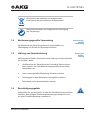 7
7
-
 8
8
-
 9
9
-
 10
10
-
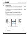 11
11
-
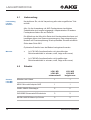 12
12
-
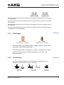 13
13
-
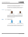 14
14
-
 15
15
-
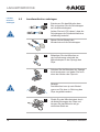 16
16
-
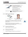 17
17
-
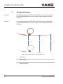 18
18
-
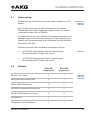 19
19
-
 20
20
-
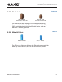 21
21
-
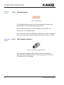 22
22
-
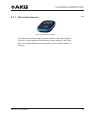 23
23
-
 24
24
-
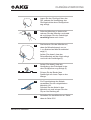 25
25
-
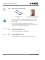 26
26
-
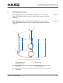 27
27
-
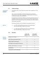 28
28
-
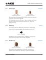 29
29
-
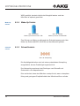 30
30
-
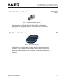 31
31
-
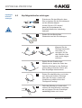 32
32
-
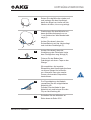 33
33
-
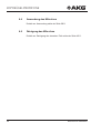 34
34
-
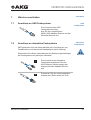 35
35
-
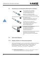 36
36
-
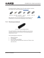 37
37
-
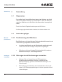 38
38
-
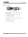 39
39
-
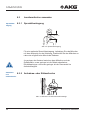 40
40
-
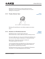 41
41
-
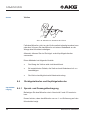 42
42
-
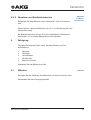 43
43
-
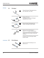 44
44
-
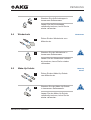 45
45
-
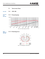 46
46
-
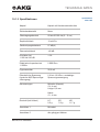 47
47
-
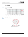 48
48
-
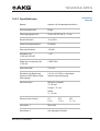 49
49
-
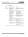 50
50
-
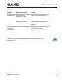 51
51
-
 52
52
-
 53
53
-
 54
54
-
 55
55
-
 56
56
-
 57
57
-
 58
58
-
 59
59
-
 60
60
-
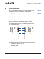 61
61
-
 62
62
-
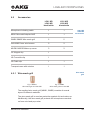 63
63
-
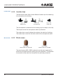 64
64
-
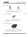 65
65
-
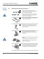 66
66
-
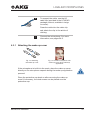 67
67
-
 68
68
-
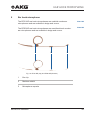 69
69
-
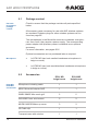 70
70
-
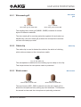 71
71
-
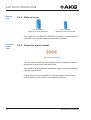 72
72
-
 73
73
-
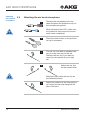 74
74
-
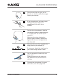 75
75
-
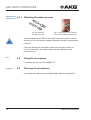 76
76
-
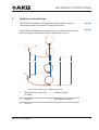 77
77
-
 78
78
-
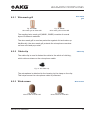 79
79
-
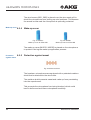 80
80
-
 81
81
-
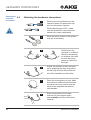 82
82
-
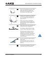 83
83
-
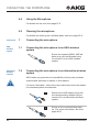 84
84
-
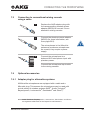 85
85
-
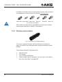 86
86
-
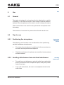 87
87
-
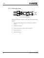 88
88
-
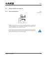 89
89
-
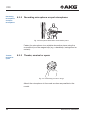 90
90
-
 91
91
-
 92
92
-
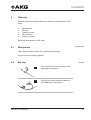 93
93
-
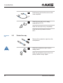 94
94
-
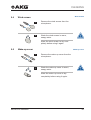 95
95
-
 96
96
-
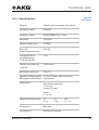 97
97
-
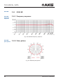 98
98
-
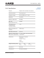 99
99
-
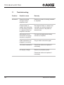 100
100
-
 101
101
-
 102
102
-
 103
103
-
 104
104
-
 105
105
-
 106
106
-
 107
107
-
 108
108
-
 109
109
-
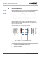 110
110
-
 111
111
-
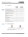 112
112
-
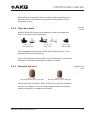 113
113
-
 114
114
-
 115
115
-
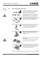 116
116
-
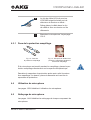 117
117
-
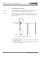 118
118
-
 119
119
-
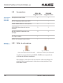 120
120
-
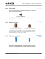 121
121
-
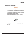 122
122
-
 123
123
-
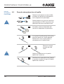 124
124
-
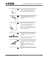 125
125
-
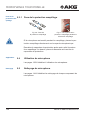 126
126
-
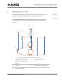 127
127
-
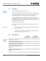 128
128
-
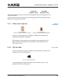 129
129
-
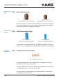 130
130
-
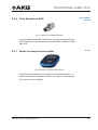 131
131
-
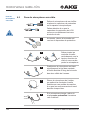 132
132
-
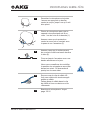 133
133
-
 134
134
-
 135
135
-
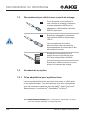 136
136
-
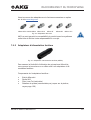 137
137
-
 138
138
-
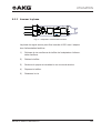 139
139
-
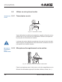 140
140
-
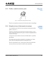 141
141
-
 142
142
-
 143
143
-
 144
144
-
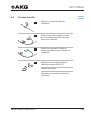 145
145
-
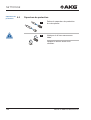 146
146
-
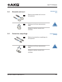 147
147
-
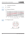 148
148
-
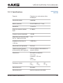 149
149
-
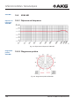 150
150
-
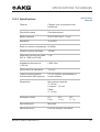 151
151
-
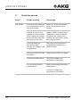 152
152
-
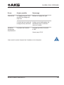 153
153
-
 154
154
-
 155
155
-
 156
156
-
 157
157
-
 158
158
-
 159
159
-
 160
160
-
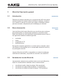 161
161
-
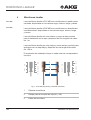 162
162
-
 163
163
-
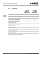 164
164
-
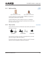 165
165
-
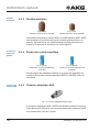 166
166
-
 167
167
-
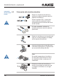 168
168
-
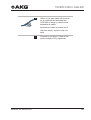 169
169
-
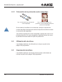 170
170
-
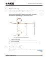 171
171
-
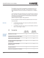 172
172
-
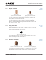 173
173
-
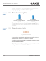 174
174
-
 175
175
-
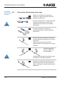 176
176
-
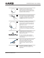 177
177
-
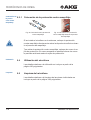 178
178
-
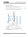 179
179
-
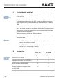 180
180
-
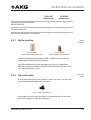 181
181
-
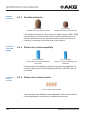 182
182
-
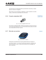 183
183
-
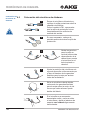 184
184
-
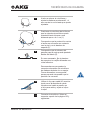 185
185
-
 186
186
-
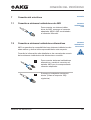 187
187
-
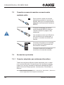 188
188
-
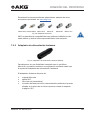 189
189
-
 190
190
-
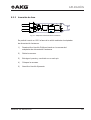 191
191
-
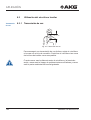 192
192
-
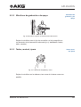 193
193
-
 194
194
-
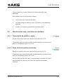 195
195
-
 196
196
-
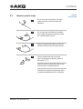 197
197
-
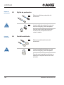 198
198
-
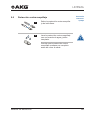 199
199
-
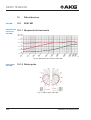 200
200
-
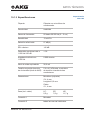 201
201
-
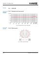 202
202
-
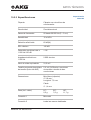 203
203
-
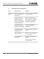 204
204
-
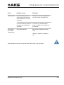 205
205
-
 206
206
-
 207
207
-
 208
208


AKG EC81 MD El manual del propietario
- Categoría
- Micrófonos
- Tipo
- El manual del propietario
en otros idiomas
- français: AKG EC81 MD Le manuel du propriétaire
- Deutsch: AKG EC81 MD Bedienungsanleitung
Artículos relacionados
-
AKG C544 El manual del propietario
-
-
-
-
-
-
-
-
-