Mantis 7228 El manual del propietario
- Categoría
- Mini cultivadores
- Tipo
- El manual del propietario

MODEL 7228
OPERATOR’S/PARTS MANUAL
MAN 430158
Rev. C 10-5-16
Operator’s Manual and Safety Instructions for
Tiller/Cultivator
Tiller/Cultivator

2 Operator’s Manual
IMPORTANT MESSAGE
Thank you for purchasing this Schiller Grounds Care, Inc. product. You have purchased a world class product, one of the best designed and built anywhere.
This machine comes with Operation and Safety instructions, Parts and Service instructions and Engine instructions. The useful life and good service you receive
from this machine depends to a large extent on how well you read and understand these manuals. Treat your machine properly, lubricate and adjust it as instructed,
and it will give you many years of reliable service.
Your safe use of this Schiller Grounds Care, Inc. product is one of our prime design objectives. Many safety features are built in, but we also rely on your good
sense and care to achieve accident-free operation. For best protection, study the manuals thoroughly. Learn the proper operation of all controls. Observe all
safety precautions. Follow all instructions and warnings completely. Do not remove or defeat any safety features. Make sure those who operate this machine
are as well informed and careful in its use as you are.
See a Schiller Grounds Care, Inc. dealer for any service or parts needed. Schiller Grounds Care, Inc. service ensures that you continue to receive the best
results possible from Schiller Grounds Care, Inc. products. You can trust Schiller Grounds Care, Inc. replacement parts because they are manufactured with
the same high precision and quality as the original parts.
Schiller Grounds Care, Inc. designs and builds its equipment to serve many years in a safe and productive manner. For longest life, use this machine only as
directed in the manuals, keep it in good repair and follow safety warnings and instructions. You’ll always be glad you did.
Schiller Grounds Care, Inc.
1028 Street Road
Southampton, PA 18966-4217
PHONE (800) 366-6268 • FAX (215) 956-3855
SAFETY RULES & WARNINGS
Special Safety Information ................................................. 3
Safety & Warnings ............................................................. 3
Safety Decal Information ................................................... 3
Warning Dos ...................................................................... 4
Warning Don’ts .................................................................. 5
Engine/Fuel Warning Do’s ................................................. 5
Engine/Fuel Warning Don’ts .............................................. 5
ASSEMBLY ............................................................................6
Lower Handle .................................................................... 7
Upper Handle Assembly .................................................... 8
Tines ...............................................................................8-9
Kickstand ........................................................................... 9
FUELING & STARTING
2-Cycle Fueling ................................................................ 10
2-Cycle Tiller Starting ................................................. 11-12
OPERATION ....................................................................13-14
TRANSPORT ....................................................................... 15
STORAGE ............................................................................ 15
MAINTENANCE ..............................................................16-18
TROUBLESHOOTING ......................................................... 19
MANTIS TILLER ASSEMBLIES ......................................20-24
CONTROL ............................................................................ 25
EPA .......................................................................................26
LIMITED WARRANTY INFORMATION ................BACK PAGE
TABLE OF CONTENTS
Welcome to the World of Mantis Gardening
Here’s your new MANTIS Tiller . . . the lightweight wonder that’s Changing the
Way Americans Garden.
®
Unlike big tillers, your MANTIS Tiller weighs only 20 lbs. (Model 7228). So it lifts
easily, handles smoothly, tills and weeds precisely. And, unlike other small tillers,
it features serpentine tines that churn soil to ten inches deep. It creates a soft,
smooth seed bed, even in problem soil.
Once you know how to use your tiller correctly, we guarantee you’ll love it. So rst, please read this manual. It shows, step by
step, how to use your tiller safely.
ATTENTION MANTIS PRODUCT OWNERS!
Get maintenance tips for your Mantis
product on our web site
at www.mantis.com
This Operator’s / Parts Manual is part of the machine. Suppliers of both new and
second-hand machines must make sure that this manual is provided with the machine.

3Contact us at www.mantis.com
You will notice throughout this Operator’s Manual Safety Rules and Important Notes. Make sure you understand and obey these
warnings for your own protection.
I. SPECIAL SAFETY INFORMATION
II. SAFETY & WARNINGS
III. SAFETY DECAL INFORMATION
An important part of the safety system incorporated in this tiller are the warning and information decals found on various parts of
the tiller. These decals must be replaced in time due to abrasion, etc. It is your responsibility to replace these decals when they
become hard to read.
Safety Rules & Warnings
Improper use or care of this tiller or failure to wear
proper protection can result in serious injury.
Read and understand the rules for safe
operation and all instructions in this manual.
Wear hearing and eye protection.
To reduce the potential for accidents, comply
with the safety instructions in this manual.
Failure to comply may result in serious
personal injury, and/or equipment
and property damage.
The engine exhaust from this product contains
chemicals known to the State of California to cause
cancer, birth defects or other reproductive harm.
Attention: This symbol points out our
important safety instructions.
When you see this symbol,
heed it’s warning!! Stay alert!!
P/N 430057P/N 400630
Cutting hazard;
keep feet and
hands away from
rotating tines.
Don’t operate
indoors
Caution: when assembling
the handles, make sure fuel
tank faces operator. This is
the rear of the tiller, refer to
assembly instructions
Incorrect assembly.
Wear ear and
eye Protection.
Do not carry
the tiller in this
position.
Don’t fuel, refuel, or
check fuel while smoking,
or near an open ame or
other ignition source.
Mix unleaded gas
with 2 cycle 50:1 oil.
Read operators manual before
using tiller, or performing any
repair or maintenance. Keep
operators manual in a safe place.
PRODUCT EMISSION DURABILITY
The 300 hour emission durability compliance period
is the time span selected by the manufacturer
certifying the engine emissions output meets
applicable emissions regulations, provided that
approved maintenance procedures are followed as
listed in the Maintenance Section of this manual.
An Emission Control
Label is located on
the engine (This is
an EXAMPLE ONLY,
information on label
varies by engine
FAMILY.)

4 Operator’s Manual
If the tiller is used improperly or safety precautions
are not followed, the users risk serious injury
to themselves and others.
Read and understand this manual before
attempting to operate this tiller.
Operation of this equipment may create sparks
that can start res around dry vegetation. A spark
arrestor is installed. The operator should contact
local re agencies for laws or regulations relating
to re prevention requirements.
IV. WARNINGS - DOS
Read and understand the owner’s manual.
Pay particular attention to all sections
regarding safety.
1. Always keep a rm grip on both handles
while the tines are moving and/or the
engine is running. BE AWARE!! The
tines may coast after throttle trigger is
released. Make sure tines have come to
a complete stop and engine is off before
letting go of the tiller.
2. Always maintain a rm footing and
good balance. Do not overreach while
operating the tiller. Before you start to
use the tiller check the work area for
obstacles that might cause you to lose
your footing, balance or control of the
machine.
3. Thoroughly inspect the area where
equipment is to be used and remove
all objects, which can be thrown by the
machine.
4. Always keep area clear of children,
pets, and bystanders.
5. Always stay alert. Watch what you are
doing and use common sense. Do not
operate unit when fatigued.
6. Always dress properly. Do not wear
loose clothing or jewelry, they might
get caught in moving parts. Use sturdy
gloves. Gloves reduce the transmission
of vibration to your hands. Prolonged
exposure to vibration can cause
numbness and other ailments.
7. While working, always wear substantial
footwear and long trousers. Do not
operate the equipment when barefoot or
wearing open sandals.
8. Always wear ear and eye protection.
Eye protection must meet applicable CE
requirements. To avoid hearing damage,
we recommend hearing protection be
worn whenever using the equipment.
9. To reduce re hazard, keep the
engine, and petrol/gas storage area free
of vegetative material and excessive
grease.
10. Start the engine carefully, according to
the manufacturer’s instructions and with
feet well away from tool(s).
11.
Keep all nuts, bolts and screws tight
to be sure the equipment is in safe
working condition.
12.
Use extreme caution when reversing
or pulling the machine towards you.
13. Work only in daylight or good
articial light.
14. Always be sure of your footing on
slopes.
15. Exercise extreme caution when
changing direction on slopes.
16. Always keep a safe distance between
two or more people when working
together.
17. Always inspect your unit before each
use. Keep all knobs, nuts, bolts and
screws tight to be sure the equipment is
in safe working condition.
18. Always visually inspect to see that
the tools are not worn or damaged.
Before using your tiller, replace worn or
damaged elements and bolts in sets to
preserve balance.
19. Always maintain and examine your
Tiller with care. Follow maintenance
instructions given in manual.
20. Always store tiller in a sheltered area
(a dry place), not accessible to children.
The tiller as well as fuel should not be
stored in a house.
21. Always keep in mind that the operator
or user is responsible for accidents or
hazards occurring to other people or
their property.

5Contact us at www.mantis.com
Handle fuel with care, it is highly ammable. Fueling a hot engine or near an ignition source can
cause a re and result in serious personal injury and/or property damage.
Safety Rules & Warnings
VI. ENGINE/FUEL WARNINGS - DOS
VII. ENGINE/FUEL WARNINGS - DON’TS
Always use fresh gasoline in the fuel mixture.
Stale gasoline can cause damage.
Always store fuel in containers
specically designed for this purpose.
Always add fuel before starting
the engine.
Always replace all fuel tank and
container caps securely.
Always pull starter cord slowly until
resistance is felt to avoid kickback and
prevent arm or hand injury.
Always operate engine with spark
arrestor installed and operating properly.
Stop the engine whenever you leave
the machine and before refueling. Allow
the engine to cool before storing in any
enclosure. Replace worn or damaged
parts for safety.
If the fuel tank needs to be drained, this
should be done outdoors.
Never pick up or carry a machine while
the engine is running.
Don’t fuel, refuel or check fuel while
smoking, or near an open ame or other
ignition source. Stop engine and be sure
it is cool before refueling.
Don’t leave the engine running while the
tiller is unattended. Stop the engine when
carrying out maintenance and cleaning
operations, when changing tools and
when being transported by means other
than under its own power.
Never remove the cap of the fuel tank or
add fuel while the engine is running or
when the engine is hot.
Don’t refuel, start or run this tiller indoors
or in an improperly ventilated area.
Don’t run engine when electrical system
causes spark outside the cylinder. During
periodical checks of the spark plug, keep
plug a safe distance from cylinder to
avoid burning of evaporated fuel from
cylinder.
Don’t check for spark with spark plug
or plug wire removed. Use an approved
tester.
Don’t crank engine with spark plug
removed unless spark plug wire is
disconnected. Sparks can ignite fumes.
Don’t run engine when the odor of gasoline
is present or other explosive conditions exist.
Do not attempt to start the engine if
fuel is spilled, but move the machine
away from the area of spillage and avoid
creating any source of ignition until fuel
vapors have dissipated.
Don’t operate your tiller if there is an
accumulation of debris around the
mufer, and cooling ns. To reduce the
re hazard, keep the engine and fuel
storage area free of vegetative material
and excessive grease.
Don’t touch hot mufers, cylinders
or cooling ns as contact may cause
serious burns.
Don’t change the engine governor
setting or over speed the engine.
Don’t attempt to remove spark plug while
engine is hot. Removing a spark plug
from a hot engine can cause irreparable
damage to the engine and will void your
warranty.
Don’t use starter uids as they will cause
permanent engine damage.
V. WARNINGS - DON’TS
Don’t use tiller with one hand. Keep
both hands on handles with ngers and
thumbs encircling the handles, while
tines are moving, and engine
is running.
Don’t run with the machine, walk.
Don’t work on excessively steep slopes.
Don’t attempt to clear tines while they
are moving. Never try to remove jammed
material before switching the engine off
and making sure the tines have stopped
completely.
Don’t allow children or people unfamiliar
with these instructions to use the
machine. Local regulations can restrict
the age of operator.
Don’t let others operate tiller without
proper training.
Don’t operate while under the inuence
of alcohol or drugs.
Don’t attempt to repair this tiller. Have
repairs made by a qualied dealer or
repairman. See that only original Mantis
parts are used.
Don’t overreach. Keep a good footing at
all times.
Don’t stand in front of tiller when tines
are rotating.

6 Operator’s Manual
Assembly
WHAT COMES IN THE BOX
WHAT YOU WILL NEED
TO ASSEMBLE THE TILLER
Prior to removing the contents and assembling, it is
important to:
• Have a clean work area.
• Make sure all necessary tools are handy.
• You will need two 7/16” wrenches. (Power tools may
be required)
Improper assembly of this tiller can result in serious injury. Make
sure to follow all instructions carefully. If you have any questions,
contact our factory at 1-800-366-6268 or an authorized Mantis dealer.
Key Qty. Part No. Description
T1 1 Upper Handle Throttle Side Assembly
T2 1 Upper Handle Assembly, Left
T3 2 Lower Handles W/Plug
T4 1 Handle Brace Assembly
T10 1 Plastic Carrying Handle
T21, T20,
T46
1 Engine Assembly (includes Fender Guard &
Worm Gear Transmission)
T39/T40 1 Pair Tiller/Cultivator Tines
1 Bag of Hardware Containing
T7 2 Handle Clamps
T9 1 Throttle Clip
T11 2 Bolts (3” long)
T12 2 Knobs
T14 4 Lock Nuts
T15 2 Cap Screws
T41 2 Tine Retaining Pins
T42 2 Carriage Bolts
Not
Shown
1 2-Cycle Oil
Picture of Model 7228
T40
T41
T4
T10
T15
T39
T1
T3
T20
T46
T21
T2
T12
T9
T7
T11
T42
Bag Contents
T41
T15
T12
T7
T9
T11
T14
T42
T14

7Contact us at www.mantis.com
LET’S BEGIN
• With the box upright, open the box and remove the
tine box and the loose parts that are at the top of the
tiller box. Do not remove any other parts in the box.
• Lay the box on one side and open the bottom aps.
• Return the box to an upright position (as shown) and
pull the box straight up.
• Leave the engine and throttle handle in the cradle to
assist in the assembly.
• Lay everything out so you can easily identify the
parts (see parts image and list on page 6).
Assembly
NOTE: Some of the photos in this manual do not represent your
tiller engine. They are for assembly purposes only.
• Take the lower handles that
you’ve just put together.
Slide them into the two
recessed channels.
• Make sure you insert them
from the rear of the tiller
(gasoline tank faces the
operator)... so that the bolt
ts along the back of the
housing.
• Slide the second 3-inch
bolt (T11) through the
second set of holes in
the short legs. Add a
lock
nut
(T14)
and tighten
nger tight until you’ve
completed assembly.
LOWER HANDLE ASSEMBLY
• For ease of assembly and
stability it is important that you
keep the engine assembly in its
cardboard cradle.
1
6
• Locate recessed channels
below the engine.
4
5
NOTE: THE LOCK NUTS ARE STAMPED. FINGER TIGHT IS APPROXIMATELY 1/2 TO 1-1/2 TURNS UNTIL YOU’VE COMPLETED ASSEMBLY.
To identify part numbers see page 6.
• Lay the handle parts within easy
reach. You’ll need one of the
handle clamps (T7) and one of
the lower handles (T3). Note that
the lower handles have a short
leg on one end.
• Fit the handle clamp along the
outside of the short leg. Line
up the holes on the clamp and
the leg.
2
• Choose one of the two 3-inch
bolts (T11). Slide it through the
rst set of holes — near the
elbow where the lower handle
curves. (Pictures 2 & 3)
• Now slide the other lower
handle onto the 3-inch bolt. Fit
the other
clamp onto the other
handle’s short leg. Add a lock nut
(T14) and tighten nger tight.
(Picture 3)
3

8 Operator’s Manual
Assembly (Continued)
UPPER HANDLE ASSEMBLY
8
• Lift the upper handle until it lines up
with the lower handle.
•
Insert carriage bold (T42) from outside in.
• Screw on knob (T12) and fully tighten
the knob at the pivot point.
• You’ll need the 2 Tines and the
2 retaining pins.
• Remove the unit from the
cardboard cradle and lay the
unit on its side.
• You will notice that one side of the
Tine has a circular hole while the
other has a “D” shaped hole.
TINE ASSEMBLY
1 2 3
• Follow the same steps to install the
other upper handle onto the other
lower handle.
• Use the clip (T9) to secure the throttle
cable and wire in place on the lower
handle.
• Now install the handle brace. Line it up with
the holes on the upper handles. Then insert a
cap screw (T15) and a lock nut (T14) on either
side.
• Use a wrench to tighten cap screws and lock
nuts.
• Now use wrench to tighten all nuts and bolts
rmly and securely. (Power tools may be
required)
10
9
• Lightly squeeze the lower
handles (T3) toward one another
so that they line up with the two
smaller holes on the carrying
handle (T10). Then slide the
carrying handle over and down
the lower handles. It will rest
about four to six inches above the
fender.
• Gently pull the lower handles out
to their original position.
• Your Mantis Tiller will look like
this when the lower handle
assembly is complete.
7a
7b

9Contact us at www.mantis.com
Assembly (Continued)
IMPORTANT NOTE:
Be sure you have proper throttle movements and that
the throttle cable is not wrapped or twisted around the
handle bar. Hold the lockout button, fully squeeze the
throttle trigger and let go. The throttle triangle must
click in both directions. If there is any doubt, remove
air lter and visually check that the throttle triangle hits
both the idle screw and the full open stop. THIS MUST
BE DONE BEFORE STARTING THE ENGINE.
IMPORTANT NOTE:
Before you use your MANTIS Tiller, read the
Safety Rules & Warnings on pages 3-5
IMPORTANT NOTE:
Make sure you have installed the handles properly.
When you stand behind your tiller, holding the handles,
the fender warning label should face you.
Improper Throttle installation can cause tines to rotate unexpectedly.
7228
TINE ASSEMBLY (Continued)
• Attach the Tine so that the circular hole
slides onto the axle rst.
• When the axle protrudes from the
other side it will line up perfectly
with the “D” shaped hole.
• Slide a retaining pin (T41) through
the hole in the axle to secure the
Tine.
• Repeat steps for the other side.
4 5 6

10 Operator’s Manual
2-CYCLE TILLER FUELING
MIXING FUEL
Use a mixture of 50 parts unleaded
regular gasoline and 1 part two-stroke
oil (50:1.) Use branded 89 octane
(R+M+2) unleaded gasoline (maximum
10% ethanol, or 15% MTBE, no methyl
alcohol.)
Here’s how to mix the oil with the gas:
1. Pour 1/2 of the gasoline into a safe container. Do not mix
the fuel and oil in the engine fuel tank.
2. Add 2.6 ounces of two-cycle engine oil to the gasoline and
mix. Then add the rest of the gasoline.
3. Screw the cap onto the gasoline can. Then swirl the can to
blend the oil and gas.
4. Carefully pour the fuel mix into the tiller’s fuel tank. After
putting the fuel tank’s cap back on, wipe up any spilled fuel
from tank and gasoline can.
Need pre-measured engine oil? You can order it directly
from Mantis or your local authorized Mantis dealer. Just
call toll free 1-800-366-6268 and ask for our Sales Dept.
IMPORTANT:
Two stroke fuel separates and ages. Do not mix more than
you will use in a month. Using old fuel can cause difcult
starting or engine damage. Shake fuel container to thoroughly
mix fuel before each use.
Remember …
• Never, run your tiller on gasoline alone. This will ruin your
engine and void all warranties.
• Always use a clean gas can and always use unleaded gas.
• Never try to mix the oil and gasoline in the engine fuel tank.
• Always mix oil and gas in the proper proportions: 2.6 ounces
of two-cycle engine oil to one gallon of unleaded gasoline.
IMPORTANT NOTE:
Do Not use old or stale oil/gasoline mixture. Always use
the proper oil/gasoline mixture. If you do not, your engine will
suffer rapid, permanent damage. And you will void the engine
warranty.
2-Cycle Tiller Fueling
Fuel is extremely ammable. Handle it with
care. Keep away from ignition sources. Do not
smoke while fueling your equipment
Do not operate the engine in a conned
space where dangerous carbon monoxide
fumes can collect.
Avoid accidental blade engagement.
Do not squeeze the throttle trigger when starting. Main-
tain proper idle speed adjustment (2500-3100 rpm)
WARNING • DANGER
ALTERNATIVE FUELS, SUCH AS E-15 (15% ETHANOL), E-85 (85% ETHANOL) OR ANY FUELS NOT MEETING ECHO REQUIREMENTS ARE NOT APPROVED FOR USE IN
ECHO 2-STROKE GASOLINE ENGINES. USE OF ALTERNATIVE FUELS MAY CAUSE PERFORMANCE PROBLEMS, LOSS OF POWER, OVERHEATING, FUEL VAPOR LOCK
AND UNINTENDED MACHINE OPERATION, INCLUDING, BUT NOT LIMITED TO, IMPROPER CLUTCH ENGAGEMENT. ALTERNATIVE FUELS MAY ALSO CAUSE PREMATURE
DETERIORATION OF FUEL LINES, GASKETS, CARBURETORS AND OTHER ENGINE COMPONENTS.
! !
2.6 oz. bottle of 50:1
2-cycle engine oil

11Contact us at www.mantis.com
Switch
Picture 1 Picture 2
Choke
OFF ON
Pull the recoil starter handle/rope (Picture 4A) with a
controlled motion until resistance is felt. Then give the
cord a few brisk pulls until the engine res. During cold
starting, you may need to try three or four times before
the engine res. Do not pull the rope out to end stop
and do not let it snap back into the starter housing.
7. Push the choke button in, all the way, to open the choke.
8. Then pull the starter cord again until engine starts and
runs.
Let the engine warm up two to three minutes before using
NOTE: If engine does not start with choke in “Run” position
after 5 engine engagements, repeat Cold Start instructions.
WARM STARTING
• To start a warm engine, follow the same procedure. The
only exception is that you can leave the choke button in
and you don’t have to pump the primer bulb.
• Before using the tiller, let the engine idle for a minute to
warm up. Before shutting it down, let the engine idle for
two to three minutes to cool down.
2-Cycle Tiller Starting
Never use starting uids as they will cause permanent engine damage. Using them will void the warranty.
Before you use the tiller, read the Safety & Warning rules on pages 5.
2-CYCLE TILLER STARTING
1. Fill the fuel tank with the proper oil/gasoline mixture.
(See previous section.)
2. Hand tighten the gasoline cap just until it’s snug.
3. Place the O/I switch into the I “start/on” position.
(Picture 1)
4. Pull the choke button all the way out, to completely
close the choke. (Picture 2)
5. Locate the purge bulb on the upper right of the
engine, in front of the fuel tank. (See Picture 3) It
sends fuel into the carburetor, for easy starting.
Press the purge bulb until you see fuel ow through
the clear fuel return line. Since you’re starting “cold,”
you may need to press six to eight times. As soon
as fuel starts owing through the clear fuel line, stop
pressing!
NOTE: Don’t press the throttle trigger
during the starting of the engine.
6. Recoil pull starting (Different for each model)
NOTE: DO NOT PULL THE CORD MORE THEN 4 TIMES WHEN THE CHOKE IS CLOSED. OVER PULLING MAY
CAUSE ENGINE FLOODING!
Bear in mind that, when the engine res, it only coughs or sputters, and will not run on choke.
Picture 3
Picture 4A

12 Operator’s Manual
WHAT TO DO JUST IN CASE
If you follow the normal starting procedure, you should have no problem starting your
tiller. But, just in case you do have problems, here’s what to do.
Make sure the O/I switch is on “I” (start).You’d be surprised how many people
forget to push the switch into the “I” (start)
position.
If the switch was on “O” (stop) when you
pulled the cord, you may have ooded
the engine.
• First, examine the spark plug. Use the
special wrench that comes with our
optional MANTIS Handy Item Kit (Item
#8444) or a 3/4 inch spark plug wrench.
(Picture 1)
• Remove the cap over the spark plug.
• Unscrew the spark plug. (Picture 2)
STARTING A FLOODED ENGINE
If the end of the spark plug is wet, the engine may be ooded. Make sure the switch
is in the “O” (stop) position, disconnect spark plug wire and remove plug. Use a
paper towel or a clean rag to dry the spark plug, then, with the spark plug out of
the engine, pull the starter cord several times. Next, replace the spark plug.
Use the wrench to tighten it and replace the cap. Then, put the switch in the “I” (start)
position and pull the choke button out. Pull the starter cord three or four times until the
engine coughs or sputters. Open the choke (push the choke button in) and pull the
cord a few times. The engine should start and run.
FUEL LINES CHECK
If the end of the spark plug is dry, check to see if the fuel line is blocked. First loosen
the fuel cap to relieve the pressure in the tank. The fuel line runs from the fuel tank to
the carburetor. Pull it off at the carburetor end. Fuel should drip slowly from the line.
Wipe off any excess or spilled fuel.
If fuel does not drip from the line, check the line for any bends or pinches. (Picture
3). Kinks in the line restrict the ow of fuel to the engine. Just straighten out the line.
Reconnect. Then follow the normal starting procedure.
If fuel drips too freely, the line may be disconnected from the fuel lter. You’ll nd the
fuel lter inside the fuel tank. Just re-attach the line to the lter, and put the lter back
in the tank. Then follow the normal starting procedure.
12
If you follow the normal
starting procedure, you should
have no problem starting your
tiller. But, just in case you do
have problems, here’s what to do.
Make sure the start/stop
switch is on “start.” You’d be
surprised how many people
forget to push the switch into the
“start” position.
If the switch was on “stop”
when you pulled the cord, you
may have flooded the engine.
•First, examine the spark plug.
Use the special wrench that
comes with our optional
MANTIS Handy Item Kit (Item
#1422) or a 3/4 inch spark plug
wrench. (Picture 1)
•Remove the cap over the spark
plug.
•Unscrew the spark plug.
(Picture 2)
Starting a Flooded
Engine
1. If the end of the spark plug
is wet, the engine may be
flooded. Make sure the switch
is in the stop position,
disconnect spark plug wire and
remove plug. Use a paper towel
or a clean rag to dry the spark
plug, then, with the spark plug
out of the engine, pull the
starter cord several times.
Next, replace the spark plug. Use
the wrench to tighten it and
replace the cap. Next, put the
switch in the start position and
pull the choke button out. Pull
the starter cord three or four
times until the engine coughs or
sputters. Open the choke (push
the choke button in) and pull
the cord a few times. The engine
should start and run.
2. If the end of the spark plug
is dry, check to see if the fuel
line is blocked. First loosen the
fuel cap to relieve pressure in the
tank. The fuel line runs from
the fuel tank to the carburetor.
Pull it off at the carburetor end.
Fuel should drip slowly from the
line. Wipe off any excess or
spilled fuel.
If fuel does not drip from the
line, check the line for any bends
or pinches. (Picture 3). Kinks in
the line restrict the flow of fuel
to the engine. Just straighten out
the line. Reconnect. Then follow
the normal starting procedure.
If fuel drips too freely, the line
may be disconnected from the
fuel filter. You’ll find the fuel
filter inside the fuel tank. Just re-
attach the line to the filter, and
put the filter back in the tank.
Then follow the normal starting
procedure.
Here’s Another Way to
Start your MANTIS
Tiller
If you follow the steps above
and your engine still won’t start,
try this:
1. Push the switch to “start.”
WARNING
MAKE SURE THE START/STOP
SWITCH IS IN THE
STOP POSITION.
KEEP PLUG WIRE AWAY
FROM ENGINE TO AVOID
UNINTENTIONAL SPARK.
IMPORTANT NOTE:
To avoid possible damage
to the threads, do not try
to remove the plug from a
hot aluminum cylinder
head.
WHAT TO DO JUST IN CASE
! !
Picture 1
Picture 2
Picture 3
IMPORTANT NOTE:
To avoid possible damage to the
threads, do not try to remove the plug
from a hot aluminum cylinder head.
WARNING
MAKE SURE THE START/STOP SWITCH IS IN THE
STOP POSITION. KEEP PLUG WIRE AWAY FROM
ENGINE TO AVOID UNINTENTIONAL SPARK.
! !
2-Cycle Tiller Starting (Continued)

13Contact us at www.mantis.com
2-Cycle Tiller Operation
If engine does not stop when switch is put in the stop position, release the throttle, allow engine to idle. Put the tiller
down, and slide the choke lever to the cold start (closed) position. Have product serviced before using.
Read the instructions carefully. Be
familiar with the controls and the
proper use of the equipment.
A SPECIAL FEATURE
(With the idle set properly and the
engine running)
Even when the engine is running, the
tines won’t turn unless you squeeze
the throttle trigger on the handlebars.
When you release the throttle trigger,
the tines will stop
.
A TIP FOR EXTENDING
YOUR ENGINE’S LIFE
After you start the engine, let your
tiller warm up for two to three
minutes before you use it. Then,
before you put your tiller away, let it
idle for a minute to give the engine a
chance to cool down.
OPERATION
With engine running, and both
hands on the handles, hold down
the throttle lockout trigger (Figure
1), then squeeze the throttle trigger
gradually to increase the engine
speed and engage the tines.
NOTE: This step must be repeated
each time your tiller trigger is
released.
NOW YOU’RE READY TO USE
YOUR MANTIS TILLER.
If you’ve seen other tillers, your MANTIS
Tiller may surprise you. It tills best when
you pull it backward! You see, when you
pull your MANTIS Tiller backward, you
give extra resistance to the tines, so they
dig deeper. (Figure 2)
In addition, when you go backward,
you erase your footprints. So your soil
stays light and uffy. With other tillers,
by contrast, you walk right over the soil
you’ve just tilled, packing it down, so it’s
less plantable.
RUN YOUR MANTIS TILLER
LIKE A VACUUM CLEANER
Place your Tiller at the head of the row
or area you want to till. Start it up. Then
use an easy rocking motion. First, pull
your Tiller backward. Then use an easy
rocking motion. Again, pull your Tiller
backward. Then, let it move forward just
a little bit. Then pull it backward again.
This will help you till deeper.
Keep repeating these steps until you’ve
tilled an entire row. Start again on the
next row. It’s much like running a vacuum
cleaner! (Figure 3)
You Can Even Control Depth.
For Deeper Tilling:
Move your Tiller slowly back and forth, as
you would a vacuum cleaner. Work the
same area over and over until you’ve dug
to your desired depth. (Figure 4)
For Shallow Tilling:
Switch the tines to the cultivating
position. (See page 14 to learn how.)
Then move your Tiller quickly over your
soil surface.
For Big Weeds or Tough Roots:
Let your Tiller rock back and forth over
the tough spot, until the tines slice
through the weed or root.
Your MANTIS Tiller Handles Special
Tilling Projects:
Want to turn part of your lawn into a
colorful ower border? Your MANTIS
Tiller makes it easy! Just run your Tiller
back and forth until the sod begins to
break up. Then continue tilling. Your Tiller
will chop the clumps of sod until they’re
ne. Then, it will work them into the soil.
Pretty soon, you’ll have a soft, fresh
planting bed.
Figure 1
WARNING
ALWAYS MAKE SURE THE HANDLE KNOBS ARE
SECURE BEFORE STARTING YOUR MANTIS TILLER.
! !
Figure 2 Figure 3 Figure 4

14 Operator’s Manual
YOUR MANTIS TILLER MAKES
WEEDING A PLEASURE!
As a tiller, your MANTIS Tiller works the soil
down to 10” (25.4 cm) deep. But, as a cultivator,
it gently cultivates the surface, only 2” to 3” (5.09
cm to 7.62 cm) deep.
First, you must switch the tines to the weeding,
cultivating position. This takes less than a
minute.
Then, your MANTIS Tiller’s sharp “tine teeth” will
slice up those pesky weeds, burying them as you
go along. And, since the tines in this position
won’t dig too deep, they won’t hurt your plants’
precious root systems.
The result? Your Tiller will cut your weeding time
in half, and turn a tiresome chore into a pleasure.
HOW TO SWITCH FROM TILLING TO
CULTIVATING POSITION
1. Make sure your Tiller is off.
2. Remove the retaining pins from the tines.
3. Remove the tines from the axle.
4. Place the right-side tine onto the left-side axle.
Place the left side tine onto the right-side axle.
The “D” hole should be to the outside.
5. Reinsert the pins. (Figure 1)
2-Cycle Tiller Operation (Continued)
The operator of this tiller is responsible for
accidents or hazards occurring to himself,
other people or their property.
If your tines get jammed or entangled, shut off the
engine at once. Remove the obstruction while the
engine is off. Never try to remove an obstruction while
the engine is running. Serious injury can result.
To set them for tilling, attach the tines
so the points of the blades face forward
- away from the operator. The tines’
points will contact the ground rst.
For cultivating, reverse the tines
so that the points of the tines face
backward - toward the operator. Now
the long at part of the tine’s blade
will contact the ground rst.
Tilling Cultivating
Figure 1

15Contact us at www.mantis.com
Each fall, or before you store your
Mantis Tiller for any long period, be sure
to take these measures:
1. Do not store your Tiller with fuel still in
it. Even under ideal conditions, stored
fuel containing ethanol or MTBE can
start to go stale in 30 days. And, since
stale fuel has a high gum content, it
can clog the carburetor, this, in turn,
will restrict fuel ow. Therefore, when
you’re ready to store your Tiller, or will
not be using it for more than 2 weeks,
drain the fuel tank completely.
2. Next, restart the engine to make
sure no fuel is left in the carburetor.
Then, run the engine until it stops.
This will prevent gum deposits,
forming inside of the carburetor and
possible engine damage.
3. Disconnect spark plug wire and
remove the spark plug. Slowly pull the
starter cord once.
4. Inspect the spark plug, and if
necessary, clean it. If you need to
replace it, buy a NGR-BPM8Y.
Pour about a teaspoon of clean, air-
cooled, two-cycle oil through the spark-
plug hole into the combustion chamber.
Leaving the spark plug out slowly pull
the starter cord two or three times to
coat the inside of the cylinder wall.
5. Install the spark plug, but leave the
spark plug wire disconnected.
6. Wipe the tines with oil or spray them
with WD-40, to prevent rusting.
7. Clean or replace the air lter.
8. Check or replace fuel lter.
9. Check the grease level in the worm
gear housing. Add grease if needed.
10. Store your Tiller in an upright position
in a clean, dry place. You can store
with the handles in an extended
position or folded down.
To fold the handles down, simply
loosen the lower 2-pronged knobs
until you can pivot the upper handles
down. (Figure 3)
Or it can be hung using the handle
brace.
11. Do you have fuel left over from last
season? Dispose of it properly. Buy
fresh oil and gasoline next season.
12. Remove Tilling Tines or attachments
and lightly oil tine shaft at least once
a year.
2-Cycle Tiller Transportation & Storage
Never store the equipment
with Fuel in the tank or in
an area where fumes may
accumulate and breach an
open ame or spark
2-CYCLE TILLER TRANSPORTATION
Transporting your Tiller is easy. It’s light enough and easy
to carry using the carrying handle as seen in Figure 1.
Or, with it running, you can walk it by gently squeezing
the throttle until it moves at a comfortable pace.
Your tiller is easily transported in the back of a car or
truck. Be sure to empty the fuel tank (This is crucial)!
Then stow your tiller in the trunk of your car or truck.
TILLER STORAGE
Figure 1
Figure 3
Figure 2
WARNING
NEVER CARRY YOUR TILLER AS THE PERSON IN
FIGURE 2 IS DOING. IF YOU DO, YOU WILL SUFFER
SERIOUS INJURY.
! !

16 Operator’s Manual
HOW TO CHECK, CLEAN AND CHANGE THE AIR FILTER
1. Loosen the wing nut on the side of the air-cleaner cover. (Picture 1)
2. Take off the cover. Make sure to clear the choke button.
3. The air lter is the pad on the inside of the air-cleaner cover. Check whether it is
soiled or moist.
4. If the air lter needs cleaning or no longer ts properly, remove it. Just lift an edge
carefully and “peel” it out. (Picture 2)
5. Use a brush to remove debris from the pad.
6. If the air lter is so dirty that it won’t come clean, you must replace it or severe
engine damage will occur. Order a new one directly from our Customer Service Dept.
Call 1-800-366-6268.
7. Insert your clean lter inside the air-cleaner cover.
IMPORTANT! Make sure lter is “seated” properly in the cover. The lter must t
snugly inside the rim that holds the lter in place.
Installing the lter incorrectly will cause engine damage and void the warranty. Fit the
cover back over the air cleaner. (Again, make sure to clear the choke button.)
8. Tighten the wing nut to secure the cover.
2-Cycle Tiller Maintenance
Fuel Filter
FUEL FILTER REPLACEMENT
The fuel lter should be replaced every year. Open the fuel cap and using the cap
retainer you can remove the fuel intake line. The lter is at the end.
Hold the fuel line and work the lter out. Then just push the new one back into the tube
making sure the clamping wire is up high enough to engage with the stem of the lter.
Picture 2
Picture 1
Air Filter
Note:
Please check the lip on the Air Cleaner Cover. If the lip is chipped or cracked,
it should be replaced. This will prevent dirt from being ingested through the
carburetor into the inside of the engine.

17Contact us at www.mantis.com
WHAT TO DO IF YOUR ENGINE
IDLES TOO HIGH
What if your engine runs too fast … or if the
tines turn the instant you start the Tiller?
You may need to adjust the idle screw right
below the H and L screws. Gently turn
it counter-clockwise. You’ll know you’ve
adjusted it correctly when the axles do not
turn at low idle.
WHAT TO DO IF YOUR ENGINE
RUNS “ROUGH” CARBURATOR
ADJUSTMENT
If your engine runs “rough” or stalls, you
may need to adjust the carburetor and idle
screws.
If you remove the air-cleaner cover, you’ll
see the two carburetor, adjustment
screws
next to the choke button. (Picture 1)
The “RED” screw is the HIGH-speed
adjustment…The “WHITE” screw is the low
speed adjustment.
First, remove the tines from the axle. Then
start engine. Let it run for two to three
minutes. “FLASH” the choke several times
during the warm-up by closing and opening
it while engine runs in order to clear any air
from the Fuel system.
Then stop the engine after it reaches
operating temperature.
Now, turn the RED, high-speed screw
counter-clockwise all the way to stop…
Then turn the WHITE, low speed screw
halfway between the counter-clockwise and
clockwise stop positions.
Now restart the engine to nish the
carburetor adjustment.
Run the engine at full speed two or three
seconds to clear out any excess fuel. Then
return to idle.
Now, accelerate the engine to full throttle
several times to check for a smooth
transition from idle to high speed.
If the engine hesitates turn the WHITE, low-
speed screw counter-clockwise one-eighth
of a turn. Then accelerate the engine.
Repeat the adjustment until you get a
smooth transition to high speed.
Picture 1
CLEANING THE MUFFLER SCREEN
1. Take out the spark plug.
2. Remove the red cylinder cover,
(#D1) which is held on by 2 phillips-
head screws, (#D2) and 1 hex-head
screw, (#D3) which you will need an
allen wrench to remove.
3. You will see the metal exhaust
guide, held on by 3 more phillips-head
screws. (#C1) Remove the exhaust
guide.
4. Behind the exhaust guide (#C2) will
be the mufer gasket (#C3) and mufer
screen (#C4). The screen sits under
the gasket.
5. If the screen (#C4) is clogged with
deposits, it needs to be cleaned.
Use carburetor cleaner, and any brush
that is not metal. Brush the screen until
you are able to see through it.
6. If the screen remains plugged
after attempts at cleaning, it must be
replaced.
99922200869 - 8 - REVISED 10/16/13
Table of Contents Part Number Index
SV-5C/2 Engine Engine Cover, Fancase, Starter
C9
C8
C4
C3
C2
C1
C5
C6
C7
D2
D1
D3
2-Cycle Tiller Maintenance
WARNING • DANGER
REMOVE TINES BEFORE STARTING ENGINE AND
MAKING ADJUSTMENTS
! !
WARNING • DANGER
DO NOT USE GASOLINE OR OTHER
FLAMMABLE SUBSTANCE
! !
HIGH ALTITUDE OPERATION
This engine has been factory adjusted to
maintain satisfactory starting, emission, and
durability performance up to 1,100 feet (96,0
kPa and above) mean sea level (MSL). To
maintain proper engine operation above
1,100 feet (96,0 kPa and above) MSL the
carburetor may need to be adjusted by an
authorized ECHO service dealer.
IMPORTANT
If the engine is adjusted for operation above
1,100 feet MSL, the carburetor must be re-
adjusted when operating the engine below
1,100 feet MSL, otherwise severe engine
damage can result.
EXHAUST PORT/MUFFLER CLEANING
Tools required: 4mm Hex wrench, Wood or
plastic scraper
Parts Required: As needed: Heat Shield
1. Remove spark plug lead from spark plug,
and remove engine cover (2 screws).
2. Place piston at top dead center. Remove
mufer (A) and heat shield (B).
3. Use a wood or plastic scraping tool to
clean deposits from cylinder exhaust port.
IMPORTANT
Never use a metal tool to scrape carbon from
the exhaust port. Do not scratch the cylinder
or piston when cleaning the exhaust port.
Do not allow carbon particles to enter the
cylinder.
4. Inspect heat shield, and replace if
damaged.
5. Install heat shield and mufer.
6. Tighten mufer mounting bolts (or nuts) to
80-95 in•lbf (90-110 kgf•cm).
7. Start engine, and warm to operating
temperature.
8. Stop engine, and re-tighten mounting bolts
(or nuts) to specications.
9. Install engine cover and attach spark plug
lead.

18 Operator’s Manual
Check the transmission grease level after the rst
10 hours of use, then check yearly.
With the tines off, remove the transmission plate
(Figure 3) and gasket to see if the grease level is up
to the plate ange (Figure 4). If it is not, you will need
to add lithium zero or lithium one grease.
Wipe off any excess grease, replace the transmission
gasket and plate.
At some point, you may nd that the
tines won’t turn when you press the
throttle. This may mean the engine isn’t
sitting all the way down on the worm
gear housing.
Perhaps you’ve been using your Tiller
for several years. Or perhaps you’ve
removed the engine for use with our
hedge trimmer attachment, then replaced
it. In either case, the ange bolt may
have come loose and lifted the
engine up.
If this happened you’ll notice a gap
between the bottom of the engine clutch
case and the top of the worm gear
housing. (Figure 1)
To x this, loosen the ange bolt. Take
the engine off the worm gear housing.
Notice the hex head on top of the drive
shaft . Inside the clutch case, you’ll nd
the clutch drum. Make sure the hex head
lines up with the clutch drum inside the
clutch case.
Then put the engine back on the
worm gear housing. Make sure the
plastic carrying handle is not under the
fuel tank.
If you’ve followed these steps properly,
there will be no gap between the clutch
case and the worm gear housing.
(Figure 2) Make sure you tighten the
ange bolt!
Note how the engine doesn’t sit all
the way down on the transmission.
HOW TO RESEAT THE FLANGE
TRANSMISSION CARE
Note how the engine sits all the
way down on the transmission.
2-Cycle Tiller Maintenance
Figure 3
Figure 4
Figure 1
Figure 2
Gap
No Gap

19Contact us at www.mantis.com
Troubleshooting
Problem Cause Remedy
1. Tines don’t turn when throttle
is depressed
• Engine is not seated properly on the gear housing. • Re-install engine following the instructions on
page 18 “How to reseat the flange”.
2. Engine fails to start
• O/I switch is in “O” position.
• No fuel in tank.
• Fuel strainer clogged.
• Fuel line clogged.
• Spark plug shorted or fouled.
• Spark plug is broken (cracked porcelain or
electrodes broken)
• Ignition lead wire shorted, broken or disconnected from
spark plug.
• Ignition inoperative
• Move switch to “I”
• Fill Tank.
• Replace Strainer.
• Clean fuel line.
• Install new spark plug.
• Replace spark plug.
• Replace lead wire or attach to spark plug.
• Contact your local authorized dealer.
3. Engine hard to start. • Water in gasoline or stale fuel mixture.
• Too much oil in fuel mixture.
• Engine under or over choked.
• Carburetor out of adjustment.
• Gasket leaks (carburetor or cylinder base gasket).
• Weak spark at spark plug.
• Drain entire system and refill with fresh fuel.
• Drain and refill with correct mixture.
• If flooded by over choking, proceed according
to instructions in operation section. If under
choked, move choke lever to closed position
and crank two or three times.
• See “Carburetor Adjustment.”
• Replace gaskets.
• Contact your local authorized dealer.
4. Engine continuously floods. • Fuel tank vent line is not in an upright position. • Return the fuel tank vent line to the upright
position and place it under the cylinder cover in
the small “pocket” in the cylinder cover
5. There is black smoke coming from
exhaust
• The muffler screen is clogged • Clean carbon from muffler screen (page 17)
6. Engine misses. • Dirt in fuel line or carburetor.
• Carburetor improperly adjusted.
• Spark plug fouled, broken or incorrect
gap setting.
• Weak or intermittent spark at spark plug.
• Remove and clean.
• See “Carburetor Adjustment” (page 17)
• Clean or replace spark plug - set
gap to .024-.028
in. (0.6-0.7 mm)
• Contact your local authorized dealer.
7. Engine lacks power. • Air filter clogged.
• Carburetor out of adjustment.
• Muffler clogged.
• Clogged exhaust ports.
• Spark Arrestor Clogged.
• Poor compression.
• Clean or replace air filter.
• See “Carburetor Adjustment”.
• Clean carbon from muffler.
• Remove muffler, rotate engine until the piston
is at top of cylinder. With a wooden scraper
or blunt tool, remove all carbon from exhaust
ports. Be careful not to scratch or damage
piston or cylinder walls. Blow out all loose
carbon with compressed air. Install muffler and
gasket.
• Clean muffler screen (page 17)
• Contact your local authorized dealer.
8. Engine overheats. • Insufficient oil in fuel mixture
• Air flow obstructed
• Mix fuel as described in starting instructions.
• Clean flywheel cylinder fins and screen.
9. Engine noisy or knocking. • Spark plug in incorrect heat range.
• Bearings, piston ring or cylinder walls are worn.
• Replace with plugs specified for engine.
• Contact your local authorized dealer.
10. Engine stalls under load. • Carburetor adjustment too “lean.”
• Engine overheats.
• See “Carburetor Adjustment.” (page 17)
• Remove dust and dirt from between fins.

20 Operator’s Manual
2-Cycle Tiller Assembly
T16
T17
37
T36
Model #7228 ___ 2-CYCLE TILLER
T38
T34
EXPLODED VIEW
T44
T46
T38
T37
T36
T33
31
T30
T29
T45
T32
T28
T27
T24
T25
T26
T35
T35
T23
T20
T39
T41
T3
T22*
T42
T18
T8
T9
T9
T4
T2
T1
Rev. A, 07/28/2016
T41
T40
T43
T11
T21
T15
T42
T7
T7
T14
T10
T12
T12
T19
T14
T14
T15

21Contact us at www.mantis.com
Parts List
Key Qty. Part No. Description
T1 1
430160 Upper Handle Throttle Side Assembly
T2
1
430161 Upper Handle Assembly, Left
T3
2
430082 Lower Handle W/Plug
T4
1
430163 Handle Brace Assembly
T7
2
377 Handle Clamp
T8
2
4078 M6 Jam Nut
T9
2
478 Throttle Clip
T10
1
400133 Carry Handle
T11 2
470 Bolt 1/4-20 X 3”
T12
2
400523 Knob, Two Prongs, Female
T14
4
972 1/4-20 Two-Way Lock Nut
T15
2 144-2
1/4-20 X 1.125 Hex Head Cap Screw
T16
2
140 Bolt 1/4-20 X 3/8” Long
T17
1
430058 Mantis Logo Label
T18
2
4079 M6 Internal Lock Washer
T19
1
487MA Engine Label
T20
1
465 Fender Guard
T21
1
400908 Engine Assembly SV-5C/2
T22*
1
468 Drive Shaft
T23
1
466 Worm Gear Housing
T24
1
436 Gasket
T25
1
437A Gear Housing Cover
Key Qty. Part No. Description
T26
4
651 #8 Self Tapping Screw
T27
1
423 Roller Bearing
T28
2
425 Worm Bearing Race
T29
1
424 Worm Thrust Bearing
T30
1
422 Worm Shaft
T31 1
426 Worm Disk
T32 1
428 Retaining Ring
T33
1
429 Worm Gear
T34
1
431 Tine Shaft
T35
2
430 Worm Gear Thrust Washer
T36
2
432 Worm Gear Bearing
T37
2
434 Bearing Seal
T38
2
435 Bearing Seal Retainer
T39
1
438RA Tine Assembly, Right
T40
1
438LA Tine Assembly, Left
T41
2
418-1 Tine Retaining Pin
T42
2
400509 Carriage Bolt 1/4-20 X 2.25”
T43
1
430042 Ground Wire Jumper, 2 Cycle Engine
T44
1
400630 Triangle Warning Label (2 Cycle Engine)
T45
1
458 Roller Bearing
T46
1
400010 Worm Gear Transmission Assembly
*Also in key T46

22 Operator’s Manual
99922200869 - 4 - REVISED 10/16/13
Table of Contents Part Number Index
SV-5C/2 Engine Carburetor -- C1U-K82
23
A34
A2
A3
A4
A35
A36
A24
A25
A22
A26
A27
A28
A29
A30
A6
A5
A8
A7
A9
A10
A12
A13
A11
A37
A38
A32
A33
A18
A21
A20
A19
A17
A16
A15
A23
A31
A14
A1
Carburetor - C1U-K82
Explosion A
99922200869 - 20 - REVISED 10/16/13
Table of Contents Part Number Index
SV-5C/2 Engine Intake
99922200869 - 20 - REVISED 10/16/13
Table of Contents Part Number Index
SV-5C/2 Engine Intake
B1
B3
B5
B2
B4
B6
B7
B8
B9
B11
B10
B12
B13
B16
B14
B15
B17
Key Part No. Qty. Description
A021001090 1 Carburetor - C1U-K82
A1 P005000980 4 Screw, Purge Bulb Retainer
A2 P005000620 1 Retainer, Purge Bulb
A3 12538108660 1 Bulb, Purge
A4 P005000970 1 Base, Purge
A5 ------------------ 1 Body, Carburetor / Not Available Separately
A6 12537613120 1 Nozzle, Check Valve
A7 12532939030 1 Cap, Limiter
A8 12532013310 1 Needle - High Speed
A9 12532909860 1 Cap, Limiter
A10 12531813120 1 Needle - Low Speed
A11 12537242030 1 Swivel
A12 P005001070 1 Shaft, Throttle
A13 12532713930 1 Ring, Retaining
A14 12531342030 1 Spring, Return
A15 12531413930 1 Screw,Valve
A16 12531649030 1 Valve, Throttle
A17 12532715130 1 Ring, Retaining
A18 12532412820 1 Base, Purge
A19 12533406960 1 Screw, Idle Adjust
A20 12533306960 1 Spring, Idle Adjust
A21 12531012820 2 Screw, Pump Cover
A22 12533942030 1 Screw, Metering Lever Pin
A23 12530013120 1 Repair Kit / Includes Items 24-33
A24 ------------------- 1 Diaphragm, Metering
A25 ------------------- 1 Gasket, Metering Diaphragm
A26 ------------------- 1 Pin, Metering Lever
A27 ------------------- 1 Lever, Metering
A28 ------------------- 1 Valve, Inlet Needle
A29 ------------------- 1 Plug, Welch
A30 ------------------- 1 Spring, Metering Lever
A31 ------------------- 1 Strainer
A32 ------------------- 1 Diaphragm, Pump
A33 ------------------- 1 Gasket, Pump
A34 12530313120 1
Diaphragm/Gasket Kit / Includes Items 35-38
A35 ------------------- 1 Diaphragm, Metering
A36 ------------------- 1 Gasket, Metering
A37 ------------------- 1 Diaphragm, Pump
A38 ------------------- 1 Gasket, Pump
Key Part No. Qty. Description
B1 90052800005 1 Wingnut - 6
B2 13032611522 1 Cover, Air Filter
B3 89012147530 1 Label - Choke
B4 13031004560 1 Filter, Air
B5 90024205057 2 Screw - 5X57
B6 13041005360 1 Plate, Prevent
B7 17851504560 1 Shutter, Choke
B8 17851600830 1 Washer - 5
B9 13030104560 1 Case, Air Filter Includes Item 10
B10 17881005230 1 Grommet
B11 17851004560 1 Rod, Choke
B12 ------------------ 1 Carburetor
1
B13 13001642031 1 Gasket, Intake
B14 90023805020 2 Screw - 5X20
B15 90050000005 2 Nut - 5
B16 13001742031 1 Insulator, Intake
B17 V103000490 1 Shield, Intake
Key Part No. Qty. Description
C1 9136704012 3 Screw - 4X12
C2 A313000700 1 Guide, Exhaust
C3 V104000072 1 Gasket, Exhaust/Included In Gasket Kit
C4 14586240630 1 Screen, Spark Arrester
C5 90010505055 2 Screw - 5X55
C6 V347000000 1 Washer - Conical
C7 V150000371 1 Plate
C8 A300000521 1 Mufer
C9 V104000590 1 Shield Exhaust/Included In Gasket Kit
Air Cleaner
Explosion B
Muffler
Explosion C
99922200869 - 12 - REVISED 10/16/13
Table of Contents Part Number Index
SV-5C/2 Engine Exhaust
99922200869 - 12 - REVISED 10/16/13
Table of Contents Part Number Index
SV-5C/2 Engine Exhaust
C9
C8
C4
C3
C2
C1
C5
C6
C7
1
See Carburetor Diagram For Details
Parts Assemblies
Model 7228
SV-5C/2 Engine

23Contact us at www.mantis.com
99922200869 - 6 - REVISED 10/16/13
Table of Contents Part Number Index
SV-5C/2 Engine Clutch Case, Clutch
D4
D5
D6
D7
D8
D9
D10
D12
D11
D13
D14
D17
D16
D15
99922200869 - 18 - REVISED 10/16/13
Table of Contents Part Number Index
SV-5C/2 Engine Ignition
E26
E25
E23
E21
E22
E24
E28
E27
E29
E30
Key Part No. Qty. Description
D1 A160000610 1 Cover, Engine
D2 90023804018 2 Screw - 4X18
D3 9110704008 1 Screw - 4X8
D4 13041611520 1 Bolt - 5X25
D5 90023804018 4 Screw - 4X18
D6 61022311520 1 Case, Clutch
D7 90023806012 1 Screw - 6X12
D8 17501411520 1 Washer, Clutch
D9 17504404630 1 Washer, Clutch
D10 17501004635 1 Drum, Clutch
D11 90080836000 1 Bearing, Ball - 6000
D12 90060000010 1 Washer - 10
D13 17501904630 1 Plate, Clutch
D14 17500007531 1 Clutch Asy
D15 17501805130 2 Spring, Clutch
D16 17500905131 2 Shoe, Clutch
D17 17501605020 1 Hub, Clutch
Key Part No. Qty. Description
E1 SB1087 1 Short Block -- Sb1087 Includes Items 2-17
E2 90016205022 2 Screw - 5X22
E3 A130000550 1 Cylinder
E4 V100000160 1 Gasket, Cylinder Included In Gasket Kit
E5 P021007712 1 Piston Kit Includes Items 6-9
E6 A101000090 1 Ring, Piston
E7 10001311520 1 Pin, Piston
E8 10001504630 2 Ring, Retaining
E9 10001411520 2 Spacer, Piston
E10 A011000390 1 Crankshaft Asy Includes Item 11
E11 V553000060 1 Bearing, Needle - 8
E12 10020411521 1 Crankcase Kit Items 13-17
E13 10021242031 2 Seal, Oil
E14 V622000020 2 Pin, Locating
E15 10024242030 1 Gasket, Crankcase Included In Gasket Kit
E16 9403536201 2 Bearing, Ball - 6201
E17 90016205028 3 Screw - 5X28
E18 ------------------ 1 Gasket, Intake Included In Gasket Kit
E19 ------------------ 1 Shield, Intake Included In Gasket Kit
E20 ------------------ 1 Shield, Exhaust Included In Gasket Kit
E21 9111304020 2 Screw - 4X20
E22 A411000220 1 Coil, Ignition
E23 16202152830 1 Lead - Ignition
E24 15901019830 1 Spark Plug -- BPM-8Y
E24 A425000000 1 Spark Plug -- BPMR-8Y Canada Models
E25 15901103432 1 Terminal, Spark Plug Cap
E26 15901201620 1 Cap, Spark Plug
E27 15611004920 1 Grommet
E28 V475002200 1 Tube, Insulator
E29 A409000150 1 Flywheel
E30 61032502730 1 Key,Woodruff
Engine Cover, Fancase,
Clutch Case & Clutch
Explosion D
Ignition, Engine & Short Block
Explosion E
99922200869 - 10 - REVISED 10/16/13
Table of Contents Part Number Index
SV-5C/2 Engine Engine, Short Block -- SB1087
E13
E17
E16
E15
E11
E10
E5
E7
E4
E2
E1
E3
E6
E8
E9
E14
E13
E12
E18
E20
E19
Parts Assemblies
Model 7228
SV-5C/2 Engine
99922200869 - 8 - REVISED 10/16/13
Table of Contents Part Number Index
SV-5C/2 Engine Engine Cover, Fancase, Starter
D3
D1
D2

24 Operator’s Manual
99922200869 - 16 - REVISED 10/16/13
Table of Contents Part Number Index
SV-5C/2 Engine Fuel System S/N: E14112098001 - E14112999999
G14
G3
G2
G6
G5
G4
G9
G10
G11
G8
G7
G12
G13
G15
G1
G16
Key Part No. Qty. Description
G1 P021034480 1 Cap Asy - Black Includes Item 2-3
G2 V107000150 1 Gasket, Cap
G3 13105156030 1 Connector, Cap
G4 A356000031 1 Vent, Fuel Tank
G5 V471001200 1 Pipe - 3 X 5 X 70 -- Black
1
G6 13201006460 1 Pipe - 3 X 6 X 110 -- Clear
2
G7 V471003720 1 Pipe - 3 X 5 X 70 -- Black
3
G8 V490001240 2 Clip - 6
G9 V186000520 1 Connector, Fuel Pipe
G10 13120507320 1 Filter, Fuel
G11 V471003730 1 Pipe - 3X5x140 -- Black
1
G12 13211546730 1 Grommet
G13 90027505015 2 Screw - 5X16 -- Tapping
G14 A350000300 1 Fuel tank Asy Includes Item 15
G15 13104528230 21 Sleeve
G16 P021009110 1 Gasket Kit
Fuel System
Explosion G
1
RePower Bulk Option: 90014
2
RePower Bulk Option: 90017
3
RePower Bulk Option: N/A
Gasket Kit
Key Part No. Qty. Description
F20 A051000950 4 Starter Asy Includes Items 2-8
F21 17722042030 1 Spring, Rewind
F22 17721544430 1 Reel, Rope
F23 17723644330 1 Screw
F24 17722605530 1 Rope, Starter - 3 X 890
1
F25 17722742030 1 Guide, Rope
F26 17722811120 1 Starter Grip Asy Includes Item 8
F27 17724611120 1 Retainer, Rope
F28 90023804016 4 Screw - 4 X 16
F29 17720212220 1 Starter Pawl Assy Includes Items 11-12
F30 17721844330 2 Pawl, Starter
F31 17723412220 2 Spring, Return
F32 90060500008 1 Lockwasher - 8
99922200869 - 8 - REVISED 10/16/13
Table of Contents Part Number Index
SV-5C/2 Engine Engine Cover, Fancase, Starter
F29
F32
F30
F31
99922200869 - 8 - REVISED 10/16/13
Table of Contents Part Number Index
SV-5C/2 Engine Engine Cover, Fancase, Starter
F28
F27
F25
F26
F24
F23
F22
F21
F20
99922200869 - 8 - REVISED 10/16/13
Table of Contents Part Number Index
SV-5C/2 Engine Engine Cover, Fancase, Starter
Engine Starter
Explosion F
Parts Assemblies
Model 7228
SV-5C/2 Engine
1
RePower BULK OPTION: 99944440000

25Contact us at www.mantis.com
ECHO INCORPORATED EMISSION CONTROL WARRANTY STATEMENT
FOR ECHO AND SHINDAIWA BRANDS
The Environmental Protection Agency (EPA) and ECHO Incorporated (ECHO Inc.) are pleased to explain the emission control system warranty
on your 2010 and later equipment/small off-road engine (SORE). New equipment/SORE must be designed, built and equipped to meet stringent
EPA anti-smog standards. ECHO Inc. must warrant the emission control system on your equipment/SORE for the periods of time listed below,
provided there has been no abuse, neglect or improper maintenance of your equipment/SORE. Your emission control system may include parts
such as: carburetor, fuel-injection system, ignition system, catalytic converter/mufer, fuel tank, fuel feed lines, fuel cap assembly, spark plug, air
lters, and other associated components. Where a warrantable condition exists, ECHO Inc will repair your equipment/SORE at no cost to you
including diagnosis, parts and labor. The Emission Control System warranty is extended to the original owner including all subsequent owners.
MANUFACTURER'S WARRANTY COVERAGE:
The emission control system is warranted for 2 years or the length of the ECHO Inc. warranty, whichever is longer. If any emission-related part
on your equipment is defective, the part will be repaired or replaced by ECHO Inc. or its Authorized Service Representative.
OWNER'S WARRANTY RESPONSIBILITIES:
As the equipment/SORE owner, you are responsible for the performance of the required maintenance listed in your Operator's Manual. ECHO
Inc. recommends that you retain all receipts covering maintenance on your equipment/SORE however, ECHO Inc. cannot deny warranty solely
for the lack of receipts or for your failure to ensure the performance of all scheduled maintenance. As the equipment/SORE owner, you should be
aware that ECHO Inc. may deny you warranty coverage if your equipment/SORE or a part has failed due to abuse, neglect, improper maintenance
or unapproved modications.
You are responsible for presenting your equipment/SORE to an ECHO Inc. authorized service representative as soon as a problem exists. The
warranty repairs should be completed in a reasonable amount of time, not to exceed 30 days. If a warrantable condition exists and there is no
Authorized Dealer within 100 miles, ECHO Inc. will pay to ship the unit to the nearest authorized dealer. If you have questions regarding your
warranty coverage, you should contact ECHO Inc. at 1-800-673-1558, web site WWW.ECHO-USA.COM or contact Shindaiwa at 1-877-986-
7783, web site WWW.SHINDAIWA.COM.
WHAT DOES THIS WARRANTY COVER?
ECHO Inc. warrants that your equipment/SORE was designed, built and equipped to conform with applicable EPA emissions standards and that
your equipment/SORE is free from defects in material and workmanship that would cause it to fail to conform with applicable requirements for 2
years or the length of the ECHO Inc. warranty, whichever is longer. The warranty period begins on the date the product is purchased by an end user.
HOW WILL A COVERED PART BE CORRECTED?
If there is a defect in a part covered by this warranty, any ECHO Inc. Authorized Service Dealer will correct the defect. You will not have to pay
anything to have the part adjusted, repaired or replaced. This includes any labor and diagnosis for warranted repairs performed by the dealer. In
addition, engine parts not expressly covered under this warranty but whose failure is a result of a failure of a covered part will be warranted.
WHAT PARTS ARE COVERED?
Any applicable emission related part not scheduled for "required maintenance" will be repaired or replaced within the warranty period. The repaired
or replaced part will be warranted for the remaining ECHO Inc. warranty period.
Any warranted part that is scheduled only for regular inspection in the written instructions supplied is warranted for the warranty period stated
above. Any such part repaired or replaced under warranty will be warranted for the remaining ECHO Inc. warranty period.
Any emission related part scheduled for replacement during "required maintenance" is warranted for the period of time prior to the rst scheduled
replacement point for that part. Any such part repaired or replaced under warranty shall be warranted for the remainder of the period prior to the
rst scheduled replacement point for that part.
Any manufacturer-approved replacement part may be used in the performance of any warranty maintenance or repairs on emission related parts,
and must be provided without charge if the part is still under warranty.
Any replacement part that is equivalent in performance and durability may be used in non-warranty maintenance or repairs, and shall not reduce
the warranty obligations of the manufacturer.
Throughout the equipment/SORE warranty period, ECHO Inc. will maintain a supply of warranted parts sufcient to meet the expected demand
for such parts.
SPECIFIC EMISSION RELATED WARRANTED PARTS:
• Electronic Ignition System • Spark Plug
• Catalytic Converter / Mufer Assembly • Carburetor (complete assembly or replaceable components)
• Choke • Fuel-Injection Assembly (or replaceable components)
• Fuel Tank • Fuel Cap Assembly
• Air Filter • Fuel Feed Line (and associated clamps/connectors as applicable)
WHAT IS NOT COVERED?
Any failure caused by abuse, neglect, improper maintenance, unapproved modications, use of unapproved add-on parts/modied parts or
unapproved accessories.
This Emission Control Warranty is valid only for the U.S.A., it's Territories, and Canada.
X7563200600
01/2013

©2016 Schiller Grounds Care, Inc. All Rights Reserved.
LIMITED WARRANTY
Specications, descriptions, and illustrative material in this literature are as accurate as known at the time of publication, but are
subject to change without notice.
MANTIS extends this limited warranty against defects in material and workmanship for a period of ve (5) years under normal
usage for residential purposes and two (2) years under normal usage for commercial purposes, from the date of purchase by
the original purchaser.
MANTIS will repair or replace, at its option, any part or parts of the product found to be defective in material or workmanship
during the warranty period. Warranty repairs and replacements will be made without charge for parts or labor. All parts replaced
under warranty will be considered as part of the original product, and any warranty on the replaced parts will expire coincident
with the original product warranty. If you think your MANTIS TILLER is defective in material or workmanship, please contact
customer service at 800-366-6268 for the location of an authorized servicing dealer or send it, along with your proof of purchase
(sales receipt) to:
Mantis
1028 Street Road
Southampton, PA 18966
You are responsible for pickup and delivery charges; if shipping to factory the product must be returned to us postage paid.
Engines are warranted separately by the engine manufacturer
MANTIS assumes no responsibility in the event that the product was not assembled or used in compliance with any assembly,
care, safety, or operating instructions contained in the Operators Manual or accompanying the product. This limited warranty
does not cover damages or defects due to normal wear and tear, lack of reasonable and proper maintenance, failure to follow
operating instructions or operators manual, misuse, lack of proper storage or accidents. This limited warranty shall not be effective
if your Mantis tiller has been subjected to negligence or has been repaired or altered by anyone other than an authorized dealer
or authorized service center.
You must maintain your MANTIS TILLER by following the maintenance procedures described in the operators manual. Such
routine maintenance, whether performed by you or a dealer, is at your expense.
MANTIS MAKES NO EXPRESS OR IMPLIED WARRANTIES, REPRESENTATIONS OR PROMISES EXCEPT THOSE
CONTAINED HEREIN. THERE ARE NO OTHER WARRANTIES, INCLUDING WARRANTIES OF MERCHANTABILITY AND
FITNESS FOR A PARTICULAR PURPOSE. ALL WARRANTIES OTHER THAN THE EXPRESS WARRANTY SET FORTH ABOVE
ARE SPECIFICALLY DISCLAIMED. THE DURATION OF ANY IMPLIED WARRANTY, INCLUDING MERCHANTABILITY AND
FITNESS FOR A PARTICULAR PURPOSE, IS LIMITED TO THE DURATION OF THIS WRITTEN LIMITED WARRANTY. MANTIS
DISCLAIMS ALL LIABILITY FOR INDIRECT, INCIDENTAL AND/OR CONSEQUENTIAL DAMAGES IN CONNECTION WITH
THE USE OF THE MANTIS PRODUCTS COVERED BY THIS WARRANTY. SOME STATES DO NOT ALLOW LIMITATIONS ON
HOW LONG AN IMPLIED WARRANTY LASTS AND/OR DO NOT ALLOW THE EXCLUSION OR LIMITATION OF INCIDENTAL
OR CONSEQUENTIAL DAMAGES, SO THAT ABOVE LIMITATIONS AND EXCLUSIONS MAY NOT APPLY TO YOU. THIS
WARRANTY GIVES YOU SPECIFIC LEGAL RIGHTS, AND YOU MAY ALSO HAVE OTHER RIGHTS WHICH VARY FROM
STATES TO STATE.
MANTIS
1028 Street Road
Southampton, PA 18966
(215) 355-9700

MODELO 7228
MANUAL DEL OPERADOR/COMPONENTES
MAN 430158
Rev. C 10-5-16
Manual del operador e instrucciones de
seguridad para la excavadora/cultivadora
Excavadora/cultivadora

2 Manual del operador
MENSAJE IMPORTANTE
Gracias por comprar este producto de Schiller Grounds Care, Inc. Acaba de comprar un producto de clase mundial, uno de los productos mejor diseñados y fabricados.
Esta máquina incluye las instrucciones de operación y seguridad, componentes e instrucciones de servicios y para el motor. La vida útil y el buen servicio que recibe de esta
máquina depende en gran medida de lo bien que lea y entienda estos manuales. Cuide la máquina debidamente, lubríquela y ajústela según las instrucciones, y le dará muchos
años de servicio able.
El uso seguro de este producto Schiller Grounds Care, Inc. por su parte es uno de nuestros objetivos de diseño principales. Muchas características de seguridad están integradas,
pero también conamos en su sentido común y en sus buenos cuidados para lograr una operación sin accidentes. Estudie completamente los manuales para obtener la máxima
protección. Aprenda a operar debidamente todos los controles. Observe todas las precauciones de seguridad. Siga completamente todas las instrucciones y advertencias. No
retire ni anule ninguna característica de seguridad. Asegúrese de que los que manejen esta máquina estén bien informados y sean tan cuidadosos en su uso como lo es usted.
Acuda a un distribuidor de Schiller Grounds Care, Inc. para solicitar el servicio o los componentes necesarios. El servicio de Schiller Grounds Care, Inc. le asegura que continuará
obteniendo los mejores resultados posibles de los productos Schiller Grounds Care, Inc. Puede conar en los componentes de repuesto de Schiller Grounds Care, Inc. porque
están fabricados con la misma gran precisión y calidad que los componentes originales.
Schiller Grounds Care, Inc. diseña y fabrica sus equipos para que le sirvan muchos años de manera segura y productiva. Para obtener la máxima duración, use esta máquina
sólo según las instrucciones de los manuales, manténgala en buen estado de reparación y siga las advertencias e instrucciones de seguridad. Nunca se arrepentirá.
Schiller Grounds Care, Inc.
1028 Street Road
Southampton, PA 18966-4217
TELÉFONO (800) 366-6268 • FAX (215) 956-3855
REGLAS Y ADVERTENCIAS DE SEGURIDAD
Información especial de seguridad ..............................................3
Seguridad y advertencias.............................................................3
Información de las etiquetas engomadas de seguridad...............3
Advertencias - Siempre ................................................................4
Advertencias - Nunca ...................................................................5
Advertencias - Lo que siempre se debe hacer con el motor/
combustible .................................................................................. 5
Advertencias - Lo que nunca se debe hacer con el motor/
combustible .................................................................................. 5
ENSAMBLE ....................................................................................... 6
Manubrio inferior ..........................................................................7
Ensamble del manubrio superior .................................................8
Cuchillas....................................................................................8-9
Pata de apoyo .............................................................................. 9
CARGA DE COMBUSTIBLE Y ARRANQUE
Carga de combustible de 2 ciclos ..............................................10
Arranque de la excavadora de 2 ciclos ................................. 11-12
FUNCIONAMIENTO ................................................................... 13-14
TRANSPORTE ................................................................................ 15
ALMACENAMIENTO .......................................................................15
MANTENIMIENTO .....................................................................16-18
RESOLUCIÓN DE PROBLEMAS ...................................................19
ENSAMBLES DE LA EXCAVADORA MANTIS ..........................20-24
CONTROL ....................................................................................... 25
EPA .................................................................................................. 26
INFORMACIÓN DE LA GARANTÍA LIMITADA ...CONTRAPORTADA
CONTENIDO
Bienvenido al mundo de la jardinería Mantis
He aquí su nueva excavadora MANTIS. . . la maravilla de peso ligero que está
cambiando la manera en la que los norteamericanos practican la jardinería.
®
A diferencia de las excavadoras de gran tamaño, su excavadora MANTIS pesa
únicamente 20 libras. (9 kg) (Modelo 7228). Por lo tanto, es fácil de levantar, se maneja
con suavidad, excava y elimina las yerbas con toda precisión. Y, a diferencia de todas
las excavadoras de menor tamaño, se caracteriza por sus cuchillas de serpentín que
revuelven la tierra hasta una profundidad de diez pulgadas (25 cm). El resultado que se
obtiene es una cama almáciga suave y uniforme, aún con la tierra más difícil.
Una vez que haya aprendido a usar correctamente su excavadora, le garantizamos que se enamorará de ella. Así que, para empezar, por
favor lea este manual. Este manual le indicará, paso a paso, cómo usar su excavadora de manera segura.
¡ATENCIÓN PROPIETARIOS DE LOS
PRODUCTOS MANTIS!
Obtenga consejos de mantenimiento para su
producto Mantis en nuestro sitio web en
www.mantis.com
Este manual del operador/componentes es parte de la máquina. Los proveedores de
máquinas nuevas y de segunda mano deben asegurarse de que este manual esté
incluido con la máquina.

3Comuníquese con nosotros en www.mantis.com
Usted se podrá dar cuenta, a través de la lectura de este manual del operador, de la existencia de reglas de seguridad y notas importantes.
Cerciórese de haberlos entendido, y para su propia protección, respete dichas advertencias.
I. INFORMACIÓN ESPECIAL DE SEGURIDAD
II. SEGURIDAD Y ADVERTENCIAS
III. INFORMACIÓN EN LAS ETIQUETAS ENGOMADAS DE SEGURIDAD
Una parte importante del sistema de seguridad que se ha integrado a esta excavadora son las etiquetas engomadas con las advertencias e
información que han sido adheridas en varias partes de la excavadora. Estas etiquetas engomadas deberán reemplazarse en el momento
oportuno, debido a los efectos abrasivos, etc. Es su responsabilidad reemplazar estos engomados cuando hayan perdido su legibilidad.
Reglas y advertencias de seguridad
El uso o cuidado inadecuado de esta excavadora, o descuidar
el uso de equipo de protección adecuado, pudiera resultar en
lesiones de gravedad. Lea y entienda todas las reglas para la
operación segura, así como todas las instrucciones impresas
en este manual. Use siempre dispositivos de protección para la
vista y el oído.
Siga las instrucciones de seguridad mencionadas
en este manual para reducir el potencial de sufrir un
accidente. La falta de cumplimiento podría causarle
lesiones personales y/o dañar el equipo o bienes
materiales.
El humo que emana del motor instalado en este producto
contiene productos químicos, que han sido establecidos
por el Estado de California como causantes de cáncer,
defectos de nacimiento u otras lesiones al sistema
reproductivo.
N/P 430057N/P 400630
Riesgo de sufrir una
cortadura; mantenga sus
pies y manos alejados de
las cuchillas mientras estén
girando.
No opere la
unidad en
interiores
Precaución: al ensamblar los
manubrios, asegúrese de que el
tanque de combustible esté orientado
hacia el operador. Esta es la parte
posterior de la excavadora, consulte
las instrucciones de ensamblado.
Ensamblado
incorrecto.
Use protección
para los ojos y
el oído.
No transporte
la excavadora
en esta
posición.
Nunca recargue combustible
ni revise el nivel del
combustible si está fumando,
o cerca de llamas expuestas
o cualquier otra fuente de
ignición.
Mezcle gasolina sin plomo con
aceite para motores de 2 ciclos
de proporción de 50:1.
Lea el manual del operador antes
de utilizar la excavadora o realizar
cualquier reparación o labor de
mantenimiento. Mantenga el manual
del operador en un lugar seguro.
VIGENCIA DE LAS EMISIONES DEL PRODUCTO
El periodo de vigencia del cumplimiento de 300 horas en
materia de emisiones, es el lapso de tiempo seleccionado por
el fabricante, en el cual se certifica el cumplimiento con las
emisiones contaminantes del motor, siempre y cuando se sigan
los procedimientos aprobados para su mantenimiento según se
mencionan en la sección de Mantenimiento en este manual.
Una etiqueta de control de
emisiones se encuentra en el
motor (esto es ÚNICAMENTE
UN EJEMPLO; la información
en la etiqueta varía según la
FAMILIA del motor).
ADVERTENCIA
ADVERTENCIA
ADVERTENCIA
Atención: Este símbolo señala las instrucciones
de seguridad más importantes. ¡¡Respete la
advertencia indicada cuando vea este
símbolo!! ¡Manténgase alerta!
ADVERTENCIA

4 Manual del operador
Si el uso de la excavadora es inadecuado o si no se respetan
las normas de precaución, los usuarios podrían arriesgarse a
sufrir lesiones graves, o lesionar a terceros.
Lea y entienda este manual antes de intentar usar esta
excavadora.
Es posible que la operación de este equipo cree chispas
que pueden comenzar incendios alrededor de vegetación
seca. Hay un parachispas instalado. El operador debe
comunicarse con el departamento de bomberos local para
obtener las leyes o reglamentos acerca de los requisitos
para la prevención de incendios.
IV. ADVERTENCIAS – SIEMPRE
Lea y entienda el contenido del manual del
propietario. Preste atención particularmente
a todas las secciones relacionadas con la
seguridad.
1. Siempre mantenga sujetados rmemente
ambos manubrios mientras las cuchillas
estén en movimiento y/o el motor esté
funcionando. ¡¡NO SE DISTRAIGA!! Las
cuchillas podrían seguir girando lentamente,
aún después de haber liberado el gatillo del
acelerador. Asegúrese de que las cuchillas
se hayan detenido completamente y el
motor se haya apagado antes de soltar la
excavadora.
2. Siempre manténgase rmemente apoyado
y equilibrado. No exceda el alcance de
sus brazos mientras esté manejando la
excavadora. Antes de empezar a usar la
excavadora, verique que en el área de
trabajo no existan obstáculos que pudieran
hacerlo tropezar, perder el equilibrio o perder
el control de la máquina.
3.
Inspeccione completamente el área en
donde será utilizada la máquina y elimine
todos los objetos que pudieran ser lanzados
por la máquina.
4. Siempre mantenga alejados del área de
trabajo a los niños, las mascotas y los
curiosos.
5. Siempre manténgase alerta. Preste atención
a lo que está haciendo y use el sentido
común. No opere la unidad si está fatigado.
6. Siempre vístase con la ropa adecuada.
No use ropa holgada ni alhajas, ya que
se podrían atorar entre las piezas en
movimiento. Use guantes gruesos. Los
guantes reducen la transmisión de las
vibraciones a las manos. La exposición
prolongada a la vibración puede provocar
adormecimiento en las manos y otras
molestias.
7. Mientras trabaje, use siempre calzado
resistente y pantalón largo. No opere el
equipo estando descalzo o utilizando
sandalias abiertas.
8. Siempre use protección para los ojos y
oídos. La protección de la vista deberá
cumplir con todos los requisitos de CE. Antes
de usar este equipo y para evitar lesiones
en los oídos, se recomienda usar los
dispositivos de protección.
9. A n de reducir el riesgo de provocar
un incendio, mantenga el área de
almacenamiento del motor y el combustible
sin la presencia de materiales vegetales y
excesos de grasa.
10. Arranque el motor cuidadosamente
según las instrucciones del fabricante, y
mantenga alejados los pies de toda clase de
herramienta(s).
11. Mantenga siempre todas las tuercas,
tornillos y sujetadores apretados a n de que
el equipo esté en condiciones funcionales
seguras.
12. Extreme siempre precauciones al
retroceder o tirar de la excavadora hacia
usted.
13. Ejecute siempre sus labores a la luz del
día o con la iluminación de una buena luz
articial.
14. Siempre mantenga sus pies rmemente
apoyados al caminar por las pendientes.
15. Tenga mucho cuidado al cambiar de
dirección en las pendientes.
16. Siempre mantenga una distancia prudente
cuando dos o más personas estén
trabajando juntas.
17. Siempre inspeccione su unidad antes de
cada uso. Mantenga siempre todas las
perillas, tuercas, tornillos y sujetadores
apretados a n de que el equipo esté en
condiciones funcionales seguras.
18. Siempre realice inspecciones visuales para
vericar que las herramientas no estén
desgastadas o dañadas. Antes de usar su
excavadora, reemplace los componentes
y tornillos desgastados o dañados en los
conjuntos para conservar el equilibrio.
19. Siempre mantenga y examine
cuidadosamente su excavadora. Siga las
instrucciones de este manual.
20. Siempre guarde la excavadora en un área
protegida (en un lugar seco) y que no esté
al alcance de los niños. No debe guardar la
excavadora ni el combustible en el interior
de una casa.
21. Siempre tenga en cuenta que el operador
o el usuario es responsable de los riesgos o
accidentes que sufran otras personas o de
los daños materiales que se produzcan.
ADVERTENCIA ADVERTENCIA

5Comuníquese con nosotros en www.mantis.com
Maneje el combustible con cuidado, ya que es altamente inamable. Abastecer de combustible un motor caliente o cerca de una
fuente de ignición puede provocar un incendio y dar lugar a lesiones personales graves y/o daños materiales.
Reglas y advertencias de seguridad
VI. ADVERTENCIAS - LO QUE SIEMPRE SE DEBE HACER CON EL MOTOR/COMBUSTIBLE
VII. ADVERTENCIAS - LO QUE NUNCA SE DEBE HACER CON EL MOTOR/COMBUSTIBLE
Siempre use gasolina nueva en la mezcla. La
gasolina vieja puede causar daños.
Siempre almacene el combustible en
envases diseñados especícamente para ese
propósito.
Siempre añada combustible antes de
arrancar el motor.
Siempre apriete todas las tapas del tanque
de combustible y del envase del combustible.
Siempre tire lentamente de la cuerda del
arrancador, hasta sentir cierta resistencia
para evitar un contragolpe y prevenir lesiones
en el brazo o la mano.
Siempre opere el motor con el parachispas
instalado y funcionando correctamente.
Apague el motor al abandonar la máquina y
antes de reabastecer el combustible. Permita
que el motor se enfríe, antes de almacenarlo
en un lugar cerrado. Por seguridad,
reemplace los componentes desgastados o
rotos.
Si fuese necesario vaciar el tanque del
combustible, esto deberá hacerse al aire libre.
Nunca levante ni transporte una máquina
mientras el motor está en funcionamiento.
Nunca recargue combustible ni revise el nivel
del combustible si está fumando, o cerca de
llamas expuestas o cualquier otra fuente de
ignición. Apague el motor y espere a que
se haya enfriado antes de reabastecer de
combustible.
Nunca deje el motor en marcha si deja la
excavadora desatendida. Detenga el motor al
realizar labores de mantenimiento y limpieza,
al cambiar los accesorios, y cuando sea
transportada por otros medios que no sea su
propulsión propia.
Nunca quite la tapa del tanque de
combustible ni añada combustible mientras
el motor esté en funcionamiento o cuando el
motor esté caliente.
Nunca cargue combustible a la excavadora
ni la encienda en interiores ni en ningún lugar
que no tenga ventilación adecuada.
Nunca arranque el motor cuando el sistema
eléctrico provoque chispas fuera del cilindro.
Durante las vericaciones periódicas de la
bujía, mantenga la bujía a una distancia
prudente del cilindro para evitar quemar
el combustible en evaporación dentro del
cilindro.
Nunca revise la chispa de encendido
después de haber extraído la bujía o
desconectado el cable de la misma. Use un
dispositivo de prueba apropiado.
Nunca intente poner en marcha el motor
cuando se haya extraído la bujía, salvo que
el cable de ignición haya sido desconectado.
Las chispas pueden encender la evaporación
del combustible.
Nunca ponga en marcha el motor ante la
presencia de olor a combustible, o cuando
existan otras circunstancias que pudieran
provocar una explosión.
Nunca intente arrancar el motor si hay
un derrame de combustible, sino retire la
máquina del área del derrame y evite crear
cualquier fuente de ignición hasta que se
hayan disipado los vapores.
Nunca use la excavadora si hay una
acumulación de desperdicios alrededor del
silenciador y las aletas de enfriamiento.
Con el n de reducir el riesgo de provocar
un incendio, mantenga el área de
almacenamiento del motor y el combustible
sin la presencia de materiales vegetales y
excesos de grasa.
Nunca toque el silenciador, el cilindro
o las aletas de enfriamiento cuando
estén calientes, ya que podrían causarle
quemaduras graves.
Nunca modique la disposición del
gobernador del motor ni acelerar demasiado
el motor.
Nunca intente quitar la bujía mientras el
motor esté caliente. Quitar una bujía de un
motor caliente puede causar daño irreparable
al motor y anulará la garantía.
Nunca use líquidos de arranque ya que estos
dañarán el motor permanentemente.
V. ADVERTENCIAS - NUNCA
Nunca opere la excavadora con una
sola mano. Mantenga ambas manos en
los manubrios con los dedos y pulgares
rodeando los manubrios mientras las
cuchillas estén en movimiento y el motor esté
en marcha.
Nunca corra con la máquina; camine.
Nunca ejecute labores en pendientes muy
pronunciadas.
Nunca intente limpiar las cuchillas mientras
estén en movimiento. Nunca trate de extraer
cualquier material atascado, sin antes apagar
el motor y asegurarse de que las cuchillas se
hayan detenido completamente.
Nunca permita que los niños o las
personas que no estén familiarizadas con
estas instrucciones usen la máquina. Los
reglamentos locales pueden restringir la edad
del operador.
Nunca permita que otros usen la excavadora
sin recibir una capacitación adecuada.
Nunca opere la unidad si está bajo los
efectos de bebidas alcohólicas o drogas.
Nunca intente reparar esta excavadora.
Toda reparación debe ser realizada por un
distribuidor o técnico calicado. Pida que
utilicen únicamente refacciones originales
Mantis.
Nunca se estire demasiado. Siempre
mantenga sus pies bien apoyados.
Nunca se coloque de pie frente a la
excavadora cuando las cuchillas estén
girando.
ADVERTENCIA

6 Manual del operador
Ensamble
QUÉ INCLUYE LA BOLSA
LO QUE NECESITARÁ
PARA ENSAMBLAR LA
EXCAVADORA
Antes de extraer el contenido
y comenzar a ensamblar, es
importante:
• Tener un área de trabajo
limpia.
• Asegúrese de que todas las
herramientas necesarias
estén a la mano.
• Necesitará dos llaves de
7/16" (11 mm) (quizá se
requieran herramientas
eléctricas)
El ensamblado incorrecto de esta excavadora puede resultar en
lesiones graves. Asegúrese de seguir con atención todas las
instrucciones. Si tiene cualquier pregunta, llame a nuestra fábrica al
1-800-366-6268 o con un distribuidor autorizado Mantis.
Clave
Cant.
No. de
parte
Descripción
T1 1 Ensamble del manubrio superior del lado del
acelerador
T2 1 Ensamble del manubrio superior, izquierdo
T3 2 Manubrio inferior con tapón
T4 1 Ensamble del puntal del manubrio
T10 1 Empuñadura de transportación de plástico
T21, T20,
T46
1 Ensamble del motor (que incluye el
guardafangos y la transmisión de engranaje
helicoidal)
T39/T40 1 Par de cuchillas excavadoras/cultivadoras
1 Bolsa de tornillos que contiene
T7 2 Abrazaderas del manubrio
T9 1 Sujetador del acelerador
T11 2 Tornillos (3 pulg de longitud (7.6 mm))
T12 2 Perillas
T14 4 Tuercas autobloqueantes
T15 2 Tornillos de cabeza
T41 2 Sujetadores de retención de las cuchillas
T42 2 Pernos de cabeza redonda
No se
muestra
1 Aceite de 2 ciclos
Fotografía del modelo 7228
T40
T41
T4
T10
T15
T39
T1
T3
T20
T46
T21
T2
T12
T9
T7
T11
T42
Contenido de
la bolsa
T41
T15
T12
T7
T9
T11
T14
T42
T14
ADVERTENCIA

7Comuníquese con nosotros en www.mantis.com
EMPECEMOS
• Con la caja en posición vertical, abra la caja y saque la caja de cuchillas y
las piezas sueltas que se encuentran en la parte superior de la caja de la
excavadora. No quite ningún otro componente en la caja.
• Coloque la caja en un lado y abra las pestañas inferiores.
• Regrese la caja a la posición vertical (como se muestra) y tire de la caja
directamente hacia arriba.
• Deje el motor y el manubrio con el acelerador en la base para ayudar en
el ensamble.
• Deje todo afuera de la caja para que pueda identicar fácilmente los
componentes (vea la lista e ilustraciones de los componentes en la
página 6).
Ensamble
NOTA: Algunas de las fotos de este manual no representan el motor de
su excavadora. Son únicamente para nes del ensamble.
• Sostenga los dos manubrios
inferiores que acaba de
ensamblar. Deslícelos a través
de las dos ranuras en canal.
• Asegúrese de que se inserten
desde la parte posterior de
la excavadora (el tanque de
combustible está orientado
hacia el operador)...de manera
que el tornillo pueda pasar por
detrás de la carcasa.
• Deslice el segundo tornillo
de 3 pulgadas (7.6 cm)
(T11) a través del segundo
conjunto de perforaciones
en las secciones cortas.
Instale una tuerca
autobloqueante (T14) y
apriétela con la fuerza de
los dedos hasta que haya
terminado el ensamble.
ENSAMBLE DEL MANUBRIO INFERIOR
• Para que sea más fácil el
ensamblado y la estabilidad,
es importante que mantenga el
ensamble del motor en su base de
cartón.
1
6
• Ubique las ranuras en canal
abajo del motor.
4
5
NOTA: LAS TUERCAS AUTOBLOQUEANTES CONTIENEN UNA IDENTIFICACIÓN. APRETAR MANUALMENTE SIGNIFICA
APROXIMADAMENTE 1/2 A 1-1/2 VUELTAS HASTA QUE HAYA TERMINADO EL ENSAMBLE.
Consulte la página 6 si desea identicar los números de los componentes.
• Coloque los componentes del manubrio
al alcance de su mano. Necesitará una
de las abrazaderas del manubrio (T7)
y uno de los manubrios inferiores (T3).
Observe que los manubrios inferiores
tienen una pata más corta en uno de los
extremos.
• Inserte la abrazadera del manubrio
a través del exterior de la pata
corta. Alinee las perforaciones de la
abrazadera con las de la pata corta.
2
• Tome uno de los dos tornillos de
3 pulgadas (7.6 cm) (T11). Deslícelo
a través del primer conjunto de
perforaciones, cerca del codo en
donde el manubrio inferior conforma su
curvatura. (Ilustraciones 2 y 3)
•
Ahora deslice el otro manubrio inferior
por el tornillo de 3 pulg. (7.6 cm).
Coloque la otra abrazadera a través de
la pata corta del otro manubrio. Instale
una tuerca autobloqueante (T14) y
apriétela con la fuerza de los dedos.
(Ilustración 3)
3

8 Manual del operador
Ensamble (continuación)
ENSAMBLE DEL MANUBRIO SUPERIOR
8
• Levante el manubrio superior hasta que se alinee
con el manubrio inferior.
• Inserte el perno de cabeza redonda (T42) desde
afuera hacia adentro.
• Atornille la perilla (T12) y apriete completamente la
perilla al punto de pivote.
• Necesitará las 2 cuchillas y los 2 tornillos
sujetadores de retención.
• Retire la unidad de la base de
cartón y coloque la unidad sobre
un costado.
• Observará que un lado de las cuchillas
tiene un agujero circular, mientras que
el otro tiene un oricio en forma "D".
ENSAMBLE DE LAS CUCHILLAS
1 2 3
• Siga los mismos pasos mencionados
anteriormente para instalar el otro manubrio
superior en el otro manubrio inferior.
• Use el sujetador (T9) para jar rmemente el
cable del acelerador y el cable de aterrizado
en el lugar correspondiente en el manubrio
inferior.
• Ahora instale el puntal del manubrio. Alineelo con las
perforaciones de los manubrios superiores. Ahora,
inserte un tornillo con cabeza (T15) y una tuerca
autobloqueante (T14) en cualquiera de sus lados.
• Use una llave de tuercas para apretar los tornillos y
las tuercas autobloqueantes.
• Ahora, use la llave de tuercas para apretar con
rmeza y seguridad todas las tuercas y tornillos.
(Quizá se requieran herramientas eléctricas.)
10
9
• Apriete suavemente los manubrios
inferiores entre sí (T3), de manera
que se alineen con las dos
perforaciones más pequeñas de la
empuñadura de transportación (T10).
Ahora, deslice la empuñadura de
transportación por encima y hacia
abajo de los manubrios inferiores.
Esta empuñadura se apoyará
aproximadamente a una distancia
de cuatro a seis pulgadas (10 cm
a 15 cm) por encima del nivel del
guardafangos.
• Tire suavemente de los manubrios
inferiores hasta su posición original.
• Su excavadora Mantis tendrá esta
apariencia después de terminar el
ensamble del manubrio inferior.
7a
7b

9Comuníquese con nosotros en www.mantis.com
Ensamble (continuación)
NOTA IMPORTANTE:
Asegúrese de que los movimientos del acelerador
sean los apropiados, y que el cable del acelerador no
esté enredado o doblado alrededor de la barra de los
manubrios. Presione y sostenga el botón inmovilizador,
presione por completo el gatillo del acelerador y
suéltelo. El triángulo del acelerador deberá hacer
un chasquido en ambas direcciones. Si tiene alguna
duda al respecto, saque el ltro del aire y verique
visualmente que el triángulo del acelerador haga
contacto con el tornillo de marcha en ralentí y el tope
de su posición abierta al máximo. ESTO DEBERÁ
HACERSE ANTES DE ARRANCAR EL MOTOR.
NOTA IMPORTANTE:
Antes de usar su excavadora Mantis, lea las normas de
seguridad y las advertencias en las páginas 3 a 5.
NOTA IMPORTANTE:
Asegúrese de haber instalado los manubrios
correctamente. Al colocarse detrás de la excavadora,
sosteniendo los manubrios, la etiqueta de advertencia
del guardafangos debe estar orientada hacia usted.
La instalación incorrecta del acelerador hará que las cuchillas giren
inesperadamente.
7228
ENSAMBLE DE LAS CUCHILLAS (continuación)
• Sujete las cuchillas a n de que el agujero
circular se deslice sobre el primer eje.
• Cuando el eje sobresalga del otro lado,
este debe alinearse perfectamente con
el agujero en forma "D".
• Deslice un sujetador de retención (T41)
a través del agujero en el eje para
asegurar las cuchillas.
• Repita los pasos en el otro lado.
4 5 6
ADVERTENCIA

10 Manual del operador
CARGA DE COMBUSTIBLE DE LA EXCAVADORA DE
2 CICLOS
MEZCLADO DEL COMBUSTIBLE
Use una mezcla de 50 partes de gasolina
sin plomo y 1 parte de aceite lubricante
para motores de 2 tiempos (50:1). Use la
gasolina sin plomo de 89 octanos (R+M+2)
indicada (máximo 10% de etanol, o 15%
MTBE, sin alcohol metílico).
He aquí la manera de mezclar el aceite con la gasolina:
1. Vierta la mitad de la gasolina en un envase seguro. No mezcle
el combustible con el aceite lubricante en el tanque de
combustible del motor.
2. Añada a la gasolina 2.6 onzas (76 ml) de aceite para motores de
dos ciclos y mézclelos. Ahora, añada el combustible restante.
3. Vuelva a colocar el tapón del envase de gasolina. Ahora, mueva el
envase en círculos para mezclar el aceite con el combustible.
4. Vierta cuidadosamente la mezcla del combustible y el aceite en el
tanque de combustible de la excavadora. Después de colocar la
tapa del tanque del combustible de la excavadora, limpie cualquier
cantidad de combustible que se haya derramado del tanque y del
recipiente.
¿Necesita aceite de motor previamente medido? Puede
ordenarlo directamente a Mantis o a su concesionario
autorizado de Mantis local. Simplemente llame sin costo al
1-800-366-6268 y solicite el departamento de ventas.
IMPORTANTE:
El combustible para motores de dos tiempos se separa y pierde
sus cualidades combustibles. No mezcle más combustible que la
cantidad que utilizará durante un mes. El uso de un combustible que
ha perdido sus cualidades combustibles dicultará el encendido o
dañará el motor. Agite bien el envase con el combustible con el n de
mezclarlo completamente antes de cada uso.
Recuerde…
• Nunca haga funcionar el motor de su excavadora únicamente con
combustible. Esto arruinará el motor y anulará todas las garantías.
• Siempre use un recipiente limpio para el combustible y use
siempre gasolina sin plomo.
• Nunca intente mezclar el aceite y la gasolina en el tanque de
combustible del motor.
• Siempre mezcle el aceite y la gasolina en sus proporciones
adecuadas: 76 ml (2.6 onzas) de aceite para motores de dos
tiempos por cada galón de gasolina sin plomo.
NOTA IMPORTANTE:
No utilice una mezcla de aceite y gasolina que haya perdido sus
cualidades combustibles. Use siempre la mezcla apropiada de
aceite con la gasolina. De no hacerlo, el motor sufrirá un daño rápido
y permanente. Y además, anulará la garantía.
Carga de combustible de la excavadora de 2 ciclos
El combustible es sumamente inamable. Manéjelo
con cuidado. Manténgalo alejado de fuentes de
ignición. No fume mientras abastece combustible al
equipo
No haga funcionar el motor en lugares connados
donde se puedan acumular vapores peligrosos de
monóxido de carbono.
Evite que las cuchillas se embraguen por accidente. No tire del
gatillo del acelerador al arrancar el motor. Mantenga el ajuste
de la velocidad adecuada del ralentí (2500-3100 rpm)
ADVERTENCIA • PELIGRO
LOS COMBUSTIBLES ALTERNATIVOS, TALES COMO E-15 (15% ETANOL), E-85 (85% ETANOL) O CUALQUIER OTRO COMBUSTIBLE QUE NO CUMPLA CON LOS REQUISITOS
DE ECHO NO ESTÁN APROBADOS PARA USARSE EN MOTORES DE GASOLINA DE 2 TIEMPOS DE ECHO. EL USO DE COMBUSTIBLES ALTERNATIVOS PUEDE PROVOCAR
PROBLEMAS DE RENDIMIENTO, PÉRDIDA DE POTENCIA, SOBRECALENTAMIENTO, BLOQUEO DE VAPOR DE COMBUSTIBLE Y FUNCIONAMIENTO DE LA MÁQUINA NO PREVISTO,
INCLUYENDO ENTRE OTROS, LA OPERACIÓN INADECUADA DEL EMBRAGUE. LOS COMBUSTIBLES ALTERNATIVOS TAMBIÉN PUEDEN PROVOCAR UN DETERIORO PREMATURO
DE LAS LÍNEAS DE COMBUSTIBLE, EMPAQUES, CARBURADORES Y OTROS COMPONENTES DEL MOTOR.
! !
Recipiente de 2.6 onzas
(76 ml) de aceite de 2
tiempos a una proporción
de 50:1
ADVERTENCIA
ADVERTENCIA
ADVERTENCIA

11Comuníquese con nosotros en www.mantis.com
Interruptor
Ilustración 1 Ilustración 2
Estrangulador
APAGAR
ENCENDER
Tire de la cuerda/mango del arrancador con resorte
antagónico (Ilustración 4A) con un movimiento controlado
hasta que sienta resistencia. Luego tire de la cuerda unas
cuantas veces en una acción corta y enérgica, hasta que el
motor esté en marcha. Durante el encendido en frío, quizá
sea necesario tirar tres o cuatro veces antes de lograr que
el motor se encienda. No tire de la cuerda hasta el tope y
no permita que retroceda súbitamente hacia la carcasa del
arrancador.
7. Empuje el botón del estrangulador totalmente hacia adentro,
para abrirlo.
8. Luego tire de nuevo de la cuerda del arrancador hasta que el
motor arranque y empiece a funcionar.
Permita que el motor se caliente durante dos o tres minutos antes
de estar en condiciones de uso
NOTA: Si el motor no arranca con el estrangulador en la posición
"RUN" (en marcha) después de 5 acoplamientos del motor, repita
las instrucciones de Arranque en frío.
ARRANQUE EN TIBIO
• Para encender un motor caliente, siga el mismo procedimiento.
La única excepción es que puede dejar el botón del estrangulador
abierto y no es necesario bombear la pera de cebado.
• Antes de usar la excavadora, deje funcionando el motor en ralentí
por un minuto hasta calentarlo. Antes de apagarlo, deje el motor
funcionando en ralentí durante dos a tres minutos para enfriarlo.
Arranque de la excavadora de 2 ciclos
Nunca use líquidos para provocar el arranque, ya que estos dañarán el motor permanentemente. El uso de estos
invalidará la garantía. Antes de proceder con el uso de la excavadora, lea las reglas de seguridad y las advertencias en
la página 5.
ARRANQUE DE LA EXCAVADORA DE 2 CICLOS
1. Llene el tanque de combustible con la mezcla adecuada de
aceite y gasolina. (Consulte la sección anterior).
2. Gire y apriete la tapa del tanque de combustible con la fuerza
de la mano.
3. Coloque el interruptor O/I en la posición I de “arranque/
encendido”. (Ilustración 1)
4. Tire del botón del estrangulador completamente hacia fuera,
para cerrar completamente el estrangulador (Ilustración 2)
5. Localice la pera de purga ubicada en el lado derecho superior
del motor al frente del tanque del combustible. (Consulte la
Ilustración 3) Esta pera inyecta combustible al carburador
para facilitar el arranque inicial. Presione la pera de purgado
hasta que observe que el combustible uye a través del tubo
de combustible transparente de retorno. Debido a que el
encendido del motor es “en frío”, será necesario ejercer presión
sobre la pera seis u ocho veces. ¡En cuanto empiece a uir
el combustible a través de la línea transparente de retorno,
suspenda el proceso de purgado!
NOTA: No ejerza presión sobre el gatillo del
acelerador durante el arranque del motor.
6. Arranque con resorte antagónico (Diferente para cada modelo)
NOTA: NO TIRE DE LA CUERDA MÁS DE 4 VECES CUANDO EL ESTRANGULADOR ESTÉ CERRADO. ¡TIRAR DE LA CUERDA
MÁS DE LO DEBIDO, PODRÍA AHOGAR EL MOTOR!
Tenga en cuenta que cuando el motor esté en marcha, solamente funcionará irregularmente tosiendo o fallando; y no funcionará si
está cerrado el estrangulador.
Ilustración 3
Ilustración 4A

12 Manual del operador
QUÉ HACER SI SE PRESENTA ALGÚN PROBLEMA
Si usted sigue el procedimiento normal de arranque, no tendrá ningún problema para hacer
funcionar su excavadora. Sin embargo, en caso de que usted se enfrentara con algunos
problemas, he aquí lo que deberá hacer.
Asegúrese de que el interruptor O/I esté en
"I" (arranque). Se sorprendería de cuántas
personas olvidan cambiar el interruptor a la
posición "I" (arranque).
Si el interruptor estaba en la posición "O"
(apagar) al tirar de la cuerda, quizá haya
inundado el motor.
• Primero, examine la bujía. Use la llave de
bujías especial que se incluye en el juego útil
de herramientas opcional de MANTIS (Artículo
Núm. 8444) o una llave de bujías de 3/4 pulg.
(19 mm). (Ilustración 1)
• Extraiga la tapa que cubre la bujía.
• Desenrosque la bujía. (Ilustración 2)
ARRANQUE DE UN MOTOR AHOGADO
Si el extremo de la bujía está húmedo, quizá el motor se ahogó con combustible. Asegúrese
de que el interruptor esté en la posición "O" (apagar), desconecte el cable de la bujía
y extraiga la bujía. Use una toalla desechable de papel o un paño limpio, para secar la
bujía. Una vez que la bujía haya sido extraída del motor, tire varias veces de la cuerda
del arrancador. Vuelva a instalar la bujía. Use la llave de bujías para apretarla y vuelva a
colocar la tapa. Luego, coloque el interruptor en la posición “I” (arranque) y tire del botón
del estrangulador hacia afuera. Tire de la cuerda del arrancador tres o cuatro veces, hasta
que el motor “tosa” o “escupa”. Abra el estrangulador (empuje el botón del estrangulador)
y vuelva a tirar de la cuerda unas cuantas veces más. El motor deberá arrancar y entrar en
funcionamiento.
VERIFICACIÓN DEL TUBO DEL COMBUSTIBLE
Si el extremo de la bujía está seco, asegúrese de que el tubo de combustible no esté
obstruido. Primero, aoje la tapa del tanque de combustible para eliminar la presión en
el interior. El tubo de combustible está instalado desde el tanque de combustible hasta
el carburador. Extraiga el tubo de combustible del extremo conectado al carburador. El
combustible deberá gotear lentamente en el extremo de la línea. Limpie cualquier exceso o
derrame de combustible.
Si el combustible no gotea por la línea, verique que la línea del combustible no esté doblada
o comprimida. (Ilustración 3). Las dobladuras en el tubo de combustible impiden el ujo de
combustible hacia el motor. Simplemente corrija las dobladuras en el tubo abastecedor de
combustible. Vuelva a conectarlo. Ahora, siga el procedimiento normal de arranque.
Si el combustible gotea excesivamente, el tubo de combustible podría haberse desconectado
del ltro de combustible. El ltro del combustible se encuentra en el interior del tanque de
combustible. Simplemente conecte nuevamente el tubo al ltro y coloque nuevamente el ltro
en el interior del tanque de combustible. Ahora, siga el procedimiento normal de arranque.
12
If you follow the normal
starting procedure, you should
have no problem starting your
tiller. But, just in case you do
have problems, here’s what to do.
Make sure the start/stop
switch is on “start.” You’d be
surprised how many people
forget to push the switch into the
“start” position.
If the switch was on “stop”
when you pulled the cord, you
may have flooded the engine.
•First, examine the spark plug.
Use the special wrench that
comes with our optional
MANTIS Handy Item Kit (Item
#1422) or a 3/4 inch spark plug
wrench. (Picture 1)
•Remove the cap over the spark
plug.
•Unscrew the spark plug.
(Picture 2)
Starting a Flooded
Engine
1. If the end of the spark plug
is wet, the engine may be
flooded. Make sure the switch
is in the stop position,
disconnect spark plug wire and
remove plug. Use a paper towel
or a clean rag to dry the spark
plug, then, with the spark plug
out of the engine, pull the
starter cord several times.
Next, replace the spark plug. Use
the wrench to tighten it and
replace the cap. Next, put the
switch in the start position and
pull the choke button out. Pull
the starter cord three or four
times until the engine coughs or
sputters. Open the choke (push
the choke button in) and pull
the cord a few times. The engine
should start and run.
2. If the end of the spark plug
is dry, check to see if the fuel
line is blocked. First loosen the
fuel cap to relieve pressure in the
tank. The fuel line runs from
the fuel tank to the carburetor.
Pull it off at the carburetor end.
Fuel should drip slowly from the
line. Wipe off any excess or
spilled fuel.
If fuel does not drip from the
line, check the line for any bends
or pinches. (Picture 3). Kinks in
the line restrict the flow of fuel
to the engine. Just straighten out
the line. Reconnect. Then follow
the normal starting procedure.
If fuel drips too freely, the line
may be disconnected from the
fuel filter. You’ll find the fuel
filter inside the fuel tank. Just re-
attach the line to the filter, and
put the filter back in the tank.
Then follow the normal starting
procedure.
Here’s Another Way to
Start your MANTIS
Tiller
If you follow the steps above
and your engine still won’t start,
try this:
1. Push the switch to “start.”
WARNING
MAKE SURE THE START/STOP
SWITCH IS IN THE
STOP POSITION.
KEEP PLUG WIRE AWAY
FROM ENGINE TO AVOID
UNINTENTIONAL SPARK.
IMPORTANT NOTE:
To avoid possible damage
to the threads, do not try
to remove the plug from a
hot aluminum cylinder
head.
WHAT TO DO JUST IN CASE
! !
Picture 1
Picture 2
Picture 3
NOTA IMPORTANTE:
Para evitar la posibilidad de dañar la
rosca de la bujía, no intente extraer la
bujía cuando la cabeza de aluminio del
cilindro esté caliente.
ADVERTENCIA
ASEGÚRESE DE QUE EL INTERRUPTOR DE
ENCENDIDO/APAGADO ESTÉ EN LA POSICIÓN DE
APAGADO. MANTENGA EL CABLE DE LA BUJÍA
ALEJADO DEL MOTOR PARA EVITAR ASÍ UNA
CHISPA IMPREVISTA.
!
!
Arranque de la excavadora de 2 ciclos (continuación)
Ilustración 1
Ilustración 2
Ilustración 3

13Comuníquese con nosotros en www.mantis.com
Operación de la excavadora de 2 ciclos
Si el motor no se detiene cuando el interruptor se coloca en la posición de apagado, libere el gatillo del acelerador y deje
funcionando el motor en ralentí. Coloque la excavadora sobre la supercie del suelo y deslice la palanca del estrangulador a la
posición de arranque en frío (cerrada). Lleve el producto al servicio antes de usarlo.
Lea detenidamente las instrucciones.
Familiarícese con todos los controles y
el uso apropiado del equipo.
UNA CARACTERÍSTICA
ESPECIAL
(Con el motor en ralentí ajustado
correctamente y el motor en marcha)
Aun cuando el motor esté en marcha,
las cuchillas no girarán, salvo que usted
apriete el gatillo del acelerador instalada
en los manubrios. Cuando suelte el gatillo
del acelerador, las cuchillas se detendrán.
UN CONSEJO PARA
PROLONGAR LA VIDA ÚTIL DEL
MOTOR
Después de haber puesto en marcha
el motor, permita que este se caliente
durante dos o tres minutos antes de
proceder a usarlo. Y antes de guardar
su excavadora, espere a que el motor
funcione en ralentí durante un minuto y
así permite que el motor se enfríe.
OPERACIÓN
Con el motor en marcha y ambas manos
en el manubrio, oprima el ador del gatillo
del acelerador (Figura 1), luego oprima
el gatillo del acelerador gradualmente
para aumentar la velocidad del motor y
desembragar las cuchillas.
NOTA: Debe repetir este paso cada vez
que suelte el gatillo de la excavadora.
AHORA USTED ESTÁ LISTO PARA USAR
SU EXCAVADORA MANTIS.
Si usted ha tenido la oportunidad de observar
el funcionamiento de otras excavadoras, se
sorprenderá con la excavadora MANTIS. ¡La
excavadora funciona mejor cuando usted tira de
esta hacia atrás! Al tirar de la excavadora MANTIS
hacia atrás, estará ejerciendo más resistencia contra
las cuchillas y por lo tanto, la excavación será más
profunda. (Figura 2)
Además, al desplazarla hacia atrás, borrará sus
huellas. De esta manera la tierra permanecerá ligera
y esponjosa. Con otras excavadoras, usted caminará
sobre el terreno recién excavado, aplanándolo y
perdiendo así sus características de cultivo.
UTILICE SU EXCAVADORA MANTIS
COMO LO HARÍA CON UNA
ASPIRADORA DE ALFOMBRAS
Coloque la excavadora a la cabeza de una hilera
o el área que desee excavar. Ponga en marcha el
motor. Después, proceda con movimientos suaves
hacia el frente y hacia atrás. Primero, tire de la
excavadora hacia atrás. Después, proceda con
movimientos suaves hacia el frente y hacia atrás.
Una vez más, tire de la excavadora hacia atrás.
Después, permita que se desplace solamente un
poco hacia adelante. Vuelva a tirar de ella una vez
más. Estos movimientos le ayudarán a excavar a
mayor profundidad.
Continúe repitiendo estos pasos hasta que haya
excavado toda una hilera. Empiece una vez más
con la siguiente hilera. ¡Es muy similar a usar una
aspiradora de alfombras! (Figura 3)
Usted mismo podrá controlar la profundidad de
la excavación.
Excavaciones a mayor profundidad:
Desplace lentamente la excavadora de adelante
hacia atrás, como lo haría con una aspiradora de
alfombras. Ejecute estos movimientos en la misma
área una y otra vez, hasta lograr que la excavación
tenga la profundidad deseada. (Figura 4)
Excavaciones a menor profundidad:
Cambie la posición de las cuchillas a su posición
de cultivado. (Consulte la página 14 para enterarse
cómo hacerlo). Después, desplace la excavadora
rápidamente sobre la supercie del terreno.Corte de
yerbas de gran tamaño o raíces profundas:
Permita que la excavadora se desplace hacia el
frente y hacia atrás sobre el punto difícil, hasta que
las cuchillas corten las yerbas o las raíces.
Su excavadora MANTIS tiene la capacidad
de manejo especializado en proyectos de
excavación:
¿Quiere convertir parte de su césped en un borde
con ores multicolores? ¡Su excavadora MANTIS se
lo facilitará! Basta con desplazar la excavadora hacia
adelante y hacia atrás, hasta que el césped empiece
a aojarse. Después, continúe con la excavación. La
excavadora desmenuzará los terrones con césped
hasta que estén namente diseminados. Después,
los integrará con la tierra existente. En unos cuantos
minutos usted obtendrá un área de terreno suave y
fresca para sembrar.
Figura 1
ADVERTENCIA
SIEMPRE ASEGÚRESE DE QUE LAS PERILLAS
DEL MANUBRIO ESTÉN FIRMEMENTE APRETADAS
ANTES DE ARRANCAR EL MOTOR DE LA
EXCAVADORA MANTIS.
! !
Figura 2 Figura 3 Figura 4
Bloqueado
Gatillo de
traba
Destrabado
Rápido
Lento
Gatillo del acelerador
Apriete el gatillo para aumentar la velocidad
ADVERTENCIA
ADVERTENCIA

14 Manual del operador
¡SU EXCAVADORA MANTIS HACE DE LAS
LABORES DE DESYERBADO TODO UN
PLACER!
Como excavadora, la excavadora MANTIS mezcla
la tierra hasta una profundidad de 10 pulgadas (25
cm). Pero, como cultivadora, cultiva suavemente la
supercie, a solamente 2 a 3 pulgadas (5 cm a 7.5
cm) de profundidad.
Primero, debe cambiar las cuchillas a la posición de
desyerbado y cultivo. Esto solamente le tomará un
minuto de su tiempo.
Ahora, las aladas “cuchillas de corte” de su
excavadora MANTIS cortarán todas esas yerbas
molestas, enterrándolas mientras continúa excavando.
Y, debido a que las cuchillas de corte en esta posición
no excavan a mucha profundidad, éstas no dañarán
las raíces de sus bellas plantas.
¿El resultado? Su excavadora reducirá a la mitad el
tiempo consumido normalmente cuando se cortan las
yerbas, y hará de esa fastidiosa labor todo un placer.
CÓMO CAMBIAR LA POSICIÓN DE LAS
CUCHILLAS PARA EXCAVAR O CULTIVAR
1. Asegúrese de que el motor de la excavadora no
esté en marcha.
2. Desinstale los sujetadores de retención de las
cuchillas.
3. Desinstale las cuchillas del eje.
4. Coloque la cuchilla del lado derecho en el eje del
lado izquierdo. Coloque la cuchilla del lado izquierdo
en el eje del lado derecho. La cavidad en “D” deberá
estar hacia el exterior.
5. Reinserte los sujetadores. (Figura 1)
Operación de la excavadora de 2 ciclos (continuación)
El operador de esta excavadora es responsable de
los accidentes o riesgos que le pudieran ocurrir a él,
a otras personas o a los bienes de su propiedad.
Si las cuchillas se atascan o algún cuerpo extraño se enreda
entre ellas, apague el motor inmediatamente. Extraiga la
obstrucción mientras el motor esté apagado. Nunca intente
extraer una obstrucción mientras en motor esté en marcha.
Puede provocar una lesión grave.
ADVERTENCIAADVERTENCIA
Para colocarlas para excavar, coloque las
cuchillas de modo que las puntas de las
hojas estén orientadas hacia adelante,
lejos del operador. Las puntas de las
cuchillas tendrán contacto con el suelo
primero.
Para cultivar, invierta las cuchillas a
n de que las puntas de estas queden
orientadas hacia atrás, hacia el operador.
Ahora la parte larga y plana de la hoja de
la cuchilla tendrá contacto con el suelo
primero.
Excavar Cultivar
Figura 1
Manubrios
Rotación de las
cuchillas
Cuchillas de
corte
Atrás
Frente
Manubrios
Rotación de las
cuchillas
Cuchillas de
corte
Atrás
Frente

15Comuníquese con nosotros en www.mantis.com
Durante la época de otoño, o antes de almacenar
su excavadora MANTIS durante un periodo de
tiempo prolongado, asegúrese de tomar estas
precauciones:
1.
No almacene su excavadora si contiene aún
cierta cantidad de combustible en su interior
.
Aún bajo condiciones ideales, el combustible
almacenado que contenga etano o MTBE
puede perder sus condiciones combustibles
después de 30 días. Y, debido a que el
combustible que ha perdido sus condiciones
combustibles contiene un elevado contenido
de resinas, éstas podrían obstruir los
conductos del carburador; y por lo tanto como
resultado, impedir el ujo de combustible. Por
lo tanto, una vez que usted haya decidido
almacenar su excavadora, o no aprovechar su
uso durante más de 2 semanas consecutivas,
extraiga el combustible sobrante en el tanque.
2. A continuación, arranque el motor para
cerciorarse que el motor haya consumido todo
el combustible acumulado en el carburador.
Luego, deje funcionando el motor hasta que
se detenga por sí solo. Esta acción previene
que las resinas se adhieran en el interior del
carburador y la posibilidad de que el motor se
dañe.
3.
Desconecte el cable de la bujía y extraiga la
bujía. Luego, vuelva a tirar lentamente de la
cuerda del arrancador
.
4. Inspeccione las condiciones de la bujía de
encendido, si es necesario, y límpiela. Si
es necesario cambiarla, adquiera una bujía
NGR-BPM8Y. Vierta aproximadamente una
cucharada cafetera de aceite limpio para
motor de dos ciclos enfriado por aire en
la cavidad de la cabeza de la cámara de
combustión. Sin haber instalado la bujía, tire
lentamente dos o tres veces de la cuerda del
arrancador para recubrir las paredes interiores
del cilindro.
5.
Instale la bujía, pero deje el cable de la bujía
desconectado.
6.
Limpie las cuchillas con aceite o rocíelas con
aceite WD-40, para prevenir su oxidación.
7.
Limpie o sustituya el ltro de aire.
8.
Verique o sustituya el ltro del combustible.
9.
V
erique el nivel de grasa en la carcasa de la
transmisión de engranaje helicoidal. Añada
grasa de ser necesario.
10. Almacene su excavadora, en una posición
vertical en un lugar seco y limpio. Usted
podrá almacenar la excavadora con los
manubrios extendidos o abatidos.
Para abatir los manubrios hacia abajo,
simplemente aoje las perillas de 2 puntas
inferiores hasta que pueda girar los
manubrios
superiores hacia abajo. (Figura 3)
O puede colgarse usando el puntal del
manubrio.
11.
¿T
iene algún sobrante de combustible que
no haya sido consumido durante la última
época del año? Deséchelo apropiadamente.
Adquiera aceite nuevo y combustible sin
plomo al inicio de la siguiente temporada.
12. Quite las cuchillas o accesorios de la
excavadora y aplique una capa ligera de
aceite al eje de las cuchillas al menos una
vez al año.
Transporte y almacenamiento de la excavadora de 2 ciclos
Nunca almacene el equipo con
combustible en el tanque o en un
área donde los vapores puedan
acumularse y alcancen una llama
abierta o chispa
TRANSPORTE DE LA EXCAVADORA DE 2
CICLOS
Transportar la excavadora es fácil. Es sucientemente ligera y
fácil de cargar usando la empuñadura de transportación como
se observa en la Figura 1.
O, mientras está en funcionamiento, puede hacerla avanzar
apretando suavemente el acelerador hasta que se mueva a un
paso cómodo.
Su excavadora puede transportarse fácilmente en la parte
trasera de un vehículo o camioneta. ¡Asegúrese de vaciar
el tanque de combustible (esto es muy importante)! Luego,
coloque su excavadora en el guardaequipajes de su automóvil
o camioneta.
ALMACENAMIENTO DE LA EXCAVADORA
Figura 1
Figura 3
Figura 2
ADVERTENCIA
NUNCA TRANSPORTE SU EXCAVADORA COMO LO
HACE LA PERSONA EN LA FIGURA 2. HACERLO ASÍ
PUDIERA CAUSARLE UNA LESIÓN GRAVE.
!
!
ADVERTENCIA

16 Manual del operador
CÓMO VERIFICAR, LIMPIAR Y CAMBIAR EL FILTRO DE AIRE
1. Aoje la tuerca tipo mariposa ubicada a un costado de la cubierta del puricador del aire.
(Ilustración 1)
2. Extraiga la cubierta. Asegúrese de que el botón del estrangulador no sea un obstáculo.
3. El ltro de aire es la almohadilla colocada en el interior de la cubierta del puricador de aire.
Verique si está sucio o húmedo.
4. Si el ltro de aire necesita limpiarse o no cumple apropiadamente con su función, extráigalo.
Simplemente levante una de las orillas y “despéguelo” hacia fuera. (Ilustración 2)
5. Use un cepillo para eliminar la suciedad de la almohadilla.
6. Si el ltro del aire está demasiado sucio y no es posible limpiarlo correctamente, será
necesario sustituirlo por uno nuevo. De otra manera existe la posibilidad de que el motor se dañe
permanentemente. Solicite uno nuevo directamente del Departamento de Servicio a Clientes
llamando al 1-800-366-6268.
7. Inserte el ltro nuevo en el interior de la cubierta del puricador de aire.
¡IMPORTANTE! Asegúrese de que el ltro esté “apoyado” adecuadamente en el interior de
la carcasa. El ltro deberá colocarse ceñidamente en el interior de la ceja que lo sostiene
en su posición.
Instalar el ltro incorrectamente dañará el motor e invalidará la garantía. Instale nuevamente la
cubierta sobre el puricador del aire. (Asegúrese nuevamente de que el botón del estrangulador
no sea un obstáculo).
8. Apriete la tuerca tipo mariposa, para jar rmemente la cubierta.
Mantenimiento de la excavadora de 2 ciclos
Filtro de combustible
REEMPLAZO DEL FILTRO DE COMBUSTIBLE
El ltro de combustible debe reemplazarse cada año. Abra la tapa del combustible y usando el
sujetador de la tapa puede extraer la línea de entrada de combustible. El ltro se encuentra al
nal de la línea.
Sostenga la línea de combustible y extraiga el ltro. A continuación, solo empuje el ltro nuevo
hacia adentro del tubo asegurándose de que el cable de la abrazadera tiene la altura suciente
para enganchar el vástago del ltro.
Ilustración 2
Ilustración 1
Filtro de aire
Nota:
Por favor verique las condiciones de apoyo del labio de la cubierta del puricador del
aire. Si el labio está agrietado o rasgado, éste deberá ser sustituido por uno nuevo.
Este labio previene que el polvo ingrese a través del carburador y hacia el interior del
motor.

17Comuníquese con nosotros en www.mantis.com
QUÉ HACER CUANDO EL RALENTÍ DEL MOTOR
SEA DEMASIADO ALTO
¿Qué pasa si el motor está demasiado acelerado…o
si las cuchillas giran al instante de arrancar la
excavadora? Quizá sea necesario ajustar el tornillo de
ralentí ubicado debajo de los tornillos marcados H y
L. Gírelo suavemente en contra de la dirección de las
manecillas del reloj. Usted podrá percatarse de que
el ralentí ha sido ajustado correctamente si los ejes
de la excavadora no giran cuando el motor esté en su
velocidad de ralentí.
QUÉ HACER CUANDO EL MOTOR FUNCIONA
"IRREGULARMENTE" CON EL AJUSTE DEL
CARBURADOR
Si el motor funciona "irregularmente" o interrumpe su
funcionamiento, será necesario ajustar el carburador y
los tornillos de ralentí.
Al extraer la cubierta del puricador de aire, usted
podrá ver los dos tornillos de ajuste en el carburador
junto al botón del estrangulador. (Ilustración 1)
El tornillo color "ROJO" es para ajustar la ALTA
velocidad… El tornillo color "BLANCO" es para ajustar
la BAJA velocidad.
Primero, extraiga las cuchillas de la echa impulsora.
Ahora, haga funcionar el motor. Permita que
funcione durante dos o tres minutos. Empuje y
tire "SÚBITAMENTE" del botón del estrangulador
varias veces durante el calentamiento cerrando y
abriéndolo mientras el motor está en marcha, para
eliminar cualquier cantidad de aire en el sistema del
combustible.
Ahora, interrumpa el funcionamiento del motor una vez
que haya alcanzado la temperatura operativa.
Luego, gire el tornillo ROJO de alta velocidad hacia la
izquierda hasta que se detenga…ahora, gire el tornillo
BLANCO de baja velocidad a una posición media
entre las posiciones de tope de izquierda y derecha.
Ahora, vuelva a arrancar el motor para nalizar el
ajuste del carburador.
Haga funcionar el motor a su máxima capacidad
durante dos o tres segundos y eliminar así cualquier
exceso de combustible. Luego, permita que regrese a
la velocidad en ralentí.
Ahora, acelere el motor a su capacidad máxima
varias veces y así vericar la transición sin tropiezos
del funcionamiento en ralentí hasta su máxima
aceleración.
Si el motor falla, gire el tornillo color BLANCO de
baja velocidad un octavo de vuelta hacia la dirección
contraria a las manecillas del reloj. Ahora, acelere una
vez más el motor.
Repita este ajuste, hasta obtener una transición sin
tropiezos a la máxima aceleración posible.
Ilustración 1
LIMPIEZA DE LA MALLA PROTECTORA
DEL SILENCIADOR
1. Extraiga la bujía.
2. Extraiga la cubierta color rojo del cilindro
(#D1) que está sostenida por 2 tornillos con
cabeza tipo Phillips (#D2) y 1 tornillo con
cabeza hexagonal (#D3) donde necesitará
una llave Allen para destornillarlo.
3. Usted notará que el accesorio de la guía
metálica del escape está sostenida con 3 o
más tornillos con cabeza tipo Phillips. (#C1)
Extraiga la guía del escape.
4. Detrás de la guía del escape que extrajo
(#C2) estará ubicado el empaque del
silenciador (#C3) y la malla protectora del
silenciador (#C4). La malla protectora está
apoyada sobre el empaque.
5. Si la malla protectora (#C4) está obstruida
con desechos, será necesario limpiarla. Use
un limpiador de carburadores y cualquier tipo
de cepillo sin cerdas de alambre. Cepille la
malla protectora hasta lograr ver a través de
la misma.
6. Si la malla protectora continúa obstruida
con desechos después de haber intentado
limpiarla, deberá sustituirla con una nueva.
99922200869 - 8 - REVISED 10/16/13
Table of Contents Part Number Index
SV-5C/2 Engine Engine Cover, Fancase, Starter
C9
C8
C4
C3
C2
C1
C5
C6
C7
D2
D1
D3
Mantenimiento de la excavadora de 2 ciclos
ADVERTENCIA • PELIGRO
EXTRAIGA LAS CUCHILLAS EXCAVADORAS ANTES
DE PONER EN MARCHA EL MOTOR Y HACER LOS
AJUSTES NECESARIOS
! !
ADVERTENCIA • PELIGRO
NO USE COMBUSTIBLE NI OTRA SUSTANCIA
INFLAMABLE.
! !
OPERACIÓN EN ALTAS ELEVACIONES
Este motor se ha ajustado de fábrica para mantener
un desempeño de durabilidad, emisión y arranque
satisfactorios en ambientes de hasta 1,100 pies (96.0
kPa y más) sobre el nivel del mar (MSL). Para mantener
la operación adecuada del motor a más de 1,100 pies
(96.0 kPa y más) sobre el nivel del mar, es posible que
un concesionario de servicio autorizado de ECHO deba
ajustar el carburador.
IMPORTANTE
Si el motor se ajusta para poder funcionar a más de
1,100 pies sobre el nivel del mar, el carburador debe
reajustarse cuando se ponga en marcha el motor
a menos de 1,100 pies sobre el nivel del mar, de lo
contrario podría provocar daños graves al motor.
LIMPIEZA DEL SILENCIADOR/ORIFICIO DEL
ESCAPE
Herramienta necesaria: Llave hexagonal de 4 mm,
raspador de madera o plástico
Piezas necesarias: Según se requiera: Blindaje térmico
1. Extraiga el cable de la bujía de la bujía y quite la
cubierta del motor (2 tornillos).
2. Coloque el pistón exactamente en el centro. Extraiga
el silenciador (A) y el blindaje térmico (B).
3. Use un raspador de madera o plástico para limpiar los
depósitos del oricio del escape del cilindro.
IMPORTANTE
Nunca use una herramienta de metal para raspar el
carbono del oricio del escape. No raspe el cilindro ni el
pistón cuando limpie el oricio del escape. No permita
que partículas de carbono ingresen al cilindro.
4. Inspeccione el blindaje térmico y reemplácelo si está
dañado.
5. Instale el blindaje térmico y el silenciador.
6. Apriete los tornillos de montaje (o tuercas) del
silenciador hasta 80 a 95 in•lbf (90-110 kgf•cm).
7. Arranque el motor y caliéntelo hasta alcanzar la
temperatura de funcionamiento.
8. Apague el motor y vuelva a apretar los tornillos de
montaje (o tuercas) según las especicaciones.
9. Instale la cubierta del motor y conecte el cable de la
bujía.

18 Manual del operador
Verique el nivel de grasa de transmisión después de las
primeras 10 horas de uso, luego verifíquelo cada año.
Con las cuchillas apagadas, quite la placa de la transmisión
(Figura 3) y el empaque para ver si el nivel de grasa está
hasta la brida de la placa (Figura 4). Si no es así, deberá
añadir grasa de litio cero o de litio uno.
Limpie cualquier exceso de grasa, vuelva a colocar el
empaque y la placa de la transmisión.
En algún momento quizá observe que las
cuchillas no girarán al accionar la palanca
del acelerador. Esto podría signicar que el
motor no está totalmente apoyado sobre la
carcasa de la transmisión helicoidal.
Quizá esto se deba a que usted ha usado
su excavadora durante varios años. O
quizá desmontó el motor para usarlo con
el accesorio de la podadora de arbustos, y
después lo reinstaló en su excavadora. En
cualquiera de estos casos, el tornillo de la
brida podría haberse aojado y elevado el
motor.
Si esto ocurrió, usted podrá notar un espacio
entre el extremo inferior de la carcasa del
embrague y la parte superior de la carcasa
de la transmisión helicoidal. (Figura 1)
Para reparar esta irregularidad, aoje el
tornillo de la brida. Extraiga el motor de
la carcasa de la transmisión helicoidal.
Observe la existencia de un tornillo con
cabeza hexagonal en la parte superior de
la echa propulsora. Dentro de la carcasa
del embrague usted encontrará el tambor
del embrague. Asegúrese de que la cabeza
hexagonal esté alineada con el tambor
del embrague en el interior de la carcasa del
embrague.
Después, coloque el motor nuevamente
sobre la carcasa de la transmisión helicoidal.
Asegúrese de que la empuñadura de
transportación de plástico no esté debajo del
tanque de combustible.
Si usted siguió estos pasos correctamente,
deberá haberse eliminado el espacio entre
la carcasa del embrague y la carcasa de la
transmisión helicoidal. (Figura 2) ¡Asegúrese
de haber apretado el tornillo de la brida!
Observe cómo el motor no está
apoyado totalmente sobre la
transmisión.
CÓMO VOLVER A ACOPLAR LA BRIDA
CUIDADO DE LA TRANSMISIÓN
Observe cómo el motor está
apoyado totalmente sobre la
transmisión.
Mantenimiento de la excavadora de 2 ciclos
Figura 3
Figura 4
Figura 1
Figura 2
Espacio
Sin espacio

19Comuníquese con nosotros en www.mantis.com
Resolución de problemas
Problema Causa Remedio
1. Las cuchillas no se mueven cuando se oprime el
gatillo del acelerador
• El motor no está correctamente apoyado sobre la carcasa de la
transmisión.
• Reinstale el motor según las instrucciones en la página
18 "Cómo volver a acoplar la brida".
2. El motor no arranca.
• El INTERRUPTOR O/I está en la posición "O".
• El tanque de combustible está vacío.
• El filtro del combustible está obstruido.
• La línea de combustible está obstruida.
• La bujía tiene un corto circuito o quedó inservible.
• La bujía está rota (la porcelana se fisuró o el electrodo se
rompió).
• El cable de la bujía tiene un corto circuito, está roto o se
desconectó de la bujía.
• El sistema de ignición está descompuesto.
• Mueva el interruptor a "I"
• Llene el tanque de combustible.
• Sustituya el filtro del combustible.
• Limpie el tubo del combustible.
• Instale una bujía nueva.
• Sustituya la bujía de encendido.
• Sustituya el cable de la ignición o conéctelo a la bujía.
• Comuníquese con su concesionario autorizado más
cercano.
3. Se dificulta el arranque del motor. • Agua en el combustible, o la mezcla de combustible ha perdido
sus propiedades.
• Demasiado aceite en la mezcla de combustible.
•
El estrangulador del motor no está del todo cerrado, o está
demasiado cerrado.
• El carburador está desajustado.
• Fuga en el empaque (el empaque del carburador o de la base
del cilindro).
• Chispa débil en la bujía de encendido.
• Vacíe totalmente el sistema y vuelva a llenarlo con
combustible nuevo.
• Vacíelo y llénelo con la mezcla de combustible
adecuada.
• Si el carburador se inunda por haber mantenido el
estrangulador cerrado, proceda según lo indican las
instrucciones en la sección "Operación". Si la posición
del estrangulador está demasiado abierta, mueva la
palanca del estrangulador hacia la posición de cerrado
y tire dos o tres veces de la cuerda del arrancador.
• Vea "Ajuste del carburador".
• Reemplace los empaques.
• Comuníquese con su concesionario autorizado más
cercano.
4. El motor se inunda constantemente. • El tubo de ventilación del tanque de combustible no está en una
posición vertical.
• Vuelva a colocar el tubo de ventilación del tanque de
combustible en su posición vertical y colóquelo debajo
de la cubierta del cilindro en la pequeña “concavidad”
de la cubierta del cilindro
5. Sale humo negro del tubo de escape. • La malla del silenciador está obstruida. • Elimine el carbono acumulado en la malla del
silenciador (página 17)
6. El motor falla. • Suciedad en la tubería del combustible o en el carburador.
• Ajuste inapropiado del carburador.
• Fallas o averías en la bujía o el ajuste del espacio en el
electrodo es incorrecto.
•
Chispa débil o intermitente en la bujía de encendido.
• Extráigala y límpiela.
• Vea "Ajuste del carburador" (página 17).
• Limpie o sustituya la bujía, establezca el espacio del
arco voltaico del electrodo a 0.024-0.028 pulg.
(0.6-0.7 mm)
•
Comuníquese con su concesionario autorizado más
cercano.
7. El motor no tiene potencia. • El filtro del aire está obstruido.
• El carburador está desajustado.
• El silenciador del motor está obstruido.
• Los orificios del escape están obstruidos.
• El parachispas está obstruido.
• Compresión insuficiente.
• Limpie o cambie el filtro de aire.
• Vea "Ajuste del carburador".
• Elimine el carbono acumulado en el silenciador.
• Extraiga el silenciador, haga girar el motor hasta que
el pistón esté en la parte superior del cilindro. Con
un raspador de madera o un cincel sin filo, elimine el
carbono acumulado en los orificios del escape. Tenga
cuidado de no rayar o dañar el pistón ni las paredes del
cilindro. Elimine con aire comprimido todo el carbono
que haya limpiado. Instale el silenciador y su empaque.
• Limpie la malla del silenciador (página 17)
• Comuníquese con su concesionario autorizado más
cercano.
8. El motor se sobrecalienta. • Insuficiente aceite en la mezcla de combustible.
•
El flujo del aire está obstruido.
• Mezcle el combustible como se describió en las
instrucciones de arranque.
• Limpie el volante, las aletas del cilindro y la malla.
9. El motor hace mucho ruido o golpetea. • El rango de calor de la bujía es incorrecto.
•
Los cojinetes, anillos del pistón o las paredes del cilindro están
desgastadas.
• Sustituya la bujía con una bujía especificada para esa
clase de motor.
• Comuníquese con su concesionario autorizado más
cercano.
10. El motor se apaga mientras excava el terreno. • El ajuste del carburador está demasiado "pobre".
• El motor se sobrecalienta.
• Vea "Ajuste del carburador". (página 17)
• Elimine el polvo y la tierra acumulados entre las aletas
del cilindro.

20 Manual del operador
Ensamblado de la excavadora de 2 ciclos
T16
T17
37
T36
Model #7228 ___ 2-CYCLE TILLER
T38
T34
EXPLODED VIEW
T44
T46
T38
T37
T36
T33
31
T30
T29
T45
T32
T28
T27
T24
T25
T26
T35
T35
T23
T20
T39
T41
T3
T22*
T42
T18
T8
T9
T9
T4
T2
T1
Rev. A, 07/28/2016
T41
T40
T43
T11
T21
T15
T42
T7
T7
T14
T10
T12
T12
T19
T14
T14
T15

21Comuníquese con nosotros en www.mantis.com
Lista de componentes
Clave Cant.
No. de parte
Descripción
T1 1
430160 Ensamble del manubrio superior del lado del acelerador
T2
1
430161 Ensamble del manubrio superior, izquierdo
T3
2
430082 Manubrio inferior con tapón
T4
1
430163 Ensamble del puntal del manubrio
T7
2
377 Abrazadera del manubrio
T8
2
4078 Contratuerca M6
T9
2
478 Sujetador del acelerador
T10
1
400133 Empuñadura de transportación
T11 2
470 Perno de 1/4-20 X 3”
T12
2
400523 Perilla, dos puntas, hembras
T14
4
972 Tuerca autobloqueante de dos vías 1/4-20
T15
2 144-2
Tornillo de cabeza hexagonal 1/4-20 X 1.125
T16
2
140 Perno de 1/4-20 X 3/8" largo
T17
1
430058 Etiqueta del logotipo de Mantis
T18
2
4079 Arandela de presión interna M6
T19
1
487 MA Etiqueta del motor
T20
1
465 Protector guardafangos
T21
1
400908 Ensamble del motor SV-5C/2
T22*
1
468 Flecha propulsora
T23
1
466 Carcasa de la transmisión helicoidal
T24
1
436 Empaque
T25
1
437A Cubierta de la carcasa del engranaje
Clave Cant.
No. de parte
Descripción
T26
4
651 Tornillo autorroscante #8
T27
1
423 Cojinete de rodillo
T28
2
425 Carrera del cojinete helicoidal
T29
1
424 Cojinete helicoidal de empuje
T30
1
422 Eje helicoidal
T31 1
426 Disco helicoidal
T32 1
428 Anillo de retención
T33
1
429 Engrane helicoidal
T34
1
431 Eje de las cuchillas
T35
2
430 Arandela de empuje del engrane helicoidal
T36
2
432 Cojinete del engrane helicoidal
T37
2
434 Sello del cojinete
T38
2
435 Retén del sello del cojinete
T39
1
438RA Ensamble de las cuchillas, derecho
T40
1
438LA Ensamble de las cuchillas, izquierdo
T41
2
418-1 Sujetador de retención de las cuchillas
T42
2
400509 Tornillo de cabeza redonda 1/4-20 X 2.25”
T43
1
430042 Puente de cable de tierra, motor de 2 ciclos
T44
1
400630 Etiqueta de advertencia de triángulo (motor de 2 ciclos)
T45
1
458 Cojinete de rodillo
T46
1
400010 Ensamble de la transmisión de engranaje helicoidal
*También en la clave T46

22 Manual del operador
99922200869 - 4 - REVISED 10/16/13
Table of Contents Part Number Index
SV-5C/2 Engine Carburetor -- C1U-K82
23
A34
A2
A3
A4
A35
A36
A24
A25
A22
A26
A27
A28
A29
A30
A6
A5
A8
A7
A9
A10
A12
A13
A11
A37
A38
A32
A33
A18
A21
A20
A19
A17
A16
A15
A23
A31
A14
A1
Carburador - C1U-K82
Diagrama A
99922200869 - 20 - REVISED 10/16/13
Table of Contents Part Number Index
SV-5C/2 Engine Intake
99922200869 - 20 - REVISED 10/16/13
Table of Contents Part Number Index
SV-5C/2 Engine Intake
B1
B3
B5
B2
B4
B6
B7
B8
B9
B11
B10
B12
B13
B16
B14
B15
B17
Clave No. de parte
Cant.
Descripción
A021001090 1 Carburador - C1U-K82
A1 P005000980 4 Tornillo del retén de la pera de purgado
A2 P005000620 1 Retén de la pera de purgado
A3 12538108660 1 Pera de purgado
A4 P005000970 1 Base de la pera de purgado
A5 ------------------ 1 Carcasa, carburador / no disponible por separado
A6 12537613120 1 Boquilla, válvula de retención
A7 12532939030 1 Tapa del limitador
A8 12532013310 1 Aguja de alta velocidad
A9 12532909860 1 Tapa del limitador
A10 12531813120 1 Aguja de baja velocidad
A11 12537242030 1 Rótula
A12 P005001070 1 Varilla del acelerador
A13 12532713930 1 Anillo de retención
A14 12531342030 1 Resorte antagónico
A15 12531413930 1 Válvula de tornillo
A16 12531649030 1 Válvula del acelerador
A17 12532715130 1 Anillo de retención
A18 12532412820 1 Base de la pera de purgado
A19 12533406960 1 Tornillo de ajuste de ralentí
A20 12533306960 1 Resorte de ajuste de ralentí
A21 12531012820 2 Tornillo de la cubierta de la bomba
A22 12533942030 1 Tornillo del perno de la palanca dosicadora
A23 12530013120 1 Juego de reparación / incluye artículos 24 a 33
A24 ------------------- 1 Diafragma dosicador
A25 ------------------- 1 Empaque del diafragma dosicador
A26 ------------------- 1 Perno de la palanca dosicadora
A27 ------------------- 1 Palanca del dosicador
A28 ------------------- 1 Válvula de la aguja de entrada
A29 ------------------- 1 Tapón Welch
A30 ------------------- 1 Resorte de la palanca del dosicador
A31 ------------------- 1 Colador
A32 ------------------- 1 Diafragma, bomba
A33 ------------------- 1 Empaque, bomba
A34 12530313120 1
Juego de diafragma/empaques / incluye artículos
35 a 38
A35 ------------------- 1 Diafragma dosicador
A36 ------------------- 1 Empaque del dosicador
A37 ------------------- 1 Diafragma, bomba
A38 ------------------- 1 Empaque, bomba
Clave No. de parte
Cant.
Descripción
B1 90052800005 1 Tuerca tipo mariposa - 6
B2 13032611522 1 Cubierta del ltro del aire
B3 89012147530 1 Etiqueta del estrangulador
B4 13031004560 1 Filtro de aire
B5 90024205057 2 Tornillo - 5X57
B6 13041005360 1 Placa de prevención
B7 17851504560 1 Obturador del estrangulador
B8 17851600830 1 Arandela - 5
B9 13030104560 1 Carcasa, ltro de aire incluye art. 10
B10 17881005230 1 Arandela aislante
B11 17851004560 1 Varilla del estrangulador
B12 ------------------ 1 Carburador
1
B13 13001642031 1 Empaque de entrada
B14 90023805020 2 Tornillo - 5X20
B15 90050000005 2 Tuerca - 5
B16 13001742031 1 Aislante de entrada
B17 V103000490 1 Blindaje, entrada
Clave No. de parte
Cant.
Descripción
C1 9136704012 3 Tornillo - 4X12
C2 A313000700 1 Guía del escape
C3 V104000072 1
Empaque, escape/incluido en el juego de
empaques
C4 14586240630 1 Malla del parachispas
C5 90010505055 2 Tornillo - 5X55
C6 V347000000 1 Arandela cónica
C7 V150000371 1 Placa
C8 A300000521 1 Silenciador
C9 V104000590 1
Blindaje del escape/incluido en el juego de
empaques
Purificador de aire
Diagrama B
Silenciador
Diagrama C
99922200869 - 12 - REVISED 10/16/13
Table of Contents Part Number Index
SV-5C/2 Engine Exhaust
99922200869 - 12 - REVISED 10/16/13
Table of Contents Part Number Index
SV-5C/2 Engine Exhaust
C9
C8
C4
C3
C2
C1
C5
C6
C7
1
Ver diagrama del carburador para obtener más detalles
Ensambles de
componentes
Modelo 7228
Motor SV-5C/2

23Comuníquese con nosotros en www.mantis.com
99922200869 - 6 - REVISED 10/16/13
Table of Contents Part Number Index
SV-5C/2 Engine Clutch Case, Clutch
D4
D5
D6
D7
D8
D9
D10
D12
D11
D13
D14
D17
D16
D15
99922200869 - 18 - REVISED 10/16/13
Table of Contents Part Number Index
SV-5C/2 Engine Ignition
E26
E25
E23
E21
E22
E24
E28
E27
E29
E30
Clave No. de parte
Cant.
Descripción
D1 A160000610 1 Cubierta, motor
D2 90023804018 2 Tornillo - 4X18
D3 9110704008 1 Tornillo - 4X8
D4 13041611520 1 Tornillo - 5X25
D5 90023804018 4 Tornillo - 4X18
D6 61022311520 1 Carcasa del embrague
D7 90023806012 1 Tornillo - 6X12
D8 17501411520 1 Arandela del embrague
D9 17504404630 1 Arandela del embrague
D10 17501004635 1 Tambor del embrague
D11 90080836000 1 Cojinete de bolas - 6000
D12 90060000010 1 Arandela - 10
D13 17501904630 1 Disco del embrague
D14 17500007531 1 Ensamble del embrague
D15 17501805130 2 Resorte del embrague
D16 17500905131 2 Zapata del embrague
D17 17501605020 1 Maza del embrague
Clave No. de parte
Cant.
Descripción
E1 SB1087 1
Bloque corto -- Sb1087 incluye los artículos 2
a 17
E2 90016205022 2 Tornillo - 5X22
E3 A130000550 1 Cilindro
E4 V100000160 1
Empaque, cilindro incluido en el juego de
empaques
E5 P021007712 1 Juego de pistones incluye arts. 6 a 9
E6 A101000090 1 Anillo del pistón
E7 10001311520 1 Pasador del pistón
E8 10001504630 2 Anillo de retención
E9 10001411520 2 Espaciador del pistón
E10 A011000390 1 Ensamble del cárter incluye art. 11
E11 V553000060 1 Rodamiento de agujas - 8
E12 10020411521 1 Juego del cárter arts. 13 a 17
E13 10021242031 2 Sello del lubricante
E14 V622000020 2 Pasador de jación
E15 10024242030 1
Empaque, cárter incluido en el juego de
empaques
E16 9403536201 2 Cojinete de bolas - 6201
E17 90016205028 3 Tornillo - 5X28
E18 ------------------ 1
Empaque, entrada incluido en el juego de
empaques
E19 ------------------ 1
Blindaje, entrada incluido en el juego de
empaques
E20 ------------------ 1
Blindaje del escape incluido en el juego de
empaques
E21 9111304020 2 Tornillo - 4X20
E22 A411000220 1 Bobina de ignición
E23 16202152830 1 Acometida de la ignición
E24 15901019830 1 Bujía – BPM-8Y
E24 A425000000 1 Bujía -- BPMR-8Y modelos de Canadá
E25 15901103432 1 Terminal, tapa de la bujía
E26 15901201620 1 Tapa de la bujía
E27 15611004920 1 Arandela aislante
E28 V475002200 1 Aislante del tubo
E29 A409000150 1 Volante
E30 61032502730 1 Llave Woodruff
Cubierta del motor,
carcasa de la turbina,
carcasa del embrague
y embrague
Diagrama D
Ignición, motor y bloque corto
Diagrama E
99922200869 - 10 - REVISED 10/16/13
Table of Contents Part Number Index
SV-5C/2 Engine Engine, Short Block -- SB1087
E13
E17
E16
E15
E11
E10
E5
E7
E4
E2
E1
E3
E6
E8
E9
E14
E13
E12
E18
E20
E19
Ensambles de componentes
Modelo 7228
Motor SV-5C/2
99922200869 - 8 - REVISED 10/16/13
Table of Contents Part Number Index
SV-5C/2 Engine Engine Cover, Fancase, Starter
D3
D1
D2

24 Manual del operador
99922200869 - 16 - REVISED 10/16/13
Table of Contents Part Number Index
SV-5C/2 Engine Fuel System S/N: E14112098001 - E14112999999
G14
G3
G2
G6
G5
G4
G9
G10
G11
G8
G7
G12
G13
G15
G1
G16
Clave No. de parte
Cant.
Descripción
G1 P021034480 1 Ensamble de la tapa - negra / incluye arts. 2-3
G2 V107000150 1 Empaque de la tapa
G3 13105156030 1 Conector de la tapa
G4 A356000031 1 Ventila del tanque de combustible
G5 V471001200 1 Tubo - 3 X 5 X 70 -- Negro
1
G6 13201006460 1 Tubo - 3 X 6 X 110 -- Transparente
2
G7 V471003720 1 Tubo - 3 X 5 X 70 -- Negro
3
G8 V490001240 2 Sujetador - 6
G9 V186000520 1 Conector del tubo de combustible
G10 13120507320 1 Filtro del combustible
G11 V471003730 1 Tubo - 3X5x140 -- Negro
1
G12 13211546730 1 Arandela aislante
G13 90027505015 2 Tornillo - 5X16 -- Autorroscante
G14 A350000300 1
Ensamble del tanque de combustible incluye
art. 15
G15 13104528230 21 Manguito
G16 P021009110 1 Juego de empaques
Sistema de
combustible
Diagrama G
1
Opción RePower en cantidad: 90014
2
Opción RePower en cantidad: 90017
3
Opción RePower en cantidad: N/A
Juego de empaques
Clave No. de parte
Cant.
Descripción
F20 A051000950 4 Ensamble del arrancador incluye art. 2-8
F21 17722042030 1 Resorte antagónico de retroceso
F22 17721544430 1 Carrete de cuerda
F23 17723644330 1 Tornillo
F24 17722605530 1 Cuerda de arrancador - 3 X 890
1
F25 17722742030 1 Guía de la cuerda
F26 17722811120 1
Juego de la empuñadura del arrancador incluye
el artículo 8
F27 17724611120 1 Retén de cuerda
F28 90023804016 4 Tornillo - 4 X 16
F29 17720212220 1
Ensamble del trinquete del arrancador incluye
arts. 11-12
F30 17721844330 2 Trinquete del arrancador
F31 17723412220 2 Resorte antagónico
F32 90060500008 1 Arandela de presión - 8
99922200869 - 8 - REVISED 10/16/13
Table of Contents Part Number Index
SV-5C/2 Engine Engine Cover, Fancase, Starter
F29
F32
F30
F31
99922200869 - 8 - REVISED 10/16/13
Table of Contents Part Number Index
SV-5C/2 Engine Engine Cover, Fancase, Starter
F28
F27
F25
F26
F24
F23
F22
F21
F20
99922200869 - 8 - REVISED 10/16/13
Table of Contents Part Number Index
SV-5C/2 Engine Engine Cover, Fancase, Starter
Arrancador del motor
Diagrama F
Ensambles de componentes
Modelo 7228
Motor SV-5C/2
1
OPCIÓN RePower EN CANTIDAD: 99944440000

25Comuníquese con nosotros en www.mantis.com
MANIFESTACIÓN DE LA GARANTÍA DEL CONTROL DE LAS EMISIONES
DE ECHO INCORPORATED PARA LAS MARCAS ECHO Y SHINDAIWA
La Agencia de Protección del Medio Ambiente (EPA) y ECHO Incorporated (ECHO Inc.) se complacen en explicarle la garantía del sistema de
control de emisión de contaminantes de su motor de pequeña cilindrada y uso en todo terreno (SORE) modelo del año 2010 y posteriores.
Los nuevos equipos/SORE deberán diseñarse, fabricarse y equiparse para cumplir con normas rigurosas anti smog que ha establecido la
EPA. ECHO Inc., deberá garantizar el sistema de control de emisiones instalado en su equipo/SORE durante los periodos de tiempo
mencionados a continuación, siempre y cuando no se haya abusado, omitido por negligencia, o se hayan hecho labores inapropiadas de
mantenimiento al equipo/SORE. En el sistema de control de emisiones se pudieran incluir componentes como: carburador, sistema de
inyección de combustible, sistema de ignición, convertidor catalítico/silenciador, tanque de combustible, tuberías de combustible, bujía, filtros
de aire y otros componentes afines. En donde existan circunstancias cubiertas por la garantía, ECHO Inc reparará, sin costo alguno para el
adquiriente, el equipo/SORE, incluido el diagnóstico, refacciones y mano de obra. La garantía del sistema de control de emisiones cubre al
propietario original e incluye a cualquier propietario posterior.
COBERTURA DE LA GARANTÍA DEL FABRICANTE:
El sistema de control de emisiones tiene una garantía de 2 años o por la duración de la garantía de ECHO Inc., lo que sea mayor. Si
cualquiera de los componentes del equipo relacionados con las emisiones resultaran estar defectuosos, ese componente será reparado o
sustituido por ECHO Inc. o su representante de servicio autorizado.
RESPONSABILIDADES DEL PROPIETARIO SEGÚN LA GARANTÍA:
Como propietario del equipo/SORE, usted será responsable de su funcionamiento según los requisitos de mantenimiento indicados en el
manual del propietario. ECHO Inc. recomienda que conserve todos los recibos que cubran los gastos de mantenimiento del equipo/SORE; no
obstante esto, ECHO Inc. no podrá negarse a cumplir con la garantía únicamente porque usted no haya conservado los recibos o por no
haber cumplido con todas las labores de mantenimiento programadas. Como propietario del equipo/SORE, debe tener presente que ECHO
Inc. podría negarle la cobertura de la garantía, si el equipo/SORE, o uno de sus componentes ha fallado debido al abuso, negligencia,
mantenimiento inapropiado, o modificaciones hechas sin previa autorización.
Usted es responsable de presentar su equipo/SORE a un representante de servicio autorizado de ECHO Inc., tan pronto surja un problema.
Las reparaciones cubiertas por esta garantía deberán ser ejecutadas dentro de un lapso de tiempo razonable, sin exceder los 30 días. Si se
produce una circunstancia cubierta por la garantía y no hay un agente autorizado en un radio de 100 millas, ECHO Inc., pagará el envío de la
unidad al concesionario autorizado más cercano. Si tiene preguntas acerca de la cobertura de su garantía, comuníquese con ECHO Inc.
llamando al 1-800-673-1558, por medio de su sitio web en WWW.ECHO-USA.COM o llame a Shindaiwa al 1-877-986- 7783, sitio web
WWW.SHINDAIWA.COM.
¿QUÉ ES LO QUE CUBRE ESTA GARANTÍA?
ECHO Inc., garantiza por un lapso de 2 años o por la duración de la garantía de ECHO Inc., lo que sea mayor, que este equipo/SORE fue
diseñado, fabricado y equipado cumpliendo las normas de emisiones aplicables de EPA y que el equipo/SORE no tiene defectos en los
materiales utilizados para su fabricación, ni en la mano de obra, que pudieran ser la causa de la falta de cumplimiento de los requisitos
pertinentes. El periodo de garantía se inicia a partir de la fecha en la que el producto fue comprado por el usuario final.
¿CÓMO SE CORREGIRÁ UN COMPONENTE CUBIERTO POR LA GARANTÍA?
Si existiera algún defecto en alguno de los componentes cubiertos por esta garantía, el concesionario de servicio autorizado por ECHO Inc.,
se hará cargo de corregir el defecto. Usted no tendrá que pagar nada por concepto del ajuste del componente, su reparación o sustitución.
Esto incluye cualquier gasto, por la mano de obra y diagnóstico de los componentes garantizados, en los que haya intervenido el
concesionario. Además de lo anterior, los componentes del motor que no estén expresamente cubiertos por esta garantía, pero cuya falla sea
provocada por una falla en algún otro componente, se respetará la garantía del componente afectado.
¿CUÁLES PIEZAS ESTÁN CUBIERTAS?
Cualquier componente aplicable relacionado con la emisión de contaminantes que no esté programada para “mantenimiento necesario” será
reparado o sustituido dentro de la vigencia de la garantía. El componente reparado o sustituido quedará cubierto bajo el periodo de tiempo
remanente de la garantía de ECHO Inc.
Todo componente cubierto por la garantía programado únicamente para inspección periódica en las instrucciones suministradas está
garantizado por el periodo de garantía indicado arriba. Dicho componente reparado o sustituido en virtud de la garantía quedará amparado
bajo el periodo de tiempo remanente de la garantía de ECHO Inc.
Cualquier componente relacionado con la emisión de contaminantes que deba ser sustituido durante el periodo de “mantenimiento necesario”
quedará garantizado durante el periodo de tiempo previo al punto que se haya establecido como primera sustitución programada de ese
componente. Cualquiera de esos componentes que sea reparado o sustituido bajo la garantía estará garantizado durante el remanente del
periodo previo a la primera sustitución programada de ese componente.
Cualquier componente sustituido con la aprobación previa del fabricante podrá ser utilizado para el rendimiento operativo de cualquier
mantenimiento bajo garantía o reparaciones hechas a los componentes relacionados con las emisiones, y deberán ser provistos sin costo
alguno, si dicho componente está aún bajo la cobertura de la garantía.
Podrá utilizarse cualquier componente a sustituir que sea el equivalente al original en su rendimiento y durabilidad cuando se hagan
reparaciones o labores de mantenimiento fuera de la garantía, mas no reducirá las obligaciones del fabricante establecidas en la garantía.
Durante el periodo de garantía del equipo/SORE, ECHO Inc. tendrá en existencia suficientes componentes cubiertos por la garantía para
satisfacer la demanda esperada de dichos componentes.
COMPONENTES ESPECÍFICOS GARANTIZADOS QUE SE RELACIONAN CON LAS EMISIONES:
• Sistema de ignición electrónico • Bujía
• Convertidor catalítico/ensamble del silenciador • Carburador (el ensamble completo o sus componentes sustituibles)
• Estrangulador • Ensamble de la inyección de combustible (o sus componentes sustituibles)
• Tanque de combustible • Ensamble de la tapa del combustible
• Filtro de aire • Tubos de combustible (y abrazaderas/enchufes afines, según corresponda)
¿QUÉ NO ESTÁ CUBIERTO?
Cualquier falla provocada por uso indebido, negligencia, mantenimiento incorrecto, modificaciones no autorizadas, el uso de componentes
agregados/modificados no autorizados o el uso de accesorios no autorizados.
Esta garantía de control de las emisiones solo es válida en EE.UU., sus territorios y Canadá.
Comuníquese con nosotros en www.mantis.com
X7563200600
01/2013
25
MANIFESTACIÓN DE LA GARANTÍA DEL CONTROL DE LAS EMISIONES
DE ECHO INCORPORATED PARA LAS MARCAS ECHO Y SHINDAIWA
La Agencia de Protección del Medio Ambiente (EPA) y ECHO Incorporated (ECHO Inc.) se complacen en explicarle la garantía del sistema de
control de emisión de contaminantes de su motor de pequeña cilindrada y uso en todo terreno (SORE) modelo del año 2010 y posteriores.
Los nuevos equipos/SORE deberán diseñarse, fabricarse y equiparse para cumplir con normas rigurosas anti smog que ha establecido la
EPA. ECHO Inc., deberá garantizar el sistema de control de emisiones instalado en su equipo/SORE durante los periodos de tiempo
mencionados a continuación, siempre y cuando no se haya abusado, omitido por negligencia, o se hayan hecho labores inapropiadas de
mantenimiento al equipo/SORE. En el sistema de control de emisiones se pudieran incluir componentes como: carburador, sistema de
inyección de combustible, sistema de ignición, convertidor catalítico/silenciador, tanque de combustible, tuberías de combustible, bujía, filtros
de aire y otros componentes afines. En donde existan circunstancias cubiertas por la garantía, ECHO Inc reparará, sin costo alguno para el
adquiriente, el equipo/SORE, incluido el diagnóstico, refacciones y mano de obra. La garantía del sistema de control de emisiones cubre al
propietario original e incluye a cualquier propietario posterior.
COBERTURA DE LA GARANTÍA DEL FABRICANTE:
El sistema de control de emisiones tiene una garantía de 2 años o por la duración de la garantía de ECHO Inc., lo que sea mayor. Si
cualquiera de los componentes del equipo relacionados con las emisiones resultaran estar defectuosos, ese componente será reparado o
sustituido por ECHO Inc. o su representante de servicio autorizado.
RESPONSABILIDADES DEL PROPIETARIO SEGÚN LA GARANTÍA:
Como propietario del equipo/SORE, usted será responsable de su funcionamiento según los requisitos de mantenimiento indicados en el
manual del propietario. ECHO Inc. recomienda que conserve todos los recibos que cubran los gastos de mantenimiento del equipo/SORE; no
obstante esto, ECHO Inc. no podrá negarse a cumplir con la garantía únicamente porque usted no haya conservado los recibos o por no
haber cumplido con todas las labores de mantenimiento programadas. Como propietario del equipo/SORE, debe tener presente que ECHO
Inc. podría negarle la cobertura de la garantía, si el equipo/SORE, o uno de sus componentes ha fallado debido al abuso, negligencia,
mantenimiento inapropiado, o modificaciones hechas sin previa autorización.
Usted es responsable de presentar su equipo/SORE a un representante de servicio autorizado de ECHO Inc., tan pronto surja un problema.
Las reparaciones cubiertas por esta garantía deberán ser ejecutadas dentro de un lapso de tiempo razonable, sin exceder los 30 días. Si se
produce una circunstancia cubierta por la garantía y no hay un agente autorizado en un radio de 100 millas, ECHO Inc., pagará el envío de la
unidad al concesionario autorizado más cercano. Si tiene preguntas acerca de la cobertura de su garantía, comuníquese con ECHO Inc.
llamando al 1-800-673-1558, por medio de su sitio web en WWW.ECHO-USA.COM o llame a Shindaiwa al 1-877-986- 7783, sitio web
WWW.SHINDAIWA.COM.
¿QUÉ ES LO QUE CUBRE ESTA GARANTÍA?
ECHO Inc., garantiza por un lapso de 2 años o por la duración de la garantía de ECHO Inc., lo que sea mayor, que este equipo/SORE fue
diseñado, fabricado y equipado cumpliendo las normas de emisiones aplicables de EPA y que el equipo/SORE no tiene defectos en los
materiales utilizados para su fabricación, ni en la mano de obra, que pudieran ser la causa de la falta de cumplimiento de los requisitos
pertinentes. El periodo de garantía se inicia a partir de la fecha en la que el producto fue comprado por el usuario final.
¿CÓMO SE CORREGIRÁ UN COMPONENTE CUBIERTO POR LA GARANTÍA?
Si existiera algún defecto en alguno de los componentes cubiertos por esta garantía, el concesionario de servicio autorizado por ECHO Inc.,
se hará cargo de corregir el defecto. Usted no tendrá que pagar nada por concepto del ajuste del componente, su reparación o sustitución.
Esto incluye cualquier gasto, por la mano de obra y diagnóstico de los componentes garantizados, en los que haya intervenido el
concesionario. Además de lo anterior, los componentes del motor que no estén expresamente cubiertos por esta garantía, pero cuya falla sea
provocada por una falla en algún otro componente, se respetará la garantía del componente afectado.
¿CUÁLES PIEZAS ESTÁN CUBIERTAS?
Cualquier componente aplicable relacionado con la emisión de contaminantes que no esté programada para “mantenimiento necesario” será
reparado o sustituido dentro de la vigencia de la garantía. El componente reparado o sustituido quedará cubierto bajo el periodo de tiempo
remanente de la garantía de ECHO Inc.
Todo componente cubierto por la garantía programado únicamente para inspección periódica en las instrucciones suministradas está
garantizado por el periodo de garantía indicado arriba. Dicho componente reparado o sustituido en virtud de la garantía quedará amparado
bajo el periodo de tiempo remanente de la garantía de ECHO Inc.
Cualquier componente relacionado con la emisión de contaminantes que deba ser sustituido durante el periodo de “mantenimiento necesario”
quedará garantizado durante el periodo de tiempo previo al punto que se haya establecido como primera sustitución programada de ese
componente. Cualquiera de esos componentes que sea reparado o sustituido bajo la garantía estará garantizado durante el remanente del
periodo previo a la primera sustitución programada de ese componente.
Cualquier componente sustituido con la aprobación previa del fabricante podrá ser utilizado para el rendimiento operativo de cualquier
mantenimiento bajo garantía o reparaciones hechas a los componentes relacionados con las emisiones, y deberán ser provistos sin costo
alguno, si dicho componente está aún bajo la cobertura de la garantía.
Podrá utilizarse cualquier componente a sustituir que sea el equivalente al original en su rendimiento y durabilidad cuando se hagan
reparaciones o labores de mantenimiento fuera de la garantía, mas no reducirá las obligaciones del fabricante establecidas en la garantía.
Durante el periodo de garantía del equipo/SORE, ECHO Inc. tendrá en existencia suficientes componentes cubiertos por la garantía para
satisfacer la demanda esperada de dichos componentes.
COMPONENTES ESPECÍFICOS GARANTIZADOS QUE SE RELACIONAN CON LAS EMISIONES:
• Sistema de ignición electrónico • Bujía
• Convertidor catalítico/ensamble del silenciador • Carburador (el ensamble completo o sus componentes sustituibles)
• E
strangulador • Ensamble de la inyección de combustible (o sus componentes sustituibles)
• Tanque de combustible • Ensamble de la tapa del combustible
• Filtro de aire • Tubos de combustible (y abrazaderas/enchufes afines, según corresponda)
¿QUÉ NO ESTÁ CUBIERTO?
Cualquier falla provocada por uso indebido, negligencia, mantenimiento incorrecto, modificaciones no autorizadas, el uso de componentes
agregados/modificados no autorizados o el uso de accesorios no autorizados.
Esta garantía de control de las emisiones solo es válida en EE.UU., sus territorios y Canadá.
Comuníquese con nosotros en www.mantis.com
X7563200600
01/2013
25

©2016 Schiller Grounds Care, Inc. Todos los derechos reservados.
GARANTÍA LIMITADA
Las especicaciones, descripciones y material ilustrativo en este material impreso son los más exactos posibles hasta el
momento de su publicación; no obstante, quedan sujetos a modicaciones sin previo aviso.
MANTIS proporciona esta garantía limitada contra defectos de material y mano de obra por un periodo de cinco (5) años bajo
uso normal para nes residenciales y dos (2) años bajo uso normal para nes comerciales, a partir de la fecha de compra del
comprador original.
MANTIS reparará o reemplazará, a su elección, cualquier parte o partes del producto que encuentre que tienen defectos en
materiales o mano de obra durante el periodo de garantía. Las reparaciones y reemplazos bajo garantía se harán sin cargo
alguno por componentes o mano de obra. Todos los componentes que se reemplacen bajo garantía serán considerados parte
del producto original y cualquier garantía sobre los componentes reemplazados expirará al mismo tiempo que la garantía del
producto original. Si usted cree que su EXCAVADORA MANTIS tiene defectos de material o mano de obra, comuníquese con
servicio al cliente al 800-366-6268 para obtener la ubicación de un concesionario de servicio autorizado o enviarlo, junto con su
prueba de compra (recibo de venta) a:
Mantis
1028 Street Road
Southampton, PA 18966
Usted es responsable de los cargos de recolección y entrega; si se envía a la fábrica, debe enviarnos el producto con porte
pagado. El motor tiene una garantía independiente que ofrece el fabricante del motor.
MANTIS no asume ninguna responsabilidad en el caso de que el producto no se haya ensamblado o usado de conformidad
con cualquiera de las instrucciones de ensamblado, cuidado, seguridad o funcionamiento que se incluyen en el manual del
operador o que acompañan el producto. Esta garantía limitada no cubre los daños o defectos debido al desgaste normal, falta
de mantenimiento razonable y adecuado, incumplimiento con las instrucciones de funcionamiento o el manual del operador,
mal uso, falta de un almacenamiento adecuado o accidentes. Esta garantía limitada no será vigente si su excavadora Mantis
se sometió a abuso o ha sido reparada o modicada por cualquier persona que no sea un concesionario autorizado o centro
de servicio autorizado.
Debe dar mantenimiento a su EXCAVADORA MANTIS siguiendo los procedimientos de mantenimiento descritos en el manual
del operador. Los gastos de mantenimiento rutinario, ya sea que usted o un concesionario lo realicen, correrán por su cuenta.
MANTIS NO EXPIDE EXPRESA O IMPLÍCITAMENTE NINGUNA GARANTÍA, REPRESENTACIÓN NI PROMESA, A EXCEPCIÓN
DE AQUELLAS AQUÍ CONTENIDAS Y CONTEMPLADAS. NO EXISTE NINGUNA OTRA GARANTÍA, INCLUYENDO GARANTÍAS
DE COMERCIABILIDAD E IDONEIDAD PARA UN FIN EN PARTICULAR. SE DESCONOCEN ESPECÍFICAMENTE TODAS
LAS GARANTÍAS EXCEPTO LA GARANTÍA EXPRESA ESTABLECIDA ANTERIORMENTE. LA VIGENCIA DE CUALQUIER
GARANTÍA IMPLÍCITA, QUE INCLUYE SU COMERCIALIZACIÓN E IDONEIDAD PARA UN PROPÓSITO EN PARTICULAR, SE
LIMITA A LA VIGENCIA DE ESTA GARANTÍA LIMITADA POR ESCRITO. MANTIS DESCONOCE TODA RESPONSABILIDAD
POR DAÑOS INDIRECTOS, INCIDENTALES Y/O CONSECUENTES EN RELACIÓN CON EL USO DE LOS PRODUCTOS
MANTIS QUE CUBRE ESTA GARANTÍA. ALGUNOS ESTADOS NO PERMITEN LAS LIMITANTES RELACIONADAS CON
LA DURACIÓN DE UNA GARANTÍA IMPLÍCITA Y/O NO PERMITEN EXCLUIR NI LIMITAR LOS DAÑOS INCIDENTALES O
RESULTANTES; POR LO TANTO, LAS LIMITACIONES Y EXCLUSIONES ARRIBA CITADAS PUEDEN NO SER APLICABLES
EN SU CASO. ESTA GARANTÍA LE OTORGA DERECHOS LEGALES ESPECÍFICOS Y ES POSIBLE QUE USTED TENGA
OTROS DERECHOS QUE VARÍAN DE ESTADO A ESTADO.
MANTIS
1028 Street Road
Southampton, PA 18966
(215) 355-9700
-
 1
1
-
 2
2
-
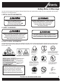 3
3
-
 4
4
-
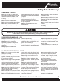 5
5
-
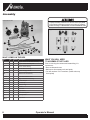 6
6
-
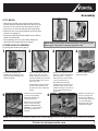 7
7
-
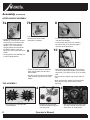 8
8
-
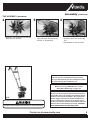 9
9
-
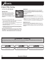 10
10
-
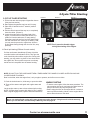 11
11
-
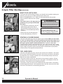 12
12
-
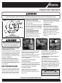 13
13
-
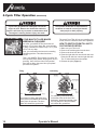 14
14
-
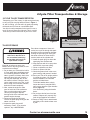 15
15
-
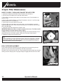 16
16
-
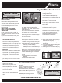 17
17
-
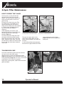 18
18
-
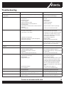 19
19
-
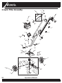 20
20
-
 21
21
-
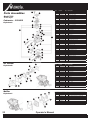 22
22
-
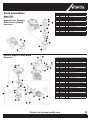 23
23
-
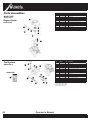 24
24
-
 25
25
-
 26
26
-
 27
27
-
 28
28
-
 29
29
-
 30
30
-
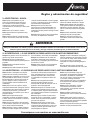 31
31
-
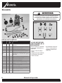 32
32
-
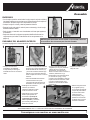 33
33
-
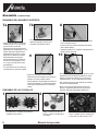 34
34
-
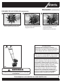 35
35
-
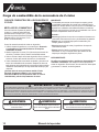 36
36
-
 37
37
-
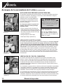 38
38
-
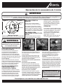 39
39
-
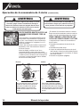 40
40
-
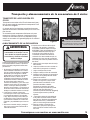 41
41
-
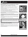 42
42
-
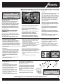 43
43
-
 44
44
-
 45
45
-
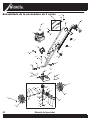 46
46
-
 47
47
-
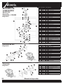 48
48
-
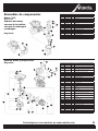 49
49
-
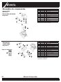 50
50
-
 51
51
-
 52
52


Mantis 7228 El manual del propietario
- Categoría
- Mini cultivadores
- Tipo
- El manual del propietario
en otros idiomas
- English: Mantis 7228 Owner's manual
Artículos relacionados
-
Mantis 7268 El manual del propietario
-
-
-
Mantis 7262 El manual del propietario
-
-
-
-
-
-
