Allen-Bradley SLC 500 Series Installation Instructions Manual
- Tipo
- Installation Instructions Manual

SLC 500™ Programmable Controller
Rack Interconnect Cables
Catalog Number 1746-C7, 1746-C9, 1746-C16
Installation Instructions
Inside...
English Section........................................................................... 1
Français ...................................................................................... 5
Deutscher Abschnitt.................................................................... 9
Sezione in Italiano..................................................................... 13
Sección en español................................................................... 17
Japanese Section ..................................................................... 21


English Section
SLC 500™ Programmable Controller
Rack Interconnect Cables
Catalog Number 1746-C7, 1746-C9, 1746-C16
Installation Instructions

2
SLC 500™ Programmable Controller Rack Interconnect Cables
The following cables are available for linking racks:
• 1746-C7 - 152.44 mm (6 in.)
• 1746-C9 - 914.4 mm (36 in.)
• 1746-C16 - 1270.0 mm (50 in.)
Important Installation Notes
1. Install the rack interconnect cable before installing the power supply in
multiple rack configurations.
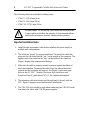
2. The cables are “keyed” for proper installation. The end of the cable that
plugs into the left socket has the “key” on the outside of the connector. The
opposite end of the cable has the “key” on the inside of the connector.
Figure 1 displays the connector and the keys.
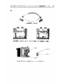
3. Make sure the cable is properly secured to prevent against the effects of
shock and vibration. To remove the cable, move the tabs on the socket
outward and the connector will pop out. See Figure 1 on the next page.
Refer to the SLC 500™ Modular Hardware Style Installation and
Operation Manual, publication 1747-6.2, for complete information.
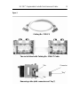
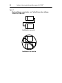
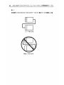
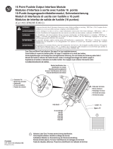
4. The expansion cable must always exit the right end of the rack with the
CPU. Figure 2 displays correct and incorrect installations.
5. The 1746-C16 cable should be used when connecting two 1746-A13 racks
(one above the other) with 1746-P4 power supplies.
!
ATTENTION:
Do not use any other cables than those provided.
Longer cables could affect the integrity of data communications
between the processors, possibly causing unsafe operation.

SLC 500™ Programmable Controller Rack Interconnect Cables
3
Figure 1
Two racks linked with Catalog No. 1746-C7 Cable
Catalog number 1746-C9
Catalog number 1746-C9
Two racks linked with Catalog No. 1746-C7 Cable
Catalog No. 1746-C9
Tab
Connecto
r
“Key”
Tab
Removing cable (with connector and “key”)

4
SLC 500™ Programmable Controller Rack Interconnect Cables
C
P
U
C
P
U
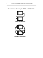
Two racks linked with Catalog No. 1746-C9 or 1746-C16 Cable
CORRECT INSTALLATION
INCORRECT INSTALLATION

Français
Câbles de raccordement des racks
pour le SLC 500™
Références 1746-C7, 1746-C9, 1746-C16
Notice d’installation

6
Câbles de raccordement des racks pour le SLC 500™
Les longueurs de câble suivantes sont disponibles :
• 1746-C7 - 152,44 mm
• 1746-C9 - 914,4 mm
• 1746-C16 - 1270 mm
Importantes remarques d’installation
1. Installez le câble de connexion du rack avant d’installer l’alimentation
générale dans les installations comprenant plusieurs racks.
2. Les câbles sont munis de détrompeurs pour assurer un branchement correct.
Le détrompeur de l’extrémité du câble se branchant dans la prise gauche se
trouve à l’extérieur du connecteur. Le détrompeur de l’autre extrémité du
câble se trouve à l’intérieur du connecteur. Voir Figure 1.
3. Assurez-vous que le câble est bien fixé pour empêcher les chocs électriques
et les vibrations. Pour retirer le câble, écartez les pattes de la prise et le
connecteur en sera automatiquement éjecté. (Voir la figure 1 à la page
suivante). Pour de plus amples informations, consultez le Manuel
d’installation et d’utilisation du SLC 500™ modulaire, publication
1747-6.2FR.
4. Le câble d’extension doit toujours sortir de l’extrémité droite du rack vers le
module d’unité centrale. La figure 2 illustre une installation correcte et une
installation incorrecte.
5. Utilisez le câble 1746-C16 lorsque vous connectez deux racks
1746-A13 (l’un au-dessus de l’autre) avec une alimentation 1746-P4.
!
ATTENTION :
N’utilisez pas d’autres câbles que ceux fournis.
Des câbles plus longs risquent d’affecter la qualité des échanges
de données entre les unités centrales et de poser des problèmes de
sécurité.

Câbles de raccordement des racks pour le SLC 500™
7
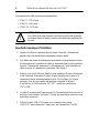
Figure 2
Two racks linked with Catalog No. 1746-C7 Cable
Catalog number 1746-C9
Catalog number 1746-C9
Deux racks reliés par câble (référence 1746-C7)
Référence 1746-C9
Patte
Connecteur
“Détrompeur”
Patte
Retrait du câble (avec connecteur et “détrompeur”)

8
Câbles de raccordement des racks pour le SLC 500™
C
P
U
C
P
U
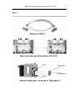
Deux racks reliés par câble (référence 1746-C9 ou 1746-C16)
INSTALLATION CORRECTE
INSTALLATION INCORRECTE

Deutscher Abschnitt
Speicherprogrammierbare Steuerung
SLC 500™ Rack-Verbindungskabel
Bestellnummern 1746-C7, 1746-C9, 1746-C16
Installationsanleitung

10
Speicherprogrammierbare Steuerung SLC 500™ Rack-Verbindungskabel
Zum Verbinden von Racks stehen die folgenden Kabel zur Verfügung:
•
1746-C7 - 152,44 mm
•
1746-C9 - 914,4 mm
•
1746-C16 - 1270,0 mm
Wichtige Hinweise zur Installation
1.
Bei Konfigurationen mit mehreren Racks sollte vor dem Einbauen des
Netzteils das Rack-Verbindungskabel installiert werden.
2.
Zur Sicherstellung der korrekten Installation sind die Kabel codiert. An
dem Ende des Kabels, das in die linke Buchse gesteckt wird, befindet sich
die Codierung außen am Stecker. Am anderen Kabelende ist diese
Codierung innen am Stecker angebracht. Siehe Abb. 1.
3.
Zur Absicherung gegen Stoß und Erschütterung muß das Kabel
vorschriftsmäßig gesichert sein. Das Kabel wird entfernt, indem die Zungen
an der Buchse nach außen gedrückt werden, damit der Stecker
herausspringt. Siehe Abb. 1 auf der nächsten Seite. Vollständige
Informationen sind im SLC 500™ Modulare Hardware Installations- und
Betriebshandbuch, Publikation 1747-6.2DE, enthalten.
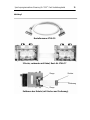
4.
Das Verlängerungskabel muß immer auf der rechten Seite des Racks mit der
CPU ausgeführt werden. Abbildung 2 zeigt die richtige und die falsche
Installation.
5.
Zur Verbindung von zwei 1746-A13-Racks übereinander mit 1746-P4-
Netzteilen sollte das 1746-C16-Kabel verwendet werden.
!
ACHTUNG:
Verwenden Sie nur die oben angegebenen Kabel.
Längere Kabel können die Qualität der Datenverbindung
zwischen den Prozessoren beeinträchtigen und möglicherweise
den sicheren Betrieb gefährden.

Speicherprogrammierbare Steuerung SLC 500™ Rack-Verbindungskabel
11
Abbildung 3
2 Racks, verbunden mit Kabel, Best.-Nr. 1746-C7
Bestellnummer 1746-C9
Zunge
Stecker
Codierung
Zunge
Entfernen des Kabels (mit Stecker und Codierung)

12
Speicherprogrammierbare Steuerung SLC 500™ Rack-Verbindungskabel
C
P
U
C
P
U
Zwei Racks, verbunden mit Kabel, Best.-Nr. 1746-C9 oder 1746-C16
RICHTIGE INSTALLATION
FALSCHE INSTALLATION

Sezione in Italiano
Controllore programmabile SLC 500™
Cavi per il collegamento dei rack
Numeri di catalogo 1746-C7, 1746-C9, 1746-C16
Istruzioni per l’installazione

14
Controllore programmabile SLC 500™ Cavi per il collegamento dei rack
Sono disponibili i seguenti cavi per collegare i rack:
• 1746-C7 - 152,44 mm
• 1746-C9 - 914,4 mm
• 1746-C16 - 1270,0 mm
Note importanti sull’installazione
1. In sistemi a più rack, installare i cavi di collegamento prima di collegare
l’alimentazione elettrica.
2. Per un collegamento corretto i cavi devono avere l’inserimento “a chiave” Il
capo del cavo da inserire nella presa di sinistra ha la “chiave” all’esterno del
connettore mentre il capo opposto la ha all’interno. L’illustrazione 1 mostra
il connettore e le relative chiavi.
3. Accertarsi che il cavo sia montato solidamente in maniera da escludere
possibili scollegamenti dovuti ad impatti o a vibrazioni. Per scollegare il
cavo, muovere le alette della presa verso l’esterno ed il connettore verrà
espulso. Vedere l’illustrazione 1alla pagina seguente. Per una descrizione
completa dell’installazione, fare riferimento al Manuale per l’installazione
ed il funzionamento SLC 500™ Modulare, pubblicazione 1747-6.2IT.
4. Il cavo di espansione deve essere collegato sempre sul lato destro del rack
con il processore. L’illustrazione 2 mostra un esempio di installazione
corretta ed una sbagliata.
5. Utilizzare il cavo 1746-C16 quando si connettono due rack 1746-A13 (uno
sopra l’altro) con alimentazioni 1746-P4.
!
ATTENZIONE:
Non utilizzare cavi diversi da questi elencati.
Cavi più lunghi possono alterare i dati comunicati fra i processori,
causando pericoli nell’operazione.

Controllore programmabile SLC 500™ Cavi per il collegamento dei rack
15
Illustrazione 4
Due rack uniti con il cavo N. di catalogo 1746-C7
Numero di catalogo 1746-C9
Cavo di rimozione (con connettore “a chiave”)
“Chiave
Connettor
e
Alette
Alette

16
Controllore programmabile SLC 500™ Cavi per il collegamento dei rack
Illustrazione 5
Due rack uniti con il cavo N. di catalogo 1746-C9 o 1746-C16
C
P
U
C
P
U
Installazione corretta
Installazione sbagliata

Sección en español
Cables de interconexión de
bastidores para el SLC 500™
Número de catálogo 1746-C7, 1746-C9, 1746-C16
Instrucciones de instalación

18
Cables de interconexión de bastidores para el SLC 500™
Los siguientes cables están disponibles para enlace de bastidores:
• 1746-C7 - 152,44 mm (6 pulg.)
• 1746-C9 - 914,4 mm (36 pulg.)
• 1746-C16 - 1270,0 mm (50 pulg.)
Notas importantes de instalación
1. En configuraciones con bastidores múltiples, instale el cable de
interconexión de bastidores antes de instalar la fuente de alimentación.
2. Los cables tienen una “guía” para lograr una instalación apropiada. El
extremo del cable que se enchufa en el zócalo izquierdo tiene la “guía” en el
exterior del conector. El extremo contrario del cable tiene la “guía” en el
interior del conector. La Figura 1 muestra el conector y las “guías”.
3. Cerciórese de que el cable esté seguramente conectado para evitar el efecto
de los cortocircuitos y las vibraciones. Para sacar el cable, mueva las
lengüetas en el zócalo hacia afuera y el conector “saltará”. Vea la Figura 1.
Para información completa, refiérase a Estilo de hardware modular SLC
500™ Manual de instalación y operación, Número de publicación
1747-6.2ES.
4. El cable de extensión tiene que salir siempre del costado derecho de la
unidad de procesamiento central (CPU). La Figura 2 muestra las
instalaciones correctas e incorrectas.
5. El cable 1746-C16 se debe usar al conectar dos bastidores 1746-A13 (uno
sobre el otro) con las fuentes de alimentación 1746-P4.
!
ATENCION:
No use ningún otro tipo de cable que los
suministrados. Cables más largos podrían afectar la integridad de
la comunicación de datos entre los procesadores, resultando en la
posible operación insegura.

Cables de interconexión de bastidores para el SLC 500™
19
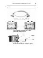
Figura 6
Dos bastidores conectados con el Cable
Cable Número de catálogo 1746-C9
Número de catálogo 1746-C7
“guía”
conector
lengüeta
lengüeta
Extracción del cable (con conector y “guía”)

20
Cables de interconexión de bastidores para el SLC 500™
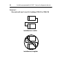
Figura 7
C
P
U
C
P
U
Dos bastidores conectados con Cable Número de catálogo
1746-C9 ó 1746-C16
Instalación correcta
Instalación incorrecta


25

February 1999 PN 40063-019-01(B)
Copyright © 2007 Rockwell Automation, Inc. All rights reserved. Printed in Singapore.
´H&>3!¶BA¨
Transcripción de documentos
SLC 500™ Programmable Controller Rack Interconnect Cables Catalog Number 1746-C7, 1746-C9, 1746-C16 Installation Instructions Inside... English Section ........................................................................... 1 Français ...................................................................................... 5 Deutscher Abschnitt.................................................................... 9 Sezione in Italiano..................................................................... 13 Sección en español................................................................... 17 Japanese Section ..................................................................... 21 English Section SLC 500™ Programmable Controller Rack Interconnect Cables Catalog Number 1746-C7, 1746-C9, 1746-C16 Installation Instructions 2 SLC 500™ Programmable Controller Rack Interconnect Cables The following cables are available for linking racks: • 1746-C7 - 152.44 mm (6 in.) • 1746-C9 - 914.4 mm (36 in.) • 1746-C16 - 1270.0 mm (50 in.) ! ATTENTION: Do not use any other cables than those provided. Longer cables could affect the integrity of data communications between the processors, possibly causing unsafe operation. Important Installation Notes 1. Install the rack interconnect cable before installing the power supply in multiple rack configurations. 2. The cables are “keyed” for proper installation. The end of the cable that plugs into the left socket has the “key” on the outside of the connector. The opposite end of the cable has the “key” on the inside of the connector. Figure 1 displays the connector and the keys. 3. Make sure the cable is properly secured to prevent against the effects of shock and vibration. To remove the cable, move the tabs on the socket outward and the connector will pop out. See Figure 1 on the next page. Refer to the SLC 500™ Modular Hardware Style Installation and Operation Manual, publication 1747-6.2, for complete information. 4. The expansion cable must always exit the right end of the rack with the CPU. Figure 2 displays correct and incorrect installations. 5. The 1746-C16 cable should be used when connecting two 1746-A13 racks (one above the other) with 1746-P4 power supplies. 3 SLC 500™ Programmable Controller Rack Interconnect Cables Figure 1 Catalog Catalog number No. 1746-C9 1746-C9 Catalog number 1746-C9 Two racks linked with Catalog No. 1746-C7 Cable Two racks linked with Catalog No. 1746-C7 Cable Tab Connector “Key” Tab Removing cable (with connector and “key”) 4 SLC 500™ Programmable Controller Rack Interconnect Cables Two racks linked with Catalog No. 1746-C9 or 1746-C16 Cable C P U CORRECT INSTALLATION C P U INCORRECT INSTALLATION Français Câbles de raccordement des racks pour le SLC 500™ Références 1746-C7, 1746-C9, 1746-C16 Notice d’installation 6 Câbles de raccordement des racks pour le SLC 500™ Les longueurs de câble suivantes sont disponibles : • 1746-C7 - 152,44 mm • 1746-C9 - 914,4 mm • 1746-C16 - 1270 mm ! ATTENTION : N’utilisez pas d’autres câbles que ceux fournis. Des câbles plus longs risquent d’affecter la qualité des échanges de données entre les unités centrales et de poser des problèmes de sécurité. Importantes remarques d’installation 1. Installez le câble de connexion du rack avant d’installer l’alimentation générale dans les installations comprenant plusieurs racks. 2. Les câbles sont munis de détrompeurs pour assurer un branchement correct. Le détrompeur de l’extrémité du câble se branchant dans la prise gauche se trouve à l’extérieur du connecteur. Le détrompeur de l’autre extrémité du câble se trouve à l’intérieur du connecteur. Voir Figure 1. 3. Assurez-vous que le câble est bien fixé pour empêcher les chocs électriques et les vibrations. Pour retirer le câble, écartez les pattes de la prise et le connecteur en sera automatiquement éjecté. (Voir la figure 1 à la page suivante). Pour de plus amples informations, consultez le Manuel d’installation et d’utilisation du SLC 500™ modulaire, publication 1747-6.2FR. 4. Le câble d’extension doit toujours sortir de l’extrémité droite du rack vers le module d’unité centrale. La figure 2 illustre une installation correcte et une installation incorrecte. 5. Utilisez le câble 1746-C16 lorsque vous connectez deux racks 1746-A13 (l’un au-dessus de l’autre) avec une alimentation 1746-P4. Câbles de raccordement des racks pour le SLC 500™ 7 Figure 2 Catalog number 1746-C9 Référence 1746-C9 Catalog number 1746-C9 Deux racks reliés par câble (référence 1746-C7) Two racks linked with Catalog No. 1746-C7 Cable Patte Connecteur “Détrompeur” Patte Retrait du câble (avec connecteur et “détrompeur”) 8 Câbles de raccordement des racks pour le SLC 500™ Deux racks reliés par câble (référence 1746-C9 ou 1746-C16) C P U INSTALLATION CORRECTE C P U INSTALLATION INCORRECTE Deutscher Abschnitt Speicherprogrammierbare Steuerung SLC 500™ Rack-Verbindungskabel Bestellnummern 1746-C7, 1746-C9, 1746-C16 Installationsanleitung 10 Speicherprogrammierbare Steuerung SLC 500™ Rack-Verbindungskabel Zum Verbinden von Racks stehen die folgenden Kabel zur Verfügung: • 1746-C7 - 152,44 mm • 1746-C9 - 914,4 mm • 1746-C16 - 1270,0 mm ! ACHTUNG: Verwenden Sie nur die oben angegebenen Kabel. Längere Kabel können die Qualität der Datenverbindung zwischen den Prozessoren beeinträchtigen und möglicherweise den sicheren Betrieb gefährden. Wichtige Hinweise zur Installation 1. Bei Konfigurationen mit mehreren Racks sollte vor dem Einbauen des Netzteils das Rack-Verbindungskabel installiert werden. 2. Zur Sicherstellung der korrekten Installation sind die Kabel codiert. An dem Ende des Kabels, das in die linke Buchse gesteckt wird, befindet sich die Codierung außen am Stecker. Am anderen Kabelende ist diese Codierung innen am Stecker angebracht. Siehe Abb. 1. 3. Zur Absicherung gegen Stoß und Erschütterung muß das Kabel vorschriftsmäßig gesichert sein. Das Kabel wird entfernt, indem die Zungen an der Buchse nach außen gedrückt werden, damit der Stecker herausspringt. Siehe Abb. 1 auf der nächsten Seite. Vollständige Informationen sind im SLC 500™ Modulare Hardware Installations- und Betriebshandbuch, Publikation 1747-6.2DE, enthalten. 4. Das Verlängerungskabel muß immer auf der rechten Seite des Racks mit der CPU ausgeführt werden. Abbildung 2 zeigt die richtige und die falsche Installation. 5. Zur Verbindung von zwei 1746-A13-Racks übereinander mit 1746-P4Netzteilen sollte das 1746-C16-Kabel verwendet werden. 11 Speicherprogrammierbare Steuerung SLC 500™ Rack-Verbindungskabel Abbildung 3 Bestellnummer 1746-C9 2 Racks, verbunden mit Kabel, Best.-Nr. 1746-C7 Zunge Stecker Codierung Zunge Entfernen des Kabels (mit Stecker und Codierung) 12 Speicherprogrammierbare Steuerung SLC 500™ Rack-Verbindungskabel Zwei Racks, verbunden mit Kabel, Best.-Nr. 1746-C9 oder 1746-C16 C P U RICHTIGE INSTALLATION C P U FALSCHE INSTALLATION Sezione in Italiano Controllore programmabile SLC 500™ Cavi per il collegamento dei rack Numeri di catalogo 1746-C7, 1746-C9, 1746-C16 Istruzioni per l’installazione 14 Controllore programmabile SLC 500™ Cavi per il collegamento dei rack Sono disponibili i seguenti cavi per collegare i rack: • 1746-C7 - 152,44 mm • 1746-C9 - 914,4 mm • 1746-C16 - 1270,0 mm ! ATTENZIONE: Non utilizzare cavi diversi da questi elencati. Cavi più lunghi possono alterare i dati comunicati fra i processori, causando pericoli nell’operazione. Note importanti sull’installazione 1. In sistemi a più rack, installare i cavi di collegamento prima di collegare l’alimentazione elettrica. 2. Per un collegamento corretto i cavi devono avere l’inserimento “a chiave” Il capo del cavo da inserire nella presa di sinistra ha la “chiave” all’esterno del connettore mentre il capo opposto la ha all’interno. L’illustrazione 1 mostra il connettore e le relative chiavi. 3. Accertarsi che il cavo sia montato solidamente in maniera da escludere possibili scollegamenti dovuti ad impatti o a vibrazioni. Per scollegare il cavo, muovere le alette della presa verso l’esterno ed il connettore verrà espulso. Vedere l’illustrazione 1alla pagina seguente. Per una descrizione completa dell’installazione, fare riferimento al Manuale per l’installazione ed il funzionamento SLC 500™ Modulare, pubblicazione 1747-6.2IT. 4. Il cavo di espansione deve essere collegato sempre sul lato destro del rack con il processore. L’illustrazione 2 mostra un esempio di installazione corretta ed una sbagliata. 5. Utilizzare il cavo 1746-C16 quando si connettono due rack 1746-A13 (uno sopra l’altro) con alimentazioni 1746-P4. 15 Controllore programmabile SLC 500™ Cavi per il collegamento dei rack Illustrazione 4 Numero di catalogo 1746-C9 Due rack uniti con il cavo N. di catalogo 1746-C7 Alette Connettore “Chiave Alette Cavo di rimozione (con connettore “a chiave”) 16 Controllore programmabile SLC 500™ Cavi per il collegamento dei rack Illustrazione 5 Due rack uniti con il cavo N. di catalogo 1746-C9 o 1746-C16 C P U Installazione corretta C P U Installazione sbagliata Sección en español Cables de interconexión de bastidores para el SLC 500™ Número de catálogo 1746-C7, 1746-C9, 1746-C16 Instrucciones de instalación 18 Cables de interconexión de bastidores para el SLC 500™ Los siguientes cables están disponibles para enlace de bastidores: • 1746-C7 - 152,44 mm (6 pulg.) • 1746-C9 - 914,4 mm (36 pulg.) • 1746-C16 - 1270,0 mm (50 pulg.) ! ATENCION: No use ningún otro tipo de cable que los suministrados. Cables más largos podrían afectar la integridad de la comunicación de datos entre los procesadores, resultando en la posible operación insegura. Notas importantes de instalación 1. En configuraciones con bastidores múltiples, instale el cable de interconexión de bastidores antes de instalar la fuente de alimentación. 2. Los cables tienen una “guía” para lograr una instalación apropiada. El extremo del cable que se enchufa en el zócalo izquierdo tiene la “guía” en el exterior del conector. El extremo contrario del cable tiene la “guía” en el interior del conector. La Figura 1 muestra el conector y las “guías”. 3. Cerciórese de que el cable esté seguramente conectado para evitar el efecto de los cortocircuitos y las vibraciones. Para sacar el cable, mueva las lengüetas en el zócalo hacia afuera y el conector “saltará”. Vea la Figura 1. Para información completa, refiérase a Estilo de hardware modular SLC 500™ Manual de instalación y operación, Número de publicación 1747-6.2ES. 4. El cable de extensión tiene que salir siempre del costado derecho de la unidad de procesamiento central (CPU). La Figura 2 muestra las instalaciones correctas e incorrectas. 5. El cable 1746-C16 se debe usar al conectar dos bastidores 1746-A13 (uno sobre el otro) con las fuentes de alimentación 1746-P4. 19 Cables de interconexión de bastidores para el SLC 500™ Figura 6 Cable Número de catálogo 1746-C9 Dos bastidores conectados con el Cable Número de catálogo 1746-C7 lengüeta conector “guía” lengüeta Extracción del cable (con conector y “guía”) 20 Cables de interconexión de bastidores para el SLC 500™ Figura 7 Dos bastidores conectados con Cable Número de catálogo 1746-C9 ó 1746-C16 C P U Instalación correcta C P U Instalación incorrecta 25 February 1999 PN 40063-019-01(B) Copyright © 2007 Rockwell Automation, Inc. All rights reserved. Printed in Singapore. ´H&>3!¶BA¨-
 1
1
-
 2
2
-
 3
3
-
 4
4
-
 5
5
-
 6
6
-
 7
7
-
 8
8
-
 9
9
-
 10
10
-
 11
11
-
 12
12
-
 13
13
-
 14
14
-
 15
15
-
 16
16
-
 17
17
-
 18
18
-
 19
19
-
 20
20
-
 21
21
-
 22
22
-
 23
23
-
 24
24
-
 25
25
-
 26
26
-
 27
27
-
 28
28


Allen-Bradley SLC 500 Series Installation Instructions Manual
- Tipo
- Installation Instructions Manual
en otros idiomas
- français: Allen-Bradley SLC 500 Series
- italiano: Allen-Bradley SLC 500 Series
- English: Allen-Bradley SLC 500 Series
- Deutsch: Allen-Bradley SLC 500 Series
Artículos relacionados
-
 Allen-Bradley SLC 5/04 Installation Instructions Manual
-
 AB Quality 1747-L524 Guía de instalación
-
 Allen-Bradley SLC 5/04 Installation Instructions Manual
-
 Allen-Bradley SLC 500 1747-L30 Installation Instructions Manual
-
 Allen-Bradley SLC 5/04 Installation Instructions Manual
-
 Allen-Bradley SLC 5/01 Installation Instructions Manual
-
 Allen-Bradley SLC 5/01 Installation Instructions Manual
-
 Allen-Bradley 1492-IFM20F-F240-2 Manual de usuario


