ESAB EPP-400 Plasma Power Source Manual de usuario
- Tipo
- Manual de usuario

EPP- 400
Fuente de alimentación para aplicaciones de plasma
Manual de instrucciones (ES)
0558006939 08/2010

Este equipo se funcionará en conformidad con la descripción contenida en este manual y las etiquetas de acom-
pañamiento, y también de acuerdo con las instrucciones proporcionadas. Este equipo se debe comprobar perió-
dicamente. La operación incorrecta o el equipo mal mantenido no deben ser utilizados. Las piezas que están
quebradas, faltantes, usadas, torcidas o contaminadas se deben sustituir inmediatamente. Si tal reparación o el
reemplazo llegan a ser necesario, el fabricante recomienda que una llamada por teléfono o un pedido escrito de
servicio esté hecha al distribuidor ESAB de quien fue comprado.
Este equipo o cualquiera de sus piezas no se deben alterar sin la previa aprobación escrita del fabricante. El usu-
ario de este equipo tendrá la responsabilidad única de cualquier malfuncionamiento que resulte de uso incor-
recto, de mantenimiento inadecuado, daños, reparaciones o de la alteración incorrecta por cualquier persona
con excepción del fabricante o de un distribuidor autorizado señalado por el fabricante.
ASEGURE DE QUE ESTA INFORMACIÓN ALCANCE EL OPERADOR.
USTED PUEDE CONSEGUIR COPIAS ADICIONALES A TRAVÉS DE SU DISTRIBUIDOR ESAB.
Estas INSTRUCCIONES están para los operadores experimentados. Si usted no es completa-
mente familiar con la teoría de operación y las prácticas seguras para la soldadura de arco
y equipos de corte, le pedimos leer nuestro librete, “precautions and safe practices for arc
welding, cutting, and gouging,” la forma 52-529. No permita a personas inexperimentadas
instale, opere, o mantenga este equipo. No procure instalar o funcionar este equipo hasta
que usted ha leído completamente estas instrucciones. Si usted no entiende completamente
estas instrucciones, entre en contacto con a su distribuidor ESAB para información adicio-
nal. Asegure leer las medidas de seguridad antes de instalar o de operar este equipo.
PRECAUCIÓN
RESPONSABILIDAD DEL USUARIO
LEER Y ENTENDER EL MANUAL ANTES DE INSTALAR U OPERAR EL EQUIPO.
PROTEJA A USTED Y LOS OTROS!

ÍNDICE
Sección / Título Página
1.0 Precauciones de seguridad . . . . . . . . . . . . . . . . . . . . . . . . . . . . . . . . . . . . . . . . . . . . . . . . . . . . . . . . . . . . . . . . . . . . . . . . . . . .5
2.0 Descripción . . . . . . . . . . . . . . . . . . . . . . . . . . . . . . . . . . . . . . . . . . . . . . . . . . . . . . . . . . . . . . . . . . . . . . . . . . . . . . . . . . . . . . . . . . .7
2.1 Introducción. . . . . . . . . . . . . . . . . . . . . . . . . . . . . . . . . . . . . . . . . . . . . . . . . . . . . . . . . . . . . . . . . . . . . . . . . . . . . . . . . . . . . .7
2.2 Especicaciones generales. . . . . . . . . . . . . . . . . . . . . . . . . . . . . . . . . . . . . . . . . . . . . . . . . . . . . . . . . . . . . . . . . . . . . . . .7
2.3 Dimensiones y peso . . . . . . . . . . . . . . . . . . . . . . . . . . . . . . . . . . . . . . . . . . . . . . . . . . . . . . . . . . . . . . . . . . . . . . . . . . . . . .8
3.0 Instalación . . . . . . . . . . . . . . . . . . . . . . . . . . . . . . . . . . . . . . . . . . . . . . . . . . . . . . . . . . . . . . . . . . . . . . . . . . . . . . . . . . . . . . . . . . . .9
3.1 General. . . . . . . . . . . . . . . . . . . . . . . . . . . . . . . . . . . . . . . . . . . . . . . . . . . . . . . . . . . . . . . . . . . . . . . . . . . . . . . . . . . . . . . . . . .9
3.2 Desembalaje . . . . . . . . . . . . . . . . . . . . . . . . . . . . . . . . . . . . . . . . . . . . . . . . . . . . . . . . . . . . . . . . . . . . . . . . . . . . . . . . . . . . .9
3.3 Colocación . . . . . . . . . . . . . . . . . . . . . . . . . . . . . . . . . . . . . . . . . . . . . . . . . . . . . . . . . . . . . . . . . . . . . . . . . . . . . . . . . . . . . . .9
3.4 Conexión de la potencia de entrada . . . . . . . . . . . . . . . . . . . . . . . . . . . . . . . . . . . . . . . . . . . . . . . . . . . . . . . . . . . . . .10
3.5 Conexión de salida . . . . . . . . . . . . . . . . . . . . . . . . . . . . . . . . . . . . . . . . . . . . . . . . . . . . . . . . . . . . . . . . . . . . . . . . . . . . . .12
3.6 Instalación en paralelo . . . . . . . . . . . . . . . . . . . . . . . . . . . . . . . . . . . . . . . . . . . . . . . . . . . . . . . . . . . . . . . . . . . . . . . . . . .13
3.7 Cables de interfaz. . . . . . . . . . . . . . . . . . . . . . . . . . . . . . . . . . . . . . . . . . . . . . . . . . . . . . . . . . . . . . . . . . . . . . . . . . . . . . . .16
4.0 Funcionamiento . . . . . . . . . . . . . . . . . . . . . . . . . . . . . . . . . . . . . . . . . . . . . . . . . . . . . . . . . . . . . . . . . . . . . . . . . . . . . . . . . . . . .19
4.1 Descripción del circuito del diagrama de bloques . . . . . . . . . . . . . . . . . . . . . . . . . . . . . . . . . . . . . . . . . . . . . . . . .19
4.2 Panel de control . . . . . . . . . . . . . . . . . . . . . . . . . . . . . . . . . . . . . . . . . . . . . . . . . . . . . . . . . . . . . . . . . . . . . . . . . . . . . . . . 22
4.3 Secuencia de funcionamiento. . . . . . . . . . . . . . . . . . . . . . . . . . . . . . . . . . . . . . . . . . . . . . . . . . . . . . . . . . . . . . . . . . . 26
4.4 Ajustes de puesta en marcha del arco . . . . . . . . . . . . . . . . . . . . . . . . . . . . . . . . . . . . . . . . . . . . . . . . . . . . . . . . . . . .27
4.5 Curvas V-I de la EPP-400 . . . . . . . . . . . . . . . . . . . . . . . . . . . . . . . . . . . . . . . . . . . . . . . . . . . . . . . . . . . . . . . . . . . . . . . . 30
5.0 Mantenimiento . . . . . . . . . . . . . . . . . . . . . . . . . . . . . . . . . . . . . . . . . . . . . . . . . . . . . . . . . . . . . . . . . . . . . . . . . . . . . . . . . . . . . .33
5.1 General. . . . . . . . . . . . . . . . . . . . . . . . . . . . . . . . . . . . . . . . . . . . . . . . . . . . . . . . . . . . . . . . . . . . . . . . . . . . . . . . . . . . . . . . . .33
5.2 Limpieza . . . . . . . . . . . . . . . . . . . . . . . . . . . . . . . . . . . . . . . . . . . . . . . . . . . . . . . . . . . . . . . . . . . . . . . . . . . . . . . . . . . . . . . .33
5.3 Lubricación. . . . . . . . . . . . . . . . . . . . . . . . . . . . . . . . . . . . . . . . . . . . . . . . . . . . . . . . . . . . . . . . . . . . . . . . . . . . . . . . . . . . . 34
6.0 Localización y resolución de problemas . . . . . . . . . . . . . . . . . . . . . . . . . . . . . . . . . . . . . . . . . . . . . . . . . . . . . . . . . . . . . . .35
6.1 General. . . . . . . . . . . . . . . . . . . . . . . . . . . . . . . . . . . . . . . . . . . . . . . . . . . . . . . . . . . . . . . . . . . . . . . . . . . . . . . . . . . . . . . . . .35
6.2 Indicadores de fallo. . . . . . . . . . . . . . . . . . . . . . . . . . . . . . . . . . . . . . . . . . . . . . . . . . . . . . . . . . . . . . . . . . . . . . . . . . . . . .35
6.3 Aislamiento del fallo . . . . . . . . . . . . . . . . . . . . . . . . . . . . . . . . . . . . . . . . . . . . . . . . . . . . . . . . . . . . . . . . . . . . . . . . . . . . 38
6.4 Pruebas y sustitución de componentes . . . . . . . . . . . . . . . . . . . . . . . . . . . . . . . . . . . . . . . . . . . . . . . . . . . . . . . . . . 46
6.5 Interfaz de circuito de control que utiliza los conectores J1 y J6 . . . . . . . . . . . . . . . . . . . . . . . . . . . . . . . . . . . .52
6.6 Contactor principal auxiliar (K3) y circuitos de contactor de estado sólido o
con semiconductores. . . . . . . . . . . . . . . . . . . . . . . . . . . . . . . . . . . . . . . . . . . . . . . . . . . . . . . . . . . . . . . . . . . . . . . . . . . 54
6.7 Circuito de activación del contactor principal (k1A, K1B y K1C) . . . . . . . . . . . . . . . . . . . . . . . . . . . . . . . . . . . . .55
6.8 Circuitos del detector de corriente del arco . . . . . . . . . . . . . . . . . . . . . . . . . . . . . . . . . . . . . . . . . . . . . . . . . . . . . . 56
6.9 Vref remoto y potenciómetro de control de corriente . . . . . . . . . . . . . . . . . . . . . . . . . . . . . . . . . . . . . . . . . . . . 57
6.10 Circuito de marcado / corte HI / LO del arco piloto . . . . . . . . . . . . . . . . . . . . . . . . . . . . . . . . . . . . . . . . . . . . . . . 58
7.0 Piezas de repuesto . . . . . . . . . . . . . . . . . . . . . . . . . . . . . . . . . . . . . . . . . . . . . . . . . . . . . . . . . . . . . . . . . . . . . . . . . . . . . . . . . . .59
7.1 General. . . . . . . . . . . . . . . . . . . . . . . . . . . . . . . . . . . . . . . . . . . . . . . . . . . . . . . . . . . . . . . . . . . . . . . . . . . . . . . . . . . . . . . . . .59
7.2 Realización de pedidos. . . . . . . . . . . . . . . . . . . . . . . . . . . . . . . . . . . . . . . . . . . . . . . . . . . . . . . . . . . . . . . . . . . . . . . . . . .59

4

5
SECCIÓN 1 PRECAUCIONES DE SEGURIDAD
1.0 Precauciones de seguridad
Los usuarios de los equipos de corte y soldadura ESAB tienen la responsabilidad de asegurar que las personas
que trabajan o están cerca del equipo sigan las normas de seguridad.
Las precauciones de seguridad deben estar de acuerdo con equipos de corte y soldadura. Las recomendaciones
abajo deben ser seguidas adicionalmente a las normas estándar.
1. Cualquier persona que utilice un equipo de soldadura o corte plasma debe ser familiar con:
-su operación
-localización de los paros de emergencia
-sus funciones
-precauciones de seguridad
-corte plasma y soldadura
2. El operador debe asegurar que:
-ninguna otra persona este en la área de trabajo durante el arranque de la maquina
-ninguna persona este sin protección al momento de la partida del arco
3. La área de trabajo debe:
-estar de acuerdo con el trabajo
-estar libre de corrientes de aire
4. Equipo de seguridad individual:
-siempre utilice equipos de seguridad, lentes, prendas ignífugas, guantes, etc.
-no utilice artículos sueltos, como bufandas, pulseras, anillos, etc.
5. Precauciones generales:
-este seguro que el cable de retorno esta bien conectado
-el trabajo con alta voltaje debe ser realizado por un técnico calicado.
-un extintor de incendios apropiado debe estar acerca de la maquina.
-lubricación de la maquina no debe ser realizada durante la operación.
El código IP indica la clase de cubierta protectora, por ejemplo, el grado de protección contra la penetración
de objetos sólidos o agua. Se proporciona protección contra toques con dedo, penetración de objetos sólidos
de más de 12 mm y contra la pulverización de agua con una inclinación de hasta 60 grados. El equipo con el
código IP23S puede almacenarse pero no está previsto para su uso en exteriores en caso de lluvia, a no ser que
se cubra.
Clase de cubierta protectora
15°
Inclinación
máxima
permitida
PRECAUCIÓN
Si el equipo se sitúa en una supercie con
una inclinación mayor a 15°, es posible que
vuelque, lo cual puede causar daños perso-
nales y/o daños importantes al equipo.

6
SECCIÓN 1 PRECAUCIONES DE SEGURIDAD
Soldadura y corte plasma puede ser fatal a usted o otros. Tome las
precauciones de seguridad para corte plasma y soldadura.
DESCARGA ELÉCTRICA puede matar.
- Instale un cable tierra de acuerdo con las normas
- No toque partes eléctricas o consumibles que estén energizados.
- Mantengas aislado del piso y de la pieza de trabajo.
- Certique que su situación de trabajo es segura
HUMOS Y GASES- Son peligrosos a su salud
- Mantenga su cabeza alejada de los humos
- utilice ventilación o aspiración para eliminar los humos del área de trabajo.
RAYO DEL ARCO. Puede quemar la piel o dañar los ojos.
- Protege sus ojos y piel con lentes y ropa apropiadas.
- Proteja las personas en la área de trabajo utilizando una cortina
PELIGRO DE INCENDIO
- Chispas pueden provocar incendio. Este seguro que no hagan materiales inamables al rededor de
la maquina.
RUIDO – El ruido en exceso puede dañar los oídos.
- Proteja sus oídos. utilice protección auricular.
- Avise las personas al rededor sobre el riesgo.
AVERÍAS – Llame a ESAB en caso de una avería con el equipo.
LEER Y ENTENDER EL MANUAL ANTES DE INSTALAR U OPERAR EL EQUIPO.
PROTEJA A USTED Y LOS OTROS!
ADVERTENCIA
Este producto está diseñado exclusivamente para el corte por
plasma. Cualquier otro uso puede causar daños personales y/o
daños al equipo.
PRECAUCIÓN
PRECAUCIÓN
Para evitar daños personales y/o daños al
equipo, elévelo usando el método y los pun-
tos de agarre que se muestran aquí.

7
SECCIÓN 2 DESCRIPCIÓN
2.1 Introducción
La fuente de alimentación EPP ha sido diseñada para realizar operaciones de marcado y de corte mecanizado
por plasma a gran velocidad. También puede utilizarse junto con otros productos de la marca ESAB, como por
ejemplo los sopletes PT-15, PT-19XLS, PT-600 y PT-36 y con el Smart Flow II, un sistema informatizado de conmu-
tación y regulación de gas.
• Entre 12 y 400 amperios para marcado
• Rango de tensiones de corte entre 50 y 400 amperios
• Refrigeración por aire forzada
• Potencia CC estado sólido
• Protección de la tensión de entrada
• Control local o remoto del panel frontal
• Protección térmica del interruptor del transformador principal y de los componentes de los
semiconductores
• Anillos de elevación en la parte superior o espacio en la base para brazos de carretilla elevadora para
el transporte
• Capacidad de acoplar fuente de corriente adicionales en paralelo para ampliar el rango de potencias
de entrada.
EPP-400, 400V,
50 / 60 Hz CE
EPP-400 460V,
60 Hz
EPP-400 575V,
60 Hz
Número de pieza 0558006470 0558006471 0558006472
Salida
(Ciclo de trabajo
100%)
Tensión 200 VDC
Gama de corriente CC
(marcado)
12A a 400A
Gama de corriente CC
(corte)
50A a 400A
Potencia 120 kW
* Tensión del circuito abierto
(OCV)
423 VDC 427 VDC 427 VDC
Entrada
Tensión (trifásico) 400 V 460 V 575 V
Corriente (trifásico) 138A RMS 120A RMS 96A RMS
Frecuencia 50 / 60 HZ 60 HZ 60 HZ
KVA 95,6 KVA 95,6 KVA 95,6 KVA
Potencia 87 KW 87 KW 87 KW
Factor de potencia 91,0 % 91,0% 91,0%
Rec. fusible entrada 200A 150A 125A
2.2 Especicaciones generales
* La tensión del circuito abierto se reduce a 360 V en el modo de marcado para los modelos de 460V y 575V, a
60 Hz y para el modelo de 310V a 400V, a 50 Hz.

8
SECCIÓN 2 DESCRIPCIÓN
2.3 Dimensiones y peso
114.3 cm
45.00”
94.6 cm
37.25”
102.2 cm
40.25”
Peso = 825 kg.

9
SECCIÓN 3 INSTALACIÓN
3.1 General
3.3 Colocación
Nota:
Sírvase de ambas argollas de suspensión a la hora de transportar el aparato por elevación.
• Deberá dejar un espacio mínimo de 1m por delante y por detrás para permitir la circulación del aire de
refrigeración.
• Prevea la posibilidad de tener que retirar los paneles superior y laterales para realizar tareas de mante-
nimiento, limpieza y revisión.
• Sitúe la EPP-400 relativamente próxima a una alimentación de corriente eléctrica debidamente instalada.
• Mantenga libre de obstáculos la zona debajo de la fuente de alimentación para permitir la circulación
del aire de refrigeración.
• El entorno en el que se instale debe estar relativamente libre de polvo, humos y calor excesivo. Estos
factores incidirían en la eciencia de la refrigeración.
La presencia de polvo o suciedad con propiedades conductoras dentro de
la fuente de alimentación podría provocar el incendio generalizado el arco
voltaico y ocasionar daños al equipo. En el caso de que se produjera una
acumulación de polvo en el interior de la fuente de alimentación podría
producirse un cortocircuito. Consulte la sección de mantenimiento.
3.2 Desembalaje
Si únicamente utiliza una argolla de suspensión provocará daños en
la hoja de metal y en la estructura. Sírvase utilizar ambas argollas de
suspensión a la hora de transportarlo mediante elevación.
• Revise el aparato en cuanto lo reciba por si hubiera sufrido daños durante el transporte.
• Saque todos los componentes del envase de envío y compruebe que no queda ninguna pieza suelta
en el mismo.
• Compruebe que la celosía de ventilación no presenta obstrucciones al aire.
AVISO
EL HECHO DE HACER CASO OMISO DE LAS SIGUIENTES INS
TRUCCIONES PODRÍA PROVOCARLE DAÑOS EN LA PROPIEDAD,
DAÑOS PERSONALES E INCLUSO LA MUERTE. SIGA LAS INS
TRUCCIONES PARA EVITAR QUE SE PRODUZCAN DAÑOS PER
SONALES O EN LA PROPIEDAD. DEBE ACATAR LOS CÓDIGOS
SOBRE ELECTRICIDAD LOCALES, ESTATALES Y NACIONALES
EN MATERIA DE SEGURIDAD.
ADVERTENCIA
AVISO

10
SECCIÓN 3 INSTALACIÓN
3.4 Conexión de la potencia de entrada
LA CORRIENTE ELÉCTRICA PUEDE MATAR!
TOME TODAS LAS PRECAUCIONES NECESARIAS PARA QUE NO
SE PRODUZCA UNA DESCARGA ELÉCTRICA.
ANTES DE ESTABLECER CONEXIÓN ALGUNA DENTRO DEL
APARATO, ABRA EL DESCONECTADOR DE LA LÍNEA PRINCIPAL
PARA APAGAR LA CORRIENTE
3.4.1 Potencia de entrada
La EPP-400 es una unidad trifásica. La potencia de entrada debe proceder de un desconectador de línea principal
que contenga fusibles o cortacircuitos de conformidad con la normativa local o estatal vigente.
Podría ser necesario contar con una línea de corriente dedicada.
La EPP-400 está equipada con una compensación de tensión de línea,
aunque para evitar un mal funcionamiento debido a una sobrecarga en el
circuito podría ser necesario contar con una línea de corriente dedicada.
NOTA
Corriente de entrada =
(V arco) x (I arco) x 0,688
(V línea)
Tamaños de los fusibles de línea y conductor de entrada recomendados:
* Tamaños conforme al Código Eléctrico Nacional para un conductor de cobre para 90º C a una temperatura ambiente
de 40º C. No colocar más de tres conductores en el cable o en longitudinal. Deberá acatarse la normativa local aplicable
cuando especique tamaños distintos de los que se enumeran a continuación.
Para calcular la corriente de entrada en una amplia gama de condiciones de salida, utilice la siguiente fórmula.
Entrada a la carga nominal Conductor de tierra
y entrada* CU/ mm
2
(AWG)
Tamaño del fusible
temporizado
(amperios)
Voltios Amperios
400 138 95 (4/0) 200
460 120 95 (3/0) 150
575 96 50 (1/0) 125
La carga nominal da una salida de 400A a 200V
ADVERTENCIA

11
• Se suministran al cliente bajo petición
• Pueden estar compuestos de conductores de cobre recubiertos de goma (tres de potencia y uno tierra)
o estar incluidos en un conducto exible o sólido.
• Se dispone de los tamaños que constan en el gráco.
3.4.2 Conductores de entrada
Los conductores de entrada deben terminar con terminales de lengüeta
redonda. Los conductores de entrada deben terminar con terminales de
lengüeta redonda para 12,7 mm antes de acoplarse a la EPP-400.
1. Retire el panel lateral izquierdo de la EPP-400
2. Introduzca los cables por la apertura de acceso del panel
trasero.
3. Sujete los cables con un protector o con un manguito de con-
ducto (que no se suministra) en la apertura de acceso.
4. Conecte la toma de tierra al vástago de la base del chasis.
5. Conecte los terminales de lengüeta redonda a los terminales
primarios con los pernos, arandelas y tuercas que se facilitan.
6. Conecte los conectores de entrada al desconectador de línea.
3.4.3 Procedimiento de conexión de entrada
1
3
2
1 = Terminales primarios
2 = Toma de tierra del chasis
3 = Apertura de acceso del cable de entrada de potencia (panel posterior)
SECCIÓN 3 INSTALACIÓN
NOTA

12
LA CORRIENTE ELÉCTRICA PUEDE MATAR!
LAS TERMINALES CON LENGÜETA REDONDA DEBEN TENER
ESPACIO ENTRE EL PANEL LATERAL Y EL TRANSFORMADOR.
ESTE HUECO DEBE SER SUFICIENTE PARA EVITAR UNA POSIBLE
FORMACIÓN DE ARCO. ASEGÚRESE DE QUE LOS CABLES NO
INTERFIEREN EN LA ROTACIÓN DEL VENTILADOR.
UNA TOMA DE TIERRA MAL REALIZADA PODRÍA PROVOCAR
LESIONES PERSONALES E INCLUSO LA MUERTE. EL CHASIS
DEBE ESTAR CONECTADO A UNA TOMA DE TIERRA ELÉCTRICA
CERTIFICADA. ASEGÚRESE DE QUE EL CABLE NO ESTÁ CONEC
TADO A UN TERMINAL PRIMARIO.
LA CORRIENTE ELÉCTRICA PUEDE MATAR! TENSIONES Y
CORRIENTES PELIGROSAS! SIEMPRE QUE SE TRABAJE CERCA
DE UNA FUENTE DE ALIMENTACIÓN DE PLASMA CON LAS
TAPAS QUITADAS:
• DESCONECTE LA FUENTE DE ALIMENTACIÓN EN EL DESCO-
NECTADOR DE LÍNEA (PARED).
• HAGA QUE PERSONAL CUALIFICADO REVISE LAS BARRAS
DEL CONTACTO DE SALIDA (POSITIVA Y NEGATIVA) CON UN
VOLTÍMETRO.
3.5 Conexiones de salida
3.5.1 Cables de salida (suministrados por cliente)
Elija los cables de salida para el corte de plasma (suministrados por el cliente) en función del cable de cobre
aislado 4/0 AWG, 600 voltios por cada 400 amperios de corriente de salida.
Nota:
No utilice el cable de soldadura aislado de 100 voltios.
SECCIÓN 3 INSTALACIÓN
ADVERTENCIA
ADVERTENCIA
ADVERTENCIA

13
SECCIÓN 3 INSTALACIÓN
3.5.2 Procedimiento de conexión de salida
panel de acceso
1. Quite el panel de acceso de la parte delantera inferior de la fuente de alimentación.
2. Introduzca los cables de salida por las aperturas situadas en la parte inferior del panel delantero o de la parte inferior
de la fuente de alimentación justo detrás del panel delantero.
3. Conecte los cables a los terminales designados instalados dentro de la fuente de alimentación utilizando los conectores
de presión de la lista UL.
4. Vuelva a colocar el panel previamente retirado en el primer paso.
Es posible conectar juntas dos fuentes de alimentación EPP-400 en paralelo para ampliar el rango de tensiones
de salida.
3.6 Instalación en paralelo
La corriente mínima de salida de la fuente de alimentación instalada en
paralelo supera la cantidad recomendada al realizar cortes por debajo de
100A.
Utilice únicamente una fuente de alimentación para realizar cortes por
debajo de 100A.
Recomendamos que desconecte el cable negativo de la fuente de
alimentación complementaria al pasar a corrientes inferiores a 100A. Este
cable debe contar con una terminación segura para protegerle contra las
descargas eléctricas.
AVISO

14
SECCIÓN 3 INSTALACIÓN
Nota:
La fuente de alimentación primaria tiene el conductor del electrodo (-) puenteado. La fuente de
alimentación complementaria tiene la carga (+) puenteada.
1. Conecte los cables de salida negativa (-) a la caja de arranque del arco (generador de alta frecuencia).
2. Conecte los cables de salida positiva (-) a la pieza sobre la que quiere trabajar.
3. Conecte los conductores positivo (+) y negativo (-) entre las fuentes de alimentación.
4. Conecte el cable del arco piloto al terminal del arco piloto que encontrará en la fuente de alimentación primaria. La
conexión del arco piloto en la fuente de alimentación complementaria no se utiliza. El circuito del arco piloto no discurre
en paralelo.
5. Coloque el interruptor de ALTO / BAJO (HIGH/LOW) del arco piloto en la fuente de alimentación complementaria en la
posición “BAJO” (LOW).
6. Coloque el interruptor de ALTO / BAJO (HIGH/LOW) del arco piloto en la fuente de alimentación primaria en la posición
“ALTO” (HIGH).
7. Si se utiliza una señal de referencia de corriente entre 0,00 y 10,00 VDC remota para jar la tensión de salida, haga llegar
la misma señal a ambas fuentes de alimentación. Conecte el J1-G (positivo entre 0,00 y 10,00 VDC) a ambas fuentes
de alimentación juntas y conecte el J1-P (negativo) de ambas fuentes de alimentación juntas. Con ambas fuentes de
alimentación en funcionamiento, es posible predecir la tensión de salida utilizando la siguiente fórmula: [tensión de
salida (amperios)] = [tensión de referencia] x [100]
Conexiones para la instalación en paralelo de dos fuentes de alimentación EPP-400 con ambas fuentes de
alimentación en funcionamiento.
3.6.1 Conexiones para dos EPP-400 en paralelo
Fuente de alimentación
complementaria
Fuente de alimentación
primaria
carga
(+)
electrodo
(-)
arco piloto
2 – cables positivos
4/0 600V a la pieza
de trabajo
1 – conexión cable 14 AWG
600V a arco piloto en la
caja de arranque del arco
(h.f. generador)
2 – cables
negativos 4/0
600V en la caja de
arranque del arco
(h.f. generador)
EPP-400 EPP-400
carga
(+)
electrodo
(-)

15
SECCIÓN 3 INSTALACIÓN
LAS DESCARGAS ELÉCTRICAS PUEDEN PROVOCAR LA MUERTE!
LOS CONDUCTORES ELÉCTRICOS EXPUESTOS PUEDEN SER
PELIGROSOS!
NO DEJE LOS CONDUCTORES “VIVOS” CON ELECTRICIDAD EX
PUESTOS. AL DESCONECTAR LA FUENTE DE ALIMENTACIÓN
COMPLEMENTARIA DE LA PRIMARIA, COMPRUEBE QUE DES
CONECTA LOS CABLES CORRECTOS. AISLE LOS EXTREMOS
DESCONECTADOS.
CUANDO UTILICE ÚNICAMENTE UNA FUENTE DE ALIMENTA
CIÓN EN LA DISPOSICIÓN EN PARALELO, EL CONDUCTOR DEL
ELECTRODO NEGATIVO DEBE ESTAR DESCONECTADO DE LA
FUENTE DE ALIMENTACIÓN COMPLEMENTARIA Y DE LA CAJA DE
CONEXIONES. EN CASO CONTRARIO, DEJARÍA “VIVA” CON ELEC
TRICIDAD LA FUENTE DE ALIMENTACIÓN COMPLEMENTARIA.
NO PONGA EN FUNCIONAMIENTO LA EPP400 CUANDO NO
TENGA COLOCADAS LAS TAPAS PROTECTORAS. LOS COMPO
NENTES QUE SOPORTAN ALTAS TENSIONES ESTÁN EXPUESTOS
A UN MAYOR RIESGO DE SUFRIR UNA DESCARGA.
LOS COMPONENTES INTERNOS PODRÍAN RESULTAR DAÑADOS
A CAUSA DE UNA PÉDIDA DE EFICACIA DE LOS VENTILADORES.
La EPP-400 no tiene un interruptor de ENCENDIDO / APAGADO (ON/OFF). La corriente principal se controla mediante el
desconectador de línea (pared).
Conexiones para la instalación en paralelo de dos fuentes de alimentación EPP-400 únicamente con una
fuente de alimentación en funcionamiento.
Fuente de alimentación
complementaria
Fuente de alimentación
primaria
carga
carga
electrodo
electrodo
2 – cables positivos
4/0 600V a la pieza
de trabajo
2 – cables negativos
4/0 600V en la caja
de arranque del arco
(h.f. generador)
Desconecte la conexión
negativa de la fuente de
alimentación secunda-
ria y aíslela para pasar
de dos a una fuentes de
alimentación
EPP-400 EPP-400
ADVERTENCIA
ADVERTENCIA

16
SECCIÓN 3 INSTALACIÓN
3.7 Cables de interfaz
Interfaz CNC (24 clavijas)
3.6.2 Marcado con dos EPP-400 en paralelo
Interfaz del refrigerador de agua (8 clavijas)
Dos unidades EPP-400, conectadas en paralelo puede utilizarse para marcar hasta a 24A y para cortar desde 100A a 800A.
Cabe la posibilidad de introducir dos sencillas modicaciones en la fuente de alimentación complementaria para posi-
bilitar realizar marcas a 12A. Estas modicaciones son obligatorias únicamente en el caso de que sea necesario realizar
operaciones de marcado a 12A.
CAMBIOS DE CAMPO PARA POSIBILITAR EL MARCADO A 12A:
1. CAMBIOS EN LA FUENTE DE ALIMENTACIÓN PRIMARIA: Ninguno
2. CAMBIOS EN LA FUENTE DE ALIMENTACIÓN COMPLEMENTARIA:
A. Desenchufe el cable WHT de la bobina de K12
B. Quite el puente ORN de TB7-11 y conecte ambos extremos del puente en TB7-12.
FUNCIONAMIENTO DE DOS UNIDADES EPP-400 EN PARALELO:
1. Haga llegar las señales de Encendido / Apagado (On/O), Corte / Marca (Cut/Mark) y arco pilo ALTO / BAJO (HIGH/
LOW) a las unidades primaria y complementaria para realizar operaciones tanto de corte como de marcado. Al mar-
car, ambas fuentes de alimentación están en funcionamiento, aunque la Señal de marcado deshabilita la salida de la
fuente de alimentación complementaria cuando haya sido modicada para marcar a 12A. En el caso de que la fuente
de alimentación complementaria no hubiera sido modicada, suministrará la misma tensión de salida que la fuente
de alimentación primaria.
2. Haga llegar la misma señal V
REF
a las unidades primaria y complementaria para realizar operaciones tanto de corte como
de marcado. En aquellas instalaciones que se cuente con una fuente de alimentación secundaria modicada, la función
de transferencia de la tensión de salida para el marcado será la de la fuente de alimentación primaria: I
OUT
= 50 x V
REF
.
Para cortar, se suman las fuentes de alimentación primaria y complementaria: I
OUT
= 100 x V
REF
. En aquellas instalaciones
que cuenten con una fuente de alimentación secundaria sin modicaciones, la función de transferencia de la tensión de
salida para el marcado y el corte será I
OUT
= 100 x V
REF
.

17
SECCIÓN 3 INSTALACIÓN
3.7.1 Cables de interfaz CNC con conector de fuente de potencia a juego e
interfaz CNC sin terminar
3.7.2 Cables de interfaz CNC con conectores de fuente de potencia a juego en ambos extremos
GRN/YEL
RED #4
GRN/YEL
RED #4
VISTA DEL
CABLEADO
VISTA DEL
CABLEADO
VISTA DEL
CABLEADO

18
SECCIÓN 3 INSTALACIÓN
3.7.3 Cables de interfaz del refrigerador de agua con conectores de fuente de potencia a juego
en ambos extremos
VISTA DEL CABLEADO
VISTA DEL CABLEADO
LONGITUD

19
SECCIÓN 4 FUNCIONAMIENTO
4.1 Descripción del circuito del
diagrama de bloques
Left PWM / Gate Drive Board
Galvanic
Isolator
PWM
Gate
Drive
Galvanic
Isolator
PWM
Gate
Drive
(Master)
(Slave)
Right PWM / Gate Drive Board
2
H
Sync Signal
For Alternate
Switching
3 Phase
Input
T1 Main
Transformer
-300V-375V
DC Bus
Bus Rectiers
300U120’s
Cap.
Bank
Control Circuit
Feedback For Fast Inner Servos
Error Ampliers
Galvanic
Isolator
0.0 - 10.0V DC Vref
Iout = (Vref) x (50)
CNC Common
(Floating)
S
T
“T” Common Connected to Earth Grounded Work Through the “+” Output
Feedback for Constant
Current Servo
Twisted Pair
Left
IGBT Modules
See Note
Right
IGBT Modules
T
Left Hall
Sensor
Right Hall
Sensor
L1
Blocking Diodes
Blocking Diodes
L2
Free Wheeling
Diodes - See Note
T
T1
T1
Contact on Pilot
Arc Contactor
425V Peak
250V Peak
Boost Starting
Circuit
Biased Snubber
R (boost)
R (snub)
Pilot Arc
Circuit
Precision
Shunt
ELECTRODE
NOZZLE
WORK
DIAGRAMA DE BLOQUES
DE LA EPP-400
See
Note
See Note
Nota
Tanto el IGTB (siglas en inglés equivalentes a “transistor bipolar de
puerta aislada”) como el Diodo de Libre Circulación (FWD, siglas en
inglés) están dentro del mismo módulo.

20
P. K. Higgins: Current_Ripple_ESP-600C; RMS CURRENT RIPPLE Chart 17
EPP-600 10/20KHz Output RMS Ripple Current Versus Output Voltage
0.0
1.0
2.0
3.0
4.0
5.0
6.0
7.0
8.0
9.0
0 50 100 150 200 250 300 350
Output Voltage (Volts)
RMS Ripple Current (Amperes)
Choppers Synchronized and Switchng in Unison (10KHz Ripple)
Choppers Synchronized and Switching Alternately (20KHz Ripple)
SECCIÓN 4 FUNCIONAMIENTO
4.1 Descripción del circuito del diagrama de bloques (conti.)
El circuito de corriente utilizado en la EPP-400 suele conocerse como el Convertidor de transferencia inversa o como un
Relé modulador. Los interruptores electrónicos de alta velocidad se encienden y apagan cientos de veces por segundo para
generar impulsos de potencia de salida. Un circuito de ltro, que consta básicamente de un inductor (también llamado en
ocasiones bobina de choque) convierte los impulsos en una salida de CC (corriente continua) relativamente constante.
A pesar de que el inductor elimina la mayor parte de las uctuaciones de la salida “modulada” de los interruptores
electrónicos, aún quedan ciertas ligeras uctuaciones de la salida, denominadas “ondulaciones residuales”. La EPP-400
utiliza un circuito de potencia patentado que combina la salida de los dos relés moduladores, aportando cada uno de ellos
aproximadamente la mitad de la salida total, de forma que se reducen las ondulaciones residuales. Los relés moduladores
están sincronizados para que las ondulaciones residuales del primer relé incrementen la potencia de salida, mientras que
las del segundo relé reduzcan la salida. El resultado es que las ondulaciones residuales de cada relé modulador amortiguan
en parte las ondulaciones residuales del otro relé. Con esto se consiguen unas ondulaciones residuales ultra bajas con una
potencia de salida suave y estable. Lo ideal sería que se produjeran unas bajas ondulaciones residuales dado que la vida
útil del soplete suele verse ampliada cuando se dan unas ondulaciones residuales bajas.
El gráco que gura a continuación muestra el efecto de la reducción de las ondulaciones residuales patentadas ESAB
mediante la utilización de dos relés moduladores sincronizados y que cambian alternativamente. Si se compara está
organización con la utilización de los dos relé de forma conjunta, esta conmutación alternativa suele reducir las ondulaciones
residuales a un factor de 4 sobre 10.
Tensión de salida comparado con la tensión de las ondulaciones residuales RMS de
salida de la EPP-400 10/20 KHz
Tensión de las ondulaciones residuales (amperios)
Tensión de salida (voltios)
Relés moduladores sincronizados y cambiando de forma conjunta (ondulaciones residuales 10 KHz)
Relés moduladores sincronizados y cambiando alternativamente (ondulaciones residuales 20 KHz)

21
El Circuito de control contiene servomotores de regulación para ambos relés moduladores. También posee un tercer servo-
motor que supervisa la señal de corriente de salida total procedente del shunt de precisión. Este tercer servomotor ajusta
los dos servomotores de regulación para mantener una tensión de salida controlada precisa controlada por la señal Vref.
Los circuitos Vref disponen de un aislamiento galvanizado del resto de la fuente de alimentación. El aislamiento evita que
se produzcan problemas que pudieran derivarse de los bucles de “tierra”.
Cada relé modulador, el maestro izquierdo y el esclavo derecho, tienen sus propias tarjetas de circuito impreso para el
PWM (siglas en inglés para Modulador de ancho de pulso) / movimiento puerta instaladas cerca de la IGTB. Estos circuitos
emiten las señales de encendido / apagado del PWM para mover los IGTB. El PWM izquierdo (maestro) emite una señal
de reloj sincronizada a su propio circuito impulsor de la puerta y también al circuito impulsor de la puerta de la derecha
(esclavo). Es gracias a esta señal sincronizada como se consigue que los IGTB de los dos lados cambien alternativamente
para reducir las ondulaciones residuales de salida.
La EPP-400 posee un Suministro de alimentación que proporciona aproximadamente 425V de CC para el inicio del arco.
Una vez creado el arco de corte, el Suministro de alimentación se apaga con un contacto situado en el Contactor del arco
piloto (K4).
Un amortiguador de vibraciones reduce la tensión transitoria creada durante la terminación del arco de corte. También
reduce la tensión transitoria de una fuente de alimentación paralelo con lo que evita que se produzcan daños en la fuente
de alimentación.
El Circuito del arco piloto consta de los componentes necesarios para crear un arco piloto. Este circuito se desconecta.
* La tensión de contacto del modelo 400V, 50 Hz es de uno 320V CC.
SECCIÓN 4 FUNCIONAMIENTO
El Diagrama de bloques de la EPP-400 (tras la subsección 6.4.4) muestra los principales elementos funcionales de la fuente
de alimentación. T1, el Transformador principal, que proporciona aislamiento de la línea de tensión primaria así como
también la tensión adecuada para el contacto *375 CC. Los recticadores de contacto convierten la salida trifásica en
una tensión de contacto de *375 CC. Una batería de condensadores suministra el ltrado y el almacenamiento de energía
que abastece de potencia a los interruptores electrónicos de alta velocidad. Los interruptores son IGTB (siglas en inglés
equivalentes a “transistor bipolar de puerta aislada”) El contacto *375 CC proporciona corriente tanto al relé izquierdo
(maestro) como al derecho (esclavo).
Cada relé modulador contiene IGTB, diodos de libre circulación, un sensor Hall, un inductor de ltrado y diodos de bloqueo.
Los IGTB son unos interruptores electrónicos que, en la EPP-400, se encienden y apagan unas 10000 veces por segundo.
Proporcionan los impulsos de potencia ltrados por un inductor. Los Diodos de libre circulación facilitan la ruta para que
circule la corriente cuando los IGTB están desconectados. El sensor Hall es un transductor de corriente que supervisa la
tensión de salida y genera una señal de retroalimentación para el circuito de control.
Los Diodos de bloqueo desempeñan dos funciones. La primera, sirven para evitar que los 425V CC del Circuito de arranque
del propulsor vuelvan al IGTB y al contacto de *375V. La segunda es que sirven de aislamiento de los dos relés modulados
entre sí. Esto permite el funcionamiento independiente de cada uno de los relés sin necesidad de que esté el otro en
funcionamiento.
4.1 Descripción del circuito del diagrama de bloques (conti.)

22
SECCIÓN 4 FUNCIONAMIENTO
4.2 Panel de control
A - Potencia principal
El indicador se ilumina cuando la fuente de alimentación recibe potencia de entrada.
B - Encendido del contactor
El indicador se ilumina cuando el contactor principal recibe energía.
C - Temperatura excesiva
El indicador se ilumina cuando la fuente de alimentación se ha sobrecalentado.
D - Fallo
El indicador se ilumina cuando existen anomalías en el proceso de corte o cuando la tensión de la línea de entrada registra
unos valores fuera del rango nominal necesario de +/- 10%.
E - Fallo de reinicio de potencia
El indicador se ilumina cuando se detecta un fallo grave. Entonces hay que desconectar la potencia de entrada durante unos
5 segundos y luego volver a encenderla.
F - Dial de corriente (potenciómetro)
El dial de la EPP-400 que se muestra. La EPP-400 dispone de un rango que va de los 12 a los 400A. Únicamente se utiliza en
el modo panel.
C
B
D
E
K
J
I
H
F
G
A
L

23
SECCIÓN 4 FUNCIONAMIENTO
G - Interruptor remoto del panel
Controla la ubicación del control de corriente.
• Colóquelo en la posición PANEL para controlarlo utilizando el potenciómetro de corriente.
• Colóquelo en la posición REMOTO para controlarlo mediante una señal externa (CNC).
C
B
D
E
K
J
I
H
F
G
A
H y L - Conexiones remotas
H - Enchufe de 24 clavijas para conectar la fuente de alimentación a la CNC (control remoto)
L - Enchufe de 8 clavijas para conectar la fuente de alimentación al refrigerador de agua
I - Interruptor de ALTO / BAJO del arco piloto
Sirve para seleccionar la cantidad de corriente deseada para el arco. Por lo general, para 100 amperios y menos, se utiliza
la posición BAJO del interruptor. Esto puede variar dependiendo del gas, del material y del soplete empleados. Los ajustes
alto / bajo se especican en los datos de corte incluidos en el manual del soplete. Una vez que la EPP-400 está congurada
en el modo de marcado, este interruptor debe encontrarse en la posición “bajo”.
4.2 Panel de control (conti.)
L

24
SECCIÓN 4 FUNCIONAMIENTO
J - Contadores
Muestra la tensión y el amperaje mientras se realiza el corte. Se puede activar el amperímetro mientras no se realizan cortes
para ver un cálculo aproximado de la tensión de corte antes de iniciarlo.
K - Interruptor reales / predeterminados
El interruptor de palanca con resorte de retorno AMPERIOS REALES (ACTUAL AMPS) / AMPERIOS PREDETERMINADOS (PRE-
SET AMPS), S42, se coloca por defecto en la posición REALES (ARRIBA) En la posición REALES, el AMPERÍMETRO DE SALIDA
muestra la tensión de corte de salida.
En la posición PRESELECCIONADOS (ABAJO), el AMPERÍMETRO DE SALIDA muestra un cálculo aproximado de la tensión de
corte de salida mediante la supervisión de la señal de referencia (Vref) de corriente de corte o marcado entre 0,00 y 10,00
VDC. La señal de referencia procede del POTENCIÓMETRO DE CORRIENTE con el interruptor de PANEL / REMOTO en la po-
sición de PANEL (ARRIBA) y de la señal de la referencia remota (J1-J / J1 – L (+)) con el interruptor de REMOTO / PANEL en la
posición REMOTO (ABAJO). El valor que aparece en el AMPERÍMETRO DE SALIDA corresponderá al valor de 50 veces el Vref
(voltios). Por ejemplo, una señal de referencia de 5,00V ofrecerá una lectura predeterminada de 250 amperios en el contador.
Se puede pasar el interruptor de la posición REALES a PRESELECCIONADOS en cualquier momento sin que ello interera
en el proceso de corte.
TENSIONES Y CORRIENTES PELIGROSAS!
LAS DESCARGAS ELÉCTRICAS PUEDEN CAUSAR LA MUERTE!
ANTES DE PONERLO EN FUNCIONAMIENTO, ASEGÚRESE DE
QUE SE HAN RESPETADO Y SEGUIDO LOS PROCEDIMIENTOS
DE INSTALACIÓN Y TOMA DE TIERRA. NO PONGA ESTA
MÁQUINA EN FUNCIONAMIENTO MIENTRAS NO TENGA LAS
TAPAS INSTALADAS EN SU POSICIÓN.
4.2 Panel de control (conti.)
ADVERTENCIA

25
SECCIÓN 4 FUNCIONAMIENTO
4.2.1 Modos de funcionamiento: Modo de corte y marcado
1. La EPP-400 trabaja en el Modo de corte con una única gama de tensiones de salida regulable continuamente que va
desde los 50 a los 400A utilizando el Potenciómetro de corriente, situado en el panel frontal, o una señal de referencia
de corriente remota que entra en el conector, J1.
Cuando se utiliza una señal remota, 50A corresponden a una señal de referencia de corriente de 1,00VDC y 400A
amperios equivalen a un señal de 8,00 VDC. Para las señales que superen los 8,00VDC, la fuente de alimentación
limitará internamente la corriente de salida a un valor típico de 420A.
La EPP-400 selecciona de forma predeterminada el Modo de funcionamiento de corte a menos que reciba una señal
de orden procedente de un control remoto para que pase al Modo de marcado.
2. La fuente de alimentación pasa al Modo de marcado con un relé externo aislado o un interruptor de contacto
conectando el J1-R (115VAC) al J1-M. Consulte el Diagrama esquemático que se incluye dentro de la tapa posterior. El
cierre de este contacto debe realizarse antes (50 mseg. o más) de dar la orden de Arrancar o Encender el contacto.
En el Modo de marcado, la corriente de salida se regula mediante una única gama de tensiones regulable continuamente
que va desde los 12 a los 400A utilizando el Potenciómetro de corriente, situado en el panel frontal, o una señal de
referencia de corriente remota que entra en el conector, J1.
Cuando se utiliza una señal remota, 12A corresponden a una señal de referencia de corriente de 0,24VDC y 400A
amperios equivalen a un señal de 8,00 VDC. Para las señales que superen los 8,00VDC, la fuente de alimentación
limitará internamente la corriente de salida a un valor típico de 420A.
En el Modo de marcado, se desactiva el Suministro de alimentación, empleado para arrancar el arco en el Modo de
corte. La Tensión del circuito abierto resultante es de uno 360V a la tensión nominal de la línea de entrada*. Además,
el K12 se cierre conectando el R60 mediante el R67 al circuito de salida. Estas resistencias contribuyen a estabilizar la
salida de las corrientes de marcado bajo. La fuente de alimentación es capaz de ofrecer su pleno rendimiento de salida
a 400ª en el modo de marcado.
Las resistencias R60-R67 proporcionan la salida de 12 amperios. La Corriente mínima de arranque (SW2) es de
3 amperios. Los ajustes predeterminados del Interruptor dos (SW2) de la placa de control del PC instalada detrás de la
tapa de acceso de la parte superior derecha del panel frontal son con las posiciones 5, 6, 7 y 8 desconectadas (abajo).
* Aproximadamente 310V para el modelo 400V.

26
SECCIÓN 4 FUNCIONAMIENTO
1. Cierre el interruptor de línea (pared) para hacerle llegar corriente. (La EPP-400 no
tiene un interruptor de encendido / apagado) El testigo luminoso de corriente
principal se iluminará y la luz de fallo parpadeará y luego se apagará.
2. Seleccione el ajuste Panel / Remoto.
3. Fije el interruptor del arco piloto en Alto / Bajo. Si se selecciona esta opción desde
un control remoto, el interruptor deberá estar en la posición bajo. (Consulte lo datos
de corte que encontrará en el Manual del soplete).
4. Cuando utilice el modo de panel, visualice los amperios predeterminados con el
interruptor REALES / PREDETERMINADOS. Ajuste la corriente hasta alcanzar más o
menos el valor deseado en la pantalla del amperímetro. Si utiliza un modo remoto, al
colocar el interruptor REALES / PREDETERMINADOS en la posición Predeterminados
hará llegar una corriente de salida inicial dirigida por el control remoto.
5. Comience las operaciones de corte con plasma. Esto podría requerir la conguración
manual de otras opciones, dependiendo del paquete del plasma.
6. Si utiliza el modo de panel, una vez iniciado el corte, ajuste la corriente al valor que
desee.
7. En el caso de que se produjera un error al inicio del proceso de corte o marcado, revise
si existe algún indicador luminoso de fallo. En caso de que así sea, compruebe a qué
hace referencia en la sección localización y resolución de problemas.
Nota:
El indicador luminoso de fallo parpadea cuando se enciende inicialmente
el contactor y quiere decir que el contacto de CC se ha encendido correcta-
mente.
4.3 Secuencia de funcionamiento
SECTION 4 Operation
ESP 400C Plasma Power Source
ESP 400C Plasma Power SourceESP 400C Plasma Power Source
ESP 400C Plasma Power Source
4-4
Begin
Cutting
ACTUAL AMPS
PRESET AMPS
HIGH
LOW
PILOT
ARC
PANEL
REMOTE
Apply Power
4.3 Sequence of Operation
1. Apply power by closing the line (wall) switch.
(The ESP-400C does not have an on/off
switch). The main power light will illuminate
and the fault light will flash and then go out.
2. Select the Panel/Remote setting.
3. Set pilot arc High/Low switch. (Refer to cutting
data in the torch manual.)
4. If using panel mode, view preset amps with the
ACTUAL/PRESET AMPS switch. Adjust current
until the approximate desired value is shown on
the ammeter.
5. Begin plasma cutting operation. This may
include manually setting up other options,
depending on the total plasma package.
6. If using panel mode, after cutting has begun,
adjust current to desired amount.
7. Check for fault light. If a fault light illuminates,
refer to troubleshooting section.
Note: The fault light flashes when the contactor is
Note: The fault light flashes when the contactor isNote: The fault light flashes when the contactor is
Note: The fault light flashes when the contactor is
first turned on signifying the DC Bus powered up
first turned on signifying the DC Bus powered upfirst turned on signifying the DC Bus powered up
first turned on signifying the DC Bus powered up
normally.
normally.normally.
normally.
4.4 Arc Initiation Settings
The time to achieve full current can be adjusted to
suit your particular system. This feature uses 50%
of the cutting current to start, dwell and then
gradually (less than a second) achieve full current.
The ESP-400C is factory shipped with this feature
enabled. The default settings are:
Minimum Start Current 40A
Start Current 50% of cut current
Timing to achieve full current 800 msec
Dwell Time 50 msec

27
SECCIÓN 4 FUNCIONAMIENTO
4.4 Ajustes de puesta en marcha del arco
Cabe la posibilidad de ajustar el tiempo necesario para alcanzar la corriente máxima y así conseguir un arranque suave. Esta
función utiliza una menor corriente para arrancar el aparato y posteriormente le administra una corriente creciente hasta
alcanzar la capacidad máxima. La EPP-400 viene habilitada de fábrica para un arranque suave. Los ajustes predeterminados
son los siguientes:
Corriente máxima de arranque. . . . . . . . . . . . . . . . . . .3A
Corriente de arranque . . . . . . . . . . . . . . . . . . . . . . . . . . .50% de la corriente de corte
Tiempo para lograr la máxima corriente . . . . . . . . . .800 mseg.
Tiempo de permanencia. . . . . . . . . . . . . . . . . . . . . . . . .800 mseg.
Es posible deshabilitar o regular estas funciones de tiempo para que se ajusten a las necesidades concretas del sistema.
Start Current Wave Form With Soft Start OFF
Cut Current
1
OUT
= 50 V
REF
Approx. 2 msec time to full current
DC Output Current
Time
Start Current Wave Form With Soft Start ON
Cut Current
1
OUT
= 50 V
REF
Start Current
Time to full current
800 msec
Dwell
Time
DC Output Current
Time
LAS DESCARGAS ELÉCTRICAS PUEDEN PROVOCAR LA
MUERTE!
DESCONECTE LA CORRIENTE DE LA LÍNEA PARED ANTES DE
QUITAR CUALQUIER TAPA O DE INTRODUCIR MODIFICACIONES
O AJUSTES EN LA FUENTE DE ALIMENTACIÓN.
ADVERTENCIA

28
4.4.1 Habilitar / deshabilitar condiciones de puesta en marcha del arco voltaico
SECCIÓN 4 FUNCIONAMIENTO
1. Quite el panel del acceso situado en la esquina superior derecha del panel frontal. Asegúrese de volver a poner este
panel una vez introducidas las modicaciones y ajustes.
2. Localice el SW1 y el PCB1 y presione hacia abajo ambos interruptores de balancín para desconectarlos. Para conectarlos,
solo tiene que volverlos a subir. (si uno está activado y otro desactivado, se considera que el tiempo de inicio del arco
está conectado).
4.4.2 Ajuste del temporizador de intervalo programado o permanencia para la puesta en
marcha del arco
El tiempo del intervalo programado o permanencia se controla mediante las posiciones de 1 a 4 del SW2 en la PCB1. Cuando
un interruptor está conectado, a su valor se la añade el tiempo mínimo de permanencia de 10 mseg.
Interruptor nº 1 = tiempo de permanencia de 10 mseg.
Interruptor nº 2 = tiempo de permanencia de 20 mseg.
Interruptor nº 3 = tiempo de permanencia de 40 mseg.
Interruptor nº 4 = tiempo de permanencia de 80 mseg.
La conguración predeterminada es con el interruptor 3 activado 40 mseg. + 10 mseg. (mínimo) = 50 mseg.
4.4.3 Ajuste de la corriente mínima de inicio
La corriente mínima de arranque se controla mediante las posiciones de 5 a 8 del SW2 en la PCB1. Cuando un interruptor
está conectado, a su valor se la añade al valor mínimo jado de fábrica de 3A.
Interruptor nº 5 = corriente mínima de arranque de 25A
Interruptor nº 6 = corriente mínima de arranque de 12A
Interruptor nº 7 = corriente mínima de arranque de 6A
Interruptor nº 8 = corriente mínima de arranque de 3A
Los ajustes predeterminados para las posiciones 5, 6, 7 y 8 son desconectados (abajo) 0A + 0A + 0A + 3A = 3A
Ajustes predeterminados de fábrica
Ajustes predeterminados de fábrica
1 2 3 4 5 6 7 8
SW2
SW1
on
o
1 2 3 4 5 6 7 8
SW2
on
o
38
4.4.1 Enable/Disable Arc Initiation Conditions
SECTION 4 OPERATION
1. Remove access panel on the upper-right corner of the front panel. Be sure to replace this panel after adjustments have
been made.
2. Locate SW1 and PCB1 and push both rocker switches down to disable. To enable push both switches up. (If one switch
is up and the other is down, arc initiation time is considered on.)
4.4.2 Adjusting Arc Initiation Dwell Timer
Dwell Time is controlled by selections of positions 1 through 4 of SW2 on PCB1. When a switch is pushed on, its value is
added to the minimum dwell time of 10 msec.
Switch #1 = 10 msec dwell time
Switch #2 = 20 msec dwell time
Switch #3 = 40 msec dwell time
Switch #4 = 80 msec dwell time
The default setting is with switch #3 on. 40 msec + 10 msec (minimum) = 50 msec
4.4.3 Adjusting the Minimum Start Current
Minimum Start Current is controlled by selection of positions 5 through 8 of SW2. When a switch is pushed on, its value is
added to the factory set minimum value of 3A.
Switch #5 = 25A min. start current
Switch #6 = 12A min. start current
Switch #7 = 6A min. start current
Switch #8 = 3A min. start current
Default setting is with 5, 6, 7 and 8 off (down) 0A + 0A + 0A + 3A = 3A
Factory default settings shown
Factory default setting shown.
1 2 3 4 5 6 7 8
SW2
SW1
on
off
1 2 3 4 5 6 7 8
SW2
on
off
SW2
1 2 3 4 5 6 7 8

29
SECCIÓN 4 FUNCIONAMIENTO
4.4.4 Mandos de puesta en marcha del arco
38
Sincronizador de rampa de inicio
Potenciómetro de la
corriente de arranque
4.4.5 Corriente de inicio y sincronizador de rampa de inicio
Corriente de inicio
Regule el potenciómetro situado en la parte superior izquierda
del centro de la PCB1. El ajuste predeterminado de fábrica de 7
ofrece una corriente de inicio del 50% de la corriente de corte.
Sincronizador de la rampa de inicio
Un interruptor de tres posiciones situado junto al potenció-
metro de la corriente de inicio. El tiempo puede varia desde
la corriente de inicio (después de concluido el tiempo de
permanencia) hasta máxima corriente. Valor predeterminado
de fábrica = 800 mseg.
Posición izquierda = 250 mseg.
Posición central = 800 mseg.
Posición derecha = 120 mseg.
90%
80%
70%
60%
50%
40%
30%
20%
10%
0%
0 1 2 3 4 5 6 7
8 9 10
Tanto por ciento (%) de la corriente de inicio
Ajuste del potenciómetro de la corriente de inicio
Relación entre el ajuste del potenciómetro y
(%) de la corriente de inicio
MAX
SW1
SW2

30
PKH: VI_Curves_370V_Bus.xls; EPP-400 (460&575V) VI Curves
EPP-400 V-I CURVES FOR 460V & 575V INPUTS
0
100
200
300
400
0 100 200 300 400 500
OUTPUT CURRENT (Amperes)
OUTPUT VOLTAGE (Volts)
427V Open Circuit (460V & 575V Inputs)
INTERNAL CURRENT LIMIT
VREF = 8.000
VREF = 6.000
VREF = 4.000
VREF = 2.000
VREF = 1.000
MIN CUT CURRENT RATING
Output of Boost/Start Circuit
Max Output Voltage
@ Nominal Line
I
OUT
= (50) x (V
REF
)
MIN MARK CURRENT RATING
VREF = 0.240
DATA PLATE
MAX RATING
SECCIÓN 4 FUNCIONAMIENTO
4.5.1 Curvas V-I de la EPP-400 para potencias de entrada de 460V y 575V, 60 Hz
Tensión de salida (voltios)
Corriente de salida (amperios)
427V Open Circuit (460V & 575V Inputs)
Output of Boost / Start Circuit
I
OUT
= (50) x ( V
REF
)
Max. Output Voltage
@Nominal Line
Internal Current Limit
V
REF
= 8.000V
V
REF
= 6.000V
Min. Cutting Current
V
REF
= 0.240V Min. Marking Current
V
REF
= 2.000V
V
REF
= 4.000V
V
REF
= 1.000V
DATA PLATE
MAX RATING

31
PKH: VI_Curves_370V_Bus.xls; EPP-400 (400V) VI Curves
EPP-400 V-I CURVES FOR 400V INPUT
0
100
200
300
400
0 100 200 300 400 500
OUTPUT CURRENT (Amperes)
OUTPUT VOLTAGE (Volts)
423V Open Circuit (400V Input)
INTERNAL CURRENT LIMIT
VREF = 8.000
VREF = 6.000
VREF = 4.000
VREF = 2.000
VREF = 1.000
MIN CUT CURRENT RATING
Output of Boost/Start Circuit
Max Output Voltage
@ Nominal Line
I
OUT
= (50) x (V
REF
)
MIN MARK CURRENT RATING
VREF = 0.240
DATA PLATE
MAX RATING
SECCIÓN 4 FUNCIONAMIENTO
4.5.2 Curvas V-I de la EPP-400 para potencias de entrada de 400V, 60 Hz
Tensión de salida (voltios)
Corriente de salida (amperios)
423V Open Circuit (400V Inputs)
Output of Boost / Start Circuit
I
OUT
= (50) x ( V
REF
)
Max. Output Voltage
@Nominal Line
Internal Current Limit
V
REF
= 8.000V
V
REF
= 6.000V
Min. Cutting Current
V
REF
= 0.240V Min. Marking Current
V
REF
= 2.000V
V
REF
= 4.000V
V
REF
= 1.000V
DATA PLATE
MAX RATING

32
SECCIÓN 4 FUNCIONAMIENTO

33
SECTION 5 MAINTENANCE
5.1 General
ELECTRIC SHOCK CAN KILL!
SHUT OFF POWER AT THE LINE WALL DISCONNECT BEFORE AT
TEMPTING ANY MAINTENANCE.
WARNING
WARNING
EYE HAZARD WHEN USING COMPRESSED AIR TO CLEAN.
• Wear approved eye protection with side shields when cleaning the
power source.
• Use only low pressure air.
CAUTION
Maintenance On This Equipment Should Only Be Performed By
Trained Personnel.
5.2 Cleaning
Regularly scheduled cleaning of the power source is required to help keep the unit running trouble free. The frequency of
cleaning depends on environment and use.
1. Turn power o at wall disconnect.
2. Remove side panels.
3. Use low pressure compressed dry air, remove dust from all air passages and components. Pay particular attention to
heat sinks in the front of the unit. Dust insulates, reducing heat dissipation. Be sure to wear eye protection.

34
SECTION 5 MAINTENANCE
Air restrictions may cause EPP-400 to over heat.
Thermal Switches may be activated causing interruption of func-
tion.
Do not use air lters on this unit.
Keep air passages clear of dust and other obstructions.
WARNING
CAUTION
5.3 Lubrication
• Some units are equipped with oil tubes on the fans. These fans should be oiled after 1 year of ser-
vice.
• All other EPP-400s have fan motors that are permanently lubricated and require no regular mainte-
nance.
ELECTRIC SHOCK HAZARD!
BE SURE TO REPLACE ANY COVERS REMOVED DURING CLEANING
BEFORE TURNING POWER BACK ON.

35
SECTION 6 TROUBLESHOOTING
6.1 General
ELECTRIC SHOCK CAN KILL!
DO NOT PERMIT UNTRAINED PERSONS TO INSPECT OR REPAIR THIS
EQUIPMENT. ELECTRICAL WORK MUST BE PERFORMED BY AN EXPE
RIENCED ELECTRICIAN.
WARNING
Stop work immediately if power source does not work properly.
Have only trained personnel investigate the cause.
Use only recommended replacement parts.
CAUTION
6.2 Fault Indicators
Fault indicators are found on the front panel Used with
the LEDs on PCB1 (located behind the cover with the
EPP label) problems can be diagnosed.
NOTE:
It is normal for momentary light-
ing (ashing) of the fault indicator
and LED 3 when a “contactor on”
signal is applied at the beginning
of each cut start.
Fault Indicator used with:
LED 3 - Bus Ripple
LED 4 - High Bus
LED 5 - Low Bus
LED 7 - Arc Voltage Saturation
LED 8 - Arc Voltage Cuto
Power Reset Fault Indicator used with:
LED 6 - Right Overcurrent
LED 9 - Left Overcurrent
LED 10 - Left IGBT Unsaturated
LED 11 - Right IGBT Unsaturated
LED 12 - Left -12V Bias Supply
LED 13 - Right -12V Bias Supply
PCB1 Located behind
this panel.
Front Panel Fault
Indicators

36
SECTION 6 TROUBLESHOOTING
Fault Indicator (Front Panel)
Illuminates when there are abnormalities in the cutting process or when the input
voltage falls ±10% outside the normal value. Momentary illumination is normal. If
continuously lit, check LEDs 3, 4, 5, 7, and 8 on PCB1 for further diagnosis.
38
38
LED 3 – (amber) Bus Ripple Fault - Momentarily illuminates at the beginning
of each cut. Continuously lit during single-phasing or imbalanced line-to-line
voltages of the three phase input line (Excessive Ripple). Power Source is shut
down.
LED 4 – (amber) High Bus Fault – Illuminates when input line voltage is too high
for proper operation (approximately 20% above nominal line voltage rating).
Power source is shut down.
LED 5 – (amber) Low Bus Fault – Illuminates when input line
voltage is approximately 20% below nominal line voltage
rating. Power Source is shut down.
LED 7 – (amber) Arc Voltage Saturation Fault – Illuminates
when the cutting arc voltage is too high and cutting current
drops below preset level. LED will extinguish after voltage
decreases and current rises.
LED 8 – (amber) Arc Voltage Cuto Fault – Illuminates when arc
voltage increases over the preset value. PS is shut down.

37
SECTION 6 TROUBLESHOOTING
Power Reset Fault Indicator (on front panel)
Illuminates when a serious fault is detected. Input power must be disconnected for a
least 5 seconds to clear this fault. Check PCB1 Red LEDs 6, 9, 10, 11, 12, and 13 if this
fault is illuminated for further diagnosis.
LED 6 – (red) Right Overcurrent Fault – Illuminates when the current out of the right
side chopper is too high (300 amps). This current is measured by the right-side hall
sensor. The power source is shut down.
38
LED 9 – (red) Left Overcurrent Fault – Illuminates when the current from the left side
chopper is too high (300 amps). Measured by the left hall sensor. Power source is
shut down.
LED 10 _ (red) Left IGBT Unsaturated Fault – Illuminates when left IGBT is not fully
conducting. PS (PS) is shut down.
LED 11 – (red) Right IGBT Unsaturated Fault – Illuminates
when right IGBT is not fully conducting. Power Source (PS)
is shut down.
LED 12 – (red) Left -(neg) 12V Bias Supply Fault – Illuminates
when negative 12 V bias supply to the left side IGBT gate
drive circuit (located on PWM-drive board PCB2) is missing.
PS is shut down.
LED 13 – (red) Right –(neg) 12V Bias Supply Fault - Illuminates when negative 12 V bias
supply to the right side IGBT gate drive circuit (located on PWM drive board PCB3) is
missing. PS is shut down.

38
SECTION 6 TROUBLESHOOTING
6.3 Fault Isolation
Many of the most common problems are listed by symptom.
6.3.1 Fans not working
6.3.2 Power not on
6.3.3 Fault Light Illumination
6.3.4 Torch won’t re
6.3.5 Fusses Blown F1 and F2
6.3.6 Intermittent, Interrupted or Partial Operation
6.3.1 Fans Not Working
Problem Possible Cause Action
All 4 fans do not run
This is normal when not cutting.
Fans run only when “Contactor On”
signal is received.
None
1, 2 or 3 fans do not run.
Broken or disconnected wire in fan
motor circuit.
Repair wire.
Faulty fan(s) Replace fans
6.3.2 Power Not On or LOW Voltage
Problem Possible Cause Action
Power source inoperable:
Main power lamp is o.
Missing 3-phase input voltage
Restore all 3 phases of input voltage to within
±10% of nominal line.
Missing 1 of 3-phase input voltage
Restore all 3 phases of input voltage to within
±10% of nominal line.
Low open circuit voltage
Fuse F3 blown Replace F3
Pilot arc Contactor (K4) faulty Replace K4
Faulty Control PCB1 Replace Control PCB1 (P/N
0558038287
)

39
Problem Possible Cause Action
Fault light illuminates at the end of
cut but goes o at the start of the
next.
Normal condition caused when ter-
minating the arc by running the torch
o the work or the arc being attached
to a part that falls away.
Reprogram cutting process to
ensure arc is terminated only by
removing the “Contactor On” signal.
LED 3 – (amber) Bus Ripple
Imbalance of 3-phase input power
Maintain phase voltage imbalance
of less than 5%.
Momentary loss of one phase of
input power
Restore and maintain input power
within ±10% nominal
Faulty control PCB1 Replace PCB1 P/N
0558038287
LED 4 – (amber) High Bus
One or more phases of input voltage
exceed nominal line voltage by more
than 15%.
Restore and maintain line voltage
within ±10%
Faulty control PCB1 Replace PCB1 P/N
0558038287
One or more shorted diode rectiers
(D25-D28) on the “Electrode Plate”
Replace shorted diode rectiers
LED 5 – (amber) Low Bus
One or more phases of input volt-
age are lower than nominal by more
than 15%.
Restore and maintain within
±10% of nominal
Blown F1 and F2 fuses
See F1 and F2 in Blown
Fuses Section
Over temp Light comes on. See over temp in Fault Light Section
Imbalanced 3-phase input
power
Maintain phase voltage imbalance
of less than 5%
Momentary loss of one phase of
input power
Restore and maintain within
±10% of nominal
Faulty Main Contactor (K1) Replace K1
FAULTY Control PCB1 Replace PCB1 P/N
0558038287
SECTION 6 TROUBLESHOOTING
6.3.3 Fault Light Illumination

40
SECTION 6 TROUBLESHOOTING
Problem Possible Cause Action
LED 6 – (red) Right Over Cur-
rent
Note:
If operation at 275A or less is
possible, then the LEFT side is
not working.
Cutting at over 275A with a faulty left side
(left side output = 0)
See faulty left or right side
Right current transducer connector loose
or unplugged. PCB loose.
Secure connections
Loose or unplugged connector at right
PWM/Drive Printed circuit board.
Secure connection
P2 at left of PWM / Drive PCB loose or un-
plugged.
Secure connection
Check voltage between P7-6 and P7-7. A
voltage in either polarity of greater than
0.01 V indicates a faulty right current trans-
ducer (TD2).
Replace right current transducer
(TD2)
Faulty PCB1 Replace PCB1 P/N
0558038287
Faulty right PWM / Drive PCB
Replace right PWM / Drive PCB P/N
0558038308
LED 9 – (red) Left Over Current
Note:
If operation at 275A or less is
possible, then the Right side is
not working.
Cutting at over 275A with a faulty right side
(right side output = 0)
See faulty right side
Left current transducer connector loose or
unplugged. PCB loose.
Secure connections
Loose or unplugged connector at left PWM
/ Drive Printed circuit board.
Secure connection
P2 at right of PWM / Drive PCB loose or
unplugged.
Secure connection
Check voltage between P7-2 and P7-3. A
voltage in either polarity of greater than
0.01 V indicates a faulty left current trans-
ducer (TD1).
Replace left current transducer (TD1)
Faulty PCB1 Replace PCB1 P/N
0558038287
Faulty left PWM / Drive PCB
Replace left PWM / Drive PCB P/N
0558038308
NEVER attempt to power-up or operate the power source with any
Gate / Emitter IGBT Plug disconnected from it’s PWM / Gate Drive
Board. Attempting to operate the power source with any open (un-
plugged) IGBT Gate / Emitter Connector may damage the IGBT and
the plasma cutting torch.
CAUTION

41
SECTION 6 TROUBLESHOOTING
Problem Possible Cause Action
Very high Output current ac-
companied by either a left or
right over current (LED 6)
Shorted IGBT Replace the IGBTs
Current pot set too high Lower the current setting
Faulty left PWM / Drive PCB Replace left PWM / Drive PCB
High remote current signal Decrease remote current signal
Faulty PCB1 Replace PCB1 P/N 0558038287
LED 10 - (red) Left IGBT Un-
saturated
Black wire connecting IGBT (Q2) collector to P3 of the
left PWM / Drive PCB (PCB2) is disconnected.
Secure connector
Shorted Freewheeling Diode(s) Replace freewheeling diode(s)
Loose or unplugged P1 connector at the left PWM /
Drive PCB
Secure P1
Loose or unplugged P10 connector at PCB1 Secure P10
Faulty PCB1 Replace PCB1 P/N 0558038287
Faulty left PWM / Drive PCB Replace PCB2 P/N 0558038308
LED 11 - (red) Right IGBT
Unsaturated
Black wire connecting IGBT (Q5) collector to P3 of the
right PWM / Drive PCB (PCB3) is disconnected.
Secure connector
Shorted Freewheeling Diode(s) Replace freewheeling diode(s)
Loose or unplugged P1 connector at the left PWM /
Drive PCB
Secure P1
Loose or unplugged P10 connector at PCB1 Secure P11
Faulty PCB1 Replace PCB1 P/N 0558038287
Faulty right PWM / Drive PCB Replace PCB3 P/N 0558038308

42
SECTION 6 TROUBLESHOOTING
Problem Possible Cause Action
LED 12 – (red) Left –12V Missing
Loose or unplugged P1 connector at
the left PWM / Drive PCB
Secure P1 connector
Loose or unplugged P10 connector
at PCB1
Secure P10 connector
Faulty left PWM / Drive PCB
Replace left PWM / Drive PCB P/N
0558038308
LED 12 – (red) Right –12V Missing
Loose or unplugged P1 connector at
the right PWM / Drive PCB
Secure P1 connector
Loose or unplugged P11 connector
at PCB1
Secure P11 connector
Faulty right PWM / Drive PCB
Replace right PWM / Drive PCB P/N
0558038308
Very high Output current accompa-
nied by either a left or right over cur-
rent (LED 9 or LED 6 respectively)
Shorted IGBT Replace the IGBTs
Current pot set too high Lower the current setting
Faulty left PWM / Drive PCB
Replace left PWM / Drive PCB P/N
0558038308
High remote current signal Decrease remote current signal
Faulty PCB1 Replace PCB1 P/N 0558038287
Over Temp Lamp illuminates
One or more fans inoperable Repair or replace fan(s)
Broken wire or unplugged connector
at thermal switch.
Repair broken wires and unplugged con-
nector
Obstruction to air ow closer than 3 feet
(1 m) to rear of power source.
Allow 3 ft. (1 m) minimum between the rear
of the power source and any object that may
restrict air ow.
Excessive dirt restricting cooling air
ow
Clean out excessive dirt, especially in the
extrusions for the IGBTs and freewheeling
diodes, the POS, NEG and Electrode Plates,
the main transformer (T1) and the lter
inductors (L1 and L2).
Obstructed air intake
Check and clear any obstructions from the
bottom, front, and top rear of the Power
Source.

43
SECTION 6 TROUBLESHOOTING
6.3.4 Torch Will Not Fire
Problem Possible Cause Action
Main Arc Transfers to the work with a
short “pop”, placing only a small dimple
in the work.
Remote control removes the start
signal when the main arc transfers to
the work.
Panel/Remote switch in “Remote” with
no remote control of the current
Place Panel/Remote switch in “Panel”
position
Remote current control present but
signal missing.
Check for current reference signal at TB1-
4(+) and TB1-5(-). See Signal vs. Output
Current Curve this section.
Current pot set too low. Increase current pot setting.
Start current pot, located behind the
cover for the control PCB is set too
low.
Increase the start current post setting
to “7”.
Arc does not start. There is no arc at the
torch. Open circuit voltage is OK.
Open connection between the power
source positive output and the work.
Repair connection
Fuse F6 in the Pilot arc circuit is blown. Replace F6
Fuse F7 in the pilot arc circuit is blown. Replace F7
Pilot arc High/Low switch is in the ”LOW”
position when using consumables for
100A or higher (Refer to process data
included in torch manuals)
Change Pilot arc to “High” position.
(Refer to process data included in torch
manuals)
Pilot arc contactor (K4) faulty. Replace K4
Faulty PCB1
Replace PCB1 P/N
0558038287

44
Problem Possible Cause Action
Fuses F1 and F2 blown.
Process controller ignites pilot arc too
soon after providing the “Contactor
On” signal
Process controller must allow at least
300MS to lapse between the applica-
tion of the “Contactor On” signal and
the ignition of the pilot arc. Fix process
controller logic and replace diodes.
Faulty negative (Electrode) output cable
shorting to earth ground.
Repair cable
Shorted freewheeling diode.
Replace shorted freewheeling diode
and F1-F2
One or more shorted diode rectiers
(D13-D18) on “POS Plate”.
Replace all diode rectiers on the “POS
Plate”.
One or more shorted diode rectiers
(D7-D12) on “NEG Plate”.
Replace all diode rectiers on the “NEG
Plate”.
SECTION 6 TROUBLESHOOTING
6.3.5 Fuses F1 and F2 Blown
Problem Possible Cause Action
Works OK at 275A or less - Over
current right side when cutting
over 275A. LED 6 on control board
illuminated.
Loose or unplugged connector at left PWM /
Drive PCB (PCB2)
Secure connector
Faulty left PWM / Drive PCB
Replace right PWM / Drive PCB P/N
0558038308
Check voltage between P5-1 and P5-2 at the
left PWM / Drive PCB (PCB2). Should be 20V
AC. Between P5-1 and P5-3 should be 40V AC.
If not the control transformer (T5) is faulty.
Replace control transformer T5
6.3.6 Intermittent, Interrupted or Partial Operation
NEVER attempt to power-up or operate the power source with any
Gate / Emitter IGBT Plug disconnected from it’s PWM / Gate Drive
Board. Attempting to operate the power source with any open (un-
plugged) IGBT Gate / Emitter Connector may damage the IGBT and
the plasma cutting torch.
CAUTION
Works OK at 275A or less - Over
current left side when cutting
over 275A. LED 9 on control board
illuminated.
Loose or unplugged connector at Right PWM
/ Drive PCB (PCB3)
Secure connector
Faulty Right PWM / Drive PCB
Replace right PWM / Drive PCB P/N
0558038308
Check voltage between P5-1 and P5-2 at the
right PWM / Drive PCB (PCB3). Should be 20V
AC. Between P5-1 and P5-3 should be 40V AC.
If not the control transformer (T7) is faulty.
Replace control transformer T7

45
SECTION 6 TROUBLESHOOTING
Problem Possible Cause Action
Power Supply turns o prema-
turely in the middle of the cut.
“Contactor On” signal is removed from unit.
Power source is OK. Trouble shoot pro-
cess controller.
Momentary loss of primary input power.
Restore and maintain input voltage
within ±10% of nominal.
Faulty condition, indicated by illumination
of the fault lamp.
Remove control PCB (PCB1) access panel
to determine the fault causing the shut-
down. Refer to fault light illumination
section.
Faulty condition, indicated by the illumination
of the power reset fault lamp.
Remove control PCB (PCB1) access panel
to determine the fault causing the shut-
down. Refer to fault light illumination
section.
Current setting too low. Increase current setting
Remote current signal removed during cut. Fix remote current signal
Problem Possible Cause Action
Output current is unstable and
drifts above or below the set-
ting.
Place the PANEL / REMOTE switch in the “PANEL”
position. Adjust current control pot. If current
no longer drifts, the remote current control
signal is faulty.
Fix the remote current control signal to
operate the PANEL / REMOTE switch in
the “PANEL” position.
Select “PANEL” on the PANEL / REMOTE switch
and adjust the current control pot. The cur-
rent still drifts, measure the current reference
signal at TB1-4 (+) and TB1-5 (-). If the signal
drifts, the current control pot is faulty. If the
signal does not drift, the Control PCB (PCB1)
is faulty.
Replace the current control pot.
Replace the control PCB (PCB1) P/N
0558038287

46
SECTION 6 TROUBLESHOOTING
6.4 Testing and Replacing Components
• Replace a PC board only when a problem is isolated to that board.
• Always disconnect power before removing or installing a PC board.
• Do not grasp or pull on board components.
• Always place a removed board on a static free surface.
• If a PC board is found to be a problem, check with your ESAB distribu-
tor for a replacement. Provide the distributor with the part number of
the board as well as the serial number of the power source.
• Do not attempt to repair the board yourself. Warranty will be voided if
repaired by the customer or an unauthorized repair shop.
NOTICE
Power Semiconductor Components
Categories of power semiconductors include;
• Power Rectiers
• Modules containing the free wheeling diodes and IGBTs

47
SECTION 6 TROUBLESHOOTING
6.4.1 Power Rectiers
Power Rectiers – Procedure to access behind the front panel
1. Remove top cover and side panels
2. Locate and disconnect plug in rear of ammeter (at-
tached tone red and one black wire)
3. Remove pilot arc switch
4. Disconnect voltmeter
5. Disconnect orange and yellow wires from relay K4.
6. Remove two bolts holding the left side of the front
panel to the base.
7. Remove three bolts holding across the center base
of the front panel. These are accessed from under-
neath.
8. Remove one of the bolts holding the right side of the
front panel to the base. Loosen the second bolt. Of
these two bolts, remove the bolt on the left and loosen
the bold on the right.
9. Swing the front panel out to gain access to power
rectier components.
Power Rectiers located behind the
front panel.
Troubleshooting Procedures –Negative Plate
1. Visually inspect fuses F8 and F9. Replace if they show signs
of being blown or melted. Inspect diodes. If ruptured
or burned, replace all diodes on the NEG Plate. If diodes
appear to be OK, proceed to next step.
Location of Neg. Plate
Location of fuses F8 and F9

48
SECTION 6 TROUBLESHOOTING
1. Check ohms between NEG Plate and BR “A” Bus. A reading
of 2 ohms or less indicates one or more shorted diodes.
Replace all Diodes on NEG Plate.
2. If fuses F8 and/or F9 were open in the rst step, make two
more ohmmeter readings.
A. Measure resistance between the NEG Plate and
BR “B” bus.
B. Measure between NEG Plate and BR “C” bus.
If resistance is 2 ohms or less in either case, replace all the
diodes on the NEG Plate.
POS PlateElectrode Plate
Diode RectierNEG Plate
Location of Pos. Plate
Location of fuses F8 and F9
Troubleshooting POS Plate
1. Check ohms between POS Plate and BR “A” Bus. A reading
of 2 ohms or less indicates one or more shorted diodes.
Replace all Diodes on POS Plate.
2. If fuses F8 and/or F9 were open in the rst step, make two
more ohmmeter readings.
A. Measure resistance between the POS Plate and BR
“B” bus.
B. Measure between POS Plate and BR “C” bus.
If resistance is 2 ohms or less in either case, replace all the
diodes on the POS Plate.
D27,28
D25,26
Cathode
Leads
Bus
1. Visually inspect for ruptured or burned diodes. Replace
only those damaged.
2. Check resistance between Electrode Plate and the parallel
pig tails (cathode leads) of D25 and D26. If reading is 2
ohms or less, disconnect leads from bus and check each
diode. Replace only shorted diodes.
Repeat procedure for D27 and D28. Replace only shorted
diodes.

49
SECTION 6 TROUBLESHOOTING
6.4.2 IGBT / Freewheeling Diode (FWD) Replacement
The emitter and the gate of each aected IGBT must be jum-
pered together to prevent electrostatic damage. Each power
source is supplied with six jumper plugs that mate to the IGBT
Gate / Emitter Plug.
CAUTION
Electrostatic Discharge Hazard
Electrostatic discharge may damage these components.
• Damage is accumulative and may only appear as shortened compo-
nent life and not as a catastrophic failure.
• Wear a protective ground strap when handling to prevent damage
to PCB components.
• Always place a pc board in a static-free bag when not installed.
CAUTION
The module gate plugs must be plugged into the PWM/Gate
Drive PC Board whenever the power source is in operation.
Failure to plug them in will result in damage to the module and
possible damage to the torch.
CAUTION
REMOVAL:
A. Insure that input power is removed by two actions such as a disconnect switch and removal of fuses. Tag and lock any
disconnect switch to prevent accidental activation.
B. Remove the top panel to gain access to the modules located in the top rear of the power source.
C. Clean the compartment containing the modules with dry, oil-free compressed air.
D. Unplug the gate drive leads connecting the IGBT Gates to the PWM/Gate Drive PC Board. In order to prevent damage
to the IGBT, install jumper plugs into the IGBT Gate Drive Connector. See Caution below. Jumper plugs are supplied
with each power source.
E. Remove the copper buss plates and bars connected to the IGBT’s. Save the M6 hardware connecting the bus structure
to the module terminals. You may need to re-use the hardware. Longer hardware can damage the module by contact-
ing the circuitry directly below the terminals.
F. Remove the M6 hardware mounting the modules to the heat sink. Save the hardware because you may need to re-use
it. Hardware too short can strip the threads in the Aluminum heat sink. Hardware too long can hit the bottom of the
holes causing the modules to have insucient thermal contact to the heat sink. Hardware too long or too short can
cause module damage due to over heating.

50
three leads
SECTION 6 TROUBLESHOOTING
REPLACEMENT:
A. Thoroughly clean any thermal compound from the heat sink and the modules. Any foreign material trapped between
the module and heat sink, other than an appropriate thermal interface, can cause module damage due to over heat-
ing.
B. Inspect the thermal (interface) pad, P/N 951833, for damage. A crease or deformity can prevent the module from seat-
ing properly, impeding the heat transfer from the module to the heat sink. The result can be module damage due to
over heating.
If a thermal pad is not available, a heat sink compound such as Dow Corning® 340 Heat Sink Compound may be used. It’s
a good idea to mount all paralleled modules located on the same heat sink using the same thermal interface. Dierent
interfaces can cause the modules to operate at dierent temperatures resulting in un-equal current sharing. The imbal-
ance can shorten module life.
C. Place a thermal pad, and an IGBT module on the heat sink. Carefully align the holes in the thermal pad with the heat-
sink and module holes. If heat sink compound is used in place of a thermal pad, apply a thin coat of even thickness to
the metal bottom of the module. A thickness of 0.002” – 0.003” (0.050mm – 0.075mm) is optimum. Too much com-
pound impedes heat transfer from the module to the heat sink resulting in short module life due to over heating.
D. Insert the four M6 mounting bolts, but do not tighten. Leave them loose a few turns. Be certain that the threads from
the mounting bolts do not bend the edges of the thermal pad clearance holes. A bent thermal pad can prevent the
module from seating properly, impeding the heat transfer from the module to the heat sink. The result can be module
damage due to over heating.
E. Partially tighten the four mounting bolts a little more than nger tight in the order: A-B-C-D. See gure below.
F. Fully tighten, in the same order above, to a torque of 35 – 44 in-lbs (4.0 – 5.0 N-M). See gure below.
G. Install the bus plates and bus bars. Be careful that the sheets of insulation separating the bus plates are still in their
original positions. It’s a good idea to tighten the mounting hardware only after getting it all started. Torque the M6
module terminal hardware to 35 – 44 in-lbs (4.0 – 5.0 N-M).
H. Remove the jumper plugs from the module gate lead plugs, and plug into the appropriate plugs from the PWM/Gate
Drive PC Board. See Caution below.
I. Replace the top panel.
The module gate plugs must be plugged into the PWM/Gate
Drive PC Board whenever the power source is in operation.
Failure to plug them in will result in damage to the module and
possible damage to the torch.
CAUTION
Four-Point Mounting Type
Partial tightening - A
➜B➜C➜D
Fully tightening - A
➜B➜C➜D
A
D
C
B
1
2
3
6 (RED)
7 (WHT)
Key Plug
Position 1 (RED)
1 - IBGT Collector, Free Wheeling
Diode (FWD) Anode
2 - IGBT Emitter
3 - FWD Cathode
6 - IGBT Gate
7 - IGBT Emitter

51
6.4.3 Power Shunt Installation
Instability or oscillation in cutting current can be caused by im-
proper dressing of shunt pick-up leads.
Poor torch consumable life will be the result.
CAUTION
Terminals parallel
to bus bars
There are two cables that attach to the shunt pick-up points:
a two conductor cable drives the ammeter
a three conductor which provides the current feedback signal to PCB1 (control PCB).
Dressing of the 2 conductor cable is not critical.
The following is the dressing procedure for the 3 conductor cable.
• The breakout point should be physically at the middle of the shunt. The breakout point is the place
where the conductors exit from the outer insulation jacket.
• The black and clear insulated wires must be kept next to the shunt and under the cable ties.
• The wire terminals for the black and clear insulated wires should be oriented in parallel with bus bars
as shown.
SECTION 6 TROUBLESHOOTING
clear insulation
two leads
three leads
• It is important to have the barrels of the black
and clear insulated wires, from the three lead
cable, be pointing in opposite directions.
• The third wire attaches to the bus bar on the left
with the shunt mounting hardware. Orientation
of this wire is not critical.

52
SECTION 6 TROUBLESHOOTING
6.5 Control Circuit Interface Using J1 and J6 Connectors
Interface to the EPP-400 control circuitry is made with connectors J1 and J6 on the front panel. J1 has 24 conductors, and
J6 has 8.
J1-P and J1-G provide access to the galvanically isolated transistor output signal indicating an “Arc On” condition. See
Subsection 6.8, Arc Current Detector Circuits. J1-L and J1-J are the inputs for the remote Voltage Reference Signal that
commands the EPP-400 output current Subsection 6.9, Current Control Pot & Remote Vref. J1-R and J1-Z supply 115V AC
for remote controls. See Subsection 6.6, Auxiliary Main Contactor (K3) & Solid State Contactor Circuits and Subsection 6.10,
Pilot Arc Hi/lo & Cut/mark Circuits.
J1-E and J1-F are the input connections for the Emergency Stop function. For Emergency Stop to operate, the Jumper
between TB8-18 and TB8-19 must be removed.
J1-S is the input to K8 that parallels S1 switch contact. When 115V AC from J1-R is fed into J1-S, K8 activates placing the Pilot
Arc in High.
J6 Cut / Mark selection: The power source defaults to Cutting mode when there is no signal fed into J1-C. When 115V AC
from J1-R is fed into J1-C, K11 is activated placing the EPP-400 in the Marking mode. For more details concerning the opera-
tion of K11 and the Cut / Mark modes, refer to Subsection 6.10, Pilot Arc HI / LO & Cut / Mark Circuits.
J6 connects to the water cooler. J6-A and J6-B are 115VAC hot and neutral respectively. This 115VAC activates the contactor
for the pump. J6-C and J6-D connect to the ow switch. The ow switch is closed when coolant is owing. J6-E and J6-H
connect to the coolant level switch. The switch is closed when the coolant reservoir contains sucient coolant and it is
open when the reservoir is low.
6.4.4 Procedure For Verifying Calibration Of Digital Meters.
Voltmeter
1. Connect a digital meter known to be calibrated to the positive and negative output bus bars.
2. Compare the power source voltmeter reading to the calibrated meter reading. Readings should match within
±0.75%.
Ammeter
1. External to the power source, connect a precision shunt in series with the work lead(s). The best shunt is one with a
value of 100 micro-ohms (50mV / 500A or 100mV / 1000A) and a calibrated tolerance of 0.25%.
2. Use a calibrated 4 ½ digit meter to measure the output of the shunt. The amperage indicated with the external shunt
and meter should match power source ammeter to within 0.75%.

53
SECTION 6 TROUBLESHOOTING

54
SECTION 6 TROUBLESHOOTING
K3, activated by supplying a Contactor Signal, initiates and controls the operation of K2 (Starting Contactor) and K4 (Pilot
Arc Contactor). K3 is called the Auxiliary Main Contactor because it must be activated before the Main Contactor (K1)
power-up sequence can occur. The Contactor Signal is supplied through a remote contact connecting 115VAC from J1-R to
J1-M. If K6-2 is closed (no fault) and the Emergency Stop loop is closed, K3 will activate. The closing of K3-3 activates K2,
the Starting Contactor, and K4, the Pilot Arc Contactor, provided the power source is not over heated. See Subsection 6.7,
Main Contactor (K1A, K1B and K1C) Activation Circuit for more information on the operation of K2. K4 is turned o when
the Current Detector senses arc current and opens the contact connecting P2-5 to P2-6 on the Control PC Board.
In addition to operating K3, the Contactor Signal also activates the Solid State Contactor. The Solid State Contactor is a
logic and interlock circuit permitting the IGBT’s to conduct whenever the remote Contactor Signal is present. The 115V AC
Contactor Signal is fed to TB1-9, TB7-8, and resistors R45 and R45A. These resistors reduce the 115V to approximately 16V
AC fed into the Control PC Board at P6-1 and P6-2. The Control PC Board sends a signal to both the Left and Right PWM /
Gate Drive PC Boards mounted directly on the IGBT’s. Illumination of LED3 on both of the PWM / Gate Drive PC Boards is
indication that the Solid State Contactor is functioning.
6.6 Auxiliary Main Contactor (K3) and Solid State Contactor Circuits
J1-R
J1-Z
J1-D
J1-F
J1-E
J1-M

55
SECTION 6 TROUBLESHOOTING
6.7 Main Contactor (K1A, K1B and K1C) Activation Circuit
A power-up sequence takes place before the Main Contactor (K1) activates. K1 is actually three separate contactors – one
for each primary input phase. Thus, K1A, K1B, and K1C switch phases A, B, and C respectively to the Main Transformer, T1.
The power-up sequence begins with a remote Contactor Signal activating K3. Refer to the description entitled, “Auxiliary
Main Contactor (K3) & Solid State Contactor Circuits” for more information. K3 activates K2 closing the three contacts of
K2. K2 bypasses K1 contacts providing primary input power to the Main Transformer, T1. This current is limited by three
one Ohm resistors, R1, R2, and R3. The resistors eliminate the high surge currents typical of the turn-on inrush transients
associated with large transformers. The high current surge of charging the Bus Capacitor Bank is also eliminated by initially
powering the Main Transformer through K2 and the resistors.
The discharged Bus Capacitor Bank initially prevents the output of the Main transformer from reaching its normal value.
As the Bus Capacitor Bank charges, the Main Transformer output voltage rises and becomes high enough for K1A, K1B, and
K1C to close. Once the K1’s are closed, the contacts of the Starting Contactor, K2, are bypassed, and full primary line power
is supplied to the Main Transformer.
Because the starting sequence takes time, it is important at least 300 mS lapse between applying the Contactor Signal and
applying load to the power source. Applying load too soon will prevent K1 from closing, and fuses F1 and F2 will open.

56
SECTION 6 TROUBLESHOOTING
6.8 Arc Current Detector Circuits
There are three Arc Current Detector circuits in the EPP-400. One is used internally to control the Pilot Arc Contactor, K4.
The other two are available for remote use.
A galvanically isolated transistor Current Detector Output is accessible at J1-G (-) and J1-P (+). J1 is the 24 conductor con-
nector on the EPP-400 front panel. The transistor is best suited for switching small relays or low current logic signals like
those utilized by PLC’s (Programmable Logic Controllers). The transistor can withstand a maximum peak voltage of 150V.
It can switch a maximum of 50 mA. The transistor turns on whenever the arc current through the Work Lead exceeds 5A.
Pilot arcs not establishing main arcs will not turn on the transistor.
A second current detector output is available at TB8-3 and TB8-4. This output is supplied by an isolated relay contact rated
for 150V, 3 Amperes. This contact is closed when the primary input power to the EPP-400 is o. It opens whenever primary
power is supplied to the power source, and it closes when main arc current is established. Like the transistor output, the
relay contact closes whenever the arc current through the Work Lead exceeds 3A. Pilot arcs not establishing main arcs will
not close the contact.
J6-D J6-E J1-G J1-P

57
SECTION 6 TROUBLESHOOTING
6.9 Current Control Pot and Remote Vref
A Reference Voltage, Vref, is used to command the output current of the EPP-400. Vref is a DC voltage that can come from
either the Current Control Potentiometer on the front panel or from a remote source. In the “Panel” position, S2, the Panel
/ Remote switch selects the Current Control Potentiometer. In the “Remote” position, the Panel/Remote switch selects the
Vref fed into J1-L (+) and J1-J (-). The EPP-400 Output Current, I (out), will follow Vref with the following relationship:
I(out) = (50) x (Vref)
The Control PC Board contains two inputs for Vref: High Speed; and Normal. When the negative of the Vref signal is fed
into the High Speed input (P8-3), the EPP-400 will respond to a change in Vref within 10 mS. When the negative of the
Vref signal is fed into the Low Speed input (P8-1), the EPP-400 will respond to a change in Vref within 50 mS. The slower
response of the “Normal” input helps lter electrical noise sometimes encountered in industrial environments.
EPP-400:
(50)

58
SECTION 6 TROUBLESHOOTING
6.10 Pilot Arc HI / LO and Cut / Mark Circuits
A remote contact connecting 115V AC from J1-F to J1-L places the Pilot Arc in High by operating K8. Note, that for this func-
tion to operate, the Pilot Arc Hi/Lo switch on the front panel must be in the “LO” position.
The EPP-400 is placed in the Marking mode when a remote contact connecting 115V AC from J1-R to J1-C operates K11. In
the Marking mode, a normally closed contact on K11 opens turning o K10. When K10 turns o, the Boost supply is discon-
nected lowering the normal Cutting Mode 425V DC Open Circuit Voltage to 360V* DC for Marking. A normally open con-
tact on K11 activates K12. K12 connects the I (min) resistors necessary for stabilizing the low currents required for marking.
In the Cutting mode, the minimum stable output current is 50A, and in the marking mode, it’s 12A.
* 310V for 400V, 50/60Hz model
J1-Z
J1-S J1-C
J1-D
J1-R
J6-A
J6-B

59
SECTION 7 REPLACEMENT PARTS
7.1 General
Always provide the serial number of the unit on which the parts will be used. The serial number is stamped on
the unit serial number plate.
To ensure proper operation, it is recommended that only genuine ESAB parts and products be used with this
equipment. The use of non-ESAB parts may void your warranty.
Replacement parts may be ordered from your ESAB Distributor.
Be sure to indicate any special shipping instructions when ordering replacement parts.
Refer to the Communications Guide located on the back page of this manual for a list of customer service phone
numbers.
7.2 Ordering
Bill of material items that have blank part numbers are provided for customer information only.
Hardware items should be available through local sources.
Note
7.0 Replacement Parts
NOTE:
Schematics on 279.4mm x 431.8mm
(11” x 17”) paper are included
inside the back cover of this manual.

60
SECTION 7 REPLACEMENT PARTS

61
SECTION 7 REPLACEMENT PARTS

62
SECTION 7 REPLACEMENT PARTS

63
SECTION 7 REPLACEMENT PARTS

64
SECTION 7 REPLACEMENT PARTS

65
SECTION 7 REPLACEMENT PARTS
EPP-400
Only - 2
Places
EPP-400
Only - 2
Places

66
SECTION 7 REPLACEMENT PARTS

67
SECTION 7 REPLACEMENT PARTS
49

68
SECTION 7 REPLACEMENT PARTS

69
SECTION 7 REPLACEMENT PARTS

70
SECTION 7 REPLACEMENT PARTS

71
SECTION 7 REPLACEMENT PARTS
35751Y
35752Y
0558006169

72
SECTION 7 REPLACEMENT PARTS
17280215
R10-11 RESISTOR 1.5K OHMS 100W
R28-31
951198 L3 FERRITE CORE

73
SECTION 7 REPLACEMENT PARTS

74
SECTION 7 REPLACEMENT PARTS

75
SECTION 7 REPLACEMENT PARTS

76
SECTION 7 REPLACEMENT PARTS
0558954035

77
SECTION 7 REPLACEMENT PARTS
4600610
3.62 W

NOTES

REVISION HISTORY
1. Original release - 11 / 2006.
2. Revision 08/2010 - Updated with new DOC form.

Europe
AUSTRIA
ESAB Ges.m.b.H
Vienna-Liesing
Tel: +43 1 888 25 11
Fax: +43 1 888 25 11 85
BELGIUM
S.A. ESAB N.V.
Brussels
Tel: +32 2 745 11 00
Fax: +32 2 745 11 28
THE CZECH REPUBLIC
ESAB VAMBERK s.r.o.
Prague
Tel: +420 2 819 40 885
Fax: +420 2 819 40 120
DENMARK
Aktieselskabet ESAB
Copenhagen-Valby
Tel: +45 36 30 01 11
Fax: +45 36 30 40 03
FINLAND
ESAB Oy
Helsinki
Tel: +358 9 547 761
Fax: +358 9 547 77 71
FRANCE
ESAB France S.A.
Cergy Pontoise
Tel: +33 1 30 75 55 00
Fax: +33 1 30 75 55 24
GERMANY
ESAB GmbH
Solingen
Tel: +49 212 298 0
Fax: +49 212 298 218
GREAT BRITAIN
ESAB Group (UK) Ltd
Waltham Cross
Tel: +44 1992 76 85 15
Fax: +44 1992 71 58 03
ESAB Automation Ltd
Andover
Tel: +44 1264 33 22 33
Fax: +44 1264 33 20 74
HUNGARY
ESAB Kft
Budapest
Tel: +36 1 20 44 182
Fax: +36 1 20 44 186
ITALY
ESAB Saldatura S.p.A.
Mesero (Mi)
Tel: +39 02 97 96 81
Fax: +39 02 97 28 91 81
THE NETHERLANDS
ESAB Nederland B.V.
Utrecht
Tel: +31 30 2485 377
Fax: +31 30 2485 260
NORWAY
AS ESAB
Larvik
Tel: +47 33 12 10 00
Fax: +47 33 11 52 03
POLAND
ESAB Sp.zo.o.
Katowice
Tel: +48 32 351 11 00
Fax: +48 32 351 11 20
PORTUGAL
ESAB Lda
Lisbon
Tel: +351 8 310 960
Fax: +351 1 859 1277
SLOVAKIA
ESAB SIovakia s.r.o.
Bratislava
Tel: +421 7 44 88 24 26
Fax: +421 7 44 88 87 41
SPAIN
ESAB Ibérica S.A.
Alcalá de Henares (MADRID)
Tel: +34 91 878 3600
Fax: +34 91 802 3461
SWEDEN
ESAB Sverige AB
Gothenburg
Tel: +46 31 50 95 00
Fax: +46 31 50 92 22
ESAB International AB
Gothenburg
Tel: +46 31 50 90 00
Fax: +46 31 50 93 60
SWITZERLAND
ESAB AG
Dietikon
Tel: +41 1 741 25 25
Fax: +41 1 740 30 55
North and South America
ARGENTINA
CONARCO
Buenos Aires
Tel: +54 11 4 753 4039
Fax: +54 11 4 753 6313
BRAZIL
ESAB S.A.
Contagem-MG
Tel: +55 31 2191 4333
Fax: +55 31 2191 4440
CANADA
ESAB Group Canada Inc.
Missisauga, Ontario
Tel: +1 905 670 02 20
Fax: +1 905 670 48 79
MEXICO
ESAB Mexico S.A.
Monterrey
Tel: +52 8 350 5959
Fax: +52 8 350 7554
USA
ESAB Welding and
Cutting Products
Florence, SC
Tel: +1 843 669 44 11
Fax: +1 843 664 57 48
Asia/Pacic
CHINA
Shanghai ESAB A/P
Shanghai
Tel: +86 21 5308 9922
Fax: +86 21 6566 6622
INDIA
ESAB India Ltd
Calcutta
Tel: +91 33 478 45 17
Fax: +91 33 468 18 80
INDONESIA
P.T. ESABindo Pratama
Jakarta
Tel: +62 21 460 0188
Fax: +62 21 461 2929
JAPAN
ESAB Japan
Tokyo
Tel: +81 3 5296 7371
Fax: +81 3 5296 8080
MALAYSIA
ESAB (Malaysia) Snd Bhd
Shah Alam Selangor
Tel: +60 3 5511 3615
Fax: +60 3 5512 3552
SINGAPORE
ESAB Asia/Pacic Pte Ltd
Singapore
Tel: +65 6861 43 22
Fax: +65 6861 31 95
SOUTH KOREA
ESAB SeAH Corporation
Kyungnam
Tel: +82 55 269 8170
Fax: +82 55 289 8864
UNITED ARAB EMIRATES
ESAB Middle East FZE
Dubai
Tel: +971 4 887 21 11
Fax: +971 4 887 22 63
Representative Oces
BULGARIA
ESAB Representative Oce
Soa
Tel/Fax: +359 2 974 42 88
EGYPT
ESAB Egypt
Dokki-Cairo
Tel: +20 2 390 96 69
Fax:+20 2 393 32 13
ROMANIA
ESAB Representative Oce
Bucharest
Tel/Fax: +40 1 322 36 74
RUSSIA-CIS
ESAB Representative Oce
Moscow
Tel: +7 095 937 98 20
Fax: +7 095 937 95 80
ESAB Representative Oce
St Petersburg
Tel: +7 812 325 43 62
Fax: +7 812 325 66 85
Distributors
For addresses and phone num-
bers to our distributors in other
countries, please visit our home
page
www.esab.co m
ESAB AB
SE-695 81 LAXÅ
SWEDEN
Phone: +46 584 81 000
www.esab.co m
ESAB subsidiaries and representative oces
-
 1
1
-
 2
2
-
 3
3
-
 4
4
-
 5
5
-
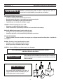 6
6
-
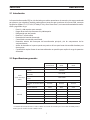 7
7
-
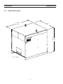 8
8
-
 9
9
-
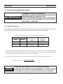 10
10
-
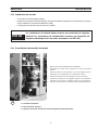 11
11
-
 12
12
-
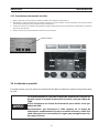 13
13
-
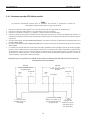 14
14
-
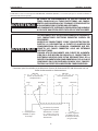 15
15
-
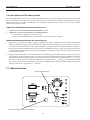 16
16
-
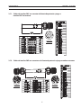 17
17
-
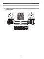 18
18
-
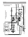 19
19
-
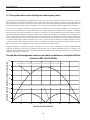 20
20
-
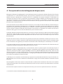 21
21
-
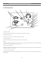 22
22
-
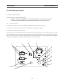 23
23
-
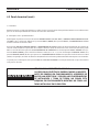 24
24
-
 25
25
-
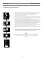 26
26
-
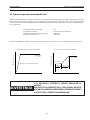 27
27
-
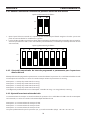 28
28
-
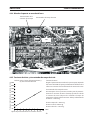 29
29
-
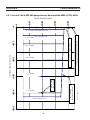 30
30
-
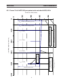 31
31
-
 32
32
-
 33
33
-
 34
34
-
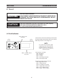 35
35
-
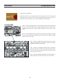 36
36
-
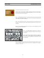 37
37
-
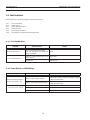 38
38
-
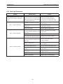 39
39
-
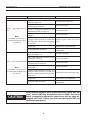 40
40
-
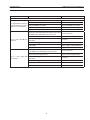 41
41
-
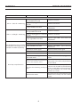 42
42
-
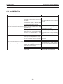 43
43
-
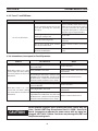 44
44
-
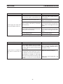 45
45
-
 46
46
-
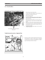 47
47
-
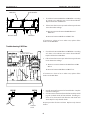 48
48
-
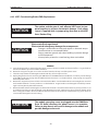 49
49
-
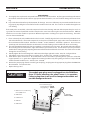 50
50
-
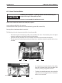 51
51
-
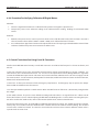 52
52
-
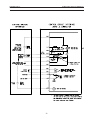 53
53
-
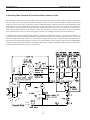 54
54
-
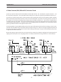 55
55
-
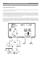 56
56
-
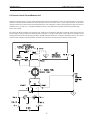 57
57
-
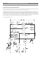 58
58
-
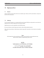 59
59
-
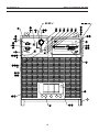 60
60
-
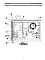 61
61
-
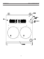 62
62
-
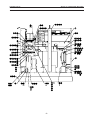 63
63
-
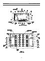 64
64
-
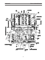 65
65
-
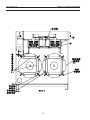 66
66
-
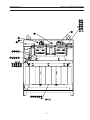 67
67
-
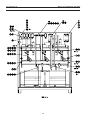 68
68
-
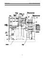 69
69
-
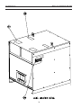 70
70
-
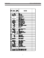 71
71
-
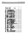 72
72
-
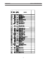 73
73
-
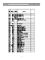 74
74
-
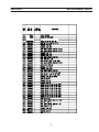 75
75
-
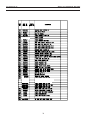 76
76
-
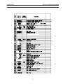 77
77
-
 78
78
-
 79
79
-
 80
80


ESAB EPP-400 Plasma Power Source Manual de usuario
- Tipo
- Manual de usuario
en otros idiomas
Artículos relacionados
-
ESAB EPP-360 Manual de usuario
-
ESAB EPP-201 Manual de usuario
-
ESAB EPP-450 Plasma Power Source Manual de usuario
-
ESAB EPP-400 Plasma Power Source Manual de usuario
-
ESAB EPP-600 Plasma Power Source Manual de usuario
-
-
ESAB EPP-450 Manual de usuario
-
ESAB EPP-201 Plasma Power Source Manual de usuario
-
-