
69-2685ES-01
INSTALLATION GUIDE/OWNER’S MANUAL
HE240, HE280
Humidifier and
Installation Kit
M33322
SAVE THIS DOCUMENT
FOR FUTURE REFERENCE
69-2685ES_A.book Page 1 Monday, March 5, 2012 12:04 PM

HE240, HE280 HUMIDIFIER AND INSTALLATION KIT
69-2685ES—01 2
Safety Definitions
These safety terms identify information you must read prior to installing or operating the
humidifier.
WARNING
Indicates a hazardous situation which, if not avoided, could result in death or
serious injury.
CAUTION
Indicates a hazardous situation which, if not avoided, could cause bodily injury or
property damage.
Safety Precautions
Make sure you read and understand the following safety hazards before installing,
using, or working with the humidifier:
WARNING
Serious Personal Injury Hazard.
Can cause electrical shock and injury from moving parts.
Disconnect power and shut off water supply before removing cover.
WARNING
Hazardous Voltage
Can cause personal injury or equipment damage.
Do not cut or drill into any air conditioning or electrical accessory.
CAUTION
Chemical Hazard.
Can cause personal injury or equipment damage.
Do not use any line connected to an air conditioner.
Do not use gas line.
CAUTION
Temperature and Static Pressure Hazard.
Can cause property or equipment damage.
Locate humidifier where ambient temperature is between 32 and 120 °F (0 to 49 °C).
Do not install humidifier where freezing temperatures could occur.
Be sure supply plenum static pressure is no greater than 0.4 in. wc and water pressure is
no greater than 120 psi.
CAUTION
Sharp Edges Installation Hazard.
Can cause personal injury.
Wear gloves and safety glasses.
69-2685ES_A.book Page 2 Monday, March 5, 2012 12:04 PM

HE240, HE280 HUMIDIFIER AND INSTALLATION KIT
3 69-2685ES—01
IMPORTANT
Read and save these instructions.
WELCOME
Congratulations on your purchase of a Honeywell whole-house humidifier. Proper use
of a Honeywell humidifier has numerous benefits related to your family’s health and
comfort, as well as helping to safeguard and protect your home.
How Your Humidifier Works
Your Honeywell humidifier uses the principle that vapor (evaporated water) is created
when warm air blows over a water-soaked area. As the vapor circulates, the relative
humidity rises.
Your humidity control monitors the relative humidity and activates the humidifier
accordingly. The humidifier has a water supply that dispenses water evenly over a
humidifier pad. The warm dry air from the furnace passes over the humidifier pad and
picks up the moist air to circulate it throughout your home.
Humidified air feels warmer and more comfortable so you may be able to lower your
thermostat heating setpoint, which saves money on your heating fuel bills. The end result
is that your humidifier gives you a comfortable environment that is also energy efficient.
Model Specific Features
The HE280 humidifier has water savings technology built in that could save up to 30%
versus leading brands. This translates to up to 20 gallons of water saved per day!
APPLICATION
This kit contains your new Honeywell HE240 or HE280 Humidifier, H8908 Humidistat
and all the accessories required for installation.
69-2685ES_A.book Page 3 Monday, March 5, 2012 12:04 PM

HE240, HE280 HUMIDIFIER AND INSTALLATION KIT
69-2685ES—01 4
PREPARING FOR THE INSTALLATION
Be sure to identify all the required (Table 1) accessories (included) and make sure the
appropriate tools are available before beginning the installation.
Included Accessories
Required Tools
Tools required for installation include:
•Tin snip
• Screwdriver
• Pliers
• Adjustable or open-end wrench
•Drill
•Level
• 3/4 in. (19 mm) sheet metal drill bit
Table 1. Included Accessories.
Quantity Accessory
48 in. (1.22 m)
Bypass ducting including:
6 in. (155 mm) diameter flexible duct
20 ft (6.2 m) 18 gauge, two-strand thermostat wire
20 ft (6.2 m) 1/4 in. (6.35 mm) OD feed water tubing
10 ft (3.1 m) 1/2 in. (12.7 mm) ID drain tubing
1 bag
Connecting and mounting hardware:
4 mounting screws
1 drain tube clamp
1 H8908 Humidistat
1 bag
Saddle Valve Assembly:
1 saddle valve and top clamp
1 threaded bottom clamp
2 bolts
1 rubber gasket
1 brass insert
1 plastic bushing
1 eyelet
1 Plug-in transformer
1 Foil tape roll
1 bag
1 plastic elbow
1 grommet
1 connector strap
1 PVC tubing
1 wire nut
1 Mounting template
69-2685ES_A.book Page 4 Monday, March 5, 2012 12:04 PM

HE240, HE280 HUMIDIFIER AND INSTALLATION KIT
5 69-2685ES—01
Determining Best Location for Humidifier
• Select a location for the humidifier on the supply (warm air stream) duct. See Fig. 1
for examples. Return duct mounting is acceptable if there are space restrictions on
the supply duct. If you are mounting the humidifier on the return duct, simply swap
“return duct” for “supply duct” throughout these instructions.
• Select a location that cannot damage the air conditioner A-coil during installation.
• Do not locate the humidifier on the furnace body.
• Mount the humidifier in a conditioned space to prevent freezing.
• Mount the humidifier at least 3 in. (78 mm) above the furnace body to allow
adequate space for the solenoid valve and drain line.
Fig. 1. Typical humidifier installation locations.
M12248D
HORIZONTAL
DOWN
FLO
LOWBOY
HIGHBOY
HUMIDIFIER
BYPASS
COLLAR
69-2685ES_A.book Page 5 Monday, March 5, 2012 12:04 PM

HE240, HE280 HUMIDIFIER AND INSTALLATION KIT
69-2685ES—01 6
Fig. 2. Typical humidifier installation locations.
Selecting Location for Humidistat
• Select a location for the humidistat on the return plenum or on the wall in the living space.
• Mounting on the return plenum is the easiest installation for the control wiring circuit.
IMPORTANT
The humidistat must be mounted upstream from the humidifier or bypass duct to ensure
it is properly sensing the relative humidity of the living space. Locate the control at least
8 in. (203 mm) upstream from the humidifier in the return air duct. (See Fig. 3.)
Fig. 3. Selecting duct location for humidistat.
Locating Closest 120 V Electrical Outlet
• Select location with access to an outlet. If not available, contact an electrician to
have one installed.
• Make sure that the 20 ft (6.2 m) of thermostat wire is adequate to reach from the
humidifier to the humidistat, and also from the humidifier to the transformer. Please
note that the thermostat wire will need to be cut into the 2 correct lengths. See
“Wiring” on page 14 for more information.
CHOOSE A LOCATION IN A CONDITIONED
SPACE THAT HAS ACCESS TO A WATER SUPPLY
PIPE. COLD OR HOT WATER CAN BE USED.
SELECT A SURFACE ON THE HVAC SUPPLY OR
RETURN DUCT WITH CLEARANCE FOR THE
SOLENOID VALVE, DRAIN LINE AND COVER
REMOVAL.
LOCATION MUST ALSO HAVE ACCESS TO 120
VAC POWER.
ENSURE THE LOCATION IS NEAR A DRAIN.
CONSULT LOCAL PLUMBING CODES FOR
PROPER DRAINAGE.
M33410
ALTERNATE LOCATION
RETURN
AIR
RETURN
AIR
6 in. (152 mm)
MINIMUM
15 in. (381 mm)
MINIMUM
BEST
LOCATION
RETURN AIR DUCT
M12831
69-2685ES_A.book Page 6 Monday, March 5, 2012 12:04 PM

HE240, HE280 HUMIDIFIER AND INSTALLATION KIT
7 69-2685ES—01
INSTALLATION
1. Turn off power to the air handling system at the circuit breaker.
2. Draw a level line on the plenum in the selected location.
IMPORTANT
To ensure optimal product performance, be sure the mounting template is
level before marking. Use of a small level is recommended.
3. Locate the template (form number 69-2710 included in the box). For the HE240
model, cut out the template along the dotted line.
4. Tape the template in position and trace around the template.
5. Remove the template and carefully cut the rectangular opening using tin snips.
6. Disassemble the humidifier; remove the cover and take out the humidifier pad
assembly. See Fig. 4.
Fig. 4. Disassembling humidifier.
M33323
WATER
FEED NOZZLE
FRAME
HUMIDIFIER
HOUSING
WATER
FEED TUBE
HUMIDIFIER
PAD ASSEMBLY
COVER
SIDEWALL
BY-PASS SIDEWALL
PRESSURE SWITCH
SOLENOID VALVE
PerfectFLO™ WATER
DISTRIBUTION TRAY
69-2685ES_A.book Page 7 Monday, March 5, 2012 12:04 PM

HE240, HE280 HUMIDIFIER AND INSTALLATION KIT
69-2685ES—01 8
7. Make sure the humidifier housing is
level, then position it in the opening
so the plastic tabs are in place on the
lower sheet metal edge of the open-
ing. Use pliers, as necessary, to flat-
ten cut edges. See Fig. 5.
8. Secure the humidifier housing to the
opening at the top and bottom using
sheet metal screws.
9. Use the 6 in. (155 mm) starter collar
as a template to mark the opening for
the bypass. The starter collar end
can be identified by the pliable metal
tabs.
Fig. 5. Installing humidifier on duct.
10. Carefully cut the opening for the 6 in. (155 mm) starter collar end of the 48 in.
(1.22 m) flex duct. See Fig. 6. Use a drill to start the cut in the middle of the cir-
cle. Cut in an outward spiral to assist in controlling the cut.
Fig. 6. Cutting bypass opening.
DUCT
LEVEL
SHEET METAL
SCREWS (4)
PLASTIC
TABS (2)
DRAIN TUBING
M33324
OPENING
TO AIR DUCT
STARTING
HOLE
6 IN. ROUND TEMPLATE
M20172
69-2685ES_A.book Page 8 Monday, March 5, 2012 12:04 PM

HE240, HE280 HUMIDIFIER AND INSTALLATION KIT
9 69-2685ES—01
11. Reassemble humidifier side plates to customize the orientation for your specific
install. The side plate with the humidifier port needs to be on the side of the
humidifier that is closest to the 6 in. (155mm) hole cut in Step 10.
12. Insert flex duct with starter collar into the 6" (155mm) hole that was cut in Step
10. Reach into hole THROUGH THE FLEX DUCT so that the pliable metal tabs
can be bent outwards into the hole. These tabs, when bent outwards, will help
secure the flex duct into your home's duct work.
13. Slide remaining loose end of flex duct over the humidifier port on the HE240/
HE280, making sure that the flex duct advances past the raised plastic tabs on
the port. These tabs will help to hold the flex duct in place. Verify that the damper
blade has adequate clearance to move back and forth between the summer and
winter positions. Secure the flex duct in place with the plastic connector strap.
14. Seal the duct connec-
tions with foil tape.
Seal both
1) the connection
between the starter
collar end of the flex
duct and the home's
duct work and
2) the end of the flex
duct to the humidifier
over the top of the
connector strap.
15. Reinstall the humidi-
fier pad assembly in
the humidifier hous-
ing.
16. Hinge the cover in
place and secure with
the thumbscrew
located at the bottom
of the cover.
Fig. 7. Connecting bypass ducting.
M33325
HUMIDIFIER PORT
CONNECTOR STRAP
69-2685ES_A.book Page 9 Monday, March 5, 2012 12:04 PM

HE240, HE280 HUMIDIFIER AND INSTALLATION KIT
69-2685ES—01 10
Connecting the Plumbing
Use hot or cold water and either hard or softened water in the humidifier.
NOTE: Using hot water will increase operating costs, but may provide a small
increase in the amount of humidity delivered.
IMPORTANT
Please consult local plumbing code for proper plumbing regulations before begin-
ning. Use of a manual shutoff valve may be required to meet code in your area.
1. Shut off the water.
2. Use the self-piercing saddle valve (included)
to tap into the water supply line at the loca-
tion selected. Turn the handle on the top of
the saddle valve to the right (clockwise) until
the needle pierces the water supply line.
Leave the needle in this position until the
humidifier is fully installed to prevent leaking
(even though the water supply is turned off,
there can still be water in the line that will
leak as soon as the needle is backed out).
See Fig. 8. If tapping into galvanized pipe,
drain the line and pre-drill 3/16 in. tap for the
saddle valve.
Fig. 8. Installing the saddle valve.
NOTE: The saddle valve is not designed to regulate water flow. The valve is
either open or closed.
IMPORTANT
To prevent debris from clogging the solenoid in-line filter, be sure to install the
saddle valve handle pointing toward the ceiling.
3. Use 1/4 in. (6 mm) OD tubing and
connect the saddle valve to the
inlet side of the solenoid valve on
the humidifier (see Fig. 9).
a. Place the brass compression nut
over the tubing.
b. Slide the plastic compression ring
over the tubing. (Discard copper
compression ring provided with
valve.)
c. Install brass insert into end of
tubing.
Fig. 9. Installing feed tubing.
NOTE: To prevent leaking, use plastic (Delrin) compression rings with plastic
tubing. Use copper sleeve rings only with copper tubing.
M20175
SCREW DRIVER
WATER LINE
M33404
BRASS COMPRESSION NUT
PLASTIC
COMPRESSION
RING
BRASS INSERT
69-2685ES_A.book Page 10 Monday, March 5, 2012 12:04 PM

HE240, HE280 HUMIDIFIER AND INSTALLATION KIT
11 69-2685ES—01
d. Insert the tubing into the saddle valve fitting and support the valve while
tightening the compression nut.
e. Insert plastic supply tubing into quick connect fitting. Insert fully, and apply
modest pull pressure to ensure a tight fit.
4. Use the following steps to install a
1/2 in. (13 mm) drain tube between the
humidifier and the floor drain (see Fig. 10).
a. Slide the drain clamp over the tubing.
b. Push the tubing over the drain nipple
on the humidifier.
c. Hand-tighten the clamp around the
tubing to secure it to the humidifier
drain. The clamp is tightened by com-
pressing the two sides together so
that one side fits into the ridged grove
on the other side.
d. Secure the tubing (can use foil tape)
along the route to prevent movement
and ensure downward slope for cor-
rect drainage.
Fig. 10. Installing the drain tubing.
NOTE: Cut tubing to correct length so the tubing terminates at the drain.
Connecting the Pressure Switch
1. If the humidifier is installed on
the supply duct (as is recom-
mended), the pressure switch
needs to have the tubing fed to
the return duct. If the humidifier
is installed on the return duct,
the pressure switch needs to
have the tubing fed to the supply
duct.
2. Drill a 3/4-in. (19 mm) diameter
hole in the duct within 10 ft.
(3 m) of the switch to ensure the
provided tubing reaches the
pressure tap elbow.
Fig. 11. Pressure switch.
M20177
M33405
69-2685ES_A.book Page 11 Monday, March 5, 2012 12:04 PM

HE240, HE280 HUMIDIFIER AND INSTALLATION KIT
69-2685ES—01 12
3. Insert the black rubber grommet into
the duct hole.
4. Connect the tubing to the tubing fit-
ting elbow and insert the tubing fit-
ting elbow into the black rubber
grommet.
5. Connect the other end of the tubing
to the applicable pressure connec-
tion on the switch.
a. If the humidifier is installed on the
supply duct (as is recom-
mended), the tube that inserts
into the humidifier needs to be
attached to the black port, and
the tube that runs to the return
duct needs to be attached to the
gray port.
b. If the humidifier is installed on the
return duct, the tube that inserts
into the humidifier needs to be
attached to the gray port, and the
tube that runs to the supply duct
needs to be attached to the black
port.
Fig. 12. Installing the pressure switch
tubing.
6. You may cut the tubing to fit the connection length between the elbow fitting and
switch. It is also recommended to secure the hose to existing structures to avoid
accidental disconnection.
M33326
69-2685ES_A.book Page 12 Monday, March 5, 2012 12:04 PM

HE240, HE280 HUMIDIFIER AND INSTALLATION KIT
13 69-2685ES—01
Installing the Humidistat
1. Find the mounting template included in the H8908 Humidistat Installation
Instructions.
2. Apply the template to the return
duct (see Fig. 3 on page 6). Make
sure the template is level before
drilling. (Use of a small level is rec-
ommended.)
3.
Remove base bracket from the H8908
.
4. Slide the foam gasket onto the base.
(See Fig. 14.)
5. Position the base bracket on the duct
with the arrow up.
6. Secure the base bracket to the duct
using the four 1 in. (25 mm) mounting
screws provided with the humidistat.
(See Fig. 15.)
Fig. 13. Humidistat base and rear view.
7. Connect the low-voltage wires to the leads and replace the H8908 case.
See Fig. 16.
NOTE: For wall mounting instructions, see the H8908 Installation Instructions.
Fig. 14. Slide the foam
gasket onto the base.
Fig. 15. Secure the
base bracket to the duct.
M20179
WIRE SLOT
HUMIDISTAT WIRES
HUMIDISTAT BASE REAR OF HUMIDISTAT
M24733
M29879
69-2685ES_A.book Page 13 Monday, March 5, 2012 12:04 PM

HE240, HE280 HUMIDIFIER AND INSTALLATION KIT
69-2685ES—01 14
WIRING
CAUTION
Hazardous Voltage.
Can cause personal injury or equipment damage.
Disconnect power supply before installing or servicing equipment.
IMPORTANT
All wiring must comply with applicable local code, ordinances and regulations.
Wire the humidifier solenoid valve, humidistat and transformer. See Fig. 16.
Fig. 16. Wiring the controls and the HE240.
Fig. 17. Wiring the controls and the HE280.
1. Determine the length of wire necessary to run from the humidifier to the humidi-
stat. Cut to length and strip the ends appropriately.
2. Connect the red and white wires to the leads on the humidistat per the wiring
diagram. Use the provided wire nuts to secure the connections.
3. Taking the opposite end of the wire, connect RED WIRE to one terminal on the
humidifier. Leave the white wire loose at this point.
4. Using remaining wire, determine length needed to run from humidifier to the
transformer. Cut to length and strip the ends appropriately.
5. Unplug the transformer. Connect the red and white wires to the transformer by
loosening the screws on the transformer, wrap wire around screw post and then
re-tighten the screws.
6. Taking the opposite end of the wire, connect the RED WIRE to the open remain-
ing loose terminal on the humidifier.
7. Connect the remaining two white wires together using the provided wire nut.
M33413
HUMIDIFIER
SOLENOID
VALVE
H
u
m
i
d
i
t
y
Co
n
t
r
o
l
égu
la
t
e
u
r
d
'
h
u
m
i
d
i
t
é
-
2
0
¡
F
-
1
0
¡
F
0
¡
F
+
1
0
¡F
+2
0
¡F
O
ve
r
2
0
¡
F
1
5
%
2
0
%
2
5
%
30
%
3
5
%
4
0%
H
U
M
ID
I
T
Y
S
E
T
T
I
N
G
O
U
TD
O
O
R
TE
M
P
ER
ATU
R
E
-
3
0 ¡
C
-
25
¡
C
-
2
0
¡
C
-
1
0
¡C
-
5
¡C
O
ve
r
0
¡
C
HUMIDISTAT
TRANSFORMER
WHITE WIRE
RED WIRE
WIRE NUT
WHITE WIRE
WHITE WIRE
WIRE NUTWIRE NUT
RED
WIRE
RED
WIRE
RED WIRE
WHITE WIRE
1
2
5
4
7
6
3
M33327
HUMIDIFIER
SOLENOID
VALVE
H
u
m
id
i
t
y
Co
n
t
r
o
l
é
gu
la
t
e
u
r
d
'h
u
m
i
d
i
t
é
-
2
0
¡F
-
1
0
¡
F
0
¡
F
+
1
0
¡
F
+
2
0
¡F
O
ve
r
2
0
¡F
1
5
%
2
0
%
2
5
%
3
0
%
3
5
%
4
0%
H
U
M
I
D
IT
Y
S
E
T
T
I
N
G
OU
T
D
O
O
R
TE
M
P
ER
ATU
R
E
-
3
0
¡
C
-
2
5
¡
C
-
2
0
¡
C
-
1
0
¡C
-
5
¡C
O
ver
0
¡
C
HUMIDISTAT
TRANSFORMER
WHITE WIRE
RED WIRE
WIRE NUT
WHITE WIRE
WHITE WIRE
WIRE NUT
WIRE NUT
RED WIRE
RED
WIRE
RED WIRE
WHITE WIRE
69-2685ES_A.book Page 14 Monday, March 5, 2012 12:04 PM

HE240, HE280 HUMIDIFIER AND INSTALLATION KIT
15 69-2685ES—01
TESTING HUMIDIFIER OPERATION
Checklist
Humidifier is level.
Control wiring was reviewed using circuit diagram.
Humidifier is plugged in.
Feed line has no kinks.
Drain line slopes continuously down and ends at floor drain.
Water hose inside humidifier is connected to PerfectFLO
™
water distribution tray.
Tubing from pressure switch is not kinked or pinched.
After installation use the following steps to check the humidifier operation:
1. Turn on the power and the water supply
2. Ensure the saddle valve is fully opened by turning the handle to the left (counter
clockwise) until there is resistance.
3. Turn the H8908 Humidistat to On and turn on the heat by setting the thermostat
to 10 ºF (6 ºC) above room temperature.
IMPORTANT
The furnace blower must be on to activate the humidifier.
4. Make sure that water is flowing out of the drain hose. If water does not flow, see
Troubleshooting Your Humidifier section.
5. Check for leaks.
6. Reset the thermostat and H8908 Humidistat to a comfortable setting for auto-
matic operation. (35% relative humidity is recommended.)
OPERATION
Controlling Your Humidity Settings
Your H8908 Humidistat controls your humidifier.
• Choose the humidity control setting using the combination of relative humidity/
outdoor temperature setting scale on your humidity control dial.
• Match the dial setting to the outdoor temperature to optimize the humidity level
while reducing the moisture condensation on your windows. See Table 2 on
page 16 to adjust the humidity control to the recommended setting.
NOTE: As the outside temperature drops, a lower humidity setting is recom-
mended to accommodate dewpoint effects. These settings should
reduce the accumulation of moisture and ice on windows and other
areas of the home.
• Adjust the humidity control setting to adjust for indoor activities such as cooking,
showering and clothes drying, which can cause excessive levels of humidity that
can accumulate moisture on your windows.
NOTE: If these activities persist for more than a few hours, set the humidity
control to the lowest setting to turn off the humidifier. If the condition
does not improve, ventilate your home to remove the moisture.
69-2685ES_A.book Page 15 Monday, March 5, 2012 12:04 PM

HE240, HE280 HUMIDIFIER AND INSTALLATION KIT
69-2685ES—01 16
MAINTAINING YOUR HUMIDIFIER
A regular maintenance program prolongs the life of your humidifier and makes your
home more comfortable. The frequency of cleaning depends on the condition of your
water.
You can use either hard or soft water in your humidifier, but hard water mineral
deposits are more difficult to clean than soft water deposits.
Use the following procedure to clean your Honeywell humidifier.
IMPORTANT
Never oil any part of the humidifier.
Once per year, depending on water quality
(either at the beginning or the end of the humidification season)
1. Disconnect the power by unplugging the transformer from the outlet and turn off
the humidifier’s water supply by turning the handle to the right (clockwise) until
the water stops flowing and/or there is resistance.
2. Remove the humidifier cover. See Fig. 18 on page 17.
3. Remove the humidifier pad assembly from the humidifier by grasping the top of
the tray and pulling it toward you.
4. Pull one side of the humidifier pad assembly frame toward you and remove the
tray from the frame.
5. Gently pinch the water nozzle prongs (a pair of prongs is located on each side of
the PerfectFLO
™
water distribution tray) inward until you can lift the water nozzle
off the tray.
6. Slide the humidifier pad out of the frame and discard the pad. Honeywell recom-
mends replacing the humidifier pad on an annual basis. However, if your home
has hard water, the pad may need to be replaced more frequently.
7. Carefully remove any mineral deposits from the tray and frame. Be sure the
frame drain hole has nothing blocking it.
8. Disconnect the drain hose from the drain fitting on the bottom of the humidifier
housing.
Table 2. Setting Your Humidistat.
When Outside
Temperature is:
Use This Control
Setting:
-20 °F (-29 °C) 15
-10 °F (-23 °C) 20
0 °F (-18 °C) 25
+10 °F (-12 °C) 30
+20 °F (-7 °C) 35
Above 20 °F (-7 °C) 40
69-2685ES_A.book Page 16 Monday, March 5, 2012 12:04 PM

HE240, HE280 HUMIDIFIER AND INSTALLATION KIT
17 69-2685ES—01
9. Clean the drain fitting, if neces-
sary.
10. Bend the drain hose to loosen
any mineral deposits.
11. Flush the drain hose with pres-
surized water (a running tap)
to clean the hose.
12. Reattach the drain hose to the
drain fitting.
13. Slide a new Honeywell humidi-
fier pad back into the frame.
14. Snap the water nozzle back on
the tray.
15. Reattach the tray to the frame.
16. Place the humidifier pad
assembly in the humidifier
housing and press until the
assembly is completely
seated. Be careful not to pinch
or kink the water feed tube.
17. Replace the humidifier cover.
18. Verify the humidifier operation
by following the steps in the
Checking Your Humidifier for
Correct Operation section.
Fig. 18. Cleaning your humidifier.
End of Humidification Season
• Clean the humidifier and shut it off at the end of the heating season.
• Turn the water off at the saddle valve by turning the handle to the right (clockwise)
until the water stops flowing and/or there is resistance.
• Unplug the humidifier at the wall outlet
• Turn the damper blade to the "summer" position.
IMPORTANT
Be sure the humidifier power is off.
Replacement Humidifier Pads
Honeywell recommends replacing the humidifier pad on an annual basis. However, if
your home has hard water, the pad may need to be replaced more frequently because
of the buildup of minerals diminishing its ability to operate normally. If there is access to
a water softener, it is recommended to use softened water.
Table 3. Replacement pad part numbers.
Humidifier Model Replacement Pad
HE240 HC22P
HE280 HC26P
M33328
PerfectFLO™ WATER
DISTRIBUTION TRAY
HUMIDIFIER PAD ASSEMBLY
WATER FEED NOZZLE
HUMIDIFIER HOUSING
SIDEWALL
BYPASS
SIDEWALL
COVER
WATER FEED TUBE
69-2685ES_A.book Page 17 Monday, March 5, 2012 12:04 PM

HE240, HE280 HUMIDIFIER AND INSTALLATION KIT
69-2685ES—01 18
Vacation
• When leaving on vacation, turn off the humidifier water supply and your humidistat.
• When you return, turn on the humidifier water supply and reset your humidistat.
Start of the Humidification Season
Use the following steps to bring the humidifier back to normal (winter) operation:
1. Turn damper blade to "winter" position.
2. Plug the humidifier transformer back into wall outlet and turn water supply to the
humidifier back on by turning the handle on the saddle valve to the left (counter
clockwise) until there is resistance.
3. Turn the humidistat to its highest setting and set the thermostat to 10 °F (6 °C)
above the room temperature.
4. Observe that water is flowing out of the drain hose.
NOTE: The furnace blower must be running to activate the humidifier.
5. Reset the thermostat and humidistat to a comfortable setting for automatic oper-
ation. (35% relative humidity is recommended.)
TROUBLESHOOTING YOUR HUMIDIFIER
Table 4. Troubleshooting Humidifier.
Problem What to look for What to do
Water
leakage
Leaking joints. Shut off water and tighten connections.
Brass tubing inserts Verify that brass tubing inserts are used.
Saddle valve leaking. Verify rubber pad is installed on saddle valve.
No water to
drain.
Electrical Verify control circuit wiring.
Check all connections.
Humidistat Turn humidistat up and down and listen for
contact to click.
Humidifier power Verify that outlet has power.
Solenoid After verifying other wiring components, turn on
furnace fan, turn humidistat up and down, and
listen for solenoid to click.
Plumbing Verify plumbing connections.
Check for kinks.
Saddle valve Verify that needle pierces water line and then
backs out needle to open valve.
Humidifier Remove cover and verify that water flows into
distribution tray.
Drain tubing Verify no obstructions.
Air leakage Check duct joints Seal with foil tape.
69-2685ES_A.book Page 18 Monday, March 5, 2012 12:04 PM

HE240, HE280 HUMIDIFIER AND INSTALLATION KIT
19 69-2685ES—01
Low
humidity
Furnace blower
not operating.
• Reset circuit breaker or check for blown fuse.
• Check that the furnace power is on.
• Check all external wiring connections.
• Check the humidity control setting.
• Verify that pressure switch tubing isn't
pinched or obstructed.
• Call a professional heating contractor.
Rapid air changes.
Drafts (cold air is
dry and is an
added load to the
humidifier).
• Keep doors and windows closed.
• Close fireplace damper when not in use.
• Keep exhaust fan running time to a minimum.
• Seal around doors and windows.
Damper in
“summer” position
• Set damper blade to "winter" position to allow
humidification.
High
humidity
Condensation on
walls.
• Turn off humidity control and water until
condensation is completely evaporated.
Heavy
condensation on
windows.
• Turn humidity control down low enough to
eliminate condensation caused by moisture
from bathing, mopping, cooking, etc. If
moisture persists, more ventilation is needed.
Table 4. Troubleshooting Humidifier. (Continued)
69-2685ES_A.book Page 19 Monday, March 5, 2012 12:04 PM

HE240, HE280 HUMIDIFIER AND INSTALLATION KIT
Automation and Control Solutions
Honeywell International Inc.
1985 Douglas Drive North
Golden Valley, MN 55422
customer.honeywell.com
® U.S. Registered Trademark
© 2012 Honeywell International Inc.
69-2685ES—01 M.S. 03-12
Printed in United States
LIMITED ONE-YEAR WARRANTY
Honeywell warrants this product, excluding humidifier pad, to be free from defects in the workmanship or
materials, under normal use and service, for a period of one (1) year from the date of purchase by the
consumer. If, at any time during the warranty period, the product is defective or malfunctions, Honeywell shall
repair or replace it (at Honeywell’s option) within a reasonable period of time.
If the product is defective, return it, with a bill of sale or other dated proof of purchase, to the retailer where you
purchased it.
This warranty does not cover removal or reinstallation costs. This warranty shall not apply if it is shown by
Honeywell that the defect or malfunction was caused by damage which occurred while the product was in
the possession of a consumer.
Honeywell’s sole responsibility shall be to repair or replace the product within the terms stated above.
HONEYWELL SHALL NOT BE LIABLE FOR ANY LOSS OR DAMAGE OF ANY KIND, INCLUDING ANY
INCIDENTAL OR CONSEQUENTIAL DAMAGES RESULTING, DIRECTLY OR INDIRECTLY, FROM ANY
BREACH OF ANY WARRANTY, EXPRESS OR IMPLIED, OR ANY OTHER FAILURE OF THIS PRODUCT.
Some states do not allow the exclusion or limitation of incidental or consequential damages, so this limitation
may not apply to you.
THIS WARRANTY IS THE ONLY EXPRESS WARRANTY HONEYWELL MAKES ON THIS PRODUCT. THE
DURATION OF ANY IMPLIED WARRANTIES, INCLUDING THE WARRANTIES OF MERCHANTABILITY
AND FITNESS FOR A PARTICULAR PURPOSE, IS HEREBY LIMITED TO THE ONE YEAR DURATION
OF THIS WARRANTY. Some states do not allow limitations on how long an implied warranty lasts, so the
above limitation may not apply to you.
This warranty gives you specific legal rights, and you may have other rights which vary from state to state.
If you have any questions concerning this warranty, please write to Honeywell Customer Care, 1985 Douglas
Drive, Minneapolis, MN55422.
69-2685ES_A.book Page 20 Monday, March 5, 2012 12:04 PM

GUÍA DE INSTALACIÓN/MANUAL DEL PROPIETARIO
Humidificadores
HE240 o HE280
y kit de instalación
M33322
GUARDE ESTE DOCUMENTO
PARA REFERENCIA FUTURA
69-2685ES_A.book Page 1 Monday, March 5, 2012 12:04 PM

HUMIDIFICADORES HE240 O HE280 Y KIT DE INSTALACIÓN
69-2685ES—01 2
Definiciones de seguridad
Estos términos de seguridad identifican la información que deberá leer antes de instalar o utilizar
el humidificador.
ADVERTENCIA
Indica una situación peligrosa que, si no se evita, podría ocasionar la muerte o
lesiones graves.
PRECAUCIÓN
Indica una situación peligrosa que, si no se evita, podría ocasionar lesiones
físicas o daño a la propiedad.
Precauciones de seguridad
Lea y comprenda los siguientes peligros que amenazan la seguridad antes de instalar,
utilizar o trabajar con el humidificador:
ADVERTENCIA
Peligro de lesiones personales graves.
Puede causar descarga eléctrica y lesiones provenientes de las partes en movimiento.
Desconecte la electricidad y corte el suministro de agua antes de retirar la tapa.
ADVERTENCIA
Voltaje peligroso
Puede causar lesiones personales o daño al equipo.
No corte ni taladre en ningún accesorio de aire acondicionado o de electricidad.
PRECAUCIÓN
Peligro de sustancias químicas.
Puede causar lesiones personales o daño al equipo.
No utilice ninguna tubería conectada a un equipo de aire acondicionado.
No utilice tubería de gas.
PRECAUCIÓN
Peligro por temperatura y presión estática.
Puede dañar la propiedad o el equipo.
Ubique el humidificador donde la temperatura ambiente esté entre 32 y 120 °F (0 á
49 °C).
No instale el humidificador donde pudiesen ocurrir temperaturas de congelamiento.
Cerciórese de que la presión estática del plenum de alimentación no sea mayor de 0.4 in
en la columna de agua y que la presión de agua no sea mayor de 120 psi.
PRECAUCIÓN
Riesgo de bordes afilados en la instalación.
Puede ocasionar lesiones personales.
Utilice guantes y gafas de seguridad.
69-2685ES_A.book Page 2 Monday, March 5, 2012 12:04 PM

HUMIDIFICADORES HE240 O HE280 Y KIT DE INSTALACIÓN
3 69-2685ES—01
IMPORTANTE
Lea estas instrucciones y consérvelas para consulta posterior.
BIENVENIDO
Felicitaciones por la compra de su nuevo humidificador Honeywell para toda la
vivienda. El uso adecuado de un humidificador Honeywell tiene numerosos beneficios
relacionados con la salud y el confort de su familia y también contribuye a
salvaguardar y proteger su hogar.
Cómo trabaja su humidificador
Su humidificador Honeywell utiliza el principio de que el vapor (agua evaporada) se
crea cuando el aire cálido sopla sobre un área empapada con agua. A medida que
circula el vapor, la humedad relativa se eleva.
Su control de humedad monitoriza la humedad relativa y activa el humidificador
cuando sea necesario. El humidificador tiene un suministro de agua que dispensa
agua uniformemente sobre una almohadilla del humidificador. El aire seco cálido del
sistema de calefacción pasa sobre la almohadilla del humidificador y recoge el aire
húmedo para que circule por toda su casa.
El aire humidificado se siente más cálido y más confortable de modo que puede bajar el
punto de ajuste del termostato, lo cual le ahorra dinero en sus facturas de calefacción. El
resultado final es que su humidificador le brinda un ambiente confortable que también le
ahorra energía.
Características específicas del modelo
El humidificador HE280 posee tecnología integrada para el ahorro de agua que podría
ahorrar hasta 30% en comparación con otras marcas destacadas. ¡Esto significa un
ahorro de hasta 20 galones (75.7 l) de agua al día!
APLICACIÓN
Este kit contiene su nuevo humidificador Honeywell HE240 o HE280, el humidistato
H8908 y todos los accesorios necesarios para la instalación.
69-2685ES_A.book Page 3 Monday, March 5, 2012 12:04 PM

HUMIDIFICADORES HE240 O HE280 Y KIT DE INSTALACIÓN
69-2685ES—01 4
PREPARACIÓN PARA LA INSTALACIÓN
Cerciórese de identificar todos los accesorios necesarios que se incluyen (Tabla 1) y
tener disponibles los implementos adcuados antes de comenzar la instalación.
Accesorios incluidos
Herramientas necesarias
Las herramientas necesarias para la instalación incluyen:
• Tijera de hojalata.
• Destornillador.
• Alicate
• Llave ajustable o de extremo abierto
• Taladro
• Nivel
• Broca para taladrar lámina de metal de 3/4 in (19 mm)
Tabla 1. Accesorios incluidos.
Cantidad Accesorio
48 in. (1.22 m)
Conductos de derivación que incluyen:
Conducto flexible de 6 in (155 mm) de diámetro
20 ft (6.1 m) Cable calibre 18 de dos conductores para termostato
20 ft (6.1 m)
Tubería de alimentación de agua de 1/4 in (6.35 mm)
de diámetro interno
10 ft (3.1 m)
Tubería de drenaje 1/2 in (12.7 mm) de diámetro
interno
1 bolsa
Accesorios para conexión y montaje:
4 tornillos de montaje
1 abrazadera para el tubo de drenaje
1 Humidistato H8908
1 bolsa
Ensamblaje de válvula de asiento:
1 válvula de asiento y abrazadera superior
1 abrazadera inferior roscada
2 pernos
1 junta de goma
1 inserto de latón
1 cojinete plástico
1 armella
1 Transformador enchufable
1 Rollo de cinta metálica
1 bolsa
1 codo plástico
1 arandela aislante
1 banda del conector
1 tubería de PVC
1 empalme para cables
1 Plantilla de montaje
69-2685ES_A.book Page 4 Monday, March 5, 2012 12:04 PM

HUMIDIFICADORES HE240 O HE280 Y KIT DE INSTALACIÓN
5 69-2685ES—01
Cómo determinar la mejor ubicación para el humidificador
• Elija un lugar para el humidificador en el conducto de alimentación (corriente de
aire cálido). Consulte la Fig. 1 para ver los ejemplos. El montaje en el conducto de
retorno es aceptable si existen restricciones de espacio en el conducto de
suministro. Si monta el humidificador en el conducto de retorno, simplemente
sustituya "conducto de retorno" por "conducto de alimentación" en estas
instrucciones.
• Elija un lugar que no pueda dañar el serpentín A del aire acondicionado durante la
instalación.
• No ubique el humidificador en la estructura del sistema de calefacción.
• Monte el humidificador en un espacio acondicionado para evitar el congelamiento.
• Monte el humidificador al menos 3 in (78 mm) por encima del sistema de
calefacción para permitir suficiente espacio para la válvula solenoide y la tubería de
drenaje.
Fig. 1. Ubicaciones de instalación típicas para el humidificador.
MS12248D
HORIZONTAL
LOWBOY
HIGHBOY
HUMIDIFICADOR
COLLARÍN DEL
DESVIADOR
DOWN
FLO
69-2685ES_A.book Page 5 Monday, March 5, 2012 12:04 PM

HUMIDIFICADORES HE240 O HE280 Y KIT DE INSTALACIÓN
69-2685ES—01 6
Fig. 2. Ubicaciones de instalación típicas para el humidificador.
Elección de la ubicación del humidistato
• Elija una ubicación para el humidistato en el plenum de retorno o en la pared del espacio habitable.
• El montaje en el plenum de retorno es la instalación más fácil para el circuito de cableado de control.
IMPORTANTE
El humidistato deberá estar montado por encima del humidificador o del conducto de
derivación para lograr que detecte adecuadamente la humedad relativa del espacio
habitable. Ubique el control al menos 8 in (203 mm) por encima del humidificador en el
conducto de aire de retorno. (Consulte la Fig. 3.)
Fig. 3. Elección de la ubicación del conducto para el humidistato.
Ubicación más cercana a un tomacorriente de 120 V
• Elija la ubicación con acceso a un tomacorriente. Si no está disponible, contacte a un
electricista para que instale un tomacorriente.
• Cerciórese de que el cable de 20 ft (6.1 m) del termostato sea adecuado para llegar
desde el humidificador hasta el humidistato y también desde el humidificador hasta el
transformador. Tenga en cuenta que el cable del termostato deberá cortarse en 2 largos
adecuados. Consulte la sección “Cableado” en la página 16 para más información.
ELIJA UN LUGAR EN UN ESPACIO ACONDICIO-
NADO QUE TENGA ACCESO A UNA TUBERÍA
DE SUMINISTRO DE AGUA. SE PUEDE
UTILIZAR AGUA FRÍA O CALIENTE.
ELIJA UNA SUPERFICIE EN EL CONDUCTO DE
ALIMENTACIÓN O RETORNO DEL HVAC CON
DESPEJE PARA LA VÁLVULA SOLENOIDE, LA
TUBERÍA DE DRENAJE Y LA REMOCIÓN DE LA
CUBIERTA.
LA UBICACIÓN TAMBIÉN DEBERÁ TENER
ACCESO A ELECTRICIDAD DE 120 V CA.
COMPRUEBE QUE LA UBICACIÓN ESTÉ CERCA
DE UN DRENAJE. CONSULTE LOS CÓDIGOS DE
PLOMERÍA LOCALES PARA EL DRENAJE
ADECUADO.
MS33410
UBICACIÓN ALTERNA
AIRE DE
RETORNO
AIRE DE
RETORNO
MÍNIMO 6 in
(152 mm)
MÍNIMO 15 in.
(381 mm)
UBICACIÓN
PREFERENTE
CONDUCTO DE
AIRE DE RETORNO
MS12831A
69-2685ES_A.book Page 6 Monday, March 5, 2012 12:04 PM

HUMIDIFICADORES HE240 O HE280 Y KIT DE INSTALACIÓN
7 69-2685ES—01
INSTALACIÓN
1. Desconecte el suministro eléctrico del sistema de manejo de aire en el interrup-
tor de circuito.
2. Trace una línea nivelada en el plenum en la ubicación elegida.
IMPORTANTE
Para lograr un óptimo rendimiento del producto, cerciórese de que la plantilla de
montaje esté a nivel antes de marcar. Se recomienda el uso de un nivel pequeño.
3. Ubique la plantilla (forma número 69-2710 que se incluye en la caja). Para el
modelo HE240, corte la plantilla por la línea punteada.
4. Encinte la plantilla en su posición y trace alrededor de la plantilla.
5. Retire la plantilla y corte cuidadosamente la abertura rectangular utilizando una
tijera de hojalata.
6. Desensamble el humidificador; retire la cubierta y saque el ensamble de la
almohadilla del humidificador. Consulte la Fig. 4.
Fig. 4. Desensamblaje del humidificador.
MS33323
BOQUILLA DEL TUBO
DE ALIMENTACIÓN
MARCO
CARCASA DEL
HUMIDIFICADOR
TUBO DE
ALIMENTACIÓN
DE AGUA
ENSAMBLE DE LA
ALMOHADILLA DEL
HUMIDIFICADOR
CUBIERTA
PARED
LATERAL
PARED DE DERIVACIÓN
INTERRUPTOR DE PRESIÓN
VÁLVULA SOLENOIDE
BANDEJA DE DISTRIBUCIÓN
DEL AGUA PerfectFLO™
69-2685ES_A.book Page 7 Monday, March 5, 2012 12:04 PM

HUMIDIFICADORES HE240 O HE280 Y KIT DE INSTALACIÓN
69-2685ES—01 8
7. Cerciórese de que la carcasa del
humidificador esté a nivel y seguida-
mente colóquela en la abertura de
modo que las pestañas plásticas
queden en su lugar en el borde infe-
rior de la lámina metálica de la aber-
tura. Use un alicate según sea
necesario, para aplanar los bordes
cortados. Consulte la Fig. 5.
8. Fije la carcasa del humidificador en la
abertura de la parte superior e infe-
rior utilizando tornillos para lámina
metálica.
9. Utilice el collarín de arranque de 6 in
(155 mm) como plantilla para marcar
la abertura del desviador. El collarín
de arranque puede identificarse
mediante las lengüetas metálicas
maleables.
Fig. 5. Instalación del humidificador en
un conducto.
10. Corte cuidadosamente la abertura para el extremo del collarín de arranque de
6 in (155 mm) del conducto flexible de 48 in (1.22 m). Consulte la Fig. 6. Utilice
un taladro para iniciar el corte en la mitad del círculo. Corte en forma de espiral
hacia afuera para permitir el control del corte.
Fig. 6. Corte para la abertura del desviador.
GAINE
NIVEAU
VIS À TÔLE (4)
ATTACHES EN
PLASTIQUE (2)
TUYAU DE VIDANGE
MF33324
OUVERTURE
VERS LA
GAINE D'AIR
AGUJERO DE
ARRANQUE
PLANTILLA REDONDA
DE 6 IN (155 mm)
MS20172A
69-2685ES_A.book Page 8 Monday, March 5, 2012 12:04 PM

HUMIDIFICADORES HE240 O HE280 Y KIT DE INSTALACIÓN
9 69-2685ES—01
11. Vuelva a ensamblar las placas laterales del humidificador para personalizar la
orientación de su instalación específica. La placa lateral con el puerto del
humidificador debe estar en el lado del humidificador más cercano al agujero de
6 in (155 mm) que se cortó en el paso 10.
12. 12. Inserte el conducto flexible con el collarín de arranque en el agujero de 6 in
(155 mm) que se cortó en el paso 10. Introduzca la mano en el agujero A
TRAVÉS DEL CONDUCTO FLEXIBLE de modo que las lengüetas de metal
maleable puedan doblarse hacia afuera dentro del agujero. Estas lengüetas,
cuando se doblan hacia afuera, contribuirán a fijar el conducto flexible en el
sistema de conductos de su hogar.
13. Coloque el extremo suelto restante del conducto flexible sobre el puerto del
humidificador en el HE240/HE280 y compruebe que el conducto flexible se pro-
longa más allá de las lengüetas plásticas elevadas del puerto. Estas lengüetas
contribuirán a retener el conducto flexible en su lugar. Verifique que la hoja del
regulador tenga el despeje adecuado para moverla hacia atrás y hacia adelante
en las posiciones de verano o invierno. Fije el conducto flexible en su lugar con
la banda plástica del conector.
14. Selle las conexiones
del conducto con cinta
metálica. Selle tanto
la conexión entre el
extremo del collarín
de arranque del con-
ducto flexible y el
sistema de conductos
de la vivienda y
2) el extremo del con-
ducto flexible hacia el
humidificador sobre la
parte superior de la
banda del conector.
15. Vuelva a instalar el
en-samble de la almo-
hadilla del humidifica-
dor en la carcasa del
mismo.
Fig. 7. Conexión del conducto de derivación.
16. Coloque la cubierta en su lugar y asegure con los tornillos de pulgar ubicados
en la parte inferior de la cubierta.
MS33325
PUERTO DEL HUMIDIFICADOR
BANDA DEL CONECTOR
69-2685ES_A.book Page 9 Monday, March 5, 2012 12:04 PM

HUMIDIFICADORES HE240 O HE280 Y KIT DE INSTALACIÓN
69-2685ES—01 10
Conexión de plomería
Utilice agua caliente o fría y dura o suave en el humidificador.
NOTA: Utilizar agua caliente aumentará los costos de funcionamiento, pero puede pro-
porcionarle un pequeño aumento en la cantidad de humedad que se proporciona.
IMPORTANTE
Consulte la normativa local de plomería sobre las regulaciones pertinentes antes
de comenzar. Es posible que sea necesario utilizar una válvula de corte manual
para cumplir con la normativa en su área.
1. Corte el suministro de agua.
2.
Utilice la válvula de asiento autoperforante
que se incluye para insertar en la tubería de
suministro agua en la ubicación elegida. Gire la
manija de la parte superior de la válvula de
asiento hacia la derecha (en el sentido horario)
hasta que la aguja perfore la tubería de sumin-
istro de agua. Deje la aguja en esta posición
hasta que el humidificador esté totalmente
instalado para evitar fugas (incluso si el sumin-
istro de agua está cerrado, puede haber agua
en la tubería, la cual goteará tan pronto como la
aguja se retire). Consulte la Fig. 8. Si utiliza un
tubo galvanizado, purgue la tubería y pretaladre
3/16 in (4.4 mm) para la válvula de asiento.
Fig. 8. Instalación de la válvula de asiento.
NOTA: La válvula de asiento no está diseñada para regular el flujo de agua. La
válvula está abierta o cerrada.
IMPORTANTE
Para evitar que los desechos obstruyan el filtro de la tubería del solenoide,
instale la manija de la válvula de asiento orientada hacia el techo.
3. Utilice tubería de 1/4 in (6 mm) de diá-
metro externo y conecte la válvula de
asiento al lado de la toma de la válvula
del solenoide del humidificador (consulte
la Fig. c).
a. Coloque la tuerca de compresión de
latón sobre la tubería.
b. Coloque el aro de compresión plástico
sobre la tubería. (Deseche el aro de
compresión de cobre que se suminis-
tra con la válvula).
c. Instale el inserto de latón en el extremo
de la tubería.
Fig. 9. Instalación de la tubería de
alimentación.
NOTE: Para evitar fugas, utilice aros de compresión plásticos (Delrin) con
tubería plástica. Utilice aros de cobre únicamente con tubería de cobre.
MS20175
DESTORNILLADOR
TUBERÍA
DE AGUA
MS33404
TUERCA DE COMPRESIÓN DE LATÓN
ARO DE
COMPRESIÓN
PLÁSTICO
INSERTO
DE LATÓN
69-2685ES_A.book Page 10 Monday, March 5, 2012 12:04 PM

HUMIDIFICADORES HE240 O HE280 Y KIT DE INSTALACIÓN
11 69-2685ES—01
d. Inserte la tubería en el acople de la válvula de asiento y soporte la válvula
mientras aprieta la tuerca de compresión.
e. Inserte la tubería plástica de suministro en el acople de conexión rápida. Inserte
completamente y aplique una presión moderada para lograr un ajuste ceñido.
4.
Ejecute los siguientes pasos para instalar un tubo de drenaje de 1/2 in (13 mm) entre
el humidificador y el drenaje de piso (consulte la Fig. 10).
a. Coloque la abrazadera del drenaje sobre
la tubería.
b. Empuje la tubería sobre la boquilla de
drenaje del humidificador.
c. Apriete a mano la abrazadera alrededor
de la tubería para asegurar el drenaje
del humidificador. La abrazadera se
aprieta comprimiendo los dos lados jun-
tos para que uno de los lados encaje en
la ranura estriada del otro lado.
d. Fije la tubería de drenaje (puede utilizar
cinta metálica) por toda la ruta para evi-
tar el movimiento y lograr una pendi-
ente descendente para el drenaje.
Fig. 10. Instalación de la tubería de drenaje.
NOTA: corte la tubería al largo adecuado de modo que finalice en el drenaje.
Cómo conectar el interruptor de presión
1. Si el humidificador está instalado en
el conducto de alimentación (como se
recomienda), el interruptor de presión
debe tener la tubería conectada al
conducto de retorno. Si el humidifica-
dor está instalado en el conducto de
retorno, el interruptor de presión debe
tener la tubería conectada al con-
ducto de alimentación.
2.
Taladre un agujero de 3/4 in (19 mm)
de diámetro en el conducto en el
trayecto de 10 ft (3 m) desde el inter-
ruptor para lograr que la tubería que
se suministra alcance el codo de la
toma de presión.
Fig. 11. Interruptor de presión.
M20177
M33405
69-2685ES_A.book Page 11 Monday, March 5, 2012 12:04 PM

HUMIDIFICADORES HE240 O HE280 Y KIT DE INSTALACIÓN
69-2685ES—01 12
3. Inserte la arandela aislante negra en el agujero del conducto.
4. Conecte la tubería al codo de acople de la tubería e inserte este en la arandela
aislante negra.
5. Conecte el otro extremo de la
tubería a la conexión de presión
pertinente en el interruptor.
a. Si el humidificador está instalado
en el conducto de alimentación
(como se recomienda), el tubo
que se inserta en el humidifica-
dor debe estar fijado en el
puerto negro y el tubo que va al
conducto de retorno debe estar
fijado al puerto gris.
b. Si el humidificador está instalado
en el conducto de retorno, el
tubo que se inserta en el
humidificador debe estar fijado
en el puerto gris y el tubo que
va al conducto de suministro
debe estar fijado en puerto
negro.
Fig. 12. Instalación de la tubería
del interruptor de presión.
6. Puede cortar la tubería para adecuar el largo de la conexión entre el codo de
acople y el interruptor. También se recomienda fijar la manguera a las
estructuras existentes para evitar la desconexión accidental.
M33326
69-2685ES_A.book Page 12 Monday, March 5, 2012 12:04 PM

HUMIDIFICADORES HE240 O HE280 Y KIT DE INSTALACIÓN
13 69-2685ES—01
Instalación del humidistato
1. La plantilla de montaje se incluye con las instrucciones de instalación del
humidistato.
2. Aplique la plantilla al conducto de retorno (consulte la Fig. 3 en la
página 6). Compruebe que la plantilla esté nivelada antes de perforar los
agujeros. (Se recomienda el uso de un nivel pequeño).
3. Retire el soporte de base del H8908.
4. Deslice la junta de espuma sobre la
base. (Consulte la Fig. 14.)
5. Coloque el soporte de base en el con-
ducto con la flecha hacia arriba.
6. Fije el soporte de base al conducto
utilizando los cuatro tornillos de mon-
taje de 1 in (25 mm) que se proporcio-
nan con el humidistato. (Consulte la
Fig. 15.)
Fig. 13. Base del humidistato y vista posterior.
7. Conecte los cables de bajo voltaje a los cables conductores y reemplace la caja
del H8908. Consulte la Fig. 16.
NOTA: Para las instrucciones de montaje en pared, refiérase a las instruccio-
nes de instalación del H8908.
Fig. 14. Coloque la junta de espuma
sobre la base.
Fig. 15. Fije el soporte de base al
conducto.
MS20179
RANURA
PARA CABLES
CABLES DEL
HUMIDISTATO
BASE DEL HUMIDISTATO PARTE POSTERIOR DEL HUMIDISTATO
M24733
M29879
69-2685ES_A.book Page 13 Monday, March 5, 2012 12:04 PM

HUMIDIFICADORES HE240 O HE280 Y KIT DE INSTALACIÓN
69-2685ES—01 14
CABLEADO
PRECAUCIÓN
Voltaje peligroso. Puede causar lesiones personales o daño al equipo.
Desconecte el suministro eléctrico antes de instalar o prestar servicio al equipo.
IMPORTANTE
Todo el cableado debe cumplir con la normativa, ordenanzas y regulaciones
locales pertinentes.
Cablee la válvula del solenoide del humidificador, el humidistato y el transformador.
Consulte la Fig. 16.
Fig. 16. Cableado de los controles y el HE240.
Fig. 17. Cableado de los controles y el HE280.
1. Determine la longitud de cable necesaria para llegar desde el humidificador hasta
el humidistato. Corte al largo y pele los extremos adecuadamente.
2. Conecte los cables rojo y blanco a los cables conductores del humidistato de acu-
erdo con el diagrama de cableado. Use los empalmes para cables que se suminis-
tran para fijar las conexiones.
3. Tomando el extremo opuesto del cable, conecte el CABLE ROJO a un terminal del
humidificador. Deje el cable blanco suelto en este punto.
4. Utilizando el cable restante, determine el largo necesario para llegar desde el
humidificador hasta el transformador. Corte al largo y pele los extremos adecua-
damente.
5. Desenchufe el transformador. Conecte los cables rojo y blanco al transformador
aflojando los tornillos del transformador, enrolle el cable alrededor del poste del
tornillo y vuelva a apretar los tornillos.
6. Tomando el extremo opuesto del cable, conecte el CABLE ROJO al terminal
suelto abierto restante del humidificador.
7. Conecte los dos cables blancos restantes juntos utilizando el empalme para
cables que se suministra.
MS33413
VÁLVULA DEL
SOLENOIDE DEL
HUMIDIFICADOR
H
u
m
id
i
t
y
Co
n
t
r
o
l
é
g
u
l
a
t
e
u
r
d
'h
u
m
i
d
i
t
é
-
2
0
¡F
-
10
¡
F
0
¡F
+
1
0
¡
F
+
2
0
¡
F
O
ve
r
2
0
¡F
1
5
%
2
0
%
25
%
3
0
%
3
5
%
4
0
%
H
U
M
I
D
IT
Y
S
E
T
TI
N
G
OU
TD
O
O
R
T
E
M
P
ER
ATU
R
E
-
3
0 ¡
C
-25
¡
C
-
2
0
¡
C
-1
0
¡
C
-
5
¡
C
O
ve
r
0
¡C
HUMIDISTATO
TRANSFORMADOR
WHITE WIRE
RED WIRE
WIRE NUT
WHITE WIRE
WHITE WIRE
WIRE NUTWIRE NUT
RED
WIRE
RED
WIRE
RED WIRE
WHITE WIRE
1
2
5
4
7
6
3
MS33327
VÁLVULA DEL
SOLENOIDE DEL
HUMIDIFICADOR
H
u
m
id
i
ty
C
o
n
t
r
o
l
égu
la
t
e
u
r
d
'h
u
m
i
d
i
t
é
-
2
0
¡F
-
10
¡
F
0
¡
F
+
1
0
¡
F
+
2
0
¡F
O
v
e
r
2
0
¡F
1
5
%
2
0
%
2
5
%
30
%
3
5
%
4
0
%
H
U
M
I
DI
T
Y
S
E
T
TI
N
G
OU
TD
O
O
R
T
E
M
P
ER
AT
U
R
E
-
3
0
¡
C
-
25
¡
C
-
2
0
¡
C
-
1
0
¡C
-
5
¡C
O
ve
r
0
¡
C
HUMIDISTATO
TRANSFORMADOR
WHITE WIRE
RED WIRE
WIRE NUT
WHITE WIRE
WHITE WIRE
WIRE NUT
WIRE NUT
RED WIRE
RED
WIRE
RED WIRE
WHITE WIRE
69-2685ES_A.book Page 14 Monday, March 5, 2012 12:04 PM

HUMIDIFICADORES HE240 O HE280 Y KIT DE INSTALACIÓN
15 69-2685ES—01
PRUEBA DE FUNCIONAMIENTO DEL
HUMIDIFICADOR
Checklist
El humidificador está nivelado.
El cableado de control ha sido revisado utilizando el diagrama de circuito.
El humidificador está enchufado.
La tubería de alimentación no tiene torceduras.
La tubería de drenaje desciende continuamente y termina en el drenaje de piso.
La manguera de agua dentro del humidificador está conectada a la bandeja de
distribución de agua PerfectFLO
™
.
La tubería del interruptor de presión no está torcida ni comprimida.
Después de la instalación siga estos pasos para revisar el funcionamiento del
humidificador:
1. Active el suministro de electricidad y de agua.
2. Compruebe que la válvula de asiento esté completamente abierta girando la
manija hacia la izquierda (sentido antihorario) hasta que encuentre resistencia.
3. Encienda el humidistato H8908 y la calefacción colocando el termostato 10 °F
(6 °C) por encima de la temperatura de la habitación.
IMPORTANTE
El soplador del sistema de calefacción deberá estar encendido para activar el
humidificador.
4. Cerciórese de que el agua fluya hacia afuera en la manguera de drenaje. Si el
agua no fluye, refiérase a la sección de Localización y solución de problemas de
su humidificador.
5. Revise si hay fugas.
6. Reinicie el termostato y el humidistato H8908 a una graduación confortable para
el funcionamiento automático. (Se recomienda un 35% de humedad relativa.)
FUNCIONAMIENTO
Control de la configuración de humedad
Su humidistato H8908 controla su humidificador.
• Elija la configuración de control de humedad utilizando la escala de combinación de
configuración de humedad relativa/temperatura en exteriores de su selector de
control de humedad.
• Haga coincidir la configuración del selector con la temperatura exterior para
optimizar el nivel de humedad mientras disminuye la condensación de humedad en
sus ventanas. Consulte la Tabla 2 en la página 18 para ajustar el control de
humedad con la configuración recomendada.
69-2685ES_A.book Page 15 Monday, March 5, 2012 12:04 PM

HUMIDIFICADORES HE240 O HE280 Y KIT DE INSTALACIÓN
69-2685ES—01 16
NOTA: a medida que la temperatura exterior descienda, se recomienda una
configuración de humedad más baja para lograr la adecuación al punto
de condensación. Estas configuraciones deben disminuir la acumu-
lación de humedad y hielo en las ventanas y otras áreas de la casa.
• Regule la configuración del control de humedad para actividades en interiores tales
como cocinar, ducharse y secar la ropa, lo cual puede ocasionar niveles excesivos
de humedad que pueden acumular condensación en sus ventanas.
NOTA: si estas actividades persisten por más de algunas horas, coloque el con-
trol de humedad en la graduación más baja para apagar el humidificador.
Si la situación no mejora, ventile su hogar para eliminar la humedad.
MANTENIMIENTO DE SU HUMIDIFICADOR
Un programa regular de mantenimiento prolonga la vida de su humidificador y hace que
su casa sea más confortable. La frecuencia de limpieza depende de la calidad del agua.
Puede utilizar agua dura o suave en su humidificador, pero los depósitos minerales del
agua dura son más difíciles de limpiar que los depósitos del agua suave.
Emplee el siguiente procedimiento para limpiar su humidificador Honeywell.
IMPORTANTE
Nunca aceite ninguna parte del humidificador.
Una vez al año, dependiendo de la calidad del agua
(bien al comienzo o al final de la estación de humidificación)
1.
Desconecte de la electricidad desenchufando el transformador del tomacorriente
y cierre el suministro de agua del humidificador girando la manija hacia la dere-
cha (sentido horario) hasta que el agua deje de salir o encuentre resistencia.
2. Retire la cubierta del humidificador. Consulte la Fig. 18 en la página 19.
3. Retire el ensamble de la almohadilla del humidificador tomando la parte superior
de la bandeja y halándola hacia usted.
4. Hale un lado del ensamble de la almohadilla del humidificador hacia usted y
retire la bandeja del marco.
Tabla 2. Configuración del humidistato.
Cuando la temperatura
externa sea:
Coloque el control en
esta configuración:
-20 °F (-29 °C) 15
-10 °F (-23 °C) 20
0 °F (-18 °C) 25
+10 °F (-12 °C) 30
+20 °F (-7 °C) 35
Superior a 20 °F (-7 °C) 40
69-2685ES_A.book Page 16 Monday, March 5, 2012 12:04 PM

HUMIDIFICADORES HE240 O HE280 Y KIT DE INSTALACIÓN
17 69-2685ES—01
5. Comprima suavemente los retenedores de la boquilla del agua (hay un par de
retenedores en cada lado de la bandeja de distribución de agua PerfectFLO
™
)
hacia adentro hasta que pueda extraer la boquilla del agua de la bandeja.
6.
Deslice la almohadilla del humidificador hacia afuera para retirarla del marco y
deséchela. Honeywell recomienda reemplazar la almohadilla del humidificador
anualmente. Sin embargo, si el agua de su vivienda tiene una alta concentración
de minerales, es posible que la almohadilla deba cambiarse con mayor frecuencia.
7. Retire cuidadosamente cualquier depósito de minerales de la bandeja y del
marco. Cerciórese de que el agujero de drenaje del marco no tenga un obstá-
culo que lo bloquee.
8. Desconecte la manguera de drenaje del acople de drenaje en la parte inferior de
la carcasa del humidificador.
9. Limpie el acople de drenaje, si fuese necesario.
10. Doble la manguera de drenaje para aflojar los depósitos minerales.
11. Enjuague la manguera de drenaje con agua presurizada (de un grifo de agua
corriente) para limpiar la manguera.
12. Vuelva a fijar la manguera de
drenaje en el acople de drenaje.
13. Coloque una nueva almohad-
illa de humidificador Honeywell
en el marco.
14. Coloque a presión la boquilla
del tubo de alimentación del
agua nuevamente en la
bandeja.
15. Vuelva a fijar la bandeja al
marco.
16. Coloque el ensamble de la
almohadilla del humidificador
en la carcasa del mismo y pre-
sione hasta que el ensamble
esté completamente asentado.
Tenga cuidado de no pellizcar
o torcer el tubo de aliment-
ación.
17. Vuelva a colocar la cubierta
del humidificador.
18. Verifique el funcionamiento del
humidificador siguiendo los
pasos de la sección Revisión
de su humidificador para lograr
el funcionamiento adecuado.
Fig. 18. Limpieza del humidificador.
Fin de la temporada de humidificación
• Limpie el humidificador y desconéctelo al final de la temporada de uso de la
calefacción.
• Cierre el suministro de agua en la válvula de asiento girando la manija hacia la
derecha (sentido horario) hasta que el agua deje de salir o encuentre resistencia.
• Desenchufe el humidificador del tomacorriente de pared.
• Coloque la hoja del regulador en la posición "summer" (verano).
MS33328
BANDEJA DE DISTRIBUCIÓN
DEL AGUA PerfectFLO™
ENSAMBLE DE LA ALMOHADILLA
DEL HUMIDIFICADOR
BOQUILLA DEL TUBO DE
ALIMENTACIÓN DE AGUA
CARCASA DEL
HUMIDIFICADOR
PARED LATERAL
PARED DE
DERIVACIÓN
CUBIERTA
TUBO DE
ALIMENTACIÓN DE AGUA
69-2685ES_A.book Page 17 Monday, March 5, 2012 12:04 PM

HUMIDIFICADORES HE240 O HE280 Y KIT DE INSTALACIÓN
69-2685ES—01 18
IMPORTANTE
Cerciórese de que la electricidad que alimenta el humidificador esté desconectada.
Reemplazo de las almohadillas del humidificador
Honeywell recomienda reemplazar la almohadilla del humidificador anualmente. Sin
embargo, si el agua de su vivienda tiene una alta concentración de minerales, es
posible que la almohadilla deba cambiarse con mayor frecuencia porque la
acumulación de minerales disminuye su capacidad de funcionar normalmente. Si hay
acceso a un suavizador de agua, se recomienda el uso de agua suavizada.
De vacaciones
• Desconecte la electricidad cuando esté de vacaciones y cierre el suministro de
agua del humidificador y del humidistato.
• Cuando regrese, active el suministro de agua al humidificador y reinicie el
humidistato.
Comienzo de la temporada de humidificación
Siga los siguientes pasos para que el humidificador regrese a su funcionamiento
normal (invierno):
1. Coloque la hoja del regulador en la posición "winter" (invierno).
2. Enchufe el transformador del humidificador nuevamente en el tomacorriente de
pared y abra el suministro de agua al humidificador girando la manija de la vál-
vula de asiento hacia la izquierda (sentido antihorario) hasta que encuentre
resistencia.
3. Gire el humidistato a su graduación más alta y coloque el termostato 10 °F
(6 °C) por encima de la temperatura de la habitación.
4. Observe si el agua fluye hacia afuera de la manguera de drenaje.
NOTA: el soplador del sistema de calefacción deberá estar encendido para
activar el humidificador.
5. Reinicie el termostato y el humidistato a una graduación confortable para el fun-
cionamiento automático. (Se recomienda un 35% de humedad relativa.)
Tabla 3. Número de pieza de las almohadillas de reemplazo.
Modelo del humidificador Almohadilla de reemplazo
HE240 HC22P
HE280 HC26P
69-2685ES_A.book Page 18 Monday, March 5, 2012 12:04 PM

HUMIDIFICADORES HE240 O HE280 Y KIT DE INSTALACIÓN
19 69-2685ES—01
LOCALIZACIÓN Y SOLUCIÓN DE
PROBLEMAS
Tabla 4. Localización y solución de problemas.
Problema
Lo que debe
buscar Cómo resolverlo
Fuga de
agua
Juntas que goteen. Corte el suministro de agua.
Apriete las conexiones.
Insertos de latón para
tubería
Verifique que los insertos de latón para tubería se hayan utilizado.
Fugas en la válvula de
asiento
Verifique que la almohadilla de goma se haya instalado en la
válvula de asiento.
No hay agua
en el
drenaje.
Electricidad Verifique el cableado del circuito de control.
Revise todas las conexiones.
Humidistato Gire el humidistato hacia arriba y hacia abajo y escuche que el
contacto haga clic.
Electricidad en el
humidificador
Verifique que el tomacorriente tenga electricidad.
Solenoide Después de verificar otros componentes del cableado, encienda
el ventilador del sistema de calefacción, gire el humidistato hacia
arriba y hacia abajo y escuche que el solenoide haga clic.
Plomería Verifique las conexiones de plomería.
Revise si hay torceduras.
Válvula de asiento Verifique que la aguja atraviesa la tubería de agua y luego se
retira hacia la válvula abierta.
Humidificador Retire la cubierta y verifique que el agua fluye hacia la bandeja de
distribución.
Tubería de drenaje Verifique que no existan obstrucciones.
Fuga de aire Revise todas las
uniones del
conducto
Cinta adhesiva para conductos.
Humedad
alta
Condensación en
las paredes.
•
Apague el control de humedad y cierre el suministro de agua
hasta que la condensación se haya evaporado completamente.
Mucha
condensación en
las ventanas.
• Disminuya el control de humedad lo suficiente como para
eliminar la condensación provocada por la humedad en el
baño, por la limpieza con trapeador, por la actividad en la
cocina, etc. Si persiste la humedad, es necesario aumentar la
ventilación.
69-2685ES_A.book Page 19 Monday, March 5, 2012 12:04 PM

HUMIDIFICADORES HE240 O HE280 Y KIT DE INSTALACIÓN
Automatización y control desenlace
Honeywell International Inc.
1985 Douglas Drive North
Golden Valley, MN 55422
customer.honeywell.com
® Marca Registrada en los Estados Unidos
© 2012 Honeywell International Inc. todos
Los Derechos Reservados
69-2685ES—01 M.S. 03-12
Impreso en Estados Unidos
LIMITED ONE-YEAR WARRANTY
GARANTÍA LIMITADA DE UN AÑO
Honeywell garantiza por el período de un (1) año a partir de la fecha de compra por parte del consumidor, que
este producto, sin incluir la almohadilla del humidificador, no presentará defectos en los materiales ni en la mano
de obra, en condiciones normales de uso y de servicio. Si en cualquier momento, durante el período de vigencia
de la garantía, se determina que el producto está defectuoso o no funciona adecuadamente, Honeywell lo
reparará o lo reemplazará (a elección de Honeywell) en un período razonable.
Si el producto está defectuoso, devuélvalo con la factura de venta u otra prueba de compra con la fecha, al
distribuidor donde lo adquirió.
Esta garantía no cubre los gastos de remoción ni de reinstalación. Esta garantía no se aplicará si Honeywell
demuestra que el defecto o funcionamiento inadecuado fueron causados por daños que se produjeron
mientras el producto estaba en posesión de un consumidor.
La única responsabilidad de Honeywell será la de reparar o reemplazar el producto dentro de los términos
mencionados anteriormente. HONEYWELL NO SERÁ RESPONSABLE DE LA PÉRDIDA NI DAÑO DE
NINGÚN TIPO, QUE INCLUYE CUALQUIER DAÑO INCIDENTAL O CONSECUENTE QUE RESULTE,
DIRECTA O INDIRECTAMENTE, DE CUALQUIER INCUMPLIMIENTO DE CUALQUIER GARANTÍA,
EXPRESA O IMPLÍCITA, O DE CUALQUIER OTRA FALLA DE ESTE PRODUCTO. Algunos estados no
permiten la exclusión o limitación de los daños incidentales o consecuentes, por lo que esta limitación podría
no aplicarse en su caso.
ESTA GARANTÍA ES LA ÚNICA GARANTÍA EXPRESA QUE HONEYWELL OTORGA SOBRE ESTE
PRODUCTO. LA DURACIÓN DE CUALQUIERA DE LAS GARANTÍAS IMPLÍCITAS, INCLUIDAS LAS
GARANTÍAS DE APTITUD E IDONEIDAD PARA UN FIN DETERMINADO, QUEDA, POR EL PRESENTE,
LIMITADA A LA DURACIÓN DE UN AÑO DE ESTA GARANTÍA. Algunos estados no permiten limitaciones en
relación a la duración de una garantía implícita, de manera tal que la limitación anterior puede no aplicarse en
su caso.
Esta garantía le otorga derechos legales específicos, pero es posible que usted goce de otros derechos que
varían de un estado a otro.
Si tiene preguntas acerca de esta garantía, escriba a Honeywell Customer Care, 1985 Douglas Drive,
Minneapolis, MN55422.
Humedad
baja
El soplador del
sistema de
calefacción no está
funcionando.
• Reinicie el interruptor de circuito o verifique si hay algún
fusible quemado.
• Verifique que haya energía en los sistemas de calefacción.
• Revise todas las conexiones de cableado externo.
• Revise la configuración del control de humedad.
• Verifique que el interruptor de presión no esté comprimido u
obstruido.
• Llame a un contratista de calefacción profesional.
Cambios rápidos
de aire.
Corrientes de aire
(el aire frío está
seco y es una
carga añadida al
humidificador).
• Mantenga las puertas y las ventanas cerradas.
• Cierre el regulador de la chimenea cuando no la utilice.
• Mantenga el ventilador extractor funcionando al mínimo.
• Selle todos los espacios alrededor de las puertas y de las
ventanas.
El regulador está
en la posición
"summer" (verano)
• Coloque la hoja del regulador en la posición "winter" (invierno)
para permitir la humidificación.
Tabla 4. Localización y solución de problemas. (Continued)
69-2685ES_A.book Page 20 Monday, March 5, 2012 12:04 PM
-
 1
1
-
 2
2
-
 3
3
-
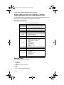 4
4
-
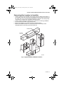 5
5
-
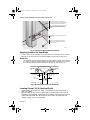 6
6
-
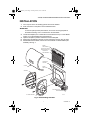 7
7
-
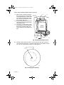 8
8
-
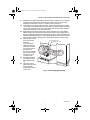 9
9
-
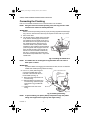 10
10
-
 11
11
-
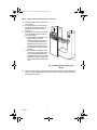 12
12
-
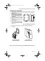 13
13
-
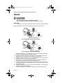 14
14
-
 15
15
-
 16
16
-
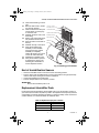 17
17
-
 18
18
-
 19
19
-
 20
20
-
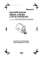 21
21
-
 22
22
-
 23
23
-
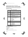 24
24
-
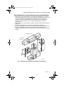 25
25
-
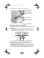 26
26
-
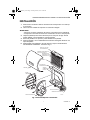 27
27
-
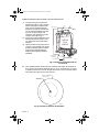 28
28
-
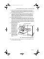 29
29
-
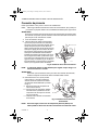 30
30
-
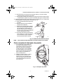 31
31
-
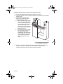 32
32
-
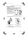 33
33
-
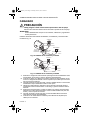 34
34
-
 35
35
-
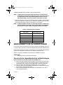 36
36
-
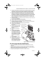 37
37
-
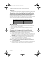 38
38
-
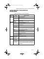 39
39
-
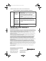 40
40


en otros idiomas
Artículos relacionados
Otros documentos
-
 Honeywell Home HE240D2001/U Guía del usuario
-
 Honeywell Home HE360 El manual del propietario
-
Honeywell Home Humidifier 480 El manual del propietario
-
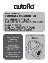 AutoFlo 250G El manual del propietario
-
Hamilton 12HF Guía de instalación
-
FIELD CONTROLS TM-2000 EVENMIST Humidifier Guía de instalación
-
-
Carel humiSteam UE010 Manual de usuario
-
Carel UC0650D000 Manual de usuario
-
Robertshaw J10-808 Y J10-821 Humidistat Manual de usuario


