Yamaha RX-V765 El manual del propietario
- Categoría
- Receptores AV
- Tipo
- El manual del propietario

RX-V765
AV Receiver
OWNER’S MANUAL
MANUAL DE INSTRUCCIONES
RL

Caution-i En
1 To assure the finest performance, please read this manual
carefully. Keep it in a safe place for future reference.
2 Install this sound system in a well ventilated, cool, dry, clean
place – away from direct sunlight, heat sources, vibration,
dust, moisture, and/or cold. Allow ventilation space of at least
30 cm on the top, 20 cm on the left and right, and 20 cm on
the back of this unit.
3 Locate this unit away from other electrical appliances, motors,
or transformers to avoid humming sounds.
4 Do not expose this unit to sudden temperature changes from
cold to hot, and do not locate this unit in an environment with
high humidity (i.e. a room with a humidifier) to prevent
condensation inside this unit, which may cause an electrical
shock, fire, damage to this unit, and/or personal injury.
5 Avoid installing this unit where foreign objects may fall onto
this unit and/or this unit may be exposed to liquid dripping or
splashing. On the top of this unit, do not place:
– Other components, as they may cause damage and/or
discoloration on the surface of this unit.
– Burning objects (i.e. candles), as they may cause fire,
damage to this unit, and/or personal injury.
– Containers with liquid in them, as they may fall and liquid
may cause electrical shock to the user and/or damage to
this unit.
6 Do not cover this unit with a newspaper, tablecloth, curtain,
etc. in order not to obstruct heat radiation. If the temperature
inside this unit rises, it may cause fire, damage to this unit,
and/or personal injury.
7 Do not plug in this unit to a wall outlet until all connections
are complete.
8 Do not operate this unit upside-down. It may overheat,
possibly causing damage.
9 Do not use force on switches, knobs and/or cords.
10 When disconnecting the power cable from the wall outlet,
grasp the plug; do not pull the cable.
11 Do not clean this unit with chemical solvents; this might
damage the finish. Use a clean, dry cloth.
12 Only voltage specified on this unit must be used. Using this
unit with a higher voltage than specified is dangerous and may
cause fire, damage to this unit, and/or personal injury. Yamaha
will not be held responsible for any damage resulting from use
of this unit with a voltage other than specified.
13 To prevent damage by lightning, keep the power cord and
outdoor antennas disconnected from a wall outlet or the unit
during a lightning storm.
14 Do not attempt to modify or fix this unit. Contact qualified
Yamaha service personnel when any service is needed. The
cabinet should never be opened for any reasons.
15 When not planning to use this unit for long periods of time
(i.e. vacation), disconnect the AC power plug from the wall
outlet.
16 Install this unit near the AC outlet and where the AC power
plug can be reached easily.
17 Be sure to read the “Troubleshooting” section on common
operating errors before concluding that this unit is faulty.
18 Before moving this unit, press AMAIN ZONE ON/OFF
to set this unit in the standby mode, and disconnect the AC
power plug from the wall outlet.
19 VOLTAGE SELECTOR (Asia and General models only)
The VOLTAGE SELECTOR on the rear panel of this unit
must be set for your local main voltage BEFORE plugging
into the AC wall outlet. Voltages are:
.......AC 110/120/220/230–240 V, 50/60 Hz (General model)
.......................... AC 220/230–240 V, 50/60 Hz (Asia model)
20 The batteries shall not be exposed to excessive heat such as
sunshine, fire or like.
21 Excessive sound pressure from earphones and headphones can
cause hearing loss.
22 When replacing the batteries, be sure to use batteries of the
same type. Danger of explosion may happen if batteries are
incorrectly replaced.
Caution: Read this before operating your unit.
WARNING
TO REDUCE THE RISK OF FIRE OR ELECTRIC
SHOCK, DO NOT EXPOSE THIS UNIT TO RAIN
OR MOISTURE.
As long as this unit is connected to the AC wall outlet,
it is not disconnected from the AC power source even
if you turn off this unit by AMAIN ZONE ON/
OFF. In this state, this unit is designed to consume a
very small quantity of power.

1 En
English
INTRODUCTION
APPENDIX
PREPARATION
BASIC
OPERATION
ADVANCED
OPERATION
Features.................................................................... 2
About this manual................................................... 3
Supplied accessories................................................ 3
Part names and functions....................................... 4
Front panel ................................................................. 4
Rear panel .................................................................. 5
Front panel display..................................................... 6
Remote control........................................................... 7
Quick start guide..................................................... 8
L
Preparing remote control ....................................... 9
Installing batteries in the remote control ................... 9
Using the remote control............................................ 9
Connections ........................................................... 10
Placing speakers....................................................... 10
Connecting speakers ................................................ 11
Information on jacks and cable plugs ...................... 14
Connecting a video monitor..................................... 15
Connecting other components ................................. 16
Connecting a multi-format player or an external
decoder................................................................. 18
Connecting an external amplifier............................. 18
Using REMOTE IN/OUT jacks............................... 19
Connecting a Yamaha iPod universal dock or
Bluetooth™ wireless audio receiver.................... 19
Connecting a camcorder or portable audio player ... 19
Connecting the FM and AM antennas ..................... 20
Connecting the power cable..................................... 20
Turning this unit on and off ..................................... 20
Optimizing the speaker setting for your
listening room (YPAO) ..................................... 21
Using Auto Setup..................................................... 21
When an error message is displayed during
measurement ........................................................ 23
When a warning message is displayed after
measurement ........................................................ 23
Playback................................................................. 24
Basic procedure........................................................ 24
Using the SCENE function ...................................... 24
Muting audio output temporarily (MUTE) .............. 25
Adjusting high/low frequency sound
(tone control) ....................................................... 25
Enjoying pure hi-fi sound (Pure Direct mode) ........ 25
Using your headphones............................................ 26
Displaying input signal information ........................ 26
Changing information on the front panel display .... 26
Enjoy the sound field programs ..........................27
Selecting sound field programs................................ 27
Enjoying unprocessed input sources
(Straight decoding mode) .................................... 30
Enjoying sound field programs without surround
speakers (Virtual CINEMA DSP) ....................... 30
Enjoy sound field programs with headphones
(SILENT CINEMA™) ........................................ 30
Enjoying more spatial sound fields
(CINEMA DSP 3D mode)................................... 30
FM/AM tuning ...................................................... 31
Tuning into the desired FM/AM station
(Frequency tuning mode)..................................... 31
Registering FM/AM stations and tuning in
(Preset tuning mode)............................................ 31
Using iPod™ ..........................................................33
Controlling iPod™................................................... 33
Using Bluetooth™ components ........................... 35
Pairing the Bluetooth™ wireless audio receiver
and your Bluetooth™ component........................ 35
Playback of the Bluetooth™ component ................. 35
Other functions ..................................................... 36
Using the sleep timer ............................................... 36
Using the HDMI™ control function........................ 36
Setting the option menu for each input source
(OPTION menu) ............................................... 37
OPTION menu items ............................................... 37
Outputting a video signal input from another
input source during reproducing a multi-channel
audio signal.......................................................... 39
Editing surround decoders/sound field
programs ........................................................... 40
Setting sound field parameters................................. 40
Sound field parameters ............................................ 40
Changing various settings of this unit
(SETUP menu) .................................................. 44
Basic operation of the SETUP menu ....................... 45
Speaker Setup .......................................................... 45
Sound Setup ............................................................. 47
Function Setup ......................................................... 48
DSP Parameter ......................................................... 50
Memory Guard......................................................... 50
Using multi-zone configuration ........................... 51
Connecting Zone2.................................................... 51
Controlling Zone2.................................................... 52
Controlling other components with the remote
control................................................................ 53
Setting remote control codes.................................... 53
Resetting all remote control codes........................... 54
Advanced setup..................................................... 55
Troubleshooting .................................................... 57
General..................................................................... 57
HDMI™................................................................... 60
Tuner (FM/AM) ....................................................... 61
Remote control......................................................... 61
iPod™ ...................................................................... 62
Bluetooth™.............................................................. 63
Auto Setup (YPAO)................................................. 63
Glossary ................................................................. 66
Sound field program information ....................... 68
Information on HDMI™...................................... 68
Specifications......................................................... 69
Index ...................................................................... 70
(at the end of this manual)
Contents
INTRODUCTION
PREPARATION
BASIC OPERATION
ADVANCED OPERATION
APPENDIX
List of remote control codes...................................i

2 En
INTRODUCTION
■ Built-in 7-channel power amplifier
• Minimum RMS Output Power (20 Hz-20 kHz, 0.08%
THD, 8 Ω)
• FRONT L/R: 95 W + 95 W
• CENTER: 95 W
• SURROUND L/R: 95 W + 95 W
• SURROUND BACK L/R: 95 W + 95 W
■ Speaker/Preout outputs
• Speaker jacks (7-channel + presence 2-channel), preout
output jacks (7-channel, and subwoofer preout jack x 2)
■ Input/Output terminals
Input terminals
• HDMI input x 4
• Audio/Video input
[Audio] Digital input (coaxial) x 2, digital input
(optical) x 2, analog input x 2
[Video] Component video x 2, composite video x 4
• Audio input (analog) x 2
• Phono input x 1
• Multi-channel audio input x 1
• Dock input x 1
• V-AUX input
[Audio] Analog x 1, stereo mini jack x 1
[Video] Composite video x 1
Output terminals
• Monitor output
[Audio/Video] HDMI x 1
[Video] Component video x 1, Composite video x 1
• Audio/Video output
[Audio] Analog x 1
[Video] Composite video x 1
• Audio output
Analog x 1
• Zone2 output
Analog x 1
Other terminals
Remote input x 1, Remote output x 1
Trigger output x 1
■ Proprietary Yamaha technology for the
creation of sound fields
• CINEMA DSP 3D
• Compressed Music Enhancer mode
• Virtual CINEMA DSP
• SILENT CINEMA™
■ Digital audio decoders
• Dolby TrueHD, Dolby Digital Plus
• DTS-HD Master Audio, DTS-HD High Resolution
Audio, DTS Express
• Dolby Digital, Dolby Digital EX
• DTS, DTS 96/24, DTS-ES Matrix 6.1,
DTS-ES Discrete 6.1
• Dolby Pro Logic, Dolby Pro Logic II,
Dolby Pro Logic IIx
• DTS NEO:6
• DSD
■ Sophisticated FM/AM tuner
• 40-station random and direct preset tuning
• Automatic preset tuning
■ HDMI™
(High-Definition Multimedia Interface)
• HDMI interface for standard, enhanced or high-
definition video as well as multi-channel digital audio
– Automatic audio and video synchronization (lip sync)
information capability
– Deep Color video signal (30/36 bit) transmission
capability
– “x.v.Color” video signal transmission capability
– High refresh rate and high resolution video signals
capability
– High definition digital audio format signals capability
• Analog video to HDMI digital video up-conversion
(composite video → HDMI, component video →
HDMI) capability for monitor out
• Analog video input up-scaling for HDMI digital video
output 480i or 480p → 720p, 1080i or 1080p (NTSC),
576i or 576p → 720p, 1080i or 1080p (PAL)
• HDMI control capability
■ DOCK jack
• DOCK jack to connect a Yamaha iPod universal dock
(such as YDS-11, sold separately) or Bluetooth wireless
audio receiver (such as YBA-10, sold separately)
■ Automatic speaker setup features
• “YPAO” (Yamaha Parametric Room Acoustic
Optimizer) for automatically optimizing speaker
outputs suitable for listening environments
■ Other features
• 192-kHz/24-bit D/A converter
• OSD (on-screen display) menus that allow you to
optimize this unit to suit your individual audiovisual
system
• Pure Direct mode for pure hi-fi sound for all sources
• Adaptive dynamic range controlling capability
• SCENE function that allows you to change input
sources and sound field programs with one key
• Sleep timer
• Multi-zone function
Features

3 En
English
INTRODUCTION
ADDITIONAL
INFORMATION APPENDIX
PREPARATION
BASIC
OPERATION
ADVANCED
OPERATION
Manufactured under license from Dolby Laboratories.
Dolby, Pro Logic and the double-D symbol are trademarks of Dolby
Laboratories.
Manufactured under license under U.S. Patent No’s:
5,451,942;5,956,674;5,974,380;5,978,762;6,226,616;6,487,535 &
other U.S. and worldwide patents issued & pending. DTS is a
registered trademark and the DTS logos, Symbol, DTS-HD and DTS-
HD Master Audio are trademark of DTS, Inc. © 1996-2007 DTS, Inc.
All Rights Reserved.
iPod™
“iPod” is a trademark of Apple Inc., registered in the U.S. and other
countries.
Bluetooth™
Bluetooth is a registered trademark of Bluetooth SIG and is used by
Yamaha in accordance with a license agreement.
“HDMI,” the “HDMI” logo and “High-Definition Multimedia
Interface” are trademarks, or registered trademarks of HDMI
Licensing LLC.
x.v.Color™
“x.v.Color” is a trademark of Sony Corporation.
“SILENT CINEMA” is a trademark of Yamaha Corporation.
Check that you received all of the following parts.
• Remote control (see page 9)
• Batteries (AAA, R03, UM-4) x 2 (see page 9)
• Optimizer microphone (see page 21)
• AM loop antenna (see page 20)
• Indoor FM antenna (see page 20)
• Controls diagram
About this manual
• Some operations can be performed by using either the keys on the front panel or the ones on the remote control. In case the key names differ between
the front panel and the remote control, the key name on the remote control is given in parentheses.
• This manual is printed prior to production. Design and specifications are subject to change in part as a result of improvements, etc. In case of
differences between the manual and product, the product has priority.
• “AMAIN ZONE ON/OFF” or “eHDMI 1” (example) indicates the name of the parts on the front panel or the remote control. Refer to the
“Controls diagram” or “Part names and functions” on page 4 for the information about each position of the parts.
• y indicates a tip for your operation.
• ☞ indicates the page describing the related information.
Supplied accessories

4 En
A MAIN ZONE ON/OFF
Turns this unit on and off (see page 20).
B PHONES jack
For connecting headphones (see page 26).
C ZONE2 ON/OFF
Switches Zone2 between on and off (see page 52).
D HDMI THROUGH
During standby, lights up under the following conditions:
• the HDMI control function is enabled (see page 48).
• an HDMI signal input to this unit passes through this unit and
output (see page 48).
E ZONE2 CONTROL
Enables operation of a receiver set in Zone2, including input
source switching, volume control and tuner operation, with the
main amplifier or remote control after this key is pressed.
F INFO
Changes information on the front panel display, such as input
source and sound field program name (see page 26).
G MEMORY
Registers FM/AM stations as preset stations (see page 32).
H PRESET l / h
Selects an FM/AM preset station (see page 32).
I FM/AM
Changes the tuner bands between FM and AM.
J TUNING l / h
Changes FM/AM frequencies.
K Front panel display
Displays information on this unit (see page 6).
L VOLUME control
Controls the volume of this unit (see page 24).
M SCENE
Switches between linked sets of input sources and sound field
programs (see page 24).
N TONE CONTROL
Adjusts high-frequency/low-frequency output of speakers/
headphones (see page 24).
O PROGRAM selector
Changes sound field programs (see page 27).
P STRAIGHT
Toggles between the selected sound field program and straight
decoding mode (see page 30).
Q PURE DIRECT
Changes mode to Pure Direct mode (see page 25). This key
lights up when Pure Direct mode is on.
R INPUT selector
Selects an input source (see page 24).
S OPTIMIZER MIC jack
For connecting the supplied optimizer microphone and adjusting
output characteristics of speakers (see page 21).
T VIDEO (VIDEO AUX) jack
For connecting the video output cable of a camcorder or game
console (see page 19).
U AUDIO L/R (VIDEO AUX) jack
For connecting the audio output cable of a camcorder or game
console (see page 19).
V PORTABLE (VIDEO AUX) jack
For connecting the audio output cable of a portable music player
(see page 19).
Part names and functions
Front panel
TUNING
PHONES
SILENT
CINEMA
TONE
CONTROL
STRAIGHT
PROGRAM INPUT
PURE DIRECT
OPTIMIZER
MIC
VIDEO
AUDI O
PORTABLE
THROUGH
INFO
MEMORY
VIDEO
AUX
VOLUME
HDMI
EFFECT
PRESET
l
h
l
h
BD/DVD
TV
CD
RADIO
SCENE
ZONE2
ON/OFF
ZONE2
CONTROL
ON/OFF
FM AM
MAIN
ZONE
E
N Q SO R
D
K
C
L
GF JIH
M
U VTP
AB

5 En
Part names and functions
English
INTRODUCTION
ADDITIONAL
INFORMATION APPENDIX
PREPARATION
BASIC
OPERATION
ADVANCED
OPERATION
a DOCK jack
For connecting a Yamaha iPod universal dock (YDS-11, sold
separately) or a Bluetooth wireless audio receiver (YBA-10,
sold separately) (see page 19).
b PHONO jacks
For connecting a turntable (see page 17).
c ANTENNA jacks
For connecting supplied FM and AM antennas (see page 20).
d HDMI OUT/HDMI 1-4 jacks
For connecting an HDMI-compatible video monitor or external
components for HDMI inputs 1-4 (see page 16).
e REMOTE IN/OUT jacks
For connecting an external component that supports the remote
control function (see page 19).
f TRIGGER OUT jack
For connecting an external terminal with a trigger input terminal
to operate it linked with operation of this unit. For example,
when an electric screen that supports a trigger input is
connected, it opens and closes linked with operation of an input
source selected in this unit.
g SPEAKERS terminals
For connecting front right and left, center, surround and
surround back speakers (see page 11). Connect the presence
speakers (see page 12) or the speakers for Zone2 (see page 51)
to the EXTRA SP jacks.
h Power Cable
Connect this cable to an AC wall outlet (see page 20).
i AV 1-6 jacks
For connecting external components for audio/video inputs 1-6
(see page 16).
j AV OUT jacks
Outputs audio/video signals from a selected analog input source
to an external component (see page 17).
k AUDIO 1/2 jacks
For connecting external components for audio inputs 1-2
(see page 17).
l MONITOR OUT terminals
Outputs video signals from this unit to a video monitor, such as
a TV (see page 15).
m MULTI CH INPUT terminals
For connecting a player that supports a multi-channel output
(see page 18).
n AUDIO OUT jacks
Outputs audio signals from a selected analog input source to an
external component (see page 17).
o ZONE2 OUT jacks
Outputs sound of this unit to an external amplifier set in a
different zone.
p PRE OUT terminals
For connecting a subwoofer with built-in amplifier (see page 11)
or an external power amplifier (see page 18).
q VOLTAGE SELECTOR (Asia and General models
only)
Selects the switch position according to your local voltage
(see page 20).
Rear panel
ZONE2
OUT
TRIGGER OUT
12V
0.1A MAX.
ANTENNAPHONO
UNBAL.
FM
GND
GND
AM
COMPONENT
VIDEO
PR
PB
Y
IN
OUT
REMOTE
EXTRA SP
ZONE2
/
PRESENCE
VOLTAGE
SELECTOR
MONITOR OUT
SPEAKERS
ZONE2
COMPORNENT
VIDEO
SINGLE
PR
PB
Y
OPTICAL
(
TV
)
A
V
1
AV 2
COAXIAL
AV 3
(
CD
)
COAXIAL
OPTICAL
AV 4
AV 5
AV 6
AV
OUT
AUDI O1
AUDIO2
FRONT
SURROUND
SUR.BACK
SUBWOOFER
MULTI CH INPUT
AUDIO
OUT
FRONT
SURROUND
SUR. BACK
SUBWOOFER
PRE OUT
CENTER
VIDEO
HDMI
HDMI 1 HDMI 2 HDMI 3 HDMI 4
(
BD/DVD
)
VIDEO
FRONT
CENTER
SURROUND
SURROUND BACK/
BI-AMP
SINGLE
1
2
CENTER
OUT
DOCK
a
d
b
c
g
e
ij mknop q
h
l
f

6 En
Part names and functions
a HDMI indicator
Lights up during normal communication when HDMI is
selected as an input source.
b CINEMA DSP indicator
Lights up when a sound field program that uses CINEMA DSP
is selected.
c CINEMA DSP 3D indicator
Lights up when CINEMA DSP 3D is activated.
d Tuner indicator
Lights up during receiving radio broadcast signals from an FM/
AM station (see page 31).
e ZONE2 indicator
Lights up when Zone2 is turned on (see page 51).
f SLEEP indicator
Lights up when the sleep timer is activated (see page 36).
g MUTE indicator
Flashes when audio is muted.
h VOLUME indicator
Displays volume levels.
i Cursor indicators
Light up when corresponding cursors on the remote control are
available for operations.
j Multi information display
Displays menu items and settings for the current operation.
k Speaker indicators
Indicate speaker terminals from which signals are currently
output.
Front panel display
STEREO
SLEEP
VOL.
TUNED
PL PR
SW
C
LR
SL SR
SBL SB SBR
MUTE
3
ZONE
2
abcdfehg
ij ki
SW
C
LR
SL SR
SBL SB SBR
PL PR
Subwoofer
Front L
Surround L
Surround back L
Center
Front R
Surround R
Surround back R
Surround back
Presence L Presence R

7 En
Part names and functions
English
INTRODUCTION
ADDITIONAL
INFORMATION APPENDIX
PREPARATION
BASIC
OPERATION
ADVANCED
OPERATION
a Remote control signal transmitter
Transmits infrared signals.
b MAIN/ZONE2
Switches the zone to be operated by the remote control between
the Main zone and Zone2 (see page 52).
c TRANSMIT
Lights up when a signal is output from the remote control.
d SOURCE POWER
Switches an external component on and off.
e Input selection keys
f Tuner keys
g INFO
Changes information on the front panel display, such as input
source and sound field program name (see page 26).
h Sound selection keys
Selects sound field programs (see page 27).
i SCENE
Switch between linked sets of input sources and sound field
programs (see page 24).
j SETUP
Displays the SETUP menu (see page 45).
k Cursors k / n / l / h/ENTER/RETURN
l External component operation keys
Operate recording, playback etc. of external components
(see page 53).
m Numeric keys
Enter numbers.
n TV control keys
Enable operations of a monitor such as a TV and a projector.
o CODE SET
Sets remote control codes for external component operations
(see page 53).
p POWER
Switches this unit on and standby.
q SLEEP
Switches the sleep timer operations (see page 36).
r OPTION
Displays the OPTION menu (see page 37).
s VOLUME +/–
Adjust the volume of this unit (see page 24).
t DISPLAY
Changes the operation mode of the iPod connected to the
Yamaha iPod universal dock (see page 33).
u MUTE
Turns the mute function of the sound output on and off
(see page 25).
Remote control
HDMI 1-4
Select HDMI inputs 1 through 4.
AV 1-6
Select AV inputs 1 through 6.
AUDIO 1/2
Select AUDIO inputs 1 and 2.
V-AUX
Selects the V-AUX jack on the front panel of this
unit.
MAIN
POWER
1234
1256
1234
7856
90
10
1234
POWER
SOURCE
V-AUX PHONO
[ A ] DOCK
MULTI
TUNER
FM
MOVIE
BD
DVD
TOP
MENU
MUSIC
SCENE
TV
CD
OPTIONSETUP
RETURN
REC
ENT
POWER
TV
TV VOL
INPUT
MUTE
TV CH
ENTER
VOLUME
DISPLAY
MUTE
MENU
RADIO
STEREO
ENHANCER SUR. DECODE
PURE DIRECT
STRAIGHT
INFO
MEMORY
AM
PRESET
TUNING
SLEEP
HDMI
AV
AUDIO
ZONE2
TRANSMIT
CODE SET
a
b
c
d
q
p
e
h
i
j
r
s
t
m
n
o
f
g
u
l
k
PHONO
Selects a component such as a turntable that is
connected to the PHONO jack on the rear panel
as an input source.
[A]
To control external components using the
lExternal component operation
keys separately from operations of this unit
(see page 53).
DOCK
Selects a Yamaha iPod universal dock/Bluetooth
wireless audio receiver connected to the DOCK
jack.
TUNER
Selects the FM/AM tuner.
MULTI
Selects a signal input from the MULTI CH
INPUT jack on the rear panel as an input source.
FM
Select the FM band or AM band.
AM
MEMORY
Presets radio stations.
PRESET k / n
Select a preset station.
TUNING k / n
Change tuning frequencies.
Cursors k / n / l / h
Select menu items displayed on the
front panel display or on a video
monitor, or change settings.
ENTER
Confirms a selected item.
RETURN
Returns to the previous screen or
ends the menu display.

8 En
When you use this product for the first time, perform the steps below. See the related pages for details of operations and
settings.
Prepare speakers, DVD player, cables, and other items
necessary for setup.
For example, prepare the following items for setting up a
7.1-channel sound system.
y
• Prepare at least two (front) speakers. Speakers other than front speakers
may be used in the following order of preference:
1 Two surround speakers
2 One center speaker
3 One or two surround back speakers
• If your video monitor is a CRT, we recommend that you use magnetically
shielded speakers.
• An audio cable is not required when you use an HDMI cable.
Place your speakers in the room and connect them to this
unit.
y
• This unit has a YPAO (Yamaha Parametric Room Acoustic Optimizer)
that automatically optimizes this unit based on room acoustic
characteristics (audio characteristics of the speakers, speaker positions,
and room acoustics, etc.).
You can enjoy good balanced sound without special knowledge by using
the YPAO technology (see page 21).
Connect your TV, DVD player, or other components.
Connect the power cable and turn on this unit.
Select the component connected in the step 3 as an input
source and start playback.
y
• This unit supports the SCENE function that changes the input source and
sound field program at one time. Four SCENE are preset for different
purposes for Blu-ray disc, DVD and CD. You can select a SCENE from
those just by pressing a remote control key. See page 24 for details.
Quick start guide
Step 1: Prepare items for setup
Requirements qty.
Speakers Front speaker 2
Center speaker 1
Surround speaker 2
Surround back speaker 2
Active subwoofer 1
Speaker cable 5
Subwoofer cable 1
Reproduction component such as DVD player 1
Video monitor such as TV 1
Video cable or HDMI cable 2
Audio cable 2
Components
(such as DVD player)
Center speaker
Front left speaker
Front right speaker
Subwoofer
Video monitor
Surround right speaker
Surround left speaker
Surround back right
speaker
Surround back left
speaker
Step 2: Set up your speakers
• Placing speakers ☞P. 1 0
• Connecting speakers ☞P. 1 1
Step 3: Connect your components
• Connecting a video monitor ☞P. 1 5
• Connecting other components ☞P. 1 6
• Connecting a multi-format player or an
external decoder ☞P. 1 8
• Connecting an external amplifier ☞P. 1 8
• Connecting a Yamaha iPod universal
dock or Bluetooth wireless audio receiver ☞P. 1 9
• Connecting the FM and AM antennas ☞P. 2 0
Step 4: Turn on the power
• Connecting the power cable ☞P. 2 0
• Turning this unit on and off ☞P. 2 0
Step 5: Select the input source and start
playback
• Basic procedure ☞P. 2 4
• Selecting sound field programs ☞P. 2 7

9 En
English
INTRODUCTION
ADDITIONAL
INFORMATION APPENDIX
PREPARATION
BASIC
OPERATION
ADVANCED
OPERATION
PREPARATION
1 Take off the battery compartment cover.
2 Insert the two supplied batteries (AAA, R03,
UM-4) according to the polarity markings (+
and –) on the inside of the battery
compartment.
3 Snap the battery compartment cover back
into place.
Notes
• Change all batteries if you notice the following conditions:
– the operation range of the remote control narrows.
– the transmit indicator does not flash or is dim.
• Do not use old batteries together with new ones.
This may shorten the life of the new batteries or cause old batteries
to leak.
• Do not use different types of batteries (such as alkaline and
manganese batteries) together. Specification of batteries may be
different even though they look the same.
• If you find leaking batteries, discard the batteries immediately,
taking care not to touch the leaked material. If the leaked material
comes into contact with your skin or gets into your eyes or mouth,
rinse it away immediately and consult a doctor. Clean the battery
compartment thoroughly before installing new batteries.
• Dispose of the old batteries correctly in accordance with your local
regulations.
• If the remote control is without batteries for more than 2 minutes,
or if exhausted batteries remain in the remote control, the contents
of the memory may be cleared. In such a case, install new batteries
and set the remote control code.
The remote control transmits a directional infrared ray. Be
sure to aim the remote control directly at the remote
control sensor on this unit during operation.
Notes
• Do not spill water or other liquids on the remote control.
• Do not drop the remote control.
• Do not leave or store the remote control in the following conditions:
– places of high humidity, such as near a bath
– places of high temperatures, such as near a heater or stove
– places of extremely low temperatures
– dusty places
y
• You can operate external components with this remote control by setting
the remote control code. See page 53 for details.
Preparing remote control
Installing batteries in the remote
control
1
3
2
Using the remote control
30 30
Remote control sensor window
within 6 m

10 En
This unit supports up to 7.1-channel surround playback. We recommend the following speaker layout in order to obtain
the optimum surround effect.
7.1-channel speaker layout
6.1-channel speaker layout
5.1-channel speaker layout
■ Front left and right speakers (FL and FR)
The front speakers output the front channel sounds (stereo
sound) and effect sounds. Place these speakers at an equal
distance from the ideal listening position. When using a
screen, the appropriate top positions of the speakers are
about 1/4 of the screen from the bottom.
■ Center speaker (C)
The center speaker outputs the center channel sounds
(dialog, vocals, etc.). Place it halfway between the left and
right speakers. When using a TV, place the speaker just
above or just under the center of the TV with the front
surfaces of the TV and the speaker aligned. When using a
screen, place it just under the center of the screen.
■ Surround left and right speakers (SL and SR)
The surround speakers output effect sounds and surround
sounds. Place them at the rear left and rear right facing the
listening position.
To obtain a natural sound flow in the 5.1-channel speaker
layout, place them slightly further back than in the 7.1-
channel speaker layout.
■ Surround back left and right speakers (SBL
and SBR) / Surround back speaker (SB)
The surround back left and right speakers output rear
effect sounds. Place them at the rear of the room facing the
listening position at least 30 cm away from each other,
ideally at the same distance as that between the front left
and right speakers.
In the 6.1-channel speaker layout, surround back left and
right channel sound signals are mixed down and output
from the single surround back speaker.
In the 5.1-channel speaker layout, surround back left and
right channel sound signals are output from the surround
left and right speakers.
■ Subwoofer (SW)
The subwoofer speaker outputs bass sounds and low-
frequency effect (LFE) sounds included in Dolby Digital
and DTS signals. Use a subwoofer with a built-in
amplifier, such as the Yamaha Active Servo Processing
Subwoofer System. Place it exterior to the front left and
right speakers facing slightly inward to reduce reflections
from a wall.
Connections
Placing speakers
60˚
30˚
SBR
SBL
FL
FR
C
SL
SR
SR
80˚
SL
SW
SW
30 cm or more
60˚
30˚
SB
FL
FR
C
SL
SR
SR
80˚
SL
SW
SW
60˚
30˚
FL
FR
C
SL
SR
SR
80˚
SL
SW
SW
Speaker channels

11 En
Connections
English
INTRODUCTION
ADDITIONAL
INFORMATION APPENDIX
PREPARATION
BASIC
OPERATION
ADVANCED
OPERATION
When you connect speakers, connect them to the respective jacks as follows, according to your speaker layout.
y
• You can connect up to two subwoofers. When two subwoofers are connected, the same sound is output from them.
■ 7.1-channel
■ 6.1-channel
■ 5.1-channel
Connecting speakers
Speakers Jacks on this unit
a Front speaker L FRONT (L)
b Front speaker R FRONT (R)
c Center speaker CENTER
d Surround speaker L SURROUND (L)
e Surround speaker R SURROUND (R)
f Surround back speaker L SURROUND
BACK/BI-AMP (L)
g Surround back speaker R SURROUND
BACK/BI-AMP (R)
h Subwoofer 1 SUBWOOFER 1
i Subwoofer 2 (optional) SUBWOOFER 2
EXTRA SP
ZONE2
/
2
PRESENCE
S
PEAKER
S
SUBWOOFER
T
FRONT
CENTER
SURROUND
SURROUND BACK/
BI-AMP
SINGLE
1
2
OUT
.
EXTRA SP
ZONE2
/
2
PRESENCE
Z
ONE
2
ZONE2
SINGL
E
R.BA
C
K
S
UBW
OO
FER
N
PU
T
A
UDI
O
OUT
F
R
O
NT
SU
RR
OU
ND
SU
R. BA
C
K
PRE OU
T
C
ENTER
C
ENTE
R
e d
b
a
g
f
c
h
i
Speakers Jacks on this unit
a Front speaker L FRONT (L)
b Front speaker R FRONT (R)
c Center speaker CENTER
d Surround speaker L SURROUND (L)
e Surround speaker R SURROUND (R)
f Surround back speaker SURROUND
BACK/BI-AMP (SINGLE)
h Subwoofer 1 SUBWOOFER 1
i Subwoofer 2 (optional) SUBWOOFER 2
Speakers Jacks on this unit
a Front speaker L FRONT (L)
b Front speaker R FRONT (R)
c Center speaker CENTER
d Surround speaker L SURROUND (L)
e Surround speaker R SURROUND (R)
h Subwoofer 1 SUBWOOFER 1
i Subwoofer 2 (optional) SUBWOOFER 2

12 En
Connections
You can connect presence speakers (PL/PR) that output
front effect sounds to this unit. With CINEMA DSP sound
field programs (see page 27) and their CINEMA DSP 3D
functions, a sound with a richer and more spacial presence
can be created. You can adjust the vertical position of
center sound such as a dialog (see page 45).
To use the presence speakers, connect them to the EXTRA
SP jacks and set “Extra SP Assign” in “Speaker Setup” in
the SETUP menu to “Presence” (see page 45).
y
• Although you can connect both surround back speakers and presence
speakers to this unit, you cannot output sounds from those speakers at the
same time. This unit automatically selects speakers to output sounds
according to the selected input source and sound field program.
• You can connect Zone2 speakers with a multi-zone function to the
EXTRA SP jacks. For details, see page 51.
Presence speakers
FR
PRPL
C
FL
0.5 to 1 m0.5 to 1 m
1.8 m 1.8 m
EXTRA SP
ZONE2
/
PRESENCE
X.
DMI
3
HDMI
4
FR
O
NT
C
ENTER
S
URR
O
UND
S
URR
O
UND BA
C
K
/
BI
-
AMP
PR
PL
Presence
speaker L
Presence
speaker R

13 En
Connections
English
INTRODUCTION
ADDITIONAL
INFORMATION APPENDIX
PREPARATION
BASIC
OPERATION
ADVANCED
OPERATION
1 Remove approximately 10 mm of insulation
from the end of each speaker cable and then
twist bare wires of the cable together so that
they will not cause a short circuits.
2 Loosen the knob, insert the twisted bare
wires into the hole, and then tighten the
knob.
y
• You can connect the presence speakers (see page 12) or the speakers in
the second zone (Zone2) (see page 51) to the EXTRA SP jacks.
You can connect speakers that support bi-amplification
connections to this unit. To connect the speakers via a bi-
amp connection, connect them to the FRONT jacks and
SURROUND BACK/BI-AMP jacks as illustrated.
To enable the bi-amp connection, connect the power cable
to the wall outlet, display the ADVANCED SETUP menu
and set “BI AMP” to “ON” (see page 55).
Note
• You cannot use surround back speakers or extra speakers (presence and
Zone2 speakers) when bi-amplification connections are made.
Connecting the speaker cable
Caution
• A speaker cable is a pair of insulated cables running side by side in general. One of the cables is colored differently
or striped to indicate a polarity. Connect one end of the colored/striped cable to the “+” (red) terminal of this unit
and the other end to that of your speaker, and connect one end of the other cable to the “–” (black) terminal of this
unit and the other end to that of your speaker.
• Before connecting the speakers, be sure to disconnect the power cable.
• Do not let the bare speaker wires touch each other or any metal part of this unit. This could damage this unit and/or
speakers. If the circuit shorts out, “CHECK SP WIRES!” appears on the front panel display when this unit is turned
on.
• If your video monitor is a CRT, use magnetically shielded speakers. If images on the monitor are still distorted even
when you use the magnetically shielded speakers, place the speakers away from the monitor.
• Use speakers with an impedance of 6-ohm or larger. Set speaker impedance in “ADVANCED SETUP” before
connecting the speakers. You can also use 4-ohm speakers as the front speakers when you set “SP IMP.” to
“6ΩMIN” (see page 55).
Connecting the banana plug (Except U.K.,
Europe, Russian, Asia and Korea models)
Tighten the knob, and then insert the banana plug into
the end of the terminal.
10 mm
1
2
3
Red: positive (+)
Black: negative (–)
Banana plug
Using bi-amplification connections
Caution
Before making bi-amplification connections, remove
any brackets or cables that connect a woofer with a
tweeter. Refer to the instruction manuals of speakers for
details.
When not making bi-amplification connections, make
sure that the brackets or cables are connected before
connecting the speaker cables.
FRONT
SURROUND BACK/
BI-AMP
SINGLE
Front speakers
Right Left
This unit

14 En
Connections
This unit has the following input and output jacks. Use jacks and cables appropriate for components that you are
connecting.
■ Audio jacks
■ Video jacks
■ Video/audio jacks
y
• We recommend that you use a commercially available 19-pin HDMI
cable no longer than 5 meters (16 feet) with the HDMI logo printed on it.
• If you connect this unit to a component that has a DVI jack, an HDMI/
DVI-D cable is required.
• You can check error information on HDMI connections (see page 38).
Information on jacks and cable plugs
Jack and cables Description
AUDIO jacks To transmit conventional analog
(stereo) signals. Use stereo pin
cables. Connect red plugs to red
jacks (R) and white plugs to white
jacks (L).
COAXIAL jacks To transmit coaxial digital audio
signals. Use pin cables for digital
audio signals.
OPTICAL jacks To transmit optical digital audio
signals. Use optical fiber cables for
optical digital audio signals.
Jack and cables Description
VIDEO jacks To transmit conventional
composite video signals. Use video
pin cables.
COMPONENT VIDEO
jacks
To transmit component video
signals that include luminance (Y),
chrominance blue (PB) and
chrominance red (PR) components.
Use component video cables.
AUDIO
L
R
(white)
(red)
COAXIAL
C
(orange)
OPTICAL
O
VIDEO
V
(yellow)
PR
PB
Y
COMPONENT
VIDEO
P
B
Y
P
R
(red)
(blue)
(green)
Jack and cables Description
HDMI jacks To transmit digital video and
digital audio signals. Use HDMI
cables.
A video signal input to this unit is output from the jacks
in MONITOR OUT for the same kind of signal as the
input signal.
For example, if a VCR with a composite output signal
and a DVD player with a component video output
signal are connected, connect both VIDEO jack and
COMPONENT VIDEO jack in MONITOR OUT to the
video monitor.
If an HDMI input compatible monitor is connected, this
unit automatically converts an analog signal that is
input from a video input jack to a digital video signal,
and then outputs it from the HDMI OUT jack.
HDMI
HDMI
HDMI
VIDEO
COMPONENT
VIDEO
Y
PB
PR
HDMI
VIDEO
COMPONENT
VIDEO
Y
PB
PR
Input Output
Not converted Converted

15 En
Connections
English
INTRODUCTION
ADDITIONAL
INFORMATION APPENDIX
PREPARATION
BASIC
OPERATION
ADVANCED
OPERATION
Connect a video monitor such as a TV or projector to an output jack of this unit. You can select one of the following three
types according to the input signal format supported by the video monitor: HDMI OUT, COMPONENT VIDEO and
VIDEO (composite video).
Note
• Make sure that this unit and video monitor are unplugged from the AC wall outlets.
■ To connect an HDMI video monitor
y
• This unit supports the HDMI control function. By connecting a TV that
supports the HDMI control, operations of this unit can be controlled with
the remote control of the TV. For details, see page 36.
■ To connect component video monitor
Note
• Only video signals input from this unit via the COMPONENT VIDEO
jack are output from the COMPONENT VIDEO jack.
■ To connect composite video monitor
Note
• Only video signals input from this unit via the VIDEO jacks are output
from the VIDEO jacks.
To output sound of a TV from this unit, connect an audio
output terminal of the TV to any of the AV 1-6 jacks.
If the TV supports an optical digital output, we
recommend that you use the AV 1. Connecting to the AV 1
allows you to switch an input source to the AV input 1
with a just a single key operation using the SCENE
function (see page 24).
Note
• If the video monitor connected to this unit supports the HDMI control
function, we recommend that you connect its audio output jack to the
OPTICAL jack of the AV1 jacks of this unit. By doing so, this unit
automatically turns on and “TV” of SCENE is automatically selected
when you turn on the video monitor. You can obtain the same result even
if you connect the audio output jacks to the AV2-6, AUDIO1-2 or V-
AUX jacks by assigning those jacks to TV in advance (see page 24).
Connecting a video monitor
Jacks on components Jacks on this unit
a HDMI input HDMI OUT
Jacks on components Jacks on this unit
b Component video output MONITOR OUT
(COMPONENT VIDEO)
Jacks on components Jacks on this unit
c Video input (composite) MONITOR OUT (VIDEO)
P
R
P
B
Y
MONITOR OUT
COMPORNENT
VIDEO
HDMI
VIDEO
OUT
T
RIGGER OU
T
12
V
0
.1
A
MAX
.
ANTENNA
P
H
O
N
O
UNBAL
.
FM
G
ND
G
ND
A
M
IN
OUT
R
EM
O
T
E
E
O
HDMI
1
HDMI
2
HDMI
(
BD
/
DVD
)
V
c
b
P
B
YP
R
HDMI
a
TV or projector
Outputting sound of a TV from this unit
OPTICAL
(
TV
)
A
V
1
ANTENNA
P
H
O
N
O
UNBAL.
FM
G
N
D
G
ND
A
M
CO
MP
O
NEN
T
VIDE
O
P
R
P
B
Y
MO
NIT
O
R
O
U
T
CO
MP
O
RNEN
T
V
IDE
O
P
R
P
B
Y
AV 2
CO
AXIAL
AV
3
(
CD
)
CO
AXIAL
O
PTI
C
AL
AV 4
AV
5
AV
6
AV
OU
T
AUDI
O
1
A
UDIO
2
FR
ON
V
IDE
O
V
IDE
O
Digital output
(optical)
TV or projector

16 En
Connections
This unit has input and output jacks for respective input and output sources. You can reproduce sound and movies from
input sources selected with the front panel display or remote control.
Note
• Make sure that this unit and other components are unplugged from the AC wall outlets.
■ Audio and video player/Set-top box
y
• Input sources in parentheses are recommended to connect to the respective jacks. If a component is compatible with the SCENE function, you can switch
the input source to that component with a single key operation using the SCENE function (see page 24).
• You can change the name of the input source displayed on the front panel display or the video monitor as necessary (see page 50).
• See page 51 on how to use ZONE2 OUT jack.
Connecting other components
Output jacks on the connected external component
Input sources/jacks of this unit
External
components
Signals Output jacks
External component
with HDMI output
Audio/Video HDMI output HDMI1 (BD/DVD) HDMI 1
HDMI2 HDMI 2
HDMI3 HDMI 3
HDMI4 HDMI 4
External component
with component video
output
Audio Optical digital output AV1 (TV) OPTICAL
Video Component video output COMPONENT VIDEO
Audio Coaxial digital output AV2 COAXIAL
Video Component video output COMPONENT VIDEO
External component
with composite video
output
Audio Coaxial digital output AV3 (CD) COAXIAL
Video Composite video output VIDEO
Audio Optical digital output AV4 OPTICAL
Video Composite video output VIDEO
Audio Analog audio output AV5 AUDIO
Video Composite video output VIDEO
Audio Analog audio output AV6 AUDIO
Video Composite video output VIDEO
TRIGGER
OUT
PHONO
GND
COMPONENT
VIDEO
P
R
P
B
Y
OPTICAL
(
TV
)
AV 1
AV 2
COAXIAL
AV 3
(
CD
)
COAXIAL
OPTICAL
AV 4
AV 5
AV 6
AV
OUT
AUDIO1
AUDIO2
FRONT
SURROUND
SUR.BACK
SUBWOOFER
MULTI CH INPUT
AUDIO
OUT
VIDEO
HDMI 1 HDMI 2 HDMI 3 HDMI 4
(
BD/DVD
)
CENTER
OU
T
TRIGGER OUT
12V
0
.1A MAX.
ANTENNA
U
NBAL.
FM
G
ND
AM
P
R
P
B
Y
IN
OU
T
REM
O
TE
MO
NIT
O
R
O
U
T
Z
O
NE
2
ZONE2
CO
MP
O
RNEN
T
V
IDE
O
HDMI
HDMI
VIDE
O
FR
O
N
T
C
OUT
OUT
DOCK
Audio/video input
(AV 1-6)
Audio/video output (AV OUT)
Audio input (AUDIO 1-2)
HDMI input
(HDMI 1-4)
Audio output
(AUDIO OUT)
Multi channel audio input (MULTI CH)
Phono input
(PHONO)

17 En
Connections
English
INTRODUCTION
ADDITIONAL
INFORMATION APPENDIX
PREPARATION
BASIC
OPERATION
ADVANCED
OPERATION
■ Audio player
y
• When connecting a turntable with a low-output MC cartridge to the PHONO jack, use an in-line boosting transformer or MC-head amplifier.
• Connect your turntable to the GND terminal of this unit to reduce noise in the signal.
• We recommend connecting the coaxial digital output terminal of a CD player to the AV3 jack.
Output jacks on the connected external component
Input sources/jacks of this unit
External components Output jacks
External component with optical digital
output
Optical digital output AV 1 (TV) OPTICAL
AV 4 OPTICAL
External component with coaxial digital
output
Coaxial digital output AV 2 COAXIAL
AV 3 (CD) COAXIAL
External component with analog audio
output
Analog audio output AV 5 AUDIO
AV 6 AUDIO
AUDIO 1 AUDIO
AUDIO 2 AUDIO
Turntable Analog audio output PHONO PHONO
About audio/video output jacks
Among the analog audio and analog video signals input to this unit via input terminals, the audio/video signals of the
selected input sources are output from the AV OUT jack and AUDIO OUT jack. An HDMI input signal,
COMPONENT VIDEO input signal or digital audio input signal cannot be output. When using the AV OUT jacks or
AUDIO OUT jacks, connect them as follows:
When using the AV OUT jacks: connect them to composite video and analog audio input jacks of an external
component.
When using the AUDIO OUT jacks: connect them to analog audio jacks of an external component.

18 En
Connections
This unit has 8 sets of input jacks (FRONT L/R,
CENTER, SURROUND L/R, SUR. BACK and
SUBWOOFER) to input multi-channel analog sound
signals. If your playback component, such as a DVD
player or SACD player, has multi-channel analog output
capability, you can enjoy up to 7.1-channel multi-channel
sound. To output multi-channel sound, connect the audio
output jacks of your playback component to the MULTI
CH INPUT jacks of this unit, and set the input source of
this unit to “MULTI CH.” For details on how to change
input sources, see page 24.
Notes
• When you select “MULTI CH” as the input source, the digital sound field
processor is automatically disabled.
• Since this unit does not redirect signals input at the MULTI CH INPUT
jacks to accommodate for missing speakers, connect at least a 5.1-
channel speaker system when using this feature.
• When the input source is switched to “MULTI CH,” images input from a
component connected to “AV1-6” or “V-AUX” can be displayed on a
video monitor (see page 39). If your DVD player does not support multi-
channel digital output, connect it to these input jacks.
The same channel signals are output from the jacks of the
PRE OUT terminals as from their corresponding
SPEAKERS terminals. When connecting an external
power amplifier (pre-main amplifier) to enhance speaker
output, connect the input terminals of the power amplifier
to the PRE OUT terminals of this unit.
Note
• When a component is connected to the PRE OUT terminals, do not
connect speakers to the SPEAKERS terminals corresponding to those
PRE OUT terminals.
a FRONT (PRE OUT) jacks
Front channel output jacks.
b SURROUND (PRE OUT) jacks
Surround channel output jacks.
c SUR. BACK (PRE OUT) jacks
Surround back output jacks. When you only connect one
external amplifier for the surround back channel, connect it to
the SUR. BACK (SINGLE) jack.
y
• To output surround back channel signals through these jacks, set
“Sur.B L/R SP” to any parameter except for “None” in “Speaker
Setup” (see page 46).
d CENTER (PRE OUT) jack
Center channel output jack.
e SUBWOOFER (PRE OUT) 1/2 jack
Connect a subwoofer with a built-in amplifier. When two
subwoofers are connected, the same sound is output from them.
Connecting a multi-format player or an
external decoder
FRONT
SURROUND
SUR.BACK
SUBWOOFER
MULTI CH INPUT
CENTER
LRLR LR
Surround
back out
Surround
out
Front out
Subwoofer out
Center out
Multi-format player/External decoder
(7.1-channel output)
Connecting an external amplifier
FRONT
SURROUND
SUR. BACK
SUBWOOFER
PRE OUT
CENTERSINGLE
1
2
abc d
e

19 En
Connections
English
INTRODUCTION
ADDITIONAL
INFORMATION APPENDIX
PREPARATION
BASIC
OPERATION
ADVANCED
OPERATION
When the components are the Yamaha products and have
the capability of the transmission of the remote control
signals, connect the REMOTE IN and REMOTE OUT
jacks to the remote control input and output jack with the
monaural analog mini cable as follows.
y
• If your Yamaha component supports the SCENE link playback function,
remote connection automatically starts playback when you press
MSCENE (or iSCENE) to select a SCENE.
• If the component connected to the REMOTE OUT jack is not a Yamaha
product, set “SCENE IR” in the ADVANCED SETUP menu to “OFF”
(see page 55).
This unit has the DOCK jack, to which you can connect a
Yamaha iPod universal dock (YDS-11, sold separately) or
a Bluetooth wireless audio receiver (YBA-10, sold
separately). You can play an iPod or a Bluetooth
component with this unit by connecting it to the DOCK
jack.
Use a dedicated cable for connection between the dock/
receiver and this unit.
The V-AUX terminals on the front panel are useful for
connecting a camcorder, a game console or a portable
music player to this unit. Be sure to turn down the volume
of this unit and other components before making
connections.
y
• To connect a component to the PORTABLE jack, use a 3.5 mm stereo
mini plug cable.
• When external components are connected both the PORTABLE jack and
AUDIO jack, sound input from the PORTABLE jack is output.
Using REMOTE IN/OUT jacks
Connecting a Yamaha iPod universal
dock or Bluetooth™ wireless audio
receiver
IN
OUT
REMOTE
P
R
P
B
Y
M
O
NIT
O
R
OU
T
CO
MP
O
RNENT
VIDE
O
H
DMI
1
H
DMI
2
HDMI
3
H
DMI 4
B
D
/
DV
D
)
VIDE
O
Remote
control out
Remote
control in
Infrared signal
receiver or Yamaha
component
Yamaha component
(CD or DVD player, etc.)
D
OCK
ANTENNA
PH
O
N
O
U
NBAL
.
FM
GND
G
N
D
AM
CO
MP
O
NENT
V
IDE
O
P
R
HDMI
HDMI
OUT
OUT
Yamaha iPod universal
dock/Bluetooth wireless
audio receiver
Connecting a camcorder or portable
audio player
VIDEO
AUDIO
PORTABLE
VIDEO
AUX
TU
NIN
G
S
TRAI
G
H
T
M
I
NP
UT
P
URE DIRE
C
T
O
PTIMIZER
MI
C
M
EM
O
R
Y
V
O
L
U
M
E
EFFECT
PRESET
l
h
l
h
B
D
/
DV
D
TV
CD
R
ADI
O
SC
ENE
FM
AM
VIDEO
AUDI O
PORTABLE
VIDEO
AUX
V
L
R
Game console/Camcorder Music player
Analog audio
output
Analog audio
output
Video output

20 En
Connections
An indoor FM antenna and an AM loop antenna are
supplied with this unit. Connect these antennas properly to
the respective jacks.
y
• The supplied antennas are normally sensitive enough to obtain good
reception.
• Position the AM loop antenna away from this unit.
• If you cannot get good reception, we recommend that you use an outdoor
antenna. For more details, consult the nearest authorized Yamaha dealer
or service center.
• Always use the AM loop antenna even when the outdoor antenna is
connected.
Assembling the AM loop antenna
Connecting the AM loop antenna
The wires of the AM loop antenna have no polarity. You
can connect either wire to the AM terminal and the other
to the GND terminal.
Select the switch position according to your local voltage
using a straight slot screwdriver.
[General model]
Voltages are AC 110/120/220/230-240 V, 50/60 Hz.
[Asia model]
Voltages are AC 220/230-240 V, 50/60 Hz.
After all connections are complete, plug the AC power
cable of this unit into an AC wall outlet.
1 Press AMAIN ZONE ON/OFF (or
pPOWER) to turn on this unit.
2 Press AMAIN ZONE ON/OFF (or
pPOWER) again to turn off this unit
(standby).
y
• This unit needs a few seconds until ready to play back.
• You can also turn on this unit by pressing MSCENE (or iSCENE).
• This unit consumes a small amount of electricity even during standby.
We recommend disconnecting the power cable from the AC wall outlet.
Connecting the FM and AM antennas
ANTENNA
UNBAL.
FM
GND
AM
TRIGGER OUT
1
2
V
0
.1A MAX.
P
H
O
N
O
G
ND
CO
MP
O
NENT
VIDE
O
P
R
P
B
Y
IN
O
U
T
R
EM
O
TE
M
O
NIT
O
R
O
UT
CO
MP
O
RNENT
VIDE
O
P
R
P
B
Y
VIDE
O
VIDE
O
F
R
Outdoor AM antenna
Connect a 5 to 10 m vinyl-
covered wire, and extend
it outdoors (use the AM
loop antenna together
with this antenna).
Ground (GND terminal)
The GND terminal is not for earth grounding.
To reduce noises, connect a ground bar or a
vinyl-covered wire with a copper plate at its tip,
and place it in the moist ground.
Indoor FM antenna
AM loop
antenna
Press and hold ReleaseInsert
Connecting the power cable
VOLTAGE SELECTOR (Asia and General
models only)
Caution
The VOLTAGE SELECTOR on the rear panel of this
unit must be set for your local voltage BEFORE
plugging the power cable into the AC wall outlet.
Improper setting of the VOLTAGE SELECTOR may
cause damage to this unit and create a potential fire
hazard.
Connecting the AC power cable
Turning this unit on and off
Caution
Do not unplug this unit while it is turned on. Doing so
may damage this unit or cause the settings of this unit
to be saved incorrectly.
230-
240V
VOLTAGE
SELECTOR
Voltage indication

21 En
English
INTRODUCTION
ADDITIONAL
INFORMATION APPENDIX
PREPARATION
BASIC
OPERATION
ADVANCED
OPERATION
This unit has a Yamaha Parametric Room Acoustic Optimizer (YPAO). With the YPAO, this unit automatically adjusts the
output characteristics of your speakers based on speaker position, speaker performance, and the acoustic characteristics of
the room. We recommend that you first adjust the output characteristics with the YPAO when you use this unit.
1 Check the following points.
Before starting the automatic setup, check the
following.
• All speakers and subwoofer are connected
properly.
• Headphones are disconnected from this unit.
• The video monitor is connected properly.
• This unit and the video monitor are turned on.
• This unit is selected as the video input source of the
video monitor.
• The connected subwoofer is turned on and the
volume level is set to about half way (or slightly
less).
• The crossover frequency controls of the connected
subwoofer are set to the maximum.
2 Connect the supplied optimizer microphone
to the OPTIMIZER MIC jack on the front
panel.
“MIC ON. View OSD MENU” appears on the front panel
display. The following menu screen appears on the video
monitor.
y
• You can bring up the above menu screen from the SETUP menu
(see page 45).
3 Place the optimizer microphone at your
normal listening position on a flat level
surface with the omni-directional
microphone heading upward.
y
• It is recommended that you use a tripod or something similar to fix the
optimizer microphone at the same height as your ears would be when
seated in your listening position. You can fix the optimizer microphone to
the tripod with the attaching screw of the tripod.
4 When the speakers are connected to EXTRA
SP jacks, press kCursor k repeatedly to
select “Extra SP Assign,” and then press
kCursor l / h to select how to use EXTRA
SP jacks from “Zone2,” “Presence” or
“None.”
If this unit does not work when you press kCursor,
press jSETUP once and then operate this unit.
Optimizing the speaker setting for your listening room (YPAO)
Notes
• Loud test tones may be output during the automatic
setup procedure. Do not allow small children to enter
the room during the procedure.
• To achieve the best results, make sure the room is as
quiet as possible while the automatic setup procedure
is in progress. If there is too much ambient noise, the
results may not be satisfactory.
y
• You can manually adjust the output characteristics of your speakers
with “2 Manual Setup” in the SETUP menu. For details, see page 45.
Using Auto Setup
VOLUME
MIN MAX
CROSSOVER/
HIGH CUT
MIN MAX
Subwoofer
VIDEO
AUDI
O
PO
RTABL
E
VIDE
O
A
UX
OPTIMIZER
MIC
Optimizer microphone
1 AutoSetup
>Zone2Presence
ExtraSPAssign
[ENTER]:Start
None
EQ Type;;;;Natural
. Start
[]/[]:Up/Down
[
[
Optimizer microphone

22 En
Optimizing the speaker setting for your listening room (YPAO)
5 To select a sound character for adjustment,
press kCursor n to select “EQ Type” and
then press kCursor l / h.
If this unit does not work when you press kCursor,
press jSETUP once and then operate this unit.
This unit has a parametric equalizer that adjusts the
output levels for each frequency range. The equalizer
is adjusted to produce a cohesive sound field based on
automatically measured speaker characteristics.
In “EQ Type,” you can select the following
parametric equalizer characteristics suitable for the
desired sound characteristics.
Natural
Adjusts all speakers to achieve natural sound. Select
this if sounds in the high frequency range seem too
strong when “EQ Type” is set to “Flat.”
Flat
Adjusts each speaker to obtain the same
characteristics. Select this if your speakers have
similar qualities.
Front
Adjusts each speaker to obtain the same
characteristics as the front left and right speakers.
Select this if your front left and right speakers have
significantly better qualities than the other speakers.
6 Press kCursor n to select “Start” and then
press kENTER to start the setup procedure.
A countdown starts and a measurement starts in 10
seconds. A loud test tone is output during
measurement.
Notes
• During the automatic setup procedure, do not perform any
operation on this unit.
• To cancel the automatic setup procedure, press kCursor k.
When measurement is successfully completed,
“YPAO Complete” appears on the front panel display
and the results appear on the video monitor.
SP
Displays the number of speakers connected to this unit in
the following order:
Total of Front, Center, and Presence/Total of Surround and
Surround Back/Subwoofer
DIST
Displays the speaker distance from the listening position
in the following order:
Closest speaker distance/Farthest speaker distance
LVL
Displays the speaker output levels in the following order:
Lowest speaker output level/Highest speaker output level
Notes
• If “ERROR” appears on the video monitor during the automatic setup
procedure, measurement is canceled and the type of error is displayed.
For details, see “When an error message is displayed during
measurement” (see page 23).
• If problems occur during measurement, “WARNING (XX)” (xx indicates
the number of warning) appears above “RESULT” (see page 23).
7 Press kENTER.
The speaker characteristics are adjusted according to
measurement results.
To cancel the operation, press kCursor l / h to
select “Cancel” and press kENTER.
When the following screen appears, remove the
optimizer microphone. The automatic setup
procedure is now complete.
y
• If you do not want to apply the measurement results, select “Cancel.”
• Perform the automatic setup procedure again if you change the number
or positions of speakers.
• If you press kENTER before removing the optimizer microphone,
“1 Auto Setup” of “Speaker Setup” in the SETUP menu (see page 45) is
displayed.
Measurement takes about 3 minutes. To obtain
precise results, stay where you will not disturb the
measurement, such as to the side of or behind the
speakers or outside the room.
1 AutoSetup
RESULT
[ENTER]:Finish
SP:3/4/0.1
DIST:2.50/3.00m
LVL:-3.5/+4.5dB
. >Set Cancel
[]/[]:Select
p[
The optimizer microphone is sensitive to heat. Store it
in a cool place and away from direct sunlight after
measurement. Do not leave it in a place where it will be
subjected to high temperatures such on an AV
component.
1 AutoSetup
AUTOSETUPComplete
[SETUP]:Exit
DisconnectMicrophone
PRESS[ENTER]

23 En
Optimizing the speaker setting for your listening room (YPAO)
English
INTRODUCTION
ADDITIONAL
INFORMATION APPENDIX
PREPARATION
BASIC
OPERATION
ADVANCED
OPERATION
Press kCursor n once, and select “Retry” or
“Exit” using kCursor l / h and then press
kENTER.
Retry
Performs the automatic setup procedure again.
Exit
Terminates the measurement and the automatic setup
procedure.
y
• See page 63 for details on error messages.
• When “E-5:NOISY” appears, you can continue measurement. To
continue measurement, select “Proceed.” However, we recommend that
you solve the problem first and then perform measurement again.
If a problem occurs during measurement, “WARNING” is
displayed on the result display screen. Check the error and
solve the problems.
y
• See page 64 for details on warning messages.
• Optimization will not be performed while a warning message is
displayed. We recommend that you solve the problem and perform the
automatic setup procedure again.
1 If “→” is displayed on the left of “WARNING”
on the result display screen, press
kENTER.
Details of the warning message are displayed. If there
are multiple warning messages, you can display the
next message using kCursor h.
2 To return to the top result display, press
kENTER again.
When an error message is displayed
during measurement
ERROR
Don't
operate
.E-9:USER CANCEL
[ENTER]:Return
any function
>RetryExit
[]/[]:Select
p[
When a warning message is displayed
after measurement
WARNING
Reversechannel
W-1:OUTOFPHASE
[ENTER]:Return
FL---
CENTER
------
SBL---
SL---
[]/[]:Select
p[

24 En
BASIC OPERATION
1 Turn on external components (TV, DVD
player, etc.) connected to this unit.
2 Rotate the RINPUT selector (or press the
eInput selection keys) to select an input
source.
The name of the selected input source is displayed for
a few seconds.
y
• You can change the input source name displayed on the front panel
display or on the video monitor as necessary (see page 50).
3 Play the external component that you have
selected as the source input, or select a radio
station on the tuner.
Refer to the instruction manuals provided with the
external component for details on playback. For
selecting radio stations or playback of an iPod or
Bluetooth component using this unit, see the
following.
• Using iPod (see page 33)
• Using Bluetooth components (see page 35)
4 Turn the LVOLUME control to adjust the
volume (or press sVOLUME +/–).
This unit has four SCENE keys that allow you to change
input sources and sound field programs with one key. A
set of input source and sound program suitable for a
certain situation, such as playing back movies or music, is
assigned to each key by default.
y
• This unit turns on when MSCENE (or iSCENE) is pressed during
standby.
• If a Yamaha DVD player that can receive SCENE control signals is
connected to the REMOTE OUT jack of this unit, the DVD player
automatically turns on and starts playback when MSCENE (or
iSCENE) is pressed (see page 19). For details, refer to the instruction
manual of the DVD player.
Press MSCENE (or iSCENE).
Select the desired input source/sound field
program, and press down MSCENE (or
iSCENE) until “SET Complete” appears on the
front panel display.
When the OSD is displayed on the video monitor,
“SCENE Setting Complete” appears on the video monitor.
y
• If you are using the remote control for an external component, set that
external component too whenever SCENE setting is performed. For more
details, see the next section.
Playback
Basic procedure
Note
When you play back a DTS-CD, noise may be output in some
conditions, which may cause a speaker malfunction. Make sure
that the volume is set to low before starting playback. If noise is
output, do the following.
1) When only noise is output
If a DTS bitstream signal is not properly input to this unit,
only noise is output. Connect the playback component to this
unit by digital connection and play back the DTS-CD. If the
condition is not improved, the problem may results from the
playback component. Consult the manufacturer of the
playback component.
2) When noise is output during playback or skip operation
Before playing back the DTS-CD, display the OPTION
menu after selecting the input source and set “Decoder
Mode” to “DTS” (see page 38).
VOL.
SW
C
LR
SL SR
AV1
Input source name
VOL.
SW
C
LR
SL SR
Volume-18.5dB
Volume
Using the SCENE function
Input source Sound field program
BD/DVD HDMI1 Straight
TV AV1 Straight
CD AV3 Straight
RADIO TUNER 7ch Enhancer
Selecting a SCENE
Registering input source/sound field
program

25 En
Playback
English
INTRODUCTION
ADDITIONAL
INFORMATION APPENDIX
PREPARATION
BASIC
OPERATION
ADVANCED
OPERATION
You can operate an external component with the remote
control of this unit by setting a remote control code for the
external component for each input source. Setting remote
control codes for desired input sources allows you to
switch between external components linked to SCENE
selections.
When you change the SCENE key settings, change
settings of the external component as well by following
the steps below.
1 Register the remote control code of an
external component to the desired input
source (see page 53).
Note
• Remote control codes cannot be registered to TUNER input
sources.
2 Press eInput selection keys on the
remote control for the input source whose
remote control code was registered in step 1
for about 3 seconds while pressing down
iSCENE key whose assignment you want
to change.
The external component can now be controlled
remotely just by selecting the iSCENE key.
1 Press uMUTE on the remote control to mute
the audio output.
The MUTE indicator on the front panel display
flashes while audio output is muted.
2 Press uMUTE again to resume audio
output.
You can adjust the balance of the high frequency range
(Treble) and low frequency range (Bass) of sounds output
from the front left and right speakers to obtain desired
tone.
y
• The tone control of the speakers or headphones can be set separately. Set
the headphone tone control with the headphones connected.
1 Press NTONE CONTROL on the front panel
repeatedly to select “Treble” or “Bass.”
The current setting is displayed on the front panel
display.
2 Rotate the OPROGRAM selector to adjust
the output level in those frequency ranges.
Adjustable range: –10.0 dB to +10.0 dB
The display returns to the previous screen soon after
you release the selector.
Notes
• The tone control settings are not effective during playback in Pure Direct
mode.
• If you set the balance extremely off, sounds may not match those from
other channels well.
Use Pure Direct mode to enjoy the pure high fidelity
sound of the selected source. When Pure Direct mode is
activated, this unit plays back the selected source with the
least circuitry.
Press QPURE DIRECT (or hPURE DIRECT)
to turn the Pure Direct mode on or off.
The following features are disabled in Pure Direct mode.
– sound field program and tone control
– display and operation of the OPTION menu and
SETUP menu
– multi-zone function
y
• The front panel display turns off in Pure Direct mode. It turns on again
when Pure Direct mode is turned off.
Switching remotely controlled external
components linked to SCENE selections
Muting audio output temporarily
(MUTE)
Adjusting high/low frequency sound
(tone control)
Enjoying pure hi-fi sound
(Pure Direct mode)
Treble
0.0dB

26 En
Playback
Plug your headphones in the BPHONES jack on
the front panel.
When you select a sound field program while using the
headphones, the mode is automatically set to SILENT
CINEMA mode.
Notes
• When you connect headphones, no signals are output from the
SPEAKERS terminals.
• When multi-channel signals are processed, sounds in all channels are
divided to left and right channels. When the input source is set to
“MULTI CH,” only front L/R sound is output from the headphones.
When HDMI1-4 or AV1-4 is selected as the input source,
you can display audio/video signal information.
y
• Input signal information is displayed on both a video monitor and the
front panel display.
1 Select the desired input source, and press
rOPTION.
The OPTION menu for the selected input source is
displayed (see page 37).
2 Press kCursor k / n to select “Signal Info,”
and press kENTER.
Information on input signals is displayed. See
page 38 on information displayed on the screen.
y
• You can change items of information displayed on the front panel
display using kCursor k / n.
• If an HDMI related error occurs, error information is displayed at
the bottom of the screen.
3 To end the information display, press
rOPTION.
You can display information on the front panel display
such as the names of the currently selected sound field
program and surround decoders on the front panel display.
To change the display, press FINFO (or gINFO)
repeatedly. The following information can be displayed on
the front panel display.
• Currently selected input source name (Input)
• Currently selected sound field program name (DSP
Program)
• Currently selected surround decoder (Audio Decoder)
• Currently set FM/AM tuner frequency (Frequency)
• iPod playback information (Song, Album, Artist, List)
For example, if you select HDMI1 and display “DSP
Program,” the following screen appears on the front panel
display.
The information on each input source that can be
displayed is shown in the table below.
Using your headphones
Displaying input signal information
Changing information on the front
panel display
Input source Items
HDMI1-4
AV 1 - 6
AUDIO1-2
V-AUX
PHONO
Input
DSP Program
Audio Decoder
MULTI CH Input
FM/AM Frequency
DSP Program
Audio Decoder
iPod
(Simple remote mode)
Input
DSP Program
Audio Decoder
iPod
(Menu browse mode)
(Play information display)
Artist
Album
Song
DSP Program
Audio Decoder
(Play menu display)
List
Bluetooth Input
DSP Program
Audio Decoder
Straight
Input source
Sound field program (DSP program)

27 En
English
INTRODUCTION
ADDITIONAL
INFORMATION APPENDIX
PREPARATION
BASIC
OPERATION
ADVANCED
OPERATION
This unit is also equipped with a Yamaha digital sound field processing (DSP) chip. You can enjoy multi-channel sounds
for almost all input sources using various sound field programs stored on the chip and a variety of surround decoders.
■ Selecting a sound field program on the front panel
Rotate the OPROGRAM selector to select a desired sound field program.
■ Selecting a sound field program with the remote control
Perform the following operations depending on the category of the sound field programs.
Sound field programs for movies/TV programs............................... Press hMOVIE repeatedly.
Sound field programs for music ....................................................... Press hMUSIC repeatedly.
Stereo reproduction .......................................................................... Press hSTEREO repeatedly.
Multi-channel stereo reproduction ................................................... Press hSTEREO repeatedly.
Compressed Music Enhancer ........................................................... Press hSTEREO repeatedly.
Surround decoder ............................................................................. Press hSUR. DECODE repeatedly.
For example, if you select “Sci-Fi” in “MOVIE,” the following screen appears on the front panel display.
Notes
• Sound field programs are stored for each input source. When you change the input source, the sound field program previously selected for that input
source is applied again.
• When you play back the Dolby Digital Plus, Dolby TrueHD, DTS Express, DTS-HD Master Audio, or DTS-HD High Resolution Audio sources, sound is
reproduced in straight decode mode.
• If the sampling frequency of an input source is higher than 96 kHz, this unit does not apply any sound field programs.
This unit provides sound field programs for multiple categories including music, movies and stereo reproduction. Select
a sound field program based on your listening preference, not merely on the name of the program, etc.
y
• You can check what speakers are currently outputting signals with the speaker indicators on the front panel display (see page 6).
• Each program can adjust sound field elements (sound field parameters). For details, see page 40.
• in the table indicates the sound field program with CINEMA DSP.
Enjoy the sound field programs
Selecting sound field programs
Sound field program descriptions
For movie/TV program sources (MOVIE)
Program Descriptions
Standard Creates a sound field that emphasizes the surrounding feeling without disturbing the original acoustic positioning
of multi-channel audio such as Dolby Digital and DTS. The design concept of this sound field is “an ideal movie
theater,” in which the audience is surrounded by beautiful reverberations from the left, right and rear.
Spectacle Creates a spectacular sound field that produces a sense of magnificent scale. This sound field program features a
wide dynamic range that reproduces a broad theater sound field matching cinemascope and wider-screen movies,
from tiny sound effects to big acoustics.
Sci-Fi Creates a clear sound field that allows you to enjoy the finely elaborated sound design of the latest science fiction
and SFX movies. Different atmospheres can be vividly reproduced while dialog, sound effects and background
music are clearly separated.
Adventure Creates a sound field ideal for action and adventure movies, reproducing a sense of power by reducing
reverberations and emphasizing a horizontal soundscape. A clear and powerful atmosphere is reproduced while
maintaining separation of audio channels and sound clarity with a shallower depth of feeling.
Sci-Fi
Program name
Sound field program category

28 En
Enjoy the sound field programs
y
• When multi-channel signals are input, they are downmixed to 2 channels and output from the front left and right speakers.
Drama Creates a calm sound field suitable for different genres of movies, from serious dramas to musicals and comedies.
Sound is produced with discreet reverberation yet with a three-dimensional feeling. Spatial sound effects and
background music are reproduced with soft reverberations around the center position, which reduces fatigue from
watching movies for a long time.
Mono Movie Creates a sound field that allows you to enjoy old monaural movies in an atmosphere of a movie theater of those
days. A comfortable space with a feeling of depth is reproduced by adding soundscape and reasonable
reverberation to the original sound.
Sports Creates a lively sound field suitable for stereo sports broadcasts and TV studio shows. In sports broadcasts, the
voices of sports commentators and analysts are output from the center while the crowd’s cheers and other sounds
are suitably spread out, creating a realistic stadium atmosphere that makes you feel as if you are really there.
Action Game Creates a sound field designed for action games such as car racing and FPS games. The presence of various sound
effects is enhanced while maintaining a clear feeling of direction by limiting each channel’s sound effect range
using reflection data, which produces a realistic and powerful playing environment.
Roleplaying Game Creates a sound field designed for roleplaying games and adventure games. Depth and a three-dimensional feel to
the game are produced by combining movie sound field effects and the sound design used in “Action Game.” In
movie scenes, movie-like surround effects are produced.
For audio music sources (MUSIC)
Program Descriptions
Hall in Munich Creates a sound field designed by simulating a concert hall with about 2,500 seat in Munich, which is a typical
European concert venue with elegant wooden interior walls. A rich, delicate and beautiful sound is produced,
creating a relaxing atmosphere. The seat setting is a left center orchestra seat.
Hall in Vienna Creates a sound field designed by simulating a concert hall with about 1,700 seats in Vienna, which is a traditional
middle-size shoebox type concert venue. In this hall, complex omnidirectional reflections bounce off pillars and
carvings to produce a characteristically rich sound.
Chamber Creates a sound field designed by simulating a relatively large room with a high ceiling such as a palace chamber.
It produces pleasant reverberations suitable for court music and chamber music.
Cellar Club Creates a realistic live sound field designed by simulating a live house with a low ceiling and intimate atmosphere.
It features a powerful sound that makes you feel as if you are right in front of a small stage.
The Roxy Theatre Creates a sound field designed by simulating a rock music live house with up to about 460 seats in Los Angeles.
The seat setting is a left center seat.
The Bottom Line Creates a sound field designed by simulating “The Bottom Line,” a famous New York jazz club which has a floor
occupied by 300 wide seats. It produces clear reverberations. The seat setting is in front of the stage.
Music Video Creates a sound field designed by simulating a concert venue where live performances of pop, rock and jazz music
take place. You can indulge yourself in a hot live atmosphere created by a presence sound field that emphasizes the
vividness of vocals and solos and the beat of the drums, and by a surround sound field that reproduces a big live
venue atmosphere.
For stereo reproduction (STEREO)
Program Descriptions
2ch Stereo Produces front stereo sound. This is standard playback mode.
For multi-channel stereo reproduction (STEREO)
Program Descriptions
7ch Stereo Produces front and rear sound for a large area. This playback mode is suitable for BGM at a house party. Sound is
output from a maximum of seven speakers.
Program Descriptions

29 En
Enjoy the sound field programs
English
INTRODUCTION
ADDITIONAL
INFORMATION APPENDIX
PREPARATION
BASIC
OPERATION
ADVANCED
OPERATION
Reproduces sound from 2-channel sound sources in up to 7 channels using a surround decoder.
y
• When multi-channel sound is input, sound is reproduced in straight decoding mode (see page 30).
The Compressed Music Enhancer (ENHNCR)
Program Descriptions
Straight Enhancer Dynamically reproduces sound from 2-channel or multi-channel compressed sound data with the same number of
channels as its source sound.
7ch Enhancer Dynamically reproduces sound from compressed sound data in 7 channels regardless of the source sound channels.
Surround decode mode (SUR.DEC)
Decoder Descriptions
Pro Logic Reproduces sound using the Dolby Pro Logic decoder. This is suitable for all kinds of sound sources.
PLIIx Movie /
PLII Movie
Reproduces sound using the Dolby Pro Logic IIx (or Dolby Pro Logic II) decoder. This is suitable for movies. You
cannot select the Dolby Pro Logic IIx decoder in the following conditions:
• When no surround back speakers are connected
• When headphones are connected
PLIIx Music /
PLII Music
Reproduces sound using the Dolby Pro Logic IIx (or Dolby Pro Logic II) decoder. This is suitable for music. You
cannot select the Dolby Pro Logic IIx decoder in the following conditions:
• When no surround back speakers are connected
• When headphones are connected
PLIIx Game /
PLII Game
Reproduces sound using the Dolby Pro Logic IIx (or Dolby Pro Logic II) decoder. This is suitable for games. You
cannot select the Dolby Pro Logic IIx decoder in the following conditions:
• When no surround back speakers are connected
• When headphones are connected
Neo:6 Cinema Reproduces sound using the DTS Neo:6 decoder. This is suitable for movies.
Neo:6 Music Reproduces sound using the DTS Neo:6 decoder. This is suitable for music.

30 En
Enjoy the sound field programs
In straight decoding mode, sounds are reproduced without
sound field effect. 2-channel stereo sources are output
from only the front left and right speakers. Multi-channel
input sources are decoded straight into the appropriate
channels and multi-channel sounds are reproduced
without a sound field effect.
1 To enable straight decoding mode, press
PSTRAIGHT (or hSTRAIGHT).
“Straight” appears on the front panel display.
2 To cancel straight decoding mode, press
PSTRAIGHT (or hSTRAIGHT) again.
A sound field program name appears on the front
panel display, and sound is reproduced with that
sound field effect.
Virtual CINEMA DSP allows you to enjoy DSP sound
field surround effects even without any surround speakers
by using virtual surround speakers. You can even enjoy
Virtual CINEMA DSP using a minimal two-speaker
system that does not include a center speaker.
When “Sur. L/R SP” in the SETUP menu is set to “None”
(see page 46), this unit operates in Virtual CINEMA DSP
mode.
Note
• Virtual CINEMA DSP is not available in the following conditions even if
you set “Sur. L/R SP” to “None” (see page 46).
– headphone plug is connected to the PHONES jack.
– 7ch Stereo of the field sound program is selected.
– Pure Direct mode or straight decoding mode is used.
SILENT CINEMA allows you to enjoy multi-channel
sources with your headphones. SILENT CINEMA mode
is automatically selected when you connect the headphone
plug to the PHONES jack.
Note
• SILENT CINEMA mode is not available in the following conditions.
– 2ch Stereo of the sound field program is selected.
– Pure Direct mode or straight decoding mode is selected.
CINEMA DSP 3D mode creates an intensive and accurate
stereoscopic sound field in the listening room.
To use this unit in CINEMA DSP 3D mode, presence
speakers are required. Do the following steps and then
select a CINEMA DSP sound field program. When a
sound field program runs in CINEMA DSP 3D mode, the
CINEMA DSP 3D indicator on the front panel lights up.
• Connect the presence speakers to the EXTRA SP jacks
(see page 12).
• Set “Extra SP Assign” to “Presence” (see page 45).
• Enable CINEMA DSP 3D in the SETUP menu
(see page 40).
Note
• If headphones are connected to this unit, this unit plays back in SILENT
CINEMA mode so CINEMA DSP 3D mode cannot be enabled.
Enjoying unprocessed input sources
(Straight decoding mode)
Enjoying sound field programs without
surround speakers
(Virtual CINEMA DSP)
Enjoy sound field programs with
headphones (SILENT CINEMA™)
Enjoying more spatial sound fields
(CINEMA DSP 3D mode)

31 En
English
INTRODUCTION
ADDITIONAL
INFORMATION APPENDIX
PREPARATION
BASIC
OPERATION
ADVANCED
OPERATION
The FM/AM tuner of this unit provides the following two
modes for tuning.
■ Frequency tuning mode
You can tune into a desired FM/AM station by searching
or specifying its frequency.
■ Preset tuning mode
You can preset the frequencies of FM/AM stations by
registering them to specific numbers, and later just select
those numbers to tune in.
Note
• Adjust the FM/AM antennas connected to this unit for the best reception.
1 Rotate the RINPUT selector (or press
eTUNER) to switch the input source to
“TUNER.”
2 Press IFM (fFM) or IAM (fAM) to select
a band.
“FM” or “AM” appears on the front panel display
according to the band that you have selected.
3
Press
JTUNING
l / h
(or
fTUNING
k / n
)
to specify the frequency.
To adjust the frequency to a higher range, press h (or
k). To adjust it to the lower range, press l (or n).
The TUNED indicator on the front panel display
lights up when the tuner is tuned into a station. The
STEREO indicator also lights up if the program being
broadcasted is in stereo.
The frequency changes in the following manner according
to how you press JTUNING l / h (or fTUNING
k / n).
When you press the key more than 1 second
The tuner searches the frequency of a station that is
detectable around the current frequency. This is effective
when the tuner can receive strong signals without any
interference. Once the search starts, release the key.
When you press and release the key
The tuner increases or decreases the frequency in steps.
Use this method when the tuner cannot receive strong
signals and stations are skipped during the search.
y
• You can switch between stereo and monaural for FM broadcast in the
OPTION menu (see page 39).
4 To tune in by direct frequency tuning, enter
the frequency of the desired station using
mNumeric keys on the remote control.
Enter only integers. For example, if you want to set
the frequency to 88.90 MHz, enter “8890” using
mNumeric keys.
Notes
• When you press mNumeric keys during preset tuning, a
preset number is selected. Set tuning mode to frequency tuning
mode using JTUNING l / h (or fTUNING k / n) prior to
the operation.
• “Wrong Station!” appears on the front panel display when you
enter a frequency that is out of receivable range. Make sure that the
entered frequency is correct.
• You do not need enter zero if it comes at the end of a decimal
number. For example, enter “925” for “92.50 MHz” or “940” for
“94.00 MHz.”
You can register up to 40 FM/AM stations (Preset) using
the automatic station preset feature or manual station
preset feature.
The tuner automatically detects FM stations with strong
signals and registers up to 40 stations. AM stations cannot
be automatically registered. Use manual station preset.
1 Rotate the RINPUT selector (or press
eTUNER) to switch the input source to
“TUNER.”
2 Press rOPTION on the remote control.
The OPTION menu screen for setting options of
tuner input appears on the front panel display.
y
• For details on the OPTION menu, see page 37.
• The OPTION menu is displayed on the video monitor.
3 Select “Auto Preset,” using kCursor k / n
and press kENTER.
Automatic station preset starts about 5 seconds later
from the lowest frequency upwards.
FM/AM tuning
Note
Be sure to set the tuner frequency step according to the frequency
spacing in your area before you tune into a radio station. See
page 55 for the tuner frequency step setting.
Tuning into the desired FM/AM station
(Frequency tuning mode)
STEREO
TUNED
FM92.50MHz
Registering FM/AM stations and
tuning in (Preset tuning mode)
Registering stations by automatic station
preset
Auto Preset

32 En
FM/AM tuning
y
• You can select the preset number at which the preset starts by
pressing fPRESET k / n or kCursor k / n on the remote
control while “READY” is displayed on the front panel display.
• To cancel registration, press kRETURN on the remote control.
During the automatic station preset, the upper area of
the screen changes as follows: SEARCH →
MEMORY each time a station is registered.
When registration is complete, “FINISH” appears
and the OPTION menu screen automatically
reappears. When you press rOPTION on the
remote control, the screen returns to the original state.
You can manually register AM stations or FM stations
with weak signals.
1 Tune into a station referring to “Tuning into
the desired FM/AM station
(Frequency tuning mode)” (see page 31).
2 Press GMEMORY (or fMEMORY).
“Manual Preset” appears on the front panel display,
followed soon by the preset number to which the
station will be registered.
y
• By pressing down GMEMORY (or fMEMORY) for more
than 2 seconds, you can skip step 3. The station is registered to the
lowest empty preset number or a preset number one higher than the
last preset number.
3
Press
HPRESET
l / h
(or
fPRESET
k / n
)
to select the preset number to which the station
will be registered.
When you select a preset number to which no station
is registered, “Empty” appears on the display. When
you select a registered preset number, a registered
frequency is displayed on the right of the preset
number.
y
• You can select a preset number using the mNumeric keys.
4 Press GMEMORY (or fMEMORY) again to
register.
When registration is complete, the screen returns to
the original state.
y
• To cancel registration, press kRETURN on the remote control
or leave the tuner without any operations for about 30 seconds.
You can call preset stations registered by automatic station
preset or manual station preset.
Press HPRESET l / h (or fPRESET k / n) to
select a preset number.
y
• Preset numbers to which no stations are registered will be skipped.
• If no stations are registered, “No Presets” or “No Presets in Memory”
appears on the display. See page 31 and register stations.
• You can directly select a preset number by pressing a mNumeric
keys while calling a preset station. “Empty” appears on the display if
you enter a preset number to which no station is registered. “Wrong
Num.” appears if you enter an invalid number.
• When you press mNumeric keys during normal tuning, a preset
number is selected. Set tuning mode to preset tuning mode using
HPRESET l / h (or fPRESET k / n) prior to the operation.
1 Rotate the RINPUT selector (or press
eTUNER) to switch the input source to
“TUNER.”
2 Press rOPTION on the remote control.
The OPTION menu screen for setting options of
tuner input appears on the front panel display.
3 Display “Clear Preset” using the kCursor
k / n and press kENTER.
The following screen appears on the display.
y
• You can cancel the operation and return to the OPTION menu
screen by pressing kRETURN on the remote control.
4 Select the preset number of the registered
station you want to clear using the kCursor
k / n and press kENTER.
The preset station registered to the selected preset
number is cleared. To clear the registration of
multiple preset numbers, repeat the above steps.
To end the operation, press rOPTION.
Registering stations by manual station
preset
01:FM87.50MHz
Preset number Frequency
Status
01:Empty
Flashing
Frequency to be registered
Empty (or frequency that is currently
registered to the preset number)
Preset
number
Calling a preset station (Preset tuning)
Clearing the preset station
01:FM92.50MHz
Preset number of the registered station you want to clear.

33 En
English
INTRODUCTION
ADDITIONAL
INFORMATION APPENDIX
PREPARATION
BASIC
OPERATION
ADVANCED
OPERATION
Once you have stationed your iPod in a Yamaha iPod universal dock (such as the YDS-11, sold separately) connected to
the DOCK jack on the rear panel of this unit (see page 19), you can operate your iPod with the remote control of this unit
using a menu displayed on the video monitor. You can also use the Compressed Music Enhancer mode of this unit to
improve the sound quality of the compression artifacts (such as MP3 format) stored on your iPod (see page 29).
Notes
• iPod touch, iPod (Click and Wheel including iPod classic), iPod nano, and iPod mini are supported.
• Some features may not be compatible depending on the model or the software version of your iPod.
• Some features may not be available depending on the model of Yamaha iPod universal dock. The following sections describe the procedure when using
the YDS-11.
y
• Once the connection between your iPod and this unit is complete, “iPod connected” appears on the front panel display.
• For a complete list of status messages that appear on the front panel display and video monitor, see the “iPod” section on page 62.
You can control your iPod when you set it in the iPod
universal dock and switch the input source to DOCK. The
operations of your iPod can be done with the aid of the
video monitor (menu browse mode) or without it (simple
remote mode).
When you connect your iPod to this unit, you can perform
the following operations with the remote control.
You can perform basic iPod operations (play, stop, skip,
etc.) using the supplied remote control without displaying
the menu on the video monitor. You can also directly
control your iPod in this mode.
You can perform advanced iPod operations using the
remote control while looking at the menu displayed on the
video monitor. You can browse the song files or video files
stored on your iPod and displayed on the monitor. You
cannot directly control your iPod in this mode.
y
• “_”(underscore) is displayed for characters that this unit cannot display.
1 Rotate the RINPUT selector (or press
eDOCK repeatedly) to select “iPod (DOCK)”
as the input source.
2 Press tDISPLAY on the remote control.
The following screen appears on the video monitor.
3 Press kCursor k / n to select “Music” or
“Videos” and press kCursor h.
• Select “Music” to browse music files.
• Select “Videos” to browse video files.
Note
• “Videos” will not be displayed when your iPod or Yamaha iPod
universal dock do not support the browser function for browsing
video files.
Using iPod™
Controlling iPod™
Key Function
k
ENTER
Subsequent menu
k Menu up
n Menu down
l Previous menu
h Subsequent menu
l
w Search backward (Press and hold)
f Search forward (Press and hold)
a Skip forward
b Skip backward
s Stop
e
Pause (Menu browse mode)
Play/Pause (Simple remote mode)
p
Play (Menu browse mode)
Play/Pause (Simple remote mode)
t
DISPLAY
Switch between Menu browse mode and
Simple remote mode
Controlling iPod in simple remote mode
Controlling iPod in menu browse mode
iPodTop
Videos>
Music>

34 En
Using iPod™
4 Press kCursor k / n / l / h to select a
menu item and then kENTER to start
playback.
Menu items of “Music”
Playlists, Artists, Albums, Songs, Genres, Composers
• Playlists > Songs
• Artists > Albums > Songs
• Albums > Songs
• Songs
• Genres > Artists > Albums > Songs
• Composers > Albums > Songs
Menu items of “Videos”
Menu items vary depending on the files stored on your
iPod.
■ Description of the play information display
a Track number/total tracks
b Artist name
c Album title
d Song title
e Progress bar
f Elapsed time
g Shuffle and repeat icons
h (playback), (pause), (search forward) and
(search backward)
i Remaining time
y
• You can change information screens on the front panel display using
FINFO (or gINFO) (see page 26). Items displayed on the front panel
display vary depending on mode that is currently selected.
You can use a special playback function such as shuffle
playback and repeat playback by setting the OPTION
menu.
1 Press tDISPLAY to switch to menu browse
mode while “iPod (DOCK)” is selected as the
input source.
To use the shuffle or repeat playback function in
simple remote mode, set your iPod from its menu.
2 Press rOPTION.
The OPTION menu is displayed.
3 Press kCursor k / n to select the desired
playback function, “Shuffle” or “Repeat,”
then press kENTER.
The following playback styles are available
depending on the playback function selected.
Shuffle: Plays back songs or albums in random
order (Choices: Off, Songs, Albums).
• Select “Off” if you do not want to play back in
random order.
• Select “Songs” to play back songs in random order.
• Select “Albums” to play back albums in random
order.
Repeat: Plays back songs or albums repeatedly
(Choices: Off, One, All).
• Select “Off” if you do not want to play back
repeatedly.
• Select “One” to repeat each song.
• Select “All” to repeat all songs.
4 Select the desired style using kCursor
l / h.
The style is selected. Playback starts with the
function selected in step 3.
To return to the previous screen, press kRETURN.
To return to the previous playback function, redo the
above steps.
y
• When the shuffle function is on, “ ” appears on the video monitor.
• When “Repeat” is set to “One” or “All,” “ ” or “ ” appears on the
video monitor.
iPod[Play]
1/9
FrankieZipper
Made-to-order
RoadtoIndia
|||||;;;;;;;;;;;;;;;
0:51-7:44
All
a
b
c
d
e
f
g
h
i
Shuffle/repeat playback
1 All

35 En
English
INTRODUCTION
ADDITIONAL
INFORMATION APPENDIX
PREPARATION
BASIC
OPERATION
ADVANCED
OPERATION
This unit supports A2DP (Advanced Audio Distribution Profile) of the Bluetooth profile. You can connect a Yamaha
Bluetooth wireless audio receiver (such as YBA-10, sold separately) to the DOCK jack of this unit and enjoy the music
contents stored in your Bluetooth component (such as a portable music player) without wiring between this unit and the
Bluetooth component. You need to perform “Pairing” the connected Bluetooth wireless audio receiver and your
Bluetooth component in advance.
“Pairing” refers to the operation of registering a Bluetooth
component for Bluetooth communications. Pairing must
be performed when using a Bluetooth component with the
Bluetooth wireless audio receiver connected to this unit
for the first time or if the pairing data has been deleted.
y
• You only need the pairing operation for the first time that you use the
Bluetooth component with the Bluetooth wireless audio receiver.
• Pairing requires operations on this unit and on the other component with
which Bluetooth communications are to be established. If necessary,
refer to the instruction manuals provided with other component.
■ Pairing the Bluetooth wireless audio receiver
and your Bluetooth component
1 Rotate the RINPUT selector (or press
eDOCK repeatedly) to select “Bluetooth
(DOCK)” as the input source.
2 Turn on the Bluetooth component you want
to pair with and set it to pairing mode.
For details on operation of the Bluetooth component,
refer to its instruction manuals.
3 Press rOPTION.
The OPTION menu for DOCK input appears on the
video monitor.
4 Press kCursor n to select “Pairing” and
press kENTER.
“Searching” appears on the front panel display and
the pairing operation starts.
y
• To cancel pairing, press kRETURN.
• You can also start pairing operation by pressing and holding
GMEMORY on the front panel.
5 Make sure the Bluetooth component
recognizes the Bluetooth wireless audio
receiver.
If the Bluetooth have recognized the Bluetooth
wireless audio receiver, “YBA-10 YAMAHA,” for
instance, is displayed in the Bluetooth device list.
6 Select the Bluetooth wireless audio receiver
from the Bluetooth device list, and enter a
path key “0000” into the Bluetooth
component.
When pairing is complete, “Completed” appears on
the front panel display.
y
• The Yamaha Bluetooth wireless audio receiver can be paired with up to
eight Bluetooth components. When pairing is conducted successfully
with a ninth component and the pairing data is registered, the pairing data
for the least recently used other component is cleared.
1 Rotate the RINPUT selector (or press
eDOCK repeatedly) to select “Bluetooth
(DOCK)” as the input source.
2 Press rOPTION.
3 Press kCursor n repeatedly to select
“Connect” and press kENTER.
After you execute “Connect,” communication with
the Bluetooth component is established. When the
connected Bluetooth wireless audio receiver
recognizes the Bluetooth component, “BT
Connected” appears on the front panel display.
y
• When you press kENTER on the remote control, the connected
Bluetooth wireless audio receiver searches and connects to the last
connected Bluetooth component. If the Bluetooth wireless audio
receiver cannot find the Bluetooth component, “Not found”
appears on the front panel display.
• To disconnect the Bluetooth wireless audio receiver from the
Bluetooth component, display the OPTION menu again, select
“Disconnect,” and press kENTER.
4 Start playback of the Bluetooth component.
Using Bluetooth™ components
Pairing the Bluetooth™ wireless audio
receiver and your Bluetooth™
component
To ensure security, a time limit of 8 minutes is set for
the pairing operation. We recommend that you read the
instructions so that you fully understand them before
starting.
DOCKOPTION
Connect
.VolumeTrim
[ENTER]:Select
Pairing
[]/[]:Up/Down
[
[
Playback of the Bluetooth™
component

36 En
You can set this unit to automatically return to standby
after a set time has passed.
The sleep timer is useful if you want to go to sleep while
this unit is playing or recording a source.
Press qSLEEP repeatedly to set the amount of
time.
Each time you press the key, the front panel display
changes as shown below.
When the sleep timer is set, the SLEEP indicator on the
front panel display lights up.
Press qSLEEP on the remote control repeatedly until
“Sleep Off” appears on the front panel display.
This unit supports the HDMI control function.
When a TV that supports the HDMI control function is
connected with this unit via the HDMI connection, the
following operations of this unit can be controlled with the
TV remote control (except for some TVs).
• Switching between on and standby (linked to the TV)
• Volume control (up/down, mute)
• Switching the sound output between a TV and this unit
y
• The HDMI control-compatible components include Panasonic VIERA
Link compatible TV, DVD player/recorder and Blu-ray Disc player.
• When a DVD recorder/Blu-ray recorder/HD DVD recorder that supports
the HDMI control function is connected via the HDMI connection, its
operations are also linked to those of this unit. For details, refer to its
instruction manuals.
• We recommend that you use a TV, DVD recorder, Blu-ray recorder and
HD DVD recorder of the same manufacturer.
1 Connect a TV that supports the HDMI control
function to this unit via the HDMI connection.
2 Turn on all components connected to this
unit via the HDMI connection.
For details on operations of external components,
refer to instruction manuals provided with them.
3 Check the settings of those components and
enable the HDMI control function.
This unit: Set “Control (SETUP menu → Function
Setup → 1 HDMI)” to “On” in the SETUP menu
(see page 48).
External components: Refer to their instruction
manuals.
4 Turn off the TV.
All external components that support the HDMI
control function turn off linked to the TV being turns
off. If any component does not turn off, turn it off
manually.
5 Turn on the TV.
Make sure that this unit turns on linked to the TV
being turned on. If it does not turn on, turn it on
manually.
6 Set the input of the TV according to the
component connected to this unit such as
[HDMI].
7 If a DVD recorder or Blu-ray recorder that
supports the HDMI control function is
connected to this unit, turn it on.
This unit: Make sure that the input source to which
the DVD recorder or Blu-ray recorder is connected is
selected. If another input source is selected, select the
input source manually.
External component: Make sure that you can see
images properly on the video monitor.
y
• You do not need to do step 1 through 7 from the second time.
8 Perform the following operations with the TV
remote control to check the link.
• Turning on and off
• Adjusting volume
• Switching sound output components
Notes
• If this unit does not work linked with the TV, turn the TV off and
back on or unplug the AC power plug and plug back in. Doing so
may solve the problem.
• If the problem still persists, check the following:
– This unit: Is the HDMI control function set to “On”?
(see page 48)
– TV: Is the HDMI control function is enabled?
y
• If the TV connected to this unit supports the HDMI control function, you
only need to connect its audio output jacks to the AV1 jacks of this unit,
which are optical digital input jacks, and turn on the video monitor. TV
of SCENE is automatically selected when you turn on the TV, and you
can enjoy TV sound right away. When connecting the audio output jacks
to the AV2-6, AUDIO1-2 or V-AUX jacks, assign those jacks to the TV
beforehand (see page 24).
Other functions
Using the sleep timer
Using the HDMI™ control function
When you use the HDMI control function, do the
following referring to the instruction manuals of the TV.
• Turn on the HDMI control function on the TV.
• Connect the TV to this unit following the instructions
for connecting the TV to an AV amplifier.
Sleep 120min. Sleep 90min.
Sleep 60min.Sleep 30min.Sleep Off

37 En
English
INTRODUCTION
ADDITIONAL
INFORMATION APPENDIX
PREPARATION
BASIC
OPERATION
ADVANCED
OPERATION
ADVANCED OPERATION
This unit has the OPTION menu of frequently used menu items for input sources compatible with this unit. The
procedure for setting the OPTION menu items is described below.
1 Select an input source using the RINPUT
selector (or eInput selection keys).
2 Press rOPTION on the remote control.
The OPTION menu appears. The displayed OPTION
menu items differ depending on the input source. For
details, see next section.
3 Select the desired menu item using
kCursor k / n, and press kENTER.
Parameters of the selected menu item are displayed.
4 Change the setting of the selected menu item
(or enable a function) using kCursor k / n /
l / h and kENTER.
Details of the selected menu item are displayed.
Parameters you can set differ depending on the menu
items.
5 To close the OPTION menu, press
rOPTION.
You can also use kRETURN to return to the
previous screen or close the OPTION menu.
y
• If kCursor or other keys do not work after closing the OPTION
menu, select the input source again using the eInput
selection keys.
The following menu items are provided for each input
source.
Below is a detailed explanation of the menu items in this
table.
y
• The default settings are marked with “*.”
■ Volume Trim
Reduces any change in volume when switching input
sources by correcting volume differences between input
sources.
You can set this parameter for each input source.
Setting the option menu for each input source (OPTION menu)
HDMI1OPTION
DecoderMode
.VolumeTrim
[ENTER]:Select
ExtendedSurround
SignalInfo
[]/[]:Up/Down
[
[
OPTION menu items
Input
Source
Menu item
HDMI1-4 Volume
Trim
Decoder
Mode
Extended
Surround
Signal Info
AV1-4 Volume
Trim
Decoder
Mode
Extended
Surround
Signal Info
AV5-6 Volume
Trim
AUDIO1-2 Volume
Trim
V-AUX Volume
Trim
PHONO Volume
Trim
iPod
(DOCK)
Vo l u m e
Trim
Shuffle Repeat
Bluetooth
(DOCK)
Vo l u m e
Trim
Connect/
Disconnect
Pairing
TUNER Volume
Trim
FM Mode Auto
Preset
Clear
Preset
MULTI
CH
Vo l u m e
Trim
Video Out
Input source: All
Adjustable range: -6.0 dB to 0.0 dB* to +6.0 dB
(in 0.5 dB steps)

38 En
Setting the option menu for each input source (OPTION menu)
■ Decoder Mode
Selects DTS digital audio signals for reproduction.
■ Extended Surround
Selects whether to reproduce multi-channel input signals
in 6.1- or 7.1-channel when surround back speakers are
used.
■ Signal Info
Displays information on audio and video signals on the
video monitor and front panel display. You can change
items to be displayed using kCursor k / n.
■ Audio information
Notes
• “No Signal” is displayed when no signals are input and “---” is displayed
when signals that this unit cannot recognize are input.
• The bit rate may vary during playback.
■ Video information
HDMI error message
(appears only when an error has occurred)
Input source: HDMI1-4, AV1-4
Choices: Auto*/DTS
Auto Automatically selects audio input signals.
DTS Selects DTS signals only. Other input signals
are not reproduced.
Input source: HDMI1-4, AV1-4
Choices: Auto*/PLIIx Movie/PLIIx Music/EX/ES/
Off
Auto Automatically selects the most suitable
decoder according to whether a flag for
reproducing surround back channel is present,
and reproduces the signals in 6.1- or 7.1-
channel.
PLIIx
Movie
Always reproduces signals in 6.1- or 7.1-
channel using the PLIIx Movie decoder
whether or not surround back channel signals
are contained. You can select this parameter
when two surround back speakers are
connected.
PLIIx
Music
Always reproduces signals in 6.1- or 7.1-
channel using the PLIIx Music decoder
whether or not surround back channel signals
are contained. You can select this parameter
when one or two surround back speakers are
connected.
EX/ES Automatically selects the most suitable
decoder for input signals whether or not the
flag for reproducing surround back channel is
present, and always reproduces signals in 6.1-
channel.
Off Always reproduces signals in 5.1-channel
when 5.1-channel sound is input, whether or
not the flag for reproducing surround back
channel is present.
Input source: HDMI1-4, AV1-4
Signal Info parameters
Information Description
Format
Format of digital audio signals.
Channel
The number of input signal channels (front/
surround/LFE).
For example, if input signal channels are 3
front channels, 2 surrounds and LFE, “3/2/
0.1” is displayed.
If a channel that cannot be expressed as the
above, a total number of channels such as
“5.1ch” may be displayed.
Sampling
The sampling frequency of digital input
signal.
Bitrate
The bit rate of input signal per second.
Information Description
In
Format and resolution of video input signal.
Out
Format and resolution of video output signal.
Message
Error messages about HDMI signals and
HDMI components. See the following for
details of the error messages.
HDCP Error
HDCP authentication failed.
Device Over
The number of HDMI components connected is
over the limit.
Out of Res.
The connected monitor is not compatible with
the video input signal.

39 En
Setting the option menu for each input source (OPTION menu)
English
INTRODUCTION
ADDITIONAL
INFORMATION APPENDIX
PREPARATION
BASIC
OPERATION
ADVANCED
OPERATION
■ FM Mode
Sets FM broadcasting receiving mode.
■ Auto Preset
Automatically detects radio stations in the FM frequency
band and registers them as preset stations (see page 31).
■
Clear Preset
Clears the preset stations (see page 32).
■
Shuffle
Changes the shuffle playback style (see page 34).
■
Repeat
Changes the repeat playback style (see page 34).
■
Connect / Disconnect
Switches communication with a Bluetooth component on
and off (see page 35).
■
Pairing
Performs pairing of this unit and a Bluetooth component
(see page 35).
■
Video Out
When the multi-channel input is selected, outputs a signal
input from another terminal to the video monitor. See
“Outputting a video signal input from another input source
during reproducing a multi-channel audio signal” on this
page.
When “MULTI CH” is selected as the input source, a
video signal input from another terminal can be output to
the video monitor. For example, even if an audio and
video component such as a DVD player that does not
support a multi-channel digital audio output, the video
signal can be output to the video monitor while
reproducing a multi-channel analog audio signal.
1 Rotate the RINPUT selector (or press
eMULTI) to change the input source to
“MULTI CH.”
2 Press rOPTION on the remote control.
The OPTION menu appears.
3 Press kCursor k / n to display “Video Out,”
and press kENTER.
The following screen appears.
4 Press kCursor l / h to select a video input
jack to which a component to be used as a
video input source is connected.
– AV1-2 (COMPONENT VIDEO jacks)
– AV3-6 (VIDEO jack)
– V-AUX (VIDEO jack)
– Off (no video input)
5 To end the setting, press rOPTION.
Input source: TUNER
Choices: Stereo*/Mono
Stereo Receives in stereo mode.
Mono Receives in monaural mode. You can get a
better reception in monaural mode.
Input source: TUNER
Input source: TUNER
Input source: iPod (DOCK)
Choices: Off*/Songs/Albums
Input source: iPod (DOCK)
Choices: Off*/One/All
Input source: Bluetooth (DOCK)
Input source: Bluetooth (DOCK)
Input source: MULTI CH
Choices: AV1 to 6/V-AUX/Off*
Outputting a video signal input from
another input source during
reproducing a multi-channel audio
signal
MULTI CHOPTION
Video Out;;;;Off
[Return]:Return
[]/[]:Video
[
[

40 En
Although the sound field programs would satisfy you as
they are with the default parameters, you can arrange
sound effect or decoders suitable for acoustical conditions
of sources or rooms by setting the parameters (sound field
elements).
y
• You can protect the sound field against the changes of parameters the
sound filed parameters when “Memory Guard” of the SETUP menu is set
to “On” (see page 50). To change the parameters, set it to “Off.”
1 Turn on the video monitor connected to this
unit.
2 Press jSETUP on the remote control.
The SETUP menu appears on the monitor.
3 Press kCursor k / n to select “DSP
Parameter” and press kENTER.
The screen changes as follows.
4 Press kCursor k / n to move “→” to the
sound field program and press kCursor
l / h to select the sound field program.
5 Press kCursor k / n to select the parameter
that you want to change, and press kCursor
l / h to change the parameter.
An asterisk (*) appears on the left of the sound field
parameter name displayed on the monitor when you
change the parameter from its default setting. For
details on functions and adjustable ranges of the
sound field parameters, see “Sound field parameters”
on this page.
y
• Repeat steps 4 and 5 to change other sound field program
parameters.
• A complete list of the parameters of some sound field programs
may exceed one page. In this case, press kCursor k / n to
scroll through pages.
6 To end the edit, press jSETUP.
y
• The default settings are marked with “*.”
SUR.
Selects a surround decoder to be used with a sound field
program in the MOVIE category.
PLIIx Movie: Selects the Dolby Pro Logic IIx (Movie)
decoder.
Neo:6 Cinema: Selects the Neo:6 (Cinema) decoder.
Note
• Surround decoders cannot be changed when used with the following
MOVIE sound field programs.
– Mono Movie
– Sports
– Action Game
– Roleplaying Game
3D DSP
When CINEMA DSP 3D is enabled, sets whether to use
sound field programs in CINEMA DSP 3D mode.
Note
• When the presence speakers are not used, the 3D DSP parameters are not
displayed.
DSP Level
Fine adjusts an effect level (level of the sound field effect
to be added). You can adjust the level of the sound field
effect while checking sound levels. Adjust “DSP Level” as
follows.
• The effect sound is too soft.
• There is no difference in effects between the sound field
programs.
→Increase the effect level.
• The sound is dull.
• The sound field effect is added too much.
→Reduce the effect level.
Editing surround decoders/sound field programs
Setting sound field parameters
MOVIE1/2
3DDSP;;;;;;;;;ON
.Sci-Fi
SUR.;;;;PLI
[]/[]:Select
DSPLevel;;;;;0dB
S.Init.DLY;;;;2ms
p
[
P.Init.Dly;;;16ms
P.RoomSize;;;1.0
Movie
I
Sound field program
Sound field parameters
Cursor
Set values
Page number
To initialize the parameters of the selected sound field
program, kCursor n repeatedly to select “Initialize”
and then press, kCursor h. When the confirmation
screen appears on the monitor, press kCursor h to
confirm the initialization or kCursor l to cancel it.
Sound field parameters
CINEMA DSP basic parameters
Choices: PLIIx Movie*/Neo:6 Cinema
Choices: On*/Off
Adjustable range: -6 dB to 0 dB* to +3 dB

41 En
Editing surround decoders/sound field programs
English
INTRODUCTION
ADDITIONAL
INFORMATION APPENDIX
PREPARATION
BASIC
OPERATION
ADVANCED
OPERATION
Dialog Lift
Adjusts the vertical position of center sound such as
dialogues when presence speakers are used. Increasing
this parameter raises the position.
If the dialog seems to come out from a lower position than
the video monitor screen, increase this parameter.
“0” (default) corresponds to the lowest position and “5” to
the highest position.
Notes
• “Dialog Lift” is displayed only when the presence speakers are available.
• You cannot move the dialog position lower than the default setting.
y
• Some sound field programs have parameters for adjusting specific sound
fields. The following letters are displayed next to the names of those
parameters.
– P (presence sound field)
– S (surround sound field)
– SB (surround back sound field)
■ Parameters for adjusting early-reflected
sound
Adjust attenuation characteristics of early-reflected sound.
You can create a lively sound field (with a high
reverberant sound level) as you increase the value, and a
dead sound field (with a low reverberant sound level) as
you decrease the value. Creating either a lively sound field
or a dead sound field in an actual music hall is determined
by the acoustic absorption characteristics of reflection
surfaces. A dead sound field is created when the
attenuation time is short while a lively sound field is
created when the attenuation time is long.
y
• We recommend that you adjust the size of corresponding sound field
when you adjust the delay time.
■ Parameters for specifying room size
Produce different senses of sound expansion according to
room sizes specified. In a large size room such as a music
hall, the duration from when reflected sound is heard until
when the next reflected sound is heard is long. Thus,
different senses of sound expansion can be created by
changing the duration. 1.0 is the original room size. When
this parameter is set to 2.0, each side of the room is
defined as twice larger than the original room size.
Choices: 0* to 5
Sound field parameters for the advanced
configurations
Parameter Adjustable range
Init.Dly
P.Init.Dly
S.Init.Dly
SB Init.Dly
1 to 99ms
1 to 99ms
1 to 49ms
1 to 49ms
The ideal dialog
position
Move up to the ideal
dialog position
Parameter Adjustable range
Room Size
P.Room Size
S.Room Size
SB Room Size
0.1 to 2.0
Delay
Time
Level
Delay
Time
Level
Early-reflected
sound
Original source sound
Sound source
Reflecting
surface
Small = 1ms Large = 99ms

42 En
Editing surround decoders/sound field programs
■ Parameters for defining attenuation
characteristics of early-reflected sound
Adjust the attenuation of reflected sound. You can create a
lively sound field (with a high reverberant sound level) as
you increase the value, and a dead sound field (with a low
reverberant sound level) as you decrease the value.
Creating either a lively sound field or a dead sound field in
an actual music hall is determined by the acoustic
absorption characteristics of reflection surfaces. A dead
sound field is created when the attenuation time is short
while a lively sound field is created when the attenuation
time is long.
■ Parameters for adjusting reverberant sound
Rev.Time parameter adjusts the attenuation time of the
rear reverberant sound based on the time that about 1kHz
reverberant sound takes for 60dB of attenuation.
Reverberant sound attenuates faster as you decrease the
value. Rev.Time adjustment allows you to create a natural
reverberant sound, by setting the attenuation time longer
for a sound source or room with less echo, or shorter for a
sound source or room with more echo.
Rev.Delay parameter adjusts the time difference between
the beginning of the direct sound and the beginning of the
reverberation sound. The larger the value, the later the
reverberation sound begins. Increasing the value of
Rev.Delay allows you to create a reverberant sound in a
wider area for the same Rev.Time.
Parameter Adjustable range
Liveness
S.Liveness
SB Liveness
0 to 10
0 to 10
0 to 10
Parameter Adjustable range
Rev.Time
Rev.Delay
Rev.Level
1.0 to 5.0s
0 to 250ms
0 to 100%
Time
Level
Level
Time
Early reflections
Source sound
Sound source
Small = 0.1 Large = 2.0
Time
Level
Small = 0 Large = 10
Time
Level
Source sound
Live
Dead
Large reflected
sound
Small reflected
sound
Time Time
Small = 1.0s Large = 5.0s
Source sound
Rear reverberation
Rear
reverberation
Early reflections
Short
reverberation
Long
reverberation
Sound source
Rev.Time Rev.Time
60dB 60dB
Time
Level
Source sound
Reverberation
(dB)
Rev.Delay Rev.Time
60dB

43 En
Editing surround decoders/sound field programs
English
INTRODUCTION
ADDITIONAL
INFORMATION APPENDIX
PREPARATION
BASIC
OPERATION
ADVANCED
OPERATION
Rev.Level parameter adjusts the reverberation sound level.
Increasing the value of Rev.Level makes the reverbration
sound level higher, which allows you to create more echo.
2ch Stereo only
Direct
Automatically bypasses the DSP circuit and tone control
circuit when an analog sound source is selected as the
input source. This creates a higher quality sound.
y
• See page 47 for equalizers that can be used with this unit.
7ch Stereo only
CT Level/SL Level/SR Level/
SB Level/PL Level/PR Level
Adjusts the volume ofthe center (CT), surround L (SL),
surround R (SR), surround back (SB), presence L (PL)
and presence R (PR) channels in the 7ch Stereo program.
The available parameters differ depending on the setting
of the speakers.
Straight Enhancer/7ch Enhancer only
Effect Level
Adjusts the Compressed Music Enhancer effect level. To
reduce the effect, set this parameter to “Low.”
You can customize decoder effects by setting the
following parameters. For kinds of decoders, see page 29.
When PLIIx Music/PLII Music is selected
Panorama
Adjusts the soundscape of the front sound field. A small
value increases the soundscape and a large value narrows
it (makes the center more dominant).
Dimension
Adjusts the difference in level between the front sound
field and the surround sound field. You can adjust the
difference in level created by the software being played
back to obtain the preferred sound balance. The surround
sound gets stronger as you make the value more negative
and the front sound gets stronger as you make the value
more positive.
Center Width
Spreads the center sound toward left and right according
to your preference. Set this parameter to 0 for outputting
the center sound from the center speaker only, or to 7 for
outputting it from the front left/right speaker.
When Neo:6 Music is selected
C.Image
Adjusts the front left and right channel output relative to
the center channel to make the center channel more or less
dominant as necessary.
Parameters only usable in certain sound
field programs
Choices: Auto*/Off
Auto Outputs sound by bypassing the DSP circuit and
tone control circuit when the “Bass” and “Treble”
tone controls are both set to 0 dB.
Off Does not bypass the circuits.
Adjustable range: 0 to 100%
Choices: High*/Low
Time
Level
Source sound
Rev.Level
(dB)
Rear reverberation
Decoder parameters
Choices: Off*/On
Adjustable range: -3 to STD* to +3
Adjustable range: 0 to 3* to 7
Adjustable range: 0.0 to 0.3* to 1.0

44 En
You can change various settings of this unit using the SETUP menu. See “Basic operation of the SETUP menu” on the
next page, and other respective pages to change the settings.
■ List of SETUP menu items
Changing various settings of this unit (SETUP menu)
Menu/Submenu Function Page
Speaker Setup Sets items for speakers.
45
1 Auto Setup (YPAO) Automatically adjusts output characteristics of speakers.
45
2 Manual Setup Manually adjusts output characteristics of speakers.
45
A)Config Sets speaker configurations, such as connection status of speaker and a size of the
connected speaker (sound reproduction capacity), suitable for the listening
environment.
45
B)Level Separately adjusts volume of each speaker.
47
C)Distance Adjusts timing at which each speaker outputs sound based on distances between
speakers and the listening position.
47
D)Equalizer Selects an equalizer that adjusts speaker output characteristics.
47
E)Test Tone Generates test tones.
47
Sound Setup Sets various items for sound outputs.
47
1 Dynamic Range Adjusts dynamic ranges of speakers and headphones.
47
2 Lipsync Adjusts delay in output timing between video signals and audio signals.
48
HDMI Auto Sets on or off of automatic adjustments for delay between output timing between
video signals input from the HDMI jack and audio signals.
48
Auto Delay Fine adjusts a delay time of HDMI Auto.
48
Manual Delay Manually fine adjusts the delay of audio and video output.
48
Function Setup Sets various items for HDMI and display.
48
1 HDMI Sets various items for input sources.
48
Control Selects on or off of HDMI control functions.
48
Standby Through Selects on or off of output of HDMI signals input from the HDMI 1-4 jacks to the
HDMI OUT jack when this unit is on standby.
48
Audio Output Selects this unit or a component connected to this unit via the HDMI OUT jack of
this unit for reproducing sound signals input from the HDMI 1-4 jacks.
48
Resolution Sets resolution of the HDMI output that is converted from analogy video input
signals.
48
Aspect Sets an aspect ratio of images reproduced by HDMI signals converted from analog
video input signals.
49
2 Display Sets items for a monitor or the front panel display.
49
Dimmer Sets brightness of the front panel display.
49
FL Scroll Selects the way to display characters on the front panel display.
49
OSD Shift Adjusts top and bottom positions of the OSD (on-screen display) menus.
49
3 Volume Sets items for volumes.
49
Adaptive DRC Adjusts the dynamic range (difference between the maximum volume and the
minimum volume) in conjunction with the volume level.
49
Max Volume Sets the maximum volume level so that the volume will not be accidentally
increased.
49
Init. Volume Sets the volume at the time this unit is turned on.
49
4 Input Rename Changes input source names to be displayed on a video monitor or the front panel
display.
50
5 Zone2 Sets the maximum volume level and initial volume level of Zone2.
50
Max Volume Sets the maximum volume level so that the volume will not be accidentally
increased.
50
Init. Volume Sets the volume at the time this unit is turned on.
50
DSP Parameter Sets parameters for the sound field programs.
50
Memory Guard Protects some settings against accidental alteration.
50

45 En
Changing various settings of this unit (SETUP menu)
English
INTRODUCTION
ADDITIONAL
INFORMATION APPENDIX
PREPARATION
BASIC
OPERATION
ADVANCED
OPERATION
The SETUP menu screen appears on both video display
(OSD) and front panel display.
Video display (OSD)
Front panel display
In this section, procedures of setting menus displayed on
the video monitor are described.
1 Press jSETUP on the remote control.
The SETUP menu screen appears.
2 Select a menu using kCursor k / n, and
press kENTER.
Items of the selected menu are displayed. For
example, the following screen appears when you
select “Function Setup.”
y
• You can return to the previous screen by pressing kRETURN.
3 To display submenus, select a menu that you
want to set using kCursor k / n, and press
kENTER.
For example, the following screen appears when you
select “2 Display.”
4 Select an item using kCursor k / n, and
change the setting of the item using
kCursor l / h.
Some items in the Manual Setup menu of Speaker
Setup take up a full screen. To display other items in
the Manual Setup menu, press kCursor k / n.
Example: A)Config
y
• You can change other items by repeating step 4.
5 To finish setting, press jSETUP.
y
• If kCursor or other keys do not work after exiting the SETUP menu,
select the input source again using eInput selection keys.
You can set various items for speakers. Two kinds of
adjustments are available. One is “1 Auto Setup (YPAO)”
for automatic adjustment and another is “2 Manual Setup”
for manual adjustment.
y
• The default settings are marked with “*.”
Automatically adjusts output characteristics of speakers to
obtain optimum balance for the output sound based on
positions and performances of the speakers and acoustic
characteristics or the room, which are automatically
measured. For details on operations, see page 21.
Adjusts output characteristics of speakers based on
manually set parameters.
After Auto Setup (YPAO) is performed, you can check
automatically adjusted parameters in the Manual Setup
menu. Fine adjust the parameters for your preference if
necessary.
■
A)Config
Sets speaker configurations, such as connection status of
speaker and a size of the connected speaker (sound
reproduction capacity), suitable for the listening
environment.
y
• The speaker configuration includes items for defining a speaker size:
Large or Small. Large and Small refer to speakers with woofer diameters
16 cm or larger and smaller than 16 cm, respectively.
Extra SP Assign
Selects the application for EXTRA SP jacks.
Note
•
When setting “Extra SP Assign” to “Zone2” or “Presence,” the surround back
channel signals for main output is separately output from other channels.
Basic operation of the SETUP menu
SetupMenu
;SoundSetup
.;SpeakerSetup
[ENTER]:Enter
;FunctionSetup
;DSPParameter
;MemoryGuard
[]/[]:Up/Down
[
[
;SpeakerSetup
;FunctionSetup
2Display
. 1HDMI
[ENTER]:Enter
3Volume
4InputRename
[]/[]:Up/Down
[
[
5Zone2
2Display
FLScroll;;Continue
. Dimmer;;;;;;;;;;;;0
OSDShift;;;;;;;;;0
[]/[]:Up/Down
[
[
[]/[]:Adjust
[
[
Speaker Setup
1 Auto Setup
2Manual Setup
Choices: Zone2*/Presence/None
Zone2 Assigns the EXTRA SP jacks for the speakers
in the second zone.
Presence Assigns the EXTRA SP jacks for the
Presence speaker.
None Disables the EXTRA SP jacks.
A)Config
Center SP
None >Small Large

46 En
Changing various settings of this unit (SETUP menu)
LFE/Bass Out
Selects speaker(s) for outputting low-frequency
components of the LFE (low-frequency effect sound)
channel or other channels. The output status is as follows.
LFE channel signals
Low-frequency components of other channel signals
Front SP
Sets the sizes of front left and right speakers.
Note
• When “LFE/Bass Out” is set to “Front,” you can only select “Large.” If
“LFE/Bass Out” is changed to “Front,” this parameter automatically
switches to “Large” even when it is set to “Small.”
Center SP
Sets the size of center speaker.
Sur. L/R SP
Sets sizes of left and right surround speakers.
y
• When “None” is selected, the sound field programs automatically enter
the Virtual CINEMA DSP mode.
Sur.B L/R SP
Sets sizes of left and right surround back speakers.
Note
• When “None” is selected, “PLIIx Movie,” “PLIIx Music,” and “PLIIx
Game” cannot be selected.
Choices: SWFR/Front/Both*
Parameter Subwoofer
Front
speakers
Other
speakers
Both Output Not output Not output
SWFR Output Not output Not output
Front Not output Output Not output
Parameter Subwoofer
Front
speakers
Other
speakers
Both [1] [2] [3]
SWFR [4] [3] [3]
Front Not output [1] [3]
[1] Outputs low-frequency components of the front left and right
channels and the channel of speaker, the size of which is set to
“Small.”
[2] Outputs low-frequency components of the front left and right
channels.
[3] Outputs low frequency components when the sizes of speakers
are set to “Large.”
[4] Outputs low-frequency components of the channel of speaker,
the size of which is set to “Small.”
Choices: Small/Large*
Small Select this when small speakers are
connected. Low-frequency components of the
front left and right channels are output from a
subwoofer.
Large Select this when large speakers are
connected.
Choices: None/Small*/Large
None Select this when no center speaker is
connected. Center channel signals are spread
to front left and right speakers.
Small Select this when a small center speaker is
connected. Low-frequency components of
center channel are output from a subwoofer.
If a subwoofer is not connected they are
output from front speakers.
Large Select this when a large center speaker is
connected.
Choices: None/Small*/Large
None Select this when no surround speakers are
connected. Surround channel signals are
spread to front left and right speakers. “Sur.B
L/R SP” automatically switches to “None”
when this is selected.
Small Select this when small surround speakers are
connected. Low-frequency components of
surround channels are output from a
subwoofer. If a subwoofer is not connected
they are output from front speakers.
Large Select this when large surround speakers are
connected.
Choices: None/SMLx1/SMLx2*/LRGx1/LRGx2
None Select this when no surround back speaker
are connected. Surround back channel signals
are output from the surround L/R speakers
and subwoofer. If the subwoofer is disabled,
they are output from the surround L/R
speakers and front speakers.
SMLx1 Select this when one small surround back
speaker is connected.
SMLx2 Select this when two small surround back
speakers are connected.
LRGx1 Select this when one large surround back
speaker is connected.
LRGx2 Select this when two large surround back
speakers are connected.

47 En
Changing various settings of this unit (SETUP menu)
English
INTRODUCTION
ADDITIONAL
INFORMATION APPENDIX
PREPARATION
BASIC
OPERATION
ADVANCED
OPERATION
Crossover Freq.
Sets the lower limit of the low frequency component
output from a speaker with a size set to “Small (SMLx1/
SMLx2).” Sound with a frequency below that limit is
output from a subwoofer or front speakers.
y
• If your subwoofer has a volume control or a crossover frequency control,
set the volume to half or the crossover frequency at the maximum.
Subwoofer Phase
Sets the phase of your subwoofer if bass sounds are
lacking or unclear.
■
B)Level
Separately adjusts volume of each speaker so that the
sounds from speakers are at the same volume at the
listening position. Items to be displayed vary depending
on the number of speakers connected.
y
• When only one surround back speaker is connected, “SB” appears
instead of “SBL” and “SBR.”
• You can adjust the volume listening to test tones when you set “E)Test
Tone” to “On” (see page 47).
• If your subwoofer has a volume control or a crossover frequency control,
set the volume to half or the crossover frequency at the maximum.
■ C)Distance
Adjusts timing at which each speaker outputs sound so
that sounds from speakers reach the listening position at
the same time. Set the unit (Unit) first and then the
distance of each speaker.
Unit
Front L
/ Front R / Center / Sur. L /
Sur. R / Sur.B L / Sur.B R / SWFR/
PRNS L/ PRNS R
y
• Different items are displayed depending on settings of “A)Config”
(see page 45).
• When only one surround back speaker is connected, “Sur.B” appears
instead of “Sur.B L” and “Sur.B R.”
■ D)Equalizer
Adjusts sound quality and tone using a parametric graphic
equalizer.
EQ Type Select
Selects an equalizer type.
GEQ
Adjusts sound quality of each speaker using a graphic
equalizer. The graphic equalizer of this unit can adjust
signal levels in 7 frequency ranges.
To adjust the signal level within each range, select the
desired speaker with kCursor l / h while “→” is
displayed next to “Channel,” then the desired frequency
band with kCursor k / n, and adjust the signal level
with kCursor l / h.
■
E)Test Tone
Switches test tones on and off. To generate test tones
select “On” using kCursor l / h. When “On” is
selected, you can adjust the settings of “2 Manual Setup”
while listening to a test tone.
You can set various items for sound outputs.
y
• The default settings are marked with “*.”
■ 1 Dynamic Range
Selects the dynamic range adjustment method for
reproducing bitstream signals.
Choices: 40Hz/60Hz/80Hz*/90Hz/100Hz/110Hz/120Hz/
160Hz/200Hz
Choices: Normal*/Reverse
Normal Select this not to change the phase of your
subwoofer.
Reverse Select this to reverse the phase of your
subwoofer.
Adjustable range: -10.0dB to +10.0dB (0.5 dB steps)
Defaults: “FR.L/FR.R/SWFR/PR.L/PR.R” 0dB
“CNTR/SUR.L/SUR.R/SBL/SBR” -1.0dB
Choices: meters (m)*/feet (ft)
meters (m) Displays the speaker distance in meters.
feet (ft) Displays the speaker distance in feet.
Adjustable range: 0.30m to 24.00m (1.0ft to 80.0ft)
Defaults: 3.00m (10.0ft) “Front L/Front R/
SWFR/PRNS L/PRNS R”
2.60m (8.5ft) “Center”
2.40m (8.0ft) “Sur. L/Sur. R/
Sur.B L/Sur.B R/PRNS L/PRNS R”
Choices: Auto PEQ/GEQ*/Off
Auto PEQ Uses a parametric equalizer selected in
“1 Auto Setup.” Characteristics of the
currently used parametric equalizer
(see page 21) are displayed below “Auto
PEQ.”
If Auto Setup is not executed, this
parameter is not displayed.
GEQ Adjusts tone using a graphic equalizer. To
display the adjustment menu, press
kENTER.
Off Not use a graphic equalizer.
Choices: 63Hz/160Hz/400Hz/1kHz/2.5kHz/
6.3kHz/16kHz
Adjustable range: -6.0dB to 0dB* to +6.0dB (0.5 dB steps)
Choices: Off*/On
Off Does not generate test tones.
On Generates test tones.
Sound Setup
Choices: Min/Auto/STD/Max*
Min/Auto (Min) Sets the dynamic range suitable for
low volume or a quiet environment, such as
at night, for bitstream signals except for
Dolby TrueHD signals.
(Auto) Adjusts the dynamic range for Dolby
TrueHD signals based on input signal
information.
STD Sets the standard dynamic range
recommended for regular home use.
Max Outputs sound without adjusting the
dynamic range of the input signals.

48 En
Changing various settings of this unit (SETUP menu)
■ 2 Lipsync
Adjusts delay between video output and audio output.
HDMI Auto
Automatically adjusts output timing of audio and video
signals when a monitor that supports an automatic lip-
sync function is connected to this unit.
Auto Delay
Fine adjusts the correction time when “HDMI Auto” is set
to “On.” The actual correction time is displayed under in
“Auto Delay” field and an offset time set by the user in
“offset” field.
Manual Delay
Manually fine adjusts the correction time. Select this when
the connected monitor does not support the automatic lip-
sync function or you set “HDMI Auto” to “Off.”
You can set various items for HDMI and display.
y
• The default settings are marked with “*.”
You can set items for HDMI.
■
Control
Selects on or off of HDMI control functions when a
component that supports the HDMI control functions is
connected with this unit.
When this is set to “On,” signals input from the HDMI 1-4
jacks are output to a monitor component even when this
unit is on standby.
■
Standby Through
Selects on or off of output of HDMI signals input from the
HDMI 1-4 jacks to the HDMI OUT jack when this unit is
on standby. When this parameter is set to “On” signals
input from the HDMI 1-4 jacks can be output to a monitor
component.
This item is not displayed when “Control” is set to “On.”
y
• To enables pass-through output, any one of the input sources connected
to the HDMI 1-4 jacks must be selected before switching to standby.
• During pass-through output, the HDMI THROUGH indicator on the
front panel display lights up. While the indicator lights up, it consumes 1
to 3W of power depending on a condition of an HDMI signal passing
through this unit.
■ Audio Output
Selects this unit or a component connected to this unit via
the HDMI OUT jack of this unit for reproducing sound
signals input from the HDMI 1-4 jacks.
This item is not displayed when “Control” is set to “On.”
Note
• When “TV” or “Amp+TV” is selected, signal formats of audio and video
signals output from this unit to the monitor vary depending on
specifications of the monitor.
■ Resolution
Upscales the resolution of HDMI output that is converted
from analog video input signals and output from the
HDMI OUT jack.
Notes
• Resolution of the HDMI output converted from 720p or 1080i video
signals cannot be upscaled.
• When a video monitor is connected to this unit via the HDMI jack, this
unit automatically detects a resolution that the monitor supports. An
asterisk (*) appears on the left of the detected resolution.
• If this unit cannot detect the resolution that the monitor supports, set
“MON.CHK” in the ADVANCED SETUP menu to “SKIP”
(see page 55) and try it again.
Choices: Off*/On
Off Select this when the connected monitor does
not support the automatic lip-sync function or
that function is not to be used. Set the
correction time in “Manual Delay.”
On Select this when the connected monitor
supports the automatic lip-sync function. Fine
adjust the correction time in “Auto Delay.”
Adjustable range: 0* to 240ms (1 ms steps)
Adjustable range: 0* to 240ms (1 ms steps)
Function Setup
1HDMI
Choices: On/Off*
On Enables the HDMI control function.
Off Disables the HDMI control function.
Choices: On/Off*
On Outputs the HDMI signals to the HDMI OUT
jack.
Off Does not output the HDMI signals to the
HDMI OUT jack.
Choices: Amp*/TV/Amp+TV
Amp Outputs HDMI sound signals form the
speakers connected to this unit.
TV Outputs HDMI sound signals from the
speakers of a TV connected to this unit.
Sound output from the speakers connected to
this unit is muted.
Amp+TV Outputs HDMI sound signals from the
speakers connected to this unit and the
speakers of a TV connected to this unit.
Choices: Through*/480p or 576p/720p/1080i/1080p

49 En
Changing various settings of this unit (SETUP menu)
English
INTRODUCTION
ADDITIONAL
INFORMATION APPENDIX
PREPARATION
BASIC
OPERATION
ADVANCED
OPERATION
■ Aspect
Sets a horizontal to vertical ratio (aspect ratio) of images
reproduced by HDMI signals output from the HDMI OUT
jack when the HDMI signals are converted from analog
video input signals by a video conversion function.
Notes
• You cannot change the aspect ratio of the screen when “Resolution” is set
to “Through.”
• The setting is not effective for inputs with the aspect ratio other than 4:3.
• You cannot obtain an effect of the aspect ratio when video signals are
input from the HDMI 1-4 jacks or 720p, 1080i or 1080p signals are input.
You can change some parameters for a monitor or the
front panel display.
■
Dimmer
Sets brightness of the front panel display. As the value is
lowered, the brightness of the front panel display is
darkened.
Note
• The brightness of display does not become bright in Pure Direct mode
even if the value is increased.
■ FL Scroll
Selects the way to scroll the screen when a total number of
characters exceed a display area of the front panel display.
■
OSD Shift
Adjusts top and bottom positions of the OSD (on-screen
display) menus. To move up the screen, set this value
larger. To move down the screen, set it smaller.
You can change some parameters for volumes.
■
Adaptive DRC
Adjusts the dynamic range in conjunction with the volume
level. This function is useful when you are listening at
lower volumes or at night. When this function is enabled,
the dynamic range is adjusted as follows.
If the volume setting is low:
the dynamic range is narrow
If the volume setting is high:
the dynamic range is wide
y
• The “Adaptive DRC” setting is effective for headphones.
■ Max Volume
Sets the maximum volume level so that the volume will
not be accidentally increased. For example, you can adjust
the volume between –80.0 dB and –5.0 dB or mute when
you set this parameter to “–5.0dB.” The volume increases
to the maximum level when this parameter is set to
+16.5 dB (default).
■
Init. Volume
Sets the volume at the time this unit is turned on. When
this parameter is set to “Off,” the volume is set to a level
that last time this unit is set to standby.
Note
• If the setting of “Max Volume” is lower than the setting of “Init.
Volume,” the setting of “Max Volume” becomes effective. For example,
when you set “Max Volume” to “–30.0dB” and “Init. Volume” to
“0.0dB,” the volume is automatically set to “–30.0dB” at the next time
this unit is turned on.
Choices: Thrgh*/16:9/Smart
Thrgh Outputs the video signals without changing
the aspect ratio.
16:9 Outputs the video signals that displays 4:3
images on a 16:9 monitor with black bands
on the right and left sides of the monitor
screen.
Smart Outputs the video signals that displays 4:3
images on a 16:9 monitor by stretching right
and left of images to fit on the monitor
screen.
2Display
Adjustable range: -4 to 0*
Choices: Continue*/Once
Continue Repeatedly displays all characters by
scrolling.
Once Displays all characters by scrolling once,
halts scrolling, and then displays first 14
characters.
Adjustable range: -5 to 0* to +5
3Volume
Choices: Auto/Off*
Auto Adjusts the dynamic range automatically.
Off Does not adjust the dynamic range
automatically.
Adjustable range: -30.0dB to +15.0dB/+16.5dB* (5.0 dB
steps)
Choices: Off*/Mute/-80.0dB to +16.5dB (0.5 dB steps)
Volume: highVolume: low
Input levelInput level
Output level
Output level
Auto
Off Off
Auto

50 En
Changing various settings of this unit (SETUP menu)
You can change input source names to be displayed on the
front panel display.
You can select an input source that you want to change the
name to be displayed using kCursor.
Selecting a name to be displayed from templates
Select an input source that you want to change the name,
and select a name from the following templates using
kCursor.
y
• If you change the display name of an input source to your original one
and select the input source, the current input source name and the
template name are displayed. This is convenient if you want to cancel
name change operation.
Entering an original name
Select an input source that you want to name, and press
kENTER. You can enter up to 9 characters by selecting
one character at a time with the following keys according
to the following operation.
The following characters are available for input.
A to Z, 0 to 9, a to z, symbols (#, *, –, +, etc.) and space
You can set the maximum volume level and initial volume
level of Zone2.
y
• This item is displayed only when “Extra SP Assign” is set to “Zone2.”
■ Max Volume
Sets the maximum volume level of Zone2 so that the
volume will not be accidentally increased. For example,
you can adjust the volume between –80.0 dB and –5.0 dB
or mute when you set this parameter to “–5.0dB.”
■
Init. Volume
Sets the volume level of Zone2 when the power of Zone2
unit is turned on.
Note
• If the setting of “Max Volume” is lower than the setting of “Init.
Volume,” the setting of “Max Volume” becomes effective. For example,
when you set “Max Volume” to “–30.0dB” and “Init. Volume” to
“0.0dB,” the volume is automatically set to “–30.0dB” at the next time
this unit is turned on.
You can change some parameters for the sound field
programs. For details, see page 40.
y
• The default settings are marked with “*.”
Protects settings of SETUP menu against accidental
alteration.
Note
• When this parameter is switched to “On,” “G” appears while the SETUP
menu is displayed on the video monitor.
4 Input Rename
– Blu-ray – Satellite
– DVD – VCR
– SetTopBox – Tape
– Game – MD
– TV – PC
– DVR – iPod
– CD – HD DVD
– CD-R – “blank”
kCursor l / h For selecting characters that you
want to change
kCursor k / n For selecting characters to be
entered
kENTER For entering the selected characters
5 Zone2
Adjustable range: -30.0dB to +15.0dB / +16.5dB*
(5.0 dB steps)
Choices: Off*/Mute/-80.0dB to +16.5dB (0.5 dB steps)
DSP Parameter
Memory Guard
Choices: Off*/On
Off Does not protect settings.
On Protects the settings of the SETUP menu
(except for the Memory Guard setting).

51 En
English
INTRODUCTION
ADDITIONAL
INFORMATION APPENDIX
PREPARATION
BASIC
OPERATION
ADVANCED
OPERATION
This unit allows you to configure a multi-zone audio system. The Zone2 feature allows you to set this unit to reproduce
separate input sources in the main zone and the second zone (Zone2). You can control this unit from the second zone
using the supplied remote control.
You need the following additional equipment to use the
multi-zone functions of this unit:
• An infrared signal receiver in the second zone.
• An infrared signal emitter in the main zone. This emitter
transmits infrared signals from the remote control to a
CD player or a DVD player, etc. in the main zone via
the infrared signal receiver in the second zone.
• An amplifier and speakers in the second zone.
y
• Since there are many possible ways to connect and use this unit in a
multi-zone configuration, we recommend that you consult with your
nearest authorized Yamaha dealer or service center about the Zone2
connections that best meet your requirements.
• Some Yamaha models can be directly connected to the REMOTE jacks
of this unit. These models may not require an infrared signal emitter. Up
to 6 Yamaha components can be connected as shown below.
You can connect the amplifier/receiver in the second zone
and other components to this unit as follows.
Note
• To avoid unexpected noise, DO NOT USE the Zone2 feature with CDs
encoded in DTS.
Connect the speakers in the second zone to the EXTRA
SP jacks and then set the “Extra SP Assign” to “Zone2”
(see page 45).
y
• You can use the speakers connected to the EXTRA SP jacks as the front
speaker system of another zone. Set “Extra SP Assign” to “Zone2”
(see page 45).
• When you use the internal amplifiers for the Zone2 speakers, you can
adjust the volume level and set the initial volume and maximum volume
of the Zone2 speakers (see page 50).
Using multi-zone configuration
Only analog signal can be sent to Zone2. If you want to output sound from Zone2, connect an external component to
AV5-6 or AUDIO1-2 by analog connection. For example, if you want to output sound from an HDMI DVD player in
Zone2, you must connect the component to this unit by both HDMI and analog connections.
Connecting Zone2
Using the external amplifier
This unit Yamaha
component
Infrared signal
receiver
To the REMOTE IN jack
Infrared signal
emitter
DVD player (etc.)
Amplifier
Remote control
Second zone
(Zone2)
Main zone
This unit
From the ZONE2 OUT jacks
Infrared signal
receiver
From the REMOTE OUT jack
Using the internal amplifier of this unit
Important safety notice
The EXTRA SP jacks of this unit should not be
connected to a Passive Loudspeaker Selector Box or
more than one loudspeaker per channel.
Connection to a Passive Loudspeaker Selector Box or
multiple speakers per channel could create an
abnormally low impedance load resulting in amplifier
damage. See this owner’s manual for correct usage.
Compliance with minimum speaker impedance
information for all channels must be maintained at all
times. This information is found on the back panel of
this unit.
ZONE2
OUT
TRIGGER OUT
12V
0.1A MAX.
ANTENNA MONITOR OUT
UNBAL.
FM
GND
AM
COMPONENT
VIDEO
P
R
P
B
Y
IN
OUT
REMOTE
EXTRA SP
ZONE2
/
PRESENCE
SPEAKERS
ZONE2
P
R
P
B
Y
OPTICAL
(
TV
)
A
V
1
AV 2
COAXIAL
AV 3
(
CD
)
COAXIAL
OPTICAL
AV 4
AV 5
AV 6
AV
OUT
AUDIO1
AUDIO2
FRONT
SURROUND
SUR.BACK
SUBWOOFER
MULTI CH INPUT
AUDIO
OUT
FRONT
SURROUND
SUR. BACK
SUBWOOFER
PRE OUT
CENTERSINGLE
VIDEO
HDMI
HDMI 1 HDMI 2 HDMI 3 HDMI 4
(
BD/DVD
)
VIDEO
FRONT
CENTER
SURROUND
SURROUND BACK/
BI-AMP
SINGLE
12
CENTER
OUT
DOCK
COMPONENT
VIDEO
PHONO
GND
EXTRA SP
ZONE2
/
PRESENCE
Second zone
(Zone2)
This unit
Main zone

52 En
Using multi-zone configuration
You can select and control Zone2 by using the control
keys on the front panel or on the remote control. The
available operations are as follows:
• Selecting the input source (AV5-6, AUDIO1-2, V-AUX)
of Zone2.
• Adjusting the volume of Zone2 (when a Zone2 speaker
is connected to the EXTRA SP jack).
• Tuning into FM or AM when “TUNER” is selected as
the input source of Zone2 (see page 31).
• Playing back music stored on your iPod stationed in a
Yamaha iPod universal dock (such as YDS-11 sold
separately) connected to the DOCK jack.
• You can play back music stored on a Bluetooth
component via a Bluetooth wireless audio receiver (sold
separately) connected to the DOCK jack (see page 35).
Note
• You must complete each step while the ZONE2 indicator is flashing on
the front panel display. Otherwise, the Zone2 mode is automatically
canceled and this unit returns to the normal operation mode. In this case,
repeat the Zone2 selection procedure.
■ Turning on Zone2
Press CZONE2 ON/OFF to turn on Zone2.
■ Activating the Zone2 operation mode
Press EZONE2 CONTROL to control Zone2.
The ZONE2 indicator flashes on the front panel display
for approximately 10 seconds.
■ Operating Zone2
Rotate the RINPUT selector to select the
desired input source while the ZONE2 indicator
on the front panel display is flashing.
• When AV5-6, AUDIO1-2 or V-AUX is selected, you
can listening to the input source in Zone2.
• Select “TUNER” as the input source to use the TUNER
features in Zone2. For details about the TUNER
operations, see “FM/AM tuning” on page 31.
• Select “DOCK” as the input source to use iPod features
in Zone2. For details about the iPod operations, see
“Using iPod” on page 33.
• Select “DOCK” as the input source to use Bluetooth
component features in Zone2. For details about the
Bluetooth component operations, see “Using Bluetooth
components” on page 35.
■ Setting Zone2 to standby
Press CZONE2 ON/OFF to set Zone2 to
standby.
■ Turning on Zone2
Set bMAIN/ZONE2 to the ZONE2 position, and
press pPOWER.
■ Operating Zone2
Set bMAIN/ZONE2 to the ZONE2 position, and
press one of the input selection keys to select
the desired input source of Zone2.
Note
• uMUTE and sVOLUME +/– are available to control Zone2 with
same procedure as mentioned above.
■ Setting Zone2 to standby
Set bMAIN/ZONE2 to the ZONE2 position, and
press pPOWER, then set ZONE2 to standby.
Controlling Zone2
Controlling Zone2 with the front panel
ZONE
2
Flashes
Controlling Zone2 with the remote control

53 En
English
INTRODUCTION
ADDITIONAL
INFORMATION APPENDIX
PREPARATION
BASIC
OPERATION
ADVANCED
OPERATION
You can control external components for a selected input source with the remote control. The keys available for
controlling external components are as follows:
dSOURCE POWER
Turns on and off an external component.
kCursor, ENTER, RETURN
Operates the menus of external components.
tDISPLAY
Switches between the screens of external components.
lExternal component operation keys
Function as a recording or playback key of an external
component, or a menu display key.
mNumeric keys
Function as numeric keys of an external component.
nTV control keys
y
• You need to set the remote control code first to control external
components.
• The remote control keys for controlling external components are
available only when the external components have corresponding control
keys.
The following remote control codes are assigned to input
sources as factory default settings. For a complete list of
available remote control codes, refer to “List of remote
control codes” at the end of this manual.
■ Default remote control code settings
“—” indicates no assignment
y
• An external component that is controlled by the remote control can be
automatically selected according to the iSCENE key selection
(see page 25).
You can control other components by setting the
appropriate remote control codes. For a complete list of
available remote control codes, refer to “List of remote
control codes” at the end of this manual.
y
• Each of the steps described in this section should be performed within
one minute. Setting operation is automatically canceled when one minute
has passed since the last step. If the operation is cancelled, start again
from the beginning.
1 Press oCODE SET on the remote control
using a pointed object such as the tip of a
ballpoint pen.
cTRANSMIT on the remote control blinks twice.
2 Press eInput selection keys
corresponding to the input source whose
remote control code you want to register.
3 Enter a remote control code using
mNumeric keys.
Once the remote control code is registered,
cTRANSMIT on the remote control blinks twice.
If it fails, cTRANSMIT blinks six times. Repeat
from step 1.
Controlling other components with the remote control
INPUT Switches video inputs of TV
MUTE Mute audio of TV
TV VOL +/– Controls the volume of TV
TV CH +/– Switches channels of TV
POWER Turns on and off TV
Input source Category Manufacturer
Default
code
[HDMI1] Blu-ray Disc Yamaha 2018
[HDMI2] — — —
[HDMI3] — — —
[HDMI4] — — —
[AV1] — — —
[AV2] — — —
[AV3] CD Yamaha 5013
[AV4] — — —
[AV5] — — —
[AV6] — — —
[AUDIO1] — — —
[AUDIO2] — — —
[V-AUX] — — —
[PHONO] — — —
[A] — — —
[DOCK] DOCK Yamaha 5011
[TUNER] Tuner Yamaha 5007
[MULTI CH] — — —
Setting remote control codes
Input source Category Manufacturer
Default
code

54 En
Controlling other components with the remote control
You can clear all the remote control codes previously set,
and reset all of them to the initial factory settings.
y
• Each of the steps described in this section should be performed within
one minute. Setting operation is automatically canceled when one minute
has passed since the last step. If the operation is cancelled, start again
from the beginning.
1 Press oCODE SET on the remote control
using a pointed object such as a tip of a
ballpoint pen.
cTRANSMIT on the remote control blinks twice.
2 Press jSETUP on the remote control.
3 Enter “9981” using mNumeric keys.
Once the initialization is complete, cTRANSMIT
on the remote control blinks twice. If it fails,
cTRANSMIT blinks six times. Repeat from
step 1.
Resetting all remote control codes

55 En
English
INTRODUCTION
ADDITIONAL
INFORMATION APPENDIX
PREPARATION
BASIC
OPERATION
ADVANCED
OPERATION
The advanced setup includes more parameters for basic
operation of this unit such as turning a bi-amp connection
on and off and initializing user settings. This section
describes what those parameters are and how to change
them.
1 Set this unit to standby.
2 Press AMAIN ZONE ON/OFF while
pressing and holding PSTRAIGHT on the
front panel.
The ADVANCED SETUP menu appears on the front
panel display.
3 Rotate the OPROGRAM selector to select
the parameter you want to change.
y
• Set values are placed in XXX of the following parameters on an
actual display screen.
• The default setting are marked with “*.”
SP IMP. -XXX
Selects output impedance of this unit according to
connected speakers. When you connect 4-ohm
speakers to the FRONT jacks of the SPEAKERS
terminals, set “SP IMP.” to “6ΩMIN.”
REMOTE ID -XXX
Selects a remote control ID for this unit. When using
multiple Yamaha AV receivers, you can operate them
with a single remote control by setting them to have
the same remote control ID. By setting the receivers
to have different remote control IDs, you can operate
them with their respective remote controls.
BI AMP - XXX
Switches on and off of bi-amp connection of main
speakers. For bi-amp connection, see page 13.
SCENE IR -XXX
Selects whether or not to transmit the SCENE control
signals to an external component connected to the
REMOTE jacks on this unit when BD/DVD or CD
SCENE function is selected. If “ON” is selected and a
playback component that supports the SCENE link
playback, such as a Yamaha DVD player, is
connected to the REMOTE OUT jack of this unit,
remote connection automatically starts playback
when a different SCENE key is selected.
MON.CHK - XXXX
Adds upscaling limitation on output signals to a video
monitor connected to this unit via the HDMI OUT
jack.
TU-XXXXXXXXXX (Asia and General
models only)
Changes the frequency step of the FM/AM tuner.
INIT-XXXXXXXXX
Initializes various settings stored in this unit. You can
select an initialization method from the following.
4 Press PSTRAIGHT a few times to select the
value you want to change.
The value selected here becomes effective when this
unit is turned on the next time. You can change
multiple settings by repeating steps 3 and 4.
5 Press AMAIN ZONE ON/OFF, turns off this
system, and press AMAIN ZONE ON/OFF
again.
The value set in step 4 becomes effective, and this
unit turns on. When you select initialization in step 3,
the initialization is performed.
Advanced setup
Choices: 6 MIN/8 MIN*
Choices: ID1*/ID2
Choices: ON/OFF*
Choices: ON*/OFF
ADVANCEDSETUP
Choices: YES*/SKIP
Choices: AM10/FM100/AM9/FM50*
Choices: DSP PARAM/VIDEO/ALL/CANCEL*
DSP PARAM Resets all parameters of sound field
programs.
VIDEO Resets video conversion settings
(resolution/aspect) in the SETUP
menu and the OSD menus display
position.
ALL Resets this unit to initial factory
settings.
CANCEL Initialization.

56 En
Advanced setup
Two IDs are provided for the remote control of this unit. If
another Yamaha amplifier is in the same room, setting a
different remote control ID to this unit prevents unwanted
operation of the other amplifier.
y
• Each of the steps described in this section should be performed within
one minute. Setting operation is automatically canceled when one minute
has passed since the last step. If the operation is cancelled, start again
from the beginning.
1 Press oCODE SET on the remote control
using a pointed object such as the tip of a
ballpoint pen.
cTRANSMIT blinks twice.
2 Press jSETUP on the remote control.
3 Enter the desired remote control ID code.
To switch to ID1:
Enter “5019” using mNumeric keys.
To switch to ID2:
Enter “5020” using mNumeric keys.
Once the remote control code is registered,
cTRANSMIT blinks twice.
If it fails, cTRANSMIT blinks six times. Repeat
from step 1.
y
• Initializing the remote control code (see page 54) returns it to ID1.
Setting a remote control ID
ID1 is set for both remote control and amplifier by
default.
When you change the remote control ID, display
“ADVANCED SETUP” (see the previous section) and
change the ID for the amplifier too.

57 En
English
INTRODUCTION
APPENDIX
PREPARATION
BASIC
OPERATION
ADVANCED
OPERATION
APPENDIX
Refer to the table below when this unit does not function properly. If the problem you are experiencing is not listed below
or if the instruction below does not help, turn off this unit, disconnect the power cable, and contact the nearest authorized
Yamaha dealer or service center.
Troubleshooting
General
Problem Cause Remedy
See
page
This unit turns off
soon after being
turned on, or does not
turn on after AMAIN
ZONE ON/OFF (or
pPOWER) is
pressed.
The power cable is not connected or the
plug is not completely inserted.
Connect the power cable properly to an AC wall
outlet.
—
The speaker impedance setting is
incorrect.
Set the speaker impedance to match your speakers. 55
(When this unit is turned back on and
“CHECK SP WIRES!” is displayed.) The
protection circuitry has been activated
because this unit was turned on while a
speaker cable was shorted.
Make sure that all speaker cables between this unit
and speakers are connected properly.
13
This unit cannot be
turned off or does not
work properly.
The internal microcomputer is frozen due
to an external electric shock (such as
lightning or excessive static electricity) or
by a drop in power supply voltage.
Disconnect the power cable from the AC wall outlet,
wait about 30 seconds and then plug it in again.
—
This unit suddenly
enters the standby
mode.
The internal temperature becomes too
high and the overheat protection circuitry
has been activated.
Wait about 1 hour for this unit to cool down and then
turn it back on.
—
Sound/images
suddenly go off.
The protection circuitry has been activated
because of a short circuit, etc.
Check that the speaker impedance setting is correct. 55
Check that the speaker wires are not touching each
other and then turn this unit back on.
—
The sleep timer has turned off this unit. Turn on this unit, and play the source again. —
“CHECK SP WIRES!”
appears on the front
panel display.
Speaker cables are short-circuited. Make sure all speaker cables are connected correctly. 13
“Memory Guard!” is
displayed on the front
panel display and the
setting cannot be
changed.
“Memory Guard” in the SETUP menu is
set to “On.”
Set “Memory Guard” to “Off.” 50
The picture is
disturbed.
The video software is copy-protected.

58 En
Troubleshooting
No sound. Incorrect input or output cable
connections.
Connect the cables properly. If the problem persists,
the cables may be defective.
15-19
Speaker connections are not secure. Secure the connections. 11
The HDMI components connected to this
unit do not support the HDCP copy
protection standards.
Connect HDMI components that support the HDCP
copy protection standards.
68
The HDMI audio output parameter in the
SETUP menu (Function Setup →
1 HDMI → Audio Output) is set to “TV.”
Set the parameter to an item other than “TV.” 48
No appropriate input source has been
selected.
Select an appropriate input source with the
RINPUT selector (or eInput selection
keys).
24
The volume is turned down or muted. Turn up the volume. —
Signals that this unit cannot reproduce are
being input from a source component,
such as a CD-ROM.
Use an input source whose signals are reproducible
on this unit.
—
A proper audio decoder is not selected. Display the OPTION menu and set “Decoder Mode”
to “Auto.”
38
No picture. The video signal output from this unit is
not supported by a monitor connected to
this unit via the HDMI OUT jack.
Displays the ADVANCED SETUP menu and select
“VIDEO” in “INIT” to reset the video parameters.
55
Displays the ADVANCED SETUP menu and set
“MON.CHK” to “YES.”
55
The VIDEO jack is used to output a
component video signal, or the
COMPONENT VIDEO jacks are used to
output a composite video signal.
If your video monitor does not support the HDMI
connection, connect it to the COMPONENT VIDEO
jacks and the VIDEO jack and select an appropriate
video input on the monitor.
15
Non-standard video signals are input. Connect the monitor to this unit via the
COMPONENT VIDEO jacks or the VIDEO jack.
15
An appropriate video input is not selected
on the video monitor.
Select an appropriate video input on the video
monitor.
—
Problem Cause Remedy
See
page

59 En
Troubleshooting
English
INTRODUCTION
APPENDIX
PREPARATION
BASIC
OPERATION
ADVANCED
OPERATION
No sound is output
from a specific
speaker.
The speaker is in malfunction. Check the Speaker indicators on the front panel
display. If the corresponding indicator lights up,
connect another speaker and check if sound is output.
If sound is not output, this unit may be malfunction.
6, 10
The playback component or speakers are
not connected properly.
Connect the cables properly. If the problem persists,
the cables may be defective.
11
Output from that speaker is disabled. Check the Speaker indicators on the front panel
display. If the corresponding indicator is turned off,
try the following.
1) Change the input source to another one.
2) With the selected sound field program, sound is not
output from that speaker.
Select another sound field program.
3) “None” may have been selected for that speaker on
this unit. Display Speaker Setup in the SETUP menu
and set respective parameters to enable output from
that speaker (Speaker Setup → 2 Manual Setup →
A)Config).
6, 24, 27,
46
The volume of that speaker is set to the
minimum in Speaker Setup in the SETUP
menu.
Display Speaker Setup in the SETUP menu and
adjust the volume (2 Manual Setup → B)Level).
47
(If hardly any sound comes from one
channel)
Speaker output balance is not properly set.
Set the volume of each speaker to be balanced from
“B)Level” in the SETUP menu (Speaker Setup →
2 Manual Setup → B)Level).
47
Sound may not be output from certain
channels depending on the input source or
sound field program.
Try another sound field program. 27
Only the center
speaker outputs
substantial sound.
When a monaural source sound field
program is applied, sound of all channels
are output from the center speaker for
some surround decoders.
Try another sound field program. 27
No sound is heard
from the presence
speakers.
This unit is in “STRAIGHT” mode. Press PSTRAIGHT (or hSTRAIGHT) to exit
“STRAIGHT” mode.
30
No sound is heard
from the surround
speakers.
This unit is in “STRAIGHT” mode and a
monaural source is being played back.
Press PSTRAIGHT (or hSTRAIGHT) to exit
“STRAIGHT” mode.
30
Sound may not be output from certain
channels depending on input sources or
sound field programs.
Try another sound field program. 27
No sound is heard
from the subwoofer.
A Dolby Digital or DTS signal is
reproduced while the LFE channel setting
(LFE/Bass Out) of the Speaker Setup in
the SETUP menu is set to “Front.”
Set “LFE/Bass Out” to “SWFR” or “Both.” 46
A 2-channel signal is reproduced while
the LFE channel setting (LFE/Bass Out)
of the Speaker Setup in the SETUP menu
is set to “SWFR” or “Front.”
Set “LFE/Bass Out” to “Both.” 46
The source does not contain LFE or low
frequency signals.
Problem Cause Remedy
See
page

60 En
Troubleshooting
No sound is heard
from the surround
back speakers.
“Extended Surround” in the OPTION
menu is set to “Off,” or an input signal
does not contain a surround back flag with
“Extended Surround” set to “Auto.”
Set “Extended Surround” other than “Off” or “Auto.” 38
The audio input
sources cannot be
played in the desired
digital audio signal
format.
The connected component is not set to
output the desired digital audio signals.
Set the playback component properly referring to its
instruction manuals.
—
There is noise
interference from
digital or radio
frequency equipment.
This unit is too close to other digital or
radio frequency equipment.
Move this unit further away from such equipment. —
Noise/hum noise is
heard.
Incorrect cable connection. Connect the audio cables properly. If the problem
persists, the cables may be defective.
—
No connection from the turntable to the
GND terminal.
Connect the grounding cable of the turntable to the
GND terminal of this unit.
17
A DTS-CD is being played back. 1) When only noise is output
If a DTS bitstream signal is not properly input to this
unit, only noise is output. Connect the playback
component to this unit by digital connection and play
back the DTS-CD. If the condition is not improved,
the problem may results from the playback
component. Consult the manufacturer of the playback
component.
2) When noise is output during playback or skip
operation
Before playing back the DTS-CD, display the
OPTION menu after selecting the input source and
set “Decoder Mode” to “DTS.”
16, 38
The volume level is
low while a record is
being played.
The record is being played on a turntable
with an MC cartridge.
Connect your turntable to this unit through an MC-
head amplifier.
17
The volume cannot be
increased or the
sound is distorted.
The component connected to the output
jacks of this unit is not turned on.
When the component connected to the output jacks of
this unit is not turned on, the sound may be distorted
or the volume may decrease due to the nature of AV
receivers. Turn on all components connected to this
unit.
—
“Max Volume” is set to a low value. Set it to a higher value. 49
HDMI™
Problem Cause Remedy
See
page
No picture or sound. The number of the connected HDMI
components is over the limit.
Disconnect some of the HDMI components. —
The connected HDMI component does not
support high-bandwidth digital copyright
protection (HDCP).
Connect an HDMI component that supports HDCP. 16
Problem Cause Remedy
See
page

61 En
Troubleshooting
English
INTRODUCTION
APPENDIX
PREPARATION
BASIC
OPERATION
ADVANCED
OPERATION
Tuner (FM/AM)
Problem Cause Remedy
See
page
FM
FM stereo reception is
noisy.
You are too far from the station
transmitter or the input from the
antenna is weak.
Check the antenna connections. 20
Replace the outdoor antenna with a more
sensitive multi-element antenna.
—
Switch to monaural mode. 39
There is distortion, and
clear reception cannot
be obtained even with a
good FM antenna.
There is multi-path interference. Adjust the antenna height or orientation, or
place it in a different location.
—
The desired station
cannot be tuned into
with the automatic
tuning method.
You are in an area far from a station or
an input from the antenna is weak.
Replace an outdoor antenna with more
sensitive multi element antenna.
—
Tune in manually or by direct frequency
tuning.
31
AM
The desired station
cannot be tuned into
with the automatic
tuning method.
The signal is weak or the antenna
connections are loose.
Adjust the AM loop antenna orientation. 20
Use the manual tuning method. 31
Automatic station preset
does not work.
Automatic station preset is not
available for AM stations.
Use manual station preset. 32
There are continuous
crackling and hissing
noises.
Supplied AM loop antenna is not
connected.
Connect the AM loop antenna correctly even
if you use an outdoor antenna.
20
The noises may be caused by lightning,
fluorescent lamps, motors, thermostats
and other electrical equipment.
It is difficult to completely eliminate noise,
but it can be reduced by installing and
properly grounding an outdoor AM antenna.
20
There are buzzing and
whining noises.
A TV set is being used nearby. Move this unit away from the TV set. —
Remote control
Problem Cause Remedy
See
page
The remote control
does not work or
function properly.
Wrong distance or angle. The remote control will function within a maximum
range of 6 m and no more than 30 degrees offaxis
from the front panel.
9
Direct sunlight or lighting (from an
inverter type of fluorescent lamp, strobe
light, etc.) is striking the remote control
sensor of this unit.
Adjust the lighting angle or reposition this unit. —
The batteries are weak. Replace all batteries. 9
The remote control ID of the remote
control and this unit do not match.
Match the remote control ID of this unit and the
remote control.
55

62 En
Troubleshooting
Note
• In case of a transmission error without a status message appearing on the front panel display and on the OSD, check the connection of your iPod
(see page 19).
External components
cannot be controlled
by the remote control.
The remote control code is not correctly
set.
Set the remote control code correctly using “List of
remote control codes” at the end of this manual.
53
Try setting another code of the same manufacturer
using “List of remote control codes” at the end of this
manual.
53
If this unit does not work when you press kCursor,
do the following.
When the key does not work during DVD disc menu
operation: press the eInput selection keys on
the remote control again.
When the key does not work during OPTION menu/
SETUP menu operation: press the key applicable for
the current menu operation again.
—
Even if the remote control code is
correctly set, there are some models that
do not respond to the remote control.
iPod™
Problem Cause Remedy
See
page
Loading... This unit is in the middle of recognizing
the connection with your iPod.
This unit is in the middle of acquiring
song lists from your iPod.
Connect error There is a problem with the signal path
from your iPod to this unit.
Turn off this unit and reconnect the Yamaha iPod
universal dock to the DOCK jack of this unit.
19
Remove your iPod in the Yamaha iPod universal dock
and then place it back in the dock.
19
Unknown iPod The iPod being used is not supported by
this unit.
Connect an iPod supported by this unit. —
iPod Connected Your iPod is properly placed in the
Yamaha iPod universal dock.
Disconnected Your iPod is removed from the Yamaha
iPod universal dock.
Unable to play This unit cannot play back the songs
currently stored on your iPod.
Check that the songs currently stored on your iPod
are playable.
—
Problem Cause Remedy
See
page

63 En
Troubleshooting
English
INTRODUCTION
APPENDIX
PREPARATION
BASIC
OPERATION
ADVANCED
OPERATION
Notes
• If an error or warning message is displayed, resolve the problem and run the automatic setup procedure again.
• Warning message “W-2” or “W-3” indicates that the adjusted settings may not be optimal.
• Depending on the speakers, warning message “W-1” may appears even if the speaker connections are correct.
• If error message “E-10” occurs repeatedly, contact a qualified Yamaha service center.
Bluetooth™
Problem Cause Remedy
See
page
Searching... The Bluetooth wireless audio receiver and
the Bluetooth component are in the
middle of the pairing.
The Bluetooth wireless audio receiver and
the Bluetooth component are in the
middle of establishing the connection.
Completed The pairing is completed.
Canceled The pairing is canceled.
BT Connected The connection between the Yamaha
Bluetooth wireless audio receiver and the
Bluetooth component is established.
Disconnected The Bluetooth component is disconnected
from the Yamaha Bluetooth wireless
audio receiver.
Not found The Bluetooth component is not found. During pairing:
– pairing must be performed on the Bluetooth
component and this unit simultaneously. Check if
the Bluetooth component is in pairing mode.
During connecting:
– check if the Bluetooth component is turned on.
– check if the Bluetooth component is within 10 m
of the Yamaha Bluetooth wireless audio receiver.
—
Auto Setup (YPAO)
Before Auto Setup
Error message Cause Remedy
See
page
Connect MIC! Optimizer microphone is not connected. Connect the supplied optimizer microphone to the
OPTIMIZER MIC jack on the front panel.
21
Unplug HP! Headphones are connected. Unplug the headphones. —
Memory Guard! The parameters of this unit are protected. Set “Memory Guard” to “Off.” 50
During Auto Setup
Error message Cause Remedy
See
page
E-1:NO FRONT SP Front L/R channel signals are not
detected.
Check the front L/R speaker connections. 11
E-2:NO SUR. SP Only one surround channel signal is
detected.
Check the surround L/R speaker connections. 11

64 En
Troubleshooting
E-3:NO PRNS SP Only one presence channel signal is
detected.
Check the presence L/R speaker connections. 11
E-4:SBR->SBL Only right surround back channel signal
is detected.
If you connect only one surround back speaker,
connect it to the L-side (SINGLE) jack.
11
E-5:NOISY Measurement cannot be performed
accurately due to loud ambient noise.
Run the automatic setup procedure again during a
time when the environment is quiet.
—
Turn off noisy electric equipment like air
conditioners or move them away from the optimizer
microphone.
—
E-6:CHECK SUR. Surround back speakers are connected,
though surround L/R speakers are not.
When using surround back speakers, you need to
connect surround L/R speakers.
11
E-7:NO MIC The optimizer microphone was
unplugged during the “Auto Setup”
procedure.
Do not touch the optimizer microphone during the
automatic setup procedure.
21
E-8:NO SIGNAL The optimizer microphone does not
detect test tones.
Check whether the microphone is properly placed. 21
Check whether the speakers are properly placed and
connected.
11
The optimizer microphone or OPTIMIZER MIC
jack may be defective. Contact the nearest Yamaha
dealer or service center.
21
If a monitor such as a TV is connected to this unit
via HDMI connection, sound may not be output
from this unit due to the HDMI control function. In
such a case, change the monitor setting, for example,
change the sound output setting to an amplifier so
that sound is output from this unit.
—
E-9:USER CANCEL The automatic setup procedure was
cancelled due to an inappropriate user
operation.
Run the automatic setup procedure. Do not adjust the
volume or do other operations during the procedure.
21
E-10:INTERNAL ERROR An internal error occurred. Run the automatic setup procedure again. 21
After Auto Setup
Error message Cause Remedy
See
page
W-1:OUT OF PHASE Speaker polarity is not correct. This
message may appear depending on the
speakers even when the speakers are
connected correctly.
Check the polarities (+, –) of the displayed speaker.
If they are correct, the speakers work properly even
when this message is displayed.
11
W-2:OVER 24m (80ft) The distance between the speaker and the
listening position is over 24 m (80 ft).
Bring the speaker within 24 m (80 ft.) area around
the listening position.
—
W-3:LEVEL ERROR The difference of volume level among
speakers is excessive.
Recheck the speaker positions and make sure all
speakers are placed in a similar environment.
—
Check the polarities (+, –) of the speakers. 11
We recommend that you use speakers with the same
or similar specifications.
—
Adjust the output volume of the subwoofer. —
Error message Cause Remedy
See
page

65 En
Troubleshooting
English
INTRODUCTION
APPENDIX
PREPARATION
BASIC
OPERATION
ADVANCED
OPERATION
W-4:CHECK PRNS Presence speakers were not detected
during measurement with “Extra SP
Assign” set to “Presence.”
Check the presence speaker connections and perform
measurement again.
If presence speakers are not connected, set the
“Extra SP Assign” to other than “Presence.”
45
If presence speakers are connected, set the “Extra SP
Assign” to “Presence,” and retry the automatic setup
procedure.
45
Error message Cause Remedy
See
page

66 En
■ Audio and video synchronization (lip sync)
Lip sync, an abbreviation for lip synchronization, is a technical term
that involves both a problem and a capability of maintaining audio and
video signals synchronized during post-production and transmission.
Whereas the audio and video latency requires complex end-user
adjustments, HDMI version 1.3 incorporates an automatic audio and
video syncing capability that allows devices to perform this
synchronization automatically and accurately without user interaction.
■ Bi-amplification connection
A bi-amplification connection uses two amplifiers for a speaker.
One amplifier is connected to the woofer section of a loudspeaker
while the other is connected to the combined mid and tweeter section.
With this arrangement each amplifier operates over a restricted
frequency range. This restricted range presents each amplifier with a
much simpler job and each amplifier is less likely to influence the
sound in some way.
■ Component video signal
With the component video signal system, the video signal is separated
into the Y signal for the luminance and the PB and PR signals for the
chrominance. Color can be reproduced more faithfully with this
system because each of these signals is independent. The component
signal is also called the “color difference signal” because the
luminance signal is subtracted from the color signal. A monitor with
component input jacks is required in order to output component
signals.
■ Composite video signal
With the composite video signal system, the video signal is composed
of three basic elements of a video picture: color, brightness and
synchronization data. A composite video jack on a video component
transmits these three elements combined.
■ Deep Color
Deep Color refers to the use of various color depths in displays, up
from the 24-bit depths in previous versions of the HDMI specification.
This extra bit depth allows HDTVs and other displays go from
millions of colors to billions of colors and eliminate on-screen color
banding for smooth tonal transitions and subtle gradations between
colors. The increased contrast ratio can represent many times more
shades of gray between black and white. Also Deep Color increases
the number of available colors within the boundaries defined by the
RGB or YCbCr color space.
■ Dolby Digital
Dolby Digital is a digital surround sound system that gives you
completely independent multi-channel audio. With 3 front channels
(front L/R and center), and 2 surround stereo channels, Dolby Digital
provides 5 full-range audio channels. With an additional channel
especially for bass effects, called LFE (Low Frequency Effect), the
system has a total of 5.1-channels (LFE is counted as 0.1 channel). By
using 2-channel stereo for the surround speakers, more accurate
moving sound effects and surround sound environment are possible
than with Dolby Surround. The wide dynamic range from maximum
to minimum volume reproduced by the 5 full-range channels and the
precise sound orientation generated using digital sound processing
provide listeners with unprecedented excitement and realism.
With this unit, any sound environment from monaural up to a 5.1-
channel configuration can be freely selected for your enjoyment.
■ Dolby Digital Surround EX
Dolby Digital EX creates 6 full-bandwidth output channels from 5.1-
channel sources.
For the best results, Dolby Digital EX should be used with movie
sound tracks recorded with Dolby Digital Surround EX. With this
additional channel, you can experience more dynamic and realistic
moving sound especially with scenes with “fly-over” and “fly-
around” effects.
■ Dolby Digital Plus
Dolby Digital Plus is an advanced audio technology developed for
high-definition programming and media including HD broadcasts,
and Blu-ray Disc. Selected as an optional audio standard for Blu-ray
Disc, this technology delivers multichannel sound with discrete
channel output. Supporting bitrates up to 6.0 Mbps, Dolby Digital
Plus can carry up to 7.1 discreet audio channels simultaneously.
Supported by HDMI version 1.3 and designed for the optical disc
players and AV receivers/amplifiers of the future, Dolby Digital Plus
also remains fully compatible with the existing multichannel audio
systems that incorporate Dolby Digital.
■ Dolby Pro Logic II
Dolby Pro Logic II is an improved technique used to decode vast
numbers of existing Dolby Surround sources. This new technology
enables a discrete 5-channel playback with 2 front left and right
channels, 1 center channel, and 2 surround left and right channels
instead of only 1 surround channel for conventional Pro Logic
technology. There are three modes available: “Music mode” for music
sources, “Movie mode” for movie sources and “Game mode” for
game sources.
■ Dolby Pro Logic IIx
Dolby Pro Logic IIx is a new technology enabling discrete
multichannel playback from 2-channel or multi-channel sources.
There are three modes available: “Music mode” for music sources,
“Movie mode” for movie sources (for 2-channel sources only) and
“Game mode” for game sources.
■ Dolby Surround
Dolby Surround is widely used with nearly all video tapes and laser
discs, and in many TV and cable broadcasts as well. Dolby Surround
uses a 4-channel analog recording system to reproduce realistic and
dynamic sound effects: 2 front left and right channels (stereo), a
center channel for dialog (monaural), and a surround channel for
special sound effects (monaural). The surround channel reproduces
sound within a narrow frequency range. The Dolby Pro Logic decoder
built into this unit employs a digital signal processing system that
automatically stabilizes the volume on each channel to enhance
moving sound effects and directionality.
■ Dolby TrueHD
Dolby TrueHD is an advanced lossless audio technology developed
for high-definition disc-based media including Blu-ray Disc. Selected
as an optional audio standard for Blu-ray Disc, this technology
delivers sound that is bit-for-bit identical to the studio master, offering
a high-definition home theater experience.
Supporting bitrates up to 18.0 Mbps, Dolby TrueHD can carry up to 8
discrete channels of 24-bit/96 kHz audio simultaneously.
Dolby TrueHD also remains fully compatible with the existing
multichannel audio systems and retains the metadata capability of
Dolby Digital, allowing dialog normalization and dynamic range
control.
Glossary

67 En
Glossary
English
INTRODUCTION
APPENDIX
PREPARATION
BASIC
OPERATION
ADVANCED
OPERATION
■ DSD
Direct Stream Digital (DSD) technology stores audio signals on
digital storage media, such as Super Audio CDs. Using DSD, signals
are stored as single bit values at a high-frequency sampling rate of
2.8224 MHz, while noise shaping and oversampling are used to
reduce distortion, a common occurrence with very high quantization
of audio signals. Due to the high sampling rate, better audio quality
can be achieved than that offered by the PCM format used for normal
audio CDs. The frequency is equal to or higher than 100 kHz and the
dynamic range is 120 dB. This unit can transmit or receive DSD
signals via the HDMI jack.
■ DTS 96/24
DTS 96/24 offers an unprecedented level of audio quality for multi-
channel sound on DVD video, and is fully backward-compatible with
all DTS decoders. “96” refers to a 96 kHz sampling rate compared to
the typical 48 kHz sampling rate. “24” refers to 24-bit word length.
DTS 96/24 offers sound quality transparent to the original 96/24
master, and 96/24 5.1-channel sound with full-quality full-motion
video for music programs and motion picture soundtracks on DVD
video.
■ DTS Digital Surround
DTS Digital Surround was developed to replace the analog
soundtracks of movies with a 5.1-channel digital sound track, and is
now rapidly gaining popularity in movie theaters around the world.
DTS, Inc. has developed a home theater system so that you can enjoy
the depth of sound and natural spatial representation of DTS Digital
Surround in your home. This system produces practically distortion-
free 6-channel sound (technically, front left and right, center, surround
left and right, and LFE 0.1 (subwoofer) channels for a total of 5.1
channels). This unit incorporates a DTS-ES decoder that enables 6.1-
channel reproduction by adding the surround back channel to the
existing 5.1-channel format.
■ DTS Express
This is an audio format for next-generation optical discs such as Blu-
ray discs. It uses optimized low bit rate signals for network streaming.
In the case of a Blu-ray disc, this format is used with secondary audio,
enabling you to enjoy the commentary of the movie producer via the
Internet while playing the main program.
■ DTS-HD High Resolution Audio
DTS-HD High Resolution Audio is a high resolution audio
technology developed for high-definition disc-based media including
Blu-ray Disc. Selected as an optional audio standard for Blu-ray Disc,
this technology delivers sound that is virtually indistinguishable from
the original, offering a high-definition home theater experience.
Supporting bitrates up to 6.0 Mbps for Blu-ray Disc, DTS-HD High
Resolution Audio can carry up to 7.1 discrete channels of 24-bit/96
kHz audio simultaneously.
DTS-HD High Resolution Audio also remains fully compatible with
the existing multichannel audio systems that incorporate DTS Digital
Surround.
■ DTS-HD Master Audio
DTS-HD Master Audio is an advanced lossless audio technology
developed for high-definition disc-based media including Blu-ray
Disc. Selected as an optional audio standard for Blu-ray Disc, this
technology delivers sound that is bit-for-bit identical to the studio
master, offering a high-definition home theater experience.
Supporting bitrates up to 24.5 Mbps for Blu-ray Disc, DTS-HD
Master Audio can carry up to 7.1 discrete channels of 24-bit/96 kHz
audio simultaneously. Supported by HDMI version 1.3 and designed
for the optical disc players and AV receivers/amplifiers of the future,
DTS-HD Master Audio also remains fully compatible with the
existing multichannel audio systems that incorporate DTS Digital
Surround.
■ HDMI
HDMI (High-Definition Multimedia Interface) is the first industry-
supported, uncompressed, all-digital audio/video interface. Providing
an interface between any source (such as a set-top box or AV receiver)
and an audio/video monitor (such as a digital television), HDMI
supports standard, enhanced or high-definition video as well as multi-
channel digital audio using a single cable. HDMI transmits all ATSC
HDTV standards and supports 8-channel digital audio, with
bandwidth to spare to accommodate future enhancements and
requirements.
When used in combination with HDCP (High-bandwidth Digital
Content Protection), HDMI provides a secure audio/video interface
that meets the security requirements of content providers and system
operators. For further information on HDMI, visit the HDMI website
at “http://www.hdmi.org/.”
■ LFE 0.1 channel
This channel reproduces low-frequency signals. The frequency range
of this channel is from 20 Hz to 120 Hz. This channel is counted as
0.1 because it only enforces a low-frequency range compared to the
full-range reproduced by the other 5/6 channels in Dolby Digital or
DTS 5.1/6.1-channel systems.
■ Neo:6
Neo:6 decodes the conventional 2-channel sources for 6- channel
playback by the specific decoder. It enables playback with the full-
range channels with higher separation just like digital discrete signal
playback. There are two modes available: “Music mode” for music
sources and “Cinema mode” for movie sources.
■ PCM (Linear PCM)
Linear PCM is a signal format under which an analog audio signal is
digitized, recorded and transmitted without using any compression.
This is used as a method of recording CDs and DVD audio. The PCM
system uses a technique for sampling the size of the analog signal per
very small unit of time. Standing for “Pulse Code Modulation,” the
analog signal is encoded as pulses and then modulated for recording.
■ Sampling frequency and number of
quantized bits
When digitizing an analog audio signal, the number of times the
signal is sampled per second is called the sampling frequency, while
the degree of fineness when converting the sound level into a numeric
value is called the number of quantized bits. The range of rates that
can be played back is determined based on the sampling rate, while
the dynamic range representing the sound level difference is
determined by the number of quantized bits. In principle, the higher
the sampling frequency, the wider the range of frequencies that can be
played back, and the higher the number of quantized bits, the more
finely the sound level can be reproduced.
■ “x.v.Color”
A color space standard supported by HDMI version 1.3. It is a more
extensive color space than sRGB, and allows the expression of colors
that could not be expressed before. While remaining compatible with
the color gamut of sRGB standards, “x.v.Color” expands the color
space and can thus produce more vivid, natural images. It is
particularly effective for still pictures and computer graphics.

68 En
■ CINEMA DSP
Since the Dolby Surround and DTS systems were originally designed
for use in movie theaters, their effect is best felt in a theater having
many speakers designed for acoustic effects. Since home conditions,
such as room size, wall material, number of speakers, and so on, can
differ so widely, it is inevitable that there are differences in the sound
heard.
Based on a wealth of actually measured data, Yamaha CINEMA DSP
provides the audiovisual experience of a movie theater in the listening
room of your own home by using the Yamaha original sound field
technology combined with various digital audio systems.
■ CINEMA DSP 3D
The actually measured sound field data contain the information of the
height of the sound images. CINEMA DSP 3D feature achieves the
reproduction of the accurate height of the sound images so that it
creates the accurate and intensive stereoscopic sound fields in a
listening room.
■ SILENT CINEMA
Yamaha has developed a natural, realistic sound effect DSP algorithm
for headphones. Parameters for headphones have been set for each
sound field so that accurate representations of all the sound field
programs can be enjoyed on headphones.
■ Virtual CINEMA DSP
Yamaha has developed a Virtual CINEMA DSP algorithm that allows
you to enjoy DSP sound field surround effects even without any
surround speakers by using virtual surround speakers. It is even
possible to enjoy Virtual CINEMA DSP using a minimal two-speaker
system that does not include a center speaker.
■ Compressed Music Enhancer
The Compressed Music Enhancer feature of this unit enhances your
listening experience by regenerating the missing harmonics in a
compression artifact. As a result, flattened complexity due to the loss
of high-frequency fidelity as well as lack of bass due to the loss of
low-frequency bass is compensated, providing improved performance
of the overall sound system.
■ HDMI signal compatibility
Audio signals
y
• If the input source component can decode the bitstream audio signals of audio commentaries, you can play back the audio sources with the audio
commentaries mixed down by using the following connections:
– multi-channel analog audio input (see page 18)
– DIGITAL INPUT OPTICAL (or COAXIAL)
• Refer to the supplied instruction manuals of the input source component, and set the component appropriately.
Notes
• When CPPM copy-protected DVD-Audio is played back, video and audio signals may not be output depending on the type of the DVD player.
• This unit is not compatible with HDCP-incompatible HDMI or DVI components.
• To decode audio bitstream signals on this unit, set the input source component appropriately so that the component outputs the bitstream audio signals
directly (does not decode the bitstream signals on the component). Refer to the supplied instruction manuals for details.
• This unit is not compatible with the audio commentary features (for example, the special audio contents downloaded via Internet) of Blu-ray Disc or HD
DVD. This unit does not play back the audio commentaries of the Blu-ray Disc or HD DVD contents.
Video signals
This unit is compatible with the video signals of the following resolutions:
• 480i/60 Hz
• 576i/50 Hz
• 480p/60 Hz
• 576p/50 Hz
• 720p/60 Hz, 50 Hz
• 1080i/60 Hz, 50 Hz
• 1080p/60 Hz, 50 Hz, 24 Hz
Sound field program information
Information on HDMI™
Audio signal types Audio signal formats Compatible media
2ch Linear PCM 2ch, 32-192 kHz, 16/20/24 bit CD, DVD-Video, DVD-Audio, etc.
Multi-ch Linear PCM 8ch, 32-192 kHz, 16/20/24 bit DVD-Audio, Blu-ray Disc, HD DVD, etc.
DSD 2/5.1ch, 2.8224 MHz, 1 bit SACD, etc.
Bitstream Dolby Digital, DTS DVD-Video, etc.
Bitstream (High definition audio) Dolby TrueHD, Dolby Digital Plus, DTS-HD
Master Audio, DTS-HD High Resolution Audio,
DTS Express
Blu-ray Disc, HD DVD, etc.

69 En
English
INTRODUCTION
APPENDIX
PREPARATION
BASIC
OPERATION
ADVANCED
OPERATION
AUDIO SECTION
• Minimum RMS Output Power for Front, Center, Surround,
Surround back
20 Hz - 20 kHz, 0.08% THD, 8 Ω ..........................................95 W
• Dynamic Power (IHF)
Front Speakers 8/6/4/2 Ω.................................130/165/195/240 W
• Maximum Useful Output Power (JEITA)
[China, Korea, General and Asia models]
1 kHz, 10% THD, 8 Ω .......................................................... 135 W
• Maximum Output Power
[U.K., Europe, Russia and Asia models]
1 kHz, 0.7% THD, 4 Ω ......................................................... 145 W
• Dynamic Headroom [U.S.A. and Canada models]
8 Ω ........................................................................................ 1.4 dB
• IEC Output Power [U.K., Europe, Russia and Asia models]
Front Speakers 1 kHz, 0.08% THD, 8 Ω ..............................105 W
• Input Sensitivity/Input Impedance
PHONO
[China, Korea, U.K., Europe, Russia, Australia,
General and Asia models]..................................... 3.5 mV/47 kΩ
AV5, etc. ................................................................. 200 mV/47 kΩ
MULTI CH INPUT................................................. 200 mV/47 kΩ
• Maximum Input Voltage
PHONO (1 kHz, 0.1% THD)
[China, Korea, U.K., Europe, Russia, Australia,
General and Asia models].................................... 60 mV or more
AV5, etc. (1 kHz, 0.5% THD) .................................. 2.3 V or more
• Rated Output Voltage/Output Impedance
AUDIO OUT ......................................................... 200 mV/1.2 kΩ
PRE OUT....................................................................1.0 V/1.2 kΩ
SUBWOOFER (2ch Stereo & FRONT: Small)
.................................................................................1.0 V/1.2 kΩ
ZONE2 OUT ......................................................... 200 mV/1.2 kΩ
• Headphone Jack Rated Output/Impedance
AV5, etc. (1 kHz, 50 mV, 8 Ω) ............................... 100 mV/470 Ω
• Frequency Response
AV5, etc. to FRONT .......................... 10 Hz to 100 kHz, +0/–3 dB
• RIAA Equalization Deviation
[China, Korea, U.K., Europe, Russia, Australia,
General and Asia models]
PHONO ..........................................................................0 ± 0.5 dB
• Total Harmonic Distortion
PHONO to AUDIO OUT
[China, Korea, U.K., Europe, Russia, Australia,
General and Asia models]
(20 Hz to 20 kHz, 1 V) ........................................... 0.02% or less
AV5, etc. to FRONT, Pure Direct
(20 Hz to 20 kHz, 50 W, 8 Ω)................................. 0.06% or less
• Signal to Noise Ratio (IHF-A Network)
PHONO Input Shorted (5.0 mV to AUDIO OUT)
[China and General models]
.............................................................................. 86 dB or more
PHONO Input Shorted (5.0 mV to AUDIO OUT)
[Korea, U.K., Europe, Russia, Australia and Asia models]
.............................................................................. 81 dB or more
AV5, etc. (Pure Direct) Input Shorted (250 mV to Front Speakers)
............................................................................ 100 dB or more
• Residual Noise (IHF-A Network)
Front Speakers ......................................................... 150 µV or less
• Channel Separation (1 kHz/10 kHz)
PHONO (Input Shorted)
[China, Korea, U.K., Europe, Russia, Australia,
General and Asia models]...........................60 dB/55 dB or more
AV5, etc. (5.1 kΩ shortened) .........................60 dB/45 dB or more
• Volume Control.................................... MUTE / –80 dB to +16.5 dB
• Tone Control (Front Speakers)
BASS Boost/Cut ................................................... ±10 dB at 50 Hz
BASS Turnover Frequency .................................................. 350 Hz
TREBLE Boost/Cut ............................................ ±10 dB at 20 kHz
TREBLE Turnover Frequency............................................ 3.5 kHz
• Filter Characteristics (fc=40/60/80/90/100/110/120/160/200 Hz)
H.P.F. (Front, Center, Surround, Surround back: Small)
......................................................................................12 dB/oct.
L.P.F. (Subwoofer) ..........................................................24 dB/oct.
VIDEO SECTION
• Video Signal Type (Gray Back)
[U.S.A., Canada, Korea and General models] ...................... NTSC
[Other models] ......................................................................... PAL
• Signal Level
Composite ................................................................... 1 Vp-p/75 Ω
S-video [U.K., Europe and Russia models]
........................................1 Vp-p/75 Ω (Y), 0.286 Vp-p/75 Ω (C)
Component ................... 1 Vp-p/75 Ω (Y), 0.7 Vp-p/75 Ω (CB/CR)
• Maximum Input Level............................................ 1.5 Vp-p or more
• Signal to Noise Ratio .................................................. 50 dB or more
• Frequency Response [MONITOR OUT]
Component .................................................5 Hz to 60 MHz, –3 dB
FM SECTION
• Tuning Range
[U.S.A. and Canada models]............................. 87.5 to 107.9 MHz
[Asia and General models]..........87.5/87.50 to 108.0/108.00 MHz
[Other models] ..............................................87.50 to 108.00 MHz
• 50 dB Quieting Sensitivity (IHF)
Mono ...................................................................3.0 µV (20.8 dBf)
• Signal to Noise Ratio (IHF)
Mono/Stereo................................................................74 dB/70 dB
• Harmonic Distortion (1 kHz)
Mono/Stereo......................................................................0.3/0.3%
• Antenna Input (unbalanced)....................................................... 75 Ω
AM SECTION
• Tuning Range
[U.S.A. and Canada models]................................ 530 to 1710 kHz
[Asia and General models]................... 530/531 to 1710/1611 kHz
[Other models] ..................................................... 531 to 1611 kHz
GENERAL
• Power Supply
[U.S.A. and Canada models]................................AC 120 V, 60 Hz
[General model] ................ AC 110/120/220/230–240 V, 50/60 Hz
[China model] ......................................................AC 220 V, 50 Hz
[Korea model] ......................................................AC 220 V, 60 Hz
[Australia model] .................................................AC 240 V, 50 Hz
[U.K., Europe and Russia models].......................AC 230 V, 50 Hz
[Asia model].....................................AC 220/230–240 V, 50/60 Hz
• Power Consumption
[U.S.A. and Canada models]................................... 400 W/500 VA
[Other models] ..................................................................... 400 W
• Standby Power Consumption
HDMI control off/Standby through off...................... 0.2 W or less
HDMI control on/Standby through on/No Repeat ..... 1.2 W or less
HDMI control on/Standby through on/Repeat .............. 3 W or less
• Maximum Power Consumption
[Asia and General models]................................................... 590 W
• Dimensions (W x H x D) .................................. 435 x 171 x 365 mm
• Weight .................................................................................... 11.0 kg
* Specifications are subject to change without notice.
Specifications

70 En
■ Numerics
1 Dynamic Range, sound setup ..................... 47
1 HDMI, function setup ................................. 48
2 Display, function setup ............................... 49
2 Lipsync, sound setup .................................. 48
2ch Stereo, sound field program .................... 28
3 Volume, function setup .............................. 49
3D DSP, sound field parameter ..................... 40
4 Input Rename, function setup ..................... 50
5.1-channel speaker layout ............................ 10
6.1-channel speaker layout ............................ 10
7.1-channel speaker layout ............................ 10
7ch Enhancer, sound field program ............... 29
7ch Stereo, sound field program .................... 28
■ A
A)Config, speaker setup ................................ 45
Action Game, sound field program ............... 28
Adaptive DRC, 3 Volume, function setup ..... 49
Adjusting high frequency sound .................... 25
Adjusting low frequency sound ..................... 25
ADVANCED SETUP ................................... 55
Adventure, sound field program .................... 27
AM antenna connection ................................. 20
AM tuning ..................................................... 31
ANTENNA jacks, rear panel ........................... 5
Aspect, 1 HDMI, function setup .................... 49
AUDIO 1/2 jacks, rear panel ........................... 5
Audio and video player connection ............... 16
AUDIO jack ................................................... 14
Audio jack ..................................................... 14
AUDIO L/R jack, front panel .......................... 4
AUDIO OUT jacks, rear panel ........................ 5
Audio Output, 1 HDMI, function setup ......... 48
Audio player connection ................................ 17
Auto Delay, 2 Lipsync, sound setup .............. 48
Auto Preset, OPTION menu .......................... 39
Auto Setup (YPAO), troubleshooting ........... 63
Automatic setup ............................................. 21
AV 1-6 jacks, rear panel .................................. 5
AV OUT jacks, rear panel ............................... 5
■ B
B)Level, speaker setup .................................. 47
Basic operation, SETUP menu ...................... 45
BI-AMP connection switch,
ADVANCED SETUP ............................... 55
Bluetooth component playback ..................... 35
Bluetooth wireless audio receiver
connection ................................................. 19
Bluetooth, troubleshooting ............................ 63
■ C
C)Distance, speaker setup .............................. 47
C.Image, decoder parameter .......................... 43
Cellar Club, sound field program .................. 28
Center SP, A)Config, speaker setup .............. 46
Center speaker ............................................... 10
Center width, decoder parameter ................... 43
Center, C)Distance, speaker setup ................. 47
Chamber, sound field program ...................... 28
Changing information on the front panel
display ....................................................... 26
CINEMA DSP 3D indicator,
front panel display ...................................... 6
CINEMA DSP basic parameter ..................... 40
CINEMA DSP indicator,
front panel display ...................................... 6
Clear Preset, OPTION menu ......................... 39
COAXIAL jack .............................................. 14
CODE SET, remote control ............................. 7
COMPONENT VIDEO jack ......................... 14
Connect, OPTION menu ............................... 39
Connecting AM antenna ................................ 20
Connecting audio and video player ............... 16
Connecting audio player ................................ 17
Connecting Bluetooth wireless audio
Receiver .....................................................19
Connecting external amplifier ........................18
Connecting external decoder ..........................18
Connecting FM antenna .................................20
Connecting iPod universal dock ....................19
Connecting multi-format player .....................18
Connecting power cable .................................20
Connecting projector ......................................15
Connecting set-top box ..................................16
Connecting speaker ........................................11
Connecting speaker cable ...............................13
Connecting the AC power cable ....................20
Connecting TV monitor .................................15
Connecting Zone2 ..........................................51
Connection .....................................................10
Control, 1 HDMI, function setup ...................48
Controlling other component,
remote control ...........................................53
Controlling Zone2 ..........................................52
Crossover Freq., A)Config, speaker setup .....47
CT Level, sound field parameter ....................43
Cursor indicator, front panel display ................6
Cursors k / n / l / h, remote control ............7
■ D
D)Equalizer, speaker setup .............................47
Decoder Mode, OPTION menu .....................38
Decoder parameter .........................................43
Dialog Lift, sound field parameter .................41
Dimension, decoder parameter .......................43
Dimmer, 2 Display, function setup ................49
Direct, sound field parameter .........................43
Disconnect, OPTION menu ...........................39
DISPLAY, remote control ...............................7
Displaying input signal information ..............26
DOCK jack, rear panel .....................................5
Drama, sound field program ..........................28
DSP Level, sound field parameter .................40
DSP Parameter, SETUP menu .......................50
■ E
E)Test Tone, speaker setup ............................47
Editing sound field program ..........................40
Editing surround decoder ...............................40
Effect Level, sound field parameter ...............43
ENTER, remote control ...................................7
EQ Type Select, D)Equalizer,
speaker setup .............................................47
Extended Surround, OPTION menu ..............38
External component operation key,
remote control .............................................7
Extra SP Assign, A)Config, speaker setup ....45
■ F
FL Scroll, 2 Display, function setup ..............49
FM antenna connection ..................................20
FM Mode, OPTION menu .............................39
FM tuning .......................................................31
FM/AM, front panel .........................................4
Frequency tuning mode ..................................31
Front L, C)Distance, speaker setup ................47
Front left speaker ...........................................10
Front panel .......................................................4
Front panel display ...........................................6
Front panel display, front panel .......................4
Front R, C)Distance, speaker setup ................47
Front right speaker .........................................10
Front SP, A)Config, speaker setup .................46
Function Setup, SETUP menu .......................48
■ H
Hall in Munich, sound field program .............28
Hall in Vienna, sound field program ..............28
HDMI Auto, 2 Lipsync, sound setup .............48
HDMI indicator, front panel display ................6
HDMI information .........................................68
HDMI jack ..................................................... 14
HDMI OUT/HDMI 1-4 jacks, rear panel ........ 5
HDMI THROUGH, front panel ....................... 4
HDMI, troubleshooting ................................. 60
Headphones using .......................................... 26
Hi-fi sound playback ..................................... 25
High frequency sound adjustment ................. 25
■ I
INFO, front panel ............................................ 4
INFO, remote control ...................................... 7
INIT, ADVANCED SETUP .......................... 55
Init. Volume, 3 Volume, function setup ........ 49
Initialize setting, ADVANCED SETUP ........ 55
Input selection key, remote control ................. 7
INPUT selector, front panel ............................. 4
Input signal information displaying ............... 26
Input source registration ................................ 24
Installing batteries, remote control .................. 9
iPod playback ................................................ 33
iPod universal dock connection ..................... 19
iPod, troubleshooting ..................................... 62
■ L
LFE/Bass Out, A)Config, speaker setup ....... 46
Low frequency sound adjustment .................. 25
■ M
MAIN ZONE ON/OFF, front panel ................ 4
MAIN/ZONE2, remote control ....................... 7
Manual Delay, 2 Lipsync, sound setup .......... 48
Max Volume, 3 Volume, function setup ....... 49
Memory guard, SETUP menu ....................... 50
MEMORY, front panel .................................... 4
MON.CHK, ADVANCED SETUP ............... 55
MONITOR OUT terminals, rear panel ............ 5
Mono Movie, sound field program ................ 28
MULTI CH INPUT terminals, rear panel ........ 5
Multi information display,
front panel display ...................................... 6
Multi-zone configuration ............................... 51
Music Video, sound field program ................ 28
MUTE indicator, front panel display ............... 6
MUTE, remote control .................................... 7
■ N
Numeric key, remote control ........................... 7
■ O
OPTICAL jack ............................................... 14
OPTIMIZER MIC jack, front panel ................ 4
OPTION menu ............................................... 37
OPTION, remote control ................................. 7
OSD Shift, 2 Display, function setup ............ 49
■ P
Pairing Bluetooth components ....................... 35
Pairing, OPTION menu ................................. 39
Panorama, decoder parameter ........................ 43
PHONES jack, front panel ............................... 4
PHONO jacks, rear panel ................................ 5
PL Level, sound field parameter .................... 43
Placing speaker .............................................. 10
PORTABLE jack, front panel ......................... 4
Power cable connection ................................. 20
Power Cable, rear panel ................................... 5
POWER, remote control .................................. 7
PR Level, sound field parameter ................... 43
PRE OUT terminals, rear panel ....................... 5
PRESET l / h, front panel ........................... 4
Preset tuning mode ........................................ 31
PRNS L, C)Distance, speaker setup .............. 47
PRNS R, C)Distance, speaker setup .............. 47
PROGRAM selector, front panel ..................... 4
Projector connection ...................................... 15
PURE DIRECT, front panel ............................ 4
Index

Index
71 En
English
INTRODUCTION
APPENDIX
PREPARATION
BASIC
OPERATION
ADVANCED
OPERATION
■ R
Registering input source .................................24
Registering sound field program ....................24
Remote control .................................................7
Remote control code resetting ........................54
Remote control code setting ...........................53
Remote control ID, ADVANCED SETUP ....55
Remote control signal transmitter,
remote control .............................................7
Remote control, controlling other
component .................................................53
Remote control, preparation .............................9
Remote control, troubleshooting ....................61
REMOTE ID, ADVANCED SETUP ............55
REMOTE IN/OUT jacks, rear panel ................5
Repeat playback, iPod ....................................34
Repeat, OPTION menu ..................................39
Resetting remote control code ........................54
Resolution, 1 HDMI, function setup ..............48
RETURN, remote control ................................7
Roleplaying Game, sound field program .......28
■ S
SB Level, sound field parameter ....................43
SCENE function .............................................24
SCENE IR, ADVANCED SETUP ................55
SCENE, front panel ..........................................4
SCENE, remote control ....................................7
Sci-Fi, sound field program ............................27
Selecting SCENE ...........................................24
Setting remote control code ...........................53
Set-top box connection ...................................16
SETUP menu ..................................................44
SETUP menu basic operation ........................45
SETUP, remote control ....................................7
Shuffle playback, iPod ...................................34
Shuffle, OPTION menu .................................39
Signal Info parameter .....................................38
Signal Info, OPTION menu ...........................38
SILENT CINEMA .........................................30
SL Level, sound field parameter ....................43
SLEEP indicator, front panel display ...............6
Sleep timer .....................................................36
SLEEP, remote control .....................................7
Sound field parameter ....................................40
Sound field program editing ...........................40
Sound field program registration ...................24
Sound selection key, remote control ................7
Sound Setup, SETUP menu ...........................47
SOURCE POWER, remote control ..................7
SP IMP., ADVANCED SETUP .....................55
Speaker cable connection ...............................13
Speaker connection ........................................11
Speaker impedance, ADVANCED SETUP ...55
Speaker indicator, front panel display ..............6
Speaker layout ................................................10
Speaker placement .........................................10
Speaker setup .................................................45
SPEAKERS terminals, rear panel ....................5
Specifications .................................................69
Spectacle, sound field program ......................27
Sports, sound field program ...........................28
SR Level, sound field parameter ....................43
Standard, sound field program .......................27
Standby Through, 1 HDMI, function setup ...48
Straight decoding mode ..................................30
Straight Enhancer, sound field program .........29
STRAIGHT, front panel ...................................4
Subwoofer ......................................................10
Subwoofer Phase, A)Config, speaker setup ...47
Sur. L, C)Distance, speaker setup ..................47
Sur. L/R SP, A)Config, speaker setup ............46
Sur. R, C)Distance, speaker setup ..................47
SUR., sound field parameter ..........................40
Sur.B L, C)Distance, speaker setup ...............47
Sur.B L/R SP, A)Config, speaker setup .........46
Sur.B R, C)Distance, speaker setup ...............47
Surround back left speaker .............................10
Surround back right speaker ...........................10
Surround back speaker ................................... 10
Surround decoder editing ............................... 40
Surround left speaker ..................................... 10
Surround right speaker ................................... 10
SWFR, C)Distance, speaker setup ................. 47
■ T
The Bottom Line, sound field program ......... 28
The Roxy Theatre, sound field program ........ 28
Tone control ................................................... 25
TONE CONTROL, front panel ....................... 4
TRANSMIT, remote control ........................... 7
TRIGGER OUT jack, rear panel ..................... 5
Troubleshooting ............................................. 57
TU, advanced setup ....................................... 55
Tuner frequency step, advanced setup ........... 55
Tuner indicator, front panel display ................. 6
Tuner key, remote control ................................ 7
Tuner, troubleshooting ................................... 61
TUNING l / h, front panel .......................... 4
Tuning, AM ................................................... 31
Tuning, FM .................................................... 31
Turning off ..................................................... 20
Turning on ..................................................... 20
TV control key, remote control ....................... 7
TV monitor connection .................................. 15
■ U
Using the remote control ................................. 9
■ V
VIDEO jack ................................................... 14
Video jack ...................................................... 14
VIDEO jack, front panel .................................. 4
Video Out, OPTION menu ............................ 39
Video/audio jack ............................................ 14
Virtual CINEMA DSP ................................... 30
VOLTAGE SELECTOR ............................... 20
VOLTAGE SELECTOR, rear panel ...............5
VOLUME +/–, remote control ........................ 7
VOLUME control, front panel ........................ 4
VOLUME indicator, front panel display ......... 6
Volume Trim, OPTION menu ....................... 37
■ Y
YPAO ............................................................ 21
YPAO, troubleshooting ................................. 63
■ Z
ZONE2 CONTROL, front panel ..................... 4
ZONE2 indicator, front panel display ............. 6
ZONE2 ON/OFF, front panel .......................... 4
ZONE2 OUT jacks, rear panel ........................ 5
“AMAIN ZONE ON/OFF” or
“pPOWER” (example) indicates
the name of the parts on the front
panel or the remote control. Refer
to “Controls diagram” or “Part
names and functions” on page 4.

Precaución-i Es
1 Lea atentamente este manual para garantizar el mejor
rendimiento de este aparato. Guárdelo en un lugar seguro para
poder consultarlo en el futuro.
2 Instale este sistema de sonido en un lugar bien ventilado,
fresco, seco, limpio y alejado de la luz solar directa, fuentes
de calor, vibración, polvo, humedad y/o frío. Deje un espacio
de ventilación de 30 cm como mínimo en la parte superior de
la unidad, de 20 cm en los lados derecho e izquierdo y de 20
cm en la parte posterior.
3 Sitúe este aparato lejos de otros aparatos eléctricos, motores o
transformadores para evitar los ruidos de zumbido.
4 No exponga este aparato a cambios bruscos de temperatura, ni
lo coloque en lugares con alta humedad (por ejemplo, en una
habitación con humidificador), para impedir así que se forme
condensación en su interior que podría provocar descarga
eléctricas, incendios, daños en el aparato y/o lesiones
personales.
5 Evite instalar este aparato en un lugar donde puedan caerle
encima objetos extraños o donde quede expuesto al goteo o a
la salpicadura de líquidos. No coloque encima de este aparato:
– Otros componentes dado que pueden causar daños y/o
descoloración de la superficie de este aparato.
– Objetos con fuego (velas, por ejemplo), porque pueden
provocar incendios, daños en el aparato y/o lesiones
personales.
– Recipientes con líquidos que pueden caerse y derramar el
líquido, causando descargas eléctricas al usuario y/o daños
en el aparato.
6 No tape este aparato con periódicos, manteles, cortinas, etc.
que puedan impedir la salida del calor. Si se incrementa la
temperatura en el interior del aparato, se pueden provocar
incendios, daños en el aparato y/o lesiones personales.
7 No enchufe este aparato en una toma de corriente hasta que
haya realizado todas las conexiones.
8 No ponga el aparato boca abajo. Podría recalentarse y
provocar daños potenciales.
9 No utilice una fuerza excesiva en los interruptores, perillas y/o
cables.
10 Cuando desconecte el cable de alimentación de la toma de
corriente, sujete la clavija y tire de ella; no tire del propio
cable.
11 No limpie este aparato con disolventes químicos que podrían
estropear el acabado. Utilice un paño limpio y seco para
limpiar el aparato.
12 Utilice únicamente la tensión especificada para este aparato.
El uso de este aparato con una tensión superior a la
especificada resulta peligroso y puede provocar incendios,
daños en el aparato y/o lesiones personales. Yamaha no se
hará responsable de ningún daño debido al uso de este aparato
con una tensión diferente a la especificada.
13 Para impedir daños debidos a los rayos, desconecte el cable de
alimentación y antenas externas de la toma de corriente
durante las tormentas eléctricas.
14 No intente modificar ni arreglar este aparato. Póngase en
contacto con el personal cualificado del servicio Yamaha
cuando necesite realizar alguna reparación. La caja no se
deberá abrir nunca por ninguna razón.
15 Cuando no piense utilizar este aparato durante mucho tiempo
(cuando se ausente de casa por vacaciones, por ejemplo)
desconecte el cable de alimentación de la toma de corriente.
16 Instale este aparato cerca de la toma de corriente y en donde
se pueda alcanzar fácilmente el enchufe de alimentación.
17 Asegúrese de leer la sección “Resolución de problemas” antes
de dar por concluido que su aparato está averiado.
18 Antes de trasladar esta unidad, pulse AMAIN ZONE ON/
OFF para situar la unidad en el modo de espera y desconecte
la clavija de alimentación de CA de la toma de corriente.
19 VOLTAGE SELECTOR (Sólo Modelos de Asia y General)
El selector VOLTAGE SELECTOR del panel posterior de esta
unidad deberá situarse en la posición correspondiente a la
tensión local ANTES de conectar la unidad aparato a la toma
de CA. Tensiones:
.....CA 110/120/220/230-240 V, 50/60 Hz (Modelo General)
................... CA 220/230-240 V, 50/60 Hz (Modelo de Asia)
20 Las baterías no deberán exponer a un calor excesivo como,
por ejemplo, la luz solar directa, el fuego o similares.
21 La presión acústica excesiva de los auriculares puede causar
pérdida auditiva.
22 Utilice pilas del mismo tipo cuando las sustituya. Se podría
provocar explosiones si se emplean pilas erróneas.
Precaución: Lea las siguientes indicaciones antes de utilizar este aparato
ADVERTENCIA
PARA REDUCIR EL RIESGO DE INCENDIO O DE
DESCARGAS ELÉCTRICAS, NO EXPONGA ESTE
APARATO A LA LLUVIA O A LA HUMEDAD.
Aunque apague esta unidad con
A
MAIN ZONE ON/
OFF
, esta unidad no se desconectará de la fuente de
alimentación mientras esté enchufada en la toma de
corriente. En tal estado, se ha diseñado esta unidad
para que consuma una cantidad de corriente muy
pequeña.

1 Es
Español
INTRODUCCIÓN
APÉNDICE
PREPARACIÓN
FUNCIONAMIENTO
BÁSICO
FUNCIONAMIENTO
AVANZADO
Características.........................................................2
Notas sobre este manual .........................................3
Accesorios suministrados .......................................3
Nombres y funciones de las piezas.........................4
Panel delantero........................................................... 4
Panel trasero...............................................................5
Visor del panel delantero ...........................................6
Mando a distancia ...................................................... 7
Guía de inicio rápido ..............................................8
L
Preparación del mando a distancia .......................9
Instalación de las pilas en el mando a distancia.........9
Utilización del mando a distancia..............................9
Conexiones.............................................................10
Colocación de los altavoces..................................... 10
Conexión de los altavoces........................................ 11
Información sobre terminales y clavijas de cables.....14
Conexión de un monitor de vídeo............................ 15
Conexión de otros componentes.............................. 16
Conexión de un reproductor multiformato o de un
descodificador externo......................................... 18
Conexión de un amplificador externo...................... 18
Uso de los terminales REMOTE IN/OUT............... 19
Conexión de un dock universal para iPod de
Yamaha o de un receptor de audio inalámbrico
Bluetooth™ ......................................................... 19
Conexión de una videocámara o un reproductor de
audio portátil........................................................ 19
Conexión de antenas de FM y AM .......................... 20
Conexión del cable de alimentación ........................ 20
Encendido y apagado de esta unidad ....................... 20
Optimización de los ajustes de los altavoces
para su sala de escucha (YPAO)......................21
Uso de Auto Setup ................................................... 21
Cuando aparece un mensaje de error durante la
medición .............................................................. 23
Cuando aparece un mensaje de error después de la
medición .............................................................. 23
Reproducción ........................................................24
Procedimiento básico............................................... 24
Uso de la función SCENE ....................................... 24
Silenciamiento temporal de salida de audio
(MUTE) ............................................................... 25
Ajuste de sonido de alta/baja frecuencia
(control de tono) .................................................. 25
Para disfrutar del sonido hi-fi puro
(modo Pure Direct) .............................................. 25
Uso de auriculares.................................................... 26
Visualización de información sobre las señales de
entrada ................................................................. 26
Cambio de información en el visor del panel
delantero .............................................................. 26
Para disfrutar de los programas de campo
sonoro.................................................................27
Selección de programas de campo sonoro............... 27
Para disfrutar de fuentes de entrada no procesadas
(Modo de descodificación directa) ...................... 30
Para disfrutar de programas de campo sonoro sin
altavoces surround (Virtual CINEMA DSP) ....... 30
Para disfrutar de programas de campo sonoro con
auriculares (SILENT CINEMA™)...................... 30
Para disfrutar de campos sonoros más espaciales
(Modo CINEMA DSP 3D).................................. 30
Sintonización de FM/AM..................................... 31
Sintonización de la emisora de FM/AM deseada
(Modo de sintonización de frecuencia) ............... 31
Registro de emisoras de FM/AM y sintonización
(Modo de presintonización).................................31
Uso de un iPod™ .................................................. 33
Control del iPod™ ................................................... 33
Uso de los componentes de Bluetooth™ ............. 35
Emparejamiento del receptor de audio inalámbrico
Bluetooth™ y de su componente Bluetooth™....35
Reproducción del componente Bluetooth™............ 35
Otras funciones ..................................................... 36
Utilización del temporizador para dormir................ 36
Uso de la función de control de HDMI™................ 36
Ajuste del menú de opciones para cada fuente de
entrada (menú OPTION).....................................37
Elementos del menú OPTION ................................. 37
Cómo dar salida a una entrada de señal de vídeo desde
otra fuente de entrada durante la reproducción de
una señal de audio multicanal................................... 39
Edición de descodificadores de surround/
programas de campo sonoro............................ 40
Ajuste de los parámetros de campo sonoro ............. 40
Parámetros de campo sonoro ................................... 40
Cambio de diversos ajustes de esta unidad
(menú SETUP).................................................. 44
Funcionamiento básico del menú SETUP ............... 45
Speaker Setup .......................................................... 45
Sound Setup ............................................................. 47
Function Setup ......................................................... 48
DSP Parameter......................................................... 50
Memory Guard......................................................... 50
Uso de la configuración multizona...................... 51
Conexión de Zone2.................................................. 51
Control de Zone2 ..................................................... 52
Control de otros componentes con el mando a
distancia............................................................. 53
Ajuste de los códigos de mando a distancia ............ 53
Restablecimiento de todos los códigos del mando a
distancia............................................................... 54
Ajuste avanzado.................................................... 55
Resolución de problemas ..................................... 57
Generalidades........................................................... 57
HDMI™................................................................... 60
Sintonizador (FM/AM)............................................ 61
Mando a distancia .................................................... 61
iPod™ ...................................................................... 62
Bluetooth™.............................................................. 63
Auto Setup (YPAO)................................................. 63
Glosario ................................................................. 66
Información sobre los programas de campo
sonoro................................................................. 68
Información sobre HDMI™ ................................ 68
Especificaciones .................................................... 69
Índice ..................................................................... 70
(al final de este manual)
Contenido
INTRODUCCIÓN
PREPARACIÓN
FUNCIONAMIENTO BÁSICO
FUNCIONAMIENTO AVANZADO
APÉNDICE
Lista de códigos de mando a distancia..................i

2 Es
INTRODUCCIÓN
■
Amplificador de potencia incorporado de 7 canales
• Potencia de salida RMS mínima (20 Hz-20 kHz, 0,08%
THD, 8 Ω)
• FRONT L/R: 95 W + 95 W
• CENTER: 95 W
• SURROUND L/R: 95 W + 95 W
• SURROUND BACK L/R: 95 W + 95 W
■ Salidas de altavoces/presalida
• Terminales de altavoces (7 canales + 2 canales de
presencia), terminales de salida de presalida (7 canales
y terminal de presalida de subwoofer x 2)
■ Terminales de entrada/salida
Terminales de entrada
• Entrada HDMI x 4
• Entrada de Audio/Vídeo
[Audio] Entrada digital (coaxial) x 2, Entrada digital
(óptica) x 2, Entrada analógica x 2
[Video] Vídeo componente x 2, Vídeo compuesto x 4
• Entrada de audio (analógica) x 2
• Entrada de micrófono x 1
• Entrada de audio multicanal x 1
• Entrada de base de acoplamiento x 1
• Entrada V-AUX
[Audio] Analógica x 1, Miniterminal estéreo x 1
[Vídeo] Vídeo compuesto x 1
Terminales de salida
• Salida de monitor
[Audio/Vídeo] HDMI x 1
[Video] Vídeo componente x 1, Vídeo compuesto x 1
• Salida de Audio/Vídeo
[Audio] Analógica x 1
[Vídeo] Vídeo compuesto x 1
• Salida de audio
Analógica x 1
• Salida Zone2
Analógica x 1
Otros terminales
Entrada remota x 1, Salida remota x 1
Salida disparo x 1
■ Tecnología patentada por Yamaha para la
creación de campos sonoros
• CINEMA DSP 3D
• Modo Compressed Music Enhancer
• Virtual CINEMA DSP
• SILENT CINEMA™
■ Descodificadores de audio digital
• Dolby TrueHD, Dolby Digital Plus
• DTS-HD Master Audio, DTS-HD High Resolution
Audio, DTS Express
• Dolby Digital, Dolby Digital EX
• DTS, DTS 96/24, DTS-ES Matrix 6.1,
DTS-ES Discrete 6.1
• Dolby Pro Logic, Dolby Pro Logic II,
Dolby Pro Logic IIx
• DTS NEO:6
• DSD
■ Sofisticado sintonizador de FM/AM
•
Sintonización aleatoria y directa de 40 emisoras presintonizadas
• Sintonización automática de emisoras presintonizadas
■ HDMI™
(High-Definition Multimedia Interface)
• Interfaz HDMI para obtener vídeo estándar, realzado o
de alta definición y también audio digital multicanal
– Capacidad para información sobre la sincronización
automática de audio y vídeo (sincronización de voz)
– Capacidad de transmisión de señales de vídeo Deep
Color (30/36 bits)
–
Capacidad de transmisión de señales de vídeo “x.v.Color”
– Capacidad para señales de vídeo de alta resolución y
alta frecuencia de renovación
– Capacidad para señales de formato de audio digital de
alta definición
• Conversión ascendente de vídeo analógico a vídeo
digital HDMI (vídeo compuesto → HDMI, vídeo
componente → HDMI) para salida de monitor
•
Escalado ascendente de entrada de vídeo analógico para
salida de vídeo digital HDMI 480i o 480p
→
720p, 1080i o
1080p (NTSC), 576i o 576p
→
720p, 1080i o 1080p (PAL)
• Capacidad de control de HDMI
■ Terminal DOCK
• Terminal DOCK para conectar un dock universal para
iPod de Yamaha (como el YDS-11, que se vende por
separado) o un receptor de audio inalámbrico Bluetooth
(como el YBA-10, que se vende por separado)
■ Características de ajuste automático de los
altavoces
• “YPAO” (Yamaha Parametric Room Acoustic
Optimizer) para optimizar automáticamente las salidas
de los altavoces apropiadas a ambientes de escucha
■ Otras características
• Convertidor D/A de 192 kHz/24 bits
• Menús OSD (visualización en pantalla) que le permiten
optimizar este equipo para adaptarlo a su propio sistema
de audio y vídeo
• Modo Pure Direct para obtener un sonido de alta
fidelidad para todas las fuentes
• Capacidad para controlar la gama dinámica adaptativa
• Función SCENE, que le permite cambiar las fuentes de
entrada y los programas de campo sonoro con una tecla
• Temporizador para dormir
• Función multizona
Características

3 Es
Español
INTRODUCCIÓN
INFORMACIÓN
ADICIONAL APÉNDICE
PREPARACIÓN
FUNCIONAMIEN
TO BÁSICO
FUNCIONAMIEN
TO AVANZADO
Fabricado bajo licencia de Dolby Laboratories.
Dolby, Pro Logic y el símbolo de la doble D son marcas comerciales
de Dolby Laboratories.
Fabricado bajo licencia según patentes de los EE.UU. con los números:
5,451,942;5,956,674;5,974,380;5,978,762;6,226,616;6,487,535, y
otras patentes de los EE.UU. e internacionales emitidas o pendientes.
DTS es una marca registrada, y el símbolo y logotipos DTS, DTS-HD
y DTS-HD Master Audio son marcas comerciales de DTS, Inc.
© 1996-2007 DTS, Inc. Todos los derechos reservados.
iPod™
“iPod” es una marca comercial de Apple Inc., registrada en los
EE.UU. y en otros países.
Bluetooth™
Bluetooth es una marca registrada de Bluetooth SIG y es utilizada por
Yamaha de acuerdo con un contrato de licencia.
“HDMI”, el logotipo “HDMI” y “High-Definition Multimedia
Interface” son marcas comerciales o marcas comerciales registradas
de HDMI Licensing LLC.
x.v.Color™
“x.v.Color” es una marca comercial de Sony Corporation.
“SILENT CINEMA” es una marca comercial de Yamaha Corporation.
Compruebe que ha recibido todos los componentes siguientes.
• Mando a distancia (vea la página 9)
• Pilas (AAA, R03, UM-4) x 2 (vea la página 9)
• Micrófono optimizador (vea la página 21)
• Antena de cuadro de AM (vea la página 20)
• Antena de FM interior (vea la página 20)
• Diagrama de controles
Notas sobre este manual
• Algunas operaciones se pueden llevar a cabo con las teclas del panel delantero o con los del mando a distancia. Cuando los nombres de las teclas del
panel delantero y del mando a distancia sean diferentes, los nombres de las teclas del mando a distancia estarán entre paréntesis.
• Este manual se imprime antes de la producción. El diseño y las especificaciones están sujetos a cambios en parte como consecuencia de las mejoras,
etc. Si hay diferencias entre el manual y el producto, el producto tiene prioridad.
•
“
AMAIN ZONE ON/OFF
” o “
eHDMI 1
” (ejemplo) indica el nombre de las partes del panel delantero o del mando a distancia. Consulte el
“Diagrama de controles” o “Nombres y funciones de las piezas” en la página 4 para obtener información sobre cada una de las posiciones de las piezas.
• y indica un consejo para su utilización.
• ☞ indica la página que describe la información relacionada.
Accesorios suministrados

4 Es
A MAIN ZONE ON/OFF
Enciende y apaga esta unidad (vea la página 20).
B Terminal PHONES
Para conectar auriculares (vea la página 26).
C ZONE2 ON/OFF
Cambia Zone2 entre encendido y apagado (vea la página 52).
D HDMI THROUGH
Durante el modo de espera se enciende en las condiciones siguientes:
• la función de control de HDMI está activada (vea la página 48).
• una entrada de señal de HDMI a esta unidad atraviesa esta
unidad y la salida (vea la página 48).
E ZONE2 CONTROL
Permite el funcionamiento de un aparato receptor en Zone2,
incluido el cambio de la fuente de entrada, control del volumen
y funcionamiento del sintonizador, con el amplificador principal
o mando a distancia después de que se pulsa esta tecla.
F INFO
Cambia la información en el visor del panel delantero, como,
por ejemplo, la fuente de entrada y el nombre del programa de
campo sonoro (vea la página 26).
G MEMORY
Registra las emisoras de FM/AM como emisoras
presintonizadas (vea la página 32).
H PRESET l / h
Selecciona una emisora presintonizada de FM/AM (vea la página 32).
I FM/AM
Cambian las bandas del sintonizador entre FM y AM.
J TUNING l / h
Cambia las frecuencias de FM/AM.
K Visor del panel delantero
Muestra información sobre esta unidad (vea la página 6).
L Control VOLUME
Controla el volumen de esta unidad (vea la página 24).
M SCENE
Cambia entre conjuntos relacionados de fuentes de entrada y
programas de campo sonoro (vea la página 24).
N TONE CONTROL
Ajusta la salida de alta frecuencia/baja frecuencia de los
Altavoces/auriculares (vea la página 24).
O Selector PROGRAM
Cambia los programas de campo sonoro (vea la página 27).
P STRAIGHT
Alterna entre el programa de campo sonoro seleccionado y el
modo de descodificación directa (vea la página 30).
Q PURE DIRECT
Cambia el modo a modo Pure Direct (vea la página 25). Esta
tecla se enciende cuando el modo Pure Direct está activado.
R Selector INPUT
Selecciona una fuente de entrada (vea la página 24).
S Terminal OPTIMIZER MIC
Para conectar el micrófono optimizador suministrado y ajustar
las características de salida de los altavoces (vea la página 21).
T Terminal VIDEO (VIDEO AUX)
Para conectar el cable de salida de vídeo de una videocámara o
una consola de juegos (vea la página 19).
U Terminal AUDIO L/R (VIDEO AUX)
Para conectar el cable de salida de audio de una videocámara o
una consola de juegos (vea la página 19).
V Terminal PORTABLE (VIDEO AUX)
Para conectar el cable de salida de audio de un reproductor de
música portátil (vea la página 19).
Nombres y funciones de las piezas
Panel delantero
TUNING
PHONES
SILENT
CINEMA
TONE
CONTROL
STRAIGHT
PROGRAM INPUT
PURE DIRECT
OPTIMIZER
MIC
VIDEO
AUDI O
PORTABLE
THROUGH
INFO
MEMORY
VIDEO
AUX
VOLUME
HDMI
EFFECT
PRESET
l
h
l
h
BD/DVD
TV
CD
RADIO
SCENE
ZONE2
ON/OFF
ZONE2
CONTROL
ON/OFF
FM AM
MAIN
ZONE
E
N Q SO R
D
K
C
L
GF JIH
M
U VTP
AB

5 Es
Nombres y funciones de las piezas
Español
INTRODUCCIÓN
INFORMACIÓN
ADICIONAL APÉNDICE
PREPARACIÓN
FUNCIONAMIEN
TO BÁSICO
FUNCIONAMIEN
TO AVANZADO
a Terminal DOCK
Para conectar un dock universal para iPod de Yamaha (YDS-11,
que se vende por separado) o un receptor de audio inalámbrico
Bluetooth (YBA-10, que se vende por separado) (vea la página 19).
b Terminales PHONO
Para conectar un giradiscos (vea la página 17).
c Terminales ANTENNA
Para conectar las antenas de FM y AM suministradas (vea la página 20).
d Terminales HDMI OUT/HDMI 1-4
Para conectar un monitor de vídeo compatible con HDMI o componentes
externos para las entradas HDMI 1-4 (vea la página 16).
e Terminales REMOTE IN/OUT
Para conectar un componente externo que admite la función de
mando a distancia (vea la página 19).
f Terminal TRIGGER OUT
Para conectar un terminal externo a un terminal de entrada de
disparo para que funcione en relación con el funcionamiento de
esta unidad. Por ejemplo, cuando se conecta una pantalla
eléctrica que admite una entrada de disparo, se abre y se cierra
en relación con el funcionamiento de una fuente de entrada
seleccionada en esta unidad.
g Terminales SPEAKERS
Para conectar los altavoces delanteros derecho e izquierdo,
central, surround y surround trasero (vea la página 11). Conecte
los altavoces de presencia (vea la página 12) o los altavoces de
Zone2 (vea la página 51) a los terminales EXTRA SP.
h Cable de alimentación
Conecte este cable a una toma de CA (vea la página 20).
i Terminales AV 1-6
Para conectar componentes externos para las entradas de audio/
vídeo 1-6 (vea la página 16).
j Terminales AV OUT
Da salida a señales de audio/vídeo desde una fuente de entrada
analógica seleccionada a un componente externo (vea la página 17).
k Terminales AUDIO 1/2
Para conectar componentes externos para entradas de audio 1-2
(vea la página 17).
l Terminales MONITOR OUT
Da salida a señales de vídeo desde esta unidad a un monitor de
vídeo, como, por ejemplo, un televisor (vea la página 15).
m Terminales MULTI CH INPUT
Para conectar un reproductor que admite una salida multicanal
(vea la página 18).
n Terminales AUDIO OUT
Da salida a señales de audio desde una fuente de entrada analógica
seleccionada a un componente externo (vea la página 17).
o Terminales ZONE2 OUT
Da salida a sonido de esta unidad a un amplificador externo
ubicado en una zona diferente.
p Terminales PRE OUT
Para conectar un subwoofer con amplificador incorporado (vea la página 11)
o un amplificador de potencia externo (vea la página 18).
q VOLTAGE SELECTOR (únicamente modelos de
Asia y General)
Seleccione la posición de conmutación de acuerdo con su
tensión local (vea la página 20).
Panel trasero
ZONE2
OUT
TRIGGER OUT
12V
0.1A MAX.
ANTENNAPHONO
UNBAL.
FM
GND
GND
AM
COMPONENT
VIDEO
PR
PB
Y
IN
OUT
REMOTE
EXTRA SP
ZONE2
/
PRESENCE
VOLTAGE
SELECTOR
MONITOR OUT
SPEAKERS
ZONE2
COMPORNENT
VIDEO
SINGLE
PR
PB
Y
OPTICAL
(
TV
)
A
V
1
AV 2
COAXIAL
AV 3
(
CD
)
COAXIAL
OPTICAL
AV 4
AV 5
AV 6
AV
OUT
AUDI O1
AUDIO2
FRONT
SURROUND
SUR.BACK
SUBWOOFER
MULTI CH INPUT
AUDIO
OUT
FRONT
SURROUND
SUR. BACK
SUBWOOFER
PRE OUT
CENTER
VIDEO
HDMI
HDMI 1 HDMI 2 HDMI 3 HDMI 4
(
BD/DVD
)
VIDEO
FRONT
CENTER
SURROUND
SURROUND BACK/
BI-AMP
SINGLE
1
2
CENTER
OUT
DOCK
a
d
b
c
g
e
ij mknop q
h
l
f

6 Es
Nombres y funciones de las piezas
a Indicador HDMI
Se enciende durante la comunicación normal cuando HDMI está
seleccionado como fuente de entrada.
b Indicador CINEMA DSP
Se enciende cuando está seleccionado un programa de campo
sonoro que utiliza CINEMA DSP.
c Indicador CINEMA DSP 3D
Se enciende cuando se activa CINEMA DSP 3D.
d Indicador de sintonizador
Se enciende durante la recepción de señales de emisión de radio
desde una emisora de FM/AM (vea la página 31).
e Indicador ZONE2
Se ilumina cuando se enciende Zone2 (vea la página 51).
f Indicador SLEEP
Se enciende cuando el temporizador para dormir está activado
(vea la página 36).
g Indicador MUTE
Parpadea cuando se silencia el audio.
h Indicador VOLUME
Muestra los niveles de sonido.
i Indicadores del cursor
Se enciende cuando los cursores correspondientes del mando a
distancia están disponibles para las operaciones.
j Pantalla de información múltiple
Muestra elementos y ajustes de menú para la operación actual.
k Indicadores de altavoces
Indican los terminales de altavoces desde los que salen las
señales actualmente.
Visor del panel delantero
STEREO
SLEEP
VOL.
TUNED
PL PR
SW
C
LR
SL SR
SBL SB SBR
MUTE
3
ZONE
2
abcdfehg
ij ki
SW
C
LR
SL SR
SBL SB SBR
PL PR
Subwoofer
Delant. Izq. (L)
Surround Izq. (L)
Surround Trasero
Izq. (L)
Central
Delant. Der. (R)
Surround Der. (R)
Surround Trasero
Der. (R)
Surround Trasero
Pres. Izq. Pres. Der.

7 Es
Nombres y funciones de las piezas
Español
INTRODUCCIÓN
INFORMACIÓN
ADICIONAL APÉNDICE
PREPARACIÓN
FUNCIONAMIEN
TO BÁSICO
FUNCIONAMIEN
TO AVANZADO
a Transmisor de señal del mando a distancia
Transmite señales infrarrojas.
b MAIN/ZONE2
Cambia la zona que va a ser accionada por medio del mando a
distancia entre la Zona principal y Zone2 (vea la página 52).
c TRANSMIT
Se enciende cuando sale una señal del mando a distancia.
d SOURCE POWER
Enciende y apaga un componente externo.
e Teclas selectoras de entrada
f Teclas del sintonizador
g INFO
Cambia la información en el visor del panel delantero, como,
por ejemplo, la fuente de entrada y el nombre del programa de
campo sonoro (vea la página 26).
h Teclas selectoras de sonido
Selecciona programas de campo sonoro (vea la página 27).
i SCENE
Cambia entre conjuntos relacionados de fuentes de entrada y
programas de campo sonoro (vea la página 24).
j SETUP
Muestra el menú SETUP (vea la página 45).
k Cursores k / n / l / h / ENTER / RETURN
l Teclas de operaciones de componentes externos
Controlan la grabación, reproducción, etc. de componentes
externos (vea la página 53).
m Teclas numéricas
Introducen números.
n Teclas de control de TV
Permite las operaciones de un monitor, como, por ejemplo, un TV y un proyector.
o CODE SET
Establece códigos de mando a distancia para operaciones de
componentes externos (vea la página 53).
p POWER
Cambia esta unidad entre encendido y modo de espera.
q SLEEP
Pasa al modo operativo del temporizador para dormir (vea la página 36).
r OPTION
Muestra el menú OPTION (vea la página 37).
s VOLUME +/–
Ajusta el volumen de esta unidad (vea la página 24).
t DISPLAY
Cambia el modo de funcionamiento del iPod conectado al dock
universal para iPod de Yamaha (vea la página 33).
u MUTE
Enciende y apaga la función de silenciamiento de la salida de sonido
(vea la página 25).
Mando a distancia
HDMI 1-4
Selecciona las entradas 1 a 4 de HDMI.
AV 1-6
Selecciona las entradas 1 a 6 de AV.
AUDIO 1/2
Selecciona las entradas 1 y 2 de AUDIO.
V-AUX
Selecciona el terminal V-AUX en el panel
delantero de esta unidad.
MAIN
POWER
1234
1256
1234
7856
90
10
1234
POWER
SOURCE
V-AUX PHONO
[ A ] DOCK
MULTI
TUNER
FM
MOVIE
BD
DVD
TOP
MENU
MUSIC
SCENE
TV
CD
OPTIONSETUP
RETURN
REC
ENT
POWER
TV
TV VOL
INPUT
MUTE
TV CH
ENTER
VOLUME
DISPLAY
MUTE
MENU
RADIO
STEREO
ENHANCER SUR. DECODE
PURE DIRECT
STRAIGHT
INFO
MEMORY
AM
PRESET
TUNING
SLEEP
HDMI
AV
AUDIO
ZONE2
TRANSMIT
CODE SET
a
b
c
d
q
p
e
h
i
j
r
s
t
m
n
o
f
g
u
l
k
PHONO
Selecciona un componente, como, por ejemplo, un
giradiscos, que está conectado al terminal PHONO
en el panel trasero, como fuente de entrada.
[A]
Para controlar los componentes externos
utilizando las lTeclas de operaciones
de componentes externos de forma
independiente de las operaciones de esta unidad
(vea la página 53).
DOCK
Selecciona un dock universal para iPod de
Yamaha / receptor de audio inalámbrico
Bluetooth conectado al terminal DOCK.
TUNER
Selecciona el sintonizador de FM/AM.
MULTI
Selecciona una señal de entrada del terminal
MULTI CH INPUT en el panel trasero como
fuente de entrada.
FM
Selecciona la banda de FM o la
banda de AM.
AM
MEMORY
Presintoniza emisoras de radio.
PRESET k / n
Selecciona una emisora presintonizada.
TUNING k / n
Cambia las frecuencias de sintonización.
Cursores
k / n
/
l / h
Seleccionan los elementos de menú mostrados
en el visor del panel delantero o en un monitor
de vídeo, o cambian los ajustes.
ENTER
Confirma un elemento seleccionado.
RETURN
Vuelve a la pantalla anterior o
finaliza la visualización del menú.

8 Es
Cuando utilice este producto por primera vez, siga los pasos indicados a continuación. Vea las páginas relacionadas para
obtener información detallada de las operaciones y los ajustes.
Prepare los altavoces, el reproductor de DVD, los cables y
los demás elementos necesarios para el ajuste.
Por ejemplo, prepare los elementos siguientes para un
sistema de sonido de 7.1 canales.
y
• Prepare al menos dos altavoces (delanteros). Se pueden utilizar altavoces
distintos a los altavoces delanteros en el siguiente orden de preferencia:
1 Dos altavoces surround
2 Un altavoz central
3 Uno o dos altavoces surround traseros
• Si su monitor de vídeo es un CRT, le recomendamos utilizar altavoces
con blindaje antimagnético.
• No se necesita un cable de audio cuando utilice un cable HDMI.
Sitúe los altavoces en la habitación y conéctelos a este
equipo.
y
• Esta unidad dispone de un YPAO (Yamaha Parametric Room Acoustic
Optimizer) que mejora automáticamente esta unidad basándose en las
características acústicas de la sala (características de audio de los
altavoces, posiciones de los altavoces y acústica de la sala, etc.).
Puede disfrutar de sonido bien equilibrado sin conocimientos especiales
por medio de la tecnología YPAO (vea la página 21).
Conecte su TV, reproductor de DVD o cualquier otro
componente.
Conecte el cable de alimentación y encienda esta unidad.
Seleccione el componente conectado en el paso 3 como
fuente de entrada e inicie la reproducción.
y
• Esta unidad admite la función SCENE, que cambia la fuente de entrada y
el programa de campo sonoro al mismo tiempo. Se han preajustado
cuatro SCENE con diferentes fines para discos Blu-ray, DVD y CD.
Puede seleccionar una SCENE de entre esas simplemente pulsando una
tecla del mando a distancia. Vea la página 24 para obtener información
detallada.
Guía de inicio rápido
Paso 1: Prepare los elementos para el ajuste
Requisitos cant.
Altavoces Altavoz delantero 2
Altavoz central 1
Altavoz surround 2
Altavoz surround
trasero
2
Subwoofer activo 1
Cable de altavoces 5
Cable del subwoofer 1
Componente de reproducción, como, por
ejemplo, un reproductor de DVD
1
Monitor de vídeo, como, por ejemplo un TV 1
Cable de video o cable HDMI 2
Cable de audio 2
Componentes
(como, por ejemplo, un
reproductor de DVD)
Altavoz central
Altavoz delantero
izquierdo
Altavoz delantero derecho
Subwoofer
Monitor de vídeo
Altavoz surround derecho
Altavoz surround izquierdo
Altavoz surround
trasero derecho
Altavoz surround trasero
izquierdo
Paso 2: Instale los altavoces
• Colocación de los altavoces ☞P. 10
• Conexión de los altavoces ☞ P. 11
Paso 3: Conecte los componentes
• Conexión de un monitor de vídeo ☞P. 15
• Conexión de otros componentes ☞P. 16
• Conexión de un reproductor
multiformato o de un descodificador
externo ☞P. 18
• Conexión de un amplificador externo ☞P. 18
• Conexión de un dock universal para iPod
de Yamaha o un receptor de audio
inalámbrico Bluetooth ☞P. 19
• Conexión de antenas de FM y AM ☞P. 20
Paso 4: Encienda el equipo
• Conexión del cable de alimentación ☞P. 20
• Encendido y apagado de esta unidad ☞P. 20
Paso 5: Seleccione la fuente de entrada e
inicie la reproducción
• Procedimiento básico ☞P. 24
• Selección de programas de campo sonoro ☞P. 27

9 Es
Español
INTRODUCCIÓN
INFORMACIÓN
ADICIONAL APÉNDICE
PREPARACIÓN
FUNCIONAMIEN
TO BÁSICO
FUNCIONAMIEN
TO AVANZADO
PREPARACIÓN
1 Retire la tapa del compartimento de las pilas.
2 Introduzca las dos pilas suministradas (AAA,
R03, UM-4) según las marcas de polaridad (+
y –), en el interior del compartimento para las
pilas.
3 Cierre la tapa del compartimento de las pilas.
Notas
• Cambie todas las pilas si observa alguna de las siguientes
condiciones:
– el radio de acción del mando a distancia se reduce.
– el indicador de transmisión no parpadea o está atenuado.
• No utilice conjuntamente pilas viejas y pilas nuevas.
Esto puede acortar la vida de las pilas nuevas o hacer que las pilas
viejas tengan fugas.
• No utilice conjuntamente pilas de diferentes tipos (por ejemplo,
alcalinas y de manganeso). La especificación de las pilas puede ser
diferente aunque parezcan la misma.
• Si encuentra pilas con fugas, deséchelas inmediatamente,
procurando no tocar el material que sale de las pilas. Si el material
que sale de las pilas entra en contacto con su piel o entra en sus
ojos o boca, lávese inmediatamente y acuda a un médico. Limpie a
fondo el compartimento de las pilas antes de instalar otras nuevas.
• Deshágase de las pilas viejas según la reglamentación local.
• Si el mando a distancia se queda sin pilas durante más de 2
minutos, o si las pilas agotadas se quedan en su interior, el
contenido de la memoria podría borrarse. En ese caso, instale pilas
nuevas y establezcla el código del mando a distancia.
El mando a distancia transmite un rayo infrarrojo
direccional. Asegúrese de apuntar directamente el mando
a distancia al sensor de mando a distancia de esta unidad
durante el funcionamiento.
Notas
• No derrame agua u otros líquidos en el mando a distancia.
• No deje caer el mando a distancia.
• No deje ni guarde el mando a distancia en uno de las siguientes lugares:
– lugares de humedad alta como, por ejemplo, cerca de un baño
– lugares con temperaturas elevadas, por ejemplo, cerca de una
calefacción o estufa
– lugares con temperaturas muy bajas
– lugares polvorientos
y
• Puede hacer funcionar componentes externos con este mando a distancia
estableciendo el código del mando a distancia. Vea la página 53 para
obtener información detallada.
Preparación del mando a distancia
Instalación de las pilas en el mando a
distancia
1
3
2
Utilización del mando a distancia
30 30
Ventana del sensor de mando a distancia
en un área de 6 m

10 Es
Esta unidad admite reproducción surround de hasta 7.1 canales. Recomendamos la siguiente disposición de los altavoces
con el fin de obtener el efecto surround óptimo.
Disposición de altavoces de 7.1 canales
Disposición de altavoces de 6.1 canales
Disposición de altavoces de 5.1 canales
■
Altavoces delanteros izquierdo y derecho (FL y FR)
Los altavoces delanteros dan salida a sonidos del canal
delantero (sonido estéreo) y efectos de sonido. Coloque
estos altavoces a distancias iguales de la posición de
escucha ideal. Cuando utilice una pantalla, las posiciones
principales apropiadas de los altavoces son de 1/4 de la
pantalla desde la parte inferior.
■ Altavoz central (C)
El altavoz central da salida a los sonidos del canal central
(diálogos, voces, etc.). Colóquelo en una posición media
entre los altavoces izquierdo y derecho. Si utiliza un
televisor, coloque el altavoz justo por encima o por debajo
del centro del televisor, alineando las superficies
delanteras del televisor y del altavoz. Si usa una pantalla,
cóloquelo justo por debajo del centro de la pantalla.
■
Altavoces surround izquierdo y derecho (SL y SR)
Los altavoces surround dan salida a efectos de sonido y
sonidos surround. Colóquelos en la parte trasera izquierda
y derecha mirando hacia la posición de escucha.
Para obtener un flujo de sonido natural en la disposición
de altavoces de 5.1 canales, colóquelos ligeramente más
atrás que en la disposición de altavoces de 7.1 canales.
■
Altavoces surround traseros izquierdo y derecho
(SBL y SBR) / Altavoz surround trasero (SB)
Los altavoces surround traseros izquierdo y derecho dan
salida a efectos de sonido traseros. Colóquelos en la parte
trasera de la sala, mirando hacia la posición de escucha y
al menos a 30 cm uno de otro, siendo lo ideal que estén a
la misma distancia existente entre los altavoces izquierdo
y derecho.
En la disposición de altavoces de 6.1 canales, las señales
de sonido de los canales surround traseros izquierdo y
derecho se mezclan y salen por el único altavoz surround
trasero.
En la disposición de altavoces de 5.1 canales, las señales
de sonido de los canales surround traseros izquierdo y
derecho salen por los altavoces surround izquierdo y
derecho.
■ Subwoofer (SW)
El altavoz subwoofer da salida a sonidos graves y sonidos
de efecto de baja frecuencia (LFE) incluidos en señales
Dolby Digital y DTS. Utilice un subwoofer con un
amplificador incorporado, como, por ejemplo, el Yamaha
Active Servo Processing Subwoofer System. Colóquelo en
la parte exterior de los altavoces delanteros izquierdo y
derecho, mirando ligeramente hacia dentro, para reducir
los reflejos de una pared.
Conexiones
Colocación de los altavoces
60˚
30˚
SBR
SBL
FL
FR
C
SL
SR
SR
80˚
SL
SW
SW
30 cm o más
60˚
30˚
SB
FL
FR
C
SL
SR
SR
80˚
SL
SW
SW
60˚
30˚
FL
FR
C
SL
SR
SR
80˚
SL
SW
SW
Canales de altavoces

11 Es
Conexiones
Español
INTRODUCCIÓN
INFORMACIÓN
ADICIONAL APÉNDICE
PREPARACIÓN
FUNCIONAMIEN
TO BÁSICO
FUNCIONAMIEN
TO AVANZADO
Cuando conecte altavoces, conéctelos a los terminales respectivos de la manera siguiente, de acuerdo con su disposición
de altavoces.
y
• Puede conectar hasta dos subwoofers (altavoces de subgraves). Cuando se conectan dos subwoofers, sale el mismo sonido por ellos.
■ 7.1 canales
■ 6.1 canales
■ 5.1 canales
Conexión de los altavoces
Altavoces
Terminales de esta unidad
a Altavoz delantero Izq. (L) FRONT (L)
b Altavoz delantero Der. (R) FRONT (R)
c Altavoz central CENTER
d Atlavoz surround Izq. (L) SURROUND (L)
e Altavoz surround Der. (R) SURROUND (R)
f
Altavoz surround trasero Izq. (L)
SURROUND
BACK/BI-AMP (L)
g
Altavoz surround trasero Der. (R)
SURROUND
BACK/BI-AMP (R)
h Subwoofer 1 SUBWOOFER 1
i Subwoofer 2 (opcional) SUBWOOFER 2
EXTRA SP
ZONE2
/
2
PRESENCE
S
PEAKER
S
SUBWOOFER
T
FRONT
CENTER
SURROUND
SURROUND BACK/
BI-AMP
SINGLE
1
2
OUT
.
EXTRA SP
ZONE2
/
2
PRESENCE
Z
ONE
2
ZONE2
SINGL
E
R.BA
C
K
S
UBW
OO
FER
N
PU
T
A
UDI
O
OUT
F
R
O
NT
SU
RR
OU
ND
SU
R. BA
C
K
PRE OU
T
C
ENTER
C
ENTE
R
e d
b
a
g
f
c
h
i
Altavoces
Terminales de esta unidad
a Altavoz delantero Izq. (L) FRONT (L)
b Altavoz delantero Der. (R) FRONT (R)
c Altavoz central CENTER
d Atlavoz surround Izq. (L) SURROUND (L)
e Altavoz surround Der. (R) SURROUND (R)
f Altavoz surround trasero SURROUND
BACK/BI-AMP (SINGLE)
h Subwoofer 1 SUBWOOFER 1
i Subwoofer 2 (opcional) SUBWOOFER 2
Altavoces
Terminales de esta unidad
a Altavoz delantero Izq. (L) FRONT (L)
b Altavoz delantero Der. (R) FRONT (R)
c Altavoz central CENTER
d Atlavoz surround Izq. (L) SURROUND (L)
e Altavoz surround Der. (R) SURROUND (R)
h Subwoofer 1 SUBWOOFER 1
i Subwoofer 2 (opcional) SUBWOOFER 2

12 Es
Conexiones
Puede conectar altavoces de presencia (PL/PR) que den
salida a efectos de sonido delanteros a esta unidad. Con
los programas de campo sonoro CINEMA DSP (vea
la página 27) y sus fucniones de CINEMA DSP 3D, se
puede crear un sonido con una presencia más intensa y
más espacial. Puede ajustar la posición vertical de un
sonido central, como, por ejemplo, un diálogo (vea
la página 45).
Para utilizar los altavoces de presencia, conéctelos a los
terminales EXTRA SP y establezca “Extra SP Assign” de
“Speaker Setup” del menú SETUP en “Presence” (vea
la página 45).
y
• Aunque puede conectar tanto los altavoces traseros surround como los
altavoces de presencia a esta unidad, no puede dar salida a sonidos desde
estos altavoces al mismo tiempo. Esta unidad selecciona
automáticamente los altavoces por los que saldrán los sonidos de acuerdo
con la fuente de entrada y el programa de campo sonoro seleccionado.
• Puede conectar altavoces Zone2 con una función multizona a los
terminales EXTRA SP. Para conocer más detalles, vea la página 51.
Altavoces de presencia
FR
PRPL
C
FL
0,5 a 1 m0,5 a 1 m
1,8 m 1,8 m
EXTRA SP
ZONE2
/
PRESENCE
X.
DMI
3
HDMI
4
FR
O
NT
C
ENTER
S
URR
O
UND
S
URR
O
UND BA
C
K
/
BI
-
AMP
PR
PL
Altavoz de
presencia Izq.
Altavoz de
presencia Der.

13 Es
Conexiones
Español
INTRODUCCIÓN
INFORMACIÓN
ADICIONAL APÉNDICE
PREPARACIÓN
FUNCIONAMIEN
TO BÁSICO
FUNCIONAMIEN
TO AVANZADO
1
Quite aproximadamente 10 mm de aislamiento
del extremo de cada cable de altavoz y luego
retuerza juntos los hilos expuestos del cable
para evitar cortocircuitos.
2 Afloje la perilla, inserte los hilos expuestos
en el orificio y, por último, apriete la perilla.
y
• Puede conectar los altavoces de presencia (vea la página 12) o los
altavoces de la segunda zona (Zone2) (vea la página 51) a los terminales
EXTRA SP.
Puede conectar a esta unidad altavoces que admitan
conexiones de biamplificación. Para conectar los altavoces
por medio de una conexión de biamplificación, conéctelos
a los terminales FRONT y SURROUND BACK/BI-AMP,
como se indica.
Para habilitar la conexión de biamplificación, conecte el
cable de alimentación a la toma de corriente, visualice el
menú ADVANCED SETUP y establezca “BI AMP” en
“ON” (vea la página 55).
Nota
• No puede utilizar altavoces surround traseros o altavoces adicionales
(altavoces de presencia y Zone2) cuando se han realizado conexiones de
biamplificación.
Conexión del cable del altavoz
Precaución
• Un cable de altavoz consiste generalmente en un par de cables aislados uno junto al otro. Uno de los cables tiene un
color diferente o presenta franjas para indicar una polaridad. Conecte un extremo del cable de color/franjas al
terminal “+” (rojo) de esta unidad y el otro extremo al de su altavoz, y conecte un extremo del otro cable al terminal
“–” (negro) de esta unidad y el otro extremo al de su altavoz.
• Antes de conectar los altavoces, asegúrese de desconectar el cable de alimentación.
• No permita que los hilos expuestos de los cables de los altavoces toquen ninguna parte metálica de este equipo. Esto
podría dañar esta unidad y/o los altavoces. Si se produce un corto en el cortocircuito, aparece “CHECK SP
WIRES!” en el visor del panel delantero cuando se enciende esta unidad.
• Si su monitor de vídeo es un CRT, utilice altavoces con blindaje antimagnético. Si las imágenes del monitor siguen
estando distorsionadas incluso cuando utiliza los altavoces con blindaje antimagnético, coloque los altavoces lejos
del monitor.
• Utilice altavoces de una impedancia de 6 ohmios o superior. Establezca la impedancia de los altavoces en
“ADVANCED SETUP” antes de conectar los altavoces. También puede utilizar altavoces de 4 ohmios como los
altavoces delanteros cuando establezca “SP IMP.” en “6ΩMIN” (vea la página 55).
Conexión del conector tipo banana (excepto
para los modelos del R.U., Europa, Rusia, Asia
y Corea)
Apriete la perilla e inserte el conector tipo banana en el
extremo del terminal.
10 mm
1
2
3
Rojo: positivo (+)
Negro: negativo (–)
Conector tipo banana
Uso de la conexión de biamplificación
Precaución
Antes de efectuar conexiones de biamplificación, retire
los soportes o los cables que conectan un altavoz de
graves a un altavoz de agudos. Consulte los detalles en
el manual de instrucciones de los altavoces.
Cuando no se efectúen conexiones de biamplificación,
asegúrese de que los soportes o los cables estén
conectados antes de conectar los cables de altavoces.
FRONT
SURROUND BACK/
BI-AMP
SINGLE
Altavoces delanteros
Derecho Izquierdo
Esta unidad

14 Es
Conexiones
Esta unidad posee los siguientes terminales de entrada y salida. Utilice terminales y cables apropiados para los componentes
que esté conectando.
■ Terminales de audio
■ Terminales de vídeo
■ Terminales de vídeo/audio
y
• Le recomendamos usar un cable HDMI de 19 patillas, no superior a 5
metros, de venta en el comercio, que tenga impreso el logotipo HDMI.
• Si conecta esta unidad a un componente que tenga un terminal DVI, se
necesita un cable HDMI/DVI-D.
• Puede verificar la información sobre errores en las conexiones HDMI
(vea la página 38).
Información sobre terminales y clavijas de cables
Terminal y cables Descripción
Terminales AUDIO
Para transmitir señales analógicas
(estéreo) convencionales. Utilice
cables con clavijas estéreo. Conecte
las clavijas rojas a los terminales
rojos (R) y las clavijas blancas a los
terminales blancos (L).
Terminales COAXIAL Para transmitir señales de audio
digital coaxial. Utilice cables con
clavijas para señales de audio
digital.
Terminales OPTICAL Para transmitir señales de audio
digital óptico. Utilice cables de
fibra óptica para las señales de
audio digital óptico.
Terminal y cables Descripción
Terminales VIDEO Para transmitir señales de vídeo
compuesto convencionales. Utilice
cables con clavijas de vídeo.
Terminales
COMPONENT VIDEO
Para transmitir señales de vídeo
componente que incluyen
componentes de luminancia (Y),
crominancia azul (P
B) y
crominancia roja (PR). Utilice
cables de vídeo componente.
AUDIO
L
R
(blanco)
(rojo)
COAXIAL
C
(naranja)
OPTICAL
O
VIDEO
V
(amarillo)
PR
PB
Y
COMPONENT
VIDEO
P
B
Y
P
R
(rojo)
(azul)
(verde)
Terminal y cables Descripción
Terminales HDMI Para transmitir señales de vídeo
digital y de audio digital. Utilice
cables HDMI.
Una entrada de señal de vídeo a esta unidad sale de los
terminales de MONITOR OUT para el mismo tipo de
señal que la señal de entrada.
Por ejemplo, si están conectados un VCR con una señal
de salida compuesta y un reproductor de DVD con una
señal de salida de vídeo componente, conecte el
terminal VIDEO y el terminal COMPONENT VIDEO
de MONITOR OUT al monitor de vídeo.
Si está conectado un monitor compatible con una
entrada HDMI, esta unidad convierte automáticamente
una señal analógica que se introduce desde un terminal
de entrada de vídeo en una señal de vídeo digital y, a
continuación, le da salida por el terminal HDMI OUT.
HDMI
HDMI
HDMI
VIDEO
COMPONENT
VIDEO
Y
PB
PR
HDMI
VIDEO
COMPONENT
VIDEO
Y
PB
PR
Entrada Salida
Sin convertir Convertida

15 Es
Conexiones
Español
INTRODUCCIÓN
INFORMACIÓN
ADICIONAL APÉNDICE
PREPARACIÓN
FUNCIONAMIEN
TO BÁSICO
FUNCIONAMIEN
TO AVANZADO
Conecte un monitor de vídeo, como un TV o un proyector, a un terminal de salida de esta unidad. Puede seleccionar uno
de los tres tipos siguientes, de acuerdo con el formato de señal de entrada soportado por el monitor de vídeo: HDMI
OUT, COMPONENT VIDEO y VIDEO (vídeo compuesto).
Nota
• Asegúrese de que esta unidad y el monitor de vídeo estén desenchufados de la toma de CA.
■ Para conectar un monitor de vídeo HDMI
y
• Esta unidad admite la función de control de HDMI. Conectando un TV
que admita el control HDMI, las operaciones de esta unidad se pueden
controlar con el mando a distancia del TV. Para conocer más detalles, vea
la página 36.
■
Para conectar un monitor de vídeo componente
Nota
• Sólo las señales de vídeo que entran desde esta unidad a través del
terminal COMPONENT VIDEO salen por el terminal COMPONENT
VIDEO.
■
Para conectar un monitor de vídeo compuesto
Nota
• Sólo las señales de vídeo que entran desde esta unidad a través de los
terminales VIDEO salen por los terminales VIDEO.
Para dar salida al sonido de un TV desde esta unidad,
conecte un terminal de salida de audio del TV a cualquiera
de los terminales AV 1-6.
Si el TV admite una salida digital óptica, le
recomendamos usar la AV 1. La conexión a la AV 1 le
permite cambiar una fuente de entrada a la entrada 1 de
AV con sólo una sencilla operación de teclas usando la
función SCENE (vea la página 24).
Nota
• Si el monitor de vídeo conectado a esta unidad admite la función de
control HDMI, le recomendamos que conecte su terminal de salida de
audio al terminal OPTICAL de los terminales AV1 de esta unidad. Al
hacer esto, la unidad se enciende automáticamente y se selecciona de
forma automática “TV” de SCENE cuando usted enciende el monitor de
vídeo. Puede obtener el mismo resultado incluso si conecta los
terminales de salida de audio a los terminales AV2-6, AUDIO1-2 o V-
AUX mediante la asignación por adelantado de esos terminales al TV
(vea la página 24).
Conexión de un monitor de vídeo
Terminales de los componentes
Terminales de esta unidad
a Entrada HDMI HDMI OUT
Terminales de los componentes
Terminales de esta unidad
b Salida de vídeo componente MONITOR OUT
(COMPONENT VIDEO)
Terminales de los componentes
Terminales de esta unidad
c
Entrada de vídeo (compuesto)
MONITOR OUT (VIDEO)
P
R
P
B
Y
MONITOR OUT
COMPORNENT
VIDEO
HDMI
VIDEO
OUT
T
RIGGER OU
T
12
V
0
.1
A
MAX
.
ANTENNA
P
H
O
N
O
UNBAL
.
FM
G
ND
G
ND
A
M
IN
OUT
R
EM
O
T
E
E
O
HDMI
1
HDMI
2
HDMI
(
BD
/
DVD
)
V
c
b
P
B
YP
R
HDMI
a
TV o proyector
Cómo dar salida a sonido de un TV desde
esta unidad
OPTICAL
(
TV
)
A
V
1
ANTENNA
P
H
O
N
O
UNBAL.
FM
G
N
D
G
ND
A
M
CO
MP
O
NEN
T
VIDE
O
P
R
P
B
Y
MO
NIT
O
R
O
U
T
CO
MP
O
RNEN
T
V
IDE
O
P
R
P
B
Y
AV 2
CO
AXIAL
AV
3
(
CD
)
CO
AXIAL
O
PTI
C
AL
AV 4
AV
5
AV
6
AV
OU
T
AUDI
O
1
A
UDIO
2
FR
ON
V
IDE
O
V
IDE
O
Salida digital
(óptica)
TV o proyector

16 Es
Conexiones
Esta unidad tiene terminales de entrada y salida para las fuentes de entrada y salida respectivas. Usted puede reproducir sonido
y películas desde las fuentes de entrada seleccionadas, utilizando el visor del panel delantero o el mando a distancia.
Nota
• Asegúrese de que esta unidad y otros componentes estén desenchufados de la toma de CA.
■ Reproductor de audio y vídeo / Receptor digital multimedia
y
• Se recomienda conectar las fuentes de entrada entre paréntesis a los terminales respectivos. Si un componente es compatible con la función SCENE, usted
puede cambiar la fuente de entrada a ese componente con una sencilla operación de teclas utilizando la función SCENE (vea la página 24).
• Si es necesario, puede cambiar el nombre de la fuente de entrada que aparece en el visor del panel delantero o en el monitor de vídeo (vea la página 50).
• Vea la página 51 sobre cómo utilizar el terminal ZONE2 OUT.
Conexión de otros componentes
Terminales de salida del componente externo conectado
Fuentes/terminales de entrada de esta unidad
Componentes
externos
Señales Terminales de salida
Componente externo
con salida HDMI
Audio/Vídeo Salida HDMI HDMI1 (BD/DVD) HDMI 1
HDMI2 HDMI 2
HDMI3 HDMI 3
HDMI4 HDMI 4
Componente externo
con salida de vídeo
componente
Audio Salida digital óptica AV1 (TV) OPTICAL
Vídeo
Salida de vídeo componente
COMPONENT VIDEO
Audio Salida digital coaxial AV2 COAXIAL
Vídeo
Salida de vídeo componente
COMPONENT VIDEO
Componente externo
con salida de vídeo
compuesto
Audio Salida digital coaxial AV3 (CD) COAXIAL
Vídeo Salida de vídeo compuesto VIDEO
Audio Salida digital óptica AV4 OPTICAL
Vídeo Salida de vídeo compuesto VIDEO
Audio Salida de audio analógico AV5 AUDIO
Vídeo Salida de vídeo compuesto VIDEO
Audio Salida de audio analógico AV6 AUDIO
Vídeo Salida de vídeo compuesto VIDEO
TRIGGER
OUT
PHONO
GND
COMPONENT
VIDEO
P
R
P
B
Y
OPTICAL
(
TV
)
AV 1
AV 2
COAXIAL
AV 3
(
CD
)
COAXIAL
OPTICAL
AV 4
AV 5
AV 6
AV
OUT
AUDIO1
AUDIO2
FRONT
SURROUND
SUR.BACK
SUBWOOFER
MULTI CH INPUT
AUDIO
OUT
VIDEO
HDMI 1 HDMI 2 HDMI 3 HDMI 4
(
BD/DVD
)
CENTER
OU
T
TRIGGER OUT
12V
0
.1A MAX.
ANTENNA
U
NBAL.
FM
G
ND
AM
P
R
P
B
Y
IN
OU
T
REM
O
TE
MO
NIT
O
R
O
U
T
Z
O
NE
2
ZONE2
CO
MP
O
RNEN
T
V
IDE
O
HDMI
HDMI
VIDE
O
FR
O
N
T
C
OUT
OUT
DOCK
Entrada de audio/vídeo
(AV 1-6)
Salida de audio/vídeo (AV OUT)
Entrada de audio (AUDIO 1-2)
Entrada de HDMI
(HDMI 1-4)
Salida de audio
(AUDIO OUT)
Entrada de audio multicanal (MULTI CH)
Entrada de micrófono
(PHONO)

17 Es
Conexiones
Español
INTRODUCCIÓN
INFORMACIÓN
ADICIONAL APÉNDICE
PREPARACIÓN
FUNCIONAMIEN
TO BÁSICO
FUNCIONAMIEN
TO AVANZADO
■ Reproductor de audio
y
• Cuando conecta un giradiscos con un cartucho MC de bajo rendimiento de salida con el terminal PHONO, emplee un transformador de refuerzo en línea
o un amplificador para cápsulas MC.
• Conecte su giradiscos al terminal GND de esta unidad para reducir el ruido de la señal.
• Recomendamos conectar el terminal de salida digital coaxial de un reproductor de CD al terminal AV3.
Terminales de salida del componente externo conectado
Fuentes/terminales de entrada de esta unidad
Componentes externos Terminales de salida
Componente externo con salida digital
óptica
Salida digital óptica AV 1 (TV) OPTICAL
AV 4 OPTICAL
Componente externo con salida digital
coaxial
Salida digital coaxial AV 2 COAXIAL
AV 3 (CD) COAXIAL
Componente externo con salida de audio
analógico
Salida de audio analógico AV 5 AUDIO
AV 6 AUDIO
AUDIO 1 AUDIO
AUDIO 2 AUDIO
Giradiscos Salida de audio analógico PHONO PHONO
Acerca de los terminales de salida de audio/vídeo
Entre las señales de audio analógico/vídeo analógico que se introducen en esta unidad a través de terminales de entrada,
las señales de audio/vídeo de las fuentes de entrada seleccionadas salen por el terminal AV OUT y el terminal AUDIO
OUT. No se puede dar salida a una señal de entrada HDMI, una señal de entrada COMPONENT VIDEO o una señal de
entrada de audio digital. Cuando utilice los terminales AV OUT o los terminales AUDIO OUT, conéctelos de la siguiente
manera:
Cuando utilice los terminales AV OUT: conéctelos a los terminales de entrada de audio analógico y vídeo
compuesto de un componente externo.
Cuando utilice los terminales AUDIO OUT: conéctelos a terminales de audio analógico de un componente externo.

18 Es
Conexiones
Esta unidad tiene 8 conjuntos de terminales de entrada
(FRONT L/R, CENTER, SURROUND L/R, SUR. BACK y
SUBWOOFER) para introducir señales de sonido
analógico multicanal. Si su componente de reproducción,
como, por ejemplo, un reproductor de DVD o un
reproductor de SACD, posee capacidad de salida analógica
multicanal, usted puede disfrutar de sonido multicanal de
hasta 7.1 canales. Para dar salida al sonido multicanal,
conecte los terminales de salida de audio de su componente
de reproducción a los terminales MULTI CH INPUT de
esta unidad y establezca la fuente de entrada de esta unidad
en “MULTI CH”. Para obtener información detallada sobre
cómo cambiar las fuentes de entrada, vea la página 24.
Notas
• Cuando selecciona “MULTI CH” como la fuente de entrada, se
deshabilita automáticamente el procesador de campo sonoro digital.
• Dado que este equipo no redirige la entrada de señales a los terminales
MULTI CH INPUT para acomodar los altavoces ausentes, conecte como
mínimo un sistema de altavoces de 5.1 canales cuando emplee esta
función.
• Cuando la fuente de entrada se cambia a “MULTI CH”, las imágenes
introducidas desde un componente conectado a “AV1-6” o “V-AUX” se
pueden mostrar en un monitor de vídeo (vea la página 39). Si su
reproductor de DVD no admite salida digital multicanal, conéctelo a
estos terminales de entrada.
Las señales del mismo canal salen por los terminales PRE
OUT, así como por sus correspondientes terminales
SPEAKERS. Cuando conecte un amplificador de potencia
externo (preamplificador principal) para mejorar la salida
de los altavoces, conecte los terminales de entrada del
amplificador de potencia a los terminales PRE OUT de
esta unidad.
Nota
• Cuando se conecte un componente a los terminales PRE OUT, no
conecte altavoces a los terminales SPEAKERS correspondientes a esos
terminales PRE OUT.
a Terminales FRONT (PRE OUT)
Terminales de salida de canales delanteros.
b Terminales SURROUND (PRE OUT)
Terminales de salida de canales surround.
c Terminales SUR. BACK (PRE OUT)
Terminales de salida de surround trasero. Cuando conecte
únicamente un amplificador externo para el canal surround
trasero, conéctelo al terminal SUR. BACK (SINGLE).
y
• Para dar salida a las señales del canal surround trasero por medio
de estos terminales, establezca “Sur.B L/R SP” en cualquier
parámetro excepto “None” en “Speaker Setup” (vea la página 46).
d Terminal CENTER (PRE OUT)
Terminales de salida de canal central.
e Terminal SUBWOOFER (PRE OUT) 1/2
Conecte un subwoofer con amplificador incorporado. Cuando se
conectan dos subwoofers, sale el mismo sonido por ellos.
Conexión de un reproductor multiformato
o de un descodificador externo
FRONT
SURROUND
SUR.BACK
SUBWOOFER
MULTI CH INPUT
CENTER
LRLR LR
Salida de surround
traseros
Salida de altavoz surround
Salida de altavoces delanteros
Salida de subwoofer (altavoz de subgraves)
Salida de altavoz central
Reproductor multiformato/Descodificador externo
(salida de 7.1 canales)
Conexión de un amplificador externo
FRONT
SURROUND
SUR. BACK
SUBWOOFER
PRE OUT
CENTERSINGLE
1
2
abc d
e

19 Es
Conexiones
Español
INTRODUCCIÓN
INFORMACIÓN
ADICIONAL APÉNDICE
PREPARACIÓN
FUNCIONAMIEN
TO BÁSICO
FUNCIONAMIEN
TO AVANZADO
Cuando los componentes son productos Yamaha y pueden
transmitir señales del mando a distancia, conecte como se
indica más abajo los terminales REMOTE IN y REMOTE
OUT con los terminales de entrada y salida del mando
utilizando el minicable analógico monoaural.
y
•
Si su componente Yamaha admite la función de reproducción de unión de
SCENE, la conexión remota inicia automáticamente la reproducción cuando
usted pulsa
M
SCENE
(o
i
SCENE
) para seleccionar una SCENE.
• Si el componente conectado al terminal REMOTE OUT no es un
producto Yamaha, establezca “SCENE IR” del menú ADVANCED
SETUP en “OFF” (vea la página 55).
Esta unidad dispone del terminal DOCK, al que puede
conectar un dock universal para iPod de Yamaha (YDS-11,
que se vende por separado) o un receptor de audio
inalámbrico Bluetooth (YBA-10, que se vende por
separado). Puede reproducir un componente de iPod o un
Bluetooth con esta unidad conectándolo al terminal DOCK.
Utilice un cable específico para la conexión entre el dock/
receptor y esta unidad.
Los terminales V-AUX del panel delantero resultan útiles
para conectar a esta unidad una videocámara, una consola
de juegos o un reproductor de música portátil. Asegúrese
de bajar el volumen de esta unidad y de otros componentes
antes de hacer conexiones.
y
• Para conectar un componente al terminal PORTABLE, utilice un cable de
miniclavija estéreo de 3,5 mm.
• Cuando están conectados componentes externos al terminal PORTABLE
y al terminal AUDIO, se da salida a la entrada de sonido del terminal
PORTABLE.
Uso de los terminales REMOTE IN/OUT
Conexión de un dock universal para
iPod de Yamaha o de un receptor de
audio inalámbrico Bluetooth™
IN
OUT
REMOTE
P
R
P
B
Y
M
O
NIT
O
R
OU
T
CO
MP
O
RNENT
VIDE
O
H
DMI
1
H
DMI
2
HDMI
3
H
DMI 4
B
D
/
DV
D
)
VIDE
O
Salida de
mando a distancia
Entrada del
mando a distancia
Receptor de señales
infrarrojas o componente
Yamaha
Componente Yamaha
(reproductor de CD o DVD, etc.)
D
OCK
ANTENNA
PH
O
N
O
U
NBAL
.
FM
GND
G
N
D
AM
CO
MP
O
NENT
V
IDE
O
P
R
HDMI
HDMI
OUT
OUT
Dock universal para iPod de
Yamaha/receptor de audio
inalámbrico Bluetooth
Conexión de una videocámara o un
reproductor de audio portátil
VIDEO
AUDIO
PORTABLE
VIDEO
AUX
TU
NIN
G
S
TRAI
G
H
T
M
I
NP
UT
P
URE DIRE
C
T
O
PTIMIZER
MI
C
M
EM
O
R
Y
V
O
L
U
M
E
EFFECT
PRESET
l
h
l
h
B
D
/
DV
D
TV
CD
R
ADI
O
SC
ENE
FM
AM
VIDEO
AUDI O
PORTABLE
VIDEO
AUX
V
L
R
Consola de juegos/
Videocámara
Reproductor de
música
Salida de audio
analógico
Salida de audio
analógico
Salida de
vídeo

20 Es
Conexiones
Con esta unidad sse suministran una antena de FM interior
y una antena de cuadro de AM. Conecte estas antenas
correctamente a los terminales respectivos.
y
• Generalmente, las antenas suministradas son bastante sensibles para
obtener una buena recepción.
• Coloque la antena de cuadro de AM lejos de esta unidad.
• Si no puede obtener una buena recepción, le recomendamos usar una
antena exterior. Para obtener información detallada, consulte con el
centro de servicio o conesionario Yamaha autorizado más cercano.
• Utilice siempre la antena de cuadro de AM incluso si está conectada la
antena exterior.
Montaje de la antena de cuadro de AM
Conexión de la antena de cuadro de AM
Los cables de la antena de cuadro de AM no tienen
polaridad. Puede conectar uno de los cables al terminal de
AM y el otro al terminal GND.
Seleccione la posición de conmutación según su tensión
local utilizando un destornillador de punta plana.
[Modelo General]
Las tensiones son CA 110/120/220/230-240 V, 50/60 Hz.
[Modelo de Asia]
Las tensiones son CA 220/230-240 V, 50/60 Hz.
Después de que todas las conexiones estén completas,
enchufe el cable de alimentación de CA de esta unidad a
una toma de CA.
1
Pulse
A
MAIN ZONE ON/OFF
(o
p
POWER
)
para encender esta unidad.
2 Pulse de nuevo AMAIN ZONE ON/OFF
(o pPOWER) para apagar esta unidad
(modo de espera).
y
• Esta unidad necesita unos segundos hasta que esté lista para reproducir.
•
También puede encender esta unidad pulsando
M
SCENE
(o
i
SCENE
).
• La unidad consume una pequeña cantidad de electricidad incluso durante
el modo de espera. Recomendamos desconectar el cable de alimentación
de la toma de CA.
Conexión de antenas de FM y AM
ANTENNA
UNBAL.
FM
GND
AM
TRIGGER OUT
1
2
V
0
.1A MAX.
P
H
O
N
O
G
ND
CO
MP
O
NENT
VIDE
O
P
R
P
B
Y
IN
O
U
T
R
EM
O
TE
M
O
NIT
O
R
O
UT
CO
MP
O
RNENT
VIDE
O
P
R
P
B
Y
VIDE
O
VIDE
O
F
R
Antena de AM exterior
Conecte un cable cubierto
de vinilo de 5 a 10 m y
extiéndalo hacia el
exterior (utilice la antena
de cuadro de AM junto
con esta antena).
Tierra (terminal GND)
El terminal GND no es para la conexión a tierra.
Para reducir ruidos, conecte una barra de tierra
o un cable cubierto de vinilo con una placa de
cobre en la punta, y colóquelo en tierra húmeda.
Antena de FM interior
Antena de
cuadro de AM
Mantener pulsado SoltarInsertar
Conexión del cable de alimentación
VOLTAGE SELECTOR (únicamente modelos
de Asia y General)
Precaución
El VOLTAGE SELECTOR del panel posterior de esta
unidad se debe ajustar para la tensión de la red eléctrica
local ANTES de conectar el cable de alimentación a la
toma de CA. Un ajuste incorrecto del VOLTAGE
SELECTOR puede provocar daños en el equipo y
convertirse en un peligro de incendio potencial.
Conexión del cable de alimentación de CA
Encendido y apagado de esta unidad
Precaución
No desenchufe esta unidad mientras esté encendida. Si
lo hace, puede dañar la unidad o hacer que sus ajustes
se guarden incorrectamente.
230-
240V
VOLTAGE
SELECTOR
Indicador de tensión

21 Es
Español
INTRODUCCIÓN
INFORMACIÓN
ADICIONAL APÉNDICE
PREPARACIÓN
FUNCIONAMIEN
TO BÁSICO
FUNCIONAMIEN
TO AVANZADO
Esta unidad dispone de un Yamaha Parametric Room Acoustic Optimizer (YPAO). Con el YPAO, esta unidad ajusta automáticamente
las características de salida de sus altavoces basándose en la posición y rendimiento de los altavoces, así como en las características
acústicas de la sala. Cuando utilice esta unidad, recomendamos que primero ajuste las características de salida con el YPAO.
1 Compruebe los puntos siguientes.
Antes de iniciar el ajuste automático, compruebe que
se cumple lo siguiente.
• Todos los altavoces y el subwoofer están
conectados correctamente.
•
Los auriculares están desconectados de esta unidad.
• El monitor de vídeo está conectado correctamente.
• Esta unidad y el monitor de vídeo se encienden.
• Esta unidad está seleccionada como la fuente de
entrada de vídeo del monitor de vídeo.
• El subwoofer conectado se enciende y el nivel del
volumen se fija en la mitad aproximadamente (o un
poco menos).
• Los controles de la frecuencia de cruce del
subwoofer conectado están ajustados al máximo.
2
Conecte el micrófono optimizador suministrado
al terminal OPTIMIZER MIC del panel delantero.
“MIC ON. View OSD MENU” aparece en el visor del
panel delantero. La pantalla de menú siguiente aparece en
el monitor de vídeo.
y
• Puede hacer que aparezca la pantalla del menú anterior a partir del menú
SETUP (vea la página 45).
3 Ponga el micrófono optimizador en su
posición de escucha normal en una
superficie nivelada y plana, con la cabeza de
micrófono omnidireccional hacia arriba.
y
• Se le recomienda utilizar un trípode o algo parecido para fijar el
micrófono optimizador a la misma altura que sus oídos cuando se sienta
en la posición de escucha. Puede fijar el micrófono optimizador en el
trípode con el tornillo de sujeción del trípode.
4 Cuando los altavoces están conectados a los
terminales EXTRA SP, pulse kCursor k de
forma repetida para seleccionar “Extra SP
Assign” y después pulse kCursor l / h
para seleccionar cómo utilizar los terminales
EXTRA SP a partir de “Zone2”, “Presence” o
“None”.
Si esta unidad no funciona cuando usted pulsa
kCursor, pulse jSETUP una vez y después
haga funcionar esta unidad.
Optimización de los ajustes de los altavoces para su sala de escucha (YPAO)
Notas
•
Es probable que salgan tonos de prueba altos durante el
procedimiento de ajuste automático. No permita que entren
niños pequeños en la sala durante este procedimiento.
•
Para obtener los mejores resultados, asegúrese de que la
sala esté lo más silenciosa posible durante el procedimiento
de ajuste automático. Si hay demasiado ruido ambiental,
los resultados puede que no sean satisfactorios.
y
• Puede ajustar manualmente las características de salida de sus
altavoces con “2 Manual Setup” en el menú SETUP. Para conocer
más detalles, vea la página 45.
Uso de Auto Setup
VOLUME
MIN MAX
CROSSOVER/
HIGH CUT
MIN MAX
Subwoofer
VIDEO
AUDI
O
PO
RTABL
E
VIDE
O
A
UX
OPTIMIZER
MIC
Micrófono optimizador
1 AutoSetup
>Zone2Presence
ExtraSPAssign
[ENTER]:Start
None
EQ Type;;;;Natural
. Start
[]/[]:Up/Down
[
[
Micrófono optimizador

22 Es
Optimización de los ajustes de los altavoces para su sala de escucha (YPAO)
5
Para seleccionar un carácter de sonido para un
ajuste, pulse
k
Cursor n
con objeto de seleccionar
“EQ Type” y después pulse
k
Cursor
l / h
.
Si esta unidad no funciona cuando usted pulsa
k
Cursor
, pulse
j
SETUP
una vez y después haga funcionar esta unidad.
Esta unidad posee un ecualizador paramétrico que ajusta los
niveles de salida de cada gama de frecuencias. El ecualizador
se ajusta para producir un campo sonoro uniforme, basándose
en características de los altavoces medidas automáticamente.
En “EQ Type”, puede seleccionar las siguientes
características del ecualizador paramétrico,
apropiadas para las características acústicas deseadas.
Natural
Ajusta todos los altavoces para conseguir un sonido
natural. Seleccione esta opción si los sonidos de la
gama de alta frecuencia parecen demasiado fuertes
cuando “EQ Type” está ajustado en “Flat”.
Flat
Ajusta cada altavoz para obtener las mismas características. Seleccione
esta opción si sus altavoces tienen calidades parecidas.
Front
Ajusta cada altavoz para obtener las mismas
características que los altavoces delanteros izquierdo
y derecho. Seleccione esta opción si sus altavoces
delanteros izquierdo y derecho poseen calidades
significativamente mejores que los otros altavoces.
6 Pulse kCursor n para seleccionar “Start” y
después pulse kENTER para iniciar el
procedimiento de ajuste.
Comienza una cuenta atrás y se inicia una medición en 10 segundos.
Durante la medición se emite un potente tono de prueba.
Notas
• No haga ninguna operación en esta unidad durante el
procedimiento de ajuste automático.
•
Para cancelar el procedimiento de ajuste automático, pulse
k
Cursor k
.
Cuando la medición ha finalizado satisfactoriamente,
aparece “YPAO Complete” en el visor del panel delantero
y se muestran los resultados en el monitor de vídeo.
SP
Muestra el número de altavoces conectados a esta unidad
en el siguiente orden:
Total de Delanteros, Centrales y Presencia/Total de
Surround y Surround Traseros/Subwoofer
DIST
Muestra en el siguiente orden la distancia a los altavoces
desde la posición de escucha:
Distancia del altavoz más cercano/distancia del altavoz
más lejano
LVL
Muestra en el siguiente orden los niveles de salida de los
altavoces:
Nivel de salida del altavoz más bajo/nivel de salida del
altavoz más alto
Notas
• Si aparece “ERROR” en el monitor de vídeo durante el procedimiento de
ajuste automático, se cancela la medición y se muestra el tipo de error.
Para conocer más detalles, consulte “Cuando aparece un mensaje de error
durante la medición” (vea la página 23).
• Si se producen problemas durante la medición, aparece “WARNING
(XX)” (xx indica el número de advertencia) sobre “RESULT” (vea
la página 23).
7 Pulse kENTER.
Las características de los altavoces se ajustan de
acuerdo con los resultados de las mediciones.
Para cancelar la operación, pulse kCursor l / h
para seleccionar “Cancel” y pulse kENTER.
Cuando aparezca la siguiente pantalla, retire el
micrófono optimizador. Ahora el procedimiento de
ajuste automático está completo.
y
• Si no desea aplicar los resultados de la medición, seleccione “Cancel”.
• Realice de nuevo el procedimiento de ajuste automático si cambia el
número o las posiciones de los altavoces.
• Si pulsa kENTER antes de quitar el micrófono optimizador, aparece
“1 Auto Setup” de “Speaker Setup” en el menú SETUP (vea
la página 45).
La medición dura unos 3 minutos. Para obtener
unos resultados precisos, permanezca donde no
interfiera en la medición, como, por ejemplo, a un
lado o detrás de los altavoces, o fuera de la sala.
1 AutoSetup
RESULT
[ENTER]:Finish
SP:3/4/0.1
DIST:2.50/3.00m
LVL:-3.5/+4.5dB
. >Set Cancel
[]/[]:Select
p[
El micrófono optimizador es sensible al calor. Después
de la medición guárdelo en un lugar fresco y alejado de
la luz solar directa. No lo deje en un lugar donde esté
sometido a altas temperaturas, como, por ejemplo,
sobre un componente de AV.
1 AutoSetup
AUTOSETUPComplete
[SETUP]:Exit
DisconnectMicrophone
PRESS[ENTER]

23 Es
Optimización de los ajustes de los altavoces para su sala de escucha (YPAO)
Español
INTRODUCCIÓN
INFORMACIÓN
ADICIONAL APÉNDICE
PREPARACIÓN
FUNCIONAMIEN
TO BÁSICO
FUNCIONAMIEN
TO AVANZADO
Pulse kCursor n una vez y seleccione “Retry” o
“Exit” utilizando kCursor l / h y después
pulse kENTER.
Retry
Realiza de nuevo el procedimiento de ajuste automático.
Exit
Termina la medición y el procedimiento de ajuste
automático.
y
• Vea la página 63 para obtener información detallada sobre mensajes de
error.
• Cuando aparece “E-5:NOISY”, usted puede continuar con la medición.
Para continuar con la medición, seleccione “Proceed”. Sin embargo, le
recomendamos que solucione el problema primero, antes de efectuar de
nuevo la medición.
Si se produce un problema durante la medición, aparece
“WARNING” en la pantalla de visualización de resultados.
Compruebe el error y solucione los problemas.
y
• Vea la página 64 para obtener información detallada sobre mensajes de
advertencia.
• No se llevará a cabo una optimización mientras aparezca un mensaje de
advertencia. Le recomendamos que resuelva el problema y efectúe de
nuevo el procedimiento de ajuste automático.
1 Si aparece “→” a la izquierda de “WARNING”
en la pantalla de visualización de resultados,
pulse kENTER.
Se muestran los detalles del mensaje de advertencia. Si
hay múltiples mensajes de advertencia, puede mostrar
el mensaje siguiente utilizando
k
Cursor h
.
2
Para regresar a la visualización de resultados
principales, pulse de nuevo
k
ENTER
.
Cuando aparece un mensaje de error
durante la medición
ERROR
Don't
operate
.E-9:USER CANCEL
[ENTER]:Return
any function
>RetryExit
[]/[]:Select
p[
Cuando aparece un mensaje de error
después de la medición
WARNING
Reversechannel
W-1:OUTOFPHASE
[ENTER]:Return
FL---
CENTER
------
SBL---
SL---
[]/[]:Select
p[

24 Es
FUNCIONAMIENTO BÁSICO
1
Encienda los componentes externos (TV, reproductor
de DVD, etc.) conectados a esta unidad.
2 Gire el RSelector INPUT (o pulse las
eTeclas selectoras de entrada) para
seleccionar una fuente de entrada.
El nombre de la fuente de entrada seleccionada
aparece durante unos pocos segundos.
y
• Si es necesario, puede cambiar el nombre de la fuente de entrada
que aparece en el visor del panel delantero o en el monitor de vídeo
(vea la página 50).
3
Reproduzca el componente externo que ha
seleccionado como la fuente de entrada o
seleccione una emisora de radio en el sintonizador.
Para conocer detalles sobre la reproducción, consulte los
manuales de instrucciones suministrados con el
componente externo. Para selecionar emisoras de radio o
para la reproducción de un componente de iPod o Bluetooth
mediante el uso de esta unidad, vea lo siguiente.
• Uso de un iPod (vea la página 33)
•
Uso de los componentes de Bluetooth (vea la página 35)
4 Gire el LControl VOLUME para ajustar el
volumen (o pulse sVOLUME +/–).
Esta unidad dispone de cuatro teclas SCENE, que le
permiten cambiar las fuentes de entrada y los programas
de campo sonoro con un tecla. A cada tecla se le asgina de
forma predeterminada un conjunto de fuente de entrada y
programa sonoro apropiado para una situación
determinada, como, por ejemplo, la reproducción de
películas o música.
y
• Esta unidad se enciende cuando se pulsa MSCENE (o iSCENE)
durante el modo de espera.
• Si un reproductor de DVD de Yamaha que pueda recibir señales de
control SCENE se conecta al terminal REMOTE OUT de esta unidad, el
reproductor de DVD se enciende automáticamente y comienza la
reproducción cuando se pulsa MSCENE (o iSCENE) (vea
la página 19). Para obtener información detallada, consulte el manual de
instrucciones del reproductor de DVD.
Pulse MSCENE (o iSCENE).
Seleccione la fuente de entrada/programa de
campo sonoro deseado y pulse MSCENE
(o iSCENE) hasta que “SET Complete”
aparezca en el visor del campo delantero.
Cuando se muestra la OSD en el monitor de vídeo,
aparece “SCENE Setting Complete” en el monitor de
vídeo.
y
• Si está utilizando el mando a distancia para un componente externo,
establezca también ese componente externo siempre que se lleve a cabo
el ajuste de SCENE. Para obtener información detallada vea la siguiente
sección.
Reproducción
Procedimiento básico
Nota
Cuando reproduce un DTS-CD, se puede producir ruido en ciertas
condiciones, que pueden provocar un fallo de los altavoces.
Asegúrese de que el volumen esté situado en un nivel bajo antes de
iniciar la reproducción. Si sale ruido, haga lo siguiente.
1) Cuando se produce ruido
Si una señal de series de bits de DTS no se introduce correctamente en esta
unidad, sólo se produce ruido. Conecte el componente de reproducción a
esta unidad mediante conexión digital y reproduzca el DTS-CD. Si la
condición no mejora, el problema puede tener su origen en el componente
de reproducción. Consulte al fabricante del componente de reproducción.
2) Cuando se produce ruido durante la operación de reproducción o salto
Antes de reproducir el DTS-CD, visualice el menú OPTION
después de seleccionar la fuente de entrada y establezca
“Decoder Mode” en “DTS” (vea la página 38).
VOL.
SW
C
LR
SL SR
AV1
Nombre de la fuente de entrada
VOL.
SW
C
LR
SL SR
Volume-18.5dB
Volumen
Uso de la función SCENE
Fuente de entrada
Programa de campo sonoro
BD/DVD HDMI1 Straight
TV AV1 Straight
CD AV3 Straight
RADIO TUNER 7ch Enhancer
Selección de una SCENE
Registro de fuente de entrada/progama de
campo sonoro

25 Es
Reproducción
Español
INTRODUCCIÓN
INFORMACIÓN
ADICIONAL APÉNDICE
PREPARACIÓN
FUNCIONAMIENTO
BÁSICO
FUNCIONAMIEN
TO AVANZADO
Puede controlar un componente externo con el mando a
distancia de esta unidad ajustando un código del mando a
distancia del componente externo para cada fuente de
entrada. El ajuste de los códigos del mando a distancia para
las fuentes de entrada deseadas le permite cambiar entre
componentes externos unidos a selecciones de SCENE.
Cuando cambie los ajustes de la tecla SCENE, cambie
también los ajustes del componente externo, siguiendo los
pasos que se indican a continuación.
1 Registre el código del mando a distancia de
un componente externo en la fuente de
entrada deseada (vea la página 53).
Nota
• Los códigos del mando a distancia no se pueden registrar en las
fuentes de entrada de TUNER.
2
Pulse
e
Teclas selectoras de entrada
en
el mando a distancia para la fuente de entrada
cuyo código del mando a distancia estuvo
registrado en el paso 1 durante 3 segundos
aproximadamente, mientras pulsa la tecla
i
SCENE
cuya asignación desea cambiar.
Ahora el componente externo se puede controlar a distancia
simplemente seleccionando la tecla
i
SCENE
.
1 Pulse uMUTE en el mando a distancia para
silenciar la salida de audio.
El indicador MUTE del visor del panel delantero
parpadea mientras se silencia la salida de audio.
2 Pulse de nuevo uMUTE para reanudar la
salida de audio.
Puede ajustar el balance de la gama de altas frecuencias
(Treble) y la gama de altas frecuencias (Bass) de los
sonidos que salen de los altavoces delanteros izquierdo y
derecho para obtener el tono deseado.
y
• El control de tono de los altavoces o auriculares se puede establecer por
separado. Establezca el control de tono de los auriculares con éstos
conectados.
1 Pulse repetidamente NTONE CONTROL en
el panel delantero para seleccionar “Treble”
o “Bass”.
El ajuste actual aparece en el visor del panel
delantero.
2 Haga girar el OSelector PROGRAM para
ajustar el nivel de salida en esas gamas de
frecuencias.
Margen ajustable: –10,0 dB a +10,0 dB
La visualización regresa a la pantalla anterior poco
tiempo después de que usted suelte el selector.
Notas
• Los ajustes de control de tono no son eficaces durante la reproducción en
modo Pure Direct.
• Si ajusta el balance a un valor extremo, es posible que los sonidos no se
adapten bien a los de los demás canales.
Utilice el modo Pure Direct para disfrutar del sonido de
alta fidelidad puro de la fuente seleccionada. Cuando el
modo Pure Direct está activado, esta unidad reproducirá la
fuente seleccionada con la circuitería de sonido puro.
Pulse QPURE DIRECT (o hPURE DIRECT)
para encender o apagar el modo Pure Direct.
En el modo Pure Direct se desactivan las siguientes
funciones.
– programa de campo sonoro y control de tono
– visualización y funcionamiento del menú OPTION y
del menú SETUP
– función multizona
y
• El visor del panel delantero se apaga en modo Pure Direct. Se enciende
de nuevo cuando el modo Pure Direct se apaga.
Cambio de componentes externos controlados
a distancia unidos a selecciones de SCENE
Silenciamiento temporal de salida de audio
(MUTE)
Ajuste de sonido de alta/baja frecuencia
(control de tono)
Para disfrutar del sonido hi-fi puro
(modo Pure Direct)
Treble
0.0dB

26 Es
Reproducción
Enchufe sus auriculares en el
B
terminal
PHONES
del panel delantero.
Cuando seleccione un programa de campo sonoro
mientras utiliza los auriculares, el modo se establecerá
automáticamente en el modo SILENT CINEMA.
Notas
• Cuando conecte auriculares no saldrán señales por los terminales
SPEAKERS.
• Cuando se procesan señales multicanal, los sonidos de todos los canales
se dividen en canales izquierdo y derecho. Cuando la fuente de entrada
está establecida en “MULTI CH”, únicamente sale por los auriculares
sonido delantero izq./der.
Cuando se selecciona HDMI1-4 o AV1-4 como la fuente
de entrada, puede visualizar información sobre la señal de
audio/vídeo.
y
• La información de señales de entrada se muestra en un monitor de vídeo
y en el visor del panel delantero.
1 Seleccione la fuente de entrada deseada y
pulse rOPTION.
Aparece el menú OPTION para la fuente de entrada
seleccionada (vea la página 37).
2 Pulse kCursor k / n para seleccionar
“Signal Info” y pulse kENTER.
Aparece información sobre señales de entrada. Vea la
página 38 sobre la información mostrada en la pantalla.
y
• Puede cambiar elementos de información mostrados en el visor del
panel delantero utilizando kCursor k / n.
• Cuando se produce un error relacionado con HDMI, aparece
información sobre errores en la parte inferior de la pantalla.
3
Para finalizar la visualización de la información,
pulse
r
OPTION
.
Puede mostrar información en el visor del panel delantero,
como, por ejemplo, los nombres del programa de campo
sonoro seleccionado actualmente y los descodificadores
surround en el visor del panel delantero. Para cambiar la
visualización, pulse FINFO (o gINFO) de forma
repetida. En el visor del panel delantero se puede mostrar
la siguiente información.
• Nombre de la fuente de entrada seleccionada
actualmente (Input)
• Nombre del programa de campo sonoro seleccionado
actualmente (DSP Program)
• Descodificador surround seleccionado actualmente
(Audio Decoder)
• Frecuencia del sintonizador de FM/AM establecida
actualmente (Frequency)
• Información sobre reproducción del iPod (Song,
Album, Artist, List)
Por ejemplo, si selecciona HDMI1 y visualiza “DSP
Program”, la pantalla siguiente aparece en el visor del
panel delantero.
En la tabla siguiente se muestra la información sobre cada
fuente de entrada que puede aparecer.
Uso de auriculares
Visualización de información sobre
las señales de entrada
Cambio de información en el visor del
panel delantero
Fuente de entrada Elementos
HDMI1-4
AV 1 - 6
AUDIO1-2
V-AUX
PHONO
Input
DSP Program
Audio Decoder
MULTI CH Input
FM/AM Frequency
DSP Program
Audio Decoder
iPod
(Modo a distancia sencillo)
Input
DSP Program
Audio Decoder
iPod
(Modo de examinar menú)
(Visualización de la información de
reproducción)
Artist
Album
Song
DSP Program
Audio Decoder
(Visualización del menú de
reproducción)
List
Bluetooth Input
DSP Program
Audio Decoder
Straight
Fuente de entrada
Programa de campo sonoro (DSP program)

27 Es
Español
INTRODUCCIÓN
INFORMACIÓN
ADICIONAL APÉNDICE
PREPARACIÓN
FUNCIONAMIENTO
BÁSICO
FUNCIONAMIEN
TO AVANZADO
Esta unidad también está equipada con un chip de procesamiento de campo sonoro digital (DSP) Yamaha. Puede
disfrutar de sonidos multicanal para casi todas las fuentes de entrada, utilizando diversos programas de campo sonoro
almacenados en el chip y una amplia variedad de descodificadores surround.
■ Selección de un programa de campo sonoro en el panel delantero
Haga girar el OSelector PROGRAM para seleccionar un programa de campo sonoro deseado.
■ Selección de un programa de campo sonoro con el mando a distancia
Realice las siguientes operaciones dependiendo de la categoría de los programas de campo sonoro.
Programas de campo sonoro para películas/programas de TV ........ Pulse repetidamente hMOVIE.
Programas de campo sonoro para música ........................................ Pulse repetidamente hMUSIC.
Reproducción estéreo....................................................................... Pulse repetidamente hSTEREO.
Reproducción de estéreo multicanal ................................................ Pulse repetidamente hSTEREO.
Compressed Music Enhancer........................................................... Pulse repetidamente hSTEREO.
Descodificacor surround .................................................................. Pulse repetidamente hSUR. DECODE.
Por ejemplo, si selecciona “Sci-Fi” en “MOVIE”, la pantalla siguiente aparece en el visor del panel delantero.
Notas
• Los programas de campo sonoro se almacenan para cada fuente de entrada. Cuando usted cambia la fuente de entrada, el programa de campo sonoro
previamente seleccionado para esa fuente de entrada se aplica de nuevo.
• Cuando reproduce las fuentes Dolby Digital Plus, Dolby TrueHD, DTS Express, DTS-HD Master Audio o DTS-HD High Resolution Audio, el sonido se
reproduce en modo de descodificador directo.
• Si la frecuencia de muestreo de una fuente de entrada es superior a 96 kHz, esta unidad no aplica ningún programa de campo sonoro.
Esta unidad proporciona programas de campo sonoro para múltiples categorías, incluida la reproducción de música, películas y
estéreo. Seleccione un programa de campo sonoro según sus preferencias de escucha, y no se base en el nombre del programa, etc.
y
•
Puede comprobar qué altavoces en ese momento están dando salida a señales con los indicadores de altavoces del visor del panel delantero (vea la página 6).
• Cada programa puede ajustar elementos de campo sonoro (parámetros de campo sonoro). Para conocer más detalles, vea la página 40.
• de la tabla indica el programa de campo sonoro con CINEMA DSP.
Para disfrutar de los programas de campo sonoro
Selección de programas de campo sonoro
Descripciones de programas de campo sonoro
Para fuentes de películas/programas de TV (MOVIE)
Programa Descripciones
Standard Crea un campo sonoro que realza la sensación envolvente sin alterar el posicionamiento acústico original del audio
multicanal como Dolby Digital y DTS. El concepto del diseño de este campo sonoro es “un cine ideal”, en el que
los espectadores están rodeados por hermosas reberveraciones por las partes derecha, izquierda y posterior.
Spectacle Crea un campo sonoro espectacular que genera una sensación de dimensiones magníficas. Este programa de
campo sonoro presenta una amplia gama dinámica que reproduce un campo sonoro de cine amplio, adecuado para
películas en cinemascope y pantalla panorámica, desde pequeños efectos de sonido hasta una gran acústica.
Sci-Fi Crea un campo sonoro nítido, que le permite disfrutar del diseño acústico muy elaborado de las más recientes
películas de ciencia ficción y SFX. Se pueden reproducir diversos ambientes de una forma realista, mientras que
los diálogos, los efectos de sonido y la música de fondo están claramente separados.
Adventure Crea un campo sonoro ideal para las películas de acción y aventuras, reproduciendo una sensación de fuerza
mediante la reducción de las reverberaciones y realzando un sonido ambiente horizontal. Se reproduce un
ambiente claro e intenso, al tiempo que se mantiene la separación de los canales de audio y una claridad acústica,
con una menor profundidad de las sensaciones.
Sci-Fi
Nombre de programa
Categoría del programa de campo sonoro

28 Es
Para disfrutar de los programas de campo sonoro
y
• Cuando se introducen señales multicanal éstas se mezclan en 2 canales y salen por los altavoces delanteros derecho e izquierdo.
Drama Crea un campo sonoro tranquilo, apropiado para diferentes géneros cinematográficos, desde dramas intensos hasta
musicales y comedias. El sonido se genera con una reverberación discreta, aunque con una sensación
tridimensional. Los efectos de sonido espaciales y la música de fondo se reproducen con suaves reverberaciones
alrededor de la posición central, lo que reduce la fatiga a la hora de ver películas por un tiempo prolongado.
Mono Movie Crea un campo sonoro que le permite disfrutar de las antiguas películas monaurales en el ambiente de un cine de
aquella época. Se reproduce un espacio confortable con cierta sensación de profundidad mediante la adición de
sonido ambiente y una reverberación razonable al sonido original.
Sports
Crea un campo sonoro vigoroso, apropiado para las emisiones deportivas en estéreo y los programas realizados en un estudio de TV. En la s
emisiones deportivas las voces de los comentaristas y analistas salen desde el centro, mientras que los gritos de los aficionados y otros
sonidos se reparten de forma adecuada, creando un ambiente realista de estadio que le hará sentir como si verdaderamente estuviera allí.
Action Game
Crea un campo sonoro diseñado para los juegos de acción, como las carreras de automóviles y los juegos FPS. Se realza la
presencia de diversos efectos de sonido, al tiempo que se mantiene una clara sensación de dirección, limitando la gama de
efectos de cada canal mediante el uso de datos de reflejo, lo que genera un ambiente de reproducción realista y poderoso.
Roleplaying Game
Crea un campo sonoro diseñado para juegos de rol y de aventuras. La profundidad y una sensación tridimensional del
juego se crean mediante la combinación de efectos de campo sonoro cinematográficos y el diseño acústico utilizado
en “Action Game”. En las escenas cinematográficas se generan efectos de sonido similares a los de las películas.
Para fuentes de música (MUSIC)
Programa Descripciones
Hall in Munich
Crea un campo sonoro diseñado mediante la simulación de una sala de conciertos de un aforo aproximado de 2.500 butacas, que es un
escenario de conciertos típico de Europa, con elegantes paredes interiores cubiertas de madera. Se genera un sonido rico y delicado, que
crea un ambiente relajante. La configuración de la ubicación es una ubicación de la orquesta en la parte central izquierda.
Hall in Vienna
Crea un campo sonoro mediante la simulación de una sala de conciertos de un aforo aproximado de 1.700 butacas, que
es un tradicional escenario de conciertos en forma de caja de zapatos de tamaño medio. En esta sala los complejos
reflejos omnidireccionales rebotan en las columnas y esculturas para generar una sonido particularmente rico.
Chamber
Crea un campo sonoro diseñado mediante la simulación de una sala relativamente grande, con un techo alto, como la
cámara de un palacio. Produce agradables reverberaciones, apropiadas para la música de corte y la música de cámara.
Cellar Club Crea un campo sonoro real y vivo, diseñado mediante la simulación de un local de actuaciones de techo bajo y
ambiente íntimo. Ofrece un sonido potente que le hace sentir como si estuviera delante de un pequeño escenario.
The Roxy Theatre Crea un campo sonoro diseñado mediante la simulación de un local de actuaciones de música rock de hasta 460
butacas en Los Angeles. La configuración de la ubicación es una ubicación central izquierda.
The Bottom Line
Crea un campo sonoro mediante la simulación de “The Bottom Line”, un famoso club de jazz de Nueva York, que tiene
un aforo de 300 asientos. Genera claras reverberaciones. La configuración de la ubicación está delante del escenario.
Music Video Crea un campo sonoro diseñado mediante la simulación de un local de conciertos en el que tienen lugar
actuaciones en vivo de música pop, rock y jazz. Usted puede disfrutar de un ambiente de música en directo, creado
por un campo sonoro de presencia que realza la viveza de las voces, los solos y los instrumentos de percusión, y
mediante un campo sonoro surround que reproduce el ambiente de una gran sala de conciertos en directo.
Para reproducción estéreo (STEREO)
Programa Descripciones
2ch Stereo Genera sonido estéreo delantero. Éste es el modo de reproducción estándar.
Para reproducción estéreo multicanal (STEREO)
Programa Descripciones
7ch Stereo Genera sonido delantero y trasero para una gran superficie. Este modo de reproducción es apropiado para BGM en
una fiesta en casa. El sonido sale por un máximo de siete altavoces.
Programa Descripciones

29 Es
Para disfrutar de los programas de campo sonoro
Español
INTRODUCCIÓN
INFORMACIÓN
ADICIONAL APÉNDICE
PREPARACIÓN
FUNCIONAMIENTO
BÁSICO
FUNCIONAMIEN
TO AVANZADO
Reproduce sonido procedente de fuentes de sonido de 2 canales hasta en 7 canales utilizando un descodificador surround.
y
• Cuando se introduce sonido multicanal, el sonido se reproduce en modo de descodificación directa (vea la página 30).
El Compressed Music Enhancer (ENHNCR)
Programa Descripciones
Straight Enhancer Reproduce de forma dinámica sonido procedente de datos acústicos comprimidos de 2 canales o multicanal, con el
mismo número de canales que su sonido fuente.
7ch Enhancer Reproduce de forma dinámica sonido procedente de datos acústicos comprimidos en 7 canales,
independientemente de los canales de sonido fuente.
Modo de descodificadcor surround (SUR.DEC)
Descodificador Descripciones
Pro Logic Reproduce sonido utilizando el descodificador Dolby Pro Logic. Esto es apropiado para todo tipo de fuentes de
sonido.
PLIIx Movie /
PLII Movie
Reproduce sonido utilizando el descodificador Dolby Pro Logic IIx (o Dolby Pro Logic II). Esto es apropiado para
películas. No puede seleccionar el descodificador Dolby Pro Logic IIx en las siguientes condiciones:
• Cuando los altavoces surround traseros no están conectados
• Cuando están conectados auriculares
PLIIx Music /
PLII Music
Reproduce sonido utilizando el descodificador Dolby Pro Logic IIx (o Dolby Pro Logic II). Esto es apropiado para
música. No puede seleccionar el descodificador Dolby Pro Logic IIx en las siguientes condiciones:
• Cuando los altavoces surround traseros no están conectados
• Cuando están conectados auriculares
PLIIx Game /
PLII Game
Reproduce sonido utilizando el descodificador Dolby Pro Logic IIx (o Dolby Pro Logic II). Esto es apropiado para
juegos. No puede seleccionar el descodificador Dolby Pro Logic IIx en las siguientes condiciones:
• Cuando los altavoces surround traseros no están conectados
• Cuando están conectados auriculares
Neo:6 Cinema Reproduce sonido utilizando el descodificador DTS Neo:6. Esto es apropiado para películas.
Neo:6 Music Reproduce sonido utilizando el descodificador DTS Neo:6. Esto es apropiado para música.

30 Es
Para disfrutar de los programas de campo sonoro
En modo de descodificación directa los sonidos se
reproducen sin efecto de campo sonoro. Las fuentes
estéreo de 2 canales sólo saldrán por los altavoces
delanteros derecho e izquierdo. Las fuentes de entrada
multicanal se decodifican directamente a los canales
apropiados y los sonidos multicanal se reproducen sin un
efecto de campo sonoro.
1
Para habilitar el modo de descodificación
directa pulse
P
STRAIGHT
(o
h
STRAIGHT
).
“Straight” aparece en el visor del panel delantero.
2
Para cancelar el modo de descodificación
directa pulse
P
STRAIGHT
(o
h
STRAIGHT
)
de nuevo.
El nombre de un programa de campo sonoro aparece
en el visor del panel delantero y el sonido se
reproduce con ese efecto de campo sonoro.
Virtual CINEMA DSP le permite disfrutar, utilizando
altavoces surround virtuales, de los efectos surround de los
campos sonoros DSP aunque no disponga de altavoces
surround. Incluso puede disfrutar de Virtual CINEMA
DSP utilizando un sistema con un mínimo de dos
altavoces sin un altavoz central.
Cuando “Sur. L/R SP” del menú SETUP esté establecido
en “None” (vea la página 46), esta unidad funciona en
modo Virtual CINEMA DSP.
Nota
• Virtual CINEMA DSP no está disponible en las siguientes condiciones,
incluso si estableció “Sur. L/R SP” en “None” (vea la página 46).
– La clavija de los auriculares está conectada al terminal PHONES.
– Está seleccionado 7ch Stereo del programa de campo sonoro.
– Se utiliza el modo Pure Direct o el modo de descodificación directa.
SILENT CINEMA le permite disfrutar de fuentes
multicanal con sus auriculares. El modo SILENT
CINEMA se selecciona automáticamente cuando conecta
la clavija de los auriculares al terminal PHONES.
Nota
• El modo SILENT CINEMA no se selecciona automáticamente en las
siguientes condiciones.
– Está seleccionado 2ch Stereo del programa de campo sonoro.
– Está seleccionado el modo Pure Direct o el modo de descodificación
directa.
El modo CINEMA DSP 3D crea un campo sonoro
estereoscópico intenso y preciso en la sala de escucha.
Para utilizar esta unidad en modo CINEMA DSP 3D, se
requieren altavoces de presencia. Siga estos pasos y
después seleccione un programa de campo sonoro de
CINEMA DSP. Cuando el programa de campo sonoro se
ejecuta en modo CINEMA DSP 3D, el indicador
CINEMA DSP 3D del panel delantero se enciende.
• Conecte los altavoces de presencia a los terminales
EXTRA SP (vea la página 12).
• Establezca “Extra SP Assign” en “Presence” (vea
la página 45).
• Active CINEMA DSP 3D en el menú SETUP (vea
la página 40).
Nota
• Si esta unidad tiene conectados auriculares, la unidad reproduce en modo
SILENT CINEMA, por lo que no se puede activar el modo CINEMA
DSP 3D.
Para disfrutar de fuentes de entrada no procesadas
(Modo de descodificación directa)
Para disfrutar de programas de campo
sonoro sin altavoces surround
(Virtual CINEMA DSP)
Para disfrutar de programas de campo sonoro
con auriculares (SILENT CINEMA™)
Para disfrutar de campos sonoros más
espaciales (Modo CINEMA DSP 3D)

31 Es
Español
INTRODUCCIÓN
INFORMACIÓN
ADICIONAL APÉNDICE
PREPARACIÓN
FUNCIONAMIENTO
BÁSICO
FUNCIONAMIEN
TO AVANZADO
El sintonizador de FM/AM de esta unidad proporciona los
dos modos de sintonización siguientes.
■ Modo de sintonización de frecuencia
Puede sintonizar una emisora de FM/AM deseada
buscando o especificando su frecuencia.
■ Modo de presintonización
Puede presintonizar las frecuencias de emisoras de FM/AM
registrándolas en números específicos y posteriormente sólo
tiene que seleccionar dichos números para sintonizarlas.
Nota
• Ajuste las antenas de FM/AM conectadas a esta unidad para conseguir la
recepción óptima.
1 Haga girar el RSelector INPUT (o pulse
eTUNER) para cambiar la fuente de entrada
a “TUNER”.
2 Pulse IFM (fFM) o IAM (fAM) para
seleccionar una banda.
Aparece “FM” o “AM” en el visor del panel delantero
según la banda que haya seleccionado.
3 Pulse JTUNING l / h (o fTUNING k / n)
para especificar la frecuencia.
Para ajustar la frecuencia a una gama superior, pulse
h
(o
k
). Para ajustarla a una gama inferior, pulse
l
(o
n
).
El indicador TUNED del visor del panel delantero se
ilumina cuando el sintonizador está sintonizado en una
emisora. El indicador STEREO también se ilumina si el
programa que se está emitiendo está en estéreo.
La frecuencia cambia de la siguiente manera, según cómo
pulse JTUNING l / h (o fTUNING k / n).
Si pulsa la tecla durante más de 1 segundo
El sintonizador busca la frecuencia de una emisora que se
puede detectar alrededor de la frecuencia actual. Esto resulta
eficaz cuando el sintonizador puede recibir señales intensas sin
interferencia. Cuando la búsqueda comience, suelte la tecla.
Si pulsa y suelta la tecla
El sintonizador aumenta o disminuye la frecuencia por pasos.
Utilice este método cuando el sintonizador no pueda recibir
señales intensas y se omitan las emisoras durante la búsqueda.
y
• Puede cambiar entre estéreo y mono para una emisión de FM en el menú
OPTION (vea la página 39).
4 Para sintonizar mediante sintonización de
frecuencia directa, introduzca la frecuencia
de la emisora deseada utilizando mTeclas
numéricas en el mando a distancia.
Introduza sólo números enteros. Por ejemplo, si desea
establecer la frecuencia en 88,90 MHz, introduzca
“8890” utilizando mTeclas numéricas.
Notas
•
Cuando pulsa
m
Teclas numéricas
durante la presintonización, se
selecciona un número presintonizado. Establezca el modo de sintonización en
el modo de sintonización de frecuencia utilizando
J
TUNING
l / h
(o
f
TUNING
k / n
) antes del funcionamiento.
• Aparece “Wrong Station!” (Emisora incorrecta) en el visor del
panel delantero cuando usted introduce una frencuencia que está
fuera del rango de recepción. Asegúrese de que la frecuencia
introducida es correcta.
• No necesita introducir cero si viene al final de un número decimal.
Por ejemplo, introduzca “925” para “92,50 MHz” o “940” para
“94,00 MHz”.
Puede registrar hasta 40 emisoras de FM/AM (Presintonizadas)
utilizando la función de presintonización automática de emisoras
o la función de presintonización manual de emisoras.
El sintonizador detecta automáticamente emisoras de FM
con señales intensas y registra hasta 40 emisoras. Las
emisoras de AM no se pueden registrar automáticamente.
Utilice la presintonización manual de emisoras.
1 Haga girar el RSelector INPUT (o pulse
eTUNER) para cambiar la fuente de entrada
a “TUNER”.
2 Pulse rOPTION en el mando a distancia.
En el visor del panel delantero aparece la pantalla del
menú OPTION para establecer las opciones de
entrada del sintonizador.
y
• Para obtener información detallada sobre el menú OPTION, vea
la página 37.
• El menú OPTION se muestra en el monitor de vídeo.
3 Seleccione “Auto Preset”, utilizando
kCursor k / n y pulse kENTER.
La presintonización automática de emisoras comienza unos
5 segundos después de la frecuencia más baja hacia arriba.
Sintonización de FM/AM
Nota
Asegúrese de establecer el paso de frecuencias del sintonizador según la
separación de frecuencias de su zona antes de sintonizar una emisora de radio.
Vea la página 55 para conocer el ajuste del paso de frecuencias del sintonizador.
Sintonización de la emisora de FM/AM deseada
(Modo de sintonización de frecuencia)
STEREO
TUNED
FM92.50MHz
Registro de emisoras de FM/AM y sintonización
(Modo de presintonización)
Registro de emisoras mediante
presintonización automática de emisoras
Auto Preset

32 Es
Sintonización de FM/AM
y
•
Puede seleccionar el número presintonizado en el que comienza la
presintonización pulsando
f
PRESET
k / n
o
k
Cursor
k / n
en el mando a distancia mientras se muestra “READY” en el visor
del panel delantero.
•
Para cancelar el registro pulse
k
RETURN
en el mando a distancia.
Durante la presintonización automática de emisoras,
la zona superior de la pantalla cambia de la siguiente
manera: SEARCH → MEMORY cada vez que se
registra una emisora.
Cuando el registro está completo, aparece “FINISH” y la
pantalla del menú OPTION reaparece automáticamente.
Cuando pulsa
r
OPTION
en el mando a distancia, la
pantalla regresa a su estado original.
Puede registrar manualmente emisoras de AM o FM con
señales débiles.
1 Sintonice una emisora consultando
“Sintonización de la emisora de FM/AM
deseada (Modo de sintonización de
frecuencia)” (vea la página 31).
2 Pulse GMEMORY (o fMEMORY).
Aparece “Manual Preset” en el visor del panel
delantero, seguido inmediatamente del número
presintonizado en el que se registrará la emisora.
y
• Pulsando GMEMORY (o fMEMORY) durante más de 2
segundos, puede saltar el paso 3. La emisora se registra en el
número presintonizado vacío más bajo o en un número
presintonizado más alto que el último número presintonizado.
3
Pulse
H
PRESET
l / h
(o
f
PRESET
k / n
)
para seleccionar el número presintonizado en
el que se registrará la emisora.
Cuando selecciona un número presintonizado en el
que no se registra ninguna emisora, aparece “Empty”
en el visor. Cuando selecciona un número
presintonizado registrado, a la derecha del número
presintonizado aparece una frecuencia registrada.
y
• Puede seleccionar un número presintonizado usando las
mTeclas numéricas.
4 Pulse GMEMORY (o fMEMORY) de nuevo
para realizar el registro.
Cuando el registro está completo, la pantalla regresa a
su estado original.
y
• Para cancelar el registro, pulse kRETURN en el mando a
distancia o deje que en sintonizador no se realicen operaciones
durante 30 segundos aproximadamente.
Puede acceder a emisoras presintonizadas registradas mediante presintonización
automática de emisoras o presintonización manual de emisoras.
Pulse HPRESET l / h (o fPRESET k / n)
para seleccionar un número presintonizado.
y
•
Se omitirán los números presintonizados en los que no se haya registrado ninguna emisora.
• Si no se han registrado emisoras, aparece “No Presets” o “No Presets in
Memory” en la visualización. Vea la página 31 y registre las emisoras.
•
Puede seleccionar directamente un número presintonizado pulsando una de las
m
Teclas numéricas
mientras accede a una emisora presintonizada. Si
introduce un número presintonizado en el que no se registra ninguna emisora, aparece
“Empty” en el visor. “Wrong Num.” aparece si introduce un número incorrecto.
•
Cuando pulsa
m
Teclas numéricas
durante la sintonización normal, sse
selecciona un número presintonizado. Establezca el modo de sintonización en el modo
de presintonización utilizando
H
PRESET
l / h
(o
f
PRESET
k / n
)
antes del funcionamiento.
1 Haga girar el RSelector INPUT (o pulse
eTUNER) para cambiar la fuente de entrada
a “TUNER”.
2 Pulse rOPTION en el mando a distancia.
En el visor del panel delantero aparece la pantalla del
menú OPTION para establecer las opciones de
entrada del sintonizador.
3 Visualice “Clear Preset” utilizando el
kCursor k / n y pulse kENTER.
Se visualiza la siguiente pantalla en el visor.
y
• Puede cancelar la operación y regresar a la pantalla del menú
OPTION pulsando kRETURN en el mando a distancia.
4
Seleccione el número presintonizado de la
emisora registrada que desea borrar utilizando
el
k
Cursor
k / n
y pulse
k
ENTER
.
Se borra la emisora presintonizada registrada en el número
presintonizado seleccionado. Para borrar el registro de
múltiples números presintonizados, repita los pasos anteriores.
Para finalizar la operación, pulse rOPTION.
Registro de emisoras mediante
presintonización manual de emisoras
01:FM87.50MHz
Número presintonizado Frecuencia
Estado
01:Empty
Parpadeando
Frecuencia que se va a registrar
Vacía (o frecuencia que está registrada
actualmente en el número presintonizado)
Número
presintoniz
Acdeso a una emisora presintonizada
(Presintonización)
Borrado de la emisora presintonizada
01:FM92.50MHz
Número presintonizado de la emisora registrada que desea
borrar.

33 Es
Español
INTRODUCCIÓN
INFORMACIÓN
ADICIONAL APÉNDICE
PREPARACIÓN
FUNCIONAMIENTO
BÁSICO
FUNCIONAMIEN
TO AVANZADO
Una vez que haya colocado su iPod en un dock universal para iPod de Yamaha (como el YDS-11, que se vende por
separado) conectado al terminal DOCK del panel trasero de esta unidad (vea la página 19), puede manejar su iPod con el
mando a distancia de esta unidad utilizando un menú que aparece en el monitor de vídeo. También podrá utilizar el modo
Compressed Music Enhancer (sistema de mejora de música comprimida) de esta unidad para mejorar la calidad del
sonido de los artefactos de compresión (por ejemplo, el formato MP3) almacenados en el iPod (vea la página 29).
Notas
• Se admiten iPod touch, iPod (Click and Wheel que incluye iPod classic), iPod nano e iPod mini.
• Algunas funciones pueden no ser compatibles dependiendo del modelo o de la versión de software de su iPod.
• Es posible que algunas funciones no estén disponibles dependiendo del modelo de dock universal para iPod de Yamaha. En las secciones siguientes se
describe el procedimiento de uso del YDS-11.
y
• Una vez que se ha realizado la conexión entre el iPod y esta unidad, “iPod connected” aparecerá en el visor del panel delantero.
• Para conocer una lista completa de los mensajes de estado que aparecen en el visor del panel delantero y en el monitor de vídeo, consulte la sección
“iPod” en la página 62.
Puede controlar su iPod cuando lo ajusta en el dock
universal para iPod y cambia la fuente de entrada a
DOCK. Las operaciones del iPod se pueden realizar con la
ayuda del monitor de vídeo (modo de examen de menú) o
sin ella (modo a distancia sencillo).
Cuando conecte su iPod a esta unidad, podrá realizar las
siguientes operaciones con el mando a distancia.
Puede realizar operaciones de iPod básicas (reprdoucir,
parar, omitir, etc.) utilizando el mando a distancia
suministrado sin mostrar el menú en el monitor de vídeo.
En este modo también puede controlar directamente su
iPod.
Puede realizar operaciones de iPod avanzadas utilizando
el mando a distancia mientras mira el menú que aparece
en el monitor de vídeo. Puede examinar archivos de
canciones o de vídeo almacenados en su iPod y
visualizarlos en el monitor. En este modo no puede
controlar directamente su iPod.
y
• Aparece “_”(subrayado) para los caracteres que esta unidad no puede
mostrar.
1 Haga girar el RSelector INPUT (o pulse
repetidamente eDOCK) para seleccionar
“iPod (DOCK)” como la fuente de entrada.
2 Pulse tDISPLAY en el mando a distancia.
En el monitor de vídeo aparece la pantalla siguiente.
3 Pulse kCursor k / n para seleccionar
“Music” o “Videos” y pulse kCursor h.
• Seleccione “Music” para examinar archivos de
música.
• Seleccione “Videos” para examinar archivos de
vídeo.
Nota
• “Videos” no aparecerá cuando el iPod o el dock para iPod de
Yamaha no admitan la función del navegador para examinar
archivos de vídeo.
Uso de un iPod™
Control del iPod™
Tecla Función
k
ENTER
Menú posterior
k Menú arriba
n Menú abajo
l Menú anterior
h Menú posterior
l
w Búsqueda hacia atrás (Mantenga pulsado)
f Búsqueda hacia atrás (Mantenga pulsado)
a Salto hacia adelante
b Salto hacia atrás
s Parada
e
Pausa (Modo de examinar menú)
Reproducción/Pausa (Modo a distancia sencillo)
p
Reproducción (Modo de examinar menú)
Reproducción/Pausa (Modo a distancia sencillo)
t
DISPLAY
Cambie entre Modo de examen de menú y
Modo a distancia sencillo
Control del iPod en modo a distancia sencillo
Control del iPod en modo de examen de menú
iPodTop
Videos>
Music>

34 Es
Uso de un iPod™
4 Pulse kCursor k / n / l / h para
seleccionar un elemento de menú y después
kENTER para iniciar la reproducción.
Elementos del menú de “Music”
Playlists, Artists, Albums, Songs, Genres, Composers
• Playlists > Songs
• Artists > Albums > Songs
• Albums > Songs
• Songs
• Genres > Artists > Albums > Songs
• Composers > Albums > Songs
Elementos del menú de “Videos”
Muchos elementos varían en función de los archivos
almacenados en su iPod.
■ Descripción de la visualización de la
información de reproducción
a Número de pista/número total de pistas
b Nombre de artista
c Título del álbum
d Título de la canción
e Barra de progreso
f Tiempo transcurrido
g Iconos de reproducción aleatoria y repetición de
reproducción
h (reproducción), (pausa), (búsqueda hacia
adelante) y (búsqueda hacia atrás)
i Tiempo restante
y
• Puede cambiar las pantallas de información en el visor del panel
delantero utilizando FINFO (o gINFO) (vea la página 26). Los
elementos mostrados en el visor del panel delantero varían en función del
modo que está seleccionado actualmente.
Mediante el ajuste del menú OPTION puede utilizar una
función de reproducción especial, como la reproducción
aleatoria y la repetición de reproducción.
1 Pulse tDISPLAY para cambiar al modo de
examen de menú mientras “iPod (DOCK)”
está seleccionado como la fuente de entrada.
Para utilizar la reproducción aleatoria o la repetición
de reproducción en modo a distancia sencillo, ajuste
su iPod desde su menú.
2 Pulse rOPTION.
Se muestra el menú OPTION.
3 Pulse kCursor k / n para seleccionar la
función de reproducción deseada, “Shuffle”
o “Repeat”, y después pulse kENTER.
Están disponibles los siguientes estilos de
reproducción dependiendo de la función de
reproducción seleccionada.
Shuffle: Reproduce canciones o álbumes en orden
aleatorio (Opciones: Off, Songs, Albums).
• Seleccione “Off” si no desea reproducir en orden
aleatorio.
• Seleccione “Songs” para reproducir canciones en
orden aleatorio.
• Seleccione “Albums” para reproducir álbumes en
orden aleatorio.
Repeat: Reproduce canciones o álbumes de forma
repetida (Opciones: Off, One, All).
• Seleccione “Off” si no desea reproducir de forma
repetida.
• Seleccione “One” para repetir cada canción.
• Seleccione “All” para repetir todas las canciones.
4 Seleccione el estilo deseado utilizando
kCursor l / h.
El estilo se ha seleccionado. La reproducción se inicia
mediante la función seleccionada en el paso 3.
Para regresar a la pantalla anterior, pulse
kRETURN. Para volver a la función de
reproducción anterior, vuelva a seguir los pasos
anteriores.
y
• Cuando la función aleatoria esté activada, aparecerá “ ” en el
monitor de vídeo.
• Cuando “Repeat” se ha establecido en “One” o “All”, aparece “ ” o
“ ” en el monitor de vídeo.
iPod[Play]
1/9
FrankieZipper
Made-to-order
RoadtoIndia
|||||;;;;;;;;;;;;;;;
0:51-7:44
All
a
b
c
d
e
f
g
h
i
Reproducción aleatoria/repretición de
reproducción
1
All

35 Es
Español
INTRODUCCIÓN
INFORMACIÓN
ADICIONAL APÉNDICE
PREPARACIÓN
FUNCIONAMIENTO
BÁSICO
FUNCIONAMIEN
TO AVANZADO
Esta unidad soporta el A2DP (Advanced Audio Distribution Profile) del perfil de Bluetooth. Puede conectar un receptor de
audio inalámbrico Bluetooth de Yamaha (como un YBA-10, que se vende por separado) al terminal DOCK de esta unidad y
disfrutar de los contenidos musicales almacenados almacenados en su componente Bluetooth (p. ej., un reproductor de
música portátil) sin necesidad de conectar con cables esta unidad y el componente Bluetooth. Es necesario realizar con
anterioridad un “Pairing” (emparejamiento) del receptor de audio inalámbrico Bluetooth y el componente Bluetooth.
“Pairing” se refiere a la operación de registrar un componente
Bluetooth para comunicaciones Bluetooth. El emparejamiento se
debe realizar cuando se esté usando un componente Bluetooth con
el receptor de audio inalámbrico Bluetooth conectado por primera
vez a esta unidad o si se han borrado los datos de emparejamiento.
y
•
La operación de emparejamiento sólo es necesaria la primera vez que se emplea
el componente Bluetooth con el receptor de audio inalámbrico Bluetooth.
•
El emparejamiento requiere operaciones en esta unidad y en el otro componente
con el que se van a establecer las comunicaciones Bluetooth. Si fuera necesario,
consulte los manuales de instrucciones suministrados con el otro componente.
■
Emparejamiento del receptor de audio inalámbrico
Bluetooth y de su componente Bluetooth
1
Haga girar el
R
Selector
INPUT
(o pulse
repetidamente
e
DOCK
) para seleccionar
“Bluetooth (DOCK)” como la fuente de entrada.
2
Encienda el componente Bluetooth con el que
desea realizar el emparejamiento y depués
establézcalo en el modo emparejamiento.
Para obtener información detallada del componente
Bluetooth, consulte sus manuales de instrucciones.
3 Pulse rOPTION.
El menú OPTION para la entrada DOCK aparece en
el monitor de vídeo.
4 Pulse kCursor n para seleccionar “Pairing”
y pulse kENTER.
Aparece “Searching” en el visor del panel delantero y
se inicia la operación de emparejamiento.
y
• Para cancelar el emparejamiento, pulse kRETURN.
• También puede iniciar la operación de emparejamiento pulsando y
manteniendo pulsada GMEMORY en el panel delantero.
5 Asegúrese de que el componente Bluetooth
reconoce el receptor de audio inalámbrico
Bluetooth.
Si el Bluetooth ha reconocido el receptor de audio
inalámbrico Bluetooth, “YBA-10 YAMAHA”, por
ejemplo, aparece en la lista de dispositivos de
Bluetooth.
6 Seleccione el receptor de audio inalámbrico
Bluetooth de la lista de dispositivos
Bluetooth e introduzca una clave de ruta
“0000” en el componente Bluetooth.
Cuando el emparejamiento está completo, aparece
“Completed” en el visor del panel delantero.
y
• El receptor de audio inalámbrico Yamaha Bluetooth se puede emparejar
hasta con ocho componentes Bluetooth. Cuando se realice el
emparejamiento con un noveno componente y se registren los datos de
emparejamiento, los datos de emparejamiento del componente con
menor uso se borrarán.
1 Haga girar el RSelector INPUT (o pulse
repetidamente eDOCK) para seleccionar
“Bluetooth (DOCK)” como la fuente de
entrada.
2 Pulse rOPTION.
3 Pulse repetidamente kCursor n para
seleccionar “Connect” y pulse kENTER.
Después de que ejecuta “Connect”, se establece la
comunicación con el componente Bluetooth. Cuando
el receptor de audio inalámbrico Bluetooth conectado
reconoce al componente Bluetooth, aparece “BT
Connected” en el visor del panel delantero.
y
• Cuando pulsa kENTER en el mando a distancia, el receptor de
audio inalámbrico Bluetooth conectado busca y se conecta al
último componente Bluetooth conectado. Si el receptor de audio
inalámbrico Bluetooth no puede encontrar el componente
Bluetooth, aparecerá “Not found” en el visor del panel delantero.
• Para desconectar el receptor de audio inalámbrico Bluetooth del
componente Bluetooth, visualice de nuevo el menú OPTION,
seleccione “Disconnect” y pulse kENTER.
4 Inicie la reproducción del componente
Bluetooth.
Uso de los componentes de Bluetooth™
Emparejamiento del receptor de audio
inalámbrico Bluetooth™ y de su
componente Bluetooth™
Para garantizar la seguridad, se establece un límite de tiempo de 8 minutos
para la operación de emparejamiento. Le recomendamos leer las
instrucciones para que las entienda completamente antes de empezar.
DOCKOPTION
Connect
.VolumeTrim
[ENTER]:Select
Pairing
[]/[]:Up/Down
[
[
Reproducción del componente
Bluetooth™

36 Es
Puede hacer que esta unidad regrese automáticamente al
modo de espera después de que haya transcurrido un
tiempo establecido.
El temporizador para dormir es útil si desea acostarse
mientras esta unidad reproduce o graba una fuente.
Pulse qSLEEP repetidamente para establecer la
cantidad de tiempo.
Cada vez que pulsa la tecla, el visor del panel delantero
cambia como se muestra más abajo.
Cuando se ha establecido el temporizador para dormir, el
indicador SLEEP del visor del panel delantero se enciende.
Pulse de forma repetida
q
SLEEP
en el mando a distancia
hasta que “Sleep Off” aparezca en el visor del panel delantero.
Esta unidad admite la función de control de HDMI.
Cuando un TV que admite la función de control de HDMI está
conectado a esta unidad a través de la conexión de HDMI, las
operaciones siguientes de esta unidad se pueden controlar con
el mando a distancia del TV (salvo para algunos TV).
•
Cambio entre encendido y modo de espera (conectado al TV)
• Control de volumen (arriba/abajo, silenciamiento)
•
Cambio de la salida del sonido entre un TV y esta unidad
y
• Los componentes compatibles con el control de HDMI incluyen un TV,
reproductor/grabadora de DVD y reproductor de Blu-ray Disc
compatibles con Panasonic VIERA Link.
• Cuando una grabadora de DVD/grabadora de Blu-ray/grabadora de HD
DVD que admite la función de control de HDMI está conectada a través
de la conexión de HDMI, sus operaciones también están relacionadas con
las de esta unidad. Para obtener información detallada, consulte sus
manuales de instrucciones.
• Le recomendamos usar un TV, grabadora de DVD, grabadora de Blu-ray
y grabadora de HD DVD del mismo fabricante.
1 Conecte un TV que admita la función de
control de HDMI en esta unidad a través de la
conexión de HDMI.
2
Encienda todos los componentes conectados
a esta unidad a través de la conexión de HDMI.
Para obtener información detallada de las operaciones
de los componentes externos, consulte los manuales
de instrucciones que se suministran con ellos.
3
Compruebe los ajustes de esos componentes
y active la función de control de HDMI.
Esta unidad: Establezca “Control (menú SETUP →
Function Setup → 1 HDMI)” en “On” en el menú
SETUP (vea la página 48).
Componentes externos: Consulte sus manuales de
instrucciones.
4 Apague el TV.
Todos los componentes externos que admiten la
función de control de HDMI se apagan de forma
sincronizada con el TV que se está apagando. Si algún
componente no se apaga, apáguelo manualmente.
5 Encienda el TV.
Asegúrese que esta unidad se enciende de forma
sincronizada con el TV que se está encendiendo. Si
no se enciende, enciéndala manualmente.
6
Establezca la entrada del TV según el componente
conectado a esta unidad, como [HDMI].
7
Si una grabadora de DVD o una grabadora de
Blu-ray que admite la función de control de
HDMI está conectada a esta unidad, enciéndala.
Esta unidad: Asegúrese de que está seleccionada la
fuente de entrada a la que se se ha conectado la
grabadora de DVD o la grabadora de Blu-ray. Si está
seleccionada otra fuente de entrada, seleccione
manualmente la fuente de entrada.
Componente externo: Asegúrese de que usted puede
ver correctamente las imágenes en el monitor de vídeo.
y
• No necesita seguir los pasos 1 a 7 a partir de la segunda vez.
8 Realice las siguientes operaciones con el
mando a distancia del TV para comprobar la
vinculación.
• Encendido y apagado
• Ajuste de volumen
• Cambio de componentes de salida del sonido
Notas
• Si esta unidad no trabaja de forma sincronizada con el TV, apague
el TV y vuelva a encenderlo o desenchufe la clavija de
alimentación de CA y vuelva a enchufarla. Hacer eso puede
resolver el problema.
• Si el problema persiste, compruebe lo siguiente:
– Esta unidad: ¿Se ha establecido la función de control de HDMI
en “On”? (vea la página 48)
– TV: ¿Está activada la función de control de HDMI?
y
• Si el TV conectado a esta unidad admite la función de control de HDMI,
usted sólo tiene que conectar sus terminales de salida de audio a los
terminales AV1 de esta unidad, que son terminales de entrada digital
óptica, y encender el monitor de vídeo. El TV de SCENE se selecciona
automáticamente cuando usted enciende el TV, y puede disfrutar
perfectamente del sonido del TV. Al conectar los terminales de salida de
audio a los terminales AV2-6, AUDIO1-2 o V-AUX, asigne de antemano
esos terminales al TV (vea la página 24).
Otras funciones
Utilización del temporizador para dormir
Uso de la función de control de HDMI™
Cuando utilice la función de control de HDMI, lleve a cabo lo
siguiente consultando los manuales de instrucciones del TV.
• Encienda la función de control de HDMI en el TV.
•
Conecte el TV a esta unidad siguiendo las instrucciones
para conectar el TV a un amplificador de AV.
Sleep 120min. Sleep 90min.
Sleep 60min.Sleep 30min.Sleep Off

37 Es
Español
INTRODUCCIÓN
INFORMACIÓN
ADICIONAL APÉNDICE
PREPARACIÓN
FUNCIONAMIEN
TO BÁSICO
FUNCIONAMIENTO
AVANZADO
FUNCIONAMIENTO AVANZADO
Esta unidad tiene el menú OPTION de elementos de menú de uso frecuente para fuentes de entrada compatibles con esta
unidad. A continuación se describe el procedimiento para ajustar los elementos del menú OPTION.
1
Seleccione una fuente de entrada utilizando el
R
Selector
INPUT
(o
e
Teclas selectoras
de entrada
).
2 Pulse rOPTION en el mando a distancia.
Aparece el menú OPTION. Los elementos del menú
OPTION difieren dependiendo de la fuente de
entrada. Para obtener información detallada vea la
siguiente sección.
3 Seleccione el elemento de menú deseado
utilizando kCursor k / n y pulse kENTER.
Se muestran los parámetros del elemento del menú
seleccionado.
4
Cambie el ajuste del elemento de menú
seleccionado (o active una función) utilizando
k
Cursor
k / n
/
l / h
y
k
ENTER
.
Se muestran los detalles del elemento del menú
seleccionado. Los parámetros que puede ajustar
difieren dependiendo de los elementos del menú.
5
Para cerrar el menú OPTION, pulse
r
OPTION
.
También puede usar kRETURN para regresar a la
pantalla anterior o cerrar el menú OPTION.
y
• Si kCursor o cualquier otra tecla no funciona después de cerrar
el menú OPTION, seleccione de nuevo la fuente de entrada
utilizando las eTeclas selectoras de entrada.
Para cada fuente de entrada se proporcionan los siguientes
elementos del menú.
A continuación se ofrece una explicación detallada de los
elementos de menú de esta tabla.
y
• Los ajustes predeterminados están marcados con “*”.
■ Volume Trim
Reduce cualquier cambio de volumen al cambiar las
fuentes de entrada corrigiendo diferencias de volumen
entre fuentes de entrada.
Puede ajustar este parámetro para cada fuente de entrada.
Ajuste del menú de opciones para cada fuente de entrada (menú OPTION)
HDMI1OPTION
DecoderMode
.VolumeTrim
[ENTER]:Select
ExtendedSurround
SignalInfo
[]/[]:Up/Down
[
[
Elementos del menú OPTION
Fuente de
entrada
Elemento del menú
HDMI1-4 Volume
Trim
Decoder
Mode
Extended
Surround
Signal Info
AV1-4 Volume
Trim
Decoder
Mode
Extended
Surround
Signal Info
AV5-6 Volume
Trim
AUDIO1-2 Volume
Trim
V-AUX Volume
Trim
PHONO Volume
Trim
iPod
(DOCK)
Vo l u m e
Trim
Shuffle Repeat
Bluetooth
(DOCK)
Vo l u m e
Trim
Connect/
Disconnect
Pairing
TUNER Volume
Trim
FM Mode Auto
Preset
Clear
Preset
MULTI
CH
Vo l u m e
Trim
Video Out
Fuente de entrada:Todas
Margen ajustable: -6.0 dB a 0.0 dB* a +6.0 dB
(en pasos de 0,5 dB)

38 Es
Ajuste del menú de opciones para cada fuente de entrada (menú OPTION)
■ Decoder Mode
Selecciona señales de audio digital DTS para su reproducción.
■ Extended Surround
Selecciona si se van a reproducir señales de entrada
multicanal en 6.1 o 7.1 canales cuando se utilizan
altavoces traseros surround.
■
Signal Info
Muestra información sobre señales de audio y vídeo en el
monitor de vídeo y en el visor del panel delantero. Puede
cambiar los elementos que se van a mostrar utilizando
kCursor k / n.
■ Información de audio
Notas
• Aparece “No Signal” cuando no se introducen señales y aparece “---”
cuando se introducen señales que esta unidad no puede reconocer.
• La velocidad de bits puede variar durante la reproducción.
■ Información de vídeo
Mensaje sobre errores de HDMI
(aparece solamente cuando se ha producido un
error)
Fuente de entrada: HDMI1-4, AV1-4
Opciones: Auto*/DTS
Auto Selecciona automáticamente señales de entrada
de audio.
DTS Selecciona únicamente señales DTS. Otras
señales de entrada no se reproducen.
Fuente de entrada: HDMI1-4, AV1-4
Opciones: Auto*/PLIIx Movie/PLIIx Music/EX/
ES/Off
Auto Selecciona automáticamente el descodificador
más apropiado en función de si está presente
una bandera para reproducir el canal trasero
surround y reproduce las señales en 6.1 o 7.1
canales.
PLIIx
Movie
Reproduce siempre señales en 6.1 o 7.1 canales
utilizando el descodificador PLIIx Movie si se
incluyen o no señales de canal trasero surround.
Puede seleccionar este parámetro cuando estén
conectados dos altavoces surround.
PLIIx
Music
Reproduce siempre señales en 6.1 o 7.1 canales
utilizando el descodificador PLIIx Music si se
incluyen o no señales de canal trasero surround.
Puede seleccionar este parámetro cuando estén
conectados uno o dos altavoces surround.
EX/ES Selecciona automáticamente el descodificador
más apropiado para las señales de entrada si
está presente o no la bandera para reproducir el
canal trasero surround y reproduce siempre
señales en 6.1 canales.
Off Reproduce siempre señales en 5.1 canales
cuando se introduce sonido de 5.1 canales, esté
presente o no la bandera para reproducir el
canal trasero surround.
Fuente de entrada: HDMI1-4, AV1-4
Parámetros de Signal Info
Información Descripción
Format
Formato de señales de audio digital.
Channel
El número de canales de señal de entrada
(delantero/surround/LFE).
Por ejemplo, si los canales de señal de
entrada son 3 canales delanteros, 2 surround
y LFE, aparece “3/2/0.1”.
Si un canal no se puede expresar como el
anterior, se puede mostrar un número total de
canales, como, por ejemplo, “5.1ch”.
Sampling
La frecuencia de muestreo de la señal de
entrada digital.
Bitrate
La velocidad de bits de señal de entrada por
segundo.
Información Descripción
In
Formato y resolución de señal de entrada de
vídeo.
Out
Formato y resolución de señal de salida de
vídeo.
Message
Mensajes de error sobre señales de HDMI y
componentes de HDMI. Vea lo siguiente
para obtener información detallada de los
mensajes de error.
HDCP Error
Fallo en la autentificación HDCP.
Device Over
El número de componentes HDMI conectados
sobrepasa el límite.
Out of Res.
El monitor conectado no es compatible con la
señal de vídeo introducida.

39 Es
Ajuste del menú de opciones para cada fuente de entrada (menú OPTION)
Español
INTRODUCCIÓN
INFORMACIÓN
ADICIONAL APÉNDICE
PREPARACIÓN
FUNCIONAMIEN
TO BÁSICO
FUNCIONAMIENTO
AVANZADO
■ FM Mode
Ajusta el modo de recepción de emisión de FM.
■ Auto Preset
Detecta automáticamente emisoras de radio en la banda de
frecuencias de FM y las registra como emisoras
presintonizadas (vea la página 31).
■
Clear Preset
Borra las emisoras presintonizadas (vea la página 32).
■
Shuffle
Cambia el estilo de reproducción aleatoria (vea
la página 34).
■
Repeat
Cambia el estilo de repetición de reproducción (vea
la página 34).
■
Connect / Disconnect
Activa y desactiva la comunicación con un componente de
Bluetooth (vea la página 35).
■
Pairing
Realiza el emparejamiento de esta unidad y un
componente de Bluetooth (vea la página 35).
■
Video Out
Cuando se selecciona la entrada multicanal, una señal
introducida desde otro terminal se hace salir por el
monitor de vídeo. Consulte “Cómo dar salida a una
entrada de señal de vídeo desde otra fuente de entrada
durante la reproducción de una señal de audio multicanal”
en esta página.
Cuando se selecciona “MULTI CH” como fuente de
entrada, se puede dar salida a una entrada de señal de
vídeo desde otro terminal al monitor de vídeo. Por
ejemplo, incluso si un componente de audio y vídeo,
como, por ejemplo, un reproductor de DVD que no admite
una salida de audio digital multicanal, se puede dar salida
a la señal de vídeo hacia el monitor de vídeo mientras se
reproduce una señal de audio analógico multicanal.
1 Haga girar el RSelector INPUT (o pulse
eMULTI) para cambiar la fuente de entrada
a “MULTI CH”.
2 Pulse rOPTION en el mando a distancia.
Aparece el menú OPTION.
3 Pulse kCursor k / n para visualizar “Video
Out” y pulse kENTER.
Aparece la pantalla siguiente.
4 Pulse kCursor l / h para seleccionar un
terminal de entrada de vídeo al que está
conectado un componente que se va a usar
como una fuente de entrada de vídeo.
– AV1-2 (terminales COMPONENT VIDEO)
– AV3-6 (terminal VIDEO)
– V-AUX (terminal VIDEO)
– Off (sin entrada de vídeo)
5 Para finalizar el ajuste, pulse rOPTION.
Fuente de entrada: TUNER
Opciones: Stereo*/Mono
Stereo Recibe en modo estéreo.
Mono Recibe en modo mono. Puede obtener una
mejor recepción en modo mono.
Fuente de entrada: TUNER
Fuente de entrada: TUNER
Fuente de entrada: iPod (DOCK)
Opciones: Off*/Songs/Albums
Fuente de entrada: iPod (DOCK)
Opciones: Off*/One/All
Fuente de entrada: Bluetooth (DOCK)
Fuente de entrada: Bluetooth (DOCK)
Fuente de entrada: MULTI CH
Opciones: AV1 a 6/V-AUX/Off*
Cómo dar salida a una entrada de
señal de vídeo desde otra fuente de
entrada durante la reproducción de
una señal de audio multicanal
MULTI CHOPTION
Video Out;;;;Off
[Return]:Return
[]/[]:Video
[
[

40 Es
Aunque los programas de campo sonoro le pueden
satisfacer, puesto que están de acuerdo con los parámetros
predeterminados, puede preparar efectos de sonido o
descodificadores apropiados para las condiciones
acústicas de fuentes o salas mediante el ajuste de los
parámetros (elementos de campo sonoro).
y
• Puede proteger el campo sonoro frente a los cambios de parámetros de
campo sonoro cuando “Memory Guard” del menú SETUP esté
establecido en “On” (vea la página 50). Para cambiar los parámetros,
establézcalo en “Off”.
1 Encienda el monitor de vídeo conectado a
esta unidad.
2 Pulse jSETUP en el mando a distancia.
El menú SETUP aparece en el monitor.
3 Pulse kCursor k / n para seleccionar “DSP
Parameter” y pulse kENTER.
La pantalla cambia de la siguiente manera.
4 Pulse kCursor k / n para mover “→” al
programa de campo sonoro y pulse
kCursor l / h para seleccionar el
programa de campo sonoro.
5 Pulse kCursor k / n para seleccionar el
parámetro que desee cambiar y pulse
kCursor l / h para cambiar el parámetro.
Aparece un asterisco (*) a la izquierda del nombre del
parámetro de campo sonoro mostrado en el monitor
cuando usted cambia el parámetro de su ajuste
predeterminado. Para obtener información detallada
sobre funciones y márgenes ajustables de los
parámetros de campo sonoro, vea “Parámetros de
campo sonoro” en esta página.
y
• Repita los pasos 4 y 5 para cambiar otros parámetros de programas
de campo sonoro.
• Una lista completa de los parámetros de algunos programas de
campo sonoro puede exceder de una página. En este caso pulse
kCursor k / n para desplazarse por las páginas.
6 Para finalizar la edición, pulse jSETUP.
y
• Los ajustes predeterminados están marcados con “*”.
SUR.
Selecciona un descodificacor surround que se va a usar
con un programa de campo sonoro en la categoría
MOVIE.
PLIIx Movie: Selecciona el descodificador Dolby Pro
Logic IIx (Película).
Neo:6 Cinema: Selecciona el descodificador Neo:6
(Cine).
Nota
• Los descodificadores surround no se pueden cambiar cuando se utilizan
con los programas de campo sonoro de MOVIE siguientes.
– Mono Movie
– Sports
– Action Game
– Roleplaying Game
3D DSP
Cuando está activado CINEMA DSP 3D, se establece si se
van a usar programas de campo sonoro en modo CINEMA
DSP 3D.
Nota
• Cuando no se utilizan los altavoces de presencia, no se muestran los
parámetros de 3D DSP.
DSP Level
Realiza un ajuste fino de un nivel del efecto (nivel del
efecto de campo sonoro que se va a añadir). Puede ajustar
el nivel del efecto de campo sonoro mientras comprueba
los niveles del sonido. Ajuste “DSP Level” como se
explica a continuación.
• El sonido del efecto es demasiado suave.
• No hay diferencias entre los efectos de los programas de
campo sonoro.
→Aumente el nivel del efecto.
• El sonido es sordo.
• El efecto del campo sonoro se añade demasiado.
→Reduzca el nivel del efecto.
Edición de descodificadores de surround/programas de campo sonoro
Ajuste de los parámetros de campo sonoro
MOVIE1/2
3DDSP;;;;;;;;;ON
.Sci-Fi
SUR.;;;;PLI
[]/[]:Select
DSPLevel;;;;;0dB
S.Init.DLY;;;;2ms
p
[
P.Init.Dly;;;16ms
P.RoomSize;;;1.0
Movie
I
Programa de campo sonoro
Parámetros de campo sonoro
Cursor
Establecer valores
Número de
página
Para inicializar los parámetros del programa de campo
sonoro seleccionado, kCursor n repetidamente para
seleccionar “Initialize” y después pulse kCursor h.
Cuando aparezca la pantalla de confirmación en el
monitor, pulse kCursor h para confirmar la
inicialización o kCursor l para cancelarla.
Parámetros de campo sonoro
Parámetros de CINEMA DSP
Opciones: PLIIx Movie*/Neo:6 Cinema
Opciones: On* / Off
Margen ajustable: -6 dB a 0 dB* a +3 dB

41 Es
Edición de descodificadores de surround/programas de campo sonoro
Español
INTRODUCCIÓN
INFORMACIÓN
ADICIONAL APÉNDICE
PREPARACIÓN
FUNCIONAMIEN
TO BÁSICO
FUNCIONAMIENTO
AVANZADO
Dialog Lift
Ajusta la posición vertical del sonido central, como, por
ejemplo, los diálogos cuando se usan altavoces de presencia.
Si se aumenta este parámetro, se eleva la posición.
Si el diálogo parece provenir de una posición más baja que
la pantalla del monitor de vídeo, aumente este parámetro.
“0” (valor predeterminado) corresponde a la posición más
baja y “5” a la posición más alta.
Notas
• “Dialog Lift” solamente se muestra cuando los altavoces de presencia
están disponibles.
• No puede mover la posición de diálogo a un valor más bajo que el
predeterminado.
y
• Algunos programas de campo sonoro tienen parámetros para ajustar
campos sonoros específicos. Las letras siguientes se muestran junto a los
nombres de esos parámetros.
– P (campo sonoro de presencia)
– S (campo sonoro surround)
– SB (campo sonoro surround trasero)
■ Parámetros para ajustar el sonido reflejado
inicialmente
Ajuste las características de atenuación del sonido
reflejado inicialmente. Puede crear un campo sonoro vivo
(con un nivel de sonido de alta reverberación) cuando
incremente el valor y un campo sonoro apagado (con un
nivel de sonido de baja reverberación) cuando reduzca el
valor. La creación de un campo sonoro vivo o de un campo
sonoro apagado en una sala de conciertos real viene
determinada por las características de absorción acústica
de las superficies de reflexión. Se crea un campo sonoro
apagado cuando el tiempo de atenuación es corto,
mientras que se crea un campo sonoro vivo cuando el
tiempo de atenuación es largo.
y
• Le recomendamos ajustar el tamaño del campo sonoro correspondiente
cuando ajuste el tiempo de retardo.
■
Parámetros para especificar el tamaño de la sala
En una sala grande, como, por ejemplo, una sala de
conciertos, la duración existente entre el momento en que
se oye el sonido reflejado y el momento en que se oye el
siguiente sonido reflejado es larga. De esta forma, se
pueden crear diferentes sensaciones de expansión sonora
cambiando la duración. 1,0 es el tamaño de sala original.
Cuando este parámetro se establece en 2,0, cada lado de la
habitación se define como dos veces más grande que el
tamaño de sala original.
Opciones: 0* a 5
Parámetros de campo sonoro para las
configuraciones avanzadas
Parámetro Margen ajustable
Init.Dly
P.Init.Dly
S.Init.Dly
SB Init.Dly
1 a 99ms
1 a 99ms
1 a 49ms
1 a 49ms
Posición ideal de
los diálogos
Suba a la posición
de diálogo ideal
Parámetro Margen ajustable
Room Size
P.Room Size
S.Room Size
SB Room Size
0.1 a 2.0
Retardo
Tiempo
Nivel
Retardo
Tiempo
Nivel
Sonido reflejado
inicialmente
Sonido de fuente original
Fuente de
sonido
Superficie
reflectora
Pequeña = 1 ms Grande = 99 ms

42 Es
Edición de descodificadores de surround/programas de campo sonoro
■ Parámetros para definir las características de
atenuación del sonido reflejado inicialmente
Ajuste la atenuación del sonido reflejado. Puede crear un
campo sonoro vivo (con un nivel de sonido de alta
reverberación) cuando incremente el valor y un campo
sonoro apagado (con un nivel de sonido de baja
reverberación) cuando reduzca el valor. La creación de un
campo sonoro vivo o de un campo sonoro apagado en una
sala de conciertos real viene determinada por las
características de absorción acústica de las superficies de
reflexión. Se crea un campo sonoro apagado cuando el
tiempo de atenuación es corto, mientras que se crea un
campo sonoro vivo cuando el tiempo de atenuación es largo.
■
Parámetros para ajustar el sonido reverberante
El parámetro Rev.Time ajusta el tiempo de atenuación del
sonido reverberante trasero, basándose en el tiempo que
un sonido reverberante de 1 kHz aproximadamente tarda
en 60 dB de atenuación. El sonido reverberante se atenúa
más rápido a medida que usted reduce el valor. El ajuste
de Rev.Time le permite crear un sonido reverbertante
natural, haciendo que el tiempo de atenuación sea más
largo para una fuente de sonido o sala con menos eco, o
más corto para una fuente de sonido o sala con más eco.
El parámetro Rev.Delay ajusta la diferencia de tiempo entre
el comienzo del sonido directo y el comienzo del sonido de
reverberación. Cuanto más grande es el valor, más tarde
empieza el sonido de reverberación. El aumento del valor
de Rev.Delay le permite crear un sonido reverberante en
una zona más amplia para el mismo Rev.Time.
Parámetro Margen ajustable
Liveness
S.Liveness
SB Liveness
0 a 10
0 a 10
0 a 10
Parámetro Margen ajustable
Rev.Time
Rev.Delay
Rev.Level
1.0 a 5.0s
0 a 250ms
0 a 100%
Tiempo
Nivel
Nivel
Tiempo
Primeros reflejos
Sonido fuente
Fuente de sonido
Pequeña = 0,1 Grande = 2,0
Tiempo
Nivel
Pequeña = 0 Grande = 10
Tiempo
Nivel
Sonido fuente
Vivo
Muerto
Sonido grande
reflejado
Sonido pequeño
reflejado
Tiempo
Tiempo
Pequeña = 1,0 seg Grande = 5,0 seg
Sonido fuente
Reverberación trasera
Reverberación
trasera
Primeros reflejos
Reverberación
corta
Reverberación
larga
Fuente de sonido
Rev.Time Rev.Time
60 dB 60 dB
Tiempo
Nivel
Sonido fuente
Reverberación
(dB)
Rev.Delay Rev.Time
60 dB

43 Es
Edición de descodificadores de surround/programas de campo sonoro
Español
INTRODUCCIÓN
INFORMACIÓN
ADICIONAL APÉNDICE
PREPARACIÓN
FUNCIONAMIEN
TO BÁSICO
FUNCIONAMIENTO
AVANZADO
El parámetro Rev.Level ajusta el nivel de sonido de
reverberación. El aumento del valor de Rev.Level hace que
el nivel de sonido de reverberación sea mayor, lo que le
permite crear más eco.
2ch Stereo únicamente
Direct
Omite automáticamente el circuito de DSP y el circuito de
control de tono cuando se selecciona una fuente de sonido
analógico como la fuente de entrada. Esto crea un sonido
de mayor calidad.
y
• Vea la página 47 para ecualizadores que se pueden utilizar con esta
unidad.
7ch Stereo únicamente
CT Level/SL Level/SR Level/
SB Level/PL Level/PR Level
Ajusta el volumen de los canales central (CT), surround
Izq. (L) (SL), surround Der. (R) (SR), surround trasero
(SB), presencia Izq. (L) (PL) y presencia Der. (R) (PR) en
el programa 7ch Stereo. Los parámetros disponibles son
distintos según el ajuste de los altavoces.
Straight Enhancer/7ch Enhancer únicamente
Effect Level
Ajusta el nivel del efecto de Compressed Music Enhancer.
Para reducir el efecto, ajuste este parámetro en “Low”.
Puede personalizar los efectos del decodificador ajustando
los parámetros siguientes. Para tipos de descodificadores,
vea la página 29.
Cuando PLIIX Music/PLII Music está seleccionado
Panorama
Ajusta el sonido ambiente del campo sonoro delantero. Un
valor pequeño aumenta el sonido ambiente y un valor
grande lo reduce (hace que el centro predomine más).
Dimension
Ajusta la diferencia de nivel entre el campo sonoro
delantero y el campo sonoro surround. Puede ajustar la
diferencia de nivel creada por el software que se está
reproduciendo para obtener un balance de sonido preferido.
El sonido surround se hace más fuerte a medida que usted
hace el valor más negativo y el sonido delantero se hace
más fuerte a medida que el valor se hace más positivo.
Center Width
Propaga el sonido central a izquierda y derecha según sus
preferencias. Ajuste este parámetro en 0 para dar salida al
sonido central desde el altavoz central únicamente, o en 7
para darle salida desde el altavoz delantero izquierdo/
derecho.
Cuando está seleccionado Neo:6 Music
C.Image
Ajusta la salida de los canales delanteros derecho e
izquierdo con relación al canal central para que éste
domine más o menos según sea necesario.
Parámetros que sólo se pueden utilizar en
ciertos programas de campo sonoro
Opciones: Auto*/Off
Auto
Da salida al sonido omitiendo el circuito DSP y el
circuito de control de tono cuando los controles de
tono “Bass” y “Treble” están ambos ajustados en 0 dB.
Off No omite los circuitos.
Margen ajustable: 0 a 100%
Opciones: High*/Low
Tiempo
Nivel
Sonido fuente
Rev.Level
(dB)
Reverberación trasera
Parámetros del descodificador
Opciones: Off*/On
Margen ajustable: -3 a STD* a +3
Margen ajustable: 0 a 3* a 7
Margen ajustable: 0.0 a 0.3* a 1.0

44 Es
Puede cambiar diversos ajustes de esta unidad utilizando el menú SETUP. Consulte “Funcionamiento básico del menú
SETUP” en la página siguiente y otras páginas relacionadas para cambiar los ajustes.
■ Lista de elementos del menú SETUP
Cambio de diversos ajustes de esta unidad (menú SETUP)
Menú/Submenú Función Página
Speaker Setup Ajusta elementos de los altavoces.
45
1 Auto Setup (YPAO) Ajusta automáticamente las características de salida de los altavoces.
45
2 Manual Setup Ajusta manualmente las características de salida de los altavoces.
45
A)Config Ajusta las configuraciones de los altavoces, tales como el estado de conexión de un
altavoz y el tamaño del altavoz conectado (capacidad de reproducción de sonido),
apropiadas para el entorno de escucha.
45
B)Level Ajusta por separado el volumen de cada altavoz.
47
C)Distance Ajusta la sincronización en la que cada altavoz da salida al sonido basándose en las
distancias entre los altavoces y la posición de escucha.
47
D)Equalizer Selecciona un ecualizador que ajusta las características de salida de los altavoces.
47
E)Test Tone Genera tonos de prueba.
47
Sound Setup Establece diversos elementos para salidas de sonido.
47
1 Dynamic Range Ajusta las gamas dinámicas de altavoces y auriculares.
47
2Lipsync
Ajusta un retardo de la sincronización de salida entre señales de vídeo y señales de audio.
48
HDMI Auto
Activa o desactiva ajustes automáticos para el retardo entre la sincronización de salida
entre las señales de vídeo introducidas desde el terminal HDMI y las señales de audio.
48
Auto Delay Realiza un ajuste fino de un tiempo de retardo de HDMI Auto.
48
Manual Delay Realiza manualmente un ajuste fino del retardo de la salida de audio y vídeo.
48
Function Setup Establece diversos elementos para HDMI y visualización.
48
1 HDMI Establece diversos elementos para fuentes de entrada.
48
Control Selecciona la activación o desactivación de las funciones de control de HDMI.
48
Standby Through Selecciona la activación o desactivación de la salida de las señales de HDMI
introducidas desde los terminales HDMI 1-4 en el terminal HDMI OUT cuando
esta unidad está en modo de espera.
48
Audio Output
Selecciona esta unidad o un componente conectado a esta unidad a través del terminal HDMI OUT
de esta unidad para reproducir señales de sonido introducidas desde los terminales HDMI 1-4.
48
Resolution Establece la resolución de la salida de HDMI que se convierte a partir de señales de
entrada de vídeo analógico.
48
Aspect Establece una relación de aspecto de imágenes reproducidas por señales de HDMI
convertidas a partir de señales de entrada de vídeo analógico.
49
2 Display Establece elementos para un monitor o el visor del panel delantero.
49
Dimmer Establece el brillo del visor del panel delantero.
49
FL Scroll Selecciona la forma de mostrar caracteres en el visor del panel delantero.
49
OSD Shift
Ajusta las posiciones superior e inferior de los menús OSD (visualización en pantalla).
49
3 Volume Establece elementos para volúmenes.
49
Adaptive DRC
Ajusta la gama dinámica (diferencia entre el volumen máximo y el volumen mínimo)
conjuntamente con el nivel de volumen.
49
Max Volume
Establece el nivel de volumen máximo, de forma que el volumen no aumente accidentalmente.
49
Init. Volume Ajusta el volumen en el momento en que se enciende la unidad.
49
4 Input Rename Cambia los nombres de las fuentes de entrada que se van a mostrar en un monitor
de vídeo o el visor del panel delantero.
50
5 Zone2 Establece el nivel de volumen máximo y el nivel de volumen inicial de Zone2.
50
Max Volume
Establece el nivel de volumen máximo, de forma que el volumen no aumente accidentalmente.
50
Init. Volume Ajusta el volumen en el momento en que se enciende la unidad.
50
DSP Parameter Establece parámetros para los programas de campo sonoro.
50
Memory Guard Protege algunos ajustes frente a la modificación accidental.
50

45 Es
Cambio de diversos ajustes de esta unidad (menú SETUP)
Español
INTRODUCCIÓN
INFORMACIÓN
ADICIONAL APÉNDICE
PREPARACIÓN
FUNCIONAMIEN
TO BÁSICO
FUNCIONAMIENTO
AVANZADO
La pantalla del menú SETUP aparece tanto en la visualización
de vídeo (OSD) como en el visor del panel delantero.
Visualización de vídeo (OSD)
Visor del panel delantero
En esta sección se describen los procedimientos de los
menús de ajuste mostrados en el monitor de vídeo.
1 Pulse jSETUP en el mando a distancia.
Aparece la pantalla del menú SETUP.
2
Seleccione un menú utilizando
k
Cursor
k / n
y pulse
k
ENTER
.
Se muestran los elementos del menú seleccionado.
Por ejemplo, aparece la pantalla siguiente cuando
selecciona “Function Setup”.
y
• Puede regresar a la pantalla anterior pulsando kRETURN.
3 Para mostrar los submenús seleccione un
menú que desee establecer utilizando
kCursor k / n y pulse kENTER.
Por ejemplo, aparece la pantalla siguiente cuando
selecciona “2 Display”.
4
Seleccione un elemento utilizando
k
Cursor
k / n
y cambie el ajuste del elemento utilizando
k
Cursor
l / h
.
Algunos elementos del menú Manual Setup de
Speaker Setup ocupan una pantalla completa. Para
mostrar otros elementos del menú Manual Setup,
pulse kCursor k / n.
Ejemplo: A)Config
y
• Puede cambiar otros elementos repitiendo el paso 4.
5 Para finalizar el ajuste, pulse jSETUP.
y
• Si kCursor o cualquier otra tecla no funciona después de salir del
menú SETUP, seleccione de nuevo la fuente de entrada utilizando
eTeclas selectoras de entrada.
Puede establecer diversos elementos para los altavoces.
Están disponibles dos tipos de ajustes. Uno es “1 Auto
Setup (YPAO)” para el ajuste automático y el otro es
“2 Manual Setup” para el ajuste manual.
y
• Los ajustes predeterminados están marcados con “*”.
Ajusta automáticamente las características de salida de los
altavoces para obtener un balance óptimo del sonido de
salida, basándose en posiciones y rendimientos de los
altavoces y las características acústicas de la sala, que se
miden automáticamente. Para obtener información
detallada sobre operaciones, vea la página 21.
Ajusta las características de salida de los altavoces
basándose en parámetros establecidos manualmente.
Una vez que se realiza Auto Setup (YPAO), puede comprobar los
parámetros ajustados automáticamente en el menú Manual Setup. Si es
necesario, realice un ajuste fino de los parámetros de su preferencia.
■ A)Config
Ajusta las configuraciones de los altavoces, tales como el estado de
conexión de un altavoz y el tamaño del altavoz conectado (capacidad
de reproducción de sonido), apropiadas para el entorno de escucha.
y
•
La configuración de los altavoces incluye elementos para definir el tamaño de un
altavoz: Grande o Pequeño. Grande y Pequeño se refiere a altavoces con diámetros
de altavoz de graves de 16 cm o mayores y menores de 16 cm, respectivamente.
Extra SP Assign
Selecciona la aplicación para terminales EXTRA SP.
Nota
•
Cuando se establezca “Extra SP Assign” en “Zone2” o “Presence”, las señales del canal
trasero surround para la salida principal salen de forma independiente desde otros canales.
Funcionamiento básico del menú SETUP
SetupMenu
;SoundSetup
.;SpeakerSetup
[ENTER]:Enter
;FunctionSetup
;DSPParameter
;MemoryGuard
[]/[]:Up/Down
[
[
;SpeakerSetup
;FunctionSetup
2Display
. 1HDMI
[ENTER]:Enter
3Volume
4InputRename
[]/[]:Up/Down
[
[
5Zone2
2Display
FLScroll;;Continue
. Dimmer;;;;;;;;;;;;0
OSDShift;;;;;;;;;0
[]/[]:Up/Down
[
[
[]/[]:Adjust
[
[
Speaker Setup
1 Auto Setup
2Manual Setup
Opciones: Zone2*/Presence/None
Zone2 Asigna los terminales EXTRA SP para los
altavoces en la segunda zona.
Presence Asigna los terminales EXTRA SP para el
altavoz de Presencia.
None Desactiva los terminales EXTRA SP.
A)Config
Center SP
None >Small Large

46 Es
Cambio de diversos ajustes de esta unidad (menú SETUP)
LFE/Bass Out
Selecciona el altavoz o altavoces para dar salida a
componentes de baja frecuencia del canal de LFE (sonido
de efecto de baja frecuencia) o de otros canales. El estado
de la salida es el siguiente.
Señales de canales LFE
Componentes de baja frecuencia de otras señales de canales
Front SP
Ajusta los tamaños de los altavoces delanteros izquierdo y
derecho.
Nota
• Cuando “LFE/Bass Out” se establece en “Front”, usted solamente puede
seleccionar “Large”. Si “LFE/Bass Out” se cambia a “Front”, este
parámetro cambia automáticamente a “Large” incluso cuando está
establecido en “Small”.
Center SP
Establece el tamaño del altavoz central.
Sur. L/R SP
Establece tamaños de altavoces surround izquierdo y derecho.
y
• Cuando está seleccionado “None”, los programas de campo sonoro
entran automáticamente el modo Virtual CINEMA DSP.
Sur.B L/R SP
Establece tamaños de altavoces traseros surround
izquierdo y derecho.
Nota
• Cuando se selecciona “None”, no se pueden seleccionar “PLIIx Movie”,
“PLIIx Music” y “PLIIx Game”.
Opciones: SWFR/Front/Both*
Parámetro Subwoofer
Altavoces
delanteros
Otros
altavoces
Both Salida No hay salida No hay salida
SWFR Salida No hay salida No hay salida
Front No hay salida Salida No hay salida
Parámetro Subwoofer
Altavoces
delanteros
Otros
altavoces
Both [1] [2] [3]
SWFR [4] [3] [3]
Front No hay salida [1] [3]
[1] Da salida a componentes de baja frecuencia de los canales
delanteros izquierdo y derecho y el canal del altavoz, cuyo
tamaño está ajustado en “Small”.
[2] Da salida a componentes de baja frecuencia de los canales
delanteros izquierdo y derecho.
[3] Da salida a componentes de baja frecuencia cuando los tamaños
de los altavoces están ajustados en “Large”.
[4] Da salida a componentes de baja frecuencia del canal del
altavoz, cuyo tamaño está ajustado en “Small”.
Opciones: Small/Large*
Small Seleccione esta opción cuando estén
conectados altavoces pequeños. Los
componentes de baja frecuencia de los
canales delanteros izquierdo y derecho salen
de un subwoofer.
Large Seleccione esta opción cuando estén
conectados altavoces grandes.
Opciones: None/Small*/Large
None Seleccione esta opción cuando no esté
conectado ningún altavoz central. Las señales
del canal central se propagan a los altavoces
delanteros izquierdo y derecho.
Small Seleccione esta opción cuando esté conectado
un altavoz central pequeño. Los componentes
de baja frecuencia del canal central salen de
un subwoofer. Si no está conectado un
subwoofer, salen de los altavoces delanteros.
Large Seleccione esta opción cuando esté conectado
un altavoz central grande.
Opciones: None/Small*/Large
None Seleccione esta opción cuando no esté
conectado ningún altavoz surround. Las
señales del canal surround se propagan a los
altavoces delanteros izquierdo y derecho.
“Sur.B L/R SP” cambia automáticamente a
“None” cuando éste se selecciona.
Small
Seleccione esta opción cuando estén conectados
altavoces surround pequeños. Los componentes
de baja frecuencia de los canales suround salen
de un subwoofer. Si no está conectado un
subwoofer, salen de los altavoces delanteros.
Large Seleccione esta opción cuando estén
conectados altavoces surround grandes.
Opciones: None/SMLx1/SMLx2*/LRGx1/LRGx2
None
Seleccione esta opción cuando no esté
conectado ningún altavoz trasero surround.
Las señales del canal trasero surround salen de
los altavoces surround izquierdo/derecho y del
subwoofer. Si el subwoofer está desactivado,
salen de los altavoces surround izquierdo/
derecho y de los altavoces delanteros.
SMLx1 Seleccione esta opción cuando esté conectado
un altavoz trasero surround pequeño.
SMLx2
Seleccione esta opción cuando estén conectados
dos altavoces traseros surround pequeños.
LRGx1 Seleccione esta opción cuando esté conectado
un altavoz trasero surround grande.
LRGx2
Seleccione esta opción cuando estén conectados
dos altavoces traseros surround grandes.

47 Es
Cambio de diversos ajustes de esta unidad (menú SETUP)
Español
INTRODUCCIÓN
INFORMACIÓN
ADICIONAL APÉNDICE
PREPARACIÓN
FUNCIONAMIEN
TO BÁSICO
FUNCIONAMIENTO
AVANZADO
Crossover Freq.
Establece el límite inferior de la salida de los componentes de
baja frecuencia desde un altavoz con un tamaño establecido en
“Small (SMLx1/SMLx2)”. El sonido con una frecuencia inferior
al límite sale de un subwoofer o de los altavoces delanteros.
y
•
Si su subwoofer tiene un control de volumen o un control de frecuencia de
cruce, establezca el volumen a la mitad o la frecuencia de cruce al máximo.
Subwoofer Phase
Establece la fase del subwoofer si faltan los sonidos
graves o no son claros.
■
B)Level
Ajusta por separado el volumen de cada altavoz, de forma
que los sonidos de los altavoces tengan el mismo volumen en
la posición de escucha. Los elementos que se van a mostrar
varían en función del número de altavoces conectados.
y
• Cuando solamente está conectado un altavoz trasero surround, aparece
“SB” en lugar de “SBL” y “SBR”.
• Puede ajustar el volumen escuchando tonos de prueba cuando establece
“E)Test Tone” en “On” (vea la página 47).
•
Si su subwoofer tiene un control de volumen o un control de frecuencia de
cruce, establezca el volumen a la mitad o la frecuencia de cruce al máximo.
■ C)Distance
Ajusta la sincronización en la que cada altavoz da salida al
sonido, de forma que los sonidos de los altavoces alcancen la
posición de escucha al mismo tiempo. Establezca primero la
unidad (Unit) y después la distancia de cada altavoz.
Unit
Front L
/ Front R / Center / Sur. L /
Sur. R / Sur.B L / Sur.B R / SWFR/
PRNS L/ PRNS R
y
• Se muestran diferentes elementos dependiendo de los ajustes de
“A)Config” (vea la página 45).
• Cuando solamente está conectado un altavoz trasero surround, aparece
“Sur.B” en lugar de “Sur.B L” y “Sur.B R”.
■ D)Equalizer
Ajusta la calidad y el tono del sonido utilizando un
ecualizador gráfico paramétrico.
EQ Type Select
Seleccione un tipo de ecualizador.
GEQ
Ajusta la calidad del sonido de cada altavoz utilizando un
ecualizador gráfico. El ecualizador gráfico de esta unidad
puede ajustar niveles de señales en 7 gamas de frecuencias.
Para ajustar el nivel de la señal dentro de cada margen,
seleccione el altavoz deseado con
k
Cursor
l / h
mientras se muestra “
→
” junto a “Channel”, a continuación,
la banda de frecuencia deseada con
k
Cursor
k / n
y
ajuste el nivel de la señal con
k
Cursor
l / h
.
■ E)Test Tone
Activa y desactiva los tonos de prueba. Para generar tonos
de prueba seleccione “On” utilizando kCursor l / h.
Cuando está seleccionado “On”, puede realizar los ajustes
de “2 Manual Setup” mientras escuche un tono de prueba.
Puede establecer diversos elementos para salidas de sonido.
y
• Los ajustes predeterminados están marcados con “*”.
■ 1 Dynamic Range
Selecciona el método de ajuste de gama dinámica para
reproducir señales de series de bits.
Opciones: 40Hz/60Hz/80Hz*/90Hz/100Hz/110Hz/120Hz/
160Hz/200Hz
Opciones: Normal*/Reverse
Normal Seleccione esta opción para no cambiar la
fase del subwoofer.
Reverse Seleccione esta opción para invertir la fase
del subwoofer.
Margen ajustable: -10.0dB a +10.0dB (pasos de 0,5 dB)
Predeterminados: “FR.L/FR.R/SWFR/PR.L/PR.R” 0dB
“CNTR/SUR.L/SUR.R/SBL/SBR” -1.0dB
Opciones: meters (m)*/feet (ft)
meters (m)
Muestra la distancia de los altavoces en metros.
feet (ft)
Muestra la distancia de los altavoces en pies.
Margen ajustable: 0.30m a 24.00m (1.0ft a 80.0ft)
Predeterminados: 3.00m (10.0ft) “Front L/Front R/
SWFR/PRNS L/PRNS R”
2.60m (8.5ft) “Center”
2.40m (8.0ft) “Sur. L/Sur. R/
Sur.B L/Sur.B R/PRNS L/PRNS R”
Opciones: Auto PEQ/GEQ*/Off
Auto PEQ
Utiliza un ecualizador paramétrico seleccionado
en “1 Auto Setup”. Las características del
ecualizador paramétrico utilizado actualmente
(vea la página 21) se muestran en “Auto PEQ”.
Si no se ejecuta Auto Setup, este parámetro
no se muestra.
GEQ Ajusta el tono utilizando un ecualizador
gráfico. Para mostrar el menú de ajuste,
pulse kENTER.
Off No utilizar un ecualizador gráfico.
Opciones: 63Hz/160Hz/400Hz/1kHz/2.5kHz/
6.3kHz/16kHz
Margen ajustable: -6.0dB a 0dB* a +6.0dB (pasos de 0,5 dB)
Opciones: Off*/On
Off No genera tonos de prueba.
On Genera tonos de prueba.
Sound Setup
Opciones: Min/Auto/STD/Max*
Min/Auto (Min) Ajusta la gama dinámica apropiada
para bajo volumen o un entorno silencioso,
como, por ejemplo, de noche, para señales
de series de bits, salvo para señales de
Dolby TrueHD.
(Auto) Ajusta la gama dinámica para
señales de Dolby TrueHD basándose en
información sobre señales de entrada.
STD
Establece la gama dinámica estándar
recomendada para el uso doméstico habitual.
Max Da salida a sonido sin ajustar la gama
dinámica de las señales de entrada.

48 Es
Cambio de diversos ajustes de esta unidad (menú SETUP)
■ 2 Lipsync
Ajusta el retardo entre la salida de vídeo y la salida de audio.
HDMI Auto
Ajusta automáticamente la sincronización de salida de
señales de audio y vídeo cuando un monitor que admite
una función de sincronización de voz automática está
conectado a esta unidad.
Auto Delay
Realiza un ajuste fino del tiempo de corrección cuando
“HDMI Auto” esté establecido en “On”. El tiempo de
corrección real se muestra en el campo “Auto Delay” y el
tiempo de desviación establecido por el usuario en el
campo “offset”.
Manual Delay
Realiza manualmente un ajuste fino del tiempo de
corrección. Seleccione esta opción cuando el monitor
conectado no admita la función de sincronización de voz
automática o usted establezca “HDMI Auto” en “Off”.
Puede establecer diversos elementos para HDMI y visualización.
y
• Los ajustes predeterminados están marcados con “*”.
Puede establecer elementos para HDMI.
■
Control
Selecciona la activación o desactivación de las funciones
de control de HDMI cuando un componente que admite
las funciones de control de HDMI está conectado a esta
unidad.
Cuando esta opción está establecida en “On”, las señales
introducidas desde los terminales HDMI 1-4 tienen salida
a un componente del monitor incluso cuando esta unidad
esté en modo de espera.
■
Standby Through
Selecciona la activación o desactivación de la salida de las
señales de HDMI introducidas desde los terminales HDMI
1-4 en el terminal HDMI OUT cuando esta unidad está en
modo de espera. Cuando este parámetro está establecido en
“On”, las señales introducidas desde los terminales HDMI
1-4 pueden tener salida a un componente del monitor.
Este elemento no se muestra cuando “Control” está
establecido en “On”.
y
• Para permitir la salida de paso, se debe seleccionar cualquiera de las
fuentes de entrada conectadas a los terminales HDMI 1-4 antes de
cambiar a modo de espera.
• Durante la salida de paso el indicador HDMI THROUGH del visor del
panel delantero se ilumina. Mientras el indicador esta encendido,
consume de 1 a 3W de potencia, en función de la condición de una señal
de HDMI que atraviesa esta unidad.
■ Audio Output
Selecciona esta unidad o un componente conectado a esta
unidad a través del terminal HDMI OUT de esta unidad
para reproducir señales de sonido introducidas desde los
terminales HDMI 1-4.
Este elemento no se muestra cuando “Control” está
establecido en “On”.
Nota
• Cuando se selecciona “TV” o “Amp+TV”, los formatos de las señales de
audio y vídeo que salen de esta unidad al monitor varían vary en función
de las especificaciones del monitor.
■ Resolution
Realiza un escalado de la resolución de la salida de HDMI
que se convierte a partir de señales de entrada de vídeo
analógico y sale por el terminal HDMI OUT.
Notas
• No se puede realizar el escalado de la resolución de la salida de HDMI
convertida a partir de señales de vídeo de 720p o 1080i.
• Cuando un monitor de vídeo está conectado a esta unidad a través del
terminal HDMI, esta unidad detecta automáticamente una resolución que
el monitor admite. Aparece un asterisco (*) a la izquierda de la
resolución detectada.
• Si esta unidad no puede detectar la resolución que admite el monitor,
establezca “MON.CHK” en el menú ADVANCED SETUP en “SKIP”
(vea la página 55) e inténtelo de nuevo.
Opciones: Off*/On
Off Seleccione esta opción cuando el monitor
conectado no admita la función de
sincronización de voz automática o cuando
esa función no se vaya a usar. Establezca el
tiempo de corrección en “Manual Delay”.
On
Seleccione esta opción cuando el monitor
conectado admita la función de sincronización
de voz automática. Realice un ajuste fino del
tiempo de corrección en “Auto Delay”.
Margen ajustable: 0* a 240ms (pasos de 1 ms)
Margen ajustable: 0* a 240ms (pasos de 1 ms)
Function Setup
1HDMI
Opciones: On/Off*
On Activa la función de control de HDMI.
Off Desactiva la función de control de HDMI.
Opciones: On/Off*
On Da salida a las señales de HDMI al terminal
HDMI OUT.
Off No da salida a las señales de HDMI al
terminal HDMI OUT.
Opciones: Amp*/TV/Amp+TV
Amp Da salida a señales de sonido de HDMI por
los altavoces conectados a esta unidad.
TV Da salida a señales de sonido de HDMI por
los altavoces de un TV conectado a esta
unidad. La salida del sonido por los altavoces
conectados a esta unidad está silenciada.
Amp+TV Da salida a señales de sonido HDMI por los
altavoces conectados a esta unidad y por los
altavoces de un TV conectado a esta unidad.
Opciones: Through*/480p o 576p/720p/1080i/1080p

49 Es
Cambio de diversos ajustes de esta unidad (menú SETUP)
Español
INTRODUCCIÓN
INFORMACIÓN
ADICIONAL APÉNDICE
PREPARACIÓN
FUNCIONAMIEN
TO BÁSICO
FUNCIONAMIENTO
AVANZADO
■ Aspect
Establezca una relación de horizontal a vertical (relación
de aspecto) de imágenes reproducidas por señales de
HDMI que salen por el terminal HDMI OUT cuando las
señales de HDMI se convierten a partir de señales de
entrada de vídeo analógico mediante una función de
conversión de vídeo.
Notas
• No puede cambiar la relación de aspecto de la pantalla cuando
“Resolution” está establecido en “Through”.
• El ajuste no es efectivo para entradas con una relación de aspecto distinta
a 4:3.
• No puede obtener un efecto de la relación de aspecto cuando se
introducen señales de vídeo desde los terminales HDMI 1-4 o cuando se
introducen señales de 720p, 1080i o 1080p.
Puede cambiar algunos parámetros para un monitor o el
visor del panel delantero.
■
Dimmer
Establece el brillo del visor del panel delantero. A medida
que se reduce el valor, el brillo del visor del panel
delantero se oscurece.
Nota
• El brillo de la visualización no se hace intenso en modo Pure Direct
incluso si el valor aumenta.
■ FL Scroll
Selecciona la forma de desplazarse por la pantalla cuando
un número total de caracteres sobrepasa un área de
visualización del visor del panel delantero.
■
OSD Shift
Ajusta las posiciones superior e inferior de los menús
OSD (visualización en pantalla). Para mover hacia arriba
la pantalla, haga que este valor sea mayor. Para mover
hacia abajo la pantalla, haga que este valor sea menor.
Puede cambiar algunos parámetros para volúmenes.
■
Adaptive DRC
Ajusta la gama dinámica conjuntamente con el nivel de
volumen. Esta función es útil para escuchar con volúmenes
bajos o durante la noche. Cuando se activa esta función, la
gama dinámica se ajusta de la siguiente manera.
Si el ajuste de volumen está bajo:
la gama dinámica es estrecha
Si el ajuste de volumen está alto:
la gama dinámica es ancha
y
• El ajuste de “Adaptive DRC” es eficaz para auriculares.
■ Max Volume
Establece el nivel de volumen máximo, de forma que el
volumen no aumente accidentalmente. Por ejemplo, puede
ajustar el volumen entre –80,0 dB y –5,0 dB o el silenciamiento
cuando establezca este parámetro en “–5.0dB”. El volumen
aumenta al nivel máximo cuando este parámetro se establece en
+16,5 dB (valor predeterminado).
■ Init. Volume
Ajusta el volumen en el momento en que se enciende la
unidad. Cuando este parámetro se ajusta en “Off”, el
volumen se establece el nivel de la última vez que esta
unidad se estableció en modo de espera.
Nota
• Si el ajuste de “Max Volume” es inferior al ajuste de “Init. Volume”, el
ajuste de “Max Volume” se hace efectivo. Por ejemplo, cuando establece
“Max Volume” en “–30.0dB” y “Init. Volume” en “0.0dB”, el volumen
se establece automáticamente en “–30.0dB” la próxima vez que esta
unidad se encienda.
Opciones: Thrgh*/16:9/Smart
Thrgh Da salida a las señales de vídeo sin cambiar la
relación de aspecto.
16:9 Da salida a las señales de vídeo que muestra
imágenes de 4:3 en un monitor de 16:9 con
bandas negras en los lados derecho e
izquierdo de la pantalla del monitor.
Smart Da salida a señales de vídeo que muestra
imágenes de 4:3 en un monitor de 16:9
alargando la parte derecha e izquierda de las
imágenes para que se ajusten en la pantalla
del monitor.
2Display
Margen ajustable: -4 a 0*
Opciones: Continue*/Once
Continue
Muestra repetidamente todos los caracteres
mediante desplazamiento de la pantalla.
Once Muestra todos los caracteres
desplazándolos una vez por la pantalla,
detiene el desplazamiento y después
muestra los 14 primeros caracteres.
Margen ajustable: -5 a 0* a +5
3Volume
Opciones: Auto/Off*
Auto Ajusta automáticamente la gama dinámica.
Off
No ajusta automáticamente la gama dinámica.
Margen ajustable: -30.0dB a +15.0dB/+16.5dB*
(pasos de 5,0 dB)
Opciones: Off*/Mute/-80.0dB a +16.5dB (pasos de 0,5 dB)
Volumen: altoVolumen: bajo
Nivel de entradaNivel de entrada
Nivel de salida
Nivel de salida
Auto
Off Off
Auto

50 Es
Cambio de diversos ajustes de esta unidad (menú SETUP)
Puede cambiar los nombres de las fuentes de entrada que
se van a mostrar en el visor del panel delantero.
Usted puede seleccionar que se muestre una fuente de
entrada cuyo nombre desea cambiar utilizando
k
Cursor
.
Selección de un nombre que se va a mostrar de
las plantillas
Seleccione una fuente de entrada cuyo nombre desea
cambiar y seleccione un nombre de las plantillas
siguientes utilizando kCursor.
y
• Si cambia el nombre de visualización de una fuente de entrada a su
nombre original y selecciona la fuente de entrada, se muestran el nombre
de la fuente de entrada actual y el nombre de la plantilla. Esto es
conveniente si usted desea cancelar la operación de cambio de nombre.
Introducción de un nombre original
Seleccione una fuente de entrada cuyo nombre desee
cambiar y pulse kENTER. Puede introducir hasta 9
caracteres seleccionando un carácter cada vez con las
siguientes teclas según la operación siguiente.
Los caracteres siguientes están disponibles para su introducción.
A a Z, 0 a 9, a a z, símbolos (#, *, –, +, etc.) y espacio
Puede establecer el nivel de volumen máximo y el nivel de
volumen inicial de Zone2.
y
• Este elemento solamente se muestra cuando “Extra SP Assign” está
establecido en “Zone2”.
■ Max Volume
Establece el nivel de volumen máximo de Zone2, de forma
que el volumen no aumente accidentalmente. Por ejemplo,
puede ajustar el volumen entre –80,0 dB y –5,0 dB o el
silenciamiento cuando establezca este parámetro en “–5.0dB”.
■ Init. Volume
Ajusta el nivel de volumen de Zone2 cuando se conecta la
alimentación de la unidad Zone2.
Nota
• Si el ajuste de “Max Volume” es inferior al ajuste de “Init. Volume”, el
ajuste de “Max Volume” se hace efectivo. Por ejemplo, cuando establece
“Max Volume” en “–30.0dB” y “Init. Volume” en “0.0dB”, el volumen
se establece automáticamente en “–30.0dB” la próxima vez que esta
unidad se encienda.
Puede cambiar algunos parámetros para los programas de
campo sonoro. Para conocer más detalles, vea la página 40.
y
• Los ajustes predeterminados están marcados con “*”.
Protege los ajustes del menú SETUP frente a una
modificación accidental.
Nota
• Cuando este parámetro está situado en “On”, aparece “G” mientras el
menú SETUP se muestra en el monitor de vídeo.
4 Input Rename
– Blu-ray – Satellite
– DVD – VCR
– SetTopBox – Tape
– Game – MD
– TV – PC
– DVR – iPod
– CD – HD DVD
– CD-R – “en blanco”
kCursor l / h Para seleccionar caracteres que
desee cambiar
kCursor k / n Para seleccionar caracteres que se
van a introducir
kENTER Para introducir los caracteres
seleccionados
5 Zone2
Margen ajustable: -30.0dB a +15.0dB / +16.5dB*
(pasos de 5,0 dB)
Opciones: Off*/Mute/-80.0dB a +16.5dB (pasos de 0,5 dB)
DSP Parameter
Memory Guard
Opciones: Off*/On
Off No protege los ajustes.
On Protege los ajustes del menú SETUP
(salvo para el ajuste de Memory Guard).

51 Es
Español
INTRODUCCIÓN
INFORMACIÓN
ADICIONAL APÉNDICE
PREPARACIÓN
FUNCIONAMIEN
TO BÁSICO
FUNCIONAMIENTO
AVANZADO
Esta unidad le permite configurar un sistema de audio de múltiples zonas. La función Zone2 le permite establecer esta
unidad para reproducir fuentes de entrada independientes en la zona principal y la segunda zona (Zone2). Con el mando
a distancia puede controlar esta unidad desde la segunda zona.
Para utilizar las funciones multizona de esta unidad
necesita el siguiente equipo adicional:
• Un receptor de señales infrarrojas en la segunda zona.
• Un emisor de señales infrarrojas en la zona principal.
Este emisor transmite señales infrarrojas desde el
mando a distancia a un reproductor de CD o un
reproductor de DVD, etc. en la zona principal por medio
de un receptor de señales infrarrojas en la segunda zona.
• Un amplificador y altavoces en la segunda zona.
y
• Como hay muchas formas posibles de conectar y utilizar esta unidad en
una configuración multizona, le recomendamos que pregunte en el centro
de servicio o concesionario Yamaha autorizado más cercano sobre las
conexiones de Zone2 que mejor puedan satisfacer sus necesidades.
• Algunos modelos Yamaha pueden conectarse directamente a los
terminales REMOTE de esta unidad. Es posible que estos modelos no
requieran un emisor de señales infrarrojas. Como se muestra a
continuación, se pueden conectar hasta seis componentes Yamaha.
Puede conectar el amplificador/receptor en la segunda zona
y otros componentes a esta unidad de la siguiente manera.
Nota
• Para evitar cualquier ruido imprevisto, NO UTILICE la función Zone2
con CDs codificados en DTS.
Conecte los altavoces de la segunda zona a los terminales
EXTRA SP y después establezca el “Extra SP Assign” en
“Zone2” (vea la página 45).
y
• Puede utilizar los altavoces conectados a los terminales EXTRA SP
como el sistema de altavoces delanteros de otra zona. Establezca “Extra
SP Assign” en “Zone2” (vea la página 45).
• Cuando utiliza los amplificadores internos para los altavoces Zone2,
puede ajustar el nivel de volumen y establecer el volumen inicial y el
volumen máximo de los altavoces Zone2 (vea la página 50).
Uso de la configuración multizona
Solamente se puede enviar una señal analógica a Zone2. Si desea dar salida al sonido desde Zone2, conecte un componente
externo a AV5-6 o AUDIO1-2 mediante una conexión analógica. Por ejemplo, si desea dar salida al sonido desde un
reproductor de HDMI DVD en Zone2, debe conectar el componente a esta unidad mediante conexiones HDMI y analógicas.
Conexión de Zone2
Utilización del amplificador externo
Esta unidad Componente Yamaha
Receptor de
señales
infrarrojas
Al terminal REMOTE IN
Receptor de
señales infrarrojas
Reproductor de DVD (etc.)
Amplificador
Mando a distancia
Tercera zona
(Zone2)
Zona principal
Esta unidad
Desde los terminales ZONE2 OUT
Receptor de señales
infrarrojas
Desde el terminal REMOTE OUT
Uso del amplificador interno de esta unidad
Aviso de seguridad importante
Los terminales EXTRA SP de esta unidad no se
deberían conectar a una caja selectora de altavoz pasivo
o con más de un altavoz por canal.
La conexión de una caja selectora de altavoz pasivo o
múltiples altavoces por canal podría crear una carga de
impedancia anormalmente baja que dañaría el
amplificador. Vea este manual del propietario para
hacer un uso correcto.
Debe cumplirse en todo momento con las indicaciones
de impedancia mínima de altavoces para todos los
canales. Esta información se encuentra en el panel
trasero de esta unidad.
ZONE2
OUT
TRIGGER OUT
12V
0.1A MAX.
ANTENNA MONITOR OUT
UNBAL.
FM
GND
AM
COMPONENT
VIDEO
P
R
P
B
Y
IN
OUT
REMOTE
EXTRA SP
ZONE2
/
PRESENCE
SPEAKERS
ZONE2
P
R
P
B
Y
OPTICAL
(
TV
)
A
V
1
AV 2
COAXIAL
AV 3
(
CD
)
COAXIAL
OPTICAL
AV 4
AV 5
AV 6
AV
OUT
AUDIO1
AUDIO2
FRONT
SURROUND
SUR.BACK
SUBWOOFER
MULTI CH INPUT
AUDIO
OUT
FRONT
SURROUND
SUR. BACK
SUBWOOFER
PRE OUT
CENTERSINGLE
VIDEO
HDMI
HDMI 1 HDMI 2 HDMI 3 HDMI 4
(
BD/DVD
)
VIDEO
FRONT
CENTER
SURROUND
SURROUND BACK/
BI-AMP
SINGLE
12
CENTER
OUT
DOCK
COMPONENT
VIDEO
PHONO
GND
EXTRA SP
ZONE2
/
PRESENCE
Tercera zona
(Zone2)
Esta unidad
Zona principal

52 Es
Uso de la configuración multizona
Puede seleccionar y controlar Zone2 usando los botones
de control del panel delantero o del mando a distancia. Las
operaciones disponibles son las siguientes:
• Selección de la fuente de entrada (AV5-6, AUDIO1-2,
V-AUX) de Zone2.
• Ajuste del volumen de Zone2 (cuando un altavoz de
Zone2 está conectado al terminal EXTRA SP).
•
Sintonización en FM o AM cuando se selecciona “TUNER”
como la fuente de entrada de Zone2 (vea la página 31).
•
Reproducción de música almacenada en su iPod colocado en un
dock universal para iPod de Yamaha (como, por ejemplo, YDS-
11, que se vende por separado) conectado al terminal DOCK.
•
Puede reproducir música almacenada en un componente de Bluetooth
por medio de un receptor de audio inalámbrico Bluetooth (que se
vende por separado) conectado al terminal DOCK (vea la página 35).
Nota
•
Debe completar cada paso mientras el indicador ZONE2 está parpadeando
en el visor del panel delantero. En caso contrario, el modo Zone2 se
cancela automáticamente y esta unidad regresa al modo de funcionamiento
normal. En este caso, repita el procedimiento de selección de Zone2.
■ Encendido de Zone2
Pulse CZONE2 ON/OFF para activar Zone2.
■
Activación del modo de funcionamiento de Zone2
Pulse
E
ZONE2 CONTROL
para controlar Zone2.
El indicador ZONE2 parpadea en el visor del panel
delantero durante unos 10 segundos.
■ Funcionamiento de Zone2
Haga girar el
R
Selector
INPUT
para seleccionar la
fuente de entrada deseada, mientras el indicador
ZONE2 del visor del panel delantero está parpadeando.
• Cuando está seleccionado AV5-6, AUDIO1-2 o V-AUX,
puede escuchar la fuente de entrada en Zone2.
•
Seleccione “TUNER” como la fuente de entrada para
utilizar las funciones de TUNER en Zone2. Para obtener
información detallada sobre las operaciones de TUNER,
consulte “Sintonización de FM/AM” en la página 31.
• Seleccione “DOCK” como la fuente de entrada para
utilizar las funciones de iPod en Zone2. Para obtener
información detallada sobre las operaciones de iPod,
consulte “Uso de un iPod” en la página 33.
• Seleccione “DOCK” como la fuente de entrada para
utilizar las funciones del componente de Bluetooth en
Zone2. Para obtener información detallada sobre las
operaciones del componente de Bluetooth, consulte
“Uso de componentes de Bluetooth” en la página 35.
■ Ajuste de Zone2 en modo de espera
Pulse CZONE2 ON/OFF para establecer Zone2
en modo de espera.
■ Encendido de Zone2
Establezca
b
MAIN/ZONE2
en la posición ZONE2
y pulse
p
POWER
.
■ Funcionamiento de Zone2
Establezca bMAIN/ZONE2 en la posición
ZONE2 y pulse una de las teclas de selección de
entrada para seleccionar la fuente de entrada
deseada de Zone2.
Nota
• uMUTE y sVOLUME +/– están disponibles para controlar Zone2
con el mismo procedimiento mencionado anteriormente.
■ Ajuste de Zone2 en modo de espera
Establezca bMAIN/ZONE2 en la posición
ZONE2 y pulse pPOWER; a continuación,
establezca ZONE2 en modo de espera.
Control de Zone2
Control de Zone2 con el panel delantero
ZONE
2
Parpadea
Control de Zone2 con el mando a distancia

53 Es
Español
INTRODUCCIÓN
INFORMACIÓN
ADICIONAL APÉNDICE
PREPARACIÓN
FUNCIONAMIEN
TO BÁSICO
FUNCIONAMIENTO
AVANZADO
Puede controlar componentes externos para una fuente de entrada seleccionada con el mando a distancia. Las teclas
disponibles para controlar los componentes externos son las siguientes:
dSOURCE POWER
Enciende y apaga un componente externo.
kCursor, ENTER, RETURN
Controla los menús de componentes externos.
tDISPLAY
Cambia entre las pantallas de componentes externos.
lTeclas de operaciones de componentes
externos
Funcionan como una tecla de grabación o reproducción de un
componente externo, o una tecla de visualización de menú.
mTeclas numéricas
Funcionan como teclas numéricas de un componente externo.
nTeclas de control de TV
y
• Primero necesita establecer el código del mando a distancia para
controlar los componentes externos.
• Las teclas del mando a distancia para controlar los componentes externos
están disponibles únicamente cuando los componentes externos tienen
teclas de control correspondientes.
Los siguientes códigos del mando a distancia se asignan a
fuentes de entrada como ajustes predeterminados en la
fábrica. Para conocer una lista completa de los códigos de
mando a distancia disponibles, consulte “Lista de códigos
de mando a distancia” al final de este manual.
■ Ajustes predeterminados del código del
mando a distancia
“—” indica sin asignación
y
• Un componente externo que está controlado por el mando a distancia se
puede seleccionar automáticamente de acuerdo con la selección de teclas
de iSCENE (vea la página 25).
Estableciendo los códigos de mando a distancia
apropiados puede controlar otros componentes. Para
conocer una lista completa de los códigos de mando a
distancia disponibles, consulte “Lista de códigos de
mando a distancia” al final de este manual.
y
• Cada uno de los pasos descritos en esta sección se deben realizar en el
intervalo de un minuto. La operación de ajuste se cancela
automáticamente cuando ha pasado un minuto desde el último paso. Si la
operación se cancela, comience de nuevo desde el principio.
1 Pulse oCODE SET en el mando a distancia
usando un objeto puntiagudo, como, por
ejemplo, la punta de un bolígrafo.
cTRANSMIT en el mando a distancia parpadea
dos veces.
2 Pulse las eTeclas selectoras de entrada
correspondientes a la fuente de entrada cuyo
código de mando a distancia desee registrar.
3 Introduzca un código del mando a distancia
usano mTeclas numéricas.
Cuando el código del mando a distancia está
registrado, cTRANSMIT del mando a distancia
parpadea dos veces. Si falla, cTRANSMIT
parpadea seis veces. Repita desde el paso 1.
Control de otros componentes con el mando a distancia
INPUT Cambia las entradas de vídeo de TV
MUTE Silencian el audio de TV
TV VOL +/– Controla el volumen de TV
TV CH +/– Cambia canales de TV
POWER Enciende y apaga el TV
Fuente de
entrada
Categoría Fabricante
Código
predeterminado
[HDMI1] Blu-ray Disc Yamaha 2018
[HDMI2] — — —
[HDMI3] — — —
[HDMI4] — — —
[AV1] — — —
[AV2] — — —
[AV3] CD Yamaha 5013
[AV4] — — —
[AV5] — — —
[AV6] — — —
[AUDIO1] — — —
[AUDIO2] — — —
[V-AUX] — — —
[PHONO] — — —
[A] — — —
[DOCK] DOCK Yamaha 5011
[TUNER] Tuner Yamaha 5007
[MULTI CH] — — —
Ajuste de los códigos de mando a distancia
Fuente de
entrada
Categoría Fabricante
Código
predeterminado

54 Es
Control de otros componentes con el mando a distancia
Puede borrar todos los códigos del mando a distancia
previamente establecidos y restablecerlos todos a los
ajustes iniciales de fábrica.
y
• Cada uno de los pasos descritos en esta sección se deben realizar en el
intervalo de un minuto. La operación de ajuste se cancela
automáticamente cuando ha pasado un minuto desde el último paso. Si la
operación se cancela, comience de nuevo desde el principio.
1 Pulse oCODE SET en el mando a distancia
usando un objeto puntiagudo, como, por
ejemplo, la punta de un bolígrafo.
cTRANSMIT en el mando a distancia parpadea
dos veces.
2 Pulse jSETUP en el mando a distancia.
3
Introduzca “9981” usando
m
Teclas numéricas
.
Cuando la inicialización esté completa,
cTRANSMIT del mando a distancia parpadea dos
veces. Si falla, cTRANSMIT parpadea seis veces.
Repita desde el paso 1.
Restablecimiento de todos los códigos
del mando a distancia

55 Es
Español
INTRODUCCIÓN
INFORMACIÓN
ADICIONAL APÉNDICE
PREPARACIÓN
FUNCIONAMIEN
TO BÁSICO
FUNCIONAMIENTO
AVANZADO
El ajuste avanzado incluye más parámetros para el
funcionamiento básico de esta unidad, como, por ejemplo, la
activación y desactivación de una conexión de biamplificación
y la inicialización de ajustes del usuario. En esta sección se
describe qué son esos parámetros y cómo cambiarlos.
1 Establezca esta unidad en modo de espera.
2 Pulse AMAIN ZONE ON/OFF mientras
pulsa y mantiene pulsada PSTRAIGHT en
el panel delantero.
Aparece el menú ADVANCED SETUP en el visor
del panel delantero.
3 Haga girar el OSelector PROGRAM para
seleccionar el parámetro que desee cambiar.
y
• Los valores establecidos se colocan en XXX de los parámetros
siguientes en una pantalla de visualización real.
• El ajuste predeterminado está marcado con “*”.
SP IMP. -XXX
Selecciona la impedancia de salida de esta unidad de acuerdo
con los altavoces conectados. Cuando conecte altavoces de 4
ohmios en los terminales FRONT de los terminales
SPEAKERS, establezca “SP IMP.” en “6
Ω
MIN”.
REMOTE ID -XXX
Seleccione una ID del mando a distancia para esta unidad.
Cuando utilice múltiples receptores de AV de Yamaha,
puede hacerlos funcionar con un único mando a distancia
estableciéndolos para que tengan la misma ID del mando a
distancia. Si establece los receptores de forma que tengan
IDs del mando a distancia diferentes, puede manejarlos
con sus mandos a distancia respectivos.
BI AMP - XXX
Activa y desactiva la conexión de biamplificación de
los altavoces principales. Para conexión de
biamplificación, vea la página 13.
SCENE IR -XXX
Selecciona si se van a transmitir o no las señales de control de
SCENE a un componente externo conectado a los terminales
REMOTE en esta unidad cuando se selecciona la función BD/
DVD o CD SCENE. Si se selecciona “ON” y un componente de
reproducción que admita la reproducción de vinculación de
SCENE, como, por ejemplo, un reproductor de DVD de
Yamaha, está conectado al terminal REMOTE OUT de esta
unidad, entonces la conexión remota inicia automáticamente la
reproducción cuando se selecciona una tecla SCENE diferente.
MON.CHK -XXXX
Añade limitación de escalado sobre señales de salida
a un monitor de vídeo conectado a esta unidad a
través del terminal HDMI OUT.
TU-XXXXXXXXXX (Modelos de Asia y
General únicamente)
Cambia el más pequeño paso de frecuencias del
sintonizador de FM/AM.
INIT-XXXXXXXXX
Inicializa diversos ajustes almacenados en esta
unidad. Puede seleccionar uno de los métodos de
inicialización siguientes.
4 Pulse PSTRAIGHT unas pocas veces para
seleccionar el valor que desea cambiar.
El valor seleccionado aquí se hace efectivo cuando
esta unidad se enciende la próxima vez. Puede
cambiar múltiples ajustes repitiendo los pasos 3 y 4.
5 Pulse AMAIN ZONE ON/OFF, se apaga
este sistema, y pulse AMAIN ZONE ON/
OFF de nuevo.
El valor establecido en el paso 4 se hace efectivo y
esta unidad se enciende. Cuando usted selecciona la
inicialización en el paso 3, la inicialización se lleva a
cabo.
Ajuste avanzado
Opciones: 6 MIN/8 MIN*
Opciones: ID1*/ID2
Opciones: ON/OFF*
Opciones: ON*/OFF
ADVANCEDSETUP
Opciones: YES*/SKIP
Opciones: AM10/FM100/AM9/FM50*
Opciones: DSP PARAM/VIDEO/ALL/CANCEL*
DSP PARAM Restablece todos los parámetros de
programas de campo sonoro.
VIDEO Restablece los ajustes de conversión
de vídeo (resolución/aspecto) en el
menú SETUP y la posición de
visualización de los menús OSD.
ALL Restablece esta unidad a los ajustes
iniciales de fábrica.
CANCEL Inicialización.

56 Es
Ajuste avanzado
Se suministran dos ID para el mando a distancia de esta
unidad. Si hay otro amplificador Yamaha en la misma
sala, el ajuste de una ID del mando a distancia diferente al
de esta unidad impide el funcionamiento no deseado del
otro amplificador.
y
• Cada uno de los pasos descritos en esta sección se debe realizar en el
intervalo de un minuto. La operación de ajuste se cancela
automáticamente cuando ha pasado un minuto desde el último paso. Si la
operación se cancela, comience de nuevo desde el principio.
1 Pulse oCODE SET en el mando a distancia
usando un objeto puntiagudo, como, por
ejemplo, la punta de un bolígrafo.
cTRANSMIT parpadea dos veces.
2 Pulse jSETUP en el mando a distancia.
3 Introduzca el código de ID del mando a
distancia deseado.
Para cambiar a ID1:
Introduzca “5019” usando
m
Teclas numéricas
.
Para cambiar a ID2:
Introduzca “5020” usando
m
Teclas numéricas
.
Cuando el código del mando a distancia está
registrado, cTRANSMIT parpadea dos veces.
Si falla, cTRANSMIT parpadea seis veces. Repita
desde el paso 1.
y
• La inicialización del código del mando a distancia (vea
la página 54) lo devuelve a ID1.
Ajuste de la ID del mando a distancia
ID1 está establecido de forma predeterminada tanto
para el mando a distancia como para el amplificador.
Cuando cambie la ID del mando a distancia, visualice
“ADVANCED SETUP” (vea la sección anterior) y
cambie la ID también para el amplificador.

57 Es
Español
INTRODUCCIÓN
APÉNDICE
PREPARACIÓN
FUNCIONAMIEN
TO BÁSICO
FUNCIONAMIEN
TO AVANZADO
APÉNDICE
Consulte la tabla inferior cuando el equipo no funcione correctamente. Si el problema que usted tiene no aparece en la
lista inferior o las instrucciones no le sirven de ayuda, apague esta unidad, desenchufe el cable de alimentación y póngase
en contacto con un centro de servicio o concesionario Yamaha autorizado.
Resolución de problemas
Generalidades
Problema Causa Remedio
Vea la
página
Esta unidad se apaga
poco después de ser
encendida o no se
enciende después de
que se ha pulsado
AMAIN ZONE ON/
OFF (o pPOWER).
El cable de alimentación no está
conectado o el enchufe no están bien
insertado.
Conecte el cable de alimentación correctamente a una
toma de CA.
—
El ajuste de impedancia de los altavoces
es incorrecto.
Ajuste la impedancia de los altavoces para que se
adapte a sus altavoces.
55
(Cuando esta unidad se enciende de nuevo
y aparece “CHECK SP WIRES!”). El
circuito de protección se ha activado
porque se encendió esta unidad mientras
se provocó un cortocircuito en un cable de
altavoz.
Asegúrese de que todos los cables de altavoces entre esta
unidad y los altavoces están conectados correctamente.
13
Esta unidad no se
puede apagar o no
funciona
correctamente.
El microprocesador interno está dañado
por una descarga eléctrica externa (rayo o
electricidad estática excesiva) o por una
caída de la tensión de la fuente de
alimentación.
Desenchufe el cable de alimentación de la toma de
CA, espere unos 30 segundos y enchúfelo de nuevo.
—
Esta unidad entra
repentinamente en el
modo de espera.
La temperatura interna aumenta
demasiado y se activa el circuito protector
contra el recalentamiento.
Espere aproximadamente una hora para que se enfríe
la unidad y vuelva a encenderla.
—
El sonido/las
imágenes se apagan
repentinamente.
El circuito de protección se ha activado
debido a un cortocircuito, etc.
Compruebe que el ajuste de impedancia de los
altavoces es correcto.
55
Compruebe que los cables de los altavoces no se
tocan entre sí y encienda luego de nuevo esta unidad.
—
El temporizador para dormir ha apagado
esta unidad.
Encienda esta unidad y reproduzca de nuevo la fuente.
—
“CHECK SP WIRES!”
aparece en el visor
del panel delantero.
Los cables de los altavoces están
cortocircuitados.
Asegúrese de que todos los cables de los altavoces
están conectados correctamente.
13
Aparece “Memory
Guard!” en el visor
del panel delantero y
el ajuste no se puede
cambiar.
“Memory Guard” del menú SETUP está
establecido en “On”.
Establezca “Memory Guard” en “Off”. 50
La imagen está
distorsionada.
El software del vídeo está protegido frente
a copia.

58 Es
Resolución de problemas
No hay sonido. Conexión incorrecta de los cables de
entrada o salida.
Conecte correctamente los cables. Si el problema
persiste, los cables podrán estar defectuosos.
15-19
Las conexiones de los altavoces no están
seguras.
Asegure las conexiones. 11
Los componentes HDMI conectados a
esta unidad no soportan las normas HDCP
de protección contra copia.
Conecte componentes HDMI que soporten las
normas HDCP de protección contra copia.
68
El parámetro de salida de audio de HDMI
del menú SETUP (Function Setup →
1 HDMI → Audio Output) está
establecido en “TV”.
Establezca el parámetro en un elemento distinto de
“TV”.
48
No se ha seleccionado una fuente de
entrada apropiada.
Seleccione una fuente de entrada apropiada con el
RSelector INPUT (o eTeclas selectoras
de entrada).
24
El volumen es bajo o silenciado. Suba el volumen. —
Existen señales que esta unidad no puede
reproducir y que se están introduciendo
desde un componente fuente, por ejemplo,
un CD-ROM.
Utilice una fuente de entrada cuyas señales se puedan
reproducir en esta unidad.
—
No se ha seleccionado un descodificador
de audio apropiado.
Visualice el menú OPTION y establezca “Decoder
Mode” en “Auto”.
38
No hay imagen. La salida de señal de vídeo de esta unidad
no es admitida por un monitor conectado a
esta unidad por medio del terminal HDMI
OUT.
Muestra el menú ADVANCED SETUP y seleccione
“VIDEO” en “INIT” para restablecer los parámetros
de vídeo.
55
Muestra el menú ADVANCED SETUP y establezca
“MON.CHK” en “YES”.
55
El terminal VIDEO se utiliza para dar
salida a una señal de vídeo componente, o
los terminales COMPONENT VIDEO se
usan para dar salida a una señal de vídeo
compuesto.
Si su monitor de vídeo no admite la conexión de
HDMI, conéctelo a los terminales COMPONENT
VIDEO y al terminal VIDEO y seleccione una
entrada de vídeo apropiada en el monitor.
15
Se introducen señales de vídeo no
estándar.
Conecte el monitor a esta unidad por medio de los
terminales COMPONENT VIDEO o el terminal
VIDEO.
15
En el monitor de vídeo no se ha
seleccionado una entrada de vídeo
apropiada.
Seleccione una entrada de vídeo apropiada en el
monitor de vídeo.
—
Problema Causa Remedio
Vea la
página

59 Es
Resolución de problemas
Español
INTRODUCCIÓN
APÉNDICE
PREPARACIÓN
FUNCIONAMIEN
TO BÁSICO
FUNCIONAMIEN
TO AVANZADO
No sale sonido de un
altavoz específico.
El altavoz presenta un fallo de
funcionamiento.
Compruebe los indicadores del Altavoz en el visor del
panel delantero. Si el indicador correspondiente se
enciende, conecte otro altavoz y compruebe si se
produce sonido. Si no se produce sonido, esta unidad
puede presentar un fallo.
6, 10
El componente de reproducción o los
altavoces no están conectados
correctamente.
Conecte correctamente los cables. Si el problema
persiste, los cables podrán estar defectuosos.
11
La salida de ese altavoz está desactivada. Compruebe los indicadores del Altavoz en el visor del
panel delantero. Si el indicador correspondiente está
apagado, pruebe a hacer lo siguiente.
1) Cambie la fuente de entrada a otra.
2) Con el programa de campo sonoro seleccionado,
no sale sonido por ese altavoz.
Seleccione otro programa de campo sonoro.
3) Se puede haber seleccionado “None” para ese
altavoz en esta unidad. Visualice Speaker Setup en el
menú SETUP y establezca los parámetros respectivos
para permitir la salida desde ese altavoz (Speaker
Setup → 2 Manual Setup → A)Config).
6, 24, 27,
46
El volumen de ese altavoz está establecido
en el mínimo, en Speaker Setup en el
menú SETUP.
Visualice Speaker Setup en el menú SETUP y ajuste
el volumen (2 Manual Setup → B)Level).
47
(Si apenas sale sonido desde un canal)
El balance de salida de los altavoces no
está establecido correctamente.
Establezca el volumen de cada altavoz para que esté
equilibrado desde “B)Level” en el menú SETUP
(Speaker Setup → 2 Manual Setup → B)Level).
47
Es posible que no salga sonido de ciertos
canales dependiendo de la fuente de
entrada o del programa de campo sonoro.
Pruebe con otro programa de campo sonoro. 27
Sólo sale buen sonido
por el altavoz central.
Cuando se aplica un programa de campo
sonoro de fuente mono, el sonido de todos
los canales sale por el altavoz central para
algunos descodificadores surround.
Pruebe con otro programa de campo sonoro. 27
No se oye sonido por
los altavoces de
presencia.
Esta unidad está en modo “STRAIGHT”. Pulse PSTRAIGHT (o hSTRAIGHT) para salir
del modo “STRAIGHT”.
30
No se oye sonido por
los altavoces
surround.
Esta unidad está en modo “STRAIGHT” y
se está reproduciendo una fuente mono.
Pulse PSTRAIGHT (o hSTRAIGHT) para salir
del modo “STRAIGHT”.
30
Es posible que no salga sonido de ciertos
canales dependiendo de las fuentes de entrada
o de los programas de campo sonoro.
Pruebe con otro programa de campo sonoro. 27
No hay sonido en el
subwoofer.
Se reproduce una señal Dolby Digital o
DTS mientras el ajuste del canal LFE
(LFE/Bass Out) de Speaker Setup en el
menú SETUP está establecido en “Front”.
Establezca “LFE/Bass Out” en “SWFR” o “Both”. 46
Se reproduce una señal de 2 canales
mientras el ajuste del canal LFE (LFE/
Bass Out) de Speaker Setup en el menú
SETUP está establecido en “SWFR” o
“Front”.
Establezca “LFE/Bass Out” en “Both”. 46
La fuente no contiene señales de LFE o de
baja frecuencia.
Problema Causa Remedio
Vea la
página

60 Es
Resolución de problemas
No se oye sonido en
los altavoces
surround traseros.
“Extended Surround” en el menú
OPTION está establecido en “Off” o una
señal de entrada no incluye una bandera
de surround trasero con “Extended
Surround” establecido en “Auto”.
Establezca “Extended Surround” en un valor distinto
de “Off” o “Auto”.
38
Las fuentes de entrada
de audio no se pueden
reproducir en el
formato de señal de
audio digital deseado.
El componente conectado no está
configurado para emitir las señales de
audio digital deseadas.
Establezca correctamente el componente de
reproducción consultando sus manuales de
instrucciones.
—
Hay interferencia de
ruido procedente de
un equipo digital o de
radiofrecuencia.
Esta unidad está demasiado cerca de otro
equipo digital o de radiofrecuencia.
Aleje más esta unidad de ese equipo. —
Se oye ruido/zumbido.
Conexión incorrecta de los cables.
Conecte correctamente los cables de audio. Si el
problema persiste, los cables podrán estar defectuosos.
—
El giradiscos no está conectado con el
terminal GND.
Conecte el cable de tierra del giradiscos con el
terminal GND de este equipo.
17
Un DTS-CD se está reproduciendo. 1) Cuando solamente se produce ruido
Si una señal de series de bits de DTS no se introduce
correctamente en esta unidad, sólo se produce ruido.
Conecte el componente de reproducción a esta unidad
mediante conexión digital y reproduzca el DTS-CD.
Si la condición no mejora, el problema puede tener su
origen en el componente de reproducción. Consulte al
fabricante del componente de reproducción.
2) Cuando se produce ruido durante la operación de
reproducción o salto
Antes de reproducir el DTS-CD, visualice el menú
OPTION después de seleccionar la fuente de entrada
y establezca “Decoder Mode” en “DTS”.
16, 38
El nivel de volumen
durante la
reproducción de un
disco es bajo.
El disco se está reproduciendo en un
giradiscos con un cartucho MC.
Conecte el giradiscos a esta unidad a través de un
amplificador para cápsulas MC.
17
El volumen no se
puede aumentar o el
sonido está
distorsionado.
El componente conectado a los terminales
de salida de esta unidad no está encendido.
Cuando el componente conectado a los terminales de
salida de esta unidad no está encendido, el sonido puede
estar distorsionado o el volumen puede disminuir
debido a la naturaleza de los receptores de AV. Encienda
todos los componentes conectados a esta unidad.
—
“Max Volume” está establecido en un
valor bajo.
Establézcalo en un valor más alto. 49
HDMI™
Problema Causa Remedio
Vea la
página
No hay imagen o
sonido.
El número de componentes HDMI
conectados sobrepasa el límite.
Desconecte algunos de los componentes de HDMI. —
El componente del HDMI conectado no
soporta protección del copyright digital de
banda ancha alta (HDCP).
Conecte un componente de HDMI que soporte
HDCP.
16
Problema Causa Remedio
Vea la
página

61 Es
Resolución de problemas
Español
INTRODUCCIÓN
APÉNDICE
PREPARACIÓN
FUNCIONAMIEN
TO BÁSICO
FUNCIONAMIEN
TO AVANZADO
Sintonizador (FM/AM)
Problema Causa Remedio
Vea la
página
FM
La recepción de FM
estéreo tiene ruidos.
Usted está demasiado lejos del
transmisor de la emisora o la entrada de
la antena es débil.
Verifique las conexiones de la antena. 20
Sustituya la antena exterior por una antena de
elementos múltiples más sensible.
—
Cambie a modo mono. 39
Hay distorsión y no se
puede obtener una
buena recepción a pesar
de utilizar una buena
antena de FM.
Hay interferencia de trayectorias
múltiples.
Ajuste la altura o la orientación de la antena, o
colóquela en una ubicación diferente.
—
La emisora deseada no
se puede sintonizar con
el método de
sintonización
automática.
Uste está en una zona alejada de una
emisora o una entrada de la antena es
débil.
Sustituya una antena exterior por una antena
de elementos múltiples más sensible.
—
Sintonice manualmente o mediante
sintonización de frecuencia directa.
31
AM
La emisora deseada no
se puede sintonizar con
el método de
sintonización
automática.
La señal es débil o las conexiones de la
antena están flojas.
Ajuste la orientación de la antena de cuadro
de AM.
20
Utilice el método de sintonización manual. 31
La presintonización
automática de emisoras
no funciona.
La presintonización automática de
emisoras no está disponible para
emisoras de AM.
Utilice la presintonización manual de emisoras.
32
Se oye un ruido
continuo de fritura y
crepitación.
La antena de cuadro de AM
suministrada no está conectada.
Conecte correctamente la antena de cuadro de
AM aunque utilice una antena exterior.
20
Los ruidos se pueden producir debido a
rayos, lámparas fluorescentes, motores,
termostatos y otros equipos eléctricos.
Es difícil eliminar completamente el ruido,
pero se puede reducir instalando y poniendo a
tierra correctamente una antena de AM
exterior.
20
Hay ruidos de zumbidos
y aullidos.
Se está utilizando cerca un aparato de
TV.
Separe esta unidad del TV. —
Mando a distancia
Problema Causa Remedio
Vea la
página
El mando a distancia
no funciona o
funciona mal.
Distancia o ángulo erróneos. El mando a distancia funcionará dentro de una
distancia de 6 m y sin exceder un ángulo de 30 grados
a partir del eje central del panel delantero.
9
La luz solar directa o de otras luces
(lámpara fluorescente tipo inversor, luz
estroboscópica, etc.) cae directamente
sobre el sensor de mando a distancia de
esta unidad.
Ajuste el ángulo de iluminación o vuelva a colocar
esta unidad.
—
Las pilas están casi agotadas. Cambie todas las pilas. 9
El código identificativo del mando a
distancia de este equipo y del mando a
distancia no coinciden.
Haga coincidir los códigos identificativos del mando
a distancia del equipo y del propio mando a distancia.
55

62 Es
Resolución de problemas
Nota
• Si se produce un error de transmisión sin que aparezca un mensaje de estado en el visor del panel delantero y en la OSD, compruebe la conexión de su
iPod (vea la página 19).
Los componentes
externos no se
pueden controlar por
medio del mando a
distancia.
El código del mando a distancia no está
correctamente establecido.
Establezca correctamente el código del mando a
distancia utilizando la “Lista de códigos de mando a
distancia” al final de este manual.
53
Intente poner otro código del mismo fabricante
usando “Lista de códigos de mando a distancia” al
final de este manual.
53
Si esta unidad no funciona cuando usted pulsa
kCursor, haga lo siguiente.
Cuando la tecla no funciona durante la operación del
menú del disco de DVD: pulse las eTeclas
selectoras de entrada en el mando a distancia
de nuevo.
Cuando la tecla no funciona durante la operación del
menú OPTION/menú SETUP: pulse de nuevo la tecla
aplicable a la operación de menú actual.
—
Aunque el código del mando a distancia
esté bien establecido, hay algunos modelos
que no responderán al mando a distancia.
iPod™
Problema Causa Remedio
Vea la
página
Loading... Esta unidad está reconociendo la conexión
con su iPod.
Esta unidad está adquiriendo la lista de
canciones de su iPod.
Connect error Hay un problema en la trayectoria de señal
de su iPod a esta unidad.
Apague esta unidad y conecte de nuevo el dock
universal para iPod de Yamaha al terminal DOCK de
esta unidad.
19
Quite su iPod del dock universal para iPod de Yamaha
y después vuelva a colocarlo en el dock.
19
Unknown iPod El iPod que se está usando no es
compatible con esta unidad.
Conecte un iPod admitido por esta unidad. —
iPod Connected Su iPod está colocado correctamente en el
dock universal para iPod de Yamaha.
Disconnected Su iPod está retirado del dock universal
para iPod de Yamaha.
Unable to play Esta unidad no puede reproducir las
canciones almacenadas actualmente en su
iPod.
Compruebe que las canciones almacenadas
actualmente en su iPod se pueden reproducir.
—
Problema Causa Remedio
Vea la
página

63 Es
Resolución de problemas
Español
INTRODUCCIÓN
APÉNDICE
PREPARACIÓN
FUNCIONAMIEN
TO BÁSICO
FUNCIONAMIEN
TO AVANZADO
Notas
• Si aparece un mensaje de error o advertencia, resuelva el problema y ejecute de nuevo el procedimiento de ajuste automático.
• El mensaje de advertencia “W-2” o “W-3” indica que los ajustes establecidos quizá no sean óptimos.
• En función de los altavoces, es posible que aparezca el mensaje de advertencia “W-1” incluso si las conexiones de los altavoces son correctas.
• Si se produce repetidamente el mensaje de error “E-10”, póngase en contacto con un reconocido centro Yamaha de atención al cliente.
Bluetooth™
Problema Causa Remedio
Vea la
página
Searching... El receptor de audio inalámbrico
Bluetooth y el componente Bluetooth
están realizando el emparejamiento.
El receptor de audio inalámbrico
Bluetooth y el componente Bluetooth
están estableciendo la conexión.
Completed El emparejamiento está completado.
Canceled El emparejamiento está cancelado.
BT Connected La conexión entre el receptor de audio
inalámbrico Bluetooth de Yamaha y el
componente Bluetooth está establecida.
Disconnected El componente de Bluetooth está
desconectado del receptor de audio
inalámbrico de Bluetooth de Yamaha.
Not found No se encuentra el componente Bluetooth. Durante el emparejamiento:
– el emparejamiento se debe realizar en el
componente Bluetooth y en esta unidad
simultáneamente. Compruebe si el componente
Bluetooth está en modo de emparejamiento.
Durante la conexión:
–
compruebe si el componente Bluetooth está encendido.
–
compruebe si el componente Bluetooth está dentro de un rango
de 10 m del receptor de audio inalámbrico Bluetooth de Yamaha.
—
Auto Setup (YPAO)
Antes de Auto Setup
Mensaje de error Causa Remedio
Vea la
página
Connect MIC! El micrófono optimizador no está
conectado.
Conecte el micrófono optimizador suministrado al
terminal OPTIMIZER MIC del panel delantero.
21
Unplug HP! Hay auriculares conectados. Desconecte los auriculares. —
Memory Guard!
Los parámetros de esta unidad están protegidos.
Establezca “Memory Guard” en “Off”. 50
Durante Auto Setup
Mensaje de error Causa Remedio
Vea la
página
E-1:NO FRONT SP No se detectan señales de los canales
delanteros izquierdo/derecho.
Compruebe las conexiones de los altavoces
delanteros izquierdo/derecho.
11
E-2:NO SUR. SP Sólo se detecta una señal del canal
surround.
Compruebe las conexiones de los altavoces surround
izquierdo/derecho.
11

64 Es
Resolución de problemas
E-3:NO PRNS SP Sólo se detecta una señal del canal de
presencia.
Compruebe las conexiones de los altavoces de
presencia izquierdo/derecho.
11
E-4:SBR->SBL Sólo se detecta la señal del canal
surround trasero derecho.
Si conecta solamente un altavoz surround trasero,
conéctelo al terminal (SINGLE) del lado izquierdo.
11
E-5:NOISY La medición no se puede realizar de
forma precisa debido al alto ruido
ambiente.
Ejecute de nuevo el procedimiento de ajuste automático
en un momento en que haya silencio en el entorno.
—
Apague los equipos eléctricos ruidosos, por ejemplo,
acondicionadores de aire o aléjelos del micrófono
optimizador.
—
E-6:CHECK SUR. Los altavoces surround traseros están
conectados, pero los altavoces surround
izquierdo/derecho no lo están.
Cuando utiliza altavoces surround traseros, necesita
conectar altavoces surround izquierdo/derecho.
11
E-7:NO MIC El micrófono optimizador se desenchufó
durante el procedimiento “Auto Setup”.
No toque el micrófono optimizador durante el
procedimiento de ajuste automático.
21
E-8:NO SIGNAL El micrófono optimizador no detecta
tonos de prueba.
Compruebe si el micrófono está colocado correctamente.
21
Compruebe si los altavoces están colocados y
conectados correctamente.
11
El micrófono optimizador o el terminal OPTIMIZER MIC
puede tener defectos. Póngase en contacto con el concesionario
o centro de atención al cliente de Yamaha más cercano.
21
Si un monitor, como, por ejemplo, un TV está
conectado a esta unidad a través de la conexión de
HDMI, es posible que no salga sonido de esta unidad
debido a la función de control de HDMI. En un caso
así, cambie el ajuste del monitor, por ejemplo, cambie
el ajuste de salida de sonido a un amplificador, de
forma que el sonido salga de esta unidad.
—
E-9:USER CANCEL El procedimiento de ajuste automático se
canceló debido a una operación del
usuario inapropiada.
Ejecute el procedimiento de ajuste automático. No
ajuste el volumen ni realice otras operaciones
durante el procedimiento.
21
E-10:INTERNAL ERROR Se ha producido un error interno.
Ejecute de nuevo el procedimiento de ajuste automático.
21
Después de Auto Setup
Mensaje de error Causa Remedio
Vea la
página
W-1:OUT OF PHASE La polaridad de los altavoces no es la
correcta. Este mensaje puede aparecer
dependiendo de los altavoces aunque
estos estén correctamente conectados.
Compruebe las polaridades (+, –) del altavoz
mostrado. Si son correctas, los altavoces funcionan
correctamente incluso cuando aparece este mensaje.
11
W-2:OVER 24m (80ft) La distancia entre el altavoz y la posición
de escucha es de más de 24m (80 ft).
Acerque el altavoz a una zona de un radio de 24m
(80 ft) alrededor de la posición de escucha.
—
W-3:LEVEL ERROR Excesiva diferencia de nivel entre el
sonido de los altavoces.
Vuelva a comprobar las posiciones de los altavoces y
asegúrese de que todos los altavoces están colocados
en un entorno similar.
—
Compruebe las polaridades (+, –) de los altavoces. 11
Le recomendamos utilizar altavoces con las mismas
especificaciones o similares.
—
Ajuste el volumen de salida del subwoofer. —
Mensaje de error Causa Remedio
Vea la
página

65 Es
Resolución de problemas
Español
INTRODUCCIÓN
APÉNDICE
PREPARACIÓN
FUNCIONAMIEN
TO BÁSICO
FUNCIONAMIEN
TO AVANZADO
W-4:CHECK PRNS No se detectaron los altavoces de
presencia durante la medición con “Extra
SP Assign” establecida en “Presence”.
Compruebe las conexiones de altavoces de presencia
y realice de nuevo la medición.
Si los altavoces de presencia no están conectados,
establezca “Extra SP Assign” en otro sitio que no sea
“Presence”.
45
Si los altavoces de presencia están conectados,
establezca “Extra SP Assign” en “Presence”, y
vuelva a intentar el procedimiento de ajuste
automático.
45
Mensaje de error Causa Remedio
Vea la
página

66 Es
■
Sincronización audio y vídeo (sincronización de voz)
La sincronización de voz es un término técnico que se refiere al
mismo tiempo a un problema y a una capacidad de mantener las
señales de audio y vídeo sincronizadas durante la postproducción y la
transmisión. Mientras que el estado latente de audio y vídeo requiere
que el usuario final realice ajustes complejos, la versión 1.3 de HDMI
incorpora una capacidad de sincronización automática de audio y
vídeo que permite que los aparatos realicen esta sincronización de
forma automática y precisa sin interacción del usuario.
■ Conexión de biamplificación
La conexión de biamplificación usa dos amplificadores para un
altavoz.
Un amplificador se conecta a la sección del woofer y el otro se
conecta a la sección de altavoz de gama central y altavoz de agudos
combinados. Con esta disposición, cada amplificador funciona con
una gama de frecuencias limitada. Esta gama limitada presenta a cada
amplificador un trabajo más sencillo, siendo menos probable que cada
amplificador influya en el sonido de alguna forma.
■ Señal de vídeo componente
Con el sistema de señal de vídeo componente, la señal de vídeo se
separa en señal Y para la luminancia y señales PB y PR para la
crominancia. El color se puede reproducir más fielmente con este
sistema porque cada una de estas señales es independiente. La señal
componente también se llama “señal de diferencia de color” porque la
señal de luminancia se quita de la señal de color. Para dar salida a las
señales de vídeo componente se necesita un monitor con terminales de
entrada de vídeo componente.
■ Señal de vídeo compuesto
Con el sistema de señal de vídeo compuesto, la señal de vídeo se
compone de tres elementos básicos de imagen de vídeo: color, brillo y
datos de sincronización. Un terminal de vídeo compuesto en un
componente de vídeo trasmite estos tres elementos combinados.
■ Deep Color
Deep Color se refiere al uso de varias profundidades de colores en las
pantallas; profundidades de hasta 24 bits en las versiones previas de la
especificación HDMI. Esta profundidad de bits extra permite a los
HDTV y a otras pantallas pasar de mostrar millones de colores a
mostrar miles de millones de colores, y eliminar el franjeado
cromático en las pantallas para efectuar transiciones tonales suaves y
sutiles gradaciones entre los colores. La relación de contraste
incrementada puede representar muchos más matices del gris entre el
negro y el blanco. Además, Deep Color aumenta el número de colores
disponibles dentro de los límites definidos por el espacio cromático de
RGB o YCbCr.
■ Dolby Digital
Dolby Digital es un sistema de sonido surround digital que le
proporciona un sonido de múltiples canales completamente
independiente. Con 3 canales delanteros (delantero izquierdo/derecho
y central) y 2 canales surround estéreo, Dolby Digital proporciona 5
canales de audio de gama completa. Con un canal adicional especial
para efectos de graves, llamado LFE (efecto de baja frecuencia), el
sistema tiene un total de 5.1 canales (LFE se cuenta como canal 0.1).
Utilizando estéreo de 2 canales para los altavoces surround, es posible
obtener efectos de sonido en movimiento y un entorno de sonido
surroun más precisos que con Dolby Surround. La amplia gama
dinámica (desde el volumen máximo al mínimo) reproducida por los 5
canales de gama completa y la orientación precisa del sonido
generada mediante procesamiento de sonido digital proporcionan al
oyente una sensación y realismo nunca antes logrados.
Con esta unidad, cualquier ambiente de sonido desde mono hasta la
configuración de 5.1 canales se puede seleccionar libremente para
disfrutar de él.
■ Dolby Digital Surround EX
Dolby Digital EX crea 6 canales de salida de banda ancha de fuentes
de 5.1 canales.
Para obtener los mejores resultados, Dolby Digital EX deberá utilizarse
con pistas de sonido de películas grabadas con Dolby Digital Surround
EX. Con este canal adicional, usted podrá experimentar sonido en
movimiento más dinámico y real, especialmente con escenas de efectos
de “desfiles aéreos” y “vuelos rasantes”.
■ Dolby Digital Plus
Dolby Digital Plus es una avanzada tecnología de audio, desarrollada
para programación y medios de alta definición, incluidas emisiones de
HD y Blu-ray Disc. Seleccionada como una norma de audio opcional
para Blu-ray Disc, esta tecnología proporciona un sonido multicanal
con salida de canales discretos. Soportando velocidades de bits de
hasta 6,0 Mbps, Dolby Digital Plus puede transportar
simultáneamente hasta 7.1 canales de audio discretos. Soportado por
la versión 1.3 de HDMI y diseñado para los reproductores de discos
ópticos y los receptores/amplificadores de AV del futuro, Dolby
Digital Plus sigue siendo totalmente compatible con los sistemas de
audio multicanal existentes que incorporan Dolby Digital.
■ Dolby Pro Logic II
Dolby Pro Logic II es una técnica mejorada utilizada para descodificar
grandes cantidades de fuentes Dolby Surround existentes. Esta nueva
tecnología permite realizar una reproducción discreta de 5 canales con
2 canales delanteros derecho e izquierdo, 1 canal central y 2 canales
surround derecho e izquierdo en lugar de 1 solo canal surround para la
tecnología Pro Logic convencional. Existen tres modos posibles:
“Music mode” para fuentes de música, “Movie mode” para fuentes de
películas y “Game mode” para fuentes de juegos.
■ Dolby Pro Logic IIx
Dolby Pro Logic IIx es una tecnología nueva que permite realizar una
reproducción multicanal discreta de fuentes de 2 canales o de múltiples
canales. Existen tres modos posibles: “Music mode” para fuentes de
música, “Movie mode” para fuentes de películas (para fuentes de 2
canales solamente) y “Game mode” para fuentes de juegos.
■ Dolby Surround
Dolby Surround se utiliza ampliamente con casi todas las cintas de
vídeo y discos láser, y también en muchas emisiones de TV y televisión
por cable. Dolby Surround utiliza un sistema de grabación analógica de
4 canales para reproducir efectos de sonido reales y dinámicos: 2
canales delanteros derecho e izquierdo (estéreo), un canal central para
el diálogo (mono) y un canal surround para efectos de sonido especiales
(mono). El canal surround reproduce el sonido dentro de una gama de
frecuencias estrecha. El descodificador Dolby Pro Logic incorporado
en esta unidad emplea un sistema de procesamiento de señales digitales
que estabiliza automáticamente el volumen de cada canal para realzar
los efectos y la direccionalidad del sonido en movimiento.
■ Dolby TrueHD
Dolby TrueHD es una avanzada tecnología de audio sin pérdida,
desarrollada para los medios basados en discos y de alta definición,
incluido Blu-ray Disc. Seleccionada como una norma de audio
opcional para Blu-ray Disc, esta tecnología proporciona un sonido que
es bit a bit idéntico al original, ofreciendo una experiencia de cine en
casa de alta definición.
Soportando velocidades de bits de hasta 18,0 Mbps, Dolby TrueHD
puede transportar simultáneamente hasta 8 canales discretos de audio
de 24 bits/96 kHz.
Dolby TrueHD sigue siendo totalmente compatible con los sistemas
de audio multicanal existentes y conserva la capacidad de metadatos
de Dolby Digital, permitiendo la normalización de los diálogos y el
control de la gama dinámica.
Glosario

67 Es
Glosario
Español
INTRODUCCIÓN
APÉNDICE
PREPARACIÓN
FUNCIONAMIEN
TO BÁSICO
FUNCIONAMIEN
TO AVANZADO
■ DSD
La tecnología Direct Stream Digital (DSD) guarda señales de audio en
medios de almacenamiento digital, como los Super Audio CDs. Usando
DSD, las señales se gurardan como valores de un solo bit a frecuencias de
muestreo altas de 2,8224 MHz, mientras que la formación de ruido y el
sobremuestreo se utilizan para reducir la distorsión, algo muy común con la
cuantificación muy alta de las señales de audio. Gracias a la frecuencia de
muestreo alta, se puede lograr un sonido de mejor calidad que el ofrecido
por el formato PCM de los CDs de audio normales. La frecuencia es igual o
superior a 100 kHz y la gama dinámica es de 120 dB. Esta unidad puede
trasnmitir o recibir señales de DSD a través del terminal HDMI.
■ DTS 96/24
DTS 96/24 ofrece un nivel sin precedentes de calidad de audio para el
sonido de múltiples canales en vídeo DVD, y es compatible con todos
los descodificadores DTS. “96” se refiere a una frecuencia de muestreo
de 96 kHz en comparación con la típica frecuencia de muestreo de 48
kHz. “24” se refiere a una longitud de palabra de 24 bits.
DTS 96/24 ofrece una calidad de sonido transparante al valor maestro
96/24 original, y un sonido de 5.1 canales de 96/24 con vídeo de pleno
movimiento y máxima calidad para los programas de música y las
pistas de sonido de películas de vídeo DVD.
■ DTS Digital Surround
DTS Digital Surround fue desarrollado para reemplazar las pistas de sonido
analógico de las películas por pistas de sonido digital de 5.1 canales, y
actualmente está ganando una gran popularidad en los cines de todo el
mundo. DTS, Inc. ha desarrollado un sistema de cine en casa con el que
usted puede disfrutar de la profundida del sonido y la representación
espacial natural de DTS Digital Surround en su propia casa. Este sistema
produce un sonido de 6 canales prácticamente sin distorsión (técnicamente,
los canales delanteros derecho e izquierdo, central, surround izquierdo y
derecho, más LFE 0.1 (subgraves) para un total de 5.1 canales). Esta unidad
incorpora un descodificador DTS-ES que permite reproducir 6.1 canales
agregando el canal surround trasero al formato de 5.1 canales existente.
■ DTS Express
Éste es un formato de audio para discos ópticos de siguiente generación, como, por
ejemplo, los Blu-ray discs. Utiliza señales de baja velocidad de bits optimizadas
para usar en redes. En el caso de un Blu-ray disc, este formato se utiliza con audio
secundario, lo que le permite disfrutar del comentario del productor de la película a
través de Internet mientras reproduce el programa principal.
■ DTS-HD High Resolution Audio
DTS-HD High Resolution Audio es una tecnología de audio de alta resolución
desarrollada para medios basados en disco y de alta definición, incluido Blu-
ray Disc. Seleccionada como una norma de audio opcional para Blu-ray Disc,
esta tecnología proporciona un sonido que es prácticamente imposible de
distinguir del original, ofreciendo una experiencia de cine en casa de alta
definición. Soportando velocidades de bits de hasta 6,0 Mbps para Blu-ray
Disc, DTS-HD High Resolution Audio puede transportar simultáneamente
hasta 7.1 canales discretos de audio de 24 bits/96 kHz.
DTS-HD High Resolution Audio también sigue siendo totalmente
compatible con los sistemas de audio multicanal existentes que
incorporan DTS Digital Surround.
■ DTS-HD Master Audio
DTS-HD Master Audio es una avanzada tecnología de audio sin pérdida,
desarrollada para los medios basados en discos y de alta definición, incluido
Blu-ray Disc. Seleccionada como una norma de audio opcional para Blu-ray
Disc, esta tecnología proporciona un sonido que es bit a bit idéntico al original,
ofreciendo una experiencia de cine en casa de alta definición. Soportando
velocidades de bits de hasta 24,5 Mbps para Blu-ray Disc, DTS-HD Master
Audio puede transportar simultáneamente hasta 7.1 canales discretos de audio
de 24 bits/96 kHz. Soportado por la versión 1.3 de HDMI y diseñado para los
reproductores de discos ópticos y los receptores/amplificadores de AV del
futuro, DTS-HD Master Audio sigue siendo totalmente compatible con los
sistemas de audio multicanal existentes que incorporan DTS Digital Surround.
■ HDMI
HDMI (High-Definition Multimedia Interface) es la primera interfaz
de audio/vídeo completamente digital sin comprimir admitida por el
sector. Siempre que una interfaz entre cualquier fuente (como, por
ejemplo, un receptor digital multimedia o receptor de AV) y un
monitor de audio/vídeo (como una televisión digital), HDMI admita
vídeo estándar, mejorado o de alta definición, así como audio digital
multicanal utilizando un único cable. HDMI transmite todas las
normas ATSC HDTV y soporta audio digital de 8 canales, con ancho
de banda de sobra para acomodar futuras mejoras y requisitos.
Utilizado junto con HDCP (High-bandwidth Digital Content
Protection), HDMI ofrece una interfaz de audio/vídeo segura que
cumple los requisitos de seguridad de proveedores de contenido y
operadores de sistemas. Para obtener más información sobre HDMI,
visite el sitio web de HDMI en “http://www.hdmi.org/”.
■ Canal 0.1 LFE
Este canal reproduce señales de baja frecuencia. La gama de
frecuencias de este canal es de 20 Hz a 120 Hz. Este canal se cuenta
como 0.1 porque sólo impone una gama de bajas frecuencias en
comparación con la gama completa reproducida por los otros 5/6
canales de los sistemas Dolby Digital o DTS de 5.1/6.1 canales.
■ Neo:6
Neo:6 descodifica las fuentes de 2 canales convencionales para
reproducir 6 canales empleando un descodificador específico. Permite
reproducir los canales de gama completa con una separación mas alta,
como en la reproducción de señal discreta digital. Hay tres modos
disponibles: “Music mode” para fuentes de música y “Cinema mode”
para fuentes de películas.
■ PCM (Lineal PCM)
Lineal PCM es un formato de señal bajo el cual una señal de audio
analógico se digitaliza, se graba y se transmite sin utilizar ninguna
compresión. Esto se utiliza como un método de grabación de CDs y
DVD audio. El sistema PCM utiliza una técnica para realizar el
muestreo del tamaño de la señal analógica por unidades de tiempo
muy pequeñas. Siendo las siglas de “Pulse Code Modulation”, la señal
analógica se codifica como impulsos y luego se modula para la
grabación.
■ Frecuencia de muestreo y número de bits
cuantificados
Cuando se digitaliza una señal de audio analógico, el número de veces
que se muestrea la señal por segundo recibe el nombre de frecuencia
de muestreo, mientras que el grado de idoneidad cuando el nivel del
sonido se convierte en valor numérico se llama bits cuantificados. La
gama de frecuencias que se puede reproducir se determina mediante la
frecuencia de muestreo, mientras que la gama dinámica que
representa la diferencia del nivel del sonido se determina mediante el
número de bits cuantificados. En principio, cuanto más alta es la
frecuencia de muestreo, más amplia es la gama de frecuencias que
puede reproducirse, y cuanto más alto es el número de bits
cuantificados, más preciso es el nivel del sonido que puede
reproducirse.
■ “x.v.Color”
Un estándar de espacio cromático soportado por la versión 1.3 de
HDMI. Es un espacio cromático más extenso que sRGB y permite la
expresión de colores que no se podían expresar con anterioridad.
Aunque se mantiene compatible con la gama de colores del estándar
sRGB, “x.v.Color” expande el espacio cromático, pudiendo de esa
manera producir imágenes más vivas y naturales. Es especialmente
eficaz para imágenes fijas y gráficos de ordenador.

68 Es
■ CINEMA DSP
Como los sistemas Dolby Surround y DTS se diseñaron originalmente para ser
utilizados en cines, su efecto se nota mejor en un cine con muchos altavoces diseñados
para efectos acústicos. Como las condiciones de una casa, tales como el tamaño de la
habitación, el material de las paredes, el número de altavoces, etc., pueden cambiar
tanto, es inevitable que se produzcan también diferencias en el sonido.
Tomando como base la abundancia de datos medidos realmente, Yamaha
CINEMA DSP proporciona la experiencia audiovisual de un cine en la habitación
donde usted escucha en su propia casa utilizando la tecnología de campo sonoro
original de Yamaha combinada con varios sistemas de audio digital.
■ CINEMA DSP 3D
Los datos de campo sonoro medidos realmente contienen la información de la
altura de las imágenes de sonido. La función CINEMA DSP 3D logra la
reproducción de la altura precisa de las imágenes de sonido, para crear campo
sonoro precisos e intensamente estereoscópicos en una sala de escucha.
■ SILENT CINEMA
Yamaha ha desarrollado un algoritmo DSP de efectos de sonido naturales y
realistas para los auriculares. Los parámetros para los auriculares han sido
establecidos para cada campo sonoro de forma que se pueda disfrutar con
auriculares de representaciones precisas de todos los programas de campo sonoro.
■ Virtual CINEMA DSP
Yamaha ha desarrollado un algoritmo Virtual CINEMA DSP que le
permite disfrutar, utilizando altavoces surround virtuales, de los efectos
surround de los campos sonoros DSP aunque no disponga de altavoces
surround. Hasta se puede disfrutar de Virtual CINEMA DSP utilizando
un sistema con un mínimo de dos altavoces sin altavoz central.
■ Compressed Music Enhancer
La función Compressed Music Enhancer de esta unidad mejora su
experiencia de escucha al regenerar los armónicos que faltan en un
artefacto de compresión. Por consiguiente, se compensa la
complejidad aplanada debida a la pérdida de fidelidad de las
frecuencias altas y la falta de graves debida a la pérdida de graves de
bajas frecuencias, proporcionando un rendimiento mejorado de todo
el sistema de sonido.
■ Compatibilidad con señales HDMI
Señales de audio
y
• Si el componente fuente de audio puede decodificar las señales de audio de serie de bits de los comentarios de audio, usted podrá reproducir las fuentes de
audio con los comentarios de audio mezclados usando las conexiones siguientes:
– entrada de audio analógico multicanal (vea la página 18)
– DIGITAL INPUT OPTICAL (o COAXIAL)
• Consulte el manual de instrucciones del componente fuente de entrada y ajuste correctamente el componente.
Notas
• Cuando se reproduzca un DVD de audio con protección contra la copia CPPM, las señales de vídeo y audio tal vez no salgan dependiendo del tipo de
reproductor de DVD.
• Esta unidad no es compatible con componentes de HDMI o DVI incompatibles con HDCP.
• Para decodificar señales de serie de bits de audio en esta unidad, ajuste correctamente el componente fuente de entrada para que éste dé salida
directamente a las señales de seride de bits de audio (no decodifica las señales de serie de bits en el componente). Consulte los manuales de instrucciones
suministrados para conocer detalles.
• Esta unidad no es compatible con las funciones de comentarios de audio (por ejemplo, el contenido de audio especial descargado a través de Internet) de
Blu-ray Disc o HD DVD. Esta unidad no reproduce los comentarios de audio del contenido de Blu-ray Disc o HD DVD.
Señales de vídeo
Esta unidad es compatible con las señales de vídeo de las resoluciones siguientes:
• 480i/60 Hz
• 576i/50 Hz
• 480p/60 Hz
• 576p/50 Hz
• 720p/60 Hz, 50 Hz
• 1080i/60 Hz, 50 Hz
• 1080p/60 Hz, 50 Hz, 24 Hz
Información sobre los programas de campo sonoro
Información sobre HDMI™
Tipos de señales de audio Formatos de señales de audio Medios compatibles
2 canales Linear PCM 2 can., 32-192 kHz, 16/20/24 bits CD, DVD-Vídeo, DVD-Audio, etc.
PCM lineal multicanal 8 can., 32-192 kHz, 16/20/24 bits DVD-Audio, Blu-ray Disc, HD DVD, etc.
DSD 2/5.1can., 2,8224 MHz, 1 bit SACD, etc.
Serie de bits Dolby Digital, DTS DVD-Vídeo, etc.
Serie de bits (Audio de alta definición)
Dolby TrueHD, Dolby Digital Plus, DTS-HD
Master Audio, DTS-HD High Resolution Audio,
DTS Express
Blu-ray Disc, HD DVD, etc.

69 Es
Español
INTRODUCCIÓN
APÉNDICE
PREPARACIÓN
FUNCIONAMIEN
TO BÁSICO
FUNCIONAMIEN
TO AVANZADO
SECCIÓN DE AUDIO
• Potencia de salida RMS mínima para los altavoces delanteros,
central, surround y surround trasero
20 Hz - 20 kHz, 0,08% THD, 8 Ω ..........................................95 W
• Potencia dinámica (IHF)
Altavoces delanteros 8/6/4/2 Ω........................130/165/195/240 W
• Potencia máxima de salida útil (JEITA)
[Modelos de China, Corea, General y Asia]
1 kHz, 10% THD, 8 Ω ..........................................................135 W
• Potencia de salida máxima
[Modelos de R.U., Europa, Rusia y Asia]
1 kHz, 0,7% THD, 4 Ω .........................................................145 W
• Techo dinámico [Modelos de EE.UU. y Canadá]
8 Ω ........................................................................................1,4 dB
• Potencia de salida IEC [Modelos de R.U., Europa, Rusia y Asia]
Altavoces delanteros 1 kHz, 0,08% THD, 8 Ω.....................105 W
• Sensibilidad de entrada/Impedancia de entrada
PHONO
[Modelos de China, Corea, R.U., Europa, Rusia, Australia,
General y Asia]..................................................... 3,5 mV/47 kΩ
AV5, etc. ................................................................. 200 mV/47 kΩ
MULTI CH INPUT................................................. 200 mV/47 kΩ
• Tensión de entrada máxima
PHONO (1 kHz, 0,1% THD)
[Modelos de China, Corea, R.U., Europa, Rusia, Australia,
General y Asia]....................................................... 60 mV o más
AV5, etc. (1 kHz, 0,5% THD) ..................................... 2,3 V o más
• Tensión de salida nominal/Impedancia de salida
AUDIO OUT ......................................................... 200 mV/1,2 kΩ
PRE OUT....................................................................1,0 V/1,2 kΩ
SUBWOOFER (Estéreo 2 canales y FRONT: Small)
.................................................................................1,0 V/1,2 kΩ
ZONE2 OUT ......................................................... 200 mV/1,2 kΩ
• Salida/impedancia nominal del jack de auriculares
AV5, etc. (1 kHz, 50 mV, 8 Ω) ............................... 100 mV/470 Ω
• Respuesta de frecuencia
AV5, etc. a FRONT..............................10 Hz a 100 kHz, +0/–3 dB
• Desviación de ecualización RIAA
[Modelos de China, Corea, R.U., Europa, Rusia, Australia,
General y Asia]
PHONO ..........................................................................0 ± 0,5 dB
• Distorsión armónica total
PHONO a AUDIO OUT
[Modelos de China, Corea, R.U., Europa, Rusia, Australia,
General y Asia]
(20 Hz a 20 kHz, 1 V)..........................................0,02% o menos
AV5, etc. a FRONT, Pure Direct
(20 Hz a 20 kHz, 50 W, 8 Ω) ...............................0,06% o menos
• Relación señal a ruido (red IHF-A)
PHONO Entrada en cortocircuito (5,0 mV en AUDIO OUT)
[Modelos de China y General]
..................................................................................86 dB o más
PHONO Entrada en cortocircuito (5,0 mV en AUDIO OUT)
[Modelos de Corea, R.U., Europa, Rusia, Australia y Asia]
..................................................................................81 dB o más
AV5, etc. (Pure Direct) Entrada en cortocircuito
(250 mV a Altavoces delanteros) ...........................100 dB o más
• Ruido residual (red IHF-A)
Altavoces delanteros ............................................. 150 µV o menos
• Separación de canales (1 kHz/10 kHz)
PHONO (Entrada en cortocircuito)
[Modelos de China, Corea, R.U., Europa, Rusia, Australia,
General y Asia]..............................................60 dB/55 dB o más
AV5, etc. (5,1 kΩ en cortocircuito) ..................60 dB/45 dB o más
• Control de volumen ................................ MUTE/–80 dB a +16,5 dB
• Control de tono (Altavoces delanteros)
Refuerzo/corte BASS ............................................ ±10 dB a 50 Hz
Frecuencia de transisión BASS ........................................... 350 Hz
Refuerzo/corte TREBLE .................................... ±10 dB a 20 kHz
Frecuencia de transisión TREBLE ................................... 3,5 kHz
• Características de filtro (fc=40/60/80/90/100/110/120/160/200 Hz)
H.P.F. (Delantero, Central, Surround, Surround trasero: Pequeño)
......................................................................................12 dB/oct.
L.P.F. (Subwoofer) ..........................................................24 dB/oct.
SECCIÓN DE VÍDEO
• Tipo de señal de vídeo (Gray Back)
[Modelos de EE.UU., Canadá, Corea y General] ................. NTSC
[Otros modelos]........................................................................ PAL
• Nivel de señal
Compuesto ................................................................ 1 Vp-p/75 Ω
S-vídeo [Modelos de R.U., Europa y Rusia]
........................................1 Vp-p/75 Ω (Y), 0,286 Vp-p/75 Ω (C)
Componente ................. 1 Vp-p/75 Ω (Y), 0,7 Vp-p/75 Ω (CB/CR)
• Nivel de entrada máximo ...........................................1,5 Vp-p o más
• Relación señal a ruido .................................................. 50 dB o más
• Respuesta de frecuencia [MONITOR OUT]
Componente ................................................5 Hz a 60 MHz, –3 dB
SECCIÓN DE FM
• Gama de sintonización
[Modelos de EE.UU. y Canadá] ....................... 87,5 a 107,9 MHz
[Modelos de Asia y General] ..... 87,5/87,50 a 108,0/108,00 MHz
[Otros modelos] ............................................ 87,50 a 108,00 MHz
• Umbral de silenciamiento de 50 dB (IHF)
Mono ...................................................................3,0 µV (20,8 dBf)
• Relación señal a ruido (IHF)
Mono/Estéreo ..............................................................74 dB/70 dB
• Distorsión armónica (1 kHz)
Mono/Estéreo .................................................................. 0,3/0,3%
• Entrada de antena (desequilibrada) ............................................ 75 Ω
SECCIÓN DE AM
• Gama de sintonización
[Modelos de EE.UU. y Canadá] ........................... 530 a 1710 kHz
[Modelos de Asia y General] ............... 530/531 a 1710/1611 kHz
[Otros modelos] .................................................... 531 a 1611 kHz
GENERALIDADES
• Alimentación
[Modelos de EE.UU. y Canadá] ......................... CA 120 V, 60 Hz
[Modelo General].............. CA 110/120/220/230–240 V, 50/60 Hz
[Modelo de China] ............................................. CA 220 V, 50 Hz
[Modelo de Corea] ............................................. CA 220 V, 60 Hz
[Modelo de Australia] ........................................ CA 240 V, 50 Hz
[Modelos de R.U., Europa y Rusia] .....................CA 230 V, 50 Hz
[Modelo de Asia] ............................ CA 220/230–240 V, 50/60 Hz
•Consumo
[Modelos de EE.UU. y Canadá].............................. 400 W/500 VA
[Otros modelos].................................................................... 400 W
• Consumo en espera
Desconexión de control de HDMI/Modo de espera a desconexión
.............................................................................. 0,2 W o menos
Conexión de control de HDMI/Modo de espera a conexión/
Sin repetición ....................................................... 1,2 W o menos
Conexión de control de HDMI/Modo de espera a conexión/
Repetición ............................................................... 3 W o menos
• Consumo máximo
[Modelos de Asia y General] ............................................... 590 W
• Dimensiones (An x Al x Prof) ..........................435 x 171 x 365 mm
• Peso ........................................................................................ 11,0 kg
* Las especificaciones están sujetas a cambios sin previo aviso.
Especificaciones

70 Es
■ Numéricos
1 Dynamic Range, sound setup ..................... 47
1 HDMI, function setup ................................. 48
2 Display, function setup ............................... 49
2 Lipsync, sound setup .................................. 48
2ch Stereo, programa de campo sonoro ......... 28
3 Volume, function setup .............................. 49
3D DSP, parámetro de campo sonoro ........... 40
4 Input Rename, function setup ..................... 50
7ch Enhancer, programa de campo
sonoro ....................................................... 29
7ch Stereo, programa de campo sonoro ......... 28
■ A
A)Config, speaker setup ................................ 45
Action Game, programa de campo
sonoro ....................................................... 28
Adaptive DRC, 3 Volume,
function setup ............................................ 49
ADVANCED SETUP ................................... 55
Adventure, programa de campo sonoro ......... 27
Ajuste automático .......................................... 21
Ajuste de sonido de alta frecuencia ............... 25
Ajuste de sonido de baja frecuencia .............. 25
Altavoces, colocación .................................... 10
Altavoces, disposición ................................... 10
Altavoz central ............................................... 10
Altavoz delantero derecho ............................. 10
Altavoz delantero izquierdo ........................... 10
Altavoz surround derecho .............................. 10
Altavoz surround izquierdo ........................... 10
Altavoz surround trasero ............................... 10
Altavoz surround trasero derecho .................. 10
Altavoz surround trasero izquierdo ............... 10
Altavoz, colocación ....................................... 10
Altavoz, conexión .......................................... 11
Antena de AM, conexión ............................... 20
Antena de FM, conexión ............................... 20
Apagado ......................................................... 20
Aspect, 1 HDMI, function setup .................... 49
Audio Output, 1 HDMI, function setup ......... 48
Auriculares, utilización .................................. 26
Auto Delay, 2 Lipsync, sound setup .............. 48
Auto Preset, menú OPTION .......................... 39
Auto Setup (YPAO), resolución de
problemas .................................................. 63
■ B
B)Level, speaker setup .................................. 47
Bluetooth, conexión del receptor de audio
inalámbrico ............................................... 19
Bluetooth, resolución de problemas .............. 63
■ C
C)Distance, speaker setup .............................. 47
C.Image, parámetro del descodificador ......... 43
Cable de alimentación, conexión ................... 20
Cable de alimentación, panel trasero ............... 5
Cable del altavoz, conexión ........................... 13
Cambio de información en el visor del
panel delantero .......................................... 26
Campo sonoro, parámetro .............................. 40
Cellar Club, programa de campo sonoro ....... 28
Center SP, A)Config, speaker setup .............. 46
Center width, parámetro del
descodificador ........................................... 43
Center, C)Distance, speaker setup ................. 47
Chamber, programa de campo sonoro ........... 28
Clear Preset, menú OPTION ......................... 39
CODE SET, mando a distancia ....................... 7
Código del mando a distancia, ajuste ............ 53
Código del mando a distancia,
restablecimiento ........................................ 54
Componentes Bluetooth (reproducción) ........ 35
Conexión ........................................................ 10
Conexión de reproductor de audio ................. 17
Conexión de reproductor de
audio y vídeo .............................................16
Conexión de un amplificador externo ............18
Conexión de un descodificador externo .........18
Conexión de un dock universal para
iPod ............................................................19
Conexión de un monitor de TV ......................15
Conexión de un proyector ..............................15
Conexión de un receptor de audio
inalámbrico Bluetooth ...............................19
Conexión de un receptor digital
multimedia .................................................16
Conexión de un reproductor
multiformato ..............................................18
Conexión de una antena de AM .....................20
Conexión de una antena de FM ......................20
Conexión del altavoz ......................................11
Conexión del cable de alimentación ..............20
Conexión del cable de alimentación de
CA .............................................................20
Conexión del cable del altavoz ......................13
Conmutación de conexión BI-AMP,
ADVANCED SETUP ...............................55
Connect, menú OPTION ................................39
Control de otro componente,
mando a distancia ......................................53
Control tono ...................................................25
Control VOLUME, panel delantero .................4
Control, 1 HDMI, function setup ...................48
Crossover Freq., A)Config,
speaker setup .............................................47
CT Level, parámetro de campo sonoro ..........43
Cursores k / n / l / h,
mando a distancia ........................................7
■ D
D)Equalizer, speaker setup .............................47
Decoder Mode, menú OPTION .....................38
Descodificador surround, edición ..................40
Dialog Lift, parámetro de campo sonoro .......41
Dimension, parámetro del
descodificador ...........................................43
Dimmer, 2 Display, function setup ................49
Direct, parámetro de campo sonoro ...............43
Disconnect, menú OPTION ...........................39
DISPLAY, mando a distancia ..........................7
Disposición de altavoces de 5.1 canales ........10
Disposición de altavoces de 6.1 canales ........10
Disposición de altavoces de 7.1 canales ........10
Drama, programa de campo sonoro ...............28
DSP Level, parámetro de campo sonoro ........40
DSP Parameter, menú SETUP .......................50
■ E
E)Test Tone, speaker setup ............................47
Edición del descodificador surround ..............40
Edición del programa de campo sonoro .........40
Effect Level, parámetro de campo
sonoro ........................................................43
Emparejamiento de los componentes
Bluetooth ...................................................35
Encendido .......................................................20
ENTER, mando a distancia ..............................7
EQ Type Select, D)Equalizer,
speaker setup .............................................47
Especificaciones .............................................69
Extended Surround, menú OPTION ..............38
Extra SP Assign, A)Config,
speaker setup .............................................45
■ F
FL Scroll, 2 Display, function setup ..............49
FM Mode, menú OPTION .............................39
FM/AM, panel delantero ..................................4
Front L, C)Distance, speaker setup ................47
Front R, C)Distance, speaker setup ................47
Front SP, A)Config, speaker setup .................46
Fuente de entrada, registro ............................. 24
Función SCENE ............................................ 24
Funcionamiento básico del menú
SETUP ...................................................... 45
Funcionamiento básico, menú SETUP .......... 45
Function Setup, menú SETUP ....................... 48
■ H
Hall in Munich, programa de campo
sonoro ........................................................ 28
Hall in Vienna, programa de campo
sonoro ........................................................ 28
HDMI Auto, 2 Lipsync, sound setup ............. 48
HDMI THROUGH, panel delantero ................4
HDMI, información ....................................... 68
HDMI, resolución de problemas ................... 60
■ I
ID de mando a distancia,
ADVANCED SETUP ............................... 55
Indicador CINEMA DSP 3D, visor del panel
delantero ...................................................... 6
Indicador CINEMA DSP, visor del panel
delantero ...................................................... 6
Indicador de altavoces, visor del panel
delantero ...................................................... 6
Indicador de sintonizador, visor del panel
delantero ...................................................... 6
Indicador del cursor, visor del panel
delantero ...................................................... 6
Indicador HDMI, visor del panel
delantero ...................................................... 6
Indicador MUTE, visor del panel
delantero ...................................................... 6
Indicador SLEEP, visor del panel
delantero ...................................................... 6
Indicador VOLUME, visor del panel
delantero ...................................................... 6
Indicador ZONE2, visor del panel
delantero ...................................................... 6
INFO, mando a distancia ................................. 7
INFO, panel delantero ..................................... 4
Inicializar ajuste, ADVANCED SETUP ....... 55
INIT, ADVANCED SETUP .......................... 55
Init. Volume, 3 Volume, function setup ........ 49
Instalación de las baterías,
mando a distancia ........................................ 9
iPod, conexión del soporte universal ............. 19
iPod, resolución de problemas ....................... 62
■ L
LFE/Bass Out, A)Config, speaker setup ....... 46
■ M
MAIN ZONE ON/OFF, panel delantero ......... 4
MAIN/ZONE2, mando a distancia .................. 7
Mando a distancia ............................................ 7
Mando a distancia, control de otro
componente ............................................... 53
Mando a distancia, preparación ....................... 9
Mando a distancia, resolución de
problemas .................................................. 61
Manual Delay, 2 Lipsync, sound setup .......... 48
Max Volume, 3 Volume, function setup ....... 49
Memory guard, menú SETUP .......................50
MEMORY, panel delantero ............................. 4
Menú OPTION .............................................. 37
Menú SETUP ................................................. 44
Modo de descodificación directa ................... 30
Modo de presintonización ............................. 31
Modo de sintonización de frecuencia ............ 31
MON.CHK, ADVANCED SETUP ............... 55
Monitor de TV, conexión .............................. 15
Mono Movie, programa de campo
sonoro ........................................................ 28
Multizona, configuración ............................... 51
Índice

Índice
71 Es
Español
INTRODUCTION
APÉNDICE
PREPARATION
BASIC
OPERATION
ADVANCED
OPERATION
Music Video, programa de campo
sonoro ........................................................28
MUTE, mando a distancia ................................7
■ O
OPTION, mando a distancia ............................7
OSD Shift, 2 Display, function setup .............49
■ P
Pairing, menú OPTION ..................................39
Panel delantero .................................................4
Panorama, parámetro del descodificador .......43
Pantalla de información múltiple,
visor del panel delantero .............................6
Parámetro básico de CINEMA DSP ..............40
Parámetro del descodificador .........................43
PL Level, parámetro de campo sonoro ..........43
POWER, mando a distancia .............................7
PR Level, parámetro de campo sonoro ..........43
PRESET l / h, panel delantero .....................4
PRNS L, C)Distance, speaker setup ...............47
PRNS R, C)Distance, speaker setup ..............47
Programa de campo sonoro, edición ..............40
Programa de campo sonoro, registro ..............24
Proyector, conexión ........................................15
PURE DIRECT, panel delantero ......................4
■ R
Receptor digital multimedia, conexión ..........16
Registro de fuente de entrada .........................24
Registro de programa de campo sonoro .........24
REMOTE ID, ADVANCED SETUP ............55
Repeat, menú OPTION ..................................39
Repetición de reproducción, iPod ..................34
Reproducción aleatoria, iPod .........................34
Reproducción de sonido de alta
fidelidad .....................................................25
Reproducción del iPod ...................................33
Reproductor de audio y vídeo,
conexión ....................................................16
Reproductor de audio, conexión ....................17
Resolución de problemas ...............................57
Resolution, 1 HDMI, function setup ..............48
RETURN, mando a distancia ...........................7
Roleplaying Game, programa de campo
sonoro ........................................................28
■ S
SB Level, parámetro de campo sonoro ..........43
SCENE IR, ADVANCED SETUP ................55
SCENE, mando a distancia ..............................7
SCENE, panel delantero ...................................4
Sci-Fi, programa de campo sonoro ................27
Selección de SCENE ......................................24
Selector INPUT, panel delantero .....................4
Selector PROGRAM, panel delantero .............4
Señal de entrada, visualización de
información ...............................................26
SETUP, mando a distancia ...............................7
Shuffle, menú OPTION .................................39
Signal Info, menú OPTION ...........................38
Signal Info, parámetro ....................................38
SILENT CINEMA .........................................30
Sintonización de AM ......................................31
Sintonización de FM ......................................31
Sintonización, AM .........................................31
Sintonización, FM ..........................................31
Sintonizador, resolución de problemas ..........61
SL Level, parámetro de campo sonoro ..........43
SLEEP, mando a distancia ...............................7
Sonido de alta frecuencia, ajuste ....................25
Sonido de baja frecuencia, ajuste ...................25
Sound Setup, menú SETUP ...........................47
SOURCE POWER, mando a distancia ............7
SP IMP., ADVANCED SETUP .....................55
Speaker impedance,
ADVANCED SETUP ...............................55
Speaker setup .................................................45
Spectacle, programa de campo sonoro ...........27
Sports, programa de campo sonoro ............... 28
SR Level, parámetro de campo sonoro ..........43
Standard, programa de campo sonoro ........... 27
Standby Through, 1 HDMI,
function setup ............................................48
Straight Enhancer, programa de campo
sonoro ........................................................ 29
STRAIGHT, panel delantero ...........................4
Subwoofer ...................................................... 10
Subwoofer Phase, A)Config,
speaker setup .............................................47
Sur. L, C)Distance, speaker setup .................. 47
Sur. L/R SP, A)Config, speaker setup ........... 46
Sur. R, C)Distance, speaker setup .................47
SUR., parámetro de campo sonoro ................40
Sur.B L, C)Distance, speaker setup ............... 47
Sur.B L/R SP, A)Config, speaker setup ........46
Sur.B R, C)Distance, speaker setup ...............47
SWFR, C)Distance, speaker setup .................47
■ T
Tecla de control de TV,
mando a distancia ........................................ 7
Tecla de operaciones de componentes externos,
mando a distancia ........................................ 7
Tecla del sintonizador,
mando a distancia ........................................ 7
Tecla numérica, mando a distancia ..................7
Tecla selectora de entrada,
mando a distancia ........................................ 7
Tecla selectora de sonido,
mando a distancia ........................................ 7
Temporizador para dormir ............................. 36
Terminal AUDIO ...........................................14
Terminal AUDIO L/R, panel delantero ........... 4
Terminal COAXIAL ...................................... 14
Terminal COMPONENT VIDEO .................14
Terminal de audio .......................................... 14
Terminal de vídeo .......................................... 14
Terminal de vídeo/audio ................................ 14
Terminal DOCK, panel trasero ........................ 5
Terminal HDMI ............................................. 14
Terminal OPTICAL ....................................... 14
Terminal OPTIMIZER MIC,
panel delantero ............................................ 4
Terminal PHONES, panel delantero ................ 4
Terminal PORTABLE, panel delantero ..........4
Terminal TRIGGER OUT, panel trasero ......... 5
Terminal VIDEO ........................................... 14
Terminal VIDEO, panel delantero ................... 4
Terminales ANTENNA, panel trasero ............ 5
Terminales AUDIO 1/2, panel trasero .............5
Terminales AUDIO OUT, panel trasero .......... 5
Terminales AV 1-6, panel trasero ....................5
Terminales AV OUT, panel trasero ................. 5
Terminales HDMI OUT/HDMI 1-4, panel
trasero .......................................................... 5
Terminales MONITOR OUT,
panel trasero ................................................ 5
Terminales MULTI CH INPUT,
panel trasero ................................................ 5
Terminales PHONO, panel trasero .................. 5
Terminales PRE OUT, panel trasero ............... 5
Terminales REMOTE IN/OUT,
panel trasero ................................................ 5
Terminales SPEAKERS, panel trasero ............5
Terminales ZONE2 OUT, panel trasero .......... 5
The Bottom Line, programa de campo
sonoro ........................................................ 28
The Roxy Theatre, programa de campo
sonoro ........................................................ 28
TONE CONTROL, panel delantero ................4
Transmisor de señal del mando a distancia,
mando a distancia ........................................ 7
TRANSMIT, mando a distancia ...................... 7
TU, advanced setup ....................................... 55
Tuner frequency step,
ADVANCED SETUP ............................... 55
TUNING l / h, panel delantero ...................4
■ U
Utilización del mando a distancia ................... 9
■ V
Video Out, menú OPTION ............................ 39
Virtual CINEMA DSP .................................. 30
Visor del panel delantero ................................. 6
Visor del panel delantero,
panel delantero ........................................... 4
Visualización de información sobre las
señales de entrada ..................................... 26
VOLTAGE SELECTOR ............................... 20
VOLTAGE SELECTOR, panel trasero .......... 5
VOLUME +/–, mando a distancia ................... 7
Volume Trim, menú OPTION ...................... 37
■ Y
YPAO ............................................................ 21
YPAO, resolución de problemas ................... 63
■ Z
ZONE2 CONTROL, panel delantero .............. 4
ZONE2 ON/OFF, panel delantero .................. 4
Zone2, conexión ............................................ 51
Zone2, control ............................................... 52
“AMAIN ZONE ON/OFF” o
“pPOWER” (ejemplo) indica el
nombre de las partes del panel
delantero o del mando a distancia.
Consulte el “Diagrama de
controles” o “Nombres y funciones
de las piezas” en la página 4.

i
List of remote control codes
Lista de códigos de mando a distancia
TV
A.R. Systems 0274
Acme 0260
Acura 0261, 0273
ADC 0259
Admiral 0100, 0224, 0257,
0258, 0259, 0264,
0265
Advent 0204
Adventura 0107
Adyson 0260, 0327, 0328
Agashi 0327, 0328
Agazi 0259
Aiko 0260, 0261, 0273,
0274, 0327, 0328
Aim 0274
Aiwa 0028, 0297
Akai 0063, 0096, 0101,
0205, 0231, 0261,
0262, 0268, 0271,
0273, 0274, 0327,
0328
Akiba 0262, 0274
Akura 0259, 0262, 0273,
0274
Alaron 0327
Alba 0243, 0260, 0261,
0262, 0266, 0269,
0271, 0273, 0274,
0294, 0300, 0327
Albatron 0222
Alcyon 0249
Alleron 0105
Allorgan 0328
Allstar 0268, 0274
America Action
0225
AMOi 0326
Amplivision 0243, 0260, 0275,
0328
Amstrad 0259, 0261, 0262,
0273, 0274
Amtron 0104
Anam 0225, 0261
Anam National
0102, 0104
Anglo 0261, 0273
Anitech 0249, 0259, 0261,
0273, 0274
Ansonic 0243, 0250, 0261,
0263, 0273, 0274
AOC 0072, 0090, 0096,
0103
Apex 0061, 0117, 0139
Arcam 0327, 0328
Arcam Delta 0260
Aristona 0268, 0271, 0274
Arthur Martin 0275
ASA 0257, 0265
Asberg 0249, 0268, 0274
Astra 0261
Asuka 0259, 0260, 0262,
0327, 0328
Atlantic 0260, 0268, 0271,
0274, 0327
Atori 0261, 0273
Auchan 0275
Audiosonic 0243, 0260, 0261,
0262, 0268, 0271,
0274, 0328
AudioTon 0243, 0260, 0328
Audiovox 0104, 0144, 0225
Ausind 0249
Autovox 0249, 0257, 0259,
0260, 0328
Aventura 0097
Awa 0327, 0328
Axion 0206
Baird 0328
Bang & Olufsen
0230, 0257
Basic Line 0261, 0262, 0268,
0273, 0274, 0328
Bastide 0260, 0328
Baur 0271, 0274
Bazin 0328
Beko 0243, 0269, 0274,
0282, 0351, 0357,
0372, 0380
Belcor 0090
Bell & Howell
0065, 0100
Benq 0051, 0160, 0315
Beon 0268, 0271, 0274
Best 0243
Bestar 0243, 0268, 0274
Binatone 0260, 0328
Blue Sky 0262, 0274
Blue Star 0270
Boots 0260, 0328
BPL 0270, 0274
Bradford 0104, 0225
Brandt 0267, 0272
Brillian 0228
Brinkmann 0274
Brionvega 0257, 0268, 0271,
0274
Britannia 0260, 0327, 0328
Brockwood 0090
Broksonic 0063, 0225
Bruns 0257
BTC 0262
Bush 0261, 0262, 0264,
0266, 0268, 0270,
0271, 0273, 0274,
0282, 0286, 0294,
0300, 0328, 0329,
0351, 0388, 0394,
0413
Candle 0072, 0090, 0096,
0107
Capsonic 0259
Carena 0274
Carnivale 0096
Carrefour 0266
Carver 0088
Cascade 0261, 0273, 0274
Casio 0317
Cathay 0268, 0271, 0274
CCE 0229, 0328
Celebrity 0057, 0101
Celera 0117
Centurion 0268, 0271, 0274
Century 0257
CGE 0243, 0249
Changhong 0117
Chimei 0323
Cimline 0261, 0273
Citizen 0072, 0085, 0090,
0096, 0104
City 0261, 0273
Clarion 0225
Clarivox 0271
Clatronic 0243, 0249, 0259,
0260, 0261, 0262,
0268, 0269, 0273,
0274, 0328
CMS 0327
CMS Hightec 0328
Coby 0151
Colortyme 0072, 0090
Commercial Solutions
0071
Concerto 0072, 0090
Concorde 0261, 0273
Condor 0243, 0260, 0268,
0269, 0273, 0274,
0327
Contec 0225, 0260, 0261,
0266, 0273, 0327
Contec/Cony 0094, 0104
Continental Edison
0267
Cosmel 0261, 0273
Craig 0104, 0225
Crosley 0088, 0119, 0249,
0257
Crown 0104, 0225, 0243,
0249, 0261, 0268,
0269, 0271, 0273,
0274
CS Electronics
0260, 0262, 0327
CTC Clatronic
0263
CTX 0159
Curtis Mathes 0065, 0071, 0072,
0085, 0088, 0090,
0096, 0099, 0224
CXC 0104, 0225
Cybertron 0262
Cytron 0202
Daewoo 0072, 0085, 0090,
0103, 0119, 0245,
0260, 0261, 0268,
0273, 0274, 0281,
0285, 0303, 0321,
0327, 0328, 0344,
0361, 0387
Dainichi 0262, 0327
Dansai 0259, 0268, 0271,
0274, 0327, 0328
Dantax 0243, 0271
Dawa 0274
Daytron 0072, 0085, 0090,
0261, 0273
De Graaf 0264
Decca 0260, 0268, 0271,
0274, 0328
Dell 0167, 0195
Denver 0308, 0312
Desmet 0268, 0271, 0274
Diamant 0274
Diamond 0327
DiamondVision
0213, 0221
Dimensia 0099
Disney 0137
Dixi 0261, 0268, 0271,
0273, 0274, 0328
Dream Vision 0415, 0416
DTS 0261, 0273
Dual 0260, 0274, 0328
Dual-Tec 0260, 0261
Dumont 0076, 0090, 0108,
0257, 0260, 0263,
0328
Durabrand 0077, 0097, 0133,
0225
Dux 0271
Dwin 0224
Dynatron 0268, 0271, 0274
Dynex 0181, 0182
Elbe 0243, 0250, 0274,
0328
Elcit 0257
Electa 0270
ELECTRO TECH
0261
Electroband 0057, 0101
Electrograph 0226
Electrohome 0072, 0090, 0101,
0102
Element 0180
Elin 0260, 0268, 0271,
0273, 0274, 0327
Elite 0262, 0268, 0274
Elman 0263
Elta 0261, 0273, 0327
Emerson 0065, 0072, 0077,
0082, 0085, 0090,
0094, 0095, 0097,
0104, 0105, 0119,
0225, 0243, 0257,
0274
Emprex 0200
Envision 0072, 0090, 0096
Epson 0156, 0201, 0309
Erres 0268, 0271, 0274
ESA 0097
ESC 0328
Etron 0261
Eurofeel 0328
Euro-Feel 0259
Euroline 0271
Euroman 0243, 0327, 0328
Euromann 0259, 0260, 0268,
0274
Europhon 0260, 0263, 0268,
0274, 0327, 0328
Expert 0275
Exquisit 0274
Fenner 0261, 0273
Ferguson 0267, 0271, 0272
Fidelity 0260, 0264, 0274,
0327
Filsai 0328
Finlandia 0264
Finlux 0249, 0257, 0260,
0263, 0268, 0271,
0274, 0328
FIRST LINE 0260, 0261, 0268
Firstline 0273, 0274, 0327,
0328
Fisher 0065, 0243, 0257,
0260, 0266, 0269,
0328
Flint 0268, 0274
Formenti 0249, 0257, 0258,
0260, 0271, 0327
Formenti/Phoenix
0327
Fortress 0257, 0258
Fraba 0243, 0274
Friac 0243

ii
Frontech 0259, 0261, 0264,
0265, 0273, 0328
Fujitsu 0023, 0024, 0025,
0105, 0328
Fujitsu General
0328
Fujitsu Siemens
0425, 0426, 0427,
0428, 0429
Funai 0033, 0034, 0035,
0036, 0037, 0097,
0104, 0105, 0225,
0259
Futuretech 0104, 0225
Galaxi 0269, 0274
Galaxis 0243, 0274
Gateway 0163, 0226, 0227
GBC 0261, 0266, 0273
GE 0069, 0071, 0072,
0073, 0077, 0090,
0099, 0102, 0106,
0112, 0131
Geant Casino 0275
GEC 0260, 0265, 0268,
0271, 0274, 0328
Geloso 0261, 0264, 0273
General Technic
0261, 0273
Genexxa 0262, 0265, 0268,
0274
GFM 0177, 0210
Giant 0328
Gibralter 0076, 0090, 0096,
0108
GoldHand 0327
Goldline 0274
GoldStar 0072, 0077, 0085,
0090, 0094, 0096,
0103, 0243, 0260,
0261, 0264, 0268,
0271, 0273, 0274,
0327, 0328
Goodmans 0164, 0259, 0261,
0266, 0268, 0271,
0273, 0274, 0322,
0328, 0395, 0399,
0412
Gorenje 0243, 0269
GPM 0262
GPX 0211
Gradiente 0162
Graetz 0265
Granada 0249, 0260, 0264,
0266, 0268, 0271,
0274, 0275, 0328
Grandin 0261, 0262, 0270,
0271
Gronic 0328
Grundig 0242, 0243, 0249,
0274, 0356
Grunpy 0104, 0105, 0225
Haier 0187, 0207
Halifax 0259, 0260, 0327,
0328
Hallmark 0072, 0077, 0090
Hampton 0260, 0327, 0328
Hanseatic 0243, 0250, 0260,
0261, 0266, 0268,
0271, 0273, 0274,
0328
Hantarex 0261, 0273, 0274
Hantor 0274
Harman/Kardon
0088
Harvard 0104, 0225
Harwood 0273, 0274
Havermy 0224
HCM 0259, 0260, 0261,
0270, 0273, 0274,
0328
Hema 0273, 0328
Hewlett Packard
0146
Higashi 0327
HiLine 0274
Hinari 0261, 0262, 0266,
0268, 0271, 0273,
0274
Hisawa 0262, 0270, 0275
Hisense 0165
Hitachi 0006, 0014, 0015,
0016, 0042, 0072,
0090, 0094, 0173,
0254, 0255, 0256,
0260, 0264, 0265,
0266, 0274, 0285,
0300, 0319, 0328,
0348, 0349, 0385,
0402, 0410
Hornyphon 0268, 0274
Hoshai 0262
Huanyu 0260, 0327
Hygashi 0260, 0327, 0328
Hyper 0260, 0261, 0273,
0327, 0328
Hypson 0259, 0260, 0268,
0270, 0271, 0274,
0275, 0328
Hyundai 0223
Iberia 0274
ICE 0259, 0260, 0261,
0262, 0268, 0273,
0274, 0327, 0328
ICeS 0327
Ilo 0198, 0203
IMA 0104
Imperial 0243, 0249, 0265,
0268, 0269, 0274
Indiana 0268, 0271, 0274
Infinity 0088
InFocus 0168, 0277, 0313,
0397, 0430
Ingelen 0265
Ingersol 0261, 0273
Initial 0203
Inno Hit 0249, 0260, 0261,
0262, 0268, 0271,
0273, 0274, 0328
Innovation 0259, 0261
Insignia 0182, 0188, 0190,
0209
Inteq 0076
Interactive 0243
Interbuy 0261, 0273
Interfunk 0243, 0257, 0265,
0268, 0271, 0274
International 0327
Intervision 0243, 0259, 0260,
0263, 0274, 0328
Irradio 0249, 0261, 0262,
0268, 0271, 0273,
0274
Isukai 0262, 0274
ITC 0260, 0328
ITS 0262, 0268, 0270,
0274, 0327
ITT 0261, 0265
ITV 0261, 0271, 0274
Janeil 0107
JBL 0088
JC Penney 0072, 0073, 0085,
0090, 0099, 0103,
0106
JCB 0057, 0101
Jensen 0072, 0090
JVC 0017, 0018, 0019,
0092, 0093, 0094,
0106, 0251, 0252,
0266, 0268, 0293,
0360, 0379
Kaisui 0260, 0261, 0262,
0270, 0273, 0274,
0327, 0328
Kamosonic 0260
Kamp 0260, 0327
Kapsch 0265
Karcher 0243, 0260, 0261,
0271, 0274
Kawasho 0072, 0090, 0101,
0327
KEC 0225
Kendo 0243, 0263, 0264,
0274
Kenwood 0072, 0090, 0096
KIC 0328
Kingsley 0260, 0327
KLH 0117
Kloss Novabeam
0104, 0107
Kneissel 0243, 0250, 0274
Kolster 0268, 0274
Konka 0262
Korpel 0268, 0271, 0274
Korting 0243, 0257
Kosmos 0274
Koyoda 0261
KTV 0085, 0096, 0104,
0225, 0229, 0260,
0328
Kyoto 0327, 0328
Lasat 0243
Lenco 0261, 0273
Lenoir 0260, 0261, 0273
Leyco 0259, 0268, 0271,
0274
LG 0016, 0038, 0039,
0077, 0103, 0145,
0222, 0243, 0246,
0253, 0260, 0261,
0264, 0268, 0271,
0273, 0274, 0282,
0290, 0299, 0316,
0327, 0328, 0351,
0359, 0367, 0382,
0384, 0389, 0396
LG/GoldStar 0246
Liesenk 0271
Liesenkotter 0274
Life 0259, 0261
Lifetec 0259, 0261, 0273,
0274
Lloyds 0273
Loewe 0243, 0250, 0274,
0280, 0306, 0347
Loewe Opta 0257, 0268, 0271
Logik 0100
Luma 0264, 0271, 0273,
0274
Lumatron 0264, 0268, 0271,
0274, 0328
Lux May 0268
Luxman 0072, 0090
Luxor 0260, 0264, 0328
LXI 0061, 0065, 0071,
0072, 0073, 0077,
0088, 0099
M Electronic 0260, 0261, 0265,
0267, 0268, 0271
MAG 0050
Magnadyne 0257, 0263, 0271
Magnafon 0249, 0260, 0263,
0327
Magnavox 0072, 0088, 0090,
0091, 0095, 0096,
0098, 0114, 0115,
0129, 0134, 0176,
0178, 0189, 0210
Magnum 0259, 0261
Majestic 0100
Mandor 0259
Manesth 0259, 0260, 0268,
0271, 0274, 0328
Marantz 0072, 0088, 0090,
0096, 0158, 0268,
0271, 0274
Marelli 0257
Mark 0268, 0271, 0273,
0274, 0327, 0328
Masuda 0328
Matsui 0260, 0261, 0264,
0266, 0268, 0271,
0273, 0274, 0328,
0405
Matsushita 0067
Maxent 0193, 0226
Mediator 0268, 0271, 0274
Medion 0259, 0261, 0274
Megapower 0222
Megatron 0072, 0077
MElectronic 0273, 0274, 0327,
0328
Melvox 0275
Memorex 0065, 0072, 0077,
0100, 0103, 0133,
0219, 0261, 0273
Memphis 0261, 0273
Mercury 0273, 0274
Metz 0257
MGA 0072, 0077, 0090,
0096, 0103
Micromaxx 0259, 0261
Microstar 0259, 0261
Midland 0069, 0071, 0073,
0076, 0085, 0106,
0108
Minerva 0249
Minoka 0268, 0274
Mintek 0203
Mitsubishi 0006, 0015, 0016,
0048, 0072, 0077,
0090, 0103, 0196,
0224, 0257, 0266,
0268, 0274, 0298,
0371
Mivar 0243, 0249, 0250,
0260, 0327, 0328
Monivision 0222
Montgomery Ward
0100
Motion 0249
Motorola 0102, 0224
MTC 0072, 0090, 0096,
0103, 0243, 0327
Multi System 0271
Multitech 0104, 0225, 0229,
0243, 0260, 0261,
0263, 0264, 0266,
0271, 0273, 0274,
0327, 0328
Murphy 0260, 0327
NAD 0061, 0072, 0077
Naonis 0264

iii
NEC 0026, 0053, 0072,
0090, 0096, 0102,
0103, 0266, 0328
Neckermann 0243, 0257, 0260,
0264, 0268, 0269,
0271, 0274, 0328
NEI 0268, 0271, 0274
Net-TV 0226
Neufunk 0273, 0274
New Tech 0261, 0268
New World 0262
NewTech 0273, 0274, 0328
Nicamagic 0260, 0327
Nikkai 0259, 0260, 0262,
0268, 0271, 0273,
0274, 0327, 0328
Nikko 0072, 0077, 0096
Nobliko 0249, 0260, 0263,
0327
Nokia 0265
Norcent 0155
Nordic 0328
Nordmende 0257, 0265, 0267,
0268
Nordvision 0271
Novatronic 0274
Oceanic 0265, 0275
Okano 0243, 0269, 0274
Olevia 0052, 0140, 0149,
0154, 0157
ONCEAS 0260
Onwa 0104, 0225
Opera 0274
Oppo 0208
Optimus 0065, 0067
Optoma 0194
Optonica 0224
Orbit 0268, 0274
Orion 0121, 0192, 0261,
0268, 0271, 0273,
0274, 0282, 0329
Orline 0274
Osaki 0259, 0260, 0262,
0274, 0328
Oso 0262
Otto Versand 0258, 0260, 0266,
0268, 0270, 0271,
0274, 0328
Pael 0260, 0327
Palladium 0243, 0260, 0269,
0274, 0328
Palsonic 0328
Panama 0259, 0260, 0261,
0273, 0274, 0327,
0328
Panasonic 0006, 0007, 0066,
0067, 0068, 0069,
0070, 0102, 0106,
0113, 0147, 0215,
0241, 0265, 0274,
0279, 0310, 0332,
0334, 0368, 0374
Panavision 0274
Pathe Cinema 0243, 0250, 0260,
0275, 0327
Pausa 0261, 0273
Penney 0061, 0069, 0071,
0077, 0096
Perdio 0274, 0327
Perfekt 0274
Philco 0072, 0088, 0090,
0091, 0094, 0096,
0102, 0103, 0243,
0249, 0257, 0274
Philharmonic 0260, 0328
Philips 0040, 0088, 0089,
0090, 0091, 0094,
0098, 0099, 0102,
0114, 0135, 0143,
0176, 0178, 0189,
0210, 0212, 0232,
0233, 0257, 0260,
0268, 0271, 0274,
0278, 0287, 0301,
0302, 0307, 0311,
0314, 0330, 0331,
0333, 0337, 0338,
0339, 0341, 0343,
0345, 0355, 0363,
0365, 0377, 0378,
0381, 0383, 0406,
0409, 0414
Philips Magnavox
0089, 0114, 0115
Phoenix 0243, 0257, 0268,
0271, 0274, 0327
Phonola 0257, 0268, 0271,
0274, 0327
Pilot 0085, 0090, 0096
Pioneer 0012, 0013, 0072,
0090, 0243, 0265,
0267, 0268, 0271,
0274, 0408
Plantron 0259, 0268, 0273,
0274
Playsonic 0328
Polaroid 0117, 0152, 0184,
0220
Poppy 0261, 0273
Portland 0072, 0085, 0090,
0103
Prandoni-Prince
0249, 0264
Precision 0260, 0328
Prima 0161, 0207, 0261,
0265, 0273
Princeton 0222
Prism 0069, 0106
Profex 0261, 0273
Profi-Tronic 0268, 0274
Proline 0268, 0274
Proscan 0071, 0073, 0099
Prosonic 0243, 0260, 0271,
0274, 0327, 0328
Protech 0259, 0260, 0261,
0263, 0268, 0271,
0328
Proton 0072, 0077, 0090,
0094
Protron 0150
PROVIEW 0050, 0164
Provision 0271, 0274
Pulsar 0076, 0090, 0108
Pye 0268, 0271, 0274,
0296, 0338
Pymi 0261, 0273
Quandra Vision
0275
Quasar 0067, 0069, 0102,
0106
Quelle 0259, 0260, 0268,
0271, 0274, 0328
Questa 0266
Radialva 0274
RadioShack 0065, 0071, 0077,
0096, 0225, 0274
RadioShack/Realistic
0072, 0085, 0090,
0094, 0099, 0104
Radiola 0268, 0271, 0274,
0328
Radiomarelli 0257, 0274
Radiotone 0243, 0268, 0273,
0274
Rank 0266
RCA 0071, 0072, 0073,
0074, 0075, 0090,
0099, 0102, 0103,
0109, 0120, 0179,
0218
Realistic 0065, 0077, 0096,
0225
Recor 0274
Redstar 0274
Reflex 0274
Revox 0243, 0268, 0271,
0274
Rex 0259, 0264, 0265
RFT 0243, 0250, 0257
Rhapsody 0327
R-Line 0268, 0271, 0274
Roadstar 0259, 0261, 0262,
0273
Robotron 0257
Rowa 0327, 0328
Royal Lux 0243
RTF 0257
Runco 0076, 0096, 0108
Saba 0257, 0265, 0267,
0272, 0376
Saisho 0259, 0260, 0261,
0273, 0328
Salora 0264, 0265
Sambers 0249, 0263
Sampo 0072, 0085, 0090,
0096, 0226
Samsung 0029, 0030, 0031,
0032, 0044, 0045,
0046, 0047, 0072,
0077, 0084, 0085,
0086, 0087, 0090,
0094, 0096, 0103,
0118, 0217, 0229,
0235, 0236, 0237,
0243, 0259, 0260,
0261, 0268, 0269,
0271, 0273, 0274,
0284, 0295, 0327,
0328, 0336, 0346,
0390, 0407
Sandra 0260, 0327, 0328
Sansui 0063, 0121, 0268,
0274
Sanyo 0020, 0021, 0022,
0049, 0065, 0090,
0141, 0191, 0243,
0250, 0260, 0266,
0273, 0291, 0327,
0328, 0370, 0373,
0391
SBR 0271, 0274
Sceptre 0166, 0185
Schaub Lorenz
0265
Schneider 0260, 0262, 0268,
0271, 0274, 0287,
0300, 0328, 0364,
0366
Scotch 0072, 0077
Scott 0072, 0077, 0090,
0094, 0104, 0105,
0199, 0225
Sears 0061, 0065, 0071,
0072, 0073, 0077,
0088, 0090, 0097,
0099, 0105
SEG 0259, 0260, 0263,
0266, 0271, 0273,
0274, 0300, 0327,
0328
SEI 0274
SEI-Sinudyne 0257, 0263, 0265
Seleco 0264, 0265, 0266
Sencora 0261, 0273
Sentra 0273
Serino 0327
Sharp 0009, 0010, 0011,
0072, 0080, 0081,
0082, 0083, 0085,
0090, 0094, 0110,
0148, 0183, 0216,
0224, 0247, 0248,
0258, 0266, 0288,
0304, 0324, 0325,
0340, 0358, 0362,
0369, 0386, 0392,
0398, 0400, 0401,
0403
Sheng Chia 0224
Shogun 0090
Siarem 0257, 0263, 0274
Sierra 0268, 0274
Siesta 0243
Signature 0100
Silva 0327
Silver 0266
Singer 0257, 0263, 0275
Sinudyne 0257, 0263, 0271,
0274
Skantic 0265
Solavox 0265
Sonitron 0243, 0328
Sonoko 0259, 0260, 0261,
0268, 0271, 0273,
0274, 0328
Sonolor 0265, 0275
Sontec 0243, 0268, 0271,
0274
Sony 0041, 0057, 0058,
0059, 0060, 0101,
0116, 0125, 0126,
0127, 0142, 0169,
0170, 0171, 0172,
0174, 0234, 0261,
0266, 0276, 0289,
0292, 0393, 0411
Sound & Vision
0262, 0263
Soundesign 0072, 0077, 0090,
0104, 0105, 0225
Soundwave 0268, 0271, 0274
Squareview 0097
SSS 0090, 0104, 0225
Standard 0260, 0261, 0262,
0268, 0273, 0274,
0328
Starlite 0104, 0225, 0271,
0273, 0274
Stenway 0270
Stern 0264, 0265
Strato 0273, 0274
Stylandia 0328
Sunkai 0261
Sunstar 0273, 0274
Sunwood 0261, 0268, 0273,
0274
Superla 0260, 0327, 0328
Superscan 0095, 0224
SuperTech 0273, 0274, 0327
Supra 0261, 0273
Supre-Macy 0107
Supreme 0057, 0101

iv
Susumu 0262
Sutron 0261, 0273
SVA 0197
Sydney 0260, 0327, 0328
Sylvania 0072, 0088, 0089,
0090, 0091, 0095,
0096, 0097, 0098,
0175, 0177, 0210
Symphonic 0097, 0104, 0108,
0133, 0210, 0225
Syntax 0149
Syntax-Brillian
0149
Sysline 0271
Sytong 0327
Tandy 0224, 0258, 0260,
0262, 0265, 0328
Tashiko 0260, 0264, 0266,
0327, 0328
Tatung 0102, 0227, 0260,
0268, 0271, 0274,
0328
TCM 0259, 0261
Teac 0274, 0328
Tec 0260, 0261, 0273,
0328
Technics 0067, 0069, 0106
TechniSat 0320, 0417, 0418,
0419
Techwood 0069, 0072, 0090,
0106
TEDELEX 0328
Teknika 0072, 0085, 0088,
0090, 0094, 0100,
0103, 0104, 0105,
0225
Teleavia 0267
Telecor 0274, 0328
Telefunken 0267, 0268, 0272,
0274
Telegazi 0274
Telemeister 0274
Telesonic 0274
Telestar 0274
Teletech 0261, 0271, 0273,
0274
Teleton 0260, 0328
Televideon 0327
Televiso 0275
Tensai 0261, 0262, 0268,
0273, 0274, 0328
Tesmet 0268
Tevion 0259, 0261
Texet 0260, 0273, 0327,
0328
Thomson 0238, 0239, 0240,
0260, 0267, 0268,
0272, 0274, 0335
Thorn 0271, 0274
TMK 0072, 0077, 0090
TNCi 0076
Tokai 0268, 0274, 0328
Tokyo 0260, 0327
Toma shi 0270
Toshiba 0027, 0043, 0053,
0054, 0061, 0062,
0063, 0064, 0065,
0122, 0123, 0124,
0128, 0130, 0132,
0139, 0214, 0244,
0266, 0283, 0305,
0328, 0329, 0342,
0350, 0352, 0353,
0354, 0375, 0404
Totevision 0085
Towada 0265, 0328
Trakton 0328
Trans Continens
0274, 0328
Transtec 0327
Trident 0328
Triumph 0274
Uher 0243, 0249, 0265,
0268, 0274
Ultravox 0257, 0260, 0263,
0274, 0327
Unic Line 0274
United 0271
Universum 0243, 0249, 0259,
0268, 0269, 0271,
0274, 0328
Univox 0274
Vector Research
0096
Vestel 0264, 0265, 0268,
0269, 0271, 0274,
0328
Vexa 0261, 0271, 0273,
0274
Victor 0093, 0266, 0268
VIDEOLOGIC
0327
Videologique 0260, 0262, 0327,
0328
VideoSystem 0268, 0274
Videotechnic 0327, 0328
Vidikron 0088
Vidtech 0072, 0077, 0090,
0103
Viewsonic 0153, 0186, 0226,
0318
Viking 0107
Viore 0198
Visiola 0260, 0327
Vision 0268, 0274, 0328
Vizio 0090, 0136, 0160,
0227, 0420, 0421,
0422, 0423, 0424
Vortec 0268, 0271, 0274
Voxson 0249, 0257, 0264,
0265, 0268, 0274
Waltham 0260, 0274, 0328
Wards 0072, 0077, 0088,
0090, 0091, 0096,
0098, 0099, 0100,
0103, 0105
Watson 0268, 0271, 0274
Watt Radio 0260, 0263, 0327
Waycon 0061
Wega 0257, 0266, 0274
Wegavox 0273
Weltblick 0268, 0271, 0274,
0328
Westinghouse 0057, 0138, 0142
White Westinghouse
0008, 0119, 0260,
0263, 0271, 0274,
0327
Wincom 0055, 0056
Xrypton 0274
Yamaha 0000, 0001, 0002,
0003, 0004, 0005,
0072, 0090, 0096,
0103
Yamishi 0274, 0328
Yokan 0274
Yoko 0243, 0259, 0260,
0261, 0262, 0268,
0271, 0273, 0274,
0327, 0328
Yorx 0262
Zanussi 0264, 0328
Zenith 0076, 0077, 0078,
0079, 0090, 0100,
0108, 0111
VCR
ABS 1066
Adventura 1023
Adyson 1090
Aiwa 1023, 1072, 1073,
1074
Akai 1071, 1073
Akiba 1079, 1090
Akura 1073, 1079, 1090
Alba 1074, 1075, 1076,
1079, 1090, 1091
Alienware 1066
Ambassador 1076
American High
1022
Amstrad 1072, 1090, 1091
Anitech 1079, 1090
Apex 1010
ASA 1077, 1078
Asha 1020
Asuka 1072, 1077, 1078,
1079, 1090
Audio Dynamics
1018
Audiosonic 1091
Audiovox 1021
Baird 1072, 1073, 1075,
1091
Bang & Olufsen
1067
Basic Line 1074, 1075, 1076,
1079, 1090, 1091
Baur 1078
Beaumark 1020
Bell & Howell
1019
Bestar 1075, 1076, 1091
Black Panther Line
1075, 1091
Blaupunkt 1078
Bondstec 1076, 1090
Broksonic 1054
Bush 1074, 1075, 1079,
1090, 1091, 1097,
1099, 1109, 1139
Calix 1021
Candle 1020, 1021
Canon 1022
Cathay 1091
Catron 1076
CGE 1072, 1073
Cimline 1074, 1079, 1090
CineVision 1058
Citizen 1020, 1021
Clatronic 1076, 1090
Colortyme 1018
Condor 1075, 1076, 1091
Craig 1020, 1021
Crown 1075, 1076, 1079,
1090, 1091
Curtis Mathes 1018, 1020, 1022
Cybernex 1020
CyberPower 1066
Daewoo 1023, 1075, 1076,
1091, 1116, 1141
Dansai 1079, 1090, 1091
Dantax 1074
Daytron 1075, 1091
DBX 1018
De Graaf 1078
Decca 1072, 1073, 1078
Dell 1066
Denko 1090
DiamondVision
1050
DigiFusion 1092
DIRECTV 1035, 1038, 1040,
1059, 1060, 1061,
1065
Dish Network 1064
Dishpro 1064
Dual 1073, 1078, 1091
Dumont 1072, 1078
Durabrand 1032
Dynatech 1023
Echostar 1064
Elbe 1091
Elcatech 1090
Electrohome 1021
Electrophonic 1021
Elsay 1090
Elta 1079, 1090, 1091
Emerson 1021, 1022, 1023,
1070, 1090
ESC 1075, 1091
Etzuko 1079, 1090
Expressvu 1064
Ferguson 1073
Fidelity 1072, 1090
Finlandia 1078
Finlux 1072, 1073, 1078
Firstline 1074, 1077, 1079,
1090
Fisher 1019
Flint 1074
Formenti/Phoenix
1078
Frontech 1076
Fuji 1022
Fujitsu 1072
Funai 1023, 1072
Galaxy 1072
Garrard 1023
Gateway 1066
GBC 1076, 1079
GE 1020, 1022
GEC 1078
Geloso 1079
General 1076
General Technic
1074
GOI 1064
GoldHand 1079, 1090
Goldstar 1018, 1021, 1072,
1077
Goodmans 1072, 1075, 1076,
1077, 1079, 1090,
1091
Gradiente 1023
Graetz 1073
Granada 1078
Grandin 1072, 1075, 1076,
1077, 1079, 1090,
1091
Grundig 1078, 1079
Hanseatic 1077, 1078, 1091
Harley Davidson
1023
Harman/Kardon
1018
Harwood 1090
HCM 1079, 1090
Headquarter 1019
Hewlett Packard
1066
Hinari 1074, 1079, 1090,
1091
Hisawa 1074
Hitachi 1072, 1073, 1078,
1089, 1108, 1124
HNS 1060
Howard Computers
1066
HP 1066
HTS 1064
Hughes 1035, 1040, 1061

v
Hughes Network Systems
1038, 1060
Humax 1035, 1060, 1094
Hush 1066
Hypson 1074, 1079, 1090,
1091
iBUYPOWER 1066
Impego 1076
Imperial 1072
Inno Hit 1075, 1076, 1078,
1079, 1090, 1091
Innovation 1074
Instant Replay 1022
Interbuy 1077, 1090
Interfunk 1078
Intervision 1072, 1091
Irradio 1077, 1079, 1090
ITT 1073
ITV 1075, 1077, 1091
JC Penney 1018, 1019, 1020,
1021, 1022
JCL 1022
JVC 1011, 1012, 1013,
1014, 1015, 1016,
1017, 1018, 1019,
1028, 1035, 1064,
1073, 1085, 1117,
1130, 1131, 1133,
1134, 1135, 1136
Kaisui 1079, 1090
Karcher 1078
Kendo 1074, 1075, 1076,
1090
Kenwood 1018, 1019, 1073
Kodak 1021, 1022
Korpel 1079, 1090
Kyoto 1090
Lenco 1075
Leyco 1079, 1090
LG 1021, 1053, 1072,
1077, 1088, 1100,
1106, 1125, 1143
Lifetec 1074
Linksys 1066
Lloyd’s 1023
Loewe Opta 1077, 1078
Logik 1079, 1090
Lumatron 1075, 1091
Luxor 1090
LXI 1021
M Electronic 1072
Magnavox 1022, 1032, 1044,
1070
Magnin 1021
Manesth 1079, 1090
Marantz 1018, 1019, 1022,
1078
Mark 1091
Marta 1021
Matsui 1074, 1077
Matsushita 1022
Media Center PC
1066
Mediator 1078
Medion 1074
MEI 1022
Memorex 1019, 1020, 1021,
1022, 1023, 1032,
1048, 1069, 1072,
1077
Memphis 1079, 1090
MGN Technology
1020
Micromaxx 1074
Microsoft 1066
Microstar 1074
Migros 1072
Mind 1066
Mitsubishi 1029, 1072, 1078
Motorola 1022
MTC 1020
Multitech 1020, 1023, 1072,
1076, 1078, 1079,
1090
Murphy 1072
NEC 1018, 1019, 1073
Neckermann 1073, 1078
NEI 1078
Nesco 1079, 1090
Nikkai 1076, 1090, 1091
Nikko 1021
Niveus Media 1066
Noblex 1020
Nokia 1073, 1091
Nordmende 1073
Northgate 1066
Oceanic 1072, 1073
Okano 1074, 1090, 1091
Olympus 1022
Optimus 1021
Orion 1033, 1069, 1074,
1097, 1139
Orson 1072
Osaki 1072, 1077, 1079,
1090
Otto Versand 1078
Palladium 1073, 1077, 1079,
1090
Panasonic 1007, 1008, 1009,
1022, 1026, 1042,
1043, 1068, 1082,
1101, 1126, 1132
Pathe Marconi 1073
Perdio 1072
Philco 1022, 1090
Philips 1022, 1030, 1035,
1038, 1039, 1040,
1044, 1055, 1060,
1078, 1084, 1095,
1096, 1104, 1105,
1111, 1113, 1122,
1124, 1127, 1128,
1129
Philips Magnavox
1030
Phonola 1078
Pilot 1021
Pioneer 1078, 1118
Polaroid 1010, 1049
Portland 1075, 1076, 1091
Prinz 1072
Profex 1079
Proline 1072
Proscan 1065
Prosonic 1074, 1091
Pulsar 1032
Pye 1052, 1078
Quarter 1019
Quartz 1019
Quasar 1022
Quelle 1072, 1078
Radialva 1090
RadioShack 1021
RadioShack/Realistic
1019, 1020, 1021,
1022, 1023
Radiola 1078
Radix 1021
Randex 1021
RCA 1020, 1022, 1025,
1035, 1040, 1047,
1060, 1065
Realistic 1019, 1020, 1021,
1022, 1023
ReplayTV 1041, 1068
Rex 1073
RFT 1076, 1078, 1090
Ricavision 1066
Roadstar 1075, 1077, 1079,
1090, 1091
Royal 1090
Runco 1032
Saba 1073
Saisho 1074, 1079
Samsung 1006, 1020, 1038,
1040, 1046, 1060,
1080, 1107, 1110,
1112, 1121, 1123,
1140, 1142
Samurai 1076, 1090
Sanky 1032
Sansui 1033, 1056, 1069,
1073
Sanyo 1019, 1020, 1114
Saville 1091
SBR 1078
Schaub Lorenz
1072, 1073
Schneider 1072, 1074, 1075,
1076, 1077, 1078,
1079, 1090, 1091
Sears 1019, 1021, 1022
SEG 1079, 1090, 1091
SEI-Sinudyne 1078
Seleco 1073
Sentra 1076, 1090
Sentron 1079, 1090
Sharp 1031, 1045, 1057,
1081, 1115, 1137
Shintom 1079, 1090
Shivaki 1077
Shogun 1020
Siemens 1077
Silva 1077
Silver 1091
Singer 1022
Sinudyne 1078
Solavox 1076
Sonic Blue 1041, 1068
Sonneclair 1090
Sonoko 1075, 1091
Sontec 1077
Sony 1000, 1001, 1002,
1003, 1024, 1027,
1036, 1062, 1066,
1083, 1098, 1103,
1138
Stack 1066
Stack 9 1066
Standard 1075, 1091
Stern 1091
STS 1022
Sunkai 1074
Sunstar 1072
Suntronic 1072
Sunwood 1079, 1090
Superscan 1070
Sylvania 1022, 1023, 1044,
1052, 1070
Symphonic 1023, 1044, 1090
Systemax 1066
Tagar Systems 1066
Taisho 1074
Tandberg 1091
Tandy 1019
Tashiko 1021, 1072
Tatung 1072, 1073, 1078
TCM 1074, 1093, 1120
Teac 1023, 1091
Tec 1076, 1090, 1091
Technics 1022
Teknika 1021, 1022, 1023
Teleavia 1073
Telefunken 1073
Teletech 1090, 1091
Tenosal 1079, 1090
Tensai 1072, 1077, 1079,
1090
Tevion 1074
Thomson 1073, 1087
Thorn 1073
Tivo 1035, 1036, 1037,
1039, 1040, 1060,
1061, 1062
TMK 1020
Tokai 1077, 1079, 1090
Tonsai 1079
Toshiba 1004, 1005, 1034,
1051, 1063, 1066,
1073, 1078, 1086,
1099, 1102, 1119,
1144
Totevision 1020, 1021
Touch 1066
Towada 1079, 1090
Towika 1079, 1090
TVA 1076
Uher 1077
UltimateTV 1065
Ultravox 1091
Unitech 1020
United Quick Star
1075, 1091
Universum 1072, 1077, 1078
Vector Research
1018
Video Concepts
1018
Videon 1074
Videosonic 1020
Viewsonic 1066
Voodoo 1066
Wards 1020, 1021, 1022,
1023
Weltblick 1077
XR-1000 1022, 1023
Yamaha 1018, 1019
Yamishi 1079, 1090
Yokan 1079, 1090
Yoko 1076, 1077, 1079,
1090
Zenith 1032
ZT Group 1066
DVD
4Kus 2097
Accurian 2220
Advent 2169, 2201
AEG 2312
Airis 2318
Aiwa 2272
Akai 2170, 2195, 2225,
2227
Akura 2310
Alba 2018, 2232, 2247,
2259, 2264
Alco 2199
Alize 2315
Allegro 2215
Amitech 2312
Amphion MediaWorks
2145
AMW 2145, 2313
Apex 2044, 2045, 2046,
2047, 2076, 2208,
2209

vi
Apple 2163
Arrgo 2216
Asono 2318
Aspire 2140, 2202
Astar 2162
ATACOM 2318
Audiovox 2111, 2199
Avious 2317
Awa 2313
Axion 2171
Bang & Olufsen
2210
Baze 2317
BBK 2318
Bellagio 2313
Best Buy 2309
Blaupunkt 2209
Blue Parade 2207
Boghe 2300
Brainwave 2312
Brandt 2198, 2238
Broksonic 2192, 2195
Bush 2018, 2060, 2248,
2264, 2301, 2308,
2317, 2350, 2368
California Audio Labs
2197
Cambridge Audio
2304
CAT 2306, 2307
CAVS 2146
Centrum 2307
CGV 2304, 2312
Changhong 2222
Cinetec 2313
CineVision 2191, 2215
Clatronic 2308, 2317
Coby 2077, 2124, 2314
Conia 2301
Continental Edison
2313
Crown 2312
C-Tech 2305
Curtis Mathes 2217
CVG 2299
CyberHome 2048, 2068, 2216,
2233, 2258
Cytron 2166
Daenyx 2313
Daewoo 2083, 2215, 2280,
2299, 2312, 2313,
2326, 2376
Daewoo International
2313
Dalton 2311
Dansai 2303, 2312
Daytek 2145, 2234, 2313
Dayton 2313
DEC 2308
Decca 2312
Denon 2105, 2147, 2197,
2286
Denver 2288, 2308, 2310,
2314
Denzel 2302
Desay 2159
Diamond 2304, 2305
DiamondVision
2179, 2186
Disney 2078, 2088
DK Digital 2257
Dmtech 2226
Dual 2302
Durabrand 2218
DVX 2305
Easy Home 2309
Eclipse 2304
E-Dem 2318
Electrohome 2312
Elin 2312
Elta 2263, 2312, 2315
Emerson 2196, 2211, 2219
Enterprise 2211
Enzer 2302
Epson 2165
ESA 2219
Finlux 2304, 2312, 2317
Fintec 2299
Fisher 2212
Funai 2219
Gateway 2097
GE 2079, 2206, 2209
Gericom 2269
GFM 2176
Giec 2300
Global Solutions
2305
Global Sphere 2305
Go Video 2135, 2215
Goodmans 2247, 2289, 2298,
2300, 2308, 2330,
2369
GPX 2177
Gradiente 2197
Graetz 2302
Greenhill 2209
Grundig 2271
Grunkel 2312, 2316
GVG 2299
H&B 2308
H_her 2318
Haaz 2304, 2305
Haier 2172
Harman/Kardon
2125, 2213
HiMAX 2309
Hitachi 2008, 2033, 2108,
2302, 2309, 2320,
2366
Hiteker 2208
Home Tech Industries
2318
Hyundai 2316
Ilo 2167
Initial 2167, 2209
Innovation 2228
Insignia 2080, 2175, 2219
Integra 2207
Irradio 2103
iSymphony 2164
JBL 2213
JVC 2049, 2050, 2051,
2052, 2053, 2054,
2055, 2056, 2057,
2070, 2242, 2261,
2275, 2276, 2277,
2278, 2339, 2340,
2341, 2342, 2386,
2387, 2389, 2390,
2391
Jwin 2148
Kansai 2314
Kawasaki 2199
Kennex 2312
Kenwood 2123, 2197, 2270
KeyPlug 2312
Kiiro 2312
Kingavon 2308
Kiss 2302
KLH 2199, 2209
Koda 2308
Koss 2095, 2198, 2204
KXD 2309
Landel 2221
Lasonic 2214
Lawson 2305
Lecson 2303
Lenco 2308, 2312, 2317
Lenoxx 2203, 2218
LG 2080, 2107, 2115,
2116, 2141, 2188,
2211, 2215, 2237,
2239, 2285, 2293,
2295, 2348, 2370
Life 2228
Lifetec 2228
Limit 2305
Liquid Video 2204
Liteon 2097, 2121, 2220
Loewe 2274
LogicLab 2305
Magnavox 2075, 2096, 2178,
2180, 2196, 2205,
2219, 2308
Magnex 2317
Majestic 2314
Marantz 2282
Marquant 2312
Matsui 2198, 2296
McIntosh 2149
Mecotek 2312
Medion 2228
Memorex 2078, 2184, 2195
MiCO 2300, 2304
Micromaxx 2228
Microsoft 2206
Microstar 2228
Minoka 2312
Minowa 2317
Mintek 2167, 2209
Mitsubishi 2081
Mizuda 2308, 2309
Monyka 2302
Mustek 2232
Mx Onda 2304
Mystral 2316
Naiko 2312
Nesa 2209
Neufunk 2302
Nevir 2312
Next Base 2221
Nexxtech 2161
NU-TEC 2301
Onkyo 2205, 2290
Oopla 2097
Oppo 2150, 2173
Optim 2303
Optimus 2230
Orava 2308
Orbit 2313
Orion 2027, 2060
Oritron 2198, 2204
P&B 2308
Pacific 2305
Panasonic 2015, 2016, 2017,
2036, 2037, 2038,
2039, 2040, 2041,
2042, 2043, 2074,
2089, 2104, 2108,
2112, 2120, 2131,
2132, 2197, 2205,
2244, 2245, 2246,
2253, 2254, 2255,
2292, 2321, 2324,
2327, 2328, 2329,
2331, 2383, 2388
Parasound 2151
peeKTON 2318
Philips 2026, 2061, 2062,
2075, 2090, 2094,
2096, 2097, 2103,
2110, 2126, 2180,
2193, 2205, 2231,
2235, 2241, 2251,
2252, 2256, 2260,
2268, 2282, 2332,
2333, 2343, 2344,
2345, 2367, 2371,
2373, 2380, 2382,
2385
Phonotrend 2317
Pioneer 2012, 2013, 2014,
2063, 2064, 2065,
2066, 2067, 2113,
2134, 2207, 2230,
2236, 2265, 2266,
2267, 2297, 2322,
2351, 2352, 2353,
2354, 2355, 2356,
2357, 2358, 2359,
2377
Pointer 2312
Polaroid 2047, 2133, 2185
Portland 2312
Powerpoint 2313
Prima 2174
Proceed 2208
Proscan 2206
Prosonic 2299, 2314
Protron 2152
Provision 2308
Pye 2194
Qwestar 2198
Raite 2302
RCA 2058, 2059, 2071,
2079, 2183, 2199,
2206, 2207, 2209
RedStar 2310, 2312, 2314
Regent 2203
Reoc 2305
Rimax 2315
Rio 2215
Roadstar 2281, 2308
Ronin 2313
Rotel 2153
Rowa 2200, 2301
Rownsonic 2307
Saba 2198, 2238
Sabaki 2305
Saivod 2312
Sampo 2223
Samsung 2031, 2032, 2033,
2034, 2035, 2082,
2127, 2137, 2138,
2154, 2182, 2197,
2283, 2319, 2325,
2346, 2347, 2349,
2372, 2381
Sansui 2027, 2195, 2304,
2305, 2312
Sanyo 2139, 2195, 2212,
2374
ScanMagic 2232
Schaub Lorenz
2312
Schneider 2226
Scientific Labs
2305
Scott 2243, 2311
Seeltech 2318
SEG 2240, 2302, 2305,
2313

vii
Sharp 2009, 2010, 2084,
2122, 2142, 2143,
2144, 2181, 2190,
2228, 2262, 2375
Shinsonic 2167
Sigmatek 2309, 2318
Silva 2310
Singer 2304, 2305
Skymaster 2279, 2305
Skyworth 2310
Slim Art 2312
SM Electronic 2305
Sonic Blue 2215
Sontech 2316
Sony 2005, 2006, 2007,
2020, 2021, 2022,
2023, 2024, 2025,
2069, 2072, 2073,
2085, 2086, 2087,
2091, 2092, 2093,
2102, 2128, 2129,
2130, 2249, 2250,
2323, 2334, 2335,
2336, 2360, 2361,
2362, 2363, 2364,
2365, 2384
Soundmaster 2305
Soundmax 2305
Spectra 2313
Spectroniq 2155
Standard 2305
Star Cluster 2305
Starmedia 2308, 2318
Sungale 2158
Sunkai 2312
Superscan 2196
Supervision 2305
Sylvania 2094, 2180, 2189,
2196, 2219, 2224
Symphonic 2062, 2180
Synn 2305
T.D.E. Systems
2316
Tatung 2083, 2312
TCM 2228, 2379
Teac 2199, 2287, 2301,
2305
Tec 2310
Technics 2197
Technika 2312, 2317
Telefunken 2307
Tensai 2312
Tevion 2228, 2305, 2311
Theta Digital 2207
Thomson 2229, 2238, 2284,
2294
Tokai 2302, 2310
Top Suxess 2318
Toshiba 2004, 2026, 2027,
2028, 2029, 2030,
2098, 2099, 2100,
2101, 2114, 2117,
2118, 2119, 2136,
2187, 2195, 2205,
2291, 2337, 2338,
2378
TRANScontinents
2313, 2317
Transonic 2317
Trio 2312
Trutech 2160
TruVision 2309
TSM 2318
Umax 2315
United 2317
Urban Concepts
2205
US Logic 2167
Venturer 2199
Viewmaster 2318
Vocopro 2156
VocoStar 2157
Waitec 2318
Welltech 2300
Westinghouse 2109, 2168
Wharfedale 2304, 2305
Woxter 2315, 2318
Xbox 2206, 2229
Xlogic 2305, 2312
XMS 2312
Xoro 2300
Yamada 2097, 2313, 2315
Yamaha 2000, 2001, 2002,
2003, 2011, 2018,
2019, 2036, 2106,
2197, 2273
Yamakawa 2302, 2313
Yukai 2232
Zenith 2080, 2141, 2205,
2211, 2215
Blu-ray Disc
LG 2115
Panasonic 2089, 2131, 2132
Pioneer 2134
Samsung 2035, 2127
Sharp 2142, 2143, 2144
Sony 2025
Yamaha 2018
DVR
Bush 2060
Panasonic 2037, 2038, 2039,
2040, 2041, 2042
Philips 2061, 2062
Pioneer 2063, 2064, 2065,
2066, 2067
RCA 2059
Samsung 2035
Yamaha 2036
DVD Recorder
Aspire 2140
Astar 2162
Broksonic 2192
Go Video 2135
Hitachi 2108
Insignia 2080
Irradio 2103
JVC 2054, 2055, 2056,
2057
LG 2107, 2115, 2141,
2188
Liteon 2121
Panasonic 2037, 2038, 2039,
2041, 2042, 2043,
2089, 2104, 2108,
2112
Philips 2090, 2096, 2097,
2126, 2193
Pioneer 2067, 2113
Pye 2194
Samsung 2034, 2082, 2138
Sansui 2027
Sanyo 2139
Sony 2022, 2023, 2024,
2085, 2086, 2087,
2102, 2128, 2129,
2130
Sylvania 2189
Toshiba 2030, 2099, 2100,
2101, 2114, 2117,
2118, 2119
Yamaha 2106
Cable
ABC 3004, 3015, 3016,
3017, 3037, 3040,
3067, 3080, 3081
ADB 3070
Adelphia 3003
Alcatel 3066
Americast 3046
Amstrad 3048, 3068
Antronix 3019, 3020
Archer 3020
Arcon 3048
AT&T 3013
Axis 3048
Bell South 3046
Cable Vision 3014
Cabletenna 3019
Cabletime 3058
Cableview 3005
Clearmaster 3045
ClearMax 3045
Clyde Cablevision
3059
Colour Voice 3022
Comcast 3006, 3010, 3039
Comcrypt 3057
Comtronics 3023
Contec 3024
Coolmax 3045
COX 3006
Cryptovision 3060
Director 3006
Eastern 3025
Everquest 3041
Fidelity 3048
Filmnet 3057
Filmnet Cablecrypt
3061
Filmnet Comcrypt
3061
Finlux 3051
Focus 3044
Foxtel 3068
France Telecom
3054, 3055
Freebox 3069
GC Electronics
3020
GE 3015, 3016
GEC 3059
Gemini 3026, 3041
General Instrument
3006, 3008, 3016,
3039, 3050, 3067,
3075
Goldstar 3042
Gooding 3049
Grundig 3048, 3049
Hamlin 3027, 3028
Hirschmann 3051
Hitachi 3016
HomeChoice 3056
Humax 3001, 3002, 3071
ITT Nokia 3051
Jasco 3041
Jerrold 3006, 3008, 3016,
3026, 3037, 3041,
3050, 3064, 3067,
3075
JVC 3049
Kabel Deutschland
3043, 3073, 3074
Macab 3055
Magnavox 3029
Maspro 3049
Matsui 3049
MegaCable 3039
Memorex 3030, 3040
Minerva 3049
Mnet 3057
Motorola 3006, 3008, 3010,
3013, 3039, 3072,
3075
Movie Time 3031, 3063
Mr Zapp 3055
Multichoice 3057
Multitech 3045
NEC 3018
NET Brazil 3007
Nokia 3051
Noos 3055
NSC 3031
Oak 3024
Pace 3011, 3043, 3084
Palladium 3049
Panasonic 3034, 3036, 3040
Paragon 3040
Philips 3021, 3022, 3029,
3049, 3053, 3054,
3055
Pioneer 3012, 3032, 3038,
3042, 3048, 3083,
3084
Popular Mechanics
3044
Proscan 3015, 3016
Pulsar 3040
PVP Stereo Visual Matrix
3064
Quasar 3040
RadioShack 3041, 3045
RCA 3005, 3036, 3076,
3077
Realistic 3020
Recoton 3044
Regal 3028
Regency 3025
Rembrandt 3016
Runco 3040
Sagem 3055
Samsung 3011, 3023, 3032,
3042
SAT 3048
Scientific Atlanta
3003, 3004, 3011,
3012, 3013, 3062,
3078, 3079, 3080,
3081, 3082, 3083,
3084
Signal 3026, 3041
Signature 3016
Sony 3014, 3047
Sprucer 3036
Standard Component
3033
Starcom 3026, 3037, 3041,
3067
Stargate 3026, 3041
Starquest 3026, 3041
Supercable 3008
Supermax 3045
Tele+1 3057, 3061
Telepiu 3057
Thomson 3000, 3009
TIME WARNER
3006
Tocom 3017
Torx 3067
Toshiba 3040

viii
Tristar 3045
Tudi 3052
Tusa 3026, 3041
TV86 3031
Unika 3019, 3020
United Cable 3037, 3064
Universal 3019, 3020
Universum 3049, 3051
V2 3045
Videoway 3065
View Star 3024, 3029, 3031
Viewmaster 3045
Vision 3045
Visiopass 3051, 3054, 3055
Vortex View 3045
Wittenberg 3048
Zenith 3035, 3040, 3046
Zentek 3044
Sattelite
AB Sat 4138, 4139
AccessHD 4058
ADB 4142
AGS 4138
Akai 4101, 4103
Alba 4083, 4084, 4085,
4086, 4108, 4139
Aldes 4085, 4087, 4088
Allsat 4098, 4101, 4103
Allsonic 4074, 4087, 4090
Alltech 4139
Alpha 4103
Alpha Digital 4058
Alphastar 4031
Amitronica 4139
Amstrad 4089, 4113, 4136,
4139
Anglo 4139
Ankaro 4074, 4087, 4090,
4139
Anttron 4083, 4086
Apollo 4083
Armstrong 4089, 4103
Artec 4054
Asat 4101, 4103
ASLF 4139
Astacom 4138
Astra 4089, 4091, 4100,
4137, 4139
Astro 4074, 4086, 4088,
4090, 4093, 4135,
4136, 4137
AudioTon 4086, 4098
Aurora 4140
Austar 4140
Axiel 4138
Axis 4074, 4090, 4091,
4096
Best 4074, 4090
Blaupunkt 4093
Blue Sky 4139
Boca 4089, 4100, 4105,
4139
Boston 4138
Brain Wave 4095
Broadcast 4094
Broco 4139
BSkyB 4113, 4123
BT 4138
Bubu Sat 4139
Bush 4084, 4127
Cambridge 4136
Canal Satellite 4135
Canal+ 4135
CaptiveWorks 4049
Channel Master
4060, 4085
Chaparral 4025
CHEROKEE 4138
Chess 4134, 4139
CityCom 4084, 4133, 4137
Clatronic 4095
CNT 4088
Comag 4000, 4001, 4002,
4003, 4004
Commlink 4087
Comtech 4096
Condor 4074, 4090, 4137
Connexions 4074, 4092
Conrad 4074, 4133, 4136,
4137
Conrad Electronic
4137, 4139
Contec 4096
Coolsat 4050
Cosat 4098
Coship 4063
Crown 4089
Daeryung 4092
Daewoo 4107, 4139
DDC 4085
Delega 4085
Dew 4096
Diamond 4097
Digiality 4137
Digital Stream 4059
DIRECTV 4017, 4018, 4020,
4021, 4022, 4024,
4037, 4038, 4040,
4041, 4043, 4045,
4057, 4106, 4143,
4144, 4145, 4146,
4147, 4148, 4149,
4150, 4151, 4152,
4153, 4154, 4155,
4156, 4157
Discoverer 4134
Discovery 4138
Diseqc 4138
Dish Network 4011, 4012, 4013,
4014, 4019, 4039,
4064
Dishpro 4039, 4064
Distrisat 4103
Ditristrad 4098
DNT 4092, 4101, 4103
Drake 4026
DStv 4140
Dune 4074
Echostar 4011, 4019, 4039,
4064, 4092, 4139
Einhell 4083, 4087, 4089,
4136, 4139
Elap 4138, 4139
Elekta 4088
Elsat 4139
Elta 4074, 4083, 4090,
4098, 4101, 4103
Emanon 4083
Emme Esse 4074, 4090
Engel 4139
Ep Sat 4084
EURIEULT 4077
Eurodec 4102
Europa 4103, 4136, 4137
Europhon 4137
Eurosat 4089
Eurosky 4074, 4089, 4090,
4133, 4136, 4137
Eurostar 4089, 4133, 4137
Eutelsat 4139
Exator 4083, 4086
Expressvu 4039
Fenner 4074, 4134, 4139
Ferguson 4084, 4102, 4132
Fidelity 4136
Finlandia 4084
Finlux 4084
FinnSat 4096, 4102
Flair Mate 4139
Foxtel 4140
Freecom 4083, 4099, 4136
FTEmaximal 4074, 4139
Fuba 4074, 4083, 4090,
4092, 4093, 4101,
4133
Galaxis 4074, 4087, 4090,
4091, 4096, 4098,
4133, 4140
GE 4015, 4016, 4061,
4151
General Instrument
4027, 4065
GMI 4089
GOI 4039
Goldbox 4135
GoldStar 4099
Goodmans 4079, 4080, 4084
Goodmind 4061
Grandin 4077
Grothusen 4083, 4099
Grundig 4084, 4086, 4093,
4113, 4129, 4136,
4140
Hänsel & Gretel
4137
Hantor 4083, 4095
Hanuri 4088
Hauppauge 4126
Heliocom 4137
Helium 4137
Hinari 4085
Hirschmann 4074, 4093, 4128,
4136, 4137, 4138
Hisawa 4095
Hisense 4066
Hitachi 4032, 4084, 4149,
4153
Homecast 4005, 4006, 4007
Houston 4098
HTS 4039
Hughes 4018, 4022, 4144,
4146, 4150, 4152
Hughes Network Systems
4021
Humax 4051, 4075, 4076,
4110
Huth 4087, 4089, 4094,
4095, 4096, 4098,
4137, 4141
Hypson 4077
Ilo 4066
Imex 4077
Innovation 4090
Insignia 4057
Intertronic 4089
Intervision 4098, 4137
ITT Nokia 4084
Jerrold 4065
Johansson 4095
JOK 4138
JSR 4098
JVC 4011, 4019, 4039,
4079
Kamm 4139
Kathrein 4093, 4101, 4103,
4109, 4112, 4120,
4133, 4138, 4139
Kathrein Eurostar
4133
Klap 4138
Konig 4137
Kosmos 4099
KR 4086
Kreiselmeyer 4093
K-SAT 4139
Kyostar 4083
L&S Electronic
4074
Lasat 4074, 4088, 4090,
4100, 4133, 4134,
4137
Lasonic 4062
Lenco 4074, 4083, 4099,
4133, 4137, 4139
Leng 4095
Lennox 4098
Lenson 4136
Lexus 4103
LG 4053, 4057, 4099
Lifesat 4074, 4090, 4134,
4139
Lifetec 4090
Lorenzen 4137
Lorraine 4099
Lupus 4074, 4090
Luxor 4136
Lyonnaise 4102
Macab 4102
Magnavox 4045, 4055
Manata 4077, 4138, 4139
Manhattan 4084, 4088, 4098,
4138
Marantz 4101
Mascom 4088
Maspro 4084, 4139
Matsui 4138
Max 4137
Mediabox 4135
Mediamarkt 4089
Mediasat 4091, 4135, 4136
Medion 4074, 4090, 4139
Medison 4139
Mega 4101, 4103
Memorex 4045
Metronic 4077, 4078, 4083,
4086, 4087, 4088,
4139
Metz 4093
Micro electronic
4136, 4137, 4139
Micro Technology
4139
MicroGem 4056
Micromaxx 4074, 4090
Microstar 4090
Microtec 4139
Minerva 4093
Mitsubishi 4084, 4093, 4152
Mitsumi 4100
Morgan’s 4089, 4100, 4101,
4103, 4139
Motorola 4008, 4009, 4010,
4065
Multichoice 4140
Multitec 4134
Muratto 4099
Mysat 4139
Navex 4095
Neuhaus 4091, 4098, 4136,
4137, 4139
Neusat 4139
Next Level 4065
NextWave 4141
Nikko 4089, 4139
Nokia 4084, 4122

ix
Nordmende 4083, 4084, 4085,
4088, 4102
Nova 4140
Novis 4095
Oceanic 4097
Octagon 4083, 4086, 4096
Okano 4089
Optex 4098
Optus 4135, 4140, 4141
Orbitech 4083, 4134, 4135,
4136
OSat 4086
Otto Versand 4093
Pace 4084, 4093, 4113,
4121, 4125, 4138
Pacific 4097
Packsat 4138
Palcom 4085
Palladium 4089, 4136
Palsat 4134, 4136
Panasat 4140
Panasonic 4043, 4044, 4046,
4084, 4113, 4118,
4143, 4148
Panda 4084, 4137
Pansat 4047
Patriot 4138
Paysat 4045
PCT 4060
Philco 4055
Philips 4021, 4022, 4045,
4084, 4101, 4103,
4111, 4115, 4135,
4138, 4150, 4152,
4153, 4155, 4156
Phoenix 4096
Phonotrend 4084, 4087, 4098
Pioneer 4124, 4135
Polsat 4102
Predki 4095
Premiere 4098, 4135
Priesner 4089
Primestar 4030
Profile 4138
Promax 4084
Prosat 4085, 4087
Proscan 4015, 4016, 4040,
4151
Protek 4097
Proton 4066
Provision 4088
Quadral 4074, 4085, 4087,
4090, 4138
Quelle 4093, 4133, 4137
Quiero 4102
RadioShack 4065
Radiola 4101, 4103
Radix 4092, 4119
Rainbow 4086
RCA 4015, 4016, 4034,
4035, 4036, 4037,
4038, 4040, 4151,
4157
Realistic 4028
Redpoint 4091
Redstar 4074, 4090
RFT 4087, 4101, 4103
Roadstar 4139
Roch 4077
Rover 4074, 4139
Saba 4088, 4133, 4137,
4138
Sabre 4084
Sagem 4069, 4102
Sakura 4096
Samsung 4018, 4021, 4023,
4041, 4042, 4081,
4082, 4083, 4114,
4150, 4154
SAT 4085, 4136
Sat Cruiser 4141
Sat Partner 4083, 4086, 4088,
4095, 4099, 4136
Sat Team 4139
Satcom 4094, 4137
Satec 4139
Satelco 4074
Satford 4094
Satmaster 4094
Satplus 4134
Schneider 4090, 4134, 4138
Schwaiger 4097, 4134, 4137
SCS 4133
Seemann 4089, 4091, 4092
SEG 4074, 4083, 4090,
4095
Seleco 4098
Servi Sat 4077, 4139
Siemens 4093
Silva 4099
Skantin 4139
Skardin 4091
Skinsat 4136
SKR 4139
Skymaster 4067, 4068, 4087,
4134, 4139
Skymax 4101, 4103
SkySat 4134, 4136, 4137,
4139
Skyvision 4098
SM Electronic 4134, 4139
Smart 4133, 4139
Sony 4017, 4020, 4135
SR 4089, 4100
Star Choice 4065
Starland 4139
Starring 4095
Start Trak 4083
Strong 4074, 4083, 4086,
4090, 4099, 4140
STS 4033
STVI 4077
Sumida 4089
Sunny Sound 4074
Sunsat 4139
Sunstar 4074, 4089, 4100
Supermax 4141
Tandberg 4102
Tandy 4086
Tantec 4084
TCM 4090
Techniland 4094
TechniSat 4071, 4072, 4073,
4092, 4103, 4116,
4117, 4134, 4135,
4136
Technology 4140
Technosat 4141
Technowelt 4137
Teco 4089, 4100
Telanor 4085
Telasat 4133, 4137
Telecom 4139
Telefunken 4067, 4083, 4138
Teleka 4086, 4089, 4092,
4136, 4137
Telemaster 4088
Telesat 4137
Telestar 4134, 4135, 4136
Televes 4084, 4136
Telewire 4098
Tempo 4141
Tevion 4090, 4139
Thomson 4070, 4084, 4102,
4104, 4130, 4133,
4135, 4137, 4138,
4139
Thorens 4097
Thorn 4084
Tivax 4058
Tivo 4150
Tokai 4103
Tonna 4084, 4094, 4098,
4136, 4139
Toshiba 4144, 4152, 4153
Triad 4099
Triasat 4136
Triax 4093, 4133, 4136,
4139
Turnsat 4139
Tvonics 4132
Twinner 4077, 4139
UEC 4140
Uher 4134
UltimateTV 4020
Uniden 4029, 4045
Unisat 4089, 4096, 4103
Unitor 4095
Universum 4093, 4133, 4137
US Digital 4066
Variosat 4093
Vega 4074
Ventana 4101, 4103
Viewsat 4048
Visiosat 4095, 4098, 4138,
4139
Voom 4065
Vortec 4083
Welltech 4134
WeTeKom 4134, 4136
Wevasat 4084
Wewa 4084
Winersat 4095
Wisi 4084, 4092, 4093,
4136, 4137
Woorisat 4088
Worldsat 4138
Xrypton 4074
XSat 4139
Zehnder 4074, 4088, 4090,
4131, 4133
Zenith 4052, 4057, 4145
Zodiac 4086
CD
Yamaha 5000, 5013
CD Recoder
Yamaha 5001
MD
Yamaha 5002, 5003, 5004
Tape
Yamaha 5005, 5006
Tuner
Yamaha 5007, 5008, 5009,
5010, 5014, 5015,
5016, 5017, 5018
USB
Yamaha 5012, 5021
DOCK
Yamaha 5011, 5022
LD
Yamaha 2002


© 2009 Yamaha Corporation All rights reserved.
Printed in Malaysia WQ95140
-
 1
1
-
 2
2
-
 3
3
-
 4
4
-
 5
5
-
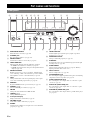 6
6
-
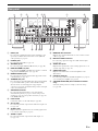 7
7
-
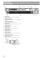 8
8
-
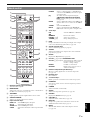 9
9
-
 10
10
-
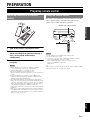 11
11
-
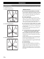 12
12
-
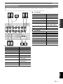 13
13
-
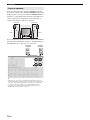 14
14
-
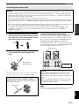 15
15
-
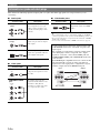 16
16
-
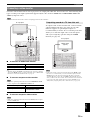 17
17
-
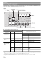 18
18
-
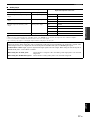 19
19
-
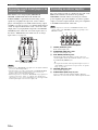 20
20
-
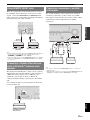 21
21
-
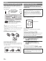 22
22
-
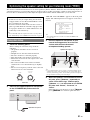 23
23
-
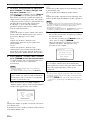 24
24
-
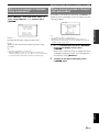 25
25
-
 26
26
-
 27
27
-
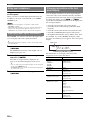 28
28
-
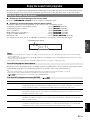 29
29
-
 30
30
-
 31
31
-
 32
32
-
 33
33
-
 34
34
-
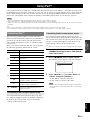 35
35
-
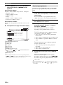 36
36
-
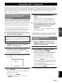 37
37
-
 38
38
-
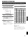 39
39
-
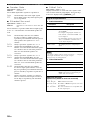 40
40
-
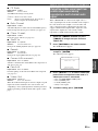 41
41
-
 42
42
-
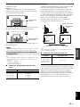 43
43
-
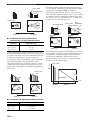 44
44
-
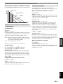 45
45
-
 46
46
-
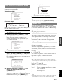 47
47
-
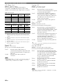 48
48
-
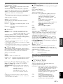 49
49
-
 50
50
-
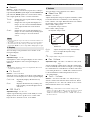 51
51
-
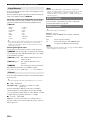 52
52
-
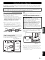 53
53
-
 54
54
-
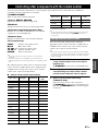 55
55
-
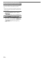 56
56
-
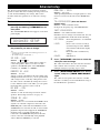 57
57
-
 58
58
-
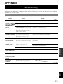 59
59
-
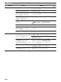 60
60
-
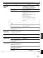 61
61
-
 62
62
-
 63
63
-
 64
64
-
 65
65
-
 66
66
-
 67
67
-
 68
68
-
 69
69
-
 70
70
-
 71
71
-
 72
72
-
 73
73
-
 74
74
-
 75
75
-
 76
76
-
 77
77
-
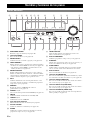 78
78
-
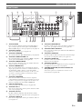 79
79
-
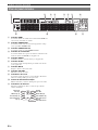 80
80
-
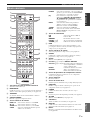 81
81
-
 82
82
-
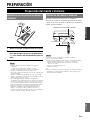 83
83
-
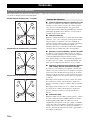 84
84
-
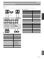 85
85
-
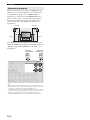 86
86
-
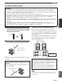 87
87
-
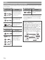 88
88
-
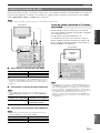 89
89
-
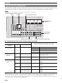 90
90
-
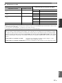 91
91
-
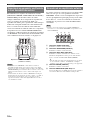 92
92
-
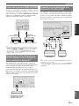 93
93
-
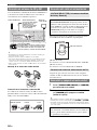 94
94
-
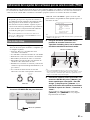 95
95
-
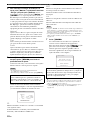 96
96
-
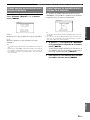 97
97
-
 98
98
-
 99
99
-
 100
100
-
 101
101
-
 102
102
-
 103
103
-
 104
104
-
 105
105
-
 106
106
-
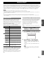 107
107
-
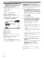 108
108
-
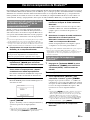 109
109
-
 110
110
-
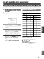 111
111
-
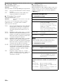 112
112
-
 113
113
-
 114
114
-
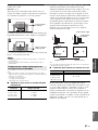 115
115
-
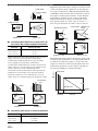 116
116
-
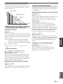 117
117
-
 118
118
-
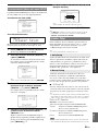 119
119
-
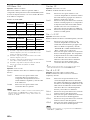 120
120
-
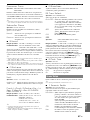 121
121
-
 122
122
-
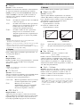 123
123
-
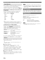 124
124
-
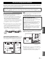 125
125
-
 126
126
-
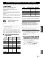 127
127
-
 128
128
-
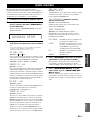 129
129
-
 130
130
-
 131
131
-
 132
132
-
 133
133
-
 134
134
-
 135
135
-
 136
136
-
 137
137
-
 138
138
-
 139
139
-
 140
140
-
 141
141
-
 142
142
-
 143
143
-
 144
144
-
 145
145
-
 146
146
-
 147
147
-
 148
148
-
 149
149
-
 150
150
-
 151
151
-
 152
152
-
 153
153
-
 154
154
-
 155
155
-
 156
156


Yamaha RX-V765 El manual del propietario
- Categoría
- Receptores AV
- Tipo
- El manual del propietario
en otros idiomas
- English: Yamaha RX-V765 Owner's manual
Artículos relacionados
-
Yamaha RX-V1067 El manual del propietario
-
Yamaha RX-A1000 El manual del propietario
-
-
Yamaha RX-V767 El manual del propietario
-
Yamaha RX-V667 El manual del propietario
-
Yamaha RX-V1065 El manual del propietario
-
Yamaha RX-V465 El manual del propietario
-
Yamaha RX-V765 El manual del propietario
-

