
For use by trained healthcare professionals only.
For use with compatible Ambu® visualization devices.
Ambu® aBox™ 2
INSTRUCTIONS
FOR USE

A B
C D
E F
G H
IJ
QUICK GUIDE
2

Contents Page
English (Instructions for use) ........................................................................................................ 4-51
Deutsch (Bedienungsanleitung) ............................................................................................ 52-106
Español (Manual de instrucciones) ..................................................................................... 107-159
Français (Mode d´emploi) .......................................................................................................160-211
Italiano (Manuale d’uso) ..........................................................................................................212-263
Nederlands (Gebruiksaanwijzing) .......................................................................................264-315
Português (Manual de instruções) ......................................................................................316-367
3

Content Page
1. Important Information – Read Before Use ........................................................................................ 6
1.1. Intended use .............................................................................................................................................................................6
1.2. Indications for use .................................................................................................................................................................6
1.3. Intended patient population ............................................................................................................................................6
1.4. Intended user profile ............................................................................................................................................................6
1.5. Clinical benefits ......................................................................................................................................................................6
1.6. Potential adverse events .....................................................................................................................................................6
1.7. General notes ...........................................................................................................................................................................6
1.8. Contraindications...................................................................................................................................................................6
1.9. Warnings and cautions ........................................................................................................................................................6
2. Device Description ............................................................................................................................... 8
2.1. Displaying unit parts ............................................................................................................................................................. 8
2.2. Product compatibility ..........................................................................................................................................................8
2.3. Endoscope activation ..........................................................................................................................................................9
2.4. Description of components ............................................................................................................................................ 10
2.5. Spare parts ..............................................................................................................................................................................11
2.6. System overview ..................................................................................................................................................................11
3. Explanation of Symbols Used ........................................................................................................... 12
4. Getting Started ................................................................................................................................... 13
4.1. First-time setup ....................................................................................................................................................................13
4.2. User profiles ..........................................................................................................................................................................14
5. General Settings ................................................................................................................................. 16
6. Network Setup .................................................................................................................................... 16
6.1. Wi-Fi setup ............................................................................................................................................................................. 16
6.1.1. Wi-Fi network with WPA/WPA2 authentication ............................................................................................17
6.1.2. Hidden Wi-Fi network (Wi-Fi not showing on the list of available Wi-Fi connections) ................17
6.1.3. Wi-Fi network with WPA2 Enterprise authentication (username and password required) ........17
6.1.4. Import network certificate for WPA2 (TLS -transport security layer) ...................................................17
6.2. LAN connection via Ethernet cable ............................................................................................................................ 18
6.3. Set up static IP address and/or DNS server for a Wi-Fi or LAN network ..................................................... 18
6.4. Disconnect from Wi-Fi network .................................................................................................................................... 18
6.5. Clear all network data from the displaying unit .....................................................................................................19
7. Setup Connection to PACS and Worklist ......................................................................................... 19
7.1. Set up the displaying unit for server connection ....................................................................................................19
7.2. Set up connection to PACS server .................................................................................................................................19
7.3. Set up connection to Worklist server ......................................................................................................................... 20
8. Output Setup ...................................................................................................................................... 21
9. Endoscope Buttons Configuration...................................................................................................22
9.1. Configure the endoscope buttons ............................................................................................................................... 22
10. Operating the Displaying Unit .......................................................................................................22
10.1. Preparation and inspection of the displaying unit before use ...................................................................... 22
10.2. Starting and stopping a procedure .......................................................................................................................... 23
10.2.1. Starting a procedure ............................................................................................................................................. 23
10.2.2. Stopping a procedure .........................................................................................................................................23
10.3. Procedure workflow using the worklist .................................................................................................................. 23
10.4. Overview of Live View functions ................................................................................................................................ 24
10.5. Using image adjustments ............................................................................................................................................. 24
10.5.1. Adjust colour, contrast, sharpness and brightness ................................................................................... 25
10.5.2. Rotate the live image ............................................................................................................................................ 25
10.5.3. Use the zoom function ........................................................................................................................................25
10.5.4. Light on/off .............................................................................................................................................................. 26
10.5.5. Adjust ARC (Advanced Red Contrast) setting ............................................................................................. 26
4

en
5
10.6. Using the stopwatch ....................................................................................................................................................... 26
10.7. Using dual view .................................................................................................................................................................. 27
10.8. Taking photos and recording videos ....................................................................................................................... 27
10.9. Current procedure folder ............................................................................................................................................. 27
10.10. After use of the displaying unit ................................................................................................................................ 28
11. File Handling in The Archive ...........................................................................................................28
11.1. Accessing files in the Archive ....................................................................................................................................... 28
11.2. Exporting files to PACS server or USB flash drive ................................................................................................ 29
11.3. Deleting files from the Archive ................................................................................................................................... 31
12. Connect External Equipment .........................................................................................................32
12.1. Connecting to an External Monitor .......................................................................................................................... 32
12.2. Connecting USB Flash Drives....................................................................................................................................... 33
12.3. Connecting to an External Medical Imaging Recorder ................................................................................... 33
12.4. Printing images via external medical printer ....................................................................................................... 33
12.5. Connect external audio devices .................................................................................................................................34
12.5.1. Record sound during the procedure ..............................................................................................................34
12.5.2. Play sound recorded during a procedure .................................................................................................... 34
13. System Information and Software Updates/Upgrades ...............................................................34
13.1. Device information page ............................................................................................................................................... 34
13.2. Software updates/upgrades ........................................................................................................................................34
13.3. Reporting a problem .......................................................................................................................................................35
13.4. Data reset ............................................................................................................................................................................. 35
14. Cleaning and Disinfection of the Displaying Unit ....................................................................... 35
15. Maintenance .....................................................................................................................................37
16. Disposal .............................................................................................................................................37
17. Technical Product Specifications ...................................................................................................37
17.1. Standards applied ............................................................................................................................................................. 37
17.2. Specifications for the displaying unit ....................................................................................................................... 38
18. Troubleshooting ............................................................................................................................... 39
19. Warranty and Replacement ............................................................................................................42
Appendix 1. Electromagnetic Compatibility ..................................................................................... 43
Appendix 2. Radio Frequency Compliance .........................................................................................46
Appendix 3. Cybersecurity ....................................................................................................................49
Appendix 3.1. Network Setup ................................................................................................................................................ 49
Appendix 3.2. Data at Rest and In Transit ......................................................................................................................... 50
Appendix 3.3. Software Bill Of Materials (SBOM) ........................................................................................................... 51

1. Important Information – Read Before Use
Read these Instructions for Use carefully before using the Ambu® aBox™ 2. These Instructions for
Use may be updated without further notice. Copies of the current version are available upon
request. The latest version is available on ambu.com. Please be aware that the instructions do
not explain or discuss clinical procedures. They describe only the basic operation and
precautions related to the operation of the Ambu® aBox™ 2.
In these Instructions for Use, the term displaying unit refers to Ambu® aBox™ 2. The terms
visualization device and endoscope are used interchangeably throughout the document and
refer to compatible Ambu endoscopes and other visualization devices that can be connected
to and used with the displaying unit.
These Instructions for Use apply only to the displaying unit. For information on a specific Ambu
visualization device, refer to the relevant Instructions for Use
1.1. Intended use
The aBox™ 2 is intended to display live imaging data from compatible Ambu visualization devices.
1.2. Indications for use
As the aBox™ 2 is intended to display live imaging data from compatible Ambu visualization
devices, the intended medical indication will be defined by the connected visualization devices.
1.3. Intended patient population
As the displaying unit is intended to display live imaging data from specific Ambu
visualization devices, the intended patient population will be defined by the connected
Ambu visualization devices.
1.4. Intended user profile
Healthcare professionals trained on procedures with compatible visualization devices typically
assisted by other healthcare professionals and medical technicians with knowledge of setting
up medical devices.
1.5. Clinical benefits
In conjunction with a compatible single-use visualization device, the Ambu® aBox™ 2 provides
visualization and inspection of hollow organs and cavities in the body.
1.6. Potential adverse events
None known for the displaying unit.
1.7. General notes
If, during the use of this device or as a result of its use, a serious incident has occurred, please
report it to the manufacturer and to your national authority.
1.8. Contraindications
None known for the displaying unit.
1.9. Warnings and cautions
Failure to observe these warnings and cautions may result in patient injury or damage to the
equipment. Ambu is not responsible for any damage to the equipment or patient injury
resulting from incorrect use.
6

en
7
WARNINGS
1. To avoid patient injury during procedure, be careful to check whether the image on the
screen is a live image or a recorded image and verify that the orientation of the image
is as expected.
2. To minimize risk of contamination, always wear gloves during handling of the
displaying unit and ensure that the displaying unit is cleaned and disinfected before
and after each use in accordance with the chapter 14.
3. Portable radio frequency (RF) communications equipment (including peripherals such
as antenna cables and external antennas) should be used no closer than 30 cm
(12inches) to any part of the displaying unit and the attached visualization device,
including cables specified by the manufacturer. Otherwise, this could result in
degradation of the performance of this equipment.
4. To avoid risk of electric shock only connect mains or battery powered ancillary
equipment, if it is approved as medical electrical equipment.
5. To avoid risk of electric shock, this equipment shall only be connected to a supply
mains with protective earth.
6. Use of this equipment adjacent to or stacked with other equipment should be avoided
because it could result in improper operation. If such use is necessary, this equipment
and the other equipment should be observed to verify that they are operating
normally.
7. To avoid patient injury due to loss of the live image during procedure, ensure to
correctly connect the power cord to an appropriate power source that will ensure
continuous power supply.
8. To avoid patient injury due to overheating of the displaying unit causing it to suddenly
shut down during procedure, do not cover the ventilation holes at the bottom of the
displaying unit.
9. Do not touch any metal parts of the displaying unit while using high frequency tools
(e.g. electrosurgical equipment), due to the risk of electric shock and burns.
10. To ensure that images and videos are correctly exported to external systems and to
avoid potential misdiagnosis due to mixing-up of patient data, carefully
check that the patient identifiers are correct before starting, saving and
exporting the procedure.
CAUTIONS
1. To prevent damaging the displaying unit, always place the displaying unit on a hard
flat surface during use to avoid covering the ventilation holes at the bottom of the
displaying unit. Be aware that covering the ventilation holes can also lead to a high
surface temperature.
2. Using high frequency tools (e.g. electrosurgical equipment) in proximity of a
connected visualization device may affect the live image. This is not a malfunction.
Wait a few seconds for the image to return to normal.
3. Do not place any heavy objects on the top of the displaying unit when it is folded
flat, as this could damage the equipment and lead to malfunction or exposure of
electrical parts.
4. Use of accessories, transducers, and cables other than those specified or provided by
the manufacturer of this equipment could result in increased electromagnetic
emissions or decreased electromagnetic immunity of this equipment and result in
improper operation.
5. To avoid malfunction during procedure, do not use the displaying unit if it is damaged
in any way or if any part of the functional check described in section 10.1 fails.

6. To avoid malfunction of the equipment only use spare parts supplied by Ambu.
Do not modify the spare parts.
7. Cleaning and disinfection wipes shall be moist, but not dripping to ensure no damage
to internal electronics of the displaying unit.
8. If using wipes containing hypochlorite or citric acid during cleaning, ensure that all
residue is completely removed. Wipes containing hypochlorite or citric acid may affect
the screen's antireflective coating over time. You should limit the use of wipes
containing hypochlorite or citric acid to required cases only.
2. Device Description
The displaying unit can be connected to compatible Ambu visualization devices to display
video images. The following sections describe the components of the displaying unit and list
compatible devices.
2.1. Displaying unit parts
Ambu® aBox™ 2 Item number
505001000
2.2. Product compatibility
aBox 2 includes two connector ports on the front marked in colours. Ambu visualization
devices are compatible with aBox 2 at the colour-coded connection mechanism and
connector geometry.
A full list of compatible visualization devices is displayed in the user interface of the displaying unit.
To see compatible Ambu visualization devices:
•Press the Settings tab 1, then press About 2.
•Press Device info 3, then scroll to Supported visualization devices 4.
1
2
3
4
8

en
9
Compatible external equipment
•External medical grade monitors (video output)
•External medical imaging recorders (video output and trigger output)
•USB flash drives
•Medical USB printer
•USB powered audio devices that comply with IEC 60601-1, IEC 60950-1 or IEC 62368-1
Note: Verified compatibility with Sony UP-DR80MD digital colour printer for medical
applications. For specifications of connections to external equipment, refer to chapter 12.
Note: IEC 60950-1 and IEC 62368-1 are consumer electronic standards and do not cover patient
safety. Therefore do not touch the accessories while touching the patient and place the
equipment out of reach of the patient.
2.3. Endoscope activation
New endoscope types that are not found on the displaying unit's list of supported endoscopes
(see section 2.2) must be activated with an activation code before they can be used with the
displaying unit. The activation code is entered only once for each endoscope type, and once
an endoscope type has been activated, it can be found on the list of supported visualization
devices. The activation codes are found on Ambu's website via the URL shown on the
displaying unit's screen next to the input field where the activation code is to be entered.
Activate a new endoscope type:
•Press the Settings tab, then press About.
•Scroll to Activation codes 5 and press the question mark 6 to find the URL or QR code
for the activation codes.
•Enter the URL in the address field of the internet browser on your connected device,
e.g. computer, tablet or mobile phone or scan the QR code with your mobile phone.
•Find the activation code for the endoscope to be activated and enter the code into the
input field below Activation codes 7.
5
6
7

2.4. Description of components
1
3
2
4
Wi-Fi
1
23
45
10 11 12 13 14 15 16 17 18 19
6
7
8
9
No. Component Function
1Touch screen Displays the graphical user interface and shows
the live image from the Ambu visualization device.
2
VDI port (connector port
for specific Ambu
visualization devices)
Connector port geometry and colour
ensures correct connection with compatible
visualization devices.
3USB 3.0 port (front) Enables connection of external USB flash drives.
4USB port cover (front) Protects the front USB port.
5Power button Turns the power ON or switches to STANDBY mode.
6Base Contains the main unit.
7Positioning arm
Enables manual positioning of the touch screen.
The screen can be adjusted horizontally and
vertically as well as rotated.
8Power cable Connects the displaying unit to a power outlet.
9Wi-Fi antenna Connect Wi-Fi antenna to the displaying unit for
improved Wi-Fi signal.
10 Video output ports
(2x DVI-D) Enable connection to external monitor or external
medical imaging recorder. See section 7.1. for details
on the difference between using DVI-D and 3G-SDI
on the displaying unit.
11 Video output ports
(2x 3G-SDI)
12 Wi-Fi antenna connector Enables connection of Wi-Fi antenna.
13 USB 3.0 ports Enables connection of external USB flash drives.
14 LAN port Enables connection to ethernet.
15 USB 2.0 ports Enables connection of external USB flash drives.
16 Trigger output ports
(2 x 3.5 mm jack) Enable connection to an external medical imaging
recorder to transfer trigger signals.
17 Trigger output ports
(2 x D-SUB9)
10

en
11
No. Component Function
18 Power inlet Enables connection to power cable.
19 Connector for potential
equalization cable
Enables bonding of electrical products to eliminate
potential differences between conductive parts.
2.5. Spare parts
Spare parts are intended as replacements for components that are exposed to wear and tear
during the lifetime of the device. Consult the troubleshooting guide in chapter 13 for issues
that might require replacement of spare parts.
Spare parts Name Item number
Thickness: 4 pt
Ambu® aBox™ 2 -Visualization device
interface kit - Grey-Empty-Green
Contains:
One grey and one green visualization device
interface board (VDI), a front cover with a color
ring (grey and green), a plectrum tool, and two
screws for the VDI.
505000530
Power cable – B (US, JP) 505000521
Power cables – J (CH), K (DK), I (AUS) 505000520
Power cable – G (UK), E/F (EU, not DK, CH) 505000522
2.6. System overview
A complete Ambu Imaging System is configured as illustrated in the figure below. The various
connections are described in more detail in chapter 12.
DVI-D
3G-SDI
DVI-D
USB 2.0/3.0
USB 3.0 Type A
USB 3.0 Type A
DICOM
USB Flash Drive
Server
Wi-Fi
LAN
PACS Server/
Worklist Server
Medical Printer
Audio Device
External Monitor
External Medical
Imaging Recorder
Visualization
Device
Image and
Video Streams
USB 3.0
Ambu Displaying Unit
External Connection OptionsAmbu Imaging System
Software
Update/Upgrade
Wi-Fi
LAN
Recordings/
Log Files
3G-SDI
3.5 mm Jack
D-SUB9

Please note that your organization is responsible for the following areas, which should be
implemented according to your local policy:
•Network setup
•Ensuring availability and confidentiality of the network
•Ensuring confidentiality and integrity of physical devices
•Management of the displaying unit user profiles
•Maintenance of user passwords
•Monitoring and audit of the Ambu imaging system
•Complete data erasure before disposal of the displaying unit
3. Explanation of Symbols Used
Symbols for the
displaying unit Description Symbols for the
displaying unit Description
Warning Caution
Medical Device Made in Taiwan
Type BF applied part Follow
Instructions for Use
Batch Code Consult
Instructions for Use
CE marking Japan Radio Law
TELEC RF certification
Australia and New
Zealand’s Regulatory
Compliance Mark
Taiwan Radio
Requirement
NCC certification
E354633
Medical – general
medical equipment as
to electrical shock, fire
and mechanical
hazards only in
accordance with ANSI/
AAMI ES60601-
1:2005+ AMD 2012,
CAN/CSA-C22.2
No. 60601-1:14+
IEC 60601-2-18:2009
Waste Bin symbol,
indicating that waste
must be collected
according to local
regulation and
collection schemes for
disposal of electronic
and electrical waste
(WEEE)
Universal Serial Bus
(USB 2.0, USB 3.0) DVI-D Digital Visual Interface
3G-SDI Serial Digital Interface LAN Local Area Network
Rx Only
US Federal Law
restricts this device to
sale by or on the order
of a physician
IP31 Protection against
solid particles and
liquid ingress
Humidity Limitation Atmospheric
Pressure Limitation
12

en
13
Symbols for the
displaying unit Description Symbols for the
displaying unit Description
Catalogue Number UK Conformity
Assessed
UK Responsible Person
Importer
(For products imported
into Great Britain only)
A full list of symbol explanations can be found on ambu.com/symbol-explanation.
4. Getting Started
4.1. First-time setup
Follow the steps below before using the displaying unit for the first time. Letters in grey circles
refer to the illustrations in the Quick Guide on page 2.
1. Unpack the displaying unit and verify that no parts are missing. Refer to the parts
described in section 2.4.
2. Closely examine the displaying unit and other parts for any damage. Do not use the
displaying unit if it is damaged in any way A.
3. Place the displaying unit on a hard and leveled surface. Be aware to place the displaying
unit in a position where the power cord is accessible. The displaying unit can be placed on
a medical cart to make it moveable. Make sure to proper position of the displaying unit to
avoid falling down during transportation.
4. If necessary, connect the supplied Wi-Fi antenna to the back of the displaying unit.
5. Connect the power cable to a power outlet and insert the power plug into the power inlet
on the back of the displaying unit B.
6. If needed, connect an external monitor C and/or medical imaging recorder to the back of
the displaying unit.
7. If necessary, manually adjust the orientation of the touch screen of the displaying unit D
8. Turn ON the displaying unit by short pressing the power button. The indicator light in the
power button switches from orange (STANDBY mode) to green (ON) E, but a live image is
available soon after the monitor is turned on if a visualization device is connected. If no
visualization device is connected, the interface will illustrate how to correctly connect
a visualization device to the displaying unit.
9. Select the preferred language, then press 1.
10. Select and confirm your country, then press Continue 2. Press confirm 3.
11. Go to Appendix 3. Cybersecurity and ensure that the use of the displaying unit's software
and connectivity is aligned with your organization's policies.
12. Log in as Administrator to get access to system settings: Press the Login tab
in the Toolbar.
– Press arrow right 4 , then press System Administrator 5.
– Enter the password and press Log in 6. The factory default password is AmbuAdmin
– Navigate to User profiles to change the Password. For security reasons you should
change the factory default password as soon as possible.
12

IMPORTANT!: Selecting the correct country
from the first time is a requirement for
regulatory compliance, and the selected
country cannot subsequently be changed by
any users of the displaying unit. If selection
of a new country is necessary, please contact
your local Ambu representative.
The displaying unit’s language can be
changed by the Administrator at any time.
4
5
6
Change system language:
• Press the Settings tab,
then press Setup 7.
•Press Language 8.
•Press Device language 9,
and select the required
language. The system
language changes
immediately when selected.
Note: If the Administrator
password is lost, please contact
your local Ambu representative.
13. Set date and time:
•Press Date and time 10 .
•Press Time zone setting 11 , and select the required time zone.
•Press Set date and time 10 to return to the previous menu.
•Select the required setting below Time format 12 .
•Scroll the hours and minutes below Set time 13 to set the time.
•Select the required date 14 in the calendar.
11
10
12
14
13
4.2. User profiles
User profiles are created as different user types according to their purpose (see table below).
Only the Administrator has full access to the displaying unit's settings and functions, including
the creation of new users.
3
78
9
14

en
15
For daily operation it is recommended to create minimum one Advanced user profile, either as
a shared department login or as individual profiles. It is not possible to create additional
Administrator or Service Technician user profiles.
User profile types and system access
User profile type
Function access
Default user Advanced
user
Administrator Service
Technician
Access
without login
Daily
operation
Administrator
with full access
Service
related tasks
Login required -x x x
Live View x x x x
Video recording x x x x
Photo x x x x
Current procedure x x x x
Worklist -*x x -*
+ARC Image adjustments x** x** x x
Archive*** -*x x -*
Settings - x**** x x****
* The Administrator can enable or disable access without login.
** The Administrator and the Service Technician can enable or disable functions for other users.
*** User profiles access to the Bin is described in section 11.3.
**** Some settings are not accessible for the Advance user and the Service Technician.
Create an Advanced user:
•Press the Settings tab.
•Press User Profiles, then press
Add user 5.
•Enter username, password, and
repeated password in the respective
input fields 6, and press the
Save icon 7.
To delete a user profile, press the user
name, then press the delete icon.
Press OK to confirm.
Log in as any user profile:
•Press the Login tab.
•Press arrow right, then press your user name.
•Enter your password and press Login.
Note: Passwords must be minimum 8 characters. Any character is allowed, but it is recommended
to use a combination of upper- and lower-case letters, numbers, and symbols to enhance
password protection.
7
6
5

Change username or password:
•Press the Settings tab, then press User Profiles.
•Press the username 8, then press the edit icon 9.
•Enter the new username, password, and repeated password in the respective input fields
10 and press the save icon 11 .
Note: The Administrator can change username and password for other user types.
11
10
8
9
5. General Settings
The Administrator can enable and disable functionalities for all users.
In the Setup menu under the tab General Settings the following functionalities can be
enabled or disabled using the ON/OFF sliders:
•USB Management – Possibility to enable file export, software upgrade, import of TLS
certificate and ability to print using the USB port.
•Communication Settings – Enabling allows the possibility to upgrade software online if
connected to the internet.
•Archive Settings – Decide when a procedure is moved to the bin and when it is deleted
from the bin.
•Zoom, Stopwatch, ARC – functions available during a procedure can be disabled for all
types of scopes and users.
•Login Settings – determine if a user that is not logged in can still access the archive and
see the worklist.
•User inactivity settings – choose if the displaying unit will logout the user due to inactivity.
Be aware that if a function is disabled (not green), the symbol is not visible in the menu where
it is normally located.
6. Network Setup
Importing a worklist or transferring imagery requires that the displaying unit is connected to
the network via Wi-Fi or LAN/Ethernet cable.
6.1. Wi-Fi setup
The displaying unit supports WPA, WPA2 and WPA2 Enterprise authentication. Wi-Fi networks
that redirect to a login webpage are not supported.
Enable Wi-Fi:
1) Press the Settings tab, then press Setup 1.
16

en
17
2) Press Network setup 2.
3) Press the ON/OFF slider to turn on Wi-Fi 3 (switch to green).
4) If required by your organization’s Wi-Fi network, press the input
field next to Hostname 4 and enter the hostname.
Note: The hostname is provided by your organization's IT
administrator and is used for identifying the displaying unit on the
Wi-Fi network. The hostname can be 1-63 characters long excl. dots
and can consist of numbers and upper- or lowercase letters (A-Z/
a-z). Hyphens cannot be used as first or last character.
5) Press Configure 5 and wait while the displaying unit searches
for available networks.
6.1.1. Wi-Fi network with
WPA/WPA2 authentication
1) Select the Wi-Fi network
from the list.
2) Enter the password and press
Save 6, then press Connect.
3) When the connection has been
established, a Wi-Fi symbol
appears in the Toolbar.
4) To enable automatic connection
to this Wi-Fi press the Connect
automatically 7 ON/OFF slider
(switch to green).
6.1.2. Hidden Wi-Fi network
(Wi-Fi not showing on the list
of available Wi-Fi connections)
1) Press Add network 8.
2) Press the input field next to SSID and enter
the name of the hidden Wi-Fi network,
then press OK.
3) Enter the remaining information in the
input fields depending on the type of
Wi-Fi network.
6.1.3. Wi-Fi network with WPA2
Enterprise authentication
(username and password
required)
1) Enter username in the Identity
9 field.
2) Enter password in the Password
10 field.
3) Select the required certificate 11 .
4) Press Connect 12 .
5) When the connection has been established,
a Wi-Fi symbol appears in the Toolbar.
6) To enable automatic connection to this
Wi-Fi, press the Connect automatically
13 ON/OFF slider (switch to green).
6.1.4. Import network certificate for
WPA2 (TLS -transport security layer)
In the Network menu, scroll to Imported
Network certificates 14 .
1
6
7
4
2
5
3
8
9
10 11
12
13
14

6.1.4.1. Import TLS certificates from a server
1) Ensure that the displaying unit is connected to a temporary Wi-Fi or LAN network
(see section 5.1.1 or 5.2.).
2) Press Server import.
3) Enter Certificate file name 15 , Host name 16 , and Port number 17 .
4) Press Import 18 .
15
16
17
18
6.1.4.2. Import network certificates from a USB flash drive
1) Ensure that USB connection has been enabled for certificate import (see section 2.5.).
Insert USB containing network certificate. (see section 6.1.4).
2) Press USB import and wait while the displaying unit searches for network certificates on
the USB flash drive.
3) Select the required network certificate and press Import 19 .
19
Note: When the network certificate has been imported, the name of the certificate file is
shown below Imported Network certificates in the Network menu.
6.2. LAN connection via Ethernet cable
1) Connect a LAN cable to the Ethernet connection port on the back of the displaying unit
and to a router or LAN wall socket.
2) In the Network menu, check the LAN connection status shown below Ethernet.
6.3. Set up static IP address and/or
DNS server for a Wi-Fi or LAN network
1) In the Network menu, press the currently
selected Wi-Fi network.
2) Below the name of the Wi-Fi network, press the
arrow next to IP address. Press the ON/OFF
slider next to Enable static IP 20 or Configure
manual DNS servers 21 (switch to green) and
enter the required information.
6.4. Disconnect from Wi-Fi network
In the Network menu, press the currently selected. Wi-Fi network, then press Disconnect.
20
21
18

en
19
6.5. Clear all network data from the displaying unit
In the Network menu, press Clear all data. Press OK.
7. Setup Connection to PACS and Worklist
Importing a worklist and exporting of imagery requires that the worklist server/PACS (Picture
Archiving and Communication System) server can send and receive data in DICOM (Digital
Imaging and Communications in Medicine) format. Setting up server connections require that
the displaying unit is connected to a Wi-Fi or LAN network (see section 6.1 and 6.2).
7.1. Set up the displaying unit for server connection
•Press the Settings tab, then press Setup.
•Press DICOM setup 22 .
•It is optional to change the Station name 23 . The Station name is used to recognize the
unit if a special worklist needs to be pushed to a specific unit or if it is important to track
from which unit data has been sent from. The default name is AmbuMon and the maximum
length of the station name is 16 characters.
•Press Use serial number or Use custom name next to Station AE title 24 . If you selected
Use custom name, press the input field and enter the name.
22 25
24
23
7.2. Set up connection to PACS server
26
27
28
29
30
•Press Add new 25 below PACS servers.
•Press the input field next to PACS name 26 and enter the name you want to use for the
PACS connection.
•Press the input fields next to PACS AE title, Host name and Port number 27 and enter
the required information in each field.
•Press the required setting next to TLS 28 .
Note: If you enable TLS, you need to import the required TLS certificate from a server or
USB flash drive (see instructions further below).
•Press Test connection 29 to verify that the information has been entered correctly and
the server connection can be established.
•Press Create 30 to save the server connection setup.
Some PACS systems may require the MAC address and the IP address of the displaying unit.
The MAC address is unique for each displaying unit, while the IP address is assigned by the
hospital network.
Retrieve the MAC address and IP address of the displaying unit:
•Login as Administrator, then go to Settings - About - Device Info.
•Depending on whether Wi-Fi or Ethernet is used, find the information tab Network.
The MAC address is a 48-BIT address grouped into 6 octets. In the example below, the MAC
address is highlighted in red boxes depending on the network setup.

The IP address assigned by your network can also be found. In the example below, the IP
address is highlighted in a blue box.
7.3. Set up connection to Worklist server
•Enable Worklist 31 with the ON/OFF switched to green.
•Enter the required information in Worklist server AE title, Worklist server hostname and
Worklist server port number 32 .
•Press the required TLS 33 settings .
Note: If you enable TLS, you need to import the required TLS certificate from a server or
USB flash drive.
•Choose the modality (ES=endoscopy, US=ultrasound) or enter a specific modality in the
Other 34 field deciding which worklist you choose to retrieve.
•Enter the timeframe, that the retrieved worklist will show, in the Display upcoming
procedures (hours) 35 field.
•Hide past procedures older than (hours) 36 allows you to limit the amount of
procedures in the worklist.
•Press Test worklist connection 37 to verify that the information has been entered
correctly and the server connection is established.
31
37
35
32
33
36
34
38
Import TLS certificate from server or USB flash drive:
You can use TLS for enhanced security when setting up PACS and Worklist server connections.
Enabling TLS requires a TLS certificate to be imported to the displaying unit from a server or
from a USB flash drive. If multiple TLS certificates are imported to the displaying unit,
the PACS/Worklist server will select the required TLS certificate automatically. For import
from server, ensure that the displaying unit is connected to a Wi-Fi or LAN network.
For import from USB flash drive, ensure that USB connection has been enabled for certificate
import and a USB flash drive connected to the displaying unit.
20

en
21
To import TLS certificates from a server:
•Press Server import 38 .
•Press the input field next to Certificate file name 39 and enter the file name.
•Press the input field next to Host name 40 , and enter the hostname.
•Press the input field next to Port number 41 and enter the port number.
•Press Import 42 .
39
40
41
42
To import TLS certificates from a USB
flash drive:
•Press USB import and wait while the
displaying unit searches for TLS
certificates on the USB flash drive.
•Select the required TLS certificate and
press Import 43 .
Note: When the TLS certificate has been
imported, the name of the certificate file is shown below Imported TLS certificates.
Information needed Explanation
PACS name This is the name of the PACS. Used in the export menu to
select the PACS when transferring photos and videos.
PACS AE Title PACS Application Entity Title.
The maximum length of the AE Title is 16 characters.
Host name IP-address, MAC address or full web address for the PACS.
Port number Network port no. for the PACS.
8. Output Setup
The Administrator can view and reconfigure what Trigger Outputs (photo or video functions)
1 are sent via the output ports to a connected external medical imaging recorder.
To access the Trigger output menu:
•Press the Settings tab in the toolbar on the left.
•Press Setup and press Output setup.
You can configure the trigger output channels A, B, C and D. By default, trigger output A sends
a signal to take a photo and trigger output D sends a signal to start or stop a video recording on
the medical imaging recorder. Trigger B and C does not have any trigger signals assigned by default.
Reconfigure the trigger outputs as an administrator:
•Select the trigger output channel you wish to reconfigure (A, B, C or D) and select an
output signal in the selection menu that appears on the right side of the screen 2.
•It is important that the assigned function on the trigger output port of the displaying unit
matches the function assigned to the connected input port of the medical imaging recorder.
•Test if the system behaves as expected.
When set up correctly, the medical imaging recorder will capture a photo or start/stop
a video sequence, if the corresponding function is activated via the buttons on a connected
endoscope or directly on the buttons in the Live view tab.
43

In the menu Trigger duration the pulse length for can be set to align with your medical
imaging recorder.
2
1
9. Endoscope Buttons Configuration
The Administrator and the Service Technician can set up
the endoscope button configuration, also when the endoscope
is not connected. All other users can view the current button
configuration, but not change it. The available functions depend
on the type of the selected endoscope. To view the current
configuration of a compatible endoscope or to reconfigure the
buttons, press the Settings tab in the tool bar, press Endoscope
buttons and select an endoscope type 1. An overview will appear.
9.1. Configure the endoscope buttons
•Press the Settings tab, then press Endoscope buttons.
•Press the required endoscope category 2 and select an endoscope.
•The screen shows an overview of the endoscope buttons with the available functions.
•Press the required endoscope button 3, then select long or short button press 4.
•Press the action to be performed when the selected button is pressed 5 .
•Repeat for each button. The overview shows the selected functions next to the buttons.
2
3
4
5
Note: Each endoscope type comes with a default button configuration.
Note: The changes made will be saved and apply for all visualization devices of the same type.
Note: For some visualization devices e.g. ARC can only be assigned to be activated by
a "long press".
10. Operating the Displaying Unit
10.1. Preparation and inspection of the displaying unit before use
Before using the displaying unit for a patient procedure, follow the relevant steps below and
any other necessary steps according to your organization's procedures and requirements for
preparation and inspection of this type of device.
1
22

en
23
1. Closely examine the displaying unit and other parts for any damage. Do not use the
displaying unit if it is damaged in any way.
2. Clean and disinfect the displaying unit (see chapter 14).
3. Connect the displaying unit to a suitable power outlet using the included power cable
and turn on the power outlet. The orange indicator light in the power button turns on to
indicate that the displaying unit is in STANDBY mode.
4. Adjust position and orientation of the touch screen to your preference.
5. Turn ON the displaying unit by pressing the power button. The indicator light in the power
button switches from orange (STANDBY mode) to green (ON). If an Ambu visualization
device is connected, a live image is available while the user interface is loading.
6. If necessary, connect the displaying unit to the Wi-Fi network.
7. Connect the Ambu visualization device to the displaying unit by plugging its connector
into the corresponding connector port on the displaying unit. Ensure that the arrows are
aligned and the colour matches on the connector and its port.
Note: For preparing and operating the Ambu visualization device, please refer to the
Instructions for Use for the specific visualization device.
8. Verify that a live video image appears on the screen by pointing the distal end of the Ambu
visualization device towards an object, e.g. the palm of your hand.
9. If required, an external monitor can be connected to the DVI or SDI port on the back ofthe
displaying unit.
10.2. Starting and stopping a procedure
10.2.1. Starting a procedure
When an Ambu visualization device is connected to the displaying unit, a new procedure
starts when one of the following actions is performed: 1) a patient is selected from Worklist,
2) a photo or video is captured, or 3) the stopwatch is activated.
If a visualization device is connected, the live image is available soon after the displaying unit
is turned ON. Even if a network error or other problems in the system occur, the Live view will
still be available making it possible to use the displaying unit for clinical purposes.
10.2.2. Stopping a procedure
Disconnect the Ambu visualization device from the displaying unit and select one of the
following options:
•Press Finish and export 1 to end the current procedure and export the recorded files.
•Press X 2 to end the procedure without exporting files.
Reconnect the visualization device (or a replacement visualization device) to return to the
current procedure and continue the procedure.
2
1
10.3. Procedure workflow using the worklist
The displaying unit can retrieve patient information from a Worklist server. When a patient is
selected in the Worklist drop-down menu, the selected patient’s information will be saved
with the images and videos created during the current procedure. The patient’s information
can be retrieved before or during the procedure. If the procedure is ended with no patient
selected, the patient’s information must be entered manually.

Update Worklist and search for patient:
•Press arrow down 3 to open the patient list on
the Worklist server.
•Press the update icon 4 to retrieve current
patient information from the Worklist server.
•Press the search field 5 and enter the search
term, e.g. patient name, procedure type, or the
HCP's name.
•Press the pin icon 6 to keep the current search term active while scrolling through the
search results.
•The search term will remain pinned until it is unpinned by pressing the pin icon again.
Select a patient from the Worklist:
•Press the patient’s name, then press Confirm.
•To select a different patient, press the new patient's name and press Change.
•To deselect a patient, press the selected patient’s name and press Deselect.
10.4. Overview of Live View functions
When an Ambu visualization device has been connected to the displaying unit, the Live View
functions are available via the Live View tab.
Overview of Live View functions
Icon Name Function
Live View tab Showing the live image when an Ambu visualization
device is connected.
Video recording
icon
Starting and stopping video recording during a procedure
(see section 10.8.).
Photo icon Taking photos during a procedure, also during video
recording (see section 10.8.).
Current procedure
folder icon
Saving photos and videos recorded during the current
procedure (see section 10.8.).
Worklist menu Selecting a patient for the current procedure
(see section 10.3.).
00:00
Stopwatch Recording the time and making time stamps during a
procedure (see section 10.6.).
Image adjustment Adjusting colour, contrast, sharpness, brightness, zoom,
and rotation (see section 10.5.1.).
+ARC
Image adjustment*
Adjusting colour, contrast, sharpness, brightness, zoom,
rotation, and ARC (Advanced Red Contrast)
(see section 10.5.1.).
* This icon is shown only when ARC is enabled and the connected endoscope supports the function.
10.5. Using image adjustments
•Press the image adjustment icon to open the menu.
•After adjusting the image settings, press X to save the settings.
45
6
3
24

en
25
Explanations of functions in Image adjustments
+ARC
Icon Name Function
Colour Adjusts the image colour temperature from cold to warm.
Contrast Adjusts the image contrast. A higher value equals a larger
difference between dark and bright areas.
Sharpness Enhances the image details. A higher value equals
a more detailed image.
Brightness Adjusts the overall screen brightness. A higher value equals
more brightness.
Light off
Turns off the LED light on the distal end of the connected
visualization device. When Light off is active, the icon will show
on the top right corner of the live image. Applicable for Ambu
Gastroenterology aScope™ portfolio.
ZOOM Zooms in on the live image. A
Z
icon in the top right corner
of the live image indicates that Zoom is active.
ARC
ARC tab
Open the ARC tab to adjust advanced red colour contrast. An
A
icon in the top right corner of the live image indicates that ARC is
active (see section 10.5.5. for details).
Note: Some image adjustments can be disabled by the Administrator.
Note: The changes made will be saved and apply for all visualization devices of the same type.
10.5.1. Adjust colour, contrast, sharpness and brightness
•Adjust the image settings by pressing the icons 7 at either end of the slider bars or by
dragging the sliders 8 left or right.
10.5.2. Rotate the live image
•Press the rotate icon 9 to rotate the live image
180 degrees.
•Press the rotate icon again to rotate the live image back
to normal.
•When image rotation is active, the rotation symbol R
is shown in the Live View screen.
Note: Rotation is only available if the connected
endoscope supports the rotation function.
Note: If Rotate is available the rotate icon will be replacing
the 'Light' icon.
10.5.3. Use the zoom function
•Press the Zoom icon 10 to zoom in.
•Press the Zoom icon again to zoom out.
•When the zoom function is active, the zoom symbol is shown in the Live View screen.
Note: It is also possible to zoom in and out by double tapping the screen. In zoom mode
the image is cropped and the top and bottom of the image will not be shown.
12
7 7
11 10
8
R
Rotate
13
9

10.5.4. Light on/off
The LED light on the distal end of the
visualization device is powered on as
soon as the visualization device is
connected to the displaying unit and
stays on until the visualization device is
disconnected. Turning the light on
and off is only applicable for some
visualization devices.
•To activate Light off, open the Image
adjustment
+ARC
menu and press the
Light off button 11 .
When Light off is active, the icon will
show on the top right corner of the live
image ( and a notification will pop up
at the center of the live image with an additional Light off button for deactivation).
Notes:
•Light on/off function applies for Ambu Gastroenterology aScope™ portfolio.
•The live image will continue to show the camera stream.
•The Light off function does not interfere with other functions (Zoom, ARC, photo or video
and other functions can run at the same time).
•The Light off function will reset to default (the light will be on when a visualization
device is connected), after a scope has been removed, after a procedure is finished
and after reboot.
10.5.5. Adjust ARC (Advanced Red Contrast) setting
ARC is Ambu's proprietary red-colour contrast enhancement algorithm, which amplifies
the red colour relative to other colour components at the same location. ARC is intended to
improve the visibility of red colour tones in the image. An adjustment of the strength of ARC
for each individual type of visualization device will be stored after the displaying unit has been
turned off.
•The watermark
A
will not be visible on captured images or videos.
•Videos recorded with ARC active will look slightly desaturated, as some colour correction
in the image processing system is disabled while ARC is active.
•Press the ARC tab 12 .
•Press the ARC button 13 to enable ARC adjustment (the button switches to be green and
a small green dot will appear on the ARC tab).
•Adjust the ARC setting by pressing the icons at either end of the slider bars or by dragging
the slider left or right.
•When ARC is enabled, the ARC symbol A is shown in the Live View screen.
Note: ARC is only available if the connected endoscope supports the
ARC function.
Note: Adjustment of the strength of ARC for each individual type of
visualization device will be stored after the displaying unit has been
turned off.
10.6. Using the stopwatch
You can use the displaying unit's stopwatch to record the duration
of the procedure or parts of the procedure. While the stopwatch
is running, you can make timestamps to mark specific points in time.
•Press the stopwatch icon 14 to start the stopwatch.
•Press the plus sign 15 to make a timestamp while the stopwatch
is running.
•Press the stopwatch icon again to pause the stopwatch.
•When the stopwatch has been paused, you can start it again by
pressing the stopwatch icon, or press the plus sign to start the
stopwatch with a new time stamp.
11
14
15
26

en
27
Note: The stopwatch keeps running in the background even if it is covered by the Live View
screen, e.g. while Dual View is active.
Note: The stopwatch will stop running when the visualization device is removed. If the same
visualization device is reconnected within 60 seconds, the stopwatch will resume
automatically. If more than 60 seconds pass, press Continue procedure to resume the
procedure and keep the stopwatch running.
10.7. Using dual view
With Dual View, the Live View screen can show live image from two visualization devices
connected at the same time.
Use Dual View:
•Connect two Ambu visualization devices to connector ports on the displaying unit.
•The Live View screen shows two images, one larger and one smaller. The number shown in
each image corresponds to the number on the connector port of the displaying unit.
10.8. Taking photos and recording videos
Take a photo:
•Press the photo icon to take a photo and save it in the current procedure folder.
Record a video:
•Press the video icon to start a video recording.
•Press the video icon again to stop the video recording and save the video in the current
procedure folder.
Note: Zoom view will not be shown in recorded material.
Note: It is possible to take photos while recording a video.
Note: Maximum video recording time is 30 minutes per video. After a short warning on the
screen, the recording will be stopped automatically, and a new recording can be started.
There is no limitation on the number of recordings made during one procedure.
10.9. Current procedure folder
When a new procedure is started the current procedure folder is created automatically and
named with the date of the procedure followed by the procedure number of the day
(format: YYYY-MM-DD_XXX).
The image and video files created during the procedure are saved in the current procedure
folder. During the procedure, the files in the current procedure folder are accessible from the
Live View screen via the current procedure folder icon. After the procedure has ended, the
current procedure folder moves to the Recent folder, which is accessible via the Archive tab in
the Toolbar.

View the files in the current procedure folder:
The current procedure folder icon shows
the total number of photos and videos saved
during the current procedure.
•Press the current procedure folder icon 16 .
•Press arrow right 17 .
•The current procedure overview shows the
files in the folder and information about the
current procedure, such as date, time,
connected endoscope and timestamps 18 .
•To add a note to the folder, press the
Procedure note field 19 and enter a short
description to a specific procedure or file
(max. 40 characters).
•Scroll through the thumbnails 20 and
press the required image or video to see
a larger view.
•To use video playback functions, see section 11.1.
18
19 20
10.10. After use of the displaying unit
Follow the steps below after use of the displaying unit. Letters in grey circles refer to the
illustrations in the Quick Guide on page 2.
1. Disconnect the Ambu visualization device from the displaying unit H. For disposal
of the visualization device, please refer to the Instructions for Use for the specific
visualization device.
2. Press the power button to turn the displaying unit OFF I. Press OK.
3. Clean and disinfect the displaying unit J (see chapter 14).
11. File Handling in The Archive
11.1. Accessing files in the Archive
Photos and videos created during previous procedures are saved in the Archive in the folder
created when the procedure was started. In the Archive, files can be viewed, exported, printed,
and deleted.
View photos and videos in the Archive:
•Press the Archive tab, then press
Procedures.
•To search for a folder: Enter the date or note
of the folder in the search field
1
and/or
scroll the wheel to filter by time period
2
.
•Press the required procedure folder 3
to view the files created during
the patient procedure.
•Scroll through the thumbnails and press the required image or video to see a larger view.
16
17
3
2
1
28

en
29
Use video playback functions:
•Press the playback icon 4.
•To play the video in slow-motion, press the slow-motion icon 5 repeatedly to switch
between playback speeds.
•During video playback, press the pause icon 4 to pause the video.
•To move forwards or backwards while the video is paused, press arrow left 6 or
arrow right 7, or drag the slider 8 left or right.
Capture a frame from a video:
When playback has been paused, press the capture frame icon 9. The captured frame is
saved as a photo in the procedure folder.
Note: Images saved as captured frames have a lower image quality than regular photos.
Captured frame images are saved with a capture frame icon shown in the image.
00:02
1.0x
5
6 78 9
4
Photos and videos from the procedure are shown in descending order with the most recent
on the left. Scroll sideways on the thumbnails to see all photos and videos from the procedure.
On the right side of the screen, File information is available.
11.2. Exporting files to PACS server or USB flash drive
Before you export files, ensure that connection to the PACS server has been set up or
USB connection has been enabled for file export and a USB flash drive connected to
the displaying unit.
Select files for export:
•Press the Archive
tab, then press
Procedures.
•Press the required
procedure folder.
•Select the required
files by ticking the
boxes below the
thumbnails 10 , or
press Select all 11 .
Select file format:
•Press the export icon 12 .
•Select DICOM or BASIC file format 13 .
•If you selected DICOM format, all patient information fields 14 must be filled out
manually, unless the patient information has been retrieved from Worklist before or during
the procedure.
Note: Only DICOM format can be used for export to PACS server. See table below for more
information about file formats.
12
11
10

13
14
15
16
”Your PACS server”
”Your USB”
17
Notes:
•Always check if the entered patient data is correct before exporting to PACS.
•Protected Health Information (PHI) will be saved on the local storage of the displaying unit
until the files are deleted, either manually or with auto delete function. Notice access to
PHI requires logging in.
•Always use a secure network when exporting files from the displaying unit.
•A stable network connection (Wi-Fi or LAN) is required when exporting photos and videos
to a PACS server. If a network error occurs while exporting, the export will be cancelled.
You can choose to export files to a USB flash drive instead or wait until the connection has
reestablished before exporting to the PACS server.
Export files:
•Press the name of the PACS server 15 or USB flash drive 16 shown below the export icon
to select it as the file export destination (green dot).
•Press Export 17 .
•Wait until the file export has been confirmed by a pop-up on the screen before you
disconnect the displaying unit from the Wi-Fi network or remove the USB flash drive.
When files are exported to a USB flash drive, they are placed in a folder with a name composed
by the procedure name and the note (if any). Example below: The procedure name is 2020-02-
04 001 and the note written is “For teaching”. The exported files in the folder will be called;
YYYY-MM-DD XXX ZZZZ, where XXX is the procedure count and ZZZZ is the photo count
within the procedure.
Note: It is recommended to perform regular backup of the displaying unit by exporting files to
a PACS server or USB flash drive. Protected Health Information (PHI) is stored with password
protection in the displaying unit's memory and is not deleted from the displaying unit by
exporting files. To delete PHI from the displaying unit, the files must be deleted from the
displaying unit, either manually or using the auto-delete function.
Storage settings
Image (photo) using grey connector PNG (800 x 800 pixels) – no compression
Image (photo) using green connector PNG (400 x 400 pixels) – no compression
Video MP4 – compressed when exported
30

en
31
Explanations of functions in export menu
Icon Name Function
-DICOM*Photos and videos can be exported to a USB flash drive or a
PACS server in DICOM format.
- BASIC BASIC file format (PNG and MP4). Photos and videos can be
exported via a USB port in BASIC.
-Patient
information
Patient data can be retrieved automatically by selecting a
patient in the Worklist (refer to section 7.3.) or it can be
entered manually.
Patient data will be saved on the local storage of the
displaying unit until the files are deleted, either manually or
with auto delete function (can be configured by
Administrator in General settings, see chapter 5.).
-USB Select a connected USB flash drive to export photo(s) or
video(s) to the USB flash drive in BASIC or DICOM format.
-PACS**
Select a connected PACS server to export photos and videos
to the server in DICOM format. For setting up connection to
the PACS server see section 7.2.
Export
Export
button
Press the Export button, to export selected photos and
videos when all necessary settings have been made.
i
Info Press Info to view the photo, video or procedure information
in the procedure folder.
Export
menu Press the Export menu button to open the Export menu.
Bin Press the Bin button to permanently delete photos and
videos and any patient data from the displaying unit.
Export
indicators
To indicate if an export of a photo or video was successful,
a green export indicator will appear next to the photo or
video. A red indicator means the photo or video was not
exported.
* Digital Imaging and Communications in Medicine
** Picture Archiving and Communication System
11.3. Deleting files from the Archive
Deleted files are moved to the Bin until they are deleted permanently. The Administrator can
set the files to be moved to the Bin or deleted permanently after a certain time. By default,
files in the Bin are deleted permanently after three months.
All users can move files to the Bin, but you need to be an Advanced or Admin user to
permanently delete files.
Set time for automatic deletion of files:
•Press the Settings tab, then press Setup.
•Press General Settings.
•Press the required time period below, Move to bin after 18 and Delete files from
Bin after 19 .

Move files from procedure folders
to the Bin:
•Press the Archive tab, then press
Procedures.
•Press the required procedure folder.
•Select the required files by ticking
the boxes below the thumbnails 20 ,
or press Select all 21 .
•Press the delete icon 22 ,
then press OK.
Delete files permanently:
•Press the Archive tab, then press Bin.
•Press the required folder.
•Select the required files by ticking the boxes below the thumbnails, or press Select all.
•Press the permanently delete icon 23 , then press OK.
23
21 22
20
12. Connect External Equipment
See the overview of input and output connections in section 2.4. Please consult the
Instructions for Use of the external equipment for further information. Ensure that the
displaying unit is in STANDBY mode (orange light in power button), turned OFF or
disconnected (no light in power button) when connecting the equipment.
12.1. Connecting to an External Monitor
If needed, connect an external monitor to one of the video out ports (3G-SDI or DVI-D)
located on the back of the displaying unit (see section 2.4. for video out port locations).
Use a medical grade monitor with resolution of at least 1920 x 1080, 60 frames per second (fps)
and a monitor size of at least 27” with DVI and/or 3G-SDI input(s). The recommended color
space is sRGB.
If connection is established via 3G-SDI the external monitor will mirror the complete user
interface shown on the screen of the displaying unit.
If connection is established via DVI-D, the image shown on the external monitor will always
show the Live View image and the following information:
•Stopwatch 00:00 (If enabled in General settings, see chapter 5.).
•Current procedure folder with a number to indicate the number of photos and videos
made in the current procedure.
•Zoom icon Z in the top right corner of the live image indicates if the zoom function is
active (must be enabled in General settings (see chapter 5.).
•ARC icon A in the top right corner of the live view image indicates if ARC is active.
•Live view image.
•Date and time.
•When ending a procedure, the Timestamp table will appear.
•When recording a video, the elapsed recording time next to a recording icon will show in
the upper right corner.
Note: It is advised to connect the external monitor while the displaying unit is turned off.
18
19
32

en
33
12.2. Connecting USB Flash Drives
If needed, connect an external USB flash drive to the USB ports on the front or back of the
displaying unit (see section 2.4. for USB port locations).
12.3. Connecting to an External Medical Imaging Recorder
If needed, connect an external medical imaging recorder to one of the video out ports
(3G-SDI or DVI-D) located on the back of the displaying unit.
It is also possible to transfer trigger signals to the imaging recorder via the Trigger out ports
A, B (3.5 mm jack), C or D (D-SUB9) located on the back of the displaying unit. See chapter 8 for
instructions on how to view and reconfigure which functions are transmitted via the Trigger
out ports.
Connecting video output to a medical imaging recorder:
•Connect a DVI-D or 3G-SDI cable to video output group 2 on the back of the displaying
unit. See section 2.4. for Video out port locations.
•Connect the other end of the DVI-D or 3G-SDI cable to the corresponding video-in port on
the medical imaging recorder.
Connecting trigger output to a medical imaging recorder:
•Connect a 3.5 mm jack or D-SUB9 cable to the trigger output channel you wish to use
(A, B, C or D). See section 2.4. for Trigger out port locations.
•Connect the other end of the cable to the corresponding trigger input port on the medical
imaging recorder.
Note: It is important that the assigned function on the trigger output port of the displaying unit
matches the function assigned to the connected input port of the medical imaging recorder.
12.4. Printing images via external medical printer
Before you print images via a medical printer, ensure that USB connection has been enabled
for printing and a medical printer has been connected via USB (see section 5.3.).
Select settings for printing:
•Press the Settings tab,
then press Setup.
•Press Printer settings.
•Press the required page size 1.
Print images via medical printer:
•Press the Archive tab,
then press Procedures.
•Press the required procedure folder.
•Select the required images by ticking the boxes below the thumbnails 2, or press
Select all 3.
•Press the export icon 4, then press Basic 5.
•Ensure that the printer name is shown below the export icon to verify that connection has
been established 6.
•Press Print 7.
5
2
3
7
0:00:07
Print
4
6
1

Note: Patient data is not included on the printed image.
Note:
Verified compatibility with Sony UP-DR80MD digital colour printer for medical applications.
12.5. Connect external audio devices
12.5.1. Record sound during the procedure
•Connect the displaying unit to an audio device via USB connection.
•A microphone icon in the Toolbar indicates if the microphone is compatible or not.
12.5.2. Play sound recorded during a procedure
•Connect a speaker to the displaying unit's USB connector port to listen to audio during
video playback.
13. System Information and Software Updates/Upgrades
13.1. Device information page
You can view information about the displaying unit, e.g. software version, free disk space, etc.
View device information:
•Press the Settings tab, then press About.
•The Device info 1 page is shown on the screen.
•Scroll down to see all the information.
1
13.2. Software updates/upgrades
Software updates/upgrades can be performed online or installed from a USB flash drive.
Enable online updates/upgrades:
•Press the Settings tab,
then press Setup.
•Press General settings.
•Press the ON/OFF slider next to
Enable online upgrade 2 to enable
the function (switch to green).
Install update/upgrade from USB flash drive:
Before you install software updates/upgrades via USB,
ensure that USB connection has been enabled for
system upgrade and a USB flash drive connected to
the displaying unit.
•Press the Settings tab, then press About.
•Press System upgrade, then press Upgrade
through USB 3.
•Press the USB flash drive name, then press Next.
•Follow the instruction on the screen to finish installing the update/upgrade.
2
3
4
34

en
35
Perform online update/upgrade:
Before you perform online update/upgrade, ensure that
online updates/upgrades have been enabled (see below) and
a Wi-Fi network connection has been set up (see section 6.1).
Check that the network you connect to can reach the address:
https://api.services.ambu.com to ensure that the displaying
unit can retrieve any available update/upgrade.
•Press the Settings tab, then press About.
•Press System upgrade, then press Online upgrade 4.
•Wait while the displaying unit is checking for available updates/upgrades.
•If a new software version is available, press Upgrade software 5.
•Follow the instructions on the screen to finish installing the update/upgrade.
Note: Software updates/upgrades cannot be carried out when an endoscope is connected to
the displaying unit or simultaneously with other functions or procedures.
13.3. Reporting a problem
If you are experiencing problems with the displaying unit, please follow the Troubleshooting
guide in chapter 13 to find a solution. If this does not solve the problem, please contact your
local Ambu representative. To solve the problem, Ambu may need a log file providing
information about the displaying unit system.
Export a log file:
•Press the Settings tab, then press About.
•Press Export log files.
•Press the USB flash drive name,
then press the Export icon 6.
•Wait while the log files are exported,
then press Ok.
13.4. Data reset
If a displaying unit is to be handled by a third party or needs to be disposed, it is advised to
delete all sensitive data. Please follow your local guidelines for data protection. Only the
Administrator can reset the data.
The data reset function will delete:
•All procedure folders with saved images and videos including patient information
retrieved from the Worklist.
•All created user profiles, the Administrator and Service user profiles will be reset to
default password.
•Wireless network settings and certificates.
•DICOM, PACS and Worklist server settings
and certificates.
Reset the data:
•Press the Settings tab, then press About.
•Press Data reset, then press Delete 7.
A dialog box appears informing of the
consequences and asking to confirm.
•Press Confirm, then enter Administrator
password and press Continue.
•A dialog box appears informing that this
operation may take a while, the operation can succeed or fail. If failed, please try again.
14. Cleaning and Disinfection of the Displaying Unit
The displaying unit is a reusable medical device. According to the Spaulding classification,
the displaying unit is a non-critical device.
5
6
7

The displaying unit should be cleaned and disinfected before and after each use, following
one of the procedures below. Any deviation from the instructions should be properly
evaluated for effectiveness and potential adverse consequences by the person responsible for
cleaning and disinfection to ensure that the device continues to fulfill its intended purpose.
Cleaning procedures should begin as soon as possible following use. Excessive soil should be
removed on accessible areas of the device, excluding electrical ports.
Cautions: Cleaning and disinfection wipes shall be moist but not dripping to ensure no
damage to the internal electronics of the displaying unit. If using wipes containing
hypochlorite or citric acid, ensure that all residue is completely removed. Wipes containing
hypochlorite or citric acid may affect the screen's anti-reflective coatings over time. You should
limit the use of wipes containing hypochlorite or citric acid to required cases only.
Limitations: The displaying unit is not compatible with ultrasonic or automatic cleaners and
should not be immersed.
Procedure 1 – Cleaning and disinfection with hypochlorite
Hypochlorite-based wipes approved for disinfection of medical devices, e.g., Sani-Cloth®
Bleach from PDI, should be used in accordance with the wipe manufacturer’s instructions.
Cleaning: Use a wipe to remove heavy soil. All blood and other body fluids must be
thoroughly cleaned from surfaces and objects. Inspect the displaying unit for cleanliness,
function, and integrity before disinfection by germicidal wipe. If visible soil remains,
reclean the displaying unit.
Disinfecting:
1. For heavily soiled surfaces, use a wipe to pre-clean the displaying unit prior
to disinfecting.
2. Unfold a clean wipe and thoroughly wet the surface of the displaying unit.
3. The treated surfaces must remain visibly wet for a full four (4) minutes (or the time
recommended by the manufacturer of the disinfectant, at least 4 minutes). Use
additional wipes if needed to assure continuous 4 minutes wet contact time.
4. Let the displaying unit air dry.
Procedure 2 – Cleaning and disinfection with quaternary ammonium compounds
Wipes containing a mixture of quaternary ammonium compounds and isopropyl alcohol
approved for disinfection of medical devices, e.g., Super Sani-Cloth® from PDI, should be
used in accordance with the wipe manufacturer’s instructions.
Cleaning: Use a wipe to remove heavy soil. All blood and other body fluids must be
thoroughly cleaned from surfaces and objects. Inspect the displaying unit for cleanliness,
function, and integrity before disinfection by germicidal wipe. If visible soil remains,
reclean the displaying unit.
Disinfecting:
1. For heavily soiled surfaces, use a wipe to pre-clean the displaying unit prior
to disinfecting.
2. Unfold a clean wipe and thoroughly wet the surface of the displaying unit.
3. The treated surfaces must remain visibly wet for a full two (2) minutes (or the time
recommended by the manufacturer of the disinfectant, at least 2 minutes).
Use additional wipes if needed to assure continuous 2 minutes wet contact time.
4. Let the displaying unit air dry.
36

en
37
Procedure 3 – Enzymatic detergent cleaning and alcohol disinfection
Cleaning:
1. Prepare a cleaning solution using a standard enzymatic detergent prepared per
manufacturers' recommendations. Recommended detergent: enzymatic,
mild pH: 7–9, low foaming (Enzol or equivalent).
2. Soak a sterile gauze in the enzymatic solution and make sure that the gauze is moist
and not dripping.
3. Thoroughly clean the button, external side of rubber covers, screen, external casing of
the monitor with the moist gauze. Avoid getting the displaying unit wet to prevent
damaging internal electronic components.
4. Wait for 10 minutes (or the time recommended by the manufacturer of the detergent)
to allow the enzymes to activate.
5. Wipe the displaying unit clean using sterile gauze that has been moistened with
RO/DI water. Ensure all traces of the detergent are removed.
6. Repeat steps 1 to 5.
Disinfecting: Wipe the surfaces of the displaying unit for approximately 15 minutes using
a piece of sterile gauze moistened with the alcohol mixture indicated below
(approximately once every 2 minutes). Follow safety procedures for the handling of
isopropyl. The gauze should be moist and not dripping since liquid can affect the
electronics inside the displaying unit. Pay close attention to the button, external side of
rubber covers, screen, external casing and slots and gaps on the displaying unit. Use a
sterile cotton swab for these areas. Solution: Isopropyl (alcohol) 95 %; Concentration:
70–80 %; Preparation: 80 cc of 95 % Isopropyl (alcohol) added to 20cc of purified water
(PURW). Alternatively, use EPA-registered hospital disinfection wipes containing at least
70% isopropyl. Safety precautions and directions of use of the manufacturer must be
followed.
Note: After cleaning and disinfection, the displaying unit must be submitted to the pre-check
procedure in chapter 10. The specified cleaning and disinfection procedures show compliance
with the AAMI TIR12 and AAMI TIR30 guidelines.
15. Maintenance
The displaying unit shall be subject to preventive inspection prior to use according to
chapter 10 and shall be cleaned and disinfected according to chapter 14.
No other preventive inspection, maintenance or calibration activities are required for the
displaying unit.
16. Disposal
At the end of product life, clean and disinfect the displaying unit (see chapter 14).
Before disposing of the displaying unit, it is advised to follow these steps to erase all data:
•Log in as Administrator.
•Delete all files stored in the displaying unit from the Archive - Select all folders and press
the bin .
•Delete Wi-Fi network and password though the Settings – Setup – Network setup menu.
•Delete DICOM network via the Settings – Setup – DICOM setup menu.
•Delete all Advanced Users from the Settings – User profiles menu.
•Then, dispose of the displaying unit in accordance with local guidelines for electrical and
electronic waste.
17. Technical Product Specifications
17.1. Standards applied
The displaying unit function conforms with the following standards:
•IEC 60601-1 Medical electrical equipment – Part 1: General requirements for basic safety
and essential performance.
•IEC 60601-1-2 Medical electrical equipment – Part 1-2: General requirements for safety –
Collateral standard: Electromagnetic compatibility - Requirements for test.

•IEC 60601-2-18 Medical electrical equipment – Part 2-18: Particular requirements for the
basic safety and essential performance of endoscopic equipment.
17.2. Specifications for the displaying unit
Display
Resolution 1920 x 1080 pixels
Orientation Landscape
Display type 12.8” colour TFT LCD
Startup time Live image available within 8 seconds
Connections
USB connections Front: 1 x USB 3.0 type A
Back: 3 x USB 3.0 type A and 2 x USB 2.0 type A
Video output DVI-D (1920 x 1080 p, 60 fps) and 3G-SDI
(1920 x 1080 p, 60 fps)
Wi-Fi Supports IEEE Standards 802.11ac/a/b/g/n
LAN Ethernet RJ45 connector, 10/100/1000 Mbps
Trigger output 2 x D-SUB9 and 2 x 3.5 mm Jack
Connection to
potential equalization cable
DIN 42801 standard
Memory
Storage capacity 128 GB
Electrical power
Power requirement 100 – 240 VAC ; 2 A
Protection against electrical shock Class I
Operating environment
Operating temperature 10 – 40 °C (50 – 104 °F)
Operating relative humidity 30 – 85 %
Operating atmospheric pressure 80 – 106 kPa
Operating altitude ≤ 2000 m
Storage environment
Storage temperature 0 – 40 °C (32 – 104 °F)
Storage relative humidity 10 – 85 %
Storage atmospheric pressure 50 – 106 kPa
IP Protection Classification
IP Protection Classification IP31 – Protection against solid particles
(3: < 2.5 mm) and liquid ingress
(1: dripping water):
38

en
39
Dimensions
Height – touch screen in
90° angle (a)
278 mm (10.9")
Height – touch screen folded flat (b) 121 mm (4.76")
Width (c) 330 mm (13.0")
Depth (d) 337 mm (13.3")
Weight 8 kg (17.6 lbs)
Power cables
Power cables –
6 interchangeable types
Not all types of power cables can be
shipped to all markets
1. USA and Japan: Type B, Model NEMA,
5 AC grounded power plug
2. Australian: Type I, AS3112,
AC grounded power plug
3. UK: Type G, BS1363, AC grounded power plug
4. European: Type E/F, CEE 7,
AC grounded power plug
5. Danish: Type K, 2-5a, AC grounded
power plug
6. Swiss: Type J, AC grounded power plug
Length of power cables – US, AUS, DK 1800 mm (71") including connector
Contact your local Ambu representative for further information.
18. Troubleshooting
If a problem occurs with the displaying unit, please use this troubleshooting guide to identify
the cause and correct the error. If the problem cannot be resolved by the actions in the
troubleshooting guide, contact your local Ambu representative.
Many problems can be solved by restarting the displaying unit through a Power OFF Cycle.
This can be done in 3 different ways, and should be tried in the following order:
Power OFF Cycle
NOTE: Do not power off the displaying unit during the software update/upgrade
download and installation process!
Restart the displaying unit
1. Press the power button to put the displaying unit in STANDBY mode (power button
turns orange).
2. When the displaying unit is in STANDBY mode, press the power button again to turn it
back ON (power button turns green).
If the displaying unit does not enter STANDBY mode, force it to completely turn OFF
(no light in power button)
3. Press the power button for 10 seconds to force it to completely turn OFF.
4. Press the power button again to turn the displaying unit back ON.
If restart and complete turn OFF does not work, reset displaying unit hardware
5. Disconnect the power cable from the displaying unit.
6. Wait at least 10 seconds before reconnecting the power cable.
7. Press the power button to turn ON the displaying unit.
b
c
d
a

Problem Possible cause Recommended action
The displaying
unit does not turn
ON when the
power button
is pressed.
The displaying unit is not
connected to power.
Ensure that the light indicator
in the power button lights up
when the displaying unit is
connected to power.
Connect the power cable to the
displaying unit and to a power
outlet. Make sure the power
outlet is turned on.
The displaying unit does not
turn ON even though the power
is connected.
Perform a Power OFF Cycle
(follow the procedure above
this table).
No live image
from the
visualization
device on the
displaying unit
screen
OR
No LED light in the
distal end of the
visualization
device.
A recorded image in the current
procedure folder is blocking the
live image
OR
A menu box is blocking
the live image.
Return to live image by pressing
the Live View tab .
If this does not work perform a
Power OFF Cycle (follow the
procedure above this table).
LED light switched off
by activation of the Light
off function.
Deactivate the Light off
function (see section 7.3.8.).
Failure on visualization
device connection.
Connect/reconnect
visualization device.
The displaying unit and the
Ambu visualization device have
communication problems.
Perform a Power OFF Cycle
(follow the procedure above
this table).
Failure on visualization
device or VDI-port on
the displaying unit.
Connect a new
visualization device.
If this does not work, the VDI-
port on the displaying unit may
be damaged.
40

en
41
Problem Possible cause Recommended action
Live image on the
displaying unit is
ONLY working
while booting.
Processing failure. Perform a Power OFF Cycle
(follow the procedure above
this table).
No image or User
Interface on the
external monitor.
External monitor is turned OFF. Turn ON external monitor.
Issue with SDI or VDI cable or
cable connection.
Check if the cable
is connected properly.
If possible, try a new cable.
Note: Cable may be damaged,
or cabling quality or length may
be insufficient. An RG6 grade
cable with shielding is
recommended.
SDI – External monitor does not
support 3G-SDI.
Make sure that your external
monitor supports 3G-SDI
(1920 x 1080 p 60 fps.).
Wrong input channel is selected
on the external monitor.
Make sure the correct input
channel is selected on the
external monitor.
Wrong video output is chosen
on the displaying unit.
Make sure to connect the video
cable to one of the connector
ports in the video output
group, that is configured for
external monitors. Default on a
new device is Video Output
group 1.
Touch interface
does not respond.
The displaying unit has internal
communication problems.
Perform a Power OFF Cycle
(follow the procedure above
this table).
Low picture
quality.
Dirty/damp screen. Wipe the screen with a clean
cloth as described in chapter 9.
Image adjustment settings are
not optimal.
Open the Image adjustment
menu to adjust colour, contrast,
sharpness and brightness.
The distal end in the visualiza-
tion device is dirty/damp.
Refer to the Instructions for Use
of the visualization device.
Wi-Fi signal
cannot be
obtained.
Wi-Fi antenna cannot reach the
Wi-Fi signal in the room.
Choose a new placement
of the displaying unit
OR
make sure that the external
Wi-Fi antenna is connected and
oriented optimally.

Problem Possible cause Recommended action
Displaying unit
cannot identify
a connected
USB device.
USB input may be disabled. Log in as Administrator, go to
Settings - Setup - General
settings - to enable USB input.
USB cable or external USB
device is damaged.
Connect a new USB cable or a
new USB device.
The displaying unit has internal
communication problems.
Perform a Power OFF Cycle
(follow the procedure above
this table).
USB connector port is damaged. Move the USB device to another
USB connector port.
Buttons on
endoscope is not
registered by the
displaying unit.
The endoscope buttons have
not been configured.
View current configuration of
endoscope buttons in section
5.10.
None of the buttons
activate any function on
the displaying unit.
Issue with connection between
endoscope and displaying unit.
Unplug and reconnect
the endoscope
OR
Connect a new endoscope.
If this does not work, the VDI-
port in the displaying unit may
be damaged.
The displaying unit has internal
communication problems.
Perform a Power OFF Cycle
(follow the procedure above
this table).
Activation of
endoscope
buttons is not
registered by the
displaying unit or
any connected
medical recorder
The trigger outputs have not
been configured correctly.
For reconfiguration of trigger
outputs refer to section 5.9.
Communication problems
between the endoscope and
the displaying unit.
See problem “Buttons on
endoscope is not registered by
the displaying unit”.
The displaying unit has internal
communication problems.
Perform a Power OFF Cycle
(follow the procedure above
this table).
19. Warranty and Replacement
Ambu warrants that the displaying unit will conform to the specifications described by Ambu
and be free from defects in material and workmanship for a period of one (1) year from the
date of invoice.
Under this limited warranty, Ambu will be responsible only for either supplying authorized
spare parts or replacement of the displaying unit, as Ambu may decide in its sole discretion.
In case of replacement of spare parts, the customer is obligated to provide reasonable
assistance to Ambu, including, where relevant, by customer’s biomedical technicians pursuant
to instruction from Ambu.
Unless otherwise expressly agreed in writing, this warranty is the only warranty which applies
to the displaying unit, and Ambu expressly disclaims any other warranty, expressed or implied,
including any warranty of merchantability, suitability or fitness for a particular purpose.
The warranty applies only if it can be established that:
a) The displaying unit has not been disassembled, repaired, tampered with, altered,
changed, or modified by persons other than technical personnel (except with the prior
written consent of Ambu or in accordance with the instructions in the Spare Part
Replacement Manual); and
42

en
43
b) The defects or damage to the displaying unit does not result from abuse, incorrect use,
negligence, improper storage, inadequate maintenance or use of unauthorized
accessories, spare parts, consumables, or supplies.
In no event shall Ambu be liable for any indirect, incidental, consequential or special loss or
damages of any kind (including without limitation loss of profits or loss of use), whether or not
Ambu is or should be aware of the possibility of such potential loss or damage.
The warranty applies only to the original customer of Ambu and cannot be assigned or
otherwise transferred.
In order to avail itself of this limited warranty, if requested by Ambu, the customer must return
the displaying unit to Ambu (at its own expense and risk of shipment). In compliance with
applicable regulations, any displaying unit that has come into contact with potentially
infectious material must be decontaminated before being returned to Ambu under this limited
warranty (pursuant to the cleaning and disinfection procedures in chapter 14). Ambu is
entitled to reject a displaying unit which has not been duly decontaminated, in which case
this limited warranty shall not apply.
Appendix 1. Electromagnetic Compatibility
Like other electrical medical equipment, the system requires special precautions to ensure
electromagnetic compatibility with other electrical medical devices. To ensure
electromagnetic compatibility (EMC) the system must be installed and operated according to
the EMC information provided in this Instructions for Use. The system has been designed and
tested to comply with IEC 60601-1-2 requirements for EMC with other devices.
Guidance and manufacturer’s declaration – electromagnetic emission
The system is intended for use in the electromagnetic environment specified below.
The customer or the user of the system should assure that it is used in such an environment.
Emissions Test Compliance Electromagnetic Environment Guidance
RF emission CISPR 11 Group 1 The system uses RF energy only for its internal
function. Therefore, its RF emissions are very low
and are not likely to cause any interference in
nearby electronic equipment.
RF emission CISPR 11 Class A The system is suitable for use in all establishments
other than domestic, and may be used in
domestic establishments and those directly
connected to the public low-voltage power
supply network that supplies buildings used for
domestic purposes, , provided the following NOTE
1 is heeded.
Harmonic emission
IEC/EN 61000-3-2
Complies
Voltage fluctuations/
flicker emissions
IEC/EN 61000-3-3
Complies
Note 1: The emissions Characteristics of this equipment makes it suitable for use in industrial
areas and hospitals (CISPR 11 class A). If it is used in a residential environment (for which CISPR
11 class B is normally required) this equipment might not offer adequate protection to the
radio-frequency communication service. The user might need to take mitigation measures,
such as relocating or re-orienting the equipment.

Guidance and manufacturer’s declaration – electromagnetic immunity
The system is intended for use in the electromagnetic environment specified below.
The customer or the user of the system should assure that it is used in such an environment.
Immunity test IEC 60601-1-2
test level
Compliance
Level
Electromagnetic
Environment Guidance
Electrostatic
discharge
(ESD)
IEC 61000-4-2
+/- 8 kV contact
+/- 2, 4, 8,
15 kV air
+/- 8 kV contact
+/- 2, 4, 8,
15 kV air
If floors are covered with
synthetic material the
relative humidity shall be
least 30 %.
Electrical fast
transient /
burst
IEC 61000-4-4
+/- 2 kV for power
supply lines
+/- 1 kV for input
/ output lines
+/- 2 kV power
supply lines
N/A
Mains power quality shall
be that of a typical
commercial or hospital
environment.
Surge
IEC61000-4-5
+/- 1 kV line(s)
to line(s)
+/- 2 kV line(s)
to earth
+/- 1 kV line(s)
to line(s)
+/- 2 kV line(s)
to earth
Mains power quality shall
be that of a typical
commercial or hospital
environment.
Voltage
Dips, short
interruptions
and voltage
variations on
power supply
input lines
IEC 61000-4-11
0% UT for
0,5cycle
0% UT for
1cycle
70% UT for
25cycles
0% UT for
250cycles
0% UT for
0,5cycle
0% UT for
1cycle
70% UT for
25cycles
0% UT for
250cycles
Mains power quality shall
be that of a typical
commercial or hospital
environment.
Power
frequency
(50/60 Hz)
magnetic field
IEC 61000-4-8
30 A/m 30 A/m Power frequency magnetic
fields should be at levels
characteristic of a typical
location in a typical
commercial or hospital
environment.
44

en
45
Guidance and manufacturer’s declaration – electromagnetic immunity
The system is intended for use in the electromagnetic environment specified below.
The customer or the user of the system should assure that it is used in such an environment.
Immunity test IEC 60601-1-2
test level
Compliance
Level
Electromagnetic
Environment Guidance
Conducted
Radio
Frequency
IEC 61000-4-6
3 V RMS
0,15 MHz –
80 MHz
6 V RMS
in ISM bands
80 % AM at 1 kHz
3 V RMS
0,15 MHz –
80 MHz
6 V RMS
in ISM bands
80 % AM
at 1 kHz
Portable and mobile
RF communications
equipment should be used
no closer to any part of
the system, including
its cables, than the
recommended separation
distance calculated from
the equation applicable
to the frequency of
the transmitter.
Recommended
separation distance
d = 1.17√P
d = 1.17√P 80 MHz
to 800 MHz
d = 2.33√P 800 MHz
to 2.7 GHz
Where P is the maximum
output power rating of
the transmitter in watts (W)
according to the transmitter
manufacturer and d is the
recommended separation
distance in meters (m).
Field strengths from
fixed RF transmitters,
as determined by an
electromagnetic site survey:
a) Should be less than the
compliance level in each
frequency range.
b) Interference may
occur in the vicinity of
equipment marked with
the following symbol.
Radiated Radio
Frequency
IEC 61000-4-3
3 V/m
80 MHz to 2.7 GHz
80 % AM at 1 kHz
3 V/m
80 – 2700MHz
80 % AM at 1 kHz
Immunity to
Proximity
Magnetic
Fields,
IEC61000-4-
39:2017
134,2kHz Pulse
Modulation
2,1kHz 65A/m*
13,56MHz Pulse
Modulation
50kHz 7,5A/m*
*r.m.s before
modulation is
applied.
134,2kHz Pulse
Modulation
2,1kHz 65A/m*
13,56MHz Pulse
Modulation
50kHz 7,5A/m*
*r.m.s before
modulation is
applied.
Proximity magnetic fields
should be at levels
characteristic of a typical
location in a hospital
environment.

Note 1: At 80 MHz, the higher frequency range applies.
Note 2: These guidelines may not apply in all situations. Electromagnetic propagation is
affected by absorption and reflection from structures, objects and people.
a) Field strengths from fixed transmitters, such as base stations for radio (cellular/cordless)
telephones and land mobile radios, amateur radio, AM and FM radio broadcast,
and TV broadcast, cannot be predicted theoretically with accuracy. To assess the
electromagnetic environment due to fixed RF transmitters, an electromagnetic site
survey shall be considered. If the measured field strength in the location in which the
system is used exceeds the applicable RF compliance level above, the system shall be
observed to verify normal operation. If abnormal performance is observed, additional
measures may be necessary, such as reorienting or relocating the system.
b) Over the frequency range 150 kHz to 80 MHz, field strengths shall be less than 3 V/m.
Recommended Separation Distances Between Portable and
Mobile RF CommunicationEquipment and system.
The system is intended for use in an electromagnetic environment in which radiated RF
disturbances are controlled. The user of the system can help prevent electromagnetic
interference by maintaining a minimum distance between portable and mobile RF
communications equipment (transmitters and the system as recommended below,
according to the maximum output power of the communication equipment.
Rated maximum
output power (W)
of transmitter
Separation distance (m) according to frequency of transmitter
150 kHz to 80 MHz
D = 1.17√P
80 MHz to 800 MHz
D = 1.17√P
800 MHz to 2.7 GHz
D = 2.33√P
0.01 0.12 m 0.12 m 0.23 m
0.1 0.37 m 0.37 m 0.74 m
11.17 m 1.17 m 2.33 m
10 3.70 m 3.70 m 7.37 m
100 11.7 m 11.7 m 23.3 m
For transmitters rated at a maximum output power not listed above, the recommended
separation distance (D) in meters (m) can be estimated using the equation applicable to the
frequency of the transmitter, where P is the maximum output power rating of the transmitter
in watts (W) according to the transmitter manufacturer.
Note 1: At 80 MHz and 800 MHz, the separation distance for the higher frequency range applies
Note 2: These guidelines may not apply in all situations. Electromagnetic propagation is
affected by absorption and reflection from structures, objects and people.
Appendix 2. Radio Frequency Compliance
To ensure Radio Frequency Compliance (RF) the system must be installed and operated
according to the RF information provided in this Instructions for Use.
Guidance and manufacturer’s declaration – Radio frequencies
This device complies with Directive 2014/53/EU issued
by the Commission of the European Community.
Operations in the 5.15 – 5.35 GHz band are restricted to indoor usage only:
Check RF regulations in the individual countries
Belgium (BE), Bulgaria (BG), Czech Republic (CZ), Denmark (DK), Germany (DE), Estonia (EE),
Ireland (IE), Greece (EL), Spain (ES), France (FR), Croatia (HR), Italy (IT), Cyprus (CY), Latvia
(LV), Lithuania (LT), Luxembourg (LU), Hungary (HU), Malta (MT), Netherlands (NL), Austria
(AT), Poland (PL), Portugal (PT), Romania (RO), Slovenia (SI), Slovakia (SK), Finland (FI),
Sweden (SE) and United Kingdom (UK).
46

en
47
Industry Canada statement (IC)
EN: This device complies with ISED’s licence-exempt RSSs. Operation is subject to
the following two conditions: (1) This device may not cause harmful interference, and (2)
this device must accept any interference received, including interference that may cause
undesired operation.
FR: Le présent appareil est conforme aux CNR d’ ISED applicables aux appareils radio
exempts de licence. L’exploitation est autorisée aux deux conditions suivantes:
(1) le dispositif ne doit pas produire de brouillage préjudiciable, et (2) ce dispositif doit
accepter tout brouillage reçu, y compris un brouillage susceptible de provoquer un
fonctionnement indésirable.
Caution/Avertissement
EN: (i) the device for operation in the band 5150-5250 MHz is only for indoor use to reduce
the potential for harmful interference to co-channel mobile satellite systems;
(ii) where applicable, antenna type(s), antenna models(s), and worst-case tilt angle(s)
necessary to remain compliant with the e.i.r.p. elevation mask requirement set forth in
section 6.2.2.3. shall be clearly indicated.
FR: Le guide d’utilisation des dispositifs pour réseaux locaux doit inclure des instructions
précises sur les restrictions susmentionnées, notamment:
(i) les dispositifs fonctionnant dans la bande 5150-5250 MHz sont réservés uniquement
pour une utilisation à l’intérieur afin de réduire les risques de brouillage p
(ii) lorsqu’il y a lieu, les types d’antennes (s’il y en a plusieurs), les numéros de modèle de
l’antenne et les pires angles d’inclinaison nécessaires pour rester conforme à l’exigence
de la p.i.r.e. applicable au masque d’élévation, énoncée à la section 6.2.2.3, doivent être
clairement indiqués
Radiation Exposure Statement/ Déclaration d'exposition aux radiations
EN: This equipment complies with ISED radiation exposure limits set forth for an
uncontrolled environment. This equipment should be installed and operated with greater
than 20cm between the radiator & your body.
FR: Cet équipement est conforme aux limites d'exposition aux rayonnements ISED établies
pour un environnement non contrôlé. Cet équipement doit être installé et utilisé à plus de
20cm entre le radiateur et votre corps.
Federal Communication Commission Interference Statement (FCC)
This device complies with Part 15 of the FCC Rules. Operation is subject to the following two
conditions: (1) This device may not cause harmful interference, and (2) this device must
accept any interference received, including interference that may cause undesired operation.
This equipment has been tested and found to comply with the limits for a Class B digital
device, pursuant to Part 15 of the FCC Rules. These limits are designed to provide reasonable
protection against harmful interference in a residential installation. This equipment
generates, uses and can radiate radio frequency energy and, if not installed and used in
accordance with the instructions, may cause harmful interference to radio communications.
However, there is no guarantee that interference will not occur in a particular installation.
If this equipment does cause harmful interference to radio or television reception, which
can be determined by turning the equipment off and on, the user is encouraged to try to
correct the interference by one of the following measures:
Reorient or relocate the receiving antenna.
Increase the separation between the equipment and receiver.
Connect the equipment into an outlet on a circuit different from that to which the receiver
is connected.
Consult the dealer or an experienced radio/TV technician for help.

FCC Caution
Any changes or modifications not expressly approved by the party responsible for
compliance could void the user's authority to operate this equipment.
This transmitter must not be co-located or operating in conjunction with any other
antenna or transmitter.
This device meets all the other requirements specified in Part 15E, Section 15.407 of
the FCC Rules.
Radiation Exposure Statement
This equipment complies with FCC radiation exposure limits set forth for an uncontrolled
environment. This equipment should be installed and operated with minimum distance
20cm between the radiator & your body.
Wi-Fi
Standard IEEE 802.11ac, IEEE 802.11a, IEEE 802.11b, IEEE 802.11g,
IEEE 802.11n
ISM frequency Band 2.4/5 GHz
Data Rate
802.11a:
54, 48, 36, 24, 18, 12, 9, 6 Mbps
802.11b:
11, 5.5, 2, 1 Mbps
802.11g:
54, 48, 36, 24, 18, 12, 9, 6 Mbps
802.11n:
MCS 0 to 15 for HT20MHz
MCS 0 to 15 for HT40MHz
802.11ac:
MCS 0 to 8 for HT20MHz
MCS 0 to 9 for HT40MHz
MCS 0 to 9 for HT80MHz
Modulation Techniques
802.11ac:
256QAM, 64QAM, 16QAM, QPSK, BPSK
802.11a:
64QAM, 16QAM, QPSK, BPSK
802.11b:
CCK, DQPSK, DBPSK
802.11g:
64QAM, 16QAM, QPSK, BPSK
802.11n:
64QAM, 16QAM, QPSK, BPSK
48

en
49
Wi-Fi
Transmit Output
Power – 2x2
(Tolerance:
±1.5dBm@2.4GHz
±2dBm@5GHz)
802.11b / CCK: 18 dBm
802.11a:
13 dBM@6,24,36Mbps
12 dBM@48Mbps
10.5 dBM@54Mbps
802.11g / OFDM:
18 dBm@6,9,12,18,24Mbps
17 dBm@36Mbps
16 dBm@48Mbps
16 dBm@54Mbps
2.4G:
802.11n / HT20:
18 dBm@MCS0
16 dBm@MCS7
802.11n / HT40:
17 dBm@MCS0
16 dBm@MCS7
5G:
802.11n / HT20:
12.5 dBm@MCS0
10 dBm@MCS7
802.11n / HT40:
11.5 dBm@MCS0
10 dBm@MCS7
AC:
HT20:
10 dBm@MCS7
9 dBm@MCS8
HT40:
8 dBm@MCS8
7 dBm@MCS9
HT80:
7 dBm@MCS8
6 dBm@MCS9
Appendix 3. Cybersecurity
This appendix is intended for the IT network responsible at the organization where the
displaying unit is used. It contains technical information regarding the setup of the IT
network and the devices connected to the displaying unit. It also contains information
regarding the types of data contained in and transmitted from the displaying unit.
The displaying unit is of medium security risk (according to NIST) as:
•The displaying unit does not allow any input from external devices (except from Ambu
visualization devices and secured software updates).
•Essential functionality is secured in case of network problems.
Appendix 3.1. Network Setup
When preparing the network for connection to the displaying unit, the following should
be considered:

Overview of the existing ports and their communication protocols
Item Standards used Comments
Wireless
communication
IEEE 802.11 The device uses a WPA_Supplicant to support
WPA2 Wireless communication as TKIP and CCMP.
The authentication and integrity of the
communication is provided by the underlying
FIPS 140-2 compliant chipset wireless driver. Wi-Fi
option supports WPA2 Enterprise for mschapv2.
LAN
communication
IEEE 802.3
IEEE 802.3ab
IEEE 802.3az
PICMG3.1
The device uses a standard Gigabit Ethernet
controller supporting a 1000base-T interface.
Access test ICMP/ping Allowing ease-of-discovery for hospital
IT infrastructure.
Network adaptor
configuration
DHCP
Static IP
Static IP address (IPv4) is configurable in the GUI.
Re-routing The device does not support re-routing traffic
from Wi-Fi to LAN or vice versa, therefore the
device cannot act as a NAT (Network Address
Translation) gateway.
PACS servers DICOM To support a broad range of network
infrastructures and PACS servers, the device
supports DICOM without CMS (Cryptographic
Message Syntax) encryption for transporting
photo(s) and video(s) to the PACS server.
Ports There are no open ports, the device firewall only
accepts TCP responses for DICOM and replies to
ICMP ping requests.
Note: There are no open ports, the device firewall only accepts TCP responses for DICOM and
replies to ICMP ping requests
Appendix 3.2. Data at Rest and In Transit
The displaying unit uses SQLite3 databases to secure information about the scopes,
procedures and network configurations. The SQLite database is not accessible from the GUI,
but photos, videos and a limited log can be exported to a PACS server and/or USB device.
The following exportable data are stored:
Item Format Comments
Photos DICOM object/PNG
Video DICOM object/MP4
(h.264)
Ambu
Application log
Clear-text format The log files exported are mainly for
troubleshooting purposes by Ambu staff,
in case you encounter problems with the
displaying unit.
The files are compressed in a format more
secure than Windows standard compression
function. Unzipping the data requires a third
party tool (e.g. 7-zip).
50

en
51
Photos and videos can be transferred to a PACS server. The following formats and protocols are
used during the transfer from the displaying unit to the PACS server:
Item Format Protocols Comments
Photo DICOM object/PNG DICOM without CMS Can use either Wi-Fi or
LAN communication.
Video DICOM object/MP4
(h.264)
DICOM without CMS Can use either Wi-Fi or
LAN communication.
Appendix 3.3. Software Bill Of Materials (SBOM)
The following main off-the-shelf software components are used in the displaying unit.
Main known vulnerabilities of each component including explanations of why they are
acceptable for this application are continuously updated by Ambu. Contact your local Ambu
representative for an up to date list with this information. Vulnerabilities with a low CVSS score
are omitted as a consequence of the medium security risk rating of the displaying unit.
Title Version Used for
Qt 5.14.2 Qt is used for the graphical user interface (GUI).
Boost 1.78.0 Boost is used for IO file interaction and
asynchronous handling.
libyaml-c 0.2.2
Is used to parse YAML files on the device.
YAML files are used for configuration,
including keys and values.
libyaml 0.6.2
Is used to parse YAML files on the device.
YAML files are used for configuration,
including keys and values.
SQLite3 3.31.1 Main database.
Linux Linux Kernel
version 4.19.217
The embedded Linux kernel is built
custom by Ambu.
GStreamer 1.18.6
The following plugins are used:
v4l2src
glupload
glcolorconvert
vaapipostproc
vaapih264enc
matroskamux
tcpserversink
tcpclientsrc
filesink
qmlglsink
OpenSSL 1.1.1i
Used to generate the private key and
authenticate the public key used to sign
the upgrade package.
dcmtk 3.6.6 Used for the DICOM protocol communicating
to the PACS server.
DICOMConnect 3.3.3 Used for the DICOM protocol communicating
to the PACS server.
RAUC 1.5.1 Used for system upgrades.
yocto dunfell Used to build the embedded Linux system.
Barebox 2021.03.0 Used for bootloading the Embedded system.

Inhaltsverzeichnis Seite
1. Wichtige Informationen– Vor Verwendung lesen.........................................................................54
1.1. Zweckbestimmung ............................................................................................................................................................. 54
1.2. Indikationen .......................................................................................................................................................................... 54
1.3. Vorgesehene Patientenpopulation ............................................................................................................................. 54
1.4. Vorgesehenes Anwenderprofil ..................................................................................................................................... 54
1.5. Klinische Vorteile ................................................................................................................................................................. 54
1.6. Potenzielle unerwünschte Ereignisse .........................................................................................................................54
1.7. Allgemeine Hinweise .........................................................................................................................................................54
1.8. Kontraindikationen ............................................................................................................................................................ 54
1.9. Warnhinweise und Vorsichtsmaßnahmen ................................................................................................................54
2. Gerätebeschreibung .......................................................................................................................... 56
2.1. Teile der Visualisierungseinheit..................................................................................................................................... 56
2.2. Produktkompatibilität ...................................................................................................................................................... 56
2.3. Endoskopaktivierung ........................................................................................................................................................57
2.4. Beschreibung der Komponenten .................................................................................................................................58
2.5. Ersatzteile ............................................................................................................................................................................... 59
2.6. Systemübersicht .................................................................................................................................................................. 60
3. Erklärung der verwendeten Symbole .............................................................................................60
4. Erste Schritte ....................................................................................................................................... 61
4.1. Ersteinrichtung .................................................................................................................................................................... 61
4.2. Benutzerprofile ................................................................................................................................................................... 63
5. Allgemeine Einstellungen .................................................................................................................65
6. Netzwerkeinrichtung .........................................................................................................................65
6.1. WLAN-Einrichtung .............................................................................................................................................................. 65
6.1.1. WLAN-Netzwerk mit WPA-/WPA2-Authentifizierung ................................................................................66
6.1.2. Ausgeblendetes WLAN-Netzwerk (WLAN wird nicht in der Liste der verfügbaren
WLAN-Verbindungen angezeigt) ..................................................................................................................................66
6.1.3. WLAN-Netzwerk mit WPA2Enterprise-Authentifizierung (Benutzername und
Passwort erforderlich) .........................................................................................................................................................66
6.1.4. Importieren des Netzwerkzertifikats für WPA2 (TLS– Transport Security Layer) ......................... 67
6.2. LAN-Verbindung über Ethernet-Kabel ...................................................................................................................... 68
6.3. Einrichten einer statischen IP-Adresse und/oder eines DNS-Servers für ein WLAN- oder
LAN-Netzwerk ............................................................................................................................................................................. 68
6.4. Vom WLAN-Netzwerk trennen ......................................................................................................................................68
6.5. Löschen aller Netzwerkdaten von der Visualisierungseinheit ........................................................................ 68
7. Verbindung zu PACS und Arbeitslisten einrichten ........................................................................68
7.1. Einrichten der Visualisierungseinheit für die Serververbindung .................................................................... 68
7.2. Einrichtung einer Verbindung zum PACS-Server ................................................................................................... 69
7.3. Verbindung zum Arbeitslisten-Server einrichten .................................................................................................. 69
8. Ausgabeeinstellungen ......................................................................................................................71
9. Konfiguration der Endoskoptasten ................................................................................................72
9.1. Konfigurieren der Endoskoptasten .............................................................................................................................. 72
10. Bedienung der Visualisierungseinheit .........................................................................................73
10.1. Vorbereitung und Prüfung der Visualisierungseinheit vor dem Gebrauch ............................................. 73
10.2. Starten und Stoppen eines Verfahrens ................................................................................................................... 73
10.2.1. Starten eines Verfahrens ..................................................................................................................................... 73
10.2.2. Stoppen eines Verfahrens .................................................................................................................................. 73
10.3. Verfahrensablauf mit der Arbeitsliste .......................................................................................................................74
10.4. Überblick der Live-Ansicht-Funktionen ...................................................................................................................74
10.5. Verwendung der Bildanpassungen .......................................................................................................................... 75
10.5.1. Anpassen von Farbe, Kontrast, Schärfe und Helligkeit .......................................................................... 76
10.5.2. Drehen des Live-Bildes ........................................................................................................................................ 76
52

de
10.5.3. Verwendung der Zoom-Funktion .................................................................................................................. 76
10.5.4. Licht ein/aus ............................................................................................................................................................. 76
10.5.5. ARC (Advanced Red Contrast) anpassen ...................................................................................................... 76
10.6. Verwendung der Stoppuhr ...........................................................................................................................................77
10.7. Verwendung der Side-by-Side-Ansicht ................................................................................................................... 77
10.8. Fotos machen und Videos aufnehmen ................................................................................................................... 78
10.9. Aktueller Verfahrensordner ......................................................................................................................................... 78
10.10. Nach der Verwendung der Visualisierungseinheit ........................................................................................... 79
11. Dateiverwaltung im Archiv .............................................................................................................79
11.1. Zugriff auf Dateien im Archiv ....................................................................................................................................... 79
11.2. Exportieren von Dateien auf PACS-Server oder USB-Flash-Laufwerk ........................................................80
11.3. Dateien aus dem Archiv löschen ................................................................................................................................ 83
12. Anschluss externer Geräte ............................................................................................................. 83
12.1. Anschluss an einen externen Monitor .................................................................................................................... 83
12.2. Anschließen von USB-Flash-Laufwerken................................................................................................................84
12.3. Anschluss an einen externen medizinischen Videorekorder .......................................................................84
12.4. Drucken von Bildern über einen externen medizinischen Drucker ............................................................84
12.5. Externe Audiogeräte anschließen .............................................................................................................................85
12.5.1. Ton während des Eingriffs aufzeichnen ........................................................................................................ 85
12.5.2. Während eines Eingriffs aufgenommenen Ton abspielen .................................................................... 85
13. Systeminformationen und Software-Updates/-Upgrades ......................................................... 85
13.1. Geräteinformationen ....................................................................................................................................................... 85
13.2. Software-Updates/-Upgrades ..................................................................................................................................... 86
13.3. Problemmeldung.............................................................................................................................................................. 87
13.4. Daten zurücksetzen ......................................................................................................................................................... 87
14. Reinigung und Desinfektion der Visualisierungseinheit ........................................................... 87
15. Wartung ............................................................................................................................................. 89
16. Entsorgung ........................................................................................................................................89
17. Technische Daten .............................................................................................................................. 90
17.1. Angewandte Normen ...................................................................................................................................................... 90
17.2. Spezifikationen für die Visualisierungseinheit ..................................................................................................... 90
18. Fehlerbehebung ............................................................................................................................... 92
19. Garantie und Umtausch ...................................................................................................................96
Anhang1. Elektromagnetische Verträglichkeit ................................................................................97
Anhang2. Funkfrequenz-Konformität .............................................................................................. 100
Anhang 3. Cybersicherheit ..................................................................................................................103
Anhang3.1. Netzwerkeinrichtung .....................................................................................................................................104
Anhang3.2. Ruhende und Durchgangsdaten ..............................................................................................................104
Anhang3.3. Software-Stückliste (SBOM) ........................................................................................................................105
53

1. Wichtige Informationen– Vor Verwendung lesen
Lesen Sie diese Bedienungsanleitung sorgfältig durch, bevor Sie die Ambu® aBox™2
verwenden. Die Bedienungsanleitung kann ohne Ankündigung aktualisiert werden.
Die aktuelle Version ist auf Anfrage erhältlich. Die neueste Version ist unter ambu.com
verfügbar. In der hier vorliegenden Bedienungsanleitung werden keine klinischen Verfahren
erläutert oder behandelt. Sie beschreibt ausschließlich die grundlegenden Schritte und
Vorsichtsmaßnahmen zur Bedienung der Ambu® aBox™ 2.
In dieser Bedienungsanleitung bezieht sich der Begriff Visualisierungseinheit auf die Ambu®
aBox™2. Die Begriffe Visualisierungsgerät und Endoskop werden im gesamten Dokument
untereinander austauschbar verwendet und beziehen sich auf kompatible Ambu-Endoskope
und andere Visualisierungsgeräte, die an die Visualisierungseinheit angeschlossen und mit
dieser verwendet werden können.
Diese Bedienungsanleitung gilt nur für die Visualisierungseinheit. Weitere Informationen zu
spezifischen Visualisierungsprodukten von Ambu finden Sie in der entsprechenden
Bedienungsanleitung.
1.1. Zweckbestimmung
Die Ambu aBox™2 dient zur Anzeige von Live-Bilddaten von kompatiblen Ambu
Visualisierungsgeräten.
1.2. Indikationen
Da die Ambu aBox™ 2 für die Anzeige von Live-Bilddaten von kompatiblen Ambu
Visualisierungsgeräten vorgesehen ist, wird die beabsichtigte medizinische Indikation durch
die angeschlossenen Visualisierungsgeräte definiert.
1.3. Vorgesehene Patientenpopulation
Da die Visualisierungseinheit für die Anzeige von Live-Bilddaten von bestimmten Ambu
Visualisierungsgeräten vorgesehen ist, wird die beabsichtigte Patientengruppe durch die
angeschlossenen Ambu Visualisierungsgeräte definiert.
1.4. Vorgesehenes Anwenderprofil
Medizinische Fachkräfte, die für das Verfahren mit kompatiblen Visualisierungsgeräten geschult
sind, werden in der Regel von anderen medizinischen Fachkräften und medizinisch-technischen
Fachkräften mit Kenntnissen in der Einrichtung von medizinischen Geräten unterstützt.
1.5. Klinische Vorteile
In Verbindung mit einem kompatiblen Einweg-Visualisierungsgerät ermöglicht die
Ambu® aBox™2 die Visualisierung und Untersuchung von Hohlorganen und Körperhöhlen.
1.6. Potenzielle unerwünschte Ereignisse
Es sind keine Kontraindikationen für die Visualisierungseinheit bekannt.
1.7. Allgemeine Hinweise
Falls während oder infolge der Verwendung des Produkts ein schwerer Zwischenfall aufgetre-
ten ist, melden Sie diesen bitte dem Hersteller und Ihrer zuständigen nationalen Behörde.
1.8. Kontraindikationen
Es sind keine Kontraindikationen für die Visualisierungseinheit bekannt.
1.9. Warnhinweise und Vorsichtsmaßnahmen
Ein Nichtbeachten dieser Warnhinweise und Vorsichtsmaßnahmen kann zu Verletzungen
des Patienten oder Beschädigungen der Geräte führen. Ambu lehnt jegliche Haftung für
Schäden am Gerät oder Verletzungen des Patienten ab, die auf eine nicht sachgemäße
Benutzung zurückzuführen sind.
54

de
WARNHINWEISE
1. Um Verletzungen des Patienten während des Eingriffs zu vermeiden, überprüfen Sie
sorgfältig, ob es sich beim angezeigten Bild auf dem Monitor um ein Live-Bild oder
eine Aufzeichnung handelt, und stellen Sie sicher, dass die Ausrichtung des Bildes
korrekt ist.
2. Um das Risiko einer Kontamination zu minimieren, tragen Sie beim Umgang mit der
Visualisierungseinheit stets Handschuhe und stellen Sie sicher, dass die
Visualisierungseinheit vor und nach jedem Gebrauch gemäß Kapitel14 gereinigt und
desinfiziert wird.
3. Tragbare HF-Kommunikationsgeräte (einschließlich Peripheriegeräte wie Antennenka-
bel und externe Antennen) sollten in einem Abstand von mindestens 30cm von allen
Teilen der Visualisierungseinheit und des verbundenen Visualisierungsgerätes, ein-
schließlich der vom Hersteller angegebenen Kabel, betrieben werden. Andernfalls
kann dadurch die Leistung dieses Geräts beeinträchtigt werden.
4. Um das Risiko von Stromschlägen zu vermeiden, dürfen nur netz- oder
batteriebetriebene Zusatzgeräte angeschlossen werden, die als medizinische
Elektrogeräte zugelassen sind.
5. Um das Risiko von Stromschlägen zu vermeiden, muss das Gerät an ein Stromnetz mit
Schutzleiter angeschlossen sein.
6. Die Verwendung dieses Geräts in der Nähe von oder auf anderen Geräten sollte
vermieden werden, da dies zu unsachgemäßem Betrieb führen kann. Wenn eine solche
Verwendung erforderlich ist, sollten dieses und die anderen Geräte beobachtet
werden, um sicherzustellen, dass sie ordnungsgemäß funktionieren.
7. Um Verletzungen des Patienten aufgrund des Verlusts des Live-Bildes während des Ein-
griffs zu vermeiden, stellen Sie sicher, dass das Netzkabel korrekt an eine geeignete
Stromquelle angeschlossen ist, die eine kontinuierliche Stromversorgung gewährleistet.
8. Um Verletzungen des Patienten durch Überhitzung der Visualisierungseinheit zu
vermeiden, wodurch sie während des Eingriffs plötzlich abschaltet, dürfen die
Ventilationsöffnungen am Boden der Visualisierungseinheit nicht abgedeckt werden.
9. Berühren Sie aufgrund der Gefahr für Stromschläge und Verbrennungen während der
Verwendung von HF-Instrumenten (z.B. elektrochirurgische Geräte) keine leitfähigen
Metallteile der Visualisierungseinheit.
10. Um sicherzustellen, dass Bilder und Videos korrekt auf externe Systeme exportiert
werden und um mögliche Fehldiagnosen aufgrund einer Verwechslung
von Patientendaten zu vermeiden, überprüfen Sie sorgfältig, ob die
Patientenkennungen korrekt sind, bevor Sie den Eingriff starten,
speichern und exportieren.
SICHERHEITSHINWEISE
1. Um eine Beschädigung der Visualisierungseinheit zu vermeiden, stellen Sie die
Visualisierungseinheit während des Gebrauchs immer auf eine harte, flache
Oberfläche, um zu vermeiden, dass die Ventilationsöffnungen an der Unterseite der
Visualisierungseinheit abgedeckt werden. Beachten Sie, dass die Abdeckung der
Ventilationsöffnungen auch zu einer hohen Oberflächentemperatur führen kann.
2. Die Verwendung von HF-Instrumenten (z.B. elektrochirurgische Geräte) in der Nähe
eines angeschlossenen Visualisierungsgeräts kann das Live-Bild beeinträchtigen. Das
ist keine Funktionsstörung. Warten Sie einige Sekunden, bis das Bild wieder normal ist.
3. Legen Sie keine schweren Gegenstände oben auf die Visualisierungseinheit, wenn sie
flach zusammengeklappt ist, da dies das Gerät beschädigen und zu Fehlfunktionen
oder der Freilegung elektrischer Teile führen könnte.
4. Nur die vom Hersteller empfohlenen oder mitgelieferten Zubehörteile, Energiewandler
und Kabel verwenden, da andernfalls stärkere elektromagnetische Emissionen
entstehen können oder die elektromagnetische Störfestigkeit dieses Geräts verringert
werden kann, was zu einer Fehlfunktion führen könnte.
55

5. Um Funktionsstörungen während des Verfahrens zu vermeiden, darf die Visualisie-
rungseinheit nicht verwendet werden, wenn sie in irgendeiner Weise beschädigt ist
oder wenn ein Teil der in Abschnitt10.1 beschriebenen Funktionsprüfung fehlschlägt.
6. Um eine Fehlfunktion des Geräts zu vermeiden, verwenden Sie nur von Ambu
gelieferte Ersatzteile. Ersatzteile dürfen nicht verändert werden.
7. Reinigungs- und Desinfektionstücher müssen feucht, dürfen aber nicht tropfnass sein,
um keine Schäden an der Elektronik im Inneren der Visualisierungseinheit zu verursachen.
8. Falls die während der Reinigung verwendeten Tücher Hypochlorit oder Zitronensäure
enthalten, stellen Sie sicher, dass alle Rückstände komplett entfernt werden.
Hypochlorithaltige oder zitronensäurehaltige Desinfektionstücher können die
Antireflexbeschichtung des Bildschirms mit der Zeit beeinträchtigen. Die Verwendung
von hypochlorit- oder zitronensäurehaltigen Tüchern muss auf jene Fälle beschränkt
werden, in denen ihre Verwendung unbedingt erforderlich ist.
2. Gerätebeschreibung
Die Visualisierungseinheit kann an kompatible Ambu Visualisierungsgeräte angeschlossen
werden, um Videobilder anzuzeigen. In den folgenden Abschnitten werden die Komponenten
der Visualisierungseinheit beschrieben und kompatible Geräte aufgelistet.
2.1. Teile der Visualisierungseinheit
Ambu® aBox™ 2 Artikelnummer
505001000
2.2. Produktkompatibilität
Die aBox2 verfügt über zwei farblich gekennzeichnete Konnektoranschlüsse an der
Vorderseite. Ambu Visualisierungsgeräte sind mit der aBox 2 am farbcodierten
Anschlussmechanismus und der Anschlussgeometrie kompatibel.
Eine vollständige Liste der kompatiblen Visualisierungsgeräte wird auf der Benutzeroberfläche
der Visualisierungseinheit angezeigt.
Kompatible Ambu Visualisierungsgeräte anzeigen:
•Klicken Sie auf die Registerkarte Einstellungen 1 (Settings) und anschließend auf
Info 2 (About).
•Klicken Sie auf Geräteinfo (Device info) 3 und scrollen Sie dann zu Unterstützte
Visualisierungsgeräte 4 (Supported visualization devices).
1
2
3
4
56

de
Kompatible externe Geräte
•Externe medizinische Monitore (Videoausgang)
•Externe medizinische Videorekorder (Videoausgang und Trigger-Ausgang)
•USB-Flash-Laufwerke
•Medizinischer USB-Drucker
•USB-betriebene Audiogeräte, die IEC60601-1, IEC60950-1 oder IEC62368-1 entsprechen
Hinweis: Geprüfte Kompatibilität mit dem digitalen Farbdrucker Sony UP-DR80MD für
medizinische Anwendungen. Spezifikationen zur Verbindung an externe Geräte finden Sie
in Kapitel12.
Hinweis: IEC60950-1 und IEC62368-1 sind elektronische Verbraucherstandards und decken
nicht die Patientensicherheit ab. Berühren Sie daher das Zubehör nicht, während Sie den
Patienten berühren, und stellen Sie das Gerät außerhalb der Reichweite des Patienten auf.
2.3. Endoskopaktivierung
Neue Endoskoptypen, die nicht in der Liste der unterstützten Endoskope der
Visualisierungseinheit aufgeführt sind (siehe Abschnitt2.2), müssen mit einem
Aktivierungscode aktiviert werden, bevor sie mit der Visualisierungseinheit verwendet werden
können. Der Aktivierungscode wird nur einmal für jeden Endoskoptyp eingegeben. Sobald ein
Endoskoptyp aktiviert wurde, ist er in der Liste der unterstützten Visualisierungsgeräte zu
finden. Die Aktivierungscodes finden Sie auf der Website von Ambu über die URL, die auf dem
Bildschirm der Visualisierungseinheit neben dem Eingabefeld angezeigt wird, in das der
Aktivierungscode eingegeben werden soll.
Neuen Endoskoptyp aktivieren:
•Klicken Sie auf die Registerkarte Einstellungen (Settings) und anschließend auf
Info (About).
•Scrollen Sie zu Aktivierungscodes 5 (Activation codes) und klicken Sie auf das
Fragezeichen 6, um die URL oder den QR-Code für die Aktivierungscodes zu finden.
•Geben Sie die URL in das Adressfeld des Internetbrowsers auf Ihrem verbundenen Gerät
ein, z.B. Computer, Tablet oder Smartphone, oder scannen Sie den QR-Code mit Ihrem
Smartphone.
•Suchen Sie den Aktivierungscode für das zu aktivierende Endoskop und geben Sie den
Code in das Eingabefeld unter Aktivierungscodes 7 (Activation codes) ein.
5
6
7
57

2.4. Beschreibung der Komponenten
1
3
2
4
Wi-Fi
1
23
45
10 11 12 13 14 15 16 17 18 19
6
7
8
9
Nr. Bestandteile Funktion
1Touchscreen Zeigt die grafische Benutzeroberfläche und das
Live-Bild des Ambu Visualisierungsgeräts an.
2
VDI-Anschluss
(Konnektoranschlüsse
für spezifische Ambu
Visualisierungsgeräte)
Die Konnektoranschlussgeometrie und -farbe
gewährleistet die korrekte Verbindung mit
kompatiblen Visualisierungsgeräten.
3USB 3.0-Anschluss
(Vorderseite)
Ermöglicht den Anschluss externer
USB-Speichermedien.
4Abdeckung USB-Anschluss
(vorne) Schützt den vorderen USB-Anschluss.
5Ein/Aus-Taste Schaltet die Stromversorgung EIN oder wechselt
in den STANDBY-Modus.
6Basiseinheit Enthält das Hauptgerät.
7Positionierarm
Ermöglicht die manuelle Positionierung des
Touchscreens. Der Bildschirm kann horizontal
und vertikal eingestellt sowie gedreht werden.
8Netzkabel Verbindet die Visualisierungseinheit mit einem
Stromanschluss.
9WLAN-Antenne
Verbindet die WLAN-Antenne mit der
Visualisierungseinheit, um das WLAN-Signal
zu verbessern.
10 Videoausgangsanschlüsse
(2 x DVI-D)
Ermöglicht den Anschluss an einen externen
Monitor oder externen medizinischen Videore-
korder. Einzelheiten zum Unterschied zwischen
der Verwendung von DVI-D und 3G-SDI auf der
Visualisierungseinheit finden Sie in Abschnitt7.1.
11 Videoausgangsanschlüsse
(2 x 3G-SDI)
58

de
Nr. Bestandteile Funktion
12 WLAN-Antennenanschluss Ermöglicht den Anschluss der WLAN-Antenne.
13 USB 3.0-Anschlüsse Ermöglicht den Anschluss externer
USB-Flash-Laufwerke.
14 LAN-Anschluss Ermöglicht die Verbindung zum Ethernet.
15 USB 2.0-Anschlüsse Ermöglicht den Anschluss externer
USB-Flash-Laufwerke.
16
Anschlüsse für
Trigger-Ausgänge
(2 x 3,5-mm-Buchse) Ermöglicht die Verbindung zu einem externen
medizinischen Videorekorder, um Triggersignale
zu übertragen.
17
Anschlüsse für
Trigger-Ausgänge
(2 x D-SUB9)
18 Netzanschluss Ermöglicht den Anschluss an das Netzkabel.
19 Anschluss für
Potenzialausgleichskabel
Ermöglicht die Verbindung elektrischer
Produkte, um potenzielle Unterschiede zwischen
leitfähigen Teilen zu beseitigen.
2.5. Ersatzteile
Ersatzteile sind für den Austausch von Komponenten vorgesehen, die während der
Lebensdauer des Geräts einsatzbedingtem Verschleiß unterliegen. Informationen zu
Problemen, die einen Austausch von Ersatzteilen erfordern könnten, finden Sie in der
Anleitung zur Fehlerbehebung in Kapitel13.
Ersatzteil Beschreibung Artikelnummern
Thickness: 4 pt
Ambu® aBox™ 2 – Schnittstellen-
modul für Visualisierungseinheit –
Grau-Leer-Grün
Umfasst:
Eine graue und eine grüne VDI-Plati-
ne für die Visualisierungseinheit (VDI),
eine Frontabdeckung mit Farbring
(grau und grün), ein Plektron-Werk-
zeug und zwei Schrauben für die VDI
505000530
Netzkabel – J (CH), K (DK), I (AUS/NZ) 505000520
Netzkabel – B (US, JP) 505000521
Netzkabel – G (UK), E/F (EU, nicht DK, CH)
505000522
59

2.6. Systemübersicht
Ein vollständiges Ambu Bildgebungssystem ist wie in der Abbildung unten dargestellt
konfiguriert. Die verschiedenen Anschlüsse werden in Kapitel12 genauer beschrieben.
DVI-D
3G-SDI
DVI-D
USB 2.0/3.0
USB 3.0 Typ A
USB 3.0 Typ A
DICOM
USB-Flash-
Laufwerk
Server
WLAN
LAN
PACS-Server/
Arbeitslisten-Server
Medizinischer Drucker
Audiogerät
Externe
Visualisierungseinheit
Externer
medizinischer
Videorekorder
Visualisierungsgerät
Bild- und
Video-Stream
USB 3.0
Ambu Visualisierungseinhei
Externe AnschlussoptionenAmbu Bildgebungssystem
Software-
Update/
-Upgrade
WLAN
LAN
Aufzeichnungen/
Protokolldateien
3G-SDI
3,5-mm-Buchse
D-SUB9
Bitte beachten Sie, dass Ihre Einrichtung für folgende Bereiche verantwortlich ist, die gemäß
Ihren Vorschriften vor Ort umgesetzt werden sollten:
•Netzwerkeinrichtung
•Sicherstellung der Netzwerk-Verfügbarkeit und -Vertraulichkeit
•Sicherstellung der Vertraulichkeit und Integrität der technischen Geräte
•Verwaltung der Benutzerprofile der Visualisierungseinheit
•Pflege der Benutzer-Passwörter
•Überwachung und Prüfung des Ambu-Bildgebungssystems
•Vollständiges Löschen der Daten vor der Entsorgung der Visualisierungseinheit
3. Erklärung der verwendeten Symbole
Symbole der
Visualisierungseinheit
Beschreibung
Symbole der
Visualisierungseinheit
Beschreibung
Warnhinweis Achtung
Medizinprodukt Hergestellt in
Taiwan
Anwendungsteil
vom TypBF
Bedienungs-
anleitung befolgen
Chargencode Bedienungs-
anleitung beachten
60

de
Symbole der
Visualisierungseinheit
Beschreibung
Symbole der
Visualisierungseinheit
Beschreibung
CE-Kennzeichnung
Japanisches
Rundfunkgesetz;
HF-zertifiziert
durch TELEC
Australiens und
Neuseelands
Konformitätskenn-
zeichnung (RCM)
Taiwanesische Rund-
funkanforderung
NCC-Zertifizierung
E354633
Medizinisch–
allgemeine
medizinische
Geräte hinsichtlich
Stromschlägen,
Brand und
mechanischen
Gefahren nur
gemäß ANSI/AAMI
ES60601-1:2005+
AMD 2012, CAN/
CSA-C22.2 Nr.
60601-1:14+
IEC60601-2-18:2009
Abfallbehälter-
Symbol zeigt an,
dass Abfälle gemäß
den örtlichen
Vorschriften und
Sammelsystemen
zur Entsorgung von
elektronischen und
elektrischen
Abfällen entsorgt
werden müssen
(Elektro- und
Elektronik-
Altgeräte)
Universal Serial Bus
(USB 2.0, USB 3.0) DVI-D Digital Visual
Interface
3G-SDI Serial Digital
Interface LAN Local Area Network
Rx Only
Laut US-Bundes-
recht darf dieses
Gerät nur von Ärz-
ten oder auf deren
Anweisung ver-
kauft werden
IP31
Schutz gegen
Feststoffpartikel
und Eindringen von
Flüssigkeiten
Feuchtigkeitsbe-
schränkung
Beschränkung des
atmosphärischen
Drucks
Katalognummer
Konformität für
das Vereinigte
Königreich geprüft
Verantwortliche
Person im
Vereinigten
Königreich
Importeur
(Nur für nach
Großbritannien
importierte
Produkte)
Eine vollständige Liste der Symbolerklärungen finden Sie unter ambu.com/symbol-explanation.
4. Erste Schritte
4.1. Ersteinrichtung
Befolgen Sie die unten beschriebenen Schritte, bevor Sie die Visualisierungseinheit zum ersten
Mal verwenden. Die grau eingekreisten Buchstaben beziehen sich auf die Abbildungen in
der Kurzanleitung auf Seite2.
1. Packen Sie die Visualisierungseinheit aus und vergewissern Sie sich, dass keine Teile fehlen.
Siehe die in Abschnitt2.4 beschriebenen Teile.
61

2. Untersuchen Sie die Visualisierungseinheit und andere Teile sorgfältig auf Schäden.
Bei Schäden irgendeiner Art die Visualisierungseinheit nicht verwenden A.
3. Stellen Sie die Visualisierungseinheit auf eine stabile und ebene Oberfläche. Stellen Sie die
Visualisierungseinheit so auf, dass das Netzkabel frei zugänglich ist. Die
Visualisierungseinheit kann auf einen medizinischen Wagen gestellt werden, um sie
ortsbeweglich zu machen. Achten Sie auf die richtige Position der Visualisierungseinheit,
damit sie während des Transports nicht herunterfällt.
4. Schließen Sie ggf. die mitgelieferte WLAN-Antenne hinten an die Visualisierungseinheit an.
5. Schließen Sie das Netzkabel an eine Steckdose an und stecken Sie den Netzstecker in den
Netzeingang an der Rückseite der Visualisierungseinheit B.
6. Schließen Sie bei Bedarf einen externen Monitor C und/oder einen medizinischen
Videorekorder an der Rückseite der Visualisierungseinheit an.
7. Passen Sie ggf. manuell die Ausrichtung des Touchscreens der Visualisierungseinheit an D
8. Drücken Sie kurz auf die Ein/Aus-Taste, um die Visualisierungseinheit einzuschalten. Die
Anzeigeleuchte in der Ein/Aus-Taste wechselt von orange (STANDBY-Modus) zu grün (EIN)
E, aber ein Live-Bild ist kurz nach dem Einschalten des Monitors verfügbar, wenn ein
Visualisierungsgerät angeschlossen ist. Wenn kein Visualisierungsgerät angeschlossen ist,
wird auf der Benutzeroberfläche bildlich dargestellt, wie ein Visualisierungsgerät korrekt
an die Visualisierungseinheit angeschlossen wird.
9. Wählen Sie die gewünschte Sprache und klicken Sie dann auf 1.
10. Wählen Sie Ihr Land aus und bestätigen Sie es. Klicken Sie dann auf Weiter (Continue) 2.
Klicken Sie auf Bestätigen (Confirm) 3.
11. Gehen Sie zu Anhang3. Cybersicherheit und stellen Sie sicher, dass die Verwendung der
Software und Konnektivität der Visualisierungseinheit mit den Richtlinien Ihres
Unternehmens übereinstimmt.
12. Melden Sie sich als Administrator an, um Zugriff auf die Systemeinstellungen zu erhalten.
Klicken Sie in der Symbolleiste auf die Registerkarte Anmelden (Login).
– Klicken Sie auf den Pfeil rechts 4, dann auf System-Administrator 5
(System Administrator).
– Geben Sie das Passwort ein und klicken Sie auf Anmelden 6 (Login). Das werksseitig
eingestellte Standardpasswort lautet AmbuAdmin.
– Navigieren Sie zu „Benutzerprofile“, um das Passwort zu ändern. Aus Sicherheitsgründen
sollten Sie das werkseitig voreingestellte Passwort so schnell wie möglich ändern.
12
WICHTIG!: Die Auswahl des richtigen Landes
beim ersten Einschalten ist eine Voraussetzung
für die Einhaltung gesetzlicher Vorschriften,
und das ausgewählte Land kann danach von
keinem Benutzer der Visualisierungseinheit
geändert werden. Wenn die Auswahl eines
neuen Landes erforderlich ist, wenden Sie
sich bitte an Ihren Ambu-Vertreter vor Ort.
Die Sprache der Visualisierungseinheit kann
jederzeit vom Administrator geändert werden.
3
62

de
4
5
6
Systemsprache ändern:
• Klicken Sie auf die
Registerkarte Einstellungen
(Settings) und anschließend
auf Setup 7.
•Klicken Sie auf Sprache 8
(Language).
•Klicken Sie auf Gerätesprache
9
(Device language) und
wählen Sie die gewünschte
Sprache aus. Die Systemsprache
ändert sich sofort, wenn sie
ausgewählt wird.
Hinweis: Wenn das Administrator-Passwort verloren geht, wenden Sie sich bitte an Ihre
Ambu-Vertretung vor Ort.
13. Datum und Zeit einstellen:
•Klicken Sie auf Datum und Uhrzeit 10 (Date and time).
•Klicken Sie auf Zeitzoneneinstellung 11 (Time zone setting) und wählen Sie die
gewünschte Zeitzone aus.
•Klicken Sie auf Datum und Uhrzeit einstellen (Set date and time) 10 , um zum vorherigen
Menü zurückzukehren.
•Wählen Sie die gewünschte Einstellung unter Zeitformat 12 (Time format).
•Scrollen Sie durch die Stunden und Minuten unter Zeit einstellen 13 (Set time), um die
Zeit einzustellen.
•Wählen Sie das gewünschte Datum 14 im Kalender aus.
11
10
12
14
13
4.2. Benutzerprofile
Benutzerprofile werden je nach ihrem Zweck als unterschiedliche Benutzertypen erstellt
(siehe Tabelle unten). Nur der Administrator hat vollen Zugriff auf die Einstellungen und
Funktionen der Visualisierungseinheit, einschließlich der Erstellung neuer Benutzer.
78
9
63

Für den täglichen Betrieb wird empfohlen, mindestens ein erweitertes Benutzerprofil zu
erstellen, entweder als gemeinsame Abteilungsanmeldung oder als individuelle Profile. Es ist
nicht möglich, zusätzliche Administrator- oder Servicetechniker-Benutzerprofile zu erstellen.
Benutzerprofiltypen und Systemzugriff
Benutzerprofiltypen
Funktionszugriff
Standard-
benutzer
Erweiterter
Benutzer
Administrator Service techniker
Zugriff
ohne
Anmeldung
Täglicher
Gebrauch
Administrator
mit vollen
Zugriffsrechten
Servicebezogene
Zugriffsrechte
Anmeldung
erforderlich -x x x
Live-Ansicht
(Live View) x x x x
Videoaufnahme
(Video recording) x x x x
Foto (Photo) x x x x
Aktuelles Verfahren
(Current procedure)
x x x x
Arbeitsliste
(Worklist) -*x x -*
+ARC
Bildanpassungen
(Image adjustments)
x** x** x x
Archiv*** (Archive) -*x x -*
Einstellungen
(Settings) - x**** x x****
* Der Administrator kann den Zugriff ohne Anmeldung aktivieren oder deaktivieren.
** Der Administrator und der Servicetechniker können Funktionen für andere Benutzer
aktivieren oder deaktivieren.
*** Der Zugriff der Benutzerprofile auf den Papierkorb wird in Abschnitt11.3 beschrieben.
**** Einige Einstellungen sind für den erweiterten Benutzer und den Servicetechniker
nicht zugänglich.
Erweiterten Benutzer erstellen:
•Klicken Sie auf die Registerkarte
Einstellungen (Settings) .
•Klicken Sie auf Benutzerprofile
(User Profiles) und dann auf Benutzer
hinzufügen (Add user) 5.
•Geben Sie Benutzernamen, Passwort
und Passwortwiederholung in die
entsprechenden Eingabefelder ein
6 und klicken Sie auf das
Speichern-Symbol 7.
Um ein Benutzerprofil zu löschen, klicken
Sie auf den Benutzernamen und
anschließend auf das Löschen-Symbol.
Klicken Sie auf OK, um dies zu bestätigen.
Als beliebiges Benutzerprofil anmelden:
•Klicken Sie auf die Registerkarte Anmelden (Login).
•Klicken Sie auf den Pfeil rechts, dann auf Ihren Benutzernamen.
•Geben Sie Ihr Passwort ein und klicken Sie auf Anmelden (Login).
7
6
5
64

de
Hinweis: Passwörter müssen mindestens 8Zeichen lang sein. Alle Zeichen sind erlaubt,
es wird jedoch empfohlen, eine Kombination aus großen und kleinen Buchstaben, Zahlen und
Symbolen zu verwenden, um den Passwortschutz zu erhöhen.
Benutzernamen oder Passwort ändern:
•Klicken Sie auf die Registerkarte Einstellungen (Settings) und anschließend auf
Benutzerprofile (User Profiles).
•Klicken Sie auf den Benutzernamen 8 und anschließend auf das Bearbeiten-Symbol 9.
•Geben Sie den neuen Benutzernamen, das Passwort und die Passwortwiederholung in die
entsprechenden Eingabefelder ein 10 und klicken Sie auf das Speichern-Symbol 11 .
Hinweis: Der Administrator kann den Benutzernamen und das Passwort für andere
Benutzertypen ändern.
11
10
8
9
5. Allgemeine Einstellungen
Der Administrator kann Funktionen für alle Benutzer aktivieren und deaktivieren.
Im Menü Setup unter der Registerkarte Allgemeine Einstellungen (General Settings) können
die folgenden Funktionen mit den EIN/AUS-Schiebereglern aktiviert oder deaktiviert werden:
•USB-Verwaltung (USB Management)– Möglichkeit zur Aktivierung von Dateiexport,
Software-Upgrade, Import des TLS-Zertifikats und zum Drucken über den USB-Anschluss.
•Kommunikationseinstellungen (Communication Settings)– ermöglicht die Online-
Aktualisierung der Software, wenn diese mit dem Internet verbunden ist.
•Archiveinstellungen (Archive Settings)– legen Sie fest, wann ein Verfahren in den
Papierkorb verschoben und wann es aus dem Papierkorb gelöscht wird.
•Zoom, Stoppuhr, ARC (Zoom, Stopwatch, ARC)– Funktionen, die während eines
Verfahrens verfügbar sind, können für alle Arten von Endoskopen und Benutzern
deaktiviert werden.
•Anmeldeeinstellungen (Login Settings)– legen Sie fest, ob ein nicht angemeldeter
Benutzer weiterhin auf das Archiv zugreifen und die Arbeitsliste sehen kann.
•Benutzerinaktivitätseinstellungen (User inactivity settings)– wählen Sie aus, ob die
Visualisierungseinheit den Benutzer aufgrund von Inaktivität abmeldet.
Beachten Sie, dass wenn eine Funktion deaktiviert ist (nicht grün), das Symbol dafür im Menü,
in dem sie sich normalerweise befindet, nicht sichtbar ist.
6. Netzwerkeinrichtung
Das Importieren einer Arbeitsliste oder die Übertragung von Bildern erfordert, dass die
Visualisierungseinheit über WLAN oder LAN-/Ethernet-Kabel mit dem Netzwerk verbunden ist.
6.1. WLAN-Einrichtung
Die Visualisierungseinheit unterstützt WPA-, WPA2- und WPA2-Enterprise-Authentifizierung.
WLAN-Netzwerke, die auf eine Login-Webseite umleiten, werden nicht unterstützt.
65

WLAN aktivieren:
1) Klicken Sie auf die Registerkarte Einstellungen (Settings)
und anschließend auf Setup 1.
2) Klicken Sie auf Netzwerkeinrichtung 2 (Network setup).
3) Klicken Sie auf den EIN/AUS-Schieberegler, um das WLAN
einzuschalten (wechselt zu grün) 3.
4) Wenn das WLAN-Netzwerk Ihres Unternehmens dies erfordert,
klicken Sie auf das Eingabefeld neben Hostname 4 (Host name)
und geben Sie den Hostnamen ein.
Hinweis: Der Hostname wird vom IT-Administrator Ihres
Unternehmens bereitgestellt und dient zur Identifizierung der
Visualisierungseinheit im WLAN-Netzwerk.
Der Hostname kann 1–63Zeichen
lang sein, ausgenommen Punkte,
und kann aus Ziffern und Groß-
oder Kleinbuchstaben (A-Z/a-z)
bestehen. Bindestriche können
nicht als erstes oder letztes
Zeichen verwendet werden.
5) Klicken Sie auf Konfigurieren
5 (Configure) und warten Sie,
während die Visualisierungseinheit nach verfügbaren Netzwerken sucht.
6.1.1. WLAN-Netzwerk mit WPA-/WPA2-Authentifizierung
1) Wählen Sie das WLAN-Netzwerk
aus der Liste aus.
2) Geben Sie das Passwort ein und
klicken Sie auf Speichern 6
(Save) und anschließend auf
Verbinden (Connect).
3) Wenn die Verbindung hergestellt
ist, erscheint ein WLAN-Symbol in der Symbolleiste.
4) Um die automatische Verbindung zu diesem WLAN zu aktivieren, schalten Sie den
Schieberegler auf Automatisch verbinden 7 (Connect automatically) (wechselt zu grün).
6.1.2. Ausgeblendetes WLAN-Netzwerk (WLAN wird nicht in der Liste der
verfügbaren WLAN-Verbindungen angezeigt)
1) Klicken Sie auf Netzwerk hinzufügen 8
(Add network).
2) Klicken Sie auf das Eingabefeld neben SSID
und geben Sie den Namen des
ausgeblendeten WLAN-Netzwerks ein.
Klicken Sie dann auf OK.
3) Geben Sie in den Eingabefeldern je nach
Art des WLAN-Netzes die restlichen
Informationen ein.
6.1.3. WLAN-Netzwerk mit WPA2Enterprise-Authentifizierung
(Benutzername und Passwort erforderlich)
1) Geben Sie den Benutzernamen in das Feld Identität 9 (Identity) ein.
1
4
2
5
3
6
7
8
66

de
2) Geben Sie das Passwort in das
Feld Passwort
10
(Password) ein.
3) Wählen Sie das gewünschte
Zertifikat aus
11
.
4) Klicken Sie auf Verbinden 12
(Connect).
5) Wenn die Verbindung
hergestellt ist, erscheint ein
WLAN-Symbol in der
Symbolleiste.
6) Um die automatische Verbindung zu
diesem WLAN zu aktivieren, schalten Sie
den Schieberegler auf Automatisch
verbinden 13 (Connect automatically)
(wechselt zu grün).
6.1.4. Importieren des
Netzwerkzertifikats für WPA2 (TLS–
Transport Security Layer)
Scrollen Sie im Menü Netzwerk (Network)
zu Importierte Netzwerkzertifikate 14
(Imported Network certificates).
6.1.4.1. TLS-Zertifikate von einem Server importieren
1) Stellen Sie sicher, dass die Visualisierungseinheit an ein temporäres WLAN- oder LAN-
Netzwerk angeschlossen ist (siehe Abschnitt5.1.1 oder 5.2.).
2) Klicken Sie auf Serverimport (Server import).
3) Geben Sie den Namen der Zertifikatsdatei 15 (Certificate file name), den Hostnamen
16 (Host name) und die Portnummer 17 (Port number) ein.
4) Klicken Sie auf Importieren 18 (Import).
15
16
17
18
6.1.4.2. Importieren von Netzwerkzertifikaten von einem USB-Stick
1) Stellen Sie sicher, dass die USB-Verbindung für den Zertifikatsimport aktiviert ist (siehe
Abschnitt2.5.). Stecken Sie den USB-Stick mit dem Netzwerkzertifikat ein (siehe Kapitel6.1.4).
2) Klicken Sie auf USB-Import (USB import) und warten Sie, während die
Visualisierungseinheit nach Netzwerkzertifikaten auf dem USB-Stick sucht.
3) Wählen Sie das gewünschte Netzwerkzertifikat aus und klicken Sie auf Importieren 19
(Import).
19
9
10 11
12
13
14
67

Hinweis: Wenn das Netzwerkzertifikat importiert wurde, wird der Name der Zertifikatdatei
unter Importierte Netzwerkzertifikate (Importes Network certificates) im Menü Netzwerk
(Network) angezeigt.
6.2. LAN-Verbindung über Ethernet-Kabel
1) Schließen Sie ein LAN-Kabel an den Ethernet-Anschluss auf der Rückseite der
Visualisierungseinheit und an einen Router oder eine LAN-Wandsteckdose an.
2) Überprüfen Sie im Menü Netzwerk (Network) den LAN-Verbindungsstatus, der unter
Ethernet angezeigt wird.
6.3. Einrichten einer statischen IP-Adresse und/oder eines
DNS-Servers für ein WLAN- oder LAN-Netzwerk
1) Klicken Sie im Menü Netzwerk (Network) auf das
aktuell ausgewählte WLAN-Netzwerk.
2) Klicken Sie unter dem Namen des WLAN-
Netzwerks auf den Pfeil neben der IP-Adresse.
Klicken Sie auf den EIN/AUS-Schieberegler neben
Statische IP aktivieren 20 (Enable static IP) oder
Manuelle DNS-Server konfigurieren 21
(Configure manual DNS servers) (wechselt zu
grün) und geben Sie die erforderlichen
Informationen ein.
6.4. Vom WLAN-Netzwerk trennen
Klicken Sie im Menü Netzwerk (Network) auf das aktuell ausgewählte WLAN-Netzwerk und
dann auf Trennen (Disconnect).
6.5. Löschen aller Netzwerkdaten von der Visualisierungseinheit
Klicken Sie im Menü Netzwerk (Network) auf Alle Daten löschen (Clear all data).
Klicken Sie auf OK.
7. Verbindung zu PACS und Arbeitslisten einrichten
Das Importieren einer Arbeitsliste und das Exportieren von Bildern erfordert, dass der
Arbeitslisten-Server/PACS-Server (Picture Archiving and Communication System) Daten im
DICOM-Format (Digital Imaging and Communications in Medicine) senden und empfangen
kann. Das Einrichten von Serververbindungen erfordert, dass die Visualisierungseinheit mit
einem WLAN- oder LAN-Netzwerk verbunden ist (siehe Abschnitt6.1 und 6.2).
7.1. Einrichten der Visualisierungseinheit für die Serververbindung
•Klicken Sie auf die Registerkarte Einstellungen (Settings) und anschließend auf Setup.
•Klicken Sie auf DICOM-Einrichtung 22 (DICOM setup).
•Der Stationsname 23 (Station name) kann optional geändert werden. Der Stationsname
wird verwendet, um die Einheit zu erkennen, wenn eine spezielle Arbeitsliste an eine
bestimmte Einheit gesendet werden muss oder wenn es wichtig ist, nachzuverfolgen, von
welcher Einheit Daten gesendet wurden. Der Standardname ist AmbuMon und die
maximale Länge des Stationsnamens beträgt 16Zeichen.
•Klicken Sie auf Seriennummer verwenden (Use serial number) oder Benutzerdefinierten
Namen verwenden (Use custom name) neben AE-Titel Station 24 (Station AE title).
Wenn Sie Benutzerdefinierten Namen verwenden (Use custom name) gewählt haben,
klicken Sie auf das Eingabefeld und geben Sie den Namen ein.
22 25
24
23
20
21
68

de
7.2. Einrichtung einer Verbindung zum PACS-Server
26
27
28
29
30
•Klicken Sie auf Neue hinzufügen 25 (Add new) unter PACS-Server (PACS servers).
•Klicken Sie auf das Eingabefeld neben PACS-Name 26 (PACS name) und geben Sie den
Namen ein, den Sie für die PACS-Verbindung verwenden möchten.
•Klicken Sie auf die Eingabefelder neben AE-Titel PACS (PACS AE title), Hostname
(Host name) und Portnummer 27 (Port number) und geben Sie die erforderlichen
Informationen in jedes Feld ein.
•Klicken Sie auf die gewünschte Einstellung neben TLS 28 .
Hinweis: Wenn Sie TLS aktivieren, müssen Sie das erforderliche TLS-Zertifikat von einem
Server oder USB-Stick importieren (siehe Anweisungen weiter unten).
•Klicken Sie auf Verbindung testen 29 (Test connection), um zu überprüfen, ob die Infor-
mationen korrekt eingegeben wurden und die Serververbindung hergestellt werden kann.
•Klicken Sie auf Erstellen 30 (Create), um die Einrichtung der Serververbindung zu speichern.
Manche PACS-Systeme benötigen möglicherweise die MAC-Adresse und die IP-Adresse der
Visualisierungseinheit. Die MAC-Adresse ist für jede Visualisierungseinheit eindeutig,
während die IP-Adresse vom Krankenhausnetzwerk zugewiesen wird.
So stellen Sie MAC-Adresse und IP-Adresse der Visualisierungseinheit wieder her:
•Melden Sie sich als Administrator an und gehen Sie dann zu Einstellungen – Info –
Geräteinfo (Settings – About – Device Info).
•Je nachdem, ob WLAN oder Ethernet verwendet wird, finden Sie die
Informationsregisterkarte „Netzwerk“.
Die MAC-Adresse ist eine 48-BIT-Adresse, die in 6Oktetten aufgeführt ist. Im Beispiel unten ist
die MAC-Adresse je nach Netzwerkeinrichtung in roten Kästchen hervorgehoben.
Die von Ihrem Netzwerk vergebene IP-Adresse finden Sie dort ebenfalls. Im Beispiel unten ist
die IP-Adresse in einem blauen Feld hervorgehoben.
7.3. Verbindung zum Arbeitslisten-Server einrichten
•Arbeitsliste aktivieren 31 , wenn die Ein/Aus-Taste auf grün geschaltet ist.
•Geben Sie die erforderlichen Informationen in AE-Titel Arbeitslisten-Server
(Worklist server AE title), Hostname Arbeitslisten-Server (Worklist server hostname)
und (Portnummer Arbeitslisten-Server 32 (Worklist server port number) ein.
69

•Klicken Sie auf die gewünschten TLS-Einstellungen 33 .
Hinweis: Wenn Sie TLS aktivieren, müssen Sie das erforderliche TLS-Zertifikat von einem
Server oder USB-Stick importieren.
•Wählen Sie die Modalität (ES=Endoskopie, US=Ultraschall) oder geben Sie eine bestimmte
Modalität in das Feld Sonstiges 34 (Other) ein, um zu entscheiden, welche Arbeitsliste Sie
abrufen möchten.
•Geben Sie den Zeitraum, den die abgerufene Arbeitsliste anzeigen soll, in das Feld
Anstehende Verfahren (Stunden) anzeigen
35
(Display upcoming procedures (hours)) ein.
•Mit der Funktion Frühere Verfahren ausblenden, die älter als (Stunden) sind 36
(Hide past procedures older than (hours)), können Sie die Anzahl der Verfahren in der
Arbeitsliste einschränken.
•Klicken Sie auf Arbeitslistenverbindung testen 37 (Test worklist connection), um zu
überprüfen, ob die Informationen korrekt eingegeben wurden und die Serververbindung
hergestellt ist.
31
37
35
32
33
36
34
38
TLS-Zertifikat vom Server oder USB-Stick importieren:
Sie können TLS für erhöhte Sicherheit beim Einrichten von PACS- und Arbeitslisten-
Serververbindungen verwenden.
Um TLS zu aktivieren, muss ein TLS-Zertifikat von einem Server oder von einem USB-Flash-
Laufwerk in die Visualisierungseinheit importiert werden. Wenn mehrere TLS-Zertifikate in die
Visualisierungseinheit importiert werden, wählt der PACS/Worklist-Server automatisch das
erforderliche TLS-Zertifikat aus. Stellen Sie für den Import vom Server sicher, dass die
Visualisierungseinheit mit einem WLAN- oder LAN-Netzwerk verbunden ist.
Stellen Sie für den Import von einem USB-Stick sicher, dass die USB-Verbindung für den
Zertifikatimport aktiviert ist und ein USB-Stick an die Visualisierungseinheit angeschlossen ist.
So importieren Sie TLS-Zertifikate von einem Server:
•Klicken Sie auf Serverimport 38 (Server import).
•Klicken Sie auf das Eingabefeld neben Zertifikatsdateiname 39 (Certificate file name)
und geben Sie den Dateinamen ein.
•Klicken Sie auf das Eingabefeld neben Hostname 40 (Host name) und geben Sie den
Hostnamen ein.
•Klicken Sie auf das Eingabefeld neben Portnummer 41 (Port number) und geben Sie die
Portnummer ein.
•Klicken Sie auf Importieren 42 (Import).
39
40
41
42
70

de
Importieren von TLS-Zertifikaten von
einem USB-Stick:
•Klicken Sie auf USB-Import (USB import)
und warten Sie, während die
Visualisierungseinheit nach TLS-
Zertifikaten auf dem USB-Stick sucht.
•Wählen Sie das gewünschte TLS-Zertifikat
aus und klicken Sie auf Importieren 43
(Import).
Hinweis: Wenn das TLS-Zertifikat importiert wurde, wird unter Importierte TLS-Zertifikate
(Imported TLS certificates) der Name der Zertifikatsdatei angezeigt.
Benötigte Informationen Erklärung
PACS-Name Dies ist der Name des PACS. Er wird im Exportmenü
verwendet, um das PACS auszuwählen, wenn Fotos und
Videos übertragen werden.
PACS AE-Titel PACS Anwendungseinheitstitel
Die maximale Länge des AE-Titels beträgt 16Zeichen.
Hostname IP-Adresse, MAC-Adresse oder volle Web-Adresse des PACS
Portnummer Netzwerk-Portnummer des PACS
8. Ausgabeeinstellungen
Der Administrator kann anzeigen und neu konfigurieren, welche Trigger-Ausgänge
(Trigger Outputs) (Foto- oder Videofunktionen) 1 über welche Ausgangsports an einen
angeschlossenen externen medizinischen Videorekorder gesendet werden.
Um auf das Menü Trigger-Ausgabe zuzugreifen:
•Klicken Sie auf die Registerkarte Einstellungen (Settings) in der Symbolleiste auf der
linken Seite.
•Klicken Sie auf Setup und dann auf Ausgabeeinstellungen (Output setup).
Sie können die Trigger-Ausgangskanäle A, B, C und D konfigurieren. Trigger-Ausgang A sendet
standardmäßig ein Signal zur Aufnahme eines Fotos und Trigger-Ausgang D sendet ein Signal
zum Starten oder Stoppen einer Videoaufnahme auf dem medizinischen Videorekorder.
Trigger B und C sind standardmäßig nicht mit Triggersignalen belegt.
Konfigurieren Sie die Trigger-Ausgänge als Administrator neu:
•Wählen Sie den Trigger-Ausgangskanal aus, den Sie neu konfigurieren möchten (A, B, C
oder D) und wählen Sie im Auswahlmenü auf der rechten Seite des Bildschirms ein
Ausgangssignal 2.
•Es ist wichtig, dass die zugeordnete Funktion am Trigger-Ausgang der Visualisierungsein-
heit mit der Funktion übereinstimmt, die dem angeschlossenen Eingang des medizini-
schen Videorekorders zugeordnet ist.
•Prüfen Sie, ob sich das System wie erwartet verhält.
Bei korrekter Einrichtung erfasst der medizinische Videorekorder ein Foto oder startet/stoppt
eine Videosequenz, wenn die entsprechende Funktion über die Tasten an einem
angeschlossenen Endoskop oder direkt über die Tasten in der Registerkarte Live-Ansicht
(Live view) aktiviert wird.
Im Menü Triggerdauer (Trigger duration) kann die Impulslänge so eingestellt werden, dass sie
mit Ihrem medizinischen Videorekorder übereinstimmt.
43
71

2
9. Konfiguration der Endoskoptasten
Der Administrator und der Servicetechniker können die
Konfiguration der Endoskoptaste einrichten, auch wenn das
Endoskop nicht angeschlossen ist. Alle anderen Benutzer können
die aktuelle Tastenkonfiguration einsehen, aber nicht ändern.
Die verfügbaren Funktionen hängen vom Typ des ausgewählten
Endoskops ab. Um die aktuelle Konfiguration eines kompatiblen
Endoskoptyps anzuzeigen oder die Tasten neu zu konfigurieren,
klicken Sie auf die Registerkarte Einstellungen (Settings) in der
Symbolleiste. Klicken Sie dann auf Endoskoptasten (Endoscope
buttons) und wählen Sie einen Endoskoptyp aus 1. Es erscheint
eine Übersicht.
9.1. Konfigurieren der Endoskoptasten
•Klicken Sie auf die Registerkarte Einstellungen (Settings) und anschließend auf
Endoskoptasten (Endoscope buttons).
•Klicken Sie auf die gewünschte Endoskopkategorie 2 und wählen Sie ein Endoskop aus.
•Der Bildschirm zeigt eine Übersicht der Endoskoptasten mit den verfügbaren Funktionen.
•Klicken Sie auf die gewünschte Endoskop-Taste 3, wählen Sie dann langes oder kurzes
Drücken 4.
•Wählen Sie die Aktion, die ausgeführt werden soll, wenn die ausgewählte Taste
gedrückt wird 5.
•Wiederholen Sie den Vorgang für jede Taste. Die Übersicht zeigt die ausgewählten
Funktionen neben den Schaltflächen.
2
3
4
5
Hinweis: Jeder Endoskoptyp verfügt über eine Standard-Tastenkonfiguration.
Hinweis: Die vorgenommenen Änderungen werden gespeichert und gelten für alle
Visualisierungsgeräte desselben Typs.
Hinweis: Bei einigen Visualisierungsgeräten, kann z.B. ARC kann nur durch „langes Drücken“
aktiviert werden.
1
1
72

de
10. Bedienung der Visualisierungseinheit
10.1. Vorbereitung und Prüfung der Visualisierungseinheit vor
dem Gebrauch
Bevor Sie die Visualisierungseinheit für ein Patientenverfahren verwenden, befolgen Sie die
entsprechenden Schritte unten und alle anderen notwendigen Schritte gemäß den Verfahren
und Anforderungen Ihrer Organisation für die Vorbereitung und Inspektion dieses Gerätetyps.
1. Untersuchen Sie die Visualisierungseinheit und andere Teile sorgfältig auf Schäden.
Bitte verwenden Sie die Visualisierungseinheit bei Schäden jeglicher Art nicht mehr.
2. Reinigung und Desinfektion der Visualisierungseinheit (siehe Kapitel14).
3. Schließen Sie die Visualisierungseinheit mit dem mitgelieferten Netzkabel an einen
geeigneten Stromanschluss an und schalten Sie die Steckdose ein. Die orangefarbene
Anzeigeleuchte in der Ein/Aus-Taste leuchtet auf, um anzuzeigen, dass sich die
Visualisierungseinheit im STANDBY-Modus befindet.
4. Passen Sie Position und Ausrichtung des Touchscreens an Ihre Präferenzen an.
5. Drücken Sie den Einschaltknopf, um die Visualisierungseinheit einzuschalten. Die
Anzeigeleuchte in der Ein/Aus-Taste wechselt von orange (STANDBY-Modus) auf grün (EIN).
Während die Benutzeroberfläche geladen wird, ist ein Live-Bild verfügbar, falls ein Ambu
Visualisierungsgerät angeschlossen ist.
6. Schließen Sie die Visualisierungseinheit bei Bedarf an das WLAN-Netzwerk an.
7. Schließen Sie das Ambu Visualisierungsgerät an die Visualisierungseinheit an, indem Sie
den Konnektor in den entsprechenden Konnektoranschluss an der Visualisierungseinheit
stecken. Stellen Sie sicher, dass die Pfeile ausgerichtet sind und die Farbe am Konnektor
und dessen Anschluss übereinstimmen.
Hinweis: Angaben zur Einrichtung und zur Bedienung von Ambu Visualisierungsgeräten
sind den jeweiligen Bedienungsanleitungen zu entnehmen.
8. Stellen Sie sicher, dass ein Live-Videobild auf dem Bildschirm angezeigt wird, indem Sie die
distale Spitze des Ambu Visualisierungsgeräts auf ein Objekt richten, z.B. auf Ihre Handfläche.
9. Bei Bedarf kann ein externer Monitor an den DVI- oder SDI-Anschluss auf der Rückseite der
Visualisierungseinheit angeschlossen werden.
10.2. Starten und Stoppen eines Verfahrens
10.2.1. Starten eines Verfahrens
Wenn ein Ambu Visualisierungsgerät an die Visualisierungseinheit angeschlossen ist, beginnt
ein neues Verfahren, wenn eine der folgenden Aktionen durchgeführt wird: 1) ein Patient wird
aus der Arbeitsliste ausgewählt, 2) ein Foto oder Video wird aufgenommen oder
3)dieStoppuhr wird aktiviert.
Wenn ein Visualisierungsgerät angeschlossen ist, ist das Live-Bild verfügbar, sobald die
Visualisierungseinheit eingeschaltet ist. Auch wenn ein Netzwerkfehler oder andere Probleme
auftreten, ist die Live-Ansicht weiterhin verfügbar, sodass die Visualisierungseinheit für
klinische Zwecke verwendet werden kann.
10.2.2. Stoppen eines Verfahrens
Trennen Sie das Ambu Visualisierungsgerät von der Visualisierungseinheit und wählen Sie eine
der folgenden Optionen:
•Klicken Sie auf Beenden und Exportieren (Finish and export) 1, um den aktuellen
Vorgang zu beenden und die aufgezeichneten Dateien zu exportieren.
•Klicken Sie auf X 2, um den Vorgang ohne Export von Dateien zu beenden.
Schließen Sie das Visualisierungsgerät (oder ein Ersatz-Visualisierungsgerät) wieder an,
um zum aktuellen Verfahren zurückzukehren und den Vorgang fortzusetzen.
73

2
1
10.3. Verfahrensablauf mit der Arbeitsliste
Die Visualisierungseinheit kann Patienteninformationen von einem Arbeitslisten-Server
abrufen. Wenn ein Patient im Dropdown-Menü Arbeitsliste (Worklist) ausgewählt wird, werden
die ausgewählten Patienteninformationen mit den Fotos und Videos gespeichert, die beim
aktuellen Verfahren erstellt wurden. Die Patientendaten können vor oder während des
Eingriffs abgerufen werden. Wenn das Verfahren ohne ausgewählten Patienten beendet wird,
müssen die Patientendaten manuell eingegeben werden.
Arbeitsliste aktualisieren und nach Patient suchen:
•Klicken Sie auf den Pfeil nach unten 3, um
die Patientenliste auf dem Arbeitslisten-Server
zu öffnen.
•Klicken Sie auf das Aktualisierungssymbol 4,
um aktuelle Patienteninformationen vom
Arbeitslisten-Server abzurufen.
•Klicken Sie auf das Suchfeld 5 und geben Sie
den Suchbegriff ein, z.B. Patientenname, Verfahrenstyp oder Name des Arztes.
•Klicken Sie auf das Stecknadel-Symbol 6, um den aktuellen Suchbegriff aktiv zu halten,
während Sie durch die Suchergebnisse scrollen.
•Der Suchbegriff bleibt solange aktiv, bis er durch erneutes Klicken des Stecknadel-
Symbols deaktiviert wird.
Wählen Sie einen Patienten aus der Arbeitsliste aus:
•Klicken Sie auf den Namen des Patienten und anschließend auf Bestätigen (Confirm).
•Um einen anderen Patienten auszuwählen, klicken Sie einfach auf den Namen des neuen
Patienten und dann auf Ändern (Change).
•Um die Auswahl eines Patienten zu löschen, klicken Sie auf den ausgewählten
Patientennamen und dann auf Auswahl löschen (Deselect).
10.4. Überblick der Live-Ansicht-Funktionen
Wenn ein Ambu Visualisierungsgerät an die Visualisierungseinheit angeschlossen wurde,
sind die Live-Ansicht-Funktionen über die Registerkarte Live-Ansicht (Live View) verfügbar.
Überblick der Live-Ansicht-Funktionen
Symbol Name Funktion
Registerkarte
Live-Ansicht
Zeigt das Live-Bild, wenn ein Ambu
Visualisierungsgerät angeschlossen ist.
Videoaufzeichnungs-
symbol
Starten und Stoppen der Videoaufzeichnung
während eines Eingriffs (siehe Abschnitt10.8.).
45
6
3
74

de
Überblick der Live-Ansicht-Funktionen
Symbol Name Funktion
Foto-Symbol Fotografieren während eines Eingriffs, auch während
der Videoaufnahme (siehe Abschnitt10.8.).
Symbol für
den aktuellen
Verfahrensordner
Speichern von Fotos und Videos, die während des
aktuellen Verfahrens aufgezeichnet wurden
(siehe Abschnitt10.8.).
Menü Arbeitsliste Auswahl eines Patienten für das aktuelle Verfahren
(siehe Abschnitt10.3.).
00:00
Stoppuhr Zeiterfassung und Zeitstempelerstellung während
eines Eingriffs (siehe Abschnitt10.6.).
Bildanpassung Einstellen von Farbe, Kontrast, Schärfe, Helligkeit,
Zoom und Rotation (siehe Abschnitt10.5.1.).
+ARC Bildanpassung*
Einstellen von Farbe, Kontrast, Schärfe, Helligkeit,
Zoom, Rotation und ARC (Advanced Red Contrast)
(siehe Abschnitt10.5.1.).
* Dieses Symbol wird nur angezeigt, wenn ARC aktiviert ist und das angeschlossene Endoskop die
Funktion unterstützt.
10.5. Verwendung der Bildanpassungen
•Klicken Sie auf das Symbol Bildanpassung (Image adjustment), um das Menü zu öffnen.
•Klicken Sie nach dem Anpassen der Bildeinstellungen auf X, um die Einstellungen
zu speichern.
Erklärung der Funktionen in der Bildanpassung +ARC
Symbol
Name Funktion
Farbe Stellt die Farbtemperatur des Bildes von kalt auf warm ein.
Kontrast
(Contrast)
Steuerung und Einstellung des Kontrasts. Ein höherer Wert
entspricht einer größeren Differenz zwischen dunklen und
hellen Bereichen.
Schärfe
(Sharpness)
Verbessert die Bilddetails. Ein höherer Wert entspricht einem
detaillierteren Bild.
Helligkeit
(Brightness)
Passt die Gesamthelligkeit des Bildschirms an. Ein höherer Wert
bedeutet mehr Helligkeit.
Licht aus
Schaltet das LED-Licht am distalen Ende des angeschlossenen
Visualisierungsgerätsaus. Wenn „Licht aus“ aktiv ist, wird das
Symbol in der oberen rechten Ecke des Live-Bildes angezeigt.
Gilt für das Ambu aScope™ Sortiment für die Gastroenterologie.
ZOOM
Vergrößert das Live-Bild. Das Symbol
Z
in der oberen rechten
Ecke des Live-Bildes zeigt außerdem an, dass der Zoom aktiviert ist.
ARC
Registerkarte
ARC
Öffnen Sie die Registerkarte ARC, um den erweiterten roten
Farbkontrast einzustellen. Das Symbol
A
in der oberen
rechten Ecke des Live-Bildes zeigt an, dass ARC aktiv ist (siehe
Abschnitt10.5.5. für weitere Einzelheiten).
Hinweis: Einige Bildanpassungen können vom Administrator deaktiviert werden.
Hinweis: Die vorgenommenen Änderungen werden gespeichert und gelten für alle
Visualisierungsgeräte desselben Typs.
75

10.5.1. Anpassen von Farbe, Kontrast, Schärfe und Helligkeit
•Passen Sie die Bildeinstellungen an, indem Sie auf die Symbole 7 am Ende der
Schieberegler klicken oder die Schieberegler 8 nach links oder rechts ziehen.
10.5.2. Drehen des Live-Bildes
•Klicken Sie auf das Rotationssymbol 9, um das Live-Bild
um 180Grad zu drehen.
•Klicken Sie erneut auf das Rotationssymbol, um das
Live-Bild wieder in die Normalstellung zu bringen.
•Wenn die Bilddrehung aktiv ist, wird das Rotationssymbol
R im Bildschirm Live-Ansicht angezeigt.
Hinweis: Die Rotation ist nur verfügbar, wenn das
angeschlossene Endoskop die Rotationsfunktion unterstützt.
Hinweis: Wenn die Rotationsfunktion verfügbar ist, ersetzt das
Rotationssymbol das Lichtsymbol.
10.5.3. Verwendung der Zoom-Funktion
•Klicken Sie zum Vergrößern auf das Zoom-Symbol 10 .
•Klicken Sie zum Verkleinern erneut auf das Zoom-Symbol.
•Wenn die Zoom-Funktion aktiv ist, wird das Zoom-Symbol im Live-Ansicht-Bildschirm angezeigt.
Hinweis: Es ist auch möglich, durch Doppelklicken auf den Bildschirm zu vergrößern und zu
verkleinern. Im Zoom-Modus wird das Bild beschnitten und der obere und untere Teil des
Bildes werden nicht angezeigt.
10.5.4. Licht ein/aus
Das LED-Licht am distalen Ende des
Visualisierungsgeräts leuchtet, sobald
das Visualisierungsgerät mit der
Visualisierungseinheit verbunden ist,
und leuchtet, bis das Visualisierungsgerät
getrennt wird. Das Ein- und Ausschalten
des Lichts ist nur bei einigen
Visualisierungsgeräten möglich.
•Um „Licht aus“ zu aktivieren, öffnen
Sie das Menü Bildanpassung
+ARC
(Image adjustment) und klicken Sie
auf Licht aus 11 (Light off).
Wenn Licht aus (Light off) aktiv ist, wird
das Symbol in der oberen rechten Ecke
des Live-Bildes angezeigt und es erscheint eine Benachrichtigung in der Mitte des
Live-Bildes mit einer weiteren Taste Licht aus zur Deaktivierung.
Hinweise:
•Die Ein/Aus-Funktion der Leuchte gilt für das Ambu aScope™ Sortiment für die
Gastroenterologie.
•Das Live-Bild zeigt weiterhin den Kamerastream.
•Die Funktion „Licht aus“ stört andere Funktionen nicht (Zoom, ARC, Foto oder Video und
andere Funktionen können gleichzeitig ausgeführt werden).
•Die Funktion „Licht aus“ wird auf die Werkseinstellung zurückgesetzt (das Licht ist an,
wenn ein Visualisierungsgerät angeschlossen ist), nachdem ein Endoskop entfernt,
ein Eingriff beendet und ein Neustart durchgeführt wurde.
10.5.5. ARC (Advanced Red Contrast) anpassen
ARC ist der proprietäre Algorithmus zur Kontrastverbesserung der roten Farbe von Ambu, der
die rote Farbe im Vergleich zu anderen Farbkomponenten an derselben Stelle verstärkt. ARC
soll die Sichtbarkeit von Rottönen im Bild verbessern. Nachdem die Visualisierungseinheit
ausgeschaltet wurde, wird eine Einstellung der ARC-Stärke für jeden einzelnen
Visualisierungsgerättyp gespeichert.
12
7 7
11 10
8
R
Drehen
13
9
11
76

de
•Das Wasserzeichen
A
ist auf aufgenommenen Bildern oder Videos nicht sichtbar.
•Videos, die mit aktivem ARC aufgenommen wurden, sehen leicht entsättigt aus, da eine
Farbkorrektur im Bildverarbeitungssystem deaktiviert ist, während ARC aktiv ist.
•Klicken Sie auf die Registerkarte ARC 12 .
•Klicken Sie auf die ARC-Schaltfläche 13 , um die ARC-Anpassung zu aktivieren
(wechselt zu grün und ein kleiner grüner Punkt erscheint auf der ARC-Registerkarte).
•Passen Sie die ARC-Einstellung an, indem Sie auf die Symbole am Ende der
Schiebereglerleisten klicken oder den Schieberegler nach links oder rechts ziehen.
•Wenn ARC aktiviert ist, wird das ARC-Symbol A im Bildschirm Live-Ansicht angezeigt.
Hinweis: ARC ist nur verfügbar, wenn das angeschlossene Endoskop die ARC-Funktion unterstützt.
Hinweis: Nachdem die Visualisierungseinheit ausgeschaltet wurde, wird eine Einstellung der
ARC-Stärke für jeden einzelnen Visualisierungsgerättyp gespeichert.
10.6. Verwendung der Stoppuhr
Sie können die Stoppuhr der Visualisierungseinheit verwenden, um die
Dauer des Eingriffs oder Teile des Eingriffs aufzuzeichnen. Während die
Stoppuhr läuft, können Sie Zeitstempel erstellen, um bestimmte
Zeitpunkte zu markieren.
•Klicken Sie auf das Stoppuhr-Symbol 14 , um die Stoppuhr
zu starten.
•Klicken Sie auf das Pluszeichen 15 , um einen Zeitstempel zu
erstellen, während die Stoppuhr läuft.
•Klicken Sie erneut auf das Stoppuhr-Symbol, um die Stoppuhr
anzuhalten.
•Wenn die Stoppuhr angehalten wurde, können Sie sie erneut
starten, indem Sie auf das Stoppuhr-Symbol klicken, oder auf
das Pluszeichen klicken, um die Stoppuhr mit einem neuen
Zeitstempel zu starten.
Hinweis: Die Stoppuhr läuft im Hintergrund weiter, auch wenn sie vom
Live-Bildschirm verdeckt wird, z.B. während die Side-by-Side-Ansicht
aktiv ist.
Hinweis: Die Stoppuhr stoppt, wenn das Visualisierungsgerät entfernt wird. Wenn dasselbe
Visualisierungsgerät innerhalb von 60Sekunden wieder angeschlossen wird, wird die
Stoppuhr automatisch fortgesetzt. Wenn mehr als 60Sekunden vergangen sind, klicken Sie auf
Verfahren fortsetzen (Continue procedure), um den Vorgang fortzusetzen und die Stoppuhr
weiterlaufen zu lassen.
10.7. Verwendung der Side-by-Side-Ansicht
Mit der Side-by-Side-Ansicht kann der Live-Ansicht-Bildschirm Live-Bilder von zwei gleichzeitig
verbundenen Visualisierungsgeräten anzeigen.
Verwendung der Side-by-Side Ansicht:
•Schließen Sie zwei Ambu Visualisierungsgeräte an die Konnektoranschlüsse der
Visualisierungseinheit an.
•Auf dem Live-Bildschirm werden zwei Bilder angezeigt, eines größer und eines kleiner.
Die in jedem Bild angezeigte Nummer entspricht der Nummer am Anschluss der
Visualisierungseinheit.
14
15
77

10.8. Fotos machen und Videos aufnehmen
Foto aufnehmen:
•Klicken Sie auf das Fotosymbol , um ein Foto aufzunehmen und es im Ordner für den
aktuellen Eingriff zu speichern.
Video aufnehmen:
•Klicken Sie auf das Videosymbol , um eine Videoaufzeichnung zu starten.
•Klicken Sie erneut auf das Videosymbol, um die Videoaufnahme zu stoppen und das
Video im aktuellen Verfahrensordner zu speichern.
Hinweis: Die Zoom-Ansicht wird nicht in aufgezeichnetem Material angezeigt.
Hinweis: Es ist auch möglich, während der Aufnahme eines Videos Fotos zu machen.
Hinweis: Die maximale Videoaufnahmezeit beträgt 30Minuten pro Video. Nach einer kurzen
Warnung auf dem Bildschirm wird die Aufzeichnung automatisch gestoppt und eine neue
Aufzeichnung kann gestartet werden. Die Anzahl der Aufzeichnungen, die während eines
Eingriffs gemacht werden, ist nicht begrenzt.
10.9. Aktueller Verfahrensordner
Wenn ein neues Verfahren gestartet wird, wird der aktuelle Verfahrensordner automatisch
erstellt und mit dem Datum des Verfahrens gefolgt von der Verfahrensnummer des Tages
benannt (Format: JJJJ-MM-TT_XXX).
Die während des Eingriffs erstellten Bild- und Videodateien werden im aktuellen Verfahrens-
ordner gespeichert. Während des Eingriffs sind die Dateien im aktuellen Verfahrensordner
über das Symbol des aktuellen Verfahrensordners vom Bildschirm Live-Ansicht aus zugänglich.
Nach Beendigung des Verfahrens wird der aktuelle Verfahrensordner in den Verfahrensordner
verschoben, der über die Registerkarte Archiv (Archive) in der Symbolleiste zugänglich ist.
Anzeigen der Dateien im aktuellen Verfahrensordner:
Das Symbol für den aktuellen Verfahrensordner
zeigt die Gesamtzahl der während des aktuellen
Verfahrens gespeicherten Fotos und Videos.
•Klicken Sie auf das Symbol für den aktuellen
Verfahrensordner 16 .
•Klicken Sie auf den Pfeil nach rechts 17 .
•Die aktuelle Verfahrensübersicht zeigt die
Dateien im Ordner und Informationen zum
aktuellen Verfahren, wie Datum, Uhrzeit,
angeschlossenes Endoskop und
Zeitstempel 18 .
•Um dem Ordner eine Notiz hinzuzufügen,
klicken Sie auf das Feld Hinweise zum
Verfahren (Procedure note field) 19 und
geben Sie eine kurze Beschreibung für ein
bestimmtes Verfahren oder eine bestimmte
Datei ein (max. 40Zeichen).
16
17
78

de
•Scrollen Sie durch die Miniaturansichten 20 und klicken Sie auf das gewünschte Bild oder
Video, um eine größere Ansicht anzuzeigen.
•Zur Verwendung von Videowiedergabefunktionen siehe Abschnitt11.1.
18
19 20
10.10. Nach der Verwendung der Visualisierungseinheit
Befolgen Sie die Schritte unten nach der Verwendung der Visualisierungseinheit. Die grau
eingekreisten Buchstaben beziehen sich auf die Abbildungen in der Kurzanleitung auf Seite2.
1. Trennen Sie das Ambu Visualisierungsgerät von der Visualisierungseinheit H. Angaben
zur Entsorgung von Visualisierungsgeräten sind den jeweiligen Bedienungsanleitungen
zu entnehmen.
2. Drücken Sie die Ein/Aus-Taste, um die Visualisierungseinheit auszuschalten I.
Klicken Sie auf OK.
3. Reinigen und desinfizieren Sie die Visualisierungseinheit J (siehe Kapitel14).
11. Dateiverwaltung im Archiv
11.1. Zugriff auf Dateien im Archiv
Fotos und Videos, die während früherer Verfahren erstellt wurden, werden im Archiv in dem
Ordner gespeichert, der beim Start des Verfahrens erstellt wurde. Im Archiv können Dateien
angesehen, exportiert, gedruckt, und gelöscht werden.
Fotos und Videos im Archiv anzeigen:
•Klicken Sie auf die Registerkarte Archiv
(Archive) und dann auf Verfahren (Procedures).
•So suchen Sie nach einem Ordner: Geben Sie
das Datum oder den Hinweis zur Datei in das
Suchfeld ein 1 und/oder scrollen Sie, um
nach Zeitraum zu filtern 2.
•Klicken Sie auf den gewünschten
Verfahrensordner 3, um die während des
Patientenverfahrens erstellten Dateien anzuzeigen.
•Scrollen Sie durch die Miniaturansichten und klicken Sie auf das gewünschte Bild oder
Video, um eine größere Ansicht anzuzeigen.
Videowiedergabefunktionen verwenden:
•Klicken Sie auf das Wiedergabe-Symbol 4.
•Um das Video in Zeitlupe abzuspielen, klicken Sie wiederholt auf das Zeitlupen-Symbol 5,
um zwischen den Wiedergabegeschwindigkeiten zu wechseln.
•Klicken Sie während der Videowiedergabe auf das Pause-Symbol 4, um das
Video anzuhalten.
•Um vorwärts oder rückwärts zu springen, während das Video angehalten ist, klicken Sie
auf den Pfeil nach links 6 oder Pfeil nach rechts 7 oder ziehen Sie den
Schieberegler 8 nach links oder rechts.
3
2
1
79

Ein Bild aus einem Video aufnehmen:
Wenn die Wiedergabe angehalten wurde, klicken Sie auf das Bilderfassungs-Symbol 9.
Das aufgenommene Bild ist als Foto im Verfahrensordner gespeichert.
Hinweis: Bilder, die als Aufnahmen gespeichert werden, haben eine geringere Bildqualität
als normale Fotos. Die aufgenommenen Bilder werden mit einem Bilderfassungs-Symbol
gespeichert.
00:02
1.0x
5
6 78 9
4
Fotos und Videos aus dem Verfahren werden in absteigender Reihenfolge angezeigt, wobei
das letzte ganz links angeordnet ist. Scrollen Sie auf den Miniaturbildern seitwärts, um sich alle
Fotos und Videos aus dem Verfahren anzeigen zu lassen. Auf der rechten Seite des Bildschirms
sind Dateiinformationen verfügbar.
11.2. Exportieren von Dateien auf PACS-Server oder
USB-Flash-Laufwerk
Stellen Sie vor dem Export von Dateien sicher, dass die Verbindung zum PACS-Server
hergestellt oder die USB-Verbindung für den Dateiexport und einen an die
Visualisierungseinheit angeschlossenen USB-Stick aktiviert wurde.
Dateien für Export auswählen:
•Klicken Sie auf die Registerkarte Archiv (Archive) und dann auf Verfahren (Procedures).
•Klicken Sie auf den
gewünschten
Verfahrensordner.
•Wählen Sie die
gewünschten
Dateien aus, indem
Sie die Kästchen
unter den
Miniaturansichten
markieren 10 oder
auf Alle auswählen
(Select all) 11
klicken.
Dateiformat auswählen:
•Klicken Sie auf das Exportsymbol 12 .
•Wählen Sie das Dateiformat DICOM oder BASIC 13 .
•Wenn Sie das DICOM-Format ausgewählt haben, müssen alle Patienteninformationsfelder
14 manuell ausgefüllt werden, es sei denn, die Patienteninformationen wurden vor oder
während des Verfahrens aus der Arbeitsliste abgerufen.
Hinweis: Für den Export auf den PACS-Server kann nur das DICOM-Format verwendet werden.
Siehe Tabelle unten für weitere Informationen zu Dateiformaten.
12
11
10
80

de
13
14
15
16
„Ihr PACS-Server“
„Ihr USB“
17
Hinweise:
•Überprüfen Sie vor dem Export in ein PACS immer, ob die eingegebenen Patientendaten
korrekt sind.
•Geschützte Gesundheitsdaten (Protected Health Information, PHI) werden auf dem lokalen
Speicher der Visualisierungseinheit gespeichert, bis die Dateien entweder manuell oder
mit der automatischen Löschfunktion gelöscht werden. Beachten Sie, dass der Zugriff auf
PHI eine Anmeldung erfordert.
•Verwenden Sie immer ein sicheres Netzwerk, wenn Sie Dateien von der
Visualisierungseinheit exportieren.
•Für das Exportieren von Fotos und Videos auf einen PACS-Server ist eine stabile
Netzwerkverbindung (WLAN oder LAN) erforderlich. Wenn während des Exportierens ein
Netzwerkfehler auftritt, wird das Exportieren abgebrochen. Sie können stattdessen
Dateien auf ein USB-Flash-Laufwerk exportieren oder warten, bis die Verbindung
wiederhergestellt ist, bevor Sie sie auf den PACS-Server exportieren.
Dateien exportieren:
•Klicken Sie auf den Namen des PACS-Servers 15 oder USB-Flash-Laufwerks, 16 das unter
dem Exportsymbol angezeigt wird, um sie als Ziel für den Dateiexport auszuwählen
(grüner Punkt).
•Klicken Sie auf Exportieren (Export) 17 .
•Warten Sie, bis der Dateiexport durch ein Popup-Fenster auf dem Bildschirm bestätigt
wurde, bevor Sie die Visualisierungseinheit vom WLAN-Netzwerk trennen oder den
USB-Stick entfernen.
Wenn Dateien auf ein USB-Flash-Laufwerk exportiert werden, werden Sie in einen Ordner mit
einem Namen, kombiniert aus dem Namen des Eingriffs und des Hinweises (falls vorhanden),
abgelegt. Im Beispiel unten lautet der Name des Verfahrens 2020-02-04 001 und der
schriftliche Hinweis „Zur Schulung“. Die exportierten Dateien im Ordner werden JJJJ-MM-TT
XXX ZZZZ genannt, wobei XXX die Zahl des Verfahrens und ZZZZ die Zahl des Fotos innerhalb
des Verfahrens angibt.
Hinweis: Es wird empfohlen, eine regelmäßige Sicherung der Visualisierungseinheit
durchzuführen, indem Dateien auf einen PACS-Server oder ein USB-Flash-Laufwerk exportiert
werden. Geschützte Gesundheitsinformationen (Protected Health Information, PHI) werden
mit einem Passwortschutz im Speicher der Visualisierungseinheit gespeichert und nicht durch
den Export von Dateien aus der Visualisierungseinheit gelöscht. Um PHI von der
Visualisierungseinheit zu löschen, müssen die Dateien entweder manuell oder mit der
automatischen Löschfunktion von der Visualisierungseinheit gelöscht werden.
81

Speichereinstellungen
Bild (Foto) mit grauem Konnektor PNG (800 x 800 Pixel)– keine Komprimierung
Bild (Foto) mit grünem Konnektor PNG (400 x 400 Pixel)– keine Komprimierung
Video MP4– komprimiert beim Export
Erläuterungen zu den Funktionen im Exportmenü
Symbol Name Funktion
-DICOM*Fotos und Videos können auf einen PACS-Server oder ein
USB-Flash-Laufwerk im DICOM-Format exportiert werden.
- BASIC
BASIC-Dateiformat (PNG und MP4). Fotos und Videos
können über eine USB-Schnittstelle im BASIC-Format
exportiert werden.
-Patientenin-
formationen
Patientendaten können automatisch abgerufen werden,
indem ein Patient in der Arbeitsliste ausgewählt (siehe
Abschnitt7.3.) oder manuell eingegeben wird.
Patientendaten werden auf dem lokalen Speicher der
Visualisierungseinheit gespeichert, bis die Dateien entweder
manuell oder mit der automatischen Löschfunktion gelöscht
werden (kann vom Administrator unter Allgemeine
Einstellungen konfiguriert werden, siehe Kapitel5.).
-USB
Wählen Sie ein angeschlossenes USB-Flash-Laufwerk aus,
um ein oder mehrere Fotos oder Videos im BASIC- oder
DICOM-Format auf das USB-Flash-Laufwerk zu exportieren.
-PACS**
Wählen Sie einen verbundenen PACS-Server aus, um Fotos
oder Videos im DICOM-Format auf den Server zu
exportieren. Informationen zum Einrichten der Verbindung
zum PACS-Server finden Sie in Abschnitt7.2.
Export
Export-
Schaltfläche
Klicken Sie auf die Export-Schaltfläche, um ausgewählte
Fotos oder Videos zu exportieren, wenn alle erforderlichen
Einstellungen vorgenommen wurden.
i
Info Klicken Sie auf Info, um die Foto-, Video- oder
Verfahrensinformationen im Verfahrensordner anzuzeigen.
Exportmenü Klicken Sie die Schaltfläche Exportmenü, um das
Exportmenü zu öffnen.
Papierkorb
Klicken Sie auf die Schaltfläche Papierkorb (Bin), um Fotos
und Videos sowie alle Patientendaten dauerhaft aus der
Visualisierungseinheit zu löschen.
Exportindi-
katoren
Um anzuzeigen, ob der Export eines Fotos oder Videos
erfolgreich war, erscheint neben dem Foto oder Video eine
grüne Exportanzeige. Eine rote Anzeige bedeutet, dass das
Foto oder Video nicht exportiert wurde.
* Digital Imaging and Communications in Medicine (Digitale Bildgebung und Kommunikation in der Medizin)
** Picture Archiving and Communication System (Bildarchivierungs- und Kommunikationssystem)
82

de
11.3. Dateien aus dem Archiv löschen
Gelöschte Dateien werden in den Papierkorb verschoben, bis sie endgültig gelöscht werden.
Der Administrator kann einstellen, dass die Dateien nach einer bestimmten Zeit in den
Papierkorb verschoben oder dauerhaft gelöscht werden. Standardmäßig werden Dateien im
Papierkorb nach drei Monaten endgültig gelöscht.
Alle Benutzer können Dateien in den Papierkorb verschieben, aber Sie müssen ein erweiterter
Benutzer oder Admin-Benutzer sein, um Dateien dauerhaft zu löschen.
Zeit für automatisches Löschen von Dateien einstellen:
•Klicken Sie auf die Registerkarte Einstellungen (Settings) und anschließend auf Setup.
•Klicken Sie auf Allgemeine Einstellungen (General settings).
•Klicken Sie unten auf den gewünschten Zeitraum, In den Papierkorb verschieben nach
(Move to bin after) 18 und Löschen von Dateien aus dem Papierkorb nach (Delete files
from Bin after) 19 .
Dateien aus Verfahrensordnern in
den Papierkorb verschieben:
•Klicken Sie auf die Registerkarte
Archiv (Archive) und dann auf
Verfahren (Procedures).
•Klicken Sie auf den gewünschten
Verfahrensordner.
•Wählen Sie die gewünschten Dateien
aus, indem Sie die Kästchen unter den
Miniaturansichten markieren 20 oder
auf Alle auswählen (Select all) 21 klicken.
•Klicken Sie auf das Löschen-Symbol 22 , dann auf OK.
Dateien endgültig löschen:
•Klicken Sie auf die Registerkarte Archiv (Archive) und dann auf Papierkorb (Bin).
•Klicken Sie auf den gewünschten Ordner.
•Wählen Sie die gewünschten Dateien aus, indem Sie die Kästchen unter den
Miniaturansichten markieren, oder klicken Sie auf Alle auswählen (Select all).
•Klicken Sie auf die Schaltfläche Dauerhaft löschen (permanently delete) 23 und dann auf OK.
23
21 22
20
12. Anschluss externer Geräte
Siehe Übersicht der Ein- und Ausgangsanschlüsse in Abschnitt2.4. Weitere Informationen dazu
finden Sie in der Bedienungsanleitung für die externe Ausrüstung. Stellen Sie sicher, dass sich
die Visualisierungseinheit im STANDBY-Modus befindet (orangefarbenes Licht in der Ein/
Aus-Taste), ausgeschaltet oder getrennt ist (kein Licht in der Ein/Aus-Taste), wenn Sie das
Gerät anschließen.
12.1. Anschluss an einen externen Monitor
Schließen Sie bei Bedarf einen externen Monitor an einen der Videoausgangsanschlüsse
(3G-SDI oder DVI-D) auf der Rückseite der Visualisierungseinheit an (die Position der
Videoausgänge ist in Abschnitt2.4. angegeben).
Verwenden Sie eine medizinische Visualisierungseinheit mit einer Auflösung von mindestens
1920x1080, 60Bildern pro Sekunde (fps) und einer Monitorgröße von mindestens 27Zoll mit
DVI- und/oder 3G-SDI-Eingängen. Der empfohlene Farbbereich ist sRGB.
18
19
83

Wenn die Verbindung über 3G-SDI hergestellt wird, gibt der externe Monitor die gesamte
Benutzeroberfläche wieder, die auf dem Bildschirm der Visualisierungseinheit angezeigt wird.
Wenn die Verbindung über DVI-D hergestelltwird, zeigt das auf dem externen Monitor
angezeigte Bild immer das Live-Bild und die folgenden Informationen:
•Stoppuhr 00:00 (Wenn unter Allgemeine Einstellungen (General settings) aktiviert,
siehe Kapitel5.).
•Ordner Aktuelles Verfahren (Current Procedure) mit einer Zahl, die die Anzahl der Fotos
und Videos angibt, die beim aktuellen Eingriff gemacht wurden.
•Das Zoom-Symbol in der oberen rechten Ecke des Live-Bildes zeigt an, ob die
Zoom-Funktion aktiv ist (muss in Allgemeine Einstellungen (General settings)
aktiviert sein (siehe Kapitel5.)).
•Das ARC-Symbol in der oberen rechten Ecke des Live-Bildes zeigt an, ob ARC aktiv ist.
•Bild der Live-Ansicht.
•Datum und Zeit.
•Wenn ein Eingriff beendet wird, erscheint die Zeitstempel-Tabelle.
•Wenn Sie ein Video aufnehmen, wird die verstrichene Aufnahmezeit neben einem
Aufnahmesymbol in der oberen rechten Ecke angezeigt.
Hinweis: Es wird empfohlen, den externen Monitor anzuschließen, während die
Visualisierungseinheit ausgeschaltet ist.
12.2. Anschließen von USB-Flash-Laufwerken
Schließen Sie bei Bedarf ein externes USB-Flash-Laufwerk an die USB-Anschlüsse an der
Vorder- oder Rückseite der Visualisierungseinheit an (Die Position der USB-Anschlüsse ist in
Abschnitt2.4. angegeben.).
12.3. Anschluss an einen externen medizinischen Videorekorder
Schließen Sie bei Bedarf einen externen medizinischen Videorekorder an einen der
Videoausgangsanschlüsse (3G-SDI oder DVI-D) auf der Rückseite der Visualisierungseinheit an.
Es ist auch möglich, Triggersignale über die Trigger-Ausgänge A, B (3,5-mm-Buchse), C oder D
(D-SUB9) auf der Rückseite der Visualisierungseinheit an den Videorekorder zu übertragen.
Siehe Kapitel8. für Anweisungen zum Anzeigen und Neukonfigurieren der Funktionen,
die über die Trigger-Ausgänge übertragen werden.
Anschluss des Videoausgangs an einen medizinischen Videorekorder:
•Schließen Sie ein DVI-D- oder 3G-SDI-Kabel an den Videoausgang Gruppe2 auf der
Rückseite der Visualisierungseinheit an. Die Positionen der Videoausgänge sind in
Abschnitt2.4. angegeben.
•Verbinden Sie das andere Ende des DVI-D- oder 3G-SDI-Kabels mit dem entsprechenden
Video-Eingangsanschluss des medizinischen Videorekorders.
Anschließen des Trigger-Ausgangs an einen medizinischen Videorekorder:
•Schließen Sie einen 3,5-mm-Klinkenstecker oder ein D-SUB9-Kabel an den Trigger-
Ausgangskanal an, den Sie verwenden möchten (A, B, C oder D). Die Positionen der
Trigger-Ausgänge sind in Abschnitt2.4. angegeben.
•Verbinden Sie das andere Ende des Kabels mit dem entsprechenden Triggereingang am
medizinischen Videorekorder.
Hinweis: Es ist wichtig, dass die zugeordnete Funktion am Trigger-Ausgang der
Visualisierungseinheit mit der Funktion übereinstimmt, die dem angeschlossenen Eingang
des medizinischen Videorekorders zugeordnet ist.
12.4. Drucken von Bildern über einen externen medizinischen Drucker
Stellen Sie vor dem Drucken von Bildern über einen medizinischen Drucker sicher, dass die
USB-Verbindung zum Drucken aktiviert ist und ein medizinischer Drucker über USB
angeschlossen wurde (siehe Abschnitt5.3.).
84

de
Einstellungen zum
Drucken auswählen:
•Klicken Sie auf die Registerkarte
Einstellungen (Settings) und
anschließend auf Setup.
•Klicken Sie auf
Druckereinstellungen
(Printer settings).
•Klicken Sie auf die gewünschte
Seitengröße 1.
Drucken von Bildern über einen medizinischen Drucker:
•Klicken Sie auf die Registerkarte Archiv (Archive) und dann auf Verfahren (Procedures).
•Klicken Sie auf den gewünschten Verfahrensordner.
•Wählen Sie die gewünschten Bilder aus, indem Sie die Kästchen unter den
Miniaturansichten markieren 2 oder auf Alle auswählen (Select all) 3 klicken.
•Klicken Sie auf das Exportsymbol 4 und anschließend auf Basic 5.
•Stellen Sie sicher, dass der Druckername unter dem Exportsymbol angezeigt wird, um zu
überprüfen, ob die Verbindung eingerichtet wurde 6.
•Klicken Sie auf Drucken 7.
5
2
3
7
0:00:07
Drucken
4
6
Hinweis: Die Patientendaten sind nicht im Druckbild enthalten.
Hinweis: Geprüfte Kompatibilität mit dem digitalen Farbdrucker Sony UP-DR80MD für
medizinische Anwendungen.
12.5. Externe Audiogeräte anschließen
12.5.1. Ton während des Eingriffs aufzeichnen
•Schließen Sie die Visualisierungseinheit über den USB-Anschluss an ein Audiogerät an.
•Ein Mikrofonsymbol in der Symbolleiste zeigt an, ob das Mikrofon kompatibel ist oder nicht.
12.5.2. Während eines Eingriffs aufgenommenen Ton abspielen
•Schließen Sie einen Lautsprecher an den USB-Anschluss der Visualisierungseinheit an,
um während der Videowiedergabe Audio zu hören.
13. Systeminformationen und Software-Updates/-Upgrades
13.1. Geräteinformationen
Sie können Informationen über die Visualisierungseinheit anzeigen, z.B. Softwareversion,
freier Festplattenspeicher usw.
Geräteinformationen anzeigen:
•Klicken Sie auf die Registerkarte Einstellungen (Settings) und anschließend auf Info (About).
•Die Seite Geräteinfo 1 (Device info) wird auf dem Bildschirm angezeigt.
•Scrollen Sie nach unten, um alle Informationen anzuzeigen.
1
85

1
13.2. Software-Updates/-Upgrades
Software-Updates/-Upgrades können
online durchgeführt oder über einen
USB-Stick installiert werden.
Online-Updates/-Upgrades aktivieren:
•Klicken Sie auf die Registerkarte
Einstellungen (Settings) und
anschließend auf Setup.
•Klicken Sie auf Allgemeine
Einstellungen (General settings).
•Klicken Sie auf den EIN/AUS-Schieberegler neben Online-Upgrade aktivieren 2
(Enable online upgrade), um die Funktion zu aktivieren (wechselt zu grün).
Update/Upgrade von USB-Stick installieren:
Stellen Sie vor der Installation von Software-Updates/-
Upgrades über USB sicher, dass die USB-Verbindung für
das System-Upgrade aktiviert und ein USB-Flash-
Laufwerk an die Visualisierungseinheit angeschlossen ist.
•Klicken Sie auf die Registerkarte Einstellungen
(Settings) und anschließend auf Info (About).
•Klicken Sie auf System-Upgrade (System upgrade)
und dann auf Upgrade über USB (Upgrade
through USB) 3.
•Klicken Sie auf den Namen des USB-Sticks und dann auf Weiter (Next).
•Folgen Sie den Anweisungen auf dem Bildschirm, um die Installation des Updates/
Upgrades abzuschließen.
Online-Update/-Upgrade durchführen:
Stellen Sie vor der Durchführung von Online-Updates/-
Upgrades sicher, dass Online-Updates/-Upgrades aktiviert sind
(siehe unten) und eine WLAN-Netzwerkverbindung eingerichtet
wurde (siehe Abschnitt6.1). Stellen Sie sicher, dass das Netzwerk,
mit dem Sie sich verbinden, die Adresse https://api.services.
ambu.com erreichen kann, damit die Visualisierungseinheit
alle verfügbaren Updates/Upgrades abrufen kann.
•Klicken Sie auf die Registerkarte Einstellungen (Settings) und anschließend auf Info (About).
•Klicken Sie auf System-Upgrade (System upgrade) und dann auf Online-Upgrade
(Online upgrade) 4.
•Warten Sie, während die Visualisierungseinheit nach verfügbaren Updates/Upgrades sucht.
•Wenn eine neue Softwareversion verfügbar ist, klicken Sie auf Software aktualisieren 5.
•Folgen Sie den Anweisungen auf dem Bildschirm, um die Installation des Updates/
Upgrades abzuschließen.
2
3
4
5
86

de
Hinweis: Software-Updates/-Upgrades können nicht durchgeführt werden, wenn ein
Endoskop an die Visualisierungseinheit angeschlossen ist oder gleichzeitig zur Ausführung
anderer Funktionen oder Verfahren.
13.3. Problemmeldung
Wenn Sie Probleme mit der Visualisierungseinheit haben, befolgen Sie bitte die Richtlinien zur
Fehlerbehebung in Kapitel13, um eine Lösung zu finden. Wenn das nicht weiterhilft, wenden Sie
sich bitte an Ihren Ambu-Vertreter vor Ort. Zur Lösung des Problems benötigt Ambu
möglicherweise eine Protokolldatei mit Informationen über das System der Visualisierungseinheit.
Protokolldateien exportieren:
•Klicken Sie auf die Registerkarte
Einstellungen (Settings) und
anschließend auf Info (About).
•Klicken Sie auf Protokolldateien
exportieren (Export log files).
•Klicken Sie auf den Namen des USB-Sticks
und anschließend auf das Exportieren-Symbol 6.
•Warten Sie, während die Protokolldateien exportiert werden, und klciken Sie dann auf OK.
13.4. Daten zurücksetzen
Wenn eine Visualisierungseinheit von einem Dritten gehandhabt oder entsorgt werden muss,
wird empfohlen, alle sensiblen Daten zu löschen. Bitte beachten Sie die lokalen
Datenschutzrichtlinien. Nur der Administrator kann die Daten zurücksetzen.
Die Funktion zum Zurücksetzen der Daten löscht:
•Alle Verfahrensordner mit gespeicherten Bildern und Videos, einschließlich
Patienteninformationen, die aus der Arbeitsliste abgerufen wurden.
•Alle erstellten Benutzerprofile, Administrator- und Service-Benutzerprofile werden auf das
Standardpasswort zurückgesetzt.
•Einstellungen und Zertifikate für drahtlose Netzwerke.
•DICOM-, PACS- und Arbeitslisten-Servereinstellungen und -Zertifikate.
Zurücksetzen der Daten:
•Klicken Sie auf die Registerkarte
Einstellungen (Settings) und anschließend
auf Info (About).
•Klicken Sie auf Daten zurücksetzen
(Data reset), dann auf Löschen (Delete) 7.
Es erscheint ein Dialogfeld, das über die
Konsequenzen informiert und Sie zur
Bestätigung auffordert.
•Klicken Sie auf Bestätigen (Confirm), geben Sie dann das Administrator-Passwort ein
und klicken Sie dann auf Weiter (Continue).
•Es erscheint ein Dialogfeld, das darauf hinweist, dass dieser Vorgang eine Weile dauern
kann. Der Vorgang kann erfolgreich sein oder fehlschlagen. Bitte versuchen Sie es bei
einem Fehlschlagen erneut.
14. Reinigung und Desinfektion der Visualisierungseinheit
Die Visualisierungseinheit ist ein wiederverwendbares Medizinprodukt. Gemäß der Spaulding-
Klassifikation ist die Visualisierungseinheit ein nicht kritisches Gerät.
Die Visualisierungseinheit sollte vor und nach jedem Gebrauch gemäß einem der folgenden
Verfahren gereinigt und desinfiziert werden. Jede Abweichung von dieser Anleitung sollte von
der für die Reinigung und Desinfektion zuständigen Person gründlich auf Wirksamkeit und
mögliche negative Auswirkungen überprüft werden, um sicherzustellen, dass das Gerät
weiterhin seinen vorgesehenen Zweck erfüllt. Die Reinigungsverfahren sollten so bald wie
möglich nach der Verwendung beginnen. Übermäßige Verschmutzungen sollten an
zugänglichen Stellen des Geräts entfernt werden, mit Ausnahme von elektrischen Anschlüssen.
6
7
87

Warnhinweise: Um keine Schäden an der Elektronik im Inneren der Visualisierungseinheit zu
verursachen, dürfen Reinigungs- und Desinfektionstücher feucht, nicht aber tropfnass sein.
Falls die verwendeten Tücher Hypochlorit oder Zitronensäure enthalten, stellen Sie sicher,
dass alle Rückstände komplett entfernt werden. Hypochlorithaltige oder zitronensäurehaltige
Desinfektionstücher können die Antireflexbeschichtungen des Bildschirms mit der Zeit
beeinträchtigen. Die Verwendung von hypochlorit- oder zitronensäurehaltigen Tüchern muss
auf jene Fälle beschränkt werden, in denen ihre Verwendung unbedingt erforderlich ist.
Einschränkungen: Die Visualisierungseinheit ist nicht kompatibel mit Ultraschall- oder
automatischen Reinigungsgeräten und sollte nicht in Flüssigkeit getaucht werden.
Verfahren1– Reinigung und Desinfektion mit Hypochlorit
Reinigungstücher auf Hypochloritbasis, die für die Desinfektion von Medizinprodukten
zugelassen sind sollten gemäß den Anweisungen des Reinigungstuchherstellers
verwendet werden. (z.B. Sani-Cloth® Bleach von PDI)
Reinigung: Entfernen Sie groben Schmutz mit einem Tuch. Oberflächen und Objekte
müssen gründlich von Blut und sonstigen Körperflüssigkeiten befreit sein. Prüfen Sie die
Visualisierungseinheit vor der Desinfektion mit einem keimtötenden Tuch auf Sauberkeit,
Funktion und Unversehrtheit. Wenn sichtbare Verschmutzungen verbleiben, reinigen Sie
die Visualisierungseinheit erneut.
Desinfektion:
1. Sehr verschmutzte Oberflächen an der Visualisierungseinheit müssen vor der
Desinfektion mit einem Tuch vorgereinigt werden.
2. Falten Sie ein sauberes Tuch auseinander und befeuchten Sie die Oberfläche der
Visualisierungseinheit gründlich.
3. Die behandelten Oberflächen müssen mindestens vier (4) ganze Minuten lang sichtbar
feucht sein (oder solange, wie es vom Hersteller des Desinfektionsmittels empfohlen
wird, mindestens 4Minuten). Verwenden Sie bei Bedarf weitere Tücher, um
sicherzustellen, dass die Oberflächen 4Minuten lang feucht bleiben.
4. Lassen Sie die Visualisierungseinheit an der Luft trocknen.
Verfahren2– Reinigung und Desinfektion mit quartären Ammoniumverbindungen
Tücher, die eine Mischung aus quartären Ammoniumverbindungen und Isopropylalkohol
enthalten, die für die Desinfektion von Medizinprodukten zugelassen sind, z.B. Super
Sani-Cloth® von PDI, sollten gemäß den Anweisungen des Reinigungstuchherstellers
verwendet werden.
Reinigung: Entfernen Sie groben Schmutz mit einem Tuch. Oberflächen und Objekte
müssen gründlich von Blut und sonstigen Körperflüssigkeiten befreit sein. Prüfen Sie die
Visualisierungseinheit vor der Desinfektion mit einem keimtötenden Tuch auf Sauberkeit,
Funktion und Unversehrtheit. Wenn sichtbare Verschmutzungen verbleiben, reinigen Sie
die Visualisierungseinheit erneut.
Desinfektion:
1. Sehr verschmutzte Oberflächen an der Visualisierungseinheit müssen vor der
Desinfektion mit einem Tuch vorgereinigt werden.
2. Falten Sie ein sauberes Tuch auseinander und befeuchten Sie die Oberfläche der
Visualisierungseinheit gründlich.
3. Die behandelten Oberflächen müssen mindestens zwei (2) ganze Minuten lang
sichtbar feucht sein (oder solange, wie es vom Hersteller des Desinfektionsmittels
empfohlen wird, mindestens 2Minuten). Verwenden Sie bei Bedarf weitere Tücher,
um sicherzustellen, dass die Oberflächen 2Minuten lang feucht bleiben.
4. Lassen Sie die Visualisierungseinheit an der Luft trocknen.
88

de
Verfahren3– Reinigung mit einem enzymatischen Reinigungsmittel und
Desinfektion mit Alkohol
Reinigung:
1. Bereiten Sie eine Lösung mit einem enzymatischen Reinigungsmittel gemäß den
Herstellerangaben vor. Empfohlenes Reinigungsmittel: enzymatisch, milder pH-Wert:
7–9, schaumarm (Enzol oder vergleichbares Produkt).
2. Weichen Sie eine sterile Gaze in die enzymatische Lösung ein. Sie muss feucht,
darf aber nicht tropfnass sein.
3. Reinigen Sie die Schaltertaste, die Außenseite der Gummiabdeckungen, den Bildschirm
und das Gehäuse des Monitors sorgfältig mit der feuchten Gaze. Achten Sie darauf,
dass keine Feuchtigkeit in die Visualisierungseinheit dringt, da andernfalls
innenliegende elektronische Komponenten beschädigt werden können.
4. Warten Sie 10Minuten (oder entsprechend der Herstellerangaben), bis die Enzyme wirken.
5. Wischen Sie die Visualisierungseinheit anschließend mit einer sterilen, in gefiltertem
Trinkwasser (RO/DI) angefeuchteten Gaze ab. Stellen Sie sicher, dass alle Rückstände
des Reinigungsmittels entfernt wurden.
6. Wiederholen Sie die Schritte1 bis 5.
Desinfektion: Wischen Sie die Oberfläche der Visualisierungseinheit mit einem Stück
steriler Gaze (die ca. alle 2Minuten mit der unten beschriebenen Alkoholmischung
befeuchtet wird) über einen Zeitraum von etwa 15Minuten ab. Befolgen Sie die
Sicherheitsvorkehrungen für den Umgang mit Isopropyl. Die Gaze muss feucht, darf aber
nicht tropfnass sein, da Flüssigkeit die Elektronik im Inneren der Visualisierungseinheit
beeinträchtigen kann. Reinigen Sie die Schaltertaste, die Außenseite der
Gummiabdeckungen, den Bildschirm, das Gehäuse und den Ständer sowie die Schlitze und
Aussparungen an der Visualisierungseinheit gründlich. Verwenden Sie für diese Stellen
einen sterilen Baumwolltupfer. Lösung: Isopropyl (Alkohol) 95%; Konzentration: 70–80%;
Vorbereitung: 80cm³ Isopropyl 95% (Alkohol) auf 20cm³ destilliertes Wasser (PURW).
Alternativ können krankenhausübliche EPA-registrierte Desinfektionstücher mit
mindestens 70% Isopropyl verwendet werden. Die Sicherheitsvorkehrungen und
Anwendungshinweise des Herstellers sind zu beachten.
Hinweis: Nach dem Reinigen und Desinfizieren muss die Visualisierungseinheit dem in
Kapitel10. beschriebenen Kontrollverfahren unterzogen werden. Die spezifizierten Reinigungs-
und Desinfektionsverfahren entsprechen den Richtlinien AAMITIR12 und AAMITIR30.
15. Wartung
Die Visualisierungseinheit muss vor der Anwendung einer präventiven Kontrolle gemäß
Kapitel10 unterzogen werden und gemäß Kapitel14 gereinigt und desinfiziert werden.
Es sind keine weitere präventive Kontrolle, Wartung oder Kalibrierungstätigkeiten für die
Visualisierungseinheit erforderlich.
16. Entsorgung
Reinigen und desinfizieren Sie die Visualisierungseinheit zum Ende des Produktlebenszyklus
(siehe Kapitel14).Vor der Entsorgung der Visualisierungseinheit wird empfohlen, diese Schritte
zu befolgen, um alle Daten zu löschen:
•Bitte melden Sie sich als Administrator an.
•Löschen Sie alle in der Visualisierungseinheit gespeicherten Dateien aus dem Archiv–
Wählen Sie alle Ordner aus und klicken Sie auf den Papierkorb.
•Löschen Sie das WLAN-Netzwerk und Passwort über das Menü Einstellungen – Setup –
Netzwerkeinrichtung (Settings –Setup – Network setup).
•Löschen Sie das DICOM-Netzwerk über das Menü Einstellungen– Setup – DICOM-
Einrichtung (Settings –Setup – DICOM setup).
•Löschen Sie alle Erweiterten Benutzer unter dem Menü Einstellungen– Benutzerprofile
(Settings– User profiles).
•Entsorgen Sie die Visualisierungseinheit anschließend gemäß den örtlichen Richtlinien für
Elektro- und Elektronikschrott.
89

17. Technische Daten
17.1. Angewandte Normen
Die Funktionsweise der Visualisierungseinheit entspricht folgenden Normen und Richtlinien:
•DIN EN 60601-1 Medizinische elektrische Geräte– Teil1: Allgemeine Festlegungen für die
Basissicherheit einschließlich der wesentlichen Leistungsmerkmale.
•IEC60601-1-2 Medizinische elektrische Geräte– Teil1-2: Allgemeine Anforderungen an
die Sicherheit– Ergänzungsnorm: Elektromagnetische Verträglichkeit– Anforderungen
und Prüfungen.
•DIN EN 60601-2-18 Medizinische elektrische Geräte– Teil2-18: Besondere Festlegungen
für die Sicherheit einschließlich der wesentlichen Leistungsmerkmale von
endoskopischen Geräten.
17.2. Spezifikationen für die Visualisierungseinheit
Bildschirm
Auflösung 1920x1080Pixel
Ausrichtung Querformat
Bildschirm 12,8"-Farb-TFT-LCD
Systemstartdauer Live-Bild innerhalb von 8Sekunden verfügbar
Anschlüsse
USB-Anschlüsse Vorderseite: 1xUSB 3.0 Typ A
Rückseite: 3 x USB 3.0 Typ A und 2 x USB 2.0 Typ A
Videoausgabe DVI-D (1920x1080p, 60fps) und 3G-SDI
(1920x1080p, 60fps)
WLAN Unterstützt die IEEE-Standards 802.11ac/a/b/g/n
LAN Ethernet RJ45-Anschluss, 10/100/1000 Mbps
Trigger-Ausgang 2 x D-SUB9 und 2 x 3,5-mm-Buchse
Anschluss an Potenzialausgleichskabel
DIN-Norm 42801
Speicher
Speicherkapazität 128GB
Stromversorgung
Eingangsspannung 100 – 240VAC; 2A
Schutz vor Stromschlägen KlasseI
Betriebsumgebung
Betriebstemperatur 10 – 40°C
Relative Betriebsluftfeuchtigkeit 30 – 85%
Atmosphärischer Betriebsdruck 80 – 106kPa
Betriebshöhe ≤ 2000m
90

de
Lagerumgebung
Lagertemperatur 0 – 40°C
Relative Luftfeuchtigkeit bei Lagerung
10 – 85%
Atmosphärischer Druck bei Lagerung 50 – 106kPa
Klassifizierungssystem für den
IP-Schutz
Klassifizierungssystem für den
IP-Schutz
IP31– Schutz gegen feste Partikel (3: <2,5mm)
und Eindringen von Flüssigkeiten (1: Tropfwasser):
Abmessungen
Höhe– Touchscreen im 90°-Winkel (a) 278mm
Höhe– Touchscreen flach gefaltet (b) 121mm
Breite (c) 330mm
Tiefe (d) 337mm
Gewicht 8kg
Stromkabel
Stromkabel– 6austauschbare
Typen von Stromkabeln
Nicht alle Arten von Stromkabeln
können in alle Märkte geliefert werden
1. USA und Japan: TypB, Modell NEMA,
5Wechselstrom-Netzstecker geerdet
2. Australien: TypI, AS3112,
Wechselstrom-Netzstecker geerdet
3. GB: Typg, BS1363,
Wechselstrom-Netzstecker geerdet
4. Europa: TyoE/F, CEE7,
Wechselstrom-Netzstecker geerdet
5. Dänemark: TypK, 2-5a,
Wechselstrom-Netzstecker geerdet
6. Schweiz: TypJ, Netzstecker geerdet
Länge der Netzkabel– US, AUS, DK 1800mm inkl. Stecker
Wenden Sie sich an Ihren Ambu-Vertreter vor Ort für weitere Informationen.
b
c
d
a
91

18. Fehlerbehebung
Falls ein Problem mit der Visualisierungseinheit auftritt, versuchen Sie bitte, mithilfe dieser
Anleitung die Ursache zu identifizieren und den Fehler zu beheben. Wenn das Problem nicht
mithilfe der Anleitung zur Fehlerbehebung gelöst werden kann, wenden Sie sich an Ihren
Ambu-Vertreter vor Ort.
Viele Probleme können gelöst werden, indem Sie die Visualisierungseinheit ausschalten und
wieder neu starten. Dies kann auf drei verschiedene Arten erfolgen und sollte in der folgenden
Reihenfolge versucht werden:
Aus-/Einschaltzyklus
HINWEIS: Schalten Sie die Visualisierungseinheit während des Software-Updates/
-Upgrades und des Installationsvorgangs nicht aus!
Starten Sie die Visualisierungseinheit neu.
1. Klicken Sie auf die Ein/Aus-Taste, um die Visualisierungseinheit in den STANDBY-Modus
zu versetzen (die Ein/Aus-Taste wird orange).
2. Wenn die Visualisierungseinheit im STANDBY-Modus ist, drücken Sie die Ein/
Aus-Taste erneut, um sie wieder einzuschalten (die Ein/AusTaste wird grün).
Wenn die Visualisierungseinheit nicht in den STANDBY-Modus wechselt, erzwingen Sie
ein vollständiges Ausschalten (kein Licht an der Ein/Aus-Taste).
3. Halten Sie die Ein/Aus-Taste 10Sekunden lang gedrückt, um das Ausschalten des
Geräts zu erzwingen.
4. Drücken Sie die Ein/Aus-Taste erneut, um die Visualisierungseinheit wieder
einzuschalten.
Wenn ein Neustart und erzwungenes Ausschalten nicht funktionieren, setzen Sie die
Hardware der Visualisierungseinheit zurück.
5. Trennen Sie das Netzkabel von der Visualisierungseinheit.
6. Warten Sie mindestens 10Sekunden, bevor Sie das Netzkabel wieder anschließen.
7. Drücken Sie den Einschaltknopf, um die Visualisierungseinheit einzuschalten.
Problem Mögliche Ursache Empfohlene Maßnahme
Die Visualisie-
rungseinheit schal-
tet sich nicht ein,
wenn die
Einschalttaste
gedrückt wird.
Die Visualisierungseinheit ist
nicht an die Stromversorgung
angeschlossen.
Stellen Sie sicher, dass die
Anzeigeleuchte in der Ein/
Aus-Taste aufleuchtet, wenn die
Visualisierungseinheit an die
Stromversorgung
angeschlossen wird.
Schließen Sie das Netzkabel an
die Visualisierungseinheit und
an eine Steckdose an. Stellen Sie
sicher, dass die Steckdose
eingeschaltet ist.
Die Visualisierungseinheit schal-
tet sich nicht ein, obwohl sie mit
dem Netzteil verbunden ist.
Führen Sie einen Aus-/
Einschaltzyklus durch
(befolgen Sie das Verfahren
oben in dieser Tabelle).
92

de
Problem Mögliche Ursache Empfohlene Maßnahme
Auf dem
Bildschirm der
Visualisierungsein-
heit ist kein
Live-Bild von der
Visualisierungsein-
heit zu sehen.
ODER
Kein LED-Licht am
distalen Ende des
Visualisierungsge-
räts.
Ein aufgenommenes Bild im
Ordner Aktuelles Verfahren
(Current procedure) blockiert
das Live-Bild.
ODER
Ein Menüfeld blockiert das
Live-Bild.
Gehen Sie zum Live-Bild zurück,
indem Sie auf die Registerkarte
Live-Ansicht (Live View)
klicken.
Wenn dies nicht funktioniert,
führen Sie einen Aus-/
Einschaltzyklus durch (befolgen
Sie das Verfahren oberhalb
dieser Tabelle).
LED-Licht wird durch
Aktivierung der Funktion Licht
aus ausgeschaltet.
Deaktivieren Sie die Funktion
Licht aus (siehe Abschnitt7.3.8.).
Fehler am Konnektoranschluss
des Visualisierungsgeräts.
Verbinden Sie das
Visualisierungsgerät (erneut).
Es gibt Kommunikationsproble-
me zwischen der Visualisie-
rungseinheit und dem Ambu
Visualisierungsgerät.
Führen Sie einen Aus-/
Einschaltzyklus durch
(befolgen Sie das Verfahren
oberhalb dieser Tabelle).
Fehler am Visualisierungsgerät
oder VDI-Anschluss an der
Visualisierungseinheit.
Schließen Sie ein neues
Visualisierungsgerät an.
Wenn dies nicht funktioniert,
kann der VDI-Anschluss an der
Visualisierungseinheit
beschädigt sein.
Das Live-Bild auf
dem Bildschirm
der Visualisie-
rungseinheit
funktioniert nur
beim Hochfahren.
Verarbeitungsfehler. Führen Sie einen Aus-/
Einschaltzyklus durch
(befolgen Sie das Verfahren
oben in dieser Tabelle).
93

Problem Mögliche Ursache Empfohlene Maßnahme
Kein Bild
oder keine Benut-
zeroberfläche auf
dem externen
Monitor.
Der externe Monitor ist
ausgeschaltet.
Schalten Sie den externen
Monitor ein.
Problem mit SDI- oder VDI-
Kabel oder Kabelanschluss.
Überprüfen Sie, ob das Kabel
korrekt angeschlossen ist.
Versuchen Sie, falls möglich,
ein neues Kabel.
Hinweis: Das Kabel kann
beschädigt oder die Qualität
oder Länge der Verkabelung
unzureichend sein. Es wird ein
RG6-Kabel mit Abschirmung
empfohlen.
SDI – Externer Monitor
unterstützt 3G-SDI nicht.
Stellen Sie sicher, dass Ihr
externer Monitor 3G-SDI
(1920x1080p, 60fps.)
unterstützt.
Auf der externen
Visualisierungseinheit ist
der falsche Eingangskanal
ausgewählt.
Stellen Sie sicher, dass der
richtige Eingangskanal auf der
externen Visualisierungseinheit
ausgewählt wurde.
Falscher Videoausgang an
der Visualisierungseinheit
ausgewählt.
Schließen Sie das Videokabel an
einen der Konnektoranschlüsse
in der Videoausgangsgruppe an,
die für externe Monitore
konfiguriert ist. Die
Standardeinstellung für ein
neues Gerät ist
Videoausgangsgruppe1.
Die Touch-
Oberfläche
reagiert nicht.
Die Visualisierungseinheit
hat interne
Kommunikationsprobleme.
Führen Sie einen Aus-/
Einschaltzyklus durch
(befolgen Sie das Verfahren
oben in dieser Tabelle).
Schlechte
Bildqualität.
Bildschirm verschmutzt/
beschlagen.
Wischen Sie den Bildschirm wie
in Kapitel9 beschrieben mit
einem sauberen Tuch ab.
Die Bildeinstellungen
sind nicht optimal.
Öffnen Sie das Menü
Bildanpassung (Image
adjustment), um Farbe, Kontrast,
Schärfe und
Helligkeit einzustellen.
Das distale Ende des
Visualisierungsgeräts ist
verschmutzt/beschlagen.
Angaben zu spezifischen Visua-
lisierungsgeräten sind den rele-
vanten Bedienungsanleitungen
zu entnehmen.
94

de
Problem Mögliche Ursache Empfohlene Maßnahme
WLAN-Signal kann
nicht empfangen
werden.
WLAN-Antenne kann das WLAN-
Signal im Raum
nicht erreichen.
Wählen Sie eine neue Position
der Visualisierungseinheit
ODER
stellen Sie sicher, dass die externe
WLAN-Antenne optimal ange-
schlossen und ausgerichtet ist.
Die Visualisie-
rungseinheit kann
kein angeschlosse-
nes USB-Gerät
erkennen.
USB-Eingang ggf. deaktiviert. Melden Sie sich als
Administrator an, gehen Sie zu
Einstellungen – Setup –
Allgemeine Einstellungen –
(Settings– Setup– General
settings), um den USB-Eingang
zu aktivieren.
USB-Kabel oder externes USB-
Gerät beschädigt.
Schließen Sie ein neues USB-Ka-
bel oder ein neues USB-Gerät an.
Die Visualisierungseinheit
hat interne
Kommunikationsprobleme.
Führen Sie einen Aus-/
Einschaltzyklus durch
(befolgen Sie das Verfahren
oberhalb dieser Tabelle).
Der USB-Konnektoranschluss
ist beschädigt.
Stecken Sie das USB-Gerät in
einen anderen USB-Anschluss.
Die
Endoskoptasten
werden von der
Visualisierungsein-
heit nicht erkannt.
Die Endoskoptasten wurden
nicht konfiguriert.
Siehe aktuelle Konfiguration der
Endoskoptasten in
Abschnitt5.10.
Keine der Endoskoptasten
aktiviert eine Funktion der
Visualisierungseinheit.
Problem mit der Verbindung
zwischen Endoskop und
Visualisierungseinheit.
Endoskop ausstecken und
wieder anschließen
ODER
Ein neues Endoskop
anschließen.
Wenn dies nicht funktioniert,
kann der VDI-Anschluss an der
Visualisierungseinheit
beschädigt sein.
Die Visualisierungseinheit hat
interne
Kommunikationsprobleme.
Führen Sie einen Aus-/
Einschaltzyklus durch
(befolgen Sie das Verfahren
oberhalb dieser Tabelle).
Die Aktivierung
der Endoskoptas-
ten wird von der
Visualisierungsein-
heit oder einem
angeschlossenen
medizinischen
Videorekorder
nicht erkannt.
Die Trigger-Ausgänge wurden
nicht korrekt konfiguriert.
Zur Neukonfiguration der
Trigger-Ausgänge siehe
Abschnitt5.9.
Kommunikationsprobleme
zwischen Endoskop und
Visualisierungseinheit.
Siehe Problem „Die Endoskop-
tasten werden von der Visuali-
sierungseinheit nicht erkannt“.
Die Visualisierungseinheit
hat interne
Kommunikationsprobleme.
Führen Sie einen Aus-/
Einschaltzyklus durch
(befolgen Sie das Verfahren
oberhalb dieser Tabelle).
95

19. Garantie und Umtausch
Ambu garantiert, dass die Visualisierungseinheit den von Ambu beschriebenen
Spezifikationen entspricht und für einen Zeitraum von einem (1) Jahr ab Rechnungsdatum frei
von Material-und Herstellungsfehlern ist.
Im Rahmen dieser beschränkten Garantie ist Ambu nur für die Lieferung zugelassener
Ersatzteile oder den Austausch der Visualisierungseinheit verantwortlich, was Ambu nach
eigenem Ermessen entscheiden kann.
Bei einem Austausch von Ersatzteilen ist der Kunde verpflichtet, Ambu angemessene
Unterstützung zu gewähren, gegebenenfalls auch durch MTA des Kunden gemäß den
Anweisungen von Ambu.
Sofern nicht ausdrücklich schriftlich anders vereinbart, ist diese Garantie die einzige Garantie,
die sich auf die Visualisierungseinheit bezieht, und Ambu lehnt ausdrücklich jede andere
ausdrückliche oder stillschweigende Garantie ab, einschließlich der Garantie der
Marktgängigkeit oder Eignung für einen bestimmten Zweck.
Die Garantie gilt nur, wenn Folgendes festgestellt werden kann:
a) Die Visualisierungseinheit wurde nicht von anderen Personen als von technischem
Personal demontiert, repariert, manipuliert, angepasst, verändert oder modifiziert
(außer mit der vorherigen schriftlichen Zustimmung von Ambu oder gemäß der
Anleitung zum Austausch von Ersatzteilen); und
b) Die Mängel oder Beschädigungen an der Visualisierungseinheit resultieren nicht aus
Missbrauch, unsachgemäßer Verwendung, Fahrlässigkeit, unsachgemäßer Lagerung,
unzureichender Wartung oder der Verwendung von nicht zugelassenen Zubehörteilen,
Ersatzteilen, Verbrauchsmaterialien oder Teilen.
In keinem Fall ist Ambu haftbar für indirekte, zufällige, Folge- oder Sonderschäden sowie
Verlust jeglicher Art (einschließlich, aber nicht beschränkt auf entgangenen Gewinn oder
Nutzungsverlust), unabhängig davon, ob Ambu sich der Möglichkeit eines solchen
potenziellen Verlustes oder Schadens bewusst ist oder nicht.
Die Garantie gilt nur für den ursprünglichen Kunden von Ambu und kann nicht übertragen
oder anderweitig weitergegeben werden.
Um von dieser beschränkten Garantie Gebrauch zu machen, muss der Kunde auf Verlangen
von Ambu die Visualisierungseinheit an Ambu zurücksenden (auf eigene Kosten und
Versandrisiko). In Übereinstimmung mit den geltenden Vorschriften muss jede
Visualisierungseinheit, die mit potenziell infektiösem Material in Berührung gekommen ist,
dekontaminiert werden, bevor sie im Rahmen dieser beschränkten Garantie (gemäß den
Reinigungs- und Desinfektionsverfahren in Kapitel14) an Ambu zuückgegeben wird. Ambu ist
berechtigt, eine nicht ordnungsgemäß dekontaminierte Visualisierungseinheit abzulehnen.
In diesem Fall greift diese beschränkte Garantie nicht.
96

de
Anhang1. Elektromagnetische Verträglichkeit
Wie bei anderen elektronischen Medizinprodukten, müssen auch für dieses System bestimmte
Sicherheitsvorkehrungen getroffen werden, um die elektromagnetische Verträglichkeit mit
anderen elektronischen Medizingeräten zu gewährleisten. Um die elektromagnetische
Verträglichkeit (EMV) zu gewährleisten, muss das System in Übereinstimmung mit den in
dieser Bedienungsanleitung enthaltenen EMV-Informationen eingerichtet und betrieben
werden. Das System wurde für die Übereinstimmung mit den Anforderungen gemäß
IEC60601-1-2 zur EMV mit anderen Geräten entwickelt und getestet.
Empfehlungen und Herstellererklärung – elektromagnetische Emissionen
Das System ist für die Verwendung in den im Folgenden genannten elektromagnetischen
Umgebungen vorgesehen. Der Kunde oder Anwender des Systems muss sicherstellen,
dass es in einer solchen Umgebung verwendet wird.
Emissionstest Konformität Empfehlung zur elektromagnetischen
Umgebung
HF-Emissionen
CISPR11
Gruppe1 Das System verwendet HF-Energie nur für seine
internen Funktionen. Aus diesem Grund sind die
HF-Emissionen sehr gering und eine Störung von
in der Nähe befindlichen elektronischen Geräten
ist unwahrscheinlich.
HF-Emissionen
CISPR11
KlasseA Das System ist für die Verwendung in allen
Einrichtungen, außer häuslichen, geeignet, und
kann in häuslichen Umgebungen und solchen
mit öffentlichen Niederstromnetzwerken
verwendet werden, die häusliche Einrichtungen
versorgen, wenn der unten stehende HINWEIS1
befolgt wird.
Oberwellen-
emissionen
IEC/EN 61000-3-2
Konform
Spannungs-
schwankungen/
Flicker-Emissionen
IEC/EN 61000-3-3
Konform
Hinweis1: Dank seiner Emissionseigenschaften eignet sich dieses Gerät zur Verwendung in
Industrie- und Krankenhausumgebungen (CISPR11 KlasseA). Falls es in häuslichen
Umgebungen verwendet wird (für die normalerweise CISPR11 KlasseB erforderlich ist),
bietet dieses Gerät möglicherweise keinen ausreichenden Schutz für den Funkfrequenz-
Kommunikationsdienst. Der Benutzer muss möglicherweise Vorbeugemaßnahmen wie eine
Umstellung oder Neuausrichtung des Geräts ergreifen.
97

Empfehlungen und Herstellererklärung– elektromagnetische Störfestigkeit
Das System ist für die Verwendung in den im Folgenden genannten elektromagnetischen
Umgebungen vorgesehen. Der Kunde oder Anwender des Systems muss sicherstellen, dass
es in einer solchen Umgebung verwendet wird.
Störfestigkeits-
prüfung
IEC60601-1-2
Testebene
Konformitäts-
ebene
Empfehlung zur elektromag-
netischen Umgebung
Elektrostatische
Entladung (ESD)
IEC61000-4-2
+/- 8kV Kontakt
+/- 2, 4, 8, 15kV
Luft
+/- 8 kV Kontakt
+/- 2, 4, 8, 15kV
Luft
Sind Böden mit
synthetischem Material
bedeckt, muss die relative
Luftfeuchtigkeit mindestens
30% betragen.
Elektrische
Störgrößen/Burst
IEC61000-4-4
+/- 2kV für
Stromversor-
gungsleitungen
+/- 1kV für
Eingangs-/Aus-
gangsleitungen
+/- 2kV Strom-
versorgungslei-
tungen N/A
Die Qualität der
Netzspannung muss der
einer kommerziellen oder
Krankenhausumgebung
entsprechen.
Stoßspannung
IEC61000-4-5
+/- 1kV
Leitung(en)
zu Leitung(en)
+/- 2kV
Leitung(en)
zu Erde
+/- 1kV
Leitung(en)
zu Leitung(en)
+/- 2kV
Leitung(en)
zu Erde
Die Qualität der
Netzspannung muss der
einer kommerziellen oder
Krankenhausumgebung
entsprechen.
Spannungsein-
brüche, kurze
Unterbrechungen
und Spannungs-
änderung in der
Netzteileingangs-
leitung
IEC61000-4-11
0% UT für
0,5Zyklen
0% UT für
1Zyklus
70% UT für
25Zyklen
0% UT für
250Zyklen
0% UT für
0,5Zyklen
0% UT für
1Zyklus
70% UT für
25Zyklen
0% UT für
250Zyklen
Die Qualität der
Netzspannung muss der
einer kommerziellen oder
Krankenhausumgebung
entsprechen.
Magnetfeld bei
Versorgungsfre-
quenz (50/60Hz)
IEC61000-4-8
30A/m 30A/m Magnetfelder bei
Versorgungsfrequenz
sollten stets auf einer
für kommerzielle oder
Krankenhausumgebungen
typischen Höhe liegen.
98

de
Empfehlungen und Herstellererklärung– elektromagnetische Störfestigkeit
Das System ist für die Verwendung in den im Folgenden genannten elektromagnetischen
Umgebungen vorgesehen. Der Kunde oder Anwender des Systems muss sicherstellen, dass
es in einer solchen Umgebung verwendet wird.
Störfestigkeits-
prüfung
IEC60601-1-2
Testebene
Konformitäts-
ebene
Empfehlung zur elektromag-
netischen Umgebung
Geleitete
Funkfrequenzen
IEC61000-4-6
3 V RMS
0,15MHz –
80MHz
6 V RMS
in ISM-Bändern
80% AM bei
1kHz
3 V RMS
0,15MHz –
80MHz
6 V RMS
in ISM-Bändern
80% AM bei
1kHz
Tragbare und mobile HF-
Kommunikationsgeräte soll-
ten nicht näher an dem Sys-
tem einschließlich Kabel ver-
wendet werden, als im emp-
fohlenen Trennungsabstand
angegeben, der durch die
Formel zur Berechnung der
Frequenz des Senders ermit-
telt wird.
Empfohlener
Trennungsabstand
(d = Abstand)
d=1,17√P
d = 1,17√P 80MHz
bis 800MHz
d = 2,33√P 800MHz
bis 2,7GHz
Wobei P die maximal
abgegebene Leistung
des Senders in Watt (W)
nach Angaben des
Senderherstellers und
der empfohlene
Trennungsabstand
in Metern (m) ist.
Die in einer Untersuchung des
Standortes ermittelten Feld-
stärken von stationären HF-
Sendern sollten
a) In jedem Frequenzbereich
unter dem Konformitätspegel
liegen.
b) In der Nähe von Geräten,
die mit dem folgenden Sym-
bol gekennzeichnet sind, kön-
nen Interferenzen auftreten.
Ausgestrahlte
Funkfrequenzen
IEC61000-4-3
3V/m 80MHz
bis 2,7GHz
80% AM bei
1kHz
3V/m
80–2700MHz
80% AM bei
1kHz
Störfestigkeit
gegenüber
Magnetfeldern in
der Nähe,
IEC61000-4-
39:2017
134,2kHz
Pulsmodulation
2,1kHz 65A/m*
13,56MHz
Pulsmodulation
50kHz 7,5A/m*
*Effektivwert
vor der
Modulation.
134,2kHz
Pulsmodulation
2,1kHz 65A/m*
13,56MHz
Pulsmodulation
50kHz 7,5A/m*
*Effektivwert
vor der
Modulation.
Magnetfelder in der Nähe
sollten stets auf einer für
kommerzielle oder
Krankenhausumgebungen
typischen Höhe liegen.
99

Hinweis1: Bei 80MHz kommt der höhere Frequenzbereich zur Anwendung.
Hinweis2: Diese Richtlinien treffen möglicherweise nicht auf alle Situationen zu.
Elektromagnetische Ausbreitung wird von der Absorption und Reflexion durch Strukturen,
Objekte und Personen beeinflusst.
a) Die Feldstärke stationärer Sender, wie z.B. Basisstationen von Funktelefonen und
mobilen Landfunkdiensten, Amateurstationen, AM- und FM-Rundfunk- und
Fernsehsendern, können theoretisch nicht genau vorherbestimmt werden. Um die
elektromagnetische Umgebung in Folge von stationären HF-Sendern zu ermitteln,
ist eine Untersuchung des Standortes zu empfehlen. Wenn die ermittelte Feldstärke am
Standort des Systems den oben angegebenen HF-Konformitätspegel überschreitet,
muss das System hinsichtlich seines normalen Betriebs an jedem Anwendungsort
beobachtet werden. Wenn ungewöhnliche Leistungsmerkmale beobachtet werden,
kann es notwendig sein, zusätzliche Maßnahmen zu ergreifen, wie z.B. die
Neuausrichtung oder Umstellung des Systems.
b) Im Frequenzbereich von 150kHz bis 80MHz müssen Feldstärken weniger als
3V/m betragen.
Empfohlene Trennungsabstände zwischen tragbaren und mobilen
HF-Kommunikationsgeräten und dem System.
Das System ist für den Betrieb in einer elektromagnetischen Umgebung bestimmt, in der
die HF-Störgrößen kontrolliert sind. Der Kunde oder Benutzer des Systems kann dazu
beitragen, die elektromagnetische Störung zu verhindern, indem wie unten empfohlen ein
Mindestabstand zwischen dem tragbaren und mobilen HF-Kommunikationsgerät (Sender)
und dem System eingehalten wird; dieser Mindestabstand richtet sich nach der maximalen
Ausgangsleistung des Kommunikationsgeräts.
Maximale
Ausgangsnennleistung
(W) des Senders
Trennabstand (m) entsprechend der Frequenz des Senders
150kHz bis
80MHz
d=1,17√P
80MHz bis
800MHz
d=1,17√P
800MHz bis
2,7GHz
d=2,33√P
0,01 0,12m 0,12m 0,23m
0,1 0,37m 0,37m 0,74m
11,17m 1,17m 2,33m
10 3,70m 3,70m 7, 37m
100 11,7 m 11,7m 23,3m
Für Sender, deren maximal abgegebene Leistung oben nicht angegeben ist, kann der
empfohlene Trennabstand (d) in Metern (m) mittels einer Gleichung, die für die Frequenz des
Senders anwendbar ist, geschätzt werden, wobei P die maximal abgegebene Leistung des
Senders in Watt (W) nach Angaben des Senderherstellers ist.
Hinweis1: Bei 80MHz und 800MHz kommt der Trennungsabstand für den höheren
Frequenzbereich zur Anwendung.
Hinweis2: Diese Richtlinien treffen möglicherweise nicht auf alle Situationen zu.
Elektromagnetische Ausbreitung wird von der Absorption und Reflexion durch Strukturen,
Objekte und Personen beeinflusst.
Anhang2. Funkfrequenz-Konformität
Um die Funkfrequenz-(HF)-Konformität zu gewährleisten, muss das System in
Übereinstimmung mit den in dieser Bedienungsanleitung enthaltenen HF-Informationen
eingerichtet und betrieben werden.
100

de
Empfehlungen und Herstellererklärung – Hochfrequenzen
Dieses Gerät entspricht der Richtlinie 2014/53/EU, herausgegeben von der Kommission der
Europäischen Gemeinschaft.
Der Betrieb im Bereich 5,15 – 5,35GHz ist auf die Verwendung in Innenräumen beschränkt:
Prüfen Sie die HF-Bestimmungen der jeweiligen Länder
Belgien (BE), Bulgarien (BG), Tschechische Republik (CZ), Dänemark (DK), Deutschland (DE),
Estland (EE), Irland (IE), Griechenland (EL), Spanien (ES), Frankreich (FR), Kroatien (HR),
Italien (IT), Zypern (CY), Lettland (LV), Litauen (LT), Luxemburg (LU), Ungarn (HU), Malta
(MT), Niederlande (NL), Österreich (AT), Polen (PL), Portugal (PT), Rumänien (RO), Slowenien
(SI), Slowakei (SK), Finnland (FI), Schweden (SE) und das Vereinigte Königreich (UK).
Erklärung von Industry Canada (IC)
DE: Dieses Gerät entspricht den lizenzfreien RSS von ISED. Der Betrieb unterliegt den
folgenden zwei Bedingungen: (1) Dieses Gerät darf keine schädlichen Störungen
verursachen und (2) dieses Gerät muss unanfällig gegenüber beliebigen empfangenen
Störungen sein, einschließlich solcher, die einen unerwünschten Betrieb verursachen.
FR: Le présent appareil est conforme aux CNR d’ ISED applicables aux appareils radio
exempts de licence. L’exploitation est autorisée aux deux conditions suivantes:
(1) le dispositif ne doit pas produire de brouillage préjudiciable, et (2) ce dispositif doit
accepter tout brouillage reçu, y compris un brouillage susceptible de provoquer un
fonctionnement indésirable.
Warnung/Avertissement:
(i) das Gerät ist für den Betrieb im Frequenzbereich 5150 – 5250MHz nur für den
Innenbereich bestimmt, um das Potenzial für schädliche Störungen bei mobilen
Zweikanal-Satellitensystemen zu reduzieren;
(ii) gegebenenfalls sind Antennentyp(en), Antennenmodelle und stärkste Neigungswinkel,
die erforderlich sind, um die in Abschnitt6.2.2.3 festgelegten Anforderungen der
äquivalenten isotropen Strahlungsleistung der Elevationsmaske einzuhalten,
deutlich anzugeben.
FR: Le guide d’utilisation des dispositifs pour réseaux locaux doit inclure des instructions
précises sur les restrictions susmentionnées, notamment:
(i) les dispositifs fonctionnant dans la bande 5150 – 5250 MHz sont réservés uniquement
pour une utilisation à l’intérieur afin de réduire les risques de brouillage p
(ii) lorsqu’il y a lieu, les types d’antennes (s’il y en a plusieurs), les numéros de modèle de
l’antenne et les pires angles d’inclinaison nécessaires pour rester conforme à l’exigence de
la p.i.r.e. applicable au masque d’élévation, énoncée à la section 6.2.2.3, doivent être
clairement indiqués
Erklärung zur Strahlenexposition/Déclaration d'exposition aux radiations:
DE: Dieses Gerät entspricht den Grenzen der ISED-Strahlungsexposition für eine
unkontrollierte Umgebung. Dieses Gerät sollte mit mehr als 20cm Abstand zwischen dem
Strahler und Ihrem Körper installiert und betrieben werden.
FR: Cet équipement est conforme aux limites d'exposition aux rayonnements ISED établies
pour un environnement non contrôlé. Cet équipement doit être installé et utilisé à plus de
20cm entre le radiateur et votre corps.
101

Störungserklärung der Federal Communication Commission (FCC)
Dieses Gerät entspricht Teil15 der FCC-Regeln. Der Betrieb unterliegt den folgenden zwei
Bedingungen: (1) Dieses Gerät darf keine schädlichen Störungen verursachen und (2)
dieses Gerät muss unanfällig gegenüber beliebigen empfangenen Störungen sein,
einschließlich solcher, die einen unerwünschten Betrieb verursachen.
Dieses Gerät wurde getestet und entspricht den Grenzwerten für ein digitales Gerät der Klasse
B, entsprechend Teil15 der FCC-Regeln. Diese Grenzwerte sind so ausgelegt, dass sie in Wohn-
bereichen einen ausreichenden Schutz vor schädlichen Interferenzen bieten. Dieses Gerät
erzeugt, nutzt und emittiert Funkfrequenzstrahlung und kann sich bei einer nicht den Anwei-
sungen entsprechenden Installation und Verwendung negativ auf den Funkverkehr auswirken.
Allerdings kann nicht gänzlich ausgeschlossen werden, dass bei bestimmten Anwendungen
Störungen auftreten können. Sollte es durch dieses Gerät zu Störungen beim Radio- und Fern-
sehempfang kommen (man kann dies durch Ein- und Ausschalten des Geräts feststellen), sollte
der Anwender diese Störungen durch eine der folgenden Maßnahmen beseitigen:
Verändern Sie die Ausrichtung oder den Standort der Empfangsantenne.
Vergrößern Sie den Abstand zwischen dem Gerät und dem Empfänger.
Schließen Sie das Gerät und den Empfänger an Netzquellen in unterschiedlichen
Stromkreisen an.
Lassen Sie sich durch den Händler oder einen erfahrenen Radio- und Fernsehtechniker beraten.
Vorsichtswarnung der FCC
Alle Änderungen oder Modifikationen, die nicht ausdrücklich von der für die Einhaltung
der Vorschriften verantwortlichen Stelle genehmigt wurden, könnten die Befugnis des
Benutzers zum Betrieb dieses Geräts aufheben.
Dieser Sender darf nicht zusammen mit anderen Antennen oder Sendern aufgestellt oder
betrieben werden.
Dieses Gerät erfüllt alle anderen Anforderungen in Teil15E, Abschnitt 15.407 der FCC-Regeln.
Erklärung zur Strahlenexposition
Dieses Gerät entspricht den Grenzen der FCC-Strahlungsexposition für eine unkontrollierte
Umgebung. Dieses Gerät sollte mit einem Mindestabstand von 20cm zwischen dem
Strahler und Ihrem Körper installiert und betrieben werden.
WLAN
Standard IEEE 802.11ac, IEEE 802.11a, IEEE 802.11b, IEEE 802.11g,
IEEE 802.11n
ISM-Frequenzbereich 2,4/5GHz
Datenrate
802.11a:
54, 48, 36, 24, 18, 12, 9, 6 Mbps
802.11b:
11, 5,5, 2, 1 Mbps
802.11g:
54, 48, 36, 24, 18, 12, 9, 6 Mbps
802.11n:
MCS 0 bis 15 für HT 20 MHz
MCS 0 bis 15 für HT 40 MHz
802.11ac:
MCS 0 bis 8 für HT 20 MHz
MCS 0 bis 9 für HT 40 MHz
MCS 0 bis 9 für HT 80 MHz
102

de
WLAN
Modulationstechniken
802.11ac:
256QAM, 64QAM, 16QAM, QPSK, BPSK
802.11a:
64QAM, 16QAM, QPSK, BPSK
802.11b:
CCK, DQPSK, DBPSK
802.11g:
64QAM, 16QAM, QPSK, BPSK
802.11n:
64QAM, 16QAM, QPSK, BPSK
Sendungsausgang
Strom – 2 x 2
(Toleranz:
± 1,5dBm bei 2,4GHz
± 2,5dBm bei 5GHz)
802.11b / CCK: 18 dBm
802.11a:
13 dBM bei 6,24,36Mbps
12 dBM bei 48Mbps
10,5 dBM bei 54Mbps
802.11g / OFDM:
18 dBM bei 6, 9, 12, 18, 24Mbps
17 dBM bei 36Mbps
16 dBM bei 48Mbps
16 dBM bei 54Mbps
2,4G:
802.11n / HT 20:
18 dBm bei MCS0
16 dBm bei MCS7
802.11n / HT 40:
17 dBm bei MCS0
16 dBm bei MCS7
5G:
802.11n / HT 20:
12,5 dBm bei MCS0
10 dBm bei MCS7
802.11n / HT 40:
11,5 dBm bei MCS0
10 dBm bei MCS7
AC:
HT 20:
10 dBm bei MCS7
9 dBm bei MCS8
HT 40:
8 dBm bei MCS8
7 dBm bei MCS9
HT 80:
7 dBm bei MCS8
6 dBm bei MCS9
Anhang 3. Cybersicherheit
Dieser Anhang ist für die für das IT-Netzwerk verantwortliche Stelle in der Einrichtung
bestimmt, in der die Visualisierungseinheit verwendet wird. Er enthält technische
Informationen zur Einrichtung des IT-Netzwerks und der Geräte, die an die
Visualisierungseinheit angeschlossen werden. Darüber hinaus enthält er Informationen zu den
Datentypen, die in der Visualisierungseinheit enthalten sind und von ihr übertragen werden.
Die Visualisierungseinheit besitzt nur ein geringes Sicherheitsrisiko (gemäß NIST), denn:
•Die Visualisierungseinheit lässt keine Eingänge aus externen Geräten zu (mit Ausnahme
von Ambu Visualisierungsgeräten und gesicherten Software-Updates).
•Wesentliche Funktionen sind bei Netzwerkproblemen sichergestellt.
103

Anhang3.1. Netzwerkeinrichtung
Wenn das Netzwerk für den Anschluss an eine Visualisierungseinheit vorbereitet wird,
sollte Folgendes berücksichtigt werden:
Übersicht der vorhandenen Ports und deren Kommunikationsprotokolle
Objekt Verwendete
Standards
Anmerkungen
Drahtloskommu-
nikation
IEEE 802.11 Das Gerät verwendet einen WPA_Supplicant zur
Unterstützung einer WPA2-Drahtloskommunikati-
on wie TKIP und CCMP. Die Authentifizierung und
Integrität der Kommunikation wird durch den
zugrundeliegenden FIPS 140-2-konformen draht-
losen Chipsatztreiber gewährleistet. WLAN-Opti-
on unterstützt WPA2Enterprise für mschapv2.
LAN-
Kommunikation
IEEE 802.3
IEEE 802.3ab
IEEE 802.3az
PICMG3.1
Das Gerät verwendet einen standardmäßigen
Gigabit Ethernet-Controller, der ein 1000Base-T
Interface unterstützt.
Zugriffstest ICMP/ping Ermöglicht eine einfache Erkennung für die
IT-Infrastruktur im Krankenhaus.
Netzwerkadap-
terkonfiguration
DHCP
Statische IP
Die statische IP-Adresse (IPv4) ist in der GUI
konfigurierbar.
Weiterleitung Das Gerät unterstützt keine Weiterleitung von
LAN zu WLAN oder umgekehrt. Deshalb kann das
Gerät nicht als NAT-(Network Address
Translation)-Gateway fungieren.
PACS-Server DICOM Zur Unterstützung eines weiten Bereichs von
Netz-Infrastrukturen und PACS-Servern unter-
stützt das Gerät DICOM ohne CMS-(Cryptographic
Message Syntax)-Verschlüsselung für die Übertra-
gung von Fotos und Videos auf den PACS-Server.
Ports Es gibt keine offenen Ports. Die Firewall des
Geräts akzeptiert nur TCP-Antworten für DICOM
und antwortet auf ICMP-Ping-Abfragen.
Hinweis: Es gibt keine offenen Ports. Die Firewall des Geräts akzeptiert nur TCP-Antworten für
DICOM und antwortet auf ICMP-Ping-Abfragen.
Anhang3.2. Ruhende und Durchgangsdaten
Die Visualisierungseinheit verwendet SQLite3-Datenbanken zur Sicherung von Informationen
über die Endoskope, Eingriffe und Netzwerkkonfigurationen. Die SQLite-Datenbank ist von der
grafischen Benutzeroberfläche aus nicht zugänglich, aber Fotos, Videos und ein eingeschränk-
tes Log können auf einen PACS-Server und/oder ein USB-Gerät exportiert werden.
104

de
Folgende exportierbare Daten werden gespeichert:
Objekt Format Anmerkungen
Fotos DICOM-Objekt/
PNG
Video DICOM-Objekt/MP4
(h.264)
Ambu
Application Log
Reines Textformat Die Protokolldateien werden hauptsächlich zu
Zwecken der Fehlerbehebung durch das
Ambu-Personal exportiert, falls Sie Probleme
mit der Visualisierungseinheit haben.
Die Dateien werden in ein sichereres Format
als die standardmäßige Kompressionsfunktion
von Windows komprimiert. Für das Entpacken
der Daten ist ein Drittanbieter-Tool erforderlich
(z.B. 7-Zip).
Fotos und Videos können in einen PACS-Server übertragen werden. Folgende Formate und
Protokolle werden während der Übertragung von der Visualisierungseinheit in den
PACS-Server verwendet:
Objekt Format Protokolle Anmerkungen
Foto (Photo) DICOM-Objekt/PNG DICOM ohne CMS Entweder über LAN
oder WLAN
Video DICOM-Objekt/MP4
(h.264)
DICOM ohne CMS Entweder über LAN
oder WLAN
Anhang3.3. Software-Stückliste (SBOM)
Folgende serienmäßig produzierten Haupt-Softwarekomponenten werden in der
Visualisierungseinheit verwendet.
Die wichtigsten bekannten Schwachstellen jeder Komponente, einschließlich Erläuterungen,
warum sie für diese Anwendung akzeptabel sind, werden von Ambu kontinuierlich aktualisiert.
Eine aktuelle Liste dieser Informationen erhalten Sie von Ihrem Ambu-Vertreter vor Ort.
Schwachstellen mit einem niedrigen CVSS-Wert wurden infolge des mittleren
Sicherheitsrisikos der Visualisierungseinheit nicht aufgeführt.
Titel Version Verwendung
Qt 5.14.2 Qt wird für die grafische Benutzeroberfläche
verwendet.
Boost 1.78.0 Boost wird für IO-Datei-Interaktion und
asynchrones Handling verwendet.
libyaml-c 0.2.2
Wird zum Parsen von YAML-Dateien auf dem
Gerät verwendet.
YAML-Dateien werden für die Konfiguration,
einschließlich Schlüssel und Werte, verwendet.
libyaml 0.6.2
Wird zum Parsen von YAML-Dateien auf dem
Gerät verwendet.
YAML-Dateien werden für die Konfiguration,
einschließlich Schlüssel und Werte, verwendet.
SQLite3 3.31.1 Hauptdatenbank
105

Titel Version Verwendung
Linux Linux Kernel
Version 4.19.217
Das integrierte Linux Kernel ist eine
Spezialanfertigung von Ambu.
GStreamer 1.18.6
Folgende Plugins werden verwendet:
•v4l2src
•glupload
•glcolorconvert
•vaapipostproc
•vaapih264enc
•matroskamux
•tcpserversink
•tcpclientsrc
•filesink
•qmlglsink
OpenSSL 1.1.1i
Wird zum Generieren des privaten Schlüssels
und zur Authentifizierung des öffentlichen
Schlüssels für die Signatur des Upgrade-Pakets
verwendet.
dcmtk 3.6.6 Wird für das DICOM-Protokoll verwendet,
das mit dem PACS-Server kommuniziert.
DICOMConnect 3.3.3 Wird für das DICOM-Protokoll verwendet,
das mit dem PACS-Server kommuniziert.
RAUC 1.5.1 Für System-Upgrades verwendet.
yocto dunfell Dient zum Aufbau des eingebetteten
Linux-Systems.
Barebox 2021.03.0 Wird zum Bootloaden des eingebetteten
Systems verwendet.
106

es
Índice Página
1. Información importante (Leer antes de utilizar el dispositivo) ................................................. 109
1.1. Uso previsto .........................................................................................................................................................................109
1.2. Indicaciones de uso..........................................................................................................................................................109
1.3. Población de pacientes objetivo ................................................................................................................................109
1.4. Perfil de usuario previsto ............................................................................................................................................... 109
1.5. Beneficios clínicos .............................................................................................................................................................109
1.6. Posibles eventos adversos .............................................................................................................................................109
1.7. Notas generales ..................................................................................................................................................................109
1.8. Contraindicaciones ..........................................................................................................................................................109
1.9. Precauciones y advertencias ........................................................................................................................................109
2. Descripción del dispositivo ............................................................................................................ 111
2.1. Componentes de la unidad de visualización ..........................................................................................................111
2.2. Compatibilidad del producto .......................................................................................................................................111
2.3. Activación del endoscopio ........................................................................................................................................... 112
2.4. Descripción de los componentes............................................................................................................................... 113
2.5. Piezas de repuesto ........................................................................................................................................................... 114
2.6. Vista general del sistema ............................................................................................................................................... 115
3. Explicación de los símbolos utilizados .......................................................................................... 115
4. Primeros pasos ................................................................................................................................. 116
4.1. Primera configuración ....................................................................................................................................................116
4.2. Perfiles de usuario ........................................................................................................................................................... 118
5. Ajustes generales .............................................................................................................................120
6. Configuración de red .......................................................................................................................120
6.1. Configuración Wi-Fi..........................................................................................................................................................120
6.1.1. Red Wi-Fi con autenticación WPA/WPA2 .......................................................................................................121
6.1.2. Red Wi-Fi oculta (la red Wi-Fi no se muestra en la lista de conexiones Wi-Fi disponibles) ..... 121
6.1.3. Red Wi-Fi con autenticación WPA2 Enterprise (se requiere nombre de usuario y contraseña)
..... 121
6.1.4. Importar certificado de red para WPA2 (TLS - Capa de seguridad de transporte) ...................... 122
6.2. Conexión LAN a través de cable Ethernet ..............................................................................................................122
6.3. Configuración de una dirección IP estática y/o un servidor DNS para una red Wi-Fi o LAN ........... 123
6.4. Desconexión de la red Wi-Fi.........................................................................................................................................123
6.5. Borrar todos los datos de red de la unidad de visualización .......................................................................... 123
7. Configuración de la conexión con PACS y la lista de trabajo ......................................................123
7.1. Configure la unidad de visualización para la conexión al servidor ..............................................................123
7.2. Configure la conexión al servidor PACS ..................................................................................................................123
7.3. Configure la conexión al servidor de listas de trabajo ...................................................................................... 124
8. Configuración de salida ...................................................................................................................126
9. Configuración de los botones del endoscopio .............................................................................127
9.1. Configuración de los botones del endoscopio .....................................................................................................127
10. Funcionamiento de la unidad de visualización .........................................................................128
10.1. Preparación e inspección de la unidad de visualización antes de su uso ...............................................128
10.2. Inicio y detención de un procedimiento ..............................................................................................................128
10.2.1. Inicio de un procedimiento ............................................................................................................................. 128
10.2.2. Detención de un procedimiento ..................................................................................................................128
10.3. Flujo de trabajo del procedimiento utilizando la lista de trabajo .............................................................129
10.4. Resumen de las funciones de Imagen en tiempo real (Live View) .............................................................129
10.5. Uso de los ajustes de imagen .................................................................................................................................... 130
10.5.1. Ajuste el color, el contraste, la nitidez y el brillo .....................................................................................131
10.5.2. Gire la imagen en tiempo real ......................................................................................................................... 131
10.5.3. Use la función Zoom ........................................................................................................................................... 131
10.5.4. Luz encendida/apagada ................................................................................................................................... 131
10.5.5. Ajuste el valor ARC (Contraste rojo avanzado) .........................................................................................132
107

10.6. Uso del cronómetro .......................................................................................................................................................132
10.7. Uso de la vista dual .........................................................................................................................................................132
10.8. Hacer fotografías y grabar vídeos............................................................................................................................133
10.9. Carpeta del procedimiento actual .........................................................................................................................133
10.10. Después del uso de la unidad de visualización ...............................................................................................134
11. Gestión de archivos en el Archivo ................................................................................................134
11.1. Acceso a los archivos del Archivo ............................................................................................................................. 134
11.2. Exportación de archivos al servidor PACS o a la unidad USB ....................................................................... 135
11.3. Eliminación de archivos del Archivo ....................................................................................................................... 138
12. Conexión de equipos externos .................................................................................................... 138
12.1. Conexión a un monitor externo ..............................................................................................................................138
12.2. Conexión de unidades USB ........................................................................................................................................139
12.3. Conexión a una grabadora externa de imágenes médicas ......................................................................... 139
12.4. Impresión de imágenes con una impresora médica externa ......................................................................139
12.5. Conexión de dispositivos de audio externos ......................................................................................................140
12.5.1. Grabación de sonido durante el procedimiento .....................................................................................140
12.5.2. Reproducción de sonido grabado durante un procedimiento .........................................................140
13. Información del sistema y actualizaciones de software ...........................................................140
13.1. Página de información del dispositivo ...................................................................................................................140
13.2. Actualizaciones de software ...................................................................................................................................... 141
13.3. Comunicación de un problema ................................................................................................................................ 142
13.4. Restablecimiento de datos ......................................................................................................................................... 142
14. Limpieza y desinfección de la unidad de visualización ............................................................ 142
15. Mantenimiento ............................................................................................................................... 144
16. Eliminación ......................................................................................................................................144
17. Especificaciones técnicas del producto.......................................................................................145
17.1. Estándares aplicados ......................................................................................................................................................145
17.2. Especificaciones de la unidad de visualización..................................................................................................145
18. Resolución de problemas .............................................................................................................. 146
19. Garantía y sustitución ....................................................................................................................149
Anexo 1. Compatibilidad electromagnética ....................................................................................150
Anexo 2. Conformidad en materia de radiofrecuencia ...................................................................153
Anexo 3. Ciberseguridad ..................................................................................................................... 156
Anexo 3.1. Configuración de red......................................................................................................................................... 157
Anexo 3.2. Datos en reposo y en tránsito .......................................................................................................................157
Anexo 3.3. Lista de materiales del software (SBOM) .................................................................................................. 158
108

es
1. Información importante (Leer antes de utilizar el dispositivo)
Lea detenidamente estas instrucciones de uso antes de utilizar la unidad Ambu® aBox™ 2. Estas
instrucciones de uso están sujetas a actualizaciones sin previo aviso. Con previa solicitud le
facilitaremos las copias disponibles de la versión actual. La última versión está disponible en
ambu.es. Tenga en cuenta que las instrucciones no explican ni analizan las intervenciones
clínicas. Únicamente describen el funcionamiento básico y las precauciones relacionadas con
el funcionamiento de la unidad Ambu® aBox™ 2.
En estas instrucciones de uso, el término unidad de visualización hace referencia a la unidad
Ambu® aBox™ 2. Los términos dispositivo de visualización y endoscopio se utilizan de forma
intercambiable a lo largo del documento y hacen referencia a los endoscopios y demás
dispositivos de visualización de Ambu que se pueden conectar y utilizar con la unidad
de visualización.
Estas instrucciones de uso se aplican únicamente a la unidad de visualización. Para obtener
información sobre un dispositivo de visualización de Ambu específico, consulte las
instrucciones de uso correspondientes.
1.1. Uso previsto
La unidad aBox™ 2 está diseñada para visualizar datos en forma de imágenes en tiempo real
procedentes de dispositivos de visualización compatibles de Ambu.
1.2. Indicaciones de uso
Dado que la unidad aBox™ 2 está diseñada para mostrar datos de imágenes en tiempo
real procedentes de dispositivos de visualización Ambu compatibles, los dispositivos de
visualización conectados definirán la indicación médica prevista.
1.3. Población de pacientes objetivo
Dado que la unidad de visualización está diseñada para mostrar datos de imágenes en tiempo
real procedentes de dispositivos de visualización específicos de Ambu, la población de
pacientes prevista se definirá mediante los dispositivos de visualización de Ambu conectados.
1.4. Perfil de usuario previsto
Profesionales sanitarios con formación en procedimientos con dispositivos de visualización
compatibles, normalmente asistidos por otros profesionales sanitarios, y técnicos médicos con
conocimientos sobre la configuración de dispositivos médicos.
1.5. Beneficios clínicos
Junto con un dispositivo de visualización de un solo uso compatible, la unidad Ambu® aBox™ 2
permite visualizar e inspeccionar órganos huecos y cavidades del cuerpo.
1.6. Posibles eventos adversos
No se conocen para la unidad de visualización.
1.7. Notas generales
Si, durante el uso del dispositivo o como resultado de su uso, se produce un accidente grave,
informe de ello al fabricante y a sus autoridades nacionales.
1.8. Contraindicaciones
No se conocen para la unidad de visualización.
1.9. Precauciones y advertencias
La falta de seguimiento de estas precauciones y advertencias puede dar como resultado
lesiones en el paciente o daños en el equipo. Ambu no es responsable de los daños
producidos en el equipo o de las lesiones de un paciente derivados de un uso incorrecto.
109

ADVERTENCIAS
1. Para evitar que el paciente se lesione durante el procedimiento, compruebe que la
imagen de la pantalla sea una imagen en tiempo real y no una imagen grabada,
y verifique que la orientación de la imagen sea la esperada.
2. Para minimizar el riesgo de contaminación, utilice siempre guantes durante la
manipulación de la unidad de visualización y asegúrese de que esta se limpie y
desinfecte antes y después de cada uso de acuerdo con lo indicado en el capítulo 14.
3. Los equipos de comunicación por radiofrecuencia (RF) portátiles (incluidos periféricos
como los cables de antena y las antenas externas) no deben utilizarse a menos de
30cm (12 pulgadas) de ninguna pieza de la unidad de visualización o del dispositivo
de visualización conectado, incluidos los cables especificados por el fabricante. De lo
contrario, el rendimiento de este equipo podría verse afectado.
4. Para evitar el riesgo de descarga eléctrica, conecte únicamente equipos auxiliares
alimentados por batería o la red eléctrica, si están aprobados como equipos
electromédicos.
5. Para evitar riesgo de descarga eléctrica, este equipo solo se conectará a una red
eléctrica con puesta a tierra de protección.
6. Se debe evitar el uso de este equipo al lado o encima de otros equipos, ya que esto
podría dar como resultado un funcionamiento incorrecto. Si fuese necesario este tipo
de uso, este equipo y el resto de los equipos se deberán supervisar para asegurarse de
que funcionen con normalidad.
7. Para evitar que el paciente se lesione debido a la pérdida de la imagen en tiempo real
durante el procedimiento, asegúrese de conectar correctamente el cable de
alimentación a una fuente de alimentación adecuada que garantice una fuente de
alimentación continua.
8. Para evitar que el paciente se lesione debido al sobrecalentamiento de la unidad de
visualización, lo que provocaría su apagado repentino durante el procedimiento,
no cubra los orificios de ventilación situados en la parte inferior de la unidad de
visualización.
9. No toque ninguna pieza metálica de la unidad de visualización mientras utiliza
herramientas de alta frecuencia (por ejemplo, equipos electroquirúrgicos) debido al
riesgo de descarga eléctrica o quemaduras.
10. Para garantizar que las imágenes y los vídeos se exportan correctamente a sistemas
externos, y evitar posibles diagnósticos erróneos debidos a la mezcla de datos
de pacientes, compruebe cuidadosamente que los identificadores de los
pacientes sean correctos antes de iniciar, guardar y exportar el procedimiento.
PRECAUCIONES
1. Para evitar daños en la unidad de visualización, colóquela siempre sobre una superficie
plana y dura durante su uso para evitar cubrir los orificios de ventilación situados en la
parte inferior de la unidad de visualización. Tenga en cuenta que cubrir los orificios de
ventilación también puede provocar una alta temperatura en la superficie.
2. El uso de herramientas de alta frecuencia (por ejemplo, equipos electroquirúrgicos)
en un dispositivo de visualización conectado puede afectar a la imagen en tiempo real.
Esto no es un funcionamiento incorrecto. Espere unos segundos hasta que la imagen
vuelva a la normalidad.
3. No coloque ningún objeto pesado encima de la unidad de visualización cuando esté
plegada, ya que podría dañar el equipo y provocar un funcionamiento incorrecto o la
exposición de las piezas eléctricas.
4. El uso de accesorios, transductores y cables distintos de los especificados o suministrados
por el fabricante del equipo puede aumentar las emisiones electromagnéticas del equipo
o reducir su inmunidad a dichas emisiones y causar un funcionamiento incorrecto.
110

es
5. No utilice la unidad de visualización si tiene cualquier tipo de daño o si alguna parte de
la comprobación funcional descrita en las instrucciones de preparación e inspección
del apartado 10.1 da un error, debido al riesgo de funcionamiento incorrecto durante el
procedimiento.
6. Para evitar un funcionamiento incorrecto del equipo, utilice únicamente piezas de
repuesto suministradas por Ambu. No modifique las piezas de repuesto.
7. Las toallitas de limpieza y desinfección deben estar húmedas, pero sin gotear, para
asegurarse de que los componentes electrónicos internos de la unidad de visualización
no sufran daños.
8. Si se utilizan toallitas con lejía o ácido cítrico durante la limpieza, asegúrese de que se
eliminan todos los residuos. Las toallitas con lejía o ácido cítrico pueden afectar a los
revestimientos antirreflejo de las pantallas con el paso del tiempo. Debe limitar el uso de
toallitas con lejía o ácido cítrico únicamente a aquellos casos en los que sea necesario.
2. Descripción del dispositivo
La unidad de visualización se puede conectar a dispositivos de visualización Ambu
compatibles para mostrar imágenes de vídeo. Los siguientes apartados describen los
componentes de la unidad de visualización y enumeran los dispositivos compatibles.
2.1. Componentes de la unidad de visualización
Ambu® aBox™ 2 Referencia
505001000
2.2. Compatibilidad del producto
La unidad aBox 2 incluye dos puertos de conexión en la parte delantera marcados en colores.
Los dispositivos de visualización Ambu son compatibles con la unidad aBox 2 de acuerdo con
el mecanismo de conexión codificado por colores y la geometría de los conectores.
En la interfaz de usuario de la unidad de visualización se muestra una lista completa de los
dispositivos de visualización compatibles.
Para ver los dispositivos de visualización Ambu compatibles:
•Pulse la pestaña Ajustes 1 (Settings) y, a continuación, pulse Acerca de 2 (About).
•Pulse Información del dispositivo 3 (Device info) y, a continuación, desplácese hasta
Dispositivos de visualización compatibles 4 (Supported visualization devices).
1
2
3
4
111

Equipos externos compatibles
•Monitores externos de uso médico (salida de vídeo)
•Grabadoras de imágenes médicas externa (salida de vídeo y salida de activación)
•Unidades USB
•Impresora USB médica
•Dispositivos de audio alimentados por USB que cumplen con las normas IEC60601-1,
IEC60950-1 o IEC62368-1
Nota: Compatibilidad verificada con la impresora digital en color Sony UP-DR80MD para
aplicaciones médicas. Para conocer las especificaciones de las conexiones a equipos externos,
consulte el capítulo 12.
Nota: IEC60950-1 e IEC62368-1 son normas relativas a la electrónica de consumo y no cubren
la seguridad del paciente. Por lo tanto, no toque los accesorios mientras toca al paciente y
coloque el equipo fuera del alcance del paciente.
2.3. Activación del endoscopio
Los nuevos tipos de endoscopios que no se encuentran en la lista de endoscopios compatibles
de la unidad de visualización (consulte el apartado 2.2) deben activarse con un código de
activación antes de que se puedan utilizar con la unidad de visualización. El código de
activación solo se introduce una vez para cada tipo de endoscopio y, una vez activado,
se puede encontrar en la lista de dispositivos de visualización compatibles. Los códigos de
activación se encuentran en el sitio web de Ambu, a través de la URL que se muestra en la
pantalla de la unidad de visualización, junto al campo de entrada en el que se debe introducir
el código de activación.
Active un nuevo tipo de endoscopio:
•Pulse la pestaña Ajustes (Settings) y, a continuación, pulse Acerca de (About).
•Desplácese hasta Códigos de activación 5 (Activation codes) y pulse el signo de
interrogación 6 para encontrar la URL o el código QR de los códigos de activación.
•Introduzca la URL en el campo de dirección del navegador de Internet de su dispositivo
conectado, por ejemplo, ordenador, tableta o teléfono móvil, o escanee el código QR con
su teléfono móvil.
•Busque el código de activación del endoscopio que desea activar e introdúzcalo en el
campo de entrada situado debajo de Códigos de activación 7 (Activation codes).
5
6
7
112

es
2.4. Descripción de los componentes
1
3
2
4
Wi-Fi
1
23
45
10 11 12 13 14 15 16 17 18 19
6
7
8
9
Ref. Componente Función
1Pantalla táctil
Muestra la interfaz gráfica de usuario y la imagen
en tiempo real procedente del dispositivo de
visualización Ambu.
2
Puerto VDI (puerto de
conexión para dispositivos
de visualización Ambu
específicos)
La geometría y el color del puerto de conexión
garantizan una conexión correcta con
dispositivos de visualización compatibles.
3Puerto USB 3.0 (frontal) Permite la conexión de unidades USB externas.
4Cubierta del puerto USB
(frontal) Protege el puerto USB delantero.
5Botón de encendido Enciende el dispositivo o cambia a modo
STANDBY.
6Base Contiene la unidad principal.
7Brazo de posicionamento
Permite el posicionamiento manual de la
pantalla táctil. La pantalla se puede ajustar
horizontal y verticalmente, así como rotar.
8Cable de alimentación Conecta la unidad de visualización a una toma
de corriente.
9Antena Wi-Fi Conecte la antena Wi-Fi a la unidad de
visualización para mejorar la señal Wi-Fi.
10 Puertos de salida de vídeo
(2x DVI-D)
Permite la conexión a un monitor externo o a
una grabadora externa de imágenes médicas.
Consulte el apartado 7.1 para obtener más
información sobre la diferencia entre el uso de
DVI-D y 3G-SDI en la unidad de visualización.
11 Puertos de salida de vídeo
(2x 3G-SDI)
12 Conector de antena Wi-Fi Permite la conexión de una antena Wi-Fi.
13 Puertos USB 3.0 Permite la conexión de unidades USB externas.
113

Ref. Componente Función
14 Puerto LAN Permite la conexión a Ethernet.
15 Puertos USB 2.0 Permite la conexión de unidades USB externas.
16
Puertos de salida de activación
(2 tomas de 3,5mm)
Permiten la conexión a una grabadora externa
de imágenes médicas para la transmisión de
señales de activación.
17 Puertos de salida de
activación (2 x D-SUB9)
18 Entrada de alimentación Permite la conexión al cable de alimentación.
19 Conector para cable de
ecualización de potencial
Permite la unión de productos eléctricos con el
fin de eliminar las diferencias de potencial entre
piezas conductoras.
2.5. Piezas de repuesto
Las piezas de repuesto están diseñadas como elementos de sustitución para los componentes
que están expuestos a desgaste durante la vida útil del dispositivo. Consulte la guía de
resolución de problemas del capítulo 13 para conocer los problemas que podrían requerir la
sustitución de piezas de repuesto.
Pieza de repuesto Descripción Referencias
Thickness: 4 pt
Ambu® aBox™ 2 – Kit de interfaz del
dispositivo de visualización – Gris-
Vacío-Verde
Contiene:
Una placa de interfaz del dispositivo de
visualización (VDI) gris y otra verde, una
cubierta frontal con un anillo de color
(gris y verde), una herramienta de púa y
dos tornillos para la VDI.
505000530
Cables de alimentación – J (CH), K (DK),
I (AUS/NZ) 505000520
Cable de alimentación – B (EE. UU., JP) 505000521
Cables de alimentación – G (Reino Unido),
E/F (UE, no DK, CH) 505000522
114

es
2.6. Vista general del sistema
Un sistema de imágenes de Ambu completo se configura tal como aparece indicado en la
siguiente imagen. Las diferentes conexiones se describen de un modo más detallado en el
capítulo 12.
DVI-D
3G-SDI
DVI-D
USB 2.0/3.0
USB 3.0 tipo A
USB 3.0 tipo A
DICOM
Unidad USB
Servidor
Wi-Fi
LAN
Servidor PACS /
servidor de listas
de trabajo
Impresora médica
Dispositivo
de audio
Monitor externo
Grabadora
externa de
imágenes médicas
Dispositivo
de visualización
Transmisión
de imagen y vídeo
USB 3.0
Unidad de visualización de Ambu
Opciones de conexión externaSistema de imágenes de Ambu
Actualización
de software
Wi-Fi
LAN
Grabaciones /
archivos de registro
3G-SDI
Clavija de 3,5mm
D-SUB9
Recuerde que su organización es la responsable de las áreas descritas a continuación,
que se deben implementar en función de su política local:
•Configuración de red
•Garantizar la disponibilidad y confidencialidad de la red
•Garantizar la confidencialidad y la integridad de los dispositivos físicos
•La gestión de los perfiles de usuario de la unidad de visualización
•El mantenimiento de las contraseñas de los usuarios
•El control y auditoría del sistema de imágenes de Ambu
•Borrado completo de los datos antes de desechar la unidad de visualización
3. Explicación de los símbolos utilizados
Símbolos para
la unidad de
visualización
Descripción
Símbolos para
la unidad de
visualización
Descripción
Advertencia Precaución
Producto sanitario Fabricado en Taiwán
Parte aplicada tipo BF Siga las
instrucciones de uso
Código del lote Consulte las
instrucciones de uso
115

Símbolos para
la unidad de
visualización
Descripción
Símbolos para
la unidad de
visualización
Descripción
Marcado CE
Ley de radio de Japón;
certificación de
radiofrecuencia TELEC
Marca de cumplimiento
normativo para Austra-
lia y Nueva Zelanda
Certificación NCC
para requisitos de radio
de Taiwán
E354633
Equipo médico. En
cuanto a descargas
eléctricas, incendios y
peligros mecánicos,
este equipo médico de
uso general
únicamente cumple lo
establecido en las
siguientes normas:
ANSI/AAMI ES60601-
1:2005+ AMD 2012,
CAN/CSA-C22.2 N.°
60601-1:14+
IEC60601-2-18:2009
Símbolo de papelera,
que indica que el
producto se debe
desechar de acuerdo
con las normas locales
para la recogida y
eliminación de residuos
de aparatos eléctricos y
electrónicos (RAEE)
Bus de serie universal
(USB 2.0, USB 3.0) DVI-D Interfaz visual digital
3G-SDI Interfaz digital en serie LAN Red de área local
Rx Only
La legislación federal
de EE.UU. solo autoriza
la venta de este dispo-
sitivo a un médico
o bajo prescripción
facultativa.
IP31 Protección contra la
entrada de partículas
sólidas y líquidos
Límites de humedad Límites de presión
atmosférica
Número de referencia Conformidad evaluada
del Reino Unido
Persona responsable
en el Reino Unido
Importador
(Únicamente para
productos importados
a Gran Bretaña)
Encontrará una lista con la explicación de todos los símbolos en ambu.com/symbol-explanation.
4. Primeros pasos
4.1. Primera configuración
Antes de utilizar la unidad de visualización por primera vez, siga los pasos que se describen a
continuación. Las letras en círculos grises hacen referencia a las ilustraciones de la Guía
rápida de la página 2.
1. Desembale la unidad de visualización y verifique que no falte ninguna pieza. Consulte las
piezas descritas en el apartado 2.4.
116

es
2. Examine detenidamente la unidad de visualización y el resto de los componentes para
comprobar si hay algún daño. No utilice la unidad de visualización si está dañada A.
3. Coloque la unidad de visualización sobre una superficie rígida y nivelada. Asegúrese de
colocar la unidad de visualización en una posición en la que se pueda acceder al cable de
alimentación. La unidad de visualización se puede colocar en un carro médico para
permitir su desplazamiento. Asegúrese de que la unidad de visualización esté en la
posición correcta para evitar caídas durante el transporte.
4. Si fuera necesario, conecte la antena Wi-Fi suministrada en la parte posterior de unidad
de visualización.
5. Conecte el cable de alimentación a una toma de corriente e introduzca el conector en la
entrada de alimentación situada en la parte posterior de la unidad de visualización B.
6. Si fuera necesario, conecte un monitor externo C o una grabadora de imágenes médicas
a la parte posterior de la unidad de visualización.
7. Si fuera necesario, ajuste manualmente la orientación de la pantalla táctil de la unidad de
visualización D.
8. Encienda la unidad de visualización pulsando brevemente el botón de encendido/
apagado. La luz indicadora del botón de encendido/apagado cambia de color naranja
(modo STANDBY) a verde (encendido), E pero dispondrá de una imagen en tiempo real
después de encender el monitor si hay un dispositivo de visualización conectado. Si no hay
ningún dispositivo de visualización conectado, la interfaz mostrará cómo conectar
correctamente un dispositivo de visualización a la unidad de visualización.
9. Seleccione el idioma preferido y, a continuación, pulse 1.
10. Seleccione y confirme su país y, a continuación, pulse Continuar 2 (Continue).
Pulse Confirmar 3 (Confirm).
11. Diríjase al Anexo 3. Ciberseguridad y asegúrese de que el uso del software y la
conectividad de la unidad de visualización estén alineados con las políticas de su
organización.
12. Inicie sesión como Administrador para obtener acceso a los ajustes del sistema: Pulse la
pestaña Inicio de sesión (Login) en la barra de herramientas.
– Pulse la flecha a la derecha 4 y, a continuación, pulse Administrador del sistema 5
(System Administrator).
– Introduzca la contraseña y pulse Iniciar sesión 6 (Log in). La contraseña
predeterminada de fábrica es AmbuAdmin.
– Vaya a Perfiles de usuario para cambiar la Contraseña. Por motivos de seguridad,
debe cambiar la contraseña predeterminada de fábrica lo antes posible.
12
IMPORTANTE: La selección del país correcto
desde el principio es un requisito para el
cumplimiento de la normativa y el país
seleccionado no puede ser modificado por
ningún usuario de la unidad de visualización.
Si fuera necesario seleccionar un nuevo país,
póngase en contacto con su representante
local de Ambu. El administrador puede
cambiar el idioma de la unidad de
visualización en cualquier momento.
3
117

4
5
6
Cambie el idioma del sistema:
•Pulse la pestaña Ajustes
(Settings) y, a continuación,
pulse Configuración
7
(Setup).
•Pulse Idioma 8 (Language).
•Pulse Idioma del dispositivo
9 (Device language) y
seleccione el idioma deseado.
El idioma del sistema cambia
inmediatamente cuando se
selecciona.
Nota: Si se pierde la contraseña
de Administrador, póngase en contacto con su representante local de Ambu.
13. Ajuste la fecha y la hora:
•Pulse Fecha y hora 10 (Date and time).
•Pulse Ajuste de la zona horaria 11 (Time zone setting) y seleccione la zona horaria deseada.
•Pulse Ajustar hora y fecha 10 (Set date and time) para regresar al menú anterior.
•Seleccione el ajuste deseado debajo de Formato de hora 12 (Time format).
•Desplácese por las horas y minutos debajo de Ajustar hora 13 (Set time) para ajustar la hora.
•Seleccione la fecha deseada 14 en el calendario.
11
10
12
14
13
4.2. Perfiles de usuario
Los perfiles de usuario se crean como diferentes tipos de usuario según su finalidad (consulte
la tabla siguiente). Solo el Administrador tiene acceso completo a los ajustes y funciones de la
unidad de visualización, incluida la creación de nuevos usuarios.
Para el funcionamiento diario, se recomienda crear al menos un perfil de usuario avanzado,
ya sea como inicio de sesión de departamento compartido o como perfiles individuales. No es
posible crear perfiles de usuario adicionales de Administrador o Técnico de mantenimiento.
78
9
118

es
Tipos de perfiles de usuario y acceso al sistema
Tipo de perfil
de usuario
Acceso a
las funciones
Usuario prede-
terminado
Usuario
avanzado
Admin-
istrador
Técnico de
servicio
Acceso sin
inicio de sesión
Funciona-
miento diario
Admin-
istrador con
acceso total
Tareas rela-
cionadas con
el servicio
Inicio de sesión
necesario - x x x
Imagen en
tiempo real x x x x
Grabación de
vídeo x x x x
Fotografía x x x x
Procedimiento
actual x x x x
Lista de trabajo -*x x -*
+ARC
Ajustes de
imagen x** x** x x
Archivo*** -*x x -*
Ajustes - x**** x x****
* El administrador puede activar o desactivar el acceso sin inicio de sesión.
** El administrador y el técnico de mantenimiento pueden activar o desactivar funciones para
otros usuarios.
*** El acceso de los perfiles de usuario a la papelera se describe en el apartado 11.3.
**** El usuario avanzado y el técnico de mantenimiento no pueden acceder a algunos ajustes.
Crear un usuario avanzado:
•Pulse la pestaña Ajustes (Settings).
•Pulse Perfiles de usuario (User
Profiles) y, a continuación, pulse
Añadir usuario 5 (Add user).
•Introduzca el nombre de usuario, la
contraseña y la contraseña repetida
en los campos de entrada 6
correspondientes y pulse el icono
de guardar 7.
Para eliminar un perfil de usuario, pulse
el nombre de usuario y, a continuación,
pulse el icono de eliminación.
Pulse OK para confirmar.
Inicie sesión con cualquier perfil de usuario:
•Pulse la pestaña Inicio de sesión (Login).
•Pulse la flecha a la derecha y, a continuación, pulse su nombre de usuario.
•Introduzca su contraseña y pulse Inicio de sesión (Login).
Nota: Las contraseñas deben tener un mínimo de 8 caracteres. Se permite el uso de cualquier
carácter, aunque se recomienda utilizar una combinación de letras mayúsculas y minúsculas,
números y símbolos para mejorar la protección de la contraseña.
7
6
5
119

Cambie el nombre de usuario o la contraseña:
•Pulse la pestaña Ajustes (Settings) y, a continuación, pulse Perfiles de usuario (User Profiles).
•Pulse el Nombre de usuario
8
(Username) y, a continuación, pulse el icono de edición
9
.
•Introduzca el nuevo nombre de usuario, la contraseña y la contraseña repetida en los
campos de entrada 10 correspondientes y pulse el icono de guardar 11 .
Nota: El Administrador puede cambiar el nombre de usuario y la contraseña para otros tipos
de usuarios.
11
10
8
9
5. Ajustes generales
El Administrador puede activar y desactivar funcionalidades para todos los usuarios.
En el menú Configuración (Setup), en la pestaña Ajustes generales (General Settings)
se pueden habilitar o deshabilitar las siguientes funciones con los deslizadores de encendido/
apagado (ON/OFF):
•Gestión de USB (USB Management): posibilidad de habilitar la exportación de archivos,
actualización de software, importación de certificados TLS y la posibilidad de imprimir a
través del puerto USB.
•Ajustes de comunicación (Communication Settings): su habilitación ofrece la
posibilidad de actualizar el software en línea si está conectado a Internet.
•Ajustes de archivo (Archive Settings): deciden cuándo se mueve un procedimiento a la
papelera y cuándo se elimina de la papelera.
•Zoom, cronómetro, ARC (Zoom, Stopwatch, ARC): las funciones disponibles durante un
procedimiento se pueden desactivar para todos los tipos de endoscopios y usuarios.
•Ajustes de inicio de sesión (Login Settings): determinan si un usuario que no ha iniciado
sesión puede seguir teniendo acceso al archivo y ver la lista de trabajo.
•Ajustes de inactividad del usuario (User inactivity settings): seleccione si la unidad de
visualización cerrará la sesión del usuario por inactividad.
Tenga en cuenta que si una función está deshabilitada (no en verde), el símbolo no estará
visible en el menú donde se encuentra normalmente.
6. Configuración de red
La importación de una lista de trabajo o la transferencia de imágenes requieren que la unidad
de visualización esté conectada a la red a través de Wi-Fi o un cable LAN/Ethernet.
6.1. Configuración Wi-Fi
La unidad de visualización es compatible con la autenticación WPA, WPA2 y WPA2 Enterprise.
No se admiten las redes Wi-Fi que redirigen a una página web de inicio de sesión.
120

es
Activar Wi-Fi:
1) Pulse la pestaña Ajustes (Settings) y, a continuación,
pulse Configuración 1 (Setup).
2) Pulse Configuración de red 2 (Network setup).
3) Pulse el control deslizante de encendido/apagado (ON/OFF)
para activar la conexión Wi-Fi 3 (cambio a verde).
4) Si la red Wi-Fi de su organización lo requiere, pulse el campo de
entrada situado junto a Nombre de host 4 (Hostname)
eintroduzca el nombre de host.
Nota: El nombre de host lo proporciona el administrador de TI de
su organización y se utiliza para identificar la unidad de
visualización en la red Wi-Fi. El nombre de host puede tener entre
1 y 63 caracteres, excepto puntos,
y puede estar formado por
números y letras mayúsculas o
minúsculas (A-Z/a-z). Los guiones
no se pueden utilizar ni como
primer ni último carácter.
5) Pulse Configurar 5 (Configure)
y espere a que la unidad de
visualización busque las redes
disponibles.
6.1.1. Red Wi-Fi con
autenticación WPA/WPA2
1) Seleccione la red Wi-Fi de la lista.
2) Introduzca la contraseña y pulse
Guardar 6 (Save) y, a continua-
ción, pulse Conectar (Connect).
3) Una vez establecida la conexión, aparece un símbolo Wi-Fi enla barra de herramientas.
4) Para habilitar la conexión automática a esta red Wi-Fi, pulse el control deslizante de
encendido/apagado de Conectar automáticamente 7 (Connect automatically ON/OFF)
(cámbielo a verde).
6.1.2. Red Wi-Fi oculta (la red Wi-Fi
no se muestra en la lista de
conexiones Wi-Fi disponibles)
1) Pulse Añadir red 8 (Add network).
2) Pulse el campo de entrada situado junto a
SSID e introduzca el nombre de la red Wi-Fi
oculta. A continuación, pulse OK.
3) Introduzca la información restante en los
campos de entrada en función del tipo de
red Wi-Fi.
6.1.3. Red Wi-Fi con autenticación WPA2 Enterprise (se requiere nombre de
usuario y contraseña)
1) Introduzca el nombre de usuario en el campo Identidad 9 (Identity).
2) Introduzca la contraseña en el
campo Contraseña
10
(Password).
3) Seleccione el certificado
requerido 11 .
4) Pulse Conectar 12 (Connect).
5) Una vez establecida la conexión,
aparece un símbolo Wi-Fi en la
barra de herramientas.
1
4
2
5
3
6
7
8
9
10 11
12
13
121

6) Para habilitar la conexión automática a
esta red Wi-Fi, pulse el control deslizante
de encendido/apagado de Conectar
automáticamente 13 (Connect
automátically ON/OFF) (cámbielo a verde).
6.1.4. Importar certificado de red para
WPA2 (TLS - Capa de seguridad de
transporte)
En el menú Red (Network), desplácese a la
opción Certificados de red importados 14
(Imported Network certificates).
6.1.4.1. Importar certificados TLS desde un servidor
1) Asegúrese de que la unidad de visualización esté conectada a una red Wi-Fi o LAN
temporal (consulte el apartado 5.1.1 o 5.2.).
2) Pulse Importar desde el servidor (Server import).
3) Introduzca el Nombre del archivo del certificado 15 (Certificate file name), Nombre de
host 16 (Host name) y Número de puerto 17 (Port number).
4) Pulse Importar 18 (Import).
15
16
17
18
6.1.4.2. Importar certificados de red desde una unidad USB
1) Asegúrese de que la conexión USB se ha habilitado para la importación de certificados
(consulte el apartado 2.5.). Inserte la unidad USB que contiene el certificado de red
(consulte el apartado 6.1.4).
2) Pulse Importar desde USB (USB import) y espere mientras la unidad de visualización
busca los certificados de red en la unidad USB.
3) Seleccione el certificado de red requerido y pulse Importar 19 (Import).
19
Nota: Cuando se ha importado el certificado de red, el nombre del archivo de certificado se
muestra debajo de Certificados de red importados (Imported Network certificates) en el
menú Red (Network).
6.2. Conexión LAN a través de cable Ethernet
1) Conecte un cable LAN al puerto de conexión Ethernet situado en la parte posterior de la
unidad de visualización y a un router o toma LAN de pared.
2) En el menú Red (Network), compruebe el estado de la conexión LAN que se muestra
debajo de Ethernet.
14
122

es
6.3. Configuración de una dirección IP estática y/o un servidor DNS
para una red Wi-Fi o LAN
1) En el menú Red (Network), pulse la red Wi-Fi
seleccionada actualmente.
2) Debajo del nombre de la red Wi-Fi, pulse la flecha
situada junto a Dirección IP (IP address). Pulse el
control deslizante de encendido/apagado (ON/
OFF) situado junto a Habilitar IP estática 20
(Enable static IP) o Configurar servidores DNS
de forma manual 21 (Configure manual DNS
servers) (cambio a verdes) e introduzca la
información requerida.
6.4. Desconexión de la red Wi-Fi
En el menú Red (Network), pulse la red Wi-Fi seleccionada actualmente y, a continuación,
pulse Desconectar (Desconectar).
6.5. Borrar todos los datos de red de la unidad de visualización
En el menú Red (Network), pulse Borrar todos los datos (Clear all data). Pulse OK.
7. Configuración de la conexión con PACS y la lista de trabajo
La importación de una lista de trabajo y la exportación de imágenes requieren que el servidor
de listas de trabajo/PACS (Sistema
de archivo y comunicación de imágenes) pueda enviar y recibir datos en formato DICOM
(Imágenes digitales y comunicaciones en medicina). La configuración de las conexiones del
servidor requiere que la unidad de visualización esté conectada a una red Wi-Fi o LAN
(consulte los apartados 6.1 y 6.2).
7.1. Configure la unidad de visualización para la conexión al servidor
•Pulse la pestaña Ajustes (Settings) y, a continuación, pulse Configuración (Setup).
•Pulse Configuración DICOM 22 (DICOM setup).
•Cambiar el Nombre de la estación 23 (Station name) es opcional. El Nombre de la
estación (Station name) se utiliza para reconocer la unidad si es necesario enviar una lista
de trabajo especial a una unidad específica o si es importante rastrear desde qué unidad se
han enviado los datos. El nombre predeterminado es AmbuMon y la longitud máxima del
nombre de la estación es de 16 caracteres.
•Pulse Utilizar número de serie (Use serial number) o Utilizar nombre personalizado
(Use custom name) situado junto al Título de entidad de aplicación de la estación 24
(Station AE title). Si ha seleccionado la opción Use custom name (Utilizar nombre
personalizado), pulse el campo de entrada e introduzca el nombre.
22 25
24
23
7.2. Configure la conexión al servidor PACS
26
27
28
29
30
20
21
123

•Pulse Añadir nuevo 25 (Add new) debajo de Servidores PACS (PACS servers).
•Pulse el campo de entrada situado junto al Nombre PACS 26 (PACS name) e introduzca el
nombre que desee utilizar para la conexión PACS.
•Pulse los campos de entrada situados junto a Título de entidad de aplicación PACS
(PACS AE title), Nombre de host (Host name) y Número de puerto 27 (Port number),
e introduzca la información requerida en cada campo.
•Pulse el ajuste requerido situado junto a TLS 28 .
Nota: Si habilita TLS, debe importar el certificado TLS requerido desde un servidor o
unidad USB (consulte las instrucciones que se ofrecen a continuación).
•Pulse Comprobar la conexión 29 (Test connection) para verificar que la información se
ha introducido correctamente y que se puede establecer la conexión con el servidor.
•Pulse Crear 30 (Create) para guardar la configuración de la conexión del servidor.
Es posible que algunos sistemas PACS requieran la dirección MAC y la dirección IP de la unidad
de visualización. La dirección MAC es única para cada unidad de visualización, mientras que la
dirección IP es asignada por la red del hospital.
Recupere la dirección MAC y la dirección IP de la unidad de visualización:
•Inicie sesión como Administrador y, a continuación, vaya a Ajustes – Acerca de –
Información del dispositivo (Settings – About – Device Info).
•En función de si se utiliza Wi-Fi o Ethernet, busque la pestaña de información Red (Network).
La dirección MAC es una dirección 48 BITS agrupada en 6 octetos. En el siguiente ejemplo,
la dirección MAC aparece resaltada en cuadros rojos en función de la configuración de la red.
También puede encontrar la dirección IP asignada por su red. En el siguiente ejemplo,
la dirección IP aparece resaltada en un cuadro azul.
7.3. Configure la conexión al servidor de listas de trabajo
•Habilitar la lista de trabajo 31 (Enable Worklist) con el interruptor ON/OFF en verde.
•Introduzca la información requerida en Título de entidad de aplicación del servidor de
listas de trabajo (Worklist server AE title), Nombre de host del servidor de listas de
trabajo (Worklist server hostname) y Número de puerto del servidor de listas de
trabajo 32 (Worklist server port number).
•Pulse los ajustes de TLS 33 requeridos.
Nota: Si habilita TLS, debe importar el certificado TLS requerido desde un servidor o
unidad USB.
•Elija la modalidad (ES = endoscopia, US = ultrasonido) o introduzca una modalidad
específica en el campo Otro 34 (Other) para decidir qué lista de trabajo desea recuperar.
•Introduzca el periodo de tiempo que se mostrará con la lista de trabajo recuperada
en el campo Mostrar los próximos procedimientos (horas) 35 (Display upcoming
procedures (hours)).
124

es
•Ocultar procedimientos pasados con un antigüedad superior a (horas) 36 (Hide past
procedures older than (hours)) le permite limitar la cantidad de procedimientos de la lista
de trabajo.
•Pulse Comprobar la conexión de la lista de trabajo 37 (Test worklist connection) para
verificar que la información se ha introducido correctamente y que se puede establecer la
conexión con el servidor.
31
37
35
32
33
36
34
38
Importe el certificado TLS desde el servidor o la unidad USB:
Puede utilizar TLS para mejorar la seguridad al configurar conexiones de servidor PACS y listas
de trabajo.
Para habilitar TLS es necesario importar un certificado TLS a la unidad de visualización desde
un servidor o desde una unidad USB. Si se importan varios certificados TLS a la unidad de
visualización, el servidor PACS/lista de trabajo seleccionará automáticamente el certificado TLS
necesario. Para importar desde el servidor, asegúrese de que la unidad de visualización esté
conectada a una red Wi-Fi o LAN.
Para importar desde una unidad USB, asegúrese de que se haya habilitado la conexión USB
para la importación de certificados y de que haya una unidad USB conectada a la unidad
de visualización.
Para importar certificados TLS desde un servidor:
•Pulse Importar desde el servidor 38 (Server import).
•Pulse el campo de entrada situado junto al Nombre del archivo de certificado 39
(Certificate file name) e introduzca el nombre del archivo.
•Pulse el campo de entrada situado junto al Nombre de host 40 (Host name) e introduzca
el nombre de host.
•Pulse el campo de entrada situado junto al Número de puerto 41 (Port number)
e introduzca el número del puerto.
•Pulse Importar 42 (Import).
39
40
41
42
125

Para importar certificados TLS desde
una unidad USB:
•Pulse Importar desde USB (USB import) y
espere mientras la unidad de visualización
busca los certificados TLS en la unidad USB.
•Seleccione el certificado TLS requerido y
pulse Importar 43 (Import).
Nota: Cuando se ha importado el certificado
TLS, el nombre del archivo de certificado se
muestra debajo de Certificados TLS importados (Imported TLS certificates).
Información necesaria Explicación
Nombre de PACS Este es el nombre del PACS. Se utiliza en el menú de
exportación para seleccionar el PACS que se utilizará para la
transferencia de las fotos y vídeos.
Título de entidad de
aplicación PACS
Título de la entidad de aplicación del PACS.
La longitud máxima del título de entidad de aplicación (AE
Title) es de 16 caracteres.
Nombre del host Dirección IP, dirección MAC o dirección web completa del PACS.
Número de puerto Número de puerto de red para el PACS.
8. Configuración de salida
El administrador puede visualizar y reconfigurar las Salidas de activación (Trigger Outputs)
(funciones de fotografía o vídeo) 1 que se enviarán a través de los puertos de salida a una
grabadora externa de imágenes médicas.
Para acceder al menú Salida de activación (Trigger output):
•Pulse la pestaña Ajustes (Settings) en la barra de herramientas situada a la izquierda.
•Pulse Configuración (Setup) y pulse Configuración de salida (Output setup).
Puede configurar los canales de salida de activación A, B, C y D. De forma predeterminada, la
salida de activación A envía una señal para tomar una fotografía y la salida de activación D
envía una señal para iniciar o detener una grabación de vídeo en la grabadora de imágenes
médicas. Los dispositivos de activación B y C no tienen ninguna señal de activación asignada
de forma predeterminada.
Vuelva a configurar las salidas de activación como administrador:
•Seleccione el canal de salida de activación que desee reconfigurar (A, B, C o D) y
seleccione una señal de salida en el menú de selección que aparece en el lado derecho
de la pantalla 2.
•Es importante que la función asignada al puerto de salida de activación de la unidad de
visualización coincida con la función asignada al puerto de entrada conectado de la
grabadora de imágenes médicas.
•Compruebe si el sistema funciona como se esperaba.
Si se configura correctamente, la grabadora de imágenes médicas obtendrá una foto o
iniciará/detendrá una secuencia de vídeo si la función correspondiente se activa mediante los
botones de un endoscopio conectado o directamente en los botones de la pestaña Imagen
en tiempo real (Live View).
En el menú Duración de activación (Trigger duration), la longitud de pulso puede ajustarse
para alinearse con su grabadora de imágenes médicas.
43
126

es
2
9. Configuración de los botones del endoscopio
El administrador y el técnico de mantenimiento pueden ajustar la
configuración de los botones del endoscopio, incluso cuando el
endoscopio no está conectado. Todos los demás usuarios pueden
ver la configuración actual de los botones, pero no cambiarla.
Las funciones disponibles dependen del tipo de endoscopio
seleccionado. Para ver la configuración actual de un endoscopio
compatible o para reconfigurar los botones, pulse la pestaña
Ajustes (Settings)en la barra de herramientas, pulse los botones
del endoscopio y seleccione un tipo de endoscopio 1.
Aparecerá una vista general.
9.1. Configuración de los botones del endoscopio
•Pulse la pestaña Ajustes (Settings) y, a continuación, pulse Botones del endoscopio
(Endoscope buttons).
•Pulse la categoría de endoscopio deseada 2 y seleccione un endoscopio.
•La pantalla muestra una vista general de los botones del endoscopio con las funciones
disponibles.
•Pulse el botón del endoscopio deseado 3 y, a continuación, seleccione pulsación larga o
corta del botón 4.
•Pulse la acción a realizar cuando se pulse el botón seleccionado 5.
•Repita esta operación para cada botón. La vista general muestra las funciones
seleccionadas junto a los botones.
2
3
4
5
Nota: Cada tipo de endoscopio viene con una configuración de botón predeterminada.
Nota: Los cambios realizados se guardarán y se aplicarán a todos los dispositivos de
visualización del mismo tipo.
Nota: Para algunos dispositivos de visualización, por ejemplo, la función ARC solo puede
asignarse para activarse mediante una «pulsación larga».
1
1
127

10. Funcionamiento de la unidad de visualización
10.1. Preparación e inspección de la unidad de visualización antes de
su uso
Antes de utilizar la unidad de visualización para un procedimiento para un paciente, siga los
pasos pertinentes que se indican a continuación y cualquier otro paso necesario de acuerdo
con los procedimientos y requisitos de su organización para la preparación e inspección de
este tipo de dispositivo.
1. Examine detenidamente la unidad de visualización y el resto de los componentes para
comprobar si hay algún daño. No utilice la unidad de visualización si está dañada.
2. Limpie y desinfecte la unidad de visualización (consulte el capítulo 14).
3. Conecte la unidad de visualización a una toma de corriente adecuada con el cable de
alimentación incluido y encienda la toma de corriente. El indicador visual de color naranja
del botón de encendido se enciende para indicar que la unidad de visualización está en
modo STANDBY.
4. Ajuste la posición y la orientación de la pantalla táctil según sus preferencias.
5. Encienda la unidad de visualización pulsando el botón de encendido/apagado. La luz
indicadora del botón de encendido/apagado cambia de color naranja (modo STANDBY)
a verde (encendido). Mientras se carga la interfaz de usuario, dispondrá de una imagen en
tiempo real si hay un dispositivo de visualización de Ambu conectado.
6. Si fuera necesario, conecte la unidad de visualización a la red Wi-Fi.
7. Conecte el dispositivo de visualización de Ambu a la unidad de visualización insertando el
conector correspondiente en el puerto de conexión correspondiente de la unidad de
visualización. Asegúrese de que las flechas estén alineadas y que el color coincida en el
conector y su puerto.
Nota: Para preparar y utilizar el dispositivo de visualización Ambu, consulte las
instrucciones de uso del dispositivo de visualización correspondiente.
8. Compruebe que aparece una imagen de vídeo en tiempo real en la pantalla apuntando el
extremo distal del dispositivo de visualización de Ambu hacia un objeto, por ejemplo,
la palma de la mano.
9. Si fuera necesario, se puede conectar un monitor externo al puerto DVI o SDI de la parte
trasera de la unidad de visualización.
10.2. Inicio y detención de un procedimiento
10.2.1. Inicio de un procedimiento
Cuando un dispositivo de visualización de Ambu se conecta a la unidad de visualización,
se inicia un nuevo procedimiento cuando se ejecuta una de las siguientes acciones:
1) se selecciona un paciente de la lista de trabajo, 2) se captura una foto o un vídeo,
o 3) se activa el cronómetro.
Si hay un dispositivo de visualización conectado, la imagen en tiempo real estará disponible
poco después de encender la unidad de visualización. Aunque se produzca un error de red u
otros problemas en el sistema, la función imagen en tiempo real seguirá disponible, lo que
hará posible el uso de la unidad de visualización con fines clínicos.
10.2.2. Detención de un procedimiento
Desconecte el dispositivo de visualización Ambu de la unidad de visualización y seleccione
una de las siguientes opciones:
•Pulse Finalizar y exportar 1 (Finish and export) para finalizar el procedimiento actual y
exportar los archivos registrados.
•Pulse X 2 para finalizar el procedimiento sin exportar los archivos.
Vuelva a conectar el dispositivo de visualización (o un dispositivo de visualización de repuesto)
para volver al procedimiento actual y continuar con el procedimiento.
128

es
2
1
10.3. Flujo de trabajo del procedimiento utilizando la lista de trabajo
La unidad de visualización puede recuperar la información del paciente de un servidor de
listas de trabajo. Cuando se selecciona un paciente en el menú desplegable Lista de trabajo
(Worklist), la información del paciente se guardará con las fotografías y vídeos creados en el
procedimiento actual. La información del paciente se puede recuperar antes o durante el
procedimiento. Si el procedimiento finaliza sin que se haya seleccionado ningún paciente,
la información del paciente debe introducirse manualmente.
Actualice la lista de trabajo y busque al paciente:
•Pulse la flecha hacia abajo 3 para abrir la lista
de pacientes en el servidor de listas de trabajo.
•Pulse el icono de actualización 4 para
recuperar la información actual del paciente del
servidor de listas de trabajo.
•Pulse el campo de búsqueda 5 e introduzca el
término de búsqueda, por ejemplo: nombre del
paciente, tipo de procedimiento o nombre del profesional sanitario.
•Pulse el icono de chincheta para 6 mantener activo el término de búsqueda actual
mientras se desplaza por los resultados de búsqueda.
•El término de búsqueda permanecerá fijado hasta que se desancle pulsando de nuevo el
icono de chincheta.
Seleccione un paciente de la lista de trabajo:
•Pulse el nombre del paciente y, a continuación, pulse Confirmar (Confirm).
•Para seleccionar un paciente diferente, pulse el nombre del nuevo paciente y,
a continuación, pulse Cambiar (Change).
•Para deseleccionar un paciente, pulse el nombre del paciente seleccionado y,
a continuación, pulse Deseleccionar (Deselect).
10.4. Resumen de las funciones de Imagen en tiempo real (Live View)
Cuando se ha conectado un dispositivo de visualización Ambu a la unidad de visualización,
las funciones de Imagen en tiempo real están disponibles a través de la pestaña Imagen en
tiempo real (Live View).
Resumen de las funciones de Imagen en tiempo real (Live View)
Icono Nombre Función
Pestaña Imagen
en tiempo real
(Live View)
Se muestra la imagen en tiempo real cuando hay un
dispositivo de visualización de Ambu conectado.
Icono de grabación
de vídeo
Inicio y detención de la grabación de vídeo durante un
procedimiento (consulte el apartado 10.8.).
45
6
3
129

Resumen de las funciones de Imagen en tiempo real (Live View)
Icono Nombre Función
Icono de fotografía Toma de fotografías durante un procedimiento, también
durante la grabación de vídeo (consulte el apartado 10.8.).
Icono de carpeta del
procedimiento
actual
Guardado de fotografías y vídeos grabados durante el
procedimiento actual (consulte el apartado 10.8.).
Menú Lista de
trabajo (Worklist)
Selección de un paciente para el procedimiento actual
(consulte el apartado 10.3.).
00:00
Cronómetro Registro de la hora y marca de tiempo durante un
procedimiento (consulte el apartado 10.6.).
Ajuste de imagen Ajuste del color, el contraste, la nitidez, el brillo, el zoom y
la rotación (consulte el apartado 10.5.1.).
+ARC
Ajuste de imagen*
Ajuste del color, contraste, nitidez, brillo, zoom, rotación y
ARC (Contraste rojo avanzado) (consulte el apartado 10.5.1.).
* Este icono se muestra solo cuando la función ARC está activada y el endoscopio conectado admite la función.
10.5. Uso de los ajustes de imagen
•Pulse el icono Ajuste de imagen (Image adjustment) para abrir el menú.
•Después de ajustar la configuración de la imagen, pulse X para guardar la configuración.
Explicaciones de las funciones de Ajustes de imagen (Image adjustments)
+ARC
Icono Nombre Función
Color
Ajusta la temperatura del color de la imagen de frío a caliente.
Contraste
Ajusta el contraste de la imagen. Un valor más alto
equivale a una mayor diferencia entre las áreas oscuras
y brillantes.
Nitidez Mejora los detalles de la imagen. Un valor más alto
equivale a una imagen más detallada.
Brillo Ajusta el brillo general de la pantalla. Un valor más alto
equivale a más brillo.
Luz apagada
Apaga la luz LED del extremo distal del dispositivo de
visualización conectado. Cuando la función Luz apagada
(Light off) está activa, el icono se muestra en la esquina
superior derecha de la imagen en tiempo real. Aplicable a la
gama de productos aScope™ para gastroenterología de Ambu.
ZOOM
Amplía la imagen en tiempo real. Un icono
Z
en la
esquina superior derecha de la imagen en tiempo real
indica que la función Zoom está activa.
ARC
Pestaña ARC
Abra la pestaña ARC ( Contraste Rojo Avanzado) para
ajustar el contraste avanzado de color rojo. Un icono
A
en
la esquina superior derecha de la imagen en tiempo real
indica que la función ARC está activa (consulte el apartado
10.5.5. para obtener más información).
Nota: El administrador puede desactivar algunos ajustes de imagen.
Nota: Los cambios realizados se guardarán y se aplicarán a todos los dispositivos de
visualización del mismo tipo.
130

es
10.5.1. Ajuste el color, el contraste, la nitidez y el brillo
•Ajuste la configuración de la imagen pulsando los
iconos 7 situados en cualquiera de los extremos
de las barras deslizantes o arrastrando los controles
deslizantes 8 hacia la izquierda o la derecha.
10.5.2. Gire la imagen en tiempo real
•Pulse el icono de rotación 9 para girar la imagen en
tiempo real 180 grados.
•Pulse de nuevo el icono de rotación para volver a girar la
imagen a su posición normal.
•Cuando la rotación de imágenes está activa, se muestra el símbolo de rotación R en la
pantalla de Imagen en tiempo real (Live View).
Nota: La rotación solo está disponible si el endoscopio conectado admite la función de rotación.
Nota: Si la función de rotación está disponible, el icono de rotación sustituirá al icono de luz.
10.5.3. Use la función Zoom
•Pulse el icono Zoom 10 para acercar la imagen.
•Pulse de nuevo el icono Zoom para alejar la imagen.
•Cuando la función de zoom está activa, el símbolo de zoom se muestra en la pantalla de
Imagen en tiempo real (Live View).
Nota: También es posible acercar y alejar la imagen tocando dos veces la pantalla. En el modo
de zoom, la imagen se recorta y no se mostrará ni la parte superior ni la inferior.
10.5.4. Luz encendida/apagada
La luz LED del extremo distal del dispositivo
de visualización se enciende en cuanto el
dispositivo de visualización se conecta a la
unidad de visualización y permanece
encendida hasta que se desconecta el
dispositivo de visualización. El encendido
y apagado de la luz solo se aplica a algunos
dispositivos de visualización.
•Para activar la función Luz apagada
(Light off), abra el menú Ajuste de
imagen (Image adjustment)
+ARC
y pulse el botón Luz apagada
(Light off) 11 .
Cuando la función Luz apagada (Light off)
está activa, el icono se mostrará en la esquina superior derecha de la imagen en tiempo real
( y una notificación aparecerá en el centro de la imagen en tiempo real con un botón
Luz apagada (Light off) para la desactivación.
Notas:
•La función de encendido/apagado de la luz se aplica a la gama de productos aScope™ para
gastroenterología de Ambu.
•La imagen en tiempo real seguirá mostrando la transmisión de la cámara.
•La función Luz apagada (Light off) no interfiere con el resto de funciones (Zoom, ARC,
fotografía o vídeo y otras funciones que pueden ejecutarse al mismo tiempo).
•La función Luz apagada (Light off) se restablecerá al valor predeterminado (la luz se
encenderá cuando haya un dispositivos de visualización conectado) después de retirar un
endoscopio, después de finalizar un procedimiento y después de reiniciar.
12
7 7
11 10
8
R
Girar
13
9
11
131

10.5.5. Ajuste el valor ARC (Contraste rojo avanzado)
ARC es el algoritmo patentado de mejora del contraste del color rojo de Ambu, que amplifica
el color rojo en relación con otros componentes de color en la misma ubicación. El objetivo del
ARC es mejorar la visibilidad de los tonos de color rojo en la imagen. Una vez apagada la
unidad de visualización, se almacenará un ajuste de la intensidad de la función ARC para cada
tipo de dispositivo de visualización.
•La marca de agua
A
no será visible en las imágenes o vídeos capturados.
•Los vídeos grabados con la función ARC activa tendrán un aspecto ligeramente
desaturado, ya que la corrección del color en el sistema de procesamiento de imágenes
está deshabilitada mientras la función ARC está activa.
•Pulse la pestaña ARC 12 .
•Pulse el botón ARC 13 para habilitar el ajuste del ARC (el botón pasa a ser verde y aparece
un pequeño punto verde en la pestaña ARC).
•Ajuste la configuración de ARC pulsando los iconos situados en cualquiera de los extremos
de las barras deslizantes o arrastrando el control deslizante hacia la izquierda o la derecha.
•Cuando el ARC está habilitado, se muestra el símbolo ARC A en la pantalla de Imagen en
tiempo real (Live View).
Nota: ARC solo está disponible si el endoscopio conectado admite la función ARC.
Nota: Una vez apagada la unidad de visualización, se almacenará un ajuste de la intensidad de
la función ARC para cada tipo de dispositivo de visualización.
10.6. Uso del cronómetro
Puede utilizar el cronómetro de la unidad de visualización para registrar
la duración del procedimiento o partes de este. Mientras el cronómetro
está en marcha, puede crear marcas de tiempo para marcar puntos
específicos en el tiempo.
•Pulse el icono del cronómetro 14 para iniciar el cronómetro.
•Pulse el signo más 15 para crear una marca de tiempo mientras el
cronómetro está en funcionamiento.
•Vuelva a pulsar el icono del cronómetro para pausarlo.
•Cuando el cronómetro se haya pausado, puede iniciarlo de nuevo
pulsando el icono del cronómetro o pulsar el signo más para iniciar
el cronómetro con una nueva marca de tiempo.
Nota: El cronómetro sigue funcionando en segundo plano incluso si
está cubierto por la pantalla de Imagen en tiempo real (Live View),
por ejemplo, mientras la vista dual esté activa.
Nota: El cronómetro se detendrá cuando se retire el dispositivo de
visualización. Si se vuelve a conectar el mismo dispositivo de
visualización antes de que transcurran 60 segundos, el cronómetro se reanudará
automáticamente. Si pasan más de 60 segundos, pulse Continuar procedimiento (Continue
procedure) para reanudar el procedimiento y mantener el cronómetro en funcionamiento.
10.7. Uso de la vista dual
Con la vista dual, la pantalla de Imagen en tiempo real (Live View) puede mostrar la imagen en
tiempo real desde dos dispositivos de visualización conectados al mismo tiempo.
Utilice la vista dual:
•Conecte dos dispositivos de visualización de Ambu a los puertos de conexión de la unidad
de visualización.
•La pantalla Imagen en tiempo real (Live View) muestra dos imágenes, una más grande y
otra más pequeña. El número que se ve en cada imagen corresponde al número del puerto
de conexión de la unidad de visualización.
14
15
132

es
10.8. Hacer fotografías y grabar vídeos
Haga una foto:
•Pulse el icono de fotografía para hacer una foto y guardarla en la carpeta del
procedimiento actual.
Grabe un vídeo:
•Pulse el icono de vídeo para iniciar una grabación de vídeo.
•Vuelva a pulsar el icono de vídeo para detener la grabación de vídeo y guardar el vídeo en
la carpeta del procedimiento actual.
Nota: La vista de zoom no se mostrará en el material grabado.
Nota: Es posible tomar fotografías mientras se graba un vídeo.
Nota: El tiempo máximo de grabación de vídeo es de 30 minutos por vídeo. Tras un breve aviso
en la pantalla, la grabación se detendrá automáticamente y podrá iniciarse una nueva
grabación. No hay limitación en el número de grabaciones realizadas durante un procedimiento.
10.9. Carpeta del procedimiento actual
Cuando se inicia un nuevo procedimiento, la carpeta del procedimiento actual se crea
automáticamente y se nombra con la fecha del procedimiento seguida del número de
procedimiento del día (formato: AAAA-MM-DD_XXX).
Los archivos de imagen y vídeo creados durante el procedimiento se guardan en la carpeta del
procedimiento actual. Durante el procedimiento, se puede acceder a los archivos de la carpeta
del procedimiento actual desde la pantalla de Imagen en tiempo real (Live View) a través del
icono de la carpeta del procedimiento actual. Una vez finalizado el procedimiento, la carpeta
del procedimiento actual se mueve a la carpeta Reciente (Recent), a la que se puede acceder a
través de la pestaña Archivo (Archive) de la barra de herramientas.
Vea los archivos en la carpeta del
procedimiento actual:
El icono de la carpeta del procedimiento actual
muestra el número total de fotografías y vídeos
guardados durante el procedimiento actual.
•Pulse el icono de la carpeta del
procedimiento actual 16 .
•Pulse la flecha hacia la derecha 17 .
•La vista general del procedimiento actual
muestra los archivos de la carpeta e
información sobre el procedimiento actual,
como la fecha, la hora, el endoscopio
conectado y las marcas de tiempo 18 .
•Para añadir una nota a la carpeta, pulse
el campo Nota de procedimiento 19
(Procedure note) e introduzca una breve
descripción de un procedimiento o archivo
específico (máx. 40 caracteres).
16
17
133

•Desplácese por las miniaturas 20 y pulse la imagen o el vídeo necesarios para acceder a
una vista más grande.
•Para utilizar las funciones de reproducción de vídeo, consulte la sección 11.1.
18
19 20
10.10. Después del uso de la unidad de visualización
Siga estos pasos después de utilizar la unidad de visualización. Las letras en círculos grises
hacen referencia a las ilustraciones de la Guía rápida de la página 2.
1. Desconecte el dispositivo de visualización de Ambu de la unidad de visualización H.
Para la eliminación del dispositivo de visualización, consulte las instrucciones de uso del
dispositivo de visualización correspondiente.
2. Pulse el botón de encendido para apagar la unidad de visualización I. Pulse OK.
3. Limpie y desinfecte la unidad de visualización J (consulte el capítulo 14).
11. Gestión de archivos en el Archivo
11.1. Acceso a los archivos del Archivo
Las fotografías y vídeos creados durante procedimientos anteriores se guardan en el Archivo
(Archive) de la carpeta creada cuando se inició el procedimiento. En el Archivo (Archive),
los archivos se pueden ver, exportar, imprimir y eliminar.
Vea fotografías y vídeos en el Archivo:
•Pulse la pestaña Archivo (Archive) y,
a continuación, pulse Procedimientos
(Procedures).
•Para buscar una carpeta: Introduzca la fecha
o nota de la carpeta en el campo de
búsqueda 1 y/o desplácese por la rueda
para filtrar por periodo de tiempo 2.
•Pulse la carpeta del procedimiento
requerido 3 para ver los archivos creados
durante el procedimiento del paciente.
•Desplácese por las miniaturas y pulse la imagen o el vídeo necesarios para acceder a una
vista más grande.
Utilice las funciones de reproducción de vídeo:
•Pulse el icono de reproducción 4.
•Para reproducir el vídeo a cámara lenta, pulse repetidamente el icono de cámara lenta
5 para cambiar entre las velocidades de reproducción.
•Durante la reproducción de vídeo, pulse el icono de pausa 4 para pausar el vídeo.
•Para desplazarse hacia delante o hacia atrás con el vídeo en pausa, pulse la flecha hacia la
izquierda 6 o la flecha hacia la derecha 7, o arrastre el control deslizante 8 hacia
la izquierda o la derecha.
3
2
1
134

es
Capture un fotograma de un vídeo:
Cuando la reproducción se haya pausado, pulse el icono de captura de fotogramas 9.
El fotograma capturado se guardacomo una foto en la carpeta del procedimiento.
Nota: Las imágenes guardadas como fotogramas capturados tienen una calidad de imagen
menor que las fotografías normales. Los fotogramas capturados se guardan con un icono de
fotograma capturado mostrado en la imagen.
00:02
1.0x
5
6 78 9
4
Las fotos y vídeos del procedimiento se muestran en orden descendente, con el más reciente
a la izquierda. Desplácese lateralmente por las imágenes en miniatura para ver todas las fotos
y vídeos del procedimiento. En el lado derecho de la pantalla, está disponible la información
del archivo.
11.2. Exportación de archivos al servidor PACS o a la unidad USB
Antes de exportar los archivos, asegúrese de que se haya configurado la conexión con el
servidor PACS o de que se haya activado la conexión USB para la exportación de archivos y de
que haya una unidad USB conectada a la unidad de visualización.
Seleccione los archivos
que desee exportar:
•Pulse la pestaña
Archivo (Archive) y,
a continuación, pulse
Procedimientos
(Procedures).
•Pulse la carpeta
de procedimiento
deseada.
•Seleccione los
archivos deseados
marcando las
casillas debajo de las miniaturas 10 , o pulse Seleccionar todo 11 (Select all).
Seleccione el formato del archivo:
•Pulse el icono de exportación 12 .
•Seleccione el formato de archivo DICOM o BASIC 13 .
•Si ha seleccionado el formato DICOM, todos los campos de información del paciente 14
deben rellenarse manualmente, a menos que la información del paciente se haya
recuperado de la lista de trabajo antes o durante el procedimiento.
Nota: Solo se puede utilizar el formato DICOM para exportar al servidor PACS. Consulte la
siguiente tabla para obtener más información sobre los formatos de archivo.
12
11
10
135

13
14
15
16
«Su servidor
PACS»
«Su USB»
17
Notas:
•Compruebe siempre que los datos del paciente introducidos sean correctos antes de
exportarlos al PACS.
•La información médica protegida (PHI) se guardará en la unidad de almacenamiento local de
la unidad de visualización hasta que se eliminen los archivos, ya sea manualmente o con la
función de borrado automático. Tenga en cuenta que el acceso a la PHI requiere iniciar sesión.
•Utilice siempre una red segura para exportar los archivos desde la unidad de visualización.
•Se requiere una conexión de red estable (Wi-Fi o LAN) para exportar fotos y vídeos a un
servidor PACS. Si se produce un error en su red durante la exportación, esta se cancelará.
Puede optar por exportar los archivos a una unidad USB o esperar hasta que se restablezca
la conexión antes de exportarlos al servidor PACS.
Exporte archivos:
•Pulse el nombre del servidor PACS 15 o la unidad USB 16 que se muestra debajo del
icono de exportación para seleccionarlo como el destino de exportación del archivo
(punto verde).
•Pulse Exportar 17 (Export).
•Espere hasta que una ventana emergente de la pantalla confirme la exportación del archivo
antes de desconectar la unidad de visualización de la red Wi-Fi o retirar la unidad USB.
Cuando los archivos se exportan a una unidad USB, se colocan en una carpeta con un nombre
compuesto por el nombre del procedimiento y la nota (si la hubiera). Ejemplo: El nombre del
procedimiento es 2020-02-04 001 y la nota redactada es «Para enseñanza» (For teaching).
Los archivos exportados en la carpeta recibirán el nombre AAAA-MM-DD XXX ZZZZ, donde
XXX es el número de recuento de procedimientos y ZZZZ es el número de recuento de fotos
dentro del procedimiento.
Nota: Se recomienda realizar una copia de seguridad periódica de la unidad de visualización
exportando los archivos a un servidor PACS o a una unidad USB. La información médica
protegida (PHI) se almacena con protección mediante contraseña en la memoria de la unidad
de visualización y no se elimina de la unidad de visualización al exportar los archivos. Para
eliminar la PHI de la unidad de visualización, deben eliminarse los archivos de la unidad de
visualización, ya sea manualmente o mediante la función de borrado automático.
136

es
Ajustes de almacenamiento
Imagen (foto) con conector gris PNG (800 x 800 píxeles): sin compresión
Imagen (foto) con conector verde PNG (400 x 400 píxeles): sin compresión
Icono de grabación MP4, comprimido al exportar
Explicaciones de las funciones del menú de exportación
Icono Nombre Función
-DICOM*Las fotos y vídeos se pueden exportar a una unidad USB o
a un servidor PACS en formato DICOM.
-BÁSICO
Formato de archivo BASIC (PNG y MP4). Las fotos y los
vídeos se pueden exportar a través de un puerto USB en
formato BASIC.
-Información
del paciente
Los datos del paciente se pueden recuperar
automáticamente seleccionando un paciente en la Lista
de trabajo (Worklist) (consulte el apartado 7.3), o se
pueden introducir manualmente.
Los datos del paciente se guardarán en la unidad de
almacenamiento local de la unidad de visualización hasta
que se eliminen los archivos, ya sea manualmente o con
la función de borrado automático (el Administrador
puede configurar estas funciones en Ajustes generales
(General Settings); consulte el capítulo 5.).
-USB
Seleccione una unidad USB conectada para exportar foto-
grafías o vídeos a la unidad USB en formato BASIC o
DICOM.
-PACS**
Seleccione un servidor PACS conectado para exportar
fotos y vídeos al servidor en formato DICOM. Para
configurar la conexión con el servidor PACS, consulte el
apartado 7.2.
Export
Botón Exportar
Pulse el botón Exportar (Export) para exportar las fotos y
vídeos seleccionados cuando se hayan realizado todos los
ajustes necesarios.
i
Información Pulse Info para ver la información de las fotos, vídeos o
procedimientos en la carpeta de procedimientos.
Menú Exportar Pulse el botón del menú Exportar (Export) para abrir el
menú Exportar (Export).
Papelera
Pulse el botón Bin (Papelera) para borrar de forma
permanente fotografías y vídeos, así como cualquier dato
del paciente de la unidad de visualización.
Indicadores de
exportación
Para indicar si la exportación de una foto o un vídeo se ha
realizado correctamente, aparecerá un indicador verde
de exportación junto a la foto o el vídeo. Un indicador
rojo significa que la foto o el vídeo no se exportaron.
* Imágenes digitales y comunicaciones en medicina
** Sistema de archivo y comunicación de imágenes
137

11.3. Eliminación de archivos del Archivo
Los archivos eliminados se moverán a la papelera hasta que se eliminen de forma permanente.
El administrador puede establecer los archivos que se moverán a la papelera o borrarlos de
forma permanente después de un cierto tiempo. Por defecto, los archivos de la papelera se
eliminan de forma permanente después de tres meses.
Todos los usuarios pueden mover archivos a la papelera, pero debe ser un usuario avanzado o
administrador para eliminar archivos de forma permanente.
Ajuste la hora para la eliminación automática de archivos:
•Pulse la pestaña Ajustes (Settings) y, a continuación, pulse Configuración (Setup).
•Pulse Ajustes generales (General Settings).
•Pulse el período de tiempo deseado a continuación, Mover a la papelera después de 18
(Move to bin after) y Eliminar archivos de la papelera después de 19 (Delete files from
Bin after).
Mueva los archivos de las carpetas
de procedimientos a la papelera:
•Pulse la pestaña Archivo (Archive) y,
a continuación, pulseProcedimientos
(Procedures).
•Pulse la carpeta de procedimiento
deseada.
•Seleccione los archivos deseados
marcando las casillas debajo de las
miniaturas 20 , o pulse Seleccionar
todo 21 (Select all).
•Pulse el icono de eliminación 22 y, a continuación, pulse OK.
Elimine archivos permanentemente:
•Pulse la pestaña Archivo (Archive) y, a continuación, pulse Papelera (Bin).
•Pulse la carpeta deseada.
•Seleccione los archivos requeridos marcando las casillas debajo de las miniaturas, o pulse
Seleccionar todo (Select all).
•Pulse el icono de eliminación permanente 23 y, a continuación, pulse OK.
23
21 22
20
12. Conexión de equipos externos
Consulte la descripción general de las conexiones de entrada y salida en el apartado 2.4.
Consulte las Instrucciones de uso de los equipos externos para obtener más información.
Asegúrese de que la unidad de visualización esté en modo STANDBY (luz naranja en el botón
de encendido/apagado), apagada o desconectada (sin luz en el botón de encendido/apgado)
al conectar el equipo.
12.1. Conexión a un monitor externo
Si fuera necesario, conecte un monitor externo a uno de los puertos de salida de vídeo
(3G-SDI o DVI-D) situados en la parte posterior de la unidad de visualización (consulte el
apartado 2.4 para saber dónde se encuentran los puertos de salida de vídeo).
Utilice un monitor de uso médico con una resolución de al menos 1920 x 1080, 60 fotogramas
por segundo (fps) y un tamaño de monitor de al menos 27", con entradas DVI y/o 3G-SDI.
18
19
138

es
El espacio de color recomendado es sRGB.
Si la conexión se establece a través de 3G-SDI, el monitor externo reflejará toda la interfaz de
usuario mostrada en la pantalla de la unidad de visualización.
Si se establece la conexión a través de DVI-D, la imagen mostrada en el monitor externo
mostrará siempre la imagen de Live View y la siguiente información:
•Cronómetro 00:00 (Si está habilitado en Ajustes generales (General settings), consulte el
capítulo 5.).
•Carpeta de procedimiento actual con un número para indicar el número de fotografías y
vídeos realizados en el procedimiento actual.
•El icono de Zoom Z en la esquina superior derecha de la imagen en tiempo real indica si la
función Zoom está activa (debe habilitarse en Ajustes generales (General settings)
(consulte el capítulo 5).
•El icono ARC A en la esquina superior derecha de la imagen de la vista en tiempo real
(Live View) indica si la función ARC está activa.
•Imagen en tiempo real (Live View).
•Fecha y hora.
•Al finalizar un procedimiento, aparecerá la tabla Registro de tiempo (Timestamp).
•Al grabar un vídeo, el tiempo de grabación transcurrido junto a un icono de grabación se
mostrarán en la esquina superior derecha.
Nota: Se recomienda conectar el monitor externo mientras la unidad de visualización
está apagada.
12.2. Conexión de unidades USB
Si fuera necesario, conecte una unidad USB externa a los puertos USB situados en la parte
frontal o posterior de la unidad de visualización (consulte el apartado 2.4 para conocer las
ubicaciones de los puertos USB).
12.3. Conexión a una grabadora externa de imágenes médicas
Si fuera necesario, conecte una grabadora externa de imágenes médicas a uno de los
puertos de salida de vídeo (3G-SDI o DVI-D) situados en la parte posterior de la unidad
de visualización.
También es posible transferir señales de activación a la grabadora de imágenes a través de los
puertos de salida de activación A, B (clavija de 3,5 mm), C o D (D-SUB9) situados en la parte
posterior de la unidad de visualización. Consulte el capítulo 8 para obtener instrucciones sobre
cómo ver y reconfigurar qué funciones se transmiten a través de los puertos de salida de
activación.
Conexión de la salida de vídeo a una grabadora de imágenes médicas:
•Conecte un cable DVI-D o 3G-SDI al grupo de salida de vídeo 2 de la parte posterior de la
unidad de visualización. Consulte el apartado 2.4 para conocer la ubicación de los puertos
de salida de vídeo.
•Conecte el otro extremo del cable DVI-D o 3G-SDI al puerto de entrada de vídeo
correspondiente de la grabadora de imágenes médicas.
Conexión de la salida de activación a una grabadora de imágenes médicas:
•Conecte una clavija de 3,5 mm o un cable D-SUB9 al canal de salida de activación que
desee utilizar (A, B, C o D). Consulte el apartado 2.4 para conocer la ubicación de los
puertos de salida de activación.
•Conecte el otro extremo del cable al puerto de entrada de activación correspondiente de
la grabadora de imágenes médicas.
Nota: Es importante que la función asignada al puerto de salida de activación de la unidad de
visualización coincida con la función asignada al puerto de entrada conectado de la grabadora
de imágenes médicas.
12.4. Impresión de imágenes con una impresora médica externa
Antes de imprimir imágenes con una impresora médica, asegúrese de que la conexión USB
esté habilitada para imprimir y que se haya conectado una impresora médica a través de USB
(consulte el apartado 5.3.).
139

Seleccione los ajustes para
la impresión:
•Pulse la pestaña Ajustes
(Settings) y, a continuación,
pulse Configuración (Setup).
•Pulse Ajustes de impresora
(Printer settings).
•Pulse el tamaño de página 1
(Page size) deseado.
Imprima imágenes con una impresora médica:
•Pulse la pestaña Archivo (Archive) y, a continuación, pulse Procedimientos (Procedures).
•Pulse la carpeta de procedimiento deseada.
•Seleccione las imágenes deseadas marcando las casillas debajo de las miniaturas 2,
o pulse Seleccionar todo 3 (Select all).
•Pulse el icono de exportación 4 y, a continuación, pulse Básica 5 (Basic).
•Asegúrese de que el nombre de la impresora se muestra debajo del icono de exportación
para verificar que la conexión se ha establecido 6.
•Pulse Imprimir 7 (Print).
5
2
3
7
0:00:07
Imprimir
4
6
Nota: Los datos del paciente no se incluyen en la imagen impresa.
Nota: Compatibilidad verificada con la impresora digital en color Sony UP-DR80MD para
aplicaciones médicas.
12.5. Conexión de dispositivos de audio externos
12.5.1. Grabación de sonido durante el procedimiento
•Conecte la unidad de visualización a un dispositivo de audio a través de la conexión USB.
•Un icono de micrófono en la barra de herramientas indica si el micrófono es compatible o no.
12.5.2. Reproducción de sonido grabado durante un procedimiento
•Conecte un altavoz al puerto de conexión USB de la unidad de visualización para escuchar
audio durante la reproducción de vídeo.
13. Información del sistema y actualizaciones de software
13.1. Página de información del dispositivo
Puede ver información sobre la unidad de visualización, por ejemplo, versión de software,
espacio libre en disco, etc.
Ver información del dispositivo:
•Pulse la pestaña Ajustes (Settings) y, a continuación, pulse Acerca de (About).
•La página Información del dispositivo 1 (Device info) se muestra en la pantalla.
•Desplácese hacia abajo para ver toda la información.
1
140

es
1
13.2. Actualizaciones de software
Las actualizaciones de software se pueden realizar en línea o instalarse desde una unidad USB.
Active las actualizaciones en línea:
•Pulse la pestaña Ajustes (Settings) y,
a continuación, pulse Configuración
(Setup).
•Pulse Ajustes generales (General Settings).
•Pulse el control deslizante de encendido/
apagado (ON/OFF) situado junto a Activar
la actualización en línea 2 (Enable
online upgrade) para activar la función (cámbielo a verde).
Instale la actualización desde la unidad USB:
Antes de instalar actualizaciones de software mediante
USB, asegúrese de que se haya habilitado la conexión
USB para la actualización del sistema y de que haya
una unidad USB conectada a la unidad de
visualización.
•Pulse la pestaña Ajustes (Settings) y,
a continuación, pulse Acerca de (About).
•Pulse Actualización del sistema (System upgrade)
y, a continuación, pulse Actualizar a través de
USB 3 (Upgrade through USB).
•Pulse el nombre de la unidad USB y, a continuación, pulse Siguiente (Next).
•Siga las instrucciones de la pantalla para finalizar la instalación de la actualización.
Realice la actualización en línea:
Antes de realizar la actualización en línea, asegúrese de que se
hayan activado las actualizaciones en línea (consulte a
continuación) y se haya configurado una conexión de red
Wi-Fi (consulte el apartado 6.1). Compruebe que la red a la que
se conecta pueda acceder a la dirección https://api.services.
ambu.com para asegurarse de que la unidad de visualización
pueda recuperar cualquier actualización disponible.
•Pulse la pestaña Ajustes (Settings) y, a continuación,
pulse Acerca de (About).
•Pulse Actualización del sistema (System upgrade) y, a continuación, pulse Actualización
en línea 4 (Online upgrade).
•Espere mientras la unidad de visualización comprueba si hay actualizaciones disponibles.
•Si hay una nueva versión de software disponible, pulse Actualizar software 5
(Upgrade software).
•Siga las instrucciones de la pantalla para finalizar la instalación de la actualización.
2
3
4
5
141

Nota: Las actualizaciones de software no se pueden realizar cuando un endoscopio está conec-
tado a la unidad de visualización o simultáneamente con otras funciones o procedimientos.
13.3. Comunicación de un problema
Si tiene problemas con la unidad de visualización, siga las directrices para la resolución de
problemas para encontrar una solución en el capítulo 13. Si esto no resuelve el problema,
póngase en contacto con su representante local de Ambu. Para resolver el problema,
es posible que Ambu necesite un archivo de registro que proporcione información sobre el
sistema de la unidad de visualización.
Exporte un archivo de registro:
•Pulse la pestaña Ajustes (Settings) y,
a continuación, pulse Acerca de (About).
•Pulse Exportar archivos de registro
(Export log files).
•Pulse el nombre de la unidad USB y,
a continuación, pulse el icono
Exportar 6 (Export).
•Espere mientras se exportan los archivos de registro y, a continuación, pulse OK.
13.4. Restablecimiento de datos
Si una unidad de visualización debe ser manipulada por un tercero o es necesario desecharla,
se recomienda eliminar todos los datos confidenciales. Siga las directrices locales sobre
protección de datos. Solo el administrador puede restablecer los datos.
La función de restablecimiento de datos eliminará:
•Todas las carpetas de procedimientos con imágenes y vídeos guardados, incluida la
información del paciente recuperada de la lista de trabajo.
•Todos los perfiles de usuario creados, los perfiles de usuario Administrador y Servicio se
restablecerán a la contraseña predeterminada.
•Ajustes y certificados de las redes inalámbricas.
•Ajustes y certificados del servidor DICOM, PACS y Lista de trabajo.
Restablezca los datos:
•Pulse la pestaña Ajustes (Settings) y,
a continuación, pulse Acerca de (About).
•Pulse Restablecimiento de datos (Data
reset) y, a continuación, pulse Eliminar 7
(Delete). Aparece un cuadro de diálogo en
el que se informa de las consecuencias y se
pide confirmación.
•Pulse Confirmar (Confirm) y,
a continuación, introduzca la Contraseña del administrador (Administrator password)
y pulse Continuar (Continue).
•Aparece un cuadro de diálogo informando de que esta operación puede tardar un tiempo,
la operación puede realizarse de forma correcta o incorrecta. Si se produce de forma
incorrecta, inténtelo de nuevo.
14. Limpieza y desinfección de la unidad de visualización
La unidad de visualización es un equipo médico reutilizable. De acuerdo con la clasificación
de Spaulding, la unidad de visualización es un dispositivo no crítico.
La unidad de visualización debe limpiarse y desinfectarse antes y después de cada uso
siguiendo uno de los procedimientos que se indican a continuación. Todo incumplimiento de
las instrucciones debe ser evaluado adecuadamente por la persona responsable de la
limpieza y desinfección en relación con la eficacia y a las posibles consecuencias adversas, a
fin de garantizar que el dispositivo siga adecuándose a su finalidad prevista. Los
procedimientos de limpieza deben comenzar tan pronto como sea posible después del uso.
La suciedad excesiva debe eliminarse en las zonas accesibles del dispositivo, excluyendo los
puertos eléctricos.
6
7
142

es
Precauciones: Las toallitas de limpieza y desinfección deben estar húmedas, pero sin gotear,
para asegurarse de que los componentes electrónicos internos de la unidad de visualización
no sufran daños. Si se utilizan toallitas con lejía o ácido cítrico, asegúrese de que se eliminan
todos los residuos. Las toallitas con lejía o ácido cítrico pueden afectar a los revestimientos
antirreflejos de las pantallas con el paso del tiempo. Debe limitar el uso de toallitas con lejía o
ácido cítrico únicamente a aquellos casos en los que sea necesario.
Limitaciones: La unidad de visualización no es compatible con limpiadores ultrasónicos ni
automáticos, y no debe sumergirse.
Procedimiento 1: Limpieza y desinfección con hipoclorito
Se deben utilizar toallitas a base de hipoclorito aprobadas para la desinfección de
dispositivos médicos, por ejemplo, Sani-Cloth® Bleach de PDI, de acuerdo con las
instrucciones del fabricante de las toallitas.
Limpieza: Utilice un paño para eliminar las manchas más grandes. Deberán limpiarse
minuciosamente las manchas de sangre y otros fluidos corporales de las diferentes
superficies y objetos. Compruebe la limpieza, el funcionamiento y la integridad de la
unidad de visualización antes de desinfectarla con un paño germicida. Si quedan restos
de suciedad visibles, vuelva a limpiar la unidad de visualización.
Desinfección:
1. En caso de superficies muy sucias, utilice un paño para hacer una limpieza previa de la
unidad de visualización antes de desinfectarla.
2. Utilice un paño limpio para humedecer totalmente la superficie de la unidad de
visualización.
3. Las superficies tratadas deberán permanecer visiblemente húmedas durante cuatro (4)
minutos completos (o durante el tiempo recomendado por el fabricante del
desinfectante, al menos 4 minutos). Si fuera necesario, utilice más paños para
garantizar una humedad constante durante esos cuatro minutos.
4. Deje secar al aire la unidad de visualización.
Procedimiento 2: Limpieza y desinfección con compuestos de amonio cuaternario
Las toallitas que contengan una mezcla de compuestos de amonio cuaternario y alcohol
isopropílico aprobado para la desinfección de dispositivos médicos, por ejemplo, Super
Sani-Cloth® de PDI, deben utilizarse de acuerdo con las instrucciones del fabricante de
las toallitas.
Limpieza: Utilice un paño para eliminar las manchas más grandes. Deberán limpiarse
minuciosamente las manchas de sangre y otros fluidos corporales de las diferentes
superficies y objetos. Compruebe la limpieza, el funcionamiento y la integridad de la
unidad de visualización antes de desinfectarla con un paño germicida. Si quedan restos
de suciedad visibles, vuelva a limpiar la unidad de visualización.
Desinfección:
1. En caso de superficies muy sucias, utilice un paño para hacer una limpieza previa de la
unidad de visualización antes de desinfectarla.
2. Utilice un paño limpio para humedecer totalmente la superficie de la unidad de
visualización.
3. Las superficies tratadas deberán permanecer visiblemente húmedas durante dos (2)
minutos completos (o durante el tiempo recomendado por el fabricante del
desinfectante, al menos 2 minutos). Si fuera necesario, utilice más paños para
garantizar una humedad constante durante esos dos minutos.
4. Deje secar al aire la unidad de visualización.
143

Procedimiento 3: Limpieza con detergente enzimático y desinfección con alcohol
Limpieza:
1. Prepare un líquido limpiador mediante un detergente enzimático según se indica en
las recomendaciones del fabricante. Detergente recomendado: enzimático, pH suave:
7–9, baja formación de espuma (como Enzol o similar).
2. Moje una gasa estéril y limpia en la solución enzimática y asegúrese de que la gasa esté
húmeda pero no gotee.
3. Limpie a fondo el botón, la parte exterior de las cubiertas de goma, la pantalla y la
carcasa exterior del monitor con la gasa húmeda. Evite mojar la unidad de visualización
demasiado para que no se dañen los componentes electrónicos internos.
4. Espere 10 minutos (o el tiempo recomendado por el fabricante del detergente) a que
las enzimas se activen.
5. Limpie la unidad de visualización con una gasa estéril humedecida en agua RO/DI.
Asegúrese de que no quedan restos de detergente.
6. Repita los pasos del 1 al 5.
Desinfección: Limpie las superficies de la unidad de visualización durante unos
15minutos con una gasa estéril humedecida en la mezcla de alcohol que se indica a
continuación (aproximadamente, una vez cada 2 minutos). Siga los procedimientos de
seguridad para manipular el isopropilo. La gasa debe estar húmeda pero sin gotear, ya que
el líquido puede afectar a los componentes electrónicos del interior de la unidad de
visualización. Preste especial atención al botón, la parte exterior de las cubiertas de goma,
la pantalla, la carcasa exterior, las ranuras y los huecos de la unidad de visualización.
Use un algodón estéril para estas áreas. Solución: Isopropilo (alcohol) 95%; Concentración:
70–80%; Preparación: 80cm³ de isopropilo (alcohol) al 95% agregado a 20cm³ de agua
purificada. Alternativamente, utilice toallitas desinfectantes de hospital, registradas por
EPA, que contengan al menos un 70% de isopropilo. Deben seguirse las precauciones de
seguridad y las instrucciones del fabricante.
Nota: Tras la limpieza y desinfección, la unidad de visualización se deberá someter al
procedimiento de comprobación previa indicado en el capítulo 10. Los procedimientos de
limpieza y desinfección especificados cumplen con las directrices de AAMI TIR12 y AAMI TIR30.
15. Mantenimiento
La unidad de visualización se deberá someter a una inspección preventiva antes de su uso de
acuerdo con lo indicado en el capítulo 10 y debe limpiarse y desinfectarse de acuerdo con lo
indicado en el capítulo 14.
No se requiere ninguna otra actividad de inspección preventiva, mantenimiento o calibración
para la unidad de visualización.
16. Eliminación
Al final del ciclo de vida útil del producto, limpie y desinfecte la unidad de visualización
(consulte el capítulo 14). Antes de desechar la unidad de visualización, se recomienda llevar a
cabo las siguientes acciones para borrar todos los datos:
•Inicie sesión como Administrador.
•Elimine todos los archivos almacenados en la unidad de visualización del Archivo
(Archive): seleccione todas las carpetas y pulse la papelera .
•Elimine la red Wi-Fi y la contraseña en el menú Ajustes – Configuración – Configuración
de la red (Settings – Setup – Network setup).
•Elimine la red DICOM en el menú Ajustes (Settings) – Configuración (Setup) –
Configuración de DICOM (DICOM setup) .
•Elimine todos los usuarios avanzados en el menú Ajustes – Perfiles de usuario.
•A continuación, deseche la unidad de visualización de acuerdo con las directrices locales
para residuos eléctricos y electrónicos.
144

es
17. Especificaciones técnicas del producto
17.1. Estándares aplicados
El funcionamiento de la unidad de visualización cumple con las siguientes normas:
•CEI 60601-1 Equipos electromédicos. Parte 1: requisitos generales para la seguridad básica
y el funcionamiento esencial.
•CEI 60601-1-2 Equipos electromédicos. Parte 1-2: Requisitos generales para la seguridad
básica. Norma colateral: Perturbaciones electromagnéticas. Requisitos y ensayos.
•CEI 60601-2-18 Equipos electromédicos. Parte 2-18: Requisitos particulares para la
seguridad básica y el funcionamiento esencial de los equipos de endoscopia.
17.2. Especificaciones de la unidad de visualización
Pantalla
Resolución 1920x1080píxeles
Orientación Horizontal
Tipo de pantalla LCD TFT en color de 12,8pulgadas
Tiempo de arranque Imagen en tiempo real disponible en menos
de 8 segundos
Conexiones
Conexiones USB Parte delantera: 1 puerto USB 3.0 tipo A
Parte posterior: 3 puertos USB 3.0 tipo A y 2
puertos USB 2.0 tipo A
Salida de vídeo DVI-D (1920 x 1080 p, 60 fps) y 3G-SDI
(1920 x 1080 p, 60 fps)
Wi-Fi Admite los estándares IEEE 802.11ac/a/b/g/n
LAN Conector Ethernet RJ45, 10/100/1000Mbps
Salida del activador 2 salidas D-SUB9 y 2 salidas de 3,5 mm
Conexión al cable de ecualización
de potencial
Norma DIN 42801
Memoria
Capacidad de almacenamiento 128 GB
Potencia eléctrica
Requisitos de potencia 100 – 240VCA; 2A
Protección contra descarga eléctrica Clase I
Entorno de funcionamiento
Temperatura de funcionamiento 10 – 40°C (50 – 104°F)
Humedad relativa de funcionamiento 30 – 85%
Presión atmosférica de
funcionamiento
80 – 106kPa
Altitud de funcionamiento ≤ 2000 m
145

Entorno de almacenamiento
Temperatura de almacenamiento 0 – 40°C (32 – 104°F)
Humedad relativa de almacenamiento 10 – 85%
Presión atmosférica de
almacenamiento
50 – 106 kPa
Clasificación de protección IP
Clasificación de protección IP IP31: protección contra la entrada de partículas
sólidas (3: <2,5mm) y líquidos (1: goteo de agua):
Dimensiones
Altura: pantalla táctil en un ángulo
de 90° (a)
278 mm (10,9 in)
Altura: pantalla táctil plegada (b) 121 mm (4,76 in)
Anchura (c) 330 mm (13,0 in)
Profundidad (d) 337 mm (13,3 in)
Peso 8 kg (17,6 lb)
Cables de alimentación
Cables de alimentación:
6 tipos intercambiables
No todos los tipos de cables de
alimentación se pueden enviar a
todos los mercados.
1. EE.UU. y Japón: Conexión de alimentación
con puesta a tierra CA, modelo NEMA 5, tipo
B
2. Australia: Conexión de alimentación con
puesta a tierra CA, AS3112, tipo I
3. Reino Unido: Conexión de alimentación con
puesta a tierra CA, BS1363, tipo G
4. Europa: Conexión de alimentación con
puesta a tierra CA, CEE 7, tipo E/F
5. Dinamarca: Conexión de alimentación con
puesta a tierra CA, 2-5a, tipo K
6. Suiza: Conexión de alimentación de puesta
a tierra CA, tipo J
Longitud de los cables de
alimentación - EE.UU., AUS, DK
1800 mm (71in), conector incluido
Póngase en contacto con su representante local de Ambu para obtener más información.
18. Resolución de problemas
Si surge un problema con la unidad de visualización, utilice esta guía de resolución de
problemas para identificar la causa y corregir el error. Si el problema no se puede solucionar
ejecutando las acciones descritas en la guía de solución de problemas, póngase en contacto
con su representante local de Ambu.
Muchos problemas se pueden resolver reiniciando la unidad de visualización mediante un
ciclo de apagado. Esta operación se puede realizar de tres maneras diferentes y se deben
probar en el siguiente orden:
b
c
d
a
146

es
Ciclo de apagado
NOTA: No apague la unidad de visualización durante el proceso de descarga e instalación
de las actualizaciones del software.
Reinicie la unidad de visualización
1. Pulse el botón de encendido para poner la unidad de visualización en el modo
STANDBY (el botón de encendido se ilumina en color naranja).
2. Cuando la unidad de visualización esté en modo STANDBY, vuelva a pulsar el botón de
encendido para volver a encenderla (el botón de encendido se ilumina en color verde).
Si la unidad de visualización no entra en el modo STANDBY, fuerce su apagado
completo (botón de encendido sin iluminación).
3. Vuelva a pulsar el botón de encendido durante 10 segundos para forzar el apagado
completo del equipo.
4. Vuelva a pulsar el botón de encendido para encender la unidad de visualización.
Si la función de reinicio y el apagado completo no funcionan, reinicie el hardware de la
unidad de visualización.
5. Desconecte el cable de alimentación de la unidad de visualización.
6. Espere al menos 10 segundos antes de volver a conectar el cable de alimentación.
7. Pulse el botón de encendido para encender la unidad de visualización.
Problema Posible causa Acción recomendada
La unidad de
visualización no
se enciende
después de
pulsar el botón
de encendido.
La unidad de visualización no está
conectada a la alimentación.
Asegúrese de que el indicador visual
del botón de encendido se ilumina
cuando la unidad de visualización
está conectada a la alimentación.
Conecte el cable de alimentación
a la unidad de visualización y a
una toma de corriente.
Asegúrese de que la toma de
corriente esté activada.
La unidad de visualización no
se enciende aunque la corriente
esté conectada.
Ejecute un ciclo de apagado
(siga el procedimiento descrito
anteriormente en esta tabla).
No se muestra
ninguna imagen
en tiempo real
procedente del
dispositivo de
visualización en
la pantalla de la
unidad de visua-
lización
O
No hay ninguna
luz LED en el
extremo distal
del dispositivo
de visualización.
Una imagen grabada en la carpeta
del procedimiento actual está blo-
queando la imagen en tiempo real
O
Un cuadro de menú está bloquean-
do la imagen en tiempo real.
Vuelva a la imagen en tiempo
real pulsando la pestaña Imagen
en tiempo real (Live View) .
Si esto no funciona, ejecute un
ciclo de apagado (OFF) (siga el
procedimiento indicado en
esta tabla).
Luz LED apagada al activar la
función Luz apagada (Light off).
Desactive la función Luz
apagada (Light off)
(consulte el apartado 7.3.8.).
Fallo en la conexión del dispositivo
de visualización.
Conecte / vuelva a conectar el
dispositivo de visualización.
La unidad de visualización y el dis-
positivo de visualización de Ambu
tienen problemas de comunicación.
Ejecute un ciclo de apagado
(siga el procedimiento descrito
anteriormente en esta tabla).
Fallo en el dispositivo de
visualización o en el puerto VDI de
la unidad de visualización.
Conecte un nuevo dispositivo de
visualización.
Si esto no funciona, puede que
el puerto VDI de la unidad de
visualización esté dañado.
147

Problema Posible causa Acción recomendada
La imagen en
tiempo real de la
unidad de
visualización
SOLO funciona
durante el inicio
del sistema.
Fallo de procesamiento. Ejecute un ciclo de apagado
(siga el procedimiento descrito
anteriormente en esta tabla).
No aparece nin-
guna imagen ni
ninguna interfaz
de usuario en el
monitor externo.
El monitor externo está apagado. Encienda el monitor externo.
Problema con el cable SDI o VDI o
con la conexión del cable.
Compruebe si el cable está
conectado correctamente.
Si fuera posible, pruebe con un
cable nuevo.
Nota: El cable puede estar
dañado, o la calidad o longitud
del cableado puede ser
insuficiente. Se recomienda
utilizar un cable de grado RG6
con protección.
SDI: el monitor externo no admite
3G-SDI.
Asegúrese de que su monitor
externo admita el uso de 3G-SDI
(1920x1080p, 60fps)
Se ha seleccionado el canal de
entrada erróneo en el monitor
externo.
Asegúrese de que se ha seleccio-
nado el canal de entrada correc-
to en el monitor externo.
Se ha seleccionado una salida de
vídeo incorrecta en la unidad de
visualización.
Asegúrese de conectar el cable
de vídeo a uno de los puertos de
conexión del grupo de salida de
vídeo, que está configurado para
monitores externos. El valor
predeterminado en un nuevo
dispositivo es el grupo de salida
de vídeo 1.
La interfaz táctil
no responde.
La unidad de visualización tiene pro-
blemas de comunicación internos.
Ejecute un ciclo de apagado
(siga el procedimiento descrito
anteriormente en esta tabla).
Baja calidad
de la imagen.
Pantalla sucia/húmeda. Limpie la pantalla con un paño
limpio tal como se describe en el
capítulo 9.
El Ajuste de imagen (Image
adjustment) no es el óptimo.
Abra el menú Ajuste de imagen
(Image adjustment) para ajustar
el color, el contraste, la nitidez y
el brillo.
El extremo distal del dispositivo de
visualización está sucio o húmedo.
Consulte las Instrucciones de uso
del dispositivo de visualización.
No se puede
obtener la señal
Wi-Fi.
La antena Wi-Fi no puede alcanzar
la señal Wi-Fi de la habitación.
Seleccione una nueva ubicación
para la unidad de visualización
O
asegúrese de que la antena Wi-Fi
externa esté conectada y
orientada de forma óptima.
148

es
Problema Posible causa Acción recomendada
La unidad de
visualización no
puede identificar
un dispositivo
USB conectado.
Puede que la entrada USB esté
deshabilitada.
Inicie sesión como Administrador
y diríjase a Ajustes (Settings) –
Configuración (Setup) – Ajustes
generales (General settings) –
para habilitar la entrada USB.
El cable USB o el dispositivo USB
externo están dañados.
Conecte un nuevo cable USB o
un nuevo dispositivo USB.
La unidad de visualización tiene
problemas de comunicación
internos.
Ejecute un ciclo de apagado
(siga el procedimiento descrito
anteriormente en esta tabla).
El puerto del conector USB está
dañado.
Coloque el dispositivo USB en
otro puerto de conexión USB.
Los botones del
endoscopio no
se registran en la
unidad de
visualización.
Los botones del endoscopio no se
han configurado.
Consulte la configuración actual
de los botones del endoscopio
en el apartado 5.10.
Ninguno de los botones activa
ninguna función en la unidad de
visualización.
Problema con la conexión entre el
endoscopio y la unidad de
visualización.
Desconecte y vuelva a conectar
el endoscopio
O
Conecte un nuevo endoscopio.
Si esto no funciona, es posible
que el puerto VDI de la unidad
de visualización esté dañado.
La unidad de visualización tiene
problemas de comunicación
internos.
Ejecute un ciclo de apagado
(siga el procedimiento descrito
anteriormente en esta tabla).
La activación de
los botones del
endoscopio no
está registrada
por la unidad de
visualización ni
por ninguna
grabadora
médica
conectada
Las salidas de activación no se han
configurado correctamente.
Para la reconfiguración de las
salidas de activación, consulte
el apartado 5.9.
Problemas de comunicación entre
el endoscopio y la unidad de
visualización.
Consulte el problema «Los
botones del endoscopio no se
registran en la unidad de
visualización».
La unidad de visualización tiene
problemas de comunicación
internos.
Ejecute un ciclo de apagado
(siga el procedimiento descrito
anteriormente en esta tabla).
19. Garantía y sustitución
Ambu garantiza que la unidad de visualización estará conforme con las especificaciones
descritas por Ambu y no tendrá defectos de materiales o fabricación durante un periodo de un
(1) año desde la fecha de compra.
En virtud de lo establecido en esta garantía limitada, Ambu solo será responsable del
suministro de piezas de repuesto autorizadas o de la sustitución de la unidad de visualización,
según el criterio de Ambu.
En caso de sustitución de las piezas de repuesto, el cliente estará obligado a proporcionar una
asistencia razonable a Ambu, incluyendo, si fuera el caso, la ayuda de los técnicos biomédicos
del cliente a la hora de seguir las instrucciones de Ambu.
A menos que se acuerde lo contrario de forma expresa y por escrito, esta garantía será la única
garantía aplicable a la unidad de visualización, y Ambu rechaza de forma expresa cualquier
otra garantía, expresa o implícita, incluida cualquier garantía de comerciabilidad, conveniencia
o idoneidad para un fin concreto.
149

La garantía se aplica únicamente si se puede establecer que:
a) La unidad de visualización no ha sido desmontada, reparada, alterada, cambiada o
modificada por personas que no formen parte del personal técnico (excepto si se ha
obtenido el consentimiento previo y por escrito de Ambu, o de acuerdo con las
instrucciones incluidas en el manual de sustitución de piezas de repuesto); y
b) Los defectos o daños presentes en la unidad de visualización no son el resultado de un
abuso, uso incorrecto, negligencia, almacenamiento inadecuado o del uso de accesorios,
piezas de repuesto, consumibles o suministros no autorizados.
En ningún caso Ambu será responsable de ninguna pérdida o daño indirecto, incidental,
o especial de ningún tipo (incluida, sin limitación alguna, la pérdida de beneficios o de la
capacidad de uso), independientemente de si Ambu fuese conocedora de la posibilidad de
que se produjese esta posible pérdida o daño.
La garantía solo se aplica al cliente original de Ambu y no se puede asignar ni transferir de
ningún otro modo.
Para poder beneficiarse de esta garantía limitada, si así lo solicita Ambu, el cliente deberá
devolver la unidad de visualización a Ambu (corriendo con los gastos y riesgos asociados al
envío). De conformidad con las normativas aplicables, cualquier unidad de visualización que
haya entrado en contacto con materiales potencialmente infecciosos se debe descontaminar
antes de ser devuelta a Ambu en virtud de lo establecido en esta garantía limitada (de acuerdo
con lo indicado en los procedimientos de limpieza y desinfección incluidos en el capítulo 14).
Ambu tendrá derecho a rechazar una unidad de visualización que no haya sido debidamente
descontaminada, en cuyo caso no se aplicará esta garantía limitada.
Anexo 1. Compatibilidad electromagnética
Al igual que otros equipos médicos eléctricos, el sistema requiere precauciones especiales
para asegurar la compatibilidad electromagnética con otros productos sanitarios eléctricos.
Para asegurar la compatibilidad electromagnética (CEM), el sistema se debe instalar y utilizar
de acuerdo con la información de CEM que se proporciona en estas Instrucciones de uso.
El sistema se ha diseñado y comprobado de conformidad con los requisitos incluidos en la
norma CEI 60601-1-2 para la CEM con otros dispositivos.
Indicaciones y declaración del fabricante: emisiones electromagnéticas
Este sistema se ha diseñado para su uso en el entorno electromagnético que se especifica a
continuación. El cliente o el usuario del sistema deberá asegurarse de que se utilice en
dicho entorno.
Prueba de emisiones Conformidad Orientación de entorno electromagnético
Emisión de RF CISPR 11 Grupo 1 El sistema utiliza energía de radiofrecuencia úni-
camente para su funcionamiento interno. Por lo
tanto, las emisiones de radiofrecuencia son muy
bajas y no deberían causar ninguna interferencia
en los equipos electrónicos próximos.
Emisión de RF CISPR 11 Clase A El sistema es adecuado para su uso en cualquier
ubicación, a excepción de los entornos domésti-
cos, y, siempre que se respete lo indicado en la
NOTA 1 posterior, podrá utilizarse también en
entornos domésticos y en aquellos estableci-
mientos conectados directamente a la red de ali-
mentación eléctrica pública de baja tensión que
suministra energía a edificios residenciales.
Emisión de armónicos
CEI/EN 61000-3-2
Conforme
Fluctuaciones de ten-
sión o parpadeo
CEI/EN 61000-3-3
Conforme
Nota 1: Las características de emisiones de este equipo lo hacen adecuado para su uso en
zonas industriales y hospitales (CISPR 11 de clase A). Si se utiliza en entornos residenciales
(para los cuales suele requerirse CISPR 11 de clase B), este equipo podría no ofrecer la
protección adecuada frente a servicios de comunicación por radiofrecuencia. El usuario podría
tener que aplicar medidas de atenuación, como la reubicación o reorientación del equipo.
150

es
Indicaciones y declaración del fabricante: Inmunidad electromagnética
Este sistema se ha diseñado para su uso en el entorno electromagnético que se especifica a
continuación. El cliente o el usuario del sistema deberá asegurarse de que se utilice en
dicho entorno.
Prueba de
inmunidad
CEI 60601-1-2
nivel de prueba
Nivel de
conformidad
Orientación de entorno
electromagnético
Descarga
electrostática (ESD)
CEI 61000-4-2
+/- 8kV en
contacto
+/- 2, 4, 8,
15kV con aire
+/- 8kV en
contacto
+/- 2, 4, 8,
15kV con aire
Si los suelos están cubiertos
de material sintético, la
humedad relativa deberá ser
del 30%, como mínimo.
Transitorios
eléctricos rápidos
en ráfagas
CEI 61000-4-4
+/- 2kV para
líneas de
alimentación
+/- 1kV para
líneas de
entrada/salida
+/- 2kV para
líneas de ali-
mentación N/A
La calidad de la alimentación
eléctrica debe corresponder a
la de un entorno comercial u
hospitalario habitual.
Sobretensión
CEI61000-4-5
+/-1kV de
línea(s) a línea(s)
+/-2kV línea(s) a
tierra
+/-1kV de
línea(s) a línea(s)
+/-2kV línea(s)
a tierra
La calidad de la alimentación
eléctrica debe corresponder a
la de un entorno comercial u
hospitalario habitual.
Caídas de tensión,
interrupciones
breves y variaciones
de tensión en las
líneas de entrada de
suministro eléctrico
CEI 61000-4-11
0% UT durante
0,5ciclo
0% UT durante
1ciclo
70% UT durante
25ciclos
0% UT durante
250ciclos
0% UT durante
0,5ciclo
0% UT durante
1ciclo
70% UT durante
25ciclos
0% UT durante
250ciclos
La calidad de la alimentación
eléctrica debe corresponder a
la de un entorno comercial u
hospitalario habitual.
Campo
electromagnético
de la frecuencia de
alimentación
(50/60Hz)
CEI 61000-4-8
30 A/m 30 A/m Los campos electromagnéti-
cos de la frecuencia de ali-
mentación deben mantenerse
en los niveles característicos
de las ubicaciones habituales
en entornos comerciales y
hospitalarios.
151

Indicaciones y declaración del fabricante: Inmunidad electromagnética
Este sistema se ha diseñado para su uso en el entorno electromagnético que se especifica a
continuación. El cliente o el usuario del sistema deberá asegurarse de que se utilice en
dicho entorno.
Prueba de
inmunidad
CEI 60601-1-2
nivel de prueba
Nivel de
conformidad
Orientación de entorno
electromagnético
Radiofrecuencia
por conducción
CEI 61000-4-6
3 V RMS
0,15MHz –
80MHz
6 V RMS
en bandas ISM
80% AM a 1kHz
3 V RMS
0,15MHz –
80MHz
6 V RMS
en bandas ISM
80% AM a
1kHz
Los equipos de comunicación
por RF portátiles y móviles no
se deben utilizar a menos
distancia de cualquier pieza
del sistema, incluidos los
cables, que la distancia de
separación recomendada
calculada a partir de la
ecuación correspondiente a la
frecuencia del transmisor.
Distancia de separación
recomendada
d = 1,17√P
d = 1,17√P 80MHz a 800MHz
d = 2,33√P 800MHz a 2,7GHz
Donde P es la potencia
máxima de salida nominal del
transmisor en vatios (W) de
acuerdo con el fabricante del
transmisor y d es la distancia
de separación recomendada
en metros (m).
La intensidad de campo de
los transmisores fijos de RF,
según determine un estudio
electromagnético del sitio:
a) Deberá ser inferior al nivel
de conformidad en cada
intervalo de frecuencias.
b) Se pueden producir
interferencias cerca de los
equipos marcados con el
siguiente símbolo.
Radiofrecuencia
radiada
CEI 61000-4-3
3 V/m
80MHz a 2,7GHz
80% AM a 1kHz
3V/m
80–2700MHz
80% AM a 1kHz
Inmunidad a los
campos
electromagnéticos
de proximidad, IEC
61000-4-39:2017
134,2kHz
Modulación de
pulsos 2,1kHz,
65A/m*
13,56MHz,
Modulación de
pulsos 50kHz,
7,5A/m*
*r.m.s antes
de aplicar la
modulación.
134,2kHz
Modulación de
pulsos 2,1kHz,
65A/m*
13,56MHz,
Modulación de
pulsos 50kHz,
7,5A/m*
*r.m.s antes
de aplicar la
modulación.
Los campos electromagnéti-
cos de proximidad deben
mantenerse en los niveles
característicos de las ubicacio-
nes habituales en un entorno
hospitalario.
152

es
Nota 1: A 80MHz, se aplica el intervalo de frecuencias superior.
Nota 2: Es posible que estas indicaciones no sean aplicables a todas las situaciones.
La absorción y la reflexión de estructuras, objetos y personas afectan a la propagación
electromagnética.
a) La intensidad de campo de los transmisores fijos, como las estaciones de base para
teléfonos por radio (móviles o inalámbricos) y radios móviles terrestres, radioaficionados,
radiodifusión AM y FM y emisión de televisión, en teoría, no se puede predecir con
precisión. Para evaluar el entorno electromagnético debido a los transmisores fijos de RF,
se debe plantear la posibilidad de realizar un estudio electromagnético del lugar. Si la
intensidad de campo medida en la ubicación donde se usa el sistema supera el
correspondiente nivel de conformidad de RF indicado más arriba, se deberá observar el
sistema para comprobar que funciona con normalidad. Si se observa un rendimiento
anómalo, es posible que se necesiten medidas adicionales, como por ejemplo,
la reorientación o reubicación del sistema.
b) En el intervalo de frecuencias de 150kHz a 80MHz, la intensidad de campo debe ser
menor de 3V/m.
Distancias de separación recomendadas entre los equipos
de comunicación por RFEquipo y sistema.
El sistema se ha diseñado para su uso en un entorno electromagnético en el que las
perturbaciones de RF radiada estén controladas. El usuario del sistema puede ayudar a
evitar las interferencias electromagnéticas si mantiene una distancia mínima entre los
equipos (transmisores) de comunicación por RF móviles y portátiles y el sistema,
como se recomienda a continuación, de acuerdo con la potencia máxima de salida del
equipo de comunicación.
Potencia (W)
máxima de salida
nominal del
transmisor
Distancia de separación (m) según la frecuencia del transmisor
De 150kHz a
80MHz
D = 1,17√P
De 80MHz a
800MHz
D = 1,17√P
De 800MHz a
2,7GHz
D = 2,33√P
0,01 0,12 m 0,12 m 0,23 m
0,1 0,37 m 0,37 m 0,74 m
11,17 m 1,17 m 2,33 m
10 3,70 m 3,70 m 7,37 m
100 11,7 m 11,7 m 23,3 m
Para los transmisores, cuya potencia máxima de salida nominal no aparezca en la lista anterior,
la distancia de separación recomendada (D) en metros (m) se puede calcular utilizando la
ecuación correspondiente a la frecuencia del transmisor, donde P es la potencia máxima de
salida nominal del transmisor en vatios (W) de acuerdo con el fabricante del transmisor.
Nota 1: A 80MHz y 800MHz, se aplica la distancia de separación correspondiente al intervalo
de frecuencias más alto
Nota 2: Es posible que estas indicaciones no sean aplicables a todas las situaciones.
La absorción y la reflexión de estructuras, objetos y personas afectan a la propagación
electromagnética.
Anexo 2. Conformidad en materia de radiofrecuencia
Para asegurar la conformidad en materia de radiofrecuencia (RF), el sistema se debe instalar y
utilizar de acuerdo con la información sobre RF que se proporciona en estas Instrucciones de uso.
153

Orientación y declaración del fabricante: Radiofrecuencias
Este equipo cumple con lo establecido en la Directiva 2014/53/UE promulgada por la
Comisión de la Comunidad Europea.
Las operaciones realizadas en la banda de 5,15 – 5,35GHz están limitadas únicamente a
uso en espacios interiores:
Consulte las normas sobre RF de cada país.
Bélgica (BE), Bulgaria (BG), República Checa (CZ), Dinamarca (DK), Alemania (DE), Estonia
(EE), Irlanda (IE), Grecia (EL), España (ES), Francia (FR), Croacia (HR), Italia (IT), Chipre (CY),
Letonia (LV), Lituania (LT), Luxemburgo (LU), Hungría (HU), Malta (MT), Países Bajos (NL),
Austria (AT), Polonia (PL), Portugal (PT), Rumanía (RO), Eslovenia (SI), Eslovaquia (SK),
Finlandia (FI), Suecia (SE) y Reino Unido (UK).
Declaración de Industry Canada (IC)
ES: Este equipo cumple los RSS de exención de licencia de la ISED. El funcionamiento está
sometido a las siguientes dos condiciones: (1) no puede provocar interferencias dañinas,
y (2) debe aceptar cualquier tipo de interferencias, incluidas aquellas que puedan causar
un funcionamiento no deseado.
FR: Le présent appareil est conforme aux CNR d’ ISED applicables aux appareils radio
exempts de licence. L’exploitation est autorisée aux deux conditions suivantes :
(1) le dispositif ne doit pas produire de brouillage préjudiciable, et (2) ce dispositif doit
accepter tout brouillage reçu, y compris un brouillage susceptible de provoquer un
fonctionnement indésirable.
Precaución/Advertencia
ES: (i) el equipo para un funcionamiento en la banda de 5150-5250 MHz solo es apto para
su uso en espacios interiores con el fin de reducir el potencial de que se produzcan
interferencias dañinas en sistemas de satélites móviles con canal compartido;
(ii) cuando sea aplicable, los tipos de antenas, los modelos de antenas y los ángulos de
inclinación más desfavorables necesarios para mantener la conformidad con el requisito
de enmascaramiento de elevación e.i.r.p. establecido en el apartado 6.2.2.3. se
indicarán claramente.
FR: Le guide d’utilisation des dispositifs pour réseaux locaux doit inclure des instructions
précises sur les restrictions susmentionnées, notamment:
(i) les dispositifs fonctionnant dans la bande 5150 – 5250 MHz sont réservés uniquement
pour une utilisation à l’intérieur afin de réduire les risques de brouillage p
(ii) lorsqu’il y a lieu, les types d’antennes (s’il y en a plusieurs), les numéros de modèle de
l’antenne et les pires angles d’inclinaison nécessaires pour rester conforme à l’exigence
de la p.i.r.e. applicable au masque d’élévation, énoncée à la section 6.2.2.3, doivent être
clairement indiqués
Declaración de exposición a la radiación/Déclaration d'exposition aux radiations
ES: Este equipo cumple los límites de exposición a la radiación especificados por la ISED
para un entorno no controlado. Este equipo se debe instalar y utilizar con una distancia
superior a 20 cm entre el radiador y su cuerpo.
FR: Cet équipement est conforme aux limites d'exposition aux rayonnements ISED établies
pour un environnement non contrôlé. Cet équipement doit être installé et utilisé à plus de
20cm entre le radiateur et votre corps.
154

es
Declaración sobre interferencias de la Comisión Federal de Comunicaciones (FCC)
Este equipo cumple con lo establecido en el apartado 15 del Reglamento de la FCC.
El funcionamiento está sometido a las siguientes dos condiciones: (1) no puede provocar
interferencias dañinas, y (2) debe aceptar cualquier tipo de interferencias, incluidas aquellas
que puedan causar un funcionamiento no deseado.
Se ha comprobado que este equipo cumple los límites para dispositivos digitales de clase B,
de acuerdo con el apartado 15 de las normas de la FCC. Estos límites están diseñados para
ofrecer una protección razonable contra las interferencias perjudiciales en una instalación
doméstica. Este equipo genera, utiliza y puede irradiar energía de radiofrecuencia y, si no se
instala y se utiliza de acuerdo con las instrucciones suministradas, podría ocasionar interfe-
rencias perjudiciales para las comunicaciones de radio. No obstante, no se puede garantizar
que no se vaya a producir este tipo de interferencias en una instalación en particular. Si este
equipo ocasiona interferencias perjudiciales para la recepción de radio o televisión, que
pueden comprobarse encendiendo y apagando el equipo, se recomienda que intente corre-
gir dichas interferencias mediante una de las siguientes acciones:
Reoriente o reubique la antena receptora.
Aumente la separación entre el equipo y el receptor.
Conecte el equipo a una toma de un circuito diferente de aquel al que está conectado
el receptor.
Consulte a su distribuidor o a un técnico especialista en radio y televisión.
Aviso de la FCC
Cualquier cambio o modificación que no haya sido aprobada de forma expresa por la parte
responsable de la conformidad podría suponer la anulación de la autoridad del usuario para
utilizar este equipo.
Este transmisor no se debe colocar ni utilizar en combinación con ninguna otra antena
o transmisor.
Este dispositivo cumple todos los demás requisitos especificados en el apartado 15E,
sección 15.407, del Reglamento de la FCC.
Declaración de exposición a la radiación
Este equipo cumple los límites de exposición a la radiación especificados por la FCC para un
entorno no controlado. Este equipo se debe instalar y utilizar con una distancia mínima de
20cm entre el radiador y su cuerpo.
Wi-Fi
Estándar IEEE 802.11ac, IEEE 802.11a, IEEE 802.11b, IEEE 802.11g,
IEEE 802.11n
Banda de frecuencia ISM 2,4/5GHz
Velocidad de transferencia
de datos
802.11a:
54, 48, 36, 24, 18, 12, 9 y 6Mbps
802.11b:
11, 5,5, 2 y 1Mbps
802.11g:
54, 48, 36, 24, 18, 12, 9 y 6Mbps
802.11n:
MCS 0 a 15 para HT 20MHz
MCS 0 a 15 para HT 40MHz
802.11ac:
MCS 0 a 8 para HT 20MHz
MCS 0 a 9 para HT 40MHz
MCS 0 a 9 para HT 80MHz
155

Wi-Fi
Técnicas de modulación
802.11ac:
256QAM, 64QAM, 16QAM, QPSK y BPSK
802.11a:
64QAM, 16QAM, QPSK y BPSK
802.11b:
CCK, DQPSK y DBPSK
802.11g:
64QAM, 16QAM, QPSK y BPSK
802.11n:
64QAM, 16QAM, QPSK y BPSK
Salida de transmisión
Potencia – 2 x 2
(Tolerancia:
± 1,5dBm a 2,4GHz
± 2dBm a 5GHz)
802.11b/CCK: 18dBm
802.11a:
13dBM a 6, 24, 36Mbps
12dBM a 48Mbps
10,5dBM a 54Mbps
802.11g/OFDM:
18dBma 6, 9, 12, 18 y 24Mbps
17dBm a 36Mbps
16dBm a 48Mbps
16dBm a 54Mbps
2,4G:
802.11n/HT20:
18 dBm con MCS0
16 dBm con MCS7
802.11n/HT40:
17 dBm con MCS0
16 dBm con MCS7
5G:
802.11n/HT20:
12,5 dBm con MCS0
10 dBm con MCS7
802.11n/HT40:
11,5 dBm con MCS0
10 dBm con MCS7
CA:
HT20:
10 dBm con MCS7
9 dBm con MCS8
HT40:
8 dBm con MCS8
7 dBm con MCS9
HT80:
7 dBm con MCS8
6 dBm con MCS9
Anexo 3. Ciberseguridad
El presente anexo está pensado para el responsable de la red de IT de la organización en
la que se utilice la unidad de visualización. Contiene información técnica acerca de la
configuración de la red de IT y los dispositivos conectados a la unidad de visualización.
También contiene información acerca de los tipos de datos contenidos en la unidad de
visualización y que se transmiten desde ella.
156

es
La unidad de visualización presenta un riesgo de seguridad medio (según NIST) como:
•La unidad de visualización no permite ninguna entrada procedente de dispositivos externos
(salvo los dispositivos de visualización de Ambu y las actualizaciones de software seguras).
•La funcionalidad esencial está asegurada en caso de que surjan problemas en la red.
Anexo 3.1. Configuración de red
A la hora de preparar la red para su conexión a la unidad de visualización, se debe tener en
cuenta lo siguiente:
Vista general de los puertos existentes y sus protocolos de comunicación
Artículo Normas utilizadas Comentarios
Comunicación
inalámbrica
IEEE 802.11 El dispositivo utiliza un protocolo WPA_
Supplicant para permitir la comunicación WPA2
Wireless como TKIP y CCMP. La autenticación y la
integridad de la comunicación se obtiene
mediante el controlador inalámbrico subyacente,
con chipset conforme con FIPS 140-2. La opción
Wi-Fi admite WPA2 Enterprise para mschapv2.
Comunicación
LAN
IEEE 802.3
IEEE 802.3ab
IEEE 802.3az
PICMG3.1
El dispositivo utiliza un controlador Gigabit
Ethernet estándar compatible con una interfaz
1000base-T.
Prueba de
acceso
ICMP/ping Detección sencilla para la infraestructura de IT
del hospital.
Configuración
del adaptador
de red
DHCP
IP estática
La dirección IP estática (IPv4) se puede configurar
en la GUI.
Desvío El dispositivo no permite el desvío del tráfico de
Wi-Fi a LAN ni viceversa; por lo tanto, el
dispositivo no puede actuar como una pasarela
NAT (Network Address Translation).
Servidores
PACS
DICOM Para permitir el uso de una amplia gama de
infraestructuras de red y servidores PACS, el dis-
positivo admite el uso de DICOM sin cifrado CMS
(Cryptographic Message Syntax) para la transmi-
sión de fotografías y vídeos al servidor PACS.
Puertos No hay ningún puerto abierto, el firewall del dis-
positivo solo acepta respuestas TCP para DICOM
y responde a las solicitudes de ping del ICMP.
Nota: No hay ningún puerto abierto, el firewall del dispositivo solo acepta respuestas TCP para
DICOM y responde a las solicitudes de ping del ICMP.
Anexo 3.2. Datos en reposo y en tránsito
La unidad de visualización utiliza bases de datos SQLite3 para asegurar la información de los
endoscopios, procedimientos y configuraciones de red. No es posible acceder a la base de
datos SQLite desde la GUI, pero las fotografías, los vídeos y una versión limitada del registro
se pueden exportar a un servidor PACS y a un dispositivo USB.
157

Se almacenan los siguientes datos exportables:
Artículo Formato Comentarios
Fotos Objeto DICOM/PNG
Icono de
grabación
Objeto DICOM/MP4
(h.264)
Registro de
aplicaciones
de Ambu
Texto en formato
normal
Los archivos de registro exportados permiten
al personal de Ambu resolver averías, en caso
de que surjan problemas con la unidad de
visualización.
Los archivos se comprimen en un formato más
seguro de lo que permite la función de
compresión estándar de Windows. La
descompresión de los datos requiere el uso de
una herramienta externa (por ejemplo, 7-zip).
Las fotos y los vídeos se pueden transferir a un servidor PACS. Se utilizan los siguientes
formatos y protocolos durante la transferencia desde la unidad de visualización hasta el
servidor PACS:
Artículo Formato Protocolos Comentarios
Fotografía Objeto DICOM/PNG DICOM sin CMS Puede utilizar la
comunicación
Wi-Fi o LAN.
Icono de
grabación
Objeto DICOM/MP4
(h.264)
DICOM sin CMS Puede utilizar la
comunicación
Wi-Fi o LAN.
Anexo 3.3. Lista de materiales del software (SBOM)
Se utilizan los siguientes componentes de software comercial en la unidad de visualización.
Ambu actualiza continuamente las principales vulnerabilidades conocidas de cada
componente, incluidas las explicaciones de por qué son aceptables para esta aplicación.
Póngase en contacto con su representante local de Ambu para obtener una lista actualizada
con esta información. Las vulnerabilidades con un nivel de CVSS bajo no aparecen debido al
riesgo de seguridad medio de la unidad de visualización.
Título Versión Se utiliza para
Qt 5.14.2 Qt se utiliza para la interfaz gráfica
de usuario (GUI).
Boost 1.78.0 Boost se utiliza para la interacción de archivos
IO y para la gestión asíncrona.
libyaml-c 0.2.2
Se utiliza para analizar los archivos YAML
en el dispositivo.
Los archivos YAML se utilizan para la configura-
ción, incluyendo las claves y los valores.
libyaml 0.6.2
Se utiliza para analizar los archivos YAML
en el dispositivo.
Los archivos YAML se utilizan para la configura-
ción, incluyendo las claves y los valores.
SQLite3 3.31.1 Base de datos principal.
158

es
Título Versión Se utiliza para
Linux Kernel Linux
versión 4.19.217
Ambu ha creado el kernel Linux integrado
de forma específica.
GStreamer 1.18.6
Se utilizan los siguientes complementos:
•v4l2src
•glupload
•glcolorconvert
•vaapipostproc
•vaapih264enc
•matroskamux
•tcpserversink
•tcpclientsrc
•filesink
•qmlglsink
OpenSSL 1.1.1i
Se utiliza para generar la clave privada y para
autenticar la clave pública que se utilizan para
firmar el paquete de actualización.
dcmtk 3.6.6 Se utiliza para el protocolo DICOM que se
comunica con el servidor PACS.
DICOMConnect 3.3.3 Se utiliza para el protocolo DICOM que se
comunica con el servidor PACS.
RAUC 1.5.1 Se utiliza para actualizaciones del sistema.
yocto dunfell Se utiliza para crear el sistema Linux integrado.
Barebox 2021.03.0 Se utiliza para cargar el sistema integrado.
159

Table des matières Page
1. Informations importantes – À lire avant utilisation .................................................................... 162
1.1. Usage prévu ......................................................................................................................................................................... 162
1.2. Indications d’utilisation .................................................................................................................................................. 162
1.3. Population de patients cible ........................................................................................................................................162
1.4. Profil d'utilisateurs prévu ...............................................................................................................................................162
1.5. Avantages cliniques ......................................................................................................................................................... 162
1.6. Effets secondaires potentiels ....................................................................................................................................... 162
1.7. Remarques générales ......................................................................................................................................................162
1.8. Contre-indications ............................................................................................................................................................162
1.9. Avertissements et précautions .................................................................................................................................... 162
2. Description du dispositif .................................................................................................................164
2.1. Composants de l'écran ....................................................................................................................................................164
2.2. Compatibilité du produit ............................................................................................................................................... 164
2.3. Activation de l’endoscope ............................................................................................................................................165
2.4. Description des composants .......................................................................................................................................166
2.5. Pièces détachées ...............................................................................................................................................................167
2.6. Aperçu du système...........................................................................................................................................................168
3. Explication des symboles utilisés ..................................................................................................168
4. Prise en main ..................................................................................................................................... 169
4.1. Configuration initiale ......................................................................................................................................................169
4.2. Profils d’utilisateur ..........................................................................................................................................................171
5. Paramètres généraux ......................................................................................................................173
6. Configuration réseau .......................................................................................................................173
6.1. Configuration Wi-Fi .......................................................................................................................................................... 173
6.1.1. Réseau Wi-Fi avec authentification WPA/WPA2 ......................................................................................... 174
6.1.2. Réseau Wi-Fi masqué (Wi-Fi ne figurant pas dans la liste des connexions Wi-Fi disponibles) .... 174
6.1.3. Réseau Wi-Fi avec authentification WPA2 Enterprise (nom d’utilisateur et mot
de passe requis) ................................................................................................................................................................... 174
6.1.4. Importer le certificat réseau pour WPA2 (TLS– transport security layer,
sécurité de la couche de transport) ............................................................................................................................175
6.2. Connexion LAN via un câble Ethernet .....................................................................................................................175
6.3. Configurer une adresse IP statique et/ou un serveur DNS pour un réseau Wi-Fi ou LAN ................ 176
6.4. Déconnecter du réseau Wi-Fi ...................................................................................................................................... 176
6.5. Effacer toutes les données réseau de l’écran ........................................................................................................176
7. Configurer la connexion au PACS et à la liste de tâches .............................................................. 176
7.1. Configurer l’écran pour la connexion au serveur ................................................................................................. 176
7.2. Configuration de la connexion au serveur PACS ................................................................................................. 176
7.3. Configurer la connexion au serveur de liste des tâches ................................................................................... 177
8. Configuration de sortie ................................................................................................................... 179
9. Configuration des boutons de l’endoscope .................................................................................180
9.1. Configurer les boutons de l’endoscope ................................................................................................................... 180
10. Fonctionnement de l'écran ...........................................................................................................180
10.1. Préparation et inspection de l'écran avant utilisation.....................................................................................180
10.2. Démarrage et arrêt d’une procédure .....................................................................................................................181
10.2.1. Démarrage d’une procédure ...........................................................................................................................181
10.2.2. Arrêt d’une procédure .......................................................................................................................................181
10.3. Flux de travail de la procédure à l’aide de la liste de tâches ........................................................................ 181
10.4. Aperçu des fonctions de Visualisation en direct ............................................................................................... 182
10.5. Utilisation des réglages de l'image ......................................................................................................................... 182
10.5.1. Régler les couleurs, le contraste, la netteté et la luminosité ..............................................................183
10.5.2. Pivoter l'image en direct....................................................................................................................................183
10.5.3. Utiliser la fonction Zoom ................................................................................................................................... 183
160

fr
10.5.4. Éclairage endoscopique allumé/éteint ......................................................................................................184
10.5.5. Réglage de l’ARC (contraste rouge avancé) ............................................................................................... 184
10.6. Utilisation du chronomètre ........................................................................................................................................ 184
10.7. Utilisation de l’aperçu double (Dual View) ........................................................................................................... 185
10.8. Prendre des photos et enregistrer des vidéos ...................................................................................................185
10.9. Dossier de procédure en cours ................................................................................................................................ 185
10.10. Après l’utilisation de l'écran .....................................................................................................................................186
11. Gestion des fichiers dans Les archives ........................................................................................186
11.1. Accès aux fichiers dans les Archives ........................................................................................................................186
11.2. Exportation de fichiers vers un serveur PACS ou une clé USB ..................................................................... 187
11.3. Suppression de fichiers des archives ...................................................................................................................... 190
12. Raccordement d'équipements externes .................................................................................... 191
12.1. Raccordement à un moniteur externe ..................................................................................................................191
12.2. Connexion de clés USB .................................................................................................................................................191
12.3. Connexion à un enregistreur d’imagerie médicale externe ....................................................................... 191
12.4. Impression d’images via une imprimante médicale externe .......................................................................192
12.5. Connexion de dispositifs audio externes .............................................................................................................193
12.5.1. Enregistrer le son pendant la procédure ....................................................................................................193
12.5.2. Lecture d’un son enregistré pendant une procédure ...........................................................................193
13. Informations système et mises à jour/mises à niveau logicielles ............................................193
13.1. Page d'informations du dispositif ............................................................................................................................193
13.2. Mise à jour/mise à niveau du logiciel ..................................................................................................................... 193
13.3. Signaler un problème ...................................................................................................................................................194
13.4. Réinitialisation des données ...................................................................................................................................... 194
14. Nettoyage et désinfection de l'écran ..........................................................................................195
15. Entretien .......................................................................................................................................... 196
16. Élimination ...................................................................................................................................... 196
17. Caractéristiques techniques .........................................................................................................197
17.1. Normes appliquées ......................................................................................................................................................... 197
17.2. Spécifications de l'écran ..............................................................................................................................................197
18. Dépannage ...................................................................................................................................... 198
19. Garantie et remplacement ............................................................................................................ 201
Annexe1. Compatibilité électromagnétique ..................................................................................202
Annexe2. Conformité radiofréquences ............................................................................................206
Annexe3. Cybersécurité ......................................................................................................................209
Annexe3.1. Configuration réseau ......................................................................................................................................209
Annexe3.2. Données au repos et en transit .................................................................................................................. 210
Annexe3.3. Nomenclature logiciel (SBOM) ...................................................................................................................210
161

1. Informations importantes – À lire avant utilisation
Lire attentivement ce mode d'emploi avant d'utiliser l’Ambu® aBox™ 2. Ce mode d’emploi peut
être mis à jour sans notification préalable. Des exemplaires de la version en vigueur sont
disponibles sur demande. La dernière version est disponible sur ambu.com. Il convient de
noter que le mode d'emploi n'explique pas et ne décrit pas les procédures cliniques. Il
présente uniquement le fonctionnement de base et les consignes liées au fonctionnement
d'Ambu® aBox™ 2.
Dans ce mode d'emploi, le terme écran fait référence à l’Ambu® aBox™ 2. Les termes dispositif de
visualisation et endoscope sont utilisés de manière interchangeable dans l'ensemble du
document et font référence aux endoscopes Ambu et autres dispositifs de visualisation
compatibles qui peuvent être connectés et utilisés avec l'écran.
Ce mode d'emploi s'applique uniquement à l'écran. Pour plus d'informations sur un dispositif de
visualisation Ambu spécifique, consulter le mode d'emploi afférent.
1.1. Usage prévu
L’aBox™ 2 est destiné à l’affichage de données d'imagerie en direct captées par des dispositifs
de visualisation Ambu compatibles.
1.2. Indications d’utilisation
L’aBox™ 2 étant destiné à afficher des données d'imagerie en direct à partr de dispositifs de
visualization Ambu compatibles, l’indication médicale prévue sera définie par les dispositifs
de visualization connectés.
1.3. Population de patients cible
L'écran étant destiné à afficher des données d'imagerie en direct provenant de dispositifs de
visualisation Ambu spécifiques, la population de patients prévue sera définie par les dispositifs
de visualisation Ambu connectés.
1.4. Profil d'utilisateurs prévu
Professionnels de santé formés aux procédures avec des dispositifs de visualisation
compatibles, généralement assistés par d'autres professionnels de santé et techniciens
médicaux sachant configurer des dispositifs médicaux.
1.5. Avantages cliniques
Associé à un dispositif de visualisation à usage unique compatible, l’Ambu® aBox™ 2 permet de
visualiser et d’inspecter les organes creux et les cavités du corps.
1.6. Effets secondaires potentiels
Aucun connu pour l'écran.
1.7. Remarques générales
Si, pendant l’utilisation de ce dispositif ou en conséquence de celle-ci, un grave incident se
produit, le signaler au fabricant et à l’autorité nationale.
1.8. Contre-indications
Aucune connue pour l'écran.
1.9. Avertissements et précautions
Le non-respect de ces avertissements et précautions peut entraîner des blessures pour le
patient ou une détérioration de l’équipement. Ambu décline toute responsabilité en cas
d'endommagement de l'équipement ou de blessure du patient découlant d'une
utilisation incorrecte.
162

fr
AVERTISSEMENTS
1. Afin d'éviter toute blessure du patient au cours de la procédure, vérifier si l'image à
l'écran est une image en direct ou une image enregistrée et s'assurer qu'elle est
orientée comme il convient.
2. Pour minimiser le risque de contamination, toujours porter des gants pendant la
manipulation de l’écran et s’assurer que l’écran est nettoyé et désinfecté avant et après
chaque utilisation, conformément à la section14.
3. Les équipements de communication RF portables (y compris les périphériques tels que
câbles d'antenne et antennes externes) ne doivent pas être utilisés à moins de 30cm
(12pouces) d'une quelconque partie de l'écran et du dispositif de visualisation raccordé;
cela concerne également les câbles préconisés par le fabricant. Dans le cas contraire,
cela pourrait entraîner une dégradation des performances de cet équipement.
4. Afin d’éviter tout risque de décharge électrique, connecter uniquement un
équipement auxiliaire alimenté par secteur ou par batterie, s’il est approuvé comme
équipement électrique médical.
5. Afin d'éviter tout risque de décharge électrique, cet équipement doit être uniquement
connecté à une alimentation secteur mise à la terre.
6. L'utilisation de cet équipement à côté d’un autre équipement ou empilé sur celui-ci est
déconseillée car ceci pourrait entraîner un fonctionnement incorrect. Le cas échéant,
cet équipement et l'autre équipement devraient être observés pour vérifier qu'ils
fonctionnement normalement.
7. Pour éviter toute blessure du patient en cas de perte de l’image en direct pendant la
procédure, veiller à brancher correctement le cordon d’alimentation à une source
d’alimentation appropriée qui garantira une alimentation continue.
8. Pour éviter que le patient ne se blesse en raison d’une surchauffe de l’écran qui
provoque son arrêt soudain au cours de la procédure, ne pas couvrir les orifices de
ventilation au bas de l’écran.
9. En raison du risque de décharges électriques et de brûlures, ne toucher aucune
pièce métallique de l'écran pendant l'utilisation d'un outil haute fréquence
(p. ex. équipement électrochirurgical).
10. Pour s’assurer que les images et les vidéos sont correctement exportées vers des
systèmes externes et pour éviter toute erreur de diagnostic due à la confusion
des données du patient, vérifier attentivement que les identifiants du patient
sont corrects avant de démarrer, d’enregistrer et d’exporter la procédure.
MISES EN GARDE
1. Pour éviter d'endommager l'écran, toujours le placer sur une surface plane et dure
pendant l'utilisation afin d'éviter de couvrir les orifices de ventilation au bas de l'écran.
Noter que le fait de couvrir les orifices de ventilation peut également entraîner une
surchauffe de la surface.
2. L'utilisation d'outils haute fréquence (équipement électrochirurgical) dans un dispositif de
visualisation connecté peut entraîner une altération de l'image en direct. Il ne s'agit pas
d'un dysfonctionnement. Attendre quelques secondes que l’image revienne à la normale.
3. Ne pas placer d'objets lourds au-dessus de l'écran lorsqu'il est replié à plat, car cela
pourrait endommager l'équipement et entraîner un dysfonctionnement ou l'exposition
de pièces électriques.
4. L'utilisation d'accessoires, de transducteurs et de câbles autres que ceux spécifiés ou
vendus par le fabricant de ce dispositif peut entraîner une augmentation des émissions
électromagnétiques ou une diminution de l'immunité électromagnétique de ce
dispositif, ainsi qu'un fonctionnement incorrect.
5. En raison du risque de dysfonctionnement pendant la procédure, ne pas utiliser l’écran
s'il est endommagé de quelque façon que ce soit ou si une partie quelconque de
l'inspection fonctionnelle décrite à la section10.1 échoue.
163

6. Pour éviter tout dysfonctionnement de l’équipement, utiliser uniquement les pièces de
rechange fournies par Ambu. Ne pas modifier les pièces détachées.
7. Les lingettes de nettoyage et de désinfection doivent être humides sans goutter afin
de ne pas endommager les composants électroniques à l'intérieur de l'écran.
8. Si les lingettes contiennent de l'hypochlorite ou de l'acide citrique, s'assurer que les
résidus ont été entièrement retirés. Les lingettes qui contiennent de l'hypochlorite ou
de l'acide citrique peuvent endommager le revêtement antireflet de l'écran avec le
temps. Limiter l’utilisation de lingettes contenant de l’hypochlorite ou de l’acide
citrique aux cas où elles sont strictement nécessaires.
2. Description du dispositif
L'écran peut être connecté à des dispositifs de visualisation Ambu compatibles pour afficher
des images vidéo. Les sections suivantes décrivent les composants de l'écran et répertorient
les dispositifs compatibles.
2.1. Composants de l'écran
Ambu® aBox™ 2 Référence
505001000
2.2. Compatibilité du produit
L’aBox 2 comprend deux ports de connexion à code couleur à l’avant. Les dispositifs de
visualisation Ambu sont compatibles avec l’aBox 2 au niveau du mécanisme de connexion à
code couleur et de la forme du connecteur.
Une liste complète des dispositifs de visualisation compatibles est affichée dans l’interface
utilisateur de l’écran.
Pour connaître les dispositifs de visualisation Ambu compatibles:
•Appuyer sur l’onglet Paramètres (Settings) 1, puis sur À propos de (About) 2.
•Appuyer sur Informations du dispositif (Device info) 3, puis faire défiler jusqu’à
Dispositifs de visualisation compatibles (Supported visualization devices) 4.
1
2
3
4
164

fr
Équipement externe compatible
•Moniteurs médicaux externes (sortie vidéo)
•Enregistreur d'imagerie médicale externe (sortie vidéo et sortie de déclenchement)
•Clés USB
•Imprimante USB médicale
•Dispositifs audio alimentés par USB conformes aux normes CEI 60601-1, CEI 60950-1
ou CEI 62368-1
Remarque: compatibilité vérifiée avec l’imprimante couleur numérique Sony UP-DR80MD
pour applications médicales. Pour les spécifications des connexions à l'équipement externe,
se reporter à la section12.
Remarque: les normes CEI 60950-1 et CEI 62368-1 sont des normes électroniques grand public
qui ne couvrent pas la sécurité des patients. Par conséquent, ne pas toucher les accessoires
lors de la manipulation du patient et placer l’équipement hors de portée du patient.
2.3. Activation de l’endoscope
Les nouveaux types d’endoscopes ne se trouvant pas dans la liste des endoscopes compatibles
(voir section2.2) doivent être activés avec un code d’activation avant de pouvoir être utilisés
avec l’écran. Le code d’activation est saisi une seule fois pour chaque type d’endoscope, et une
fois qu’un type d’endoscope a été activé, il se trouve dans la liste des dispositifs de
visualisation compatibles. Les codes d’activation se trouvent sur le site Web d’Ambu via l’URL
affichée sur l’écran à côté du champ de saisie où le code d’activation doit être saisi.
Activer un nouveau type d’endoscope:
•Appuyer sur l’onglet Paramètres (Settings), puis sur À propos de (About).
•Faire défiler jusqu’à Codes d'activation (Activation codes) 5 et appuyer sur le point
d’interrogation 6 pour trouver l’URL ou le code QR des codes d’activation.
•Saisir l’URL dans le champ d’adresse du navigateur Internet du dispositif connecté, par
exemple: ordinateur, tablette ou téléphone portable ou scanner le code QR avec un
téléphone mobile.
•Trouver le code d’activation de l’endoscope à activer et le saisir dans le champ de saisie
sous Codes d’activation (Activation codes) 7.
5
6
7
165

2.4. Description des composants
1
3
2
4
Wi-Fi
1
23
45
10 11 12 13 14 15 16 17 18 19
6
7
8
9
N° Composant Fonction
1Écran tactile Affiche l’interface utilisateur graphique et affiche
l’image en direct du dispositif de visualisation Ambu.
2
Port VDI (port de connecteur
pour les dispositifs de
visualisation Ambu)
La géométrie et la couleur du port du connecteur
garantissent le bon raccordement de dispositifs de
visualisation compatibles.
3Port USB 3.0 (avant) Permet la connexion de clés USB externes.
4Cache du port USB (avant) Protège le port USB à l'avant.
5Bouton d’alimentation Met l'appareil sous tension ou passe en mode VEILLE.
6Base Contient l’unité principale.
7Bras de positionnement
Permet le positionnement manuel de l’écran
tactile. L’écran peut être réglé horizontalement et
verticalement ainsi que tourné.
8Câble d'alimentation Permet de connecter l'écran à une prise de courant.
9Antenne Wi-Fi Connecte l'antenne Wi-Fi à l'écran pour améliorer
le signal Wi-Fi.
10 Ports de sortie vidéo
(2x DVI-D) Permet la connexion à un moniteur externe ou à
un enregistreur d'imagerie médicale externe. Voir
la section 7.1 pour plus de détails sur la différence
entre l’utilisation de DVI-D et 3G-SDI sur l’écran.
11 Ports de sortie vidéo
(2x 3G-SDI)
166

fr
N° Composant Fonction
12 Connecteur d’antenne Wi-Fi Permet la connexion de l’antenne Wi-Fi.
13 Ports USB 3.0 Permet la connexion de clés USB externes.
14 Port LAN Permet la connexion au réseau Ethernet.
15 Ports USB 2.0 Permet la connexion de clés USB externes.
16
Ports de sortie de
déclenchement
(2prises jack 3,5mm) Permettent la connexion à un enregistreur
d'imagerie médicale externe pour le transfert
des signaux de déclenchement.
17
Ports de sortie de
déclenchement
(2 x D-SUB9)
18 Entrée d'alimentation Permet le raccordement au câble d’alimentation.
19 Connecteur pour câble
d'équipotentialité
Permet de relier des équipements électriques afin
d'éliminer les différences de potentiel entre les
pièces conductrices.
2.5. Pièces détachées
Les pièces détachées servent à remplacer les composants exposés à l'usure pendant la durée
de vie du dispositif. Consulter le guide de dépannage à la section13 pour connaître les
problèmes pouvant nécessiter le remplacement de pièces détachées.
Pièce détachée Description Références
Thickness: 4 pt
Ambu® aBox™ 2 – Kit de raccord pour
les dispositifs de visualisation –
Gris-Vide-Vert
Contient:
Une carte de raccord pour les
dispositifs de visualisation (VDI) grise
et une verte, un capot avant avec un
anneau de couleur (gris et vert),
un plectre et deux vis pour le VDI.
505000530
Câbles d’alimentation – J (CH), K (DK),
I (AUS/NZ) 505000520
Câbles d’alimentation – B (É.-U., JP) 505000521
Câbles d’alimentation – G (R.-U.),
E/F (UE; DK, CH non concernés) 505000522
167

2.6. Aperçu du système
Un système d'imagerie Ambu complet est configuré comme illustré dans la figure ci-dessous.
Les diverses connexions sont décrites plus en détail à la section12.
DVI-D
3G-SDI
DVI-D
USB 2.0/3.0
USB 3.0 Type A
USB 3.0 Type A
DICOM
Clés USB
Serveur
Wi-Fi
LAN
Serveur PACS/
Serveur de liste
de tâches
Imprimante médicale
Appareil
audio
Moniteur externe
Enregistreur
d’imagerie
médicale externe
Dispositif de
visualisation
Flux de vidéos
et images
USB 3.0
Écran Ambu
Options de connexion externeSystème d’imagerie Ambu
Mise à jour/
mise à niveau
du logiciel
Wi-Fi
LAN
Enregistrements/
chiers journaux
3G-SDI
Prise jack 3,5mm
D-SUB9
Remarque: l'organisation est responsable des éléments suivants qui doivent être mis en
œuvre conformément à la politique locale:
•Configuration réseau
•Garantir la disponibilité et la confidentialité du réseau
•Garantir la confidentialité et l'intégrité des dispositifs physiques
•Gestion des profils des utilisateurs de l'écran
•Maintenance des mots de passe des utilisateurs
•Surveillance et audit du système d'imagerie Ambu
•Effacement complet des données avant la mise au rebut de l’écran
3. Explication des symboles utilisés
Symboles
de l'écran Description Symboles
de l'écran Description
Avertissement Attention
Dispositif médical Fabriqué à Taïwan
Pièce appliquée
de type BF
Télécharger le
Mode d’emploi
Code de lot Consulter le
Mode d’emploi
168

fr
Symboles
de l'écran Description Symboles
de l'écran Description
Marquage CE
Loi japonaise sur les
équipements hertziens;
certification TELEC RF
Marque de conformité
réglementaire de
l'Australie et de la
Nouvelle-Zélande
Exigence en matière
d’équipements radio à
Taïwan – Certification
NCC
E354633
Médical – Appareils
médicaux généraux
en ce qui concerne les
risques de décharge
électrique, d'incendie
et de dangers méca-
niques uniquement
conformément aux
normes ANSI/AAMI
ES60601-1:2005+ AMD
2012, CAN/CSA-C22.2
no 60601-1:14+
CEI 60601-2-18:2009
Symbole de poubelle
barrée: indique que les
déchets doivent être
éliminés conformé-
ment à la réglementa-
tion locale et aux sys-
tèmes de collecte pour
l’élimination des
déchets d’équipements
électriques et électro-
niques (DEEE)
Bus série universel
(USB 2.0, USB 3.0) DVI-D Interface visuelle
numérique
3G-SDI Serial Digital Interface LAN Local Area Network
Rx Only
Les lois fédérales des
États-Unis exigent que
la vente de ce disposi-
tif soit faite sur ordon-
nance ou par l’inter-
médiaire d’un médecin
IP31 Protection contre les
particules solides et la
pénétration de liquides
Limite d'humidité Limite de pression
atmosphérique
Référence catalogue Marquage UKCA
Responsable
Royaume-Uni
Importateur
(Pour les produits
importés en Grande-
Bretagne uniquement)
Une liste complète des explications des symboles est disponible à l’adresse
ambu.com/symbol-explanation.
4. Prise en main
4.1. Configuration initiale
Avant d’utiliser l’écran pour la première fois, suivre les étapes décrites ici. Les lettres dans des
cercles gris se rapportent aux illustrations du Guide rapide à la page2.
1. Déballer l'écran et vérifier qu'il ne manque aucune pièce. Se référer aux pièces décrites
à la section2.4.
2. Examiner attentivement l'écran et les autres composants pour s'assurer que rien n'est
endommagé. Ne pas utiliser le moniteur en cas de dommage quelconque A.
169

3. Placer l'écran sur une surface dure et plane. Veiller à placer l'écran dans une position
permettant de débrancher facilement le cordon d'alimentation en cas d'urgence. L’écran
peut être placé sur un chariot médical pour le rendre mobile. S’assurer que le moniteur
est correctement positionné pour éviter qu’il ne tombe pendant le transport.
4. Si nécessaire, connecter l'antenne Wi-Fi fournie à l'arrière de l'écran.
5. Connecter le câble d'alimentation à une prise électrique et insérer la fiche secteur dans la
prise d'alimentation à l'arrière de l’écran B.
6. Si nécessaire, connecter un moniteur externe C et/ou un enregistreur d’imagerie
médicale à l’arrière de l’écran.
7. Si nécessaire, régler manuellement l’orientation de l’écran tactile D.
8. Allumer l'écran en appuyant sur le bouton d'alimentation. Le témoin du bouton d’alimen-
tation passe de l’orange (mode VEILLE) au vert (MARCHE) E, mais une image en direct est
disponible peu après la mise sous tension du moniteur si un dispositif de visualisation est
connecté. Si aucun dispositif de visualisation n'est connecté, une animation indiquera com-
ment connecter correctement un dispositif de visualisation à l'écran.
9. Sélectionner la langue souhaitée, puis appuyer sur 1.
10. Sélectionner et confirmer le pays, puis appuyer sur Continuer (Continue) 2. Appuyer
pour confirmer 3.
11. Consulter l’annexe3. Cybersécurité et s’assurer que l’utilisation du logiciel et la
connectivité de l’écran sont conformes aux politiques de l’organisation.
12. Se connecter en tant qu'administrateur pour accéder aux paramètres système:
Appuyer sur l’onglet Connexion (Login) dans la barre d’outils.
– Appuyer sur la flèche droite 4, puis sur Administrateur système (System
Administrator) 5.
– Saisir le mot de passe et appuyer sur Connexion (Log in) 6. Le mot de passe par défaut
est AmbuAdmin
– Accéder aux Profils d’utilisateur pour modifier le mot de passe. Pour des raisons de
sécurité, le mot de passe par défaut doit être modifié dès que possible.
12
IMPORTANT: La sélection du pays correct
à la première utilisation est une exigence
de conformité réglementaire, et le pays
sélectionné ne peut plus être modifié par
un utilisateur de l’écran. S’il est nécessaire de
sélectionner un nouveau pays, contacter un
représentant Ambu local. La langue de l’écran
peut être modifiée par l’administrateur à
tout moment.
4
5
6
3
170

fr
Modifier la langue du système:
• Appuyer sur l’onglet
Paramètres (Settings),
puis sur Configuration
(Setup) 7.
•Appuyer sur Langue
(Language) 8.
•Appuyer sur Langue du
dispositif (Device language)
9 et sélectionner la langue
souhaitée. La langue du
système change
immédiatement lorsqu’elle
est sélectionnée.
Remarque: si le mot de passe administrateur est perdu et qu’un nouveau mot de passe est
requis, contacter le représentant Ambu local.
13. Régler la date et l'heure:
•Appuyer sur Date et heure (Date and time) 10 .
•Appuyer sur Paramètres fuseaux horaires (Time zone setting) 11 , et sélectionner le
fuseau horaire souhaité.
•Appuyer sur Régler la date et l'heure (Set date and time)
10
pour revenir au menu précédent.
•Sélectionner le réglage souhaité sous Format horaire (Time format) 12 .
•Faire défiler les heures et les minutes en dessous de Définir l'heure (Set time) 13 pour
régler l’heure.
•Sélectionner la date 14 souhaitée dans le calendrier.
11
10
12
14
13
4.2. Profils d’utilisateur
Les profils d’utilisateur sont créés sous la forme de différents types d’utilisateurs selon leur
fonction (voir tableau ci-dessous). Seul l’administrateur a un accès complet aux paramètres et
aux fonctions de l’écran, y compris la création de nouveaux utilisateurs.
Pour une utilisation quotidienne, il est recommandé de créer au moins un profil d’utilisateur
avancé, soit en tant qu’identifiant de service partagé, soit en tant que profils individuels.
Il est impossible de créer des profils d’utilisateur Administrateur ou Technicien de maintenance
supplémentaires.
78
9
171

Types de profils d'utilisateur et accès au système
Type de profils
d’utilisateur
Accès aux
fonctions
Utilisateur
par défaut
Utilisateur
avancé
Admin-
istrateur
Technicien de
maintenance
Accès sans
connexion
Fonction-
nement
quotidien
Admin-
istrateur avec
accès complet
Tâches liées
au service
Identifiant requis -x x x
Visualisation en
direct (Live View) x x x x
Enregistrement vidéo
(Video recording) x x x x
Photo x x x x
Procédure en cours
(Current procedure) x x x x
Liste des tâches
(Worklist) -*x x -*
+ARC
Réglages de l'image
(Image adjustments) x** x** x x
Archives*** -*x x -*
Réglages (Settings) - x**** x x****
* L’administrateur peut activer ou désactiver l’accès sans connexion.
** L’administrateur et le technicien de maintenance peuvent activer ou désactiver des fonctions
pour d’autres utilisateurs.
*** L’accès des profils d’utilisateur à la corbeille est décrit à la section 11.3.
****
Certains réglages ne sont pas accessibles à l’utilisateur avancé et au technicien de maintenance.
Créer un utilisateur avancé:
•Appuyer sur l’onglet Réglages
(Settings).
•Appuyer sur Profils d’utilisateur
(User Profiles), puis sur Ajouter un
utilisateur (Add user) 5.
•Saisir le nom d’utilisateur, le mot de
passe et le mot de passe répété dans
les champs de saisie respectifs 6,
puis appuyer sur l’icône Enregistrer
(Save) 7.
Pour supprimer un profil d’utilisateur,
appuyer sur le nom d’utilisateur,
puis sur l’icône supprimer.
Appuyer sur OK pour confirmer.
Se connecter sous n’importe quel profil utilisateur:
•Appuyer sur l’onglet Connexion (Login).
•Appuyer sur la flèche droite, puis sur le nom d’utilisateur.
•Saisir le mot de passe et appuyer sur Connexion (Login).
Remarque: les mots de passe doivent comporter au moins 8caractères. Tous les caractères
sont autorisés mais il est recommandé d'utiliser une combinaison de majuscules, minuscules,
chiffres et symboles pour une protection maximale.
7
6
5
172

fr
Modifier le nom d’utilisateur ou le mot de passe:
•Appuyer sur l’onglet Paramètres (Settings), puis sur Profils utilisateurs (User Profiles).
•Appuyer sur le nom d’utilisateur 8, puis sur l’icône de modification 9.
•Saisir le nouveau nom d’utilisateur, le mot de passe et le mot de passe répété dans les
champs de saisie respectifs 10 et appuyer sur l’icône Enregistrer (Save) 11 .
Remarque: l’administrateur peut modifier le nom d’utilisateur et le mot de passe pour d’autres
types d’utilisateurs.
11
10
8
9
5. Paramètres généraux
L’administrateur peut activer et désactiver des fonctionnalités pour tous les utilisateurs.
Dans le menu Configuration (Setup), sous l’onglet Paramètres généraux (General Settings),
les fonctionnalités suivantes peuvent être activées ou désactivées à l’aide des curseurs ON/OFF:
•Gestion USB – possibilité d’exporter des fichiers, de mettre à niveau le logiciel, d’importer
un certificat TLS et d’imprimer à l’aide du port USB.
•Paramètres de communication – permet de mettre à niveau le logiciel en ligne s’il est
connecté à Internet.
•Paramètres d’archive – détermine le moment où une procédure est déplacée vers la
corbeille et où elle est supprimée de la corbeille.
• Zoom, Chronomètre, ARC – les fonctions disponibles pendant une procédure peuvent
être désactivées pour tous les types d’endoscopes et d’utilisateurs.
•Paramètres de connexion – détermine si un utilisateur qui n’est pas connecté peut
toujours accéder aux archives et voir la liste des tâches.
•Paramètres d’inactivité de l’utilisateur – choisir si l’écran déconnectera l’utilisateur en
raison d’une inactivité.
Si une fonction est désactivée (non verte), le symbole n’est pas visible dans le menu où elle se
trouve normalement.
6. Configuration réseau
L’importation d’une liste de tâches ou le transfert d’images nécessite que l’écran soit connecté
au réseau via un câble Wi-Fi ou LAN/Ethernet.
6.1. Configuration Wi-Fi
L’écran prend en charge l’authentification WPA, WPA2 et WPA2 Enterprise. Les réseaux Wi-Fi
qui redirigent vers une page Web de connexion ne sont pas compatibles.
173

Activer le Wi-Fi:
1) Appuyer sur l’onglet Paramètres (Settings),
puis sur Configuration (Setup) 1.
2) Appuyer sur Configuration réseau (Network setup) 2.
3)
Appuyer sur le curseur ON/OFF pour activer le Wi-Fi
3
(passe au vert).
4) Si le réseau Wi-Fi de l’organisation l’exige, appuyer sur le champ de
saisie à côté de Nom d’hôte (Hostname) 4 et saisir le nom d’hôte.
Remarque: le nom d’hôte est fourni par l’administrateur
informatique de l’organisation et sert à identifier l’écran sur le
réseau Wi-Fi. Le nom d’hôte peut comporter entre 1 et
63caractères, à l’exception de points, et peut être composé de
chiffres et de lettres majuscules ou minuscules (A-Z/a-z). Il n’est pas
possible d’utiliser un tiret comme premier ou dernier caractère.
5) Appuyer sur Configurer
(Configure) 5 et attendre
pendant que l’écran recherche
les réseaux disponibles.
6.1.1. Réseau Wi-Fi avec
authentification WPA/WPA2
1) Sélectionner le réseau Wi-Fi
requis dans la liste.
2) Saisir le mot de passe et appuyer
sur Enregistrer (Save) 6,
puis appuyer sur Connecter
(Connect).
3) Une fois la connexion établie, un
symbole Wi-Fi apparaît dans
la barre d’outils.
4) Pour activer la connexion automatique à ce réseau Wi-Fi, appuyer sur le curseur de
Connexion automatique 7 ON/OFF (passe au vert).
6.1.2. Réseau Wi-Fi masqué (Wi-Fi ne figurant pas dans la liste des connexions
Wi-Fi disponibles)
1) Appuyer sur Ajouter un réseau
(Add network) 8.
2) Appuyer sur le champ de saisie à côté de
SSID et saisir le nom du réseau Wi-Fi
masqué, puis appuyer sur OK.
3) Saisir les informations restantes dans les
champs de saisie en fonction du type de
réseau Wi-Fi.
6.1.3. Réseau Wi-Fi avec authentification WPA2 Enterprise (nom d’utilisateur
et mot de passe requis)
1) Saisir le nom d’utilisateur dans le
champ Identité (Identity) 9.
2) Saisir le mot de passe dans le
champ Mot de passe
(Password) 10 .
3) Sélectionner le certificat requis
11
.
4) Appuyer sur Connecter
(Connect) 12 .
5) Une fois la connexion établie, un symbole Wi-Fi apparaît dans la barre d’outils.
6) Pour activer la connexion automatique à ce réseau Wi-Fi, appuyer sur le curseur de
Connexion automatique 13 ON/OFF (passe au vert).
1
4
2
5
3
6
7
8
9
10 11
12
13
174

fr
6.1.4. Importer le certificat réseau pour
WPA2 (TLS– transport security layer,
sécurité de la couche de transport)
Dans le menu Réseau (Network), faire défiler
jusqu’à Certificats réseau importés
(Imported Network certificates) 14 .
6.1.4.1. Importer des certificats TLS depuis
un serveur
1) S’assurer que l’écran est connecté à un
réseau Wi-Fi ou LAN temporaire (voir
section 5.1.1 ou 5.2.).
2) Appuyer sur Importation serveur (Server import).
3) Saisir le Nom du fichier de certificat 15 , le Nom d’hôte 16 et le Numéro de port 17 .
4) Appuyer sur Importer (Import) 18 .
15
16
17
18
6.1.4.2. Importer des certificats réseau à partir d’une clé USB
1) S’assurer que la connexion USB a été activée pour l’importation du certificat (voir
section2.5.). Insérer une clé USB contenant le certificat réseau (voir section6.1.4).
2) Appuyer sur Importation USB (USB import) et attendre pendant que l’écran recherche les
certificats réseau sur la clé USB.
3) Sélectionner le certificat réseau requis et appuyer sur Importer (Import) 19 .
19
Remarque: lorsque le certificat réseau a été importé, le nom du fichier de certificat est
affiché sous Certificats réseau importés (Imported Network certificates) dans le menu
Réseau (Network).
6.2. Connexion LAN via un câble Ethernet
1) Connecter un câble LAN au port de connexion Ethernet à l’arrière de l’écran et à un routeur
ou à une prise murale LAN.
2) Dans le menu Réseau (Network) , vérifier l’état de la connexion LAN indiqué sous Ethernet.
14
175

6.3. Configurer une adresse IP statique et/ou un serveur DNS pour un
réseau Wi-Fi ou LAN
1) Dans le menu Réseau (Network), appuyer sur le
réseau Wi-Fi actuellement sélectionné.
2) En dessous du nom du réseau Wi-Fi, appuyer sur la
flèche à côté de l’adresse IP. Appuyer sur le
curseur ON/OFF à côté d’Activer l'IP statique
(Enable static IP) 20 ou Configurer les
serveurs DNS manuels (Configure manual DNS
servers) 21 (passe au vert) et saisir les
informations requises.
6.4. Déconnecter du réseau Wi-Fi
Dans le menu Réseau (Network), appuyer sur le réseau Wi-Fi actuellement sélectionné puis
appuyer sur Déconnecter (Disconnect).
6.5. Effacer toutes les données réseau de l’écran
Dans le menu Réseau (Network), appuyer sur Effacer toutes les données (Clear all data).
Appuyer sur OK.
7. Configurer la connexion au PACS et à la liste de tâches
L’importation d’une liste de tâches et l’exportation d’images nécessitent que le serveur de liste
de tâches/le PACS (Système de communication et d’archivage d’images) puisse envoyer et
recevoir des données au format DICOM (Imagerie numérique et communications en
médecine). La configuration des connexions au serveur nécessite que l’écran soit connecté à
un réseau Wi-Fi ou LAN (voir les sections6.1 et 6.2).
7.1. Configurer l’écran pour la connexion au serveur
•Appuyer sur l’onglet Paramètres (Settings), puis sur Configuration (Setup).
•Appuyer sur Configuration DICOM (DICOM setup) 22 .
•La modification du nom de la Station 23 est facultative. Le nom de la station est utilisé
pour reconnaître l’unité si une liste de tâches spéciale doit être envoyée à une unité
spécifique ou s’il est important de savoir à partir de quelle unité les données ont été
envoyées. Le nom par défaut est AmbuMon et la longueur maximale du nom de la Station
est de 16caractères.
•Appuyer sur Utiliser le numéro de série (Use serial number) ou Utiliser le nom
personnalisé (Use custom name) à côté de Titre AE de la Station (Station AE title) 24 .
Si Utiliser le nom personnalisé (Use custom name) a été sélectionné, appuyer sur le
champ de saisie et saisir le nom.
22 25
24
23
7.2. Configuration de la connexion au serveur PACS
26
27
28
29
30
20
21
176

fr
•Appuyer sur Ajouter nouveau (Add new)
25
en dessous des serveurs PACS (PACS servers).
•Appuyer sur le champ de saisie à côté du nom PACS (PACS name) 26 et saisir le nom à
utiliser pour la connexion PACS.
•Appuyer sur les champs de saisie à côté de Titre AE PACS (PACS AE title), Nom de l’hôte
(Host name) et Numéro de port (Port number) 27 et saisir les informations requises
dans chaque champ.
•Appuyer sur le réglage souhaité à côté de TLS 28 .
Remarque: si TLS est activé, le certificat TLS requis doit être importé depuis un serveur ou
une clé USB (voir les instructions ci-après).
•Appuyer sur Tester la connexion (Test connection) 29 pour vérifier que les informations
ont été saisies correctement et que la connexion au serveur peut être établie.
•Appuyer sur Créer (Create) 30 pour enregistrer la configuration de la connexion au serveur.
Certains systèmes PACS peuvent nécessiter l'adresse MAC et l'adresse IP de l'écran. L'adresse
MAC est unique à chaque écran, tandis que l'adresse IP est attribuée par le réseau de l'hôpital.
Récupérer l'adresse MAC et l'adresse IP de l'écran:
•Se connecter en tant qu'administrateur, puis accéder à Paramètres (Settings) – À propos
(About) – Informations du dispositif (Device Info).
•Selon la connexion utilisée, c'est-à-dire Wi-Fi ou Ethernet, rechercher l'onglet d'information
Réseau (Network).
L'adresse MAC est une adresse de 48bits regroupés en 6octets. Dans l’exemple ci-dessous,
l’adresse MAC est surlignée en rouge selon la configuration du réseau.
L'adresse IP attribuée par le réseau est également disponible. Dans l’exemple ci-dessous,
l’adresse IP est surlignée dans une case bleue.
7.3. Configurer la connexion au serveur de liste des tâches
•Activer la liste de travail 31 avec le bouton ON/OFF basculé sur le vert.
•Saisir les informations requises dans Titre AE du serveur de la liste de tâches
(Worklist server AE title), Nom de l'hôte du serveur de liste de tâches (Worklist
server hostname) et Numéro de port du serveur de la liste de tâches (Worklist
server port number) 32 .
•Appuyer sur les paramètres TLS 33 requis.
Remarque: si TLS est activé, le certificat TLS requis doit être importé depuis un serveur ou
une clé USB.
•Choisir la modalité (ES = endoscopie, US = ultrasons) ou saisir une modalité spécifique dans
le champ Autre (Other) 34 en décidant de la liste de tâches à récupérer.
•Saisir la période que la liste de tâches récupérée affichera, dans le champ Afficher les
procédures à venir (heures) (Display upcoming procedures [hours]) 35 .
•Le champ Masquer les procédures antérieures à (heures) (Hide past procedures older
than [hours]) 36 permet de limiter le nombre de procédures dans la liste de tâches.
177

•Appuyer sur Tester la connexion de la la connexion à la liste de tâches (Test worklist
connection) 37 pour vérifier que les informations ont été saisies correctement et que la
connexion au serveur est établie.
31
37
35
32
33
36
34
38
Importer le certificat TLS depuis un serveur ou une clé USB
Il est possible d’utiliser TLS pour une sécurité renforcée lors de la configuration des connexions
PACS et du serveur de liste de tâches.
L’activation de TLS nécessite l’importation d’un certificat TLS sur l’écran à partir d’un serveur
ou d’une clé USB. Si plusieurs certificats TLS sont importés sur l’écran, le serveur PACS/la liste
de tâches sélectionne automatiquement le certificat TLS requis. Pour l’importation depuis un
serveur, s’assurer que l’écran est connecté à un réseau Wi-Fi ou LAN.
Pour l’importation à partir d’une clé USB, s’assurer que la connexion USB a été activée pour
l’importation de certificats et qu’une clé USB est connectée à l’écran.
Pour importer des certificats TLS depuis un serveur:
•Appuyer sur Importation serveur (Server import) 38 .
•Appuyer sur le champ Nom de fichier du certificat (Certificate file name) 39 et saisir le
nom du fichier.
•Appuyer sur le champ Nom d’hôte (Host name) 40 et saisir le nom d’hôte.
•Appuyer sur le champ Numéro de port (Port number) 41 et saisir le numéro de port.
•Appuyer sur Importer (Import) 42 .
39
40
41
42
Pour importer des certificats TLS depuis
une clé USB:
•Appuyer sur Importation USB (USB
import) et attendre pendant que l’écran
recherche les certificats TLS sur la clé USB.
•Sélectionner le certificat TLS requis et
appuyer sur Importer (Import) 43 .
Remarque: lorsque le certificat TLS a été
importé, le nom du fichier de certificat est
affiché sous Certificats TLS importés (Imported TLS certificates).
43
178

fr
Informations requises Explication
Nom PACS Il s'agit du nom du PACS. Utilisé dans le menu d'exportation pour
sélectionner le PACS lors du transfert d'images et de vidéos.
Titre AE PACS Titre de l'entité d'application du PACS.
La longueur maximale du titre AE est de 16 caractères.
Nom de l'hôte Adresse IP, adresse MAC ou adresse Web complète pour le PACS.
Numéro du port Numéro du port de réseau pour le PACS.
8. Configuration de sortie
L’administrateur peut afficher et reconfigurer les Sorties de déclenchement (Trigger
Outputs) (fonctions photo ou vidéo) 1 qui sont envoyées via les ports de sortie vers un
enregistreur d’imagerie médicale externe connecté.
Pour accéder au menu Sortie de déclenchement:
•Appuyer sur l'onglet Paramètres (Settings) dans la barre d'outils à gauche.
•Appuyer sur Configuration (Setup) et sur Configuration de sortie (Output setup).
Il est possible de configurer les canaux de sorties de déclenchement A, B, C et D. Par défaut, la
sortie de déclenchement A envoie un signal pour capturer une image et la sortie de déclenche-
ment D envoie un signal pour démarrer ou arrêter un enregistrement vidéo sur l'enregistreur
d'images. Les déclencheurs B et C n’ont aucun signal de déclenchement attribué par défaut.
Reconfigurer les sorties de déclenchement en tant qu’administrateur:
•Sélectionner le canal de sortie de déclenchement à reconfigurer (A, B, C ou D) et
sélectionner un signal de sortie dans le menu de sélection qui apparaît sur le côté droit
de l’écran 2.
•Il est important que la fonction assignée sur le port de sortie de déclenchement de
l’écran corresponde à la fonction assignée au port d’entrée connecté de l’enregistreur
d’imagerie médicale.
•Vérifier que le système fonctionne comme prévu.
Lorsqu’il est correctement configuré, l’enregistreur d’imagerie médicale capture une photo ou
démarre/arrête une séquence vidéo, si la fonction correspondante est activée via les boutons
d’un endoscope connecté ou directement sur les boutons de l’onglet Vue en direct (Live view).
Dans le menu Durée du déclenchement (Trigger duration), la longueur d’impulsion pour peut
être réglée pour s’aligner sur l’enregistreur d’imagerie médicale utilisé.
2
1
179

9. Configuration des boutons de l’endoscope
L’administrateur et le technicien de maintenance peuvent configurer
les boutons de l’endoscope, même lorsque l’endoscope n’est pas
connecté. Tous les autres utilisateurs peuvent voir la configuration
actuelle des boutons, mais ne peuvent pas la modifier. Les fonctions
disponibles dépendent du type d’endoscope sélectionné. Pour
afficher la configuration actuelle d’un endoscope compatible ou
pour reconfigurer les boutons, appuyer sur l’onglet Paramètres
(Settings)dans la barre d’outils, appuyer sur Boutons d’endoscope
(Endoscope buttons) et sélectionner un type d’endoscope 1.
Une vue d’ensemble apparaît.
9.1. Configurer les boutons de l’endoscope
•Appuyer sur l’onglet Paramètres (Settings), puis appuyer sur Boutons Endoscope
(Endoscope buttons).
•Appuyer sur la catégorie d’endoscope requise 2 et sélectionner un endoscope.
•L’écran affiche une vue d’ensemble des boutons de l’endoscope avec les fonctions disponibles.
•Appuyer sur le bouton d’endoscope souhaité 3, puis sélectionner l’appui long ou court 4.
•Appuyer sur l’action à effectuer lorsque le bouton sélectionné est actionné 5.
•Répéter l’opération pour chaque bouton. La vue d’ensemble affiche les fonctions
sélectionnées à côté des boutons.
2
3
4
5
Remarque: chaque type d’endoscope est fourni avec une configuration de bouton par défaut.
Remarque: les modifications apportées seront enregistrées et s’appliqueront à tous les
dispositifs de visualisation du même type.
Remarque: pour certains dispositifs de visualisation par ex., l’ARC ne peut être activé que par
une «pression longue».
10. Fonctionnement de l'écran
10.1. Préparation et inspection de l'écran avant utilisation
Avant d’utiliser l’écran pour une procédure sur un patient, suivre les étapes ci-dessous et
toutes les autres étapes nécessaires conformément aux procédures de votre organisation et
aux exigences de préparation et d’inspection de ce type de dispositif.
1. Examiner attentivement l'écran et les autres composants pour s'assurer que rien n'est
endommagé. Ne pas utiliser l’écran en cas de dommage quelconque.
2. Nettoyer et désinfecter l’écran (voir section14).
3. Brancher l'écran sur une prise de courant appropriée à l'aide du câble d'alimentation
fourni et activer la prise de courant. Le témoin lumineux orange du bouton d’alimentation
s’allume pour indiquer que le moniteur est en mode VEILLE.
4. Régler la position et l’orientation de l’écran tactile selon les préférences de l’utilisateur.
5. Allumer l'écran appuyant sur le bouton d'alimentation. Le témoin lumineux du bouton
d’alimentation passe de l’orange (mode VEILLE) au vert (MARCHE). Lorsque l'interface
utilisateur est en cours de chargement, une image en direct s'affiche si un dispositif de
visualisation Ambu est connecté.
6. Si nécessaire, connecter l’écran au réseau Wi-Fi.
7. Connecter le dispositif de visualisation Ambu à l’écran en branchant le connecteur de
câble sur le port de connecteur correspondant de l’écran. S’assurer que les flèches sont
alignées et que la couleur correspond au connecteur et à son port.
1
180

fr
Remarque: pour la préparation et l’utilisation du dispositif de visualisation Ambu,
se reporter au mode d'emploi du dispositif de visualisation en question.
8. Vérifier qu'une image vidéo en direct s'affiche à l'écran en pointant l'embout distal du
dispositif de visualisation Ambu vers un objet, par exemple la paume de la main.
9. Si nécessaire, un moniteur externe peut être branché sur le port DVI ou SDI situé à
l'arrière de l’écran.
10.2. Démarrage et arrêt d’une procédure
10.2.1. Démarrage d’une procédure
Lorsqu’un dispositif de visualisation Ambu est connecté à l’écran, une nouvelle procédure
démarre lorsque l’une des actions suivantes est effectuée: 1) un patient est sélectionné dans la
liste des tâches, 2) une photo ou une vidéo est capturée, ou 3) le chronomètre est activé.
Si un dispositif de visualisation est connecté, l'image en direct est disponible dès l'allumage de
l'écran. Même en cas d'erreur sur le réseau ou d'autres problèmes sur le système, l'affichage en
direct reste disponible, ce qui permet d'utiliser l'écran à des fins cliniques.
10.2.2. Arrêt d’une procédure
Débrancher le dispositif de visualisation Ambu de l’écran et sélectionner l’une des
options suivantes:
•Appuyer sur Terminer et exporter (Finish and export) 1 pour terminer la procédure en
cours et exporter les fichiers enregistrés.
•Appuyer sur X 2 pour terminer la procédure sans exporter de fichiers.
Reconnecter le dispositif de visualisation (ou un dispositif de visualisation de remplacement)
pour revenir à la procédure en cours et poursuivre la procédure.
2
1
10.3. Flux de travail de la procédure à l’aide de la liste de tâches
L’écran peut récupérer les informations sur le patient à partir d’un serveur de liste de tâches.
Lorsqu’un patient est sélectionné dans le menu déroulant Liste des tâches (Worklist),
les informations patient sélectionnées sont enregistrées avec les photos et vidéos créées
pendant la procédure en cours. Les informations sur le patient peuvent être récupérées avant
ou pendant la procédure. Si aucun patient n’est sélectionné à la fin de la procédure,
les informations du patient doivent être saisies manuellement.
Mettre à jour la liste de tâches et rechercher un patient:
•Appuyer sur la flèche vers le bas 3 pour
ouvrir la liste des patients sur le serveur de
liste de tâches.
•Appuyer sur l’icône de mise à jour 4 pour
récupérer les informations actuelles du patient à
partir du serveur de liste de tâches.
•Appuyer sur le champ de recherche 5 et saisir
le terme de recherche, par ex. le nom du patient,
le type de procédure ou le nom du professionnel de santé.
45
6
3
181

•Appuyer sur l’icône Épingler (pin) 6 pour garder le terme de recherche actuel actif tout
en faisant défiler les résultats de la recherche.
•Le terme de recherche restera épinglé jusqu’à ce qu’il soit détaché en appuyant à nouveau
sur l’icône Épingler (pin).
Sélectionner un patient dans la liste de tâches:
•Appuyer sur le nom du patient, puis appuyer sur Confirmer (Confirm).
•Pour sélectionner un autre patient, il suffit d’appuyer sur le nom du nouveau patient et
d’appuyer sur Modifier (Change).
•Pour désélectionner un patient, appuyer sur le nom du patient sélectionné et appuyer sur
Désélectionner (Deselect).
10.4. Aperçu des fonctions de Visualisation en direct
Lorsqu’un dispositif de visualisation Ambu a été connecté à l’écran, les fonctions de Visualisa-
tion en direct (Live View) sont disponibles via l’onglet Visualisation en direct (Live View).
Aperçu des fonctions de Visualisation en direct
Icône Nom Fonction
Onglet Visualisation
en direct (Live View)
Cet onglet affiche l'image en direct lorsqu'un dispositif de
visualisation Ambu est connecté.
Icône d’enregistre-
ment vidéo
Démarrage et arrêt de l’enregistrement vidéo pendant
une procédure (voir section10.8.).
Icône de photo Prise de photos pendant une procédure, également
pendant l’enregistrement vidéo (voir section10.8.).
Icône du dossier de la
procédure en cours
Sauvegarde des photos et vidéos enregistrées pendant la
procédure en cours (voir section10.8.).
Menu Liste de tâches
(Worklist)
Sélection d’un patient pour la procédure en cours
(voir section10.3.).
00:00
Chronomètre Enregistrement de l’heure et horodatage pendant une
procédure (voir section10.6.).
Réglages de l'image Réglage de la couleur, du contraste, de la netteté, de la
luminosité, du zoom et de la rotation (voir section10.5.1.).
+ARC Réglage de l'image*
Réglage de la couleur, du contraste, de la netteté, de la
luminosité, du zoom, de la rotation et de l’ARC
(contraste rouge avancé) (voir section10.5.1.).
* Cette icône s’affiche uniquement lorsque l’ARC est activé et que l’endoscope connecté prend en charge
la fonction.
10.5. Utilisation des réglages de l'image
•Appuyer sur l'icône de réglage de l'image pour ouvrir le menu.
•Après avoir réglé les paramètres de l’image, appuyer sur X pour enregistrer les paramètres.
Explications des fonctions dans les Réglages de l'image (Image adjustments)
+ARC
Icône Nom Fonction
Couleur Ajuste la température de la couleur de l'image de froide à
chaude.
Contraste
Ajuste le contraste de l'image. Une valeur plus élevée
équivaut à une différence plus importante entre les zones
sombres et claires.
182

fr
Explications des fonctions dans les Réglages de l'image (Image adjustments)
+ARC
Icône Nom Fonction
Netteté Améliore les détails de l'image. Une valeur plus élevée
équivaut à une image plus détaillée.
Luminosité Règle la luminosité globale de l'écran. Une valeur plus
élevée équivaut à une luminosité accrue.
Éclairage éteint
Éteint la lumière LED sur l’extrémité distale du dispositif de
visualisation connecté. Lorsque Éclairage éteint (Light off)
est actif, l’icône s’affiche dans le coin supérieur droit de
l’image en direct. Applicable à la gamme d'endoscopes de
gastroentérorologie Ambu aScope™.
ZOOM
Agrandit l'image en direct. Une icône
Z
dans le coin
supérieur droit de l'image en direct indique que la
fonction Zoom est activée.
ARC
Onglet ARC
Ouvrir l'onglet ARC pour régler le contraste de couleur
rouge avancé. Une icône
A
dans le coin supérieur droit
de l’image en direct indique que l’ARC est actif (voir la
section 10.5.5. pour plus de détails).
Remarque: certains réglages d’image peuvent être désactivés par l’administrateur.
Remarque: les modifications apportées seront enregistrées et s’appliqueront à tous les
dispositifs de visualisation du même type.
10.5.1. Régler les couleurs, le contraste, la netteté et la luminosité
•Régler les paramètres de l’image en appuyant sur les icônes
7 à l’une ou l’autre des extrémités des curseurs ou en
faisant glisser les curseurs 8 vers la gauche ou la droite.
10.5.2. Pivoter l'image en direct
•Appuyer sur l’icône de rotation 9 pour faire pivoter
l’image en direct à 180degrés.
•Appuyer à nouveau sur l’icône de rotation pour revenir à
l’image en direct normale.
•Lorsque la rotation de l’image est active, le symbole de rota-
tion R s’affiche sur l’écran Visualisation en direct (Live View).
Remarque: la rotation n’est disponible que si l’endoscope
connecté prend en charge la fonction de rotation.
Remarque: si la rotation est disponible, l’icône de rotation remplacera l’icône «Light» (Lumière).
10.5.3. Utiliser la fonction Zoom
•Appuyer sur l’icône Zoom 10 pour effectuer un zoom avant.
•Appuyer à nouveau sur l’icône Zoom pour effectuer un zoom arrière.
•Lorsque la fonction zoom est active, le symbole de zoom s’affiche dans l’écran Visualisation
en direct (Live View).
Remarque: il est également possible de faire un zoom avant ou arrière en appuyant deux fois
sur l’écran. En mode zoom, l’image est rognée et les parties supérieure et inférieure de l’image
ne sont pas affichées.
12
7 7
11 10
8
R
Rotation
13
9
183

10.5.4. Éclairage endoscopique
allumé/éteint
Le voyant LED sur l’extrémité distale du
dispositif de visualisation est allumé dès
que le dispositif de visualisation est
connecté à l’écran et reste allumé jusqu’à
ce que le dispositif de visualisation soit
débranché. L’allumage et l’extinction de
la lumière ne s’appliquent qu’à certains
dispositifs de visualisation.
•Pour activer l'Éclairage éteint (Light off),
ouvrir le menu de Réglage de l'image
(Image adjustment)
+ARC
et appuyer
sur le boutonÉclairage éteint
(Light off) 11 .
Lorsque Éclairage éteint (Light off) est actif, l’icône s’affiche dans le coin supérieur droit de
l’image en direct ( et une notification apparaissent au centre de l’image en direct avec un
bouton Éclairage éteint (Light off) supplémentaire pour la désactivation).
Remarques:
•La fonction marche/arrêt de l’éclairage s’applique à la gamme d'endoscopes de
gastroentérorologie Ambu aScope™.
•L’image en direct continuera d’afficher le flux de la caméra.
•La fonction Éclairage éteint (Light off) n’interfère pas avec d’autres fonctions (Zoom, ARC,
photo ou vidéo et d’autres fonctions peuvent être exécutées en même temps).
•La fonction éclairage éteint (Light off) est réinitialisée à sa valeur par défaut (l'éclairage est
allumé lorsqu'un endoscope est connecté) après le retrait d’un endoscope, après la fin
d’une procédure et après le redémarrage.
10.5.5. Réglage de l’ARC (contraste rouge avancé)
L’ARC est l'algorithme d'amélioration du contraste de couleur rouge exclusif d'Ambu, qui
amplifie la couleur rouge par rapport à d'autres couleurs au même endroit. L’ARC est destiné à
améliorer la visibilité des tons rouges dans l'image. Un réglage du niveau de l’ARC pour chaque
type de dispositif de visualisation sera enregistré après la mise hors tension de l’écran.
•Le filigrane
A
ne sera pas visible sur les images ou vidéos capturées.
•Les vidéos enregistrées avec l’ARC activé seront légèrement désaturées, car certaines
corrections de couleur dans le système de traitement d’image sont désactivées lorsque
l’ARC est activé.
•Appuyer sur l’onglet ARC 12 .
•Appuyer sur le bouton ARC 13 pour activer le réglage ARC (le bouton devient vert et un
petit point vert apparaît sur l’onglet ARC).
•Ajuster le réglage de l’ARC en appuyant sur les icônes à l’une ou l’autre des extrémités des
curseurs ou en faisant glisser le curseur vers la gauche ou la droite.
•Lorsque l’ARC est activé, le symbole ARC A s’affiche sur l’écran
Visualisation en direct (Live View).
Remarque: l’ARC n’est disponible que si l’endoscope connecté
prend en charge la fonction ARC.
Remarque: le réglage du niveau de l’ARC pour chaque type de dispositif
de visualisation sera enregistré après la mise hors tension de l’écran.
10.6. Utilisation du chronomètre
Il est possible d’utiliser le chronomètre de l’écran pour enregistrer la
durée de la procédure ou des parties de la procédure. Lorsque le
chronomètre est en marche, il est possible d’effectuer des horodatages
pour marquer des moments précis.
•Appuyer sur l’icône chronomètre 14 pour démarrer le chronomètre.
•Appuyer sur le signe plus 15 pour effectuer un horodatage lorsque
le chronomètre fonctionne.
11
14
15
184

fr
•Appuyer à nouveau sur l’icône du chronomètre pour mettre le chronomètre en pause.
•Lorsque le chronomètre a été mis en pause, il peut être redémarré en appuyant sur l’icône
chronomètre, ou appuyer sur le signe plus pour démarrer le chronomètre avec un nouvel
horodatage.
Remarque: le chronomètre continue de fonctionner en arrière-plan même s’il est couvert par
l’écran Visualisation en direct, par exemple pendant que l’aperçu double est actif.
Remarque: le chronomètre cesse de fonctionner lorsque le dispositif de visualisation est
retiré. Si le même dispositif de visualisation est reconnecté dans les 60secondes, le
chronomètre reprendra automatiquement. Si plus de 60secondes se sont écoulées, appuyer
sur Continuer la procédure (Continue procedure) pour reprendre la procédure et maintenir le
chronomètre en fonctionnement.
10.7. Utilisation de l’aperçu double (Dual View)
Avec l’aperçu double, l’écran Visualisation en direct (Live View) peut afficher l’image en direct
de deux dispositifs de visualisation connectés en même temps.
Utiliser l’aperçu double:
•Connecter deux dispositifs de visualisation Ambu aux ports de connexion de l’écran.
•L’écran Visualisation en direct (Live View) affiche deux images, l’une plus grande et l’autre
plus petite. Le numéro indiqué sur chaque image correspond au numéro sur le port de
connexion de l’écran.
10.8. Prendre des photos et enregistrer des vidéos
Prendre une photo:
•Appuyer sur l’icône photo pour prendre une photo et l’enregistrer dans le dossier de la
procédure en cours.
Enregistrer une vidéo:
•Appuyer sur l’icône vidéo pour démarrer un enregistrement vidéo.
•Appuyer à nouveau sur l’icône vidéo pour arrêter l’enregistrement vidéo et l’enregistrer
dans le dossier de la procédure en cours.
Remarque: la vue agrandie ne sera pas affichée dans l’enregistrement.
Remarque: il est également possible de prendre des photos pendant l’enregistrement d’une vidéo.
Remarque: la durée d’enregistrement vidéo maximale est de 30minutes par vidéo. Après un
bref avertissement à l’écran, l’enregistrement s’arrête automatiquement et un nouvel
enregistrement peut être lancé. Le nombre d’enregistrements effectués au cours d’une
procédure n’est pas limité.
10.9. Dossier de procédure en cours
Lorsqu’une nouvelle procédure est lancée, le dossier de procédure en cours est créé
automatiquement et nommé avec la date de la procédure suivie du numéro de procédure du
jour (format: AAAA-MM-JJ_XXX).
185

Les fichiers image et vidéo créés pendant la procédure sont enregistrés dans le dossier de la
procédure en cours. Pendant la procédure, les fichiers du dossier de la procédure en cours sont
accessibles depuis l’écran Visualisation en direct (Live View) via l’icône du dossier de la procé-
dure en cours. Une fois la procédure terminée, le dossier de la procédure en cours est déplacé
dans le dossier Récent (Recent), accessible via l’onglet Archives (Archive) de la barre d’outils.
Afficher les fichiers dans le dossier de la procédure en cours:
L’icône du dossier de procédure en cours indique
le nombre total de photos et de vidéos
enregistrées pendant la procédure en cours.
•Appuyer sur l’icône du dossier de procédure
en cours 16 .
•Appuyer sur la flèche droite 17 .
•L’aperçu de la procédure en cours affiche les
fichiers dans le dossier et des informations sur
la procédure en cours, telles que la date,
l’heure, l’endoscope connecté et les
horodatages 18 .
•Pour ajouter une note au dossier, appuyer sur
le champ Remarque sur la procédure
(Procedure note) 19 et saisir une brève
description d’une procédure ou d’un fichier
spécifique (max. 40caractères).
•Faire défiler les vignettes 20 et appuyer sur
l’image ou la vidéo requise pour afficher une vue plus grande.
•Pour utiliser les fonctions de lecture vidéo, voir la section11.1.
18
19 20
10.10. Après l’utilisation de l'écran
Suivre les étapes ci-dessous après l’utilisation de l'écran. Les lettres dans des cercles gris se
rapportent aux illustrations du Guide rapide à la page2.
1. Débrancher le dispositif de visualisation Ambu de l’écran H. Pour la mise au rebut du
dispositif de visualisation, se reporter au mode d'emploi du dispositif de visualisation
en question.
2. Appuyer sur le bouton d'alimentation pour éteindre l’écran I. Appuyer sur OK.
3. Nettoyer et désinfecter l’écran J (voir section14).
11. Gestion des fichiers dans Les archives
11.1. Accès aux fichiers dans les Archives
Les photos et vidéos créées lors des procédures précédentes sont enregistrées dans les
Archives du dossier créées au démarrage de la procédure. Dans les Archives, les fichiers
peuvent être affichés, exportés, imprimés et supprimés.
16
17
186

fr
Voir les photos et vidéos dans les Archives:
•Appuyer sur l’onglet Archives, puis sur
Procédures.
•Pour rechercher un dossier: Saisir la date ou
la remarque du dossier dans le champ de
recherche 1 et/ou faire défiler la molette
pour filtrer par période 2.
•Appuyer sur le dossier de procédure requis
3 pour afficher les fichiers créés pendant
la procédure patient.
•Faire défiler les vignettes et appuyer sur l’image ou la vidéo requise pour afficher une
vue plus grande.
Utiliser les fonctions de lecture vidéo:
•Appuyer sur l’icône de lecture 4.
•Pour lire la vidéo en mode ralenti, appuyer plusieurs fois sur l’icône de ralenti 5 pour
basculer entre les vitesses de lecture.
•Pendant la lecture de la vidéo, appuyer sur l’icône pause 4 pour mettre la vidéo en pause.
•Pour avancer ou revenir en arrière alors que la vidéo est en pause, appuyer sur la flèche
gauche 6 ou la flèche droite 7, ou faire glisser le curseur 8 vers la gauche ou la droite.
Capturer une image d’une vidéo:
Lorsque la lecture a été interrompue, appuyer sur l’icône de capture d’image 9.
L’image capturée est enregistrée sous forme de photo dans le dossier de la procédure.
Remarque: les images enregistrées en tant qu’images capturées présentent une qualité
d’image inférieure à celle des photos normales. Les images capturées sont enregistrées avec
une icône d’image capturée affichée sur l’image.
00:02
1.0x
5
6 78 9
4
Les photos et vidéos enregistrées pendant la procédure sont affichées par ordre décroissant
avec l'enregistrement le plus récent à gauche. Faire défiler horizontalement les miniatures
pour afficher toutes les photos et vidéos de la procédure. À droite de l’écran, les informations
du fichier sont disponibles.
11.2. Exportation de fichiers vers un serveur PACS ou une clé USB
Avant d’exporter des fichiers, s’assurer que la connexion au serveur PACS a été établie ou que
la connexion USB a été activée pour l’exportation de fichiers et qu’une clé USB est connectée
à l’écran.
3
2
1
187

Sélectionner un fichier à exporter:
•Appuyer sur l’onglet
Archives, puis sur
Procédures.
•Appuyer sur le
dossier de
procédure requis.
•Sélectionner les
fichiers requis en
cochant les cases
sous les vignettes
10 , ou appuyer sur
Sélectionner tout
(Select all) 11 .
Sélectionner le format de fichier:
•Appuyer sur l’icône d’exportation 12 .
•Sélectionner le format de fichier DICOM ou BASIC 13 .
•Si le format DICOM a été sélectionné, tous les champs d’informations sur le patient 14
doivent être remplis manuellement, sauf si les informations sur le patient ont été
récupérées à partir de la liste de tâches avant ou pendant la procédure.
Remarque: seul le format DICOM peut être utilisé pour l’exportation vers le serveur PACS.
Voir le tableau ci-dessous pour plus d’informations sur les formats de fichier.
13
14
15
16
«Votre serveur
PACS»
«Votre USB»
17
Remarques:
•Toujours vérifier que les données patient saisies sont correctes avant d’exporter vers PACS.
•Les informations de santé protégées (PHI) sont enregistrées sur le stockage local de l’unité
d’affichage jusqu’à ce que les fichiers soient supprimés, manuellement ou avec la fonction
de suppression automatique. Noter que l’accès aux informations de santé protégées
nécessite une connexion.
•Toujours utiliser un réseau sécurisé lors de l'exportation de fichiers depuis l'écran.
•Une connexion réseau stable (Wi-Fi ou LAN) est nécessaire lors de l’exportation de photos
et de vidéos vers un serveur PACS. En cas d'erreur de réseau lors de l'exportation, cette
dernière sera annulée. Il est possible de choisir d’exporter des fichiers vers une clé USB à la
place ou attendre que la connexion soit rétablie avant d’exporter vers le serveur PACS.
Exportation de fichiers:
•Appuyer sur le nom du serveur PACS 15 ou de la clé USB 16 affiché(e) sous l’icône d’ex-
portation pour le/la sélectionner comme destination d’exportation du fichier (point vert).
12
11
10
188

fr
•Appuyer sur Exporter (Export) 17 .
•Attendre que l’exportation du fichier soit confirmée par une fenêtre contextuelle à l’écran
avant de déconnecter l’écran du réseau Wi-Fi ou de retirer la clé USB.
Lorsque des fichiers sont exportés vers un dispositif USB, ils sont placés dans un dossier avec
un nom composé du nom de la procédure et de la remarque (le cas échéant). Exemple
ci-dessous: Le nom de la procédure est 2020-02-04 001 et la remarque écrite est «For
teaching» (pour formation). Les fichiers exportés dans le dossier seront dénommés de la
manière suivante: AAAA-MM-JJ XXX ZZZZ, où XXX correspond au numéro de la procédure et
ZZZZ correspond au nombre d'images dans la procédure.
Remarque: il est recommandé d’effectuer une sauvegarde régulière de l’écran en exportant
des fichiers vers un serveur PACS ou une clé USB. Les informations médicales protégées (PHI)
sont stockées dans la mémoire de l’écran avec protection par mot de passe et ne sont pas
supprimées de l’écran par exportation de fichiers. Pour supprimer des données médicales
protégées de l’écran, les fichiers doivent être supprimés de l’écran, manuellement ou à l’aide
de la fonction de suppression automatique.
Paramètres de stockage
Image (photo) à l’aide du connecteur gris PNG (800 x 800pixels) – sans compression
Image (photo) à l’aide du connecteur vert PNG (400 x 400pixels) – sans compression
Vidéo MP4– compressé lors de l’exportation
Explications des fonctions du menu d'exportation
Icône Nom Fonction
-DICOM*Les enregistrements peuvent être exportés vers un serveur
PACS ou une clé USB au format DICOM.
- BASIC Format de fichier BASIC (PNG et MP4). Les photos et vidéos
peuvent être exportées via un port USB au format BASIC.
-Informations
patient
Les données patient peuvent être récupérées
automatiquement en sélectionnant un patient dans la liste
de tâches (voir section 7.3.). ou en le saisissant manuellement.
Les données patient seront enregistrées sur le stockage local
de l’écran jusqu’à ce que les fichiers soient supprimés,
manuellement ou avec la fonction de suppression
automatique (peut être configurée par l’administrateur dans
Paramètres généraux (General settings), voir section5.).
-USB Sélectionner une clé USB connectée pour exporter des photos
ou des vidéos vers la clé USB au format BASIC ou DICOM.
-PACS**
Sélectionner un serveur PACS connecté pour exporter photos
et vidéos vers le serveur au format DICOM. Pour configurer la
connexion au serveur PACS, voir la section 7.2.
Export
Bouton
Exporter
(Export)
Appuyer sur le bouton Exporter (Export) pour exporter les
photos et vidéos sélectionnés lorsque tous les réglages
nécessaires ont été effectués.
189

Explications des fonctions du menu d'exportation
Icône Nom Fonction
i
Info
Appuyer sur Info pour afficher les informations relatives à
la photo, à la vidéo ou à la procédure dans le dossier de la
procédure.
Menu
Exporter
(Export)
Appuyer sur le bouton du menu Exporter (Export) pour ouvrir
le menu d'exportation.
Corbeille
(Bin)
Appuyer sur le bouton Corbeille (Bin) pour supprimer
définitivement les photos et vidéos ainsi que les données
patient de l’écran.
Exporter les
indicateurs
Pour indiquer si l’exportation d’une photo ou d’une vidéo a
réussi, un indicateur d’exportation vert apparaît à côté de la
photo ou de la vidéo. Un indicateur rouge signifie que la
photo ou la vidéo n’a pas été exportée.
* Digital Imaging and Communications in Medicine (Imagerie numérique et communications en médecine)
** Picture Archiving and Communication System (Système de communication et d’archivage d’images)
11.3. Suppression de fichiers des archives
Les fichiers supprimés sont déplacés dans la corbeille jusqu’à ce qu’ils soient définitivement
supprimés. L’Administrateur peut définir les fichiers à déplacer dans la corbeille ou à supprimer
définitivement après un certain temps. Par défaut, les fichiers dans la corbeille sont supprimés
définitivement au bout de trois mois.
Tous les utilisateurs peuvent déplacer des fichiers dans la corbeille, mais il faut être un
utilisateur Avancé ou Administrateur pour supprimer définitivement des fichiers.
Régler l’heure de suppression automatique des fichiers:
•Appuyer sur l’onglet Paramètres
(Settings), puis sur Configuration
(Setup).
•Appuyer sur Paramètres généraux
(General Settings).
•Appuyer sur la période requise
ci-dessous Déplacer dans la corbeille
ensuite (Move to bin after) 18 et
Supprimer les fichiers de la corbeille
ensuite (Delete files from Bin after)
19
.
Déplacer les fichiers des dossiers de procédure vers la corbeille:
•Appuyer sur l’onglet Archives, puis sur Procédures.
•Appuyer sur le dossier de procédure requis.
•Sélectionner les fichiers requis en cochant les cases sous les vignettes 20 , ou appuyer sur
Sélectionner tout (Select all) 21 .
•Appuyer sur l’icône de suppression 22 , puis sur OK.
Supprimer définitivement les fichiers:
•Appuyer sur l’onglet Archives (Archive), puis sur Corbeille (Bin).
•Appuyer sur le dossier souhaité.
•Sélectionner les fichiers requis en cochant les cases sous les vignettes, ou appuyer sur
Sélectionner tout (Select all).
•Appuyer sur l’icône de suppression permanente 23 , puis sur OK.
18
19
190

fr
23
21 22
20
12. Raccordement d'équipements externes
Consulter l'aperçu des connexions d'entrée et de sortie à la section2.4. Consulter le manuel
des équipements externes pour plus d'informations. S’assurer que l’écran est en mode VEILLE
(témoin orange du bouton d’alimentation), éteint ou débranché (pas de témoin du bouton
d’alimentation) lors du branchement de l’équipement.
12.1. Raccordement à un moniteur externe
Si nécessaire, connecter un moniteur externe à l'un des ports de sortie vidéo (3G-SDI ou DVI-
D) situés à l'arrière de l'écran (voir section2.4 pour l’emplacement des ports de sortie vidéo).
Utiliser un moniteur de qualité médicale d’une résolution d’au moins 1920 x 1080, 60 images
par seconde (ips) et une taille de moniteur d’au moins 27" avec entrée(s) DVI et/ou 3G-SDI.
L’espace couleur recommandé est sRGB.
Si la connexion est établie via 3G-SDI, le moniteur externe reflétera l’interface utilisateur
complète affichée sur l’écran.
Si la connexion est établie via DVI-D, l’image affichée sur le moniteur externe affichera
toujours l’image en direct et les informations suivantes:
•Chronomètre 00:00 (si activé dans Paramètres généraux (General settings), voir section5.).
•Dossier de procédure en cours avec un numéro indiquant le nombre de photos et de
vidéos réalisées dans la procédure en cours
•L’icône de zoom dans le coin supérieur droit de l’image en direct indique si la fonction de
zoom est active (doit être activée dans Paramètres généraux (General settings)
(voir section5)).
•L’icône ARC A dans le coin supérieur droit de l’image en direct indique si la fonction
ARC est active.
•Image en direct.
•Date et heure.
•À la fin d’une procédure, le tableau Horodatage apparaît.
•Lorsqu’une vidéo est enregistrée, le temps d’enregistrement écoulé à côté d’une icône
d’enregistrement s’affiche dans le coin supérieur droit.
Remarque: il est conseillé de connecter le moniteur externe lorsque l’écran est hors tension.
12.2. Connexion de clés USB
Si nécessaire, connecter une clé USB externe aux ports USB situés à l'avant ou à l'arrière de
l'écran (voir section2.4 pour l'emplacement des ports USB).
12.3. Connexion à un enregistreur d’imagerie médicale externe
Si nécessaire, connecter un enregistreur d'imagerie médicale externe à l'un des ports de
sortie vidéo (3G-SDI ou DVI-D) situés à l'arrière de l'écran.
Il est également possible de transférer les signaux de déclenchement vers l’enregistreur
d’images via les ports de déclenchement A, B (jack 3,5mm), C ou D (D-SUB9) situés à l’arrière
de l’écran. Voir section8 pour obtenir des instructions sur la manière d’afficher et de
reconfigurer les fonctions qui sont transmises via les ports de sortie de déclenchement.
191

Connexion de la sortie vidéo à un enregistreur d’imagerie médicale:
•Connecter un câble DVI-D ou 3G-SDI au groupe de sortie vidéo 2 à l’arrière de l’écran.
Voir la section2.4 pour les emplacements des ports de sortie vidéo.
•Connecter l’autre extrémité du câble DVI-D ou 3G-SDI au port d’entrée vidéo
correspondant sur l’enregistreur d’imagerie médicale.
Connexion de la sortie de déclenchement à un enregistreur d’imagerie médicale:
•Connecter une prise jack 3,5mm ou un câble D-SUB9 au canal de sortie du déclencheur à
utiliser (A, B, C ou D). Voir section2.4 pour les emplacements des ports de déclenchement.
•Connecter l’autre extrémité du câble au port d’entrée de déclenchement correspondant
sur l’enregistreur d’imagerie médicale.
Remarque: il est important que la fonction assignée sur le port de sortie de déclenchement
de l’écran corresponde à la fonction assignée au port d’entrée connecté de l’enregistreur
d’imagerie médicale.
12.4. Impression d’images via une imprimante médicale externe
Avant d’imprimer des images à l’aide d’une imprimante médicale, s’assurer que la connexion
USB est activée pour l’impression et qu’une imprimante médicale est connectée via USB
(voir section5.3.).
Sélectionner les paramètres d’impression:
•Appuyer sur l’onglet Paramètres
(Settings), puis sur
Configuration (Setup).
•Appuyer sur Réglages de
l'imprimante (Printer settings).
•Appuyer sur la taille de page
requise 1.
Imprimer les images via
l’imprimante médicale:
•Appuyer sur l’onglet Archives, puis sur Procédures.
•Appuyer sur le dossier de procédure requis.
•Sélectionner les images requises en cochant les cases sous les vignettes 2, ou appuyer
sur Sélectionner tout (Select all) 3.
•Appuyer sur l’icône d’exportation 4, puis sur Basic 5.
•S’assurer que le nom de l’imprimante s’affiche sous l’icône d’exportation pour vérifier que
la connexion a été établie 6.
•Appuyer sur Imprimer (Print) 7.
5
2
3
7
0:00:07
Imprimer
4
6
Remarque: les données du patient ne sont pas incluses dans l’image imprimée.
Remarque: compatibilité vérifiée avec l’imprimante couleur numérique Sony UP-DR80MD
pour applications médicales.
1
192

fr
12.5. Connexion de dispositifs audio externes
12.5.1. Enregistrer le son pendant la procédure
•Connecter l’écran à un dispositif audio via une connexion USB.
•Une icône de microphone dans la barre d’outils indique si le microphone est compatible ou non.
12.5.2. Lecture d’un son enregistré pendant une procédure
•Connecter un haut-parleur au port de connexion USB de l’écran pour écouter le son
pendant la lecture vidéo.
13. Informations système et mises à jour/mises à niveau logicielles
13.1. Page d'informations du dispositif
Il est possible d’afficher des informations sur l’écran, par exemple: version du logiciel,
espace disque libre, etc.
Voir les informations sur le dispositif:
•Appuyer sur l’onglet Paramètres (Settings), puis sur À propos de (About).
•La page Informations du dispositif (Device info) 1 s’affiche à l’écran.
•Faire défiler vers le bas pour voir toutes les informations.
1
13.2. Mise à jour/mise à niveau du logiciel
Les mises à jour/mises à niveau du logiciel peuvent être effectuées en ligne ou installées à
partir d’une clé USB.
Activer les mises à jour/mises à niveau en ligne:
•Appuyer sur l’onglet Paramètres
(Settings), puis sur Configuration
(Setup).
•Appuyer sur Paramètres généraux
(General Settings).
•Appuyer sur le curseur ON/OFF à côté
de Activer la mise à jour en ligne
(Enable online upgrade) 2 pour
activer la fonction (passe au vert).
Installer une mise à jour/mise à niveau depuis une clé USB:
Avant d’installer les mises à jour/mises à niveau logicielles via USB, s’assurer que la connexion
USB a été activée pour la mise à niveau du système et
qu’une clé USB est connectée à l’écran.
•Appuyer sur l’onglet Paramètres (Settings),
puis sur À propos de (About).
•Appuyer sur Mise à jour système (System
upgrade), puis sur Mise à jour via USB
(Upgrade through USB) 3.
•Appuyer sur le nom de la clé USB, puis sur
Suivant (Next).
•Suivre les instructions à l’écran pour terminer l’installation de la mise à jour/mise à niveau.
2
3
4
193

Effectuer la mise à jour/mise à niveau en ligne:
Avant d’effectuer une mise à jour/mise à niveau en ligne, s’assurer que les mises à jour/mises à
niveau en ligne ont été activées (voir ci-dessous) et qu’une connexion réseau Wi-Fi a été
configurée (voir section6.1.). Vérifier que le réseau auquel le dispositif est connecté peut
accéder à l’adresse https://api.services.ambu.com pour vérifier que l’écran peut récupérer
toute mise à jour/mise à niveau disponible.
•Appuyer sur l’onglet Paramètres (Settings), puis sur À propos de (About).
•Appuyer sur Mise à jour système (System upgrade), puis sur Mise à jour en ligne
(Online upgrade) 4.
•Patienter pendant que l’écran vérifie les mises à jour/mises
à niveau disponibles.
•Si une nouvelle version du logiciel est disponible, appuyer
sur Mettre à jour le logiciel (Upgrade software) 5.
•Suivre les instructions à l’écran pour terminer l’installation
de la mise à jour/mise à niveau.
Remarque: les mises à jour/mises à niveau du logiciel ne peuvent pas être effectuées lorsqu’un
endoscope est connecté à l’écran ou simultanément avec d’autres fonctions ou procédures.
13.3. Signaler un problème
En cas de problèmes avec l'écran, se reporter au guide de dépannage à la section13 pour
trouver une solution. Si cette solution ne résout pas le problème, contacter un un représentant
Ambu local. Pour résoudre le problème, Ambu peut avoir besoin d’un fichier journal
fournissant des informations sur le système de l’écran.
Exporter un fichier journal:
•Appuyer sur l’onglet Paramètres
(Settings), puis sur À propos de (About).
•Appuyer sur Exporter les fichiers
journaux (Export log files).
•Appuyer sur le nom de la clé USB, puis sur
l’icône Exporter (Export) 6.
•Patienter pendant l’exportation des fichiers journaux, puis appuyer sur OK.
13.4. Réinitialisation des données
Si un écran doit être manipulé par un tiers ou mis au rebut, il est conseillé de supprimer toutes
les données sensibles. Respecter les directives locales en matière de protection des données.
Seul l’administrateur peut réinitialiser les données.
La fonction de réinitialisation des données supprimera:
•Tous les dossiers de procédure contenant des images et des vidéos enregistrées, y compris
les informations sur le patient, récupérées à partir de la liste de tâches.
•Tous les profils d’utilisateur créés, les profils d’utilisateurs Administrateur et Service seront
réinitialisés au mot de passe par défaut.
•Les réglages et certificats du réseau sans fil.
•Les réglages et certificats des serveurs DICOM, PACS et liste de tâches.
Réinitialiser les données:
•Appuyer sur l’onglet Paramètres
(Settings), puis sur À propos de (About).
•Appuyer sur Réinitialisation des données
(Data reset), puis sur Supprimer (Delete)
7. Une boîte de dialogue apparaît pour
indiquer les conséquences et demander
une confirmation.
•Appuyer sur Confirmer (Confirm), puis
saisir le mot de passe de l’administrateur
et appuyer sur Continuer (Continue).
•Une boîte de dialogue apparaît pour indiquer que l’opération peut prendre un certain
temps et qu’elle peut réussir ou échouer. En cas d’échec, réessayer.
5
6
7
194

fr
14. Nettoyage et désinfection de l'écran
L’écran est un dispositif médical réutilisable. Selon la classification de Spaulding, l’écran est un
dispositif non critique.
Il doit être nettoyé et désinfecté avant et après chaque utilisation, en suivant l’une des
procédures ci-dessous. Tout écart par rapport aux instructions doit être convenablement
évalué par le responsable du nettoyage et de la désinfection du point de vue de l’efficacité et
des conséquences néfastes possibles, afin de garantir le fonctionnement efficace du dispositif.
Les procédures de nettoyage doivent commencer dès que possible après l’utilisation.
Les souillures excessives doivent être éliminées sur les zones accessibles de l’appareil,
à l’exception des ports électriques.
Attention: les lingettes de nettoyage et de désinfection doivent être humides sans goutter afin
de ne pas endommager les composants électroniques à l’intérieur de l’écran. Si les lingettes
contiennent de l’hypochlorite ou de l’acide citrique, s’assurer que les résidus ont été entièrement
retirés. Les lingettes qui contiennent de l’hypochlorite ou de l’acide citrique peuvent endomma-
ger le revêtement antireflet de l’écran avec le temps. Limiter l’utilisation de lingettes contenant
de l’hypochlorite ou de l’acide citrique aux cas où elles sont strictement nécessaires.
Limitations: le moniteur n’est pas compatible avec les nettoyeurs à ultrasons ou automatiques
et ne doit pas être immergé.
Procédure 1– Nettoyage et désinfection à l’hypochlorite
Des lingettes à base d’hypochlorite approuvées pour la désinfection des dispositifs
médicaux, p. ex. Sani-Cloth® Bleach de PDI, doivent être utilisées conformément aux
instructions du fabricant des lingettes.
Nettoyage: utiliser une lingette pour enlever les taches tenaces. Les surfaces et les objets
doivent être nettoyés en profondeur pour enlever toutes les taches de sang et d’autres
liquides corporels. Inspecter l’écran pour vérifier sa propreté, son fonctionnement et son
intégrité avant de le désinfecter à l’aide d’une lingette germicide. S’il reste des souillures
visibles, nettoyer à nouveau l’écran.
Désinfection:
1. Pour les surfaces particulièrement sales, utiliser une lingette pour pré-nettoyer l'écran
avant de le désinfecter.
2. Déplier une lingette propre et bien humidifier la surface de l’écran.
3. Les surfaces traitées doivent rester visiblement humides pendant quatre (4) minutes
(ou la durée recommandée par le fabricant du désinfectant, au moins 4minutes). Si
nécessaire, utiliser des lingettes supplémentaires pour garantir un temps de contact
humide continu de 4minutes.
4. Laisser l’écran sécher à l’air libre.
Procédure 2– Nettoyage et désinfection avec des composés d’ammonium quaternaire
Les lingettes contenant un mélange de composés d’ammonium quaternaire et d’alcool
isopropylique approuvé pour la désinfection des dispositifs médicaux, par exemple
Super Sani-Cloth® de PDI, doivent être utilisées conformément aux instructions du
fabricant des lingettes.
Nettoyage: utiliser une lingette pour enlever les taches tenaces. Les surfaces et les objets
doivent être nettoyés en profondeur pour enlever toutes les taches de sang et d’autres
liquides corporels. Inspecter l’écran pour vérifier sa propreté, son fonctionnement et son
intégrité avant de le désinfecter à l’aide d’une lingette germicide. S’il reste des souillures
visibles, nettoyer à nouveau l’écran.
195

Désinfection:
1. Pour les surfaces particulièrement sales, utiliser une lingette pour pré-nettoyer l'écran
avant de le désinfecter.
2. Déplier une lingette propre et bien humidifier la surface de l'écran.
3. Les surfaces traitées doivent rester visiblement humides pendant deux (2) minutes
(ou la durée recommandée par le fabricant du désinfectant, au moins 2minutes). Si
nécessaire, utiliser des lingettes supplémentaires pour garantir un temps de contact
humide continu de 2minutes.
4. Laisser l’écransécher à l’air libre.
Procédure 3– Nettoyage au détergent enzymatique et désinfection à l’alcool
Nettoyage:
1. Préparer une solution de nettoyage à l’aide d’un détergent enzymatique standard,
conformément aux recommandations des fabricants. Détergent recommandé:
enzymatique, pH doux: 7–9, peu moussant (Enzol ou équivalent).
2. Faire tremper une compresse de gaze stérile propre dans la solution enzymatique et
s’assurer qu’elle est humide sans goutter.
3. Nettoyer soigneusement le bouton, les capuchons en caoutchouc, l’écran, le boîtier
externe du moniteur à l’aide de la compresse humide. Éviter de mouiller l’écran pour
ne pas endommager les composants électroniques internes.
4. Attendre 10minutes (ou la durée recommandée par le fabricant du détergent)
pour permettre aux enzymes de s’activer.
5. Nettoyer l’écran à l’aide d’une compresse de gaze stérile, humidifiée avec de l’eau
obtenue par osmose inverse ou désionisée. S’assurer que toutes les traces de détergent
ont été éliminées.
6. Répéter les étapes1 à 5.
Désinfection: nettoyer pendant environ 15minutes les surfaces de l'écran à l'aide d'une
compresse de gaze stérile humidifiée avec le mélange d'alcool indiqué ci-dessous (toutes
les 2minutes environ). Se conformer aux procédures de sécurité relatives à la manipulation
d’isopropyle. La compresse de gaze doit être humide sans goutter, car le liquide peut
endommager les composants électroniques à l’intérieur de l’écran. Faire très attention au
bouton, aux capuchons en caoutchouc, à l’écran, au boîtier externe et au socle, aux fentes
et aux espaces libres présents sur l’écran. Utiliser un coton-tige stérile pour nettoyer ces
endroits. Solution: alcool isopropylique à 95%; concentration 70 à 80% Préparation: 80ml
d’alcool isopropylique à 95% additionné à 20ml d’eau distillée. Il est également possible
d'utiliser des lingettes désinfectantes à usage hospitalier classées EPA contenant au moins
70% d'isopropyle. Se conformer aux précautions de sécurité et au mode d'emploi du
fabricant.
Remarque: Au terme du nettoyage et de la désinfection, l’écran doit faire l’objet d’un contrôle
préalable conformément à la procédure décrite à la section10. Les procédures de nettoyage et
de désinfection spécifiées montrent la conformité aux directives AAMI TIR12 et AAMI TIR30.
15. Entretien
L'écran doit faire l'objet d'une inspection préventive avant son utilisation conformément à la
section10 et doit être nettoyé et désinfecté conformément à la section14.
Aucune autre activité d'inspection préventive, de maintenance ou d'étalonnage n'est requise
pour l'écran.
16. Élimination
À la fin du cycle de vie du produit, nettoyer et désinfecter l'écran (voir section14). Avant de
mettre l'écran au rebut, il est conseillé de suivre les étapes suivantes pour effacer l'ensemble
des données:
•Se connecter en tant qu'administrateur.
•Supprimer tous les fichiers stockés sur l'écran dans les archives – Sélectionner tous les
dossiers et appuyer sur la corbeille .
196

fr
•Supprimer le réseau Wi-Fi et le mot de passe via le menu Paramètres (Settings) –
Configuration (Setup) – Configuration réseau (Network setup).
•Supprimer le réseau DICOM via le menu Paramètres (Settings) – Configuration (Setup) –
DICOM setup (Configuration DICOM) .
•Supprimer tous les utilisateurs avancés dans le menu Paramètres (Settings) – Profils
utilisateurs (User profiles).
•Éliminer ensuite l'écran conformément aux directives locales en matière de déchets
électriques et électroniques.
17. Caractéristiques techniques
17.1. Normes appliquées
Le fonctionnement de l'écran est conforme aux normes suivantes:
•CEI 60601-1 Appareils électromédicaux – Partie 1: exigences générales pour la sécurité de
base et les performances essentielles.
•CEI 60601-1-2 Appareils électromédicaux – Partie 1-2: règles générales de sécurité –
Norme collatérale: compatibilité électromagnétique – Prescriptions et essais.
•CEI 60601-2-18 Appareils électromédicaux – Partie 2-18: exigences particulières pour la
sécurité de base et les performances essentielles des appareils d'endoscopie.
17.2. Spécifications de l'écran
Affichage
Résolution 1920 x 1080pixels
Orientation Horizontale
Type d'affichage 12,8" couleur TFT LCD
Temps de démarrage Image en direct disponible en 8secondes
Connexions
Connexions USB Avant: 1 x USB3.0 type A
Arrière: 3 x USB 3.0 type A et 2 x USB 2.0 type A
Sortie vidéo DVI-D (1920 x 1080p, 60ips) et 3G-SDI
(1920 x 1080p, 60ips)
Wi-Fi Prend en charge les normes IEEE 802.11ac/a/b/g/n
LAN Connecteur Ethernet RJ45, 10/100/1000Mbps
Sortie de déclenchement 2D-SUB9 et 2jack 3,5mm
Raccordement au câble
d'équipotentialité
Norme DIN 42801
Mémoire
Capacité de stockage 128Go
Alimentation électrique
Puissance requise 100 – 240V CA; 2A
Protection contre les
décharges électriques
ClasseI
197

Environnement d'utilisation
Température d'utilisation 10 – 40°C (50 – 104°F)
Humidité relative en fonctionnement 30 – 85%
Pression atmosphérique en
fonctionnement
80 – 106kPa
Altitude de fonctionnement ≤ 2000m
Environnement de stockage
Température de stockage 0 – 40°C (32 – 104°F)
Humidité relative en fonctionnement 10 – 85%
Pression atmosphérique de stockage 50 – 106kPa
Classification de la protection IP
Classification de la protection IP IP31 – Protection contre les particules solides
(3: < 2,5mm) et la pénétration de liquides
(1: gouttes d'eau):
Dimensions
Hauteur – écran tactile à 90° (a) 278mm (10,9")
Hauteur – écran tactile replié à plat (b) 121mm (4,76")
Largeur (c) 330mm (13,0")
Profondeur (d) 337mm (13,3")
Poids 8kg (17,6lb)
Câbles électriques
Câbles électriques – 6types
interchangeables
Tous les types de câbles
d’alimentation ne peuvent pas être
expédiés vers tous les marchés
1. États-Unis et Japon: type B, modèle NEMA 5,
prise d'alimentation CA avec terre
2. Australie: type I, AS3112, prise d'alimentation
CA avec terre
3. Royaume-Uni: type G, BS1363, prise
d'alimentation CA avec terre
4. Europe: type E/F, CEE 7, prise d'alimentation
CA avec terre
5. Danemark: type K, 2-5a, prise d'alimentation
CA avec terre
6. Suisse: type J, prise d'alimentation CA avec terre
Longueur des câbles
d'alimentation – É.-U., AUS, DK
1800mm (71") avec connecteur
Contacter un représentant Ambu local pour plus d'informations.
18. Dépannage
En cas de problème lié à l'écran, consulter ce guide de dépannage pour en identifier la cause et
y remédier. Si le problème ne peut être résolu par les actions préconisées dans le guide de
dépannage, contacter le représentant Ambu local.
De nombreux problèmes peuvent être résolus en redémarrant l'écran via un cycle de mise hors ten-
sion. Cette opération peut se faire de 3façons différentes et doit être tentée dans l'ordre suivant:
b
c
d
a
198

fr
Cycle de mise hors tension
REMARQUE: ne pas éteindre l’écran pendant le téléchargement et l’installation de la mise
à jour/mise à niveau du logiciel!
Redémarrer l'écran
1. Appuyer sur le bouton d'alimentation pour mettre l'écran en mode VEILLE (le bouton
d'alimentation devient orange).
2. Quand l'écran est en VEILLE, appuyer à nouveau sur le bouton d'alimentation pour le
rallumer (le bouton d'alimentation devient vert).
Si l'écran ne passe pas en mode VEILLE, forcer l'extinction totale (pas de voyant allumé
sur le bouton d'alimentation)
3. Appuyer sur le bouton d'alimentation pendant 10secondes pour forcer l'extinction.
4. Appuyer à nouveau sur le bouton d'alimentation pour rallumer l'écran.
Si le redémarrage et la mise hors tension forcée ne fonctionnent pas, réinitialiser le
matériel de l'écran
5. Débrancher le câble d'alimentation de l'écran.
6. Patienter au moins 10secondes avant de rebrancher le câble d'alimentation.
7. Appuyer sur le bouton d'alimentation pour allumer le moniteur.
Problème Cause possible Action préconisée
L'écran ne s'allume
pas lorsque l'on
appuie sur le
bouton
d'alimentation.
L'écran n'est pas branché à
l'alimentation.
S'assurer que le bouton d'alimen-
tation s'allume lorsque l'écran est
branché à l'alimentation.
Brancher le câble d'alimentation
à l'écran et à une prise de
courant. S'assurer que la prise
électrique est sous tension.
L'écran ne s'allume pas,
même quand l'alimentation
est connectée.
Effectuer un cycle de mise hors
tension (suivre la procédure
ci-dessus).
Aucune image en
direct captée par
le dispositif de
visualisation ne
s'affiche à l'écran
OU
Absence de
lumière LED à
l'embout distal du
dispositif de
visualisation.
Une image enregistrée dans le
dossier de la procédure en
cours bloque l'image en direct
OU
Une fenêtre de menu bloque
l'image en direct.
Retourner à l'image en direct en
appuyant sur l'onglet Visualisa-
tion en direct (Live View) .
Si cela ne fonctionne pas,
effectuer un cycle de mise
hors tension (suivre la
procédure ci-dessus).
La LED s’éteint en activant
la fonction Éclairage éteint
(Light off).
Désactiver la fonction
d’extinction de la lumière
(voir section 7.3.8.).
Erreur lors de la connexion du
dispositif de visualisation.
Connecter/reconnecter le
dispositif de visualisation.
L'écran et le dispositif de
visualisation Ambu ont des
problèmes de communication.
Effectuer un cycle de mise hors
tension (suivre la procédure
ci-dessus).
Défaillance du dispositif de
visualisation ou du port VDI
sur l'écran.
Connecter un nouveau
dispositif de visualisation.
Si cela ne fonctionne pas,
le port VDI de l'écran peut
être endommagé.
199

Problème Cause possible Action préconisée
L'image en direct
sur l'écran
fonctionne
UNIQUEMENT au
démarrage.
Erreur de traitement. Effectuer un cycle de mise
hors tension (suivre la
procédure ci-dessus).
Pas d'image ni
d'interface
utilisateur sur le
moniteur externe.
Le moniteur externe est éteint. Allumer le moniteur externe.
Problème avec le câble SDI ou
VDI ou la connexion câblée.
Vérifier que le câble est
correctement branché.
Si possible, essayer un
nouveau câble.
Remarque: le câble peut être
endommagé, ou la qualité ou la
longueur du câble peut être
insuffisante. Il est recommandé
d'utiliser un câble RG6 avec
blindage.
SDI – Le moniteur externe ne
prend pas en charge le 3G-SDI.
S'assurer que le moniteur
externe prend en charge le
3G-SDI (1920 x 1080 p 60ips.)
Le mauvais canal d'entrée est
sélectionné sur le moniteur
externe.
S'assurer que le bon canal
d'entrée est sélectionné sur le
moniteur externe.
Mauvaise sortie vidéo
sélectionnée sur l'écran.
S'assurer de connecter le câble
vidéo à l'un des ports de
connexion du groupe de sorties
vidéo configuré pour les moni-
teurs externes. Le groupe de sor-
ties vidéo1 est défini par défaut
sur un nouveau dispositif.
L'interface tactile
ne répond pas.
L'écran a des problèmes de
communication interne.
Effectuer un cycle de mise hors
tension (suivre la procédure
ci-dessus).
Image de
qualité médiocre.
Écran sale/humide. Essuyer l'écran à l'aide d'un
chiffon propre comme décrit à
la section9.
Les paramètres de réglage
d'image ne sont pas optimaux.
Ouvrir le menu Réglage d'image
(Image adjustment) pour régler
la couleur, le contraste,
la netteté et la luminosité.
L'embout distal du dispositif de
visualisation est sale/humide.
Se reporter au Mode d'emploi du
dispositif de visualisation
correspondant.
Impossible
d'obtenir un
signal Wi-Fi.
L'antenne Wi-Fi ne parvient pas
à atteindre le signal Wi-Fi dans
la pièce.
Choisir un nouvel emplacement
pour l'écran
OU
S'assurer que l'antenne Wi-Fi
externe est connectée et
orientée de manière optimale.
200

fr
Problème Cause possible Action préconisée
L'écran ne parvient
pas à identifier un
périphérique USB
connecté.
L'entrée USB peut être
désactivée.
Se connecter en tant
qu'administrateur, accéder à
Paramètres (Settings) –
Configuration (Setup) –
Paramètres généraux
(General settings) - pour
activer l'entrée USB.
Le câble USB ou le dispositif
USB externe est endommagé.
Connecter un nouveau câble
USB ou un nouveau
périphérique USB.
L'écran a des problèmes de
communication interne.
Effectuer un cycle de mise
hors tension (suivre la
procédure ci-dessus).
Le port du connecteur USB
est endommagé.
Déplacer le périphérique
USB vers un autre port de
connexion USB.
Les boutons de
l'endoscope ne
sont pas
enregistrés
par l'écran.
Les boutons de l'endoscope
n'ont pas été configurés.
Voir la configuration actuelle
des boutons de l'endoscope
à la section5.10.
Aucun des boutons n'active de
fonction sur l'écran.
Problème de connexion entre
l'endoscope et l'écran.
Débrancher et rebrancher
l'endoscope
OU
Connecter un nouvel
endoscope.
Si cela ne fonctionne pas,
le port VDI de l'écran peut
être endommagé.
L'écran a des problèmes de
communication interne.
Effectuer un cycle de mise
hors tension (suivre la
procédure ci-dessus).
L’activation des
boutons de
l’endoscope n’est
pas enregistrée
par l’écran ou un
enregistreur
médical connecté
Les sorties de déclenchement
n'ont pas été configurées
correctement.
Pour reconfigurer les sorties
de déclenchement, voir la
section 5.9.
Problèmes de communication
entre l'endoscope et l'écran.
Voir le problème «Les boutons
de l'endoscope ne sont pas
enregistrés par l'écran».
L'écran a des problèmes de
communication interne.
Effectuer un cycle de mise
hors tension (suivre la
procédure ci-dessus).
19. Garantie et remplacement
Ambu garantit que l'écran sera conforme aux spécifications décrites par Ambu et exempt de
défauts en termes de matériel et de fabrication pendant une période d'un (1)an à partir de la
date de facturation.
En vertu de cette garantie limitée, Ambu ne prendra en charge que la fourniture de pièces
détachées autorisées ou le remplacement de l'écran, et ce à son entière discrétion.
En cas de remplacement de pièces détachées, le client est tenu de fournir une aide raisonnable
à Ambu, et notamment, le cas échéant, en s'assurant que ses techniciens biomédicaux suivent
les instructions données par Ambu.
201

Sauf accord écrit exprès, cette garantie est la seule qui s'applique à l'écran, et Ambu décline
expressément toute autre garantie, explicite ou implicite, et notamment toute garantie de
valeur marchande ou d'utilisation à des fins particulières.
La garantie ne s'applique que s'il peut être établi que:
a) L'écran n'a pas été démonté, réparé, modifié, ni altéré par des personnes ne faisant pas
partie du personnel technique (à moins qu'Ambu n'ait donné son accord écrit préalable
ou conformément aux instructions figurant dans le manuel de remplacement des
pièces détachées); et
b) Les défauts ou dommages que présente l'écran ne sont pas le résultat d'un abus, d'une
utilisation incorrecte, d'une négligence, d'un stockage inadapté, d'une maintenance
inadéquate ou de l'utilisation d'accessoires, de pièces détachées, de consommables ou
de fournitures non autorisés;
Ambu ne pourra en aucun cas être tenue responsable de tout dommage (ou perte) indirect,
fortuit, consécutif ou particulier de quelque type que ce soit (y compris, sans toutefois s'y
limiter, d'un manque à gagner ou d'une perte d'usage), qu'Ambu soit ou non avertie de la
possibilité d'une telle perte ou d'un tel dommage.
La garantie ne s'applique qu'au client original d'Ambu et ne peut être transférée.
Afin de bénéficier de cette garantie limitée, le client doit retourner l'écran à Ambu si Ambu
l'exige (à ses frais et en assumant les risques liés au transport). Conformément à la
réglementation en vigueur, tout écran ayant été en contact avec des éléments potentiellement
infectieux doit être décontaminé avant d'être retourné à Ambu dans le cadre de cette garantie
limitée (conformément aux procédures de nettoyage et de désinfection de la section14).
Ambu est en droit de refuser un écran qui n'a pas été dûment décontaminé, auquel cas cette
garantie ne s'applique pas.
Annexe1. Compatibilité électromagnétique
Comme tout autre équipement électromédical, le système nécessite de prendre des
précautions particulières pour s'assurer de sa compatibilité électromagnétique avec d'autres
dispositifs électromédicaux. Pour garantir la compatibilité électromagnétique (CEM),
le système doit être installé et doit fonctionner conformément aux informations de CEM
fournies dans ce Mode d'emploi. Le dispositif a été conçu et testé pour être conforme aux
exigences de la norme CEI 60601-1-2 en matière de CEM avec d'autres dispositifs.
Conseils et déclaration du fabricant: Émissions électromagnétiques
Le système est destiné à une utilisation dans l’environnement électromagnétique indiqué
ci-dessous. Le client ou l'utilisateur du système doit s'assurer qu'il est utilisé dans
un tel environnement.
Test d'émissions Conformité Conseils sur l'environnement électromagnétique
Émissions
RF CISPR 11
Groupe1 Le système n'utilise l'énergie RF que pour son
fonctionnement interne. Ses émissions RF sont
donc très faibles et ne devraient pas provoquer
d'interférences avec les équipements
électroniques à proximité.
Émissions
RF CISPR 11
ClasseA Le dispositif est adapté à une utilisation dans tous
les établissements autres que les établissements
domestiques, et peut être utilisé dans les
établissements domestiques et ceux directement
connectés au réseau d'alimentation publique
basse tension qui alimente les bâtiments à usage
domestique, à condition de tenir compte de la
REMARQUE1 suivante.
Émissions
harmoniques
CEI/EN 61000-3-2
Conformes
Variations de
tension/émissions
de papillotement
CEI/EN 61000-3-3
Conformes
202

fr
Remarque1: Les caractéristiques d'émissions de ce dispositif permettent de l'utiliser dans des
environnements industriels et hospitaliers (CISPR11 classeA). En cas d’utilisation dans un
environnement résidentiel (pour lequel la norme CISPR11 classeB est en principe requise),
il est possible que ce dispositif n’offre pas une protection appropriée aux services de
communication par radiofréquences. Il est possible que l'utilisateur doive prendre des mesures
d'atténuation, telles que le déplacement ou la réorientation du dispositif.
Conseils et déclaration du fabricant: Immunité électromagnétique
Le système est destiné à une utilisation dans l’environnement électromagnétique indiqué
ci-dessous. Le client ou l'utilisateur du système doit s'assurer qu'il est utilisé dans
un tel environnement.
Test d'immunité CEI 60601-1-2
niveau de test
Niveau de
conformité
Conseils sur l'environne-
ment électromagnétique
Décharge
électrostatique
(DES)
CEI61000-4-2
+/– 8kV contact
+/– 2, 4, 8,
15kV air
+/– 8kV contact
+/– 2, 4, 8,
15kV air
Si les sols sont couverts
d'un matériau synthétique,
l'humidité relative doit être
d'au moins 30%.
Transitoire
électrique rapide/
Rafale
CEI61000-4-4
+/– 2kV pour les
lignes
d'alimentation
+/– 1kV pour les
lignes d'entrée/
de sortie
+/– 2kV pour les
lignes
d'alimentation
N/A
La qualité de l'alimentation
secteur doit être typique
d'un environnement
commercial ou hospitalier.
Surtension
CEI61000-4-5
+/– 1kV ligne(s)
vers ligne(s)
+/– 2kV ligne(s)
vers terre
+/– 1kV ligne(s)
vers ligne(s)
+/– 2kV ligne(s)
vers terre
La qualité de l'alimentation
secteur doit être typique
d'un environnement
commercial ou hospitalier.
Creux de tension,
coupures brèves
et variations de
tension des lignes
d’entrée
d’alimentation
CEI61000-4-11
0% UT pendant
0,5cycle
0% UT pendant
1cycle
70% UT pendant
25cycles
0% UT pendant
250cycles
0% UT pendant
0,5cycle
0% UT pendant
1cycle
70% UT pendant
25cycles
0% UT pendant
250cycles
La qualité de l'alimentation
secteur doit être typique
d'un environnement
commercial ou hospitalier.
Champ
magnétique à la
fréquence du
réseau (50/60Hz)
CEI61000-4-8
30A/m 30A/m Les champs magnétiques
à la fréquence du réseau
doivent être à des niveaux
caractéristiques d’un envi-
ronnement commercial ou
hospitalier typique.
203

Conseils et déclaration du fabricant: Immunité électromagnétique
Le système est destiné à une utilisation dans l’environnement électromagnétique indiqué
ci-dessous. Le client ou l'utilisateur du système doit s'assurer qu'il est utilisé dans
un tel environnement.
Test d'immunité CEI 60601-1-2
niveau de test
Niveau de
conformité
Conseils sur l'environne-
ment électromagnétique
Radiofréquence
par conduction
CEI61000-4-6
3V RMS
0,15MHz –
80MHz
6V RMS
dans les bandes
ISM
80% AM à 1kHz
3V RMS
0,15MHz –
80MHz
6V RMS
dans les bandes
ISM
80% AM à 1kHz
Les équipements de com-
munication RF portables et
mobiles ne doivent pas
être utilisés en deçà de la
distance de séparation
recommandée calculée à
l'aide de l'équation appli-
cable à la fréquence de
l'émetteur, par rapport à
toute partie du dispositif,
y compris de ses câbles.
Distance de séparation
recommandée
d = 1,17√P
d = 1,17√P 80MHz à
800MHz
d = 2,33√P 800MHz à
2,7GHz
Où P correspond à la
puissance de sortie
nominale maximale de
l'émetteur en watts (W)
indiquée par le fabricant
de l'émetteur et d à la
distance de séparation
recommandée en
mètres (m).
Les intensités de champ
des émetteurs RF fixes,
telles que déterminées par
une étude électromagné-
tique du site:
a) Devraient être infé-
rieures au niveau de
conformité pour chaque
gamme de fréquences.
b) Des interférences
peuvent se produire à
proximité des équipements
portant le symbole suivant.
Radiofréquence
par rayonnement
CEI61000-4-3
3V/m
80MHz à 2,7GHz
80% AM à 1kHz
3V/m
80 – 2700MHz
80% AM à 1kHz
204

fr
Conseils et déclaration du fabricant: Immunité électromagnétique
Le système est destiné à une utilisation dans l’environnement électromagnétique indiqué
ci-dessous. Le client ou l'utilisateur du système doit s'assurer qu'il est utilisé dans
un tel environnement.
Test d'immunité CEI 60601-1-2
niveau de test
Niveau de
conformité
Conseils sur l'environne-
ment électromagnétique
Immunité aux
champs
magnétiques de
proximité, CEI
61000-4-39:2017
134,2kHz
Modulation
d’impulsions
2,1kHz 65A/m*
13,56MHz
Modulation
d’impulsions
50kHz 7,5A/m*
*r.m.s avant
l’application de
la modulation.
134,2kHz
Modulation
d’impulsions
2,1kHz 65A/m*
13,56MHz
Modulation
d’impulsions
50kHz 7,5A/m*
*r.m.s avant
l’application de
la modulation.
Les champs magnétiques à
proximité doivent présen-
ter des niveaux caractéris-
tiques d’un environnement
hospitalier typique.
Remarque1: À 80MHz, la plage de fréquences supérieure s'applique.
Remarque2: Ces directives peuvent ne pas s'appliquer dans toutes les situations.
La propagation électromagnétique est affectée par l'absorption et la réflexion des structures,
objets et personnes.
a) Les intensités de champ provenant d'émetteurs fixes, tels que les stations de base pour
les radiotéléphones (cellulaires/sans fil) et les radios terrestres mobiles, les stations de
radio amateur, les stations radio à modulation d'amplitude/de fréquence et les stations
de diffusion télévisuelle, ne peuvent pas être anticipées théoriquement avec précision.
Pour évaluer l'environnement électromagnétique influencé par les émetteurs RF fixes,
il convient d'envisager une étude électromagnétique du site. Si l’intensité de champ
mesurée à l’endroit où le dispositif est utilisé dépasse le niveau de conformité RF
applicable indiqué plus haut, il convient de le surveiller pour s’assurer qu’il fonctionne
normalement. En cas de fonctionnement anormal, des mesures supplémentaires
peuvent être nécessaires, telles que la réorientation ou le déplacement du dispositif.
b) Dans la plage de fréquences de 150kHz à 80MHz, les intensités de champ doivent être
inférieures à 3V/m.
Distances de séparation recommandées entre les équipements de communication RF
portables et mobiles et le dispositif.
Le dispositif est destiné à une utilisation dans un environnement électromagnétique dans
lequel les perturbations RF par rayonnement sont contrôlées. L'utilisateur du dispositif
peut contribuer à prévenir les interférences électromagnétiques en maintenant une
distance minimale entre les équipements de communication RF portables et mobiles
(émetteurs) et le dispositif, tel que recommandé ci-dessous, en fonction de la puissance de
sortie maximale des équipements de communication.
Puissance de
sortie nominale
maximale (W) de
l'émetteur
Distance de séparation (m) selon la fréquence de l'émetteur
150kHz à 80MHz
D = 1,17√P
80MHz à 800MHz
D = 1,17√P
800MHz à 2,7GHz
D = 2,33√P
0,01 0,12m 0,12m 0,23m
0,1 0,37m 0,37m 0,74m
205

11,17m 1,17m 2,33m
10 3,70m 3,70m 7, 37m
100 11,7 m 11,7m 23,3m
Pour les émetteurs dont la puissance de sortie nominale maximum ne figure pas dans la liste
ci-dessus, la distance de séparation recommandée (D) en mètres (m) peut être évaluée en
utilisant l'équation applicable à la fréquence de l'émetteur, où P est la puissance de sortie
nominale maximale de l'émetteur en watts (W) indiquée par le fabricant de l'émetteur.
Remarque1: À 80MHz et 800MHz, la distance de séparation pour la plage de fréquences
supérieure s'applique
Remarque2: Ces directives peuvent ne pas s'appliquer dans toutes les situations. La
propagation électromagnétique est affectée par l'absorption et la réflexion des structures,
objets et personnes.
Annexe2. Conformité radiofréquences
Pour garantir la compatibilité radiofréquence (RF), le dispositif doit être installé et doit
fonctionner conformément aux informations RF fournies dans ce Mode d'emploi.
Conseils et déclaration du fabricant – Radiofréquences
Ce dispositif est conforme à la directive 2014/53/UE émise par la Commission européenne.
Les opérations comprises entre 5,15 et 5,35GHz sont confinées à un usage en intérieur
uniquement:
Vérifier les réglementations en matière de RF de chaque pays
Belgique (BE), Bulgarie (BG), République tchèque (CZ), Danemark (DK), Allemagne (DE),
Estonie (EE), Irlande (IE), Grèce (EL), Espagne (ES), France (FR), Croatie (HR), Italie (IT), Chypre
(CY), Lettonie (LV), Lituanie (LT), Luxembourg (LU), Hongrie (HU), Malte (MT), Pays-Bas (NL),
Autriche (AT), Pologne (PL), Portugal (PT), Roumanie (RO), Slovénie (SI), Slovaquie (SK),
Finlande (FI), Suède (SE) et Royaume-Uni (UK).
Déclaration Industrie Canada (IC)
EN: This device complies with ISED's licence-exempt RSSs. Operation is subject to the
following two conditions: (1) This device may not cause harmful interference, and (2)
this device must accept any interference received, including interference that may cause
undesired operation.
FR: Le présent appareil est conforme aux CNR d'ISED applicables aux appareils radio
exempts de licence. L’exploitation est autorisée aux deux conditions suivantes:
(1) le dispositif ne doit pas produire de brouillage préjudiciable, et (2) ce dispositif doit
accepter tout brouillage reçu, y compris un brouillage susceptible de provoquer un
fonctionnement indésirable.
Avertissement
EN: (i) the device for operation in the band 5150-5250 MHz is only for indoor use to reduce
the potential for harmful interference to co-channel mobile satellite systems;
(ii) where applicable, antenna type(s), antenna models(s), and worst-case tilt angle(s)
necessary to remain compliant with the e.i.r.p. elevation mask requirement set forth in
section 6.2.2.3. shall be clearly indicated.
FR: Le guide d’utilisation des dispositifs pour réseaux locaux doit inclure des instructions
précises sur les restrictions susmentionnées, notamment:
206

fr
(i) les dispositifs fonctionnant dans la bande 5150-5250MHz sont réservés uniquement à
une utilisation à l'intérieur afin de réduire les risques de brouillage p
(ii) lorsqu'il y a lieu, les types d'antennes (s'il y en a plusieurs), les numéros de modèle
d'antenne et les pires angles d'inclinaison nécessaires pour rester conforme à l'exigence de
la p.i.r.e. applicable au masque d'élévation, énoncée à la section 6.2.2.3, doivent être
clairement indiqués
Radiation Exposure Statement/ Déclaration d'exposition aux radiations:
EN: This equipment complies with ISED radiation exposure limits set forth for an
uncontrolled environment. This equipment should be installed and operated with greater
than 20 cm between the radiator & your body.
FR: Cet équipement est conforme aux limites d'exposition aux rayonnements ISED établies
pour un environnement non contrôlé. Cet équipement doit être installé et utilisé à une
distance de plus de 20cm entre le radiateur et votre corps.
Déclaration sur les interférences de la Federal Communication Commission (FCC)
Ce dispositif est conforme à la section 15 du règlement FCC. Le fonctionnement est sujet
aux deux conditions suivantes: (1) Ce dispositif ne cause pas d'interférence nocive et
(2) ce dispositif doit accepter toute interférence reçue, y compris les interférences pouvant
provoquer un fonctionnement indésirable.
Le présent équipement a été testé et respecte les limites des dispositifs numériques de
classe B, conformément à la section 15 du règlement FCC. Ces limites sont fixées pour offrir
une protection raisonnable contre les interférences nocives au sein d'une installation
résidentielle. Le présent équipement génère, utilise et peut émettre de l'énergie de
radiofréquence et, s'il n'est pas installé et utilisé conformément aux instructions, peut
causer des interférences nuisant aux communications radio. Cependant, l'absence
d'interférences n'est pas garantie dans une installation en particulier. Si cet équipement
provoque des interférences nuisant à la réception des signaux de radio ou de télévision,
ce qui peut être vérifié en mettant l'équipement hors tension puis sous tension, l'utilisateur
est invité à tenter de corriger ces interférences en appliquant une des mesures suivantes:
Réorienter ou déplacer l'antenne de réception;
Augmenter la distance séparant l'équipement du récepteur;
Brancher l'équipement sur une prise appartenant à un circuit différent de celui du récepteur;
Contacter un revendeur ou un technicien radio/TV pour obtenir de l'aide.
Avertissement de la FCC
Tout changement ou modification n'ayant pas été expressément approuvé par la partie
responsable de la conformité pourrait priver l'utilisateur de son droit à utiliser l'équipement.
Cet émetteur ne doit pas être placé à proximité ni fonctionner de manière conjointe à
toute autre antenne ou tout autre émetteur.
Ce dispositif répond à toutes les autres exigences énoncées aux sections 15E, 15.407 du
règlement FCC.
Déclaration sur l'exposition aux radiations
Cet équipement est conforme aux limites d'exposition aux radiations énoncées pour un
environnement non contrôlé. Cet équipement devrait être installé et utilisé avec une
distance d'au moins 20cm entre le radiateur et votre corps.
Wi-Fi
Standard IEEE802.11ac, IEEE802.11a, IEEE802.11b, IEEE 802.11g,
IEEE 802.11n
Plage de fréquences ISM 2,4/5GHz
207

Wi-Fi
Débit de données
802.11a:
54, 48, 36, 24, 18, 12, 9, 6Mbps
802.11b:
11, 5,5, 2, 1Mbps
802.11g:
54, 48, 36, 24, 18, 12, 9, 6Mbps
802.11n:
MCS de 0 à 15 pour HT 20MHz
MCS de 0 à 15 pour HT 40MHz
802.11ac:
MCS de 0 à 8 pour HT 20MHz
MCS de 0 à 9 pour HT 40MHz
MCS de 0 à 9 pour HT 80MHz
Techniques de modulation
802.11ac:
256QAM, 64QAM, 16QAM, QPSK, BPSK
802.11a:
64QAM, 16QAM, QPSK, BPSK
802.11b:
CCK, DQPSK, DBPSK
802.11g:
64QAM, 16QAM, QPSK, BPSK
802.11n:
64QAM, 16QAM, QPSK, BPSK
Sortie de transmission
Alimentation – 2 x 2
(Tolérance:
±1,5dBm à 2,4GHz
±2dBm à 5GHz)
802.11b / CCK: 18dBm
802.11a:
13dBM à 6, 24, 36Mbps
12dBM à 48Mbps
10,5dBM à 54Mbps
802.11g / OFDM:
18dBm à 6, 9,12,18, 24Mbps
17dBm à 36Mbps
16dBm à 48Mbps
16dBm à 54Mbps
2.4G:
802.11n / HT20:
18dBm à MCS0
16dBm à MCS7
802.11n / HT40:
17dBm à MCS0
16dBm à MCS7
5G:
802.11n / HT20:
12,5dBm à MCS0
10dBm à MCS7
802.11n / HT40:
11,5dBm à MCS0
10dBm à MCS7
AC:
HT20:
10dBm à MCS7
9dBm à MCS8
HT40:
8dBm à MCS8
7dBm à MCS9
HT80:
7dBm à MCS8
6dBm à MCS9
208

fr
Annexe3. Cybersécurité
Cette annexe est destinée au responsable du réseau informatique de l'organisation où
l'écran est utilisé. Elle contient des informations techniques concernant la configuration du
réseau informatique et les dispositifs connectés à l'écran. Elle fournit également des
informations concernant les types de données contenues et transmises par l'écran.
L'écran présente un risque de sécurité moyen (selon le NIST) comme suit:
•L'écran ne permet pas l'importation de données depuis des dispositifs externes
(à l'exception des dispositifs de visualisation Ambu et des mises à jour de sécurité du logiciel).
•Les fonctionnalités essentielles sont garanties en cas de problème de réseau.
Annexe3.1. Configuration réseau
Lors de la préparation du réseau pour une connexion à l'écran, il convient de tenir compte de
ce qui suit:
Aperçu des ports existants et de leurs protocoles de communication
Élément Normes utilisées Commentaires
Communication
sans fil
IEEE 802.11 Le dispositif utilise WPA_Supplicant pour les com-
munications sans fil WPA2, notamment TKIP et
CCMP. L'authentification et l'intégrité de la commu-
nication sont fournies par le pilote sans fil de chip-
set conforme à la norme FIPS 140-2. L’option Wi-Fi
prend en charge WPA2 Enterprise pour mschapv2.
Communication
LAN
IEEE 802.3
IEEE 802.3ab
IEEE 802.3az
PICMG3.1
Le dispositif utilise un contrôleur Ethernet Gigabit
standard compatible avec une interface
1000BASE-T.
Test d'accès ICMP/ping Facilite les découvertes pour l'infrastructure
informatique des hôpitaux.
Configuration
de l'adaptateur
de réseau
DHCP
IP statique
L’adresse IP statique (IPv4) est configurable dans
l’interface utilisateur graphique.
Reroutage Le dispositif ne prend pas en charge le trafic de
reroutage du Wi-Fi au LAN et inversement. Par
conséquent, le dispositif ne peut pas servir de
passerelle NAT (traduction d'adresse réseau).
Serveurs PACS DICOM Pour prendre en charge une large gamme
d'infrastructures réseau et de serveurs PACS, le
dispositif est compatible avec le format DICOM
sans chiffrage CMS (syntaxe des messages
cryptographiques) pour le transport de photos et
de vidéos vers le serveur PACS.
Ports Il n'existe aucun port ouvert. Le pare-feu du
dispositif accepte uniquement les réponses TCP
pour DICOM et répond aux requêtes ping ICMP.
Remarque: Il n'existe aucun port ouvert. Le pare-feu du dispositif accepte uniquement les
réponses TCP pour DICOM et répond aux requêtes ping ICMP.
209

Annexe3.2. Données au repos et en transit
L'écran utilise des bases de données SQLite3 pour sécuriser les informations concernant les
endoscopes, procédures et configurations réseau. La base de données SQLite n'est pas
accessible depuis l'interface graphique, mais des photos, des vidéos et un journal limité
peuvent être exportés vers un serveur PACS et/ou un dispositif USB.
Les données exportables suivantes sont stockées:
Élément Format Commentaires
Photos Objet DICOM/PNG
Vidéo Objet DICOM/MP4
(h.264)
Journal
d'application
Ambu
Format de texte
clair
Les fichiers journaux exportés sont
principalement utilisés à des fins de
dépannage par le personnel d'Ambu,
en cas de problèmes avec l'écran.
Les fichiers sont compressés dans un format
plus sécurisé que la fonction de compression
standard Windows. La décompression de
données requiert un outil tiers (p. ex. 7-zip).
Les photos et vidéos peuvent être transférées vers un serveur PACS. Les formats et protocoles
suivants sont utilisés pendant le transfert depuis l'écran vers le serveur PACS:
Élément Format Protocoles Commentaires
Photo Objet DICOM/PNG DICOM sans CMS Peut utiliser une
communication
Wi-Fi ou LAN.
Vidéo Objet DICOM/MP4
(h.264)
DICOM sans CMS Peut utiliser une
communication
Wi-Fi ou LAN.
Annexe3.3. Nomenclature logiciel (SBOM)
Les principaux composants logiciels normalisés suivants sont utilisés dans l'écran.
Les principales vulnérabilités connues de chaque composant, y compris les explications
expliquant pourquoi elles sont acceptables pour cette application, sont mises à jour en
permanence par Ambu. Contacter un représentant Ambu local pour obtenir une liste à jour
avec ces informations. Les vulnérabilités présentant un score CVSS faible ne sont pas incluses
dans cette liste en raison du risque moyen de sécurité de l'écran.
Intitulé Version Utilisé pour
Qt 5.14.2
Qt est utilisé pour l'interface utilisateur graphique.
Boost 1.78.0 Boost est utilisé pour l'interaction de fichiers IO
et la gestion asynchrone.
libyaml-c 0.2.2
Est utilisé pour analyser les fichiers YAML
sur le dispositif.
Les fichiers YAML sont utilisés pour la
configuration, y compris les clés et valeurs.
210

fr
Intitulé Version Utilisé pour
libyaml 0.6.2
Est utilisé pour analyser les fichiers YAML
sur le dispositif.
Les fichiers YAML sont utilisés pour la
configuration, y compris les clés et valeurs.
SQLite3 3.31.1 Base de données principale.
Linux Noyau Linux
version 4.19.217
Le noyau Linux intégré est conçu sur mesure
par Ambu.
GStreamer 1.18.6
Les plug-ins suivants sont utilisés:
•v4l2src
•glupload
•glcolorconvert
•vaapipostproc
•vaapih264enc
•matroskamux
•tcpserversink
•tcpclientsrc
•filesink
•qmlglsink
OpenSSL 1.1.1i Utilisé pour générer la clé privée et authentifier la
clé publique pour signer le pack de mise à jour.
dcmtk 3.6.6 Utilisé pour la communication du protocole
DICOM avec le serveur PACS.
DICOMConnect 3.3.3 Utilisé pour la communication du protocole
DICOM avec le serveur PACS.
RAUC 1.5.1 Utilisé pour les mises à jour du système.
yocto dunfell Utilisé pour construire le système Linux intégré.
Barebox 2021.03.0 Utilisé pour le démarrage du système intégré.
211

Indice Pagine
1. Informazioni importanti: Leggere prima dell'uso ....................................................................... 214
1.1. Uso previsto ......................................................................................................................................................................... 214
1.2. Indicazioni per l'uso ......................................................................................................................................................... 214
1.3. Popolazione di pazienti di destinazione ................................................................................................................. 214
1.4. Profilo utente di destinazione ..................................................................................................................................... 214
1.5. Vantaggi clinici ...................................................................................................................................................................214
1.6. Potenziali eventi avversi .................................................................................................................................................214
1.7. Note generali .......................................................................................................................................................................214
1.8. Controindicazioni .............................................................................................................................................................214
1.9. Avvertenze e avvisi ...........................................................................................................................................................214
2. Descrizione dispositivo ................................................................................................................... 216
2.1. Parti dell'unità display ..................................................................................................................................................... 216
2.2. Compatibilità del prodotto ..........................................................................................................................................216
2.3. Attivazione dell'endoscopio ........................................................................................................................................217
2.4. Descrizione dei componenti ........................................................................................................................................218
2.5. Parti di ricambio ................................................................................................................................................................ 219
2.6. Panoramica del sistema ................................................................................................................................................. 219
3. Spiegazione dei simboli utilizzati ..................................................................................................220
4. Attività iniziali ..................................................................................................................................221
4.1. Prima configurazione .....................................................................................................................................................221
4.2. Profili utente ......................................................................................................................................................................223
5. Impostazioni generali (General Settings) ..................................................................................... 225
6. Configurazione della rete ...............................................................................................................225
6.1. Configurazione Wi-Fi .......................................................................................................................................................225
6.1.1. Rete Wi-Fi con autenticazione WPA/WPA2 ................................................................................................... 226
6.1.2. Rete Wi-Fi nascosta (non appare nell'elenco delle connessioni Wi-Fi disponibili)......................226
6.1.3. Rete Wi-Fi con autenticazione WPA2 Enterprise (necessari nome utente e password) ............226
6.1.4. Importa certificato di rete per WPA2 (TLS -transport security layer) ................................................227
6.2. Collegamento LAN tramite cavo Ethernet .............................................................................................................227
6.3. Impostare un indirizzo IP statico e/o un server DNS per una rete Wi-Fi o LAN ......................................228
6.4. Disconnessione dalla rete Wi-Fi .................................................................................................................................. 228
6.5. Cancellare tutti i dati di rete dall'unità display .....................................................................................................228
7. Configurazione della connessione al PACS e alla Lista di lavoro ...............................................228
7.1. Impostare l'unità display per la connessione al server: ..................................................................................... 228
7.2. Configurazione della connessione al server PACS ..............................................................................................228
7.3. Impostare la connessione al server della Lista di lavoro ..................................................................................229
8. Impostazione uscita (Output setup) .............................................................................................. 231
9. Configurazione dei pulsanti dell'endoscopio ..............................................................................231
9.1. Configurazione dei pulsanti dell'endoscopio .......................................................................................................232
10. Funzionamento dell'unità display ...............................................................................................232
10.1. Preparazione e ispezione dell'unità display prima dell'uso ..........................................................................232
10.2. Avvio e arresto di una procedura ............................................................................................................................232
10.2.1. Avvio di una procedura .....................................................................................................................................232
10.2.2. Interruzione di una procedura .......................................................................................................................233
10.3. Procedura del flusso di lavoro utilizzando la lista di lavoro .........................................................................233
10.4. Panoramica delle funzioni di Live View ................................................................................................................234
10.5. Utilizzo regolazioni dell'immagine .........................................................................................................................234
10.5.1. Regola colore, contrasto, nitidezza e luminosità .....................................................................................235
10.5.2. Rotazione dell'immagine dal vivo .................................................................................................................235
10.5.3. Per utilizzare la funzione Zoom .....................................................................................................................235
10.5.4. Accensione/spegnimento sorgente luminosa ........................................................................................235
10.5.5. Impostazioni regolazione ARC (contrasto rosso avanzato) ................................................................236
212

it
10.6. Utilizzo del cronometro ...............................................................................................................................................236
10.7. Uso della Visualizzazione doppia (Dual View) ....................................................................................................236
10.8. Scattare foto e registrare video ................................................................................................................................237
10.9. Cartella Procedura in corso .......................................................................................................................................237
10.10. Dopo l'utilizzo dell'unità display ............................................................................................................................ 238
11. Gestione dei file nell'Archivio .......................................................................................................238
11.1. Accesso ai file nell'Archivio ..........................................................................................................................................238
11.2. Esportazione dei file sul server PACS o sull'unità flash USB .........................................................................239
11.3. Eliminazione di file dall'Archivio ...............................................................................................................................241
12. Collegamento di apparecchiature esterne ................................................................................242
12.1. Collegamento a un monitor esterno .....................................................................................................................242
12.2. Collegamento di unità flash USB .............................................................................................................................243
12.3. Collegamento a un registratore esterno di immagini mediche ................................................................243
12.4. Stampa di immagini tramite stampante medica esterna ..............................................................................243
12.5. Collegamento di dispositivi audio esterni ...........................................................................................................244
12.5.1. Registrazione del suono durante la procedura ........................................................................................244
12.5.2. Riprodurre un suono registrato durante una procedura ..................................................................... 244
13. Informazioni sul sistema e aggiornamenti software ................................................................244
13.1. Pagina informazioni sul dispositivo ........................................................................................................................244
13.2. Aggiornamento del software ....................................................................................................................................245
13.3. Segnalazione di un problema ...................................................................................................................................245
13.4. Reset dati ............................................................................................................................................................................246
14. Pulizia e disinfezione dell'unità display .....................................................................................246
15. Manutenzione .................................................................................................................................248
16. Smaltimento ...................................................................................................................................248
17. Specifiche tecniche del prodotto .................................................................................................248
17.1. Norme applicabili ............................................................................................................................................................248
17.2. Specifiche dell'unità display ....................................................................................................................................... 248
18. Risoluzione dei problemi ..............................................................................................................250
19. Garanzia e sostituzione .................................................................................................................253
Appendice 1. Compatibilità elettromagnetica ................................................................................254
Appendice 2. Conformità della radiofrequenza ..............................................................................258
Appendice 3. Sicurezza informatica ..................................................................................................260
Appendice 3.1. Configurazione della rete .......................................................................................................................261
Appendice 3.2. Dati a riposo e in transito .......................................................................................................................261
Appendice 3.3. Distinta base del software (SBOM) ....................................................................................................262
213

1. Informazioni importanti: Leggere prima dell'uso
Leggere attentamente le presenti Istruzioni per l'uso prima di utilizzare Ambu® aBox™ 2.
Le Istruzioni per l'uso sono soggette ad aggiornamento senza preavviso. Copie della versione
attuale sono disponibili su richiesta. L'ultima versione è disponibile su ambu.it. Le presenti
istruzioni non spiegano né trattano le procedure cliniche. Descrivono esclusivamente il
funzionamento di base e le precauzioni relative al funzionamento di Ambu® aBox™ 2.
Nelle presenti Istruzioni per l'uso, il termine unità display si riferisce a Ambu® aBox™ 2. Nel
presente documento i termini dispositivo di visualizzazione ed endoscopio sono utilizzati in
modo intercambiabile e si riferiscono agli endoscopi Ambu compatibili e ad altri dispositivi di
visualizzazione che possono essere collegati e utilizzati con l'unità display.
Le presenti Istruzioni per l'uso si applicano esclusivamente all'unità display. Per informazioni su
un dispositivo di visualizzazione Ambu specifico, consultare le relative Istruzioni per l'uso.
1.1. Uso previsto
aBox™ 2 è progettato per visualizzare i dati delle immagini dal vivo dei dispositivi di
visualizzazione Ambu compatibili.
1.2. Indicazioni per l'uso
Poiché aBox™ 2 è destinato a mostrare dati di imaging dal vivo di dispositivi di visualizzazione
Ambu compatibili, l'indicazione medica prevista sarà definita dai dispositivi di visualizzazione
collegati.
1.3. Popolazione di pazienti di destinazione
Poiché l'unità display è destinata a mostrare i dati di imaging dal vivo di dispositivi di
visualizzazione Ambu specifici, la popolazione di pazienti di destinazione sarà definita dai
dispositivi di visualizzazione Ambu collegati.
1.4. Profilo utente di destinazione
Professionisti sanitari formati sulle procedure con dispositivi di visualizzazione compatibili,
di solito assistiti da altri operatori sanitari e tecnici medici preparati sulla configurazione di
dispositivi medici.
1.5. Vantaggi clinici
In combinazione con un dispositivo di visualizzazione monouso compatibile, Ambu® aBox™ 2
permette la visualizzazione e l'ispezione di organi cavi e cavità del corpo.
1.6. Potenziali eventi avversi
Nessuna nota per l'unità display.
1.7. Note generali
Se durante o dopo l'utilizzo del dispositivo si verifica un incidente grave, comunicarlo al
produttore e alle autorità nazionali.
1.8. Controindicazioni
Nessuna nota per l'unità display.
1.9. Avvertenze e avvisi
Il mancato rispetto di queste avvertenze e avvisi può causare lesioni al paziente o danni
all’attrezzatura. Ambu non è responsabile di eventuali danni al sistema o lesioni al
paziente dovuti a un utilizzo errato.
214

it
AVVERTENZE
1. Per evitare lesioni al paziente durante la procedura, controllare se l'immagine sullo
schermo è dal vivo o registrata e verificare che l'immagine sia orientata nel
modo previsto.
2. Per ridurre al minimo il rischio di contaminazione, indossare sempre guanti durante la
manipolazione dell'unità display e assicurarsi che l'unità display sia pulita e disinfettata
prima e dopo ogni utilizzo secondo quanto indicato nel capitolo 14.
3. Le apparecchiature di comunicazione portatili in RF (incluse le periferiche come i cavi
per antenna e le antenne esterne) devono essere utilizzate a una distanza non inferiore
a 30 cm (12 pollici) da qualsiasi componente dell'unità display e dal dispositivo di
visualizzazione collegato, cavi inclusi, specificata dal produttore. In caso contrario, le
prestazioni di questa apparecchiatura potrebbero risultare compromesse.
4. Per evitare il rischio di scosse elettriche, collegare solo apparecchiature ausiliarie
alimentate a batteria, se approvate come apparecchiature elettromedicali.
5. Per evitare il rischio di scosse elettriche, l'apparecchio deve essere collegato
esclusivamente a una rete di alimentazione con messa a terra protettiva.
6. Evitare di utilizzare l'apparecchiatura in prossimità o sopra altre apparecchiature per
non pregiudicarne il funzionamento. Se è necessario utilizzarla in tale modo, osservare
tutte le apparecchiature per verificare che funzionino normalmente.
7. Per evitare lesioni al paziente dovute alla perdita dell'immagine dal vivo durante la
procedura, assicurarsi di collegare correttamente il cavo di alimentazione a una fonte
di alimentazione adeguata che garantisca un'alimentazione continua.
8. Per evitare lesioni al paziente dovute al surriscaldamento dell'unità display che ne
provoca l'arresto improvviso durante la procedura, non coprire i fori di ventilazione
nella parte inferiore dell'unità display.
9. Per evitare scosse elettriche e ustioni, non toccare nessuna parte metallica dell'unità
display durante l'uso di strumenti ad alta frequenza (per es. strumenti elettrochirurgici).
10. Per garantire che le immagini e i video siano correttamente esportati a sistemi esterni
e per evitare potenziali diagnosi errate dovute a scambi di dati dei pazienti,
verificare attentamente che gli identificativi dei pazienti siano corretti prima
di avviare, salvare ed esportare la procedura.
AVVISI
1. Per evitare di danneggiare l'unità display, posizionarla sempre su una superficie piana e
rigida durante l'utilizzo per evitare di coprire i fori di ventilazione sul fondo dell'unità
display. Tenere presente che anche la copertura dei fori di ventilazione può causare
una temperatura superficiale elevata.
2. L'utilizzo di strumenti ad alta frequenza (per es. attrezzature elettrochirurgiche) in
prossimità di un dispositivo di visualizzazione collegato può influire sull'immagine dal
vivo. Non si tratta di un malfunzionamento. Attendere qualche secondo affinché
l'immagine torni alla normalità.
3. Non posizionare oggetti pesanti sulla parte superiore dell'unità display quando è
ripiegata in piano, poiché questo potrebbe danneggiare l'attrezzatura e causare
malfunzionamenti o l'esposizione di parti elettriche.
4. L'utilizzo di accessori, trasduttori e cavi diversi da quelli specificati o forniti dal produt-
tore di questa apparecchiatura può determinare maggiori emissioni elettromagnetiche
o una minore immunità dell'apparecchiatura e causare un funzionamento errato.
5. Per evitare malfunzionamenti durante la procedura, non utilizzare l'unità display se
presenta danni di qualsiasi genere o se il test funzionale descritto nelle istruzioni di
preparazione e ispezione della sezione 10.1 non viene superato anche solo in parte.
6. Per evitare malfunzionamenti dell'apparecchiatura, utilizzare solo parti di ricambio
fornite da Ambu. Non modificare le parti di ricambio.
215

7. Le salviette di pulizia e disinfezione devono essere umide ma non inzuppate per
evitare danni ai componenti elettronici interni dell'unità display.
8. Se si utilizzano salviette contenenti ipoclorito o acido citrico, assicurarsi che i residui
vengano completamente rimossi. Salviette contenenti ipoclorito o acido citrico
potrebbero nel tempo danneggiare il rivestimento antiriflesso dello schermo. Limitare
l'utilizzo di salviette contenenti ipoclorito o acido citrico solo ai casi che lo richiedono.
2. Descrizione dispositivo
L'unità display può essere collegata a dispositivi di visualizzazione Ambu compatibili per
visualizzare immagini video. Le sezioni seguenti descrivono i componenti dell'unità display ed
elencano i dispositivi compatibili.
2.1. Parti dell'unità display
Ambu® aBox™ 2 Codice articolo
505001000
2.2. Compatibilità del prodotto
aBox 2 include due porte connettore contrassegnate con colori sulla parte anteriore.
I dispositivi di visualizzazione Ambu sono compatibili con aBox 2 in corrispondenza del
meccanismo di collegamento codificato a colori e della geometria del connettore.
Un elenco completo dei dispositivi di visualizzazione compatibili è visualizzato nell'interfaccia
utente dell'unità display.
Visualizzare i dispositivi di visualizzazione Ambu compatibili
•Premere la scheda Impostazioni (Settings) 1, quindi premere Informazioni (About) 2.
•Premere Informazioni sul dispositivo 3, quindi scorrere fino a Dispositivi di
visualizzazione supportati 4.
1
2
3
4
216

it
Apparecchiature esterne compatibili
•Monitor esterni per uso medico (uscita video)
•Registratori esterni di immagini mediche (uscita video e uscita trigger)
•Unità flash USB
•Stampante USB medica
•Dispositivi audio alimentati tramite USB conformi alle norme IEC 60601-1,
IEC 60950-1 o IEC 62368-1
Nota: Compatibilità verificata con la stampante digitale a colori Sony UP-DR80MD per
applicazioni mediche. Per le specifiche dei collegamenti alle apparecchiature esterne,
consultare il capitolo 12.
Nota: IEC 60950-1 e IEC 62368-1 sono standard elettronici di consumo e non coprono la
sicurezza del paziente. Pertanto, non toccare gli accessori mentre si tocca il paziente e
posizionare l'apparecchiatura fuori dalla portata del paziente.
2.3. Attivazione dell'endoscopio
I nuovi tipi di endoscopio non presenti nell'elenco degli endoscopi supportati dell'unità
display (vedere la sezione 2.2) devono essere attivati con un codice di attivazione prima di
poter essere utilizzati con l'unità display. Il codice di attivazione viene inserito solo una volta
per ogni tipo di endoscopio e, una volta attivato, è riportato nell'elenco dei dispositivi di
visualizzazione supportati. I codici di attivazione si trovano sul sito web Ambu tramite l'URL
visualizzato sullo schermo dell'unità display, accanto al campo di immissione in cui deve essere
inserito il codice di attivazione.
Attivare un nuovo tipo di endoscopio:
•Premere la Scheda Impostazioni (Settings), quindi premere Informazioni (About).
•Scorrere fino a Codici di attivazione (Activation codes) 5 e premere il punto
interrogativo 6 per trovare l'URL o il codice QR per i codici di attivazione.
•Inserire l'URL nel campo dell'indirizzo del browser Internet sul dispositivo collegato, per es.
computer, tablet o telefono cellulare, oppure scansionare il codice QR con il cellulare.
•Trovare il codice di attivazione per l'endoscopio da attivare e inserire il codice nel campo di
immissione sotto Codici di attivazione 7.
5
6
7
217

2.4. Descrizione dei componenti
1
3
2
4
Wi-Fi
1
23
45
10 11 12 13 14 15 16 17 18 19
6
7
8
9
N. Componente Funzione
1Touchscreen
Visualizza l'interfaccia utente grafica e mostra
l'immagine dal vivo dal dispositivo di
visualizzazione Ambu.
2
Porta VDI (porta del connet-
tore per dispositivi di visua-
lizzazione Ambu specifici)
La geometria e il colore della porta del connettore
garantiscono il collegamento corretto con dispo-
sitivi di visualizzazione compatibili.
3Porta USB 3.0 (anteriore)
Permette il collegamento di unità flash USB esterne.
4Coperchio porta USB
(anteriore) Protegge la porta USB anteriore.
5Pulsante di alimentazione Accende l'alimentazione o passa alla modalità
STANDBY.
6Base Contiene l'unità principale.
7Braccio di posizionamento
Permette il posizionamento manuale del
touchscreen. Lo schermo può essere ruotato e
regolato orizzontalmente e verticalmente.
8Cavo di alimentazione Collega l'unità display a una presa di corrente.
9Antenna Wi-Fi Collega l'antenna Wi-Fi all'unità display per un
miglior segnale Wi-Fi.
10 Porte di uscita video
(2x DVI-D) Permette il collegamento a un monitor esterno o
a un registratore di immagini mediche esterno.
Vedere la sezione 7.1 per dettagli sulla differenza
tra l'uso di DVI-D e 3G-SDI sull'unità display.
11 Porte di uscita video
(2x 3G-SDI)
218

it
N. Componente Funzione
12 Connettore per antenna
Wi-Fi Abilita il collegamento dell'antenna Wi-Fi.
13 Porte USB 3.0 Permette il collegamento di unità flash USB esterne.
14 Porta LAN Abilita la connessione Ethernet.
15 Porte USB 2.0 Permette il collegamento di unità flash USB esterne.
16 Porte output trigger
(2 x jack da 3,5 mm) Permette il collegamento a un registratore di
immagini mediche esterno per trasferire i
segnali trigger.
17 Porte di uscita trigger
(2 x D-SUB9)
18 Ingresso di alimentazione Permette il collegamento al cavo di
alimentazione.
19
Connettore per il cavo
di equalizzazione del
potenziale
Permette il collegamento di prodotti elettrici
per eliminare le differenze di potenziale tra le
parti conduttive.
2.5. Parti di ricambio
Le parti di ricambio sono sostituzioni di componenti esposti all'usura durante la vita del
dispositivo. Consultare la guida alla risoluzione dei problemi nel capitolo 13 per i problemi che
potrebbero richiedere la sostituzione di parti di ricambio.
Parti di ricambio Nome Codice
articolo
Thickness: 4 pt
Ambu® aBox™ 2 – Kit interfaccia dispositivo
di visualizzazione – Grigio-Vuoto-Verde
Contiene:
Una scheda d'interfaccia del dispositivo di
visualizzazione (VDI) grigia e una verde, un
coperchio anteriore con un anello colorato
(grigio e verde), uno strumento a forma di
plettro e due viti per VDI
505000530
Cavi di alimentazione – J (CH), K (DK), I (AUS/NZ) 505000520
Cavo di alimentazione – B (US, JP) 505000521
Cavi di alimentazione – G (UK),
E/F (UE, non DK, CH)
505000522
2.6. Panoramica del sistema
Un sistema di imaging Ambu completo viene configurato come illustrato nell'immagine di
seguito. I vari collegamenti sono descritti nel dettaglio nel capitolo 12.
219

DVI-D
3G-SDI
DVI-D
USB 2.0/3.0
USB 3.0 di tipo A
USB 3.0 di tipo A
DICOM
Unità ash USB
Server
Wi-Fi
LAN
Server PACS/Server
per Lista di lavoro
Stampante medica
Audiouređaj
Monitor esterno
Registratore
esterno di
immagini mediche
Dispositivo di
visualizzazione
Flussi di
immagini e video
USB 3.0
Unità display Ambu
Opzioni di collegamento esternoSistema di immagini Ambu
Aggiornamento
del software
Wi-Fi
LAN
Registrazioni/
File log
3G-SDI
Jack 3,5 mm
D-SUB9
L'organizzazione è responsabile delle seguenti aree, che vanno implementate secondo la
politica locale:
•Configurazione della rete
•Garantire disponibilità e riservatezza della rete
•Garantire riservatezza e integrità dei dispositivi fisici
•Gestione dei profili utente dell'unità display
•Manutenzione delle password utente
•Monitoraggio e revisione del sistema di imaging Ambu
•Cancellazione completa dei dati prima dello smaltimento dell'unità display
3. Spiegazione dei simboli utilizzati
Simboli
dell'unità display Descrizione Simboli
dell'unità display Descrizione
Avvertenza Attenzione
Dispositivo medico Prodotto in Taiwan
Parte applicata di tipo BF
Seguire le
Istruzioni per l'uso
Codice lotto Consultare le
Istruzioni per l'uso
Marchio CE
Legge giapponese sulle
trasmissioni radio;
certificazione TELEC RF
220

it
Simboli
dell'unità display Descrizione Simboli
dell'unità display Descrizione
Marchio di conformità
normativa di Australia e
Nuova Zelanda
Certificazione NCC sui
requisiti delle trasmis-
sioni radio di Taiwan
E354633
Medico – apparecchia-
ture mediche generi-
che collegate a scosse
elettriche, rischi mecca-
nici e incendi conformi
con ANSI/AAMI
ES60601-1:2005+ AMD
2012, CAN/CSA-C22.2
N. 60601-1:14+
IEC 60601-2-18:2009
Il simbolo del cassonet-
to barrato indica che il
prodotto, al termine
del proprio ciclo di vita,
deve essere smaltito in
conformità con la legi-
slazione e con i sistemi
di raccolta locali vigenti
per lo smaltimento
delle apparecchiature
elettriche ed elettroni-
che (RAEE)
USB (USB 2.0, USB 3.0) DVI-D
Interfaccia visiva digitale
3G-SDI Interfaccia
digitale seriale LAN Local Area Network
Rx Only
La legge federale degli
Stati Uniti limita la ven-
dita di questo dispositi-
vo esclusivamente ai
medici o dietro prescri-
zione medica
IP31 Protezione dall'ingres-
so di particelle solide
e liquidi
Limiti di umidità Limiti di pressione
atmosferica
Numero di catalogo Conformità Regno
Unito verificata
Persona responsabile
nel Regno Unito
Importatore
(Solo per prodotti
importati in Gran
Bretagna)
L'elenco completo delle spiegazioni dei simboli è disponibile su ambu.com/symbol-explanation.
4. Attività iniziali
4.1. Prima configurazione
Prima di utilizzare l'unità display per la prima volta, seguire i passaggi seguenti. Le lettere nei
cerchi grigi fanno riferimento alle illustrazioni nella Guida rapida a pagina 2.
1. Disimballare l'unità display e verificare la presenza di tutti i componenti. Fare riferimento
alle parti indicate nella sezione 2.4.
2. Esaminare attentamente l'eventuale presenza di danni sull'unità display e su altre parti.
Non utilizzare l'unità display se danneggiata in qualsiasi modo A.
3. Posizionare l'unità display su una superficie rigida e piana. Collocare l'unità display in una
posizione in cui il cavo di alimentazione sia accessibile. L'unità display può essere
posizionata su un carrello medico per renderla mobile. Assicurarsi che l'unità display sia
posizionata in modo corretto per evitare cadute durante il trasporto.
4. Se necessario, collegare l'antenna Wi-Fi in dotazione al retro dell'unità display.
221

5. Collegare il cavo di alimentazione a una presa di corrente e inserire la spina nell'ingresso di
alimentazione sul retro dell'unità display B.
6. Se necessario, collegare un monitor esterno C e/o un registratore di immagini mediche al
retro dell'unità display.
7. Se necessario, regolare manualmente l'orientamento del touchscreen dell'unità display D.
8. Accendere l'unità display premendo brevemente il pulsante di alimentazione. La spia del pul-
sante di accensione passa da arancione (modalità STANDBY) a verde (ON) E, ma un'immagi-
ne dal vivo è disponibile subito dopo l'accensione del monitor, se è collegato un dispositivo
di visualizzazione. Se nessun dispositivo di visualizzazione è collegato, l'interfaccia mostra
come collegare in modo corretto il dispositivo di visualizzazione all'unità display.
9. Selezionare la lingua desiderata, quindi premere 1.
10. Selezionare e confermare il paese, quindi premere Continua 2. Premere Conferma 3.
11. Consultare l'Appendice 3. Sicurezza informatica e assicurarsi che l'uso del software dell'uni-
tà display e la connettività siano in linea con le politiche della propria organizzazione.
12. Effettuare l'accesso come Amministratore (Administrator) per accedere alle impostazioni
di sistema: Premere la scheda Accesso (Login) nella barra degli strumenti.
– Premere la freccia a destra 4, quindi premere Amministratore di sistema
(System Administrator) 5.
– Immettere la password e premere Accesso (Log in) 6. La password preimpostata è
AmbuAdmin.
– Entrare in Profili utente per modificare la Password. Per motivi di sicurezza è necessario
modificare al più presto la password predefinita.
12
IMPORTANTE!: La selezione del paese corretto
dal primo utilizzo è un requisito per la
conformità normativa e il paese selezionato
non può essere modificato da alcun utente
dell'unità display. Se è necessario selezionare
un nuovo paese, contattare il rappresentante
Ambu di zona. La lingua dell'unità display
può essere modificata dall'Amministratore
in qualsiasi momento.
4
5
6
3
222

it
Modificare la lingua del sistema:
• Premere la Scheda
Impostazioni (Settings),
quindi premere
Configurazione (Setup) 7.
•Premere Lingua
(Language) 8.
•Premere Lingua dispositivo
(Device language) 9 e sele-
zionare la lingua desiderata.
La lingua del sistema cambia
immediatamente quando
viene selezionata.
Nota: se si perde la password Amministratore, contattare il rappresentante Ambu di zona.
13. Impostazione di data e ora
•Premere Data e ora (Date and time) 10 .
•Premere Impostazione fuso orario (Time zone setting) 11 e selezionare il fuso
orario desiderato.
•Premere Imposta data e ora (Set date and time) 10 per tornare al menu precedente.
•Selezionare l'impostazione desiderata sotto Formato ora (Time format) 12 .
•Scorrere le ore e i minuti sotto Imposta ora (Set time) 13 per impostare l'ora.
•Selezionare la data 14 desiderata nel calendario.
11
10
12
14
13
4.2. Profili utente
I profili utente vengono creati come diversi tipi di utente in base allo scopo (vedere tabella
seguente). Solo l'Amministratore ha accesso completo alle impostazioni e alle funzioni
dell'unità display, inclusa la creazione di nuovi utenti.
Per il funzionamento quotidiano, si consiglia di creare almeno un profilo utente Esperto
(Advanced), o come login di reparto condiviso o come profili individuali. Non è possibile creare
ulteriori profili utente Amministratore (Administrator) o Tecnico dell'assistenza (Service Technician).
Tipologie di profilo utente e accesso al sistema
Tipologia di
Profilo utente
Accesso funzione
Utente
predefinito
Utente
esperto
Amministratore Tecnico
dell'assistenza
Accesso
senza login
Funzionamen-
to quotidiano
Amministratore
con accesso
completo
Attività di
assistenza
Accesso richiesto -x x x
Live View x x x x
78
9
223

Tipologie di profilo utente e accesso al sistema
Tipologia di
Profilo utente
Accesso funzione
Utente
predefinito
Utente
esperto
Amministratore Tecnico
dell'assistenza
Accesso
senza login
Funzionamen-
to quotidiano
Amministratore
con accesso
completo
Attività di
assistenza
Registrazione
video x x x x
Foto x x x x
Procedura in corso x x x x
Lista di lavoro -*x x -*
+ARC
Regolazione
dell'immagine x** x** x x
Archivio*** -*x x -*
Impostazioni - x**** x x****
* L'Amministratore può abilitare o disabilitare l'accesso senza effettuare il login.
**
L'Amministratore e il Tecnico dell'assistenza possono abilitare o disabilitare funzioni per altri utenti.
*** L'accesso dei profili utente al Cestino è descritto nella sezione 11.3.
**** Alcune impostazioni non sono accessibili all'utente Esperto (Advanced) e al Tecnico
dell'assistenza (Service Technician).
Creazione di un utente Esperto:
•Premere la Scheda Impostazioni
(Settings).
•Premere Profili utente (User
Profiles), quindi premere Aggiungi
utente (Add user) 5.
•Inserire nome utente, password e
ripetere la password nei rispettivi
campi di immissione 6 e premere
l'icona Salva (Save) 7.
Per eliminare un profilo utente, premere
il nome utente, quindi premere l'icona
Elimina (Delete).
Premere OK per confermare.
Accedere con qualsiasi profilo utente
•Premere la scheda Accesso (Login).
•Premere la freccia a destra, quindi premere il nome utente.
•Inserire la password e premere Login.
Nota: Le password devono contenere almeno 8 caratteri. È ammesso qualunque tipo di
carattere, ma si consiglia di utilizzare una combinazione di lettere maiuscole e minuscole,
numeri e simboli per rendere la password più sicura.
Modificare Nome utente o password:
•Premere la Scheda Impostazioni (Settings), quindi premere Profili utente (User Profiles).
•Premere il nome utente 8, quindi premere l'icona Modifica (Edit) 9.
7
6
5
224

it
•Inserire il nuovo nome utente, la nuova password e ripetere la nuova password nei
rispettivi campi di immissione 10 e premere l'icona Salva (Save) 11 .
Nota: l'Amministratore può modificare il nome utente e la password per altri tipi di utente.
11
10
8
9
5. Impostazioni generali (General Settings)
L'Amministratore può abilitare e disabilitare le funzionalità per tutti gli utenti.
Nel menu Configurazione (Setup) nella scheda Impostazioni generali (General Settings)
è possibile abilitare o disabilitare le seguenti funzionalità utilizzando i cursori ON/OFF:
•Gestione USB – Possibilità di abilitare l'esportazione dei file, l'aggiornamento del software,
l'importazione del certificato TLS e la possibilità di stampare utilizzando la porta USB.
•Impostazioni di comunicazione (Communication Settings) – L'abilitazione consente di
aggiornare il software online se connesso a Internet.
•Impostazioni Archivio (Archive Settings) – Decidere quando una procedura viene
spostata nel Cestino e quando viene eliminata dal Cestino.
•Zoom, cronometro, ARC – funzioni disponibili durante una procedura possono essere
disabilitate per tutti i tipi di endoscopi e utenti.
•Impostazioni di accesso (Login Settings) – Stabilire se un utente che non ha effettuato
l'accesso può ancora accedere all'archivio e visualizzare la lista di lavoro.
•Impostazioni di inattività dell'utente (User inactivity settings) – Scegliere se l'unità
display scollega l'utente per inattività.
Tenere presente che se una funzione è disabilitata (non verde), il simbolo non è visibile nel
menu in cui si trova di solito.
6. Configurazione della rete
L'importazione di una Lista di lavoro o il trasferimento di immagini richiede che l'unità display
sia collegata alla rete tramite Wi-Fi o un cavo LAN/Ethernet.
6.1. Configurazione Wi-Fi
L'unità display supporta l'autenticazione WPA, WPA2 e WPA2 Enterprise. Le reti Wi-Fi che
reindirizzano a una pagina web di accesso non sono supportate.
225

Abilita Wi-Fi:
1) Premere la Scheda Impostazioni (Settings), quindi premere
Configurazione (Setup) 1.
2) Premere Configurazione di rete (Network setup) 2.
3) Premere il cursore ON/OFF per accendere il Wi-Fi 3
(interruttore su verde).
4) Se richiesto dalla rete Wi-Fi dell'organizzazione, premere il campo
di immissione accanto a Nome host (Hostname) 4 e inserire il
nome host.
Nota: il nome host viene fornito dall'amministratore IT
dell'organizzazione e viene utilizzato per identificare l'unità display
sulla rete Wi-Fi. Il nome host può contenere da 1 a 63 caratteri
(punto escluso) che possono
essere numeri e lettere
maiuscole o minuscole (A-Z/a-z).
I trattini non possono essere
utilizzati come primo o
ultimo carattere.
5) Premere Configura (Configure)
5 e attendere che l'unità
display cerchi le reti disponibili.
6.1.1. Rete Wi-Fi con autenticazione WPA/WPA2
1) Selezionare la rete Wi-Fi dall'elenco.
2) Inserire la password e premere Salva (Save) 6, quindi premere Connetti (Connect).
3) Una volta stabilita la connessione, sulla barra degli strumenti appare il simbolo Wi-Fi.
4) Per abilitare la connessione automatica a questo Wi-Fi, premere il cursore Connetti
automaticamente (Connect automatically) 7 ON/OFF (passa a verde).
6.1.2. Rete Wi-Fi nascosta (non
appare
nell'elenco delle connessioni
Wi-Fi disponibili)
1) Premere Aggiungi rete (Add
network)
8
.
2) Premere il campo di immissione
accanto
aSSID e inserire il nome della rete Wi-Fi
nascosta, quindi premere OK.
3) Inserire le informazioni rimanenti nei
campi di immissione a seconda del tipo
di rete Wi-Fi.
6.1.3. Rete Wi-Fi con autenticazione
WPA2 Enterprise (necessari nome
utente e password)
1) Inserire il nome utente nel
campo 9 Identità (Identity).
2) Inserire la password nel campo
Password 10 .
3) Selezionare il certificato
richiesto 11 .
4) Premere Connetti (Connect) 12 .
5) Una volta stabilita la connessione,
nella Barra degli strumenti viene
visualizzato il simbolo Wi-Fi.
1
4
2
5
3
6
7
8
9
10 11
12
13
226

it
6) Per abilitare la connessione automatica al
Wi-Fi, premere il cursore 13 Connetti
automaticamente (Connect
automatically) ON/OFF (passa al verde).
6.1.4. Importa certificato di rete per
WPA2 (TLS -transport security layer)
Nel menu Rete (Network), scorrere fino a
Certificati di rete importati (Imported
Network certificates) 14 .
6.1.4.1. Importazione di certificati TLS da un server
1) Assicurarsi che l'unità display sia collegata a una rete Wi-Fi o LAN temporanea (vedere la
sezione 5.1.1 o 5.2.).
2) Premere Importazione server (Server import).
3) Inserire nome del file del certificato (Certificate file name) 15 , nome host (Host name)
16 e numero di porta (Port number) 17 .
4) Premere Importa (Import) 18 .
15
16
17
18
6.1.4.2. Importare i certificati di rete da un'unità flash USB
1) Verificare che la connessione USB sia stata abilitata per l'importazione del certificato (con-
sultare la sezione 2.5.). Inserire USB contenente il certificato di rete (vedere la sezione 6.1.4).
2) Premere Importa USB (USB import) e attendere che l'unità display cerchi i certificati di
rete sull'unità flash USB.
3) Selezionare il certificato di rete richiesto e premere Importa (Import) 19 .
19
Nota: una volta importato il certificato di rete, il nome del file del certificato viene visualizzato
sotto Certificati di rete importati (Imported Network certificates) nel menu Rete (Network).
6.2. Collegamento LAN tramite cavo Ethernet
1) Collegare un cavo LAN alla porta di connessione Ethernet sul retro dell'unità display e a un
router o a una presa a muro LAN.
2) Nel menu Rete (Network), controllare lo stato della connessione LAN mostrato sotto Ethernet.
14
227

6.3. Impostare un indirizzo IP statico e/o
un server DNS per una rete Wi-Fi o LAN
1) Nel menu Rete (Network) premere la rete Wi-Fi
attualmente selezionata.
2) Sotto il nome della rete Wi-Fi, premere la freccia
accanto all'indirizzo IP. Premere il cursore ON/
OFF accanto a Abilita IP statico (Enable static
IP) 20 o Configura server DNS manuali
(Configure manual DNS servers) 21 (interrutto-
re su verde) e inserire le informazioni richieste.
6.4. Disconnessione dalla rete Wi-Fi
Nel menu Rete (Network), premere il pulsante attualmente selezionato. Rete Wi-Fi, quindi
premere Disconnetti (Disconnect).
6.5. Cancellare tutti i dati di rete dall'unità display
Nel menu Rete (Network) premere Cancella tutti i dati (Clear all data). Premere OK.
7. Configurazione della connessione al PACS e alla Lista di lavoro
L'importazione di una Lista di lavoro e l'esportazione di immagini richiede che il server Lista di
lavoro/PACS (Sistema di archiviazione e trasmissione di immagini) possa inviare e ricevere dati
in formato DICOM (immagini e comunicazioni digitali in medicina). L'impostazione delle
connessioni del server richiede che l'unità display sia collegata a una rete Wi-Fi o LAN
(vedere le sezioni 6.1 e 6.2).
7.1. Impostare l'unità display per la connessione al server:
•Premere la scheda Impostazioni (Settings), quindi premere Configurazione (Setup).
•Premere Configurazione DICOM 22 .
•È facoltativo modificare il nome della stazione (Station name) 23 . Il nome della stazione
viene utilizzato per riconoscere l'unità se è necessario inviare una lista di lavoro speciale a
un'unità specifica o se è importante tracciare da quale unità sono stati inviati i dati. Il nome
predefinito è AmbuMon e la lunghezza massima del nome della stazione è 16 caratteri.
•Premere Usa numero di serie (Use serial number) o Usa nome personalizzato
(Use custom name) accanto al nome della stazione AE (Station AE title) 24 . Se si è
selezionato Usa nome personalizzato (Use custom name), premere il campo di
immissione e inserire il nome.
22 25
24
23
7.2. Configurazione della connessione al server PACS
26
27
28
29
30
•Premere Aggiungi nuovo (Add new) 25 sotto i server PACS.
•Premere il campo di immissione accanto al nome PACS 26 e inserire il nome che si
desidera utilizzare per la connessione PACS.
20
21
1
228

it
•Premere i campi di immissione accanto a Nome PACS AE (PACS AE title), Nome hoste
Numero porta (Port number) 27 e immettere le informazioni richieste in ciascun campo.
•Premere l'impostazione desiderata accanto a TLS 28 .
Nota: Se si abilita TLS, occorre importare il certificato TLS richiesto da un server o da
un'unità flash USB (vedere le istruzioni che seguono).
•Premere Test connessione 29 per verificare che le informazioni siano state inserite
correttamente e che sia possibile stabilire la connessione al server.
•Premere Crea (Create) 30 per salvare la configurazione della connessione al server.
Alcuni sistemi PACS possono richiedere l'indirizzo MAC e l'indirizzo IP dell'unità display.
L'indirizzo MAC è univoco per ciascuna unità display, mentre l'indirizzo IP è assegnato dalla
rete ospedaliera.
Recuperare l'indirizzo MAC e l'indirizzo IP dell'unità display:
•Accedere come Amministratore e andare su Impostazioni – Informazioni – Informazioni
dispositivo.
•A seconda che si utilizzi una rete Wi-Fi o Ethernet, cercare la scheda informativa Rete (Network).
L'indirizzo MAC è un indirizzo 48-BIT raggruppato in 6 ottetti. Nell'esempio seguente,
l'indirizzo MAC è evidenziato in caselle rosse a seconda della configurazione della rete.
È inoltre possibile trovare l'indirizzo IP assegnato dalla rete. Nell'esempio seguente, l'indirizzo
IP è evidenziato in una casella blu.
7.3. Impostare la connessione al server della Lista di lavoro
•Abilitare Lista di lavoro (Worklist) 31 con l'interruttore ON/OFF su verde.
•Inserire le informazioni richieste in Nome del server AE per lista di lavoro (Worklist
server AE title), Nome host del server per lista di lavoro (Worklist server hostname)
e Numero di porta del server per worklist (Worklist server port number) 32 .
•Premere le impostazioni TLS 33 richieste.
Nota: Se si abilita TLS, occorre importare il certificato TLS richiesto da un server o da
un'unità flash USB.
•Scegliere la modalità (ES = endoscopia, US = ultrasuoni) o immettere una modalità
specifica nel campo Altro (Other) 34 per decidere quale lista di lavoro recuperare.
•Inserire l'intervallo di tempo che la lista di lavoro richiamata mostrerà nel campo
Visualizza le procedure successive (ore) (Display upcoming procedures (hours)) 35 .
•Nascondi le procedure passate più vecchie di (ore) 36 consente di limitare il numero di
procedure nella lista di lavoro.
•Premere Test connessione lista di lavoro (Test worklist connection) 37 per verificare che
le informazioni siano state inserite correttamente e che la connessione al server sia stabilita.
229

31
37
35
32
33
36
34
38
Importa certificato TLS dal server o dall'unità flash USB:
È possibile utilizzare TLS per una maggiore sicurezza durante l'impostazione delle connessioni
del server PACS e della Lista di lavoro.
L'abilitazione TLS richiede l'importazione di un certificato TLS nell'unità display da un server o
da un'unità flash USB. Se vengono importati più certificati TLS nell'unità display, il server PACS/
Lista di lavoro selezionerà automaticamente il certificato TLS richiesto. Per l'importazione dal
server, assicurarsi che l'unità display sia collegata a una rete Wi-Fi o LAN.
Per l'importazione da un'unità flash USB, assicurarsi che la connessione USB sia stata abilitata
per l'importazione del certificato e che un'unità flash USB sia collegata all'unità display.
Per importare certificati TLS da un server:
•Premere Importazione server (Server import) 38 .
•Premere il campo di immissione accanto al nome del file del certificato (Certificate file
name) 39 e inserire il nome del file.
•Premere il campo di immissione accanto a Nome host (Host name)
40
e inserire il nome host.
•Premere il campo di immissione accanto a Numero porta (Port number) 41 e inserire il
numero di porta.
•Premere Importa (Import) 42 .
39
40
41
42
Per importare i certificati TLS da
un'unità flash USB:
•Premere Importa USB (USB import)
e attendere che l'unità display cerchi i
certificati TLS sull'unità flash USB.
•Selezionare il certificato TLS richiesto e
premere Importa (Import) 43 .
Nota: Una volta importato il certificato TLS, il
nome del file del certificato viene visualizzato
sotto Certificati TLS importati (Imported TLS certificates).
Informazioni richieste Spiegazione
Nome PACS Si tratta del nome del PACS. Utilizzato nel menu esportazione
per selezionare il PACS durante il trasferimento di foto e video.
Nome PACS EA Nome entità di applicazione del PACS.
La lunghezza massima del nome AE è di 16 caratteri.
43
230

it
Informazioni richieste Spiegazione
Nome host Indirizzo IP, indirizzo MAC o indirizzo web completo per il PACS.
Numero porta N. porta di rete per il PACS.
8. Impostazione uscita (Output setup)
L'Amministratore (Administrator) può visualizzare e riconfigurare le Uscite trigger (Trigger
outputs) (funzioni foto o video) 1 da inviare attraverso le porte di uscita a un registratore
esterno di immagini mediche collegato.
Per accedere al menu Uscita trigger (Trigger output):
•Premere il pulsante Impostazioni (Settings) nella barra degli strumenti sulla sinistra.
•Premere Configurazione (Setup) e quindi Impostazione uscita (Output setup).
È possibile configurare i canali di uscita trigger A, B, C e D. Per impostazione predefinita,
l'uscita trigger A invia un segnale per scattare una foto e l'uscita trigger D invia un segnale per
avviare o arrestare una registrazione video sul registratore di immagini mediche. I trigger B e C
non hanno alcun segnale trigger predefinito.
Riconfigurare le uscite trigger come Amministratore:
•Selezionare il canale di uscita trigger da riconfigurare (A, B, C o D) e selezionare un segnale
di uscita nel menu di selezione che appare sul lato destro della schermata 2.
•È importante che la funzione assegnata sulla porta di uscita trigger dell'unità display corrispon-
da alla funzione assegnata alla porta di ingresso collegata del registratore di immagini mediche.
•Verificare che il sistema funzioni come previsto.
Se impostato correttamente, il registratore di immagini mediche acquisisce una foto o avvia/
arresta una sequenza video, se la funzione corrispondente è attivata tramite i pulsanti di un
endoscopio collegato o direttamente sui pulsanti nella scheda Live View.
Nel menu Durata trigger (Trigger duration) è possibile impostare la durata dell'impulso in
modo che si allinei con il registratore di immagini mediche.
2
1
9. Configurazione dei pulsanti dell'endoscopio
L'Amministratore e il Tecnico dell'assistenza possono impostare la
configurazione del pulsante dell'endoscopio anche quando
l'endoscopio non è collegato. Tutti gli altri utenti possono
visualizzare la configurazione corrente dei pulsanti, ma non
modificarla. Le funzioni disponibili dipendono dal tipo di endoscopio
selezionato. Per visualizzare la configurazione corrente di un tipo
di endoscopio compatibile o per riconfigurare i pulsanti, premere la
scheda Impostazioni (Settings)nella barra degli strumenti,
premere Pulsanti dell'endoscopio (Endoscope buttons)
e selezionare un tipo di endoscopio 1. Apparirà una panoramica.
1
231

9.1. Configurazione dei pulsanti dell'endoscopio
•Premere la scheda Impostazioni (Settings), quindi premere Pulsanti dell'endoscopio
(Endoscope buttons).
•Premere la categoria di endoscopio richiesta 2 e selezionare un endoscopio.
•La schermata mostra una panoramica dei pulsanti dell'endoscopio con le funzioni disponibili.
•Premere il pulsante dell'endoscopio desiderato 3, quindi selezionare la pressione lunga o
corta del pulsante 4.
•Premere l'azione da eseguire quando si preme il pulsante selezionato 5.
•Ripetere per ogni pulsante. La panoramica mostra le funzioni selezionate accanto ai pulsanti.
2
3
4
5
Nota: Ogni tipo di endoscopio è dotato di una configurazione predefinita dei pulsanti.
Nota: Le modifiche apportate verranno salvate e applicate a tutti i dispositivi di
visualizzazione dello stesso tipo.
Nota: Ad alcuni dispositivi di visualizzazione, per esempio ARC, è possibile assegnare solo a
una "pressione lunga".
10. Funzionamento dell'unità display
10.1. Preparazione e ispezione dell'unità display prima dell'uso
Prima di utilizzare l'unità display per la procedura su un paziente, seguire i passaggi pertinenti
riportati di seguito e gli altri passaggi necessari in base alle procedure della propria
organizzazione e ai requisiti per la preparazione e l'ispezione di questo tipo di dispositivo.
1. Esaminare attentamente l'eventuale presenza di danni sull'unità display e su altre parti.
Non utilizzare l'unità display in presenza di danni di qualsiasi genere.
2. Pulire e disinfettare l'unità display (vedere il capitolo 14).
3. Collegare l'unità display a una presa di corrente adatta utilizzando il cavo di alimentazione
in dotazione e accendere la presa di corrente. La spia arancione del pulsante di accensione
si accende per indicare che l'unità display è in modalità STANDBY.
4. Regolare la posizione e l'orientamento del touchscreen in base alle proprie preferenze.
5. Accendere l'unità display premendo il pulsante di accensione. La spia del pulsante di
accensione passa da arancione (modalità STANDBY) a verde (ON). Se si collega un
dispositivo di visualizzazione Ambu, compare un'immagine dal vivo durante il caricamento
dell'interfaccia utente.
6. Se necessario, collegare l'unità display alla rete WLAN.
7. Collegare il dispositivo di visualizzazione Ambu all'unità display inserendo il connettore del
cavo nella porta del connettore corrispondente sull'unità display. Assicurarsi che le frecce
siano allineate e che il colore sul connettore corrisponda a quello sulla porta.
Nota: Consultare le Istruzioni per l'uso per il dispositivo di visualizzazione specifico per
preparare e attivare il dispositivo di visualizzazione Ambu.
8. Verificare che compaia un'immagine video dal vivo sullo schermo puntando l'estremità
distale del dispositivo di visualizzazione Ambu verso un oggetto, per es. il palmo della mano.
9. Se necessario, è possibile collegare un monitor esterno alla porta DVI o SDI sul retro
dell'unità display.
10.2. Avvio e arresto di una procedura
10.2.1. Avvio di una procedura
Quando un dispositivo di visualizzazione Ambu viene collegato all'unità display, una nuova
procedura si avvia quando viene eseguita una delle seguenti azioni: 1) si seleziona un paziente
dalla Lista di lavoro, 2) si scatta una foto o un video, oppure 3) si attiva il cronometro.
232

it
Se il dispositivo di visualizzazione è collegato, l'immagine dal vivo è disponibile subito dopo
l'accensione dell'unità display. In caso di errore di rete o altri problemi di sistema, Live View è
comunque disponibile per consentire l'utilizzo dell'unità display per fini medici.
10.2.2. Interruzione di una procedura
Scollegare il dispositivo di visualizzazione Ambu dall'unità display e selezionare una delle
seguenti opzioni:
•Premere Fine ed esporta (Finish and export) 1 per terminare la procedura in corso ed
esportare i file registrati.
•Premere X 2 per terminare la procedura senza esportare i file.
Ricollegare il dispositivo di visualizzazione (o un dispositivo di visualizzazione sostitutivo)
per tornare alla procedura in corso e continuare la procedura.
2
1
10.3. Procedura del flusso di lavoro utilizzando la lista di lavoro
L'unità display può recuperare le informazioni del paziente da un server della Lista di lavoro.
Quando un paziente viene selezionato nel menu a discesa Lista di lavoro (Worklist), le
informazioni sul paziente selezionato saranno allegate alle foto e ai video creati nella
procedura corrente. I dati del paziente possono essere recuperati prima o durante la
procedura. Se la procedura viene terminata senza che sia stato selezionato alcun paziente,
i dati del paziente vanno inseriti manualmente.
Aggiornare la lista di lavoro e cercare un paziente:
•Premere la freccia giù 3 per aprire l'elenco
pazienti sul server della Lista di lavoro.
•Premere l'icona Aggiorna (Update) 4 per
recuperare le informazioni attuali del paziente
dal server della Lista di lavoro.
•Premere il campo di ricerca 5 e inserire il
termine di ricerca, per esempio nome del
paziente, tipo di procedura o nome del professionista sanitario.
•Premere l'icona Puntina (Pin) 6 per mantenere attivo il termine di ricerca corrente
mentre si scorre attraverso i risultati della ricerca.
•Il termine di ricerca rimarrà fissato fino a quando non viene sbloccato premendo
nuovamente l'icona Puntina.
Selezionare un paziente dalla Lista di lavoro:
•Premere il nome del paziente, quindi premere Conferma (Confirm).
•Per selezionare un altro paziente, premere il nome del nuovo paziente e premere
Modifica (Change).
•Per deselezionare un paziente, premere il nome del paziente selezionato e premere
Deseleziona (Deselect).
45
6
3
233

10.4. Panoramica delle funzioni di Live View
Quando un dispositivo di visualizzazione Ambu è stato collegato all'unità display, le funzioni
Live View sono disponibili tramite la scheda Live View.
Panoramica delle funzioni di Live View
Icona Nome Funzione
Scheda Live View Mostra l'immagine dal vivo quando un dispositivo di
visualizzazione Ambu è collegato.
Icona Registrazione
video
Avvio e arresto della registrazione video durante una
procedura (consultare la sezione 10.8.).
Icona Foto Scattare foto durante una procedura, anche durante la
registrazione video (vedere la sezione 10.8.).
Icona cartella
Procedura in corso
Salvataggio di foto e video registrati durante la procedura
in corso (vedere la sezione 10.8.).
Menu Lista
di lavoro
Selezione di un paziente per la procedura corrente
(consultare la sezione 10.3.).
00:00
Cronometro Registrare l'ora e contrassegnare l'ora durante una
procedura (vedere la sezione 10.6.).
Regolazione
dell'immagine
Regolazione di colore, contrasto, nitidezza, luminosità,
zoom e rotazione (vedere sezione 10.5.1.).
+ARC
Regolazione
dell'immagine*
Regolazione di colore, contrasto, nitidezza, luminosità,
zoom, rotazione e ARC (contrasto rosso avanzato)
(vedere la sezione 10.5.1.).
* Questa icona viene visualizzata solo quando ARC è abilitato e l'endoscopio collegato supporta la funzione.
10.5. Utilizzo regolazioni dell'immagine
•Selezionare l'icona Regolazione dell'immagine per aprire il menu.
•Dopo aver regolato le impostazioni dell'immagine, premere X per salvare le impostazioni.
Spiegazione delle funzioni in Regolazione dell'immagine (Image adjustment)
+ARC
Icona Nome Funzione
Colore Regola la temperatura del colore dell'immagine da fredda a calda.
Contrasto Regola il contrasto dell'immagine. Un valore più alto equivale a
una differenza maggiore tra le aree scure e quelle chiare.
Nitidezza Migliora i dettagli dell'immagine. Un valore più alto corrisponde a
un'immagine più dettagliata.
Luminosità Regola la luminosità complessiva dello schermo. Un valore
superiore equivale a una maggiore luminosità.
Luce
spenta
(Light off)
Spegne la luce LED sull'estremità distale del dispositivo di
visualizzazionecollegato. Quando Luce spenta (Light off) è attiva,
l'icona appare nell'angolo in alto a destra dell'immagine dal
vivo. Applicabile al portfolio Ambu Gastroenterology aScope™.
ZOOM Ingrandisce l'immagine dal vivo. Una
Z
icona nell'angolo in alto a
destra dell'immagine dal vivo indica che lo Zoom è abilitato.
ARC
Scheda
ARC
Aprire la scheda ARC per regolare il contrasto rosso avanzato.
Una
A
icona nell'angolo in alto a destra dell'immagine dal vivo
indica che ARC è attivo (vedere la sezione 10.5.5. per i dettagli).
234

it
Nota: Alcune regolazioni delle immagini possono essere disabilitate dall'Amministratore.
Nota: Le modifiche apportate verranno salvate e applicate a tutti i dispositivi di visualizzazione
dello stesso tipo.
10.5.1. Regola colore, contrasto, nitidezza e luminosità
•Regolare le impostazioni dell'immagine premendo le icone 7 alle estremità delle barre di
scorrimento o trascinando i cursori 8 a sinistra o a destra.
10.5.2. Rotazione dell'immagine dal vivo
•Premere l'icona Rotazione 9 per ruotare l'immagine dal
vivo di 180 gradi.
•Premere nuovamente l'icona Rotazione per riportare
l'immagine dal vivo alla normalità.
•Quando la rotazione dell'immagine è attiva, il simbolo di
rotazione R viene visualizzato nella schermata Live View.
Nota: La rotazione è disponibile solo se l'endoscopio collegato
supporta la funzione di rotazione.
Nota: Se l'opzione Rotazione è disponibile, l'icona Rotazione
sostituirà l'icona "Luce".
10.5.3. Per utilizzare la funzione Zoom
•Premere l'icona Zoom 10 per ingrandire.
•Premere nuovamente l'icona Zoom per ridurre lo zoom.
•Quando la funzione Zoom è attiva, il simbolo dello zoom viene visualizzato nella
schermata Live View.
Nota: è anche possibile ingrandire o ridurre lo zoom toccando due volte lo schermo.
In modalità Zoom l'immagine viene ritagliata e la parte superiore e inferiore dell'immagine
non verranno mostrate.
10.5.4. Accensione/spegnimento
sorgente luminosa
La sorgente luminosa LED sull'estremità
distale del dispositivo di visualizzazione si
accende non appena il dispositivo di
visualizzazione viene collegato all'unità
display e rimane accesa finché il dispositivo
di visualizzazione non viene scollegato.
L'accensione e lo spegnimento della luce
sono applicabili solo su alcuni dispositivi
di visualizzazione.
•Per attivare Luce spenta (Light off),
aprire il menu Regolazione
dell'immagine (Image adjustment)
+ARC e premere il pulsante Luce spenta
(Light off) 11 .
Quando Luce spenta (Light off) è attiva, l'icona compare nell'angolo in alto a destra
dell'immagine dal vivo e compare una notifica al centro dell'immagine dal vivo con un
pulsante Luce spenta (Light off) aggiuntivo per la disattivazione.
Note:
•La funzione di accensione/spegnimento luce si applica al portfolio Ambu Gastroenterology
aScope™.
•L'immagine dal vivo continuerà a mostrare il flusso della videocamera.
•La funzione Luce spenta (Light off) non interferisce con altre funzioni (Zoom, ARC, foto o
video e altre funzioni possono essere eseguite contemporaneamente).
•La funzione Luce spenta (Light off) viene ripristinata ai valori predefiniti (la luce è accesa
quando un dispositivo di visualizzazione è collegato) dopo la rimozione dell'endoscopio,
al termine di una procedura e dopo il riavvio.
12
7 7
11 10
8
R
Ruotare
13
9
11
235

10.5.5. Impostazioni regolazione ARC (contrasto rosso avanzato)
ARC è l'algoritmo di proprietà di Ambu per il miglioramento del contrasto del colore rosso che
amplifica il colore rosso rispetto agli altri colori nella stessa posizione. ARC serve a migliorare la
visibilità delle tonalità di rosso dell'immagine. Una volta spenta l'unità display, verrà memorizzata
una regolazione dell'intensità di ARC per ogni singolo tipo di dispositivo di visualizzazione.
•La filigrana
A
non sarà visibile sulle immagini o sui video acquisiti.
•I video registrati con ARC attivo appariranno leggermente desaturati poiché alcune
correzioni di colore nel sistema di elaborazione delle immagini sono disabilitate mentre
ARC è attivo.
•Premere la scheda ARC 12 .
•Premere il pulsante ARC 13 per abilitare la regolazione ARC (il pulsante diventa verde e
appare un piccolo punto verde sulla scheda ARC).
•Regolare l'impostazione ARC premendo le icone alle estremità delle barre di scorrimento o
trascinando il cursore a sinistra o a destra.
•Quando ARC è abilitato, nella schermata Live View viene visualizzato il simbolo A.
Nota: ARC è disponibile solo se l'endoscopio collegato supporta la funzione ARC.
Nota: Una volta spenta l'unità display, verrà memorizzata una regolazione dell'intensità di ARC
per ogni singolo tipo di dispositivo di visualizzazione.
10.6. Utilizzo del cronometro
È possibile utilizzare il cronometro dell'unità display per registrare la
durata della procedura o di parti di essa. Mentre il cronometro è in
funzione, è possibile creare timestamp per contrassegnare punti
specifici nel tempo.
•Premere l'icona Cronometro (Stopwatch) 14 per avviare il
cronometro.
•Premere il segno più 15 per contrassegnare l'ora mentre il
cronometro è in funzione.
•Premere nuovamente l'icona Cronometro per mettere in pausa il
cronometro.
•Una volta messo in pausa il cronometro, è possibile riavviarlo
premendo l'icona Cronometro o premendo il segno più per avviare
il cronometro con un nuovo timestamp.
Nota: Il cronometro continua a scorrere sullo sfondo anche se è
coperto dalla schermata Live View, per esempio mentre la
visualizzazione doppia è attiva.
Nota: Il cronometro smetterà di funzionare quando il dispositivo di visualizzazione viene rimos-
so. Se lo stesso dispositivo di visualizzazione viene ricollegato entro 60 secondi, il cronometro
riprende automaticamente. Se sono trascorsi più di 60 secondi, premere Continua procedura
(Continue procedure) per riprendere la procedura e mantenere in funzione il cronometro.
10.7. Uso della Visualizzazione doppia (Dual View)
Con la Visualizzazione doppia, lo schermo Live View può mostrare l'immagine dal vivo da due
dispositivi di visualizzazione collegati contemporaneamente.
Uso della Visualizzazione doppia (Dual View):
•Collegare due dispositivi di visualizzazione Ambu alle porte del connettore sull'unità display.
•La schermata Live View mostra due immagini, una più grande e una più piccola. Il numero
mostrato in ciascuna immagine corrisponde al numero sulla porta del connettore
dell'unità display.
14
15
236

it
10.8. Scattare foto e registrare video
Scattare una foto:
•Premere l'icona Foto (Photo) per scattare una foto e salvarla nella cartella Procedura
in corso.
Registra un video:
•Premere l'icona Video per avviare una registrazione video.
•Premere nuovamente l'icona Video per interrompere la registrazione video e salvare il
video nella cartella Procedura in corso.
Nota: La visualizzazione Zoom non verrà visualizzata nel materiale registrato.
Nota: È inoltre possibile scattare foto durante la registrazione di un video.
Nota: Il tempo massimo di registrazione video è 30 minuti per video. Dopo un breve avviso sullo
schermo, la registrazione viene interrotta automaticamente e può essere avviata una nuova regi-
strazione. Non vi sono limitazioni al numero di registrazioni effettuate durante una procedura.
10.9. Cartella Procedura in corso
Quando viene avviata una nuova procedura, la cartella della procedura corrente viene creata
automaticamente e denominata con la data della procedura seguita dal numero della
procedura del giorno (formato: AAAA-MM-GG_XXX).
I file immagine e video creati durante la procedura vengono salvati nella cartella Procedura in
corso. Durante la procedura, i file nella cartella Procedura in corso sono accessibili dalla
schermata Live View tramite l'icona della cartella Procedura in corso. Al termine della
procedura, la cartella Procedura in corso si sposta nella cartella Procedura, accessibile tramite
la scheda Archivio nella Barra degli strumenti.
Visualizzare i file nella cartella Procedura in corso:
L'icona della cartella Procedura in corso mostra il numero totale di foto e video salvati durante
la procedura in corso.
•Premere l'icona della cartella Procedura
in corso 16 .
•Premere la freccia a destra 17 .
•La panoramica della procedura in corso
mostra i file nella cartella e le informazioni
sulla procedura in corso come data, ora,
endoscopio collegato e timestamp 18 .
•Per aggiungere una nota alla cartella,
premere il campo Nota sulla procedura
(Procedure note) 19 e inserire una breve
descrizione di una procedura o di un file
specifico (max. 40 caratteri).
•Scorrere le miniature 20 e premere
l'immagine o il video desiderato per
visualizzare una vista più grande.
16
17
237

•Per utilizzare le funzioni di riproduzione video, vedere la sezione 11.1.
18
19 20
10.10. Dopo l'utilizzo dell'unità display
Dopo l'utilizzo dell'unità display seguire i passaggi seguenti. Le lettere nei cerchi grigi fanno
riferimento alle illustrazioni nella Guida rapida a pagina 2.
1. Scollegare il dispositivo di visualizzazione Ambu dall'unità display H. Per smaltire un
dispositivo di visualizzazione specifico, consultare le Istruzioni per l'uso.
2. Premere il pulsante di alimentazione per spegnere l'unità display I. Premere OK.
3. Pulire e disinfettare l'unità display J (vedere capitolo 14).
11. Gestione dei file nell'Archivio
11.1. Accesso ai file nell'Archivio
Le foto e i video creati durante le procedure precedenti vengono salvati nell'Archivio nella
cartella creata all'avvio della procedura. Nell'Archivio è possibile visualizzare, esportare,
stampare ed eliminare i file.
Visualizzare foto e video nell'Archivio:
•Premere la scheda Archivio
(Archive tab), quindi premere
Procedure (Procedures).
•Per cercare una cartella: Inserire la data o la
nota della cartella nel campo di ricerca 1
e/o scorrere la rotellina per filtrare in base al
periodo 2.
•Premere la cartella della procedura richiesta
3 per visualizzare i file creati durante la procedura del paziente.
•Scorrere le miniature e premere l'immagine o il video desiderato per visualizzarne un
formato più grande.
Utilizzare le funzioni di riproduzione video:
•Premere l'icona Riproduzione (Playback) 4.
•Per riprodurre il video in slow-motion, premere ripetutamente l'icona Slow-motion 5
per passare da una velocità di riproduzione all'altra.
•Durante la riproduzione video, premere l'icona Pausa (Pause)
4
per mettere in pausa il video.
•Per spostarsi avanti o indietro mentre il video è in pausa, premere la freccia sinistra 6
o la freccia destra 7, oppure trascinare il cursore 8 verso destra o sinistra.
Acquisire un fotogramma da un video:
Quando la riproduzione è in pausa, premere l'icona Fotogramma di acquisizione (Capture
frame) 9. Il fotogramma acquisito viene salvato come foto nella cartella della procedura.
Nota: Le immagini salvate come fotogrammi acquisiti hanno una qualità dell'immagine
inferiore rispetto alle foto normali. I fotogrammi acquisiti vengono salvati con l'icona
fotogramma acquisito mostrata nell'immagine.
3
2
1
238

it
00:02
1.0x
5
6 78 9
4
Le foto e i video della procedura sono mostrati in ordine decrescente con il più recente a
sinistra. Scorrere da un lato all'altro sulle anteprime per visualizzare tutte le foto e i video della
procedura. Sul lato destro della schermata sono disponibili le informazioni sul file.
11.2. Esportazione dei file sul server PACS o sull'unità flash USB
Prima di esportare i file, assicurarsi che sia stata configurata la connessione al server PACS o
che sia stata abilitata la connessione USB per l'esportazione dei file e che un'unità flash USB sia
collegata all'unità display.
Selezionare il file da esportare:
•Premere la scheda
Archivio (Archive
tab), quindi premere
Procedure
(Procedures).
•Premere la cartella
della procedura
richiesta.
•Selezionare i file
desiderati spuntando
le caselle sotto le
miniature 10 o
premere Seleziona
tutto (Select all) 11 .
Selezione del formato file:
•Premere l'icona di esportazione 12 .
•Selezionare il formato di file DICOM o BASIC 13 .
•Se è stato selezionato il formato DICOM, tutti i campi delle informazioni sul paziente 14
devono essere compilati manualmente, a meno che le informazioni sul paziente non siano
state recuperate dalla Lista di lavoro prima o durante la procedura.
Nota: Solo il formato DICOM può essere utilizzato per l'esportazione sul server PACS. Vedere la
tabella seguente per ulteriori informazioni sui formati di file.
12
11
10
239

13
14
15
16
"Il server PACS"
"La tua USB"
17
Nota:
•Controllare sempre che i dati paziente inseriti siano corretti prima di esportarli sul PACS.
•Le informazioni sanitarie protette (PHI) vengono salvate nell'archivio locale dell'unità
display fino a quando i file non vengono eliminati manualmente o con la funzione di
eliminazione automatica. L'accesso alle PHI richiede il login.
•Utilizzare sempre una rete sicura durante l'esportazione dei file dall'unità display.
•Quando si esportano foto e video su un server PACS, è necessaria una connessione di rete
stabile (Wi-Fi o LAN). L'esportazione sarà annullata in caso di problema di rete. È possibile
scegliere di esportare i file su un'unità flash USB o attendere che la connessione venga
ristabilita prima di esportare sul server PACS.
Esportazione di file:
•Premere il nome del server PACS 15 o dell'unità flash USB 16 mostrato sotto l'icona di
esportazione per selezionarlo come destinazione di esportazione del file (punto verde).
•Premere Esporta (Export) 17 .
•Attendere che l'esportazione del file sia stata confermata da una finestra pop-up sullo
schermo prima di scollegare l'unità display dalla rete Wi-Fi o rimuovere l'unità flash USB.
I file esportati su un'unità flash USB vengono salvati in una cartella con un nome composto
dal nome della procedura e dalla nota (se presente). Esempio di seguito: il nome della
procedura è 2020-02-04 001 e la nota è "Per formazione". I file esportati nella cartella si
chiameranno AAAA-MM-GG XXX ZZZZ, dove XXX rappresenta il numero della procedura
e ZZZZ è il numero dell'immagine nella procedura.
Nota: Si consiglia di eseguire un backup regolare dell'unità display esportando i file su un ser-
ver PACS o un'unità flash USB. Le informazioni sanitarie protette (PHI) vengono memorizzate
nella memoria dell'unità display con protezione tramite password e non vengono eliminate
dall'unità display esportando i file. Per eliminare le PHI dall'unità display, i file devono essere
eliminati dall'unità display manualmente o utilizzando la funzione di eliminazione automatica.
Impostazioni memoria
Immagine (foto) con connettore grigio PNG (800 x 800 pixel) – nessuna compressione
Immagine (foto) con connettore verde PNG (400 x 400 pixel) – nessuna compressione
Video MP4 – compresso quando esportato
240

it
Spiegazione delle funzioni nel menu Esporta
Icona Nome Funzione
-DICOM*Le registrazioni di foto e video possono essere esportate su
un'unità flash USB o un server PACS in formato DICOM.
- BASIC Formato file BASIC (PNG e MP4). Le foto e i video possono
essere esportati tramite una porta USB in formato BASIC.
-Informazioni
paziente
I dati del paziente possono essere recuperati in modo
automatico selezionando un paziente nella Lista di lavoro
(Worklist) (fare riferimento alla sezione 7.3.) oppure
inserendolo manualmente.
I dati del paziente verranno salvati nell'archivio locale
dell'unità display fino a quando i file non saranno eliminati
manualmente o con la funzione di eliminazione automatica
(può essere configurata dall'Amministratore in Impostazioni
generali, vedere la sezione 5.).
-USB Selezionare un'unità flash USB collegata per esportare foto o
video sull'unità flash USB in formato BASIC o DICOM.
-PACS**
Selezionare un server PACS collegato per esportare foto e
video sul server in formato DICOM. Per impostare la
connessione al server PACS vedere la sezione 7.2.
Export
Pulsante
Esporta
(Export)
Premere il pulsante Esporta (Export) per esportare le foto e
i video selezionati una volta definite tutte le impostazioni
necessarie.
i
Info Premere Info per visualizzare le informazioni su foto e video
o sulla procedura nella cartella della procedura.
Menu
Esporta
(Export)
Premere il pulsante Esporta (Export) del menu per aprire il
menu Esporta (Export).
Cestino
Premere il pulsante Cestino (Bin) per eliminare in modo
permanente foto e video e tutti i dati del paziente
dall'unità display.
Indicatori di
esportazione
Per indicare se un'esportazione di una foto o di un video è
andata a buon fine, accanto alla foto o al video appare un
indicatore verde di esportazione. Un indicatore rosso indica
che la foto o il video non sono stati esportati.
* Immagine e comunicazione digitali in medicina
** Sistema di archiviazione e trasmissione di immagini
11.3. Eliminazione di file dall'Archivio
I file eliminati vengono spostati nel Cestino finché non vengono eliminati definitivamente.
L'Amministratore può impostare i file da spostare nel Cestino o eliminare in modo permanente
dopo un certo periodo. Per impostazione predefinita, i file nel Cestino vengono eliminati in
modo permanente dopo tre mesi.
Tutti gli utenti possono spostare i file nel Cestino, ma solo un utente Esperto (Advanced)
o l'Amministratore (Admin) possono eliminare permanentemente i file.
241

Impostazione dell'ora per l'eliminazione automatica dei file:
•Premere la scheda Impostazioni
(Settings), quindi premere
Configurazione (Setup).
•Premere Impostazioni generali
(General Settings).
•Premere il periodo richiesto di
seguito, Sposta nel cestino dopo
(Move to bin after) 18
e Elimina file dal cestino dopo
(Delete files from Bin after) 19 .
Spostare i file dalle cartelle della procedura nel Cestino:
•Premere la scheda Archivio (Archive tab), quindi premere Procedure (Procedures).
•Premere la cartella della procedura richiesta.
•Selezionare i file desiderati spuntando le caselle sotto le miniature 20 o premere
Seleziona tutto (Select all) 21 .
•Premere l'icona Elimina (Delete) 22 , quindi premere OK.
Eliminare i file in modo permanente:
•Premere la scheda Archivio (Archive), quindi il pulsante Cestino (Bin).
•Premere la cartella desiderata.
•Selezionare i file desiderati spuntando le caselle sotto le miniature o premere Seleziona
tutto (Select all).
•Premere l'icona Eliminazione permanente (Permanently delete) 23 , quindi premere OK.
23
21 22
20
12. Collegamento di apparecchiature esterne
Vedere la panoramica dei collegamenti in ingresso e uscita nella sezione 2.4. Per ulteriori
informazioni consultare le Istruzioni per l'uso delle apparecchiature esterne. Quando si collega
l'apparecchiatura, assicurarsi sempre che l'unità display sia in modalità STANDBY (luce
arancione nel pulsante di alimentazione), spenta o scollegata (nessuna spia nel pulsante
di alimentazione).
12.1. Collegamento a un monitor esterno
Se necessario, collegare un monitor esterno a una delle porte di uscita video (3G-SDI o DVI-D)
sul retro dell'unità display (vedere la sezione 2.4 per le posizioni della porta di uscita video).
Utilizzare un monitor per uso medico con risoluzione di almeno 1920 x 1080, 60 fotogrammi al
secondo (fps) e dimensioni di almeno 27" con ingressi DVI e/o 3G-SDI . Lo spazio colore
consigliato è sRGB.
Se la connessione viene stabilita tramite 3G-SDI il monitor esterno rispecchierà l'interfaccia
utente completa visualizzata sullo schermo dell'unità display.
Se la connessione viene stabilita tramite DVI-D, l'immagine mostrata sul monitor esterno
mostrerà sempre l'immagine Live View e le seguenti informazioni:
•Cronometro 00:00 (se abilitato in Impostazioni generali, vedere il capitolo 5.).
•Cartella Procedura in corso (Current procedure) con un numero per indicare il numero di
foto e video realizzati nella procedura in corso.
18
19
242

it
•L'icona Z nell'angolo in alto a destra dell'immagine dal vivo indica se la funzione
Zoom è attiva (deve essere abilitata in Impostazioni generali (General settings)
(vedere la sezione 5.).
•L'icona A nell'angolo in alto a destra dell'immagine Live View indica se ARC è attivo.
•Immagine Live View.
•Data e ora.
•Al termine di una procedura, viene visualizzata la tabella Timestamp.
•Durante la registrazione di un video, nell'angolo in alto a destra viene visualizzato il tempo
di registrazione trascorso accanto all'icona di registrazione.
Nota: Si consiglia di collegare il monitor esterno mentre l'unità display è spenta.
12.2. Collegamento di unità flash USB
Se necessario, collegare un'unità flash USB esterna alle porte USB sulla parte anteriore o
posteriore dell'unità display (vedere la sezione 2.4 per le posizioni della porta USB).
12.3. Collegamento a un registratore esterno di immagini mediche
Se necessario, collegare un registratore per immagini mediche a una delle porte di uscita
video (3G-SDI o DVI-D) posizionate sul retro dell'unità display.
È inoltre possibile trasferire i segnali trigger al registratore di immagini tramite le porte di
uscita trigger (Trigger out) A, B (jack da 3,5 mm), C o D (D-SUB9) collocate sul retro dell'unità
display. Vedere il capitolo 8 per le istruzioni su come visualizzare e riconfigurare le funzioni
trasmesse tramite le porte di Uscita trigger (Trigger out).
Collegamento dell'uscita video a un registratore di immagini mediche:
•Collegare un cavo DVI-D o 3G-SDI al gruppo di uscita video 2 sul retro dell'unità display.
Vedere la sezione 2.4 per le posizioni della porta di uscita video.
•Collegare l'altra estremità del cavo DVI-D o 3G-SDI alla porta di ingresso video
corrispondente sul registratore di immagini mediche.
Collegare l'uscita trigger a un registratore di immagini mediche:
•Collegare un jack da 3,5 mm o un cavo D-SUB9 al canale di uscita trigger che si desidera
utilizzare (A, B, C o D). Vedere la sezione 2.4. per le posizioni delle porte di uscita trigger.
•Collegare l'altra estremità del cavo alla porta di ingresso trigger corrispondente sul
registratore di immagini mediche.
Nota: È importante che la funzione assegnata sulla porta di uscita trigger dell'unità display
corrisponda alla funzione assegnata alla porta di ingresso collegata del registratore di
immagini mediche.
12.4. Stampa di immagini tramite stampante medica esterna
Prima di stampare le immagini tramite una stampante medica, assicurarsi che la connessione
USB sia abilitata per la stampa e che una stampante medica sia collegata tramite USB (vedere
la sezione 5.3.).
Selezionare le impostazioni
per la stampa:
•Premere la scheda Impostazioni
(Settings), quindi premere
Configurazione (Setup).
•Premere Impostazioni stampante.
•Premere il formato pagina
desiderato 1.
Stampa delle immagini tramite stampante medica:
•Premere la scheda Archivio (Archive tab), quindi premere Procedure (Procedures).
•Premere la cartella della procedura richiesta.
•Selezionare le immagini desiderate spuntando le caselle sotto le miniature 2 o premere
Seleziona tutto (Select all) 3.
1
243

•Premere l'icona Esporta (Export) 4, quindi premere Base (Basic) 5.
•Assicurarsi che il nome della stampante sia visualizzato sotto l'icona di esportazione per
verificare che la connessione sia stabilita 6.
•Premere Stampa (Print) 7.
5
2
3
7
0:00:07
Stampa
4
6
Nota: I dati del paziente non sono inclusi nell'immagine stampata.
Nota: Compatibilità verificata con la stampante digitale a colori Sony UP-DR80MD per
applicazioni mediche.
12.5. Collegamento di dispositivi audio esterni
12.5.1. Registrazione del suono durante la procedura
•Collegare l'unità display a un dispositivo audio tramite il collegamento USB.
•L'icona Microfono (Microphone) nella Barra degli strumenti indica se il microfono è
compatibile o no.
12.5.2. Riprodurre un suono registrato durante una procedura
•Collegare un altoparlante alla porta del connettore USB dell'unità display per ascoltare
l'audio durante la riproduzione video.
13. Informazioni sul sistema e aggiornamenti software
13.1. Pagina informazioni sul dispositivo
È possibile visualizzare informazioni sull'unità display, per es. versione software, spazio libero
su disco, ecc.
Visualizza informazioni sul dispositivo:
•Premere la Scheda Impostazioni (Settings), quindi premere Informazioni (About).
•La pagina Informazioni sul dispositivo (Device info) 1 appare sullo schermo.
•Scorrere verso il basso per visualizzare tutte le informazioni.
1
244

it
13.2. Aggiornamento del software
Gli aggiornamenti del software possono essere eseguiti online o installati da un'unità flash USB.
Abilitare gli aggiornamenti online:
•Premere la scheda Impostazioni
(Settings), quindi premere
Configurazione (Setup).
•Premere Impostazioni generali
(General settings).
•Premere il cursore ON/OFF accanto a
Abilita aggiornamento online (Enable
online upgrade) 2 per abilitare la funzione (interruttore su verde).
Installare l'aggiornamento dall'unità flash USB:
Prima di installare aggiornamenti software tramite USB, assicurarsi che la connessione USB sia stata
abilitata per l'aggiornamento del sistema e che un'unità flash USB sia collegata all'unità display.
•Premere la Scheda Impostazioni (Settings),
quindi premere Informazioni (About).
•Premere Aggiornamento sistema (System
upgrade), quindi premere Aggiorna tramite USB
(Upgrade through USB) 3.
•Premere il nome dell'unità flash USB, quindi
premere Avanti (Next).
•Seguire le istruzioni sullo schermo per terminare
l'installazione dell'aggiornamento.
Eseguire l'aggiornamento online:
Prima di eseguire l'aggiornamento online, assicurarsi che gli aggiornamenti online siano stati
abilitati (vedere sotto) e che sia stata impostata una connessione di rete Wi-Fi (vedere la
sezione 6.1). Controllare che la rete a cui ci si connette possa raggiungere l'indirizzo
https://api.services.ambu.com, assicurandosi che l'unità display possa recuperare qualsiasi
aggiornamento disponibile.
•Premere la Scheda Impostazioni (Settings), quindi premere Informazioni (About).
•Premere Aggiornamento sistema (System upgrade), quindi premere Aggiornamento
online (Online upgrade) 4.
•Attendere che l'unità display controlli gli
aggiornamenti disponibili.
•Se è disponibile una nuova versione del software,
premere Aggiorna software (Upgrade software) 5.
•Seguire le istruzioni sullo schermo per terminare
l'installazione dell'aggiornamento.
Nota: gli aggiornamenti del software non possono essere effettuati quando un endoscopio è
collegato all'unità display o contemporaneamente ad altre funzioni o procedure.
13.3. Segnalazione di un problema
In caso di problemi con l'unità display, seguire la guida Risoluzione dei problemi nel capitolo 13
per trovare una soluzione. Se questo non risolve il problema, contattare il rappresentante Ambu
di zona. Per risolvere il problema, Ambu potrebbe aver bisogno di un file log che fornisca
informazioni sul sistema dell'unità display.
Esportazione file log:
•Premere la scheda Impostazioni (Settings), quindi premere Informazioni (About).
•Premere Esporta file log (Export log files).
•Premere il nome dell'unità flash USB, quindi
premere l'icona Esporta (Export) 6.
•Attendere l'esportazione dei file log,
quindi premere OK.
2
3
4
5
6
245

13.4. Reset dati
Si consiglia di eliminare tutti i dati sensibili se un'unità display deve essere maneggiata da
terzi o deve essere smaltita. Attenersi alle linee guida locali per la protezione dei dati.
Solo l'Amministratore può ripristinare i dati.
La funzione di ripristino dei dati eliminerà:
•Tutte le cartelle della procedura con immagini e video salvati, incluse le informazioni sul
paziente recuperate dalla Lista di lavoro.
•Tutti i profili utente creati, Amministratore (Administrator) e Assistenza (Service) verranno
reimpostati alla password predefinita.
•Impostazioni e certificati della rete wireless.
•Impostazioni e certificati del server DICOM, PACS e Lista di lavoro.
Reset dei dati:
•Premere la Scheda Impostazioni
(Settings), quindi premere
Informazioni (About).
•Premere Ripristino dati (Data reset),
quindi premere Elimina (Delete) 7.
Appare una finestra di dialogo che informa
delle conseguenze e chiede di confermare.
•Premere Conferma (Confirm), quindi
inserire la password Amministratore e premere Continua (Continue).
•Appare una finestra di dialogo che informa che l'operazione potrebbe richiedere un po' di
tempo, avere successo o fallire. Se non riesce, riprovare.
14. Pulizia e disinfezione dell'unità display
L'unità display è un dispositivo medico riutilizzabile. Secondo la classificazione Spaulding,
l'unità display è un dispositivo non critico.
L'unità display va pulita e disinfettata prima e dopo ogni utilizzo seguendo una delle
procedure riportate di seguito. Qualsiasi scostamento da tali istruzioni va adeguatamente
esaminato in termini di efficacia e di possibili effetti collaterali dal responsabile di pulizia e
disinfezione in modo da garantire che il dispositivo continui a funzionare come previsto.
Le procedure di pulizia devono iniziare il prima possibile dopo l'uso. Rimuovere lo sporco in
eccesso dalle aree accessibili del dispositivo, escluse le porte elettriche.
Attenzione: Le salviette di pulizia e disinfezione devono essere umide ma non inzuppate per
evitare danni ai componenti elettronici interni dell'unità display. Se si utilizzano salviette
contenenti ipoclorito o acido citrico, assicurarsi che i residui vengano completamente rimossi.
Salviette contenenti ipoclorito o acido citrico potrebbero nel tempo danneggiare il
rivestimento antiriflesso dello schermo. Limitare l'utilizzo di salviette contenenti ipoclorito o
acido citrico solo ai casi che lo richiedono.
Limitazioni: L'unità display non è compatibile con la pulizia a ultrasuoni o automatica e non
deve essere immersa.
7
246

it
Procedura 1 – Pulizia e disinfezione con ipoclorito
Le salviette a base di ipoclorito approvate per la disinfezione di dispositivi medici, per es.
Sani-Cloth® Bleach di PDI, vanno utilizzate in conformità con le istruzioni del produttore
delle salviette.
Pulizia: Utilizzare una salvietta per rimuovere la sporcizia in profondità. Le tracce di
sangue e altri fluidi corporei vanno rimosse completamente da superfici e oggetti.
Verificare pulizia, funzionamento e integrità dell'unità display prima della disinfezione
con una salvietta germicida. Se rimane dello sporco visibile, pulire di nuovo l'unità display.
Disinfezione:
1. Per superfici molto sporche utilizzare una salvietta per pulire l'unità display prima della
disinfezione.
2. Aprire una salvietta pulita e bagnare abbondantemente la superficie dell'unità display.
3. Le superfici trattate devono rimanere visibilmente umide per quattro (4) minuti (o per il
periodo di tempo raccomandato dal produttore del disinfettante, almeno 4 minuti).
All'occorrenza utilizzare altre salviette per garantire un contatto continuo di 4 minuti in
condizioni di bagnato.
4. Lasciare asciugare l'unità display all'aria.
Procedura 2 – Pulizia e disinfezione con composti di ammonio quaternario
Le salviette contenenti una miscela di composti di ammonio quaternario e alcol
isopropilico approvati per la disinfezione di dispositivi medici, per es. Super Sani-Cloth®
di PDI, devono essere utilizzate in conformità alle istruzioni del produttore delle salviette.
Pulizia: Utilizzare una salvietta per rimuovere la sporcizia in profondità. Le tracce di
sangue e altri fluidi corporei vanno rimosse completamente da superfici e oggetti.
Verificare pulizia, funzionamento e integrità dell'unità display prima della disinfezione con
una salvietta germicida. Se rimane dello sporco visibile, pulire di nuovo l'unità display.
Disinfezione:
1. Per superfici molto sporche utilizzare una salvietta per pulire l'unità display prima della
disinfezione.
2. Aprire una salvietta pulita e bagnare abbondantemente la superficie dell'unità display.
3. Le superfici trattate devono rimanere visibilmente umide per due (2) minuti (o per il
tempo raccomandato dal produttore del disinfettante, almeno 2 minuti). All'occorrenza
utilizzare altre salviette per garantire un contatto continuo di 2 minuti in condizioni
di bagnato.
4. Lasciare asciugare l'unità display all'aria.
Procedura 3 - Pulizia enzimatica con detergente e disinfezione con alcol
Pulizia:
1. Preparare una soluzione di pulizia a base di detergenti enzimatici standard attenendosi
alle raccomandazioni del produttore. Detergente consigliato: enzimatico con pH non
aggressivo 7–9, con formazione di schiuma (Enzol o equivalente).
2. Imbibire una garza sterile con la soluzione enzimatica e assicurarsi che la garza sia
umida e non goccioli.
3. Pulire a fondo pulsante, coperture di gomma laterali esterne, schermo e struttura
esterna del monitor con la garza umida. Non bagnare l'unità display per evitare danni
ai componenti elettronici interni.
4. Attendere 10 minuti (o il tempo consigliato dal produttore del detergente) per
consentire l'attivazione degli enzimi.
5. Passare sull'unità display una garza sterile pulita inumidita con acqua demineralizzata
prodotta usando un trattamento di osmosi inversa. Accertarsi che ogni traccia di
detergente sia stata eliminata.
6. Ripetere le fasi da 1 a 5.
247

Disinfezione: Pulire le superfici dell'unità display per 15 minuti circa usando una garza
sterile inumidita con la miscela di alcool indicata di seguito (ogni 2 minuti circa). Seguire le
procedure di sicurezza per la manipolazione dell'isopropile. La garza deve essere umida
ma non gocciolante poiché il liquido può danneggiare i componenti elettronici interni
dell'unità display. Prestare particolare attenzione a pulsante, coperture laterali esterne di
gomma, schermo, struttura esterna e supporto, scanalature e interstizi dell'unità display.
Per pulire questi punti servirsi di un tampone di cotone. Soluzione: Isopropile (alcol) 95%;
Concentrazione: 70–80%; Preparazione: 80cc di Isopropile (alcol) al 95% aggiunti a 20cc
di acqua purificata (PURW). In alternativa, utilizzare salviette disinfettanti per uso clinico
approvate EPA contenenti almeno il 70% di isopropile. È necessario attenersi alle
precauzioni e alle istruzioni per l'uso fornite dal produttore.
Nota: Una volta eseguite pulizia e disinfezione, l'unità display va sottoposta alla procedura di
controllo prima dell'uso descritta nella sezione 10. Le procedure di pulizia e disinfezione
specificate sono conformi alle linee guida AAMI TIR12 e AAMI TIR30.
15. Manutenzione
Prima dell'uso, sottoporre l'unità display a un'ispezione preventiva come indicato nella sezione
10 e pulirla e disinfettarla secondo quanto indicato nel capitolo 14.
Non sono richieste ulteriori attività di ispezione, manutenzione e calibrazione per l'unità display.
16. Smaltimento
Al termine del ciclo di vita del prodotto, pulire e disinfettare l'unità display (vedere il capitolo 14).
Prima di smaltire l'unità display, si consiglia di seguire i seguenti passaggi per eliminare tutti i dati:
•Effettuare il login come Amministratore.
•Eliminare tutti i file archiviati nell'unità display dall'Archivio – Selezionare tutte le cartelle
e premere Cestino.
•Eliminare la rete Wi-Fi e la password attraverso il menu Impostazioni – Configurazione –
Configurazione della rete.
•Eliminare la rete DICOM attraverso il menu Impostazioni – Configurazione –
Configurazione DICOM (Settings – Setup – DICOM setup).
•Eliminare tutti gli utenti Avanzati dal menu Impostazioni – Profili utente
(Settings – User profiles).
•Smaltire quindi l'unità display secondo le direttive locali per lo smaltimento dei rifiuti
elettrici ed elettronici.
17. Specifiche tecniche del prodotto
17.1. Norme applicabili
Il funzionamento dell'unità display è conforme ai seguenti standard:
•IEC 60601-1 Apparecchiature elettromedicali – Parte 1: Prescrizioni generali relative alla
sicurezza fondamentale e alle prestazioni essenziali.
•IEC 60601-1-2 Apparecchiature elettromedicali – Parti 1-2 Norme generali per la sicurezza –
Norma collaterale: Compatibilità elettromagnetica – Prescrizioni e prove.
•IEC 60601-2-18 Apparecchiature elettromedicali – Parte 2-18: Requisiti particolari per la
sicurezza di base e il funzionamento essenziale delle apparecchiature endoscopiche.
17.2. Specifiche dell'unità display
Display
Risoluzione 1920 x 1080 pixel
Orientamento Orizzontale
Tipo schermo LCD TFT a colori da 12,8"
Tempo di avvio Immagine dal vivo disponibile in 8 secondi
248

it
Connessioni
Connessioni USB Parte anteriore: 1 x USB 3.0 di tipo A
Parte posteriore: 3 x USB 3.0 tipo A e 2 x USB
2.0 tipo A
Uscita video DVI-D (1920 x 1080 p, 60 fps) e 3G-SDI
(1920 x 1080 p, 60 fps)
Wi-Fi Conforme agli standard IEEE 802.11ac/a/b/g/n
LAN Connettore Ethernet RJ45, 10/100/1000 Mbps
Output trigger 2 x D-SUB9 e 2 x jack da 3,5 mm
Collegamento al cavo di
equalizzazione del potenziale
Standard DIN 42801
Memoria
Capacità di archiviazione 128 GB
Alimentazione elettrica
Requisiti di alimentazione 100 – 240 V CA; 2 A
Protezione contro le scosse elettriche Classe I
Ambiente di funzionamento
Temperatura di funzionamento 10 – 40 °C (50 – 104 °F)
Umidità relativa di funzionamento 30 – 85 %
Pressione atmosferica di
funzionamento
80 – 106 kPa
Altitudine di funzionamento ≤ 2000 m
Ambiente di stoccaggio
Temperatura di stoccaggio 0 – 40 °C (32 – 104 °F)
Umidità relativa di stoccaggio 10 – 85 %
Pressione atmosferica di stoccaggio 50 – 106 kPa
Classificazione per protezione IP
Classificazione per protezione IP IP31 – Protezione da particelle solide (3: < 2,5 mm)
e ingresso di liquidi (1: inzuppamento d'acqua):
Dimensioni
Altezza – touchscreen con angolo
di 90° (a)
278 mm (10,9")
Altezza – touchscreen ripiegato piatto (b)
121 mm (4,76")
Larghezza (c) 330 mm (13,0")
Profondità (d) 337 mm (13,3")
Peso 8 kg (17,6 lbs)
b
c
d
a
249

Cavi di alimentazione
Cavi di alimentazione – 6 tipi
intercambiabili
Non tutti i tipi di cavi di
alimentazione possono essere
spediti in tutti i mercati
1. USA e Giappone: Spina di alimentazione CA
con collegamento a terra modello NEMA 5,
tipo B
2. Australia: Spina di alimentazione CA con
collegamento a terra AS3112, tipo I
3. UK: Spina di alimentazione CA con
collegamento a terra BS1363, tipo G
4. Europa: Spina di alimentazione CA con
collegamento a terra CEE 7, tipo E/F
5. Danimarca: Spina di alimentazione CA con
collegamento a terra 2-5a, tipo K
6. Svizzera: spina di alimentazione CA con
collegamento a terra Tipo J
Lunghezza dei cavi di alimentazione
– US, AUS, DK
1800 mm (71") connettore incluso
Contattare il rappresentante Ambu di zona per ulteriori informazioni.
18. Risoluzione dei problemi
In caso di problemi con l'unità display, utilizzare la Guida per la risoluzione dei problemi per
individuare la causa e correggere l'errore. Se non è possibile risolvere il problema seguendo le
indicazioni della Guida per la risoluzione dei problemi, contattare il rappresentante Ambu di zona.
Molti problemi possono essere risolti riavviando l'unità display con un ciclo di spegnimento.
Questa operazione può essere eseguita in 3 modi diversi e deve essere eseguita nel
seguente ordine:
Ciclo di spegnimento
NOTA: Non spegnere l'unità display durante il processo di download dell'aggiornamento e
di installazione del software!
Riavviare l'unità display
1. Premere il pulsante di accensione per portare l'unità display in modalità STANDBY
(il pulsante di accensione diventa arancione).
2. Una volta in STANDBY, riaccendere l'unità display premendo di nuovo il pulsante di
alimentazione (il pulsante di accensione diventa verde).
Se l'unità display non va in STANDBY, forzarla fino al completo spegnimento
(nessuna spia accesa sul pulsante di accensione)
3. Premere il pulsante di accensione per 10 secondi per forzare lo spegnimento.
4. Premere di nuovo il pulsante di accensione per riaccendere l'unità display.
Se riavvio e spegnimento completo non funzionano, ripristinare l'hardware
dell'unità display
5. Scollegare il cavo di alimentazione dall'unità display.
6. Attendere almeno 10 secondi prima di ricollegare il cavo di alimentazione.
7. Premere il pulsante di alimentazione per accendere l'unità display.
250

it
Problema Possibili cause Azione consigliata
L'unità display non
si accende quando
si preme il
pulsante di
alimentazione.
L'unità display non è collegata
all'alimentazione.
Controllare che il pulsante di
accensione si accenda quando
l'unità display è collegata
all'alimentazione.
Collegare il cavo di alimentazio-
ne all'unità display e a una presa
di corrente. Assicurarsi che la
presa di corrente sia accesa.
L'unità display non si accende
anche se è collegata
all'alimentazione.
Eseguire un ciclo di spegni-
mento (seguire la procedura
descritta sopra questa tabella).
Nessuna
immagine dal vivo
dal dispositivo di
visualizzazione
sullo schermo
dell'unità display
OPPURE
Nessuna luce LED
nell'estremità
distale del
dispositivo di
visualizzazione.
Un'immagine registrata nella
cartella Procedura in corso
blocca l'immagine dal vivo
OPPURE
Un riquadro menu blocca
l'immagine dal vivo.
Ritornare all'immagine dal vivo
premendo la scheda Live View
.
Se questo non funziona, esegui-
re un ciclo di spegnimento
(seguire la procedura descritta
sopra questa tabella).
Luce a LED spenta tramite
attivazione della funzione
Luce spenta (Light off).
Disattivare la funzione Luce
spenta (Light off) (vedere la
sezione 7.3.8.).
Errore di connessione del
dispositivo di visualizzazione.
Connettere/riconnettere il
dispositivo di visualizzazione.
L'unità display e il dispositivo di
visualizzazione Ambu hanno
problemi di comunicazione.
Eseguire un ciclo di spegni-
mento (seguire la procedura
descritta sopra questa tabella).
Errore del dispositivo di
visualizzazione o della porta
VDI sull'unità display.
Collegare un nuovo dispositivo
di visualizzazione.
Se questo non funziona, la
porta VDI sull'unità display
potrebbe essere danneggiata.
L'immagine dal
vivo sullo schermo
dell'unità display
funziona SOLO
durante l'avvio.
Errore di funzionamento. Eseguire un ciclo di
spegnimento (seguire la
procedura descritta sopra
questa tabella).
251

Problema Possibili cause Azione consigliata
Nessuna immagi-
ne o Interfaccia
utente sullo scher-
mo esterno.
Il monitor esterno è spento. Accendere lo schermo esterno.
Problema con il cavo SDI o DVI
o con il collegamento del cavo.
Controllare che il cavo sia
collegato correttamente.
Se possibile, provare con un
cavo nuovo.
Nota: Il cavo potrebbe essere
danneggiato oppure la qualità
o la lunghezza potrebbero
essere insufficienti. Si consiglia
un cavo RG6 con schermatura.
SDI – Il monitor esterno
non supporta 3G-SDI.
Assicurarsi che il monitor
esterno supporti 3G-SDI
(1920 x 1080 p 60 fps.).
È stato selezionato un canale
di ingresso sbagliato sul
monitor esterno.
Controllare che sia stato
selezionato il canale di ingresso
corretto sul monitor esterno.
È stata selezionata un'uscita
video errata sull'unità display.
Assicurarsi di collegare il cavo
video a una delle porte di colle-
gamento nel gruppo di uscita
video, configurato per monitor
esterni. L'impostazione predefi-
nita su un nuovo dispositivo è
Gruppo di uscita video 1.
L'interfaccia touch
non risponde.
L'unità display ha problemi di
comunicazione interni.
Eseguire un ciclo di spegni-
mento (seguire la procedura
descritta sopra questa tabella).
Scarsa qualità
dell'immagine.
Schermo sporco o umido.
Pulire lo schermo con un panno
pulito come indicato nel capitolo 9.
Le impostazioni di Regolazione
dell'immagine non sono
ottimali.
Aprire il menu Regolazione
dell'immagine per regolare colore,
contrasto, nitidezza e luminosità.
L'estremità distale del
dispositivo di visualizzazione è
sporca/umida.
Consultare le Istruzioni per l'uso
del dispositivo di visualizzazione.
Impossibile
acquisire il segnale
Wi-Fi.
L'antenna Wi-Fi non riesce a
raggiungere il segnale Wi-Fi
nella stanza.
Scegliere una nuova posizione
per l'unità display
OPPURE
assicurarsi che l'antenna Wi-Fi
esterna sia collegata e orientata
in modo ottimale.
252

it
Problema Possibili cause Azione consigliata
L'unità display non
è in grado di
identificare un
dispositivo USB
collegato.
L'ingresso USB potrebbe essere
disabilitato.
Accedere come Amministratore
(Administrator), selezionare
Impostazioni – Configurazione –
Impostazioni generali (Settings –
Setup – General settings) per
abilitare l'ingresso USB.
Cavo USB o dispositivo USB
esterno danneggiato.
Collegare un nuovo cavo USB o
un nuovo dispositivo USB.
L'unità display ha problemi di
comunicazione interni.
Eseguire un ciclo di spegni-
mento (seguire la procedura
descritta sopra questa tabella).
La porta del connettore USB
è danneggiata.
Spostare il dispositivo USB
in un'altra porta del
connettore USB.
I pulsanti
sull'endoscopio
non sono registrati
dall'unità display.
I pulsanti dell'endoscopio non
sono stati configurati.
Visualizzare la configurazione
corrente dei pulsanti dell'endo-
scopio nella sezione 5.10.
Nessuno dei pulsanti attiva una
funzione sull'unità display.
Problema di connessione tra
endoscopio e unità display.
Scollegare e ricollegare
l'endoscopio
OPPURE
Collegare un nuovo endoscopio.
Se questo non funziona, la porta
VDI dell'unità display potrebbe
essere danneggiata.
L'unità display ha problemi di
comunicazione interni.
Eseguire un ciclo di spegnimen-
to (seguire la procedura descrit-
ta sopra questa tabella).
L'attivazione dei
pulsanti dell'endo-
scopio non è regi-
strata dall'unità
display o da qual-
siasi registratore
medico collegato
Le uscite trigger non sono state
configurate in modo corretto.
Per la riconfigurazione delle
uscite del trigger, consultare
la sezione 5.9.
Problemi di comunicazione tra
l'endoscopio e l'unità display.
Vedere il problema "I pulsanti
sull'endoscopio non sono
registrati dall'unità display".
L'unità display ha problemi di
comunicazione interni.
Eseguire un ciclo di spegni-
mento (seguire la procedura
descritta sopra questa tabella).
19. Garanzia e sostituzione
Ambu garantisce che l'unità display è conforme alle specifiche indicate da Ambu e che è priva
di difetti di materiale e fabbricazione per un periodo di un (1) anno dalla data di fatturazione.
Ai sensi della presente Garanzia limitata, Ambu sarà responsabile esclusivamente della
fornitura di parti di ricambio autorizzate o della sostituzione dell'unità display a proprio
insindacabile giudizio.
In caso di sostituzione di parti di ricambio, il cliente ha l'obbligo di fornire tutta la ragionevole
assistenza ad Ambu compresa, se necessario, l'assistenza da parte dei tecnici biomedici del
cliente secondo le istruzioni di Ambu.
253

Se non diversamente concordato espressamente per iscritto, la presente garanzia è l'unica
garanzia applicabile all'unità display e Ambu declina espressamente qualunque altra garanzia,
esplicita o implicita, compresa qualunque garanzia di commerciabilità o idoneità a un
particolare scopo.
La presente garanzia è applicabile solamente se può essere stabilito che:
a) L'unità display non è stata smontata, riparata, manomessa, alterata, cambiata o
modificata da persone non riconosciute come personale tecnico (tranne nel caso di
consenso scritto preventivo da parte di Ambu o in conformità con le istruzioni del
Manuale per la sostituzioni delle parti di ricambio); e
b) I difetti o il danno dell'unità display non sono il risultato di abuso, uso scorretto,
negligenza, conservazione scorretta, manutenzione inadeguata o utilizzo di accessori,
parti di ricambio, materiali di consumo o forniture non autorizzati.
In nessun caso Ambu sarà responsabile di eventuali perdite o danni indiretti, accidentali,
consequenziali o speciali di qualsivoglia natura (incluse senza limitazioni la perdita di profitti o
la perdita di utilizzo), a prescindere dal fatto che Ambu sia stata o avrebbe dovuto essere al
corrente della possibilità di tale perdita o danno potenziale.
La garanzia si applica esclusivamente ai clienti originali Ambu e non può essere assegnata o in
altro modo trasferita.
Al fine di avvalersi della presente Garanzia limitata, se richiesto da Ambu, il cliente deve
restituire l'unità display a Ambu (a proprie spese e rischi di spedizione). Nel rispetto dei
regolamenti applicabili, qualunque unità display entrata in contatto con materiale
potenzialmente infetto deve essere decontaminata prima della restituzione a Ambu ai sensi
della presente Garanzia limitata (secondo le procedure di pulizia e disinfezione indicate nel
capitolo 14). Ambu ha il diritto di rifiutare un'unità display non perfettamente decontaminata,
nel qual caso la presente garanzia non sarà valida.
Appendice 1. Compatibilità elettromagnetica
Come ogni altro dispositivo elettromedicale, il sistema richiede precauzioni speciali per
garantire la compatibilità elettromagnetica con gli altri dispositivi elettromedicali. Per
assicurare la compatibilità elettromagnetica (EMC) il sistema deve essere installato e utilizzato
secondo le informazioni di EMC fornite nelle presenti Istruzioni per l'uso. Il sistema è stato
pensato e testato per essere conforme ai requisiti IEC 60601-1-2 per l'EMC con altri dispositivi.
Raccomandazioni e dichiarazione del produttore – Emissione elettromagnetica
Il sistema è destinato all'uso nell'ambiente elettromagnetico specificato di seguito. Cliente
o utente del sistema devono garantire l'utilizzo in tale ambiente.
Test delle emissioni Conformità Raccomandazioni ambiente elettromagnetico
Emissioni in
radiofrequenza,
CISPR 11
Gruppo 1 Il sistema utilizza energia RF solo per il
funzionamento interno. Quindi, le sue emissioni
RF sono molto basse ed è improbabile che
causino interferenze nelle apparecchiature
elettroniche circostanti.
Emissioni RF, CISPR 11 Classe A Il sistema è adatto all'uso in tutti gli ambienti non
adibiti a uso residenziale e potrebbe essere utiliz-
zato in ambienti abitativi o collegati direttamente
alla rete elettrica pubblica a bassa tensione che
rifornisce gli edifici adibiti a uso residenziale, pur-
ché si tenga conto della seguente NOTA 1.
Emissioni armoniche
IEC/EN 61000-3-2
Conforme
Fluttuazioni di tensio-
ne/emissioni flicker
IEC/EN 61000-3-3
Conforme
Nota 1: le Caratteristiche di emissione di questa apparecchiatura la rendono idonea per l'uso
in aree industriali e negli ospedali (CISPR 11 classe A). Se utilizzata in un ambiente residenziale
(per cui è normalmente richiesta la normativa CISPR 11 Classe B), questa apparecchiatura
254

it
potrebbe non offrire una protezione adeguata ai servizi di comunicazione in radiofrequenza.
Potrebbe essere necessario adottare misure correttive, come per esempio riposizionare o
riorientare l'apparecchiatura.
Raccomandazioni e dichiarazione del produttore – Immunità elettromagnetica
Il sistema è destinato all'uso nell'ambiente elettromagnetico specificato di seguito.
Cliente o utente del sistema devono garantire l'utilizzo in tale ambiente.
Test di immunità IEC 60601-1-2
livello di test
Livello di
conformità
Raccomandazioni ambien-
te elettromagnetico
Scariche elettro-
statiche (ESD)
IEC 61000-4-2
+/- 8 kV a
contatto
+/- 2, 4, 8,
15 kV in aria
+/- 8 kV a
contatto
+/- 2, 4, 8,
15 kV in aria
Se i pavimenti sono rico-
perti di materiale sintetico,
l'umidità relativa deve
essere almeno del 30%.
Transitorio elettri-
co rapido/burst
IEC 61000-4-4
+/- 2 kV
per le linee di
alimentazione
+/- 1 kV
per le linee in
ingresso/uscita
+/- 2 kV
per le linee di
alimentazione
N/A
La qualità dell'alimentazio-
ne di rete deve essere quel-
la tipica di un ambiente
ospedaliero o commerciale.
Sovraccarico
IEC61000-4-5
+/- 1 kV
da linea a linea
+/- 2 kV
da linea a terra
+/- 1 kV
da linea a linea
+/- 2 kV
da linea a terra
La qualità dell'alimentazio-
ne di rete deve essere quel-
la tipica di un ambiente
ospedaliero o commerciale.
Cali di tensione,
brevi interruzioni
e variazioni di
tensione sulle
linee di
alimentazione in
ingresso
IEC 61000-4-11
0% UT per
0,5cicli
0% UT per
1ciclo
70% UT per
25cicli
0% UT per
250cicli
0% UT per
0,5cicli
0% UT per
1ciclo
70% UT per
25cicli
0% UT per
250cicli
La qualità dell'alimentazio-
ne di rete deve essere quel-
la tipica di un ambiente
ospedaliero o commerciale.
Campo
magnetico della
frequenza di rete
(50/60Hz)
IEC 61000-4-8
30A/m 30A/m I campi magnetici della
frequenza di rete devono
attestarsi ai livelli
caratteristici di una tipica
ubicazione di un ambiente
commerciale o ospedaliero.
255

Raccomandazioni e dichiarazione del produttore – Immunità elettromagnetica
Il sistema è destinato all'uso nell'ambiente elettromagnetico specificato di seguito.
Cliente o utente del sistema devono garantire l'utilizzo in tale ambiente.
Test di immunità IEC 60601-1-2
livello di test
Livello di
conformità
Raccomandazioni ambien-
te elettromagnetico
Radiofrequenza
condotta
IEC 61000-4-6
3 V RMS
0,15 MHz –
80MHz
6 V RMS
nelle bande ISM
80% AM at
1kHz
3 V RMS
0,15MHz –
80MHz
6 V RMS
nelle bande ISM
80% AM at
1kHz
Le apparecchiature di
comunicazione portatili e
mobili in RF devono essere
utilizzate a una distanza da
qualsiasi componente del
sistema, compresi i cavi,
non inferiore alla distanza
di separazione calcolata in
base all'equazione valida
per la frequenza del
trasmettitore.
Distanza di separazione
consigliata
d = 1,17√P
d = 1,17√P da 80 MHz a
800MHz
d = 2,33√P da 800 MHz a
2,7GHz
Dove P è la potenza
massima emessa dal
trasmettitore in watt (W)
secondo quanto dichiarato
dal produttore del
trasmettitore e d è la
distanza di separazione
consigliata in metri (m).
Le intensità di campo
prodotte dai trasmettitori a
RF fissi, in base a quanto
stabilito nella sede
delle emissioni
elettromagnetiche:
a) Devono essere inferiori
al livello di conformità in
ogni gamma di frequenza.
b) Potrebbero verificarsi
interferenze in prossimità
di apparecchiature
contrassegnate con il
seguente simbolo.
Radiofrequenza
irradiata
IEC 61000-4-3
3 V/m da 80MHz
a 2,7GHz
80% AM a 1kHz
3 V/m
80 – 2700MHz
80% AM at 1kHz
256

it
Raccomandazioni e dichiarazione del produttore – Immunità elettromagnetica
Il sistema è destinato all'uso nell'ambiente elettromagnetico specificato di seguito.
Cliente o utente del sistema devono garantire l'utilizzo in tale ambiente.
Test di immunità IEC 60601-1-2
livello di test
Livello di
conformità
Raccomandazioni ambien-
te elettromagnetico
Immunità ai
campi magnetici
di prossimità, IEC
61000-4-39:2017
134,2kHz
modulazione a
impulsi 2,1kHz
65A/m*
13,56MHz
modulazione a
impulsi 50kHz
7,5A/m*
*r.m.s. prima
dell'applicazione
della
modulazione.
134,2kHz
modulazione a
impulsi 2,1kHz
65A/m*
13,56MHz
modulazione a
impulsi 50kHz
7,5A/m*
*r.m.s. prima
dell'applicazione
della
modulazione.
I campi magnetici di
prossimità devono attestarsi
ai livelli caratteristici di una
tipica ubicazione di un
ambiente ospedaliero.
Nota 1: A 80MHz si applica la gamma di frequenza più alta.
Nota 2: Le presenti linee guida potrebbero non essere valide in tutte le situazioni. La
propagazione elettromagnetica è influenzata dall'assorbimento e dalla riflessione di strutture,
oggetti e persone.
a) Le intensità di campo da trasmettitori fissi, come stazioni base per radiotelefoni
(cellulari/cordless) e radiomobili terrestri, radio amatoriali, trasmissioni radio AM e FM
ed emittenti televisive, non possono essere previste teoricamente con precisione.
Per valutare l'ambiente elettromagnetico dovuto ai trasmettitori in RF fissi, considerare
un rilevamento elettromagnetico dell'area. Se l'intensità di campo misurata nel luogo in
cui viene utilizzato il sistema supera il livello di conformità RF applicabile sopra indicato,
il sistema deve essere osservato per verificarne il normale funzionamento. In caso di
comportamento anomalo, possono essere necessarie misure aggiuntive, come il
riorientamento o lo spostamento dell'unità del sistema.
b) Nel campo di frequenze da 150kHz a 80MHz, l'intensità di campo deve essere
inferiore a 3V/m.
Distanze di separazione consigliate tra le apparecchiature di comunicazione in RF
portatili e mobili e il sistema.
Il sistema è destinato all'uso in un ambiente elettromagnetico in cui i disturbi RF irradiati
sono controllati. L'utente del sistema può prevenire le interferenze elettromagnetiche
mantenendo una distanza minima tra i dispositivi in RF portatili e mobili (trasmettitori)
e il sistema secondo quanto indicato di seguito, in base alla potenza di emissione
massima degli apparecchi di comunicazione.
Potenza nominale
massima (W)
emessa dal
trasmettitore
Distanza di separazione (m) in base alla frequenza del trasmettitore
Da 150 kHz
a 80MHz
D = 1,17√P
Da 80 MHz
a 800MHz
D = 1,17√P
Da 800 MHz
a 2,7GHz
D = 2,33√P
0,01 0,12 m 0,12 m 0,23 m
0,1 0,37 m 0,37 m 0,74 m
11,17 m 1,17 m 2,33 m
10 3,70 m 3,70 m 7,37 m
100 11,7 m 11,7 m 23,3 m
Per i trasmettitori con potenza nominale massima emessa non elencata qui sopra, la distanza
di separazione consigliata (D) in metri (m) può essere stimata utilizzando l'equazione
257

applicabile alla frequenza del trasmettitore, dove P è la potenza massima emessa dal
trasmettitore in watt (W) secondo quanto dichiarato dal produttore del trasmettitore.
Nota 1: A 80 MHz e 800MHz si applica la distanza di separazione per la gamma di
frequenza più alta.
Nota 2: Le presenti linee guida potrebbero non essere valide in tutte le situazioni. La propagazione
elettromagnetica è influenzata dall'assorbimento e dalla riflessione di strutture, oggetti e persone.
Appendice 2. Conformità della radiofrequenza
Per garantire la Conformità della radiofrequenza (RF), il sistema deve essere installato e
utilizzato secondo le informazioni di RF fornite nelle presenti Istruzioni per l'uso.
Raccomandazioni e dichiarazione del produttore – Radiofrequenze
Il dispositivo è conforme alla Direttiva 2014/53/UE emessa dalla Commissione della
Comunità europea.
Il funzionamento a bande da 5,15 – 5,35 GHz è limitato esclusivamente all'uso interno:
Controllare le normative sulle radiofrequenze nei singoli paesi
Belgio (BE), Bulgaria (BG), Repubblica Ceca (CZ), Danimarca (DK), Germania (DE), Estonia
(EE), Irlanda (IE), Grecia (EL), Spagna (ES), Francia (FR), Croazia (HR), Italia (IT), Cipro (CY),
Lettonia (LV), Lituania (LT), Lussemburgo (LU), Ungheria (HU), Malta (MT), Paesi Bassi (NL),
Austria (AT), Polonia (PL), Portogallo (PT), Romania (RO), Slovenia (SI), Slovacchia (SK),
Finlandia (FI), Svezia (SE) e Regno Unito (UK).
Dichiarazione IC (Industry Canada)
IT Il dispositivo è conforme alle RSS (norme in materia di radiofonia) non soggette a licenza
dell'ISED. Il funzionamento è soggetto alle due condizioni seguenti: (1) il dispositivo non
deve causare interferenze dannose e (2) il dispositivo deve accettare ogni interferenza in
ricezione, comprese quelle che possono causare un funzionamento non desiderato.
FR: Le présent appareil est conforme aux CNR d’ ISED applicables aux appareils radio exemp-
ts de licence. L’exploitation est autorisée aux deux conditions suivantes : (1) le dispositif ne
doit pas produire de brouillage préjudiciable, et (2) ce dispositif doit accepter tout brouillage
reçu, y compris un brouillage susceptible de provoquer un fonctionnement indésirable.
Avvertenza/Avertissement
IT: (i) il funzionamento del dispositivo nella banda 5150 – 5250 MHz è adatto
esclusivamente all'uso interno per ridurre potenziali interferenze dannose a sistemi
satellitari mobili con canale unico;
(ii) se necessario, indicare chiaramente tipologie e modelli di antenna e angoli di
inclinazione più sfavorevoli necessari per mantenere la conformità con i requisiti EIRP per
la maschera di elevazione indicati nella sezione 6.2.2.3.
FR: Le guide d’utilisation des dispositifs pour réseaux locaux doit inclure des instructions
précises sur les restrictions susmentionnées, notamment:
(i) les dispositifs fonctionnant dans la bande 5150 – 5250 MHz sont réservés uniquement
pour une utilisation à l’intérieur afin de réduire les risques de brouillage p
(ii) lorsqu’il y a lieu, les types d’antennes (s’il y en a plusieurs), les numéros de modèle de
l’antenne et les pires angles d’inclinaison nécessaires pour rester conforme à l’exigence de
la p.i.r.e. applicable au masque d’élévation, énoncée à la section 6.2.2.3, doivent être
clairement indiqués
Dichiarazione di esposizione a radiazioni/Déclaration d'exposition aux radiations
IT L'apparecchiatura rispetta i limiti di esposizione alle radiazioni ISED indicati per un
ambiente non controllato. Installare e utilizzare l'apparecchiatura a una distanza di più
di 20cm tra il radiatore e l'utente.
258

it
FR: Cet équipement est conforme aux limites d'exposition aux rayonnements ISED établies
pour un environnement non contrôlé. Cet équipement doit être installé et utilisé à plus de
20cm entre le radiateur et votre corps.
Dichiarazione di interferenza della FCC (Commissione federale per le comunicazioni)
Il dispositivo è conforme alla Parte 15 delle Regole FCC. Il funzionamento è soggetto alle
due condizioni seguenti: (1) il dispositivo non deve causare interferenze dannose e (2) il
dispositivo deve accettare ogni interferenza in ricezione, comprese quelle che possono
causare un funzionamento non desiderato.
L'apparecchiatura è stata testata ed è risultata conforme ai limiti relativi ai dispositivi
digitali di Classe B secondo quanto indicato nel fascicolo 15 del regolamento FCC. Tali limiti
sono stati stabiliti per assicurare una protezione congrua contro le interferenze dannose in
un impianto residenziale. Questa apparecchiatura genera, utilizza e può irradiare energia a
radiofrequenza e, se non viene installata e utilizzata secondo le istruzioni, può causare
interferenze dannose per le radiocomunicazioni. Non è tuttavia certo che si verifichino tali
interferenze in un particolare impianto. Se l'apparecchiatura causa interferenze dannose
alla ricezione radio o tv, che possono essere provocate dall'accensione o spegnimento
della stessa, l'utente è invitato ad adoperarsi per correggere l'interferenza adottando una
delle seguenti misure:
Orientare o posizionare nuovamente l'antenna ricevente.
Aumentare la distanza tra il dispositivo e l'apparecchio ricevente.
Collegare l'apparecchiatura ad una presa appartenente ad un circuito diverso da quello a
cui è collegato l'apparecchio ricevente.
Consultare il rivenditore o un tecnico radio-TV per assistenza.
Avvertimenti FCC
Qualunque cambiamento o modifica non espressamente approvato dalla parte responsabile
della conformità potrebbe annullare il permesso dell'utente a utilizzare l'apparecchiatura.
Il trasmettitore non deve essere posizionato o azionato in concomitanza con un'altra
antenna o trasmettitore.
Il dispositivo rispetta tutti i requisiti indicati nella Parte 15E, sezione 15.407 delle regole FCC.
Dichiarazione di esposizione a radiazioni
L'apparecchiatura rispetta i limiti di esposizione alle radiazioni FCC indicati per un ambien-
te non controllato. Installare e utilizzare l'apparecchiatura a una distanza minima di 20cm
tra il radiatore e l'utente.
Wi-Fi
Standard IEEE802.11ac, IEEE802.11a, IEEE802.11b, IEEE 802.11g,
IEEE 802.11n
Banda di frequenza ISM 2,4/5GHz
Frequenza dei dati
802.11a:
54, 48, 36, 24, 18, 12, 9, 6Mbps
802.11b:
11, 5,5, 2, 1 Mbps
802.11g:
54, 48, 36, 24, 18, 12, 9, 6Mbps
802.11n:
MCS da 0 a 15 per HT20MHz
MCS da 0 a 15 per HT40MHz
802.11ac:
MCS da 0 a 8 per HT20MHz
MCS da 0 a 9 per HT40MHz
MCS da 0 a 9 per HT80MHz
259

Wi-Fi
Tecniche di modulazione
802.11ac:
256 QAM, 64 QAM, 16 QAM, QPSK, BPSK
802.11a:
64 QAM, 16 QAM, QPSK, BPSK
802.11b:
CCK, DQPSK, DBPSK
802.11g:
64 QAM, 16 QAM, QPSK, BPSK
802.11n:
64 QAM, 16 QAM, QPSK, BPSK
Potenza di trasmissione
in uscita – 2 x 2
(Tolleranza:
± 1,5 dBm@2,4GHz
± 2 dBm@5GHz)
802.11b / CCK : 18 dBm
802.11a:
13 dBM @6,24,36Mbps
12 dBM @48Mbps
10,5 dBM @54Mbps
802.11g / OFDM:
18 dBm@6,9,12,18,24Mbps
17 dBm@36Mbps
16 dBm@48Mbps
16 dBm@54Mbps
2,4G:
802.11n / HT20:
18 dBm@MCS0
16 dBm@MCS7
802.11n / HT40:
17 dBm@MCS0
16 dBm@MCS7
5G:
802.11n / HT20:
12,5 dBm@MCS0
10 dBm@MCS7
802.11n / HT40:
11,5 dBm@MCS0
10 dBm@MCS7
CA:
HT20:
10 dBm@MCS7
9 dBm@MCS8
HT40:
8 dBm@MCS8
7 dBm@MCS9
HT80:
7 dBm@MCS8
6 dBm@MCS9
Appendice 3. Sicurezza informatica
Questa appendice è pensata per il responsabile della rete IT dell'organizzazione che
utilizza l'unità display. Contiene informazioni tecniche sulla configurazione della rete IT e sui
dispositivi collegati all'unità display. Contiene inoltre informazioni sul tipo di dati contenuti e
trasmessi dall'unità display.
L'unità display presenta un rischio medio per la sicurezza (secondo NIST):
•L'unità display non accetta nessun inserimento da parte di dispositivi esterni (eccetto i
dispositivi di visualizzazione Ambu e gli aggiornamenti sicuri del software).
•Il funzionamento di base è garantito in caso di problemi di rete.
260

it
Appendice 3.1. Configurazione della rete
Tenere in considerazione i seguenti fattori durante la preparazione della rete per il
collegamento all'unità display:
Panoramica delle porte esistenti e dei relativi protocolli di comunicazione
Articolo
Standard utilizzati
Commenti
Comunicazione
senza fili
IEEE 802.11 Il dispositivo utilizza WPA_Supplicant per
supportare comunicazione senza fili WPA2 come
TKIP e CCMP. Autenticazione e integrità della
comunicazione sono fornite dal driver chipset
senza fili conforme a FIPS 140-2. L'opzione wi-fi
supporta WPA2 Enterprise per mschapv2.
Comunicazione
LAN
IEEE 802.3
IEEE 802.3ab
IEEE 802.3az
PICMG3.1
Il dispositivo utilizza un controller Gigabit
Ethernet standard che supporta un'interfaccia
1000base-T.
Prova di accesso ICMP/ping Ne agevola l'individuazione da parte
dell'infrastruttura IT dell'ospedale.
Configurazione
dell'adattatore
di rete
DHCP
IP statico
L'indirizzo IP statico (IPv4) è configurabile
nell'interfaccia utente grafica.
Reindirizzamento Il dispositivo non supporta il reindirizzamento
del traffico da Wi-Fi a LAN o viceversa e non può
perciò agire come porta NAT (traduzione degli
indirizzi di rete).
Server PACS DICOM Al fine di supportare un'ampia gamma di
infrastrutture di rete e server PACS, il dispositivo
supporta DICOM senza crittografia CMS (sintassi
del messaggio criptografico) per trasportare foto
e video al server PACS.
Porte Non sono presenti porte aperte, il firewall del
dispositivo accetta solo risposte TCP per DICOM
e risposte a richieste ICMP ping.
Nota: Non sono presenti porte aperte, il firewall del dispositivo accetta solo risposte TCP per
DICOM e risposte a richieste ICMP ping
Appendice 3.2. Dati a riposo e in transito
L'unità display utilizza database SQLite3 per proteggere le informazioni su endoscopi,
procedure e configurazioni di rete. Il database SQLite non è accessibile dall'interfaccia utente,
ma è possibile esportare foto, video e log limitati al server PACS e/o al dispositivo USB.
Vengono memorizzati i seguenti dati esportabili:
Articolo Formato Commenti
Foto Oggetto DICOM/
PNG
Video Oggetto DICOM/
MP4 (h.264)
261

Log applicazio-
ne Ambu
Formato testo
in chiaro
I file log esportati servono soprattutto per la
risoluzione di problemi da parte del personale
Ambu in caso di difficoltà con l'unità display.
I file sono compressi in un formato più sicuro
della funzione di compressione standard di
Windows. Per la decompressione è necessario
uno strumento di terzi (per es. 7-zip).
Foto e video possono essere trasferiti al server PACS. I seguenti formati e protocolli sono
utilizzati durante il trasferimento dall'unità display al server PACS:
Articolo Formato Protocolli Commenti
Foto Oggetto DICOM/
PNG
DICOM
senza CMS
Si può utilizzare una
comunicazione Wi-Fi o LAN.
Video Oggetto DICOM/
MP4 (h.264)
DICOM
senza CMS
Si può utilizzare una
comunicazione Wi-Fi o LAN.
Appendice 3.3. Distinta base del software (SBOM)
Nell'unità display sono utilizzati i seguenti componenti software disponibili sul mercato.
Le principali vulnerabilità note di ciascun componente, incluse le spiegazioni sul motivo
per cui sono accettabili per questa applicazione, sono continuamente aggiornate da Ambu.
Contattare il rappresentante Ambu di zona per un elenco aggiornato di queste informazioni.
Vulnerabilità con un punteggio CVSS basso sono state omesse dall'elenco per il basso
punteggio di rischio di sicurezza dell'unità display.
Titolo Versione Utilizzato per
Qt 5.14.2
Qt è utilizzato per l'interfaccia utente grafica (IUG).
Incremento 1.78.0 L'incremento è utilizzato per l'interazione dei
file IO e per la gestione asincrona.
libyaml-c 0.2.2
Utilizzato per analizzare file YAML sul dispositivo.
I file YAML sono utilizzati per la configurazione,
compresi chiavi e valori.
libyaml 0.6.2
Utilizzato per analizzare file YAML sul dispositivo.
I file YAML sono utilizzati per la configurazione,
compresi chiavi e valori.
SQLite3 3.31.1 Database principale.
Linux Linux Kernel
versione 4.19.217 Il kernel Linux integrato è realizzato da Ambu.
GStreamer 1.18.6
Vengono utilizzati i seguenti plugin:
•v4l2src
•glupload
•glcolorconvert
•vaapipostproc
•vaapih264enc
•matroskamux
•tcpserversink
•tcpclientsrc
•filesink
•qmlglsink
262

it
Titolo Versione Utilizzato per
OpenSSL 1.1.1i
Utilizzato per generare la chiave privata e
autenticare la chiave pubblica utilizzate per
siglare il pacchetto di aggiornamento.
dcmtk 3.6.6 Utilizzato per il protocollo DICOM in
comunicazione con il server PACS.
DICOMConnect 3.3.3 Utilizzato per il protocollo DICOM in
comunicazione con il server PACS.
RAUC 1.5.1 Utilizzato per aggiornamenti di sistema.
yocto dunfell Utilizzato per costruire il sistema Linux integrato.
Barebox 2021.03.0 Utilizzato per il bootload del Sistema integrato.
263

Inhoud Pagina
1. Belangrijke informatie – Vóór gebruik lezen ...............................................................................266
1.1. Beoogd gebruik ..................................................................................................................................................................266
1.2. Indicaties voor gebruik ...................................................................................................................................................266
1.3. Beoogde patiëntenpopulatie ......................................................................................................................................266
1.4. Beoogd gebruikersprofiel .............................................................................................................................................266
1.5. Klinische voordelen ..........................................................................................................................................................266
1.6. Mogelijke bijwerkingen ..................................................................................................................................................266
1.7. Algemene opmerkingen ................................................................................................................................................266
1.8. Contra-indicaties ...............................................................................................................................................................266
1.9. Waarschuwingen en voorzorgsmaatregelen ........................................................................................................266
2. Beschrijving van het apparaat .......................................................................................................268
2.1. Onderdelen van de weergave-eenheid ...................................................................................................................268
2.2. Productcompatibiliteit ...................................................................................................................................................268
2.3. Activering van de endoscoop......................................................................................................................................269
2.4. Beschrijving van de componenten ...........................................................................................................................270
2.5. Reserveonderdelen ..........................................................................................................................................................271
2.6. Systeemoverzicht..............................................................................................................................................................271
3. Toelichting van de gebruikte symbolen .......................................................................................272
4. Aan de slag ........................................................................................................................................273
4.1. Eerste keer configureren ............................................................................................................................................... 273
4.2. Gebruikersprofielen .......................................................................................................................................................275
5. Algemene instellingen ....................................................................................................................277
6. Netwerkinstellingen ........................................................................................................................278
6.1. Wifi-instellingen.................................................................................................................................................................278
6.1.1. Wifinetwerk met WPA/WPA2-verificatie ........................................................................................................278
6.1.2. Verborgen wifinetwerk (wifi wordt niet weergegeven in de lijst met beschikbare
wifiverbindingen) ...............................................................................................................................................................278
6.1.3. Wifinetwerk met WPA2 Enterprise-verificatie (gebruikersnaam en wachtwoord vereist) ......279
6.1.4. Netwerkcertificaat importeren voor WPA2 (TLS– transportbeveiligingslaag).............................279
6.2. LAN-verbinding via Ethernet-kabel ..........................................................................................................................280
6.3. Een statisch IP-adres en/of DNS-server instellen voor een wifi- of LAN-netwerk ................................280
6.4. Verbinding met wifinetwerk verbreken ..................................................................................................................280
6.5. Alle netwerkgegevens op de weergave-eenheid wissen ................................................................................280
7. Verbinding met PACS en werklijst instellen .................................................................................280
7.1. De weergave-eenheid instellen voor de serververbinding .............................................................................280
7.2. Verbinding met PACS-server instellen .....................................................................................................................281
7.3. Verbinding met werklijstserver instellen ................................................................................................................282
8. Uitgangsinstellingen .......................................................................................................................283
9. Configuratie van endoscoopknoppen ..........................................................................................284
9.1. De endoscoopknoppen configureren ......................................................................................................................284
10. De weergave-eenheid bedienen ..................................................................................................285
10.1. Voorbereiding en inspectie van de weergave-eenheid vóór gebruik .....................................................285
10.2. Een ingreep starten en stoppen ..............................................................................................................................285
10.2.1. Een ingreep starten .............................................................................................................................................285
10.2.2. Een ingreep stoppen .........................................................................................................................................286
10.3. Ingreepworkflow met behulp van de werklijst .................................................................................................286
10.4. Overzicht van livebeeldfuncties ..............................................................................................................................286
10.5. Beeldaanpassingen gebruiken .................................................................................................................................287
10.5.1. Kleur, contrast, scherpte en helderheid aanpassen ...............................................................................288
10.5.2. Het livebeeld roteren ..........................................................................................................................................288
10.5.3. De zoomfunctie gebruiken .............................................................................................................................288
264

nl
10.5.4. Licht aan/uit ...........................................................................................................................................................288
10.5.5. ARC (Advanced Red Contrast, geavanceerd rood contrast) aanpassen: .......................................289
10.6. De stopwatch gebruiken .............................................................................................................................................289
10.7. Dubbele weergave (Dual View) gebruiken ..........................................................................................................289
10.8. Foto's maken en video's opnemen .........................................................................................................................290
10.9. Huidige ingreepmap ....................................................................................................................................................290
10.10. Na het gebruik van de weergave-eenheid ........................................................................................................ 291
11. Bestandsverwerking in het archief .............................................................................................. 291
11.1. Bestanden openen in het Archief ............................................................................................................................. 291
11.2. Bestanden exporteren naar PACS-server of USB-stick .................................................................................... 292
11.3. Bestanden uit het archief verwijderen ..................................................................................................................295
12. Externe apparatuur aansluiten ...................................................................................................295
12.1. Aansluiten op een externe monitor ....................................................................................................................... 295
12.2. USB-sticks aansluiten ....................................................................................................................................................296
12.3. Aansluiten op een externe medische beeldrecorder ....................................................................................296
12.4. Afbeeldingen afdrukken via een externe medische printer ........................................................................296
12.5. Externe audio-apparaten aansluiten .....................................................................................................................297
12.5.1. Geluid opnemen tijdens de ingreep ............................................................................................................. 297
12.5.2. Geluid afspelen dat tijdens een ingreep is opgenomen .....................................................................297
13. Systeeminformatie en software-updates/-upgrades ...............................................................297
13.1. Pagina met apparaatinformatie ................................................................................................................................ 297
13.2. Software-updates/-upgrades ....................................................................................................................................298
13.3. Een probleem melden ..................................................................................................................................................299
13.4. Gegevens resetten .........................................................................................................................................................299
14. Reiniging en ontsmetting van de weergave-eenheid...............................................................299
15. Onderhoud ...................................................................................................................................... 301
16. Afvalverwerking ............................................................................................................................. 301
17. Technische productspecificaties ..................................................................................................301
17.1. Toegepaste normen .......................................................................................................................................................301
17.2. Specificaties voor de weergave-eenheid .............................................................................................................302
18. Problemen oplossen ......................................................................................................................303
19. Garantie en vervanging ................................................................................................................. 306
Bijlage 1. Elektromagnetische compatibiliteit ...............................................................................306
Bijlage 2. Naleving van radiofrequentie ........................................................................................... 310
Bijlage 3. Cyberbeveiliging ................................................................................................................. 313
Bijlage 3.1. Netwerkinstellingen ..........................................................................................................................................313
Bijlage 3.2. Gegevens in rust en in transit ....................................................................................................................... 314
Bijlage 3.3. Software-stuklijst (SBOM) ..............................................................................................................................314
265

1. Belangrijke informatie – Vóór gebruik lezen
Lees deze Gebruiksaanwijzing zorgvuldig door voordat u de Ambu® aBox™ 2 gebruikt.
De Gebruiksaanwijzing kan zonder kennisgeving worden bijgewerkt. Exemplaren van de
huidige versie zijn op verzoek verkrijgbaar. De laatste versie is beschikbaar op ambu.com.
Wij wijzen u erop dat deze gebruiksaanwijzing geen uitleg of bespreking bevat van klinische
ingrepen. Enkel de algemene werking en de te nemen voorzorgsmaatregelen in verband met
het gebruik van de Ambu® aBox™ 2 worden behandeld.
In deze Gebruiksaanwijzing verwijst de term weergave-eenheid naar de Ambu® aBox™ 2. De
termen weergaveapparaat en endoscoop worden in het hele document door elkaar gebruikt en
verwijzen naar compatibele Ambu-endoscopen en andere weergaveapparaten die op de
weergave-eenheid kunnen worden aangesloten en met de weergave-eenheid kunnen worden
gebruikt.
Deze Gebruiksaanwijzing is alleen van toepassing op de weergave-eenheid. Raadpleeg de
relevante Gebruiksaanwijzing voor informatie over een specifiek Ambu-weergaveapparaat.
1.1. Beoogd gebruik
De aBox™ 2 is bedoeld voor de weergave van livebeelden van compatibele
Ambu-weergaveapparaten.
1.2. Indicaties voor gebruik
Aangezien de aBox™ 2 is bedoeld voor het weergeven van livebeelden van compatibele
Ambu-weergaveapparaten, wordt de beoogde medische indicatie bepaald door de
aangesloten weergaveapparaten.
1.3. Beoogde patiëntenpopulatie
Aangezien de weergave-eenheid is bedoeld voor het weergeven van livebeelden van
specifieke Ambu-weergaveapparaten, wordt de beoogde patiëntenpopulatie bepaald
door de aangesloten Ambu-weergaveapparaten.
1.4. Beoogd gebruikersprofiel
Professionele zorgverleners die getraind zijn in ingrepen met compatibele
weergaveapparaten, doorgaans ondersteund door andere professionele zorgverleners en
medische technici met kennis over hoe medische apparaten moeten worden opgezet.
1.5. Klinische voordelen
In combinatie met een compatibel weergaveapparaat voor eenmalig gebruik biedt de
Ambu® aBox™ 2 visualisatie en inspectie van holle organen en holtes in het lichaam.
1.6. Mogelijke bijwerkingen
Geen bekend voor de weergave-eenheid.
1.7. Algemene opmerkingen
Als tijdens het gebruik van dit apparaat of als gevolg van het gebruik ervan een ernstig
incident is opgetreden, meld dit dan aan de fabrikant en uw nationale autoriteit.
1.8. Contra-indicaties
Geen bekend voor de weergave-eenheid.
1.9. Waarschuwingen en voorzorgsmaatregelen
Het niet in acht nemen van deze waarschuwingen en voorzorgsmaatregelen kan leiden tot
letsel bij de patiënt of beschadiging van de apparatuur. Ambu is niet aansprakelijk voor
schade aan de apparatuur of letsel bij de patiënt ten gevolge van verkeerd gebruik.
266

nl
WAARSCHUWINGEN
1. Om letsel van de patiënt tijdens de ingreep te voorkomen, controleert u heel
zorgvuldig of het beeld op het scherm live of opgenomen is en of de oriëntatie van het
beeld naar verwachting is.
2. Om het risico op verontreiniging te minimaliseren, moet u tijdens het hanteren van
de weergave-eenheid altijd handschoenen dragen en ervoor zorgen dat de weergave-
eenheid voor en na elk gebruik wordt gereinigd en ontsmet in overeenstemming met
hoofdstuk 14.
3. Draagbare radiofrequentiecommunicatieapparatuur (RF) (inclusief randapparatuur
zoals antennekabels en externe antennes) dient niet dichter dan 30 cm (12 inch) bij
enig deel van de weergave-eenheid en het aangesloten weergaveapparaat te worden
gebruikt. Dit geldt ook voor door de fabrikant gespecificeerde kabels. Anders kan dit
leiden tot verslechtering van de prestaties van deze apparatuur.
4. Om het risico van een elektrische schok te voorkomen, mag u alleen door netvoeding
of een batterij aangedreven hulpapparatuur aansluiten, als deze apparatuur is
goedgekeurd als medische elektrische apparatuur.
5. Om elektrische schokken te voorkomen, mag deze apparatuur uitsluitend op een
netvoeding met veiligheidsaarding worden aangesloten.
6. Het gebruik van deze apparatuur naast of gestapeld op andere apparatuur moet
worden voorkomen, omdat dit kan leiden tot verkeerde werking. Als dergelijk gebruik
nodig is, moet deze apparatuur en de andere apparatuur in de gaten worden
gehouden om te controleren dat ze normaal werken.
7. Om letsel bij de patiënt als gevolg van het verlies van het livebeeld tijdens de ingreep
te voorkomen, moet u ervoor zorgen dat het netsnoer correct is aangesloten op een
geschikte voedingsbron die een continue voeding garandeert.
8. Om letsel bij de patiënt als gevolg van oververhitting van de weergave-eenheid te
voorkomen, waardoor de weergave-eenheid tijdens de ingreep plotseling wordt
uitgeschakeld, mag u de ventilatiegaten aan de onderkant van de weergave-eenheid
niet afdekken.
9. Raak tijdens het gebruik van hogefrequentie-instrumenten (bijvoorbeeld
elektrochirurgische apparatuur) geen metalen onderdelen van de weergave-eenheid
aan, vanwege het risico op elektrische schokken en brandwonden.
10. Om ervoor te zorgen dat beelden en video's correct worden geëxporteerd naar
externe systemen en om mogelijke onjuiste diagnoses als gevolg van
verwisseling van patiëntgegevens te voorkomen, moet u zorgvuldig
controleren of de patiëntidentificaties correct zijn voordat u de ingreep
start, opslaat en exporteert.
VOORZORGSMAATREGELEN
1. Om schade aan de weergave-eenheid te voorkomen, moet u de weergave-eenheid
tijdens het gebruik altijd op een harde, vlakke ondergrond plaatsen om te voorkomen
dat de ventilatiegaten in de onderkant van de weergave-eenheid worden afgedekt.
Houd er rekening mee dat het afdekken van de ventilatiegaten ook kan leiden tot een
hoge oppervlaktetemperatuur.
2. Het gebruik van hoogfrequente instrumenten (bijvoorbeeld elektrochirurgische
apparatuur) in de nabijheid van een aangesloten weergaveapparaat kan het livebeeld
beïnvloeden. Dit is geen storing. Wacht enkele seconden tot het beeld weer normaal is.
3. Plaats geen zware voorwerpen op de weergave-eenheid wanneer deze plat is
ingeklapt, omdat dit de apparatuur kan beschadigen en kan leiden tot storingen of
blootstelling van elektrische onderdelen.
4. Het gebruik van accessoires, omzetters en kabels anders dan gespecificeerd of
meegeleverd door de fabrikant van deze apparatuur, zou kunnen leiden tot hogere
elektromagnetische emissies of een verminderde elektromagnetische immuniteit van
deze apparatuur en kan de correcte werking ervan beïnvloeden.
267

5. Om storingen tijdens de ingreep te voorkomen, mag u de weergave-eenheid niet
gebruiken als deze op een of andere manier beschadigd is of als niet alle functionele
tests die in hoofdstuk 10.1 worden beschreven, goed zijn verlopen.
6. Gebruik, om storingen van de apparatuur te voorkomen, alleen door Ambu geleverde
reserveonderdelen. Wijzig de reserveonderdelen niet.
7. Reinigings- en ontsmettingsdoekjes moeten vochtig zijn, maar niet druipen, om te
zorgen dat er geen schade aan de interne elektronica van de weergave-eenheid
wordt toegebracht.
8. Als u tijdens de reiniging doekjes met hypochloriet of citroenzuur gebruikt, zorg er dan
voor dat alle resten volledig worden verwijderd. Doekjes met hypochloriet of citroen-
zuur kunnen de antireflectieve coating op het scherm in de loop der tijd beïnvloeden.
U moet het gebruik van doekjes met hypochloriet of citroenzuur beperken tot uitslui-
tend vereiste gevallen.
2. Beschrijving van het apparaat
De weergave-eenheid kan worden aangesloten op compatibele Ambu-weergaveapparaten
om videobeelden weer te geven. De volgende hoofdstukken beschrijven de componenten
van de weergave-eenheid en geven een lijst met compatibele apparaten.
2.1. Onderdelen van de weergave-eenheid
Ambu® aBox™ 2 Artikelnummer
505001000
2.2. Productcompatibiliteit
De aBox 2 bevat twee connectorpoorten aan de voorzijde, gemarkeerd in kleuren.
Ambu-weergaveapparaten zijn compatibel met de aBox 2 op het kleurgecodeerde
aansluitingsmechanisme en de connectorgeometrie.
Een volledige lijst met compatibele weergaveapparaten wordt weergegeven in de
gebruikersinterface van de weergave-eenheid.
Compatibele Ambu-weergaveapparaten bekijken:
•Druk op het tabblad Instellingen (Settings) 1 en druk dan op Over (About) 2.
•Druk op Apparaatinformatie (Device info) en blader dan naar Ondersteunde
weergaveapparaten (Supported visualization devices) 3 4.
1
2
3
4
268

nl
Compatibele externe apparatuur
•Externe medische monitor (video-uitgang)
•Externe medische beeldrecorders (video-uitgang en triggeruitgang)
•USB-sticks
•Medische USB-printer
•Audioapparaten met USB-voeding die voldoen aan IEC 60601-1, IEC 60950-1 of IEC 62368-1
Opmerking: Gecontroleerde compatibiliteit met Sony UP-DR80MD digitale kleurenprinter
voor medische toepassingen. Zie hoofdstuk 12 voor specificaties van aansluitingen op
externe apparatuur.
Opmerking: IEC 60950-1 en IEC 62368-1 zijn elektronische normen voor consumenten en
hebben geen betrekking op de veiligheid van patiënten. Raak de accessoires daarom niet
aan terwijl u de patiënt aanraakt en plaats de apparatuur buiten het bereik van de patiënt.
2.3. Activering van de endoscoop
Nieuwe endoscooptypes die niet worden gevonden in de lijst met ondersteunde endoscopen
van het weergaveapparaat (zie hoofdstuk 2.2), moeten met een activeringscode worden geac-
tiveerd voordat ze met het weergaveapparaat kunnen worden gebruikt. De activeringscode
wordt slechts één keer ingevoerd voor elk endoscooptype en zodra een endoscooptype is
geactiveerd, kan deze worden gevonden in de lijst met ondersteunde weergaveapparaten.
De activeringscodes zijn te vinden op de website van Ambu via de URL die op het scherm van
de weergave-eenheid wordt weergegeven naast het invoerveld waar de activeringscode moet
worden ingevoerd.
Een nieuw endoscooptype activeren:
•Druk op het tabblad Instellingen (Settings) en druk dan op Over (About).
•Blader naar Activeringscodes (Activation codes) 5 en druk op het vraagteken 6
om de URL of QR-code voor de activeringscodes te vinden.
•Voer de URL in het adresveld van de internetbrowser op uw aangesloten apparaat in, bijv.
computer, tablet of mobiele telefoon, of scan de QR-code met uw mobiele telefoon.
•Zoek de activeringscode voor de te activeren endoscoop en voer de code in het invoerveld
onder Activeringscodes (Activation codes) 7 in.
5
6
7
269

2.4. Beschrijving van de componenten
1
3
2
4
Wi-Fi
1
23
45
10 11 12 13 14 15 16 17 18 19
6
7
8
9
Nr. Component Functie
1Aanraakscherm Geeft de grafische gebruikersinterface weer en toont
het livebeeld vanaf het Ambu-weergaveapparaat.
2
VDI-poort (connectorpoort
voor specifieke Ambu-
weergaveapparaten)
De geometrie en kleur van de connectorpoort
zorgen voor een correcte aansluiting op
compatibele weergaveapparaten.
3USB 3.0-poort (voorzijde) Voor aansluiting van externe USB-sticks.
4Afdekking voor USB-poort
(voorzijde) Beschermt de USB-poort aan de voorzijde.
5Aan/uit-knop Schakelt de stroom IN of schakelt over naar de
STANDBY-modus.
6Basis Bevat de hoofdeenheid.
7Positioneringsarm
Voor het handmatig positioneren van het
aanraakscherm. Het scherm kan horizontaal en
verticaal worden bijgesteld of worden gedraaid.
8Voedingskabel Sluit de weergave-eenheid aan op een stopcontact.
9Wifi-antenne Sluit de wifi-antenne aan op de weergave-eenheid
voor een verbeterd wifisignaal.
10 Video-uitgangspoorten
(2x DVI-D) Voor verbinding met externe monitor of externe
medische beeldrecorder. Zie hoofdstuk 7.1 voor
meer informatie over het verschil tussen het gebruik
van DVI-D en 3G-SDI op de weergave-eenheid.
11 Video-uitgangspoorten
(2x 3G-SDI)
12 Wifi-antenneconnector Voor aansluiting van de wifi-antenne.
13 USB 3.0-poorten Voor aansluiting van externe USB-sticks.
270

nl
Nr. Component Functie
14 LAN-poort Voor verbinding met ethernet.
15 USB 2.0-poorten Voor aansluiting van externe USB-sticks.
16 Triggeruitgangspoorten
(2 x aansluiting van 3,5 mm) Voor verbinding met een externe medische
beeldrecorder om triggersignalen over te brengen.
17 Triggeruitgangspoorten
(2 x D-SUB9)
18 Voedingsaansluiting Voor aansluiting met de voedingskabel.
19 Connector voor potentiaal-
vereffeningskabel
Maakt het verbinden van elektrische producten
mogelijk om potentiaalverschillen tussen
geleidende onderdelen te elimineren.
2.5. Reserveonderdelen
Reserveonderdelen zijn bedoeld als vervanging voor onderdelen die tijdens de levensduur van
het apparaat aan slijtage worden blootgesteld. Raadpleeg de probleemoplossingsgids in
hoofdstuk 13 voor problemen waarbij mogelijk reserveonderdelen moeten worden vervangen.
Reserveonderdelen Naam Artikelnummer
Thickness: 4 pt
Ambu® aBox™ 2 – Interfacekit van het
weergaveapparaat – Grijs-Leeg-Groen
Bevat:
Een grijze en groene interfaceplaat voor het
weergaveapparaat (VDI), een voorafdekking
met een kleurring (grijs en groen), een
plectrumgereedschap en twee schroeven
voor de VDI.
505000530
Voedingskabels – J (CH), K (DK), I (AUS/NZ) 505000520
Voedingskabel – B (VS, JP) 505000521
Voedingskabels – G (VK), E/F (EU, niet DK, CH) 505000522
2.6. Systeemoverzicht
Er wordt een volledig Ambu-beeldvormingssysteem geconfigureerd, zoals weergegeven
in de onderstaande afbeelding. In hoofdstuk 12 worden de verschillende aansluitingen
nader beschreven.
271

DVI-D
3G-SDI
DVI-D
USB 2.0/3.0
USB 3.0 Type A
USB 3.0 Type A
DICOM
USB-stick
Server
Wi
LAN
PACS-server/
werklijstserver
Medische printer
Audioapparaat
Externe monitor
Externe medische
beeldrecorder
Weergaveapparaat
Beeld- en
videostream
USB 3.0
Ambu Weergave-eenheid
Externe aansluitingsoptiesAmbu-beeldvormingssysteem
Software-
update/
-upgrade
Wi
LAN
Opnames/
logbestanden
3G-SDI
Aansluiting van 3,5 mm
D-SUB9
Merk op dat uw organisatie verantwoordelijk is voor de volgende gebieden, die moeten
worden geïmplementeerd in overeenstemming met uw lokale beleid:
•Netwerkinstellingen
•De beschikbaarheid en vertrouwelijkheid van het netwerk garanderen
•De vertrouwelijkheid en integriteit van fysieke apparaten garanderen
•De gebruikersprofielen van de weergave-eenheid beheren
•Wachtwoorden van gebruikers onderhouden
•Bewaking en audit van het Ambu-beeldvormingssysteem
•Volledige gegevensverwijdering vóór verwijdering van de weergave-eenheid
3. Toelichting van de gebruikte symbolen
Symbolen voor
de weergave-
eenheid
Beschrijving
Symbolen voor
de weergave-
eenheid
Beschrijving
Waarschuwing Let op
Medisch hulpmiddel Made in Taiwan
Type BF toegepast
onderdeel
Volg de
Gebruiksaanwijzing
Batchcode Raadpleeg de
Gebruiksaanwijzing
CE-markering
Japanse
radiowetgeving;
TELEC RF-certificering
272

nl
Symbolen voor
de weergave-
eenheid
Beschrijving
Symbolen voor
de weergave-
eenheid
Beschrijving
Regelgevende
nalevingsmarkering
van Australië en
Nieuw-Zeeland
NCC-certificering van
Taiwanese radiovereiste
E354633
Medisch — algemene
medische apparaten
wat betreft risico's van
elektrische schokken,
brand en mechanische
gevaren uitsluitend
conform ANSI/AAMI
ES60601-1:2005+ AMD
2012, CAN/CSA-C22.2
Nr. 60601-1:14+
IEC 60601-2-18:2009
Afvalcontainersym-
bool: afval dient vol-
gens de lokale voor-
schriften en inzame-
lingsregelingen voor
afgedankte elektri-
sche en elektronische
apparatuur (AEEA) te
worden ingezameld.
Universele seriële bus
(USB 2.0, USB 3.0) DVI-D
Digitale visuele interface
3G-SDI
Seriële Digitale Interface
LAN Local Area Network
Rx Only
Volgens de federale
wetgeving in de VS
mag dit apparaat
uitsluitend door of op
voorschrift van een
arts worden verkocht.
IP31 Bescherming tegen
vaste deeltjes en
vloeistofindringing
Vochtigheidsbereik Bereik van de
atmosferische druk
Catalogusnummer Op conformiteit
beoordeeld in het VK
Verantwoordelijke
voor het VK
Importeur
(Alleen voor naar
Groot-Brittannië
geïmporteerde
producten)
Een volledige lijst met symboolverklaringen is te vinden op ambu.com/symbol-explanation.
4. Aan de slag
4.1. Eerste keer configureren
Volg de hieronder beschreven stappen voordat u de weergave-eenheid voor de eerste keer gebruikt.
Letters in grijze cirkels verwijzen naar de illustraties in de Korte handleiding op pagina 2.
1. Pak de weergave-eenheid uit en controleer of er geen onderdelen ontbreken. Zie de
onderdelen die in hoofdstuk 2.4 zijn beschreven.
2. Onderwerp de weergave-eenheid en de andere onderdelen aan een nauwkeurige controle
op schade. Gebruik de weergave-eenheid niet als hij op enigerlei wijze beschadigd is A.
3. Plaats de weergave-eenheid op een harde en vlakke ondergrond. Plaats de weergave-
eenheid zodanig dat de voedingskabel toegankelijk is. De weergave-eenheid kan op een
medische trolley worden gezet, zodat hij kan worden verplaatst. Zorg ervoor dat de
weergave-eenheid goed geplaatst is om te voorkomen dat hij tijdens transport valt.
273

4. Sluit indien nodig de meegeleverde wifi-antenne op de achterkant van de weergave-
eenheid aan.
5. Steek de stekker in het stopcontact en de andere kant van de stroomkabel in de voedings-
aansluiting aan de achterkant van de weergave-eenheid B.
6. Sluit zo nodig een externe monitor C en/of medische beeldrecorder aan op de
achterkant van de weergave-eenheid.
7. Pas zo nodig handmatig de oriëntatie van het aanraakscherm op de weergave-eenheid
D
aan.
8. Schakel de weergave-eenheid IN door kort op de aan/uit-knop te drukken. Het
indicatielampje in de aan/uit-knop schakelt van oranje (STANDBY-modus) naar groen
(AAN), E maar er is kort na het inschakelen van de monitor een livebeeld beschikbaar als
er een weergaveapparaat is aangesloten. Als er geen weergaveapparaat is aangesloten,
wordt op de interface aangegeven hoe een weergaveapparaat correct op de weergave-
eenheid moet worden aangesloten.
9. Selecteer de gewenste taal en druk op 1.
10. Selecteer en bevestig uw land en druk vervolgens op Doorgaan (Continue) 2. Druk op
Bevestigen (Confirm) 3.
11. Ga naar Bijlage 3. Cyberbeveiliging en zorgen dat het gebruik van de software en
connectiviteit van de weergave-eenheid is afgestemd op het beleid van uw organisatie.
12. Meld u als Beheerder (Administrator) aan om toegang tot de systeeminstellingen te
krijgen: Druk op het tabblad Aanmelden (Login) in de werkbalk.
– Druk op de pijl naar rechts 4 en druk dan op Systeembeheerder (System
Administrator) 5.
– Voer het wachtwoord in en druk op Aanmelden (Log in) 6. Het standaard
fabriekswachtwoord is AmbuAdmin
– Navigeer naar Gebruikersprofielen om het wachtwoord te wijzigen. Om veiligheidsrede-
nen moet u het standaard fabriekswachtwoord zo snel mogelijk wijzigen.
12
BELANGRIJK!: Het selecteren van het juiste
land vanaf de eerste keer is een vereiste voor
naleving van de regelgeving en het
geselecteerde land kan vervolgens niet
worden gewijzigd door gebruikers van de
weergave-eenheid. Neem contact op met uw
plaatselijke Ambu-vertegenwoordiger als er
een nieuw land moet worden geselecteerd.
De taal van de weergave-eenheid kan op elk
moment door de beheerder worden gewijzigd.
4
5
6
3
274

nl
Systeemtaal wijzigen:
•Druk op het tabblad
Instellingen (Settings)
en vervolgens op
Configureren (Setup) 7.
•Druk op Taal (Language) 8.
•Druk op Apparaattaal
(Device language) 9 en
selecteer de benodigde taal.
De systeemtaal verandert
onmiddellijk wanneer u deze
hebt geselecteerd.
Opmerking: Neem contact op met uw plaatselijke
Ambu-vertegenwoordiger als het beheerderswachtwoord verloren is gegaan.
13. Datum en tijd instellen:
•Druk op Datum en tijd (Date and time) 10 .
•Druk op Tijdzone-instelling (Time zone setting) 11 en selecteer de benodigde tijdzone.
•Druk op Datum en tijd instellen (Set date and time) 10 om terug te keren naar het
vorige menu.
•Selecteer de gewenste instelling onder Tijdsindeling (Time format) 12 .
•Blader naar de uren en minuten onder Tijd instellen (Set time) 13 om de tijd in te stellen.
•Selecteer de gewenste datum 14 in de kalender.
11
10
12
14
13
4.2. Gebruikersprofielen
Gebruikersprofielen worden aangemaakt als verschillende gebruikerstypen op basis van hun
doel (zie onderstaande tabel). Alleen de beheerder heeft volledige toegang tot de instellingen
en functies van de weergave-eenheid, inclusief het aanmaken van nieuwe gebruikers.
Voor dagelijks gebruik wordt aanbevolen om minimaal één geavanceerd gebruikersprofiel
(Advanced) aan te maken als gedeelde afdelingsaanmelding of als individuele profielen.
Het is niet mogelijk om extra gebruikersprofielen voor een beheerder (Administrator)
of servicemonteur (Service Technician) aan te maken.
78
9
275

Soorten gebruikersprofielen en systeemtoegang
Soort
gebruikersprofiel
Functietoegang
Standaard-
gebruiker
(Default user)
Geavanceerde
gebruiker
(Advanced
user)
Beheerder
(Administrator)
Servicemonteur
(Service
Technician)
Toegang
zonder
aanmelding
Dagelijks
gebruik
Beheerder met
volledige
toegang
Aan onderhoud
verwante taken
Aanmelding
vereist -x x x
Livebeeld
(Live View) x x x x
Video-opname
(Video recording) x x x x
Foto (Photo) x x x x
Huidige ingreep
(Current
procedure)
x x x x
Werklijst -*x x -*
+ARC
Beeldaanpassingen
(Image adjustments)
x** x** x x
Archief
(Archive)*** -*x x -*
Instellingen - x**** x x****
* De beheerder kan toegang zonder aanmelding in- of uitschakelen.
** De beheerder en de onderhoudsmonteur kunnen functies voor andere gebruikers in- of
uitschakelen.
*** Toegang tot de prullenmand voor gebruikersprofielen wordt beschreven in hoofdstuk 11.3.
**** Sommige instellingen zijn niet toegankelijk voor de geavanceerde gebruiker (Advance)
en de onderhoudsmonteur (Service Technician).
Een geavanceerde gebruiker
aanmaken:
•Druk op het tabblad Instellingen
(Settings).
•Druk op Gebruikersprofielen (User
Profiles) en druk dan op Gebruiker
toevoegen (Add user) 5.
•Voer de gebruikersnaam, het
wachtwoord en het herhaalde
wachtwoord in de betreffende
invoervelden 6 in en druk op
het pictogram Opslaan (Save) 7.
Als u een gebruikersprofiel wilt
verwijderen, drukt u op het pictogram Verwijderen (Delete).
Druk op OK om te bevestigen.
7
6
5
276

nl
Aanmelden als gebruikersprofiel:
•Druk op het tabblad Aanmelden (Login).
•Druk op de pijl naar rechts en druk vervolgens op uw gebruikersnaam.
•Voer uw wachtwoord in en druk op Aanmelden (Login).
Opmerking: Wachtwoorden moeten uit minimaal 8 tekens bestaan. Alle tekens zijn
toegestaan, maar het wordt aanbevolen om een combinatie van hoofdletters en kleine letters,
cijfers en symbolen te gebruiken om de wachtwoordbeveiliging te verbeteren.
Gebruikersnaam of wachtwoord wijzigen:
•Druk op het tabblad Instellingen (Settings) en druk dan op Gebruikersprofielen
(User Profiles).
•Druk op de gebruikersnaam (username) 8 en druk dan op het pictogram
bewerken (edit) 9.
•Voer de nieuwe gebruikersnaam, het nieuwe wachtwoord en het herhaalde wachtwoord in
de betreffende invoervelden 10 in en druk op het pictogram save (Opslaan) 11 .
Opmerking: De beheerder kan de gebruikersnaam en het wachtwoord voor andere
gebruikerstypen wijzigen.
11
10
8
9
5. Algemene instellingen
De Beheerder (Administrator) kan functies voor alle gebruikers in- en uitschakelen.
In het menu Configuratie (Setup) onder het tabblad Algemene instellingen (General
Settings) kunnen de volgende functies worden in- of uitgeschakeld met behulp van de
AAN/UIT-schuifregelaars (ON/OFF):
•USB-beheer (USB Management) - mogelijkheid tot inschakeling van bestandsexport,
software-upgrade, import van TLS-certificaat en de mogelijkheid om af te drukken via
de USB-poort.
•Communicatie-instellingen (Communication Settings) - door dit in te schakelen kunt u
software online upgraden indien u bent verbonden met het internet.
•Archiefinstellingen (Archive Settings) - bepaal wanneer een ingreep naar de prullenbak
wordt verplaatst en wanneer deze uit de prullenbak wordt verwijderd.
•Zoom, Stopwatch, ARC (Zoom, Stopwatch, ARC) - functies die tijdens een ingreep beschik-
baar zijn, kunnen worden uitgeschakeld voor alle soorten endoscopen en gebruikers.
•Aanmeldingsinstellingen (Login Settings) - bepaal of een gebruiker die niet is
aangemeld, nog steeds toegang heeft tot het archief en de werklijst kan bekijken.
•Instellingen voor inactiviteit van de gebruiker (User inactivity settings) - kies of de
weergave-eenheid de gebruiker afmeldt vanwege inactiviteit.
Houd er rekening mee dat als een functie is uitgeschakeld (niet groen), het symbool niet
zichtbaar is in het menu waar het zich normaal gesproken bevindt.
277

6. Netwerkinstellingen
Voor het importeren van een werklijst of het overbrengen van beelden moet de weergave-
eenheid via wifi- of LAN/Ethernet-kabel met het netwerk zijn verbonden.
6.1. Wifi-instellingen
De weergave-eenheid ondersteunt WPA-, WPA2- en WPA2 Enterprise-verificatie. Wifinetwer-
ken die de gebruiker naar een aanmeldingswebpagina doorsturen, worden niet ondersteund.
Wifi inschakelen:
1) Druk op het tabblad Instellingen (Settings) en vervolgens op
Configureren (Setup) 1.
2) Druk op Netwerk instellen (Network setup) 2.
3) Druk op de schuifregelaar AAN/UIT (ON/OFF) om de wifi in te
schakelen (gaat over op groen) 3.
4) Indien dit in het wifinetwerk van uw organisatie wordt vereist,
drukt u op het invoerveld naast Hostnaam (Hostname).
4 en voert u de hostnaam in.
Opmerking: De hostnaam wordt verstrekt door de IT-beheerder
van uw organisatie en wordt gebruikt om de weergave-eenheid in
het wifinetwerk te identificeren. De hostnaam kan uit 1-63 tekens
bestaan, exclusief punten, en mag cijfers en hoofd- of kleine letters
(A-Z/a-z) bevatten. U kunt geen
koppelteken als eerste of laatste
teken gebruiken.
5) Druk op Configureren
(Configure) 5 en wacht terwijl
de weergave-eenheid naar
beschikbare netwerken zoekt.
6.1.1. Wifinetwerk met WPA/
WPA2-verificatie
1) Selecteer het wifinetwerk
in de lijst.
2) Voer het wachtwoord in en druk
op Opslaan (Save) 6 en druk
vervolgens op Verbinden
(Connect).
3) Wanneer de verbinding tot stand is gebracht, verschijnt er een wifisymbool in de werkbalk.
4) Als u de automatische verbinding met deze wifi wilt inschakelen, drukt u de schuifregelaar
Automatisch Verbinden (Connect automatically) 7 AAN/UIT (schakelaar op groen).
6.1.2. Verborgen wifinetwerk (wifi wordt niet weergegeven in de lijst met
beschikbare wifiverbindingen)
1) Druk op Netwerk toevoegen (Add network) 8.
2) Druk op het invoerveld naast SSID en voer de naam van het verborgen wifinetwerk in.
Druk vervolgens op OK.
3) Voer de overige informatie in de invoervelden in, afhankelijk van het type wifinetwerk.
1
4
2
5
3
6
7
278

nl
6.1.3. Wifinetwerk met WPA2 Enterprise-verificatie (gebruikersnaam en
wachtwoord vereist)
1) Voer de gebruikersnaam in het veld
Identiteit (Identity) 9 in.
2) Voer het wachtwoord in het veld
Wachtwoord (Password) 10 in.
3) Selecteer het gewenste certificaat 11 .
4) Druk op Verbinden (Connect) 12 .
5) Wanneer de verbinding tot stand
is gebracht, verschijnt er een
wifisymbool in de werkbalk.
6) Als u de automatische verbinding
met deze wifi wilt inschakelen,
drukt u de schuifregelaar
Automatisch Verbinden
(Connect automatically) 13
AAN/UIT (schakelaar op groen).
6.1.4. Netwerkcertificaat
importeren voor WPA2 (TLS–
transportbeveiligingslaag)
Blader in het menu Netwerk (Network)
naar Geïmporteerde netwerkcertificaten
(Imported Network certificates) 14 .
6.1.4.1. TLS-certificaten vanaf
een server importeren
1) Zorg ervoor dat de weergave-eenheid is
verbonden met een tijdelijk wifi- of LAN-
netwerk (zie hoofdstuk 5.1.1. of 5.2.).
2) Druk op Serverimport (Server import).
3) Voer de bestandsnaam van het certificaat (Certificate file name) 15 , de hostnaam
(Host name) 16 en het poortnummer (Port number) 17 in.
4) Druk op Importeren (Import) 18 .
15
16
17
18
6.1.4.2. Netwerkcertificaten vanaf een USB-stick importeren
1) Zorg ervoor dat de USB-verbinding is ingeschakeld voor het importeren van certificaten
(zie hoofdstuk 2.5.). Plaats de USB met het netwerkcertificaat (zie hoofdstuk 6.1.4).
2) Druk op USB-import (USB import) en wacht terwijl de weergave-eenheid naar
netwerkcertificaten op de USB-stick zoekt.
8
9
10 11
12
13
14
279

3) Selecteer het gewenste netwerkcertificaat en druk op Importeren (Import) 19 .
19
Opmerking: Wanneer het netwerkcertificaat is geïmporteerd, wordt de naam van het
certificaatbestand weergegeven onder Geïmporteerde netwerkcertificaten (Imported
Network certificates) in het menu Netwerk (Network).
6.2. LAN-verbinding via Ethernet-kabel
1) Sluit een LAN-kabel aan op de Ethernet-aansluitingspoort aan de achterkant van de
weergave-eenheid en op een router of LAN-wandconnector.
2) Controleer in het menu Netwerk (Network) de LAN-verbindingsstatus die onder Ethernet
wordt weergegeven.
6.3. Een statisch IP-adres en/of DNS-server instellen voor een wifi- of
LAN-netwerk
1) Druk in het menu Netwerk (Network) op het
momenteel geselecteerde wifinetwerk.
2) Druk onder de naam van het wifinetwerk op de
pijl naast IP-adres (IP address). Druk op de
schuifregelaar AAN/UIT (ON/OFF) naast Statische
IP inschakelen (Enable static IP)
20
of
Handmatige DNS-servers configureren
(Configure manual DNS servers)
21
(schakelt over
naar groen) en voer de benodigde informatie in.
6.4. Verbinding met wifinetwerk verbreken
Druk in het menu Netwerk (Network) op het momenteel geselecteerde wifinetwerk en druk
vervolgens op Verbinding verbreken (Disconnect).
6.5. Alle netwerkgegevens op de weergave-eenheid wissen
Druk in het menu Netwerk (Network) op Alle gegevens wissen (Clear all data). Druk op OK.
7. Verbinding met PACS en werklijst instellen
Het importeren van een werklijst en het exporteren van afbeeldingen vereist dat de
werklijstserver/PACS-server (Picture Archiving and Communication System) gegevens kan
verzenden en ontvangen in DICOM-indeling (Digital Imaging and Communications in
Medicine). Voor het instellen van serververbindingen moet de weergave-eenheid verbonden
zijn met een wifi- of LAN-netwerk (zie hoofdstuk 6.1 en 6.2).
7.1. De weergave-eenheid instellen voor de serververbinding
•Druk op het tabblad Instellingen (Settings) en vervolgens op Configureren (Setup).
•Druk op DICOM-instellingen (DICOM setup) 22 .
•Het is optioneel om de Stationsnaam (Station name) 23 te wijzigen. De naam van het
station wordt gebruikt om de eenheid te herkennen als er een speciale werklijst naar een
specifieke eenheid moet worden gepusht of als het belangrijk is om te volgen vanaf welke
eenheid gegevens zijn verzonden. De standaardnaam is AmbuMon en de maximale lengte
van de stationsnaam is 16 tekens.
20
21
280

nl
•Druk op Serienummer gebruiken (Use serial number) of Aangepaste naam gebruiken
(Use custom name) naast AE-titel van station (Station AE title) 24 . Als u Aangepaste
naam gebruiken (Use custom name) hebt geselecteerd, drukt u op het invoerveld en
voert u de naam in.
22 25
24
23
7.2. Verbinding met PACS-server instellen
26
27
28
29
30
•Druk op Nieuw toevoegen (Add new) 25 onder PACS-servers (PACS servers).
•Druk op het invoerveld naast PACS-naam (PACS name) 26 en voer de naam in die u voor
de PACS-verbinding wilt gebruiken.
•Druk op de invoervelden naast AE-titel van PACS (PACS AE title), Hostnaam (Host name)
en Poortnummer (Port number) 27 en voer de gewenste informatie in elk veld in.
•Druk op de gewenste instelling naast TLS 28 .
Opmerking: Als u TLS inschakelt, moet u het vereiste TLS-certificaat importeren vanaf een
server of USB-stick (zie onderstaande instructies).
•Druk op Verbinding testen (Test connection) 29 om te controleren of de informatie
correct is ingevoerd en of de serververbinding tot stand kan worden gebracht.
•Druk op Aanmaken (Create) 30 om de instelling van de serververbinding op te slaan.
Bepaalde PACS-systemen vereisen mogelijk het MAC-adres en het IP-adres van de weergave-
eenheid. Het MAC-adres is uniek voor elke weergave-eenheid, terwijl het IP-adres door het
ziekenhuisnetwerk wordt toegewezen.
Het MAC-adres en IP-adres van de weergave-eenheid ophalen:
•Meld u aan als Beheerder (Administrator) en ga dan naar Instellingen – Over –
Apparaatinformatie (Settings – About – Device Info).
•Ga naar het tabblad Netwerk (Network), afhankelijk van het feit of er wifi of Ethernet
wordt gebruikt.
Het MAC-adres is een adres van 48 BITS, gegroepeerd in 6 octetten. In het onderstaande voor-
beeld wordt het MAC-adres, afhankelijk van de netwerkinstellingen, in rode vakjes gemarkeerd.
Het IP-adres dat door uw netwerk is toegewezen, kan ook worden gevonden. In het
onderstaande voorbeeld is het IP-adres in een blauw vak gemarkeerd.
281

7.3. Verbinding met werklijstserver instellen
•Schakel werklijst (Worklist) 31 in met AAN/UIT (ON/OFF) overgeschakeld naar groen.
•Voer de benodigde informatie in bij AE-titel van werklijstserver ( Worklist server AE
title), Hostnaam van werklijstserver (Worklist server hostname) en Poortnummer van
werklijstserver (Worklist server port number) 32 .
•Druk op de gewenste TLS-instellingen 33 .
Opmerking: Als u TLS inschakelt, moet u het vereiste TLS-certificaat importeren vanaf een
server of USB-stick.
•Kies de modaliteit (ES = endoscopie of US = ultrasound) of voer in het veld Andere (Other)
34 een specifieke modaliteit in die bepaalt welke werklijst u wilt ophalen.
•Voer in het veld Aankomende ingrepen weergeven (uren) (Display upcoming
procedures (hours)) 35 het tijdsbestek in dat de opgehaalde werklijst moet weergeven.
•Met Eerdere ingrepen ouder dan ... (uren) verbergen (Hide past procedures older
than (hours)) 36 kunt u de hoeveelheid ingrepen in de werklijst beperken.
•Druk op Werklijstverbinding testen (Test worklist connection) 37 om te controleren of
de informatie correct is ingevoerd en de serververbinding tot stand is gebracht.
31
37
35
32
33
36
34
38
TLS-certificaat vanaf server of USB-stick importeren:
U kunt TLS gebruiken voor een betere beveiliging bij het configureren van PACS- en werklijst-
serververbindingen.
Voor het inschakelen van TLS moet een TLS-certificaat vanaf een server of een USB-stick naar
de weergave-eenheid worden geïmporteerd. Als er meerdere TLS-certificaten naar de
weergave-eenheid worden geïmporteerd, selecteert de PACS/werklijst-server automatisch het
vereiste TLS-certificaat. Zorg er bij het importeren vanaf de server voor dat de weergave-
eenheid is verbonden met een wifi- of LAN-netwerk.
282

nl
Zorg er bij het importeren vanaf een USB-stick voor dat de USB-verbinding is ingeschakeld
voor het importeren van certificaten en dat er een USB-stick is aangesloten op de
weergave-eenheid.
TLS-certificaten vanaf een server importeren:
•Druk op Serverimport (Server import) 38 .
•Druk op het invoerveld naast Bestandsnaam van certificaat (Certificate file name) 39
en voer de bestandsnaam in.
•Druk op het invoerveld naast Hostnaam (Host name) 40 en voer de hostnaam in.
•Druk op het invoerveld naast Poortnummer (Port number)
41
en voer het poortnummer in.
•Druk op Importeren (Import) 42 .
39
40
41
42
TLS-certificaten importeren vanaf een
USB-stick:
•Druk op USB-import (USB import) en
wacht terwijl de weergave-eenheid TLS-
certificaten op de USB-stick zoekt.
•Selecteer het gewenste TLS-certificaat en
druk op Importeren (Import) 43 .
Opmerking: Wanneer het TLS-certificaat
is geïmporteerd, wordt de naam van het
certificaatbestand weergegeven onder Geïmporteerde TLS-certificaten (Imported TLS
certificates).
Benodigdeinformatie Toelichting
PACS-naam (PACS name) Dit is de naam van de PACS. Gebruikt in het exportmenu om de
PACS te selecteren bij het overbrengen van foto's en video's.
PACS AE-titel
(PACS AE Title)
Titel van de PACS-applicatie-entiteit.
De maximale lengte van de AE-titel is 16 tekens.
Hostnaam (Host name) IP-adres, MAC-adres of volledig webadres voor de PACS.
Poortnummer
(Port number)
Netwerkpoortnr. voor de PACS.
8. Uitgangsinstellingen
De beheerder kan zien en herconfigureren welke Triggeruitgangen (Trigger Outputs) (foto- of
videofuncties) 1 via welke uitgangspoorten worden verzonden naar een verbonden externe
medische beeldrecorder.
Toegang tot het triggeruitgangsmenu:
•Druk op het tabblad Instellingen (Settings) op de werkbalk aan de linkerkant.
•Druk op Configuratie (Setup) en druk op Uitgangsinstellingen (Output setup) .
U kunt de triggeruitgangskanalen A, B C en D configureren. In de standaardinstelling stuurt
triggeruitgang A een signaal om een foto te maken en stuurt triggeruitgang D een signaal om
een video-opname op de medische beeldrecorder te starten of te stoppen. Aan trigger B en C
zijn standaard geen triggersignalen toegewezen.
43
283

De triggeruitgangen opnieuw configureren als beheerder:
•Selecteer het triggeruitgangskanaal dat u opnieuw wilt configureren (A, B, C of D) en
selecteer een uitgangssignaal in het selectiemenu dat rechts op het scherm 2 verschijnt.
•Het is belangrijk dat de toegewezen functie op de triggeruitgangspoort van de weergave-
eenheid overeenkomt met de functie die is toegewezen aan de aangesloten ingangspoort
van de medische beeldrecorder.
•Test of het systeem naar verwachting werkt.
Wanneer de medische beeldrecorder correct is ingesteld, legt hij een foto vast of start/stopt hij
een videoserie als de bijbehorende functie wordt geactiveerd via de knoppen op een aange-
sloten endoscoop of rechtstreeks op de knoppen van het tabblad Livebeeld (Live view).
In het menu Triggerduur (Trigger duration) kan de pulslengte worden ingesteld voor uitlijning
met uw medische beeldrecorder.
2
1
9. Configuratie van endoscoopknoppen
De beheerder (Administrator) en onderhoudsmonteur (Service
Technician) kunnen de endoscoopknoppen instellen, ook als de
endoscoop niet is aangesloten. Alle andere gebruikers kunnen de
huidige knoppenconfiguratie bekijken, maar niet wijzigen. De
beschikbare functies zijn afhankelijk van het type geselecteerde
endoscoop. Als u de huidige configuratie van compatibele
endoscopen wilt bekijken of de knoppen opnieuw wilt
configureren, drukt u op het tabblad Instellingen (Settings) in de
werkbalk, drukt u op Endoscoopknoppen (Endoscope buttons)
en selecteert u een endoscooptype 1. Er verschijnt een overzicht.
9.1. De endoscoopknoppen configureren
•Druk op het tabblad Instellingen (Settings) en dan op Endoscoopknoppen
(Endoscope buttons).
•Druk op de gewenste endoscoopcategorie 2 en selecteer een endoscoop.
•Het scherm toont een overzicht van de endoscoopknoppen met de beschikbare functies.
•Druk op de gewenste endoscoopknop 3 en selecteer vervolgens knop lang of kort
indrukken 4.
•Druk op de actie die moet worden uitgevoerd wanneer de geselecteerde knop wordt
ingedrukt 5.
•Herhaal dit voor elke knop. Het overzicht toont de geselecteerde functies naast de knoppen.
1
284

nl
2
3
4
5
Opmerking: Elk endoscooptype wordt geleverd met een standaardconfiguratie voor de knoppen.
Opmerking: De gemaakte wijzigingen worden opgeslagen en zijn op alle weergaveapparaten
van hetzelfde type van toepassing.
Opmerking: Voor sommige weergaveapparaten kan bijv. ARC alleen worden toegewezen om
te worden geactiveerd door "lang indrukken".
10. De weergave-eenheid bedienen
10.1. Voorbereiding en inspectie van de weergave-eenheid vóór gebruik
Voordat u de weergave-eenheid voor een patiëntingreep gebruikt, volgt u de relevante
stappen hieronder en alle andere noodzakelijke stappen in overeenstemming met de
procedures en vereisten van uw organisatie voor de voorbereiding en inspectie van dit
type apparaat.
1. Onderwerp de weergave-eenheid en de andere onderdelen aan een nauwkeurige controle
op schade. Gebruik de weergave-eenheid niet als hij op enigerlei wijze beschadigd is.
2. De weergave-eenheid reinigen en ontsmetten (zie hoofdstuk 14).
3. Sluit de weergave-eenheid aan op een geschikt stopcontact met behulp van de
meegeleverde voedingskabel en schakel het stopcontact in. Het oranje indicatielampje
in de aan/uit-knop gaat branden om aan te geven dat de weergave-eenheid in de
STANDBY-modus staat.
4. Pas de positie en oriëntatie van het aanraakscherm aan uw voorkeur aan.
5. Schakel de weergave-eenheid in door op de aan/uit-knop te drukken. Het indicatielampje
in de aan/uit-knop gaat van oranje (STANDBY-modus) over op groen (AAN). Terwijl de
gebruikersinterface wordt geladen, is er een live beeld beschikbaar als er een Ambu-
weergaveapparaat is aangesloten.
6. Sluit indien nodig de weergave-eenheid aan op het wifinetwerk.
7. Sluit het Ambu-weergaveapparaat op de weergave-eenheid aan door de connector ervan
in de bijbehorende connectorpoort van de weergave-eenheid te steken. Zorg ervoor dat
de pijlen zijn uitgelijnd en dat de kleuren op de connector en de bijbehorende poort met
elkaar overeenkomen.
Opmerking: Raadpleeg de gebruiksaanwijzing van het betreffende weergaveapparaat om
het Ambu-weergaveapparaat voor te bereiden en te bedienen.
8. Controleer of er een rechtstreekse video op het scherm wordt weergegeven door het
distale uiteinde van het Ambu-weergaveapparaat naar een object te richten, bijvoorbeeld
uw handpalm.
9. Er kan zo nodig een externe monitor op de DVI- of SDI-poort aan de achterkant van de
weergave-eenheid worden aangesloten.
10.2. Een ingreep starten en stoppen
10.2.1. Een ingreep starten
Wanneer er een Ambu-weergaveapparaat op de weergave-eenheid is aangesloten, begint er
een nieuwe ingreep wanneer een van de volgende acties wordt uitgevoerd: 1) er wordt een
patiënt geselecteerd in de werklijst (Worklist), 2) er wordt een foto of video vastgelegd of
3) de stopwatch wordt geactiveerd.
Als er een weergaveapparaat is aangesloten, is het livebeeld direct na het inschakelen van de
weergave-eenheid beschikbaar. Zelfs als er zich een netwerkfout of andere problemen in het
systeem voordoen, blijft het livebeeld beschikbaar, zodat de weergave-eenheid voor klinische
doeleinden kan worden gebruikt.
285

10.2.2. Een ingreep stoppen
Koppel het Ambu-weergaveapparaat los van de weergave-eenheid en selecteer een van de
volgende opties:
•Druk op Voltooien en exporteren (Finish and export) 1 om de huidige ingreep te
beëindigen en de opgenomen bestanden te exporteren.
•Druk op X 2 om de ingreep te beëindigen zonder bestanden te exporteren.
Sluit het weergaveapparaat (of een vervangend weergaveapparaat) opnieuw aan om terug te
keren naar de huidige ingreep en de ingreep voort te zetten.
2
1
10.3. Ingreepworkflow met behulp van de werklijst
De weergave-eenheid kan patiëntinformatie ophalen vanaf een werklijstserver (Worklist
server). Wanneer er een patiënt wordt geselecteerd in het vervolgkeuzemenu Werklijst
(Worklist), worden de geselecteerde patiëntgegevens opgeslagen met de foto's en video's die
tijdens de huidige ingreep zijn gemaakt. De informatie van de patiënt kan voor of tijdens de
ingreep worden opgehaald. Als de ingreep wordt beëindigd zonder dat er een patiënt wordt
geselecteerd, moeten de patiëntgegevens handmatig worden ingevoerd.
De werklijst bijwerken en naar een patiënt zoeken:
•Druk op de pijl omlaag 3 om de patiëntenlijst
op de werklijstserver te openen.
•Druk op het pictogram Bijwerken (Update) 4
om de huidige patiëntinformatie van de
werklijstserver op te halen.
•Druk op het zoekveld 5 en voer de zoekterm
in, bijv. patiëntnaam, ingreeptype of de naam
van de zorgverlener.
•Druk op het pictogram Vastzetten (Pin) 6 om de huidige zoekterm actief te houden
terwijl u door de zoekresultaten bladert.
•De zoekterm blijft vastgezet totdat hij wordt losgemaakt door opnieuw op het pictogram
Vastzetten (Pin) te drukken.
Een patiënt in de werklijst selecteren:
•Druk op de naam van de patiënt en vervolgens op Bevestigen (Confirm).
•Als u een andere patiënt wilt selecteren, drukt u op de naam van de nieuwe patiënt en
vervolgens op Wijzigen (Change).
•Als u een patiënt wilt deselecteren, drukt u op de geselecteerde patiëntnaam en dan op
Deselecteren (Deselect).
10.4. Overzicht van livebeeldfuncties
Wanneer een Ambu-weergaveapparaat op de weergave-eenheid is aangesloten, zijn de
functies van Livebeeld beschikbaar via het tabblad Livebeeld (Live View).
45
6
3
286

nl
Overzicht van de functies van Livebeeld (Live View)
Pictogram Naam Functie
Tabblad Livebeeld
(Live View)
Dit tabblad toont het livebeeld wanneer er een
Ambu-weergaveapparaat is aangesloten.
Pictogram voor
video-opname
Start en stopt een video-opname tijdens een ingreep
(zie hoofdstuk 10.8.).
Fotopictogram Maakt foto's tijdens een ingreep, ook tijdens een
video-opname (zie hoofdstuk 10.8.).
Pictogram voor
de huidige
ingreepmap
Slaat foto's en video's op die tijdens de huidige
ingreep zijn opgenomen (zie hoofdstuk 10.8.).
Werklijstmenu Selecteert een patiënt voor de huidige ingreep
(zie hoofdstuk 10.3.).
00:00
Stopwatch Legt de tijd vast en maakt tijdstempels tijdens een
ingreep (zie hoofstuk 10.6.).
Beeldaanpassing
(Image adjustment)
Past kleur, contrast, scherpte, helderheid, zoom en
rotatie aan (zie hoofdstuk 10.5.1.).
+ARC
Beeldaanpassing
(Image adjustment)*
Past kleur, contrast, scherpte, helderheid, zoom,
rotatie en ARC (Advanced Red Contrast) aan
(zie hoofdstuk 10.5.1.).
* Dit pictogram wordt alleen weergegeven wanneer ARC is ingeschakeld en de aangesloten endoscoop de
functie ondersteunt.
10.5. Beeldaanpassingen gebruiken
•Druk op het pictogram Beeldaanpassing (Image adjustment) om het menu te openen.
•Druk na het aanpassen van de beeldinstellingen op X om de instellingen op te slaan.
Uitleg van de functies in Beeldaanpassingen (Image adjustments)
+ARC
Pictogram Naam Functie
Kleur Past de temperatuur van de beeldkleur aan van koud
naar warm.
Contrast Past het beeldcontrast aan. Een hogere waarde betekent
een groter verschil tussen donkere en lichte gebieden.
Scherpte
(Sharpness)
Verbetert de beelddetails. Een hogere waarde staat gelijk
aan een gedetailleerder beeld.
Helderheid
(Brightness)
Past de algehele helderheid van het scherm aan.
Een hogere waarde betekent meer helderheid.
Licht uit
Schakelt het ledlampje op het distale uiteinde van het
aangesloten weergaveapparaat uit. Wanneer Licht uit
(Light off) actief is, verschijnt het pictogram in de
rechterbovenhoek van het livebeeld. Van toepassing op
het Ambu Gastro-enterologie aScope™-portfolio.
ZOOM
Zoomt in op het livebeeld. Een
Z
pictogram in de rechter-
bovenhoek van het livebeeld betekent dat Zoom actief is.
ARC
Tabblad ARC
Open het tabblad ARC om het geavanceerde rode
kleurcontrast aan te passen. Het pictogram
A
in de
rechterbovenhoek van het livebeeld geeft aan dat ARC
actief is (zie hoofdstuk 10.5.5 voor meer informatie).
287

Opmerking: Sommige beeldaanpassingen kunnen door de beheerder worden uitgeschakeld.
Opmerking: De gemaakte wijzigingen worden opgeslagen en zijn op alle weergaveapparaten
van hetzelfde type van toepassing.
10.5.1. Kleur, contrast, scherpte en helderheid aanpassen
•Pas de beeldinstellingen aan door op de pictogrammen
7 aan beide uiteinden van de schuifbalken te drukken of
door de schuifbalken 8 naar links of rechts te slepen.
10.5.2. Het livebeeld roteren
•Druk op het rotatiepictogram 9 om het livebeeld
180graden te draaien.
•Druk nogmaals op het rotatiepictogram om het livebeeld
terug te draaien naar normaal.
•Wanneer beeldrotatie actief is, wordt het rotatiesymbool R
weergegeven op het scherm Livebeeld (Live View).
Opmerking: Rotatie is alleen beschikbaar als de
aangesloten endoscoop de rotatiefunctie ondersteunt.
Opmerking: Als Roteren beschikbaar is, vervangt het rotatiepictogram het 'Licht'-pictogram.
10.5.3. De zoomfunctie gebruiken
•Druk op het zoompictogram 10 om in te zoomen.
•Druk nogmaals op het zoompictogram om uit te zoomen.
•Als de zoomfunctie actief is, wordt het zoomsymbool op het scherm Livebeeld (Live View)
weergegeven.
Opmerking: U kunt ook in- en uitzoomen door tweemaal op het scherm te tikken. In de
zoommodus wordt het beeld bijgesneden en worden de boven- en onderkant van het beeld
niet weergegeven.
10.5.4. Licht aan/uit
Het ledlampje op het distale uiteinde van
het weergaveapparaat gaat aan zodra het
weergaveapparaat op de weergave-
eenheid is aangesloten en blijft aan totdat
het weergaveapparaat wordt losgekoppeld.
Het in- en uitschakelen van het licht is
alleen van toepassing op sommige
weergaveapparaten.
•Als u Licht uit (Light off) wilt activeren,
opent u het menu Beeldaanpassing
(Image adjustment) +ARC en drukt u
op de knop Licht uit (Light off) 11 .
Wanneer Licht uit (Light off) actief is,
verschijnt het pictogram in de
rechterbovenhoek van het livebeeld (en verschijnt er een melding in het midden van het
livebeeld met een extra knop Licht uit (Light off) voor deactivering).
Opmerkingen:
•De licht aan/uit-functie is van toepassing op het Ambu Gastro-enterologie aScope™-portfolio.
•Het livebeeld blijft de camerastream weergeven.
•De functie Licht uit (Light off) heeft geen invloed op andere functies (Zoom, ARC,
foto of video en andere functies kunnen tegelijkertijd werken).
•De functie Licht uit (Light off) wordt teruggezet naar de standaardinstelling (het licht gaat
aan wanneer er een weergaveapparaat wordt aangesloten) nadat een endoscoop is
verwijderd, nadat een ingreep is voltooid en na een herstart.
12
7 7
11 10
8
R
Roteren
13
9
11
288

nl
10.5.5. ARC (Advanced Red Contrast, geavanceerd rood contrast) aanpassen:
ARC is Ambu's eigen algoritme om het rode kleurcontrast te versterken. De rode kleur wordt
hiermee versterkt ten opzichte van andere kleurcomponenten op dezelfde locatie. ARC is
bedoeld om de zichtbaarheid van rode kleurtonen in het beeld te verbeteren. Nadat de
weergave-eenheid is uitgeschakeld, wordt een aanpassing van de ARC-sterkte voor elk
afzonderlijk type weergaveapparaat opgeslagen.
•Het watermerk
A
is niet zichtbaar op opgenomen afbeeldingen of video's.
•Video's die zijn opgenomen terwijl ARC actief is, zien er minder verzadigd uit, omdat een
bepaalde kleurcorrectie in het beeldverwerkingssysteem is uitgeschakeld terwijl ARC actief is.
•Druk op het tabblad ARC 12 .
•Druk op de knop ARC 13 om ARC-aanpassing in te schakelen (de knop schakelt naar groen
en er verschijnt een kleine groene stip op het tabblad ARC).
•Pas de ARC-instelling aan door op de pictogrammen aan weerszijden van de schuifbalken
te drukken of door de schuifregelaar naar links of rechts te slepen.
•Wanneer ARC is ingeschakeld, wordt het ARC-symbool A weergegeven in het scherm
Livebeeld (Live View).
Opmerking: ARC is alleen beschikbaar als de aangesloten endoscoop de ARC-functie ondersteunt.
Opmerking: Nadat de weergave-eenheid is uitgeschakeld, wordt de aanpassing van de
ARC-sterkte voor elk afzonderlijk type weergaveapparaat opgeslagen.
10.6. De stopwatch gebruiken
U kunt de stopwatch van de weergave-eenheid gebruiken om de duur
van de ingreep of delen van de ingreep vast te leggen. Terwijl de
stopwatch loopt, kunt u tijdstempels maken om specifieke punten in
de tijd te markeren.
•Druk op het stopwatchpictogram 14 om de stopwatch te starten.
•Druk op het plusteken 15 om een tijdstempel te maken terwijl de
stopwatch loopt.
•Druk nogmaals op het stopwatchpictogram om de stopwatch te
pauzeren.
•Als de stopwatch is gepauzeerd, kunt u hem opnieuw starten door
op het stopwatchpictogram te drukken of door op het plusteken te
drukken om de stopwatch met een nieuw tijdstempel te starten.
Opmerking: De stopwatch blijft op de achtergrond draaien, zelfs als
hij wordt afgedekt door het scherm Livebeeld (Live View), bijv. terwijl
Dubbele weergave (Dual View) actief is.
Opmerking: De stopwatch stopt wanneer het weergaveapparaat wordt verwijderd.
Als hetzelfde weergaveapparaat binnen 60 seconden opnieuw wordt aangesloten,
wordt de stopwatch automatisch hervat. Als er meer dan 60 seconden zijn verstreken,
drukt u op Ingreep voortzetten (Continue procedure) om de ingreep te hervatten en de
stopwatch door te laten lopen.
10.7. Dubbele weergave (Dual View) gebruiken
Met Dubbele weergave (Dual View) kan het scherm Livebeeld (Live View) het livebeeld van
twee tegelijkertijd aangesloten weergaveapparaten weergeven.
Dubbele weergave (Dual View) gebruiken:
•Sluit twee Ambu-weergaveapparaten aan op de connectorpoorten van de weergave-eenheid.
•Het scherm Livebeeld (Live View) toont twee beelden: één groter en één kleiner. Het
nummer in elke afbeelding komt overeen met het nummer op de connectorpoort van de
weergave-eenheid.
14
15
289

10.8. Foto's maken en video's opnemen
Een foto maken:
•Druk op het fotopictogram om een foto te maken en in de huidige ingreepmap op te slaan.
Een video opnemen:
•Druk op het videopictogram om een video-opname te starten.
•Druk nogmaals op het videopictogram om de video-opname te stoppen en de video in
de huidige ingreepmap op te slaan.
Opmerking: Zoomweergave wordt niet weergegeven in opgenomen materiaal.
Opmerking: Het is ook mogelijk om tijdens het opnemen van een video foto's te maken.
Opmerking: De maximale video-opnametijd is 30 minuten per video. Na een korte
waarschuwing op het scherm wordt de opname automatisch gestopt en kan er een nieuwe
opname worden gestart. Er geldt geen beperking voor het aantal opnames dat tijdens één
ingreep wordt gemaakt.
10.9. Huidige ingreepmap
Wanneer er een nieuwe ingreep wordt gestart, wordt de huidige ingreepmap automatisch
aangemaakt en benoemd met de datum van de ingreep gevolgd door het ingreepnummer
van de dag (indeling: JJJJ-MM-DD_XXX).
De tijdens de ingreep gemaakte beeld-en videobestanden worden opgeslagen in de huidige
ingreepmap. Tijdens de ingreep zijn de bestanden in de huidige ingreepmap toegankelijk
vanuit het scherm Livebeeld (Live View) via het pictogram van de huidige ingreepmap.
Nadat de ingreep is beëindigd, wordt de huidige ingreepmap verplaatst naar de map Recent,
die toegankelijk is via het tabblad Archief (Archive) in de werkbalk.
De bestanden in de huidige ingreepmap bekijken:
Het pictogram van de huidige ingreepmap toont
het totale aantal foto's en video's dat tijdens de
huidige ingreep is opgeslagen.
•Druk op het pictogram van de huidige
ingreepmap 16 .
•Druk op de pijl naar rechts 17 .
•Het huidige ingrepenoverzicht toont de
bestanden in de map en informatie over de
huidige ingreep, zoals datum, tijd,
aangesloten endoscoop en tijdstempels 18 .
•Als u een notitie aan de map wilt toevoegen,
drukt u op het veld Ingreepnotitie
(Procedure note) 19 en voert u een korte
beschrijving in voor een specifieke ingreep of
een specifiek bestand (max. 40 tekens).
•Blader door de miniaturen 20 en druk op de
gewenste afbeelding of video om een grotere
weergave te zien.
16
17
290

nl
•Zie hoofdstuk 11.1 om videoafspeelfuncties te gebruiken.
18
19 20
10.10. Na het gebruik van de weergave-eenheid
Volg de onderstaande stappen na het gebruik van de weergave-eenheid. Letters in grijze
cirkels verwijzen naar de illustraties in de Korte handleiding op pagina 2.
1. Ontkoppel het Ambu-weergaveapparaat van de weergave-eenheid H. Raadpleeg de
gebruiksaanwijzing van het betreffende weergaveapparaat voor informatie over het
wegdoen van het weergaveapparaat.
2. Druk op de aan/uit-knop om de weergave-eenheid UIT (OFF) I te schakelen. Druk op OK.
3. De weergave-eenheid J reinigen en ontsmetten (zie hoofdstuk 14).
11. Bestandsverwerking in het archief
11.1. Bestanden openen in het Archief
Foto's en video's die tijdens voorgaande ingrepen zijn gemaakt, worden in het archief
opgeslagen in de map die werd aangemaakt toen de ingreep begon. In het archief kunnen
bestanden worden bekeken, geëxporteerd, afgedrukt en verwijderd.
Foto's en video's in het Archief bekijken:
•Druk op het tabblad Archief (Archive)
en vervolgens op Ingrepen (Procedures).
•Een map zoeken: Voer de datum of notitie
van de map in het zoekveld
1
in en/of
blader met het wiel om te filteren op
tijdsperiode
2
.
•Druk op de gewenste ingreepmap 3 om
de bestanden te bekijken die tijdens de
patiëntingreep zijn aangemaakt.
•Blader door de miniaturen en druk op de gewenste afbeelding of video om een grotere
weergave te zien.
Videoafspeelfuncties gebruiken:
•Druk op het afspeelpictogram 4.
•Om de video in slow motion af te spelen, drukt u herhaaldelijk op het slow motion-
pictogram 5 om tussen de afspeelsnelheden te wisselen.
•Druk tijdens het afspelen van de video op het pauzepictogram
4
om de video te pauzeren.
•Als u vooruit of achteruit wilt bewegen terwijl de video is gepauzeerd, drukt u op de pijl naar
links
6
of de pijl naar rechts
7
of sleept u de schuifregelaar
8
naar links of rechts.
Een frame van een video vastleggen:
Wanneer het afspelen is gepauzeerd, drukt u op het framevastleggingspictogram 9.
Het vastgelegde frame wordt als foto in de ingreepmap opgeslagen.
Opmerking: Afbeeldingen die als vastgelegde frames worden opgeslagen, hebben een lagere
beeldkwaliteit dan gewone foto's. Vastgelegde frame-afbeeldingen worden opgeslagen met
een framevastleggingspictogram dat in de afbeelding wordt weergegeven.
3
2
1
291

00:02
1.0x
5
6 78 9
4
Alle foto's en video's van de ingreep worden in aflopende volgorde weergegeven, met de
meest recente aan de linkerkant. Blader zijwaarts over de miniaturen om alle foto's en video's
van de ingreep te bekijken. Aan de rechterkant van het scherm is Bestandsinformatie
(File information) beschikbaar.
11.2. Bestanden exporteren naar PACS-server of USB-stick
Voordat u bestanden exporteert, moet u ervoor zorgen dat de verbinding met de PACS-server
is geconfigureerd of dat de USB-verbinding is ingeschakeld voor het exporteren van
bestanden en dat er een USB-stick is aangesloten op de weergave-eenheid.
Bestanden voor export selecteren:
•Druk op het tabblad
Archief (Archive)
en vervolgens op
Ingrepen
(Procedures).
•Druk op de gewens-
te ingreepmap.
•Selecteer de
gewenste bestan-
den door de vakjes
onder de miniaturen
10 aan te vinken of
druk op Alles selec-
teren (Select all) 11 .
Bestandsformaat selecteren:
•Druk op het exportpictogram 12 .
•Selecteer de bestandsindeling DICOM of BASIC 13 .
•Als u de DICOM-indeling hebt geselecteerd, moeten alle patiëntinformatievelden 14
handmatig worden ingevuld, tenzij de patiëntinformatie vóór of tijdens de ingreep uit de
werklijst werd opgehaald.
Opmerking: Alleen de DICOM-indeling kan worden gebruikt voor export naar de PACS-server.
Zie onderstaande tabel voor meer informatie over bestandsindelingen.
12
11
10
292

nl
13
14
15
16
"Uw PACS-server"
"Uw USB"
17
Opmerkingen:
•Controleer altijd of de ingevoerde patiëntgegevens correct zijn voordat u ze naar
PACS exporteert.
•Beschermde gezondheidsinformatie (PHI, Protected Health Information) wordt opgeslagen op
de lokale opslag van de weergave-eenheid totdat de bestanden handmatig of met de automa-
tische verwijderfunctie worden verwijderd. Voor toegang tot PHI moet u zich aanmelden.
•Gebruik altijd een beveiligd netwerk bij het exporteren van bestanden vanaf de
weergave-eenheid.
•Voor het exporteren van foto's en video's naar een PACS-server is een stabiele
netwerkverbinding (wifi of LAN) vereist. Als er tijdens het exporteren een netwerkfout
optreedt, wordt de export geannuleerd. U kunt in plaats daarvan kiezen om bestanden
naar een USB-stick te exporteren of te wachten tot de verbinding is hersteld voordat u naar
de PACS-server exporteert.
Bestanden exporteren:
•Druk op de naam van de PACS-server 15 of de USB-stick 16 onder het exportpictogram
•om het te selecteren als bestemming voor de bestandsexport (groene stip).
•Druk op Exporteren (Export) 17 .
•Wacht tot het exporteren van het bestand is bevestigd door een pop-up op het scherm
voordat u de weergave-eenheid van het wifinetwerk loskoppelt of de USB-stick verwijdert.
Wanneer bestanden naar een USB-stick worden geëxporteerd, worden ze in een map
geplaatst met een naam die is samengesteld uit de ingreepnaam en de notitie (indien van
toepassing). Voorbeeld hieronder: De naam van de ingreep is 2020-02-04 001 en de notitie is
"Voor opleiding". De geëxporteerde bestanden in de map heten: JJJJ-MM-DD XXX ZZZZ,
waarbij XXX de ingreeptelling is en ZZZZ de fototelling binnen de ingreep.
Opmerking: Het wordt aanbevolen om regelmatig een back-up van de weergave-eenheid te
maken door bestanden naar een PACS-server of USB-stick te exporteren. Beveiligde
gezondheidsinformatie (PHI) wordt opgeslagen met wachtwoordbeveiliging in het geheugen
van de weergave-eenheid en wordt niet uit de weergave-eenheid verwijderd door bestanden
te exporteren. Als u PHI uit de weergave-eenheid wilt verwijderen, moeten de bestanden
handmatig of met behulp van de functie voor automatisch verwijderen uit de weergave-
eenheid worden verwijderd.
293

Opslaginstellingen
Afbeelding (foto) met grijze connector PNG (800 x 800 pixels) - geen compressie
Afbeelding (foto) met groene connector PNG (400 x 400 pixels) - geen compressie
Video MP4– gecomprimeerd bij export
Uitleg van de functies in het exportmenu
Pictogram Naam Functie
-DICOM*Foto's en video's kunnen in DICOM-indeling naar een USB-
stick of PACS-server worden geëxporteerd.
-BASIS (BASIC)
BASIS-bestandsindeling (PNG en MP4). Foto's en video's
kunnen via een USB-poort in BASIS-indeling worden
geëxporteerd.
-
Patiëntinfor-
matie (Patient
information)
Patiëntgegevens kunnen automatisch worden opgehaald
door een patiënt in de werklijst te selecteren (zie
hoofdstuk 7.3.) of u kunt het handmatig invoeren.
Patiëntgegevens worden opgeslagen op de lokale opslag
van de weergave-eenheid totdat de bestanden worden
verwijderd, handmatig of met de automatische
verwijderingsfunctie (kan door de beheerder worden
geconfigureerd in Algemene instellingen (General
settings), zie hoofdstuk 5.).
-USB
Selecteer een aangesloten USB-stick om foto('s) of
video('s) in BASIS- of DICOM-indeling naar de USB-stick
te exporteren.
-PACS**
Selecteer een aangesloten PACS-server om de foto's en
video's in DICOM-indeling naar de server te exporteren.
Zie hoofdstuk 7.2 voor het instellen van de verbinding
met de PACS-server.
Export
Knop
Exporteren
(Export)
Druk op de knop Exporteren om de geselecteerde
foto's en video's te exporteren wanneer alles naar
behoren is ingesteld.
i
Info Druk op Info om de foto-, video- of ingreepinformatie in
de ingreepmap te bekijken.
Menu
Exporteren
(Export)
Druk op de exportmenuknop om het menu Exporteren
(Export) te openen.
Prullenbak
(Bin)
Druk op de toets Prullenbak (Bin) om foto's, video's en
eventuele patiëntgegevens permanent van de weergave-
eenheid te verwijderen.
Exportin-
dicatoren
Om aan te geven dat het exporteren van een foto of video
is geslaagd, verschijnt er een groene exportindicator naast
de foto of video. Een rode indicator betekent dat de foto of
video niet is geëxporteerd.
* Digital Imaging and Communications in Medicine
** Picture Archiving and Communication System
294

nl
11.3. Bestanden uit het archief verwijderen
Verwijderde bestanden worden naar de Prullenbak (Bin) verplaatst totdat ze permanent
worden verwijderd. De beheerder kan instellen dat de bestanden naar de Prullenbak (Bin)
worden verplaatst of na een bepaalde tijd permanent worden verwijderd. Bestanden in de
Prullenbak (Bin) worden standaard na drie maanden definitief verwijderd.
Alle gebruikers kunnen bestanden naar de Prullenbak (Bin) verplaatsen, maar u moet een
geavanceerde gebruiker of beheerder (Advanced user of Admin user) zijn om permanent
bestanden te verwijderen.
Tijd instellen voor het automatisch verwijderen van bestanden:
•Druk op het tabblad Instellingen
(Settings) en vervolgens op
Configureren (Setup).
•Druk op Algemene instellingen
(General Settings).
•Druk op de gewenste tijdsperiode
hieronder, op Verplaatsen naar prul-
lenbak na (Move to bin after) 18 en
op Uit prullenbak verwijderen na
(Delete files from Bin after) 19 .
Bestanden verplaatsen vanuit de map Ingrepen (Procedures) naar de Prullenbak (Bin):
•Druk op het tabblad Archief (Archive) en vervolgens op Ingrepen (Procedures).
•Druk op de gewenste ingreepmap.
•Selecteer de gewenste bestanden door de vakjes onder de miniaturen 20 aan te vinken of
druk op Alles selecteren (Select all) 21 .
•Druk op het verwijderpictogram 22 en vervolgens op OK.
Bestanden permanent verwijderen:
•Druk op het tabblad Archief (Archive) en vervolgens op Prullenbak (Bin).
•Druk op de gewenste map.
•Selecteer de gewenste bestanden door de vakjes onder de miniaturen aan te vinken of
druk op Alles selecteren (Select all).
•Druk op het pictogram voor permanent verwijderen 23 en druk dan op OK.
23
21 22
20
12. Externe apparatuur aansluiten
Zie het overzicht van de ingangs- en uitgangsaansluitingen in hoofdstuk 2.4. Lees de
gebruiksaanwijzing van de externe apparatuur voor meer informatie. Zorg er altijd voor dat de
weergave-eenheid in de STANDBY-modus staat (oranje lampje in de aan/uit-knop), UIT staat of
is losgekoppeld (geen lampje in de aan/uit-knop) wanneer u de apparatuur aansluit.
12.1. Aansluiten op een externe monitor
Sluit indien nodig een externe monitor aan op een van de video-uitgangspoorten
(3G-SDI of DVI-D) aan de achterkant van de weergave-eenheid (zie hoofdstuk 2.4 voor
video-uitgangspoortlocaties).
Gebruik een monitor van medische kwaliteit met een resolutie van ten minste 1920 x 1080,
60frames per seconde (fps) en een monitorgrootte van ten minste 27" met DVI- en/of
3G-SDI-ingang(en). De aanbevolen kleurruimte is sRGB.
18
19
295

Als de verbinding via 3G-SDI tot stand wordt gebracht, zal de externe monitor de volledige
gebruikersinterface die op het scherm van de weergave-eenheid wordt weergegeven,
weerspiegelen.
Als er verbinding wordt gemaakt via DVI-D, geeft het beeld dat op de externe monitor wordt
weergegeven altijd het livebeeld en de volgende informatie weer:
•Stopwatch 00:00 (Indien ingeschakeld in Algemene instellingen (General Settings),
zie hoofdstuk 5.)
•Huidige ingreepmap met een nummer om het aantal foto's en video's aan te geven die in
de huidige ingreep zijn gemaakt.
•Zoom-pictogram Z in de rechterbovenhoek van het livebeeld geeft aan of de zoomfunctie
actief is (moet worden ingeschakeld in Algemene instellingen (General Settings)
(zie hoofdstuk 5.)
•Het ARC-pictogram A in de rechterbovenhoek van het livebeeld geeft aan of ARC actief is.
•Livebeeld.
•Datum en tijd.
•Wanneer u een ingreep beëindigt, verschijnt de tabel Tijdstempel (Timestamp).
•Bij het opnemen van een video wordt de verstreken opnametijd naast een
opnamepictogram rechtsboven weergegeven.
Opmerking: Het wordt aanbevolen om de externe monitor aan te sluiten terwijl de
weergave-eenheid is uitgeschakeld.
12.2. USB-sticks aansluiten
Sluit zo nodig een externe USB-stick aan op de USB-poorten aan de voor- of achterkant van
de weergave-eenheid (zie hoofdstuk 2.4 voor de locaties van de USB-poorten).
12.3. Aansluiten op een externe medische beeldrecorder
Sluit zo nodig een externe medische beeldrecorder aan op een van de video-
uitgangspoorten (3G-SDI of DVI-D) aan de achterkant van de weergave-eenheid.
Het is ook mogelijk om triggersignalen naar de beeldrecorder over te brengen via de Trigger-
uitgangspoorten (Trigger out) A, B (3,5 mm-aansluiting), C of D (D-SUB9) op de achterkant van
de weergave-eenheid. Zie hoofdstuk 8 voor instructies om te bekijken en opnieuw te configu-
reren welke functies via de Triggeruitgangspoorten (Trigger out) worden verzonden.
Video-uitgang aansluiten op een medische beeldrecorder:
•Sluit een DVI-D- of 3G-SDI-kabel aan op video-uitgangsgroep 2 aan de achterzijde van de
weergave-eenheid. Zie hoofdstuk 2.4 voor de locaties van video-uitgangspoorten.
•Sluit het andere uiteinde van de DVI-D- of 3G-SDI-kabel aan op de bijbehorende video-in-
poort op de medische beeldrecorder.
De triggeruitgang aansluiten op een medische beeldrecorder:
•Sluit een 3,5 mm-aansluiting of D-SUB9-kabel aan op het triggeruitgangskanaal dat u wilt
gebruiken (A, B, C of D). Zie hoofdstuk 2.4 voor de locaties van de triggeruitgangspoorten.
•Sluit het andere uiteinde van de kabel aan op de bijbehorende triggeringangspoort van de
medische beeldrecorder.
Opmerking: Het is belangrijk dat de toegewezen functie op de triggeruitgangspoort van de
weergave-eenheid overeenkomt met de functie die is toegewezen aan de aangesloten
ingangspoort van de medische beeldrecorder.
12.4. Afbeeldingen afdrukken via een externe medische printer
Voordat u afbeeldingen afdrukt via een medische printer, moet u ervoor zorgen dat de USB-
aansluiting is ingeschakeld voor afdrukken en dat er een medische printer is aangesloten via
USB (zie hoofdstuk 5.3.).
296

nl
Instellingen voor
afdrukken selecteren:
•Druk op het tabblad Instellingen
(Settings) en vervolgens op
Configureren (Setup).
•Druk op Printerinstellingen
(Printer settings).
•Druk op de gewenste
paginagrootte 1.
Afbeeldingen afdrukken via een medische printer:
•Druk op het tabblad Archief (Archive) en vervolgens op Ingrepen (Procedures).
•Druk op de gewenste ingreepmap.
•Selecteer de gewenste afbeeldingen door de vakjes onder de miniaturen 2 aan te vinken
of druk op Alles selecteren (Select all) 3.
•Druk op het exportpictogram 4 en vervolgens op Basis (Basic) 5.
•Zorg ervoor dat de naam van de printer onder het exportpictogram wordt weergegeven
om te controleren of de verbinding tot stand is gebracht 6.
•Druk op Afdrukken (Print) 7.
5
2
3
7
0:00:07
Afdrukken
4
6
Opmerking: Patiëntgegevens worden niet op de afgedrukte afbeelding vermeld.
Opmerking: Gecontroleerde compatibiliteit met Sony UP-DR80MD digitale kleurenprinter
voor medische toepassingen.
12.5. Externe audio-apparaten aansluiten
12.5.1. Geluid opnemen tijdens de ingreep
•Sluit de weergave-eenheid via een USB-aansluiting aan op een audio-apparaat.
•Een microfoonpictogram in de werkbalk geeft aan of de microfoon al dan niet compatibel is.
12.5.2. Geluid afspelen dat tijdens een ingreep is opgenomen
•Sluit een luidspreker aan op de USB-connectorpoort van de weergave-eenheid om tijdens
het afspelen van video naar audio te luisteren.
13. Systeeminformatie en software-updates/-upgrades
13.1. Pagina met apparaatinformatie
U kunt informatie over de weergave-eenheid bekijken, bijv. softwareversie, vrije schijfruimte, enz.
Apparaatinformatie weergeven:
•Druk op het tabblad Instellingen (Settings) en druk dan op Over (About).
•De pagina Apparaatinformatie (Device info) 1 wordt op het scherm weergegeven.
•Blader omlaag om alle informatie te zien.
1
297

1
13.2. Software-updates/-upgrades
Software-updates/-upgrades kunnen
online worden uitgevoerd of worden
geïnstalleerd vanaf een USB-stick.
Online updates/upgrades inschakelen:
•Druk op het tabblad Instellingen
(Settings) en vervolgens op
Configureren (Setup).
•Druk op Algemene instellingen
(General Settings).
•Druk op de schuifregelaar AAN/UIT (ON/OFF) naast Online upgrade inschakelen
(Enable online upgrade) 2 om de functie in te schakelen (schakelt over naar groen).
Update/upgrade vanaf USB-stick installeren:
Voordat u software-updates/-upgrades via USB instal-
leert, moet u ervoor zorgen dat de USB-aansluiting is
ingeschakeld voor een systeemupgrade en dat er een
USB-stick op de weergave-eenheid is aangesloten.
•Druk op het tabblad Instellingen (Settings)
en druk dan op Over (About).
•Druk op Systeemupgrade (System upgrade) en
druk dan op Upgraden met behulp van USB
(Upgrade through USB) 3.
•Druk op de naam van de USB-stick en druk op Volgende (Next).
•Volg de instructies op het scherm om de installatie van de update/upgrade te voltooien.
Online update/upgrade uitvoeren:
Voordat u een online update/upgrade uitvoert, moet u ervoor
zorgen dat online updates/upgrades zijn ingeschakeld (zie
hieronder) en dat er een wifinetwerkverbinding is ingesteld
(zie hoofdstuk 6.1.). Zorg ervoor dat het netwerk waarmee u
verbinding maakt, het adres https://api.services.ambu.com
kan bereiken, zodat de weergave-eenheid alle beschikbare
updates/upgrades kan ophalen.
•Druk op het tabblad Instellingen (Settings) en druk dan op Over (About).
•Druk op Systeemupgrade (System upgrade) en druk dan op Online upgrade 4.
•Wacht terwijl de weergave-eenheid controleert op beschikbare updates/upgrades.
•Als er een nieuwe softwareversie beschikbaar is, drukt u op Software upgraden
(Upgrade software) 5.
•Volg de instructies op het scherm om de installatie van de update/upgrade te voltooien.
Opmerking: Software-updates/-upgrades kunnen niet worden uitgevoerd wanneer een
endoscoop op het weergaveapparaat is aangesloten of gelijktijdig met andere functies
of procedures.
2
3
4
5
298

nl
13.3. Een probleem melden
Als u problemen met de weergave-eenheid ondervindt, volg dan de
probleemoplossingsrichtlijnen in hoofdstuk 13 om een oplossing te vinden. Als het probleem
hiermee niet kan worden opgelost, neem dan contact op met uw plaatselijke Ambu-
vertegenwoordiger. Om het probleem op te lossen, heeft Ambu mogelijk een logbestand
nodig dat informatie over het weergave-eenheidssysteem verschaft.
Een logbestand exporteren:
•Druk op het tabblad Instellingen
(Settings) en druk dan op Over (About).
•Druk op Logbestanden exporteren
(Export log files).
•Druk op de naam van de USB-stick en druk
vervolgens op het exportpictogram 6.
•Wacht tot de logbestanden zijn geëxporteerd en druk dan op OK.
13.4. Gegevens resetten
Als een weergave-eenheid door een derde partij moet worden gehanteerd of moet worden
afgevoerd, wordt geadviseerd alle gevoelige gegevens te verwijderen. Volg de lokale
richtlijnen voor gegevensbescherming. Alleen de beheerder kan de gegevens resetten.
De gegevensresetfunctie verwijdert:
•Alle ingreepmappen met opgeslagen afbeeldingen en video's, inclusief patiëntinformatie
die uit de werklijst is opgehaald.
•Alle aangemaakte gebruikersprofielen, beheerders- en servicegebruikersprofielen worden
teruggezet naar het standaardwachtwoord.
•Instellingen en certificaten van het draadloze netwerk.
•DICOM-, PACS- en werklijstserverinstellingen en -certificaten.
De gegevens resetten:
•Druk op het tabblad Instellingen
(Settings) en druk dan op Over (About).
•Druk op Gegevens resetten (Data reset)
en druk dan op Verwijderen (Delete) 7.
Er verschijnt een dialoogvenster met
informatie over de gevolgen en de vraag
om te bevestigen.
•Druk op Bevestigen (Confirm), voer het Wachtwoord van de beheerder (Administrator
password) in en druk op Doorgaan (Continue).
•Er verschijnt een dialoogvenster dat aangeeft dat deze handeling enige tijd kan duren;
de bewerking kan wel of niet slagen. Probeer het opnieuw als het niet lukt.
14. Reiniging en ontsmetting van de weergave-eenheid
De weergave-eenheid is een medisch apparaat dat herbruikbaar is. Volgens de Spaulding-
classificatie is de weergave-eenheid een niet-kritisch apparaat.
De weergave-eenheid moet voor en na elk gebruik worden gereinigd en ontsmet volgens een
van de onderstaande procedures. De effectiviteit en mogelijke nadelige gevolgen van
afwijkingen van de instructies moeten naar behoren worden geëvalueerd door de persoon die
verantwoordelijk is voor reiniging en desinfectie om te waarborgen dat het apparaat blijft
werken zoals het bedoeld is. De reinigingsprocedures moeten zo snel mogelijk na gebruik
beginnen. Overmatige vervuiling moet worden verwijderd op toegankelijke gebieden van het
apparaat, met uitzondering van elektrische poorten.
Let op: Reinigings- en ontsmettingsdoekjes moeten vochtig zijn, maar niet druipen, om te
zorgen dat er geen schade aan de interne elektronica van de weergave-eenheid wordt
toegebracht. Als u doekjes met hypochloriet of citroenzuur gebruikt, zorg er dan voor dat alle
resten volledig worden verwijderd. Doekjes met hypochloriet of citroenzuur kunnen de
antireflectieve lagen op het scherm in de loop der tijd beïnvloeden. U moet het gebruik van
doekjes met hypochloriet of citroenzuur beperken tot uitsluitend vereiste gevallen.
Beperkingen: De weergave-eenheid is niet compatibel met ultrasone of automatische
reinigingsmiddelen en mag niet worden ondergedompeld.
6
7
299

Procedure 1 – Reiniging en desinfectie met hypochloriet
Gebruik doekjes op basis van hypochloriet die zijn goedgekeurd voor het desinfecteren van
medische hulpmiddelen, bijv. Sani-Cloth® Bleach van PDI, in overeenstemming met de
instructies van de fabrikant van het doekje.
Reiniging: Gebruik een doekje om ernstige vervuilingen te verwijderen. Bloed en overige
lichaamsvloeistoffen moeten zorgvuldig van alle oppervlakken en objecten worden
verwijderd. Controleer de weergave-eenheid op schoon zijn, werking en integriteit voordat
u hem ontsmet met een bacteriedodend doekje. Als er nog zichtbaar vuil aanwezig is,
reinigt u de weergave-eenheid opnieuw.
Desinfecteren:
1. Bij zwaar vervuilde oppervlakken voorafgaand aan het desinfecteren eerst de
weergave-eenheid met een doekje reinigen.
2. Vouw een schoon doekje open en maak het oppervlak van de weergave-eenheid
zorgvuldig nat schoon.
3. De behandelde oppervlakken moeten gedurende vier (4) minuten (of de door de
fabrikant van het desinfectiemiddel aanbevolen tijd, maar ten minste 4 minuten)
zichtbaar nat blijven. Gebruik zo nodig meer doekjes om een continue natte-contacttijd
van 4 minuten te garanderen.
4. Laat de weergave-eenheid aan de lucht drogen.
Procedure 2 – Reiniging en desinfectie met quaternaire ammoniumverbindingen
Gebruik doekjes met een mengsel van quaternaire ammoniumverbindingen en isopropylal-
cohol die zijn goedgekeurd voor het desinfecteren van medische hulpmiddelen, zoals
Super Sani-Cloth® van PDI, volgens de instructies van de fabrikant van het doekje.
Reiniging: Gebruik een doekje om ernstige vervuilingen te verwijderen. Bloed en overige
lichaamsvloeistoffen moeten zorgvuldig van alle oppervlakken en objecten worden
verwijderd. Controleer de weergave-eenheid op schoon zijn, werking en integriteit voordat
u hem ontsmet met een bacteriedodend doekje. Als er nog zichtbaar vuil aanwezig is,
reinigt u de weergave-eenheid opnieuw.
Desinfecteren:
1. Bij zwaar vervuilde oppervlakken voorafgaand aan het desinfecteren eerst de
weergave-eenheid met een doekje reinigen.
2. Vouw een schoon doekje open en maak het oppervlak van de weergave-eenheid
zorgvuldig nat schoon.
3. De behandelde oppervlakken moeten gedurende twee (2) minuten (of de door de
fabrikant van het desinfectiemiddel aanbevolen tijd, maar ten minste 2 minuten)
zichtbaar nat blijven. Gebruik zo nodig meer doekjes om een continue natte-contacttijd
van 2 minuten te garanderen.
4. Laat de weergave-eenheid aan de lucht drogen.
Procedure 3 – Reinigen met een enzymatisch reinigingsmiddel en desinfecteren
met alcohol
Reiniging:
1. Maak een reinigingsoplossing klaar op basis van een standaard enzymatisch reinigings-
middel en volg de aanbevelingen van de fabrikant. Aanbevolen reinigingsmiddel: enzy-
matisch, milde pH: 7 – 9, weinig schuimvorming (Enzol of equivalent).
2. Week een schoon, steriel gaasje in de enzymatische oplossing en zorg dat het gaasje
vochtig is, maar niet drupt.
3. Reinig de knop, de buitenkant van de rubberen afdekkingen, het scherm en de
buitenkant van de behuizing van de monitor goed met het vochtige gaasje. Laat de
weergave-eenheid niet nat worden, om beschadiging van de interne elektronische
componenten te voorkomen.
4. Wacht 10 minuten (of de door de fabrikant van het reinigingsmiddel aanbevolen tijd)
zodat de enzymen hun werk kunnen doen.
5. Veeg de weergave-eenheid schoon met een steriel gaasje dat met RO/DI-water is
bevochtigd. Zorg dat alle resten van het reinigingsmiddel worden verwijderd.
6. Herhaal stap 1 tot en met 5.
300

nl
Desinfecteren:Neem de oppervlakken van de weergave-eenheid gedurende ongeveer 15
minuten af met een stuk steriel gaas dat met het hieronder genoemde alcoholmengsel is
bevochtigd (ongeveer elke 2 minuten). Volg de veiligheidsprocedures voor het werken met
isopropyl. Het gaasje moet vochtig zijn maar mag niet druppen, aangezien de vloeistof
schadelijk kan zijn voor de elektronica in de weergave-eenheid. Maak vooral de knop, de
buitenkant van de rubberen afdekkingen, het scherm, de buitenkant van de behuizing,
sleuven en uitsparingen van de weergave-eenheid goed schoon. Gebruik een steriel wat-
tenstaafje voor deze gebieden. Oplossing: Isopropyl (alcohol) 95%; Concentratie: 70–80%;
Preparaat: 80ml van 95% Isopropyl (alcohol) toegevoegd aan 20 ml gezuiverd water
(PURW). U kunt ook desinfectiedoekjes van ziekenhuiskwaliteit gebruiken die ten minste
70% isopropyl bevatten. De veiligheidsmaatregelen en gebruiksaanwijzing van de fabri-
kant moeten worden opgevolgd.
Opmerking:Na reiniging en ontsmetting moet de weergave-eenheid worden onderworpen aan
de voorcontrole zoals beschreven in hoofdstuk 10. De gespecificeerde reinigings- en ontsmet-
tingsprocedures tonen aan dat de AAMI TIR12- en AAMI TIR30-richtlijnen worden nageleefd.
15. Onderhoud
De weergave-eenheid wordt voorafgaand aan het gebruik ervan in overeenstemming met
hoofdstuk 10 aan een preventieve inspectie onderworpen en moet in overeenstemming met
hoofdstuk 14 worden gereinigd en ontsmet.
Er zijn geen andere preventieve inspectie-, onderhouds- of kalibratie-activiteiten nodig voor
de weergave-eenheid.
16. Afvalverwerking
Aan het einde van de levensduur van het product moet u de weergave-eenheid reinigen en
ontsmetten (zie hoofdstuk 14). Voordat u de weergave-eenheid wegdoet, wordt u geadviseerd
de volgende stappen uit te voeren om alle gegevens te wissen:
•Meld u aan als beheerder (Administrator).
•Verwijder alle bestanden die in de weergave-eenheid zijn opgeslagen uit het Archief
(Archive) – selecteer alle mappen en druk op de prullenbak.
•Verwijder het wifinetwerk en -wachtwoord via het menu Instellingen – Configuratie –
Netwerkinstellingen (Settings – Setup – Network setup).
•Verwijder het DICOM-netwerk via het menu Instellingen – Configuratie – DICOM –
instellingen (Settings – Setup – DICOM setup).
•Verwijder alle geavanceerde gebruikers via het menu Instellingen – Gebruikersprofielen
(Settings – User profiles).
•Verwijder de weergave-eenheid vervolgens in overeenstemming met de lokale richtlijnen
voor elektrisch en elektronisch afval.
17. Technische productspecificaties
17.1. Toegepaste normen
De werking van de weergave-eenheid voldoet aan de volgende normen:
•IEC 60601-1 Medische elektrische toestellen – Deel 1: Algemene vereisten voor basisveiligheid
en essentiële prestaties.
•IEC 60601-1-2 Medische elektrische toestellen – Deel 1-2 Algemene vereisten voor veiligheid
– Secundaire norm: Elektromagnetische compatibiliteit – Eisen en beproevingen.
•IEC 60601-2-18 Medische elektrische toestellen – Deel 2-18: Bijzondere vereisten voor de
basisveiligheid en essentiële prestaties van endoscopische instrumenten.
301

17.2. Specificaties voor de weergave-eenheid
Display
Resolutie 1920 x 1080 pixels
Oriëntatie Liggend
Displaytype 12,8" kleuren-TFT LCD
Opstarttijd Livebeeld beschikbaar binnen 8 seconden
Aansluitingen
USB-aansluitingen Voorzijde: 1 x USB 3.0 type A
Achterzijde: 3 x USB 3.0 type A en 2 x USB 2.0 type A
Video-uitgang DVI-D (1920 x 1080 p, 60 fps) en 3G-SDI
(1920 x 1080 p, 60 fps)
Wifi Ondersteunt IEEE-normen 802.11ac/a/b/g/n
LAN Ethernet RJ45-connector, 10/100/1000 Mbps
Triggeruitgang 2 x D-SUB9 en 2 x aansluiting van 3,5 mm
Aansluiting van
potentiaalvereffeningskabel
DIN 42801-norm
Geheugen
Opslagcapaciteit 128 GB
Stroomvoorziening
Benodigde voeding 100 – 240 VAC ; 2 A
Bescherming tegen elektrische
schokken
Klasse I
Bedrijfsomgeving
Bedrijfstemperatuur 10 – 40 °C (50 – 104 °F).
Relatieve bedrijfsvochtigheid 30 – 85 %
Atmosferische bedrijfsdruk 80 – 106 kPa
Bedrijfshoogte ≤ 2000 m
Opslagomgeving
Opslagtemperatuur 0 – 40 °C (32 – 104 °F)
Relatieve opslagvochtigheid 10 – 85 %
Atmosferische opslagdruk 50 – 106 kPa
IP-beschermingsclassificatie
IP-beschermingsclassificatie
IP31 - Bescherming tegen vaste deeltjes
(3: < 2,5mm) en vloeistofindringing (1: druppelwater):
Afmetingen
Hoogte - aanraakscherm in
hoek van 90° (a)
278 mm (10,9")
Hoogte – aanraakscherm plat
ingeklapt (b)
121 mm (4,76")
Breedte (c) 330 mm (13,0")
Diepte (d) 337 mm (13,3")
Gewicht 8 kg (17,6 lbs)
b
c
d
a
302

nl
Voedingskabels
Voedingskabels - 6 onderling
verwisselbare typen
Niet alle typen voedingskabels
kunnen naar alle markten worden
verzonden
1. VS en Japan: Type B, Model NEMA 5 geaarde
AC-stekker
2. Australisch: Type I, AS3112, geaarde AC-stekker
3. VK: Type G, BS1363, geaarde AC-stekker
4. Europees: Type E/F, CEE 7, geaarde AC-stekker
5. Deens: Type K, 2-5a, geaarde AC-stekker
6. Zwitsers: Type J, geaarde AC-stekker
Lengte van voedingskabels – VS,
AUS, DK
1800 mm (71") inclusief connector
Neem contact op met uw lokale Ambu-vertegenwoordiger voor meer informatie.
18. Problemen oplossen
Wanneer zich een probleem met de weergave-eenheid voordoet, dient u deze probleemop-
lossingsgids te raadplegen om de oorzaak te achterhalen en het probleem te verhelpen.
Als het probleem niet kan worden opgelost door de acties in de probleemoplossingsgids,
neemt u contact op met uw plaatselijke Ambu-vertegenwoordiger.
Veel problemen kunnen worden opgelost door de weergave-eenheid opnieuw op te starten
met een uitschakelcyclus. Dit kan op 3 verschillende manieren en moet in de volgende
volgorde worden geprobeerd:
Uitschakelcyclus
OPMERKING: Schakel de weergave-eenheid niet uit tijdens het downloaden en installeren
van de software-update/upgrade!
Start de weergave-eenheid opnieuw
1. Druk op de aan/uit-knop om de weergave-eenheid in de STANDBY-modus te zetten
(aan/uit-knop wordt oranje).
2. Wanneer de weergave-eenheid in de STANDBY-modus staat, drukt u nogmaals op de
aan/uit-knop om hem opnieuw IN te schakelen (aan/uit-knop wordt groen).
Als de weergave-eenheid niet naar de STANDBY-modus overgaat, forceert u de eenheid
volledig naar UIT (geen lampje in de aan/uit-knop)
3. Druk gedurende 10 seconden op de aan/uit-knop om de eenheid geforceerd UIT
te schakelen.
4. Druk nogmaals op de aan/uit-knop om de weergave-eenheid weer in te schakelen.
Als opnieuw starten en geforceerd uitschakelen niet werkt, dan reset u de hardware
van de weergave-eenheid
5. Koppel de voedingskabel los van de weergave-eenheid.
6. Wacht ten minste 10 seconden voordat u de voedingskabel weer aansluit.
7. Druk op de aan/uit-knop om de weergave-eenheid IN te schakelen.
Probleem Mogelijke oorzaak Aanbevolen actie
De weergave-
eenheid gaat niet
AAN wanneer op
de aan/uit-knop
wordt gedrukt.
De weergave-eenheid is niet
aangesloten op de netvoeding.
Controleer of het indicatielampje
in de aan/uit-knop brandt wan-
neer de weergave-eenheid op
de voeding is aangesloten.
Sluit de voedingskabel op de
weergave-eenheid en op een
stopcontact aan. Controleer of
het stopcontact is ingeschakeld.
De weergave-eenheid gaat niet
AAN, zelfs niet als de voeding is
aangesloten.
Voer een uitschakelcyclus
uit (volg de bovenstaande
procedure).
303

Probleem Mogelijke oorzaak Aanbevolen actie
Geen livebeeld
vanaf het
weergave apparaat
op het scherm van
de weergave-
eenheid
OF
geen ledlicht in het
distale uiteinde van
het weergave-
apparaat.
Een opgenomen beeld in de
huidige ingreep-map blokkeert
het livebeeld
OF
een menuvak blokkeert het
livebeeld.
Keer terug naar het livebeeld
door op het tabblad Livebeeld
te drukken.
Als dit niet werkt, voer dan
een uitschakelcyclus uit
(volg de procedure hierboven).
Het ledlampje wordt uitgescha-
keld door activering van de
functie Licht uit (Light off).
Deactiveer de licht uit-functie
(zie hoofdstuk 7.3.8.).
Storing in aansluiting met
weergaveapparaat.
Sluit het weergaveapparaat
(opnieuw) aan.
De weergave-eenheid en het
Ambu-weergaveapparaat heb-
ben communicatieproblemen.
Voer een uitschakelcyclus
uit (volg de bovenstaande
procedure).
Storing in weergaveapparaat of
VDI-poort op de weergave-
eenheid.
Sluit een nieuw
weergaveapparaat aan.
Als dit niet werkt, kan de VDI-
poort op de weergave-eenheid
beschadigd zijn.
Livebeeld op de
weergave-eenheid
werkt ENKEL tijdens
het opstarten.
Verwerkingsfout. Voer een uitschakelcyclus uit
(volg de bovenstaande
procedure).
Geen beeld of
gebruikersinterface
op de externe
monitor.
Externe monitor is uitgeschakeld. Schakel de externe monitor IN.
Probleem met SDI- of VDI-kabel
of kabelaansluiting.
Controleer of de kabel goed is
aangesloten.
Probeer zo mogelijk een
nieuwe kabel.
Opmerking: De kabel kan bescha-
digd zijn of de kwaliteit of lengte
van de bekabeling kan onvol-
doende zijn. Een RG6-kabel met
afscherming wordt aanbevolen.
SDI - Externe monitor
ondersteunt 3G-SDI niet.
Zorg dat uw externe monitor
3G-SDI (1920 x 1080 p 60 fps)
ondersteunt.
Er is een verkeerd invoerkanaal
op de externe monitor
geselecteerd.
Zorg dat het juiste invoerkanaal
op de externe monitor is
geselecteerd.
De verkeerde video-uitgang voor
de weergave-eenheid is
geselecteerd.
Zorg ervoor dat u de videokabel
aansluit op een van de connector-
poorten in de video-uitgangs-
groep die is geconfigureerd voor
externe monitors. Op een nieuw
apparaat is dat standaard
video-uitgangsgroep 1.
Aanraakinterface
reageert niet.
De weergave-eenheid heeft inter-
ne communicatieproblemen.
Voer een uitschakelcyclus
uit (volg de bovenstaande
procedure).
304

nl
Probleem Mogelijke oorzaak Aanbevolen actie
Slechte
beeldkwaliteit.
Vuil/vochtig beeldscherm. Veeg het scherm schoon met
een schone doek, zoals
beschreven in hoofdstuk 9.
De beeldaanpassingsinstellingen
zijn niet optimaal.
Open het menu Beeldaanpas-
sing (Image adjustment) om de
kleur, het contrast, de scherpte
en de helderheid aan te passen.
Het distale uiteinde in het weer-
gaveapparaat is vuil/vochtig.
Raadpleeg de Gebruiksaanwij-
zing van het weergaveapparaat.
Er kan geen
wifisignaal worden
verkregen.
De wifi-antenne kan het wifisig-
naal in de kamer niet bereiken.
Kies een nieuwe locatie voor
de weergave-eenheid
OF
zorg ervoor dat de externe
wifi-antenne is aangesloten
en optimaal is georiënteerd.
De weergave-
eenheid kan een
aangesloten USB-
apparaat niet
identificeren.
USB-invoer mogelijk
uitgeschakeld.
Meld u aan als beheerder en ga
naar Instellingen – Configuratie
– Algemene instellingen – (Set-
tings – Setup – General settings)
om USB-invoer in te schakelen.
USB-kabel of extern USB-
apparaat is beschadigd.
Sluit een nieuwe USB-kabel of
een nieuw USB-apparaat aan.
De weergave-eenheid heeft
interne communicatieproblemen.
Voer een uitschakelcyclus
uit (volg de bovenstaande
procedure).
USB-connectorpoort is
beschadigd.
Verplaats de USB-stick naar een
andere USB-connectorpoort.
Knoppen op de
endoscoop worden
niet door de weer-
gave-eenheid
geregistreerd.
De endoscoopknoppen zijn
niet geconfigureerd.
Bekijk de huidige configuratie
van endoscoopknoppen in
hoofdstuk 5.10.
Geen van de knoppen activeert
enige functie op de weergave-
eenheid.
Probleem met verbinding tussen
endoscoop en weergave-
eenheid.
Koppel de endoscoop los en
sluit hem opnieuw aan
OF
Sluit een nieuwe endoscoop aan.
Als dit niet werkt, kan de VDI-
poort in de weergave-eenheid
beschadigd zijn.
De weergave-eenheid heeft
interne
communicatieproblemen.
Voer een uitschakelcyclus
uit (volg de bovenstaande
procedure).
De activering van
de endoscoop-
knoppen wordt
niet door de weer-
gave-eenheid of
een aangesloten
medische recorder
geregistreerd
De triggeruitgangen zijn niet
correct geconfigureerd.
Zie hoofdstuk 5.9 voor informa-
tie over het opnieuw configure-
ren van triggeruitgangen.
Communicatieproblemen tussen
de endoscoop en de weergave-
eenheid.
Zie het probleem 'Knoppen op
de endoscoop worden niet door
de weergave-eenheid
geregistreerd'.
De weergave-eenheid heeft
interne communicatieproblemen.
Voer een uitschakelcyclus
uit (volg de bovenstaande
procedure).
305

19. Garantie en vervanging
Ambu garandeert dat de weergave-eenheid voldoet aan de specificaties die door Ambu
worden beschreven en vrij is van defecten in materiaal en vakmanschap gedurende een
periode van een (1) jaar vanaf de datum van de factuur.
Onder deze beperkte garantie is Ambu uitsluitend verantwoordelijk voor ofwel het leveren
van geautoriseerde reserveonderdelen ofwel vervanging van de weergave-eenheid,
zoals Ambu naar eigen goeddunken kan beslissen.
In het geval van vervanging van reserveonderdelen is de klant verplicht Ambu redelijke
assistentie te verlenen, inclusief, waar relevant, door de biomedische technici van de klant
volgens instructies van Ambu.
Tenzij anderszins uitdrukkelijk schriftelijk overeengekomen is deze garantie de enige garantie
die van toepassing is op de weergave-eenheid en Ambu wijst uitdrukkelijk enige andere
garantie, expliciet of impliciet, inclusief enige garantie van verhandelbaarheid, bruikbaarheid
of geschiktheid voor een bepaald doel, af.
De garantie is uitsluitend van toepassing als kan worden vastgesteld dat:
a) De weergave-eenheid niet uit elkaar is gehaald, is gerepareerd, ermee is geknoeid, is
gewijzigd, veranderd of gemodificeerd door personen anders dan technisch personeel
(met uitzondering van de voorafgaande schriftelijke toestemming van Ambu of in
overeenstemming met de instructies in de Handleiding voor vervanging van
reserveonderdelen); en
b) De defecten van of schade aan de weergave-eenheid niet het gevolg zijn van misbruik,
onjuist gebruik, verwaarlozing, ongepaste opslag, onvoldoende onderhoud of gebruik van
ongeautoriseerde accessoires, reserveonderdelen, verbruiksartikelen of benodigdheden.
In geen enkel geval is Ambu aansprakelijk voor enig(e) indirect, incidenteel, gevolg- of speciaal
verlies of schade van welke aard dan ook (met inbegrip van, zonder beperking, winstderving
of verlies van gebruik), ongeacht of Ambu zich bewust is of moet zijn van de mogelijkheid van
dergelijk mogelijk verlies of schade.
De garantie is uitsluitend van toepassing op de oorspronkelijke klant van Ambu en kan niet
worden toegewezen of anderszins overgebracht.
Teneinde van deze beperkte garantie te kunnen profiteren, moet de klant, als Ambu dit
verzoekt, de weergave-eenheid aan Ambu retourneren (op eigen kosten en risico van
verzending). In naleving van toepasselijke voorschriften moet elke weergave-eenheid die in
contact is geweest met mogelijk besmettelijk materiaal, worden ontsmet voordat de eenheid
naar Ambu wordt teruggestuurd onder deze beperkte garantie (in naleving van de reinigings-
en ontsmettingsprocedures in hoofdstuk 14) . Ambu heeft het recht om een weergave-
eenheid die niet naar behoren is ontsmet, te weigeren. In dit geval vervalt de garantie.
Bijlage 1. Elektromagnetische compatibiliteit
Zoals bij andere medische elektrische apparatuur zijn er ook voor dit systeem bijzondere
voorzorgsmaatregelen nodig om de elektromagnetische compatibiliteit met andere medische
elektrische toestellen te garanderen. Om de elektromagnetische compatibiliteit te garanderen,
moet het systeem overeenkomstig de in deze Gebruiksaanwijzing verstrekte EMC-informatie
worden geïnstalleerd en bediend. Het systeem is ontworpen en getest om te voldoen aan de
vereisten van IEC 60601-1-2 voor EMC met andere apparaten.
Richtsnoeren en verklaring van de fabrikant – Elektromagnetische emissie
Het systeem is bestemd voor gebruik in de hieronder gespecificeerde elektromagnetische
omgeving. De klant of de gebruiker van het systeem moet zich ervan verzekeren dat het
systeem in een dergelijke omgeving wordt gebruikt.
Emissietest Naleving Elektromagnetische omgeving – richtsnoer
RF-emissie CISPR 11 Groep 1 Het systeem gebruikt voor de interne werking
uitsluitend RF-stroom. De RF-emissies zijn
derhalve zeer laag en het is niet waarschijnlijk dat
deze interferentie zouden veroorzaken bij nabij
geplaatste elektronische apparatuur.
306

nl
Richtsnoeren en verklaring van de fabrikant – Elektromagnetische emissie
Het systeem is bestemd voor gebruik in de hieronder gespecificeerde elektromagnetische
omgeving. De klant of de gebruiker van het systeem moet zich ervan verzekeren dat het
systeem in een dergelijke omgeving wordt gebruikt.
Emissietest Naleving Elektromagnetische omgeving – richtsnoer
RF-emissie CISPR 11 Klasse A Het systeem is geschikt voor gebruik in alle zor-
ginstellingen (niet voor thuisgebruik), met inbe-
grip van residentiële instellingen en instellingen
die rechtstreeks zijn aangesloten op het openbare
laagspanningsnet, mits de onderstaande OPMER-
KING 1 in acht wordt genomen.
Harmonische emissie
IEC/EN 61000-3-2
Voldoet aan
de norm
Spanningsschomme-
lingen/flikkeremissies
IEC/EN 61000-3-3
Voldoet aan
de norm
Opmerking 1: Door de emissiekenmerken van deze apparatuur, is deze geschikt voor gebruik
in industriële en ziekenhuisomgevingen (CISPR 11 klasse A). Bij gebruik in een woonomgeving
(waarvoor gewoonlijk CISPR 11 klasse B wordt vereist) biedt deze apparatuur mogelijk
onvoldoende bescherming tegen radiofrequentie-communicatiediensten. De gebruiker moet
mogelijk extra maatregelen treffen, zoals het draaien of verplaatsen van de apparatuur.
Richtsnoeren en verklaring van de fabrikant – Elektromagnetische immuniteit
Het systeem is bestemd voor gebruik in de hieronder gespecificeerde elektromagnetische
omgeving. De klant of de gebruiker van het systeem moet zich ervan verzekeren dat het
systeem in een dergelijke omgeving wordt gebruikt.
Immuniteitstest IEC 60601-1-2
testniveau
Nalevingsniveau
Elektromagnetische
omgeving – richtsnoer
Elektrostatische
ontlading (ESD)
IEC 61000-4-2
+/- 8 kV contact
+/- 2, 4, 8, 15 kV
lucht
+/- 8 kV contact
+/- 2, 4, 8, 15 kV
lucht
Wanneer vloeren met
synthetisch materiaal zijn
bedekt, moet de relatieve
luchtvochtigheid mini-
maal 30% bedragen.
Snelle elektrische
transiënten/
lawines
IEC 61000-4-4
+/- 2 kV voor
voedingsingangs-
kabels
+/- 1 kV voor
ingangs-/
uitgangskabels
+/- 2 kV
voedingsingangs-
kabels n.v.t.
De netvoedingskwaliteit
dient die van een typische
commerciële of zieken-
huisomgeving te zijn.
Stootspanningen
IEC61000-4-5
+/- 1 kV kabel(s)
naar kabel(s)
+/- 2 kV kabel(s)
naar massa
+/- 1 kV kabel(s)
naar kabel(s)
+/- 2 kV kabel(s)
naar massa
De netvoedingskwaliteit
dient die van een typische
commerciële of zieken-
huisomgeving te zijn.
Spannings-
dalingen, korte
onderbrekingen
en spannings-
fluctuaties op de
voedingsingangs-
lijnen
IEC 61000-4-11
0% UT gedurende
0,5cyclus
0% UT gedurende
1cyclus
70% UT gedurende
25cycli
0% UT gedurende
250cycli
0% UT gedurende
0,5cyclus
0% UT gedurende
1cyclus
70% UT gedurende
25cycli
0% UT gedurende
250cycli
De netvoedingskwaliteit
dient die van een typische
commerciële of zieken-
huisomgeving te zijn.
307

Richtsnoeren en verklaring van de fabrikant – Elektromagnetische immuniteit
Het systeem is bestemd voor gebruik in de hieronder gespecificeerde elektromagnetische
omgeving. De klant of de gebruiker van het systeem moet zich ervan verzekeren dat het
systeem in een dergelijke omgeving wordt gebruikt.
Immuniteitstest IEC 60601-1-2
testniveau
Nalevingsniveau
Elektromagnetische
omgeving – richtsnoer
Netfrequentie
(50/60Hz)
magnetisch veld
IEC 61000-4-8
30 A/m 30 A/m De netfrequentie van het
magnetische veld moet
geschikt zijn voor een
typische locatie binnen
een typische
commerciële of
ziekenhuisomgeving.
Geleide
radiofrequentie
IEC 61000-4-6
3 V RMS
0,15 MHz – 80 MHz
6 V RMS
in ISM-banden
80% AM bij 1kHz
3 V RMS
0,15 MHz – 80MHz
6 V RMS
in ISM-banden
80% AM bij 1kHz
Draagbare en mobiele
RF-communicatieappara-
tuur dient, inclusief kabels,
niet dichter bij het sys-
teem te worden gebruikt
dan de aanbevolen schei-
dingsafstand berekend
aan de hand van de verge-
lijking die geldt voor de
zenderfrequentie.
Aanbevolen
scheidingsafstand
d = 1,17√P
d = 1,17√P 80 MHz tot
800MHz
d = 2,33√P 800 MHz tot
2,7 GHz
Waarbij P het door de
zenderfabrikant aange-
geven nominale maxima-
le uitgangsvermogen van
de zender in watt (W) is
en d de aanbevolen
scheidingsafstand in
meter (m).
Veldsterkten van vaste
RF-zenders, bepaald door
een elektromagnetisch
onderzoek van het terrein:
a) Moeten lager zijn dan
het nalevingsniveau in elk
frequentiebereik.
b) Er kunnen storingen
optreden in de nabijheid
van apparatuur die is
gemarkeerd met het
volgende symbool.
Radiofrequente
velden
IEC 61000-4-3
3 V/m 80 MHz
tot 2,7 GHz
80% AM bij 1kHz
3 V/m
80 – 2700MHz
80% AM bij 1kHz
308

nl
Richtsnoeren en verklaring van de fabrikant – Elektromagnetische immuniteit
Het systeem is bestemd voor gebruik in de hieronder gespecificeerde elektromagnetische
omgeving. De klant of de gebruiker van het systeem moet zich ervan verzekeren dat het
systeem in een dergelijke omgeving wordt gebruikt.
Immuniteitstest IEC 60601-1-2
testniveau
Nalevingsniveau
Elektromagnetische
omgeving – richtsnoer
Immuniteit voor
de nabijheid van
magnetische
velden, IEC
61000-4-39:2017
134,2kHz
pulsmodulatie
2,1kHz 65 A/m*
13,56MHz
pulsmodulatie
50kHz 7,5A/m*
*r.m.s voordat
modulatie wordt
toegepast.
134,2kHz
pulsmodulatie
2,1kHz 65 A/m*
13,56MHz
pulsmodulatie
50kHz 7,5A/m*
*r.m.s voordat
modulatie wordt
toegepast.
Magnetische velden in
de nabijheid moeten
geschikt zijn voor een
typische locatie binnen
een ziekenhuisomgeving.
Opmerking 1: Bij 80MHz geldt het hogere frequentiebereik.
Opmerking 2: Deze richtsnoeren gelden mogelijk niet in alle situaties. De voortplanting van
elektromagnetische golven is afhankelijk van de mate van absorptie en reflectie door
structuren, voorwerpen en personen.
a) Het is niet mogelijk om theoretisch de veldsterktes van vaste zenders, zoals basisstations
voor draadloze/mobiele telefoons, portofoons en mobilofoons, 27 MC, AM- en FM-ra-
dio-uitzendingen en tv-uitzendingen nauwkeurig te voorspellen. Om de elektromagne-
tische omgeving in de buurt van vaste RF-zenders te bepalen, kan een elektromagne-
tisch onderzoek van het terrein worden uitgevoerd. Indien de gemeten veldsterkte op
de gebruikslocatie voor het systeem hoger is dan het hierboven vermelde relevante
RF-nalevingsniveau, moet het systeem op een normale werking worden gecontroleerd.
Wordt geconstateerd dat het systeem niet normaal functioneert, dan kunnen aanvullen-
de maatregelen noodzakelijk zijn, zoals het draaien of verplaatsen van het systeem.
b) Binnen het frequentiebereik van 150 kHz tot 80 MHz moeten de veldsterkten lager dan
3 V/m zijn.
Aanbevolen scheidingsafstanden tussen draagbare en mobiele
RF-communicatieapparatuur en het systeem.
Het systeem is bedoeld voor gebruik in een elektromagnetische omgeving waarin
storingen door uitgestraalde RF-energie beheersbaar zijn. De gebruiker van het systeem
kan elektromagnetische storingen helpen voorkomen door een minimale afstand tussen
draagbare en mobiele RF-communicatieapparatuur (zenders) en het systeem aan te
houden, zoals hieronder is aanbevolen, conform het maximale uitgangsvermogen
van de communicatieapparatuur.
Nominaal
maximaal
uitgangsvermogen
(W) van de zender
Scheidingsafstand (m) op basis van de frequentie van de zender
150 kHz
tot 80 MHz
D = 1,17√P
80 MHz
tot 800 MHz
D = 1,17√P
800 MHz
tot 2,7 GHz
D = 2,33√P
0,01 0,12 m 0,12 m 0,23 m
0,1 0,37 m 0,37 m 0,74 m
11,17 m 1,17 m 2,33 m
10 3,70 m 3,70 m 7, 37 m
100 11,7 m 11,7 m 23,3 m
309

Voor zenders met een afwijkend nominaal maximaal uitgangsvermogen kan de aanbevolen
scheidingsafstand (D) in meter (m) worden geschat met behulp van de vergelijking voor de
zenderfrequentie, waarbij P het door de zenderfabrikant aangegeven nominale maximale
uitgangsvermogen van de zender in watt (W) is.
Opmerking 1: Bij 80 MHz en 800 MHz geldt de scheidingsafstand voor het hogere frequentiebereik.
Opmerking 2: Deze richtsnoeren gelden mogelijk niet in alle situaties. De voortplanting van
elektromagnetische golven is afhankelijk van de mate van absorptie en reflectie door
structuren, voorwerpen en personen.
Bijlage 2. Naleving van radiofrequentie
Om naleving met de radiofrequentie (RF) te garanderen, moet het systeem overeenkomstig de
in deze Gebruiksaanwijzing verstrekte RF-informatie worden geïnstalleerd en bediend.
Richtsnoeren en verklaring van de fabrikant - Radiofrequenties
Dit apparaat voldoet aan Richtlijn 2014/53/EU uitgegeven door de Commissie
van de Europese Gemeenschap.
Bewerkingen in de band 5,15 – 5,35 GHz worden beperkt tot uitsluitend binnengebruik:
Controleer de RF-voorschriften in de individuele landen
België (BE), Bulgarije (BG), Tsjechische Republiek (CZ), Denemarken (DK), Duitsland (DE),
Estland (EE), Ierland (IE), Griekenland (EL), Spanje (ES), Frankrijk (FR), Kroatië (HR), Italië (IT),
Cyprus (CY), Letland (LV), Litouwen (LT), Luxemburg (LU), Hongarije (HU), Malta (MT),
Nederland (NL), Oostenrijk (AT), Polen (PL), Portugal (PT), Roemenië (RO), Slovenië (SI),
Slowakije (SK), Finland (FI), Zweden (SE) en het Verenigd Koninkrijk (VK).
Verklaring van Industrie Canada (IC)
NL: Dit apparaat voldoet aan de van de ISED uitgesloten licentie RSSs. Bediening is
onderhevig aan de volgende twee voorwaarden: (1) Dit apparaat mag geen schadelijke
interferentie veroorzaken en (2) dit apparaat moet elke storing accepteren, waaronder
storingen die een ongewenste werking kunnen veroorzaken.
FR: Le présent appareil est conforme aux CNR d’ ISED applicables aux appareils radio
exempts de licence. L’exploitation est autorisée aux deux conditions suivantes :
(1) le dispositif ne doit pas produire de brouillage préjudiciable, et (2) ce dispositif doit
accepter tout brouillage reçu, y compris un brouillage susceptible de provoquer un
fonctionnement indésirable.
Let op/Avertissement
NL: (i)- het apparaat voor bedrijfsvoering in de band 5150-5250 MHz is uitsluitend bedoeld
voor binnengebruik om de mogelijkheid van schadelijke interferentie aan mobiele
satellietsystemen op hetzelfde kanaal te verminderen;
(ii) waar toepasselijk, moeten antennetype(n), antennemodel(len) en ongunstigste
kantelhoek(en) noodzakelijk om compatibel te blijven met de e.i.r.p.-vereiste voor
hoogtemaskers uiteengezet in hoofdstuk 6.2.2.3, duidelijk worden aangegeven.
FR: Le guide d’utilisation des dispositifs pour réseaux locaux doit inclure des instructions
précises sur les restrictions susmentionnées, notamment:
(i) les dispositifs fonctionnant dans la bande 5150-5250 MHz sont réservés uniquement
pour une utilisation à l’intérieur afin de réduire les risques de brouillage p
(ii) lorsqu’il y a lieu, les types d’antennes (s’il y en a plusieurs), les numéros de modèle de
l’antenne et les pires angles d’inclinaison nécessaires pour rester conforme à l’exigence de
la p.i.r.e. applicable au masque d’élévation, énoncée à la section 6.2.2.3, doivent être
clairement indiqués
310

nl
Verklaring inzake blootstelling aan straling/Déclaration d'exposition aux radiations
NL: Deze apparatuur voldoet aan ISED-stralingsblootstellingslimieten uiteengezet voor
een onbeheerste omgeving. Deze apparatuur moet worden geïnstalleerd en bediend met
meer dan 20 cm tussen de radiator en uw lichaam.
FR: Cet équipement est conforme aux limites d'exposition aux rayonnements ISED établies
pour un environnement non contrôlé. Cet équipement doit être installé et utilisé à plus de
20cm entre le radiateur et votre corps.
Interferentieverklaring van de Federale Communicatiecommissie (FCC)
Dit apparaat voldoet aan Deel 15 van de FCC-regels. Bediening is onderhevig aan de
volgende twee voorwaarden: (1) Dit apparaat mag geen schadelijke interferentie
veroorzaken en (2) dit apparaat moet elke storing accepteren, waaronder storingen
die een ongewenste werking kunnen veroorzaken.
Dit apparaat is getest en voldoet aan de vereisten van een digitaal apparaat van klasse B
overeenkomstig deel 15 van de FCC-regels. Deze vereisten zijn opgesteld om redelijke
bescherming te bieden tegen schadelijke verstoring bij installatie in een woonomgeving.
Dit apparaat genereert, gebruikt en kan radiofrequentie-energie uitstralen en het kan, als het
niet geïnstalleerd en gebruikt wordt volgens de instructies, schadelijke storing veroorzaken
aan de radiocommunicatie. Er is echter geen garantie dat er geen storing op zal treden bij
een bepaalde installatie. Als dit apparaat schadelijke storing veroorzaakt aan de ontvangst
van radio of tv, hetgeen kan worden bepaald door het apparaat in en uit te schakelen,
raden wij u aan de storing te corrigeren door een van de volgende maatregelen te treffen:
Richt de antenne anders of zet hem op een andere plaats.
Zorg dat er meer afstand is tussen het apparaat en de ontvanger.
Sluit het apparaat aan op een stopcontact dat op een ander circuit is aangesloten dan
de ontvanger.
Neem contact op met de distributeur of een ervaren radio- of tv-monteur.
FCC-voorzichtigheidsaanmaning
Eventuele wijzigingen of modificaties die niet uitdrukkelijk zijn goedgekeurd door de partij
die verantwoordelijk is voor naleving, kunnen de autoriteit van de gebruiker om dit
apparaat te bedienen, ongeldig maken.
Deze zender mag niet op dezelfde plaats worden gezet of in werking worden gezet in
combinatie met een andere antenne of zender.
Dit apparaat voldoet aan alle andere vereisten gespecificeerd in Deel 15E, sectie 15.407 van
de FCC-regels.
Verklaring inzake blootstelling aan straling
Deze apparatuur voldoet aan FCC-stralingsblootstellingslimieten uiteengezet voor een
onbeheerste omgeving. Deze apparatuur moet worden geïnstalleerd en bediend met een
minimale afstand van 20 cm tussen de radiator en uw lichaam.
Wifi
Standaard IEEE802.11ac, IEEE802.11a , IEEE802.11b , IEEE 802.11g ,
IEEE802.11n
ISM-frequentiebereik 2,4/5 GHz
311

Wifi
Gegevenssnelheid
802.11a:
54, 48, 36, 24, 18, 12, 9, 6 Mbps
802.11b:
11, 5,5, 2, 1 Mbps
802.11g:
54, 48, 36, 24, 18, 12, 9, 6 Mbps
802.11n:
MCS 0 tot 15 voor HT20MHz
MCS 0 tot 15 voor HT40MHz
802.11ac:
MCS 0 tot 8 voor HT20MHz
MCS 0 tot 9 voor HT40MHz
MCS 0 tot 9 voor HT80MHz
Modulatietechnieken
802.11ac:
256QAM, 64QAM, 16QAM, QPSK, BPSK
802.11a:
64QAM, 16QAM, QPSK, BPSK
802.11b:
CCK, DQPSK, DBPSK
802.11g:
64QAM, 16QAM, QPSK, BPSK
802.11n:
64QAM, 16QAM, QPSK, BPSK
Verzenduitgangs-
vermogen – 2 x 2
(Afwijking:
± 1,5 dBm @ 2,4 GHz
± 2 dBm @ 5 GHz)
802.11b / CCK : 18 dBm
802.11a :
13 dBM @ 6, 24, 36 Mbps
12 dBM @ 48 Mbps
10,5 dBM @ 54 Mbps
802.11g / OFDM:
18 dBm @ 6, 9, 12, 18, 24 Mbps
17 dBm @ 36 Mbps
16 dBm @ 48 Mbps
16 dBm @ 54 Mbps
2,4 G:
802.11n / HT20:
18 dBm @ MCS0
16 dBm @ MCS7
802.11n / HT40:
17 dBm @ MCS0
16 dBm @ MCS7
5G:
802.11n / HT20:
12,5 dBm @ MCS0
10 dBm @ MCS7
802.11n / HT40:
11,5 dBm @ MCS0
10 dBm @ MCS7
AC:
HT20:
10 dBm @ MCS7
9 dBm @ MCS8
HT40:
8 dBm @ MCS8
7 dBm @ MCS9
HT80:
7 dBm @ MCS8
6 dBm @ MCS9
312

nl
Bijlage 3. Cyberbeveiliging
Deze bijlage is bedoeld voor het IT-netwerk dat verantwoordelijk is bij de organisatie
waar de weergave-eenheid wordt gebruikt. Het bevat technische informatie in verband
met de instellingen van het IT-netwerk en de apparaten die op de weergave-eenheid zijn
aangesloten. Het bevat ook informatie in verband met de soorten gegevens die in de
weergave-eenheid zijn opgenomen en door de weergave-eenheid worden verzonden.
De weergave-eenheid levert een middelhoog beveiligingsrisico op (volgens NIST) aangezien:
•De weergave-eenheid geen invoer van externe apparaten toelaat (behalve Ambu-weerga-
veapparaten en beveiligde software-updates).
•Essentiële functionaliteit is beveiligd in geval van netwerkproblemen.
Bijlage 3.1. Netwerkinstellingen
Bij het voorbereiden van het netwerk op verbinding met de weergave-eenheid moet rekening
worden gehouden met het volgende:
Overzicht van de bestaande poorten en de bijbehorende communicatieprotocollen
Item Gebruikte
normen
Opmerkingen
Draadloze
communicatie
IEEE 802.11 Het apparaat gebruikt een WPA_Aanvrager om
draadloze WPA2-communicatie als TKIP en CCMP
te ondersteunen. De verificatie en integriteit van
de communicatie wordt geleverd door het
onderliggende draadloze stuurprogramma dat
compatibel is met de FIPS 140-2-chipset. Wifi-op-
tie ondersteunt WPA2 Enterprise voor mschapv2.
LAN-
communicatie
IEEE 802.3
IEEE 802.3ab
IEEE 802.3az
PICMG3.1
Het apparaat maakt gebruik van een standaard
Gigabit Ethernet-controller die een 1000base-T-
interface ondersteunt.
Toegangstest ICMP/ping Maakt het gemakkelijk om de IT-infrastructuur
van ziekenhuizen te ontdekken.
Configuratie van
de netwerkadapter
DHCP
Statische IP
Statisch IP-adres (IPv4) is configureerbaar in
de GUI.
Omleiden Het apparaat ondersteunt geen omleidingsver-
keer van wifi naar LAN of omgekeerd. Daarom
kan het apparaat niet fungeren als NAT-gateway
(Network Address Translation).
PACS-servers DICOM Ter ondersteuning van een breed scala aan
netwerkinfrastructuren en PACS-servers
ondersteunt het apparaat DICOM zonder CMS-
versleuteling (Cryptographic Message Syntax)
voor het transporteren van foto('s) en video('s)
naar de PACS-server.
Poorten Er zijn geen open poorten aanwezig. De firewall
van het apparaat accepteert alleen TCP-
antwoorden voor DICOM en antwoorden op
ICMP-pingverzoeken.
Opmerking: Er zijn geen open poorten aanwezig. De firewall van het apparaat accepteert
alleen TCP-antwoorden voor DICOM en antwoorden op ICMP-pingverzoeken
313

Bijlage 3.2. Gegevens in rust en in transit
De weergave-eenheid gebruikt SQLite3-databases om informatie over de endoscopen,
procedures en netwerkconfiguraties te beveiligen. De SQLite-database is niet toegankelijk
vanuit de GUI, maar foto's, video's en een beperkt logbestand kunnen naar een PACS-server
en/of USB-stick worden geëxporteerd.
De volgende exporteerbare gegevens worden opgeslagen:
Item Indeling Opmerkingen
Foto's DICOM-object/PNG
Video DICOM-object/MP4
(h.264)
Logboekbe-
stand van
de Ambu-
toepassing
Leesbare tekst De geëxporteerde logbestanden zijn voorname-
lijk bedoeld voor het oplossen van problemen
door Ambu-personeel, in het geval dat u pro-
blemen met de weergave-eenheid ondervindt.
De bestanden worden gecomprimeerd naar
een indeling die beter is beveiligd dan de
standaard compressiefunctie van Windows.
Voor het uitpakken van de gegevens is een
hulpprogramma van derden nodig (bijv. 7-zip).
Foto's en video's kunnen naar een PACS-server worden overgebracht. De volgende indelingen
en protocollen worden gebruikt tijdens de overdracht vanaf de weergave-eenheid naar
de PACS-server:
Item Indeling Protocollen Opmerkingen
Foto (Photo) DICOM-object/PNG DICOM zonder CMS Kan zowel wifi- als
LAN-communicatie
gebruiken.
Video DICOM-object/MP4
(h.264)
DICOM zonder CMS Kan zowel wifi- als
LAN-communicatie
gebruiken.
Bijlage 3.3. Software-stuklijst (SBOM)
De volgende hoofdsoftwarecomponenten die overal verkrijgbaar zijn, worden in de weergave-
eenheid gebruikt.
De belangrijkste bekende kwetsbaarheden van elke component, inclusief uitleg waarom ze
aanvaardbaar zijn voor deze toepassing, worden voortdurend door Ambu bijgewerkt. Neem
contact op met uw plaatselijke Ambu-vertegenwoordiger voor een actuele lijst met deze
informatie. Kwetsbaarheden met een lage CVSS-score worden weggelaten als gevolg van de
matige beveiligingsrisicoscore van de weergave-eenheid.
Titel Versie Gebruikt voor
Qt 5.14.2 Qt wordt gebruikt voor de grafische
gebruikersinterface (GUI).
Boost 1.78.0 Boost wordt gebruikt voor IO-bestandsinterac-
tie en asynchrone behandeling.
libyaml-c 0.2.2
Wordt gebruikt om YAML-bestanden op het
apparaat te parseren.
YAML-bestanden worden gebruikt voor
configuratie, inclusief toetsen en waarden.
314

nl
Titel Versie Gebruikt voor
libyaml 0.6.2
Wordt gebruikt om YAML-bestanden op het
apparaat te parseren.
YAML-bestanden worden gebruikt voor
configuratie, inclusief toetsen en waarden.
SQLite3 3.31.1 Hoofddatabase.
Linux Linux Kernel-versie
4.19.217
De geïntegreerde Linux-kernel wordt op maat
gemaakt door Ambu.
GStreamer 1.18.6
De volgende plugins worden gebruikt:
•v4l2src
•glupload
•glcolorconvert
•vaapipostproc
•vaapih264enc
•matroskamux
•tcpserversink
•tcpclientsrc
•filesink
•qmlglsink
OpenSSL 1.1.1i
Wordt gebruikt voor het genereren van de
privésleutel en het verifiëren van de openbare
sleutel gebruikt om het upgradepakket te
ondertekenen.
dcmtk 3.6.6 Wordt gebruikt voor het DICOM-protocol dat
met de PACS-server communiceert.
DICOMConnect 3.3.3 Wordt gebruikt voor het DICOM-protocol dat
met de PACS-server communiceert.
RAUC 1.5.1 Gebruikt voor systeemupgrades.
yocto dunfell Wordt gebruikt om het ingebouwde
Linux-systeem te bouwen.
Barebox 2021.03.0 Gebruikt voor het opstarten van het
ingebouwde systeem.
315

Índice Página
1. Informação importante – Ler antes de usar ..................................................................................318
1.1. Fim a que se destina ......................................................................................................................................................... 318
1.2. Indicações de utilização ................................................................................................................................................. 318
1.3. Pacientes a que se destina ............................................................................................................................................ 318
1.4. Perfil de utilizador pretendido .................................................................................................................................... 318
1.5. Benefícios clínicos .............................................................................................................................................................318
1.6. Eventos adversos possíveis ........................................................................................................................................... 318
1.7. Notas gerais .........................................................................................................................................................................318
1.8. Contraindicações .............................................................................................................................................................. 318
1.9. Advertências e precauções ........................................................................................................................................... 318
2. Descrição do dispositivo .................................................................................................................320
2.1. Peças da unidade de visualização .............................................................................................................................. 320
2.2. Compatibilidade do produto ....................................................................................................................................... 320
2.3. Ativação do endoscópio ................................................................................................................................................321
2.4. Descrição dos componentes ........................................................................................................................................ 322
2.5. Peças sobresselentes ....................................................................................................................................................... 323
2.6. Descrição geral do sistema ........................................................................................................................................... 323
3. Explicação dos símbolos utilizados ...............................................................................................324
4. Início ................................................................................................................................................... 325
4.1. Primeira configuração .................................................................................................................................................... 325
4.2. Perfis de utilizador ..........................................................................................................................................................327
5. Definições gerais ..............................................................................................................................329
6. Configuração da rede ......................................................................................................................329
6.1. Configuração de Wi-Fi .....................................................................................................................................................329
6.1.1. Rede Wi-Fi com autenticação WPA/WPA2 ....................................................................................................330
6.1.2. Rede Wi-Fi oculta (Wi-Fi não apresentado na lista de ligações Wi-Fi disponíveis) .....................330
6.1.3. Rede Wi-Fi com autenticação WPA2 Empresa (obrigatório nome de utilizador e palavra-passe)...330
6.1.4. Importar certificado de rede para WPA2 (nível de segurança de transporte TLS) ...................... 331
6.2. Ligação LAN através do cabo Ethernet....................................................................................................................332
6.3. Definir o endereço IP estático e/ou o servidor DNS para uma rede Wi-Fi ou LAN ...............................332
6.4. Desligar da rede Wi-Fi ..................................................................................................................................................... 332
6.5. Limpar todos os dados de rede da unidade de visualização .........................................................................332
7. Configuração da ligação ao PACS e Worklist ................................................................................332
7.1. Configure a unidade de visualização para a ligação do servidor .................................................................. 332
7.2. Configurar a ligação ao servidor PACS ..................................................................................................................... 333
7.3. Configurar a ligação ao servidor Worklist ...............................................................................................................334
8. Configuração da saída .....................................................................................................................335
9. Configuração dos botões do endoscópio .....................................................................................336
9.1. Configurar os botões do endoscópio .......................................................................................................................336
10. Funcionamento da unidade de visualização .............................................................................. 337
10.1. Preparação e inspeção da unidade de visualização antes da utilização .................................................337
10.2. Iniciar e parar um procedimento ............................................................................................................................. 337
10.2.1. Iniciar um procedimento .................................................................................................................................. 337
10.2.2. Parar um procedimento ...................................................................................................................................337
10.3. Fluxo de trabalho do procedimento usando o Worklist ................................................................................338
10.4. Descrição geral das funções da Visualização ao vivo ......................................................................................338
10.5. Utilizar os ajustes da imagem ....................................................................................................................................339
10.5.1. Ajustar a cor, o contraste, a nitidez e a luminosidade ...........................................................................340
10.5.2. Rodar a imagem em direto ............................................................................................................................... 340
10.5.3. Utilizar a função Zoom .......................................................................................................................................340
10.5.4. Luz ligada/desligada ..........................................................................................................................................340
10.5.5. Definição do ARC (Advanced Red Contrast - contraste vermelho avançado) ............................340
316

pt
10.6. Utilizar o cronómetro .................................................................................................................................................... 341
10.7. Utilizar a visualização dupla .......................................................................................................................................341
10.8. Tirar fotografias e gravar vídeos ..............................................................................................................................342
10.9. Pasta do procedimento atual ...................................................................................................................................342
10.10. Após a utilização da unidade de visualização ..................................................................................................343
11. Tratamento do ficheiro no Arquivo ..............................................................................................343
11.1. Aceder aos ficheiros no Arquivo ...............................................................................................................................343
11.2. Exportar ficheiros para o servidor PACS ou unidade flash USB ..................................................................344
11.3. Eliminar ficheiros do Arquivo.....................................................................................................................................347
12. Ligar equipamento externo ......................................................................................................... 347
12.1. Ligação a um monitor externo ................................................................................................................................. 347
12.2. Ligar unidades flash USB .............................................................................................................................................348
12.3. Ligar a um gravador de imagiologia médica externo ....................................................................................348
12.4. Imprimir imagens através de uma impressora médica externa .................................................................348
12.5. Ligar aparelhos de áudio externos ..........................................................................................................................349
12.5.1. Gravar som durante o procedimento ...........................................................................................................349
12.5.2. Reproduzir som gravado durante um procedimento ........................................................................... 349
13. Informações do sistema e atualizações do software.................................................................349
13.1. Página de informações do dispositivo ...................................................................................................................349
13.2. Atualizações de software ............................................................................................................................................350
13.3. Comunicar um problema ............................................................................................................................................351
13.4. Reposição de dados .......................................................................................................................................................351
14. Limpeza e desinfeção da unidade de visualização ....................................................................351
15. Manutenção ....................................................................................................................................353
16. Eliminação ....................................................................................................................................... 353
17. Especificações técnicas do produto ............................................................................................. 354
17.1. Normas aplicadas ............................................................................................................................................................354
17.2. Especificações para a unidade de visualização ..................................................................................................354
18. Resolução de problemas ...............................................................................................................355
19. Garantia e Substituição .................................................................................................................358
Anexo 1. Compatibilidade eletromagnética ....................................................................................359
Anexo 2. Conformidade de radiofrequência ....................................................................................363
Anexo 3. Cibersegurança.....................................................................................................................365
Anexo 3.1. Configuração da rede ........................................................................................................................................365
Anexo 3.2. Dados em repouso e em trânsito.................................................................................................................366
Anexo 3.3. Lista de Materiais do Software (SBOM) .....................................................................................................367
317

1. Informação importante – Ler antes de usar
Leia atentamente estas Instruções de utilização antes de utilizar o Ambu® aBox™ 2. Estas Instru-
ções de utilização podem ser atualizadas sem aviso prévio. Cópias da versão atual disponibiliza-
das mediante solicitação. A versão mais recente está disponível na ambu.com. Tenha em aten-
ção que as instruções não explicam nem abordam procedimentos clínicos. Descrevem apenas o
funcionamento básico e as precauções relacionados com o funcionamento do Ambu® aBox™ 2.
Nestas Instruções de utilização, o termo unidade de visualização refere-se ao Ambu® aBox™ 2.
Os termos dispositivo de visualização e endoscópio são utilizados de forma intermutável ao
longo do documento e referem-se a endoscópios Ambu compatíveis e outros dispositivos
de visualização que podem ser ligados e utilizados com a unidade de visualização.
Estas Instruções de utilização aplicam-se apenas à unidade de visualização. Para obter
informações sobre um dispositivo de visualização Ambu específico, consulte as Instruções
de utilização relevantes.
1.1. Fim a que se destina
O aBox™ 2 destina-se a apresentar dados de imagem em tempo real a partir de dispositivos de
visualização Ambu compatíveis.
1.2. Indicações de utilização
Como o aBox™ 2 se destina a apresentar dados de imagem em tempo real a partir de
dispositivos de visualização Ambu compatíveis, a indicação médica pretendida será definida
pelos dispositivos de visualização ligados.
1.3. Pacientes a que se destina
Como a unidade de visualização se destina a apresentar dados de imagem em direto a partir
de dispositivos de visualização Ambu específicos, os pacientes a que se destina serão definidos
pelos dispositivos de visualização Ambu ligados.
1.4. Perfil de utilizador pretendido
Profissionais de cuidados de saúde com formação em procedimentos com dispositivos de
visualização compatíveis, normalmente assistidos por outros profissionais de saúde e técnicos
de medicina com conhecimentos em matéria de configuração de dispositivos médicos.
1.5. Benefícios clínicos
Em conjunto com um dispositivo de visualização de utilização única compatível, o Ambu®
aBox™ 2 permite a visualização e inspeção de órgãos ocos e cavidades no corpo.
1.6. Eventos adversos possíveis
Não conhecidas para a unidade de visualização.
1.7. Notas gerais
Se durante a utilização deste dispositivo, ou como resultado da sua utilização, tiver ocorrido um
incidente grave, comunique o mesmo ao fabricante e à autoridade competente do seu país.
1.8. Contraindicações
Não conhecidas para a unidade de visualização.
1.9. Advertências e precauções
A não observância destas advertências e precauções poderá resultar numa ventilação deficiente
do paciente ou em danos no equipamento. A Ambu não se responsabiliza por quaisquer
danos no equipamento ou lesões no paciente que resultem de uma utilização incorreta.
318

pt
ADVERTÊNCIAS
1. Para evitar lesões no paciente durante o procedimento, tenha o cuidado de verificar se
a imagem no ecrã é uma imagem em direto ou uma imagem gravada e verifique se a
orientação da imagem é a prevista.
2. Para minimizar o risco de contaminação, utilize sempre luvas durante o manuseamento
da unidade de visualização e certifique-se de que esta está limpa e desinfetada antes e
depois de cada utilização, de acordo com o capítulo 14.
3. Os equipamentos de comunicações por radiofrequência (RF) portáteis (incluindo peri-
féricos, como cabos de antena e antenas externas) devem ser utilizados a uma distân-
cia mínima de 30 cm (12 polegadas) de qualquer parte da unidade de visualização e do
dispositivo de visualização instalado, incluindo cabos especificados pelo fabricante.
Caso contrário, isto pode resultar na degradação do desempenho deste equipamento.
4. Para evitar o risco de choque elétrico, ligue apenas equipamento elétrico ou auxiliar
alimentado por bateria, se estiver aprovado como equipamento elétrico médico.
5. Para evitar o risco de choque elétrico, este equipamento só deverá ser ligado a uma
rede de alimentação com ligação à terra de proteção.
6. A utilização deste equipamento próximo a, ou empilhado com, outros equipamentos
deve ser evitada, pois pode resultar num funcionamento incorreto. Caso seja
necessário utilizar dessa forma, ambos os equipamentos devem ser observados para
verificar se estão a funcionar normalmente.
7. Para evitar lesões no paciente devido à perda de imagem em direto durante o
procedimento, certifique-se de que liga corretamente o cabo de alimentação a uma
fonte de alimentação adequada, que garanta uma alimentação contínua.
8. Para evitar ferimentos no paciente devido ao sobreaquecimento da unidade de
visualização, fazendo com que esta se desligue subitamente durante o procedimento,
não cubra os orifícios de ventilação na parte inferior da unidade de visualização.
9. Não toque em quaisquer peças metálicas da unidade de visualização durante a
utilização de ferramentas de elevada frequência (por ex., equipamento eletrocirúrgico)
devido ao risco de choque elétrico e queimaduras.
10. Para garantir que as imagens e os vídeos são corretamente exportados para os sistemas
externos e para evitar potenciais erros de diagnóstico devido à mistura de
dados do paciente, verifique cuidadosamente se os identificadores do
paciente estão corretos antes de iniciar, guardar e exportar o procedimento.
PRECAUÇÕES
1. Para evitar danificar a unidade de visualização, coloque sempre a unidade de visualiza-
ção numa superfície plana rígida durante a utilização, para evitar cobrir os orifícios de
ventilação na parte inferior da unidade de visualização. Tenha em atenção que cobrir
os orifícios de ventilação também pode levar a uma temperatura elevada da superfície.
2. O uso de ferramentas de alta frequência (por ex., equipamento eletrocirúrgico) nas proxi-
midades de um dispositivo de visualização conectado pode afetar a imagem ao vivo. Não
se trata de uma avaria. Aguarde alguns segundos para que a imagem volte ao normal.
3. Não coloque quaisquer objetos pesados em cima da unidade de visualização quando
esta estiver dobrada, pois isso pode danificar o equipamento e provocar avarias ou
exposição a peças elétricas.
4. A utilização de acessórios, transdutores e cabos além dos especificados ou fornecidos
pelo fabricante deste equipamento pode resultar num aumento das emissões
eletromagnéticas ou numa redução da imunidade eletromagnética deste equipamento
e, consequentemente, num funcionamento incorreto.
5. Não utilize a unidade de visualização se esta estiver de alguma forma danificada ou se
falhar alguma parte da verificação funcional descrita nas instruções de preparação e
inspeção na secção 10.1, devido ao risco de avaria durante o procedimento.
319

6. Para evitar avarias no equipamento, utilize apenas peças sobresselentes fornecidas
pela Ambu. Não modifique as peças sobresselentes.
7. As toalhitas de limpeza e desinfeção deverão estar humedecidas, mas não a pingar,
para garantir que não danificam os componentes eletrónicos internos da unidade
de visualização.
8. Se usar toalhitas contendo hipoclorito ou ácido cítrico durante a limpeza, certifique-se de
que todos os resíduos são completamente removidos. As toalhitas com hipoclorito ou ácido
cítrico podem afetar o revestimento antirreflexo do ecrã ao longo do tempo. Deve limitar o
uso de toalhitas contendo hipoclorito ou ácido cítrico apenas aos casos necessários.
2. Descrição do dispositivo
A unidade de visualização pode ser ligada a dispositivos de visualização Ambu compatíveis
para exibição de imagens de vídeo. As secções seguintes descrevem os componentes da
unidade de visualização e listam os dispositivos compatíveis.
2.1. Peças da unidade de visualização
Ambu® aBox™ 2 Número do item
505001000
2.2. Compatibilidade do produto
O aBox 2 inclui duas portas de conector na frente marcadas a cores. Os dispositivos de
visualização Ambu são compatíveis com o aBox 2 no mecanismo de ligação com código de
cores e na geometria do conector.
Na interface de utilizador da unidade de visualização, é apresentada uma lista completa dos
dispositivos de visualização compatíveis.
Para ver os dispositivos de visualização Ambu compatíveis:
•Prima o separador Definições (Settings) 1 e, em seguida, prima Sobre (About) 2.
•Prima Informação do dispositivo (Device Info) e, em seguida, desloque-se para
Dispositivos de visualização suportados (Supported visualization devices) 3 4.
1
2
3
4
320

pt
Equipamento externo compatível
•Monitores externos de nível médico (saída de vídeo)
•Gravadores de imagiologia médica externos (saída de vídeo e saída do acionador)
•Unidades de memória flash USB
•Impressora USB médica
•Aparelhos áudio alimentados por USB em conformidade com as normas IEC 60601-1,
IEC 60950-1 ou IEC 62368-1
Nota: Compatibilidade verificada com a impressora digital a cores Sony UP-DR80MD para
aplicações médicas. Para conhecer as especificações de ligações a equipamento externo,
consulte o capítulo 12.
Nota: As normas IEC 60950-1 e IEC 62368-1 são normas para produtos eletrónicos de consumo
e não abrangem a segurança do paciente. Por isso, não toque nos acessórios enquanto estiver
a tocar no paciente e coloque o equipamento fora do alcance do paciente.
2.3. Ativação do endoscópio
Os novos tipos de endoscópio que não se encontram na lista de endoscópios suportados da
unidade de visualização (consulte a secção 2.2) têm de ser ativados com um código de ativa-
ção antes de poderem ser utilizados com a unidade de visualização. O código de ativação é
introduzido apenas uma vez para cada tipo de endoscópio e, uma vez ativado, pode ser
encontrado na lista de dispositivos de visualização suportados. Os códigos de ativação encon-
tram-se no website da Ambu através do URL apresentado no ecrã da unidade de visualização,
junto ao campo de entrada de dados no qual o código de ativação deve ser introduzido.
Ative um novo tipo de endoscópio:
•Prima o separador Definições (Settings) e, em seguida, prima Sobre (About).
•Vá a Códigos de ativação 5 e prima o ponto de interrogação 6 para encontrar o URL
ou o código QR para os códigos de ativação.
•Introduza o URL no campo do endereço do navegador de Internet no seu dispositivo
ligado, por exemplo, computador, tablet ou telemóvel, ou digitalize o código QR com o
seu telemóvel.
•Encontre o código de ativação para o endoscópio a ativar e introduza o código no campo
de entrada por baixo de Códigos de ativação 7.
5
6
7
321

2.4. Descrição dos componentes
1
3
2
4
Wi-Fi
1
23
45
10 11 12 13 14 15 16 17 18 19
6
7
8
9
N.º Componente Função
1Ecrã tátil
Apresenta a interface do utilizador gráfica e
apresenta a imagem em direto do dispositivo de
visualização Ambu.
2
Porta VDI (porta do
conector para dispositivos
de visualização Ambu
específicos)
A geometria e a cor da porta do conector garantem
uma ligação correta a dispositivos de visualização
compatíveis.
3Porta USB 3.0 (frontal)
Permite a ligação de unidades de memória USB externas.
4Tampa da porta USB
(frontal) Protege a porta USB frontal.
5Botão de ligar/desligar Liga a alimentação (ON) ou altera para o modo de
espera (STANDBY).
6Base Contém a unidade principal.
7Braço de posicionamento
Permite o posicionamento manual do ecrã tátil.
O ecrã pode ser ajustado na horizontal e na vertical,
bem como rodado.
8Cabo de alimentação Liga a unidade de visualização a uma tomada elétrica.
9Antena Wi-Fi Ligue a antena Wi-Fi à unidade de visualização para
melhorar o sinal de Wi-Fi.
10 Portas de saída de vídeo
(2 DVI-D)
Permite a ligação ao monitor externo ou a um
gravador de imagiologia médica externo. Consulte
a secção 7.1 para obter mais informações sobre a
diferença entre a utilização de DVI-D e 3G-SDI na
unidade de visualização.
11 Portas de saída de vídeo
(2 3G-SDI)
12 Conector da antena Wi-Fi Permite a ligação da antena Wi-Fi.
322

pt
N.º Componente Função
13 Portas USB 3.0
Permite a ligação de unidades de memória USB externas.
14 Porta LAN Permite a ligação à Ethernet.
15 Portas USB 2.0
Permite a ligação de unidades de memória USB externas.
16 Portas de saída do
acionador (2 fichas 3,5 mm) Permite a ligação a um gravador de imagiologia
médica externo para transferir sinais do acionador.
17 Portas de saída do
acionador (2 D-SUB9)
18 Entrada de alimentação Permite a ligação ao cabo de alimentação.
19 Conector para cabo de
equalização de potencial
Permite agregar produtos elétricos, a fim de eliminar
potenciais diferenças entre peças condutoras.
2.5. Peças sobresselentes
As peças sobresselentes destinam-se a substituir componentes expostos ao desgaste durante
a vida útil do dispositivo. Consulte o guia de resolução de problemas no capítulo 13 para
questões que possam exigir a substituição de peças sobresselentes.
Peças
sobresselentes Nome Número
do item
Thickness: 4 pt
Ambu® aBox™ 2 – Kit de interface do dispositivo
de visualização – Cinzento-Vazio-Verde
Contém:
Uma placa de interface do dispositivo de
visualização (VDI) cinzenta e outra verde, uma
tampa frontal com um anel colorido (cinzento e
verde), uma palheta e dois parafusos para a VDI.
505000530
Cabos de alimentacao – J (CH), K (DK), I (AUS/NZ) 505000520
Cabo de alimentacao – B (EUA, JP) 505000521
Cabos de alimentacao – G (RU), E/F (UE, nao DK, CH) 505000522
2.6. Descrição geral do sistema
Um Sistema de Imagiologia Ambu completo é configurado conforme ilustrado na figura
abaixo. As várias ligações estão descritas com maior detalhe no capítulo 12.
323

DVI-D
3G-SDI
DVI-D
USB 2.0/3.0
USB 3.0 Tipo A
USB 3.0 Tipo A
DICOM
Unidades
de memória
ash USB
Servidor
Wi-Fi
LAN
Servidor PACS/
Servidor Worklist
Impressora médica
Dispositivo de áudio
Monitor externo
Gravador de
imagiologia
médica externo
Dispositivo
de visualização
Transmissão
de imagem e vídeo
USB 3.0
Unidade de visualização Ambu®
Opções de ligação externaSistema de imagem Ambu
Atualização
do software
Wi-Fi
LAN
Ficheiros de
gravação/registo
3G-SDI
Tomada de 3,5 mm
D-SUB9
Tenha em atenção que a sua organização é responsável pelas seguintes áreas, que devem ser
implementadas de acordo com a sua política local:
•Configuração da rede
•Garantir a disponibilidade e confidencialidade da rede
•Garantir a confidencialidade e a integridade dos dispositivos físicos
•Gestão dos perfis de utilizador da unidade de visualização
•Manutenção de palavras-passe de utilizador
•Monitorização e auditoria do sistema de imagiologia Ambu
•Apagar todos os dados antes de eliminar a unidade de visualização
3. Explicação dos símbolos utilizados
Símbolos para
a unidade de
visualização
Descrição
Símbolos para
a unidade de
visualização
Descrição
Aviso Cuidado
Dispositivo médico Fabricado em Taiwan
Peça aplicada de tipo BF Siga as Instruções
de utilização
Código do lote Consulte as Instruções
de Utilização
Marcação CE Lei de Rádio do Japão;
certificação TELEC RF
324

pt
Símbolos para
a unidade de
visualização
Descrição
Símbolos para
a unidade de
visualização
Descrição
Marca de Conformidade
Regulamentar da Aus-
trália e Nova Zelândia
Certificação NCC de
Requisito de Rádio de
Taiwan
E354633
Médico — equipamen-
to geral para medicina
relativamente a cho-
ques elétricos, incên-
dios e perigos mecâni-
cos apenas de acordo
com ANSI/AAMI
ES60601-1:2005+ AMD
2012, CAN/CSA-C22.2
No. 60601-1:14+
IEC 60601-2-18:2009
Símbolo do caixote do
lixo, que indica que os
resíduos devem ser
recolhidos de acordo
com as diretrizes locais
e os sistemas de reco-
lha para eliminação de
resíduos de equipa-
mentos elétricos e ele-
trónicos (REEE)
Universal Serial Bus
(USB 2.0, USB 3.0) DVI-D Interface visual digital
3G-SDI Interface digital de série LAN Rede de área local
Rx Only
Em conformidade com
a lei federal dos EUA,
este dispositivo só
pode ser vendido por
médicos ou mediante
prescrição médica
IP31 Proteção contra
partículas sólidas e
infiltração de líquidos
Limite de humidade Limite de pressão
atmosférica
Número de catálogo
Avaliação de
conformidade
do Reino Unido
Pessoa responsável
no Reino Unido
Importador
(Apenas para produtos
importados para a
Grã-Bretanha)
Pode encontrar uma lista completa das explicações dos símbolos em
ambu.com/symbol-explanation.
4. Início
4.1. Primeira configuração
Siga os passos abaixo antes de utilizar a unidade de visualização pela primeira vez. As letras
em círculos cinzentos referem-se às ilustrações no Guia Rápido na página 2.
1. Desembale a unidade de visualização e certifique-se de que não faltam peças. Consulte as
peças descritas na secção 2.4.
2. Examine atentamente se a unidade de visualização e as outras peças apresentam danos.
Não utilize a unidade de visualização se esta apresentar qualquer tipo de dano A.
3. Coloque a unidade de visualização numa superfície rígida e nivelada. Certifique-se de que
coloca a unidade de visualização numa posição em que o cabo de alimentação esteja
acessível. A unidade de visualização pode ser colocada num carrinho médico para a tornar
móvel. Certifique-se de que a unidade de visualização está na posição correta, para evitar
que caia durante o transporte.
325

4. Se necessário, ligue a antena Wi-Fi fornecida à parte de trás da unidade de visualização.
5. Ligue o cabo de alimentação a uma tomada elétrica e introduza a ficha na entrada de
alimentação na parte traseira da unidade de visualização B.
6. Se necessário, ligue um monitor externo C e/ou um gravador de imagiologia médica à
parte de trás da unidade de visualização.
7. Se necessário, ajuste manualmente a orientação do ecrã tátil da unidade de visualização D.
8. Ligue a unidade de visualização premindo brevemente o botão de ligar/desligar. A luz
indicadora no botão de ligar/desligar muda de cor-de-laranja (modo de ESPERA) para
verde (LIGADO), E mas uma imagem em direto fica disponível logo após o monitor ser
ligado se estiver ligado um dispositivo de visualização. Se não estiver instalado um
dispositivo de visualização, a interface irá ilustrar como ligar corretamente um dispositivo
de visualização à unidade de visualização.
9. Selecione o idioma preferido e, em seguida, prima 1.
10. Selecione e confirme o seu país e, em seguida, prima Continuar (Continue) 2. Prima
Confirmar (Confirm) 3.
11. Consulte o Anexo 3. Cibersegurança e certifique-se de que a utilização do software
e da conectividade da unidade de visualização está em linha com as políticas da sua
organização.
12. Inicie sessão como Administrador para obter acesso às definições do sistema: Prima o
separador Iniciar sessão (Login) na barra de ferramentas.
– Prima a seta para a direita 4 e, em seguida, prima Administrador do sistema (System
Administrator) 5.
– Introduza a palavra-passe e prima Iniciar sessão (Log in) 6. A palavra-passe predefinida
é AmbuAdmin
– Navegue para Perfis do utilizador para alterar a Palavra-passe. Por razões de segurança,
deve alterar a palavra-passe predefinida de fábrica o mais rapidamente possível.
12
IMPORTANTE! Selecionar o país correto
na primeira vez é um requisito para a
conformidade regulamentar e o país
selecionado não pode ser posteriormente
alterado por quaisquer utilizadores da unidade
de visualização. Se for necessário selecionar
um novo país, contacte o seu representante
local da Ambu. O idioma da unidade de
visualização pode ser alterado pelo
Administrador em qualquer altura.
4
5
6
3
326

pt
Alte
rar o idioma do sistema:
•Prima o separador Definições
(Settings) e, em seguida,
prima Configuração (Setup)
7
.
•Prima Idioma (Language) 8.
•Prima Idioma do dispositivo
(Device language) 9
e selecione o idioma
pretendido. O idioma do
sistema muda imediatamente
quando selecionado.
Nota: Se a palavra-passe do
Administrador for perdida,
contacte o seu representante local da Ambu.
13. Definir data e hora:
•Prima Data e hora (Date and time) 10 .
•Prima a definição Fuso horário (Time zone) 11 e selecione o fuso horário pretendido.
•Prima Definir data e hora (Set date and time) 10 para regressar ao menu anterior.
•Selecione a definição pretendida em Formato da hora 12 .
•Percorra as horas e os minutos em Definir hora 13 para definir a hora.
•Selecione a data pretendida no calendário. 14
11
10
12
14
13
4.2. Perfis de utilizador
Os perfis de utilizador são criados como diferentes tipos de utilizador de acordo com a sua
finalidade (consulte a tabela abaixo). Apenas o Administrador tem acesso total às definições e
funções da unidade de visualização, incluindo a criação de novos utilizadores.
Para as operações diárias, recomenda-se a criação de, no mínimo, um perfil de utilizador Avan-
çado, seja como um início de sessão de departamento partilhado ou como perfis individuais.
Não é possível criar perfis de utilizador Administrador ou Técnico de assistência adicionais.
Tipos de perfil de utilizador e acesso ao sistema
Tipo de perfil
de utilizador
Acesso à função
Utilizador
predefinido
Utilizador
avançado
Administrador Técnico de
assistência
Acesso sem
iniciar sessão
Funciona-
mento diário
Administrador
com acesso total
Tarefas rela-
cionadas com
a assistência
Necessário
iniciar sessão -xxx
Visualizaçã
o ao vivo x x x x
78
9
327

Tipos de perfil de utilizador e acesso ao sistema
Tipo de perfil
de utilizador
Acesso à função
Utilizador
predefinido
Utilizador
avançado
Administrador Técnico de
assistência
Acesso sem
iniciar sessão
Funciona-
mento diário
Administrador
com acesso total
Tarefas rela-
cionadas com
a assistência
Gravação
de vídeo x x x x
Fotografia x x x x
Procedimento
atual x x x x
Worklist -*x x -*
+ARC Ajustes à imagem x** x** x x
Arquivo*** -*x x -*
Definições - x**** x x****
* O Administrador pode ativar ou desativar o acesso sem iniciar sessão.
** O Administrador e o Técnico de assistência podem ativar ou desativar funções para outros
utilizadores.
*** O acesso dos perfis de utilizador ao Lixo está descrito na secção 11.3.
**** Algumas definições não estão acessíveis para o utilizador Avançado e para o técnico
de assistência.
Criar um utilizador Avançado:
•Prima o separador Definições
(Settings).
•Prima Perfis de utilizador (User
Profiles) e, em seguida, prima
Adicionar utilizador (Add user) 5.
•Introduza o nome de utilizador,
apalavra-passe e a palavra-passe
repetida nos respetivos campos de
introdução 6 e prima o ícone
Guardar (Save) 7.
Para eliminar um perfil de utilizador,
prima o nome de utilizador e depois o ícone para eliminar.
Prima OK para confirmar.
Iniciar sessão como qualquer perfil de utilizador:
•Prima o separador Iniciar sessão (Login).
•Prima a seta para a direita e, em seguida, prima o seu nome de utilizador.
•Introduza a sua palavra-passe e prima Iniciar sessão (Login).
Nota:As palavras-passe têm de ter, no mínimo, 8 caracteres. São permitidos quaisquer
caracteres, mas recomenda-se a utilização de uma combinação de letras maiúsculas e
minúsculas, números e símbolos para melhorar a proteção da palavra-passe.
Alterar nome de utilizador ou palavra-passe:
•Prima o separador Definições (Settings) e, em seguida, prima Perfis de utilizador
(User Profiles).
•Prima o nome de utilizador 8 e, em seguida, prima o ícone de edição 9.
7
6
5
328

pt
•Introduza o novo nome de utilizador, a palavra-passe e a palavra-passe repetida nos
respetivos campos de entrada 10 e prima o ícone para guardar 11 .
Nota: O Administrador pode alterar o nome de utilizador e a palavra-passe para outros tipos
de utilizador.
11
10
8
9
5. Definições gerais
O Administrador pode ativar e desativar funcionalidades para todos os utilizadores.
No menu Configuração (Setup) no separador Definições gerais (General Settings),
podem ser ativadas ou desativadas as seguintes funcionalidades através dos cursores ON/OFF
(Ligar/Desligar):
•Gestão USB – possibilidade de ativar a exportação de ficheiros, atualização de software,
importação de certificado TLS e capacidade de impressão utilizando a porta USB.
•Definições de comunicação – a ativação permite a possibilidade de atualizar o software
online se estiver ligado à Internet.
•Definições de arquivo – decida quando um procedimento é movido para o recipiente e
quando é eliminado do recipiente
•Zoom, Cronómetro, ARC – as funções disponíveis durante um procedimento podem ser
desativadas para todos os tipos de âmbitos e utilizadores.
•Definições de início de sessão – determine se um utilizador que não tenha iniciado
sessão ainda pode aceder ao arquivo e ver o Worklist.
•Definições de inatividade do utilizador – escolha se a unidade de visualização encerrará
a sessão do utilizador devido a inatividade.
Tenha em atenção que, se uma função for desativada (não estiver verde), o símbolo não é
visível no menu onde se encontra normalmente.
6. Configuração da rede
A importação de um Worklist ou a transferência de imagens requer que a unidade de
visualização esteja ligada à rede através de Wi-Fi ou de um cabo LAN/Ethernet.
6.1. Configuração de Wi-Fi
A unidade de visualização suporta a autenticação WPA, WPA2 e WPA2 Empresa. As redes Wi-Fi
que redirecionam para uma página web de início de sessão não são suportadas.
LAN
(Ethernet)
Antena
Wi-Fi
LAN
(Ethernet)
Antena
Wi-Fi
329

Ativar Wi-Fi:
1) Prima o separador Definições (Settings) e, em seguida, prima
Configuração (Setup) 1.
2) Prima Configuração de rede (Network setup) 2.
3) Prima o cursor para ligar/desligar para ligar o Wi-Fi (mudar
para verde) 3.
4) Se for solicitado pela rede Wi-Fi da sua organização, prima o campo
de introdução junto a Nome do anfitrião (Hostname) 4 e
introduza o nome do anfitrião.
Nota: O nome do anfitrião é fornecido pelo administrador de TI da
sua organização e é utilizado para identificar a unidade de
visualização na rede Wi-Fi. O nome do anfitrião pode ter entre 1 e
63 caracteres, excluindo pontos,
e pode ser composto por
números e letras maiúsculas ou
minúsculas (A-Z/a-z). Os hífenes
não podem ser utilizados como
primeiro ou último caráter.
5) Prima Configurar (Configure)
5 e aguarde enquanto a
unidade de visualização procura
as redes disponíveis.
6.1.1. Rede Wi-Fi com autenticação WPA/WPA2
1) Selecione a rede Wi-Fi da lista.
2) Introduza a palavra-passe e prima Guardar (Save) 6 e, em seguida, prima Ligar (Connect).
3) Quando a ligação tiver sido estabelecida, aparece um símbolo de Wi-Fi na Barra de
ferramentas.
4) Para ativar a ligação automática a
este Wi-Fi, prima o cursor para
ligar/desligar automaticamente
7 (mudar para verde).
6.1.2. Rede Wi-Fi oculta (Wi-Fi
não apresentado na lista de
ligações Wi-Fi disponíveis)
1) Prima Adicionar rede (Add network) 8.
2) Prima o campo de entrada junto ao SSID e
introduza o nome da rede Wi-Fi oculta,
em seguida prima OK.
3) Dependendo do tipo de rede Wi-Fi,
introduza as informações restantes nos
campos de introdução.
6.1.3. Rede Wi-Fi com autenticação WPA2 Empresa (obrigatório nome de
utilizador e palavra-passe)
1) Introduza o nome de utilizador no campo Identidade (Identity) 9.
2) Introduza a palavra-passe no campo Palavra-passe (Password) 10 .
3) Selecione o certificado pretendido 11 .
4) Prima Ligar (Connect) 12 .
1
4
2
5
3
6
7
8
330

pt
5) Quando a ligação tiver sido
estabelecida, aparece um símbolo
de Wi-Fi na Barra de ferramentas.
6) Para ativar a ligação automática
a este Wi-Fi, prima o cursor para
ligar/desligar automaticamente
13 (mudar para verde).
6.1.4. Importar certificado de
rede para WPA2 (nível de
segurança de transporte TLS)
No menu Rede, desloque-se até aos
certificados de rede importados 14 .
6.1.4.1. Importar certificados TLS
de um servidor
1) Certifique-se de que a unidade de
visualização está ligada a uma rede Wi-Fi
ou LAN temporária (consulte a secção
5.1.1. ou 5.2.).
2) Prima Importação do servidor
(Server import).
3) Introduza o nome do ficheiro de certificado 15 , o nome do anfitrião 16 e o número
da porta 17 .
4) Prima Importar (Import) 18 .
15
16
17
18
6.1.4.2. Importar certificados de rede de uma unidade flash USB
1) Certifique-se de que a ligação USB foi ativada para a importação do certificado (consulte a
secção 2.5.). Insira o USB que contém o certificado de rede. (consulte a secção 6.1.4).
2) Prima Importar USB (Import USB) e aguarde enquanto a unidade de visualização procura
certificados de rede na unidade flash USB.
3) Selecione o certificado de rede pretendido e prima Importar (Importar) 19 .
19
Nota: Quando o certificado de rede tiver sido importado, o nome do ficheiro de certificado é
apresentado por baixo dos certificados de rede importados no menu Rede (Network).
9
10 11
12
13
14
331

6.2. Ligação LAN através do cabo Ethernet
1) Ligue um cabo LAN à porta de ligação Ethernet na parte traseira da unidade de
visualização e a um router ou tomada de parede LAN.
2) No menu Rede (Network), verifique o estado da ligação LAN mostrado por baixo de Ethernet.
6.3. Definir o endereço IP estático e/ou o servidor DNS para uma rede
Wi-Fi ou LAN
1) No menu Rede (Network), prima a rede Wi-Fi
atualmente selecionada.
2) Por baixo do nome da rede Wi-Fi, prima a seta ao
lado do endereço IP. Prima o cursor de ligar/
desligar ao lado de Ativar IP estático (Enable
static IP) 20 ou Configurar servidores DNS
manuais (Configure manual DNS servers) 21
(mudar para verde) e introduza as informações
necessárias.
6.4. Desligar da rede Wi-Fi
No menu Rede (Network), prima a rede atualmente selecionada. Rede Wi-Fi e, em seguida,
prima Desligar (Disconnect).
6.5. Limpar todos os dados de rede da unidade de visualização
No menu Rede (Network), prima Limpar todos os dados (Clear all data). Prima OK.
7. Configuração da ligação ao PACS e Worklist
Importar uma lista de trabalho e exportar imagens requer que o servidor Worklist/PACS (Picture
Archiving and Communication System) consiga enviar e receber dados no formato DICOM (Digital
Imaging and Communications in Medicine). A configuração das ligações do servidor requer que a
unidade de visualização esteja ligada a uma rede Wi-Fi ou LAN (consulte as secções 6.1 e 6.2).
7.1. Configure a unidade de visualização para a ligação do servidor
•Prima o separador Definições (Settings) e, em seguida, prima Configuração (Setup).
•Prima Configuração DICOM (DICOM setup) 22 .
•É opcional alterar o nome da estação 23 . O nome da estação é utilizado para reconhecer a
unidade se uma lista de trabalho especial tiver de ser solicitada para uma unidade específi-
ca ou se for importante rastrear a partir de que unidade os dados foram enviados. O nome
predefinido é AmbuMon e o comprimento máximo do nome da estação é de 16 caracteres.
•Prima Usar número de série (Use serial number) ou Usar nome personalizado (Use
custom name) junto ao Título AE da estação (Station AE title) 24 . Se tiver selecionado
Utilizar nome personalizado (Use custom name), prima o campo de introdução e
introduza o nome.
22 25
24
23
20
21
332

pt
7.2. Configurar a ligação ao servidor PACS
26
27
28
29
30
•Prima Adicionar novo (Add new) 25 em Servidores PACS (PACS servers).
•Prima o campo de entrada junto a Nome PACS (PACS name) 26 e introduza o nome que
pretende utilizar para a ligação PACS.
•Prima os campos de introdução junto a Título AE PACS (PACS AE title), Nome do
anfitrião (Host name) e Número da porta (Port number) 27 e introduza a informação
necessária em cada campo.
•Prima a definição pretendida junto a TLS 28 .
Nota: Se ativar o TLS, terá de importar o certificado TLS necessário a partir de um servidor
ou unidade flash USB (consulte as instruções mais abaixo).
•Prima Testar ligação (Test connection) 29 para verificar se a informação foi introduzida
corretamente e se a ligação ao servidor pode ser estabelecida.
•Prima Criar (Create) 30 para guardar a configuração da ligação ao servidor.
Alguns sistemas PACS podem necessitar do endereço MAC e do endereço IP da unidade de
visualização. O endereço MAC é único para cada unidade de visualização, enquanto o
endereço IP é atribuído pela rede do hospital.
Recuperar o endereço MAC e o endereço IP da unidade de visualização:
•Inicie sessão como Administrador e, em seguida, vá a Definições – Sobre – Informações do
dispositivo (Settings – About – Device Info).
•Dependendo da utilização de Wi-Fi ou Ethernet, encontre o separador de informação
Rede (Network).
O endereço MAC é um endereço 48-BIT agrupado em 6 octetos. No exemplo abaixo, o
endereço MAC está destacado em caixas vermelhas, dependendo da configuração da rede.
Também pode encontrar o endereço IP atribuído pela sua rede. No exemplo abaixo,
o endereço IP está destacado numa caixa azul.
333

7.3. Configurar a ligação ao servidor Worklist
•Ative o Worklist 31 com o interruptor ON/OFF (ligar/desligar) para verde.
•Insira a informação necessária no título AE do servidor Worklist, nome do anfitrião do
servidor Worklist e número da porta do servidor Worklist 32 .
•Prima as definições TLS 33 pretendidas.
Nota: Se ativar o TLS, terá de importar o certificado TLS necessário a partir de um servidor
ou unidade flash USB.
•Escolha a modalidade (ES = endoscopia, US = ultrassom) ou introduza uma modalidade
específica no campo Other (Outra) 34 que decide a lista de trabalho que pretende recuperar.
•Introduza o período de tempo que a lista de trabalho obtida mostrará, no campo Mostrar
os próximos procedimentos (horas) (Display upcoming procedures (hours)) 35 .
•Ocultar procedimentos passados mais antigos do que (horas) permite-lhe limitar a
quantidade de procedimentos na lista de trabalho. 36
•Prima Testar ligação ao Worklist (Test worklist connection) 37 para verificar se a
informação foi introduzida corretamente e se a ligação ao servidor está estabelecida.
31
37
35
32
33
36
34
38
Importar certificado TLS do servidor ou unidade flash USB:
Pode utilizar o TLS para uma maior segurança ao configurar as ligações ao PACS e servidor Worklist.
Ativar o TLS requer que um certificado TLS seja importado para a unidade de visualização a
partir de um servidor ou de uma unidade flash USB. Se forem importados vários certificados
TLS para a unidade de visualização, o servidor PACS/Worklist selecionará automaticamente o
certificado TLS necessário. Para importar do servidor, certifique-se de que a unidade de
visualização está ligada a uma rede Wi-Fi ou LAN.
Para importar da unidade flash USB, certifique-se de que a ligação USB foi ativada para
importação de certificado e de que foi ligada uma unidade flash USB à unidade de visualização.
Para importar certificados TLS de um servidor:
•Prima Importar do servidor (Server import) 38 .
•Prima o campo de introdução junto a Nome do ficheiro de certificado (Certificate file
name) 39 e introduza o nome do ficheiro.
•Prima o campo de introdução junto a Nome do anfitrião (Host name) 40 e introduza o
nome do anfitrião.
•Prima o campo de introdução junto a Número da porta (Port number) 41 e introduza o
número da porta.
•Prima Importar (Import) 42 .
39
40
41
42
334

pt
Para importar certificados TLS a partir de
uma unidade flash USB:
•Prima Importar USB (Import USB) e
aguarde enquanto a unidade de
visualização procura certificados TLS na
unidade flash USB.
•Selecione o certificado TLS pretendido e
prima Importar (Importar) 43 .
Nota: Quando o certificado TLS tiver sido
importado, o nome do ficheiro de certificado é apresentado por baixo dos certificados TLS
importados.
Informação necessária Explicação
Nome PACS Este é o nome do PACS. Utilizado no menu de exportação para
selecionar o PACS ao transferir fotografias e vídeos.
Título AE PACS Título da entidade de aplicação PACS.
O comprimento máximo do Título AE é de 16 carateres.
Hostname
Endereço IP, endereço MAC ou endereço web completo para o PACS.
Número da porta N.º da porta de rede para o PACS.
8. Configuração da saída
O Administrador pode ver e reconfigurar que Saídas de acionamento (Trigger Outputs)
(funções de fotografia ou vídeo) 1 são enviadas através das portas de saída para um
gravador de imagiologia médica externo ligado.
Para aceder ao menu Saída de acionamento (Trigger output):
•Prima o separador Definições (Settings) na barra de ferramentas à esquerda.
•Prima Configuração (Setup) e prima Configuração da saída (Output setup).
Pode configurar os canais de saída A, B, C e D. Por predefinição, a saída de acionamento A
envia um sinal para tirar uma fotografia e a saída de acionamento D envia um sinal para iniciar
ou parar uma gravação de vídeo no gravador de imagiologia médica. Os acionadores B e C não
têm quaisquer sinais de acionamento atribuídos por predefinição.
Reconfigurar as saídas de acionamento como administrador:
•Selecione o canal de saída de acionamento que pretende reconfigurar (A, B, C ou D) e
selecione um sinal de saída no menu de seleção que aparece no lado direito do ecrã 2.
•É importante que a função atribuída na porta de saída de acionamento da unidade de
visualização corresponda à função atribuída à porta de entrada ligada do gravador de
imagiologia médica.
•Teste se o sistema se comporta conforme esperado.
Quando configurado corretamente, o gravador de imagiologia médica captura uma fotografia
ou inicia/para uma sequência de vídeo, se a função correspondente for ativada através dos
botões de um endoscópio ligado ou diretamente nos botões no separador Visualização ao
vivo (Live view).
No menu Duração do acionamento, a duração do impulso pode ser definida para estar
alinhada com o seu gravador de imagiologia médica.
43
335

2
1
9. Configuração dos botões do endoscópio
O Administrador e o Técnico de assistência podem configurar o
botão do endoscópio, mesmo quando o endoscópio não está
ligado. Todos os outros utilizadores podem visualizar a
configuração atual dos botões, mas não alterá-la. As funções
disponíveis dependem do tipo de endoscópio selecionado. Para
visualizar a configuração atual de um endoscópio compatível ou
para reconfigurar os botões, prima o separador Definições
(Settings)na barra de ferramentas, prima os botões do
endoscópio e selecione um tipo de endoscópio 1. É apresentada
uma descrição geral.
9.1. Configurar os botões do endoscópio
•Prima o separador Definições (Settings) e, em seguida, prima os botões do endoscópio.
•Pressione a categoria do endoscópio pretendido 2 e selecione um endoscópio.
•O ecrã apresenta uma descrição geral dos botões do endoscópio com as funções disponíveis.
•Premir o botão do endoscópio pretendido 3 e, em seguida, opte por um toque longo ou
curto no botão 4.
•Prima a ação a realizar quando o botão selecionado for premido 5.
•Repita para cada botão. A descrição geral mostra as funções selecionadas ao lado dos botões.
2
3
4
5
Nota: Cada tipo de endoscópio é fornecido com uma configuração de botão predefinida.
Nota: As alterações efetuadas serão guardadas e aplicam-se a todos os dispositivos de
visualização do mesmo tipo.
Nota: Para alguns dispositivos de visualização, por exemplo, O ARC só pode ser atribuído para
ser ativado por uma "pressão longa".
1
336

pt
10. Funcionamento da unidade de visualização
10.1. Preparação e inspeção da unidade de visualização antes da
utilização
Antes de utilizar a unidade de visualização para o procedimento de um paciente, siga os pas-
sos relevantes abaixo e quaisquer outros passos necessários de acordo com os procedimentos
e requisitos da sua organização para a preparação e inspeção deste tipo de dispositivo.
1. Examine atentamente se a unidade de visualização e as outras peças apresentam danos.
Não utilize a unidade de visualização se esta apresentar qualquer tipo de dano.
2. Limpar e desinfetar a unidade de visualização (consulte o capítulo 14).
3. Ligue a unidade de visualização a uma tomada elétrica adequada utilizando o cabo de ali-
mentação incluído e ligue a tomada elétrica. A luz indicadora laranja no botão de ligar/desli-
gar acende-se para indicar que a unidade de visualização está no modo de espera (STANDBY).
4. Ajuste a posição e a orientação do ecrã tátil de acordo com as suas preferências.
5. Ligue a unidade de visualização premindo o botão de ligar/desligar. O indicador luminoso
no botão de ligar/desligar passa de cor-de-laranja (modo de ESPERA) para verde (LIGADO).
Se estiver ligado um dispositivo de visualização Ambu, está disponível uma imagem em
direto enquanto a interface de utilizador estiver a carregar.
6. Se necessário, ligue a unidade de visualização à rede Wi-Fi.
7. Ligue o dispositivo de visualização Ambu à unidade de visualização ligando o respetivo
conector à porta do conector correspondente na unidade de visualização. Certifique-se de
que as setas estão alinhadas e que a cor corresponde ao conector e à respetiva porta .
Nota: Para preparar e operar o dispositivo de visualização Ambu, consulte as Instruções de
utilização para o dispositivo de visualização específico.
8. Verifique se é apresentada uma imagem de vídeo ao vivo no ecrã, apontando a ponta dis-
tal do dispositivo de visualização Ambu para um objeto, por exemplo, a palma da sua mão.
9. Se necessário, pode ligar um monitor externo à porta DVI ou SDI localizada na parte
traseira da unidade de visualização.
10.2. Iniciar e parar um procedimento
10.2.1. Iniciar um procedimento
Quando um dispositivo de visualização Ambu está ligado à unidade de visualização, um novo
procedimento começa quando uma das seguintes ações for realizada: 1) um paciente é selecio-
nado a partir do Worklist, 2) uma fotografia ou vídeo é capturado, ou 3) o cronómetro é ativado.
Se estiver ligado um dispositivo de visualização, a imagem em direto fica disponível logo após
a unidade de visualização ser ligada. Mesmo que ocorra um erro de rede ou outros problemas
no sistema, a Visualização em tempo real continuará a estar disponível, tornando possível
utilizar a unidade de visualização para fins clínicos.
10.2.2. Parar um procedimento
Desligue o dispositivo de visualização Ambu da unidade de visualização e selecione uma das
seguintes opções:
•Prima Terminar (Finish) 1 e exporte para terminar o procedimento atual e exportar os
ficheiros registados.
•Prima X 2 para terminar o procedimento sem exportar ficheiros.
Volte a ligar o dispositivo de visualização (ou um dispositivo de visualização de substituição)
para voltar ao procedimento atual e continuar o procedimento.
337

2
1
10.3. Fluxo de trabalho do procedimento usando o Worklist
A unidade de visualização pode obter informações do paciente a partir de um servidor
Worklist. Quando um paciente é selecionado no menu pendente do Worklist, as informações
do paciente selecionado serão guardadas com as fotografias e vídeos criados no procedimento
atual. As informações do paciente podem ser recuperadas antes ou durante o procedimento.
Se o procedimento for terminado sem nenhum paciente selecionado, as informações do
paciente devem ser introduzidas manualmente.
Atualizar o Worklist e procurar o paciente:
•Prima a seta para baixo 3 para abrir a lista de
pacientes no servidor Worklist.
•Prima o ícone de atualização 4 para
recuperar as informações atuais do paciente do
servidor Worklist.
•Prima o campo de pesquisa 5 e introduza o
termo de pesquisa, por ex. nome do paciente,
tipo de procedimento ou nome do profissional de saúde.
•Prima o ícone do pino 6 para manter o termo de pesquisa atual ativo enquanto percorre
os resultados da pesquisa.
•O termo de pesquisa permanecerá marcado até ser desmarcado, premindo novamente o
ícone do alfinete.
Selecione um paciente a partir do Worklist:
•Prima o nome do paciente e, em seguida, prima Confirmar (Confirm).
•Para selecionar um paciente diferente, basta premir o nome do novo paciente e premir
Mudar (Change).
•Para anular a seleção de um paciente, prima o nome do paciente selecionado e prima
Anular a seleção (Deselect).
10.4. Descrição geral das funções da Visualização ao vivo
Quando um dispositivo de visualização Ambu tiver sido ligado à unidade de visualização,
as funções de Visualização em tempo real estão disponíveis através do separador Visualização
em tempo real (Live View) .
Descrição geral das funções da Visualização ao vivo
Ícone Nome Função
Separador
Visualização ao vivo
Mostra a imagem em direto quando um dispositivo de
visualização Ambu está ligado.
Ícone de gravação
de vídeo
Iniciar e parar a gravação de vídeo durante um
procedimento (consulte a secção 10.8.).
45
6
3
338

pt
Descrição geral das funções da Visualização ao vivo
Ícone Nome Função
Ícone de fotografia Tirar fotografias durante um procedimento, mesmo
durante a gravação de vídeo (consulte a secção 10.8.).
Ícone da pasta do
procedimento atual
Guardar fotografias e vídeos gravados durante o
procedimento atual (consulte a secção 10.8.).
Menu do Worklist Selecionar um paciente para o procedimento atual
(consulte a secção 10.3.).
00:00
Cronómetro
(Stopwatch)
Registo da hora e realização de carimbos de data/hora
durante um procedimento (consulte a secção 10.6.).
Regulação
da imagem
Ajuste da cor, contraste, nitidez, luminosidade,
zoom e rotação (consulte a secção 10.5.1.).
+ARC
Regulação
da imagem*
Ajustar a cor, contraste, nitidez, luminosidade, zoom,
rotação e ARC (Advanced Red Contrast – Contrast –
Contraste vermelho avançado) (consulte a secção 10.5.1.).
* Este ícone é apresentado apenas quando o ARC está ativado e o endoscópio ligado suporta a função.
10.5. Utilizar os ajustes da imagem
•Prima o ícone de ajuste da imagem para abrir o menu.
•Depois de ajustar as definições da imagem, prima X para guardar as definições.
Explicações das funções nos ajustes da imagem
+ARC
Ícone Nome Função
Cor Regula a temperatura da cor da imagem, de fria para quente.
Contraste Regula o contraste da imagem. Um valor mais elevado equivale
a uma diferença maior entre áreas escuras e claras.
Nitidez Melhora os detalhes da imagem. Um valor mais elevado
equivale a uma imagem mais detalhada.
Luminosidade Regula a luminosidade geral do ecrã. Um valor mais elevado
equivale a mais brilho.
Iluminação
desligada
Desliga a luz LED na extremidade distal do dispositivo de
visualização ligado. Quando a Iluminação desligada (Light off)
está ativa, o ícone aparecerá no canto superior direito da
imagem em direto. Aplicável à gama de produtos Ambu
Gastroenterology aScope™.
ZOOM Amplia a imagem em direto. Um
Z
ícone no canto superior
direito da imagem em direto indica que o Zoom está ativado.
ARC
Separador
ARC
Abra o separador ARC para ajustar o contraste de cor vermelha
avançado. Um
A
ícone no canto superior direito da imagem em
direto indica que o ARC está ativo (consulte a secção 10.5.5. para
obter mais informações).
Nota: Alguns ajustes da imagem podem ser desativados pelo Administrador.
Nota: As alterações efetuadas serão guardadas e aplicam-se a todos os dispositivos de
visualização do mesmo tipo.
339

10.5.1. Ajustar a cor, o contraste, a nitidez e a luminosidade
•Ajuste as definições de imagem premindo os ícones 7 em
ambas as extremidades das barras deslizantes ou arrastando
os cursores para a 8 esquerda ou para a direita.
10.5.2. Rodar a imagem em direto
•Prima o ícone de rotação 9 para rodar a imagem em
direto 180 graus.
•Prima novamente o ícone de rodar para rodar novamente
a imagem em direto para a posição normal.
•Quando a rotação da imagem está ativa, o símbolo de
rotação R é apresentado no ecrã Visualização ao vivo.
Nota: A rotação só está disponível se o endoscópio ligado
suportar a função de rotação.
Nota: Se a opção Rodar estiver disponível, o ícone de rodar substituirá o ícone 'Luz'.
10.5.3. Utilizar a função Zoom
•Prima o ícone Zoom 10 para aumentar o zoom.
•Prima novamente o ícone Zoom novamente para diminuir o zoom.
•Com a função Zoom ativa, o símbolo de zoom é apresentado no ecrã Visualização ao vivo.
Nota: Também é possível ampliar e diminuir o zoom tocando duas vezes no ecrã. No modo de
zoom, a imagem é cortada e a parte superior e inferior da imagem não são apresentadas.
10.5.4. Luz ligada/desligada
A luz LED na extremidade distal do
dispositivo de visualização é ligada assim
que o dispositivo de visualização é ligado
à unidade de visualização e permanece
acesa até o dispositivo de visualização ser
desligado. Ligar e desligar a luz é apenas
aplicável a alguns dispositivos
de visualização.
•Para ativar a Iluminação desligada
(Light off), abra o menu Ajuste da
imagem (Image adjustment)
+ARC
e prima o botão Iluminação
desligada (Light off) 11 .
Quando a Iluminação desligada (Light off)
está ativa, o ícone aparecerá no canto
superior direito da imagem em direto e uma notificação aparecerá no centro da imagem em
direto com um botão Iluminação desligada (Light off) adicional para desativação.
Notas:
•A função de luz ligada/desligada aplica-se à gama de produtos Ambu Gastroenterology
aScope™.
•A imagem em direto continuará a mostrar a transmissão da câmara.
•A função de Iluminação desligada não interfere com outras funções (Zoom, ARC, fotografia
ou vídeo e outras funções podem ser executadas ao mesmo tempo).
•A função de Iluminação desligada será reposta para o valor predefinido (a iluminação
estará ligada quando um dispositivo de visualização estiver ligado) após a remoção de
uma sonda, após a conclusão de um procedimento e após a reinicialização.
10.5.5. Definição do ARC (Advanced Red Contrast - contraste vermelho avançado)
ARC é o algoritmo patenteado de melhoria do contraste de cor vermelha da Ambu, que
intensifica a cor vermelha relativamente a outros componentes de cor no mesmo local. O ARC
destina-se a melhorar a visibilidade dos tons de vermelho na imagem. Será guardado um
ajuste da força do ARC para cada tipo de dispositivo de visualização individual depois de a
unidade de visualização ter sido desligada.
12
7 7
11 10
8
R
Rodar
13
9
11
340

pt
•A marca de água
A
não estará visível nas imagens ou vídeos capturados.
•Os vídeos gravados com ARC ativo parecerão ligeiramente desaturados, uma vez que está
desativada a correção de algumas cores no sistema de processamento de imagem
enquanto o ARC está ativo.
•Prima o separador ARC 12 .
•Prima o botão ARC 13 para ativar o ajuste ARC (o interruptor do botão tem de estar verde
e aparece um pequeno ponto verde no separador ARC).
•Ajuste a definição ARC premindo os ícones em ambas as extremidades das barras
deslizantes ou arrastando o cursor para a esquerda ou para a direita.
•Quando o ARC está ativado, o símbolo ARC A é apresentado no ecrã Visualização ao vivo.
Nota: O ARC só está disponível se o endoscópio ligado suportar a função ARC.
Nota: Será guardado um ajuste da força do ARC para cada tipo de dispositivo de visualização
individual depois de a unidade de visualização ter sido desligada.
10.6. Utilizar o cronómetro
Pode utilizar o cronómetro da unidade de visualização para registar a
duração do procedimento ou partes do procedimento. Enquanto o
cronómetro está a contar, pode fazer carimbos de data e hora para
marcar pontos específicos no tempo.
•Prima o ícone do cronómetro 14 para iniciar o cronómetro.
•Prima o sinal de mais 15 para fazer uma marca temporal enquanto
o cronómetro está em execução.
•Prima novamente o ícone do cronómetro para pausar o cronómetro.
•Quando o cronómetro tiver sido colocado em pausa, pode iniciá-lo
novamente premindo o ícone do cronómetro, ou prima o sinal de
mais para iniciar o cronómetro com um novo carimbo de hora.
Nota: O cronómetro continua a funcionar em segundo plano mesmo
que seja coberto pelo ecrã Visualização ao vivo, por exemplo, enquanto
a Visualização dupla está ativa.
Nota: O cronómetro parará de funcionar quando o dispositivo de
visualização for removido. Se o mesmo dispositivo de visualização for
ligado novamente no espaço de 60 segundos, o cronómetro é retomado automaticamente.
Sedecorrerem mais de 60 segundos, prima Continuar procedimento (Continue procedure)
para retomar o procedimento e manter o cronómetro em execução.
10.7. Utilizar a visualização dupla
Com a Visualização dupla, o ecrã Visualização ao vivo pode mostrar imagem em direto a partir
de dois dispositivos de visualização ligados ao mesmo tempo.
Use a visualização dupla:
•Ligue dois dispositivos de visualização Ambu às portas do conector na unidade de
visualização.
•O ecrã Visualização ao vivo apresenta duas imagens, uma maior e uma mais pequena.
O número apresentado em cada imagem corresponde ao número na porta do conector da
unidade de visualização.
14
15
341

10.8. Tirar fotografias e gravar vídeos
Tirar uma fotografia:
•Prima o ícone da fotografia para tirar uma fotografia e guardá-la na pasta do
procedimento atual.
Gravar um vídeo:
•Prima o ícone de vídeo para iniciar uma gravação de vídeo.
•Prima novamente o ícone de vídeo para parar a gravação de vídeo e guardar o vídeo na
pasta do procedimento atual.
Nota: A vista Zoom não será apresentada no material gravado.
Nota: É possível tirar fotografias durante a gravação de um vídeo.
Nota: O tempo máximo de gravação de vídeo é de 30 minutos por vídeo. Após um breve aviso
no ecrã, a gravação para automaticamente e é possível iniciar uma nova gravação. Não existe
qualquer limitação em relação ao número de registos efetuados durante um procedimento.
10.9. Pasta do procedimento atual
Quando é iniciado um novo procedimento, a pasta do procedimento atual é criada
automaticamente e nomeada com a data do procedimento seguido do número do
procedimento do dia (formato: AAAA-MM-DD_XXX).
Os ficheiros de imagem e vídeo criados durante
o procedimento são guardados na pasta do
procedimento atual. Durante o procedimento,
os ficheiros na pasta do procedimento atual são
acessíveis a partir do ecrã Visualização ao vivo
através do ícone da pasta do procedimento
atual. Após o procedimento ter terminado, a
pasta do procedimento atual move-se para a
pasta Recente, que está acessível através do
separador Arquivo na Barra de ferramentas.
Ver os ficheiros na pasta do
procedimento atual:
O ícone da pasta do procedimento atual mostra
o número total de fotografias e vídeos
guardados durante o procedimento atual.
•Prima o ícone da pasta do
procedimento atual 16 .
16
17
342

pt
•Prima a seta para a direita 17 .
•A descrição geral do procedimento atual apresenta os ficheiros na pasta e informações
sobre o procedimento atual, tais como data, hora, endoscópio ligado e carimbos de
data/hora. 18
•Para adicionar uma nota à pasta, prima o campo Nota do procedimento 19 e introduza
uma breve descrição para um procedimento ou ficheiro específico (máx. 40 caracteres).
•Percorra as miniaturas 20 e prima a imagem ou o vídeo pretendido para ver uma vista maior.
•Para utilizar as funções de reprodução de vídeo, consulte a secção 11.1.
18
19 20
10.10. Após a utilização da unidade de visualização
Siga os passos abaixo após a utilização da unidade de visualização. As letras em círculos
cinzentos referem-se às ilustrações no Guia Rápido na página 2.
1. Desligue o dispositivo de visualização Ambu da unidade de visualização H. Para a
eliminação do dispositivo de visualização, consulte as Instruções de utilização para o
dispositivo de visualização específico.
2. Prima o botão de alimentação para desligar a unidade de visualização I. Prima OK.
3. Limpar e desinfetar a unidade de visualização (consulte o capítulo 14) J.
11. Tratamento do ficheiro no Arquivo
11.1. Aceder aos ficheiros no Arquivo
As fotografias e vídeos criados durante os procedimentos anteriores são guardados no Arquivo
na pasta criada quando o procedimento foi iniciado. No Arquivo, os ficheiros podem ser
visualizados, exportados, impressos e eliminados.
Visualizar fotografias e vídeos no Arquivo:
•Prima o separador Arquivo (Archive) e, em
seguida, prima Procedimentos (Procedures).
•Para pesquisar uma pasta: Introduza a data
ou nota da pasta no campo de pesquisa 1
e/ou percorra a roda para filtrar por período
de tempo 2.
•Prima a pasta do procedimento necessário
3 para ver os ficheiros criados durante o
procedimento do paciente.
•Percorra as miniaturas e prima a imagem ou o vídeo pretendido para ver uma vista maior.
Utilize as funções de reprodução de vídeo:
•Prima o ícone de reprodução 4.
•Para reproduzir o vídeo em movimento lento, prima o ícone de movimento lento 5
repetidamente para alternar entre as velocidades de reprodução.
•Durante a reprodução de vídeo, prima o ícone de pausa 4 para pausar o vídeo.
•Para avançar ou recuar com o vídeo em pausa, prima a seta para a esquerda 6 ou a seta
para a direita 7 ou arraste o cursor 8 para a esquerda ou para a direita.
3
2
1
343

Capturar um fotograma de um vídeo:
Quando a reprodução tiver sido pausada, prima o ícone da estrutura de captura 9.
O fotograma capturado é guardado como fotografia na pasta do procedimento.
Nota: As imagens guardadas como fotogramas capturados têm uma qualidade de imagem
mais baixa do que as fotografias normais. As imagens capturadas são guardadas com um ícone
de captura de fotograma mostrado na imagem.
00:02
1.0x
5
6 78 9
4
As fotografias e vídeos do procedimento são apresentados por ordem decrescente, com o
mais recente à esquerda. Desloque-se lateralmente nas miniaturas para ver todas as fotografias
e vídeos do procedimento. No lado direito do ecrã, está disponível a informação do Ficheiro.
11.2. Exportar ficheiros para o servidor PACS ou unidade flash USB
Antes de exportar
ficheiros, certifique-se
de que a ligação ao
servidor PACS foi
configurada ou que a
ligação USB foi ativada
para exportação de
ficheiros e uma
unidade flash USB
ligada à unidade de
visualização.
Selecione o ficheiro
a exportar:
•Prima o separador
Arquivo (Archive) e, em seguida, prima Procedimentos (Procedures).
•Prima a pasta do procedimento necessário.
•Selecione os ficheiros pretendidos marcando as caixas por baixo das miniaturas , ou prima
Selecionar todos (Select all) 10 11 .
Selecione o formato do ficheiro:
•Prima o ícone de exportação 12 .
•Selecione o formato do ficheiro DICOM ou BASIC 13 .
•Se tiver selecionado o formato DICOM, todos os campos de informação do paciente 14
têm de ser preenchidos manualmente, a menos que as informações do paciente tenham
sido recuperadas do Worklist antes ou durante o procedimento.
Nota: Só pode ser utilizado o formato DICOM para exportação para o servidor PACS. Consulte
a tabela abaixo para obter mais informações sobre os formatos de ficheiro.
12
11
10
344

pt
13
14
15
16
"O seu servidor
PACS"
"A sua USB"
17
Notas:
•Verifique sempre se os dados do paciente introduzidos estão corretos antes de exportar
para o PACS.
•As Informações de Saúde Protegidas (PHI) serão guardadas no armazenamento local da
unidade de visualização até os ficheiros serem eliminados, manualmente ou com a função
de eliminação automática. A notificação de acesso a PHI requer o início de sessão.
•Utilize sempre uma rede segura ao exportar ficheiros da unidade de visualização.
•É necessária uma ligação de rede estável (Wi-Fi ou LAN) quando exportar fotografias e vídeos
para um servidor PACS. Se ocorrer um erro de rede durante a exportação, a exportação será
cancelada. Em vez disso, pode optar por exportar ficheiros para uma unidade flash USB ou
esperar até a ligação estar restabelecida antes de exportar para o servidor PACS.
Exportar ficheiros:
•Prima o nome do servidor PACS 15 ou da unidade flash USB 16 apresentada por baixo do
ícone de exportação
•para o selecionar como destino de exportação do ficheiro (ponto verde).
•Prima 17 Exportar (Export).
•Aguarde até que a exportação do ficheiro tenha sido confirmada por uma janela pop-up
no ecrã antes de desligar a unidade de visualização da rede Wi-Fi ou remover a unidade
flash USB.
Quando os ficheiros são exportados para uma unidade flash USB, são colocados numa pasta
com um nome composto pelo nome do procedimento e pela nota (se existir). Exemplo abaixo:
O nome do procedimento é 2020-02-04 001 e a nota escrita é "Para ensino". Os ficheiros
exportados na pasta serão chamados; AAAA-MM-DD XXX ZZZZ, em que XXX é a contagem do
procedimento e ZZZZ é a contagem de fotografias no procedimento.
Nota: Recomenda-se que efetue uma cópia de segurança regular da unidade de visualização
ao exportar ficheiros para um servidor PACS ou unidade flash USB. A Informação de Saúde
Protegida (PHI) é armazenada com proteção por palavra-passe na memória da unidade de
visualização e não é eliminada da unidade de visualização ao exportar ficheiros. Para eliminar a
PHI da unidade de visualização, os ficheiros têm de ser eliminados da unidade de visualização,
manualmente ou utilizando a função de eliminação automática.
345

Definições de armazenamento
Imagem (fotografia) com conector cinzento PNG (800 x 800 pixéis) - sem compressão
Imagem (fotografia) com conector verde PNG (400 x 400 pixéis) - sem compressão
Vídeo MP4 - comprimido quando exportado
Explicações das funções no menu de exportação
Ícone Nome Função
-DICOM*As fotografias e os vídeos podem ser exportados para uma
unidade flash USB ou um servidor PACS no formato DICOM.
- BASIC
Formato de ficheiro BASIC (PNG e MP4). As fotografias e
os vídeos podem ser exportados através de um USB em
formato BASIC.
-Informação
do doente
Os dados do paciente podem ser recuperados automatica-
mente selecionando um paciente na Lista de trabalho (con-
sulte a secção 7.3.) ou podem ser inseridos manualmente.
Os dados do paciente serão guardados no armazenamento
local da unidade de visualização até os ficheiros serem
eliminados, manualmente ou com a função de eliminação
automática (pode ser configurado pelo Administrador nas
Definições gerais (General settings), consulte o capítulo 5.).
-USB
Selecione uma unidade flash USB ligada para exportar
fotografias ou vídeos para a unidade flash USB em formato
BASIC ou DICOM.
-PACS**
Selecione um servidor PACS ligado para exportar fotografias
e vídeos para o servidor no formato DICOM. Para configurar
a ligação ao servidor PACS, consulte a secção 7.2.
Export
Botão
Exportar
Prima o botão Exportar (Export) para exportar as fotografias
e vídeos selecionados quando todas as definições
necessárias tiverem sido efetuadas.
i
Info Prima as informações para ver as informações sobre as foto-
grafias, vídeos ou procedimentos na pasta de procedimentos.
Menu
Exportar
Prima o botão de menu de exportação para abrir o menu
Exportar (Export).
Lixo
Prima o botão Lixo (Bin) para apagar permanentemente
fotografias e vídeos e quaisquer dados do paciente da
unidade de visualização .
Indicadores
de
exportação
Para indicar se uma exportação de uma fotografia ou vídeo
foi bem-sucedida, aparece um indicador de exportação verde
junto à fotografia ou vídeo. Um indicador vermelho significa
que a fotografia ou o vídeo não foi exportado.
* Imagiologia digital e comunicações na medicina
** Sistema de arquivo de imagens e comunicação
346

pt
11.3. Eliminar ficheiros do Arquivo
Os ficheiros eliminados são movidos para o Lixo até serem eliminados permanentemente.
OAdministrador pode definir os ficheiros a mover para o Lixo ou eliminá-los
permanentemente após um determinado período de tempo. Por predefinição, os ficheiros no
Lixo são eliminados permanentemente ao fim de três meses.
Todos os utilizadores podem mover ficheiros para o Lixo, mas tem de ser um utilizador
Avançado ou Administrador para eliminar ficheiros permanentemente.
Defina a hora para a eliminação automática dos ficheiros:
•Prima o separador Definições
(Settings) e, em seguida, prima
Configuração (Setup).
•Prima Definições gerais (General
Settings).
•Prima o período de tempo pretendido
em baixo, Mover para o lixo após
(Move to bin after) 18 e Eliminar
ficheiros do Lixo após (Delete files
from Bin after) 19 .
Mover ficheiros da pasta Procedimentos para o Lixo:
•Prima o separador Arquivo (Archive) e, em seguida, prima Procedimentos (Procedures).
•Prima a pasta do procedimento necessário.
•Selecione os ficheiros pretendidos marcando as caixas por baixo das miniaturas , ou prima
Selecionar todos (Select all) 20 21 .
•Prima o ícone de eliminação 22 e, em seguida, prima OK.
Eliminar ficheiros permanentemente:
•Prima o separador Arquivo (Archive) e, em seguida, prima Lixo (Bin).
•Prima a pasta pretendida.
•Selecione os ficheiros pretendidos marcando as caixas por baixo das miniaturas , ou prima
Selecionar todos (Select all).
•Prima o ícone de eliminação permanente 23 e, em seguida, prima OK.
23
21 22
20
12. Ligar equipamento externo
Consulte a descrição geral das ligações de entrada e saída na secção 2.4. Consulte as instruções
de utilização do equipamento externo para obter mais informações. Certifique-se sempre de
que a unidade de visualização está no modo de ESPERA (luz laranja no botão de alimentação)
ou desligada (sem luz no botão de alimentação) quando ligar o equipamento.
12.1. Ligação a um monitor externo
Se necessário, ligue um monitor externo a uma das portas de saída de vídeo (3G-SDI ou
DVI-D) localizadas na parte traseira da unidade de visualização (consulte a secção 2.4 para
saber a localizações da porta de saída de vídeo).
Utilize um monitor de nível médico com uma resolução de, pelo menos, 1920x1080,
60fotogramas por segundo (fps) e um tamanho do monitor de, pelo menos, 27" com
entrada(s) DVI e/ou 3G-SDI. O espaço de cores recomendado é sRGB.
18
19
347

Se a ligação for estabelecida através de 3G-SDI, o monitor externo irá espelhar a interface de
utilizador completa mostrada no ecrã da unidade de visualização.
Se a ligação for estabelecida através de DVI-D, a imagem apresentada no monitor externo
mostrará sempre a imagem em tempo real e a seguinte informação:
•Cronómetro 00:00 (se estiver ativado em Definições gerais, consulte o capítulo 5.).
•Pasta do procedimento atual com um número para indicar o número de fotografias e
vídeos efetuados no procedimento atual.
•O ícone de zoom no canto superior direito da imagem em direto indica se a função de zoom
está ativa (deve ser ativada em Definições gerais (General settings) (consulte o capítulo 5.)
•O ícone ARC A no canto superior direito da imagem da visualização em tempo real indica
se o ARC está ativo.
•Imagem de visualização ao vivo.
•Data e hora.
•Quando terminar um procedimento, será apresentada a tabela Marca temporal (Timestamp)
•Ao gravar um vídeo, será apresentado no canto superior direito o tempo de gravação
decorrido junto a um ícone de gravação.
Nota: É aconselhável ligar o monitor externo enquanto a unidade de visualização está desligada.
12.2. Ligar unidades flash USB
Se necessário, ligue uma unidade flash USB externa às portas USB nas partes frontal ou
traseira da unidade de visualização (consulte a secção 2.4 para saber as localizações
das portas USB).
12.3. Ligar a um gravador de imagiologia médica externo
Se necessário, ligue um gravador de imagiologia médica externo a uma das portas de saída
de vídeo (3G-SDI ou DVI-D) localizadas na parte traseira da unidade de visualização.
Também é possível transferir sinais de acionamento para o gravador de imagem através das por-
tas de Saída do acionamento A, B (tomada de 3,5 mm), C ou D (D-SUB9) localizadas na parte tra-
seira da unidade de visualização. Consulte o capítulo 8 para obter instruções sobre como ver e
reconfigurar as funções que são transmitidas através das portas de Saída do acionamento.
Ligar a saída de vídeo a um gravador de imagiologia médica:
•Ligue um cabo DVI-D ou 3G-SDI ao grupo de saída de vídeo 2 na parte de trás da unidade de
visualização. Consulte a secção 2.4 para saber as localizações da porta de saída de vídeo.
•Ligue a outra extremidade do cabo DVI-D ou 3G-SDI à porta de entrada de vídeo
correspondente no gravador de imagiologia médica.
Ligar a saída de acionamento a um gravador de imagiologia médica:
•Ligue um cabo jack de 3,5 mm ou D-SUB9 ao canal de saída do acionamento que pretende
utilizar (A, B, C ou D). Consulte a secção 2.4 para saber as localizações da porta de saída de
acionamento.
•Ligue a outra extremidade do cabo à porta de entrada do acionador correspondente no
gravador de imagiologia médica.
Nota:É importante que a função atribuída na porta de saída do acionamento da unidade de
visualização corresponda à função atribuída à porta de entrada ligada do gravador de
imagiologia médica.
12.4. Imprimir imagens através de uma impressora médica externa
Antes de imprimir imagens através de uma impressora médica, certifique-se de que a ligação USB
foi ativada para impressão e foi ligada uma impressora médica via USB (consulte a secção 5.3.).
348

pt
Selecione as definições para imprimir:
•Prima o separador Definições
(Settings) e, em seguida, prima
Configuração (Setup).
•Prima Definições da impressora
(Printer settings).
•Prima o tamanho de página
1 pretendido.
Imprimir imagens através da
impressora médica:
•Prima o separador Arquivo (Archive) e, em seguida, prima Procedimentos (Procedures).
•Prima a pasta do procedimento necessário.
•Selecione as imagens pretendidas marcando as caixas por baixo das miniaturas 2,
ou prima Selecionar todos (Select all) 3.
•Prima o ícone de exportação 4 e, em seguida, prima Basic 5.
•Certifique-se de que o nome da impressora é apresentado por baixo do ícone de
exportação para verificar se a ligação
•foi estabelecida 6.
•Prima Imprimir 7.
5
2
3
7
0:00:07
Impressão
4
6
Nota: Os dados do paciente não estão incluídos na imagem impressa.
Nota: Compatibilidade verificada com a impressora digital a cores Sony UP-DR80MD para
aplicações médicas.
12.5. Ligar aparelhos de áudio externos
12.5.1. Gravar som durante o procedimento
•Ligue a unidade de visualização a um dispositivo de áudio através da ligação USB.
•Um ícone de microfone na Barra de ferramentas indica se o microfone é ou não compatível.
12.5.2. Reproduzir som gravado durante um procedimento
•Ligue um altifalante à porta de ligação USB da unidade de visualização para ouvir áudio
durante a reprodução de vídeo.
13. Informações do sistema e atualizações do software
13.1. Página de informações do dispositivo
Pode visualizar informações sobre a unidade de visualização, por exemplo, versão do software,
espaço livre no disco, etc.
Visualizar informações do dispositivo:
•Prima o separador Definições (Settings) e, em seguida, prima Sobre (About).
•A página Informação do dispositivo (Device info) 1 é apresentada no ecrã.
•Desloque-se para baixo para ver todas as informações.
1
349

1
13.2. Atualizações de software
As atualizações de software podem ser
realizadas online ou instaladas a partir
de uma unidade flash USB.
Ativar as atualizações online:
•Prima o separador Definições (Settings)
e, em seguida, prima Configuração
(Setup).
•Prima Definições gerais
(General Settings).
•Prima o cursor de ligar/desligar ao lado para ativar a atualização online 2 e ativar a
função (mudar para verde).
Instalar atualizações a partir da unidade flash USB:
Antes de instalar atualizações de software através de
USB, certifique-se de que a ligação USB foi ativada para
atualização do sistema e foi ligada uma unidade flash
USB à unidade de visualização.
•Prima o separador Definições (Settings) e,
em seguida, prima Sobre (About).
•Prima Atualização do sistema e, em seguida,
prima Atualizar através de USB. 3
•Prima o nome da unidade flash USB e, em seguida, prima Seguinte (Next).
•Siga as instruções no ecrã para terminar a instalação da atualização.
Realizar a atualização online:
Antes de efetuar a atualização online, certifique-se de que as
atualizações online foram ativadas (consulte a abaixo) e que
foi configurada uma ligação à rede Wi-Fi (consulte a secção
6.1.). Certifique-se de que a rede à qual se liga pode chegar
ao endereço https://api.services.ambu.com, garantindo que a
unidade de visualização pode recuperar qualquer
atualização disponível.
•Prima o separador Definições (Settings) e, em seguida, prima Sobre (About).
•Prima Atualização do sistema (Systema upgrade) e, em seguida, prima Atualização
online (Online upgrade) 4.
•Aguarde enquanto a unidade de visualização está a verificar se existem atualizações
disponíveis.
•Se estiver disponível uma nova versão de software, prima Atualizar software (Upgrade
software) 5.
•Siga as instruções no ecrã para concluir a instalação da atualização.
Nota:As atualizações de software não podem ser efetuadas quando um endoscópio estiver
ligado à unidade de visualização ou em simultâneo com outras funções ou procedimentos.
2
3
4
5
350

pt
13.3. Comunicar um problema
Caso tenha problemas com a unidade de visualização, siga o guia de resolução de problemas
no capítulo 14 para encontrar uma solução. Se isto não resolver o problema, contacte o seu
representante local da Ambu. Para resolver o problema, a Ambu poderá necessitar de um
ficheiro de registo que forneça informações sobre o sistema da unidade de visualização.
Exportar um ficheiro de registo:
•Prima o separador Definições (Settings)
e, em seguida, prima Sobre (About).
•Prima Exportar ficheiros de registo
(Export log files).
•Prima o nome da unidade flash USB e,
em seguida, prima o ícone Exportar
(Export) 6.
•Aguarde enquanto os ficheiros de registo são exportados e, em seguida, prima Ok.
13.4. Reposição de dados
Se uma unidade de visualização tiver de ser manuseada por terceiros ou necessitar de ser
eliminada, recomenda-se que elimine todos os dados sensíveis. Siga as suas orientações locais
sobre proteção de dados. Apenas o Administrador pode repor os dados.
A função de reposição de dados apagará:
•Todas as pastas de procedimento com imagens e vídeos guardados, incluindo informações
do paciente recuperadas do Worklist.
•Todos os perfis de utilizador criados, os perfis de utilizador Administrador e Assistência
serão repostos para a palavra-passe predefinida.
•Definições e certificados da rede sem fios.
•Definições e certificados de DICOM, PACS e dos ervidor Worklist.
Repor os dados:
•Prima o separador Definições (Settings)
e, em seguida, prima Sobre (About).
•Prima Repor dados (Reset data) e, em
seguida, prima Eliminar (Delete) 7.
Aparece uma caixa de diálogo a informar
sobre as consequências e a pedir para
confirmar.
•Prima Confirmar (Confirm) e, em seguida,
introduza a palavra-passe de Administrador e prima Continuar (Continue).
•Aparece uma caixa de diálogo a informar que esta operação pode demorar algum tempo,
a operação pode ser bem sucedida ou falhar. Se falhar, tente novamente.
14. Limpeza e desinfeção da unidade de visualização
A unidade de visualização é um dispositivo médico reutilizável. De acordo com a classificação
Spaulding, a unidade de visualização é um dispositivo não crítico.
A unidade de visualização deve ser limpa e desinfetada antes e depois de cada utilização,
seguindo um dos procedimentos abaixo. Qualquer incumprimento das instruções deve ser
devidamente avaliado em termos de eficácia e potenciais consequências adversas, por parte
da pessoa responsável pela limpeza e desinfeção, para assegurar que o dispositivo continua a
satisfazer a finalidade a que se destina. Os procedimentos de limpeza devem iniciar-se logo
que possível após a utilização. A sujidade em excesso deve ser removida nas áreas acessíveis
do dispositivo, excluindo as portas elétricas.
6
7
351

Precauções: As toalhitas de limpeza e desinfeção deverão estar humedecidas, mas não a
pingar, para garantir que não danificam os componentes eletrónicos internos da unidade de
visualização. Se usar toalhitas contendo hipoclorito ou ácido cítrico, certifique-se de que todos
os resíduos são completamente removidos. As toalhitas com hipoclorito ou ácido cítrico
podem afetar os revestimentos antirreflexo do ecrã ao longo do tempo. Deve limitar o uso de
toalhitas contendo hipoclorito ou ácido cítrico apenas aos casos necessários.
Limitações: A unidade de visualização não é compatível com aparelhos de limpeza
ultrassónicos ou automáticos e não deve ser imersa.
Procedimento 1 - Limpeza e desinfeção com hipoclorito
As toalhitas à base de hipoclorito aprovadas para a desinfeção de dispositivos médicos,
por exemplo, Sani-Cloth® Bleach da PDI, devem ser utilizadas de acordo com as instruções
do fabricante das mesmas.
Limpeza: Utilize uma toalhita para remover a sujidade mais intensa. Todo o sangue e
outros fluidos corporais devem ser minuciosamente limpos das superfícies e objetos.
Inspecione a unidade de visualização quanto à limpeza, funcionamento e integridade
antes da desinfeção com uma toalhita germicida. Se permanecer sujidade visível, volte a
limpar a unidade de visualização.
Desinfeção:
1. Para superfícies muito sujas, utilize uma toalhita para pré-limpar a unidade de
visualização antes da desinfeção.
2. Desdobre uma toalhita limpa e molhe completamente a superfície da unidade de
visualização.
3. As superfícies tratadas devem permanecer visivelmente molhadas durante quatro (4)
minutos (ou o tempo recomendado pelo fabricante do desinfetante, pelo menos 4
minutos). Utilize toalhitasadicionais se necessário para garantir o tempo de contacto
molhado de 4 minutos completos.
4. Deixe a unidade de visualização secar ao ar.
Procedimento 2 - Limpeza e desinfeção com compostos de amónio quaternário
As toalhitas que contenham uma mistura de compostos de amónio quaternário e álcool
isopropílico aprovado para a desinfeção de dispositivos médicos, por exemplo, Super Sani-
Cloth® da PDI, devem ser utilizadas de acordo com as instruções do fabricante das mesmas.
Limpeza:Utilize uma toalhita para remover a sujidade mais intensa. Todo o sangue e
outros fluidos corporais devem ser minuciosamente limpos das superfícies e objetos.
Inspecione a unidade de visualização quanto à limpeza, funcionamento e integridade
antes da desinfeção com uma toalhita germicida. Se permanecer sujidade visível, volte a
limpar a unidade de visualização.
Desinfeção:
1. Para superfícies muito sujas, utilize uma toalhita para pré-limpar a unidade de
visualização antes da desinfeção.
2. Desdobre uma toalhita limpa e molhe completamente a superfície da unidade
de visualização.
3. As superfícies tratadas devem permanecer visivelmente molhadas durante dois (2)
minutos (ou o tempo recomendado pelo fabricante do desinfetante, pelo menos 2
minutos). Utilize toalhitas adicionais se necessário para garantir o tempo de contacto
molhado de 2 minutos completos.
4. Deixe a unidade de visualização secar ao ar.
352

pt
Procedimento 3 - Limpeza enzimática com detergente e desinfeção com álcool
Limpeza:
1. Prepare uma solução de limpeza usando um detergente enzimático padrão preparada
de acordo com as recomendações do fabricante. Detergente recomendado:
enzimático, pH suave: 7 – 9, baixa formação de espuma (Enzol ou equivalente).
2. Embeba uma gaze esterilizada na solução enzimática e certifique-se de que está
húmida e não pinga.
3. Limpe meticulosamente o botão, o lado exterior das tampas de borracha, o ecrã e a
caixa exterior do monitor com a gaze humedecida. Evite molhar a unidade de
visualização, para não danificar os componentes eletrónicos internos.
4. Deixe a solução enzimática actuar durante 10 minutos (ou o tempo recomendado pelo
fabricante) de forma a activar as enzimas.
5. Limpe a unidade de visualização com uma gaze esterilizada que tenha sido
humedecida com água obtida por osmose inversa e desionização (RO/DI). Verifique se
foram removidos todos os vestígios de detergente.
6. Repita os passos de 1 a 5.
Desinfeção: Limpe as superfícies da unidade de visualização durante aproximadamente
15 minutos utilizando uma gaze esterilizada humedecida com a mistura de álcool
indicada abaixo (aproximadamente uma vez a cada 2 minutos). Siga os procedimentos de
segurança adequados ao manuseamento de álcool isopropílico. A gaze deverá estar
humedecida e não a pingar, pois o líquido poderá afetar os componentes eletrónicos no
interior da unidade de visualização. Preste especial atenção ao botão, ao lado exterior das
tampas de borracha, ecrã, caixa exterior e ranhuras e aberturas da unidade de
visualização. Utilize uma cotonete de algodão esterilizada para estas zonas. Solução:
Isopropílico (álcool) 95%; Concentração: 70 – 80%; Preparação: 80cc de álcool
isopropílico a 95% adicionado a 20 cc de água purificada (PURW). Alternativamente,
utilize toalhetes de desinfeção hospitalares aprovados pela Agência de Proteção
Ambiental, contendo um mínimo de 70% de álcool isopropílico. As precauções de
segurança e as instruções do fabricante devem ser respeitadas.
Nota: Após a limpeza e desinfeção, a unidade de visualização deve ser submetida ao procedi-
mento de pré-verificação indicado no capítulo 10. Os procedimentos de limpeza e desinfeção
especificados demonstram a conformidade com as diretrizes AAMI TIR12 e AAMI TIR30.
15. Manutenção
A unidade de visualização deve ser sujeita a inspeção preventiva antes da utilização (de acordo
com o capítulo 10) e deve ser limpa e desinfetada de acordo com a secção 14.
Não são necessárias outras ações de inspeção preventiva, manutenção ou calibração para a
unidade de visualização.
16. Eliminação
No final da vida útil do produto, limpe e desinfete a unidade de visualização (consulte a secção 14).
Recomenda-se que siga os passos seguintes para apagar todos os dados antes de eliminar a
unidade de visualização:
•Inicie sessão como administrador.
•Elimine todos os ficheiros guardados na unidade de visualização a partir do Arquivo –
Selecione todas as pastas e prima no lixo.
•Elimine a rede de Wi-Fi e a palavra-passe através do menu de configuração de
Definições – Configuração – Rede (Settings – Setup – Network).
•Elimine a rede DICOM através do menu Definições (Settings)– Configuração (Setup) –
Configuração DICOM (DICOM setup).
•Elimine todos os utilizadores Avançado a partir do menu Settings – User profiles.
•Em seguida, elimine a unidade de visualização de acordo com as diretrizes locais para
resíduos elétricos e eletrónicos.
353

17. Especificações técnicas do produto
17.1. Normas aplicadas
O funcionamento da unidade de visualização está em conformidade com as seguintes normas:
•CEI 60601-1 Equipamento elétrico para medicina – Parte 1: Requisitos gerais de segurança
de base e desempenho essencial.
•IEC 60601-1-2 Equipamento elétrico para medicina – Parte 1-2: Requisitos gerais de
segurança – Norma colateral: Compatibilidade eletromagnética - requisitos de teste.
•CEI 60601-2-18 Equipamento elétrico para medicina – Parte 2-18: Requisitos particulares de
segurança de base e desempenho essencial do equipamento endoscópico.
17.2. Especificações para a unidade de visualização
Ecrã
Resolução 1920 x 1080 píxeis
Orientação Horizontal
Tipo de ecrã LCD TFT a cores de 12,8"
Tempo de arranque Imagem em direto disponível em 8 segundos
Ligações
Ligações USB Frente: 1 x USB 3.0 Tipo A
Traseira: 3 x USB 3.0 Tipo A e 2 x USB 2.0 Tipo A
Saída de vídeo DVI-D (1920 x 1080 p, 60 fps) e 3G-SDI
(1920 x 1080 p, 60 fps)
Wi-Fi Suporta as normas IEEE 802.11ac/a/b/g/n
LAN Conector Ethernet RJ45, 10/100/1000 Mbps
Saída do gatilho 2 fichas D-SUB9 e 2 x 3,5 mm
Ligação ao cabo de equalização
de potencial
DIN 42801 padrão
Memória
Capacidade de armazenamento 128 GB
Energia elétrica
Requisitos de energia 100 – 240 VCA; 2 A
Proteção contra choques elétricos Classe I
Ambiente de funcionamento
Temperatura de funcionamento 10 – 40 °C (50 – 104 °F)
Humidade relativa de funcionamento 30 – 85 %
Pressão atmosférica de funcionamento
80 – 106 kPa
Altitude de funcionamento ≤ 2000 m
Ambiente de armazenamento
Temperatura de armazenamento 0 – 40 °C (32 – 104 °F)
Humidade relativa de
armazenamento
10 – 85 %
Pressão atmosférica de
armazenamento
50 – 106 kPa
354

pt
Classificação de proteção IP
Classificação de proteção IP IP31 - Proteção contra partículas sólidas
(3: <2,5 mm) e infiltração de líquidos
(1: gotejamento de água):
Dimensões
Altura - ecrã tátil com um ângulo
de 90° (a)
278 mm (10,9")
Altura - ecrã tátil dobrado (b) 121 mm (4,76")
Largura (c) 330 mm (13,0")
Profundidade (d) 337 mm (13,3")
Peso 8 kg (17,6 lbs)
Cabos de alimentação
Cabos de alimentação - 6 tipos
intercambiáveis
Nem todos os tipos de cabos de
alimentação podem ser enviados
para todos os mercados
1. EUA e Japão: Ficha com terra Tipo B,
modelo NEMA, 5 CA
2. Austrália: Ficha com terra Tipo I, AS3112, CA
3. Reino Unido: Ficha com terra Tipo G, BS1363, CA
4. Europa: Ficha com terra Tipo E/F, CEE 7, CA
5. Dinamarca: Ficha com terra Tipo K, 2-5a, CA
6. Suíça: Ficha com terra tipo J, CA
Comprimento dos cabos de
alimentação - EUA, AUS, DK
1800 mm (71") incluindo conector
Contacte o seu representante local da Ambu para obter mais informações.
18. Resolução de problemas
Se ocorrerem problemas com a unidade de visualização, utilize este guia de resolução de
problemas para identificar a causa e corrigir o erro. Se o problema não puder ser resolvido
pelas ações do guia de resolução de problemas, entre em contacto com seu representante
local da Ambu.
Muitos problemas podem ser resolvidos reiniciando a unidade de visualização através de um
ciclo de DESLIGAR. Isto pode ser feito de 3 formas diferentes e deve ser experimentado pela
seguinte ordem:
Ciclo de desligar
NOTA: Não desligue a unidade de visualização durante a atualização do software e o
processo de instalação!
Reinicie a unidade de visualização
1. Prima o botão de alimentação para colocar a unidade de visualização no modo de
espera (o botão de alimentação fica cor de laranja).
2. Quando a unidade de visualização estiver no modo de espera (STANDBY), prima nova-
mente o botão de alimentação para voltar a ligar (o botão de alimentação fica verde).
Se a unidade de visualização não entrar no modo de espera (STANDBY), force-a a
desligar por completo (sem luz no botão de alimentação)
3. Prima novamente o botão de alimentação durante 10 segundos para forçar a DESLIGAR
completamente.
4. Prima novamente o botão de alimentação para voltar a ligar a unidade de visualização.
Se reiniciar e forçar a desligar não funcionar, reinicie o hardware da unidade de visualização
5. Desligue o cabo de alimentação da unidade de visualização.
6. Aguarde pelo menos 10 segundos antes de voltar a ligar o cabo de alimentação.
7. Prima o botão de alimentação para ligar a unidade de visualização.
b
c
d
a
355

Problema Possível causa Ação recomendada
A unidade de
visualização não
desliga quando o
botão de alimen-
tação é premido.
A unidade de visualização não
está ligada à corrente elétrica.
Certifique-se de que o indica-
dor luminoso no botão de
ligar/desligar acende quando a
unidade de visualização está
ligada à corrente elétrica.
Ligue o cabo de alimentação à
unidade de visualização e a uma
tomada elétrica. Certifique-se de
que a tomada elétrica está ligada.
A unidade de visualização não
liga, apesar de a alimentação
estar ligada.
Execute um Ciclo de desligar
(OFF) (siga o procedimento acima
desta tabela).
Sem imagem em
direto do
dispositivo de
visualização no
ecrã da unidade
de exibição
OU
Sem luz LED na
extremidade
distal do
dispositivo de
visualização.
Uma imagem gravada na pasta
do procedimento atual está a
bloquear a imagem em direto
OU
Uma caixa de menu está a
bloquear a imagem em direto.
Regresse à imagem em direto
premindo o separador Visualiza-
ção em tempo real (Live View)
Se isto não funcionar, execute um
ciclo de desligar (siga o procedi-
mento acima desta tabela).
A luz LED desliga-se ao ativar a
função de Iluminação
desligada (Light off).
Desative a função de Iluminação
desligada (Light off) (consulte a
secção 7.3.8.).
Falha na ligação do dispositivo
de visualização.
Ligue/volte a ligar o dispositivo
de visualização.
A unidade de visualização e o
dispositivo de visualização
Ambu têm problemas de comu-
nicação.
Execute um Ciclo de desligar
(OFF) (siga o procedimento acima
desta tabela).
Falha no dispositivo de
visualização ou na porta VDI
na unidade de visualização.
Ligue um novo dispositivo de
visualização.
Se isto não funcionar, a porta VDI
da unidade de visualização pode
estar danificada.
A imagem em
direto na unidade
de visualização
APENAS funciona
durante o
arranque.
Falha no processamento. Execute um Ciclo de desligar
(OFF) (siga o procedimento acima
desta tabela).
356

pt
Problema Possível causa Ação recomendada
Sem imagem ou
Interface do
utilizador no
monitor externo.
O monitor externo está
desligado.
Ligue o monitor externo.
Problema com o cabo SDI ou
VDI ou a ligação do cabo.
Verifique se o cabo está ligado
corretamente.
Se possível, experimente com
outro cabo.
Nota: O cabo pode estar danifica-
do, ou a qualidade ou o compri-
mento da cablagem podem ser
insuficientes. Recomenda-se um
cabo de nível RG6 com blindagem.
SDI – O monitor externo não
suporta o 3G-SDI.
Certifique-se de que o seu
monitor externo suporta o
3G-SDI (1920 x 1080 p 60 fps.).
Está selecionado o canal de
entrada errado no monitor
externo.
Certifique-se de que está
selecionado o canal de entrada
correto no monitor externo.
Foi escolhida a saída de vídeo
errada na unidade de
visualização.
Certifique-se de que liga o cabo
de vídeo a uma das portas de
conector no grupo de saída de
vídeo, que está configurada para
monitores externos. A predefini-
ção num novo dispositivo é o
grupo de saída de vídeo 1.
A interface tátil
não responde.
A unidade de visualização tem
problemas internos de
comunicação.
Execute um Ciclo de desligar
(OFF) (siga o procedimento acima
desta tabela).
Fraca qualidade
de imagem.
Ecrã sujo/húmido. Limpe o ecrã com um pano limpo,
como descrito no capítulo 9.
As definições de ajuste da
imagem não são as ideais.
Abra o menu Ajuste da imagem
(Image adjustment) para ajustar a
cor, o contraste, a nitidez e a
luminosidade.
A extremidade distal no
dispositivo de visualização está
suja/húmida.
Consulte as Instruções de
utilização do dispositivo de
visualização.
Não é possível
obter o sinal de
Wi-Fi.
A antena de Wi-Fi não
consegue alcançar o sinal de
Wi-Fi na sala.
Escolha uma nova posição da
unidade de visualização
OU
certifique-se de que a antena de
Wi-Fi externa está ligada e
orientada da melhor forma.
357

Problema Possível causa Ação recomendada
A unidade de
visualização não
consegue
identificar um
dispositivo USB
ligado.
A entrada USB pode estar
desativada.
Inicie sessão como administrador,
aceda a Definições (Settings) –
Configuração (Setup) – Definições
gerais (General settings) – para
ativar a entrada USB.
O cabo USB ou o dispositivo
USB externo está danificado.
Ligue um cabo USB novo ou um
dispositivo USB novo.
A unidade de visualização tem
problemas internos de
comunicação.
Execute um Ciclo de desligar
(OFF) (siga o procedimento
acima desta tabela).
A porta do conector USB está
danificada.
Mude o dispositivo USB para
outra porta de conector USB.
Os botões no
endoscópio não
estão registados
pela unidade de
visualização.
Os botões do endoscópio não
foram configurados.
Veja a configuração atual dos
botões do endoscópio na
secção 5.10.
Nenhum dos botões ativa
qualquer função na unidade
de visualização.
Problema com a ligação entre
o endoscópio e a unidade de
visualização.
Desligue e volte a ligar o
endoscópio
OU
Ligue um endoscópio novo.
Se isto não funcionar, a porta VDI
da unidade de visualização pode
estar danificada.
A unidade de visualização
possui problemas
de comunicação internos.
Execute um Ciclo de desligar
(OFF) (siga o procedimento acima
desta tabela).
A ativação dos
botões do endos-
cópio não é regis-
tada pela unidade
de visualização ou
por qualquer dis-
positivo de regis-
to médico ligado
As saídas de acionamento não
foram configuradas
corretamente.
Para a reconfiguração das saídas
de acionamento, consulte a
secção 5.9.
Problemas de comunicação
entre o endoscópio e a
unidade de visualização.
Ver problema “Os botões no
endoscópio não estão registados
pela unidade de visualização”.
A unidade de visualização tem
problemas internos de
comunicação.
Execute um Ciclo de desligar
(OFF) (siga o procedimento
acima desta tabela).
19. Garantia e Substituição
A Ambu garante que a unidade de visualização está em conformidade com as especificações
descritas pela Ambu e isenta de defeitos de material ou mão-de-obra durante um período de
um (1) ano a partir da data da fatura.
Ao abrigo desta garantia limitada, a Ambu apenas será responsável pelo fornecimento de
peças sobresselentes autorizadas ou pela substituição da unidade de visualização, segundo os
próprios critérios da Ambu.
Em caso de substituição de peças sobresselentes, o cliente é obrigado a fornecer assistência
razoável à Ambu, incluindo, quando relevante, por técnicos biomédicos do cliente em
conformidade com as instruções da Ambu.
Exceto expressamente acordado por escrito, esta garantia é a única garantia aplicável à unidade
de visualização, e a Ambu rejeita expressamente qualquer outra garantia, expressa ou implícita,
incluindo qualquer garantia de comercialização ou adequabilidade a um fim em particular.
358

pt
A garantia apenas se aplica se puder provar-se que:
a) A unidade de visualização não foi desmontada, reparada, manipulada, alterada, mudada
ou modificada por outras pessoas que não os técnicos (exceto com o prévio
consentimento por escrito da Ambu ou em conformidade com as instruções no Manual
de Substituição de Peças Sobresselentes); e
b) Os defeitos ou danos na unidade de visualização não resultam de abuso, utilização
incorreta, negligência, armazenamento inadequado, manutenção inadequada ou
utilização de acessórios, peças sobresselentes, consumíveis ou artigos não autorizados.
Em circunstância alguma deverá ser a Ambu responsabilizada por quaisquer danos indiretos,
acidentais, consequentes ou perdas especiais (incluindo sem limitações a perda de lucros ou
perda de uso), independentemente da Ambu estar ou dever estar ciente da possibilidade
dessa potencial perda ou dano.
A garantia apenas é aplicável ao cliente original da Ambu e não pode ser atribuída ou de
alguma forma transferida.
Para invocar esta garantia limitada, se solicitado pela Ambu, o cliente deve devolver a unidade
de visualização à Ambu (a expensas e risco de expedição próprios). Em conformidade com aos
regulamentos aplicáveis, qualquer unidade de visualização que entre em contacto com material
potencialmente infecioso deve ser descontaminada antes de ser devolvida à Ambu ao abrigo da
presente garantia limitada (em conformidade com os procedimentos de limpeza e desinfeção no
capítulo 14). A Ambu tem o direito de rejeitar a unidade de visualização que não tenha sido devi-
damente descontaminada, sendo que, neste caso, não se aplica a garantia limitada.
Anexo 1. Compatibilidade eletromagnética
Tal como outros equipamentos médicos elétricos, o sistema necessita de cuidados especiais para
assegurar a compatibilidade eletromagnética com outros dispositivos médicos elétricos. Para
assegurar a compatibilidade eletromagnética (EMC), o sistema deve ser instalado e operado de
acordo com a informação de EMC fornecida nestas Instruções de utilização. O sistema foi dese-
nhado e testado para cumprir os requisitos de IEC 60601-1-2 para EMC com outros dispositivos.
Diretrizes e declaração do fabricante - Emissão eletromagnética
O sistema destina-se à utilização no ambiente eletromagnético especificado abaixo.
O cliente ou o utilizador do sistema deverá assegurar que este é utilizado nesse ambiente.
Teste de emissões Conformidade Diretrizes do ambiente eletromagnético
Emissão de RF CISPR
11
Grupo 1 O sistema utiliza exclusivamente energia de
RF para o seu funcionamento interno. Por
conseguinte, as suas emissões de radiofrequência
são muito reduzidas e é pouco provável que
causem interferências com equipamentos
eletrónicos próximos.
Emissão de
RF CISPR 11
Classe A O sistema é adequado para utilizar em todos os
estabelecimentos, excluindo estabelecimentos
domésticos, e os ligados diretamente à rede
pública de baixa tensão que alimenta edifícios
utilizados para fins domésticos, desde que seja
tida em conta a seguinte NOTA 1.
Emissão harmónica
IEC/EN 61000-3-2
Conforme
Flutuações de
tensão/emissões
intermitentes
IEC/EN 61000-3-3
Conforme
Nota 1: As emissões características deste equipamento tornam-no adequado para utilização
em áreas industriais e hospitais (CISPR 11 classe A). Se for usado num ambiente residencial
(para o qual é geralmente requerido CISPR 11 classe B) este equipamento pode não oferecer
proteção adequada para o serviço de comunicação de radiofrequência. O utilizador pode ter
de tomar medidas corretivas, tais como a reorientação ou relocalização do equipamento.
359

Diretrizes e declaração do fabricante - Imunidade eletromagnética
O sistema destina-se à utilização no ambiente eletromagnético especificado abaixo.
O cliente ou o utilizador do sistema deverá assegurar que este é utilizado nesse ambiente.
Teste de
imunidade
IEC 60601-1-2
nível de teste
Nível de
conformidade
Diretrizes do ambiente
eletromagnético
Descarga
eletrostática
(ESD)
IEC 61000-4-2
Contacto de
+/- 8 kV
Ar de +/- 2, 4, 8,
15 kV
Contacto de
+/- 8 kV
Ar de +/- 2, 4, 8,
15kV
Se o pavimento estiver
coberto com material
sintético, a humidade
relativa deverá ser de,
pelo menos, 30%.
Transiente/
rajada elétrica
rápida
IEC 61000-4-4
+/- 2 kV para
linhas de
alimentação
elétrica
+/- 1 kV para
linhas de
entrada/saída
Linhas de
alimentação
+/- 2 kV N/A
A qualidade da alimentação
de rede deverá ser a de um
ambiente comercial
ou hospitalar típico.
Pico
IEC61000-4-5
+/- 1 kV linha(s)
para linha(s)
+/- 2 kV linha(s)
para terra
+/- 1 kV linha(s)
para linha(s)
+/- 2 kV linha(s)
para terra
A qualidade da alimentação
de rede deverá ser a de um
ambiente comercial ou hos-
pitalar típico.
Quedas de
tensão,
interrupções
breves e
variações de
tensão nas linhas
de alimentação
elétrica
IEC 61000-4-11
0% UT para
0,5ciclo
0% UT para
1ciclo
70% UT para
25ciclos
0% UT para
250ciclos
0% UT para
0,5ciclo
0% UT para
1ciclo
70% UT para
25ciclos
0% UT para
250ciclos
A qualidade da alimentação
de rede deverá ser a de um
ambiente comercial ou
hospitalar típico.
Campo
magnético de
frequência de
potência
(50/60 Hz)
IEC 61000-4-8
30 A/m 30 A/m Os campos magnéticos da
frequência elétrica devem
situar-se em níveis caracte-
rísticos de uma localização
típica num ambiente comer-
cial ou hospitalar típico.
360

pt
Diretrizes e declaração do fabricante - Imunidade eletromagnética
O sistema destina-se à utilização no ambiente eletromagnético especificado abaixo.
O cliente ou o utilizador do sistema deverá assegurar que este é utilizado nesse ambiente.
Teste de
imunidade
IEC 60601-1-2
nível de teste
Nível de
conformidade
Diretrizes do ambiente
eletromagnético
Radiofrequência
conduzida
IEC 61000-4-6
3 V RMS
0,15 MHz –
80MHz
6 V RMS
em bandas
de ISM
80% AM a 1 kHz
3 V RMS
0,15 MHz –
80MHz
6 V RMS
em bandas
de ISM
80% AM a 1 kHz
Os equipamentos de comu-
nicações de RF portáteis e
móveis devem ser utilizados
a uma distância mínima de
qualquer parte do sistema,
incluindo cabos, igual ou
superior à distância de
separação recomendada
calculada pela equação apli-
cável à frequência do trans-
missor.
Distância de separação
recomendada
d = 1,17√P
d = 1,17√P 80 MHz a
800MHz
d = 2,33√P 800 MHz a
2,7GHz
Em que P é a potência
nominal de saída máxima
do transmissor em watt (W)
de acordo com o fabricante
do transmissor e d é a
distância de separação
recomendada em
metros(m).
As forças dos campos de
transmissores de RF fixos,
conforme determinadas por
um levantamento
eletromagnético do local: a)
Deve ser inferior ao nível de
conformidade em cada
gama de frequências.
b) Pode ocorrer
interferência nas
proximidades de
equipamento marcado com
o seguinte símbolo.
Radiofrequência
irradiada
IEC 61000-4-3
3 V/m
80MHz a 2,7 GHz
80% AM a 1 kHz
3 V/m
80 – 2700MHz
80% AM a 1 kHz
361

Diretrizes e declaração do fabricante - Imunidade eletromagnética
O sistema destina-se à utilização no ambiente eletromagnético especificado abaixo.
O cliente ou o utilizador do sistema deverá assegurar que este é utilizado nesse ambiente.
Teste de
imunidade
IEC 60601-1-2
nível de teste
Nível de
conformidade
Diretrizes do ambiente
eletromagnético
Imunidade a
campos
magnéticos de
proximidade, IEC
61000-4-39:2017
134,2kHz
Modulação de
impulsos 2,1kHz
65A/m*
13,56MHz
Modulação de
impulsos 50 kHz
7,5A/m*
*r.m.s. antes da
aplicação da
modulação."
134,2kHz
Modulação de
impulsos 2,1kHz
65A/m*
13,56MHz
Modulação de
impulsos 50 kHz
7,5A/m*
*r.m.s. antes da
aplicação da
modulação."
Os campos magnéticos
de proximidade devem
situar-se em níveis
característicos de uma
localização típica num
ambiente hospitalar.
Nota 1: A 80 MHz, aplica-se o intervalo de frequência mais alto.
Nota 2: Estas diretrizes podem não se aplicar a todas as situações. A propagação
eletromagnética é afetada pela absorção e reflexão de estruturas, objetos e pessoas.
a) As forças de campo de transmissores fixos, tais como estações de base para telefones de
rádio (celulares/sem fios) e rádios móveis terrestres, rádio amadores, emissores de AM e
FM e emissores de TV não podem ser previstas em teoria com precisão. Para avaliar o
ambiente eletromagnético devido a transmissores de RF fixos, deverá ser considerada
uma avaliação eletromagnética do local. Se a força de campo medida no local onde o
sistema é utilizado exceder o nível de conformidade de RF aplicável referido acima, o
sistema deverá ser observado para verificar o funcionamento normal. Se for observado
um comportamento anormal, podem ser necessárias medidas adicionais, tais como a
reorientação ou a recolocação da unidade do sistema.
b) No intervalo de frequência entre 150 kHz e 80 MHz, as forças de campo deverão ser
inferiores a 3 V/m.
Distâncias de separação recomendadas entre equipamentos de comunicação por RF
portáteis e móveis Equipamento e sistema.
O sistema destina-se a utilização num ambiente eletromagnético em que as perturbações
por irradiação de RF são controladas. O utilizador do sistema pode ajudar a evitar a interfe-
rência eletromagnética mantendo uma distância mínima entre equipamentos de comunica-
ção por RF portáteis e móveis (transmissores) e o sistema conforme recomendado abaixo,
de acordo com a potência máxima de saída do equipamento de comunicação.
Potência máxima
nominal de saída
(W) do transmissor
Distância de separação (m) de acordo com a frequência
do transmissor
150 kHz a 80 MHz
D = 1,17√P
80 MHz a 800 MHz
D = 1,17√P
800 MHz a 2,7 GHz
D = 2,33√P
0,01 0,12 m 0,12 m 0,23 m
0,1 0,37 m 0,37 m 0,74 m
11,17 m 1,17 m 2,33 m
10 3,70 m 3,70 m 7,37 m
100 11,7 m 11,7 m 23,3 m
Para transmissores com potência nominal máxima de saída não indicada acima, a distância de
separação recomendada (D) em metros (m) pode ser estimada, utilizando a equação aplicável
à frequência do transmissor, onde P é a potência nominal máxima de saída do transmissor em
watts (W), de acordo com o fabricante do transmissor.
362

pt
Nota 1: A 80 MHz e 800 MHz, aplica-se a distância de separação para o intervalo de
frequências mais alto
Nota 2:Estas diretrizes podem não se aplicar a todas as situações. A propagação
eletromagnética é afetada pela absorção e reflexão de estruturas, objetos e pessoas.
Anexo 2. Conformidade de radiofrequência
Para garantir a conformidade de radiofrequência (RF), o sistema deve ser instalado e operado
de acordo com a informação de RF fornecida nestas Instruções de utilização.
Diretrizes e declaração do fabricante – Radiofrequências
Este dispositivo cumpre a Diretiva 2014/53/UE emitida pela Comissão da
Comunidade Europeia.
As operações na banda 5,15 a 5,35 GHz estão limitadas a uma utilização em espaços interiores:
Consulte as regulamentações de RF nos países individuais
Bélgica (BE), Bulgária (BG), República Checa (CZ), Dinamarca (DK), Alemanha (DE), Estónia
(EE), Irlanda (IE), Grécia (EL), Espanha (ES), França (FR), Croácia (HR), Itália (IT), Chipre (CY),
Letónia (LV), Lituânia (LT), Luxemburgo (LU), Hungria (HU), Malta (MT), Holanda (NL), Áustria
(AT), Polónia (PL), Portugal (PT), Roménia (RO), Eslovénia (SI), Eslováquia (SK), Finlândia (FI),
Suécia (SE) e Reino Unido (UK).
Declaração da indústria do Canadá (IC)
PT: Este dispositivo cumpre as RSS de isenção de licença da ISED. O funcionamento está
sujeito às duas condições seguintes: (1) este dispositivo não pode causar qualquer
interferência prejudicial, e (2) este dispositivo deve aceitar qualquer interferência que
receba, incluindo interferência que possa causar um funcionamento indesejado.
FR: Le présent appareil est conforme aux CNR d’ ISED applicables aux appareils radio
exempts de licence. L’exploitation est autorisée aux deux conditions suivantes :
(1) le dispositif ne doit pas produire de brouillage préjudiciable, et (2) ce dispositif doit
accepter tout brouillage reçu, y compris un brouillage susceptible de provoquer un
fonctionnement indésirable.
Precaução/Avertissement
PT: (i) o dispositivo para funcionamento na banda 5150 – 5250 MHz destina-se
exclusivamente para uso em espaços interiores para reduzir o potencial de interferência
nociva em sistemas satélite móveis de canal conjunto;
(ii) onde aplicável, deverão ser claramente indicados os tipos de antena, os modelos de
antena e os piores ângulos de inclinação necessários para manter a compatibilidade com os
requisitos da máscara de elevação e.i.r.p. definidos na secção 6.2.2.3.
FR: Le guide d’utilisation des dispositifs pour réseaux locaux doit inclure des instructions
précises sur les restrictions susmentionnées, notamment:
(i) les dispositifs fonctionnant dans la bande 5150-5250 MHz sont réservés uniquement pour
une utilisation à l’intérieur afin de réduire les risques de brouillage p
(ii) lorsqu’il y a lieu, les types d’antennes (s’il y en a plusieurs), les numéros de modèle de
l’antenne et les pires angles d’inclinaison nécessaires pour rester conforme à l’exigence de
la p.i.r.e. applicable au masque d’élévation, énoncée à la section 6.2.2.3, doivent être
clairement indiqués
Declaração de exposição à radiação/ Déclaration d'exposition aux radiations
PT: Este equipamento cumpre os limites de exposição a radiação ISED definidos para um
ambiente não controlado. Este equipamento deve ser instalado e operado a uma distância
superior a 20 cm entre o radiador e o seu corpo.
FR: Cet équipement est conforme aux limites d'exposition aux rayonnements ISED établies
pour un environnement non contrôlé. Cet équipement doit être installé et utilisé à plus de
20cm entre le radiateur et votre corps.
363

Declaração de interferência da Comissão de comunicação federal (FCC)
Este dispositivo cumpre a Parte 15 das Normas FCC. O funcionamento está sujeito às duas
condições seguintes: (1) este dispositivo não pode causar qualquer interferência
prejudicial, e (2) este dispositivo deve aceitar qualquer interferência que receba,
incluindo interferência que possa causar um funcionamento indesejado.
Este equipamento foi testado e está em conformidade com os limites para um dispositivo
digital Classe B, de acordo com a parte 15 das Normas FCC. Estes limites foram
estabelecidos para proporcionar proteção razoável contra interferência prejudicial numa
instalação residencial. Este equipamento gera, utiliza e pode irradiar energia de
radiofrequência e, se não estiver instalado ou não for utilizado de acordo com as
instruções, pode provocar interferência prejudicial às comunicações via rádio. No entanto,
não há garantia de que não ocorrerá interferência numa instalação específica. Se este
equipamento causar interferência prejudicial no que respeita à receção de rádio ou de
televisão, o que pode ser determinado ao ligar e desligar o equipamento, encoraja-se o
utilizador a tentar corrigir a interferência através de uma das seguintes ações:
Reorientar ou recolocar a antena de receção.
Aumentar a distância entre o equipamento e o recetor.
Conectar o equipamento a uma tomada ou a um circuito diferente daquele a que o recetor
estiver conectado.
Contactar o fornecedor ou um técnico especializado em rádio/TV para solicitar assistência.
Cuidado FCC
Quaisquer alterações ou modificações não expressamente aprovadas pela parte
responsável pela conformidade podem inviabilizar a autorização do utilizador para operar
este equipamento.
Este transmissor não pode ser co-localizado ou estar a funcionar em conjunto com
qualquer outra antena ou transmissor.
Este dispositivo cumpre todos os outros requisitos especificados na Parte 15E, Secção
15.407 das Normas FCC.
Declaração de exposição a radiação
Este equipamento cumpre os limites de exposição a radiação FCC definidos para um
ambiente não controlado. Este equipamento deve ser instalado e operado a uma distância
mínima de 20 cm entre o radiador e o seu corpo.
Wi-Fi
Normal IEEE802.11ac, IEEE802.11a, IEEE802.11b, IEEE 802.11g,
IEEE 802.11n
Banda de frequência ISM 2,4/5 GHz
Taxa de dados
802.11a:
54, 48, 36, 24, 18, 12, 9, 6 Mbps
802.11b:
11, 5,5, 2, 1 Mbps
802.11g:
54, 48, 36, 24, 18, 12, 9, 6 Mbps
802.11n:
MCS 0 a 15 para HT20 MHz
MCS 0 a 15 para HT40 MHz
802.11ac:
MCS 0 a 8 para HT20 MHz
MCS 0 a 9 para HT40 MHz
MCS 0 a 9 para HT80 MHz
364

pt
Wi-Fi
Técnicas de modulação
802.11ac:
256QAM, 64QAM, 16QAM, QPSK, BPSK
802.11a:
64QAM, 16QAM, QPSK, BPSK
802.11b:
CCK, DQPSK, DBPSK
802.11g:
64QAM, 16QAM, QPSK, BPSK
802.11n:
64QAM, 16QAM, QPSK, BPSK
Saída de transmissão
Alimentação – 2 x 2
(Tolerância:
± 1,5 dBm a 2,4 GHz
± 2 dBm a 5 GHz)
802.11b/CCK: 18 dBm
802.11a:
13 dBM a 6,24,36 Mbps
12 dBM a 48 Mbps
10,5 dBM a 54 Mbps
802.11g/OFDM:
18 dBm a 6,9,12,18,24 Mbps
17 dBm a 36 Mbps
16 dBm a 48 Mbps
16 dBm a 54 Mbps
2,4 G:
802.11n/HT20:
18 dBm a MCS0
16 dBm a MCS7
802.11n/HT40:
17 dBm a MCS0
16 dBm a MCS7
5 G:
802.11n/HT20:
12,5 dBm a MCS0
10 dBm a MCS7
802.11n/HT40:
11,5 dBm a MCS0
10 dBm a MCS7
CA:
HT20:
10 dBm a MCS7
9 dBm a MCS8
HT40:
8 dBm a MCS8
7 dBm a MCS9
HT80:
7 dBm a MCS8
6 dBm a MCS9
Anexo 3. Cibersegurança
Este anexo destina-se à rede de TI responsável na organização onde a unidade de
visualização é utilizada. Contém informações técnicas relativas à configuração da rede de TI
e aos dispositivos ligados à unidade de visualização. Também contém informações sobre os
tipos de dados contidos e transmitidos a partir da unidade de visualização.
A unidade de visualização tem um risco de segurança médio (de acordo com NIST) como:
•A unidade de visualização não permite qualquer entrada de dispositivos externos (exceto
dos dispositivos de visualização Ambu e atualizações de software seguras).
•A funcionalidade essencial é garantida em caso de problemas de rede.
Anexo 3.1. Configuração da rede
Ao preparar a rede para a ligação à unidade de visualização, deve considerar-se o seguinte:
365

Descrição geral das portas existentes e dos respetivos protocolos de comunicação
Item
Normas utilizadas
Comentários
Comunicação
sem fios
IEEE 802.11 O dispositivo utiliza um fornecedor_WPA para apoiar
a comunicação sem fios WPA2 como TKIP e CCMP. A
autenticação e a integridade da comunicação são for-
necidas pelo controlador sem fios de chipset em con-
formidade com a norma FIPS 140-2 subjacente. A
opção Wi-Fi suporta a WPA2 Empresa para mschapv2.
Comunicação
LAN
IEEE 802.3
IEEE 802.3ab
IEEE 802.3az
PICMG3.1
O dispositivo utiliza um controlador Ethernet Gigabit
padrão que suporta uma interface 1000base-T.
Teste de
acesso
ICMP/ping Permitir a facilidade de descoberta para a
infraestrutura de TI do hospital.
Configuração
do adaptador
de rede
DHCP
IP estático
O endereço IP estático (IPv4) é configurável na IGU.
Reencami-
nhamento
O dispositivo não suporta o reencaminhamento do
tráfego do Wi-Fi para a LAN ou vice-versa, pelo que o
dispositivo não pode atuar como uma porta NAT
(Network Address Translation).
Servidores
PACS
DICOM
Para suportar uma vasta gama de infraestruturas de rede
e servidores PACS, o dispositivo suporta DICOM sem
encriptação CMS (Cryptographic Message Syntax) para o
transporte de fotografias e vídeos para o servidor PACS.
Portas Não existem portas abertas, a firewall do dispositivo
apenas aceita respostas TCP para DICOM e responde a
pedidos de ping ICMP.
Nota: Não existem portas abertas, a firewall do dispositivo apenas aceita respostas TCP para
DICOM e responde a pedidos de ping ICMP.
Anexo 3.2. Dados em repouso e em trânsito
A unidade de visualização utiliza bases de dados SQLite3 para proteger informações sobre os
âmbitos, procedimentos e configurações de rede. A base de dados SQLite não está acessível a
partir da GUI, mas as fotografias, vídeos e um registo limitado podem ser exportados para um
servidor PACS e/ou dispositivo USB.
São armazenados os seguintes dados exportáveis:
Item Formato Comentários
Fotografias Objeto DICOM/
PNG
Vídeo Objeto DICOM/
MP4 (h.264)
Registo de
aplicações
Ambu
Formato de texto
transparente
Os ficheiros de registo exportados são principalmente
para fins de resolução de problemas por parte do
pessoal da Ambu, caso ocorram problemas com a uni-
dade de visualização.
Os ficheiros são comprimidos num formato mais
seguro do que a função de compressão padrão do
Windows. Descompactar os dados requer uma
ferramenta de terceiros (por exemplo, 7-zip).
Podem ser transferidas fotografias e vídeos para um servidor PACS. Os seguintes formatos e
protocolos são utilizados durante a transferência da unidade de visualização para o servidor PACS:
366

pt
Item Formato Protocolos Comentários
Fotografia Objeto DICOM/PNG DICOM sem CMS Pode utilizar comunicação
Wi-Fi ou LAN.
Vídeo Objeto DICOM/MP4
(h.264)
DICOM sem CMS Pode utilizar comunicação
Wi-Fi ou LAN.
Anexo 3.3. Lista de Materiais do Software (SBOM)
São utilizados os seguintes componentes principais do software prontos a utilizar na unidade
de visualização.
As principais vulnerabilidades conhecidas de cada componente, incluindo explicações da
razão por que são aceitáveis para esta aplicação, são continuamente atualizadas pela Ambu.
Contacte o seu representante local da Ambu para obter uma lista atualizada com estas
informações. As vulnerabilidades com uma pontuação CVSS baixa são omitidas como
consequência da classificação de risco de segurança média da unidade de visualização.
Título Versão Usado para
Qt 5.14.2 O Qt é utilizado para a interface gráfica do
utilizador (GUI).
Reforço 1.78.0 O reforço é utilizado para a interação do ficheiro
E/S e o tratamento assíncrono.
libyaml-c 0.2.2
É utilizado para analisar ficheiros YAML no
dispositivo.
Os ficheiros YAML são utilizados para a
configuração, incluindo teclas e valores.
libyaml 0.6.2
É utilizado para analisar ficheiros YAML no
dispositivo.
Os ficheiros YAML são utilizados para a
configuração, incluindo teclas e valores.
SQLite3 3.31.1 Base de dados principal.
Linux Linux Kernel versão
4.19.217
O kernel Linux integrado é construído de forma
personalizada pela Ambu.
GStreamer 1.18.6
São utilizados os seguintes plugins:
•v4l2src
•glupload
•glcolorconvert
•vaapipostproc
•vaapih264enc
•matroskamux
•tcpserversink
•tcpclientsrc
•fileink
•qmlglsink
OpenSSL 1.1.1i
Utilizado para gerar a chave privada e autenticar
a chave pública utilizada para assinar o pacote
de atualização.
dcmtk 3.6.6 Utilizado para o protocolo DICOM que comunica
com o servidor PACS.
DICOMConnect 3.3.3 Utilizado para o protocolo DICOM que comunica
com o servidor PACS.
RAUC 1.5.1 Utilizado para atualizações do sistema.
yocto dunfell Usado para construir o sistema Linux integrado.
Barebox 2021.03.0 Utilizado para carregar o sistema integrado.
367

Ambu A/S
Baltorpbakken 13
2750 Ballerup
Denmark
T +45 72 25 20 00
ambu.com
Ambu Ltd
First Floor, Incubator 2
Alconbury Weald Enterprise Campus
Alconbury Weald
Huntingdon PE28 4XA
United Kingdom
www.ambu.co.uk
Ambu is a registered trademark and aScope and aBox are trademarks of Ambu A/S.
492 4212 00 – V04 – 2023/07. TCC 11505
-
 1
1
-
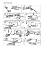 2
2
-
 3
3
-
 4
4
-
 5
5
-
 6
6
-
 7
7
-
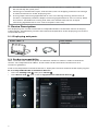 8
8
-
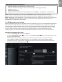 9
9
-
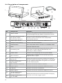 10
10
-
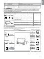 11
11
-
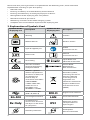 12
12
-
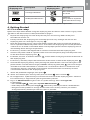 13
13
-
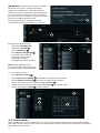 14
14
-
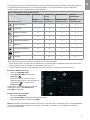 15
15
-
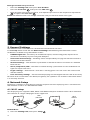 16
16
-
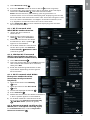 17
17
-
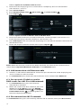 18
18
-
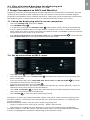 19
19
-
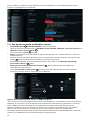 20
20
-
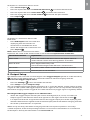 21
21
-
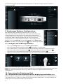 22
22
-
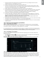 23
23
-
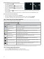 24
24
-
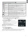 25
25
-
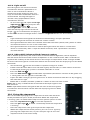 26
26
-
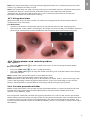 27
27
-
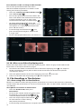 28
28
-
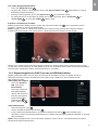 29
29
-
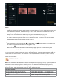 30
30
-
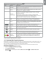 31
31
-
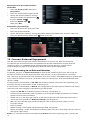 32
32
-
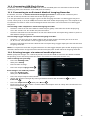 33
33
-
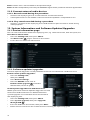 34
34
-
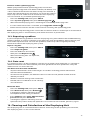 35
35
-
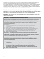 36
36
-
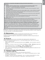 37
37
-
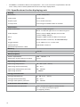 38
38
-
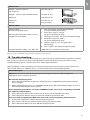 39
39
-
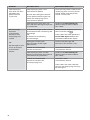 40
40
-
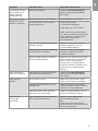 41
41
-
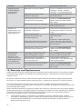 42
42
-
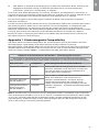 43
43
-
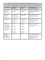 44
44
-
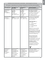 45
45
-
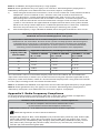 46
46
-
 47
47
-
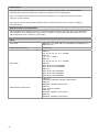 48
48
-
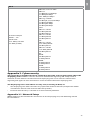 49
49
-
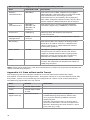 50
50
-
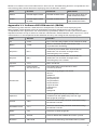 51
51
-
 52
52
-
 53
53
-
 54
54
-
 55
55
-
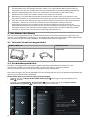 56
56
-
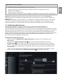 57
57
-
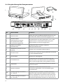 58
58
-
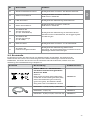 59
59
-
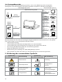 60
60
-
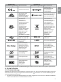 61
61
-
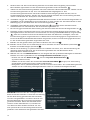 62
62
-
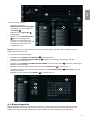 63
63
-
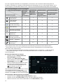 64
64
-
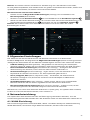 65
65
-
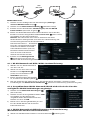 66
66
-
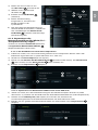 67
67
-
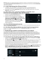 68
68
-
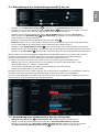 69
69
-
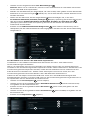 70
70
-
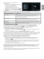 71
71
-
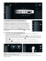 72
72
-
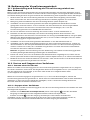 73
73
-
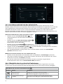 74
74
-
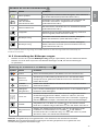 75
75
-
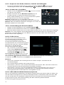 76
76
-
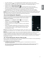 77
77
-
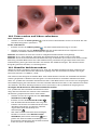 78
78
-
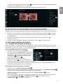 79
79
-
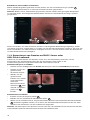 80
80
-
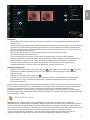 81
81
-
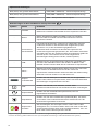 82
82
-
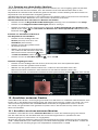 83
83
-
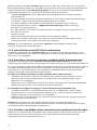 84
84
-
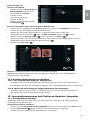 85
85
-
 86
86
-
 87
87
-
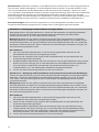 88
88
-
 89
89
-
 90
90
-
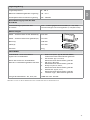 91
91
-
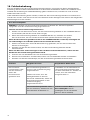 92
92
-
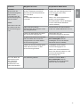 93
93
-
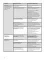 94
94
-
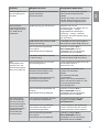 95
95
-
 96
96
-
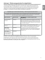 97
97
-
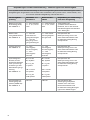 98
98
-
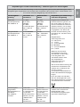 99
99
-
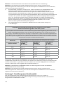 100
100
-
 101
101
-
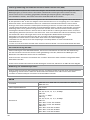 102
102
-
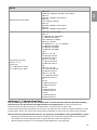 103
103
-
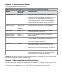 104
104
-
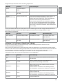 105
105
-
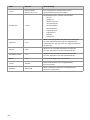 106
106
-
 107
107
-
 108
108
-
 109
109
-
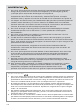 110
110
-
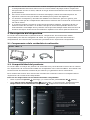 111
111
-
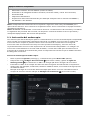 112
112
-
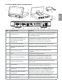 113
113
-
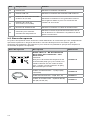 114
114
-
 115
115
-
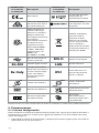 116
116
-
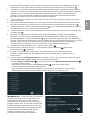 117
117
-
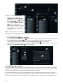 118
118
-
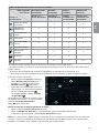 119
119
-
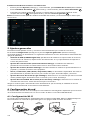 120
120
-
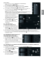 121
121
-
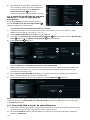 122
122
-
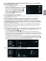 123
123
-
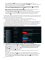 124
124
-
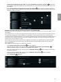 125
125
-
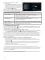 126
126
-
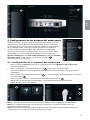 127
127
-
 128
128
-
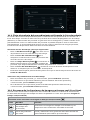 129
129
-
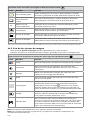 130
130
-
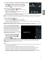 131
131
-
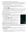 132
132
-
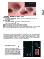 133
133
-
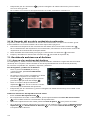 134
134
-
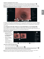 135
135
-
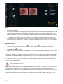 136
136
-
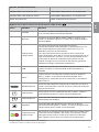 137
137
-
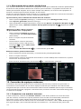 138
138
-
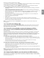 139
139
-
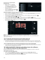 140
140
-
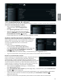 141
141
-
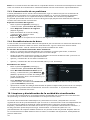 142
142
-
 143
143
-
 144
144
-
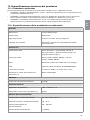 145
145
-
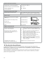 146
146
-
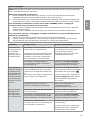 147
147
-
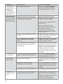 148
148
-
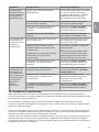 149
149
-
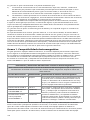 150
150
-
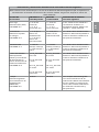 151
151
-
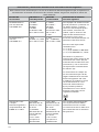 152
152
-
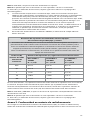 153
153
-
 154
154
-
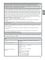 155
155
-
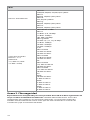 156
156
-
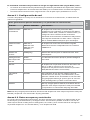 157
157
-
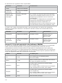 158
158
-
 159
159
-
 160
160
-
 161
161
-
 162
162
-
 163
163
-
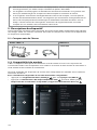 164
164
-
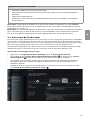 165
165
-
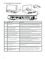 166
166
-
 167
167
-
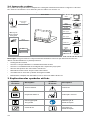 168
168
-
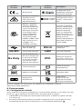 169
169
-
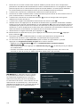 170
170
-
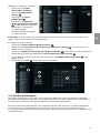 171
171
-
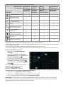 172
172
-
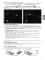 173
173
-
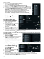 174
174
-
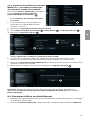 175
175
-
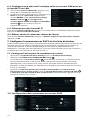 176
176
-
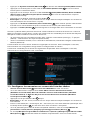 177
177
-
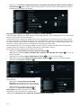 178
178
-
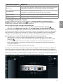 179
179
-
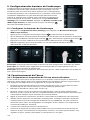 180
180
-
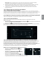 181
181
-
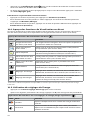 182
182
-
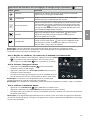 183
183
-
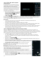 184
184
-
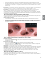 185
185
-
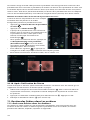 186
186
-
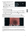 187
187
-
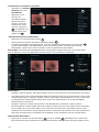 188
188
-
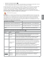 189
189
-
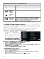 190
190
-
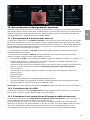 191
191
-
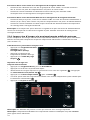 192
192
-
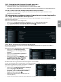 193
193
-
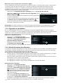 194
194
-
 195
195
-
 196
196
-
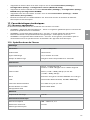 197
197
-
 198
198
-
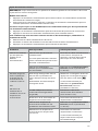 199
199
-
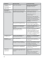 200
200
-
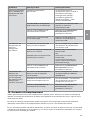 201
201
-
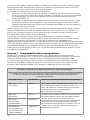 202
202
-
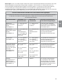 203
203
-
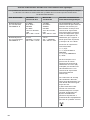 204
204
-
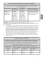 205
205
-
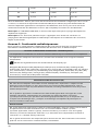 206
206
-
 207
207
-
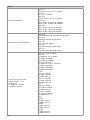 208
208
-
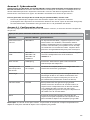 209
209
-
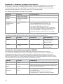 210
210
-
 211
211
-
 212
212
-
 213
213
-
 214
214
-
 215
215
-
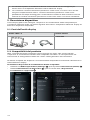 216
216
-
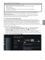 217
217
-
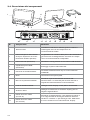 218
218
-
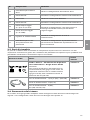 219
219
-
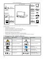 220
220
-
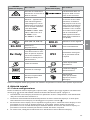 221
221
-
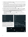 222
222
-
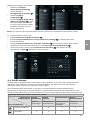 223
223
-
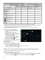 224
224
-
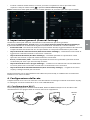 225
225
-
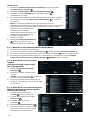 226
226
-
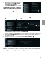 227
227
-
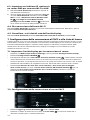 228
228
-
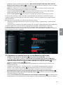 229
229
-
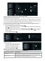 230
230
-
 231
231
-
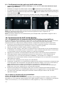 232
232
-
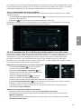 233
233
-
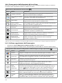 234
234
-
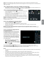 235
235
-
 236
236
-
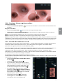 237
237
-
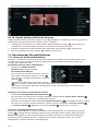 238
238
-
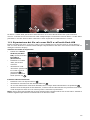 239
239
-
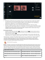 240
240
-
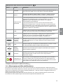 241
241
-
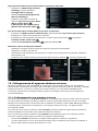 242
242
-
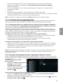 243
243
-
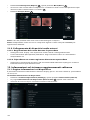 244
244
-
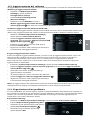 245
245
-
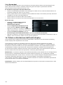 246
246
-
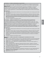 247
247
-
 248
248
-
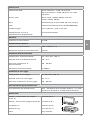 249
249
-
 250
250
-
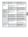 251
251
-
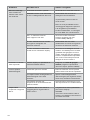 252
252
-
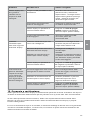 253
253
-
 254
254
-
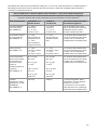 255
255
-
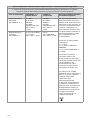 256
256
-
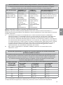 257
257
-
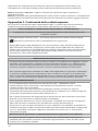 258
258
-
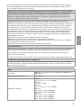 259
259
-
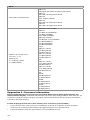 260
260
-
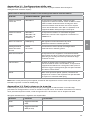 261
261
-
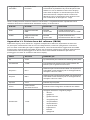 262
262
-
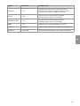 263
263
-
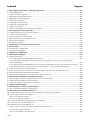 264
264
-
 265
265
-
 266
266
-
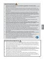 267
267
-
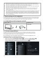 268
268
-
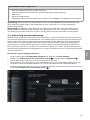 269
269
-
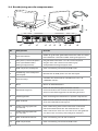 270
270
-
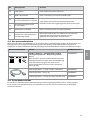 271
271
-
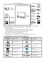 272
272
-
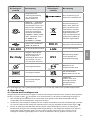 273
273
-
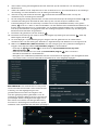 274
274
-
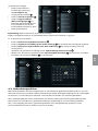 275
275
-
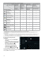 276
276
-
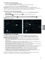 277
277
-
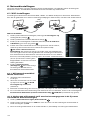 278
278
-
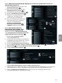 279
279
-
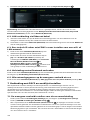 280
280
-
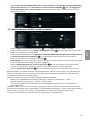 281
281
-
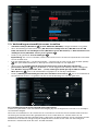 282
282
-
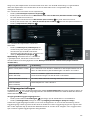 283
283
-
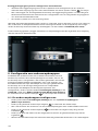 284
284
-
 285
285
-
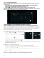 286
286
-
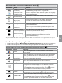 287
287
-
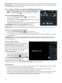 288
288
-
 289
289
-
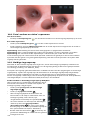 290
290
-
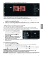 291
291
-
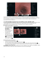 292
292
-
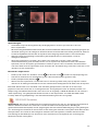 293
293
-
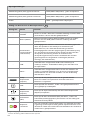 294
294
-
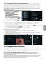 295
295
-
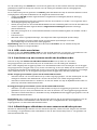 296
296
-
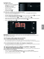 297
297
-
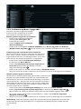 298
298
-
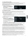 299
299
-
 300
300
-
 301
301
-
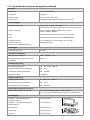 302
302
-
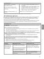 303
303
-
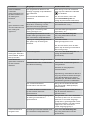 304
304
-
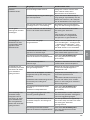 305
305
-
 306
306
-
 307
307
-
 308
308
-
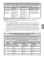 309
309
-
 310
310
-
 311
311
-
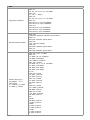 312
312
-
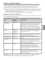 313
313
-
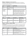 314
314
-
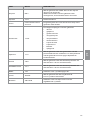 315
315
-
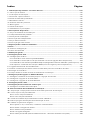 316
316
-
 317
317
-
 318
318
-
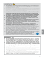 319
319
-
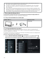 320
320
-
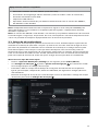 321
321
-
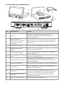 322
322
-
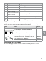 323
323
-
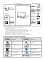 324
324
-
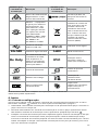 325
325
-
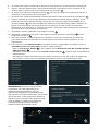 326
326
-
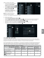 327
327
-
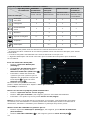 328
328
-
 329
329
-
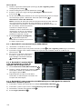 330
330
-
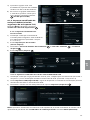 331
331
-
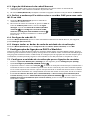 332
332
-
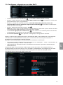 333
333
-
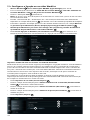 334
334
-
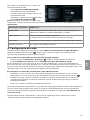 335
335
-
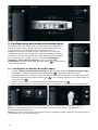 336
336
-
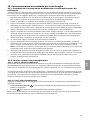 337
337
-
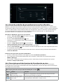 338
338
-
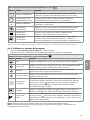 339
339
-
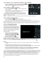 340
340
-
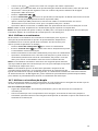 341
341
-
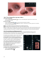 342
342
-
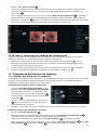 343
343
-
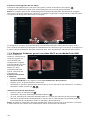 344
344
-
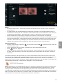 345
345
-
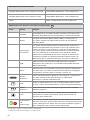 346
346
-
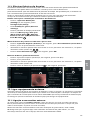 347
347
-
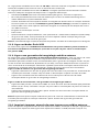 348
348
-
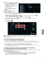 349
349
-
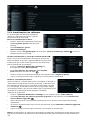 350
350
-
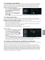 351
351
-
 352
352
-
 353
353
-
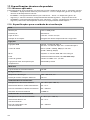 354
354
-
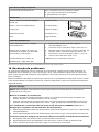 355
355
-
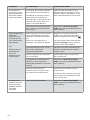 356
356
-
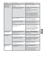 357
357
-
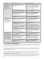 358
358
-
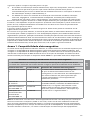 359
359
-
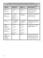 360
360
-
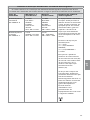 361
361
-
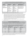 362
362
-
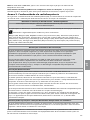 363
363
-
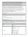 364
364
-
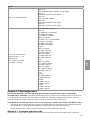 365
365
-
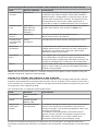 366
366
-
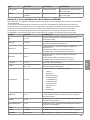 367
367
-
 368
368


en otros idiomas
- français: Ambu aBox™ 2 Mode d'emploi
- italiano: Ambu aBox™ 2 Istruzioni per l'uso
- Deutsch: Ambu aBox™ 2 Bedienungsanleitung
- Nederlands: Ambu aBox™ 2 Handleiding
- português: Ambu aBox™ 2 Instruções de operação
Otros documentos
-
Gima 34207 El manual del propietario
-
DEPSTECH DS350 Manual de usuario
-
 DEPSTECH DS300 Industrial Endoscope Manual de usuario
-
 Steris Proarmor Endoscope Tip Protector Instrucciones de operación
-
DEPSTECH DS300 Manual de usuario
-
 Interacoustics OtoAccess® Worklist HL7 Instrucciones de operación
-
 Hologic Cenova 2.2 Guía del usuario
-
Microlife O3 El manual del propietario
-
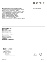 Steris Torrent Scope Connectors Instrucciones de operación
-
Samsung UN65C6500VF Manual de usuario


