Duratech PLP-REM Manual de usuario
- Categoría
- Estroboscopios
- Tipo
- Manual de usuario

English....................Page 3
Nederlands.......Pagina 21
Français...............Page 39
Deutsch...............Seite 57
Español.............Página 75
PLP-REM
Manual
LINK Driver
18-10-22

2

3
ENG
Table of contents
Technical specifications
General Specifications
Logic board
Installation Instructions
Single PLP-REM unit
Multiple PLP-REM installation
Operation modes
DIP switch functionalities
Transmitter functions
Operation mode: PLC
Operatio mode: ON/OFF
Replacing transmitter keypad
Pairing the handheld transmitter
DMX 512 communication
Single PLP-REM unit
Multiple PLP-REM installation
RS-485 communication
Single PLP-REM unit
Multiple PLP-REM installation
RS-485 command set
RESET procedure
Transmitter battery
Troubleshooting
Pool light wiring instructions
Wiring remark
Page 4
Page 5
Page 6
Page 7
Page 8
Page 9
Page 10
Page 10
Page 11
Page 11
Page 12
Page 13
Page 14
Page 14
Page 15
Page 16
Page 16
Page 17
Page 18
Page 19
...........................................................
..............................................................................
...............................................................
...............................................
..................................................................................
....................................................................
............................................................
........................................................
...............................................
.........................................
...............................................................
...............................................
...............................................................
...............................................
...........................................................................
...................................................................................
.................................................................................
.....................................................................................
..............................................................
.........................................................................................

4
General specifications
Input Voltage: 12VAC 50Hz ± 10%
Max rating “12VAC TO LAMPS” contact 58A / 12VAC
Max rating relay contact A &B 16A / 250 VAC
Max switching power A & B 4000VA
RF band 868 MHz
Ambient Air Temperature: 0°C to +40°C
Humidity 10% to 90% RH
non condensing
Ingress protection rate: IP54
IEC Protection Class: Class II
Technical specifications

5
ENG
Logic board
DMX Address dial
To choose the
DMX start address
CAN bus
12VAC connection
terminals
To connect the pool
lights
DIP switch
To select controller functionalities
RS-485
connection
To connect to
home automation
system
(see page 14)
SD card slot
For firmware updates
DMX input/outpout
The PLP-REM can act
as a DMX receiver with
DMX passthrough
A/B output
For auxiliary circuits
Acts as a SPST
(single-pole, single-
throw) switch
Status LED’s:
(1) General status
Green = OK
Red = error overvoltage or overcurrent
(2) Pairing / RESET status
(3) 12VAC to Pool lamps (Green = ON)
(4) Switch A (Green = ON)
(1)
(2)
(3)
(5)
(4)
(8)
(6)
(7)
(5) Switch B status (Green = ON)
(6) CAN status
(7) RS-485 signal
(8) DMX signal
Pairing / RESET
button
DuraLink RF board
For wireless communication
DuraLink

6
Installation Instructions
Single PLP-REM unit
. Connect a 12VAC magnetic transformer to the “12VAC FROM TRANSFORMER”
terminal of the PLP-REM.
Connect the pool lights to the “12VAC TO LAMPS” terminal in the PLP-REM.
. Install the filter (included in box) to the primary circuit (230VAC side)
of the transformer
. The “12VAC TO LAMPS” relay contact has a max rating of 58A. Make sure the
total power load does not exceed this (58A x 12VAC = 696VA)
12VAC
230VAC
C
C

7
ENG
12VAC 230VAC
C
12VAC 230VAC
C
12VAC 230VAC
C
Multiple PLP-REM installation
For extended installations (total lamp power > 700VA), multiple PLP-REM’s
can be linked together. This way, a perfect synchronisation of all pool lights
is still guaranteed.
The PLP-REM’s need to communicate with each other, to ensure all the
lamps are in perfect sync.
Connect the PLP-REM’s with each other using the CAN bus:
Connect the CAN terminals of the first PLP-REM with the CAN terminal of
the second PLP-REM*.
If more than 2 PLP-REM’s are necessary, simply daisy chain each CAN termi-
nal with the one from the next PLP-REM (see below). Respect the
polarity of the terminals! (CAN L & H)
Next, set the DIP switches on the PLP-REM’s to the correct MASTER/SLAVE
setting. The first PLP-REM will be the MASTER. All the others will be SLAVE’s.
Refer to page 9 for Master/Slave DIP switch info.
CAN BUS
set as MASTER set as SLAVE set as SLAVE
* We recommend using a shielded twisted pair cable (min. 0,5mm² - up to 200m) to connect
multiple PLP-REM’s using the CAN bus.
In a Master/Slave setup, only the PLP-REM that is set as MASTER will
react to transmitter commands. Any additional transmitters will need to
be paired with this MASTER PLP-REM
!

8
ON/OFF PLC
Compatible lamps
Switch lamps ON/OFF YES YES
Change lamp color YES(1) YES(1)
Operate Relay A & B YES YES
Dimming lamps NO YES(1)
DMX control NO YES
RS-485 control YES(2) YES
Dip switch setting DIP 1 ON DIP 1 OFF
Remote keypad type(3)
Operation Modes
The PLP-REM controller has 2 main operation modes:
“ON/OFF control mode” & “PLC control mode”. Each mode has it’s own
functionalities:
1) Only for RGB lamps
2) In ON/OFF control mode, only a few RS-485 commands are available (see p 15)
3) Depending on which control mode is selected, the keypad of the transmitter needs
to be changed

9
ENG
DIP switch functionalities
The DIP switch on the main circuit board of the PLP-REM allows the user to
customise the way the PLP-REM operates.
* Fast PLC setting (Only for Adagio Pro lamps from 2018 and onwards)
Fast: lamps will respond quickly to input commands from PLP-REM (fast, but less robust)
Slow: lamps wil respond slower to input commands from PLP-REM (slow, but more robust)
DIP SWITCH
function setting 1 2 3 4 5 6
Operation Mode ON/OFF ON
PLC OFF
Relay A PULSE mode ON
TOGGLE mode OFF
Relay B PULSE mode ON
TOGGLE mode OFF
Fast PLC setting * FAST ON
STANDARD OFF
DMX NO LOOP ON
LOOP OFF
MASTER/SLAVE mode SLAVE ON
MASTER OFF
ON position
OFF position
CAUTION: Always switch o the main power supply to the
PLP-REM before changing the DIP switches

10
Transmitter functions
Short push (< 1 sec):
Toggle all lamps ON or OFF
Short push:
Go to next color program
Long push:
Auto sync procedure (3)
OPERATION MODE: PLC (default mode)
Short push:
Toggle output A ON/OFF
Long push:
/
Short push:
Toggle output B ON/OFF
Long push:
/
Short push (< 1 sec):
Toggle all lamps ON or OFF (1)
Long push (> 2 sec(2)):
All lamps & “12VAC TO LAMPS” relay are turned OFF (1)
Short push:
Go to next color program
Long push:
Toggle output A ON/OFF
Short push:
Go to the previous color program
Long push:
Toggle output B ON/OFF
Short push:
Select next dimming level:
100% -- 74% -- 36% ---> 100% -- ...
Long push:
Set lamps to Program 1 (blue) & full brightness
(1) Lamp ON or OFF status is memorized after power down
(2) The green LED in the transmitter will light up as soon as you start pressing a button, and will stop
after 2 seconds, so you know exactly when to release the button.
(3) The lamps will be turned o for 30 seconds and then switched ON/OFF 3 times. This will set all
lamps to program 1: blue
OPERATION MODE: ON/OFF

11
ENG
Short push (< 1 sec):
Toggle all lamps ON or OFF
Short push (< 1 sec):
Toggle all lamps ON or OFF (1)
Long push (> 2 sec(2)):
All lamps & “12VAC TO LAMPS” relay are turned OFF (1)
Pairing the handheld transmitter to the PLP-REM
All handheld transmitters are already paired in the factory and ready to use. In
case a problem arises, the pairing process can be done as below:
Replacing transmitter Keypad
Depending on which control mode is selected, the keypad of the transmitter
needs to be changed:
• Remove the philips head screw and open the transmitter
• Replace the Keypad in the top part of the transmitter housing
• Reassemble in reverse order
Pairing Indicator LED
(blue) Pairing button
Keypad for
ON/OFF mode
Keypad for
PLC mode
1) Press the pairing button on the circuit board, inside the PLP-REM
---> The BLUE LED will start to blink
2) Within 25 seconds, push any button on the handheld transmitter.
---> If the remote is paired correctly, the BLUE LED will flash slowly for 5 times
---> UNPAIRING:
See RESET procedure: page 16
DuraLink

12
12VAC
230VAC
C
DMX 512 communication
Single PLP-REM unit
1) Make sure DIP switch 1 is switched OFF.
2) Make sure the lights are turned ON with the remote
Address dial
Address dial setup
Setting the DMX address of the PLP-REM:
Select the desired number on the address dial. The chosen number deter-
mines the DMX addresses of the PLP-REM & lamps.
Each lamp uses 3 bytes of DMX data (R-G-B), and all lamps receive the same
DMX data from the PLP-REM.
Connect DMX
panel
to DMX IN (+/-)
DMX PANEL
The DMX start address can be overruled by using the RS-485 command:
“set DMX start address” (see page 15)
DMX
address 1 2 3 4 5 6 7 8 9 ...
0 1 2 ...
R G B R G B R G B ...
Address dial
position
! Remark:
When in DMX512 operation, the handheld transmitter can still select one of three dim-
ming levels and can still switch the lamps. This can not be overridden by DMX512 data.

13
ENG
12VAC 230VAC
C
12VAC 230VAC
C
12VAC 230VAC
C
Multiple PLP-REM installation
DMX PANEL
Address dial Address dial
Address dial
1) Connect the DMX panel to the “DMX IN” port of the first PLP-REM
2) Connect the PLP-REM’s with each other (open loop):
DMX OUT --> DMX IN (polarized terminals + -)
3) Set the DMX address for each PLP-REM via the address dial.
- Option 1: All PLP-REM’s can be set to the same address:
This implies that all lamps will receive the same DMX data,
And will all operate identically
- Option 2: PLP-REM’s can be set to dierent addresses:
Each PLP-REM will have it’s own group of connected lamps
that will operate identically.
However, since each PLP-REM has it’s own unique address,
the dierent lamp groups can be controlled separately

14
RS-485 communication
1) Make sure DIP switch 1 is switched OFF.
2) Connect the RS-485 source to the “485” port on the PLP-REM
3) Communication settings: 9600, 8, 1, n
4) Command list: see page 15
Single PLP-REM unit
1) Connect the PLP-REM’s with each other via the CAN bus (see page 7)
2) Make sure DIP switch 1 is switched OFF
3) Connect the first PLP-REM with the RS-485 source like described above.
This PLP-REM will be the Master.
4) Communication settings & command list: see above
Multiple PLP-REM installation
12VAC
230VAC
C
RS485 source

15
ENG
RS-485 Command set
Command Command Remark Example available in
ON/OFF mode
available in
PLC mode
Lamps OFF PL0 All lamps OFF X X
Lamps ON PL1 All lamps ON X X
Program UP PsU Jump to next program X X
Program Down PsD Return to previous program X
Set Program PSxx xx is the decimal representaon
of the program number (01 - 14) PS06 = jump to program 6 X
Auto sync procedure PsS executes the auto sync procedure (see page 10) X X
White 1 PW1 Jump to White 1 (program 12) X
White 2 PW2 Jump to White 2 (program 13) X
White 3 PW3 Jump to White 3 (program 14) X
Set RGB PCrrrgggbbb rrr, ggg and bbb are the decimal representaon
of the RGB value (with leading zero’s)
1) PC255128064 = Full output level on Red color, half out-
put level on Green color, 1/4 output level on Blue color
2) PC255255255 = All colors at full output level
3) PC000000000 = All colors OFF
X
Set Dim value PDxxx set the OUTPUT value of the lamp in % (000 -
100) PD075 = 75% output level (on all LED’s) X
set DMX startAdress PAxxxyz y = ‘e’ or ‘E’ PA035E = set DMX start address to 35 [35(R), 36(G),
37(B)] X
Set color in percentage Pprgbe variable size, rgb = ASCII 0-255, e = end character Pp25050100e = Red 25%, Green 50%, Blue 100% X
Set color in hex Pcrgbe variable size, rgb = HEX 0-F-F, e = end character Pc6408OFFe = Red 25%, Green 50%, Blue 100% X
Relay A control PRAx x = 1 (ON), 0 (OFF), P (Pulse) !this overrules
dipswitch PRA1 = Relay A ON PRA0 = Relay A OFF X X
Relay B control PRBx x = 1 (ON), 0 (OFF), P (Pulse) !this overrules
dipswitch PRB1 = Relay B ON PRB0 = Relay B OFF X X
ON/OFF relay control PRMx x = 1 (ON), 0 (OFF) PRM1 = Relay ON/OFF control ON X X
Color temperature PTxyz x = ten thousand ; y = thousand ; z = hundred PT035 = Set white color temperature to 3500K (in steps
of 500K) X

16
RESET procedure
RESET procedure for the control board
1) Make sure the PLP-REM is powered ON
2) Press and hold the RESET button on the logic board
3) The blue LED will light up
4) Release the RESET button when the blue LED turns o
The control board has been RESET.
And all transmitters have been unpaired.
RESET
button
Blue
LED
DuraLink
!
+
• Remove the philips head screw and open the transmitter
• Replace the battery, respecting the polarity
Battery type: A23 12V
Replacing transmitter battery:
Transmitter battery

17
ENG
Troubleshooting
PROBLEM SOLUTION
The PLP-REM doesn’t react to
transmitter commands
• Perform a RESET procedure
• Check the battery of the handheld
transmitter (see p.16)
• The transmitter is not paired-
correctly with the PLP-REM.
Repeat the pairing process
• Reduce the distance between
handheld transmitter and PLP-REM
and/or remove obstacles
• Check the General status light on
the logic board. If it’s red, then
the secondary voltage is too high
(>14VAC) or there is a short circuit
• Check the LED on the small DURA-
LINK circuit board (top right cor-
ner). This LED needs to blink each
time a transmitter button is pressed.
If the LED works, there might be a
problem with the logic board
The pool lights don’t work
or don’t change colors
correclty
• Perform a RESET procedure
• Check if all connections are made
according to the electrical scheme.
• Switch the PLP-REM to ON/OFF
mode (DIP switch nr 1) and check if
the lamps work
Handheld transmitter does not
function anymore after firmware
update of the PLP-REM for Link-
Touch compatibility
• Buy a new TX868 transmitter that
has updated firmware

18
Pool light wiring instructions
Please refer to the manual of your DURAVISION pool light for detailed
information about cable cross section and maximum length.
Cable installation guidelines
Richtlijnen voor bekabeling
Anleitung zur Verkabelung
Instructions de câblage
Istruzioni di collegamento
Instrucciones para ajuste del cableado
WARNING
Not following the instructions for cable cross section and transformer VA ratings may result in lamp malfunctioning and may
result in having to rewire the installation. The manufacturer's warranty does not apply in this situation.
Please refer to the manual of your DURAVISION® pool light
GB
DE
FR
IT
ES
NL
Manual downloads:
www.duratech.be/downloads

19
Wiring remarks
Pool
house
Pool
12VAC to lamps
230VAC / 400VAC to third party equipment
230VAC Min. 50cm
(**)
(**) Do not mix 12VAC and 230VAC / 400VAC power line cables into the
same cable trays
1. Third party equipment such as frequency inverters and electric motors
can generate excessive noise on the 230VAC / 400VAC power line.
This noise might be injected into the adjacent 12VAC power line and
disturb the power line communication towards the DURAVISION lights.
!Keep 230VAC / 400VAC power line cables at least 50cm separated over their full
length from the 12VAC power line towards any RGB lights
Do not mix 12VAC and 230VAC / 400VAC power line cables into the same cable
trays
!
We recommend using 2 CORE cables for all Adagio Pro lights to avoid PLC
communication issues
2. Floating cores in a multi-core cable are not allowed because it disturbs
PLC communication.
!

20

21
NL
Inhoudstafel
Technische specificaties
Algemene Specificaties
Controller board
Installatie Instructies
Enkele PLP-REM unit
Installatie met meerdere PLP-REM’s
Werkingsmodus
DIP schakelaar functies
Afstandsbediening functies
Werkingsmodus: PLC
Werkingsmodus: AAN/UIT
Klavier van afstandsbediening vervangen
Afstandsbediening en controller koppelen
DMX 512 communicatie
Enkele PLP-REM unit
Installatie met meerdere PLP-REM
RS-485 communication
Enkele PLP-REM unit
Installatie met meerdere PLP-REM’s
RS-485 commando’s
RESET procedure
Afstandsbediening batterij
Probleemoplossing
Kabelinstructies
Kablering opmerking
Pagina 22
Pagina 23
Pagina 24
Pagina 25
Pagina 26
Pagina 27
Pagina 28
Pagina 28
Pagina 29
Pagina 29
Pagina 30
Pagina 31
Pagina 32
Pagina 33
Pagina 33
Pagina 34
Pagina 34
Pagina 35
Pagina 36
Pagina 37
..........................................................
......................................................................
..............................................................
...................................
.....................................................................................
........................................................................
..............................................................
.....................................................
..........................
........................
.....................................................
......................................
..............................................................
...................................
............................................................................
...................................................................................
...................................................................
................................................................................
.....................................................................................
.............................................................................

22
Algemene specificaties
Ingangsspanning: 12VAC 50Hz ± 10%
Max stroom contact “12VAC NAAR LAMPEN” 58A / 12VAC
Max stroom relais contact A &B 16A / 250 VAC
Max schakel vermogen A & B 4000VA
RF band 868 MHz
Omgevingstemperatuur: 0°C to +40°C
Vochtigheidsgraad: 10% to 90% RH
non condensing
IP code : IP54
IEC beschermingsklasse: Class II
Technische specificaties

23
NL
(2)
(3)
(5)
(4)
(8)
(6)
(7)
DuraLink RF board
Voor draadloze communicatie
DuraLink
Controller bord
DMX adres toewijzer
Om het DMX start adres
te kiezen
CAN bus
12VAC aansluitklemmen
Om de zwembadverlichting
op aan te sluiten
DIP schakelaar
Om de controller functies te
selecteren
RS-485
connectie
Om te verbinden met
domotica systemen
(zie pagina 32)
SD card slot
Voor firmware updates
RESET KNOP
DMX ingang/uitgang
De PLP-REM kan werken als DMX
ontvanger (met DMX doorgang-
signaal)
A/B uitgang
Voor additionele circuits.
Gedraagt zich als een SPST
(sinlge-pole, single-throw)
schakelcontact
Status LED’s:
(1) Algemene status
Groen = OK
Rood = overvoltage of overcurrent
(2) RESET status
(3) 12VAC naar zwembadverlichting
(Groen = AAN)
(4) Schakelcontact A (Groen = AAN)
(5) Schakelcontact B status
(Groen = AAN)
(6) CAN status
(7) RS-485 signaal
(8) DMX signaal

24
Installatie instructies
12VAC
230VAC
C
Enkele PLP-REM unit
. Verbind een 12VAC transformator met de “12VAC FROM TRANSFORMER”
aansluiting van de PLP-REM. Verbind de zwembadverlichting met de
“12VAC TO LAMPS” aansluiting van de PLP-REM.
. Installeer de capaciteit (meegeleverd in verpakking) met het primaire circuit
(230VAC side) van de transformator.
. Het “12VAC TO LAMPS” relais contact heeft een max stroom van 58A.
Het totale vermogen van de zwembadverlichting mag dit
niet overschrijden (58A x 12VAC = 696VA).

25
NL
Installatie met meerdere PLP-REM’s
Voor uitgebreide installaties (totale vermogen van de lampen > 700VA) kun-
nen meerdere PLP-REM’s met elkaar verbonden worden. Op deze manier
blijft een perfecte synchronisatie van alle lampen gegarandeerd.
De PLP-REM’s moeten met elkaar kunnen communiceren, om zeker te zijn
dat alle lampen synchroon kunnen lopen.
Verbind de PLP-REM’s met elkaar via de CAN bus:
Verbind de CAN klemmen van de eerste PLP-REM met de CAN klemmen van
de tweede PLP-REM, verbind dan de tweede met de derde, enzovoort... (zie
tekening onder)*
Respecteer de polariteit van de aansluitklemmen! (CAN L & H)
Vervolgens moeten de DIP switches van de PLP-REM’s op de correcte positie
(MASTER/SLAVE) gezet worden. De eerste PLP-REM is de Master. Alle an-
deren zijn Slaves. Zie pagina 27 voor Master/Slave DIP switch info.
* We raden aan om een ‘shielded twisted pair’ kabel te gebruiken (min. 0,5mm² - tot 200m) om
verschillende PLP-REM’s te verbinden via de CAN bus.
stel in als MASTER stel in als SLAVE stel in als SLAVE
In een Master/Slave opstelling reageert enkel de PLP-REM die ingesteld
is als MASTER op de commando’s van de afstandsbediening. Eventuele
extra zenders moeten dus worden gekoppeld aan deze
MASTER PLP-REM
!
12VAC 230VAC
C
12VAC 230VAC
C
12VAC 230VAC
C
CAN BUS

26
AAN/UIT PLC
Compatibele lampen
schakel lampen AAN/UIT JA JA
Verander kleur van lamp JA(1) JA(1)
Bedien Relais A & B JA JA
Dimmen van de lampen NEE JA(1)
DMX sturing NEE JA
RS-485 sturing JA(2) JA
Dip switch positie DIP 1 AAN DIP 1 UIT
Type klavier
afstandsbediening(3)
Werkingsmodus
De PLP-REM kan gebruikt worden in 2 hoofd werkingsmodi:
“AAN/UIT bedieningsmodus” & “PLC bedieningsmodus”. Elke modus heeft
een aantal specifieke functies:
1) Enkel voor RGB lampen
2) In AAN/UIT bedieningsmodus zijn slechts enkele RS-485 commando’s beschikbaar
(zie p 33)
3) Afhankelijk van de gekozen werkingsmodus, moeten de rubber toetsen van de
afstandsbediening verwisseld worden (meegeleverd in verpakking).

27
NL
DIP switch functies
De DIP switch op het moederbord van de PLP-REM laat toe om een aantal
functies van de PLP-REM aan te passen:
* Snelle PLC instelling (enkel voor Adagio Pro lampen vanaf 2018 of nieuwer)
Snel: lampen reageren sneller op commando’s van PLP-REM (snel, maar minder robuust)
Traag: lampen reageren trager op commando’s van PLP-REM (traag, maar meer robuust)
DIP SWITCH
functie setting 1 2 3 4 5 6
Werkingsmodus AAN/UIT AAN
PLC UIT
Relais A PULS modus AAN
TOGGLE modus UIT
Relais B PULS modus AAN
TOGGLE modus UIT
SNELLE PLC instelling * SNEL AAN
STANDAARD UIT
DMX GEEN LOOP AAN
LOOP UIT
MASTER/SLAVE modus SLAVE AAN
MASTER UIT
WAARSCHUWING: Zorg ervoor dat de voedingsspanning van de
PLP-REM uitgeschakeld is, vooraleer de DIP
switches te veranderen
AAN positie
UIT positie

28
Afstandsbediening functies
Kort drukken (< 1 sec):
Zet de lampen AAN of UIT(1)
Kort drukken:
Ga naar het volgende kleurprogramma
Lang drukken:
Automatische sync procedure (3)
Kort drukken:
Zet de uitgang A AAN/UIT
Lang drukken:
/
Kort drukken:
Zet de uitgang B AAN/UIT
Lang drukken:
/
Kort drukken (< 1 sec):
Zet de lampen AAN of UIT(1)
Lang drukken (> 2 sec(2)):
Zet alle lampen & de “12VAC TO LAMPS” relais UIT (1)
Kort drukken:
Ga naar het volgende kleurprogramma
Lang drukken:
Zet de uitgang A AAN/UIT
Kort drukken:
Ga naar het vorige kleurprogramma
Lang drukken:
Zet de uitgang B AAN/UIT
Kort drukken:
Selecteer het volgende dim niveau:
100% -- 74% -- 36% ---> 100% -- ...
Lang drukken:
Zet de lampen op programma 1 (blauw) met
100% dim niveau (max helderheid)
(1) De laatste status van de lampen (AAN of UIT) wordt onthouden bij een stroomonderbreking
(2) De groene LED in de afstandsbediening licht op zodra je een knop indrukt, en gaat uit na 2 seconden
zodat je exact weet wanneer je de knop mag loslaten.
(3) De lampen worden eerst UIT gezet gedurende 30 seconden en daarna 3x AAN/UIT gezet. De lampen
worden hierdoor gesynchroniseerd en komen op kleurprogramma 1 te staan (blauw).
WERKINGSMODUS: PLC (standaard modus)
WERKINGSMODUS: AAN/UIT

29
NL
Kort drukken (< 1 sec):
Zet de lampen AAN of UIT(1)
Kort drukken (< 1 sec):
Zet de lampen AAN of UIT(1)
Lang drukken (> 2 sec(2)):
Zet alle lampen & de “12VAC TO LAMPS” relais UIT (1)
Klavier van afstandsbediening vervangen
Afhankelijk van de gekozen werkingsmodus, kan het klavier van de af-
standsbediening vervangen worden:
• Verwijder de kruis schroef en open de afstandsbediening
• Vervang het klavier van de afstandsbediening
• Monteer het geheel terug in omgekeerde volgorde
Klavier voor
AAN/UIT modus
Klavier voor
PLC modus
Afstandsbediening en controller koppelen
De afstandsbediening is reeds gekoppeld van in de febriek. In probleem-
gevallen kan men de afstandsbediening ook manueel koppelen:
1) Druk op de “koppel knop” binnenin de PLP-REM
---> De BLAUWE LED begint te knipperen.
2) Druk op eender welke knop van de afstandsbediening binnen de 25sec.
---> Als de afstandsbediening correct is gekoppeld, knippert de BLUE LED 5 keer
langzaam
---> ONTKOPPELEN:
Zie RESET procedure: pagina 34
Blauwe LED Koppel knop

30
DMX 512 communicatie
Enkele PLP-REM unit
1) Zorg ervoor dat DIP schakelaar 1 is uitgeschakeld.
2) Zorg ervoor dat de lampen aan staan via de afstandsbediening.
Adres
toewijzer
Adres toewijzer instelling
DMX adres van de PLP-REM instellen:
Kies een positie van de adres toewijzer. Het gekozen cijfer bepaalt de DMX
adressen van de PLP-REM & lampen.
Elke lamp gebruikt 3 bytes DMX data (R-G-B) en alle lampen ontvangen de-
zelfde DMX data van de PLP-REM.
verbindt DMX
paneel met
DMX IN (+/-)
Het DMX start adres kan overschreven worden, door het RS-485 commando
“set DMX start address” te gebruiken (zie pagina 33).
DMX
adres 1 2 3 4 5 6 7 8 9 ...
0 1 2 ...
R G B R G B R G B ...
Adres toewijzer
positie
12VAC
230VAC
C
DMX PANEL
! Opmerking:
In DMX512 bedrijf, kan de je met de afstandsbediening nog steeds één van de drie dim
niveaus selecteren en nog steeds de lampen schakelen. Dit kan niet verworpen worden
door DMX512 gegevens

31
NL
Installatie met meerdere PLP-REM’s
1) Verbindt het DMX paneel met de “DMX IN” poort van de eerste PLP-REM
2) Verbindt de PLP-REM’s met elkaar zoals op onderstaande foto
DMX OUT --> DMX IN (gepolariseerde aansluiting + -)
3) Stel het DMX adres in voor elke PLP-REM via de adres toewijzer.
- Optie 1: Alle PLP-REM’s zitten op hetzelfde adres:
Dit zorgt ervoor dat alle lampen dezelfde DMX data ontvangen,
en zich allemaal identiek gedragen.
- Optie 2: De PLP-REM’s zitten op verschillende adressen:
Elke PLP-REM heeft zijn eigen “groep” lampen die zich
onderling identiek gedragen.
En elke PLP-REM kan dan nog eens afzonderlijk aan-
gestuurd worden.
12VAC 230VAC
C
12VAC 230VAC
C
12VAC 230VAC
C
DMX PANEL
Adres toewijzer Adres toewijzer Adres toewijzer

32
RS-485 communicatie
1) Zorg ervoor dat DIP schakelaar 1 is uitgeschakeld.
2) Verbindt de RS-485 bron met de “485” poort op de PLP-REM
3) Communicatie instellingen: 9600, 8, 1, n
4) Commando lijst: zie pagina 33
Enkele PLP-REM unit
1) Verbindt de PLP-REM’s met elkaar via de CAN bus (zie pagina 25)
2) Zorg ervoor dat DIP schakelaar 1 is uitgeschakeld
3) Verbindt de eerste PLP-REM met de RS-485 bron zoals hierboven
beschreven. Deze PLP-REM is de Master.
4) Communicatie instellingen en commando lijst: zie boven
Installatie met meerdere PLP-REM’s
12VAC
230VAC
C
RS485 bron

33
NL
RS-485 Commando’s
Command Command Remark Example available in
ON/OFF mode
available in
PLC mode
Lamps OFF PL0 All lamps OFF X X
Lamps ON PL1 All lamps ON X X
Program UP PsU Jump to next program X X
Program Down PsD Return to previous program X
Set Program PSxx xx is the decimal representaon
of the program number (01 - 14) PS06 = jump to program 6 X
Auto sync procedure PsS executes the auto sync procedure (see pagina
10) X X
White 1 PW1 Jump to White 1 (program 12) X
White 2 PW2 Jump to White 2 (program 13) X
White 3 PW3 Jump to White 3 (program 14) X
Set RGB PCrrrgggbbb rrr, ggg and bbb are the decimal representaon
of the RGB value (with leading zero’s)
1) PC255128064 = Full output level on Red color, half out-
put level on Green color, 1/4 output level on Blue color
2) PC255255255 = All colors at full output level
3) PC000000000 = All colors OFF
X
Set Dim value PDxxx set the OUTPUT value of the lamp in % (000 -
100) PD075 = 75% output level (on all LED’s) X
set DMX startAdress PAxxxyz y = ‘e’ or ‘E’ PA035E = set DMX start address to 35 [35(R), 36(G),
37(B)] X
Set color in percentage Pprgbe variable size, rgb = ASCII 0-255, e = end character Pp25050100e = Red 25%, Green 50%, Blue 100% X
Set color in hex Pcrgbe variable size, rgb = ASCII 0-255, e = end character Pc64128255e = Red 25%, Green 50%, Blue 100% X
Relay A control PRAx x = 1 (ON), 0 (OFF), P (Pulse) !this overrules
dipswitch PRA1 = Relay A ON PRA0 = Relay A OFF X X
Relay B control PRBx x = 1 (ON), 0 (OFF), P (Pulse) !this overrules
dipswitch PRB1 = Relay B ON PRB0 = Relay B OFF X X
ON/OFF relay control PRMx x = 1 (ON), 0 (OFF) PRM1 = Relay ON/OFF control ON X X
Color temperature PTxyz x = ten thousand ; y = thousand ; z = hundred PT035 = Set white color temperature to 3500K (in steps
of 500K) X

34
RESET procedure
RESET procedure voor het controller bord
1) Zorg ervoor dat de PLP-REM AAN staat.
2) Druk op de RESET knop op het controller board.
3) De blauwe LED gaat branden
4) Laat de RESET knop los van zodra de blauwe LED uitgaat
Het controller board is nu ge-RESET.
Alle afstandsbedieningen zijn nu ontkoppeld.
RESET
knop
Blauwe
LED
!
+
-
• Verwijder de kruiskop schroef en open de afstandsbediening
• Vervang de batterij en respecteer de polariteit.
Batterij type: A23 12V
Batterij vervangen:
Afstandsbediening batterij
DuraLink

35
NL
Probleemoplossing
PROBLEEM OPLOSSING
De PLP-REM reageert niet op
commando’s van de afstandsbe-
diening
• Voer een RESET procedure uit
• Controleer de batterij van de af-
standsbediening (zie pagina 34)
• De afstandsbediening is niet cor-
rect gekoppeld met de controller.
Herhaal de koppel procedure (zie
pagina 29)
• Verminder de afstand tussen de af-
standsbediening en de controller
en/of verwijder obstakels
• Controleer de algemene status LED
op het controller board. Als deze
rood is dan is de secundaire span-
ning te hoog (>14VAC) of er is een
kortsluiting.
• Controleer de LED op de kleine
DURALINK printplaat (rechter
bovenhoek). Deze LED moet knip-
peren, elke keer er op een knop
van de afstandsbediening gedrukt
wordt. Als de LED werkt, is er mo-
gelijks een probleem met het con-
troller board
De zwembadverlichting werkt
niet
• Voer een RESET procedure uit
• Verifieer of alle verbindingen ge-
maakt zijn zoals op de electrische
schema’s
• Zet de PLP-REM in AAN/UIT mode
(DIP switch nr 1) en controleer of
de lampen werken
De afstandsbediening werkt niet
meer na een firmware update
van de PLP-REM voor LinkTouch
compatibiliteit
• Koop een nieuwe TX868 af-
standsbediening met geupdate
firmware

36
Kabelinstructies
Voor gedetailleerde informatie in verband met kabelsecties en maximum
lengtes verwijzen we graag naar de handleiding van uw DURAVISION
zwembadlamp.
Cable installation guidelines
Richtlijnen voor bekabeling
Anleitung zur Verkabelung
Instructions de câblage
Istruzioni di collegamento
Instrucciones para ajuste del cableado
WARNING
Not following the instructions for cable cross section and transformer VA ratings may result in lamp malfunctioning and may
result in having to rewire the installation. The manufacturer's warranty does not apply in this situation.
Please refer to the manual of your DURAVISION® pool light
GB
DE
FR
IT
ES
NL
Manual downloads:
www.duratech.be/downloads

37
Kablering opmerkingen
Pool
house
Zwembad
12VAC naar lampen
230VAC / 400VAC naar andere toestellen
230VAC Min. 50cm
(**)
(**) Zorg ervoor dat er geen 12VAC en 230VAC / 400VAC kabels
samen in eenzelfde kabelgoot liggen
1. Andere toestellen zoals frequentie inverters of electrische motors
kunnen veel ruis veroorzaken op de 230VAC / 400VAC spanningslijn.
Het is mogelijk dat dit ruis geïnjecteerd wordt in een nabijgelegen
12VAC kabel, en dusdanig de communicatie naar de zwembadlampen
verstoord.
!
Houdt 230VAC / 400VAC voedingskabels uit de buurt van de 12VAC kabels
van de lampen. De minimum afstand bedraagt 50cm, en dit over de gehele
lengte van de kabel
Zorg ervoor dat er geen 12VAC en 230VAC / 400VAC kabels samen in een-
zelfde kabelgoot liggen
!
We raden aan om 2-aderige kabels te gebruiken voor alle Adagio Pro lampen
om PLC communcatie problemen te vermijden
!
2. Stroomloze aders in een meeraderige kabel zijn niet toegestaan omdat
dit de PLC communicatie verstoort

38

39
FR
Sommaire
Spécifications techniques
Spécifications générales
Circuit imprimé
Instructions d’installation
Installation d’un seul appareil PLP-REM
Installation de plusieurs appareils PLP-REM
Modes de fonctionnement
Fonctions du commutateur DIP
Fonctions de la télécommande
Mode de fonctionnement: PLC
Mode de fonctionnement: ON/OFF
Remplacer le clavier de la télécommande
Appairer la télécommande portable
Communication via DMX 512
Avec un seul appareil PLP-REM
Avec plusieurs appareils PLP-REM
Communication via RS-485
Avec un seul appareil PLP-REM
Avec plusieurs appareils PLP-REM
Jeu d’instructions pour RS-485
Procédure de réinitialisation
Pile de la télécommande
Résolution des problèmes
Instructions de câblage de la piscine
Instructions de câblage - remarque
Page 40
Page 41
Page 42
Page 43
Page 44
Page 45
Page 46
Page 46
Page 47
Page 47
Page 48
Page 49
Page 50
Page 50
Page 51
Page 52
Page 52
Page 53
Page 54
Page 55
........................................................
........................................................................
.............................
......................
..................................................................
.........................................................
............................................
....................................
........................
...................................
.....................................................
.....................................
............................................
.......................................
..........................................................
...............................................................
......................................................................
...................................................................
................................................
..................................................

40
Spécifications techniques
Spécifications générales
Tension d’entrée: 12VAC 50Hz ± 10%
Valeur max du contact « 12VAC TO LAMPS » 58A / 12VAC
Valeurs maximales des contacts de relais A & B 16A / 250 VAC
Puissance de commutation maximale A & B 4000VA
Bande RF 868 MHz
Température ambiante : 0°C à +40°C
Humidité 10% à 90% RH
sans condensation
Indice de protection: IP54
Classe de Protection IEC : Class II

41
FR
(1)
(2)
(3)
(5)
(4)
(8)
(6)
(7)
Circuit imprimé DuraLink RF
Pour la communication sans fil
DuraLink
Circuit imprimé
Molette d’adresse DMX
Pour sélectionner
l’adresse de départ du DMX
Bus CAN
Bornes de
raccordement 12
VAC
Pour raccorder les
lampes de la piscine
Commutateur DIP
Pour sélectionner les fonctions du
contrôleur
Connexion RS-485
Pour eectuer une
connexion au système
d’automatisation
domestique
(voir page 50)
Emplacement pour
carte SD
Pour les mises à jour
logicielles
Bouton de réinitialisation
Entrées/sorties DMX
Le PLP-REM peut servir
de récepteur DMX avec
intermédiaire DMX
Sorties A/B
Pour des circuits auxilia-
ires. Sert de commuta-
teur SPST (single-pole,
single-throw)
Sorties A/B
Témoins LED :
(1) État général
Vert = OK
Rouge = Erreur surtension où court-circuit
(2) RÉINITIALISATION
(3) 12 VAC vers les lampes de la piscine
(VERT = allumé)
(4) Commutateur A (VERT = allumé)
(5) Commutateur B
(VERT = allumé)
(6) État CAN
(7) Signal RS-485
(8) Signal DMX

42
Instructions d’installation
Installation d’un seul appareil PLP-REM
. Raccordez un transformateur magnétique de 12 VAC aux bornes “12VAC
FROM TRANSFORMER” du PLP-REM. Raccordez les lampes de la piscine
aux bornes “12VAC TO LAMPS” dans le PLP-REM.
. Installez le filtre (inclus dan la boîte) au circuit primaire ( côté 230VAC)
du transformateur
. Les relais de contact “12VAC TO LAMPS” ont une valeur maximale de 58 A.
Assurez-vous que la puissance totale ne dépasse pas cette valeur
(58 A x 12VAC = 696VA)
12VAC
230VAC
C

43
FR
Installation de plusieurs appareils PLP-REM
Pour des installations plus grandes (puissance totale des lampes > 700 VA),
plusieurs PLP-REM peuvent être raccordés entre eux. Ainsi, une synchroni-
sation parfaite de toutes les lampes de la piscine reste garantie
Les PLP-REM doivent pouvoir communiquer entre eux, de manière à ce que
toutes les lampes soient parfaitement synchronisées.
Raccordez les PLP-REM entre eux via le bus CAN.
Raccordez les bornes CAN du premier PLP-REM avec celles du second PLP-
REM*
Si plus de 2 PLP-REM sont nécessaires, raccordez simplement chaque
borne CAN en parrallel avec celle du PLP-REM suivant (voir ci-dessous).
Veillez à respecter la polarité des bornes ! (CAN L & H)
Ensuite, réglez les commutateurs DIP des PLP-REM sur le bon réglage
MAÎTRE / ESCLAVE. Le premier PLP-REM sera le maître. Tous les autres
seront ESCLAVE. Reportez-vous à la page 45 pour les informations sur les
commutateurs DIP MAÎTRE / ESCLAVE.
définir comme MAÎTRE
* Nous vous recommandons d’utiliser un câble à paire torsadée blindée (min. 0,5 mm² - jusqu’à
200 m) pour la connexion plusieurs PLP-REM utilisant le bus CAN.
définir comme ESCLAVE définir comme ESCLAVE
Dans une configuration Maître/Esclave, seul le PLP-REM défini com-
me MAÎTRE réagit aux commandes de la télécommande. Toutes les
télécommandes supplémentaire devra être couplé avec ce MAÎTRE
PLP-REM
!
12VAC 230VAC
C
12VAC 230VAC
C
12VAC 230VAC
C
CAN BUS

44
ON/OFF PLC
Lampes compatibles
Allumer/éteindre les lampes OUI OUI
Changer la couleur de la lampe OUI(1) OUI(1)
Contrôler les relais A & B OUI OUI
Régler l’intensité des lampes NON OUI(1)
Contrôle DMX NON OUI
Contrôle RS-485 OUI(2) OUI
Configuration du commutateur
DIP DIP 1 ON DIP 1 OFF
Type de clavier
sur la télécommande(3)
Modes de fonctionnement
Le contrôleur PLP-REM ore 2 modes de fonctionnement principaux :
« Mode de fonctionnement ON/OFF » & « Mode de fonctionnement PLC ».
Chaque mode ore ses propres fonctions :
1) Uniquement pour les lampes RGB
2) En mode commande ON/OFF, seules quelques commandes RS-485 sont
disponibles (voir page 51)
3) En fonction du mode de commande sélectionné, le clavier de la télécommande
doit être changé

45
FR
Fonctions du commutateur DIP
Le commutateur DIP intégré sur le circuit imprimé principal du PLP-REM per-
met à l’utilisateur de personnaliser la manière dont le PLP-REM fonctionne.
* PLC rapide (Seulement pour les lampes Adagio Pro à partir de 2018):
Rapide: les lampes répondront rapidement aux commandes du PLP-REM
(rapide, mais moins robuste)
Standard: les lampes répondront plus lentement aux commandes du PLP-REM
(lent, mais plus robuste)
DIP SWITCH
fonction réglage 1 2 3 4 5 6
Mode de fonctionnement ON/OFF ON
PLC OFF
Relais A Mode PULSE ON
Mode TOGGLE OFF
Relais B Mode PULSE ON
Mode TOGGLE OFF
PLC rapide * RAPIDE ON
STANDARD OFF
DMX PAS DE BOUCLE ON
BOUCLE OFF
Mode MAÎTRE/ESCLAVE ESCLAVE ON
MAÎTRE OFF
ATTENTION: Toujours couper l’alimentation électrique principale
PLP-REM avant de changer les commutateurs DIP
position ON
position OFF

46
Fonctions de la télécommande
Appuyer brièvement(< 1 sec):
Allumer ou éteindre les lampes (1)
Appuyer brièvement:
Aller au programme de couleur suivant
Appuyer longuement:
Procédure de synchronisation automatique (3)
Appuyer brièvement:
Allumer/éteindre la sortie A
Appuyer longuement:
/
Appuyer brièvement:
Allumer/éteindre la sortie B
Appuyer longuement:
/
Appuyer brièvement (< 1 sec) :
Allumer ou éteindre les lampes (1)
Appuyer longuement (> 2 sec(2)) :
Toutes les lampes & le relais “12VAC TO LAMPS” sont éteints (1)
Appuyer brièvement:
Aller au programme de couleur suivant
Appuyer longuement:
Allumer/éteindre la sortie A
Appuyer brièvement:
Aller au programme de couleur précédent
Appuyer longuement:
Allumer/éteindre la sortie B
Appuyer brièvement:
Sélectionner le réglage d’intensité suivant:
100% -- 74% -- 36% ---> 100% -- ...
Appuyer longuement:
Réglage des lampes sur le Programme 1 (bleu) & intensité maximale
(1) L’état des lampes (ON ou OFF) est mémorisé après la mise hors tension
(2) La LED verte de la télécommande s’allumera dès que vous appuierez sur un bouton et s’éteindra après 2
seconds, de façon à ce que vous sachiez exactement quand vous pouvez relâcher le bouton.
(3) Les lampes seront éteintes durant 30 secondes et ensuite allumées/éteintes 3 fois. Cela règlera toutes
les lampes sur le programme 1 : bleu
MODE DE FONCTIONNEMENT: PLC (mode par défaut)
MODE DE FONCTIONNEMENT: ON/OFF

47
FR
Appuyer brièvement(< 1 sec):
Allumer ou éteindre les lampes (1)
Appuyer brièvement (< 1 sec) :
Allumer ou éteindre les lampes (1)
Appuyer longuement (> 2 sec(2)) :
Toutes les lampes & le relais “12VAC TO LAMPS” sont éteints (1)
Remplacer le clavier de la télécommande (sélection du mode de commande)
En fonction du mode de commande sélectionné, le clavier de la télécom-
mande doit être changé:
• Retirez la vis cruciforme et ouvrez la télécommande
• Remplacez le clavier dans la partie supérieure du boîtier de la
télécommande
• Réassemblez en ordre inverse
Clavier pour
mode ON/OFF
Clavier pour
mode PLC
Appairer la télécommande portable au PLP-REM
Toutes les télécommandes portables sont appairées au préalable en usine et prêtes à être util-
isées. Si un problème devait survenir, le processus d’appairage peut être réalisé comme suit :
1) Appuyez sur le bouton d’appairage sur le petit circuit imprimé à l’intérieur du
PLP-REM.
---> La LED bleue va commencer à clignoter
2) Dans les 25 secondes qui suivent, appuyez sur n’importe quel bouton de la
télécommande portable.
---> Si la télécommande est correctement appariée, la LED
bleue clignotera lentement pendant 5 fois
---> UNPAIRING:
Voir la procédure RESET: page 52
Témoin d’appairage LED (BLEU) Bouton d’appairage
DuraLink

48
Communication via DMX 512
Avec un seul appareil PLP-REM
1) Assurez-vous que le commutateur DIP 1 est désactivé.
2) Assurez-vous que les lumières sont allumées avec la télécommande.
Molette d’adresse
Réglage de la molette d’adresse
Définir l’adresse DMX du PLP-REM :
Sélectionnez le chire désiré sur la molette d’adresse. Le chire choisi
détermine les adresses DMX du PLP-REM et des lampes. Chaque lampe utilise
3 octets de données DMX (R-G-B), et toutes les lampes reçoivent les mêmes
données DMX depuis le PLP-REM.
Raccordez le
panneau DMX
aux bornes
DMX IN (+/-)
PANNEAU DMX
L’adresse DMX de départ peut être peut être annulée en utilisant la commande
RS-485 : “set DMX start address” (voir page 51)
Adresse
DMX 1 2 3 4 5 6 7 8 9 ...
0 1 2 ...
R G B R G B R G B ...
Position de la
molette d’adresse
12VAC
230VAC
C
! Remarque:
En fonctionnement DMX512, l’émetteur portable peut toujours sélectionner l’un des
trois niveaux de gradation et peut toujours commuter les lampes. Cela ne peut pas être
annulé par les données DMX512.

49
FR
Avec plusieurs appareils PLP-REM
Panneau DMX
Molette d’adresse
1) Raccordez le panneau DMX au port « DMX IN » du premier PLP-REM
2) Raccordez les PLP-REM entre eux (boucle ouverte) : DMX OUT -->
DMX IN (bornes polarisées + -)
3) Définissez l’adresse DMX pour chaque PLP-REM via la molette
d’adresse.
- Option 1: Tous les PLP-REM peuvent être réglés sur la même
adresse:
Cela implique que toutes les lampes recevront les mêmes
données DMX, et qu’elles fonctionneront toutes de la même
manière
- Option 2: Il est possible d’attribuer des adresses diérentes
aux PLP-REM:
Chaque PLP-REM aura son propre groupe de
lampes raccordées qui fonctionneront de manière identique.
Cela étant, vu que chaque PLP-REM a sa propre adresse
unique, les diérents groupes de lampes peuvent être
contrôlés séparément
12VAC 230VAC
C
12VAC 230VAC
C
12VAC 230VAC
C
Molette d’adresse Molette d’adresse

50
Communication via RS-485
1) Assurez-vous que le commutateur DIP 1 est désactivé.
2) Raccordez la source RS-485 au port “485” sur le PLP-REM
3) Paramètres de communication: 9600, 8, 1, n
4) Liste de commandes: voir page 51
Avec un seul appareil PLP-REM
1) Connectez les PLP-REM entre eux via le bus CAN (voir page 47)
2) Assurez-vous que le commutateur DIP 1 est désactivé
3) Connectez le premier PLP-REM à la source RS-485 comme ci-dessus
décrit. Ce PLP-REM est le maître.
4) Paramètres de communication et liste de commandes: voir ci-dessus
Avec plusieurs appareils PLP-REM
12VAC
230VAC
C
source RS-485

51
FR
RS-485 Command set
Command Command Remark Example available in
ON/OFF mode
available in
PLC mode
Lamps OFF PL0 All lamps OFF X X
Lamps ON PL1 All lamps ON X X
Program UP PsU Jump to next program X X
Program Down PsD Return to previous program X
Set Program PSxx xx is the decimal representaon
of the program number (01 - 14) PS06 = jump to program 6 X
Auto sync procedure PsS executes the auto sync procedure (see page 10) X X
White 1 PW1 Jump to White 1 (program 12) X
White 2 PW2 Jump to White 2 (program 13) X
White 3 PW3 Jump to White 3 (program 14) X
Set RGB PCrrrgggbbb rrr, ggg and bbb are the decimal representaon
of the RGB value (with leading zero’s)
1) PC255128064 = Full output level on Red color, half out-
put level on Green color, 1/4 output level on Blue color
2) PC255255255 = All colors at full output level
3) PC000000000 = All colors OFF
X
Set Dim value PDxxx set the OUTPUT value of the lamp in % (000 -
100) PD075 = 75% output level (on all LED’s) X
set DMX startAdress PAxxxyz y = ‘e’ or ‘E’ PA035E = set DMX start address to 35 [35(R), 36(G),
37(B)] X
Set color in percentage Pprgbe variable size, rgb = ASCII 0-255, e = end character Pp25050100e = Red 25%, Green 50%, Blue 100% X
Set color in hex Pcrgbe variable size, rgb = ASCII 0-255, e = end character Pc64128255e = Red 25%, Green 50%, Blue 100% X
Relay A control PRAx x = 1 (ON), 0 (OFF), P (Pulse) !this overrules
dipswitch PRA1 = Relay A ON PRA0 = Relay A OFF X X
Relay B control PRBx x = 1 (ON), 0 (OFF), P (Pulse) !this overrules
dipswitch PRB1 = Relay B ON PRB0 = Relay B OFF X X
ON/OFF relay control PRMx x = 1 (ON), 0 (OFF) PRM1 = Relay ON/OFF control ON X X
Color temperature PTxyz x = ten thousand ; y = thousand ; z = hundred PT035 = Set white color temperature to 3500K (in steps
of 500K) X

52
Procédure de réinitialisation (RESET)
Procédure de réinitialisation du circuit imprimé
1) Assurez-vous que le PLP-REM est sous tension
2) Appuyez et maintenez le bouton RÉINITIALISER sur la carte logique
3) La LED bleue s’allume
4) La LED bleue s’allumera. Relâchez la touche RÉINITIALISER lorsque la
LED bleue s’éteint
La carte de commande a été RÉINITIALISÉ.
et tous les émetteurs ont été désaccouplés.
RÉINITIALISER
bouton
LED
bleu
!
DuraLink
+
-
• Retirez la vis cruciforme et ouvrez la télécommande
• Remplacez la pile, en veillant à respecter la polarité
Type de pile : A23 12V
Remplacez la pile de la télécommande :
Pile de la télécommande

53
FR
PROBLÈME SOLUTION
Le PLP-REM ne réagit pas aux
commandes de la
télécommande
• Suivez la procédure de réinitialisa-
tion
• Vérifiez la pile de la télécommande
portable (voir p. 52)
• La télécommande n’a pas été
appairée correctement avec le
PLP-REM. Répétez le processus
d’appairage (voir p. 47)
• Réduisez la distance entre la
télécommande portable et le
PLP-REM et/ou éliminez les
obstacles
• Vérifier le voyant d’état général sur
la carte logique. S’il est rouge, la
tension secondaire est trop élevée
(> 14VAC) ou il y a un court-circuit.
• Vérifiez la LED sur le petit circuit
imprimé DURALINK (coin supérieur
droit). Cette LED doit clignot-
er chaque fois qu’un bouton de
l’émetteur est enfoncé. Si le voyant
fonctionne, il peut y avoir un prob-
lème avec la carte mère
Les lumières de la piscine ne
fonctionnent pas
ou ne change pas de couleurs
correctement
• Suivez la procédure de réinitialisa-
tion
• Vérifiez si tous les raccordements
ont été réalisés selon le schéma
électrique
• Mettez le PLP-REM en mode
ON/OFF (interrupteur DIP n ° 1)
et vérifiez si les lampes fonction-
nent.
Résolution des problèmes
L’émetteur à main ne fonctionne
plus après la mise à jour du firm-
ware du PLP-REM pour la com-
patibilité LinkTouch
• Achetez un nouvel émetteur TX868
avec firmware mis à jour

54
Instructions de câblage de la piscine
Veuillez vous référer au manuel de votre lampe de piscine DURAVISION
pour des informations détaillées sur la section de câble et la longueur
maximale.
Cable installation guidelines
Richtlijnen voor bekabeling
Anleitung zur Verkabelung
Instructions de câblage
Istruzioni di collegamento
Instrucciones para ajuste del cableado
WARNING
Not following the instructions for cable cross section and transformer VA ratings may result in lamp malfunctioning and may
result in having to rewire the installation. The manufacturer's warranty does not apply in this situation.
Please refer to the manual of your DURAVISION® pool light
GB
DE
FR
IT
ES
NL
Manual downloads:
www.duratech.be/downloads

55
Instructions de câblage - remarques
Pool
house
Piscine
12VAC vers lamps
230VAC / 400VAC vers autres équipements
230VAC Min. 50cm
(**)
(**) Ne pas mélanger les câbles de ligne 12 VAC et 230 VAC / 400
VAC dans les mêmes goulottes de câbles.
1. Autres équipements comme variateurs de fréquence ou les moteurs
électriques peuvent générer un bruit excessif sur la ligne électrique 230
VAC / 400 VAC.
Ce bruit pourrait être injecté dans la ligne électrique 12VAC adjacente et
perturber la communication des signaux vers les lumières DURAVISION
!Gardez les câbles de ligne 230 VAC / 400 VAC au moins 50cm séparés sur
leur longeur totale de la ligne 12 VAC vers toutes les lumières RGB
Ne pas mélanger les câbles de ligne 12 VAC et 230 VAC / 400 VAC dans les
mêmes goulottes de câbles.
!
Nous vous recommendons d’utiliser câbles à 2 fils pour toutes les lampes
Adagio Pro afin d’éviter les problèmes de communication PLC
2. Des fils non-utilisés dans un cable multiconducteurs ne sont pas
autorisés cars ils pertubent la communication PLC.
!

56

57
DE
Inhalt
Technische Angaben
Allgemeine Spezifikation
Logikplatine
Installationsanweisungen
Einzelinstallation der PLP-REM Einheit
Mehrfachinstallation von PLP-REM
Betriebsarten
Funktionalitäten des DIP-schalters
Funktionen des Senders
Betriebsmodus: PLC
Betriebsmodus: ZWEIPUNKTS
Ersetzen der Sendertastatur
Handsender koppeln
DMX 512 Kommunikation
Einzelinstallation der PLP-REM Einheit
Mehrfachinstallation von PLP-REM
RS-485 Kommunikation
Einzelinstallation der PLP-REM Einheit
Mehrfachinstallation von PLP-REM
RS-485 Befehlssatz
RÜCKSTELL-Prozedur
Senderbatterie
Fehlerdiagnose
Anleitung zur Verkabelung
Verkabelung Bemerkung
Seite 58
Seite 59
Seite 60
Seite 61
Seite 62
Seite 63
Seite 64
Seite 64
Seite 65
Seite 65
Seite 66
Seite 67
Seite 68
Seite 68
Seite 69
Seite 70
Seite 70
Seite 71
Seite 72
Seite 73
.......................................................
..............................................................................
..............................
.....................................
..........................................................................................
....................................................
...............................................................
..............................................
..................................................
..............................................................
..............................
.....................................
...............................
.....................................
...............................................................................
...........................................................................
........................................................................................
.......................................................................................
..................................................................
......................................................................

58
Technische Angaben
Allgemeine Spezifikationen
Eingangsspannung: 12VAC 50Hz ± 10%
Max Belastbarkeit “12VAC ZU LAMPEN” Kontact 58A / 12VAC
Max Bemessungsrelaiskontakt A &B 16A / 250 VAC
Max Schaltleistung A & B 4000VA
RF-Band 868 MHz
Umgebungstemperatur: 0°C bis +40°C
Luftfeuchtigkeit 10% bis 90% RH
Night kondensierend
Schutzklasse: IP54
IEC Schutzklasse: Class II

59
DE
(1)
(2)
(3)
(5)
(4)
(8)
(6)
(7)
DuraLink
Logic-Platine
DMX-Adresswahl
Für die Auswahl der
DMX-Startadresse
CAN bus
12VAC Anschlussklemmen
um die
Pool-Beleuchtung zu verbinden
DIP-Schalter
Für die Auswahl der
Steuerungsfunktionalitäten
RS-485
connection
Verbindung Für die
Verbindung mit
einem
Hausautomations-
system (siehe Seite
68)
SD card slot
Für Firmware-Updates
Rückstellknopf
DMX eingang/Ausgang
Der PLP-REM kann wie ein
DMX Empfänger fungieren mit
DMX-Pass-Through
A/B Ausgang
Für die Hilfschaltungen
Fungiert als SPST-Schal-
ter (Single-ploe, single
throw) A/B Ausgang
Status LEDs:
(1) Allgemeiner Status
Grün = OK
Rot = Fehler Überspannung/Überstrom
(2) RUCKSTELL Status
(3) 12VAC zu Poolbeleuchtung (Grün = EIN)
(4) Schalter A (Grün = EIN)
(5) Schalter B Status (Grün = EIN)
(6) CAN Status
(7) RS-485 Signal
(8) DMX Signal
DuraLink RF board
für drahtlose Kommunikation

60
Installationsanweisungen
Einzelinstallation der PLP-REM-Einheit
. Verbinden Sie einen 12VAC magnetischen Transformator mit dem “12VAC
VOM TRANSFORMATOR” Anschluss im PLP-REM. Verbinden Sie die Pool
beleuchtung am “12VAC ZU LAMEPN” Anschluss im PLP-REM.
. Installieren Sie den Filter (im Lieferumfang enthalten) am Primärkreis
(230VAC Seite) des Transformators.
. Der “12VAC ZU LAMPEN” Relay-Kontakt hat eine max. Belastbarkeit von
58A Stellen Sie sicher, dass die Gesamtstrombelastung das nigcht über
steigt (58A x 12VAC = 696 VA)
12VAC
230VAC
C

61
DE
Mehrfachinstallation des PLP-REM
Für erweiterte Installationen (Insgesamt Lampenleistung > 700 VA) können
mehrere PLP-REM Einheiten miteinander verbinden. Auf diese Weise ist eine
perfekte Synchronisierung aller Poollampen auch weiterhin gewährleistet
Die PLP-REM Einheiten müssen miteinander kommunizieren, um sicherzus-
tellen, dass alle Lampen perfekt synchronisiert sind.
Verbinden Sie die PLP-REM Einheiten miteinander über den CAN bus
Verbinden Sie die CAN Anschlüsse der ersten PLP-REM Einheit mit
dem CAN Anschluss der zweiten PLP-REM Einheit*
Falls mehr als zwei PLP-REM Einheiten notwendig sind, verketten
Sie jeden CAN Anschluss mit dem entsprechenden CAN Anschluss der
folgenden PLP-REM Einheit (siehe unten). Beachten Sie die Polung
der Anschlüsse! (CAN L & H)
Stellen Sie als nächstes die DIP-Schalter am PLP-REM auf die richtige MAS-
TER / SLAVE-Einstellung. Der erste PLP-REM wird der Master sein. Alle
anderen sind Sklaven. Informationen zu den Master / Slave-DIP-Schaltern
finden Sie auf Seite 63.
als MASTER einstellen
* Wir empfehlen die Verwendung eines geschirmten Twisted-Pair-Kabels (min. 0,5 mm² - bis
zu 200 m) zum Anschließen mehrere PLP-REM über den CAN-Bus.
als SLAVE einstellen als SLAVE einstellen
In einem Master / Slave-Setup reagiert nur der als MASTER eingestellte
PLP-REM auf Senderbefehle. Alle zusätzlichen Sender müssen mit die-
sem MASTER PLP-REM gekoppelt werden
!
12VAC 230VAC
C
12VAC 230VAC
C
12VAC 230VAC
C
CAN BUS

62
Zweipunktsteuerung PLC Steuerung
Kompatible Lampen
Lampen ein/ausschalten JA JA
Lampenfarbe ändern JA(1) JA(1)
Steuert Relay A & B JA JA
Dimmt die Lampen NEIN JA(1)
DMX Steuerung NEIN JA
RS-485 Steuerung JA(2) JA
DIP Schalter Einstellung DIP 1 EIN DIP 1 AUS
Fernbedienungstastatur typ(3)
Betriebsarten
Die PLP-REM-Steuerung hat 2 Hauptbetriebsarten:
„der Modus Zweipunktsteuerung“ & „der Modus PLC-Steuerung“. Jeder Mo-
dus hat seine eigenen Funktionalitäten:
1) Nur für RGB Lampen
2) Bei der Zweipunktsteuerung sind nur wenige RS-485 Befehle verfügbar (siehe Seite 69)
3) Abhängig davon, welcher Steuerungsmodus ausgewählt ist, muss die Tastatur oder der
Sender getauscht werden

63
DE
DIP-Schalter-Funktionalitäten
Die DIP-Schalter auf der Hauptplatine des PLP-REM ermöglicht es den Benu-
tzern, selbst festzulegen, wie die PLP-REM funktioniert.
* Schnelle PLC-Einstellung (nur für Adagio Pro Lampen ab 2018):
Schnell: Lampen reagieren schnell auf Eingabebefehle von PLP-REM
(schnell, aber weniger robust)
Langsam: Lampen reagieren langsamer auf Eingabebefehle von PLP-REM
(langsam, aber robuster)
DIP SWITCH
Function Einstellung 1 2 3 4 5 6
Betriebsmodus Zweipunkt EIN
PLC AUS
Relay A PULS-Modus EIN
TOGGLE modus AUS
Relay B PULS-Modus EIN
TOGGLE Modus AUS
SCHNELLE PLC-EINSTELLUNG * SCHNELL EIN
STANDARD AUS
DMX NO LOOP EIN
LOOP AUS
MASTER/SLAVE modus SLAVE EIN
MASTER AUS
Position EIN
Position AUS
VORSICHT: Schalten Sie immer die Netzspannung aus PLP-REM,
bevor Sie die DIP-Schalter wechseln

64
Senderfunktionen
Kurzes Drücken (<1 Sek.):
Schaltet die Lampe zwischen EIN und AUS(1)
Kurzes Drücken:
Zum nächsten Farbprogramm wechseln
Langes Drücken:
Autosynchronisierungsprozedur(3)
Kurzes Drücken:
Schaltet den Ausgang A AUS/EIN
Langes Drücken:
/
Kurzes Drücken:
Schaltet den Ausgang B AUS/EIN
Langes Drücken:
/
Kurzes Drücken (<1 Sek.):
Schaltet die Lampe zwischen EIN und AUS(1)
Langes Drücken (>2 Sek.(2)):
Alle Lampen & das „12VAC ZU LAMPEN“ Relay sind
AUS(1)-geschaltet
Kurzes Drücken:
Zum nächsten Farbprogramm wechseln
Langes Drücken:
Schaltet den Ausgang A AUS/EIN
Kurzes Drücken:
Zum vorangegangenen Farbprogramm zurückkehren
Langes Drücken:
Schaltet den Ausgang B AUS/EIN
Kurzes Drücken:
Nächsten Dimm-Schritt wählen:
100% -- 74% -- 36% ---> 100% -- ...
Langes Drücken:
Stellt die Lampen auf Programm 1 (blau) & volle
Leuchtkraft
(1) Der Status Lampe EIN oder AUS wird nach dem Ausschalten gespeichert
(2) Die grüne LED Lampe auf dem Sender wird eingeschaltet, sobald Sie den Knopf drücken und schaltet
sich nach 2 Sekunden aus, so wissen Sie genau, wann Sie den Knopf auslassen müssen.
(3) Die Lampen werden für 30 Sekunden ausgeschaltet und dann 3 Mal EIN/AUS geschaltet. Das stellt alle
Lampen auf Programm 1 ein: blau
BETRIEBSMODUS: PLC (Standardmodus)
BETRIEBSMODUS: ZWEIPUNKT

65
DE
Sendertastatur ersetzen
Abhängig vom ausgesuchten Steuermodus, muss man die Tastatur des Send-
ers austauschen:
• Entfernen Sie die Kreuzschlitzschraube und önen Sie den Sender
• Ersetzen Sie die Tastatur am oberen Ende des Sendergehäuses
• Setzen Sie ihn wieder in umgekehrter Reihenfolge zusammen
Tastatur für den
Zweipunktmodus
Tastatur für
den PLC
MODUS
Kopplung des Handsenders mit der PLP-REM Steuerung
Alle Handsendegeräte sind bereits werkseitig gekoppelt und bereit für die
Verwendung. Im Falle, dass ein Problem auftaucht, kann der Kopplungsprozess wie
unten beschrieben durchgeführt werden:
1) Drücken Sie die Paarungstaste auf der kleinen Leiterplatte im PLP-REM
---> Die BLAUE LED beginnt zu blinken
2) Innerhalb von 25 Sekunden drücken Sie eine beliebige Taste auf dem
Handgerät.
---> Wenn die Fernbedienung korrekt gekoppelt wurde, wird die BLAUE
LED-Anzeige fünf Mal langsam blinken
---> ENTKOPPELN:
Siehe RÜCKSTELL-Prozedur: Seite 70)
Paarungsindikator LED
(BLAUE) Paarungstaste
DuraLink
Kurzes Drücken (<1 Sek.):
Schaltet die Lampe zwischen EIN und AUS(1)
Kurzes Drücken (<1 Sek.):
Schaltet die Lampe zwischen EIN und AUS(1)
Langes Drücken (>2 Sek.(2)):
Alle Lampen & das „12VAC ZU LAMPEN“ Relay sind
AUS(1)-geschaltet

66
12VAC
230VAC
C
DMX 512 Kommunikation
Einzelinstallation der PLP-REM-Einheit
1) Achten Sie darauf, dass der DIP-Schalter 1 ausgeschaltet ist.
2) Vergewissern Sie sich, dass die Lampen mit der Fernbedienung
eingeschaltet sind.
Adresswahl
Adresswahleinrichtung
Die Einrichtung der DMX-Adresse des PLP-REM:
Wählen Sie die gewünschte Nummer auf der Adresswahl. Die gewählten
Nummern bestimmen die DMX-Adressen des PLP-REM & der Lampen. Jede
Lampe braucht 3 Bytes der DMX Daten (R-G-B) und alle Lampen
empfangen die gleichen DMX-Daten vom PLP-REM.
Verbinden Sie
das DMX Bedi-
enfeld mit DMX
IN (+/-)
DMX BEDIENFELD
Die DMX-Startadresse kann mit Hilfe des RS-485 Befehles außer Kraft gesetzt
werden: „DMX-Startadresse einrichten“ (Siehe Seite 69)
DMX
adresse 1 2 3 4 5 6 7 8 9 ...
0 1 2 ...
R G B R G B R G B ...
Adresswahl
Position
! Anmerkung:
Im DMX512-Betrieb kann der Handsender weiterhin eine von drei Dimmstufen auswählen
und die Lampen weiterhin schalten. Dies kann nicht durch DMX512-Daten überschrieben
werden.

67
DE
Mehrfachinstallation von PLP-REM-Einheiten
DMX BEDIENFELD
Adresswahl Adresswahl
Adresswahl
1) Verbinden Sie das DMX Bedienfeld mit dem “DMX IN” Anschluss auf
dem ersten PLP-REM
2) Verbinden Sie die PLP-REM Einheiten miteinander (oene Schleife):
DMX OUT --> DMX IN (gepolte Anschlüsse + -)
3) richten Sie jeweils eine DMX Adresse für jede PLP-REM Einheit über die
Adresswahl ein.
- Option 1: Alle PLP-REM Einheiten können auf die gleiche Adresse
eingerichtet werden:
Das hat zur Folge, dass alle Lampen die gleichen DMX Daten
erhalten werden und identisch funktionieren werden
- Option 2: Die PLP-REM können auf unterschiedliche Adressen
eingerichtet werden:
Jede PLP-REM Einheit wird ihre eigen Gruppe von
verbundenen Lampen haben, die identisch
funktionieren werden. Da jedoch jede PLP-REM Einheit
ihre eigene eindeutige Adresse hat,können die verschiedenen
Lampengruppen separat gesteuert werden
12VAC 230VAC
C
12VAC 230VAC
C
12VAC 230VAC
C
Adresswahl Adresswahl Adresswahl

68
RS-485 Kommunikation
RS-485 QUELLE
1) Achten Sie darauf, dass der DIP-Schalter 1 ausgeschaltet ist.
2) Verbinden Sie die RS-485 Quelle am “485” Anschluss an
der PLP-REM Einheit
3) Kommunikationseinstellungen: 9600, 8, 1, n
) Befehlsliste: siehe Seite 69
Einzelinstallation der PLP-REM-Einheit
1) Verbinden Sie die PLP-REM über den CAN-Bus miteinander (siehe
Seite 61)
2) Stellen Sie sicher, dass der DIP-Schalter 1 auf OFF steht
3) Schließen Sie den ersten PLP-REM wie beschrieben an die RS-485-
Quelle an über. Dieser PLP-REM wird der Master sein.
4) Kommunikationseinstellungen und Befehlsliste: siehe oben
Mehrfachinstallation von PLP-REM-Einheiten
12VAC
230VAC
C

69
DE
RS-485 Command set
Command Command Remark Example available in
ON/OFF mode
available in
PLC mode
Lamps OFF PL0 All lamps OFF X X
Lamps ON PL1 All lamps ON X X
Program UP PsU Jump to next program X X
Program Down PsD Return to previous program X
Set Program PSxx xx is the decimal representaon
of the program number (01 - 14) PS06 = jump to program 6 X
Auto sync procedure PsS executes the auto sync procedure (see page 10) X X
White 1 PW1 Jump to White 1 (program 12) X
White 2 PW2 Jump to White 2 (program 13) X
White 3 PW3 Jump to White 3 (program 14) X
Set RGB PCrrrgggbbb rrr, ggg and bbb are the decimal representaon
of the RGB value (with leading zero’s)
1) PC255128064 = Full output level on Red color, half out-
put level on Green color, 1/4 output level on Blue color
2) PC255255255 = All colors at full output level
3) PC000000000 = All colors OFF
X
Set Dim value PDxxx set the OUTPUT value of the lamp in % (000 -
100) PD075 = 75% output level (on all LED’s) X
set DMX startAdress PAxxxyz y = ‘e’ or ‘E’ PA035E = set DMX start address to 35 [35(R), 36(G),
37(B)] X
Set color in percentage Pprgbe variable size, rgb = ASCII 0-255, e = end character Pp25050100e = Red 25%, Green 50%, Blue 100% X
Set color in hex Pcrgbe variable size, rgb = ASCII 0-255, e = end character Pc64128255e = Red 25%, Green 50%, Blue 100% X
Relay A control PRAx x = 1 (ON), 0 (OFF), P (Pulse) !this overrules
dipswitch PRA1 = Relay A ON PRA0 = Relay A OFF X X
Relay B control PRBx x = 1 (ON), 0 (OFF), P (Pulse) !this overrules
dipswitch PRB1 = Relay B ON PRB0 = Relay B OFF X X
ON/OFF relay control PRMx x = 1 (ON), 0 (OFF) PRM1 = Relay ON/OFF control ON X X
Color temperature PTxyz x = ten thousand ; y = thousand ; z = hundred PT035 = Set white color temperature to 3500K (in steps
of 500K) X

70
RÜCKSTELL-Prozedur (RESET)
RÜCKSTELL-Prozedur für die Steuertafel
1) Stellen Sie sicher, dass der PLP-REM eingeschaltet ist
2) Halten Sie die RÜCKSTELL-Taste auf der Logikplatine gedrückt
3) Die blaue LED leuchtet auf
4) Lassen Sie die RÜCKSTELL-Taste los, wenn die blaue LED leuchtet
Die Steuertafel wurde ZURÜCKGESTELLT und alle Sender sind
ungepaart.
RÜCKSTELL-Taste
Blaue LED-Anzeige
!
Senderbatterie
DuraLink
+
-
• Entfernen Sie die Kreuzschlitzschraube und önen Sie das Sendegerät
• Ersetzen Sie die Batterie, achten Sie auf die Polung
Batterietyp: A23 12V
Ersetzen der Senderbatterie:

71
DE
Fehlerdiagnose
PROBLEM LÖSUNG
Der PLP-REM reagiert nicht auf
die Sender-Befehle
• Führen Sie eine RÜCKSTEL
Prozedur durch
• Prüfen Sie die Batterie des
Handsendegerätes (siehe Seite 70)
• Der Sender ist nicht korrekt mit dem
PLP-REM gekoppelt. Wiederholen Sie
den Kopplungsprozess (siehe Seite 65)
• Verringern Sie die Entfernung
zwischen dem Handsendegerät und
der PLP-REM Einheit und/oder ent-
fernen Sie Hindernisse
• Überprüfen Sie die allgemeine
Statusanzeige auf der Logikplatine.
Wenn es rot ist, dann ist die Sekundär-
spannung zu hoch
(> 14VAC) oder es ist ein
Kurzschluss.
• Überprüfen Sie die LED auf der
kleinen DURALINK-Platine (obere
rechte Ecke). Diese LED muss jedes
Mal blinken, wenn eine Sendertaste
gedrückt wird. Wenn die LED funk-
tioniert, liegt möglicherweise ein
Problem mit der Hauptplatine vor
Die Poolbeleuchtung funktioniert
nicht
• Führen Sie eine RÜCKSTEL
Prozedur durch
• Prüfen Sie, ob alle Verbindungen
entsprechend dem elektrischen
Schema verbunden sind.
• Schalten Sie den PLP-REM in den
EIN/ AUS-Modus (DIP-Schalter Nr.
1) und prüfen Sie, ob die Lampen
funktionieren.
Der Handsender funktioniert nach
einem Firmware-Update des
PLP-REM aus Gründen der Link-
Touch-Kompatibilität nicht mehr
• Kaufen Sie einen neuen
TX868-Sender mit aktualisierter
Firmware

72
Anleitung zur Verkabelung
Ausführliche Informationen zum Kabelquerschnitt und zur maximalen
Länge finden Sie im Handbuch Ihrer DURAVISION Poolleuchte.
Cable installation guidelines
Richtlijnen voor bekabeling
Anleitung zur Verkabelung
Instructions de câblage
Istruzioni di collegamento
Instrucciones para ajuste del cableado
WARNING
Not following the instructions for cable cross section and transformer VA ratings may result in lamp malfunctioning and may
result in having to rewire the installation. The manufacturer's warranty does not apply in this situation.
Please refer to the manual of your DURAVISION® pool light
GB
DE
FR
IT
ES
NL
Manual downloads:
www.duratech.be/downloads

73
Verkabelung Bemerkung
Pool
house
Pool
12VAC zu Lampen
230VAC / 400VAC zu anderen Geräten
230VAC Min. 50cm
(**)
(**) Mischen Sie keine 12VAC und 230VAC / 400VAC Netzkabel in
das gleiche Kabeltrasse
1. Andere Geräte wie Frequenzumrichter und Elektromotoren können
übermäßiges Rauschen an der Stromversorgung 230VAC / 400VAC
erzeugen.
Dieses Rauschen könnte in die angrenzende 12VAC Stromleitung
eingespeist werden und stören die Stromleitung Kommunikation zu den
DURAVISION Lichter.
!Halten Sie 230VAC / 400VAC Stromleitung Kabel mindestens 50cm getrennt
über ihre volle Länge von der 12VAC Stromleitung zu jedem RGB Lichter
Mischen Sie keine 12VAC und 230VAC / 400VAC Netzkabel in das gleiche
Kabeltrasse
!
Wir emfehlen die Verwendung von 2-adriges Kabeln für alle Adagio Pro
Leuchten, um PLC Kommunikationsproble zu vermeiden
2. Nicht verwendete Adern in einem mehradrigen Kabel sind nicht zulässig,
da dies die PLC Kommunication stört
!

74

75
ESP
Índice
Especi caciones técnicas
Especi caciones generales
Tablero lógico
Instrucciones de instalación
Unidad sencilla PLP-REM
Instalación múltiple PLP-REM
Modos de operación
Funcionalidades del interruptor DIP
Funciones del transmisor
Modo de operación: CON./DESC
Modos de operación: PLC.
Substitución del teclado del transmisor de mano.
Emparejamiento del transmisor de mano
Comunicación DMX 512
Unidad sencilla PLP-REM
Instalación múltiple PLP-REM
Comunicación RS-485
Unidad sencilla PLP-REM
Instalación múltiple PLP-REM
Juego de comandos RS-485
Procedimiento de REINICIO
Pila del transmisor
Reparación de averías de averías
Instrucciones de cableado
Cableado notas
Page 76
Page 77
Page 78
Page 79
Page 80
Page 81
Page 82
Page 82
Page 83
Page 83
Page 84
Page 85
Page 86
Page 86
Page 87
Page 88
Page 88
Page 89
Page 90
Page 91
....................................................
..........................................................................
.......................................................
...............................................
.............................................................................
..................................................
.......................................
....................................................
..........
.........................
.......................................................
...............................................
......................................................
...............................................
..............................................................
...............................................................
..................................................................................
.......................................................
..................................................................
......................................................................................

76
Especi caciones técnicas
Especi caciones generales
Voltaje de entrada: 12VAC 50Hz ± 10%
Índice máximo de contacto “12 V CA a LÁMPARAS 58A / 12VAC
Índice máximo de contacto relé A y B 16A / 250 VAC
Potencia máxima de cambio A y B 4000VA
Banda RF 868 MHz
Temperatura del aire ambiente: 0°C to +40°C
Humedad 10% to 90% RH
sin condensación
Índice de protección de acceso: IP54
Clase de protección IEC: Class II

77
ESP
Tablero lógico
Dial de dirección DMX
Para elegir dirección de
inicio DMX
CAN bus
Conexión
terminales 12VAC
Para conectar a luces
de piscina
Interruptor DIP
Para seleccionar Funcionalidades del
regulador
Conexión RS-485
Para conectar al
sistema automático
local
(ver página 86)
Ranura de tarjeta SD
Para la actualización del
firmware
Entrada/salida DMX
El PLP-REM puede actuar
como receptor DMX con
paso DMX ugh
Salida A/B
Para circuitos
auxiliares. Actúa
como interruptor
SPST (unipolar)
Estado LED:
(1) Estado general
Verde = ACEPTABLE
Rojo = error sobretensión/sobrecorriente
(2) Estado de REINICIO
(3) 12 V CA a lámparas de piscina
(4) Interruptor A (verde = ENCENDIDO)
(1)
(2)
(3)
(5)
(4)
(8)
(6)
(7)
(5) Cambie la Estado de B
(verde = ENCENDIDO)
(6) Estado CAN
(7) Señal RS-485
(8) Señal de DMX
BOTÓN DE
REINICIO
Placa DuraLink RF
Para comunicación inalámbrica
DuraLink

78
Instrucciones de instalación
Sola unidad de PLP-REM
. Conecte un transformador magnético 12 V CA con el terminal “12 V CA
DEL TRANSFORMADOR” del PLP-REM.
Conecte las luces de la piscina con el terminal “12 V CA a las LÁMPARAS”
en el PLP-REM.
. Instale el filtro (incluido en la caja) al circuito primario (lado 230 V CA) del
transformador
. El contacto de relé de “12 V CA a las LÁMPARAS” tiene un índice máximo
de 58A. Asegúrese de que la carga total no exceda esto
(58A x 12 V CA = 696VA)
12VAC
230VAC
C

79
ESP
Instalación múltiple de PLP-REM
Para instalaciones extendidas (potencia total de la lámpara> 720 VA), se
pueden vincular varias PLP-REM. De esta manera, se garantiza una sincroni-
zación perfecta de todas las luces de la piscina.
El PLP-REM necesita comunicarse entre sí para garantizar que todas las
lámparas estén en perfecta sincronización.
Se prefiere si varios PLP-REM están a una distancia muy larga de
cada uno.
Conecte los PLP-REM entre sí con el bus CAN
Conecte los terminales CAN del primer PLP-REM con el CAN
terminal del segundo PLP-REM*
Si se necesitan más de 2 PLP-REM, simplemente conecte en
cadena cada uno Terminal CAN con el del próximo PLP-REM
(ver más abajo). ¡Respeta la polaridad de los terminales! (PUEDE L & H)
A continuación, configure los interruptores DIP del PLP-REM en la configu-
ración MASTER / SLAVE correcta. El primer PLP-REM será el maestro. Todos
los demás serán esclavos. Consulte la página 81 para obtener información
sobre el interruptor DIP maestro / esclavo.
Establecer como MASTER
* Recomendamos utilizar un cable de par trenzado apantallado (mín. 0,5 mm² - hasta 200 m)
para conectar múltiples PLP-REM utilizando el bus CAN.
Establecer como SLAVE Establecer como SLAVE
En una configuración Maestro / Esclavo, solo el PLP-REM configurado
como MAESTRO reaccionará a los comandos del transmisor. Cualquier
transmisor adicional deberá emparejarse con este MASTER PLP-REM
!
12VAC 230VAC
C
12VAC 230VAC
C
12VAC 230VAC
C
CAN BUS

80
Control CONECTADO/
DESCONECTADO Control del PLC
Lámparas compatibles
Cambiar lámparas CON./DESC. SÍ SÍ
Cambiar color de la lámpara SÍ(1) SÍ(1)
Operar relé A y B SÍ SÍ
Atenuación de las lámparas NO SÍ(1)
Control DMX NO SÍ
Control RS-485 SÍ(2) SÍ
Ajuste de los interruptores DIP DIP 1 ENCENDIDO DIP 1 APAGADO
Tipo del teclado remoto(3)
Modos de operación
El controlador PLP-REM tiene 2 modos de operación principales:
“Modo de control CON./DESC.” y “Modo de control PLC”. Cada modo tiene
sus propias funcionalidades:
1) Solamente para las lámparas RGB
2) En modo de control CON./DESC., solamente algunos comandos RS-485 están
disponibles (véase p. 86)
3) Dependiendo del modo de control seleccionado, necesita cambiar el teclado
del transmisor

81
ESP
Funcionalidades del interruptor DIP
El interruptor DIP en la placa de circuito principal del PLP-REM permite que
el usuario modi que la manera de actuar del PLP-REM.
* Configuration rápida de PLC (solo para lámparas Adagio Pro desde 2018 y adelante)
Rápido: las lámparas responderán rápidamente a los comandos de PLP-REM
(rápido, pero menos robusto)
Lento: las lámparas responderán más lentamente a los comandos de PLP-REM
(lento, pero más robusto)
Posición CON.
Posición DESC.
DIP SWITCH
función setting 1 2 3 4 5 6
Modo de operación CON./DESC. CON
PLC DES
Relé A Modo PULSACIÓN CON
Modo CAMBIO DES
Relé B Modo PULSACIÓN CON
Modo CAMBIO DES
PLC RÁPIDO * RÁPIDO CON
NORMAL DES
DMX SIN BUCLE CON
BUCLE DES
Modo MAESTRO/ESCLAVO ESCLAVO CON
MAESTRO DES
PRECAUCIÓN: Apague siempre la fuente de alimentación principal al
PLP-REM antes de cambiar los interruptores DIP

82
Funciones del transmisor
Pulsación corta (< 1 segundo):
Cambie la lámpara a CONECTADA o DESCONECTADA(1)
Pulsación corta:
Vaya al siguiente programa de color
Pulsación larga:
Procedimiento de sincronización auto(3)
Pulsación corta:
Cambie la salida A CON./DESC.
Pulsación larga:
/
Pulsación corta:
Cambie la salida B CON./DESC
Pulsación larga:
/
Pulsación corta (< 1 segundo):
Cambie la lámpara a CONECTADA o DESCONECTADA(1)
Pulsación larga (> 2 segundos(2)):
Todos los relés de las lámparas de 12 V CA se
DESCONECTAN
(1)
Pulsación corta:
Vaya al siguiente programa de color.
Pulsación larga:
Cambie la salida A CON./DESC
Pulsación corta:
Vaya al programa del color anterior
Pulsación larga:
Cambie la salida B CON./DESC.
Pulsación corta:
Seleccione el siguiente nivel de atenuación:
100% -- el 74% -- el 36% ---> 100% -- ...
Pulsación larga:
Fije las lámparas en el Programa 1 (azul) brillo
completo
(1) El estado CON./DESC. de la lámpara se memoriza después de desconectar
(2) El LED verde en el transmisor se encenderá tan pronto como usted comience a pulsar un botón, y
parará después de 2 segundos, así que usted sabe exactamente cuándo soltar el botón.
(3) Las lámparas se apagarán durante 30 segundos y entonces cambian CON./DESC. 3 veces.
Esto jará todas las lámparas en el programa 1: azul
MODO DE OPERACIÓN: PLC (mode por defecto)
MODO DE OPERACIÓN: ON/OFF

83
ESP
Sustitución del teclado del transmisor (selección de modo de control)
Dependiendo del modo de control seleccionado, se necesita cambiar el
teclado numérico del transmisor:
• Quite el tornillo y abra el transmisor
• Substituya el teclado en la parte superior de la carcasa del transmisor
• Vuelva a montar en orden inverso
Teclado lado
para modo
CON./DESCON.
Teclado para
modo PLC
Emparejamiento del transmisor manual y el controlador PLP-REM
Todos los telemandos mandos a distancia ya están emparejados en fábrica y listos para el uso. En
caso de que surja un problema, el proceso de emparejamiento se puede hacer como se indica a
continuación:
Indicador LED de
emparejamiento
(azul)
Botón
de
emparejamiento
1) Presione el botón de emparejamiento en la placeta electronica, dentro del
PLP-REM
---> El LED AZUL comenzará a parpadear
2) Dentro de 25 segundos, presione cualquier botón en el transmisor de mano.
---> Si el mando a distancia está correctamente sincronizado, el LED
AZUL parpadeará lentamente 5 veces
---> DESEMPAREJAR:
Consulte el procedimiento REINICIO: en la página 88
DuraLink
Pulsación corta (< 1 segundo):
Cambie la lámpara a CONECTADA o DESCONECTADA(1)
Pulsación corta:
Vaya al siguiente programa de color
Pulsación larga:
Procedimiento de sincronización auto(3)

84
12VAC
230VAC
C
Comunicación de DMX 512
Unidad sencilla PLP-REM
Dial de
dirección
Con guración del dial de dirección
Determinación de la dirección DMX del PLP-REM:
Seleccione el número deseado en el dial de la dirección.
El número elegido determina las direcciones DMX del PLP-REM y de las
lámparas. Cada lámpara utiliza 3 bytes de datos DMX (R-G-B), y todas las
lámparas reciben los mismos datos DMX del PLP-REM.
Conecte el panel
DMX al DMX IN
(+/-)
La dirección de comienzo de DMX se puede invalidar usando el
comando RS-485: fije la dirección de comienzo de DMX” (véase la página 89)
Dirección
DMX 1 2 3 4 5 6 7 8 9 ...
0 1 2 ...
R G B R G B R G B ...
Posición del dial
de dirección
1) Asegúrese de que el interruptor DIP 1 esté APAGADO.
2) Asegúrese de que las luces estén encendidas primero con el control remoto.
DMX PANEL
! Observación:
Cuando está en funcionamiento DMX512, el transmisor de mano aún puede seleccionar
uno de los tres niveles de atenuación y aún puede cambiar las lámparas. Esto no puede
ser reemplazado por datos DMX512.

85
ESP
Instalación múltiple PLP-REM
1) Conecte el panel DMX al puerto “DMX IN” del primer PLP-REM
2) Conecte los PLP-REMs uno con uno (lazo abierto):
DMX OUT --> DMX IN (terminales polarizados + -)
3) Fije la dirección de DMX para cada PLP-REM a través del dial de la dirección.
- Opción 1:Todos los PLP-REM se jan a la misma dirección:
Esto implica que todas las lámparas recibirán los mismos
datos de DMX,Por lo tanto, todas actuarán idénticamente
- Opción 2:Los PLP-REM se puede jar a diversas direcciones:
Cada PLP-REM tiene su propio grupo de lámparas
conectadas Que funcionan idénticamente.
Sin embargo, puesto que cada PLP-REM tiene su
dirección úni ca,Los diversos grupos de lámparas se pueden
controlar
Dial de dirección
DMX PANEL
12VAC 230VAC
C
12VAC 230VAC
C
12VAC 230VAC
C
Dial de dirección Dial de dirección

86
Comunicación RS-485
1) Asegúrese de que el interruptor DIP 1 esté APAGADO.
2) Conecte la fuente RS-485 con el puerto “485” en el PLP-REM
3) Ajustes de comunicación: 9600, 8, 1, n
4) Lista de comandos: vea la página 87
Unidad sencilla PLP-REM
1) Conecte los PLP-REM entre sí a través del bus CAN
(consulte la página 79)
2) Asegúrese de que el interruptor DIP 1 esté apagado
3) Conecte el primer PLP-REM con la fuente RS-485 como se describe
encima. Este PLP-REM será el maestro.
4) Configuración de comunicación y lista de comandos: ver arriba
Instalación múltiple PLP-REM
12VAC
230VAC
C
RS485 source

87
ESP
Juego de comandos RS-485
Command Command Remark Example available in
ON/OFF mode
available in
PLC mode
Lamps OFF PL0 All lamps OFF X X
Lamps ON PL1 All lamps ON X X
Program UP PsU Jump to next program X X
Program Down PsD Return to previous program X
Set Program PSxx xx is the decimal representaon
of the program number (01 - 14) PS06 = jump to program 6 X
Auto sync procedure PsS executes the auto sync procedure (see page 10) X X
White 1 PW1 Jump to White 1 (program 12) X
White 2 PW2 Jump to White 2 (program 13) X
White 3 PW3 Jump to White 3 (program 14) X
Set RGB PCrrrgggbbb rrr, ggg and bbb are the decimal representaon
of the RGB value (with leading zero’s)
1) PC255128064 = Full output level on Red color, half out-
put level on Green color, 1/4 output level on Blue color
2) PC255255255 = All colors at full output level
3) PC000000000 = All colors OFF
X
Set Dim value PDxxx set the OUTPUT value of the lamp in % (000 -
100) PD075 = 75% output level (on all LED’s) X
set DMX startAdress PAxxxyz y = ‘e’ or ‘E’ PA035E = set DMX start address to 35 [35(R), 36(G),
37(B)] X
Set color in percentage Pprgbe variable size, rgb = ASCII 0-255, e = end character Pp25050100e = Red 25%, Green 50%, Blue 100% X
Set color in hex Pcrgbe variable size, rgb = ASCII 0-255, e = end character Pc64128255e = Red 25%, Green 50%, Blue 100% X
Relay A control PRAx x = 1 (ON), 0 (OFF), P (Pulse) !this overrules
dipswitch PRA1 = Relay A ON PRA0 = Relay A OFF X X
Relay B control PRBx x = 1 (ON), 0 (OFF), P (Pulse) !this overrules
dipswitch PRB1 = Relay B ON PRB0 = Relay B OFF X X
ON/OFF relay control PRMx x = 1 (ON), 0 (OFF) PRM1 = Relay ON/OFF control ON X X
Color temperature PTxyz x = ten thousand ; y = thousand ; z = hundred PT035 = Set white color temperature to 3500K (in steps
of 500K) X

88
Procedimiento de REINICIO
Procedimiento de REINICIO para el tablero de control
1) Asegúrese de que el PLP-REM esté encendido
2) Mantenga presionado el botón REINICIO en la placeta electronica.
3) El LED azul se encenderá
4) Suelte el botón REINICIO cuando el LED azul se apague
La tarjeta de control ha sido REINICIADO.
Y todos los telemandos han sido unpaired.
Botón de
REINICIO
LED AZUL
!
DuraLink
+
-
• Quite el tornillo con cabeza Philips y abra el telemandos
• Cambie la pila respetando la polaridad
Tipo de pila: A23 12V
Cambio de la pila del transmisor:
Pila del transmisor

89
ESP
PROBLEMA SOLUCIÓN
El PLP-REM no reacciona a los
comandos del telemandos
• Realice un procedimiento de
REINICIO
• Compruebe la pila del transmisor de
mano (véase p. 88)
• El transmisor no está bien em-
parejado con el PLP-REM. Repita el
proceso de emparejamiento (véase
p. 79)
• Reduzca la distancia entre el tele-
mandos de mano y el PLP-REM y/o
quite los obstáculos
• Compruebe la luz de estado gen-
eral en el tablero lógico. Si es roja,
entonces el voltaje secundario es
demasiado alto (>14V CA) o hay un
cortocircuito
• Verifique el LED en la pequeña placa
de circuito DURALINK (esquina
superior derecha). Este LED debe
parpadear cada vez que se presiona
un botón del transmisor. Si el LED
funciona, puede haber un problema
con la placa lógica.
Las luces de la piscina no
funcionan ni cambian los colores
correctamente
• Realice un procedimiento de
REINICIO
• Compruebe si todas las conex-
iones se hacen según el esquema
eléctrico.
• Cambie el PLP-REM al modo
CON./DESC. (el No del interruptor
DIP 1) y comprueba si las lámparas
funcionan
Reparación de averías
El transmisor de mano ya no fun-
ciona después de la actualización
del firmware del PLP-REM para
compatibilidad con LinkTouch
• Compre un nuevo transmisor
TX868 que haya actualizado el
firmware

90
Instrucciones de cableado de la luz de la piscina
Consulte el manual de su luz para piscina DURAVISION para obtener
información detallada sobre la sección transversal del cable y la longitud
máxima.
Cable installation guidelines
Richtlijnen voor bekabeling
Anleitung zur Verkabelung
Instructions de câblage
Istruzioni di collegamento
Instrucciones para ajuste del cableado
WARNING
Not following the instructions for cable cross section and transformer VA ratings may result in lamp malfunctioning and may
result in having to rewire the installation. The manufacturer's warranty does not apply in this situation.
Please refer to the manual of your DURAVISION® pool light
GB
DE
FR
IT
ES
NL
Manual downloads:
www.duratech.be/downloads

91
Cableado notas
Pool
house
Piscina
12VAC a lámparas
230VAC / 400VAC a otros equipos
230VAC Min. 50cm
(**)
(**) No mezcle cables del circuito de alimentación de 12VAC y
230VAC / 400VAC en el mismo conducto de cables
1. Otros equipos como los convertidores de frecuencia y los motores
eléctricos pueden generar parasitos excesivos en el circuito de
alimentación de 230VAC / 400VAC.
Estos parasitos pueden penetrar el circuito de alimentación de 12VAC
situado en la proximida, y perturbar el circuito de alimentación hacia las
lámparas DURAVISION.
!
Mantenga los cables del circuito de alimentación de 230VAC / 400VAC por lo
menos 50cm separados sobre toda su longitud desde el circuito de alimentac-
ión de 12VAC hacia cualquier lámpara RGB
No mezcle cables del circuito de alimentación de 12VAC y 230VAC / 400VAC
en el mismo conducto de cables
!
Recomendamos usar cables de 2-núcleos para todas la luces Adagio Pro para
evitar los problemas de communcación PLC.
2. No se permiten núcleos no usado en un cable de varios nucleos porque
perturba el communicación el PLC
!

92
Declaraction of Conformity
Declarations of conformity covering this product are available for
download from the House of Duratech website: www.duratech.be

93

94

95
VISION Moonlight
VISION Spectra
VISION Adagio Pro
VISION Wall Conduits
VISION Faces Plates
VISION Specials
COVER Tube
COVER Wall Duct
COVER Motor
VISION Pro
HEAT Hot Splash
HEAT Sun Spring
HEAT Dura +i
HEAT Dura Vi
HEAT Dura V
HEAT Dura Pro
HEAT Accessories
LINK Touch
LINK Driver
LINK Master
LINK Controller
LINK Accessoires
LINK Cover
FLOW Inverter
COVER Hanging System
COVER Cable Duct

96
Contact details
Propulsion Systems bv
Dooren 72
1785 Merchtem, Belgium
Tel +32 2 461 02 53
www.duratech.be
We reserve the rights to change all or part of the contents of this document without prior notice
402-0104-6
-
 1
1
-
 2
2
-
 3
3
-
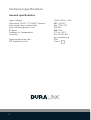 4
4
-
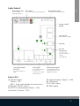 5
5
-
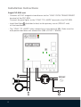 6
6
-
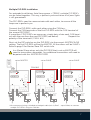 7
7
-
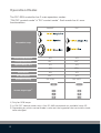 8
8
-
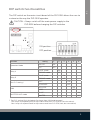 9
9
-
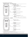 10
10
-
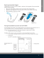 11
11
-
 12
12
-
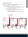 13
13
-
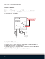 14
14
-
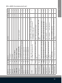 15
15
-
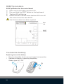 16
16
-
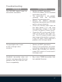 17
17
-
 18
18
-
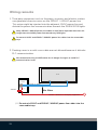 19
19
-
 20
20
-
 21
21
-
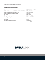 22
22
-
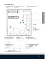 23
23
-
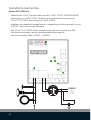 24
24
-
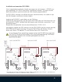 25
25
-
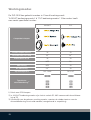 26
26
-
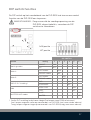 27
27
-
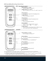 28
28
-
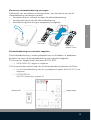 29
29
-
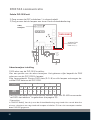 30
30
-
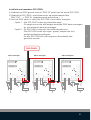 31
31
-
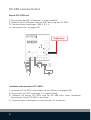 32
32
-
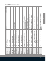 33
33
-
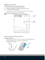 34
34
-
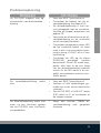 35
35
-
 36
36
-
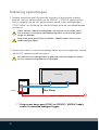 37
37
-
 38
38
-
 39
39
-
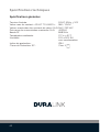 40
40
-
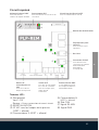 41
41
-
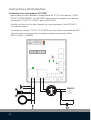 42
42
-
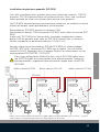 43
43
-
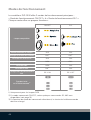 44
44
-
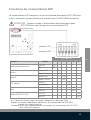 45
45
-
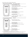 46
46
-
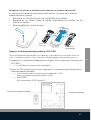 47
47
-
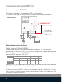 48
48
-
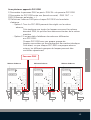 49
49
-
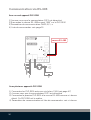 50
50
-
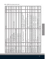 51
51
-
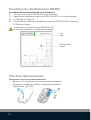 52
52
-
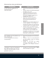 53
53
-
 54
54
-
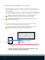 55
55
-
 56
56
-
 57
57
-
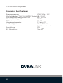 58
58
-
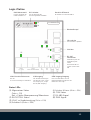 59
59
-
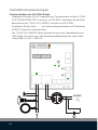 60
60
-
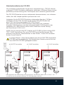 61
61
-
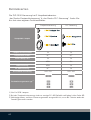 62
62
-
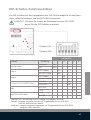 63
63
-
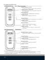 64
64
-
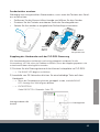 65
65
-
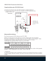 66
66
-
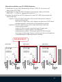 67
67
-
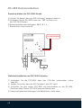 68
68
-
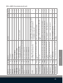 69
69
-
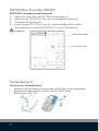 70
70
-
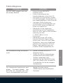 71
71
-
 72
72
-
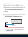 73
73
-
 74
74
-
 75
75
-
 76
76
-
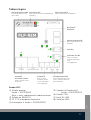 77
77
-
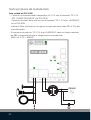 78
78
-
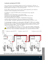 79
79
-
 80
80
-
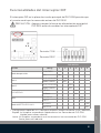 81
81
-
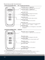 82
82
-
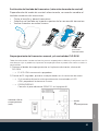 83
83
-
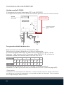 84
84
-
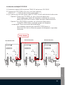 85
85
-
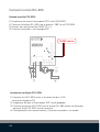 86
86
-
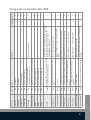 87
87
-
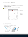 88
88
-
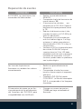 89
89
-
 90
90
-
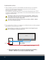 91
91
-
 92
92
-
 93
93
-
 94
94
-
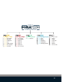 95
95
-
 96
96


Duratech PLP-REM Manual de usuario
- Categoría
- Estroboscopios
- Tipo
- Manual de usuario
en otros idiomas
- français: Duratech PLP-REM Manuel utilisateur
- Deutsch: Duratech PLP-REM Benutzerhandbuch
- Nederlands: Duratech PLP-REM Handleiding
Otros documentos
-
Pahlen MA50-25 El manual del propietario
-
-
Parkside PLP 160 SOLDERING GUN Manual de usuario
-
Peerless Industries SA763PU Manual de usuario
-
Promax MO-480, MO-481 Manual de usuario
-
Peerless SA771P Especificación
-
-
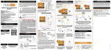 Nodon SIN-2-2-01 Guía del usuario
-
-
