SICK PowerProx Analog - WTT12L-Axxx Instrucciones de operación
- Tipo
- Instrucciones de operación
La página se está cargando...
La página se está cargando...
La página se está cargando...
La página se está cargando...
La página se está cargando...
La página se está cargando...
La página se está cargando...
La página se está cargando...
La página se está cargando...
La página se está cargando...
La página se está cargando...

-Axx1x -Axx2x -Axx3x -Axx4x -Axx5x -Axx6x
Switching output (max. output
current I
max.
)
1x PUSH/
PULL:
PNP/NPN
(50 mA)
1x PUSH/
PULL:
PNP/NPN
(50 mA)
1x PUSH/
PULL:
PNP/NPN
(50 mA)
1x PUSH/
PULL:
PNP/NPN
(50 mA)
1x PUSH/
PULL:
PNP/NPN
(50 mA)
1x PUSH/
PULL:
PNP/NPN
(50 mA)
Sensing range 100 ... 1600
mm
1)
100 ... 1400
mm
1)
100 ... 2500
mm
1)
100 ...
1800
1)
100 ...
1800
1)
100 ...
3800
1)
Sensing range max. 50 ... 1600
mm
1)
50 ... 1400
mm
1)
50 ... 2500
mm
1)
50 ... 1800
1)
50 ... 1800
1)
50 ... 3800
1)
Max. switching frequency 1,000 Hz
2)
30 Hz
2)
1,000 Hz
2)
30 Hz
2)
100 Hz
2)
100 Hz
2)
Max. response time 0.5 ms
3)
16.7 ms
3)
0.5 ms
3)
16.7 ms
3)
5 ms
3)
5 ms
3)
Analog output 1x 4 mA ...
20 mA (≤450
Ω)0 V ... 10 V
(≥50 k Ω)
configurable
1x 4 mA ...
20 mA (≤450
Ω)0 V ... 10 V
(≥50 k Ω)
configurable
1x 4 mA ...
20 mA (≤450
Ω)0 V ... 10 V
(≥50 k Ω)
configurable
1x 4 mA ...
20 mA (≤450
Ω)0 V ... 10 V
(≥50 k Ω)
configurable
1x 4 mA ...
20 mA (≤450
Ω)0 V ... 10 V
(≥50 k Ω)
configurable
1x 4 mA ...
20 mA (≤450
Ω)0 V ... 10 V
(≥50 k Ω)
configurable
Measuring range 100 ... 1600
mm
100 ... 1400
mm
100 ... 2500
mm
100 ... 1800
mm
100 ... 1800
mm
100 ... 3800
mm
Resolution 1 mm / 12
Bit
1 mm / 12
Bit
1 mm / 12
Bit
1 mm / 12
Bit
1 mm / 12
Bit
1 mm / 12
Bit
Reproducibility 2.7 ... 8.0
mm
1.1 ... 1.5
mm
2.3 ... 6.1
mm
0.9 ... 1.3
mm
1.2 ... 3.0
mm
1.1 ... 3.0
mm
Accuracy typ. ±20 mm
(50 ... 1000
mm)
typ. ±15 mm
(1000 ...
1600 mm)
typ. ±20 mm
(50 ... 1000
mm)
typ. ±15 mm
(1000 ...
1400 mm)
typ. ±15 mm typ. ±15 mm typ. ±20 mm
(50 ... 1000
mm)
typ. ±15 mm
(1000 ...
1800 mm)
typ. ±15 mm
Output rate 3 ms 16.7 ms 3 ms 16.7 ms 5 ms 5 ms
Input inactive (U
Low): <5 V /
active (U
High): 12 V ...
V
S
inactive (U
Low): <5 V /
active (U
High): 12 V ...
V
S
inactive (U
Low): <5 V /
active (U
High): 12 V ...
V
S
inactive (U
Low): <5 V /
active (U
High): 12 V ...
V
S
inactive (U
Low): <5 V /
active (U
High): 12 V ...
V
S
inactive (U
Low): <5 V /
active (U
High): 12 V ...
V
S
Enclosure rating IP 67 IP 67 IP 67 IP 67 IP 67 IP 67
Supply voltage V
S
DC 12 ... 30
V (for use of
analog volt‐
age output
VS = 13 ...
30 V DC)
4)
DC 12 ... 30
V (for use of
analog volt‐
age output
VS = 13 ...
30 V DC)
4)
DC 12 ... 30
V (for use of
analog volt‐
age output
VS = 13 ...
30 V DC)
4)
DC 12 ... 30
V (for use of
analog volt‐
age output
VS = 13 ...
30 V DC)
4)
DC 12 ... 30
V (for use of
analog volt‐
age output
VS = 13 ...
30 V DC)
4)
DC 12 ... 30
V (for use of
analog volt‐
age output
VS = 13 ...
30 V DC)
4)
Protection class III III III III III III
Circuit protection A, B, C
5)
A, B, C
5)
A, B, C
5)
A, B, C
5)
A, B, C
5)
A, B, C
5)
Ambient operating temperature -35 ...
+50 °C
6)
-35 ...
+50 °C
6)
-35 ...
+50 °C
6)
-35 ...
+50 °C
6)
-35 ...
+50 °C
6)
-35 ...
+50 °C
6)
Warm-up time <15 min <15 min <15 min <15 min <15 min <15 min
TECHNICAL DATA 7
8020879.ZM26 | SICK
Subject to change without notice
11
La página se está cargando...
La página se está cargando...
La página se está cargando...
La página se está cargando...
La página se está cargando...
La página se está cargando...
La página se está cargando...
La página se está cargando...
La página se está cargando...
La página se está cargando...
La página se está cargando...

-Axx1x -Axx2x -Axx3x -Axx4x -Axx5x -Axx6x
Lichtfleckdurchmesser/Entfer‐
nung
< 11.0 mm /
1600 mm
< 10.0 mm /
1400 mm
< 14.0 mm /
2500 mm
<12.0 /
1800 mm
<12.0 /
1800 mm
<12.0 /
3800 mm
Schaltausgang (Ausgangsstrom
I
max.
)
1x PUSH/
PULL:
PNP/NPN
(50 mA)
1x PUSH/
PULL:
PNP/NPN
(50 mA)
1x PUSH/
PULL:
PNP/NPN
(50 mA)
1x PUSH/
PULL:
PNP/NPN
(50 mA)
1x PUSH/
PULL:
PNP/NPN
(50 mA)
1x PUSH/
PULL:
PNP/NPN
(50 mA)
Schaltabstand 100 ... 1600
mm
1)
100 ... 1400
mm
1)
100 ... 2500
mm
1)
100 ...
1800
1)
100 ...
1800
1)
100 ...
3800
1)
Schaltabstand max. 50 ... 1600
mm
1)
50 ... 1400
mm
1)
50 ... 2500
mm
1)
50 ... 1800
1)
50 ... 1800
1)
50 ... 3800
1)
Schaltfolge max. 1,000 Hz
2)
30 Hz
2)
1,000 Hz
2)
30 Hz
2)
100 Hz
2)
100 Hz
2)
Ansprechzeit max. 0.5 ms
3)
16.7 ms
3)
0.5 ms
3)
16.7 ms
3)
5 ms
3)
5 ms
3)
Analogausgang 1x 4 mA ...
20 mA (≤450
Ω)0 V ... 10 V
(≥50 k Ω)
configurable
1x 4 mA ...
20 mA (≤450
Ω)0 V ... 10 V
(≥50 k Ω)
configurable
1x 4 mA ...
20 mA (≤450
Ω)0 V ... 10 V
(≥50 k Ω)
configurable
1x 4 mA ...
20 mA (≤450
Ω)0 V ... 10 V
(≥50 k Ω)
configurable
1x 4 mA ...
20 mA (≤450
Ω)0 V ... 10 V
(≥50 k Ω)
configurable
1x 4 mA ...
20 mA (≤450
Ω)0 V ... 10 V
(≥50 k Ω)
configurable
Messbereich 100 ... 1600
mm
100 ... 1400
mm
100 ... 2500
mm
100 ... 1800
mm
100 ... 1800
mm
100 ... 3800
mm
Auflösung 1 mm / 12
Bit
1 mm / 12
Bit
1 mm / 12
Bit
1 mm / 12
Bit
1 mm / 12
Bit
1 mm / 12
Bit
Reproduzierbarkeit 1 2.7 ... 8.0
mm
1.1 ... 1.5
mm
2.3 ... 6.1
mm
0.9 ... 1.3
mm
1.2 ... 3.0
mm
1.1 ... 3.0
mm
Genauigkeit typ. ±20 mm
(50 ... 1000
mm)
typ. ±15 mm
(1000 ...
1600 mm)
typ. ±20 mm
(50 ... 1000
mm)
typ. ±15 mm
(1000 ...
1400 mm)
typ. ±15 mm typ. ±15 mm typ. ±20 mm
(50 ... 1000
mm)
typ. ±15 mm
(1000 ...
1800 mm)
typ. ±15 mm
Ausgaberate 3 ms 16.7 ms 3 ms 16.7 ms 5 ms 5 ms
Eingang inactive (U
Low): <5 V /
active (U
High): 12 V ...
V
S
inactive (U
Low): <5 V /
active (U
High): 12 V ...
V
S
inactive (U
Low): <5 V /
active (U
High): 12 V ...
V
S
inactive (U
Low): <5 V /
active (U
High): 12 V ...
V
S
inactive (U
Low): <5 V /
active (U
High): 12 V ...
V
S
inactive (U
Low): <5 V /
active (U
High): 12 V ...
V
S
Schutzart IP 67 IP 67 IP 67 IP 67 IP 67 IP 67
Versorgungsspannung U
V
DC 12 ... 30
V (for use of
analog vol‐
tage output
VS = 13 ...
30 V DC)
4)
DC 12 ... 30
V (for use of
analog vol‐
tage output
VS = 13 ...
30 V DC)
4)
DC 12 ... 30
V (for use of
analog vol‐
tage output
VS = 13 ...
30 V DC)
4)
DC 12 ... 30
V (for use of
analog vol‐
tage output
VS = 13 ...
30 V DC)
4)
DC 12 ... 30
V (for use of
analog vol‐
tage output
VS = 13 ...
30 V DC)
4)
DC 12 ... 30
V (for use of
analog vol‐
tage output
VS = 13 ...
30 V DC)
4)
Schutzklasse III III III III III III
Schutzschaltungen A, B, C
5)
A, B, C
5)
A, B, C
5)
A, B, C
5)
A, B, C
5)
A, B, C
5)
Betriebsumgebungstemperatur -35 ...
+50 °C
6)
-35 ...
+50 °C
6)
-35 ...
+50 °C
6)
-35 ...
+50 °C
6)
-35 ...
+50 °C
6)
-35 ...
+50 °C
6)
Aufwärmzeit <15 min <15 min <15 min <15 min <15 min <15 min
TECHNISCHE DATEN 16
8020879.ZM26 | SICK
Subject to change without notice
23
La página se está cargando...
La página se está cargando...
La página se está cargando...
La página se está cargando...
La página se está cargando...
La página se está cargando...
La página se está cargando...
La página se está cargando...
La página se está cargando...
La página se está cargando...
La página se está cargando...

25 Caractéristiques techniques
-Axx1x -Axx2x -Axx3x -Axx4x -Axx5x -Axx6x
Classe laser 1 1 1 1 1 1
Diamètre spot / distance < 11.0 mm /
1600 mm
< 10.0 mm /
1400 mm
< 14.0 mm /
2500 mm
<12.0 /
1800 mm
<12.0 /
1800 mm
<12.0 /
3800 mm
Sortie de commutation (courant
de sortie I
max
)
1x PUSH/
PULL:
PNP/NPN
(50 mA)
1x PUSH/
PULL:
PNP/NPN
(50 mA)
1x PUSH/
PULL:
PNP/NPN
(50 mA)
1x PUSH/
PULL:
PNP/NPN
(50 mA)
1x PUSH/
PULL:
PNP/NPN
(50 mA)
1x PUSH/
PULL:
PNP/NPN
(50 mA)
Distance de commutation 100 ... 1600
mm
1)
100 ... 1400
mm
1)
100 ... 2500
mm
1)
100 ...
1800
1)
100 ...
1800
1)
100 ...
3800
1)
Portée max. 50 ... 1600
mm
1)
50 ... 1400
mm
1)
50 ... 2500
mm
1)
50 ... 1800
1)
50 ... 1800
1)
50 ... 3800
1)
Commutation max. 1,000 Hz
2)
30 Hz
2)
1,000 Hz
2)
30 Hz
2)
100 Hz
2)
100 Hz
2)
Temps de réponse max. 0.5 ms
3)
16.7 ms
3)
0.5 ms
3)
16.7 ms
3)
5 ms
3)
5 ms
3)
Sortie analogique 1x 4 mA ...
20 mA (≤450
Ω)0 V ... 10 V
(≥50 k Ω)
configurable
1x 4 mA ...
20 mA (≤450
Ω)0 V ... 10 V
(≥50 k Ω)
configurable
1x 4 mA ...
20 mA (≤450
Ω)0 V ... 10 V
(≥50 k Ω)
configurable
1x 4 mA ...
20 mA (≤450
Ω)0 V ... 10 V
(≥50 k Ω)
configurable
1x 4 mA ...
20 mA (≤450
Ω)0 V ... 10 V
(≥50 k Ω)
configurable
1x 4 mA ...
20 mA (≤450
Ω)0 V ... 10 V
(≥50 k Ω)
configurable
Plage de mesure 100 ... 1600
mm
100 ... 1400
mm
100 ... 2500
mm
100 ... 1800
mm
100 ... 1800
mm
100 ... 3800
mm
Résolution 1 mm / 12
Bit
1 mm / 12
Bit
1 mm / 12
Bit
1 mm / 12
Bit
1 mm / 12
Bit
1 mm / 12
Bit
Reproductibilité 1 2.7 ... 8.0
mm
1.1 ... 1.5
mm
2.3 ... 6.1
mm
0.9 ... 1.3
mm
1.2 ... 3.0
mm
1.1 ... 3.0
mm
Précision typ. ±20 mm
(50 ... 1000
mm)
typ. ±15 mm
(1000 ...
1600 mm)
typ. ±20 mm
(50 ... 1000
mm)
typ. ±15 mm
(1000 ...
1400 mm)
typ. ±15 mm typ. ±15 mm typ. ±20 mm
(50 ... 1000
mm)
typ. ±15 mm
(1000 ...
1800 mm)
typ. ±15 mm
Taux de sortie 3 ms 16.7 ms 3 ms 16.7 ms 5 ms 5 ms
Entrée inactive (U
Low): <5 V /
active (U
High): 12 V ...
V
S
inactive (U
Low): <5 V /
active (U
High): 12 V ...
V
S
inactive (U
Low): <5 V /
active (U
High): 12 V ...
V
S
inactive (U
Low): <5 V /
active (U
High): 12 V ...
V
S
inactive (U
Low): <5 V /
active (U
High): 12 V ...
V
S
inactive (U
Low): <5 V /
active (U
High): 12 V ...
V
S
Indice de protection IP 67 IP 67 IP 67 IP 67 IP 67 IP 67
Tension d'alimentation U
V
DC 12 ... 30
V (for use of
analog vol‐
tage output
VS = 13 ...
30 V DC)
4)
DC 12 ... 30
V (for use of
analog vol‐
tage output
VS = 13 ...
30 V DC)
4)
DC 12 ... 30
V (for use of
analog vol‐
tage output
VS = 13 ...
30 V DC)
4)
DC 12 ... 30
V (for use of
analog vol‐
tage output
VS = 13 ...
30 V DC)
4)
DC 12 ... 30
V (for use of
analog vol‐
tage output
VS = 13 ...
30 V DC)
4)
DC 12 ... 30
V (for use of
analog vol‐
tage output
VS = 13 ...
30 V DC)
4)
Classe de protection III III III III III III
Protections électriques A, B, C
5)
A, B, C
5)
A, B, C
5)
A, B, C
5)
A, B, C
5)
A, B, C
5)
Température de service -35 ...
+50 °C
6)
-35 ...
+50 °C
6)
-35 ...
+50 °C
6)
-35 ...
+50 °C
6)
-35 ...
+50 °C
6)
-35 ...
+50 °C
6)
Temps de montée en température <15 min <15 min <15 min <15 min <15 min <15 min
CARACTÉRISTIQUES TECHNIQUES 25
8020879.ZM26 | SICK
Subject to change without notice
35
La página se está cargando...
La página se está cargando...
La página se está cargando...
La página se está cargando...
La página se está cargando...
La página se está cargando...
La página se está cargando...
La página se está cargando...
La página se está cargando...
La página se está cargando...
La página se está cargando...

34 Dados técnicos
-Axx1x -Axx2x -Axx3x -Axx4x -Axx5x -Axx6x
Classe de laser 1 1 1 1 1 1
Diâmetro do ponto de luz/
distância
< 11.0 mm /
1600 mm
< 10.0 mm /
1400 mm
< 14.0 mm /
2500 mm
<12.0 /
1800 mm
<12.0 /
1800 mm
<12.0 /
3800 mm
Saída de comutação (corrente de
saída I
máx.
)
1x PUSH/
PULL:
PNP/NPN
(50 mA)
1x PUSH/
PULL:
PNP/NPN
(50 mA)
1x PUSH/
PULL:
PNP/NPN
(50 mA)
1x PUSH/
PULL:
PNP/NPN
(50 mA)
1x PUSH/
PULL:
PNP/NPN
(50 mA)
1x PUSH/
PULL:
PNP/NPN
(50 mA)
Distância de comutação 100 ... 1600
mm
1)
100 ... 1400
mm
1)
100 ... 2500
mm
1)
100 ...
1800
1)
100 ...
1800
1)
100 ...
3800
1)
Distância de comutação máx. 50 ... 1600
mm
1)
50 ... 1400
mm
1)
50 ... 2500
mm
1)
50 ... 1800
1)
50 ... 1800
1)
50 ... 3800
1)
Sequência máx. de comutação 1,000 Hz
2)
30 Hz
2)
1,000 Hz
2)
30 Hz
2)
100 Hz
2)
100 Hz
2)
Tempo máx. de resposta 0.5 ms
3)
16.7 ms
3)
0.5 ms
3)
16.7 ms
3)
5 ms
3)
5 ms
3)
Saída analógica 1x 4 mA ...
20 mA (≤450
Ω)0 V ... 10 V
(≥50 k Ω)
configurable
1x 4 mA ...
20 mA (≤450
Ω)0 V ... 10 V
(≥50 k Ω)
configurable
1x 4 mA ...
20 mA (≤450
Ω)0 V ... 10 V
(≥50 k Ω)
configurable
1x 4 mA ...
20 mA (≤450
Ω)0 V ... 10 V
(≥50 k Ω)
configurable
1x 4 mA ...
20 mA (≤450
Ω)0 V ... 10 V
(≥50 k Ω)
configurable
1x 4 mA ...
20 mA (≤450
Ω)0 V ... 10 V
(≥50 k Ω)
configurable
Faixa de medição 100 ... 1600
mm
100 ... 1400
mm
100 ... 2500
mm
100 ... 1800
mm
100 ... 1800
mm
100 ... 3800
mm
Resolução 1 mm / 12
Bit
1 mm / 12
Bit
1 mm / 12
Bit
1 mm / 12
Bit
1 mm / 12
Bit
1 mm / 12
Bit
Reprodutibilidade 1 2.7 ... 8.0
mm
1.1 ... 1.5
mm
2.3 ... 6.1
mm
0.9 ... 1.3
mm
1.2 ... 3.0
mm
1.1 ... 3.0
mm
Precisão typ. ±20 mm
(50 ... 1000
mm)
typ. ±15 mm
(1000 ...
1600 mm)
typ. ±20 mm
(50 ... 1000
mm)
typ. ±15 mm
(1000 ...
1400 mm)
typ. ±15 mm typ. ±15 mm typ. ±20 mm
(50 ... 1000
mm)
typ. ±15 mm
(1000 ...
1800 mm)
typ. ±15 mm
Taxa de emissão 3 ms 16.7 ms 3 ms 16.7 ms 5 ms 5 ms
Entrada inactive (U
Low): <5 V /
active (U
High): 12 V ...
V
S
inactive (U
Low): <5 V /
active (U
High): 12 V ...
V
S
inactive (U
Low): <5 V /
active (U
High): 12 V ...
V
S
inactive (U
Low): <5 V /
active (U
High): 12 V ...
V
S
inactive (U
Low): <5 V /
active (U
High): 12 V ...
V
S
inactive (U
Low): <5 V /
active (U
High): 12 V ...
V
S
Tipo de proteção IP 67 IP 67 IP 67 IP 67 IP 67 IP 67
Tensão de alimentação U
V
DC 12 ... 30
V (for use of
analog vol‐
tage output
VS = 13 ...
30 V DC)
4)
DC 12 ... 30
V (for use of
analog vol‐
tage output
VS = 13 ...
30 V DC)
4)
DC 12 ... 30
V (for use of
analog vol‐
tage output
VS = 13 ...
30 V DC)
4)
DC 12 ... 30
V (for use of
analog vol‐
tage output
VS = 13 ...
30 V DC)
4)
DC 12 ... 30
V (for use of
analog vol‐
tage output
VS = 13 ...
30 V DC)
4)
DC 12 ... 30
V (for use of
analog vol‐
tage output
VS = 13 ...
30 V DC)
4)
Classe de proteção III III III III III III
Circuitos de proteção A, B, C
5)
A, B, C
5)
A, B, C
5)
A, B, C
5)
A, B, C
5)
A, B, C
5)
Temperatura ambiente de funcio‐
namento
-35 ...
+50 °C
6)
-35 ...
+50 °C
6)
-35 ...
+50 °C
6)
-35 ...
+50 °C
6)
-35 ...
+50 °C
6)
-35 ...
+50 °C
6)
Tempo de aquecimento <15 min <15 min <15 min <15 min <15 min <15 min
DADOS TÉCNICOS 34
8020879.ZM26 | SICK
Subject to change without notice
47
La página se está cargando...
La página se está cargando...
La página se está cargando...
La página se está cargando...
La página se está cargando...
La página se está cargando...
La página se está cargando...
La página se está cargando...
La página se está cargando...
La página se está cargando...
La página se está cargando...

43 Dati tecnici
-Axx1x -Axx2x -Axx3x -Axx4x -Axx5x -Axx6x
Classe laser 1 1 1 1 1 1
Diametro punto luminoso/
distanza
< 11.0 mm /
1600 mm
< 10.0 mm /
1400 mm
< 14.0 mm /
2500 mm
<12.0 /
1800 mm
<12.0 /
1800 mm
<12.0 /
3800 mm
Uscita di commutazione (corrente
in uscita I
max.
)
1x PUSH/
PULL:
PNP/NPN
(50 mA)
1x PUSH/
PULL:
PNP/NPN
(50 mA)
1x PUSH/
PULL:
PNP/NPN
(50 mA)
1x PUSH/
PULL:
PNP/NPN
(50 mA)
1x PUSH/
PULL:
PNP/NPN
(50 mA)
1x PUSH/
PULL:
PNP/NPN
(50 mA)
Distanza di commutazione 100 ... 1600
mm
1)
100 ... 1400
mm
1)
100 ... 2500
mm
1)
100 ...
1800
1)
100 ...
1800
1)
100 ...
3800
1)
Distanza max. di commutazione 50 ... 1600
mm
1)
50 ... 1400
mm
1)
50 ... 2500
mm
1)
50 ... 1800
1)
50 ... 1800
1)
50 ... 3800
1)
Sequenza di commutazione max. 1,000 Hz
2)
30 Hz
2)
1,000 Hz
2)
30 Hz
2)
100 Hz
2)
100 Hz
2)
Tempo di reazione max. 0.5 ms
3)
16.7 ms
3)
0.5 ms
3)
16.7 ms
3)
5 ms
3)
5 ms
3)
Uscita analogica 1x 4 mA ...
20 mA (≤450
Ω)0 V ... 10 V
(≥50 k Ω)
configurable
1x 4 mA ...
20 mA (≤450
Ω)0 V ... 10 V
(≥50 k Ω)
configurable
1x 4 mA ...
20 mA (≤450
Ω)0 V ... 10 V
(≥50 k Ω)
configurable
1x 4 mA ...
20 mA (≤450
Ω)0 V ... 10 V
(≥50 k Ω)
configurable
1x 4 mA ...
20 mA (≤450
Ω)0 V ... 10 V
(≥50 k Ω)
configurable
1x 4 mA ...
20 mA (≤450
Ω)0 V ... 10 V
(≥50 k Ω)
configurable
Campo di misura 100 ... 1600
mm
100 ... 1400
mm
100 ... 2500
mm
100 ... 1800
mm
100 ... 1800
mm
100 ... 3800
mm
Risoluzione 1 mm / 12
Bit
1 mm / 12
Bit
1 mm / 12
Bit
1 mm / 12
Bit
1 mm / 12
Bit
1 mm / 12
Bit
Riproducibilità 1 2.7 ... 8.0
mm
1.1 ... 1.5
mm
2.3 ... 6.1
mm
0.9 ... 1.3
mm
1.2 ... 3.0
mm
1.1 ... 3.0
mm
Accuratezza typ. ±20 mm
(50 ... 1000
mm)
typ. ±15 mm
(1000 ...
1600 mm)
typ. ±20 mm
(50 ... 1000
mm)
typ. ±15 mm
(1000 ...
1400 mm)
typ. ±15 mm typ. ±15 mm typ. ±20 mm
(50 ... 1000
mm)
typ. ±15 mm
(1000 ...
1800 mm)
typ. ±15 mm
Frequenza di uscita 3 ms 16.7 ms 3 ms 16.7 ms 5 ms 5 ms
Ingresso inactive (U
Low): <5 V /
active (U
High): 12 V ...
V
S
inactive (U
Low): <5 V /
active (U
High): 12 V ...
V
S
inactive (U
Low): <5 V /
active (U
High): 12 V ...
V
S
inactive (U
Low): <5 V /
active (U
High): 12 V ...
V
S
inactive (U
Low): <5 V /
active (U
High): 12 V ...
V
S
inactive (U
Low): <5 V /
active (U
High): 12 V ...
V
S
Tipo di protezione IP 67 IP 67 IP 67 IP 67 IP 67 IP 67
Tensione di alimentazione U
V
DC 12 ... 30
V (for use of
analog vol‐
tage output
VS = 13 ...
30 V DC)
4)
DC 12 ... 30
V (for use of
analog vol‐
tage output
VS = 13 ...
30 V DC)
4)
DC 12 ... 30
V (for use of
analog vol‐
tage output
VS = 13 ...
30 V DC)
4)
DC 12 ... 30
V (for use of
analog vol‐
tage output
VS = 13 ...
30 V DC)
4)
DC 12 ... 30
V (for use of
analog vol‐
tage output
VS = 13 ...
30 V DC)
4)
DC 12 ... 30
V (for use of
analog vol‐
tage output
VS = 13 ...
30 V DC)
4)
Classe di protezione III III III III III III
Commutazioni di protezione A, B, C
5)
A, B, C
5)
A, B, C
5)
A, B, C
5)
A, B, C
5)
A, B, C
5)
Temperatura ambientale di fun‐
zionamento
-35 ...
+50 °C
6)
-35 ...
+50 °C
6)
-35 ...
+50 °C
6)
-35 ...
+50 °C
6)
-35 ...
+50 °C
6)
-35 ...
+50 °C
6)
Tempo di riscaldamento <15 min <15 min <15 min <15 min <15 min <15 min
DATI TECNICI 43
8020879.ZM26 | SICK
Subject to change without notice
59
La página se está cargando...
La página se está cargando...

Producto descrito
PowerProx Small Analog - WTT12L-Axxx
Fabricante
SICK AG
Erwin-Sick-Str. 1
79183 Waldkirch
Alemania
Información legal
Este documento está protegido por la legislación sobre la propiedad intelectual. Los
derechos derivados de ello son propiedad de SICK AG. Únicamente se permite la repro‐
ducción total o parcial de este documento dentro de los límites establecidos por las
disposiciones legales sobre propiedad intelectual. Está prohibida la modificación, abre‐
viación o traducción del documento sin la autorización expresa y por escrito de SICK
AG.
Las marcas mencionadas en este documento pertenecen a sus respectivos propieta‐
rios.
© SICK AG. Reservados todos los derechos.
Documento original
Este es un documento original de SICK AG.
2006/42/EC
NO
SAFETY
62
8020879.ZM26 | SICK
Subject to change without notice

Índice
46 Indicaciones generales de seguridad............................................. 64
47 Indicaciones sobre la homologación UL........................................ 64
48 Descripción del producto................................................................. 64
48.1 Uso conforme a lo previsto....................................................................... 64
48.2 Dibujo acotado.......................................................................................... 65
49 Puesta en marcha............................................................................. 66
49.1 Comprobar las condiciones de aplicación:............................................. 66
49.2 Montaje..................................................................................................... 67
49.3 Electrónica................................................................................................ 67
49.4 Alineación.................................................................................................. 68
50 Configuración..................................................................................... 68
50.1 Ajuste......................................................................................................... 68
51 Solución de fallos.............................................................................. 70
51.1 Resolución de problemas......................................................................... 70
51.2 Tabla de diagnóstico de fallos................................................................. 70
52 Datos técnicos................................................................................... 71
53 Desmontaje y eliminación............................................................... 72
54 Mantenimiento.................................................................................. 72
ÍNDICE
8020879.ZM26 | SICK
Subject to change without notice
63

46 Indicaciones generales de seguridad
■
Lea las instrucciones de uso antes de realizar la puesta en servicio.
■
Únicamente personal especializado y debidamente cualificado debe llevar
a cabo las tareas de conexión, montaje y configuración.
■
2006/42/EC
NO
SAFETY
No se trata de un componente de seguridad según las definiciones de la
directiva de máquinas de la UE.
■
Al realizar la puesta en servicio, el dispositivo se debe proteger ante la
humedad y la contaminación.
■
Las presentes instrucciones de uso contienen la información necesaria para toda
la vida útil del sensor.
EN/IEC 60825-1:2014
IEC60825-1:2007
Laser
1
Maximum pulse power < 20 mW
Puls length: 5.3 µs
Wavelength: 940 nm
Complies with 21 CFR 1040.10
and 1040.11 except for deviations
pursuant to Laser Notice No. 50,
dated June 24, 2007
LASER CLASS 1
ATENCIÓN
ADVERTENCIA: La intervención, la manipulación y el uso incorrecto pueden causar una
situación de riesgo de exposición a radiación láser.
47 Indicaciones sobre la homologación UL
The device must be supplied by a Class 2 source of supply.
UL Environmental Rating: Enclosure type 1
48 Descripción del producto
48.1 Uso conforme a lo previsto
La WTT12L-Axxxx es una fotocélula optoelectrónica de detección sobreobjeto con
salida analógica de valores de distancia (en lo sucesivo llamadasensor) empleada para
la detección óptica y sin contacto de objetos.Cualquier uso diferente al previsto o modi‐
ficación en el producto invalidarála garantía por parte de SICK AG.
46 INDICACIONES GENERALES DE SEGURIDAD
64
8020879.ZM26 | SICK
Subject to change without notice

48.2 Dibujo acotado
20 (0.79)
21.1
(0.83)
36.3
(1.43)
1
2
47
(1.85)
18.5
(0.73)
8
3
4
5
A
Figura 26: WTT12L-A1xxx / -A3xxx
1
Centro del eje óptico del emisor
2
Centro del eje óptico del receptor
3
LED indicador amarillo: estado de salida analógica
4
LED indicador verde: tensión de alimentación activa
5
LED indicador amarillo: salida conmutada
6
Orificio de fijación D4.2 mm
7
Salida del cable
8
Tecla teach sencilla
20 (0.79)
21.1
(0.83)
36.3
(1.43)
6
(0.24)
Ø 4.2
(0.17)
31.9
(1.26)
4
(0.16)
4.6
(0.18)
48.7
(1.92)
5.1
(0.2)
44.2
(1.74)
49.6
(1.95)
1
2
7
47
(1.85)
18.5
(0.73)
M12x1 36.5
(1.44)
8
6
39.9
(1.57)
3
4
5
A
Figura 27: WTT12L-A2xxx
1
Centro del eje óptico del emisor
2
Centro del eje óptico del receptor
3
LED indicador amarillo: estado de salida analógica
4
LED indicador verde: tensión de alimentación activa
5
LED indicador amarillo: salida conmutada
DESCRIPCIÓN DEL PRODUCTO 48
8020879.ZM26 | SICK
Subject to change without notice
65

6
Orificio de fijación D4.2 mm
7
Conector macho M12, 5 polos
8
Tecla teach sencilla
49 Puesta en marcha
49.1 Comprobar las condiciones de aplicación:
Salida analógica:
Puede consultar las indicaciones de precisión de la salida analógica en la tabla Datos
técnicos y en el diagrama H3, H4.
Salida conmutada:
comparar la distancia de conmutación y la distancia respecto al objeto o al fondo, así
como la capacidad de reflectancia del objeto, con el diagrama correspondiente [véase
figura H1, H2]. (x = distancia de conmutación, y = distancia mínima entre el objeto y el
fondo en mm [reflectancia del objeto / reflectancia del fondo]). Reflectancia: 6% =
negro, 90% = blanco (referido al blanco estándar según DIN 5033).
La distancia mínima (= y) para suprimir el fondo puede extraerse del diagrama [véase
figura H11] del modo siguiente:
Ejemplo: x = 1.000 mm, y = 25 mm. Es decir, el fondo se suprimirá a partir de una
distancia de > 25 mm del objeto.
0
5
(0.2)
10
(0.39)
15
(0.59)
20
(0.79)
25
(0.98)
30
(1.18)
35
(1.38)
40
(1.57)
0
1
6%/90%
2
6%/90%
90%/90%
5
4
90%/90%
3
6%/90%
6
90%/90%
Min. distance from object to background in mm (inch)
1,000
(39.37)
2,000
(78.74)
3,000
(118.11)
4,000
(157.48)
Distance in mm (inch)
1) -Bxx3x: 6 % / 90 %
2) -Bxx3x: 90 % / 90 %
3) -Bxx6x: 6 % / 90 %
4) -Bxx6x: 90 % / 90 %
5) -Bxx4x: 6 % / 90 %
6) -Bxx4x: 90 % / 90 %
Figura: H-1
0
4
5
6
90%/90%
90%/90%
90%/90%
1
6%/90%
2
3
6%/90%
6%/90%
30
(1.18)
20
(0.79)
10
(0.39)
50
(1.97)
40
(1.57)
500
(19.69)
1,000
(39.37)
1,500
(59.06)
2,000
(78.74)
Min. distance from object to background in mm (inch)
Distance in mm (inch)
1) -Bxx1x: 6 % / 90 %
2) -Bxx1x: 90 % / 90 %
3) -Bxx5x: 6 % / 90 %
4) -Bxx5x: 90 % / 90 %
5) -Bxx2x: 6 % / 90 %
6) -Bxx2x: 90 % / 90 %
Figura: H-2
49 PUESTA EN MARCHA
66
8020879.ZM26 | SICK
Subject to change without notice

0
0
2
1
3
(0.12)
2
(0.08)
1
(0.04)
7
(0.28)
6
(0.24)
5
(0.2)
4
(0.16)
Repeatability in mm (inch)
1,000
(39.37)
2,000
(78.74)
3,000
(118.11)
4,000
(157.48)
Distance in mm (inch)
4
3
6
5
1) -Axx3x: 6 %
2) -Axx3x: 90 %
3) -Axx6x: 6 %
4) -Axx6x: 90 %
5) -Axx4x: 6 %
6) -Axx4x: 90 %
Figura: H-3
0
0
2
1
3
(0.12)
2
(0.08)
1
(0.04)
7
(0.28)
8
(0.31)
9
(0.35)
6
(0.24)
5
(0.2)
4
(0.16)
Repeatability in mm (inch)
1,000
(39.37)
2,000
(78.74)
3,000
(118.11)
4, 000
(157.48)
Distance in mm (inch)
6
5
4
3
1) -Axx1x: 6 %
2) -Axx1x: 90 %
3) -Axx5x: 6 %
4) -Axx5x: 90 %
5) -Axx2x: 6 %
6) -Axx2x: 90 %
Figura: H-4
49.2 Montaje
Montar el sensor en una escuadra de fijación adecuada (véase el programa de acceso‐
rios SICK).
Respetar el par de apriete máximo admisible del sensor de 0,8 Nm.
Respetar la orientación preferente del objeto con respecto al sensor. [véase fig. C].
49.3 Electrónica
Los sensores deben conectarse sin tensión (V
s
= 0 V). Debe tenerse en cuenta la infor‐
mación de las figuras [B] en función de cada tipo de conexión:
– Conexión de enchufes: asignación de terminales
– Cable: color del hilo
+ (L+)
QA
- (M)
brn
wht
blu
Q1
blk
SenderOff
gra
Figura: B: -A15X3
+ (L+)
QA
- (M)
brn
wht
blu
1
2
3
Q1
blk
4
SenderOff
gra
5
Figura: B-2: -A25X3/ -A35X3
+ (L+)
QA
- (M)
brn
wht
blu
Q1
blk
L/D
gra
Figura: B: -A15X7
+ (L+)
QA
- (M)
brn
wht
blu
1
2
3
Q1
blk
4
L/D
gra
5
Figura: B: -A25X7 / -A35X7
No aplicar o conectar la fuente de alimentación (V
s
> 0 V) hasta que no se hayan finali‐
zado todas las conexiones eléctricas. En el sensor se ilumina el LED indicador verde.
Explicaciones relativas al esquema de conexión (figura B):
SenderOff = desconexión del LED emisor, HIGH active
L/D = conmutador en claro / en oscuro
PUESTA EN MARCHA
49
8020879.ZM26 | SICK
Subject to change without notice
67

49.4 Alineación
Oriente el sensor hacia el objeto. Seleccione una posición que permita que el haz de luz
roja del transmisor incida en el centro del objeto. Hay que procurar que la apertura
óptica (pantalla frontal) del sensor esté completamente libre [véase figura D]. Reco‐
mendamos realizar los ajustes con un objeto de remisión baja.
Figura: D
50 Configuración
50.1 Ajuste
Realizar la parametrización:
a) Ajuste de la salida analógica
La salida analógica viene con los siguientes ajustes de fábrica:
4 mA = 100 mm
20 mA = alcance máximo (según el tipo)
La configuración puede adaptarse a la aplicación mediante la teclateach-in Q
A
(véanse
las figuras E y G). La tecla teach-in no debeaccionarse con objetos puntiagudos. La
secuencia de aprendizaje y ladistancia al objeto definen la curva característica de la
salida analógica.Colocar un objeto en la trayectoria del haz. Mantener pulsada latecla
teach-in Q
A
> 1 s; cuando el LED amarillo izquierdo empiece aparpadear, soltar la tecla.
El LED sigue parpadeando. La distancia actualal objeto se asigna al valor 4 mA (0,05
V). A continuación, desplazarel objeto. Volver a pulsar la tecla teach-in Q
A
> 1 s hasta
que el LEDamarillo izquierdo deje de parpadear. La distancia medida ahora alobjeto se
asigna al valor 20 mA (10 V). Dependiendo de si el objeto semueve de cerca a lejos o a
la inversa, se obtiene un flanco ascendenteo descendente.
La salida analógica puede conmutarse entre salida de corriente o detensión (véase la
figura J). Para ello, mantener pulsada la tecla teach-inQ
A
> 10 s hasta que el LED ama‐
rillo izquierdo y el LED verde empiecena parpadear de forma alternada. A continuación,
soltar la tecla. El LEDverde sigue parpadeando. Dependiendo de si el sensor se
encuentraen modo de corriente o de tensión, el LED amarillo izquierdo se ilumina.Para
cambiar entre los modos, pulsar brevemente la tecla teach-in Q
A
.Si no se pulsa ninguna
tecla en > 10 s, el sensor guarda el modo actualy sale del menú de configuración.
b) Configuración de la salida conmutada
Pulsando la tecla teach-in Q > 1 s se ajusta la distancia de conmutación(véase la figura
F). La tecla teach-in no debe accionarsecon objetos puntiagudos. Recomendamos
poner la distancia de conmutaciónen el objeto. Una vez ajustada la distancia de con‐
mutación,retirar el objeto de la trayectoria del haz; el fondo se suprime y la salidacon‐
mutada se cambia (véase la figura C).
c) Configuración a través de SOPAS y transferencia de los ajustes con launidad de
memoria SICK
49
PUESTA EN MARCHA
68
8020879.ZM26 | SICK
Subject to change without notice

Como alternativa, el sensor puede configurarse a través del softwareSOPAS exclusivo
de SICK. También se puede usar como accesorio launidad de memoria SICK (IOLP2ZZ-
M3201, referencia 1064290) paratransferir los ajustes de un sensor a otro. En caso de
duda, póngase encontacto con el representante de ventas pertinente.
Figura: C
>1s
Q
A
Q
Teach 1 = 0.05V / 4m A
Figura: E
>1s
Teach 2 = 10V / 20m A
Teach
>1s
Figura 28: F
Teach 1
20.5mA / 11V
20mA / 10V
4mA / 0.05V
3.5mA / 0.03V
Teach 2
Teach 1
Teach 2
min. 50 mm
Figura 29: G
Teach 2
20.5mA / 11V
20mA / 10V
4mA / 0.05V
3.5mA / 0.03V
Teach 1
Teach 1
Teach 2
min. 50 mm
CONFIGURACIÓN 50
8020879.ZM26 | SICK
Subject to change without notice
69

I IU
l
1
2 3
C D E
10s 10s 10s
>10s
A
A
A
B
B
l l
Figura 30: J
51 Solución de fallos
51.1 Resolución de problemas
La tabla “Resolución de problemas” muestra las medidas que hay que tomar cuando
ya no está indicado el funcionamiento del sensor.
51.2 Tabla de diagnóstico de fallos
LED indicador / imagen de
error
Causa Acción
El LED verde no se ilumina Sin tensión o tensión por
debajo de los valores límite
Comprobar la fuente de ali‐
mentación, comprobar toda la
conexión eléctrica (cables y
conectores)
El LED verde no se ilumina Interrupciones de tensión Asegurar una fuente de ali‐
mentación estable sin inte‐
rrupciones de tensión
El LED verde no se ilumina El sensor está defectuoso Si la fuente de alimentación
no tiene problemas, cambiar
el sensor
El LED verde se ilumina, no hay
señal de salida cuando se
detecta un objeto
SenderOff no está correcta‐
mente conectada
Ver indicaciones para conec‐
tar la entrada de SenderOff
Los LED amarillos parpadean
simultáneamente
El sensor no está listo para su
uso. Si la temperatura
ambiente es baja, el sensor se
encuentra en la fase de calen‐
tamiento. Si la temperatura
ambiente es alta, el sensor se
ha desconectado.
Si la temperatura ambiente es
baja, esperar hasta que el
sensor se haya calentado. Si
la temperatura ambiente es
demasiado alta, refrigerar
El LED amarillo parpadea (solo
brevemente)
Modo de aprendizaje (Teach) Comprobar el modo de apren‐
dizaje
rechte gelbe LED leuchtet, kein
Objekt im Strahlengang
La distancia entre el sensor y
el fondo es insuficiente
Reducir la distancia de con‐
mutación
El objeto se encuentra en la
trayectoria del haz, el LED ama‐
rillo no se ilumina
La distancia entre el sensor y
el objeto es excesiva o la dis‐
tancia de conmutación ajus‐
tada es insuficiente
Aumentar la distancia de con‐
mutación
51 SOLUCIÓN DE FALLOS
70
8020879.ZM26 | SICK
Subject to change without notice

52 Datos técnicos
-Axx1x -Axx2x -Axx3x -Axx4x -Axx5x -Axx6x
Clase de láser 1 1 1 1 1 1
Diámetro del punto luminoso/
distancia
< 11.0 mm /
1600 mm
< 10.0 mm /
1400 mm
< 14.0 mm /
2500 mm
<12.0 /
1800 mm
<12.0 /
1800 mm
<12.0 /
3800 mm
Salida conmutada (intensidad de
salida I
max.
)
1x PUSH/
PULL:
PNP/NPN
(50 mA)
1x PUSH/
PULL:
PNP/NPN
(50 mA)
1x PUSH/
PULL:
PNP/NPN
(50 mA)
1x PUSH/
PULL:
PNP/NPN
(50 mA)
1x PUSH/
PULL:
PNP/NPN
(50 mA)
1x PUSH/
PULL:
PNP/NPN
(50 mA)
Distancia de conmutación 100 ... 1600
mm
1)
100 ... 1400
mm
1)
100 ... 2500
mm
1)
100 ...
1800
1)
100 ...
1800
1)
100 ...
3800
1)
Distancia de conmutación máx. 50 ... 1600
mm
1)
50 ... 1400
mm
1)
50 ... 2500
mm
1)
50 ... 1800
1)
50 ... 1800
1)
50 ... 3800
1)
Secuencia de conmutación máx. 1,000 Hz
2)
30 Hz
2)
1,000 Hz
2)
30 Hz
2)
100 Hz
2)
100 Hz
2)
Tiempo de respuesta máx. 0.5 ms
3)
16.7 ms
3)
0.5 ms
3)
16.7 ms
3)
5 ms
3)
5 ms
3)
Salida analógica 1x 4 mA ...
20 mA (≤450
Ω)0 V ... 10 V
(≥50 k Ω)
configurable
1x 4 mA ...
20 mA (≤450
Ω)0 V ... 10 V
(≥50 k Ω)
configurable
1x 4 mA ...
20 mA (≤450
Ω)0 V ... 10 V
(≥50 k Ω)
configurable
1x 4 mA ...
20 mA (≤450
Ω)0 V ... 10 V
(≥50 k Ω)
configurable
1x 4 mA ...
20 mA (≤450
Ω)0 V ... 10 V
(≥50 k Ω)
configurable
1x 4 mA ...
20 mA (≤450
Ω)0 V ... 10 V
(≥50 k Ω)
configurable
Campo de medición 100 ... 1600
mm
100 ... 1400
mm
100 ... 2500
mm
100 ... 1800
mm
100 ... 1800
mm
100 ... 3800
mm
Resolución 1 mm / 12
Bit
1 mm / 12
Bit
1 mm / 12
Bit
1 mm / 12
Bit
1 mm / 12
Bit
1 mm / 12
Bit
Reproducibilidad 2.7 ... 8.0
mm
1.1 ... 1.5
mm
2.3 ... 6.1
mm
0.9 ... 1.3
mm
1.2 ... 3.0
mm
1.1 ... 3.0
mm
Exactitud typ. ±20 mm
(50 ... 1000
mm)
typ. ±15 mm
(1000 ...
1600 mm)
typ. ±20 mm
(50 ... 1000
mm)
typ. ±15 mm
(1000 ...
1400 mm)
typ. ±15 mm typ. ±15 mm typ. ±20 mm
(50 ... 1000
mm)
typ. ±15 mm
(1000 ...
1800 mm)
typ. ±15 mm
Velocidad de salida 3 ms 16.7 ms 3 ms 16.7 ms 5 ms 5 ms
Entrada inactive (U
Low): <5 V /
active (U
High): 12 V ...
V
S
inactive (U
Low): <5 V /
active (U
High): 12 V ...
V
S
inactive (U
Low): <5 V /
active (U
High): 12 V ...
V
S
inactive (U
Low): <5 V /
active (U
High): 12 V ...
V
S
inactive (U
Low): <5 V /
active (U
High): 12 V ...
V
S
inactive (U
Low): <5 V /
active (U
High): 12 V ...
V
S
Tipo de protección IP 67 IP 67 IP 67 IP 67 IP 67 IP 67
Tensión de alimentación U
V
DC 12 ... 30
V (for use of
analog vol‐
tage output
VS = 13 ...
30 V DC)
4)
DC 12 ... 30
V (for use of
analog vol‐
tage output
VS = 13 ...
30 V DC)
4)
DC 12 ... 30
V (for use of
analog vol‐
tage output
VS = 13 ...
30 V DC)
4)
DC 12 ... 30
V (for use of
analog vol‐
tage output
VS = 13 ...
30 V DC)
4)
DC 12 ... 30
V (for use of
analog vol‐
tage output
VS = 13 ...
30 V DC)
4)
DC 12 ... 30
V (for use of
analog vol‐
tage output
VS = 13 ...
30 V DC)
4)
Clase de protección III III III III III III
Circuitos de protección A, B, C
5)
A, B, C
5)
A, B, C
5)
A, B, C
5)
A, B, C
5)
A, B, C
5)
Temperatura ambiente de servi‐
cio
-35 ...
+50 °C
6)
-35 ...
+50 °C
6)
-35 ...
+50 °C
6)
-35 ...
+50 °C
6)
-35 ...
+50 °C
6)
-35 ...
+50 °C
6)
Tiempo de calentamiento <15 min <15 min <15 min <15 min <15 min <15 min
DATOS TÉCNICOS 52
8020879.ZM26 | SICK
Subject to change without notice
71

-Axx1x -Axx2x -Axx3x -Axx4x -Axx5x -Axx6x
1)
Material con un 6 % ... 90% de
reflexión (sobre el blanco
estándar según DIN 5033)
2)
Con una relación claro/oscuro
de 1:1
3)
Duración de la señal con carga
óhmica
4)
Valores límite; funcionamiento
en red protegida contra cortocir‐
cuitos máx. 8 A; ondulación resi‐
dual máx. 5 Vss
5)
A = UV protegidas contra polari‐
zación inversa
B = Entradas y salidas protegidas
contra polarización incorrecta
C = Supresión de impulsos
parásitos
6)
Para VS ≤ 24 V. A partir de TV =
45 °C se admite una resistencia
de carga máxima en QA de 300
Ω ... 450 Ω. Por debajo de TV =
-10 °C, es necesario un tiempo
de calentamiento.
53 Desmontaje y eliminación
El sensor debe eliminarse de conformidad con las reglamentaciones nacionales aplica‐
bles. Como parte del proceso de eliminación, se debe intentar reciclar los materiales al
máximo posible (especialmente los metales preciosos).
INDICACIÓN
Eliminación de las baterías y los dispositivos eléctricos y electrónicos
•
De acuerdo con las directivas internacionales, las pilas, las baterías y los dispositi‐
vos eléctricos y electrónicos no se deben eliminar junto con la basura doméstica.
•
La legislación obliga a que estos dispositivos se entreguen en los puntos de reco‐
gida públicos al final de su vida útil.
•
La presencia de este símbolo en el producto, el material de embalaje o
este documento indica que el producto está sujeto a esta reglamentación.
54 Mantenimiento
Los sensores SICK no precisan mantenimiento.
A intervalos regulares, recomendamos:
•
Limpiar las superficies ópticas externas
•
Comprobar las uniones roscadas y las conexiones.
No se permite realizar modificaciones en los aparatos.
Sujeto a cambio sin previo aviso. Las propiedades y los datos técnicos del producto no
suponen ninguna declaración de garantía.
53 DESMONTAJE Y ELIMINACIÓN
72
8020879.ZM26 | SICK
Subject to change without notice
La página se está cargando...
La página se está cargando...
La página se está cargando...
La página se está cargando...
La página se está cargando...
La página se está cargando...
La página se está cargando...
La página se está cargando...
La página se está cargando...

LED 指示灯 / 故障界面 原因 措施
黄色 LED 闪烁(非常短暂) 示教模式 检查示教模式
rechte gelbe LED leuchtet,
kein Objekt im Strahlengang
传感器和背景之间的间距过
小
降低开关距离,
光路中有物体,黄色 LED 未
亮起
传感器和物体之间的间距过
大或开关距离设置的过小
增大开关距离,
61 技术数据
-Axx1x -Axx2x -Axx3x -Axx4x -Axx5x -Axx6x
激光等级 1 1 1 1 1 1
光斑直径/距离 < 11.0
mm / 1600
mm
< 10.0
mm / 1400
mm
< 14.0
mm / 2500
mm
<12.0 /
1800 mm
<12.0 /
1800 mm
<12.0 /
3800 mm
开关量输出(输出电流 I
max.
) 1x PUSH/
PULL:
PNP/NPN
(50 mA)
1x PUSH/
PULL:
PNP/NPN
(50 mA)
1x PUSH/
PULL:
PNP/NPN
(50 mA)
1x PUSH/
PULL:
PNP/NPN
(50 mA)
1x PUSH/
PULL:
PNP/NPN
(50 mA)
1x PUSH/
PULL:
PNP/NPN
(50 mA)
开关距离 100 ... 1600
mm
1)
100 ... 1400
mm
1)
100 ... 2500
mm
1)
100 ...
1800
1)
100 ...
1800
1)
100 ...
3800
1)
最大开关距离 50 ... 1600
mm
1)
50 ... 1400
mm
1)
50 ... 2500
mm
1)
50 ... 1800
1)
50 ... 1800
1)
50 ... 3800
1)
最大开关操作顺序 1,000 Hz
2)
30 Hz
2)
1,000 Hz
2)
30 Hz
2)
100 Hz
2)
100 Hz
2)
最长响应时间 0.5 ms
3)
16.7 ms
3)
0.5 ms
3)
16.7 ms
3)
5 ms
3)
5 ms
3)
模拟输出 1x 4 mA ...
20 mA
(≤450 Ω)0
V ... 10 V
(≥50 k Ω)
configurable
1x 4 mA ...
20 mA
(≤450 Ω)0
V ... 10 V
(≥50 k Ω)
configurable
1x 4 mA ...
20 mA
(≤450 Ω)0
V ... 10 V
(≥50 k Ω)
configurable
1x 4 mA ...
20 mA
(≤450 Ω)0
V ... 10 V
(≥50 k Ω)
configurable
1x 4 mA ...
20 mA
(≤450 Ω)0
V ... 10 V
(≥50 k Ω)
configurable
1x 4 mA ...
20 mA
(≤450 Ω)0
V ... 10 V
(≥50 k Ω)
configurable
测量范围 100 ... 1600
mm
100 ... 1400
mm
100 ... 2500
mm
100 ... 1800
mm
100 ... 1800
mm
100 ... 3800
mm
分辨率 1 mm / 12
Bit
1 mm / 12
Bit
1 mm / 12
Bit
1 mm / 12
Bit
1 mm / 12
Bit
1 mm / 12
Bit
再现性 1 2.7 ... 8.0
mm
1.1 ... 1.5
mm
2.3 ... 6.1
mm
0.9 ... 1.3
mm
1.2 ... 3.0
mm
1.1 ... 3.0
mm
精度 typ. ±20
mm (50 ...
1000 mm)
typ. ±15
mm
(1000 ...
1600 mm)
typ. ±20
mm (50 ...
1000 mm)
typ. ±15
mm
(1000 ...
1400 mm)
typ. ±15
mm
typ. ±15
mm
typ. ±20
mm (50 ...
1000 mm)
typ. ±15
mm
(1000 ...
1800 mm)
typ. ±15
mm
输出率 3 ms 16.7 ms 3 ms 16.7 ms 5 ms 5 ms
输入 inactive (U
Low): <5 V /
active (U
High): 12
V ... V
S
inactive (U
Low): <5 V /
active (U
High): 12
V ... V
S
inactive (U
Low): <5 V /
active (U
High): 12
V ... V
S
inactive (U
Low): <5 V /
active (U
High): 12
V ... V
S
inactive (U
Low): <5 V /
active (U
High): 12
V ... V
S
inactive (U
Low): <5 V /
active (U
High): 12
V ... V
S
防护类型 IP 67 IP 67 IP 67 IP 67 IP 67 IP 67
供电电压 U
V
DC 12 ... 30
V (for use of
analog
DC 12 ... 30
V (for use of
analog
DC 12 ... 30
V (for use of
analog
DC 12 ... 30
V (for use of
analog
DC 12 ... 30
V (for use of
analog
DC 12 ... 30
V (for use of
analog
61 技术数据
82
8020879.ZM26 | SICK
Subject to change without notice
La página se está cargando...
La página se está cargando...
La página se está cargando...
La página se está cargando...
La página se está cargando...
La página se está cargando...
La página se está cargando...
La página se está cargando...
La página se está cargando...
La página se está cargando...
La página se está cargando...

-Axx1x -Axx2x -Axx3x -Axx4x -Axx5x -Axx6x
スイッチング出力 (出力電流
I
max.
)
1x PUSH/
PULL:
PNP/NPN
(50 mA)
1x PUSH/
PULL:
PNP/NPN
(50 mA)
1x PUSH/
PULL:
PNP/NPN
(50 mA)
1x PUSH/
PULL:
PNP/NPN
(50 mA)
1x PUSH/
PULL:
PNP/NPN
(50 mA)
1x PUSH/
PULL:
PNP/NPN
(50 mA)
検出範囲 100 ... 1600
mm
1)
100 ... 1400
mm
1)
100 ... 2500
mm
1)
100 ...
1800
1)
100 ...
1800
1)
100 ...
3800
1)
最大検出範囲 50 ... 1600
mm
1)
50 ... 1400
mm
1)
50 ... 2500
mm
1)
50 ... 1800
1)
50 ... 1800
1)
50 ... 3800
1)
最大スイッチング周波数 1,000 Hz
2)
30 Hz
2)
1,000 Hz
2)
30 Hz
2)
100 Hz
2)
100 Hz
2)
最大応答時間 0.5 ms
3)
16.7 ms
3)
0.5 ms
3)
16.7 ms
3)
5 ms
3)
5 ms
3)
アナログ出力 1x 4 mA ...
20 mA
(≤450 Ω)0
V ... 10 V
(≥50 k Ω)
configurable
1x 4 mA ...
20 mA
(≤450 Ω)0
V ... 10 V
(≥50 k Ω)
configurable
1x 4 mA ...
20 mA
(≤450 Ω)0
V ... 10 V
(≥50 k Ω)
configurable
1x 4 mA ...
20 mA
(≤450 Ω)0
V ... 10 V
(≥50 k Ω)
configurable
1x 4 mA ...
20 mA
(≤450 Ω)0
V ... 10 V
(≥50 k Ω)
configurable
1x 4 mA ...
20 mA
(≤450 Ω)0
V ... 10 V
(≥50 k Ω)
configurable
測定範囲 100 ... 1600
mm
100 ... 1400
mm
100 ... 2500
mm
100 ... 1800
mm
100 ... 1800
mm
100 ... 3800
mm
分解能 1 mm / 12
Bit
1 mm / 12
Bit
1 mm / 12
Bit
1 mm / 12
Bit
1 mm / 12
Bit
1 mm / 12
Bit
再現性 1 2.7 ... 8.0
mm
1.1 ... 1.5
mm
2.3 ... 6.1
mm
0.9 ... 1.3
mm
1.2 ... 3.0
mm
1.1 ... 3.0
mm
正確性 typ. ±20
mm (50 ...
1000 mm)
typ. ±15
mm
(1000 ...
1600 mm)
typ. ±20
mm (50 ...
1000 mm)
typ. ±15
mm
(1000 ...
1400 mm)
typ. ±15
mm
typ. ±15
mm
typ. ±20
mm (50 ...
1000 mm)
typ. ±15
mm
(1000 ...
1800 mm)
typ. ±15
mm
出力レート 3 ms 16.7 ms 3 ms 16.7 ms 5 ms 5 ms
入力 inactive (U
Low): <5 V /
active (U
High): 12
V ... V
S
inactive (U
Low): <5 V /
active (U
High): 12
V ... V
S
inactive (U
Low): <5 V /
active (U
High): 12
V ... V
S
inactive (U
Low): <5 V /
active (U
High): 12
V ... V
S
inactive (U
Low): <5 V /
active (U
High): 12
V ... V
S
inactive (U
Low): <5 V /
active (U
High): 12
V ... V
S
保護等級 IP 67 IP 67 IP 67 IP 67 IP 67 IP 67
供給電圧 U
v
DC 12 ... 30
V (for use of
analog
voltage
output VS =
13 ... 30 V
DC)
4)
DC 12 ... 30
V (for use of
analog
voltage
output VS =
13 ... 30 V
DC)
4)
DC 12 ... 30
V (for use of
analog
voltage
output VS =
13 ... 30 V
DC)
4)
DC 12 ... 30
V (for use of
analog
voltage
output VS =
13 ... 30 V
DC)
4)
DC 12 ... 30
V (for use of
analog
voltage
output VS =
13 ... 30 V
DC)
4)
DC 12 ... 30
V (for use of
analog
voltage
output VS =
13 ... 30 V
DC)
4)
保護クラス III III III III III III
回路保護 A, B, C
5)
A, B, C
5)
A, B, C
5)
A, B, C
5)
A, B, C
5)
A, B, C
5)
周辺温度 (作動中) -35 ...
+50 °C
6)
-35 ...
+50 °C
6)
-35 ...
+50 °C
6)
-35 ...
+50 °C
6)
-35 ...
+50 °C
6)
-35 ...
+50 °C
6)
ウォームアップ時間 <15 min <15 min <15 min <15 min <15 min <15 min
70 技術仕様(抜粋)
94
8020879.ZM26 | SICK
Subject to change without notice
La página se está cargando...
La página se está cargando...
La página se está cargando...
La página se está cargando...
La página se está cargando...
La página se está cargando...
La página se está cargando...
La página se está cargando...
La página se está cargando...
La página se está cargando...
La página se está cargando...
La página se está cargando...
La página se está cargando...
La página se está cargando...
Transcripción de documentos
TECHNICAL DATA 7 -Axx1x -Axx2x -Axx3x -Axx4x -Axx5x -Axx6x Switching output (max. output current Imax.) 1x PUSH/ PULL: PNP/NPN (50 mA) 1x PUSH/ PULL: PNP/NPN (50 mA) 1x PUSH/ PULL: PNP/NPN (50 mA) 1x PUSH/ PULL: PNP/NPN (50 mA) 1x PUSH/ PULL: PNP/NPN (50 mA) 1x PUSH/ PULL: PNP/NPN (50 mA) Sensing range 100 ... 1600 mm1) 100 ... 1400 mm1) 100 ... 2500 mm1) 100 ... 18001) 100 ... 18001) 100 ... 38001) Sensing range max. 50 ... 1600 mm1) 50 ... 1400 mm1) 50 ... 2500 mm1) 50 ... 18001) 50 ... 18001) 50 ... 38001) Max. switching frequency 1,000 Hz2) 30 Hz2) 1,000 Hz2) 30 Hz2) 100 Hz2) 100 Hz2) Max. response time 0.5 ms3) 16.7 ms3) 0.5 ms3) 16.7 ms3) 5 ms3) 5 ms3) Analog output 1x 4 mA ... 20 mA (≤450 Ω)0 V ... 10 V (≥50 k Ω) configurable 1x 4 mA ... 20 mA (≤450 Ω)0 V ... 10 V (≥50 k Ω) configurable 1x 4 mA ... 20 mA (≤450 Ω)0 V ... 10 V (≥50 k Ω) configurable 1x 4 mA ... 20 mA (≤450 Ω)0 V ... 10 V (≥50 k Ω) configurable 1x 4 mA ... 20 mA (≤450 Ω)0 V ... 10 V (≥50 k Ω) configurable 1x 4 mA ... 20 mA (≤450 Ω)0 V ... 10 V (≥50 k Ω) configurable Measuring range 100 ... 1600 mm 100 ... 1400 mm 100 ... 2500 mm 100 ... 1800 mm 100 ... 1800 mm 100 ... 3800 mm Resolution 1 mm / 12 Bit 1 mm / 12 Bit 1 mm / 12 Bit 1 mm / 12 Bit 1 mm / 12 Bit 1 mm / 12 Bit Reproducibility 2.7 ... 8.0 mm 1.1 ... 1.5 mm 2.3 ... 6.1 mm 0.9 ... 1.3 mm 1.2 ... 3.0 mm 1.1 ... 3.0 mm Accuracy typ. ±20 mm (50 ... 1000 mm) typ. ±15 mm (1000 ... 1600 mm) typ. ±20 mm (50 ... 1000 mm) typ. ±15 mm (1000 ... 1400 mm) typ. ±15 mm typ. ±15 mm typ. ±20 mm (50 ... 1000 mm) typ. ±15 mm (1000 ... 1800 mm) typ. ±15 mm Output rate 3 ms 16.7 ms 3 ms 16.7 ms 5 ms 5 ms Input inactive (U Low): <5 V / active (U High): 12 V ... VS inactive (U Low): <5 V / active (U High): 12 V ... VS inactive (U Low): <5 V / active (U High): 12 V ... VS inactive (U Low): <5 V / active (U High): 12 V ... VS inactive (U Low): <5 V / active (U High): 12 V ... VS inactive (U Low): <5 V / active (U High): 12 V ... VS Enclosure rating IP 67 IP 67 IP 67 IP 67 IP 67 IP 67 Supply voltage VS DC 12 ... 30 V (for use of analog volt‐ age output VS = 13 ... 30 V DC)4) DC 12 ... 30 V (for use of analog volt‐ age output VS = 13 ... 30 V DC)4) DC 12 ... 30 V (for use of analog volt‐ age output VS = 13 ... 30 V DC)4) DC 12 ... 30 V (for use of analog volt‐ age output VS = 13 ... 30 V DC)4) DC 12 ... 30 V (for use of analog volt‐ age output VS = 13 ... 30 V DC)4) DC 12 ... 30 V (for use of analog volt‐ age output VS = 13 ... 30 V DC)4) Protection class III III III III III III Circuit protection A, B, C Ambient operating temperature -35 ... +50 °C6) -35 ... +50 °C6) -35 ... +50 °C6) Warm-up time <15 min <15 min <15 min 8020879.ZM26 | SICK Subject to change without notice 5) A, B, C 5) A, B, C 5) 5) A, B, C A, B, C 5) -35 ... +50 °C6) -35 ... +50 °C6) -35 ... +50 °C6) <15 min <15 min <15 min 5) A, B, C 11 TECHNISCHE DATEN 16 -Axx1x -Axx2x -Axx3x -Axx4x -Axx5x -Axx6x Lichtfleckdurchmesser/Entfer‐ nung < 11.0 mm / < 10.0 mm / < 14.0 mm / <12.0 / 1600 mm 1400 mm 2500 mm 1800 mm <12.0 / 1800 mm <12.0 / 3800 mm Schaltausgang (Ausgangsstrom Imax.) 1x PUSH/ PULL: PNP/NPN (50 mA) 1x PUSH/ PULL: PNP/NPN (50 mA) 1x PUSH/ PULL: PNP/NPN (50 mA) 1x PUSH/ PULL: PNP/NPN (50 mA) 1x PUSH/ PULL: PNP/NPN (50 mA) 1x PUSH/ PULL: PNP/NPN (50 mA) Schaltabstand 100 ... 1600 mm1) 100 ... 1400 mm1) 100 ... 2500 mm1) 100 ... 18001) 100 ... 18001) 100 ... 38001) Schaltabstand max. 50 ... 1600 mm1) 50 ... 1400 mm1) 50 ... 2500 mm1) 50 ... 18001) 50 ... 18001) 50 ... 38001) Schaltfolge max. 1,000 Hz2) 30 Hz2) 1,000 Hz2) 30 Hz2) 100 Hz2) 100 Hz2) Ansprechzeit max. 0.5 ms3) 16.7 ms3) 0.5 ms3) 16.7 ms3) 5 ms3) 5 ms3) Analogausgang 1x 4 mA ... 20 mA (≤450 Ω)0 V ... 10 V (≥50 k Ω) configurable 1x 4 mA ... 20 mA (≤450 Ω)0 V ... 10 V (≥50 k Ω) configurable 1x 4 mA ... 20 mA (≤450 Ω)0 V ... 10 V (≥50 k Ω) configurable 1x 4 mA ... 20 mA (≤450 Ω)0 V ... 10 V (≥50 k Ω) configurable 1x 4 mA ... 20 mA (≤450 Ω)0 V ... 10 V (≥50 k Ω) configurable 1x 4 mA ... 20 mA (≤450 Ω)0 V ... 10 V (≥50 k Ω) configurable Messbereich 100 ... 1600 mm 100 ... 1400 mm 100 ... 2500 mm 100 ... 1800 mm 100 ... 1800 mm 100 ... 3800 mm Auflösung 1 mm / 12 Bit 1 mm / 12 Bit 1 mm / 12 Bit 1 mm / 12 Bit 1 mm / 12 Bit 1 mm / 12 Bit Reproduzierbarkeit 1 2.7 ... 8.0 mm 1.1 ... 1.5 mm 2.3 ... 6.1 mm 0.9 ... 1.3 mm 1.2 ... 3.0 mm 1.1 ... 3.0 mm Genauigkeit typ. ±20 mm (50 ... 1000 mm) typ. ±15 mm (1000 ... 1600 mm) typ. ±20 mm (50 ... 1000 mm) typ. ±15 mm (1000 ... 1400 mm) typ. ±15 mm typ. ±15 mm typ. ±20 mm (50 ... 1000 mm) typ. ±15 mm (1000 ... 1800 mm) typ. ±15 mm Ausgaberate 3 ms 16.7 ms 3 ms 16.7 ms 5 ms 5 ms Eingang inactive (U Low): <5 V / active (U High): 12 V ... VS inactive (U Low): <5 V / active (U High): 12 V ... VS inactive (U Low): <5 V / active (U High): 12 V ... VS inactive (U Low): <5 V / active (U High): 12 V ... VS inactive (U Low): <5 V / active (U High): 12 V ... VS inactive (U Low): <5 V / active (U High): 12 V ... VS Schutzart IP 67 IP 67 IP 67 IP 67 IP 67 IP 67 Versorgungsspannung UV DC 12 ... 30 V (for use of analog vol‐ tage output VS = 13 ... 30 V DC)4) DC 12 ... 30 V (for use of analog vol‐ tage output VS = 13 ... 30 V DC)4) DC 12 ... 30 V (for use of analog vol‐ tage output VS = 13 ... 30 V DC)4) DC 12 ... 30 V (for use of analog vol‐ tage output VS = 13 ... 30 V DC)4) DC 12 ... 30 V (for use of analog vol‐ tage output VS = 13 ... 30 V DC)4) DC 12 ... 30 V (for use of analog vol‐ tage output VS = 13 ... 30 V DC)4) Schutzklasse III III III III III III Schutzschaltungen A, B, C 5) A, B, C 5) A, B, C 5) A, B, C 5) A, B, C 5) A, B, C 5) Betriebsumgebungstemperatur -35 ... +50 °C6) -35 ... +50 °C6) -35 ... +50 °C6) -35 ... +50 °C6) -35 ... +50 °C6) -35 ... +50 °C6) Aufwärmzeit <15 min <15 min <15 min <15 min <15 min <15 min 8020879.ZM26 | SICK Subject to change without notice 23 CARACTÉRISTIQUES TECHNIQUES 25 25 Caractéristiques techniques -Axx1x -Axx2x -Axx3x -Axx4x -Axx5x -Axx6x Classe laser 1 1 1 1 1 1 Diamètre spot / distance < 11.0 mm / < 10.0 mm / < 14.0 mm / <12.0 / 1600 mm 1400 mm 2500 mm 1800 mm <12.0 / 1800 mm <12.0 / 3800 mm Sortie de commutation (courant de sortie Imax) 1x PUSH/ PULL: PNP/NPN (50 mA) 1x PUSH/ PULL: PNP/NPN (50 mA) 1x PUSH/ PULL: PNP/NPN (50 mA) 1x PUSH/ PULL: PNP/NPN (50 mA) 1x PUSH/ PULL: PNP/NPN (50 mA) 1x PUSH/ PULL: PNP/NPN (50 mA) Distance de commutation 100 ... 1600 mm1) 100 ... 1400 mm1) 100 ... 2500 mm1) 100 ... 18001) 100 ... 18001) 100 ... 38001) Portée max. 50 ... 1600 mm1) 50 ... 1400 mm1) 50 ... 2500 mm1) 50 ... 18001) 50 ... 18001) 50 ... 38001) Commutation max. 1,000 Hz2) 30 Hz2) 1,000 Hz2) 30 Hz2) 100 Hz2) 100 Hz2) Temps de réponse max. 0.5 ms3) 16.7 ms3) 0.5 ms3) 16.7 ms3) 5 ms3) 5 ms3) Sortie analogique 1x 4 mA ... 20 mA (≤450 Ω)0 V ... 10 V (≥50 k Ω) configurable 1x 4 mA ... 20 mA (≤450 Ω)0 V ... 10 V (≥50 k Ω) configurable 1x 4 mA ... 20 mA (≤450 Ω)0 V ... 10 V (≥50 k Ω) configurable 1x 4 mA ... 20 mA (≤450 Ω)0 V ... 10 V (≥50 k Ω) configurable 1x 4 mA ... 20 mA (≤450 Ω)0 V ... 10 V (≥50 k Ω) configurable 1x 4 mA ... 20 mA (≤450 Ω)0 V ... 10 V (≥50 k Ω) configurable Plage de mesure 100 ... 1600 mm 100 ... 1400 mm 100 ... 2500 mm 100 ... 1800 mm 100 ... 1800 mm 100 ... 3800 mm Résolution 1 mm / 12 Bit 1 mm / 12 Bit 1 mm / 12 Bit 1 mm / 12 Bit 1 mm / 12 Bit 1 mm / 12 Bit Reproductibilité 1 2.7 ... 8.0 mm 1.1 ... 1.5 mm 2.3 ... 6.1 mm 0.9 ... 1.3 mm 1.2 ... 3.0 mm 1.1 ... 3.0 mm Précision typ. ±20 mm (50 ... 1000 mm) typ. ±15 mm (1000 ... 1600 mm) typ. ±20 mm (50 ... 1000 mm) typ. ±15 mm (1000 ... 1400 mm) typ. ±15 mm typ. ±15 mm typ. ±20 mm (50 ... 1000 mm) typ. ±15 mm (1000 ... 1800 mm) typ. ±15 mm Taux de sortie 3 ms 16.7 ms 3 ms 16.7 ms 5 ms 5 ms Entrée inactive (U Low): <5 V / active (U High): 12 V ... VS inactive (U Low): <5 V / active (U High): 12 V ... VS inactive (U Low): <5 V / active (U High): 12 V ... VS inactive (U Low): <5 V / active (U High): 12 V ... VS inactive (U Low): <5 V / active (U High): 12 V ... VS inactive (U Low): <5 V / active (U High): 12 V ... VS Indice de protection IP 67 IP 67 IP 67 IP 67 IP 67 IP 67 Tension d'alimentation UV DC 12 ... 30 V (for use of analog vol‐ tage output VS = 13 ... 30 V DC)4) DC 12 ... 30 V (for use of analog vol‐ tage output VS = 13 ... 30 V DC)4) DC 12 ... 30 V (for use of analog vol‐ tage output VS = 13 ... 30 V DC)4) DC 12 ... 30 V (for use of analog vol‐ tage output VS = 13 ... 30 V DC)4) DC 12 ... 30 V (for use of analog vol‐ tage output VS = 13 ... 30 V DC)4) DC 12 ... 30 V (for use of analog vol‐ tage output VS = 13 ... 30 V DC)4) Classe de protection III III III III III III Protections électriques A, B, C Température de service -35 ... +50 °C6) -35 ... +50 °C6) -35 ... +50 °C6) Temps de montée en température <15 min <15 min <15 min 8020879.ZM26 | SICK Subject to change without notice 5) A, B, C 5) A, B, C 5) 5) A, B, C A, B, C 5) -35 ... +50 °C6) -35 ... +50 °C6) -35 ... +50 °C6) <15 min <15 min <15 min 5) A, B, C 35 DADOS TÉCNICOS 34 34 Dados técnicos -Axx1x -Axx2x -Axx3x -Axx4x -Axx5x -Axx6x Classe de laser 1 1 1 1 1 1 Diâmetro do ponto de luz/ distância < 11.0 mm / < 10.0 mm / < 14.0 mm / <12.0 / 1600 mm 1400 mm 2500 mm 1800 mm <12.0 / 1800 mm <12.0 / 3800 mm Saída de comutação (corrente de 1x PUSH/ saída Imáx.) PULL: PNP/NPN (50 mA) 1x PUSH/ PULL: PNP/NPN (50 mA) 1x PUSH/ PULL: PNP/NPN (50 mA) 1x PUSH/ PULL: PNP/NPN (50 mA) 1x PUSH/ PULL: PNP/NPN (50 mA) 1x PUSH/ PULL: PNP/NPN (50 mA) Distância de comutação 100 ... 1600 mm1) 100 ... 1400 mm1) 100 ... 2500 mm1) 100 ... 18001) 100 ... 18001) 100 ... 38001) Distância de comutação máx. 50 ... 1600 mm1) 50 ... 1400 mm1) 50 ... 2500 mm1) 50 ... 18001) 50 ... 18001) 50 ... 38001) Sequência máx. de comutação 1,000 Hz2) 30 Hz2) 1,000 Hz2) 30 Hz2) 100 Hz2) 100 Hz2) Tempo máx. de resposta 0.5 ms3) 16.7 ms3) 0.5 ms3) 16.7 ms3) 5 ms3) 5 ms3) Saída analógica 1x 4 mA ... 20 mA (≤450 Ω)0 V ... 10 V (≥50 k Ω) configurable 1x 4 mA ... 20 mA (≤450 Ω)0 V ... 10 V (≥50 k Ω) configurable 1x 4 mA ... 20 mA (≤450 Ω)0 V ... 10 V (≥50 k Ω) configurable 1x 4 mA ... 20 mA (≤450 Ω)0 V ... 10 V (≥50 k Ω) configurable 1x 4 mA ... 20 mA (≤450 Ω)0 V ... 10 V (≥50 k Ω) configurable 1x 4 mA ... 20 mA (≤450 Ω)0 V ... 10 V (≥50 k Ω) configurable Faixa de medição 100 ... 1600 mm 100 ... 1400 mm 100 ... 2500 mm 100 ... 1800 mm 100 ... 1800 mm 100 ... 3800 mm Resolução 1 mm / 12 Bit 1 mm / 12 Bit 1 mm / 12 Bit 1 mm / 12 Bit 1 mm / 12 Bit 1 mm / 12 Bit Reprodutibilidade 1 2.7 ... 8.0 mm 1.1 ... 1.5 mm 2.3 ... 6.1 mm 0.9 ... 1.3 mm 1.2 ... 3.0 mm 1.1 ... 3.0 mm Precisão typ. ±20 mm (50 ... 1000 mm) typ. ±15 mm (1000 ... 1600 mm) typ. ±20 mm (50 ... 1000 mm) typ. ±15 mm (1000 ... 1400 mm) typ. ±15 mm typ. ±15 mm typ. ±20 mm (50 ... 1000 mm) typ. ±15 mm (1000 ... 1800 mm) typ. ±15 mm Taxa de emissão 3 ms 16.7 ms 3 ms 16.7 ms 5 ms 5 ms Entrada inactive (U Low): <5 V / active (U High): 12 V ... VS inactive (U Low): <5 V / active (U High): 12 V ... VS inactive (U Low): <5 V / active (U High): 12 V ... VS inactive (U Low): <5 V / active (U High): 12 V ... VS inactive (U Low): <5 V / active (U High): 12 V ... VS inactive (U Low): <5 V / active (U High): 12 V ... VS Tipo de proteção IP 67 IP 67 IP 67 IP 67 IP 67 IP 67 Tensão de alimentação UV DC 12 ... 30 V (for use of analog vol‐ tage output VS = 13 ... 30 V DC)4) DC 12 ... 30 V (for use of analog vol‐ tage output VS = 13 ... 30 V DC)4) DC 12 ... 30 V (for use of analog vol‐ tage output VS = 13 ... 30 V DC)4) DC 12 ... 30 V (for use of analog vol‐ tage output VS = 13 ... 30 V DC)4) DC 12 ... 30 V (for use of analog vol‐ tage output VS = 13 ... 30 V DC)4) DC 12 ... 30 V (for use of analog vol‐ tage output VS = 13 ... 30 V DC)4) Classe de proteção III III III III III III Circuitos de proteção A, B, C Temperatura ambiente de funcio‐ namento -35 ... +50 °C6) -35 ... +50 °C6) -35 ... +50 °C6) Tempo de aquecimento <15 min <15 min <15 min 8020879.ZM26 | SICK Subject to change without notice 5) A, B, C 5) A, B, C 5) 5) A, B, C A, B, C 5) -35 ... +50 °C6) -35 ... +50 °C6) -35 ... +50 °C6) <15 min <15 min <15 min 5) A, B, C 47 DATI TECNICI 43 43 Dati tecnici -Axx1x -Axx2x -Axx3x -Axx4x -Axx5x -Axx6x Classe laser 1 1 1 1 1 1 Diametro punto luminoso/ distanza < 11.0 mm / < 10.0 mm / < 14.0 mm / <12.0 / 1600 mm 1400 mm 2500 mm 1800 mm <12.0 / 1800 mm <12.0 / 3800 mm Uscita di commutazione (corrente 1x PUSH/ in uscita Imax.) PULL: PNP/NPN (50 mA) 1x PUSH/ PULL: PNP/NPN (50 mA) 1x PUSH/ PULL: PNP/NPN (50 mA) 1x PUSH/ PULL: PNP/NPN (50 mA) 1x PUSH/ PULL: PNP/NPN (50 mA) 1x PUSH/ PULL: PNP/NPN (50 mA) Distanza di commutazione 100 ... 1600 mm1) 100 ... 1400 mm1) 100 ... 2500 mm1) 100 ... 18001) 100 ... 18001) 100 ... 38001) Distanza max. di commutazione 50 ... 1600 mm1) 50 ... 1400 mm1) 50 ... 2500 mm1) 50 ... 18001) 50 ... 18001) 50 ... 38001) Sequenza di commutazione max. 1,000 Hz2) 30 Hz2) 1,000 Hz2) 30 Hz2) 100 Hz2) 100 Hz2) Tempo di reazione max. 0.5 ms3) 16.7 ms3) 0.5 ms3) 16.7 ms3) 5 ms3) 5 ms3) Uscita analogica 1x 4 mA ... 20 mA (≤450 Ω)0 V ... 10 V (≥50 k Ω) configurable 1x 4 mA ... 20 mA (≤450 Ω)0 V ... 10 V (≥50 k Ω) configurable 1x 4 mA ... 20 mA (≤450 Ω)0 V ... 10 V (≥50 k Ω) configurable 1x 4 mA ... 20 mA (≤450 Ω)0 V ... 10 V (≥50 k Ω) configurable 1x 4 mA ... 20 mA (≤450 Ω)0 V ... 10 V (≥50 k Ω) configurable 1x 4 mA ... 20 mA (≤450 Ω)0 V ... 10 V (≥50 k Ω) configurable Campo di misura 100 ... 1600 mm 100 ... 1400 mm 100 ... 2500 mm 100 ... 1800 mm 100 ... 1800 mm 100 ... 3800 mm Risoluzione 1 mm / 12 Bit 1 mm / 12 Bit 1 mm / 12 Bit 1 mm / 12 Bit 1 mm / 12 Bit 1 mm / 12 Bit Riproducibilità 1 2.7 ... 8.0 mm 1.1 ... 1.5 mm 2.3 ... 6.1 mm 0.9 ... 1.3 mm 1.2 ... 3.0 mm 1.1 ... 3.0 mm Accuratezza typ. ±20 mm (50 ... 1000 mm) typ. ±15 mm (1000 ... 1600 mm) typ. ±20 mm (50 ... 1000 mm) typ. ±15 mm (1000 ... 1400 mm) typ. ±15 mm typ. ±15 mm typ. ±20 mm (50 ... 1000 mm) typ. ±15 mm (1000 ... 1800 mm) typ. ±15 mm Frequenza di uscita 3 ms 16.7 ms 3 ms 16.7 ms 5 ms 5 ms Ingresso inactive (U Low): <5 V / active (U High): 12 V ... VS inactive (U Low): <5 V / active (U High): 12 V ... VS inactive (U Low): <5 V / active (U High): 12 V ... VS inactive (U Low): <5 V / active (U High): 12 V ... VS inactive (U Low): <5 V / active (U High): 12 V ... VS inactive (U Low): <5 V / active (U High): 12 V ... VS Tipo di protezione IP 67 IP 67 IP 67 IP 67 IP 67 IP 67 Tensione di alimentazione UV DC 12 ... 30 V (for use of analog vol‐ tage output VS = 13 ... 30 V DC)4) DC 12 ... 30 V (for use of analog vol‐ tage output VS = 13 ... 30 V DC)4) DC 12 ... 30 V (for use of analog vol‐ tage output VS = 13 ... 30 V DC)4) DC 12 ... 30 V (for use of analog vol‐ tage output VS = 13 ... 30 V DC)4) DC 12 ... 30 V (for use of analog vol‐ tage output VS = 13 ... 30 V DC)4) DC 12 ... 30 V (for use of analog vol‐ tage output VS = 13 ... 30 V DC)4) Classe di protezione III III III III III III Commutazioni di protezione A, B, C Temperatura ambientale di fun‐ zionamento -35 ... +50 °C6) -35 ... +50 °C6) -35 ... +50 °C6) Tempo di riscaldamento <15 min <15 min <15 min 8020879.ZM26 | SICK Subject to change without notice 5) A, B, C 5) A, B, C 5) 5) A, B, C A, B, C 5) -35 ... +50 °C6) -35 ... +50 °C6) -35 ... +50 °C6) <15 min <15 min <15 min 5) A, B, C 59 Producto descrito PowerProx Small Analog - WTT12L-Axxx Fabricante SICK AG Erwin-Sick-Str. 1 79183 Waldkirch Alemania Información legal Este documento está protegido por la legislación sobre la propiedad intelectual. Los derechos derivados de ello son propiedad de SICK AG. Únicamente se permite la repro‐ ducción total o parcial de este documento dentro de los límites establecidos por las disposiciones legales sobre propiedad intelectual. Está prohibida la modificación, abre‐ viación o traducción del documento sin la autorización expresa y por escrito de SICK AG. Las marcas mencionadas en este documento pertenecen a sus respectivos propieta‐ rios. © SICK AG. Reservados todos los derechos. Documento original Este es un documento original de SICK AG. NO 2006/42/EC SAFETY 62 8020879.ZM26 | SICK Subject to change without notice ÍNDICE Índice 46 Indicaciones generales de seguridad............................................. 64 47 Indicaciones sobre la homologación UL........................................ 64 48 Descripción del producto................................................................. 64 48.1 Uso conforme a lo previsto....................................................................... 48.2 Dibujo acotado.......................................................................................... 49 Puesta en marcha............................................................................. 66 49.1 49.2 49.3 49.4 50 Comprobar las condiciones de aplicación:............................................. Montaje..................................................................................................... Electrónica................................................................................................ Alineación.................................................................................................. 68 Solución de fallos.............................................................................. 70 51.1 Resolución de problemas......................................................................... 51.2 Tabla de diagnóstico de fallos................................................................. 8020879.ZM26 | SICK Subject to change without notice 66 67 67 68 Configuración..................................................................................... 68 50.1 Ajuste......................................................................................................... 51 64 65 70 70 52 Datos técnicos................................................................................... 71 53 Desmontaje y eliminación............................................................... 72 54 Mantenimiento.................................................................................. 72 63 46 INDICACIONES GENERALES DE SEGURIDAD 46 Indicaciones generales de seguridad ■ Lea las instrucciones de uso antes de realizar la puesta en servicio. ■ Únicamente personal especializado y debidamente cualificado debe llevar a cabo las tareas de conexión, montaje y configuración. ■ NO 2006/42/EC No se trata de un componente de seguridad según las definiciones de la directiva de máquinas de la UE. SAFETY ■ ■ Al realizar la puesta en servicio, el dispositivo se debe proteger ante la humedad y la contaminación. Las presentes instrucciones de uso contienen la información necesaria para toda la vida útil del sensor. LASER CLASS 1 Laser 1 EN/IEC 60825-1:2014 IEC60825-1:2007 Maximum pulse power < 20 mW Puls length: 5.3 µs Wavelength: 940 nm Complies with 21 CFR 1040.10 and 1040.11 except for deviations pursuant to Laser Notice No. 50, dated June 24, 2007 ATENCIÓN ADVERTENCIA: La intervención, la manipulación y el uso incorrecto pueden causar una situación de riesgo de exposición a radiación láser. 47 Indicaciones sobre la homologación UL The device must be supplied by a Class 2 source of supply. UL Environmental Rating: Enclosure type 1 48 Descripción del producto 48.1 Uso conforme a lo previsto La WTT12L-Axxxx es una fotocélula optoelectrónica de detección sobreobjeto con salida analógica de valores de distancia (en lo sucesivo llamadasensor) empleada para la detección óptica y sin contacto de objetos.Cualquier uso diferente al previsto o modi‐ ficación en el producto invalidarála garantía por parte de SICK AG. 64 8020879.ZM26 | SICK Subject to change without notice DESCRIPCIÓN DEL PRODUCTO 48 48.2 Dibujo acotado 20 (0.79) 36.3 (1.43) 47 (1.85) 1 21.1 18.5 (0.73) (0.83) 2 8 A 3 4 5 Figura 26: WTT12L-A1xxx / -A3xxx Centro del eje óptico del emisor Centro del eje óptico del receptor LED indicador amarillo: estado de salida analógica LED indicador verde: tensión de alimentación activa LED indicador amarillo: salida conmutada Orificio de fijación D4.2 mm Salida del cable Tecla teach sencilla 44.2 (1.74) 31.9 (1.26) 6 (0.24) 49.6 (1.95) 36.3 (1.43) 21.1 2 (0.83) 18.5 (0.73) 47 (1.85) 1 6 7 M12x1 4 (0.16) 36.5 (1.44) 39.9 (1.57) 48.7 (1.92) 4.6 20 (0.79) (0.18) Ø 4.2 (0.17) 5.1 (0.2) 1 2 3 4 5 6 7 8 8 A 3 4 5 Figura 27: WTT12L-A2xxx 1 2 3 4 5 8020879.ZM26 | SICK Subject to change without notice Centro del eje óptico del emisor Centro del eje óptico del receptor LED indicador amarillo: estado de salida analógica LED indicador verde: tensión de alimentación activa LED indicador amarillo: salida conmutada 65 49 PUESTA EN MARCHA Orificio de fijación D4.2 mm Conector macho M12, 5 polos Tecla teach sencilla 6 7 8 49 Puesta en marcha 49.1 Comprobar las condiciones de aplicación: Salida analógica: Puede consultar las indicaciones de precisión de la salida analógica en la tabla Datos técnicos y en el diagrama H3, H4. Salida conmutada: comparar la distancia de conmutación y la distancia respecto al objeto o al fondo, así como la capacidad de reflectancia del objeto, con el diagrama correspondiente [véase figura H1, H2]. (x = distancia de conmutación, y = distancia mínima entre el objeto y el fondo en mm [reflectancia del objeto / reflectancia del fondo]). Reflectancia: 6% = negro, 90% = blanco (referido al blanco estándar según DIN 5033). La distancia mínima (= y) para suprimir el fondo puede extraerse del diagrama [véase figura H11] del modo siguiente: Ejemplo: x = 1.000 mm, y = 25 mm. Es decir, el fondo se suprimirá a partir de una distancia de > 25 mm del objeto. Min. distance from object to background in mm (inch) Min. distance from object to background in mm (inch) 50 40 1) -Bxx3x: 6 % / 90 % (1.57) (1.97) 6%/90% 2) -Bxx3x: 90 % / 90 % 35 3) -Bxx6x: 6 % / 90 % (1.38) 4) -Bxx6x: 90 % / 90 % 5) -Bxx4x: 6 % / 90 % 30 6) -Bxx4x: 90 % / 90 % 1) -Bxx1x: 6 % / 90 % 2) -Bxx1x: 90 % / 90 % 3) -Bxx5x: 6 % / 90 % 4) -Bxx5x: 90 % / 90 % 5) -Bxx2x: 6 % / 90 % 6) -Bxx2x: 90 % / 90 % 1 40 (1.57) (1.18) 6%/90% 3 25 6%/90% 1 30 (0.98) (1.18) 6%/90% 20 (0.79) 3 2 20 90%/90% 15 (0.59) (0.79) 2 5 10 5 6%/90% 4 (0.39) (0.2) 6%/90% 10 90%/90% 6 5 (0.39) 1,000 2,000 3,000 4,000 (39.37) (78.74) (118.11) (157.48) 0 Distance in mm (inch) 66 90%/90% 90%/90% 0 Figura: H-1 4 6 90%/90% 0 90%/90% 500 1,000 1,500 2,000 (19.69) (39.37) (59.06) (78.74) Distance in mm (inch) Figura: H-2 8020879.ZM26 | SICK Subject to change without notice PUESTA EN MARCHA 49 Repeatability in mm (inch) 9 Repeatability in mm (inch) 7 1) -Axx3x: 6 % (0.28) (0.35) 2) -Axx3x: 90 % 3) -Axx6x: 6 % 4) -Axx6x: 90 % 5) -Axx4x: 6 % 6) -Axx4x: 90 % 6 (0.24) 5 (0.2) 1) -Axx1x: 6 % 2) -Axx1x: 90 % 3) -Axx5x: 6 % 4) -Axx5x: 90 % 5) -Axx2x: 6 % 6) -Axx2x: 90 % 8 (0.31) 1 7 (0.28) 6 1 (0.24) 5 4 (0.2) (0.16) 4 3 2 3 (0.16) (0.12) 2 3 (0.12) 2 (0.08) 1 5 (0.08) 4 1 6 (0.04) 3 2 5 (0.04) 0 4 6 0 0 1,000 2,000 3,000 4,000 (39.37) (78.74) (118.11) (157.48) 0 1,000 2,000 3,000 4, 000 (39.37) (78.74) (118.11) (157.48) Distance in mm (inch) Figura: H-3 49.2 Distance in mm (inch) Figura: H-4 Montaje Montar el sensor en una escuadra de fijación adecuada (véase el programa de acceso‐ rios SICK). Respetar el par de apriete máximo admisible del sensor de 0,8 Nm. Respetar la orientación preferente del objeto con respecto al sensor. [véase fig. C]. 49.3 Electrónica Los sensores deben conectarse sin tensión (Vs = 0 V). Debe tenerse en cuenta la infor‐ mación de las figuras [B] en función de cada tipo de conexión: – – Conexión de enchufes: asignación de terminales Cable: color del hilo brn wht blu blk gra + (L+) QA - (M) Q1 SenderOff Figura: B: -A15X3 brn wht blu blk gra + (L+) QA - (M) Q1 L/D Figura: B: -A15X7 brn 1 wht 2 blu 3 blk 4 gra 5 + (L+) QA - (M) Q1 SenderOff Figura: B-2: -A25X3/ -A35X3 brn 1 wht 2 blu 3 blk 4 gra 5 + (L+) QA - (M) Q1 L/D Figura: B: -A25X7 / -A35X7 No aplicar o conectar la fuente de alimentación (Vs > 0 V) hasta que no se hayan finali‐ zado todas las conexiones eléctricas. En el sensor se ilumina el LED indicador verde. Explicaciones relativas al esquema de conexión (figura B): SenderOff = desconexión del LED emisor, HIGH active L/D = conmutador en claro / en oscuro 8020879.ZM26 | SICK Subject to change without notice 67 49 PUESTA EN MARCHA 49.4 Alineación Oriente el sensor hacia el objeto. Seleccione una posición que permita que el haz de luz roja del transmisor incida en el centro del objeto. Hay que procurar que la apertura óptica (pantalla frontal) del sensor esté completamente libre [véase figura D]. Reco‐ mendamos realizar los ajustes con un objeto de remisión baja. Figura: D 50 Configuración 50.1 Ajuste Realizar la parametrización: a) Ajuste de la salida analógica La salida analógica viene con los siguientes ajustes de fábrica: 4 mA = 100 mm 20 mA = alcance máximo (según el tipo) La configuración puede adaptarse a la aplicación mediante la teclateach-in QA (véanse las figuras E y G). La tecla teach-in no debeaccionarse con objetos puntiagudos. La secuencia de aprendizaje y ladistancia al objeto definen la curva característica de la salida analógica.Colocar un objeto en la trayectoria del haz. Mantener pulsada latecla teach-in QA > 1 s; cuando el LED amarillo izquierdo empiece aparpadear, soltar la tecla. El LED sigue parpadeando. La distancia actualal objeto se asigna al valor 4 mA (0,05 V). A continuación, desplazarel objeto. Volver a pulsar la tecla teach-in QA > 1 s hasta que el LEDamarillo izquierdo deje de parpadear. La distancia medida ahora alobjeto se asigna al valor 20 mA (10 V). Dependiendo de si el objeto semueve de cerca a lejos o a la inversa, se obtiene un flanco ascendenteo descendente. La salida analógica puede conmutarse entre salida de corriente o detensión (véase la figura J). Para ello, mantener pulsada la tecla teach-inQA > 10 s hasta que el LED ama‐ rillo izquierdo y el LED verde empiecena parpadear de forma alternada. A continuación, soltar la tecla. El LEDverde sigue parpadeando. Dependiendo de si el sensor se encuentraen modo de corriente o de tensión, el LED amarillo izquierdo se ilumina.Para cambiar entre los modos, pulsar brevemente la tecla teach-in QA.Si no se pulsa ninguna tecla en > 10 s, el sensor guarda el modo actualy sale del menú de configuración. b) Configuración de la salida conmutada Pulsando la tecla teach-in Q > 1 s se ajusta la distancia de conmutación(véase la figura F). La tecla teach-in no debe accionarsecon objetos puntiagudos. Recomendamos poner la distancia de conmutaciónen el objeto. Una vez ajustada la distancia de con‐ mutación,retirar el objeto de la trayectoria del haz; el fondo se suprime y la salidacon‐ mutada se cambia (véase la figura C). c) Configuración a través de SOPAS y transferencia de los ajustes con launidad de memoria SICK 68 8020879.ZM26 | SICK Subject to change without notice CONFIGURACIÓN 50 Como alternativa, el sensor puede configurarse a través del softwareSOPAS exclusivo de SICK. También se puede usar como accesorio launidad de memoria SICK (IOLP2ZZM3201, referencia 1064290) paratransferir los ajustes de un sensor a otro. En caso de duda, póngase encontacto con el representante de ventas pertinente. Figura: C QA >1s Q >1s Teach 2 = 10V / 20m A Teach 1 = 0.05V / 4m A Figura: E >1s Teach Figura 28: F Teach 1 Teach 1 Teach 2 Teach 2 min. 50 mm min. 50 mm 20.5mA / 11V 20.5mA / 11V 20mA / 10V 20mA / 10V 4mA / 0.05V 4mA / 0.05V 3.5mA / 0.03V 3.5mA / 0.03V Teach 1 Teach 2 Teach 2 Teach 1 Figura 29: G 8020879.ZM26 | SICK Subject to change without notice 69 51 SOLUCIÓN DE FALLOS 2 1 3 I >10s U I A B C D E A B 10s 10s 10s A l l l Figura 30: J 51 Solución de fallos 51.1 Resolución de problemas La tabla “Resolución de problemas” muestra las medidas que hay que tomar cuando ya no está indicado el funcionamiento del sensor. 51.2 70 Tabla de diagnóstico de fallos LED indicador / imagen de error Causa Acción El LED verde no se ilumina Sin tensión o tensión por debajo de los valores límite Comprobar la fuente de ali‐ mentación, comprobar toda la conexión eléctrica (cables y conectores) El LED verde no se ilumina Interrupciones de tensión Asegurar una fuente de ali‐ mentación estable sin inte‐ rrupciones de tensión El LED verde no se ilumina El sensor está defectuoso Si la fuente de alimentación no tiene problemas, cambiar el sensor El LED verde se ilumina, no hay SenderOff no está correcta‐ señal de salida cuando se mente conectada detecta un objeto Ver indicaciones para conec‐ tar la entrada de SenderOff Los LED amarillos parpadean simultáneamente El sensor no está listo para su uso. Si la temperatura ambiente es baja, el sensor se encuentra en la fase de calen‐ tamiento. Si la temperatura ambiente es alta, el sensor se ha desconectado. Si la temperatura ambiente es baja, esperar hasta que el sensor se haya calentado. Si la temperatura ambiente es demasiado alta, refrigerar El LED amarillo parpadea (solo brevemente) Modo de aprendizaje (Teach) Comprobar el modo de apren‐ dizaje rechte gelbe LED leuchtet, kein La distancia entre el sensor y Objekt im Strahlengang el fondo es insuficiente Reducir la distancia de con‐ mutación El objeto se encuentra en la La distancia entre el sensor y trayectoria del haz, el LED ama‐ el objeto es excesiva o la dis‐ rillo no se ilumina tancia de conmutación ajus‐ tada es insuficiente Aumentar la distancia de con‐ mutación 8020879.ZM26 | SICK Subject to change without notice DATOS TÉCNICOS 52 52 Datos técnicos -Axx1x -Axx2x -Axx3x -Axx4x -Axx5x -Axx6x Clase de láser 1 1 1 1 1 1 Diámetro del punto luminoso/ distancia < 11.0 mm / < 10.0 mm / < 14.0 mm / <12.0 / 1600 mm 1400 mm 2500 mm 1800 mm <12.0 / 1800 mm <12.0 / 3800 mm Salida conmutada (intensidad de salida Imax.) 1x PUSH/ PULL: PNP/NPN (50 mA) 1x PUSH/ PULL: PNP/NPN (50 mA) 1x PUSH/ PULL: PNP/NPN (50 mA) 1x PUSH/ PULL: PNP/NPN (50 mA) 1x PUSH/ PULL: PNP/NPN (50 mA) 1x PUSH/ PULL: PNP/NPN (50 mA) Distancia de conmutación 100 ... 1600 mm1) 100 ... 1400 mm1) 100 ... 2500 mm1) 100 ... 18001) 100 ... 18001) 100 ... 38001) Distancia de conmutación máx. 50 ... 1600 mm1) 50 ... 1400 mm1) 50 ... 2500 mm1) 50 ... 18001) 50 ... 18001) 50 ... 38001) Secuencia de conmutación máx. 1,000 Hz2) 30 Hz2) 1,000 Hz2) 30 Hz2) 100 Hz2) 100 Hz2) Tiempo de respuesta máx. 0.5 ms3) 16.7 ms3) 0.5 ms3) 16.7 ms3) 5 ms3) 5 ms3) Salida analógica 1x 4 mA ... 20 mA (≤450 Ω)0 V ... 10 V (≥50 k Ω) configurable 1x 4 mA ... 20 mA (≤450 Ω)0 V ... 10 V (≥50 k Ω) configurable 1x 4 mA ... 20 mA (≤450 Ω)0 V ... 10 V (≥50 k Ω) configurable 1x 4 mA ... 20 mA (≤450 Ω)0 V ... 10 V (≥50 k Ω) configurable 1x 4 mA ... 20 mA (≤450 Ω)0 V ... 10 V (≥50 k Ω) configurable 1x 4 mA ... 20 mA (≤450 Ω)0 V ... 10 V (≥50 k Ω) configurable Campo de medición 100 ... 1600 mm 100 ... 1400 mm 100 ... 2500 mm 100 ... 1800 mm 100 ... 1800 mm 100 ... 3800 mm Resolución 1 mm / 12 Bit 1 mm / 12 Bit 1 mm / 12 Bit 1 mm / 12 Bit 1 mm / 12 Bit 1 mm / 12 Bit Reproducibilidad 2.7 ... 8.0 mm 1.1 ... 1.5 mm 2.3 ... 6.1 mm 0.9 ... 1.3 mm 1.2 ... 3.0 mm 1.1 ... 3.0 mm Exactitud typ. ±20 mm (50 ... 1000 mm) typ. ±15 mm (1000 ... 1600 mm) typ. ±20 mm (50 ... 1000 mm) typ. ±15 mm (1000 ... 1400 mm) typ. ±15 mm typ. ±15 mm typ. ±20 mm (50 ... 1000 mm) typ. ±15 mm (1000 ... 1800 mm) typ. ±15 mm Velocidad de salida 3 ms 16.7 ms 3 ms 16.7 ms 5 ms 5 ms Entrada inactive (U Low): <5 V / active (U High): 12 V ... VS inactive (U Low): <5 V / active (U High): 12 V ... VS inactive (U Low): <5 V / active (U High): 12 V ... VS inactive (U Low): <5 V / active (U High): 12 V ... VS inactive (U Low): <5 V / active (U High): 12 V ... VS inactive (U Low): <5 V / active (U High): 12 V ... VS Tipo de protección IP 67 IP 67 IP 67 IP 67 IP 67 IP 67 Tensión de alimentación UV DC 12 ... 30 V (for use of analog vol‐ tage output VS = 13 ... 30 V DC)4) DC 12 ... 30 V (for use of analog vol‐ tage output VS = 13 ... 30 V DC)4) DC 12 ... 30 V (for use of analog vol‐ tage output VS = 13 ... 30 V DC)4) DC 12 ... 30 V (for use of analog vol‐ tage output VS = 13 ... 30 V DC)4) DC 12 ... 30 V (for use of analog vol‐ tage output VS = 13 ... 30 V DC)4) DC 12 ... 30 V (for use of analog vol‐ tage output VS = 13 ... 30 V DC)4) Clase de protección III III III III III III Circuitos de protección A, B, C Temperatura ambiente de servi‐ cio -35 ... +50 °C6) -35 ... +50 °C6) -35 ... +50 °C6) Tiempo de calentamiento <15 min <15 min <15 min 8020879.ZM26 | SICK Subject to change without notice 5) A, B, C 5) A, B, C 5) A, B, C5) 5) A, B, C A, B, C 5) -35 ... +50 °C6) -35 ... +50 °C6) -35 ... +50 °C6) <15 min <15 min <15 min 71 53 DESMONTAJE Y ELIMINACIÓN -Axx1x -Axx2x -Axx3x -Axx4x -Axx5x -Axx6x Material con un 6 % ... 90% de reflexión (sobre el blanco estándar según DIN 5033) 2) Con una relación claro/oscuro de 1:1 3) Duración de la señal con carga óhmica 4) Valores límite; funcionamiento en red protegida contra cortocir‐ cuitos máx. 8 A; ondulación resi‐ dual máx. 5 Vss 5) A = UV protegidas contra polari‐ zación inversa B = Entradas y salidas protegidas contra polarización incorrecta C = Supresión de impulsos parásitos 6) Para VS ≤ 24 V. A partir de TV = 45 °C se admite una resistencia de carga máxima en QA de 300 Ω ... 450 Ω. Por debajo de TV = -10 °C, es necesario un tiempo de calentamiento. 1) 53 Desmontaje y eliminación El sensor debe eliminarse de conformidad con las reglamentaciones nacionales aplica‐ bles. Como parte del proceso de eliminación, se debe intentar reciclar los materiales al máximo posible (especialmente los metales preciosos). INDICACIÓN Eliminación de las baterías y los dispositivos eléctricos y electrónicos • De acuerdo con las directivas internacionales, las pilas, las baterías y los dispositi‐ vos eléctricos y electrónicos no se deben eliminar junto con la basura doméstica. • La legislación obliga a que estos dispositivos se entreguen en los puntos de reco‐ gida públicos al final de su vida útil. • La presencia de este símbolo en el producto, el material de embalaje o este documento indica que el producto está sujeto a esta reglamentación. 54 Mantenimiento Los sensores SICK no precisan mantenimiento. A intervalos regulares, recomendamos: • • Limpiar las superficies ópticas externas Comprobar las uniones roscadas y las conexiones. No se permite realizar modificaciones en los aparatos. Sujeto a cambio sin previo aviso. Las propiedades y los datos técnicos del producto no suponen ninguna declaración de garantía. 72 8020879.ZM26 | SICK Subject to change without notice 61 技术数据 61 LED 指示灯 / 故障界面 原因 措施 黄色 LED 闪烁(非常短暂) 示教模式 检查示教模式 rechte gelbe LED leuchtet, 传感器和背景之间的间距过 kein Objekt im Strahlengang 小 降低开关距离, 光路中有物体,黄色 LED 未 亮起 增大开关距离, 传感器和物体之间的间距过 大或开关距离设置的过小 技术数据 -Axx1x -Axx2x -Axx3x -Axx4x -Axx5x -Axx6x 激光等级 1 1 1 1 1 1 光斑直径/距离 < 11.0 mm / 1600 mm < 10.0 mm / 1400 mm < 14.0 mm / 2500 mm <12.0 / 1800 mm <12.0 / 1800 mm <12.0 / 3800 mm 开关量输出(输出电流 Imax.) 1x PUSH/ PULL: PNP/NPN (50 mA) 1x PUSH/ PULL: PNP/NPN (50 mA) 1x PUSH/ PULL: PNP/NPN (50 mA) 1x PUSH/ PULL: PNP/NPN (50 mA) 1x PUSH/ PULL: PNP/NPN (50 mA) 1x PUSH/ PULL: PNP/NPN (50 mA) 开关距离 100 ... 1600 100 ... 1400 100 ... 2500 100 ... mm1) mm1) mm1) 18001) 100 ... 18001) 100 ... 38001) 最大开关距离 50 ... 1600 mm1) 50 ... 1400 mm1) 50 ... 2500 mm1) 50 ... 18001) 50 ... 18001) 50 ... 38001) 最大开关操作顺序 1,000 Hz2) 30 Hz2) 1,000 Hz2) 30 Hz2) 16.7 ms3) 模拟输出 1x 4 mA ... 20 mA (≤450 Ω)0 V ... 10 V (≥50 k Ω) configurable 测量范围 100 ... 1600 100 ... 1400 100 ... 2500 100 ... 1800 100 ... 1800 100 ... 3800 mm mm mm mm mm mm 分辨率 1 mm / 12 Bit 1 mm / 12 Bit 1 mm / 12 Bit 1 mm / 12 Bit 1 mm / 12 Bit 1 mm / 12 Bit 再现性 1 2.7 ... 8.0 mm 1.1 ... 1.5 mm 2.3 ... 6.1 mm 0.9 ... 1.3 mm 1.2 ... 3.0 mm 1.1 ... 3.0 mm 精度 typ. ±20 mm (50 ... 1000 mm) typ. ±15 mm (1000 ... 1600 mm) typ. ±20 mm (50 ... 1000 mm) typ. ±15 mm (1000 ... 1400 mm) typ. ±15 mm typ. ±15 mm typ. ±20 mm (50 ... 1000 mm) typ. ±15 mm (1000 ... 1800 mm) typ. ±15 mm 输出率 3 ms 16.7 ms 3 ms 16.7 ms 5 ms 5 ms 输入 inactive (U inactive (U inactive (U inactive (U inactive (U inactive (U Low): <5 V / Low): <5 V / Low): <5 V / Low): <5 V / Low): <5 V / Low): <5 V / active (U active (U active (U active (U active (U active (U High): 12 High): 12 High): 12 High): 12 High): 12 High): 12 V ... VS V ... VS V ... VS V ... VS V ... VS V ... VS 防护类型 IP 67 供电电压 UV DC 12 ... 30 DC 12 ... 30 DC 12 ... 30 DC 12 ... 30 DC 12 ... 30 DC 12 ... 30 V (for use of V (for use of V (for use of V (for use of V (for use of V (for use of analog analog analog analog analog analog IP 67 1x 4 mA ... 20 mA (≤450 Ω)0 V ... 10 V (≥50 k Ω) configurable IP 67 16.7 ms3) 1x 4 mA ... 20 mA (≤450 Ω)0 V ... 10 V (≥50 k Ω) configurable IP 67 5 ms3) 100 Hz2) 0.5 1x 4 mA ... 20 mA (≤450 Ω)0 V ... 10 V (≥50 k Ω) configurable 0.5 ms3) 100 Hz2) 最长响应时间 82 ms3) 5 ms3) 1x 4 mA ... 20 mA (≤450 Ω)0 V ... 10 V (≥50 k Ω) configurable IP 67 1x 4 mA ... 20 mA (≤450 Ω)0 V ... 10 V (≥50 k Ω) configurable IP 67 8020879.ZM26 | SICK Subject to change without notice 70 技術仕様(抜粋) -Axx1x -Axx2x -Axx3x -Axx4x -Axx5x -Axx6x スイッチング出力 (出力電流 Imax.) 1x PUSH/ PULL: PNP/NPN (50 mA) 1x PUSH/ PULL: PNP/NPN (50 mA) 1x PUSH/ PULL: PNP/NPN (50 mA) 1x PUSH/ PULL: PNP/NPN (50 mA) 1x PUSH/ PULL: PNP/NPN (50 mA) 1x PUSH/ PULL: PNP/NPN (50 mA) 検出範囲 100 ... 1600 100 ... 1400 100 ... 2500 100 ... mm1) mm1) mm1) 18001) 100 ... 18001) 100 ... 38001) 最大検出範囲 50 ... 1600 mm1) 50 ... 1400 mm1) 50 ... 2500 mm1) 50 ... 18001) 50 ... 18001) 50 ... 38001) 最大スイッチング周波数 1,000 Hz2) 30 Hz2) 1,000 Hz2) 30 Hz2) 100 Hz2) 100 Hz2) 最大応答時間 0.5 ms3) 16.7 ms3) 0.5 ms3) 16.7 ms3) 5 ms3) 5 ms3) アナログ出力 1x 4 mA ... 20 mA (≤450 Ω)0 V ... 10 V (≥50 k Ω) configurable 1x 4 mA ... 20 mA (≤450 Ω)0 V ... 10 V (≥50 k Ω) configurable 1x 4 mA ... 20 mA (≤450 Ω)0 V ... 10 V (≥50 k Ω) configurable 1x 4 mA ... 20 mA (≤450 Ω)0 V ... 10 V (≥50 k Ω) configurable 1x 4 mA ... 20 mA (≤450 Ω)0 V ... 10 V (≥50 k Ω) configurable 1x 4 mA ... 20 mA (≤450 Ω)0 V ... 10 V (≥50 k Ω) configurable 測定範囲 100 ... 1600 100 ... 1400 100 ... 2500 100 ... 1800 100 ... 1800 100 ... 3800 mm mm mm mm mm mm 分解能 1 mm / 12 Bit 1 mm / 12 Bit 1 mm / 12 Bit 1 mm / 12 Bit 1 mm / 12 Bit 1 mm / 12 Bit 再現性 1 2.7 ... 8.0 mm 1.1 ... 1.5 mm 2.3 ... 6.1 mm 0.9 ... 1.3 mm 1.2 ... 3.0 mm 1.1 ... 3.0 mm 正確性 typ. ±20 mm (50 ... 1000 mm) typ. ±15 mm (1000 ... 1600 mm) typ. ±20 mm (50 ... 1000 mm) typ. ±15 mm (1000 ... 1400 mm) typ. ±15 mm typ. ±15 mm typ. ±20 mm (50 ... 1000 mm) typ. ±15 mm (1000 ... 1800 mm) typ. ±15 mm 出力レート 3 ms 16.7 ms 3 ms 16.7 ms 5 ms 5 ms 入力 inactive (U inactive (U inactive (U inactive (U inactive (U inactive (U Low): <5 V / Low): <5 V / Low): <5 V / Low): <5 V / Low): <5 V / Low): <5 V / active (U active (U active (U active (U active (U active (U High): 12 High): 12 High): 12 High): 12 High): 12 High): 12 V ... VS V ... VS V ... VS V ... VS V ... VS V ... VS 保護等級 IP 67 IP 67 IP 67 IP 67 IP 67 IP 67 供給電圧 Uv DC 12 ... 30 V (for use of analog voltage output VS = 13 ... 30 V DC)4) DC 12 ... 30 V (for use of analog voltage output VS = 13 ... 30 V DC)4) DC 12 ... 30 V (for use of analog voltage output VS = 13 ... 30 V DC)4) DC 12 ... 30 V (for use of analog voltage output VS = 13 ... 30 V DC)4) DC 12 ... 30 V (for use of analog voltage output VS = 13 ... 30 V DC)4) DC 12 ... 30 V (for use of analog voltage output VS = 13 ... 30 V DC)4) 保護クラス III III III III III III 回路保護 A, B, C 周辺温度 (作動中) -35 ... +50 °C6) -35 ... +50 °C6) -35 ... +50 °C6) -35 ... +50 °C6) -35 ... +50 °C6) -35 ... +50 °C6) ウォームアップ時間 <15 min <15 min <15 min <15 min <15 min <15 min 94 5) A, B, C 5) A, B, C 5) A, B, C 5) A, B, C 5) A, B, C 5) 8020879.ZM26 | SICK Subject to change without notice-
 1
1
-
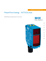 2
2
-
 3
3
-
 4
4
-
 5
5
-
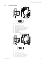 6
6
-
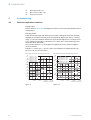 7
7
-
 8
8
-
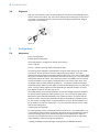 9
9
-
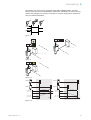 10
10
-
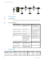 11
11
-
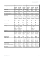 12
12
-
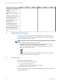 13
13
-
 14
14
-
 15
15
-
 16
16
-
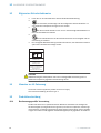 17
17
-
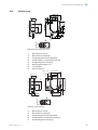 18
18
-
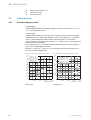 19
19
-
 20
20
-
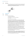 21
21
-
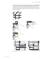 22
22
-
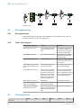 23
23
-
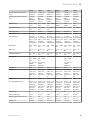 24
24
-
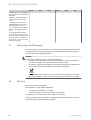 25
25
-
 26
26
-
 27
27
-
 28
28
-
 29
29
-
 30
30
-
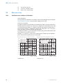 31
31
-
 32
32
-
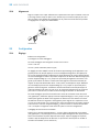 33
33
-
 34
34
-
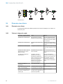 35
35
-
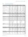 36
36
-
 37
37
-
 38
38
-
 39
39
-
 40
40
-
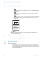 41
41
-
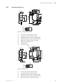 42
42
-
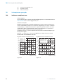 43
43
-
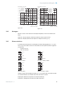 44
44
-
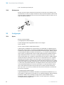 45
45
-
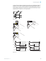 46
46
-
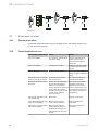 47
47
-
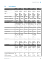 48
48
-
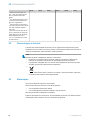 49
49
-
 50
50
-
 51
51
-
 52
52
-
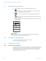 53
53
-
 54
54
-
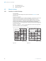 55
55
-
 56
56
-
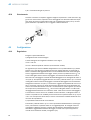 57
57
-
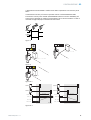 58
58
-
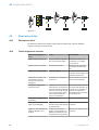 59
59
-
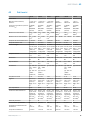 60
60
-
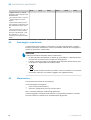 61
61
-
 62
62
-
 63
63
-
 64
64
-
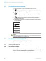 65
65
-
 66
66
-
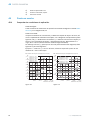 67
67
-
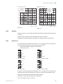 68
68
-
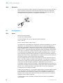 69
69
-
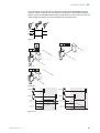 70
70
-
 71
71
-
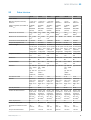 72
72
-
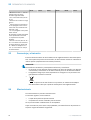 73
73
-
 74
74
-
 75
75
-
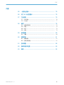 76
76
-
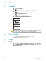 77
77
-
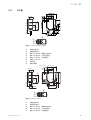 78
78
-
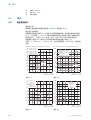 79
79
-
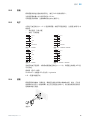 80
80
-
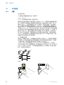 81
81
-
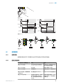 82
82
-
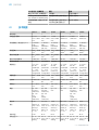 83
83
-
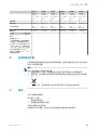 84
84
-
 85
85
-
 86
86
-
 87
87
-
 88
88
-
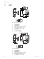 89
89
-
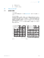 90
90
-
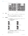 91
91
-
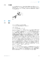 92
92
-
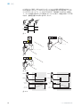 93
93
-
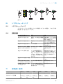 94
94
-
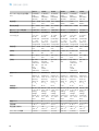 95
95
-
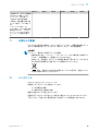 96
96
-
 97
97
-
 98
98
-
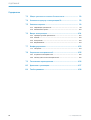 99
99
-
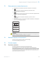 100
100
-
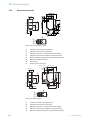 101
101
-
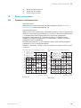 102
102
-
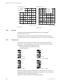 103
103
-
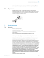 104
104
-
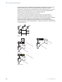 105
105
-
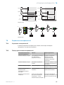 106
106
-
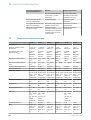 107
107
-
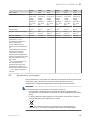 108
108
-
 109
109


SICK PowerProx Analog - WTT12L-Axxx Instrucciones de operación
- Tipo
- Instrucciones de operación
en otros idiomas
- français: SICK PowerProx Analog - WTT12L-Axxx Mode d'emploi
- italiano: SICK PowerProx Analog - WTT12L-Axxx Istruzioni per l'uso
- English: SICK PowerProx Analog - WTT12L-Axxx Operating instructions
- Deutsch: SICK PowerProx Analog - WTT12L-Axxx Bedienungsanleitung
- русский: SICK PowerProx Analog - WTT12L-Axxx Инструкция по эксплуатации
- português: SICK PowerProx Analog - WTT12L-Axxx Instruções de operação
- 日本語: SICK PowerProx Analog - WTT12L-Axxx 取扱説明書
Artículos relacionados
-
SICK PowerProx - WTT12L MultiTask photoelectric sensor Instrucciones de operación
-
-
-
-
-
-
-
-
-