AVENTICS Distance Measuring Sensor Series ST6-SM Manual de usuario
- Tipo
- Manual de usuario

Montageanleitung | Assembly instructions | Instructions de montage
Istruzioni di montaggio | Instrucciones de montaje | Monteringsanvisning
R412028907-BAL-001-AA
2023-08; Replaces: -
DE/EN/FR/IT/ES/SV
AVENTICS™ ST6-SM
Wegmesssensor
Distance measuring sensor
Capteur de déplacement
Sensore di misura della posizione
Sensor de medición de recorrido
Vägmätsensor

AVENTICS™ ST6-SM | R412028907-BAL-001-AA | Deutsch 2
Inhaltsverzeichnis
1 Zu dieser Dokumentation.................................................................................................................................................................................................. 4
1.1 Gültigkeit der Dokumentation .......................................................................................................................................................................................... 4
1.2 Zusätzliche Dokumentationen.......................................................................................................................................................................................... 4
1.3 Verwendete Abkürzungen ................................................................................................................................................................................................ 4
2 Sicherheit .......................................................................................................................................................................................................................... 4
2.1 Zu diesem Kapitel ............................................................................................................................................................................................................. 4
2.2 Bestimmungsgemäße Verwendung.................................................................................................................................................................................. 4
2.3 Nicht bestimmungsgemäße Verwendung ........................................................................................................................................................................ 4
2.4 Pflichten des Betreibers..................................................................................................................................................................................................... 4
2.5 Qualifikation des Personals ............................................................................................................................................................................................... 4
2.6 Gefahrenquellen ............................................................................................................................................................................................................... 4
2.6.1 Materialschäden................................................................................................................................................................................................. 4
3 Lieferumfang..................................................................................................................................................................................................................... 4
4 Transport und Lagerung .................................................................................................................................................................................................... 4
4.1 Produkt transportieren...................................................................................................................................................................................................... 4
4.2 Produkt lagern .................................................................................................................................................................................................................. 4
4.3 Produkt zurücksenden ...................................................................................................................................................................................................... 4
5 Produktbeschreibung........................................................................................................................................................................................................ 4
5.1 Kurzbeschreibung............................................................................................................................................................................................................. 4
5.2 Kennzeichnung und Identifikation .................................................................................................................................................................................... 5
5.3 Produktübersicht .............................................................................................................................................................................................................. 5
5.3.1 Standardkomponenten...................................................................................................................................................................................... 5
5.3.2 Anschlussvarianten ............................................................................................................................................................................................ 5
5.3.3 Optional: IO-Link Verbindung............................................................................................................................................................................. 5
5.4 Funktion und Anwendung................................................................................................................................................................................................. 5
6 Montage und Installation................................................................................................................................................................................................... 6
6.1 Planung............................................................................................................................................................................................................................. 6
6.1.1 Einbaubedingungen........................................................................................................................................................................................... 6
6.1.2 Benötigtes Zubehör, Material und Werkzeug ..................................................................................................................................................... 6
6.2 Vorbereitung .................................................................................................................................................................................................................... 6
6.2.1 Produkt auspacken und prüfen........................................................................................................................................................................... 6
6.2.2 Hinweise ............................................................................................................................................................................................................ 6
6.2.3 Schutzmaßnahmen durchführen........................................................................................................................................................................ 6
6.2.4 Softwareinstallation ........................................................................................................................................................................................... 6
6.3 Produkt befestigen ........................................................................................................................................................................................................... 6
6.4 Elektrik anschließen .......................................................................................................................................................................................................... 6
6.4.1 Versorgungsspannung anschließen.................................................................................................................................................................... 6
6.4.2 Leitungen verdrahten......................................................................................................................................................................................... 6
7 Inbetriebnahme................................................................................................................................................................................................................. 7
7.1 Schrittweise Inbetriebnahme ............................................................................................................................................................................................ 7
7.2 Messbereich einlernen ...................................................................................................................................................................................................... 7
7.3 Applikationsmessbereich ermitteln................................................................................................................................................................................... 7
7.4 Analogmessbereich skalieren............................................................................................................................................................................................ 7
8 Betrieb .............................................................................................................................................................................................................................. 7
8.1 Grundlegende Vorgaben................................................................................................................................................................................................... 7
8.2 Einstellung von Nullpunkt und Endpunkt kontrollieren...................................................................................................................................................... 7
8.3 Über IO-Link betreiben...................................................................................................................................................................................................... 8
8.3.1 Positionsoffset ................................................................................................................................................................................................... 8
8.3.2 Manueller Teach-in von bis zu 8 Schaltpunkten .................................................................................................................................................. 8
8.3.3 Alarmbenachrichtigungen ................................................................................................................................................................................. 8
8.3.4 Schaltpunkt........................................................................................................................................................................................................ 8

AVENTICS™ ST6-SM | R412028907-BAL-001-AA | Deutsch 3
8.3.5 Reset durchführen.............................................................................................................................................................................................. 8
8.3.6 Aktordiagnose durchführen ............................................................................................................................................................................... 9
9 Instandhaltung.................................................................................................................................................................................................................. 10
9.1 Inspektion......................................................................................................................................................................................................................... 10
9.1.1 Allgemeine Vorgaben......................................................................................................................................................................................... 10
9.1.2 Vorgehen ........................................................................................................................................................................................................... 10
9.2 Reinigung ......................................................................................................................................................................................................................... 10
9.2.1 Allgemeine Vorgaben......................................................................................................................................................................................... 10
9.2.2 Vorgehen ........................................................................................................................................................................................................... 10
9.3 Wartung ........................................................................................................................................................................................................................... 10
9.4 Nach der Instandhaltung................................................................................................................................................................................................... 10
10 Demontage und Austausch................................................................................................................................................................................................ 10
10.1 Vorbereitung .................................................................................................................................................................................................................... 10
10.2 Vorgehen.......................................................................................................................................................................................................................... 11
11 Daten und Parameter ........................................................................................................................................................................................................ 11
11.1 Hinweise zur Sicherheit..................................................................................................................................................................................................... 11
11.2 Anzeige............................................................................................................................................................................................................................. 11
11.2.1 LED-Anzeige....................................................................................................................................................................................................... 11
11.3 Pinbelegung...................................................................................................................................................................................................................... 11
11.4 Prozessdatenstruktur IO-Link............................................................................................................................................................................................ 11
11.5 Schaltpunktmodi IO-Link .................................................................................................................................................................................................. 11
12 Entsorgung........................................................................................................................................................................................................................ 12
13 Fehlersuche und Fehlerbehebung...................................................................................................................................................................................... 12
13.1 Vorgehen.......................................................................................................................................................................................................................... 12
13.2 Fehlerbilder....................................................................................................................................................................................................................... 12
14 Technische Daten .............................................................................................................................................................................................................. 13
15 Ersatzteile ......................................................................................................................................................................................................................... 13
16 Zubehör ............................................................................................................................................................................................................................ 13

1 Zu dieser Dokumentation
Lesen Sie diese Dokumentation vollständig und insbesondere das Kapitel g2.Si-
cherheit, bevor Sie mit dem Produkt arbeiten.
Diese Anleitung enthält wichtige Informationen, um das Produkt sicher und sach-
gerecht zu montieren, zu bedienen, zu warten und einfache Störungen selbst zu
beseitigen.
1.1 Gültigkeit der Dokumentation
Diese Dokumentation gilt für den Wegmesssensor ST6-SM.
Diese Dokumentation richtet sich an:
Anlagenbetreiber, Anlagenplaner, Maschinenhersteller, Monteure
1.2 Zusätzliche Dokumentationen
Beachten Sie folgende mitgeltende Dokumentationen:
• Anlagendokumentation des Herstellers
1.3 Verwendete Abkürzungen
In dieser Dokumentation werden folgende Abkürzungen verwendet:
Abkürzung Bedeutung
PELV Protective Extra Low Voltage (Schutzkleinspannung)
PSA Persönliche Schutzausrüstung
SELV Safety Extra Low Voltage (Sicherheitskleinspannung)
SW Schlüsselweite
2 Sicherheit
2.1 Zu diesem Kapitel
• Lesen Sie dieses Kapitel sowie die gesamte Dokumentation gründlich und
vollständig, bevor Sie mit dem Produkt arbeiten.
• Bewahren Sie die Dokumentation so auf, dass sie jederzeit für alle Benutzer
zugänglich ist.
2.2 Bestimmungsgemäße Verwendung
Einsatzzwecke
• Berührungslose Erfassung des Kolbenhubs von pneumatischen Antrieben mit
axial und diametral magnetisierten Dauermagneten.
• Das Produkt ist ausschließlich für den professionellen Gebrauch bestimmt.
• Das Produkt ist ausschließlich dazu bestimmt, in ein Endprodukt (eine An-
lage / Maschine) eingebaut oder mit anderen Komponenten zu einem End-
produkt zusammengefügt zu werden.
Einsatzbereich und Einsatzort
• Industriebereich
• Gewerblicher Bereich
• Innenräume
INFO: Wenn das Produkt in einem anderen Bereich eingesetzt werden soll:
Einzelgenehmigung beim Hersteller einholen.
Hinweise
• Einsatz nur bei AVENTICS-Aktoren mit T-Nut.
2.3 Nicht bestimmungsgemäße Verwendung
Das Produkt ist nicht für den Einsatz in explosionsgefährdeten Bereichen be-
stimmt (Explosionsschutz).
2.4 Pflichten des Betreibers
• Der Betreiber muss sicherstellen, dass Personen, die das Produkt montieren,
bedienen, demontieren oder warten, nicht unter dem Einfluss von Alkohol,
sonstigen Drogen oder Medikamenten stehen, die die Reaktionsfähigkeit be-
einflussen.
• Der Betreiber muss den Einsatz von PSA gewährleisten. Vorgaben der Ge-
samtanlage beachten.
2.5 Qualifikation des Personals
Ausschließlich für die Aufgaben qualifiziertes Personal darf die Tätigkeiten aus-
führen, die in dieser Dokumentation beschrieben werden. Je nach Tätigkeit sind
grundlegende Kenntnisse in folgenden Bereichen und Kenntnisse der zugehöri-
gen Fachbegriffe erforderlich:
• Pneumatik
• Elektrik
2.6 Gefahrenquellen
2.6.1 Materialschäden
Beschädigung durch zu hohe mechanische Belastungen
• Das Produkt und Anbauteile niemals verdrehen, biegen oder unter Spannung
befestigen.
• Das Produkt nicht als Griff oder Stufe verwenden.
• Keine Gegenstände auf dem Produkt abstellen.
3 Lieferumfang
• 1x Sensor (siehe: Bestellung)
4 Transport und Lagerung
4.1 Produkt transportieren
Gefährdungen während des Transports
• Während des Entladens und des Transports des verpackten Produkts zum
Zielort vorsichtig vorgehen und die Informationen auf der Verpackung beach-
ten.
• Sicherstellen, dass das Produkt nicht herunterfallen kann, bevor das Produkt
aus den Befestigungen gelöst wird.
• Vorkehrungen treffen, um Beschädigungen beim Anheben des Produkts zu
vermeiden.
• PSA tragen.
4.2 Produkt lagern
Beschädigung durch falsche Lagerung
Ungünstige Lagerbedingungen können zu Korrosion und Werkstoffalterung füh-
ren.
• Das Produkt nur an Orten lagern, die trocken, kühl und korrosionsverhindernd
sind.
• Produkt vor direkter Sonneneinstrahlung und UV-Strahlung schützen.
• Das Produkt in der Verpackung bis zum Zeitpunkt des Einbaus aufbewahren.
• Falls vorhanden, weiterführende Hinweise zur Lagerung auf der Produktverpa-
ckung beachten.
4.3 Produkt zurücksenden
• Vor Rücksendung des Produkts: Wenden Sie sich an unsere Kontaktadresse.
Siehe Rückseite.
• Bis zur Rücksendung Lagerbedingungen berücksichtigen.
5 Produktbeschreibung
5.1 Kurzbeschreibung
Das Produkt dient der berührungslosen Erfassung des Kolbenhubs von pneumati-
schen Antrieben mit axial magnetisierten Dauermagneten. Das Produkt liefert
ein Ausgangssignal, das zum Zylinderhub proportional ist.
Zielapplikationen:
• Analoge Positionsmessung für Kurzhub in Anlagen ohne IO-Link
• Positionsmessung für Kurzhub in Anlagen mit IO-Link
• Detektion von 8 Positionen über 8 Schaltpunkte mit IO-Link
AVENTICS™ ST6-SM | R412028907-BAL-001-AA | Deutsch 4

5.2 Kennzeichnung und Identifikation
Produktidentifikation
Das bestellte Produkt wird anhand der Materialnummer eindeutig identifiziert.
Die Materialnummer finden Sie an folgender Stelle:
• Als QR-Code auf der Kabelfahne.
• Auf dem Klebeetikett der Verpackung.
CE-Kennzeichnung und UKCA-Kennzeichnung
Dieses Produkt entspricht der Richtlinie 2014/30/EU (EMV) und deren Er-
gänzungen über die Elektromagnetische Verträglichkeit. Das Produkt ist
mit CE und UKCA gekennzeichnet. Die Konformitätserklärung steht auf
Anfrage zur Verfügung.
Geben Sie bitte für die entsprechenden Produkte die Materialnummer
und Seriennummer an.
UL-Zulassung
Dieses Produkt wurde nach den geltenden UL-Standards geprüft und zer-
tifiziert.
5.3 Produktübersicht
5.3.1 Standardkomponenten
1 2 3 4
Abb.1: Produktübersicht ST6-SM
1 Physikalische Nulllage 2 2 x LED (PWR (grün) = Spannungsver-
sorgung, MR (gelb) = Messbereich)
3 Befestigungsschraube SW 2,5 4 Halterippen
5.3.2 Anschlussvarianten
1
2
Abb.2: Anschlussvarianten
1 Leitungsenden 2 M12-Stecker
5.3.3 Optional: IO-Link Verbindung
Über die IO-Link-Kommunikationsschnittstelle können bis zu 8 Schaltpunkte ein-
gestellt und zusätzlich Aktordiagnosedaten erfasst und ausgegeben werden. Sie-
he g8.3.6Aktordiagnose durchführen.
5.4 Funktion und Anwendung
Funktionsprinzip
Das Produkt ermittelt die Position eines Gebermagneten über eine Zeile von 2
Sensorelementen im Sensorkopf.
Die Sensorelemente messen jeweils die Feldstärke in x-Richtung und y-Richtung,
dadurch sind axial und diametral magnetisierte Magnete erkennbar.
y y
xx
y y
xx
y (radial)
x (axial)
12
3
4
Abb.3: Funktionsprinzip
1 Sensorelement 1 2 Sensorelement 2
3 Axial magnetisierter Magnet 4 Diametral magnetisierter Magnet
Erfassungsbereich
50
32,5
0- 25 mm+ 25 mm
3
1
2
Abb.4: Erfassungsbereich
1 Erfassungsbereich, 50 mm 2 Gehäuselänge, 32,5 mm
3 Nullpunkt / physikalische Nulllage
Positionsausgabe
Das Produkt gibt eine linearisierte Position in einem Erfassungsbereich von ca.
50mm (antriebsabhängig) aus.
0
-32760
32760
1
23
4
5
6
Abb.5: Positionsausgabe IO-Link
1 Nullpunkt / physikalische Nulllage 2 Positive Positionen
3 Negative Positionen 4 Erfassungsbereich Sensor: -2.500 ...
2.500 Digits (IO-Link-Ausgang), 1 Di-
git entspricht 10 μm
5 Kolbenposition 6 Positionsausgabe Sensor
AVENTICS™ ST6-SM | R412028907-BAL-001-AA | Deutsch 5

0
10.5 V
10 V
11 V
0 V
1
23
4
5
6
Abb.6: Positionsausgabe analog
1 Nullpunkt / physikalische Nulllage 2 Positive Positionen
3 Negative Positionen 4 Erfassungsbereich Sensor: 0 ... 10 V
(Analogausgang)
5 Kolbenposition 6 Positionsausgabe Sensor
6 Montage und Installation
Bevor Sie mit dem Einbau anfangen: Machen Sie sich möglichst frühzeitig im Vor-
feld mit den grundlegenden Vorgaben für die Montage vertraut. Siehe g6.1Pla-
nung und g6.2Vorbereitung.
6.1 Planung
6.1.1 Einbaubedingungen
Allgemeine Vorgaben
• Sicherstellen, dass das Produkt gegen jegliche mechanische Belastung ge-
schützt eingebaut ist.
• Sicherstellen, dass ausreichend Platz zur Verfügung steht.
Vorgaben für das Produkt
• Einbaulage. Siehe g14.Technische Daten.
Umgebungsbedingungen
• Der Einbauort muss frei von Vibration sein.
• Produkt vor direkter Sonneneinstrahlung und UV-Strahlung schützen.
• Sicherstellen, dass sich keine ferromagnetischen Quellen in der Nähe des Pro-
dukts befinden (Materialschutz).
6.1.2 Benötigtes Zubehör, Material und Werkzeug
Wählen Sie Material und Werkzeug passend zu Ihrer Produktkonfiguration. Je
nach Konfiguration benötigen Sie weiteres Zubehör.
Befestigungsmaterial
Für die Befestigung können Sie eigenes Befestigungsmaterial oder AVENTICS-Be-
festigungsmaterial verwenden. Maße und Anzugsmomente beachten.
Werkzeug
• 1x nicht magnetisierbarer Innensechskantschlüssel (SW2,5)
INFO: SW2,5 entspricht AF2,5 auf der Verpackung.
6.2 Vorbereitung
6.2.1 Produkt auspacken und prüfen
1. Anhand der Materialnummer prüfen, ob das Produkt mit Ihrer Bestellung
übereinstimmt.
2. Produkt auf Transportschäden und Lagerungsschäden prüfen.
Ein beschädigtes Produkt darf nicht montiert werden. Beschädigte Produkte
zusammen mit den Lieferunterlagen zurückschicken. Siehe g4.3Produkt zu-
rücksenden.
3. Benötigtes Zubehör, Material und Werkzeug bereitlegen.
6.2.2 Hinweise
• Aderenden gegeneinander isolieren. Bei eingeschalteter Versorgungsspan-
nung besteht Kurzschlussgefahr, wenn sich offene Aderenden berühren.
• Aderquerschnitte der Versorgungsleitung, die vom Anwender zugeführt wird,
gemäß IEC60364-1 und IEC60364-5-52 ausführen.
6.2.3 Schutzmaßnahmen durchführen
Vorgehen
1. Während der Vorbereitungen keine Arbeiten an der Anlage vornehmen.
2. Gefahrenbereiche absperren.
3. Anlage bzw. Anlagenteil drucklos und spannungsfrei schalten.
4. Anlage gegen Wiedereinschalten sichern.
5. Produkt und benachbarte Anlagenteile abkühlen lassen.
6. PSA anlegen.
6.2.4 Softwareinstallation
1. IODD-Datei mit dem Produktionsdatum des Produkts im Dateinamen herun-
terladen. Siehe Produktseite im Emerson Store.
2. IODD-Dateien installieren.
6.3 Produkt befestigen
Hinweise
• Die Dreiecke auf dem Produkt geben die Position der physikalischen Nulllage
an.
Vorgehen
uProdukt mittig zum Verfahrbereich des Magneten in die T-Nut einsetzen.
ðAnalogausgang gibt einen Wert von 2V…8V aus.
uSchraube festziehen.
Anzugsmoment: 0,7Nm
1
4
3
2
Abb.7: Produkt befestigen
6.4 Elektrik anschließen
Hinweise
• Am Produkt angeschlossene Stromkreise als SELV- und PELV-Stromkreise aus-
führen.
• Stromquelle gemäß EN 60204-1 verwenden.
6.4.1 Versorgungsspannung anschließen
uDas Produkt gemäß Pinbelegung anschließen. Siehe g11.Daten und Para-
meter.
6.4.2 Leitungen verdrahten
Vorgehen
Tab.1: Leistungsgruppen der Leitungen in Bezug auf Störempfindlichkeit /
Störaussendung
Leistungsgrup-
pe
Beschreibung Beispiel
1 Sehr störempfindliche Leitungen Analoge Messleitungen
2 Störempfindliche Leitungen Sensorleitung, Kommunikationssi-
gnale, Bussignale
3 Störquellen Steuerleitung für induktive Lasten
und Motorbremsen
4 Stark störende Leitungen Ausgangsleitung von Frequenzum-
richtern, Versorgung von Schweiß-
anlangen, Leistungskabel
AVENTICS™ ST6-SM | R412028907-BAL-001-AA | Deutsch 6

1. Sicherstellen, dass der Sensor korrekt axial ausgerichtet ist.
2. Leitungen der Gruppen 1 und 2 mit Leitungen der Gruppen 3 und 4 recht-
winklig kreuzen. Siehe g6.4.2Leitungen rechtwinklig kreuzen.
3. Leitungen der Gruppen 1 und 2 sowie Leitungen der Gruppen 3 und 4 in ver-
schiedenen Kabelkanälen verlegen oder metallische Trennstege verwenden.
Siehe g6.4.2Ideale Verlegung der Leitungen und g6.4.2Alternative Verle-
gung der Leitungen.
1
2
4
3
1
2
4
3
90
90
Abb.8: Leitungen rechtwinklig kreuzen
1
2
3
4
Abb.9: Ideale Verlegung der Leitungen
1
23
4
5
Abb.10: Alternative Verlegung der Leitungen
5 Trennsteg
7 Inbetriebnahme
7.1 Schrittweise Inbetriebnahme
Vorgehen
uWenn das Produkt vorher auf einem Antrieb montiert war: Application reset
durchführen. Siehe g8.3.5Reset durchführen.
7.2 Messbereich einlernen
Hinweise
• Werden vor dem vollständigen Einlernen Schaltpunkte eingelernt, verändert
sich die Position der Schaltpunkte während des Einlernprozesses.
• Wert des Index 16512 MDC Descr > Subindex 1 und 2 (Measurement Range)
verändert sich während des Einlernprozesses.
Vorgehen
1. Werkseinstellungen wiederherstellen: Factory Reset oder Device Reset durch-
führen. Siehe g8.3.5Reset durchführen.
2. Wenn IO-Link verwendet wird: Application Reset, Factory Reset oder Reset
Trained Algorithm Parameter durchführen. Siehe g8.3.5Reset durchführen.
3. Wenn IO-Link verwendet wird: Indizes anpassen. Siehe g8.3.2Manueller Te-
ach-in von bis zu 8 Schaltpunkten.
4. Magnetkolben in die Position für den Nullpunkt bringen.
5. Prüfen, ob die sich der Magnetkolben im Messbereich befindet: Prüfen, ob die
gelbe LED 1 (MR) leuchtet.
6. Antrieb min. 5x über den kompletten Verfahrbereich des Antriebs verfahren
lassen.
ðVolle Genauigkeit ist erreicht (minimaler Linearitätsfehler, korrekte Anzeige
Messbereich).
7.3 Applikationsmessbereich ermitteln
Hinweise
• Je kleiner der Applikationsmessbereich ist, desto besser ist die Performance.
Vorgehen
1. Wenn IO-Link verwendet wird: Über den Index 16512 (0x4080) MDC Descr >
Subindex 1 (0x01) Lower limit und Subindex 2 (0x02) Upper limit den Applika-
tionsmessbereich auslesen.
2. Wenn IO-Link verwendet wird: Über den Index 265 Position noise limit for app-
lication range [mm] den Applikationsmessbereich beeinflussen.
7.4 Analogmessbereich skalieren
uÜber den Index 207 (0xCF) Set up analog output den Analogmessbereich dem
Hub entsprechend skalieren.
Tab.2: Position im Default
Position in mm Position in Digits Spannung
-25mm -2.500Digits 0V
+25mm 2.500Digits 10V
Bei Hüben unter 50mm den gesamten Analogwertbereich ausgeben:
1. Gewünschten Startpunkt unter Subindex 1 (0x01) Measurement area start
point eintragen.
2. Gewünschten Endpunkt unter Subindex 2 (0x02) Measurement area end point
eintragen.
8 Betrieb
8.1 Grundlegende Vorgaben
Allgemeine Vorgaben
• Schutzvorrichtungen nie ausschalten, modifizieren oder umgehen.
• Im laufenden Betrieb weder das Produkt noch damit verbundene Teile berüh-
ren.
Bei Störungen im laufenden Betrieb
• Bei Auftreten einer Störung, die eine unmittelbare Gefahr für Mitarbeiter oder
Anlagen darstellt: Produkt ausschalten.
8.2 Einstellung von Nullpunkt und Endpunkt kontrollieren
1. Nullpunkt anfahren.
ðSpannung am entsprechenden Ausgangs-Pin beträgt ca. 0V.
ðGelbe LED 1 (MR) leuchtet.
2. Falls an dem Ausgangs-Pin eine andere Spannung ausgegeben wird, oder die
gelbe LED 1 (MR) nicht leuchtet: Messbereich neu einlernen. Siehe
g7.2Messbereich einlernen.
3. Endpunkt anfahren.
ðSpannung am entsprechenden Ausgangs-Pin beträgt ca. 10V
ðGelbe LED 1 (MR) leuchtet.
4. Falls an dem Ausgangs-Pin eine andere Spannung ausgegeben wird, oder die
gelbe LED 1 (MR) nicht leuchtet: Messbereich neu einlernen. Siehe
g7.2Messbereich einlernen.
AVENTICS™ ST6-SM | R412028907-BAL-001-AA | Deutsch 7

8.3 Über IO-Link betreiben
8.3.1 Positionsoffset
257 (0x101) [x10µm] Position offset
Der Wert des Positionsoffset in µm wird in 10-µm-Schritten eingestellt und zum
tatsächlichen Positionswert addiert.
uPositionsoffset in Index 257 (0x101) Position offset [x10µm] verändern.
ðWerte in Index 260 (0x104) Detection range [x10µm] und in Index 16512
(0x4080) MDC Descr > Subindex 1 und 2 verändern um den Wert des Positi-
onsoffset.
8.3.2 Manueller Teach-in von bis zu 8 Schaltpunkten
Hinweise
• Limitierende Faktoren sind die Wiederholgenauigkeit und die Auflösung, der
Abstand zwischen 2 Schaltpunkten kann kleiner als 1mm sein.
Vorgehen
Am Beispiel Qint.1:
1. Schaltpunktmodus Window Mode oder Two-point Mode wählen. Siehe
g11.5Schaltpunktmodi IO-Link.
2. Startpunkt und Endpunkt der Schaltpunktbreite einstellen: Index 60 (0x3C)
Qint.1 SP1 / SP2 anpassen.
3. Schaltpunktlogik einstellen: Index 61 (0x3D) Qint.1 Configuration > Subindex
1 (0x01) Switchpoint Logic anpassen.
4. Schaltpunktmodus einstellen: Index 61 (0x3D) Qint.1 Configuration > Subin-
dex 2 (0x02) Switchpoint Mode anpassen.
5. Schaltpunkthysterese einstellen: Index 61 (0x3D) Qint.1 Configuration > Sub-
index 3 (0x03) Switchpoint Hysteresis anpassen.
6. Qint.2 SP1 / SP2 und Qint.3 SP1 / SP2…Qint.8 SP1 / SP2 konfigurieren: Indizes
62 (0x3E) und 16384 (0x4000)…16395 (0x400B) anpassen.
ðDie Hysterese der konfigurierten Schaltpunkte beträgt 0,7mm.
8.3.3 Alarmbenachrichtigungen
Über Indizes auslesen
1. Die Alarmschwellen über die Indizes 4369 (0x1111) DD - Alert limit und 4399
(0x112F) Actuator alert limits anpassen.
2. Über die Indizes 4370 (0x1112) DD - Alert flags und 4400 (0x1130) Actuator
alerts Alarmbenachrichtigungen auslesen. (Standard)
Über das Prozessdatum auslesen
üAlarmbenachrichtigungen können ausgelesen werden, wenn die eingestellte
Alarmschwelle überschritten wird.
1. Die Alarmschwellen über die Indizes 4369 (0x1111) DD - Alert limit und 4399
(0x112F) Actuator alert limits anpassen.
2. Im Index 67 (0x43) Process data user definition Alarmbenachrichtigungen an-
stelle der Schaltpunkte einstellen. Siehe gTab.3.
3. Alarmbenachrichtigungen über das Prozessdatum auslesen.
ðAlarmbenachrichtigungen werden regelmäßig automatisch übertragen.
Tab.3: Alarmbenachrichtigungen über Prozessdatum auslesen
Wert Beschreibung
60 Group alert: Cycle time (Typ: Ereignis)
Inhalt: Index 4400 (0x1130) Actuator alerts > Subindex 2 (0x02) Min. cycle
time alert und Subindex 3 (0x03) Max. cycle time alert
65 Direct alert: Operating hours max. (Typ: Ereignis)
68 Direct alert: Power cycles max. (Typ: Ereignis)
69 Direct alert: Cycle count max. (Typ: Ereignis)
90 Direct alert: Total actuator travel max. (Typ: Ereignis)
Alarmverzögerungszeit einstellen
Die eingestellte Alarmverzögerungszeit wirkt sich nur auf Alarmbenachrichtigun-
gen vom Typ „Status“ aus. Alarmbenachrichtigungen vom Typ „Ereignis“ treten
sofort nach Unterschreiten oder Überschreiten der eingestellten Grenze auf.
uAlarmverzögerungszeit über den Index 4842 (0x12EA) > Subindex (0x01) Alert
delay time [ms] einstellen.
ðAlarm wird nur ausgegeben, wenn die entsprechende Alarmbedingung länger
als die hier definierte Alarmverzögerungszeit erfüllt ist.
Alarm automatisch zurücksetzen
Das automatische Alarm-Reset beschreibt die Zeit, nach der Alerts automatisch
zurückgesetzt werden, wenn sich die Alert-Bits in den Prozessdaten nicht ändern.
Ein negativer Wert deaktiviert das automatische Zurücksetzen von Alarmbenach-
richtigungen. In der Standardeinstellung ist der automatische Alarm-Reset deak-
tiviert.
uAlarm-Reset über den Index 4842 (0x12EA) > Subindex 2 (0x02) Automatic
alert reset time [ms] einstellen.
8.3.4 Schaltpunkt
Schaltpunktlogik invertieren
uSubindex 1 (0x01) Switchpoint Logic anpassen.
ðLogik der eingelernten Schaltpunkte wird invertiert. Standardmäßig sind die
Schaltpunkte beim Überfahren auf high.
Schaltpunkthysterese
uHysterese über den Subindex 3 (0x03) Switchpoint Hysteresis in 10µm Schrit-
ten anpassen (Max: 327,67mm, min: 0,01mm).
Schaltpunktbreite
üSchaltpunktmodus Cylinder switch mode ausgewählt. Siehe g11.5Schalt-
punktmodi IO-Link.
1. Manuellen Teach-in durchführen.
2. Breite der eingelernten Schaltpunkte über den Index 170 (0xAA) Switchpoint
width [x10µm] bestimmen (Standard: 2mm, max.: 10mm).
8.3.5 Reset durchführen
Tab.4: Resets
Reset Index Wert Ergebnis
Device Reset Index 2 (0x02) System Command 128 Produkt wird neu gestartet.
Folgende Indizes werden zurückgesetzt:
•4372 (0x1114) Actuator travel [x10 µm]
•4380 (0x111C) Cycle time [ms]
•4381 (0x111D) Dwell time [ms]
•4379 (0x111B) Actuator travel time [ms]
•4375 (0x1117) Average actuator velocity [m/s]
•4602 (0x11FA) Current field strength [mT]
4604 (0x111FC) Peak field strength
Folgende Indizes bleiben erhalten:
•4374 (0x1116) Total actuator travel [sum m]
•4382 (0x111E) Cycle count [sum]
•Qint. 1-8 SP1 / SP2, Qint. 1-8 Configuration
AVENTICS™ ST6-SM | R412028907-BAL-001-AA | Deutsch 8

Reset Index Wert Ergebnis
Restore Factory Settings Index 2 (0x02) System Command 130 • Messwerte des Algorithmus werden zurückgesetzt. Siehe Reset trained algorithm parameter.
• Die Einstellungen werden auf Defaultwerte zurückgesetzt.
Folgende Indizes bleiben erhalten:
•4356 (0x1104) Operating hours
•4357 (0x1105) Power cycles > Subindex 1
•4382 (0x111E) Cycle count [sum]
•4374 (0x1116) Total actuator travel [sum m]
Reset Diagnostic Parameters Index 2 (0x02) System Command 228 Folgende Indizes werden zurückgesetzt:
•4356 (0x1104) Operating hours > Subindex 2 (0x02) Since last reset
•4357 (0x1105) Power cycles > Subindex 2 (0x02) Since last reset
•4382 (0x111E) Cycle count [sum]
•4374 (0x1116) Total actuator travel [sum m]
Reset all present alerts Index 2 (0x02) System Command 229 Die gesetzten Alarmbenachrichtigungen werden zurückgesetzt.
Reset operating hours counter Index 2 (0x02) System Command 228 Folgende Indizes werden zurückgesetzt:
•4356 (0x1104) Operating hours > Subindex 2 (0x02) Since last reset.
Reset power cycles counter Index 2 (0x02) System Command 228 Folgende Indizes werden zurückgesetzt:
•4357 (0x1105) Power cycles
Reset actuator cycles counter Index 4398 (0x112E) Reset actua-
tor diagnostics parameters
2 Folgende Indizes werden zurückgesetzt:
•4382 (0x111E) Cycle Count [sum]
Reset total actuator travel Index 4398 (0x112E) Reset actua-
tor diagnostics parameters
1 Folgende Indizes werden zurückgesetzt:
•4374 (0x1116) Total actuator travel [sum m]
Reset all actuator diagnostics pa-
rameters
Index 4398 (0x112E) Reset actua-
tor diagnostics parameters
255 Folgende Resets werden durchgeführt:
•Reset diagnostic parameters
•Reset all present alerts
•Reset operating hours counter
•Reset power cycles counter
•Reset actuator cycles count
Application reset Index 2 (0x02) System Command 129 Werkseinstellungen werden wiederhergestellt. Siehe Restore Factory Settings.
Folgende Indizes bleiben erhalten:
• Identifikationsparameter Index 24, 25, 26 und 64
Reset trained algorithm parame-
ter
Index 2 (0x02) System Command 192 • Messwerte des Algorithmus werden zurückgesetzt.
• Einstellungen und Diagnosedaten bleiben erhalten.
8.3.6 Aktordiagnose durchführen
Tab.5: Aktordiagnose
Diagnose Beschreibung Auslesen über Index
Zurückgelegter Hub (Actuator travel) Gemessenen Weg des letzten Hubs in mm auslesen 4372 (0x1114) Actuator travel [x10µm]
Zykluszeit (Cycle time) Die Dauer des letzten Zyklus in ms wird über den Index 4380 (0x111C) Cycle time [ms] ausgegeben.
Ein Zyklus entspricht 2 Hüben: Startposition – Stoppposition – Startposition.
Unterschwelle für die Zykluszeit in ms festlegen
Beim Unterschreiten der Unterschwelle wird über den Index 4400
(0x1130) > Subindex 2 (0x02) Min. cycle time alert ein Alarm über das
Prozessdatum ausgegeben.
4399 (0x112F) > Subindex 2 (0x02) Min. cycle time limit
Oberschwelle für die Zykluszeit in ms festlegen
Beim Überschreiten der Oberschwelle wird über den Index 4400
(0x1130) > Subindex 3 (0x03) Max. cycle time alert ein Alarm über das
Prozessdatum ausgegeben.
4399 (0x112F) > Subindex 3 (0x03) Max. cycle time limit
Verweildauer Startposition und Stopppositi-
on (Dwell time [ms])
Verweilzeit in ms an der Startposition auslesen 4381 (0x111D) Dwell time [ms] > Subindex 1 (0x01) Start position
Verweilzeit in ms an der Stoppposition auslesen 4381 (0x111D) Dwell time [ms] > Subindex 2 (0x02) Stop position
Verfahrzeit des Kolbens beim Ausfahren und
beim Einfahren (Actuator travel time [ms])
Ein Hub entspricht einer Bewegung in eine Richtung.
Bewegungsrichtung beim Ausfahren: Stoppposition – Startposition.
Bewegungsrichtung beim Einfahren: Startposition – Stoppposition.
Dauer des letzten Hubs in ms in positiver Richtung (Kolben fährt aus)
auslesen
4379 (0x111B) Actuator travel time [ms] > Subindex 1 (0x01) Extend
(positive direction)
Dauer des letzten Hubs in ms in negativer Richtung (Kolben fährt ein)
auslesen
4379 (0x111B) Actuator travel time [ms] > Subindex 2 (0x02) Retract
(negative direction)
Durchschnittliche Kolbengeschwindigkeit
beim Ausfahren und beim Einfahren (Average
actuator velocity [m/s])
Durchschnittliche Geschwindigkeit in m/s des Kolbens in positiver
Richtung (Kolben fährt aus) auslesen
4375 (0x1117) Average actuator velocity [m/s] > Subindex 1 (0x01) Ex-
tend (positive direction)
Durchschnittliche Geschwindigkeit in m/s des Kolbens in negativer
Richtung (Kolben fährt ein) auslesen
4375 (0x1117) Average actuator velocity [m/s] > Subindex 2 (0x02) Re-
tract (negative direction)
Aktuelle gemessene Feldstärke an den Sen-
sorelementen (Current field strength [mT])
Aktuelle gemessene Feldstärke für das Sensorelement 1 in mT (Sensor
element 1) auslesen
4602 (0x11FA) Current field strength [mT] > Subindex 1 (0x01) Cur-
rent1
Aktuelle gemessene Feldstärke für das Sensorelement 2 in mT (Sensor
element 2) auslesen
4602 (0x11FA) Current field strength [mT] > Subindex 2 (0x02) Cur-
rent2
AVENTICS™ ST6-SM | R412028907-BAL-001-AA | Deutsch 9

Diagnose Beschreibung Auslesen über Index
Maximale gemessene Feldstärke an den Sen-
sorelementen (Peak field strength [mT])
Seit dem letzten Power cycle maximale gemessene Feldstärke für das
Sensorelement 1 in mT (Sensor element 1) auslesen.
4604 (0x11FC) Peak field strength [mT] > Subindex 1 (0x01) Current1
Seit dem letzten Power cycle maximale gemessene Feldstärke für das
Sensorelement 2 in mT (Sensor element 2) auslesen.
4604 (0x11FC) Peak field strength [mT] > Subindex 2 (0x02) Current2
Zykluszähler (Cycle count) Seit dem letzten Power cycle maximale gemessene Feldstärke für das
Sensorelement 1 in mT (Sensor element 1) auslesen
4604 (0x11FC) Peak field strength [mT] > Subindex 1 (0x01) Current1
Seit dem letzten Power cycle maximale gemessene Feldstärke für das
Sensorelement 2 in mT (Sensor element 2) auslesen
4604 (0x11FC) Peak field strength [mT] > Subindex 2 (0x02) Current2
Gesamte zurückgelegte Strecke des Kolbens
(Total actuator travel)
Die gesamte zurückgelegte Strecke des Kolbens wird nur alle 10m im EEPROM gespeichert.
Wird die Spannungsversorgung nach einem Verfahrweg von 9,99m unterbrochen, wird nach dem Spannungszyklus über IO-Link wieder 0,0m
ausgelesen.
Gesamten zurückgelegten Weg des Kolbens in m auslesen 4374 (0x1116) Total actuator travel [sum m]
Betriebsstunden (Operating hours) Ausgabe der Betriebsstunden in Stunden auslesen Subindizes des Index 4356 (0x1104) Operating hours
Absolute Betriebsstunden 1 (0x01) Total
Betriebsstunden seit dem letzten Reset 2 (0x02) Since last reset
Zeit seit dem letzten Power-on 3 (0x03) Since startup
Power-on-Zyklen / Power-off-Zyklen (Power
cycles)
Die Power-on-Zyklen/ Power-off-Zyklen beschreiben die Anzahl der Einschaltvorgänge und Ausschaltvorgänge.
1 Zyklus entspricht einem Power-on und einem Power-off.
Power-on- Zyklen / Power-off-Zyklen auslesen 4357 Power cycles
Gesamtanzahl Subindex 1 (0x01) Total
Anzahl seit dem letzten Reset Subindex 2 (0x02) Since last reset
9 Instandhaltung
9.1 Inspektion
9.1.1 Allgemeine Vorgaben
Einsatz unter normalen Umgebungsbedingungen
• Prüfintervall: Das Produkt muss monatlich auf Verschmutzung und Beschädi-
gung geprüft werden.
Einsatz unter aggressiven Umgebungsbedingungen
Aggressive Umgebungsbedingungen sind z.B.:
• Hohe Temperaturbelastung
• Starker Schmutzanfall
• Nähe zu fettlösenden Flüssigkeiten oder Dämpfen
Als Folge von aggressiven Umgebungsbedingungen ergeben sich weitere Vorga-
ben für die Inspektion:
• Prüfintervall für Dichtungen an die Umgebungsbedingungen anpassen.
9.1.2 Vorgehen
Vorbereitung
1. Während der Vorbereitungen keine Arbeiten an der Anlage vornehmen.
2. Gefahrenbereiche absperren.
3. Anlage bzw. Anlagenteil drucklos und spannungsfrei schalten.
4. Anlage gegen Wiedereinschalten sichern.
5. Produkt und benachbarte Anlagenteile abkühlen lassen.
6. PSA anlegen.
Sichtkontrolle
uEine Sichtkontrolle auf Unversehrtheit durchführen.
Detailprüfung
• Kennzeichnungen und Warnungen am Produkt: Der Betreiber muss schwer
lesbare Kennzeichnungen oder Warnungen umgehend ersetzen.
• Dichtungen prüfen.
• Alle Schraubverbindungen auf festen Sitz kontrollieren.
• Alle Steckverbinder auf festen Sitz kontrollieren.
• Schutzvorrichtungen der Anlage kontrollieren.
• Produktfunktionen kontrollieren.
9.2 Reinigung
9.2.1 Allgemeine Vorgaben
Reinigungsintervalle
• Die Reinigungsintervalle legt der Betreiber gemäß der Umweltbeanspruchung
am Einsatzort fest.
Hilfsmittel
• Das Produkt ausschließlich mit feuchten Tüchern reinigen.
• Für die Reinigung ausschließlich Wasser und ggf. ein mildes Reinigungsmittel
verwenden.
9.2.2 Vorgehen
1. Alle Öffnungen mit geeigneten Schutzeinrichtungen verschließen, damit kein
Reinigungsmittel ins System eindringen kann.
2. Alle Staubablagerungen auf dem Produkt und den benachbarten Anlagentei-
len entfernen.
3. Ggf. andere produktionsbedingte Ablagerungen auf dem Produkt und den
benachbarten Anlagenteilen entfernen.
9.3 Wartung
Unter normalen Umgebungsbedingungen ist das Produkt wartungsfrei.
9.4 Nach der Instandhaltung
Wenn keine Schäden festgestellt wurden und der Betreiber keine Störungen ge-
meldet hat, kann das Produkt wieder an die Stromversorgung angeschlossen und
in Betrieb genommen werden.
10 Demontage und Austausch
Ein Ausbau ist nur erforderlich, wenn das Produkt ausgetauscht, anderenorts ein-
gebaut oder entsorgt werden muss.
10.1 Vorbereitung
uSchutzmaßnahmen durchführen. Siehe g6.2.3Schutzmaßnahmen durch-
führen.
Werkzeug
• 1x nicht magnetisierbarer Innensechskantschlüssel (SW2,5)
INFO: SW2,5 entspricht AF2,5 auf der Verpackung.
AVENTICS™ ST6-SM | R412028907-BAL-001-AA | Deutsch 10

10.2 Vorgehen
Die Demontage erfolgt in umgekehrter Reihenfolge zur Montage. Siehe
g6.Montage und Installation.
Vorgehen
1. Versorgungsspannung ausschalten.
2. Alle Anschlussleitungen des Produkts lösen.
3. Falls das Produkt ersetzt werden soll: Lage und Ausrichtung des Produkts auf
der Halterung oder der Umgebung kennzeichnen.
4. Produkt von der Halterung lösen.
11 Daten und Parameter
11.1 Hinweise zur Sicherheit
• Keine Parameteränderungen im laufenden Betrieb vornehmen (Verletzungs-
prävention).
11.2 Anzeige
11.2.1 LED-Anzeige
Tab.6: LED-Anzeige SIO
Bezeichnung Farbe Zustand Bedeutung
LED 1 (MR) Gelb Leuchtet Magnet innerhalb
des Messbereichs
Leuchtet nicht Magnet außerhalb
des Messbereichs
LED 2 (PWR) Grün Leuchtet Power ok
Tab.7: LED-Anzeige IO-Link
Bezeichnung Farbe Zustand Bedeutung
LED 1 (MR) Gelb Keine Funktion Keine Funktion
LED 2 (PWR) Grün Blinkt IO-Link aktiv
11.3 Pinbelegung
Tab.8: Aderbelegung offenes Leitungsende, 4-adrig
Pin Signal Bedeutung
1 BN + (L+)
2 WH UOUT
3 BU - (M)
4 BK IO-Link
Tab.9: Pinbelegung M12-Stecker, A-kodiert, 4-polig
Pin Signal Bedeutung
1 BN
4 BK
3 BU
2 WH
1 BN + (L+)
2 WH UOUT
3 BU - (M)
4 BK IO-Link
11.4 Prozessdatenstruktur IO-Link
Während die IO-Link Verbindung aktiv ist, ist der Analogausgang deaktiviert und
steht auf 0V.
Bitoffset
Byte 0 31 30 29 28 27 26 25 24
Beschreibung Messwert
Datentyp Integer 16
Bitoffset 16
Byte 1 23 22 21 20 19 18 17 16
Beschreibung Messwert
Subindex 1
Datentyp Integer 16
Bitoffset 8
Byte 2 15 14 13 12 11 10 9 8
Beschreibung Messwert
Subindex 1
Datentyp Integer 8
Bitoffset 7 6 5 4 3 2 1 0
Byte 3 7 6 5 4 3 2 1 0
Beschreibung Qint.X / Alarm
Subindex 3 4 5 6 7 8 9 10
Datentyp Boolean
11.5 Schaltpunktmodi IO-Link
1. Manuellen Teach-in durchführen.
2. Für die Schaltpunkte 1 bis 8 über den zugehörigen Index Switchpoint Mode
Schaltpunktmodus auswählen:
Schaltpunktmodus Single point mode
Der Einschaltpunkt wird durch Qint.SP1 definiert. Für alle darüber liegenden Posi-
tionen ist das Schaltsignal high. Der Ausschaltpunkt ist definiert durch Qint.SP1
minus Hysterese. Für alle Positionen unterhalb dieses Punkts ist das Schaltsignal
low.
Qint.SP1
+ 25 mm
ON
OFF
ON
OFF
+ 25 mm
– 25 mm
– 25 mm
ON ON OFF OFF
OFFONON
Qint.SP1
ON
ON
ON
1
3
2
1 2
3
12
3
12
3
Abb.11: Schaltpunktmodus Single point mode
1 Schaltbereich 2 Hysterese
3 Bewegungsrichtung des Magnets
Schaltpunktmodus Window mode
Qint.SP1 und Qint.SP2 definieren ein Schaltfenster, in dem das Schaltsignal high
ist. Die Hysterese liegt symmetrisch um jedes Qint.SP.
AVENTICS™ ST6-SM | R412028907-BAL-001-AA | Deutsch 11

Qint.SP2
+ 25 mm
OFF
ON
OFF
OFF
ON
OFF
+ 25 mm
– 25 mm
– 25 mm
ON ON OFF OFF
OFF OFFONON
Qint.SP2
Qint.SP1
Qint.SP1
2 1 2
3
2 1 2
3
1
2
3
2
212
3
Abb.12: Schaltpunktmodus Window mode
1 Schaltfenster 2 Hysterese
3 Bewegungsrichtung des Magnets
Schaltpunktmodus Two point mode
Qint.SPx und Qint.SPy werden bestimmt. Sobald der Magnet Qint.SPx und
Qint.SPy passiert hat, ist das Signal high. Sobald der Magnet unter Qint.SPx ist, ist
das Signal low. (Qint.SPx < Qint.SPy)
Qint.SPy
+ 25 mm
ON
OFF
ON
OFF
+ 25 mm
– 25 mm
– 25 mm
ON OFF OFF
OFFONON
Qint.SPy
Qint.SPx
Qint.SPx
ON OFF
ONON
2
3
3
2
1
2
1
2
Abb.13: Schaltpunktmodus Two point mode
1 Schaltbereich 2 Bewegungsrichtung des Magnets
Schaltpunktmodus Cylinder switch mode
Innerhalb der Breite des Schaltpunkts ist das Schaltsignal high. Die Hysterese
liegt symmetrisch um Qint.SP1.
Das Schaltsignal schaltet auf high, sobald sich der Kolben in die Schaltbreite be-
wegt und schaltet auf low, sobald der Kolben die Hysterese verlässt.
Qint.SP1
+ 25 mm
OFF
ON
OFF
OFF
ON
OFF
+ 25 mm
– 25 mm
– 25 mm
ON ON OFF OFF
OFF OFFONON
Qint.SP1
2 1 2
2 1 2
3
3
1
2
3
1
2
22
3
Abb.14: Schaltpunktmodus Cylinder switch mode
1 Breite des Schaltpunkts 2 Hysterese
3 Bewegungsrichtung des Magnets
12 Entsorgung
Nicht bestimmungsgemäßes Entsorgen führt zu Umweltverschmutzungen. Roh-
stoffe können dann nicht mehr wiederverwertet werden.
uDas Produkt, die Verpackung und eventuell ausgetretene Betriebsmittel nach
den geltenden Landesbestimmungen entsorgen.
13 Fehlersuche und Fehlerbehebung
13.1 Vorgehen
Schritt 1: Anlage prüfen
uBei Störungen zuerst die Anlage prüfen bzw. den Anlagenteil, in den das Pro-
dukt verbaut ist. Folgende Punkte prüfen:
• Alle Anschlüsse
• Einstellungen. Siehe g14.Technische Daten.
Schritt 2: Produkt prüfen
1. Anlage bzw. Anlagenteil drucklos und spannungsfrei schalten.
2. Produkt prüfen anhand der nachfolgend beschriebenen Fehlerbilder.
3. Störungsbehebung durchführen mithilfe der Informationen unter „Abhilfe“.
Wenn sich die Störung nicht wie beschrieben beheben lässt: Produkt demon-
tieren und zurücksenden. Siehe g4.3Produkt zurücksenden.
4. Wenn die Störung behoben wurde: Anlage und Produkt wieder in Betrieb neh-
men.
13.2 Fehlerbilder
Fehler Mögliche Ursache Abhilfe
Grüne LED leuchtet nicht Keine Spannung oder Span-
nung unterhalb der Grenz-
werte
Spannungsversorgung, Lei-
tungen und Steckerverbin-
dungen prüfen.
Sensorposition ist ungenau Montageposition ungünstig
gewählt
Produkt neu positionieren
und Spannungsreset durch-
führen. Siehe g6.3Produkt
befestigen.
AVENTICS™ ST6-SM | R412028907-BAL-001-AA | Deutsch 12

Fehler Mögliche Ursache Abhilfe
Endpositionen werden verlo-
ren
Sensor ist noch nicht kom-
plett auf Antrieb eingelernt
Mehrere Hübe (>5) durchfüh-
ren und Endpositionen erneut
setzen.
Beide LEDs blinken schnell Falsche Sensorkonfiguration
erkannt
Factory reset durchführen.
Siehe KT | Restore Factory
Settings.
Die analoge Positionsangabe
gibt 10,5V oder 11V aus
Außerhalb des Erfassungsbe-
reichs
Produkt neu positionieren.
Siehe g6.3Produkt befesti-
gen.
Die Positionsangabe über IO-
Link gibt -32760Digits1 oder
32760Digits1 aus
Außerhalb des Erfassungsbe-
reichs
Produkt neu positionieren.
Siehe g6.3Produkt befesti-
gen.
Über IO-Link wird 32764 aus-
gegeben
Feldstärke nicht ausreichend Produkt neu positionieren.
Siehe g6.3Produkt befesti-
gen.
14 Technische Daten
Dieses Kapitel enthält einen Auszug der wichtigsten Technischen Daten. Weitere
Technische Daten finden Sie auf der Produktseite im Emerson Store.
Allgemein
Spezifikation
Abmessungen 32,5mm x 5,8mm x 4,8mm
Zylinderbauform T-Nut
Umgebungstemperatur Betrieb
min.…max.
–20°C…+70°C
Leistungsmerkmale
Spezifikation
Detektionsbereich 50mm: -25mm…+25mm (je nach Antrieb sind
Abweichungen möglich)
Bereitschaftsverzögerung 0,15s
Auflösung typ. IO-Link 0,01mm
Analogausgang 0,013mm
Linearität typ. Bei 25°C, Lineari-
tätsfehler (Maxi-
malabweichung)
abhängig von Ant-
wortkurve und Mi-
nimalabwei-
chungsfunktion.
0,3mm
Wiederholgenau-
igkeit (Ansprech-
zeit) typ.
Bei 25°C, Wieder-
holgenauigkeit bei
Magnetbewegung
aus einer Rich-
tung.
0,05mm
Abtastrate typ. 1ms
Elektrik
Spezifikation
Schutzklasse III
Schutzart nach EN 60529/IEC529 IP67 (nur mit vollständig verschraubten Leitungen)
Versorgungsspan-
nung
13…30VDC
Out-of-Range-An-
zeige deaktiviert
12…30VDC
Schutzkleinspannung nach EC
364-4-41
SELV / PELV
Analogausgang
(Spannung)
0V…10V
Out-of-Range-An-
zeige
10,5V oder 11V
Leistungsaufnahme ≤400mW
Stromaufnahme Min. 5W
Leitungsquerschnitt 0,08mm2
AWG 28
Erforderliche Magnetfeldstärke typ. ≥2mT
Schutzschaltun-
gen
A UB-Anschlüsse verpolsicher
B Ein- und Ausgänge verpolsicher, Spannungsausgang
nicht verpolgeschützt
D Ausgänge überstromfest und kurzschlussfest
Berücksichtigte Normen und Richtlinien
Norm/ Richtlinie Beschreibung
EN60204-1 Sicherheit von Maschinen– Elektrische Ausrüstung von Maschinen,
Teil1: Allgemeine Anforderungen
IEC60364-1 Errichten von Niederspannungsanlagen, Teil 1: Allgemeine Grund-
sätze, Bestimmungen allgemeiner Merkmale, Begriffe
IEC60364-5-52 Errichten von Niederspannungsanlagen, Teil5-52: Kabel- und Lei-
tungsanlagen (IEC 64/1373/CD:2003)
Kommunikationsschnittstelle
Spezifikation
IO-Link 1.1
Min Zykluszeit 1.0ms
Baudrate COM3 (230,4kbit/s)
Prozessdatenlänge 4 Byte
Alarmverzögerungszeit 0…1.000s in Millisekunden-Schritten
Automatischer Alarm-Reset 0…1.000s in Millisekunden-Schritten
15 Ersatzteile
Hinweise zu Ersatzteilen finden Sie auf der Produktseite im Emerson Store.
16 Zubehör
Hinweise zu Zubehör finden Sie auf der Produktseite im Emerson Store.
AVENTICS™ ST6-SM | R412028907-BAL-001-AA | Deutsch 13

AVENTICS™ ST6-SM | R412028907-BAL-001-AA | English 14
Table of contents
1 About this documentation................................................................................................................................................................................................. 16
1.1 Documentation validity .................................................................................................................................................................................................... 16
1.2 Additional documentation................................................................................................................................................................................................ 16
1.3 Abbreviations used ........................................................................................................................................................................................................... 16
2 Safety................................................................................................................................................................................................................................ 16
2.1 About this chapter ............................................................................................................................................................................................................ 16
2.2 Intended use..................................................................................................................................................................................................................... 16
2.3 Improper use .................................................................................................................................................................................................................... 16
2.4 Obligations of the operator............................................................................................................................................................................................... 16
2.5 Personnel qualifications .................................................................................................................................................................................................... 16
2.6 Hazards............................................................................................................................................................................................................................. 16
2.6.1 Material damage ................................................................................................................................................................................................ 16
3 Scope of delivery ............................................................................................................................................................................................................... 16
4 Transport and storage ....................................................................................................................................................................................................... 16
4.1 Transporting the product.................................................................................................................................................................................................. 16
4.2 Storing the product........................................................................................................................................................................................................... 16
4.3 Returning the product ...................................................................................................................................................................................................... 16
5 Product description ........................................................................................................................................................................................................... 16
5.1 Brief description................................................................................................................................................................................................................ 16
5.2 Labeling and identification................................................................................................................................................................................................ 17
5.3 Product overview .............................................................................................................................................................................................................. 17
5.3.1 Standard components........................................................................................................................................................................................ 17
5.3.2 Connection variants ........................................................................................................................................................................................... 17
5.3.3 Optional: IO-Link connection.............................................................................................................................................................................. 17
5.4 Function and application................................................................................................................................................................................................... 17
6 Assembly and installation .................................................................................................................................................................................................. 18
6.1 Planning............................................................................................................................................................................................................................ 18
6.1.1 Installation conditions........................................................................................................................................................................................ 18
6.1.2 Required accessories, materials and tools .......................................................................................................................................................... 18
6.2 Preparation....................................................................................................................................................................................................................... 18
6.2.1 Unpacking and checking the product ................................................................................................................................................................. 18
6.2.2 Notes ................................................................................................................................................................................................................. 18
6.2.3 Implementing safety measures .......................................................................................................................................................................... 18
6.2.4 Software installation .......................................................................................................................................................................................... 18
6.3 Mounting the product....................................................................................................................................................................................................... 18
6.4 Connecting the electrical system ...................................................................................................................................................................................... 18
6.4.1 Connecting the supply voltage........................................................................................................................................................................... 18
6.4.2 Wiring the lines .................................................................................................................................................................................................. 18
7 Commissioning ................................................................................................................................................................................................................. 19
7.1 Step-by-step commissioning............................................................................................................................................................................................. 19
7.2 Teaching in the measurement range................................................................................................................................................................................. 19
7.3 Determining the application measurement range............................................................................................................................................................. 19
7.4 Scaling the analog measurement range ............................................................................................................................................................................ 19
8 Operation.......................................................................................................................................................................................................................... 19
8.1 Basic requirements ........................................................................................................................................................................................................... 19
8.2 Checking the zero point and end point adjustment........................................................................................................................................................... 19
8.3 Operating via IO-Link ........................................................................................................................................................................................................ 19
8.3.1 Position offset .................................................................................................................................................................................................... 19
8.3.2 Manual teach-in of up to 8 switching points ....................................................................................................................................................... 20
8.3.3 Alert messages................................................................................................................................................................................................... 20
8.3.4 Switching point .................................................................................................................................................................................................. 20

AVENTICS™ ST6-SM | R412028907-BAL-001-AA | English 15
8.3.5 Carry out a reset................................................................................................................................................................................................. 20
8.3.6 Carrying out an actuator diagnosis ..................................................................................................................................................................... 21
9 Service............................................................................................................................................................................................................................... 22
9.1 Inspection......................................................................................................................................................................................................................... 22
9.1.1 General requirements ........................................................................................................................................................................................ 22
9.1.2 Procedure .......................................................................................................................................................................................................... 22
9.2 Cleaning............................................................................................................................................................................................................................ 22
9.2.1 General requirements ........................................................................................................................................................................................ 22
9.2.2 Procedure .......................................................................................................................................................................................................... 22
9.3 Maintenance..................................................................................................................................................................................................................... 22
9.4 After service...................................................................................................................................................................................................................... 22
10 Disassembly and exchange ................................................................................................................................................................................................ 22
10.1 Preparation....................................................................................................................................................................................................................... 22
10.2 Procedure ......................................................................................................................................................................................................................... 22
11 Data and parameters ......................................................................................................................................................................................................... 22
11.1 Notes on safety ................................................................................................................................................................................................................. 22
11.2 Display.............................................................................................................................................................................................................................. 23
11.2.1 LED display......................................................................................................................................................................................................... 23
11.3 Pin assignment.................................................................................................................................................................................................................. 23
11.4 IO-Link process data structure........................................................................................................................................................................................... 23
11.5 IO-Link switching point modes.......................................................................................................................................................................................... 23
12 Disposal............................................................................................................................................................................................................................. 24
13 Troubleshooting................................................................................................................................................................................................................ 24
13.1 Procedure ......................................................................................................................................................................................................................... 24
13.2 Malfunction types ............................................................................................................................................................................................................. 24
14 Technical data ................................................................................................................................................................................................................... 24
15 Spare parts ........................................................................................................................................................................................................................ 25
16 Accessories........................................................................................................................................................................................................................ 25

1 About this documentation
Read this documentation completely, especially chapterg2.Safety before work-
ing with the product.
These instructions contain important information on the safe and appropriate as-
sembly, operation, and maintenance of the product and how to remedy simple
malfunctions yourself.
1.1 Documentation validity
This documentation applies to the ST6-SM distance measuring sensor.
This documentation is intended for:
System owners, system planning engineers, machine manufacturers, installers
1.2 Additional documentation
Observe the following related documents:
• Manufacturer’s system documentation
1.3 Abbreviations used
This documentation uses the following abbreviations:
Abbreviation Meaning
PELV Protective Extra Low Voltage
PPE Personal protective equipment
SELV Safety Extra Low Voltage
WS Wrench size
2 Safety
2.1 About this chapter
• Read this chapter and this documentation completely before working with
the product.
• Keep this documentation in a location where it is accessible to all users at all
times.
2.2 Intended use
Applications
• Non-contact detection of the piston stroke of pneumatic actuators with axi-
ally and diametrically magnetized permanent magnets.
• The product is intended for solely for professional use.
• The product is exclusively intended to be installed in an end product (a sys-
tem/machine) or to be assembled with other components to form an end
product.
Application area and location
• Industrial applications
• Industrial sector
• Indoor areas
INFO: If the product is to be used in a different area: Obtain an individual li-
cense from the manufacturer.
Notes
• Use only on AVENTICS actuators with T-slot.
2.3 Improper use
The product is not intended for use in explosive areas (explosion protection).
2.4 Obligations of the operator
• The owner must ensure that persons who assemble, operate, disassemble, or
maintain products must not consume any alcohol, drugs, or pharmaceuticals
that may affect their ability to respond.
• The owner must ensure that PPE is used. Observe all specifications for the
overall system.
2.5 Personnel qualifications
Only personnel qualified for the tasks at hand are allowed to perform the activi-
ties described in this documentation. Depending on the activity, this requires ba-
sic knowledge in the following areas and knowledge of the relevant technical
concepts:
• Pneumatics
• Electrics
2.6 Hazards
2.6.1 Material damage
Damage due to too high mechanical loads
• Never twist or bend the product and add-on parts, or mount them when they
are under tension.
• Do not use the product as a handle or step.
• Do not position any objects on the product.
3 Scope of delivery
• 1x Sensor (see: order)
4 Transport and storage
4.1 Transporting the product
Hazards during transportation
• Proceed with caution and observe the information on the packaging when un-
loading and transporting the packaged product to the destination.
• Ensure that the product cannot fall down before the product is released from
the mountings.
• Take steps to avoid damage when lifting the product.
• Wear PPE.
4.2 Storing the product
Damage due to incorrect storage
Unfavorable storage conditions can result in corrosion and material deteriora-
tion.
• Only store the product in locations which are dry, cool, and prevent corrosion.
• Protect the product from direct sunlight and UV radiation.
• Keep the product in its packaging until the time of installation.
• Also observe any additional storage information on the product packaging.
4.3 Returning the product
• Before returning the product: Get in touch with our contact address. See back
cover.
• Observe the storage conditions until such time as you return the product.
5 Product description
5.1 Brief description
The product is intended for non-contact detection of the piston stroke of pneu-
matic actuators with axially magnetized permanent magnets. The product pro-
vides an output signal proportional to the cylinder stroke.
Target applications:
• Analog position measuring for short-stroke applications in systems without
IO-Link
• Position measuring for short-stroke applications in systems with IO-Link
• Detection of 8 positions via 8 switching points with IO-Link
AVENTICS™ ST6-SM | R412028907-BAL-001-AA | English 16

5.2 Labeling and identification
Product identification
The ordered product is clearly identified by the material number. The material
number can be found in these locations:
• As a QR code on the cable flag.
• On the adhesive label on the packaging.
CE mark and UKCA identification
This product complies with the Electromagnetic Compatibility (EMC) Di-
rective 2014/30/EU and its amendments. The product is labeled with CE
and UKCA identification. The declaration of conformity is available on re-
quest.
Please provide the material number and serial number for the correspond-
ing products.
ULapproval
This product has been checked and certified to the applicable ULstan-
dards.
5.3 Product overview
5.3.1 Standard components
1 2 3 4
Fig.1: ST6-SM product overview
1 Physical zero position 2 2 x LED (PWR (green) = power supply,
MR (yellow) = measurement range)
3 Mounting screw AF 2.5 4 Retaining ribs
5.3.2 Connection variants
1
2
Fig.2: Connection variants
1 Line ends 2 M12 plug
5.3.3 Optional: IO-Link connection
The IO-Link communication interface can be used to set up to 8 switching points
and additionally capture and output actuator diagnostic data. See g8.3.6Carry-
ing out an actuator diagnosis.
5.4 Function and application
Principle of operation
The product determines the position of a sensor magnet via a row of 2 sensor ele-
ments in the sensor head.
The sensor elements measure the field strength in x-direction and y-direction re-
spectively, which allows axially and diametrically magnetized magnets to be de-
tected.
y y
xx
y y
xx
y (radial)
x (axial)
12
3
4
Fig.3: Principle of operation
1 Sensor element 1 2 Sensor element 2
3 Axially magnetized magnet 4 Diametrically magnetized magnet
Detection range
50
32,5
0- 25 mm+ 25 mm
3
1
2
Fig.4: Detection range
1 Detection range, 50mm 2 Housing length, 32.5mm
3 Zero point / physical zero position
Position output
The product outputs a linearized position in a detection range of approx. 50mm
(depending on actuator).
0
-32760
32760
1
23
4
5
6
Fig.5: IO-Link position output
1 Zero point / physical zero position 2 Positive positions
3 Negative positions 4 Sensor detection range: -2,500 ...
2,500 digits (IO-Link output), 1 digit
corresponds to 10μm
5 Piston position 6 Sensor position output
AVENTICS™ ST6-SM | R412028907-BAL-001-AA | English 17

0
10.5 V
10 V
11 V
0 V
1
23
4
5
6
Fig.6: Analog position output
1 Zero point / physical zero position 2 Positive positions
3 Negative positions 4 Sensor detection range: 0 ... 10V
(analog output)
5 Piston position 6 Sensor position output
6 Assembly and installation
Before you start with the installation: Familiarize yourself with the basic specifica-
tions for assembly as early as possible in advance. See g6.1Planning and
g6.2Preparation.
6.1 Planning
6.1.1 Installation conditions
General requirements
• Make sure that the product is installed in a manner that protects it from all
types of mechanical loads.
• Make sure that there is sufficient space.
Product-specific requirements
• Mounting orientation. See g14.Technical data.
Ambient conditions
• Keep the installation location free from vibration.
• Protect the product from direct sunlight and UV radiation.
• Make sure that there are no ferromagnetic sources near the product (material
protection).
6.1.2 Required accessories, materials and tools
Select material and tools that are suitable for your product configuration. De-
pending on the configuration, you will need further accessories.
Mounting material
For mounting, you can use your own mounting material or AVENTICS mounting
material. Respect dimensions and tightening torques.
Tools
• 1x non-magnetizable hex key (size 2.5)
INFO: Size 2.5 corresponds to AF2.5 on the packaging.
6.2 Preparation
6.2.1 Unpacking and checking the product
1. Check the material number to see if the product matches your order.
2. Check the product for transport and storage damage.
Do not install a damaged product. Return damaged products together with
the delivery documents. See g4.3Returning the product.
3. Prepare required accessories, materials and tools.
6.2.2 Notes
• Insulate the wire ends against each other. When the supply voltage is
switched on, there is a risk of short circuits if open wire ends touch each other.
• Wire cross-sections of the supply line provided by the user must be in accor-
dance with IEC60364-1 and IEC60364-5-52.
6.2.3 Implementing safety measures
Procedure
1. Do not carry out any work on the system during preparation.
2. Close off dangerous areas.
3. Make sure the system or system part is not under pressure or voltage.
4. Protect the system against being restarted.
5. Allow product and adjacent system parts to cool down.
6. Wear PPE.
6.2.4 Software installation
1. Download the IODD file with the production date of the product in its file
name. See product page in the Emerson store.
2. Install IODD files.
6.3 Mounting the product
Notes
• The triangles on the product indicate the location of the physical zero posi-
tion.
Procedure
uInsert the product into the T-slot in the centre of the magnet's travel range.
ðAnalog output provides a value of 2V…8V.
uTighten the screw.
Tightening torque: 0.7Nm
1
4
3
2
Fig.7: Mounting the product
6.4 Connecting the electrical system
Notes
• Circuits connected to the product must be SELV and PELV circuits.
• Use a power source in compliance with EN60204-1.
6.4.1 Connecting the supply voltage
uConnect the product according to the pin assignment. See g11.Data and pa-
rameters.
6.4.2 Wiring the lines
Procedure
Table1: Power groups of the cables with regard to interference immunity / inter-
ference emission
Power group Description Example
1 Very interference-sensitive lines Analog measuring lines
2 Interference-sensitive lines Sensor line, communication signals,
bus signals
3 Interference sources Control line for inductive loads and
motor brakes
4 Strongly interfering lines Output cable of frequency convert-
ers, supply of welding equipment,
power cables
1. Ensure that the sensor is properly aligned in the axial direction.
AVENTICS™ ST6-SM | R412028907-BAL-001-AA | English 18

2. Cross lines of groups 1 and 2 with lines of groups 3 and 4 at right angles. See
g6.4.2Crossing lines at right angles.
3. Route cables of groups 1 and 2 as well as cables of groups 3 and 4 in different
cable conduits or use metallic separators. See g6.4.2Ideal routing of lines
and g6.4.2Alternative routing of lines.
1
2
4
3
1
2
4
3
90
90
Fig.8: Crossing lines at right angles
1
2
3
4
Fig.9: Ideal routing of lines
1
23
4
5
Fig.10: Alternative routing of lines
5 Trennsteg
7 Commissioning
7.1 Step-by-step commissioning
Procedure
uIf the product was installed on an actuator before: Perform an Application re-
set. See g8.3.5Carry out a reset.
7.2 Teaching in the measurement range
Notes
• If switching points are taught in before the full teach-in, the position of the
switching points changes during the teach-in process.
• Value of index 16512 MDC Descr > Subindex 1 and 2 (Measurement Range)
changes during teach-in process.
Procedure
1. Restoring factory defaults: Carry out Factory Reset or Device Reset. See
g8.3.5Carry out a reset.
2. If using IO-Link: Carry out Application Reset, Factory Reset or Reset Trained Al-
gorithm Parameter. See g8.3.5Carry out a reset.
3. If using IO-Link: Adjust the indices. See g8.3.2Manual teach-in of up to 8
switching points.
4. Move the magnetic piston to the position for the zero point.
5. Check whether the magnetic piston is in the measurement range: check
whether the yellow LED 1 (MR) lights up.
6. Let the actuator cycle over the full travel range at least five times.
ðFull accuracy has been reached (minimum linearity error, correct measure-
ment range display).
7.3 Determining the application measurement range
Notes
• The smaller the application measurement range, the better the performance.
Procedure
1. If using IO-Link: Use the index 16512 (0x4080) MDC Descr > Subindex 1 (0x01)
Lower limit and Subindex 2 (0x02) Upper limit to read out the application mea-
surement range.
2. If using IO-Link: Use the index 265 Position noise limit for application range
[mm] to influence the application measurement range.
7.4 Scaling the analog measurement range
uUse the index 207 (0xCF) Set up analog output to scale the analog measure-
ment range corresponding to the stroke.
Table2: Default position
Position in mm Position in digits Voltage
-25mm -2,500digits 0V
+25mm 2,500digits 10V
Output the entire analog value range with strokes below 50mm:
1. Enter the desired starting point under subindex 1 (0x01) Measurement area
start point .
2. Enter the desired end point under subindex 2 (0x02) Measurement area end
point .
8 Operation
8.1 Basic requirements
General requirements
• Never switch off, modify or bypass safety devices.
• Do not touch the product or any connected parts during operation.
In case of malfunctions during operation
• In case of a malfunction that presents an immediate danger for employees or
systems: Switch off product.
8.2 Checking the zero point and end point adjustment
1. Travel to the zero point.
ðVoltage at the corresponding output pin is approx. 0V.
ðYellow LED 1 (MR) lights up.
2. If a different voltage is output at the output pin or the yellow LED 1 (MR) does
not light up: Teach in measurement range again. See g7.2Teaching in the
measurement range.
3. Travel to the end point.
ðVoltage at the corresponding output pin is approx. 10V.
ðYellow LED 1 (MR) lights up.
4. If a different voltage is output at the output pin or the yellow LED 1 (MR) does
not light up: Teach in measurement range again. See g7.2Teaching in the
measurement range.
8.3 Operating via IO-Link
8.3.1 Position offset
257 (0x101) [x10µm] Position offset
The value of the position offset in µm is set in 10-µm increments and added to
the actual position value.
uChange the position offset in index 257 (0x101) Position offset [x10µm].
AVENTICS™ ST6-SM | R412028907-BAL-001-AA | English 19

ðChange values in index 260 (0x104) Detection range [x10µm] and in index
16512 (0x4080) MDC Descr > Subindex 1 and 2 by the value of the position off-
set.
8.3.2 Manual teach-in of up to 8 switching points
Notes
• Limiting factors are the repeatability and the resolution, the distance between
2 switching points can be less than 1mm.
Procedure
Using Qint.1 as an example:
1. Select switching point mode Window Mode or Two-point Mode. See
g11.5IO-Link switching point modes.
2. Set the starting point and the end point of the switching point width: Adjust
index 60 (0x3C) Qint.1 SP1 / SP2 .
3. Set the switching point logic: Adjust index 61 (0x3D) Qint.1 Configuration >
Subindex 1 (0x01) Switchpoint Logic .
4. Set the switching point mode: Adjust index 61 (0x3D) Qint.1 Configuration >
Subindex 2 (0x02) Switchpoint Mode .
5. Set the switching point hysteresis: Adjust index 61 (0x3D) Qint.1 Configura-
tion > Subindex 3 (0x03) Switchpoint Hysteresis .
6. Configure Qint.2 SP1 / SP2 and Qint.3 SP1 / SP2…Qint.8 SP1 / SP2: Adjust in-
dices 62 (0x3E) and 16384 (0x4000)…16395 (0x400B).
ðThe hysteresis of the configured switching points is 0.7mm.
8.3.3 Alert messages
Reading out via indices
1. Use indices 4369 (0x1111) DD - Alert limit and 4399 (0x112F) Actuator alert
limits to adjust the alert limits.
2. Use indices 4370 (0x1112) DD - Alert flags and 4400 (0x1130) Actuator alerts
to read out alert messages. (default)
Reading out via the process date
üAlert messages can be read out if the set alert limit is exceeded.
1. Use indices 4369 (0x1111) DD - Alert limit and 4399 (0x112F) Actuator alert
limits to adjust the alert limits.
2. Set alert messages in index 67 (0x43) Process data user definition instead of
the switching points. See gTable3.
3. Read out alert messages via the process date.
ðAlert messages are automatically transferred at regular intervals.
Table3: Reading out alert messages via the process date
Value Description
60 Group alert: Cycle time (type: event)
Content: Index 4400 (0x1130) Actuator alerts > Subindex 2 (0x02) Min. cy-
cle time alert and Subindex 3 (0x03) Max. cycle time alert
65 Direct alert: Operating hours max. (type: event)
68 Direct alert: Power cycles max. (type: event)
69 Direct alert: Cycle count max. (type: event)
90 Direct alert: Total actuator travel max. (type: event)
Setting the alert delay time
The set alert delay time only affects alert messages of the “status” type. Alert
messages of the “event” type occur immediately after falling below or exceeding
the set limit.
uUse index 4842 (0x12EA) > Subindex (0x01) Alert delay time [ms] to set the
alert delay time.
ðAlert is only issued if the corresponding alert condition is fulfilled for longer
than the alert delay time defined here.
Automatically resetting alerts
The automatic alert reset designates the time after which alerts will automati-
cally be reset if the alert bits in the process data do not change.
A negative value deactivates the automatic reset of alert messages. By default,
the automatic alert reset is deactivated.
uUse index 4842 (0x12EA) > Subindex 2 (0x02) Automatic alert reset time [ms]
to set the alert reset.
8.3.4 Switching point
Inverting the switch point logic
uAdjust subindex 1 (0x01) Switchpoint Logic.
ðThe logic of the taught-in switching points is inverted. By default, the switch-
ing points are in 'high' state when they are passed.
Switching point hysteresis
uUse subindex 3 (0x03) Switchpoint Hysteresis to adjust the hysteresis in 10-µm
increments (max.: 327.67mm, min.: 0.01mm).
Switching point width
üSwitching point mode Cylinder switch mode selected. See g11.5IO-Link
switching point modes.
1. Perform manual teach-in.
2. Use index 170 (0xAA) Switchpoint width [x10µm] to determine the width of
the taught-in switching points (default: 2mm, max.: 10mm).
8.3.5 Carry out a reset
Table4: Resets
Reset Index Value Result
Device Reset Index 2 (0x02) System Command 128 The product is restarted.
The following indices will be reset:
•4372 (0x1114) Actuator travel [x10 µm]
•4380 (0x111C) Cycle time [ms]
•4381 (0x111D) Dwell time [ms]
•4379 (0x111B) Actuator travel time [ms]
•4375 (0x1117) Average actuator velocity [m/s]
•4602 (0x11FA) Current field strength [mT]
4604 (0x111FC) Peak field strength
The following indices will be retained:
•4374 (0x1116) Total actuator travel [sum m]
•4382 (0x111E) Cycle count [sum]
•Qint. 1-8 SP1 / SP2, Qint. 1-8 Configuration
Restore Factory Settings Index 2 (0x02) System Command 130 • The measured values of the algorithm are reset. See Reset trained algorithm parameter.
• The settings are reset to the default values.
The following indices will be retained:
•4356 (0x1104) Operating hours
•4357 (0x1105) Power cycles > Subindex 1
•4382 (0x111E) Cycle count [sum]
•4374 (0x1116) Total actuator travel [sum m]
AVENTICS™ ST6-SM | R412028907-BAL-001-AA | English 20

Reset Index Value Result
Reset Diagnostic Parameters Index 2 (0x02) System Command 228 The following indices will be reset:
•4356 (0x1104) Operating hours > Subindex 2 (0x02) Since last reset
•4357 (0x1105) Power cycles > Subindex 2 (0x02) Since last reset
•4382 (0x111E) Cycle count [sum]
•4374 (0x1116) Total actuator travel [sum m]
Reset all present alerts Index 2 (0x02) System Command 229 The present alert messages will be reset.
Reset operating hours counter Index 2 (0x02) System Command 228 The following indices will be reset:
•4356 (0x1104) Operating hours > Subindex 2 (0x02) Since last reset.
Reset power cycles counter Index 2 (0x02) System Command 228 The following indices will be reset:
•4357 (0x1105) Power cycles
Reset actuator cycles counter Index 4398 (0x112E) Reset actua-
tor diagnostics parameters
2 The following indices will be reset:
•4382 (0x111E) Cycle Count [sum]
Reset total actuator travel Index 4398 (0x112E) Reset actua-
tor diagnostics parameters
1 The following indices will be reset:
•4374 (0x1116) Total actuator travel [sum m]
Reset all actuator diagnostics pa-
rameters
Index 4398 (0x112E) Reset actua-
tor diagnostics parameters
255 The following resets will be performed:
•Reset diagnostic parameters
•Reset all present alerts
•Reset operating hours counter
•Reset power cycles counter
•Reset actuator cycles count
Application reset Index 2 (0x02) System Command 129 The factory settings will be restored. See Restore Factory Settings.
The following indices will be retained:
• Identification parameters index 24, 25, 26 and 64
Reset trained algorithm parame-
ter
Index 2 (0x02) System Command 192 • The measured values of the algorithm are reset.
• Settings and diagnostic data will be retained.
8.3.6 Carrying out an actuator diagnosis
Table5: Actuator diagnosis
Diagnosis Description Reading out via the index
Travelled stroke (Actuator travel) Reading out the measured travel of the last stroke in mm 4372 (0x1114) Actuator travel [x10µm]
Cycle time The duration of the last cycle in ms is output via index 4380 (0x111C) Cycle time [ms].
One cycle corresponds to 2 strokes: starting position – stop position – starting position.
Defining the lower threshold for the cycle time in ms
When the value falls below the lower threshold, an alert is issued based
on the process date via index 4400 (0x1130) > Subindex 2 (0x02) Min.
cycle time alert.
4399 (0x112F) > Subindex 2 (0x02) Min. cycle time limit
Defining the upper threshold for the cycle time in ms
When the value exceeds the upper threshold, an alert is issued based
on the process date via index 4400 (0x1130) > Subindex 3 (0x03) Max.
cycle time alert.
4399 (0x112F) > Subindex 3 (0x03) Max. cycle time limit
Dwell time for starting position and stop po-
sition (Dwell time [ms])
Reading out the dwell time at the starting position in ms 4381 (0x111D) Dwell time [ms] > Subindex 1 (0x01) Start position
Reading out the dwell time at the stop position in ms 4381 (0x111D) Dwell time [ms] > Subindex 2 (0x02) Stop position
Travel time of the piston when extending and
retracting (Actuator travel time [ms])
One stroke corresponds to a movement in one direction.
Direction of travel when extending: stop position – starting position.
Direction of travel when retracting: starting position – stop position.
Reading out the duration of the last stroke in positive direction in ms
(piston extends)
4379 (0x111B) Actuator travel time [ms] > Subindex 1 (0x01) Extend
(positive direction)
Reading out the duration of the last stroke in negative direction in ms
(piston retracts)
4379 (0x111B) Actuator travel time [ms] > Subindex 2 (0x02) Retract
(negative direction)
Average piston speed when extending and
retracting (Average actuator velocity [m/s])
Reading out the average speed of the piston in positive direction in m/s
(piston extends)
4375 (0x1117) Average actuator velocity [m/s] > Subindex 1 (0x01) Ex-
tend (positive direction)
Reading out the average speed of the piston in negative direction in m/
s (piston retracts)
4375 (0x1117) Average actuator velocity [m/s] > Subindex 2 (0x02) Re-
tract (negative direction)
Current measured field strength at the sen-
sor elements (Current field strength [mT])
Reading out the current measured field strength for sensor element 1
in mT (Sensor element 1)
4602 (0x11FA) Current field strength [mT] > Subindex 1 (0x01) Cur-
rent1
Reading out the current measured field strength for sensor element 2
in mT (Sensor element 2)
4602 (0x11FA) Current field strength [mT] > Subindex 2 (0x02) Cur-
rent2
Maximum measured field strength at the
sensor elements (Peak field strength [mT])
Read out the maximum measured field strength since the last Power
cycle for sensor element 1 in mT (Sensor element 1).
4604 (0x11FC) Peak field strength [mT] > Subindex 1 (0x01) Current1
Read out the maximum measured field strength since the last Power
cycle for sensor element 2 in mT (Sensor element 2).
4604 (0x11FC) Peak field strength [mT] > Subindex 2 (0x02) Current2
Cycle count Read out the maximum measured field strength since the last Power
cycle for sensor element 1 in mT (Sensor element 1).
4604 (0x11FC) Peak field strength [mT] > Subindex 1 (0x01) Current1
Read out the maximum measured field strength since the last Power
cycle for sensor element 2 in mT (Sensor element 2).
4604 (0x11FC) Peak field strength [mT] > Subindex 2 (0x02) Current2
AVENTICS™ ST6-SM | R412028907-BAL-001-AA | English 21

Diagnosis Description Reading out via the index
Total distance travelled by the piston (Total
actuator travel)
The total distance travelled by the piston is only saved in the EEPROM every 10m.
If the power supply is interrupted after a travel distance of 9.99m, 0.0m will be read out again via IO-Link after the voltage cycle.
Reading out the total distance travelled of the piston in m 4374 (0x1116) Total actuator travel [sum m]
Operating hours Reading out the output of the operating hours Subindices of index 4356 (0x1104) Operating hours
Absolute operating hours 1 (0x01) Total
Operating hours since the last reset 2 (0x02) Since last reset
Time since the last power-on 3 (0x03) Since startup
Power-on cycles / power-off cycles (Power cy-
cles)
The power-on cycles/ power-off cycles designate the number of switch-on and switch-off processes.
1 cycle corresponds to one power-on and one power-off process.
Reading out the power-on cycles / power-off cycles 4357 Power cycles
Total number Subindex 1 (0x01) Total
Number since the last reset Subindex 2 (0x02) Since last reset
9 Service
9.1 Inspection
9.1.1 General requirements
Use in normal ambient conditions
• Inspection interval: The product must be checked monthly for contamination
and damage.
Use in aggressive ambient conditions
Aggressive ambient conditions include, for example:
• High temperatures
• Heavy accumulation of dirt
• Proximity to grease-dissolving liquids or vapors
Aggressive ambient conditions lead to further requirements for inspection:
• Adapt the inspection interval for seals to the ambient conditions.
9.1.2 Procedure
Preparation
1. Do not carry out any work on the system during preparation.
2. Close off dangerous areas.
3. Make sure the system or system part is not under pressure or voltage.
4. Protect the system against being restarted.
5. Allow product and adjacent system parts to cool down.
6. Wear PPE.
Visual inspection
uVisually inspect for integrity.
Detailed inspection
• Identifications and warnings on the product: The system owner has to replace
labels or warnings that are difficult to read immediately.
• Check the seals.
• Check to make sure that all fittings are properly connected.
• Check all plug connectors are properly connected.
• Check the safety devices on the system.
• Check the product functions.
9.2 Cleaning
9.2.1 General requirements
Cleaning intervals
• The system owner specifies the cleaning intervals in line with the ambient
conditions at the operating site.
Aids
• Only clean the product with damp cloths.
• Only use water for cleaning and a mild detergent, if necessary.
9.2.2 Procedure
1. Close all openings with suitable safety devices so that no cleaning agent can
enter into the system.
2. Remove all dust deposits from the product and the adjacent system parts.
3. If necessary, remove other production-related deposits from the product and
the adjacent system parts.
9.3 Maintenance
In normal ambient conditions, the product is maintenance-free.
9.4 After service
If no damage has been detected and the operator has not reported any malfunc-
tions, the product can be reconnected to the power supply and put back into op-
eration.
10 Disassembly and exchange
Disassembly is only required if the product has to be exchanged, installed in a dif-
ferent location or disposed off.
10.1 Preparation
uImplement safety measures. See g6.2.3Implementing safety measures.
Tools
• 1x non-magnetizable hex key (size 2.5)
INFO: Size 2.5 corresponds to AF2.5 on the packaging.
10.2 Procedure
Disassembly is performed in reverse order to assembly. See g6.Assembly and
installation.
Procedure
1. Switch off the supply voltage.
2. Detach all connecting cables of the product.
3. If the product is to be replaced: Mark position and orientation of the product
on the bracket or surrounding area.
4. Release the product from the bracket.
11 Data and parameters
11.1 Notes on safety
• Do not make parameter changes during operation (injury prevention).
AVENTICS™ ST6-SM | R412028907-BAL-001-AA | English 22

11.2 Display
11.2.1 LED display
Table6: LED display SIO
Designation Color State Meaning
LED 1 (MR) Yellow Illuminates Magnet within the
measurement
range
Does not illuminate Magnet outside the
measurement
range
LED 2 (PWR) Green Illuminates Power OK
Table7: IO-Link LED display
Designation Color State Meaning
LED 1 (MR) Yellow No function No function
LED 2 (PWR) Green Flashes IO-Link active
11.3 Pin assignment
Table8: Wire allocation of open line end, 4-wire
Pin Signal Meaning
1 BN + (L+)
2 WH UOUT
3 BU - (M)
4 BK IO-Link
Table9: Pin assignment M12 plug, A-coded, 4-pin
Pin Signal Meaning
1 BN
4 BK
3 BU
2 WH
1 BN + (L+)
2 WH UOUT
3 BU - (M)
4 BK IO-Link
11.4 IO-Link process data structure
While the IO-Link connection is active, the analog output is deactivated and set
to 0V.
Bit offset
Byte0 31 30 29 28 27 26 25 24
Description Measured value
Data type Integer 16
Bit offset 16
Byte1 23 22 21 20 19 18 17 16
Description Measured value
Subindex 1
Data type Integer 16
Bit offset 8
Byte2 15 14 13 12 11 10 9 8
Description Measured value
Subindex 1
Data type Integer 8
Bit offset 7 6 5 4 3 2 1 0
Byte3 7 6 5 4 3 2 1 0
Description Qint.X / Alarm
Subindex 3 4 5 6 7 8 9 10
Data type Boolean
11.5 IO-Link switching point modes
1. Perform manual teach-in.
2. Use the associated index Switchpoint Mode to select the switching point
mode for switching points 1 to 8:
Switching point mode Single point mode
The switch-on point is defined by Qint.SP1. For all positions above this, the switch
signal is 'high'. The switch-off point is defined by Qint.SP1 minus hysteresis. For all
positions below this point, the switch signal is 'low'.
Qint.SP1
+ 25 mm
ON
OFF
ON
OFF
+ 25 mm
– 25 mm
– 25 mm
ON ON OFF OFF
OFFONON
Qint.SP1
ON
ON
ON
1
3
2
1 2
3
12
3
12
3
Fig.11: Switching point mode Single point mode
1 Switching range 2 Hysteresis
3 Direction of travel of the magnet
Switching point mode Window mode
Qint.SP1 and Qint.SP2 define a switching window within which the switch signal
is 'high'. The hysteresis lies symmetrically around each Qint.SP.
Qint.SP2
+ 25 mm
OFF
ON
OFF
OFF
ON
OFF
+ 25 mm
– 25 mm
– 25 mm
ON ON OFF OFF
OFF OFFONON
Qint.SP2
Qint.SP1
Qint.SP1
2 1 2
3
2 1 2
3
1
2
3
2
212
3
Fig.12: Switching point mode 'Window mode'
1 Switching window 2 Hysteresis
3 Direction of travel of the magnet
AVENTICS™ ST6-SM | R412028907-BAL-001-AA | English 23

Switching point mode Two point mode
Qint.SPx and Qint.SPy are determined. As soon as the magnet has passed
Qint.SPx and Qint.SPy, the signal is 'high'. As soon as the magnet is below
Qint.SPx, the signal is 'low'. (Qint.SPx < Qint.SPy)
Qint.SPy
+ 25 mm
ON
OFF
ON
OFF
+ 25 mm
– 25 mm
– 25 mm
ON OFF OFF
OFFONON
Qint.SPy
Qint.SPx
Qint.SPx
ON OFF
ONON
2
3
3
2
1
2
1
2
Fig.13: Switching point mode 'Two point mode'
1 Switching range 2 Direction of travel of the magnet
Switching point mode Cylinder switch mode
Within the width of the switching point, the switch signal is 'high'. The hysteresis
lies symmetrically around Qint.SP1.
The switch signal switches to 'high' as soon as the piston moves into the switch-
ing width and switches to 'low' as soon as the piston leaves the hysteresis.
Qint.SP1
+ 25 mm
OFF
ON
OFF
OFF
ON
OFF
+ 25 mm
– 25 mm
– 25 mm
ON ON OFF OFF
OFF OFFONON
Qint.SP1
2 1 2
2 1 2
3
3
1
2
3
1
2
22
3
Fig.14: Switching point mode 'Cylinder switch mode'
1 Width of the switching point 2 Hysteresis
3 Direction of travel of the magnet
12 Disposal
Improper disposal will lead to pollution of the environment. Furthermore, the
materials can no longer be recycled.
uDispose of the product, the packaging and any escaping operating materials
in accordance with the applicable national regulations.
13 Troubleshooting
13.1 Procedure
Step 1: Check the system
uIn case of malfunctions, first check the system or the system part where the
product is installed. Check the following items:
• All connections
• Settings. See g14.Technical data.
Step 2: Check the product
1. Make sure the system or system part is not under pressure or voltage.
2. Check the product based on the fault patterns described below.
3. Perform troubleshooting using the information under “Remedy”.
If the malfunction cannot be eliminated as described under “Remedy”: Disas-
semble the product and return it. See g4.3Returning the product.
4. After the malfunction has been eliminated; Put the system or product back
into operation.
13.2 Malfunction types
Error Possible cause Remedy
Green LED does not illumi-
nate
No voltage or voltage below
limits
Check power supply, lines
and plug connections.
Sensor position is inaccurate Unfavorable installation posi-
tion selected
Reposition the product and
perform a voltage reset. See
g6.3Mounting the product.
End positions are lost The sensor is not yet com-
pletely taught-in to the actua-
tor
Perform several strokes (>5)
and set the end positions
again.
Both LEDs are flashing quickly Incorrect sensor configura-
tion detected
Perform a Factory reset. See .
The analog position indica-
tion outputs 10.5V or 11V
Outside detection range Reposition the product. See
g6.3Mounting the product.
The position indication via IO-
Link outputs -32760Digits1
or 32760Digits1
Outside detection range Reposition the product. See
g6.3Mounting the product.
32764 is output via IO-Link Field strength insufficient Reposition the product. See
g6.3Mounting the product.
14 Technical data
This section contains an excerpt of the most important technical data. Further
technical data can be found on the product page in the Emerson store.
General
Specifications
Dimensions 32.5mm x 5.8mm x 4.8mm
Cylinder design T-slot
Ambient temperature during operation
min.…max.
–20°C…+70°C
Performance data
Specifications
Detection range 50mm: -25mm…+25mm (deviations may occur
depending on the actuator)
Readiness delay 0.15s
Resolution, typ. IO-Link 0.01mm
Analog output 0.013mm
AVENTICS™ ST6-SM | R412028907-BAL-001-AA | English 24

Specifications
Linearity, typ. At 25°C, linearity
error (maximum
deviation) depen-
dent on response
curve and mini-
mum deviation
function.
0.3mm
Repeatability (re-
sponse time), typ.
At 25°C, repeata-
bility with magnet
movement from
one direction.
0.05mm
Proximity switching rate, typ. 1ms
Electrics
Specifications
Protection class III
Degree of protection according to
EN60529/IEC529
IP67 (only with completely screwed lines)
Supply voltage 13…30VDC
Out-of-range dis-
play deactivated
12…30VDC
Protective extra low voltage acc. to
EC364-4-41
SELV / PELV
Analog output
(voltage)
0V…10V
Out-of-range dis-
play
10.5V or 11V
Power consumption ≤400mW
Current consumption Min. 5W
Cable cross section 0.08mm2
AWG 28
Required magnetic field strength, typ. ≥2mT
Protective circuits A UB connections resistant to reverse polarity
B Inputs and outputs resistant to reverse polarity, volt-
age output not protected against reverse polarity
D Outputs overcurrent-proof and short-circuit-resis-
tant
Standards and directives complied with
Standard/ directive Description
EN60204-1 Safety of machinery– Electrical equipment of machines, Part 1: Gen-
eral requirements
IEC60364-1 Low-voltage electrical installations, Part1: Fundamental principles,
assessment of general characteristics, definitions
IEC60364-5-52 Low-voltage electrical installations, Part 5-52: Wiring systems
(IEC64/1373/CD:2003)
Communication interface
Specifications
IO-Link 1.1
Min. cycle time 1.0ms
Baud rate COM3 (230.4kbit/s)
Process data length 4 bytes
Alert delay time 0…1,000s in millisecond increments
Automatic alert reset 0…1,000s in millisecond increments
15 Spare parts
Information on spare parts can be found on the product page in the Emerson
store.
16 Accessories
Information on accessories can be found on the product page in the Emerson
store.
AVENTICS™ ST6-SM | R412028907-BAL-001-AA | English 25

AVENTICS™ ST6-SM | R412028907-BAL-001-AA | Français 26
Table des matières
1 A propos de cette documentation...................................................................................................................................................................................... 28
1.1 Validité de la documentation ............................................................................................................................................................................................ 28
1.2 Documentation supplémentaire....................................................................................................................................................................................... 28
1.3 Abréviations utilisées ........................................................................................................................................................................................................ 28
2 Sécurité............................................................................................................................................................................................................................. 28
2.1 À propos de ce chapitre..................................................................................................................................................................................................... 28
2.2 Utilisation conforme ......................................................................................................................................................................................................... 28
2.3 Utilisation non conforme .................................................................................................................................................................................................. 28
2.4 Obligations de l’exploitant................................................................................................................................................................................................ 28
2.5 Qualification du personnel ................................................................................................................................................................................................ 28
2.6 Sources de danger ............................................................................................................................................................................................................ 28
2.6.1 Dommages matériels......................................................................................................................................................................................... 28
3 Fourniture ......................................................................................................................................................................................................................... 28
4 Transport et stockage........................................................................................................................................................................................................ 28
4.1 Transport du produit......................................................................................................................................................................................................... 28
4.2 Stockage du produit.......................................................................................................................................................................................................... 28
4.3 Retour du produit ............................................................................................................................................................................................................. 28
5 Description du produit....................................................................................................................................................................................................... 28
5.1 Brève description .............................................................................................................................................................................................................. 28
5.2 Marquage et identification................................................................................................................................................................................................ 29
5.3 Vue d’ensemble des produits............................................................................................................................................................................................ 29
5.3.1 Composants standard ........................................................................................................................................................................................ 29
5.3.2 Variantes de raccordement ................................................................................................................................................................................ 29
5.3.3 En option: connexion IO-Link ............................................................................................................................................................................. 29
5.4 Fonction et application ..................................................................................................................................................................................................... 29
6 Montage et installation...................................................................................................................................................................................................... 30
6.1 Planification...................................................................................................................................................................................................................... 30
6.1.1 Conditions d’installation .................................................................................................................................................................................... 30
6.1.2 Accessoires, matériel et outils requis.................................................................................................................................................................. 30
6.2 Préparation....................................................................................................................................................................................................................... 30
6.2.1 Déballage et vérification du produit ................................................................................................................................................................... 30
6.2.2 Remarques......................................................................................................................................................................................................... 30
6.2.3 Exécution des mesures préventives .................................................................................................................................................................... 30
6.2.4 Installation du logiciel ........................................................................................................................................................................................ 30
6.3 Fixer le produit.................................................................................................................................................................................................................. 30
6.4 Raccordement électrique.................................................................................................................................................................................................. 30
6.4.1 Raccordement de la tension d’alimentation ....................................................................................................................................................... 30
6.4.2 Câbler les conduites ........................................................................................................................................................................................... 30
7 Mise en service .................................................................................................................................................................................................................. 31
7.1 Mise en service progressive............................................................................................................................................................................................... 31
7.2 Apprendre la plage de mesure .......................................................................................................................................................................................... 31
7.3 Calculer la plage de mesure d’application ......................................................................................................................................................................... 31
7.4 Mettre à l’échelle la plage de mesure analogique.............................................................................................................................................................. 31
8 Fonctionnement................................................................................................................................................................................................................ 31
8.1 Spécifications générales.................................................................................................................................................................................................... 31
8.2 Contrôler le réglage du point zéro et du point final............................................................................................................................................................ 31
8.3 Actionner via IO-Link......................................................................................................................................................................................................... 32
8.3.1 Décalage de position.......................................................................................................................................................................................... 32
8.3.2 Apprentissage manuel de jusqu’à 8points de commutation .............................................................................................................................. 32
8.3.3 Notifications d’alarme........................................................................................................................................................................................ 32
8.3.4 Point de commutation ....................................................................................................................................................................................... 32

AVENTICS™ ST6-SM | R412028907-BAL-001-AA | Français 27
8.3.5 Réinitialiser ........................................................................................................................................................................................................ 32
8.3.6 Exécuter un diagnostic d’actionneur .................................................................................................................................................................. 33
9 Entretien ........................................................................................................................................................................................................................... 34
9.1 Inspection......................................................................................................................................................................................................................... 34
9.1.1 Spécifications générales..................................................................................................................................................................................... 34
9.1.2 Procédure .......................................................................................................................................................................................................... 34
9.2 Nettoyage......................................................................................................................................................................................................................... 34
9.2.1 Spécifications générales..................................................................................................................................................................................... 34
9.2.2 Procédure .......................................................................................................................................................................................................... 34
9.3 Maintenance..................................................................................................................................................................................................................... 34
9.4 Après l’entretien ............................................................................................................................................................................................................... 34
10 Démontage et remplacement............................................................................................................................................................................................ 34
10.1 Préparation....................................................................................................................................................................................................................... 34
10.2 Procédure ......................................................................................................................................................................................................................... 35
11 Données et paramètres ..................................................................................................................................................................................................... 35
11.1 Consignes relatives à la sécurité ........................................................................................................................................................................................ 35
11.2 Affichage .......................................................................................................................................................................................................................... 35
11.2.1 Affichage LED..................................................................................................................................................................................................... 35
11.3 Affectation des broches .................................................................................................................................................................................................... 35
11.4 Structure des données de processus IO-Link ..................................................................................................................................................................... 35
11.5 Modes de point de commutation IO-Link .......................................................................................................................................................................... 35
12 Elimination........................................................................................................................................................................................................................ 36
13 Recherche et élimination de défauts .................................................................................................................................................................................. 36
13.1 Procédure ......................................................................................................................................................................................................................... 36
13.2 Erreurs possibles ............................................................................................................................................................................................................... 36
14 Données techniques .......................................................................................................................................................................................................... 37
15 Pièces de rechange ............................................................................................................................................................................................................ 37
16 Accessoires........................................................................................................................................................................................................................ 37

1 A propos de cette documentation
Lire entièrement la présente documentation et en particulier le chapitre g2.Sé-
curité avant de travailler avec le produit.
Cette notice d’instruction contient des informations importantes pour monter,
utiliser et entretenir le produit de manière sûre et conforme, ainsi que pour pou-
voir éliminer soi-même de simples interférences.
1.1 Validité de la documentation
Cette documentation s’applique aux capteurs de déplacement de la série ST6-
SM.
Cette documentation s’adresse à:
Exploitants d’installation, planificateurs d’installations, fabricants de machines,
monteurs
1.2 Documentation supplémentaire
Tenez compte de la documentation de référence obligatoire suivante:
• Documentation d’installation du fabricant
1.3 Abréviations utilisées
Les abréviations suivantes sont utilisées dans cette documentation:
Abréviation Signification
PELV Protective Extra Low Voltage (très basse tension de protection)
EPI Equipement de protection individuel
SELV Safety Extra Low Voltage (très basse tension de sécurité)
SW Ouverture de clé
2 Sécurité
2.1 À propos de ce chapitre
• Lire attentivement et intégralement ce chapitre ainsi que toute la documenta-
tion avant de travailler avec le produit.
• Conserver la documentation de manière à ce qu’elle soit toujours accessible à
tous les utilisateurs.
2.2 Utilisation conforme
Applications
• Saisie sans contact de la course de piston des entraînements pneumatiques
avec aimants permanents axialement et diamétralement magnétisés.
• Le produit est exclusivement destiné à un usage professionnel.
• Le produit est exclusivement destiné à être intégré dans un produit final (par
exemple une machine / une installation) ou à être assemblé avec d’autres
composants pour former un produit final.
Domaine d’application et lieu d’utilisation
• Industrie
• Domaine industriel
• Espaces intérieurs
INFO: Si le produit doit être utilisé dans un autre domaine: obtenir une appro-
bation individuelle du fabricant.
Remarques
• Utilisation uniquement avec des actionneurs AVENTICS à rainure en T.
2.3 Utilisation non conforme
Le produit n’est pas conçu pour une utilisation dans des zones explosibles (pro-
tection contre les explosions).
2.4 Obligations de l’exploitant
• L’exploitant doit s’assurer que les personnes chargées du montage, du fonc-
tionnement, du démontage ou de la maintenance du produit ne sont pas sous
l’influence de l’alcool, d’autres drogues ou de médicaments qui affectent leur
capacité de réaction.
• L’exploitant doit garantir l’utilisation d’EPI. Respecter les directives de l’instal-
lation complète.
2.5 Qualification du personnel
Seul le personnel qualifié pour ces tâches est autorisé à effectuer les activités dé-
crites dans la présente documentation. Ces activités exigent des connaissances
de base dans les domaines suivants ainsi que la connaissance des termes tech-
niques associés:
• Pneumatique
• Électrique
2.6 Sources de danger
2.6.1 Dommages matériels
Dommages dus à des charges mécaniques excessives
• Ne jamais tordre, plier ou fixer sous tension le produit et ses accessoires.
• Ne pas utiliser le produit en guise de poignée ou de marchepied.
• Ne pas placer d’objets sur le produit.
3 Fourniture
• 1x Capteur (voir: commande)
4 Transport et stockage
4.1 Transport du produit
Dangers pendant le transport
• Lors du déchargement et du transport du produit emballé jusqu’à sa destina-
tion, procéder avec prudence et respecter les informations figurant sur l’em-
ballage.
• S’assurer que le produit ne puisse pas tomber avant que le produit ne soit libé-
ré de ses fixations.
• Prendre les précautions nécessaires pour éviter tout dommage lors du soulè-
vement du produit.
• Porter un EPI.
4.2 Stockage du produit
Endommagement dû à un stockage incorrect
Des conditions de stockage défavorables peuvent entraîner la corrosion et le
vieillissement des matériaux.
• Ne stocker le produit que dans des endroits secs, frais et protégés contre la
corrosion.
• Protéger le produit des rayons directs du soleil et des rayons UV.
• Conserver le produit dans son emballage jusqu’au moment de l’installation.
• Le cas échéant, respecter les autres instructions de stockage figurant sur l’em-
ballage du produit.
4.3 Retour du produit
• Avant de renvoyer le produit: écrivez à notre adresse de contact. Voir la face
arrière.
• Respecter les conditions de stockage jusqu’au renvoi.
5 Description du produit
5.1 Brève description
Le produit sert à la saisie sans contact de la course de piston des entraînements
pneumatiques avec aimants permanents axialement et diamétralement magné-
tisés. Le produit émet un signal de sortie proportionnel à la course de vérin.
Applications cibles:
• Mesure de position analogique pour course courte dans des installations sans
IO-Link
• Mesure de position pour course courte dans des installations avec IO-Link
• Détection de 8positions via 8points de commutation avec IO-Link
AVENTICS™ ST6-SM | R412028907-BAL-001-AA | Français 28

5.2 Marquage et identification
Identification du produit
Le produit commandé est identifié de manière univoque au moyen de la réfé-
rence. Vous trouverez la référence à l’emplacement suivant:
• En tant que code QR sur l’étiquette du câble.
• Sur l’étiquette adhésive de l’emballage.
Marquage CE et marquage UKCA
Ce produit est conforme à la directive 2014/30/UE (CEM) et à ses annexes
relatives à la compatibilité électromagnétique. Le produit est doté des
sigles CE et UKCA. La déclaration de conformité est disponible sur de-
mande.
Veuillez indiquer la référence et le numéro de série des produits en ques-
tion.
Homologation UL
Ce produit a été contrôlé et certifié conformément aux normes UL en vi-
gueur.
5.3 Vue d’ensemble des produits
5.3.1 Composants standard
1 2 3 4
Fig.1: Vue d’ensemble des produits ST6-SM
1 Position zéro physique 2 2 x LED (PWR (vert) = alimentation
électrique, MR (jaune) = plage de me-
sure)
3 Vis de fixation, ouverture de clé 2,5 4 Nervures de maintien
5.3.2 Variantes de raccordement
1
2
Fig.2: Variantes de raccordement
1 Extrémités de conduite 2 Connecteur M12
5.3.3 En option: connexion IO-Link
L’interface de communication IO-Link permet de régler jusqu’à 8points de com-
mutation, puis de saisir et d’éditer des données de diagnostic des actionneurs.
Voir g8.3.6Exécuter un diagnostic d’actionneur.
5.4 Fonction et application
Principe de fonctionnement
Le produit détermine la position d’un aimant de capteur via une ligne de 2élé-
ments de capteur dans la tête du capteur.
Les éléments de détection capteur mesurent respectivement l’intensité de
champ dans la direction x et la direction y. Les aimants magnétisés sont ainsi dé-
tectables axialement et diamétralement.
y y
xx
y y
xx
y (radial)
x (axial)
12
3
4
Fig.3: Principe de fonctionnement
1 Élément de détection capteur1 2 Élément de détection capteur2
3 Aimant magnétisé axialement 4 Aimant magnétisé diamétralement
Plage de détection
50
32,5
0- 25 mm+ 25 mm
3
1
2
Fig.4: Plage de détection
1 Plage de détection, 50mm 2 Longueur de boîtier, 32,5mm
3 Point zéro/position zéro physique
Sortie de position
Le produit émet une position linéarisée dans une plage de détection d’env.
50mm (en fonction de l’entraînement).
0
-32760
32760
1
23
4
5
6
Fig.5: Sortie de position IO-Link
1 Point zéro/position zéro physique 2 Positions positives
3 Positions négatives 4 Plage de détection du capteur:
-2500...2500chiffres (sortie IO-Link),
1chiffre correspond à 10μm
5 Position des pistons 6 Sortie de position du capteur
AVENTICS™ ST6-SM | R412028907-BAL-001-AA | Français 29

0
10.5 V
10 V
11 V
0 V
1
23
4
5
6
Fig.6: Émission de position analogique
1 Point zéro/position zéro physique 2 Positions positives
3 Positions négatives 4 Plage de détection du capteur:
0...10V (sortie analogique)
5 Position des pistons 6 Sortie de position du capteur
6 Montage et installation
Avant de commencer l’installation: se familiariser le plus tôt possible avec les
spécifications de base pour le montage. Voir g6.1Planification et g6.2Prépara-
tion.
6.1 Planification
6.1.1 Conditions d’installation
Spécifications générales
• S’assurer que le produit est installé à l’abri de toute contrainte mécanique.
• S’assurer qu’il y a suffisamment de place.
Spécifications pour le produit
• Position de montage. Voir g14.Données techniques.
Conditions ambiantes
• Veiller à l’absence de vibrations sur l’emplacement de montage.
• Protéger le produit des rayons directs du soleil et des rayons UV.
• S’assurer qu’aucune source ferromagnétique ne se trouve à proximité du pro-
duit (protection du matériel).
6.1.2 Accessoires, matériel et outils requis
Sélectionner un matériau et un outil adaptés à la configuration du produit. Des
outils supplémentaires sont nécessaires en fonction de la configuration.
Matériel de fixation
Pour la fixation, vous pouvez utiliser votre propre matériel de fixation ou le maté-
riel de fixation AVENTICS. Tenir compte des dimensions et des couples de ser-
rage.
Outils
• 1x clé à six pans creux (ouverture de clé2,5) non magnétisable
INFO: Ouverture de clé2,5 correspond à AF2,5 sur l’emballage.
6.2 Préparation
6.2.1 Déballage et vérification du produit
1. A l’aide de la référence, vérifier si le produit correspond à votre commande.
2. Vérifier un éventuel endommagement du produit lié au transport.
Ne pas monter un produit endommagé. Retourner les produits endommagés
avec les documents de livraison. Voir g4.3Retourner le produit.
3. Préparer les accessoires, le matériel et les outils requis.
6.2.2 Remarques
• Isoler les extrémités de fil les unes des autres. Lorsque la tension d’alimenta-
tion est activée, risque de court-circuit si les extrémités de fil ouvertes se
touchent.
• Réaliser les sections des fils du câble d’alimentation fourni par l’utilisateur
conformément à CEI60364-1 et CEI60364-5-52.
6.2.3 Exécution des mesures préventives
Procédure
1. Pendant les préparations, ne pas procéder à des travaux sur l’installation.
2. Délimiter les zones dangereuses.
3. Mettre l’installation et/ou la partie de l’installation hors pression et hors ten-
sion.
4. Sécuriser l’installation contre toute remise en marche.
5. Laisser refroidir le produit et les parties voisines de l’installation.
6. Porter un EPI.
6.2.4 Installation du logiciel
1. Télécharger fichier IODD avec date de fabrication du produit dans le nom du
fichier. Voir page dédiée au produit dans l’Emerson Store.
2. Installer les fichiers IODD.
6.3 Fixer le produit
Remarques
• Les triangles sur le produit indiquent la position de la position zéro physique.
Procédure
uPlacer le produit dans la rainure en T, au centre de la zone de déplacement de
l’aimant.
ðLa sortie analogique donne une valeur de 2V...8V.
uSerrer la vis.
Couple de serrage: 0,7Nm
1
4
3
2
Fig.7: Fixer le produit
6.4 Raccordement électrique
Remarques
• Configurer les circuits électriques raccordés au produit en tant que circuits
TBTS et TBTP.
• Utiliser une source de courant prescrite par la norme EN60204-1.
6.4.1 Raccordement de la tension d’alimentation
uRaccorder le produit conformément à l’affectation des broches. Voir
g11.Données et paramètres.
6.4.2 Câbler les conduites
Procédure
Tab.1: Groupes de puissance des conduites en fonction de la sensibilité aux im-
pulsions parasites/suppression des impulsions parasites
Groupe de puis-
sance
Description Exemple
1 Conduites très sensibles aux impul-
sions parasites
Conduites de mesure analogiques
2 Conduites sensibles aux impulsions
parasites
Conduite de capteur, signaux de
communication, signaux de bus
3 Sources d’impulsions parasites Conduite de pilotage pour charges
inductives et freins de moteur
AVENTICS™ ST6-SM | R412028907-BAL-001-AA | Français 30

Groupe de puis-
sance
Description Exemple
4 Conduites très émettrices d’impul-
sions parasites
Conduite de sortie de convertis-
seurs de fréquence, alimentation de
poste de soudage, câble de puis-
sance
1. S’assurer que le capteur est correctement aligné axialement.
2. Croiser en angle droit les conduites des groupes 1 et 2 avec les conduites des
groupes 3 et 4. Voir g6.4.2Croiser les conduites en angle droit.
3. Poser les conduites des groupes 1 et 2 ainsi que les conduites des groupes 3 et
4 dans différents chemins de câbles ou utiliser des séparateurs métalliques.
Voir g6.4.2Pose idéale des conduites et g6.4.2Autre pose des conduites.
1
2
4
3
1
2
4
3
90
90
Fig.8: Croiser les conduites en angle droit
1
2
3
4
Fig.9: Pose idéale des conduites
1
23
4
5
Fig.10: Autre pose des conduites
5 Trennsteg
7 Mise en service
7.1 Mise en service progressive
Procédure
uSi le produit était monté auparavant sur un entraînement: exécuter Applica-
tion reset. Voirg8.3.5Réinitialiser.
7.2 Apprendre la plage de mesure
Remarques
• Si des points de commutation sont appris avant l’apprentissage complet, la
position des points de commutation change pendant le processus d’appren-
tissage.
• La valeur de l’index 16512MDCDescr > sous-index 1 et 2 (Measurement
Range) se modifie pendant le processus d’apprentissage.
Procédure
1. Rétablir les réglages d’usine: exécuter Factory Reset ou Device Reset. Voir
g8.3.5Réinitialiser.
2. Si IO-Link est utilisé: exécuter Application Reset, Factory Reset ou Reset Trai-
ned Algorithm Parameter. Voir g8.3.5Réinitialiser.
3. Si IO-Link est utilisé: Adapter l’index. Voir g8.3.2Apprentissage manuel de
jusqu’à 8points de commutation.
4. Positionner le piston magnétique pour le point zéro.
5. S’assurer que le piston magnétique est situé dans la plage de mesure: vérifier
si la LED jaune1 (MR) est allumée.
6. Déplacer l’entraînement au moins 5fois sur toute la plage de déplacement de
l’entraînement.
ðLa précision maximale est atteinte (erreur de linéarité minimale, affichage cor-
rect de la plage de mesure).
7.3 Calculer la plage de mesure d’application
Remarques
• Plus la plage de mesure d’application est petite, meilleures sont les perfor-
mances.
Procédure
1. Si IO-Link est utilisé: lire la plage de mesure d’application via l’index 16512
(0x4080) MDC Descr > sous-index 1 (0x01) lower limit et sous-index 2 (0x02)
Upper limit.
2. Si IO-Link est utilisé: agir sur la plage de mesure d’application via l’index 265
Position noise limit for application range [mm].
7.4 Mettre à l’échelle la plage de mesure analogique
uMettre à l’échelle la plage de mesure analogique en fonction de la course via
l’index 207 (0xCF) Set up analog output .
Tab.2: Position par défaut
Position en mm Position en chiffres Tension
-25mm -2500chiffres 0V
+25mm 2 500chiffres 10V
Pour les courses inférieures à 50mm, émettre la totalité de la plage de valeurs
analogiques:
1. Saisir le point de démarrage souhaité sous sous-index 1 (0x01) Measurement
area start point .
2. Saisir le point final souhaité sous sous-index 2 (0x02) Measurement area end
point .
8 Fonctionnement
8.1 Spécifications générales
Spécifications générales
• Ne pas éteindre, ne pas modifier et ne pas contourner les dispositifs de sécuri-
té.
• En cours de fonctionnement, ne toucher ni le produit, ni les pièces qui y sont
reliées.
En cas de défauts en cours de fonctionnement
• Si un défaut survient et constitue un danger immédiat pour les employés ou
les installations: éteindre le produit.
8.2 Contrôler le réglage du point zéro et du point final
1. Atteindre le point zéro.
ðLa tension sur la broche de sortie correspondante est d’environ 0V.
ðLa LED jaune1 (MR) est allumée.
2. Si une autre tension est émise sur la broche de sortie ou si la LED jaune1 (MR)
n’est pas allumée: réapprendre la plage de mesure. Voir g7.2Apprendre la
plage de mesure.
3. Atteindre le point final.
ðLa tension sur la broche de sortie correspondante est d’environ 10V
ðLa LED jaune1 (MR) est allumée.
AVENTICS™ ST6-SM | R412028907-BAL-001-AA | Français 31

4. Si une autre tension est émise sur la broche de sortie ou si la LED jaune1 (MR)
n’est pas allumée: réapprendre la plage de mesure. Voir g7.2Apprendre la
plage de mesure.
8.3 Actionner via IO-Link
8.3.1 Décalage de position
Décalage de position 257 (0x101) [x10µm]
La valeur du décalage de position en µm est réglée par pas de 10µm et ajoutée à
la valeur réelle de position.
uModifier le décalage de position dans index 257 (0x101) Position offset
[x10µm].
ðModifier les valeurs 260 (0x104) Detection range [x10µm] et dans l’index
16512 (0x4080) MDC Descr > sous-index 1 et 2 de la valeur correspondant au
décalage de position.
8.3.2 Apprentissage manuel de jusqu’à 8points de commutation
Remarques
• Les facteurs limitants sont la répétabilité et la résolution, la distance entre
2points de commutation peut être inférieure à 1mm.
Procédure
Par exemple Qint.1:
1. Sélectionner un mode de point de commutation Window Mode ou Two-point
Mode. Voir g11.5Modes de point de commutation IO-Link.
2. Régler le point de démarrage et le point final de la largeur du point de com-
mutation: adapter l’index 60 (0x3C) Qint.1 SP1 / SP2 .
3. Régler la logique du point de commutation: adapter index 61 (0x3D) Qint.1
Configuration > sous-index 1 (0x01) Switchpoint Logic .
4. Régler le mode du point de commutation: adapter index 61 (0x3D) Qint.1
Configuration > sous-index 2 (0x02) Switchpoint Mode .
5. Régler l’hystérèse du point de commutation: adapter index 61 (0x3D) Qint.1
Configuration > sous-index 3 (0x03) Switchpoint Hysteresis .
6. Configurer Qint.2 SP1/SP2 et Qint.3 SP1/SP2…Qint.8 SP1/SP2: adapter index
62 (0x3E) et 16384 (0x4000)…16395 (0x400B).
ðL’hystérèse des points de commutation configurés est de 0,7mm.
8.3.3 Notifications d’alarme
Lire via les index
1. Adapter les seuils d’alarme via l’index 4369 (0x1111) DD - Alert limit et 4399
(0x112F) Actuator alert limits.
2. Lire les notifications d’alarme via les index 4370 (0x1112) DD - Alert flags et
4400 (0x1130) Actuator alerts. (Standard)
Lire via la date de processus
üLes notifications d’alarme peuvent être lues lorsque le seuil d’alarme réglé est
dépassé.
1. Adapter les seuils d’alarme via l’index 4369 (0x1111) DD - Alert limit et 4399
(0x112F) Actuator alert limits.
2. Dans l’index 67 (0x43) Process data user definition, régler les notifications
d’alarme à la place des points de commutation. Voir gTab.3.
3. Lire les notifications d’alarme via la date de processus.
ðLa transmission régulière des notifications d’alarme est automatique.
Tab.3: Lire les notifications d’alarme via la date de processus
Valeur Description
60 Group alert: Cycle time (type: événement)
Contenu: index 4400 (0x1130) Actuator alerts > Subindex 2 (0x02) Min.
cycle time alert et sous-index 3 (0x03) Max. cycle time alert
65 Direct alert: Operating hours max. (type: événement)
68 Direct alert: Power cycles max. (type événement)
69 Direct alert: Cycle count max. (type: événement)
90 Direct alert: Total actuator travel max. (type: événement)
Régler durée de temporisation de l’alarme
La durée de la temporisation d’alarme réglée agit exclusivement sur les notifica-
tions d’alarme de type «État». Les notifications d’alarme de type «Événement»
se produisent immédiatement après le dépassement par le haut ou par le bas de
la limite définie.
uRégler la durée de temporisation de l’alarme via l’index 4842 (0x12EA) > sous-
index (0x01) Alert delay time [ms].
ðL’alarme n’est émise que si la condition d’alarme correspondante est remplie
pendant une durée supérieure à la durée de temporisation de l’alarme définie
ici.
Réinitialiser automatiquement l’alarme
La réinitialisation automatique de l’alarme décrit le délai de réinitialisation auto-
matique de l’alerte si les bits d’alerte ne sont pas modifiés dans les données de
processus.
Une valeur négative désactive la réinitialisation automatique des notifications
d’alarme. Dans le réglage par défaut, la réinitialisation automatique de l’alarme
est désactivée.
uRégler la réinitialisation de l’alarme via l’index 4842 (0x12EA) > sous-index 2
(0x02) Automatic alert reset time [ms].
8.3.4 Point de commutation
Inverser la logique du point de commutation
uAdapter le sous-index 1 (0x01) Switchpoint Logic.
ðLa logique des points de commutation appris est inversée. Par défaut, les
points de commutation sont réglés sur «high» en cas de dépassement par le
haut.
Hystérèse des points de commutation
uAdapter l’hystérèse via le sous-index 3 (0x03) Switchpoint Hysteresis par pas
de 10µm (max.: 327,67mm, min.: 0,01mm).
Largeur des points de commutation
üMode de point de commutation Cylinder switch mode sélectionné. Voir
g11.5Modes de point de commutation IO-Link.
1. Exécuter un apprentissage manuel.
2. Déterminer la largeur des points de commutations appris via l’index 170
(0xAA) Switchpoint width [x10µm] (standard: 2mm, max.: 10mm).
8.3.5 Réinitialiser
Tab.4: Réinitialisations
Réinitialisation Index Valeur Résultat
Device Reset Index 2 (0x02) System Command 128 Le produit est redémarré.
Les index suivants sont réinitialisés:
•4372 (0x1114) Actuator travel [x10 µm]
•4380 (0x111C) Cycle time [ms]
•4381 (0x111D) Dwell time [ms]
•4379 (0x111B) Actuator travel time [ms]
•4375 (0x1117) Average actuator velocity [m/s]
•4602 (0x11FA) Current field strength [mT]
4604 (0x111FC) Peak field strength
Les index suivants sont maintenus:
•4374 (0x1116) Total actuator travel [sum m]
•4382 (0x111E) Cycle count [sum]
•Qint. 1-8 SP1 / SP2, Qint. 1-8 Configuration
AVENTICS™ ST6-SM | R412028907-BAL-001-AA | Français 32

Réinitialisation Index Valeur Résultat
Restore Factory Settings Index 2 (0x02) System Command 130 • Les valeurs mesurées de l’algorithme sont réinitialisées. Voir Reset trained algorithm parameter.
• Les réglages sont réinitialisés aux valeurs par défaut.
Les index suivants sont maintenus:
•4356 (0x1104) Operating hours
•4357 (0x1105) Power cycles > Subindex 1
•4382 (0x111E) Cycle count [sum]
•4374 (0x1116) Total actuator travel [sum m]
Reset Diagnostic Parameters Index 2 (0x02) System Command 228 Les index suivants sont réinitialisés:
•4356 (0x1104) Operating hours > Subindex 2 (0x02) Since last reset
•4357 (0x1105) Power cycles > Subindex 2 (0x02) Since last reset
•4382 (0x111E) Cycle count [sum]
•4374 (0x1116) Total actuator travel [sum m]
Reset all present alerts Index 2 (0x02) System Command 229 Les notifications d’alarme définies sont réinitialisées.
Reset operating hours counter Index 2 (0x02) System Command 228 Les index suivants sont réinitialisés:
•4356 (0x1104) Operating hours > Subindex 2 (0x02) Since last reset.
Reset power cycles counter Index 2 (0x02) System Command 228 Les index suivants sont réinitialisés:
•4357 (0x1105) Power cycles
Reset actuator cycles counter Index 4398 (0x112E) Reset actua-
tor diagnostics parameters
2 Les index suivants sont réinitialisés:
•4382 (0x111E) Cycle Count [sum]
Reset total actuator travel Index 4398 (0x112E) Reset actua-
tor diagnostics parameters
1 Les index suivants sont réinitialisés:
•4374 (0x1116) Total actuator travel [sum m]
Reset all actuator diagnostics pa-
rameters
Index 4398 (0x112E) Reset actua-
tor diagnostics parameters
255 Les réinitialisations suivantes sont exécutées:
•Reset diagnostic parameters
•Reset all present alerts
•Reset operating hours counter
•Reset power cycles counter
•Reset actuator cycles count
Application reset Index 2 (0x02) System Command 129 Les réglages d’usine sont rétablis. Voir Restore Factory Settings.
Les index suivants sont maintenus:
• Index des paramètres d’identification 24, 25, 26 et 64
Reset trained algorithm parame-
ter
Index 2 (0x02) System Command 192 • Les valeurs mesurées de l’algorithme sont réinitialisées.
• Les réglages et données de diagnostic sont maintenus.
8.3.6 Exécuter un diagnostic d’actionneur
Tab.5: Diagnostic d’actionneur
Diagnostic Description Lecture via index
Course parcourue (Actuator travel) Lire parcours mesuré de la dernière course en mm 4372 (0x1114) Actuator travel [x10µm]
Durée de cycle (Cycle time) La durée du dernier cycle est émise en ms via l’index 4380 (0x111C) Cycle time [ms].
Un cycle correspond à 2courses: position de démarrage – position d’arrêt – position de démarrage.
Déterminer le seuil inférieur de la durée de cycle en ms
En cas de dépassement du seul inférieur, une alarme est émise via l’in-
dex 4400 (0x1130) > sous-index 2 (0x02) Min. cycle time alert par le
biais de la date de processus.
4399 (0x112F) > sous-index 2 (0x02) Min. cycle time limit
Déterminer le seuil supérieur de la durée de cycle en ms
En cas de dépassement du seul supérieur, une alarme est émise via l’in-
dex 4400 (0x1130) > sous-index 3 (0x03) Max. cycle time alert par le
biais de la date de processus.
4399 (0x112F) > sous-index 3 (0x03) Max. cycle time limit
Durée de temporisation position de démar-
rage et position d’arrêt (Dwell time [ms])
Lire la durée de temporisation en ms au niveau de la position de dé-
marrage
4381 (0x111D) Dwell time [ms] > sous-index 1 (0x01) Start position
Lire la durée de temporisation en ms au niveau de la position d’arrêt 4381 (0x111D) Dwell time [ms] > sous-index 2 (0x02) Stop position
Durée de déplacement du piston lors de la
sortie et de la rétractation (Actuator travel
time [ms])
Une course correspond à un mouvement dans une direction.
Sens de déplacement lors de la sortie: position d’arrêt – position de démarrage.
Sens de déplacement lors de la rétractation: position de démarrage – position d’arrêt.
Lire durée de la dernière course en ms en direction positive (le piston
sort)
4379 (0x111B) Actuator travel time [ms] > sous-index 1 (0x01) Extend
(positive direction)
Lire durée de la dernière course en ms en direction négative (le piston
se rétracte)
4379 (0x111B) Actuator travel time [ms] > sous-index 2 (0x02) Retract
(negative direction)
Vitesse de piston moyenne lors de la sortie et
de la rétractation (Average actuator velocity
[m/s])
Lire vitesse moyenne en m/s du piston en direction positive (le piston
sort)
4375 (0x1117) Average actuator velocity [m/s] > sous-index 1 (0x01)
Extend (positive direction)
Lire vitesse moyenne en m/s du piston en direction négative (le piston
se rétracte)
4375 (0x1117) Average actuator velocity [m/s] > sous-index 2 (0x02)
Retract (negative direction)
Intensité de champ actuellement mesurée au
niveau des éléments de détection capteur
(Current field strength [mT])
Lire intensité de champ actuellement mesurée pour l’élément de dé-
tection capteur 1 en mT (Sensor element 1)
4602 (0x11FA) Current field strength [mT] > sous-index 1 (0x01) Cur-
rent1
Lire intensité de champ actuellement mesurée pour l’élément de dé-
tection capteur 2 en mT (Sensor element 2)
4602 (0x11FA) Current field strength [mT] > sous-index 2 (0x02) Cur-
rent2
AVENTICS™ ST6-SM | R412028907-BAL-001-AA | Français 33

Diagnostic Description Lecture via index
Intensité maximale de champ mesurée au ni-
veau des éléments de détection capteur
(Peak field strength [mT])
Lire l’intensité de champ maximale depuis le dernier Power cycle pour
l’élément de détection capteur1 en mT (Sensor element1).
4604 (0x11FC) Peak field strength [mT] > sous-index 1 (0x01) Current1
Lire l’intensité de champ maximale depuis le dernier Power cycle pour
l’élément de détection capteur2 en mT (Sensor element2).
4604 (0x11FC) Peak field strength [mT] > sous-index 2 (0x02) Current2
Compteur de cycles (Cycle count) Lire l’intensité de champ maximale depuis le dernier Power cycle pour
l’élément de détection capteur1 en mT (Sensor element1)
4604 (0x11FC) Peak field strength [mT] > sous-index 1 (0x01) Current1
Lire l’intensité de champ maximale depuis le dernier Power cycle pour
l’élément de détection capteur2 en mT (Sensor element2)
4604 (0x11FC) Peak field strength [mT] > sous-index 2 (0x02) Current2
Distance totale parcourue par le piston (Total
actuator travel)
La distance totale parcourue par le piston s’enregistre seulement tous les 10mètres dans l’EEPROM.
Si l’alimentation électrique est interrompue après un déplacement de 9,99m, 0,0m se lit à nouveau via IO-Link après le cycle de tension.
Lire la distance totale parcourue par le piston en m 4374 (0x1116) Total actuator travel [sum m]
Heures de service (Operating hours) Lire sortie des heures de service en heures Sous-index de l’index 4356 (0x1104) Operating hours
Heures de service absolues 1 (0x01) Total
Heures de service depuis la dernière réinitialisation 2 (0x02) Since last reset
Temps écoulé depuis la dernière mise sous tension 3 (0x03) Since startup
Cycles Power on/cycles Power off (Power
cycles)
Les cycles Power on/cycles Power off décrivent le nombre de mises sous tension et de mises hors tension.
1cycle correspond à un Power on et Power off.
Lire cycles Power on/cycles Power off 4357 Power cycles
Nombre total Sous-index 1 (0x01) Total
Nombre depuis la dernière réinitialisation Sous-index 2 (0x02) Since last reset
9 Entretien
9.1 Inspection
9.1.1 Spécifications générales
Utilisation dans des conditions ambiantes normales
• Intervalle de contrôle: le produit doit être vérifié tous les mois pour contrôler
l’absence d’encrassement et de dommages.
Utilisation dans des conditions ambiantes agressives
Les conditions ambiantes agressives sont par exemple:
• Charge thermique élevée
• Fort encrassement
• Proximité de liquides ou de vapeurs dissolvant les graisses
En raison des conditions ambiantes agressives, il existe des spécifications supplé-
mentaires pour l’inspection:
• Adapter l’intervalle d’inspection des joints aux conditions ambiantes.
9.1.2 Procédure
Préparation
1. Pendant les préparations, ne pas procéder à des travaux sur l’installation.
2. Délimiter les zones dangereuses.
3. Mettre l’installation et/ou la partie de l’installation hors pression et hors ten-
sion.
4. Sécuriser l’installation contre toute remise en marche.
5. Laisser refroidir le produit et les parties voisines de l’installation.
6. Porter un EPI.
Contrôle visuel
uEffectuer un contrôle visuel quant à son état intact.
Vérification des détails
• Marquages et avertissements sur le produit: l’exploitant doit immédiatement
remplacer les marquages ou avertissements difficilement lisibles.
• Vérifier les joints.
• Contrôler tous les raccords à vis quant à un positionnement fixe.
• Vérifier que tous les raccords enfichables sont bien en place.
• Contrôler les dispositifs de protection de l’installation.
• Contrôler les fonctions du produit.
9.2 Nettoyage
9.2.1 Spécifications générales
Intervalles de nettoyage
• Les intervalles de nettoyage sont définis par l’exploitant conformément aux
contraintes environnementales du lieu d’utilisation.
Moyens auxiliaires
• Nettoyer le produit exclusivement à l’aide de lingettes.
• Pour le nettoyage, utiliser exclusivement de l’eau et, le cas échéant, un pro-
duit de nettoyage doux.
9.2.2 Procédure
1. Fermer toutes les ouvertures à l’aide de protections appropriées pour empê-
cher le produit de nettoyage de pénétrer dans le système.
2. Retirer tous les dépôts de poussière sur le produit et les parties adjacentes de
l’installation.
3. Le cas échéant, retirer d’autres dépôts liés à la production sur le produit et les
parties adjacentes de l’installation.
9.3 Maintenance
Dans des conditions ambiantes normales, le produit est sans maintenance.
9.4 Après l’entretien
Si aucun dommage n’a été détecté et que l’exploitant n’a pas signalé de dysfonc-
tionnement, le produit peut être rebranché à l’alimentation électrique et mis en
service.
10 Démontage et remplacement
La dépose n’est nécessaire que si le produit doit être remplacé, installé ailleurs ou
mis au rebut.
10.1 Préparation
uPrendre les mesures préventives. Voirg6.2.3Exécution des mesures préven-
tives.
Outils
• 1x clé à six pans creux (ouverture de clé2,5) non magnétisable
INFO: Ouverture de clé2,5 correspond à AF2,5 sur l’emballage.
AVENTICS™ ST6-SM | R412028907-BAL-001-AA | Français 34

10.2 Procédure
Le démontage se fait dans le sens inverse du montage. Voir g6.Montage et ins-
tallation.
Procédure
1. Couper la tension d’alimentation.
2. Desserrer toutes les conduites de raccordement du produit.
3. Si le produit doit être remplacé: marquer l’emplacement et l’orientation du
produit sur le support ou dans l’environnement.
4. Desserrer le produit du support.
11 Données et paramètres
11.1 Consignes relatives à la sécurité
• Ne procéder à aucune modification des paramètres en cours de fonctionne-
ment (prévention des blessures).
11.2 Affichage
11.2.1 Affichage LED
Tab.6: Affichage LED SIO
Désignation Couleur État Signification
LED1 (MR) Jaune S’allume Aimant dans la
plage de mesure
Ne s’allume pas Aimant hors de la
plage de mesure
LED2 (PWR) Vert S’allume Power ok
Tab.7: Affichage LED IO-Link
Désignation Couleur État Signification
LED1 (MR) Jaune Aucune fonction Aucune fonction
LED2 (PWR) Vert Clignote IO-Link actif
11.3 Affectation des broches
Tab.8: Affectation des connecteurs, extrémité de conduite ouverte, 4fils
Broche Signal Signification
1 BN + (L+)
2 WH UOUT
3 BU - (M)
4 BK IO-Link
Tab.9: Affectation des broches connecteur M12, codage A, 4pôles
Broche Signal Signification
1 BN
4 BK
3 BU
2 WH
1 BN + (L+)
2 WH UOUT
3 BU - (M)
4 BK IO-Link
11.4 Structure des données de processus IO-Link
Pendant que la connexion IO-Link est activée, la sortie analogique est désactivée
et située sur 0V.
Décalage des
bits
Octet0 31 30 29 28 27 26 25 24
Description Valeur mesurée
Type de données Integer16
Décalage des
bits
16
Octet1 23 22 21 20 19 18 17 16
Description Valeur mesurée
Sous-index 1
Type de données Integer16
Décalage des
bits
8
Octet2 15 14 13 12 11 10 9 8
Description Valeur mesurée
Sous-index 1
Type de données Integer8
Décalage des
bits
76543210
Octet3 7 6 5 4 3 2 1 0
Description Qint.X/alarme
Sous-index 3 4 5 6 7 8 9 10
Type de données Booléen
11.5 Modes de point de commutation IO-Link
1. Exécuter un apprentissage manuel.
2. Pour les points de commutation 1 à 8, sélectionner le mode de point de com-
mutation via l’index correspondant Switchpoint Mode:
Mode de point de commutation Single point mode
Le point d’enclenchement est défini par Qint.SP1. Pour toutes les positions si-
tuées au-dessus, le signal de commutation est «high». Le point de désactivation
est défini par Qint.SP1 moins l’hystérèse. Pour toutes les positions situées en des-
sous de ce point, le signal de commutation est «low».
Qint.SP1
+ 25 mm
ON
OFF
ON
OFF
+ 25 mm
– 25 mm
– 25 mm
ON ON OFF OFF
OFFONON
Qint.SP1
ON
ON
ON
1
3
2
1 2
3
12
3
12
3
Fig.11: Mode de point de commutation Single point mode
1 Plage de commutation 2 Hystérèse
3 Sens de déplacement de l’aimant
Mode de point de communication Window mode
Qint.SP1 et Qint.SP2 définissent une fenêtre de commutation dans laquelle le si-
gnal de commutation est «high». L’hystérèse est symétrique autour de chaque
Qint.SP.
AVENTICS™ ST6-SM | R412028907-BAL-001-AA | Français 35

Qint.SP2
+ 25 mm
OFF
ON
OFF
OFF
ON
OFF
+ 25 mm
– 25 mm
– 25 mm
ON ON OFF OFF
OFF OFFONON
Qint.SP2
Qint.SP1
Qint.SP1
2 1 2
3
2 1 2
3
1
2
3
2
212
3
Fig.12: Mode de point de communication Window mode
1 Fenêtre de commutation 2 Hystérèse
3 Sens de déplacement de l’aimant
Mode de point de commutation Two point mode
Qint.SPx et Qint.SPy sont déterminés. Dès que l’aimant a passé Qint.SPx et
Qint.SPy, le signal est «high». Dès que l’aimant est en dessous de Qint.SPx, le si-
gnal est «low» (Qint.SPx < Qint.SPy)
Qint.SPy
+ 25 mm
ON
OFF
ON
OFF
+ 25 mm
– 25 mm
– 25 mm
ON OFF OFF
OFFONON
Qint.SPy
Qint.SPx
Qint.SPx
ON OFF
ONON
2
3
3
2
1
2
1
2
Fig.13: Mode de point de commutation Two point mode
1 Plage de commutation 2 Sens de déplacement de l’aimant
Mode de point de commutation Cylinder switch mode
Dans la largeur du point de commutation le signal de commutation est «high».
L’hystérèse est symétrique autour de Qint.SP1.
Le signal de commutation passe à «high» dès que le piston se déplace dans la lar-
geur de commutation et passe à «low» dès que le piston quitte l’hystérèse.
Qint.SP1
+ 25 mm
OFF
ON
OFF
OFF
ON
OFF
+ 25 mm
– 25 mm
– 25 mm
ON ON OFF OFF
OFF OFFONON
Qint.SP1
2 1 2
2 1 2
3
3
1
2
3
1
2
22
3
Fig.14: Mode de point de commutation Cylinder switch mode
1 Largeur du point de commutation 2 Hystérèse
3 Sens de déplacement de l’aimant
12 Elimination
Une élimination inadéquate du produit et de l’emballage entraîne une pollution
de l’environnement. Les matières premières ne peuvent alors plus être recyclées.
uÉliminer le produit, l’emballage ainsi que les éventuels consommables utilisés
selon les dispositions nationales en vigueur.
13 Recherche et élimination de défauts
13.1 Procédure
Étape 1: vérifier l’installation
uEn cas de défauts, vérifier d’abord l’installation ou la partie de l’installation
dans laquelle le produit est monté. Vérifier les points suivants:
• Tous les raccordements
• Réglages. Voir g14.Données techniques.
Etape 2: vérifier le produit
1. Mettre l’installation et/ou la partie de l’installation hors pression et hors ten-
sion.
2. Vérifier le produit à l’appui des exemples d’erreur décrits ci-dessous.
3. Procéder au dépannage à l’aide des informations figurant dans «Mesures cor-
rectives».
Si vous ne pouvez pas effectuer le dépannage comme indiqué, démonter le
produit et le retourner. Voir g4.3Retourner le produit.
4. Lorsque la panne a été résolue: remettre en service l’installation et le produit.
13.2 Erreurs possibles
Erreur Cause possible Remède
La LED verte ne s’allume pas Absence de tension ou ten-
sion en dessous des valeurs li-
mites
Vérifier l’alimentation élec-
trique, les conduites et les
branchements.
La position du capteur n’est
pas précise
La position de montage sélec-
tionnée ne convient pas
Repositionner le produit et ré-
initialiser la tension.
Voir .g6.3Fixer le produit
AVENTICS™ ST6-SM | R412028907-BAL-001-AA | Français 36

Erreur Cause possible Remède
Les positions finales sont per-
dues
Le capteur n’est pas encore
complètement appris sur
l’entraînement
Effectuer plusieurs courses
(>5) et redéfinir les positions
finales.
Les deux LED clignotent rapi-
dement
Configuration erronée de
capteur détectée
Exécuter Factory reset. Voir .
L’indication de position ana-
logique affiche 10,5V ou 11V
Hors de la plage de détection Repositionner le produit. Voir
g6.3Fixer le produit.
L’indication de position via
IO-Link affiche
-32760chiffres1 ou
32760chiffres1
Hors de la plage de détection Repositionner le produit. Voir
g6.3Fixer le produit.
Via IO-Link, 32764 est affiché Intensité de champ insuffi-
sante
Repositionner le produit. Voir
g6.3Fixer le produit.
14 Données techniques
Ce chapitre contient un extrait des principales données techniques. D’autres don-
nées techniques sont disponibles sur la page dédiée au produit dans l’Emerson
Store.
Généralités
Spécification
Dimensions 32,5mm x 5,8mm x 4,8mm
Forme du vérin Rainure en T
Température ambiante de fonctionne-
ment
min. …max.
–20°C…+70°C
Caractéristiques de performance
Spécification
Plage de détection 50mm: -25mm…+25mm (selon l’entraînement,
des écarts sont possibles)
Temporisation de disponibilité 0,15s
Résolution typ. IO-Link 0,01mm
Sortie analogique 0,013mm
Linéarité typ. À 25°C, erreur de
linéarité (écart
maximal) en fonc-
tion de la courbe
de réponse et de
la fonction d’écart
minimal.
0,3mm
Répétabilité
(temps de réac-
tion) typ.
À 25°C, répétabili-
té pour un mouve-
ment magnétique
provenant d’une
seule direction.
0,05mm
Taux de balayage typ. 1ms
Système électrique
Spécification
Classe de protection III
Indice de protection selon EN60529/
IEC529
IP67 (uniquement avec des conduites complète-
ment vissées)
Tension d’alimen-
tation
13…30VCC
Affichage Out of
Range désactivé
12…30VCC
Très basse tension de protection selon
CE364-4-41
SELV/PELV
Sortie analogique
(tension)
0V…10V
Affichage Out of
Range
10,5V ou 11V
Puissance absorbée ≤400mW
Puissance absorbée Min. 5W
Section de câble 0,08mm2
AWG28
Intensité de champ magnétique re-
quise typ.
≥2mT
Commutations de
protection
A Raccordements UB protégés contre inversion de po-
larité
Spécification
B Entrées et sorties protégées contre inversion de po-
larité, sortie de tension non protégée contre inver-
sion de polarité
D Sorties résistantes aux courts-circuits et surintensi-
tés de courant
Normes et directives prises en compte
Norme/Directive Description
EN60204-1 Sécurité des machines – Equipement électrique des machines, par-
tie1: exigences générales
CEI60364-1 Réalisation d’installations à basse tension, partie1: Principes géné-
raux, dispositions relatives aux caractéristiques générales, défini-
tions
CEI60364-5-52 Réalisation d’installations à basse tension, partie5-52: Installations
de câbles et de conduites (CEI64/1373/CD:2003)
Interface de communication
Spécification
IO-Link 1.1
Durée de cycle min. 1.0ms
Vitesse de transmission COM3 (230,4kbit/s)
Longueur de données de processus 4octets
Durée de temporisation de l’alarme Pas de 0…1000s en millisecondes
Réinitialisation d’alarme automatique Pas de 0…1 000s en millisecondes
15 Pièces de rechange
Des informations relatives aux pièces de rechange figurent sur la page dédiée au
produit dans l’Emerson Store.
16 Accessoires
Des informations relatives aux accessoires sont disponibles sur la page dédiée au
produit dans l’Emerson Store.
AVENTICS™ ST6-SM | R412028907-BAL-001-AA | Français 37

AVENTICS™ ST6-SM | R412028907-BAL-001-AA | Italiano 38
Indice
1 Sulla presente documentazione......................................................................................................................................................................................... 40
1.1 Validità della documentazione.......................................................................................................................................................................................... 40
1.2 Documentazione aggiuntiva............................................................................................................................................................................................. 40
1.3 Abbreviazioni utilizzate..................................................................................................................................................................................................... 40
2 Sicurezza ........................................................................................................................................................................................................................... 40
2.1 Sul presente capitolo ........................................................................................................................................................................................................ 40
2.2 Uso a norma...................................................................................................................................................................................................................... 40
2.3 Uso non a norma............................................................................................................................................................................................................... 40
2.4 Obblighi del gestore.......................................................................................................................................................................................................... 40
2.5 Qualifica del personale...................................................................................................................................................................................................... 40
2.6 Fonti di pericolo ................................................................................................................................................................................................................ 40
2.6.1 Danni materiali................................................................................................................................................................................................... 40
3 Fornitura ........................................................................................................................................................................................................................... 40
4 Trasporto e stoccaggio ...................................................................................................................................................................................................... 40
4.1 Trasporto del prodotto...................................................................................................................................................................................................... 40
4.2 Stoccaggio del prodotto ................................................................................................................................................................................................... 40
4.3 Restituzione del prodotto ................................................................................................................................................................................................. 40
5 Descrizione del prodotto ................................................................................................................................................................................................... 40
5.1 Descrizione breve.............................................................................................................................................................................................................. 40
5.2 Marcatura e identificazione............................................................................................................................................................................................... 41
5.3 Panoramica sul prodotto................................................................................................................................................................................................... 41
5.3.1 Componenti standard ........................................................................................................................................................................................ 41
5.3.2 Varianti di collegamento .................................................................................................................................................................................... 41
5.3.3 Opzionale: collegamento IO-Link ....................................................................................................................................................................... 41
5.4 Funzione e uso .................................................................................................................................................................................................................. 41
6 Montaggio e installazione.................................................................................................................................................................................................. 42
6.1 Pianificazione.................................................................................................................................................................................................................... 42
6.1.1 Condizioni di montaggio .................................................................................................................................................................................... 42
6.1.2 Accessori, materiale e utensili necessari ............................................................................................................................................................. 42
6.2 Preparazione..................................................................................................................................................................................................................... 42
6.2.1 Disimballaggio e controllo del prodotto ............................................................................................................................................................. 42
6.2.2 Indicazioni.......................................................................................................................................................................................................... 42
6.2.3 Esecuzione delle misure di protezione................................................................................................................................................................ 42
6.2.4 Installazione software......................................................................................................................................................................................... 42
6.3 Fissaggio del prodotto ...................................................................................................................................................................................................... 42
6.4 Collegamento elettrico ..................................................................................................................................................................................................... 42
6.4.1 Collegamento della tensione di alimentazione ................................................................................................................................................... 42
6.4.2 Cablaggio........................................................................................................................................................................................................... 42
7 Messa in funzione .............................................................................................................................................................................................................. 43
7.1 Messa in funzione graduale............................................................................................................................................................................................... 43
7.2 Apprendimento del campo di misurazione........................................................................................................................................................................ 43
7.3 Rilevamento del campo di misura dell'applicazione........................................................................................................................................................... 43
7.4 Campo di misura dell'applicazione in scala ........................................................................................................................................................................ 43
8 Funzionamento ................................................................................................................................................................................................................. 43
8.1 Disposizioni di base........................................................................................................................................................................................................... 43
8.2 Controllare l’impostazione di punto zero e punto finale .................................................................................................................................................... 43
8.3 Utilizzo tramite IO-Link ..................................................................................................................................................................................................... 44
8.3.1 Offset di posizione.............................................................................................................................................................................................. 44
8.3.2 Teach-in manuale di un massimo di 8 punti di commutazione............................................................................................................................ 44
8.3.3 Notifiche di allarme ............................................................................................................................................................................................ 44
8.3.4 Punto di commutazione ..................................................................................................................................................................................... 44

AVENTICS™ ST6-SM | R412028907-BAL-001-AA | Italiano 39
8.3.5 Eseguire un reset................................................................................................................................................................................................ 44
8.3.6 Esecuzione della diagnosi degli attuatori............................................................................................................................................................ 45
9 Manutenzione ................................................................................................................................................................................................................... 46
9.1 Revisione .......................................................................................................................................................................................................................... 46
9.1.1 Disposizioni generali .......................................................................................................................................................................................... 46
9.1.2 Procedura........................................................................................................................................................................................................... 46
9.2 Pulizia ............................................................................................................................................................................................................................... 46
9.2.1 Disposizioni generali .......................................................................................................................................................................................... 46
9.2.2 Procedura........................................................................................................................................................................................................... 46
9.3 Manutenzione................................................................................................................................................................................................................... 46
9.4 Dopo la manutenzione...................................................................................................................................................................................................... 46
10 Smontaggio e sostituzione ................................................................................................................................................................................................ 46
10.1 Preparazione..................................................................................................................................................................................................................... 46
10.2 Procedura ......................................................................................................................................................................................................................... 46
11 Dati e parametri ................................................................................................................................................................................................................ 47
11.1 Indicazioni sulla sicurezza.................................................................................................................................................................................................. 47
11.2 Visualizzazione.................................................................................................................................................................................................................. 47
11.2.1 Indicatore LED.................................................................................................................................................................................................... 47
11.3 Piedinatura ....................................................................................................................................................................................................................... 47
11.4 Struttura dati di processo IO-Link...................................................................................................................................................................................... 47
11.5 Modalità del punto di commutazione IO-Link.................................................................................................................................................................... 47
12 Smaltimento ..................................................................................................................................................................................................................... 48
13 Ricerca e risoluzione errori................................................................................................................................................................................................. 48
13.1 Procedura ......................................................................................................................................................................................................................... 48
13.2 Immagini errori................................................................................................................................................................................................................. 49
14 Dati tecnici ........................................................................................................................................................................................................................ 49
15 Parti di ricambio ................................................................................................................................................................................................................ 49
16 Accessori ........................................................................................................................................................................................................................... 49

1 Sulla presente documentazione
Leggere questa documentazione in ogni sua parte e in particolare il capitolo
g2.Sicurezzaprima di adoperare il prodotto.
Le istruzioni contengono informazioni importanti per installare, azionare e sotto-
porre a manutenzione il prodotto e per riparare autonomamente piccoli guasti,
nel rispetto delle norme e della sicurezza.
1.1 Validità della documentazione
La presente documentazione si intende valida per il sensore di misura della posi-
zione ST6-SM.
La presente documentazione è destinata a:
Gestore dell'impianto, progettista dell'impianto, produttore della macchina,
montatori
1.2 Documentazione aggiuntiva
Osservare la seguente documentazione correlata:
• Documentazione dell'impianto del produttore
1.3 Abbreviazioni utilizzate
Nella presente documentazione sono utilizzate le seguenti abbreviazioni:
Abbreviazione Significato
PELV Protective Extra Low Voltage (bassissima tensione di protezione)
DPI Dispositivi di protezione individuali
SELV Safety Extra Low Voltage (bassissima tensione di sicurezza)
SW Apertura chiave
2 Sicurezza
2.1 Sul presente capitolo
• Leggere il presente capitolo e l'intera documentazione attentamente e com-
pletamente prima di utilizzare il prodotto.
• Conservare la documentazione in modo che sia sempre accessibile a tutti gli
utenti.
2.2 Uso a norma
Scopi d’impiego
• Rilevamento senza contatto della corsa del pistone di azionamenti pneumatici
con magneti permanenti magnetizzati in senso assiale e diametrale.
• Il prodotto è destinato esclusivamente a un uso professionale.
• Il prodotto è destinato esclusivamente a essere montato in un prodotto finale
(una macchina/un impianto) o a essere incorporato con altri componenti per
realizzare un prodotto finale.
Campo e luogo d’impiego
• industriale
• Campo industriale
• Ambienti interni
INFO: Se il prodotto deve essere utilizzato in un altro settore: richiedere l’au-
torizzazione individuale al produttore.
Indicazioni
• Impiego solo in attuatori AVENTICS con scanalatura a T.
2.3 Uso non a norma
Il prodotto non è destinato all’impiego in aree a rischio di esplosione (protezione
contro le esplosioni).
2.4 Obblighi del gestore
• L'operatore deve assicurarsi che il personale addetto al montaggio, aziona-
mento, smontaggio e manutenzione del prodotto non sia sotto l’effetto di al-
cool, altre droghe o farmaci che ne compromettano la capacità di reazione.
• L'operatore deve garantire l'utilizzo del PSA. Rispettare le disposizioni dell'im-
pianto.
2.5 Qualifica del personale
Utilizzare esclusivamente personale qualificato e preposto per svolgere le attività
descritte nella presente documentazione. Queste attività richiedono conoscenze
di base e conoscenze dei termini specifici appartenenti ai seguenti campi:
• Pneumatica
• Specifiche elettriche
2.6 Fonti di pericolo
2.6.1 Danni materiali
Danno provocato da sollecitazioni meccaniche troppo elevate
• Non torcere, piegare o fissare mai il prodotto e sui componenti sotto tensio-
ne.
• Non utilizzare il prodotto come maniglia o gradino.
• Non posare oggetti sopra il prodotto.
3 Fornitura
• 1x Sensore (vedere ordinazione)
4 Trasporto e stoccaggio
4.1 Trasporto del prodotto
Pericoli durante il trasporto
• durante le operazioni di scarico e di trasporto del prodotto imballato verso il
luogo di destinazione procedere con cautela e attenersi alle informazioni ri-
portate sulla confezione;
• Prima di sganciare il prodotto dai fissaggi, assicurarsi che il prodotto non pos-
sa cadere.
• Attuare misure idonee volte a evitare danneggiamenti durante il sollevamen-
to del prodotto.
• Indossare gli IP.
4.2 Stoccaggio del prodotto
Danneggiamento dovuto a uno stoccaggio improprio
Condizioni di stoccaggio sfavorevoli possono provocare corrosione e usura del
materiale.
• Stoccare il prodotto esclusivamente in luogo asciutto, fresco e protetto dalla
corrosione.
• Proteggere il prodotto dalla luce diretta del sole e dai raggi UV.
• Conservare il prodotto nell'imballaggio fino al momento del montaggio.
• Se presenti, attenersi anche alle istruzioni di stoccaggio riportate sull’imbal-
laggio del prodotto.
4.3 Restituzione del prodotto
• Prima di restituire il prodotto, rivolgersi al nostro indirizzo di contatto. Vedere
sul retro.
• Fino al momento della restituzione, rispettare le condizioni di stoccaggio.
5 Descrizione del prodotto
5.1 Descrizione breve
Il prodotto serve al rilevamento senza contatto della corsa del pistone di aziona-
menti pneumatici con magneti permanenti magnetizzati in senso assiale. Il pro-
dotto fornisce un segnale di uscita proporzionale alla corsa del cilindro.
Applicazioni conformi alla destinazione:
• Misurazione analogica della posizione per corse brevi in impianti senza IO-Link
• Misurazione della posizione per corsa breve in impianti con IO-link
• Rilevamento di 8 posizioni tramite 8 punti di commutazione con IO-Link
AVENTICS™ ST6-SM | R412028907-BAL-001-AA | Italiano 40

5.2 Marcatura e identificazione
Identificazione del prodotto
Il prodotto ordinato può essere identificato in maniera univoca per mezzo del co-
dice. Il codice è riportato nel punto seguente:
• Come codice QR sull'etichetta del cavo.
• Sull'etichetta adesiva della confezione.
Marchio CE e marchio UKCA
Il presente prodotto è conforme alla direttiva2014/30/UE (EMC) e ai rela-
tivi supplementi sulla compatibilità elettromagnetica. Il prodotto è con-
trassegnato con il marchio CE e UKCA. La dichiarazione di conformità è di-
sponibile su richiesta.
Inserire il codice e il numero di serie dei prodotti in questione.
Certificazione UL
Questo prodotto è stato verificato e certificato in conformità agli standard
UL in vigore.
5.3 Panoramica sul prodotto
5.3.1 Componenti standard
1 2 3 4
Fig.1: Panoramica sul prodotto ST6-SM
1 Azzeramento fisico 2 2 LED (PWR (verde) = alimentazione
di tensione, MR (giallo) = campo di
misurazione)
3 Vite di fissaggio SW 2,5 4 Nervature di ritegno
5.3.2 Varianti di collegamento
1
2
Fig.2: Varianti di collegamento
1 Estremità dei cavi 2 Connettore M12
5.3.3 Opzionale: collegamento IO-Link
Utilizzando l'interfaccia di comunicazione IO-Link, è possibile impostare fino a 8
punti di commutazione e registrare ed emettere ulteriori dati diagnostici dell'at-
tuatore. Vedi g8.3.6Esecuzione della diagnosi degli attuatori.
5.4 Funzione e uso
Principio di funzionamento
Il prodotto rileva la posizione di un trasduttore magnetico tramite una riga, pre-
sente nella testa ottica, di 2 elementi sensori.
È possibile riconoscere magneti magnetizzati in senso assiale e diametrale, in
quanto i 2 elementi sensori misurano rispettivamente l’intensità di campo in dire-
zione x e y.
y y
xx
y y
xx
y (radial)
x (axial)
12
3
4
Fig.3: Principio di funzionamento
1 Elemento sensore 1 2 Elemento sensore 2
3 Magnete magnetizzato in senso assia-
le
4 Magnete magnetizzato in senso dia-
metrale
Campo di rilevamento
50
32,5
0- 25 mm+ 25 mm
3
1
2
Fig.4: Campo di rilevamento
1 Campo di rilevamento, 50mm 2 Lunghezza del corpo, 32,5mm
3 Zero / azzeramento fisico
Emissione della posizione
Il prodotto emette una posizione linearizzata in un campo di rilevamento di circa
50mm (in funzione dell’azionamento).
0
-32760
32760
1
23
4
5
6
Fig.5: Emissione della posizione IO-Link
1 Zero / azzeramento fisico 2 Posizioni positive
3 Posizioni negative 4 Campo di rilevamento del sensore:
-2.500 ... 2.500 cifre (uscita IO-Link),
1 cifrca corrisponde a 10 μm
5 Posizione pistone 6 Emissione della posizione del sensore
AVENTICS™ ST6-SM | R412028907-BAL-001-AA | Italiano 41

0
10.5 V
10 V
11 V
0 V
1
23
4
5
6
Fig.6: Emissione della posizione analogica
1 Zero / azzeramento fisico 2 Posizioni positive
3 Posizioni negative 4 Campo di rilevamento del sensore:
0 ... 10V (uscita analogica)
5 Posizione pistone 6 Emissione della posizione del sensore
6 Montaggio e installazione
Prima di procedere al montaggio: prendere visione quanto prima delle disposizio-
ni di base per il montaggio. Vedere g6.1Pianificazione e g6.2Preparazione.
6.1 Pianificazione
6.1.1 Condizioni di montaggio
Disposizioni generali
• Assicurarsi che il prodotto, dopo essere stato montato, non sia sottoposto a
carichi meccanici.
• Assicurarsi che lo spazio disponibile sia sufficiente.
Disposizioni per il prodotto
• Posizione di montaggio. Vedere g14.Dati tecnici.
Condizioni ambientali
• Fare in modo che il luogo di montaggio non sia soggetto a vibrazioni.
• Proteggere il prodotto dalla luce diretta del sole e dai raggi UV.
• Assicurarsi che nelle vicinanze del prodotto non siano presenti fonti ferroma-
gnetiche (protezione del materiale).
6.1.2 Accessori, materiale e utensili necessari
Scegliere il materiale e gli utensili adatti alla configurazione del proprio prodotto.
A seconda della configurazione sono necessari altri accessori.
Materiale di fissaggio
Per il fissaggio è possibile utilizzare materiale di fissaggio proprio oppure il mate-
riale di fissaggio AVENTICS. Rispettare le dimensioni e le coppie di serraggio.
Utensili
• 1x chiave brugola non magnetica (SW2,5)
INFO: SW2,5 corrisponde a AF2,5 sulla confezione.
6.2 Preparazione
6.2.1 Disimballaggio e controllo del prodotto
1. Controllare in base al codice se il prodotto coincide con quello ordinato.
2. Controllare se il prodotto presenta danni dovuti al trasporto.
Un prodotto danneggiato non deve essere montato. Rispedire i prodotti dan-
neggiati assieme alla documentazione di consegna. Vedere g4.3Restituire il
prodotto.
3. Tenere a disposizione gli accessori, il materiale e gli utensili necessari.
6.2.2 Indicazioni
• Isolare rispettivamente i terminali dei conduttori l’uno dall’altro. Con la ten-
sione di alimentazione inserita sussiste il pericolo di cortocircuito in caso di
contatto dei terminali dei conduttori.
• Realizzare le sezioni dei conduttori del cavo di alimentazione sul lato
dell’utente in conformità alle norme IEC60364-1 e IEC60364-5-52.
6.2.3 Esecuzione delle misure di protezione
Procedimento
1. Durante la fase di preparazione non effettuare lavori sull'impianto.
2. Delimitare le aree pericolose.
3. Disattivare l’alimentazione elettrica e pneumatica dell’impianto o di tutte le
parti rilevanti dell’impianto.
4. Proteggere l’impianto da una riaccensione.
5. Lasciare raffreddare il prodotto e le parti adiacenti dell'impianto.
6. Indossare DPI.
6.2.4 Installazione software
1. Scaricare il file IODD con la data di produzione del prodotto nel nome del pro-
dotto. Vedere la pagina del prodotto nell'Emerson Store.
2. Installare i file IODD.
6.3 Fissaggio del prodotto
Indicazioni
• I triangoli sul prodotto indicano la posizione dell'azzeramento fisico.
Procedimento
uUtilizzare il prodotto al centro dell'area di movimento del magnete nella sca-
nalatura a T.
ðL'uscita analogica indica un valore di 2V…8V.
uSerrare la vite.
Coppia di serraggio: 0,7Nm
1
4
3
2
Fig.7: Fissaggio del prodotto
6.4 Collegamento elettrico
Indicazioni
• Realizzare i circuiti elettrici collegati al prodotto come circuiti elettrici SELV e
PELV.
• Utilizzare un’alimentazione elettrica conforme a EN60204-1.
6.4.1 Collegamento della tensione di alimentazione
uCollegare il prodotto in base all'occupazione dei pin. Vedere g11.Dati e para-
metri.
6.4.2 Cablaggio
Procedimento
Tab.1: Gruppi di rendimento dei cavi riguardo alla sensibilità ai disturbi / emissio-
ne di disturbo
Gruppo di rendi-
mento
Descrizione Esempio
1 Cavi molto sensibili ai disturbi Cavi di misura analogici
2 Cavi sensibili ai disturbi Cavo del sensore, segnali di comu-
nicazione, segnali bus
3 Sorgenti di disturbo Cavo di comando per carichi indut-
tivi e freni motore
AVENTICS™ ST6-SM | R412028907-BAL-001-AA | Italiano 42

Gruppo di rendi-
mento
Descrizione Esempio
4 Cavi che provocano forti disturbi Cavi di uscita di convertitori di fre-
quenza, di alimentazione di impian-
ti di saldatura, cavi di potenza
1. Assicurarsi che il sensore sia orientato correttamente in modo assiale.
2. Posare i cavi dei gruppi 1, 2 e 3, 4 in modo che si incrocino ad angolo retto.
Vedi g6.4.2Incrociare i cavi ad angolo retto.
3. Posare i cavi dei gruppi 1, 2 e 3, 4 in diverse canaline o utilizzare separatori
metallici. Vedi g6.4.2Posa ideale dei cavi e g6.4.2Posa alternativa dei cavi.
1
2
4
3
1
2
4
3
90
90
Fig.8: Incrociare i cavi ad angolo retto
1
2
3
4
Fig.9: Posa ideale dei cavi
1
23
4
5
Fig.10: Posa alternativa dei cavi
5 Trennsteg
7 Messa in funzione
7.1 Messa in funzione graduale
Procedimento
uSe prima il prodotto era montato su un azionamento, eseguire l'Application
reset. Vedi g8.3.5Eseguire un reset.
7.2 Apprendimento del campo di misurazione
Indicazioni
• Se i punti di commutazione vengono appresi prima dell'apprendimento com-
pleto, cambiano la loro posizione durante il processo di apprendimento.
• Il valore dell'indice 16512 MDC Descr > Sottoindice 1 e 2 (Measurement Range)
cambia durante il processo di apprendimento.
Procedimento
1. Ripristinare le impostazioni di fabbrica: eseguire il Factory Reset o il Device Re-
set. Vedi g8.3.5Eseguire un reset.
2. Se si utilizza IO-Link: eseguire l'Application Reset, il Factory Reset o il Reset Trai-
ned Algorithm Parameter. Vedi g8.3.5Eseguire un reset.
3. Se si utilizza IO-Link: modificare indice. Vedi g8.3.2Teach-in manuale di un
massimo di 8 punti di commutazione.
4. Portare il pistone magnetico nella posizione per il punto zero.
5. Verificare se il pistone magnetico si trova nel campo di misurazione. Verificare
se il LED giallo LED 1 (MR) si accende.
6. Spostare l'azionamento almeno 5 volte sull’intero campo di spostamento.
ðIn questo modo si raggiunge la massima accuratezza di misura (errore di li-
nearità minimo, indicazione corretta del campo di misurazione).
7.3 Rilevamento del campo di misura dell'applicazione
Indicazioni
• Minore è il campo di misura dell'applicazione, migliore sono le prestazioni.
Procedimento
1. Se si utilizza IO-Link: tramite l'indice 16512 (0x4080) MDC Descr > Sottoindice
1 (0x01) Lower limit e sottoindice 2 (0x02) Upper limit leggere il campo di mi-
sura dell'applicazione.
2. Se si utilizza IO-Link: tramite l'indice 265 Position noise limit for application
range [mm] modificare il campo di misura dell'applicazione.
7.4 Campo di misura dell'applicazione in scala
uTramite l'indice 207 (0xCF) Set up analog output il campo di misura analogico
può essere scalato in base alla corsa.
Tab.2: Posizione di default
Posizione in mm Posizione in cifre Tensione
-25mm -2.500cifre 0V
+25mm 2.500cifre 10V
Per corse inferiori a 50mm può essere emessa l'intera gamma di valori analogici:
1. Inserire il punto iniziale desiderato nel sottoindice 1 (0x01) Measurement area
start point .
2. Inserire il punto finale desiderato nel sottoindice 2 (0x02) Measurement area
end point .
8 Funzionamento
8.1 Disposizioni di base
Disposizioni generali
• Non disattivare, modificare o escludere mai i dispositivi di protezione.
• Durante il funzionamento non toccare il prodotto e i suoi componenti.
In caso di guasti durante in funzionamento
• Qualora si verifichi un guasto che rappresenta un pericolo immediato per i col-
laboratori o gli impianti, disinserire il prodotto.
8.2 Controllare l’impostazione di punto zero e punto finale
1. Raggiungere il punto zero.
ðLa tensione in corrispondenza del pin di uscita è di circa 0V.
ðIl LED 1 (MR) giallo si accende.
2. Se in corrispondenza del pin di uscita viene emessa una tensione diversa o se il
LED 1 (MR) giallo non si accende: ripetere l'apprendimento del campo di misu-
razione. Vedi g7.2Apprendimento del campo di misurazione.
3. Raggiungere il punto finale.
ðLa tensione in corrispondenza del pin di uscita è di circa 10V
ðIl LED 1 (MR) giallo si accende.
4. Se in corrispondenza del pin di uscita viene emessa una tensione diversa o se il
LED 1 (MR) giallo non si accende: ripetere l'apprendimento del campo di misu-
razione. Vedi g7.2Apprendimento del campo di misurazione.
AVENTICS™ ST6-SM | R412028907-BAL-001-AA | Italiano 43

8.3 Utilizzo tramite IO-Link
8.3.1 Offset di posizione
257 (0x101) [x10µm] Position offset
Il valore di offset di posizione in μm viene impostato in passi di 10 μm e viene ag-
giunto al valore di posizione effettivo.
uModificare l’offset di posizione nell’indice 257 (0x101) Position offset
[x10µm].
ðI valori nell'indice 260 (0x104) Detection range [x10µm] e nell'indice 16512
(0x4080) MDC Descr > Sottoindice 1 e 2 si modificano del valore dell'offset di
posizione.
8.3.2 Teach-in manuale di un massimo di 8 punti di commutazione
Indicazioni
• I fattori limitanti sono la ripetibilità e la risoluzione, la distanza tra 2 punti di
commutazione può essere inferiore a 1mm.
Procedimento
Esempio Qint.1:
1. Selezionare la modalità del punto di commutazione Window Mode o Two-
point Mode. Vedi g11.5Modalità del punto di commutazione IO-Link.
2. Impostare il punto iniziale e finale dell'ampiezza del punto di commutazione:
modificare l'indice 60 (0x3C) Qint.1 SP1 / SP2 .
3. Impostare la logica del punto di commutazione: modificare l'indice 61 (0x3D)
Qint.1 Configuration > Sottoindice 1 (0x01) Switchpoint Logic .
4. Impostare la modalità del punto di commutazione: modificare l'indice 61
(0x3D) Qint.1 Configuration > Sottoindice 2 (0x02) Switchpoint Mode .
5. Impostare l'isteresi del punto di commutazione: modificare l'indice 61 (0x3D)
Qint.1 Configuration > Sottoindice 3 (0x03) Switchpoint Hysteresis .
6. Configurare Qint.2 SP1 / SP2 e Qint.3 SP1 / SP2…Qint.8 SP1 / SP2: modificare
gli indici 62 (0x3E) e 16384 (0x4000)…16395 (0x400B).
ðL'isteresi dei punti di commutazione configurati è di 0,7mm.
8.3.3 Notifiche di allarme
Lettura attraverso gli indici
1. Modificare le soglie di allarme attraverso gli indici 4369 (0x1111) DD - Alert li-
mit e 4399 (0x112F) Actuator alert limits.
2. Tramite gli indici 4370 (0x1112) DD - Alert flags e 4400 (0x1130) Actuator
alerts leggere le notifiche di allarme (standard).
Lettura attraverso la data di processo
üSe la soglia di allarme impostata viene superata, è possibile leggere le notifi-
che di allarme.
1. Modificare le soglie di allarme attraverso gli indici 4369 (0x1111) DD - Alert li-
mit e 4399 (0x112F) Actuator alert limits.
2. Nell'indice 67 (0x43) Process data user definition impostare le notifiche di allar-
me anziché per i punti di commutazione. Vedi gTab.3.
3. Leggere le notifiche di allarme attraverso la data di processo.
ðLe notifiche di allarme vengono trasferite automaticamente in modo regolare.
Tab.3: Leggere le notifiche di allarme attraverso la data di processo
Valore Descrizione
60 Group alert: Cycle time (tipo: evento)
Contenuto: Index 4400 (0x1130) Actuator alerts > Sottoindice 2 (0x02)
Min. cycle time alert e sottoindice 3 (0x03) Max. cycle time alert
65 Direct alert: Operating hours max. (tipo: evento)
68 Direct alert: Power cycles max. (tipo: evento)
69 Direct alert: Cycle count max. (tipo: evento)
90 Direct alert: Total actuator travel max. (tipo: evento)
Impostazione del tempo di ritardo dell'allarme
Il tempo di ritardo impostato per l'allarme riguarda solo le notifiche di allarme di
tipo “Stato”. Le notifiche di allarme del tipo “Evento” si verificano immediata-
mente dopo il superamento o la riduzione del limite impostato.
uImpostare il tempo di ritardo dell'allarme tramite l'indice 4842 (0x12EA) > Sot-
toindice (0x01) Alert delay time [ms].
ðUn allarme viene emesso solo se la condizione di allarme corrispondente è
soddisfatta per un periodo superiore al tempo di ritardo dell'allarme qui defi-
nito.
Reset automatico dell'allarme
Il reset automatico degli allarmi descrive il tempo dopo il quale gli allarmi vengo-
no automaticamente resettati se i bit di allarme nei dati di processo non cambia-
no.
Un valore negativo disattiva il ripristino automatico delle notifiche di allarme.
Nell'impostazione predefinita il reset automatico degli allarmi è disattivato.
uImpostare il reset degli allarmi tramite l'indice 4842 (0x12EA) > Sottoindice 2
(0x02) Automatic alert reset time [ms].
8.3.4 Punto di commutazione
Inversione della logica del punto di commutazione
uModificare il sottoindice 1 (0x01) Switchpoint Logic.
ðLa logica dei punti di commutazione appresi viene invertita. Per impostazione
predefinita, i punti di commutazione sono high al momento del passaggio.
Isteresi del punto di commutazione
uL'isteresi può essere regolata tramite il sottoindice 3 (0x03) Switchpoint Hyste-
resis con incrementi di 10µm (isteresi massima: 327,67mm, isteresi minima:
0,01mm).
Larghezza del punto di commutazione
üModalità del punto di commutazione Cylinder switch mode selezionata. Vedi
g11.5Modalità del punto di commutazione IO-Link.
1. Eseguire il teach-in manuale.
2. Apprendere la larghezza dei punti di commutazione tramite l'indice 170
(0xAA) Switchpoint width [x10µm] (standard: 2mm, max.: 10mm).
8.3.5 Eseguire un reset
Tab.4: Reset
Reset Indice Valore Risultato
Device Reset Index 2 (0x02) System Command 128 Il prodotto viene riavviato.
I seguenti indici vengono resettati:
•4372 (0x1114) Actuator travel [x10 µm]
•4380 (0x111C) Cycle time [ms]
•4381 (0x111D) Dwell time [ms]
•4379 (0x111B) Actuator travel time [ms]
•4375 (0x1117) Average actuator velocity [m/s]
•4602 (0x11FA) Current field strength [mT]
4604 (0x111FC) Peak field strength
I seguenti indici rimangono conservati:
•4374 (0x1116) Total actuator travel [sum m]
•4382 (0x111E) Cycle count [sum]
•Qint. 1-8 SP1 / SP2, Qint. 1-8 Configuration
AVENTICS™ ST6-SM | R412028907-BAL-001-AA | Italiano 44

Reset Indice Valore Risultato
Restore Factory Settings Index 2 (0x02) System Command 130 • I valori di misurazione dell'algoritmo vengono resettati. Vedi Reset trained algorithm parameter.
• Le impostazioni vengono resettati ai valori di default.
I seguenti indici rimangono conservati:
•4356 (0x1104) Operating hours
•4357 (0x1105) Power cycles > Subindex 1
•4382 (0x111E) Cycle count [sum]
•4374 (0x1116) Total actuator travel [sum m]
Reset Diagnostic Parameters Index 2 (0x02) System Command 228 I seguenti indici vengono resettati:
•4356 (0x1104) Operating hours > Subindex 2 (0x02) Since last reset
•4357 (0x1105) Power cycles > Subindex 2 (0x02) Since last reset
•4382 (0x111E) Cycle count [sum]
•4374 (0x1116) Total actuator travel [sum m]
Reset all present alerts Index 2 (0x02) System Command 229 Le notifiche di allarme impostate vengono resettate.
Reset operating hours counter Index 2 (0x02) System Command 228 I seguenti indici vengono resettati:
•4356 (0x1104) Operating hours > Subindex 2 (0x02) Since last reset.
Reset power cycles counter Index 2 (0x02) System Command 228 I seguenti indici vengono resettati:
•4357 (0x1105) Power cycles
Reset actuator cycles counter Index 4398 (0x112E) Reset actua-
tor diagnostics parameters
2 I seguenti indici vengono resettati:
•4382 (0x111E) Cycle Count [sum]
Reset total actuator travel Index 4398 (0x112E) Reset actua-
tor diagnostics parameters
1 I seguenti indici vengono resettati:
•4374 (0x1116) Total actuator travel [sum m]
Reset all actuator diagnostics pa-
rameters
Index 4398 (0x112E) Reset actua-
tor diagnostics parameters
255 Vengono eseguiti i seguenti reset:
•Reset diagnostic parameters
•Reset all present alerts
•Reset operating hours counter
•Reset power cycles counter
•Reset actuator cycles count
Application reset Index 2 (0x02) System Command 129 Le impostazioni di fabbrica vengono ripristinate. Vedi Restore Factory Settings.
I seguenti indici rimangono conservati:
• Parametri di identificazione indice 24, 25, 26 e 64
Reset trained algorithm parame-
ter
Index 2 (0x02) System Command 192 • I valori di misurazione dell'algoritmo vengono resettati.
• Le impostazioni e i dati di diagnosi rimangono conservati.
8.3.6 Esecuzione della diagnosi degli attuatori
Tab.5: Diagnosi degli attuatori
Diagnosi Descrizione Lettura attraverso gli indici
Corsa effettuata (Actuator travel) Leggere il valore misurato dell'ultima corsa in mm 4372 (0x1114) Actuator travel [x10µm]
Tempo di ciclo (Cycle time) La durata dell'ultimo ciclo in ms viene emessa tramite l'indice 4380 (0x111C) Cycle time [ms].
Un ciclo corrisponde a 2 corse: posizione di partenza – posizione di arresto – posizione di partenza.
Impostare la soglia inferiore per il tempo di ciclo in ms
Tramite l'indice 4400 (0x1130) > Sottoindice 2 (0x02) Min. cycle time
alert viene emesso un allarme tramite la data di processo se il valore
scende sotto la soglia inferiore.
4399 (0x112F) > Sottoindice 2 (0x02) Min. cycle time limit
Impostare la soglia superiore per il tempo di ciclo in ms
Tramite l'indice 4400 (0x1130) > Sottoindice 3 (0x03) Max. cycle time
alert viene emesso un allarme tramite la data di processo se il valore
supera la soglia superiore.
4399 (0x112F) > Sottoindice 3 (0x03) Max. cycle time limit
Tempo di sosta posizione iniziale e posizione
di arresto (Dwell time [ms])
Leggere il tempo di sosta in ms nella posizione di partenza 4381 (0x111D) Dwell time [ms] > Sottoindice 1 (0x01) Start position
Leggere il tempo di sosta in ms nella posizione di arresto 4381 (0x111D) Dwell time [ms] > Sottoindice 2 (0x02) Stop position
Tempo di corsa del pistone durante l'esten-
sione e la ritrazione (Actuator travel time
[ms])
Una corsa corrisponde a un movimento in una direzione.
Direzione del movimento durante l’estensione: Posizione di arresto - posizione di partenza.
Direzione del movimento durante la retrazione: Posizione di partenza - posizione di arresto.
Leggere la durata dell'ultima corsa in ms in direzione positiva (il pistone
si estende)
4379 (0x111B) Actuator travel time [ms] > Sottoindice 1 (0x01) Extend
(positive direction)
Leggere la durata dell'ultima corsa in ms in direzione negativa (il pisto-
ne si ritrae)
4379 (0x111B) Actuator travel time [ms] > Sottoindice 2 (0x02) Retract
(negative direction)
Velocità media del pistone durante l'esten-
sione e la retrazione (Average actuator veloci-
ty [m/s])
Leggere la velocità media in m/s del pistone in direzione positiva (il pi-
stone si estende)
4375 (0x1117) Average actuator velocity [m/s] > Sottoindice 1 (0x01)
Extend (positive direction)
Leggere la velocità media in m/s del pistone in direzione negativa (il pi-
stone si ritrae)
4375 (0x1117) Average actuator velocity [m/s] > Sottoindice 2 (0x02)
Retract (negative direction)
Intensità di campo attuale misurata sugli ele-
menti del sensore (Current field strength
[mT])
Leggere l'intensità di campo attuale misurata per l'elemento sensore 1
in mT (Sensor element 1)
4602 (0x11FA) Current field strength [mT] > Sottoindice 1 (0x01) Cur-
rent1
Leggere l'intensità di campo attuale misurata per l'elemento sensore 2
in mT (Sensor element 2)
4602 (0x11FA) Current field strength [mT] > Sottoindice 2 (0x02) Cur-
rent2
AVENTICS™ ST6-SM | R412028907-BAL-001-AA | Italiano 45

Diagnosi Descrizione Lettura attraverso gli indici
Intensità di campo massima misurata sugli
elementi del sensore (Peak field strength
[mT])
Dall'ultimo Power cycle leggere l'intensità di campo massima misurata
per l'elemento sensore 1 in mT (Sensor element 1).
4604 (0x11FC) Peak field strength [mT] > Sottoindice 1 (0x01) Current1
Dall'ultimo Power cycle leggere l'intensità di campo massima misurata
per l'elemento sensore 2 in mT (Sensor element 2).
4604 (0x11FC) Peak field strength [mT] > Sottoindice 2 (0x02) Current2
Contatore cicli (Cycle count) Dall'ultimo Power cycle leggere l'intensità di campo massima misurata
per l'elemento sensore 1 in mT (Sensor element 1)
4604 (0x11FC) Peak field strength [mT] > Sottoindice 1 (0x01) Current1
Dall'ultimo Power cycle leggere l'intensità di campo massima misurata
per l'elemento sensore 2 in mT (Sensor element 2)
4604 (0x11FC) Peak field strength [mT] > Sottoindice 2 (0x02) Current2
Distanza totale percorsa dal pistone (Total
actuator travel)
La distanza totale percorsa dal pistone viene memorizzata nella EEPROM solo ogni 10m.
Se l'alimentazione viene interrotta dopo una corsa di 9,99m, dopo il ciclo di alimentazione viene letto nuovamente 0,0m tramite IO-Link
Leggere la distanza totale percorsa dal pistone in m 4374 (0x1116) Total actuator travel [sum m]
Ore di funzionamento (Operating hours) Leggere le ore di funzionamento in h emesse Sottoindice dell'indice 4356 (0x1104) Operating hours
Ore di funzionamento assolute 1 (0x01) Total
Ore di funzionamento dall'ultimo reset 2 (0x02) Since last reset
Tempo trascorso dall'ultima accensione 3 (0x03) Since startup
Cicli di accensione/spegnimento (Power cy-
cles)
I cicli di accensione/spegnimento descrivono il numero di accensioni e spegnimenti.
1 ciclo corrisponde a un' accensione e a uno spegnimento.
Leggere i cicli di accensione / spegnimento 4357 Power cycles
Numero totale Sottoindice 1 (0x01) Total
Numero dall'ultimo reset Sottoindice 2 (0x02) Since last reset
9 Manutenzione
9.1 Revisione
9.1.1 Disposizioni generali
Impiego in condizioni ambientali normali
• Intervallo di verifica: il prodotto deve essere controllato ogni mese, per verifi-
care la presenza di sporcizia e danneggiamenti.
Impiego in condizioni ambientali aggressive
Per condizioni ambientali aggressive si intendono ades.:
• Temperature elevate
• Elevate quantità di sporcizia
• Vicinanza a liquidi o vapori che sciolgono i grassi
In presenza di condizioni ambientali aggressive si applicano ulteriori disposizioni
per l'ispezione:
• Adattare l'intervallo di verifica delle guarnizioni alle condizioni ambientali.
9.1.2 Procedura
Preparazione
1. Durante la fase di preparazione non effettuare lavori sull'impianto.
2. Delimitare le aree pericolose.
3. Disattivare l’alimentazione elettrica e pneumatica dell’impianto o di tutte le
parti rilevanti dell’impianto.
4. Proteggere l’impianto da una riaccensione.
5. Lasciare raffreddare il prodotto e le parti adiacenti dell'impianto.
6. Indossare DPI.
Controllo visivo
uEffettuare un controllo visivo per verificare l'integrità.
Controllo dettagliato
• Marchi e avvertimenti sul prodotto: il gestore deve sostituire sempre marchi o
avvertimenti poco leggibili.
• Controllare le guarnizioni.
• Controllare che tutti i raccordi a vite siano posizionati saldamente.
• Controllare che tutti i connettori a spina siano posizionati saldamente.
• Controllare i dispositivi di protezione dell'impianto.
• Controllare le funzioni del prodotto.
9.2 Pulizia
9.2.1 Disposizioni generali
Intervalli di pulizia
• Il gestore definisce gli intervalli di pulizia in funzione delle condizioni ambien-
tali del luogo di impiego.
Strumenti
• Pulire il prodotto esclusivamente con panni umidi.
• Per la pulizia utilizzare esclusivamente acqua ed event. un detergente delica-
to.
9.2.2 Procedura
1. Chiudere tutte le aperture con dispositivi di protezione idonei per evitare che i
detergenti possano penetrare nel sistema.
2. Rimuovere tutta la polvere depositata sul prodotto e sui componenti vicini.
3. Rimuovere eventuali altri depositi dal prodotto e dai componenti vicini.
9.3 Manutenzione
In condizioni ambientali normali il prodotto è esente da manutenzione.
9.4 Dopo la manutenzione
Se non si riscontrano danni e il gestore non ha segnalato guasti, è possibile ricol-
legare il prodotto all'alimentazione di corrente e metterlo in funzione.
10 Smontaggio e sostituzione
Lo smontaggio del prodotto si rende necessario soltanto se il prodotto deve esse-
re sostituito, montato da un'altra parte o smaltito.
10.1 Preparazione
uEsecuzione delle misure di protezione. Vedere g6.2.3Esecuzione delle misu-
re di protezione.
Utensili
• 1x chiave brugola non magnetica (SW2,5)
INFO: SW2,5 corrisponde a AF2,5 sulla confezione.
10.2 Procedura
Lo smontaggio avviene nella sequenza inversa al montaggio. Vedere g6.Mon-
taggio e installazione.
AVENTICS™ ST6-SM | R412028907-BAL-001-AA | Italiano 46

Procedimento
1. Disinserire la tensione di alimentazione.
2. Staccare tutti i cavi di collegamento del prodotto.
3. Se il prodotto deve essere sostituito, contrassegnare la posizione e l'orienta-
mento del prodotto sul supporto o rispetto all'ambiente.
4. Staccare il prodotto dal supporto.
11 Dati e parametri
11.1 Indicazioni sulla sicurezza
• Non effettuare alcuna modifica parametro in fase di funzionamento (preven-
zione delle lesioni).
11.2 Visualizzazione
11.2.1 Indicatore LED
Tab.6: Indicatore LED SIO
Definizione Colore Stato Significato
LED 1 (MR) Giallo Si accende Magnete entro il
campo di misura
Non si accende Magnete al di fuori
del campo di misu-
ra
LED 2 (PWR) Verde Si accende Power ok
Tab.7: Indicatore LED IO-Link
Definizione Colore Stato Significato
LED 1 (MR) Giallo Nessuna funzione Nessuna funzione
LED 2 (PWR) Verde Lampeggia IO-Link attivo
11.3 Piedinatura
Tab.8: Occupazione dei fili cavo con estremità a fili liberi, 4 fili
Pin Segnale Significato
1 BN + (L+)
2 WH UOUT
3 BU - (M)
4 BK IO-Link
Tab.9: Piedinatura connettoreM12, codificaA, a 4 poli
Pin Segnale Significato
1 BN
4 BK
3 BU
2 WH
1 BN + (L+)
2 WH UOUT
3 BU - (M)
4 BK IO-Link
11.4 Struttura dati di processo IO-Link
Durante il collegamento IO-Link attivo, l’uscita analogica è disattivata ed è per-
tanto su 0V.
Bitoffset
Byte0 31 30 29 28 27 26 25 24
Descrizione Valore di misura
Tipo di dati Intero 16
Bitoffset 16
Byte1 23 22 21 20 19 18 17 16
Descrizione Valore di misura
Sottoindice 1
Tipo di dati Intero 16
Bitoffset 8
Byte2 15 14 13 12 11 10 9 8
Descrizione Valore di misura
Bitoffset 8
Sottoindice 1
Tipo di dati Intero 8
Bitoffset 7 6 5 4 3 2 1 0
Byte3 7 6 5 4 3 2 1 0
Descrizione Qint.X / Alarm
Sottoindice 3 4 5 6 7 8 9 10
Tipo di dati Boolean
11.5 Modalità del punto di commutazione IO-Link
1. Eseguire il teach-in manuale.
2. Per i punti di commutazione da 1 a 8, l'indice associato Switchpoint Mode può
essere utilizzato per selezionare la modalità del punto di commutazione:
Modalità del punto di commutazione Single point mode
Il punto di accensione è definito da Qint.SP1. Per tutte le posizioni superiori a
questa, il segnale di commutazione è high. Il punto di spegnimento è definito da
Qint.SP1 meno l'isteresi. Per tutte le posizioni al di sotto di questo punto, il segna-
le di commutazione è low.
Qint.SP1
+ 25 mm
ON
OFF
ON
OFF
+ 25 mm
– 25 mm
– 25 mm
ON ON OFF OFF
OFFONON
Qint.SP1
ON
ON
ON
1
3
2
1 2
3
12
3
12
3
Fig.11: Modalità del punto di commutazione Single point mode
1 Larghezza del punto di commutazio-
ne
2 Isteresi
3 Direzione del movimento del magne-
te
Modalità del punto di commutazione Window mode
Qint.SP1 e Qint.SP2 definiscono una finestra di commutazione in cui il segnale di
commutazione è high . L'isteresi è simmetrica attorno a ciascun Qint.SP.
AVENTICS™ ST6-SM | R412028907-BAL-001-AA | Italiano 47

Qint.SP2
+ 25 mm
OFF
ON
OFF
OFF
ON
OFF
+ 25 mm
– 25 mm
– 25 mm
ON ON OFF OFF
OFF OFFONON
Qint.SP2
Qint.SP1
Qint.SP1
2 1 2
3
2 1 2
3
1
2
3
2
212
3
Fig.12: Modalità del punto di commutazione Window mode
1 Finestra di commutazione 2 Isteresi
3 Direzione del movimento del magne-
te
Modalità del punto di commutazione Two point mode
Vengono determinati Qint.SPx e Qint.SPy. Non appena il magnete ha superato
Qint.SPx e Qint.SPy, il segnale è high. Non appena il magnete si trova al di sotto di
Qint.SPx, il segnale è low. (Qint.SPx < Qint.SPy)
Qint.SPy
+ 25 mm
ON
OFF
ON
OFF
+ 25 mm
– 25 mm
– 25 mm
ON OFF OFF
OFFONON
Qint.SPy
Qint.SPx
Qint.SPx
ON OFF
ONON
2
3
3
2
1
2
1
2
Fig.13: Modalità del punto di commutazione Two point mode
1 Larghezza del punto di commutazio-
ne
2 Direzione del movimento del magne-
te
Modalità del punto di commutazione Cylinder switch mode
Entro l'ampiezza del punto di commutazione, il segnale di commutazione è high.
L'isteresi è simmetrica attorno a Qint.SP1.
Il segnale di commutazione commuta su high, non appena il pistone si sposta
nella larghezza di commutazione e commuta a low, non appena il pistone esce
dalla fase di isteresi.
Qint.SP1
+ 25 mm
OFF
ON
OFF
OFF
ON
OFF
+ 25 mm
– 25 mm
– 25 mm
ON ON OFF OFF
OFF OFFONON
Qint.SP1
2 1 2
2 1 2
3
3
1
2
3
1
2
22
3
Fig.14: Modalità del punto di commutazione Cylinder switch mode
1 Ampiezza del punto di commutazio-
ne
2 Isteresi
3 Direzione del movimento del magne-
te
12 Smaltimento
Lo smaltimento non conforme alle disposizioni è causa di inquinamento ambien-
tale, perché in questo caso le materie prime non possono essere riciclate.
uSmaltire il prodotto e l'imballaggio ed eventuali mezzi di esercizio fuoriusciti
in conformità alle disposizioni in vigore nel paese.
13 Ricerca e risoluzione errori
13.1 Procedura
Passo 1: controllare l’impianto
uIn caso di guasti controllare innanzitutto l’impianto o la parte dell’impianto in
cui è montato il prodotto. Controllare i seguenti punti:
• Tutti i collegamenti
• Impostazioni. Vedere g14.Dati tecnici.
Passo 2: controllare il prodotto
1. Disattivare l’alimentazione elettrica e pneumatica dell’impianto o di tutte le
parti rilevanti dell’impianto.
2. Controllare il prodotto in base agli errori descritti di seguito.
3. Effettuare le riparazioni con l’aiuto delle informazioni riportate sotto “Soluzio-
ne”.
Se non è possibile risolvere il guasto come descritto: smontare il prodotto e ri-
spedirlo. Vedere g4.3Restituire il prodotto.
4. Se il guasto è stato risolto: rimettere in funzionamento l’impianto e il prodot-
to.
AVENTICS™ ST6-SM | R412028907-BAL-001-AA | Italiano 48

13.2 Immagini errori
Errore Possibile causa Soluzione
Il LED verde non si accende Nessuna tensione o tensione
al di sotto del valore soglia
Verificare la tensione di ali-
mentazione, i cavi e il collega-
mento elettrico
La posizione del sensore è im-
precisa
Posizione di montaggio sele-
zionata sfavorevole
Riposizionare il prodotto ed
eseguire il reset della tensio-
ne. Vedi g6.3Fissaggio del
prodotto.
Le posizioni finali vanno perse Sensore non ancora comple-
tamente inizializzato su azio-
namento
Eseguire diverse corse (>5) e
reimpostare le posizioni finali.
Entrambi i LED lampeggiano
rapidamente
Rilevata una configurazione
errata del sensore
Eseguire il Factory reset. Vedi .
L'indicazione analogica della
posizione emette 10,5V op-
pure 11V
Al di fuori del campo di rileva-
mento
Riposizionare il prodotto. Ve-
di g6.3Fissaggio del prodot-
to.
L'indicazione della posizione
tramite IO-Link emette
-32760cifre1 oppure
32760cifre1
Al di fuori del campo di rileva-
mento
Riposizionare il prodotto. Ve-
di g6.3Fissaggio del prodot-
to.
Tramite IO-Link viene emesso
32764
Intensità di campo non suffi-
ciente
Riposizionare il prodotto. Ve-
di g6.3Fissaggio del prodot-
to.
14 Dati tecnici
Il presente capitolo contiene un estratto dei principali dati tecnici. Per maggiori
informazioni sui dati tecnici consultare la pagina del prodotto nell'Emerson Store.
Generalità
Specifiche
Dimensioni 32,5mmx 5,8mmx 4,8mm
Tipo di cilindro Scanalatura aT
Temperatura ambiente di esercizio
min.…max.
–20°C…+70°C
Caratteristiche
Specifiche
Intervallo di rilevamento 50mm: -25mm…+25mm (sono possibili scosta-
menti a seconda dell'azionamento)
Ritardo disponibilità 0,15s
Risoluzione tip. IO-Link 0,01mm
Uscita analogica 0,013mm
Linearità tip. A 25°C, errore di
linearità (scosta-
mento massimo)
in funzione della
curva di risposta e
della funzione di
scostamento mini-
mo.
0,3mm
Ripetibilità (tem-
po di risposta) tip.
A 25°C, ripetibilità
con movimento
magnete da una
direzione.
0,05mm
Frequenza di campionamento tipica 1ms
Specifiche elettriche
Specifiche
Classe di protezione III
Tipo di protezione secondo EN60529/
IEC529
IP67 (solo con cavi interamente avvitati)
Tensione di ali-
mentazione
13…30VDC
Display Out-of-
Range disattivato
12…30VDC
Bassissima tensione di protezione se-
condo EC 364-4-41
SELV / PELV
Uscita analogica
(tensione)
0V…10V
Display Out-of-
Range
10,5V o 11V
Assorbimento di potenza ≤400mW
Corrente assorbita Min. 5W
Specifiche
Sezione cavo 0,08mm2
AWG 28
Intensità di campo magnetico neces-
saria tip.
≥2mT
Collegamenti di
protezione
A Collegamenti UB con inversione di polarità
B Ingressi e uscite con inversione di polarità, uscita di
tensione non protetta contro l'inversione di polarità
D Uscite a prova di sovracorrente e cortocircuito
Norme e direttive considerate
Norma/ direttiva Descrizione
EN60204-1 Sicurezza del macchinario– Equipaggiamento elettrico delle mac-
chine, Parte1: Regole generali
IEC60364-1 Impianti elettrici a bassa tensione. Parte 1: Principi di base, valutazio-
ne delle proprietà generali, definizioni
IEC60364-5-52 Impianti elettrici a bassa tensione, Parte 5-52: Selezione e assem-
blaggio di apparecchiature elettriche - Sistemi di cablaggio
(IEC64/1373/CD:2003)
Interfaccia di comunicazione
Specifiche
IO-Link 1.1
Tempo di ciclo min. 1.0ms
Baud rate COM3 (230,4kbit/s)
Lunghezza dei dati di processo 4 byte
Tempo di ritardo dell'allarme 0…1.000s in passi da millisecondi
Reset automatico degli allarmi 0…1.000s in passi da millisecondi
15 Parti di ricambio
Per maggiori informazioni sulle parti di ricambio consultare la pagina del prodot-
to nell'Emerson Store.
16 Accessori
Per maggiori informazioni sugli accessori consultare la pagina del prodotto
nell'Emerson Store.
AVENTICS™ ST6-SM | R412028907-BAL-001-AA | Italiano 49

AVENTICS™ ST6-SM | R412028907-BAL-001-AA | Español 50
Índice de contenidos
1 Acerca de esta documentación .......................................................................................................................................................................................... 52
1.1 Validez de la documentación ............................................................................................................................................................................................ 52
1.2 Documentación adicional ................................................................................................................................................................................................. 52
1.3 Abreviaturas utilizadas...................................................................................................................................................................................................... 52
2 Seguridad.......................................................................................................................................................................................................................... 52
2.1 Acerca de este capítulo ..................................................................................................................................................................................................... 52
2.2 Uso previsto...................................................................................................................................................................................................................... 52
2.3 Uso no previsto ................................................................................................................................................................................................................. 52
2.4 Obligaciones de la empresa explotadora........................................................................................................................................................................... 52
2.5 Cualificación del personal.................................................................................................................................................................................................. 52
2.6 Fuentes de peligro ............................................................................................................................................................................................................ 52
2.6.1 Daños materiales ............................................................................................................................................................................................... 52
3 Volumen de suministro...................................................................................................................................................................................................... 52
4 Transporte y almacenamiento ........................................................................................................................................................................................... 52
4.1 Transporte del producto ................................................................................................................................................................................................... 52
4.2 Almacenamiento del producto.......................................................................................................................................................................................... 52
4.3 Devolución del producto................................................................................................................................................................................................... 52
5 Descripción del producto................................................................................................................................................................................................... 52
5.1 Breve descripción.............................................................................................................................................................................................................. 52
5.2 Marcado e identificación................................................................................................................................................................................................... 53
5.3 Vista general de productos................................................................................................................................................................................................ 53
5.3.1 Componentes estándar...................................................................................................................................................................................... 53
5.3.2 Variantes de conexión ........................................................................................................................................................................................ 53
5.3.3 Opcional: conexión IO-Link................................................................................................................................................................................. 53
5.4 Funcionamiento y aplicación............................................................................................................................................................................................. 53
6 Montaje e instalación......................................................................................................................................................................................................... 54
6.1 Planificación...................................................................................................................................................................................................................... 54
6.1.1 Condiciones de montaje..................................................................................................................................................................................... 54
6.1.2 Accesorios, material y herramientas necesarios.................................................................................................................................................. 54
6.2 Preparación....................................................................................................................................................................................................................... 54
6.2.1 Desenvasado y comprobación del producto....................................................................................................................................................... 54
6.2.2 Notas ................................................................................................................................................................................................................. 54
6.2.3 Ejecución de medidas de protección .................................................................................................................................................................. 54
6.2.4 Instalación del software...................................................................................................................................................................................... 54
6.3 Fijación del producto......................................................................................................................................................................................................... 54
6.4 Conectar el sistema eléctrico ............................................................................................................................................................................................ 54
6.4.1 Conectar la tensión de alimentación................................................................................................................................................................... 54
6.4.2 Cablear las líneas ................................................................................................................................................................................................ 54
7 Puesta en servicio .............................................................................................................................................................................................................. 55
7.1 Puesta en servicio paso a paso........................................................................................................................................................................................... 55
7.2 Programar margen de medición........................................................................................................................................................................................ 55
7.3 Determinar el margen de medición de la aplicación.......................................................................................................................................................... 55
7.4 Escalar el margen de medición analógica .......................................................................................................................................................................... 55
8 Funcionamiento ................................................................................................................................................................................................................ 55
8.1 Especificaciones básicas.................................................................................................................................................................................................... 55
8.2 Control del ajuste del punto cero y del punto final............................................................................................................................................................. 55
8.3 Manejar mediante IO-Link................................................................................................................................................................................................. 56
8.3.1 Desplazamiento de la posición ........................................................................................................................................................................... 56
8.3.2 Teach-in manual de hasta 8 puntos de conmutación.......................................................................................................................................... 56
8.3.3 Notificaciones de alarma .................................................................................................................................................................................... 56
8.3.4 Punto de conmutación....................................................................................................................................................................................... 56

AVENTICS™ ST6-SM | R412028907-BAL-001-AA | Español 51
8.3.5 Reiniciar ............................................................................................................................................................................................................. 56
8.3.6 Llevar a cabo el diagnóstico del actuador............................................................................................................................................................ 57
9 Mantenimiento ................................................................................................................................................................................................................. 58
9.1 Inspección......................................................................................................................................................................................................................... 58
9.1.1 Especificaciones generales ................................................................................................................................................................................. 58
9.1.2 Procedimiento ................................................................................................................................................................................................... 58
9.2 Limpieza ........................................................................................................................................................................................................................... 58
9.2.1 Especificaciones generales ................................................................................................................................................................................. 58
9.2.2 Procedimiento ................................................................................................................................................................................................... 58
9.3 Mantenimiento................................................................................................................................................................................................................. 58
9.4 Tras el mantenimiento...................................................................................................................................................................................................... 58
10 Desmontaje y sustitución .................................................................................................................................................................................................. 58
10.1 Preparación....................................................................................................................................................................................................................... 58
10.2 Procedimiento .................................................................................................................................................................................................................. 59
11 Datos y parámetros ........................................................................................................................................................................................................... 59
11.1 Notas sobre seguridad ...................................................................................................................................................................................................... 59
11.2 Indicación ......................................................................................................................................................................................................................... 59
11.2.1 Indicador LED ..................................................................................................................................................................................................... 59
11.3 Asignación de pines .......................................................................................................................................................................................................... 59
11.4 Estructura de datos del proceso IO-Link ............................................................................................................................................................................ 59
11.5 Modos de los puntos de conmutación IO-Link................................................................................................................................................................... 59
12 Eliminación........................................................................................................................................................................................................................ 60
13 Localización de fallos y su eliminación................................................................................................................................................................................ 60
13.1 Procedimiento .................................................................................................................................................................................................................. 60
13.2 Imágenes de error............................................................................................................................................................................................................. 60
14 Datos técnicos................................................................................................................................................................................................................... 61
15 Piezas de repuesto............................................................................................................................................................................................................. 61
16 Accesorios ......................................................................................................................................................................................................................... 61

1 Acerca de esta documentación
Lea esta documentación por completo, especialmente el capítulo g2.Seguri-
dad, antes de empezar a trabajar con el producto.
Estas instrucciones contienen información importante para montar, utilizar y
mantener el producto de forma segura y apropiada, así como para eliminar averí-
as sencillas.
1.1 Validez de la documentación
Esta documentación es válida para los sensores de medición de recorrido ST6-
SM.
Esta documentación está dirigida a:
Operadores de instalaciones, planificadores de instalaciones, fabricantes de má-
quinas, montadores
1.2 Documentación adicional
Tenga en cuenta la siguiente documentación aplicable:
• Documentación de la instalación del fabricante
1.3 Abreviaturas utilizadas
En esta documentación se utilizan las siguientes abreviaturas:
Abreviatura Significado
PELV Protective Extra Low Voltage (tensión extrabaja de protección)
EPI Equipo de protección individual
SELV Safety Extra Low Voltage (tensión extrabaja de seguridad)
SW Ancho de llave
2 Seguridad
2.1 Acerca de este capítulo
• Lea este capítulo y toda la documentación a fondo y por completo antes de
trabajar con el producto.
• Conserve la documentación para que sea accesible a todos los usuarios en to-
do momento.
2.2 Uso previsto
Finalidades de uso
• Detección sin contacto de la carrera del émbolo de accionamientos neumáti-
cos con imanes permanentes imantados axial y diametralmente.
• El producto ha sido concebido exclusivamente para el uso profesional.
• El producto solo está diseñado para integrarse en un producto final (una má-
quina / instalación) o para combinarse con otros componentes para formar un
producto final.
Campo de aplicación y lugar de uso
• Sector industrial
• Sector industrial
• Espacios interiores
INFO: Si se pretende utilizar el producto en otro sector: obtener la aprobación
individual del fabricante.
Notas
• Uso únicamente con actuadores AVENTICS con ranura en T.
2.3 Uso no previsto
El producto no está destinado a ser utilizado en en áreas con peligro de explosión
(protección contra explosiones).
2.4 Obligaciones de la empresa explotadora
• El usuario deberá garantizar que las personas que montan, operan, desmon-
tan o realizan el mantenimiento del producto no están bajo la influencia del
alcohol, otras drogas o medicamentos que afecten a su capacidad de reac-
ción.
• El usuario deberá garantizar el uso de equipo de protección individual (EPI).
Respetar las especificaciones de la documentación.
2.5 Cualificación del personal
Únicamente el personal cualificado puede realizar las actividades descritas en es-
ta documentación. En función de la actividad, se requieren conocimientos bási-
cos en las siguientes áreas, así como conocimientos de los términos técnicos co-
rrespondientes:
• Neumática
• Sistema eléctrico
2.6 Fuentes de peligro
2.6.1 Daños materiales
Daños debidos a cargas mecánicas excesivas
• Nunca girar, doblar o sujetar el producto o las piezas montadas bajo tensión.
• No utilice el producto como asa o escalón.
• No coloque ningún objeto sobre el producto.
3 Volumen de suministro
• 1xsensor (véase: pedido)
4 Transporte y almacenamiento
4.1 Transporte del producto
Peligros durante el transporte
• Proceder con cuidado durante la descarga y el transporte del producto enva-
sado y tener en cuenta la información en el envase.
• Asegurarse de que el producto no pueda caerse antes de soltarse de las fija-
ciones.
• Adoptar precauciones para evitar daños al elevar el producto.
• Utilizar EPI.
4.2 Almacenamiento del producto
Daños debido a almacenamiento incorrecto
Las condiciones de almacenamiento desfavorables pueden provocar corrosión y
envejecimiento del material.
• Almacenar el producto solo en lugares secos, frescos y sin corrosión.
• Proteja el producto de la luz solar directa y de los rayos UV.
• Conservar el producto en el envase hasta su montaje.
• Respetar las posibles notas adicionales sobre almacenamiento en el envase
del producto.
4.3 Devolución del producto
• Antes de devolver el producto: póngase en contacto con nosotros a través de
la dirección de contacto. Véase la parte posterior.
• Respetar las condiciones de almacenamiento hasta la devolución.
5 Descripción del producto
5.1 Breve descripción
El producto sirve para la detección sin contacto de la carrera del émbolo de accio-
namientos neumáticos con imanes permanentes imantados axialmente. El pro-
ducto produce una señal de salida que es proporcional a la carrera de cilindro.
Aplicaciones objetivo:
• Medición de posición analógica para carrera corta en sistemas sin IO-Link
• Medición de la posición para carrera corta en sistemas con IO-Link
• Detección de 8 posiciones a través de 8 puntos de conmutación con IO-Link
AVENTICS™ ST6-SM | R412028907-BAL-001-AA | Español 52

5.2 Marcado e identificación
Identificación del producto
El producto pedido se identifica claramente mediante el número de material. En-
contrará el número de material en el lugar siguiente:
• Como código QR en la etiqueta del cable.
• En la etiqueta adhesiva del paquete.
Identificación CE con identificación UKCA
Este producto cumple con la directiva 2014/30/UE (CEM) y los suplemen-
tos sobre compatibilidad electromagnética. El producto está marcado con
CE y UKCA. Puede solicitarse la declaración de conformidad.
Indique el número de material y el número de serie de los productos co-
rrespondientes.
Homologación UL
Este producto ha sido verificado y certificado conforme a las normas UL
aplicables.
5.3 Vista general de productos
5.3.1 Componentes estándar
1 2 3 4
Fig.1: Vista general de productos ST6-SM
1 Conexión física cero 2 2 x LED (PWR (verde) = alimentación
de tensión, MR (amarillo) = margen
de medición)
3 Tornillo de sujeción SW 2,5 4 Nervaduras de retención
5.3.2 Variantes de conexión
1
2
Fig.2: Variantes de conexión
1 Extremos de cables 2 Conector M12
5.3.3 Opcional: conexión IO-Link
Mediante la interfaz de comunicación IO-Link, se pueden configurar hasta 8 pun-
tos de conmutación y registrar y emitir datos de diagnóstico del accionador adi-
cionales. Véase g8.3.6Llevar a cabo el diagnóstico del actuador.
5.4 Funcionamiento y aplicación
Principio de funcionamiento
El producto determina la posición de un imán codificador a través de una fila de 2
elementos de sensor en el cabezal del sensor.
Los elementos de sensores miden la fuerza del campo en la dirección x y la direc-
ción y, de modo que se pueden detectar los imanes imantados axial y diametral-
mente.
y y
xx
y y
xx
y (radial)
x (axial)
12
3
4
Fig.3: Principio de funcionamiento
1 Elemento de sensor 1 2 Elemento de sensor 2
3 Imán imantado axialmente 4 Imán imantada diametralmente
Campo de detección
50
32,5
0- 25 mm+ 25 mm
3
1
2
Fig.4: Campo de detección
1 Campo de detección: 50mm 2 Longitud de la carcasa: 32,5mm
3 Punto cero/Posición física cero
Salida de posición
El producto crea una posición lineal en un campo de detección de aproximada-
mente 50mm (dependiendo del accionamiento).
0
-32760
32760
1
23
4
5
6
Fig.5: Salida de posición IO-Link
1 Punto cero/Posición física cero 2 Posiciones positivas
3 Posiciones negativas 4 Campo de detección del sensor:
−2500-2500dígitos (salida de IO-
Link), 1 dígito se corresponde con
10μm
5 Posición del émbolo 6 Posición de salida del sensor
AVENTICS™ ST6-SM | R412028907-BAL-001-AA | Español 53

0
10.5 V
10 V
11 V
0 V
1
23
4
5
6
Fig.6: Salida de posición analógica
1 Punto cero/Posición física cero 2 Posiciones positivas
3 Posiciones negativas 4 Campo de detección del sensor:
0-10V (salida analógica)
5 Posición del émbolo 6 Posición de salida del sensor
6 Montaje e instalación
Antes de comenzar con el montaje: familiarizarse lo antes posible con las especi-
ficaciones básicas para el montaje. Véase g6.1Planificación y g6.2Preparación.
6.1 Planificación
6.1.1 Condiciones de montaje
Especificaciones generales
• Asegurarse de que el producto esté montado de modo que quede protegido
contra cualquier carga mecánica.
• Asegurarse de disponer de suficiente espacio.
Especificaciones para el producto
• Posición de montaje. Véase g14.Datos técnicos.
Condiciones del entorno
• El lugar de montaje debe carecer de vibraciones.
• Proteja el producto de la luz solar directa y de los rayos UV.
• Asegurarse de que no haya fuentes ferromagnéticas cerca del producto (pro-
tección del material).
6.1.2 Accesorios, material y herramientas necesarios
Seleccione el material y la herramienta adecuado para la configuración del pro-
ducto. En función de la configuración, puede necesitar accesorios adicionales.
Material de fijación
Para la fijación es posible utilizar material propio o material de fijación de AVEN-
TICS. Observar las medidas y los pares de apriete.
Herramienta
• 1x llave Allen no imantada (ancho de llave 2,5)
INFO: SW2,5 se corresponde con AF2,5 en el embalaje.
6.2 Preparación
6.2.1 Desenvasado y comprobación del producto
1. Emplear el número de material para comprobar si el producto coincide con su
pedido.
2. Comprobar si el producto presenta daños de transporte y almacenamiento.
No se puede montar un producto dañado. Devolver los productos dañados
con los documentos de entrega. Véase g4.3Devolución del producto.
3. Disponer de los accesorios, los materiales y las herramientas necesarios.
6.2.2 Notas
• Aislar los extremos de conductor entre sí. En la tensión de alimentación co-
nectada, hay peligro de cortocircuito si se tocan entre sí los extremos de con-
ductores.
• Las secciones del cable de alimentación suministrado por el usuario deben
cumplir con las normas IEC60364-1 e IEC60364-5-52.
6.2.3 Ejecución de medidas de protección
Procedimiento
1. No completar ningún trabajo en la instalación durante la preparación.
2. Cerrar las zonas de peligro.
3. Despresurizar y apagar la instalación o parte de la instalación.
4. Asegurar la instalación contra reconexiones.
5. Dejar que el producto y las piezas de la instalación contiguas se enfríen.
6. Usar EPI.
6.2.4 Instalación del software
1. Descargar archivo IODD con la fecha de producción del producto en el nom-
bre del archivo. Consultar en la página del producto en Emerson Store.
2. Instalar el archivo IODD.
6.3 Fijación del producto
Notas
• Los triángulos del producto indican la posición física cero.
Procedimiento
uIntroducir el producto en el centro del campo de desplazamiento del imán, en
la ranura en T.
ðLa salida analógica indica un valor de 2 a 8V.
uApretar el tornillo.
Par de apriete: 0,7Nm
1
4
3
2
Fig.7: Fijación del producto
6.4 Conectar el sistema eléctrico
Notas
• Ejecutar los circuitos eléctricos conectados al producto como circuitos SELV y
PELV.
• Utilizar una fuente de corriente conforme a EN60204-1.
6.4.1 Conectar la tensión de alimentación
uConectar el producto según la asignación de pines. Véase g11.Datos y pará-
metros.
6.4.2 Cablear las líneas
Procedimiento
Tab.1: Grupos de potencia de las líneas en relación con la sensibilidad perturba-
dora/emisión perturbadora
Grupo de poten-
cia
Descripción Ejemplo
1 Conductos muy sensibles a pertur-
baciones
Conductos de medición analógicos
2 Conductos sensibles a perturbacio-
nes
Línea de sensor, señales de comuni-
cación, señales de bus
3 Fuentes de perturbación Conducto de pilotaje para cargas in-
ductivas y frenos del motor
AVENTICS™ ST6-SM | R412028907-BAL-001-AA | Español 54

Grupo de poten-
cia
Descripción Ejemplo
4 Conductos de fuerte perturbación Conducto de salida de convertido-
res de frecuencia, alimentación de
material de soldadura, cables de co-
rriente
1. Asegurarse de que el sensor está correctamente orientado en dirección axial.
2. Atravesar los conductos de los grupos 1 y 2 con los conductos de los grupos 3
y 4 en ángulo recto. Véase g6.4.2Atravesar los conductos en ángulo recto.
3. Colocar los conductos de los grupos 1 y 2, además de los conductos de los
grupos 3 y 4, en distintos canales de cables o utilizar separadores metálicos.
Véase g6.4.2Colocación ideal de los conductos y g6.4.2Colocación alter-
nativa de los conductos.
1
2
4
3
1
2
4
3
90
90
Fig.8: Atravesar los conductos en ángulo recto
1
2
3
4
Fig.9: Colocación ideal de los conductos
1
23
4
5
Fig.10: Colocación alternativa de los conductos
5 Trennsteg
7 Puesta en servicio
7.1 Puesta en servicio paso a paso
Procedimiento
uSi el producto se montó anteriormente en un accionamiento: ir a Application
reset. Véase g8.3.5Reiniciar.
7.2 Programar margen de medición
Notas
• Si se programan los puntos de conmutación antes de la programación com-
pleta, cambia la posición de los puntos de conmutación durante el proceso de
programación.
• El valor del índice 16512 MDC Descr > subíndice 1 y 2 (Measurement Range)
cambia durante el proceso de programación.
Procedimiento
1. Restaurar la configuración de fábrica: ir a Factory Reset o Device Reset. Véase
g8.3.5Reiniciar.
2. Cuando se utilice IO-Link: ir a Application Reset, Factory Reset o Reset Trained
Algorithm Parameter. Véase g8.3.5Reiniciar.
3. Cuando se utilice IO-Link: adaptar los índices. Véase g8.3.2Teach-in manual
de hasta 8 puntos de conmutación.
4. Colocar el émbolo magnético en la posición del punto cero.
5. Comprobar si el émbolo magnético se encuentra dentro del margen de medi-
ción: comprobar si se ilumina el LED 1 amarillo (MR).
6. Dejar que el accionamiento se desplace mín. 5 veces a través del campo de
desplazamiento completo del accionamiento.
ðSe consigue la precisión completa (mínimo error de linealidad, indicación co-
rrecta del margen de medición).
7.3 Determinar el margen de medición de la aplicación
Notas
• Cuanto más pequeño sea el margen de medición de la aplicación, mejor será
el rendimiento.
Procedimiento
1. Cuando se utilice IO-Link: A través del índice 16512 (0x4080) MDC Descr > su-
bíndice 1 (0x01) Lower limit y el subíndice 2 (0x02) Upper limit, leer el margen
de medición de la aplicación.
2. Cuando se utilice IO-Link: A través del índice 265 Position noise limit for appli-
cation range [mm], influir en el margen de medición de la aplicación.
7.4 Escalar el margen de medición analógica
uA través del índice 207 (0xCF) Set up analog output escalar el margen de medi-
ción analógica en función de la carrera.
Tab.2: Posición predeterminada
Posición en mm Posición en dígitos Tensión
−25mm −2500dígitos 0V
+25mm 2500dígitos 10V
En las carreras inferiores a 50mm, emitir todo el margen de valores analógicos:
1. Registrar el punto inicial deseado en el subíndice 1 (0x01) Measurement area
start point .
2. Registrar el punto final deseado en el subíndice 2 (0x02) Measurement area
end point .
8 Funcionamiento
8.1 Especificaciones básicas
Especificaciones generales
• No desconectar, modificar ni omitir los dispositivos de protección.
• No tocar el producto ni ninguna de las piezas conectadas a él durante el fun-
cionamiento.
En caso de averías durante el funcionamiento
• Si se produce una avería que representa un peligro inmediato para los emple-
ados o las instalaciones: apagar el producto.
8.2 Control del ajuste del punto cero y del punto final
1. Acercarse al punto cero.
ðLa tensión del pin de salida correspondiente mide cerca de 0V.
ðSe ilumina el LED 1 amarillo (MR).
2. Si se emite otra tensión en el pin de salida o el LED 1 amarillo (MR) no se en-
ciende: volver a programar el margen de medición. Véase g7.2Programar
margen de medición.
3. Acercarse al punto final.
ðLa tensión del pin de salida correspondiente mide cerca de 10V
ðSe ilumina el LED 1 amarillo (MR).
AVENTICS™ ST6-SM | R412028907-BAL-001-AA | Español 55

4. Si se emite otra tensión en el pin de salida o el LED 1 amarillo (MR) no se en-
ciende: volver a programar el margen de medición. Véase g7.2Programar
margen de medición.
8.3 Manejar mediante IO-Link
8.3.1 Desplazamiento de la posición
257 (0x101) [x10µm] Position offset
El valor del desplazamiento de la posición en µm se establece en etapas de 10µm
y se añade al valor de posición real.
uCambiar el desplazamiento de la posición en el índice 257 (0x101) Position off-
set [x10µm].
ðLos valores del índice 260 (0x104) Detection range [x10µm] y del índice 16512
(0x4080) MDC Descr > subíndice 1 y 2 cambian en función del valor del despla-
zamiento de la posición.
8.3.2 Teach-in manual de hasta 8 puntos de conmutación
Notas
• Los factores limitantes son la precisión de repetición y la resolución, la distan-
cia entre dos puntos de conmutación puede ser inferior a 1mm.
Procedimiento
Por ejemplo, Qint.1:
1. Seleccionar el modo de puntos de conmutación Window Mode o Two-point
Mode. Véase g11.5Modos de los puntos de conmutación IO-Link.
2. Configurar el punto inicial y el punto final de la anchura del punto de conmu-
tación: ajustar el índice 60 (0x3C) Qint.1 SP1 / SP2.
3. Configurar la lógica del punto de conmutación: ajustar el índice 61 (0x3D)
Qint.1 Configuration > subíndice 1 (0x01) Switchpoint Logic.
4. Configurar el modo del punto de conmutación: ajustar el índice 61 (0x3D)
Qint.1 Configuration > subíndice 2 (0x02) Switchpoint Mode.
5. Configurar la histéresis del punto de conmutación: ajustar el índice 61 (0x3D)
Qint.1 Configuration > subíndice 3 (0x03) Switchpoint Hysteresis.
6. Configurar Qint.2 SP1 / SP2 y Qint.3 SP1 / SP2…Qint.8 SP1 / SP2: ajustar el índi-
ce 62 (0x3E) y 16384 (0x4000)…16395 (0x400B).
ðLa histéresis del punto de conmutación configurado mide 0,7mm.
8.3.3 Notificaciones de alarma
Leer a través de índices
1. Ajustar los umbrales de alarma a través de los índices 4369 (0x1111) DD - Alert
limit y 4399 (0x112F) Actuator alert limits.
2. A través de los índices 4370 (0x1112) DD - Alert flags y 4400 (0x1130) Actuator
alerts, leer las notificaciones de alarma. (Estándar)
Leer a través de la fecha del proceso
üLas notificaciones de alarma se pueden leer cuando se supera el umbral de
alarma establecido.
1. Ajustar los umbrales de alarma a través de los índices 4369 (0x1111) DD - Alert
limit y 4399 (0x112F) Actuator alert limits.
2. En el índice 67 (0x43) Process data user definition, ajustar las notificaciones de
alarma en lugar del punto de conmutación. Véase gTab.3.
3. Leer las notificaciones de alarma a través de la fecha del proceso.
ðLas notificaciones de alarma se transmiten automáticamente de forma perió-
dica.
Tab.3: Leer notificaciones de alarma a través de la fecha del proceso
Valor Descripción
60 Group alert: Cycle time (tipo: acontecimiento)
Contenido: índice 4400 (0x1130) Actuator alerts > subíndice 2 (0x02) Min.
cycle time alert y subíndice 3 (0x03) Max. cycle time alert
65 Direct alert: Operating hours max. (tipo: acontecimiento)
68 Direct alert: Power cycles max. (tipo: acontecimiento)
69 Direct alert: Cycle count max. (tipo: acontecimiento)
90 Direct alert: Total actuator travel max. (tipo: acontecimiento)
Ajustar el tiempo de retardo de la alarma
El tiempo de retardo de la alarma solo afecta a las notificaciones de alarma del ti-
po “Estado”. Las notificaciones de alarma de tipo “Acontecimiento” aparecen in-
mediatamente después de caer por debajo del límite establecido o de sobrepa-
sarlo.
uAjustar el tiempo de retardo de la alarma a través del índice 4842 (0x12EA) >
subíndice (0x01) Alert delay time [ms].
ðSolo se emitirá la alarma cuando la condición de alarma correspondiente se
cumpla durante un tiempo superior al tiempo de retardo de la alarma definido
aquí.
Restablecer automáticamente la alarma
El restablecimiento automático de la alarma se refiere al tiempo después del cual
se restablecen las alertas automáticamente si no cambian los bits de la alerta de
las fechas del proceso.
Un valor negativo desactiva la restauración automática de las notificaciones de la
alarma. En la configuración predeterminada, el restablecimiento automático de
la alarma está desactivado.
uAjustar el restablecimiento de la alarma a través del índice 4842 (0x12EA) > su-
bíndice 2 (0x02) Automatic alert reset time [ms].
8.3.4 Punto de conmutación
Invertir la lógica de los puntos de conmutación
uAjustar el subíndice 1 (0x01) Switchpoint Logic.
ðSe invierte la lógica de los puntos de conmutación asignados. De forma prede-
terminada, los puntos de conmutación están en “high” cuando se atraviesan.
Histéresis de los puntos de conmutación
uAjustar la histéresis a través del subíndice 3 (0x03) Switchpoint Hysteresis en
etapas de 10µm (máx: 327,67mm, mín.: 0,01mm).
Anchura de los puntos de conmutación
üSeleccionar el modo de los puntos de conmutación Cylinder switch mode.
Véase g11.5Modos de los puntos de conmutación IO-Link.
1. Llevar a cabo el teach-in manual.
2. Determinar la anchura de los puntos de conmutación asignados a través del
índice 170 (0xAA) Switchpoint width [x10µm] (predeterminado: 2mm, máx.:
10mm).
8.3.5 Reiniciar
Tab.4: Restablecer
Restablecer Índice Valor Resultado
Device Reset Índice 2 (0x02) System Command 128 El producto se reinicia.
Se restablecen los siguientes índices:
•4372 (0x1114) Actuator travel [x10 µm]
•4380 (0x111C) Cycle time [ms]
•4381 (0x111D) Dwell time [ms]
•4379 (0x111B) Actuator travel time [ms]
•4375 (0x1117) Average actuator velocity [m/s]
•4602 (0x11FA) Current field strength [mT]
4604 (0x111FC) Peak field strength
Los siguientes índices permanecen sin cambios:
•4374 (0x1116) Total actuator travel [sum m]
•4382 (0x111E) Cycle count [sum]
•Qint. 1-8 SP1 / SP2, Qint. 1-8 Configuration
AVENTICS™ ST6-SM | R412028907-BAL-001-AA | Español 56

Restablecer Índice Valor Resultado
Restore Factory Settings Índice 2 (0x02) System Command 130 • Los valores de medición del algoritmo se restablecen. Véase Reset trained algorithm parameter.
• Los ajustes se restablecen a los valores predeterminados.
Los siguientes índices permanecen sin cambios:
•4356 (0x1104) Operating hours
•4357 (0x1105) Power cycles > Subíndice 1
•4382 (0x111E) Cycle count [sum]
•4374 (0x1116) Total actuator travel [sum m]
Reset Diagnostic Parameters Índice 2 (0x02) System Command 228 Se restablecen los siguientes índices:
•4356 (0x1104) Operating hours > subíndice 2 (0x02) Since last reset
•4357 (0x1105) Power cycles > subíndice 2 (0x02) Since last reset
•4382 (0x111E) Cycle count [sum]
•4374 (0x1116) Total actuator travel [sum m]
Reset all present alerts Índice 2 (0x02) System Command 229 Se restablecen las notificaciones de alarma configuradas.
Reset operating hours counter Índice 2 (0x02) System Command 228 Se restablecen los siguientes índices:
•4356 (0x1104) Operating hours > subíndice 2 (0x02) Since last reset.
Reset power cycles counter Índice 2 (0x02) System Command 228 Se restablecen los siguientes índices:
•4357 (0x1105) Power cycles
Reset actuator cycles counter Índice 4398 (0x112E) Reset actua-
tor diagnostics parameters
2 Se restablecen los siguientes índices:
•4382 (0x111E) Cycle Count [sum]
Reset total actuator travel Índice 4398 (0x112E) Reset actua-
tor diagnostics parameters
1 Se restablecen los siguientes índices:
•4374 (0x1116) Total actuator travel [sum m]
Reset all actuator diagnostics pa-
rameters
Índice 4398 (0x112E) Reset actua-
tor diagnostics parameters
255 Se restablecen los siguientes parámetros:
•Reset diagnostic parameters
•Reset all present alerts
•Reset operating hours counter
•Reset power cycles counter
•Reset actuator cycles count
Application reset Índice 2 (0x02) System Command 129 Se restaura la configuración de fábrica. Véase Restore Factory Settings.
Los siguientes índices permanecen sin cambios:
• Parámetro de identificación de índice 24, 25, 26 y 64
Reset trained algorithm parame-
ter
Índice 2 (0x02) System Command 192 • Se restablecen los valores de medición del algoritmo.
• Los ajustes y datos de diagnóstico permanecen sin cambios.
8.3.6 Llevar a cabo el diagnóstico del actuador
Tab.5: Diagnóstico del actuador
Diagnóstico Descripción Lectura a través del índice
Carrera recorrida (Actuator travel) Leer el recorrido medido de la última carrera en mm 4372 (0x1114) Actuator travel [x10µm]
Duración del ciclo (Cycle time) La duración del último ciclo en ms se muestra a través del índice 4380 (0x111C) Cycle time [ms].
Un ciclo se corresponde con 2 carreras: posición de inicio – posición de parada – posición de inicio.
Fijar el umbral inferior para la duración del ciclo en ms
Si se baja por debajo del umbral inferior, a través del índice 4400
(0x1130) > subíndice 2 (0x02) Min. cycle time alert se emite una alarma
mediante la fecha del proceso.
4399 (0x112F) > subíndice 2 (0x02) Min. cycle time limit
Fijar el umbral superior para la duración del ciclo en ms
Si se sobrepasa el umbral superior, a través del índice 4400 (0x1130) >
subíndice 3 (0x03) Max. cycle time alert se emite una alarma mediante
la fecha del proceso.
4399 (0x112F) > subíndice 3 (0x03) Max. cycle time limit
Tiempo de permanencia de la posición de ini-
cio y la posición de parada (Dwell time [ms])
Leer el tiempo de permanencia en la posición de inicio 4381 (0x111D) Dwell time [ms] > subíndice 1 (0x01) Start position
Leer el tiempo de permanencia en la posición de parada 4381 (0x111D) Dwell time [ms] > subíndice 2 (0x02) Stop position
Duración del desplazamiento del émbolo en
extracción y en retracción (Actuator travel ti-
me [ms])
Una carrera se corresponde con un movimiento en una dirección.
Dirección del movimiento en extracción: posición de parada – posición de inicio.
Dirección de movimiento en retracción: posición de inicio – posición de parada.
Leer la duración de la última carrera en ms en dirección positiva (el ém-
bolo se extrae)
4379 (0x111B) Actuator travel time [ms] > subíndice 1 (0x01) Extend
(positive direction)
Leer la duración de la última carrera en ms en dirección negativa (el
émbolo se retrae)
4379 (0x111B) Actuator travel time [ms] > subíndice 2 (0x02) Retract
(negative direction)
Velocidad media de émbolo en extracción y
en retracción (Average actuator velocity [m/
s])
Leer la velocidad media en m/s del émbolo en dirección positiva (el
émbolo se extrae)
4375 (0x1117) Average actuator velocity [m/s] > subíndice 1 (0x01) Ex-
tend (positive direction)
Leer la velocidad media en m/s del émbolo en dirección negativa (el
émbolo se retrae)
4375 (0x1117) Average actuator velocity [m/s] > subíndice 2 (0x02) Re-
tract (negative direction)
Medición actual de la intensidad de campo
en los elementos de sensor (Current field
strength [mT])
Medición actual de la intensidad de campo para el elemento de sensor
1 en mT (Sensor element 1) auslesen
4602 (0x11FA) Current field strength [mT] > subíndice 1 (0x01) Cu-
rrent1
Medición actual de la intensidad de campo para el elemento de sensor
2 en mT (Sensor element 2) auslesen
4602 (0x11FA) Current field strength [mT] > subíndice 2 (0x02) Cu-
rrent2
AVENTICS™ ST6-SM | R412028907-BAL-001-AA | Español 57

Diagnóstico Descripción Lectura a través del índice
Medición máxima de la intensidad de campo
en los elementos de sensor (Peak field
strength [mT])
Leer la máxima medición de intensidad de campo desde el último Po-
wer cycle para el elemento de sensor 1 en mT (Sensor element 1).
4604 (0x11FC) Peak field strength [mT] > subíndice 1 (0x01) Current1
Leer la máxima medición de intensidad de campo desde el último Po-
wer cycle para el elemento de sensor 2 en mT (Sensor element 2).
4604 (0x11FC) Peak field strength [mT] > subíndice 2 (0x02) Current2
Contador de ciclos (Cycle count) Leer la máxima medición de intensidad de campo desde el último Po-
wer cycle para elemento de sensor 1 en mT (Sensor element 1)
4604 (0x11FC) Peak field strength [mT] > subíndice 1 (0x01) Current1
Leer la máxima medición de intensidad de campo desde el último Po-
wer cycle para elemento de sensor 2 en mT (Sensor element 2)
4604 (0x11FC) Peak field strength [mT] > subíndice 2 (0x02) Current2
Distancia total recorrida por el émbolo (Total
actuator travel)
La distancia total recorrida por el émbolo solo se guarda cada 10m en EEPROM.
Si la alimentación de tensión se interrumpe tras un recorrido de 9,99mm, tras el ciclo de tensión se volverá a leer 0,0m a través de IO-Link.
Leer el recorrido total del émbolo en m 4374 (0x1116) Total actuator travel [sum m]
Horas de funcionamiento (Operating hours) Leer las horas de funcionamiento en horas Subíndice del índice 4356 (0x1104) Operating hours
Horas de funcionamiento absolutas 1 (0x01) Total
Horas de funcionamiento desde el último reinicio 2 (0x02) Since last reset
Tiempo desde la última vez que se encendió 3 (0x03) Since startup
Ciclos de encendido/apagado (Power cycles) Los ciclos de encendido/apagado describen el número de procedimientos de conexión y desconexión.
1 ciclo se corresponde con un encendido y un apagado.
Leer los ciclos de encendido/apagado 4357 Power cycles
Número total Subíndice 1 (0x01) Total
Número desde el último reinicio Subíndice 2 (0x02) Since last reset
9 Mantenimiento
9.1 Inspección
9.1.1 Especificaciones generales
Uso en condiciones ambientales normales
• Intervalo de comprobación: debe comprobarse mensualmente la presencia
de suciedad y daños en el producto.
Uso en condiciones ambientales agresivas
Las condiciones ambientales agresivas son, p.ej.:
• Temperatura elevada
• Gran acumulación de suciedad
• Proximidad a líquidos o vapores que disuelven grasas
Como resultado de las condiciones ambientales agresivas, existen más especifi-
caciones para la inspección:
• Adaptar el intervalo de comprobación de las juntas a las condiciones ambien-
tales.
9.1.2 Procedimiento
Preparación
1. No completar ningún trabajo en la instalación durante la preparación.
2. Cerrar las zonas de peligro.
3. Despresurizar y apagar la instalación o parte de la instalación.
4. Asegurar la instalación contra reconexiones.
5. Dejar que el producto y las piezas de la instalación contiguas se enfríen.
6. Usar EPI.
Control visual
uComprobar la integridad mediante un control visual.
Comprobación detallada
• Identificaciones y advertencias en el producto: la empresa explotadora debe
sustituir inmediatamente las identificaciones o advertencias que se lean con
dificultad.
• Comprobar las juntas.
• Comprobar si todas las unidades roscadas están bien ajustadas.
• Comprobar que todos los conectores por enchufes estén ajustados correcta-
mente.
• Comprobar los dispositivos de protección de la instalación.
• Controlar las funciones del producto.
9.2 Limpieza
9.2.1 Especificaciones generales
Intervalo de limpieza
• La empresa explotadora determina los intervalos de limpieza de acuerdo con
el impacto ambiental en el lugar de uso.
Elemento auxiliar
• Limpiar el producto únicamente con un paño húmedo.
• Utilizar únicamente agua y, en caso necesario, un producto de limpieza suave
para la limpieza.
9.2.2 Procedimiento
1. Cerrar todas las aberturas con dispositivos de protección adecuados para que
ningún producto de limpieza pueda penetrar en el sistema.
2. Eliminar todos los depósitos de polvo del producto y las partes cercanas de la
instalación.
3. En caso necesario, eliminar otros depósitos relacionados con la producción
del producto y las partes cercanas de la instalación.
9.3 Mantenimiento
El producto no requiere mantenimiento en condiciones ambientales normales.
9.4 Tras el mantenimiento
Si no se han detectado daños y la empresa explotadora no ha notificado ninguna
avería, el producto puede volver a conectarse a la fuente de alimentación y po-
nerse en funcionamiento.
10 Desmontaje y sustitución
Solo resulta necesario retirar el producto si debe sustituirse, instalarse en otro lu-
gar o eliminarse.
10.1 Preparación
uEjecutar medidas de protección . Véase g6.2.3Ejecución de medidas de pro-
tección.
Herramienta
• 1x llave Allen no imantada (ancho de llave 2,5)
INFO: SW2,5 se corresponde con AF2,5 en el embalaje.
AVENTICS™ ST6-SM | R412028907-BAL-001-AA | Español 58

10.2 Procedimiento
El desmontaje se realiza en orden inverso al montaje. Véase g6.Montaje e insta-
lación.
Procedimiento
1. Desconectar la tensión de alimentación.
2. Desconectar todos los conductos de conexión del producto.
3. Si se debe sustituir el producto: identificar la posición + orientación del pro-
ducto en el soporte o el entorno.
4. Aflojar el producto del soporte.
11 Datos y parámetros
11.1 Notas sobre seguridad
• No realizar cambios en los parámetros durante el funcionamiento en curso
(prevención de accidentes).
11.2 Indicación
11.2.1 Indicador LED
Tab.6: Indicador LED SIO
Denominación Color Estado Significado
LED 1 (MR) Amarillo Se ilumina Imán dentro del
margen de medi-
ción
No se ilumina Imán fuera del mar-
gen de medición
LED 2 (PWR) Verde Se ilumina Potencia correcta
Tab.7: Indicador LED IO-Link
Denominación Color Estado Significado
LED 1 (MR) Amarillo Sin función Sin función
LED 2 (PWR) Verde Parpadea IO-Link activo
11.3 Asignación de pines
Tab.8: Ocupación de conductores de extremo abierto del cable, 4 conductores
Pin Señal Significado
1 BN + (L+)
2 WH UOUT
3 BU - (M)
4 BK IO-Link
Tab.9: Asignación de pines del conector M12 de codificación A y 4 polos
Pin Señal Significado
1 BN
4 BK
3 BU
2 WH
1 BN + (L+)
2 WH UOUT
3 BU - (M)
4 BK IO-Link
11.4 Estructura de datos del proceso IO-Link
Mientras está activa la conexión IO-Link, la salida analógica se desactiva y se ajus-
ta a 0V.
Desplazamiento
de bits
Byte 0 31 30 29 28 27 26 25 24
Descripción Valor de medición
Tipo de datos Entero 16
Desplazamiento
de bits
16
Byte 1 23 22 21 20 19 18 17 16
Descripción Valor de medición
Subíndice 1
Desplazamiento
de bits
16
Tipo de datos Entero 16
Desplazamiento
de bits
8
Byte 2 15 14 13 12 11 10 9 8
Descripción Valor de medición
Subíndice 1
Tipo de datos Entero 8
Desplazamiento
de bits
76543210
Byte 3 7 6 5 4 3 2 1 0
Descripción Qint.X/Alarma
Subíndice 3 4 5 6 7 8 9 10
Tipo de datos Booleano
11.5 Modos de los puntos de conmutación IO-Link
1. Llevar a cabo el teach-in manual.
2. Para los puntos de conmutación 1 a 8, a través del índice correspondiente
Switchpoint Mode, seleccionar el modo de puntos de conmutación:
Modo de puntos de conmutación Single point mode
El punto de conexión se define a través de Qint.SP1. Para todas las posiciones por
encima de este, la señal de conmutación es “high”. El punto de desconexión se
define a través de Qint.SP1 menos la histéresis. Para todas las posiciones por de-
bajo de este punto, la señal de conmutación es “low”.
Qint.SP1
+ 25 mm
ON
OFF
ON
OFF
+ 25 mm
– 25 mm
– 25 mm
ON ON OFF OFF
OFFONON
Qint.SP1
ON
ON
ON
1
3
2
1 2
3
12
3
12
3
Fig.11: Modo de puntos de conmutación Single point mode
1 Campo de conmutación 2 Histéresis
3 Dirección del movimiento del imán
Modo de puntos de conmutación Window mode
Qint.SP1 y Qint.SP2 definen una ventana de conmutación en la que la señal de
conmutación es “high”. La histéresis es simétrica con respecto a cada Qint.SP.
AVENTICS™ ST6-SM | R412028907-BAL-001-AA | Español 59

Qint.SP2
+ 25 mm
OFF
ON
OFF
OFF
ON
OFF
+ 25 mm
– 25 mm
– 25 mm
ON ON OFF OFF
OFF OFFONON
Qint.SP2
Qint.SP1
Qint.SP1
2 1 2
3
2 1 2
3
1
2
3
2
212
3
Fig.12: Modo de puntos de conmutación Window mode
1 Ventana de conmutación 2 Histéresis
3 Dirección del movimiento del imán
Modo de puntos de conmutación Two point mode
Se determinan Qint.SPx y Qint.SPy. En cuanto el imán supera Qint.SPx y Qint.SPy,
la señal es “high”. En cuanto el imán está por debajo de Qint.SPx, la señal es
“low”. (Qint.SPx < Qint.SPy)
Qint.SPy
+ 25 mm
ON
OFF
ON
OFF
+ 25 mm
– 25 mm
– 25 mm
ON OFF OFF
OFFONON
Qint.SPy
Qint.SPx
Qint.SPx
ON OFF
ONON
2
3
3
2
1
2
1
2
Fig.13: Modo de puntos de conmutación Two point mode
1 Campo de conmutación 2 Dirección del movimiento del imán
Modo de puntos de conmutación Cylinder switch mode
Dentro de la anchura del punto de conmutación, la señal de conmutación es
“high”. La histéresis es simétrica con respecto a Qint.SP1.
La señal de conmutación cambia a “high” en cuanto el émbolo se mueve en la an-
chura de conmutación y cambia a “low” cuando el émbolo abandona la histére-
sis.
Qint.SP1
+ 25 mm
OFF
ON
OFF
OFF
ON
OFF
+ 25 mm
– 25 mm
– 25 mm
ON ON OFF OFF
OFF OFFONON
Qint.SP1
2 1 2
2 1 2
3
3
1
2
3
1
2
22
3
Fig.14: Modo de puntos de conmutación Cylinder switch mode
1 Anchura del punto de conmutación 2 Histéresis
3 Dirección del movimiento del imán
12 Eliminación
La eliminación inadecuada del producto provoca contaminación ambiental. En-
tonces, las materias primas ya no se pueden reciclar.
uEliminar el producto, el envase y posibles equipos generados de acuerdo con
las disposiciones nacionales aplicables.
13 Localización de fallos y su eliminación
13.1 Procedimiento
Paso 1: comprobación de la instalación
uEn caso de avería, comprobar primero la instalación o parte de la instalación
en la que está instalado el producto. Comprobar los siguientes puntos:
• Todas las conexiones
• Ajustes. Véase g14.Datos técnicos.
Paso 2: comprobación del producto
1. Despresurizar y apagar la instalación o parte de la instalación.
2. Comprobar el producto con las imágenes de error descritas a continuación.
3. Llevar a cabo la resolución de problemas utilizando la información en “Solu-
ción”.
Si no se puede subsanar la avería como se describe: desmonte el producto y
devuélvalo. Véase g4.3Devolución del producto.
4. Si se ha solucionado la avería: poner la instalación y el producto de nuevo en
funcionamiento.
13.2 Imágenes de error
Error Posible causa Solución
El LED verde no se ilumina Sin tensión o tensión por de-
bajo del valor límite
Comprobar la alimentación
de tensión, los conductos y
las conexiones de enchufe.
AVENTICS™ ST6-SM | R412028907-BAL-001-AA | Español 60

Error Posible causa Solución
La posición del sensor de no
es correcta
La posición de montaje se ha
elegido incorrectamente
Volver a colocar el producto y
llevar a cabo el restableci-
miento de la tensión. Véase
g6.3Fijación del producto.
Se pierden las posiciones fina-
les
El sensor todavía no se ha
configurado por completo en
el accionamiento
Realizar varias carreras (>5) y
volver a establecer las posi-
ciones finales.
Los dos LED parpadean rápido La configuración detectada
del sensor es incorrecta
Realizar Factory reset. Véase .
La indicación de posición ana-
lógica emite 10,5V u 11V
Fuera del campo de detección Volver a colocar el producto.
Véase g6.3Fijación del pro-
ducto.
La indicación de posición a
través de IO-Link emite
−32760dígitos 1 o 32760dí-
gitos 1
Fuera del campo de detección Volver a colocar el producto.
Véase g6.3Fijación del pro-
ducto.
32764 se emite a través de
IO-Link
La intensidad de campo es in-
suficiente
Volver a colocar el producto.
Véase g6.3Fijación del pro-
ducto.
14 Datos técnicos
Este capítulo incluye un resumen de los datos técnicos más importantes. Encon-
trará más datos técnicos en la página del producto en Emerson Store.
Generalidades
Especificación
Dimensiones 32,5mm × 5,8mm × 4,8mm
Forma del cilindro Ranura en T
Funcionamiento a temperatura ambien-
te
mín.-máx.
–20°C-+70°C
Características de potencia
Especificación
Campo de detección 50mm: −25mm-25mm (según el accionamiento,
pueden producirse desviaciones)
Retardo de la preparación 0,15s
Resolución típ. IO-Link 0,01mm
Salida analógica 0,013mm
Linealidad típ. A 25°C, error de li-
nealidad (desvia-
ción máxima) se-
gún la curva de
respuesta y la fun-
ción de desviación
mínima.
0,3mm
Precisión de repe-
tición (tiempo de
reacción) típ.
A 25°C, precisión
de repetición con
movimiento del
imán desde una
dirección.
0,05mm
Velocidad de muestreo típ. 1ms
Sistema eléctrico
Especificación
Clase de protección III
Tipo de protección según EN60529/
IEC529
IP67 (solo con conductos totalmente atornillados)
Tensión de ali-
mentación
13-30VCC
Indicación fuera
de rango desacti-
vada
12-30VCC
Tensión extrabaja de protección se-
gún CE 364-4-41
SELV/PELV
Salida analógica
(tensión)
0V-10V
Indicación fuera
de rango
10,5V o 11V
Consumo de potencia ≤400mW
Consumo de corriente Mín. 5W
Sección transversal de conductos 0,08mm2
AWG 28
Especificación
Intensidad de campo magnético nece-
saria típ.
≥2mT
Circuitos de pro-
tección
A Conexiones UB con protección de inversión de pola-
ridad
B Entradas y salidas con protección de inversión de
polaridad, salida de tensión sin protección de inver-
sión de polaridad
D Salidas resistentes a sobrecorrientes y cortocircuitos
Estándares y directrices respetadas
Norma/directiva Descripción
EN60204-1 Seguridad de las máquinas. Equipo eléctrico de las máquinas. Parte
1: Requisitos generales
IEC60364-1 Instalación de sistemas de baja tensión , parte 1: principios genera-
les, disposiciones de características generales, términos
IEC60364-5-52 Instalación de sistemas de baja tensión, parte 5-52: cables y sistemas
de conductos (IEC64/1373/CD:2003)
Interfaz de comunicación
Especificación
IO-Link 1.1
Duración mín. del ciclo 1,0ms
Velocidad en baudios COM3 (230,4kbit/s)
Longitud de datos de proceso 4bytes
Tiempo de retardo de la alarma 0-1000s en pasos de milisegundos
Restablecimiento automático de la
alarma
0-1000s en pasos de milisegundos
15 Piezas de repuesto
Encontrará indicaciones sobre las piezas de repuesto en la página del producto en
Emerson Store.
16 Accesorios
Encontrará indicaciones sobre accesorios en la página del producto en Emerson
Store.
AVENTICS™ ST6-SM | R412028907-BAL-001-AA | Español 61

AVENTICS™ ST6-SM | R412028907-BAL-001-AA | Svenska 62
Innehållsförteckning
1 Om denna dokumentation ................................................................................................................................................................................................ 64
1.1 Dokumentationens giltighet............................................................................................................................................................................................. 64
1.2 Ytterligare dokumentation ............................................................................................................................................................................................... 64
1.3 Förkortningar som används............................................................................................................................................................................................... 64
2 Säkerhet............................................................................................................................................................................................................................ 64
2.1 Om detta kapitel............................................................................................................................................................................................................... 64
2.2 Ändamålsenlig användning............................................................................................................................................................................................... 64
2.3 Ej ändamålsenlig användning............................................................................................................................................................................................ 64
2.4 Den driftsansvariges skyldigheter ..................................................................................................................................................................................... 64
2.5 Personalens kvalifikationer................................................................................................................................................................................................ 64
2.6 Farokällor.......................................................................................................................................................................................................................... 64
2.6.1 Materialskador ................................................................................................................................................................................................... 64
3 Leveransomfattning .......................................................................................................................................................................................................... 64
4 Transport och förvaring..................................................................................................................................................................................................... 64
4.1 Transportera produkten.................................................................................................................................................................................................... 64
4.2 Förvara produkten ............................................................................................................................................................................................................ 64
4.3 Skicka tillbaka produkten.................................................................................................................................................................................................. 64
5 Produktbeskrivning........................................................................................................................................................................................................... 64
5.1 Kort beskrivning................................................................................................................................................................................................................ 64
5.2 Märkning och identifiering................................................................................................................................................................................................ 65
5.3 Produktöversikt ................................................................................................................................................................................................................ 65
5.3.1 Standardkomponenter....................................................................................................................................................................................... 65
5.3.2 Anslutningsvarianter .......................................................................................................................................................................................... 65
5.3.3 IO-Link-anslutning som tillval ............................................................................................................................................................................. 65
5.4 Funktion och tillämpning .................................................................................................................................................................................................. 65
6 Montering och installation................................................................................................................................................................................................. 66
6.1 Planering........................................................................................................................................................................................................................... 66
6.1.1 Monteringsvillkor ............................................................................................................................................................................................... 66
6.1.2 Tillbehör, material och verktyg som krävs .......................................................................................................................................................... 66
6.2 Förberedelse..................................................................................................................................................................................................................... 66
6.2.1 Packa upp och kontrollera produkten................................................................................................................................................................. 66
6.2.2 Information........................................................................................................................................................................................................ 66
6.2.3 Vidta skyddsåtgärder ......................................................................................................................................................................................... 66
6.2.4 Programvaruinstallation..................................................................................................................................................................................... 66
6.3 Sätta fast produkten ......................................................................................................................................................................................................... 66
6.4 Ansluta elsystemet............................................................................................................................................................................................................ 66
6.4.1 Ansluta matningsspänning................................................................................................................................................................................. 66
6.4.2 Dra ledningarna ................................................................................................................................................................................................. 66
7 Driftstart ........................................................................................................................................................................................................................... 67
7.1 Driftstart steg för steg....................................................................................................................................................................................................... 67
7.2 Lära in mätområde............................................................................................................................................................................................................ 67
7.3 Specificera applikationens mätområde ............................................................................................................................................................................. 67
7.4 Skala analogt mätområde ................................................................................................................................................................................................. 67
8 Drift................................................................................................................................................................................................................................... 67
8.1 Grundläggande föreskrifter............................................................................................................................................................................................... 67
8.2 Kontrollera inställningen av nollpunkt och ändpunkt ........................................................................................................................................................ 67
8.3 Drift via IO-Link ................................................................................................................................................................................................................. 67
8.3.1 Positionskompensering...................................................................................................................................................................................... 67
8.3.2 Manuell inlärning av upp till 8 inkopplingslägen ................................................................................................................................................. 68
8.3.3 Larmmeddelanden............................................................................................................................................................................................. 68
8.3.4 Inkopplingsläge.................................................................................................................................................................................................. 68

AVENTICS™ ST6-SM | R412028907-BAL-001-AA | Svenska 63
8.3.5 Genomför Reset ................................................................................................................................................................................................. 68
8.3.6 Genomför aktuatordiagnostik............................................................................................................................................................................ 69
9 Underhåll .......................................................................................................................................................................................................................... 70
9.1 Inspektion......................................................................................................................................................................................................................... 70
9.1.1 Allmänna föreskrifter ......................................................................................................................................................................................... 70
9.1.2 Tillvägagångssätt ............................................................................................................................................................................................... 70
9.2 Rengöring......................................................................................................................................................................................................................... 70
9.2.1 Allmänna föreskrifter ......................................................................................................................................................................................... 70
9.2.2 Tillvägagångssätt ............................................................................................................................................................................................... 70
9.3 Underhåll .......................................................................................................................................................................................................................... 70
9.4 Efter underhåll .................................................................................................................................................................................................................. 70
10 Demontering och byte....................................................................................................................................................................................................... 70
10.1 Förberedelse..................................................................................................................................................................................................................... 70
10.2 Tillvägagångssätt.............................................................................................................................................................................................................. 70
11 Data och parametrar ......................................................................................................................................................................................................... 71
11.1 Säkerhetsinformation ....................................................................................................................................................................................................... 71
11.2 Indikering.......................................................................................................................................................................................................................... 71
11.2.1 LED-indikering.................................................................................................................................................................................................... 71
11.3 Stiftbeläggning ................................................................................................................................................................................................................. 71
11.4 Pocessdatastruktur IO-Link ............................................................................................................................................................................................... 71
11.5 Inkopplingslägen för IO-Link ............................................................................................................................................................................................. 71
12 Avfallshantering ................................................................................................................................................................................................................ 72
13 Felsökning och åtgärder .................................................................................................................................................................................................... 72
13.1 Tillvägagångssätt.............................................................................................................................................................................................................. 72
13.2 Felbeskrivningar................................................................................................................................................................................................................ 72
14 Tekniska data .................................................................................................................................................................................................................... 73
15 Reservdelar ....................................................................................................................................................................................................................... 73
16 Tillbehör............................................................................................................................................................................................................................ 73

1 Om denna dokumentation
Läs igenom denna anvisning ordentligt, i synnerhet kapitel g2.Säkerhet innan
du arbetar med produkten.
Denna bruksanvisning innehåller viktig information för att montera, använda och
underhålla produkten på ett säkert och fackmannamässigt sätt. Den innehåller
även information om hur man kan undanröja enklare fel.
1.1 Dokumentationens giltighet
Denna dokumentation gäller för vägmätsensor ST6-SM.
Denna dokumentation riktar sig till:
Anläggningsansvariga, anläggningsplanerare, maskintillverkare, montörer
1.2 Ytterligare dokumentation
Beakta följande kompletterande dokumentation:
• Tillverkarens anläggningsdokumentation
1.3 Förkortningar som används
I denna dokumentation används följande förkortningar:
Förkortning Innebörd
PELV Protective Extra Low Voltage (skyddsklenspänning)
PSA Personlig skyddsutrustning
SELV Safety Extra Low Voltage (säkerhetsklenspänning)
NV Nyckelstorlek
2 Säkerhet
2.1 Om detta kapitel
• Läs det här avsnittet och hela dokumentationen noggrant innan du arbetar
med produkten.
• Förvara dokumentation på en plats där den är tillgänglig för alla användare.
2.2 Ändamålsenlig användning
Användningssyften
• Beröringsfri detektering av kolvslaget hos pneumatiska drivningar med axiellt
och diametralt magnetiserade permanentmagneter.
• Produkten är uteslutande avsedd för yrkesmässig användning.
• Produkten är endast avsedd att byggas in i en slutprodukt (en anläggning/
maskin) alternativt sammanfogas med andra komponenter till en
slutprodukt.
Användningsområde och användningsplats
• Industriell användning
• Kommersiellt område
• Interiör
INFO: Om produkten ska användas inom ett annat område: inhämta
individuellt tillstånd från tillverkaren.
Information
• Används endast för AVENTICS-aktuatorer med T-spår.
2.3 Ej ändamålsenlig användning
Produkten är inte avsedd för användning i områden med explosionsrisk
(explosionsskydd).
2.4 Den driftsansvariges skyldigheter
• Operatören måste säkerställa att personer som monterar, använder,
demonterar eller underhåller produkten är inte påverkade av alkohol, andra
droger eller mediciner som påverkar reaktionsförmågan.
• Operatören måste garantera användning av personlig skyddsutrustning.
Observera det övergripande systemets riktlinjer.
2.5 Personalens kvalifikationer
Endast personal som är kvalificerad för uppgifterna får utföra aktiviteterna som
beskrivs i denna dokumentation. Dessa aktiviteter kräver grundläggande
kunskaper inom följande områden liksom kunskaper om tillhörande
fackbegrepp:
• Pneumatik
• Elektronik
2.6 Farokällor
2.6.1 Materialskador
Skada på grund av för hög mekanisk belastning
• Vrid aldrig produkten och påbyggnadsdelarna, böj dem inte och fäst dem
aldrig under spänning.
• Använd aldrig produkten som handtag eller steg.
• Placera inga föremål på produkten.
3 Leveransomfattning
• 1x Sensor (se: beställning)
4 Transport och förvaring
4.1 Transportera produkten
Faror under transport
• Var försiktig vid avlastning och transport av den förpackade produkten till
destinationen och beakta informationen på förpackningen.
• Säkerställ att produkten inte kan ramla ned innan den lossas från fästena.
• Vidta åtgärder för att undvika skador vid lyft av produkten.
• Bär personlig skyddsutrustning.
4.2 Förvara produkten
Skador på grund av felaktig förvaring
Ogynnsamma förvaringsförhållanden kan leda till korrosion och att materialet
åldras.
• Förvara endast produkten på platser som är torra, svala och
korrosionsskyddade.
• Skydda produkten mot direkt solljus och UV-strålning.
• Förvara produkten i förpackningen tills den ska monteras in.
• Observera även ytterligare förvaringsinformation på förpackningen om sådan
finns.
4.3 Skicka tillbaka produkten
• Innan produkten skickas tillbaka: Kontakta vår kontaktadress. Se baksida.
• Följ lagervillkoren fram till återsändningen.
5 Produktbeskrivning
5.1 Kort beskrivning
Produkten används för beröringsfri detektering av kolvslaget hos pneumatiska
drivningar med axiellt magnetiserade permanentmagneter. Produkten levererar
en utgångssignal, som är proportionell till cylinderslaglängden.
Målapplikationer:
• Analog positionsmätning för kort slaglängd i anläggningar utan IO-Link
• Positionsmätning för kort slaglängd i anläggningar med IO-Link
• Detektering av 8 positioner över 8 inkopplingslägen med IO-Link
AVENTICS™ ST6-SM | R412028907-BAL-001-AA | Svenska 64

5.2 Märkning och identifiering
Produktidentifiering
Den beställda produkten identifieras entydigt via materialnumret. Du hittar
materialnumret på följande ställe:
• Som QR-kod på kabelflaggan.
• På förpackningens påklistrade etikett.
CE-märkning och UKCA-märkning
Den här produkten uppfyller kraven i direktivet om elektromagnetisk
kompatibilitet (EMC) 2014/30/EU och dess ändringar. Produkten är CE-
och UKCA-märkt. Försäkran om överensstämmelse kan fås på begäran.
Ange materialnummer och serienummer för motsvarande produkter.
UL-godkännande
Denna produkt har testats och certifierats i enlighet med de gällande UL-
standarderna.
5.3 Produktöversikt
5.3.1 Standardkomponenter
1 2 3 4
Bild1: Produktöversikt ST6-SM
1 Fysikaliskt nolläge 2 2 x LED (PWR (grön) =
spänningsmatning, MR (gul) =
mätområde)
3 Fästskruv SW 2,5 4 Fästribba
5.3.2 Anslutningsvarianter
1
2
Bild2: Anslutningsvarianter
1 Ledningsändar 2 M12-hankontakt
5.3.3 IO-Link-anslutning som tillval
Via IO-Link-kommunikationsgränssnittet går det att ställa in upp till 8
inkopplingslägen samt registrera och mata ut diagnosdata för aktuatorn. Se
g8.3.6Genomför aktuatordiagnostik.
5.4 Funktion och tillämpning
Funktionsprincip
Produkten bestämmer positionen för en sensormagnet med hjälp av en rad med
2 sensorelement i sensorhuvudet.
Sensorelementen mäter fältstyrkan i x-riktningen och y-riktningen, vilket gör att
axiellt och diametralt magnetiserade magneter kan identifieras.
y y
xx
y y
xx
y (radial)
x (axial)
12
3
4
Bild3: Funktionsprincip
1 Sensorelement 1 2 Sensorelement 2
3 Axiellt magnetiserad magnet 4 Diametralt magnetiserad magnet
Registreringsområde
50
32,5
0- 25 mm+ 25 mm
3
1
2
Bild4: Registreringsområde
1 Registreringsområde, 50mm 2 Höljets längd, 32,5mm
3 Nollpunkt/fysikaliskt nolläge
Positionsangivelser
Produkten anger en linjär position inom ett registreringsområde på ca 50mm
(beroende på drivning).
0
-32760
32760
1
23
4
5
6
Bild5: Positionsangivelse IO-Link
1 Nollpunkt/fysikaliskt nolläge 2 Positiva positioner
3 Negativa positioner 4 Registreringsområde sensor: -2500
till 2500 Digits (IO-Link-utgång), 1
Digit motsvarar 10 μm
5 Kolvposition 6 Positionsangivelse sensor
AVENTICS™ ST6-SM | R412028907-BAL-001-AA | Svenska 65

0
10.5 V
10 V
11 V
0 V
1
23
4
5
6
Bild6: Analog positionsangivelse
1 Nollpunkt/fysikaliskt nolläge 2 Positiva positioner
3 Negativa positioner 4 Registreringsområde sensor: 0–10V
(analog utgång)
5 Kolvposition 6 Positionsangivelse sensor
6 Montering och installation
Innan du börjar med monteringen: Bekanta dig så tidigt som möjligt under
förberedelserna med de grundläggande riktlinjerna för montering. Se
g6.1Planering och g6.2Förberedelse.
6.1 Planering
6.1.1 Monteringsvillkor
Allmänna föreskrifter
• Säkerställ att produkten är monterad så att den är skyddad mot all mekanisk
belastning.
• Säkerställ att det finns tillräckligt med plats.
Riktlinjer för produkten
• Monteringsläge. Se g14.Tekniska data.
Omgivningsförhållanden
• Monteringsstället måste hållas fritt från vibrationer.
• Skydda produkten mot direkt solljus och UV-strålning.
• Säkerställ att det inte finns några ferromagnetiska källor i närheten av
produkten (skydd mot materialskador).
6.1.2 Tillbehör, material och verktyg som krävs
Välj material och verktyg som passar din produktkonfiguration. Beroende på
konfiguration kan du behöva ytterligare tillbehör.
Fästmaterial
För fästet kan du använda eget fästmaterial eller AVENTICS-fästmaterial.
Observera mått och åtdragningsmoment.
Verktyg
• 1x icke magnetiserbar insexnyckel (SW2,5)
INFO: SW2,5 motsvarar AF2,5 på förpackningen.
6.2 Förberedelse
6.2.1 Packa upp och kontrollera produkten
1. Kontrollera med hjälp av materialnumret att produkten överensstämmer med
din beställning.
2. Kontrollera att produkten inte har några transport- eller lagringsskador.
En skadad produkt får inte monteras. Skicka tillbaka skadade produkter
tillsammans med leveranshandlingarna. Se g4.3Skicka tillbaka produkten.
3. Lägg fram tillbehör, material och verktyg som behövs.
6.2.2 Information
• Isolera ledarna från varandra. Vid aktiverad matningsspänning finns risk för
kortslutning om öppna ledare vidrör varandra.
• Ledararean på matningsledningen som användaren står för ska uppfylla
IEC60364-1 och IEC60364-5-52.
6.2.3 Vidta skyddsåtgärder
Tillvägagångssätt
1. Utför inga arbeten på anläggningen under förberedelserna.
2. Spärra av riskområden.
3. Se till att anläggningen resp. anläggningsdelen är trycklös och spänningsfri.
4. Säkerställ att anläggningen inte kan slås på igen.
5. Låt produkten och intilliggande anläggningsdelar svalna.
6. Använd personlig skyddsutrustning.
6.2.4 Programvaruinstallation
1. Ladda ner IODD-filen med produktens produktionsdatum i filnamnet. Se
produktsida i Emerson Store.
2. Installera IODD-filen.
6.3 Sätta fast produkten
Information
• Trianglarna på produkten anger positionen för det fysikaliska nolläget.
Tillvägagångssätt
uSätt in produkten i mitten av magnetens rörelseområde i T-spåret.
ðDen analoga utgången anger ett värde på mellan 2–8V.
uSkruva fast skruven.
Åtdragningsmoment: 0,7Nm
1
4
3
2
Bild7: Sätta fast produkten
6.4 Ansluta elsystemet
Information
• Strömkretsar som ansluts till produkten ska vara SELV- och PELV-
strömkretsar.
• Använd strömkälla enligt EN60204-1.
6.4.1 Ansluta matningsspänning
uAnslut produkten enligt stiftbeläggningen. Se g11.Data och parametrar.
6.4.2 Dra ledningarna
Tillvägagångssätt
Tab.1: Ledningarnas prestandagrupper med avseende på störningskänslighet/
störningssignaler
Prestandagrupp Beskrivning Exempel
1 Mycket störningskänslig ledning Analoga mätledningar
2 Störningskänsliga ledningar Sensorledning,
kommunikationssignaler,
bussignaler
3 Störningskällor Styrledning för induktiva laster och
motorbromsar
4 Kraftigt störande ledningar Frekvensomriktarens
utgångsledning, matning till
svetsanläggningar, prestandakabel
1. Säkerställ att sensorn är korrekt inriktad axiellt.
AVENTICS™ ST6-SM | R412028907-BAL-001-AA | Svenska 66

2. Korsa ledningar från grupp 1 och 2 rätvinkligt med ledningar från grupp 3 och
4. Se g6.4.2Korsa ledningarna rätvinkligt.
3. Dra ledningarna i grupp 1 och 2 samt grupp 3 och 4 i olika kabelkanaler eller
använd metalliska delare. Se g6.4.2Optimal ledningsdragning och
g6.4.2Alternativ ledningsdragning.
1
2
4
3
1
2
4
3
90
90
Bild8: Korsa ledningarna rätvinkligt
1
2
3
4
Bild9: Optimal ledningsdragning
1
23
4
5
Bild10: Alternativ ledningsdragning
5 Trennsteg
7 Driftstart
7.1 Driftstart steg för steg
Tillvägagångssätt
uOm produkten tidigare varit monterad på en drivning: Genomför Application
reset. Se g8.3.5Genomför Reset.
7.2 Lära in mätområde
Information
• Om inkopplingslägen lärs in före fullständig inlärning, ändras
inkopplingslägenas position under inlärningsprocessen.
• Värdet för index 16512 MDC Descr > Subindex 1 och 2 (Measurement Range)
ändras under inlärningsprocessen.
Tillvägagångssätt
1. Återställa till fabriksinställningar: Genomför Factory Reset eller Device Reset.
Se g8.3.5Genomför Reset.
2. Om IO-Link används: Genomför Application Reset, Factory Reset eller Reset
Trained Algorithm Parameter. Se g8.3.5Genomför Reset.
3. Om IO-Link används: Anpassa index. Se g8.3.2Manuell inlärning av upp till 8
inkopplingslägen.
4. För magnetkolven till positionen för nollpunkten.
5. Kontrollera att magnetkolven befinner sig i mätområdet: Kontrollera att den
gula LED 1 (MR) lyser.
6. Kör drivningen min. 5x över hela dess rörelseområde.
ðFullständig noggrannhet uppnås (minimala linjäritetsfel, korrekt indikering av
mätområde).
7.3 Specificera applikationens mätområde
Information
• Ju mindre applikationens mätområde är, desto bättre blir prestandan.
Tillvägagångssätt
1. Om IO-Link används: Läs av applikationens mätområde via Index 16512
(0x4080) MDC Descr > Subindex 1 (0x01) Lower limit och Subindex 2 (0x02)
Upper limit.
2. Om IO-Link används: Justera applikationens mätområde via Index 265 Position
noise limit for application range [mm].
7.4 Skala analogt mätområde
uSkala det analoga mätområdet efter slaglängd via Index 207 (0xCF) Set up
analog output .
Tab.2: Standardposition
Position i mm Position i Digits Spänning
-25mm -2500Digits 0V
+25mm 2 500Digits 10V
Mata ut hela det analoga värdeområdet för slaglängder under 50mm:
1. Mata in önskad startpunkt under Subindex 1 (0x01) Measurement area start
point .
2. Mata in önskad slutpunkt under Subindex 2 (0x02) Measurement area end
point .
8 Drift
8.1 Grundläggande föreskrifter
Allmänna föreskrifter
• Stäng aldrig av, modifiera eller åsidosätt skyddsanordningar.
• Vidrör inte produkten eller delar som är förbundna med den under drift.
Vid störningar under drift
• Vid störningar som utgör en omedelbar fara för personal eller anläggningar:
Stäng av produkten.
8.2 Kontrollera inställningen av nollpunkt och ändpunkt
1. Kör till nollpunkten.
ðSpänningen vid motsvarande utgångsstift är ca 0V.
ðGul LED 1 (MR) lyser.
2. Om en annan spänning matas ut vid utgångsstiftet, eller om den gula LED 1
(MR) inte lyser: lär in mätområdet på nytt. Se g7.2Lära in mätområde.
3. Kör till slutpunkten.
ðSpänningen vid motsvarande utgångsstift är ca 10V
ðGul LED 1 (MR) lyser.
4. Om en annan spänning matas ut vid utgångsstiftet, eller om den gula LED 1
(MR) inte lyser: lär in mätområdet på nytt. Se g7.2Lära in mätområde.
8.3 Drift via IO-Link
8.3.1 Positionskompensering
257 (0x101) [x10µm] positionskompensering
Positionskompenseringsvärdet i µm ställs in i steg om 10µm och läggs till det
faktiska positionsvärdet.
uÄndra positionskompenseringen i index 257 (0x101) Position offset [x10µm].
AVENTICS™ ST6-SM | R412028907-BAL-001-AA | Svenska 67

ðFörändra värdena i index 260 (0x104) Detection range [x10µm] och index
16512 (0x4080) MDC Descr > Subindex 1 och 2 till samma värde som
positionskompenseringen.
8.3.2 Manuell inlärning av upp till 8 inkopplingslägen
Information
• Begränsande faktorer är repeternoggrannhet och upplösning, avståndet
mellan 2 inkopplingslägen kan vara mindre än 1mm.
Tillvägagångssätt
Till exempel Qint.1:
1. Välj inkopplingsläge Window Mode eller Two-point Mode. Se
g11.5Inkopplingslägen för IO-Link.
2. Ställa in startpunkt och slutpunkt för inkopplingslägets bredd Anpassa index
60 (0x3C) Qint.1 SP1 / SP2 .
3. Ställa in inkopplingslägets logik: Anpassa index 61 (0x3D) Qint.1 Configuration
> Subindex 1 (0x01) Switchpoint Logic .
4. Ställa in inkopplingsläget: Anpassa index 61 (0x3D) Qint.1 Configuration >
Subindex 2 (0x02) Switchpoint Mode .
5. Ställa in inkopplingslägets hysteres: Anpassa index 61 (0x3D) Qint.1
Configuration > Subindex 3 (0x03) Switchpoint Hysteresis .
6. Konfigurera Qint.2 SP1 / SP2 och Qint.3 SP1 / SP2…Qint.8 SP1 / SP2: Anpassa
index 62 (0x3E) och 16384 (0x4000)…16395 (0x400B).
ðDet konfigurerade inkopplingslägets hysteres är 0,7mm.
8.3.3 Larmmeddelanden
Utläsning via Index
1. Anpassa larmtröskeln via Index 4369 (0x1111) DD - Alert limit och 4399
(0x112F) Actuator alert limits.
2. Läs larmmeddelanden via Index 4370 (0x1112) DD - Alert flags och 4400
(0x1130) Actuator alerts. (Standard)
Utläsning via processdatum
üLarmmeddelanden kan läsas när den inställda larmtröskeln har överskridits.
1. Anpassa larmtröskeln via Index 4369 (0x1111) DD - Alert limit och 4399
(0x112F) Actuator alert limits.
2. Ställ in larmmeddelanden istället för inkopplingslägen i index 67 (0x43)
Process data user definition . Se gTab.3.
3. Läs larmmeddelandena via processdatumet.
ðLarmmeddelanden överförs automatiskt med jämna mellanrum.
Tab.3: Läs larmmeddelandena via processdatumet
Värde Beskrivning
60 Group alert: Cycle time (typ: händelse)
Innehåll: Index 4400 (0x1130) Actuator alerts > Subindex 2 (0x02) Min.
cycle time alert och Subindex 3 (0x03) Max. cycle time alert
65 Direct alert: Operating hours max. (typ: händelse)
68 Direct alert: Power cycles max. (typ: händelse)
69 Direct alert: Cycle count max. (typ: händelse)
90 Direct alert: Total actuator travel max. (typ: händelse)
Ställa in fördröjningstid för larm
Den inställda fördröjningstiden för larm tillämpas endast på larmmeddelanden av
typen ”Status”. Larmmeddelanden av typen ”Händelse” visas så fort det inställda
gränsvärdet har under- eller överskridits.
uStäll in fördröjningstiden för larm via Index 4842 (0x12EA) > Subindex (0x01)
Alert delay time [ms].
ðLarm visas endast när det motsvarande larmvillkoret har uppfyllts under
längre tid än den inställda fördröjningstiden.
Återställa larm automatiskt
Den automatiska återställningen av larm beskriver den tid efter vilken larm
återställs automatiskt, då aktuella larm-bits i processdata inte ändras.
Ett negativt värde avaktiverar den automatiska återställningen av
larmmeddelanden. I standardinställningarna är automatisk återställning av larm
avaktiverad.
uStäll in återställning av larm via Index 4842 (0x12EA) > Subindex 2 (0x02)
Automatic alert reset time [ms].
8.3.4 Inkopplingsläge
Invertera inkopplingslägets logik
uAnpassa Subindex 1 (0x01) Switchpoint Logic.
ðLogiken för det inlärda inkopplingsläget inverteras. Som standard står
inkopplingsläget på ”high” vid överkörning.
Inkopplingslägets hysteres
uAnpassa hysteresen i steg om 10µm via Subindex 3 (0x03) Switchpoint
Hysteresis (Max: 327,67mm, min: 0,01mm).
Inkopplingslägets bredd
üInkopplingsläge Cylinder switch mode har valts. Se g11.5Inkopplingslägen
för IO-Link.
1. Genomför manuell inlärning.
2. Specificera bredden för det inlärda inkopplingsläget via Index 170 (0xAA)
Switchpoint width [x10µm] (Standard: 2mm, max.: 10mm).
8.3.5 Genomför Reset
Tab.4: Resets
Reset Index Värde Resultat
Device Reset Index 2 (0x02) System Command 128 Produkten startas om.
Följande index återställs:
•4372 (0x1114) Actuator travel [x10 µm]
•4380 (0x111C) Cycle time [ms]
•4381 (0x111D) Dwell time [ms]
•4379 (0x111B) Actuator travel time [ms]
•4375 (0x1117) Average actuator velocity [m/s]
•4602 (0x11FA) Current field strength [mT]
4604 (0x111FC) Peak field strength
Följande index förblir oförändrade:
•4374 (0x1116) Total actuator travel [sum m]
•4382 (0x111E) Cycle count [sum]
•Qint. 1-8 SP1 / SP2, Qint. 1-8 Configuration
AVENTICS™ ST6-SM | R412028907-BAL-001-AA | Svenska 68

Reset Index Värde Resultat
Restore Factory Settings Index 2 (0x02) System Command 130 • Algoritmens mätvärden återställs. Se Reset trained algorithm parameter.
• Inställningarna återställs till standardvärden.
Följande index förblir oförändrade:
•4356 (0x1104) Operating hours
•4357 (0x1105) Power cycles > Subindex 1
•4382 (0x111E) Cycle count [sum]
•4374 (0x1116) Total actuator travel [sum m]
Reset Diagnostic Parameters Index 2 (0x02) System Command 228 Följande index återställs:
•4356 (0x1104) Operating hours > Subindex 2 (0x02) Since last reset
•4357 (0x1105) Power cycles > Subindex 2 (0x02) Since last reset
•4382 (0x111E) Cycle count [sum]
•4374 (0x1116) Total actuator travel [sum m]
Reset all present alerts Index 2 (0x02) System Command 229 De inställda larmmeddelandena återställs.
Reset operating hours counter Index 2 (0x02) System Command 228 Följande index återställs:
•4356 (0x1104) Operating hours > Subindex 2 (0x02) Since last reset.
Reset power cycles counter Index 2 (0x02) System Command 228 Följande index återställs:
•4357 (0x1105) Power cycles
Reset actuator cycles counter Index 4398 (0x112E) Reset
actuator diagnostics parameters
2 Följande index återställs:
•4382 (0x111E) Cycle Count [sum]
Reset total actuator travel Index 4398 (0x112E) Reset
actuator diagnostics parameters
1 Följande index återställs:
•4374 (0x1116) Total actuator travel [sum m]
Reset all actuator diagnostics
parameters
Index 4398 (0x112E) Reset
actuator diagnostics parameters
255 Följande återställningar genomförs:
•Reset diagnostic parameters
•Reset all present alerts
•Reset operating hours counter
•Reset power cycles counter
•Reset actuator cycles count
Application reset Index 2 (0x02) System Command 129 Återställer till fabriksinställningarna. Se Restore Factory Settings.
Följande index förblir oförändrade:
• Identifieringsparameter Index 24, 25, 26 och 64
Reset trained algorithm
parameter
Index 2 (0x02) System Command 192 • Algoritmens mätvärden återställs.
• Inställningarna och diagnosdata förblir oförändrade.
8.3.6 Genomför aktuatordiagnostik
Tab.5: Aktuatordiagnostik
Diagnostik Beskrivning Utläsning via Index
Tillryggalagd slaglängd (Actuator travel) Läs av den uppmätta vägen för senaste slaglängd i mm 4372 (0x1114) Actuator travel [x10µm]
Cykeltid (Cycle time) Varaktigheten för senaste cykel visas i ms via Index 4380 (0x111C) Cycle time [ms].
En cykel motsvarar 2 slaglängder: Startposition – slutposition – startposition.
Specificera undre tröskelvärde för cykeltid i ms
Ett larm visas i processdata när det undre tröskelvärdet underskrids i
Index 4400 (0x1130) > Subindex 2 (0x02) Min. cycle time alert.
4399 (0x112F) > Subindex 2 (0x02) Min. cycle time limit
Specificera övre tröskelvärde för cykeltid i ms
Ett larm visas i processdata när det övre tröskelvärdet överskrids i Index
4400 (0x1130) > Subindex 3 (0x03) Max. cycle time alert.
4399 (0x112F) > Subindex 3 (0x03) Max. cycle time limit
Uppehållstid för startposition och
stopposition (Dwell time [ms])
Läs av uppehållstid i ms för startpositionen 4381 (0x111D) Dwell time [ms] > Subindex 1 (0x01) Start position
Läs av uppehållstid i ms för stoppositionen 4381 (0x111D) Dwell time [ms] > Subindex 2 (0x02) Stop position
Rörelsetid för kolven vid plusrörelse och
minusrörelse (Actuator travel time [ms])
En slaglängd motsvarar en rörelse i en riktning.
Rörelseriktning vid plusrörelse: Stopposition – startposition.
Rörelseriktning vid minusrörelse: Startposition – stopposition.
Läs av tiden för senaste slaglängd i ms i positiv riktning (plusrörelse) 4379 (0x111B) Actuator travel time [ms] > Subindex 1 (0x01) Extend
(positive direction)
Läs av tiden för senaste slaglängd i ms i negativ riktning (minusrörelse) 4379 (0x111B) Actuator travel time [ms] > Subindex 2 (0x02) Retract
(negative direction)
Genomsnittlig kolvhastighet vis plusrörelse
och minusrörelse (Average actuator velocity
[m/s])
Läs av genomsnittlig kolvhastighet i m/s i positiv riktning (plusrörelse) 4375 (0x1117) Average actuator velocity [m/s] > Subindex 1 (0x01)
Extend (positive direction)
Läs av genomsnittlig kolvhastighet i m/s i negativ riktning
(minusrörelse)
4375 (0x1117) Average actuator velocity [m/s] > Subindex 2 (0x02)
Retract (negative direction)
Aktuellt uppmätt fältstyrka i
sensorelementen (Current field strength
[mT])
Läs av aktuellt uppmätt fältstyrka i sensorelement 1 i mT (Sensor
element 1)
4602 (0x11FA) Current field strength [mT] > Subindex 1 (0x01)
Current1
Läs av aktuellt uppmätt fältstyrka i sensorelement 2 i mT (Sensor
element 2)
4602 (0x11FA) Current field strength [mT] > Subindex 2 (0x02)
Current2
Maximalt uppmätt fältstyrka i
sensorelementen (Peak field strength [mT])
Läs av maximalt uppmätt fältstyrka i sensorelement 1 i mT (Sensor
element 1) sedan senaste Power cycle.
4604 (0x11FC) Peak field strength [mT] > Subindex 1 (0x01) Current1
AVENTICS™ ST6-SM | R412028907-BAL-001-AA | Svenska 69

Diagnostik Beskrivning Utläsning via Index
Läs av maximalt uppmätt fältstyrka i sensorelement 2 i mT (Sensor
element 2) sedan senaste Power cycle.
4604 (0x11FC) Peak field strength [mT] > Subindex 2 (0x02) Current2
Cykelräknare (Cycle count) Läs av maximalt uppmätt fältstyrka i sensorelement 1 i mT (Sensor
element 1) sedan senaste Power cycle
4604 (0x11FC) Peak field strength [mT] > Subindex 1 (0x01) Current1
Läs av maximalt uppmätt fältstyrka i sensorelement 2 i mT (Sensor
element 2) sedan senaste Power cycle
4604 (0x11FC) Peak field strength [mT] > Subindex 2 (0x02) Current2
Kolvens totala tillryggalagda sträcka (Total
actuator travel)
Kolvens totala tillryggalagda sträcka sparas bara var 10m i EEPROM.
Om spänningsmatningen avbryts efter en körsträcka på 9,99m läses 0,0m av igen via IO-Link efter spänningscykeln.
Läs av kolvens totala tillryggalagda sträcka i m 4374 (0x1116) Total actuator travel [sum m]
Drifttimmar (Operating hours) Läs av drifttimmar i timmar Subindex i Index 4356 (0x1104) Operating hours
Absoluta drifttimmar 1 (0x01) Total
Drifttimmar sedan senaste reset 2 (0x02) Since last reset
Tid sedan senaste uppstart 3 (0x03) Since startup
Power-on-cykler/Power-off-cykler (Power
cycles)
Power-on-cykler/Power-off-cykler beskriver antalet uppstarts- och avstängningsförlopp.
1 cykel motsvarar en Power-on och en Power-off.
Läs av Power-on-cykler/Power-off-cykler 4357 Power cycles
Totalt antal Subindex 1 (0x01) Total
Antal sedan senaste reset Subindex 2 (0x02) Since last reset
9 Underhåll
9.1 Inspektion
9.1.1 Allmänna föreskrifter
Användning under normala omgivningsförhållanden
• Kontrollintervall: produkten måste kontrolleras varje månad avseende smuts
och skador.
Användning vid aggressiva omgivningsförhållanden
Aggressiva omgivningsförhållanden är exempelvis:
• Höga temperaturer
• Stark nedsmutsning
• Närhet till fettlösande vätskor eller ångor
Om omgivningsförhållandena är aggressiva tillkommer ytterligare anvisningar
för inspektionen:
• Anpassa kontrollintervallerna för tätningarna efter omgivningsförhållandena.
9.1.2 Tillvägagångssätt
Förberedelse
1. Utför inga arbeten på anläggningen under förberedelserna.
2. Spärra av riskområden.
3. Se till att anläggningen resp. anläggningsdelen är trycklös och spänningsfri.
4. Säkerställ att anläggningen inte kan slås på igen.
5. Låt produkten och intilliggande anläggningsdelar svalna.
6. Använd personlig skyddsutrustning.
Visuell inspektion
uGör en visuell inspektion för att säkerställa att produkten är i felfritt skick.
Detaljkontroll
• Märkningar och varningar på produkten: den driftsansvarige ska omedelbart
byta ut märkningar eller varningar som är svåra att tyda.
• Kontrollera tätningarna.
• Kontrollera att alla skruvförbindelser sitter fast ordentligt.
• Kontrollera att alla kopplingar sitter fast ordentligt.
• Kontrollera anläggningens skyddsanordningar.
• Kontrollera produktfunktionerna.
9.2 Rengöring
9.2.1 Allmänna föreskrifter
Rengöringsintervaller
• Rengöringsintervallerna fastställs av den driftsansvarige utifrån de lokala
miljökraven.
Hjälpmedel
• Produkten får endast rengöras med fuktiga trasor.
• Använd endast vatten och eventuellt ett milt rengöringsmedel vid rengöring.
9.2.2 Tillvägagångssätt
1. Täta alla öppningar med lämpliga skyddsanordningar, så att det inte kommer
in något rengöringsmedel i systemet.
2. Ta bort alla dammavlagringar på produkten och intilliggande
anläggningsdelar.
3. Ta vid behov bort andra produktionsbetingade avlagringar på produkten och
intilliggande anläggningsdelar.
9.3 Underhåll
Under normala omgivningsförhållanden är produkten underhållsfri.
9.4 Efter underhåll
Om inga skador har fastställts och den driftsansvariga inte har rapporterat några
störningar kan produkten anslutas till strömförsörjningen och tas i drift igen.
10 Demontering och byte
Produkten behöver bara tas ut om den ska bytas ut, monteras på ett annat ställe
eller kasseras.
10.1 Förberedelse
uVidta skyddsåtgärder. Se g6.2.3Vidta skyddsåtgärder.
Verktyg
• 1x icke magnetiserbar insexnyckel (SW2,5)
INFO: SW2,5 motsvarar AF2,5 på förpackningen.
10.2 Tillvägagångssätt
Demonteringen sker i omvänd ordning i förhållande till monteringen. Se
g6.Montering och installation.
AVENTICS™ ST6-SM | R412028907-BAL-001-AA | Svenska 70

Tillvägagångssätt
1. Stäng av matningsspänningen.
2. Lossa alla anslutningsledningar på produkten.
3. Om produkten ska bytas: Märk produktens placering och riktning på hållaren
eller bredvid.
4. Lossa produkten från hållaren.
11 Data och parametrar
11.1 Säkerhetsinformation
• Utför inga parameterändringar under pågående drift (skadeförebyggande).
11.2 Indikering
11.2.1 LED-indikering
Tab.6: LED-indikering SIO
Beteckning Färg Tillstånd Innebörd
LED 1 (MR) Gul Lyser Magnet inom
mätområdet
Lyser inte Magnet utanför
mätområdet
LED 2 (PWR) Grön Lyser Power ok
Tab.7: LED-indikering IO-Link
Beteckning Färg Tillstånd Innebörd
LED 1 (MR) Gul Ingen funktion Ingen funktion
LED 2 (PWR) Grön Blinkar IO-Link aktiv
11.3 Stiftbeläggning
Tab.8: Ledningsanslutning öppen ledningsände, 4-trådig
Stift Signal Innebörd
1 BN + (L+)
2 WH UOUT
3 BU - (M)
4 BK IO-Link
Tab.9: Stiftbeläggning för M12-hankontakt, A-kodad, 4-polig
Stift Signal Innebörd
1 BN
4 BK
3 BU
2 WH
1 BN + (L+)
2 WH UOUT
3 BU - (M)
4 BK IO-Link
11.4 Pocessdatastruktur IO-Link
När IO-Link-anslutningen är aktiv är den analoga utgången avaktiverad och står
på 0V.
Bitoffset
Byte 0 31 30 29 28 27 26 25 24
Beskrivning Mätvärde
Datatyp Integer 16
Bitoffset 16
Byte 1 23 22 21 20 19 18 17 16
Beskrivning Mätvärde
Subindex 1
Datatyp Integer 16
Bitoffset 8
Byte 2 15 14 13 12 11 10 9 8
Beskrivning Mätvärde
Subindex 1
Datatyp Integer 8
Bitoffset 7 6 5 4 3 2 1 0
Byte 3 7 6 5 4 3 2 1 0
Beskrivning Qint.X/larm
Subindex 3 4 5 6 7 8 9 10
Datatyp Boolesk
11.5 Inkopplingslägen för IO-Link
1. Genomför manuell inlärning.
2. Välj inkopplingslägen för inkopplingsläge 1–8 via tillhörande Index
Switchpoint Mode:
Inkopplingsläge Single point mode
Inkopplingsläget definieras via Qint.SP1. För alla positioner över den är
kopplingssignalen ”high”. Urkopplingsläget definieras av Qint-SP1 minus
hysteresen. För alla positioner under denna punkt är kopplingssignalen ”low”.
Qint.SP1
+ 25 mm
ON
OFF
ON
OFF
+ 25 mm
– 25 mm
– 25 mm
ON ON OFF OFF
OFFONON
Qint.SP1
ON
ON
ON
1
3
2
1 2
3
12
3
12
3
Bild11: Inkopplingsläge Single point mode
1 Inkopplingsområde 2 Hysteres
3 Magnetens rörelseriktning
Inkopplingsläge Window mode
Qint.SP1 och Qint.SP2 definierar ett kopplingsfönster där kopplingssignalen är
”high”. Hysteresen ligger symmetriskt på respektive Qint.SP.
AVENTICS™ ST6-SM | R412028907-BAL-001-AA | Svenska 71

Qint.SP2
+ 25 mm
OFF
ON
OFF
OFF
ON
OFF
+ 25 mm
– 25 mm
– 25 mm
ON ON OFF OFF
OFF OFFONON
Qint.SP2
Qint.SP1
Qint.SP1
2 1 2
3
2 1 2
3
1
2
3
2
212
3
Bild12: Inkopplingsläge Window mode
1 Inkopplingsfönster 2 Hysteres
3 Magnetens rörelseriktning
Inkopplingsläge Two point mode
Qint.SPx och Qint.SPy definieras. Så fort magneten har passerat Qint.SPx och
Qint.SPy är signalen ”high”. Så fort magneten är under Qint.SPx är signalen
”low”. (Qint.SPx < Qint.SPy)
Qint.SPy
+ 25 mm
ON
OFF
ON
OFF
+ 25 mm
– 25 mm
– 25 mm
ON OFF OFF
OFFONON
Qint.SPy
Qint.SPx
Qint.SPx
ON OFF
ONON
2
3
3
2
1
2
1
2
Bild13: Inkopplingsläge Two point mode
1 Inkopplingsområde 2 Magnetens rörelseriktning
Inkopplingsläge Cylinder switch mode
Inom inkopplingslägets bredd är kopplingssignalen ”high”. Hysteresen ligger
symmetriskt på Qint.SP1.
Kopplingssignalen slår om till ”high” så fort kolven rör sig längs inkopplingslägets
bredd och slår om till ”low” så fort kolven lämnar hysteresen.
Qint.SP1
+ 25 mm
OFF
ON
OFF
OFF
ON
OFF
+ 25 mm
– 25 mm
– 25 mm
ON ON OFF OFF
OFF OFFONON
Qint.SP1
2 1 2
2 1 2
3
3
1
2
3
1
2
22
3
Bild14: Inkopplingsläge Cylinder switch mode
1 Inkopplingslägets bredd 2 Hysteres
3 Magnetens rörelseriktning
12 Avfallshantering
Ej korrekt avfallshantering leder till miljöföroreningar. Råmaterialet kan då inte
längre återanvändas.
uKassera produkten, förpackningen och eventuella drivmedel som läckt ut
enligt gällande nationella riktlinjer.
13 Felsökning och åtgärder
13.1 Tillvägagångssätt
Steg 1: Kontrollera anläggningen
uVid störningar ska anläggningen kontrolleras först, alternativt den del av
anläggningen som produkten är monterad i. Kontrollera följande punkter:
• Alla anslutningar
• Inställningar. Se g14.Tekniska data.
Steg 2: Kontrollera produkten
1. Se till att anläggningen resp. anläggningsdelen är trycklös och spänningsfri.
2. Kontrollera produkten med hjälp av felbeskrivningarna som följer.
3. Åtgärda fel med hjälp av informationen under ”Åtgärder”.
Om du inte kan åtgärda felet med hjälp av beskrivningen: Demontera
produkten och skicka tillbaka den. Se g4.3Skicka tillbaka produkten.
4. När felet har åtgärdats: ta anläggningen och anläggningsdelen i drift igen.
13.2 Felbeskrivningar
Fel Möjliga orsaker Åtgärder
Grön LED lyser inte Ingen spänning eller spänning
under gränsvärdet
Kontrollera
spänningsmatning, ledningar
och insticksanslutningar.
Sensorpositionen är inexakt Olämplig monteringsposition
vald
Positionera om produkten
och genomför
spänningsreset. Se
g6.3Sätta fast produkten.
Ändlägen går förlorade Sensorn har inte fullföljt
inlärning på drivningen
Kör flera slaglängder (>5) och
ställ in ändlägen på nytt.
AVENTICS™ ST6-SM | R412028907-BAL-001-AA | Svenska 72

Fel Möjliga orsaker Åtgärder
Båda LED-lampor blinkar
snabbt
Felaktig sensorkonfiguration
identifierad
Genomför Factory reset. Se .
Den analoga
positionsangivelsen visar
10,5V eller 11V
Utanför registreringsområdet Positionera om produkten. Se
g6.3Sätta fast produkten.
Positionsangivelsen via IO-
Link anger -32760Digits1
eller 32760Digits1
Utanför registreringsområdet Positionera om produkten. Se
g6.3Sätta fast produkten.
32764 matas ut via IO-Link Otillräcklig fältstyrka Positionera om produkten. Se
g6.3Sätta fast produkten.
14 Tekniska data
Det här kapitlet innehåller ett utdrag från de tekniska data som är viktigast.
Ytterligare tekniska data finns på produktsidan i Emerson Store.
Allmänt
Specifikation
Mått 32,5mm x 5,8mm x 4,8mm
Cylinderform T-spår
Omgivningstemperatur drift
min.tillmax.
–20°Ctill+70°C
Prestandaegenskaper
Specifikation
Detektionsområde 50mm: -25mmtill+25mm (avvikelser kan
förekomma beroende på vilken drivning som
används)
Fördröjning av driftberedskap 0,15s
Upplösning typ. IO-Link 0,01mm
Analog utgång 0,013mm
Linjäritet typ. Vid 25°C beror
linjäritetsfelet
(maximal
avvikelse) på
svarskurvan och
minimiavvikelsens
funktion.
0,3mm
Repeternoggrann
het
(tillslagsfördröjnin
g) typ.
Vid 25°C,
repeternoggrannh
et med
magnetrörelse
från en riktning.
0,05mm
Samplingshastighet typ. 1ms
Elektronik
Specifikation
Skyddsklass III
Skyddsklass enligt EN60529/IEC529 IP67 (endast med helt åtdragna ledningar)
Matningsspänning 13–30VDC
Out-of-Range-
indikering
avaktiverad
12–30VDC
Skyddsklenspänning enligt EC
364-4-41
SELV/PELV
Analog utgång
(spänning)
0–10V
Out-of-Range-
indikering
10,5V eller 11V
Effekt ≤400mW
Strömförbrukning Min. 5W
Ledararea 0,08mm2
AWG 28
Nödvändig magnetfältstyrka typ. ≥2mT
Skyddskretsar A UB-anslutningar skyddade mot
polaritetsomkastning
B In- och utgångar skyddade mot
polaritetsomkastning, spänningsutgång inte
skyddad mot polaritetsomkastning
D Utgångar har skydd mot överström och är
kortslutningssäkra
Beaktade standarder och riktlinjer
Standard/direktiv Beskrivning
EN60204-1 Maskinsäkerhet - Maskiners elutrustning - Del 1: Allmänna fordringar
IEC60364-1 Installation av lågspänningsutrustning, Del 1: Allmänna principer,
bestämning av allmänna egenskaper, termer
IEC60364-5-52 Installation av lågspänningsutrustning, Del 5-52: Kabel- och
ledningsanläggningar (IEC 64/1373/CD:2003)
Kommunikationsgränssnitt
Specifikation
IO-Link 1.1
Min. cykeltid 1.0ms
Överföringshastighet COM3 (230,4kbit/s)
Processdatalängd 4Byte
Fördröjningstid för larm 0–1000s i steg om millisekunder
Automatisk larmåterställning 0–1 000s i steg om millisekunder
15 Reservdelar
Information om reservdelar finns på produktsidan i Emerson Store.
16 Tillbehör
Information om tekniska data finns på produktsidan i Emerson Store.
AVENTICS™ ST6-SM | R412028907-BAL-001-AA | Svenska 73

Import into the United Kingdom is
done by:
Emerson Automation
Fluid Control & Pneumatics UK Ltd
2 Pit Hey Place, West Pimbo
Skelmersdale | WN8 9PG
United Kingdom
Emerson Automation Solutions
AVENTICS GmbH
Ulmer Straße 4
30880 Laatzen, GERMANY
phone +49 511 2136-0
fax +49 511 2136-269
www.emerson.com/aventics
Further addresses:
www.emerson.com/contactus
The data specified above only serve to describe the product. No statements concerning a cer-
tain condition or suitability for a certain application can be derived from our information. The
given information does not release the user from the obligation of own judgement and verifi-
cation. It must be remembered that our products are subject to a natural process of wear and
aging.
An example configuration is depicted on the title page. The delivered product may thus vary
from that in the illustration.
Translation of the original operating instructions. The original operating instructions were
created in the German language.
Subject to modifications. © All rights reserved by AVENTICS GmbH, even and especially in ca-
ses of proprietary rights applications. This document may not be reproduced or given to third
parties without our consent.
The Emerson logo is a trademark and service mark of Emerson Electric Co. AVENTICS is a mark
of one of the Emerson Automation Solutions family of business units. All other marks are pro-
perty of their respective owners.
-
 1
1
-
 2
2
-
 3
3
-
 4
4
-
 5
5
-
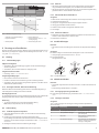 6
6
-
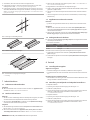 7
7
-
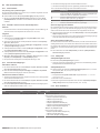 8
8
-
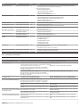 9
9
-
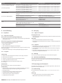 10
10
-
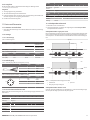 11
11
-
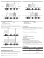 12
12
-
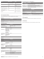 13
13
-
 14
14
-
 15
15
-
 16
16
-
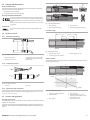 17
17
-
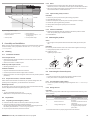 18
18
-
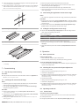 19
19
-
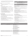 20
20
-
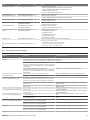 21
21
-
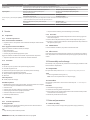 22
22
-
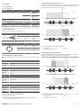 23
23
-
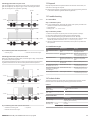 24
24
-
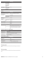 25
25
-
 26
26
-
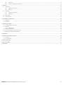 27
27
-
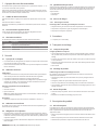 28
28
-
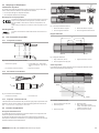 29
29
-
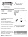 30
30
-
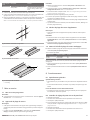 31
31
-
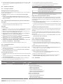 32
32
-
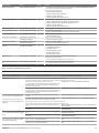 33
33
-
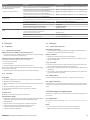 34
34
-
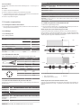 35
35
-
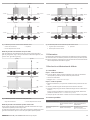 36
36
-
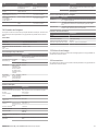 37
37
-
 38
38
-
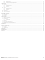 39
39
-
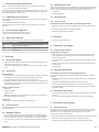 40
40
-
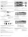 41
41
-
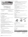 42
42
-
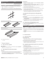 43
43
-
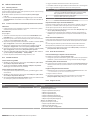 44
44
-
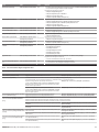 45
45
-
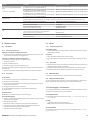 46
46
-
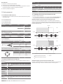 47
47
-
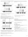 48
48
-
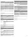 49
49
-
 50
50
-
 51
51
-
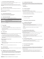 52
52
-
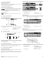 53
53
-
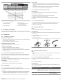 54
54
-
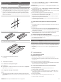 55
55
-
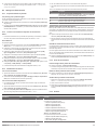 56
56
-
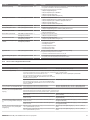 57
57
-
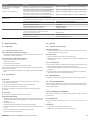 58
58
-
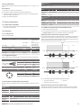 59
59
-
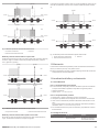 60
60
-
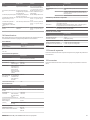 61
61
-
 62
62
-
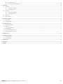 63
63
-
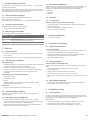 64
64
-
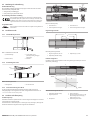 65
65
-
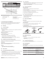 66
66
-
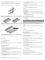 67
67
-
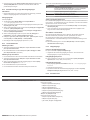 68
68
-
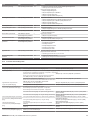 69
69
-
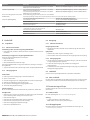 70
70
-
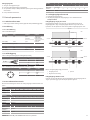 71
71
-
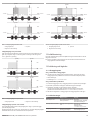 72
72
-
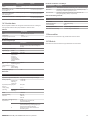 73
73
-
 74
74


AVENTICS Distance Measuring Sensor Series ST6-SM Manual de usuario
- Tipo
- Manual de usuario
en otros idiomas
Artículos relacionados
-
AVENTICS Capteur de mesure de distance avec IO-Link El manual del propietario
-
-
-
-
