STIHL FS 510 C-M Manual de usuario
- Categoría
- Podadoras de césped
- Tipo
- Manual de usuario
Este manual también es adecuado para

STIHL FS 510 C, 560 C
WARNING
Read Instruction Manual thoroughly
before use and follow all safety
precautions – improper use can
cause serious or fatal injury.
ADVERTENCIA
Antes de usar la máquina lea y siga
todas las precauciones de
seguridad dadas en el manual de
instrucciones – el uso incorrecto
puede causar lesiones graves o
mortales.
Instruction Manual
Manual de instrucciones


Original Instruction ManualPrinted on chlorine-free paper
Printing inks contain vegetable oils, paper can be recycled.
© ANDREAS STIHL AG & Co. KG, 2020
0458-772-8621-A. VB1.H20.
0000005279_013_GB
FS 510 C, FS 560 C
English
1
This instruction manual is protected by copyright. All rights reserved, especially the rights to reproduce, translate and process
with electronic systems.
Contents
Allow only persons who fully understand
this manual to operate your clearing
saw.
To receive maximum performance and
satisfaction from your STIHL clearing
saw, it is important that you read,
understand and follow the safety
precautions and the operating and
maintenance instructions in chapter
"Safety Precautions and Working
Techniques" before using your clearing
saw. For further information you can go
to www.stihlusa.com.
Contact your STIHL dealer or the STIHL
distributor for your area if you do not
understand any of the instructions in this
manual.
WARNING
Because a clearing saw is a high-speed
cutting tool some special safety
precautions must be observed to reduce
the risk of personal injury. Careless or
improper use may cause serious or even
fatal injury.
Make sure your unit is equipped with the
proper deflector or limit stop, handle and
harness for the type of cutting
attachment being used. Always wear
proper eye protection.
Guide to Using this Manual 2
Safety Precautions and Working
Techniques 3
Approved Combinations of Cutting
Attachment, Deflector, Limit Stop
and Harness 18
Mounting the Bike Handle 19
Adjusting the Throttle Cable 23
Mounting the Deflector 23
Mounting the Cutting Attachment 25
Fuel 30
Fueling 31
Fitting the Full Harness 33
Balancing the Machine 33
Starting / Stopping the Engine 34
Transporting the Unit 36
Operating Instructions 38
Air filter 38
Engine Management 39
M-Tronic 40
Winter Operation 40
Spark Plug 42
Engine Running Behavior 43
Storing the Machine 43
Sharpening Metal Cutting Blades 44
Maintaining the Mowing Head 44
Inspection and Maintenance by
User 46
Inspections and Maintenance by
Dealer 46
Maintenance and Care 48
Main Parts 50
Specifications 52
Maintenance and Repairs 53
Disposal 53
Limited Warranty 54
STIHL Incorporated Federal
Emission Control Warranty
Statement 54
Trademarks 56

FS 510 C, FS 560 C
English
2
Pictograms
The meanings of the pictograms
attached to or embossed on the
machine are explained in this manual.
Depending on the model concerned, the
following pictograms may be on your
machine.
Symbols in Text
Many operating and safety instructions
are supported by illustrations.
The individual steps or procedures
described in the manual may be shown
in different ways:
N A bullet indicates a step or
procedure.
A description of a step or procedure that
refers directly to an illustration may
contain item numbers that appear in the
illustration. For example:
N Remove the screw (1)
N Pull the spark arresting screen (2)
upwards out of the muffler
In addition to the operating instructions,
this manual may contain paragraphs
that require your special attention. Such
paragraphs are indicated with the
symbols and signal words described
below:
DANGER
Indicates a hazardous situation that, if
not avoided, will result in death or
serious injury.
WARNING
Indicates a hazardous situation that, if
not avoided, could result in death or
serious injury.
NOTICE
Indicates a risk of property damage,
including damage to the machine or its
individual components.
Engineering Improvements
STIHL’s philosophy is to continually
improve all of its products. As a result,
engineering changes and improvements
are made from time to time. Therefore,
some changes, modifications and
improvements may not be covered in
this manual. If the operating
characteristics or the appearance of
your machine differs from those
described in this manual, please contact
your STIHL dealer or the STIHL
distributor for your area for assistance.
Guide to Using this Manual
Fuel tank for gasoline
and engine oil mixture
Press to operate decom
-
pression valve
Manual fuel pump
Press to operate manual
fuel pump
Filler hole for gear
lubricant
Air intake summer mode
Air intake winter mode
Handle heating

FS 510 C, FS 560 C
English
3
The terminology utilized in this manual
when referring to the power tool reflects
the fact that different types of cutting
attachments may be mounted on it. The
term "trimmer" is used to designate an
FS unit that is equipped with a nylon line
head or a head with flexible plastic
blades (i.e., the PolyCut head). A
"brushcutter" designates a unit
equipped with a rigid metal blade. Many
FS models may be used as either a
trimmer or a brushcutter – therefore, the
power tool is referred in this manual as a
"trimmer / brushcutter." Some smaller
and / or lightweight FS models may only
be used as a trimmer, i.e., they may not
be used with metal blades.
The term "clearing saw" indicates a
high-powered trimmer / brushcutter that
is particularly suited for use with a
circular saw blade to clear saplings or
small trees.
WARNING
As more fully explained later in these
Safety Precautions, to reduce the risk of
personal injury, make sure your unit is
equipped with the proper deflector, limit
stop and harness for the type of cutting
attachment you are using. Use only
cutting attachments that are specifically
authorized by STIHL for use on your FS
model.
Have your STIHL dealer show you how
to operate your power tool. Observe all
applicable local safety regulations,
standards and ordinances.
WARNING
Do not lend or rent your power tool
without the instruction manual. Be sure
that anyone using it understands the
information contained in this manual.
WARNING
The use of this machine may be
hazardous. If the rotating line or blade
comes in contact with your body, it will
cut you. When it comes in contact with
solid foreign objects such as rocks or
bits of metal, it may fling them directly or
by ricochet in the direction of bystanders
or the operator. Striking such objects
could damage the cutting attachment
and may cause blades to crack, chip or
break. Thrown objects, including broken
heads or blades, may result in serious or
fatal injury to the operator or bystanders.
STIHL does not recommend the use of
rigid blades when cutting in stony areas.
Use your clearing saw equipped with the
appropriate cutting attachment only for
cutting grass, brush, wood and similar
material.
WARNING
Do not use it for other purposes, since
misuse may result in personal injury or
property damage, including damage to
the machine.
WARNING
Minors should never be allowed to use
this power tool. Bystanders, especially
children, and animals should not be
allowed in the area where it is in use.
WARNING
To reduce the risk of injury to bystanders
and damage to property, never let your
power tool run unattended. When it is
not in use (e.g. during a work break),
shut it off and make sure that
unauthorized persons do not use it.
Most of these safety precautions and
warnings apply to the use of all STIHL
clearing saws. Different models may
have different parts and controls. See
the appropriate section of your
instruction manual for a description of
the controls and the function of the parts
of your model.
Safe use of a clearing saw involves
1. the operator
2. the power tool
3. the use of the power tool.
Safety Precautions and
Working Techniques
Because a clearing saw
is a high-speed, fast-cut
-
ting power tool
sometimes equipped with
sharp cutting blades,
special safety precau
-
tions must be observed to
reduce the risk of per
-
sonal injury.
It is important that you
read, fully understand
and observe the following
safety precautions and
warnings. Read the
instruction manual and
the safety precautions
periodically. Careless or
improper use may cause
serious or fatal injury.

FS 510 C, FS 560 C
English
4
THE OPERATOR
Physical Condition
You must be in good physical condition
and mental health and not under the
influence of any substance (drugs,
alcohol, etc.) which might impair vision,
dexterity or judgment. Do not operate
this machine when you are fatigued.
WARNING
Be alert – if you get tired, take a break.
Tiredness may result in loss of control.
Working with any power tool can be
strenuous. If you have any condition that
might be aggravated by strenuous work,
check with your doctor before operating
this machine.
WARNING
Prolonged use of a power tool (or other
machines) exposing the operator to
vibrations may produce whitefinger
disease (Raynaud's phenomenon) or
carpal tunnel syndrome.
These conditions reduce the hand's
ability to feel and regulate temperature,
produce numbness and burning
sensations and may cause nerve and
circulation damage and tissue necrosis.
All factors which contribute to
whitefinger disease are not known, but
cold weather, smoking and diseases or
physical conditions that affect blood
vessels and blood transport, as well as
high vibration levels and long periods of
exposure to vibration are mentioned as
factors in the development of whitefinger
disease. In order to reduce the risk of
whitefinger disease and carpal tunnel
syndrome, please note the following:
– Most STIHL power tools are
available with an anti-vibration
("AV") system designed to reduce
the transmission of vibrations
created by the machine to the
operator's hands. An AV system is
recommended for those persons
using power tools on a regular or
sustained basis.
– Wear gloves and keep your hands
warm.
– Keep the AV system well
maintained. A power tool with loose
components or with damaged or
worn AV elements will tend to have
higher vibration levels.
– Maintain a firm grip at all times, but
do not squeeze the handles with
constant, excessive pressure. Take
frequent breaks.
All the above-mentioned precautions do
not guarantee that you will not sustain
whitefinger disease or carpal tunnel
syndrome. Therefore, continual and
regular users should closely monitor the
condition of their hands and fingers. If
any of the above symptoms appear,
seek medical advice immediately.
WARNING
The ignition system of the STIHL unit
produces an electromagnetic field of a
very low intensity. This field may
interfere with some pacemakers. To
reduce the risk of serious or fatal injury,
persons with a pacemaker should
consult their physician and the
pacemaker manufacturer before
operating this tool.
Proper Clothing
To reduce the risk of injury, the operator
should wear proper protective apparel.
WARNING
The deflector provided with your power
tool will not protect the operator from all
foreign objects (gravel, glass, wire, etc.)
thrown back by the rotating cutting
attachment. Thrown objects may also
ricochet and strike the operator.

FS 510 C, FS 560 C
English
5
WARNING
Be particularly alert and cautious when
wearing hearing protection because
your ability to hear warnings (shouts,
alarms, etc.) is restricted.
Avoid loose-fitting jackets, scarfs,
neckties, jewelry, flared or cuffed pants,
unconfined long hair or anything that
could become caught on branches,
brush or the moving parts of the unit.
Secure hair so it is above shoulder level.
THE POWER TOOL
For illustrations and definitions of the
power tool parts see the chapter on
"Main Parts."
WARNING
Never modify this power tool in any way.
Only attachments supplied by STIHL
and expressly approved by STIHL for
use with the specific STIHL model are
authorized. Although certain
unauthorized attachments are useable
with STIHL power tools, their use may,
in fact, be extremely dangerous. For the
cutting attachments authorized by
STIHL for your unit, see the chapter
"Approved Combinations of Cutting
Attachment, Deflector, Limit Stop and
Harness" in the instruction manual or the
STIHL "Cutting Attachments, Parts &
Accessories" catalog.
If this tool is subjected to unusually high
loads for which it was not designed (e.g.
heavy impact or a fall), always check
that it is in good condition before
continuing work. Check in particular that
the fuel system is tight (no leaks) and
that the controls and safety devices are
working properly. Do not continue
operating this machine if it is damaged.
In case of doubt, have it checked by your
STIHL servicing dealer.
THE USE OF THE POWER TOOL
Transporting the Power Tool
WARNING
To reduce the risk of injury from loss of
control and blade or line contact, never
carry or transport your power tool with
the cutting attachment moving.
To reduce the risk of
injury to your eyes never
operate your power tool
unless wearing goggles
or properly fitted protec
-
tive glasses with
adequate top and side
protection complying with
ANSI Z87 "+" (or your
applicable national stand
-
ard). To reduce the risk of
injury to your face STIHL
recommends that you
also wear a face shield or
face screen over your
goggles or protective
glasses.
Wear an approved safety
hard hat to reduce the
risk of injury to your head
when there is a danger of
head injuries.
Power tool noise may
damage your hearing.
Wear sound barriers (ear
plugs or ear mufflers) to
protect your hearing.
Continual and regular
users should have their
hearing checked
regularly.
Always wear heavy duty
work gloves (e.g. made of
leather or other wear
resistant material) when
handling the machine
and metal blades. Heavy-
duty, nonslip gloves
improve your grip and
help to protect your
hands.
Clothing must be sturdy
and snug-fitting, but allow
complete freedom of
movement. Wear long
pants made of heavy
material to help protect
your legs. Do not wear
shorts, sandals or go
barefoot.
Good footing is very
important. Wear sturdy
boots with nonslip soles.
Steel-toed safety boots
are recommended.

FS 510 C, FS 560 C
English
6
It may be carried only in a horizontal
position. Grip the shaft in a manner that
the machine is balanced horizontally.
Keep the hot muffler away from your
body.
WARNING
To reduce the risk of burn
injury, do not touch hot
parts of the machine and
the gear housing when
they are hot.
WARNING
Always shut off the engine and make
sure the cutting attachment has stopped
before putting a clearing saw down.
When transporting it in a vehicle,
properly secure it to prevent turnover,
fuel spillage and damage to the unit.
STIHL recommends that you keep metal
blades covered with the transport guard
(optional accessory).
Fuel
Your STIHL power tool uses an oil-
gasoline mixture for fuel (see the "Fuel"
chapter in this instruction manual).
WARNING
Fueling Instructions
WARNING
To reduce the risk of fire and serious
personal injury, always place the power
tool on the ground before attempting to
fuel the machine.
WARNING
Pick a Safe Location
To reduce the risk of fire and explosion,
fuel your power tool in a well-ventillated
area, outdoors away from flames, pilot
lights, heaters, electric motors, and
other sources of ignition. Vapors can be
ignited by a spark or flame many feet
away. Select bare ground for fueling and
move at least 10 feet (3 m) from the
fueling spot before starting the engine.
Wipe off any spilled fuel before starting
your power tool. Take care not to get fuel
on your clothing. If this happens, change
your clothing immediately.
Allow the Power Tool to Cool Before
Removing the Fuel Cap
WARNING
Gasoline vapor pressure may build up
inside the fuel tank. The amount of
pressure depends on a number of
factors such as the fuel used, altitude
and temperature. To reduce the risk of
burns and other personal injury from
escaping gas, vapor and fumes, always
shut off the engine and allow it to cool
before removing the fuel cap.
The engine is air cooled. When it is shut
off, cooling air is no longer drawn across
the cylinder and engine temperatures
will rise for several minutes before
starting to cool. In hot environments,
cooling will take longer. To reduce the
risk of burns and other personal injury
from escaping gas, vapor and fumes,
allow the power tool to cool. If you need
to refuel before completing a job, turn off
the machine and allow the engine to cool
before opening the fuel tank.
Fuel Spraying or “Geysering”
WARNING
Removing the cap on a pressurized fuel
tank can result in gasoline, vapors and
fumes being forcefully sprayed out from
the fuel tank in all directions. The
escaping gasoline, vapors or fumes can
cause serious personal injury, including
fire and burn injury, or property damage.
002BA479 KN
Gasoline is an extremely
flammable fuel. If spilled
and ignited by a spark or
other ignition source, it
can cause fire and seri
-
ous burn injury or
property damage. Use
extreme caution when
handling gasoline or fuel
mix. Do not smoke or
bring any fire or flame
near the fuel or the power
tool. Note that combus
-
tible fuel vapor may
escape from the fuel
system.

FS 510 C, FS 560 C
English
7
Sometimes also referred to as "fuel
geysering," fuel spraying is an expulsion
of fuel, vapors and fumes which can
occur in hot conditions, or when the
engine is hot, and the tank is opened
without allowing the power tool to cool
adequately. It is more likely to occur
when the fuel tank is half full or more.
Pressure is caused by fuel and heat and
can occur even if the engine has not
been running. When gasoline in the fuel
tank is heated (by ambient
temperatures, heat from the engine, or
other sources), vapor pressure will
increase inside the fuel tank.
Some blends of gasoline, particularly
those designed for use in winter, are
more volatile and may cause tanks to
pressurize more quickly or create
greater pressure. At higher altitudes,
fuel tank pressurization is more likely.
How to Avoid Fuel Spraying
Removing the fuel cap on a pressurized
tank can result in gasoline, vapors and
fumes being forcefully sprayed out from
the fuel tank in all directions. To reduce
the risk of burns, serious injuries or
property damage from fuel spraying:
– Follow the fueling instructions in this
chapter.
– Always assume your fuel tank is
pressurized.
– Allow the power tool to cool before
removing the fuel cap.
– In hot environments, cooling will
take longer.
– The engine is air cooled. When it is
shut off, cooling air is no longer
drawn across the cylinder and the
engine temperature will rise for
several minutes before starting to
cool.
After the power tool has cooled
appropriately, follow the safety
instructions in this chapter for removing
the cap.
Never remove the fuel filler cap by
turning it directly to the open position.
First check for residual pressure in the
tank by slowly turning the cap
approximately 1/2 turn counter-
clockwise. The cap should be held in
place by the threads while allowing
residual vapor/pressure to be relieved.
Once the fumes or vapor have been
relieved, turn the cap further until it can
be removed from the tank opening.
Use only good quality fuel that is
appropriate for the season (summer v.
winter blends). Some blends of
gasoline, particularly winter blends, are
more volatile and can contribute to fuel
spraying.
Removing the Threaded Fuel Filler Cap
WARNING
After allowing the power tool to cool,
remove the fuel filler cap slowly and
carefully to allow any remaining
pressure build-up in the tank to release:
– While maintaining steady,
downward pressure, slowly turn the
cap approximately 1/2 turn counter-
clockwise.
– If any significant venting occurs,
immediately re-seal the tank by
turning the cap clockwise to the
closed position. Allow the power
tool to cool further before
attempting to open the tank.
– Turn the cap to the open position
only after the contents of the tank
are no longer under pressure.
– Never remove the cap by turning it
directly to the open position. First
allow the power tool to cool
adequately and then release any
residual pressure by slowly turning it
approximately 1/2 turn counter-
clockwise.
– Never attempt to remove the cap
while the engine is still hot or
running.

FS 510 C, FS 560 C
English
8
Installing the Threaded Fuel Filler Cap
WARNING
Damaged or Broken Cap
If your fuel cap does not tighten properly,
it may be damaged or broken. Stop
using the power tool and take it to your
authorized STIHL dealer for repair.
Vapor Lock
WARNING
Vapor lock occurs when fuel in the fuel
line or carburetor vaporizes, causing
bubbles to block the free flow of liquid
fuel into the carburetor. Vapor lock
cannot be relieved or affected by
opening the fuel tank. Removing the fuel
filler cap without first allowing the power
tool to cool adequately can result in fuel
spraying. Always follow the instructions
in this section when removing the fuel
cap.
To relieve vapor lock:
– Press the manual fuel pump bulb at
least 20 to 30 times – even if the
bulb is already filled with fuel – to
clear the vapor and send liquid fuel
into the carburetor. Then start the
power tool. For specific starting
instructions, see the appropriate
section of your instruction manual.
– If the manual fuel pump bulb will not
be filled, place the Choke Lever to
the start position } and pull the
starter cord until the engine runs. If
the engine does not start after 10
pulls in the start position }, start
the engine in the run position F.
– If your power tool will not restart, or
if vapor lock occurs again, the
power tool is being used in
conditions too extreme for the fuel
being used. Discontinue use and let
the engine cool completely before
attempting to start the power tool.
Before Operation
Take off the transport guard and inspect
the power tool for proper condition and
operation. (See the maintenance chart
near the end of the instruction manual.)
WARNING
Always check your power tool for proper
condition and operation before starting,
particularly the throttle trigger, throttle
trigger lockout, momentary stop switch,
cutting attachment, deflector and
harness.The throttle trigger must move
freely and always spring back to the idle
position. Never attempt to modify the
controls or safety devices.
WARNING
Check fuel system for leaks, especially
the visible parts, e.g., filler cap, hose
connections, manual fuel pump (only for
power tools equipped with a manual fuel
pump). Do not start the engine if there
are leaks or damage – risk of fire. Have
the power tool repaired by a STIHL
servicing dealer before using it.
WARNING
Never operate your power tool if it is
damaged, improperly adjusted or
maintained, or not completely and
securely assembled.
WARNING
Check that the spark plug boot is
securely mounted on the spark plug – a
loose boot may cause arcing that could
ignite combustible fumes and cause a
fire.
WARNING
Do not mount any cutting attachment to
a unit without proper installation of all
required parts. Failure to use the proper
parts may cause the blade or head to fly
off and seriously injure the operator or
bystanders.
WARNING
The cutting attachment must be properly
tightened and not damaged. Inspect for
loose parts (nuts, screws, etc.) and for
cracked or damaged heads or cracked,
bent, warped or damaged blades.
Unit vibrations can cause
an improperly tightened
fuel filler cap to loosen or
come off and spill quanti
-
ties of fuel. To reduce the
risk of fuel spillage and
fire, tighten the fuel filler
cap by hand with as
much force as possible.

FS 510 C, FS 560 C
English
9
Replace damaged heads or blades
before using the power tool. Always
keep blades sharp.
Keep the handles clean and dry at all
times; it is particularly important to keep
them free of moisture, pitch, oil, fuel mix,
grease or resin in order for you to
maintain a firm grip and properly control
your power tool.
WARNING
As can be seen in that chart, some
cutting attachments may require you to
change your deflector, limit stop and / or
harness.
Keep the deflector (and the attached
skirt where appropriate) adjusted
properly at all times (see chapters on
"Mounting the Deflector" and "Mounting
the Cutting Attachment" of your
instruction manual). Make sure that the
screws of the deflector are tightened at a
torque of 89 lbf. in. (10 Nm) before
starting work.
Arrows on the deflector (A) and limit
stop (B) (as seen from the underside)
show the correct direction of rotation of
the cutting attachment. When viewed
from above, however, the cutting
attachment rotates counterclockwise.
Some of the following symbols may be
embossed on the outside of the deflector
in order to indicate the approved
combination of cutting attachment and
deflector.
Adjust carrying harness and hand grip to
suit your size before starting work. The
machine should be properly balanced as
specified in your instruction manual for
To reduce the risk
of personal injury
to the operator
from blade or line
contact and
thrown objects,
make sure your
unit is equipped
with the proper
deflector or limit
stop and harness
for the type of cut
-
ting attachment
being used (see
chart in the chap
-
ter on "Approved
Combinations of
Cutting Attach
-
ment, Deflector,
Limit Stop and
Harness").
The deflector may be
used in combination with
mowing heads.
A
000BA006 KN
B
000BA007 KN
The deflector may be
used in combination with
grass cutting blades.
The deflector may be
used in combination with
brush knives.
The deflector must not be
used in combination with
mowing heads.
The deflector must not be
used in combination with
grass cutting blades.
The deflector must not be
used in combination with
brush knives.
The deflector must not be
used in combination with
shredder blades.
The deflector must not be
used in combination with
circular saw blades.

FS 510 C, FS 560 C
English
10
proper control and less fatigue in
operation. To be better prepared in case
of an emergency, practice releasing the
unit from the harness as quickly as
possible.
For specific starting instructions, see the
appropriate section of your instruction
manual.
Starting
Start the engine at least 10 feet (3 m)
from the fueling spot, outdoors only.
For specific starting instructions, see the
appropriate section of your manual.
Place the power tool on firm ground or
other solid surface in an open area.
Maintain good balance and secure
footing.
WARNING
To reduce the risk of injury from blade or
line contact, be absolutely sure that the
cutting attachment is clear of you and all
other obstructions and objects, including
the ground, because when the engine
starts at starting-throttle, engine speed
will be fast enough for the clutch to
engage and move the cutting
attachment.
Once the engine has started,
immediately blip the throttle trigger,
which should release the starting throttle
and allow the engine to slow down to
idle.
With the engine running only at idle,
attach the power tool to the spring hook
of your harness (see appropriate
chapter of this manual).
WARNING
Your power tool is a one-person
machine. Do not allow other persons in
the general work area, even when
starting.
WARNING
To reduce the risk of injury from loss of
control, do not attempt to "drop start"
your power tool.
WARNING
When you pull the starter grip, do not
wrap the starter rope around your hand.
Do not let the grip snap back, but guide
the starter rope to rewind it properly.
Failure to follow this procedure may
result in injury to your hand or fingers
and may damage the starter
mechanism.
Important Adjustments
WARNING
To reduce the risk of personal injury
from loss of control or contact with the
running cutting attachment, do not use
your unit with incorrect idle speed. At
correct idle speed, the cutting
attachment should not move.
If your power tool shows an incorrect idle
speed, have your STIHL dealer check
your power tool and make proper
adjustments and repairs.
WARNING
This unit is equipped with an ignition
system that is normally in operational
readiness. After the setting lever is used
to stop the engine, it automatically
springs back to the "on" position. If the
engine is warm, it may be possible to
start it by simply pulling the starter rope,
with no further adjustments. To reduce
the risk of injury, be particularly alert to
keep children away from the unit.
During Operation
Holding and Controlling the Power Tool
Always hold the unit firmly with both
hands on the handles while you are
working. Wrap your fingers and thumbs
around the handles, keeping the
handles cradled between your thumb
and forefinger. Keep your hands in this
position to have your power tool under
control at all times. Make sure your
clearing saw handles and grips are in
good condition and free of moisture,
pitch, oil, fuel mix or grease.
002BA480 KN

FS 510 C, FS 560 C
English
11
WARNING
WARNING
Do not overreach. Keep proper footing
and balance at all times. Special care
must be taken in slippery conditions (wet
ground, snow) and in difficult, overgrown
terrain. Watch for hidden obstacles such
as tree stumps, roots and ditches to
avoid stumbling. For better footing, clear
away scrub and cuttings. Be extremely
cautious when working on slopes or
uneven ground.
WARNING
To reduce the risk of injury from loss of
control, never work on a ladder or on any
other insecure support. Never hold the
cutting attachment above waist height.
Working Conditions
Operate and start your power tool only
outdoors in a well-ventilated area.
Operate it under good visibility and
daylight conditions only. Work carefully.
WARNING
WARNING
If the vegetation being cut or the
surrounding ground is coated with a
chemical substance (such as an active
pesticide or herbicide), read and follow
the instructions and warnings that
accompanied the substance at issue.
WARNING
Inhalation of certain dusts, especially
organic dusts such as mold or pollen,
can cause susceptible persons to have
an allergic or asthmatic reaction.
Substantial or repeated inhalation of
dust and other airborne contaminants, in
particular those with a smaller particle
size, may cause respiratory or other
illnesses. Control dust at the source
where possible. Use good work
practices, such as operating the unit so
that the wind or operating process
directs any dust raised by the power tool
away from the operator. Follow the
recommendations of EPA / OSHA /
NIOSH and occupational and trade
associations with respect to dust
("particulate matter"). When the
inhalation of dust cannot be
substantially controlled, i.e., kept at or
near the ambient (background) level, the
operator and any bystanders should
wear a respirator approved by NIOSH /
MSHA for the type of dust encountered.
Operating Instructions
WARNING
Do not operate your power tool using the
starting throttle position, as you do not
have control of the engine speed.
In the event of an emergency, shut off
the engine immediately – move the
momentary stop switch to STOP.
WARNING
WARNING
The rotating cutting attachment may
fling foreign objects directly or by
ricochet a great distance.
Never attempt to operate
your power tool with one
hand. Loss of control of
the power tool resulting in
serious or fatal injury may
result. To reduce the risk
of cut injuries, keep
hands and feet away
from the cutting attach
-
ment. Never touch a
moving cutting attach
-
ment with your hand or
any other part of your
body.
As soon as the engine is
running, this product gen
-
erates toxic exhaust
fumes containing chemi
-
cals, such as unburned
hydrocarbons (including
benzene) and carbon
monoxide, that are
known to cause respira
-
tory problems, cancer,
birth defects, or other
reproductive harm. Some
of the gases (e.g. carbon
monoxide) may be color
-
less and odorless. To
reduce the risk of serious
or fatal injury / illness
from inhaling toxic fumes,
never run the machine
indoors or in poorly venti
-
lated locations.
The cutting attachment
continues to rotate for a
short period after the
throttle trigger is released
(flywheel effect.)

FS 510 C, FS 560 C
English
12
To reduce the risk of eye and other injury
always wear proper eye protection (see
the chapter on "Proper Clothing") and
ensure that bystanders are at least
50 feet (15 m) away. To reduce the risk
of damage to property, also maintain this
distance from such objects as vehicles
or windows. Even maintaining a
minimum distance of 15 meters cannot
exclude the potential danger. Any
coworkers who must be in the restricted
area should also wear goggles or
protective glasses. Stop the engine
immediately if you are approached.
WARNING
WARNING
This clearing saw is normally to be used
at ground level with the cutting
attachment parallel to the ground. Use of
a clearing saw above ground level or
with the cutting attachment
perpendicular to the ground may
increase the risk of injury, since the
cutting attachment is more fully exposed
and the power tool may be more difficult
to control. Never use your clearing saw
as a hedge trimmer.
WARNING
During cutting, check the tightness and
the condition of the cutting attachment at
regular short intervals with the engine
and attachment stopped. If the behavior
of the attachment changes during use,
stop the engine immediately, wait until
the cutting attachment stops, and check
the nut securing the attachment for
tightness and the blade or head for
cracks, wear and damage.
WARNING
A loose blade or head may vibrate,
crack, break or come off the clearing
saw, which may result in serious or fatal
injury. Make sure that the cutting
attachment is properly tightened. Use
the wrench supplied or one of sufficient
length to obtain the proper torque. If the
blade or head loosens after being
properly tightened, stop work
immediately. The retaining nut may be
worn or damaged and should be
replaced. If the blade or head continues
to loosen, see your STIHL dealer. Never
use a clearing saw with a loose cutting
attachment.
WARNING
Replace a cracked, damaged or worn-
out head or a cracked, bent, warped,
damaged, dull or worn out blade
immediately, even if damage is limited to
superficial cracks. Such attachments
may shatter at high speed and cause
serious or fatal injury.
WARNING
When using rigid blades, avoid cutting
close to fences, sides of buildings, tree
trunks, stones or other such objects that
could cause the power tool to kick out or
could cause damage to the blade.
STIHL recommends use of the nylon line
heads for such jobs. In addition, be alert
to an increased possibility of ricochets in
such situations.
WARNING
If a rotating metal blade strikes a rock or
other hard object, sparks may be
created, which can ignite flammable
materials under certain circumstances.
Flammable materials can include dry
vegetation and brush, particularly when
weather conditions are hot and dry.
When there is a risk of fire or wildfire, do
not use metal blades around flammable
materials or around dry vegetation or
brush. Contact your local fire authorities
or the U.S. Forestry Service if you have
any question about whether vegetation
and weather conditions are suitable for
the use of a metal blade.
WARNING
If the head, blade or deflector becomes
clogged or stuck, always shut off the
engine and make sure the cutting
attachment has stopped before
cleaning. Grass, weeds, etc. should be
cleaned off the blade or from around the
head at regular intervals.
Inspect the work area: To
reduce the risk of injury,
remove stones, pieces of
metal and other solid
objects which could be
thrown 15 meters or more
by the cutting attachment
or damage the cutting
attachment and property
(e.g. parked vehicles,
windows).
15m (50ft)

FS 510 C, FS 560 C
English
13
WARNING
To reduce the risk of unintentional
rotation of the cutting attachment and
injury, always shut off the engine and
remove the spark plug boot before
replacing the cutting attachment. To
reduce the risk of injury, always shut off
the engine before adjusting the length of
the nylon line on manually adjustable
mowing heads.
WARNING
Do not turn the engine on over the
starter with the spark plug boot or spark
plug removed since there is otherwise a
risk of fire from uncontained sparking.
WARNING
The gearbox becomes hot during
operation. To reduce the risk of burn
injury, do not touch the gear housing
when it is hot.
WARNING
Never modify your muffler. Any
modification could cause an increase in
heat radiation, sparks or sound level,
thereby increasing the risk of fire, burn
injury or hearing loss. You may also
permanently damage the engine. Have
your muffler serviced and repaired by
your STIHL servicing dealer only.
WARNING
The muffler and other parts of the engine
(e.g. fins of the cylinder, spark plug)
become hot during operation and remain
hot for a while after stopping the engine.
To reduce risk of burns, do not touch the
muffler and other parts while they are
hot. Keep the area around the muffler
clean. Remove excess lubricant and all
debris such as pine needles, branches
or leaves. Let the engine cool down
sitting on concrete, metal, bare ground
or solid wood (away from any
combustible substances.
WARNING
An improperly mounted or damaged
cylinder housing or a
damaged/deformed muffler shell may
interfere with the cooling process of the
muffler. To reduce the risk of fire or burn
injury, do not continue work with a
damaged or improperly mounted
cylinder housing or a
damaged/deformed muffler shell.
Your muffler is furnished with a spark
arresting screen designed to reduce the
risk of fire from the emission of hot
particles. Never operate your unit with a
missing or damaged spark arresting
screen. If your gas/oil mix ratio is correct
(i.e., not too rich), this screen will
normally stay clean as a result of the
heat from the muffler and need no
service or maintenance. If you
experience loss of performance and you
suspect a clogged screen, have your
muffler maintained by a STIHL servicing
dealer. Some state or federal laws or
regulations may require a properly
maintained spark arrestor for certain
uses. See the "Maintenance, Repair and
Storing" section of these Safety
Precautions. Remember that the risk of
a brush or forest fire is greater in hot or
dry conditions.
WARNING
USING THE CUTTING ATTACHMENT
For an illustration of the various cutting
attachments and instructions on proper
mounting see the chapter on "Mounting
the Cutting Attachment" in your
instruction manual.
WARNING
To reduce the risk of severe or fatal
injury from blade contact and / or loss of
control, never attempt to use a metal
blade on an FS model for which it is not
authorized.
Some STIHL power tools
are equipped with a cata
-
lytic converter, which is
designed to reduce the
exhaust emissions of the
engine by a chemical pro
-
cess in the muffler. Due
to this process, the muf
-
fler does not cool down
as rapidly as conven
-
tional mufflers when the
engine returns to idle or
is shut off. To reduce the
risk of fire and burn inju
-
ries when using a
catalytic converter,
always set your power
tool down in the upright
position and never locate
it where the muffler is
near dry brush, grass,
wood chips or other com
-
bustible materials while it
is still hot.

FS 510 C, FS 560 C
English
14
Using the Mowing Heads
Do not use with mowing line longer than
the intended length. With a properly
mounted deflector, the built-in line-
limiting blade will automatically adjust
the line to its proper length.
Using the unit with an overly long nylon
cutting line increases the load on the
engine and reduces its operating speed.
This causes the clutch to slip
continuously and results in overheating
and damage to important components
(e.g. clutch, polymer housing
components). Such damage could,
among other things, cause the cutting
attachment to rotate at idle.
Mowing heads are to be used only on
clearing saws equipped with a line-
limiting blade in the deflector in order to
keep the line at the proper length (see
"Main Parts" chapter in your instruction
manual).
If the lawn edges are planted with trees
or bordered by a fence etc., it is best to
use a nylon line head. It achieves a
"softer" cut with less risk of damaging
tree bark etc. than polymer blades.
However, the polymer-bladed STIHL
PolyCut produces a better cut if there
are no plants along the edge of the lawn.
Sharpening is not necessary, and worn
polymer blades are easily replaced.
WARNING
To reduce the risk of serious injury,
never use wire or metal-reinforced line
or other material in place of the nylon
cutting lines. Pieces of wire could break
off and be thrown at high speed toward
the operator or bystanders.
STIHL AutoCut mowing head
Nylon cutting line advances
automatically when tapped against the
ground (TapAction).
STIHL TrimCut mowing head
Frayed line is replaced by a simple
adjustment (see instruction sheet
supplied with mowing head).
STIHL DuroCut mowing head
Uses only nylon lines.
Observe wear indicators.
NOTICE
There are four wear limit indicators
shaped like exclamation marks in the
base of the DuroCut. If one of these
built-in indicators becomes visible, do
not continue using the DuroCut since it
might otherwise be damaged. Replace
the worn base plate with a new base
plate. It is important to follow the
maintenance instructions supplied with
the head.
STIHL PolyCut mowing head
Uses either nylon lines or nonrigid,
pivoting polymer blades.
Observe wear indicators.
WARNING
Three rectangular wear limit marks are
applied to the base (periphery) of the
PolyCut. To reduce the risk of serious
injury from breakage of the head or
blades, the PolyCut must not be used
when it has worn as far as one of these
marks. It is important to follow the
maintenance instructions supplied with
the head.
WARNING
If the wear limit marks are ignored, there
is a risk of the cutting attachment
shattering and flying parts injuring the
operator or bystanders. To reduce the
risk of accidents from shattered blades,
avoid contact with stones, metal and
similar solid objects. Check PolyCut
blades for cracks at regular intervals. If a
crack is found on one blade, always
replace all blades.
002BA354 KN
681BA209 KN
002BA396 KN

FS 510 C, FS 560 C
English
15
Risk of Kickout (Blade Thrust) with all
Rigid Cutting Blades
WARNING
This kickout (blade thrust) may cause
loss of control of the power tool and may
result in serious or fatal injury to the
operator or bystanders. To reduce the
risk of injury, extreme caution should be
used when cutting with the shaded area
of any rigid blade.
Using the Grass Cutting Blade
All kinds of grass and weeds can be
easily cut with the grass cutting blade.
The power tool is swept in an arc similar
to a scythe.
WARNING
To reduce the risk of serious or fatal
injury from blade breakage, never
attempt to use this blade to cut woody
materials.
The 4-tooth grass cutting blade is
intended to cut grass and weeds. It has
4 cutting knives with cutting edges on
both sides, i.e. front and rear. When the
cutting edges on one side become dull,
the blade can be turned over to utilize
the cutting edges on the other side.
The 8-tooth grass cutting blade is
recommended for cutting fern or reed.
Both types of grass cutting blade have to
be resharpened when all cutting edges
are dull.
Using the Brush Knife
When fitted to the power tool, the brush
knife is suitable for applications ranging
from cutting matted grass to clearing
weeds, wild growth and scrub.
To cut wild growth and scrub, lower the
rotating brush knife down onto the
growth to achieve a chopping effect –
but keep the tool below waist height at
all times.
WARNING
Exercise extreme caution when using
this method of cutting. The higher the
cutting attachment is off the ground, the
greater the risk of loss of control and of
cuttings being thrown sideways.
Use the power tool like a scythe to cut
grass, i.e. sweep it to and fro in an arc.
WARNING
When cutting woody materials, use the
left side of the blade to avoid "kickout"
(blade thrust) situations.
WARNING
Improper use of a brush knife may cause
it to crack, chip or shatter. Thrown blade
fragments may seriously or fatally injure
the operator or bystanders. To reduce
the risk of injury, avoid contact with hard
or solid foreign objects such as stones,
rocks or pieces of metal.
Kickout (blade thrust) is
the sudden and uncon
-
trolled motion towards
the operator's right or
rear that can occur when
the shaded area (espe
-
cially the darkly shaded
area) of a rotating blade
comes in contact with a
solid rigid object like a
tree, rock, bush or wall.
The rapid counterclock
-
wise rotation of the blade
may be stopped or
slowed, and the cutting
attachment may be
thrown to the right or to
the rear.
002BA135 KN
002BA355 KN
002BA509 KN

FS 510 C, FS 560 C
English
16
WARNING
When cutting young saplings or other
woody materials up to 2 cm (3/4 in.) in
diameter, use the left side of the blade to
avoid "kickout" situations (see section
on "Risk of kickout (blade thrust) with all
rigid cutting blades"). Do not attempt to
cut woody material with a larger
diameter, since the blade may catch or
jerk the power tool forward. This may
cause damage to the blade or power tool
or loss of control of the power tool,
resulting in personal injury. Use a
circular saw blade for such work.
WARNING
Inspect the brush knife at regular short
intervals for signs of damage. Do not
continue working with a damaged brush
knife. Resharpen the brush knife
regularly (when it has dulled noticeably).
Using the Circular Saw Blade
Circular saw blades are suitable for
thinning brush and cutting small trees up
to a diameter of 7 cm (2 3/4 in.). Do not
attempt to cut trees with larger
diameters, since the blade may catch or
jerk the clearing saw forward. This may
cause damage to the blade or loss of
control of the power tool and result in
serious injury. Use a chain saw for such
work.
WARNING
To reduce the risk that the blade will
crack and / or break, avoid all contact
with stones, rocks or the ground.
Sharpen blades in a timely manner as
specified – dull teeth may cause the
blade to crack or shatter.
When a clearing saw with a circular saw
blade is used to cut down small trees,
STIHL recommends that the standard
deflector be removed and replaced by
the special limit stop deflector (see
chapter on "Mounting the Deflector").
This limit stop helps to keep the unit
positioned against the tree during the
cutting process. Inexperienced users
should place the left side of the stop
against the tree trunk before beginning
to cut. This will keep the clearing saw
against the tree during the cutting
operation and will reduce the risk of loss
of control and possible kickout
(described above and briefly again
below).
Before starting the cut, accelerate the
engine up to full throttle. Perform cut
with uniform pressure. STIHL
recommends that the circular saw blade
be applied to the right of the tree, using
the non-shaded area of the blade, as
shown in the illustration above.
WARNING
The risk of kickout is highest when
cutting in the darker shaded area. To
reduce the risk of kickout and resulting
injury, do not use this area of the circular
saw blade for cutting trees or shrubs.
Special techniques using the lighter
shaded areas of the blade to cut shrubs
and trees should only be used by
experienced operators with specialized
training in the use and control of the
clearing saw.
When felling small trees, maintain a
distance of at least two tree lengths from
the nearest coworker.
WARNING
In order to reduce the risk of injury from
thrown objects or operator contact with
the blade or head, be sure to remount
the standard deflector when no longer
using a circular saw blade.
002BA067 KN
002BA214 ST
002BA068 KN

FS 510 C, FS 560 C
English
17
MAINTENANCE, REPAIR AND
STORING
Maintenance, replacement, or repair of
the emission control devices and
systems may be performed by any
nonroad engine repair establishment or
individual. However, if you make a
warranty claim for a component which
has not been serviced or maintained
properly, STIHL may deny coverage.
WARNING
Use only identical STIHL replacement
parts for maintenance and repair. Use of
non-STIHL parts may cause serious or
fatal injury.
Strictly follow the maintenance and
repair instructions in the appropriate
sections of your instruction manual.
WARNING
Always stop the engine and make sure
that the cutting attachment is stopped
before doing any maintenance or repair
work or cleaning the power tool. Do not
attempt any maintenance or repair work
not described in your instruction manual.
Have such work performed by your
STIHL servicing dealer only.
Wear gloves when handling or
performing maintenance on blades.
WARNING
Use the specified spark plug, and make
sure it and the ignition lead are always
clean and in good condition. Always
press the spark plug boot snugly onto
the spark plug terminal of the proper
size. (Note: If the terminal has a
detachable SAE adapter nut, it must be
securely attached.) A loose connection
between the spark plug and the ignition
wire connector in the boot may create
arcing that could ignite combustible
fumes and cause a fire.
WARNING
Never test the ignition system with the
spark plug boot removed from the spark
plug or with a removed spark plug, since
uncontained sparking may cause a fire.
WARNING
Do not operate your power tool if the
muffler is damaged, missing or modified.
An improperly maintained muffler will
increase the risk of fire and hearing loss.
Your muffler is equipped with a spark-
arresting screen to reduce the risk of
fire; never operate your power tool if the
screen is missing, damaged or clogged.
Remember that the risk of a brush or
forest fire is greater in hot or dry
weather.
In California, it is a violation of § 4442 or
§ 4443 of the Public Resources Code to
use or operate gasoline-powered tools
on forest-covered, brush-covered or
grass-covered land unless the engine’s
exhaust system is equipped with a
complying spark arrester that is
maintained in effective working order.
The owner/operator of this product is
responsible for properly maintaining the
spark arrester. Other states or
governmental entities/agencies, such as
the U.S. Forest Service, may have
similar requirements. Contact your local
fire agency or forest service for the laws
or regulations relating to fire protection
requirements.
WARNING
Never repair damaged cutting
attachments by welding, straightening or
modifying the shape. This may cause
parts of the cutting attachment to come
off and result in serious or fatal injuries.
Keep blades sharp. Tighten all nuts,
bolts and screws after each use.
Do not clean your machine with a
pressure washer. The solid jet of water
may damage parts of the machine.
Store the power tool in a dry and high or
locked location out of reach of children.
Before storing for longer than a few
days, always empty the fuel tank. See
chapter "Storing the Machine" in the
instruction manual.

FS 510 C, FS 560 C
English
18
Approved Combinations
The complete combination includes:
– Cutting attachment
– Deflector or limit stop
– Handle
– Harness
Select correct combination from the
table according to the cutting
attachment you intend to use.
WARNING
To reduce the risk of injury, only the
cutting attachments and deflectors or
limit stops shown in each row of the
table may be used together. No other
combinations are permitted.
Cutting Attachments
Mowing heads
1 STIHL AutoCut 40-4
2 STIHL AutoCut 56-2
3 STIHL TrimCut 51-2
4 STIHL DuroCut 40-4
5 STIHL PolyCut 41-3
Metal cutting attachments
6 Grass cutting blade 255-8
(255 mm dia.)
7 Brush knife 350-3
(350 mm dia.)
Approved Combinations of Cutting Attachment, Deflector, Limit Stop and Harness
Cutting Attachment Deflector, Limit Stop Harness
7
0000-GXX-0397-A0
6
10
11
13
8
9
12
5
2
1
4
3

FS 510 C, FS 560 C
English
19
8 Scratcher tooth circular saw blade
225
(225 mm dia.)
9 Chisel tooth circular saw blade 225
(225 mm dia.)
WARNING
Non-metal grass cutting blades, brush
knives and circular saw blades are not
approved.
Deflectors, Limit Stop
10 Deflector for mowing heads
11 Deflector for metal cutting
attachments, items 6 and 7
12 Limit stop for circular saw blades
Harness
13 Full harness must be used
WARNING
Based on the cutting attachment being
used:
Choose the proper deflector in order to
reduce the risk of injury from thrown
objects and contact with the cutting
attachment.
Make sure your unit is equipped with the
proper handle and harness in order to
reduce the risk of injury from loss of
control and contact with the cutting
attachment.
Use grass cutting metal blades, brush
knifes and circular saw blades on this
unit only if equipped with a bike handle.
Do not use rigid polymer blades on this
unit.
Attaching the bike handle with rotating
handlebar support
Do not rotate the control handle (1)
between unpacking and mounting it on
the handlebar; see also chapter on
"Adjusting the Throttle Cable".
The brushcutter is available with
different handlebars:
2 Handlebar for machines used
primarily for mowing and
brushcutting, but also for occasional
sawing.
Mounting the Bike Handle
1
3BA003 KN
3BA004 KN
4
2

FS 510 C, FS 560 C
English
20
3 Handlebar for machines used
mainly for sawing, but also for
mowing and brushcutting.
The machine is supplied with the clamp
moldings (4) mounted to the
handlebars (2, 3).
N Do not change the position of the
clamp moldings on the handlebar
until it is mounted on the handle
support.
The mounting procedure is the same for
both types of handlebar. Therefore, the
following description only explains how
to mount handlebar (2).
Mounting the Handlebar
To assemble the rotating handlebar
support, the clamps must be fitted with a
spring and fastened to the handlebar
support on the machine.
N Use the spring (5) from the parts kit
supplied with the machine.
N Push the spring (5) into the lower
clamp molding (6).
N Position the clamp moldings (4) with
handlebar (2) on the handle support
(7).
N Do not rotate the handlebar in the
clamp moldings.
N Raise the grip of the wing screw (8)
to the upright position.
N Rotate the wing screw
counterclockwise and tighten it only
moderately.
N Position wing screw (8) in threaded
insert in handle support (7) – against
pressure of spring (5).
N Position the clamp moldings so that
the tabs (9) on the lower clamp
molding (6) line up with the
slots (10) in the handle support (7).
2BA001 KN
4
3
3BA005 KN
5
4900BA002 KN
7
2
4
8
3BA007 KN
5
8
3BA008 KN
7
6
10
7
9
3BA0009 KN

FS 510 C, FS 560 C
English
21
N Twist the wing screw clockwise until
the lower clamp molding (6) butts
against the handle support (7).
N Swing the handlebar (2) forwards
through 180°.
N Only tighten the wing screw
moderately.
N Fold the grip of the wing screw down
so that it is flush with the surface.
Mounting the Control Handle
N Take out the screw (11) and remove
the nut (12) from the control handle
(1)
N Hold the control handle in front of
the right-hand end of the handlebar
so that the throttle cable (13) is on
the inboard side of the
handlebar (2).
N Push the control handle (1) in this
position onto the end of the
handlebar (2) until the holes (15)
line up – throttle trigger (14) facing
down.
N Fit the nut (12) in the control handle,
insert the screw (11) and tighten it
down firmly.
Adjusting the Handlebar
Opening the wing screw
N Raise the grip of the wing screw to
the upright position.
7
6
3BA010 KN
2
4900BA003 KN
4900BA004 KN
11
12
1
002BA451 KN
13
2
4900BA005 KN
14
15
15
2
4900BA007 KN
1
11
12
4900BA008 KN
4900BA009 KN

FS 510 C, FS 560 C
English
22
N Turn the wing screw
counterclockwise until the handle
support can be moved.
Aligning the handlebar
N Move the handlebar to the required
position.
N Position the handlebar (2) so that
distance (A) is about 17 cm (7 in).
Do not clamp the curved part of the
handlebar.
Closing the wing screw
N Twist the wing screw clockwise until
it becomes difficult to turn.
N Tighten down the wing screw firmly.
N Fold the grip of the wing screw down
so that it is flush with the surface.
Checking the Throttle Cable
N After mounting the control handle to
the handlebar, check the throttle
cable – see chapter on "Adjusting
the Throttle Cable".
4900BA010 KN
4900BA011 KN
4900BA012 KN
2
A
4900BA013 KN
4900BA014 KN

FS 510 C, FS 560 C
English
23
Swiveling the Handlebar
Into the transport position
N Loosen the wing screw (8) and
unscrew it until the handlebar (2)
can be turned clockwise.
N Turn the handlebar 90° and then
swivel it downward.
N Tighten down the wing screw (8)
firmly.
Into the working position
N Swivel and turn the handlebar
counterclockwise in the opposite of
the order described above
It may be necessary to correct the
adjustment of the throttle cable after
assembling the machine or after a
prolonged period of operation.
Adjust the throttle cable only when the
unit is completely and properly
assembled.
N Set the throttle trigger to the full
throttle position.
N Carefully rotate the screw in the
throttle trigger in the direction of the
arrow until you feel initial resistance.
Then rotate it another half turn in the
same direction.
Use the Right Deflector
WARNING
Deflector (1) is approved for mowing
heads only and must therefore be
mounted before fitting a mowing head.
Recommendation: Use mowing heads
with a grass shield on the gearbox, see
chapters on "Mounting the Deflector" /
"Mounting the Grass Shield".
WARNING
Deflector (2) is approved for grass
cutting blades and brush knives only and
must therefore be mounted before fitting
a grass cutting blade or brush knife.
4900BA015 KN
2
8
Adjusting the Throttle Cable
002BA655 KN
Mounting the Deflector
1
002BA461 KN
2
002BA462 KN

FS 510 C, FS 560 C
English
24
Recommendation: Use grass cutting
blades with a grass shield on the
gearbox, see chapters on "Mounting the
Deflector" / "Mounting the Grass Shield".
WARNING
Stop (3) is approved for circular saw
blades only and must therefore be
mounted before fitting a circular saw
blade.
Mounting the Deflector
Deflectors (1 to 3) are mounted to the
gearbox in the same way.
N Remove dirt from joints on gearbox
and defelector – make sure that no
dirt gets into the screw holes in the
gearbox.
N Place the deflector on the
gearbox (4).
N Insert the screws (5) and tighten
them down firmly.
Fitting the grass shield
A grass shield is mounted to the gearbox
when using mowing heads and grass
cutting blades. It greatly reduces the
amount of grass, plant residue, etc. that
wraps itself around the gearbox and
cutting attachment.
Machines which have a mowing head or
grass cutting blade as original
equipment are supplied with a grass
shield. A "grass shield kit" is available as
a special accessory for retrofitting to
machines.
N Install the grass shield before
mounting the deflector – if
necessary, remove the deflector
that is already fitted on the gearbox.
N Hold the gearbox so that the
shaft (1) faces up.
N Place the grass shield (2) on the
gearbox so that the middle hole is in
line with the rib (3).
N Hold one of the three retainers (4)
against the gearbox and grass
shield so that the hole in the retainer
lines up with the middle hole.
N Insert the screw (5) in the retainer
and tighten it down only moderately
so that the grass shield (2) can still
be rotated on the gearbox.
3
002BA472 KN
4
5
002BA473 KN
002BA501 KN
002BA502 KN
1
2
3
002BA503 KN
4
2
5

FS 510 C, FS 560 C
English
25
N Fit the other two retainers (4) on the
gearbox and tighten down the
screws only moderately.
N Align the grass shield so that the
center of the front retainer is in line
with the rib on the gearbox.
N Tighten down the screws firmly.
N Fit the 2.4-in (60-mm) diameter
thrust plate (5) on the shaft (1).
NOTICE
Only use the 2.4-in (60-mm) diameter
thrust plate. The 2.6-in (65-mm)
diameter thrust plate is too big and must
not be used – see chapter "Mounting the
Cutting Attachment / Mowing Head /
Grass Cutting Blades".
N Place the guard washer (6) on the
thrust washer – the whole collar
(arrows) on the shaft (1) must be
visible.
Placing power tool on the ground
N Shut off the engine.
N Lay your power tool on its back so
that the cutting attachment
mounting face is pointing up.
Mounting Hardware for the Cutting
Attachment
The mounting hardware supplied
depends on the cutting attachment that
comes as original equipment with the
new machine.
The appropriate deflectors and
mounting hardware are available as
special accessories for subsequently
equipping the machine with different
cutting attachments – see chapter on
"Special Accessories".
WARNING
Always use and assemble the cutting
attachment mounting hardware as
described in the chapter on "Mounting
the Cutting Attachment".
002BA504 KN
4
002BA512 KN
002BA505 KN
5
1
002BA506 KN
6
1
Mounting the Cutting
Attachment
002BA406 KN

FS 510 C, FS 560 C
English
26
Thrust Plate
– A = 60 mm (2.4 in) diameter version
for mounting mowing heads and
grass cutting blades
– A = 65 mm (2.6 in) diameter version
for mounting brush knives and
circular saw blades
NOTICE
The thrust plate is needed to mount all
cutting attachments on the gearbox.
Thrust washers
– A = 60 mm (2.4 in) diameter version
for mounting grass cutting blades
and circular saw blades
– 70 mm (2.8 in) diameter version for
mounting brush knives
Rider plates, guard ring and nut
– Rider plate (1) with approx.
A = 80 mm (3.2 in.) diameter for
grass cutting blades
– Rider plate (2) with approx.
A = 63 mm (2.5 in.) diameter for
circular saw blades
– Guard ring (3) for brush knives
Both these parts have the same
function:
– Nut (4) and thread on shaft are
protected against wear.
– Ground contact with metal cutting
attachment is minimized.
– Rider plates allow the cutting
attachment to glide along close to
ground.
WARNING
Always replace a worn rider plate and
guard ring in good time.
Nut and combination wrench
Metal cutting attachments are mounted
to the gearbox with the nut (4).
N Loosen and tighten the nut (4) with
the combination wrench (5).
WARNING
Nuts that move too easily must be
replaced.
Cleaning gearbox and mounting
hardware for the cutting attachment
The gearbox, its surroundings, the
interior of the shield and the individual
mounting hardware for the cutting
attachment should be inspected for dirt
regularly and when changing the cutting
attachment and thoroughly cleaned if
necessary. To do this:
N Remove all mounting hardware for
the cutting attachment from the
gearbox
681BA188 KN
A
A
681BA189 KN
A
A
681BA190 KN
A
A
681BA191 KN
4
3
4
681BA192 KN
5

FS 510 C, FS 560 C
English
27
Attaching the thrust plate
N Slip the thrust plate (1) over the
shaft (2).
Retaining the Shaft
The shaft (2) must be blocked to install
and remove cutting attachments.
The shaft (2) can be blocked only if the
thrust plate (1) is properly fitted – the
stop pin (3) has to engage the thrust
plate.
N Insert the stop pin (3) in the bore in
the gearbox – apply slight pressure.
N Turn the shaft, nut or cutting
attachment until the stop pin
engages and the shaft is blocked
The stop pin is held in position in the
gearbox by a rubber element.
N Fit or remove the cutting attachment
– see chapter on "Mounting the
Cutting Attachment"
N Remove the stop pin from the
gearbox
NOTICE
Always remove the stop pin used to
block the shaft since the drive train will
otherwise be damaged when the engine
runs.
Mounting the Cutting Attachment
WARNING
Use a deflector that matches the cutting
attachment – see "Mounting the
Deflector".
Fitting Mowing Head with Screw
Mounting
Keep the instruction leaflet for the
mowing head in a safe place.
All approved mowing heads are
mounted to the gearbox in the same
way.
N Check that the deflector on the
machine is approved for mowing
heads – if not, perform the next two
steps.
N Remove grass shield with thrust
plate – if fitted.
N Remove the non-approved
deflector.
N Mount deflector for mowing heads.
N Fit grass shield together with 60 mm
(2.4 in) diameter thrust plate.
N Screw the mowing head
counterclockwise on to the shaft (1)
as far as stop.
N Block the shaft.
N Tighten down the mowing head
firmly.
NOTICE
Remove the tool used to block the shaft.
Remove the mowing head.
N Block the shaft.
N Unscrew the mowing head
clockwise.
002BA467 KN
1
2
002BA507 KN
1
2
3
1
002BA468 KN

FS 510 C, FS 560 C
English
28
Removing and Installing Metal Cutting
Attachments
Before removing and installing metal
cutting attachments:
WARNING
Wear protective gloves to reduce the
risk of direct contact with the sharp
cutting edges.
Mounting Grass Cutting Blades
N Check that the deflector on the
machine is approved for grass
cutting blades – if not, perform the
next two steps.
N Remove grass shield with thrust
plate – if fitted.
N Remove the non-approved
deflector.
N Mount deflector for grass cutting
blades and brush knives.
N Fit grass shield together with 60 mm
(2.4 in) diameter thrust plate.
Check direction of rotation of cutting
attachment
The cutting edges of cutting
attachments 255
-
8 must point
clockwise.
N Place the cutting attachment (1) in
position.
WARNING
Collar (a) must locate in the cutting
attachment's mounting hole (b).
Securing the cutting attachment
N Fit 60 mm (2.4 in) diameter thrust
washer (2) – convex side must face
up.
N Fit 80 mm (3.2 in) diameter rider
plate (3).
N Block the shaft.
N Screw on the nut (4)
counterclockwise and tighten it
down firmly.
WARNING
If the mounting nut has become too
loose, fit a new one.
NOTICE
Remove the tool used to block the shaft.
Removing the cutting attachment
N Block the shaft.
N Unscrew the mounting nut (4)
clockwise.
N Pull the cutting attachment with its
mounting hardware off the gearbox.
Mounting Brush Knives
N Check that the deflector on the
machine is approved for brush
knives – if not, perform the next two
steps.
N Remove grass shield with thrust
plate – if fitted.
N Remove the non-approved
deflector.
N Mount deflector for grass cutting
blades and brush knives.
N Fit the 65 mm (2.6 in) diameter
thrust plate.
681BA194 KN
a
b
1
3
2
4
002BA510 KN

FS 510 C, FS 560 C
English
29
Check direction of rotation of cutting
attachment
Cutting edges of brush knives 350
-
3
may point in either direction – these
cutting attachments must be turned over
regularly to help avoid one-sided wear.
N Place the cutting attachment (1) in
position.
WARNING
Collar (a) must locate in the cutting
attachment's mounting hole (b).
Securing the cutting attachment
N Fit 70 mm (2.8 in) diameter thrust
washer (2) – convex side must face
up.
N Fit the guard ring (3) for brush
knives – opening must face up.
N Block the shaft.
N Screw on the nut (4)
counterclockwise and tighten it
down firmly.
WARNING
If the mounting nut has become too
loose, fit a new one.
NOTICE
Remove the tool used to block the shaft.
Removing the cutting attachment
N Block the shaft.
N Unscrew the mounting nut
clockwise.
N Pull the cutting attachment with its
mounting hardware off the gearbox.
Mounting Circular Saw Blades 225
N Check that the stop for circular saw
blades is already mounted to the
machine – if not, perform the next
two steps.
N Remove grass shield – if fitted.
N Remove deflector – if fitted.
N Mount limit stop for circular saw
blades.
N Fit the 65 mm (2.6 in) diameter
thrust plate.
Check direction of rotation of cutting
attachment
Cutting edges of circular saw blades
must point clockwise.
N Place the cutting attachment (1) in
position.
WARNING
Collar (a) must locate in the cutting
attachment's mounting hole (b).
681BA195 KN
1
002BA511 KN
3
4
2
b
a
3
681BA165 KN
2
1
4
002BA471 KN
3
b
a

FS 510 C, FS 560 C
English
30
Securing the cutting attachment
N Fit 60 mm (2.4 in) diameter thrust
washer (2) – convex side must face
up.
N Fit 63 mm (2.5 in) diameter rider
plate (3).
N Block the shaft.
N Screw on the nut (4)
counterclockwise and tighten it
down firmly.
WARNING
If the mounting nut has become too
loose, fit a new one.
NOTICE
Remove the tool used to block the shaft.
Removing the cutting attachment
N Block the shaft.
N Unscrew the mounting nut
clockwise.
N Pull the cutting attachment with its
mounting hardware off the gearbox.
This engine is certified to operate on
unleaded gasoline and STIHL two-
stroke engine oil at a mix ratio of 50:1.
Your engine requires a mixture of high-
quality gasoline and two-stroke air
cooled engine oil.
Use mid-grade unleaded gasoline with a
minimum octane rating of 89 (R+M/2)
and no more than 10% ethanol content.
Fuel with a lower octane rating may
increase engine temperatures. This, in
turn, increases the risk of piston seizure
and damage to the engine.
The chemical composition of the fuel is
also important. Some fuel additives not
only detrimentally affect elastomers
(carburetor diaphragms, oil seals, fuel
lines, etc.), but magnesium castings and
catalytic converters as well. This could
cause running problems or even
damage the engine. For this reason
STIHL recommends that you use only
high-quality unleaded gasoline!
For further details, see
www.STIHLusa.com/ethanol
Use only STIHL two-stroke engine oil or
equivalent high-quality two-stroke
engine oils that are designed for use
only in air cooled two-cycle engines.
To ensure the maximum performance of
your STIHL engine, use a high quality 2-
cycle engine oil. To help your engine run
cleaner and reduce harmful carbon
deposits, STIHL recommends using
STIHL HP Ultra 2-cycle engine oil or ask
your dealer for an equivalent fully
synthetic 2-cycle engine oil.
To meet the requirements of EPA and
CARB we recommend to use STIHL HP
Ultra oil.
Do not use NMMA or TCW rated (two-
stroke water cooled) mix oils or other
mix oils that state they are for use in both
water cooled and air cooled engines
(e.g., outboard motors, snowmobiles,
chain saws, mopeds, etc.).
Take care when handling gasoline.
Avoid direct contact with the skin and
avoid inhaling fuel vapor. When filling at
the pump, first remove the container
from your vehicle and place the
container on the ground before filling. To
reduce the risk of sparks from static
discharge and resulting fire and/or
explosion, do not fill fuel containers that
are sitting in or on a vehicle or trailer.
The container should be kept tightly
closed in order to limit the amount of any
moisture that gets into the mixture.
The machine's fuel tank should be
cleaned as necessary.
STIHL MotoMix
STIHL recommends the use of STIHL
MotoMix. STIHL MotoMix has a high
octane rating and ensures that you
always use the right mix ratio.
STIHL MotoMix uses STIHL HP Ultra
two-stroke engine oil suited for high
performance engines.
For further details, see
www.STIHLusa.com/ethanol
Fuel

FS 510 C, FS 560 C
English
31
Fuel mix ages
Only mix sufficient fuel for a few days
work, not to exceed 30 days of storage.
Store in approved fuel-containers only.
When mixing, pour oil into the container
first, and then add gasoline. Close the
container and shake it by hand to ensure
proper mixing of the oil with the fuel.
WARNING
Shaking fuel can cause pressure to build
in the fuel container. To reduce the risk
of fire and severe personal injury or
property damage from fuel spraying,
allow the fuel container to sit for several
minutes before opening. Open the
container slowly to release any residual
pressures. Never open the fuel
container in the vicinity of any ignition
source. Read and follow all warnings
and instructions that accompany your
fuel container.
Dispose of empty mixing-oil containers
only at authorized disposal locations.
WARNING
Removing the cap on a pressurized fuel
tank can result in gasoline, vapors and
fumes being forcefully sprayed out from
the tank in all directions. The escaping
gasoline, vapors or fumes, sometimes
referred to as fuel spraying or
"geysering," can cause serious personal
injury, including fire and burn injury, or
property damage.
Fuel spraying can occur when the
engine is hot and the tank is opened
while under pressure. It can occur in hot
environments even if the engine has not
been running. Spraying is more likely to
occur when the fuel tank is half full or
more.
Avoid Injuries from Fuel Spraying.
Always follow the fueling instructions in
this manual:
– Treat every fuel tank as if it is
pressurized, particularly if it is half
full or more.
– Always allow the power tool to cool
adequately before attempting to
open the fuel tank or refueling; this
will take longer in hot conditions.
– Never remove the cap by turning it
directly to the open position. Turn it
first approximately 1/2 of a turn
counter-clockwise to relieve any
residual pressure.
– Never open the fuel tank while the
engine is still hot or running.
– Never open the fuel tank or re-fuel
the power tool near any sparks,
flames or other ignition sources.
– Pick the right fuel: use only good
quality (89 octane or higher), fresh
fuel blended for the season.
– Vapor lock: do not remove the fuel
cap in an effort to relieve vapor lock.
Removing the cap has no effect on
vapor lock.
– Be aware that fuel spraying is more
likely at higher altitudes.
Preparations
WARNING
When fueling on a slope, always position
the machine so that the filler cap is
facing uphill.
Gaso
-
line
Oil (STIHL 50:1 or equiva
-
lent high-quality oils)
US gal. US fl.oz.
12.6
2 1/2 6.4
512.8
Fueling
4900BA016 KN

FS 510 C, FS 560 C
English
32
N On level ground, position the
machine so that the filler cap is
facing up.
N Before fueling, clean the filler cap
and the area around it to ensure that
no dirt falls into the tank.
Always thoroughly shake the mixture in
the canister before fueling your
machine.
WARNING
In order to reduce the risk of fire and
personal injury from escaping gas vapor
and fumes, remove the fuel filler cap
carefully so as to allow any pressure
build-up in the tank to release slowly.
Opening
WARNING
After allowing the power tool to cool,
remove the fuel filler cap slowly and
carefully to allow any remaining
pressure build-up in the tank to release:
N While maintaining steady,
downward pressure, slowly turn the
cap approximately a 1/2 turn
counter-clockwise.
N If any significant venting occurs,
immediately re-seal the tank by
turning the cap clockwise to the
closed position. Allow the power
tool to cool further before attempting
to open the tank.
N Turn the cap to the open position
only after the contents of the tank
are no longer under pressure.
N Remove the fuel filler cap.
WARNING
Never remove the cap by turning it
directly to the open position. First allow
the power tool to cool adequately and
then release any residual pressure by
slowly turning the cap approximately
1/2 turn counter-clockwise. Never
attempt to remove the cap while the
engine is still hot or running.
Refueling
Take care not to spill fuel while fueling
and do not overfill the tank – leave
approximately 1/2" (13 mm) air space.
Closing
WARNING
An improperly tightened fuel filler cap
can loosen or come off and spill
quantities of fuel. To reduce the risk of
fuel spillage and fire from an improperly
installed fuel cap, tighten the fuel filler
cap by hand with as much force as
possible:
N If your fuel cap still does not tighten
properly, it may be damaged or
broken. Stop using the power tool
and take it to your authorized STIHL
dealer for repair or replacement.
002BA447 KN
002BA448 KN

FS 510 C, FS 560 C
English
33
Fitting the full harness is described in
detail in the leaflet supplied with the
harness.
The type and style of the harness
depend on the market.
Fitting the Harness
N Put on the full harness (1).
N Adjust the length of the strap so that
the carabiner (2) is about a hand’s
width below your right hip.
N Attach the carabiner to the
machine's perforated rail (3) – see
“Attaching Machine to Harness”.
N Find the right attachment point for
the cutting attachment you are
using – see "Balancing the
Machine".
Attaching Machine to Harness
N Attach the carabiner (1) to the
perforated rail (2) on the drive tube.
Disconnecting Machine from Harness
N Press down the bar on the
carabiner (1) and pull the perforated
rail (2) out of the carabiner.
The machine will balance differently
depending on the cutting attachment
mounted.
N Let the machine swing on the
harness until it stops moving –
change the connection point if
necessary
Hanging positions
Mowing heads, grass cutting blades and
brush knives should rest lightly on the
ground.
Circular saw blades should "hover"
approx. 8 in. (20 cm) above the ground.
Fitting the Full Harness
3
002BA411 KN
1
2
2
1
002BA631 KN
1
2
2
1
002BA632 KN
1
2
Balancing the Machine
6BA009 KN
6BA010 KN

FS 510 C, FS 560 C
English
34
Putting down the machine in an
emergency
WARNING
As soon as it becomes apparent that a
dangerous situation is developing, the
machine must be put down quickly.
Practice setting down the machine
quickly. In order to avoid damage, when
practicing, do not throw the machine on
the ground.
Controls
1 Throttle trigger lockout
2 Throttle trigger
3 Stop switch with Run and Stop
positions. Depress the stop switch
(…) to switch off the ignition.
Function of stop switch and ignition
system
The stop switch is normally in the Run
position, i.e. when it is not depressed:
The ignition is switched on – the engine
is ready to start. Operate the stop switch
to switch off the ignition. The ignition is
switched on again automatically after
the engine stops.
Symbols on choke lever
Run position F – a hot engine is started
in this position or the engine runs in this
position.
Start position } – a cold engine is
started in this position.
Starting the Engine
N Press the manual fuel pump
bulb (4) at least five times – even if
the bulb is filled with fuel.
The choke lever is in the normal run
position F.
Starting / Stopping the
Engine
1
002BA474 KN
2
3
002BA481 KN
4
4900BA017 KN

FS 510 C, FS 560 C
English
35
N If the engine is cold: Depress in the
outer edge (arrows) of the choke
lever (5) and then turn it to Start }.
Cranking
N Place the unit on the ground: It must
rest securely on the engine's guard
plate and the deflector. Check that
the cutting attachment is not
touching the ground or any other
obstacles.
N Make sure you have a firm footing,
either standing, stooping or
kneeling.
N Hold the unit firmly on the ground
with your left hand and press down
– do not touch the throttle trigger or
throttle trigger lockout.
NOTICE
Do not stand or kneel on the drive tube.
N Hold the starter grip with your right
hand.
NOTICE
Do not pull out the starter rope all the
way – it might otherwise break.
N Do not let the starter grip snap back.
Guide it slowly back into the housing
so that the starter rope can rewind
properly.
N Continue cranking until the engine
runs.
N If the engine does not start: Turn the
choke lever to the start position }
and repeat starting procedure.
Using the Machine
If you have started the machine for the
first time, refer to the notes on "Starting
for first time" in section "Other Hints on
Starting".
N If the engine was started in the start
position }: Briefly press down the
trigger lockout and the pull the
throttle trigger at the same time –
the choke lever moves to the run
position (F) and the engine settles
down to idling speed.
Your machine is now ready for
operation.
WARNING
The cutting attachment must not rotate
in the Run F position with the engine at
idling speed.
If the cutting attachment rotates when
the engine is idling, refer to notes in
chapter on "Adjusting the Throttle
Cable" or have the machine serviced by
your dealer. STIHL recommends an
authorized STIHL servicing dealer.
N Attach the machine to the shoulder
strap.
N Machine is ready for use.
5
4900BA018 KN
6BA011 KN
6BA012 KN
6BA014 KN

FS 510 C, FS 560 C
English
36
Stopping the Engine
N Depress the momentary contact
stop switch – the engine stops –
release the stop switch – it springs
back to the run position.
Other Hints on Starting
Starting for first time
N Depress the throttle trigger – do not
press down the throttle trigger
lockout.
If engine speed increases or the cutting
attachment rotates:
N Go to section "Stopping the
Engine".
N Go to "Adjusting the Throttle Cable".
If the engine speed does not increase,
your machine is ready for operation.
At very low outside temperatures
N Set the engine to winter operation if
necessary, see "Winter Operation".
N If the machine is very cold (frost on
machine), allow the engine to warm
up in the start position } after
starting until normal operating
temperature is reached. Warning:
The cutting attachment runs.
At very high outside temperatures
If the engine does not start after 10 pulls
in the Start } position:
N Start the engine in the Run F
position.
If the engine does not start
N Check that all settings are correct.
N Check that there is fuel in the tank
and refuel if necessary.
N Check that the spark plug boot is
properly connected.
N Repeat the starting procedure.
Engine is flooded
N Move the choke lever to F and
continue cranking until the engine
runs.
Fuel tank run until completely dry
N After refueling, press the manual
fuel pump bulb at least five times –
even if the bulb is filled with fuel.
N Now start the engine.
Using Transport Guard
The type of transport guard depends on
the metal cutting attachment supplied
with the machine. Transport guards are
available as special accessories.
Grass cutting blades, 250 and 255
N Disconnect wire rod from the
transport guard.
N Swing wire rod outwards.
002BA485 KN
6BA024 KN
Transporting the Unit
681BA301 KN
681BA275 KN
1.
2.

FS 510 C, FS 560 C
English
37
N Fit the transport guard on the cutting
attachment from below.
N Hook wire rod to the transport
guard.
N Swing wire rod into position.
Circular saw blades, 225
N Disconnect wire rod from the
transport guard.
N Swing wire rod outwards.
N Fit the transport guard on the cutting
attachment from below, making
sure the limit stop is properly seated
in the recess.
N Swing wire rod into position.
N Hook wire rod to the transport
guard.
0000-GXX-0423-A0
681BA281 KN
2.
681BA302 KN
681BA275 KN
1.
2.
681BA276 KN
681BA277 KN
2.

FS 510 C, FS 560 C
English
38
Universal transport guard for metal
cutting attachments
The universal transport guard can be
used for shredder blades, grass cutting
blades and brush knives.
N Disconnect wire rod from the
transport guard and swing it
outwards.
N Fit the transport guard on the cutting
attachment from below.
N Attach wire rod to the hook on the
transport guard.
During break-in period
A factory-new machine should not be
run at high revs (full throttle off load) for
the first three tank fillings. This avoids
unnecessary high loads during the
break-in period. As all moving parts
have to bed in during the break-in
period, the frictional resistances in the
engine are greater during this period.
The engine develops its maximum
power after about 5 to 15 tank fillings.
During Operation
After a long period of full throttle
operation, allow the engine to run for a
short while at idle speed so that engine
heat can be dissipated by the flow of
cooling air. This protects engine-
mounted components (ignition,
carburetor) from thermal overload.
After Finishing Work
Storing for a short period: Wait for the
engine to cool down. Empty the fuel tank
and keep the machine in a dry place,
well away from sources of ignition, until
you need it again. For longer out-of-
service periods – see "Storing the
Machine".
Basic information
The filter has an extremely long service
life.
Do not dismantle the filter cover and fit a
new air filter unless there is a noticeable
loss of engine power.
Soiled air filters reduce the engine
power, increase the fuel consumption,
and hinder engine start-up.
Changing the air filter
Only if there is a noticeable loss of
engine power
N Set the choke lever to }
N Undo the fixing screws (1)
681BA293 KN
681BA294 KN
1.
2.
2.
681BA295 KN
Operating Instructions Air filter
4900BA019 KN
1

FS 510 C, FS 560 C
English
39
N Remove the filter cover (2)
N Remove coarse dirt from inside the
filter cover and around the filter (3)
The filter (3) filters the air through
pleated paper.
N Remove and check the filter
element (3) – replace if paper or
frame is dirty or damaged.
N Unpack the new filter
NOTICE
Do not bend or twist the filter before
installation as it might otherwise be
damaged – do not use damaged filters.
N Insert filter in filter housing
N Attach filter cover
Only use high-quality air filters so that
the engine is protected from the entry of
abrasive dust.
STIHL recommends the use of original
STIHL air filters. The high quality
standard of these spare parts
guarantees smooth operation, a long
engine service life and very long filter
service lives.
Filter insert for winter operation
Maintenance and care of the special
filter insert for winter operation are
described in the section "Winter
operation".
Exhaust emissions are controlled by the
design of the engine and components
(e.g. carburation, ignition, timing and
valve or port timing).
4900BA020 KN
3
2
Engine Management

FS 510 C, FS 560 C
English
40
General Information
The M-Tronic controls fuel feed and
ignition timing electronically in all
operating conditions.
M
-
Tronic guarantees simple and fast
starts. The engine is started in the
Start } position irrespective of climatic
conditions or engine temperature. After
starting, the Start } position can be
maintained until the engine runs
smoothly.
M-Tronic ensures optimum engine
power at all times, very good
acceleration and automatic adjustment
to suit changing conditions.
For this reason there is no need to
change the carburetor setting – the
carburetor has no adjusting screws.
If the usual good running behavior and
engine power are not reached after an
extreme change in operating conditions,
contact your servicing dealer for
assistance.
STIHL recommends that you have
servicing and repair work carried out
exclusively by an authorized STIHL
servicing dealer.
At temperatures below +50°F (+10°C)
Preheating the carburetor
Repositioning a shutter allows heated air
to be drawn in from around the cylinder
and mixed with cold air – this helps
prevent carburetor icing.
An arrow (1) on the shroud indicates the
setting of the shutter (2) for summer or
winter operation. Meaning of symbols:
– "Sun" = summer operation
– "Snowflake" = winter operation
N Remove the screw (3) from the
shutter.
N Pull the shutter (2) out of the
shroud.
N Rotate the shutter (2) from the
summer position to the winter
position and refit it.
N Secure the shutter in position with
the screw (3).
At temperatures between
+50°F (+10°C) and +70°F (+20°C)
The machine can normally be operated
in this temperature range with the
shutter (2) in the summer position.
Change the position of the shutter if
necessary.
M-Tronic Winter Operation
2
1
9926BA016 KN
2
9926BA017 KN
3

FS 510 C, FS 560 C
English
41
At temperatures above +70°F (+20°C)
N Always return the shutter (2) to the
summer position.
NOTICE
Do not operate the machine in the winter
position at temperatures above
+70°F (+20°C) because there is
otherwise a risk of engine running
problems and overheating.
At temperatures below +14°F (
-
10°C)
In extreme wintry conditions
– Temperatures below +14°F (
-
10°C)
– Powder or drifting snow
it is advisable to use the optional "cover
plate kit".
The cover plate kit contains the following
parts for converting the power tool:
4 Cover plate partially blanks off the
slots in the starter housing
5 Synthetic fabric filter element for the
air filter
– Instructions for converting the
machine
After installing the cover plate kit:
N Set the shutter (2) to the winter
position.
At temperatures above +14°F (
-
10°C)
N Remove the parts of the cover plate
kit and refit the standard parts for
summer operation.
Depending on the ambient temperature:
N Set the shutter (2) to the summer or
winter position.
Cleaning the Air Filter
N Loosen filter cover mounting
screws.
N Remove the filter cover.
N Clean away loose dirt from around
the filter (5) and inside the filter
cover.
N Knock the filter (5) out on the palm
of your hand or blow it clear with
compressed air from the inside
outwards.
In case of stubborn dirt or sticky filter
fabric:
N Wash the filter in a clean, non-
flammable solution (e.g. warm
soapy water) and then dry.
Always replace a damaged filter.
2
9926BA018 KN
4900BA021 KN
4
2
5

FS 510 C, FS 560 C
English
42
If there is a loss of engine power, the
machine is difficult to start or runs poorly
at idle, first check the spark plug.
Install a new spark plug after
approximately 100 operating hours or
earlier if the electrodes are
eroded/corroded.
The wrong fuel mix (too much engine oil
in the gasoline), a dirty air filter and
unfavorable running conditions (mostly
at part throttle etc.) affect the condition
of the spark plug. These factors cause
deposits to form on the insulator nose,
which may degrade performance.
Removing the Spark Plug
N Rotate the screw (1) in the cap (2)
until the screw head projects from it.
N Lift the front of the cap (2) and push
it to the rear to disengage.
N Put the cap to one side.
N Remove the spark plug boot (3).
N Unscrew the spark plug.
Wrong fuel mix (too much engine oil in
the gasoline), a dirty air filter and
unfavorable running conditions (mostly
at part throttle etc.) affect the condition
of the spark plug. These factors cause
deposits to form on the insulator nose
which may result in trouble in operation.
If engine is down on power, difficult to
start or runs poorly at idling speed, first
check the spark plug.
N Remove spark plug – see "Starting /
Stopping the Engine".
N Clean dirty spark plug.
N Check electrode gap (A) and
readjust if necessary – see
"Specifications".
N Use only resistor type spark plugs of
the approved range.
Rectify problems which have caused
fouling of spark plug:
N Too much oil in fuel mix.
N Dirty air filter.
N Unfavorable running conditions,
e.g. operating at part load.
Fit a new spark plug after approximately
100 operating hours or earlier if the
electrodes are badly eroded.
WARNING
To reduce the risk of fire and burn injury,
use only spark plugs authorized by
STIHL. Always press the spark plug
boot (1) snugly onto the spark plug
terminal (2).
Spark Plug
4900BA022 KN
1
3
4900BA023 KN
000BA039 KN
A
2
0000-GXX-1830-A0
3
1

FS 510 C, FS 560 C
English
43
Do not use a spark plug with a
detachable SAE adapter terminal (3).
Arcing may occur that could ignite
combustible fumes and cause a fire.
This can result in serious injuries or
damage to property.
N Only use resistor type spark plugs
with solid, non-threaded terminals
Installing the Spark Plug
N Screw in spark plug
N Firmly press the spark plug boot
onto the spark plug.
N Place the cap (1) on the hood from
behind and at a slight angle,
pressing the nose (2) into the
opening (3) of the hood.
N On the front, swivel the cap onto the
hood, screw in the screw (4) and
tighten.
If engine running behavior is still
unsatisfactory after servicing the air filter
and adjusting the throttle cable, the
cause may be the muffler.
Have the muffler checked by a servicing
dealer for contamination
(carbonization).
STIHL recommends that you have
servicing and repair work carried out
exclusively by an authorized STIHL
servicing dealer.
If the machine is to remain out of use for
approx. 3 months or more
N Drain and clean the fuel tank in a
well ventilated place
N Dispose of fuel in accordance with
the regulations and having regard
for the environment
N Run the engine until the carburetor
is dry. This helps to prevent the
carburetor diaphragms sticking
together.
N Remove, clean and inspect the
cutting attachment. Treat metal
cutting attachments with protective
oil.
N Thoroughly clean the machine
N Store the machine in a dry and safe
place, out of the reach of children
and other unauthorized users
2
3
4900BA024 KN
Engine Running Behavior Storing the Machine

FS 510 C, FS 560 C
English
44
N Use a sharpening file (special
accessory) to sharpen dull cutting
attachments. In case of more
serious wear or nicks: Resharpen
with a grinder or have the work done
by a dealer – STIHL recommends a
STIHL servicing dealer.
N Resharpen frequently, take away as
little material as possible: two or
three strokes of the file are usually
enough.
N Resharpen the cutters (1) uniformly
– do not alter the contour or the
parent blade (2) in any way.
See cutting attachment packaging for
additional sharpening instructions.
Balancing
N After resharpening about 5 times,
check the cutting attachment for
out-of-balance on a STIHL balancer
(special accessory) or have it
checked by a dealer and re-
balanced as necessary – STIHL
recommends a STIHL servicing
dealer.
Placing power tool on the ground
N Shut off the engine.
N Lay your power tool on its back so
that the cutting attachment
mounting face is pointing up.
Replacing Nylon Line
Always check the mowing head for signs
of wear before replacing the nylon line.
WARNING
If there are signs of serious wear,
replace the complete mowing head.
The nylon mowing line is referred to as
"nylon line" or "line" in the following.
The mowing head is supplied with
illustrated instructions for replacing the
nylon line. Keep the instructions for the
mowing head in a safe place.
N If necessary, remove the mowing
head.
Sharpening Metal Cutting
Blades
2
2
1
1
398BA026 KN
Maintaining the Mowing
Head
002BA406 KN

FS 510 C, FS 560 C
English
45
Adjusting Nylon Line
STIHL AutoCut
N With the engine running, hold the
rotating mowing head above the
grass surface.
N Tap it on the ground once – fresh
line is advanced and the blade on
the deflector trims it to the right
length.
Fresh line is advanced every time the
mowing head is tapped on the ground.
For this reason observe the mowing
head's cutting performance during
operation. If the mowing head is tapped
on the ground too often, the line limiter
blade will unnecessarily cut off unused
lengths of nylon line.
Line feed operates only if both lines are
still at least 2.5 cm (1 in) long.
STIHL TrimCut
WARNING
To reduce the risk of injury, always shut
off the engine before adjusting the nylon
line by hand.
N Pull the spool up – rotate it about 1/6
turn counterclockwise until it
engages – and allow it to spring
back.
N Pull ends of the lines outward.
Repeat the above procedure as
necessary until both lines reach the
limiter blade on the deflector.
Rotating the spool from one stop to the
next advances about 4 cm (1 1/2 in) of
fresh line.
Replacing Nylon Line
STIHL PolyCut
A length of nylon line can be fitted to the
PolyCut in place of the cutting blades.
STIHL DuroCut, STIHL PolyCut
WARNING
To reduce the risk of injury, always shut
off the engine before refilling the mowing
head.
N Fit nylon line in the mowing head as
described in the instructions
supplied.
Replacing Cutting Blades
STIHL PolyCut
Always check the mowing head for signs
of wear before installing new cutting
blades.
WARNING
If there are signs of serious wear,
replace the complete mowing head.
The thermoplastic cutting blades are
referred to as "blades" in the following.
The mowing head is supplied with
illustrated instructions for replacing the
blades. Keep the instructions for the
mowing head in a safe place.
WARNING
To reduce the risk of injury, always shut
off the engine before installing the
blades.
N Remove the mowing head.
N Replace blades as shown in the
illustrated instructions.
N Mount the mowing head on the
machine.

FS 510 C, FS 560 C
English
46
Clamped Area of Handlebar
N Check the freedom of movement of
the handlebar (1) in the clamp
moldings (2) at regular intervals.
Handlebar is difficult to move
N Loosen the wing screw (3) just
enough for the handlebar to be
moved.
N Push the handlebar (1) sideways
out of the clamp.
N Soak a cloth in a clean, non-
flammable cleaning solution – do
not use a cleaning agent containing
oil or grease.
N Thoroughly clean the clamp area of
the handlebar with the cloth and
cleaning solution.
N Line up the handlebar and secure it
in position with the wing screw.
Handlebar cannot be clamped firmly in
position
N Release handlebar in clamp as
described under "Handlebar is
difficult to move".
N Degrease clamp area on handlebar
and in clamp moldings.
N Line up the handlebar and secure it
in position with the wing screw.
Maintenance Work
STIHL recommends that you have
servicing and repair work carried out
exclusively by an authorized STIHL
servicing dealer.
Fuel Pickup Body in Tank
N Check the pickup body in the fuel
tank every year and have it replaced
if necessary.
The pickup body should be positioned in
the area of the tank shown in the
illustration.
Inspection and Maintenance
by User
1
2
6BA021 KN
3
6BA022 KN
1
Inspections and Maintenance
by Dealer
2709BA022 KN

FS 510 C, FS 560 C
English
47
Spark arrestor in muffler and spacer
N If the engine is down on power,
have the spark arrestor in the
muffler checked.
N Check spacer (2) for damage.
N Have damaged spacer (2) replaced
immediately.
Antivibration elements
Four antivibration elements (arrows) are
installed between the powerhead and
the drive tube. Have the system checked
if there is a noticeable increase in
vibrations.
Both vibration gaps (arrows) are preset
to the same width at the factory. If the
size of the two vibration gaps varies
greatly and/or one of them closes up,
have your servicing dealer repair the
antivibration system.
Wear Guard on AV Housing
There is an easily replaced wear guard
on the side of the antivibration housing.
The guard may wear as a result of
rubbing against the side plate of the
harness durng operation and should be
replaced if necessary.
2709BA024 KN
2
4900BA028 KN
4900BA029 KN

FS 510 C, FS 560 C
English
48
Maintenance and Care
The following intervals apply for normal operating conditions. The specified intervals
must be shortened accordingly when working for longer than normal or under difficult
cutting conditions (extensive dust, etc.).
Before starting work
At the end of work and/or
daily
Whenever tank is refilled
Weekly
Monthly
Annually
If faulty
If damaged
As required
Complete machine
Visual inspection (safe condition, leaks) XX
Clean X
Replace any damaged parts X
Control handle Function test XX
Air filter, paper filter
Visual inspection XX
Replace
1)
X
Air filter, plastic fabric filter
Visual inspection XX
Clean X
replace XX
Fuel tank Clean X
Manual fuel pump (if present)
check X
Have repaired by a specialist dealer
2)
X
Fuel pickup body in fuel tank
Check
2)
X
Replace
2)
XXX
Engine idle speed
Check, cutting attachment must not turn XX
If the cutting attachment turns when the
engine is idling, have machine repaired
by servicing dealer
2)
X
Spark plug
Adjust electrode gap X
Replace after every 100 hours of
operation
Intake port for cooling air
Visual inspection X
Clean X
Cylinder fins Clean
2)
X

FS 510 C, FS 560 C
English
49
Spark arrestor in muffler
Check
2)
X
Clean or replace if necessary
2)
X
Spacer, shim
check X
Replace
2)
XX
All accessible screws, nuts and bolts (not
adjusting screws)
3)
Tighten X
Anti-vibration elements
Check
4)
XX
Replace
2)
X
Cutting attachment
Visual inspection XX
replace X
Check for secure fit XX
Metal cutting attachment sharpen XX
Safety information label replace X
1)
Only if there is a noticeable loss of engine power
2)
STIHL recommends that this work be done by a STIHL servicing dealer
3)
Tighten the screws for the muffler after a running time of 10 to 20 hours after commissioning
4)
see chapter "Inspection and Maintenance by Dealer", section "Antivibration Elements"
The following intervals apply for normal operating conditions. The specified intervals
must be shortened accordingly when working for longer than normal or under difficult
cutting conditions (extensive dust, etc.).
Before starting work
At the end of work and/or
daily
Whenever tank is refilled
Weekly
Monthly
Annually
If faulty
If damaged
As required

FS 510 C, FS 560 C
English
50
1 Fuel Filler Cap
2 Starter Grip
3 Shutter
4 Spark Plug Boot
5 Muffler with Spark Arresting Screen
6 Guard Plate
7 Throttle Trigger
8 Momentary Stop Switch
9 Throttle Trigger Lockout
10 Handlebar
11 Handle Support
12 Clamp Screw
13 Carrying Strip
14 Wear Guard
15 Choke Lever
16 Manual Fuel Pump
17 Filter Cover
18 Fuel Tank
19 Spacer
# Serial Number
Main Parts
19
15
13
1
4
3
12
18
17
7
8
9
4900BA032 KN
#
16
2
6
5
14
10
11

FS 510 C, FS 560 C
English
51
Definitions
1 Fuel Filler Cap
For closing the fuel tank.
2 Starter Grip
The grip of the pull starter, for
starting the engine.
3Shutter
With summer and winter positions.
Carburetor is heated in winter
position.
4 Spark Plug Boot
Connects the spark plug with the
ignition lead.
5 Muffler with Spark Arresting Screen
Muffler reduces exhaust noises and
diverts exhaust gases away from
operator.
Spark arresting screen is designed
to reduce the risk of fire.
6 Guard Plate
Protects the fuel tank.
7 Throttle Trigger
Controls the speed of the engine.
8 Momentary Stop Switch
Switches the engine's ignition off
and stops the engine.
9 Throttle Trigger Lockout
Must be depressed before the
throttle trigger can be activated.
10 Handlebar
For holding and controlling the unit
with the hand during operation.
11 Handle Support
Connects the shaft and bike handle.
12 Clamp Screw
Locks handlebar in selected
position.
13 Carrying Strip
The device to connect the clearing
saw to the harness.
14 Wear Guard
Protects the housing of the
antivibration-system from wear.
15 Choke Lever
Eases engine starting by enriching
mixture.
16 Manual Fuel Pump
Provides additional fuel feed for a
cold start.
17 Filter Cover
Encloses and protects the air filter.
18 Fuel Tank
For fuel and oil mixture.
19 Spacer
Designed to reduce the risk of burns
and fire.
1 Mowing Head
2 Deflector for Mowing Heads
3 Line Limiting Blade
4 Metal Mowing Tool
5 Deflector for Metal Mowing Tools
Definitions
1 Mowing Head
The cutting attachment, i. e.
mowing head, for different
purposes.
2 Deflector for Mowing Heads
Designed to reduce the risk of injury
from foreign objects flung
backwards toward the operator by
the cutting attachment and from
contact with the cutting attachment.
3 Line Limiting blade
Metal blade at the deflector in order
to keep the line of the mowing head
at the proper length.
4 Metal Mowing Tool
The cutting attachment, i. e. blade,
made from metal for different
purposes.
5 Deflector for Metal Mowing Tools
Designed to reduce the risk of injury
from foreign objects flung
backwards toward the operator by
the cutting attachment and from
contact with the cutting attachment.
2
3
1
002BA475 KN
002BA476 KN
5
4

FS 510 C, FS 560 C
English
52
6 Circular Saw Blade
7 Limit Stop for Circular Saw Blade
Definitions
6 Circular Saw Blade
Cutting attachment made of metal
for cutting wood.
7 Limit Stop for Circular Saw Blade
Designed to position the brushcutter
steady against the wood in order to
reduce the risk of injury from loss of
control from reactive forces such as
thrust out.
EPA / CEPA
The Emission Compliance Period
referred to on the Emissions
Compliance Label indicates the number
of operating hours for which the engine
has been shown to meet Federal
emission requirements.
Category
Engine
Single-cylinder two-stroke engine
FS 510 C
FS 560 C
Ignition system
Electronic magneto ignition
Fuel system
All-position diaphragm carburetor with
integral fuel pump
7
002BA488 KN
6
Specifications
A = 300 hours
B = 125 hours
C = 50 hours
Displacement: 3.15 cu.in (51.6
cm
3
)
Cylinder bore: 17.6 in (44.7 mm)
Piston stroke: 12.9 in (32.9 mm)
Engine power to
ISO 8893:
3.2 hp (2.4 kW) at
9500 rpm
Idle speed: 2500 rpm
Cut-off speed (nom
-
inal value): 12300 rpm
Max. output shaft
speed (cutting
attachment) 9210 rpm
Displacement: 3.48 cu.in (57.1
cm
3
)
Cylinder bore: 18.5 in (47.0 mm)
Piston stroke: 12.9 in (32.9 mm)
Engine power to
ISO 8893:
3.8 hp (2.8 kW) at
9500 rpm
Idle speed: 2500 rpm
Cut-off speed (nom
-
inal value): 12300 rpm
Max. output shaft
speed (cutting
attachment) 9210 rpm
FS 510 C
Spark plug
(suppressed): NGK BPMR7A
Electrode gap: 0.02 in (0.5 mm)
FS 560 C
Spark plug
(suppressed):
NGK BPMR7A
Electrode gap: 0.02 in (0.5 mm)
Fuel tank capacity:
FS 510 C: 33.5 fl.oz (0.99 l)
FS 560 C: 33.5 fl.oz (0.99 l)

FS 510 C, FS 560 C
English
53
Weight
Overall length
Equipment features
Users of this unit should carry out only
the maintenance operations described
in this manual. STIHL recommends that
other repair work be performed only by
authorized STIHL servicing dealers
using genuine STIHL replacement parts.
Genuine STIHL parts can be identified
by the STIHL part number, the
{ logo and, in some cases, by
the STIHL parts symbol K. The
symbol may appear alone on small
parts.
For repairs of any component of this
unit’s air emissions control system,
please refer to the air emissions
systems warranty in this manual.
Observe all country-specific waste
disposal rules and regulations.
STIHL products must not be thrown in
the garbage can. Take the product,
accessories and packaging to an
approved disposal site for environment-
friendly recycling.
Contact your STIHL servicing dealer for
the latest information on waste disposal.
Dry, without cutting attachment and
deflector
FS 510 C-EM Z: 22.5 lbs (10.2 kg)
FS 560 C-EM Z: 22.5 lbs (10.2 kg)
without cutting attachment
FS 510 C-EM Z: 69.2 in (1760 mm)
FS 560 C-EM Z: 69.2 in (1760 mm)
C Note concerning comfort features
E Easy2Start
M M-Tronic
Z Spark arresting screen
Maintenance and Repairs Disposal
000BA073 KN

FS 510 C, FS 560 C
English
54
STIHL Incorporated Limited Warranty
Policy for Non-Emission-Related Parts
and Components
This product is sold subject to the STIHL
Incorporated Limited Warranty Policy,
available at
www.stihlusa.com/warranty.html.
It can also be obtained from your
authorized STIHL dealer or by calling
1
-
800
-
GO
-
STIHL (1
-
800
-
467
-
8445).
A separate emissions control system
warranty is provided for emission-
related components.
Your Warranty Rights and Obligations
The U.S. Environmental Protection
Agency (EPA) and STIHL Incorporated
are pleased to explain the Emission
Control System Warranty on your
equipment type engine. In the U.S. new
1997 and later model year small off-road
equipment engines must be designed,
built and equipped, at the time of sale, to
meet the U.S. EPA regulations for small
non road engines. The equipment
engine must be free from defects in
materials and workmanship which
cause it to fail to conform with U.S. EPA
standards for the first two years of
engine use from the date of sale to the
ultimate purchaser.
STIHL Incorporated must warrant the
emission control system on your small
off-road engine for the period of time
listed below provided there has been no
abuse, neglect or improper maintenance
of your small off-road equipment engine.
Your emission control system includes
parts such as the carburetor and the
ignition system. Also included may be
hoses, and connectors and other
emission-related assemblies.
Where a warrantable condition exists,
STIHL Incorporated will repair your
small off-road equipment engine at no
cost to you including diagnosis (if the
diagnostic work is performed at an
authorized dealer), parts and labor.
Manufacturer's Warranty Coverage
In the U.S., 1997 and later model year
small off-road equipment engines are
warranted for two years. If any emission-
related part on your engine is defective,
the part will be repaired or replaced by
STIHL Incorporated free of charge.
Owner's Warranty Responsibilities
As the small off-road equipment engine
owner, you are responsible for the
performance of the required
maintenance listed in your instruction
manual. STIHL Incorporated
recommends that you retain all receipts
covering maintenance on your small off-
road equipment engine, but STIHL
Incorporated cannot deny warranty
solely for the lack of receipts or for your
failure to ensure the performance of all
scheduled maintenance.
Any replacement part or service that is
equivalent in performance and durability
may be used in non-warranty
maintenance or repairs, and shall not
reduce the warranty obligations of the
engine manufacturer.
As the small off-road equipment engine
owner, you should be aware, however,
that STIHL Incorporated may deny you
warranty coverage if your small off-road
equipment engine or a part has failed
due to abuse, neglect, improper
maintenance or unapproved
modifications.
You are responsible for presenting your
small off-road equipment engine to a
STIHL service center as soon as a
Limited Warranty STIHL Incorporated Federal
Emission Control Warranty
Statement

FS 510 C, FS 560 C
English
55
problem exists. The warranty repairs will
be completed in a reasonable amount of
time, not to exceed 30 days.
If you have any questions regarding your
warranty rights and responsibilities,
please contact a STIHL customer
service representative at 1-800-467-
8445 or you can write to
STIHL Inc.
536 Viking Drive, P.O. Box 2015
Virginia Beach, VA 23450-2015
www.stihlusa.com
Coverage by STIHL Incorporated
STIHL Incorporated warrants to the
ultimate purchaser and each
subsequent purchaser that your small
off-road equipment engine will be
designed, built and equipped, at the time
of sale, to meet all applicable emissions
regulations. STIHL Incorporated also
warrants to the initial purchaser and
each subsequent purchaser that your
engine is free from defects in materials
and workmanship which cause the
engine to fail to conform with applicable
emissions regulations for a period of two
years.
Warranty Period
The warranty period will begin on the
date the utility equipment engine is
purchased by the initial purchaser.
Product registration is recommended,
so that STIHL has a means to contact
you if there ever is a need to
communicate repair or recall information
about your product, but it is not required
in order to obtain warranty service.
If any emission-related part on your
engine is defective, the part will be
replaced by STIHL Incorporated at no
cost to the owner. Any warranted part
which is not scheduled for replacement
as required maintenance, or which is
scheduled only for regular inspection to
the effect of "repair or replace as
necessary" will be warranted for the
warranty period. Any warranted part
which is scheduled for replacement as
required maintenance will be warranted
for the period of time up to the first
scheduled replacement point for that
part.
Diagnosis
You, as the owner, shall not be charged
for diagnostic labor which leads to the
determination that a warranted
emissions part is defective. However, if
you claim warranty for an emissions
component and the machine is tested as
non-defective, STIHL Incorporated will
charge you for the cost of the emission
test. Mechanical diagnostic work will be
performed at an authorized STIHL
servicing dealer. Emission test may be
performed either at STIHL Incorporated
or at any independent test laboratory.
Warranty Work
STIHL Incorporated shall remedy
warranty defects at any authorized
STIHL servicing dealer or warranty
station. Any such work shall be free of
charge to the owner if it is determined
that a warranted part is defective.
Any manufacturer-approved or
equivalent replacement part may be
used for any warranty maintenance or
repairs on emission-related parts and
must be provided without charge to the
owner. STIHL Incorporated is liable for
damages to other engine components
caused by the failure of an emissions
warranted part still under warranty.
The following list specifically defines the
emission-related warranted parts:
– Air Filter
– Carburetor (if applicable)
– Fuel Pump
– Choke (Cold Start Enrichment
System) (if applicable)
– Control Linkages
– Intake Manifold
– Magneto or Electronic Ignition
System (Ignition Module or
Electronic Control Unit)
– Fly Wheel
– Spark Plug
– Injection Valve (if applicable)
– Injection Pump (if applicable)
– Throttle Housing (if applicable)
– Cylinder
– Muffler
– Catalytic Converter (if applicable)
– Fuel Tank
– Fuel Cap
– Fuel Line
– Fuel Line Fittings

FS 510 C, FS 560 C
English
56
– Clamps
– Fasteners
Where to Make a Claim for Warranty
Service
Bring the product to any authorized
STIHL servicing dealer.
Maintenance Requirements
The maintenance instructions in this
manual are based on the application of
the recommended 2-stroke fuel-oil
mixture (see also instruction "Fuel").
Deviations from this recommendation
regarding quality and mixing ratio of fuel
and oil may require shorter maintenance
intervals.
Limitations
This Emission Control Systems
Warranty shall not cover any of the
following:
N repair or replacement required
because of misuse, neglect or lack
of required maintenance,
N repairs improperly performed or
replacements not conforming to
STIHL Incorporated specifications
that adversely affect performance
and/or durability, and alterations or
modifications not recommended or
approved in writing by STIHL
Incorporated,
and
N replacement of parts and other
services and adjustments
necessary for required maintenance
at and after the first scheduled
replacement point.
STIHL Registered Trademarks
STIHL
®
{
K
The color combination orange-grey
(U.S. Registrations #2,821,860;
#3,010,057, #3,010,058, #3,400,477;
and #3,400,476)
AutoCut
®
FARM BOSS
®
iCademy
®
MAGNUM
®
MasterWrench Service
®
MotoMix
®
OILOMATIC
®
Trademarks

FS 510 C, FS 560 C
English
57
ROCK BOSS
®
STIHL Cutquik
®
STIHL DUROMATIC
®
STIHL Quickstop
®
STIHL ROLLOMATIC
®
STIHL WOOD BOSS
®
TIMBERSPORTS
®
WOOD BOSS
®
YARD BOSS
®
Some of STIHL’s Common Law
Trademarks
4-MIX ™
BioPlus ™
Easy2Start ™
EasySpool ™
ElastoStart ™
Ematic ™
FixCut ™
IntelliCarb ™
Master Control Lever ™
Micro ™
Pro Mark ™
Quiet Line ™
STIHL M-Tronic ™
STIHL OUTFITTERS ™
STIHL PICCO ™
STIHL PolyCut ™
STIHL PowerSweep ™
STIHL Precision Series ™
STIHL RAPID ™
STIHL SuperCut ™
TapAction ™
TrimCut ™
This listing of trademarks is subject to
change.
Any unauthorized use of these
trademarks without the express written
consent of
ANDREAS STIHL AG & Co. KG,
Waiblingen is strictly prohibited.
TM
STIHL
Injection

Manual de instrucciones original Impreso en papel libre de cloro.
Las tintas contienen aceites vegetales, el papel es reciclable.
© ANDREAS STIHL AG & Co. KG, 2020
0458-772-8621-A. VB1.H20.
0000005279_013_EA
FS 510 C, FS 560 C
español / EE.UU
58
Este manual de instrucciones está protegido por derechos de propiedad intelectual. Todos los derechos reservados, especial
-
mente los derechos de reproducción, traducción y procesamiento con sistemas electrónicos.
Contenido
Deje usar esta sierra desbrozadora
únicamente a personas que
comprendan íntegramente el contenido
de este manual.
Para obtener el máximo rendimiento y la
mayor satisfacción de su sierra
desbrozadora STIHL, es importante que
lea, comprenda y respete las medidas
de seguridad y las instrucciones de uso
y mantenimiento que se dan en el
capítulo "Medidas de seguridad y
técnicas de trabajo" antes de usar la
sierra. Para más información, visite la
página www.stihlusa.com.
Póngase en contacto con el
concesionario o con el distribuidor de
STIHL de su zona si no entiende alguna
de las instrucciones que se dan en este
manual.
ADVERTENCIA
Dado que la sierra desbrozadora es una
herramienta de corte de gran velocidad,
es necesario tomar medidas de
seguridad especiales para reducir el
riesgo de lesiones. Un uso descuidado o
inadecuado puede causar lesiones
graves e incluso mortales.
Asegúrese de que su máquina está
equipada con el deflector o tope
limitador, el mango y el arnés
adecuados para el tipo de accesorio de
corte que está utilizando. Siempre
protéjase adecuadamente los ojos.
Acerca de este manual de
instrucciones 59
Medidas de seguridad y técnicas
de manejo 60
Combinaciones aprobadas de
accesorio de corte, deflector, tope
limitador y arnés 78
Montaje del manillar 79
Ajuste del cable del acelerador 83
Montaje de la barra de defensa 83
Montaje del accesorio de corte 85
Combustible 91
Llenado de combustible 92
Colocación del arnés completo 94
Equilibrio de la máquina 95
Arranque / parada del motor 95
Traslado de la unidad 98
Instrucciones para el uso 100
Filtro de aire 101
Gestión del motor 102
M-Tronic 102
Manejo durante el invierno 102
Bujía 104
Funcionamiento del motor 106
Almacenamiento de la máquina 106
Afilado de los accesorios de corte 106
Mantenimiento de la cabeza
segadora 107
Inspección y mantenimiento por el
usuario 108
Inspección y mantenimiento por el
concesionario 109
Información para mantenimiento 111
Componentes importantes 113
Especificaciones 115
Información de reparación 116
Desecho 116
Garantía limitada 117
Declaración de garantía de STIHL
Incorporated sobre sistemas de
control de emisiones según normas
Federales 117
Marcas comerciales 120

FS 510 C, FS 560 C
español / EE.UU
59
Pictogramas
Todos los pictogramas que se
encuentran fijados o grabados en la
máquina se explican en este manual.
Según el modelo, los pictogramas
siguientes pueden aparecer en su
máquina.
Símbolos en el texto
Muchas de las instrucciones de uso y
seguridad vienen acompañadas de
ilustraciones.
Los pasos individuales o
procedimientos descritos en el manual
pueden estar señalados en diferentes
maneras:
N Se usa una viñeta para denotar un
paso o procedimiento.
Una descripción de un paso o
procedimiento que se refiere
directamente a una ilustración puede
contener números de referencia que
aparecen en la ilustración. Por ejemplo:
N Saque el tornillo (1)
N Extraiga el chispero (2) hacia
arriba, fuera del silenciador
Además de las instrucciones de uso, en
este manual pueden encontrarse
párrafos a los que usted debe prestar
atención especial. Tales párrafos se
denotan con los símbolos y las palabras
identificadoras que se describen a
continuación.
PELIGRO
Identifica una situación de peligro que,
de no evitarse, causará lesiones graves
o mortales.
ADVERTENCIA
Identifica una situación de peligro que,
de no evitarse, podría causar lesiones
graves o mortales.
INDICACIÓN
Indica el riesgo de daños a la propiedad,
incluidos la máquina o sus
componentes.
Mejoramientos técnicos
La filosofía de STIHL es mejorar
continuamente todos sus productos.
Como resultado de ello, periódicamente
se introducen cambios de diseño y
mejoras. Por lo tanto, es posible que
algunos cambios, modificaciones y
mejoras no se describan en este
manual. Si las características de
funcionamiento o la apariencia de su
máquina difieren de las descritas en
este manual, comuníquese con el
concesionario STIHL para obtener la
ayuda que requiera.
Acerca de este manual de
instrucciones
Tanque de combustible
que contiene la mezcla
de combustible y aceite
Presione para accionar la
válvula de
descompresión
Bomba de combustible
manual
Presione para accionar la
bomba manual de
combustible
Orificio de llenado para
lubricante de engranajes
Toma de aire para modo
de verano
Toma de aire para modo
de invierno
Calentador de manillar

FS 510 C, FS 560 C
español / EE.UU
60
La terminología empleada en este
manual para hacer referencia a la
herramienta motorizada reflejan el
hecho de que se pueden montar en ella
distintos tipos de accesorios de corte. El
término "orilladora" se usa para hacer
referencia a una unidad FS que está
equipada con una cabeza con hilo de
nilón o con una cabeza con cuchillas de
plástico flexibles (es decir, el cabezal
PolyCut). El término "desbrozadora" se
da a una unidad equipada con una
cuchilla metálica rígida. Muchos de los
modelos FS se pueden usar como
orilladora o como desbrozadora. Por
eso, en este manual la herramienta
motorizada se denomina
"orilladora/desbrozadora". Algunos de
los modelos FS pequeños y/o livianos
solo se pueden usar como orilladoras,
es decir, no se pueden equipar con
cuchillas metálicas.
El término "sierra desbrozadora"
identifica una orilladora/desmalezadora
de alta potencia que es particularmente
útil para usarla con un disco de sierra
para cortar árboles jóvenes o pequeños.
ADVERTENCIA
Tal como se explica con más detalle en
páginas posteriores de estas Medidas
de seguridad, para reducir el riesgo de
lesiones personales debe asegurarse
de que su máquina está equipada con el
deflector, el tope limitador y el arnés
adecuados para el tipo de accesorio de
corte que esté utilizando. Use
únicamente accesorios de corte que
estén autorizados específicamente por
STIHL para el uso en su modelo FS.
Solicite a su concesionario STIHL que le
muestre cómo se maneja la herramienta
motorizada. Respete todas las
disposiciones, los estándares y las
normas de seguridad locales aplicables.
ADVERTENCIA
No preste ni alquile nunca su
herramienta motorizada sin entregar
también el manual de instrucciones.
Asegúrese de que todas las personas
que vayan a usar la máquina
comprenden la información de este
manual.
ADVERTENCIA
El uso de esta máquina puede ser
peligroso. Si el hilo o la cuchilla en
movimiento entran en contacto con su
cuerpo, le ocasionarán una cortadura.
Cuando entra en contacto con objetos
extraños sólidos, como rocas o pedazos
de metal, puede arrojarlos directamente
o por rebote hacia las personas que se
encuentren en la cercanía, o hacia el
operador. Si golpea este tipo de objetos,
el accesorio de corte puede sufrir daños,
y las cuchillas se pueden romper, astillar
o agrietar. Los objetos que salen
despedidos, entre los que puede haber
fragmentos de la cabeza o de cuchillas
rotas, pueden provocar lesiones graves
o mortales al operador o a las personas
que se encuentren en los alrededores.
STIHL no recomienda el uso de
cuchillas rígidas si va a cortar en zonas
pedregosas.
Use la sierra desbrozadora equipada
con el accesorio de corte apropiado
únicamente para cortar pasto,
matorrales, madera y materiales
similares.
ADVERTENCIA
No use la máquina para ningún otro
propósito: un uso indebido puede
causar lesiones o daños materiales,
incluidos daños en la máquina.
ADVERTENCIA
En ningún caso se debe permitir a los
niños que usen esta herramienta
motorizada. No se debe permitir la
presencia de otras personas,
Medidas de seguridad y
técnicas de manejo
Dado que la sierra des
-
brozadora es una
herramienta de corte
motorizada con cuchillas
afiladas que funciona a
gran velocidad, es nece
-
sario tomar medidas de
seguridad especiales
para reducir el riesgo de
lesiones.
Es importante que usted
lea, comprenda bien y
respete las siguientes
advertencias y medidas
de seguridad. Lea el
manual de instrucciones
y las medidas de seguri
-
dad periódicamente. Un
uso descuidado o inade
-
cuado puede causar
lesiones graves o incluso
mortales.

FS 510 C, FS 560 C
español / EE.UU
61
especialmente niños, ni de animales, en
los lugares en los que se esté usando la
máquina.
ADVERTENCIA
Para reducir el riesgo de provocar
lesiones a personas que se encuentren
cerca, así como daños a la propiedad,
nunca deje la herramienta motorizada
en marcha desatendida. Cuando no
esté en uso (por ejemplo, durante un
descanso), apáguelo y asegúrese de
que no lo puedan usar personas no
autorizadas.
La mayoría de estas advertencias y
medidas de seguridad son aplicables al
uso de todas las sierras desbrozadoras
de STIHL. Los distintos modelos pueden
tener piezas y controles diferentes.
Consulte el apartado correspondiente
de su manual de instrucciones. En él
encontrará una descripción de los
controles y de la función de los
componentes específicos de su modelo.
El uso seguro de una sierra
desbrozadora atañe a
1. el operador
2. la herramienta motorizada
3. el uso de la herramienta
motorizada.
EL OPERADOR
Condición física
Usted debe estar en buenas
condiciones físicas y psíquicas y no
encontrarse bajo los efectos de ninguna
sustancia (drogas, alcohol, etc.) que le
pueda restar visibilidad, destreza o
juicio. No maneje esta máquina si está
fatigado.
ADVERTENCIA
Esté alerta. Si se cansa, tómese un
descanso. El cansancio puede provocar
una pérdida del control. El uso de
cualquier herramienta motorizada es
fatigoso. Si usted padece de alguna
dolencia que se pueda ver agravada por
la fatiga, consulte a su médico antes de
utilizar esta máquina.
ADVERTENCIA
El uso prolongado de una herramienta
motorizada (o de otras máquinas)
expone al operador a vibraciones que
pueden provocar el fenómeno de
Raynaud (dedos blancos) o el síndrome
del túnel carpiano.
Estas dolencias reducen la capacidad
de las manos de sentir y regular la
temperatura, producen entumecimiento
y ardor y pueden provocar trastornos
nerviosos y circulatorios, así como
necrosis de los tejidos.
No se conocen todos los factores que
contribuyen a la enfermedad de
Raynaud, pero el clima frío, el fumar y
las enfermedades o condiciones físicas
que afectan a los vasos sanguíneos y a
la circulación de la sangre, así como los
niveles altos de vibración y períodos
prolongados de exposición a la
vibración se citan como factores que
favorecen el desarrollo de la
enfermedad de Raynaud. Para reducir
el riesgo de contraer la enfermedad de
dedos blancos y el síndrome del túnel
carpiano, tenga en cuenta lo siguiente:
– La mayor parte de las herramientas
motorizadas de STIHL están
disponibles con un sistema
antivibración ("AV") diseñado para
reducir la transmisión de las
vibraciones generadas por la
máquina a las manos del operador.
Se recomienda el uso de un sistema
AV a todas aquellas personas que
usen herramientas motorizadas de
forma habitual o continua.
– Use guantes y mantenga las manos
abrigadas.
– Lleve a cabo un mantenimiento
correcto del sistema AV. Una
herramienta motorizada con los
componentes flojos o con
elementos AV dañados o
desgastados tiende a tener niveles
de vibración más altos.
– Agarre los mangos firmemente en
todo momento, pero no los apriete
con una fuerza constante y
excesiva. Tómese descansos
frecuentes.
Las precauciones mencionadas no
garantizan que no se sufrirán el mal de
dedos blancos o el síndrome del túnel
carpiano. Por lo tanto, los operadores
que usen la máquina de manera
continua y habitual deben revisar con
frecuencia el estado de sus manos y
dedos. Si percibe alguno de los
síntomas mencionados más arriba,
consulte inmediatamente al médico.

FS 510 C, FS 560 C
español / EE.UU
62
ADVERTENCIA
El sistema de encendido de la máquina
STIHL produce un campo
electromagnético de intensidad muy
baja. Este campo puede interferir con
algunos tipos de marcapasos. Para
reducir el riesgo de sufrir lesiones
graves o mortales, las personas
portadoras de marcapasos deben
consultar a sus médicos y al fabricante
del marcapasos antes de usar esta
máquina.
Vestimenta adecuada
Para reducir el riesgo de lesiones, el
operador debe usar el equipo protector
adecuado.
ADVERTENCIA
El deflector provisto con su herramienta
motorizada no siempre protege al
operador contra todos los objetos
extraños (gravilla, vidrio, alambre, etc.)
arrojados por el accesorio de corte
giratorio. Los objetos arrojados o
lanzados por el accesorio también
pueden rebotar y golpear al operador.
ADVERTENCIA
Esté especialmente alerta y tenga
cuidado cuando use protectores para
los oídos, ya que reducen la capacidad
de oír señales de advertencia (gritos,
alarmas, etc.).
Evite llevar chaquetas sueltas,
bufandas, corbatas, joyas, pantalones
acampanados o con vueltas, pelo largo
suelto o cualquier cosa que pueda
engancharse en las ramas, en los
matorrales o en las piezas en
movimiento de la máquina. Sujétese el
pelo de modo que quede por encima de
los hombros.
Para reducir el riesgo de
lesionarse los ojos,
nunca maneje la herra
-
mienta motorizada si no
tiene puestas gafas o
anteojos de seguridad
bien ajustados con una
protección adecuada en
las partes superior y late
-
rales que satisfagan la
norma ANSI Z87 "+" (o la
norma nacional corres
-
pondiente). Para reducir
el riesgo de lesionarse la
cara, STIHL recomienda
usar también una careta
o un protector facial ade
-
cuado sobre las gafas o
los anteojos de
seguridad.
Use un casco de seguri
-
dad homologado para
reducir el riesgo de lesio
-
narse la cabeza cuando
exista tal peligro.
Los ruidos causados por
la herramienta motori
-
zada pueden dañar los
oídos. Siempre use
amortiguadores del ruido
(tapones u orejeras) para
protegerse los oídos. Los
usuarios constantes y
habituales deben some
-
terse regularmente a
exámenes o controles
auditivos.
Siempre use guantes
gruesos (por ejemplo, de
cuero o de otro material
resistente al desgaste)
cuando manipule la
máquina y las cuchillas
metálicas. Los guantes
gruesos y antideslizan
-
tes mejoran el agarre y
ayudan a proteger las
manos.
La ropa debe ser de con
-
fección fuerte y ajustada,
pero permitir una com
-
pleta libertad de
movimientos. Use panta
-
lones largos hechos de
un material grueso para
protegerse las piernas.
No use pantalones cortos
ni sandalias, y no maneje
la máquina con los pies
descalzos.

FS 510 C, FS 560 C
español / EE.UU
63
LA HERRAMIENTA MOTORIZADA
Encontrará las ilustraciones y las
definiciones de las piezas de la
herramienta motorizada en el capítulo
"Piezas principales".
ADVERTENCIA
Nunca modifique en modo alguno esta
herramienta motorizada. Únicamente
están autorizados los accesorios y
repuestos suministrados por STIHL y
expresamente aprobados por STIHL
para el uso con el modelo específico de
STIHL. Si bien es posible utilizar con la
herramienta motorizada de STIHL
ciertos accesorios no autorizados, su
uso puede ser extremadamente
peligroso en la práctica. Para saber qué
accesorios de corte están autorizados
por STIHL para su unidad, consulte el
capítulo "Combinaciones aprobadas de
accesorio de corte, deflector, tope
limitador, mango y arnés" del manual de
instrucciones o del catálogo STIHL
"Accesorios de corte, piezas y
accesorios".
Si la máquina se ve expuesta a cargas
excesivas para las que no ha sido
diseñada (por ejemplo, impactos
severos o una caída), siempre
asegúrese de que está en buenas
condiciones antes de reanudar el
trabajo. Compruebe específicamente si
el sistema de combustible es estanco
(ausencia de fugas), y si los controles y
dispositivos de seguridad funcionan
como es debido. No siga manejando
esta máquina si está dañada. En caso
de duda, solicite una revisión a su
concesionario de servicio de STIHL.
USO DE LA HERRAMIENTA
MOTORIZADA
Transporte de la herramienta
motorizada
ADVERTENCIA
Para reducir el riesgo de lesiones
provocadas por una pérdida de control y
por contacto con las cuchillas o con el
hilo, nunca lleve ni transporte su
herramienta motorizada con el
accesorio de corte en marcha.
La herramienta se debe cargar siempre
en posición horizontal. Agarre el mango
de forma que la máquina se mantenga
equilibrada en horizontal. Mantenga el
silenciador caliente alejado de su
cuerpo.
ADVERTENCIA
Para reducir el riesgo de
lesiones por
quemaduras, no toque
las piezas de la máquina
ni la carcasa de la caja de
engranajes cuando estén
calientes.
ADVERTENCIA
Antes de depositar la sierra
desbrozadora en el suelo, apague el
motor y asegúrese de que el accesorio
de corte se ha detenido. Cuando
transporte la unidad en un vehículo,
asegúrela firmemente para impedir que
vuelque, que sufra daños o que se
derrame combustible. STIHL le
recomienda que mantenga las cuchillas
metálicas cubiertas con el protector para
transporte (accesorio opcional).
Combustible
La herramienta motorizada STIHL utiliza
una mezcla de aceite-gasolina como
combustible (vea el capítulo
"Combustible" del manual de
instrucciones).
Es muy importante que
sus pies queden bien
apoyados sobre el suelo.
Lleve botas gruesas con
suela antideslizante.
Recomendamos el uso
de botas de seguridad
con puntera de acero.
002BA479 KN

FS 510 C, FS 560 C
español / EE.UU
64
ADVERTENCIA
Instrucciones para el llenado de
combustible
ADVERTENCIA
Para reducir el riesgo de incendios y de
lesiones graves, siempre coloque la
herramienta motorizada en el suelo
antes de cargarla con combustible.
ADVERTENCIA
Elija una ubicación segura
Para reducir el riesgo de incendio y
explosiones, cargue la herramienta
motorizada con combustible al aire libre,
en una zona bien ventilada, alejada de
llamas, pilotos, calentadores, motores
eléctricos y otras fuentes de encendido.
Una chispa o llama que está a varios
metros de distancia puede encender los
vapores. Elija una superficie despejada
para llenar el depósito y aléjese por lo
menos 10 pies (3 m) del lugar en que lo
haya llenado antes de arrancar el motor.
Si se ha derramado combustible, limpie
la zona antes de arrancar la herramienta
motorizada. Tenga cuidado de no
mancharse la ropa con combustible. Si
esto sucediera, cámbiese de ropa
inmediatamente.
Espere a que la herramienta motorizada
se enfríe antes de quitar la tapa del
depósito de combustible
ADVERTENCIA
Dentro del depósito de combustible se
puede acumular presión de los vapores
del combustible. La magnitud de la
presión depende de varios factores,
tales como el tipo de combustible
empleado, la altitud y la temperatura.
Para reducir el riesgo de quemaduras y
otras lesiones personales causadas por
los escapes de gas, vapores y humo,
siempre apague el motor y déjelo enfriar
antes de quitar la tapa del depósito de
combustible.
El motor se enfría por aire. Cuando se
apaga, deja de aspirar aire de
enfriamiento a través del cilindro, por lo
que su temperatura aumenta durante
varios minutos antes de empezar a
bajar. En entornos calientes, el
enfriamiento precisa más tiempo. Para
reducir el riesgo de quemaduras y otras
lesiones personales causadas por los
escapes de vapores de gas y humo,
espere a que la herramienta motorizada
se enfríe. Si tiene que cargar
combustible antes de finalizar un
trabajo, apague la máquina y espere a
que el motor se enfríe antes de abrir el
depósito de combustible.
Rocío de combustible o "efecto géiser"
ADVERTENCIA
Si se retira la tapa del depósito de
combustible cuando este está a presión,
se puede producir una liberación
explosiva de gasolina, vapores y humos
en todas las direcciones. La gasolina,
los vapores y los humos que salen
despedidos de este modo pueden
causar lesiones personales graves,
incendios y quemaduras, o daños a la
propiedad.
El rocío de combustible, también
llamado “efecto géiser”, es la expulsión
violenta de combustible, vapores y
humo que puede suceder en
condiciones de temperatura elevada, o
si el motor está caliente y se abre el
depósito sin esperar a que la
herramienta motorizada se enfríe de
modo adecuado. Este efecto es más
probable cuando el depósito está lleno
hasta la mitad o más.
La presión la provocan el combustible y
el calor, y puede acumularse aun si el
motor no ha estado en marcha. Cuando
la gasolina del depósito se calienta (por
la temperatura ambiente, por el calor del
motor o por otras causas), la presión del
vapor aumenta dentro del depósito de
combustible.
La gasolina es un com
-
bustible muy inflamable.
Si se derrama y arde a
consecuencia de una
chispa o de otra fuente
de ignición, puede provo
-
car un incendio y
quemaduras graves o
daños a la propiedad.
Tenga sumo cuidado
cuando manipule gaso
-
lina o la mezcla de
combustible. No fume
cerca del combustible ni
de la herramienta motori
-
zada, ni acerque ningún
fuego o llama a ellos.
Tenga en cuenta que del
sistema de combustible
puede escapar vapor
inflamable.

FS 510 C, FS 560 C
español / EE.UU
65
Algunas mezclas de gasolina, en
particular las diseñadas para su uso en
invierno, son más volátiles y pueden
provocar una presurización más rápida
del depósito o generar presiones
mayores. A alturas elevadas, es más
probable que se produzca una
presurización del depósito de
combustible.
Cómo evitar el rocío de combustible
Si se retira la tapa del depósito de
combustible cuando este está a presión,
se puede producir una liberación
explosiva de gasolina, vapores y humos
en todas las direcciones. Para reducir el
riesgo de quemaduras, lesiones graves
y daños a la propiedad a causa del rocío
de combustible:
– Respete las instrucciones de carga
de combustible que se dan en este
capítulo.
– Siempre suponga que el depósito
de combustible está presurizado.
– Espere a que la herramienta
motorizada se enfríe antes de quitar
la tapa del depósito de combustible.
– En entornos calientes, el
enfriamiento precisa más tiempo.
– El motor se enfría por aire. Cuando
se apaga, deja de aspirar aire de
enfriamiento a través del cilindro,
por lo que su temperatura aumenta
durante varios minutos antes de
empezar a bajar.
Después de que la herramienta
motorizada se haya apagado
debidamente, aténgase a las
instrucciones de seguridad dadas en
este capítulo para quitar la tapa.
Nunca quite la tapa girándola
directamente a la posición "abierta".
Primero compruebe si hay presión
residual en el depósito girando la tapa
lentamente aproximadamente media
vuelta en sentido contrahorario. La tapa
debe permanecer en su lugar, retenida
por sus roscas, y permitir que salga el
vapor/la presión residual. Una vez que
los vapores se han aliviado, siga girando
la tapa hasta que pueda quitarla de la
boca del depósito.
Utilice solamente combustible de buena
calidad que sea adecuado para la
temporada (mezcla de invierno o de
verano). Algunas mezclas de
combustible, en particular las mezclas
de invierno, son más volátiles y pueden
fomentar el rocío de combustible.
Retiro de la tapa de combustible
roscada
ADVERTENCIA
Espere a que la herramienta motorizada
se enfríe y quite la tapa de llenado de
combustible lentamente y con cuidado,
para liberar la presión acumulada en el
depósito:
– Mientras mantiene una presión
constante hacia abajo, gire la tapa
lentamente aproximadamente
media vuelta en sentido
contrahorario.
– Si se produce una ventilación
significativa, vuelva a cerrar el
depósito de inmediato girando la
tapa en sentido horario hasta que
quede cerrada. Espere a que la
herramienta motorizada se enfríe
más antes de abrir el depósito.
– Gire la tapa a la posición abierta
solamente una vez que el contenido
del depósito ya no se encuentre
bajo presión.
– Nunca retire la tapa girándola
directamente a la posición abierta.
Espere primero a que la
herramienta motorizada se enfríe
de modo adecuado y libere
entonces la presión acumulada
girando la tapa lentamente
aproximadamente media vuelta en
sentido contrahorario.
– Nunca quite la tapa mientras el
motor esté caliente o en marcha.
Instalación de la tapa de combustible
roscada
ADVERTENCIA
Tapa dañada o rota
Si la tapa del depósito de combustible
no se puede apretar adecuadamente,
podría estar averiada o rota. Deje de
usar la herramienta motorizada y llévela
al concesionario autorizado de STIHL
para que solucionen el problema.
Si la tapa queda mal
apretada, se puede aflo
-
jar y desprender a
consecuencia de las
vibraciones de la
máquina, y se puede
derramar combustible en
grandes cantidades. Para
reducir el riesgo de derra
-
mes y de incendio,
apriete la tapa de lle
-
nado de combustible a
mano con la mayor
fuerza posible.

FS 510 C, FS 560 C
español / EE.UU
66
Bloqueo de vapor
ADVERTENCIA
El bloqueo de vapor sucede cuando el
combustible se vaporiza en los
conductos o en el carburador y forma
burbujas que impiden el flujo libre del
combustible líquido hacia el carburador.
El bloqueo de vapor no se puede purgar
ni modificar abriendo depósito de
combustible. Si se quita la tapa de
llenado de combustible sin antes
permitir que la herramienta motorizada
se enfríe de manera adecuada, se
puede causar el rocío de combustible.
Siempre aténgase a las instrucciones de
esta sección a la hora de quitar la tapa
del depósito de combustible.
Para aliviar el bloqueo de vapor:
– Apriete el bulbo de la bomba de
combustible manual al menos entre
20 y 30 veces, aunque el bulbo esté
lleno de combustible, para purgar el
vapor y enviar combustible líquido
al carburador. Entonces, arranque
la herramienta motorizada.
Encontrará las instrucciones de
arranque específicas de su modelo
en la sección correspondiente de su
manual de instrucciones.
– Si el bulbo de la bomba de
combustible manual no se llena,
coloque la palanca del
estrangulador en la posición de
arranque } y tire de la cuerda de
arranque hasta que el motor se
ponga en marcha. Si el motor no
arranca después de 10 intentos en
la posición de arranque },
arranque el motor en la posición de
marcha F.
– Si la herramienta motorizada no
arranca, o si se produce de nuevo
un bloqueo de vapor, la herramienta
motorizada se está usando en
condiciones demasiado extremas
para el combustible elegido.
Interrumpa el uso y espere a que el
motor se enfríe completamente
antes de intentar arrancar la
herramienta motorizada.
Antes de usar
Retire el protector para transporte e
inspeccione la herramienta motorizada
para comprobar si está en buenas
condiciones y si funciona
correctamente. (Consulte la tabla de
mantenimiento que se incluye hacia el
final de este manual de instrucciones).
ADVERTENCIA
Siempre revise la herramienta
motorizada y compruebe si está en
buenas condiciones y si funciona
correctamente antes de arrancarla.
Preste especial atención al gatillo de
aceleración y a su bloqueo, al interruptor
de parada momentáneo, al accesorio de
corte, al deflector y al arnés. El gatillo de
aceleración debe moverse libremente, y
debe regresar siempre a la posición de
marcha en vacío por la acción de
resorte. Nunca intente modificar los
controles ni los dispositivos de
seguridad.
ADVERTENCIA
Revise el sistema de combustible en
busca de fugas, especialmente las
partes visibles, por ejemplo, la tapa de
llenado, las conexiones de mangueras y
la bomba de combustible manual
(únicamente para herramientas
motorizadas equipadas con una bomba
de combustible de mano). No arranque
el motor si se observan fugas o daños:
riesgo de incendios. Solicite al
concesionario STIHL que repare la
herramienta motorizada antes de
usarla.
ADVERTENCIA
No maneje nunca una herramienta
motorizada que esté dañada, mal
ajustada, mal mantenida o que no se ha
armado completa y debidamente.
ADVERTENCIA
Asegúrese de que el casquillo de la
bujía está firmemente colocado: un
casquillo suelto puede crear un arco
voltaico, encender los vapores del
combustible y provocar un incendio.
ADVERTENCIA
No monte ningún accesorio de corte en
una máquina si no están instaladas
correctamente todas las piezas
requeridas. Si no se utilizan las piezas
adecuadas, la cuchilla o la cabeza
pueden salir despedidas y provocar
lesiones graves al operador o a las
personas que se encuentren en los
alrededores.

FS 510 C, FS 560 C
español / EE.UU
67
ADVERTENCIA
El accesorio de corte debe estar
correctamente apretado y en buen
estado, sin daños. Compruebe si hay
piezas sueltas (tuercas, tornillos, etc.) y
cabezales agrietados o dañados, o
cuchillas agrietadas, combadas,
deformadas o dañadas. Sustituya las
cabezas o las cuchillas que estén
dañadas antes de usar la herramienta
motorizada. Mantenga las cuchillas
siempre afiladas.
Mantenga los mangos limpios y secos
en todo momento; es particularmente
importante que estén limpios de
humedad, alquitrán, aceite,
combustible, grasa o resina para que
usted pueda mantener la máquina
empuñada firmemente y controlarla de
forma segura.
ADVERTENCIA
Como se puede ver en la tabla, para
usar algunos de los accesorios de corte
puede ser necesario cambiar el
deflector, el tope limitador y/o el arnés.
Mantenga el deflector (y la faldilla, si la
hubiera), correctamente ajustado en
todo momento (consulte los capítulos
"Montaje del deflector" y "Montaje del
accesorio de corte" de su manual de
instrucciones). Asegúrese de que los
tornillos del deflector se han apretado
con un par de 89 lbf in (10 Nm) antes de
empezar a trabajar.
Las flechas del deflector (A) y del tope
limitador (B) (visto desde abajo)
muestran el sentido correcto de rotación
del accesorio de corte. Sin embargo, si
se mira desde arriba, el accesorio de
corte gira en sentido antihorario.
Algunos de los siguientes símbolos
pueden estar grabados en el exterior del
deflector, para indicar la combinación
aprobada de accesorio de corte y
deflector.
Para reducir el
riesgo de lesiones
provocadas por
contacto con la
cuchilla o con el
hilo, o por los obje
-
tos que salen
despedidos, ase
-
gúrese de que su
máquina está
equipada con el
deflector o tope
limitador y el arnés
adecuados para el
tipo de accesorio
de corte que está
usando (consulte
la tabla del capí
-
tulo
"Combinaciones
aprobadas de
accesorio de
corte, tope limita
-
dor y arnés").
El deflector se puede
usar en combinación con
cabezas segadoras.
El deflector se puede
usar en combinación con
cuchillas para pasto.
A
000BA006 KN
B
000BA007 KN

FS 510 C, FS 560 C
español / EE.UU
68
Ajuste el arnés de transporte y la
empuñadura a su estatura y a su
complexión antes de empezar a
trabajar. La máquina debe quedar bien
equilibrada, como se especifica en el
manual de instrucciones, para que usted
la pueda controlar correctamente y se
fatigue menos. Para prepararse mejor
de cara a una emergencia, practique e
intente liberar la unidad del arnés lo más
rápidamente posible.
Encontrará las instrucciones de
arranque específicas de su modelo en la
sección correspondiente de su manual
de instrucciones.
Arranque
Arranque el motor a una distancia de por
lo menos 10 pies (3 m) del lugar en que
lo haya llenado de combustible.
Encontrará las instrucciones de
arranque específicas en la sección
correspondiente de su manual. Coloque
la herramienta motorizada sobre suelo
firme o sobre otra superficie sólida en un
lugar abierto. Mantenga el equilibrio y
elija puntos de apoyo seguros para los
pies.
ADVERTENCIA
Para reducir el riesgo de lesiones
provocadas por contacto con las
cuchillas o con el hilo, cerciórese de
mantener el accesorio de corte alejado
de su cuerpo y de cualquier otro
obstáculo u objeto, incluido el suelo: al
arrancar el motor, su velocidad será lo
suficientemente rápida para que el
embrague se engrane y haga girar el
accesorio de corte.
Una vez que el motor haya arrancado,
accione inmediatamente por un breve
momento el gatillo de aceleración: el
acelerador de arranque debería soltarse
y permitir que el motor se desacelere
hasta la velocidad de marcha en vacío.
Con el motor funcionando a marcha en
vacío solamente, enganche la
herramienta motorizada al gancho de
resorte de su arnés (consulte el capítulo
correspondiente en este manual).
ADVERTENCIA
Su herramienta motorizada es una
máquina que debe ser manejada por
una persona solamente. No permita la
presencia de otras personas en el lugar
de trabajo, aun durante el arranque.
ADVERTENCIA
Para reducir el riesgo de sufrir lesiones
causadas por la pérdida de control, no
intente arrancar el motor de la
herramienta "por lanzamiento".
ADVERTENCIA
Cuando tire del mango de arranque, no
enrolle la cuerda de arranque alrededor
de la mano. No deje que el mango
retroceda bruscamente: guíe la cuerda
de arranque para que se enrolle
correctamente. De lo contrario, podría
sufrir lesiones en la mano o en los
dedos, y dañar el mecanismo de
arranque.
Ajustes importantes
ADVERTENCIA
Para reducir el riesgo de lesiones
provocadas por una pérdida de control o
por contacto con el accesorio de corte
en movimiento, no use la máquina si la
velocidad de marcha en vacío no está
ajustada correctamente. Si la velocidad
El deflector se puede
usar en combinación con
cuchillas para matorrales.
El deflector no se debe
usar en combinación con
cabezas segadoras.
El deflector no se debe
usar en combinación con
cuchillas para pasto.
El deflector no se debe
usar en combinación con
cuchillas para matorrales.
El deflector no se debe
usar en combinación con
cuchillas picadoras.
El deflector no se debe
usar en combinación con
discos de sierra.

FS 510 C, FS 560 C
español / EE.UU
69
de marcha en vacío está regulada
correctamente, el accesorio de corte no
debería moverse.
Si en su herramienta motorizada
aparece una velocidad de marcha en
vacío incorrecta, pida a su distribuidor
de STIHL que revise la herramienta
motorizada y que haga los ajustes o las
reparaciones correspondientes.
ADVERTENCIA
Esta unidad está equipada con un
sistema de encendido que normalmente
está listo para usar en todo momento.
Después de usarla para detener el
motor, la palanca de ajuste vuelve
automáticamente a la posición
"activada". Si el motor está caliente, es
posible que se pueda arrancar
simplemente tirando de la cuerda de
arranque, sin ajustes adicionales. Para
reducir el riesgo de lesiones, preste
especial atención a que los niños se
mantengan alejados de la máquina.
Durante el trabajo
Sujeción y control de la herramienta
motorizada
Cuando trabaje con ella, siempre sujete
la máquina firmemente colocando
ambas manos en los mangos. Envuelva
firmemente los mangos con todos los
dedos, manteniéndolos sujetos entre los
dedos índice y pulgar. Mantenga las
manos en esta posición, para tener la
herramienta motorizada siempre bien
controlada. Asegúrese de que los
mangos y las empuñaduras de su sierra
desbrozadora están en buenas
condiciones y libres de humedad,
alquitrán, aceite, combustible o grasa.
ADVERTENCIA
ADVERTENCIA
No extienda los brazos más de lo
necesario. Mantenga el equilibrio y los
pies bien apoyados en todo momento.
Tenga especial cuidado cuando trabaje
sobre terrenos resbaladizos (suelo
húmedo, nieve), difíciles o con
vegetación alta y abundante. Para evitar
tropezarse, preste atención a posibles
obstáculos ocultos, como tocones,
raíces o zanjas. Para no perder
estabilidad, aparte los arbustos y el
material cortado. Proceda con extrema
precaución cuando trabaje en declives o
en terrenos irregulares.
ADVERTENCIA
Para reducir el riesgo de lesiones
provocadas por una pérdida de control,
nunca trabaje sobre una escalera ni
sobre otra superficie de apoyo que no
sea segura. Nunca eleve el accesorio de
corte más arriba de su cintura.
Condiciones de trabajo
Arranque y use la herramienta
motorizada únicamente en exteriores,
en una zona bien ventilada. Manéjela
solamente en condiciones de buena
visibilidad y a la luz del día. Trabaje con
mucho cuidado.
002BA480 KN
Nunca intente manejar la
herramienta motorizada
con una sola mano. La
pérdida del control sobre
la herramienta motori
-
zada puede ocasionar
lesiones graves o incluso
mortales. Para reducir el
riesgo de cortarse, man
-
tenga las manos y los
pies alejados del acceso
-
rio de corte. No toque
nunca con las manos ni
con ninguna otra parte
del cuerpo un accesorio
de corte en movimiento.

FS 510 C, FS 560 C
español / EE.UU
70
ADVERTENCIA
ADVERTENCIA
Si la vegetación que está cortando o la
tierra a su alrededor está recubierta por
una sustancia química (como un
pesticida o un herbicida activo), lea y
siga las instrucciones suministradas con
la sustancia en cuestión.
ADVERTENCIA
La inhalación de determinados polvos, y
especialmente de polvos orgánicos
como el moho o el polen, puede
provocar reacciones alérgicas o
asmáticas en personas sensibles a
estas sustancias. La inhalación repetida
o en grandes cantidades de polvo y de
otros contaminantes presentes en el
aire, y especialmente de partículas
pequeñas, puede causar enfermedades
respiratorias o de otro tipo. Controle el
polvo en su origen siempre que sea
posible. Aplique buenas prácticas de
trabajo; por ejemplo, trabaje de manera
que el viento o el proceso de corte
dirijan el polvo levantado por la
herramienta motorizada en sentido
opuesto al operador. Siga las
recomendaciones de
EPA/OSHA/NIOSH, de las asociaciones
de trabajo y de los sindicatos en lo que
respecta al polvo ("materia
particulada"). Si no es posible controlar
la inhalación de polvo de manera
significativa, es decir, mantenerla al
nivel de ambiente (fondo) o cerca del
mismo, el operador y cualquier persona
que se encuentre en la zona deberán
usar una mascarilla aprobada por
NIOSH / MSHA para el tipo de polvo que
corresponda.
Instrucciones de manejo
ADVERTENCIA
No use el acelerador de arranque para
manejar su herramienta motorizada,
puesto que así no podrá controlar la
velocidad del motor.
En caso de emergencia, apague el
motor inmediatamente: coloque el
interruptor momentáneo de parada en la
posición STOP.
ADVERTENCIA
ADVERTENCIA
Cuando gira, el accesorio de corte
puede lanzar objetos extraños a gran
distancia, directa o indirectamente.
Para reducir el riesgo de lesiones en los
ojos o en otras partes del cuerpo, lleve
siempre una protección adecuada
(consulte el capítulo "Vestimenta
adecuada"), y asegúrese de que no
haya personas a una distancia de
menos de 50 pies (15 metros) de la
máquina. Para reducir el riesgo de
ocasionar daños a la propiedad,
mantenga esta distancia con respecto a
los vehículos y las ventanas. Aun
manteniendo una distancia mínima de
15 metros, no se elimina por completo el
peligro. Los trabajadores que deban
permanecer en la zona restringida
deben usar también gafas o protección
ocular. Apague el motor
inmediatamente si se le aproxima
alguna persona.
Tan pronto el motor
arranca, este producto
genera vapores de
escape tóxicos que con
-
tienen productos
químicos, tales como
hidrocarburos sin quemar
(incluido el benceno), y
monóxido de carbono.
Estos productos provo
-
can enfermedades
respiratorias, cáncer,
defectos de nacimiento u
otra toxicidad reproduc
-
tora. Algunos de estos
gases (por ejemplo, el
monóxido de carbono),
pueden ser incoloros e
inodoros. Para reducir el
riesgo de lesiones graves
o mortales por inhalación
de gases tóxicos, nunca
ponga la máquina en fun
-
cionamiento en interiores
ni en lugares mal
ventilados.
El accesorio de corte
sigue girando breve
-
mente una vez que se
suelta el gatillo de acele
-
ración (efecto de
volante).
15m (50ft)

FS 510 C, FS 560 C
español / EE.UU
71
ADVERTENCIA
ADVERTENCIA
La sierra desbrozadora se usa
normalmente a nivel del suelo, con el
accesorio de corte paralelo al suelo. El
uso de una sierra desbrozadora por
encima del nivel del suelo o con el
accesorio de corte en perpendicular al
suelo puede aumentar el riesgo de
lesiones, dado que el accesorio de corte
queda más expuesto y la herramienta
motorizada es más difícil de controlar.
Nunca use su sierra desbrozadora como
cortasetos.
ADVERTENCIA
Durante el corte, revise regularmente y
con frecuencia si el accesorio de corte
está correctamente apretado y en
buenas condiciones. Para ello, detenga
el motor y el accesorio. Si nota un
cambio en el comportamiento del
accesorio durante el trabajo, apague el
motor inmediatamente, espere a que el
accesorio de corte se detenga y
compruebe si la tuerca que sujeta el
accesorio está bien apretada y si la
cuchilla o la cabeza presentan grietas,
desgaste o daños.
ADVERTENCIA
Una cuchilla o una cabeza sueltas
pueden vibrar, agrietarse, romperse o
desprenderse de la sierra
desbrozadora, lo que puede provocar
lesiones graves o mortales. Asegúrese
de que el accesorio de corte está
apretado correctamente. Utilice la llave
adjunta o cualquier otra que tenga una
longitud suficiente para lograr el par de
apriete adecuado. Si la cuchilla o la
cabeza se aflojan después de apretarlas
correctamente, deje de trabajar con la
máquina inmediatamente. La tuerca de
retención puede estar desgastada o
dañada, y debe sustituirse. Si la cuchilla
o la cabeza continúan aflojándose,
consulte a su concesionario de STIHL.
Nunca use una sierra desbrozadora con
un accesorio de corte suelto.
ADVERTENCIA
Sustituya inmediatamente una cabeza
que esté agrietada, dañada o gastada, o
una cuchilla que esté agrietada,
combada, deformada, dañada, roma o
gastada, incluso si solo se ven rayas
superficiales. Los accesorios que se
encuentran en este estado pueden
romperse a velocidades elevadas y
causar lesiones graves o mortales.
ADVERTENCIA
Cuando utilice cuchillas rígidas, evite
cortar cerca de vallas, edificios, tocones,
piedras u otros objetos de ese tipo que
puedan provocar un contragolpe de la
herramienta motorizada o daños en la
cuchilla. STIHL recomienda el uso de
cabezas con hilo de nilón para este tipo
de trabajos. Además, debe prestar
especial atención, porque en estas
situaciones hay una mayor probabilidad
de que los objetos reboten.
ADVERTENCIA
Si una cuchilla metálica en movimiento
choca contra una roca o contra otro
objeto sólido, se pueden producir
chispas capaces de encender
materiales inflamables en determinadas
circunstancias. Entre los materiales
inflamables se incluyen la vegetación y
los arbustos secos, en particular cuando
el tiempo es cálido y seco. Si existe
riesgo de incendio, leve o grave, no use
cuchillas metálicas cerca de materiales
inflamables, o de vegetación o
matorrales secos. Póngase en contacto
con las autoridades locales de control
de incendios o con el servicio forestal de
EE.UU. si tiene cualquier duda sobre si
las condiciones de la vegetación y
climáticas son adecuadas para el uso de
una cuchilla metálica.
ADVERTENCIA
Si la cabeza, la cuchilla o el deflector se
obstruyen o se atascan, siempre
apague el motor y asegúrese de que el
accesorio de corte se ha detenido antes
de proceder a la limpieza. Retire el
pasto, la maleza, etc. de la cuchilla o de
los alrededores de la cabeza en
intervalos regulares.
ADVERTENCIA
Para reducir el riesgo de que el
accesorio de corte rote de forma
accidental y provoque lesiones, siempre
Revise la zona de tra
-
bajo. Para reducir el
riesgo de lesiones, retire
piedras, trozos de metal y
cualquier otro objeto
macizo que podría ser
lanzado a 15 metros o
más por el accesorio de
corte, dañar el accesorio
de corte o provocar
daños materiales (p. ej.,
a vehículos estaciona
-
dos o ventanas).

FS 510 C, FS 560 C
español / EE.UU
72
apague el motor y retire el casquillo de
la bujía antes de sustituir el accesorio de
corte. Para reducir el riesgo de lesiones,
apague siempre el motor antes de
ajustar la longitud del hilo de nilón en
cabezas segadoras de ajuste manual.
ADVERTENCIA
No encienda el motor con el arranque si
la bujía o el casquillo de la misma se han
retirado: existe riesgo de incendio por la
generación de chispas al descubierto.
ADVERTENCIA
La caja de engranajes se calienta
durante el funcionamiento de la
máquina. Para reducir el riesgo de sufrir
lesiones por quemaduras, no toque la
carcasa de la caja de engranajes
cuando está caliente.
ADVERTENCIA
Nunca modifique el silenciador.
Cualquier modificación podría causar un
aumento del calor irradiado, de las
chispas o del nivel de ruidos, y elevar
así el riesgo de incendios, quemaduras
o pérdidas de capacidad auditiva.
Además, se podría dañar
permanentemente el motor. Encargue el
mantenimiento y la reparación de su
silenciador únicamente al concesionario
de servicio STIHL.
ADVERTENCIA
El silenciador y otros componentes del
motor (p. ej., las aletas del cilindro, la
bujía), se calientan durante el
funcionamiento y permanecen calientes
durante un tiempo una vez apagado el
motor. Para reducir el riesgo de
quemaduras, no toque el silenciador ni
otros componentes mientras están
calientes. Mantenga limpia la zona
alrededor del silenciador. Elimine el
exceso de lubricante y todos los demás
residuos, como agujas de pinos, ramas
u hojas. Deje que el motor se enfríe
apoyado sobre una superficie de
hormigón, metal, suelo raso o madera
maciza, lejos de cualquier sustancia
combustible.
ADVERTENCIA
Una caja de cilindro dañada o mal
instalada, o una envuelta del silenciador
dañada/deformada, pueden perjudicar
el proceso de enfriamiento del
silenciador. Para reducir el riesgo de
incendio o de lesiones por quemadura,
no continúe trabajando si la carcasa de
cilindro o la envuelta del silenciador
están dañadas o deformadas.
El silenciador tiene un chispero
diseñado para reducir el riesgo de
incendio debido a la emisión de
partículas calientes. Nunca ponga la
unidad en marcha si no está instalado el
chispero. Si la mezcla de gasolina y
aceite es correcta (no es demasiado
rica), este chispero quedará limpio en
condiciones normales como resultado
del calor del silenciador, y no necesitará
servicio ni mantenimiento. Si el
rendimiento de su máquina comienza a
disminuir y sospecha que el chispero
está obstruido, lleve a reparar el
silenciador a un concesionario de
servicio STIHL. Para ciertas
aplicaciones, las leyes o los
reglamentos estatales o federales
pueden requerir el uso de un chispero
en buenas condiciones. Consulte la
sección "Mantenimiento, reparación y
almacenamiento" de estas Medidas de
seguridad. Recuerde que el riesgo de
incendios de matorrales o forestales es
mayor durante las estaciones calurosas
y secas.
ADVERTENCIA
Algunas herramientas
motorizadas STIHL están
equipadas con un con
-
vertidor catalítico que
está diseñado para redu
-
cir las emisiones de
escape del motor
mediante un proceso quí
-
mico en el silenciador.
Debido a este proceso, el
silenciador no se enfría
tan rápidamente como
los silenciadores conven
-
cionales cuando el motor
retorna a la marcha en
vacío o se apaga. Para
reducir el riesgo de
incendios y lesiones por
quemadura si usa un
convertidor catalítico,
apoye siempre su herra
-
mienta motorizada en
posición vertical y no la
coloque nunca donde el
silenciador quede cerca
de material seco como,
por ejemplo, matorrales,
pasto, virutas de madera
u otros materiales com
-
bustibles mientras
todavía está caliente.

FS 510 C, FS 560 C
español / EE.UU
73
USO DEL ACCESORIO DE CORTE
Encontrará una ilustración de los
distintos accesorios de corte y las
instrucciones sobre su montaje correcto
en el capítulo "Montaje del accesorio de
corte" de su manual de instrucciones.
ADVERTENCIA
Para reducir el riesgo de lesiones
graves o mortales provocadas por
contacto con las cuchillas y/o por una
pérdida de control, nunca intente usar
una cuchilla metálica en un modelo FS
para el que no está aprobada.
Uso de las cabezas segadoras
No las use con un hilo de segado más
largo de lo deseado. Con un deflector
montado correctamente, la cuchilla
limitadora integrada ajustará el hilo
automáticamente al largo adecuado.
Si la máquina se usa con un hilo de corte
de nilón excesivamente largo, aumenta
la carga del motor y se reduce la
velocidad de funcionamiento. Esto hace
que el embrague patine continuamente
y provoca sobrecalentamiento y daños
en componentes importantes (p. ej., en
el embrague y en las piezas de polímero
de la carcasa). Este tipo de daños
pueden provocar, entre otras cosas, que
el accesorio de corte gire cuando el
motor está a la velocidad de marcha en
vacío.
Las cabezas segadoras deben usarse
solamente en sierras desbrozadoras
equipadas con una cuchilla limitadora
del hilo en el deflector para mantener el
hilo al largo correcto (véase el capítulo
"Piezas principales" del manual de
instrucciones).
Si en las orillas del césped hay árboles
plantados, una valla, etc., la mejor
opción es usar una cabeza con hilo de
nilón. Proporciona un corte más "suave"
y reduce el riesgo de dañar la corteza de
los árboles, etc., que es mayor si se
usan cuchillas de polímero.
Sin embargo, la cabeza PolyCut con
cuchillas de polímero de STIHL produce
un mejor corte si no hay plantas a lo
largo del borde del césped. No es
necesario afilar, y las cuchillas de
polímero desgastadas se cambian
fácilmente.
ADVERTENCIA
Para reducir el riesgo de lesiones
graves, nunca use un hilo de alambre o
reforzado con metal ni ningún otro
material en lugar de los hilos de corte de
nilón. Podrían desprenderse pedazos
de alambre, que podrían salir
despedidos a gran velocidad hacia el
operador o hacia otras personas.
Cabeza segadora AutoCut de STIHL
El hilo de corte de nilón avanza
automáticamente cuando se le golpea
contra el suelo (TapAction).
Cabeza segadora TrimCut de STIHL
Si el hilo está deshilachado, se
reemplaza con un simple ajuste
(consulte la hoja de instrucciones que se
adjunta con la cabeza segadora).
Cabeza segadora DuroCut de STIHL
Se usa únicamente con hilos de nilón.
Preste atención a los indicadores de
desgaste.
INDICACIÓN
En la base de la DuroCut hay cuatro
indicadores de límite de desgaste en
forma de signos de exclamación. Si uno
de estos indicadores queda a la vista, no
siga usando la DuroCut, puesto que
podría sufrir daños. Reemplace la placa
de base gastada por una placa nueva.
Es importante que siga las instrucciones
de mantenimiento que se adjuntan con
la cabeza segadora.
002BA354 KN
681BA209 KN

FS 510 C, FS 560 C
español / EE.UU
74
Cabeza segadora PolyCut de STIHL
Utiliza hilos de nilón o cuchillas de
polímero pivotantes no rígidas.
Preste atención a los indicadores de
desgaste.
ADVERTENCIA
En la base (periferia) de la PolyCut hay
tres marcas de límite de desgaste
rectangulares. Para reducir el riesgo de
lesiones graves provocadas por la
rotura de la cabeza o de las cuchillas, la
PolyCut no debe utilizarse si el desgaste
ha llegado a una de estas marcas. Es
importante que siga las instrucciones de
mantenimiento que se adjuntan con la
cabeza segadora.
ADVERTENCIA
Si no se tienen en cuenta las marcas de
límite de desgaste, existe el riesgo de
que el accesorio de corte se astille y de
que salgan despedidas partes que
pueden lesionar al operador o a
terceros. Para reducir el riesgo de
accidentes provocados por la rotura de
cuchillas, evite el contacto con piedras,
metales y otros objetos sólidos
similares. Revise las cuchillas PolyCut
en intervalos regulares. Si detecta una
fisura en una cuchilla, sustituya siempre
todas las cuchillas.
Riesgo de expulsión (sacudida de
cuchilla) con todas las cuchillas de corte
rígidas
ADVERTENCIA
Esta expulsión (sacudida de cuchilla)
puede causar la pérdida del control
sobre la herramienta motorizada y
provocar lesiones graves o mortales al
operador o a las personas que se
encuentren cerca. Para reducir el riesgo
de lesiones, se debe proceder con
extrema precaución cuando se corte
con la zona sombreada de cualquier
cuchilla rígida.
Uso de la cuchilla para pasto
Con la cuchilla para pasto se puede
cortar fácilmente todo tipo de pasto y
maleza. La herramienta motorizada se
utiliza dibujando un arco, de forma
similar a una guadaña.
ADVERTENCIA
Para reducir el riesgo de lesiones
graves o mortales provocadas por una
rotura de la cuchilla, nunca intente usar
esta cuchilla para cortar materiales
similares a la madera.
La cuchilla para pasto de 4 dientes está
diseñada para cortar pasto y maleza.
Tiene 4 cuchillos de corte con filo en
ambos lados, esto es, en el delantero y
en el trasero. Cuando los filos de corte
de un lado quedan romos, la cuchilla se
puede dar la vuelta para utilizar los filos
de corte del otro lado.
Recomendamos usar la cuchilla para
pasto de 8 dientes para cortar helechos
o cañas.
Los dos tipos de cuchilla para pasto
deben volver a afilarse cuando todos los
filos estén romos.
002BA396 KN
Se denomina "expulsión"
(sacudida de cuchilla) al
movimiento repentino y
descontrolado hacia el
lado derecho o posterior
del operador que puede
producirse cuando la
zona sombreada (espe
-
cialmente la zona más
oscura) de la cuchilla
giratoria entra en con
-
tacto con un objeto sólido
como un árbol, una roca,
un arbusto o una pared.
La rápida rotación de la
cuchilla en sentido anti
-
horario puede detenerse
o ralentizarse, y el acce
-
sorio de corte puede salir
despedido hacia la dere
-
cha o hacia atrás.
002BA135 KN
002BA355 KN

FS 510 C, FS 560 C
español / EE.UU
75
Uso de la cuchilla para matorrales
Cuando se monta en la herramienta
motorizada, la cuchilla para matorrales
es adecuada para aplicaciones que
abarcan desde el corte de pasto
enmarañado al desbrozado de maleza,
vegetación silvestre y matorrales.
Para cortar vegetación silvestre y
matorrales, baje la cuchilla para
matorrales en movimiento hasta la
maleza, para lograr un efecto de
picado... pero mantenga la herramienta
por debajo de la altura de su cintura en
todo momento.
ADVERTENCIA
Proceda con extrema precaución
cuando use este método de corte.
Cuanto más se eleve el accesorio de
corte del suelo, mayor será el riesgo de
que se produzca una pérdida de control
y de que salgan despedidos pedazos de
vegetación cortada hacia los lados.
Use la herramienta motorizada como si
fuera una guadaña para cortar pasto, es
decir, balanceándola hacia delante y
hacia atrás, en un arco.
ADVERTENCIA
Cuando corte materiales similares a la
madera, use el lado izquierdo de la
cuchilla para evitar una "expulsión"
(sacudida de cuchilla).
ADVERTENCIA
Si una cuchilla para matorrales se usa
de forma inadecuada, se puede astillar,
agrietar o romper. Los fragmentos de
cuchilla que salen despedidos pueden
provocar lesiones graves o mortales al
operador o a las personas de los
alrededores. Para reducir el riesgo de
lesiones, evite el contacto con objetos
extraños duros o macizos, como
piedras, rocas o pedazos de metal.
ADVERTENCIA
Cuando corte árboles jóvenes o
materiales de otro tipo similares a la
madera de hasta 2 cm (3/4 in.) de
diámetro, use el lado izquierdo de la
cuchilla para evitar situaciones de
"expulsión" (véase el apartado "Riesgo
de expulsión (sacudida de cuchilla) con
todas las cuchillas de corte rígidas"). No
intente cortar materiales similares a la
madera que tengan un diámetro mayor:
la cuchilla podría atascarse y lanzar la
herramienta motorizada hacia delante.
Esto puede provocar daños en la
cuchilla o en la herramienta motorizada,
o la pérdida del control sobre la
herramienta motorizada, que puede
resultar en lesiones personales. Use un
disco de sierra para este tipo de
trabajos.
ADVERTENCIA
Inspeccione la cuchilla para matorrales
con regularidad y con frecuencia, y
compruebe si presenta signos de daños.
No siga trabajando con una cuchilla
para matorrales que esté dañada. Afile
la cuchilla para matorrales con
regularidad (cuando aprecie una
pérdida de filo notable).
Uso del disco de sierra
Los discos de sierra son adecuados
para recortar matorrales y para cortar
árboles pequeños de hasta 7 cm (2-
3/4 pulg) de diámetro. No intente cortar
árboles con diámetros mayores, puesto
que la cuchilla podría atascarse o lanzar
la sierra hacia delante. Esto puede
causar daños en la cuchilla, o provocar
la pérdida del control sobre la
herramienta motorizada, lo cual puede
provocar lesiones personales graves.
Use una motosierra para este tipo de
trabajos.
ADVERTENCIA
Para reducir el riesgo de que la cuchilla
se agriete y/o se rompa, evite todo
contacto con piedras, rocas o con el
suelo. Afile las cuchillas puntualmente
002BA509 KN
002BA067 KN

FS 510 C, FS 560 C
español / EE.UU
76
tal como se especifica: una cuchilla con
los dientes romos puede agrietarse o
romperse.
Cuando una sierra desbrozadora con un
disco de sierra se usa para talar árboles
pequeños, STIHL recomienda retirar el
deflector estándar y sustituirlo por el
deflector con tope limitador especial
(véase el capítulo "Montaje del
deflector"). Este tope limitador ayuda a
mantener la unidad en su posición
contra el árbol durante el proceso de
corte. A los usuarios que no tengan
experiencia se les recomienda que
coloquen el lado izquierdo del tope
contra el tronco del árbol antes de
empezar a cortar. Esto mantendrá la
sierra desbrozadora contra el árbol
durante el proceso de corte, y reducirá
el riesgo de que se pierda el control
sobre la misma y se produzca una
"expulsión" (como se describe más
arriba y brevemente de nuevo más
abajo).
Antes de empezar a cortar, acelere el
motor al máximo. Realice el corte
aplicando una presión uniforme. STIHL
recomienda aplicar el disco de sierra al
lado derecho del árbol, usando la zona
no sombreada de la cuchilla, como se
muestra en la ilustración superior.
ADVERTENCIA
El riesgo de expulsión es máximo
cuando se corta en la zona con el
sombreado más oscuro. Para reducir el
riesgo de expulsión y las lesiones que
pueden resultar de ello, no use esta
zona del disco de sierra para cortar
árboles ni matorrales. Las técnicas
especiales en las que se usan las zonas
de la cuchilla con el sombreado más
claro para cortar arbustos y árboles solo
deben ser aplicadas por operadores con
experiencia que cuenten con formación
especializada sobre el uso y el control
de la sierra desbrozadora.
Cuando tale árboles pequeños,
mantenga una distancia equivalente
como mínimo a dos largos del árbol con
respeto a su colega más cercano.
ADVERTENCIA
Para reducir el riesgo de lesiones
provocadas por los objetos que salen
despedidos o por contacto con la
cuchilla o con la cabeza, asegúrese de
volver a montar el deflector estándar
cuando ya no vaya a usar el disco de
sierra.
MANTENIMIENTO, REPARACIÓN Y
ALMACENAMIENTO
Los trabajos de mantenimiento,
sustitución o reparación de los
dispositivos y sistemas de control de
emisiones de escape pueden ser
realizados por cualquier taller o técnico
de motores no diseñados para
vehículos. Sin embargo, si reclama la
garantía de algún componente que no
ha sido reparado o mantenido
debidamente, STIHL puede denegar la
garantía.
ADVERTENCIA
Utilice solamente piezas de repuesto de
STIHL idénticas a las originales para el
mantenimiento y las reparaciones. El
uso de piezas no fabricadas por STIHL
puede causar lesiones graves o incluso
mortales.
Respete rigurosamente las
instrucciones de mantenimiento y
reparación que figuran en las secciones
correspondientes de su manual de
instrucciones.
ADVERTENCIA
Siempre apague el motor y asegúrese
de que el accesorio de corte está parado
antes de llevar a cabo cualquier trabajo
de mantenimiento, reparación o
limpieza de la herramienta motorizada.
No intente llevar a cabo ningún trabajo
de mantenimiento o reparación que no
esté descrito en su manual de
instrucciones. Este tipo de trabajos
deben ser realizados únicamente por el
concesionario de servicio de STIHL.
002BA214 ST
002BA068 KN

FS 510 C, FS 560 C
español / EE.UU
77
Use guantes siempre que manipule las
cuchillas o lleve a cabo el
mantenimiento de las mismas.
ADVERTENCIA
Use la bujía especificada y asegúrese
de que tanto esta como el cable de
encendido están siempre limpios y en
buen estado. Siempre inserte el
casquillo de la bujía bien apretado en el
borne de la bujía del tamaño adecuado.
(Nota: si el borne tiene una tuerca
adaptadora SAE desmontable, esta
tiene que estar fijada firmemente.) Una
conexión suelta entre la bujía y el
conector del cable de encendido del
casquillo puede crear un arco voltaico,
encender los vapores del combustible y
provocar un incendio.
ADVERTENCIA
No pruebe nunca el sistema de
encendido si el casquillo de la bujía se
ha retirado de la bujía, o si no está
instalada la bujía, ya que las chispas al
descubierto pueden causar un incendio.
ADVERTENCIA
Nunca maneje su herramienta
motorizada si el silenciador está
dañado, se ha perdido o se ha
modificado. Un silenciador mal cuidado
aumenta el riesgo de incendio y puede
causar pérdidas de audición. El
silenciador está equipado con un
chispero para reducir el riesgo de
incendio; no maneje nunca su
herramienta motorizada si el chispero
falta o está dañado. Recuerde que el
riesgo de incendios de matorrales o
forestales es mayor durante las
estaciones calurosas y secas.
En California, constituiría una violación
de los acápites § 4442 o § 4443 del
Código de Recursos Públicos el uso de
herramientas con motor de gasolina en
tierras cubiertas por bosques, arbustos
o pastos, a menos que el sistema de
escape del motor cuente con un
parachispas que satisfaga los requisitos
legales y reciba un mantenimiento
adecuado para estar en buenas
condiciones de funcionamiento. El
propietario/operador de este producto
es responsable de garantizar un
mantenimiento adecuado del
parachispas. Otras entidades/agencias
estatales o gubernamentales, tales
como el Servicio Forestal de los EE.
UU., pueden tener requisitos similares.
Póngase en contacto con el cuerpo de
bomberos o con el servicio forestal de
su localidad para informarse sobre las
leyes y los reglamentos relacionados
con los requisitos de protección contra
incendios.
ADVERTENCIA
Nunca repare los accesorios de corte
dañados aplicándoles soldadura,
enderezándolos o modificando su
forma. Esto podría causar el
desprendimiento de alguna pieza del
accesorio de corte y producir lesiones
graves o mortales.
Mantenga las cuchillas afiladas.
Después de usar la máquina, apriete
siempre todas las tuercas, los pernos y
los tornillos.
No limpie la máquina con una
hidrolavadora. El potente chorro de
agua podría dañar piezas de la
máquina.
Guarde la herramienta motorizada en un
lugar seco y elevado o con llave, lejos
del alcance de los niños.
Si la máquina va a estar guardada
durante un período de más de unos
pocos días, vacíe siempre el depósito
de combustible. Consulte el capítulo
"Almacenamiento de la máquina" del
manual de instrucciones.

FS 510 C, FS 560 C
español / EE.UU
78
Combinaciones aprobadas
La combinación completa consta de:
– Accesorio de corte
– Deflector o tope limitador
– Mango
– Arnés
Con ayuda de la tabla, seleccione la
combinación adecuada para el
accesorio de corte que va a utilizar.
ADVERTENCIA
Para reducir el riesgo de lesiones, solo
se pueden usar juntos los accesorios de
corte y los deflectores o topes
limitadores que se muestran en cada fila
de la tabla. No se admiten otras
combinaciones.
Accesorios de corte
Cabezas segadoras
1 STIHL AutoCut 40-4
2 STIHL AutoCut 56-2
3 STIHL TrimCut 51-2
4 STIHL DuroCut 40-4
5 STIHL PolyCut 41-3
Combinaciones aprobadas de accesorio de corte, deflector, tope limitador y arnés
Accesorio de corte Deflector, tope limitador Arnés
7
0000-GXX-0397-A0
6
10
11
13
8
9
12
5
2
1
4
3

FS 510 C, FS 560 C
español / EE.UU
79
Accesorios de corte metálicos
6 Cuchilla para pasto 255-8
(255 mm diám.)
7 Cuchilla para matorrales 350-3
(350 mm diám.)
8 Disco de sierra con dientes de
rascado 225
(225 mm diám.)
9 Disco de sierra con dientes tipo
cincel 225
(225 mm diám.)
ADVERTENCIA
Las cuchillas para pasto, las cuchillas
para matorrales y los discos de sierra no
metálicos no están aprobados.
Deflectores, tope limitador
10 Deflector para cabezas segadoras
11 Deflector para accesorios de corte
metálicos, artículos 6 y 7
12 Tope limitador para discos de sierra
Arnés
13 Se debe usar el arnés completo
ADVERTENCIA
Basado en el accesorio de corte en uso:
Seleccione un deflector adecuado para
reducir el riesgo de lesiones causadas
por los objetos lanzados y por el
contacto con el accesorio de corte.
Para reducir el riesgo de sufrir lesiones
debido a la pérdida de control y al
contacto con el accesorio de corte,
asegúrese que su máquina está
equipada con el mango y arnés
correctos.
Utilice las cuchillas metálicas para corte
de pasto, cuchillas para arbustos y
discos de sierra circular con esta
máquina únicamente si la misma está
provista con un manillar tipo bicicleta.
No utilice cuchillas de polímero rígidas
con esta máquina.
Colocación del manillar tipo bicicleta
con apoyo giratorio
No gire el mango de control (1) entre el
desembalaje y el momento en que lo
monte en el manillar; consulte también
el capítulo "Ajuste del cable del
acelerador".
La desmalezadora está disponible con
distintos manillares:
2 Manillar para máquinas usadas
principalmente para segar y
desbrozar, pero también para serrar
ocasionalmente.
Montaje del manillar
1
3BA003 KN
3BA004 KN
4
2

FS 510 C, FS 560 C
español / EE.UU
80
3 Manillar para máquinas usadas
principalmente para serrar, pero
también para segar y desbrozar.
La máquina se entrega con las piezas
moldeadas de sujeción (4) montadas en
el manillar (2, 3).
N No cambie la posición de las piezas
de sujeción en el manillar hasta que
el manillar esté montado en su
soporte.
El procedimiento de montaje es igual en
los dos tipos de manillar. Por eso, a
continuación solo se explica cómo
montar el manillar (2).
Montaje del manillar
Para montar el soporte de manillar
giratorio, las sujeciones de deben
colocar con un muelle, y fijar al soporte
del manillar de la máquina.
N Use el muelle (5) del juego de
piezas que se suministra con la
máquina.
N Encaje el muelle (5) en la pieza
moldeada de sujeción inferior (6).
N Coloque las piezas de sujeción (4)
con el manillar (2) en el soporte del
manillar (7).
N No gire el manillar en las piezas de
sujeción.
N Levante la empuñadura del tornillo
mariposa (8) de modo que quede
en vertical.
N Gire el tornillo mariposa en sentido
contrahorario y apriételo sólo
moderadamente.
N Coloque el tornillo mariposa (8) en
el orificio roscado del soporte del
manillar (7), presionándolo contra el
muelle (5).
N Coloque las piezas de sujeción de
modo que las pestañas (9) de la
pieza de sujeción inferior (6)
2BA001 KN
4
3
3BA005 KN
5
4900BA002 KN
7
2
4
8
3BA007 KN
5
8
3BA008 KN
7
6
10
7
9
3BA0009 KN

FS 510 C, FS 560 C
español / EE.UU
81
queden alineadas con las
ranuras (10) del soporte del
manillar (7).
N Gire el tornillo mariposa en sentido
horario hasta que la pieza de
sujeción inferior (6) haga tope
contra el soporte del manillar (7).
N Gire el manillar (2) 180° hacia
delante.
N Apriete el tornillo mariposa solo
ligeramente.
N Baje la empuñadura del tornillo
mariposa de modo que quede al ras
de la superficie.
Montaje del mango de control
N Saque el tornillo (11) y retire la
tuerca (12) del mango de control (1)
N Sostenga el mango de control
frente al extremo derecho del
manillar de modo que el cable del
acelerador (13) quede en el lado
interior del manillar (2).
N Encaje el mango de control (1) en
esta posición en el extremo del
manillar (2) hasta que los
orificios (15) queden alineados. El
gatillo de aceleración (14) debe
quedar orientado hacia abajo.
N Coloque la tuerca (12) en el mango
de control, inserte el tornillo (11) y
apriételo firmemente hacia abajo.
Ajuste del manillar
Apertura del tornillo mariposa
N Levante la empuñadura del tornillo
mariposa de modo que quede en
vertical.
7
6
3BA010 KN
2
4900BA003 KN
4900BA004 KN
11
12
1
002BA451 KN
13
2
4900BA005 KN
14
15
15
2
4900BA007 KN
1
11
12
4900BA008 KN
4900BA009 KN

FS 510 C, FS 560 C
español / EE.UU
82
N Gire el tornillo mariposa en sentido
contrahorario hasta que el soporte
del manillar se pueda mover.
Alineación del manillar
N Mueva el manillar a la posición
necesaria.
N Coloque el manillar (2) de modo
que la distancia (A) sea de
aproximadamente 17 cm (7 in).
No fije la parte curva del manillar.
Cierre del tornillo mariposa
N Gire el tornillo mariposa en sentido
horario hasta que sea difícil girarlo.
N Apriete firmemente el tornillo
mariposa.
N Baje la empuñadura del tornillo
mariposa de modo que quede al ras
de la superficie.
Revisión del cable del acelerador
N Después de montar el mango de
control en el manillar, revise el cable
del acelerador; consulte el capítulo
"Ajuste del cable del acelerador".
4900BA010 KN
4900BA011 KN
4900BA012 KN
2
A
4900BA013 KN
4900BA014 KN

FS 510 C, FS 560 C
español / EE.UU
83
Basculación del manillar
A la posición de transporte
N Afloje el tornillo mariposa (8) y
desenrósquelo hasta que el
manillar (2) se pueda girar en
sentido horario.
N Gire el manillar 90° y bájelo.
N Apriete firmemente el tornillo
mariposa (8).
A la posición de trabajo
N Mueva y gire el manillar en sentido
contrahorario, siguiendo los pasos
anteriores en el orden inverso.
Puede ser necesario corregir el ajuste
del cable del acelerador después de
armar el soplador o después de un
período prolongado de uso.
Ajuste el cable del acelerador solamente
cuando la unidad esté completa y
correctamente armada.
N Mueva el gatillo de aceleración en la
posición de máxima aceleración.
N Gire el tornillo cuidadosamente en
el gatillo de aceleración en la
dirección que indica la flecha hasta
que perciba una resistencia inicial.
Luego gírelo otra media vuelta en el
mismo sentido.
Utilice el deflector correcto
ADVERTENCIA
El deflector (1) está aprobado sólo para
uso con cabezas segadoras y, por lo
tanto, debe instalarse antes de colocar
una cabeza segadora
Recomendación: Use las cabezas
segadoras con un protector contra pasto
en la caja de engranajes; vea los
capítulos "Montaje del deflector" y
"Montaje del protector contra pasto".
ADVERTENCIA
El deflector (2) está aprobado sólo para
su uso con cuchillas para pasto y
cuchillas para matorrales y, por lo tanto,
4900BA015 KN
2
8
Ajuste del cable del
acelerador
002BA655 KN
Montaje de la barra de
defensa
1
002BA461 KN
2
002BA462 KN

FS 510 C, FS 560 C
español / EE.UU
84
debe instalarse antes de colocar una
cuchilla para pasto o una cuchilla para
matorrales.
Recomendación: Use las cuchillas para
pasto con un protector contra pasto en
la caja de engranajes; vea los capítulos
"Montaje del deflector" y "Montaje del
protector contra pasto".
ADVERTENCIA
El tope (3) está aprobado sólo para su
uso con discos de sierra circular y, por lo
tanto, debe instalarse antes de colocar
un disco de sierra circular.
Montaje del deflector
Los deflectores (1 a 3) se instalan en la
caja de engranajes de la misma manera.
N Elimine la suciedad de las juntas de
la caja de engranajes y del deflector
- asegúrese que no ingrese
suciedad en los agujeros de los
tornillos en la caja de engranajes.
N Coloque el deflector en la caja de
engranajes (4).
N Inserte los tornillos (5) y apriételos
bien firmes.
Instalación del protector contra pasto
Al utilizar cabezas segadoras y cuchillas
para pasto se debe instalar un protector
contra pasto en la caja de engranajes.
Éste reduce significativamente la
cantidad de pasto, residuos de plantas,
etc. que se junta alrededor de la caja de
engranajes y del accesorio de corte.
Las máquinas que incluyen cabeza
segadora o cuchilla para pasto como
equipo original se entregan con el
protector contra pasto. Hay disponible
un "juego de protector contra pasto"
como accesorio especial para su
posterior instalación en las máquinas.
N Instale el protector contra pasto
antes de montar el deflector - de ser
necesario, retire el deflector que ya
viene coIocado en la caja de
engranajes.
N Sostenga la caja de engranajes de
modo que el eje (1) quede
orientado hacia arriba.
N Coloque el protector contra
pasto (2) en la caja de engranajes
de modo que el orificio central
quede alineado con la
nervadura (3).
N Sostenga uno de los tres
retenedores (4) contra la caja de
engranajes y el protector contra
3
002BA472 KN
4
5
002BA473 KN
002BA501 KN
002BA502 KN
1
2
3
002BA503 KN
4
2
5

FS 510 C, FS 560 C
español / EE.UU
85
pasto de modo que el orificio del
retenedor se alinee con el orificio
central.
N Inserte el tornillo (5) en el retenedor
y apriételo moderadamente para
que el protector contra pasto (2)
pueda seguir girando en la caja de
engranajes.
N Instale los otros dos retenedores (4)
en la caja de engranajes y apriete
los tornillos moderadamente.
N Alinee el protector contra pasto de
modo que el centro del retenedor
delantero quede alineado con la
nervadura de la caja de engranajes.
N Apriete los tornillos firmemente.
N Instale la placa de empuje de
60 mm (2,4 pulg) de diámetro (5) en
el eje (1).
INDICACIÓN
Use únicamente la placa de empuje de
60 mm (2,4 pulg) de diámetro. La placa
de empuje de 65 mm (2,6 pulg) de
diámetro es muy grande y no debe
utilizarse - vea el capítulo "Montaje del
accesorio de corte/la cabeza
segadora/las cuchillas para pasto".
N Coloque la arandela protectora (6)
en la placa de empuje - debe
quedar visible todo el collar
(flechas) en el eje (1).
Colocación de la herramienta
motorizada en el suelo
N Apague el motor.
N Apoye la herramienta sobre su
parte trasera de modo que la
superficie de montaje del accesorio
de corte quede hacia arriba.
Montaje de las piezas de montaje para
el accesorio de corte
Las piezas de montaje que se adjuntan
dependen del accesorio de corte que
forme parte del equipamiento original de
la nueva máquina.
Las piezas de montaje y los deflectores
adecuados están disponibles como
accesorios especiales para equipar la
máquina más adelante con diferentes
accesorios de corte; consulte el capítulo
"Accesorios especiales".
002BA504 KN
4
002BA512 KN
002BA505 KN
5
1
002BA506 KN
6
1
Montaje del accesorio de
corte
002BA406 KN

FS 510 C, FS 560 C
español / EE.UU
86
ADVERTENCIA
Use y ensamble las piezas de montaje
del accesorio de corte siempre como se
describe en el capítulo "Montaje del
accesorio de corte".
Placa de empuje
– A = versión de 60 mm (2,4 in) de
diámetro para montar cabezas
segadoras y cuchillas para pasto
– A = versión de 65 mm (2,6 in) de
diámetro para montar cuchillas para
matorrales y discos de sierra
INDICACIÓN
La placa de empuje es necesaria para
montar todos los accesorios de corte en
la caja de engranajes.
Arandelas de empuje
– A = versión de 60 mm (2,4 in) de
diámetro para montar cuchillas para
pasto y discos de sierra
– Versión de 70 mm (2,8 in) de
diámetro para montar cuchillas para
matorrales
Placas de refuerzo, anillo protector y
tuerca
– Placa de refuerzo (1) con aprox.
A = 80 mm (3,2 in) de diámetro
para cuchillas para pasto
– Placa de refuerzo (2) con aprox.
A = 63 mm (2,5 in) de diámetro
para discos de sierra
– Anillo protector (3) para cuchillas
para matorrales
Estas dos piezas tienen la misma
función:
– La tuerca (4) y la rosca del tubo
están protegidas contra el
desgaste.
– El contacto del accesorio de corte
metálico con el suelo es mínimo.
– Gracias a las placas de refuerzo, el
accesorio de corte se desliza cerca
del suelo.
ADVERTENCIA
Sustituya siempre puntualmente las
placas de refuerzo y los anillos
protectores que presenten desgaste.
Tuerca y llave combinada
Los accesorios de corte metálicos se
montan en la caja de engranajes con la
tuerca (4).
681BA188 KN
A
A
681BA189 KN
A
A
681BA190 KN
A
A
681BA191 KN
4
3
4
681BA192 KN
5

FS 510 C, FS 560 C
español / EE.UU
87
N Afloje y apriete la tuerca (4) con la
llave combinada (5).
ADVERTENCIA
Las tuercas que se pueden mover con
demasiada facilidad se deben sustituir.
Limpieza de la caja de engranajes y
montaje de las piezas de montaje para
el accesorio de corte
Se debe comprobar regularmente, y
cada vez que se cambie el accesorio de
corte, si la caja de engranajes, la zona
que la rodea, el interior de la pantalla y
las piezas de montaje individuales para
el accesorio de corte están sucios, y
limpiar a fondo las piezas que lo
precisen. Para ello:
N Retire de la caja de engranajes
todas las piezas de montaje para el
accesorio de corte
Fijación de la placa de empuje
N Encaje la placa de empuje (1) en el
tubo (2).
Bloqueo del eje
El tubo (2) se debe bloquear para
instalar y retirar accesorios de corte.
El tubo (2) solo se puede bloquear si la
placa de empuje (1) está colocada
correctamente. El pasador de tope (3)
debe encajar en la placa de empuje.
N Inserte el pasador de tope (3) en el
orificio de la caja de engranajes,
aplicando una ligera presión.
N Gire el tubo, la tuerca o el accesorio
de corte hasta que el pasador de
tope encaje y el tubo quede
bloqueado.
El pasador de tope se mantiene en su
posición en la caja de engranajes por
medio de un elemento de caucho.
N Monte o retire el accesorio de corte;
consulte el capítulo "Montaje del
accesorio de corte".
N Retire el pasador de tope de la caja
de engranajes.
INDICACIÓN
Retire siempre el pasador de tope que
haya usado para bloquear el tubo,
puesto que, de lo contrario, el sistema
de transmisión sufrirá daños cuando el
motor se ponga en marcha.
Montaje del accesorio de corte
ADVERTENCIA
Use un deflector compatible con el
accesorio de corte; consulte el capítulo
"Montaje del deflector".
Colocación de cabeza segadora con
tornillo de montaje
Guarde la hoja de instrucciones de la
cabeza segadora en un lugar seguro.
Todas las cabezas segadoras se
instalan en la caja de engranajes de la
misma manera.
N Compruebe que el deflector
instalado en la máquina esté
aprobado para uso con cabezas
segadoras – en caso negativo, lleve
a cabo los dos pasos dados a
continuación.
N Retire el protector contra pasto con
la placa de empuje – si la tiene.
N Retire el deflector no aprobado.
N Monte el deflector para cabezas
segadoras.
N Coloque el protector contra pasto
con la placa de empuje de 60 mm
(2,4 pulg) de diámetro.
002BA467 KN
1
2
002BA507 KN
1
2
3

FS 510 C, FS 560 C
español / EE.UU
88
N Atornille la cabeza segadora en
sentido contrahorario en el eje (1)
hasta que tope.
N Bloquee el eje.
N Apriete la cabeza segadora bien
firme.
INDICACIÓN
Quite la herramienta usada para
bloquear el eje.
Retire la cabeza segadora.
N Bloquee el eje.
N Destornille la cabeza segadora en
sentido horario.
Retiro e instalación de accesorios de
corte metálicos
Antes de retirar o instalar accesorios de
corte metálicos:
ADVERTENCIA
Use guantes protectores para reducir el
riesgo de contacto directo con los filos.
Montaje de cuchillas para pasto
N Compruebe que el deflector
instalado en la máquina esté
aprobado para uso con cuchillas
para pasto – en caso negativo, lleve
a cabo los dos pasos dados a
continuación.
N Retire el protector contra pasto con
la placa de empuje – si la tiene.
N Retire el deflector no aprobado.
N Monte un deflector para cuchillas
para pasto y cuchillas para
matorrales.
N Coloque el protector contra pasto
con la placa de empuje de 60 mm
(2,4 pulg) de diámetro.
Verifique el sentido de rotación del
accesorio de corte
Los bordes cortantes de los accesorios
de corte 255
-
8 deben quedar orientados
en sentido horario.
N Coloque el accesorio de corte (1)
en posición.
ADVERTENCIA
El collar (a) debe colocarse en el
agujero de montaje (b) del accesorio de
corte.
1
002BA468 KN
681BA194 KN
a
b
1
3
2
4
002BA510 KN

FS 510 C, FS 560 C
español / EE.UU
89
Sujeción del accesorio de corte
N Coloque la arandela de empuje (2)
de 60 mm (2,4 pulg) de diámetro –
el lado convexo debe quedar
orientado hacia arriba.
N Coloque la placa de refuerzo (3) de
80 mm (3,2 pulg).
N Bloquee el eje.
N Atornille la tuerca (4) en sentido
contrahorario y apriétela
firmemente.
ADVERTENCIA
Si la tuerca de montaje está demasiado
floja, instale una nueva.
INDICACIÓN
Quite la herramienta usada para
bloquear el eje.
Retire el accesorio de corte.
N Bloquee el eje.
N Desenrosque la tuerca de
montaje (4) en sentido horario.
N Tire del accesorio de corte y su
tornillería de montaje para quitarlos
de la caja de engranajes.
Montaje de cuchillas para matorrales
N Compruebe que el deflector
instalado en la máquina esté
aprobado para uso con cuchillas
para matorrales – en caso negativo,
lleve a cabo los dos pasos dados a
continuación.
N Retire el protector contra pasto con
la placa de empuje – si la tiene.
N Retire el deflector no aprobado.
N Monte un deflector para cuchillas
para pasto y cuchillas para
matorrales.
N Coloque la placa de empuje de
65 mm (2,6 pulg) de diámetro.
Verifique el sentido de rotación del
accesorio de corte
Los filos de las cuchillas para matorrales
350
-
3 pueden apuntar en cualquier
sentido – estos accesorios de corte
deben invertirse a intervalos regulares
para evitar desgastar solamente uno de
sus lados.
N Coloque el accesorio de corte (1)
en posición.
ADVERTENCIA
El collar (a) debe colocarse en el
agujero de montaje (b) del accesorio de
corte.
Sujeción del accesorio de corte
N Coloque la arandela de empuje (2)
de 70 mm (2,8 pulg) de diámetro –
el lado convexo debe quedar
orientado hacia arriba.
N Coloque el anillo protector (3) para
cuchillas para matorrales – la
abertura deberá quedar orientada
hacia arriba.
N Bloquee el eje.
N Atornille la tuerca (4) en sentido
contrahorario y apriétela
firmemente.
681BA195 KN
1
002BA511 KN
3
4
2
b
a
3

FS 510 C, FS 560 C
español / EE.UU
90
ADVERTENCIA
Si la tuerca de montaje está demasiado
floja, instale una nueva.
INDICACIÓN
Quite la herramienta usada para
bloquear el eje.
Retire el accesorio de corte.
N Bloquee el eje.
N Destornille la tuerca de montaje en
sentido horario.
N Tire del accesorio de corte y su
tornillería de montaje para quitarlos
de la caja de engranajes.
Montaje de discos de sierra circular 225
N Compruebe que el tope para discos
de sierra ya se encuentre montado
en la máquina – en caso negativo,
lleve a cabo los dos pasos dados a
continuación.
N Retire el protector contra pasto – si
lo tiene.
N Retire el deflector – si lo tiene.
N Monte el tope limitador para discos
de sierra circular.
N Coloque la placa de empuje de
65 mm (2,6 pulg) de diámetro.
Verifique el sentido de rotación del
accesorio de corte
Los filos de los discos de sierra deben
quedar orientados en sentido horario.
N Coloque el accesorio de corte (1)
en posición.
ADVERTENCIA
El collar (a) debe colocarse en el
agujero de montaje (b) del accesorio de
corte.
Sujeción del accesorio de corte
N Coloque la arandela de empuje (2)
de 60 mm (2,4 pulg) de diámetro –
el lado convexo debe quedar
orientado hacia arriba.
N Coloque la placa de refuerzo (3) de
63 mm (2,5 pulg).
N Bloquee el eje.
N Atornille la tuerca (4) en sentido
contrahorario y apriétela
firmemente.
ADVERTENCIA
Si la tuerca de montaje está demasiado
floja, instale una nueva.
INDICACIÓN
Quite la herramienta usada para
bloquear el eje.
Retire el accesorio de corte.
N Bloquee el eje.
N Destornille la tuerca de montaje en
sentido horario.
N Tire del accesorio de corte y su
tornillería de montaje para quitarlos
de la caja de engranajes.
681BA165 KN
2
1
4
002BA471 KN
3
b
a

FS 510 C, FS 560 C
español / EE.UU
91
Este motor está certificado para
funcionar con una mezcla de 50 a 1 de
gasolina sin plomo y aceite STIHL para
motores de dos tiempos.
Su motor requiere una mezcla de
gasolina de alta calidad y aceite para
motores de dos tiempos enfriados por
aire.
Utilice gasolina sin plomo de grado
intermedio con un octanaje mínimo de
89 ((R+M)/2) y un contenido de etanol
no mayor que el 10%.
El combustible de octanaje bajo puede
aumentar la temperatura de
funcionamiento del motor. Esto, a su
vez, aumenta el riesgo de que se
agarrote el pistón y se dañe el motor.
La composición química del
combustible también es importante.
Algunos aditivos de combustible no
solamente tienen efectos perjudiciales
en los elastómeros (diafragmas de
carburador, sellos de aceite, tuberías de
combustible, etc.), sino también en las
piezas fundidas de magnesio y en los
convertidores catalíticos. Esto podría
causar problemas de funcionamiento e
incluso daño del motor. Por esta razón,
STIHL recomienda el uso exclusivo de
gasolina sin plomo reconocida de buena
calidad.
Consulte www.STIHLusa.com/ethanol
para mayor información
Use solamente el aceite STIHL para
motores de dos tiempos o un aceite de
marca equivalente para motores de dos
tiempos diseñado para usar
exclusivamente con los motores de dos
tiempos enfriados por aire.
Para asegurar el funcionamiento
máximo de su motor STIHL, use el
aceite para motor de 2 tiempos de alta
calidad. Para asegurar el
funcionamiento limpio del motor y para
reducir los depósitos de carbono
nocivos, STIHL recomienda el uso del
aceite para motor de 2 tiempos STIHL
Ultra o consulte con su concesionario
para obtener un aceite para motor de 2
tiempos plenamente sintético
equivalente.
Para satisfacer los requisitos de la
norma EPA y CARB recomendamos el
uso del aceite STIHL HP Ultra.
No use aceites para mezclar con
designaciones NMMA o TCW (para
motores de dos tiempos enfriados por
agua) ni otros aceites para mezclar
diseñados para usar en motores
enfriados por agua o por aire (por
ejemplo, en motores marinos fuera de
borda, motonieves, sierras de cadenas,
bicimotos, etc.).
Manipule la gasolina con sumo cuidado.
Evite el contacto directo con la piel y
evite inhalar los vapores del
combustible. Cuando se reabastece de
combustible, quite primero el envase del
vehículo y colóquelo en el suelo antes
de llenarlo. Para reducir el riesgo de la
formación de chispas causadas por la
descarga de electricidad estática y un
posible incendio y/o explosión, no llene
los envases de combustible cuando
están colocados dentro de un vehículo o
remolque.
Mantenga el envase bien cerrado para
limitar la cantidad de humedad que
penetre en la mezcla.
Limpie el tanque de combustible de la
máquina según sea necesario.
STIHL MotoMix
STIHL recomienda usar STIHL
MotoMix. STIHL MotoMix tiene un índice
de octanaje elevado y asegura que
siempre se utilice la proporción correcta
de mezcla.
STIHL MotoMix se mezcla con aceite
STIHL HP Ultra para motores de dos
tiempos para motores de alto
rendimiento.
Consulte www.STIHLusa.com/ethanol
para mayor información
Duración de la mezcla de combustible
Mezcle una cantidad suficiente de
combustible para trabajar unos pocos
días, no lo guarde por más de 30 días.
Guárdelo únicamente en envases
aprobados para combustible. Para el
proceso de mezclado, vierta el aceite en
el envase primero y luego agregue la
gasolina. Cierre el envase y agítelo
vigorosamente a mano para asegurar
que se mezclen bien el aceite y la
gasolina.
ADVERTENCIA
La agitación del combustible puede
causar la acumulación de presión en el
envase. Para reducir el riesgo de
incendios y lesiones personales graves
o daños a la propiedad debido al rociado
Combustible

FS 510 C, FS 560 C
español / EE.UU
92
del combustible, permita que el envase
permanezca en reposo por varios
minutos antes de abrirlo. Abra el envase
lentamente para aliviar la presión
residual. Nunca abra el envase de
combustible cerca de fuentes de
encendido. Lea y respete todas las
advertencias e instrucciones que
acompañan al envase de combustible.
Deseche los envases vacíos usados
para mezclar el aceite únicamente en
vertederos autorizados para ello.
ADVERTENCIA
Si se quita la tapa del depósito de
cuando está a presión, se podría causar
la liberación explosiva de gasolina,
vapores y humos en todas las
direcciones. Los escapes de gasolina,
vapores o humos, que a veces se
denominan rocío o “efecto géiser” de
combustible, pueden causar lesiones
personales graves, incluso incendios y
quemaduras, y daños a la propiedad .
El rocío de combustible puede suceder
cuando el motor está caliente y el
depósito se abre cuando está
presurizado. Puede suceder en
entornos cálidos, aun si el motor no ha
estado en marcha. El rocío es más
probable cuando el depósito está lleno a
la mitad o más.
Evite las lesiones por el rocío de
combustible.
Siempre aténgase a las instrucciones
para el llenado de combustible dadas en
este manual:
– Trate todos los depósitos de
combustible como estuvieran
presurizados, especialmente si
están llenos a la mitad o más.
– Siempre permita que la herramienta
motorizada se enfríe
adecuadamente antes de abrir el
depósito de combustible o llenarlo;
esto tomará más tiempo en
condiciones calientes.
– Nunca quite la tapa por medio de
girarla directamente a la posición
abierta. Primero, gírela
aproximadamente 1/2 de vuelta en
sentido contrahorario para aliviar la
presión residual.
– Nunca abra el depósito de
combustible mientras el motor esté
caliente o en marcha.
– Nunca abra el depósito ni cargue
combustible en la herramienta
motorizada cerca de chispas,
llamas u otras fuentes de
encendido.
– Escoja el combustible correcto;
utilice únicamente combustible de
buena calidad (89 octanos o más),
fresco y en una mezcla adecuada
para la temporada.
– Bloqueo de vapor: no quite la tapa
del depósito de combustible en un
esfuerzo por eliminar un bloqueo de
vapor. Quitar la tapa no surte efecto
alguno sobre un bloqueo de vapor.
– Sea consciente de que el rocío de
combustible es más probable a
alturas mayores.
Gaso
-
lina
Aceite (STIHL 50:1 ó aceite
de alta calidad equivalente)
gal EE.
UU.
oz fl EE.
UU.
12,6
2 1/2 6,4
512,8
Llenado de combustible

FS 510 C, FS 560 C
español / EE.UU
93
Preparaciones
ADVERTENCIA
Cuando se abastece el combustible a la
máquina cuando está sobre una
pendiente, coloque la máquina de modo
que la tapa de llenado quede cuesta
arriba.
N Sobre suelo nivelado, coloque la
máquina de modo que la tapa de
llenado quede orientada hacia
arriba.
N Antes de llenar la máquina con
combustible, limpie a fondo la tapa
de llenado y la zona alrededor del
mismo para evitar la entrada de
tierra al tanque.
Siempre agite bien la mezcla en el
recipiente antes de llenar la máquina
con combustible.
ADVERTENCIA
Para reducir el riesgo de quemaduras,
así como de incendios y de lesiones
corporales ocasionadas por los escapes
de vapor de gasolina y otras
emanaciones, quite la tapa de llenado
de combustible cuidadosamente de
modo que la presión que se pueda
haber acumulado en el tanque se disipe
lentamente.
Apertura
ADVERTENCIA
Después de permitir que la herramienta
motorizada se enfríe, quite la tapa de
llenado de combustible de modo lento y
cuidadoso para liberar la presión
acumulada en el depósito:
N Mantenga aplicada una presión
constante hacia abajo y gire la tapa
aproximadamente 1/2 vuelta en
sentido contrahorario.
N Si se produce una ventilación
significativa, de inmediato vuelva a
cerrar de depósito por medio de
girar la tapa en sentido horario a la
posición cerrada. Permita que la
herramienta motorizada se enfríe
adecuadamente antes de abrir el
depósito.
N Gire la tapa a la posición abierta
solamente después de que el
contenido del depósito ya no se
encuentre bajo presión.
N Retire la tapa de llenado de
combustible.
ADVERTENCIA
Nunca quite la tapa por medio de girarla
directamente a la posición abierta.
Primero permita que la herramienta
motorizada se enfríe de modo adecuado
y libere la presión acumulada por medio
de girar la tapa lentamente
aproximadamente 1/2 vuelta hacia la
derecha. Nunca quite la tapa mientras el
motor esté caliente o en marcha.
Carga de combustible
Tenga cuidado de no derramar el
combustible y no llene en exceso el
depósito - deje un espacio de aire de
aproximadamente 13 mm (1/2 pulg).
Cierre
ADVERTENCIA
Si la tapa de combustible está mal
apretada, la misma puede soltarse o
salirse y causar el derramamiento del
4900BA016 KN
002BA447 KN
002BA448 KN

FS 510 C, FS 560 C
español / EE.UU
94
combustible. Para reducir el riesgo de
derrames e incendio, por la colocación
incorrecta de la tapa, apriete la tapa de
llenado de combustible a mano con la
mayor fuerza posible:
N Si no es posible apretar la tapa del
depósito de combustible
adecuadamente, la misma podría
no ser la adecuada o está averiada.
Suspenda el uso de la herramienta
motorizada y llévela al
concesionario autorizado de STIHL
para la reparación o remplazo del
caso.
La instalación del arnés completo se
describe en forma detallada en el folleto
suministrada con el arnés.
El tipo y el estilo del arnés dependen del
lugar de venta.
Colocación del arnés
N Póngase el arnés completo (1).
N Ajuste el largo de la correa de modo
que el mosquetón (2) quede
aproximadamente el ancho de la
mano por debajo de su cadera
derecha.
N Enganche el mosquetón al riel
perforado de la máquina (3) – vea
"Conexión de la máquina al arnés".
N Encuentre el punto de conexión
correcto para el accesorio de corte
específico – vea la sección
"Equilibrio de la máquina".
Conexión de la máquina al arnés
N Enganche el mosquetón (1) en el
riel perforado (2) ubicada en el tubo
de mando.
Desconexión de la máquina del arnés
N Empuje la barra en el
mosquetón (1) y extraiga el riel
perforado (2) del mosquetón.
Colocación del arnés
completo
3
002BA411 KN
1
2
2
1
002BA631 KN
1
2
2
1
002BA632 KN
1
2

FS 510 C, FS 560 C
español / EE.UU
95
La máquina se equilibra de forma
diferente, dependiendo del accesorio de
corte montado.
N Deje que la máquina cuelgue en el
arnés hasta que la misma se pare –
cambie el punto de conexión, de ser
necesario
Posiciones de suspensión
Las cabezas de segado, la cuchillas
para pasto y las cuchillas para
matorrales deben quedar ligeramente
apoyadas en el suelo.
Las cuchillas circulares deben quedar
"flotando" a unos 20 cm (8 pulg) sobre el
suelo.
Retiro rápido de la máquina en caso de
emergencia
ADVERTENCIA
Tan pronto como se hace evidente que
una situación peligrosa se está
desarrollando, la máquina debe ponerse
en el suelo rápidamente. Practique la
puesta en el suelo rápida de la máquina.
Para evitar daños, no tire la máquina al
suelo al practicar el procedimiento.
Controles
1 Bloqueo del gatillo de aceleración
2 Gatillo de aceleración
3 Interruptor de parada con
posiciones de Marcha y Parada.
Apriete el interruptor de parada
(…) para apagar el encendido.
Funcionamiento del interruptor de
parada y sistema de encendido
El interruptor de parada está
normalmente en la posición "Run"
("marcha"), esto es: cuando el
interruptor no está oprimido, el
encendido está conectado y el motor
está listo para arrancar. Accione el
interruptor de parada para apagar el
Equilibrio de la máquina
6BA009 KN
6BA010 KN
Arranque / parada del motor
1
002BA474 KN
2
3

FS 510 C, FS 560 C
español / EE.UU
96
encendido. El sistema de encendido se
activa de nuevo automáticamente una
vez que el motor se detiene.
Símbolos de la palanca del
estrangulador
Posición de marcha F: un motor caliente
se arranca en esta posición, o el motor
funciona en esta posición.
Posición de arranque }: un motor frío
se arranca en esta posición.
Arranque del motor
N Oprima el bulbo (4) de la bomba de
combustible manual por lo menos
cinco veces, aunque el bulbo esté
lleno de combustible.
La palanca del estrangulador está en la
posición de marcha normal F.
N Si el motor está frío: apriete el borde
exterior (flechas) de la palanca del
estrangulador (5) y gírela después
a la posición de arranque }.
Arranque manual
N Deposite la máquina en el suelo:
debe quedar apoyada de forma
segura sobre la placa protectora del
motor y sobre el deflector.
Compruebe que el accesorio de
corte no está tocando el suelo ni
ningún otro obstáculo.
N Asegúrese de que tiene los pies
bien apoyados, tanto cuando esté
en posición erguida como cuando
se agache o se arrodille.
N Sujete la máquina firmemente en el
suelo con la mano izquierda y
empújela hacia abajo: no toque el
gatillo de aceleración ni el bloqueo
del gatillo.
INDICACIÓN
No apoye los pies ni las rodillas sobre el
tubo de mando.
N Sujete el mango de arranque con la
mano derecha.
INDICACIÓN
No tire de la cuerda de arranque hasta
sacarla por completo, puesto que se
podría romper.
N No permita que el mango de
arranque retroceda bruscamente.
Guíelo lentamente hacia el interior
de la carcasa de modo que la
cuerda de arranque se enrolle
correctamente.
N Continúe haciendo girar el motor
hasta que arranque.
N Si el motor no arranca: gire la
palanca del estrangulador a la
posición de arranque } y repita el
procedimiento de arranque.
Uso de la máquina
Si ha arrancado la máquina por primera
vez, consulte las notas sobre el
"Arranque por primera vez", en la
sección "Sugerencias adicionales para
el arranque".
002BA481 KN
4
4900BA017 KN
5
4900BA018 KN
6BA011 KN
6BA012 KN

FS 510 C, FS 560 C
español / EE.UU
97
N Si el motor se arrancó en la posición
de arranque }, pulse brevemente
el bloqueo del gatillo y tire al mismo
tiempo del gatillo de aceleración: la
palanca del estrangulador se
mueve a la posición de marcha (F) y
el motor se estabiliza en la
velocidad de marcha en vacío.
Su máquina está lista para el uso.
ADVERTENCIA
El accesorio de corte no debe girar en la
posición de marcha F con el motor en
marcha en vacío.
Si el accesorio de corte gira cuando el
motor está en marcha en vacío, consulte
las notas del capítulo "Ajuste del cable
del acelerador", o encargue a su
concesionario que revise la máquina.
STIHL recomienda acudir a un
concesionario de servicio STIHL
autorizado.
N Enganche la máquina a la correa
para el hombro.
N La máquina está lista para el uso.
Parada del motor
N Oprima el interruptor de parada de
contacto momentáneo: el motor se
para. Suelte el interruptor de
parada: vuelve a la posición de
marcha.
Sugerencias adicionales para el
arranque
Arranque por primera vez
N Apriete el gatillo de aceleración: no
oprima el bloqueo del gatillo.
Si la velocidad del motor aumenta o si el
accesorio de corte gira:
N Vaya a la sección "Parada del
motor".
N Vaya a "Ajuste del cable del
acelerador".
Si la velocidad del motor no aumenta, la
máquina está lista para el uso.
Si la temperatura ambiente es muy baja
N Si fuera necesario, ajuste el motor
al funcionamiento de invierno;
consulte el apartado
"Funcionamiento de invierno".
N Si la máquina está muy fría (tiene
rocío helado), espere a que el motor
se caliente en la posición de
arranque } después de ponerlo en
marcha, hasta que alcance la
temperatura de funcionamiento
normal. Advertencia: el accesorio
de corte se mueve.
Con temperaturas exteriores muy altas
Si el motor no arranca después de 10
intentos en la posición de arranque }:
N Arranque el motor en la posición de
marcha (Run) F.
Si el motor no arranca
N Compruebe si todos los ajustes son
correctos.
N Compruebe si hay combustible en
el tanque y agregue combustible si
fuera necesario.
N Compruebe si el casquillo de la
bujía está conectado
correctamente.
N Repita el procedimiento de
arranque.
El motor está "ahogado"
N Mueva la palanca del estrangulador
a F y continúe haciendo girar el
motor hasta que arranque.
6BA014 KN
002BA485 KN
6BA024 KN

FS 510 C, FS 560 C
español / EE.UU
98
Se agotó completamente el combustible
del tanque
N Después de llenar el tanque, oprima
el bulbo de la bomba de
combustible manual como mínimo
cinco veces, aunque el bulbo esté
lleno de combustible.
N Ahora, arranque el motor.
Uso de un protector de transporte
El tipo de protector de transporte que se
utilice depende del accesorio de corte
de metal provisto con la máquina. Los
protectores de transporte están
disponibles como accesorios
especiales.
Cuchillas para pasto 250 y 255
N Desconecte la varilla de alambre del
protector de transporte.
N Gire la varilla de alambre hacia
afuera.
N Monte el protector de transporte en
el accesorio de corte por su parte
inferior.
N Conecte la varilla de alambre al
protector de transporte.
N Gire la varilla de alambre en su
lugar.
Traslado de la unidad
681BA301 KN
681BA275 KN
1.
2.
0000-GXX-0423-A0
681BA281 KN
2.

FS 510 C, FS 560 C
español / EE.UU
99
Sierras circulares 225
N Desconecte la varilla de alambre del
protector de transporte.
N Gire la varilla de alambre hacia
afuera.
N Monte el protector de transporte en
el accesorio de corte por su parte
inferior, asegurando que el tope
limitador esté correctamente
asentado en la parte hendida.
N Gire la varilla de alambre en su
lugar.
N Conecte la varilla de alambre al
protector de transporte.
Protector de transporte universal para
accesorios de corte metálicos
El protector de transporte universal
puede usarse para cuchillas picadoras,
cuchillas para cortar pasto y cuchillas
para cortar matorrales.
N Desconecte la varilla de alambre del
protector de transporte y gírela
hacia afuera.
681BA302 KN
681BA275 KN
1.
2.
681BA276 KN
681BA277 KN
2.
681BA293 KN
681BA294 KN
1.
2.

FS 510 C, FS 560 C
español / EE.UU
100
N Monte el protector de transporte en
el accesorio de corte por su parte
inferior.
N Conecte la varilla de alambre al
gancho del protector de transporte.
Durante el período de rodaje
Una máquina nueva de fábrica no debe
hacerse funcionar a velocidad alta
(aceleración máxima sin carga) por el
lapso que tome llenar el tanque tres
veces. Esto evita la imposición de
cargas innecesariamente altas durante
el período de rodaje. Ya que todas las
piezas móviles deben asentarse
durante el período de rodaje inicial,
durante este tiempo la resistencia
causada por fricción en el motor es más
elevada. El motor desarrolla su potencia
máxima después de haber llenado el
tanque de 5 a 15 veces.
Durante el trabajo
Después de un período largo de
funcionamiento con el acelerador a
fondo, deje funcionar el motor por un
rato en ralentí de modo que el calor en
el motor sea disipado por la corriente de
aire de enfriamiento. Esto ayuda a evitar
que los componentes montados en el
motor (encendido, carburador) sufran
sobrecargas térmicas.
Después de terminar el trabajo
Almacenamiento por corto tiempo:
Espere hasta que el motor se enfríe.
Vacíe el tanque de combustible y
guarde la máquina en un lugar seco,
alejada de fuentes de encendido, hasta
que la vuelva a utilizar. Para los
intervalos de almacenamiento por
tiempo prolongado – vea
"Almacenamiento de la máquina".
2.
681BA295 KN
Instrucciones para el uso

FS 510 C, FS 560 C
español / EE.UU
101
Información básica
El filtro tiene una vida útil
extremadamente larga.
No desarme la cubierta del filtro ni
instale un filtro de aire nuevo a menos
que perciba una pérdida notable de
potencia del motor.
Los filtros de aire sucios reducen la
potencia del motor, aumentan el
consumo de combustible y dificultan el
arranque del motor.
Cambio del filtro de aire
Solo si hay una pérdida notable de
potencia del motor
N Coloque la palanca del
estrangulador en }.
N Afloje los tornillos de fijación (1).
N Retire la cubierta del filtro (2).
N Quite las partículas de suciedad
más gruesas del interior de la
cubierta del filtro y de la zona
alrededor del filtro (3).
El filtro (3) filtra el aire a través de un
elemento de papel plegado.
N Retire el elemento de filtro (3) y
revíselo. Si el papel o el marco
están sucios o dañados, cámbielo.
N Desembale el filtro nuevo.
INDICACIÓN
No doble ni retuerza el filtro antes de
instalarlo, porque podría dañarse. No
use filtros que estén dañados.
N Inserte el filtro en su carcasa.
N Fije la cubierta del filtro.
Use únicamente filtros de aire de alta
calidad, para proteger el motor de la
entrada de polvo abrasivo.
STIHL le recomienda que use
exclusivamente filtros de aire de STIHL
originales. El elevado estándar de
calidad de estas piezas de repuesto
garantiza un funcionamiento sin
problemas, una larga vida útil del motor
y una vida útil sumamente prolongada
de los filtros.
Inserto de filtro para funcionamiento de
invierno
El mantenimiento y el cuidado del
inserto de filtro especial para
funcionamiento de invierno se describen
en la sección "Funcionamiento de
invierno".
Filtro de aire
4900BA019 KN
1
4900BA020 KN
3
2

FS 510 C, FS 560 C
español / EE.UU
102
Las emisiones de gases de escape son
controladas por el diseño del motor y
sus componentes (por ej. carburación,
encendido, sincronización y regulación
de las válvulas o la lumbrera).
Información general
El módulo M-Tronic regula
electrónicamente el suministro de
combustible y la sincronización del
encendido en todas las condiciones de
operación.
M-Tronic garantiza un arranque fácil y
rápido. El motor siempre comienza a
funcionar en la posición de
Arranque }, independientemente de
las condiciones climáticas o de la
temperatura del motor. Luego, la
posición de Arranque } se puede
mantener hasta que el motor funcione
de modo uniforme.
El módulo M-Tronic garantiza un
rendimiento óptimo del motor en todo
momento, excelente aceleración y
ajustes automáticos para adaptarse a
los cambios de las condiciones.
Por esta razón, no es necesario cambiar
el ajuste del carburador – el carburador
no tiene tornillos de ajuste.
Si no es posible obtener la respuesta y
el rendimiento normales de motor
después de un cambio significativo de
las condiciones de operación,
comuníquese con el concesionario de
servicio para obtener ayuda.
STIHL recomienda que un
concesionario STIHL autorizado efectúe
los trabajos de mantenimiento y
reparación.
A temperaturas bajo +10°C (+50°F):
Precalentamiento del carburador
Si se cambia la posición del obturador,
la máquina aspira aire caliente de
alrededor del cilindro y lo mezcla con el
aire frío para evitar el congelamiento del
carburador.
Una flecha (1) en la cubierta indica la
posición del obturador (2) para el
funcionamiento en verano o en invierno.
Significado de los símbolos:
– "Sol" = funcionamiento de verano
– "Copo de nieve" = funcionamiento
de invierno
Gestión del motor M-Tronic Manejo durante el invierno
2
1
9926BA016 KN

FS 510 C, FS 560 C
español / EE.UU
103
N Saque el tornillo (3) del obturador.
N Tire del obturador (2) para quitarlo
de la cubierta.
N Gire el obturador (2) de la posición
de verano a la de invierno y
colóquelo en posición.
N Asegure el obturador en su posición
con el tornillo (3).
A temperaturas de entre +10°C (+50°F)
y +20°C (+70°F)
Normalmente, la máquina puede
funcionar en este intervalo de
temperaturas con el obturador (2) en la
posición de verano. Cambie la posición
del obturador según sea necesario.
A temperaturas sobre +20°C (+70°F)
N Siempre vuelva a colocar el
obturador (2) en la posición de
verano.
INDICACIÓN
No ponga en marcha la máquina con el
obturador en posición de invierno si la
temperatura es superior a
+20°C (+70°F) porque existe el riesgo
de causar problemas de funcionamiento
y el sobrecalentamiento del motor.
A temperaturas bajo 10°C (14°F)
En condiciones extremas de invierno
– A temperaturas bajo 10°C (+14°F)
– Nieve suelta o acumulada
Se recomienda emplear el "juego de
cierre" opcional
El juego de placa de cierre contiene las
piezas siguientes para la conversión de
la herramienta motorizada:
4 La placa de cierre cubre
parcialmente los agujeros
alargados de la caja del arrancador
5 Elemento de tela sintética para el
filtro de aire
– Instrucciones de conversión de la
máquina
Después de haber instalado el juego de
placa de cierre:
N Coloque el obturador (2) en la
posición de invierno.
A temperaturas sobre 10°C (+14°F)
N Retire las piezas del juego de placa
de cierre y vuelva a instalar las
piezas estándar de la máquina para
usarla en verano.
Según la temperatura ambiente:
N Coloque el obturador (2) en la
posición de verano o de invierno.
2
9926BA017 KN
3
2
9926BA018 KN
4900BA021 KN
4
2
5

FS 510 C, FS 560 C
español / EE.UU
104
Limpieza del filtro de aire
N Suelte los tornillos de montaje de la
cubierta del filtro.
N Quite la cubierta del filtro.
N Quite la tierra suelta de alrededor
del filtro (5) y del interior de la
cubierta de filtro.
N Golpee el filtro (5) contra la palma
de su mano o sóplelo con aire
comprimido de adentro hacia
afuera.
En caso de suciedad difícil o tela de filtro
pegajosa:
N Lave el filtro en una solución limpia
y no inflamable (por ejemplo, agua
jabonosa tibia) y séquelo.
Un filtro dañado siempre debe
sustituirse.
Si el motor pierde potencia, es difícil
arrancarlo o funciona de modo irregular
a marcha en vacío, revise la bujía
primero.
Instale una bujía nueva después de
aprox. 100 horas de funcionamiento, o
más temprano si los electrodos están
muy gastados/corroídos.
Si la mezcla del combustible es
incorrecta (demasiado aceite en la
gasolina), el filtro de aire está sucio, y
las condiciones de trabajo no son
favorables (especialmente a
aceleraciones intermedias) se afecta la
condición de la bujía. Estos factores
permiten la formación de depósitos en la
punta aislante, los cuales pueden
perjudicar el rendimiento.
Retiro de la bujía
N Gire el tornillo (1) en la tapa (2)
hasta que la cabeza del tornillo
sobresalga de la tapa.
N Levante la parte delantera de la
tapa (2) y empújela hacia atrás para
desengancharla.
N Deje la tapa a un lado.
N Quite el casquillo de la bujía (3).
N Destornille la bujía.
Si la mezcla del combustible es
incorrecta (demasiado aceite en la
gasolina), el filtro de aire está sucio, y
las condiciones de trabajo no son
favorables (especialmente a
aceleraciones intermedias) se afecta la
condición de la bujía. Estos factores
permiten la formación de depósitos en la
punta aislante, los cuales pueden
perjudicar el rendimiento.
Si el motor pierde potencia, es difícil
arrancarlo o funciona de modo irregular
a marcha en vacío, revise la bujía
primero.
Bujía
4900BA022 KN
1
3
4900BA023 KN
000BA039 KN
A

FS 510 C, FS 560 C
español / EE.UU
105
N Saque la bujía – vea
"Arranque/parada del motor".
N Limpie la bujía si está sucia.
N Revise la separación entre
electrodos (A) y ajústela de ser
necesario – vea "Especificaciones".
N Utilice únicamente bujías tipo
resistencia cuyo margen de
rendimiento sea el aprobado.
Corrija los problemas que hayan
causado la contaminación de la bujía:
N Demasiado aceite en la mezcla de
combustible.
N Filtro de aire sucio.
N Condiciones desfavorables de
funcionamiento, por ejemplo,
funcionando bajo carga parcial.
Instale una bujía nueva después de
aprox. 100 horas de funcionamiento, o
antes si los electrodos están muy
gastados.
ADVERTENCIA
Para reducir el riesgo de incendio y de
quemaduras, utilice solamente las
bujías autorizadas por STIHL. Siempre
inserte el casquillo de la bujía (1) bien
apretado en el borne de la bujía (2).
No use una bujía con un borne
adaptador SAE desmontable (3). Se
puede crear un arco voltaico y encender
los vapores del combustible,
provocando un incendio. Esto podría
causar lesiones personales graves o
daños graves a la propiedad.
N Use únicamente bujías de tipo
resistor con bornes sólidos, sin
roscas.
Instalación de la bujía
N Atornille la bujía.
N Presione el casquillo firmemente
sobre la bujía.
N Coloque la tapa (1) en la cubierta
desde atrás e inclinándola
ligeramente, presionando el
saliente (2) contra la abertura (3) de
la cubierta.
N Por la parte delantera, gire la tapa
sobre la cubierta, enrosque el
tornillo (4) y apriételo.
2
0000-GXX-1830-A0
3
1
2
3
4900BA024 KN

FS 510 C, FS 560 C
español / EE.UU
106
Si el funcionamiento del motor sigue
siendo insatisfactorio después de dar
mantenimiento al filtro de aire y de
ajustar el cable del acelerador, la causa
puede ser el silenciador.
Solicite al concesionario que revise si
hay contaminación (coquización) en el
silenciador.
STIHL recomienda que un
concesionario STIHL autorizado efectúe
los trabajos de mantenimiento y
reparación.
Si la máquina va a estar fuera de
servicio por aprox. 3 meses ó más
N Vacíe y limpie el tanque de
combustible en una zona bien
ventilada
N Deseche el combustible de acuerdo
con los reglamentos y teniendo en
mente el cuidado del medio
ambiente
N Haga funcionar el motor hasta que
el carburador se seque. Esto ayuda
a evitar que los diafragmas del
carburador se peguen.
N Retire, limpie e inspeccione el
accesorio de corte. Tratar los
accesorios de corte metálicos con
aceite protector.
N Limpie a fondo la máquina
N Guarde la máquina en un lugar seco
y seguro, fuera del alcance de los
niños y de personas no autorizadas
para usarla
N Use una lima (accesorio especial)
para afilar los accesorios de corte
romos. En el caso de desgaste o
mellas más serios: Vuelva a afilar
con una rectificadora o pida que el
trabajo se lo haga el concesionario
– STIHL recomienda acudir a un
concesionario de STIHL.
N Afile frecuentemente, quitando la
menor cantidad posible de material;
por lo general dos o tres pasadas de
la lima son suficientes.
N Afile las cuchillas (1)
uniformemente – no altere de
manera alguna el contorno de la
cuchilla matriz (2).
Vea las instrucciones en el embalaje del
accesorio de corte para información
adicional acerca del afilado.
Funcionamiento del motor Almacenamiento de la
máquina
Afilado de los accesorios de
corte
2
2
1
1
398BA026 KN

FS 510 C, FS 560 C
español / EE.UU
107
Equilibrio
N Después de aproximadamente 5
afiladas, revise la cuchilla con un
equilibrador STIHL (accesorio
especial) – o pida que un
concesionario la revise y vuelva a
ajustar el equilibrio según sea
necesario – STIHL recomienda
acudir a un concesionario STIHL
para servicio.
Colocación de la herramienta
motorizada en el suelo
N Apague el motor.
N Apoye la herramienta sobre su
parte trasera de modo que la
superficie de montaje del accesorio
de corte quede hacia arriba.
Sustitución del hilo de nilón
Compruebe siempre si la cabeza
segadora presenta signos de desgaste
antes de sustituir el hilo de nilón.
ADVERTENCIA
Si hay signos de desgaste severo,
cambie la cabeza segadora completa.
En las siguientes páginas, nos
referiremos al hilo de segado como "hilo
de nilón" o simplemente "hilo".
Con la cabeza segadora se adjuntan
instrucciones ilustradas sobre la
sustitución del hilo de nilón. Guarde las
instrucciones de la cabeza segadora en
un lugar seguro.
N Si fuera necesario, retire la cabeza
segadora.
Ajuste del hilo de nilón
STIHL AutoCut
N Con el motor en marcha, mantenga
la cabeza segadora giratoria por
encima del nivel del pasto.
N Golpee la cabeza una vez contra el
suelo: avanzará un pedazo de hilo
nuevo y la cuchilla del deflector lo
cortará a la longitud correcta.
Cada vez que la cabeza segadora se
golpea contra el suelo, avanza hilo
nuevo. Por esta razón, debe prestar
atención al rendimiento de corte de la
cabeza segadora durante el
funcionamiento. Si la cabeza segadora
se golpea contra el suelo con
demasiada frecuencia, la cuchilla
limitadora cortará innecesariamente
fragmentos de hilo sin usar.
La alimentación de hilo funciona solo si
los dos hilos miden por lo menos 2,5 cm
(1 in) de largo.
STIHL TrimCut
ADVERTENCIA
Para reducir el riesgo de lesiones,
siempre apague el motor antes de
ajustar el hilo de nilón a mano.
N Levante el carrete; rótelo
aproximadamente 1/6 de vuelta en
sentido antihorario hasta que
encaje, y deje que regrese a su
posición original.
N Tire de los extremos de los hilos
hacia afuera.
Mantenimiento de la cabeza
segadora
002BA406 KN

FS 510 C, FS 560 C
español / EE.UU
108
Repita este proceso las veces que sea
preciso, hasta que los dos hilos
alcancen la cuchilla limitadora del
deflector.
Cuando el carrete se gira de un tope al
siguiente, avanzan aproximadamente
4 cm (1 1/2 in) de hilo.
Sustitución del hilo de nilón
STIHL PolyCut
Un fragmento de hilo de nilón se puede
colocar en la cabeza PolyCut en lugar
de las cuchillas de corte.
STIHL DuroCut, STIHL PolyCut
ADVERTENCIA
Para reducir el riesgo de lesiones,
apague siempre el motor antes de
cargar nuevo hilo en la cabeza
segadora.
N Coloque el hilo de nilón en la
cabeza segadora como se describe
en las instrucciones adjuntas.
Sustitución de cuchillas de corte
STIHL PolyCut
Revise siempre la cabeza segadora en
busca de desgaste antes de instalar las
cuchillas de corte nuevas.
ADVERTENCIA
Si hay señales de desgaste serio,
sustituya la cabeza segadora completa.
Las cuchillas de termoplástico se
denominan "cuchillas" en el texto
siguiente.
Se proveen instrucciones ilustradas
para la sustitución de cuchillas en la
cabeza segadora. Guarde las
instrucciones de la cabeza segadora en
un lugar seguro.
ADVERTENCIA
Para reducir el riesgo de sufrir lesiones,
siempre apague el motor antes de
instalar las cuchillas.
N Retire la cabeza segadora.
N Sustituya las cuchillas de la manera
mostrada en las instrucciones
ilustradas.
N Instale la cabeza segadora en la
máquina.
Zona fijada del mango
N Verifique la libertad de movimiento
del mango (1) en las pinzas
moldeadas (2) en intervalos
regulares.
El mango es difícil de mover
N Suelte el tornillo mariposa (3) lo
suficiente para poder mover el
mango.
N Empuje el mango (1) en sentido
lateral para sacarlo de la pinza.
N Sumerja un trapo en una solución
de limpieza limpio, no inflamable -
no use un agente de limpieza que
contiene aceite o grasa.
Inspección y mantenimiento
por el usuario
1
2
6BA021 KN
3
6BA022 KN
1

FS 510 C, FS 560 C
español / EE.UU
109
N Limpie completamente la zona
donde se sujeta el mango con el
trapo y la solución limpiadora.
N Alinee el mango y asegúrelo en su
posición con el tornillo mariposa.
El mango no se puede sujetar
firmemente en su posición
N Soltar el mango de la pinza de la
manera descrita en " El mango es
difícil de mover".
N Quite la grasa de la zona de
sujeción del mando y en las pinzas
moldeadas.
N Alinee el mango y asegúrelo en su
posición con el tornillo mariposa.
Trabajos de mantenimiento
STIHL recomienda que un
concesionario STIHL autorizado efectúe
los trabajos de mantenimiento y
reparación.
Captador de combustible en el tanque
N Revise anualmente el recogedor en
el tanque de combustible y pida que
el concesionario lo sustituya de ser
necesario.
El cuerpo del recogedor debe quedar en
el tanque en la posición que se muestra
en la ilustración.
Parachispas en el silenciador
N Si el motor pierde potencia, haga
revisar el chispero del silenciador.
N Revise el espaciador (2) en busca
de daños.
N Solicite la sustitución del
espaciador averiado (2) de
inmediato.
Elementos antivibración
Entre el motor y el tubo de mando hay
instalados cuatro elementos
antivibración (flechas). Pida que el
concesionario revise el sistema si se
observa un aumento notable del nivel de
vibraciones.
Las dos separaciones de vibración
(flechas) se ajustan al mismo ancho en
la fábrica. Si el tamaño de las dos
separaciones de vibración varía
Inspección y mantenimiento
por el concesionario
2709BA022 KN
2709BA024 KN
2
4900BA028 KN

FS 510 C, FS 560 C
español / EE.UU
110
significativamente y/o una de ellas llega
a cerrarse, solicite al concesionario de
servicio que repare el sistema
antivibración.
Protector contra desgaste en la caja AV
Hay un protector contra desgaste que se
sustituye fácilmente en el costado de la
caja antivibraciones. El protector puede
desgastarse como resultado del
rozamiento contra la placa lateral del
arnés durante el uso, y deberá
sustituirse de ser necesario.
4900BA029 KN

FS 510 C, FS 560 C
español / EE.UU
111
Información para mantenimiento
Los intervalos que se dan a continuación son aplicables en condiciones de trabajo
normales. Los intervalos especificados deberán acortarse como corresponda si se
trabaja durante periodos más largos de lo normal o en condiciones de corte difíciles
(polvo excesivo, etc.).
Antes de empezar a trabajar
Tras finalizar el trabajo y/o a
diario
Cada vez que llene el tanque
Semanalmente
Mensualmente
Anualmente
En caso de avería
En caso de daños
Cuando sea necesario
Máquina completa
Inspección visual (buenas condiciones,
fugas)
XX
Limpiar X
Sustituir piezas dañadas X
Mango de control Prueba de funcionamiento XX
Filtro de aire, filtro de papel
Inspección visual XX
Reemplazar
1)
X
Filtro de aire, filtro de tejido plástico
Inspección visual XX
Limpiar X
Cambiar XX
Tanque de combustible Limpiar X
Bomba de combustible manual (si la
hubiera)
Revisar X
Solicitar reparación a un concesionario
especializado
2)
X
Recogedor de combustible del tanque de
combustible
Revisar
2)
X
Reemplazar
2)
XXX
Velocidad de marcha en vacío del motor
Comprobar: el accesorio de corte no
debe girar
XX
Si el accesorio de corte gira cuando el
motor está en marcha en vacío, pida a
su concesionario de servicio que repare
la máquina
2)
X
Bujía
Ajustar distancia entre electrodos X
Sustituir cada 100 horas de
funcionamiento
Orificio de aspiración de aire de
enfriamiento
Inspección visual X
Limpiar X

FS 510 C, FS 560 C
español / EE.UU
112
Aletas del cilindro Limpiar
2)
X
Chispero del silenciador
Revisar
2)
X
Limpiar o sustituir de ser necesario
2)
X
Espaciador, arandela
Revisar X
Reemplazar
2)
XX
Todos los tornillos, las tuercas y los per
-
nos accesibles (no los tornillos de
ajuste)
3)
Apretar X
Elementos antivibración
Revisar
4)
XX
Reemplazar
2)
X
Accesorio de corte
Inspección visual XX
Cambiar X
Comprobar si la colocación es segura XX
Accesorio de corte metálico Afilar XX
Etiqueta de información de seguridad Cambiar X
1)
Solo si hay una pérdida notable de potencia del motor
2)
STIHL recomienda que encargue este trabajo a un concesionario de servicio STIHL
3)
Apriete los tornillos del silenciador después de un tiempo de funcionamiento de entre 10 y 20 horas tras la primera puesta en servicio
4)
Consulte el capítulo "Inspección y mantenimiento por parte del concesionario", sección "Elementos antivibración"
Los intervalos que se dan a continuación son aplicables en condiciones de trabajo
normales. Los intervalos especificados deberán acortarse como corresponda si se
trabaja durante periodos más largos de lo normal o en condiciones de corte difíciles
(polvo excesivo, etc.).
Antes de empezar a trabajar
Tras finalizar el trabajo y/o a
diario
Cada vez que llene el tanque
Semanalmente
Mensualmente
Anualmente
En caso de avería
En caso de daños
Cuando sea necesario

FS 510 C, FS 560 C
español / EE.UU
113
1 Tapa de llenado de combustible
2 Mango de arranque
3 Obturador
4 Casquillo de bujía
5 Silenciador con chispero
6 Placa protectora
7 Gatillo de aceleración
8 Interruptor momentáneo de parada
9 Bloqueo de gatillo de aceleración
10 Manillar
11 Soporte del manillar
12 Tornillo de fijación
13 Correa de transporte
14 Protector contra desgaste
15 Palanca del estrangulador
16 Bomba de combustible manual
17 Cubierta del filtro
18 Tanque de combustible
19 Espaciador
# Número de serie
Componentes importantes
19
15
13
1
4
3
12
18
17
7
8
9
4900BA032 KN
#
16
2
6
5
14
10
11

FS 510 C, FS 560 C
español / EE.UU
114
Definiciones
1 Tapa de llenado de combustible
Para tapar el depósito de
combustible.
2 Mango de arranque
El mango del arrancador usado
para arrancar el motor.
3 Obturador
Con posiciones para invierno y
verano. El carburador se calienta en
la posición de invierno.
4 Casquillo de bujía
Conecta la bujía al alambre de
encendido.
5 Silenciador con chispero
El silenciador reduce los ruidos del
tubo de escape y desvía los gases
de escape lejos del operador.
El chispero está diseñado para
reducir el riesgo de incendios.
6 Placa protectora
Protege al tanque de combustible.
7 Gatillo de aceleración
Regula la velocidad del motor.
8 Interruptor momentáneo de parada
Apaga el sistema de encendido del
motor y para el motor.
9 Bloqueo de gatillo de aceleración
Debe ser oprimido antes de poder
activar el gatillo de aceleración.
10 Manillar
Para agarrar con la mano para
manejar y controlar la máquina
durante los trabajos.
11 Soporte del manillar
Conecta el eje y el manillar tipo
bicicleta.
12 Tornillo de fijación
Bloquea el manillar en la posición
seleccionada.
13 Correa de transporte
Un dispositivo para conectar la
sierra despejadora al arnés.
14 Protector contra desgaste
Protege la caja del sistema
antivibración contra el desgaste.
15 Palanca del estrangulador
Facilita el arranque del motor al
enriquecer la mezcla.
16 Bomba de combustible manual
Suministra alimentación adicional
de combustible para el arranque en
frío.
17 Cubierta del filtro
Encierra y protege el filtro de aire.
18 Tanque de combustible
Contiene la mezcla de combustible
y aceite.
19 Espaciador
Diseñado para reducir el riesgo de
quemaduras y incendios.
1 Cabeza segadora
2 Deflector para cabezas segadoras
3 Cuchilla limitadora del hilo
4 Herramienta segadora metálica
5 Deflector para las herramientas
segadoras metálicas
Definiciones
1 Cabeza segadora
El accesorio de corte, es decir la
cabeza segadora, se usa para
diferentes propósitos.
2 Deflector para cabezas segadoras
Sirve para reducir el riesgo de
lesiones causadas por objetos
extraños arrojados contra el
operador por el accesorio de corte y
por el contacto con el accesorio de
corte.
3 Cuchilla limitadora del hilo
Una cuchilla de metal en el deflector
para mantener el hilo de la cabeza
segadora al largo adecuado.
4 Herramienta segadora metálica
El accesorio de corte, es decir la
cuchilla, hecho de metal para varios
propósitos.
2
3
1
002BA475 KN
002BA476 KN
5
4

FS 510 C, FS 560 C
español / EE.UU
115
5 Deflector para las herramientas
segadoras metálicas
Sirve para reducir el riesgo de
lesiones causadas por objetos
extraños arrojados contra el
operador por el accesorio de corte y
por el contacto con el accesorio de
corte.
6 Cuchilla para sierra circular
7 Tope limitador para sierras
circulares
Definiciones
6 Cuchilla para sierra circular
Un accesorio de corte hecho de
metal para cortar madera.
7 Tope limitador para sierras
circulares
Diseñado para colocar la cortadora
de matorrales firmemente contra la
madera para reducir el riesgo de
lesiones causadas por la pérdida de
control como resultado de las
fuerzas reactivas.
EPA / CEPA
El período de cumplimiento de
emisiones indicado en la etiqueta de
cumplimiento de emisiones es la
cantidad de horas de funcionamiento
para la cual la máquina ha demostrado
la conformidad con los requerimientos
de emisiones del Gobierno federal de
los EE.UU.
Categoría
Motor
Motor de un cilindro, dos tiempos
FS 510 C
FS 560 C
Sistema de encendido
Encendido por magneto electrónico
Sistema de combustible
Carburador de diafragma en todas las
posiciones con bomba de combustible
incorporada
7
002BA488 KN
6
Especificaciones
A = 300 horas
B = 125 horas
C = 50 horas
Cilindrada: 3,15 cu in (51,6
cm
3
)
Diámetro del
cilindro: 17,6 in (44,7 mm)
Carrera del pistón: 12,9 in (32,9 mm)
Potencia del motor
según ISO 8893:
3,2 hp (2,4 kW) a
9500 rpm
Velocidad de mar
-
cha en vacío: 2500 rpm
Velocidad de corte
(valor nominal): 12300 rpm
Velocidad máx. del
eje de salida (acce
-
sorio de corte): 9210 rpm
Cilindrada: 3,48 cu in (57,1
cm
3
)
Diámetro del
cilindro: 18,5 in (47,0 mm)
Carrera del pistón: 12,9 in (32,9 mm)
Potencia del motor
según ISO 8893:
3,8 hp (2,8 kW) a
9500 rpm
Velocidad de mar
-
cha en vacío: 2500 rpm
Velocidad de corte
(valor nominal): 12300 rpm
Velocidad máx. del
eje de salida (acce
-
sorio de corte): 9210 rpm
FS 510 C
Bujía (con
supresión): NGK BPMR7A
Distancia entre
electrodos: 0,02 in (0,5 mm)
FS 560 C
Bujía (con
supresión):
NGK BPMR7A
Distancia entre
electrodos:
0,02 in (0,5 mm)

FS 510 C, FS 560 C
español / EE.UU
116
Peso
Largo total
Características de equipamiento
Los usuarios de esta máquina deben
efectuar únicamente los trabajos de
mantenimiento descritos en este
manual. STIHL recomienda que un
concesionario de servicio STIHL efectúe
los demás trabajos de reparación
utilizando piezas de repuesto genuinas
de STIHL.
Es posible identificar las piezas
originales de STIHL por el número de
pieza STIHL, el logotipo de { y,
en ciertos casos, el símbolo K de
piezas STIHL. En las piezas pequeñas
el símbolo puede aparecer solo.
Para reparar algún componente del
sistema de control de emisiones de aire,
consulte la garantía de sistemas de
emisiones dada en este manual.
Respete todas las leyes y los
reglamentos sobre eliminación de
desechos que correspondan a su país.
No se debe botar los aparatos STIHL en
el basurero. Lleve el producto, los
accesorios y el embalaje a un vertedero
autorizado para reciclarlos y contribuir al
cuidado del medio ambiente.
Comuníquese con un concesionario de
servicio de STIHL para obtener la
información más actualizada sobre la
eliminación de desechos.
Capacidad del tanque de combustible:
FS 510 C: 33,5 fl oz (0,99 l)
FS 560 C: 33,5 fl oz (0,99 l)
Seco, sin accesorio de corte ni deflector
FS 510 C-EM Z: 22,5 lb (10,2 kg)
FS 560 C-EM Z: 22,5 lb (10,2 kg)
Sin accesorio de corte
FS 510 C-EM Z: 69,2 in (1760 mm)
FS 560 C-EM Z: 69,2 in (1760 mm)
C Nota sobre las características de
confort
E Easy2Start
M M-Tronic
Z Chispero
Información de reparación Desecho
000BA073 KN

FS 510 C, FS 560 C
español / EE.UU
117
Política de garantía limitada de STIHL
Incorporated para piezas y
componentes no relacionados con las
emisiones
Este producto se vende sujeto a la
Política de garantía limitada de STIHL
Incorporated, disponible en
www.stihlusa.com/warranty.html.
También puede obtenerlo de un
concesionario de servicio STIHL
autorizado o llamando al 1-800-GO-
STIHL (1-800-467-8445).
Se proporciona una garantía aparte
para el sistema de control de emisiones
y para los componentes relacionados
con el sistema de emisiones.
Sus derechos y obligaciones de
garantía
La Agencia de Protección del Medio
Ambiente (EPA) de los EE.UU. y STIHL
Incorporated se complacen en
explicarle la garantía del sistema de
control de emisiones instalado en el
motor de su equipo. En los EE.UU., los
nuevos motores pequeños para equipos
de uso fuera de carretera modelos 1997
y posteriores deben estar diseñados,
construidos y equipados, al tiempo de la
venta, de conformidad con los
reglamentos de la EPA de los EE.UU.
para los motores pequeños de uso fuera
de carretera. El motor del equipo debe
carecer de defectos en el material y la
fabricación que puedan causar el
incumplimiento de las normas de la EPA
de los EE.UU. durante los primeros dos
años de uso del motor a partir de la
fecha de compra por el último
comprador.
STIHL Incorporated debe garantizar el
sistema de control de emisiones en el
motor pequeño para uso fuera de
carretera por el intervalo mencionado
más arriba, siempre que dicho motor no
haya estado sujeto a maltrato,
negligencia o cuidado inapropiado.
El sistema de control de emisiones de
su máquina incluye piezas tales como el
carburador y el sistema de encendido.
Además puede incluir mangueras,
conectores y otros conjuntos relativos a
emisiones.
En los casos de existir una condición
amparada bajo garantía, STIHL
Incorporated reparará el motor pequeño
para equipo de uso fuera de carretera
sin costo alguno, incluido el diagnóstico
(si el trabajo de diagnóstico fue
realizado por un concesionario
autorizado), las piezas y la mano de
obra.
Cobertura de garantía del fabricante
En los EE.UU., los motores pequeños
para equipos de uso fuera de carretera
modelos 1997 y posteriores también
están garantizados por dos años. En el
caso de encontrarse defectos en
cualquiera de las piezas del motor
relacionadas con el sistema de control
de emisiones, la pieza será reparada o
sustituida por STIHL Incorporated sin
costo alguno.
Responsabilidades del propietario
relativas a la garantía
Como propietario de motor pequeño
para equipo de uso fuera de carretera,
usted tiene la responsabilidad de
realizar el mantenimiento requerido
descrito en su manual de instrucciones.
STIHL Incorporated le recomienda
guardar todos los recibos comprobantes
de los trabajos de mantenimiento
hechos a su motor pequeño para equipo
de uso fuera de carretera, pero STIHL
Incorporated no puede negar garantía
basado en el solo hecho de faltar los
Garantía limitada Declaración de garantía de
STIHL Incorporated sobre
sistemas de control de
emisiones según normas
Federales

FS 510 C, FS 560 C
español / EE.UU
118
recibos o del incumplimiento del
propietario de realizar todos los trabajos
de mantenimiento programados.
El uso de cualquier pieza de repuesto o
servicio cuyo comportamiento y
durabilidad sean equivalentes está
permitido en trabajos de mantenimiento
o reparación no contemplados en la
garantía, y no reducirá las obligaciones
de la garantía del fabricante del motor.
Sin embargo, como propietario del
motor pequeño para equipo de uso
fuera de carretera usted debe ser
consciente de que STIHL Incorporated
puede negarle cobertura de garantía si
dicho motor o una pieza del mismo ha
fallado debido a maltrato, descuido,
mantenimiento inadecuado o
modificaciones no autorizadas.
Usted es responsable de llevar el motor
pequeño para equipo de uso fuera de
carretera a un centro de servicio STIHL
tan pronto surja el problema. Las
reparaciones bajo garantía serán
realizadas en un tiempo razonable, sin
exceder de 30 días.
Ante cualquier duda respecto a sus
derechos y responsabilidades bajo esta
garantía, sírvase contactar al
representante de atención al cliente
STIHL llamando al 1-800-467-8445, o si
lo prefiere puede escribir a
STIHL Inc.
536 Viking Drive, P.O. Box 2015
Virginia Beach, VA 23450-2015 EE.UU.
www.stihlusa.com
Cobertura por STIHL Incorporated
STIHL Incorporated garantiza al último
comprador y a cada comprador
subsiguiente que el motor pequeño para
equipo de uso fuera de carretera está
diseñado, construido y equipado, al
tiempo de la venta, de conformidad con
todos los reglamentos acerca de
emisiones aplicables. Además, STIHL
Incorporated garantiza al comprador
inicial y a cada comprador subsiguiente
que el motor está libre de defectos en el
material y fabricación que puedan
causar el incumplimiento de los
reglamentos acerca de emisiones
aplicables durante un período de dos
años.
Período de garantía
El período de garantía comenzará el día
en que el motor de equipo utilitario es
comprado por el comprador inicial. Se
recomienda el registro de producto, por
lo que STIHL tiene un medio para
ponerse en contacto con usted si alguna
vez hay una necesidad de comunicar
información sobre la reparación o el
retiro acerca de su producto, pero no es
necesaria con el fin de obtener el
servicio de garantía.
Si cualquier componente relacionado
con el sistema de control de emisiones
está defectuoso, el mismo será
sustituido por STIHL Incorporated sin
costo alguno para el propietario.
Cualquier pieza garantizada cuyo
reemplazo no está programado como
mantenimiento requerido, o que debe
recibir únicamente inspección regular
en el sentido de "reparar o sustituir
según sea necesario", estará
garantizada por el período de garantía.
Cualquier pieza cuyo reemplazo está
programado como mantenimiento
requerido estará garantizada por el
intervalo hasta el primer punto de
reemplazo programado para esa pieza.
Diagnóstico
Como propietario, a usted no se le debe
cobrar la mano de obra por los
diagnósticos que determinen que una
pieza de control de emisiones
garantizada está defectuosa. No
obstante, si usted reclama garantía para
un componente de control de emisiones
y se comprueba que la máquina no está
defectuosa, STIHL Incorporated le
cobrará el costo de la prueba del
sistema de control de emisiones. El
trabajo de diagnóstico mecánico se
realiza en un centro de servicio
autorizado por STIHL. La prueba del
sistema de control de emisiones se
realiza ya sea en la fábrica de STIHL
Incorporated o en un laboratorio de
ensayos independiente.
Trabajo bajo garantía
STIHL Incorporated reparará los
defectos amparados por la garantía en
cualquier estación de garantía o centro
de servicio autorizado por STIHL. Todo
trabajo de este tipo se hará gratis para el
propietario siempre que se determine
que la pieza cubierta por la garantía está
defectuosa.
Se puede usar cualquier pieza de
repuesto aprobada por el fabricante o
equivalente para el mantenimiento o la

FS 510 C, FS 560 C
español / EE.UU
119
reparación de los componentes
relacionados con el sistema de control
de emisiones, y la misma debe ser
suministrada gratis al propietario. STIHL
Incorporated es responsable por daños
a otros componentes del motor
causados por la falla de una pieza de
control de emisiones garantizada que
todavía está bajo garantía.
La lista siguiente define
específicamente las piezas
garantizadas y relacionadas con las
emisiones:
– Filtro de aire
– Carburador (si corresponde)
– Bomba de combustible
– Estrangulador (sistema de
enriquecimiento de arranque en
frío) (si corresponde)
– Varillajes de control
– Múltiple de admisión
– Sistema de encendido por magneto
o electrónico (Módulo de encendido
o unidad de control electrónica)
– Volante
– Bujía
– Válvula de inyección (si
corresponde)
– Bomba de inyección (si
corresponde)
– Carcasa del acelerador (si
corresponde)
– Cilindro
– Silenciador
– Convertidor catalítico (si lo tiene)
– Tanque de combustible
– Tapa de tanque de combustible
– Línea de combustible
– Adaptadores de línea de
combustible
– Abrazaderas
– Sujetadores
Dónde presentar el reclamo para
servicio bajo garantía
Lleve el producto a un centro de servicio
de STIHL en su localidad.
Requerimientos de mantenimiento
Las instrucciones presentadas en este
manual se basan en la aplicación de la
mezcla recomendada para motores de 2
tiempos (vea también la instrucción
"Combustible"). Las discrepancias de
estas recomendaciones con respecto a
la calidad y la proporción de la mezcla
de combustible y aceite pueden exigir
intervalos de mantenimiento más
cortos.
Limitaciones
Esta garantía de los sistemas de control
de emisiones no cubrirá ninguno de los
puntos siguientes:
N reparación o sustitución requerida
debido a maltrato, negligencia o
falta del mantenimiento requerido,
N reparaciones mal hechas o
sustituciones contrarias a las
especificaciones de STIHL
Incorporated que afecten
desfavorablemente el
funcionamiento y/o la durabilidad, y
las alteraciones o modificaciones
no recomendadas o aprobadas por
escrito por STIHL Incorporated,
y
N la sustitución de piezas y otros
servicios y ajustes necesarios para
el mantenimiento requerido en y
después del primer punto de
reemplazo programado.

FS 510 C, FS 560 C
español / EE.UU
120
Marcas registradas de STIHL
STIHL
®
{
K
La combinación de colores anaranjado-
gris (Números de registro EE.UU.
2,821,860; 3,010,057, 3,010,058,
3,400,477; y 3,400,476)
AutoCut
®
FARM BOSS
®
iCademy
®
MAGNUM
®
MasterWrench Service
®
MotoMix
®
OILOMATIC
®
ROCK BOSS
®
STIHL Cutquik
®
STIHL DUROMATIC
®
STIHL Quickstop
®
STIHL ROLLOMATIC
®
STIHL WOOD BOSS
®
TIMBERSPORTS
®
WOOD BOSS
®
YARD BOSS
®
Algunos de las marcas comerciales de
STIHL por ley común
4-MIX ™
BioPlus ™
Easy2Start ™
EasySpool ™
ElastoStart ™
Ematic ™
FixCut ™
IntelliCarb ™
Master Control Lever ™
Micro ™
Pro Mark ™
Quiet Line ™
STIHL M-Tronic ™
STIHL OUTFITTERS ™
STIHL PICCO ™
STIHL PolyCut ™
STIHL PowerSweep ™
STIHL Precision Series ™
STIHL RAPID ™
STIHL SuperCut ™
TapAction ™
TrimCut ™
Esta lista de marcas comerciales está
sujeta a cambios.
Queda terminantemente prohibido todo
uso de estas marcas comerciales sin el
consentimiento expreso por escrito de
ANDREAS STIHL AG & Co. KG,
Waiblingen.
Marcas comerciales
TM
STIHL
Injection


www.stihl.com
*04587728621A*
0458-772-8621-A
0458-772-8621-A
englisch / spanisch USA
GU
WARNING
The engine exhaust from this product
contains chemicals known to the State
of California to cause cancer, birth
defects or other reproductive harm.
ADVERTENCIA
El gas de escape del motor de esta máquina
contiene productos químicos que en el estado de
California son considerados como causantes de
cáncer, defectos de nacimiento u otros efectos
nocivos para los órganos de la reproducción.
englisch / spanisch USA
U
WARNING
This product contains chemicals
known to the State of California to cause
cancer, birth defects
or other reproductive harm.
ADVERTENCIA
Este producto contiene sustancias químicas
consideradas por el Estado de California como
causantes de cáncer, defectos de nacimiento u
otra toxicidad reproductora.
-
 1
1
-
 2
2
-
 3
3
-
 4
4
-
 5
5
-
 6
6
-
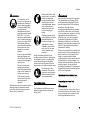 7
7
-
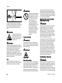 8
8
-
 9
9
-
 10
10
-
 11
11
-
 12
12
-
 13
13
-
 14
14
-
 15
15
-
 16
16
-
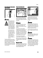 17
17
-
 18
18
-
 19
19
-
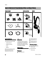 20
20
-
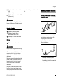 21
21
-
 22
22
-
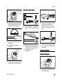 23
23
-
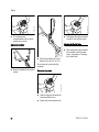 24
24
-
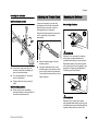 25
25
-
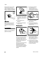 26
26
-
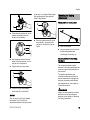 27
27
-
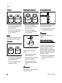 28
28
-
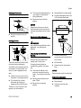 29
29
-
 30
30
-
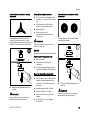 31
31
-
 32
32
-
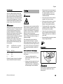 33
33
-
 34
34
-
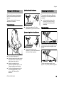 35
35
-
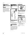 36
36
-
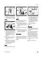 37
37
-
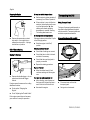 38
38
-
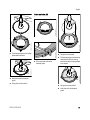 39
39
-
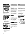 40
40
-
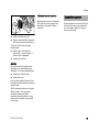 41
41
-
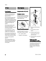 42
42
-
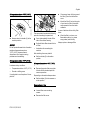 43
43
-
 44
44
-
 45
45
-
 46
46
-
 47
47
-
 48
48
-
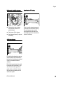 49
49
-
 50
50
-
 51
51
-
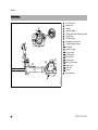 52
52
-
 53
53
-
 54
54
-
 55
55
-
 56
56
-
 57
57
-
 58
58
-
 59
59
-
 60
60
-
 61
61
-
 62
62
-
 63
63
-
 64
64
-
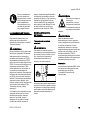 65
65
-
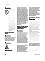 66
66
-
 67
67
-
 68
68
-
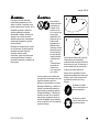 69
69
-
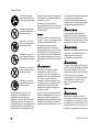 70
70
-
 71
71
-
 72
72
-
 73
73
-
 74
74
-
 75
75
-
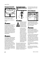 76
76
-
 77
77
-
 78
78
-
 79
79
-
 80
80
-
 81
81
-
 82
82
-
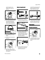 83
83
-
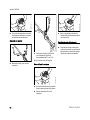 84
84
-
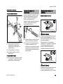 85
85
-
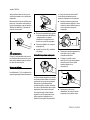 86
86
-
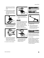 87
87
-
 88
88
-
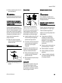 89
89
-
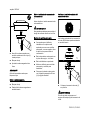 90
90
-
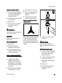 91
91
-
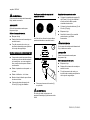 92
92
-
 93
93
-
 94
94
-
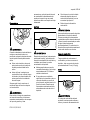 95
95
-
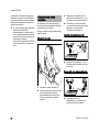 96
96
-
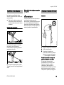 97
97
-
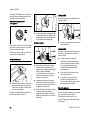 98
98
-
 99
99
-
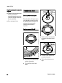 100
100
-
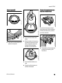 101
101
-
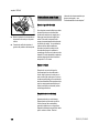 102
102
-
 103
103
-
 104
104
-
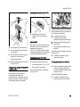 105
105
-
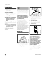 106
106
-
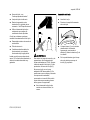 107
107
-
 108
108
-
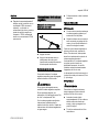 109
109
-
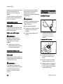 110
110
-
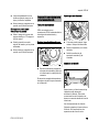 111
111
-
 112
112
-
 113
113
-
 114
114
-
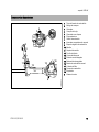 115
115
-
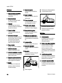 116
116
-
 117
117
-
 118
118
-
 119
119
-
 120
120
-
 121
121
-
 122
122
-
 123
123
-
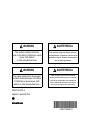 124
124


STIHL FS 510 C-M Manual de usuario
- Categoría
- Podadoras de césped
- Tipo
- Manual de usuario
- Este manual también es adecuado para
en otros idiomas
- English: STIHL FS 510 C-M User manual
Artículos relacionados
-
STIHL FS 111 RX Manual de usuario
-
-
-
-
-
STIHL R-490C Manual de usuario
-
-
-
-