McCulloch Log Splitter FB4052 Manual de usuario
- Categoría
- Partidores de troncos
- Tipo
- Manual de usuario
Este manual también es adecuado para

SAFETY OPERATION MAINTENANCE
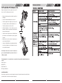
Model: FB4052
User Manual
LOG SPLITTER
© 2006 McCulloch
12802 Leffingwell Rd.
Santa Fe Springs, CA • U.S.A.
Made in China/Fabriqué à China/Hecho en China
WARNING • PLEASE READ
Both model number and serial number may be found on the main label . You should record both of them in a safe
place for future use.

32
EN
SAFETY WARNINGS & INSTRUCTIONS
EN
Read and understand the owner's manual and labels affixed to the log splitter. Learn
its application and limitations as well as the specific potential hazards peculiar to it.
• UNDERSTAND YOUR LOG SPLITTER
• DRUGS, ALCOHOL AND MEDICATION
Do not operate the log splitter while under the influence of drugs, alcohol, or any medication that
could affect your ability to use it properly.
• AVOID DANGEROUS CONDITIONS
Put the log splitter on a 60 - 75cm high, stable, flat, and level work bench where there is plenty of
room for handling, and help the operator stay altert. Bolt the log splitter to the work surface if it
tends to slip, walk, or slide.
Keep your work area clean and well lighted. Cluttered areas invites injuries.
Do not use the log splitter in wet or damp areas or expose it to rain.
Do not use it in areas where fumes from paint, solvents or flammable liquids pose a potential haz-
ard.
• INSPECT YOUR LOG SPLITTER
Check your log splitter before turning it on. Keep guards in place and in working
order. Form a habit of checking to see that keys and adjusting wrenches are
removed from tool area before turning it on. Replace damaged, missing or failed
parts before using it.
• DRESS PROPERLY
Do not wear loose clothing, gloves, neckties or jewelry (rings, wrist watches). They
can be caught in moving parts.
Protective electrically non conductive gloves and non-skid footwear are recom-
mended when working. Wear protective hair covering to contain long hair, prevent-
ing it from get caught in machinery.
• PROTECT YOUR EYES AND FACE
Any log splitter may throw foreign objects into the eyes. This can cause permanent
eye damage. Always wear safety goggles. Everyday eyeglasses have only impact
resistant lenses. They are not safety glasses.
Do not put the log splitter on the ground for operations. This is awkward operating
position that the operator has to bring his face close to the machine, and thus risks
being struck by wood chips or debris.
• EXTENSION CORDS
Improper use of extension cords may cause inefficient operation of the log splitter which can result
in overheating. Be sure the extension cord is no longer than 10m and its section is no less than
2.5mm2 to allow sufficient current flow to the motor.
Avoid use of free and inadequately insulated connections. Connections must be made with pro-
tected material suitable for outdoor use.
• AVOID ELECTRICAL SHOCK
Check that the electric circuit is adequately protected and that it corresponds with the power, volt-
age and frequency of the motor. Check that there is a ground connection, and a regulation differ-
ential switch upstream.
Ground the log splitter. Prevent body contact with grounded surfaces: pipes, radiators, ranges, and
refrigerator enclosures.
Never open the pushbutton box on the motor. Should this be necessary, contact a qualified electri-
cian.
Mark sure your fingers do not touch the plug's metal prongs when plugging or unplugging the log
splitter.
The log splitter must be always operated by one person only. Other people
should keep a safe distance from the work area, especially when the log splitter
is under operations. Never use another people to help you with freeing jammed
log.
• KEEP VISITORS AND CHILDREN AWAY
• INSPECT YOUR LOG
Make sure there are no nails or foreign objects in logs to be split. The ends of the logs must be cut
square. Branches must be cut of flush with the trunk.
• DON'T OVERREACH
Floor must not be slippery.
Keep proper footing and balance at all times.
Never stand on log splitter. Serious injury could occur if the tool is tipped or if the cutting tools is
unintentionally contacted. Do not store anything above or near the log splitter where anyone might
stand on the tool to reach them.
Always pay full attention to the movement of the log pusher.
Do not attempt to load the log on until the log pusher has stopped.
Keep hands out of the way of all moving parts.
• AVOID INJURY FROM UNEXPECTED ACCIDENT
Keep you hands away from splits and cracks which open in the log; They may close
suddenly and crush or amputate your hands.
Do not remove jammed logs with you hands.
• PROTECT YOUR HANDS
• DON'T FORCE TOOL
It will do a better and safer job at its design rate. Never try to split logs larger than those indicated
in the specifications table. This could be dangerous and may damage the machine.
Don't use log splitter for a purpose for which it was not intended.
• NEVER LEAVE TOOL RUNNING UNATTENDED
Don't leave tool until it has come to a complete stop.

54
APPLICATION CONDITIONS
EN
EN
Unplug when not in use, before making adjustments, changing parts, cleaning, or
working on the log splitter; Consult technical manual before servicing.
• DISCONNECT POWER
Take used oil to an authorized collection point or follow the stipulations in the coun-
try where the log splitter is used.
Do not discharge into drains, soil or water.
• PROTECT THE ENVIRONMENT
• MAINTAIN YOUR LOG SPLITTER WITH CARE
Keep the log splitter clean for best and safest performance.
• MAKE THE WORKSHOP CHILDPROOF
Lock the shop. Disconnect master switches. Store the log splitter away from children and others
not qualified to use it.
TABLE OF CONTENTS
Safety Warnings & Cautions . . . . . . . . . . . . . . . . . . . . . . . . . . . . . . . . . . . . . . . . . . . . . . . .2
Application Conditions . . . . . . . . . . . . . . . . . . . . . . . . . . . . . . . . . . . . . . . . . . . . . . . . . . . . .5
Specifications . . . . . . . . . . . . . . . . . . . . . . . . . . . . . . . . . . . . . . . . . . . . . . . . . . . . . . . . . . . .5
Set up and Preparation for Operation . . . . . . . . . . . . . . . . . . . . . . . . . . . . . . . . . . . . . . . .6
Wiring Diagram . . . . . . . . . . . . . . . . . . . . . . . . . . . . . . . . . . . . . . . . . . . . . . . . . . . . . . . . . .7
Plumbing Diagram . . . . . . . . . . . . . . . . . . . . . . . . . . . . . . . . . . . . . . . . . . . . . . . . . . . . . . .7
Log Splitter Operation . . . . . . . . . . . . . . . . . . . . . . . . . . . . . . . . . . . . . . . . . . . . . . . . . . . . .8
Freeing a Jammed Log . . . . . . . . . . . . . . . . . . . . . . . . . . . . . . . . . . . . . . . . . . . . . . . . . . . .9
Replacing Hydraulic Oil . . . . . . . . . . . . . . . . . . . . . . . . . . . . . . . . . . . . . . . . . . . . . . . . . . . .10
Sharpening Wedge . . . . . . . . . . . . . . . . . . . . . . . . . . . . . . . . . . . . . . . . . . . . . . . . . . . . . . .10
Trouble Shooting . . . . . . . . . . . . . . . . . . . . . . . . . . . . . . . . . . . . . . . . . . . . . . . . . . . . . . . . .11
Parts Schematic . . . . . . . . . . . . . . . . . . . . . . . . . . . . . . . . . . . . . . . . . . . . . . . . . . . . . . . .12
This log splitter is a home use model. It is designed for operating under ambient temperatures
between +5oC and 40oC and for installation at altitudes no more than 1000m above M.S.L. The sur-
rounding humidity should less than 50% at 40oC. It can be stored or transported under ambient
temperatures between -25˚C and 55˚C.
SPECIFICATIONS
Powerful 2.0HP Motor
Model Number . . . . . . . . . . . . . . . . . . . . . . . . . . . . . . . . . . . . . . . . . . . . . . . . . . .FB4052
Motor . . . . . . . . . . . . . . . . . . . . . . . . . . . . . . . . . . . . . . . . . . . . . . . . . . . . . . . . . .120V~60Hz
Input . . . . . . . . . . . . . . . . . . . . . . . . . . . . . . . . . . . . . . . . . . . . . . . . . . . . . . . . . . .1500W,IP54
Log Capacity
Diameter * . . . . . . . . . . . . . . . . . . . . . . . . . . . . . . . . . . . . . . . . . . . . . . . . . . . . . . .2”-12” (5 ~ 25cm)
Length . . . . . . . . . . . . . . . . . . . . . . . . . . . . . . . . . . . . . . . . . . . . . . . . . . . . . . . . . .20.5” (52cm)
Splitting Force . . . . . . . . . . . . . . . . . . . . . . . . . . . . . . . . . . . . . . . . . . . . . . . . . . . .4 t
Hydraulic Pressure . . . . . . . . . . . . . . . . . . . . . . . . . . . . . . . . . . . . . . . . . . . . . . . .16Mpa
Hydraulic Oil Capacity . . . . . . . . . . . . . . . . . . . . . . . . . . . . . . . . . . . . . . . . . . . . .3.5L
Overall Size
Length . . . . . . . . . . . . . . . . . . . . . . . . . . . . . . . . . . . . . . . . . . . . . . . . . . . . . . . . . .940mm
Width . . . . . . . . . . . . . . . . . . . . . . . . . . . . . . . . . . . . . . . . . . . . . . . . . . . . . . . . . .270mm
Height . . . . . . . . . . . . . . . . . . . . . . . . . . . . . . . . . . . . . . . . . . . . . . . . . . . . . . . . . .510mm
Weight . . . . . . . . . . . . . . . . . . . . . . . . . . . . . . . . . . . . . . . . . . . . . . . . . . . . . . . . . .94.61 Lbs (43 kg)
The diameter of the log is indicative - a small log can be difficult to split when it has knobs or a par-
ticularly tough fiber. On the other hand, it may not be difficult to split logs with regular fibers even
if its diameter exceeds the max. figure indicated above.

76
EN
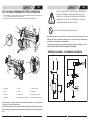
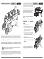
1. Log Pusher
2. Work Table
3. Wedge
4. Lift Handle
5. Support Leg
6. Log Retaining Plates
7. Switch
8. Motor
9. Pushbutton Box
10. Wheels for Minor Moving ONLY.
11. Hydraulic Control Lever
12. Control Lever Guard
13. Bleed Screw
14. Oil Drain Bolt w/ Dipstick
15. Max Pressure Limiting Screw
12
6
2
13
3
10
4
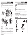
SET UP AND PREPARATION FOR OPERATION
1. Bolt the Support Leg to the Log Splitter, lift the log splitter by the handles at both ends and place it on
a 60 - 75cm high, stable, flat and level work surface.
2. Familiarize yourself with the controls and features of this log splitter in the illustrations.
11
5
7
8
9
1
14
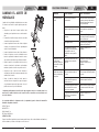
Before operating the log splitter, the Bleed Screw should be loosened by some rotations until air
can go in and out of the oil tank smoothly.
Air flow thru the Bleed Screw hole should be detectable during the log splitter is under operations.
Before moving the log splitter, make sure the Bleed Screw is tightened to avoid oil leaking from this
point.
FAILED TO LOOSEN THE BLEED SCREW WILL KEEP THE SEALED AIR IN
HYDRAULIC SYSTEM BEING COMPRESSED AFTER BEING DECOM-
PRESSED. SUCH CONTINUOUS AIR COMPRESSION AND DECOMPRES-
SION WILL BLOW OUT THE SEALS OF THE HYDRAULIC SYSTEM AND
CAUSE PERMANT DAMAGE TO THE LOG SPLITTER.
15
EN
DO NOT ADJUST THE MAX PRESSURE LIMITING SCREW !.
Max pressure was set before the log splitter ex work and the max pressure limiting screw is sealed
with glue to ensure the log splitter works under pressure no more than 4 tons.The setting was done
by qualified mechanic with professional instruments.
Unauthorized resetting will cause the hydraulic pump fail to output enough splitting pressure or
RESULT IN SERIOUS INJURY AS WELL AS DAMAGE TO THE MACHINE .
WIRING DIAGRAM
PLUMBING DIAGRAM
15

98
EN
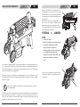
LOG SPLITTER OPERATION
EN
This log splitter is equipped with “ZHB” control system that requires to be operated by both hands of the
user - Left hand controls the hydraulic control lever while right hand controls the pushbutton switch. The log
splitter will freeze upon absence of either hand. Only after both hands release the controls, the log pusher
starts to return backward to the starting position.
Trigger type lock-out device is adopted to avoid accidental Hydraulic Control Lever pushdown. To operate
the Hydraulic Control Lever, draw the Trigger backward with the index finger before push the Hydraulic
Control Lever forward.
Never force the log splitter for more than 5 seconds by keeping pressure on it to split
excessively hard wood.
Always set logs firmly on the log retaining plates and
work table. Make sure logs will not twist, rock or slip
while being split. Do not force the blade by splitting the
log on the upper part. This will break the blade or dam-
age the machine.
Break log in the direction of its growing grain. Do not
place log across the log splitter for splitting. It may be
dangerous and may seriously damage the machine.
Do not attempt to split 2 pieces of logs at the same time.
One of them may fly up and hit you.
FREEING A JAMMED
LOG
• Release both controls.
• After the log pusher moves back and complete-
ly stops at its starting position, insert a
wedge wood under the jammed log.
• Start the log splitter to push the wedge wood to
go completely under the jammed one.
• Repeat above procedure with sharper slope
wedge woods until the log is completely
freed.
Do not try to knock the jammed log off. Knocking about
will damage the machine or may launch the log and
cause accident.
After this time interval, the oil under pressure will be overheated and the machine could be damaged. For
such extremely hard log, rotate it by 90o to see whether it can be split in a different direction. In any case,
if you are not able to split the log, this means that its hardness exceeds the capacity of the machine and
thus that log should be discarded to protect the log splitter.

1110
TROUBLE SHOOTING
EN
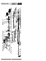
REPLACING HYDRAULIC OIL
Replace the Hydraulic oil in the log splitter after every 150
hours of use. Take following steps to replace it.
• Make sure all moving parts stops and the log splitter is
unplugged.
• Unscrew Oil Drain Bolt with Dipstick to remove it.
• Turn the log splitter on the Support Leg side over an 4
liters capacity container to drain the hydraulic oil off.
• Turn the log splitter on the the motor side.
• Refill fresh hydraulic oil at the volume as per the
hydraulic oil capacity of a particular model indicated in
above specifications table.
• Clean the surface of Dipstick on the Oil Drain Bolt and
put it back into the oil tank while keep the log splitter
vertically.
• Make sure the level of the refilled oil is just between 2
grooves around the Dipstick.
• Clean the Oil Drain Bolt before thread them back. Make
sure they are tightened to avoid leakage before place
the log splitter horizontally.
Periodically check oil level to ensure it is between 2
grooves around the Dipstick. Upon Lower oil level, oil
refilling is required.
Following hydraulic oils or equivalent are recommend for the log splitter's hydraulic transmission
system:
SHELL Tellus 22
MOBIL DTE 11
ARAL Vitam GF 22
BP Energol HLP-HM 22
SHARPENING WEDGE
After using the log splitters for some time, sharpen the wedge of the log splitter using a fine-toothed file and
smooth any burrs or crushed area along the cutting edge.
EN

12
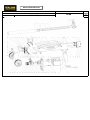
PARTS SCHEMATIC
EN
MANTENIMIENTO PARA USO SEGURO
Modelo: FB4052
Manual del usuario
PARTIDOR DE TRONCOS
ADVERTENCIA = LÉALO
Tanto el número de modelo como el número de serie se encuentran en la etiqueta principal. Debe anotar ambos
números en un lugar seguro por si tuviera que consultarlos en otro momento.

1514
ES
ADVERTENCIAS E INSTRUCCIONES DE SEGURIDAD
ES
Lea y comprenda el manual del propietario y las etiquetas fijadas en el partidor de
troncos. Aprenda su aplicación y limitaciones así como sus riesgos potenciales
específicos intrínsecos.
• FAMILIARÍCESE CON EL PARTIDOR DE TRONCOS
• DROGAS, ALCOHOL Y MEDICAMENTOS
No utilice el partidor de troncos bajo la influencia de drogas, alcohol ni ningún medicamento que
pueda afectar a la capacidad de utilizar la máquina correctamente.
• EVITE CONDICIONES PELIGROSAS
Coloque el partidor de troncos en un banco de trabajo nivelado, estable, plano, a una altura de
entre 60 cm y 75 cm y en un lugar donde haya una gran cantidad de espacio para trabajar y ayude
al operador a permanecer en alerta. Atornille el partidor de troncos a la superficie de trabajo si
tiende a resbalarse, moverse o deslizarse.
Mantenga el área de trabajo limpio y bien iluminado. Las áreas abarrotadas de objetos son propi-
cias para causar daños personales.
No utilice el partidor de troncos en áreas húmedas ni lo exponga a la lluvia.
No lo utilice el partidor de troncos en áreas donde los gases procedentes de pinturas, disolventes
o líquidos inflamables representen un peligro potencial.
• INSPECCIONE EL PARTIDOR DE TRONCOS
Compruebe el partidor de troncos antes de encenderlo. Mantenga los dispositivos
de seguridad en su lugar y listos para trabajar. Haga que las comprobaciones se
conviertan en un hábito asegurándose de que los utensilios y las llaves inglesas de
ajuste se han retirado del área de las herramientas antes de encender la máquina.
Reemplace los componentes dañados, que falten o que no funcionen antes de uti-
lizar el dispositivo.
• USE INDUMENTARIA ADECUADA
No utilice ropa suelta, guantes, corbatas ni alhajas (anillos, relojes de pulsera, etc.).
Estos artículos se pueden enganchar en las piezas móviles.
Se recomienda utilizar guantes no conductores protegidos contra la electricidad
estática y calzado antideslizante cuando trabaje. Utilice un recubrimiento protector
para recogerse el pelo y evitar así que éste quede atrapado en la máquina.
• PROTÉJASE LOS OJOS Y LA CARA
Cualquier partidor de troncos puede arrojar objetos extraños a los ojos. Este hecho
puede provocar daños irreparables en los ojos. Utilice siempre gafas de seguridad.
Las gafas de uso diario solamente tienen lentes resistentes a impactos. No son
gafas de seguridad.
No coloque el partidor de troncos en el suelo para trabajar. Es ésta una posición
incómoda en la que el operador tiene que colocar su cara junto a la máquina, por lo
que existe riesgo de que le golpeen virutas o restos de madera.
• ALARGADORES
El uso inadecuado de alargadores puede causar un uso ineficiente del partidor de troncos, lo que
puede provocar un sobrecalentamiento en la máquina. Asegúrese de que el alargador no mide más
de 10 m y que su sección no es inferior a 2,5 mm2 para que permita el suficiente flujo de corriente
al motor.
No utilice conexiones disponibles inadecuadamente aisladas. Las conexiones se deben realizar
con material protegido.
• EVITE DESCARGAS ELÉCTRICAS
Compruebe que el circuito eléctrico está correctamente protegido y que se corresponde con la
potencia, voltaje y frecuencia del motor. Compruebe que hay una conexión a tierra y un conmuta-
dor diferencial de regulación.
Conecte a tierra el partidor de troncos. Evite que su cuerpo entre en contacto con superficies
conectadas a tierra: carcasas de tuberías, radiadores, cocinas y frigoríficos.
No abra nunca la caja de pulsadores del motor. Si tuviera que hacerlo, póngase en contacto con un
electricista profesional.
Asegúrese de que sus dedos no tocan las puntas metálicas del enchufe cuando enchufe o des-
enchufe el partidor de troncos.
El partidor de troncos siempre se debe utilizar por una sola persona. El resto de
personas deben mantenerse a una distancia segura del área de trabajo, espe-
cialmente cuando el partidor de troncos está funcionando. No utilice nunca a
otra persona para que le ayude a liberar un tronco atrapado.
• MANTENGA ALEJADAS A LAS PERSONAS AJENAS Y A LOS NIÑOS
• INSPECCIONE EL TRONCO
Asegúrese de que no hay clavos ni objetos extraños en los troncos que desea trocear. Las termi-
naciones de los troncos deben estar cortadas de forma cuadrada. Las ramas deben estar cortadas
de forma que queden alineadas con el tronco.
• NO ASUMA RIESGOS
El suelo no debe estar resbaladizo.
Mantenga la máquina en posición equilibrada en todo momento.
Nunca se ponga en el partidor de troncos. Podrían producirse daños personales graves si la her-
ramienta se ladea o si se entra en contacto con las herramientas de corte involuntariamente. No
almacene nada sobre el partidor de troncos o junto a él donde nadie pudiera permanecer en la her-
ramienta o alcanzarla.
Preste siempre mucha atención al movimiento del impulsor de troncos.
No intente cargar el tronco hasta que el impulsor de troncos se haya
detenido. Mantenga las manos alejadas de la trayectoria de todas las
piezas móviles.
• EVITE DAÑOS POR ACCIDENTES INESPERADOS
Mantenga las manos alejadas de las grietas y rendijas abiertas en el tronco ya que
se pueden cerrar repentinamente y machar o amputar sus manos.
No quite los troncos atrapados con sus manos.
• PROTEJA SUS MANOS
• NO FUERCE LA HERRAMIENTA
La máquina realizará un trabajo mejor y más seguro utilizando los parámetros para los que está
diseñada. No intente nunca partir troncos más grandes que los indicados en la tabla de especifi-
caciones. Tal acción podría ser peligrosa y la máquina podría resultar dañada.
No utilice el partidor de troncos para un fin distinto para el que fue diseñado.
• NUNCA DEJE LA HERRAMIENTA DESATENDIDA Y EN FUNCIONAMIENTO
No abandone la herramienta hasta que se haya detenido completamente.

1716
CONDICIONES DE APLICACIÓN
ESES
Desenchufe la máquina cuando no la utilice, antes de realizar ajustes, cuando cam-
bie piezas, cuando la limpie o cuando trabaje con el partidor de troncos. Consulte
el manual técnico antes de solicitar ayuda al servicio técnico.
• DESCONECTE LA ALIMENTACIÓN
Lleve el aceite usado a un punto de recogida autorizado o siga la normativa corre-
spondiente del país en el que utiliza el partidor de troncos.
No tire el aceite a ningún sumidero, a la tierra o al agua.
• PROTEJA EL MEDIOAMBIENTE
• MANTENGA EL PARTIDO DE TRONCOS EN BUENAS CONDICIONES
Mantenga el partidor de troncos limpio para conseguir siempre el rendimiento máximo y más
seguro.
• HAGA QUE EL LUGAR DE TRABAJO ESTÉ A PRUEBA DE LOS NIÑOS
Cierre el lugar de trabajo. Desconecte los interruptores principales. Almacene el partidor de tron-
cos de forma que quede alejado de los niños y otras personas no cualificadas para su uso.
TABLA DE CONTENIDO
Advertencias e instrucciones de seguridad . . . . . . . . . . . . . . . . . . . . . . . . . . . . . . . . . . . . .14
Condiciones de aplicación . . . . . . . . . . . . . . . . . . . . . . . . . . . . . . . . . . . . . . . . . . . . . . . . . .17
Especificaciones técnicas . . . . . . . . . . . . . . . . . . . . . . . . . . . . . . . . . . . . . . . . . . . . . . . . . .17
Configurar y preparar la máquina para su uso . . . . . . . . . . . . . . . . . . . . . . . . . . . . . . . . . .18
Diagrama de cableado . . . . . . . . . . . . . . . . . . . . . . . . . . . . . . . . . . . . . . . . . . . . . . . . . . . .19
Diagrama de conductos . . . . . . . . . . . . . . . . . . . . . . . . . . . . . . . . . . . . . . . . . . . . . . . . . . .19
Funcionamiento del partidor de troncos . . . . . . . . . . . . . . . . . . . . . . . . . . . . . . . . . . . . . . .20
Liberar un tronco atrapado . . . . . . . . . . . . . . . . . . . . . . . . . . . . . . . . . . . . . . . . . . . . . . . . .21
Cambiar el aceite de hidráulico . . . . . . . . . . . . . . . . . . . . . . . . . . . . . . . . . . . . . . . . . . . . . .22
Afilar la cuña . . . . . . . . . . . . . . . . . . . . . . . . . . . . . . . . . . . . . . . . . . . . . . . . . . . . . . . . . . . .22
Solucionar problemas . . . . . . . . . . . . . . . . . . . . . . . . . . . . . . . . . . . . . . . . . . . . . . . . . . . . .23
Esquema de las piezas . . . . . . . . . . . . . . . . . . . . . . . . . . . . . . . . . . . . . . . . . . . . . . . . . . .24
Este partidor de troncos es un modelo de uso doméstico. Está diseñado para trabajar a una tem-
peratura ambiente comprendida entre +5 ºC y 40 ºC y no se debe instalar en altitudes superiores a
los 1000 metros sobre el nivel medio del mar. La humedad ambiente debe ser inferior al 50% a 40
ºC. Se debe almacenar o transportar bajo temperaturas comprendidas entre -25 ºC y 55 ºC.
ESPECIFICACIONES TÉCNICAS
Motor 2.0HP potente
Número de modelo . . . . . . . . . . . . . . . . . . . . . . . . . . . . . . . . . . . . . . . . . . . . . . . .FB4052
Motor . . . . . . . . . . . . . . . . . . . . . . . . . . . . . . . . . . . . . . . . . . . . . . . . . . . . . . . . . . .120V~60Hz
Entrada . . . . . . . . . . . . . . . . . . . . . . . . . . . . . . . . . . . . . . . . . . . . . . . . . . . . . . . . .1500W,IP54
Capacidad de troncos
Diámetro * . . . . . . . . . . . . . . . . . . . . . . . . . . . . . . . . . . . . . . . . . . . . . . . . . . . . . . .2”-12” (5 cm~25 cm)
Longitud . . . . . . . . . . . . . . . . . . . . . . . . . . . . . . . . . . . . . . . . . . . . . . . . . . . . . . . .20.5” (52 cm)
Fuerza de corte . . . . . . . . . . . . . . . . . . . . . . . . . . . . . . . . . . . . . . . . . . . . . . . . . . .4 t
Presión hidráulica . . . . . . . . . . . . . . . . . . . . . . . . . . . . . . . . . . . . . . . . . . . . . . . . .16Mpa
Capacidad de aceite hidráulico . . . . . . . . . . . . . . . . . . . . . . . . . . . . . . . . . .
. . . . 3.5L
Tamaño global
Longitud . . . . . . . . . . . . . . . . . . . . . . . . . . . . . . . . . . . . . . . . . . . . . . . . . . . . . . . .940mm
Ancho . . . . . . . . . . . . . . . . . . . . . . . . . . . . . . . . . . . . . . . . . . . . . . . . . . . . . . . . . .270mm
Alto . . . . . . . . . . . . . . . . . . . . . . . . . . . . . . . . . . . . . . . . . . . . . . . . . . . . . . . . . . . .510mm
Peso . . . . . . . . . . . . . . . . . . . . . . . . . . . . . . . . . . . . . . . . . . . . . . . . . . . . . . . . . . .94.61 Lbs (43 kg)
El diámetro de los troncos es indicativo: un tronco pequeño puede resultar difícil de partir si tiene
nudos o una fibra particularmente dura. Por el contrario, puede que no resulten tan difícil de partir
los troncos con fibras normales uniformes. Consulte la figura anterior.

1918
ES
1. Impulsor de troncos
2. Mesa de trabajo
3. Cuña
4. Asa elevador
5. Pata de apoyo
6. Placas de sujeción de troncos
7. Interruptor
8. Motor
9. Caja de pulsadores
10. Ruedas para pequeños
desplazamientos (SOLA-
MENTE).
11. Palanca de control del hidráulico
12. Cubierta de la palanca de con-
trol
13. Tornillo de purga
14. Tornillo de drenaje del aceite
con varilla de medición del nivel
15. Tornillo limitador de la presión
máxima
12
6
2
13
3
10
4
CONFIGURAR Y PREPARAR LA MÁQUINA PARA
SU USO
1. Atornille la pata de apoyo al partidor de troncos, levántelo por sus asas situadas en ambas termina-
ciones y colóquelo en una superficie de trabajo nivelada, estable, plana y a una altura de entre 60 cm
y 75 cm.
2. Familiarícese con los controles y funciones de este partidor de troncos consultando las ilustraciones.
11
5
7
8
9
1
14
Antes de utilizar el partidor de troncos, afloje el tornillo de purga girándolo hasta que el aire entre
y salga del tanque de aceite con facilidad.
El flujo de aire a través del tornillo de purga se debe detectar mientras se utiliza el partidor de tron-
cos. Antes de mover el partidor de troncos, asegúrese de que el tornillo de purga está apretado
para evitar fugas de aceite.
SI NO SE AFLOJA EL TORNILLO DE PURGA, EL AIRE ENCERRADO EN EL
SISTEMA HIDRÁULICO SE COMPRIMIRÍA Y DESCOMPRIMIRÁ UNA Y OTRA
VEZ. ESTE PROCESO DE COMPRESIÓN Y DESCOMPRESIÓN CONTINUO
REVENTARÁ LOS CIERRES HERMÉTICOS DEL SISTEMA HIDRÁULICO Y
PROVOCARÁ DAÑOS IRREVERSIBLES EN EL PARTIDOR DE TRONCOS.
15
ES
¡NO AJUSTE EL TORNILLO LIMITADOR DE LA PRESIÓN MÁXIMA!
La presión máxima se fijó antes de que el partidor de troncos llegara a sus manos y el tornillo lim-
itador de la presión máxima está precintado con pegamento para garantizar que la máquina fun-
ciona con una presión no superior a 4 toneladas. La configuración se realizó por mecánicos cuali-
ficados con instrumentos profesionales.
El reajuste no autorizado hará que la bomba hidráulica no pueda proporcionar la presión de corte
suficiente o PROVOCARÁ DAÑOS GRAVES PERSONALES Y A LA PROPIA MÁQUINA.
DIAGRAMA DE
CABLEADO
DIAGRAMA DE CONDUC-
TOS
15

2120
ES
FUNCIONAMIENTO DEL PARTIDOR DE TRONCOS
ES
Este partidor de troncos cuenta con un sistema de control “ZHB” que necesita ser utilizado con las dos
manos del operador: la mano izquierda maneja la palanca de control del hidráulico y la mano derecha con-
trola el interruptor de pulsador. El partidor de troncos se bloqueará en ausencia de cualquiera de las
manos. Solamente después de que ambas manos liberen los controles, el impulsor de troncos comenzará
a retroceder hasta recuperar la posición de inicio.
Se adopta el dispositivo de bloqueo de tipo gatillo para evitar el uso accidental de la palanca de control del
hidráulico. Para utilizar la palanca de control del hidráulico, eche el gatillo hacia atrás con el dedo índice
antes de empujar la palanca de control del hidráulico hacia delante.
Nunca fuerce el partidor de troncos durante más de 5 segundos manteniendo presión
en él para partir madera excesivamente dura.
Coloque siempre los troncos firmemente en las placas
de sujeción de troncos y en la mesa de trabajo.
Asegúrese de que los troncos no se girarán, bal-
ancearán ni resbalarán mientras se parten. No fuerce la
hoja partiendo el tronco en la parte superior. Si lo hace,
la hoja se partirá o la máquina resultará dañada.
Parta los troncos en la dirección de su veta de crec-
imiento. No coloque los troncos atravesados en el par-
tidor de troncos para partirlos. Tal acción podría ser
peligrosa y la máquina podría resultar gravemente
dañada.
No intente partir 2 trozos de troncos al mismo tiempo.
Uno de ellos puede salir disparado y golpearle.
FREEING A JAMMED
LOG
• Libere ambos controles.
• Después de que el impulsor de troncos retroce-
da y se detenga completamente en su posición
inicial, inserte un trozo de madera con forma de
cuña bajo el tronco atascado.
• Inicie el partidor de troncos para empujar el
trozo de madera con forma de cuña hasta que
se haya introducido completamente debajo del
tronco atascado.
• Repita el procedimiento anterior con trozos de
madera con forma de cuña más pronunciada y
afilados hasta que el tronco quede completa-
mente libre.
No golpee el tronco atrapado para extraerlo. Si lo gol-
pea, la máquina puede resultar dañada o puede salir
despedido y causar un accidente.
After this time interval, the oil under pressure will be overheated and the machine could be damaged. For
such extremely hard log, rotate it by 90o to see whether it can be split in a different direction. In any case,
if you are not able to split the log, this means that its hardness exceeds the capacity of the machine and
thus that log should be discarded to protect the log splitter.

2322
SOLUCIONAR PROBLEMAS
ES
CAMBIAR EL ACEITE DE
HIDRÁULICO
Cambie el aceite de hidráulico del partidor de troncos cada
150 horas de uso. Realice los pasos siguientes para cam-
biarlo:
• Asegúrese de que todas las partes móviles están
detenidas y que el partidor de troncos está desenchu-
fado.
• Desatornille el tornillo de drenaje del aceite con varilla
de medición del nivel para extraerlo.
• Levante el partidor de troncos sobre el lado de la pata
de apoyo y el recipiente de 4 litros de capacidad para
extraer el aceite de hidráulico.
• Levante el partidor de troncos sobre el lado del motor.
• Rellene el recipiente con aceite de hidráulico nuevo
hasta la capacidad del volumen del modelo concreto
que se indica en la tabla de especificaciones anterior.
• Limpie la superficie de la varilla del nivel de aceite y
vuelva a colocarla en el recipiente de aceite mientras
mantiene el partidor de troncos en posición vertical.
• Asegúrese de que el nivel del aceite rellenado se
encuentra justo entre las dos muescas marcadas en la
varilla del nivel de aceite.
• Limpie el tornillo de drenaje del aceite antes de
enroscarlo de nuevo. Asegúrese de que se ha apreta-
do perfectamente para evitar fugas antes colocar el
partidor de troncos en posición horizontal.
Compruebe periódicamente el nivel del aceite para asegurarse de que se encuentra entre las 2
muescas de la varilla del nivel de aceite. Cuando el aceite se encuentre en su nivel inferior será
necesario rellenarlo.
Se recomienda utilizar los siguientes aceites (o equivalentes) para el sistema de transmisión
hidráulico del partidor de troncos:
SHELL Tellus 22
MOBIL DTE 11
ARAL Vitam GF 22
BP Energol HLP-HM 22
AFILAR LA CUÑA
Después de utilizar el partidor de troncos durante mucho tiempo, afile su cuña utilizando una lima fina y
alise las rebabas y el área de colisión junto con el filo de corte.
ES
PÛngase en contacto con el
distribuidor.
El conjunto de la v·lvu la de control
del hidr·ul ico y/o los precintos
est·n ga stados.
Apriete el tornillo de drenaje del aceite
con varilla de mediciÛn del nivel de
aceite.
El tornillo de drenaje del aceite con
varilla de mediciÛn del nivel de
aceite no est· apretado.
Apriete el tornillo de purga antes de
desplazar el partidor de troncos.
El tornillo de purga no se ha
apretado antes de desplazar el
partidor de troncos.
Afloje el tornillo de purgado gir·ndolo
3 Û4 veces antes de utilizar el partidor
de troncos
Hay aire encerrado en el sistema
hidr·ul ico mientras se utiliza la
m· quina.
Hay fugas de aceite
alrededor del martillo del
cilindro o procedente de
otros puntos.
Compruebe el nivel de aceite por si
tuviera que rellenarlo.
PÛngase en contacto con el
distribuidor.
No hay aceite de hidr·u lico y hay
demasiado aire en el sistema
hidr·ul ico.
El impulsor de troncos
se mueve dando
sacudidas, haciendo un
ruido extraÒo o vibrando
en exceso.
PÛngase en contacto con el
distribuidor.
Se ha realizado un ajuste no
autorizado en el tornillo limitador
de la presiÛn m· xima. Se
estableciÛun valor de presiÛn
inferior.
Localice las fugas y pÛngase en
contacto con el proveedor
Hay fugas de aceite
Consulte la secciÛn ìAfilar la cuÒaî
para obtener informaciÛn sobre cÛmo
afilar la cuÒa de corte.
El filo de la cuÒa de corte est·
desafilado
Reduzca el tamaÒo de los troncos
antes de partirlos en el partidor de
troncos.
El tamaÒo o la dureza del tronco
supera la capacidad de la m· quina.
Cons
ulte la secciÛn ìFuncionamiento
del par
tidor de troncosî para obtener
inf
ormaciÛn sobre cÛmo colocar el
tronco perfectamente.
El tr
onco no se ha colocado
co
rrectamente.
No s
e pueden partir los
tr
oncos
SO
LUCI” N PROPUESTACAUSA PROBABLEPROBLEMA

24
ESQUEMA DE LAS PIEZAS
ES

REVISED DATE
REVISED DATE
SPECIFY MODEL NO. WHEN ORDERING PARTS
4 TON LOG SPLITTER
SERVICE SPARE PARTS LIST
N/A
8/7/2008
REVISED
DATE
MODEL NO.
4
TON
LOG
SPLITTER
FB4052 (65556)
SERVICE SPARE PARTS LISTSERVICE SPARE PARTS LISTSERVICE SPARE PARTS LISTSERVICE SPARE PARTS LISTSERVICE SPARE PARTS LIST

TIYA model #65556
6/1/2009
TIYA No. JF Parts No. Descri
p
tion
Q
P Code
JF model # FB4052
PARTS LIST
TIYA
No.
JF
Parts
No.
Description
Q
1 7200-405201 CYLINDER 1 210
2 7200-405202 PISTON O-RING 1 210
3 7200-405203 PISTON 1 210
4 7200-405204 O-RING 1 210
5 7200-405205 SPRING 1 210
PARTS LIST
6 7200-405206 POSITON ROD WELDMENT 1 210
7 7200-405207 NUT 2 210
8 7200-405208 WASHER 2 210
9 7200-405209 MOVING HANDLE 1 210
10 7200-405210 HEX. BOLT 2 210
11 7200-405211 NUT
,
M14 2 210
PARTS LIST
11
7200 405211
NUT
,
M14
2
210
12 7200-405212 PLASTIC SEAL 1 210
13 7200-405213 WING SCREW/ BLEED SCREW 1 210
14 7200-405214 O-RING 1 210
15 7200-405215 LONG STUB 4 210
16 7200-405216 HEX. BOLT 6 210
PARTS LIST
17 7200-405217 SPRING WASHER 4 210
18 7200-405218 NUT 5 210
19 7200-405219 SUPPORT PLATE 2 210
20 7200-405220 TUBE FRAME/ OIL TANK 1 210
21 7200-405221 HEX. BOLT 4 210
22
7200
-
405222
WASHER
4
210
PARTS LIST
22
7200-405222
WASHER
4
210
23 7200-405223 UPPER PLASTIC INSERT 1 210
24 7200-405224 LOG PUSHER WELDMENT 1 210
25 7200-405225 NUT 4 210
26 7200-405226 O-RING 1 210
27 7200-405227 CYLINDER COVER-LEFT 1 210
PARTS LIST
28 7200-405228 COPPER GASKET 4 210
29 7200-405229 SAFETY VALVE SPRING 1 210
PARTS LIST

30 7200-405230 SCREW 1 210
31 7200-405231 SAFETY VALVE BOLT 1 210
32 7200-405232 O-RING 1 210
33 7200-405233 ROUND HEAD NUT 3 210
34 7200-405234 LEVER GUARD 1 210
35 7200-405235 NUT 2 210
36 7200-405236 LEVER WELDMENT 1 210
37 7200-405237 LEVER HEAD 1 210
38 7200-405238 LEVER NUT 1 210
39 7200-405239 WHEEL FRAME PLATE WELDMENT 1 210
40 7200-405240 STEEL BALL 1 210
41 7200-405241 CIRCLIP 1 210
42 7200-405242 RESTORE VALVE SPRING 1 210
43 7200-405243 VALVE ROD 1 210
3
700 05 3
VV O
0
44 7200-405244 O-RING 1 210
45 7200-405245 VALVE SLEEVE 1 210
46 7200-405246 O-RING 5 210
47 7200-405247 O-RING 2 210
48 7200-405248 SLIDING SLEEVE SPRING 1 210
49 7200-405249 SLIDING SLEEVE 1 210
50 7200-405250 WASHER 1 210
51 7200-405251 VALVE PLUG 1 210
52 7200-405252 LOWER PLASTIC INSERT 1 210
53 7200-405253 DRAWING WELDMENT 1 210
54 7200-405254 LOOSE NUT 1 210
54
7200 405254
LOOSE
NUT
1
210
55 7200-405255 HEX. BOLT 1 210
56 7200-405256 WASHER 2 210
57 7200-405257 MOTOR SHAFT SEAL 1 210
58 7200-405258 SETEEL BALL, 2.5 1 210
59 7200-405259 SUPPORT LEG 1 210
60 7200-405260 CARRIAGE 5 210
61 7200-405261 CYLINDER COVER-RIGHT 1 210
62 7200-405262 DIPSTICK GASKET 1 210
63 7200-405263 DIPSTICK 1 210

64 7200-405264 MOTOR WITH SWITCH 1 210
65 7200-405265 MOTOR 1 210
66 7200-405266 SWITCH BOX 1 210
67 7200-405267 BOLT 1 210
68 7200-405268 NUT 1 210
69 7200-405269 SPRING WASHER 3 210
70 7200-405270 BOLT 3 210
71 7200-405271 MOTOR COVER 1 210
72 7200-405272 MOTOR SUPPORT SHOE - LEFT 1 210
73 7200-405273 MOTOR SUPPORT SHOE - RIGHT 1 210
74 7200-405274 WASHER 9 210
75 7200-405275 PIN 2 210
76 7200-405276 GEAR HOUSING PLATE 1 210
77 7200-405277 GEAR 2 210
77
700 0577
G
0
78 7200-405278 GEAR GEAR SHAFT SNAP WASHER 2 210
79 7200-405279 PIN 1 210
80 7200-405280 GEAR SHAFT 1 210
81 7200-405281 SLIDING BEARING 4 210
82 7200-405282 O-RING 2 210
83 7200-405283 PUMP COVER 1 210
84 7200-405284 BOLT 3 210
85 7200-405285 SPRING WASHER 9 210
86 7200-405286 WAHSER 9 210
87 7200-405287 BOLT 6 210
88 7200-405288 WHEEL COVER 2 210
88
7200 405288
WHEEL
COVER
2
210
89 7200-405289 WHEEL SHAFT SNAP RING 2 210
90 7200-405290 WHEEL 2 210
-
 1
1
-
 2
2
-
 3
3
-
 4
4
-
 5
5
-
 6
6
-
 7
7
-
 8
8
-
 9
9
-
 10
10
-
 11
11
-
 12
12
-
 13
13
-
 14
14
-
 15
15
-
 16
16
-
 17
17


McCulloch Log Splitter FB4052 Manual de usuario
- Categoría
- Partidores de troncos
- Tipo
- Manual de usuario
- Este manual también es adecuado para
en otros idiomas
Otros documentos
-
Homelite ut49103 El manual del propietario
-
-
-
-
-
Woods KLS Manual de usuario
-
 Champion Power Equipment 92205 Manual de usuario
-
EarthQuake 32229 5-Ton Electric Log Splitter El manual del propietario
-
 Champion Power Equipment 92207 Manual de usuario
-
 Champion Power Equipment 92210 Manual de usuario


