probst ALX-120 Manual de usuario
- Categoría
- Aspiradoras
- Tipo
- Manual de usuario

52600018
ALX-120
DE
I
Betriebsanleitung
GB
I
Operating Instructions
FR
I
Instructions d'emploi
ES
I
Instrucciones de uso
NL
I
Bedrijfshandleiding
IT
I
Istruzioni d’uso
PL
I
Instrukcja Obsługi


52600018
V3
Original Betriebsanleitung
ALX-120
DE
I
Betriebsanleitung

Bitte beachten Sie, dass das Produkt ohne vorliegende Betriebsanleitung in Landessprache
nicht eingesetzt / in Betrieb gesetzt werden darf. Sollten Sie mit der Lieferung des Produkts
keine Betriebsanleitung in Ihrer Landessprache erhalten haben, kontaktieren Sie uns bitte. In
Länder der EU / EFTA senden wir Ihnen diese kostenlos nach. Für Länder außerhalb der EU /
EFTA erstellen wir Ihnen gerne ein Angebot für eine Betriebsanleitung in Landessprache, falls
die Übersetzung nicht durch den Händler/Importeur organisiert werden kann.
Please note that the product may not be used / put into operation without these operating
instructions in the national language. If you did not receive operating instructions in your
national language with the delivery of the product, please contact us. In countries of the EU /
EFTA we will send them to you free of charge. For countries outside the EU / EFTA, we will be
pleased to provide you with an offer for an operating manual in the national language if the
translation cannot be organised by the dealer/importer.

Inhalt
52600018
2 / 16
DE
Inhalt
1 EG-Konformitätserklärung .................................................................................................................. 3
2 Sicherheit .............................................................................................................................................. 4
2.1 Erforderliche persönliche Schutzausrüstung ................................................................................... 4
2.2 Betriebssicherheit ............................................................................................................................ 4
2.3 Umgebungstemperatur .................................................................................................................... 4
2.4 Elektrische Sicherheitshinweise ...................................................................................................... 4
3 Sicherheitshinweise ............................................................................................................................. 5
4 Montage und Teile-Übersicht .............................................................................................................. 6
4.1 Montage .......................................................................................................................................... 6
4.2 Teileübersicht .................................................................................................................................. 6
4.3 Übersicht - optionales Zubehör ....................................................................................................... 7
4.3.1 Airlift-Saugplatten ALX-ESP ........................................................................................................ 7
4.3.2 Handgriffe und Zubehör .............................................................................................................. 7
4.4 Montage – optionales Zubehör ........................................................................................................ 8
4.4.1 Zusatz-Handgriff ......................................................................................................................... 8
4.4.2 2-Mann-Handgriff ........................................................................................................................ 9
5 Bedienung ........................................................................................................................................... 12
5.1 Vakuumbetrieb / Last Handhabung ............................................................................................... 12
6 Wartung ............................................................................................................................................... 14
6.1 Reinigungsprozess ........................................................................................................................ 14
6.2 Wartung der Vakuumfilter .............................................................................................................. 14
7 Fehlersuche ........................................................................................................................................ 15
7.1 Betriebsprüfung ............................................................................................................................. 15
7.1.1 Problembehebung: .................................................................................................................... 15
7.2 Hinweis zum Typenschild .............................................................................................................. 16
7.3 Hinweis zur Vermietung/Verleihung von PROBST-Geräten .......................................................... 16
8 Entsorgung / Recycling von Geräten und Maschinen..................................................................... 16
Änderungen gegenüber den Angaben und Abbildungen in der Betriebsanleitung sind vorbehalten.

EG-Konformitätserklärung
52600018
3 / 16
DE
1 EG-Konformitätserklärung
Bezeichnung:
Typ:
Artikel-Nr.:
AIRLIFT ALX-120 Vakuum-Handverlegegerät
ALX-120
52600018
Hersteller:
Probst GmbH
Gottlieb-Daimler-Straße 6
71729 Erdmannhausen, Germany
info@probst-handling.de
www.probst-handling.com
Die vorstehend bezeichnete Maschine entspricht den einschlägigen Vorgaben nachfolgender EU-Richtlinien:
2006/42/EG (Maschinenrichtlinie)
2014/30/EU (Elektromagnetische Verträglichkeit)
Folgende Normen und technische Spezifikationen wurden herangezogen:
DIN EN ISO 12100
Sicherheit von Maschinen - Allgemeine Gestaltungsleitsätze - Risikobeurteilung und Risikominderung
DIN EN ISO 13857
Sicherheit von Maschinen - Sicherheitsabstände gegen das Erreichen von Gefährdungsbereichen mit den oberen
und unteren Gliedmaßen
2014/30/EU (Elektromagnetische Verträglichkeit)
DIN EN 60204-1 (IEC 60204-1)
Sicherheit von Maschinen - Elektrische Ausrüstung von Industriemaschinen - Teil 1: Allgemeine Anforderungen
Dokumentationsbevollmächtigter:
Name: Jean Holderied
Anschrift: Probst GmbH; Gottlieb-Daimler-Straße 6; 71729 Erdmannhausen, Germany
Unterschrift, Angaben zum Unterzeichner:
Erdmannhausen, 19.07.2023..........................................................................
(Eric Wilhelm, Geschäftsführer)

Sicherheit
52600018
4 / 16
DE
2 Sicherheit
WARNUNG!
Betonplatten, Natursteine oder Fliesen
(in dieser Betriebsanleitung als Last bezeichnet)
sind die einzigen
Materialien, die
für die Handhabung des
AIRLIFT
ausgelegt sind. Das Material
wird durch ein Vakuum
gehalten und fällt sofort ab, wenn die Stromversorgung unterbrochen wird.
2.1 Erforderliche persönliche Schutzausrüstung
• Schutzkleidung
• Schutzhandschuhe
• Sicherheitsschuhe
2.2 Betriebssicherheit
• Nicht zum Anheben über Kopf erlaubt- nur in Bodennähe verwenden; weniger als 120 cm (4 ft.).
• Vor der Geräte-Benutzung stehendes Wasser von der Oberfläche der Last entfernen.
• Immer eine durch einen Erdschlussunterbrecher (GFI) geschützte Stromquelle verwenden und sicherstellen,
dass diese während der Geräte-Benutzung NICHT getrennt wird.
• Nicht versuchen, den AIRLIFT in einer vertikalen Position zu halten.
• Das Überschreiten der maximalen Tragfähigkeit (WLL) des Geräts (120 kg / 265 lbs) und der optionalen
Saugplatten ist verboten!!! Gefahr: Herunterfallen der Last!
• Einige der Saugplatten, die an das Gerät angebaut werden können, reduzieren seine Tragfähigkeit (WLL).
Auf jeder Saugplatte ist die maximal zulässige Tragfähigkeit (WLL) angegeben, diese darf NICHT
überschritten werden!!!
• Es dürfen nur für das Gerät zugelassene Saugplatten und des Herstellers Probst verwendet werden!
• Niemals angesaugte Last am Griff des AIRLIFTS schräg/diagonal ziehen (immer nur vertikal nach oben).
• Nicht versuchen, eingeklemmte oder festsitzende Last anzuheben oder mit Gewalt loszureißen.
• Angesaugte Last erst lösen, wenn die Last (z.B. Steinplatte) komplett am Boden abgesetzt ist.
• Nicht unter die angehängte Last greifen, schwere Verletzungen können die Folge sein.
• Nicht bei Regen, Gewitter, Schnee oder Glatteis betreiben.
• Nicht in der Nähe von explosiven Materialien betreiben.
• Nicht in den Saugschlauchöffnung bei eingeschaltetem AIRLIFT hineinschauen (Verletzungsgefahr der Augen).
• Stromversorgung erst nach kompletter Montage/Umbau unmittelbar vor Arbeitsbeginn herstellen!
2.3 Umgebungstemperatur
HITZE: Nicht bei Temperaturen über 40°C (105°F) verwenden.
KÄLTE: Nicht bei Temperaturen unter 0°C (32°F) verwenden.
Schalten Sie das Gerät aus, wenn es nicht verwendet wird, um eine Überhitzung zu vermeiden.
2.4 Elektrische Sicherheitshinweise
Es ist mindestens ein 3-adriges Verlängerungskabel mit einer Stärke von 12 zu verwenden.
Es ist immer einen durch einen Erdschlussunterbrecher (GFI) geschützter Stromkreis
verwenden.
Sicherstellen, dass der Strom während des Betriebs nicht abgetrennt werden kann.

Sicherheitshinweise
52600018
5 / 16
DE
3 Sicherheitshinweise
Es liegt in der Verantwortung des Betreibers, die verwendeten Lasten zu testen, um eine sichere
Handhabung der Lasten zu gewährleisten. Aufgrund der Vielzahl an optionalen Saugplatten
muss stets, die auf der jeweiligen Saugplatte angegebene Tragfähigkeit (WLL) UNBEDINGT
beachtet werden und darf keinesfalls überschritten werden!
Nachfolgende Aspekte sind stets vor und während des Betriebes zu beachten / zu
berücksichtigen:
• Dichte der eigentlichen Last, die angehoben wird. Die Dichten variieren selbst bei der gleichen
Schicht des hergestellten Betons.
• Verwendung der richtigen Größe der Saugplatte. (es sollte immer mit der größten Saugplatte
getestet werden, die auf die Oberfläche passt).
• Zustand der Saugplattendichtung.
• Richtige Zentrierung der Saugplatte auf den Lastschwerpunkt.
• Überprüfung der Sauberkeit des Papier- als auch Tuchfilters. Wenn diese schmutzig und oder nass
werden, verringert sich die Hubkapazität.
• Grobe Handhabung während des Betriebs.
• Dieses Gerät ist für eine Person zum Setzen von Pflastersteinen und Platten ausgelegt.

Montage und Teile-Übersicht
52600018
6 / 16
DE
1
2
3
4
5
6
8
9
7
2
14
4 Montage und Teile-Übersicht
4.1 Montage
• Sicherstellen, dass der Permanent-Stofffilter (mit Gummidichtung) installiert ist.
• Sicherstellen, dass der Einweg-Papierstaubfilter installiert ist (passt in den permanenten
Stofffilter).
• Vakuumabdeckung schließen und sicherstellen, dass die Verriegelungen sicher geschlossen
sind.
• 90°-Schwenkmanschette des Saugschlauchs ❾ oben in den Deckel stecken.
• Vakuumschlauch ❼ am Handtragegriff ❶ anschließen und mittels Schlauchschelle sichern.
4.2 Teileübersicht
1
Anschluss für Saugschlauch des
Rucksacksaugers
8
Stromkabel mit Ein-/Ausschalter des
Rucksacksaugers
2
Sicherungselement (Schlauchschelle)
9
Saugschlauch des Rucksacksaugers
3
Sicherungselement
(Rohrklappstecker)
10
Saugplatte (42600193) WLL 18 kg (40 lbs) *
4
Höhenverstellung für Handtragegriff
11
Saugplatte (42600196) WLL 35 kg (77 lbs) *
5
Handtragegriff
12
Saugplatte (42600194) WLL 12 kg (26 lbs) *
6
Vakuumschlauch
13
Saugplatte (42600195) WLL 25 kg (55 lbs) *
7
Rucksacksauger (230 V)
14
Saugplatte (42600191) WLL 50 kg (110 lbs)
* optional

Montage und Teile-Übersicht
52600018
7 / 16
DE
4.3 Übersicht - optionales Zubehör
4.3.1 Airlift-Saugplatten ALX-ESP
10
11
12
13
14
Bestell-Nr.:
42600193
42600196
42600194
42600195
42600191
4.3.2 Handgriffe und Zubehör
Bestell-Nr.: 42600206
SOLO-Handgriff
Bestell-Nr.: 48500044 / 42600207
DUO-Handgriff / Aufnahme für Rucksacksauger
48500044
42600207
42600206

Montage und Teile-Übersicht
52600018
8 / 16
DE
4.4 Montage – optionales Zubehör
4.4.1 Zusatz-Handgriff
42600206
ALX-120-SOLO-
SET
Abb. 1
AIRLIFT AXL-120
(52600018)
+
ALX-120-SOLO-
SET
(42600206)
Abb. 2
Abb. 3
Abb. 4

Montage und Teile-Übersicht
52600018
9 / 16
DE
4.4.2 2-Mann-Handgriff
AIRLIFT AXL-120 (52600018)
+
ALX-120-DUO-SET (42600209)
Abb. 1
Abb. 2
Abb. 3
Abb. 4
Abb. 5
Abb. 6

Montage und Teile-Übersicht
52600018
10 / 16
DE
Abb. 7
Abb. 8
Abb.9
Abb. 10
Abb. 11
Abb. 12

Montage und Teile-Übersicht
52600018
11 / 16
DE
Abb. 13
Abb. 14
Abb. 15
Abb. 16
Abb. 17
Abb. 18
ALX-120-DUO-
Set
42600207

Bedienung
52600018
12 / 16
DE
5 Bedienung
5.1 Vakuumbetrieb / Last Handhabung
• Vor jeder Inbetriebnahme das Vakuumgerät und Zubehör auf Anzeichen von Schäden untersuchen.
• Verbinden des Verlängerungskabels mit dem Netzkabel des Vakuumerzeugers mit Hilfe der mitgelieferten
Zugentlastung, die am Vakuumerzeuger (Rucksacksauger) angebracht ist. (Abb. 1/ Abb.2)
• Vakuumerzeuger (Rucksacksauger) aufsetzen und Rückentragegeschirr einstellen.
• Befestigen Sie den Saugschlauchs am Handtragegriff befestigen und mitgelieferte Schlauchschelle festziehen
(siehe Abb. 3 / Abb. 4).
• Verlängerungskabel an eine FI-Steckdose (mit FI-Schutzschalter) anschließen.
• Zum Einschalten des Vakuumerzeugers den Netzschalter in die Position „I“ bewegen (Abb. 5 / Abb. 6).
• Zum Ausschalten des Vakuumerzeugers den Netzschalter in die Position „0“ bewegen (Abb. 5 / Abb. 6).
Abb. 1
Abb. 3
Abb. 5
Abb. 2
Abb. 4
Abb. 6

Bedienung
52600018
13 / 16
DE
• Das Verhältnis von Hebezeit zu Belüftungszeit (Ablösen) sollte etwa 2/3 zu 1/3 betragen.
• Maximale Hebezeit 2 Minuten, anschließend 1 Minute freies Saugen (ohne Last).
• Vakuum-Hebegerät mit laufendem Vakuumerzeuger NICHT auf eine luftdichte Oberfläche
(Platte) stellen, da dies sonst zur Überhitzung des Vakuumerzeugers führen kann.
• Bei Arbeitspausen von mehr als zwei Minuten den Vakuum-Erzeuger ausschalten.
• Die Energieversorgung bzw. der externe Stromanschluss muss immer in Sichtweite des
Geräte-Bedieners sein.
• Eine entsprechend ausreichend dimensionierte Saugplatte wählen, die zu der Last passt, welche angehoben und
versetzt werden soll.
• Die Saugplatte im Schwerpunkt der Last positionieren (muss nicht immer die Mitte der Last sein).
• Etwas Druck nach unten auf den Handtragegriff () bringen und für die Ansaugvorgang mit dem Daumen
leicht auf die Belüftungsklappe () drücken (Abb. 7).
• Einen Fuß auf die zu hebende Last stellen und gleichzeitig am Handtragegriff nach oben ziehen, um
sicherzustellen, ob das erforderliche Arbeitsvakuum erreicht ist.
• Last ein wenig anheben und dabei den Handtragegriff senkrecht halten. Kräftig rütteln, um die Hubkapazität vor
der Verwendung zu testen.
• Last vorsichtig transportieren und an der gewünschten Stelle absetzen (Abb. 11 / Abb. 12).
Zum Ablösen der Last, die Belüftungsklappe mit dem Daumen etwas anheben (Abb. 8 / Abb. 9).
• Wenn eine Last von höheren Stapeln oder Paletten angehoben werden muss, ist es empfehlenswert die Höhe
des höhenverstellbaren Handtragegriffes zu verringern und den hierzu optionalen Zusatz-Handgriff zu
verwenden
(Abb. 10). Unter Umständen muss der Handtragegriff für ein ergonomischeres Handling um 90° gedreht werden,
bzw. um rechteckige Lasten sicherer transportieren zu können.
Abb. 7
Abb. 8
Abb. 9
Abb. 10
Abb. 11
Abb. 12

Wartung
52600018
14 / 16
DE
6 Wartung
REPARATUREN:
Reparaturen am Gerät dürfen nur von Personen durchgeführt werden, die die dafür notwendigen
Kenntnisse und Fähigkeiten besitzen.
Es dürfen nur Original-Ersatzteile verwendet werden. Bei Nichteinhaltung erlischt die
Gewährleitung.
Die einzigen vor Ort zuwartenden Teile sind Filter, Schläuche und Dichtungen sowie die zugehörige
Ausrüstung. Alle Arbeiten dürfen nur in stromlosen und beim stillgelegten Zustand des Gerätes
erfolgen!
Generell: Netzschalter ausschalten und Stromkabelstecker am Vakuumerzeuger abziehen und
sicherstellen, dass dieser nicht unbeabsichtigt wieder eingesteckt wird!
6.1 Reinigungsprozess
• Den Vakuumerzeuger (Rucksacksauger), Handtragegriff und Griffe mit einem feuchten Handtuch reinigen.
• Bei starker Verschmutzung des Einweg-Papierfilters ❶ (oder bei Leistungsverlust) diesen entfernen und
ersetzen.
• Permanent-Stofffilter (mit Gummidichtung) ❷ ausbauen, entleeren oder ggf. waschen. Gummidichtung
reinigen, dann wieder einbauen.
• Reinigen der Schaumstoff-Saugplattendichtung bei Bedarf (von Hand mit Wasser und Seife).
• Reinigen des Rückentragegeschirrs (von Hand) bei Bedarf.
6.2 Wartung der Vakuumfilter
• Vakuumabdeckung durch Lösen der Verriegelungen öffnen und
Abdeckung abnehmen.
• Einwegpapierfilter ❶ prüfen. Bei Verschmutzung oder Nässe wechseln.
• Entsorgen des gebrauchten Einweg-Papierfilters. Einweg-Papierfilter ❶
nicht wiederverwenden, da dies die Leistung beeinträchtigt.
• Prüfen des Permanent-Stofffilters (mit Gummidichtung) ❷ und der
Dichtung. Reinigung durch Ausschütteln oder vorsichtiges Waschen von
Hand.
• Gummidichtung sauber abwischen (mit feuchtem Tuch). Gummidichtung
erst wieder einsetzen, wenn diese vollständig getrocknet ist.

Fehlersuche
52600018
15 / 16
DE
7 Fehlersuche
7.1 Betriebsprüfung
• Die Betriebsprüfung sollte stets mit zwei Personen durchgeführt werden!
• Vakuumhebegerät auf eine Beton- oder Fliesenfläche stellen.
• Vakuum einschalten und prüfen, ob ein Vakuum-Unterdruck erreicht wird.
• Wenn kein Vakuum-Unterdruck erreicht wird, das Schmutzsieb reinigen und versuchen es mit einer neuen
Saugplatte oder Silikonschaumdichtung.
• Wenn ein Vakuum-Unterdruck erreicht wird, ist sicher zu stellen, dass der Ansaugfreigabehebel richtig
funktioniert.
• Wenn durch routinemäßige Wartung die verlorene Saugleistung nicht wieder hergestellt werden kann, das
Vakuumhebegerät von einem qualifizierten Techniker warten lassen.
7.1.1 Problembehebung:
Geringe Absaugung oder schlechtes Aufnehmen
Mögliche Ursachen:
Abhilfemaßnahmen:
• Luftweg verstopft
• Überprüfen und Beseitigung etwaiger Hindernisse für den
Luftstrom.
• Einweg-Papierfilter ist voll oder nass
• Ersetzen des Einweg-Papierfilters.
• Beschädigte oder nicht
angeschlossene Schläuche
• Sicherstellen, dass alle Schläuche nicht beschädigt und richtig
angeschlossen sind.
• Verschmutzte oder beschädigte
Saugplattendichtung
• Waschen oder ersetzen der Dichtung. Zur Reinigung nur Wasser
und Seife verwenden.
• Beschädigte Saugplatte
• Andere Saugplatte verwenden oder Saugplatte zum Austausch an
den Hersteller senden.
Vakuummotor funktioniert nicht
Mögliche Ursachen:
Abhilfemaßnahmen:
• Vakuumerzeuger ist nicht eingesteckt1
• Prüfen, ob der Vakuumerzeuger richtig eingesteckt ist.
• Ausfall der Steckdose oder des
EIN/AUS-Schalters
• Prüfen aller Anschlüsse und alle Schutzschalter zurücksetzen.
Stromkreis mit einem anderen funktionierenden Werkzeug prüfen.
• Thermischer Schutz des Motors
aktiviert
• Prüfen, ob der Luftstrom behindert wird. Vakuumerzeuger 60
Minuten lang abkühlen lassen, bevor der Betrieb fortgesetzt wird.
• Motor beschädigt
• Rückgabe an den Hersteller.
• Ausfall Vakuumpumpe durch
Feuchtigkeit
• Vor dem Ansaugen der Last, Wasser von der Ansaugfläche
entfernen.
• Vor dem Abschalten des Vakuumerzeugers (bei geöffneter
Entlüftungsklappe) mindestens 1 Minute trocken laufen lassen.

Entsorgung / Recycling von Geräten und Maschinen
52600018
16 / 16
DE
7.2 Hinweis zum Typenschild
• Gerätetyp, Gerätenummer und Baujahr sind wichtige Angaben zur Identifikation des Gerätes. Sie
sind bei Ersatzteilbestellungen, Gewährleistungsansprüchen und sonstigen Anfragen zum Gerät
stets mit anzugeben.
• Die maximale Tragfähigkeit (WLL) gibt an, für welche maximale Belastung das Gerät ausgelegt ist.
Die maximale Tragfähigkeit (WLL) darf nicht überschritten werden.
• Das im Typenschild bezeichnete Eigengewicht ist bei der Verwendung am Hebezeug/Trägergerät
(z.B. Kran, Kettenzug, Gabelstapler, Bagger...) mit zu berücksichtigen.
Beispiel:
7.3 Hinweis zur Vermietung/Verleihung von PROBST-Geräten
Bei jeder Verleihung/Vermietung von PROBST-Geräten muss unbedingt die dazu gehörige Original-
Betriebsanleitung mitgeliefert werden (bei Abweichung der Sprache des jeweiligen Benutzerlandes,
ist zusätzlich die jeweilige Übersetzung der Original-Betriebsanleitung mit zuliefern)!
8 Entsorgung / Recycling von Geräten und Maschinen
Das Produkt darf nur von qualifiziertem Fachpersonal außer Betrieb genommen und zur Entsorgung/
zum Recyclen vorbereitet werden. Entsprechend vorhandene Einzelkomponenten (wie Metalle,
Kunststoffe, Flüssigkeiten, Batterien/Akkus etc.) müssen gemäß den national/ länderspezifisch
geltenden Gesetzen und Entsorgungsvorschriften entsorgt/recycelt werden!
Das Produkt darf nicht im Hausmüll entsorgt werden!

Probst GmbH Telefon +49 7144 3309-0 www.probst-handling.com
Gottlieb-Daimler-Straße 6 Fax +49 7144 3309-50 info@probst-handling.de
71729 Erdmannhausen, Germany
Wartungsnachweis
Garantieanspruch für dieses Gerät besteht nur bei Durchführung der vorgeschriebenen Wartungsarbeiten
(durch eine autorisierte Fachwerkstatt)! Nach jeder erfolgten Durchführung eines Wartungsintervalls muss
unverzüglich dieser Wartungsnachweis (mit Unterschrift u. Stempel) an uns übermittelt werden. 1)
1)per E-Mail an: service@probst-handling.de / per Fax oder Post
Betreiber:
_ _ _ _ _ _ _ _ _ _ _ _ _
Gerätetyp:
_ _ _ _ _ _ _ _ _ _ _ _ _
Artikel-Nr.:
_ _ _ _ _ _ _ _ _ _ _ _ _
Geräte-Nr.:
_ _ _ _ _ _ _ _ _ _ _ _ _
Baujahr:
_ _ _ _
Wartungsarbeiten nach 25 Betriebsstunden
Datum:
Art der Wartung:
Wartung durch Firma:
Stempel
………………………………………
Name / Unterschrift
Wartungsarbeiten nach 50 Betriebsstunden
Datum:
Art der Wartung:
Wartung durch Firma:
Stempel
………………………………………
Name / Unterschrift
Wartung durch Firma:
Stempel
………………………………………
Name / Unterschrift
Wartung durch Firma:
Stempel
………………………………………
Name / Unterschrift
Wartungsarbeiten 1x jährlich
Datum:
Art der Wartung:
Wartung durch Firma:
Stempel
………………………………………
Name / Unterschrift
Wartung durch Firma:
Stempel
………………………………………
Name / Unterschrift
DE


52600018
V3
Translation of original operating instructions
ALX-120
GB
I
Operating Instructions

Bitte beachten Sie, dass das Produkt ohne vorliegende Betriebsanleitung in Landessprache
nicht eingesetzt / in Betrieb gesetzt werden darf. Sollten Sie mit der Lieferung des Produkts
keine Betriebsanleitung in Ihrer Landessprache erhalten haben, kontaktieren Sie uns bitte. In
Länder der EU / EFTA senden wir Ihnen diese kostenlos nach. Für Länder außerhalb der EU /
EFTA erstellen wir Ihnen gerne ein Angebot für eine Betriebsanleitung in Landessprache, falls
die Übersetzung nicht durch den Händler/Importeur organisiert werden kann.
Please note that the product may not be used / put into operation without these operating
instructions in the national language. If you did not receive operating instructions in your
national language with the delivery of the product, please contact us. In countries of the EU /
EFTA we will send them to you free of charge. For countries outside the EU / EFTA, we will be
pleased to provide you with an offer for an operating manual in the national language if the
translation cannot be organised by the dealer/importer.

Contents
52600018
2 / 16
GB
Contents
1 EC-Declaration of Conformity / UKCA-Declaration of Conformity ................................................... 3
2 Security ................................................................................................................................................. 4
2.1 Personal protective equipment required .......................................................................................... 4
2.2 Operational safety ........................................................................................................................... 4
2.3 Ambient temperature ....................................................................................................................... 4
2.4 Electrical safety instructions ........................................................................................................... 4
3 Safety instructions ............................................................................................................................... 5
4 Assembly and parts overview ............................................................................................................. 6
4.1 Assembly ......................................................................................................................................... 6
4.2 Parts overview ................................................................................................................................. 6
4.3 Overview - optional accessories ...................................................................................................... 7
4.3.1 Airlift suction plates ALX-ESP ..................................................................................................... 7
4.3.2 Handles and accessories ............................................................................................................ 7
4.4 Mounting - optional accessories ...................................................................................................... 8
4.4.1 Additional handle ........................................................................................................................ 8
4.4.2 2-man handle .............................................................................................................................. 9
5 Operation / load handling .................................................................................................................. 12
5.1 Vacuum operation ......................................................................................................................... 12
6 Maintenance........................................................................................................................................ 14
6.1 Cleaning process ........................................................................................................................... 14
6.2 Vacuum filter maintenance ............................................................................................................ 14
7 Troubleshooting ................................................................................................................................. 15
7.1 Audit .............................................................................................................................................. 15
7.1.1 Troubleshooting: ....................................................................................................................... 15
7.2 Hints to the type plate .................................................................................................................... 16
7.3 Hints to the renting/leasing of PROBST devices ........................................................................... 16
8 Disposal / recycling of devices and machines ................................................................................ 16
We hereby reserve the right to make changes to the information and illustrations in the operating instructions.

EC-Declaration of Conformity / UKCA-Declaration of Conformity
52600018
3 / 16
GB
1 EC-Declaration of Conformity / UKCA-Declaration of Conformity
Description:
Type:
Order number:
AIRLIFT ALX-120 Vacuum Hand Laying Device
ALX-120
52600018
Manufacturer:
Probst GmbH
Gottlieb-Daimler-Straße 6
71729 Erdmannhausen, Germany
info@probst-handling.de
www.probst-handling.com
Importer:
Probst Ltd
Unit 2 Fletcher House
Stafford Park 17
Telford Shropshire TF3 3DG, United Kingdom
www.probst-handling.co.uk
sales@probst-handling.co.uk
The machine described above complies with the relevant requirements of the following EU directives:
The object of the declaration described above is in conformity with the relevant UK-Regulations and UK-Guidelines:
EC-machinery directive 2006/42/EC (Reference: OJ L 157, 09.06.2006)
UK-Regulation: Supply of Machinery (Safety) Regulations 2008 (SI 2008 No. 1597)
2014/30/EU (Electromagnetic compatibility) / (Reference: OJ L 96, 29.03.2014)
UK-Regulation: Electromagnetic Compatibility Regulations 2016 (SI 2016 No. 1091)
The following standards and technical specifications were used:
DIN EN ISO 12100
Safety of machinery - General principles for design - Risk assessment and risk reduction
UK-Regulation: BS EN ISO 12100-1:2003+A1:2009
DIN EN ISO 13857
Safety of machinery - safety distances to prevent hazard zones being reached by upper and lower limbs.
UK-Regulation: BS EN ISO 13857:2019
2014/30/EU (Electromagnetic compatibility) / (Reference: OJ L 96, 29.03.2014)
UK-Regulation: Electromagnetic Compatibility Regulations 2016 (SI 2016 No. 1091)
DIN EN 60204-1 (IEC 60204-1)
Safety of machinery, electrical equipment of industrial machines. Part 1: General requirements.
UK-Regulation: BS EN 60204-1:2018
Authorized person for EC-documentation:
Name: Jean Holderied
Address: Probst GmbH; Gottlieb-Daimler-Straße 6; 71729 Erdmannhausen, Germany
Authorized person for UK-documentation:
Name: Nigel Hughes
Address: Probst Ltd ; Unit 2 Fletcher House; Stafford Park 17; Telford Shropshire TF3 3DG, United Kingdom
Signature, information to the subscriber:
Erdmannhausen, 19.07.2023..........................................................................
(Eric Wilhelm, Managing Director)

Security
52600018
4 / 16
GB
2 Security
WARNING!
Concrete slabs, natural stones or tiles
(referred to as load in these operating instructions)
are the only
materials
designed for handling the
AIRLIFT
. The material
is held by a vacuum and drops immediately
when the power supply is interrupted.
2.1 Personal protective equipment required
• Protective clothing
• Protective gloves
• Safety shoes
2.2 Operational safety
• Not allowed for overhead lifting- use only near the ground; less than 120 cm (4 ft.).
• Remove standing water from the surface of the load before using the unit.
• Always use a power source protected by a ground fault interrupter (GFI) and ensure that it is NOT disconnected
during use of the device.
• Do not attempt to hold the AIRLIFT in a vertical position.
• Exceeding the maximum load capacity (WLL) of the unit (120 kg / 265 lbs) and the optional suction plates
is prohibited!!! Danger: Falling down of the load!
• Some of the suction plates that can be attached to the unit reduce its load capacity (WLL).
The maximum permissible load capacity (WLL) is indicated on each suction plate, this must NOT be
exceeded!!!
• Only suction plates approved for the unit and from the manufacturer Probst may be used!
• Never pull the sucked-in load on the handle of the AIRLIFT diagonally (always only vertically upwards).
• Do not attempt to lift or force loose a trapped or stuck load.
• Do not release the suctioned load until the load (e.g. stone slab) is completely settled on the ground.
• Do not reach under the suspended load, serious injuries can result.
• Do not operate in rain, thunderstorms, snow or black ice.
• Do not operate near explosive materials.
• Do not look into the suction hose opening when AIRLIFT is switched on (risk of eye injury).
• Only connect the power supply after complete assembly/conversion immediately before starting work!
2.3 Ambient temperature
HEAT: Do not use at temperatures above 40°C (105°F).
COLD: Do not use at temperatures below 0°C (32°F).
Switch off the unit when not in use to avoid overheating.
2.4 Electrical safety instructions
Use at least a 3-core extension cable with a thickness of 12.
Always use a circuit protected by a ground fault interrupter (GFI).
Ensure that the power cannot be disconnected during operation.

Safety instructions
52600018
5 / 16
GB
3 Safety instructions
It is the responsibility of the operator to test the loads used to ensure safe handling of the loads.
Due to the large number of optional suction plates, the load capacity (WLL) indicated on the
respective suction plate must always be observed and must not be exceeded under any
circumstances!
The following aspects must always be observed / taken into account before and during
operation:
• Density of the actual load being lifted. The densities vary even with the same layer of concrete
produced.
• Use the correct size suction plate. (it should always be tested with the largest suction plate that fits
the surface).
• Condition of the suction plate seal.
• Correct centring of the suction plate on the load centre of gravity.
• Check the cleanliness of the paper and cloth filters. If they become dirty and/or wet, the lifting
capacity will be reduced.
• Rough handling during operation.
• This unit is designed for one person to set paving stones and slabs.

Assembly and parts overview
52600018
6 / 16
GB
1
2
3
4
5
6
8
9
7
2
14
4 Assembly and parts overview
4.1 Assembly
• Ensure that the permanent fabric filter (with rubber seal) is installed.
• Ensure that the disposable paper dust filter is installed (fits into the permanent fabric filter).
• Close the vacuum cover and ensure that the interlocks are securely closed.
• Insert the 90° swivel collar of the suction hose ❾ into the top of the cover.
• Connect the vacuum hose ❼ to the carrying handle ❶ and secure with a hose clamp.
4.2 Parts overview
1
Connection for suction hose of
the backpack vacuum cleaner
8
Power cable with backpack vacuum cleaner on/off
switch
2
Securing element (hose clamp)
9
Suction hose of the backpack vacuum cleaner
3
Fuse element (tube linch pin)
10
Suction plate (42600193) WLL 18 kg (40 lbs) *
4
Height adjustment for carry
handle
11
Suction plate (42600196) WLL 35 kg (77 lbs) *
5
Carry handle
12
Suction plate (42600194) WLL 12 kg (26 lbs) *
6
Vacuum hose
13
Suction Plate (42600195) WLL 25 kg (55 lbs) *
7
Backpack vacuum cleaner (230
V)
14
Suction plate (42600191) WLL 50 kg (110 lbs)
* optional

Assembly and parts overview
52600018
7 / 16
GB
4.3 Overview - optional accessories
4.3.1 Airlift suction plates ALX-ESP
10
11
12
13
14
Order no:
42600193
42600196
42600194
42600195
42600191
4.3.2 Handles and accessories
Order no: 42600206
SOLO handle
Order no: 48500044 / 42600207
DUO handle / holder for backpack vacuum cleaner
48500044
42600207
42600206

Assembly and parts overview
52600018
8 / 16
GB
4.4 Mounting - optional accessories
4.4.1 Additional handle
42600206
ALX-120-SOLO-
SET
Fig. 1
AIRLIFT AXL-120
(52600018)
+
ALX-120-SOLO-
SET
(42600206)
Fig. 2
Fig. 3
Fig. 4

Assembly and parts overview
52600018
9 / 16
GB
4.4.2 2-man handle
AIRLIFT AXL-120 (52600018)
+
ALX-120-DUO-SET (42600209)
Fig. 1
Fig. 2
Fig. 3
Fig. 4
Fig. 5
Fig. 6

Assembly and parts overview
52600018
10 / 16
GB
Fig. 7
Fig. 8
Fig. 9
Fig. 10
Fig. 11
Fig. 12

Assembly and parts overview
52600018
11 / 16
GB
Fig. 13
Fig. 14
Fig. 15
Fig. 16
Fig. 17
Fig. 18
ALX-120-DUO
set
42600207

Operation / load handling
52600018
12 / 16
GB
5 Operation / load handling
5.1 Vacuum operation
• Inspect the vacuum unit and accessories for signs of damage before each use.
• Connect the extension cable to the mains cable of the vacuum generator using the supplied strain relief, which is
attached to the vacuum generator (backpack suction cup). (Fig. 1/ Fig. 2)
• Put on the vacuum generator (backpack suction cup) and adjust the backpack harness.
• Attach the suction hose to the carrying handle and tighten the hose clamp supplied.
(see fig. 3 / fig. 4).
• Connect the extension cable to an FI socket (with FI circuit breaker).
• To switch on the vacuum generator, move the mains switch to the "I" position (Fig. 5 / Fig. 6).
• To switch off the vacuum generator, move the mains switch to the "0" position (Fig. 5 / Fig. 6).
Fig. 1
Fig. 3
Fig. 5
Fig. 2
Fig. 4
Fig. 6

Operation / load handling
52600018
13 / 16
GB
• The lifting time to ventilation time (release) should be about 2/3 to 1/3.
• Maximum lifting time 2 minutes, followed by 1 minute of free suction (without load).
• DO NOT place the vacuum lifting device with the vacuum generator running on an airtight
surface (plate), as this may cause the vacuum generator to overheat.
• Switch off the vacuum generator if there are breaks in operation of more than two minutes.
• The power supply or the external power connection must always be within sight of the
device operator
• Select an appropriately sized suction plate that fits the load to be lifted and moved.
• Position the suction plate at the centre of gravity of the load (does not always have to be the centre of the load).
• Bring a little pressure down to the carrying handle ( ) and press lightly on the ventilation flap ( ) with your
thumb for the suction process (Fig. 7).
• Place one foot on the load to be lifted and at the same time pull upwards on the carry handle to make sure that
the required working vacuum has been reached.
• Lift the load a little while holding the hand carry handle vertically. Shake vigorously to test the lifting capacity
before use.
• Carefully transport the load and place it in the desired position (Fig. 11 / Fig. 12).
To release the load, lift the ventilation flap slightly with your thumb (Fig. 8 / Fig. 9).
• If a load needs to be lifted from higher stacks or pallets, it is recommended to reduce the height of the height-
adjustable carry handle and use the optional additional handle for this purpose
(Fig. 10). It may be necessary to turn the carrying handle 90° for more ergonomic handling or to be able to
transport rectangular loads more safely.
Fig. 7
Fig. 8
Fig. 9
Fig. 10
Fig. 11
Fig. 12

Maintenance
52600018
14 / 16
GB
6 Maintenance
REPAIRS:Repairs to
the appliance may only be carried out by persons who have the necessary knowledge and skills.
Only original spare parts may be used. Non-compliance will invalidate the warranty.
The only parts to be serviced on site are filters, hoses and seals as well as the associated equipment.
All work must only be carried out when the unit is de-energised and shut down!
Generally: Switch off the mains switch and disconnect the power cable plug at the vacuum generator
and ensure that it is not unintentionally reconnected!
6.1 Cleaning process
• Clean the vacuum generator (backpack suction cup), carry handle and handles with a damp towel.
• If the disposable paper filter is heavily soiled ❶ (or if performance is lost), remove and replace it.
• Remove the permanent fabric filter (with rubber seal) ❷, empty it or wash it if necessary. Clean the rubber seal,
then reinstall it.
• Clean the foam suction plate seal if necessary (by hand with soap and water).
• Cleaning the back carrying harness (by hand) if necessary.
6.2 Vacuum filter maintenance
• Switch off the mains switch and unplug the vacuum generator.
• Open the vacuum cover by releasing the locks and remove the cover.
• Check disposable paper filter ❶. Change if dirty or wet.
• Dispose of the used disposable paper filter. Do not reuse disposable paper
filters ❶ as this will affect performance.
• Check the permanent fabric filter (with rubber seal) ❷ and the seal. Clean
by shaking out or carefully washing by hand.
• Wipe the rubber seal clean (with a damp cloth). Replace the rubber seal
only when it is completely dry.

Troubleshooting
52600018
15 / 16
GB
7 Troubleshooting
7.1 Audit
• The audit should always be carried out with two persons!
• Place the vacuum lifting device on a concrete or tiled surface.
• Switch on the vacuum and check whether a vacuum underpressure is reached.
• If no vacuum is achieved, clean the dirt strainer and try a new suction plate or silicone foam gasket.
• When a vacuum underpressure is reached, make sure that the suction release lever is working properly.
• If routine maintenance cannot restore the lost suction power, have the vacuum lifting device serviced by a
qualified technician.
7.1.1 Troubleshooting:
Low suction or poor pick-up
Possible causes:
Remedial action:
• Airway blocked
• Check and remove any obstructions to the airflow.
• Disposable paper filter is full or wet
• Replacing the disposable paper filter.
• Damaged or unconnected hoses
• Make sure that all hoses are not damaged and are connected
correctly.
• Dirty or damaged suction plate seal
• Wash or replace the seal. Use only soap and water for cleaning.
• Damaged suction plate
• Use a different suction plate or send the suction plate to the
manufacturer for replacement.
Vacuum motor does not work
Possible causes:
Remedial action:
• Vacuum generator is not plugged in1
• Check that the vacuum generator is plugged in correctly.
• Failure of the socket or the ON/OFF
switch
• Check all connections and reset all circuit breakers. Check circuit
with another functioning tool.
• Thermal protection of the motor
activated
• Check if the air flow is obstructed. Allow vacuum generator to cool
down for 60 minutes before continuing operation.
• Engine damaged
• Return to the manufacturer.
• Failure of vacuum pump due to
wetness
• Before sucking in the load, remove water from the suction surface.
• Before switching off the vacuum generator (with the vent flap
open), let it run dry for at least 1 minute.

Disposal / recycling of devices and machines
52600018
16 / 16
GB
7.2 Hints to the type plate
• Type, serial-number and production year are very important for the identification of your device. If
you need information to spare-parts, warranty or other specific details please refer to this
information´s.
• The maximum carrying capacity/working load limit (WLL) is the maximum load which can be
handled with the device. Do not exceed this carrying capacity/working load limit (WLL).
• If you use the device in combination with other lifting equipment (Crane, chain hoist, forklift truck,
excavator) consider the deadweight of the device.
Example:
7.3 Hints to the renting/leasing of PROBST devices
With every renting/leasing of PROBST devices the original operating instructions must be
included unconditionally (in deviation of the user´s country's language, the respective translations of
the original operating instructions must be delivered additionally)!
8 Disposal / recycling of devices and machines
The product may only be taken out of service and prepared for disposal / recycling by qualified
personnel. Correspondingly existing single components (such as metals, plastics, liquids,
batteries/rechargeable batteries etc.) must be disposed of/recycled in accordance with the
nationally/country-specific applicable laws and disposal regulations!
The product must not be disposed of in household waste!

Probst GmbH Telefon +49 7144 3309-0 www.probst-handling.com
Gottlieb-Daimler-Straße 6 Fax +49 7144 3309-50 info@probst-handling.de
71729 Erdmannhausen, Germany
Proof of maintenance
Warranty claim for this machine only apply for performance of the mandatory maintenance works (by an
authorised specialist workshop)! After each completed performance of a maintenance interval the included
form must be fill out, stamped, signed and send back to us immediately. 1)
1)via e-mail to service@probst-handling.de / via fax or post
Operator:
_ _ _ _ _ _ _ _ _ _ _ _ _
Device type:
_ _ _ _ _ _ _ _ _ _ _ _ _
Article -No.:
_ _ _ _ _ _ _ _ _ _ _ _ _
Device-No.:
_ _ _ _ _ _ _ _ _ _ _ _ _
Year of make:
_ _ _ _
First inspection after 25 operating hours
Date:
Maintenance work:
Inspection by company:
Company Stamp
………………………………………
Name / Signature
All 50 operating hours
Date:
Maintenance work:
Inspection by company:
Company Stamp
………………………………………
Name / Signature
Inspection by company:
Company Stamp
………………………………………
Name / Signature
Inspection by company:
Company Stamp
………………………………………
Name / Signature
Minimum 1x per year
Date:
Maintenance work:
Inspection by company:
Company Stamp
………………………………………
Name / Signature
Inspection by company:
Company Stamp
………………………………………
Name / Signature
GB


52600018
V3
Traduction des instructions d'emploi originales
ALX-120
FR
I
Instructions d'emploi

Description:
52600018
2 / 16
FR
Sommaire
1 CE-Déclaration de Conformité ............................................................................................................ 3
2 Sécurité ................................................................................................................................................. 4
2.1 Équipement de protection individuelle requis .................................................................................. 4
2.2 Sécurité opérationnelle .................................................................................................................... 4
2.3 Température ambiante .................................................................................................................... 4
2.4 Instructions de sécurité électrique .................................................................................................. 4
3 Consignes de sécurité ......................................................................................................................... 5
4 Aperçu de l'assemblage et des pièces ............................................................................................... 6
4.1 Montage .......................................................................................................................................... 6
4.2 Aperçu des pièces ........................................................................................................................... 6
4.3 Vue d'ensemble - accessoires en option ......................................................................................... 7
4.3.1 Plaques d'aspiration Airlift ALX-ESP ........................................................................................... 7
4.3.2 Poignées et accessoires ............................................................................................................. 7
4.4 Montage - accessoires optionnels ................................................................................................... 8
4.4.1 Poignée supplémentaire ............................................................................................................. 8
4.4.2 Poignée à 2 hommes .................................................................................................................. 9
5 Opération ............................................................................................................................................ 12
5.1 Fonctionnement sous vide / manutention de la charge ................................................................. 12
6 Maintenance........................................................................................................................................ 14
6.1 Processus de nettoyage ................................................................................................................ 14
6.2 Entretien des filtres à vide ............................................................................................................. 14
7 Dépannage .......................................................................................................................................... 15
7.1 Audit .............................................................................................................................................. 15
7.1.1 Dépannage : ............................................................................................................................. 15
7.2 Informations concernant la plaque signalétique ............................................................................ 16
7.3 Remarque concernant la location/le prêt des engins PROBST ..................................................... 16
8 Elimination / recyclage des appareils et des machines .................................................................. 16
Nous nous réservons le droit de modifier les informations et les illustrations du mode d'emploi.

CE-Déclaration de Conformité
52600018
3 / 16
FR
1 CE-Déclaration de Conformité
Description:
Type:
N° de commande:
AIRLIFT ALX-120 Pose dalles manuel
ALX-120
52600018
Fabricant:
Probst GmbH
Gottlieb-Daimler-Straße 6
71729 Erdmannhausen, Germany
info@probst-handling.de
www.probst-handling.com
La machine décrite ci-dessus est conforme aux exigences applicables des directives UE suivantes :
Idée directrice EC 2006/42/CE
2014/30/EU (Electromagnétique Compatibilité)
Les normes et spécifications techniques suivantes ont été utilisées:
DIN EN ISO 12100
Sécurité des machines – Principes généraux de conception – Appréciation du risque et réduction du risque
DIN EN ISO 13857
Sécurité des machines ― Distances de sécurité empêchant les membres supérieurs et inférieurs d'atteindre les
zones dangereuses.
2014/30/EU (Electromagnétique Compatibilité)
DIN EN 60204-1 (IEC 60204-1)
Sûreté de machines, équipement électrique de machines industrielles. Partie 1: Exigences générales.
Personne autorise pour EC-documentation:
Nom: Jean Holderied
Adresse: Probst GmbH; Gottlieb-Daimler-Straße 6; 71729 Erdmannhausen, Germany
Signature, informations ou signataire:
Erdmannhausen, 19.07.2023..........................................................................
(Eric Wilhelm, Directeur général)

Sécurité
52600018
4 / 16
FR
2 Sécurité
AVERTISSEMENT !
Les dalles de béton, les pierres naturelles ou les tuiles
(appelées charge dans le présent mode d'emploi)
sont les seuls matériaux
conçus pour la manipulation du
AIRLIFT
. Le matériau
est maintenu par un vide
et tombe immédiatement lorsque l'alimentation électrique est interrompue.
2.1 Équipement de protection individuelle requis
• Vêtements de protection
• Gants de protection
• Chaussures de sécurité
2.2 Sécurité opérationnelle
• Non autorisé pour le levage en hauteur - à utiliser uniquement près du sol ; moins de 120 cm (4 pieds).
• Retirez l'eau stagnante de la surface de la charge avant d'utiliser l'appareil.
• Utilisez toujours une source d'alimentation protégée par un disjoncteur de fuite à la terre (GFI) et assurez-vous
qu'il n'est PAS débranché lorsque l'unité est en cours d'utilisation.
• N'essayez pas de tenir l'AIRLIFT en position verticale.
• Il est interdit de dépasser la capacité de charge maximale (WLL) de l'appareil (120 kg / 265 lbs) et des
plaques d'aspiration en option ! !! Danger : chute de la charge !
• Certaines des plaques d'aspiration qui peuvent être fixées à l'appareil réduisent sa capacité de charge (WLL).
La capacité de charge maximale admissible (WLL) est indiquée sur chaque plaque d'aspiration, elle ne
doit PAS être dépassée !!!
• Seules les plaques d'aspiration homologuées pour l'appareil et du fabricant Probst peuvent être utilisées !
• Ne tirez jamais la charge aspirée sur la poignée de l'AIRLIFT en diagonale (toujours uniquement verticalement
vers le haut).
• N'essayez pas de soulever ou de libérer de force une charge coincée ou bloquée.
• Ne relâchez pas la charge aspirée avant que la charge (par exemple, une dalle de pierre) ne soit complètement
posée sur le sol.
• Ne passez pas la main sous la charge suspendue, vous risquez de vous blesser gravement.
• Ne pas utiliser sous la pluie, les orages, la neige ou le verglas.
• Ne pas utiliser à proximité de matières explosives.
• Ne regardez pas dans l'ouverture du tuyau d'aspiration lorsque AIRLIFT est en marche (risque de blessure aux
yeux).
• Ne branchez l'alimentation électrique qu'après avoir terminé le montage/la transformation, immédiatement avant
de commencer à travailler!
2.3 Température ambiante
CHALEUR : Ne pas utiliser à des températures supérieures à 40°C (105°F).
FROID : Ne pas utiliser à des températures inférieures à 0°C (32°F).
Éteignez l'appareil lorsqu'il n'est pas utilisé pour éviter toute surchauffe.
2.4 Instructions de sécurité électrique
Utilisez au moins un câble d'extension à 3 fils d'une épaisseur de 12.
Utilisez toujours un circuit protégé par un disjoncteur de fuite à la terre (GFI).
Veillez à ce que l'alimentation ne puisse pas être coupée pendant le fonctionnement.

Consignes de sécurité
52600018
5 / 16
FR
3 Consignes de sécurité
Il est de la responsabilité de l'opérateur de tester les charges utilisées afin d'assurer une
manipulation sûre des charges. En raison du grand nombre de plaques d'aspiration
optionnelles, la capacité de charge (WLL) indiquée sur la plaque d'aspiration respective doit
toujours être respectée et ne doit en aucun cas être dépassée !
Les aspects suivants doivent toujours être observés / pris en compte avant et pendant le
fonctionnement :
• Densité de la charge réelle soulevée. Les densités varient même avec la même couche de béton
produite.
• Utilisez une plaque d'aspiration de taille correcte. (il faut toujours la tester avec la plus grande
plaque d'aspiration adaptée à la surface).
• État du joint de la plaque d'aspiration.
• Centrage correct de la plaque d'aspiration sur le centre de gravité de la charge.
• Vérifiez la propreté des filtres en papier et en tissu. S'ils deviennent sales et/ou humides, la
capacité de levage sera réduite.
• Manipulation brutale pendant le fonctionnement.
• Cet appareil est conçu pour permettre à une seule personne de poser des pavés et des dalles.

Aperçu de l'assemblage et des pièces
52600018
6 / 16
FR
1
2
3
4
5
6
8
9
7
2
14
4 Aperçu de l'assemblage et des pièces
4.1 Montage
• Assurez-vous que le filtre en tissu permanent (avec joint en caoutchouc) est installé.
• Assurez-vous que le filtre à poussière en papier jetable est installé (il s'insère dans le filtre en
tissu permanent).
• Fermez le couvercle du vide et assurez-vous que les verrouillages sont bien fermés.
• Insérez le collier pivotant à 90° du tuyau d'aspiration ❾ dans le haut du couvercle.
• Raccordez le tuyau d'aspiration ❼ à la poignée de transport ❶ et fixer à l'aide d'un collier de
serrage.
4.2 Aperçu des pièces
1
Connexion pour le tuyau
d'aspiration de l'aspirateur dorsal
8
Câble d'alimentation avec interrupteur marche/arrêt
de l'aspirateur dorsal
2
Élément de fixation (collier de
serrage)
9
Tuyau d'aspiration de l'aspirateur dorsal
3
Élément fusible (goupille de tube)
10
Plaque d'aspiration (42600193) WLL 18 kg (40 lbs) *
4
Réglage en hauteur de la poignée
de transport
11
Plaque d'aspiration (42600196) WLL 35 kg (77 lbs) *
5
Poignée de transport
12
Plaque d'aspiration (42600194) WLL 12 kg (26 lbs) *
6
Tuyau d'aspiration
13
Plaque d'aspiration (42600195) WLL 25 kg (55 lbs) *
7
Aspirateur à dos (230 V)
14
Plaque d'aspiration (42600191) WLL 50 kg (110 lbs)
* facultatif

Aperçu de l'assemblage et des pièces
52600018
7 / 16
FR
4.3 Vue d'ensemble - accessoires en option
4.3.1 Plaques d'aspiration Airlift ALX-ESP
10
11
12
13
14
N° de commande
42600193
42600196
42600194
42600195
42600191
4.3.2 Poignées et accessoires
N° de commande 42600206
Poignée SOLO
N° de commande 48500044 / 42600207
Poignée / support DUO pour aspirateur dorsal
48500044
42600207
42600206

Aperçu de l'assemblage et des pièces
52600018
8 / 16
FR
4.4 Montage - accessoires optionnels
4.4.1 Poignée supplémentaire
42600206
ALX-120-SOLO-
SET
Fig. 1
AIRLIFT AXL-120
(52600018)
+
ALX-120-SOLO-
SET
(42600206)
Fig. 2
Fig. 3
Fig. 4

Aperçu de l'assemblage et des pièces
52600018
9 / 16
FR
4.4.2 Poignée à 2 hommes
AIRLIFT AXL-120 (52600018)
+
ALX-120-DUO-SET (42600209)
Fig. 1
Fig. 2
Fig. 3
Fig. 4
Fig. 5
Fig. 6

Aperçu de l'assemblage et des pièces
52600018
10 / 16
FR
Fig. 7
Fig. 8
Fig. 9
Fig. 10
Fig. 11
Fig. 12

Aperçu de l'assemblage et des pièces
52600018
11 / 16
FR
Fig. 13
Fig. 14
Fig. 15
Fig. 16
Fig. 17
Fig. 18
Ensemble ALX-
120-DUO
42600207

Opération
52600018
12 / 16
FR
5 Opération
5.1 Fonctionnement sous vide / manutention de la charge
• Avant chaque utilisation, inspectez l'unité d'aspiration et les accessoires pour détecter tout signe de dommage.
• Connectez le câble d'extension au câble secteur du générateur de vide à l'aide de la décharge de traction
fournie, qui est fixée au générateur de vide (ventouse de sac à dos). (Fig. 1/ Fig. 2)
• Mettez le générateur de vide (ventouse du sac à dos) et ajustez le harnais du sac à dos.
• Fixez le tuyau d'aspiration à la poignée de transport et serrez le collier de serrage fourni.
(voir fig. 3 / fig. 4).
• Connectez le câble de rallonge à une prise FI (avec disjoncteur FI).
• Pour mettre en marche le générateur de vide, mettez l'interrupteur principal sur la position "I" (Fig. 5 / Fig. 6).
• Pour éteindre le générateur de vide, mettez l'interrupteur principal sur la position "0" (Fig. 5 / Fig. 6).
Fig. 1
Fig. 3
Fig. 5
Fig. 2
Fig. 4
Fig. 6

Opération
52600018
13 / 16
FR
• Le rapport entre le temps de levage et le temps de ventilation (détachement) doit être
d'environ 2/3 à 1/3.
• Durée maximale de levage 2 minutes, suivie d'une minute d'aspiration libre (sans charge).
• NE PAS placer le palonnier à ventouses avec le générateur de vide en marche sur une
surface étanche (plaque), car cela pourrait entraîner une surchauffe du générateur de vide.
• Arrêtez le générateur de vide en cas d'interruptions de fonctionnement de plus de deux
minutes.
• L'alimentation électrique ou la connexion d'alimentation externe doit toujours être à portée
de vue de l'opérateur de l'appareil.
• Choisissez une plaque d'aspiration de taille appropriée, adaptée à la charge à soulever et à déplacer.
• Placez la plaque d'aspiration au centre de gravité de la charge (ce n'est pas forcément le centre de la charge).
• Exercer une légère pression vers le bas sur la poignée de transport ( ) et appuyer légèrement sur la trappe
de ventilation ( ) avec le pouce pour l'aspiration (Fig. 7).
• Placez un pied sur la charge à soulever et tirez en même temps vers le haut sur la poignée de transport pour
vous assurer que la dépression de travail requise est atteinte.
• Soulevez un peu la charge en tenant la poignée de portage à la verticale. Secouez vigoureusement pour tester
la capacité de levage avant l'utilisation.
• Transportez avec précaution la charge et déposez-la à l'endroit souhaité (Fig. 11 / Fig. 12).
Pour libérer la charge, soulevez légèrement le volet de ventilation avec votre pouce (Fig. 8 / Fig. 9).
• Si une charge doit être soulevée à partir de piles ou de palettes plus hautes, il est recommandé de réduire la
hauteur de la poignée de transport réglable en hauteur et d'utiliser la poignée supplémentaire en option à cet
effet
(Fig. 10). Il peut être nécessaire de tourner la poignée de transport de 90° pour une manipulation plus
ergonomique ou pour pouvoir transporter des charges rectangulaires de manière plus sûre.
Fig. 7
Fig. 8
Fig. 9
Fig. 10
Fig. 11
Fig. 12

Maintenance
52600018
14 / 16
FR
6 Maintenance
RÉPARATIONS : Les réparations de l'
appareil ne doivent être effectuées que par des personnes ayant les connaissances et les
compétences nécessaires.
Seules les pièces de rechange d'origine peuvent être utilisées. La non-conformité entraîne
l'annulation de la garantie.
Les seules pièces à entretenir sur place sont les filtres, les tuyaux et les joints, ainsi que les
équipements associés. Tous les travaux doivent être effectués uniquement lorsque l'unité est hors
tension et arrêtée!
En règle générale : éteignez l'interrupteur principal, débranchez la fiche du câble d'alimentation du
générateur de vide et veillez à ce qu'elle ne soit pas rebranchée par inadvertance !
6.1 Processus de nettoyage
• Nettoyez le générateur de vide (ventouse du sac à dos), la poignée de transport et les poignées avec une
serviette humide.
• Si le filtre en papier jetable est très sale ❶ (ou si les performances sont perdues), retirez-le et remplacez-le.
• Retirez le filtre permanent en tissu (avec joint en caoutchouc) ❷, videz-le ou lavez-le si nécessaire. Nettoyez le
joint en caoutchouc, puis réinstallez-le.
• Nettoyez le joint de la plaque d'aspiration en mousse si nécessaire (à la main avec de l'eau et du savon).
• Nettoyer le harnais de portage dorsal (à la main) si nécessaire.
6.2 Entretien des filtres à vide
• Mettez l'interrupteur principal hors tension et débranchez le générateur de
vide.
• Ouvrez le couvercle de l'aspirateur en relâchant les verrous et retirez le
couvercle.
• Vérifiez le filtre en papier jetable ❶. Changez-les si elles sont sales ou
humides.
• Jetez le filtre en papier jetable usagé. Ne réutilisez pas les filtres en papier
jetables ❶ car cela affecterait les performances.
• Vérifiez le filtre en tissu permanent (avec joint en caoutchouc) ❷ et le
joint. Nettoyer en secouant ou en lavant soigneusement à la main.
• Nettoyez le joint en caoutchouc (avec un chiffon humide). Remplacez le
joint en caoutchouc uniquement lorsqu'il est complètement sec.

Dépannage
52600018
15 / 16
FR
7 Dépannage
7.1 Audit
• L'audit doit toujours être effectué par deux personnes !
• Placez le palonnier à ventouses sur une surface en béton ou carrelée.
• Mettez le vide en marche et vérifiez si une dépression est atteinte.
• Si aucune aspiration n'est obtenue, nettoyez la crépine et essayez une nouvelle plaque d'aspiration ou un joint
en mousse de silicone.
• Lorsqu'une dépression est atteinte, vérifiez que le levier de dégagement de l'aspiration fonctionne correctement.
• Si l'entretien de routine ne permet pas de rétablir la puissance d'aspiration perdue, faites réviser le palonnier à
ventouses par un technicien qualifié.
7.1.1 Dépannage :
Faible aspiration ou mauvais ramassage
Causes possibles :
Action corrective :
• Voies respiratoires bloquées
• Vérifiez et éliminez toute obstruction à la circulation de l'air.
• Le filtre en papier jetable est plein ou
humide
• Remplacement du filtre en papier jetable.
• Tuyaux endommagés ou non raccordés
• Assurez-vous que tous les tuyaux ne sont pas endommagés et
qu'ils sont correctement connectés.
• Joint de la plaque d'aspiration sale ou
endommagé
• Lavez ou remplacez le joint. Utilisez uniquement de l'eau et du
savon pour le nettoyage.
• Plaque d'aspiration endommagée
• Utilisez une autre plaque d'aspiration ou envoyez la plaque
d'aspiration au fabricant pour qu'il la remplace.
Le moteur d'aspiration ne fonctionne pas
Causes possibles :
Action corrective :
• Le générateur de vide n'est pas
branché1
• Vérifiez que le générateur de vide est correctement branché.
• Défaillance de la prise ou de
l'interrupteur ON/OFF
• Vérifiez toutes les connexions et réarmez tous les disjoncteurs.
Vérifiez le circuit avec un autre outil en état de marche.
• Protection thermique du moteur activée
• Vérifiez si le flux d'air est obstrué. Laissez le générateur de vide
refroidir pendant 60 minutes avant de continuer à fonctionner.
• Moteur endommagé
• Retour au fabricant.
• Défaillance de la pompe à vide due à
l'humidité
• Avant d'aspirer la charge, éliminez l'eau de la surface d'aspiration.
• Avant d'éteindre le générateur de vide (avec le clapet de ventilation
ouvert), laissez-le fonctionner à sec pendant au moins 1 minute.

Elimination / recyclage des appareils et des machines
52600018
16 / 16
FR
7.2 Informations concernant la plaque signalétique
• Le type et le numéro de l’appareil ainsi que l’année de construction sont des informations
importantes pour identifier l’appareil. Elles doivent toujours être indiquées pour des commandes de
pièces de rechange, des demandes de garantie et d’autres questions en liaison avec l’appareil.
• La charge maximale indique la capacité de charge maximale (WLL) pour laquelle l’appareil est
conçu. La charge maximale (WLL) ne doit pas être dépassée.
• Le poids propre défini sur la plaque signalétique doit être pris en compte lors de l’utilisation avec un
engin de levage / engin porteur (par ex. grue, palan, chariot élévateur, excavateur …).
Exemple:
7.3 Remarque concernant la location/le prêt des engins PROBST
Lors de chaque location/prêt d’un engin PROBST, les instructions d’emploi originales
correspondantes doivent impérativement être jointes (si la langue n’est pas celle de l’utilisateur, une
traduction des instructions d’emploi originales dans la langue adéquate doit être fournie) !
8 Elimination / recyclage des appareils et des machines
Le produit ne doit être mis hors service et préparé pour l'élimination / le recyclage que par un
personnel qualifié. Les composants individuels présents (tels que les métaux, les plastiques, les
liquides, les piles/accumulateurs, etc.) doivent être éliminés/recyclés conformément aux lois et aux
réglementations nationales/locales en vigueur en matière d'élimination des déchets!
Le produit ne doit pas être éliminé avec les ordures ménagères!

Probst GmbH Telefon +49 7144 3309-0 www.probst-handling.com
Gottlieb-Daimler-Straße 6 Fax +49 7144 3309-50 info@probst-handling.de
71729 Erdmannhausen, Germany
Preuve de maintenance
La garantie ne peut s’appliquer pour cet appareil qu’à condition que les travaux de maintenance prévus aient
été effectués (par un atelier spécialisé et autorisé) ! Après la réalisation de travaux de maintenance
périodiques, il faudra nous transmettre sans délai la présente attestation de maintenance (signée et revêtue
de votre cachet). 1)
1) par email à: service@probst-handling.de / par fax ou par courier.
Opéateur:
_ _ _ _ _ _ _ _ _ _ _ _ _
Modèle:
_ _ _ _ _ _ _ _ _ _ _ _ _
N° de commande.:
_ _ _ _ _ _ _ _ _ _ _ _ _
N° de appareil:
_ _ _ _ _ _ _ _ _ _ _ _ _
Année de construction:
_ _ _ _
Première inspection après 25 heures de service
Date:
Opérations à effectuer:
Maintenance de firme:
Pistil
………………………………………
Nom / Nom
Toutes les 50 heures de service
Date:
Opérations à effectuer:
Maintenance de firme:
Pistil
………………………………………
Nom / Nom
Maintenance de firme:
Pistil
………………………………………
Nom / Nom
Maintenance de firme:
Pistil
………………………………………
Nom / Nom
Au minimum 1 fois par an
Date:
Opérations à effectuer:
Maintenance de firme:
Pistil
………………………………………
Nom / Nom
Maintenance de firme:
Pistil
………………………………………
Nom / Nom
FR


52600018
V3
Traducción de las instrucciones de uso originales
ALX-120
ES
I
Instrucciones de uso

Indicación:
52600018
2 / 16
ES
Índice
1 Declaración de conformidad CE ......................................................................................................... 3
2 Seguridad .............................................................................................................................................. 4
2.1 Equipo de protección personal necesario ....................................................................................... 4
2.2 Seguridad operativa ........................................................................................................................ 4
2.3 Temperatura ambiente .................................................................................................................... 4
2.4 Instrucciones de seguridad eléctrica ............................................................................................... 4
3 Instrucciones de seguridad ................................................................................................................. 5
4 Resumen de montaje y piezas ............................................................................................................ 6
4.1 Montaje ........................................................................................................................................... 6
4.2 Resumen de las piezas ................................................................................................................... 6
4.3 Resumen - accesorios opcionales ................................................................................................... 7
4.3.1 Airlift placas de succión ALX-ESP .............................................................................................. 7
4.3.2 Manillas y accesorios .................................................................................................................. 7
4.4 Montaje– accesorios opcionales ..................................................................................................... 8
4.4.1 Manilla adicional ......................................................................................................................... 8
4.4.2 Manilla para 2 personas .............................................................................................................. 9
5 Operación............................................................................................................................................ 12
5.1 Funcionamiento en vacío / manipulación de la carga .................................................................... 12
6 Mantenimiento .................................................................................................................................... 14
6.1 Proceso de limpieza ...................................................................................................................... 14
6.2 Mantenimiento de los filtros de vacío ............................................................................................ 14
7 Solución de problemas ...................................................................................................................... 15
7.1 Auditoría ........................................................................................................................................ 15
7.1.1 Solución de problemas:............................................................................................................. 15
7.2 Nota sobre la placa de características .......................................................................................... 16
7.3 Nota sobre el alquiler/préstamo de equipos PROBST .................................................................. 16
8 Eliminación/reciclaje de equipos y máquinas ................................................................................. 16
Nos reservamos el derecho a modificar la información y las ilustraciones de las instrucciones de uso.

Declaración de conformidad CE
52600018
3 / 16
ES
1 Declaración de conformidad CE
Indicación:
Referencia:
Número de orden:
AIRLIFT ALX-120 Equipo de Colocación Manual por Vacío
ALX-120
52600018
Fabricante:
Probst GmbH
Gottlieb-Daimler-Straße 6
71729 Erdmannhausen, Germany
info@probst-handling.de
www.probst-handling.com
La máquina indicada con anterioridad cumple las especificaciones pertinentes de las siguientes directivas de la UE:
2006/42/CE (Directiva sobre máquinas)
2014/30/EU (Compatibilidad electromagnética)
Se han aplicado las siguientes normas y especificaciones técnicas:
DIN EN ISO 12100
Seguridad de las máquinas - Principios generales para el diseño - Evaluación del riesgo y reducción del riesgo
DIN EN ISO 13857
Seguridad de la maquinaria ― Distancia de seguridad con el fin de evitar que las extremidades superiores y inferior
del cuerpo alcancen las zonas de peligro
2014/30/EU (Compatibilidad electromagnética)
DIN EN 60204-1 (IEC 60204-1)
Seguridad de máquinas, equipos eléctricos de máquinas industriales. Parte 1: Requisitos generales.
Persona autoriza por documentación:
Nombre: Jean Holderied
Dirección: Probst GmbH; Gottlieb-Daimler-Straße 6; 71729 Erdmannhausen, Germany
Firma, datos del firmante:
Erdmannhausen, 19.07.2023..........................................................................
(Eric Wilhelm, Director General)

Seguridad
52600018
4 / 16
ES
2 Seguridad
ATENCIÓN!
Las losas de hormigón, las piedras naturales o las baldosas (denominadas carga en estas
instrucciones de uso) son los únicos materiales diseñados para manipular el AIRLIFT. El material es
retenido por un vacío y cae inmediatamente cuando se interrumpe el suministro de energía.
2.1 Equipo de protección personal necesario
• Ropa de protección
• Guantes de protección
• Zapatos de seguridad
2.2 Seguridad operativa
• No se permite la elevación por encima de la cabeza; utilícelo sólo cerca del suelo; menos de 120 cm (4 pies).
• Elimine el agua estancada de la superficie de la carga antes de utilizar el equipo.
• Utilice siempre una fuente de alimentación protegida por un interruptor de fallo a tierra (GFI) y asegúrese de que
NO está desconectada durante el uso del equipo.
• No intente sostener el AIRLIFT en posición vertical.
• ¡¡¡Se prohíbe exceder la capacidad de carga máxima (WLL) de la unidad (120 kg / 265 lbs) y las placas de
succión opcionales!!! Peligro: ¡caída de la carga!
• Algunas de las placas de succión que se pueden acoplar a la unidad reducen su capacidad de carga
(WLL).
La capacidad de carga máxima permitida (WLL) está indicada en cada placa de succión, ¡¡¡no debe ser
superada!!!
• Sólo deben utilizarse placas de succión aprobadas para el aparato y del fabricante Probst.
• No tire nunca de la carga aspirada en el asa del AIRLIFT en ángulo/diagonalmente (siempre sólo verticalmente
hacia arriba).
• No intente levantar o forzar una carga atrapada o atascada.
• No suelte la carga fijada hasta que la carga (por ejemplo, la losa de piedra) se haya asentado completamente
en el suelo.
• No introduzca las manos debajo de la carga fijada, ya que pueden producirse lesiones graves.
• No lo haga funcionar durante la lluvia, las tormentas eléctricas, la nieve o el hielo.
• No operar cerca de materiales explosivos.
• No mire por la abertura de la manguera de aspiración cuando el AIRLIFT esté encendido (riesgo de lesiones
oculares).
• Conecte la fuente de alimentación sólo después del montaje/conversión completa, inmediatamente antes de
comenzar a trabajar.
2.3 Temperatura ambiente
• CALOR: No utilizar a temperaturas superiores a 40°C (105°F).
• FRÍO: No utilizar a temperaturas inferiores a 0°C (32°F).
Apague el aparato cuando no lo utilice para evitar el sobrecalentamiento.
2.4 Instrucciones de seguridad eléctrica
Utilice al menos un cable alargador de 3 núcleos con un grosor de 12.
Utiliza siempre un circuito protegido por un interruptor de fallo a tierra (GFI).
Asegúrese de que no se pueda desconectar la alimentación durante el funcionamiento.

Instrucciones de seguridad
52600018
5 / 16
ES
3 Instrucciones de seguridad
Es responsabilidad del operador probar las cargas utilizadas para garantizar la seguridad de la
manipulación de las mismas. Debido a la gran cantidad de placas de succión opcionales, la
capacidad de carga (WLL) indicada en la placa de succión respectiva debe respetarse siempre y
no debe superarse en ningún caso.
Los siguientes aspectos deben ser siempre observados / tenidos en cuenta antes y durante el
funcionamiento:
• Densidad de la carga real que se levanta. Las densidades varían incluso con la misma capa de
hormigón producida.
• Utilice el tamaño correcto de la placa de succión. (siempre debe probarse con la placa de succión
más grande que se adapte a la superficie).
• Estado de la junta de la placa de succión.
• Centrado correcto de la placa de succión en el centro de gravedad de la carga.
• Compruebe la limpieza de los filtros de papel y de tela. Si se ensucian y/o se mojan, la capacidad
de elevación se verá reducida.
• Manipulación brusca durante el funcionamiento.
• Esta unidad está diseñada para que una persona coloque los adoquines y las losas.

Resumen de montaje y piezas
52600018
6 / 16
ES
1
2
3
4
5
6
8
9
7
2
14
4 Resumen de montaje y piezas
4.1 Montaje
• Asegúrese de que el filtro de tela permanente (con junta de goma) está instalado.
• Asegúrese de que el filtro de polvo de papel desechable está instalado (encaja en el filtro de
tela permanente).
• Cierre la tapa de la aspiradora y asegúrese de que los pestillos estén bien cerrados.
• Introduzca el collarín giratorio de 90° de la manguera de aspiración ❾ en la parte superior de
la tapa.
• Conecte la manguera de aspiración ❼ al asa de transporte ❶ y fíjela con la abrazadera.
4.2 Resumen de las piezas
1
Conexión para la manguera de
aspiración del aspirador de mochila
8
Cable de alimentación con interruptor de
encendido/apagado del aspirador de mochila
2
Elemento de seguridad (abrazadera
de manguera)
9
Manguera de aspiración del aspirador de mochila
3
Elemento de seguridad (clip de
tubo)
10
Placa de succión (42600193) WLL 18 kg (40 lbs) *
4
Ajuste de la altura del manilla de
transporte
11
Placa de succión (42600196) WLL 35 kg (77 lbs) *
5
Manillade transporte
12
Placa de succión (42600194) WLL 12 kg (26 lbs) *
6
Manguera de vacío
13
Placa de succión (42600195) WLL 25 kg (55 lbs) *
7
Ventosa de mochila (230 V)
14
Placa de succión (42600191) WLL 50 kg (110 lbs)
* opcional

Resumen de montaje y piezas
52600018
7 / 16
ES
4.3 Resumen - accesorios opcionales
4.3.1 Airlift placas de succión ALX-ESP
10
11
12
13
14
Número de orden:
42600193
42600196
42600194
42600195
42600191
4.3.2 Manillas y accesorios
Número de orden: 42600206
SOLO manilla
Número de orden: 48500044 / 42600207
DUO manilla / receptáculo para aspiradora de
mochila
48500044
42600207
42600206

Resumen de montaje y piezas
52600018
8 / 16
ES
4.4 Montaje– accesorios opcionales
4.4.1 Manilla adicional
42600206
ALX-120-SOLO-
SET
Fig. 1
AIRLIFT AXL-120
(52600018)
+
ALX-120-SOLO-
SET
(42600206)
Fig. 2
Fig. 3
Fig. 4

Resumen de montaje y piezas
52600018
9 / 16
ES
4.4.2 Manilla para 2 personas
AIRLIFT AXL-120 (52600018)
+
ALX-120-DUO-SET (42600209)
Fig. 1
Fig. 2
Fig. 3
Fig. 4
Fig. 5
Fig. 6

Resumen de montaje y piezas
52600018
10 / 16
ES
Fig. 7
Fig. 8
Fig.9
Fig. 10
Fig. 11
Fig. 12

Resumen de montaje y piezas
52600018
11 / 16
ES
Fig. 13
Fig. 14
Fig. 15
Fig. 16
Fig. 17
Fig. 18
ALX-120-DUO-
Set
42600207

Operación
52600018
12 / 16
ES
5 Operación
5.1 Funcionamiento en vacío / manipulación de la carga
• Antes de cada uso, inspeccione el aparato de vacío y los accesorios para ver si hay signos de daños.
• Conecte el cable alargador al cable de red del generador de vacío utilizando el alivio de tensión suministrado,
que está fijado al generador de vacío (ventosa de mochila). (Fig. 1/ Fig.2)
• Coloque el generador de vacío (ventosa de la mochila) y ajuste el arnés de la mochila.
• Conecte la manguera de aspiración al asa de transporte manual y apriete la abrazadera de la manguera
suministrada.
• (ver fig. 3 / fig. 4).
• Conecte el cable alargador a una toma de corriente FI (con disyuntor FI).
• Para encender el generador de vacío, coloque el interruptor de red en la posición "I" (Fig. 5 / Fig. 6).
• Para desconectar el generador de vacío, coloque el interruptor de red en la posición "0" (Fig. 5 / Fig. 6).
Fig. 1
Fig. 3
Fig. 5
Fig. 2
Fig. 4
Fig. 6

Operación
52600018
13 / 16
ES
• La relación entre el tiempo de elevación y el tiempo de ventilación (desprendimiento) debe ser de
aproximadamente 2/3 a 1/3.
• Tiempo máximo de elevación 2 minutos, seguido de 1 minuto de aspiración libre (sin carga).
• NO coloque el aparato elevador de vacío con el generador de vacío en funcionamiento sobre
una superficie hermética (placa), ya que de lo contrario podría producirse un
sobrecalentamiento del generador de vacío.
• Desconecte el generador de vacío si hay interrupciones en el funcionamiento de más de dos
minutos.
• La fuente de alimentación o la conexión de alimentación externa deben estar siempre a la
vista del operador del dispositivo.
• Seleccione una placa de succión de tamaño adecuado que se adapte a la carga que se va a elevar y mover.
• Coloque la placa de succión en el centro de gravedad de la carga (no siempre tiene que ser el centro de la
carga).
• - Aplique una pequeña presión hacia abajo en el manilla de transporte () y presione ligeramente la solapa de
ventilación () con el pulgar para el proceso de succión (Fig. 7).
• Coloque un pie sobre la carga a elevar y al mismo tiempo tire hacia arriba del manilla de transporte para
asegurarse de que se alcanza el vacío de trabajo necesario.
• Levante un poco la carga mientras sujeta el manilla verticalmente. Agitar enérgicamente para probar la
capacidad de elevación antes de su uso.
• Transporte con cuidado la carga y colóquela en la posición deseada (Fig. 11 / Fig. 12).
Para liberar la carga, levante ligeramente la tapa de ventilación con el pulgar (Fig. 8 / Fig. 9).
• Si hay que levantar una carga desde pilas o palés más altos, se recomienda reducir la altura del manilla
regulable en altura y utilizar para ello el manilla adicional opcional (Fig. 10). Puede ser necesario girar el
manilla 90° para un manejo más ergonómico o para transportar cargas rectangulares con mayor seguridad.
Fig. 7
Fig. 8
Fig. 9
Fig. 10
Fig. 11
Fig. 12

Mantenimiento
52600018
14 / 16
ES
6 Mantenimiento
REPARACIONES:
Las reparaciones del aparato sólo pueden ser realizadas por personas que tengan los
conocimientos y la experiencia necesarios.
Sólo se pueden utilizar piezas de recambio originales. El incumplimiento invalida la garantía.
Las únicas piezas que se revisan in situ son los filtros, las mangueras y las juntas, así como los
equipos asociados. Todos los trabajos deben realizarse únicamente con la unidad sin tensión y en
estado de parada.
En general: apague el interruptor de red y desconecte el enchufe del cable de alimentación en el
generador de vacío y asegúrese de que no se vuelva a enchufar involuntariamente.
6.1 Proceso de limpieza
• Limpie el generador de vacío (ventosa de la mochila), el manilla y las manillas con una toalla húmeda.
• En caso de que el filtro de papel desechable se ensucie mucho ❶ (o pierda rendimiento), retírelo y sustitúyalo.
• Retire el filtro de tela permanente (con junta de goma) ❷, vacíelo o lávelo si es necesario. Limpie la junta de
goma y vuelva a instalarla.
• Limpie la junta de la placa de succión de espuma si es necesario (a mano con agua y jabón).
• Limpie el arnés de transporte trasero (a mano) si es necesario.
6.2 Mantenimiento de los filtros de vacío
• Abra la tapa de la aspiradora soltando los pestillos y retire la tapa.
• Compruebe el filtro de papel desechable ❶. Sustitúyalo si está sucio o
mojado.
• Deseche el filtro de papel desechable usado. No reutilice el filtro de papel
desechable ❶ ya que esto afectará al rendimiento.
• Compruebe el filtro de tela permanente (con junta de goma) ❷ y la junta.
Limpiar sacudiendo o lavando cuidadosamente a mano.
• Limpie la junta de goma (con un paño húmedo). Vuelva a colocar la junta
de goma sólo cuando esté completamente seca.

Solución de problemas
52600018
15 / 16
ES
7 Solución de problemas
7.1 Auditoría
• La auditoría debe realizarse siempre con dos personas.
• Coloque el aparato elevador por vacío sobre una superficie de hormigón o de baldosas.
• Conecte el vacío y compruebe si se alcanza una subpresión de vacío.
• Si no se consigue el vacío, limpie el colador de suciedad y pruebe con una nueva placa de succión o una junta
de espuma de silicona.
• Cuando se alcanza una subpresión de vacío, asegúrese de que la palanca de liberación de la succión funciona
correctamente.
• Si el mantenimiento rutinario no puede restablecer la potencia de succión perdida, haga que un técnico
cualificado revise el aparato elevador de vacío.
7.1.1 Solución de problemas:
Baja succión o mala captación
Posibles causas:
Acción correctiva:
• Vías respiratorias bloqueadas
• Compruebe y elimine cualquier obstrucción al flujo de aire.
• El filtro de papel desechable está lleno
o mojado
• Sustitución del filtro de papel desechable.
• Mangueras dañadas o desconectadas
• Asegúrese de que todas las mangueras no estén dañadas y estén
conectadas correctamente.
• Junta de la placa de succión sucia o
dañada
• Lavar o sustituir la junta. Utilice sólo agua y jabón para la limpieza.
• Placa de succión dañada
• Utilice una placa de succión diferente o envíe la placa de succión
al fabricante para su sustitución.
El motor de vacío no funciona
Posibles causas:
Acción correctiva:
• El generador de vacío no está
enchufado1
• Compruebe que el generador de vacío está correctamente
enchufado.
• Fallo de la toma de corriente o del
interruptor ON/OFF
• Compruebe todas las conexiones y restablezca todos los
disyuntores. Compruebe el circuito con otra herramienta que
funcione.
• Protección térmica del motor activada
• Compruebe si el flujo de aire está obstruido. Deje que el generador
de vacío se enfríe durante 60 minutos antes de seguir
funcionando.
• Motor dañado
• Volver al fabricante.
• Fallo de la bomba de vacío debido a la
humedad
• Antes de aspirar la carga, elimine el agua de la superficie de
aspiración.
• Deje que el generador de vacío funcione en seco durante al menos
1 minuto antes de apagarlo (con la tapa de ventilación abierta).

Eliminación/reciclaje de equipos y máquinas
52600018
16 / 16
ES
7.2 Nota sobre la placa de características
• El tipo de unidad, el número de unidad y el año de fabricación son datos importantes para
identificar la unidad. Deben indicarse siempre cuando se pidan piezas de recambio, se reclame la
garantía o se realicen otras consultas sobre el aparato.
• La capacidad de carga máxima (WLL) indica la carga máxima para la que está diseñada la
unidad.
La capacidad de carga
máxima (WLL) no debe ser superada.
• El peso muerto indicado en la placa de características debe tenerse en cuenta al utilizar el equipo
de elevación/transporte (por ejemplo, grúa, polipasto de cadena, carretilla elevadora,
excavadora...).
Ejemplo:
7.3 Nota sobre el alquiler/préstamo de equipos PROBST
Siempre que se alquilen unidades PROBST, se deben suministrar las correspondientes
instrucciones de uso originales (si el idioma del país del usuario es diferente, también se debe
suministrar la respectiva traducción de las instrucciones de uso originales).
8 Eliminación/reciclaje de equipos y máquinas
El producto sólo puede ser desmontado y preparado para su eliminación/reciclaje por personal
cualificado. Los componentes individuales existentes (como metales, plásticos, líquidos,
pilas/baterías recargables, etc.) deben eliminarse/reciclarse de acuerdo con las leyes y normas de
eliminación vigentes en cada país.
El producto no debe eliminarse en la basura de casa !

Probst GmbH Telefon +49 7144 3309-0 www.probst-handling.com
Gottlieb-Daimler-Straße 6 Fax +49 7144 3309-50 info@probst-handling.de
71729 Erdmannhausen, Germany
Prueba de Mantenimiento
¡La garantía de este dispositivo solo es válida cuando se realicen todos los trabajos de mantenimiento
prescritos (por un taller autorizado)! Después de cada intervalo de mantenimiento, este certificado de
mantenimiento (con firma y sello) debe ser enviado de inmediato. 1)
1)per E-Mail an: service@probst-handling.de / per Fax oder Post
Operador:
_ _ _ _ _ _ _ _ _ _ _ _ _
Aparato modelo:
_ _ _ _ _ _ _ _ _ _ _ _ _
Articulo-Nr.:
_ _ _ _ _ _ _ _ _ _ _ _ _
Aparato-Nr.:
_ _ _ _ _ _ _ _ _ _ _ _ _
Año de construcción:
_ _ _ _
Trabajo de mantenimiento después de 25 horas en operación
Fecha:
Modo de mantenimiento:
Mantenimiento hecho por:
Sello
………………………………………
Nombre / Firma
Trabajo de mantenimiento después de 50 horas en operación
Fecha:
Modo de mantenimiento:
Mantenimiento hecho por:
Sello
………………………………………
Nombre / Firma
Mantenimiento hecho por:
Sello
………………………………………
Nombre / Firma
Mantenimiento hecho por:
Sello
………………………………………
Nombre / Firma
Wartungsarbeiten 1x jährlich
Fecha:
Modo de mantenimiento:
Mantenimiento hecho por:
Sello
………………………………………
Nombre / Firma
Fecha:
Modo de mantenimiento:
Mantenimiento hecho por:
Sello
………………………………………
Nombre / Firma
ES


52600018
V3
Vertaling van de originele bedieningshandleiding
ALX-120
NL
I
Bedrijfshandleiding

Inhoud
52600018
2 / 16
NL
Inhoud
1 CE - Conformiteitsverklaring ............................................................................................................... 3
2 Beveiliging ............................................................................................................................................ 4
2.1 Persoonlijke beschermingsmiddelen vereist ................................................................................... 4
2.2 Operationele veiligheid .................................................................................................................... 4
2.3 Omgevingstemperatuur ................................................................................................................... 4
2.4 Elektrische veiligheidsinstructies .................................................................................................... 4
3 Veiligheidsvoorschriften...................................................................................................................... 5
4 Montage en onderdelen overzicht ...................................................................................................... 6
4.1 Montage .......................................................................................................................................... 6
4.2 Overzicht onderdelen ...................................................................................................................... 6
4.3 Overzicht - optionele accessoires .................................................................................................... 7
4.3.1 Airlift aanzuigplaten ALX-ESP ..................................................................................................... 7
4.3.2 Handvatten en toebehoren .......................................................................................................... 7
4.4 Montage - optionele accessoires ..................................................................................................... 8
4.4.1 Extra handvat .............................................................................................................................. 8
4.4.2 2-mans handgreep ...................................................................................................................... 9
5 Operatie ............................................................................................................................................... 12
5.1 Vacuüm werking / vrachtbehandeling ............................................................................................ 12
6 Onderhoud .......................................................................................................................................... 14
6.1 Reinigingsproces ........................................................................................................................... 14
6.2 Onderhoud van vacuümfilters........................................................................................................ 14
7 Problemen oplossen .......................................................................................................................... 15
7.1 Audit .............................................................................................................................................. 15
7.1.1 Problemen oplossen: ................................................................................................................ 15
7.2 Instructie m.b.t. het typeplaatje...................................................................................................... 16
7.3 Instructie m.b.t. verhuur/uitlenen van PROBST apparaten ............................................................ 16
8 Verwijdering / recycling van apparatuur en machines .................................................................... 16
Wijzigingen van de informatie en afbeeldingen in de gebruiksaanwijzing voorbehouden.

CE - Conformiteitsverklaring
52600018
3 / 16
NL
1 CE - Conformiteitsverklaring
Benaming:
Typ:
Bestel-Nr.:
AIRLIFT ALX-120 Vacuüm handleegapparaat
ALX-120
52600018
Fabrikant:
Probst GmbH
Gottlieb-Daimler-Straße 6
71729 Erdmannhausen, Germany
info@probst-handling.de
www.probst-handling.com
De hierboven beschreven machine voldoet aan de betreffende bepalingen van de volgende Europese richtlijnen:
2006/42/EG (machinerichtlijn)
2014/30/EU (Elektromagnetische compatibiliteit)
De volgende normen en technische specificaties zijn gebruikt:
DIN EN ISO 12100
Veiligheid van machines - Algemene ontwerpbeginselen – Risicobeoordeling en risicoreductie
DIN EN ISO 13857
Zekerheid van machines ― Zekerheidsafstand voor het vermijden van gevaarlijke delen met het boven en onder
lichaam
2014/30/EU (Elektromagnetische compatibiliteit)
DIN EN 60204-1 (IEC 60204-1)
Veiligheid van machines, elektrische uitrusting van industriële machines. Deel 1: Algemene aanvrage.
Autoriseerde persoon voor EC-dokumentatie:
Naam: Jean Holderied
Adres: Probst GmbH; Gottlieb-Daimler-Straße 6; 71729 Erdmannhausen, Germany
Handtekening, gegevens over ondertekenaar:
Erdmannhausen, 19.07.2023..........................................................................
(Eric Wilhelm, Managing Director)

Beveiliging
52600018
4 / 16
NL
2 Beveiliging
WAARSCHUWING!
Betonplaten, natuurstenen of tegels
(in deze gebruiksaanwijzing belasting genoemd)
zijn de enige
materialen
die geschikt zijn om met de
AIRLIFT
te werken. Het materiaal
wordt door een vacuüm
vastgehouden en daalt onmiddellijk wanneer de stroomtoevoer wordt onderbroken.
2.1 Persoonlijke beschermingsmiddelen vereist
• Beschermende kleding
• Beschermende handschoenen
• Veiligheidsschoenen
2.2 Operationele veiligheid
• Niet toegestaan voor hijsen boven het hoofd - alleen te gebruiken dicht bij de grond; minder dan 120 cm (4 ft.).
• Verwijder stilstaand water van het oppervlak van de lading voordat u het apparaat gebruikt.
• Gebruik altijd een stroombron die beveiligd is met een aardlekschakelaar (GFI) en zorg ervoor dat deze NIET
wordt losgekoppeld terwijl het toestel in gebruik is..
• Probeer de AIRLIFT niet in een verticale positie te houden.
• Overschrijding van het maximale draagvermogen (WLL) van het apparaat (120 kg / 265 lbs) en de
optionele zuignappen is verboden!!! Gevaar: Omvallen van de lading!
• Sommige zuignappen die aan het toestel kunnen worden bevestigd, verminderen het laadvermogen (WLL).
Het maximaal toelaatbare draagvermogen (WLL) is op elke zuigplaat aangegeven, dit mag NIET
overschreden worden!!!
• Er mogen alleen zuigplaten worden gebruikt die voor het apparaat en van de fabrikant Probst zijn
goedgekeurd!
• Trek de aangezogen last nooit diagonaal aan het handvat van de AIRLIFT (altijd alleen verticaal naar boven).
• Probeer een vastzittende lading niet op te tillen of los te forceren.
• Laat de aangezogen last pas los wanneer de last (b.v. een stenen plaat) volledig op de grond is neergekomen.
• Grijp niet onder de zwevende last, dit kan ernstig letsel tot gevolg hebben.
• Niet gebruiken bij regen, onweersbuien, sneeuw of ijzel.
• Niet gebruiken in de buurt van explosieve materialen.
• Kijk niet in de opening van de zuigslang wanneer de AIRLIFT is ingeschakeld (risico op oogletsel).
• Sluit de stroomvoorziening pas aan na volledige montage/ombouw, onmiddellijk vóór het begin van de
werkzaamheden!
2.3 Omgevingstemperatuur
HITTE: Niet gebruiken bij temperaturen boven 40°C (105°F).
KOUD: Niet gebruiken bij temperaturen onder 0°C (32°F).
Schakel het toestel uit wanneer het niet in gebruik is om oververhitting te voorkomen.
2.4 Elektrische veiligheidsinstructies
Gebruik ten minste een 3-aderige verlengkabel met een dikte van 12.
Gebruik altijd een stroomkring die is beveiligd met een aardlekschakelaar (GFI).
Zorg ervoor dat de stroom tijdens de werking niet kan worden onderbroken.

Veiligheidsvoorschriften
52600018
5 / 16
NL
3 Veiligheidsvoorschriften
Het is de verantwoordelijkheid van de bediener om de gebruikte ladingen te testen, zodat de
ladingen veilig kunnen worden gehanteerd. Vanwege het grote aantal optionele aanzuigplaten
moet het draagvermogen (WLL) dat op de desbetreffende aanzuigplaat is aangegeven altijd in
acht worden genomen en mag dit in geen geval worden overschreden!
De volgende aspecten moeten altijd in acht worden genomen / in acht worden genomen vóór en
tijdens het gebruik:
• Dichtheid van de eigenlijke last die wordt gehesen. De dichtheden variëren zelfs bij eenzelfde laag
geproduceerd beton.
• Gebruik de juiste maat zuignap. (het moet altijd worden getest met de grootste zuignap die op het
oppervlak past).
• Toestand van de zuigerplaat afdichting.
• Juiste centrering van de aanzuigplaat op het zwaartepunt van de lading.
• Controleer of de papieren en stoffen filters schoon zijn. Als ze vuil en/of nat worden, vermindert het
hefvermogen.
• Ruwe behandeling tijdens gebruik.
• Dit toestel is ontworpen voor één persoon om straatstenen en platen te plaatsen.

Montage en onderdelen overzicht
52600018
6 / 16
NL
1
2
3
4
5
6
8
9
7
2
14
4 Montage en onderdelen overzicht
4.1 Montage
• Zorg ervoor dat het permanente doekfilter (met rubberen afdichting) geïnstalleerd is.
• Zorg ervoor dat het papieren wegwerpstoffilter is geïnstalleerd (past in het permanente
stoffilter).
• Sluit het vacuümdeksel en zorg ervoor dat de vergrendelingen goed gesloten zijn.
• Steek de 90° draaikraag van de zuigslang ❾ in de bovenkant van het deksel.
• Sluit de zuigslang ❼ aan op de draagbeugel ❶ en vastzetten met een slangklem.
4.2 Overzicht onderdelen
1
Aansluiting voor de zuigslang
van de rugstofzuiger
8
Stroomkabel met aan/uit-schakelaar voor
rugstofzuiger
2
Bevestigingselement (slangklem)
9
Zuigslang van de rugstofzuiger
3
Zekering element (buis linch pin)
10
Zuigplaat (42600193) WLL 18 kg (40 lbs) *
4
In hoogte verstelbaar handvat
11
Zuigplaat (42600196) WLL 35 kg (77 lbs) *
5
Draaggreep
12
Zuigplaat (42600194) WLL 12 kg (26 lbs) *
6
Vacuümslang
13
Zuigplaat (42600195) WLL 25 kg (55 lbs) *
7
Rugzakstofzuiger (230 V)
14
Zuigplaat (42600191) WLL 50 kg (110 lbs)
* optioneel

Montage en onderdelen overzicht
52600018
7 / 16
NL
4.3 Overzicht - optionele accessoires
4.3.1 Airlift aanzuigplaten ALX-ESP
10
11
12
13
14
Bestelnr:
42600193
42600196
42600194
42600195
42600191
4.3.2 Handvatten en toebehoren
Bestelnr: 42600206
SOLO handvat
Bestelnr: 48500044 / 42600207
DUO steel / houder voor rugstofzuiger
48500044
42600207
42600206

Montage en onderdelen overzicht
52600018
8 / 16
NL
4.4 Montage - optionele accessoires
4.4.1 Extra handvat
42600206
ALX-120-SOLO-
SET
Fig. 1
AIRLIFT AXL-120
(52600018)
+
ALX-120-SOLO-
SET
(42600206)
Fig. 2
Fig. 3
Fig. 4

Montage en onderdelen overzicht
52600018
9 / 16
NL
4.4.2 2-mans handgreep
AIRLIFT AXL-120 (52600018)
+
ALX-120-DUO-SET (42600209)
Fig. 1
Fig. 2
Fig. 3
Fig. 4
Fig. 5
Fig. 6

Montage en onderdelen overzicht
52600018
10 / 16
NL
Fig. 7
Fig. 8
Fig. 9
Fig. 10
Fig. 11
Fig. 12

Montage en onderdelen overzicht
52600018
11 / 16
NL
Fig. 13
Fig. 14
Fig. 15
Fig. 16
Fig. 17
Fig. 18
ALX-120-DUO-
Set
42600207

Operatie
52600018
12 / 16
NL
5 Operatie
5.1 Vacuüm werking / vrachtbehandeling
• Inspecteer de vacuümunit en de accessoires vóór elk gebruik op tekenen van beschadiging.
• Sluit de verlengkabel aan op het netsnoer van de vacuümgenerator met behulp van de bijgeleverde
trekontlasting, die aan de vacuümgenerator is bevestigd (rugzakzuignap). (Fig. 1/ Fig. 2)
• Zet de vacuümgenerator (rugzakzuignap) op en stel het rugzakharnas af.
• Bevestig de zuigslang aan de draagbeugel en draai de meegeleverde slangklem vast.
(zie fig. 3 / fig. 4).
• Sluit de verlengkabel aan op een FI-contactdoos (met FI-veiligheidsschakelaar).
• Om de vacuümgenerator in te schakelen, zet u de hoofdschakelaar in de stand "I" (Fig. 5 / Fig. 6).
• Om de vacuümgenerator uit te schakelen, zet u de hoofdschakelaar in de stand "0" (Fig. 5 / Fig. 6).
Fig. 1
Fig. 3
Fig. 5
Fig. 2
Fig. 4
Fig. 6

Operatie
52600018
13 / 16
NL
• De verhouding tussen de heftijd en de beademingstijd (losmaken) moet ongeveer 2/3 tot 1/3 zijn.
• Maximale heftijd 2 minuten, gevolgd door 1 minuut vrije afzuiging (zonder last).
• Plaats het vacuümhefapparaat NIET met draaiende vacuümgenerator op een luchtdicht
oppervlak (plaat), omdat de vacuümgenerator daardoor oververhit kan raken.
• Schakel de vacuümgenerator uit als de werking langer dan twee minuten wordt
onderbroken.
• De stroomvoorziening of de externe stroomaansluiting moet zich altijd binnen het
gezichtsveld van de bediener van het apparaat bevinden.
• Kies een zuignap van de juiste grootte die past bij de last die moet worden geheven en verplaatst.
• Plaats de aanzuigplaat in het zwaartepunt van de lading (hoeft niet altijd het midden van de lading te zijn).
• Oefen een lichte neerwaartse druk uit op de draagbeugel ( ) en druk met uw duim lichtjes op de ventilatieklep
( ) voor het aanzuigen (Fig. 7).
• Plaats een voet op de op te tillen last en trek tegelijkertijd de draagbeugel omhoog om er zeker van te zijn dat het
vereiste werkvacuüm is bereikt.
• Til de lading een beetje op terwijl u de handgreep verticaal houdt. Schud krachtig om het hefvermogen te testen
vóór gebruik.
• Transporteer de lading voorzichtig en zet hem neer op de gewenste plaats (Fig. 11 / Fig. 12).
Om de lading los te maken, tilt u de ventilatieklep iets op met uw duim (Fig. 8 / Fig. 9).
• Als een lading van hogere stapels of pallets moet worden getild, wordt aanbevolen de hoogte van de in hoogte
verstelbare draagbeugel te verminderen en hiervoor de optionele extra handgreep tegebruiken
(Fig. 10). Het kan nodig zijn de draagbeugel 90° te draaien voor een meer ergonomische hantering of om
rechthoekige ladingen veiliger te kunnen vervoeren.
Fig. 7
Fig. 8
Fig. 9
Fig. 10
Fig. 11
Fig. 12

Onderhoud
52600018
14 / 16
NL
6 Onderhoud
REPARATIES:Reparaties aan
het apparaat mogen alleen worden uitgevoerd door personen die over de nodige kennis en
vaardigheden beschikken.
Alleen originele reserveonderdelen mogen worden gebruikt. Bij niet-naleving vervalt de
garantie.
De enige onderdelen die ter plaatse moeten worden onderhouden zijn filters, slangen en dichtingen,
alsmede de bijbehorende apparatuur. Alle werkzaamheden mogen alleen worden uitgevoerd als het
apparaat spanningsloos is en wordt uitgeschakeld!
Algemeen: Schakel de netschakelaar uit en trek de stekker van het netsnoer aan de vacuümgenerator
uit en zorg ervoor dat deze niet onbedoeld weer wordt ingestoken!
6.1 Reinigingsproces
• Maak de vacuümgenerator (rugzakzuignap), de draagbeugel en de handgrepen schoon met een vochtige
handdoek.
• Als het papieren wegwerpfilter sterk vervuild is ❶ (of als de prestaties afnemen), moet u het verwijderen en
vervangen.
• Verwijder het permanente doekfilter (met rubberen afdichting) ❷, maak het leeg of was het indien nodig. Reinig
de rubberen afdichting en installeer deze opnieuw.
• Reinig indien nodig de afdichting van de aanzuigplaat van schuimrubber (met de hand met water en zeep).
• Het rugdraagharnas reinigen (met de hand) indien nodig.
6.2 Onderhoud van vacuümfilters
• Zet de hoofdschakelaar uit en trek de stekker van de vacuümgenerator uit
het stopcontact.
• Open het vacuümdeksel door de vergrendelingen los te maken en
verwijder het deksel.
• Controleer het wegwerp papierfilter ❶. Verschonen indien vuil of nat.
• Gooi het gebruikte wegwerppapierfilter weg. Gebruik papieren
wegwerpfilters niet opnieuw ❶ omdat dit de prestaties nadelig beïnvloedt.
• Controleer het permanente doekfilter (met rubberen afdichting) ❷ en de
afdichting. Schoonmaken door uit te schudden of voorzichtig met de hand
te wassen.
• Veeg de rubberen afdichting schoon (met een vochtige doek). Vervang de
rubberen afdichting pas wanneer deze volledig droog is.

Problemen oplossen
52600018
15 / 16
NL
7 Problemen oplossen
7.1 Audit
• De audit moet altijd met twee personen worden uitgevoerd!
• Plaats de vacuümhefapparatuur op een betonnen of betegeld oppervlak.
• Schakel het vacuüm in en controleer of een vacuümonderdruk wordt bereikt.
• Indien geen vacuüm wordt bereikt, reinig dan de vuilzeef en probeer een nieuwe aanzuigplaat of pakking van
siliconenschuim.
• Wanneer een vacuümonderdruk wordt bereikt, moet u controleren of de hendel voor de ontlasting van de
aanzuiging goed werkt.
• Indien routine-onderhoud de verloren zuigkracht niet kan herstellen, moet de vacuümhefinrichting door een
gekwalificeerde technicus worden nagezien.
7.1.1 Problemen oplossen:
Lage zuigkracht of slechte pick-up
Mogelijke oorzaken:
Remediërende actie:
• Luchtweg geblokkeerd
• Controleer en verwijder eventuele belemmeringen voor de
luchtstroom.
• Wegwerppapierfilter is vol of nat
• Vervangen van het papieren wegwerpfilter.
• Beschadigde of niet aangesloten
slangen
• Controleer of alle slangen niet beschadigd zijn en goed zijn
aangesloten.
• Vuile of beschadigde zuignapafdichting
• Was of vervang de afdichting. Gebruik alleen water en zeep voor
het schoonmaken.
• Beschadigde zuigplaat
• Gebruik een andere aanzuigplaat of stuur de aanzuigplaat naar de
fabrikant voor vervanging.
Vacuümmotor werkt niet
Mogelijke oorzaken:
Remediërende actie:
• De vacuümgenerator is niet
aangesloten1
• Controleer of de vacuümgenerator correct is aangesloten.
• Defect aan het stopcontact of de
ON/OFF schakelaar
• Controleer alle aansluitingen en reset alle stroomonderbrekers.
Controleer het circuit met een ander werkend gereedschap.
• Thermische beveiliging van de motor
geactiveerd
• Controleer of de luchtstroom geblokkeerd is. Laat de
vacuümgenerator 60 minuten afkoelen alvorens verder te werken.
• Motor beschadigd
• Terug naar de fabrikant.
• Uitval van vacuümpomp door vocht
• Verwijder water van het aanzuigoppervlak voordat u de lading
aanzuigt.
• Alvorens de vacuümgenerator uit te schakelen (met geopende
ontluchtingsklep), laat u hem gedurende minstens 1 minuut
drooglopen.

Verwijdering / recycling van apparatuur en machines
52600018
16 / 16
NL
7.2 Instructie m.b.t. het typeplaatje
• Het apparaattype, apparaatnummer en bouwjaar zijn belangrijke opgaven voor de identificatie van
het apparaat. Zij dienen bij bestellingen van onderdelen, aanspraken op fabrieksgarantie en
overige aanvragen m.b.t. het apparaat altijd mee worden aangegeven.
• Het maximale draagvermogen (WLL) geeft aan voor welke maximale belasting het apparaat
ontworpen is. Het maximale draagvermogen (WLL) mag niet worden overschreden.
• Bij het gebruik bij het hefgereedschap/draagapparaat (bv. kraan, kettingtakel, vormheftruck,
bagger) moet ook rekening worden gehouden met het op het typeplaatje aangeduide eigen
gewicht.
Voorbeeld:
7.3 Instructie m.b.t. verhuur/uitlenen van PROBST apparaten
Bij iedere uitlening/verhuur van PROBST apparaten moet absoluut de daarbij horende originele
handleiding worden meegeleverd (indien de taal van het land van de betreffende gebruiker afwijkt,
dient bovendien de desbetreffende vertaling van de originele handleiding te worden meegeleverd)!
8 Verwijdering / recycling van apparatuur en machines
Het product mag alleen door gekwalificeerd personeel buiten gebruik worden gesteld en worden
voorbereid voor verwijdering / recycling. Dienovereenkomstig aanwezige afzonderlijke componenten
(zoals metalen, kunststoffen, vloeistoffen, batterijen/accu's enz.) moeten worden verwijderd/gerecycled
in overeenstemming met de nationaal/landspecifiek geldende wetten en verordeningen inzake
afvalverwerking!
Het product mag niet met het huisvuil worden meegegeven!

Probst GmbH Telefon +49 7144 3309-0 www.probst-handling.com
Gottlieb-Daimler-Straße 6 Fax +49 7144 3309-50 info@probst-handling.de
71729 Erdmannhausen, Germany
Onderhoudsbewijs
De garantie voor dit apparaat wordt enkel toegekend wanneer de voorgeschreven onderhouds-
werken (door een geautoriseerde werkplaats) uitgevoerd werden. Na iedere onderhoudsbeurt moet het
onderhoudsblad (met handtekening en stempel) onmiddellijk aan ons doorgestuurd worden. 1)
1)per e-mail aan: service@ probst-handling.de / per fax of post
Gebruiker:
_ _ _ _ _ _ _ _ _ _ _ _ _
Apparaatype:
_ _ _ _ _ _ _ _ _ _ _ _ _
Artikel-Nr.:
_ _ _ _ _ _ _ _ _ _ _ _ _
Apparaat -Nr.:
_ _ _ _ _ _ _ _ _ _ _ _ _
Bouwjaar:
_ _ _ _
Garantiewaarborg na 25 bedrijfsuren
Datum:
Onderhoudstype:
Onderhoud door firma:
Stempel
………………………………………
Naam / Handtekening
Garantiewaarborg na 50 bedrijfsuren
Datum:
Onderhoudstype:
Onderhoud door firma:
Stempel
………………………………………
Naam / Handtekening
Onderhoud door firma:
Stempel
………………………………………
Naam / Handtekening
Onderhoud door firma:
Stempel
………………………………………
Naam / Handtekening
Garantiewaarborg 1x per jaar
Datum:
Onderhoudstype:
Onderhoud door firma:
Stempel
………………………………………
Naam / Handtekening
Onderhoud door firma:
Stempel
………………………………………
Naam / Handtekening
NL


52600018
V3
Traduzione delle istruzioni d'uso originali
ALX-120
IT
I
Istruzioni d’uso

52600018
2 / 16
IT
Indice
1 Certificato di conformita´norme CE .................................................................................................... 3
2 Sicurezza ............................................................................................................................................... 4
2.1 Attrezzatura di protezione personale richiesta................................................................................. 4
2.2 Sicurezza operativa ......................................................................................................................... 4
2.3 Temperatura ambiente .................................................................................................................... 4
2.4 Istruzioni per la sicurezza elettrica ................................................................................................. 4
3 Istruzioni di sicurezza .......................................................................................................................... 5
4 Panoramica del montaggio e delle parti ............................................................................................. 6
4.1 Montaggio........................................................................................................................................ 6
4.2 Panoramica delle parti ..................................................................................................................... 6
4.3 Panoramica - accessori opzionali .................................................................................................... 7
4.3.1 Piastre di aspirazione Airlift ALX-ESP ......................................................................................... 7
4.3.2 Maniglie e accessori.................................................................................................................... 7
4.4 Montaggio - accessori opzionali ...................................................................................................... 8
4.4.1 Maniglia aggiuntiva ..................................................................................................................... 8
4.4.2 Maniglia per 2 persone................................................................................................................ 9
5 Operazione .......................................................................................................................................... 12
5.1 Funzionamento a vuoto / movimentazione del carico .................................................................... 12
6 Manutenzione ..................................................................................................................................... 14
6.1 Processo di pulizia ........................................................................................................................ 14
6.2 Manutenzione del filtro a vuoto...................................................................................................... 14
7 Risoluzione dei problemi ................................................................................................................... 15
7.1 Audit .............................................................................................................................................. 15
7.1.1 Risoluzione dei problemi: .......................................................................................................... 15
7.2 Indicazioni per l’etichetta identificativa .......................................................................................... 16
7.3 Indicazioni per il noleggio/leasing di attrezzature PROBST .......................................................... 16
8 Smaltimento / riciclaggio di apparecchi e macchinari .................................................................... 16
Ci riserviamo il diritto di apportare modifiche alle informazioni e alle illustrazioni delle istruzioni per l'uso.

Certificato di conformita´norme CE
52600018
3 / 16
IT
1 Certificato di conformita´norme CE
Descrizione:
Modello:
Articolo n.:
AIRLIFT ALX-120 Dispositivo Vacuum per la posa manuale
ALX-120
52600018
Produttore:
Probst GmbH
Gottlieb-Daimler-Straße 6
71729 Erdmannhausen, Germany
info@probst-handling.de
www.probst-handling.com
La macchina sopra descritta rispetta I requisiti principali delle seguenti normative della EU:
2006/42/CE (linea di guida CE)
2014/30/EU (Compatibilità elettromagnetica)
I seguenti standard e specifiche tecniche sono utilizzati in estratti:
DIN EN ISO 12100
Sicurezza del macchinario - Principi generali di progettazione - Valutazione del rischio e riduzione del rischio
DIN EN ISO 13857:2008
Sicurezza della macchina ― Distanza di sicurezza al fine di evitare pericolo di passaggio sotto e basso carichi
sospesi.
2014/30/EU (Compatibilità elettromagnetica)
DIN EN 60204-1 (IEC 60204-1)
Sicurezza della macchina, impianto elettrico a norme Parte 1: Requisiti generali
Persona autorizzata per CE-documentazione:
Nome: Jean Holderied
Indirizzo: Probst GmbH; Gottlieb-Daimler-Straße 6; 71729 Erdmannhausen, Germany
Firma, dati del sottoscrivente:
Erdmannhausen, 19.07.2023..........................................................................
(Eric Wilhelm, Direttore generale)

Sicurezza
52600018
4 / 16
IT
2 Sicurezza
ATTENZIONE!
Le lastre di cemento, le pietre naturali o le piastrelle
(indicate come carico in queste istruzioni operative)
sono gli unici materiali
progettati per la movimentazione dell'
AIRLIFT
. Il materiale
è trattenuto da un vuoto
e cade immediatamente quando l'alimentazione viene interrotta.
2.1 Attrezzatura di protezione personale richiesta
• Abbigliamento di protezione
• Guanti protettivi
• Scarpe di sicurezza
2.2 Sicurezza operativa
• Non consentito per il sollevamento dall'alto - utilizzare solo vicino al suolo; meno di 120 cm (4 ft.).
• Rimuovere l'acqua stagnante dalla superficie del carico prima di usare l'unità.
• Utilizzare sempre una fonte di alimentazione protetta da un interruttore di guasto a terra (GFI) e assicurarsi che
NON sia scollegato durante l'uso dell'unità..
• Non cercare di tenere l'AIRLIFT in posizione verticale.
• È vietato superare la capacità di carico massima (WLL) dell'unità (120 kg / 265 lbs) e le piastre di
aspirazione opzionali!!! Pericolo: caduta del carico!
• Alcune delle piastre di aspirazione che possono essere attaccate all'unità riducono la sua capacità di carico
(WLL).
La capacità di carico massima ammissibile (WLL) è indicata su ogni piastra di aspirazione, questa non
deve essere superata!!!
• Si possono usare solo piastre di aspirazione approvate per l'apparecchio e dal produttore Probst!
• Non tirare mai il carico aspirato sulla maniglia dell'AIRLIFT in diagonale (sempre solo verticalmente verso l'alto).
• Non tentare di sollevare o forzare il rilascio di un carico intrappolato o bloccato.
• Non rilasciare il carico aspirato fino a quando il carico (ad es. lastra di pietra) non si è completamente assestato
sul terreno.
• Non allungare le mani sotto il carico sospeso, possono verificarsi gravi lesioni.
• Non operare in caso di pioggia, temporali, neve o ghiaccio nero.
• Non operare in prossimità di materiali esplosivi.
• Non guardare nell'apertura del tubo di aspirazione quando AIRLIFT è acceso (rischio di lesioni agli occhi).
• Collegare l'alimentazione elettrica solo dopo aver completato il montaggio/la conversione, immediatamente
prima di iniziare il lavoro!
2.3 Temperatura ambiente
CALORE: Non utilizzare a temperature superiori a 40°C (105°F).
FREDDO: Non usare a temperature inferiori a 0°C (32°F).
Spegnere l'unità quando non è in uso per evitare il surriscaldamento.
2.4 Istruzioni per la sicurezza elettrica
Usare almeno un cavo di prolunga a 3 fili con uno spessore di 12.
Usare sempre un circuito protetto da un interruttore di guasto a terra (GFI).
Assicurarsi che l'alimentazione non possa essere scollegata durante il funzionamento.

Istruzioni di sicurezza
52600018
5 / 16
IT
3 Istruzioni di sicurezza
È responsabilità dell'operatore testare i carichi utilizzati per garantire una gestione sicura dei
carichi. A causa del gran numero di piastre di aspirazione opzionali, la capacità di carico (WLL)
indicata sulla rispettiva piastra di aspirazione deve essere sempre rispettata e non deve essere
superata in nessun caso!
I seguenti aspetti devono essere sempre osservati / presi in considerazione prima e durante il
funzionamento:
• Densità del carico effettivo che viene sollevato. Le densità variano anche con lo stesso strato di
calcestruzzo prodotto.
• Utilizzare la piastra di aspirazione della misura corretta. (dovrebbe sempre essere testato con la
piastra di aspirazione più grande che si adatta alla superficie).
• Condizione della guarnizione della piastra di aspirazione.
• Corretto centraggio della piastra di aspirazione sul centro di gravità del carico.
• Controllare la pulizia dei filtri di carta e di stoffa. Se si sporcano e/o si bagnano, la capacità di
sollevamento si riduce.
• Manipolazione grossolana durante il funzionamento.
• Questa unità è progettata per una sola persona per posare pietre e lastre da pavimentazione.

Panoramica del montaggio e delle parti
52600018
6 / 16
IT
1
2
3
4
5
6
8
9
7
2
14
4 Panoramica del montaggio e delle parti
4.1 Mo
nta
ggi
o
• Assicurarsi che il filtro di tessuto permanente (con guarnizione di gomma) sia installato.
• Assicurarsi che il filtro antipolvere di carta monouso sia installato (si inserisce nel filtro di tessuto
permanente).
• Chiudere il coperchio del vuoto e assicurarsi che gli interblocchi siano ben chiusi.
• Inserire il collare girevole a 90° del tubo di aspirazione ❾ nella parte superiore del coperchio.
• Collegare il tubo di aspirazione ❼ alla maniglia di trasporto ❶ e fissarlo con una fascetta
stringitubo.
4.2 Panoramica delle parti
1
Attacco per il tubo di aspirazione
dell'aspirapolvere a spalla
8
Cavo di alimentazione con interruttore on/off
dell'aspirapolvere a zaino
2
Elemento di fissaggio (fascetta)
9
Tubo di aspirazione dell'aspirapolvere a zaino
3
Elemento del fusibile (perno del
tubo)
10
Piastra di aspirazione (42600193) WLL 18 kg (40 lbs) *
4
Regolazione dell'altezza per la
maniglia di trasporto
11
Piastra di aspirazione (42600196) WLL 35 kg (77 lbs) *
5
Maniglia per il trasporto
12
Piastra di aspirazione (42600194) WLL 12 kg (26 lbs) *
6
Tubo flessibile del vuoto
13
Piastra di aspirazione (42600195) WLL 25 kg (55 lbs) *
7
Aspirapolvere a zaino (230 V)
14
Piastra di aspirazione (42600191) WLL 50 kg (110 lbs)
* opzionale

Panoramica del montaggio e delle parti
52600018
7 / 16
IT
4.3 Panoramica - accessori opzionali
4.3.1 Piastre di aspirazione Airlift ALX-ESP
10
11
12
13
14
Ordine no:
42600193
42600196
42600194
42600195
42600191
4.3.2 Maniglie e accessori
Ordine no: 42600206
Maniglia SOLO
Ordine no: 48500044 / 42600207
DUO maniglia / supporto per aspirapolvere a zaino
48500044
42600207
42600206

Panoramica del montaggio e delle parti
52600018
8 / 16
IT
4.4 Montaggio - accessori opzionali
4.4.1 Maniglia aggiuntiva
42600206
ALX-120-SOLO-
SET
Fig. 1
AIRLIFT AXL-120
(52600018)
+
ALX-120-SOLO-
SET
(42600206)
Fig. 2
Fig. 3
Fig. 4

Panoramica del montaggio e delle parti
52600018
9 / 16
IT
4.4.2 Maniglia per 2 persone
AIRLIFT AXL-120 (52600018)
+
ALX-120-DUO-SET (42600209)
Fig. 1
Fig. 2
Fig. 3
Fig. 4
Fig. 5
Fig. 6

Panoramica del montaggio e delle parti
52600018
10 / 16
IT
Fig. 7
Fig. 8
Fig. 9
Fig. 10
Fig. 11
Fig. 12

Panoramica del montaggio e delle parti
52600018
11 / 16
IT
Fig. 13
Fig. 14
Fig. 15
Fig. 16
Fig. 17
Fig. 18
Set ALX-120-
DUO
42600207

Operazione
52600018
12 / 16
IT
5 Operazione
5.1 Funzionamento a vuoto / movimentazione del carico
• Ispezionare l'unità di aspirazione e gli accessori per segni di danni prima di ogni utilizzo.
• Collegare il cavo di prolunga al cavo di alimentazione del generatore di vuoto utilizzando il dispositivo antistrappo
in dotazione, che è attaccato al generatore di vuoto (ventosa a zaino). (Fig. 1/ Fig. 2)
• Indossare il generatore di vuoto (ventosa dello zaino) e regolare l'imbracatura dello zaino.
• Collegare il tubo di aspirazione alla maniglia di trasporto e stringere la fascetta in dotazione.
(vedi fig. 3 / fig. 4).
• Collegare il cavo di prolunga a una presa FI (con interruttore FI).
• Per accendere il generatore di vuoto, spostare l'interruttore di rete sulla posizione "I" (Fig. 5 / Fig. 6).
• Per spegnere il generatore di vuoto, portare l'interruttore di rete in posizione "0" (Fig. 5 / Fig. 6).
Fig. 1
Fig. 3
Fig. 5
Fig. 2
Fig. 4
Fig. 6

Operazione
52600018
13 / 16
IT
• Il rapporto tra il tempo di sollevamento e il tempo di ventilazione (distacco) dovrebbe essere di
circa 2/3 a 1/3.
• Tempo massimo di sollevamento 2 minuti, seguito da 1 minuto di aspirazione libera (senza carico).
• NON posizionare il dispositivo di sollevamento a vuoto con il generatore di vuoto in
funzione su una superficie ermetica (piastra), poiché ciò potrebbe causare il
surriscaldamento del generatore di vuoto.
• Spegnere il generatore di vuoto se ci sono pause nel funzionamento di più di due minuti.
• L'alimentazione o il collegamento esterno devono essere sempre in vista dell'operatore del
dispositivo.
• Selezionare una piastra di aspirazione di dimensioni appropriate che si adatti al carico da sollevare e spostare.
• Posizionare la piastra di aspirazione al centro di gravità del carico (non deve essere sempre il centro del carico).
• Esercitare una leggera pressione verso il basso sulla maniglia di trasporto ( ) e premere leggermente con il
pollice sul lembo di ventilazione ( ) per il processo di aspirazione (Fig. 7).
• Mettete un piede sul carico da sollevare e allo stesso tempo tirate verso l'alto la maniglia di trasporto per
assicurarvi che il vuoto di lavoro richiesto sia stato raggiunto.
• Sollevare un po' il carico tenendo la maniglia di trasporto a mano in verticale. Agitare vigorosamente per testare
la capacità di sollevamento prima dell'uso.
• Trasportare con cura il carico e metterlo nella posizione desiderata (Fig. 11 / Fig. 12).
• Per liberare il carico, sollevare leggermente con il pollice lo sportello di ventilazione (Fig. 8 / Fig. 9).
Se un carico deve essere sollevato da pile o pallet più alti, si raccomanda di ridurre l'altezza della maniglia di
trasporto regolabile in altezza e diusare la maniglia supplementare opzionale per questo scopo
(Fig. 10). Può essere necessario ruotare la maniglia di trasporto di 90° per una manipolazione più ergonomica o
per poter trasportare carichi rettangolari in modo più sicuro.
Fig. 7
Fig. 8
Fig. 9
Fig. 10
Fig. 11
Fig. 12

Manutenzione
52600018
14 / 16
IT
6 Manutenzione
RIPARAZIONI: Le riparazioni dell'
apparecchio possono essere effettuate solo da persone che hanno le conoscenze e le
competenze necessarie. Si possono usare solo pezzi di ricambio originali. La non conformità
invaliderà la garanzia.
Le uniche parti da revisionare in loco sono i filtri, i tubi e le guarnizioni, nonché l'attrezzatura associata.
Tutti i lavori devono essere eseguiti solo quando l'unità è disalimentata e spenta!
In generale: spegnere l'interruttore di rete e staccare la spina del cavo di alimentazione dal generatore
di vuoto e assicurarsi che non venga reinserita inavvertitamente!
6.1 Processo di pulizia
• Pulire il generatore di vuoto (ventosa dello zaino), la maniglia di trasporto e le maniglie con un asciugamano
umido.
• Se il filtro di carta monouso è molto sporco ❶ (o se le prestazioni vengono meno), rimuoverlo e sostituirlo.
• Rimuovere il filtro in tessuto permanente (con guarnizione in gomma) ❷, svuotarlo o lavarlo se necessario.
Pulire la guarnizione di gomma, poi reinstallarla.
• Pulire la guarnizione della piastra di aspirazione in schiuma se necessario (a mano con acqua e sapone).
• Pulire l'imbracatura posteriore di trasporto (a mano) se necessario.
6.2 Manutenzione del filtro a vuoto
• Spegnere l'interruttore di rete e scollegare il generatore di vuoto.
• Aprire il coperchio del vuoto rilasciando le chiusure e rimuovere il
coperchio.
• Controllare il filtro di carta monouso ❶. Cambiare se sporco o bagnato.
• Smaltire il filtro di carta monouso usato. Non riutilizzare i filtri di carta
monouso ❶ in quanto ciò influisce sulle prestazioni.
• Controllare il filtro permanente in tessuto (con guarnizione in gomma) ❷ e
la guarnizione. Pulire scuotendo o lavando accuratamente a mano.
• Pulire la guarnizione di gomma (con un panno umido). Sostituire la
guarnizione di gomma solo quando è completamente asciutta.

Risoluzione dei problemi
52600018
15 / 16
IT
7 Risoluzione dei problemi
7.1 Audit
• L'audit deve essere sempre effettuato con due persone!
• Posizionare il dispositivo di sollevamento a vuoto su una superficie di cemento o piastrelle.
• Accendere il vuoto e controllare se viene raggiunta una sottopressione di vuoto.
• Se non si ottiene il vuoto, pulire il filtro dello sporco e provare una nuova piastra di aspirazione o una guarnizione
in schiuma di silicone.
• Quando si raggiunge una sottopressione di vuoto, assicurarsi che la leva di rilascio dell'aspirazione funzioni
correttamente.
• Se la manutenzione ordinaria non riesce a ripristinare la potenza di aspirazione persa, fate riparare il dispositivo
di sollevamento a vuoto da un tecnico qualificato.
7.1.1 Risoluzione dei problemi:
Aspirazione bassa o scarsa captazione
Possibili cause:
Azione correttiva:
• Vie aeree bloccate
• Controllare e rimuovere qualsiasi ostruzione al flusso d'aria.
• Il filtro di carta usa e getta è pieno o
bagnato
• Sostituzione del filtro di carta monouso.
• Tubi flessibili danneggiati o scollegati
• Assicuratevi che tutti i tubi non siano danneggiati e che siano
collegati correttamente.
• Guarnizione della piastra di aspirazione
sporca o danneggiata
• Lavare o sostituire la guarnizione. Usare solo acqua e sapone per
la pulizia.
• Piastra di aspirazione danneggiata
• Utilizzare una piastra di aspirazione diversa o inviare la piastra di
aspirazione al produttore per la sostituzione.
Il motore del vuoto non funziona
Possibili cause:
Azione correttiva:
• Il generatore di vuoto non è collegato1
• Controllare che il generatore di vuoto sia collegato correttamente.
• Guasto della presa o dell'interruttore
ON/OFF
• Controllare tutti i collegamenti e resettare tutti gli interruttori.
Controllare il circuito con un altro strumento funzionante.
• Protezione termica del motore attivata
• Controllare se il flusso d'aria è ostruito. Lasciare raffreddare il
generatore di vuoto per 60 minuti prima di continuare il
funzionamento.
• Motore danneggiato
• Ritornare al produttore.
• Guasto della pompa a vuoto a causa
dell'umidità
• Prima di aspirare il carico, rimuovere l'acqua dalla superficie di
aspirazione.
• Prima di spegnere il generatore di vuoto (con lo sportello di
ventilazione aperto), lasciarlo funzionare a secco per almeno 1
minuto.

Smaltimento / riciclaggio di apparecchi e macchinari
52600018
16 / 16
IT
7.2 Indicazioni per l’etichetta identificativa
• Modello, numero di matricola e anno di produzione sono molto importanti per l’identificazione del
vostro apparecchio. Se avete bisogno di informazioni in merito alle parti di ricambio, garanzia o
altri dettagli specifici fate riferimento a queste informazioni.
• La capacità di portata massima (WLL) indica il carico Massimo che può essere sollevato con
l’apparecchio. Non superare la capacità di portata (WLL) indicata.
• Se utilizzate l’apparecchio unitamente ad un’altra macchina operatrice (gru, argano, carrello
elevatore, escavatore) tenete in considerazione anche il peso netto dell’apparecchio.
Esempio:
7.3 Indicazioni per il noleggio/leasing di attrezzature PROBST
Ad ogni noleggio/leasing delle attrezzature PROBST è obbligatorio includere le istruzioni d’uso
originali (a seconda della lingua del paese dell’utilizzatore, verrà fornita in aggiunta la traduzione delle
istruzioni d’uso originali)!
8 Smaltimento / riciclaggio di apparecchi e macchinari
Il prodotto può essere messo fuori servizio e preparato per lo smaltimento / riciclaggio solo da
personale qualificato. I singoli componenti esistenti (come metalli, plastiche, liquidi,
batterie/accumulatori ecc.) devono essere smaltiti/riciclati in conformità alle leggi e alle norme di
smaltimento specifiche del paese!
Il prodotto non deve essere smaltito nei rifiuti domestici!

Probst GmbH Telefon +49 7144 3309-0 www.probst-handling.com
Gottlieb-Daimler-Straße 6 Fax +49 7144 3309-50 info@probst-handling.de
71729 Erdmannhausen, Germany
Certificato di manutenzione
Le richieste di garanzia sono valide solo se il programma di manutenzione specificato è stato
adeguatamente rispettato (presso un officina specializzata). Dopo ogni intervento di manutenzione il
seguente modulo deve essere compilato, timbrato e firmato e spedito a noi immediatamente. 1)
1)via e-mail a: service@probst-handling.de / via fax o post
Operatore:
_ _ _ _ _ _ _ _ _ _ _ _ _
Modello apparecchio:
_ _ _ _ _ _ _ _ _ _ _ _ _
Articolo N.:
_ _ _ _ _ _ _ _ _ _ _ _ _
Apparecchio N.:
_ _ _ _ _ _ _ _ _ _ _ _ _
Anno di fabbricazione:
_ _ _ _
Prima ispezione dopo 25 ore di funzionamento
Data:
Lavoro di manutenzione:
Ispezione effettuata da:
Timbro
………………………………………
Nome / Firma
Dopo 50 ore di funzionamento
Data:
Lavoro di manutenzione:
Ispezione effettuata da:
Timbro
………………………………………
Nome / Firma
Ispezione effettuata da:
Timbro
………………………………………
Nome / Firma
Ispezione effettuata da:
Timbro
………………………………………
Nome / Firma
Minimo 1 volta all’anno
Data:
Lavoro di manutenzione:
Ispezione effettuata da:
Timbro
………………………………………
Nome / Firma
Ispezione effettuata da:
Timbro
………………………………………
Nome / Firma
IT


52600018
V3
Tłumaczenie oryginalnej instrukcji
ALX-120
PL
I
Instrukcja Obsługi

Nazwa:
52600018
2 / 16
PL
Spis treści
1 CE - Deklaracja zgodności................................................................................................................... 3
2 Bezpieczeństwo .................................................................................................................................... 4
2.1 Wymagany sprzęt ochrony osobistej ............................................................................................... 4
2.2 Bezpieczeństwo eksploatacji ........................................................................................................... 4
2.3 Temperatura otoczenia ................................................................................................................... 4
2.4 Instrukcje bezpieczeństwa elektrycznego ....................................................................................... 4
3 Instrukcje bezpieczeństwa .................................................................................................................. 5
4 Przegląd montażu i części ................................................................................................................... 6
4.1 Montaż ............................................................................................................................................ 6
4.2 Przegląd części ............................................................................................................................... 6
4.3 Przegląd - akcesoria opcjonalne ..................................................................................................... 7
4.3.1 Płyty ssące Airlift ALX-ESP ......................................................................................................... 7
4.3.2 Uchwyty i akcesoria .................................................................................................................... 7
4.4 Montaż - akcesoria opcjonalne ........................................................................................................ 8
4.4.1 Dodatkowy uchwyt ...................................................................................................................... 8
4.4.2 2-osobowy uchwyt....................................................................................................................... 9
5 Operacja .............................................................................................................................................. 12
5.1 Obsługa podciśnienia / przenoszenie ładunków ............................................................................ 12
6 Konserwacja ....................................................................................................................................... 14
6.1 Proces czyszczenia ....................................................................................................................... 14
6.2 Konserwacja filtra próżniowego ..................................................................................................... 14
7 Rozwiązywanie problemów ............................................................................................................... 15
7.1 Audyt ............................................................................................................................................. 15
7.1.1 Rozwiązywanie problemów: ...................................................................................................... 15
7.2 Wskazówki dotyczące tabliczki znamionowej ................................................................................ 16
7.3 Wskazówka dotycząca wynajmowania/wypożyczania urządzeń marki PROBST ......................... 16
8 Utylizacja / recykling sprzętu i maszyn ............................................................................................ 16
Zastrzegamy sobie prawo do wprowadzania zmian w informacjach i ilustracjach zawartych w instrukcji obsługi.

CE - Deklaracja zgodności
52600018
3 / 16
PL
1 CE - Deklaracja zgodności
Nazwa:
Typ:
Nr zamówienia:
AIRLIFT ALX-120
ALX-120
52600018
Producent:
Probst GmbH
Gottlieb-Daimler-Straße 6
71729 Erdmannhausen, Germany
info@probst-handling.de
www.probst-handling.com
Wyżej wymieniona maszyna jest zgodna z odnośnymi wytycznymi następujących dyrektyw UE:
2006/42/CE (dyrektywa maszynowa)
2014/30 / UE (kompatybilność elektromagnetyczna)
Zastosowano następujące normy i specyfikacje techniczne:
DIN EN ISO 12100
Bezpieczeństwo maszyn – Ogólne zasady projektowania - Ocena i redukcja ryzyka
DIN EN ISO 13857
Bezpieczeństwo maszyn ― Odległości bezpieczeństwa uniemożliwiające sięganie kończynami górnymi i dolnymi
do stref niebezpiecznych
2014/30 / UE (kompatybilność elektromagnetyczna)
DIN EN 60204-1 (IEC 60204-1)
Bezpieczeństwo maszyn, wyposażenie elektryczne maszyn przemysłowych. Część 1: Wymogi ogólne
Autoryzować osoba dla EC- Dokumentacja :
Nazwisko: Jean Holderied
Adres: Probst GmbH; Gottlieb-Daimler-Straße 6; 71729 Erdmannhausen, Germany
Podpis, informacje na temat osoby podpisującej:
Erdmannhausen, 19.07.2023..........................................................................
(Eric Wilhelm, Prezes Zarządu)

Bezpieczeństwo
52600018
4 / 16
PL
2 Bezpieczeństwo
OSTRZEŻENIE!
Płyty betonowe, kamienie naturalne lub płytki
(w niniejszej instrukcji obsługi określane jako ładunek)
są
jedynymi materiałami
przeznaczonymi do obsługi
AIRLIFT
. Materiał
jest utrzymywany przez podciśnienie
i opada natychmiast po przerwaniu zasilania.
2.1 Wymagany sprzęt ochrony osobistej
• Odzież ochronna
• Rękawice ochronne
• Buty ochronne
2.2 Bezpieczeństwo eksploatacji
• Niedozwolone do podnoszenia nad głową - używać tylko blisko ziemi; mniej niż 120 cm (4 ft.).
• Przed użyciem urządzenia należy usunąć stojącą wodę z powierzchni ładunku.
• Należy zawsze korzystać ze źródła zasilania zabezpieczonego przerywaczem zwarcia doziemnego (GFI) i
upewnić się, że NIE jest ono odłączone podczas użytkowania urządzenia.
• Nie należy próbować utrzymywać AIRLIFT w pozycji pionowej.
• Przekroczenie maksymalnego udźwigu (WLL) urządzenia (120 kg / 265 lbs) i opcjonalnych płyt ssących
jest zabronione!!! Niebezpieczeństwo: Spadający ładunek!
• Niektóre z płyt ssących, które mogą być dołączone do urządzenia, zmniejszają jego nośność (WLL).
Maksymalna dopuszczalna nośność (WLL) jest podana na każdej płycie ssącej, nie wolno jej
przekraczać!!!
• Można stosować wyłącznie płyty ssące dopuszczone do stosowania w urządzeniu i pochodzące od
producenta Probst!
• Nigdy nie ciągnąć wessanego ładunku pod kątem/skośnie za uchwyt podnośnika AIRLIFT (zawsze tylko
pionowo do góry).
• Nie należy próbować podnosić lub luzować na siłę uwięzionego lub zakleszczonego ładunku.
• Nie odłączać zasysanego ładunku, dopóki ładunek (np. płyta kamienna) nie osiądzie całkowicie na podłożu.
• Nie wolno sięgać pod zawieszony ładunek, gdyż może to spowodować poważne obrażenia.
• Nie należy używać urządzenia podczas deszczu, burzy, opadów śniegu lub czarnego lodu.
• Nie używać w pobliżu materiałów wybuchowych.
• Nie patrzeć w otwór węża ssącego, gdy AIRLIFT jest włączony (ryzyko obrażeń oczu).
• Podłączyć zasilanie dopiero po zakończeniu montażu/przekształcenia, bezpośrednio przed rozpoczęciem pracy!
2.3 Temperatura otoczenia
CIEPŁO: Nie używać w temperaturach powyżej 40°C (105°F).
ZIMNO: Nie używać w temperaturach poniżej 0°C (32°F).
Wyłączyć urządzenie, gdy nie jest używane, aby uniknąć przegrzania.
2.4 Instrukcje bezpieczeństwa elektrycznego
Należy stosować co najmniej 3-żyłowy przedłużacz o grubości 12.
Zawsze używaj obwodu zabezpieczonego przerywaczem zwarć doziemnych (GFI).
Upewnij się, że podczas pracy nie można odłączyć zasilania.

Instrukcje bezpieczeństwa
52600018
5 / 16
PL
3 Instrukcje bezpieczeństwa
Operator jest odpowiedzialny za sprawdzenie używanych ładunków w celu zapewnienia ich
bezpiecznej obsługi. Ze względu na dużą liczbę opcjonalnych płyt ssących należy zawsze
przestrzegać nośności (WLL) podanej na danej płycie ssącej i w żadnym wypadku nie wolno jej
przekraczać!
Przed i podczas pracy należy zawsze przestrzegać / uwzględnić następujące aspekty:
• Gęstość rzeczywistego podnoszonego ładunku. Gęstości różnią się nawet przy tej samej warstwie
wyprodukowanego betonu.
• Należy stosować płytę ssącą o odpowiedniej wielkości. (należy zawsze testować z największą płytą
ssącą, która pasuje do danej powierzchni).
• Stan uszczelki płyty ssącej.
• Prawidłowe wyśrodkowanie płyty ssącej na środku ciężkości ładunku.
• Sprawdzić czystość filtrów papierowych i tkaninowych. Jeśli ulegną one zabrudzeniu i/lub
zamoczeniu, zmniejszy się ich udźwig.
• Nieostrożne obchodzenie się z urządzeniem podczas pracy.
• Urządzenie to jest przeznaczone dla jednej osoby do układania kostki brukowej i płyt.

Przegląd montażu i części
52600018
6 / 16
PL
1
2
3
4
5
6
8
9
7
2
14
4 Przegląd montażu i części
4.1 Montaż
• Upewnić się, że zainstalowany jest stały filtr tkaninowy (z gumową uszczelką).
• Upewnić się, że zainstalowany jest jednorazowy papierowy filtr przeciwpyłowy (pasuje do
stałego filtra tkaninowego).
• Zamknij pokrywę odkurzacza i upewnij się, że zatrzaski są dobrze zamknięte.
• Włożyć kołnierz obrotowy 90° węża ssącego ❾ do górnej części pokrywy.
• Podłączyć wąż podciśnieniowy ❼ do uchwytu do przenoszenia ❶ i zabezpieczyć go opaską
zaciskową.
4.2 Przegląd części
1
Przyłącze do węża ssącego
odkurzacza plecakowego
8
Kabel zasilający z włącznikiem/wyłącznikiem
odkurzacza plecakowego
2
Element zabezpieczający (zacisk
węża)
9
Wąż ssący odkurzacza plecakowego
3
Element bezpiecznikowy (bolec
wkładki rurowej)
10
Płyta ssąca (42600193) WLL 18 kg (40 lbs) *
4
Regulacja wysokości uchwytu do
przenoszenia
11
Płyta ssąca (42600196) WLL 35 kg (77 lbs) *
5
Uchwyt do przenoszenia
12
Płyta ssąca (42600194) WLL 12 kg (26 lbs) *
6
Wąż podciśnieniowy
13
Płyta ssąca (42600195) WLL 25 kg (55 lbs) *
7
Odkurzacz plecakowy (230 V)
14
Płyta ssąca (42600191) WLL 50 kg (110 lbs)
* opcjonalnie

Przegląd montażu i części
52600018
7 / 16
PL
4.3 Przegląd - akcesoria opcjonalne
4.3.1 Płyty ssące Airlift ALX-ESP
10
11
12
13
14
Nr zamów:
42600193
42600196
42600194
42600195
42600191
4.3.2 Uchwyty i akcesoria
Nr zamów: 42600206
Klamka SOLO
Nr zamów: 48500044 / 42600207
DUO rączka / uchwyt do odkurzacza plecakowego
42600206
48500044
42600207

Przegląd montażu i części
52600018
8 / 16
PL
4.4 Montaż - akcesoria opcjonalne
4.4.1 Dodatkowy uchwyt
42600206
ALX-120-SOLO-
SET
Rys. 1
AIRLIFT AXL-120
(52600018)
+
ALX-120-SOLO-
SET
(42600206)
Rys. 2
Rys. 3
Rys. 4

Przegląd montażu i części
52600018
9 / 16
PL
4.4.2 2-osobowy uchwyt
AIRLIFT AXL-120 (52600018)
+
ALX-120-DUO-SET (42600209)
Rys. 1
Rys. 2
Rys. 3
Rys. 4
Rys. 5
Rys. 6

Przegląd montażu i części
52600018
10 / 16
PL
Rys. 7
Rys. 8
Rys.9
Rys. 10
Rys. 11
Rys. 12

Przegląd montażu i części
52600018
11 / 16
PL
Rys. 13
Rys. 14
Rys. 15
Rys. 16
Rys. 17
Rys. 18
Zestaw ALX-
120-DUO
42600207

Operacja
52600018
12 / 16
PL
5 Operacja
5.1 Obsługa podciśnienia / przenoszenie ładunków
• Przed każdym użyciem należy sprawdzić, czy jednostka próżniowa i akcesoria nie są uszkodzone.
• Podłącz kabel przedłużający do kabla sieciowego generatora podciśnienia za pomocą dostarczonego
odciążenia, które jest przymocowane do generatora podciśnienia (ssawka plecakowa). (Rys. 1/ Rys. 2)
• Załóż generator podciśnienia (ssawkę plecakową) i wyreguluj szelki plecaka.
• Przymocować wąż ssący do uchwytu transportowego i dokręcić dostarczony zacisk węża.
(patrz rys. 3 / rys. 4).
• Podłącz przedłużacz do gniazda FI (z wyłącznikiem FI).
• W celu włączenia generatora podciśnienia należy ustawić wyłącznik sieciowy w pozycji "I" (Rys. 5 / Rys. 6).
• Aby wyłączyć generator podciśnienia, należy ustawić wyłącznik sieciowy w pozycji "0" (Rys. 5 / Rys. 6).
Rys. 1
Rys. 3
Rys. 5
Rys. 2
Rys. 4
Rys. 6

Operacja
52600018
13 / 16
PL
• Stosunek czasu podnoszenia do czasu napowietrzania (odrywania) powinien wynosić około
2/3 do 1/3.
• Maksymalny czas podnoszenia 2 minuty, a następnie 1 minuta swobodnego ssania (bez
obciążenia).
• NIE WOLNO umieszczać podnośnika podciśnieniowego na hermetycznej powierzchni
(płycie) przy pracującym generatorze podciśnienia, ponieważ może to spowodować
przegrzanie generatora podciśnienia.
• W przypadku przerwy dłuższej niż dwie minuty należy wyłączyć generator
podciśnienia.
• Zasilacz lub zewnętrzne przyłącze zasilania musi być zawsze w zasięgu wzroku
operatora urządzenia.
• Wybierz płytę ssącą o odpowiednim rozmiarze, dopasowaną do ładunku, który ma być podnoszony i
przenoszony.
• Umieścić płytę ssącą w środku ciężkości ładunku (nie zawsze musi to być środek ładunku).
• Nacisnąć lekko w dół na uchwyt do przenoszenia () i lekko nacisnąć kciukiem na klapkę wentylacyjną () w
celu odessania powietrza (Rys. 7).
• Postawić jedną stopę na podnoszonym ładunku i jednocześnie pociągnąć do góry za uchwyt do przenoszenia,
aby upewnić się, że osiągnięto wymagane podciśnienie robocze.
• Podnieś nieco ładunek trzymając uchwyt w pozycji pionowej. Przed użyciem należy energicznie wstrząsnąć, aby
sprawdzić udźwig.
• Ostrożnie przetransportować ładunek i ustawić go w żądanej pozycji (Rys. 11 / Rys. 12).
Aby odczepić ładunek, należy lekko unieść kciukiem klapkę wentylacyjną (Rys. 8 / Rys. 9).
• Jeżeli ładunek musi być podnoszony z wyższych stosów lub palet, zaleca się zmniejszenie wysokości uchwytu o
regulowanej wysokości i zastosowanie opcjonalnego uchwytu dodatkowego
(Rys. 10). Może być konieczne obrócenie uchwytu o 90° w celu bardziej ergonomicznej obsługi lub
bezpieczniejszego transportu prostokątnych ładunków.
Rys. 7
Rys. 8
Rys. 9
Rys. 10

Konserwacja
52600018
14 / 16
PL
Rys. 11
Rys. 12
6 Konserwacja
NAPRAWY: Naprawy
urządzenia mogą być przeprowadzane wyłącznie przez osoby posiadające niezbędną wiedzę i
umiejętności.
Można stosować tylko oryginalne części zamienne. Nieprzestrzeganie tego wymogu powoduje
unieważnienie gwarancji.
Jedynymi częściami, które muszą być serwisowane na miejscu są filtry, węże i uszczelki, jak również
związane z nimi wyposażenie. Wszelkie prace mogą być wykonywane tylko wtedy, gdy urządzenie jest
odłączone od napięcia i znajduje się w stanie wyłączonym!
Ogólnie: wyłączyć wyłącznik sieciowy i wyjąć wtyczkę kabla zasilającego z generatora podciśnienia
oraz upewnić się, że nie zostanie on przypadkowo ponownie podłączony!
6.1 Proces czyszczenia
• Wyczyść generator podciśnienia (ssawkę plecaka), uchwyt do przenoszenia i uchwyty wilgotnym ręcznikiem.
• Jeśli jednorazowy filtr papierowy jest silnie zabrudzony (lub traci wydajność), należy go wyjąć i wymienić.
• Wyjąć stały filtr tkaninowy (z gumową uszczelką) ❷, opróżnić go lub w razie potrzeby umyć. Oczyścić uszczelkę
gumową, a następnie ponownie ją zamontować.
• W razie potrzeby oczyścić piankową uszczelkę płyty ssącej (ręcznie, wodą z mydłem).
• W razie potrzeby oczyścić (ręcznie) tylne szelki nośne.
6.2 Konserwacja filtra próżniowego
• Otwórz pokrywę odkurzacza zwalniając blokady i zdejmij pokrywę.
• Sprawdź jednorazowy filtr papierowy ❶. Zmienić w przypadku
zabrudzenia lub zamoczenia.
• Zużyty papierowy filtr jednorazowy należy zutylizować. Nie należy
ponownie używać jednorazowych filtrów papierowych ❶, ponieważ
wpływa to na wydajność.
• Sprawdzić stały filtr tkaninowy (z gumową uszczelką) ❷ i uszczelkę.
Wyczyścić przez wytrząsanie lub starannie umyć ręcznie.
• Wytrzeć gumową uszczelkę do czysta (wilgotną szmatką). Uszczelkę
gumową wymieniać dopiero po całkowitym wyschnięciu.

Rozwiązywanie problemów
52600018
15 / 16
PL
7 Rozwiązywanie problemów
7.1 Audyt
• Kontrola powinna być zawsze przeprowadzana w dwie osoby!
• Umieść podciśnieniowe urządzenie podnoszące na betonowej lub wyłożonej płytkami powierzchni.
• Włączyć podciśnienie i sprawdzić, czy osiągnięte zostało podciśnienie.
• Jeśli nie uzyskuje się podciśnienia, należy wyczyścić sitko do zanieczyszczeń i spróbować założyć nową płytę
ssącą lub uszczelkę z pianki silikonowej.
• Po osiągnięciu podciśnienia należy upewnić się, że dźwignia zwalniająca ssanie działa prawidłowo.
• Jeśli rutynowa konserwacja nie jest w stanie przywrócić utraconej siły ssania, należy zlecić serwis
podciśnieniowego urządzenia podnoszącego wykwalifikowanemu technikowi.
7.1.1 Rozwiązywanie problemów:
Niskie ssanie lub słaby podbieracz
Możliwe przyczyny:
Działania zaradcze:
• Zablokowane drogi oddechowe
• Sprawdzić i usunąć wszelkie przeszkody w przepływie powietrza.
• Jednorazowy filtr papierowy jest pełny
lub mokry
• Wymiana papierowego filtra jednorazowego użytku.
• Uszkodzone lub niepodłączone węże
• Upewnij się, że wszystkie węże nie są uszkodzone i są prawidłowo
podłączone.
• Zanieczyszczona lub uszkodzona
uszczelka płyty ssącej
• Umyć lub wymienić uszczelkę. Do czyszczenia używać wyłącznie
wody z mydłem.
• Uszkodzona płyta ssąca
• Użyj innej płyty ssącej lub wyślij płytę ssącą do producenta w celu
wymiany.
Silnik odkurzacza nie działa
Możliwe przyczyny:
Działania zaradcze:
• Generator podciśnienia nie jest
podłączony1
• Sprawdzić, czy generator podciśnienia jest prawidłowo podłączony.
• Uszkodzenie gniazda lub przełącznika
ON/OFF
• Sprawdzić wszystkie połączenia i zresetować wszystkie wyłączniki
automatyczne. Sprawdzić obwód za pomocą innego sprawnego
narzędzia.
• Ochrona termiczna silnika aktywowana
• Sprawdź, czy przepływ powietrza nie jest utrudniony. Przed
kontynuowaniem pracy należy odczekać kilka minut60, aż
generator próżni ostygnie.
• Silnik uszkodzony
• Zwrot do producenta.
• Uszkodzenie pompy próżniowej na
skutek wilgoci
• Przed odessaniem ładunku należy usunąć wodę z powierzchni
zasysania.
• Przed wyłączeniem generatora podciśnienia (przy otwartej klapie
odpowietrzającej) pozostawić go na co najmniej 1 minutę do
wyschnięcia.

Utylizacja / recykling sprzętu i maszyn
52600018
16 / 16
PL
7.2 Wskazówki dotyczące tabliczki znamionowej
• Typ urządzenia, numer urządzenia oraz rok produkcji mają istotne znaczenie w procesie
identyfikacji urządzenia. Dane te należy podawać w przypadku zamawiania części zamiennych,
usług gwarancyjnych oraz pozostałych pytań związanych z danym urządzeniem.
• Maksymalny udźwig informuje o wartości maksymalnego obciążenia (WLL) urządzenia. Nie wolno
przekraczać maksymalnego (WLL) udźwigu.
• Podany na tabliczce znamionowej ciężar własny należy uwzględnić w przypadku zastosowania
podnośnika/urządzenia nośnego (np. dźwig, wyciąg łańcuchowy, wózek widłowy, koparka...).
Przykład:
7.3 Wskazówka dotycząca wynajmowania/wypożyczania urządzeń marki PROBST
Każde wypożyczenie/wynajęcie urządzeń marki PROBST wymaga dołączenia oryginalnej instrukcji
obsługi! Jeśli w kraju użytkownika obowiązuje inny język, należy ponadto dostarczyć tłumaczenie
oryginalnej instrukcji obsługi.
8 Utylizacja / recykling sprzętu i maszyn
Produkt może być wycofany z eksploatacji i przygotowany do utylizacji / recyklingu wyłącznie przez
wykwalifikowany personel. Odpowiednio istniejące pojedyncze komponenty (jak np. metale, tworzywa
sztuczne, ciecze, baterie / akumulatory itp.) należy utylizować / poddawać recyklingowi zgodnie z
obowiązującymi w danym kraju przepisami i zasadami utylizacji!
Produkt nie może być wyrzucany do odpadów domowych!

Probst GmbH Telefon +49 7144 3309-0 www.probst-handling.com
Gottlieb-Daimler-Straße 6 Fax +49 7144 3309-50 info@probst-handling.de
71729 Erdmannhausen, Germany
Potwierdzenie wykonania konserwacji
Roszczenia gwarancyjne dla tego urządzenia można zgłaszać tylko w przypadku wykonywania wymaganych
prac konserwacyjnych (przez autoryzowany warsztat)! Po zakończeniu prac w każdym okresie serwisowym
należy niezwłocznie przekazać nam zaświadczenie konserwacji (z podpisem i pieczątką). 1)
1)e-mailem na adres: service@probst-handling.de / faksem lub pocztą
Użytkownik:
_ _ _ _ _ _ _ _ _ _ _ _ _
Typ urządzenia:
_ _ _ _ _ _ _ _ _ _ _ _ _
Nr artykułu:
_ _ _ _ _ _ _ _ _ _ _ _ _
Nr urządzenia:
_ _ _ _ _ _ _ _ _ _ _ _ _
Rok budowy:
_ _ _ _
Czynności konserwacyjne po 25 godz. pracy
Data:
Rodzaj konserwacji:
Firma wykonująca konserwację:
Pieczęć
………………………………………
Nazwisko / Podpis
Czynności konserwacyjne po 50 godz. pracy
Data:
Rodzaj konserwacji:
Firma wykonująca konserwację:
Pieczęć
………………………………………
Nazwisko / Podpis
Firma wykonująca konserwację:
Pieczęć
………………………………………
Nazwisko / Podpis
Firma wykonująca konserwację:
Pieczęć
………………………………………
Nazwisko / Podpis
Wartungsarbeiten 1x jährlich
Data:
Rodzaj konserwacji:
Firma wykonująca konserwację:
Pieczęć
………………………………………
Nazwisko / Podpis
Firma wykonująca konserwację:
Pieczęć
………………………………………
Nazwisko / Podpis
PL

52700023
42600208
42600191
incl. Rucksacksauger, nicht dargestellt /
inclusive backpack aspirator, not shown
4
3
C
B
A
B
D
F
7
5
1
3
5
7
F
4
2
6
8
E
D
8
6
C
E
1
2
A
Zust.
Gepr.
Erst.
Name
von
Blatt
Ers. f.
Ers. d.
Urspr.
Artikelnummer/Zeichnungsnummer
Benennung
© all rights reserved conform to ISO 16016
14.4.2021
14.4.2021
R.Hoffmann
R.Hoffmann
Airlift ALX-120
Vakuum-Handverlegegerät
E52600018
1
2
Datum

42600186 21050205
48500045
25210018
21050205
42600187
21050205
4
3
C
B
A
B
D
F
7
5
1
3
5
7
F
4
2
6
8
E
D
8
6
C
E
1
2
A
Zust.
Gepr.
Erst.
Name
von
Blatt
Ers. f.
Ers. d.
Urspr.
Artikelnummer/Zeichnungsnummer
Benennung
© all rights reserved conform to ISO 16016
14.4.2021
14.4.2021
R.Hoffmann
R.Hoffmann
Airlift ALX-120
Vakuum-Handverlegegerät
E52600018
2
2
Datum

Zuletzt geändert/Last changed:
19.07.2023 / Simon, Swen
A52700023 Rucksacksauger 230V
Einige der Abbildungen sind möglicherweise optionales Zubehör des Gerätes/Some of pictures may be optional equipment of the device.
Erstellt/Created:
17.09.2021 / Simon, Swen 1 / 1
V2
Blatt / Sheet:
Version:
29040540
Beidseitig / on both Sides
29040665
-
 1
1
-
 2
2
-
 3
3
-
 4
4
-
 5
5
-
 6
6
-
 7
7
-
 8
8
-
 9
9
-
 10
10
-
 11
11
-
 12
12
-
 13
13
-
 14
14
-
 15
15
-
 16
16
-
 17
17
-
 18
18
-
 19
19
-
 20
20
-
 21
21
-
 22
22
-
 23
23
-
 24
24
-
 25
25
-
 26
26
-
 27
27
-
 28
28
-
 29
29
-
 30
30
-
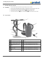 31
31
-
 32
32
-
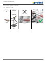 33
33
-
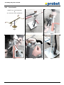 34
34
-
 35
35
-
 36
36
-
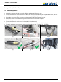 37
37
-
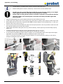 38
38
-
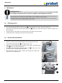 39
39
-
 40
40
-
 41
41
-
 42
42
-
 43
43
-
 44
44
-
 45
45
-
 46
46
-
 47
47
-
 48
48
-
 49
49
-
 50
50
-
 51
51
-
 52
52
-
 53
53
-
 54
54
-
 55
55
-
 56
56
-
 57
57
-
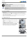 58
58
-
 59
59
-
 60
60
-
 61
61
-
 62
62
-
 63
63
-
 64
64
-
 65
65
-
 66
66
-
 67
67
-
 68
68
-
 69
69
-
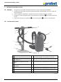 70
70
-
 71
71
-
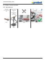 72
72
-
 73
73
-
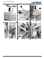 74
74
-
 75
75
-
 76
76
-
 77
77
-
 78
78
-
 79
79
-
 80
80
-
 81
81
-
 82
82
-
 83
83
-
 84
84
-
 85
85
-
 86
86
-
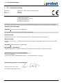 87
87
-
 88
88
-
 89
89
-
 90
90
-
 91
91
-
 92
92
-
 93
93
-
 94
94
-
 95
95
-
 96
96
-
 97
97
-
 98
98
-
 99
99
-
 100
100
-
 101
101
-
 102
102
-
 103
103
-
 104
104
-
 105
105
-
 106
106
-
 107
107
-
 108
108
-
 109
109
-
 110
110
-
 111
111
-
 112
112
-
 113
113
-
 114
114
-
 115
115
-
 116
116
-
 117
117
-
 118
118
-
 119
119
-
 120
120
-
 121
121
-
 122
122
-
 123
123
-
 124
124
-
 125
125
-
 126
126
-
 127
127
-
 128
128
-
 129
129
-
 130
130
-
 131
131
-
 132
132
-
 133
133
-
 134
134
-
 135
135
-
 136
136
-
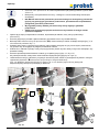 137
137
-
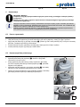 138
138
-
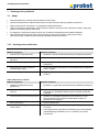 139
139
-
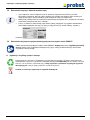 140
140
-
 141
141
-
 142
142
-
 143
143
-
 144
144


probst ALX-120 Manual de usuario
- Categoría
- Aspiradoras
- Tipo
- Manual de usuario
En otros idiomas
- français: probst ALX-120 Manuel utilisateur
- italiano: probst ALX-120 Manuale utente
- Deutsch: probst ALX-120 Benutzerhandbuch
- Nederlands: probst ALX-120 Handleiding
- polski: probst ALX-120 Instrukcja obsługi
Documentos relacionados
-
 probst RF-H Manual de usuario
-
 probst VPH-150-GREENLINE Manual de usuario
-
 probst FXAH-120-GRABO-PRO-LIFTER-GREENLINE Manual de usuario
-
 probst FXAH-120-GRABO-GREENLINE Manual de usuario
-
 probst FXAH-120-GRABO-PRO-LIFTER-GREENLINE Manual de usuario
-
 probst VPH-150-GREENLINE Manual de usuario
-
 probst SRG-UNI-3-K Manual de usuario
-
probst TSZ-UNI Manual de usuario
-
 probst KIG-I Manual de usuario
-
 probst FTZ-MULTI-15 Basic Device Manual de usuario


