probst VPH-150-GREENLINE Manual de usuario
- Categoría
- Pistolas de calor de potencia
- Tipo
- Manual de usuario

52710008 / 52710009
VPH-100 / VPH-150 GREENLINE
DE
I
Betriebsanleitung
GB
I
Operating Instructions
FR
I
Instructions d'emploi
IT
I
Istruzioni d’uso
NL
I
Bedrijfshandleiding
ES
I
Instrucciones de uso
PL
I
Instrukcja Obsługi


52710008 / 51720009
V8
Original Betriebsanleitung
VPH-100 / VPH-150 GREENLINE
DE
I
Betriebsanleitung

Bitte beachten Sie, dass das Produkt ohne vorliegende Betriebsanleitung in Landessprache
nicht eingesetzt / in Betrieb gesetzt werden darf. Sollten Sie mit der Lieferung des Produkts
keine Betriebsanleitung in Ihrer Landessprache erhalten haben, kontaktieren Sie uns bitte. In
Länder der EU / EFTA senden wir Ihnen diese kostenlos nach. Für Länder außerhalb der EU /
EFTA erstellen wir Ihnen gerne ein Angebot für eine Betriebsanleitung in Landessprache, falls
die Übersetzung nicht durch den Händler/Importeur organisiert werden kann.
Please note that the product may not be used / put into operation without these operating
instructions in the national language. If you did not receive operating instructions in your
national language with the delivery of the product, please contact us. In countries of the EU /
EFTA we will send them to you free of charge. For countries outside the EU / EFTA, we will be
pleased to provide you with an offer for an operating manual in the national language if the
translation cannot be organised by the dealer/importer.

Inhalt
52710008 / 51720009
2 / 28
DE
Inhalt
1 EG-Konformitätserklärung .................................................................................................................. 4
2 Sicherheit .............................................................................................................................................. 5
2.1 Sicherheitshinweise ......................................................................................................................... 5
2.2 Begriffsdefinitionen .......................................................................................................................... 5
2.3 Definition Fachpersonal/ Sachkundiger ........................................................................................... 5
2.4 Sicherheitskennzeichnung .............................................................................................................. 6
2.5 Persönliche Sicherheitsmaßnahmen ............................................................................................... 7
2.6 Schutzausrüstung ............................................................................................................................ 7
2.7 Unfallschutz ..................................................................................................................................... 7
2.8 Sicherheit im Betrieb ....................................................................................................................... 8
2.8.1 Allgemein .................................................................................................................................... 8
2.9 Funktions- und Sichtprüfung............................................................................................................ 9
2.9.1 Mechanik ..................................................................................................................................... 9
2.9.2 Elektrik ........................................................................................................................................ 9
3 Allgemeines ........................................................................................................................................ 10
3.1 Bestimmungsgemäßer Einsatz...................................................................................................... 10
3.2 Übersicht und Aufbau .................................................................................................................... 12
3.3 Technische Daten ......................................................................................................................... 12
4 Installation .......................................................................................................................................... 13
4.1 Mechanischer Anbau ..................................................................................................................... 13
4.1.1 Einhängeöse / Einhängebolzen ................................................................................................ 13
4.1.2 Lasthaken und Anschlagmittel .................................................................................................. 13
4.2 Montage des Radsatzes VPH-RS ................................................................................................. 14
4.3 Montage Höhenverstellbarer Anschlag VPH-RS-AS ..................................................................... 14
5 Einstellungen ...................................................................................................................................... 15
5.1 Einstellung des VPH und des Zubehörs ........................................................................................ 15
6 Bedienung ........................................................................................................................................... 16
6.1 Bedienelemente ............................................................................................................................ 16
6.2 Saugplatte ..................................................................................................................................... 16
6.3 Allgemein ...................................................................................................................................... 16
6.4 Batteriezustand ............................................................................................................................. 16
6.5 Aufnahme, Transport und Verlegung (Hebezeugbetrieb) .............................................................. 17
6.6 Aufnahme, Transport und Verlegung (Handbetrieb)...................................................................... 18
6.7 Fliesenverlegung ........................................................................................................................... 19
6.8 Beschädigung der Saugplatte ....................................................................................................... 19

EG-Konformitätserklärung
52710008 / 51720009
3 / 28
DE
7 Wartung und Pflege ........................................................................................................................... 20
7.1 Wartung ......................................................................................................................................... 20
7.1.1 Mechanik ................................................................................................................................... 20
7.2 Saugplatten / Reinigung ................................................................................................................ 21
7.3 Fehlersuche................................................................................................................................... 21
7.4 Reparaturen .................................................................................................................................. 22
7.5 Prüfungspflicht............................................................................................................................... 23
7.6 Hinweis zum Typenschild .............................................................................................................. 24
7.7 Hinweis zur Vermietung/Verleihung von PROBST-Geräten .......................................................... 24
8 Entsorgung / Recycling von Geräten und Maschinen..................................................................... 24
9 Vakuumpumpe .................................................................................................................................... 25
9.1 Allgemein ...................................................................................................................................... 25
9.2 Sicherheitshinweise ....................................................................................................................... 25
9.3 Beschreibung ................................................................................................................................ 26
9.3.1 Akku aufladen ........................................................................................................................... 26
9.4 Wartung ......................................................................................................................................... 27
9.5 Technische Daten ......................................................................................................................... 28
Änderungen gegenüber den Angaben und Abbildungen in der Betriebsanleitung sind vorbehalten.

EG-Konformitätserklärung
52710008 / 51720009
4 / 28
DE
1 EG-Konformitätserklärung
Bezeichnung:
Typ:
Artikel-Nr.:
VAKUUM-POWER-HANDY VPH-GREENLINE
VPH-100 / VPH-150 GREENLINE
52710008 / 51720009
Hersteller:
Probst GmbH
Gottlieb-Daimler-Straße 6
71729 Erdmannhausen, Germany
info@probst-handling.de
www.probst-handling.com
Die vorstehend bezeichnete Maschine entspricht den einschlägigen Vorgaben nachfolgender EU-Richtlinien:
2006/42/EG (Maschinenrichtlinie)
Folgende Normen und technische Spezifikationen wurden herangezogen:
DIN EN ISO 12100
Sicherheit von Maschinen - Allgemeine Gestaltungsleitsätze - Risikobeurteilung und Risikominderung
DIN EN ISO 13857
Sicherheit von Maschinen - Sicherheitsabstände gegen das Erreichen von Gefährdungsbereichen mit den oberen
und unteren Gliedmaßen
2014/30/EU (Elektromagnetische Verträglichkeit)
DIN EN 60204-1 (IEC 60204-1)
Sicherheit von Maschinen - Elektrische Ausrüstung von Industriemaschinen - Teil 1: Allgemeine Anforderungen
DIN EN 1012-1 / DIN EN 1012-2
Kompressoren und Vakuumpumpen; Sicherheitsanforderungen Teil 1 und 2.
Dokumentationsbevollmächtigter:
Name: Jean Holderied
Anschrift: Probst GmbH; Gottlieb-Daimler-Straße 6; 71729 Erdmannhausen, Germany
Unterschrift, Angaben zum Unterzeichner:
Erdmannhausen, 14.06.2023..........................................................................
(Eric Wilhelm, Geschäftsführer)

Sicherheit
52710008 / 51720009
5 / 28
DE
2 Sicherheit
2.1 Sicherheitshinweise
Lebensgefahr!
Bezeichnet eine Gefahr. Wenn sie nicht gemieden wird, sind Tod und schwerste Verletzungen die
Folge.
Gefährliche Situation!
Bezeichnet eine gefährliche Situation. Wenn sie nicht gemieden wird, können Verletzungen oder
Sachschäden die Folge sein.
Verbot!
Bezeichnet ein Verbot. Wenn es nicht eingehalten wird, sind Tod und schwerste Verletzungen, oder
Sachschäden die Folge.
Wichtige Informationen oder nützliche Tipps zum Gebrauch.
2.2 Begriffsdefinitionen
Greifbereich:
• gibt die minimalen und maximalen Produktabmaße des Greifgutes an, welche mit
diesem Gerät greifbar sind.
Greifgut (Greifgüter):
• ist das Produkt, welches gegriffen bzw. transportiert wird.
Öffnungsweite:
• setzt sich aus dem Greifbereich und dem Einfahrmaß zusammen.
Greifbereich + Einfahrmaß = Öffnungsbereich
Eintauchtiefe:
• entspricht der maximalen Greifhöhe von Greifgütern, bedingt durch die Höhe der
Greifarme des Gerätes.
Gerät:
• ist die Bezeichnung für das Greifgerät.
Produktmaß:
• sind die Abmessungen des Greifgutes (z.B. Länge, Breite, Höhe eines Produktes).
Eigengewicht:
• ist das Leergewicht (ohne Greifgut) des Gerätes.
Tragfähigkeit (WLL *):
• gibt die höchstzulässige Belastung des Gerätes (zum Anheben von Greifgütern) an.
*= WLL → (englisch:) Working Load Limit
Bodennaher Bereich:
• das Greifgut muss unmittelbar nach dem Aufnehmen (z.B. von einer Palette oder
von einem LKW) bis knapp über den Boden abgesenkt werden (ca. 0,5 m).
Greifgut zum Transportieren nur so hoch wie nötig anheben (Empfehlung ca. 0,5 m
über Boden).
2.3 Definition Fachpersonal/ Sachkundiger
Installations-, Wartungs-, und Reparaturarbeiten an diesem Gerät dürfen nur vom Fachpersonal oder Sachkundigen
durchgeführt werden!
Fachpersonal oder Sachkundige müssen für die folgenden Bereiche, soweit es für
dieses Gerät zutrifft, die notwendigen beruflichen Kenntnisse besitzen:
• für Mechanik
• für Hydraulik
• für Pneumatik
• für Elektrik

Sicherheit
52710008 / 51720009
6 / 28
DE
2.4 Sicherheitskennzeichnung
VERBOTSZEICHEN
Symbol
Bedeutung
Bestell-Nr.
Größe
Niemals unter schwebende Last treten. Lebensgefahr!
29040210
29040209
29040204
Ø 30 mm
Ø 50 mm
Ø 80 mm
Die angesaugte Last darf keinesfalls ohne zusätzliche Sicherung
durch die Lastsicherungskette angehoben und transportiert
werden.
2904.0765
100 x 70
mm
WARNZEICHEN
Symbol
Bedeutung
Bestell-Nr.
Größe
Quetschgefahr der Hände.
29040221
29040220
29040107
30 x 30 mm
50 x 50 mm
80 x 80 mm
GEBOTSZEICHEN
Symbol
Bedeutung
Bestell-Nr.
Größe
Jeder Bediener muss die Bedienungsanleitung für das Gerät mit
den Sicherheitsvorschriften gelesen und verstanden haben.
29040665
29040666
29041049
Ø 30 mm
Ø 50 mm
Ø 80 mm
Last mittig ansaugen. Mit entsprechender Vorrichtung
(höhenverstellbare Stütze)kann Last auch außermittig angesaugt
werden.
2904.0744
107 x 32
mm
Lastsicherungsketten müssen straff an der Last anliegen.
Lastsicherungsketten dürfen niemals locker unter der Last
hängen!
2904.0690
2904.0689
2904.0688
25 x 55 mm
70 x 41 mm
146 x 85 mm
BEDIENUNGSHINWEISE
Symbol
Bedeutung
Bestell-Nr.
Größe
Maximale Tragfähigkeit (WLL) der Saugplatte (optional)
29040575
80x40 mm
Maximale Tragfähigkeit (WLL) der Saugplatte.
29040207
80x35 mm
Aufkleber mit Gerätbezeichnung
29040129
200x50 mm

Sicherheit
52710008 / 51720009
7 / 28
DE
2.5 Persönliche Sicherheitsmaßnahmen
• Jeder Bediener muss die Bedienungsanleitung für das Gerät mit den Sicherheitsvorschriften
gelesen und verstanden haben.
• Das Gerät und alle übergeordneten Geräte in/an die das Gerät eingebaut ist, dürfen nur von dafür
beauftragten und qualifizierten Personen betrieben werden.
• Es dürfen nur Geräte mit Handgriffen manuell geführt werden.
Ansonsten besteht Verletzungsgefahr der Hände!
2.6 Schutzausrüstung
Die Schutzausrüstung besteht gemäß den
sicherheitstechnischen Anforderungen aus:
• Schutzkleidung
• Schutzhandschuhe
• Sicherheitsschuhe
2.7 Unfallschutz
• Arbeitsbereich für unbefugte Personen, insbesondere Kinder, weiträumig absichern.
• Vorsicht bei Gewitter – Gefahr durch Blitzschlag!
Je nach Intensität des Gewitters gegebenenfalls die Arbeit mit dem Geräte einstellen.
• Arbeitsbereich ausreichend beleuchten.
• Vorsicht bei nassen, angefrorenen, vereisten und verschmutzten Baustoffen!
Es besteht die Gefahr des Herausrutschens des Greifgutes. → UNFALLGEFAHR!

Sicherheit
52710008 / 51720009
8 / 28
DE
2.8 Sicherheit im Betrieb
2.8.1 Allgemein
• Das Arbeiten mit diesem Gerät darf nur in bodennahem Bereich erfolgen!
Im Hebezeugbetrieb: Die angesaugte Last muss unmittelbar nach dem Aufnehmen (z.B. von einer
Palette oder von einem LKW) bis knapp über den Boden abgesenkt werden (ca. 0,5 m).
Anschließend ist die Last durch die Lastsicherungskette zusichern und darf erst dann zur
Verlegestelle transportiert werden. Last zum Transportieren nur so hoch wie nötig anheben
(Empfehlung ca. 0,5 m über Boden). Das Schwenken des Gerätes über Personen hinweg ist
untersagt. Lebensgefahr!
• Das manuelle Führen ist nur bei Geräten mit Handgriffen erlaubt.
• Der Bediener darf den Steuerplatz nicht verlassen, solange das Gerät mit Ladung belastet ist und
muss die Ladung immer im Blick haben.
• Der Bediener muss das Manometer stets im Auge behalten. Last (z.B. Steinplatte) nur anheben
wenn der erforderliche Vakuum-Unterdruck erreicht ist. Wenn der Zeiger des Manometers sich in
den roten Bereich unter dem erforderlichen Vakuum-Unterdruck bewegt, Last sofort absetzen.
Lebensgefahr – Last wird herabfallen!
• Während des Betriebes ist der Aufenthalt von Personen im Arbeitsbereich verboten! Es sei denn es
ist unerlässlich. Bedingt durch die Art der Geräteanwendung, z.B. durch manuelles Führen des
Gerätes (an Handgriffen).
• Der Aufenthalt unter schwebender Last ist verboten. Lebensgefahr!
• Lasten niemals schräg ziehen oder schleifen.
• Die Last niemals außermittig ansaugen, ansonsten Kippgefahr.
• Last erst von der Saugplatte ablösen, wenn sie vollständig und sicher am Boden aufliegt oder steht.
Finger weg von der Last beim Lösen. Quetschgefahr!
• Die Tragfähigkeit und Nennweiten/Nenngrößen des Gerätes dürfen nicht überschritten werden.
• Festsitzende Lasten nicht mit dem Gerät losreißen.
• Ruckartiges Anheben oder Absenken des Gerätes mit und ohne Last ist verboten!
Unnötige Erschütterungen sind zu vermeiden. So wie das schnelle Fahren mit dem Trägergerät/
Hebezeug über unebenes Gelände!
Lebensgefahr: Last könnte dadurch herunterfallen, oder Lastaufnahmemittel beschädigt werden!
Generell darf mit angehobener Last nur mit Schrittgeschwindigkeit gefahren werden!

Sicherheit
52710008 / 51720009
9 / 28
DE
2.9 Funktions- und Sichtprüfung
2.9.1 Mechanik
• Das Gerät muss vor jedem Arbeitseinsatz auf Funktion und Zustand geprüft werden.
• Wartung, Schmierung und Störungsbeseitigung dürfen nur bei stillgelegtem Gerät erfolgen!
• Bei Mängeln, die die Sicherheit betreffen, darf das Gerät erst nach einer kompletten
Mängelbeseitigung wieder eingesetzt werden.
• Bei jeglichen Rissen, Spalten oder beschädigten Teilen an irgendwelchen Teilen des Gerätes,
muss sofort jegliche Nutzung des Gerätes gestoppt werden.
• Die Betriebsanleitung für das Gerät muss am Einsatzort jederzeit einsehbar sein.
• Das am Gerät angebrachte Typenschild darf nicht entfernt werden.
• Unlesbare Hinweisschilder (wie Verbots- und Warnzeichen) sind auszutauschen.
2.9.2 Elektrik
• Alle Elektroleitungen vor jedem Arbeitseinsatz auf korrekten Anschluss prüfen.
• Defekte Elektroteile im stromlosen Zustand von Fachpersonal austauschen lassen.
• Die Elektroleitungen dürfen keine Scheuerstellen aufweisen und sich bei Hub- und
Senkbewegungen an keinerlei hervorstehenden Kanten einhaken und somit abreisen.

Allgemeines
52710008 / 51720009
10 / 28
DE
3 Allgemeines
3.1 Bestimmungsgemäßer Einsatz
Das Gerät „VAKUUM-POWER-HANDY VPH-150-GREENLINE “ dient ausschließlich zum bodennahen Heben,
Transportieren und Verlegen von Natursteinen- und Betonplatten, Großpflaster, Drainfugensteine, Blockstufen
sowie Fliesen. Das zu hebende Gut darf keine porösen Oberflächen haben.
Das Gerät ist mit einer Einhängeöse für Kranhaken ausgerüstet.
Die angegebene Traglast wir nur bei einem Vakuumdruck von mind. -500 mbar erreicht!
Das Gerät kann nur senkrecht hängend eingesetzt werden.
Einige der Saugplatten, die an das Gerät angebaut werden können, reduzieren seine Tragfähigkeit.
Auf jeder Saugplatte ist die zulässige Traglast angegeben.
Überschreiten Sie niemals die angegebene Traglast!
Ohne Zubehör ist das Gerät immer von zwei Personen zu bedienen.
Mit entsprechendem Zubehör kann das Gerät auch von einer Person bedient werden.
Siehe dazu Kapitel „Übersicht und Aufbau“.
• Das Gerät darf nur für den in der Bedienungsanleitung beschriebenen bestimmungsgemäßen
Einsatz, unter Einhaltung der gültigen Sicherheitsvorschriften und unter Einhaltung der
dementsprechenden gesetzlichen Bestimmungen und den der Konformitätserklärung verwendet
werden.
• Jeder anderweitige Einsatz gilt als nicht bestimmungsgemäß und ist verboten!
• Die am Einsatzort gültigen gesetzlichen Sicherheits- und Unfallvorschriften müssen zusätzlich
eingehalten werden.
Der Anwender muss sich vor jedem Einsatz vergewissern, dass:
• das Gerät für den vorgesehenen Einsatz geeignet ist
• sich im ordnungsgemäßen Zustand befindet
• die zu hebenden Lasten für das Heben geeignet sind
In Zweifelsfällen setzen Sie sich vor der Inbetriebnahme mit dem Hersteller in Verbindung.
ACHTUNG: Das Arbeiten mit diesem Gerät darf nur in bodennahem Bereich erfolgen! (➔
Kapitel „Sicherheit im Betrieb“ und „Begriffsdefinitionen“)

Allgemeines
52710008 / 51720009
11 / 28
DE
• Die Last (Steinplatte) welche angesaugt und transportiert
werden soll, muss genügend Eigenstabilität aufweisen,
da ansonsten Bruchgefahr beim Anheben besteht!
• Steinplatten dürfen sich beim Anheben keinesfalls
durchbiegen – darauf ist besonders bei dünnen und
großformatigen Steinplatten zu achten!
• Generell dürfen Lasten (Steinplatten) nur mittig
angesaugt werden, da sonst die Last schief am Gerät
hängt, was zum Bruch der Last führen kann - speziell
beim Anheben von großformatigen Steinplatten mit einer
kleinen Saugplatte.
• Standardsaugplatten sind nicht für den Transport von
Glasscheiben geeignet!
Es dürfen nur Saugplatten des Herstellers Probst verwendet werden!
Einige der Saugplatten, die an das Gerät angebaut werden können, reduzieren seine Tragfähigkeit.
Auf jeder Saugplatte ist die zulässige Tragfähigkeit angegeben.
Es dürfen nur für das Gerät zugelassene Saugplatten verwendet werden!
Das Überschreiten der zulässigen und der angegeben Tragfähigkeit der Saugplatte ist strengstens
untersagt!
Gefahr: Herunterfallen der Last!
NICHT ERLAUBTE TÄTIGKEITEN:
Eigenmächtige Umbauten am Gerät oder der Einsatz von eventuell selbstgebauten Zusatzvorrichtungen
gefährden Leib und Leben und sind deshalb grundsätzlich verboten!
Die Tragfähigkeit (WLL) und Nennweiten/Greifbereiche des Gerätes dürfen nicht überschritten werden.
Alle nicht bestimmungsgemäßen Transporte mit dem Gerät sind strengstens untersagt:
• Transport von Menschen und Tieren.
• Transport von Baustoffpaketen, Gegenständen und Materialien, die nicht in dieser Anleitung
beschrieben sind.
• Das Anhängen von Lasten mit Seilen, Ketten o.ä. an das Gerät.

Allgemeines
52710008 / 51720009
12 / 28
DE
3.2 Übersicht und Aufbau
1
2
3
4
5
8
6
7
10
9
1. Handgriff
2. Einhängeöse
3. Akku-Adapterkabel mit Klemmen
4. Vakuumpumpe
5. Manometer
6. Luftfilter
7. Kettenkasten
8. Saugplatte
9. Radsatz VPH-RS, ermöglicht Bedienung durch eine Person (optional)
10. Anschlag für Radsatz VPH-RS-AS, für großformatige Fliesen (optional)
3.3 Technische Daten
Die genauen technischen Daten (wie z.B. Tragfähigkeit, Eigengewicht, etc.) sind dem Typenschild zu entnehmen.

Installation
52710008 / 51720009
13 / 28
DE
4 Installation
4.1 Mechanischer Anbau
Nur Original-Probst-Zubehör verwenden, im Zweifelsfall Rücksprache mit dem Hersteller halten.
Die Tragfähigkeit des Trägergerätes/Hebezeuges darf durch die Last des Gerätes, der optionalen
Anbaugeräte (Drehmotor, Einstecktasche, Kranausleger etc.) und die zusätzliche Last der Greifgüter
nicht überschritten werden!
Greifgeräte müssen immer kardanisch aufgehängt werden, so dass sie in jeder Position frei
auspendeln können.
Auf keinen Fall dürfen die Greifgeräte auf starre Weise mit dem Hebezeug/Trägergerät verbunden
werden!
Es kann in kurzer Zeit zum Bruch der Aufhängung führen. Tod, schwerste Verletzungen und
Sachschaden können die Folge sein!
Bei Verwendung des Gerätes an optionalen Anbaugeräten (wie Einstecktasche, Kranausleger etc.) ist
es aufgrund der möglichst niedrigen Bauweise des Gesamtgerätes (zur Vermeidung von
Hubhöhenverlust) nicht auszuschließen, dass bei pendelnder Aufhängung des Gerätes und
ungünstiger Positionierung bei Fahrbewegungen des Trägergerätes, das Gerät mit angrenzenden
Bauteilen zusammenstoßen kann. Dies ist durch geeignete Positionierung des Gerätes und
angepasster Fahrweise möglichst zu vermeiden. Daraus resultierende Schäden werden nicht im
Rahmen der Gewährleistung reguliert.
4.1.1 Einhängeöse / Einhängebolzen
Das Gerät ist mit einer Einhängeöse / Einhängebolzen ausgerüstet und kann somit an verschiedenste
Trägergräte/Hebezeuge angebracht werden.
Es ist darauf zu achten, dass die Einhängeöse / Einhängebolzen sicher mit dem Anschlagmittel
(Kranhaken, Schlupf etc.) verbunden ist und nicht abrutschen kann.
4.1.2 Lasthaken und Anschlagmittel
Das Gerät wird mit einem Lasthaken oder einem geeigneten Anschlagmittel am
Trägergerät/Hebezeug angebracht.
Es ist darauf zu achten, dass die einzelnen Kettenstränge nicht verdreht oder verknotet sind.
Bei der mechanischen Installation des Gerätes ist darauf zu achten, dass alle örtlich geltenden
Sicherheitsvorschriften eingehalten werden.

Installation
52710008 / 51720009
14 / 28
DE
4.2 Montage des Radsatzes VPH-RS
4.3 Montage Höhenverstellbarer Anschlag VPH-RS-AS

Einstellungen
52710008 / 51720009
15 / 28
DE
5 Einstellungen
5.1 Einstellung des VPH und des Zubehörs

Bedienung
52710008 / 51720009
16 / 28
DE
6 Bedienung
6.1 Bedienelemente
Hauptschalter - EIN/AUS - mit dem Hauptschalter können Sie die Pumpe ein- bzw. ausschalten.
Achtung! beim Ausschalten wird automatisch die Saugleitung entlüftet.
Beschreibung weiterer Bedienelemente siehe Anhang Betriebsanleitung Akku-Membranpumpe!
Zum Ansaugen und Lösen der Last:
Hauptschalter EIN = Last ansaugen, halten
Hauptschalter AUS = Last lösen (Füße vorher aus dem Gefahrenbereich bringen!)
6.2 Saugplatte
Die Saugplatte bringt das Vakuum auf die Last. Sie dient zum Heben unterschiedlicher Gegenstände.
Verwenden Sie nur die für das VPH zugelassene Saugplatte.
Überschreiten Sie nicht die zulässige Traglast der Saugplatte!
6.3 Allgemein
• Handtragegriffe des Gerätes nicht verlassen, solange eine Last gehoben wird.
• Lasten niemals schräg ziehen oder schleppen/schleifen.
• Festsitzende Lasten nicht mit dem VPH losreißen.
• Bei Energieausfall die Last wenn möglich sofort absetzen. Entfernen Sie sich sofort aus dem
Gefahrenbereich.
• Nur geeignete Lasten ansaugen und heben (Eigenstabilität und Oberflächendichte prüfen).
• Manometer stets im Auge behalten. Nie bei Vakuum unter - 0,5 bar anheben. Wenn der Zeiger des
Manometers sich in den roten Bereich unter - 0,5 bar bewegt, Last sofort absetzen..
• Werkstücke (Last) nur auf freier, ebener Fläche absetzen. Sie können sonst beim Lösen
verrutschen.
• Last erst lösen, wenn sie vollständig und sicher aufliegt oder steht. Finger weg von der Last beim
Lösen. Quetschgefahr!
6.4 Batteriezustand
Ladeanzeige:
gelb = vollständig geladen
grün = normaler Betriebszustand
rot-grün wechselnd = Akku schwach, Zeit zum Aufladen
rot = nicht betreiben, Akku leer

Bedienung
52710008 / 51720009
17 / 28
DE
6.5 Aufnahme, Transport und Verlegung (Hebezeugbetrieb)
Beim Verwenden des Gerätes im Hebezeugbetrieb muss die Lastsicherungskette im jeden Fall
verwendet werden!
1. Gerät direkt über der Last positionieren. Schrägziehen vermeiden und auf
gleichmäßige Lastverteilung achten.
2. Gerät auf die Last aufsetzen.
3. Gerät mittels Hauptschalter EIN/AUS einschalten.
4. Die Last wird angesaugt.
5. Manometer beobachten. Sobald -0,5 bar Unterdruck erreicht sind, können
Sie die Last anheben. Auf keinen Fall vorher heben, die Last würde
herabfallen.
Beim Anheben darauf achten, dass nur jeweils ein Stück des zu hebenden
Gutes angehoben wird.
Anhaftende andere Teile vorsichtig mit einem Schraubendreher ablösen,
bevor Sie das Teil weiter anheben.
Nicht mit den Händen lösen, Quetschgefahr!
6. Das Gerät mit der angesaugten Last etwas anheben (ca. 20 cm).
7. Lastsicherungskette A aus dem Kettenfach B entnehmen (siehe Abb.)
8. Lastsicherungskette unter der angehobenen Last durchwerfen / durchführen.
Dabei niemals unter die Last (Steinplatte) mit den Händen fassen! Quetschgefahr!
9. Lastsicherungskette auf der anderen Seite des Gerätes im Schlitz C straff einhängen (siehe Abb.)
10. Kettenende im Kettenfach B verstauen.
Die Lastsicherungskette muss straff an der Last anliegen, damit bei Vakuumausfall
oder -Verlust (z.B. bedingt durch Energieausfall) die Last durch die
Lastsicherungskette gehalten wird (siehe Abb.)
Lastsicherungskette darf niemals locker unter der Last hängen, da sonst Last bei
Vakuumausfall oder -Verlust (z.B. bedingt durch Energieausfall) herunterfallen
kann (siehe Abb.)
11. Nun das Gerät mit angesaugter Last zum Bestimmungsort transportieren.
12. Last vorsichtig absenken (ca. 20 cm Abstand zum Boden), Lastsicherungskette aushängen und unter Last
hervorziehen.
Dabei niemals unter die Last (Steinplatte) mit den Händen fassen! Quetschgefahr!
13. Lastsicherungskette wieder in das Kettenfach legen.
14. Last absenken und sicher auf freie, ebene Fläche ablegen, damit die Last nicht abrutschen oder kippen kann.
15. Mittels Hauptschalter EIN/AUS die Akku-Membranpumpe ausschalten.
Vorsicht! beim Ausschalten wird automatisch die Saugleitung entlüftet und somit das Vakuum
abgebaut. Füße immer aus dem Gefahrenbereich nehmen!

Bedienung
52710008 / 51720009
18 / 28
DE
6.6 Aufnahme, Transport und Verlegung (Handbetrieb)
1. Gerät direkt über der Last positionieren. Schrägziehen vermeiden und auf gleichmäßige Lastverteilung
achten.
2. Gerät auf die Last aufsetzen.
3. Gerät mittels Hauptschalter EIN/AUS einschalten.
4. Die Last wird angesaugt.
5. Manometer beobachten. Sobald -0,5 bar Unterdruck erreicht sind, können Sie die Last anheben. Auf
keinen Fall vorher heben, die Last würde herabfallen.
Beim Anheben darauf achten, dass nur jeweils ein Stück des zu hebenden Gutes angehoben wird.
Anhaftende andere Teile vorsichtig mit einem Schraubendreher ablösen, bevor Sie das Teil weiter
anheben.
Nicht mit den Händen lösen, Quetschgefahr!
6. Nun das Gerät mit angesaugter Last zum Bestimmungsort transportieren.
7. Last absenken und sicher auf freie, ebene Fläche ablegen, damit die Last nicht abrutschen oder kippen
kann.
8. Mittels Hauptschalter EIN/AUS die Akku-Membranpumpe ausschalten.
Vorsicht! beim Ausschalten wird automatisch die Saugleitung entlüftet und somit das Vakuum
abgebaut. Füße immer aus dem Gefahrenbereich nehmen!

Bedienung
52710008 / 51720009
19 / 28
DE
6.7 Fliesenverlegung
Empfohlene Gerätekonfiguration:
• VPH als Basisgerät +
• VPH-RS Radsatz +
• VPH-RS-AS Höhenverstellbarer Anschlag, über den die Fliese in unterschiedlichen
Winkelstellungen nach vorne geneigt angelegt werden kann
Beispiel für Fliesenverlegung
Nur mit der Verwendung des optionalen höhenverstellbaren Anschlags
VPH-RS-AS dürfen Lasten außermittig aufgenommen werden!
Ansonsten kann sich die Last ablösen oder brechen!
6.8 Beschädigung der Saugplatte
Verletzungsgefahr!
Gefahr durch herabfallende Last aufgrund von beschädigter Gummidichtung!
Zur Vermeidung von Beschädigungen (Risse, Materialabrieb) der Gummidichtung an der Saugplatte ist
folgendes zu beachten:
• Während dem Arbeitseinsatz muss darauf geachtet werden, dass die Saugplatte beim Anheben,
Absetzen oder Transportieren von Lasten nicht an anderen Lasten oder sonstigen Gegenständen
streift bzw. dagegen stößt.

Wartung und Pflege
52710008 / 51720009
20 / 28
DE
7 Wartung und Pflege
7.1 Wartung
Um eine einwandfreie Funktion, Betriebssicherheit und Lebensdauer des Gerätes zu gewährleisten,
sind die in der unteren Tabelle aufgeführten Wartungsarbeiten nach Ablauf der angegebenen Fristen
durchzuführen.
Es dürfen nur Original-Ersatzteile verwendet werden; ansonsten erlischt die Gewährleistung.
Alle Arbeiten dürfen nur in drucklosem, stromlosen und bei stillgelegtem Zustand des Gerätes
erfolgen!
7.1.1 Mechanik
WARTUNGSFRIST
Auszuführende Arbeiten
Erstinspektion nach
25 Betriebsstunden
• Sämtliche Befestigungsschrauben kontrollieren bzw. nachziehen
(darf nur von einem Sachkundigen durchgeführt werden).
Alle 50 Betriebsstunden
• Sämtliche Befestigungsschrauben nachziehen (achten Sie darauf, dass die
Schrauben gemäß den gültigen Anzugsdrehmomenten der zugehörigen
Festigkeitsklassen nachgezogen werden).
• Sämtliche vorhandene Sicherungselemente (wie Klappsplinte) auf einwandfreie
Funktion prüfen und defekte Sicherungselemente ersetzen. → 1)
• Alle Gelenke, Führungen, Bolzen und Zahnräder, Ketten auf einwandfreie
Funktion prüfen, bei Bedarf nachstellen oder ersetzen.
• Greifbacken (sofern vorhanden) auf Verschleiß prüfen und reinigen, bei Bedarf
ersetzen.
• Alle vorhandenen Gleitführungen, Zahnstangen, Gelenke von beweglichen
Bauteilen oder Maschinenbaukomponenten sind zur Reduzierung von
Verschleiß und für optimale Bewegungsabläufe einzufetten/ zu schmieren
(empfohlenes Schmierfett: Mobilgrease HXP 462).
• Alle Schmiernippel (sofern vorhanden) mit Fettpresse schmieren.
Mindestens 1x pro Jahr
(bei harten
Einsatzbedingungen
Prüfintervall verkürzen)
• Kontrolle aller Aufhängungsteile, sowie Bolzen und Laschen. Prüfung auf
Risse, Verschleiß, Korrosion und Funktionssicherheit durch einen
Sachkundigen.
1)

Wartung und Pflege
52710008 / 51720009
21 / 28
DE
7.2 Saugplatten / Reinigung
• Saugplatte mindestens einmal täglich von anhaftenden Gegenständen, Schmutz und Staub reinigen.
Schwammgummi mit Druckluft und/oder Wasserstrahl reinigen.
• (Sofern vorhanden: Nut in Dichtlippe mit Tuch auswischen und/oder mit Druckluft ausblasen.)
• Beschädigte oder verschlissene Saugplatte (Risse, Löcher, Wellenbildung) sofort austauschen.
• Verwenden Sie zur Reinigung des Gerätes Kaltreiniger (kein Waschbenzin oder ätzende
Flüssigkeiten verwenden, der Saugschlauch würde dadurch undicht oder zerstört).
7.3 Fehlersuche
Fehler
Ursache
Abhilfe
Unterdruck von -0,5 bar nicht
erreicht
Werkstück hat Risse,
Aussparungen oder ist porös
Werkstück nicht zum Ansaugen mit diesem Gerät
geeignet
Schwammgummi ist beschädigt
Schwammgummi austauschen
Manometer ist defekt
Manometer austauschen
Schlauch, Verschraubungen
undicht
Bauteile austauschen
Kein Vakuum vorhanden /
VPH läuft nicht an
Batterie
Batterieladezustand kontrollieren
Batterieladegerät lädt nicht
Schalter am Ladegerät auf 12V stellen
Sicherung kontrollieren
Kontrollieren ob Sicherung auf korrekten Wert
eingestellt ist (8 A) und kein Vakuumdruckverlust
hat.
Dichtgummi
Dichtgummi um Saugplatte kontrollieren.
Gegebenfalls Dichtgummi im Kantenbereich, Nut
reinigen.
Dichtgummi nicht an Saugplatte ankleben
Verbindung kontrollieren
Verbindung zwischen Vakuumschlauch und
Saugplatte kontrollieren.
Kontrollieren dass Verbindung fest angezogen ist
und sich nicht lockern kann.
Luftfilter
Luftfilter, Verbindungen Schlauchschellen etc.
kontrollieren und sicher stellen, dass alle gut
befestigt sind.
EIN/-AUS Schalter
Kontrollieren, ob EIN/-AUS Schalter richtig
funktioniert.
Magnet-Ventil
Kontrollieren, ob die Kabel am Magnet-Ventil
richtig angeschlossen sind.

Wartung und Pflege
52710008 / 51720009
22 / 28
DE
Magnet-Ventil
Kontrollieren, ob Diode am Magnetventil (1N4001
etc.) einen Kurzschluss hat, notfalls austauschen
Leitungen
Alle Leitungen der Vakuumpumpe auf
Beschädigung kontrollieren.
Fremdkörper
Kontrollieren, ob an Vakuumpumpe ein
Unterdruck vorhanden ist und das keine
Fremdkörper eingesogen wurden
Last kann nicht angesaugt
werden.
Vorgeschriebener Unterdruck
kann nicht mehr erreicht
werden.
Unterdruck baut sich beim
Abschalten des Gerätes zu
schnell ab.
Undichtigkeit an Saugplatte durch
abgelagerten Schmutz zwischen
Gummidichtung u. Saugplatte.
Schwammgummidichtung
verschlissen oder porös (Alterung
nach Einwirkung von UV Strahlung)
Gummidichtung von Saugplatte entfernen.
Saugplatte u. Schlitz in Gummidichtung reinigen.
Gummidichtung auf Saugplatte wieder aufziehen
u. befestigen.
Gegebenenfalls Gummidichtung austauschen.
7.4 Reparaturen
• Reparaturen am Gerät dürfen nur von Personen durchgeführt werden, die die dafür notwendigen
Kenntnisse und Fähigkeiten besitzen.
• Vor der Wiederinbetriebnahme muss eine außerordentliche Prüfung durch einen
Sachverständigen durchgeführt werden.

Wartung und Pflege
52710008 / 51720009
23 / 28
DE
7.5 Prüfungspflicht
• Der Unternehmer hat dafür zu sorgen, dass das Gerät mindestens jährlich durch einen
Sachkundigen geprüft und festgestellte Mängel sofort beseitigt werden (→ DGUV Regel 100-500).
• Die dementsprechenden gesetzlichen Bestimmungen u. die der Konformitätserklärung sind zu
beachten!
• Die Durchführung der Sachkundigenprüfung kann auch durch den Hersteller Probst GmbH
erfolgen. Kontaktieren Sie uns unter: service@probst-handling.de
• Wir empfehlen, nach durchgeführter Prüfung und Mängelbeseitigung des Gerätes die Prüfplakette
„Sachkundigenprüfung/ Expert inspection“ gut sichtbar anzubringen (Bestell-Nr.: 29040056+Tüv-
Aufkleber mit Jahreszahl).
Die Sachkundigenprüfung ist unbedingt zu dokumentieren!
Gerät
Jahr
Datum
Sachkundiger
Firma

Entsorgung / Recycling von Geräten und Maschinen
52710008 / 51720009
24 / 28
DE
7.6 Hinweis zum Typenschild
• Gerätetyp, Gerätenummer und Baujahr sind wichtige Angaben zur Identifikation des Gerätes. Sie
sind bei Ersatzteilbestellungen, Gewährleistungsansprüchen und sonstigen Anfragen zum Gerät
stets mit anzugeben.
• Die maximale Tragfähigkeit (WLL) gibt an, für welche maximale Belastung das Gerät ausgelegt ist.
Die maximale Tragfähigkeit (WLL) darf nicht überschritten werden.
• Das im Typenschild bezeichnete Eigengewicht ist bei der Verwendung am Hebezeug/Trägergerät
(z.B. Kran, Kettenzug, Gabelstapler, Bagger...) mit zu berücksichtigen.
Beispiel:
7.7 Hinweis zur Vermietung/Verleihung von PROBST-Geräten
Bei jeder Verleihung/Vermietung von PROBST-Geräten muss unbedingt die dazu gehörige Original-
Betriebsanleitung mitgeliefert werden (bei Abweichung der Sprache des jeweiligen Benutzerlandes,
ist zusätzlich die jeweilige Übersetzung der Original-Betriebsanleitung mit zuliefern)!
8 Entsorgung / Recycling von Geräten und Maschinen
Das Produkt darf nur von qualifiziertem Fachpersonal außer Betrieb genommen und zur Entsorgung/
zum Recyclen vorbereitet werden. Entsprechend vorhandene Einzelkomponenten (wie Metalle,
Kunststoffe, Flüssigkeiten, Batterien/Akkus etc.) müssen gemäß den national/ länderspezifisch
geltenden Gesetzen und Entsorgungsvorschriften entsorgt/recycelt werden!
Das Produkt darf nicht im Hausmüll entsorgt werden!

Vakuumpumpe
52710008 / 51720009
25 / 28
DE
9 Vakuumpumpe
9.1 Allgemein
Diese Vakuumpumpe ist mit einem Blei - Akku 12 Volt 6,5 Ah ausgerüstet die Pumpe wird mit dem eingebauten Blei
- Akku betrieben.
Über ein Ladekontroll - System kann man den Ladezustand des Blei - Akkus erkennen
9.2 Sicherheitshinweise
• Die Spannung muss mit den Angaben auf dem Typenschild der Vakuumpumpe übereinstimmen.
• Die Pumpe darf nur mit 12 Volt Gleichstrom betrieben werden.
• Ziehen Sie vor allen Arbeiten an dem Gerät, einschließlich beim Wechseln vom Förderschlauch den Stecker aus
der Steckdose.
• Anschlussleitungen müssen in einwandfreiem Zustand sein. Beschädigte Teile sofort ersetzen.
• Nur Original - Ersatzteile verwenden.
• Bei Regen oder Feuchtigkeit das Gerät nicht ans Netz anschließen.
• Beim Öffnen von Abdeckungen oder Entfernen von Teilen, außer wenn diese von Hand möglich ist, können
spannungsführende Teile freigelegt werden.
• Es können auch Anschlussstellen spannungsführend sein.
Vor Wartung, einer Instandsetzung oder einem Austausch von Teilen oder Baugruppen, muss das Gerät von
allen Spannungsstellen getrennt werden, wenn ein Öffnen des Gerätes erforderlich ist.
• Arbeiten Sie mit dem Gerät nicht in Räumen oder bei widrigen Umgebungsbedingungen, in/bei welchen Gase,
Dämpfe oder Staub vorhanden sind oder vorhanden sein können.
• Gerät vor Nässe und Feuchtigkeit schützen.
Wenn anzunehmen ist, dass ein gefahrloser Betrieb nicht mehr möglich ist, so ist das Gerät außer Betrieb zu setzen
und gegen unbeabsichtigten Betrieb zu sichern. Es ist anzunehmen, dass ein gefahrloser Betrieb nicht mehr möglich
ist wenn:
• das Gerät sichtbare Beschädigungen aufweist;
• das Gerät nicht mehr arbeitet;
• nach längerer Lagerung und ungünstigen Verhältnissen;
• nach schweren Transportschäden.
Das Gerät niemals gleich einschalten, wenn es von einem kalten in einen warmen Raum gebracht wird.
Das dabei entstandene Kondenswasser kann unter Umständen Ihr Gerät zerstören.
Das Gerät uneingeschaltet auf Zimmertemperatur kommen lassen.

Vakuumpumpe
52710008 / 51720009
26 / 28
DE
9.3 Beschreibung
Das Gerät besteht im Wesentlichen wie folgt beschrieben:
• robustes Aluminium - Gehäuse, mit Winkelhalter zur Befestigung an Probst-Ständer.
• zwei Stück 12 Volt Membranpumpen.
• Hauptschalter - Ein/Aus Funktion - mit dem Hauptschalter können Sie die Pumpe Ein-
• bzw. Ausschalten, beim Ausschalten wird automatisch die Saugleitung entlüftet.
• Sicherungshalter mit Feinsicherung
• Die Vakuumpumpe ist mit einem Ladekontroll - System ausgestattet, drei LED signalisiert den Ladezustand des
eingebauten Akkus.
• Gelbe LED über 14,5 Volt Spannung → Akku überladen
• Grüne LED 11,5 bis 14,5 Volt Spannung → Normal
• Rote LED unter 11,5 Volt Spannung → Akku entladen
An dem Geräte - Unterteil befindet sich eine Steckbuchse, über diese Steckbuchse wird der Akku - im Gerät
geladen, ohne das er ausgebaut wird muss.
Geeignetes Ladegerät benützen das den Akku vor Überladung schützt.
Am Geräteunterteil befindet sich ein Anschluss für Saugbetrieb, dort wird der beigelegt
Saugschlauch mit Filter aufgesteckt, das andere Schlauchende wird an der Saugplatte angebracht.
Auf dem Filterelement ist eine Pfeilmarkierung die den Luftstrom angibt. Es ist zu beachten, dass der Pfeil zur
Vakuumpumpe zeigt.
9.3.1 Akku aufladen
Damit die Pumpe einwandfrei arbeitet ist es wichtig, dass der Blei - Akku immer ausreichend geladen ist.
Akku aufladen:
Hierbei wie folgt vorgehen:
• Hauptschalter in - 0 – Stellung schalten.
• Zuleitungsschläuchen abziehen. (Saugschlauch)
• Ladegerät an dem Unterteil in die eingebaute Steckbuchse einstecken.
• Ladegerät am Netz 220Volt einstecken.
• Nach erfolgtem Ladevorgang Ladegerät abklemmen.
• Anschlussschläuche aufstecken, Pumpe am Hauptschalter einschalten (wenn alles in Ordnung ist leuchtet die
grüne LED von der Ladekontrolle auf)
• Sobald der eingebaute Akku unter 11,5 Volt absinkt leuchtet die rote LED auf, dann Akku neu laden.
Sowie Sie mit Ihrer Arbeit fertig sind schalten Sie das Gerät ab. Und entfernen die angebrachten Schläuche.
(Vorschriften beachten)

Vakuumpumpe
52710008 / 51720009
27 / 28
DE
9.4 Wartung
Grundsätzlich ist das Gerät wartungsfrei.
Für die Vakuumpumpe sind alle erforderlichen Ersatzteile für Instandsetzung erhältlich.
Reparaturen sollten nur durch einen autorisierten Fachbetrieb durchgeführt werden.
Vor Beginn der Reparaturarbeiten Spannungsversorgung unterbrechen.
Verschleißteile sind in erster Linie die Membrane. Beim Auswechseln der Membrane sind
zweckmäßigerweise die Ventile und die Dichtungen auch zu ersetzten.
Bei Bedarf empfiehlt es sich, dass geeignete Filter einsetzt werden. Dadurch kann die Standzeit der Pumpe
wesentlich verlängern werden.
ES IST DARAUF ZU ACHTEN, DASS DER AKKU NIE GANZ ENTLADEN WIRD.
WENN SIE DAS GERÄT NICHT BETREIBEN ENTLÄDT SICH DER AKKU TROTZDEM.
IN DIE PUMPE DÜRFEN KEINE FLÜSSIGEN ODER FESTE STOFFE GELANGEN.

Vakuumpumpe
52710008 / 51720009
28 / 28
DE
9.5 Technische Daten
Pumpe/Magnetventil
Pumpentyp
7012 V (2 Stück)
Betriebsspannung
12 Volt DC
Stromaufnahme
1,4 A
Förderleistung
18 NL/min.
Endvakuum mind.
70 %
2/2 Wege Magnetventil
12V 6,5 Watt Spule
Teile / Gerät
Membrane
NBR Perbunan
Ventile
Neopren
Pumpengehäuse
glasfaser verstärktem Polyamid
Magnetventilgehäuse
Messing
Schläuche innen
Silikon
Schläuche außen
PVC Gewebeschlauch
Blei - Akku
Type
12V6,5Ah
Ladespannung FLOAT in
V/Zelle
2,3-2,35
Ladespannung Zyklen in
V/Zelle
2,4-2,45
Transport
Gefahrgutverordnung Straße GGVS - kein Gefahrgut
Gefahrgutverordnung Eisenbahn GGVE - kein Gefahrgut

Probst GmbH Telefon +49 7144 3309-0 www.probst-handling.com
Gottlieb-Daimler-Straße 6 Fax +49 7144 3309-50 info@probst-handling.de
71729 Erdmannhausen, Germany
Wartungsnachweis
Garantieanspruch für dieses Gerät besteht nur bei Durchführung der vorgeschriebenen Wartungsarbeiten
(durch eine autorisierte Fachwerkstatt)! Nach jeder erfolgten Durchführung eines Wartungsintervalls muss
unverzüglich dieser Wartungsnachweis (mit Unterschrift u. Stempel) an uns übermittelt werden. 1)
1)per E-Mail an: service@probst-handling.de / per Fax oder Post
Betreiber:
_ _ _ _ _ _ _ _ _ _ _ _ _
Gerätetyp:
_ _ _ _ _ _ _ _ _ _ _ _ _
Artikel-Nr.:
_ _ _ _ _ _ _ _ _ _ _ _ _
Geräte-Nr.:
_ _ _ _ _ _ _ _ _ _ _ _ _
Baujahr:
_ _ _ _
Wartungsarbeiten nach 25 Betriebsstunden
Datum:
Art der Wartung:
Wartung durch Firma:
Stempel
………………………………………
Name / Unterschrift
Wartungsarbeiten nach 50 Betriebsstunden
Datum:
Art der Wartung:
Wartung durch Firma:
Stempel
………………………………………
Name / Unterschrift
Wartung durch Firma:
Stempel
………………………………………
Name / Unterschrift
Wartung durch Firma:
Stempel
………………………………………
Name / Unterschrift
Wartungsarbeiten 1x jährlich
Datum:
Art der Wartung:
Wartung durch Firma:
Stempel
………………………………………
Name / Unterschrift
Wartung durch Firma:
Stempel
………………………………………
Name / Unterschrift
DE


52710008 / 51720009
V8
Translation of original operating instructions
VPH-100 / VPH-150 GREENLINE
GB
I
Operating Instructions

Bitte beachten Sie, dass das Produkt ohne vorliegende Betriebsanleitung in Landessprache
nicht eingesetzt / in Betrieb gesetzt werden darf. Sollten Sie mit der Lieferung des Produkts
keine Betriebsanleitung in Ihrer Landessprache erhalten haben, kontaktieren Sie uns bitte. In
Länder der EU / EFTA senden wir Ihnen diese kostenlos nach. Für Länder außerhalb der EU /
EFTA erstellen wir Ihnen gerne ein Angebot für eine Betriebsanleitung in Landessprache, falls
die Übersetzung nicht durch den Händler/Importeur organisiert werden kann.
Please note that the product may not be used / put into operation without these operating
instructions in the national language. If you did not receive operating instructions in your
national language with the delivery of the product, please contact us. In countries of the EU /
EFTA we will send them to you free of charge. For countries outside the EU / EFTA, we will be
pleased to provide you with an offer for an operating manual in the national language if the
translation cannot be organised by the dealer/importer.

Contents
52710008 / 51720009
2 / 28
GB
Contents
1 EC-Declaration of Conformity / UKCA-Declaration of Conformity .................................................... 4
2 Safety ....................................................................................................................................................... 5
2.1 Safety symbols ................................................................................................................................. 5
2.2 Explanation of basic concepts .......................................................................................................... 5
2.3 Definition skilled worker / specialist .................................................................................................. 5
2.4 Safety Marking ................................................................................................................................. 6
2.5 Personal safety requirements .......................................................................................................... 7
2.6 Protective equipment ........................................................................................................................ 7
2.7 Accident prevention .......................................................................................................................... 7
2.8 Safety at work ................................................................................................................................... 8
2.8.1 General ........................................................................................................................................ 8
2.9 Function Control ............................................................................................................................... 9
2.9.1 General ........................................................................................................................................ 9
2.9.2 Electric ......................................................................................................................................... 9
3 General .................................................................................................................................................. 10
3.1 Authorized use ............................................................................................................................... 10
3.2 Survey and construction ................................................................................................................. 12
3.3 Technical data ................................................................................................................................ 12
4 Installation ............................................................................................................................................. 13
4.1 Mechanical connection ................................................................................................................... 13
4.1.1 Lifting eye / Suspension bolt ...................................................................................................... 13
4.1.2 Load hooks and lifting tackle ...................................................................................................... 13
4.2 Assembly of the Wheel Set VPH-RS ............................................................................................. 14
4.3 Assembly of Stop for Wheel Set VPH-RS-AS ................................................................................ 14
5 Adjustments .......................................................................................................................................... 15
5.1 Adjustment of VPH and the assembly ............................................................................................ 15
6 Operation ............................................................................................................................................... 16
6.1 Operating Elements ........................................................................................................................ 16
6.2 Suction Plate .................................................................................................................................. 16
6.3 General ........................................................................................................................................... 16
6.4 Battery ............................................................................................................................................ 16
6.5 Lifting, Transport and Installation (hoist operation) ........................................................................ 17
6.6 Lifting, Transport and Installation (manual operation) .................................................................... 18
6.7 Tile laying ....................................................................................................................................... 19
6.8 Damages of suction plate ............................................................................................................... 19

EC-Declaration of Conformity / UKCA-Declaration of Conformity
52710008 / 51720009
3 / 28
GB
7 Maintenance and care .......................................................................................................................... 20
7.1 Maintenance ................................................................................................................................... 20
7.1.1 Mechanics .................................................................................................................................. 20
7.2 Suction plate ................................................................................................................................... 21
7.3 Fault finding .................................................................................................................................... 21
7.4 Repairs ........................................................................................................................................... 22
7.5 Safety procedures .......................................................................................................................... 23
7.6 Hints to the type plate ..................................................................................................................... 24
7.7 Hints to the renting/leasing of PROBST devices ........................................................................... 24
8 Disposal / recycling of devices and machines .................................................................................. 24
9 Vacuum pump ....................................................................................................................................... 25
9.1 General ........................................................................................................................................... 25
9.2 Safety Advice ................................................................................................................................. 25
9.3 Description ..................................................................................................................................... 26
9.3.1 Charge battery ........................................................................................................................... 26
9.4 Maintenance ................................................................................................................................... 27
9.5 Technical Data ............................................................................................................................... 28
We hereby reserve the right to make changes to the information and illustrations in the operating instructions.

EC-Declaration of Conformity / UKCA-Declaration of Conformity
52710008 / 51720009
4 / 28
GB
1 EC-Declaration of Conformity / UKCA-Declaration of Conformity
Description:
Type:
Order number:
VAKUUM-POWER-HANDY VPH-GREENLINE
VPH-100 / VPH-150 GREENLINE
52710008 / 51720009
Manufacturer:
Probst GmbH
Gottlieb-Daimler-Straße 6
71729 Erdmannhausen, Germany
www.probst-handling.com
Importer:
Probst Ltd
Unit 2 Fletcher House
Stafford Park 17
Telford Shropshire TF3 3DG, United Kingdom
www.probst-handling.co.uk
The machine described above complies with the relevant requirements of the following EU directives:
The object of the declaration described above is in conformity with the relevant UK-Regulations and UK-Guidelines:
EC-machinery directive 2006/42/EC (Reference: OJ L 157, 09.06.2006)
UK-Regulation: Supply of Machinery (Safety) Regulations 2008 (SI 2008 No. 1597)
The following standards and technical specifications were used:
DIN EN ISO 12100
Safety of machinery - General principles for design - Risk assessment and risk reduction
UK-Regulation: BS EN ISO 12100-1:2003+A1:2009
DIN EN ISO 13857
Safety of machinery - safety distances to prevent hazard zones being reached by upper and lower limbs.
UK-Regulation: BS EN ISO 13857:2019
2014/30/EU (Electromagnetic compatibility) / (Reference: OJ L 96, 29.03.2014)
UK-Regulation: Electromagnetic Compatibility Regulations 2016 (SI 2016 No. 1091)
DIN EN 60204-1 (IEC 60204-1)
Safety of machinery, electrical equipment of industrial machines. Part 1: General requirements.
UK-Regulation: BS EN 60204-1:2018
DIN EN 1012-1 / DIN EN 1012-2
Compressors and vacuum pumps; Safety requirements part 1 and 2.
UK-Regulation: BS EN 1012-1:2010
Authorized person for EC-documentation:
Name: Jean Holderied
Address: Probst GmbH; Gottlieb-Daimler-Straße 6; 71729 Erdmannhausen, Germany
Authorized person for UK-documentation:
Name: Nigel Hughes
Address: Probst Ltd ; Unit 2 Fletcher House; Stafford Park 17; Telford Shropshire TF3 3DG, United Kingdom
Signature, information to the subscriber:
Erdmannhausen, 15.06.2023..........................................................................
(Eric Wilhelm, Managing Director)

Safety
52710008 / 51720009
5 / 28
GB
2 Safety
2.1 Safety symbols
Danger to life!
Identifies imminent hazard. If you do not avoid the hazard, death or severe injury will result.
Hazardous situation!
Identifies a potentially hazardous situation. If you do not avoid the situation, injury or damage to
property can result.
Prohibition!
Identifies imminent a prohibition. If you do not avoid the prohibition, death and severe injury, or damage
to property will result.
Important information or useful hints for the usage.
2.2 Explanation of basic concepts
Gripping range:
• specify the minimum and maximum product measurements of the gripping good,
which can be gripped with this device.
Gripping good(s):
• is the product, which will be gripped or transported.
Opening width:
• consists of the gripping range and the measure to drive over the gripping good.
gripping range + measure to drive over the gripping good = opening width
Immersion depth:
• is the maximum gripping height of gripping goods, conditional of the height of the
gripping arms of the device.
Device:
• is the description for the gripping device.
Product dimensions:
• Are the dimensions of the gripping good (e.g. length, breadth, height
of the product).
Dead weight:
• is the own weight (without gripping good) of the device.
Carrying
capacity/working load
limit (WLL*):
• specify the maximum possible load of the device (for lifting of gripping goods).
*= WLL → (english:) Working Load Limit
Area in proximity to the
ground:
• the gripping good must be lowered to just above the ground (approx. 0.5 m)
immediately after being picked up (e.g. from a pallet or from a truck). For transport, lift
the gripping good only as high as necessary (recommendation approx. 0.5 m above
the ground).
2.3 Definition skilled worker / specialist
Only skilled workers or specialists are allowed to carry out the installation-, maintenance-, and repair work on this
device!
Skilled workers or specialists must have for the following points (if it applies for
this device), the necessary professional knowledge.
• for mechanic
• for hydraulics
• for pneumatics
• for electrics

Safety
52710008 / 51720009
6 / 28
GB
2.4 Safety Marking
PROHIBITION SIGN
Symbol
Meaning
Order-No.
Size
It is not allowed to stand under hanging loads. Danger to life!
29040210
29040209
29040204
Ø 30 mm
Ø 50 mm
Ø 80 mm
The sucked load must never be lifted and transported without
additional securing by the load-securing-chain.
2904.0765
100 x 70
mm
WARNING SIGN
Symbol
Meaning
Order-No.
Size
Danger of squeezing the hands.
29040221
29040220
29040107
30 x 30 mm
50 x 50 mm
80 x 80 mm
REGULATORY SIGN
Symbol
Meaning
Order-No.
Size
Each operator must have read and understood the operating
instructions (and all safety instructions).
29040665
29040666
29041049
Ø 30 mm
Ø 50 mm
Ø 80 mm
Loads have to be sucked in centered. With a suitable device (height
adjustable stop) loads can also be sucked in eccentrically.
2904.0744
107 x 32
mm
Load-securing-chains has to fit tightly to the load.
Load-securing-chains should never hang loosely under the load!
2904.0690
2904.0689
2904.0688
25 x 55 mm
70 x 41 mm
146 x 85 mm
OPERATING INFORMATIONS
Symbol
Meaning
Order-No.
Size
Maximum working load limit of the suction plate (VPH-100)
29040575
80 x 40 mm
Maximum working load limit of the suction plate (VPH-150)
29040207
80 x 35 mm
Label with device title
29040129
200 x 50
mm

Safety
52710008 / 51720009
7 / 28
GB
2.5 Personal safety requirements
Each operator must have read and understood the operating instructions (and all safety instructions).
Only qualified, authorized personal is allowed to operate the device and all devices which are
connected (lifting device/carrier).
The manual guiding is only allowed for devices with handles.
Otherwise there is a risk of injury to the hands!
2.6 Protective equipment
The protective equipment must consist, according to the safety
regulations of the following parts:
• Protective clothing
• Safety gloves
• Safety shoes
2.7 Accident prevention
• The workplace has to be covered for unauthorized persons, especially children.
• Caution at thunderstorm - danger of lightning!
Depending on the intensity of the thunderstorm, stop working with the device if necessary.
• The workplace must be sufficiently illuminated.
• Be careful with wet, frozen, iced and dirty building materials! There is a danger of the
gripping material slipping out. → DANGER OF ACCIDENT!

Safety
52710008 / 51720009
8 / 28
GB
2.8 Safety at work
2.8.1 General
• Working with this device is only permitted in proximity to the ground.
The sucked load must never be lifted more than 1.8 m (measured from the top edge of the
load to the ground). Swinging the device over persons is prohibited. Danger to life!
• The manual guiding of is only allowed for devices with handles.
• The operator is not allowed to leave the control unit as long as the vacuum lifting device loaded with
load (stone slab). The load must always be in the range of vision of the operator.
• Always keep an eye on the vacuum gauge. Never lift loads when the vacuum is below the required
under pressure (mbar). If the pointer of the pressure gauge moves into the red danger zone, lower
the load immediately! Danger! Load could fall down!
• While using the vacuum lifting device is the stay of persons in the working area forbidden. Except it
is indispensable. Caused of the way of using the vacuum lifting device , e.g. if the device must be
leaded by hand.
• While using the vacuum lifting device be sure that there are no persons in the working area. Danger
to Life!!
• The device must never be subjected to a force acting in a lateral direction due to diagonal pulling.
• Do not lift any components off-centre, because that could fall down. Danger of tilting!
• Release the load only when it is completely safely resting on the surface. Keep fingers away from
the load when you release it as they can be crushed!
• The carrying capacity / working load limit (WLL) and the nominal width the vacuum lifting device
must not be exceeded.
• Do not pull out stuck or tightened loads with the device.
The jerky raising or lowering of the device with or without load is prohibited!
Unnecessary vibrations must be avoided. Just like driving fast with the carrier/ hoist over uneven terrain!
Danger to life: Load could fall off or load handling equipment could be damaged!
In general, only drive at walking speed with the load lifted!

Safety
52710008 / 51720009
9 / 28
GB
2.9 Function Control
2.9.1 General
• Before every usage of the device check the functions and the working condition.
• Maintenance and lubrication are only permitted when device is shut down!
• Do not use the device, until all faults which can cause safety hazards are removed.
• If there are any cracks, splits or damaged parts on any parts of the device, immediately stop using
it.
• The operating instructions must be available at the workplace every time.
• Do not remove the type plate of the machine.
• Unrecognisable information signs (such as regulatory or prohibition signs) must be replaced.
2.9.2 Electric
• Check all electric cables for connection before each use.
• Defective electrical parts may be exchanged only by qualified personnel in the dead condition.
• The electric cables must be free of breaks and abrasion. Take care that there are no outstanding
edges, where the hoses could get stuck.

General
52710008 / 51720009
10 / 28
GB
3 General
3.1 Authorized use
The device “VACUUM-POWER-HANDY VPH” is only for lifting, transporting and installing natural stone and concrete
slabs, large slabs, drain joint stones, steps, as well as tiles in close proximity to the ground. The goods to be lifted
must have no porous surfaces.
The device is equipped with a suspension lug for crane hook.
The stated maximum load can only be achieved with a vacuum of at least 500 mbar!
The device can only be used in a vertical hanging.
Some of the suction plates, which can be attached to the device, reduce its carrying capacity.
The working load limit (WLL) is stated on each suction plate.
Never exceed the working load limit!
Without additional accessoires the device has to pe operated by two persons.
With suitable equipment the device can be operated by one person.
For more information see Chapter “Survey and construction”.
• The device is only designed for the use specified in this documentation.
• Every other use is not authorized and is forbidden!
• All relevant safety regulations, corresponding legal regulations, especially regulations of the
declaration of conformity, and additional local health and safety regulations must be observed.
Prior to every operation the user must ensure that:
• The equipment is suited to the intended operation
• the functioning and the working condition of the equipment is examined
• the load is suitable to be handled.
Any doubts about instructions should be raised with the manufacturer prior to use.
ATTENTION: The use of this device is only permitted in proximity to the ground (→ chapter
“Safety at work” and “Explanation of basic concepts”).

General
52710008 / 51720009
11 / 28
GB
• The load (stone slabs) which is to be sucked and
transported, must have sufficient inherent stability,
otherwise there is risk of breakage when lifting!
• Stone slabs must not be bend when lifting - especially
take care with thin and large-sized stone slabs!
• Generally, the load (stones slab) is only to be sucked in
the middle, otherwise the load hangs diagonally under
the device which may cause a breaking of the load -
especially when lifting large stone slabs with a small
suction plate.
• Standard suction plates are not suitable for the transport
of glass plates!
Only suction plates of the manufacturer PROBST shall be used!!!
• Some suction plates which can be mounted to the device will reduce its carrying capacity.
The maximum load is indicated on each suction plate.
• Use only suction plates which are approved for this device!
Do not exceed the maximum carrying capacity of the suction plates!
Danger: Load (stone slabs) will fall down!
NOT ALLOWED ACTIVITIES:
Unauthorized alterations of the device and the use of any self-made additional equipment could cause
danger and are therefore forbidden!
Never exceed the carrying capacity/working load limit (WLL) and the nominal width/nominal size
of the device.
All unauthorized transportations with the device are not allowed:
• Transportation of people and animals.
• Transportation of other loads and materials than described in this manual.
• Never suspend any goods with ropes, chains or similar at the device.

General
52710008 / 51720009
12 / 28
GB
3.2 Survey and construction
1
2
3
4
5
8
6
7
10
9
1. Handle
2. Lifting eye
3. Battery-adapter cable with terminals
4. Vacuum pump
5. Pressure gauge
6. Air filter
7. Chain box
8. Suction plate
9. Wheel Set VPH-RS, allow to use the device by one person (optionally)
10. Stop for Wheel Set VPH-RS-AS, for large-size tiles (optionally)
3.3 Technical data
The exact technical data (carrying capacity / working load limit (WLL), dead weight, etc.) are listed on the type plate.

Installation
52710008 / 51720009
13 / 28
GB
4 Installation
4.1 Mechanical connection
Use only original accessories, in case of doubt consult the manufacturer.
Take care that the carrying capacity / working load limit (WLL) of the lifting device/carrier is not
exceeded, through the load of the device, the optional attaching devices (turning device, fork sleeves,
crane boom etc.) and the additional load of the gripping goods!
Gripping devices always have to be gimballed, so they can swing freely in any position.
In no case it is allowed to mount gripping devices with lifting devices/carriers in a rigid way!
Break of the suspension may occur within short time. Death, severe injuries and material
damage can result!
When using the device on optional attachments (such as fork sleeves, crane boom, etc.), it cannot be
excluded, due to the lowest possible construction of the total device (to avoid loss of lifting height), that
the device may collide with adjacent components if the device is suspended in an oscillating motion
and unfavourable positioning during travel movements of the carrier device. This should be avoided as
far as possible by positioning the device appropriately and in a sensible driving style. Damage resulting
from this will not be regulated within the scope of the warranty.
4.1.1 Lifting eye / Suspension bolt
The device is equipped with a lifting eye / suspension bolt and can be mounted on various carrier /
lifting devices.
Take care that the lifting eye / suspension bolt is safely joined with the lifting tackle (e.g. crane
hook, belt) and cannot slide down.
4.1.2 Load hooks and lifting tackle
The device is attached to the carrier/lifting device with a load hook or a suitable lifting tackle.
Ensure that the single chains strands are not twisted or knotted.
Attaching the device to the lifting device/carrier, take care that all local safety regulation is observed.

Installation
52710008 / 51720009
14 / 28
GB
4.2 Assembly of the Wheel Set VPH-RS
4.3 Assembly of Stop for Wheel Set VPH-RS-AS

Adjustments
52710008 / 51720009
15 / 28
GB
5 Adjustments
5.1 Adjustment of VPH and the assembly

Operation
52710008 / 51720009
16 / 28
GB
6 Operation
6.1 Operating Elements
Main switch –on / off. This is to turn the pump on and off.
Caution! The suction guide line is automatically bled when the VPH is switched off.
For a description of the other elements, please refer to the Appendix: Operating Instructions for the
Battery Diaphragm Pump!
To suction and release the load:
Main Switch ON = suction load, hold
Main switch OFF = release load (remove feet from danger area beforehand!)
6.2 Suction Plate
The suction plate brings the vacuum onto the load. It is used to lift various objects.
Only use suction plates intended for the VPH.
Never exceed the permitted maximum carrying capacity of the suction plate!
6.3 General
• Do not let go off the handle of the device VPH whilst a load is being lifted.
• Never pull the load diagonally or drag it.
• Do not try to free loads which are stuck using the VPH.
• If there is a power failure, put down the load straight away if possible. Move away from the danger
area immediately.
• Only suction and lift suitable loads (Check for stability and surface density).
• Always keep an eye on the pressure gauge. Never lift a load under - 0,5 bar. If the pointer in the
pressure gauge moves into the red zone below - 0,5 bar, put down the load immediately.
• Set down the goods on clear, even surfaces only. Otherwise they could slip when released.
• Only release the load when it is fully and securely standing or lying down.
Keep your fingers away from the load when relevant it to prevent them from being crushed!
• Always load the suction plates evenly.
6.4 Battery
LED-board:
yellow = charged completely
green = normal status
red-green changing = battery low, charge
red = do not use, battery is empty

Operation
52710008 / 51720009
17 / 28
GB
6.5 Lifting, Transport and Installation (hoist operation)
When using the device in hoist operation the safety chain has to be used in any case!
1. Position the device directly above the load. Avoid pulling it diagonally, make
sure the load is evenly distributed.
2. Place the device onto the load.
3. Switch the device on using the main ON / OFF switch.
4. The load is now sucked.
5. Look at the pressure gauge. As soon as a vacuum of -0.5 bar is reached,
you can lift the load. On no account lift it earlier, as the load would fall off.
When lifting, make sure that only one part at a time is being lifted! Carefully
release any bits left hanging on with a screwdriver before lifting the load any
further.
Do not remove any bits with your hands, risk of crushing!
6. Lift the device with the sucked load a little (approx. 20 cm).
7. Put the safety chain A out of the chain box B (see Ill.)
8. Throw the safety chain under the lifted load.
In doing so never reach you hands under the lifted load! Danger of crushing!
9. Firmly mount the safety chain on the other side of the device in the slot C (see Ill.).
10. Place the end of the safety chain in the chain box B.
The safety chain has to fit tightly on the load, to make sure, that the load will be held
by the safety chain in case of vacuum loss or vacuum failure (e.g. caused by energy
failure), (see Ill.).
The load-securing chain should never hang loosely under the load, otherwise the
load could fall down in case of vacuum loss or vacuum failure (e.g. caused by
energy failure), (see Ill.).
11. Now transport the device with the sucked load to the destination point.
12. Carefully lower the load (approx. 20 cm to the ground), unhook the safety chain and pull it out from under
the load.
In doing so never reach you hands under the lifted load! Danger of crushing!
13. Put the load-securing chain back in the chain box.
14. Lower the load and place it on clear, even surfaces, so that the load does not slip or tip.
15. Switch off the diaphragm pump using the main ON / OFF switch.
Caution! Once the machine is switched off, the suction lead is automatically bled and so the
vacuum disappears. Always keep feet well away from the danger area!

Operation
52710008 / 51720009
18 / 28
GB
6.6 Lifting, Transport and Installation (manual operation)
1. Position the device directly above the load. Avoid pulling it diagonally, make sure the load is evenly
distributed.
2. Place the device onto the load.
3. Switch the device on using the main ON / OFF switch.
4. The load is now sucked.
5. Look at the pressure gauge. As soon as a vacuum of -0.5 bar is reached, you can lift the load. On no
account lift it earlier, as the load would fall off.
When lifting, make sure that only one part at a time is being lifted! Carefully release any bits left hanging on
with a screwdriver before lifting the load any further.
Do not remove any bits with your hands, risk of crushing!
6. Now transport the device with the sucked load to the destination point.
7. Lower the load and place it on clear, even surfaces, so that the load does not slip or tip.
8. Switch off the diaphragm pump using the main ON / OFF switch.
Caution! Once the machine is switched off, the suction lead is automatically bled and so the
vacuum disappears. Always keep feet well away from the danger area!

Operation
52710008 / 51720009
19 / 28
GB
6.7 Tile laying
Recommended device configuration:
• VPH basic device+
• VPH-RS wheel set+
• VPH-RS-AS, height adjustable stop, to put the tile in different angle positions, tilted to the front.
Example for tile laying
Only with the height adjustable stop VPH-RS-AS loads can be sucked in
eccentrically.
Otherwise the load can become detached or break!
6.8 Damages of suction plate
Avoidance of damages:
Otherwise the rubber seal on the suction plate could be damaged (danger of pressure loss).
Product could fall down. Danger of accidents!
To avoid damages of the rubber seal on the suction plate (chinks, abrasion) take notice, that:
• during the operation (lifting, transporting and lowering) with the device, the suction plate does
not brush or pump against other products or materials.

Maintenance and care
52710008 / 51720009
20 / 28
GB
7 Maintenance and care
7.1 Maintenance
To ensure the correct function, safety and service life of the device the following points must be
executed in the maintenance interval.
Used only original spare parts, otherwise the warranty expires.
All operations may only be made in unpressurised, electro less and closed state of the device!
7.1.1 Mechanics
MAINTENANCE
PERIOD
Work to be carried out
Initial inspection after
25 operating hours
• Check or retighten all fixing screws
(may only be carried out by a qualified person).
Every 50 operating
hours
• Retighten all fixing screws (make sure that the screws are retightened
according to the valid tightening torques of the corresponding strength classes).
• Check all existing safety elements (such as folding pins) for proper function and
replace defective safety elements. → 1)
• Check all joints, guides, pins and sprockets, chains for proper function, readjust
or replace if necessary.
• Check gripper jaws (if present) for wear and clean, replace if necessary.
• All existing sliding guides, rack gears and joints of moving parts or machine
components must be greased / lubricated to reduce wear and for optimum
movement sequences (recommended grease: Mobilgrease HXP 462).
• Lubricate all grease nipples (if present) with grease gun.
At least 1x per year
(shorten the inspection
interval in case of harsh
operating conditions)
• Inspection of all suspension parts, as well as bolts and brackets. Inspection for
cracks, wear, corrosion and functional safety by an expert.
1)

Maintenance and care
52710008 / 51720009
21 / 28
GB
7.2 Suction plate
• Clean the sealing lips with compressed air and/or water jet once per week to remove any objects
and dirt such as sand, stone particles, dust etc. Clean slot in the sealing lip with a cloth and / or
blow out with compressed air.
• (If applicable): Clean the groove in the sealing lip with a wipe and/or blow out with compressed air.
• Damaged or worn sealing lips (cracks, holes, deformation) must be replaced immediately.
• Use only cold solvent for cleaning the device. Do not use benzene or caustic liquids, since these will
damage the hoses.
7.3 Fault finding
Fault
Cause
Remedy
A vacuum of - 0,5 bar cannot
be achieved.
The item to be lifted has splits,
recesses or is porous.
The item is not suitable to be lifted with the
device
The foam rubber is damaged.
Replace the foam rubgber.
The pressure gauge is faulty.
Replace the pressure gauge.
The hose ors screws are leaky.
Replace the relevant parts.
VPH just wont work/ or no
Vacuum available
Battery
Check the battery is fully charged
Battery charger does not charge
Set the switch on the charger to 12V
value
Check the fuse is of the correct value ( 8amp
) and is not blown
seal
Check the seal around baseplate, if possable
remove the seal and clean around the edge
of the plate, and in the groove of the seal, but
do not glue the seal on.
vacuum pipe
Check the fitting that interfaces the vacuum
pipe to the plate and check that it is fully
tightened and has not come loose.
air filter and the fittings
Check the air filter and the fittings such as
pipe clips etc, and make sure they are tightly
sealed.
ON / OFF switch
Make absolutely sure that the ON / OFF
switch is working ok.
wires on solinoid valve
Check the wires on the solinoid valve are
connected ok.

Maintenance and care
52710008 / 51720009
22 / 28
GB
short circuit on solinoid
Check the diode on the solinoid ( 1N4001 etc
) has not gone short circuit, you can remove
this completely or just cut it out, Do not
replace this component
pipes to the vacuum pumps
Check all pipes to the vacuum pumps are not
damaged.
foreign bodies
Check that there is a vacuum or pressure on
the pumps and that they have not been
damaged by the ingression of foreign bodies.
Load cannot be sucked.
Prescribed negative pressure
cannot be achieved no more.
Negative pressure diminishes
itself too fast, when switching
the device off.
Leakage at vacuum plate by deposited
dirt between rubber seal and suction
plate.
Rubber seal wore or porously (aging
after effect of UV radiation)
Remove rubber seal from suction plate.
Clean suction plate and slot in rubber seal.
Draw up and fasten rubber seal on suction
plate again.
If necessary exchange rubber seal.
7.4 Repairs
Only persons with the appropriate knowledge and ability are allowed to repair the device.
Before the device is used again, it has to be checked by an expert.

Maintenance and care
52710008 / 51720009
23 / 28
GB
7.5 Safety procedures
• It is the contractor’s responsibility to ensure that the device is checked by an expert in periods of
max. 1 year and all recognized errors are removed (→ DGUV norm 100-500).
• The corresponding legal regulations and the regulations of the declaration of conformity must be
observed!
• The expert inspection can also be done by the manufacturer Probst GmbH.
Contact us at: service@probst-handling.de
• We recommend affixing the inspection sticker "„Sachkundigenprüfung / Expert inspection" in a
clearly visible place (order no.: 2904.0056+Tüv sticker with year number) after the inspection has
been done.
The check by an expert must be proved!
Device
Year
Date
Expert
Company

Disposal / recycling of devices and machines
52710008 / 51720009
24 / 28
GB
7.6 Hints to the type plate
• Type, serial-number and production year are very important for the identification of your device. If
you need information to spare-parts, warranty or other specific details please refer to this
information´s.
• The maximum carrying capacity/working load limit (WLL) is the maximum load which can be
handled with the device. Do not exceed this carrying capacity/working load limit (WLL).
• If you use the device in combination with other lifting equipment (Crane, chain hoist, forklift truck,
excavator) consider the deadweight of the device.
Example:
7.7 Hints to the renting/leasing of PROBST devices
With every renting/leasing of PROBST devices the original operating instructions must be
included unconditionally (in deviation of the user´s country's language, the respective translations of
the original operating instructions must be delivered additionally)!
8 Disposal / recycling of devices and machines
The product may only be taken out of service and prepared for disposal / recycling by qualified
personnel. Correspondingly existing single components (such as metals, plastics, liquids,
batteries/rechargeable batteries etc.) must be disposed of/recycled in accordance with the
nationally/country-specific applicable laws and disposal regulations!
The product must not be disposed of in household waste!

Vacuum pump
52710008 / 51720009
25 / 28
GB
9 Vacuum pump
9.1 General
This vacuum pump is equipped with a rechargeable 12 Volt 6.5 Ah lead battery, and the pump is powered by an in-
built lead battery.
The recharging control system lets you see how charged up the battery is.
9.2 Safety Advice
• The voltage must comply with that stated on the vacuum pump data plate. The pump must only be powered by a
12 Volt direct current.
• Before working on the pump, including changing the supply hose, remove the plug from the socket.
• The lead wires have to be in perfect condition. Any damaged parts have to be replaced immediately.
• Only use original spare parts.
• Do not plug in the pump to the mains if it is raining or damp.
• When opening covers or removing parts, except for when this can be done by hand, live parts can be exposed.
Connections can also be live.
• Before carrying out any maintenance work, repairs or replacing any parts, the pump must be disconnected from
all power sources if it needs to be opened.
• Do not use the pump in rooms or in surroundings in which gases, fumes or dust are present or could be present.
• Protect the device for wetness and dampness.
Do not use the pump if safe working conditions cannot be guaranteed. It would not be safe to continue if:
• The pump is clearly damaged.
• The pump no longer works.
• It has been stopped for a long period or in unfavourable conditions.
• It is damaged during transportation.
Never switch the pump on straight away if it is brought in from a cold room to a warm one.
The condensation could damage your pump. Let it come to room temperature without switching it on.

Vacuum pump
52710008 / 51720009
26 / 28
GB
9.3 Description
The pump consist of the following parts:
• Robust aluminium casing with a mounting to fix it onto the Probst stand.
• Two 12 Volt diaphragm pumps.
• Main switch – on / off function – using the main switch you can switch the pump on or off. By switching it off, the
suction lead is automatically ventilated.
• Fuse holder with fine wire fuse.
• The Vacuum pump is fitted with a charging control system. 3 LEDs show you how charged the battery is.
• Yellow LED above 14.5 Volt → Voltage- Battery is overcharged
• Green LED 11.5 – 14.5 Volt → Voltage- Normal
• Red LED under 11.5 Volt Voltage → Battery needs charging
On the underpart of the pump you will find a socket. You can charge up the battery in this socket without having it
dismantled.
On the underpart of the pump you will also find a connection for the suction hose. When the suction hose and the
filter are inserted, the other end of the hose is attached to the suction plate.
On the filter element there is an arrow which indicates the air current. Please make sure that the air current is
pointing towards the vacuum pump.
9.3.1 Charge battery
To ensure the perfect working of the pump, it is important that the lead rechargeable battery is always charged up.
To charge the battery:
Proceed as follows:
• Set the main switch to 0.
• Remove the lead hoses (suction hose)
• Insert the battery charger on the underside into the in-built socket.
• Plug the battery charger into the 220 Volt mains.
Once the battery has been successfully charged, disconnect the battery charger.
Put the connection hoses in and switch on the pump at the main switch.
(if everything is okay, the green LED will light up on the charging control panel).
As soon as the in-built battery falls under 11.5 Volt, the red LED will light up. The battery will then need recharging.
When you have finished, switch off the machine and remove the hoses (in compliance with all regulations).

Vacuum pump
52710008 / 51720009
27 / 28
GB
9.4 Maintenance
The pump is basically maintenance-free.
All necessary spare parts are available for the vacuum pump.
Repaires should be only carried out by authorized experts.
Disconnect from the mains before starting any repairs.
The diaphragms are the parts which will wear out first. When replacing the diaphragms, the valves and the seals
should also be replaced.
As and when required, it would pay to use suitable filters in order to improve the life of the pump considerably.
MAKE SURE THAT THE BATTERY IS NEVER TOTALLY FLAT.
REMEMBER THAT WHEN THE MACHINE IS NOT IN USE, THE BATTERY WILL STILL BE GOING FLAT.
MAKE SURE THAT NO LIQUIDS OR SOLIDS GET INTO THE PUMP.

Vacuum pump
52710008 / 51720009
28 / 28
GB
9.5 Technical Data
Pump / Solenoid Valve
Type of Pump
7012 V (2)
Line Voltage
12 Volt DC
Power Inut
1.4 A
Conveying Caacity
18 NL/min.
Final Vacuum Minimum
70 %
2/2 Way Solenoid Valve
12V 6.5 Watt Solenoid
Part / Device
Diaphragm
NBR Perbunan
Valves
Neopren
Pump Casing
Glass-fibre reinforced polyamide
Solenoid Valve Casing
Brass
Hoses (internal)
Silicone
Hoses (external)
PVC fabric hose
Lead Battery
Type
12V6,5Ah
Charging Voltage Float in
V/Cell
2.3-2.35
Charging Load Cycles in V/Cell
2.4-2.45
Transport
decree road GGVS – no.
decree railway GGVE – no.

Probst GmbH Telefon +49 7144 3309-0 www.probst-handling.com
Gottlieb-Daimler-Straße 6 Fax +49 7144 3309-50 info@probst-handling.de
71729 Erdmannhausen, Germany
Proof of maintenance
Warranty claim for this machine only apply for performance of the mandatory maintenance works (by an
authorised specialist workshop)! After each completed performance of a maintenance interval the included
form must be fill out, stamped, signed and send back to us immediately. 1)
1)via e-mail to [email protected] / via fax or post
Operator:
_ _ _ _ _ _ _ _ _ _ _ _ _
Device type:
_ _ _ _ _ _ _ _ _ _ _ _ _
Article -No.:
_ _ _ _ _ _ _ _ _ _ _ _ _
Device-No.:
_ _ _ _ _ _ _ _ _ _ _ _ _
Year of make:
_ _ _ _
First inspection after 25 operating hours
Date:
Maintenance work:
Inspection by company:
Company Stamp
………………………………………
Name / Signature
All 50 operating hours
Date:
Maintenance work:
Inspection by company:
Company Stamp
………………………………………
Name / Signature
Inspection by company:
Company Stamp
………………………………………
Name / Signature
Inspection by company:
Company Stamp
………………………………………
Name / Signature
Minimum 1x per year
Date:
Maintenance work:
Inspection by company:
Company Stamp
………………………………………
Name / Signature
Inspection by company:
Company Stamp
………………………………………
Name / Signature
GB


52710008 / 51720009
V8
Traduction des instructions d'emploi originales
VPH-100 / VPH-150 GREENLINE
FR
I
Instructions d'emploi

Description:
52710008 / 51720009
2 / 28
FR
Sommaire
1 CE-Déclaration de Conformité .............................................................................................................. 4
2 Sécurité ................................................................................................................................................... 5
2.1 Instructions de sécurité .................................................................................................................... 5
2.2 Définitions des termes ...................................................................................................................... 5
2.3 Définition du personnel qualifié / expert ........................................................................................... 5
2.4 Signalisation de sécurité .................................................................................................................. 6
2.5 Mesures de sécurité personnelle ..................................................................................................... 7
2.6 Equipment de protection .................................................................................................................. 7
2.7 Protection contre les accidents ........................................................................................................ 7
2.8 Sécurité en cours de fonctionnement ............................................................................................... 7
2.8.1 Géneral ........................................................................................................................................ 7
2.9 Essai de fonctionnement et inspection visuelle ............................................................................... 9
2.9.1 Généralités ................................................................................................................................... 9
2.9.2 Électricité ...................................................................................................................................... 9
3 Généralités ............................................................................................................................................ 10
3.1 Utilisation conforme ........................................................................................................................ 10
3.2 Vue d´ensemble et structure .......................................................................................................... 11
3.3 Caractéristiques techniques ........................................................................................................... 12
4 Installation ............................................................................................................................................. 13
4.1 Montage sur l’appareil porteur ....................................................................................................... 13
4.1.1 Œillet d'accrochage / Boulon d’accrochage ............................................................................... 13
4.1.2 Crochets de charge et dispositif d'élingage ............................................................................... 13
4.2 Montage du jeu de roues VPH-RS ................................................................................................. 14
4.3 Montage de la butée réglable en hauteur VPH-RS-AS .................................................................. 14
5 Réglage .................................................................................................................................................. 15
5.1 Réglage de l’appareil VPH et des accessoires .............................................................................. 15
6 Maniement ............................................................................................................................................. 16
6.1 Eléments de commande................................................................................................................. 16
6.2 Platine d'aspiration ......................................................................................................................... 16
6.3 Généralités ..................................................................................................................................... 16
6.4 Niveau de charge des batteries ..................................................................................................... 16
6.5 Aspirer, transporter et poser la charge (engins de levage) ............................................................ 17
6.6 Aspirer, transporter et poser la charge (opération manuelle) ........................................................ 18
6.7 Pose de carrelage .......................................................................................................................... 19
6.8 Dommages à la plaque aspirante .................................................................................................. 19

CE-Déclaration de Conformité
52710008 / 51720009
3 / 28
FR
7 Maintenance et entretien ..................................................................................................................... 20
7.1 Maintenance ................................................................................................................................... 20
7.1.1 Mécanique.................................................................................................................................. 20
7.2 Platine d'aspiration ......................................................................................................................... 21
7.3 Élimination des dérangements ....................................................................................................... 21
7.4 Réparations .................................................................................................................................... 22
7.5 Devoir de contrôle .......................................................................................................................... 23
7.6 Informations concernant la plaque signalétique ............................................................................. 24
7.7 Remarque concernant la location/le prêt des engins PROBST ..................................................... 24
8 Elimination / recyclage des appareils et des machines ................................................................... 24
9 Pompe à vide ........................................................................................................................................ 25
9.1 Généralités ..................................................................................................................................... 25
9.2 Consignes de sécurité .................................................................................................................... 25
9.3 Description ..................................................................................................................................... 26
9.3.1 Charger l'accu ............................................................................................................................ 26
9.4 Maintenance ................................................................................................................................... 27
9.5 Caractéristiques techniques ........................................................................................................... 28
Nous nous réservons le droit de modifier les informations et les illustrations du mode d'emploi.

CE-Déclaration de Conformité
52710008 / 51720009
4 / 28
FR
1 CE-Déclaration de Conformité
Description:
Type:
N° de commande:
VAKUUM-POWER-HANDY VPH-GREENLINE
VPH-100 / VPH-150 GREENLINE
52710008 / 51720009
Fabricant:
Probst GmbH
Gottlieb-Daimler-Straße 6
71729 Erdmannhausen, Germany
info@probst-handling.de
www.probst-handling.com
La machine décrite ci-dessus est conforme aux exigences applicables des directives UE suivantes :
Idée directrice EC 2006/42/CE
Les normes et spécifications techniques suivantes ont été utilisées:
DIN EN ISO 12100
Sécurité des machines – Principes généraux de conception – Appréciation du risque et réduction du risque
DIN EN ISO 13857
Sécurité des machines ― Distances de sécurité empêchant les membres supérieurs et inférieurs d'atteindre les
zones dangereuses.
2014/30/EU (Electromagnétique Compatibilité)
DIN EN 60204-1 (IEC 60204-1)
Sûreté de machines, équipement électrique de machines industrielles. Partie 1: Exigences générales.
DIN EN 1012-1 / DIN EN 1012-2
Compresseurs et pompes a vide; Exigences en matière de sécurité. Partie 1 et 2.
Personne autorise pour EC-documentation:
Nom: Jean Holderied
Adresse: Probst GmbH; Gottlieb-Daimler-Straße 6; 71729 Erdmannhausen, Germany
Signature, informations ou signataire:
Erdmannhausen, 15.06.2023..........................................................................
(Eric Wilhelm, Directeur général)

Sécurité
52710008 / 51720009
5 / 28
FR
2 Sécurité
2.1 Instructions de sécurité
Danger mortel !
Indique un danger. Si elle n'est pas évitée, elle peut entraîner la mort et des blessures graves.
Situation dangereuse !
Indique une situation dangereuse. Le fait de ne pas l'éviter peut entraîner des blessures ou des
dommages matériels.
Prohibition !
Indique une interdiction. Le non-respect de cette consigne peut entraîner la mort, des blessures graves
ou des dommages matériels.
Informations importantes ou conseils d'utilisation utiles.
2.2 Définitions des termes
Prenez de la distance :
• indique les dimensions minimales et maximales du produit à saisir avec ce
dispositif.
Objet(s) à saisir:
• est le produit qui est saisi ou transporté.
Largeur d'ouverture :
• est composé de la plage de préhension et de la dimension d'entrée.
plage de préhension + dimension d'entrée = plage d'ouverture
Profondeur d'immersion :
• correspond à la hauteur de préhension maximale des marchandises à saisir, en
raison de la hauteur des bras de préhension de l'appareil.
Appareil :
• est la désignation du dispositif de préhension.
Dimension du produit :
• sont les dimensions de la marchandise à saisir (par ex. longueur, largeur, hauteur
d'un produit).
Un poids mort :
• est le poids à vide (sans matériel de préhension) de l'appareil.
Capacité de charge (WLL *)
:
• indique la charge maximale admissible de l'appareil (pour le levage de
marchandises à benne preneuse).
*= WLL →(anglais :) Working Load Limit
Zone à proximité du sol:
• le produit à saisir doit être abaissé juste après sa prise (par ex. d'une palette ou
d'un camion) jusqu'à ce qu'il soit juste au-dessus du sol (env. 0,5 m). Pour le
transport, ne soulever la marchandise à saisir qu'aussi haut que nécessaire
(recommandation : env. 0,5 m au-dessus du sol).
2.3 Définition du personnel qualifié / expert
Les travaux d'installation, d'entretien et de réparation sur cet appareil ne doivent être effectués que par du personnel
qualifié ou des experts !
Le personnel qualifié ou les experts doivent posséder les connaissances
professionnelles nécessaires dans les domaines suivants, dans la mesure où ils
s'appliquent à ce dispositif :
• pour les mécaniciens
• pour l'hydraulique
• pour le pneumatique
• pour l'électricité

Sécurité
52710008 / 51720009
6 / 28
FR
2.4 Signalisation de sécurité
PANNEAUX D’INTERDICTION
Symbole
Signification
Réf.
Taille
Ne jamais se placer sous une charge suspendue. Danger de mort
!
29040210
29040209
29040204
Ø30 mm
Ø50 mm
Ø80 mm
La charge aspirée ne doit jamais être soulevée et transportée
sans fixation supplémentaire par la chaîne d'arrimage.
2904.0765
100 x 70
mm
PANNEAUX D’AVERTISSEMENT
Symbole
Signification
Réf.
Taille
Risque d’écrasement des mains.
29040221
29040220
29040107
30 x 30 mm
50 x 50 mm
80 x 80 mm
PANNEAUX OBLIGATION
Symbole
Signification
Réf.
Taille
Chaque opérateur doit avoir lu et assimilé la notice d’instructions
de l’appareil, ainsi que les règles de sécurité.
29040665
29040666
29041049
Ø 30 mm
Ø 50 mm
Ø 80 mm
Aspirer la charge en positionnant la platine au centre de la
charge. Avec un dispositif adapté (support réglable en hauteur),
la charge peut également être aspirée de manière excentrée.
2904.0744
107 x 32
mm
Les chaînes de sécurité doivent être bien tendues autour de la
charge. Les chaînes de sécurité ne doivent jamais pendre
souplement sous la charge !
2904.0690
2904.0689
2904.0688
25 x 55 mm
70 x 41 mm
146 x 85 mm
INSTRUCTIONS DE FONCTIONNEMENT
Symbole
Signification
Réf.
Taille
Charge maximale de la platine d’aspiration (VPH-100)
29040575
80 x 40 mm
Charge maximale de la platine d’aspiration (VPH-150)
29040207
80 x 35 mm
Autocollant avec désignation de l’appareil
29040129
200 x 50
mm

Sécurité
52710008 / 51720009
7 / 28
FR
2.5 Mesures de sécurité personnelle
• Chaque opérateur doit avoir lu et assimilé la notice d’instructions de l’appareil, ainsi que les règles
de sécurité.
• L'appareil et tous les appareils sur et dans lesquels l'appareil est monté ne peuvent être utilisés que
par des personnes dûment mandatées, qualifiées et habilitées.
• Seules les appareils équipées de poignées peuvent être dirigées à la main.
Sinon, il y a un risque de blessure aux mains !
2.6 Equipment de protection
Conformément aux exigences techniques de sécurité,
l’équipement de protection comprend:
• des vêtements de protection
• des gants de protection
• des chaussures de sécurité
2.7 Protection contre les accidents
• Protéger largement la zone de travail pour empêcher l’accès des personnes non autorisées, en
particulier des enfants.
• Attention en cas d’orage - danger de foudre!
En fonction de l'intensité de l'orage, arrêtez de travailler avec l'appareil si nécessaire.
• Eclairer suffisamment la zone de travail !
• Attention aux matériaux de construction mouillés, gelés, glacés et sales !
Il y a un risque que le matériel de préhension glisse. → DANGER D'ACCIDENT !
2.8 Sécurité en cours de fonctionnement
2.8.1 Géneral
• Ne travailler avec l’engin qu’à proximité du sol. La charge aspirée ne doit jamais être
soulevée de plus de 1,8 m (mesurée du bord supérieur de la charge jusqu'au sol). Il est
interdit de faire passer l’engin au-dessus des personnes. Danger de mort!
• Le guidage manuel n’est autorisé que sur les appareils équipés de poignées.
• Il est interdit à l’opérateur de quitter le poste de commande tant que l’appareil est sous charge ; il
doit en outre toujours surveiller visuellement la charge.
• L’opérateur doit surveiller le manomètre en permanence. La charge (pavé par ex.) doit être
soulevée seulement lorsque le vide nécessaire est atteint. Si l’aiguille du manomètre se déplace
dans la zone rouge en dessous du vide nécessaire, la charge doit être déposée immédiatement.
Danger de mort – la charge va tomber !

Sécurité
52710008 / 51720009
8 / 28
FR
• Pendant le fonctionnement de l’engin, le stationnement de personnes dans la zone de travail est
interdit !
À moins qu’il ne soit indispensable. En raison de la nature de l’utilisation de l’appareil, comme le
guidage manuel de l’appareil (sur les poignées).
• En règle générale, il est interdit de stationner sous une charge suspendue. Danger de mort !
• Ne jamais déplacer les charges obliquement ni les traîner sur le sol.
• Ne jamais aspirer la charge en dehors du centre, risque de basculement.
• Détacher la charge de la platine d’aspiration seulement quand elle repose entièrement et en toute
sécurité sur le sol.
Attention aux doigts quand vous détachez la charge. Risque d’écrasement !
• S’assurer que les largeurs d’ouverture/ grandeurs nominales et la charge admissible de l’appareil
ne sont pas dépassées.
• Ne pas arracher de charges bloquées avec l’engin.
• Il est interdit de secouer, de soulever ou d'abaisser l'appareil avec ou sans charge!
Les vibrations inutiles doivent être évitées. C'est comme si vous rouliez vite avec le chariot
élévateur sur un terrain accidenté !
Danger de mort : La charge pourrait tomber ou l'équipement de manutention de charge pourrait
être endommagé !
En général, ne roulez à vitesse de marche qu'avec la charge soulevée !

Sécurité
52710008 / 51720009
9 / 28
FR
2.9 Essai de fonctionnement et inspection visuelle
2.9.1 Généralités
• Le fonctionnement et l'état de l'appareil doivent être vérifiés avant chaque utilisation.
• N’effectuez l‘entretien, le graissage et la remise en état de l’engin que lorsque celui-ci est à l’arrêt !
• En cas de défectuosités impliquant la sécurité, l’engin ne pourra être remis en service qu’après leur
élimination complète.
• En présence de fissures, fentes ou parties endommagées quelconques sur des éléments
quelconques de l’engin, il faut immédiatement arrêter d‘utiliser l’engin.
• Les instructions de service de l’engin doivent pouvoir être consultées à tout moment sur son lieu
d’utilisation.
• Ne pas retirer la plaque signalétique apposé sur l’engin.
• Remplacer les panneaux indicateurs illisibles (panneaux d’interdiction ou d’avertissement).
2.9.2 Électricité
• Avant chaque utilisation, vérifiez que tous les câbles électriques sont correctement branchés.
• Faites remplacer les pièces électriques défectueuses par du personnel qualifié lorsque
l'alimentation électrique est coupée.
• Les câbles électriques ne doivent présenter aucune marque de frottement et ne doivent pas
s'accrocher à des bords saillants lors des mouvements de levage et d'abaissement et ainsi quitter
la zone.

Généralités
52710008 / 51720009
10 / 28
FR
3 Généralités
3.1 Utilisation conforme
L’appareil „VAKKUM-POWER-HANDY VPH“ est exclusivement conçu pour soulever, transporter à proximité du
sol et poser les dalles en pierre naturelle ou en béton, les pavés grand format, les pavés drainants, les marches-
blocs ainsi que le carrelage. L’élément à soulever ne doit pas avoir de surfaces poreuses.
L'appareil est également équipé d'un anneau permettant de fixer un crochet de grue.
La charge maximale indiquée ne peut être obtenue qu'avec une dépression d'au moins 500 mbar !
L’appareil doit toujours être suspendu à la verticale.
Certaines platines d'aspiration qui peuvent être montées sur l'appareil réduisent sa capacité de
charge.
La charge maximale admissible est indiquée sur chaque platine d'aspiration.
Ne jamais dépasser la charge maximale indiquée !
Sans accessoire, l’appareil doit toujours être manipulé par deux personnes.
Avec l’accessoire adapté, l’appareil peut également être manoeuvré par une seule personne.
Voir chapitre „Vue détaillée et conception“.
• L’appareil ne peut être utilisé que pour l’usage prévu dans la notice d’instructions, en respectant les
règles de sécurité en vigueur, ainsi que les dispositions correspondantes de la déclaration de
conformité.
• Tout autre usage est considéré comme non conforme à l’usage prévu et est interdit !
• Les règles légales de sécurité et de prévention des accidents applicables sur le lieu d’utilisation
doivent également être respectées.
Avant chaque utilisation, l’utilisateur doit s’assurer que :
• L’appareil est adapté à l’usage prévu
• L’appareil est en bon état
• Les charges peuvent être soulevées
En cas de doute il convient de contacter le fabricant.
ATTENTION: Ne travailler avec l’engin qu’à proximité du sol (→ chapitre « Sécurité en cours de
fonctionnement « et « Définitions des termes« ).

Généralités
52710008 / 51720009
11 / 28
FR
● La charge (dalle en pierre) qui doit être aspirée et
transportée doit avoir une stabilité suffisante, dans le cas
contraire la charge risque de se briser au moment où
elle sera soulevée!
● Les dalles de pierre ne doivent en aucun cas fléchir
pendant l’opération de levage – il faut faire
particulièrement attention avec les dalles en pierre peu
épaisses ou de grand format!
● En général, les charges (dalles de pierre) ne peuvent être
aspirées qu'en position centrale, sinon la charge sera
suspendue de travers sur l'appareil, ce qui peut entraîner
la rupture de la charge en particulier lors du levage de
dalles de pierre de grand format avec une petite platine
d’aspiration.
● Les platines d’aspiration standard ne sont pas adaptées
pour transporter des vitres!
Seules peuvent être utilisées les platines d’aspiration du fabricant PROBST !
Utilisez uniquement les plaques aspirantes adaptées à l’appareil !
N'excédez pas la charge admise des plaques aspirantes ! Danger: tomber de la charge (dalle) !
NON AUTORISÉ ACTIVITES:
Toute modification effectuée sur l’appareil de la propre autorité de l’utilisateur ainsi que l‘emploi par
ce dernier de dispositifs auxiliaires éventuellement réalisés par lui-même, représentent un risque de
danger corporel ou mortel et sont, en conséquence, fondamentalement interdits!!
S’assurer que les largeurs d’ouverture/dimensions nominales et la charge admissible (WLL) de
l’appareil ne sont pas dépassées
Il est strictement interdit de procéder à des transports ne répondant pas à l’affectation de
l’appareil, p. ex. :
• transport de personnes ou d’animaux,
• transport de paquets de matériaux de construction, d’objets et de matériaux non décrits dans les
présentes instructions,
• Attacher des charges avec des cordes, chaînes, etc à l'appareil.
3.2 Vue d´ensemble et structure

Généralités
52710008 / 51720009
12 / 28
FR
1
2
3
4
5
8
6
7
10
9
1. Poignée
2. Anneau de fixation
3. Câble adaptateur pour accu avec pinces
4. Pompe à vide
5. Manomètre
6. Filtre d'aspiration
7. Coffre à chaînes
8. Platine d'aspiration
9. Jeu de roues VPH-RS, l’appareil peut être manoeuvré par une seule personne (option)
10. Butée pour le jeu de roues VPH-RS-AS, pour le carrelage grand format (option)
3.3 Caractéristiques techniques
Les caractéristiques techniques détaillées (par ex. charge maximale, poids propre, etc.) figurent dans la plaque
signalétique.

Installation
52710008 / 51720009
13 / 28
FR
4 Installation
4.1 Montage sur l’appareil porteur
N’utiliser que des accessoires Probst d’origine, en cas de doute prendre contact avec le fabricant.
La charge admissible de l’appareil porteur /engin de levage ne doit pas être dépassée par la charge
de l’appareil et des appareils rapportés (moteur vireur, poches à emboîter, potence etc.) ainsi que par
la charge supplémentaire des objets à appréhender.
En général, le appareil doit être suspendu par cardan à la appareil de lavage/porteur, de manière à
ce que le appareil raccordé puissent osciller librement avec n’importe quelle position.
En peut en aucun cas un appareil peut être monté rigide à de l’appareil porteur /engin de levage !
En cas d’entrave du mouvement d’oscillation, des contraintes peuvent apparaître et entraîner une
rupture du appareil et du système de suspension. La mort, des blessures graves et des
dommages matériels peuvent en être la conséquence.
Lors de l'utilisation de l'appareil sur des accessoires optionnels (tels que poche d'insertion, flèche de
grue, etc.), il n'est pas exclu, en raison de la construction la plus basse possible de l'ensemble de
l'appareil (pour éviter la perte de hauteur de levage), que l'appareil entre en collision avec des
composants adjacents si l'appareil est suspendu de manière oscillante et positionné de manière
défavorable lorsque le porteur se déplace. Cela doit être évité autant que possible en positionnant
l'outil de manière appropriée et en conduisant de manière adéquate. Les dommages qui en résultent
ne seront pas réglementés dans le cadre de la garantie.
4.1.1 Œillet d'accrochage / Boulon d’accrochage
L'appareil est équipé d'un œillet/boulon d'accrochage et peut donc être accroché aux appareils
porteurs les plus divers.
Veiller à ce que l'œillet/le boulon d'accrochage soit relié sûrement au crochet de grue/de levage
et ne puisse pas glisser.
4.1.2 Crochets de charge et dispositif d'élingage
• L’appareil est attaché à l’appareil porteur/de levage à l’aide d’un crochet de levage ou d'une
dispositif d'élingage appropriée.
• Il faut faire attention à ce que les différentes gaines de chaîne ne soient pas tordues ou
nouées.
• Lors de l’installation mécanique de l’appareil, il faut respecter les consignes de sécurité
localement en vigueur.

Installation
52710008 / 51720009
14 / 28
FR
4.2 Montage du jeu de roues VPH-RS
4.3 Montage de la butée réglable en hauteur VPH-RS-AS

Réglage
52710008 / 51720009
15 / 28
FR
5 Réglage
5.1 Réglage de l’appareil VPH et des accessoires

Maniement
52710008 / 51720009
16 / 28
FR
6 Maniement
6.1 Eléments de commande
Interrupteur principal - MARCHE/ARRET - l'interrupteur principal permet d'allumer ou d'éteindre la
pompe.
Attention ! La conduite d'aspiration est purgée automatiquement en cas de mise hors tension.
Description des autres éléments de commande : voir annexe, notice d'instructions de la pompe à
membrane !
Pour aspirer et déposer la charge :
Interrupteur principal MARCHE = aspirer et tenir une charge
Interrupteur principal ARRET = déposer une charge (les pieds doivent être en dehors de la
zone de danger !)
6.2 Platine d'aspiration
La platine d'aspiration applique le vide à la charge. Elle sert à soulever différents objets.
N'utilisez que des platines d'aspiration homologuées pour le VPH.
Ne jamais dépasser la charge maximale admissible d’une platine d'aspiration !
6.3 Généralités
• Ne pas lâcher les poignées de l'appareil tant qu'une charge est soulevée.
• Ne jamais tirer une charge inclinée, ne jamais traîner une charge.
• Ne pas utiliser le VPH pour détacher par la force des charges bloquées.
• En cas de panne d'alimentation électrique, déposer la charge immédiatement si possible. Eloignez-
vous de la zone de danger.
• Aspirer et lever uniquement des charges appropriées (vérifier la stabilité et la densité de surface).
• Surveiller attentivement le manomètre. Ne jamais lever une charge lorsque la dépression est
inférieure à -0,5 bar. Déposer immédiatement la charge lorsque l'aiguille du manomètre est dans la
zone rouge, en dessous de -0,5 bar.
• Déposer les charges uniquement sur une surface plane et dégagée. Elles pourraient glisser lors de
la dépose.
• Libérer la charge seulement lorsqu'elle est posée de manière sûre et stable. Eviter tout contact
avec la charge lors de l'ouverture. Risque d'écrasement !
6.4 Niveau de charge des batteries
Voyants DEL :
jaune = entièrement chargé
vert = fonctionnement normal
rouge-vert clignotant = accu faible, il est temps de recharger
rouge = ne pas faire fonctionner, accu vide

Maniement
52710008 / 51720009
17 / 28
FR
6.5 Aspirer, transporter et poser la charge (engins de levage)
1. Positionner l'appareil directement au-dessus de la charge. Eviter de tirer une
charge inclinée, veiller à une bonne répartition de la charge.
2. Poser l'appareil sur la charge.
3. Mettre l'appareil en marche avec l'interrupteur principal MARCHE/ARRET.
4. La charge est aspirée.
5. Surveiller le manomètre. Dès qu'une dépression de -0,5 bar est atteinte,
vous pouvez soulever la charge. Ne jamais soulever avant d'avoir atteint
cette valeur, la charge tomberait.
Lors du levage, veiller à ne soulever qu'une seule pièce du matériau qui doit
être transporté. Utiliser un tournevis pour détacher les autres pièces qui
pourraient adhérer, avant de continuer à soulever la pièce.
6. Soulever très légèrement (20 cm environ) l’appareil avec la charge aspirée.
7. Retirer la chaîne de sécurité A du compartiment à chaîne B
8. Faire passer sous la charge soulevée et faire passer sous la charge
soulevée.
Il ne faut jamais mettre les mains sous la charge (dalle en pierre) ! Risque d’écrasement !
9. Tendre et accrocher la chaîne de sécurité sur l’autre côté de l’appareil C.
10. Ranger l’extrémité de la chaîne dans le compartiment à chaîne B.
• La chaîne de sécurité doit être tendue contre la charge, afin que la charge soit
maintenue par la chaînesde sécurité en cas de défaillance du système de
production du vide (par ex. en cas de panne de courant) (Ill.1).
La chaîne de sécurité ne doit jamais pendre librement sous la charge, la charge
risque de tomber en cas de défaillance du système de production du vide (par
ex. en cas de panne de courant) Ill.2).
11. L’appareil et la charge aspirée peuvent maintenant être transportés vers le lieu de destination.
12. Faire descendre la charge avec précaution (jusqu’à une distance de 20 cm du sol), décrocher les chaînes de
sécurité et tirer pour la faire repasser sous la charge.
Il ne faut jamais mettre les mains sous la charge (dalle en pierre) ! Risque d’écrasement !
13. Remettre la chaîne de sécurité A dans le compartiment à chaîne B.
14. Faire descendre et poser la charge sur une surface plane et dégagée, pour éviter tout glissement de la
charge.
15. Eteindre la pompe à membrane avec l'interrupteur principal MARCHE/ARRET.
Attention ! La conduite d'aspiration est purgée automatiquement lors de la mise hors tension, et
le vide est évacué. Toujours garder les pieds hors de la zone de danger !

Maniement
52710008 / 51720009
18 / 28
FR
6.6 Aspirer, transporter et poser la charge (opération manuelle)
1. Positionner l'appareil directement au-dessus de la charge. Eviter de tirer une charge inclinée, veiller à une
bonne répartition de la charge.
2. Poser l'appareil sur la charge.
3. Mettre l'appareil en marche avec l'interrupteur principal MARCHE/ARRET.
4. La charge est aspirée.
5. Surveiller le manomètre. Dès qu'une dépression de -0,5 bar est atteinte, vous pouvez soulever la charge.
Ne jamais soulever avant d'avoir atteint cette valeur, la charge tomberait.
Lors du levage, veiller à ne soulever qu'une seule pièce du matériau qui doit être transporté. Utiliser un
tournevis pour détacher les autres pièces qui pourraient adhérer, avant de continuer à soulever la pièce.
6. L’appareil et la charge aspirée peuvent maintenant être transportés vers le lieu de destination.
7. Faire descendre et poser la charge sur une surface plane et dégagée, pour éviter tout glissement de la
charge.
8. Eteindre la pompe à membrane avec l'interrupteur principal MARCHE/ARRET.
Attention ! La conduite d'aspiration est purgée automatiquement lors de la mise hors tension,
et le vide est évacué. Toujours garder les pieds hors de la zone de danger !

Maniement
52710008 / 51720009
19 / 28
FR
6.7 Pose de carrelage
Configuration conseillée pour l’appareil :
• Appareil de base VPH +
• Jeu de roues VPH-RS +
• Butée réglable en hauteur VPH-RS-AS, pour poser le carreau avec différentes inclinaisons vers
l’avant
Exemple pour la pose de carrelage
L’utilisation de la butée réglable en hauteur VPH-RS-AS (option) est
nécessaire pour aspirer des charges de manière excentrée !
Sinon, la charge risque de se détacher ou de se briser !
6.8 Dommages à la plaque aspirante
Risque de blessure !
Danger de chute de charge due à un joint en caoutchouc endommagé !
Pour éviter d'endommager (fissures, abrasion du matériau) le joint en caoutchouc de la plaque
d'aspiration, il faut respecter les points suivants :
• - Pendant le fonctionnement, il faut veiller à ce que la plaque aspirante ne touche pas ou n'entre pas
en collision avec d'autres charges ou d'autres objets lors du levage, du dépôt ou du transport de
charges.

Maintenance et entretien
52710008 / 51720009
20 / 28
FR
7 Maintenance et entretien
7.1 Maintenance
Pour que l´appareil fonctionne parfaitement, pour assurer sa sécurité de fonctionnement et une longue
durée de vie, il est impératif d’effectuer les opérations de maintenance spécifiées dans le tableau ci-
dessous aux intervalles prescrits.
Utiliser exclusivement des pièces de rechange d’origine ; la garantie ne s’applique pas dans le cas
contraire.
Tous les travaux effectués sur l´appareil ne sont qu´ effectués en état dépressurisé, sans
courant et désaffecté!!!°
7.1.1 Mécanique
DÉLAI DE
MAINTENANCE
Travaux à réaliser
Inspection initiale après
25 heures de
fonctionnement
• Vérifiez ou resserrez toutes les vis de fixation. (ne peut être effectuée que par
une personne qualifiée).
Toutes les 50 heures de
fonctionnement
• Resserrez toutes les vis de fixation (veillez à ce que les vis soient resserrées
selon les couples de serrage valables des classes de résistance
correspondantes).
• Vérifiez le bon fonctionnement de tous les éléments de fixation existants (tels
que les goupilles fendues articulées) et remplacez les éléments de
fixation défectueux. 1)
• Vérifiez le bon fonctionnement de tous les joints, guides, axes et engrenages,
chaînes, réajustez ou remplacez-les si nécessaire.
• Vérifiez l'usure des mâchoires de préhension (s'il y en a) et nettoyez-les,
remplacez-les si nécessaire.
• Graisser/lubrifier tous les guides coulissants, crémaillères, joints de pièces
mobiles ou composants de machines existants pour réduire l'usure et pour un
mouvement optimal (graisse recommandée : Mobilgrease HXP 462).
• Lubrifiez tous les graisseurs (s'il y en a) avec un pistolet graisseur.
Au moins 1x par an
(raccourcir l'intervalle d'essai
dans des conditions de
fonctionnement difficiles)
• Inspection de toutes les pièces de suspension, ainsi que des boulons et des
oreilles. Inspection des fissures, de l'usure, de la corrosion et de la sécurité
fonctionnelle par un expert.
1)

Maintenance et entretien
52710008 / 51720009
21 / 28
FR
7.2 Platine d'aspiration
• Nettoyer la platine d'aspiration au moins une fois par jour, pour enlever les objets collés, les
salissures et la poussière.
• (Le cas échéant : essuyer la rainure du joint avec un chiffon et/ou nettoyer à l’air comprimé).
• Remplacer immédiatement une platine d'aspiration détériorée ou usée (fissures, trous,
déformations).
• Utiliser des produits de nettoyage à froid pour nettoyer l'appareil (pas d'essence ou de liquides
corrosifs, risque de détérioration ou de perte d’étanchéité du tuyau d'aspiration).
7.3 Élimination des dérangements
Défaut
Cause
Remède
Le vide de -0,5 bar n’est pas
atteint.
La pièce a des crevasses, encoches
ou est poreuse.
La pièce n’est pas appropriée à l’aspiration
par ce dispositif
Lèvre d’étanchéité de la ventouse est
endommagée.
Remplacer la lèvre d’étanchéité
Manomètre défectueux
Remplacer le manomètre
Tuyau flexible, raccords à vis non-
étanches
Remplacer des éléments
Pas de vide / l'appareil (VPH)
ne fonctionne pas
Batterie
Contrôler le niveau de charge de la batterie.
Le chargeur de batterie ne charge pas
Mettre l'interrupteur du chargeur sur 12V
Contrôler le fusible
Contrôler le bon réglage du fusible (8
ampères) et l'absence de perte de pression.
Joint caoutchouc
Contrôler le joint caoutchouc autour de la
platine d'aspiration.
Si nécessaire, nettoyer les bords du joint
caoutchouc ainsi que la rainure.
Ne pas coller le joint caoutchouc sur la platine
d'aspiration.
Contrôler les assemblages
Contrôler l'assemblage entre le tuyau à vide
et la platine.
Contrôler le bon serrage de l'assemblage, il
ne doit pas pouvoir se desserrer.
Filtre à air
Contrôler le filtre à air, les raccords et les
colliers des tuyaux, vérifier leur fixation.
Interrupteur MARCHE/ARRET
Contrôler le fonctionnement de l'interrupteur
MARCHE/ARRET

Maintenance et entretien
52710008 / 51720009
22 / 28
FR
Electrovanne
Contrôler le bon raccordement des câbles de
l'électrovanne.
Electrovanne
Contrôler si la diode de l'électrovanne
(1N4001 etc.) est court-circuitée, remplacer si
nécessaire.
Conduites
Contrôler toutes les conduites de la pompe à
vide pour détecter des défauts éventuels.
Corps étranger
Contrôler si la pompe à vide produit du vide.
Vérifier qu'aucun corps étranger n'a été
aspiré.
La charge ne peut pas être
aspirée.
Le vide prescrit ne peut plus
être obtenu.
Baisse trop rapide du vide
après la coupure de l'appareil.
Défaut d'étanchéité sur la platine
d'aspiration en raison de dépôts de
salissures entre le joint caoutchouc et
la platine d'aspiration.
Le joint caoutchouc est usé ou poreux
(altération sous l'effet des rayons UV).
Retirer le joint caoutchouc de la platine
d'aspiration.
Nettoyer la platine d'aspiration et la rainure du
joint caoutchouc.
Remonter et fixer le joint caoutchouc sur la
platine d'aspiration.
Remplacer le joint caoutchouc si nécessaire.
7.4 Réparations
• Seul un personnel disposant des connaissances et des compétences nécessaires est autorisé à
effectuer des réparations sur l´appareil.
• Avant la remise en service, faire contrôler l’appareil par un expert.

Maintenance et entretien
52710008 / 51720009
23 / 28
FR
7.5 Devoir de contrôle
• L’entrepreneur doit veiller à ce que l´appareil soit contrôlée au moins une fois par an par un expert,
et à ce que les déficiences constatées soient réparées immédiatement (→ norme DGUV 100-500).
• Observer les prescriptions correspondantes des associations professionnelles déclaration de
conformité.
• Le contrôle expert peut également être effectué par le fabricant Probst GmbH.
Contactez-nous à : service@probst-handling.de
• Lorsqu’un contrôle a été effectué et que les déficiences ont été réparées sur l´appareil, nous
conseillons d’apposer la plaquette „CONTRÔLE DE SÉCURITÉ“ bien lisiblement sur l’appareil (No
de commande: 2904.0056+vignette du contrôle technique avec date).
La vérification par un expert doit être impérativement documentée.
Appareil
Année
Date
Expert
Société

Elimination / recyclage des appareils et des machines
52710008 / 51720009
24 / 28
FR
7.6 Informations concernant la plaque signalétique
• Le type et le numéro de l’appareil ainsi que l’année de construction sont des informations
importantes pour identifier l’appareil. Elles doivent toujours être indiquées pour des commandes de
pièces de rechange, des demandes de garantie et d’autres questions en liaison avec l’appareil.
• La charge maximale indique la capacité de charge maximale (WLL) pour laquelle l’appareil est
conçu. La charge maximale (WLL) ne doit pas être dépassée.
• Le poids propre défini sur la plaque signalétique doit être pris en compte lors de l’utilisation avec un
engin de levage / engin porteur (par ex. grue, palan, chariot élévateur, excavateur …).
Exemple:
7.7 Remarque concernant la location/le prêt des engins PROBST
Lors de chaque location/prêt d’un engin PROBST, les instructions d’emploi originales
correspondantes doivent impérativement être jointes (si la langue n’est pas celle de l’utilisateur, une
traduction des instructions d’emploi originales dans la langue adéquate doit être fournie) !
8 Elimination / recyclage des appareils et des machines
Le produit ne doit être mis hors service et préparé pour l'élimination / le recyclage que par un
personnel qualifié. Les composants individuels présents (tels que les métaux, les plastiques, les
liquides, les piles/accumulateurs, etc.) doivent être éliminés/recyclés conformément aux lois et aux
réglementations nationales/locales en vigueur en matière d'élimination des déchets!
Le produit ne doit pas être éliminé avec les ordures ménagères!

Pompe à vide
52710008 / 51720009
25 / 28
FR
9 Pompe à vide
9.1 Généralités
La pompe à vide est équipée d'un accu au plomb 12 volts 6,5 Ah. La pompe est alimentée par l'accu au plomb
intégré.
Un système de contrôle du niveau de charge permet de vérifier le niveau de charge de l'accu au plomb.
9.2 Consignes de sécurité
• La tension doit être conforme aux indications figurant sur la plaque signalétique de la pompe à vide.
• La pompe doit être alimentée en courant continu 12 volts.
• Débranchez la prise de courant avant chaque intervention sur l'appareil, même pour remplacer le tuyau de
refoulement.
• Les conduites de raccordement doivent être en parfait état. Les pièces endommagées doivent être remplacées
immédiatement.
• N'utiliser que des pièces de rechange d'origine.
• Ne pas raccorder l'appareil au réseau en cas de pluie ou d'humidité.
• Des composants sous tension peuvent être mis à nu lorsque vous ouvrez des boîtiers ou démontez des pièces,
à moins que l'ouverture ne soit possible manuellement.
• Les points de raccordement peuvent également être sous tension.
Lorsque l'appareil doit être ouvert pour des travaux de maintenance ou de réparation, ou pour remplacer des
pièces ou des groupes de composants, l'appareil doit être déconnecté de tous les points sous tension.
• Ne pas utiliser l'appareil dans des locaux ou dans un environnement contenant ou susceptible de contenir des
gaz, des vapeurs ou des poussières.
• Protéger l'appareil contre l'humidité.
Si une utilisation sans risque ne peut plus être garantie, l'appareil doit être mis hors tension et protégé contre toute
mise en service involontaire. Une utilisation sans risque ne peut plus être garantie lorsque :
• l'appareil présente des détériorations apparentes ;
• l'appareil ne fonctionne plus ;
• après un stockage prolongé et en présence de conditions défavorables ;
• en présence de dégâts graves liés au transport.
Ne jamais remettre l'appareil en marche immédiatement après avoir été déplacé d'un local froid dans un
local chaud.
L'eau de condensation peut endommager votre appareil.
Laisser l'appareil revenir à température ambiante avant de le remettre en service.

Pompe à vide
52710008 / 51720009
26 / 28
FR
9.3 Description
L'appareil est principalement composé des éléments suivants :
• Boîtier robuste en aluminium, pouvant être fixé sur le support Probst.
• Deux pompes à membrane 12 volts.
• Interrupteur principal - fonction marche/arrêt - l'interrupteur principal permet d'allumer ou d'éteindre la pompe, la
conduite d'aspiration est purgée automatiquement lors de la mise hors tension.
• Disjoncteur de précision
• La pompe à vide est équipée d'un système de contrôle du niveau de charge, trois DEL indiquent le niveau de
charge de l'accu intégré.
• DEL jaune : tension supérieure à 14,5 volts accu surchargé
• DEL verte : tension entre 11,5 et 14,5 volts normal
• DEL rouge : tension inférieure à 11,5 volts accu vide
La partie inférieure de l'appareil comporte une prise servant à charger l'accu directement dans l'appareil, sans
démontage de l'accu.
Utiliser un chargeur approprié qui protège l'accu contre les surcharges.
La partie inférieure de l'appareil comporte une prise d'aspiration, permettant de raccorder le tuyau d'aspiration avec
filtre, l'autre extrémité du tuyau étant fixé à la platine d'aspiration.
L'élément filtrant comporte un repère (flèche) indiquant le sens de circulation de l'air ; la flèche doit être orientée vers
la pompe à vide.
9.3.1 Charger l'accu
Afin de permettre un fonctionnement réglementaire de la pompe, l'accu au plomb doit toujours être chargé de
manière suffisante.
Charger l'accu :
Procédure à suivre :
• Positionner l'interrupteur principal sur 0.
• Démonter les tuyaux d'alimentation. (Tuyau d'aspiration)
• Brancher le chargeur dans la prise intégrée (partie inférieure de l'appareil).
• Brancher le chargeur sur le secteur (220 volts).
• Lorsque l'opération de charge est terminée, débrancher le chargeur.
• Rebrancher les tuyaux de raccordement, mettre la pompe en marche avec l'interrupteur principal (si tout est
correct, la DEL verte de contrôle de charge s'allume).
• La DEL rouge s'allume lorsque la puissance de l'accu intégré est inférieure à 11,5 volts ; il faut alors recharger
l'accu.
Eteignez l'appareil dès que vous avez terminé vos travaux. Démontez en outre les tuyaux (respectez les consignes).

Pompe à vide
52710008 / 51720009
27 / 28
FR
9.4 Maintenance
L'appareil ne nécessite aucune maintenance.
Toutes les pièces de rechange nécessaires pour réparer la pompe à vide sont disponibles.
Les réparations doivent être réalisées par une entreprise qualifiée.
Couper l'alimentation électrique avant le début des réparations.
La membrane est la principale pièce d'usure. Pour des raisons d'ordre pratique, il est conseillé de remplacer
également les vannes et les joints lors du remplacement de la membrane.
Si nécessaire, il est conseillé d'utiliser des filtres appropriés, ce qui permet de prolonger de manière significative la
durée de vie de la pompe.
L'ACCU NE DOIT JAMAIS ETRE ENTIEREMENT DECHARGE.
L'ACCU SE DECHARGE MEME LORSQUE L'APPAREIL N'EST PAS EN SERVICE.
LA POMPE NE DOIT PAS ETRE UTILISEE POUR DES PRODUITS LIQUIDES OU SOLIDES.

Pompe à vide
52710008 / 51720009
28 / 28
FR
9.5 Caractéristiques techniques
Pompe/électrovanne
Type de pompe
7012 V (2 unités)
Tension de service
12 volts DC
Puissance absorbée
1,4 A
Débit
18 LN/min.
Vide final min.
70 %
Electrovanne 2/2 voies
12V 6,5 watts bobine
Pièces / appareil
Membrane
Perbunan NBR
Vannes
néoprène
Boîtier de la pompe
polyamide renforcé de fibres de verre
Boîtier de l'électrovanne
laiton
Tuyaux intérieurs
silicone
Tuyaux extérieurs
tube PVC textile
Accu au plomb
Type
12V6,5Ah
Tension de charge FLOAT en V/cellule
2,3-2,35
Tension de charge cycles en V/cellule
2,4-2,45
Transport
L'accu n'est pas considéré comme un produit dangereux au sens des
décrets allemands relatifs au transport des produits dangereux par
route (GGVS) et par voie ferroviaire (GGVE)

Probst GmbH Telefon +49 7144 3309-0 www.probst-handling.com
Gottlieb-Daimler-Straße 6 Fax +49 7144 3309-50 info@probst-handling.de
71729 Erdmannhausen, Germany
Preuve de maintenance
La garantie ne peut s’appliquer pour cet appareil qu’à condition que les travaux de maintenance prévus aient
été effectués (par un atelier spécialisé et autorisé) ! Après la réalisation de travaux de maintenance
périodiques, il faudra nous transmettre sans délai la présente attestation de maintenance (signée et revêtue
de votre cachet). 1)
1) par email à: service@probst-handling.de / par fax ou par courier.
Opéateur:
_ _ _ _ _ _ _ _ _ _ _ _ _
Modèle:
_ _ _ _ _ _ _ _ _ _ _ _ _
N° de commande.:
_ _ _ _ _ _ _ _ _ _ _ _ _
N° de appareil:
_ _ _ _ _ _ _ _ _ _ _ _ _
Année de construction:
_ _ _ _
Première inspection après 25 heures de service
Date:
Opérations à effectuer:
Maintenance de firme:
Pistil
………………………………………
Nom / Nom
Toutes les 50 heures de service
Date:
Opérations à effectuer:
Maintenance de firme:
Pistil
………………………………………
Nom / Nom
Maintenance de firme:
Pistil
………………………………………
Nom / Nom
Maintenance de firme:
Pistil
………………………………………
Nom / Nom
Au minimum 1 fois par an
Date:
Opérations à effectuer:
Maintenance de firme:
Pistil
………………………………………
Nom / Nom
Maintenance de firme:
Pistil
………………………………………
Nom / Nom
FR


52710008 / 51720009
V8
Traduzione delle istruzioni d'uso originali
VPH-100 / VPH-150 GREENLINE
IT
I
Istruzioni d’uso

52710008 / 51720009
2 / 28
IT
Indice
1 Certificato di conformita´norme CE...................................................................................................... 4
2 Sicurezza ................................................................................................................................................. 5
2.1 Istruzioni di sicurezza ....................................................................................................................... 5
2.2 Definizioni dei termini ....................................................................................................................... 5
2.3 Definizione di personale qualificato / esperto................................................................................... 5
2.4 Segni di sicurezza ............................................................................................................................ 6
2.5 Misure di sicurezza personali ........................................................................................................... 7
2.6 Equipaggiamento antinfortunistico ................................................................................................... 7
2.7 Protezione contro gli infortuni ........................................................................................................... 7
2.8 Sicurezza nel funzionamento ........................................................................................................... 8
2.8.1 Generale ...................................................................................................................................... 8
2.9 Controllo funzionale e visivo............................................................................................................. 9
2.9.1 Generale ...................................................................................................................................... 9
2.9.2 Sistema elettrico .......................................................................................................................... 9
3 Aspetti generali ..................................................................................................................................... 10
3.1 Uso autorizzato .............................................................................................................................. 10
3.2 Panoramica e struttura ................................................................................................................... 12
3.3 Dati tecnici ...................................................................................................................................... 12
4 Montaggio ............................................................................................................................................. 13
4.1 Connessione meccanica ................................................................................................................ 13
4.1.1 Occhiello di sospensione/bulloni di sospensione....................................................................... 13
4.1.2 Gancio di carico e imbracatura .................................................................................................. 13
4.2 Montaggio del set di ruote VPH-RS ............................................................................................... 14
4.3 Montaggio Fermo regolabile in altezza VPH-RS-AS ..................................................................... 14
5 Regolazioni ........................................................................................................................................... 15
5.1 Regolazione del VPH e degli accessori ......................................................................................... 15
6 Funzionamento ..................................................................................................................................... 16
6.1 Elementi operativi ........................................................................................................................... 16
6.2 Piastra di aspirazione ..................................................................................................................... 16
6.3 Generale ......................................................................................................................................... 16
6.4 Stato della batteria ......................................................................................................................... 16
6.5 Raccolta, trasporto e posa (operazione di sollevamento) .............................................................. 17
6.6 Raccolta, trasporto e posa (operazione manuale) ......................................................................... 18
6.7 Installazione di piastrelle ................................................................................................................ 19
6.8 Danni alla piastra di aspirazione .................................................................................................... 19

Certificato di conformita´norme CE
52710008 / 51720009
3 / 28
IT
7 Cura e manutenzione ........................................................................................................................... 20
7.1 Manutenzione ................................................................................................................................. 20
7.1.1 Meccanica .................................................................................................................................. 20
7.2 Piastre di aspirazione / Pulizia ....................................................................................................... 21
7.3 Errori ............................................................................................................................................... 21
7.4 Riparazioni ..................................................................................................................................... 22
7.5 Procedure di sicurezza ................................................................................................................... 23
7.6 Indicazioni per l’etichetta identificativa ........................................................................................... 24
7.7 Indicazioni per il noleggio/leasing di attrezzature PROBST........................................................... 24
8 Smaltimento / riciclaggio di apparecchi e macchinari ..................................................................... 24
9 Pompa a vuoto ...................................................................................................................................... 25
9.1 Generale ......................................................................................................................................... 25
9.2 Istruzioni di sicurezza ..................................................................................................................... 25
9.3 Descrizione ..................................................................................................................................... 26
9.3.1 Caricare la batteria ..................................................................................................................... 26
9.4 Manutenzione ................................................................................................................................. 27
9.5 Dati tecnici ...................................................................................................................................... 28
Ci riserviamo il diritto di apportare modifiche alle informazioni e alle illustrazioni delle istruzioni per l'uso.

Certificato di conformita´norme CE
52710008 / 51720009
4 / 28
IT
1 Certificato di conformita´norme CE
Descrizione:
Modello:
Articolo n.:
VAKUUM-POWER-HANDY VPH-GREENLINE
VPH-100 / VPH-150 GREENLINE
52710008 / 51720009
Produttore:
Probst GmbH
Gottlieb-Daimler-Straße 6
71729 Erdmannhausen, Germany
info@probst-handling.de
www.probst-handling.com
La macchina sopra descritta rispetta I requisiti principali delle seguenti normative della EU:
2006/42/CE (linea di guida CE)
I seguenti standard e specifiche tecniche sono utilizzati in estratti:
DIN EN ISO 12100
Sicurezza del macchinario - Principi generali di progettazione - Valutazione del rischio e riduzione del rischio
DIN EN ISO 13857:2008
Sicurezza della macchina ― Distanza di sicurezza al fine di evitare pericolo di passaggio sotto e basso carichi
sospesi.
2014/30/EU (Compatibilità elettromagnetica)
DIN EN 60204-1 (IEC 60204-1)
Sicurezza della macchina, impianto elettrico a norme Parte 1: Requisiti generali
DIN EN 1012-1 / DIN EN 1012-2
Compressori e pompe vacuum .Requisiti di sicurezza parte 1 e 2.
Persona autorizzata per CE-documentazione:
Nome: Jean Holderied
Indirizzo: Probst GmbH; Gottlieb-Daimler-Straße 6; 71729 Erdmannhausen, Germany
Firma, dati del sottoscrivente:
Erdmannhausen, 15.06.2023..........................................................................
(Eric Wilhelm, Direttore generale)

Sicurezza
52710008 / 51720009
5 / 28
IT
2 Sicurezza
2.1 Istruzioni di sicurezza
Pericolo per la vita!
Indica un pericolo. Se non viene evitato, il risultato è la morte e le lesioni gravi.
Situazione pericolosa!
Indica una situazione di pericolo. Se non viene evitato, possono verificarsi lesioni o danni alle cose.
Proibizione!
Denota un divieto. Se non viene osservato, il risultato è la morte e gravi lesioni o danni materiali.
Informazioni importanti o consigli utili per l'uso.
2.2 Definizioni dei termini
Afferra campo:
• indica le dimensioni minime e massime del prodotto da afferrare con questo
dispositivo.
Afferra merce (afferra
merce):
• è il prodotto che viene afferrato o trasportato.
Larghezza di apertura:
• è composto dal campo di presa e dalla dimensione di ingresso.
campo di presa + dimensione d'ingresso = campo di apertura
Profondità di immersione:
• corrisponde all'altezza massima di presa dei prodotti di presa, a causa dell'altezza
dei bracci di presa dell'apparecchio.
Dispositivo:
• è la denominazione del dispositivo di presa.
Dimensione del prodotto:
• sono le dimensioni della merce da afferrare (ad es. lunghezza, larghezza, altezza di
un prodotto).
Un peso morto:
• è il peso a vuoto (senza materiale di presa) dell'apparecchio.
Capacità di carico (WLL
*):
• indica il carico massimo ammissibile dell'apparecchio (per il sollevamento di merci
afferrate).
*= WLL →(Inglese:) Working Load Limit
Zona vicina al terreno:
• il carico deve essere abbassato appena sopra il suolo (circa 0,5 m) subito dopo
essere stato prelevato (ad esempio da un pallet o da un camion). Per il trasporto,
sollevare il carico solo all'altezza necessaria (raccomandazione: circa 0,5 m da
terra).
2.3 Definizione di personale qualificato / esperto
I lavori di installazione, manutenzione e riparazione di questo apparecchio devono essere eseguiti solo da personale
qualificato o da esperti!
Personale qualificato o esperti devono avere le necessarie conoscenze
professionali nei seguenti settori, per quanto applicabili a questo apparecchio:
• per la meccanica
• per l'idraulica
• per la pneumatica
• per l'impianto elettrico

Sicurezza
52710008 / 51720009
6 / 28
IT
2.4 Segni di sicurezza
SEGNI DI DIVIETO
Simbolo
Significato
Articolo-N.
Misura
Non calpestare mai un carico sospeso. Pericolo per la vita!
29040210
29040209
29040204
Ø 30 mm
Ø 50 mm
Ø 80 mm
In nessun caso il carico aspirato può essere sollevato e
trasportato senza un ulteriore fissaggio mediante la catena di
sicurezza del carico.
29040765
100 x 70
mm
SEGNI DI AVVERTIMENTO
Simbolo
Significato
Articolo-N.:
Misura:
Pericolo che le mani restino schiacciate
29040221
29040220
29040107
30 x 30 mm
50 x 50 mm
80 x 80 mm
SEGNI OBBLIGATORI
Simbolo
Significato
Articolo-N.
Misura
Ogni persona coinvolta nelle operazioni di installazione,
avviamento, utilizzo, manutenzione e riparazione del dispositivo
deve aver letto e compreso le istruzioni d’uso e, in particolare, il
capitolo “Sicurezza” qui contenuto.
29040665
29040666
29041049
Ø30 mm
Ø50 mm
Ø 80 mm
Aspirare il carico a livello centrale. Con l'apposito dispositivo
(supporto regolabile in altezza), il carico può essere aspirato
anche fuori centro.
29040744
107 x 32
mm
Le catene di sicurezza devono essere ben strette contro il carico.
Le catene di sicurezza non devono mai essere lasciate libere
sotto il carico!
2904.0690
2904.0689
2904.0688
25 x 55 mm
70 x 41 mm
146 x 85 mm
ISTRUZIONI PER L'USO
Simbolo
Significato
Nr° Articolo:
Dimensioni:
Capacità di carico massima della piastra di aspirazione (VPH-100)
29040575
80 x 40 mm
Capacità di carico massima della piastra di aspirazione (VPH-150)
29040207
80 x 35 mm
Adesivo con designazione del dispositivo
29040129
200 x 50
mm

Sicurezza
52710008 / 51720009
7 / 28
IT
2.5 Misure di sicurezza personali
• Tutti gli operatori devono aver letto e compreso le istruzioni d’uso.
• Solo apersonale qualificato ed autorizzato è concesso l’utilizzo del dispositivo e delle component
collegate (dispositivo di sollevamento).
• La guida manual è consentita solo su dispositive con maniglie.
Altrimenti c'è il rischio di lesioni alle mani!
2.6 Equipaggiamento antinfortunistico
In conformità con i requisiti tecnici relativi alla sicurezza,
l'equipaggiamento protettivo è costituito da:
• Indumenti antinfortunistici
• Guanti antinfortunistici
• Scarpe antinfortunistiche
2.7 Protezione contro gli infortuni
• Mettere in sicurezza l'area di lavoro per le persone non autorizzate, soprattutto i bambini, su una
vasta area.
• Attenzione durante i temporali - pericolo di fulmini!
A seconda dell'intensità del temporale, interrompere il lavoro con l'attrezzatura se necessario.
• Illuminate sufficientemente l'area di lavoro.
• Attenzione ai materiali da costruzione bagnati, congelati, ghiacciati e sporchi!
C'è il pericolo che il materiale di presa scivoli via. → PERICOLO DI INCIDENTE!

Sicurezza
52710008 / 51720009
8 / 28
IT
2.8 Sicurezza nel funzionamento
2.8.1 Generale
• I lavori con questo dispositivo possono essere eseguiti solo in aree vicine al suolo!
Nell'operazione di sollevamento: il carico sollevato deve essere abbassato appena sopra il
suolo (circa 0,5 m) immediatamente dopo essere stato prelevato (ad esempio da un pallet o da un
camion). Il carico deve poi essere assicurato dalla catena di fissaggio del carico e può essere
trasportato solo allora al punto di posa. Sollevare il carico per il trasporto solo all'altezza necessaria
(raccomandazione: circa 0,5 m da terra). È vietato far oscillare il dispositivo sulle persone.
Pericolo di vita!
• La guida manuale è consentita solo per i dispositivi con maniglie.
• L'operatore non deve lasciare la posizione di controllo mentre l'attrezzo è carico e deve sempre
avere il carico in vista.
• L'operatore deve sempre tenere d'occhio il manometro. Sollevare il carico (ad es. lastra di pietra)
solo quando si raggiunge il vuoto richiesto. Se la lancetta del manometro si sposta nella zona rossa
al di sotto della sottopressione di vuoto richiesta, mettere giù il carico immediatamente.
Pericolo di vita - il carico cadrà!
• È vietata la presenza di persone nella zona di lavoro durante il funzionamento! A meno che non sia
indispensabile. A causa del tipo di applicazione del dispositivo, ad esempio la guida manuale del
dispositivo (su maniglie).
• È vietato stare in piedi sotto carichi sospesi. Pericolo di vita!
• Non tirare o trascinare mai i carichi ad angolo.
• Non aspirare mai il carico fuori centro, altrimenti c'è il rischio di ribaltamento.
• Non staccare il carico dalla piastra di aspirazione finché non è completamente e saldamente
appoggiato o in piedi sul pavimento.
Tenere le dita lontane dal carico quando lo si rilascia. Pericolo di schiacciamento!
• La capacità di carico e le larghezze nominali del dispositivo non devono essere superate.
• Non usare il dispositivo per staccare carichi bloccati.
• È vietato sollevare o abbassare a scatti il dispositivo con o senza carico!
Le vibrazioni inutili sono da evitare. Così come la guida veloce con il trasportatore/sollevatore su
terreni irregolari!
Pericolo di vita: il carico può cadere o l'attrezzo di movimentazione del carico può essere
danneggiato! In
generale, guidate solo a passo d'uomo con il carico
sollevato!

Sicurezza
52710008 / 51720009
9 / 28
IT
2.9 Controllo funzionale e visivo
2.9.1 Generale
• Prima di di ogni operazione l'apparecchio deve essere sempre sottoposto ad un controllo
funzionale e delle condizioni.
• Gli interventi di manutenzione, di lubrificazione e l'eliminazione delle anomalie devono essere
sempre eseguiti a macchina spenta!
• In caso di anomalie che possono pregiudicare la sicurezza, l'apparecchio può essere riutilizzato
soltanto dopo l'integrale eliminazione dell'anomalia.
• In caso di crepe, spaccature o parti danneggiate in qualsiasi componente, interrompere
immediatamente l’utilizzo.
• Le istruzioni d'uso dell'apparecchio devono essere sempre accessibili in corrispondenza del luogo
d'impiego.
• La targhetta identificativa applicata all'apparecchio non deve essere rimossa.
• Simboli non riconoscibili (come regolamenti o divieti) devono essere sostituiti.
2.9.2 Sistema elettrico
• Controllare che tutti i cavi elettrici siano collegati correttamente prima di ogni utilizzo.
• Far sostituire le parti elettriche difettose da personale qualificato in uno stato privo di tensione.
• I cavi elettrici non devono avere punti di sfregamento e non devono impigliarsi su bordi sporgenti
durante i movimenti di sollevamento e abbassamento e quindi rompersi.

Aspetti generali
52710008 / 51720009
10 / 28
IT
3 Aspetti generali
3.1 Uso autorizzato
Il dispositivo "VACUUM-POWER-HANDY VPH-150-GREENLINE " è utilizzato esclusivamente per il sollevamento, il
trasporto e la posa di lastre di pietra naturale e di calcestruzzo, grandi pavimentazioni, pietre per giunti di drenaggio,
gradini in blocchi e piastrelle vicino al terreno. Il materiale da sollevare non deve avere superfici porose.
Il dispositivo è dotato di un occhiello di sospensione per ganci di gru.
Il carico specificato si ottiene solo con una pressione di vuoto di almeno -500 mbar!
Il dispositivo può essere usato solo appeso verticalmente.
Alcune delle piastre di aspirazione che possono essere attaccate all'unità riducono la sua capacità di
carico.
Il carico ammissibile è indicato su ogni piastra di aspirazione.
Non superare mai la capacità di carico specificata!
Senza accessori, il dispositivo deve essere sempre azionato da due persone.
Con gli accessori appropriati, il dispositivo può essere azionato anche da una sola persona.
Vedere il capitolo "Panoramica e struttura".
• L'apparecchio deve essere utilizzato in modo regolare ed esclusivamente per le finalità descritte
nelle istruzioni d'uso rispettando le norme sulla sicurezza vigenti e le disposizioni previste dalle
norme CE relativamente al certificato di conformità.
• È vietato ogni utilizzo diverso da quello previsto dalle norme!
• Occorre inoltre rispettare le norme sulla sicurezza e sulla prevenzione degli infortuni localmente
vigenti.
Prima di ogni utilizzo assicurarsi che:
• L’apparecchio sia adatto all’utilizzo preposto
• le condizioni funzionale e di lavoro dell’apparecchio vengano esaminate
• che i carichi da movimentare siano adatti per questo apparecchio.
In caso di dubbi in merito alle istruzioni rivolgersi al produttore prima dell’uilizzo.
ATTENZIONE: L’utilizzo dell’apparecchio è consentito solo in prossimità del terreno (→
Capitolo “Sicurezza durante il funzionamento” e “Definizioni dei termini”) !

Aspetti generali
52710008 / 51720009
11 / 28
IT
• Il carico (lastra in pietra) che deve essere aspirato e
sollevato, deve avere una stabilità inerente sufficiente, in
caso contrario sussiste il rischio di rottura durante il
sollevamento!
• Le lastre in pietra non devono piegarsi durante il
sollevamento – fate particolare attenzione a lastre in
pietra larghe e sottili!
• In generale, i carichi (lastre di pietra) possono essere
risucchiati solo centralmente, altrimenti il carico viene
appeso obliquamente sull'apparecchio, il che può portare
alla rottura del carico - specialmente quando si sollevano
lastre di pietra di grande formato con una piccola piastra
di aspirazione.
• I piatti di aspirazione standard non sono adatti per il
trasporto di lastre in vetro!
Si possono utilizzare solamente piatti prodotti da Probst!!!
• Alcuni piatti d’aspirazione che possono essere montati sui dispositivi, possono ridurre la capacità di
portata. (la portata massima è riportata sul piatto d’aspirazione)
• Usare solamente i piatti d’aspirazioni approvati per il dispositivo.
• Non superare la capacità massima di portata del piatto d’aspirazione. Pericolo: il carico
(pietra/lastra) cade!!!
ATTIVITA’ NON CONSENTITE:
Le modifiche eseguite in proprio sull'apparecchio o l'impiego di dispositivi ausiliari realizzati in proprio
possono costituire un pericolo per l'incolumità fisica ed essere causa di lesioni mortali; per questa
ragione è fatto assoluto divieto di effettuare modifiche del genere!!
La capacità di portata (WLL) e l’ampiezza nominale dell’apparecchio non possono essere superate.
É fatto divieto assoluto trasportare altre cose o persone insieme all'apparecchio, ad es:
● Trasporto di persone e animali.
● Trasporto di imballaggi contenenti materiali da costruzione o altri oggetti e materiali non indicati
nelle presenti istruzioni.
● Il sollevamento di carichi con corde o catene o simili sull’apparecchio.

Aspetti generali
52710008 / 51720009
12 / 28
IT
3.2 Panoramica e struttura
1
2
3
4
5
8
6
7
10
9
1. maniglia
2. occhio di sospensione
3. cavo adattatore della batteria con morsetti
4. pompa a vuoto
5. manometro
6. filtro dell'aria
7. scatola della catena
8. piastra di aspirazione
9. set di ruote VPH-RS, consente il funzionamento da parte di una sola persona (opzionale)
10. fermo per set di ruote VPH-RS-AS, per piastrelle di grande formato (opzionale)
3.3 Dati tecnici
I dati tecnici specifici ( capacità di portata, peso proprio, ecc.) sono specificati nella targhetta identificativa.

Montaggio
52710008 / 51720009
13 / 28
IT
4 Montaggio
4.1 Connessione meccanica
Utilizare solamente accessori originali, in caso di dubbio contattar eil produttore.
La capacità di carico dell'apparecchio di trasporto/mezzo di sollevamento non deve essere superata
dal carico dell'apparecchio, dagli accessori opzionali (motore rotante, tasca d'inserimento, braccio
della gru, ecc.) e dal carico supplementare della merce di presa!
I dispositivi di presa devono sempre essere fissati in modo da poter oscillare liberamente in qualsiasi
posizione.
In nessun caso le pinze devono essere collegate al paranco/carrello in modo rigido!
Può portare alla rottura della sospensione in poco tempo. Il risultato può essere la morte,
lesioni estremamente gravi e danni alla proprietà!
Quando si usa l'attrezzo su accessori opzionali (come la tasca di inserimento, il braccio della gru,
ecc.), non si può escludere, a causa della costruzione più bassa possibile dell'intero attrezzo (per
evitare la perdita di altezza di sollevamento), che l'attrezzo possa collidere con i componenti adiacenti
se l'attrezzo è sospeso in modo oscillante e posizionato sfavorevolmente quando il supporto è in
movimento. Questo dovrebbe essere evitato per quanto possibile posizionando l'attrezzo in modo
appropriato e guidando in modo adeguato. I danni che ne derivano non saranno regolati nell'ambito
della garanzia.
4.1.1 Occhiello di sospensione/bulloni di sospensione
• L’apparecchio è dotato di occhiello di sospensione/bulloni di sospensione e può essere montato su
vari supporti.
• Fate attenzione che l’occhiello di sospensione sia saldamente attaccata all’occhiello della
gru/brache (gancio della gru, scivolo, ecc.) in modo che non possa scivolare.
4.1.2 Gancio di carico e imbracatura
• Il dispositivo viene fissato al supporto/sollevatore con un gancio di carico o un'imbracatura adatta.
Assicurarsi che le single catene non siano attorcigliate e non annodate e che possano
scorrere liberamente.
• L’attacco dell’apparecchio alla macchina per il sollevamento deve essere conforme alle norme di
sicurezza locali.

Montaggio
52710008 / 51720009
14 / 28
IT
4.2 Montaggio del set di ruote VPH-RS
4.3 Montaggio Fermo regolabile in altezza VPH-RS-AS

Regolazioni
52710008 / 51720009
15 / 28
IT
5 Regolazioni
5.1 Regolazione del VPH e degli accessori

Funzionamento
52710008 / 51720009
16 / 28
IT
6 Funzionamento
6.1 Elementi operativi
Interruttore principale - ON/OFF - con l'interruttore principale è possibile accendere o spegnere la
pompa.
Attenzione: quando si spegne, il tubo di aspirazione viene automaticamente sfiatato.
Per la descrizione di altri elementi di funzionamento, vedere l'appendice delle istruzioni per l'uso della
pompa a membrana con accumulatore!
Per l'aspirazione e il rilascio del carico:
Interruttore principale ON=aspirazione del carico , mantenimento
Interruttore principale OFF=sciogliere il carico (spostare prima i piedi dalla zona di pericolo!)
6.2 Piastra di aspirazione
La piastra di aspirazione applica il vuoto al carico. È usato per sollevare diversi oggetti.
Usare solo la piastra di aspirazione approvata per il VPH.
Non superare il carico ammissibile della piastra di aspirazione!
6.3 Generale
• Non lasciare le maniglie di trasporto del dispositivo mentre si solleva un carico.
• Non tirare o trascinare mai i carichi ad angolo.
• Non utilizzare il VPH per strappare carichi fissi.
• Nel caso di un'interruzione di corrente, posare immediatamente il carico, se possibile. Allontanarsi
immediatamente dalla zona di pericolo.
• Aspirare e sollevare solo carichi adatti (controllare la stabilità intrinseca e la densità della
superficie).
• Tenere sempre d'occhio il manometro. Non sollevare mai con un vuoto inferiore a - 0,5 bar. Se la
lancetta del manometro si sposta nella zona rossa al di sotto di - 0,5 bar, mettere giù il carico
immediatamente....
• Posizionare i pezzi da lavorare (carico) solo su una superficie libera e piana. Altrimenti possono
scivolare quando si allentano.
• Non rilasciare il carico finché non è completamente e saldamente sostenuto o fermo. Tenere le dita
lontane dal carico quando lo si rilascia. Pericolo di schiacciamento!
6.4 Stato della batteria
Indicatore di carica:
giallo = completamente carico
verde = stato di funzionamento normale
rosso-verde che cambia = batteria scarica, tempo di ricaricare
rosso = non operare, batteria scarica

Funzionamento
52710008 / 51720009
17 / 28
IT
6.5 Raccolta, trasporto e posa (operazione di sollevamento)
Quando si utilizza l'apparecchio in funzione di paranco, la catena di sicurezza del carico deve
essere utilizzata in ogni caso!
1. Posizionare il dispositivo direttamente sopra il carico. Evitare di tirare ad
angolo e assicurare una distribuzione uniforme del carico.
2. Posizionare il dispositivo sul carico.
3. Accendere e spegnere l'unità con l'interruttore principale.
4. Il carico viene risucchiato.
5. Osservare il manometro. Non appena si raggiunge un vuoto di -0,5 bar, si
può sollevare il carico. In nessun caso sollevare prima di allora, il carico
cadrebbe.
Quando si solleva, assicurarsi che solo un pezzo del carico da sollevare sia
sollevato alla volta.
Allentare con attenzione qualsiasi altra parte che si attacca con un cacciavite
prima di sollevare ulteriormente la parte.
Non allentare con le mani, pericolo di schiacciamento!
6. Sollevare leggermente l'unità (circa 20 cm) con il carico aspirato.
7. Togliere la catena di fissaggio del carico A dallo scomparto della catena B
(vedi fig.)
8. Gettare / eseguire la catena di fissaggio del carico sotto il carico sollevato.
Non mettere mai le mani sotto il carico (lastra di pietra)! Pericolo di schiacciamento!
9. Agganciare saldamente la catena di fissaggio del carico nella fessura C sull'altro lato del dispositivo (vedi
illustrazione).
10. Riporre l'estremità della catena nello scomparto B.
La catena di fissaggio del carico deve essere stretta contro il carico in modo che in
caso di guasto o perdita del vuoto (ad esempio per mancanza di corrente) il carico
sia trattenuto dalla catena di fissaggio del carico (vedi illustrazione).
La catena di fissaggio del carico non deve mai pendere liberamente sotto il
carico, altrimenti il carico può cadere in caso di guasto o perdita del vuoto (ad
esempio per mancanza di corrente) (vedi illustrazione).
11. Ora trasportate l'unità con il carico aspirato fino alla destinazione.
12. Abbassare con cautela il carico (circa 20 cm da terra), sganciare la catena di fissaggio del carico ed estrarla
da sotto il carico.
Non mettere mai le mani sotto il carico (lastra di pietra)! Pericolo di schiacciamento!
13. Rimettete la catena di sicurezza del carico nel vano della catena.
14. Abbassare il carico e metterlo saldamente su una superficie libera e piana in modo che il carico non possa
scivolare o ribaltarsi.
15. Spegnere la pompa a membrana dell'accumulatore con l'interruttore principale ON/OFF.
Attenzione: quando si spegne, la linea di aspirazione viene automaticamente sfiatata e quindi il
vuoto si riduce. Tenere sempre i piedi fuori dalla zona di pericolo!

Funzionamento
52710008 / 51720009
18 / 28
IT
6.6 Raccolta, trasporto e posa (operazione manuale)
1. Posizionare il dispositivo direttamente sopra il carico. Evitare di tirare ad angolo e assicurare una
distribuzione uniforme del carico.
2. Posizionare il dispositivo sul carico.
3. Accendere e spegnere l'unità con l'interruttore principale.
4. Il carico viene risucchiato.
5. Osservare il manometro. Non appena si raggiunge un vuoto di -0,5 bar, si può sollevare il carico. In
nessun caso sollevare prima di allora, il carico cadrebbe.
Quando si solleva, assicurarsi che solo un pezzo del carico da sollevare sia sollevato alla volta.
Allentare con attenzione qualsiasi altra parte che si attacca con un cacciavite prima di sollevare
ulteriormente la parte.
Non allentare con le mani, pericolo di schiacciamento!
6. Ora trasportate l'unità con il carico aspirato fino alla destinazione.
7. Abbassare il carico e metterlo saldamente su una superficie libera e piana in modo che il carico non possa
scivolare o ribaltarsi.
8. Spegnere la pompa a membrana dell'accumulatore con l'interruttore principale ON/OFF.
Attenzione: quando si spegne, la linea di aspirazione viene automaticamente sfiatata e quindi
il vuoto si riduce. Tenere sempre i piedi fuori dalla zona di pericolo!

Funzionamento
52710008 / 51720009
19 / 28
IT
6.7 Installazione di piastrelle
Configurazione consigliata del dispositivo:
• VPH come dispositivo di base +
• Set di ruote VPH-RS +
• VPH-RS-AS Recinzione regolabile in altezza, tramite la quale la piastrella può essere collocata in
diverse posizioni angolari inclinate in avanti.
Esempio di piastrellatura
I carichi possono essere prelevati decentrati solo se si utilizza il fermo
opzionale regolabile in altezza VPH -RS- AS!
Altrimenti il carico potrebbe staccarsi o rompersi!
6.8 Danni alla piastra di aspirazione
Pericolo di lesioni!
Pericolo di caduta del carico a causa di una guarnizione di gomma danneggiata!
Per evitare danni (crepe, abrasione del materiale) alla guarnizione in gomma della piastra di
aspirazione, è necessario osservare quanto segue:
• Durante il funzionamento occorre assicurarsi che la piastra di aspirazione non sfreghi contro altri
carichi o altri oggetti durante il sollevamento, la messa a terra o il trasporto di carichi.

Cura e manutenzione
52710008 / 51720009
20 / 28
IT
7 Cura e manutenzione
7.1 Manutenzione
Affinché l'apparecchio funzioni perfettamente e per garantire la sua sicurezza ed una lunga durata, è
necessario effettuare le operazioni di manutenzione precisate nella tabella qui di seguito agli intervalli
prescritti.
Utilizzare solo parti di ricambio originali, altrimenti decade la garanzia.
Tutte le operazioni devono essere effettuate solamente quando l’apparecchio è spento, chiuso,
senza pressione e senza corrente!
7.1.1 Meccanica
PERIODO DI
MANUTENZIONE
Lavori da svolgere
Ispezione iniziale dopo
25 ore di
funzionamento
• Controllare o serrare tutte le viti di fissaggio
(devono essere eseguite solo da una persona qualificata).
Ogni 50 ore di
funzionamento
• Serrare nuovamente tutte le viti di fissaggio (assicurarsi che le viti siano serrate
secondo le coppie di serraggio valide delle corrispondenti classi di resistenza).
• Controllare il corretto funzionamento di tutti gli elementi di sicurezza esistenti
(ad es. perni pieghevoli) e sostituire gli elementi di sicurezza difettosi. → 1)
• Controllare tutti i giunti, le guide, i perni e i pignoni, le catene per verificarne il
corretto funzionamento, riaggiustarle o sostituirle se necessario.
• Controllare l'usura delle ganasce di presa (se presenti) e pulirle, se necessario
sostituirle.
• Tutte le guide, cremagliere e le giunzioni esistenti di parti in movimento o
componenti della macchina devono essere ingrassate / lubrificate per ridurre
l'usura e per ottenere sequenze di movimento ottimali (grasso raccomandato:
Mobilgrease HXP 462).
• Lubrificare tutti gli ingrassatori (se presenti) con l'ingrassatore.
Almeno 1x all'anno
(accorciare l'intervallo di
ispezione in caso di
condizioni operative difficili)
• Ispezione di tutte le parti di sospensione, nonché di bulloni e staffe. Ispezione
di crepe, usura, corrosione e sicurezza funzionale da parte di un esperto.
1)

Cura e manutenzione
52710008 / 51720009
21 / 28
IT
7.2 Piastre di aspirazione / Pulizia
• Pulire la piastra di aspirazione almeno una volta al giorno da oggetti aderenti, sporco e polvere.
Pulire la gomma spugna con aria compressa e/o getto d'acqua.
• (Se presente: Pulire la scanalatura del labbro di tenuta con un panno e/o soffiare con aria
compressa).
• Sostituire immediatamente la piastra di aspirazione danneggiata o usurata (crepe, fori, ondulazioni).
• Usare un detergente freddo per pulire il dispositivo (non usare etere di petrolio o liquidi corrosivi,
questo causerebbe la perdita o la distruzione del tubo di aspirazione).
7.3 Errori
Errore
Causa
Soluzione
Il Vacuum non raggiunge -
0,5 bar.
• Il manufatto da sollevare è
rotto, ha rientranze o è poroso.
• Il manufatto non è adatto al
sollevamento.
• La guarnizione è danneggiata
• Sostituire la guarnizione
• Il manometro è difettoso.
• Sostituire il manometro.
• I tubi o le viti sono allentati
• Sostituire la relative parte
VPH non lavora o non crea
vacuum
• Batteria
• Controllare che la batteria sia carica
• Il caricabatterie non si carica
• Impostare l'interruttore del
caricabatterie su 12V
• Valore
• Controllare che il fusibile sia corretto
( 8amp ) e non sia fuso
• Guarnizione
• Controllare la guarnizione alla base
del piatto. Se possibile rimuovere e
pulire con uno straccio o aria
compressa. NON incollare.
• Tubi vacuum
• Controllare che i raccordi che
collegano i tubi siano stretti.
• Filtro dell’aria e raccordi
• Controllare il filtro dell'aria ed i
raccordi come fascette, ecc, e
assicurarsi che siano ermeticamente
chiusi.
• Interruttore ON / OFF
• Accertarsi che l’interruttore ON / OFF
lavori perfettamente.
• Fili su elettrovalvola
• Controllare che I cavi
dell’elettrovalvola sia connessi
correttamente.

Cura e manutenzione
52710008 / 51720009
22 / 28
IT
• Corto circuito solenoide
• Controllare il diodo sul solenoide
(1N4001 ecc) non è andato corto
circuito, è possibile rimuovere questo
completamente o semplicemente
tagliato fuori, non sostituire questa
componente
• Tubi a pompe vacuum
• Controllare che I tubi non siano
danneggiati
• Oggetti estranei
• Verificare che vi sia un vuoto o
pressione sulle pompe e che non
sono stati danneggiati dall'ingresso di
corpi estranei.
Il carico non viene aspirato.
La depressione richiesta non
viene ottenuta.
La depressione cala troppo
velocemente quando il
dispositivo viene spento.
• Perdita del vuoto dal piatto
per sporco depositato tra la
guarnizione e il piatto.
• Guarzionione consumata o
porosità (invecchiamanto a
causa di raggi UV)
• Rimuovere la guarnizione dal
piatto.
Pulire il piatto d’aspirazione e la
guarnizione.
Rimettere la guarnizione sul
piattod’aspirazione.
• Se necessario sostituire la
guarnizione.
•
7.4 Riparazioni
• Gli interventi di riparazione dell'apparecchio possono essere eseguiti esclusivamente da persone
che possiedono le conoscenze e la competenza necessarie.
• Prima di ripristinare l'esercizio è necessario effettuare un controllo straordinario a cura di un
persona esperta.

Cura e manutenzione
52710008 / 51720009
23 / 28
IT
7.5 Procedure di sicurezza
• L'azienda deve provvedere affinché l'apparecchio venga sottoposto all'ispezione di un esperto
almeno una volta all'anno e che le anomalie riscontrate vengano tempestivamente eliminate
(→regolamento DGUV 100-500).
• Rispettare le disposizioni previste in materia dalle norme CE indicate nel certificato di
conformità!!
• L'ispezione peritale può essere eseguita anche dal produttore Probst GmbH.
Contattateci all'indirizzo: service@probst-handling.de
• Dopo l'esecuzione del controllo e l'eliminazione delle anomalie riscontrate sull'apparecchio
raccomandiamo di applicare in un punto ben visibile la targhetta “Sachkundigenprüfung / Expert
inspection”.(Articolo-No.: 2904.0056+sticker di controllo con data)
Il controllo deve essere documentato da un esperto!
Apparecchio
Anno
Data
Esperto
Società

Smaltimento / riciclaggio di apparecchi e macchinari
52710008 / 51720009
24 / 28
IT
7.6 Indicazioni per l’etichetta identificativa
• Modello, numero di matricola e anno di produzione sono molto importanti per l’identificazione del
vostro apparecchio. Se avete bisogno di informazioni in merito alle parti di ricambio, garanzia o
altri dettagli specifici fate riferimento a queste informazioni.
• La capacità di portata massima (WLL) indica il carico Massimo che può essere sollevato con
l’apparecchio. Non superare la capacità di portata (WLL) indicata.
• Se utilizzate l’apparecchio unitamente ad un’altra macchina operatrice (gru, argano, carrello
elevatore, escavatore) tenete in considerazione anche il peso netto dell’apparecchio.
Esempio:
7.7 Indicazioni per il noleggio/leasing di attrezzature PROBST
Ad ogni noleggio/leasing delle attrezzature PROBST è obbligatorio includere le istruzioni d’uso
originali (a seconda della lingua del paese dell’utilizzatore, verrà fornita in aggiunta la traduzione delle
istruzioni d’uso originali)!
8 Smaltimento / riciclaggio di apparecchi e macchinari
Il prodotto può essere messo fuori servizio e preparato per lo smaltimento / riciclaggio solo da
personale qualificato. I singoli componenti esistenti (come metalli, plastiche, liquidi,
batterie/accumulatori ecc.) devono essere smaltiti/riciclati in conformità alle leggi e alle norme di
smaltimento specifiche del paese!
Il prodotto non deve essere smaltito nei rifiuti domestici!

Pompa a vuoto
52710008 / 51720009
25 / 28
IT
9 Pompa a vuoto
9.1 Generale
Questa pompa per vuoto è dotata di una batteria al piombo 12 Volt 6,5 Ah. La pompa funziona con la batteria al
piombo incorporata.
Lo stato di carica della batteria al piombo può essere rilevato mediante un sistema di controllo della carica.
9.2 Istruzioni di sicurezza
• La tensione deve corrispondere alle specifiche riportate sulla targhetta della pompa per vuoto.
• La pompa può funzionare solo con corrente continua a 12 volt.
• Scollegare l'unità dalla presa di corrente prima di eseguire qualsiasi lavoro sull'unità, compresa la sostituzione
del tubo flessibile di mandata.
• Le linee di collegamento devono essere in perfette condizioni. Sostituire immediatamente le parti danneggiate.
• Utilizzare solo ricambi originali.
• Non collegare l'apparecchio alla rete elettrica in caso di pioggia o di umidità.
• Quando si aprono i coperchi o si rimuovono le parti, a meno che ciò non possa essere fatto a mano, le parti sotto
tensione possono essere esposte.
• I punti di connessione possono anche essere sotto tensione.
Prima della manutenzione, della riparazione o della sostituzione di parti o gruppi, l'apparecchio deve essere
scollegato da tutti i punti di tensione se è necessario aprire l'apparecchio.
• Non lavorare con l'apparecchio in ambienti o in condizioni ambientali avverse in cui siano o possano essere
presenti gas, vapori o polveri.
• Proteggere il dispositivo dall'umidità e dall'umidità.
Se si può presumere che non sia più possibile un funzionamento sicuro, l'apparecchio deve essere messo fuori
servizio e messo al sicuro da un funzionamento involontario. Si deve presumere che il funzionamento sicuro non sia
più possibile se:
• il dispositivo ha danni visibili;
• il dispositivo non funziona più;
• dopo una conservazione prolungata e condizioni sfavorevoli;
• dopo gravi danni di trasporto.
Non accendere mai l'apparecchio immediatamente quando viene portato da un ambiente freddo ad uno
caldo.
La condensa che ne risulta può distruggere il vostro apparecchio in determinate circostanze. Lasciare che
l'apparecchio raggiunga la temperatura ambiente senza accenderlo.

Pompa a vuoto
52710008 / 51720009
26 / 28
IT
9.3 Descrizione
Il dispositivo è costituito essenzialmente come descritto di seguito:
• Robusta custodia in alluminio, con staffa angolare per il montaggio su stativi Probst.
• due pompe a membrana a 12 volt.
• Interruttore principale - funzione On/Off - con l'interruttore principale è possibile accendere e spegnere la pompa.
• o spegnere, quando si spegne, la linea di aspirazione viene automaticamente sfiatata.
• Portafusibili con fusibile a filo sottile
• La pompa a vuoto è dotata di un sistema di controllo della carica, tre LED segnalano lo stato di carica della
batteria incorporata.
• LED giallo con tensione superiore a 14,5 volt → Batteria sovraccarica
• LED verde da 11,5 a 14,5 Volt di tensione → Normale
• LED rosso sotto 11,5 volt → Batteria scarica
Nella parte inferiore del dispositivo è presente una presa che serve a caricare la batteria del dispositivo senza
doverla rimuovere.
Utilizzare un caricabatterie adatto che protegga la batteria da sovraccarichi.
Nella parte inferiore dell'apparecchio è presente un collegamento per il funzionamento di aspirazione, lì il
Tubo flessibile di aspirazione con filtro attaccato, l'altra estremità del tubo flessibile è attaccata alla piastra di
aspirazione.
Sull'elemento filtrante è presente una freccia che indica il flusso d'aria. Si noti che la freccia indica la pompa per
vuoto.
9.3.1 Caricare la batteria
Affinché la pompa funzioni correttamente, è importante che la batteria al piombo sia sempre sufficientemente carica.
Caricare la batteria:
Procedere come segue:
• Posizionare l'interruttore principale su - 0 - posizione.
• Staccare i tubi di alimentazione. (Tubo flessibile di aspirazione)
• Inserire il caricabatterie nella parte inferiore nella presa incorporata.
• Collegare il caricabatterie alla rete elettrica a 220Volt.
• Scollegare il caricabatterie dopo la carica.
• Collegare i tubi flessibili di collegamento, accendere la pompa all'interruttore principale (se tutto è in ordine, il
LED verde del regolatore di carica si accende).
• Non appena la batteria incorporata scende sotto gli 11,5 volt, il LED rosso si accende, quindi ricaricare la
batteria.
Non appena avete finito il vostro lavoro, spegnete l'apparecchio. E rimuovere i tubi flessibili attaccati. (osservare le
norme)

Pompa a vuoto
52710008 / 51720009
27 / 28
IT
9.4 Manutenzione
Fondamentalmente, l'apparecchio non necessita di manutenzione.
Tutti i pezzi di ricambio necessari per la pompa per vuoto sono disponibili per la riparazione.
Le riparazioni devono essere effettuate esclusivamente da un'azienda specializzata autorizzata.
Scollegare l'alimentazione prima di iniziare i lavori di riparazione.
Le parti soggette ad usura sono principalmente i diaframmi. Quando si sostituisce il diaframma
si consiglia di sostituire anche le valvole e le guarnizioni.
Se necessario, si raccomanda di utilizzare filtri adeguati. Ciò può prolungare notevolmente la vita utile della pompa.
ASSICURARSI CHE LA BATTERIA NON SIA MAI COMPLETAMENTE SCARICA.
SE NON SI UTILIZZA L'APPARECCHIO, LA BATTERIA SI SCARICA COMUNQUE.
NESSUNA SOSTANZA LIQUIDA O SOLIDA PUÒ ENTRARE NELLA POMPA.

Pompa a vuoto
52710008 / 51720009
28 / 28
IT
9.5 Dati tecnici
Pompa / elettrovalvola
Tipo di pompa
7012 V (2 pezzi)
Tensione di funzionamento
12 Volt DC
Consumo di energia
1,4 A
Capacità di trasporto
18 NL/min.
Vuoto finale min.
70 %
Elettrovalvola a 2/2 vie
Bobina da 12V 6,5 Watt
Parti / Dispositivo
Membrana
NBR Perbunan
Valvole
Neoprene
Alloggiamento della pompa
poliammide rinforzata con fibra di vetro
Corpo valvola solenoide
Ottone
Tubi flessibili all'interno
Silicone
Tubi flessibili all'esterno
Tubo flessibile in tessuto PVC
Piombo - batteria
Tipo
12V6.5Ah
Tensione di carica FLOAT in
V/cella
2,3-2,35
Tensione di carica Cicli in
V/cella
2,4-2,45
Trasporto
Regolamentazione merci pericolose strada GGVS - nessuna merce pericolosa
Regolamentazione merci pericolose ferrovia GGVE - nessuna merce pericolosa

Probst GmbH Telefon +49 7144 3309-0 www.probst-handling.com
Gottlieb-Daimler-Straße 6 Fax +49 7144 3309-50 info@probst-handling.de
71729 Erdmannhausen, Germany
Certificato di manutenzione
Le richieste di garanzia sono valide solo se il programma di manutenzione specificato è stato
adeguatamente rispettato (presso un officina specializzata). Dopo ogni intervento di manutenzione il
seguente modulo deve essere compilato, timbrato e firmato e spedito a noi immediatamente. 1)
1)via e-mail a: [email protected] / via fax o post
Operatore:
_ _ _ _ _ _ _ _ _ _ _ _ _
Modello apparecchio:
_ _ _ _ _ _ _ _ _ _ _ _ _
Articolo N.:
_ _ _ _ _ _ _ _ _ _ _ _ _
Apparecchio N.:
_ _ _ _ _ _ _ _ _ _ _ _ _
Anno di fabbricazione:
_ _ _ _
Prima ispezione dopo 25 ore di funzionamento
Data:
Lavoro di manutenzione:
Ispezione effettuata da:
Timbro
………………………………………
Nome / Firma
Dopo 50 ore di funzionamento
Data:
Lavoro di manutenzione:
Ispezione effettuata da:
Timbro
………………………………………
Nome / Firma
Ispezione effettuata da:
Timbro
………………………………………
Nome / Firma
Ispezione effettuata da:
Timbro
………………………………………
Nome / Firma
Minimo 1 volta all’anno
Data:
Lavoro di manutenzione:
Ispezione effettuata da:
Timbro
………………………………………
Nome / Firma
Ispezione effettuata da:
Timbro
………………………………………
Nome / Firma
IT


52710008 / 52710009
V8
Vertaling van de originele bedieningshandleiding
VPH-100 / VPH-150 GREENLINE
NL
I
Bedrijfshandleiding

Inhoud
52710008 / 52710009
2 / 28
NL
Inhoud
1 CE - Conformiteitsverklaring ................................................................................................................. 4
2 Veiligheid ................................................................................................................................................. 5
2.1 Veiligheidsinstructies ........................................................................................................................ 5
2.2 Definities van termen ........................................................................................................................ 5
2.3 Definitie van gekwalificeerd personeel / deskundige ....................................................................... 5
2.4 Veiligheidsaanduidingen .................................................................................................................. 6
2.5 Persoonlijke veiligheidsmaatregelen ................................................................................................ 7
2.6 Beschermende uitrusting.................................................................................................................. 7
2.7 Ongevallenpreventie ........................................................................................................................ 7
2.8 Veiligheid in bedrijf ........................................................................................................................... 8
2.8.1 Algemeen ..................................................................................................................................... 8
2.9 Functionele en visuele controle ........................................................................................................ 9
2.9.1 Algemeen ..................................................................................................................................... 9
2.9.2 Elektrik ......................................................................................................................................... 9
3 Algemeen .............................................................................................................................................. 10
3.1 Gebruik volgens de voorschriften ................................................................................................... 10
3.2 Overzicht en opbouw ...................................................................................................................... 12
3.3 Technische gegevens .................................................................................................................... 12
4 Installatie ............................................................................................................................................... 13
4.1 Mechanische montage ................................................................................................................... 13
4.1.1 Inhangoog / Inhangbout ............................................................................................................. 13
4.1.2 Lasthaak en draagdoek ............................................................................................................. 13
4.2 Montage van het VPH-RS-wielstel ................................................................................................. 14
4.3 Montage In hoogte verstelbare stop VPH-RS-AS .......................................................................... 14
5 Afstelwerkzaamheden .......................................................................................................................... 15
5.1 Instellen van de VPH en accessoires ............................................................................................. 15
6 Bediening .............................................................................................................................................. 16
6.1 Bedieningselementen ..................................................................................................................... 16
6.2 Zuigplaat ......................................................................................................................................... 16
6.3 Algemeen ....................................................................................................................................... 16
6.4 Toestand van de batterij ................................................................................................................. 16
6.5 Hijsen, transporteren en leggen (hijswerk) ..................................................................................... 17
6.6 Ophalen, transporteren en leggen (manuele bediening) ............................................................... 18
6.7 Tegels ............................................................................................................................................. 19
6.8 Beschadiging van de zuigerplaat ................................................................................................... 19

CE - Conformiteitsverklaring
52710008 / 52710009
3 / 28
NL
7 Onderhoud en verzorging ................................................................................................................... 20
7.1 Onderhoud ..................................................................................................................................... 20
7.1.1 Mechanica .................................................................................................................................. 20
7.2 Zuigplaten / Reiniging ..................................................................................................................... 21
7.3 Problemen oplossen ....................................................................................................................... 21
7.4 Reparaties ...................................................................................................................................... 22
7.5 Controleplicht ................................................................................................................................. 23
7.6 Instructie m.b.t. het typeplaatje ...................................................................................................... 24
7.7 Instructie m.b.t. verhuur/uitlenen van PROBST apparaten ............................................................ 24
8 Verwijdering / recycling van apparatuur en machines ..................................................................... 24
9 Vacuümpomp ........................................................................................................................................ 25
9.1 Algemeen ....................................................................................................................................... 25
9.2 Veiligheidsinstructies ...................................................................................................................... 25
9.3 Beschrijving .................................................................................................................................... 26
9.3.1 Opladen van de batterij .............................................................................................................. 26
9.4 Onderhoud ..................................................................................................................................... 27
9.5 Technische gegevens .................................................................................................................... 28
Wijzigingen van de informatie en afbeeldingen in de gebruiksaanwijzing voorbehouden.

CE - Conformiteitsverklaring
52710008 / 52710009
4 / 28
NL
1 CE - Conformiteitsverklaring
Benaming:
Typ:
Bestel-Nr.:
VPH-100 / VPH-150 GREENLINE
52710008 / 52710009
Fabrikant:
Probst GmbH
Gottlieb-Daimler-Straße 6
71729 Erdmannhausen, Germany
info@probst-handling.de
www.probst-handling.com
De hierboven beschreven machine voldoet aan de betreffende bepalingen van de volgende Europese richtlijnen:
2006/42/EG (machinerichtlijn)
De volgende normen en technische specificaties zijn gebruikt:
DIN EN ISO 12100
Veiligheid van machines - Algemene ontwerpbeginselen – Risicobeoordeling en risicoreductie
DIN EN ISO 13857
Zekerheid van machines ― Zekerheidsafstand voor het vermijden van gevaarlijke delen met het boven en onder
lichaam
2014/30/EU (Elektromagnetische compatibiliteit)
DIN EN 60204-1 (IEC 60204-1)
Veiligheid van machines, elektrische uitrusting van industriële machines. Deel 1: Algemene aanvrage.
DIN EN 1012-1 / DIN EN 1012-2
Compressoren en vacuümpompen; veiligheidseisen deel 1 en 2
Autoriseerde persoon voor EC-dokumentatie:
Naam: Jean Holderied
Adres: Probst GmbH; Gottlieb-Daimler-Straße 6; 71729 Erdmannhausen, Germany
Handtekening, gegevens over ondertekenaar:
Erdmannhausen, 26.10.2023..........................................................................
(Eric Wilhelm, Managing Director)

Veiligheid
52710008 / 52710009
5 / 28
NL
2 Veiligheid
2.1 Veiligheidsinstructies
Sterfelijk gevaar!
Geeft een gevaar aan. Als dit niet wordt vermeden, zijn de dood en ernstige verwondingen het gevolg.
Gevaarlijke situatie!
Geeft een gevaarlijke situatie aan. Als dit niet wordt vermeden, kan dit leiden tot letsel of schade aan
eigendommen.
Verbod!
Dat duidt op een verbod. Het niet naleven ervan zal leiden tot de dood, ernstig letsel of schade aan
eigendommen.
Belangrijke informatie of nuttige tips voor het gebruik.
2.2 Definities van termen
Grijp bereik:
• geeft de minimale en maximale productafmetingen aan van het product dat met dit
apparaat moet worden vastgepakt.
Grijpwaar (grijpwaaren):
• is het product dat wordt vastgepakt of getransporteerd.
Openingsbreedte:
• is samengesteld uit het grijpbereik en de instapdimensie.
grijpbereik + ingangsafmeting = openingsbereik
Dompeldiepte:
• komt overeen met de maximale grijphoogte van de grijpgoederen, vanwege de
hoogte van de grijparmen van het apparaat.
Apparaat:
• is de aanduiding voor de grijper.
Productafmeting:
• zijn de afmetingen van de te grijpen goederen (bijv. lengte, breedte, hoogte van een
product).
Dood gewicht:
• is het leeggewicht (zonder grijpermateriaal) van het apparaat.
Belastingscapaciteit
(WLL *):
• geeft de maximaal toelaatbare belasting van het apparaat aan (voor het heffen van
grijpgoederen).
*= WLL →(Engels:) Working Load Limit
Gebied dicht bij de grond:
• de grijpwaar moet onmiddellijk na het opnemen (b.v. van een pallet of een
vrachtwagen) tot vlak boven de grond (ca. 0,5 m) worden neergelaten. Til de
grijpwaar voor het transport slechts zo hoog op als nodig is (aanbeveling ca. 0,5 m
boven de grond).
2.3 Definitie van gekwalificeerd personeel / deskundige
Installatie-, onderhouds- en reparatiewerkzaamheden aan dit apparaat mogen alleen door gekwalificeerd personeel
of deskundigen worden uitgevoerd!
Gekwalificeerd personeel of deskundigen moeten over de nodige vakkennis
beschikken op de volgende gebieden, voor zover van toepassing op dit toestel:
• voor monteurs
• voor hydrauliek
• voor pneumatiek
• voor de elektra

Veiligheid
52710008 / 52710009
6 / 28
NL
2.4 Veiligheidsaanduidingen
VERBODSTEKENS
Symbool
Betekenis
Bestel-Nr.
Formaat
Nooit onder een zwevende last gaan staan. Levensgevaar!
29040210
29040209
29040204
Ø30 mm
Ø50 mm
Ø80 mm
In geen geval mag de aangezogen lading worden gehesen en
getransporteerd zonder extra borging door de
ladingzekeringsketting.
2904.0765
100 x 70
mm
WAARSCHUWINGEN
Symbool
Betekenis
Bestelnummer:
Formaat:
De handen kunnen vastgeklemd raken.
2904.0221
2904.0220
2904.0107
30 x 30 mm
50 x 50 mm
80 x 80 mm
GEBODSTEKENS
Symbool
Betekenis
Bestel-Nr.
Formaat
Elke bediener moet de handleiding met de veiligheidsvoorschriften
van het toestel gelezen en begrepen hebben.
29040665
29040666
29041049
Ø 30 mm
Ø 50 mm
Ø 80 mm
Zuigbelasting in het midden. Met het juiste apparaat (in hoogte
verstelbare steun) kan de last ook uit het midden worden
aangezogen
2904.0744
107 x 32
mm
De veiligheidskettingen van de last moeten strak tegen de last
aanliggen. Lastkettingen mogen nooit los onder de last hangen!
2904.0690
2904.0689
2904.0688
25 x 55 mm
70 x 41 mm
146 x 85 mm
BEDIENINGSINSTRUCTIES
Symbool
Betekenis
Bestelnummer:
Formaat:
Maximaal draagvermogen van de zuigplaat (VPH-100)
29040575
80 x 40 mm
Maximaal draagvermogen van de zuigplaat (VPH-150)
29040207
80 x 35 mm
Sticker met apparaataanduiding
29040129
200 x 50
mm

Veiligheid
52710008 / 52710009
7 / 28
NL
2.5 Persoonlijke veiligheidsmaatregelen
• Elk persoon die het apaparaat bedient moet van tevoren de bedieningshandleiding voor de
Easy Clean met de veiligheidsvoorschriften hebben gelezen en begrepen.
• Het apparaat en alle daarmee verbonden apparaten die in het appraat in/aangebouwd zijn,
mogen enkel door door personeel worden bediend die hiervoor gekwalificeerd en
gecertificeerd zijn.
• Er mogen enkel machines met handgrepen handmatig bedient worden.
Anders bestaat er gevaar voor verwonding van de handen!
2.6 Beschermende uitrusting
De beschermende uitrusting bestaat volgens de
veiligheidstechnische eisen uit:
• Beschermende kleding
• Veiligheidshandschoenen
• Veiligheidsschoenen
2.7 Ongevallenpreventie
• Beveilig het werkgebied voor onbevoegden, vooral kinderen, over een groot gebied.
• Voorzichtig bij onweer - gevaar door blikseminslag!
Stop, afhankelijk van de intensiteit van het onweer, zo nodig met het werken met de apparatuur.
• Verlicht het werkgebied voldoende.
• Wees voorzichtig met natte, bevroren, ijzige en vuile bouwmaterialen!
Het gevaar bestaat dat het grijpmateriaal eruit glijdt. GEVAAR VOOR ONGELUK!

Veiligheid
52710008 / 52710009
8 / 28
NL
2.8 Veiligheid in bedrijf
2.8.1 Algemeen
• Werkzaamheden met dit apparaat mogen alleen dicht bij de grond worden uitgevoerd!
Bij hijswerkzaamheden: De aangezogen last moet direct na het oppakken tot net boven de grond
(ca. 0,5 m) worden neergelaten (bijv. van een pallet of een vrachtwagen). De lading moet dan
worden vastgezet door de ladingzekeringsketting en mag pas daarna naar de plaats van
opstelling worden getransporteerd. Voor het transport mag de lading slechts zo hoog worden getild
als nodig is (aanbevolen ca. 0,5 m boven de vloer). Het is verboden om het apparaat over
personen heen te zwaaien. Gevaar voor het leven!
• Handbegeleiding is alleen toegestaan voor apparaten met handgrepen.
• De operator mag het controlestation niet verlaten zolang de eenheid geladen is met lading en moet
de lading altijd in het zicht hebben.
• De operator moet altijd een oogje in het zeil houden op de manometer. Hef de last (bijv. steenplaat)
pas op als het vereiste vacuüm is bereikt. Als de wijzer van de manometer in het rode gebied onder
het vereiste vacuüm komt, laat u de belasting onmiddellijk zakken.
Gevaar voor het leven - de lading zal naar beneden vallen!
• Het is verboden voor personen om tijdens het werk in het werkgebied te verblijven! Tenzij het
absoluut noodzakelijk is. Door de manier waarop het apparaat wordt gebruikt, bijvoorbeeld door het
apparaat handmatig te geleiden (op de handgrepen).
• Het is verboden om onder een hangende lading te blijven.Gevaar voor het leven !
• Trek of versleep ladingen nooit onder een hoek.
• Zuig de lading nooit excentrisch op, anders bestaat er gevaar voor kantelen.
• Verwijder de lading niet van de zuigplaat totdat deze volledig en veilig op de vloer staat of rust.
Raak de lading niet aan bij het loslaten. Risico op verbrijzeling!
• Het draagvermogen en de nominale breedtes/nominale afmetingen van het apparaat mogen niet
worden overschreden.
• Scheur geen vastzittende lading met het apparaat af.
• Plotseling optillen of neerlaten van het apparaat met of zonder last is verboden!
Onnodige schokken moeten worden vermeden. Zoals snel rijden met het draagapparaat/takel over
oneffenheden in de grond!
Levensgevaar: De lading kan naar beneden vallen of het hulpstuk voor het hanteren van de lading
kan beschadigd raken!
Over het algemeen mag er met een geheven last alleen stapvoets worden gereden!

Veiligheid
52710008 / 52710009
9 / 28
NL
2.9 Functionele en visuele controle
2.9.1 Algemeen
• Voor elk gebruik op werking moet gecontroleerd worden of het toestel goed functioneert en of het
zich in goede staat bevindt.
• Onderhoud, smering en opheffen van storingen aan het toestel mogen uitsluitend buiten bedrijf
plaatsvinden!
• Bij gebreken die de veiligheid betreffen, mag het toestel pas nadat de gebreken volledig zijn
verholpen weer in gebruik worden genomen.
• In geval van scheuren, kieren of beschadigingen aan gelijk welke delen van het apparaat moet elke
gebruik van het apparaat onmiddellijk stop gezet worden.
• De handleiding van het toestel moet op de werklocatie altijd kunnen worden geraadpleegd.
• De op het toestel aangebrachte typeplaatje mag niet worden verwijderd.
• Onleesbare verwijzingsplaatjes (zoals verbods- en waarschuwingstekens) moeten worden
vervangen.
2.9.2 Elektrik
• Controleer alle elektrische kabels voor elk gebruik op een correcte aansluiting.
• Laat defecte elektrische onderdelen vervangen door gekwalificeerd personeel in
spanningsloze toestand.
• De elektrische kabels mogen geen wrijvingspunten hebben en mogen tijdens de hef- en
daalbewegingen niet aan uitstekende randen vasthaken en zo loskomen.

Algemeen
52710008 / 52710009
10 / 28
NL
3 Algemeen
3.1 Gebruik volgens de voorschriften
Het apparaat "VAKKUM-POWER-HANDY VPH" wordt uitsluitend gebruikt voor het tillen, transporteren en leggen
van natuursteen en betonplaten, grote straatstenen, drainagevoegstenen, bloktreden en tegels dicht bij de grond.
De te hijsen goederen mogen geen poreuze oppervlakken hebben.
De unit is voorzien van een ophangoog voor kraanhaken.
Het opgegeven draagvermogen wordt alleen bereikt bij een vacuümdruk van minimaal -500 mbar!
Het apparaat kan alleen verticaal hangend worden gebruikt.
Sommige van de zuigplaten die aan het apparaat kunnen worden bevestigd, verminderen de
belastbaarheid ervan.
Het toelaatbare draagvermogen wordt op elke zuigplaat aangegeven.
Overschrijd nooit het opgegeven draagvermogen!
Zonder accessoires kan het apparaat altijd door twee personen worden bediend.
Met de juiste accessoires kan het apparaat ook door één persoon worden bediend.
Zie hoofdstuk "Overzicht en structuur".
• Het apparaat mag uitsluitend voor het in de handleiding omschreven voorgeschreven gebruik met
inachtneming van de geldige veiligheidsvoorschriften en de desbetreffende wettelijke bepalingen
en de bepalingen van de conformiteitsverklaring worden gebruikt.
• Elk ander gebruik geldt als niet conform de voorschriften en is verboden!
• De op de plaats van gebruik geldende wettelijke veiligheids- en ongevalpreventievoorschriften
moeten bovendien worden aangehouden.
De gebruiker moet voor elk gebruik zeker zijn dat:
• het toestel geschikt is voor de voorziene toepassing
• dat het zich in de juiste stand bevindt
• dat de te heffen lasten mogen gehoffen worden
In geval van twijfel contacteert u best de fabrikant voor in gebruikname van het toestel.
OPGELET: Gebruik van het apparaat alleen op lage hoogte in de buurt van de bodem
(→ hoofdstuk „Veiligheid tijdens bedrijf“ en “Definities van termen”)!

Algemeen
52710008 / 52710009
11 / 28
NL
• De last (steenplaat) die moet worden aangezogen en
getransporteerd, moet voldoende eigen stabiliteit
bezitten, omdat anders tijdens het optillen gevaar voor
breuk bestaat!
• Steenplaten mogen bij het optillen in geen geval
doorbuigen – met name bij dunne en grote steenplaten
moet daarop worden gelet!
• Over het algemeen mogen lasten (steenplaten)
uitsluitend in het midden worden aangezogen, omdat
de last anders scheef aan het apparaat hangt; wat kan
leiden tot breuk van de last - vooral bij het heffen van
stenen platen van groot formaat met een kleine
zuigplaat
• Standaardzuigplaten zijn niet geschikt voor het
transport van glasruiten!
Er mogen uitsluitend zuigplaten van fabrikant PROBST worden gebruikt!
Sommige van de zuigplaten die aan het apparaat kunnen worden gemonteerd, reduceren de
draagkracht ervan.
Op iedere zuigplaat staat de toegestane draaglast aangegeven.
Er mogen uitsluitend voor het apparaat toegestane zuigplaten worden gebruikt !
Het overschrijden van de toegestane en de aangegeven draaglast van de zuigplaten is ten strengste
verboden!!! Gevaar: omlaagvallen van de last (steenplaat)!
NIET TOEGESTANE
TOEPASSINGEN:
Het eigenhandige ombouwen van het apparaat of het inzetten van eventueel zelfgebouwde
toevoegingen kunnen gevaarlijk zijn voor de gebruiker en diens omgeving en zijn dus ten stelligste
verboden!
De draagkracht (WLL) en het grijpbereik/grijpbreedte van het apparaat mogen niet overschreden
worden.
Het is ten strengste verboden om niet-geschikte ladingen met het apparaat te transporteren:
● Transporteren van mensen en dieren.
● Transporteren van bouwstofpakketten, objecten en materialen, die niet in deze handleiding
beschreven staan.
● Het ophangen van lasten met o.a. koorden en kettingen aan het apparaat.

Algemeen
52710008 / 52710009
12 / 28
NL
3.2 Overzicht en opbouw
1
2
3
4
5
8
6
7
10
9
1. Handvat
2. Ophangoog
3. Batterijadapterkabel met klemmen
4. Vacuümpomp
5. Manometer
6. Luchtfilter
7. Kettingkast
8. Zuigplaat
9. Wielstel VPH-RS, maakt bediening door één persoon mogelijk (optioneel)
10. Stop voor wielset VPH-RS-AS, voor groot formaat tegels (optioneel)
3.3 Technische gegevens
De precieze technische gegevens (zoals draagvermogen, eigengewicht enz.) kunt u aan het bijgevoegde
typeplaatje.

Installatie
52710008 / 52710009
13 / 28
NL
4 Installatie
4.1 Mechanische montage
Gebruik alleen origineel Probst-toebehoren en overleg bij twijfel met de fabrikant.
Het draagvermogen van het draagapparaat/hefgereedschap mag niet door de last van het apparaat,
de aangebouwde machines (roterende motor, insteektassen, etc.) en de extra last van de
grijpgoederen overschreden worden!
Grijpapparaten moeten altijd cardanisch worden opgehangen, zodat ze in elke positie vrij kunnen
schommelen.
De grijpapparaten mogen nooit rigide met het hefgereedschap/draagapparaat worden verbonden!
Als wordt voorkomen dat het vrij schommelt, kunnen belastingen optreden, die tot
breuk/beschadigingen van de ophanging en/of delen van het apparaat kunnen leiden.
4.1.1 Inhangoog / Inhangbout
Het apparaat is voorzien van een inhangoog / inhangbout en kan hiermee aan zeer uiteenlopende
draagapparaten/hefwerktuigen worden aangebracht.
Er moet worden opgelet dat het inhangoog /inhangbout veilig verbonden is met de aanslagmiddel
(kraanhaak, mof enz.) aan hefgereedschap (bv. bagger). en niet omlaag kan glijden.
4.1.2 Lasthaak en draagdoek
Het apparaat wordt met een lasthaak of meet een geschikte draagdoek aan het
draagapparaat/hefwerrtuigen aangebracht.
Er moet op worden gelet dat de afzonderlijke kettingstrengen niet verdraaid zijn of in de knoop
zitten.
Bij de mechanische installatie van het apparaat moet erop gelet worden dat alle plaatselijke
veiligheidsvoorschriften opgevolgd worden.

Installatie
52710008 / 52710009
14 / 28
NL
4.2 Montage van het VPH-RS-wielstel
4.3 Montage In hoogte verstelbare stop VPH-RS-AS

Afstelwerkzaamheden
52710008 / 52710009
15 / 28
NL
5 Afstelwerkzaamheden
5.1 Instellen van de VPH en accessoires

Bediening
52710008 / 52710009
16 / 28
NL
6 Bediening
6.1 Bedieningselementen
Hoofdschakelaar - ON/OFF - met de hoofdschakelaar kunt u de pomp in- of uitschakelen.
Let op! Bij het uitschakelen wordt de zuigleiding automatisch ontlucht.
Zie voor de beschrijving van de overige bedieningselementen de bijlage Bedieningshandleiding accu-
membraanpomp!
Voor het aanzuigen en loslaten van de lading:
Hoofdschakelaar AAN = lastafzuiging, vasthouden
Hoofdschakelaar UIT=ontkoppelen van de belasting (voeten uit de gevarenzone
verwijderen!)
6.2 Zuigplaat
De zuigplaat brengt het vacuüm aan op de lading. Het wordt gebruikt voor het optillen van diverse objecten.
Gebruik alleen de voor de VPH goedgekeurde zuigplaat.
Overschrijd de toegestane belasting van de zuigplaat niet!
6.3 Algemeen
• Laat de handgrepen van het apparaat niet achter terwijl er een last wordt opgetild.
• Trek of trek-/slijpstof nooit onder een hoek.
• Gebruik de VPH niet om vastzittende ladingen af te scheuren.
• In het geval van een stroomstoring moet de belasting, indien mogelijk, onmiddellijk worden
losgekoppeld. Verwijder uzelf onmiddellijk uit de gevarenzone.
• Zuig alleen geschikte ladingen op en hef ze op (controleer de inherente stabiliteit en de
oppervlaktedichtheid).
• Houd de manometer altijd in de gaten. Til nooit aan een vacuüm onder - 0,5 bar. Als de wijzer van
de manometer in het rode bereik onder - 0,5 bar komt, laat u de belasting onmiddellijk zakken.
• Plaats alleen werkstukken (belasting) op een vrije, vlakke ondergrond. Anders kunnen ze uitglijden
als ze worden losgelaten.
• Laat de lading pas los als deze volledig en stevig is ondersteund of staat. Raak de lading niet aan
bij het loslaten. Risico op verbrijzeling!
6.4 Toestand van de batterij
Laadindicator:
geel = volledig geladen
groen = normale bedrijfstoestand
rood-groen afwisselend = batterij bijna leeg, tijd om op te laden
rood = niet werken, batterij leeg

Bediening
52710008 / 52710009
17 / 28
NL
6.5 Hijsen, transporteren en leggen (hijswerk)
Bij gebruik van het apparaat in het hijswerk moet in ieder geval de ketting voor het vastzetten
van de lading worden gebruikt!
1. Plaats het apparaat direct boven de lading. Vermijd het trekken onder een
hoek en zorg voor een gelijkmatige verdeling van de belasting.
2. Plaats het apparaat op de lading.
3. Schakel het apparaat in met de hoofdschakelaar AAN/UIT.
4. De lading wordt opgezogen.
5. Let op de drukmeter. Zodra een negatieve druk van -0,5 bar wordt bereikt,
kunt u de lading optillen. Hef nooit eerder, dan valt de lading naar beneden.
Zorg er bij het tillen voor dat er slechts één stuk van de te tillen goederen
tegelijk wordt gehesen.
Verwijder voorzichtig alle andere vastzittende onderdelen met een
schroevendraaier voordat u het onderdeel verder optilt.
Maak niet los met je handen, gevaar voor verplettering!
6. Til het apparaat iets op met de aangezogen lading (ca. 20 cm).
7. Verwijder ketting A uit de kettingopvanger B (zie afbeelding).
8. Gooi/voert de ketting onder de gehesen last door.
Grijp nooit met uw handen onder de lading (stenen plaat)! Gevaar voor verbrijzeling!
9. Haak de lastketting stevig vast in gleuf C aan de andere kant van het apparaat (zie afbeelding).
10. Kettingeinde in kettingcompartiment B opbergen.
De ketting voor het vastzetten van de lading moet stevig aan de lading zijn
bevestigd, zodat in geval van een vacuümstoring of -verlies (bijv. door stroomuitval)
de lading door de ketting voor het vastzetten van de lading wordt vastgehouden (zie
afbeelding).
De ketting voor het vastzetten van de lading mag nooit los onder de lading
hangen, anders kan de lading vallen in geval van een vacuümstoring of -verlies
(bijv. door stroomuitval) (zie afbeelding).
11. Transporteer het apparaat nu met de aangezogen lading naar de plaats van bestemming.
12. Laat de lading voorzichtig zakken (ca. 20 cm van de grond), haal de lastketting los en trek deze er onder
belasting uit.
Grijp nooit met uw handen onder de lading (stenen plaat)! Gevaar voor verbrijzeling!
13. Leg de lastketting terug in de kettingkast.
14. Laat de lading zakken en leg deze veilig neer op een vrije, vlakke ondergrond, zodat de lading niet kan
wegglijden of kantelen.
15. Schakel de oplaadbare membraanpomp uit met de hoofdschakelaar AAN/UIT.
Let op: bij het uitschakelen wordt de zuigleiding automatisch ontlucht, waardoor het vacuüm
afneemt. Verwijder altijd de voeten uit de gevarenzone!

Bediening
52710008 / 52710009
18 / 28
NL
6.6 Ophalen, transporteren en leggen (manuele bediening)
1. Plaats het apparaat direct boven de lading. Vermijd het trekken onder een hoek en zorg voor een
gelijkmatige verdeling van de belasting.
2. Plaats het apparaat op de lading.
3. Schakel het apparaat in met de hoofdschakelaar AAN/UIT.
4. De lading wordt opgezogen.
5. Let op de manometer. Zodra een negatieve druk van -0,5 bar wordt bereikt, kunt u de lading optillen. In
geen geval zou de lading eerder worden opgetild, dan zou de lading naar beneden vallen.
Zorg er bij het tillen voor dat er slechts één stuk van de te tillen goederen tegelijk wordt gehesen.
Verwijder voorzichtig alle andere vastzittende onderdelen met een schroevendraaier voordat u het
onderdeel verder optilt.
Maak niet los met je handen, gevaar voor verplettering!
6. Transporteer het apparaat nu met de aangezogen lading naar de plaats van bestemming.
7. Laat de lading zakken en leg deze veilig neer op een vrije, vlakke ondergrond, zodat de lading niet kan
wegglijden of kantelen.
8. Schakel de oplaadbare membraanpomp uit met de hoofdschakelaar AAN/UIT.
Let op: bij het uitschakelen wordt de zuigleiding automatisch ontlucht, waardoor het vacuüm
afneemt. Verwijder altijd de voeten uit de gevarenzone!

Bediening
52710008 / 52710009
19 / 28
NL
6.7 Tegels
Aanbevolen apparaatconfiguratie:
• VPH als basiseenheid +
• VPH-RS wielset +
• VPH-RS-AS In hoogte verstelbare aanslag, waardoor de tegel in verschillende hoeken kan worden
gelegd en naar voren kan worden gekanteld.
Voorbeeld van betegeling
Alleen met behulp van de optionele in hoogte verstelbare aanslag
VPH-RS-AS mogen lasten van het midden worden getild!
Anders kan de lading losraken of breken!
6.8 Beschadiging van de zuigerplaat
Gevaar voor letsel!
Gevaar voor vallende lading door beschadigde rubberen afdichting!
Om beschadigingen (scheuren, slijtage van het materiaal) aan de rubberen afdichting van de zuigerplaat
te voorkomen, moet het volgende in acht worden genomen:
• Tijdens het gebruik moet ervoor worden gezorgd dat de zuigerplaat bij het hijsen, afzetten of
transporteren van lasten niet in aanraking komt met andere lasten of andere voorwerpen en deze
niet kan raken of botsen.

Onderhoud en verzorging
52710008 / 52710009
20 / 28
NL
7 Onderhoud en verzorging
7.1 Onderhoud
Om een perfecte werking, bedrijfsveiligheid en levensduur van het apparaat te waarborgen, moeten de
in de onderstaande tabel vermelde onderhoudswerkzaamheden na afloop van de aangegeven
termijnen worden uitgevoerd.
Er mogen uitsluitend originele reserveonderdelen worden gebruikt. Anders vervalt de
fabrieksgarantie.
Alle werkzaamheden mogen uitsluitend worden uitgevoerd als het apparaat drukloos en
spanningsloos is en stilstaat!
7.1.1 Mechanica
ONDERHOUDSPERIODE
Uit te voeren werkzaamheden
Eerste inspectie na
25 bedrijfsuren
• Controleer of draai alle bevestigingsschroeven vast
(mag alleen door een gekwalificeerd persoon worden uitgevoerd).
Elke 50 bedrijfsuren
• Draai alle bevestigingsschroeven opnieuw aan (zorg ervoor dat de schroeven
worden aangedraaid volgens de geldige aanhaalmomenten van de betreffende
sterkteklassen).
• Controleer alle bestaande veiligheidselementen (zoals vouwpennen) op een
goede werking en vervang defecte veiligheidselementen. → 1)
• Controleer alle verbindingen, geleiders, pennen en tandwielen, kettingen op
goede werking, stel ze bij of vervang ze indien nodig.
• Controleer de grijpbekken (indien aanwezig) op slijtage en reinig ze, vervang
ze indien nodig.
• Alle bestaande geleidingen en verbindingen van bewegende delen of
machineonderdelen moeten worden gesmeerd / gesmeerd om slijtage te
verminderen en voor een optimale bewegingsvolgorde.
• Smeer alle smeernippels (indien aanwezig) met een vetspuit.
• Smeer alle bestaande schuifgeleiders. Aanbevolen smeermiddel
Mobilgrease HXP 462)
Minstens 1x per jaar
(verkort de inspectie-interval
in geval van zware
bedrijfsomstandigheden)
• Inspectie van alle ophangingsonderdelen, alsmede de bouten en beugels.
Inspectie op scheuren, slijtage, corrosie en functionele veiligheid door een
deskundige.
1)

Onderhoud en verzorging
52710008 / 52710009
21 / 28
NL
7.2 Zuigplaten / Reiniging
• Maak de afzuigplaat ten minste eenmaal per dag schoon van vastzittende voorwerpen, vuil en stof.
Reinig het sponsrubber met perslucht en/of waterstraal.
• (Indien beschikbaar: Veeg de groef in de afdichtingslip af met een doek en/of blaas deze uit met
perslucht).
• Vervang beschadigde of versleten zuigplaat (scheuren, gaten, rimpelingen) onmiddellijk.
• Gebruik een koud reinigingsmiddel om het apparaat te reinigen (gebruik geen wasbenzine of bijtende
vloeistoffen, de aanzuigslang zou lekken of worden vernietigd).
7.3 Problemen oplossen
Fout
Omdat
Remedie
Negatieve druk van -0,5 bar
niet bereikt
Werkstuk heeft scheuren,
uitsparingen of is poreus
Werkstuk niet geschikt voor afzuiging met dit
apparaat
Sponsrubber is beschadigd
Vervang het sponsrubber
Manometer is defect
Vervang de manometer
Slang, armaturen lek
Vervang de onderdelen
Geen vacuüm beschikbaar /
VPH begint niet
Batterij
Controleer het laadniveau van de batterij
Acculader laadt niet op
Zet de schakelaar op de lader op 12V
Zekering controleren
Controleer of de zekering op de juiste waarde (8
A) is ingesteld en of er geen vacuümdrukverlies
is.
Afdichtrubber
Controleer het afdichtingsrubber rond de
zuigplaat.
Indien nodig, dicht het rubber in het randgebied
af, maak de groef schoon.
Plak geen afdichtrubber op de zuigplaat
Verbinding controleren
Controleer de aansluiting tussen de zuigslang en
de zuigplaat.
Controleer of de verbinding goed vastzit en niet
los kan raken.
Luchtfilter
Controleer het luchtfilter, de aansluitingen, de
slangklemmen enz. en zorg ervoor dat ze
allemaal goed vastzitten.
AAN/UIT-schakelaar
Controleer of de AAN/UIT-schakelaar goed
werkt.

Onderhoud en verzorging
52710008 / 52710009
22 / 28
NL
Magneetventiel
Controleer of de kabels correct zijn aangesloten
op het magneetventiel.
Magneetventiel
Controleer of de diode op de magneetklep
(1N4001 etc.) een kortsluiting heeft, vervang
deze indien nodig.
Kabels
Controleer alle leidingen van de vacuümpomp op
beschadigingen.
Vreemde materie
Controleer of er een vacuüm is bij de
vacuümpomp en of er geen vreemde voorwerpen
zijn aangezogen.
De lading kan niet worden
aangezogen.
Voorgeschreven negatieve
druk kan niet meer worden
bereikt.
Negatieve druk wordt te snel
gereduceerd als het apparaat
wordt uitgeschakeld.
Lekkage bij de zuigplaat door
vuilafzetting tussen de rubberen
afdichting en de zuigplaat.
Sponsrubber afdichting versleten of
poreus (veroudering na blootstelling
aan UV-straling)
Verwijder de rubberen afdichting van de
zuigplaat.
Reinig de zuigplaat en de gleuf in de rubberen
afdichting.
Vervang de rubberen afdichting op de zuigplaat
en zet deze vast.
Vervang de rubberen afdichting indien nodig.
7.4 Reparaties
• Reparaties aan het toestel mogen uitsluitend door personen worden uitgevoerd die daarvoor de
noodzakelijke kennis en competentie bezitten.
• Voordat opnieuw in gebruik wordt genomen, moet een buitengewone controle door een
gekwalificeerd persoon of deskundige worden uitgevoerd.

Onderhoud en verzorging
52710008 / 52710009
23 / 28
NL
7.5 Controleplicht
• De ondernemer dient ervoor te zorgen dat het apparaat ten minste eens per jaar door een
deskundige
wordt gekeurd en dat vastgestelde manco’s worden verholpen (→ DGUV richtlijn 100-500).
• De desbetreffende wettelijke bepalingen en de bepalingen van de conformiteitsverklaring dienen
in acht te worden genomen!
• De keuring door een deskundige kan ook door de fabrikant Probst GmbH worden gedaan. Neem
contact met ons op via: service@probst-handling.de
• Wij adviseren om het vignet van de technische keuringsdienst „Sachkundigenprüfung / Expert
inspection“ (VEILIGHEIDSKEURING) goed zichtbaar aan te brengen nadat de keuring is
uitgevoerd en manco’s zijn verholpen (Bestelnr.: 2904.0056+Tüv-sticker met jaartal).
De keuring door de deskundig moet absoluut worden gedocumenteerd!
Apparaat
Jaar
Datum
Deskundige
Bedrijf

Verwijdering / recycling van apparatuur en machines
52710008 / 52710009
24 / 28
NL
7.6 Instructie m.b.t. het typeplaatje
• Het apparaattype, apparaatnummer en bouwjaar zijn belangrijke opgaven voor de identificatie van
het apparaat. Zij dienen bij bestellingen van onderdelen, aanspraken op fabrieksgarantie en
overige aanvragen m.b.t. het apparaat altijd mee worden aangegeven.
• Het maximale draagvermogen (WLL) geeft aan voor welke maximale belasting het apparaat
ontworpen is. Het maximale draagvermogen (WLL) mag niet worden overschreden.
• Bij het gebruik bij het hefgereedschap/draagapparaat (bv. kraan, kettingtakel, vormheftruck,
bagger) moet ook rekening worden gehouden met het op het typeplaatje aangeduide eigen
gewicht.
Voorbeeld:
7.7 Instructie m.b.t. verhuur/uitlenen van PROBST apparaten
Bij iedere uitlening/verhuur van PROBST apparaten moet absoluut de daarbij horende originele
handleiding worden meegeleverd (indien de taal van het land van de betreffende gebruiker afwijkt,
dient bovendien de desbetreffende vertaling van de originele handleiding te worden meegeleverd)!
8 Verwijdering / recycling van apparatuur en machines
Het product mag alleen door gekwalificeerd personeel buiten gebruik worden gesteld en worden
voorbereid voor verwijdering / recycling. Dienovereenkomstig aanwezige afzonderlijke componenten
(zoals metalen, kunststoffen, vloeistoffen, batterijen/accu's enz.) moeten worden verwijderd/gerecycled
in overeenstemming met de nationaal/landspecifiek geldende wetten en verordeningen inzake
afvalverwerking!
Het product mag niet met het huisvuil worden meegegeven!

Vacuümpomp
52710008 / 52710009
25 / 28
NL
9 Vacuümpomp
9.1 Algemeen
Deze vacuümpomp is uitgerust met een loodaccumulator 12 Volt 6,5 Ah - de pomp wordt bediend met de
ingebouwde loodaccumulator.
Met een laadcontrolesysteem kunt u de laadstatus van de loodbatterij bekijken.
9.2 Veiligheidsinstructies
• De spanning moet overeenkomen met de specificaties op het typeplaatje van de vacuümpomp.
• De pomp mag alleen worden gebruikt met 12 Volt gelijkstroom.
• Trek de stekker uit het stopcontact voordat u werkzaamheden aan het apparaat uitvoert, ook bij het verwisselen
van de toevoerslang.
• De aansluitkabels moeten in perfecte staat zijn. Vervang beschadigde onderdelen onmiddellijk.
• Gebruik alleen originele reserveonderdelen.
• Sluit het apparaat niet aan op het elektriciteitsnet in de regen of als het vochtig is.
• Bij het openen van deksels of het verwijderen van onderdelen, behalve als dit met de hand mogelijk is, kunnen
onder spanning staande onderdelen worden blootgelegd.
• Verbindingspunten kunnen ook live zijn.
Voor het onderhoud, de reparatie of de vervanging van onderdelen of assemblages moet het apparaat van alle
spanningspunten worden losgekoppeld als het nodig is om het apparaat te openen.
• Werk niet met het apparaat in ruimten of onder ongunstige omgevingsomstandigheden waarin gassen, dampen
of stof aanwezig zijn of kunnen zijn.
• Bescherm het apparaat tegen vocht en vochtigheid.
Als kan worden aangenomen dat een veilig gebruik niet meer mogelijk is, moet het apparaat uit bedrijf worden
genomen en tegen onbedoeld gebruik worden beveiligd. Aangenomen moet worden dat een veilige werking niet
meer mogelijk is als:
• het apparaat vertoont zichtbare schade;
• het apparaat werkt niet meer;
• na langere opslag en ongunstige omstandigheden;
• na ernstige transportschade.
Schakel het apparaat nooit direct in als het van een koude naar een warme kamer wordt verplaatst.
Het resulterende condenswater kan onder bepaalde omstandigheden uw toestel vernietigen. Laat
het apparaat op kamertemperatuur komen zonder dat het wordt ingeschakeld.

Vacuümpomp
52710008 / 52710009
26 / 28
NL
9.3 Beschrijving
Het apparaat bestaat in wezen uit het volgende beschreven:
• robuuste aluminium behuizing, met hoekbeugel voor montage op Probst statieven.
• twee stuks 12 Volt membraanpompen.
• Hoofdschakelaar - Aan/uit-functie - met de hoofdschakelaar kunt u de pomp in- en uitschakelen.
• of uitschakelen, de zuigleiding wordt bij het uitschakelen automatisch ontlucht.
• Zekeringshouder met microfusie
• De vacuümpomp is uitgerust met een laadcontrolesysteem, drie LED's geven de laadstatus van de ingebouwde
accu aan.
• Gele LED boven 14,5 Volt spanning → Batterij overladen
• Groene LED 11,5 tot 14,5 Volt spanning → Normaal
• Rode LED onder 11,5 Volt spanning → Batterij ontladen
Aan de onderkant van het apparaat bevindt zich een contactdoos, waarmee de batterij in het apparaat kan worden
opgeladen zonder dat deze hoeft te worden verwijderd.
Gebruik een geschikte lader die de accu beschermt tegen overladen.
Op het onderste deel van het apparaat bevindt zich een aansluiting voor de afzuiging, waar de
Zuigslang met filter is bevestigd, het andere uiteinde van de slang is bevestigd aan de zuigplaat.
Op het filterelement is een pijlmarkering aangebracht die de luchtstroom aangeeft. Zorg ervoor dat de pijl naar de
vacuümpomp wijst.
9.3.1 Opladen van de batterij
Voor een goede werking van de pomp is het belangrijk dat de loodaccu altijd voldoende is opgeladen.
Laad de batterij op:
Ga als volgt te werk:
• Zet de hoofdschakelaar in de stand - 0 -.
• Koppel de toevoerslangen los. (zuigslang)
• Steek de lader in de ingebouwde aansluiting aan de onderkant.
• Sluit de lader aan op het 220Volt lichtnet.
• Ontkoppel de lader nadat het opladen is voltooid.
• Sluit de verbindingsslangen aan, schakel de pomp in bij de hoofdschakelaar (als alles in orde is, brandt de
groene LED van de laadregelaar).
• Zodra de ingebouwde batterij onder de 11,5 volt zakt, gaat de rode LED branden en wordt de batterij weer
opgeladen.
Zodra u klaar bent met uw werk, schakelt u het apparaat uit. En verwijder de aangesloten slangen. (neem de
voorschriften in acht)

Vacuümpomp
52710008 / 52710009
27 / 28
NL
9.4 Onderhoud
Het apparaat is in principe onderhoudsvrij.
Voor de vacuümpomp zijn alle benodigde reserveonderdelen voor reparatie beschikbaar.
Reparaties mogen alleen worden uitgevoerd door een geautoriseerd gespecialiseerd bedrijf.
Schakel de stroomtoevoer uit voordat u met de reparatiewerkzaamheden begint.
Slijtdelen zijn in de eerste plaats het diafragma. Bij het vervangen van het diafragma
Het is ook raadzaam om de kleppen en de afdichtingen te vervangen.
Indien nodig wordt aanbevolen om geschikte filters te gebruiken. Dit kan de levensduur van de pomp aanzienlijk
verlengen.
ZORG ERVOOR DAT DE BATTERIJ NOOIT VOLLEDIG WORDT ONTLADEN.
ALS U HET APPARAAT NIET GEBRUIKT, ZAL DE BATTERIJ TOCH ONTLADEN WORDEN.
ER MOGEN GEEN VLOEIBARE OF VASTE STOFFEN IN DE POMP TERECHTKOMEN.

Vacuümpomp
52710008 / 52710009
28 / 28
NL
9.5 Technische gegevens
Pomp/magneetventiel
Pomptype
7012 V (2 stuks)
Bedrijfsspanning
12 Volt DC
Energieverbruik
1,4 A
Capaciteit
18 NL/min.
Laatste vacuüm min.
70 %
2/2 weg magneetventiel
12V 6,5 Watt spoel
Onderdelen / Apparaat
Membraan
NBR Perbunan
Kleppen
Neopreen
Pomphuis
glasvezelversterkte polyamide
Magneetventielhuis
Messing
Slangen binnenin
Siliconen
Slangen buiten
PVC-weefselslang
Lood - Batterij
Type
12V6.5Ah
Laadspanning FLOAT in V/cel
2,3-2,35
Laadspanning Cycli in V/cel
2,4-2,45
Transport
Regeling gevaarlijke stoffen weg GGVS - geen gevaarlijke stoffen
Regeling gevaarlijke stoffen spoorwegen GGVE - geen gevaarlijke stoffen

Probst GmbH Telefon +49 7144 3309-0 www.probst-handling.com
Gottlieb-Daimler-Straße 6 Fax +49 7144 3309-50 info@probst-handling.de
71729 Erdmannhausen, Germany
Onderhoudsbewijs
De garantie voor dit apparaat wordt enkel toegekend wanneer de voorgeschreven onderhouds-
werken (door een geautoriseerde werkplaats) uitgevoerd werden. Na iedere onderhoudsbeurt moet het
onderhoudsblad (met handtekening en stempel) onmiddellijk aan ons doorgestuurd worden. 1)
1)per e-mail aan: service@ probst-handling.de / per fax of post
Gebruiker:
_ _ _ _ _ _ _ _ _ _ _ _ _
Apparaatype:
_ _ _ _ _ _ _ _ _ _ _ _ _
Artikel-Nr.:
_ _ _ _ _ _ _ _ _ _ _ _ _
Apparaat -Nr.:
_ _ _ _ _ _ _ _ _ _ _ _ _
Bouwjaar:
_ _ _ _
Garantiewaarborg na 25 bedrijfsuren
Datum:
Onderhoudstype:
Onderhoud door firma:
Stempel
………………………………………
Naam / Handtekening
Garantiewaarborg na 50 bedrijfsuren
Datum:
Onderhoudstype:
Onderhoud door firma:
Stempel
………………………………………
Naam / Handtekening
Onderhoud door firma:
Stempel
………………………………………
Naam / Handtekening
Onderhoud door firma:
Stempel
………………………………………
Naam / Handtekening
Garantiewaarborg 1x per jaar
Datum:
Onderhoudstype:
Onderhoud door firma:
Stempel
………………………………………
Naam / Handtekening
Onderhoud door firma:
Stempel
………………………………………
Naam / Handtekening
NL


52710008
V8
Traducción de las instrucciones de uso originales
VPH-150-GREENLINE
ES
I
Instrucciones de uso

Indicación:
52710008
2 / 28
ES
Índice
1 Declaración de conformidad CE ........................................................................................................... 4
2 Seguridad ................................................................................................................................................ 5
2.1 Instrucciones de seguridad .............................................................................................................. 5
2.2 Definiciones de términos .................................................................................................................. 5
2.3 Definición de personal cualificado / experto..................................................................................... 5
2.4 Señalización de seguridad ............................................................................................................... 6
2.5 Medidas de seguridad personales ................................................................................................... 7
2.6 Equipamiento de protección ............................................................................................................. 7
2.7 Protección contra accidentes ........................................................................................................... 7
2.8 Seguridad durante el funcionamiento .............................................................................................. 7
2.8.1 Generalidades .............................................................................................................................. 7
2.9 Examen visual y comprobación del funcionamiento ........................................................................ 9
2.9.1 Generalidades .............................................................................................................................. 9
2.9.2 Elektrik ......................................................................................................................................... 9
3 Generalidades ....................................................................................................................................... 10
3.1 Empleo conforme al uso previsto ................................................................................................... 10
3.2 Resumen y estructura .................................................................................................................... 12
3.3 Datos Técnicos ............................................................................................................................... 12
4 Instalación ............................................................................................................................................. 13
4.1 Fijación mecánica ........................................................................................................................... 13
4.1.1 Ojo de enganche / perno de fijación .......................................................................................... 13
4.1.2 Ganchos y dispositivo de eslingado .......................................................................................... 13
4.2 Montar el juego de ruedas VPH-RS ............................................................................................... 14
4.3 Montaje Tope de altura ajustable VPH-RS-AS .............................................................................. 14
5 Trabajos de ajuste ................................................................................................................................ 15
5.1 Ajustar el VPH y los accesorios ..................................................................................................... 15
6 Manejo ................................................................................................................................................... 16
6.1 Elementos de operación................................................................................................................. 16
6.2 Placa de succión ............................................................................................................................ 16
6.3 General ........................................................................................................................................... 16
6.4 La condición de la batería .............................................................................................................. 16
6.5 Recoger, transportar y colocar (operación de elevación) .............................................................. 17
6.6 Recoger, transportar y colocar (operación manual) ....................................................................... 18
6.7 Baldosas ......................................................................................................................................... 19
6.8 Daños en la placa de succión ........................................................................................................ 19

Declaración de conformidad CE
52710008
3 / 28
ES
7 Mantenimiento y conservación ........................................................................................................... 20
7.1 Mantenimiento ................................................................................................................................ 20
7.1.1 Mecánica .................................................................................................................................... 20
7.2 Placas de succión / Limpieza ......................................................................................................... 21
7.3 Solución de problemas ................................................................................................................... 21
7.4 Reparaciones ................................................................................................................................. 22
7.5 Obligación de comprobación .......................................................................................................... 23
7.6 Nota sobre la placa de características ........................................................................................... 24
7.7 Nota sobre el alquiler/préstamo de equipos PROBST ................................................................... 24
8 Eliminación/reciclaje de equipos y máquinas ................................................................................... 24
9 Bomba de vacío .................................................................................................................................... 25
9.1 Generalidades ................................................................................................................................ 25
9.2 Indicaciones de seguridad.............................................................................................................. 25
9.3 Descripción ..................................................................................................................................... 26
9.3.1 Cargar la bateria ........................................................................................................................ 26
9.4 Mantenimiento ................................................................................................................................ 27
9.5 Datos técnicas ................................................................................................................................ 28
Nos reservamos el derecho a modificar la información y las ilustraciones de las instrucciones de uso.

Declaración de conformidad CE
52710008
4 / 28
ES
1 Declaración de conformidad CE
Indicación:
Referencia:
Número de orden:
VAKUUM-POWER-HANDY VPH-150-GREENLINE
VPH-150-GREENLINE
52710008
Fabricante:
Probst GmbH
Gottlieb-Daimler-Straße 6
71729 Erdmannhausen, Germany
info@probst-handling.de
www.probst-handling.com
La máquina indicada con anterioridad cumple las especificaciones pertinentes de las siguientes directivas de la UE:
2006/42/CE (Directiva sobre máquinas)
Se han aplicado las siguientes normas y especificaciones técnicas:
DIN EN ISO 12100
Seguridad de las máquinas - Principios generales para el diseño - Evaluación del riesgo y reducción del riesgo
DIN EN ISO 13857
Seguridad de la maquinaria ― Distancia de seguridad con el fin de evitar que las extremidades superiores y inferior
del cuerpo alcancen las zonas de peligro
2014/30/EU (Compatibilidad electromagnética)
DIN EN 60204-1 (IEC 60204-1)
Seguridad de máquinas, equipos eléctricos de máquinas industriales. Parte 1: Requisitos generales.
DIN EN 1012-1 / DIN EN 1012-2
Compresores y bombas de vacío; requisitos de seguridad parte 1 y 2.
Persona autoriza por documentación:
Nombre: Jean Holderied
Dirección: Probst GmbH; Gottlieb-Daimler-Straße 6; 71729 Erdmannhausen, Germany
Firma, datos del firmante:
Erdmannhausen, 03.07.2023..........................................................................
(Eric Wilhelm, Director General)

Seguridad
52710008
5 / 28
ES
2 Seguridad
2.1 Instrucciones de seguridad
¡Peligro mortal!
Indica un peligro. Si no se evita, el resultado es la muerte y lesiones graves.
¡Situación peligrosa!
Indica una situación peligrosa. Si no se evita, se pueden producir lesiones o daños a la propiedad.
¡Prohibición!
Denota una prohibición. El incumplimiento de la misma provocará la muerte, lesiones graves o daños
a la propiedad.
Información importante o consejos útiles para su uso.
2.2 Definiciones de términos
Rango de agarre:
• indica las dimensiones mínimas y máximas del producto a sujetar con este
dispositivo.
Productos de agarre
(productos de agarre):
• es el producto que se agarra o se transporta.
Ancho de apertura:
• está compuesto por el rango de agarre y la dimensión de entrada.
rango de agarre + dimensión de entrada = rango de apertura
Profundidad de inmersión:
• corresponde a la altura máxima de agarre de los productos de agarre, debido a la
altura de los brazos de agarre del dispositivo.
Dispositivo:
• es la designación del dispositivo de agarre.
Dimensión del producto:
• son las dimensiones de la mercancía que se va a sujetar (por ejemplo, longitud,
anchura, altura de un producto).
Un peso muerto:
• es el peso en vacío (sin material de agarre) del dispositivo.
Capacidad de carga
(WLL*):
• indica la carga máxima permitida del aparato (para levantar objetos con cuchara).
*= WLL →(Inglés:) Working Load Limit
Zona cercana al suelo:
• la carga (productos de agarre) debe bajarse hasta justo por encima del suelo
(aprox. 0,5 m) inmediatamente después de ser recogida (por ejemplo, de un palé o
un camión). Para el transporte, levante la carga sólo a la altura necesaria
(recomendación aprox. 0,5 m sobre el suelo).
2.3 Definición de personal cualificado / experto
La instalación, el mantenimiento y las reparaciones de este aparato sólo pueden ser realizadas por personal
cualificado o por expertos!
El personal cualificado o los expertos deberán poseer los conocimientos
profesionales necesarios en los siguientes ámbitos, en la medida en que sean
aplicables a este dispositivo:
• para los mecánicos
• para la hidráulica
• para la neumática
• para los eléctricos

Seguridad
52710008
6 / 28
ES
2.4 Señalización de seguridad
SEÑALES DE PROHIBICIÓN
Símbolo
Significado
Nº de pedido
Tamaño
No pasar nunca por debajo de una carga suspendida.
¡Peligro de muerte!
29040210
29040209
29040204
Ø 30 mm
Ø 50 mm
Ø 80 mm
En ninguna circunstancia la carga que ha sido aspirada podrá ser
levantada y transportada sin un aseguramiento adicional por la
cadena de sujeción de la carga.
2904.0765
100 x 70
mm
SEÑALES DE ADVERTENCIA
Símbolo
Significado
Nº de pedido
Tamaño
Peligro de aplastamiento de las manos.
29040221
29040220
29040107
30 x 30 mm
50 x 50 mm
80 x 80 mm
SEÑALES DE OBLIGACIÓN
Símbolo
Significado
Nº de pedido
Tamaño
Cada usuario deberá haber leído y comprendido las instrucciones
de funcionamiento para el aparato junto a las indicaciones de
seguridad.
29040665
29040666
29041049
Ø 30 mm
Ø 50 mm
Ø 80 mm
Succionar la carga centradamente. La carga también puede
succionarse descentradamente utilizando el dispositivo
correspondiente (soporte de altura regulable).
2904.0744
107 x 32
mm
Las cadenas de seguridad deben estar tensadas y ceñidas a la
carga. ¡Las cadenas de seguridad nunca deben estar colgando
sueltas debajo de la carga!
2904.0690
2904.0689
2904.0688
25 x 55 mm
70 x 41 mm
146 x 85 mm
ADVERTENCIAS PARA EL MANEJO
Símbolo
Significado
Nº de pedido
Tamaño
Capacidad de carga máxima (WLL) de la placa de succión
(opcional)
29040575
80x40 mm
Capacidad de carga máxima (WLL) de la placa de succión.
29040207
80x35 mm
Pegatina con la designación de la unidad
29040129
200x50 mm

Seguridad
52710008
7 / 28
ES
2.5 Medidas de seguridad personales
• Todo operador debe haber leído y comprendido las instrucciones de uso del aparato con las
normas de seguridad.
• El dispositivo y todos los dispositivos de nivel superior en/sobre los que está instalado el
dispositivo sólo pueden ser manejados por personas autorizadas y cualificadas.
• Sólo los dispositivos con asas pueden ser guiados manualmente.
De lo contrario, existe el riesgo de lesiones en las manos.
2.6 Equipamiento de protección
<
De acuerdo con los requisitos técnicos de seguridad, el equipamiento
de protección se compone de:
• Ropa protectora
• Guantes de protección
• Calzado de seguridad
2.7 Protección contra accidentes
• Asegure la zona de trabajo para las personas no autorizadas, especialmente los niños, en una
zona amplia.
• ¡Precaución durante las tormentas eléctricas: ¡peligro de rayos!
Dependiendo de la intensidad de la tormenta eléctrica, deje de trabajar con el equipo si es
necesario.
• Ilumine el área de trabajo lo suficiente.
• Tenga cuidado con los materiales de construcción húmedos, congelados, helados y
sucios.
Existe el peligro de que el material de agarre se salga. ¡PELIGRO DE ACCIDENTE!
2.8 Seguridad durante el funcionamiento
2.8.1 Generalidades
• ¡Los trabajos con esta unidad sólo deben realizarse en zonas cercanas al suelo!
En operación de elevación: Inmediatamente después de ser recogida (por ejemplo, de un palé o
de un camión), la carga aspirada [debe bajarse hasta justo por encima del suelo (aprox. 0,5 m). A
continuación, la carga debe asegurarse con la cadena de sujeción de la carga y[sólo entonces
podrá transportarse al lugar de instalación. Eleve la carga para su transporte sólo lo necesario
(recomendación aprox. 0,5 m por encima del suelo). Está prohibido balancear el aparato por
encima de personas. ¡Peligro de muerte!.
• La dirección manual sólo está permitida para implementos con asas.
• El operador no debe abandonar el puesto de dirección mientras el implemento esté cargado y debe
tener siempre la carga a la vista.
• El operario debe vigilar siempre el manómetro. Levante la carga (por ejemplo, una losa de piedra)
[sólo] cuando se alcance la subpresión de vacío requerida. Si la aguja del manómetro se desplaza
hacia la zona roja por debajo de la subpresión de vacío requerida, baje la carga inmediatamente.
Peligro de muerte - ¡la carga se caerá!

Seguridad
52710008
8 / 28
ES
• ¡Está prohibido que haya personas en la zona de trabajo durante el funcionamiento! A menos que
sea imprescindible. Debido a la forma en que se utiliza la unidad, por ejemplo, guiándola
manualmente (por las asas).
• Está prohibido permanecer bajo la carga suspendida. Peligro para la vida!
• Nunca tire o arrastre cargas en ángulo.
• Nunca arrastre la carga descentrada, de lo contrario peligro de vuelco.
• No separe la carga de la placa de succión hasta que esté completamente y firmemente apoyada o
de pie sobre el suelo. Mantenga los dedos alejados de la carga al separarla ¡Peligro de
aplastamiento!.
• No deben superarse la capacidad de carga ni las anchuras/tamaños nominales de la unidad.
• No arranque cargas fijas sueltas con la unidad.
• Está prohibido levantar o bajar la unidad con sacudidas, con o sin carga.
Deben evitarse las vibraciones innecesarias. ¡Así como conducir a gran velocidad con el
transportador / elevador por terrenos irregulares!
Peligro de muerte: ¡La carga podría caerse o el equipo de manipulación de la carga podría
resultar dañado! En general, ¡conduce sólo a velocidad de marcha con la carga elevada!

Seguridad
52710008
9 / 28
ES
2.9 Examen visual y comprobación del funcionamiento
2.9.1 Generalidades
• Antes de cada trabajo, debe comprobarse el funcionamiento y el estado del aparato.
• ¡El mantenimiento, la lubricación y la subsanación de averías deben realizarse únicamente con el
aparato parado!
● En caso de que se produzcan deficiencias que afecten a la seguridad, sólo deberá volver a
utilizarse el aparato después de la completa subsanación de las deficiencias.
● En caso de cualquier fisura, hendidura o de piezas dañadas en algún componente del aparato, este
deberá dejarse de usar inmediatamente.
● Las instrucciones de funcionamiento del aparato deben estar siempre a la vista para cualquier
persona en el lugar de uso.
● No debe retirarse la placa de características colocada en el aparato.
● Deben sustituirse los letreros indicadores (como prohibiciones y advertencias) que no sean
legibles.
2.9.2 Elektrik
• Compruebe que todos los cables eléctricos estén correctamente conectados antes de cada uso.
• Haga que las piezas eléctricas defectuosas sean reemplazadas por personal cualificado en
estado de desenergización.
• Los cables eléctricos no deben tener ningún punto de roce y no deben engancharse en ningún
borde sobresaliente durante los movimientos de elevación y descenso y, por lo tanto, se
desprenden.

Generalidades
52710008
10 / 28
ES
3 Generalidades
3.1 Empleo conforme al uso previsto
El dispositivo "VAKKUM-POWER-HANDY VPH" se utiliza exclusivamente para levantar, transportar y colocar
placas de piedra natural y hormigón, grandes adoquines, piedras de juntas de drenaje, escalones de bloque y
baldosas cerca del suelo. Los bienes que se levanten no deben tener superficies porosas.
La unidad está equipada con una argolla de suspensión para los ganchos de la grúa.
¡La capacidad de carga especificada sólo se alcanza con una presión de vacío de al menos -500 mbar!
La unidad sólo puede ser usada suspendida verticalmente.
Algunas de las placas de succión que se pueden fijar a la unidad reducen su capacidad de carga.
La capacidad de carga admisible se indica en cada placa de succión.
¡Nunca exceda la capacidad de carga especificada!
Sin accesorios, el dispositivo siempre puede ser operado por dos personas.
Con los accesorios adecuados, el dispositivo también puede ser operado por una persona.
Véase el capítulo "Visión general y estructura".
• Únicamente debe emplearse el aparato conforme al uso previsto descrito en las instrucciones de
manejo, cumpliendo la normativa de seguridad vigente y cumpliendo las correspondientes
disposiciones de la declaración de conformidad.
• ¡Cualquier empleo distinto se considera no conforme al uso previsto y está prohibido!
• Además, deben cumplirse las normas legales de seguridad y de prevención de accidentes
vigentes en el lugar de empleo.
l usuario se debe asegurar antes de cada uso que:
• el aparato es apropiado para el uso previsto
• el aparato se encuentra en buen estado
• la carga a levantar es apropiada para su elevación
En caso de dudas, rogamos contacte con el fabricante antes de su puesta en marcha.
ATENCIÓN: Las labores con el aparato deben realizarse siempre cerca del suelo (→ véase el
capítulo “Seguridad durante el funcionamiento” y “Definiciones de términos”)!

Generalidades
52710008
11 / 28
ES
• La carga (losas de piedra) a transportar y a aspirar,
debe tener la suficiente estabilidad propia, ya que de lo
contrario hay peligro de rotura al elevarla.
• La carga no se deben flexionar en ningún caso al
elevarla – prestar especial atención en losas de piedra
finas o de gran formato!
• Normalmente las cargas (losas de piedra) solamente se
pueden elevar en el centro, ya que sino la carga está
suspendida de forma oblicua que puede llevar a la
rotura de la pieza. Prestar especial atención al elevar
losas de piedra de gran formato con una placa de
aspiración pequeña.
• Las placas de aspiración estándar no son apropiadas
para el transporte de vidrios.
Solamente se pueden utilizar placas de aspiración del fabricante PROBST!!!
• Algunas de las placas de aspiración que se pueden montar en el aparato reducen su capacidad
portante.
En cada placa de aspiración se indica la capacidad portante permitida.
• Solamente se pueden utilizar placas de aspiración permitidas para este aparato!
• Está totalmente prohibido sobrepasar la capacidad portante permitida indicada !!!
• Peligro: ¡Se puede caer la carga (baldosa)!
TRABAJOS NO PERMITIDOS:
Modificaciones propias en el aparato o el uso de dispositivos adicionales fabricados eventualmente
por uno mismo ponen en peligro la vida de las personas y por lo tanto están totalmente prohibidas !!
No se debe sobrepasar la capacidad portante (WLL) y los anchos nominales / áreas de apertura
del aparato.
Están totalmente prohibidos todos los transportes no debidos con el aparato:
● Transporte de personas y animales.
● Transporte de paquetes de materiales, objetos y materiales que no estén descritos en este manual.
● Colgar cargar en el aparato mediante eslingas, cadenas o similares.

Generalidades
52710008
12 / 28
ES
3.2 Resumen y estructura
1
2
3
4
5
8
6
7
10
9
1. Manejar
2. Ojo de suspensión
3. Cable adaptador de batería con pinzas
4. Bomba de vacío
5. El quinto medidor de presión
6. Filtro de aire
7. Caso de la cadena
8. Placa de succión
9. El juego de ruedas VPH-RS, permite la operación por una persona (opcional)
10. Parada para el juego de ruedas VPH-RS-AS, para baldosas de gran formato (opcional)
3.3 Datos Técnicos
Os datos técnicos exactos (como p. ej. capacidad portante, peso propio, etc.) se pueden consultar en la placa de
características (placa tipo).

Instalación
52710008
13 / 28
ES
4 Instalación
4.1 Fijación mecánica
Utilice únicamente accesorios originales de Probst; en caso de duda, consulte al fabricante.
La capacidad de carga del aparato de transporte/equipo de elevación no debe ser superada por la
carga del aparato, los accesorios opcionales (motor rotativo, cajón de inserción, pluma de grúa, etc.) y
la carga adicional del material de agarre.
Las pinzas deben estar siempre dotadas de gimbal para que puedan oscilar libremente en cualquier
posición.
Los dispositivos de agarre no deben conectarse en ningún caso de forma rígida al
polipasto/transporte.
Puede llevar a la ruptura de la suspensión en poco tiempo. El resultado puede ser la muerte,
las lesiones graves y los daños materiales.
Cuando se utiliza el implemento en accesorios opcionales (como el bolsillo de inserción, el plumín de
la grúa, etc.), no se puede descartar, debido a la construcción más baja posible de todo el implemento
(para evitar la pérdida de altura de elevación), que el implemento pueda colisionar con los
componentes adyacentes si el implemento está suspendido de forma oscilante y posicionado de
forma desfavorable cuando el portador está en movimiento. Esto debe evitarse, en la medida de lo
posible, colocando el implemento de forma adecuada y conduciendo de manera apropiada. Los daños
resultantes no se regularán dentro del ámbito de la garantía.
4.1.1 Ojo de enganche / perno de fijación
El aparato está equipado con una argolla de suspensión y puede ser así colocado en los diferentes
aparatos portantes /vehículos.
• Asegúrese de que el perno de elevación / perno de fijación esté firmemente conectado al
dispositivo de elevación (gancho de la grúa, deslizamiento, etc.) y no pueda deslizar.
4.1.2 Ganchos y dispositivo de eslingado
El dispositivo se fija al portador / dispositivo elevador (p. ej. excavadora) con un gancho de carga o una
dispositivo de eslingado adecuada. Instalar el enillo de suspensión en el gancho de carga del sistema
de elevación.
Cerciorarse de que los diferentes ramales de cadena no estén torcidos ni tengan nudos.
Conectando el mecanismo al sistema de elevación asegurese de que se cumplen todas las normas
locales de seguridad.

Instalación
52710008
14 / 28
ES
4.2 Montar el juego de ruedas VPH-RS
4.3 Montaje Tope de altura ajustable VPH-RS-AS

Trabajos de ajuste
52710008
15 / 28
ES
5 Trabajos de ajuste
5.1 Ajustar el VPH y los accesorios

Manejo
52710008
16 / 28
ES
6 Manejo
6.1 Elementos de operación
Interruptor principal - ON/OFF - con el interruptor principal puedes encender o apagar la bomba.
¡Atención! Al apagarse, la línea de succión se ventila automáticamente.
Para la descripción de otros elementos de manejo, véase el apéndice de las instrucciones de manejo de
la bomba de membrana de batería!
Para la succión y liberación de la carga:
Interruptor principal ON = succión de carga, mantener
Interruptor principal OFF = liberar la carga (¡quitar los pies del área de peligro antes!)
6.2 Placa de succión
La placa de succión aplica el vacío a la carga. Se utiliza para levantar varios objetos.
Use sólo la placa de succión aprobada para el VPH.
No exceda la carga permitida de la placa de succión!
6.3 General
• No deje las asas del dispositivo mientras se levanta una carga.
• Nunca jale o remolque/muela las cargas en un ángulo.
• No use el VPH para arrancar cargas atascadas.
• En caso de un fallo de energía, desconecte inmediatamente la carga si es posible. Retírese
inmediatamente del área de peligro.
• Sólo aspirar y levantar las cargas adecuadas (comprobar la estabilidad inherente y la densidad de
la superficie).
• Siempre vigila el medidor de presión. Nunca levante en un vacío por debajo de - 0,5 bar. Si la
aguja del manómetro se mueve en el rango rojo por debajo de - 0,5 bar, baja la carga
inmediatamente.
• Sólo colocar las piezas de trabajo (carga) en una superficie libre y plana. De lo contrario, pueden
resbalar cuando se liberan.
• No suelte la carga hasta que esté completa y seguramente apoyada o en pie. No toque la carga
cuando la libere. ¡Riesgo de aplastamiento!
6.4 La condición de la batería
Indicador de carga:
amarillo = totalmente cargado
verde = condición de funcionamiento normal
rojo-verde alternado = batería baja, tiempo de recarga
rojo = no funciona, batería agotada

Manejo
52710008
17 / 28
ES
6.5 Recoger, transportar y colocar (operación de elevación)
Cuando se utiliza el dispositivo en la operación de elevación, la cadena de sujeción de la carga
debe ser utilizada en cualquier caso!
1. Coloca el dispositivo directamente sobre la carga. Evita tirar en ángulo y
asegúrate de que la distribución de la carga sea uniforme.
2. Coloca el dispositivo en la carga.
3. Encienda la unidad con el interruptor principal ON/OFF.
4. La carga es absorbida.
5. Cuidado con el medidor de presión. Tan pronto como se alcance una
presión negativa de -0,5 bar, puedes levantar la carga. Bajo ninguna
circunstancia levantar antes, la carga se caería.
Al levantar, asegúrese de que sólo se levante una pieza de la mercancía a
levantar a la vez.
Retire cuidadosamente cualquier otra parte adherida con un destornillador
antes de levantar más la parte.
No aflojar con las manos, ¡peligro de aplastamiento!
6. Levante la unidad ligeramente con la carga que se ha aspirado (aprox. 20
cm).
7. Retire la cadena de sujeción de la carga A del compartimento de la cadena
B (véase la ilustración)
8. Lanzar / alimentar a través de la cadena de sujeción de la carga bajo la
carga levantada.
¡Nunca metas las manos debajo de la carga (losa de piedra)! ¡Peligro de aplastamiento!
9. Enganche la cadena de sujeción de la carga firmemente en la ranura C del otro lado de la unidad (véase la
ilustración)
10. Guarda el extremo de la cadena en el compartimento de la cadena B.
La cadena de sujeción de la carga debe estar firmemente sujeta a la carga, de
modo que en caso de fallo o pérdida de vacío (por ejemplo, debido a un corte de
corriente) la carga sea sostenida por la cadena de sujeción de la carga (véase la
ilustración).
La cadena de sujeción de la carga no debe colgar nunca floja bajo la carga, ya
que de lo contrario la carga puede caer en caso de fallo o pérdida de vacío (por
ejemplo, debido a un corte de corriente) (véase la ilustración).
11. Ahora transporta el dispositivo con la carga aspirada hasta el lugar de destino.
12. Baje la carga con cuidado (a unos 20 cm del suelo), desenganche la cadena de sujeción de la carga y
sáquela con la carga.
¡Nunca metas las manos debajo de la carga (losa de piedra)! ¡Peligro de aplastamiento!
13. Ponga la cadena de sujeción de la carga en el compartimento de la cadena.
14. Baje la carga y colóquela de forma segura en una superficie libre y plana para que la carga no pueda
deslizarse o volcarse.
15. Apague la bomba de diafragma recargable con el interruptor principal ON/OFF.
¡Precaución! Al apagar, la línea de succión se ventila automáticamente, reduciendo así el vacío.
¡Siempre quita los pies de la zona de peligro!

Manejo
52710008
18 / 28
ES
6.6 Recoger, transportar y colocar (operación manual)
1. Coloca el dispositivo directamente sobre la carga. Evita tirar en ángulo y asegúrate de que la distribución
de la carga sea uniforme.
2. Coloca el dispositivo en la carga.
3. Encienda la unidad con el interruptor principal ON/OFF.
4. La carga es absorbida.
5. Cuidado con el medidor de presión. Tan pronto como se alcance una presión negativa de -0,5 bar,
puedes levantar la carga. Bajo ninguna circunstancia levantar antes, la carga se caería.
Al levantar, asegúrese de que sólo se levante una pieza de la mercancía a levantar a la vez.
Retire cuidadosamente cualquier otra parte adherida con un destornillador antes de levantar más la parte.
No aflojar con las manos, ¡peligro de aplastamiento!
6. Ahora transporta el dispositivo con la carga aspirada hasta el lugar de destino.
7. Baje la carga y colóquela de forma segura en una superficie libre y plana para que la carga no pueda
deslizarse o volcarse.
8. Apague la bomba de diafragma recargable con el interruptor principal ON/OFF.
¡Precaución! Al apagar, la línea de succión se ventila automáticamente, reduciendo así el
vacío. ¡Siempre quita los pies de la zona de peligro!

Manejo
52710008
19 / 28
ES
6.7 Baldosas
Configuración del dispositivo recomendada:
• VPH como unidad base +
• Juego de ruedas VPH-RS +
• VPH-RS-AS Tope de altura ajustable, que permite que la baldosa se coloque en diferentes ángulos
y se incline hacia adelante
Ejemplo de embaldosado
¡Sólo con el uso del tope opcional de altura ajustable VPH-RS-AS se
pueden levantar cargas fuera del centro!
¡De lo contrario la carga puede desprenderse o romperse!
6.8 Daños en la placa de succión
¡Peligro de lesiones!
¡Peligro por la caída de la carga debido a un sello de goma dañado!
Para evitar daños (grietas, abrasión del material) en la junta de goma de la placa de succión, se debe
observar lo siguiente:
• Durante el trabajo, hay que tener cuidado de que la placa de succión no toque o choque con otras
cargas u otros objetos al levantar, dejar o transportar cargas.

Mantenimiento y conservación
52710008
20 / 28
ES
7 Mantenimiento y conservación
7.1 Mantenimiento
Para lograr un funcionamiento correcto y garantizar la seguridad del servicio del aparato y su
duración, deben realizarse los trabajos de mantenimiento enumerados en la tabla una vez
transcurridos los plazos indicados.
Solamente se pueden utilizar piezas de repuesto originales, de lo contrario se extingue el periodo
de garantía.
Todos los trabajos solamente se pueden efectuar con el aparato parado, sin presión y sin
corriente.
7.1.1 Mecánica
PERÍODO DE
MANTENIMIENTO
Trabajo a realizar
Inspección inicial
después de 25 horas de
funcionamiento
• Compruebe o vuelva a apretar todos los tornillos de fijación
(sólo puede hacerlo una persona cualificada).
Cada 50 horas de
funcionamiento
• Vuelva a apretar todos los tornillos de fijación (asegúrese de que los tornillos
se aprietan de acuerdo con los pares de apriete válidos de las clases de
resistencia correspondientes).
• Compruebe que todos los elementos de seguridad existentes (como los
alfileres plegables) funcionen correctamente y sustituya los elementos de
seguridad defectuosos. → 1)
• Revise todas las juntas, guías, pasadores y piñones, cadenas para su correcto
funcionamiento, reajústelas o reemplácelas si es necesario.
• Revise las mordazas (si las hay) para ver si están desgastadas y limpias,
reemplácelas si es necesario.
• Todas las guías y articulaciones existentes de las partes móviles o
componentes de la máquina deben ser engrasadas / lubricadas para reducir el
desgaste y para que las secuencias de movimiento sean óptimas
(grasa recomendada: Mobilgrease HXP 462).
• Lubrique todas las boquillas de engrase (si las hay) con la pistola de engrase.
Por lo menos 1 vez al
año
(acortar el intervalo de
inspección en caso de
condiciones de
funcionamiento difíciles)
• Inspección de todas las partes de la suspensión, así como de los pernos y
soportes. Inspección de grietas, desgaste, corrosión y seguridad funcional por
un experto.
1)

Mantenimiento y conservación
52710008
21 / 28
ES
7.2 Placas de succión / Limpieza
• Limpie la placa de succión de objetos adheridos, suciedad y polvo al menos una vez al día. Limpiar la
gomaespuma con aire comprimido y/o chorro de agua.
• (Si está disponible: Limpie la ranura del labio de sellado con un paño y/o sople con aire comprimido).
• Reemplace inmediatamente la placa de succión dañada o desgastada (grietas, agujeros,
ondulaciones).
• Utilice un limpiador en frío para limpiar la unidad (no utilice alcohol de petróleo o líquidos corrosivos, la
manguera de succión podría tener fugas o ser destruida)
7.3 Solución de problemas
Error
Porque
Remedio
No se ha alcanzado la presión
negativa de -0,5 bar
La pieza de trabajo tiene grietas,
hendiduras o es porosa
La pieza de trabajo no es adecuada para la
succión con este dispositivo
La gomaespuma está dañada
Reemplazar la goma esponjosa
El manómetro es defectuoso
Reemplazar el manómetro
Manguera, los accesorios tienen
fugas
Reemplazar los componentes
No hay vacío disponible /
El VPH no comienza
Batería
Comprobar el nivel de carga de la batería
El cargador de batería no carga
Ponga el interruptor del cargador en 12V
Revisar el fusible
Compruebe que el fusible esté ajustado al valor
correcto (8 A) y que no haya pérdida de presión
en el vacío.
Goma de sellar
Revise la goma de sellado alrededor de la placa
de succión.
Si es necesario, selle la goma en el área del
borde, limpie la ranura.
No pegue la goma de sellado a la placa de
succión
Compruebe la conexión.
Compruebe la conexión entre la manguera de
vacío y la placa de succión.
Comprueba que la conexión está bien ajustada y
no puede aflojarse.
Filtro de aire
Revise el filtro de aire, las conexiones, las
abrazaderas de las mangueras, etc. y asegúrese
de que estén bien sujetas.
Interruptor de encendido y apagado
Compruebe que el interruptor de encendido y
apagado funciona correctamente.

Mantenimiento y conservación
52710008
22 / 28
ES
Válvula solenoide
Compruebe que los cables estén correctamente
conectados a la válvula solenoide.
Válvula solenoide
Compruebe si el diodo de la válvula solenoide
(1N4001 etc.) tiene un cortocircuito, sustitúyalo si
es necesario.
Cables
Revise todas las líneas de la bomba de vacío
para ver si están dañadas.
Materias extrañas
Comprobar si hay un vacío en la bomba de vacío
y que no se ha aspirado ningún cuerpo extraño
La carga no puede ser
absorbida.
La presión negativa prescrita
ya no se puede alcanzar.
La presión negativa se reduce
demasiado rápido cuando la
unidad se apaga.
Fuga en la placa de succión debido
a la suciedad depositada entre el
sello de goma y la placa de
succión.
Sello de goma esponjosa
desgastado o poroso (envejecido
después de la exposición a la
radiación UV)
Retire el sello de goma de la placa de succión.
Limpie la placa de succión y la ranura en el sello
de goma.
Vuelva a colocar y asegure el sello de goma en
la placa de succión.
Reemplace el sello de goma si es necesario.
7.4 Reparaciones
• Las reparaciones del aparato únicamente debe realizarlas el personal que posea los
conocimientos y capacidades necesarios para ello.
• Antes de la nueva utilización, una persona cualificada o un experto debe realizar una inspección
extraordinaria.

Mantenimiento y conservación
52710008
23 / 28
ES
7.5 Obligación de comprobación
• El empresario debe procurar que el aparato sea sometido a una inspección por parte de un
experto al menos una vez al año, y que las deficiencias constatadas sean subsanadas
inmediatamente
(→ regla DGUV 100-500).
• ¡Deben observarse las disposiciones correspondientes de la declaración de conformidad!
• El fabricante Probst GmbH puede encargarse de realizar la inspección pericial. Contáctenos a
través de la siguiente dirección: service@probst-handling.de
• Una vez realizada la inspección del aparato y subsanadas las deficiencias, recomendamos colocar
el distintivo de inspección “inspección pericial / Expert inspection” en un lugar bien visible (nº de
pedido: 2904.0056+pegatina TÜV con año).
¡Es imprescindible documentar la inspección por parte de un experto!
Aparato
Año
Fecha
Experto
Empresa

Eliminación/reciclaje de equipos y máquinas
52710008
24 / 28
ES
7.6 Nota sobre la placa de características
• El tipo de unidad, el número de unidad y el año de fabricación son datos importantes para
identificar la unidad. Deben indicarse siempre cuando se pidan piezas de recambio, se reclame la
garantía o se realicen otras consultas sobre el aparato.
• La capacidad de carga máxima (WLL) indica la carga máxima para la que está diseñada la
unidad.
La capacidad de carga
máxima (WLL) no debe ser superada.
• El peso muerto indicado en la placa de características debe tenerse en cuenta al utilizar el equipo
de elevación/transporte (por ejemplo, grúa, polipasto de cadena, carretilla elevadora,
excavadora...).
Ejemplo:
7.7 Nota sobre el alquiler/préstamo de equipos PROBST
Siempre que se alquilen unidades PROBST, se deben suministrar las correspondientes
instrucciones de uso originales (si el idioma del país del usuario es diferente, también se debe
suministrar la respectiva traducción de las instrucciones de uso originales).
8 Eliminación/reciclaje de equipos y máquinas
El producto sólo puede ser desmontado y preparado para su eliminación/reciclaje por personal
cualificado. Los componentes individuales existentes (como metales, plásticos, líquidos,
pilas/baterías recargables, etc.) deben eliminarse/reciclarse de acuerdo con las leyes y normas de
eliminación vigentes en cada país.
El producto no debe eliminarse en la basura de casa !

Bomba de vacío
52710008
25 / 28
ES
9 Bomba de vacío
9.1 Generalidades
Esta bomba de vacío está equipada con una bateria de plomo de 12 Voltíos 6,5 Ah, la bomba se acciona
con esta bateria de plomo incorporada.
A través de un sistema de control de carga se puede ver el estado de carga de la bateria de plomo.
9.2 Indicaciones de seguridad
• La tensión debe coincidir con las indicaciones en la placa tipo de la bomba de vacío.
• La bomba solamente se puede accionar con 12 Voltíos corriente continua.
• Antes de realizar trabajos en el aparato, incluyendo el cambio de manguera, saque cualquier enchufe de
la corriente.
• Las tuberías de conexión tienen que estar en un perfecto estado. Las piezas dañadas se tiene que
sustituir de forma inmediata.
• Utilizar solamente piezas de recambio originales.
• No conectar el aparato a la red con lluvia o humedad.
• Al abrir tapaderas o al quitar piezas, a no ser que se puedan quitar manualmente, se pueden dejar
expuestos elementos que tengan tensión.
• También piezas de conexión pueden tener tensión. Antes de realizar mantenimientos o reparaciones o
cambiar piezas o grupos de piezas, se debe quitar cualquier elemento que contenga tensión, si es
necesario abrir el aparato.
• No trabaje con el aparato en habitaciones o en condiciones climatologicas adversas, en las cuales
pudiese haber o hubiese gases, vapores o polvo.
• Proteger el aparato de humedad y lluvia.
Si se supone que no es posible un funcionamiento sin peligro, hay que parar el aparato y asegurarle contra
una puesta en marcha involuntaria. Se supone que un funcionamiento sin peligro no es posible si:
• el aparato muestra daños visibles;
• el aparato ya no funciona;
• después de un periodo largo de almacenamiento y condiciones no favorables;
• después de graves daños de transporte.
No conectar nunca el aparato, si se lleva de una habitación fria a una caliente. El agua de
condensación que se produce puede destruir eventualmente el aparato. Dejar el aparato sin conectar
hasta conseguir la temperatura de la habitación.

Bomba de vacío
52710008
26 / 28
ES
9.3 Descripción
El aparato está compuesto principalmente como sigue:
• Carcasa robusta de aluminio, con soporte angular para su fijación al pie Probst.
• 2 bombas de membrana de 12 voltíos
• Interruptor principal – función encendido/apagado – con el interruptor principal se puede encender o
apagar la bomba, cuando se desconecta se ventila automaticamente la tubería de aspiración.
• Soporte de fusible con fusible
• La bomba de vacío está equipada con un sistema de control de carga, tres LED’s señalizan el estado de
carga de la bateria montada.
• LED amarilla más de 14,5 voltíos de tensión → Bateria sobrecargada
• LED verde 11,5 hasta 14,5 voltíos de tensión → Normal
• LED rojo por debajo de 11,5 voltíos de tensión → Batería descargada
En la parte inferior del aparato se encuentra una clavija, mediante la cual se puede cargar la bateria sin
desmontarla.
Utilizar el aparato de carga apropiado que protege la bateria de sobrecarga.
En la parte inferior del aparato se encuentra una conexión para el funcionamiento de vacío, ahí se enchufe
la manguera de aspiración con filtro que se suministra, el otro extremo de la manguera se coloca en la placa
de aspiración.
En el elemento de filtro hay una flecha que indica la corriente de aire, hay que tener en cuenta que la flecha
marque en dirección a la bomba de vacío.
9.3.1 Cargar la bateria
Para que la bomba trabaje perfectamente, es importante que la bateria de plomo este siempre
suficientemente cargada.
Cargar la bateria:
Proceder de la siguiente forma:
• Conectar el interruptor principal en posición – 0 -
• Quitar las mangueras de conexión (manguera de aspiración).
• Conectar el cargador en la parte inferior en la clavija correspondiente.
• Enchufar el cargador a la red 220 voltíos.
• Desenchufar el cargador después del proceso de carga.
• Enchufar las mangueras de conexión, conectar la bomba al interruptor principal (si todo es correcto, se
ilumina el LED verde del control de carga).
• En cuanto baje la bateria montada por debajo de 11,5 voltíos, se ilumina el LED rojo, entonces hay que
volver a cargar la bateria.
En cuanto haya terminado su trabajo, desconecte el aparato y quite las mangueras enchufadas (tener en
cuenta las prescripciones).

Bomba de vacío
52710008
27 / 28
ES
9.4 Mantenimiento
Normalmente el aparato está libre de mantenimiento.
Para la bomba de vacío se pueden conseguir todas las piezas de repuesto necesarias para su reparación.
Las reparaciones solamente se deben realizar por una empresa experta autorizada.
Antes de comenzar los trabajos de reparación, desconectar la corriente.
Las piezas de desgastes son en primera linea la membrana. Al cambiar la membrana también se deben
cambiar las válvulas y las juntas.
En caso necesario se recomienda utilizar el filtro apropiado, así se puede aumentar considerablemente la
vida de la bomba.
HAY QUE TENER EN CUENTA NO DESCARGAR LA BATERIA NUNCA COMPLETAMENTE.
SI NO TRABAJA CON EL APARATO TAMBIÉN SE DESCARGA LA BATERIA.
EN LA BOMBA NO PUEDEN ENTRAR MATERIALES LIQUIDOS O NI OTROS.

Bomba de vacío
52710008
28 / 28
ES
9.5 Datos técnicas
Válvula / válvula magnetica
Tipo de bomba
7012 V (2 piezas)
Tension de mando
12 Volt DC
Absorcion de corriente
1,4 A
Rendimiento
18 NL/min.
Vacio final min.
70 %
Valvula magnetica paso 2/2
12V bobina 6,5 Watt b
Piezas / aparato
Membrana
NBR Perbunan
Válvulas
Neopreno
Carcasa bomba
Poliamida reforzada con fibra de vidrio
Carcasa valvula magnetica
Latón
Mangueras interiores
Silicona
Mangueras exteriores
Manguera de tejido PVC
Bateria de plomo
Tipo
12V6,5Ah
Tensión de carga FLOAT
en celda V
2,3-2,35
Tensión de carga ciclos en
celda V
2,4-2,45
Transporte
Prescripción materiales peligrosos carretera GGVS – no es material
peligroso
Prescripción materiales peligrosos ferrocarril GGVE – no es material
peligroso.

Probst GmbH Telefon +49 7144 3309-0 www.probst-handling.com
Gottlieb-Daimler-Straße 6 Fax +49 7144 3309-50 info@probst-handling.de
71729 Erdmannhausen, Germany
Prueba de Mantenimiento
¡La garantía de este dispositivo solo es válida cuando se realicen todos los trabajos de mantenimiento
prescritos (por un taller autorizado)! Después de cada intervalo de mantenimiento, este certificado de
mantenimiento (con firma y sello) debe ser enviado de inmediato. 1)
1)per E-Mail an: service@probst-handling.de / per Fax oder Post
Operador:
_ _ _ _ _ _ _ _ _ _ _ _ _
Aparato modelo:
_ _ _ _ _ _ _ _ _ _ _ _ _
Articulo-Nr.:
_ _ _ _ _ _ _ _ _ _ _ _ _
Aparato-Nr.:
_ _ _ _ _ _ _ _ _ _ _ _ _
Año de construcción:
_ _ _ _
Trabajo de mantenimiento después de 25 horas en operación
Fecha:
Modo de mantenimiento:
Mantenimiento hecho por:
Sello
………………………………………
Nombre / Firma
Trabajo de mantenimiento después de 50 horas en operación
Fecha:
Modo de mantenimiento:
Mantenimiento hecho por:
Sello
………………………………………
Nombre / Firma
Mantenimiento hecho por:
Sello
………………………………………
Nombre / Firma
Mantenimiento hecho por:
Sello
………………………………………
Nombre / Firma
Wartungsarbeiten 1x jährlich
Fecha:
Modo de mantenimiento:
Mantenimiento hecho por:
Sello
………………………………………
Nombre / Firma
Fecha:
Modo de mantenimiento:
Mantenimiento hecho por:
Sello
………………………………………
Nombre / Firma
ES


52710008 / 51720009
V8
Tłumaczenie oryginalnej instrukcji
VPH-100 / VPH-150 GREENLINE
PL
I
Instrukcja Obsługi

Nazwa:
52710008 / 51720009
2 / 28
PL
Spis treści
1 CE - Deklaracja zgodności .................................................................................................................... 4
2 Bezpieczeństwo ...................................................................................................................................... 5
2.1 Instrukcje bezpieczeństwa ............................................................................................................... 5
2.2 Definicje terminów ............................................................................................................................ 5
2.3 Definicja wykwalifikowanego personelu / eksperta .......................................................................... 5
2.4 Znaki bezpieczeństwa ...................................................................................................................... 6
2.5 Środki bezpieczeństwa osobistego .................................................................................................. 7
2.6 Wyposażenie ochronne .................................................................................................................... 7
2.7 Ochrona przed nieszczęśliwym wypadkiem ..................................................................................... 7
2.8 Bezpieczeństwo podczas pracy ....................................................................................................... 8
2.8.1 Informacje ogólne ........................................................................................................................ 8
2.9 Kontrola działania i wzrokowa .......................................................................................................... 9
2.9.1 Informacje ogólne ........................................................................................................................ 9
2.9.2 Elektrik ......................................................................................................................................... 9
3 Informacje ogólne................................................................................................................................. 10
3.1 Stosowanie zgodnie z przeznaczeniem ......................................................................................... 10
3.2 Rysunek poglądowy i budowa ........................................................................................................ 12
3.3 Dane techniczne ............................................................................................................................. 12
4 Instalacja ............................................................................................................................................... 13
4.1 Montaż mechaniczny ...................................................................................................................... 13
4.1.1 Ucho zaczepowe / trzyma śruby ................................................................................................ 13
4.1.2 Haki ładunkowe i zawiesia ......................................................................................................... 13
4.2 Montaż zestawu kołowego VPH-RS .............................................................................................. 14
4.3 Montaż Ogranicznik o regulowanej wysokości VPH-RS-AS .......................................................... 14
5 Prace nastawcze ................................................................................................................................... 15
5.1 Ustawienie VPH i akcesoriów ........................................................................................................ 15
6 Manipulowanie ...................................................................................................................................... 16
6.1 elementy operacyjne ...................................................................................................................... 16
6.2 płyta ssąca ..................................................................................................................................... 16
6.3 Informacje ogólne ........................................................................................................................... 16
6.4 stan baterii ...................................................................................................................................... 16
6.5 Odbiór, transport i instalacja (obsługa dźwigu) .............................................................................. 17
6.6 Rejestracja, transport i układanie (obsługa ręczna) ....................................................................... 18
6.7 glazura ............................................................................................................................................ 19
6.8 Uszkodzenie płyty ssącej ............................................................................................................... 19

CE - Deklaracja zgodności
52710008 / 51720009
3 / 28
PL
7 Konserwacja i utrzymanie ................................................................................................................... 20
7.1 Wartung .......................................................................................................................................... 20
7.1.1 Mechanicy .................................................................................................................................. 20
7.2 Płyty ssące / czyszczenie ............................................................................................................... 21
7.3 diagnostyka i rozwiązywanie problemów ....................................................................................... 21
7.4 Naprawy ......................................................................................................................................... 22
7.5 Obowiązek przeprowadzania kontroli ............................................................................................ 23
7.6 Wskazówki dotyczące tabliczki znamionowej ................................................................................ 24
7.7 Wskazówka dotycząca wynajmowania/wypożyczania urządzeń marki PROBST ......................... 24
8 Utylizacja / recykling sprzętu i maszyn .............................................................................................. 24
9 pompa próżniowa ................................................................................................................................. 25
9.1 Informacje ogólne ........................................................................................................................... 25
9.2 instrukcje bezpieczeństwa.............................................................................................................. 25
9.3 Opis ................................................................................................................................................ 26
9.3.1 Ładowanie baterii ....................................................................................................................... 26
9.4 konserwacja ................................................................................................................................... 27
9.5 Dane techniczne ............................................................................................................................. 28
Zastrzegamy sobie prawo do wprowadzania zmian w informacjach i ilustracjach zawartych w instrukcji obsługi.

CE - Deklaracja zgodności
52710008 / 51720009
4 / 28
PL
1 CE - Deklaracja zgodności
Nazwa:
Typ:
Nr zamówienia:
VAKUUM-POWER-HANDY VPH-GREENLINE
VPH-100 / VPH-150 GREENLINE
52710008 / 51720009
Producent:
Probst GmbH
Gottlieb-Daimler-Straße 6
71729 Erdmannhausen, Germany
info@probst-handling.de
www.probst-handling.com
Wyżej wymieniona maszyna jest zgodna z odnośnymi wytycznymi następujących dyrektyw UE:
2006/42/CE (dyrektywa maszynowa)
Zastosowano następujące normy i specyfikacje techniczne:
DIN EN ISO 12100
Bezpieczeństwo maszyn – Ogólne zasady projektowania - Ocena i redukcja ryzyka
DIN EN ISO 13857
Bezpieczeństwo maszyn ― Odległości bezpieczeństwa uniemożliwiające sięganie kończynami górnymi i dolnymi
do stref niebezpiecznych
2014/30 / UE (kompatybilność elektromagnetyczna)
DIN EN 60204-1 (IEC 60204-1)
Bezpieczeństwo maszyn, wyposażenie elektryczne maszyn przemysłowych. Część 1: Wymogi ogólne
DIN EN 1012-1 / DIN EN 1012-2
Kompresory i pompy próżniowe; wymogi dotyczące bezpieczeństwa część 1 i 2.
Autoryzować osoba dla EC- Dokumentacja :
Nazwisko: Jean Holderied
Adres: Probst GmbH; Gottlieb-Daimler-Straße 6; 71729 Erdmannhausen, Germany
Podpis, informacje na temat osoby podpisującej:
Erdmannhausen, 06.07.2023..........................................................................
(Eric Wilhelm, Prezes Zarządu)

Bezpieczeństwo
52710008 / 51720009
5 / 28
PL
2 Bezpieczeństwo
2.1 Instrukcje bezpieczeństwa
Śmiertelne zagrożenie!
Wskazuje na zagrożenie. Jeśli nie uda się tego uniknąć, skutkiem tego jest śmierć i poważne
obrażenia.
Niebezpieczna sytuacja!
Wskazuje na niebezpieczną sytuację. Niezastosowanie się do tego wymogu może spowodować
obrażenia ciała lub uszkodzenie mienia.
Zakaz!
Oznacza zakaz. Niezastosowanie się do niego spowoduje śmierć, poważne obrażenia ciała lub
uszkodzenie mienia.
Ważne informacje lub przydatne wskazówki dotyczące użytkowania.
2.2 Definicje terminów
Zasięg chwytaka:
• wskazuje minimalne i maksymalne wymiary produktu, który ma być mocowany za
pomocą tego urządzenia.
Towary chwytane
(chwytanie towarów):
• to produkt, który jest chwytany lub transportowany.
Szerokość otwarcia:
• składa się z zakresu chwytu i wymiaru wejściowego.
zakres chwytania + wymiar wejścia = zakres otwarcia
Głębokość zanurzenia:
• odpowiada maksymalnej wysokości chwytaka chwytającego towar, ze względu na
wysokość ramion chwytaka urządzenia.
Urządzenie:
• jest oznaczeniem urządzenia chwytającego.
Wymiar produktu:
• to wymiary chwytanego towaru (np. długość, szerokość, wysokość towaru).
Martwa waga:
• jest wagą pustą (bez materiału chwytającego) urządzenia.
Nośność (WLL *):
• wskazuje maksymalny dopuszczalny ładunek urządzenia (do podnoszenia towarów
chwytających).
*= WLL →(angielski:) Working Load Limit
Obszar blisko ziemi:
• ładunek musi być opuszczony tuż nad ziemię (ok. 0,5 m) natychmiast po
podniesieniu (np. z palety lub ciężarówki). Do transportu należy podnosić ładunek
tylko na taką wysokość, na jaką jest to konieczne (zalecenie ok. 0,5 m nad ziemią).
2.3 Definicja wykwalifikowanego personelu / eksperta
Prace instalacyjne, konserwacyjne i naprawcze przy tym urządzeniu mogą być wykonywane wyłącznie przez
wykwalifikowany personel lub specjalistów!
Wykwalifikowany personel lub eksperci muszą posiadać niezbędną wiedzę fachową
w następujących dziedzinach, o ile ma to zastosowanie do tego urządzenia:
• dla mechaników
• dla hydrauliki
• dla pneumatyki
• w zakresie elektryki

Bezpieczeństwo
52710008 / 51720009
6 / 28
PL
2.4 Znaki bezpieczeństwa
ZNAKI ZAKAZU
Symbol
Znaczenie
Nr zam.
Wielkość
Nigdy nie stawać pod wiszącymi ciężarami. Niebezpieczeństwo
dla życia!
29040210
29040209
29040204
Ø30 mm
Ø50 mm
Ø80 mm
Odessany ładunek nie może być nigdy podnoszony i
transportowany bez dodatkowego zabezpieczenia przez łańcuch
zabezpieczający ładunek.
2904.0765
100 x 70
mm
ZNAKI OSTRZEGAWCZE
Symbol
Znaczenie
Nr zam.
Wielkość
Niebezpieczeństwo zgniecenia rąk.
29040221
29040220
29040107
30 x 30 mm
50 x 50 mm
80 x 80 mm
ZNAKI NAKAZU
Symbol
Znaczenie
Nr zam.
Wielkość
Każdy operator musi przeczytać i zrozumieć instrukcję obsługi dla
urządzenia i zawarte w niej przepisy bezpieczeństwa.
29040665
29040666
29041049
Ø30 mm
Ø50 mm
Ø 80 mm
Odessać ładunek centralnie. Za pomocą odpowiedniego
urządzenia (podpora o regulowanej wysokości), ładunek może
być również zasysany poza centrum.
2904.0744
107 x 32
mm
Łańcuchy zabezpieczające ładunek muszą ściśle przylegać do
ładunku. Łańcuchy zabezpieczające ładunek nie mogą nigdy
luźno zwisać pod ładunkiem!
2904.0690
2904.0689
2904.0688
25 x 55 mm
70 x 41 mm
146 x 85 mm
WSKAZÓWKI DOTYCZĄCE OBSŁUGI
Symbol
Znaczenie
Nr zam.
Wielkość
Maksymalny udźwig (WLL) płyty ssącej (opcjonalnie)
29040575
80x40 mm
Maksymalny udźwig (WLL) płyty ssącej.
29040207
80x35 mm
Naklejka z oznaczeniem jednostki
29040129
200x50 mm

Bezpieczeństwo
52710008 / 51720009
7 / 28
PL
2.5 Środki bezpieczeństwa osobistego
• Każdy operator musi przeczytać i zrozumieć instrukcję obsługi dla urządzenia i zawarte w niej
przepisy bezpieczeństwa.
• Urządzenie i wszystkie urządzenia nadrzędne, w/do których urządzenie jest zamontowane, mogą
być użytkowane wyłącznie przez osoby wykwalifikowane i posiadające odpowiednie pozwolenie.
• Tylko maszyny posiadające uchwyty mogą być obsługiwane ręcznie.
W przeciwnym razie istnieje niebezpieczeństwo zranienia rąk!
2.6 Wyposażenie ochronne
Zgodnie z wymaganiami w zakresie bezpieczeństwa
wyposażenie ochronne składa się z:
• odzieży ochronnej
• rękawic ochronnych
• butów ochronnych
2.7 Ochrona przed nieszczęśliwym wypadkiem
• Zabezpieczyć miejsce pracy dla osób nieupoważnionych, zwłaszcza dzieci, na dużej powierzchni.
• Uwaga podczas burzy z piorunami - zagrożenie piorunem!
W zależności od intensywności burzy, w razie potrzeby należy przerwać pracę z urządzeniem.
• Odpowiednio oświetlić obszar roboczy.
• Należy uważać na mokre, zamarznięte, oblodzone i brudne materiały budowlane!
Istnieje niebezpieczeństwo wysunięcia się materiału chwytającego. →
NIEBEZPIECZEŃSTWO WYPADKU!!

Bezpieczeństwo
52710008 / 51720009
8 / 28
PL
2.8 Bezpieczeństwo podczas pracy
2.8.1 Informacje ogólne
• Praca z tym urządzeniem może być wykonywana wyłącznie w obszarach znajdujących się
blisko podłoża!
Podczas pracy wciągnika: Podniesiony ładunek musi zostać opuszczony tuż nad ziemię (ok.
0,5 m) natychmiast po podniesieniu (np. z palety lub ciężarówki). Następnie ładunek należy
zabezpieczyć za pomocą łańcucha zabezpieczającego ładunek i dopiero wtedy można go
przetransportować na miejsce instalacji. Proszę podnosić ładunek do transportu tylko tak
wysoko, jak to konieczne (zalecenie ok. 0,5 m nad ziemią). Zabrania się przechylania
urządzenia nad ludźmi. Niebezpieczeństwo dla życia!
• Prowadzenie ręczne jest dozwolone tylko w przypadku osprzętu z uchwytami.
• Operator nie może opuszczać stanowiska sterowania, gdy narzędzie jest załadowane i zawsze
musi mieć ładunek w zasięgu wzroku.
• Operator musi zawsze obserwować manometr. Ładunek (np. płytę kamienną) należy podnosić
tylko po osiągnięciu wymaganego podciśnienia. Jeśli wskazówka manometru przesunie się do
czerwonego obszaru poniżej wymaganego podciśnienia, proszę natychmiast opuścić ładunek.
Niebezpieczeństwo dla życia - ładunek spadnie.
• Podczas pracy urządzenia przebywanie osób w obszarze roboczym jest zabronione! Chyba, że jest
to niezbędne. Ze względu na sposób użytkowania urządzenia, np. poprzez ręczne prowadzenie
urządzenia (na uchwytach).
• Przebywanie pod zawieszonym ładunkiem jest zabronione. Niebezpieczeństwo dla życia!
• Nigdy nie ciągnąć ani nie przeciągać ładunków pod kątem.
• Nigdy nie zasysać ładunku poza środkiem, w przeciwnym razie niebezpieczeństwo przewrócenia.
• Nie odłączać ładunku od płyty ssącej, dopóki nie będzie on całkowicie i bezpiecznie spoczywał lub
stał na podłodze.
Proszę trzymać palce z dala od ładunku podczas jego odłączania. Niebezpieczeństwo
zmiażdżenia!
• Nie wolno przekraczać nośności i nominalnych szerokości/rozmiarów urządzenia.
• Nie wolno odrywać luźnych stałych ładunków za pomocą urządzenia.
• Gwałtowne podnoszenie lub opuszczanie urządzenia z ładunkiem lub bez jest zabronione!
Należy unikać niepotrzebnych wibracji. Jak również szybkiej jazdy z nośnikiem/wciągnikiem po
nierównym terenie!
Zagrożenie dla życia: Ładunek może spaść lub sprzęt do obsługi ładunku może zostać
uszkodzony!
Ogólnie rzecz biorąc, proszę jeździć tylko z prędkością pieszego z podniesionym ładunkiem!

Bezpieczeństwo
52710008 / 51720009
9 / 28
PL
2.9 Kontrola działania i wzrokowa
2.9.1 Informacje ogólne
• Przed każdym użyciem urządzenie należy sprawdzić pod kątem działania i stanu.
• Konserwację, smarowanie i usuwanie awarii wolno przeprowadzać wyłącznie przy odłączonym
urządzeniu!
• W przypadku usterek dotyczących bezpieczeństwa urządzenie może być ponownie użytkowane
dopiero po całkowitym usunięciu usterki.
• W przypadku pojawienia się rys na elementach nośnych urządzenie należy bezzwłocznie
wyłączyć z użytkowania.
• Instrukcja obsługi urządzenia musi być w każdej chwili dostępna w miejscu użytkowania.
• Zabrania się usuwania tabliczki znamionowej umieszczonej na urządzeniu.
• Nieczytelne tabliczki informacyjne (takie jak znaki zakazu i ostrzegawcze) należy wymienić.
2.9.2 Elektrik
• - Przed każdym użyciem należy sprawdzić, czy wszystkie kable elektryczne są prawidłowo
podłączone.
• - Uszkodzone części elektryczne powinny być wymieniane przez wykwalifikowany personel po
odcięciu zasilania.
• - Kable elektryczne nie mogą mieć śladów chaosu i nie mogą zaczepiać się o wystające
krawędzie podczas podnoszenia i opuszczania, opuszczając tym samym teren.

Informacje ogólne
52710008 / 51720009
10 / 28
PL
3 Informacje ogólne
3.1 Stosowanie zgodnie z przeznaczeniem
Urządzenie "VAKKUM-POWER-HANDY VPH" służy wyłącznie do podnoszenia, transportu i układania płyt z
kamienia naturalnego i betonu, dużych kostki brukowej, kamieni drenażowych, stopni blokowych i płytek w pobliżu
podłogi. Podnoszone towary nie mogą mieć porowatych powierzchni.
Urządzenie wyposażone jest w oczko do zaczepów dźwigu.
Podana nośność może być osiągnięta tylko przy ciśnieniu próżniowym wynoszącym co najmniej -500 mbar!
Urządzenie może być używane tylko w pozycji pionowej.
Niektóre z płyt ssących, które można przymocować do urządzenia, zmniejszają jego nośność.
Dopuszczalne obciążenie jest wskazane na każdej płycie ssącej.
Nigdy nie przekraczać podanej nośności!
Bez akcesoriów urządzenie może być obsługiwane przez dwie osoby.
Dzięki odpowiednim akcesoriom urządzenie może być obsługiwane również przez jedną osobę.
Patrz rozdział "Przegląd i struktura".
• Urządzenie może być wykorzystywane wyłącznie do zgodnych z przeznaczeniem zastosowań
opisanych w niniejszej instrukcji obsługi zgodnie z obowiązującymi przepisami bezpieczeństwa
oraz odpowiednimi postanowieniami deklaracji zgodności.
• Każde inne zastosowanie traktowane jest jako niezgodne z przeznaczeniem i jest zabronione!
• Należy dodatkowo przestrzegać obowiązujących w miejscu zastosowania ustawowych przepisów
bezpieczeństwa i higieny pracy.
Przed każdym użyciem urządzenia użytkownik musi upewnić się, że:
• urządzenie nadaje się do danego zastosowania, jest sprawne oraz że dany ładunek można
podnosić za pomocą tego urządzenia.
W razie wątpliwości skontaktować się przed zastosowaniem z producentem.
NIEBEZPIECZEŃSTWO: Urządzenie może być eksploatowane tylko blisko podłoża (→ Rozdział
"Bezpieczeństwo w działaniu" oraz "Definicje terminów").

Informacje ogólne
52710008 / 51720009
11 / 28
PL
• Ładunek (płyta kamienna), który ma być zasysany i
transportowany, musi mieć wystarczającą stabilność
wewnętrzną, w przeciwnym razie istnieje ryzyko
złamania podczas podnoszenia!
• Płyty kamienne nie mogą się zginać podczas
podnoszenia - jest to szczególnie ważne w przypadku
cienkich i dużych płyt kamiennych!
• Ogólnie rzecz biorąc, ładunki (płyty kamienne) mogą być
zasysane tylko centralnie, ponieważ w przeciwnym razie
ładunek zawiesi się ukośnie na urządzeniu, co może
prowadzić do zerwania ładunku - szczególnie przy
podnoszeniu wielkogabarytowych płyt kamiennych z
małą płytą ssącą.
• Standardowe płyty ssące nie nadają się do transportu
tafli szklanych!
Można stosować wyłącznie płyty ssące producenta Probst!
Niektóre z płyt ssących, które można przymocować do urządzenia, zmniejszają jego nośność.
Każda płyta ssąca wskazuje dopuszczalny udźwig.
Można stosować wyłącznie dopuszczone do stosowania płyty ssące!
Surowo zabrania się przekraczania dopuszczalnej i określonej nośności płyty ssącej!
Niebezpieczeństwo: Ładunek może spaść!
DZIAŁANIA NIEDOZWOLONE:
Samowolne przeróbki urządzenia lub stosowanie samodzielnie wykonanych urządzeń dodatkowych
stanowi zagrożenie dla zdrowia oraz życia i z tego powodu jest zasadniczo zabronione!!
Nie przekraczać udźwigu (WLL) i szerokości znamionowej/zakresu uchwytu urządzenia.
Wszelki niedozwolony transport przy pomocy tego urządzenia jest zakazany:
• Transport ludzi i zwierząt.
• Transport innych ładunków i materiałów niż opisane w niniejszej instrukcji.
• Zawieszanie na urządzeniu ładunków za pomocą lin, łańcuchów itp

Informacje ogólne
52710008 / 51720009
12 / 28
PL
3.2 Rysunek poglądowy i budowa
1
2
3
4
5
8
6
7
10
9
1. 1) uchwyt
2. 2) ucho zawieszenia
3. 3) kabel adaptera baterii z zaciskami
4. 4) pompa próżniowa
5. 5) manometr
6. 6) filtr powietrza
7. 7) pojemnik na łańcuch
8. 8. płyta ssąca
9. 9. zestaw kołowy VPH-RS, umożliwiający obsługę przez jedną osobę (opcja)
10. 10. ogranicznik do zestawu kołowego VPH-RS-AS, do płytek wielkoformatowych (opcja)
3.3 Dane techniczne
Dokładne dane techniczne (takie jak nośność, ciężar własny itp.) znajdują się na tabliczce znamionowej.

Instalacja
52710008 / 51720009
13 / 28
PL
4 Instalacja
4.1 Montaż mechaniczny
Stosować wyłącznie oryginalne akcesoria Probst, w razie wątpliwości skontaktować się z
producentem.
Masa ładunku urządzenia, urządzeń doczepianych (silnik obrotowy, otwory pod widły, wysięgnik
żurawia itp.) i ładunków pobieranych nie może przekraczać udźwigu urządzenia
nośnego/podnośnika!
Urządzenia chwytne muszą być zawsze zamocowane na zawieszeniu Cardana, tak aby w każdej
pozycji był zapewniony swobodny ruch wahadłowy.
Pod żadnym pozorem urządzenia chwytne nie mogą być sztywno połączone z
podnośnikiem/urządzeniem nośnym!
Może to szybko doprowadzić do pęknięcia zawieszenia. Grozi to śmiercią, bardzo ciężkimi
obrażeniami i szkodami materialnymi!
Przy stosowaniu narzędzia roboczego na opcjonalnych przystawkach (jak np. kieszeń do wsunięcia,
wysięgnik dźwigu itp.) nie można wykluczyć, że ze względu na najniższą możliwą konstrukcję całego
narzędzia roboczego (w celu uniknięcia utraty wysokości podnoszenia), może dojść do kolizji
narzędzia roboczego z sąsiednimi elementami, jeśli narzędzie będzie zawieszone w sposób
oscylujący i niekorzystnie ustawione, gdy nośnik będzie się poruszał. Należy tego w miarę możliwości
unikać poprzez odpowiednie ustawienie maszyny i jazdę w odpowiedni sposób. Powstałe w ten
sposób szkody nie będą regulowane w ramach gwarancji.
4.1.1 Ucho zaczepowe / trzyma śruby
Ucho zaczepowe / trzyma śruby umożliwia zainstalowanie urządzenia na różnych urządzeniach
nośnych/dźwignicach.
Dopilnować, by ucho zaczepowe / trzyma śruby było stabilnie połączone z hakiem dźwigowym,
wykluczyć niebezpieczeństwo zsunięcia się z haku.
4.1.2 Haki ładunkowe i zawiesia
Urządzenie jest mocowane do nośnika/haka za pomocą haka ładunkowego lub odpowiedniej
zawiesia.
Uważać, aby pojedyncze cięgna łańcucha nie były poskręcane ani poplątane.
Podczas instalacji mechanicznej urządzenia uważać, aby przestrzegane były wszystkie lokalne
przepisy bezpieczeństwa.

Instalacja
52710008 / 51720009
14 / 28
PL
4.2 Montaż zestawu kołowego VPH-RS
4.3 Montaż Ogranicznik o regulowanej wysokości VPH-RS-AS

Prace nastawcze
52710008 / 51720009
15 / 28
PL
5 Prace nastawcze
5.1 Ustawienie VPH i akcesoriów

Manipulowanie
52710008 / 51720009
16 / 28
PL
6 Manipulowanie
6.1 elementy operacyjne
Wyłącznik główny - ON/OFF - za pomocą wyłącznika głównego można włączyć lub wyłączyć pompę.
Uwaga! Przewód ssący jest automatycznie odpowietrzany po wyłączeniu.
Opis dalszych elementów obsługowych znajduje się w załączniku Instrukcja obsługi pompy
membranowej akumulatora!
Żeby wciągnąć i uwolnić ładunek:
Główny włącznik ON=obciążenie ssania, przytrzymaj
Wyłącznik główny wyłączony = obciążenie zwalniające (najpierw usunąć stopy z
niebezpiecznej strefy!)
6.2 płyta ssąca
Płyta ssąca przenosi podciśnienie na obciążenie. Służy do podnoszenia różnych przedmiotów.
Stosować wyłącznie płytę ssącą dopuszczoną do stosowania z VPH.
Nie przekraczać dopuszczalnego obciążenia płyty ssącej!
6.3 Informacje ogólne
• Nie należy pozostawiać uchwytów transportowych urządzenia podczas podnoszenia ładunku.
• Nigdy nie ciągnąć ładunków po przekątnej ani ich nie ciągnąć/szlifować.
• Nie odrywać mocno dopasowanych obciążeń za pomocą VPH.
• W przypadku zaniku zasilania należy w miarę możliwości natychmiast zdjąć obciążenie.
Natychmiast usuń się ze strefy zagrożenia.
• Zasysać i podnosić tylko odpowiednie ładunki (sprawdzić nieodłączną stabilność i gęstość
powierzchniową).
• Zawsze miej oko na manometr. Nigdy nie podnosić pod próżnią - 0,5 bar. Jeśli wskaźnik
manometru przesunie się w czerwony zakres poniżej - 0,5 bara, natychmiast zwolnij obciążenie...
• Elementy obrabiane (obciążenie) należy umieszczać tylko na wolnej, równej powierzchni. W
przeciwnym razie mogą się poślizgnąć, gdy się rozluźniają.
• Nie zwalniać ładunku, dopóki nie będzie on w pełni i bezpiecznie spoczywał lub stał. Ręce z
ładunku przy zwalnianiu. Niebezpieczeństwo zmiażdżenia!
6.4 stan baterii
Wskaźnik ładowania:
żółty = w pełni naładowany
zielony = normalny stan roboczy
czerwono-zielony naprzemiennie = słaba bateria, czas ładowania
czerwony = nie działa, bateria jest rozładowana.

Manipulowanie
52710008 / 51720009
17 / 28
PL
6.5 Odbiór, transport i instalacja (obsługa dźwigu)
W przypadku stosowania urządzenia w trybie dźwignicowym należy zawsze stosować łańcuch
zabezpieczający!
1. Ustawić urządzenie bezpośrednio nad obciążeniem. Należy unikać
ciągnięcia po przekątnej i zapewnić równomierne rozłożenie obciążenia.
2. Umieść urządzenie na ładunku.
3. Włączyć urządzenie za pomocą przełącznika głównego ON/OFF.
4. Ładunek jest wessany.
5. Przestrzegać manometru. Gdy tylko osiągnięta zostanie próżnia -0,5 bara,
można podnieść ładunek. Nigdy wcześniej nie podnosić, ładunek spadłby w
dół.
Podczas podnoszenia należy upewnić się, że tylko jedna część
podnoszonego materiału jest podnoszona jednocześnie.
Przed dalszym podniesieniem części należy ostrożnie usunąć pozostałe
przylegające części przy pomocy śrubokręta.
Nie zwalniać rękami, niebezpieczeństwo zmiażdżenia!
6. Podnieś lekko urządzenie z zassanym ładunkiem (ok. 20 cm).
7. Zdjąć łańcuch zabezpieczający A z komory łańcucha B (patrz ilustracja).
8. Rzuć/wykonaj łańcuch zabezpieczający ładunek pod uniesionym ładunkiem.
Nigdy nie sięgać rękami pod ciężar (płyta kamienna)! Niebezpieczeństwo zmiażdżenia!
9. Zawiesić szczelnie łańcuch zabezpieczający ładunek w szczelinie C po drugiej stronie urządzenia (patrz
ilustracja).
10. Umieścić koniec łańcucha w komorze łańcucha B.
Łańcuch zabezpieczający ładunek musi być napięty w stosunku do ładunku, tak
aby w przypadku uszkodzenia lub utraty próżni (np. w wyniku awarii zasilania)
ładunek był przytrzymywany przez łańcuch zabezpieczający ładunek (patrz rysunek).
Łańcuch zabezpieczający ładunek nie może nigdy luźno zwisać pod ładunkiem,
w przeciwnym razie ładunek może spaść w przypadku awarii próżni lub utraty
(np. z powodu awarii zasilania) (patrz ilustracja).
11. Teraz należy przetransportować urządzenie z zassanym ładunkiem do miejsca przeznaczenia.
12. Ostrożnie opuścić ładunek (ok. 20 cm od podłoża), odłączyć łańcuch zabezpieczający ładunek i wyciągnąć
go pod ładunek.
Nigdy nie sięgać rękami pod ciężar (płyta kamienna)! Niebezpieczeństwo zmiażdżenia!
13. Umieścić łańcuch zabezpieczający z powrotem w komorze łańcucha.
14. Opuść ładunek i umieść go bezpiecznie na wolnej, równej powierzchni, tak aby ładunek nie mógł się
ześlizgnąć ani przewrócić.
15. Wyłączyć pompę membranową akumulatora za pomocą wyłącznika głównego ON/OFF.
Uwaga! Przy wyłączaniu przewód ssący jest automatycznie odpowietrzany, a próżnia jest
redukowana. Zawsze trzymaj stopy z dala od strefy zagrożenia!

Manipulowanie
52710008 / 51720009
18 / 28
PL
6.6 Rejestracja, transport i układanie (obsługa ręczna)
1. Ustawić urządzenie bezpośrednio nad obciążeniem. Należy unikać ciągnięcia po przekątnej i zapewnić
równomierne rozłożenie obciążenia.
2. Umieść urządzenie na ładunku.
3. Włączyć urządzenie za pomocą przełącznika głównego ON/OFF.
4. Ładunek jest wessany.
5. Przestrzegać manometru. Gdy tylko osiągnięta zostanie próżnia -0,5 bara, można podnieść ładunek. Nigdy
wcześniej nie podnosić, ładunek spadłby w dół.
Podczas podnoszenia należy upewnić się, że tylko jedna część podnoszonego materiału jest podnoszona
jednocześnie.
Przed dalszym podniesieniem części należy ostrożnie usunąć pozostałe przylegające części przy pomocy
śrubokręta.
Nie zwalniać rękami, niebezpieczeństwo zmiażdżenia!
6. Teraz należy przetransportować urządzenie z zassanym ładunkiem do miejsca przeznaczenia.
7. Opuść ładunek i umieść go bezpiecznie na wolnej, równej powierzchni, tak aby ładunek nie mógł się
ześlizgnąć ani przewrócić.
8. Wyłączyć pompę membranową akumulatora za pomocą wyłącznika głównego ON/OFF.
Uwaga! Przy wyłączaniu przewód ssący jest automatycznie odpowietrzany, a próżnia jest
redukowana. Zawsze trzymaj stopy z dala od strefy zagrożenia!

Manipulowanie
52710008 / 51720009
19 / 28
PL
6.7 glazura
Zalecana konfiguracja urządzenia:
• VPH jako jednostka podstawowa +
• VPH-RS Zestaw kół +
• VPH-RS-AS Ogranicznik regulowany wysokością, za pomocą którego płytkę można przechylać do
przodu w różnych pozycjach kątowych.
Przykład układania płytek ceramicznych
Tylko przy użyciu opcjonalnego ogranicznika o regulowanej wysokości
VPH-RS-AS obciążenia mogą być zdejmowane poza centrum!
W przeciwnym razie ładunek może się poluzować lub zerwać!
6.8 Uszkodzenie płyty ssącej
Ryzyko odniesienia obrażeń!
Niebezpieczeństwo upadku ładunku na skutek uszkodzenia gumowej uszczelki!
Aby uniknąć uszkodzenia (pęknięcia, ścieranie materiału) gumowej uszczelki na płycie ssącej, należy
przestrzegać następujących zasad:
• - Podczas pracy należy zwrócić uwagę na to, aby płyta ssąca nie dotykała lub nie kolidowała z
innymi ładunkami lub innymi przedmiotami podczas podnoszenia, odkładania lub transportu
ładunków.

Konserwacja i utrzymanie
52710008 / 51720009
20 / 28
PL
7 Konserwacja i utrzymanie
7.1 Wartung
W celu zapewnienia prawidłowego funkcjonowania, bezpieczeństwa pracy i żywotności urządzenia,
prace konserwacyjne wymienione w poniższej tabeli muszą być wykonywane po upływie określonych
terminów.
Można stosować wyłącznie oryginalne części zamienne, w przeciwnym razie gwarancja wygasa.
Wszystkie prace mogą być wykonywane tylko wtedy, gdy urządzenie nie znajduje się pod
ciśnieniem, jest odłączone od zasilania i wyłączone!
7.1.1 Mechanicy
TERMIN NA
KONSERWACJĘ
Prace do wykonania
Wstępna kontrola po
25 godzinach pracy
• Sprawdzić lub ponownie dokręcić wszystkie śruby mocujące
(może to zrobić tylko wykwalifikowana osoba).
Co 50 godzin pracy
• Dokręcić wszystkie śruby mocujące (upewnić się, że śruby są dokręcane
zgodnie z obowiązującymi momentami dokręcania odpowiednich klas
wytrzymałości).
• Sprawdzić wszystkie istniejące elementy bezpiecznikowe (np. składane
sworznie dzielone) pod kątem prawidłowego działania i wymienić uszkodzone
elementy bezpiecznikowe. →1)
• Sprawdzić wszystkie przeguby, prowadnice, sworznie i koła zębate, łańcuchy
pod kątem prawidłowego działania, w razie potrzeby wyregulować lub
wymienić.
• Sprawdzić szczęki chwytaka (jeśli są) pod kątem zużycia i wyczyścić, w razie
potrzeby wymienić.
• Wszystkie istniejące prowadnice ślizgowe, stojaki zębate, przeguby części
ruchomych lub elementów maszyny muszą być nasmarowane/ nasmarowane
w celu zmniejszenia zużycia i zapewnienia optymalnego ruchu (zalecany smar:
Mobilgrease HXP 462).
• Nasmarować wszystkie smarowniczki (jeśli są) smarowniczką.
Co najmniej 1x w roku
(skrócenie czasu między
testami w przypadku
trudnych warunków pracy)
• Kontrola wszystkich elementów zawieszenia, a także śrub i uchwytów. Kontrola
pęknięć, zużycia, korozji i bezpieczeństwa funkcjonowania przez eksperta.
1)

Konserwacja i utrzymanie
52710008 / 51720009
21 / 28
PL
7.2 Płyty ssące / czyszczenie
• - Płytę ssącą należy czyścić przynajmniej raz dziennie z przylegających do niej przedmiotów, brudu i
pyłu. Gumę gąbczastą oczyścić sprężonym powietrzem i/lub strumieniem wody.
• - (Jeśli to możliwe: Wytrzeć rowek w wardze uszczelniającej szmatką i/lub wydmuchać sprężonym
powietrzem).
• - Natychmiast wymienić uszkodzoną lub zużytą płytę ssącą (pęknięcia, otwory, powstawanie fal).
• - Do czyszczenia urządzenia należy używać środka do czyszczenia na zimno (nie używać benzyny lub
płynów o właściwościach żrących, ponieważ mogłoby to spowodować wyciek lub zniszczenie węża
ssącego).
7.3 diagnostyka i rozwiązywanie problemów
mankament
przyczyna
środek zaradczy
Negatywne ciśnienie -0,5 bara
nie zostało osiągnięte.
Obrabiany przedmiot ma pęknięcia,
wgłębienia lub jest porowaty.
Element obrabiany, który nie nadaje się do
zasysania za pomocą tego urządzenia.
Gąbczasta guma jest uszkodzona.
Wymień gumę gąbczastą
Manometr jest uszkodzony.
Wymienić manometr
Wąż, armatura przeciekająca
Wymień komponenty
Brak dostępu do podciśnienia
/
VPH nie uruchamia się.
bateria
Sprawdzanie stanu naładowania akumulatora
Ładowarka akumulatora nie ładuje
się
Ustaw przełącznik na ładowarce na 12V
Sprawdzić bezpiecznik
Sprawdzić, czy bezpiecznik jest ustawiony na
właściwą wartość (8 A) i czy nie ma utraty
ciśnienia próżni.
guma uszczelniająca
Sprawdzić gumę uszczelniającą wokół płyty
ssącej.
W razie potrzeby oczyścić gumę uszczelniającą
w obszarze krawędzi, wpust.
Nie przyklejać gumy uszczelniającej do płyty
ssącej.
Sprawdzić połączenie
Sprawdzić połączenie pomiędzy wężem
podciśnieniowym a płytą ssącą.
Sprawdź, czy połączenie jest szczelne i czy nie
może się poluzować.
filtry powietrza
Sprawdzić filtr powietrza, połączenia zaciskowe
węży itp. i upewnić się, że wszystkie są
prawidłowo zamocowane.

Konserwacja i utrzymanie
52710008 / 51720009
22 / 28
PL
Przełącznik ON/OFF
Sprawdź, czy przełącznik ON/OFF działa
prawidłowo.
zawór elektromagnetyczny
Sprawdzić, czy przewody są prawidłowo
podłączone do zaworu elektromagnetycznego.
zawór elektromagnetyczny
Sprawdzić, czy dioda na zaworze
elektromagnetycznym (1N4001 itp.) ma zwarcie,
w razie potrzeby wymienić.
dyrygenci
Sprawdzić wszystkie przewody pompy
próżniowej pod kątem uszkodzeń.
podmioty zagraniczne
Sprawdzić, czy w pompie próżniowej występuje
próżnia i czy nie zassano żadnych ciał obcych.
Ładunek nie może być
wessany.
Zalecane podciśnienie nie jest
już możliwe do osiągnięcia.
Podciśnienie zmniejsza się
zbyt szybko, gdy urządzenie
jest wyłączone.
Wyciek na płycie ssącej
spowodowany osadzającym się
brudem pomiędzy gumową
uszczelką a płytą ssącą.
Gąbczasta gumowa uszczelka
zużyta lub porowata (starzenie się
po ekspozycji na promieniowanie
UV)
Zdjąć gumową uszczelkę z płyty ssącej.
Oczyścić płytę ssącą i szczelinę w gumowej
uszczelce.
Wymienić i zamocować gumową uszczelkę na
płycie ssącej.
W razie potrzeby wymienić gumową uszczelkę.
7.4 Naprawy
• Napraw urządzenia mogą dokonywać jedynie osoby posiadające niezbędną wiedzę i
umiejętności.
• Przed ponownym uruchomieniem należy zlecić osobie wykwalifikowanej przeprowadzenie
gruntownej kontroli.

Konserwacja i utrzymanie
52710008 / 51720009
23 / 28
PL
7.5 Obowiązek przeprowadzania kontroli
• Użytkownik zapewni, że urządzenie zostanie poddane kontroli przez osobę wykwalifikowaną co
najmniej raz w roku, a stwierdzone usterki zostaną bezzwłocznie usunięte (→ rozporządzenie
DGUV 100-500).
• Przestrzegać odnoszących się do tego postanowień deklaracji zgodności!
• Ekspercka kontrola może być również przeprowadzona przez producenta Probst GmbH. Skontaktuj
się z nami pod adresem: service@probst-handling.de
• Zalecamy, aby po przeprowadzeniu kontroli i usunięciu usterek urządzenia umieścić w dobrze
widocznym miejscu plakietkę potwierdzającą fakt kontroli (Nr zamówienia.: 2904.0056 + naklejka
przeglądowa z datą)
Kontrolę urządzenia należy bezwzględnie udokumentować!
Urządzenie
Rok
Data
Osoba kontrolująca
Firma

Utylizacja / recykling sprzętu i maszyn
52710008 / 51720009
24 / 28
PL
7.6 Wskazówki dotyczące tabliczki znamionowej
• Typ urządzenia, numer urządzenia oraz rok produkcji mają istotne znaczenie w procesie
identyfikacji urządzenia. Dane te należy podawać w przypadku zamawiania części zamiennych,
usług gwarancyjnych oraz pozostałych pytań związanych z danym urządzeniem.
• Maksymalny udźwig informuje o wartości maksymalnego obciążenia (WLL) urządzenia. Nie wolno
przekraczać maksymalnego (WLL) udźwigu.
• Podany na tabliczce znamionowej ciężar własny należy uwzględnić w przypadku zastosowania
podnośnika/urządzenia nośnego (np. dźwig, wyciąg łańcuchowy, wózek widłowy, koparka...).
Przykład:
7.7 Wskazówka dotycząca wynajmowania/wypożyczania urządzeń marki PROBST
Każde wypożyczenie/wynajęcie urządzeń marki PROBST wymaga dołączenia oryginalnej instrukcji
obsługi! Jeśli w kraju użytkownika obowiązuje inny język, należy ponadto dostarczyć tłumaczenie
oryginalnej instrukcji obsługi.
8 Utylizacja / recykling sprzętu i maszyn
Produkt może być wycofany z eksploatacji i przygotowany do utylizacji / recyklingu wyłącznie przez
wykwalifikowany personel. Odpowiednio istniejące pojedyncze komponenty (jak np. metale, tworzywa
sztuczne, ciecze, baterie / akumulatory itp.) należy utylizować / poddawać recyklingowi zgodnie z
obowiązującymi w danym kraju przepisami i zasadami utylizacji!
Produkt nie może być wyrzucany do odpadów domowych!

pompa próżniowa
52710008 / 51720009
25 / 28
PL
9 pompa próżniowa
9.1 Informacje ogólne
Ta pompa próżniowa wyposażona jest w akumulator 12 Volt 6,5 Ah, pompa pracuje z wbudowanym akumulatorem
ołowiowo-akumulatorowym.
System kontroli ładowania pokazuje stan naładowania akumulatora ołowiowego.
9.2 instrukcje bezpieczeństwa
• Napięcie musi być zgodne z danymi na tabliczce znamionowej pompy próżniowej.
• Pompa może być zasilana wyłącznie prądem stałym o napięciu 12 V.
• Przed przystąpieniem do jakichkolwiek prac przy urządzeniu, w tym wymiany węża transportowego, należy
odłączyć wtyczkę od gniazdka.
• Kable połączeniowe muszą być w idealnym stanie. Uszkodzone części należy niezwłocznie wymienić.
• Stosować wyłącznie oryginalne części zamienne.
• Nie należy podłączać urządzenia do sieci zasilającej w przypadku deszczu lub wilgoci.
• Podczas otwierania pokryw lub zdejmowania części, o ile nie jest to możliwe ręcznie, części pod napięciem
mogą być narażone.
• Punkty połączeń mogą być również na żywo.
Przed serwisowaniem, naprawą lub wymianą części lub zespołów, urządzenie musi być odłączone od
wszystkich punktów napięcia, jeśli jest to konieczne do otwarcia urządzenia.
• Nie należy pracować z urządzeniem w pomieszczeniach lub w niekorzystnych warunkach otoczenia, w których
występują lub mogą występować gazy, opary lub pyły.
• Chronić urządzenie przed wilgocią i wilgocią.
Jeśli można założyć, że bezpieczna eksploatacja nie jest już możliwa, urządzenie musi zostać wyłączone z
eksploatacji i zabezpieczone przed niezamierzoną eksploatacją. Można założyć, że bezpieczna eksploatacja nie jest
już możliwa, jeśli:
• urządzenie jest wyraźnie uszkodzone;
• urządzenie nie działa;
• po dłuższym przechowywaniu i niesprzyjających warunkach;
• po poważnych uszkodzeniach transportowych.
Nigdy nie włączaj urządzenia natychmiast po przeniesieniu go z chłodni do ciepłego pomieszczenia.
Powstała w ten sposób woda kondensacyjna może w pewnych okolicznościach zniszczyć urządzenie.
Należy pozwolić, aby
urządzenie osiągnęło temperaturę pokojową bez włączania.

pompa próżniowa
52710008 / 51720009
26 / 28
PL
9.3 Opis
Urządzenie jest zasadniczo opisane w następujący sposób:
• Solidna obudowa aluminiowa, z kątownikiem do montażu na stojakach Probsta.
• dwie pompy membranowe 12 V.
• Wyłącznik główny - funkcja włączania/wyłączania - za pomocą wyłącznika głównego można włączać i wyłączać
pompę.
• Przewód ssący jest automatycznie odpowietrzany, gdy urządzenie jest wyłączone.
• Uchwyt bezpiecznika z dokładnym bezpiecznikiem drutowym
• Pompa próżniowa wyposażona jest w system kontroli ładowania, trzy diody LED wskazują stan naładowania
wbudowanego akumulatora.
• Żółta dioda LED na napięcie 14,5 V → Nadmierne naładowanie akumulatora
• Zielona dioda LED 11,5 do 14,5 V Napięcie → normalny
• Czerwona dioda LED o napięciu poniżej 11,5 V. → Wyładowanie akumulatora
W dolnej części urządzenia znajduje się gniazdo, przez które bateria jest ładowana w urządzeniu bez konieczności
jej wyjmowania.
Należy użyć odpowiedniej ładowarki, która zabezpiecza akumulator przed przeładowaniem.
Przyłącze dla operacji odsysania znajduje się w dolnej części urządzenia, gdzie
Wąż ssący z zamontowanym filtrem, drugi koniec węża jest przymocowany do płyty ssącej.
Na elemencie filtrującym znajduje się strzałka wskazująca przepływ powietrza. Zwróć uwagę, że strzałka wskazuje
pompę próżniową.
9.3.1 Ładowanie baterii
Aby pompa działała prawidłowo, ważne jest, aby akumulator ołowiowy był zawsze odpowiednio naładowany.
Naładuj baterię:
Postępować w następujący sposób:
• Przełączyć przełącznik główny na pozycję - 0 -.
• Zdjąć węże zasilające. (wąż ssący)
• Podłącz ładowarkę do wbudowanego gniazda w dolnej części.
• Podłącz ładowarkę do sieci 220Volt.
• Odłączyć ładowarkę po zakończeniu ładowania.
• Podłączyć węże przyłączeniowe, włączyć pompę przy wyłączniku głównym (jeśli wszystko jest w porządku,
świeci się zielona dioda kontrolki ładowania).
• Gdy tylko wbudowana bateria spadnie poniżej 11,5 V, zaświeci się czerwona dioda LED, a następnie naładuj
baterię.
Jak tylko skończysz pracę, wyłącz urządzenie. I zdejmij dołączone węże. (przestrzegać przepisów)

pompa próżniowa
52710008 / 51720009
27 / 28
PL
9.4 konserwacja
W zasadzie urządzenie jest bezobsługowe.
Dla pompy próżniowej dostępne są wszystkie niezbędne części zamienne do naprawy.
Naprawy powinny być wykonywane wyłącznie przez autoryzowaną firmę specjalistyczną.
Przed rozpoczęciem prac naprawczych należy odłączyć zasilanie elektryczne.
Częścią ścieralną są przede wszystkim membrany. Przy wymianie membrany należy zwrócić uwagę na następujące
kwestie
Zaleca się również wymianę zaworów i uszczelek.
W razie potrzeby zaleca się stosowanie odpowiednich filtrów. Może to znacznie wydłużyć żywotność pompy.
WAŻNE JEST ZAPEWNIENIE, ABY AKUMULATOR NIGDY NIE BYŁ CAŁKOWICIE ROZŁADOWANY.
JEŚLI NIE UŻYWASZ URZĄDZENIA, BATERIA I TAK SIĘ ROZŁADUJE.
DO POMPY NIE MOGĄ DOSTAĆ SIĘ ŻADNE SUBSTANCJE CIEKŁE LUB STAŁE.

pompa próżniowa
52710008 / 51720009
28 / 28
PL
9.5 Dane techniczne
Pompa/zawór elektromagnetyczny
typ pompy
7012 V (2 sztuki)
napięcie robocze
12 Volt DC
zużycie prądu
1,4 A
pojemność transportowa
18 NL/min.
Odkurzacz końcowy min.
70 %
Zawór elektromagnetyczny 2/2-
drożny
12V 6,5 W wężownica o mocy 6,5 Watt
Części / Urządzenie
membrana
NBR Perbunan.
zawory
neopren
obudowa pompy
poliamid wzmocniony włóknem szklanym
obudowa zaworu
elektromagnetycznego
hajs
Węże wewnątrz
silikon
Węże na zewnątrz
Wąż z tkaniny PCV
Ołów - bateria
pisać na maszynie
12V6,5Ah
Napięcie ładowania FLOAT w
V/komórce
2,3-2,35
Napięcie ładowania Cykle w
V/komórce
2,4-2,45
transport
Regulacja towarów niebezpiecznych droga GGVS - brak
regulacji towarów niebezpiecznych
kolej GGVE - brak towarów niebezpiecznych

Probst GmbH Telefon +49 7144 3309-0 www.probst-handling.com
Gottlieb-Daimler-Straße 6 Fax +49 7144 3309-50 info@probst-handling.de
71729 Erdmannhausen, Germany
Potwierdzenie wykonania konserwacji
Roszczenia gwarancyjne dla tego urządzenia można zgłaszać tylko w przypadku wykonywania wymaganych
prac konserwacyjnych (przez autoryzowany warsztat)! Po zakończeniu prac w każdym okresie serwisowym
należy niezwłocznie przekazać nam zaświadczenie konserwacji (z podpisem i pieczątką). 1)
1)e-mailem na adres: service@probst-handling.de / faksem lub pocztą
Użytkownik:
_ _ _ _ _ _ _ _ _ _ _ _ _
Typ urządzenia:
_ _ _ _ _ _ _ _ _ _ _ _ _
Nr artykułu:
_ _ _ _ _ _ _ _ _ _ _ _ _
Nr urządzenia:
_ _ _ _ _ _ _ _ _ _ _ _ _
Rok budowy:
_ _ _ _
Czynności konserwacyjne po 25 godz. pracy
Data:
Rodzaj konserwacji:
Firma wykonująca konserwację:
Pieczęć
………………………………………
Nazwisko / Podpis
Czynności konserwacyjne po 50 godz. pracy
Data:
Rodzaj konserwacji:
Firma wykonująca konserwację:
Pieczęć
………………………………………
Nazwisko / Podpis
Firma wykonująca konserwację:
Pieczęć
………………………………………
Nazwisko / Podpis
Firma wykonująca konserwację:
Pieczęć
………………………………………
Nazwisko / Podpis
Wartungsarbeiten 1x jährlich
Data:
Rodzaj konserwacji:
Firma wykonująca konserwację:
Pieczęć
………………………………………
Nazwisko / Podpis
Firma wykonująca konserwację:
Pieczęć
………………………………………
Nazwisko / Podpis
PL

AUTOMATIKLADER
AL 800
Art.-Nr.: 2420.0004
www.h-tronic.de
Optionales Zubehör / Optional accessories / Accessoires en option
Optionele accessoires / Accesorios opcionales

2 | Inhalt
D Bedienungsanleitung
1. Bestimmungsgemäßer Einsatz ...... 4
2. Allgemeine Sicherheitshinweise ... 4
3. Gefahren ................................. 7
4. Vorbereitungen .......................... 8
5. Störungshinweise ....................... 9
6. Anschluss und Inbetriebnahme ..... 9
7. Ladeabschaltung ..................... 10
8. Allgemeine Hinweise und
Informationen .......................... 12
9. Hinweise zum Umweltschutz ...... 13
GB Manual
1. Intended use ........................... 15
2. General safety instructions ......... 15
3. Getting started ........................ 16
4. Danger .................................. 18
5. Before initial operation ............. 19
6. Charging ............................... 20
7. Disconnection of charging process 21
8. Warranty ............................... 22
9. Environmental protection ........... 23
F Mode d‘emploi
1. Notice D‘Utilisation .................. 25
2. Conditions de fonctionnement .... 26
3. Consignes de sécurité .............. 28
4. Avant la mise en service ........... 28
5. Consigne pour la mise en service 29
6. Recharger .............................. 30
7. Arrêt de la charge ................... 30
8. Garantie ................................ 33
9. Protection de l‘environnement..... 33
NL Gebruiksaanwijzing
1. Gebruik ................................. 35
2. Gebruiksvoorwaarden .............. 36
3. Veiligheidsopmerkingen ............ 38
4. Voor de ingebruikname ............ 38
5. Opmerking betreffende
ingebruikname ....................... 39
6. Gebruik een beveiligingsbril! ..... 39
7. Laden .................................... 40
8. Garantie ................................ 42
9. Milieubescherming .................. 43
ES Manual
1. Uso apropiado ....................... 45
2. Condiciones de uso ................. 46
3. Indicaciones de seguridad ........ 48
4. Antes de la puesta en marcha ... 48
5. Nota sobre la puesta en marcha 49
6. Carga ................................... 50
7. Desconexión de la carga .......... 51
8. Garantía ............................... 54
9. Protección del medio ambiente .. 55
INHALT

| 3
Automatiklader AL800
AUTOMATIKLADER
AL 800
DAS I-U-LADEPRINZIP LÄDT DEN BLEIAKKU zu Beginn mit
Konstantstrom von 800 mA bis die Ladeschluss-Spannung für den
entsprechenden Akku erreicht wird. Das Ladegerät erkennt dies, schaltet
auf Konstant-Spannung um und regelt den Ladestrom zurück (Erhaltungsla-
defunktion). Die Akkuspannung wird dadurch immer auf einem optimalen
Stand gehalten. Der Akku kann dadurch für eine längere Zeit am Lader
ange schlossen bleiben – ideal zum „Überwintern“.
D
MERKMALE
– Für 2 V, 6 V und 12 V Blei-Akkus,
für Akku-Typen: Blei-Gel, Blei-Vlies,
Blei-Säure
– Verpolungs- und kurzschlusssicher
(< 1 min.) durch elektronische
Schutzschaltung
– Konstante Ladeschlussspannung
– Automatische Ladestromanpassung
– Laden mit I/U- Ladekennlinie
– Keine Ladung bei verpolt
angeschlossenem Akku,
Ladung erfolgt nur bei richtig
angeschlossenem Akku
– 3 LED-Anzeigen zeigen den Status
an: Netz, Laden, Verpolt
TECHNISCHE DATEN
– Betriebsspannung:
230V AC/50 Hz
– Ladeschlussspannung: 2,3 V,
6,9 V, 13,8 V max.
(1, 3 oder 6 Zellen)
– Moderne Schaltnetzteiltechnik
– Ladestrom: max. 0,8 A
für Bleiakkus von 1,2 – 63 Ah
– Schutzklasse: IP20

4 | Allgemeine Sicherheitshinweise
WARN- UND SICHERHEITSHINWEISE
Die besonderen Anweisungen, die den sicheren Betrieb dieses Gerätes betreffen,
sind am Anfang der Bedienungsanweisung zusammengefasst. Bitte lesen Sie
diese Bedienungsanleitung aufmerksam durch, sie enthält viele wichtige Infor-
ma tionen für Bedienung und Betrieb. Der Gesetzgeber fordert, dass wir Ihnen
wichtige Hinweise für Ihre Sicherheit geben und Sie darauf hinweisen, wie
Sie Schäden an Personen, am Gerät und anderen Einrichtungen vermeiden.
Der Hersteller haftet nicht für Schäden die aus fahrlässiger oder vorsätzlicher
Missachtung der Anweisungen in dieser Anleitung entstehen! Diese Anleitung
ist Bestandteil des Gerätes und daher sorgfältig aufzubewahren. Beachten Sie
bitte zur Vermeidung von Fehlfunktionen, Schäden und Gesundheitsstörungen
zusätzlich folgende Sicherheitshinweise:
– Eine Reparatur des Gerätes darf nur vom Fachmann durchgeführt werden!
– Entsorgen Sie nicht benötigtes Verpackungsmaterial oder bewahren Sie dieses
an einem für Kinder unzugänglichen Ort auf. Es besteht Erstickungsgefahr!
Dieses Gerät kann von Kindern ab 8 Jahren und darüber sowie von Personen mit
verringerten physischen, sensorischen oder mentalen Fähigkeiten oder Mangel
an Erfahrung und Wissen benutzt werden, wenn sie beaufsichtigt oder bezüglich
des sicheren Gebrauchs des Gerätes unterwiesen wurden und die daraus
resultierenden Gefahren verstehen. Kinder dürfen nicht mit dem Gerät spielen.
Reinigung und Benutzer-Wartung dürfen nicht von Kindern ohne Beaufsichtigung
durchgeführt werden.
ACHTUNG! Öffnen des Gerätes nur durch eine Elektrofachkraft! Beim
Öffnen des Gerätes sind spannungsführende Teile frei zugänglich. Vor
dem Öffnen muss unbedingt der Netzstecker gezogen werden.
1. BESTIMMUNGSGEMÄSSER EINSATZ
Das Gerät dient zum automatischen Laden und Puffern von Bleiakkus mit 2, 6
oder 12 V Klemmenspannung. Die Einstellung der Akku/Ladespannung erfolgt
manuell über einen Schiebeschalter. Mögliche Akkutypen sind Blei-Gel,
Blei-Vlies oder Blei-Säure-Akkus. Es dürfen keine Primär-Batterien (Zink-Kohle,
Alkaline, usw.), oder andere Akkutypen als Bleiakkus angeschlossen und
geladen werden. Eine andere Verwendung als vorgegeben ist nicht zulässig
und führt zur Beschädigung dieses Produktes. Darüber hinaus ist dies mit
Gefahren, wie z.B. Kurzschluss, Brand, elektrischer Schlag etc.verbunden.

| 5
Automatiklader AL800
2. ALLGEMEINE SICHERHEITSHINWEISE
Beim Umgang mit Produkten, die mit elektrischer Spannung in Berührung kom-
men, müssen die gültigen VDE-Vorschriften beachtet werden, insbesondere VDE
0100, VDE 0550/0551, VDE 0700, VDE 0711 und VDE 0860.
– Werkzeuge dürfen an Geräten, Bauteilen oder Baugruppen nur be nutzt wer-
den, wenn sichergestellt ist, dass die Geräte von der Ver sor gungs span nung
getrennt sind und elektrische Ladungen, die in den im Gerät befind li chen
Bauteilen gespeichert sind, vorher entladen wurden.
– Spannungsführende Kabel oder Leitungen, mit denen das Gerät, das Bauteil
oder die Baugruppe verbunden ist, müssen stets auf Isolationsfehler oder
Bruchstellen untersucht werden.
– Bei Feststellen eines Fehlers in der Zuleitung muss das Gerät unverzüglich aus dem
Betrieb genommen werden bis die defekte Leitung ausgewechselt worden ist.
Wenn aus einer vorliegenden Beschreibung für den nichtgewerblichen Endver-
brau cher nicht eindeutig hervorgeht, welche elektrischen Kennwerte für ein Bauteil
oder eine Baugruppe gelten, wie eine externe Beschaltung durchzuführen ist oder
welche externen Bauteile oder Zusatzgeräte angeschlossen werden dürfen und
welche Anschlusswerte diese externen Komponenten haben dür fen, so muss stets
eine Fachkraft um Auskunft ersucht werden. Es ist vor der Inbe trieb n ahme eines
Gerätes generell zu prüfen, ob dieses Gerät oder Baugruppe für den An wen-
dungsfall, für den es verwendet werden soll, geeignet ist. Im Zweifelsfalle sind
unbedingt Rückfragen bei Fachleuten, Sachverständigen oder den Herstellern der
verwendeten Baugruppen notwendig! Bitte beachten Sie, dass Bedienungs- und
Anschlussfehler außerhalb unseres Einflussbereiches liegen. Verständlicherweise
können wir für Schäden die da raus entstehen keinerlei Haftung übernehmen.
Das Gerät darf nur unter Einhaltung dieser Gebrauchsanweisung für den
beschriebenen Zweck verwendet werden.
– Zur Vermeidung von Schwitzwasser (Bildung von Kondenswasser) darf das
Gerät nicht bei Frost oder Frostgefahr betrieben werden.
– Verbinden Sie Ihr Ladegerät niemals gleich dann mit der Netzspannung, wenn
es von einem kalten in einen warmen Raum gebracht wird und laden Sie keine
gefrorene Batterie auf. Das dabei entstehende Kondenswasser kann unter
ungünstigen Umständen Ihr Gerät zerstören oder zu einem elektrischen Schlag
kommen. Lassen Sie das Gerät unbedingt auf Raumtemperatur kommen.

6 | Inhalt
– Um Feuergefahr und die Gefahr eines elektrischen Schlages zu vermeiden,
darf das Gerät weder Regen noch Feuchtigkeit ausgesetzt werden.
– Es darf keine Flüssigkeit, gleich welcher Art in das Gerät eindringen.
– Lüftungsschlitze bzw. Gehäuse niemals zudecken.
– Stellen Sie das Gerät nicht in die Nähe von Warmluftquellen wie Heizungen
oder ähnliches!
– Laden Sie keine Batterie in einem Boot oder Wasserfahrzeug. Die Batterie
muss zum Laden aus dem Boot oder Wasserfahrzeug entfernt werden.
– Bei unsachgemäßer Handhabung (z.B. falscher Akkutyp oder zu lange
Falschpolung) kann der Akku überladen bzw. zerstört werden. Im schlimmsten
Fall kann der Akku explodieren und dadurch erheblichen Schaden
anrichten.
– Halten Sie Sendeanlagen (Funktelefone, Sendeanlagen für Modellbau usw.)
vom Ladegerät fern, da die einfallende Senderabstrahlung zur Störung des
Ladebetriebs bzw. zur Zerstörung des Ladegerätes und damit auch der Akkus
führen kann.
– Gehen Sie vorsichtig mit dem Produkt um, durch Stöße, Schläge oder dem
Fall aus bereits geringer Höhe wird dieses beschädigt. Ein beschädigtes
Gerät darf nicht mehr betrieben werden und muss entsorgt werden.
– Setzen Sie das Gerät nicht direktern Sonnenlicht, Starker Staubentwicklung,
mechanischen Vibrationen oder Stößen aus.
– Legen oder führen Sie das Ladekabel nicht in die Nähe entzündlicher Mate-
rial ien.
– Achten Sie darauf, dass sich keine leicht brennbaren Gegenstände (Holz,
Lappen, Putzwolle o.ä.) in der Nähe des Gerätes, bzw. auf oder unter dem
La de gerät befinden. Das Gerät darf nur auf einer festen und nicht brennbaren
Unterlage betrieben werden.
– Das Ladekabel darf weder geknickt, noch über kantige Teile geführt wer den.
– Spannungsführende Kabel oder Leitungen, mit denen das Gerät verbunden
ist, müssen vor und nach Gebrauch stets auf Isolationsfehler oder Bruchstellen
untersucht werden. Bei Feststellung eines Fehlers in der Zuleitung muss das
Gerät unverzüglich aus dem Betrieb genommen werden.
– Betreiben Sie das Gerät nur außerhalb des Fahrzeuges.
– Achten Sie beim Anschluss der Batterieladeklemmen auf eine sichere und
feste Verbindung.
– Stellen Sie das Ladegerät zum Laden nicht auf die Batterie.

| 7
Automatiklader AL800
ACHTUNG! Das Gerät darf nur zum Laden von Blei-Gel, Blei-Vlies
und Blei-Säure-Batterien verwendet werden. Nicht aufladbare Batterien
können mit diesem Ladegerät nicht aufgeladen werden.
Der Betrieb unter widrigen Umgebungsbedingungen ist unter allen Umständen
zu vermeiden. Widrige Umgebungsbedingungen sind:
– Umgebungstemperaturen unter –25 °C oder über +50 °C
– Brennbare Gase, Lösungsmittel, Dämpfe, Staub
– Luftfeuchtigkeit über 80 % sowie Nässe.
Das Gerät darf nur in trockenen und geschlossenen Räumen betrieben werden.
STÖRUNG
Ist anzunehmen, dass ein gefahrloser Betrieb nicht mehr möglich ist, so ist das
Gerät außer Betrieb zu setzen und gegen unbeabsichtigten Betrieb zu sichern.
Das trifft zu, wenn:
– das Gerät sichtbare Beschädigungen aufweist
– das Gerät nicht mehr funktionsfähig ist
– Teile des Gerätes lose oder locker sind
– die Verbindungsleitungen sichtbare Schäden aufweisen
– bei Transportschädigungen
– nach Lagerung unter ungünstigen Verhältnissen.
Falls das Gerät repariert werden muss, dürfen nur Original-Ersatzteile ver wen-
det werden! Die Verwendung abweichender Ersatzteile kann zu ernsthaften
Sach- und Personenschäden führen. Eine Reparatur des Gerätes darf nur von
einer ausgebildeten Elektrofachkraft durchgeführt werden!
3. GEFAHREN
Arbeiten an elektrischen Anlagen dürfen nur von einer Fachkraft oder von un -
ter wiesenen Personen unter Leitung und Aufsicht einer Elektrofachkraft vor ge-
nommen werden. Bei zu erkennbaren Schäden, wie z. B.: Rauchent wicklung,
Eindringen von Flüssigkeiten etc., Gerät sofort vom Netz und von der Batterie
trennen. Störung umgehend beseitigen lassen. Gefahr durch Verpolung,
Kurzschluss und Kontakt mit Batteriesäure! – Unbedingt die Sicherheitshinweise
der Bleiakkuhersteller beachten.

8 | Inhalt
ACHTUNG! Batteriesäure ist stark ätzend. Säurespritzer auf der Haut oder
Kleidung sofort mit Seifenlauge behandeln und mit viel Wasser nachspülen.
Sind Säurespritzer in das Auge gekommen, sofort mit viel Wasser spülen und
umgehend einen Arzt aufsuchen.
4. VORBEREITUNGEN
1. Sorgen Sie während des Ladens für ausreichende Belüftung des Raumes.
2. Öffnen Sie vor dem Laden von Akkus mit Flüssigsäure die Verschlussstopfen
der einzelnen Zellen. Lassen Sie das Akkugehäuse ca. 2 Minuten auslüften,
damit sich feuergefährliche Gase verflüchtigen können!
3. Kontrollieren Sie vor dem und beim Laden regelmäßig den Flüssigkeitsstand
und füllen Sie bei Bedarf nach.
4. Auch bei längeren Ladezeiten (Überwinterung) regelmäßig die Flüssigkeit
kontrollieren. Schutzbrille verwenden!
5. Laden Sie Blei-Säure-Akkus bei längerer Lagerung, mind. alle 3 Monate
zwi schendurch immer wieder auf, um einer Tiefentladung vorzubeugen.
6. Schließen Sie niemals die Batteriekontakte kurz.
7. Beachten Sie beim Anschließen des Akkus unbedingt die Polarität.
ACHTUNG! Vermeiden Sie grundsätzlich offenes Feuer, offenes Licht und
Funken in der Nähe des zu ladenden Akkus (Explosionsgefahr durch Knallgas).
Beachten Sie unbedingt die Ladehinweise des jeweiligen Akkuherstellers.
HINWEIS! Ein gefahrloser Betrieb ist nur bei Einhaltung dieser vorgenannten
Punkte ge währleistet. Bitte beachten Sie, dass Sie bei eigenmächtiger Abänderung
der Schaltung, Änderung von Bauteilen, Überbrücken von Sicherungen oder Ein -
setzten eines falschen Wertes keine Ansprüche jeglicher Art gegen uns gel tend
ma chen können. Das gilt auch bei Veränderungen an der Lade- und Netzlei tung,
bei Reparaturversuchen am Gerät, bei konstruktiv nicht vor gesehener Auslagerung
von Bauteilen, eigenmächtigen Änderungen des Lade kabels, Änderungen am
Gerät, bei Anschluss an eine falsche Spannung oder Strom art, bei Fehlbedienung,
Anbringen anderer Steckerarten oder Verlängern des Ladekabels.
6. ANSCHLUSS UND INBETRIEBNAHME
Überprüfen Sie vor jeder Inbetriebnahme Ihr Ladegerät und dessen Leitungen
auf Beschädigung(en). Nehmen Sie das Gerät auf keinen Fall in Betrieb, wenn

| 9
Automatiklader AL800
die schützende Isolierung des Netz- oder Ladekabels beschädigt (gequetscht,
eingerissen, abgerissen usw.) ist.
FÜR IM FAHRZEUG EINGEBAUTE BATTERIEN
Stellen Sie zunächst sicher, dass alle Stromverbraucher des Fahrzeuges, wie
z. B. Zündung, Radio, Licht, Telefon, Handyladegeräte usw. ausgeschaltet sind.
Gegebenenfalls ist der Bleiakku auszubauen oder abzuklemmen. Ladegerät
immer vom Netz trennen, bevor Verbindung zur Batterie geschlossen oder
geöffnet werden. Je nachdem welchen Akku Sie laden wollen, stellen Sie den
Schiebeschalter am Ladegerät auf 2 V, 6 V bzw. 12 V ein.
LADEN EINER BATTERIE MIT MINUS AN MASSE
Zuerst wird die rote Ladeklemme an den Pluspol der Batterie und die schwarze Klem-
me (Minus) an das Fahrzeugchassis angeschlossen Achten Sie darauf, dass diese
Klemme nicht in der Nähe der Batterie oder Kraftstoffleitung ange schlos sen wird.
NACH DEM LADEN
Nach dem Laden ist das Batterieladegerät zuerst vom Versorgungsnetz zu
trennen. Ziehen Sie dazu stets am Stecker und niemals am Kabel! Wenn Sie den
Ladevorgang einer im Fahrzeug eingebauten Batterie unterbrechen, muss immer
das Batteriekabel von der Karosserie abgenommen werden, danach das andere
Batteriekabel (in umgekehrter Reihenfolge wie beim Anschließen an die Batterie).
5. STÖRUNGSHINWEISE
Überprüfen Sie bei Nichtfunktionieren des Gerätes folgende Punkte:
< Ist die Steckdose in Ordnung, führt diese Strom?
< Ist der angeschlossene Bleiakku defekt oder tiefentladen?
< Ist das Ladegerät polungsrichtig an die Bleibatterie angeschlossen?
Um Schäden an den Akkus zu vermeiden, ist unbedingt darauf zu achten, dass
Akkus niemals tiefentladen werden.
Achtung! Bei defekter Batterie Ladevorgang nicht fortsetzen.
Anzeichen für eine defekte Batterie: Gasgeruch im Raum, beim
Anfassen der Batterie unterschiedliche Temperatur einzelner Zellen feststellbar,
mechanische oder thermische Deformation des Batterie-Gehäuses oder La de-
gerät, unterschiedlicher Flüssigkeitsstand in den Zellen, bzw. Flüssigkeitsaustritt

10 | Inhalt
ANSCHLUSS UND LADEN EINER NICHT IM FAHRZEUG
EIN GEBAUTEN BATTERIE:
Schließen Sie die rote Ladeklemme an den Pluspol und die schwarze Ladeklemme
an den Minuspol der Batterie an (vorher Ladespannung auswählen). Wenn
Sie sich überzeugt haben, dass die Ladekabel polungsrichtig angeschlossen
sind, stecken Sie das Netzkabel des Ladegerätes in eine intakte Steckdose,
die auch den VDE-Bestimmungen entspricht. Das Gerät startet automatisch den
Lade vorgang. Das wird durch die LED „Laden“ angezeigt. Leuchtet hingegen
die rote Anzeige „Verpolt.“, kontrollieren Sie sofort die Polarität der Polklemmen
und ändern diese. Beachten Sie vor dem Laden unbedingt die Warnhinweise
des Batterie- und Fahrzeugherstellers.Das Ladegerät funktioniert bei einer
Umgebungstemperatur von –25 °C bis +45 °C. Bei welcher Temperatur oder
mit welchen Ladeparametern ein zu ladender Akku geladen werden darf,
entnehmen Sie bitte den technischen Angaben des Akkuherstellers.
Hinweis: Das Gehäuse des Ladegerätes wird bei längerer Ladedauer mit
einem Ladestrom von 800 mA (z.B. bei großen Akkus) sehr warm. Dies ist
kein Fehler des Gerätes, sondern technisch bedingt. Achten Sie daher auf eine
ausreichende Belüftung. Das Gehäuse darf nicht abgedeckt werden! Bleiakkus
niemals in einem geschlossenen Behälter laden. Achten Sie beim Laden auf
eine gute Belüftung und vermeiden Sie offenes Feuer und Funken! Beim Laden
können explosive Gase entstehen.
7. LADEABSCHALTUNG
Das Ladegerät ist mit einer automatischen Ladeabschaltung versehen, welche
den Ladevorgang automatisch bei Erreichen der Ladeschlussspannung beendet
und selbsttätig in den Erhaltungslademodus umschaltet. Die gelbe Ladeanzeige
erlischt im Erhaltungs- Lademodus bzw. wenn der Ladestrom unter 80 mA absinkt.
Des Weiteren spielt es eine Rolle, wie weit der Akku vorher entladen war.
Wurde dem Akku ein hoher Strom entnommen, so stellt sich beim Aufladen
zuerst ein hoher Anfangsladestrom ein (max. 0,8 A), der nach kurzer Zeit kleiner
wird. Dies bedeutet, mit steigender Spannung am Akku nimmt der Ladestrom ab.
Im Gegensatz zu einfachen Ladegeräten ist der Ladestrom dieses Automatik-
laders kein fester Wert und hängt von mehreren Faktoren ab.

| 11
Automatiklader AL800
Auch die Ladezeit bis zum Erreichen der Ladeschlussspannung hängt von
mehreren Parametern ab, wie z.B.:
– der Kapazität (Ah, je größer desto länger die Ladezeit)
– dem Akkutyp
– dem Ladezustand des Akkus (Voll, teilgeladen oder leer),
– der Umgebungstemperatur
– dem Allgemeinzustand (Alter) des Akkus.
Die Ladezeit richtet sich nach obigen Parametern und kann nach folgender
Formel grob ermittelt werden (für eine grobe Zeiteinschätzung):
Zum Ladeende (Akku ist voll) verlischt normalerweise die gelbe LED „Laden“.
Bei älteren oder hochkapazitiven Akkus kann es vorkommen, dass der Akku
eine zu hohe Selbstentladung aufweist (ca. 1% der Akkukapazität) und der
Steckerlader diesen erhöhten Erhaltungs-Ladestrom nicht als abgeschlossenen
Ladezyklus erkennt (gelbe LED-Anzeige schaltet nicht ab). In diesem Fall
arbeitet der Steckerlader als Puffer, um die Selbstentladung des Akkus zu
kompensieren.
Bei neueren Akkus erlischt in der Regel die LED bei vollgeladenem Akku. Es
können Akkus verschiedener Kapazität geladen werden, bei größeren Akkus
verlängert sich die Ladezeit, bei kleineren Akkus wird diese verkürzt.
Zum Laden selbst spielt es keine Rolle, ob der Akku nur teilweise oder vollständig
entladen ist. Der Akku kann auch dauernd am Ladegerät angeschlossen bleiben,
die Umgebungstemperatur sollte dabei ca. 45°C nicht überschreiten!
– Anschließend Netzkabel aus der Steckdose ziehen. Ziehen Sie dazu stets am
Stecker und niemals am Kabel!
– Bei nichtwartungsfreien Bleibatterien den Säurestand prüfen. Bei zu geringem
Säurestand mit destilliertem Wasser auffüllen.
Kapazität des Akkus in Ah
Ladestrom 0,8 A
Ladezeit (in Std. [h]) = x 1,4
12 Ah
0,8 A
x 1,4 = die Ladezeit beträgt ca. 21 Stunden
Beispiel: Blei-Gel-Akku 12 Ah, leer

12 | Inhalt
Wird der Akku versehentlich falsch gepolt an das Ladegerät angeschlossen,
so wird dies durch eine rote LED „Verpolt“ signalisiert und gleichzeitig der
Ladestrom abgeschaltet.
8. ALLGEMEINE HINWEISE UND INFORMATIONEN
Reinigen
Zum Reinigen des Gehäuses verwenden Sie ein weiches Tuch und etwas
mildes Reinigungsmittel. Starke Lösungsmittel wie Verdünner oder Benzin sowie
Scheuermittel greifen die Oberfläche an. Grundsätzlich muss beim Reinigen
aus Sicherheitsgründen der Netz stecker gezogen werden. Verhindern Sie, dass
Reinigungsmittel in das Innere des Gerätes gelangen!
Garantie/Gewährleistung
Der Händler/Hersteller, bei dem das Gerät erworben wurde, leistet für Material
und Herstellung des Gerätes eine Gewährleistung von 2 Jahren ab der Überga-
be. Dem Käufer steht im Mangelfall zunächst nur das Recht auf Nacherfüllung
zu. Die Nacherfüllung beinhaltet entweder die Nachbesserung oder die Liefe-
rung eines Ersatzproduktes. Ausgetauschte Geräte oder Teile gehen in das Ei-
gentum des Händlers/Herstellers über. Der Käufer hat festgestellte Mängel dem
Händler unverzüglich mitzuteilen. Der Nachweis des Gewährleistungsanspruch
ist durch eine ordnungsgemäße Kaufbestätigung (Kaufbeleg, ggf. Rechnung)
zu erbringen.
Schäden, die durch unsachgemäße Behandlung, falschem Anschließen, Verwen-
dung von Teilen fremder Hersteller, normalen Verschleiß, Gewaltanwendung,
eigenen Reparaturversuchen oder Änderungen am Gerät, Kabel oder Klemmen,
Änderung der Schaltung, bei Schäden durch Nichtbeachtung der Bedienungs-
anleitung, oder unsachgemäßer Benutzung oder sonstige äußere Einflüsse ent-
stehen, bei Anschluss an eine falsche Spannung oder Stromart, überbrückte
oder falsche Sicherungen, bei Fehlbedienung oder Schäden durch fahrlässige
Behandlung, fallen nicht unter die Gewährleistung bzw. es erlischt der Garan-
tieanspruch. Weitergehende Ansprüche gegen den Verkäufer aufgrund dieser
Gewährleistungsverpflichtung, insbesondere Schadensersatzansprüche wegen
entgangenen Gewinns, Nutzungsentschädigung sowie mittelbarer Schäden,
sind ausgeschlossen, soweit gesetzlich nicht zwingend gehaftet wird.

| 13
Automatiklader AL800
Wir behalten uns eine Reparatur, Nachbesserung, Ersatzlieferung oder Rück-
erstattung des Kaufpreises vor. Kosten und Risiken des Transports; Montage
und Demontageaufwand, sowie alle anderen Kosten die mit der Reparatur in
Verbindung gebracht werden können, werden nicht ersetzt. Die Haftung für
Folgeschaden aus fehlerhafter Funktion des Gerätes – gleich welcher Art – ist
grundsätzlich ausgeschlossen.
In folgenden Fällen erlischt die Garantie und es erfolgt die Rücksendung des
Gerätes zu Ihren Lasten:
– Bei Veränderungen und Reparaturversuchen am Gerät.
– Bei eigenmächtiger Abänderung der Schaltung.
– Bei Verwendung anderer, nicht originaler Bauteile.
– Bei Schäden durch Nichtbeachtung der Bedienungsanleitung und des
An schlussplanes.
– Bei Schäden durch Überlastung des Gerätes.
– Bei Schäden durch Eingriffe fremder Personen.
– Bei Anschluss an eine falsche Spannung oder Stromart.
– Bei Fehlbedienung oder Schäden durch fahrlässige Behandlung.
– Bei Defekten, die durch überbrückte Sicherungen oder durch Einsatz falscher
Sicherungen entstehen.
9. HINWEISE ZUM UMWELTSCHUTZ
Gerät: Dieses Produkt darf am Ende seiner Lebensdauer nicht
über den normalen Haushaltsabfall entsorgt werden, sondern muss
an einem Sammelpunkt für das Recycling von elektrischen und
elektronischen Geräten abgegeben werden. Das Symbol auf dem
Produkt, der Gebrauchsanleitung oder der Verpackung weist darauf hin. Die
Wertstoffe sind gemäß ihrer Kennzeichnung wieder verwertbar. Bitte informieren
Sie sich über die jeweiligen örtlichen Sammelsysteme für elektrische und
elektronische Geräte. Mit der Wiederverwendung, der stofflichen Verwertung
oder anderen Form der Verwertung von Altgeräten leisten Sie einen wichtigen
Beitrag zum Schutze unserer Umwelt.
Batterien: Sie als Endverbraucher sind gesetzlich (Batterie ver-
ord nung) zur Rückgabe aller gebrauchten Batterien und Akkus
verpflichtet; eine Entsorgung über den Hausmüll ist untersagt!

14 | Features
AUTOMATIC CHARGER
AL 800
GB
FEATURES
– For 2 V, 6 V and 12 V lead batteries (Lead-gel,
leadfleece or lead-acid)
– Electronic protection against short-circuits (<
1 min.) and incorrect polarity
– Automatic battery maintenance
mode (Automatic refreshing of
the battery after charging)
– Constant charging end voltage
– I/U charging characteristic
– No charging takes place when
the battery is connected to the
wrong polarity
– 3 LED status displays: Mains,
charging, wrong polarity
TECHNICAL DATA
– Operating voltage:
230 VAC/50 Hz
– Charging end voltage: 2.3 V,
6,9 V, 13,8 V max.
– Max. charging current 800 mA
for lead batteries 1.2 – 63 Ah
– Protection class: IP20
THE I-U-CHARGING CONCEPT charges the lead-battery with constant
current of 800 mA (0,8A) until the end of charge voltage is reached for the
respective battery. The charger recognises this and switches to constant
current in order to adjust the charging current down (Maintenance charger).
The battery charger is therefore maintained at an ideal level. As a result, the
battery can be plugged into the charger for a longer period of time. This is
the reason why this device is suitable for “over wintering”. The plug charger is
protected against overcharge and short-term short-circuit (<1min.). A protective
circuit avoids charging in case of incorrect poling that could destroy the
battery as well as the charger. Incorrect poling will be indicated by a red
light.

| 15
Automatic Charger AL800
Warnings and safety instructions
Before using this device, please carefully read this manual and follow the
instructions in it. It contains important information for the safe operation of the
unit. The law requires that this manual contains important information for your
safety and describes how the unit can be used safely, avoiding damages to the
unit and other installments. The manufacturer cannot be made liable for damages
resulting from negligent or intentional disregard of the instructions in this manual!
This manual is a part of the device and should be kept in a safe place. To
avoid malfunctions and damages, please pay attention to the following safety
instructions:
– Repairs of the unit should only be performed by a specialist!
– Dispose of the packaging material that is not needed. Children might play with
the plastic bags and risk suffocation.
– The unit and its components should not be handled by children and infants.
Danger! The unit should only be opened by a specialist. Detach
the device from the mains before opening it. Opening the device will
reveal components which have a live current and can be hazardous to your
health when touched.
1. INTENDED USE
The device is designed for automatic charge and buffering of lead batteries with
2, 6 or 12 V terminal tension. A sliding switch carries out the set-up of the battery
voltage. Possible battery types are lead-gel, leadfleece or lead-acid-batteries.
Primary batteries (zinc-carbon, alkaline, etc.) or other battery types must not be
plugged in or charged. Another mode of operation other than the one specified
is not allowed and results in the damage of the product. In addition, this is linked
with dangers, such as short-circuit, firing, electric shock etc.
2. GENERAL SAFETY INSTRUCTIONS
When handling electrical items, the VDE regulations need to be followed.
Especially VDE 0100, VDE 0550/0551, VDE 0700, VDE 0711 and VDE
0860.
– Before opening the device, make sure that it is disconnected from the mains.
– Tools may only be used on the device or components, if it is ensured, that the

16 | Getting started
device has been disconnected from the mains and that all electric charges,
that have been stored within the components, are discharged.
– Cables or leads connecting the device or connecting components within the
device should be examined thoroughly for faults in the insulation.
– If a fault in the cables of the device is found, the device should immediately be
removed from service until the defective cables have been replaced.
If the following manual does not fully describe function and safety precautions
to a layman, or if the technical appliance is not clear, or if it is unclear which
external devices may be attached and how to attach them, then it is vital to
contact a specialist for advice. Before mounting this device and connecting the
accessories, make sure, that this device is suitable for the intended use.
If there is any case of doubt or there are any questions, please contact specialists,
experts or the manufacturers of the modules and components. Please note, that
operating and connection errors are beyond our influence and that we cannot
maintain warranty or be made liable for damages occurring thereof.
3. GETTING STARTED
The charger may only be connected and used in well-ventilated, dry interiors as
well as only in a small alternate current voltage of 230V/50 Hz. The position
of operation is optional. The permissible ambient temperature must not exceed
50°C during operation. Please consider that operation and connection faults
are beyond our sphere of influence. Understandably, we cannot assume liability
for defects resulting from this.
The device may be used for the described purpose, if these operating
instructions are observed:
– Before each initial operation, check the charger as well as its leads for
damages.
– Do not operate the device during frost or danger of frost to avoid the formation
of condensation water.
– Never connect your charger with the mains voltage if it is taken from a cold
into a warm space. The condensation that is brought about may destroy or
cause an electric shock under unfavourable conditions. Let the device adjust
down to room temperature.

| 17
Automatic Charger AL800
– Do not expose the device to rain or moisture to avoid a fire hazard and the
danger of an electric shock.
– Do not allow liquids of any kind to penetrate into the device.
– Never cover the ventilation slots or housing.
– Do not place the device near hot air sources such as radiators or similar.
– Never charge batteries in a boat or watercraft. Take the battery out of the
boat or watercraft before charging.
– In case of misuse (e.g. incorrect battery type or too long polarity reversal.) the
battery can be overcharged or damaged. In the worst case, the battery can
explode and can cause considerable damage.
– Keep the transmitters (mobile phones, transmitters for modelling etc.) away
from the charger since the incoming sender radiation can result in the failure of
the charging device or destruction of the charger and therefore the batteries.
– Handle the product carefully, thrusts, blows and dropping from even little
height will cause damage. A faulty device must no longer be used and must
therefore be disposed of.
– Do not expose the device to sunlight, strong dust formation, mechanic
vibrations or thrusts.
– Never put or lead the charging cable near to inflammable materials. The
charging cable may neither be kinked nor be led over sharp-edged parts.
– Ensure that no inflammable objects (wood, cloths, cleaning rags or similar) are
placed near the device. The mains or charger leads must not be modified,
extended or shortened. In addition, the leads must neither be bent, squashed
nor be guided through square-edged parts.
– Live cables or lines, which are connected to the device, must always be tested
before and after use for insulation faults or breakages.
– Immediately discontinue using the device, if an error is determined in the
supply cable.
– If necessary, use an appropriate non-inflammable basis (e.g. a big, thick wall
tile or flagstone).
– Only use the device outside of the vehicle.
– Only start using the device outside of the vehicle. Ensure that a secure and
stable connection is established when connecting the battery charging
clamps.
– Never use in the case of adverse ambient conditions. Adverse ambient
conditions are: Ambient temperatures below –25 °C or above +50 °C,

18 | Danger
combustible gases, solvents, vapours, dust, air humidity above 80 % as well
as wetness.
– The device may only be used in dry and closed rooms.
– Do not leave packaging lying around; It can become a dangerous toy for
children. Danger of suffocation!
– This product is not meant for playing, it must be kept away from children.
Children are not able to estimate the danger when dealing with electric devices.
NOTE: The device may only be used for charging and maintainig of lead-
gel, leadfleece or lead-acid-batteries! Non-charcheable batteries can not be
charged with this charging device!
MALFUNCTION
If it can be assumed that a safe operation of the device is no longer possible
the device must be disconnected, removed and secured against unintentional
use immediately. This applies if:
– The device shows any signs of damage.
– The device is no longer functional.
– Parts of the device are loose or disconnected.
– The connecting wires show signs of damage.
– There are smoke emissions or penetration of liquids etc.
If the device needs to be repaired, only the original spare parts may be used.
The use of other components or components with different values can cause
damages and be hazardous. A repair of the device may only be carried out
by a specialist.
4. DANGER
Danger by reverse polarity, short-circuit and contact with battery acid – always
observed the safety instructions of the lead battery manufacturer.
Caution! Battery acid is extremely corrosive. Immediately treat acid splashes
on skin or clothes with a soap solution and rinse with lots of water. Acid
splashes in the eye must be immediately rinsed with lots of water; consult a
physician immediately.

| 19
Automatic Charger AL800
5. BEFORE INITIAL OPERATION
– Before each initial operation, check the charger as well as its leads for
damages.
– Do not start using the device under any circumstances if the protecting
insulation of the mains or charger leads is damaged (squashed, ripped down
or ripped off).
– Never work with the charger in spaces or unfavourable environment conditions
that contain or may contain inflammable gases, smoke or dust.
– Never cover ventilation slots or containers.
– Do not place the device near hot air sources such as radiators or similar. Do
not expose the device to sunlight, strong dust formation, mechanic vibrations
or thrusts. Do not use the device near or on easily inflammable materials. If
necessary, use an appropriate non-inflammable basis (e.g. a big, thick wall
tile or flagstone).
– Do not place or guide the mains or charger leads near inflammable
materials.
– Ensure that no inflammable objects (wood, cloths, cleaning rags or similar) are
placed near the device. The mains or charger leads must not be modified,
extended or shortened. In addition, the leads must neither be bent, squashed
nor be guided through square-edged parts.
– Current conducting cables or leads that are connected with the device, must
be checked for insulation faults such as points of rupture, squashing or bending
before and after using the device. In case of fault detection (damage) of the
cable, the device must be disposed of immediately.
– Only start using the device outside of the vehicle. Ensure that a secure and
stable connection is established when connecting the battery charging
clamps.
– Never deep charge the batteries to avoid damage of the batteries.
Operating note
The device heats up when operating. Make sure there is sufficient ventilation.
The case must not be covered. Never charge lead batteries in a closed
container. When charging sufficient ventilation must be ensured and open fire
must be avoided.

20 | Charging
Before charging batteries with liquid acid, open the closing plug of the
individual cells. Air the battery case for 2 minutes so inflammable gases can
volatilise. Check the liquid level when charging and, if necessary, refill it. In
addition, check the liquid regularly in case of longer charging time (hibernation).
Use safety goggles. Do not spill lead-acid-batteries. Avoid any kind of contact
with the battery liquid since it can cause serious burns. In case of contact,
wash off the contact spot (skin, clothes etc.) immediately with plenty of water
to dissolve the battery acid. Always see a doctor in case of skin contact. Keep
recharging lead-acid-batteries from time to time, at least every 3 months, if
stored for a longer period of time to prevent deep discharge. Never bypass
the battery contacts. When connecting the batteries, it is necessary to consider
the polarity and the charging instructions of the respective battery manufacturer.
6. CHARGING
1. First of all, set up the cell voltage at the back of the device (2/6 or 12V).
2. Place the charger in a mains socket (230 V~). The green LED “net” (Netz)
lights up if there is a mains voltage.
3. Connect the battery with the correct polarity. Red polarity clamp on positive
pole, black polarity clamp on negative pole. The charging process starts
automatically. The yellow charging display “Charge” (Laden) is lit up as long
as a charge current flows.
4. If the red display „Reverse polarity“ (Verpolt) lights up, check the polarity of
the battery terminal clamps immediately and change them.
AFTER CHARGING
Disconnect the charger from the mains. Pull the plug and not the cable. In case
you interrupt the charging process of a battery which is built-in in a vehicle,
always disconnect the battery cable from the body, followed by the other
battery cable (inverse order compared to connecting the battery).
ATTENTION! Stop the charging process in case of defective battery.
Signs of a defective battery:
– Smell of gas in the room
– Different temperatures of individual cells when touching the battery
– Mechanic and thermal deformation of the battery case or charger.
– Different liquid level in the cells or liquid leakage.

| 21
Automatic Charger AL800
7. DISCONNECTION OF CHARGING PROCESS
The charger is provided with an automatic switch-off control that ends the
charging process automatically once the charging end voltage is reached and
switches automatically to the conservation-charging mode. The yellow charging
display switches off in the conservation-charging mode or if the charge current
falls under 80mA.
The device is characterised by the following properties:
– short-circuit and reverse-polarity protection
– Constant charging end voltage
– No charging if battery is connected with reverse-polarity
– Charging is only carried out if the battery is connected correctly
– Visual display, for net, charging and reverse-polarity
As opposed to common chargers, the charge current of this automatic charger
does not represent a precise value and depends on various factors. This includes
e.g. the charge condition of the battery, the battery age, type or capacity. In
addition, it is important how much the battery was discharged before. If the batt-
ery was extracted a lot of current, a high initial charge current will take place at
the beginning (max. 0,8 A) that will diminish after a short time. This means with in-
crea sing voltage of the battery, the charge current decreases. The charging time,
until the charging end voltage is reached, depends on several parameters, e.g.
– the capacity (Ah, the bigger the longer the charging time)
– the battery type
– the charging condition of the battery (full, partly charged, flat),
– the ambience temperature
– the general condition (age) of the battery.
The charging time is based on the above parameters and can roughly be
calculated according to the following formula (for a rough time estimation):
Capacity of the battery in Ah
Charge current 0,8 A
Charging time (in hours [h]) = x 1,4
12 Ah
0,8 A
x 1,4 = the charging time amounts to approx. 21 h
Example: Lead-gel-battery 12 Ah, flat

22 | Warranty
Towards the end of the charging process (battery is full), the yellow LED
“Charging” usually switches off. Older or high-capacity batteries may show
an extremely high self-discharge (approx. 1% of the battery capacity) and the
plug connector may not recognize this elevated conservation charge current
as a completed charging cycle (yellow LED-display is not switched off). In this
case the plug connector works as a buffer to compensate the selfdischarge of
the battery.
Generally, as for more recent batteries, the LED switches off once the battery if
fully charged. Batteries of different capacities can be charged, bigger batteries
have a longer charging time whereas smaller batteries have a shorter one. As
far as the charging process is concerned, it does not make any difference
whether the battery is partly or fully discharged. The batteries may also remain
connected to the charger, the ambience temperature should not exceed approx.
50 °C. If by accident the battery is poled incorrectly when being connected to
the charger, this will be signaled by a red LED “reversepoled” and the charge
current will be switched off automatically.
8. WARRANTY
We grant warranty of 2 year for this product. The warranty includes the repair
of defects which result clearly from incorrect materials or manufacturing mi-
stakes. For damages caused by not following the instructions the warranty will
be stated void. For consequential damages resulting thereof, no liability can be
taken! For safety and licensing reasons (CE) the unauthorized conversion and/
or modification the device is forbidden. Further claims are excluded.
In the event of defects which occur as of delivery within the legal guarantee
period of two years, you have the legal right of subsequent fulfillment (either:
rectification of the defect or delivery of a new product) and – if the legal prere-
quisites are met – the legal rights of reduction or withdrawal and additionally
compensation for damages. Detected deficiencies are to be reported immedi-
ately. Proof of purchase must be provided. For reasons of safety and licensing
(CE) it is not allowed to modify the unit. Any additional claims are excluded.
We accept neither responsibility nor liability for any damages or consequential
damages in connection with this product. We reserve the right to repair, supply
spare parts or return the purchase price.

| 23
Automatic Charger AL800
In case of the following criteria the warranty does not apply neither will we
repair the product:
– changing and own repairing of the product
– changes of the switches
– during the construction not planned outsourcing of components
– destruction of the PCB and soldering spots
– overcharging of the product
– defects resulting from operations of external persons
– defects resulting from not paying attention to the manual or drawings
– connection to wrong current
– connection to wrong polarity
– wrong operation or defects from misuse
– defects due to wrong or manipulated fuses
– using components other than the original components
In all these cases the device will be returned at your expense.
9. ENVIRONMENTAL PROTECTION
This product must not be disposed of through normal household waste
at the end of its durability, but handed in at a collecting point for
recycling of electrical and electronic devices. This is shown by the
picture on the product, the manual or the packaging. The materials
are recyclable according to its labeling. By doing this you are making an im-
portant contribution to the protection of our environment.
As an end consumer you are obliged by law (battery regulation) to
return all used batteries and chargers, a disposal through household
waste is not permitted. Toxic batteries/chargers are characterized
with appropriate symbols pointing out the interdiction of the disposal
through household waste.
This manual is a publication of H-TRONIC GmbH, Industriegebiet Dienhof 11, 92242
Hirschau, Germany. All rights including translation reserved. Information provided in this
manual may not be copied, transferred or put in storage systems without the express
written consent of the publisher. Reprinting, also for parts only, is prohibited. This manual
is according to the technical data when printed. This manual is according to the technical
status at the time of printing and is a constituent part of the device. Changes in technique,
equipment and design reserved. © Copyright 2015 by H-TRONIC GmbH

24 | Charactéristiques
Charactéristiques spécifiques
– Pour des accus au plomb de 2 V, 6 V et 12 V (acide, gel, plomb-acide)
– I/U-Courbe
– Sécurité de l’inversion des pôles et du court-circuit (< 1 min.) grâce au
disjoncteur électronique
– Tension de fin de charge constante
– Trois LED pour afficher l’état du chargement: secteur, recharger, polarité.
CARACTÉRISTIQUES TECHNIQUES
– Tension de fonctionnement:
230 volts/50 Hz
– Tension finale de chargement:
2,3 volts/6,9 volts/13,8 volts
– Courant de charge max.: 0,8 ampère
– Classe de protection: IP 20
CHARGEUR ACCU PLOMB
AL 800
FR
AL 800: Le principe de charge I-U charge l’accu au plomb d’abord avec
un courant continu de 800 mA jusqu’à ce que la tension finale de charge
de l’accu correspondant soit atteinte. Le chargeur détecte cela, commute en
tension constante et règle le courant de charge (fonction de maintien de la
charge). La tension de l’accu est ainsi toujours maintenue au niveau optimal.
Cela permet également de laisser l’accu branché plus longtemps sur le
chargeur. Cet appareil est également idéal pour «l’hibernation». Le chargeur
d‘accumulateurs est protégé contre les surcharges et contre les courts-circuitsde
courte durée (<1 min). Un circuit de protection empêche la charge en cas d’in-
versement des pôles qui risquerait de détruire l’accu et le chargeur. L’inversion
des polarités est signalée par un voyant rouge.

| 25
Chargeur Accu Plomb AL800
Avertissements et consignes de sécurité
Avant d’utiliser cet appareil, il convient de lire attentivement le présent mode
d’emploi. Ce mode d’emploi appartient au produit. Il contient beaucoup de
consignes concernant sa mise en service et sa manipulation. Conservez ce
mode d’emploi pour une relecture ultérieure et soyez prudent, même si vous
transmettez le produit à une tierce personne. La garantie ne couvre pas
les dommages résultant de la non observation des présentes instructions.
Nous déclinons toute responsabilité pour les dommages qui en résulteraient
directement ou indirectement.
Danger! La réparation de l’appareil incombe à un spécialiste. Avant
ouvrir l’appareil, séparez-le de sa tension.
1. NOTICE D‘UTILISATION
L’appareil est destiné au chargement et au stockage automatiques
d’accumulateurs au plomb avec une tension aux bornes de 2, 6 et 12 V.
Le réglage de la tension d’accu s’effectue manuellement par un interrupteur
à curseur. Les types d’accus possibles sont plomb-gel, plomb-non tissé ou
plomb-acide. Ne jamais raccorder ni charger de batteries primaires (charbon-
zinc, alcalines, etc.) ni d’autres types d’accumulateurs au plomb. Toute autre
utilisation que celle prescrite n’est pas autorisée et provoque l’endommagement
de ce produit. Ceci peut entraîner par ailleurs d’autres dangers comme par ex.
un court-circuit, un incendie, un choc électrique etc.
Le chargeur a été conçu selon l’état d’avancée de la technique et les directives
de sécurité techniques connues. Toutefois il subsiste des dangers en cas de
mauvaise utilisation ou d’utilisation incorrecte pour le vie de l’utilisateur ou d’un
tiers et le chargeur et les autres biens de l’exploitant. Toutes les personnes
qui s’occupent de la mise en service, de l’utilisation, de la maintenance et de
l’entretien du chargeur doivent être des personnes qualifiées ou posséder des
connaissances sur la manipulation des chargeurs et des batteries ou posséder
et suivre attentivement cette notice. Il faut impérativement éviter toute panne qui
porte préjudice à la sécurité et la solutionner le cas échéant. Afin de garantir un
fonctionnement sans risque, l’utilisateur doit respecter les consignes de sécurité
et les avertissements de cette notice.

26 | Conditions de fonctionnement
Avertissement!
Cet appareil a quitté l’usine dans un état de sécurité technique correct. Afin de
maintenir cet état et d’assurer un fonctionnement sans risque, l’utilisateur doit
impérativement respecter les consignes de sécurité ainsi que les avertissements
de cette notice!
2. CONDITIONS DE FONCTIONNEMENT
– Le chargeur ne doit être raccordé et utilisé que dans des locaux secs et bien
aérés et ne doit fonctionner qu’avec une tension alternative de 230 V/50 Hz
usuelle pour les appareils domestiques.
– La température ambiante autorisée (température de la pièce) ne doit pas
épasser 50°C pendant le fonctionnement de l’appareil.
– Les ouvertures pour la ventilation et l’aération évitent une trop grande
augmentation de la température de fonctionnement et ne peuvent être ni
bloquées, ni couvertes.
– L’appareil ne doit pas être placé à proximité de matières facilement
inflammables, de matières inflammables, de chiffons ou de papier.
– L’appareil n’est conçu que pour une utilisation dans des lieux secs et
propres.
– En cas de formation de condensation, il faut attendre un temps d’acclimatation
allant jusqu’à 2 heures.
– Il est interdit d’utiliser l’appareil à l’extérieur ou dans des pièces humides!
– Protéger l’appareil de l’humidité, des éclaboussures et de l’effet de la
chaleur!
– Cet appareil ne permet que le chargement d’accus au plomb de 2-6-12
volts!
– Ne pas charger de batterie gelée, la laisser revenir à température
ambiante.
– Ne pas charger de batterie ni dans un bateau ni dans une embarcation. Il
faut retirer la batterie du bateau ou de l’embarcation pour la charger.
– Lors d’une utilisation incorrecte (par ex. type d’accu incorrect ou inversion de
la polarité), l’accu risque d’être surchargé ou détruit. Dans le pire des cas,
l’accu pourrait exploser et causer des dommages considérables. Veiller à
tenir toute installation émettrice (radiotéléphones, émetteurs, etc.) à l‘écart
du chargeur.

| 27
Chargeur Accu Plomb AL800
– Le rayonnement que produit l’émetteur peut entraîner un dysfonctionnement
du processus de charge, voire détruire le chargeur et les accumulateurs.
– Ne jamais brancher le chargeur au secteur immédiatement quand il vient
d’être mis d’une pièce froide dans une pièce chaude. L’eau de condensation
qui en résulte pourrait, dans des conditions défavorables, détruire votre
appareil. Laisser l’appareil débranché prendre la température ambiante.
– Ne pas conserver les accumulateurs au plomb à proximité de sources de
chaleur ou d‘un feu ouvert.
– L’appareil ne doit jamais être utilisé à proximité de liquides facilement
inflammables et combustibles!
– Les chargeurs et les accessoires doivent être hors de la portée des enfants!
Ces appareils ne sont pas des jouets.
– Dans les installations industrielles, il convient de suivre les prescriptions de
prévention des accidents relatives aux installations et au matériel électriques
émises par les associations professionnelles.
– L’utilisation de tels appareils et accessoires dans les écoles, les centres de
formation professionnelle ou les ateliers pour handicapés ou de personnes
privées, doit être surveillée par du personnel qualifié.
– Ne pas utiliser l’appareil dans un environnement où subsistent ou peuvent
subsister gaz inflammables, vapeurs ou poussières.
– En cas de réparation de l’appareil, il est impératif d’utiliser des pièces
d’origine!
– L’utilisation de toute autre pièce peut provoquer des dommages matériels et
corporels sérieux!
– Seul le personnel qualifié peut procéder aux réparations!
– Toujours débrancher l’appareil du secteur après utilisation! Toujours retirer
d’abord l’accu et ensuite seulement couper la tension!
En cas d’utilisation de produits soumis à une tension électrique, les directives
du VDE en vigueur doivent être respectées, en particulier VDE 0100, VDE
0550/0551, VDE 0700, VDE 0711 et VDE 0860.
– Toujours débrancher le cordon d’alimentation avant d’ouvrir l’appareil ou
s’assurer que l‘appareil n’est pas branché.
– Si aucune valeur électrique n’est indiquée dans la présente description pour
un consommateur final non industriel, il est impératif de se renseigner auprès
d’un spécialiste.

28 | Avant la mise en service
– Contacter également un spécialiste en cas de doute sur l’utilisation ou la
sécurité du produit.
– Vérifier avant la mise en service de l’appareil que ce produit est conçu
pour l’utilisation prévue. En cas de doute il est impératif de lire attentivement
la notice d’utilisation du produit (du produit/du véhicule à charger ou les
indications du fabricant de batteries)!
– Noter que les erreurs d’utilisation et de raccordement ne sont pas de
notre ressort. Nous déclinons naturellement toute responsabilité en cas de
dommages qui en résulteraient.
3. CONSIGNES DE SÉCURITÉ
Pour des raisons de sécurité et d’homologation (CE), il est interdit de modifier
la construction ou de transformer le produit!
– L’appareil ne doit pas être soumis à des températures extrêmes ou des
sollicitations mécaniques fortes, ceci endommage le produit.
– Manipuler le produit avec précaution, celui-ci peut être endommagé par des
chocs, des coups ou la chute d’une certaine hauteur. Un appareil endommagé
ne peut plus être utilisé et doit être jeté.
– N’utiliser l’appareil qu’avec des accus au plomb exclusivement.
– Ne pas laisser l’emballage sans surveillance, celui-ci peut devenir un jouet
dangereux pour les enfants! Risque d’étouffement!
– Ce produit n’est pas un jouet, il ne doit pas être mis entre les mains des enfants.
Les enfants ne peuvent pas reconnaître les dangers liés à la manipulation
d’appareils électriques.
4. AVANT LA MISE EN SERVICE
– Vérifier avant toute mise en service que l’appareil et ses raccordements ne sont
pas endommagés. Ne jamais mettre en service un appareil dont la protection
isolante du cordon d’alimentation ou de chargement est endommagée
(écrasée, déchirée, arrachée, etc.)
– Ne pas travailler avec le chargeur dans des pièces ou des conditions
environnementales inadaptées dans lesquelles on trouve ou on peut trouver
des gaz inflammables, des vapeurs ou des poussières.
– Ne jamais couvrir les ouvertures pour l’aération ni les boîtiers. Ne pas mettre
l’appareil à proximité de sources de chaleur comme des chauffages ou
autres!

| 29
Chargeur Accu Plomb AL800
– Ne pas exposer l’appareil à la lumière directe du soleil, à la forte formation
de poussière, aux vibrations mécaniques ni aux chocs.
– Ne pas utiliser l’appareil à proximité de matières inflammables ou facilement
inflammables.
– Utiliser le cas échéant un support correspond non inflammable (par ex. un
grand et épais carreau de porcelaine ou une dalle en pierre).
– Ne pas poser ni guider le câble de chargement ou le cordon d’alimentation
à proximité de matières inflammables.
– Veiller à ce qu’aucun objet facilement inflammable (bois, chiffon, laine à polir
ou autres) ne se trouve à proximité de l’appareil.
– Le cordon de chargement ou d’alimentation ne doit pas être modifié, c.-à-d.
ni rallongé ni raccourci. De même celui-ci ne doit être ni plié, ni écrasé, ni
guidé sur des arêtes vives. Le câble de tension ou les cordons qui raccordent
l’appareil doivent toujours être vérifiésavant et après toute utilisation pour
constater tout manque d’isolation, tout écrasement ou pliage du câble.
– En cas de constatation d’erreur (d’endommagement) du câble, l’appareil doit
être immédiatement mis hors circuit.
– N’utiliser l’appareil qu’à l’extérieur du véhicule.
– Veiller à un raccordement sécurisé et stable en cas de raccordement des
bornes de chargement de la batterie.
5. CONSIGNE POUR LA MISE EN SERVICE
– L‘appareil chauffe durant le fonctionnement.
– Penser à assurer une ventilation suffisante. Le boîtier ne doit pas être recouvert!
Veiller à une bonne aération lors de la recharge, éviter tout feu ouvert!
– Ne jamais charger des accumulateurs au plomb dans un récipient clos.
– Des gaz explosifs peuvent s’échapper pendant la charge. Conserver hors de
la portée des enfants!
– Avant de charger les accumulateurs avec de l’acide liquide, ouvrir les bouchons
de fermeture des différentes cellules. Laisser aérer le boîtier de l’accu pendant
environ 2 minutes pour que les gaz inflammables puissent s’échapper!
– Vérifier le niveau du liquide et faire l’appoint, si nécessaire. Pendant des temps
de chargement prolongés (hibernation), contrôler également régulièrement le
niveau du liquide. Porter des lunettes de protection!
– Veiller à ne rien renverser des accus plomb-acide.

30 | Arrêt de la charge
Éviter tout contact avec le liquide de la batterie,
il risque de causer de graves démangeaisons.
En cas de contact, rincer immédiatement l’endroit touché (peau, vêtements, etc.)
avec beaucoup d’eau pour diluer l’acide de la batterie. En cas de contact avec
la peau toujours consulter un médecin.
– En cas de stockage prolongé, recharger l‘accumulateur plomb-acide tous les
3 mois afin de prévenir une décharge totale.
– Ne jamais court-circuiter les contacts de la batterie.
– L ors du raccordement des accumulateurs observer impérativement la polarité
et les prescriptions de charge du fabricant d‘accumulateurs correspondant.
6. RECHARGER
– Sélectionner d’abord la tension de cellule appropriée (2V/6V ou 12V) à
l’arrière de l’appareil.
– Brancher le chargeur sur une prise de courant (230 V~). Le voyant vert
«secteur» (Netz) s’allume s’il y a une tension secteur.
– Raccorder l’accu en respectant la polarité. Borne rouge au pôle positif, borne
noire au pôle négatif. La charge démarre automatiquement. Le voyant jaune
«charge» s’allume aussitôt que le courant passe.
– Si en revanche le voyant rouge «polarité» (Verpolt) s’allume, contrôler
immédiatement la polarité des bornes et les inverser.
Attention! En cas de batterie défectueuse, arrêter immédiatement le
chargement. Signes d’une batterie défectueuse: Odeur de gaz dans la pièce,
lorsque vous touchez la batterie, vous constatez que chaque cellule a une
température différente, déformation mécanique ou thermique du boîtier de la
batterie ou du chargeur, niveau de liquide différent dans les cellules ou fuite
du liquide
7. ARRÊT DE LA CHARGE
Le chargeur est prévu avec un arrêt automatique de la charge qui arrête
automatiquement la recharge quand la tension finale de charge est atteinte et
passe automatiquement en mode de charge de maintien.
Le voyant jaune s’éteint en mode de charge de maintien ou lorsque le courant
de charge est inférieur à 80 mA.

| 31
Chargeur Accu Plomb AL800
L’appareil se distingue par les caractéristiques suivantes :
– Protection court-circuit et protection de la polarité
– Tension finale de chargement constante
– Pas de chargement si la polarité de l’accu est incorrecte
– Le chargement ne se déclenche que si la polarité de l’accu est correcte
– Affichage optique pour le secteur, le chargement et la polarité
A l‘inverse des simples chargeurs, le courant de charge de ce chargeur
automatique n’est pas une valeur fixe et dépend de plusieurs facteurs. Il s’agit
par ex. de l’état de charge de l’accu, de l’âge de l’accu, du type d’accu ou de
la capacité de l’accu. Le pourcentage de déchargement de l’accu au préalable
joue également un rôle. Si l’accu consomme beaucoup de courant, alors il
faut d’abord mettre un fort courant de charge de départ (max. 0,8 A) lors du
chargement, celui-ci diminuera ensuite. Ceci signifie que le courant de charge
diminue si la tension de l’accu augmente.
Temps
Le temps de charge jusqu’à obtention de la tension finale de charge dépend de
plusieurs paramètres, comme par ex.
– la capacité (Ah, plus elle est grande, plus le temps de chargement est long)
– du type d’accu
– de l’état de charge de l’accu (charge pleine, partielle ou accu vide),
– de la température ambiante et de l’état général (âge) de l’accu.
Le temps de chargement dépend des paramètres ci-dessus et peut être déterminé
approximativement selon la formule suivante (pour une estimation):
12 Ah
0,8 A
x 1,4 = temps de charge environ 21 h
Exemple: Accu plomb-gel 12 Ah, vide
Capacité de l‘accumulateur en Ah
Courant de charge 0,8 A
Temps de charge
(en heures [h]) x 1,4
=

32 | Arrêt de la charge
A la fin du chargement (accu plein), normalement le voyant jaune «Charge»
(Laden) s’éteint. Dans le cas d’accus plus anciens ou à haute capacité, il peut
arriver que l’accu ait une tendance trop forte à l’autodéchargement (environ 1 %
de la capacité de l’accu) et que le chargeur ne reconnaisse pas ce courant de
charge de maintien comme cycle de charge terminé (le voyant jaune ne s’éteint
pas). Dans ce cas le chargeur fonctionne comme accumulateur tampon pour
compenser l’autodéchargement de l’accu. Pour les accus plus récents, le voyant
s’éteint normalement lorsque l’accu est plein. Vous pouvez recharger des accus
de différentes capacités, pour les très grands accus le temps de charge est plus
long, pour les plus petits celui-ci est raccourci.
Que l’accu soit partiellement ou totalement déchargé, cela ne joue aucun rôle
pour le chargement lui-même. L’accu peut également toujours rester branché sur
le chargeur, mais la température ne doit pas dépasser 50 °C env.!
Si la polarité de l’accu est incorrecte, cela est signalé par le voyant rouge
«polarité» (Verpolt) et le courant de charge est immédiatement coupé.
Avertissements
– Lors du chargement de l’accu, faire très attention à la polarité du raccordement
de l’accu!
– Afin d’éviter l’endommagement des accus, il faut impérativement veiller à ce
que les accus ne soient jamais complètement déchargés!
– Veiller pendant le chargement à une aération suffisante de la pièce!
– Ouvrez les ouvertures des cellules des accus plomb-acide (s’il y en a)!
– Vérifier avant le chargement le niveau de l’acide de l’accu plomb-acide!
– Vérifier également entre-temps le niveau de l’acide des accus plomb-acide
lors d’une durée prolongée de chargement!
– Éviter absolument tout feu ouvert, toute lumière ouverte et étincelles à proximité
de l’accu en chargement (danger d’explosion par gaz détonnant)!
– Respecter absolument les consignes de chargement du fabricant d’accus (très
souvent imprimé sur l’accu)!
Si on considère qu’un fonctionnement sans risque n’est plus possible, il faut
immédiatement mettre l’appareil hors circuit et s’assurer que personne ne va
l’utiliser involontairement. Ceci est indispensable lorsque l’appareil montre des
signes visibles d’endommagement, l’appareil n’est plus capable de fonctionner,
les pièces de l’appareil bougent ou sont dévissées, les raccordements indiquent

| 33
Chargeur Accu Plomb AL800
des dégâts visibles. En cas de réparation de l’appareil, il faut impérativement
utiliser des pièces d’origine! L’utilisation d’autres pièces peut provoquer des
dommages matériels et corporels graves! Seul un spécialiste peut procéder à
la réparation de l’appareil!
8. GARANTIE
Le revendeur/fabricant, chez lequel vous avez acheté l’appareil, offre une
garantie de 2 ans pour les matériaux et la fabrication de l’appareil à partir
de la date d’achat. En cas de vis ou de défaut, l’acheteur ne jouit que du droit
de prestation postérieure. La prestation postérieure consiste en l’amélioration
ou la livraison d’un produit de remplacement. Les produits ou pièces échangés
deviennent la propriété du revendeur/du fabricant. L’acheteur doit immédiatement
informer le revendeur des vices constatés. La preuve du droit de prestation de
garantie doit être jointe par le biais une confirmation d’achat (ticket de caisse ou
facture). La prestation de garantie ainsi que le droit de garantie expirent en cas
de dommages liés à une utilisation non conforme: Un mauvais raccordement,
l’utilisation de pièces d’autres fabricants, l’usure normale, l’utilisation de la force,
des propres essais de réparation ou modifications sur l’appareil, au câble ou aux
bornes, à la modification du circuiter, en cas de dommages liés, à un non respect
de la notice d’utilisation ou une utilisation non conforme, à diverses influences
extérieures, lors du raccordement à une tension ou à un type de courant incorrect,
lors d’une erreur de manoeuvre oude dommages dus à un traitement négligent.
9. PROTECTION DE L‘ENVIRONNEMENT
A la fin de sa durée de vie, ce produit ne doit pas être jeté dans les
pou belles pour ordures ménagères, mais dans un centre de collecte
d’appareils électriques et électroniques. Le symbole sur le produit, la
notice d’emploi ou l’emballage l’indique. Les matériaux sont recyclables
en fonc tion de leur symbole. Avec le recyclage, la transformation des matières
ou toute autre forme de recyclage, vous contribuez fortement à la protection de
l’en vironnement.
Cette notice est une publication de la société H-TRONIC GmbH, Industriegebiet Dienhof 11,
D–92242 Hirschau. Tous droits réservés même ceux de la traduction. Les reproductions de
toute sorte, par ex. photocopies, microfilms ou la saisie informatique nécessitent l’accord
écrit de l’éditeur. Réimpression, même partielle, interdite. Cette notice correspond à l’état
technique lors de l’impression. Sous réserves de modifications techniques et d’aménagements.
© Copyright 2015 by H-TRONIC GmbH

34 | Speciale Kenmerken
SPECIALE KENMERKEN
– Voor 2V-, 6V- en 12V-loodaccu (zuur, gel, AGM)
– I/U- laadkromme
– Beveiliging tegen kortsluiting en onjuiste polarisatie
– Constante sluitspanning
– Softwaregestuurde diagnose van de accu voor
aanvang van de oplaadprocedure, accu testfunctie
en storingdetectie
– Geen lading door onjuist
gepoolde aangesloten accu
– Lading geschiedt uitsluitend bij
juist aangesloten accu
– 3 LED statusweergave:
netstroom, laden, lading en
polarisatie.
TECHNISCHE GEGEVENS
– Gebruiksspanning: 230VAC/50Hz
– Max. laadstrom 800 mA
– Sluitspanning: 2,3 Volt, 6,9 Volt,
13,8 Volt
– Bescherming: IP20
AUTOMATISCHE OPLADER
AL 800
NL
AL 800: Het I-U-laadprincipe laadt de loodaccu bij aanvang met een
constante stroom van 800 mA totdat de laadspanning voor de overeenkom-
stige accu is bereikt. Het laadapparaat herkent dit, schakelt over op constante
spanning en zet de laadstroom om in een onderhoudslading. De accu-
spanning wordt hierdoor altijd op een optimale stand gehouden. De accu
kan hierdoor gedurende een langere periode op de lader blijven aangesloten
(„overwinteren“). De stekkerlader is beveiligd tegen overbelasting en kortduren-
de kortsluiting (<1min.). Een beveiligings schakeling voorkomt de lading bij een
onjuiste poling, die de accu en de lader kan verstoren. Een onjuiste poling
wordt middels een rood indicatielampje weergegeven.

| 35
Automatische Oplader AL800
Waarschuwingen en veiligheidsvoorschriften
Dit apparaat heeft de fabriek in veiligheidstechnisch perfecte staat verlaten.
Om dit zo te houden en zeker te zijn van gebruik zonder gevaar, dient u zich
als gebruiker te houden aan deze veiligheidsbepalingen en waarschuwingen,
die in deze handleiding staan.
Lees eerst deze handleiding volledig en zorgvuldig door voordat u dit
oplaadtoestel in gebruik neemt. Er staan belangrijke aanwijzingen in betreffende
de ingebruikname en het gebruik. Bij schades, die ontstaan door het niet
opvolgen van de handleiding, vervalt het recht op garantie. Voor volgschades,
die hieruit ontstaan zijn wij niet aansprakelijk. Deze gebruiksaanwijzing is een
integraal onderdeel van dit product. U dient zich beslist te houden aan de
aanwijzingen betreffende de veiligheid en het gebruik.
Let er a.u.b. op, dat bedienings- en aansluitfouten buiten onze
invloedsfeer liggen. Begrijpelijkerwijze kunnen wij niet aansprakelijk
gesteld worden voor schades die daarvan het gevolg zijn.
1. GEBRUIK
Het apparaat wordt gebruikt voor het automatisch laden en bufferen van
loodaccu’s met 2, 6 of 12 V klemspanning. De instelling van de accu/
laadspanning geschiedt handmatig middels een schuifschakelaar. De lader
is voorzien van een automatisch laaduitschakeling, die de laadprocedure
automatisch beëindigt zodra de laadspanning wordt bereikt en schakelt
vervolgens om in onderhoudslading. De gele indicator gaat uit in de
onderhoudsmodus resp. als de laadstroom daalt tot onder 80 mA. Een andere
toepassing als hiervoor beschreven is niet toegestaan en leidt tot beschadiging
van het product. Bovendien bestaat hierdoor het risico op bijv. kortsluiting,
brand, elektrische schok enz.
Risico’s betreffende het gebruik van de lader De lader is conform de huidige
stand van de techniek en de erkende veiligheidstechnische richtlijnen verva-
ardigd. Desondanks bestaat bij onjuiste bediening of gebruik het risico op
persoonlijk letsel bij de gebruiker of derden en schade aan de lader en over-
ige apparaten van de gebruiker. Alle personen, die met de ingebruikname,
bediening, het onderhoud en de handhaving van de lader hebben te maken,

36 | Gebruiksvoorwaarden
2. GEBRUIKSVOORWAARDEN
De lader mag uitsluitend in goed geventileerde, droge binnenruimtes en uitsluitend
op een gewone wisselspanning van 230 V/50 Hz worden aangesloten en
gebruikt. De toegestane omgevingstemperatuur (kamertemperatuur) mag
tijdens het gebruik niet hoger zijn dan 50°C. Met dit apparaat mogen
uitsluitend 2-6-12 Volt loodaccumulatoren worden geladen! Ventilatiesleuven
resp. luchtverversingsleuven voorkomen een overmatige stijging van de
bedrijfstemperatuur en mogen niet worden geblokkeerd of toegedekt. Met
name lichtbrandbare materialen, alsmede brandbare stof, reinigingsdoeken of
papier moeten hierom niet in de buurt van het apparaat worden bewaard.
– Laad geen bevroren accu’s op, laat deze eerst bij kamertemperatuur
opwarmen.
– Laad geen accu op in een boot of vaartuig.
– Bij vorming van condenswater moet een acclimatiseringstijd worden
gegevenvan max. 2 uur.
– Het is niet toegestaan het apparaat in de open lucht resp. in vochtige ruimtes
te gebruiken!
– Beveilig het apparaat tegen vochtigheid, spattend water en blootstelling aan
warmtebronnen!
– De accu moet voor het laden uit de boot of het vaartuig worden verwijderd.
– Bij onjuist gebruik (bijv. onjuist accutype of te lange onjuiste polarisatie) kan
de accu worden overladen resp. worden verstoord.
– In het ergste geval kan de accu exploderen en daardoor aanzienlijke schade
aanrichten.
– Houd zendinstallaties (draadloze telefoons, zendinstallaties voor modelbouw
enz.) uit de buurt van de lader aangezien die invallende zenderstraling
kan leiden tot verstoring van het laden resp. tot verstoring van de lader en
daardoor van de accu.
– Verbind uw lader nooit gelijk met het elektriciteitsnet als deze uit een koude
in een warmte ruimte wordt gebracht. Het hierbij ontstane condenswater
kan onder ongunstige omstandigheden uw apparaat verstoren of tot een
elektrische schok leiden. Laat het apparaat altijd eerst op kamertemperatuur
komen.
– Bewaar de loodaccu niet in de buurt van warmtebronnen of vuur.
– Het apparaat mag niet in contact komen en gebruikt worden met licht
ontvlambare en brandbare vloeistoffen.

| 37
Automatische Oplader AL800
– Houd laders en accessoires buiten bereik van kinderen! Het is geen
speelgoed.
– In commerciële instellingen moeten de ongevallenpreventievoorschriften van
het commercial trade associations in acht worden genomen.
– In scholen, opleidingsinstellingen, hobby en zelfwerkplaatsen moet het
gebruik van laders en accessoires door het verantwoordelijke, geschoolde
personeel worden gecontroleerd.
– Gebruik de bouwgroep niet in een omgeving waar brandbare gassen,
dampen, of stoffen aanwezig zijn of zouden kunnen zijn.
– Als het apparaat moet worden gerepareerd, mogen uitsluitend originele
onderdelen worden gebruikt!
– Het gebruik van afwijkende onderdelen kan tot ernstig persoonlijk letsel of tot
schade aan overigevoorwerpen leiden!
– Een reparatie van het apparaat mag uitsluitend door een technicien worden
uitgevoerd!
– Het apparaat moet na gebruik altijd van de stroomvoorziening worden
losgekoppeld!
– Neem altijd eerst de accu weg en koppel daarna pas de bedrijfsspanning
los!
Bij de omgang met producten die in aanraking komen met een elektrische
stroomvoorziening, moeten de geldende VDE voorschriften in acht worden
genomen, met name VDE 0100, VDE 0550/0551, VDE 0700, VDE 0711 en
VDE 0860. Voor het openen van het apparaat altijd de netstekker loskoppelen
of controleren dat er op het apparaat geen spanning staat.
Als uit een omschrijving voor de niet-commerciële eindgebruiker niet duidelijk
is welke elektrische nominale waarden gelden, dient deze contact op te
nemen met een technicien voor een toelichting. Neem ook contact op met een
technicien als u twijfelt over de procedure of de veiligheid van het product.
– Voor de ingebruikname van het apparaat moet worden gecontroleerd of dit
product in principe voor de voorziene toepassing geschikt is. Bij twijfel moet
absoluut de gebruikshandleiding van het product, van het op te laden product/
voertuig of de gegevens van de accuproducent worden geraadpleegd!

38 | Voor de ingebruikname
Let op dat bedienings- en aansluitfouten buiten het invloedbereik van de
producent liggen. Uiteraard kunnen wij niet verantwoordelijk worden gesteld
voor schade die hieruit voortvloeit.
3. VEILIGHEIDSOPMERKINGEN
Uit veiligheids- en toelatingsredenen (CE) zijn zelf aangebrachte veranderingen
en/of wijzigingen aan het product niet toegestaan.
– Het apparaat mag niet worden blootgesteld aan extreme temperaturen,
sterke trillingen of zware mechanische belastingen. Dit zal schade aan het
product veroorzaken.
– Ga altijd voorzichtig om met het product, door schokken, stoten of vallen
vanaf enige hoogte zal deze reeds beschadigen. Een beschadigd apparaat
mag niet meer worden gebruikt en moet worden verwijderd.
– Gebruik het apparaat uitsluitend voor de desbetreffende loodaccu.
– Laat het verpakkingsmateriaal niet achteloos liggen, dit kan voor kinderen
gevaarlijk speelgoed zijn! Risico op verstikking!
– Dit product is geen speelgoed en moet buiten het bereik van kinderen
worden gehouden. Kinderen kunnen risico’s die in de omgang met elektrische
apparatuur ontstaan, niet herkennen.
4. VOOR DE INGEBRUIKNAME
– Controleer voor elke ingebruikname uw lader en de snoeren op eventuele
schade. Neem het apparaat in geen enkel geval in gebruik, als de
beschermende isolatie van de elektriciteits- of laadkabel is beschadigd
(gekneld, gescheurd of ingescheurd enz.).
– Werk niet met de lader in ruimtes of bij ongunstige omgevingsvoorwaarden
waar brandbare gassen, dampen, of stoffen aanwezig zijn of kunnen zijn.
– Ventilatiesleuf resp. behuizing nooit bedekken.
– Stel het apparaat niet op in de buurt van warmtebronnen, zoals verwarmingen
of dergelijke! Stel het apparaat niet bloot aan direct zonlicht, sterke
stofontwikkeling, mechanische trillingen of schokken.
– Gebruik het apparaat niet in de buurt van of op brandbare of licht ontvlambare
materialen.
– Gebruik evt. een overeenkomstig niet brandbaar oppervlak (bijv. een grote
dikke porseleinen tegel of stenen plaat.

| 39
Automatische Oplader AL800
– Plaats of geleid het laadsnoer of elektriciteitssnoer niet in de buurt van brand-
baar materiaal.
– Let erop dat geen licht ontvlambare voorwerpen (o.a. hout, lappen,
poetsdoeken) in de buurt van het apparaat liggen.
– Het laad- of elektriciteitssnoer mag niet worden gewijzigd resp. worden
verlengd of ingekort. De laadkabel mag niet worden geknikt of via hoekige
delen worden gevoerd.
– Stroomkabels of leidingen waarmee het apparaat is verbonden, moeten
voor en na gebruik altijd op isolatiegebreken of breuk-, knel- en knikplekken
worden gecontroleerd.
– Bij het vaststellen van een fout (beschadiging) in het snoer moet het apparaat
direct buiten gebruik worden genomen. Gebruik het apparaat alleen buiten
het voertuig. Let bij de aansluiting van de acculaadklemmen op een veilige
en vaste verbinding.
5. OPMERKING BETREFFENDE INGEBRUIKNAME
– Het apparaat warmt op tijdens het gebruik. Zorg voor voldoende ventilatie.
De behuizing mag niet worden afgedekt! Loodaccu’s nooit in een afgesloten
container opladen.
– Let tijdens het laden op een goede ventilatie en vermijd een open vuur!
Tijdens het laden kunnen explosieve gassen ontstaan.
– Open voor het laden van de accu met vloeibare zuren de afsluitstoppen van
de afzonderlijke cellen. Laat de accubehuizing gedurende ca. 2 minuten
ventileren opdat de brandgevaarlijke gassen kunnen vervliegen!
– Controleer tijdens het laden regelmatig de vloeistofstand en vul deze, indien
nodig, bij.
– Ook bij langere oplaadtijden (overwintering) regelmatig de vloeistof
controleren.
6. GEBRUIK EEN BEVEILIGINGSBRIL!
– Kiep de lood-zuur-accu niet om. Vermijd elk contact met de accuvloeistof, daar
dit sterk bijtend is. Spoel bij contact de desbetreffende plek (huid, kleding
enz.) direct af met water om de batterijzuren te verdunnen. Bij huidcontact
dient u altijd contact op te nemen met een arts.
– Laad de lood-zuur-accu’s bij langere opslag ten minste elke 3 maanden
tussentijds weer op om een volledige ontlading te voorkomen.

40 | Laden
– Laat de batterijcontacten nooit kortsluiten.
– Let tijdens het aansluiten van de accu op de polariteit en de laadvoorschriften
van de desbetreffende accu-fabrikant.
7. L ADE N
Stel eerst de celspanning (2V/6V of 12V) aan de achterzijde van het apparaat.
– Steek vervolgens de lader in een stopcontact (230 V~). Het groene LED
„elektriciteit“ (Netz) brandt als er stroom op staat.
– Sluit de accu aan met de juiste polarisatie. Rode poolklem op de pluspool en
de zwarte poolklem op de minpool. De laadprocedure begint automatisch.
De gele laadindicator „Laden“ brandt zodra de laadstroom stroomt.
– Als echter de rode indicator “Poling“ (Verpolt) brandt, dient u direct de
polariteit van de poolklemmen te controleren en deze te wijzigen.
Attentie! Bij defecte acculaadprocedure dient u te stoppen. Kenmerken voor
een defecte accu:
– Gaslucht in de ruimte
– Bij het aanraken van de accu zijn verschillende temperaturen bij de afzon der-
lijke cellen voelbaar
– Mechanische of thermische deformatie van de accubehuizing of de lader
– Verschillende vloeistofstand in de cellen resp. vloeistofuitvoer
In tegenstelling tot eenvoudige laders heeft de laadstroom van deze auto-
ma tische lader geen vaste waarde en is daarom afhankelijk van meerdere
factoren. Dit zijn bijv. de laadstatus van de accu, de leeftijd van de accu, het
accutype resp. de capaciteit van de accu. Verder is het van belang hoeveel
de accu al was ontladen.
Als aan de accu een hogere stroom is ontnomen, zal bij het laden eerst een
hogere aanvangsstroom worden ingesteld (max. 0,8 A), die na korte tijd lager
wordt. Dit betekent dat met stijgende spanning op de accu de laadstroom
afneemt.
De laadtijd tot aan het bereiken van de laadspanning is afhankelijk van
meerdere parameters, zoals bijv.
– de capaciteit (Ah, hoe groter des te langer de laadtijd)
– het accutype

| 41
Automatische Oplader AL800
– de laadstatus van de accu (vol, gedeeltelijk of leeg),
– de omgevingstemperatuur,
– de algemene status (leeftijd) van de accu.
De laadtijd richt zich naar de bovenvermelde parameters en kan met de
volgende formule grof berekend worden (voor een grove tijdinschatting):
Bij laadeinde (accu is vol) gaat in principe het gele LED-lampje „Laden“ uit.
Bij oudere of hoogcapacitieve accu’s kan het gebeuren dat de accu een te
hoge zelfontlading weergeeft (ca. 1% van de accucapaciteit) en de stekkerlader
deze verhoogde onderhoudsstroom niet als afgesloten laadcyclus erkent (gele
LED-lampje schakelt niet uit). In dit geval werkt de stekkerlader als buffer, om de
zelfontlading van de accu te compenseren. Bij nieuwe accu’s gaat in principe
het LED-lampje uit bij een volgeladen accu. Er kunnen accu‘s van verschillende
capaciteit worden geladen, bij grotere accu’s wordt de laadtijd langer, bij
kleinere accu’s wordt de tijd korter. Voor het laden zelf, is het niet belangrijk of
de accu slechts gedeeltelijk of volledig is ontladen. De accu kan ook continu op
het laadapparaat blijven aangesloten, de omgevingstemperatuur mag daarbij
echter niet hoger zijn dan ca. 50 °C!
Als de accu per ongeluk onjuist gepoold op het laadapparaat is aangesloten,
wordt deze door een rode LED-lampje „Verpolen“ gesignaleerd en gelijktijdig
de laadstroom uitgeschakeld.
Capaciteit van de accu in Ah
Laadstroom 0,8 A
Laadtijd (in uur [h]) = x 1,4
12 Ah
0,8 A
x 1,4 = de laadtijd bedraagt ca. 21 uur
Voorbeeld: Lood-gel accu 12 Ah, leeg

42 | Garantie
Let op
– Bij het laden van de accu dient u er op te letten dat de accu juist is aangesloten!
– Om schade aan de accu te voorkomen, dient u in acht te nemen dat de accu
nooit volledig ontladen mag worden!
– Zorg tijdens het laden voor voldoende ventilatie in de ruimte!
– Open de celstoppen van de lood-zuuraccu (mits beschikbaar)!
– Controleer de zuurstand voor het opladen van de lood-zuur-accu!
– Controleer bij langere opslag van lood-zuur-accu’s ook de zuurstand
tussendoor!
– Voorkom uit principe open vuur, licht en radioverkeer in de buurt van de te
laden accu (explosiegevaar door knalgas)!
– Neem de laadinstructies van de desbetreffende accuproducent (vaak op de
accu geprint) in acht!
Als u constateert dat een risicovrij gebruik niet meer mogelijk is, moet het
apparaat onmiddellijk worden uitgeschakeld en tegen onvoorzien gebruik
worden beveiligd.
Dit is van toepassing:
– als het apparaat zichtbare schade aantoont
– als het apparaat niet meer functioneert
– als delen van het apparaat los zitten of losser zijn gaan zitten
– als de verbindingen zichtbare schade aantoont.
Als het apparaat moet worden gerepareerd, mogen uitsluitend originele
onderdelen worden gebruikt! Het gebruik van afwijkende onderdelen kan tot
ernstig persoonlijk letsel of tot schade aan overige voorwerpen leiden!
Een reparatie van het apparaat mag uitsluitend door een specialist worden
uitgevoerd!
8. GARANTIE
Op dit apparaat geven wij 2 jaar garantie. De garantie omvat het gratis
verhelpen van de gebreken die aantoonbaar terug te voeren zijn op het gebruik
van niet perfect materiaal of op fabricagefouten. Verdere aanspraken zijn
uitgesloten. Wij zijn niet aansprakelijk voor schades en de gevolgen daarvan die
met dit product te maken hebben. Wij houden ons het recht voor tot reparatie,
verbetering, levering van reserveonderdelen of teruggaaf van de aankoopprijs.

| 43
Automatische Oplader AL800
Bij de volgende criteria vindt geen reparatie plaats resp. vervalt het recht op
garantie: bij veranderingen en pogingen tot reparatie van het apparaat bij
eigenmachtige verandering van de schakeling, bij de constructie niet voorziene,
onvakkundige opslag van onderdelen, verkeerd bedraden van onderdelen
zoals schakelaars, potmeters, bussen, overbelasting van het apparaat, bij
schades door ingrepen door derden, bij schades door het niet in acht nemen
van de bedieningshandleiding en het aansluitschema, bij aansluiting op een
verkeerde spanning of stroomsoort, bij het verkeert polen van de module, bij
verkeerde bediening of schades door slordige behandeling of misbruik In al
deze gevallen vindt terugzending van het apparaat plaats op uw kosten.
9. MILIEUBESCHERMING
Dit product mag aan het einde van zijn levensduur niet via de
standaard huisafval worden weggegooid, maar moet bij een
verzamelpunt voor recycling van elektrische en elektronische
apparatuur worden afgegeven. Het symbool op het product, de
gebruiksaanwijzing of de verpakking wijzen u hierop. De waardestoffen zijn
conform hun aanduiding weer bruikbaar. Met het hergebruik, de stoffelijke
verwerking of andere vorm van verwerking van oude apparatuur leveren een
belangrijke bijdrage aan de milieubescherming.
Milieuvriendelijke verwijdering van gebruikte batterijen/
accu’s!
U, als eindverbruiker, bent wettelijke (batterijrichtlijn) verplicht om alle
gebruikte batterijen en accu’s te retourneren; de batterijen mogen
niet bij het huisvuil terechtkomen! De batterijen/accu’s met schadelijk
stoffen worden met overeenkomstige symbolen weergegeven, en
geven bovendien een verbod op de verwijding via het huisvuil.
Deze gebruikshandleiding is een publicatie van H-TRONIC GmbH, Industriegebiet Dienhof
11, 92242 Hirschau. Onder voorbehoud van alle rechten, inclusief de vertaling. Het
Verveelvoudigen van elk soort, bijv. fotokopie, microfilm of de registratie in EDV-installaties,
mag uitsluitend met schriftelijke toestemming van de uitgever. Herdruk, of gedeeltes hieruit,
is verboden. Deze gebruikshandleiding voldoet aan de technische stand ten tijde van het
drukken. Onder voorbehoud van enige technische wijziging en uitvoering.
© 2015 by H-TRONIC GmbH

44 | Funciones
AL 800: El principio de carga I-U carga el acumulador de plomo, en un
primer momento, con una corriente constante de 800 mA (0,8 A) hasta que
se alcanza la tensión al final de la carga del acumulador. El cargador la re-
conoce, pasa a la tensión constante y vuelve a regular la corriente de carga
(función de carga de compensación). La tensión del acumulador se mantiene
así siempre en un estado óptimo y el acumulador puede estar conectado al
cargador durante más tiempo. Este equipo es también ideal para „invernar“.
El cargador está protegido contra sobrecargas y cortocircuitos temporales
(< 1 min). Un sistema de protección evita la carga en caso de polarización
inversa, lo que podría averiar el acumulador y el cargador. La polarización
inversa se señala con un indicador rojo. La conexión se realiza a través de
los bornes de polos de colores.
FUNCIONES
– Por 2 V, 6 V y 12 V baterías de plomo
– Protección temporal contra cortocircuito y polarización inversa
– Tensión constante al final de la carga
– Carga con característica IU
– Ajuste de la tensión de carga automatico
– No carga si polarización
inversa
– 3 LED indicadores:
polarización inversa, carga
DATOS TÉCNICOS
– Gebruiksspanning: 230VAC/50Hz
– Corriente de carga máx.: 800 mA
– Tensión al final de la carga: 2,3 V,
6,9 V, 13,8 V
– Protection: IP20
CARGADOR DE BATERÍAS
AL 800
ES

| 45
Cargador de Baterías AL800
Aviso y instrucciones de seguridad
Este equipo ha salido de fábrica en perfecto estado en cuanto a seguridad
técnica. Para conservarlo en tal estado y garantizar un funcionamiento seguro,
el usuario debe respetar las indicaciones de seguridad y avisos incluidos en
este manual.
Lea detenidamente las instrucciones del presente manual antes de usar el
equipo. Contiene información importante sobre la puesta en marcha y el manejo.
El presente manual pertenece a este producto. Téngala en cuenta también en
caso de ceder este producto a terceros. Conserve el presente manual para
consultas posteriores. Antes de usar el equipo, lea las instrucciones del presente
manual. La legislación exige que le facilitemos indicaciones importantes para
su seguridad, así como el modo de evitar daños y lesiones en personas, en
el equipo y en demás bienes. Si no respeta estas instrucciones, el fabricante
no asumirá la responsabilidad por daños derivados de una inobservancia
negligente o premeditada de las instrucciones del presente manual.
¡Peligro! La reparación del equipo sólo puede ser llevada a cabo
por un experto.
1. USO APROPIADO
El equipo sirve para cargar y tamponar acumuladores de plomo de 2, 6 o 12 V
de tensión en los bornes. Los ajustes de la tensión de carga del acumulador se
realizan manualmente con el conmutador deslizante. Los tipos de acumuladores
permitidos son los de gel de plomo, vellón de plomo y ácido de plomo. No se
pueden conectar ni cargar como acumuladores de plomo baterías primarias
(cinc-carbono, alcalina, etc.), ni otros tipos de acumuladores.
No está permitido un uso distinto al previsto, lo que provocaría daños en
el producto, además de otros posibles peligros como, p. ej., cortocircuito,
incendio, descarga eléctrica, etc.

46 | Condiciones de uso
Peligros en el manejo del cargador
El cargador está fabricado conforme al estado de la técnica y las directivas
reconocidas sobre seguridad técnica. Sin embargo, en caso de un
funcionamiento incorrecto o mal uso, existe peligro para:
– la vida y la salud del usuario o terceros;
– el cargador y otros bienes reales del usuario.
Todas las personas implicadas en la puesta en marcha, uso, mantenimiento y
reparación del cargador, deben estar cualificadas pertinentemente, o adquirir
o tener conocimientos sobre el manejo de cargadores y baterías, y respetar
escrupulosamente las presentes instrucciones. Deben evitarse las averías que
afecten a la seguridad y, en caso necesario, deben solucionarse de inmediato.
Para garantizar un funcionamiento sin peligro, el usuario debe tener en cuenta
las indicaciones de seguridad y las advertencias incluidas en las presentes
instrucciones de uso.
2. CONDICIONES DE USO
– El cargador sólo se puede conectar y usar en un espacio cerrado bien
ventilado y seco, y con un voltaje alterno convencional de 230 V/50 Hz.
– El equipo se puede usar en cualquier posición.
– La temperatura ambiente permitida no puede superar los 50 °C durante el
funcionamiento.
– Las ranuras de ventilación evitan un aumento excesivo de la temperatura
operativa, por lo que no se deben bloquear ni tapar.
– Sobre todo los materiales fácilmente combustibles, así como sustancias
inflamables, paños de limpieza o papel, deben mantenerse alejados del
equipo.
– El equipo debe utilizarse en espacios secos y limpios. En caso de que se
forme agua de condensación, se debe contar con un tiempo de aclimatación
de hasta 2 horas.
– No está permitido usar el equipo en exteriores ni espacios húmedos.
– Proteja el equipo de la humedad, salpicaduras de agua y calor.
– No cargue baterías congeladas; deje que antes se aclimaten a temperatura
ambiente.
– No cargue baterías en un barco ni embarcación.
– Para su carga, la batería debe descargarse del barco o embarcación.

| 47
Cargador de Baterías AL800
– En caso de manejo inapropiado (p. ej. tipo incorrecto de acumulador o
polarización inversa durante demasiado tiempo), el acumulador se puede
sobrecargar y averiar. En el peor de los casos, el acumulador puede explotar
y provocar daños considerables.
– Mantenga alejados del cargador los equipos emisores (radioteléfonos,
mandos a distancia de maquetas de radiocontrol, etc.), pues la radiación
incidente del equipo emisor puede provocar fallos durante la carga, así
como averías en el cargador y también en el acumulador. Nunca conecte el
cargador directamente a la tensión de red cuando lo pase de un espacio frío
a uno caliente. El agua de condensación generada puede averiar el equipo
o provocar una descarga eléctrica en el peor de los casos.
– Deje que el equipo se aclimate a la temperatura ambiente.
– No guarde los acumuladores de plomo cerca de fuentes de calor ni fuegos
abiertos.
– El equipo no puede usarse con líquidos fácilmente inflamables ni combustibles.
Mantenga los cargadores y accesorios fuera del alcance de los niños. No son
juguetes. En instalaciones profesionales, deben respetarse las prescripciones
sobre prevención de accidentes de la federación de asociaciones
profesionales de la industria para sistemas y recursos eléctricos.
– En escuelas, centros de formación, talleres de manualidades y autoayuda,
el personal formado es responsable de supervisar el uso de los cargadores
y accesorios.
– No utilice el módulo en un entorno donde haya gases, polvo o vapores
inflamables, o pueda haberlos.
– En caso de que deba repararse el equipo, deben utilizarse únicamente
recambios originales. La utilización de recambios distintos puede provocar
daños y lesiones graves.
– La reparación del equipo sólo puede ser llevada a cabo por un experto.
Tras su uso, el equipo debe desenchufarse siempre del suministro de corriente.
Primero retire el acumulador, y luego interrumpa la alimentación eléctrica.
Durante el manejo de productos que estén en contacto con tensión eléctrica,
se deben respetar las prescripciones vigentes de la VDE, sobre todo las VDE
0100, VDE 0550/0551, VDE 0700, VDE 0711 y VDE 0860.

48 | Antes de la puesta en marcha
Antes de abrir un equipo, retire siempre el enchufe o asegúrese de que el
equipo no tenga corriente.
– Si, a partir de lo detallado anteriormente, el usuario final no profesional no
tiene claros los valores eléctricos válidos, deberá consultar a un especialista.
Diríjase también a un experto si tiene dudas sobre el uso o la seguridad del
producto.
– Por lo general, antes de la puesta en marcha, se debe comprobar que este
producto sea adecuado, en principio, para el uso previsto. En caso de duda,
deben tenerse en cuenta las instrucciones de uso del producto (del producto/
vehículo que se carga, o la información del fabricante de la batería).
Tenga en cuenta que los errores de uso y conexión quedan fuera de nuestro
ámbito de influencia. Lógicamente, no podemos asumir ninguna responsabilidad
por los daños derivados.
3. INDICACIONES DE SEGURIDAD
Por motivos de seguridad y autorización (CE), no se permite transformar ni
modificar el producto sin autorización.
– El equipo no debe exponerse a temperaturas extremas, fuertes vibraciones ni
altas cargas mecánicas, pues se dañaría el producto.
– Maneje el producto con cuidado; los golpes o las caídas desde poca
altura pueden dañarlo. Los equipos dañados no deben usarse más, y deben
desecharse.
– Utilice el equipo únicamente con los acumuladores de plomo previstos.
– No deje sin supervisar el material del embalaje, pues puede ser un juguete
peligroso para los niños. Peligro de asfixia.
– Este producto no es un juguete, y debe mantenerse fuera del alcance de los
niños. Los niños no pueden reconocer los peligros derivados del manejo de
equipos eléctricos.
4. ANTES DE LA PUESTA EN MARCHA
Antes de cada puesta en marcha, revise si el cargador y los cables presentan
daños. No ponga en marcha el equipo si el aislamiento protector del cable de
red o de carga está dañado (estrangulado, rasgado, arrancado, etc.).
No utilice el cargador en salas o en condiciones ambientes adversas donde
haya polvo, gases o vapores inflamables, o pueda haberlos. Nunca cubra las

| 49
Cargador de Baterías AL800
ranuras de ventilación ni la carcasa. No coloque el equipo cerca de fuentes de
aire caliente, como sistemas de calefacción o similares. No exponga el equipo
a la luz solar directa, a entornos con mucho polvo ni a fuertes vibraciones
mecánicas o golpes.
– No utilice el equipo cerca de materiales combustibles o fácilmente
inflamables.
– Dado el caso, utilice una base incombustible (p. ej. una baldosa de porcelana
grande y gruesa, o una placa de piedra).
– No coloque ni lleve el cable de carga o de red cerca de materiales
inflamables.
– Asegúrese de que no haya ningún objeto fácilmente combustible (madera,
trapos, estopas, etc.) cerca del equipo.
– El cable de carga o red no se debe modificar, alargar ni acortar. Tampoco
se puede doblar, aplastar ni llevar por zonas angulosas.
– Los cables de tensión o las líneas de conexión del equipo deben revisarse
siempre antes y después de su uso para comprobar si hay fallos de aislamiento
o puntos donde los cables estén rotos, aplastados o doblados.
– Cuando se detecte un fallo (daño) del cable, el equipo debe dejar de usarse
de inmediato.
– Emplee el equipo únicamente fuera del vehículo. Al conectar los bornes de
carga de la batería, cerciórese de que estén bien conectados y de manera
segura.
5. NOTA SOBRE LA PUESTA EN MARCHA
El equipo se calienta mientras funciona. Procure que haya una ventilación
suficiente. La carcasa no debe cubrirse. Nunca cargue los acumuladores
de plomo en un contenedor cerrado. Durante la carga, procure una buena
ventilación y evite chispas y fuegos abiertos. Durante la carga, se pueden
generar gases explosivos. Mantenga el equipo fuera del alcance de los niños.
Antes de la carga del acumulador con ácidos líquidos, abra los tapones de los
elementos. Deje que la carcasa del acumulador se ventile unos 2 minutos para
que puedan disiparse los gases inflamables.
Durante la carga, controle periódicamente el nivel del líquido, y rellénelo en
caso necesario.

50 | Carga
Controle el líquido de vez en cuando durante las cargas más largas
(hibernación). Utilice gafas protectoras.
No vierta los acumuladores de ácido de plomo. Evite el contacto con el
líquido de la batería, pues pueda dar lugar a una corrosión grave. En caso
de contacto, enjuague la zona de contacto (piel, ropa, etc.) de inmediato
con abundante agua para diluir el ácido de la batería. En caso de contacto
cutáneo, consulte a un médico.
Cuando almacene un largo tiempo los acumuladores de ácido de plomo,
recárguelos cada 3 meses como mínimo para evitar una descarga total.
Nunca cortocircuite los contactos de la batería.
Al conectar el acumulador, fíjese siempre en la polaridad y las instrucciones de
carga del fabricante del acumulador.
6. CARGA
Primero, ajuste la tensión del elemento (2V/6V o 12V) en la parte posterior del
equipo.
– Enchufe entonces el cargador a una toma de corriente (230V~). El LED verde
de red se ilumina cuando hay tensión de red.
– Conecte el acumulador con la polaridad correcta. El borne rojo en el
polo positivo, y el negro en el negativo. El proceso de carga comienza
automáticamente. El indicador amarillo de carga se ilumina cuando fluye la
corriente de carga.
– En cambio, si se ilumina el indicador rojo de polarización inversa, revise de
inmediato la polaridad de los bornes de los polos y cámbielos
¡ATENCIÓN!
Si la batería está defectuosa, no siga con el proceso de carga.
Síntomas de una batería defectuosa:
– Olor a gas en la sala
– Al tocar la batería, se detectan distintas temperaturas en cada elemento
– Deformaciones mecánicas o térmicas en la carcasa de la batería o el
cargador
– Distinto nivel de líquido en los elementos, o fuga de líquido

| 51
Cargador de Baterías AL800
7. DESCONEXIÓN DE LA CARGA
El cargador está dotado de una desconexión automática de la carga que
finaliza el proceso de carga automáticamente cuando se logra la tensión final
de la carga, y el equipo pasa solo al modo de carga de compensación.
El indicador amarillo de carga se apaga en el modo de carga de compensación
o cuando la corriente de carga cae por debajo de 80 mA.
El equipo destaca por estas características:
– Protección temporal contra cortocircuito y polarización inversa
– Tensión constante al final de la carga
– En caso de polarización inversa del acumulador, no se realiza la carga
– La carga tiene lugar únicamente cuando el acumulador está conectado
correctamente
– Indicación visual de red, carga y polarización inversa
Al contrario que los cargadores sencillos, la corriente de carga de este cargador
automático no tiene un valor fijo y depende de varios factores. Por ejemplo, el
estado de carga, la antigüedad, el tipo, la capacidad, etc. del acumulador.
Además, también es importante el nivel de descarga del acumulador.
Si se ha tomado mucha corriente del acumulador, en la recarga se ajusta
primero una corriente inicial de carga elevada (máx. 0,8 A) que se reduce
tras un tiempo. Esto significa que, a medida que aumenta la tensión en el
acumulador, la corriente de carga disminuye. El siguiente diagrama aclara
este proceso.

52 | Disconexión de la carga
Tiempo
El tiempo de carga hasta llegar a la tensión al final de la carga depende de
varios parámetros, como:
– la capacidad (Ah, cuanto mayor capacidad, más tarda la carga)
– el tipo de acumulador
– el nivel de carga del acumulador (carga completa, parcial o vacía)
– la temperatura ambiente
– el estado general (antigüedad) del acumulador
El tiempo de carga se basa en los parámetros anteriores y se puede calcular
con la siguiente fórmula de forma aproximada (para tener una estimación
aproximada de la duración):
Al final de la carga (cuando el acumulador está cargado), se apaga
normalmente el LED amarillo de carga. En los acumuladores más antiguos o de
alta capacidad, puede ocurrir que el acumulador muestre una autodescarga
demasiado alta (aprox. 1% de la capacidad del acumulador), y que el
cargador no reconozca esta elevada corriente de carga de compensación
como un ciclo de carga finalizado (el LED amarillo no se apaga). En este
caso, el cargador opera como tampón para compensar la autodescarga del
acumulador.
Con los acumuladores nuevos, el LED suele apagarse cuando el acumulador
está totalmente cargado. Se pueden cargar acumuladores de diferente
capacidad: en los de mayor capacidad, el tiempo de carga es mayor,
mientras que en los de menor capacidad, el tiempo se reduce.
12 Ah
0,8 A
x 1,4 = el tiempo de carga será aprox. 21 h
Ejemplo: acumulador de gel de plomo, 12 Ah, descargado
Capacidad del acumulador en Ah
Corriente de carga 0,8 A
Tiempo de carga
(en horas [h]) x 1,4
=

| 53
Cargador de Baterías AL800
En la propia carga, no es importante si el acumulador está descargado parcial
o totalmente. El acumulador también puede estar conectado permanentemente
al cargador; eso sí, la temperatura ambiente no debería superar los 50 °C.
Si el acumulador se conecta por descuido al cargador con la polaridad
equivocada, se señalizará con un LED rojo y, al mismo tiempo, se desconectará
la corriente de carga.
Nota
Al cargar los acumuladores, fíjese bien en la correcta polarización cuando
conecte el acumulador.
– Para evitar daños en los acumuladores, cerciórese de que los acumuladores
no se descarguen nunca del todo.
– Durante el proceso de carga, procure suficiente ventilación en la sala.
– Abra los tapones de los elementos del acumulador de ácido de plomo (si
los hay).
– Antes de la carga, compruebe el nivel de ácido del acumulador de ácido
de plomo.
– Durante las cargas más largas, compruebe el nivel de ácido del acumulador
de vez en cuando.
– En principio, evite fuegos abiertos, candelas y chispas cerca del acumulador
durante la carga (peligro de explosión por gas detonante).
– Respete las indicaciones de carga del fabricante del acumulador (suelen
estar impresas en el acumulador).
Avería
Si se cree que no es posible seguir usando el equipo sin peligro, se debe dejar
de utilizar y proteger para que no se use de forma involuntaria.
Así será:
– cuando el equipo muestre daños visibles
– cuando el equipo no funcione más
– cuando haya partes del equipo sueltas o flojas
– cuando las conexiones presenten daños visibles
En caso de que deba repararse el equipo, deben utilizarse únicamente
recambios originales. La utilización de recambios distintos puede provocar
daños y lesiones graves. La reparación del equipo sólo puede ser llevada a
cabo por un experto.
x 1,4

54 | Garantía
8. GARANTÍA
Este equipo tiene 2 años de garantía. La garantía abarca la reparación gratuita
de fallos cuyo origen se demuestre atribuible a la utilización de materiales
defectuosos o fallos de fabricación.
Queda excluida la ampliación de derechos. No asumimos ningún tipo de
garantía ni responsabilidad por los daños directos o indirectos en relación con
este producto. Nos reservamos el derecho de reparación, mejora, suministro
de recambios o devolución del precio de compra.
La garantía será nula y no se procederá a la reparación en caso de:
– modificaciones o intentos de reparación del equipo
– variación del cableado sin autorización
– extracción imprevista e indebida de componentes del artículo, y cableado
libre de componentes como interruptores, potenciómetros, cojinetes, etc.
– daños en circuitos impresos o zonas terminales
– sobrecarga del equipo
– daños por la intervención de personas ajenas
– daños por la inobservancia de las instrucciones de uso y del esquema de
conexiones
– conexión de una tensión o tipo de corriente incorrectos
– polarización inversa del módulo
– uso inapropiado o daños por un manejo negligente o mal uso
– uso de piezas no originales
En todos estos casos, la devolución del equipo correrá a cargo del cliente.

| 55
Cargador de Baterías AL800
9. PROTECCIÓN DEL MEDIO AMBIENTE
Eliminación de baterías/acumuladores usados
Las baterías y acumuladores que contengan sustancias nocivas
están identificados con los símbolos pertinentes que indican la
prohibición de desecharlos en la basura de casa. Así cumplirá todas
las obligaciones legales y contribuirá a la protección del medio
ambiente.
Informaciones sobre la protección medioambiental
Al final de su vida útil, este producto no debe tirarse a la basu ra
domésti ca normal, sino que debe llevarse a un punto de reciclaje de
equi pos eléctricos y electrónicos. El símbolo que aparece en el pro duc -
to, las instrucciones de uso o el embalaje así lo indica. Las mate rias
reci clables se reutilizan según su identificación. Con la reutilización, la utili-
zación de los materiales o cualquier otra forma de aprovechamiento de equipos
antiguos, realizará una aportación importante para proteger nuestro entor no.
Este manual es una publicación de la H-Tronic GmbH, Industriegebiet Dienhof 11, 92242
Hirschau, Allemania. Reservados todos los derechos, incluidos los de la traducción. Las
reproducciones de cualquier tipo, p. ej. fotocopias, micro-filmación o el registro en sistemas
informáticos, precisan laautorización escrita del editor. Queda prohibida la reproducción,
incluso en forma de extractos. El presente manual de instrucciones corresponde al nivel
de la técnica en el momento de la impresión. Reservado el derecho a modificaciones
técnicas, de equipamiento o diseño.
© Copyright 2015 by H-TRONIC GmbH.

Diese Bedienungsanleitung ist eine Publikation der H-TRONIC GmbH,
Industriegebiet Dienhof 11, 92242 Hirschau. Alle Rechte einschließlich
Übersetzung vorbehalten. Reproduktionen jeder Art, z.B. Fotokopie,
Mikroverfilmung oder die Erfassung in EDV-Anlagen, bedürfen der
schriftlichen Genehmigung des Herausgebers. Nachdruck, auch
auszugsweise, verboten. Diese Bedienungsanleitung entspricht dem
technischen Stand bei Drucklegung und ist Bestandteil dieses Gerätes.
Irrtümer und Änderung in Technik, Ausstattung und Design vorbehalten.
Dieser Artikel wurde nach den Richtlinien 2014/35/EU und 2004/108/
EG geprüft, es wurde das entsprechende CE-Prüfzeichen zugeteilt. Jede
Änderung der Schaltung bzw. Verwendung anderer, als angegebener
Bauteile lässt diese Zulassung erlöschen!
© Copyright 2015 by H-TRONIC GmbH
www.h-tronic.de

DECLARATION OF CONFORMITY
CE
Adress
We declare on our own responsibility, that the product:
Kind of equipment: Ladegerät AL 800
Order-No.: 2243218
is in compliance with following norm(s) or documents
EN55014-1 :2006 + A2:20'11
EN55014-2 : 2015
EN61000-3-2 : 2014
EN61000-3-3 : 2013
EN60335-l i 2012 +C1|2014
EN6033S_2-29 : 2004 + 4222010
EN62233: 2008
Tiile and/or number/Daio or ih€ norm(s) or do.lmonts
2004t108tEc
2006/95/EC
Ac@rding to rhe regulations
Hirschau. 22.03.2016
H-Tronic GmbH
H-Tronic GmbH
lndustriegebiet Dienhof 1 1
D-92242 Hirschau
/
Place and Dale ol lssu€ Manlfactur6rAuthor zed
Manufacturer:
Licence-Holder:

kg /
Product Name:
Eigengewicht / Dead Weight:
Tragfähigkeit / Working Load Limit WLL:
kg /
lbs
lbs
100
19,3
220
42,5
VACUUM-POWER-HANDY VPH-100
260
649
1420 / 1565 / 1710
576
145 145
210
4
3
C
B
A
B
D
F
7
5
1
3
5
7
F
4
2
6
8
E
D
8
6
C
E
1
2
A
Zust.
Gepr.
Erst.
Name
von
Blatt
Ers. f.
Ers. d.
Urspr.
Artikelnummer/Zeichnungsnummer
Benennung
© all rights reserved conform to ISO 16016
26.4.2018
26.4.2018
M.Wunder
M.Wunder
Vakuum-Power-Handy VPH100
D52710009
1
1
mit 2-Mann Traggriff
Datum

siehe separate Liste
see separate list
siehe separate Liste
see separate list
21600016
31600005
20540040
31600006
20540040
42710001
42700109
42710098
4
3
C
B
A
B
D
F
7
5
1
3
5
7
F
4
2
6
8
E
D
8
6
C
E
1
2
A
Zust.
Gepr.
Erst.
Name
von
Blatt
Ers. f.
Ers. d.
Urspr.
Artikelnummer/Zeichnungsnummer
Benennung
© all rights reserved conform to ISO 16016
26.4.2018
26.4.2018
M.Wunder
M.Wunder
Vakuum-Power-Handy VPH100
E52710009
1
1
mit 2-Mann Traggriff
Datum

20000248
20100014
33503991
21000261
33503990
33503991
20000126
20100016
20000248
20100016
A
B
C
D
E
F
8
7
6
5
4
3
2
1
4
5
6
7
8
F
E
D
C
B
1
3,2 kg
Schutzvermerk nach DIN 34 beachten!
Nachdruck nur mit unserer Genehmigung!
Gewicht:
Bei Änderungen Rücksprache TB !
Kunde:
WA:
1
M.Wunder
26.4.2018
Michael.Wunder
4.6.2012
Gepr.
Erst.
Name
Datum
von
Blatt
Ers. d.
Ers. f.
Urspr.
Zust.
E42710098
Artikelnummer/Zeichnungsnummer
Kettenspeicher für VPH / MJ II
Benennung

25290008
42700110
42730004
21570004
4
3
C
B
A
B
D
F
7
5
1
3
5
7
F
4
2
6
8
E
D
8
6
C
E
1
2
A
Zust.
Gepr.
Erst.
Name
von
Blatt
Ers. f.
Ers. d.
Urspr.
Artikelnummer/Zeichnungsnummer
Benennung
© all rights reserved conform to ISO 16016
26.4.2018
25.4.2018
M.Wunder
M.Wunder
Saugplatte VPH-SPS-HP-100-26/21
E42700109
1
1
mit HP-Dichtung
Datum

Eigengewicht / Dead Weight:
Tragfähigkeit / Working Load Limit WLL:
lbs
lbs
kg /
Product Name:
kg /
Wheel Set VPH-RS
17
330
7,6
150
50
50
50
50
50
100
50
718,5 717,5
1436
300
567,53
940,47
886,5
167,5
376
4
3
C
B
A
B
D
F
7
5
1
3
5
7
F
4
2
6
8
E
D
8
6
C
E
1
2
A
Zust.
Gepr.
Erst.
Name
von
Blatt
Ers. f.
Ers. d.
Urspr.
Artikelnummer/Zeichnungsnummer
Benennung
© all rights reserved conform to ISO 16016
4
3
2
1
21.5.2015
15.11.2013
Michael.Wunder
M.Wunder
VPH-Mobil, Radsatz für VPH,
TK 150 kg
D42710072
1
1
Datum

21070146
33506086
20100015
20400002 20000011
20400002
33506085
20540024
20000010
20400002
42710156
20400002
20100015
4
3
C
B
A
B
D
F
7
5
1
3
5
7
F
4
2
6
8
E
D
8
6
C
E
1
2
A
Zust.
Gepr.
Erst.
Name
von
Blatt
Ers. f.
Ers. d.
Urspr.
Artikelnummer/Zeichnungsnummer
Benennung
© all rights reserved conform to ISO 16016
17.5.2018
16.5.2018
M.Wunder
M.Wunder
Anschlag für Radsatz VPH
VPH-RS-AS
E42710154
1
1
Datum

Zuletzt geändert/Last changed:
15.06.2023 / Simon, Swen
A52710008 VPH-150-GL
Einige der Abbildungen sind möglicherweise optionales Zubehör des Gerätes/Some of pictures may be optional equipment of the device.
Erstellt/Created:
22.06.2018 1 / 1
V3
Blatt / Sheet:
Version:
29040665
29040056
29040209
29040221
29040744
29040207
29040690
Auf beiden Seiten /
On both sides
29040129
Auf beiden Seiten /
On both sides

Zuletzt geändert/Last changed:
15.06.2023 / Simon, Swen
A52710009 VPH-100
Einige der Abbildungen sind möglicherweise optionales Zubehör des Gerätes/Some of pictures may be optional equipment of the device.
Erstellt/Created:
22.06.2018 1 / 1
V3
Blatt / Sheet:
Version:
29040665
29040056
29040209
29040221
29040744
29040690
Auf beiden Seiten /
On both sides
29040129
Auf beiden Seiten /
On both sides
29040575
-
 1
1
-
 2
2
-
 3
3
-
 4
4
-
 5
5
-
 6
6
-
 7
7
-
 8
8
-
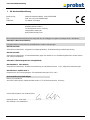 9
9
-
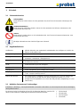 10
10
-
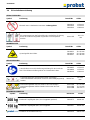 11
11
-
 12
12
-
 13
13
-
 14
14
-
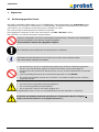 15
15
-
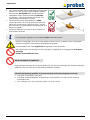 16
16
-
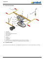 17
17
-
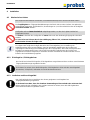 18
18
-
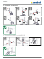 19
19
-
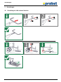 20
20
-
 21
21
-
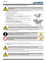 22
22
-
 23
23
-
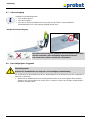 24
24
-
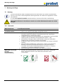 25
25
-
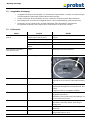 26
26
-
 27
27
-
 28
28
-
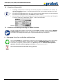 29
29
-
 30
30
-
 31
31
-
 32
32
-
 33
33
-
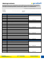 34
34
-
 35
35
-
 36
36
-
 37
37
-
 38
38
-
 39
39
-
 40
40
-
 41
41
-
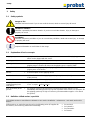 42
42
-
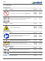 43
43
-
 44
44
-
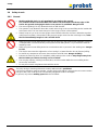 45
45
-
 46
46
-
 47
47
-
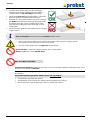 48
48
-
 49
49
-
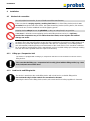 50
50
-
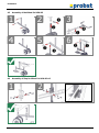 51
51
-
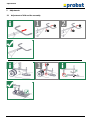 52
52
-
 53
53
-
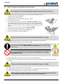 54
54
-
 55
55
-
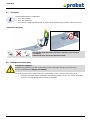 56
56
-
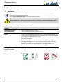 57
57
-
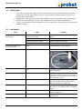 58
58
-
 59
59
-
 60
60
-
 61
61
-
 62
62
-
 63
63
-
 64
64
-
 65
65
-
 66
66
-
 67
67
-
 68
68
-
 69
69
-
 70
70
-
 71
71
-
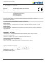 72
72
-
 73
73
-
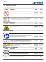 74
74
-
 75
75
-
 76
76
-
 77
77
-
 78
78
-
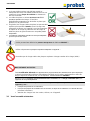 79
79
-
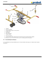 80
80
-
 81
81
-
 82
82
-
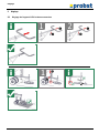 83
83
-
 84
84
-
 85
85
-
 86
86
-
 87
87
-
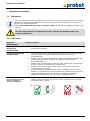 88
88
-
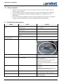 89
89
-
 90
90
-
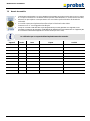 91
91
-
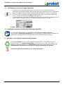 92
92
-
 93
93
-
 94
94
-
 95
95
-
 96
96
-
 97
97
-
 98
98
-
 99
99
-
 100
100
-
 101
101
-
 102
102
-
 103
103
-
 104
104
-
 105
105
-
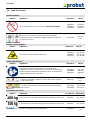 106
106
-
 107
107
-
 108
108
-
 109
109
-
 110
110
-
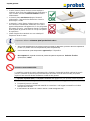 111
111
-
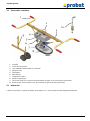 112
112
-
 113
113
-
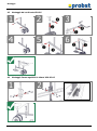 114
114
-
 115
115
-
 116
116
-
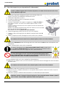 117
117
-
 118
118
-
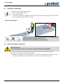 119
119
-
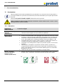 120
120
-
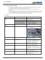 121
121
-
 122
122
-
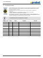 123
123
-
 124
124
-
 125
125
-
 126
126
-
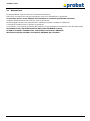 127
127
-
 128
128
-
 129
129
-
 130
130
-
 131
131
-
 132
132
-
 133
133
-
 134
134
-
 135
135
-
 136
136
-
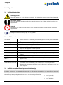 137
137
-
 138
138
-
 139
139
-
 140
140
-
 141
141
-
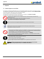 142
142
-
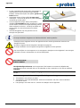 143
143
-
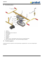 144
144
-
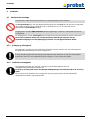 145
145
-
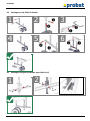 146
146
-
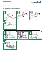 147
147
-
 148
148
-
 149
149
-
 150
150
-
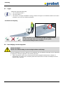 151
151
-
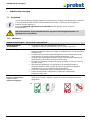 152
152
-
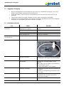 153
153
-
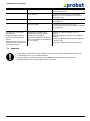 154
154
-
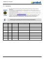 155
155
-
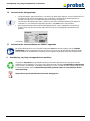 156
156
-
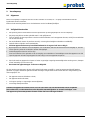 157
157
-
 158
158
-
 159
159
-
 160
160
-
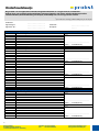 161
161
-
 162
162
-
 163
163
-
 164
164
-
 165
165
-
 166
166
-
 167
167
-
 168
168
-
 169
169
-
 170
170
-
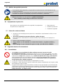 171
171
-
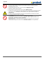 172
172
-
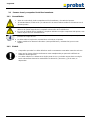 173
173
-
 174
174
-
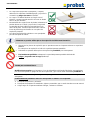 175
175
-
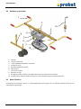 176
176
-
 177
177
-
 178
178
-
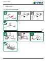 179
179
-
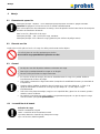 180
180
-
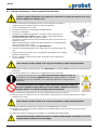 181
181
-
 182
182
-
 183
183
-
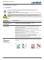 184
184
-
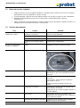 185
185
-
 186
186
-
 187
187
-
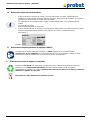 188
188
-
 189
189
-
 190
190
-
 191
191
-
 192
192
-
 193
193
-
 194
194
-
 195
195
-
 196
196
-
 197
197
-
 198
198
-
 199
199
-
 200
200
-
 201
201
-
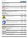 202
202
-
 203
203
-
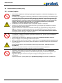 204
204
-
 205
205
-
 206
206
-
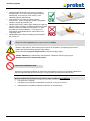 207
207
-
 208
208
-
 209
209
-
 210
210
-
 211
211
-
 212
212
-
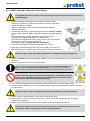 213
213
-
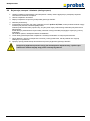 214
214
-
 215
215
-
 216
216
-
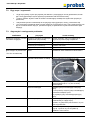 217
217
-
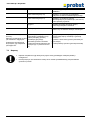 218
218
-
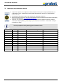 219
219
-
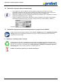 220
220
-
 221
221
-
 222
222
-
 223
223
-
 224
224
-
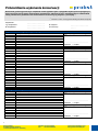 225
225
-
 226
226
-
 227
227
-
 228
228
-
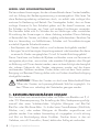 229
229
-
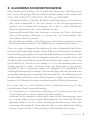 230
230
-
 231
231
-
 232
232
-
 233
233
-
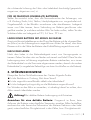 234
234
-
 235
235
-
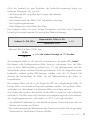 236
236
-
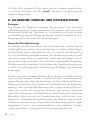 237
237
-
 238
238
-
 239
239
-
 240
240
-
 241
241
-
 242
242
-
 243
243
-
 244
244
-
 245
245
-
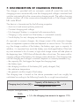 246
246
-
 247
247
-
 248
248
-
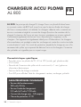 249
249
-
 250
250
-
 251
251
-
 252
252
-
 253
253
-
 254
254
-
 255
255
-
 256
256
-
 257
257
-
 258
258
-
 259
259
-
 260
260
-
 261
261
-
 262
262
-
 263
263
-
 264
264
-
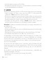 265
265
-
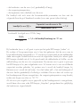 266
266
-
 267
267
-
 268
268
-
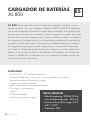 269
269
-
 270
270
-
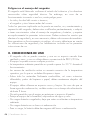 271
271
-
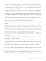 272
272
-
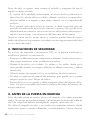 273
273
-
 274
274
-
 275
275
-
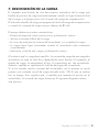 276
276
-
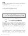 277
277
-
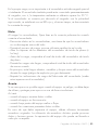 278
278
-
 279
279
-
 280
280
-
 281
281
-
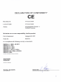 282
282
-
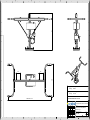 283
283
-
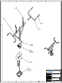 284
284
-
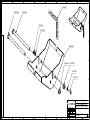 285
285
-
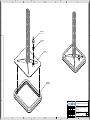 286
286
-
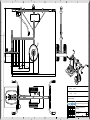 287
287
-
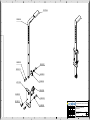 288
288
-
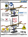 289
289
-
 290
290


probst VPH-150-GREENLINE Manual de usuario
- Categoría
- Pistolas de calor de potencia
- Tipo
- Manual de usuario
en otros idiomas
- français: probst VPH-150-GREENLINE Manuel utilisateur
- italiano: probst VPH-150-GREENLINE Manuale utente
- English: probst VPH-150-GREENLINE User manual
- Deutsch: probst VPH-150-GREENLINE Benutzerhandbuch
- Nederlands: probst VPH-150-GREENLINE Handleiding
- polski: probst VPH-150-GREENLINE Instrukcja obsługi
Artículos relacionados
-
 probst FXAH-120-GRABO-GREENLINE Manual de usuario
-
 probst FXAH-120-GRABO-PRO-LIFTER-GREENLINE Manual de usuario
-
 probst FXAH-120-GRABO-PRO-LIFTER-GREENLINE Manual de usuario
-
 probst ALX-120 Manual de usuario
-
 probst SRG-UNI-3-K Manual de usuario
-
probst TSZ-UNI Manual de usuario
-
 probst KIG-I Manual de usuario
-
 probst SVZ-UNI-VARIO Manual de usuario
-
 probst FTZ-MAXI-25 Manual de usuario
-
 probst FTZ-MULTI-15 Basic Device Manual de usuario


