Lithonia Lighting LK4OAZ PFMW M6 Guía de instalación
- Tipo
- Guía de instalación

Lithonia Lighting
Downlighting
One Lithonia Way / Conyers, GA 30012
800-315-4935 / www.lithonia.com
INSTALLATION INSTRUCTIONS
Part Number: >Revision D<
©2007 Acuity Brands Lighting, Inc., 01/01/2012
Page 1 of 11
• To reduce the risk of death, personal injury or property damage from fi re, electric
shock, falling parts, cuts/abrasions, and other hazards please read all warnings and
instructions included with and on the fi xture box and all fi xture labels.
• Before installing, servicing, or performing routine maintenance upon this equipment,
follow these general precautions.
• Installation and service of luminaires should be performed by a qualifi ed licensed
electrician.
• Maintenance of the luminaires should be performed by person(s) familiar with the
luminaires’ construction and operation and any hazards involved. Regular fi xture
maintenance programs are recommended.
• It will occasionally be necessary to clean the outside of the refractor/lens. Frequency
of cleaning will depend on ambient dirt level and minimum light output which is
acceptable to user. Refractor/lens should be washed in a solution of warm water and
any mild, non-abrasive household detergent, rinsed with clean water and wiped dry.
Should optical assembly become dirty on the inside, wipe refractor/lens and clean in
above manner, replacing damaged gaskets as necessary.
• DO NOT INSTALL DAMAGED PRODUCT! This luminaire has been properly
packed so that no parts should have been damaged during transit. Inspect to confi rm.
Any part damaged or broken during or after assembly should be replaced.
• Recycle: For information on how to recycle LED electronic products, please
visit www.epa.gov.
• These instructions do not purport to cover all details or variations in equipment nor to
provide every possible contingency to meet in connection with installation, operation,
or maintenance. Should further information be desired or should particular problems
arise which are not covered suffi ciently for the purchaser’s or owner’s purposes, this
matter should be referred to Acuity Brands Lighting, Inc.
READ AND FOLLOW ALL SAFETY INSTRUCTIONS! SAVE THESE
INSTRUCTIONS AND DELIVER TO OWNER AFTER INSTALLATION
WARNING RISK OF ELECTRIC SHOCK
CAUTION RISK OF INJURY
WARNING RISK OF BURN
CAUTION RISK OF FIRE
• Disconnect or turn off power before installation or servicing.
• Verify that supply voltage is correct by comparing it with the luminaire
label information.
• Make all electrical and grounded connections in accordance with the National
Electrical Code (NEC) and any applicable local code requirements.
• All wiring connections should be capped with UL approved recognized
wire connectors.
• Wear gloves and safety glasses at all times when removing luminaire from carton,
installing, servicing or performing maintenance.
• Avoid direct eye exposure to the light source while it is on.
• Allow lamp/fi xture to cool before handling. Do not touch enclosure or light source.
• Do not exceed maximum wattage marked on luminaire label.
• Follow all manufacturer’s warnings, recommendations and restrictions for: driver
type, burning position, mounting locations/methods, replacement and recycling.
• Keep combustible and other materials that can burn, away from lamp/lens.
• Do not operate in close proximity to persons, combustible materials or substances
affected by heat or drying.
LED IMPORTANT SAFETY INSTRUCTIONS
CAUTION: RISK OF PRODUCT DAMAGE
• Never connect components under load.
• Do not mount or support these fi xtures in a manner that can cut the outer jacket or
damage wire insulation.
• Never connect an LED product to an unapproved dimmer pack. Contact ABL
directly for any dimmers not specifi cally recommended for the product.
• Unless individual product specifi cations deem otherwise: Allow for some volume of
airspace around fi xture. Avoid covering LED fi xtures with insulation, foam, or other
material that will prevent convection or conduction cooling.
• Unless individual product specifi cations deem otherwise: Maximum ambient
temperature is 90°C. Do not operate fi xture at temperatures higher than this.
• Unless individual product specifi cations deem otherwise: Never mount in places
where fi xture will be exposed to rain, high humidity, extreme temperature changes
or restricted ventilation.
• LED products are Polarity Sensitive. Ensure proper Polarity before installation.
• Electrostatic Discharge (ESD): ESD can damage LED fi xtures. Personal grounding
equipment must be worn during all installation or servicing of the unit.
• Do not touch individual electrical components as this can cause ESD, shorten lamp
life, or alter performance.
• There are no user serviceable parts inside the unit. Do not rewire, reconfi gure,
or modify the unit or attempt any repairs yourself. Additionally, fi eld replacement
of the LED assembly or lamps is not allowed by UL standards at this time. In the
unlikely event your unit may require service, stop using the unit immediately and
contact an ABL representative.
All luminaires that contain electronic devices that generate frequencies above 9kHz from
any component within the luminaire comply with one of the following Part 15 of the FCC
Rules. Operation is subject to the following two conditions:
(1) This device may not cause harmful interference
(2) This device must accept any interference received, including interference
that may cause undesired operation.
This device complies with Part 18 of the FCC Rules but may cause interference with
cordless and cell phones, radios, televisions, and other electronic devices. To correct
the problem move the device away from the luminaire or plug into a different outlet.
This product may cause interference to radio equipment and should not be installed near
maritime safety communications equipment or other critical navigation or communica-
tions equipment operating between 0.45-30MHz.
Failure to follow any of these instructions could void product warranties.
For a complete listing of product Terms and Conditions, please visit
www.acuitybrands.com.
OUR BRANDS
Indoor/Outdoor: Lithonia Lighting, Carandini, Holophane, RELOC
Indoor Lighting: Gotham, Mark Architectural Lighting, Peerless, Renaissance
Lighting, Winona Lighting
Outdoor Lighting: American Electric Lighting, Antique Street Lamps, Hydrel, Tersen
Controls: DARK TO LIGHT, Lighting Control & Design, ROAM, Sensor Switch,
Synergy
Acuity Brands Lighting, Inc. assumes no responsibility for claims arising out of
improper or careless installation or handling of its products.
ABL LED General Warnings, Form No. 503.203
© 2010 Acuity Brands Lighting, Inc. All rights reserved. 12/01/10

Lithonia Lighting
Downlighting
One Lithonia Way / Conyers, GA 30012
800-315-4935 / www.lithonia.com
INSTALLATION INSTRUCTIONS
Part Number: >Revision D<
©2007 Acuity Brands Lighting, Inc., 01/01/2012
Page 2 of 11
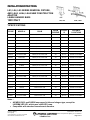
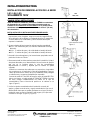
LK3, LK4, LK5 SERIES REMODEL FIXTURE,
AND LKA3, LKA4, LKA5 NEW CONSTRUCTION
ADAPTER
LKABH HANGER BARS
LK3 LKA3
120V ONLY LK4, LK5 LKA4, LKA5
*SPECIFICATIONS
CICODE MODEL # BULB
BEAM
SPREAD
IC/Non-
IC
SUITABLE
LOCATIONS
199U0L LK3GMW MR16 (GU10) 120V 50W 30° Non-IC DAMP LOCATIONS
215M87 LK3GMW LED LPI MR16 (GU10) 120V 4W LED Lamp 30° Non-IC DAMP LOCATIONS
199U0M LK3GBN MR16 (GU10) 120V 50W 30° Non-IC DAMP LOCATIONS
199U0N LK3GORB MR16 (GU10) 120V 50W 30° Non-IC DAMP LOCATIONS
199U0P LK3CBN MR16 (GU10) 120V 50W 30° Non-IC DAMP LOCATIONS
199U0R LK3BMW MR16 (GU10) 120V 50W 30° Non-IC DAMP LOCATIONS
199U0T LK3BBN MR16 (GU10) 120V 50W 30° Non-IC DAMP LOCATIONS
199U0U LK3OAZ PFMW MR16 (GU10) 120V 50W 30° Non-IC DAMP LOCATIONS
199U0V LK3PSMW MR16 (GU10) 120V 50W 30° Non-IC DAMP LOCATIONS
199U0W LK4GMW MR16 (GU10) 120V 50W 32° Non-IC DAMP LOCATIONS
199U0X LK4GBN MR16 (GU10) 120V 50W 32° Non-IC DAMP LOCATIONS
199U0Y LK4BBN MR16 (GU10) 120V 50W 32° Non-IC DAMP LOCATIONS
199U10 LK4BMW MR16 (GU10) 120V 50W 32° Non-IC DAMP LOCATIONS
199U13 LK4EMW MR16 (GU10) 120V 50W 28° Non-IC DAMP LOCATIONS
199NEG LK4EBN MR16 (GU10) 120V 50W 28° Non-IC DAMP LOCATIONS
199NEH LK4OAZ PFMW MR16 (GU10) 120V 50W 34° Non-IC DAMP LOCATIONS
199NEJ LK4LMW MR16 (GU10) 120V 50W 36° Non-IC WET LOCATIONS
199NEK LK4LBN MR16 (GU10) 120V 50W 36° Non-IC WET LOCATIONS
199VPF LK4SQMW MR16 (GU10) 120V 50W 30° Non-IC DAMP LOCATIONS
201K2E LK5MW PAR30 120V 75W 20° Non-IC DAMP LOCATIONS
201K2F LK5BMW PAR30 120V 75W 20° Non-IC DAMP LOCATIONS
205N23 LK5LMW PAR30 120V 50W 30° Non-IC WET LOCATIONS
210NN3 LK5OAZ TRMW PAR30 120V 75W 20° Non-IC DAMP LOCATIONS
Notes –
All MR16 GU10 and PAR30 lamps used in kits are halogen type, except for
LK3GMW LED LPI, which uses a 4W LED Lamp.
Compatible with standard incandescent dimmers.

Lithonia Lighting
Downlighting
One Lithonia Way / Conyers, GA 30012
800-315-4935 / www.lithonia.com
INSTALLATION INSTRUCTIONS
Part Number: >Revision D<
©2007 Acuity Brands Lighting, Inc., 01/01/2012
Page 3 of 11
LK3, LK4, LK5 SERIES REMODEL FIXTURE,
LK3
120V ONLY
LK4, LK5
SAVE THESE INSTRUCTIONS
Prior to installing the fixture, disconnect ALL power supplies to the
unit. This unit may be installed in a TYPE NON-IC installation only.
No insulation may be placed over the top of/or within 3″ (76mm) of
the fixture.
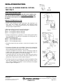
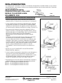
REMODEL FIXTURE INSTALLATION
1. NOTE: when deciding on fixture placement and preparing to cut
hole, take into account joist placement and electrical wiring
requirements. Your ceiling material must be non-combustible and
strong enough to support fixture.
2. Maximum ceiling thickness for remodel applications
LK3= 5/8” max gypsum; 3/4” max drop ceiling tile
LK4= 1” max gypsum and drop ceiling tile
LK5= 1” max gypsum and drop ceiling tile
3. Using the template that is provided, or fixture housing itself outline
the circle pattern on the ceiling to cut between the ceiling joists, as
required by lighting layout.
LK3= 3 1/8 inch diameter cutout.
LK4= 4 1/8 inch diameter cutout.
LK5= 5 1/2 inch diameter cutout.
4. Using the proper hole-saw and tools, cut out the circle pattern in the
ceiling.
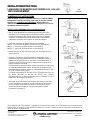
5. Disconnect all power prior to installation. Remove the appropriate
pry-out knockout with screw driver. Open snap on cover on junction
box by depressing spring and allow cover to hang.
Using the provided wire connecters, make all connections inside the
Junction box. Bring supply wires into box by shielded cable or
Romex cable and connectors (Purchased separately).
Connect the 120V HOT wire black to black; NEUTRAL wire white to
white; GROUND bare wire to ground, push wires carefully back into
junction box. Close snap on cover in place. (Figure 1)
6. Tilt fixture junction box up through hole and hold up against ceiling
and push retaining clips with screwdriver until they securely snap in
place. Check installation that fixture is secure and clips are snapped
in place. (Figure 2 & Figure 3)
Figure 1
Figure 2
Figure 3

Lithonia Lighting
Downlighting
One Lithonia Way / Conyers, GA 30012
800-315-4935 / www.lithonia.com
INSTALLATION INSTRUCTIONS
Part Number: >Revision D<
©2007 Acuity Brands Lighting, Inc., 01/01/2012
Page 4 of 11
LKA3, LKA4, LKA5 NEW CONSTRUCTION
ADAPTER
LKABH HANGER BARS
LKA3
120V ONLY LKA4, LKA5
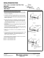
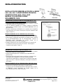
NEW CONSTRUCTION ADAPTER INSTALLATION
1. NOTE: when deciding on fixture placement take into account joist
placement and electrical wiring requirements. Your ceiling material
must be non-combustible.
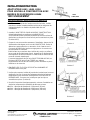
2. Install NEW CONSTRUCTION ADAPTER( purchased separately)
by positioning the LKABH BAR HANGERS (purchased separately)
between the ceiling joists and nailing in the attached nails to secure
in place. (Figure 4 & 5)
3. Disconnect all power prior to installation. Pull supply wire through
ADAPTER hole. Remove the appropriate pry-out knockout with
screw driver. Open snap on cover on junction box by depressing
spring and allow cover to hang.
Using the provided wire connecters, make all connections inside the
Junction box.
Bring supply wires into box by shielded cable or Romex cable and
connectors (Purchased separately)
Connect the 120V HOT wire black to black; NEUTRAL wire white to
white; GROUND bare wire to ground, push wires carefully back into
junction box. Close snap on cover in place.
4. REMOVE the (3) SPRING CLIPS from the REMODEL FIXTURE
and discard.
5. Tilt Fixture junction box up through hole and position adapter spring
clips with alignment grooves and rectangular openings on
REMODEL CAN HOUSING. Push up for spring clips to securely
snap in and lock in place. (Figure 6)
6. After electrical inspection is approved, complete ceiling installation,
with the following cut out openings to
LKA3= 3 1/4 inch diameter cutout.
LKA4= 4 1/4 inch diameter cutout.
LKA5= 5 5/8 inch diameter cutout.
Figure 4
Figure 5
Figure 6

Lithonia Lighting
Downlighting
One Lithonia Way / Conyers, GA 30012
800-315-4935 / www.lithonia.com
INSTALLATION INSTRUCTIONS
Part Number: >Revision D<
©2007 Acuity Brands Lighting, Inc., 01/01/2012
Page 5 of 11
LK3, LK4, LK5 SERIES REMODEL FIXTURE,
AND LKA3, LKA4, LKA5 NEW CONSTRUCTION
ADAPTER
LKABH HANGER BARS
LK3 LKA3
120V ONLY
LK4, LK5 LKA4, LKA5
TRIM FOR MODELS LK3 LK4 LK5 INSTALLATION with GU10 50W
120VAC LAMP
1. Disconnect all power prior to installation. Remove protective cover
from socket.
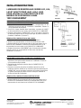
2. With the Lamp installed in the trim, connect LAMP by twisting
clockwise on to FIXTURE SOCKET.
3. Gently push up TRIM into fixture opening until flush with ceiling.
Check that the installation is secure. (Figure7)
REPLACEMENT OF GU10 50W 120VAC LAMP
1. Disconnect all power prior to installation.
2. Remove trim from housing by pulling down from ceiling.
3. Disconnect LAMP by twisting counter-clockwise on to FIXTURE
SOCKET. Connect new LAMP by twisting clockwise on to FIXTURE
SOCKET.
4. Gently push up TRIM into fixture opening until flush with ceiling.
Check that the installation is secure. (Figure7)
TRIM FOR MODELS LK5 INSTALLATION
1. Disconnect all power prior to installation. Remove protective cover
from socket.
2. Snap the fixture socket into the REFLECTOR TRIM.
3. Squeeze the torsion springs together and position and place on to
brackets in fixture. Release springs and gently pushes up TRIM into
fixture opening until flush with ceiling. Screw in Lamp and check that
the installation is secure.
REPLACEMENT OF PAR30 50W/75W 120VAC LAMP
1. Disconnect all power prior to installation.
2. Disconnect LAMP by twisting counter-clockwise on to FIXTURE
SOCKET. Connect new LAMP by twisting clockwise on to FIXTURE
SOCKET.
Figure 7

Lithonia Lighting
Downlighting
One Lithonia Way / Conyers, GA 30012
800-315-4935 / www.lithonia.com
INSTALLATION INSTRUCTIONS
Part Number: >Revision D<
©2007 Acuity Brands Lighting, Inc., 01/01/2012
Page 6 of 11
LUMINAIRE DE REMODELAGE SERIES LK3, LK4,LK5 LK3
120V UNIQUEMENT LK4,LK5
CONSERVER CES INSTRUCTIONS
Avant de mettre en place le luminaire, débrancher COMPLETEMENT
l’alimentation électrique de l’unité. Cette unité ne peut être installée
que dans une installation de TYPE NON-IC. Ne pas placer de
matériau isolant au dessus du luminaire ou à moins de 3 po (76 mm)
de distance autour du luminaire.
INSTALLATION LUMINAIRE POUR PLAFOND EXISTANT
1. NOTE: avant de décider de l’emplacement du luminaire et de
découper le trou correspondant sur le plafond, veuillez prendre en
compte l’emplacement des solives et les exigences du câblage
électrique. Le matériau du plafond doit être non combustible et
suffisamment résistant pour soutenir le poids du luminaire.
2. Epaisseur maximale de plafond pour des encastrages
LK3= 5/8” max pour du plâtre; 3/4” max pour un faux plafond
LK4= 1” max pour du plâtre et pour un faux plafond.
LK5= 1” max pour du plâtre et pour un faux plafond.
3. Utilisez une scie et des outils appropriés pour découper un cercle
dans le plafond.
4. Coupez le courant au niveau du fusible correspondant ou du
disjoncteur principal avant de commencer l’installation. Retirer la
débouchure appropriée avec un tournevis. Ouvrir l’attache sur le
Couvercle de la boîte de jonction en appuyant sur le ressort et en
laissant pendre le couvercle.
Etablir toutes les connexions dans la boîte de jonction en utilisant les
raccords de fils électriques fournis. Amener les fils d’alimentation
électrique dans la boîte en utilisant un câble blindé ou Romex et des
raccords (achetés séparément).
Connecter séparément les fils noirs SOUS TENSION de 120V, les
fils blancs NEUTRE et les fils de TERRE nus, replacer
soigneusement les fils dans la boîte de jonction. Remettre en place
l’attache sur le couvercle. (Schéma 1)
5. Remonter la boîte de jonction du luminaire par le trou, le maintenir
contre le plafond et pousser les clips de retenue avec le tournevis
jusqu’à ce qu’ils se verrouillent en place. S’assurer de la bonne
assise du luminaire et que les clips sont verrouillés en place.
(Schéma 2 & Schéma 3)
*
Une installation de TYPE NON-IC s’applique à un luminaire placé dans un renfoncement avec une absence de
contact entre le luminaire et les matériaux isolants, là où aucun matériaux isolant n’est placé au dessus/ou à
moins de 76mm (3”) du luminaire.
Schéma 1
Schéma 2
Schéma 3

Lithonia Lighting
Downlighting
One Lithonia Way / Conyers, GA 30012
800-315-4935 / www.lithonia.com
INSTALLATION INSTRUCTIONS
Part Number: >Revision D<
©2007 Acuity Brands Lighting, Inc., 01/01/2012
Page 7 of 11
ADAPTATEUR LKA3, LKA4, LKA5
POUR NOUVELLE CONSTRUCTION AVEC
BARRES DE SUSPENSION LKABH
LKA3
120V UNIQUEMENT LKA4,LKA5
INSTALLATION AVEC ADAPTATEUR POUR NOUVELLE
CONSTRUCTION
1. NOTE: avant de décider de l’emplacement du luminaire, veuillez
prendre en compte l’emplacement des solives et les exigences du
câblage électrique. Le matériau du plafond doit être non
combustible.
2. Installer L’ADAPTATEUR POUR NOUVELLE CONSTRUCTION
(acheté séparément) en positionnant les BARRES DE
SUSPENSION LKABH (achetées séparément) entre les solives du
plafond et en enfonçant les clous fournis pour les maintenir en place.
(Schéma 4 & 5)
3. Couper le courant avant de commencer l’installation. Amener les fils
d’alimentation électriques par le trou de l’ADAPTATEUR. Retirer la
débouchure appropriée avec un tournevis. Ouvrir l’attache sur le
Couvercle de la Boîte de Jonction en appuyant sur le ressort et en
laissant pendre le couvercle.
Etablir toutes les connexions dans la Boîte de Jonction en utilisant
les raccords de fils électriques fournis. Amener les fils d’alimentation
électrique dans la boîte en utilisant un câble blindé ou Romex et des
raccords (achetés séparément) .
Connecter séparément les fils noirs SOUS TENSION de 120V, les
fils blancs NEUTRE et les fils de TERRE nus, replacer
soigneusement les fils dans la boîte de jonction. Remettre en place
l’attache sur le couvercle.
4. ENLEVER LES (3) CLIPS A RESSORT du LUMINAIRE DE
REMODELAGE et les jeter.
5. Incliner puis remonter la boîte de jonction du Luminaire par le trou et
positionner les clips à ressort de l‘adaptateur d’après les rainures
d’alignement et les ouvertures rectangulaires sur le BOITIER DE
REMODELAGE. Poussez vers le haut pour que les clips se
verrouillent en place. (Schéma 6)
6. Une fois l’inspection électrique approuvée, achevez l’installation au
plafond en respectant les diamètres de découpe suivants
LKA3= découpe de diamètre de 3 1/4 pouces (83 mm).
LKA4= découpe de diamètre de 4 1/4 pouces (108 mm).
LKA5= découpe de diamètre de 5 5/8 pouces (142 mm).
Schéma 4
Schéma 5
Schéma 6

Lithonia Lighting
Downlighting
One Lithonia Way / Conyers, GA 30012
800-315-4935 / www.lithonia.com
INSTALLATION INSTRUCTIONS
Part Number: >Revision D<
©2007 Acuity Brands Lighting, Inc., 01/01/2012
Page 8 of 11
LUMINAIRE DE REMODELAGE SERIES LK3, LK4,
LK5 ET ADAPTATEUR LKA3, LKA4, LKA5
POUR NOUVELLE CONSTRUCTION AVEC
BARRES DE SUSPENSION LKABH
LK3 LKA3
120V UNIQUEMENT LK4,LK5 LKA4,LKA5
GARNITURE POUR INSTALLATION AVEC LES MODELES LK3
LK4 LK5 avec LAMPE GU10 50W 120VCA
1. Coupez le courant au niveau du fusible correspondant ou du
disjoncteur principal avant de commencer l’installation. Enlever le
cache protecteur de la douille.
2. Une fois la Lampe installée dans la garniture, connecter la LAMPE
en la tournant dans le sens horaire sur la DOUILLE DU LUMINAIRE.
3. Poussez doucement la GARNITURE vers le haut dans l’ouverture
du luminaire jusqu’à être au même niveau que le plafond. Vérifiez la
sûreté de l’installation. (Schéma 7)
REMPLACER L’AMPOULE GU10 50W 120VAC
1. Débrancher l’alimentation électrique avant l’installation.
2. Retirer l’ornement du boîtier en le tirant du plafond vers le bas.
3. Retirer l’AMPOULE en la tournant dans le sens anti horaire sur la
DOUILLE DU LUMINAIRE. Brancher la nouvelle AMPOULE en la
tournant dans le sens horaire sur la DOUILLE DU LUMINAIRE.
4. Replacer doucement l’ORNEMENT dans l’ouverture du luminaire
jusqu’à le placer au ras du plafond. Vérifier le bon maintien de
l’installation. (Schéma 7)
GARNITURE POUR INSTALLATION AVEC LES MODELE LK5
1. Coupez le courant au niveau du fusible correspondant ou du
disjoncteur principal avant de commencer l’installation. Enlever le
cache protecteur de la douille.
2. Enclenchez la douille du luminaire dans la GARNITURE DU
REFLECTEUR.
3. Pressez les ressorts de torsion ensemble et placez-les sur les
brides du luminaire. Relâchez les ressorts et poussez doucement la
GARNITURE vers le haut dans l’ouverture du luminaire jusqu’à être
au même niveau que le plafond. Visser la Lampe à l’intérieur et
vérifiez la sûreté de l’installation.
REMPLACER L’AMPOULE PAR30 50W/75W 120VAC
1. Débrancher l’alimentation électrique avant l’installation.
2. Retirer l’AMPOULE en la tournant dans le sens anti horaire sur la
DOUILLE DU LUMINAIRE. Brancher la nouvelle AMPOULE en la
tournant dans le sens horaire sur la DOUILLE DU LUMINAIRE.
Schéma 7

Lithonia Lighting
Downlighting
One Lithonia Way / Conyers, GA 30012
800-315-4935 / www.lithonia.com
INSTALLATION INSTRUCTIONS
Part Number: >Revision D<
©2007 Acuity Brands Lighting, Inc., 01/01/2012
Page 9 of 11
INSTALACIÓN DE REMODELACIÓN DE LA SERIE
LK3, LK4, LK5,
LK3
SOLAMENTE 120V LK4, LK5
GUARDE ESTAS INSTRUCCIONES
Antes de instalar la instalación, desconecte TODOS los suministros
de alimentación de la unidad. Esta unidad solamente puede ser
instalada en uns instalación del TIPO NON-IC. No se puede colocar
aislamiento sobre la parte superior de / o dentros de las 3″ (76 mm)
de la instalación.
INSTALACIÓN DE LA INSTALACIÓN DE REMODELACIÓN
1. NOTA: Cuando se decida en la colocación de la instalación y
prepare para cortar el agujero, tenga en cuenta los requerimientos
de la colocación de la vigueta y el cableado eléctrico. El material de
su techo debe ser no combustible y suficientemente fuerte para
soportar la instalación.
2. Grasos máximo del techo para las aplicaciones de remodelado
LK3= 5/8” máximo de yeso; 3/4” máx de caida desde el azulejo
del techo.
LK4= 1” máximo de yeso y de caida desde el azulejo del techo
LK5= 1” máximo de yeso y de caida desde el azulejo del techo
3. Usando la sierra de agujeros y las herramientas apropiadas corte el
patrón del círculo en el techo.
4. Desconecte toda las alimentaciones antes de la instalación. Quite el
alzaprime adecuado con el destornillador. Abra el broche de presión
que hay en la Cubierta sobre la caja de ensambladura
depresionando el resorte y dejando que la cubierta se quede
colgando.
Usando los conectores de cables que se proporciona, haga todas
las conexiones en el interior de la caja de ensambladura. Lleve los
cables de suministro al interior de la caja mediante cable protegido
o cable Romex y conectores (Adquirido por separado).
Conecte el cable HOT de 120V de negro a negro; el cable NÉUTRO
blanco con blanco; el cable pelado de TOMA de TIERRA a la toma
de tierra, empuje cuidadosamente los cables en la caja de
ensambladura. Cierre el broche de presión en la cubierta en su
lugar. (Figura 1)
5. Incline la caja de ensambladura de la instalación a través del
agujero y sujete contra el techo y empuje reteniendo los clips con el
destornillador hasta que se queden fijamente en su lugar. Revise la
instalación para ver que la instalación esté segura y los clips estén
cerrados en su lugar. (Figura 2 y Figura 3)
Figura 1
Figura 2
Figura 3

Lithonia Lighting
Downlighting
One Lithonia Way / Conyers, GA 30012
800-315-4935 / www.lithonia.com
INSTALLATION INSTRUCTIONS
Part Number: >Revision D<
©2007 Acuity Brands Lighting, Inc., 01/01/2012
Page 10 of 11
* La instalación del TIPO NON-IC se refiere a la instalación de dispositivos Incrustados donde no haya contacto
entre el dispositivo y el aislamiento, donde no haya colocado aislamiento sobre la parte superior del / o dentro de
3” (76 mm) del dispositivo.
ADAPTADORES DE NUEVA
CONSTRUCCIÓN LKA3, LKA4, LKA5
BARRAS COLGADORES LKABH
LKA3
SOLAMENTE 120V LKA4,LKA5
INSTALACIÓN DEL ADAPTADOR DE NUEVA CONSTRUCCIÓN
1. NOTA: Cuando decida en la colocación de la instalación tenga en
cuenta los requerimientos sobre la colocación de la vigueta y el
cableado eléctrico. El material de su techo debe ser no combustible.
2. Instale el ADAPTADOR DE NUEVA CONSTRUCCIÓN ( adquirido
por separado) colocando los COLGADORES DE BARRA LKABH
(adquirido por separado) entre las viguetas y elevación del techo en
los remaches que se adjuntan para fijarlos en su lugar. (Figura 4 & 5)
3. Desconecte todo alimentación antes de la instalación. Estire el
cable de suministro a través del agujero del ADAPTADOR. Quite el
alzaprime adecuado con el destornillador. Abra el broche de presión
que hay en la Cubierta sobre la Caja de Ensambladura
depresionando el resorte y dejando que la cubierta se quede
colgando.
Usando los conectores de cables que se proporciona, haga todas
las conexiones en el interior de la Caja de Ensambladura.
Lleve los cables de suministro al interior de la caja mediante cable
protegido o cable Romex y conectores (Adquirido por separado).
Conecte el cable HOT de 120V de negro a negro; el cable NÉUTRO
blanco con blanco; el cable pelado de TOMA de TIERRA a la toma
de tierra, empuje cuidadosamente los cables en la caja de
ensambladura. Cierre el broche de presión en la cubierta en su
lugar.
4. QUITE los (3) CLIPS de RESORTE de la INSTALACIÓN DE
REMODELACIÓN y desechar.
5. Incline la caja de ensamblaje de la Instalación a través del agujero y
posicione los clips de resorte del adaptador con las ranuras de
alineación y aperturas rectangulares en la CUBIERTA DE LA LATA
DE REMODELACIÓN. Empuje para que los clips de resorte se
acoplen con seguridad y se cierren en su lugar. (Figura 6)
6. Después de que la inspección eléctrica esté aprovada, complete la
instalación del techo, con las siguientes aperturas de corte hacia
LKA3= 3 1/4 de pulgadas de diámetro de recorte.
LKA4= 4 1/4 de pulgadas de diámetro de recorte.
LKA5= 5 5/8 de pulgadas de diámetro de recorte.
Figura 4
Figura 5
Figura 6

Lithonia Lighting
Downlighting
One Lithonia Way / Conyers, GA 30012
800-315-4935 / www.lithonia.com
INSTALLATION INSTRUCTIONS
Part Number: >Revision D<
©2007 Acuity Brands Lighting, Inc., 01/01/2012
Page 11 of 11
INSTALACIÓN DE REMODELACIÓN DE LA SERIE
LK3, LK4, LK5, Y ADAPTADORES DE NUEVA
CONSTRUCCIÓN LKA3, LKA4, LKA5
BARRAS COLGADORES LKABH
LK3 LKA3
SOLAMENTE 120V
LK4, LK5 LKA4,LKA5
ADORNO PARA LA INSTALACIÓN DE LOS MODELOS LK3 LK4
LK5 con LA LÁMPARA GU10 50W 120VAC
1. Desconecte toda las alimentaciones antes de la instalación. Quite la
cubierta de protección del portalámparas.
2. Con la Lámpara instalada en el adorno, conecte la LÁMPARA
enrroscando en sentido horario en el PORTALÁMPARAS DE LA
INSTALACIÓN.
3. Empuje suavemente el ADORNO en la apertura de la instalación
hasta que toque con el techo. Revise para ver que la instalación esté
segura. (Figura 7)
REEMPLAZAMIENTO DE LA LÁMPARA GU10 50W 120VAC
1. Desconecte toda la alimentación antes de efectuar la instalación.
2. Quite el reborde de la carsaca estirando desde el techo hacia abajo.
3. Desconecte la LÁMPARA retorciendo en sentido horario contrario
en el PORTALÁMPARAS DE LA INSTALACIÓN. Conecte la
LÁMPARA nueva retorciendo en sentido horario en el
PORTALÁMPARAS DE LA INSTALACIÓN.
4. Empuje suavemente hacia arriba el REBORDE en la apertura de
la instalación hasta que se alinee con el techo. Revise que la
instalación esté segura. (Figura 7)
ADORNO PARA LA INSTALACIÓN DEL MODELO LK5
1. Desconecte toda las alimentaciones antes de la instalación. Quite la
cubierta de protección del portalámparas.
2. Acople el portalámparas de la instalación en el ADORNO DEL
REFLECTOR.
3. Estruje los resortes de torsión juntos y posicione y coloque en las
abrazaderas de la instalación. Libere los resortes y empuje
suavemente el ADORNO en la apertura de la instalación hasta que
toque con el techo. Atornille la Lámpara y revise que la instalación
esté segura.
REEMPLAZAMIENTO DE LA LÁMPARA PAR30 50W/75W 120VAC
1. Desconecte toda la alimentación antes de efectuar la instalación.
2. Desconecte la LÁMPARA retorciendo en sentido horario
contrario en el PORTALÁMPARAS DE LA INSTALACIÓN. Conecte
la LÁMPARA nueva retorciendo en sentido horario en el
PORTALÁMPARAS DE LA INSTALACIÓN.
Figura 7
-
 1
1
-
 2
2
-
 3
3
-
 4
4
-
 5
5
-
 6
6
-
 7
7
-
 8
8
-
 9
9
-
 10
10
-
 11
11


Lithonia Lighting LK4OAZ PFMW M6 Guía de instalación
- Tipo
- Guía de instalación
En otros idiomas
Documentos relacionados
-
Lithonia Lighting 4" Baffle LED Module Kit Guía de instalación
-
Lithonia Lighting LF6N 2/18DTT MVOLT Guía de instalación
-
Lithonia Lighting L7XPR Guía de instalación
-
-
Acuity Brands ELM2LF Emergency Light Instrucciones de operación
-
-
Lithonia Lighting LTKMSBK MR16GU10 3L BN Manual de usuario
-
-
-
Lithonia Lighting 4BEMW LED 27K 90CRI M6 Guía de instalación
