- Categoría
- Chimeneas
- Tipo
- Guía de instalación

1
80-10-505 2022-11-01
USE AND CARE GUIDE
UNVENTED FIREBOX
MODEL #PHZC32C / PHZC36C / PHZC42C / PHZC32F / PHZC36F / PHZC42F
C US
WARNINGS
If the information in this manual is not
followed exactly, a fire or explosion
may result causing property damage,
personal injury or loss of life.
Do not store or use gasoline or other
flammable vapors and liquids in the
vicinity of this or any other appliance.
– WHAT TO DO IF YOU SMELL GAS
• Do not try to light any appliance.
• Do not touch any electrical switch; do
not use any phone in your building.
• Immediately call your gas supplier from
a neighbor’s phone. Follow the gas
supplier’s instructions.
• If you cannot reach your gas supplier,
call the fire department.
– Installation and service must be
performed by a qualified installer,
service agency or the gas supplier.
Carefully review the instructions supplied with
the decorative type unvented room heater for
the minimum fireplace size requirement.
DO NOT INSTALL AN APPLIANCE IN THIS
FIREBOX UNLESS THIS FIREBOX MEETS
THE MINIMUM DIMENSIONS REQUIRED
FOR THE INSTALLATION.
Español p. 17
Questions, problems, missing parts? Before returning to your retailer, call our
customer service department at 877-447-4768 8:30 a.m. – 4:30 pm CST,
Monday – Friday. or email us at customerservice@ghpgroupinc.com 6440 W. Howard St.
Niles, IL 60714-3302
INSTALLER: Leave this manual
with the appliance.
CONSUMER: Retain this manual
for future reference.
For use with a listed gas-fired
unvented decorative room heater
not to exceed 40,000 BTU/hr.
Do
Not Build a Wood Fire.
ANS Z21.11.2-2019
C US

2
Table of Contents
Important Safety Information ................. 3
General Installation Information ............... 5
Before You Start ........................... 5
What You Will Need for Installation ............. 5
Firebox Dimensions and Firebox Location ........ 6
Framing Dimensions ........................ 7
Minimum Clearances ........................ 8
Minimum Clearances and Firebox Framing ....... 9
Fireplace and Canopy/Hood Installation ........ 10
Gas Line Installation ....................... 11
Combustion Air ........................... 12
Optional Outside Air Kit .................... 12
Optional Equipment ........................ 13
Replacement Parts
PHZC32C / PHZC36C / PHZC42C ............. 14
PHZC32F / PHZC36F / PHZC42F .............. 15
Warranty ................................ 16
WARNING
This product and the fuels used to operate this product
(liquid propane or natural gas), and the products of
combustion of such fuels, can expose you to chemicals
including benzene, which is known to the State of California
to cause cancer and reproductive harm.
For more information go to www.p65Warnings.ca.gov

3
Important Safety Information
WARNING!
• Any change to this heater or its controls can be dangerous.
• Improper installation or use of the heater can cause serious injury or death from fire, burns, explosion or
carbon monoxide poisoning.
• Do not allow fans to blow directly into the fireplace. Avoid any drafts that alter burner flame patterns.
• Do not use a blower insert, heat exchanger insert or other accessory, not approved for use with this heater where applicable.
1. Due to high temperatures, the firebox should be located out of traffic and away from furniture and draperies.
2. Children and adults should be alerted to the hazard of high surface temperature and should stay away to avoid burns or
clothing ignition.
3. Young children should be carefully supervised when they are in the same room with the firebox.
4. Do not place clothing or other flammable material near the fireplace when the firebox is in use.
5. Any safety screen or guard removed for servicing, must be replaced prior to operating a heater within the firebox.
6. Installation and repair should be done by a qualified service person.
7. To prevent malfunction and/or sooting, an unvented gas heater/firebox should be cleaned at least annually by a profes-
sional service person. More frequent cleaning may be required due to excessive lint from carpeting, etc. It is imperative that
control compartments, burners and circulating air passageways be kept clean.
8. CARBON MONOXIDE POISONING: Early signs of carbon monoxide poisoning are similar to the flu with headaches, dizziness and/or
nausea. If you have these signs, obtain fresh air immediately. Have the heater serviced as it may not be operating properly.
9. The installation must conform with local codes or, in the absence of local codes, with the National Fuel Gas Code, ANSI Z223.l/
NFPA54.
10. This unit complies with ANS Z21.11.2-2019 ventless firebox enclosures for gas-fired unvented decorative room heaters.
11. Do not install the unvented heater in a bathroom.
12. Do not install the unvented heater in a bedroom unless the maximum input rating is equal to or less than 10,000 Btu/hr.
13. Correct installation of the ceramic fiber logs, proper location of the heater, and annual cleaning are necessary to avoid potential
problems with sooting. Sooting, resulting from improper installation or operation, can settle on surfaces outside the fireplace.
See log placement instructions for proper installation.
14. Avoid any drafts that alter burner flame patterns. Do not allow fans to blow directly into fireplace. Do not place a blower inside burn
area of firebox. Ceiling fans may create drafts that alter burnerflame patterns. Sooting and improper burning will occur.
15. CAUTION:Candles, incense, oil lamps, etc. produce combustion byproducts including soot. Vent-free appliances will not filter or
clean soot producedby these types of products. In addition, the smoke and/or aromatics (scents) may be re-burnt in the vent-free
appliance which can produce odors. It is recommended to minimize the use of candles, incense, etc. while the vent-free appliance is in
operation.
16. An unvented gas-fired heater uses air (oxygen) from the room in which it is installed. Provisions for adequate combustion and venti-
lation air must be provided. See installation guidelines.
17. Keep room area clear and free from combustible materials, gasoline and other flammable vapors and liquids.
18.Unvented gas heaters are a supplemental zone heater. They are not intended to be a primary heating appliance.
19. Unvented gas heaters emit moisture into the living area. In most homes of average construction, this does not pose a problem. In
houses of extremely tight construction, additional mechanical ventilation is recommended.
20. During manufacturing, fabricating and shipping, various components of this appliance are treated with certain oils, films or bonding
agents. These chemicals are not harmful but may produce annoying smoke and smells as they are burned off during the initial opera-
tion of the appliance; possibly causing headaches, or eye or lung irritation. This is a normal and temporary occurrence.
The initial break-in operation should last two to three hours with the burner at the highest setting. Provide maximum ventilation by
opening windows or doors to allow odors to dissipate. Any odors remaining after this initial break-in period will be slight and will disap-
pear with continued use.
21. Input ratings are shown in BTU per hour and are for elevations up to 2,000 feet. For elevations above 2,000 feet, input ratings should
be reduced 4 percent for each 1,000 feet above sea level. Refer to the National Fuel Gas Code.
22. The appliance and its appliance main gas valve must be disconnected from the gas supply piping system during any pressure test-
ing of that system at test pres-sures in excess of 1/2 psig (3.5 kPa).
23. The appliance must be isolated from the gas supply piping system by closing its equipment shutoff valve during any pressure test-
ing of the gas supply piping system at test pressures equal to or less than 1/2 psig (3.5 kPa).

4
Important Safety Information
24. Do not use this room heater if any part has been under water. Immediately call a qualified service technician to inspect the room heater
and to replace any part of the control system and any gas control which has been under water.
25. Never burn solid fuels in a fireplace where an unvented room heater is installed.
26. Always have a fireplace screen in place when the appliance is in operation, and unless other provisions for combustion air are provided,
the screen shall have an opening(s) for induction of combustion air.
27. Do not fill spaces around the firebox with insulation or other materials. These spaces must be maintained to prevent the firebox from
coming in contact with combustible materials.
WARNING!
Do not attempt to burn solid wood fuels, vented gas log sets, or any other combustible in this unvented firebox. Also, do not install a
vent-free gas log set in this firebox if the minimum clearance and height requirements of the log set are too large for the firebox.
Notice: Illustrations shown in this manual reflect “typical” installations with nominal dimensions and are for design and framing
reference only. Actual installations may vary due to individual design preferences. However, always maintain minimum clearances
to combustible materials and do not violate any specific installation requirements.
We recommend that our gas hearth products be installed and serviced by professionals who are certified in the U.S.

5
General Installation Information
The PHZC32F, PHZC36F, and PHZC42F models are radiant vent-free fireboxes.
The PHZC32C, PHZC36C, and PHZC42C feature a self contained heat-circulating system.
This installation manual will enable you to obtain a safe, efficient and dependable installation of your vent-free fireplace system.
Do not alter or modify the firebox or its components under any circumstances. Any modification
or alteration of the firebox system, including but not limited to the firebox and accessories, may void the warranty, listings and approvals of
this system and could result in an unsafe and potentially dangerous installation.
BEFORE YOU START
Carefully inspect the contents for shipping damage. If any parts are missing or damaged, immediately inform the dealer from whom you
purchased the appliance. Do not attempt to install any part of the appliance unless you have all the parts in good condition.
MAKE SURE YOU HAVE RECEIVED ALL PARTS
Check your packing list to verify that all listed parts have been received. You should have the following:
1. Vent-Free Gas Firebox
2. Canopy/Hood
3. Installation and Operating Instructions
4. Three (3) sheet metal screws for
canopy/hood
WHAT YOU WILL NEED FOR INSTALLATION TOOLS and BUILDING SUPPLIES
• Phillips screwdriver
• Square
• Framing materials
• Hammer
• Saw and / or saber saw
• Tee joint
• Level
• Pipe wrench
• Measuring tape
• Pliers
• Electric drill and bits
• Fireplace surround materials (noncombustible)
• Caulking material (noncombustible)
• Wall finishing materials
• Piping complying with local codes
• Pipe sealant approved for use with propane/L.P.G. (resistant to sulfur compounds)
Refer to the installation instructions provided with the log sets for items required for log set installation.
In planning the installation for the appliance it is necessary to determine where the unit is to be installed and whether optional accessories
are desired. Gas supply piping should also be planned. The following steps represent the normal sequence of installation. Each installation
is unique, how-ever, and might require a different sequence.
1. Position firebox prior to framing or into prepared framing.
2. Field wire main power supply to models with fan kit. (Electrical connections should only be performed by an experienced, licensed /
certified tradesman).
3. Plumb gas line. (Gas connections should only be per-formed by an experienced, licensed/certified tradesman).
4. Install vent-free gas log heater per the instructions provided with the vent-free gas log heater.
5. Complete finish wall material, surround and optionalhearth extension to your individual taste.
5. Six (6) standoff brackets, (4) side mounted and (2) top mounted
6. Twelve (12) sheet metal screws for standoff brackets

6
Firebox Dimensions and Firebox Location
LOCATION OF FIREBOX
Carefully select the best location for installation of your
vent-free firebox. The following factors should be taken
into consideration:
• Clearance to side wall, ceiling, woodwork and windows.
See “Clearances/Height Requirements on page 8.
Minimum clearances to combustibles must be main-
tained.
• Location must not be affected by drafts caused by
kitchen exhaust fans, ceiling fans, return air registers for
forced air furnaces/air conditioners, windows or doors.
• Installation must provide adequate ventilation and com-
bustion air.
• Location should be out of high traffic or windy or drafty
areas.
• DO NOT INSTALL WHERE CURTAINS, FURNITURE,
CLOTHING OR OTHER FLAMMABLE OBJECTS ARE
LESS THAN 42” FROM FRONT OF HEATER.
• Never obstruct the front opening of the vent-free firebox
or restrict the flow of combustion and ventilation air.
• Minimize modifications to existing construction. Refer to
Figure 2 below for location suggestions.
• Do not install in the vicinity where gasoline or other
flammable liquids may be stored. The vent-free firebox
must be kept clear and free from these combustible
materials.
Figure 1 - Minimum Hearth Dimensions
Fig. - Location of Firebox
Figure 2 - Location of Firebox
W
2
17.
0
16.5
20.7
3.5
34.1
W1
FIREBOX DIMENSIONS
DIMENSIONPHZCF32C / PHZCF32R PHZCF36C / PHZCF36R PHZCF42C / PHZCF42R
W1 35 7/8" 39 7/8" 45 7/8"
W2 32 3/16" 36 3/16" 42 3/16"
W3 18 1/16"22 1/16" 28 1/16"
W5
W3
W4
W4 20-1/8Ó 24-1/8Ó 30-1/8Ó
20-7/8Ó 24-7/8Ó 30-7/8ÓW5
21
Front of
rebox
Back of
rebox

7
Framing Dimensions
H
W
D
MINIMUM FRAMING DIMENSIONS
FIREBOX SIZE H W D
32" 34 3/4" 36 1/2" 21 1/2"
36" 34 3/4" 40 1/2" 21 1/2"
42" 34 3/4" 46 1/2" 21 1/2"
Figure - Framing Dimensions
A
B
C
C
Figure - Corner Framing Dimensions
MINIMUM CORNER FRAMING DIMENSIONS
Firebox Size A B C
32" 31 1/2" 63" 44 1/2"
36" 33 1/2" 67" 47 3/8"
42" 36 1/2" 73" 51 5/8"
Figure 3 - Framing Dimensions

8
Minimum Clearances
Ensure that minimum clearances shown in Figures 4 through 8
are maintained. Left and right clearances are determined when
facing the front of the firebox.
Follow these instructions carefully to ensure safe installation.
Failure to follow these requirements may create a fire hazard.
1. Sidewall clearances:
The clearance from the outside of the appliance to any combustible
wall should not be less than 9”. Figure 4 and Figure 6
2. Ceiling clearance:
The ceiling must be at least 42” from the top of the firebox opening.
Figure 4
3. Back wall clearance:
The appliance must have 1/4” MIN. clearance to a combustible back
wall.
4. Mantel clearances:
The canopy/hood supplied with the unit must be installed. If a
combustible mantel is installed, it must meet the clearance require-
ments as shown in Figure 5.
Figure 4 - Clearance to Combustible Surfaces
42" Minimum
Clearance to Ceiling
42" Minimum In
Front of Fireplace
9" Minimum Clearanc
e
to Side Walls
9" Minimum Clearance
to Side Walls
Fig. - Clearance to Combustible Surfaces
Figure 5 - Mantle Clearances (Top) Figure 6 - Mantle Leg Clearances
(Applicable for Both Sides)
Wall Stud
Drywall Board
Noncombustible
Facing Material
23"
21"
19"
16"
12"
12"
10"
8"
6"
2 1/2"
3/4" Maintain Clearance
Fig. - Mantle Clearances (Top)
2 1/2"
5"
7 1/2"
3 1/2"
6"
45°
Fig. - Mantle Leg Clearances
(Applicable for Both Sides)
Finished Wall
Wall Stud
Allowable Combustible
Material Area
1

9
42" Minimum
Clearance to Ceiling
42" Minimum In
Front of Fireplace
9" Minimum Clearance
to Side Walls
9" Minimum Clearance
to Side Walls
Fig. - Clearance to Combustible Surfaces
Figure 6 - Mantle Leg Clearances
(Applicable for Both Sides)
Minimum Clearances and Framing
5. Floor clearance: This inner chamber firebox floor must be
installed at least 5” above any combustible flooring material,
such as carpeting or asphalt tile, which is closer than 14” to
the base of the firebox. Figure 7
OR
The inner chamber firebox floor may be installed nearer to the
floor if a minimum of 14” of noncombustible material such as
slate or marble is installed between the base of the firebox and
the combustible flooring. Figure 8
FIREBOX FRAMING
Firebox framing can be built before or after the appliance is set in
place. Construct firebox framing following Figure 3 for your specific
installation requirements. See Figure 3 on Page 7 for firebox
dimensions. The framing headers may rest on the top of the firebox.
The firebox may be installed directly on a combustible floor or raised
on a platform of an appropriate height. When the firebox is installed
directly on carpeting, tile, or other combustible material, other than
wood flooring, the firebox shall be installed on a metal or wood panel
extending the full width and depth of the enclosure.
The classification “noncombustible material” includes, but is not
limited to: stone, brick, and mortar. Noncombustibles are safe to
overlay the black-painted metal face, including radiant plates, and
do not pose a fire hazard. Any noncombustible finish material must
not extend past or interfere with the fireplace opening.
The classification “combustible material” includes, but is not limited
to: plywood, drywall, and particle board. Combustible materials may
contact the sides, bottom, or back of the firebox. Do not overlay the
black painted face with combustible materials.
WARNING!
Do not fill spaces around firebox with insulation
or other materials. This could cause a fire.
WARNING!
The fireplace must be installed giving full
consideration to the clearance and height
requirements identified in this manual.
A
A
C
C
5"
Minimum
Height required
to have combustible
materials directly in
front of Firebox.
14"
Minimum distance required
for noncombustible Hearth
material for Firebox to sit at
floor level.
Combustible Material
Noncombustible Material
(Finished Hearth)
Fig. - Minimum Clearance Above
Combustible Flooring
Fig. - Minimum Noncombustible Hearth
dimension for firebox to sit at Floor Level
Figure 7 - Minimum Clearance Above Combustible Flooring.
Figure 8 - Minimum clearance above Combustible Flooring with
Noncombustible Material Installed at Base of Fireplace
Consult your local Building codes for information on insulating the “Chase”
enclosure. Proper insulation will reduce cold air drafts when the Fireplace
is not in operation.

10
Fireplace and Canopy/Hood Installation
Standoff Installation Instructions:
1. Position the Standoff Bracket as shown and start both mounting
screws.
Push the Standoff Bracket forward and tighten both mounting
screws to position the Firebox for 1/2” Drywall.
Pull the Standoff Bracket backward and tighten both mounting
screws to position the Firebox for 9/16” Drywall.
Repeat process for all four Standoff Brackets.
2. Slide the firebox into prepared framing or position firebox in its
final position and frame later.
3. Level the firebox by checking the top edge of the firebox. Shim if
necessary.
4. Anchor firebox to the side framing members using 8d nails or
other suitable fasteners. Figure 9.
5. The canopy/hood must be installed for safe operation of the
heater.
INSTALLING CANOPY/HOOD
A canopy/hood is furnished with each firebox and MUST be installed
for safe operation. Figure 11
1. Align the canopy/hood with the holes in the top frame.
2. Insert all 3 screws slightly but do not tighten.
3. Push the canopy/hood toward Firebox to insure there is no gap
between the canopy/hood and Firebox as shown in Figure 11a.
4. Then tighten all screws securely.
WARNING!
Close fireplace screen panel before operating a
decorative type unvented room heater.
WARNING!
The firebox canopy must not be modified or
replaced with a canopy that may be provided
with the unvented decorative room heater.
#8 x 3/8 Sheet
Metal Screw
Combustion
Casing Top
Nailing Flanges
FIG. - Hood Installation
Fig. - Nailing Flange Location
Canopy/Hood
Figure 10 - Nailing Flange Location
Figure 11 - Canopy/Hood Installation
Figure 9 - Mounting Standoff Brackets
B
NO GAP
(ON BOTH SIDES)
PUSH
GENTLY
FIG. 11a - Hood Assembly
Figure 11a - Canopy/Hood Assembly
9/16" DRYWALL THICKNESS (BACKWARD)
1/2" DRYWALL THICKNESS (FORWARD)
Standoff Installation Instructions:
1. Position the "Side" Standoff Bracket as shown and start both mounting screws.
Push the Standoff Bracket forward and tighten both mounting screws to position the Firebox for 9/16" Drywall.
Pull the Standoff Bracket backward and tighten both mounting screws to position the Firebox for 1/2" Drywall.
Repeat process for all four "Side" Standoff Brackets.
2. Attach the "Top" Standoff Brackets by positioning them inline with the mounting holes and inserting the screws.
SIDE Standoff (Nailing Flange)
TOP Standoff
Slotted Mounting
Hole
#8 x 3/8" Mounting Screws

11
Gas Line Installation
WARNING!
Plumbing connections should only be performed by a qualified,
licensed plumber. Main gas supply must be off when plumbing
gas line to fireplace or performing service.
Consult all local codes. All gas piping must be installed to comply
with local codes, or in the absence of local codes, with the latest
edition of the National Fuel Gas Code ANSI Z223.1/NFPA54.
The 1/2” gas line may enter either from the left side or right side
of the firebox. Gas access holes are provided on both sides of the
firebox.
A listed manual shutoff valve must be installed upstream of the
appliance. A union tee and plugged 1/8” NPT pressure tapping point
should be installed upstream of the appliance.
IMPORTANT: Install main gas valve (equipment shutoff valve) in
an accessible location. The main gas valve is for turning on or
shutting off the gas to the fireplace.
A sediment trap may be upstream of the heater to prevent moisture
and contaminants from passing through trap to the heater controls
and burners. Failure to do so could prevent the heater from operat-
ing reliably. Consult applicable codes.
An external regulator must be used on all propane/L.P.G. heaters,
in addition to the regulator fitted to the heater, to reduce the
supply tank pressure to 13” w.c. (maximum).
Any copper tubing used to supply propane / L.P.G. from
the tank must be internally tinned.
NOTE:
When connecting propane / L.P.G. vent-free room heaters, you
must use pipe sealant resistant to propane / L.P.G.
IMPORTANT: Hold heater regulator with a wrench to prevent move-
ment when connecting to inlet piping.
Check gas type: The gas supply must be the same as stated on
the heater’s rating plate. If the gas supply is different, DO NOT
INSTALL THE HEATER. Contact your dealer for the correct model
WARNING!
Connecting directly to an unregulated propane / L.P.G. tank can
cause an explosion.
WARNING!
Do no connect directly to natural gas 1/2 PSI or 2 PSI systems.
Always make sure natural gas pressure is regulated 10.5 w.c.
(maximum before operating the unit).
After completing connection, test all gas joints from the gas meter to
the gas heater regulator for leaks. Using soap and water solution or a
gas sniffer. DO NOT USE AN OPEN FLAME.

12
Combustion Air
COMBUSTION AIR
1. Locate combustion air assembly at an exterior location which is
not likely to be accidentally blocked in any manner. Locate assem-
bly a min. of 12” above the snow line to prevent blockage by snow
accumulation.
2. Never mount the combustion air inlet assembly in a garage or
storage area where combustible fumes such as gasoline might be
drawn into the fireplace.
3. Combustion air can be drawn from the crawl space under a house
when an adequate supply of air is provided by open ventilation.
4. CAUTION: Do not take combustion air from attic space or garage
space.
5. Locate air supply inlet at least 3’ away from any appliance vent
terminal.
6. Avoid extremely long runs and numerous turns in the duct leading
from the fireplace to the combustion air assembly. These conditions
increase the resistance to the free flow of air through the duct.
The use of outside air for combustion is optional unless required by
building codes. It is only necessary to supply outside combustion air
to one side of the fireplace. Use the open air kit.
OUTSIDE AIR KIT ASSEMBLY (OAK100)
1. Place the insulation gasket between the open air kit starting collar
and fireplace wall.
2. Place the starting collar (4”) on the side of fireplace. Fasten it in
place with the four sheet metal screws provided.
NOTE: When the air starting collar is securely attached, it will form
a seal against the fireplace wall.
WARNING!
Do not use a combustible duct. Always use UL Listed Class 0 or 1
duct material.
3. Attach outside duct to starting collar with duct clamp or screws.
4. Cut a 6-inch diameter opening for the open air kit in the
outside wall covering where the outside vent is to be located.
5. Select and cut a piece of duct long enough to attach to the
fireplace and stick out at least 3” beyond the face of the wall to
which the open air kit inlet air vent will be attached. Cut duct with
a standard pocket knife.
6. If the duct is the insulated type, push the insulation back from one
end of the duct approximately 2”.
7. Slip the exposed end of the duct over the starting collar on the
fireplace.
8. Using the sheet metal screws provided, secure the duct end to the
collar attached to the fireplace.
9. Nail or screw the combustion air assembly to the surface of the
wall.
A
Insulation Gasket
PHOAK Starting Collar
(4) Sheet Metal Screws
ZC Firebox
RH Side
Fig. - Outside Air Inlet Collar Attachment
PHOAK Inlet Air Vent
PHOAK Starting Collar
4" Semi-Rigid Metal
Vent Tube
Fig. - Simple Outside Air Kit Installation
Notice: If you do not install an outside air kit be sure to
keep the lever in the “closed” position to avoid cold air
drafts.
Figure 13 - Outside Air Inlet Collar Attachment
Figure 14 - Simple Outside Air Kit Installation
Figure 12 - Outside Air Operation
A
OUTSIDE AIR LEVER
OPEN
CLOSED

13
Optional Equipment
OPTIONAL BLOWER (ZCB100)
If you are installing the forced air kit on PHZC32C, PHZC36C, and PHZC42C models, see the installation instructions provided with the kit
for electrical wiring requirements, or the blower installation section. The firebox must be connected to main power supply at time of
firebox installation. The blower should be installed prior to the installation of the vent-free heater but can be installed after installation if the
electrical connections have already been installed. The electrical connections must be made before the firebox is framed and enclosed in
the finished walls.
WARNING!
Electrical connections should only be performed by a qual-
ified, licensed electrician, main power must be off when
connecting to
main electrical power supply or performing service.
The blower when installed, must be electrically grounded
in accordance with local codes or in the absence of local
codes, with the National Electrical Code ANSI/NFPA 70.
Fig. - Optional Blower Installation
Optional ZCB100 Blower Kit
Blower Mounting Bracket
Electrical Box
Lower Grill Assembly
(4) #8 Sheet Metal Screws
(4) Sheet Metal Screws
Included in Blower Kit
Figure 15 - Optional Blower Installation
Blower Installation Instructions:
1. Lower the bottom grill assembly and remove the
blower mounting bracket attached to the inner back
wall of the firebox with a #2 phillips screw driver.
2. Attach the blower to the bracket with the (4) sheet
metal screws included int he blower kit as shown in
Figure 15.
3. Re-install the bracket insuring the blower outlet is
pointed upward.
4. Plug in the cord to the properly grounded 3-prong
receptacle.
WARNING!
Never use an extension cord to power the blower.
1
1
2
2
A A
B B
ZCF-5060
GHP Group Inc.
6440 W Howard St., Niles, IL 60714
DRAWN
DanDowning
CHECKED
APPROVED
A
2/14/2018
SIZE
TITLE
REV
X.XXX = +/- 0.005"
X.XX = +/- 0.010"
X.X = +/-0.100"
ANGLES = +/- 2 Deg.
MATERIAL
DWG NO
SCALE
TOLERANCES
WIRING DIAGRAM
POWER CORD / CABLE DE ENERGIA
MOTOR / MOTOR
BLACK / NEGRO
GREEN / VERDE
WHITE / BLANCO
IF ANY ORIGINAL WIRING SUPPLIED
WITH THIS HEATER MUST BE REPLACED,
IT MUST BE TYPE AWG 105C WIRE OR ITS
EQUIVALENT EXCEPT AS INDICATED.
SI SE DEBE REEMPLAZAR UN CABLEADO
ORIGINAL PROVIEIDO CON EL CALENTADOR,
DEBE SER CABLE TIPO AWG 105C O SU
EQUIVALENTE, EXCEPTO SI SE INDICA DE
OTRA MANERA.
EARTH (SHELL)
TIERRA (CUBIERTA)
WIRING DIAGRAM
ZCF FIREBOX BLOWER

14
Replacement Parts
Ref. Description Qty. PHZC32C PHZC36C PHZC42C
1 Canopy/Hood 1 ZCF-7018 ZCF-5018 ZCF-3018
2 Center Panel 1 ZCF-7036 ZCF-5036 ZCF-3036
3 LH Panel 1 ZCF-5038 ZCF-5038 ZCF-5038
4 RH Panel 1 ZCF-5037 ZCF-5037 ZCF-5037
5 Curtain Screen Rod 1 ZCF-5016 ZCF-5017 ZCF-3017
6 Curtain Screen 2 ZCF-5035 ZCF-5035 ZCF-3035
7 Top Grill Assembly 1 ZCF-A7019 ZCF-A5019 ZCF-A3019
8 Bottom Grill Assembly 1 ZCF-A7002 ZCF-A5012 ZCF-A5012
FIREBOX COMPONENTS
CURTAIN SCREEN
CURTAIN SCREEN ROD
BOTTOM GRILL ASSEMBLY
CIRCULATING
FIREBOX
TOP GRILL
ASSEMBLY
RH PANEL
LH PANEL CENTER PANEL
Fig. - Circulating Firebox Assembly
OPTIONAL BLOWER
CANOPY/HOOD
PHZC32C / PHZC36C / PHZC42C
Ref. Description Qty. PHZC32F PHZC36F PHZC42F
9 Outside Air Kit 1 OAK100 OAK100 OAK100
10 Optional Blower 1 ZCB100 ZCB100 ZCB100
Replacement parts available at GHP Group Inc. Call Customer Service Dept. at 877-447-4768 or email us at
customerservice@ghpgroupinc.com.
OPTIONAL FIREBOX COMPONENTS (Sold separately)

15
Replacement Parts
Ref. Description Qty. PHZC32F PHZC36F PHZC42F
1 Canopy/Hood 1 ZCF-7018 ZCF-5018 ZCF-3018
2 Curtain Screen Rod 1 ZCF-5016 ZCF-5017 ZCF-3017
3 Curtain Screen 2 ZCF-5035 ZCF-5035 ZCF-3035
FIREBOX COMPONENTS
RADIANT FIREBOX
CURTAIN SCREEN
CURTAIN
SCREEN ROD
LH PANEL
RH PANEL
CENTER PANEL
Fig. - Radiant Firebox Assembly
CANOPY/HOOD
PHZC32F / PHZC36F / PHZC42F
Ref. Description Qty. PHZC32F PHZC36F PHZC42F
4 Outside Air Kit 1 OAK100 OAK100 OAK100
5 Brick Panel Sets 1 ZRP320 ZRP360 ZRP420
5-1 Center Panel 1 ZCF-7036 ZCF-5036 ZCF-3036
5-2 Left Panel 1 ZCF-5038 ZCF-5038 ZCF-5038
5-3 Right Panel 1 ZCF-5037 ZCF-5037 ZCF-5037
Replacement parts available at GHP Group Inc. Call Customer Service Dept. at 877-447-4768 or email us at
customerservice@ghpgroupinc.com.
OPTIONAL FIREBOX COMPONENTS (Sold separately)

16
Warranty
1-YEAR WARRANTY
LIMITED WARRANTY:
GHP Group Inc. warrants this product to be free from defects in materials and components for ONE (1) year from the date of first purchase,
provided that the product has been properly installed, operated and maintained in accordance with all applicable instructions, to make a
claim under this warranty, the Bill of Sale or cancelled check must be presented.
RESPONSIBILITY OF OWNER:
This warranty is extended only to the original retail purchaser. This warranty covers the cost of part(s) required to restore this heater to
proper operating condition. Warranty part(s) MUST be obtained through GHP Group, Inc. who will provide original factory replacement parts.
Failure to use original factory replacement parts voids this warranty. The heater MUST be installed by a qualified installer in accordance with
all local codes and instructions furnished with the unit.
WHAT IS NOT COVERED
This warranty does not apply to parts that are not in original condition because of normal wear and tear or parts that fail or become
damaged as a result of misuse, accidents, lack of proper maintenance or defects caused by improper installation. Travel, diagnostic cost,
labor, transportation and any and all such other costs related to repairing a defective heater will be the responsibility of the owner.
TO THE FULL EXTENT ALLOWED BY THE LAW OF THE JURISDICTION THAT GOVERNS THE SALE OF THE PRODUCT, THIS EXPRESS WARRANTY
EXCLUDES ANY AND ALL OTHER EXPRESSED WARRANTIES AND LIMITS THE DURATION OF ANY AND ALL IMPLIED WARRANTIES. INCLUDING
WARRANTIES OF MERCHANTABILITY AND FITNESS FOR A PARTICULAR PURPOSE TO ONE (1) YEAR ON ALL COMPONENTS FROM THE DATE OF
FIRST PURCHASE.
GHP GROUP INC. LIABILITY IS HEREBY LIMITED TO THE PURCHASE PRICE OF THE PRODUCT AND GHP GROUP, INC. SHALL NOT BE LIABLE FOR
ANY OTHER DAMAGES WHATSOEVER INCLUDING INDIRECT.
INCIDENTAL OR CONSEQUENTIAL DAMAGES.
Some states do not allow a limitation on how long an implied warranty lasts or an exclusion or limitation of accidental or consequential
damages, the above limitation on implied warranties, or exclusion or limitation on damages may not apply to you.
This warranty gives you specific legal right, and you may also have other rights that vary from state to state.
1-877-447-4768
www.ghpgroupinc.com
6440 W. Howard Street, Niles, Illinois 60714

17
80-10-505 2022-11-01
GUÍA DE USO Y CUIDADO
CHIMENEA SIN SALIDA AL EXTERIOR
N.º DE MODELO PHZC32C / PHZC36C / PHZC42C / PHZC32F / PHZC36F / PHZC42F
C US
ADVERTENCIAS
Si la información de este manual no se
respeta con exactitud, se podría ocasionar
un incendio o una explosión, lo que podría
provocar daños materiales y lesiones
personales, incluso la muerte.
No guarde ni utilice gasolina u otros
vapores y líquidos inflamables cerca de
este artefacto ni de ningún otro.
– QUÉ HACER SI SIENTE OLOR A GAS
• No intente encender el artefacto.
• No toque ningún interruptor eléctrico;
noutilice ningún teléfono del edificio.
• Llame inmediatamente al proveedor de
gas desde el teléfono de un vecino. Siga
las instrucciones del proveedor de gas.
• Si no puede comunicarse con el
proveedor de gas, llame al departamento
de bomberos.
– La instalación y reparación deben ser
realizadas por un instalador calificado,
agencia de servicio, o el proveedor de gas.
Revise cuidadosamente las instrucciones
provistas con el calefactor decorativo sin
salida al exterior para conocer los requisitos de
tamaño mínimo del hogar.
NO INSTALE UN ARTEFACTO EN ESTA
CHIMENEA A MENOS QUE CUMPLA CON
LAS DIMENSIONES MÍNIMAS REQUERIDAS
PARA LA INSTALACIÓN.
¿Preguntas, problemas, piezas faltantes? Antes de hacer una devolución a la tienda, llame a nuestro
Departamento de Atención al Cliente al 1-877-447-4768 de lunes a viernes de 8:30a.m. a 4:30p.m.
(hora central estándar), o escriba a customerservice@ghpgroupinc.com
6440 W. Howard St.
Niles, IL 60714-3302,
EE. UU.
INSTALADOR: deje este manual
con el artefacto.
CONSUMIDOR: guarde este
manual para futura referencia.
Para utilizar con un calefactor
decorativo de interiores a gas
sin salida al exterior registrado
que no supere los 40000 BTU/h.
No use madera para prender fuego
en la chimenea.
ANS Z21.11.2-2019
C US

18
Contenido
Información importante de seguridad ......... 19
Información general de instalación ............ 21
Antes de iniciar .......................... 21
Lo que será necesario para la instalación ...... 21
Dimensiones y ubicación de la chimenea ....... 22
Dimensiones del marco ..................... 23
Espacios libres mínimos .................... 24
Espacios libres mínimos y enmarcado
de la chimenea ........................... 25
Instalación del hogar y la marquesina/campana .. 26
Instalación de la línea de gas ................ 27
Aire de combustión ........................ 28
Kit de ventilación exterior opcional ............ 28
Equipo opcional ........................... 29
Piezas de repuesto
PHZC32C / PHZC36C / PHZC42C ............. 30
PHZC32F / PHZC36F / PHZC42F .............. 31
Garantía ................................. 32
ADVERTENCIA
Este producto y los combustibles utilizados para poner en
funcionamiento este producto (gas natural o propano líquido), y los
productos de la combustión de tales combustibles, pueden
exponerlo a sustancias químicas como el benceno que, según el
estado de California puede provocar cáncer y daños reproductivos.
Para obtener más información, visite www.p65Warnings.ca.gov

19
Información importante de seguridad
¡ADVERTENCIA!
• Realizar cambios en el calefactor o en sus controles puede ser peligroso.
• La instalación o uso incorrecto del calefactor puede ocasionar lesiones graves o la muerte por incendio, quemaduras, explosión o
intoxicación por monóxido de carbono.
• Evite que los ventiladores soplen directamente en el hogar. Evite cualquier corriente que afecte los patrones de llama del quemador.
• No use un soplador o renovador de calor insertados o cualquier otro accesorio que no haya sido aprobado para ser utilizado con
este calefactor, según corresponda.
1. Debido a las altas temperaturas, la chimenea se debe colocar fuera del tráfico y apartado de muebles y cortinas.
2. Tanto niños como adultos deben ser advertidos del peligro de la alta temperatura de la superficie y deben permanecer alejados
para evitar quemaduras e ignición de sus prendas de vestir.
3. Los niños pequeños deben ser supervisados cuidadosamente cuando estén en el lugar donde se encuentra la chimenea.
4. No coloque ropa u otro material inflamable cerca del hogar cuando la chimenea esté en uso.
5. Antes de poner en funcionamiento el calefactor que se encuentra dentro de la chimenea, vuelva a colocar todas las protecciones
o pantallas de seguridad que hayan sido retiradas para realizar el mantenimiento del artefacto.
6. La instalación y reparación deben ser realizadas por un técnico calificado.
7. Para evitar el mal funcionamiento y/o el hollín, un técnico profesional debe limpiar el calefactor/la chimenea a gas sin salida
al exterior por lo menos una vez al año. Posiblemente se requiera una limpieza más frecuente debido a una cantidad excesiva de
pelusa de las alfombras, etc. Es indispensable que el compartimento de control, los quemadores y los pasajes de circulación de aire
se mantengan limpios.
8. INTOXICACIÓN POR MONÓXIDO DE CARBONO: los signos tempranos de intoxicación por monóxido de carbono son similares a los de
la gripe con dolores de cabeza, mareos y/o náuseas. Si presenta estos signos, salga a tomar aire fresco de inmediato. Haga reparar el
calefactor, ya que podría no estar funcionando correctamente.
9. La instalación debe cumplir con los códigos locales o, en ausencia de códigos locales, con el Código Nacional de Gas Combustible y
la norma ANSIZ223.l/NFPA54.
10. Esta unidad cumple con la norma ANS Z21.11.2-2019 sobre gabinetes con chimeneas sin ventilación para calefactores decorativos
de interiores a gas sin salida al exterior.
11. No instale el calefactor sin salida al exterior en un baño.
12. No instale el calefactor sin salida al exterior en una alcoba, a menos que la capacidad nominal de entrada máxima sea igual o
menor a 10000BTU/h.
13. La correcta instalación de los leños de fibra cerámica, la ubicación correcta del calefactor y la limpieza anual son necesarias para
evitar posibles problemas de hollín. El hollín que se genera por una instalación u operación incorrecta, se puede asentar en superficies
externas del hogar.
Consulte las instrucciones de posicionamiento de los leños para instalarlos correctamente.
14. Evite cualquier corriente que afecte los patrones de llama del quemador. Evite que los ventiladores soplen directamente en el hogar.
No coloque un soplador dentro del área de quemado de la chimenea. Los ventiladores del techo pueden crear corrientes que afectan
los patrones de llama del quemador. Se generará hollín y quema incorrecta.
15. PRECAUCIÓN: velas, incienso, lámparas de aceite, etc. producen derivados de la combustión, entre ellos, hollín. Los artefactos sin
salida al exterior no filtrarán ni limpiarán el hollín producido por este tipo de productos. Además, el humo y/o esencias (aromáticas) se
pueden volver a quemar en el artefacto sin salida al exterior, lo cual puede generar olores. Se recomienda minimizar el uso de velas,
incienso, etc., mientras el artefacto sin salida al exterior esté en funcionamiento.
16. Un calefactor a gas sin salida al exterior utiliza el aire (oxígeno) de la habitación en la que está instalado. Se deben proporcionar
indicaciones sobre la cantidad adecuada de aire de combustión y ventilación. Consulte las pautas de instalación.
17. Asegúrese de que no haya material combustible, gasolina ni otros vapores y líquidos inflamables en la habitación.
18. Los calefactores a gas sin salida al exterior son calefactores complementarios. No están diseñados para ser artefactos de
calefacción principal.
19. Los calefactores a gas sin salida al exterior generan humedad en el área habitable. En la mayoría de las viviendas con espacios
promedio, esto no supone un problema. En viviendas con espacios demasiado herméticos, se recomienda tener una ventilación
mecánica adicional.
20. En el proceso de producción, fabricación y envío, varios componentes de este artefacto son tratados con aceites, capas protectoras
o agentes adhesivos. Estas sustancias químicas no son dañinas, pero pueden producir humo y olores molestos a medida que
se queman durante la primera operación del artefacto; lo que puede provocar dolores de cabeza, o irritación ocular o pulmonar.
Estehecho es normal y temporal.

20
Información importante de seguridad
La primera prueba de funcionamiento debe durar de dos a tres horas con el quemador en el valor de configuración más alto. Proporcione
ventilación máxima abriendo las ventanas o puertas de modo que los olores se disipen. Los olores que persistan después del periodo inicial
de prueba serán leves y desaparecerán con el uso continuo.
21. Las capacidades nominales de entrada son calculadas en BTU por hora, y son para aturas inferiores a los 2000pies. Para alturas
superiores a los 2000pies, las capacidades nominales de entrada se deben reducir 4% por cada 1000pies sobre el nivel del mar. Consulte
el Código Nacional de Gas Combustible.
22. Se debe desconectar el artefacto y su válvula de gas principal del sistema de tubería del suministro de gas durante cualquier prueba de
la presión de dicho sistema a presiones de prueba superiores a 1/2psig (3,5kPa).
23. El artefacto debe estar aislado del sistema de tubería del suministro de gas al cerrar la válvula de cierre del equipo durante cualquier
prueba de la presión del sistema de tubería del suministro de gas a presiones de prueba iguales o superiores a 1/2psig (3,5kPa).
24. No utilice el calefactor de interiores si se ha mojado alguna de las piezas. Llame inmediatamente a un técnico calificado para que
inspeccione el calefactor de interiores y para que reemplace las piezas del sistema de control y los controles de gas que se hayan mojado.
25. Nunca queme combustibles sólidos en un hogar que tenga instalado un calefactor de interiores sin salida al exterior.
26. La pantalla del hogar siempre debe estar en su lugar mientras el artefacto esté en funcionamiento y, a menos que se proporcionen otras
indicaciones respecto al aire de combustión, la pantalla debe tener (una) abertura(s) para que ingrese el aire de combustión.
27. No llene espacios alrededor de la chimenea usando aislantes u otros materiales. Se deben conservar dichos espacios para evitar que la
chimenea entre en contacto con materiales combustibles.
¡ADVERTENCIA!
No intente quemar combustibles sólidos de madera, conjuntos de leños a gas con salida, ni ningún otro combustible en esta
chimenea sin salida al exterior. Tampoco instale un conjunto de leños a gas sin salida al exterior en esta chimenea, si los
espacioslibres mínimos y los requisitos de altura del conjunto de leños son demasiado grandes para la chimenea.
Aviso: las ilustraciones que se muestran en este manual reflejan las instalaciones “normales” con dimensiones nominales y sirven
exclusivamente como referencia del diseño y el enmarcado. Las instalaciones reales pueden variar debido a las preferencias de
diseño del comprador. Sin embargo, siempre se deben mantener los espacios libres mínimos para materiales combustibles y no se
debe violar ningún requisito de instalación específico.
Recomendamos que nuestros productos de hogares a gas sean instalados y reparados por profesionales que estén certificados en los EE.UU.

21
Información general de instalación
Los modelos PHZC32F, PHZC36F y PHZC42F son chimeneas radiantes sin salida al exterior.
Los modelos PHZC32C, PHZC36C y PHZC42C cuentan con un sistema independiente de circulación de calor.
Este manual de instalación le permitirá lograr una instalación segura, eficaz y confiable de su sistema de hogar sin salida al exterior.
Por ningún motivo altere ni modifique la chimenea o sus componentes. Cualquier modificación o alteración del sistema de la chimenea,
incluidos, entre otros, la chimenea y sus accesorios, puede anular la garantía, listados y aprobaciones del sistema, y podría provocar una
instalación insegura y potencialmente peligrosa.
ANTES DE INICIAR
Inspeccione cuidadosamente el contenido en busca de daños causados durante el envío. Si falta alguna pieza o hay una pieza dañada,
informe de inmediato al distribuidor al que le compró el artefacto. No intente instalar ninguna pieza del artefacto, a menos que todas estén
en buen estado.
ASEGÚRESE DE QUE HA RECIBIDO TODAS LAS PIEZAS
Verifique la lista de contenido del paquete para comprobar que ha recibido todas las piezas mencionadas. Debe tener las siguientes piezas:
1. Chimenea a gas sin salida al exterior
2. Marquesina/campana
3. Instrucciones de instalación y funcionamiento
4. Tres (3) tornillos de chapa de metal para
la marquesina/campana
LO QUE SERÁ NECESARIO PARA LA INSTALACIÓN: HERRAMIENTAS Y SUMINISTROS DE CONTRUCCIÓN
• Destornillador Phillips
• Escuadra de comprobación
• Materiales del marco
• Martillo
• Sierra y/o caladora
• Junta en T
• Nivel
• Llave de tubos
• Cinta de medir
• Pinzas
• Taladro eléctrico y brocas
• Materiales que rodean el hogar (no combustibles)
• Material de calafateo (no combustible)
• Materiales para el acabado de la pared
• Tubería que cumpla con los códigos locales
• Sellador de tuberías aprobado para ser utilizado con gas propano líquido/propano (resistente a compuestos de azufre)
Consulte las instrucciones de instalación proporcionadas con el conjunto de leños para conocer los artículos requeridos en la instalación del
conjunto de leños.
Al momento de planear la instalación del artefacto, es necesario determinar dónde se instalará la unidad y si se desean accesorios opcio-
nales. También se debe planear la instalación de la tubería del suministro de gas. Los siguientes pasos representan la secuencia normal de
instalación. Sin embargo, toda instalación es única y puede requerir una secuencia diferente.
1. Ubicar la chimenea antes del marco o cuando el marco esté listo.
2. Para los modelos que incluyen un kit de ventilador, instalar el cable de alimentación eléctrica principal. (Solo personal calificado con
experiencia, licencia/certificación debe realizar las conexiones eléctricas).
3. Instalar la tubería de la línea de gas. (Solo personal calificado con experiencia, licencia/certificación debe realizar las conexiones de gas).
4. Instalar el calefactor de leños a gas sin salida al exterior según las instrucciones proporcionadas con dicho calefactor.
5. Hacer los acabados de la pared, las áreas circundantes y la extensión opcional de su hogar, según lo prefiera.
5. Seis (6) soportes tipo escuadra, (4) con montado lateral y
(2) con montado superior
6. Doce (12) tornillos de chapa de metal para los soportes
tipo escuadra

22
Dimensiones y ubicación de la chimenea
UBICACIÓN DE LA CHIMENEA
Seleccione cuidadosamente el mejor lugar para instalar su
chimenea sin salida al exterior. Se deben tener en cuenta
los siguientes factores:
• Los espacios libres entre las paredes laterales, el techo,
las molduras y las ventanas. Consulte “Espacios libres/
Requisitos de altura” en la página8.
Se deben conservar los espacios libres mínimos para
materiales combustibles.
• La ubicación no se debe ver afectada por corrientes
provenientes de los extractores de la cocina, ventiladores
del techo, rejillas de aire de ventilación, horno de aire
forzado/aires acondicionados, ventanas o puertas.
• La instalación debe proporcionar aire de combustión y
ventilación adecuados.
• La ubicación debe ser fuera del tráfico o de áreas con
mucho viento o con corrientes de aire.
• NO LA INSTALE EN LUGARES DONDE HAYA CORTINAS,
MUEBLES, ROPA U OTROS OBJETOS INFLAMABLES
A MENOS DE 42" DE LA PARTE FRONTAL O DEL
CALEFACTOR.
• Nunca obstruya la abertura de la parte frontal de la
chimenea sin salida al exterior ni restringa el flujo de aire
de combustión y ventilación.
• Minimice las modificaciones en la construcción existente.
Consulte la Figura2 que aparece más adelante para ver las
ubicaciones sugeridas.
• No la instale cerca de lugares donde se puedan
almacenar gasolina u otros líquidos inflamables.
Lachimenea sin salida al exterior debe mantenerse
limpiaylibre de dichos materiales combustibles.
Figura1: dimensiones mínimas del hogar
Fig. - Location of Firebox
Figura2: ubicación de la chimenea
Anch. 2
17.
0
16.5
20.7
3.5
34.1
Anch.1
DIMENSIONES DE LA CHIMENEA
DIMENSIî NPHZCF32C / PHZCF32R PHZCF36C / PHZCF36R PHZCF42C / PHZCF42R
Anch. 1 35 7/8" 39 7/8" 45 7/8"
Anch. 2 32 3/16" 36 3/16" 42 3/16"
Anch. 3 18 1/16" 22 1/16" 28 1/16"
Anch. 4
Anch. 3
Anch. 5
Anch. 4 20-1/8Ó 24-1/8Ó 30-1/8Ó
20-7/8Ó 24-7/8Ó 30-7/8ÓAnch. 5
21
Frente de
la caja de
fuego
Parte
trasera de
la caja de
fuego

23
Dimensiones del marco
Alt.
Anch.
Prof.
DIMENSIONES MÍNIMAS DEL MARCO
Tamaño de
la chimenea Alt. Anch. Prof.
32" 34 3/4" 36 1/2" 21 1/2"
36" 34 3/4" 40 1/2" 21 1/2"
42" 34 3/4" 46 1/2" 21 1/2"
Figure - Framing Dimensions
A
B
C
C
Figure - Corner Framing Dimensions
DIMENSIONES MÍNIMAS DE LAS ESQUINAS DEL MARCO
Tamaño de
la chimenea A B C
32" 31 1/2" 63" 44 1/2"
36" 33 1/2" 67" 47 3/8"
42" 36 1/2" 73" 51 5/8"
Figura3: dimensiones del marco

24
Espacios libres mínimos
Asegúrese de conservar los espacios libres mínimos que se muestran
en las Figuras4 a la 8. Los espacios libres de la izquierda y la
derecha se determinan al mirar la parte frontal de la chimenea.
Siga cuidadosamente estas instrucciones para garantizar que la
instalación sea segura. Si no sigue estas instrucciones puede crear
un peligro de incendio.
1. Espacios libres con respecto a la pared de los laterales:
El espacio libre entre la parte externa del artefacto y la pared
combustible no debe ser menor a 9". Figura4 y Figura6
2. Espacios libres con respecto al techo:
El techo debe estar por lo menos a 42" de distancia de la abertura de
la parte superior de la chimenea. Figura4
3. Espacios libres con respecto a la pared de la parte de atrás:
El artefacto debe tener un espacio libre mínimo de 1/4" con respecto
a la pared combustible de la parte de atrás.
4. Espacios libres con respecto al marco:
Se debe instalar la marquesina/campana provista con la unidad.
Encaso de instalar un marco combustible, este debe cumplir con
losrequisitos de espacios libres, como se muestra en la Figura5.
Figura4: espacios libres para superficies combustibles
Espacios libres
con respecto al techo
de mínimo 42"
Distancia con respecto
a la parte frontal del hogar
de mínimo 42"
Espacios libres con respecto
a las paredes laterales
de mínimo 9"
Espacios libres con respecto
a las paredes laterales
de mínimo 9"
Fig. - Clearance to Combustible Surfaces
Figura5: espacios libres con respecto al marco
(parte superior)
Figura6: espacios libres con respecto al lado del marco
(aplica para ambos laterales)
Montante
Placa de yeso
Material con revestimiento
no combustible
23"
21"
19"
16"
12"
12"
10"
8"
6"
2 1/2"
Espacios libres con
respecto al marco 3/4"
Fig. - Mantle Clearances (Top)
2 1/2"
5"
7 1/2"
3 1/2"
6"
45°
Fig. - Mantle Leg Clearances
(Applicable for Both Sides)
Pared con acabados
Montante
Área donde se permiten
materiales combustibles
1

25
Espacios libres mínimos y enmarcado
5. Espacios libres con respecto al piso: el piso interno de la
cámara de la chimenea se debe instalar por lo menos 5" por
encima de cualquier piso de material combustible, por ejemplo,
una alfombra o baldosas de asfalto, que esté a menos de 14"
de la base de la chimenea. Figura7
O
El piso interno de la cámara de la chimenea se puede instalar
más cerca del piso, si se instala mínimo 14" de material no
combustible, como pizarra o mármol, entre la base la chimenea
y el piso combustible. Figura8
ENMARCADO DE LA CHIMENEA
El marco de la chimenea se puede construir antes o después de
colocar el artefacto en su lugar. Construya el marco de la chimenea
siguiendo la Figura3 para conocer los requisitos específicos de la
instalación. Consulte la Figura3 en la página 7 para conocer las
dimensiones de la chimenea. Los cabezales del marco pueden tocar
la parte superior de la chimenea.
La chimenea se puede instalar directamente sobre un piso
combustible o en una plataforma elevada con una altura apropiada.
En caso de que la chimenea esté instalada directamente sobre
alfombras, baldosas u otros materiales combustibles, diferentes a
pisos de madera, se debe instalar la chimenea en un panel de metal
o madera que se extienda a lo largo y ancho del gabinete.
La clasificación de “material no combustible” incluye, entre otros,
piedra, ladrillo y argamasa. Los materiales no combustibles son
seguros para cubrir la parte frontal metálica pintada de negro,
incluyendo las placas radiantes, y no supone peligro de incendio.
Ningún material no combustible para acabados debe extenderse
más allá de, ni interferir con la apertura del hogar.
La clasificación de “material combustible” incluye, entre otros,
madera contrachapada, placa de yeso y tablero de partículas. Los
materiales combustibles pueden entrar en contacto con los laterales,
la parte superior o la parte de atrás de la chimenea. Nocubra la
parte frontal pintada de negro con materiales combustibles.
¡ADVERTENCIA!
No llene espacios alrededor de la chimenea
usando aislantes u otros materiales.
Esto podría ocasionar un incendio.
¡ADVERTENCIA!
El hogar se debe instalar teniendo en cuenta
los espacios libres y los requisitos de altura
mencionados en este manual.
5"
Distancia mínima requerida
para colocar material
no combustible del hogar
a nivel del piso.
14"
Material combustible
Material no combustible
(hogar con acabados)
(
Fig. - Minimum Clearance Above
Combustible Flooring
Fig. - Minimum Noncombustible Hearth
dimension for firebox to sit at Floor Level
Figura7: espacios libres mínimos sobre piso combustible
Figura8: espacios libres mínimos sobre piso combustible al
instalar material no combustible en la base del hogar
Consulte el código de construcción local para obtener más información
sobre cómo aislar el soporte del ducto. El aislamiento correcto reducirá
lascorrientes de aire frío cuando el hogar no esté en funcionamiento.

26
Instalación del hogar y la marquesina/campana
Instrucciones de instalación de las escuadras:
1. Ubique los soportes tipo escuadra como se muestra en la figura e
introduzca ambos tornillos de montaje.
Empuje el soporte tipo escuadra hacia adelante y ajuste ambos
tornillos de montaje para ubicar la chimenea, en placas de yeso de
1/2".
Empuje el soporte tipo escuadra hacia atrás y ajuste ambos tornillos
de montaje para ubicar la chimenea, en placas de yeso de 9/16".
Repita el proceso en los cuatro soportes tipo escuadra.
2. Deslice la chimenea en el marco listo o ubique la chimenea en su
posición definitiva y luego enmarque.
3. Nivele la chimenea verificando el borde superior de la misma.
Calce de ser necesario.
4. Ancle la chimenea a los armazones laterales usando clavos 8d u
otro sujetador apropiado. Figura9.
5. Debe instalar la marquesina/campana para que el calefactor
funcione de forma segura.
INSTALACIÓN DE LA MARQUESINA/CAMPANA
Con cada chimenea se incluye una marquesina/campana, la cual
DEBE ser instalada para un funcionamiento seguro. Figura11
1. Alinee la marquesina/campana con los orificios del marco superior.
2. Inserte ligeramente los 3 tornillos, pero no los ajuste.
3. Empuje la marquesina/campana hacia la chimenea para
asegurarse de que no haya espacios entre la marquesina/campana y
la chimenea, como se muestra en la Figura11a.
4. Luego, ajuste firmemente todos los tornillos.
¡ADVERTENCIA!
Cierre el panel de la pantalla del hogar antes de
encender el calefactor decorativo de interiores
sin salida al exterior.
¡ADVERTENCIA!
No se debe modificar ni reemplazar la
marquesina de la chimenea usando otra que
pueda ser proporcionada con el calefactor
decorativo de interiores sin salida al exterior.
Tornillos de
chapa de metal
de 3/8" n.º 8
Carcasa de
combustión
superior
Bridas de clavado
FIG. - Hood Installation
Fig. - Nailing Flange Location
Marquesina/
campana
Figura10: ubicación de las bridas de clavado
Figura11: instalación de la marquesina/campana
Figura9: soportes de montaje tipo escuadra
SIN ESPACIOS
(POR AMBOS LADOS)
PRESIONE
SUAVEMENTE
FIG. 11a - Hood Assembly
Figura11a: ensamblaje de la marquesina/campana
9/16" GROSOR DE LA PLACA DE YESO (POR DETRÁS)
1/2" GROSOR DE LA PLACA DE YESO (POR DELANTE)
Escuadra LATERAL
(bridas de clavado)
Escuadra SUPERIOR
Orificio de
montaje
Tornillos de montaje de 3/8" n.º 8

27
Instalación de la línea de gas
¡ADVERTENCIA!
Solo un plomero calificado y con licencia debe realizar las
conexiones de plomería. Se debe cerrar el suministro de gas
principal al momento de conectar la plomería de la línea de gas
al hogar o al hacer mantenimiento.
Consulte todos los códigos locales. La instalación de las tuberías
de gas debe cumplir con los códigos locales o, en ausencia de
códigos locales, con la última edición del Código Nacional de Gas
Combustible y la norma ANSIZ223.1/NFPA54.
La línea de gas de 1/2" puede ingresar por el lateral derecho o
izquierdo de la chimenea. Los orificios para insertar la línea de gas
están en ambos lados de la chimenea.
Se debe instalar la válvula de cierre manual mencionada aguas
arriba del artefacto. Se deben instalar un punto de conexión a
presión con macho de rosca tipo NPT de 1/8" y una unión en T aguas
arriba del artefacto.
IMPORTANTE: instale la válvula de gas principal (válvula de cierre
del equipo) en una ubicación accesible. La válvula de gas principal
es para abrir o cerrar el suministro de gas del hogar.
Puede que haya una trampa de sedimentos aguas arriba del
calefactor para evitar que la humedad y los contaminantes pasen
por la trampa y lleguen hasta los controles y quemadores del
calefactor. No hacerlo podría hacer que el calefactor no funcione de
modo confiable. Consulte los códigos aplicables.
Se debe utilizar un regulador externo en todos los calefactores de
gas propano líquido/propano, adicional al que viene con el calefactor,
con el fin de reducir la presión del cilindro de suministro a 13"C.A.
(máxima).
Toda tubería de cobre utilizada para suministrar gas propano líquido/
propano del cilindro debe tener interior estañado.
NOTA:
Al conectar el calefactor de interiores de gas propano líquido/
propano sin salida al exterior, debe utilizar un sellador de tuberías
resistente al gas propano líquido/propano.
IMPORTANTE: sostenga el regulador del calefactor con una llave
para evitar que se mueva al momento de conectarlo a la tubería
de entrada.
Verificar el tipo de gas: el suministro de gas debe ser el mismo
que se estipula en la placa de características del calefactor.
Encaso de que el suministro de gas sea diferente, NO INSTALE
ELCALEFACTOR. Comuníquese con su distribuidor para obtener
elmodelo correcto.
¡ADVERTENCIA!
Una conexión directa a un cilindro de gas propano líquido/
propano no regulado puede provocar una explosión.
¡ADVERTENCIA!
No conecte directamente a sistemas de gas natural de 1/2PSI
o 2PSI. Siempre asegúrese de que la presión del gas natural
se mantenga en 10,5C.A. (punto máximo antes de poner en
funcionamiento la unidad).
Después de realizar la conexión, realice pruebas en todas las
juntasde la tubería de gas, desde el medidor de gas hasta el
regulador del calefactor para comprobar que no haya fugas.
Utiliceuna solución de agua con jabón o un detector de gas.
NOUTILICE UNA LLAMA ABIERTA.

28
Aire de combustión
AIRE DE COMBUSTIÓN
1. Ubique el conjunto del aire de combustión en el exterior, donde no
haya la probabilidad de que se bloquee accidentalmente de alguna
manera. Ubique el conjunto como mínimo a 12" sobre la cota de
nieve para evitar bloqueos por acumulación de nieve.
2. Nunca se debe montar el conjunto de entrada de aire de
combustión en un garaje o área de almacenamiento donde humos
combustibles, como el de la gasolina, puedan ingresar al hogar.
3. El aire de combustión se puede extraer de los entrepisos debajo
de la vivienda mediante un suministro adecuado de aire generado
por ventilación abierta.
4. PRECAUCIÓN: el aire de combustión no debe provenir del ático ni
del garaje.
5. Ubique la entrada del suministro de aire por lo menos a 3" de
distancia de cualquier terminal de ventilación del artefacto.
6. Evite tendidos extremadamente largos y numerosos ángulos
en los ductos que van desde el hogar hasta el conjunto de aire de
combustión. Estas condiciones aumentan la resistencia del flujo
libre de aire a través del ducto.
El uso del aire exterior para la combustión es opcional, salvo
sea exigido en los códigos de construcción. Solo es necesario
suministrar aire de combustión externo por un lateral del hogar.
Useel kit al aire libre.
CONJUNTO DEL KIT DE VENTILACIÓN EXTERIOR (OAK100)
1. Coloque la junta aislante entre el adaptador del kit al aire libre y la
pared del hogar.
2. Coloque el adaptador (de 4") en el lateral del hogar. Sujételo en su
lugar con los cuatro tornillos de chapa de metal incluidos.
NOTA: cuando el adaptador de aire esté completamente fijo, se
ajustará a la pared del hogar.
3. Fije el ducto exterior al adaptador usando la abrazadera del ducto
o tornillos.
4. Corte una abertura de 6pulgadas de diámetro para el kit al aire
libre en la pared exterior que cubre el lugar donde se colocará la
ventilación exterior.
5. Seleccione y corte una parte del ducto lo suficientemente larga
para fijarla al hogar, la cual debe sobresalir por lo menos 3" de la
pared en la que se fijará la ventilación de entrada del kit al aire libre.
Corte el ducto usando una navaja estándar.
¡ADVERTENCIA!
No utilice un ducto combustible. Siempre utilice ductos fabricados
con material que la norma UL determina como clase0 o 1.
6. En caso de que el ducto tenga aislante, empuje el aislante hacia
uno de los extremos, aproximadamente 2".
7. Deslice el extremo del ducto sin aislante por el adaptador en el
hogar.
8. Asegure el extremo del ducto al adaptador que se fijó al hogar
usando los tornillos de chapa de metal incluidos.
9. Clave o atornille el conjunto de aire de combustión a la superficie
de la pared.
Junta aislante
Adaptador PHOAK
(4) tornillos de chapa de metal
Lateral derecho
de la chimenea ZC
Fig. - Outside Air Inlet Collar Attachment
Ventilación de entrada
de aire PHOAK
Adaptador PHOAK
Tubo de ventilación metálico
semirrígido de 4"
Fig. - Simple Outside Air Kit Installation
Aviso: en caso de que no instale un kit de ventilación
exterior, asegúrese de que la palanca esté en la
posición “cerrado” para evitar corrientes de aire frío.
Figura13: fijación del adaptador de entrada de aire exterior
Figura14: instalación sencilla del kit de ventilación exterior
Figura12: funcionamiento de la ventilación exterior
PALANCA DE
VENTILACIÓN EXTERIOR
ABIERTO
CERRADO

29
Equipo opcional
SOPLADOR OPCIONAL (ZCB100)
Si instala el kit de aire forzado en los modelos PHZC32C, PHZC36C, y PHZC42C, consulte las instrucciones de instalación proporcionadas con
el kit para conocer los requisitos de conexión eléctrica, o la sección de instalación del soplador. La chimenea se debe conectar al suministro
de alimentación principal al momento de su instalación. El soplador se debe instalar antes que el calefactor sin salida al exterior, pero
también se puede instalar después en caso de que ya se hayan instalado las conexiones eléctricas. Las conexiones eléctricas se deben
realizan antes de enmarcar la chimenea y ubicarla en las paredes con acabados.
¡ADVERTENCIA!
Solo un electricista calificado y con licencia debe hacer
las conexiones eléctricas; la alimentación principal debe
estar apagada al momento de conectar el suministro
de alimentación eléctrica principal o al realizar el
mantenimiento.
Después de su instalación, el soplador debe estar
conectado a tierra de conformidad con los códigos locales,
o en ausencia de códigos locales, con el Código Eléctrico
Nacional y la norma ANSI/NFPA 70.
Kit de soplador opcional ZCB100
Soporte de montaje del soplador
Caja eléctrica
Conjunto de parrilla inferior
(4) tornillos de chapa
de metal n.º 8
(4) tornillos de chapa de metal
incluidos en el kit del soplador
Figura15: instalación del soplador opcional
Instrucciones de instalación del soplador:
1. Baje el conjunto de la parrilla de la parte inferior
y retire el soporte de montaje del soplador fijado a
la pared interna de atrás de la chimenea usando un
destornillador Phillips n.º2.
2. Fije el soplador al soporte usando los (4) tornillos
de chapa de metal incluidos en el kit del soplador,
como se muestra en la Figura15.
3. Vuelva a instalar el soporte, asegurándose que la
salida del soplador apunte hacia arriba.
4. Enchufe el cable al tomacorriente de 3patas con
conexión a tierra.
¡ADVERTENCIA!
Nunca utilice un cable prolongador para
proporcionarle energía al soplador.
1
1
2
2
A A
B B
ZCF-5060
GHP Group Inc.
6440 W Howard St., Niles, IL 60714
DRAWN
DanDowning
CHECKED
APPROVED
A
2/14/2018
SIZE
TITLE
REV
X.XXX = +/- 0.005"
X.XX = +/- 0.010"
X.X = +/-0.100"
ANGLES = +/- 2 Deg.
MATERIAL
DWG NO
SCALE
TOLERANCES
WIRING DIAGRAM
CABLE DE ALIMENTACIÓN
MOTOR
NEGRO
VERDE
BLANCO
SI SE DEBE REEMPLAZAR UN CABLEADO ORIGINAL
PROVISTO CON EL CALEFACTOR, DEBE SER CABLE
TIPO AWG 105C O SU EQUIVALENTE, EXCEPTO SI
SE INDICA DE OTRA MANERA.
TIERRA
CUBIERTA
WIRING DIAGRAM
ZCF FIREBOX BLOWER

30
Piezas de repuesto
Ref. Descripción Cant. PHZC32C PHZC36C PHZC42C
1 Marquesina/campana 1 ZCF-7018 ZCF-5018 ZCF-3018
2 Panel central 1 ZCF-7036 ZCF-5036 ZCF-3036
3 Panel izquierdo 1 ZCF-5038 ZCF-5038 ZCF-5038
4 Panel derecho 1 ZCF-5037 ZCF-5037 ZCF-5037
5 Varilla de la pantalla de la cortina 1 ZCF-5016 ZCF-5017 ZCF-3017
6 Pantalla de la cortina 2 ZCF-5035 ZCF-5035 ZCF-3035
7 Conjunto de parrilla superior 1 ZCF-A7019 ZCF-A5019 ZCF-A3019
8 Conjunto de parrilla inferior 1 ZCF-A7002 ZCF-A5012 ZCF-A5012
COMPONENTES DE LA CHIMENEA
PANTALLA DE LA CORTINA
VARILLA DE LA PANTALLA
DE LA CORTINA
CONJUNTO DE PARRILLA INFERIOR
CHIMENEA
CIRCULANTE
CONJUNTO DE
PARRILLA SUPERIOR
PANEL
DERECHO
PANEL IZQUIERDO PANEL CENTRAL
Fig. - Circulating Firebox Assembly
SOPLADOR OPCIONAL
MARQUESINA/CAMPANA
PHZC32C / PHZC36C / PHZC42C
Ref. Descripción Cant. PHZC32F PHZC36F PHZC42F
9 Kit de ventilación exterior 1 OAK100 OAK100 OAK100
10 Soplador opcional 1 ZCB100 ZCB100 ZCB100
Las piezas de repuesto están disponibles en GHP Group Inc. Llame al Departamento de Atención al Cliente al 1-877-447-4768
o escriba a customerservice@ghpgroupinc.com.
COMPONENTES OPCIONALES DE LA CHIMENEA (se venden por separado)

31
Piezas de repuesto
Ref. Descripción Cant. PHZC32F PHZC36F PHZC42F
1 Marquesina/campana 1 ZCF-7018 ZCF-5018 ZCF-3018
2 Varilla de la pantalla de la cortina 1 ZCF-5016 ZCF-5017 ZCF-3017
3 Pantalla de la cortina 2 ZCF-5035 ZCF-5035 ZCF-3035
COMPONENTES DE LA CHIMENEA
CHIMENEA
RADIANTE
PANTALLA DE LA CORTINA
VARILLA DE
LA PANTALLA
DE LA CORTINA
PANEL IZQUIERDO
PANEL DERECHO
PANEL CENTRAL
Fig. - Radiant Firebox Assembly
MARQUESINA/CAMPANA
PHZC32F / PHZC36F / PHZC42F
Ref. Descripción Cant. PHZC32F PHZC36F PHZC42F
4 Kit de ventilación exterior 1 OAK100 OAK100 OAK100
5 Conjuntos de paneles de ladrillo 1 ZRP320 ZRP360 ZRP420
5-1 Panel central 1 ZCF-7036 ZCF-5036 ZCF-3036
5-2 Panel izquierdo 1 ZCF-5038 ZCF-5038 ZCF-5038
5-3 Panel derecho 1 ZCF-5037 ZCF-5037 ZCF-5037
Las piezas de repuesto están disponibles en GHP Group Inc. Llame al Departamento de Atención al Cliente al 1-877-447-4768
o escriba a customerservice@ghpgroupinc.com.
COMPONENTES OPCIONALES DE LA CHIMENEA (se venden por separado)

32
Garantía
GARANTÍA DE UN AÑO
GARANTÍA LIMITADA:
GHP Group, Inc. garantiza que este producto está libre de defectos en materiales y componentes por UN (1) año a partir de la fecha de
compra original, siempre y cuando se haya instalado correctamente el producto y se haya operado y sometido a mantenimiento de
conformidad con las instrucciones aplicables; para realizar un reclamo relacionado con esta garantía, se debe presentar la factura de
compra o el cheque cobrado.
RESPONSABILIDAD DEL PROPIETARIO:
Esta garantía se extiende únicamente al comprador minorista original. Esta garantía cubre los costos de la(s) pieza(s) que se requieran
para hacer que este calefactor vuelva a funcionar correctamente. La(s) pieza(s) cubiertas por la garantía se DEBEN obtener a través de GHP
Group, Inc., quien proporcionará las piezas de repuesto originales de fábrica. Si no se utilizan las piezas de repuesto originales de fábrica
se anulará esta garantía. Un instalador calificado DEBE instalar el calefactor de conformidad con los códigos locales y las instrucciones que
vienen con la unidad.
QUÉ NO CUBRE
Esta garantía no cubre piezas que no se encuentren en su estado original debido al desgaste y deterioro normal o las piezas que presenten
fallos o se dañen como resultado de un uso indebido, accidentes, falta de mantenimiento adecuado o defectos causados por una instalación
incorrecta. Costos por concepto de viajes, diagnóstico, mano de obra, transporte y demás que se relacionen con la reparación de un
calefactor defectuoso serán responsabilidad del propietario.
HASTA EL MÁXIMO GRADO PERMITIDO POR LA LEY DE LA JURISDICCIÓN QUE CONTROLA LA VENTA DEL PRODUCTO, LA PRESENTE GARANTÍA
EXPRESA EXCLUYE LAS DEMÁS GARANTÍAS EXPRESAS Y LIMITA LA DURACIÓN DE CUALQUIER GARANTÍA IMPLÍCITA, INCLUYENDO LAS
GARANTÍAS DE COMERCIABILIDAD E IDONEIDAD PARA UN FIN DETERMINADO, A UN (1) AÑO A PARTIR DE LA FECHA DE COMPRA ORIGINAL,
APLICABLE A TODOS LOS COMPONENTES.
POR EL PRESENTE, LA RESPONSABILIDAD DE GHP GROUP, INC. ESTÁ LIMITADA AL PRECIO DE COMPRA DEL PRODUCTO Y GHP GROUP, INC.
NOSERÁ RESPONSABLE DE NINGÚN OTRO DAÑO DE CUALQUIER ÍNDOLE, ENTRE ELLOS, DAÑOS INDIRECTOS,
DAÑOS INCIDENTALES O CONSIGUIENTES.
Algunos estados no permiten limitaciones por el tiempo que dura una garantía implícita ni la exclusión ni limitación por daños incidentales
o consiguientes, por lo tanto, es posible que la limitación mencionada con respecto a las garantías implícitas, a la exclusión o limitación por
daños no aplique en su caso.
Esta garantía otorga derechos legales específicos, y podría haber otros derechos aplicables según el estado.
1-877-447-4768
www.ghpgroupinc.com
6440 W. Howard Street, Niles, Illinois 60714
-
 1
1
-
2
-
3
-
4
-
5
-
6
-
7
-
8
-
9
-
10
-
11
-
12
-
13
-
14
-
15
-
16
-
17
-
18
-
19
-
20
-
21
-
22
-
23
-
24
-
25
-
26
-
27
-
28
-
29
-
30
-
31
-
32
- Categoría
- Chimeneas
- Tipo
- Guía de instalación
en otros idiomas
Artículos relacionados
Otros documentos
-
FMI LGFB32C Manual de usuario
-
Comfort Glow CGFB32CB Manual de usuario
-
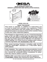 Desa Hearth Products B36L-MC El manual del propietario
-
Remington Hearth Vent-Free Gas Log Heater Manual de usuario
-
Focal Point F500116 Wall Mounted Room Heater Manual de usuario
-
Emberglow TCVFM18NL Guía de instalación
-
Emberglow TCVFT24NLDC Manual de usuario
-
Hearth Home DYNAMICS HHFAN100 Manual de usuario
