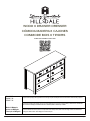
Hillsdale Furniture Addison Wood 6 Drawer Dresser El manual del propietario
- Tipo
- El manual del propietario

Page 1
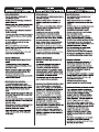
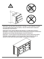
Examine all packaging material for small parts that may have come loose during shipment. Periodic checks are recommended to ensure that a
components are in proper position, tight and free from damage. Keep this asembly instruction for future reference. Adult assembly is required.
Examine el material de embalaje en busca de piezas pequeñas que puedan haberse aflojado durante el transporte. Se recomienda realizar
verificaciones periódicas para asegurar que todos los componentes estén en la posición correcta, apretados y libres de daños. Guarde estas
instrucciones de ensamblaje para referencias futuras. El ensamblaje debe ser realizado por un adulto.
Examinez tous les matériaux d'emballage pour les petites pièces qui peuvent avoir été lâche pendant le transport. Des contrôles périodiques
sont recommandées afin d'assurer que tous les composants sont en bonne position, tendu et sans dommages. Gardez ces instructions de
montage pour référence future. Assemblage par un adulte est requise.
Made in Malaysia
Hecho en Malaysia
Fabriqué en Malaysia
WOOD 6 DRAWER DRESSER
CÓMODA MADERA 6 CAJONES
COMMODE BOIS 6 TIROIRS
5419-716
5420-716
5542-716
V4 - Update 6/2/23
INTERACTIVE ASSEMBLY INSTRUCTIONS

Page 2

Page 3

Page 4
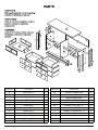
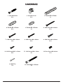
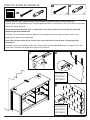
Parts No Decription Qty Parts No Description Qty
A Side Panel - L 1 M Bottom Support Bar 1
B Side Panel - R 1 N Support Bar 2
C Top Panel 1 O Back Support Bar 1
DDivider 1 P Drawer Bottom 6
EBack Bottom Panel 2 QDrawer Front Top - L 1
FBack MDF 1 R Drawer Front Top - R 1
GDrawer Back 6 S Drawer Front Bottom - L 2
HSide Leg - L 2 T Drawer Front Bottom - R 2
I Side Leg - R 2 U Drawer Side - L 6
J Frame - L 2 V Drawer Side - R 6
K Frame - R 2
LBottom Frame 1
A
B
C
D
E
N
N
E
F
G
H
I
I
K
K
O
U
V
P
Q
S
SR
T
T
J
M
L
J
H

Page 5
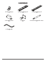
1. Cam Bolt EU24
50 x 2. Cam Nut 15/10
52 x 3. Dowel Ø8 x 50mm
1 x
4. Dowel Ø8 x 30mm
69 x 5. Dowel Ø8 x 20mm
2 x 6. CSK Screw M4 x 38mm
24 x
7. CSK Screw M4 x 30mm
12 x 8. CSK Screw M4 x 28mm
20 x 9. CSK Screw M4 x 20mm
24 x
13. Nail Pin
6 x 14. Unita M6.3 x 50mm
1 x
10. CSK Screw M3.5 x 15mm
58 x 11. CSK Screw M3 x 12mm
6 x 12. Euro Screw M6 x 8mm
12 x

15. PVC L Bracket
2 x 16. Cabinet Member 12”
6 x 17. Drawer Member 12”
6 x
Page 6
18. PVC Block 35mm
12 x 19. Handle
12 x 20. Double Head Bolt M7 x 62mm
1 x
21. Hex Key M4
1 x

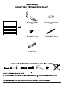
Page 7
1. Mounting L Bracket
2 x 2. Flat Washer M6 x 16mm
2 x
3. Screw #10 x 16mm
2 x 4. Screw M4 x 38mm
2 x
5. Wall Plug
2 x

Page 8
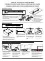
3
DRAWER BOTTOM
DRAWER FRONT
DRAWER RUNNER - B
FRONT
THIRD HOLE OUTER LAST THIRD HOLE
BACK
ROLLER
1
DRAWER FRONT
2
● Fix the second screw on
the last third hole.
Fije el segundo tornillo en
el último tercer oricio.
Fixez la deuxième vis sur
le dernier troisième trou
● Fix the rst screw on the third
hole from front.
Fije el primer tornillo en el
tercer oricio desde el frente.
Fixez la première vis sur le
troisième trou à partir de
l'avant.
● Push the runner to drawer front.
Empuje la guía hasta el frente
del cajón.
Poussez la glissière vers l'avant
du tiroir.
● Ensure the position of the drawer runner is
correct as showed above.
Asegúrese de que la posición de la guía del
cajón sea la correcta, como se muestra arriba.
Assurez-vous que la position de la glissière du
tiroir est correcte comme indiqué ci-dessus.
DRAWER ROLLER
CABINET ROLLER
21 3
INSTALL DRAWER TO CABINET / INSTALE EL CAJÓN AL GABINETE /
INSTALLER LE TIROIR SUR L'ARMOIRE
● Locate both roller on drawer
box and roller on cabinet.
Ubique tanto el rodillo en la
caja del cajón como el rodillo
en el gabinete.
Localisez à la fois le rouleau
sur la boîte à tiroirs et le
rouleau sur l'armoire
● Align the roller on drawer box
on top of the roller on cabinet.
Alinee el rodillo en la caja del
cajón en la parte superior del
rodillo en el gabinete.
Alignez le rouleau sur la boîte
à tiroirs sur le dessus du
rouleau sur l'armoire.
● Push inside the drawer box.
Empuje dentro de la caja del
cajón.
Poussez à l'intérieur de la
boîte à tiroirs
● Ensure the roller is in the track of drawer
slide before push to the end.
Asegúrese de que el rodillo esté en el
riel de la corredera del cajón antes de
empujarlo hasta el nal.
Assurez-vous que le rouleau est dans le
rail de la glissière du tiroir avant de
pousser jusqu'au bout.
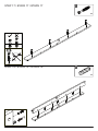
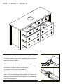
DRAWER RUNNER - A
FRONT
SECOND HOLE
TOP
BACK
TOP
FRONT
BOTTOM
BACK
1st
2nd
TOP
BOTTOM
1
TOP
2
● Fix the rst screw on the second hole on drawer runner
as shown.
Fije el primer tornillo en el segundo oricio de la guía del
cajón como se muestra
Fixez la première vis sur le deuxième trou de la glissière
du tiroir comme indiqué
● Fix the second screw following the holes on panel.
Fije el segundo tornillo siguiendo los agujeros en el panel
Fixez la deuxième vis en suivant les trous sur le panneau
● Ensure the position of the drawer
runner is correct as showed
above.
Asegúrese de que la posición de
la guía del cajón sea la
correcta, como se muestra arriba.
Assurez-vous que la position de la
glissière du tiroir est correcte
comme indiqué ci-dessus.
SPECIAL TIPS FOR FITTING DRAWER
CONSEJOS ESPECIALES PARA EL MONTAJE DEL CAJÓN
CONSEILS SPÉCIAUX POUR LE MONTAGE DU TIROIR

(2 x)
(2 x)
16 x
4
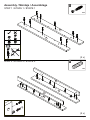
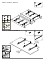
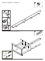
Assembly / Montaje / Assemblage
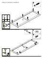
STEP 1 / ETAPA 1 / ÉTAPE 1
STEP 2 / ETAPA 2 / ÉTAPE 2
20 x
1
J
K
J
K
I
H
Page
9

(2 x)
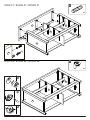
STEP 4 / ETAPA 4 / ÉTAPE 4
12 x
4
STEP 3 / ETAPA 3 / ÉTAPE 3
8 x
2
I
A
J
J
B
H
K
K
Page
10

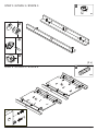
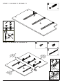
A
B
A
B
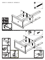
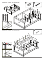
STEP 6 / ETAPA 6 / ÉTAPE 6
STEP 5 / ETAPA 5 / ÉTAPE 5
16 x
8
12 x
2
Page
11

A
B
A
B
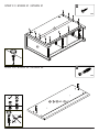
STEP 8 / ETAPA 8 / ÉTAPE 8
STEP 7 / ETAPA 7 / ÉTAPE 7
3 x
16
18 x
10
24 x
9
12 x
18
BACK
ESPALDA
ARRIÈRE
FRONT
DELANTERA
AVANT
FRONT
DELANTERA
AVANT
Page
12

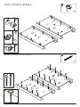
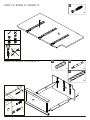
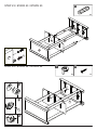
STEP 10 / ETAPA 10 / ÉTAPE 10
STEP 9 / ETAPA 9 / ÉTAPE 9
6 x
12
3 x
16
3 x
11
D
6 x
1
A
B
FRONT
DELANTERA
AVANT
3
1
BACK
ESPALDA
ARRIÈRE
2
BACK
ESPALDA
ARRIÈRE
FRONT
DELANTERA
AVANT
Page
13

D
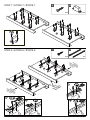
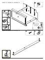
STEP 12 / ETAPA 12 / ÉTAPE 12
STEP 11 / ETAPA 11 / ÉTAPE 11
6 x
12
3 x
16
3 x
11
D
1 x
1
D
FRONT
DELANTERA
AVANT
1
3
BACK
ESPALDA
ARRIÈRE
2
BACK
ESPALDA
ARRIÈRE
BACK
ESPALDA
ARRIÈRE
FRONT
DELANTERA
AVANT
Page
14

STEP 14 / ETAPA 14 / ÉTAPE 14
STEP 13 / ETAPA 13 / ÉTAPE 13
1 x
3
1 x
20
3 x
4
E
N
A
D
1 x
3
D
20
3
Page
15

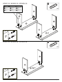
STEP 16 / ETAPA 16 / ÉTAPE 16
STEP 15 / ETAPA 15 / ÉTAPE 15
2 x
15
2 x
10
M
E
N
A
D
4 x
2
DO NOT TIGHTEN
NE SERREZ PAS
NO APRIETE
Page
16

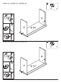
STEP 18 / ETAPA 18 / ÉTAPE 18
STEP 17 / ETAPA 17 / ÉTAPE 17
3 x
4
L
M
4 x
1
L
Page
17

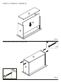
STEP 20 / ETAPA 20 / ÉTAPE 20
STEP 19 / ETAPA 19 / ÉTAPE 19
1 x
4
DM
E
A
4 x
2
M
Page
18

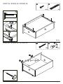
STEP 22 / ETAPA 22 / ÉTAPE 22
STEP 21 / ETAPA 21 / ÉTAPE 21 14
1 x
2 x
2
1 x
10
DM
E
E
M
A
A
TIGHTEN BOTH
SERREZ LES DEUX
APRIETE AMBOS
Page
19

STEP 24 / ETAPA 24 / ÉTAPE 24
STEP 23 / ETAPA 23 / ÉTAPE 23
4 x
2
4 x
4
DM
E
A
B
N
ME
N
1 x
10
Page
20

6 x
1
C
STEP 26 / ETAPA 26 / ÉTAPE 26
STEP 25 / ETAPA 25 / ÉTAPE 25
C
2 x
1
2 x
3
2 x
2
Page
21

6 x
4
C
A
A
D
D
B
B
STEP 28 / ETAPA 28 / ÉTAPE 28
STEP 27 / ETAPA 27 / ÉTAPE 27
6 x
2
Page
22

6 x
13
A
B
B
3mm
STEP 30 / ETAPA 30 / ÉTAPE 30
STEP 29 / ETAPA 29 / ÉTAPE 29
4 x
8
2 x
5
O
E
E
F
Page
23

12 x
10
STEP 32 / ETAPA 32 / ÉTAPE 32
STEP 31 / ETAPA 31 / ÉTAPE 31
12 x
1
S TRQ
/ / x2 / x2
B
F
Page
24

12 x
4
12 x
4
T
x2
SQ
/ x2
R
V
U
V
V
U
U
STEP 34 / ETAPA 34 / ÉTAPE 34
STEP 33 / ETAPA 33 / ÉTAPE 33
Page
25

STEP 36 / ETAPA 36 / ÉTAPE 36
STEP 35 / ETAPA 35 / ÉTAPE 35
6 x
2
6 x
2
TR
/ x2
V
V
U
U
SQ
/ x2
Page
26

24 x
6
(6 x)
(6 x)
V
P
G
V
G
STEP 38 / ETAPA 38 / ÉTAPE 38
STEP 37 / ETAPA 37 / ÉTAPE 37
Page
27

6 x
17
(6 x)
STEP 40 / ETAPA 40 / ÉTAPE 40
STEP 39 / ETAPA 39 / ÉTAPE 39
12 x
19
24 x
10
2
1
12x
7
S TRQ
/ / x2 / x2
U
G
V
V
U
Page
28

IMPORTANT: THIS UNIT MUST BE SECURE TO THE WALL TO HELP PREVENT TIPOVER.
FOLLOW THESE INSTRUCTIONS TO INSTALL THE ANTI-TIPPING SAFETY BRACKET
PROVIDED WITH THIS PRODUCT.
IMPORTANTE: ESTA UNIDAD DEBE ESTAR SEGURA A LA PARED PARA AYUDAR A
PREVENIR EL TIPOVER. SIGA ESTAS INSTRUCCIONES PARA INSTALAR EL SOPORTE DE
SEGURIDAD ANTI-TIPPING PROPORCIONADO CON ESTE PRODUCTO.
IMPORTANT : CETTE UNITÉ DOIT ÊTRE SÉCURITAIRE JUSQU’AU MUR POUR AIDER À
PRÉVENIR LA BASCULEMENT. SUIVEZ CES INSTRUCTIONS POUR INSTALLER LE
SUPPORT DE SÉCURITÉ ANTI-BASCULEMENT FOURNI AVEC CE PRODUIT.
Page
29

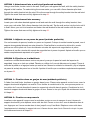
OPTION 1
OPCIÓN 1
OPTION 1
Drywall anchor that supplied with this product is general purpose wall plug only.
Consult your local hardware store for appropriate anchors for the type of wall you intend to securely
attach the safety bracket.
Ancla de paneles de yeso que se suministra con este producto es enchufe de pared de
propósito general solamente.
Consulte a su ferretería local para obtener los anclajes adecuados para el tipo de muro que
desea jar el soporte de seguridad.
Ancre de cloison sèche qui a fourni avec ce produit est prise de mur d’usage général
seulement.
Consultez votre quincaillerie locale pour trouver des ancres appropriées pour le type de mur que
vous avez l’intention de attacher le support de sécurité.
OPTION 2
OPCIÓN 2
OPTION 2
STEP 39 / ETAPA 39 / ÉTAPE 39
2 x
4
2 x
5
Page
30

OPTION 1 : Fixation dans un goujon de mur (méthode préférée)
À l’aide d’un stud nder, localisez un goujon dans le mur. Placez votre appareil contre le mur, avec le
support de sécurité alignés à cet endroit. Pour faciliter la conduite de la vis, vous pouvez percer un
trou pilote de 3 mm de diamètre à travers le support de sécurité dans le goujon. Conduisez la vis à
travers le support de sécurité dans le goujon du mur. Serrez la vis qui n’a pas été entièrement serrée
à l’étape 26.
OPTION 2 : Fixation en maçonnerie
Localisez votre appareil lorsque vous le souhaitez contre un mur et marquez le mur à travers le
support de sécurité, puis déplacer votre unité de côté. Percer un trou de 6 mm de diamètre dans le
mur. Appuyez sur l’ancre murale dans le trou jusqu’à ce qu’il est ush. Déplacez votre unité dans
l’emplacement et attachez le support de mur à l’ancre de mur avec la vis. Serrez la vis qui n’a pas
été entièrement serrée à l’étape 26.
OPTION 1: Attachment into a wall stud (preferred method)
Using a stud nder, locate a stud in the wall. Place your unit against the wall, with the safety bracket
aligned in this location. To make driving the screw easier, you can drill a 3mm diameter pilot hole
through the safety bracket into the stud. Drive the screw through the safety bracket into the wall stud.
Tighten the screw that was not fully tightened in step 26.
OPTION 2: Attachment into masonry
Locate your unit where desired against a wall and mark the wall through the safety bracket, then
move your unit aside. Drill a 6mm diameter hole into the wall. Tap the wall anchor into the hole until it
is ush. Move your unit into location and fasten the wall bracket to the wall anchor with the screw.
Tighten the screw that was not fully tightened in step 26.
OPCION 1: Adjunto en un perno de pared (método preferido)
Con un buscador de pernos, localice un perno en la pared. Coloque la unidad contra la pared, con el
soporte de seguridad alineado en esta ubicación. Para facilitar la conducción del tornillo, puede
perforar un oricio piloto de 3 mm de diámetro a través del soporte de seguridad en el perno.
Conduzca el tornillo a través del soporte de seguridad en el perno de pared. Apriete el tornillo que no
estaba completamente apretado en el paso 26.
OPCION 2: Fijación en la albañilería
Localice su unidad donde desee contra una pared y marque la pared a través del soporte de
seguridad, luego a un lado su unidad. Taladre un oricio de 6 mm de diámetro en la pared. Toque el
ancla de la pared en el agujero hasta que está al ras. Mueva la unidad a la ubicación y je el soporte
de pared al anclaje de pared con el tornillo. Apriete el tornillo que no estaba completamente apretado
en el paso 26.
Page
31

Put the Drawer that has axed anti tip warning label in the top
drawer position
Coloque el cajón que tiene una etiqueta de advertencia anti
punta ja en la posición superior del cajón
Placez le tiroir qui a une étiquette d’avertissement anti-pointe
axed dans la position du tiroir supérieur
STEP 40 / ETAPA 40 / ÉTAPE 40
R
Page
32

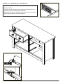
This product is designed to withstand the weight
vindicated on the plan. We are not responsible for the
breakage of parts or any injury caused by failure to comply
with this recommendation.
Este producto está diseñado para soportar el peso
indicado en el plan. No somos responsables de la rotura
de piezas o cualquier lesión causada por el
incumplimiento de esta recomendación.
Ce produit est conçu pour résister au poids indiqué sur le
plan. Nous ne sommes pas responsables de la rupture de
pièces ou de toute blessure causée par le non-respect de
cette recommandation.
STEP 41 / ETAPA 41 / ÉTAPE 41
35 lbs
25 lbs
25 lbs
R
Q
T
S
T
S
Page
33

-
 1
1
-
 2
2
-
 3
3
-
 4
4
-
 5
5
-
 6
6
-
 7
7
-
 8
8
-
 9
9
-
 10
10
-
 11
11
-
 12
12
-
 13
13
-
 14
14
-
 15
15
-
 16
16
-
 17
17
-
 18
18
-
 19
19
-
 20
20
-
 21
21
-
 22
22
-
 23
23
-
 24
24
-
 25
25
-
 26
26
-
 27
27
-
 28
28
-
 29
29
-
 30
30
-
 31
31
-
 32
32
-
 33
33
-
 34
34


Hillsdale Furniture Addison Wood 6 Drawer Dresser El manual del propietario
- Tipo
- El manual del propietario
En otros idiomas
Documentos relacionados
-
Hillsdale Furniture Addison Wood Nightstand El manual del propietario
-
-
-
-
-
-
-


