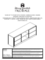
Hillsdale Furniture Brindle Wood 6 inch Media Console El manual del propietario
- Tipo
- El manual del propietario

Made in Malaysia
Hecho en Malaysia
Fabriqué en Malaysia
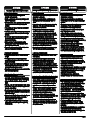
Examine all packaging material for small parts that may have come loose during shipment. Periodic checks are
recommended to ensure that a components are in proper position, tight and free from damage. Keep this
asembly instruction for future reference. Adult assembly is required.
Examine el material de embalaje en busca de piezas pequeñas que puedan haberse aflojado durante el
transporte. Se recomienda realizar verificaciones periódicas para asegurar que todos los componentes estén
en la posición correcta, apretados y libres de daños. Guarde estas instrucciones de ensamblaje para
referencias futuras. El ensamblaje debe ser realizado por un adulto.
Examinez tous les matériaux d'emballage por les petites pièces qui peuvent avoir été lâche pendant le
transport. Des contrôles périodiques sont recommandées afin d'assurer que tous les composants sont en
bonne position, tendu et sans dommages. Gardez ces instructions de montage pour référence future.
Assemblage par un adulte est requise.
2703-890
2703-891
2703-892
WOOD 60" TV STAND WITH 2 DOORS, GAMING HOOKS, GAMING
DRAWER, USB AND 2A ADAPTOR
SOPORTE DE TV DE 60" CON CAJÓN DE JUEGO, ADAPTADOR USB Y 2A
SUPPORT TV DE 60 » AVEC TIROIR DE JEU, ADAPTATEUR USB ET
ADAPTATEUR 2A
Page 1


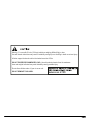
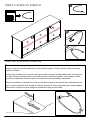
Warning - For use with 60 inch (152.4cm) televisions weighing 88lbs (40kg) or less.
Use with heavier televisions may result in instability causing tip over resulting in death or serious injury.
All other support shelves should not be loaded more than 25 lbs.
DO NOT EXCEED RECOMMENDED LOAD. Use with products heavier than the maximum
sizes and weights indicated may result instability causing possible injury.
Do not allow children under 10 year to move unit.
DO NOT REMOVE THIS LABEL

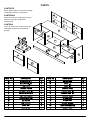
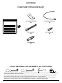
CONTENTS
Before getting started, ensure the package
contains the following components:
CONTENIDO
Antes de comenzar, asegúrese de que el
paquete contenga los siguientes
componentes:
CONTENU
Avant de commencer, assurez-vous que
l'emballage contient les composants
suivants:
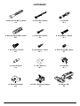
PARTS
Page 4
A
B
C
D
E
F
G
H
I
J
J
K
L
M
M
N
O
P
Q
R
S
T
U
V
W
W
W
W
X
X

HARDWARE
2. Screw M4 x 38mm
4 x
3. Cam Bolt
33 x
4. Wooden Dowel M8 x 30mm
45 x
6. Screw M3.1 x 20mm
20 x
8. Screw M3.5 x 15mm
14 x
9. Euro Screw M6 x 8mm
2 x
12. Cam Nut
33 x
Page 5
13. Back Ply Stopper
18 x
1. Unitar Screw M6.3 x 40mm
4 x
7. Screw #10 x 16mm
18 x
10. Shelf Support
4 x
5. Screw M4 x 20mm
4 x
11. PVC Nail Leg
10 x
15. Hinges 5/8"
4 x
14. PVC L Bracket (4 Holes)
2 x

19. Drawer Slide 12"
1 set x
20. Drawer Slide 12"
1 set x
21. Hex Key M4
1 x
Page 6
16. PVC Block 35mm
2 x
18. Hook 2 x 45 x 60 x 15mm
1 x
17. USB Dual Port with Adaptor
1 x
HARDWARE

3.5m/12'
TOOLS REQUIRED FOR ASSEMBLY (NOT INCLUDED)
DO NOT USE POWER TOOLS TO ASSEMBLE THIS PRODUCT. USE OF POWER TOOLS WILL INVALIDATE ANY CLAIM AND MAY
DAMAGE THIS PRODUCT MAKING IT UNSAFE.
NO USE HERRAMIENTAS ELÉCTRICAS PARA MONTAR ESTE PRODUCTO. EL USO DE LAS HERRAMIENTAS ELÉCTRICAS
INVALIDARÁ CUALQUIER RECLAMO Y PUEDE DAÑAR ESTE PRODUCTO QUE LO PONE SEGURO.
N'UTILISEZ PAS D'OUTILS ÉLECTRIQUES POUR ASSEMBLER CE PRODUIT. L'UTILISATION DES OUTILS ÉLECTRIQUES
ANNULERA TOUTE RÉCLAMATION ET PEUT ENDOMMAGER CE PRODUIT LE RENDANT SÉCURITAIRE.
Page 7
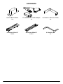
HARDWARE
FURNITURE TIPPING RESTRAINT
25. Screw 5/8"
2 x
24. Screw 2"
2 x
26. Wall Plug
2 x
22. Safety Bracket
4 x
23. Restraint Strap
2 x

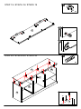
Assembly / Montaje / Assemblage
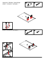
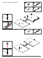
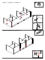
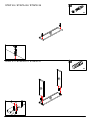
STEP 1 / ETAPA 1 / ÉTAPE 1
STEP 2 / ETAPA 2 / ÉTAPE 2
Page 8
1
2
4 x
5
2 x
8
2 x
16
1 x
19
A
A

STEP 4 / ETAPA 4 / ÉTAPE 4
STEP 3 / ETAPA 3 / ÉTAPE 3
Page 9
2 x
3
2 x
3
2 x
9
2 x
10
2 x
10
1 x
19
E
E
F
F

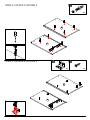
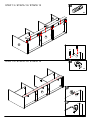
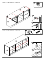
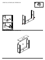
STEP 5 / ETAPA 5 / ÉTAPE 5
STEP 6 / ETAPA 6 / ÉTAPE 6
Page 10
8 x
3
4 x
8
2 x
14
A
A
B
B

1
2
STEP 7 / ETAPA 7 / ÉTAPE 7
STEP 8 / ETAPA 8 / ÉTAPE 8
Page 11
4 x
1
7 x
3
4 x
4
D
E
F
K
L

Page 12
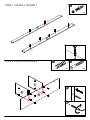
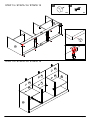
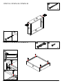
STEP 9 / ETAPA 9 / ÉTAPE 9
STEP 10 / ETAPA 10 / ÉTAPE 10
7 x
4
12 x
4
A
B
D
D
E
G
G
L
L
H
H
F

STEP 11 / ETAPA 11 / ÉTAPE 11
STEP 12 / ETAPA 12 / ÉTAPE 12
Page 13
1
2
2 x
4
12 x
12
D
G
L
M
M
H

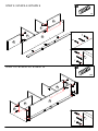
STEP 13 / ETAPA 13 / ÉTAPE 13
STEP 14 / ETAPA 14 / ÉTAPE 14
Page 14
1
2
8 x
4
7 x
12
A
B
D
D
K
M
M
M
M

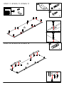
STEP 15 / ETAPA 15 / ÉTAPE 15
STEP 16 / ETAPA 16 / ÉTAPE 16
Page 15
4 x
8
10 x
11
A
A
B
B
K
L
M
M
W
XW
X
W
W

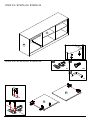
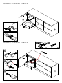
STEP 17 / ETAPA 17 / ÉTAPE 17
STEP 18 / ETAPA 18 / ÉTAPE 18
Page 16
12 x
3
2 x
4
C
C
J
J
2 x
25
2 x
22

Page 17
STEP 19 / ETAPA 19 / ÉTAPE 19
STEP 20 / ETAPA 20 / ÉTAPE 20
1
2
8 x
4
4 x
12
A
B
C
C
E
F
J
J

STEP 21 / ETAPA 21 / ÉTAPE 21
STEP 22 / ETAPA 22 / ÉTAPE 22
Page 18
1
2
1
2
18 x
6
8 x
12
18 x
13
A
B
B
C
E
F
W
W
W
W
X
X

STEP 23 / ETAPA 23 / ÉTAPE 23
STEP 24 / ETAPA 24 / ÉTAPE 24
Page 19
10 x
7
4 x
15
1 x
18
N
O
A
I

Page 20
STEP 25 / ETAPA 25 / ÉTAPE 25
8 x
7
A
B
N
O
1
234
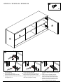
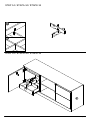
A. Lateral adjustment (Moving Door Left-Right)
by screw adjusting
A. Ajuste lateral (puerta móvil
izquierda-derecha) ajustando el tornillo
A. Réglage latéral (porte mobile gauche-droite)
par réglage de la vis
B. Vertical adjustment (Moving Door Up-Down)
via slot in the mounting plate
B. Ajuste vertical (Moving Door Up-Down) a
través de ranura en la placa de montaje
B. Réglage vertical (Moving Door Up-Down) via
fente dans la plaque de montage
C. Front-to-back adjustment (Spacing Door Off
Carcas) by slacking the hinge arm mounting
screw
C. Ajuste de frente a espalda (puerta de
espaciado de las canales) aflojando el
tornillo de montaje del brazo de la bisagra
C. Réglage avant-arrière (Espacement de la
porte hors carcasse) en relâchement de la
vis de montage du bras de charnière

Page 21
STEP 26 / ETAPA 26 / ÉTAPE 26
2 x
3
2 x
4
STEP 27 / ETAPA 27 / ÉTAPE 27
P
P
Q
R

Page 22
1
2
2 x
12
STEP 28 / ETAPA 28 / ÉTAPE 28
STEP 29 / ETAPA 29 / ÉTAPE 29
P
P
Q
Q
R
R
S
V

1
2
3
4 x
2
4 x
8
1 x
20
STEP 30 / ETAPA 30 / ÉTAPE 30
STEP 31 / ETAPA 31 / ÉTAPE 31
Page 23
P
P
Q
R
S

STEP 32 / ETAPA 32 / ÉTAPE 32
STEP 33 / ETAPA 33 / ÉTAPE 33
1
2
3
2 x
6
1 x
17
Page 24
A
B
B
N
PR
S

1
2
STEP 34 / ETAPA 34 / ÉTAPE 34
STEP 35 / ETAPA 35 / ÉTAPE 35
Page 25
B
P
T
T
U
U

Page 26
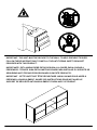
IMPORTANT: THIS UNIT MUST BE SECURE TO THE WALL TO HELP PREVENT TIPOVER.
FOLLOW THESE INSTRUCTIONS TO INSTALL THE ANTI-TIPPING SAFETY BRACKET
PROVIDED WITH THIS PRODUCT.
IMPORTANTE: ESTA UNIDAD DEBE ESTAR SEGURA A LA PARED PARA AYUDAR A
PREVENIR EL TIPOVER. SIGA ESTAS INSTRUCCIONES PARA INSTALAR EL SOPORTE DE
SEGURIDAD ANTI-TIPPING PROPORCIONADO CON ESTE PRODUCTO.
IMPORTANT : CETTE UNITÉ DOIT ÊTRE SÉCURITAIRE JUSQU’AU MUR POUR AIDER À
PRÉVENIR LA BASCULEMENT. SUIVEZ CES INSTRUCTIONS POUR INSTALLER LE
SUPPORT DE SÉCURITÉ ANTI-BASCULEMENT FOURNI AVEC CE PRODUIT.

2"/5cm
Page 27
OPTION 1
OPCIÓN 1
OPTION 1
OPTION 2
OPCIÓN 2
OPTION 2
26
STEP 36 / ETAPA 36 / ÉTAPE 36
2 x
Drywall anchor that supplied with this product is general purpose wall plug only.
Consult your local hardware store for appropriate anchors for the type of wall you intend to
securely attach the safety bracket.
Ancla de paneles de yeso que se suministra con este producto es enchufe de pared de
propósito general solamente.
Consulte a su ferretería local para obtener los anclajes adecuados para el tipo de muro que
desea fijar el soporte de seguridad.
Ancre de cloison sèche qui a fourni avec ce produit est prise de mur d’usage général
seulement.
Consultez votre quincaillerie locale pour trouver des ancres appropriées pour le type de mur que
vous avez l’intention de attacher le support de sécurité.
2 x
24 22
2 x

Page 28
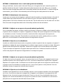
OPTION 1: Attachment into a wall stud (preferred method)
Using a stud finder, locate a stud in the wall. Place your unit against the wall, locate the position of
another bracket on the wall, 2 inches below the bracket secured to the unit. Move your unit aside.
Drive the screw through the smaller hole of the safety bracket into the wall stud. To make driving the
screw easier, you can drill a 3mm diameter pilot hole through the safety bracket into the stud.
OPTION 2: Attachment into masonry
Locate your unit where desired against a wall and locate the position of another bracket on the wall, 2
inches below the bracket secured to the unit then move your unit aside. Mark the wall through the
safety bracket. Drill a 6mm diameter hole into the wall. Tap the wall anchor into the hole until it is flush.
Drive the screw through the smaller hole of the safety bracket into the wall anchor.
OPCION 1: Adjunto en un perno de pared (método preferido)
OPCION 2: Fijación en la albañilería
Con un buscador de pernos, localice un perno en la pared. Coloque su unidad contra la pared, localice
la posición de otro soporte en la pared, 2 pulgadas por debajo del soporte asegurado a la unidad. Deja
tus unidades a un lado. Conduzca el tornillo a través del orificio más pequeño del soporte de
seguridad en el perno de pared. Para facilitar la conducción del tornillo, puede perforar un orificio
piloto de 3 mm de diámetro a través del soporte de seguridad en el perno.
Localice su unidad donde desee contra una pared y localice la posición de otro soporte en la pared, 2
pulgadas por debajo del soporte asegurado a la unidad y luego mueva su unidad a un lado. Marque la
pared a través del soporte de seguridad. Taladro de un agujero de 6 mm de diámetro en la pared.
Toque el anclaje de la pared en el agujero hasta que esté al ras. Conduzca el tornillo a través del
orificio más pequeño del soporte de seguridad en el anclaje de la pared.
OPCION 1: Adjunto en un perno de pared (método preferido)
À l’aide d’un trouveur de goujons, placez un goujon dans le mur. Placez votre appareil contre le mur,
localisez la position d’un autre support sur le mur, 2 pouces au-dessous du support fixé à l’appareil.
Déplacez vos unités de côté. Conduisez la vis à travers le plus petit trou du support de sécurité dans
le goujon mural. Pour faciliter la conduite de la vis, vous pouvez percer un trou pilote de 3 mm de
diamètre à travers le support de sécurité dans le goujon.
OPCION 2: Fijación en la albañilería
Localisez votre appareil là où vous le souhaitez contre un mur et placez la position d’un autre support
sur le mur, 2 pouces au-dessous du support fixé à l’appareil, puis déplacez votre appareil de côté.
Marquez le mur à travers le support de sécurité. Percer un trou de 6 mm de diamètre dans le mur.
Appuyez sur l’ancre murale dans le trou jusqu’à ce qu’elle soit rincée. Conduisez la vis à travers le
plus petit trou du support de sécurité dans l’ancre murale.

Page 29
STEP 37 / ETAPA 37 / ÉTAPE 37
2 x
23
STEP 38 / ETAPA 38 / ÉTAPE 38
1
2
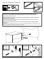
Place the furniture into position so both safety brackets are vertically in line. Lace the end of the
restraint strap through the larger hole in each safety bracket. Confirm that the strap is securely
laced and locked.
Coloque los muebles en su posición para que ambos soportes de seguridad estén verticalmente
en línea. Encaje el extremo de la correa de sujeción a través del agujero más grande en cada
soporte de seguridad. Confirme que la correa está firmemente atada y bloqueada.
Placez les meubles en position de sorte que les deux supports de sécurité sont verticalement en
ligne. Lacez l’extrémité de la sangle de retenue à travers le trou plus grand dans chaque support
de sécurité. Confirmez que la sangle est solidement lacée et verrouillée.

88 lbs
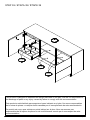
STEP 39 / ETAPA 39 / ÉTAPE 39
This product is designed to withstand the weight indicated on the plan. We are not responsible for
the breakage of parts or any injury caused by failure to comply with this recommendation.
Este producto está diseñado para soportar el peso indicado en el plan. No somos responsables
de la rotura de piezas o cualquier lesión causada por el incumplimiento de esta recomendación.
Ce produit est conçu pour résister au poids indiqué sur le plan. Nous ne sommes pas
responsables de la rupture de pièces ou de toute blessure causée par le non-respect de cette
recommandation.
11 lbs
25 lbs
25 lbs
Page 30
-
 1
1
-
 2
2
-
 3
3
-
 4
4
-
 5
5
-
 6
6
-
 7
7
-
 8
8
-
 9
9
-
 10
10
-
 11
11
-
 12
12
-
 13
13
-
 14
14
-
 15
15
-
 16
16
-
 17
17
-
 18
18
-
 19
19
-
 20
20
-
 21
21
-
 22
22
-
 23
23
-
 24
24
-
 25
25
-
 26
26
-
 27
27
-
 28
28
-
 29
29
-
 30
30


Hillsdale Furniture Brindle Wood 6 inch Media Console El manual del propietario
- Tipo
- El manual del propietario
en otros idiomas
Artículos relacionados
-
Hillsdale Furniture Campbell Wood Desk El manual del propietario
-
-
-
-
-
Otros documentos
-
Dorel Living FA1011-1 Guía de instalación
-
Dorel DL1010-6MOV Guía de instalación
-
 Dorel Home Furnishings DA7608-1SIL El manual del propietario
-
-
-
-
Ameriwood Home 5995196COM Guía de instalación
-
BABY RELAX DA7923-1GR El manual del propietario
