Hillsdale Furniture Campbell Wood Desk El manual del propietario
- Tipo
- El manual del propietario

WOODSTUDYDESKWITH1DRAWERAND2SHELFSTORAGE
ESCRITORIODEMADERACON1CAJÓNY2ESTANTES
BUREAUD'ÉTUDEENBOISAVEC1TIROIRET2ÉTAGÈRESDERANGEMENT
2729−778
2731−778
Made in Malaysia
Hecho en Malaysia
Fabriqué en Malaysia
V
Page 1

Page 2

Page 3

Page 4
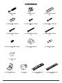
NO. PART NAME PIECES NO. PART NAME PIECES
A Side - L 1 K Drawer Bottom 1
B Side - R 1 L Front Support Bar II 1
C Top 1 M Shelf 1
D Bottom 1 N Back I 1
E Front Support Bar I 1 O Bottom Front Prole 1
F Side Front Bar 1 P Bottom Side Bar 2
G Drawer Front 1 Q Back II 1
H Drawer Side L 1 R Bottom Back 1
I Drawer Side R 1 S Partition 1
J Drawer Back 1
A
B
C
D
E
F
G
H
L
I
J
K
P
Q
R
S
P
MN
O

7. Screw M4 x 25mm
4 x 8. Screw M4 x 30mm
1 x 9. Screw M4 x 38mm
4 x
10. Euro Screw M6 x 8mm
4 x 11. Backply Stopper
6 x 12. Shelf Support
4 x
Page 5
1. Minix Bolt
24 x 2. Minix Cam
24 x 3. Dowel Ø8 x 30mm
30 x
4. Dowel Ø8 x 20mm
4 x 5. Screw M3.5 x 15mm
20 x 6. Screw M3.1 x 20 mm
6 x
13. Nail Leg
6 x
15. PVC L Bracket
8 x 16. Handle
1 x 17. Drawer Slide 12”
1 sets x 18. Drawer Slide 12”
1 sets x

Page 6
14. Wall Plug
1 x
19. Restraint Strap
1 x 20. Safety Bracket
2 x
21. Screw 5/8”
1 x 22. Screw 2’’
1 x

Page 7
4 x
10
Assembly / Montaje / Assemblage
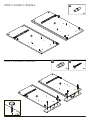
STEP 1 / ETAPA 1 / ÉTAPE 1
STEP 2 / ETAPA 2 / ÉTAPE 2
1 x
17
A
A
S
S
8 x
1

A
A
P
P
S
S
Page 8
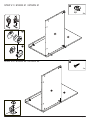
STEP 3 / ETAPA 3 / ÉTAPE 3
STEP 4 / ETAPA 4 / ÉTAPE 4
4 x
4
4 x
7
4 x
12

Page 9
STEP 6 / ETAPA 6 / ÉTAPE 6
STEP 5 / ETAPA 5 / ÉTAPE 5
8 x
3
2 x
1
P
S
S
A
L
D
R

Page 10
STEP 8 / ETAPA 8 / ÉTAPE 8
STEP 7 / ETAPA 7 / ÉTAPE 7
1 x
15
1 x
5
8 x
2
1
2
L
D
R
O

Page 11
O
STEP 9 / ETAPA 9 / ÉTAPE 9
2 x
1
STEP 10 / ETAPA 10 / ÉTAPE 10
2 x
2
O

Page 12
STEP 12/ ETAPA 12 / ÉTAPE 12
STEP 11 / ETAPA 11 / ÉTAPE 11
4 x
13
1 x
5
O
D
A
A
S
S

Page 13
STEP 14 / ETAPA 14 / ÉTAPE 14
STEP 13 / ETAPA 13 / ÉTAPE 13
3 x
15
3 x
5
B
S
Q

Page 14
STEP 16 / ETAPA 16 / ÉTAPE 16
STEP 15 / ETAPA 15 / ÉTAPE 15
2 x
3
2 x
1
B
B
F

Page 15
STEP 18 / ETAPA 18 / ÉTAPE 18
STEP 17 / ETAPA 17 / ÉTAPE 17
3 x
5
2 x
13
B
B
F

Page 16
STEP 20 / ETAPA 20 / ÉTAPE 20
STEP 19 / ETAPA 19 / ÉTAPE 19
2 x
3
4 x
15
4 x
5
E
N
N
B

Page 17
STEP 22 / ETAPA 22 / ÉTAPE 22
STEP 21 / ETAPA 21 / ÉTAPE 21
2 x
2
1
2
1 x
5
N
N
B
B

Page 18
STEP 24 / ETAPA 24 / ÉTAPE 24
STEP 23 / ETAPA 23 / ÉTAPE 23
2 x
2
1
2
6 x
3
N
N
B
E
S

Page 19
STEP 26 / ETAPA 26 / ÉTAPE 26
STEP 25 / ETAPA 25 / ÉTAPE 25
C
1 x
5
8 x
1

Page 20
STEP 28 / ETAPA 28 / ÉTAPE 28
STEP 27 / ETAPA 27 / ÉTAPE 27
10 x
3
C
N
B
E
S
A
1 x
20
1 x
21

Page 21
STEP 30 / ETAPA 30 / ÉTAPE 30
STEP 29 / ETAPA 29 / ÉTAPE 29
6 x
2
1
2
2 x
5
B
S
A
C

Page 22
STEP 32 / ETAPA 32 / ÉTAPE 32
STEP 31 / ETAPA 31 / ÉTAPE 31
2 x
2
1
2
6 x
11
6 x
6
C
N
Q

Page 23
STEP 34 / ETAPA 34 / ÉTAPE 34
STEP 33 / ETAPA 33 / ÉTAPE 33
2 x
1
4 x
3
G
G
I
H

Page 24
STEP 36 / ETAPA 36 / ÉTAPE 36
STEP 35/ ETAPA 35 / ÉTAPE 35
2 x
2
G
G
I
I
H
J
K

Page 25
STEP 38 / ETAPA 38 / ÉTAPE 38
STEP 37 / ETAPA 37 / ÉTAPE 37
4 x
9
1 x
18
4 x
5
2
1
3
G
H
J
J
K
I

G
Page 26
1 x
16
1 x
8
STEP 39 / ETAPA 39 / ÉTAPE 39

Page 27
IMPORTANT: THIS UNIT MUST BE SECURE TO THE WALL TO HELP PREVENT TIPOVER.
FOLLOW THESE INSTRUCTIONS TO INSTALL THE ANTI-TIPPING SAFETY BRACKET
PROVIDED WITH THIS PRODUCT.
IMPORTANTE: ESTA UNIDAD DEBE ESTAR SEGURA A LA PARED PARA AYUDAR A
PREVENIR EL TIPOVER. SIGA ESTAS INSTRUCCIONES PARA INSTALAR EL SOPORTE DE
SEGURIDAD ANTI-TIPPING PROPORCIONADO CON ESTE PRODUCTO.
IMPORTANT : CETTE UNITÉ DOIT ÊTRE SÉCURITAIRE JUSQU’AU MUR POUR AIDER À
PRÉVENIR LA BASCULEMENT. SUIVEZ CES INSTRUCTIONS POUR INSTALLER LE
SUPPORT DE SÉCURITÉ ANTI-BASCULEMENT FOURNI AVEC CE PRODUIT.

STEP 40 / ETAPA 40 / ÉTAPE 40
Page 28
1 x
22
1 x
20
OPTION 1
OPCIÓN 1
OPTION 1
1 x
14
OPTION 2
OPCIÓN 2
OPTION 2
2”/5cm
Drywall anchor that supplied with this product is general purpose wall plug only.
Consult your local hardware store for appropriate anchors for the type of wall you intend to securely
attach the safety bracket.
Ancla de paneles de yeso que se suministra con este producto es enchufe de pared de
propósito general solamente.
Consulte a su ferretería local para obtener los anclajes adecuados para el tipo de muro que
desea jar el soporte de seguridad.
Ancre de cloison sèche qui a fourni avec ce produit est prise de mur d’usage général
seulement.
Consultez votre quincaillerie locale pour trouver des ancres appropriées pour le type de mur que
vous avez l’intention de attacher le support de sécurité.
Page 28

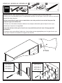
OPTION 1: Attachment into a wall stud (preferred method)
Using a stud nder, locate a stud in the wall. Place your unit against the wall, locate the position of
another bracket on the wall, 2 inches below the bracket secured to the unit. Move your units aside.
Drive the screw through the smaller hole of the safety bracket into the wall stud. To make driving the
screw easier, you can drill a 3mm diameter pilot hole through the safety bracket into the stud.
OPTION 2: Attachment into masonry
Locate your unit where desired against a wall and locate the position of another bracket on the wall,
2 inches below the bracket secured to the unit then move your unit aside. Mark the wall through the
safety bracket. Drill a 6mm diameter hole into the wall. Tap the wall anchor into the hole until it is
ush. Drive the screw through the smaller hole of the safety bracket into the wall anchor.
OPTION 1 : Fixation dans un goujon de mur (méthode préférée)
À l’aide d’un trouveur de goujons, placez un goujon dans le mur. Placez votre appareil contre le mur,
localisez la position d’un autre support sur le mur, 2 pouces au-dessous du support xé à l’appareil.
Déplacez vos unités de côté. Conduisez la vis à travers le plus petit trou du support de sécurité dans
le goujon mural. Pour faciliter la conduite de la vis, vous pouvez percer un trou pilote de 3 mm de
diamètre à travers le support de sécurité dans le goujon.
OPTION 2 : Fixation en maçonnerie
Localisez votre appareil là où vous le souhaitez contre un mur et placez la position d’un autre
support sur le mur, 2 pouces au-dessous du support xé à l’appareil, puis déplacez votre appareil de
côté. Marquez le mur à travers le support de sécurité. Percer un trou de 6 mm de diamètre dans le
mur. Appuyez sur l’ancre murale dans le trou jusqu’à ce qu’elle soit rincée. Conduisez la vis à travers
le plus petit trou du support de sécurité dans l’ancre murale.
OPCION 1: Adjunto en un perno de pared (método preferido)
Con un buscador de pernos, localice un perno en la pared. Coloque su unidad contra la pared,
localice la posición de otro soporte en la pared, 2 pulgadas por debajo del soporte asegurado a la
unidad. Deja tus unidades a un lado. Conduzca el tornillo a través del oricio más pequeño del
soporte de seguridad en el perno de pared. Para facilitar la conducción del tornillo, puede perforar
un oricio piloto de 3 mm de diámetro a través del soporte de seguridad en el perno.
OPCION 2: Fijación en la albañilería
Localice su unidad donde desee contra una pared y localice la posición de otro soporte en la pared,
2 pulgadas por debajo del soporte asegurado a la unidad y luego mueva su unidad a un lado.
Marque la pared a través del soporte de seguridad. Taladro de un agujero de 6 mm de diámetro en
la pared. Toque el anclaje de la pared en el agujero hasta que esté al ras. Conduzca el tornillo a
través del oricio más pequeño del soporte de seguridad en el anclaje de la pared.
Page 29

Place the furniture into position so both safety brackets are vertically
in line. Lace the end of the restraint strap through the larger hole in
each safety bracket. Conrm that the strap is securely laced and
locked.
Coloque los muebles en su posición para que ambos soportes de
seguridad estén verticalmente en línea. Encaje el extremo de la
correa de sujeción a través del agujero más grande en cada soporte
de seguridad. Conrme que la correa está rmemente atada y
bloqueada.
Placez les meubles en position de sorte que les deux supports de
sécurité sont verticalement en ligne. Lacez l’extrémité de la sangle
de retenue à travers le trou plus grand dans chaque support de
sécurité. Conrmez que la sangle est solidement lacée et verrouillée.
STEP 41 / ETAPA 41 / ÉTAPE 41
Page 30
1 x
19

STEP 42 / ETAPA 42 / ÉTAPE 42
Page 31
35 lbs
25 lbs

-
 1
1
-
 2
2
-
 3
3
-
 4
4
-
 5
5
-
 6
6
-
 7
7
-
 8
8
-
 9
9
-
 10
10
-
 11
11
-
 12
12
-
 13
13
-
 14
14
-
 15
15
-
 16
16
-
 17
17
-
 18
18
-
 19
19
-
 20
20
-
 21
21
-
 22
22
-
 23
23
-
 24
24
-
 25
25
-
 26
26
-
 27
27
-
 28
28
-
 29
29
-
 30
30
-
 31
31
-
 32
32


Hillsdale Furniture Campbell Wood Desk El manual del propietario
- Tipo
- El manual del propietario
en otros idiomas
Artículos relacionados
-
Hillsdale Furniture Cedar Falls Wood Desk El manual del propietario
-
-
-
-
-
