Hillsdale Furniture Cedar Falls Wood Desk El manual del propietario
- Tipo
- El manual del propietario

CEDAR FALLS LIFT TOP STUDY DESK
MESA DE ESTUDIO CON SUPERIOR ELEVADORA CEDAR FALLS
BUREAU D'ÉTUDE À DESSUS ÉLÉVATEUR CEDAR FALLS
2789-778
Made in Malaysia
Hecho en Malaysia
Fabriqué en Malaysia
V
Page 1

Page 2

1
2
LIFT UP MECHANISM SET
JUEGO DE MECANISMO DE ELEVACIÓN
ENSEMBLE DE MÉCANISME DE LEVAGE
Lift Up Mechanism L&R - 2 units
Mecanismo De Elevación L&R - 2 unidades
Mécanisme De Levage L&R - 2 unités
Spring - 2 units
Resortes - 2 unidades
Ressorts - 2 unités
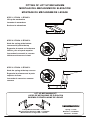
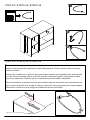
FITTING OF LIFT UP MECHANISM
MONTAJE DEL MECANISMO DE ELEVACIÓN
MONTAGE DU MÉCANISME DE LEVAGE
STEP 1 / ETAPA 1 / ÉTAPE 1
Lift up the mechanism
Levantar el mecanismo
Soulever le mécanisme
STEP 2 / ETAPA 2 / ÉTAPE 2
Hook the spring at the bottom
concave and pull to the top
Enganche el resorte en la cóncava
inferior y tire a la parte superior
Accrochez le ressort à la concave
inférieure et tirez vers le haut
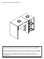
STEP 3 / ETAPA 3 / ÉTAPE 3
Hook the spring at the top concave
Engancha la primavera en la parte
superior cóncava
Accrocher le ressort au sommet
concave
Page 3

English
French
Spanish
Page 4

Page 5
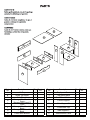
Parts
No Decription Qty Carton
No. Parts
No Description Qty Carton
No.
A Lift Top 1 I Top Apron Front 1
B Small Top Panel 1 J Top Apron Back 1
C Side Panel L 1 K Back Panel Bottom 1
DStorage Side Panel L
Front 1 L Centre Support 1
EStorage Side Panel R
Front 1 M Side Support R 1
FStorage Side Panel L
Back 1 N Fixed Shlef Top 1
GStorage Side Panel R
Back 1 O Side Support L 1
H Fixed Shelf Bottom 1 P 3MM Bottom Panel 2
A
B
J
K
C
O
P
L
P
M
N
F
D
H
G
E
I

Page 6
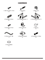
1. CSK Screw M3.5 x 15mm
8 x 2. Minix Bolt
34 x 3. Minix Cam
34 x
4. Dowel Ø8 x 30mm
30 x 5. Lift Up Mechanism - L
1 x 6. Lift Up Mechanism - R
1 x
7. Screw M5 x 13mm
16 x 8. PVC L Bracket
4 x 9. Nail Leg
6 x
10. Allen Key Z - M4
1 x 11. Back Ply Stopper
8 x 12. Screw M3.1 x 20mm
8 x
13. Door Bubble
6 x

Page 7
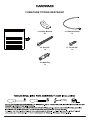
FURNITURE TIPPING RESTRAINT
17. Screw 5/8"
1 x
16. Screw 2"
1 x
18. Wall Plug
1 x
14. Safety Bracket
2 x
15. Restraint Strap
1 x

Page 8
4 x
1
4 x
8
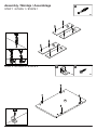
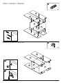
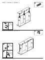
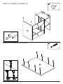
Assembly / Montaje / Assemblage
STEP 1 / ETAPA 1 / ÉTAPE 1
STEP 2 / ETAPA 2 / ÉTAPE 2
8 x
2
F
D
G
E
H

Page 9
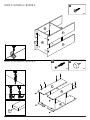
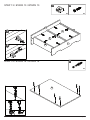
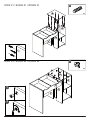
STEP 4 / ETAPA 4 / ÉTAPE 4
STEP 3 / ETAPA 3 / ÉTAPE 3
8 x
3
8 x
4
H
H
F
F
D
D
G
G
E
E
1
2
N
N

Page 10
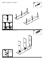
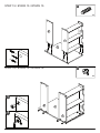
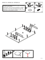
STEP 6 / ETAPA 6 / ÉTAPE 6
STEP 5 / ETAPA 5 / ÉTAPE 5
4 x
9
4 x
1
HF
F
D
D
G
G
E
E
6 x
2

Page 11
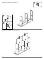
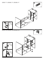
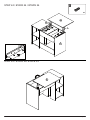
STEP 8 / ETAPA 8 / ÉTAPE 8
STEP 7 / ETAPA 7 / ÉTAPE 7
6 x
4
6 x
2
J
J
O
L
M
I

Page 12
STEP 10 / ETAPA 10 / ÉTAPE 10
STEP 9 / ETAPA 9 / ÉTAPE 9
3 x
3
O
O
L
L
M
M
1
2
P
P
J

Page 13
3 x
3
STEP 12 / ETAPA 12 / ÉTAPE 12
6 x
4
STEP 11 / ETAPA 11 / ÉTAPE 11
O
O
L
L
M
M
1
2
I
I

Page 14
STEP 14 / ETAPA 14 / ÉTAPE 14
STEP 13 / ETAPA 13 / ÉTAPE 13
6 x
2
8 x
12
8 x
11
P
P
M
L
O
J
1
2
C
I

Page 15
STEP 16 / ETAPA 16 / ÉTAPE 16
STEP 15 / ETAPA 15 / ÉTAPE 15
6 x
3
3 x
4
C
C
J
J
K
K
I
I
1
2

Page 16
STEP 18 / ETAPA 18 / ÉTAPE 18
STEP 17 / ETAPA 17 / ÉTAPE 17
5 x
3
3 x
4
F
F
D
D
J
J
K
K
II
I
1
2

Page 17
STEP 20 / ETAPA 20 / ÉTAPE 20
STEP 19 / ETAPA 19 / ÉTAPE 19
8 x
2
2 x
9
C
J
K
B

Page 18
STEP 22 / ETAPA 22 / ÉTAPE 22
STEP 21 / ETAPA 21 / ÉTAPE 21
9 x
3
4 x
4
B
F
D
F
D
G
G
E
E
1
2
B
I

1 x
6
8 x
7
6 x
13
1 x
5
STEP 23 / ETAPA 23 / ÉTAPE 23
A
IMPORTANT: See detailed instructions on page 3 for FITTING
OF LIFT UP MECHANISM.
IMPORTANTE: Vea las instruccioned detailadas en la página 3
para la INSTALACIÓN DEL MECANISMO DE ELEVACIÓN.
IMPORTANT: Voir les instructions détaillées à la page 3 pour le
MONTAGE DU MÉCANISME DE LEVAGE.
R
L
12
Page 19

Page 20
STEP 25 / ETAPA 25/ ÉTAPE 25
STEP 24 / ETAPA 24 / ÉTAPE 24
A
8 x
7
A
M
O
C
R
L

Page 21
J
1 x
17
1 x
14
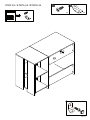
STEP 26 / ETAPA 26 /ÉTAPE 26

Page 22
IMPORTANT: THIS UNIT MUST BE SECURE TO THE WALL TO HELP PREVENT TIPOVER.
FOLLOW THESE INSTRUCTIONS TO INSTALL THE ANTI-TIPPING SAFETY BRACKET
PROVIDED WITH THIS PRODUCT.
IMPORTANTE: ESTA UNIDAD DEBE ESTAR SEGURA A LA PARED PARA AYUDAR A
PREVENIR EL TIPOVER. SIGA ESTAS INSTRUCCIONES PARA INSTALAR EL SOPORTE DE
SEGURIDAD ANTI-TIPPING PROPORCIONADO CON ESTE PRODUCTO.
IMPORTANT : CETTE UNITÉ DOIT ÊTRE SÉCURITAIRE JUSQU’AU MUR POUR AIDER À
PRÉVENIR LA BASCULEMENT. SUIVEZ CES INSTRUCTIONS POUR INSTALLER LE
SUPPORT DE SÉCURITÉ ANTI-BASCULEMENT FOURNI AVEC CE PRODUIT.

Page 23
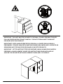
2"/5cm
Drywall anchor that supplied with this product is general purpose wall plug only.
Consult your local hardware store for appropriate anchors for the type of wall you intend to
securely attach the safety bracket.
Ancla de paneles de yeso que se suministra con este producto es enchufe de pared de
propósito general solamente.
Consulte a su ferretería local para obtener los anclajes adecuados para el tipo de muro que
desea fijar el soporte de seguridad.
Ancre de cloison sèche qui a fourni avec ce produit est prise de mur d’usage général
seulement.
Consultez votre quincaillerie locale pour trouver des ancres appropriées pour le type de mur que
vous avez l’intention de attacher le support de sécurité.
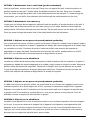
STEP 27 / ETAPA 27 /ÉTAPE 27
OPTION 1
OPCIÓN 1
OPTION 1
OPTION 2
OPCIÓN 2
OPTION 2
18
1 x
1 x
16 14
1 x

OPTION 1: Attachment into a wall stud (preferred method)
Using a stud nder, locate a stud in the wall. Place your unit against the wall, locate the position of
another bracket on the wall, 2 inches below the bracket secured to the unit. Move your unit aside.
Drive the screw through the smaller hole of the safety bracket into the wall stud. To make driving the
screw easier, you can drill a 3mm diameter pilot hole through the safety bracket into the stud.
OPTION 2: Attachment into masonry
Locate your unit where desired against a wall and locate the position of another bracket on the wall, 2
inches below the bracket secured to the unit then move your unit aside. Mark the wall through the
safety bracket. Drill a 6mm diameter hole into the wall. Tap the wall anchor into the hole until it is ush.
Drive the screw through the smaller hole of the safety bracket into the wall anchor.
OPCION 1: Adjunto en un perno de pared (método preferido)
OPCION 2: Fijación en la albañilería
Con un buscador de pernos, localice un perno en la pared. Coloque su unidad contra la pared, localice
la posición de otro soporte en la pared, 2 pulgadas por debajo del soporte asegurado a la unidad. Deja
tus unidades a un lado. Conduzca el tornillo a través del oricio más pequeño del soporte de
seguridad en el perno de pared. Para facilitar la conducción del tornillo, puede perforar un oricio
piloto de 3 mm de diámetro a través del soporte de seguridad en el perno.
Localice su unidad donde desee contra una pared y localice la posición de otro soporte en la pared, 2
pulgadas por debajo del soporte asegurado a la unidad y luego mueva su unidad a un lado. Marque la
pared a través del soporte de seguridad. Taladro de un agujero de 6 mm de diámetro en la pared.
Toque el anclaje de la pared en el agujero hasta que esté al ras. Conduzca el tornillo a través del
oricio más pequeño del soporte de seguridad en el anclaje de la pared.
OPCION 1: Adjunto en un perno de pared (método preferido)
À l’aide d’un trouveur de goujons, placez un goujon dans le mur. Placez votre appareil contre le mur,
localisez la position d’un autre support sur le mur, 2 pouces au-dessous du support xé à l’appareil.
Déplacez vos unités de côté. Conduisez la vis à travers le plus petit trou du support de sécurité dans
le goujon mural. Pour faciliter la conduite de la vis, vous pouvez percer un trou pilote de 3 mm de
diamètre à travers le support de sécurité dans le goujon.
OPCION 2: Fijación en la albañilería
Localisez votre appareil là où vous le souhaitez contre un mur et placez la position d’un autre support
sur le mur, 2 pouces au-dessous du support xé à l’appareil, puis déplacez votre appareil de côté.
Marquez le mur à travers le support de sécurité. Percer un trou de 6 mm de diamètre dans le mur.
Appuyez sur l’ancre murale dans le trou jusqu’à ce qu’elle soit rincée. Conduisez la vis à travers le
plus petit trou du support de sécurité dans l’ancre murale.
Page 24

Page 25
1 x
15
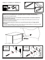
Place the furniture into position so both safety brackets are vertically in line. Lace the end of the
restraint strap through the larger hole in each safety bracket. Conrm that the strap is securely
laced and locked.
Coloque los muebles en su posición para que ambos soportes de seguridad estén verticalmente
en línea. Encaje el extremo de la correa de sujeción a través del agujero más grande en cada
soporte de seguridad. Conrme que la correa está rmemente atada y bloqueada.
Placez les meubles en position de sorte que les deux supports de sécurité sont verticalement en
ligne. Lacez l’extrémité de la sangle de retenue à travers le trou plus grand dans chaque support
de sécurité. Conrmez que la sangle est solidement lacée et verrouillée.
STEP 28 / ETAPA 28 /ÉTAPE 28
STEP 29 / ETAPA 29 /ÉTAPE 29
1
2

Page 26
This product is designed to withstand the weight indicated on the plan. We are not responsible
for the breakage of parts or any injury caused by failure to comply with this recommendation.
Este producto está diseñado para soportar el peso indicado en el plan. No somos responsables
de la rotura de piezas o cualquier lesión causada por el incumplimiento de esta recomendación.
Ce produit est conçu pour résister au poids indiqué sur le plan. Nous ne sommes pas
responsables de la rupture de pièces ou de toute blessure causée par le non-respect de cette
recommandation.
STEP 30 / ETAPA 30 /ÉTAPE 30
33 lbs
33 lbs
11 lbs
11 lbs

-
 1
1
-
 2
2
-
 3
3
-
 4
4
-
 5
5
-
 6
6
-
 7
7
-
 8
8
-
 9
9
-
 10
10
-
 11
11
-
 12
12
-
 13
13
-
 14
14
-
 15
15
-
 16
16
-
 17
17
-
 18
18
-
 19
19
-
 20
20
-
 21
21
-
 22
22
-
 23
23
-
 24
24
-
 25
25
-
 26
26
-
 27
27


Hillsdale Furniture Cedar Falls Wood Desk El manual del propietario
- Tipo
- El manual del propietario
en otros idiomas
Artículos relacionados
-
Hillsdale Furniture Campbell Wood Desk El manual del propietario
-
-
-
-

