Hillsdale Furniture Campbell Wood 6 Drawer Dresser El manual del propietario
- Tipo
- El manual del propietario

WOOD 6 DRAWER DRESSER
MADERA 6 DRAWER DRESSER
COMMODE À 6 TIROIRS EN BOIS
2729−716
2731-716
Made in Malaysia
Hecho en Malaysia
Fabriqué en Malaysia
V
Page 1

Page 2

Page 3

Page 4
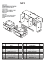
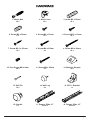
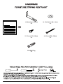
NO. PART NAME PIECES NO. PART NAME PIECES
A Side - L 1 L Drawer Bottom 6
B Side - R 1 M Drawer Side - L (L) 4
C Top 1 N Drawer Side - R (L) 4
D Partition 1 O Drawer Back (L) 4
E Drawer Front - L (S) 1 P Back Top 2
F Drawer Front - R (S) 1 Q Bottom Front Prole 1
G Drawer Front - L (L) 2 R Bottom Side Prole 2
H Drawer Front - R (L) 2 S Back Bottom Bar 2
I Drawer Side - L (S) 2 T Front Support Bar 2
J Drawer Side - R (S) 2 U Back Bottom - L 1
K Drawer Back (S) 2 V Back Bottom - R 1
A
B
C
D
E
F
G
G
H
H
L
I
J
K
Q
R
R S
S
V
U
T
T
P
P
M
N
O

7. Screw M3.1 x 20 mm
12 x 8. Screw M4 x 25mm
8 x 9. Screw M4 x 38mm
24 x
10. Euro Screw M6 x 8mm
24 x 11. Screw M4 x 30mm
6 x 12. Backply Stopper
12 x
Page 5
1. Minix Bolt
32 x 2. Minix Cam
32 x 3. Dowel Ø8 x 30mm
43 x
4. Dowel Ø8 x 20mm
8 x 5. Screw M3 x 12mm
12 x 6. Screw M3.5 x 15mm
32 x
13. Nail Pin
10 x 14. Nail Leg
6 x 15. PVC L Bracket
1 x
16. Handle
6 x 17. Drawer Slide 12”
6 sets x 18. Drawer Slide 12”
6 sets x

23. Wall Plug
2 x
Page 6
19. Mounting L Bracket
2 x 20. Flat Washer M6 x 16mm
2 x
21. Screw #10 x16mm
2 x 22. Screw M4 x 38mm
2 x

Page 7
12 x
10
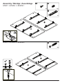
Assembly / Montaje / Assemblage
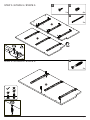
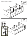
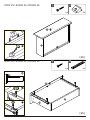
STEP 1 / ETAPA 1 / ÉTAPE 1
STEP 2 / ETAPA 2 / ÉTAPE 2
6 x
5
3 x
17
A
B
A
B
6 x
1

Page 8
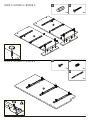
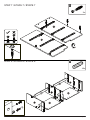
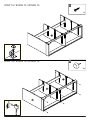
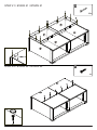
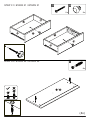
STEP 3 / ETAPA 3 / ÉTAPE 3
STEP 4 / ETAPA 4 / ÉTAPE 4
6 x
10
D
3 x
5
3 x
17
4 x
4
4 x
8
A
B
R
R

6 x
10
Page 9
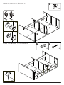
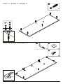
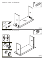
STEP 6 / ETAPA 6 / ÉTAPE 6
STEP 5 / ETAPA 5 / ÉTAPE 5
D
D
3 x
5
3 x
17
3 x
1
D

Page 10
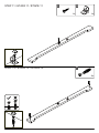
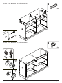
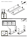
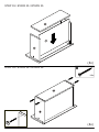
STEP 8 / ETAPA 8 / ÉTAPE 8
STEP 7 / ETAPA 7 / ÉTAPE 7
3 x
1
D
D
12 x
3
V
U
T
T
A
D
B

Page 11
STEP 10 / ETAPA 10 / ÉTAPE 10
STEP 9 / ETAPA 9 / ÉTAPE 9
12 x
2
1
2
T
U
V
T
4 x
4
4 x
8
S
S
V
U

Page 12
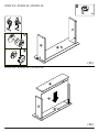
STEP 12 / ETAPA 12 / ÉTAPE 12
STEP 11 / ETAPA 11 / ÉTAPE 11
1 x
15
1 x
6
2 x
1
Q
Q

Page 13
STEP 14 / ETAPA 14 / ÉTAPE 14
STEP 13 / ETAPA 13 / ÉTAPE 13
1 x
3
1
2
2 x
2
Q
D
V
U
A
A
B
B

Page 14
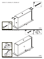
STEP 16 / ETAPA 16 / ÉTAPE 16
STEP 15 / ETAPA 15 / ÉTAPE 15
A
D
B
6 x
14
Q
D
1 x
6

Page 15
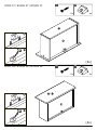
STEP 18 / ETAPA 18 / ÉTAPE 18
STEP 17 / ETAPA 17 / ÉTAPE 17
6 x
1
C
C
2 x
19
2 x
21
2 x
20

Page 16
STEP 20 / ETAPA 20 / ÉTAPE 20
STEP 19 / ETAPA 19 / ÉTAPE 19
1
2
6 x
3
6 x
2
C
A
A
B
B
D
D

Page 17
STEP 22 / ETAPA 22 / ÉTAPE 22
STEP 21 / ETAPA 21 / ÉTAPE 21
B
P
P
U
V
10 x
13
6 x
6

Page 18
STEP 24 / ETAPA 24 / ÉTAPE 24
STEP 23 / ETAPA 23 / ÉTAPE 23
4 x
1
8 x
3
F
I
F
J
E
E
J
I

(2x)
(2x)
Page 19
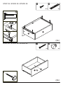
STEP 25 / ETAPA 25 / ÉTAPE 25
STEP 26 / ETAPA 26 / ÉTAPE 26
J
I
4 x
2
1
2
J
K
L
E F
/
E F
/

8 x
9
2 x
12
2 x
7
1
2
J
K
K
L
(2x)
(2x)
Page 20
STEP 28 / ETAPA 28 / ÉTAPE 28
STEP 27 / ETAPA 27 / ÉTAPE 27
E F
/
E F
/

(2x)
(2x)
Page 21
STEP 30 / ETAPA 30 / ÉTAPE 30
STEP 29 / ETAPA 29 / ÉTAPE 29
1
2
2 x
12
2 x
7
I
2 x
18
8 x
6
2
1
3I
K
E F
/
E F
/

2 x
16
2 x
11
8 x
1
I
I
J
J
K
K
(4x)
Page 22
STEP 32 / ETAPA 32 / ÉTAPE 32
STEP 31 / ETAPA 31 / ÉTAPE 31
E
F
G H
/

(4x)
(4x)
Page 23
STEP 34 / ETAPA 34 / ÉTAPE 34
STEP 33 / ETAPA 33 / ÉTAPE 33
16 x
3
8 x
2
1
2
M
NG H
/
M
N

16 x
9
(4x)
(4x)
Page 24
STEP 36 / ETAPA 36 / ÉTAPE 36
STEP 35 / ETAPA 35 / ÉTAPE 35
N
L
O
N
O

(4x)
(4x)
Page 25
STEP 38 / ETAPA 38 / ÉTAPE 38
STEP 37 / ETAPA 37 / ÉTAPE 37
1
2
4 x
12
4 x
7
1
2
4 x
12
4 x
7
L
O
L
G H
/

4 x
16
4 x
11
4 x
18
16 x
6
2
1
(4x)
(4x)
Page 26
STEP 40 / ETAPA 40 / ÉTAPE 40
STEP 39 / ETAPA 39 / ÉTAPE 39
M
O
G H
/

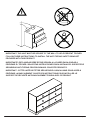
IMPORTANT: THIS UNIT MUST BE SECURE TO THE WALL TO HELP PREVENT TIPOVER.
FOLLOW THESE INSTRUCTIONS TO INSTALL THE ANTI-TIPPING SAFETY BRACKET
PROVIDED WITH THIS PRODUCT.
IMPORTANTE: ESTA UNIDAD DEBE ESTAR SEGURA A LA PARED PARA AYUDAR A
PREVENIR EL TIPOVER. SIGA ESTAS INSTRUCCIONES PARA INSTALAR EL SOPORTE DE
SEGURIDAD ANTI-TIPPING PROPORCIONADO CON ESTE PRODUCTO.
IMPORTANT : CETTE UNITÉ DOIT ÊTRE SÉCURITAIRE JUSQU’AU MUR POUR AIDER À
PRÉVENIR LA BASCULEMENT. SUIVEZ CES INSTRUCTIONS POUR INSTALLER LE
SUPPORT DE SÉCURITÉ ANTI-BASCULEMENT FOURNI AVEC CE PRODUIT.
Page 27

STEP 41 / ETAPA 41 / ÉTAPE 41
Page 28
2 x
22
2 x
23
OPTION 1
OPCIÓN 1
OPTION 1
Drywall anchor that supplied with this product is general purpose wall plug only.
Consult your local hardware store for appropriate anchors for the type of wall you intend to securely
attach the safety bracket.
Ancla de paneles de yeso que se suministra con este producto es enchufe de pared de
propósito general solamente.
Consulte a su ferretería local para obtener los anclajes adecuados para el tipo de muro que
desea jar el soporte de seguridad.
Ancre de cloison sèche qui a fourni avec ce produit est prise de mur d’usage général
seulement.
Consultez votre quincaillerie locale pour trouver des ancres appropriées pour le type de mur que
vous avez l’intention de attacher le support de sécurité.
OPTION 2
OPCIÓN 2
OPTION 2

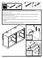
OPTION 1: Attachment into a wall stud (preferred method)
Using a stud nder, locate a stud in the wall. Place your unit against the wall, with the safety bracket
aligned in this location. To make driving the screw easier, you can drill a 3mm diameter pilot hole
through the safety bracket into the stud. Drive the screw through the safety bracket into the wall stud.
Tighten the screw that was not fully tightened in step 9.
OPTION 2: Attachment into masonry
Locate your unit where desired against a wall and mark the wall through the safety bracket, then
move your unit aside. Drill a 6mm diameter hole into the wall. Tap the wall anchor into the hole until it
is ush. Move your unit into location and fasten the wall bracket to the wall anchor with the screw.
Tighten the screw that was not fully tightened in step 9.
OPTION 1 : Fixation dans un goujon de mur (méthode préférée)
À l’aide d’un stud nder, localisez un goujon dans le mur. Placez votre appareil contre le mur, avec le
support de sécurité alignés à cet endroit. Pour faciliter la conduite de la vis, vous pouvez percer un
trou pilote de 3 mm de diamètre à travers le support de sécurité dans le goujon. Conduisez la vis à
travers le support de sécurité dans le goujon du mur. Serrez la vis qui n’a pas été entièrement serrée
à l’étape 9.
OPTION 2 : Fixation en maçonnerie
Localisez votre appareil lorsque vous le souhaitez contre un mur et marquez le mur à travers le
support de sécurité, puis déplacer votre unité de côté. Percer un trou de 6 mm de diamètre dans le
mur. Appuyez sur l’ancre murale dans le trou jusqu’à ce qu’il est ush. Déplacez votre unité dans
l’emplacement et attachez le support de mur à l’ancre de mur avec la vis. Serrez la vis qui n’a pas
été entièrement serrée à l’étape 9.
OPCION 1: Adjunto en un perno de pared (método preferido)
Con un buscador de pernos, localice un perno en la pared. Coloque la unidad contra la pared, con el
soporte de seguridad alineado en esta ubicación. Para facilitar la conducción del tornillo, puede
perforar un oricio piloto de 3 mm de diámetro a través del soporte de seguridad en el perno.
Conduzca el tornillo a través del soporte de seguridad en el perno de pared. Apriete el tornillo que no
estaba completamente apretado en el paso 9
OPCION 2: Fijación en la albañilería
Localice su unidad donde desee contra una pared y marque la pared a través del soporte de
seguridad, luego a un lado su unidad. Taladre un oricio de 6 mm de diámetro en la pared. Toque el
ancla de la pared en el agujero hasta que está al ras. Mueva la unidad a la ubicación y je el soporte
de pared al anclaje de pared con el tornillo. Apriete el tornillo que no estaba completamente apretado
en el paso 9.
Page 29

Page 30
STEP 42 / ETAPA 42 / ÉTAPE 42
Put the Drawer that has axed anti tip warning label in the top
drawer position
Coloque el cajón que tiene una etiqueta de advertencia anti
punta ja en la posición superior del cajón
Placez le tiroir qui a une étiquette d’avertissement anti-pointe
axed dans la position du tiroir supérieur
F

This product is designed to withstand the weight
vindicated on the plan. We are not responsible for the
breakage of parts or any injury caused by failure to comply
with this recommendation.
Este producto está diseñado para soportar el peso
indicado en el plan. No somos responsables de la rotura
de piezas o cualquier lesión causada por el
incumplimiento de esta recomendación.
Ce produit est conçu pour résister au poids indiqué sur le
plan. Nous ne sommes pas responsables de la rupture de
pièces ou de toute blessure causée par le non-respect de
cette recommandation.
Page 31
STEP 43 / ETAPA 43 / ÉTAPE 43
E
G
G
H
H
F
25 lbs
25 lbs
35 lbs

-
 1
1
-
 2
2
-
 3
3
-
 4
4
-
 5
5
-
 6
6
-
 7
7
-
 8
8
-
 9
9
-
 10
10
-
 11
11
-
 12
12
-
 13
13
-
 14
14
-
 15
15
-
 16
16
-
 17
17
-
 18
18
-
 19
19
-
 20
20
-
 21
21
-
 22
22
-
 23
23
-
 24
24
-
 25
25
-
 26
26
-
 27
27
-
 28
28
-
 29
29
-
 30
30
-
 31
31
-
 32
32


Hillsdale Furniture Campbell Wood 6 Drawer Dresser El manual del propietario
- Tipo
- El manual del propietario
en otros idiomas
Artículos relacionados
-
Hillsdale Furniture Shelton Wood Kitchen Pantry El manual del propietario
-
-
-
-
-
Otros documentos
-
Dorel Living FA1011-1 Guía de instalación
-
 Dorel Home Furnishings DA7608-1SIL El manual del propietario
-
-
BABY RELAX Baby Relax DA7924-1 Manual de usuario
-
-
Dorel Baby Relax DA7970-1 Manual de usuario
-
-
-
 Delta Children Fairytale 7 Drawer Dresser Assembly Instructions
-

