
Dell DR Series System
Administrator Guide

Notas, precauciones y avisos
NOTA: Una NOTA proporciona información importante que le ayuda a utilizar mejor su equipo.
PRECAUCIÓN: Una PRECAUCIÓN indica la posibilidad de daños en el hardware o la pérdida de datos, y le explica
cómo evitar el problema.
AVISO: Un mensaje de AVISO indica el riesgo de daños materiales, lesiones corporales o incluso la muerte.
© 2013 Dell Inc.
Marcas comerciales utilizadas en este texto:
Dell
™
, el logotipo de Dell,
Dell Boomi
™
Dell Precision
™
,
OptiPlex
™
,
Latitude
™
,
PowerEdge
™
,
PowerVault
™
,
PowerConnect
™
,
OpenManage
™
,
EqualLogic
™
,
Compellent
™
,
KACE
™
,
FlexAddress
™
,
Force10
™
y
Vostro
™
son marcas comerciales de Dell Inc.
Intel
®
,
Pentium
®
,
Xeon
®
,
Core
®
y
Celeron
®
son marcas comerciales registradas de Intel
Corporation en los Estados Unidos y otros países.
AMD
®
es una marca comercial registrada y
AMD Opteron
™
,
AMD Phenom
™
y
AMD Sempron
™
son marcas comerciales de Advanced Micro Devices, Inc.
Microsoft
®
,
Windows
®
,
Windows Server
®
,
Internet Explorer
®
,
MS-DOS
®
,
Windows Vista
®
y
Active Directory
®
son marcas comerciales o marcas comerciales registradas de
Microsoft Corporation en los Estados Unidos y/o en otros países.
Red Hat
®
y
Red Hat
®
Enterprise Linux
®
son marcas comerciales
registradas de Red Hat, Inc. en los Estados Unidos y/o en otros países.
Novell
®
y
SUSE
®
son marcas comerciales registradas de Novell
Inc. en los Estados Unidos y en otros países.
Oracle
®
es una marca comercial registrada de Oracle Corporation y/o sus afiliados.
Citrix
®
,
Xen
®
,
XenServer
®
y
XenMotion
®
son marcas comerciales registradas o marcas comerciales de Citrix Systems, Inc. en los
Estados Unidos y/o en otros países.
VMware
®
,
vMotion
®
,
vCenter
®
,
vCenter SRM
™
y
vSphere
®
son marcas comerciales registradas o
marcas comerciales de VMware, Inc. en los Estados Unidos u otros países.
IBM
®
es una marca comercial registrada de International
Business Machines Corporation.
2013 - 09
Rev. A05

Tabla de contenido
1 Introducción al sistema DR Series...........................................................................................9
Acerca de la documentación de la GUI del sistema DR Series............................................................................... 9
What's New In This Release.................................................................................................................................... 9
Otra información útil............................................................................................................................................... 10
Disponibilidad del código fuente............................................................................................................................ 10
2 Understanding the DR Series System....................................................................................13
About the DR Series System...................................................................................................................................14
Capacidad física disponible y de la unidad ........................................................................................................... 14
Capacidad de la unidad interna....................................................................................................................... 15
Capacidad de la unidad externa ......................................................................................................................15
Data Storage Terminology and Concepts...............................................................................................................15
Data Deduplication and Compression..............................................................................................................18
Replication........................................................................................................................................................19
Replicación inversa..........................................................................................................................................20
Replicación inversa: método alternativo..........................................................................................................21
Supported File System Protocols............................................................................................................................21
NFS...................................................................................................................................................................22
CIFS.................................................................................................................................................................. 22
Compatibilidad con ACL CIFS...........................................................................................................................22
Access Control List Support in Containers...................................................................................................... 23
Contenedores existentes (anteriores a la versión 1.1).....................................................................................24
Unix Permissions Guidelines............................................................................................................................25
Directrices de permisos Windows...................................................................................................................25
OpenStorage Technology (OST): DR Series System...............................................................................................26
API OpenStorage Technology (OST) ...............................................................................................................27
Software Components and Operational Guidelines.........................................................................................28
Rapid Data Storage (RDS): DR Series System........................................................................................................29
Rapid OFS (ROFS) API...................................................................................................................................... 29
DR Series System and Data Operations................................................................................................................. 29
DR Series Expansion Shelf...............................................................................................................................30
Understanding About Adding a DR Series Expansion Shelf............................................................................ 31
Supported Software and Hardware........................................................................................................................31
Terminal Emulation Applications......................................................................................................................32
DR Series — Expansion Shelf Cabling................................................................................................................... 32
Cómo agregar un estante de expansión del sistema DR Series.............................................................................34
3 Setting Up the DR Series System........................................................................................... 37

Interacting With the DR Series System..................................................................................................................37
Networking Preparations for the DR Series System........................................................................................37
Connections for Initializing a DR Series System.....................................................................................................38
Inicialización del sistema DR Series.......................................................................................................................39
Dirección IP y dirección de máscara de subred predeterminadas.................................................................39
Local Console Connection................................................................................................................................40
iDRAC Connection............................................................................................................................................42
Logging in and Initializing the DR Series System.............................................................................................42
Acceso a iDRAC6/iDRAC7 mediante RACADM...................................................................................................... 44
Logging in Using a Web Interface.......................................................................................................................... 44
Registering a DR Series System.......................................................................................................................47
Habilitación de Active Scripting en exploradores Windows IE....................................................................... 47
Deshabilitación de la configuración de la vista de compatibilidad................................................................. 48
Página Panel y opciones........................................................................................................................................ 48
Descripción de las opciones del Panel............................................................................................................49
Visualización de alertas del sistema................................................................................................................49
Eventos.............................................................................................................................................................49
Condición..........................................................................................................................................................50
Uso................................................................................................................................................................... 53
Viewing the Latest Range.................................................................................................................................54
Viewing a Specific Time Range........................................................................................................................55
System Usage...................................................................................................................................................56
Statistics: Container Page................................................................................................................................56
Página Estadísticas: Replicación.....................................................................................................................60
Página Almacenamiento y opciones...................................................................................................................... 62
Descripción de las opciones de almacenamiento...........................................................................................62
Containers........................................................................................................................................................ 63
Página Replicación.......................................................................................................................................... 63
Nivel de compresión........................................................................................................................................ 64
Clients...............................................................................................................................................................64
About the Schedules Page and Options.................................................................................................................66
Establecimiento de un programa de replicación............................................................................................. 66
Establecimiento de un programa de limpieza.................................................................................................. 67
About the System Configuration Page and Options............................................................................................... 67
System Configuration Page and Options..........................................................................................................68
Understanding the System Configuration Page Options..................................................................................70
Página Asistencia y opciones.................................................................................................................................71
Descripción de las opciones de la página Asistencia.....................................................................................71
4 Configuring the DR Series System Settings..........................................................................75
Configuring Networking Settings............................................................................................................................75
Networking Page and Ethernet Port Values.................................................................................................... 78

Administración de la contraseña del sistema DR Series....................................................................................... 79
Modifying the System Password......................................................................................................................79
Resetting the Default System Password..........................................................................................................79
Apagado del sistema DR Series............................................................................................................................. 80
Reinicio del sistema DR Series...............................................................................................................................80
Configuración de los valores de nivel de compresión............................................................................................81
Configuración de los valores de Active Directory..................................................................................................81
Configuración de los valores de los Usuarios de grupo de trabajo local...............................................................82
Configuración de los valores de alertas por correo electrónico............................................................................83
Cómo agregar una dirección de correo electrónico del destinatario............................................................. 84
Editing or Deleting a Recipient Email Address.................................................................................................84
Envío de un mensaje de prueba.......................................................................................................................85
Configuración de información de contacto del administrador...............................................................................85
Cómo agregar información de contacto del administrador.............................................................................86
Edición de la información de contacto del administrador............................................................................... 86
Managing Passwords.............................................................................................................................................87
Modifying the System Password......................................................................................................................87
Modifying Password Reset Options.................................................................................................................87
Configuración de un host de retransmisión de correo electrónico........................................................................87
Cómo agregar un host de retransmisión de correo electrónico......................................................................88
Edición de un host de retransmisión de correo electrónico............................................................................88
Configuración de valores de fecha y hora del sistema.......................................................................................... 89
Editing System Date and Time Settings........................................................................................................... 89
Creating Containers................................................................................................................................................90
Configuring Share-Level Security...........................................................................................................................90
5 Managing DR Series Storage Operations.............................................................................93
Managing Container Operations............................................................................................................................ 93
Creating Storage Containers............................................................................................................................93
Editing Container Settings................................................................................................................................96
Eliminación de contenedores...........................................................................................................................97
Moving Data Into a Container.......................................................................................................................... 98
Displaying Container Statistics........................................................................................................................ 98
Managing Replication Operations........................................................................................................................100
Creación de relaciones de replicación..........................................................................................................100
Edición de relaciones de replicación.............................................................................................................102
Eliminación de relaciones de replicación......................................................................................................103
Inicio y detención de una replicación............................................................................................................103
Establecimiento del ancho de banda de replicación.....................................................................................103
Visualización de estadísticas de replicación.................................................................................................104
Creating a Replication Schedule....................................................................................................................105

6 Supervisión del sistema DR Series...................................................................................... 109
Monitoring Operations Using the Dashboard Page..............................................................................................109
Barra Estado del sistema............................................................................................................................... 109
Sistema DR Series System y paneles Capacidad, Ahorros de almacenamiento y Producción.................... 110
Panel Información del sistema.......................................................................................................................111
Supervisión de alertas del sistema.......................................................................................................................111
Uso de la página Alertas del Panel................................................................................................................ 111
Visualización de alertas del sistema..............................................................................................................112
Supervisión de eventos del sistema.....................................................................................................................112
Uso del Panel para visualizar eventos del sistema........................................................................................112
Uso de la opción Eventos del panel............................................................................................................... 113
Uso del Filtro de eventos................................................................................................................................114
Supervisión de la condición del sistema..............................................................................................................115
Uso de la página Panel para supervisar la condición del sistema................................................................ 115
Uso de las opciones de condición del Panel................................................................................................. 116
Supervisión del uso del sistema........................................................................................................................... 117
Displaying Current System Usage..................................................................................................................118
Establecimiento de un valor Último rango..................................................................................................... 118
Establecimiento de un valor Rango de tiempo ..............................................................................................119
Supervisión de estadísticas de contenedor.........................................................................................................119
Displaying the Statistics: Container Page......................................................................................................120
Supervisión de estadísticas de replicación..........................................................................................................121
Displaying the Statistics: Replication Page....................................................................................................121
Visualización de las estadísticas de replicación mediante la CLI................................................................. 122
7 Uso de las opciones de asistencia del sistema DR Series.............................................. 125
Support Information Pane.....................................................................................................................................125
Página Diagnósticos y opciones.......................................................................................................................... 126
Generating a Diagnostics Log File .................................................................................................................126
Descarga de archivos de registro de diagnósticos....................................................................................... 127
Eliminación de un archivo de registro de diagnósticos.................................................................................128
DR Series System Software Upgrade...................................................................................................................128
Página Actualización de software y opciones..................................................................................................... 129
Verifying the Current Software Version ........................................................................................................ 129
Upgrading the DR Series System Software................................................................................................... 129
Restore Manager (RM).........................................................................................................................................130
Downloading the Restore Manager...............................................................................................................131
Creación de la memoria USB de Restore Manager.......................................................................................131
Ejecución de Restore Manager (RM).............................................................................................................131
Resetting the Boot LUN Setting in PERC H700 BIOS After Running RM........................................................ 132
Extracción o reemplazo de hardware...................................................................................................................132

Sistema DR Series: apagado e iniciado correctos.........................................................................................133
NVRAM del sistema DR Series.......................................................................................................................133
8 Configuración y uso de OST..................................................................................................135
Descripción de OST..............................................................................................................................................135
API OpenStorage Technology (OST) ................................................................................................................... 136
Directrices de OST................................................................................................................................................137
OST Terminology...................................................................................................................................................137
Supported OST Software and Components..........................................................................................................138
OST Required Configurations............................................................................................................................... 139
Recomendaciones: OST y el sistema DR Series...................................................................................................139
Establecimiento de la optimización del lado del cliente.......................................................................................139
Configuring an LSU............................................................................................................................................... 140
Installing the Dell OST Plug-In..............................................................................................................................140
Understanding the Dell OST Plug-In (Linux)...................................................................................................140
Understanding the Dell OST Plug-In (Windows)............................................................................................141
Installing the OST Plug-In for Backup Exec on Windows..............................................................................141
Installing the OST Plug-In for NetBackup on Windows.................................................................................142
Desinstalación del complemento OST de Dell para Windows.......................................................................143
Instalación del complemento OST para NetBackup en Linux....................................................................... 143
Desinstalación del complemento OST de Dell para Linux............................................................................. 144
Configuración de la información del sistema DR Series mediante NetBackup...................................................144
Using NetBackup CLI to Add DR Series System Name (Linux)......................................................................145
Uso de la CLI de NetBackup para agregar el nombre del sistema DR Series (Windows).............................145
Configuración de NetBackup para el sistema DR Series.............................................................................. 145
Creating Disk Pools From LSUs......................................................................................................................146
Creación de unidades de almacenamiento con la agrupación de discos.....................................................147
Backing Up Data From a DR Series System (NetBackup)....................................................................................147
Restoring Data From a DR Series System Using NetBackup.........................................................................148
Duplicating Backup Images Between DR Series Systems Using NetBackup...............................................148
Using Backup Exec With a DR Series System (Windows)................................................................................... 149
OST Plug-In and Supported Versions.............................................................................................................149
Installation Prerequisites for the OST Plug-In for Backup Exec....................................................................149
Configuración del sistema DR Series mediante la GUI de Backup Exec.......................................................149
Creación de copias de seguridad en el sistema DR Series mediante Backup Exec..................................... 150
Optimizing Duplication Between DR Series Systems Using Backup Exec.................................................... 151
Restoring Data from a DR Series System Using Backup Exec...................................................................... 151
Understanding the OST CLI Commands................................................................................................................152
Supported DR Series System CLI Commands for OST...................................................................................152
Understanding OST Plug-In Diagnostic Logs....................................................................................................... 153
Cómo girar registros del complemento OST para Windows..........................................................................153
Recopilación de diagnósticos mediante una utilidad de Linux............................................................................ 153

Cómo girar registros del complemento OST para Linux................................................................................ 154
Directrices para recopilar información del servidor multimedia......................................................................... 154
NetBackup en servidores multimedias Linux.................................................................................................154
NetBackup en servidores multimedia Windows............................................................................................155
Backup Exec en servidores multimedia Windows.........................................................................................156
9 Configuring and Using Rapid Data Storage........................................................................157
RDS Overview.......................................................................................................................................................157
RDS Guidelines..................................................................................................................................................... 158
Best Practices: RDS and the DR Series System...................................................................................................158
Setting Client-Side Optimization...........................................................................................................................158
Adding RDS Devices in NVBU.............................................................................................................................. 159
Removing RDS Devices From NVBU.....................................................................................................................159
Backing Up Data on the RDS Container Using NVBU.......................................................................................... 160
Replicating Data to an RDS Container Using NVBU.............................................................................................161
Restoring Data From a DR Series System Using NVBU........................................................................................162
Supported DR Series System CLI Commands for RDS......................................................................................... 163
10 Troubleshooting and Maintenance....................................................................................165
Troubleshooting Error Conditions.........................................................................................................................165
Mensajes de eventos y alertas del sistema DR Series........................................................................................ 165
Acerca del servicio de diagnósticos.................................................................................................................... 192
Descripción de la recopilación de diagnósticos............................................................................................193
About the DR Series System Maintenance Mode................................................................................................193
About the DR Series System Support Mode.........................................................................................................195
Programación de operaciones del sistema DR Series.........................................................................................195
Creating a Cleaner Schedule................................................................................................................................196
Visualización de estadísticas del limpiador...................................................................................................197
11 Supported Ports in a DR Series System............................................................................199
12 Obtención de ayuda..............................................................................................................201
Antes de ponerse en contacto con Dell Support................................................................................................. 201
Cómo ponerse en contacto con Dell.................................................................................................................... 202

1
Introducción al sistema DR Series
La documentación del sistema DR Series contiene temas que explican cómo utilizar el sistema DR Series para realizar
operaciones de almacenamiento de datos y administrar contenedores de replicación y almacenamiento. Los temas
sobre el sistema DR Series introducen y describen la interfaz gráfica de usuario (GUI) del sistema DR Series que puede
utilizar para administrar sus operaciones de copia de seguridad y replicación. Un conjunto completo de procedimientos
basados en la GUI le permiten acceder a todas las características y capacidades de administración mediante el uso de
un explorador web compatible. Si la GUI del sistema DR Series no admite alguna tarea u operación administrativa
importante, esta guía proporciona y describe los comandos correspondiente de la interfaz de línea de comandos (CLI).
Para obtener más información sobre los comandos de la CLI del sistema DR Series, consulte la
Dell DR Series System
Command Line Reference Guide (Guía de referencia de la línea de comandos del sistema Dell DR Series)
.
Acerca de la documentación de la GUI del sistema DR Series
La documentación del sistema DR Series describe cómo utilizar la interfaz gráfica de usuario (GUI) y sus menús,
pestañas y opciones para realizar una amplia variedad de operaciones de almacenamiento de datos y para administrar
los contenedores de almacenamiento y replicación relacionados.
La documentación se dirige a un usuario final administrador y presenta y proporciona procedimientos para el uso de los
elementos de la GUI del sistema DR Series para administrar con facilidad sus operaciones de copia de seguridad y
desduplicación. Un conjunto completo de procedimientos basados en la GUI le permiten acceder a todas las
características y capacidades de administración clave mediante el uso de un explorador web compatible.
Si la GUI del sistema DR Series no admite alguna tarea u operación administrativa importante, la documentación
proporciona y describe los comandos correspondiente de la interfaz de línea de comandos (CLI) del sistema DR Series.
NOTA: Para obtener información sobre los exploradores web compatibles que puede utilizar con el sistema DR
Series, consulte la
Dell DR Series System Interoperability Guide (Guía de interoperabilidad del sistema Dell DR
Series)
disponible en support.dell.com/manuals.
What's New In This Release
The following features have been added to the DR Series systems for this release:
Advanced
Networking
Advanced networking feature allows you to modify the default bonded network configuration
of your DR Series system. It allows you to create and manage multiple bonds on the same
system to support your data, management and replication traffic. You must use the CLI to set
up advanced networking. However, you can view and edit the NIC bonding configuration using
the web user interface.
Rapid Data
Storage Protocol
Rapid Data Storage (RDS) is developed by Dell Quest and provides a logical disk interface for
use with network storage devices. RDS allows for better coordination and integration between
DR Series system backup, restore, and optimized duplication operations with Dell Quest
NetVault Backup (NVBU). You can back up, complete optimized replication, and restore data
from DR Series systems using the Rapid Data Access protocol using the Dell Quest NetVault
Backup DMA.
9

Daily Status
Reporting
Daily status reporting feature allows you to configure daily system statistics for container
status information on bytes ingested, deduplicated, and replicated.
Security
Questions for
Password Reset
Security questions for password reset allow you to add security questions to reset your DR
Series system password.
NOTA: The maintenance mode User interface for the DR Series systems is updated in this release.
Otra información útil
AVISO: Consulte la información reglamentaria y de seguridad suministrada con el sistema. La información sobre la
garantía puede estar incluida en este documento o en un documento aparte.
• El
Dell DR Series System Owner's Manual (Manual del propietario del sistema Dell DR Series)
proporciona
información sobre las características de la solución, describe cómo solucionar problemas en el sistema y cómo
instalar o reemplazar componentes del sistema DR Series. Este documento está disponible en support.dell.com/
manuals.
• La
Dell DR Series System Command Line Reference Guide (Guía de referencia de la línea de comandos del
sistema Dell DR Series)
proporciona información sobre la administración de operaciones de copia de seguridad
y replicación de datos del sistema DR Series mediante la interfaz de línea de comandos (CLI) del sistema DR
Series. Este documento está disponible en support.dell.com/manuals.
• La
Dell DR Series System Getting Started Guide (Guía de inicio del sistema DR Series)
proporciona una
descripción general de la configuración de su sistema DR Series e incluye especificaciones técnicas. Este
documento está disponible en support.dell.com/manuals.
• El documento
Setting Up Your Dell DR4100 System (Configuración de su sistema Dell DR4100)
proporciona
información sobre la red, configuración inicial y configuración de cuentas de usuario necesaria para inicializar
el sistema Dell DR4100. Este documento está disponible en support.dell.com/manuals
• La
Dell DR Series System Interoperability Guide (Guía de interoperabilidad del sistema Dell DR Series)
proporciona información sobre el hardware y software compatibles que se pueden utilizar con el sistema DR
Series. Este documento está disponible en support.dell.com/manuals.
• El
Dell PowerVault MD1200 and MD1220 Storage Enclosures Hardware Owner's Manual (Manual del propietario
del hardware de gabinetes de almacenamiento Dell PowerVault MD1200 y MD1220)
proporciona información
sobre el hardware de estanterías de expansión de almacenamiento de datos externo (gabinetes) compatible
que se puede utilizar con el sistema DR Series. Este documento está disponible en support.dell.com/manuals
• En el soporte suministrado con el sistema se incluye documentación y herramientas para configurar y
administrar el sistema, incluidas las relacionadas con el sistema operativo, el software de administración del
sistema, las actualizaciones del sistema y los componentes del sistema adquiridos con él.
NOTA: Compruebe siempre si hay actualizaciones de la documentación en support.dell.com/manuals y lea las
actualizaciones de la documentación en primer lugar, ya que con frecuencia sustituyen información incluida en
otros documentos y contienen las últimas versiones actualizadas de los documentos.
NOTA: Compruebe siempre si hay notas de la versión en support.dell.com/manuals y léalas primero, ya que
contienen la información documentada más reciente sobre problemas conocidos con una versión de producto
específica.
Disponibilidad del código fuente
Una parte del software del sistema DR Series puede contener o consistir en software de código fuente abierto, que
usted puede utilizar bajo los términos y condiciones de la licencia específica bajo la cual el software de código fuente
abierto se distribuye.
10

Bajo ciertas licencias de software de código fuente abierto, es posible que también tenga derecho a obtener los
archivos fuente correspondientes. Para obtener más información sobre esto o para encontrar los archivos de código
fuente correspondientes para los respectivos programas, consulte el sitio web opensource.dell.com de Dell.
11

12

2
Understanding the DR Series System
The DR Series system is a high-performance, disk-based backup and recovery appliance that is simple to deploy and
manage, and offers unsurpassed Total Cost of Ownership benefits. Features such as innovative firmware and an all-
inclusive licensing model ensure optimal functionality and the assurance of no hidden costs for desired future features.
NOTA: Unless otherwise noted, later references to "the system" or "DR Series system" are used interchangeably to
represent the Dell DR Series system.
The DR Series system has a simple installation process with full, intuitive remote setup and management capabilities. It
is available in the following drive capacities—2.7 Terabytes (TB), 5.4 TB, 9 TB, 18 TB, and 27 TB (the 27 TB drive capacity
was added in Release 2.0), and is ideal for both small enterprise and remote office environments. The DR Series system
and corresponding drive capacities are as follows:
• 300 Gigabyte (GB) drive capacity: 2.7 TB system (this system version does not support the addition of expansion
shelf enclosures)
• 600 GB drive capacity: 5.4 TB system
• 1 TB drive capacity: 9 TB system
• 2 TB drive capacity: 18 TB system
• 3 TB drive capacity: 27 TB system
NOTA: To better understand the drive capacity and the available physical capacity for the drive types available in
the DR Series system, see Drive and Available Physical Capacities.
NOTA: Release 2.0 also supports using an external data storage expansion shelf (also known as expansion
enclosures). The DR Series system supports up to two expansion enclosures per system. An added expansion shelf
enclosure must be equal to or greater than each DR Series system internal drive slot capacity (0–11). For more
information about expansion enclosures, see
Installing an Expansion Shelf License, DR Series System - Expansion
Shelf Cabling, and Expansion Shelf Licenses.
Using Dell deduplication and compression algorithm technology, this system can achieve data reduction levels ranging
from 10:1 to 50:1. This reduction in data results in less incremental storage needs and a smaller backup footprint. By
removing redundant data, the system provides deduplication and compression that delivers:
• Fast, reliable backup and restore functionality
• Reduces media usage and power and cooling requirements
• Improves overall data protection and retention costs
The benefits of data deduplication can be extended across the enterprise—through the deduplicated replication
function—to provide a complete backup solution for multi-site environments.
The shorter Recovery Time Objectives (RTO) and more attainable Recovery Point Objectives (RPO) can also be assured
as critical backup data remains on disk and online longer. Capital and administrative costs are diminished at the same
time as internal service level agreements (SLAs) are more easily met.
The DR Series system includes the following:
• Advanced data protection and disaster recovery
• Simple management interface (using the system GUI)
13

• Wide variety of data backup installations and environments
The Dell DR Series system contains data backup and management software preinstalled on a Dell hardware appliance,
which provides you with a robust disk-based data backup capability installed on a deduplication-enabled appliance.
The system supports two interface types, and the system software manages the storage containers using the following
interfaces:
• A command line interface (CLI)
• A graphical user interface (GUI)
About the DR Series System
The Dell DR Series system is a solution designed to reduce your backup data footprint using a number of comprehensive
backup and deduplication operations that optimize storage savings. Collectively, the DR Series system comes in two
types:
• DR4000 system: this is preinstalled DR4000 system software on a Dell PowerEdge R510 appliance platform
• DR4100 system: this is preinstalled DR4000 system software on a Dell PowerEdge R720xd appliance platform
The DR Series system consists of the following components:
• Software — the system software supports record linkage and context-based lossless data compression
methods.
• Hardware — there are two appliance types that support the DR Series:
– DR4000 system: includes twelve 3.5 inch SAS or Nearline SAS chassis drives that are hot-swappable,
two power supplies for power redundancy, and two cabled 2.5-inch SAS drives for the operating
system. The operating system is installed on two 2.5–inch internal drives that are in a RAID 1
configuration in the DR4000 system.
– DR4100 system: includes twelve 3.5 inch SAS or Nearline SAS chassis drives that are hot-swappable,
two power supplies for power redundancy, and includes two 2.5-inch drives that are hot-pluggable in
the rear.
NOTA: For slot locations for the twelve 3.5–inch drives in the DR Series system types, see DR Series
System and Data Operations.
• Expansion shelf—the system appliance supports the addition of up to two external Dell PowerVault MD1200
data storage expansion shelf enclosures. Adding an expansion shelf provides additional data storage for the DR
Series system and also requires a license. Each added expansion shelf enclosure must be equal to or greater
than each DR Series system internal drive slot capacity (0–11).
NOTA: The 300 Gigabyte (GB) drive capacity (2.7TB) version of the DR Series system does not support the
addition of expansion shelf enclosures.
For more information, see Expansion Shelf Licenses. For more general information about the supported storage
enclosures, see “DR Series Expansion Shelf” in DR Series System and Data Operations, and support.dell.com/
manuals.
Capacidad física disponible y de la unidad
La Tabla 1 define la capacidad de la unidad del sistema interna y la capacidad física disponible (en valores decimales y
binarios) en la versión 1.0.1.2 y versiones posteriores del sistema DR4000. A partir de la versión 2.0, se suministran dos
tipos de sistemas DR Series:
• Sistema DR4000: que se compone del software del sistema DR4000 preinstalado en una plataforma de servidor
Dell R510 modificado.
14

• Sistema DR4100: que se compone del software del sistema DR4000 preinstalado en una plataforma de servidor
Dell R720xd modificado.
Capacidad de la unidad interna
Los valores de capacidad que se indican en la Tabla 1 representan la capacidad de la unidad interna y la capacidad
física disponible que se han ajustado para la carga asociada en las versiones del software de DR4000/DR4100.
NOTA: En la Tabla 1, las abreviaturas TB y GB representan Terabytes y Gigabytes en valores decimales y la
abreviatura TiB representa Tebibytes en valores binarios. Tebibytes es un múltiplo binario del byte basado en
estándares; una unidad de almacenamiento de información digital.
Tabla 1. Capacidad de la unidad interna y capacidad física disponible
Capacidad de la unidad del
sistema DR Series
Capacidad física disponible (decimal) Capacidad física disponible (binaria)
3 TB (solo sistema DR4100) 26,79 TB 23,8 TiB
2 TB 17,9 TB 15,9 TiB
1 TB 8,89 TB 7,9 TiB
600 GB 5,29 TB 4,6 TiB
300 GB 2,47 TB 2,2 TiB
Para obtener más información general sobre la capacidad de almacenamiento de datos externa que admiten los
gabinetes de estante de expansión, consulte la sección “Estante de expansión de DR Series” en Sistema DR Series y
operaciones de datos.
Capacidad de la unidad externa
Los valores de capacidad que se indican en la Tabla 2 representan la capacidad de almacenamiento adicional en las
unidades externas que están disponibles al agregar los gabinetes de estante de expansión admitidos a un sistema
DR4000 o DR4100. Puede agregarse almacenamiento de datos adicional mediante gabinetes de estante de expansión
con capacidades de 1 Terabyte (TB), 2 TB o 3 TB. Para obtener más información sobre los gabinetes de estante de
expansión, ver Cómo agregar un estante de expansión del sistema DR Series, Instalación de una licencia de estante de
expansión y Sistema DR Series: cableado de estante de expansión.
Tabla 2. Capacidad de la unidad externa y capacidad física disponible
Capacidad de la unidad del
sistema DR Series
Capacidad física disponible (decimal) Capacidad física disponible (binaria)
1 TB 8,89 TB 7,9 TiB
2 TB 17,89 TB 15,9 TiB
3 TB 26,79 TB 23,8 TiB
Data Storage Terminology and Concepts
This topic presents several key data storage terms and concepts that help you to better understand the role that the DR
Series system plays in meeting your data storage needs.
Data Deduplication and Compression: The DR Series system design draws upon a wide variety of data-reduction
technologies that include the use of advanced deduplication algorithms, in addition to the use of generic and custom
compression solutions that are effective across a large number of differing file types. The system uses a concept of
content-awareness where it analyzes data to better learn and understand the structure of your files and data types.
15

Once this is learned, it uses this method to improve your data reduction ratios while reducing resource consumption on
the host. The system uses block deduplication to address the increasing data growth, and this is well suited to providing
the best results for routine and repeated data backups of structured data. Block-level deduplication works efficiently
where there are multiple duplicate versions of the same file. This is because it looks at the actual sequence of the data–
the 0s and 1s–that comprise the data.
Whenever a document is repeatedly backed up, the 0s and 1s stay the same because the file is simply being duplicated.
The similarities between two files can be easily identified using block deduplication because the sequence of their 0s
and 1s remain exactly the same. In contrast to this, there are differences in online data. Online data has few exact
duplicates. Instead, online data files include files that may contain a lot of similarities between each file. For example, a
majority of files that contribute to increased data storage requirements come pre-compressed by their native
applications, such as:
• Images and video (such as the JPEG, MPEG, TIFF, GIF, PNG formats)
• Compound documents (such as .zip files, email, HTML, web pages, and PDFs)
• Microsoft Office application documents (including PowerPoint, MS-Word, Excel, and SharePoint)
NOTA: The DR Series system experiences a reduced savings rate when the data it ingests is already
compression-enabled by the native data source. It is highly recommended that you disable data
compression used by the data source, and especially for first-time backups. For optimal savings, the native
data sources need to send data to the DR Series system in a raw state for ingestion.
Block deduplication is not as effective on existing compressed files due to the nature of file compression because its 0s
and 1s change from the original format. Data deduplication is a specialized form of data compression that eliminates a
lot of redundant data. The compression technique improves storage utilization, and it can be used in network data
transfers to reduce the number of bytes that must be sent across a link. Using deduplication, unique chunks of data, or
byte patterns, can be identified and stored during analysis. As the analysis continues, other chunks are compared to the
stored copy and when a match occurs, the redundant chunk is replaced with a small reference that points to its stored
chunk. This reduces the amount of data that must be stored or transferred, which contributes to network savings.
Network savings are achieved by the process of replicating data that has already undergone deduplication.
By contrast, standard file compression tools identify short repeated substrings inside individual files, with the intent of
storage-based data deduplication being to inspect large volumes of data and identify large amounts of data such as
entire files or large sections of files that are identical. Once this has been done, this process allows for the system to
store only one copy of the specific data. This copy will be additionally compressed using single-file compression
techniques. For example, there may be cases where an email system may contain 100 or more emails where the same 1
Megabyte (MB) file is sent as an attachment and the following shows how this is handled:
• Without data deduplication, each time that email system is backed up, all 100 instances of the same attachment
are saved, which requires 100 MB of storage space.
• With data deduplication, only one instance of the attachment is actually stored (all subsequent instances are
referenced back to the one saved copy), with the deduplication ratio being approximately 100 to 1). The unique
chunks of data that represent the attachment are deduplicated at the block chunking level.
NOTA: The DR Series system does not support deduplication of any encrypted data, so there will be no
deduplication savings derived from ingesting encrypted data. The DR Series system cannot deduplicate
data that has already been encrypted because it considers that data to be unique, and as a result, cannot
deduplicate it.
In cases where self encrypting drives (SEDs) are used, when data is read by the backup application, it is decrypted by
the SED or the encryption layer. This works in the same way as if you were opening an MS-Word document that was
saved on a SED. This means that any data stored on a SED can be read and deduplicated. If you enable encryption in the
backup software, you will lose deduplication savings because each time the data is encrypted, the DR Series system
considers it to be unique.
Replication: Replication is the process by which the same key data is saved from multiple storage devices, with the goal
of maintaining consistency between redundant resources in data storage environments. Data replication improves the
16

level of fault-tolerance, which improves the reliability of maintaining saved data, and permits accessibility to the same
stored data. The DR Series system uses an active form of replication that lets you configure a primary-backup scheme.
During replication, the system processes data storage requests from a specified source to a specified destination (also
known as a target) that acts as a replica of the original source data.
NOTA: Starting with Release 2.0, the DR Series system software includes version checking that limits replication
only between other DR Series systems that run the same system software release version (DR Series systems
running Release 2.0.x software can only replicate with other DR Series systems that run the same release system
software). For example, Release 2.0.x systems will not be able to replicate with Release 2.1 or Release 3.0 systems,
but can replicate with systems running Release 2.0.0.1 or 2.0.0.2.
NOTA: It is important to distinguish the difference between data that has been processed by backup and data that
has been processed by replication, since backup saves a copy of data that remains unchanged for a long period of
time.
Targets with replica data are read-only, and are updated with new or unique data during scheduled or manual
replications. The DR Series system can be considered to act as a form of the storage replication where the backed up
and deduplicated data is replicated in real-time or via a scheduled window. In a replication relationship between two DR
Series systems, this means that a relationship exists between a pair of systems, one acting as the source and the other
as a target in the replication pair (for example, with acme-west and acme-east). When this type of replication
relationship exists between distinct containers on two distinct DR Series systems, it can be considered bidirectional in
the sense that:
• West1 container on the acme-west source system can replicate data to a separate East1 container on the
acme-east target system.
• The East2 container on the target acme-east system can also replicate data back to the West2 container on the
source acme-west system.
This form of replication involves separate containers on two distinct DR Series systems. Target containers in replication
must always act as read-only, while source containers can act as read-write. Unlike NFS and CIFS containers, OST and
RDS container replication is handled by the two supported Data Management Applications (DMAs) on media servers.
For more information on OST, see Understanding OST. For more information on RDS, see Configuring and Using Rapid
Data Storage.
NOTA: OST and RDS containers are categorized as Rapid Data Access (RDA) containers in DR Series systems.
This release of the DR Series system supports the 32:1 replication of data, whereby up to 32 source DR Series systems
can write data to different individual containers on a single, target DR Series system. This supports the use case where
branch or regional offices can each write their own data to a separate, distinct container on a main corporate DR Series
system.
NOTA: Be aware that the storage capacity of the target DR Series system is directly affected by the number of
source systems writing to its containers, and by the amount being written by each of the source systems.
If the source and target systems in a replication pair reside in different Active Directory (AD) domains, then the data that
resides on the target DR Series system may not be accessible. When AD is used for authentication for DR Series
systems, the AD information is saved with the file. This can serve to restrict user access to the data based on the type of
AD permissions that are in place.
NOTA: This same authentication information is replicated to the target DR Series system when you have replication
configured. To prevent domain access issues, ensure that both the target and source systems reside in the same
Active Directory domain.
Reverse Replication: The concept of reverse replication is not supported on DR Series systems. This is because replica
containers are always in a R-O (read-only) mode on the DR Series system, thus making write operations a non-
supported operation. Under very specific conditions, it might be possible for replica containers to support a type of write
operation whose sole function is to restore data from an archival target. For example, data could be replicated back to
17

the remote site where a data management application (DMA), also known as backup software, is connected to allow
this data to be restored directly.
This specific case applies only to configurations where data is backed up from a remote location to a local container,
and then replicated over a WAN to a replica container that is backed up to tape backup. The data needs to be restored
from the tape backup to the original location; first, restore the data back to a DR Series system replica container, and
then restore it back to the original source location of the data on the other side of the WAN link.
NOTA: If you choose to use this alternate workaround method, you must set up a new data storage unit in the DMA
and import the images before a restore to the original location can occur.
To support this effort to leverage deduplication across the WAN to allow this scenario, complete the following:
1. Make sure that the replication operation has completed (between source and target).
2. Delete current replication relationship, and re-create replication relationship (reversing the source and target
roles).
3. Restore data to the original source container (now the target).
4. Make sure that the replication operation has completed.
5. Delete replication relationship and re-create replication relationship (restoring original source and target
destinations).
Under this scenario, a fraction of the data to be recovered is sent across the WAN link. This could speed up a remote
restore significantly. However, there are some downsides to this type of scenario:
• If step 1 is not followed correctly, any changes not fully replicated are lost.
• During steps 2 and 3, any data that is written to the original DR Series system source container may be lost.
• During step 4, if the data is not fully replicated back before the switch is made, it may be lost.
Alternatively, you still could support this effort by completing the following:
1. Create a new container on the target DR Series system.
2. Set up replication from this container back to the source DR Series system container.
3. Set up a new disk storage unit in the DMA and make sure that the DMA is aware of any new images.
4. Import the old images back into the DMA from the target DR Series system (the original source location).
5. Use a new disk storage unit in the DMA, and then restore the data back to the original client.
Data Deduplication and Compression
The DR Series system design uses various data-reduction technologies, including advanced deduplication algorithms, in
addition to the generic and custom compression solutions that prove effective across many differing file types. Data
deduplication and compression is addressed in the following areas:
• DR4000/DR4100 — The DR Series system backup and recovery appliances provide both efficient and high-
performance disk-based data protection to leverage the advanced deduplication and compression capabilities
in the DR Series system software. Based on technology that is now part of the Dell Fluid Data Architecture, the
DR Series systems provide a key component that performs backup, recovery, and data protection operations.
• Deduplication — This technology eliminates redundant copies of data and in the process it decreases disk
capacity requirements and reduces the bandwidth needed for data transfer. Deduplication can be a major asset
for companies that are dealing with increasing data volumes and require a means for optimizing their data
protection.
• Compression — This technology reduces the size of data that is stored, protected, and transmitted.
Compression helps companies improve their backup and recovery times while helping reduce infrastructure and
network resource constraints.
In general, DR Series systems (DR4000 and DR4100) are disk-based data protection appliances that offer advanced
deduplication and compression capabilities to reduce the time and cost associated with backing up and restoring data.
18

Based on deduplication and compression technology, the DR Series systems eliminate the need to maintain multiple
copies of the same data. This lets customers keep more data online longer and reduce the need for tape backup
dependency.
Using its deduplication and compression technology, DR Series systems can help achieve an expected data reduction
ratio of 15:1. Achieving this reduction in data means that you need fewer incremental storage operations to run and it
provides you with a smaller backup footprint. By removing redundant data, DR Series systems deliver fast reliable
backup and restore functionality, reduce media usage and power and cooling requirements, and improve your overall
data protection and retention costs.
You can extend the benefits of data deduplication across the enterprise as well–using the DR Series system
deduplication replication function–to provide a complete backup solution for multi-site environments. With 32:1
deduplicated replication, up to 32 nodes can be replicated simultaneously to separate, individual containers on one
node. The DR Series systems use compression with replication to shrink the data that is needed to be moved across the
wire to a container.
Replication can be scheduled based on your settings to occur during non-peak periods. The replication schedule you
create can be set and prioritized to ingest data over replication data to ensure the most optimal back up windows based
on your needs. The DR Series systems are Symantec OpenStorage Technology (OST) certified to provide tight
integration with its NetBackup and Backup Exec DMA products to allow them to control when backup images are
created, compressed, duplicated, and deleted, so that customers using these products can leverage the DR Series
system appliance as a disk.
The DR Series systems also provide seamless integration with a number of data management applications (DMA),
including Dell Quest NetVault Backup, CommVault replicated disk libraries, IBM Tivoli Storage Manager (TSM), EMC
Networker, ARCserve, and Veeam backup software applications. Ideal for both small-sized and medium-sized
companies as well as remote offices, the DR Series system provides data deduplication and compression support for
four data capacity points: 35 Terabytes (TB), 70 TB, 130 TB, or 270 TB.
NOTA: For a complete list of supported DMAs in the 2.1 release of the DR Series system, see the
Dell DR Series
System Interoperability Guide
for details.
NOTA: The DR Series system does not support deduplication of any encrypted data. So, there will be no
deduplication savings derived from ingesting encrypted data. The DR Series system cannot deduplicate data that
has already been encrypted because it considers that data to be unique, and as a result, it cannot deduplicate it.
Replication
Replication is the process by which the same key data is saved from multiple storage locations, with the goal being to
maintain its consistency between redundant resources in data storage environments. Data replication improves the
level of fault-tolerance, which improves the reliability of maintaining saved data, and permits accessibility to the same
stored data. The DR Series system uses an active form of replication that lets you configure a primary-backup scheme.
During replication, the system processes data storage requests from a specified source to a specified destination (also
known as a target) that acts as a replica of the original source data.
NOTA: Starting with Release 2.0, the DR Series system software includes version checking that limits replication
only between other DR Series systems that run the same system software release version (DR Series systems
running Release 2.0.x software can only replicate with other DR Series systems that run the same release system
software). For example, Release 2.0.x systems will not be able to replicate with Release 2.1 or Release 3.0 systems,
but can replicate with systems running Release 2.0.0.1 or 2.0.0.2.
NOTA: It is important to distinguish the difference between data that has been processed by backup, and data that
has been processed by replication. This is because backup saves a copy of data that generally remains unchanged
for a long period of time.
Targets with replication data are read-only, and are updated with new or unique data during scheduled or manual
replications. The DR Series system can be considered to act as a form of a storage replication process in which the
19

backup and deduplication data is replicated in real-time or via a scheduled window in a network environment. In a
replication relationship between two DR Series systems, this means that a relationship exists between a pair of systems.
One system acts as the source and the other as a target in this replication pair (for example, acme-west and acme-east).
When this type of relationship exists between distinct containers on two distinct DR Series systems, it can be
considered bidirectional in the sense that:
• The West1 container on the acme-west source system can replicate data to a separate East1 container on the
acme-east target system.
• The East2 container on the target acme-east system can also replicate data back to the West2 container on the
source acme-west system.
This form of replication involves separate containers on two distinct DR Series systems. Target containers in replication
must always act as read-only, while sources containers can act as read-write. Unlike NFS and CIFS containers, OST and
RDS container replication is handled by the two supported Data Management Applications (DMAs) on media servers.
For more information on OST, see Understanding OST. For more information on RDS, see Configuring and Using Rapid
Data Storage.
NOTA: OST and RDS containers are categorized as Rapid Data Access (RDA) containers in DR Series systems.
The DR Series system supports the 32:1 replication of data, whereby up to 32 source DR Series systems can write data
to different individual containers on a single, target DR Series system. This supports the use case where branch or
regional offices can each write their own data to a separate, distinct container on a main corporate DR Series system.
NOTA: Be aware that the storage capacity of the target DR Series system is directly affected by the number of
source systems writing to its containers, and by the amount being written by each of the source systems.
However, if the source and target systems in a replication pair are in different Active Directory (AD) domains, then the
data that resides on the target system may not be accessible. When AD is used to perform authentication for DR Series
systems, the AD information is saved with the file. This can act to restrict user access to the data based on the type of
AD permissions that are in place.
NOTA: This same authentication information is replicated to the target DR Series system when you have replication
configured. To prevent domain access issues, ensure that both the target and source systems reside in the same
Active Directory domain.
Replicación inversa
Los sistemas DR Series no admiten el concepto de replicación inversa. El motivo es que los contenedores de réplica se
encuentran siempre en un modo R-O (solo lectura) en el sistema DR Series lo que impide realizar operaciones de
escritura.
En casos muy específicos, es posible que los contenedores de réplica admitan un tipo de operación de escritura con la
función exclusiva de restaurar datos desde un destino de archivado. Por ejemplo, es posible replicar datos de nuevo en
el sitio remoto donde esté conectada una aplicación de administración de datos (DMA), conocida también como
software de copia de seguridad, para permitir restaurar estos datos directamente.
Este tipo de caso especifico solo es aplicable para configuraciones en las que las copias de seguridad de los datos se
realizan desde una ubicación remota hasta un contenedor local, y a continuación, se replican sobre una WAN a un
contenedor de réplica con copias de seguridad en cinta. Los datos deben restaurarse de la copia de seguridad en cinta
a la ubicación original; en primer lugar, restaure los datos de nuevo en un contenedor de réplica del sistema DR Series
y, a continuación, restáurelos en la ubicación de la fuente original de los datos en el otro lado del enlace WAN.
NOTA: Si decide utilizar este método alternativo de soluciones temporales, debe configurar una nueva unidad de
almacenamiento de datos en DMA e importar las imágenes antes de que se pueda realizar una restauración a la
ubicación original.
20

Para aprovechar este tipo de desduplicación a través de la WAN, realice las siguientes acciones:
1. Asegúrese de que la operación de replicación haya finalizado (entre origen y destino).
2. Elimine la relación de replicación actual y vuelva a crear una relación de replicación (invirtiendo los roles de origen
y destino).
3. Restaure los datos al contenedor de la fuente original (ahora el destino).
4. Asegúrese de que la operación de replicación haya finalizado.
5. Elimine la relación de replicación y vuelva a crear una relación de replicación (restaurando el original y el destino).
En este escenario, se envía una fracción de los datos a recuperar a través del enlace WAN. Esto podría acelerar
considerablemente una restauración remota. Sin embargo, existen algunas desventajas en este tipo de escenario:
• Si no se sigue correctamente el paso 1, se perderán los cambios que no se hayan replicado completamente.
• En los pasos 2 y 3, puede perderse cualquier dato que se escriba en el contenedor de origen del sistema DR
Series original.
• En el paso 4, se pueden perder los datos si no se replican completamente antes de que se realice el cambio.
Alternativamente, aún podría permitir este tipo de esfuerzo a través de los siguientes pasos:
1. Cree un nuevo contenedor en el sistema DR Series de destino.
2. Configure la replicación desde este contenedor hasta el contenedor del sistema DR Series de origen.
3. Configure una nueva unidad de almacenamiento en disco en DMA y asegúrese de que DMA tenga en cuenta
cualquier nueva imagen.
4. Importe las imágenes antiguas en la DMA desde el sistema DR Series de destino (la ubicación de la fuente
original).
5. Utilice una unidad de almacenamiento en disco nueva en la DMA y, a continuación, restaure los datos de nuevo en
el cliente original.
Replicación inversa: método alternativo
Para admitir un método alternativo de replicación inversa, realice las siguientes acciones:
1. Cree un nuevo contenedor en el sistema DR Series de destino.
2. Configure la replicación desde este contenedor hasta el contenedor del sistema DR Series de origen.
3. Configure una nueva unidad de almacenamiento en disco en DMA y asegúrese de que DMA tenga en cuenta
cualquier nueva imagen.
4. Importe las imágenes antiguas en la DMA desde el sistema DR Series de destino (la ubicación de la fuente
original).
5. Utilice una unidad de almacenamiento en disco en la DMA y, a continuación, restaure los datos de nuevo en el
cliente original.
Supported File System Protocols
The DR Series system supports the following file system protocols:
• Network File System (NFS)
• Common Internet File System (CIFS)
• Rapid Data Access (RDA)
– OpenStorage Technology (OST)
– Rapid Data Storage (RDS)
21

NOTA: The DR Series system supports three container connection types: NFS, CIFS, and RDA. OST and RDS
provide a logical disk interface that can be used with network storage devices to store data and support data
storage operations.
For more information on OST, see Understanding OST, Creating an OST or RDS Connection Type Container, and Creating
an NSF or CIFS Connection Type Container.
For more information on NFS and CIFS, see NFS, and CIFS. For more information on RDS, see Configuring and Using
Rapid Data Storage.
NFS
El Network File System (Sistema de archivos de red - NFS) es un protocolo de sistema de archivos que se designa como
un estándar de servidor de archivos y su protocolo utiliza el método de comunicación entre equipos conocido como
Llamada a procedimiento remoto (RPC). Los clientes pueden acceder a archivos a través de la red de forma similar al
acceso al almacenamiento local.
NFS es una aplicación cliente-servidor en la que un cliente puede ver, almacenar y actualizar archivos en un sistema
remoto, de manera similar a su funcionamiento en un sistema local. Los administradores de sistema o red pueden
montar la totalidad o parte de un sistema de archivos y es posible acceder al sistema de archivos (o parte) que se monte
mediante los privilegios asignados a cada archivo. El protocolo NFS admite Unix, Macintosh, OpenVMS y los sistemas
operativos Microsoft Windows.
CIFS
El sistema DR Series admite el protocolo de acceso a archivos remotos Common Internet File System (Sistema de
archivos de Internet común - CIFS), también conocido como un Server Message Block (Bloque de mensajes del servidor
- SMB). SMB se produce más habitualmente que el protocolo Network File System (Sistema de archivos de red - NFS)
en los sistemas que ejecutan el sistema operativo Microsoft Windows. CIFS permite a los programas solicitar archivos o
servicios en equipos remotos.
CIFS también utiliza el modelo de programación cliente-servidor, en el que el cliente solicita el acceso a un archivo o
pasa un mensaje a un programa en ejecución en el servidor. Los servidores revisan todas las acciones solicitadas y
devuelven una respuesta. CIFS es una variación pública (o abierta) del SMB que Microsoft desarrolló y utilizó
originalmente.
NOTA: El sistema DR Series no admite actualmente el Server Message Block (Bloque de mensajes del servidor -
SMB), versión 2.0.
NOTA: Para obtener detalles sobre restricciones de características de CIFS, consulte la
Dell DR Series System
Interoperability Guide (Guía de interoperabilidad del sistema Dell DR Series)
en support.dell.com/manuals.
Compatibilidad con ACL CIFS
A partir de la versión 1.1 del sistema DR4000, el software del sistema DR Series admite el uso de listas de control de
acceso (ACL) para CIFS y permisos de nivel de recurso compartido. Por definición, una ACL es simplemente una lista de
permisos que pueden asociarse con cualquier recurso de red.
Cada ACL puede contener entradas de control de acceso (ACE) que definen o describen los permisos para un usuario
individual o un grupo de usuarios. Una ACL puede incluir cero (esto significa que todos los usuarios tienen acceso) o
diversas ACE que definen permisos específicos por usuario o por grupo.
NOTA: Si una lista ACE está vacía (lo que significa que contiene cero entradas), esto implica que se concederán
todas las solicitudes de acceso.
22

Una ACL describe las entidades a las que se permite acceder a un recurso específico. Las ACL son un mecanismo de
control de acceso integrado en los sistemas operativos Windows. La compatibilidad con ACL en el sistema DR Series se
diferencia por cómo afecta a los dos tipos de contenedores siguientes:
• Contenedores nuevos
• Contenedores existentes
NOTA: El sistema DR Series admite configurar permisos a nivel de recurso compartido para un recurso compartido
CIFS que utilice una herramienta administrativa de Microsoft Windows. Los permisos a nivel de recurso
compartido le permiten controlar el acceso a los recursos compartidos. Para obtener más información, ver
Configuración de la seguridad a nivel de recurso compartido.
NOTA: Cualquier usuario que forme parte de BUILTIN\Administrators puede editar ACL en recursos compartidos
CIFS. El administrador del sistema DR Series local está incluido en el grupo BUILTIN\Administrators. Para agregar
grupos de dominios adicionales en BUILTIN\Administrators, puede utilizar la herramienta Computer Manager
(Administrador de equipos) en un cliente de Windows para conectar con el sistema DR Series como Administrador
de dominio y agregar cualquier grupo que desee. La capacidad permite que usuarios distintos al Administrador de
dominio puedan modificar un ACL si es necesario.
Access Control List Support in Containers
All containers created with the 1.1 release and later versions of the DR4000 system software (or pre–1.1 version system
software that was upgraded to 1.1 or later), applies a default Access Control List (ACL) at the root of the container. This
default ACL is the same as that which would be created by a Microsoft Windows 2003 Server. Therefore, these new
containers with the default ACL support the following permission types:
NOTA: Any user that is part of BUILTIN\Administrators can edit ACLs on CIFS shares. The local DR Series system
administrator is included in the BUILTIN\Administrators group. To add additional domain groups to the BUILTIN
\Administrators group, you can use the Computer Manager tool on a Windows client to connect to the DR Series
system as Domain administrator and add any groups you want. This capability allows users other than the Domain
administrator to modify an ACL as needed.
• BUILTIN\Administrators:
Allows Full access, object inherit, and container inherit.
Applies to This folder, subfolders, and files.
• CREATOR OWNER:
Allows Full access, inherit only, object inherit, and container inherit.
Applies to Subfolders and files only.
• EVERYONE:
Allows Traverse folders, execute files, list folders, read data, read attributes, and read
extended attributes.
Applies to This folder only.
• NT AUTHORITY\SYSTEM:
Allows Full access, object inherit, and container inherit.
Applies to This folder, subfolders, and files.
• BUILTIN\Users:
Allows Create folders and append data, inherit-only, and container inherit.
23

Applies to This folder, subfolders, and files.
• BUILTIN\Users:
Allows Read and execute, and container inherit.
Applies to This folder, subfolders, and files.
• BUILTIN\Users:
Allows Create files and write data, object inherit, and container inherit.
Applies to Subfolders only.
NOTA: If these permissions are unsuitable for your needs, you can modify the default ACL to suit your own
requirement using the Windows ACL Editor (for example, using Properties → Security from Windows Explorer).
NOTA: Beginning with the 1.1 release, the system does not understand the Owner Rights permission and sets the
owner of new files/folders created by the Domain Administrators as DOM\Administrator rather than as BUILTIN
\Administrators.
Contenedores existentes (anteriores a la versión 1.1)
A partir de la versión 1.1, el software del sistema DR Series admite el uso de listas de control de acceso (ACL) para
permisos CIFS y a nivel de recurso compartido. Una ACL es una lista de permisos que pueden asociarse con cualquier
recurso. Cada ACL puede contener entradas de control de acceso (ACE) que definen o describen los permisos para un
usuario individual o un grupo de usuarios. Una ACL puede incluir cero (acceso a todo) o diversas ACE que definen
permisos específicos por usuario o por grupo.
Para cualquier contenedor existente creado antes de la versión 1.1, cualquier usuario que inicie sesión en el sistema DR
Series designado puede acceder a todos los archivos. La ACL asociada en estos contenedores anteriores a la versión
1.1 solo admite los siguientes permisos:
• Everyone:
– Permite: Full Access (Acceso total)
– Se aplica a: esta carpeta, subcarpetas y archivos
• BUILTIN\Administrators:
– Permite: Full Access (Acceso total), Object Inherit (Heredar objeto) y Container Inherit (Heredar
contenedor)
– Se aplica a: esta carpeta, subcarpetas y archivos
Sin embargo, también puede aplicar sus propias ACL a contenedores existentes si lo desea. Esto puede realizarse
desplazándose hasta la raíz del recurso compartido para el contenedor designado y, a continuación, mover una ACL
hacia abajo en el árbol de directorios. Tenga en cuenta que el tiempo necesario para completar esto depende del
número de archivos y carpetas que residan en el contenedor.
Si crea usuarios locales, se agregarán a BUILTIN\Users. Ya que la cuenta del administrador es un miembro de BUILTIN
\Administrators. Si experimenta cualquier problema con las ACL en un contenedor (por ejemplo, se aplicó una ACL que
se bloquea a sí misma o bloquea a administradores de dominio), puede conectarse a través de un cliente como
MACHINE\Administrator.
En este momento, puede editar la ACL (la cuenta BUILTIN\Administrators tiene el privilegio TakeOwnership). Tenga en
cuenta que las ACL grandes pueden consumir inodos adicionales en el contenedor, lo que pueden provocar problemas
si existe un gran número de archivos y carpetas en el contenedor. Pueden residir pequeñas ACL (con hasta 10 ACE) en
el espacio de reserva en el inodo, mientras que los más grandes pueden consumir un inodo adicional. Los inodos
funcionan como estructuras de datos en un sistema de archivos de Linux (o sistema operativo similar a Linux) donde se
almacena toda la información sobre un archivo excepto su nombre y sus datos reales.
24

NOTA: Dell recomienda que los administradores apliquen un conjunto de permisos a los contenedores existentes
que sean similares a los que se establecen de forma predeterminada para nuevos contenedores. Sin embargo,
debe prestarse atención especial sobre la concesión de permisos de acceso que contemple cualquier necesidad
de seguridad específica para usuarios individuales.
Unix Permissions Guidelines
For a user to create, delete, or rename a file or a directory requires Write access to the parent directory that contains
these files. Only the owner of a file (or the root user) can change permissions.
Permissions are based on the user IDs (UIDs) for the file Owner and group IDs (GIDs) for the primary group. Files have
owner IDs and group owner IDs. To enable Unix access, the DR Series system supports three levels of users:
• Owner (of the file)
• Group (group in which the owner belongs)
• Other (other users with an account on the system)
Each of these three user types support the following access permissions:
• Read (read access that allows user to read files)
• Write (write access that allows user to create or write to a file)
• Execute (access that allows user to execute files or traverse directories in the filesystem)
NOTA: A root user has all levels of permission access, and a user can be a member of a single group or of multiple
groups (up to 32 groups are allowed in Unix).
Directrices de permisos Windows
Para habilitar el acceso Windows, el sistema DR Series admite listas de control de acceso (ACL) que contienen cero o
más entradas de control de acceso (ACE) y una lista de ACE vacía permite todas las solicitudes de acceso. El New
Technology File System (Sistema de archivos de nueva tecnología - NTFS) de Windows utiliza las ACL como parte del
proceso descriptor de seguridad (SD), que requiere permisos para acceder a objetos del sistema de archivos como por
ejemplo archivos y directorios. Las ACL admiten dos niveles de usuarios:
• Owners (Propietarios)
• Groups (Grupos)
Tanto los Owners (Propietarios) como los Groups (Grupos) tienen Id. de seguridad (SID) que definen e identifican a un
propietario de un objeto o al grupo propietario de un objeto. Las ACE en una ACL se componen de un SID, un permiso
específico que permite o deniega el acceso y que también define cuál de los valores de herencia siguientes se aplica:
• IO (solo heredar): no se utiliza para comprobación de acceso.
• OI (heredar objeto): se añade esta ACE a los nuevos archivos.
• CI (heredar contenedor): se añade esta ACE a los nuevos directorios.
Las ACL de Windows NTFS incluyen los siguientes permisos para leer, escribir, anexar, ejecutar y eliminar, que
permiten a los usuarios:
• Sincronizar el acceso
• Leer datos o mostrar el directorio
• Escribir datos o agregar un archivo
• Anexar datos o agregar una carpeta
25

• Leer atributos extendidos (EA)
• Escribir EA
• Ejecutar archivos o atravesar carpetas
• Eliminar elementos secundarios o eliminar carpetas
• Eliminar un archivo
El tipo de usuario Owner (Propietario) tiene dos permisos predeterminados:
• Escribir ACL discrecional
• Control de lectura
OpenStorage Technology (OST): DR Series System
OpenStorage Technology (OST) is developed by Symantec and provides a logical disk interface for use with network
storage devices. The DR Series system appliance can use OST via plug-in software to integrate its data storage
operations with a number of data management applications (DMAs).
OST allows for better coordination and integration between DR Series system backup, restore, and optimized duplication
operations and the following supported DMA types:
• NetBackup
• Backup Exec
Integration is done via a Dell OST plug-in developed for the DR Series system, through which NetBackup and Backup
Exec can control when the backup images are created, duplicated, and deleted. The major benefit of OST is that it
allows the deduplication operations to happen on the client-side so that network traffic can be reduced.
OST via the Dell OST plug-in allows NetBackup and Backup Exec to take full advantage of such DR Series system
features as data deduplication, replication, and energy efficiency. DR Series systems can access the OpenStorage API
code through the plug-in, which can be installed on the media server platform choice you make (Windows or Linux). The
OST protocol allows the supported backup applications to communicate directly with the DR Series system and
determine whether a specific chunk of data already exists on the system. This process means that if the data already
exists, only the pointers need to be updated on the DR Series system, and the duplicate chunk of data does not need to
be transferred to the system. This process provides two benefits: it improves the overall backup speed, and also reduces
the network load.
When OST is used with the DR Series system, it offers the following benefits:
• OST protocol provides faster and improved data transfers:
– Focused on backups with minimal overhead
– Accommodates larger data transfer sizes
– Provides throughput that is significantly better than CIFS or NFS
• OST and DMA integration:
– OpenStorage API enables the DMA-to-media server software communications
– DR Series system storage capabilities can be used without extensive changes to DMAs
– Backup and replication operations are simplified by using built-in DMA policies
• DR Series System and OST:
– Control channel uses TCP port 10011
– Data channel uses TCP port 11000
– Optimized write operations enable client-side deduplication
26

• Replication operations between DR Series systems:
– No configuration required on source or target DR Series systems
– Replication is file-based, not container-based
– Triggered by DMA optimized duplication operation
– DR Series system transfers the data file (not the media server)
– After duplication, DR Series system notifies DMA to update its catalog (acknowledging the second
backup)
– Supports different retention policies between source and replica
NOTA: This capability to use OST, also known as DR Rapid Data Access within Dell, adds tighter integration with
backup software applications, such as the two Symantec OpenStorage-enabled backup applications supported in
this release: NetBackup and Backup Exec.
API OpenStorage Technology (OST)
La API OpenStorage Technology (OST) es una interfaz de programación de aplicaciones que permite la integración
nativa de dispositivos basados en disco, como el sistema DR Series, con las dos Data Management Applications
(Aplicaciones de administración de datos - DMA) Symantec admitidas, NetBackup y Backup Exec. Por ejemplo, como el
sistema DR Series admite desduplicación y replicación de datos, la API OST permite que estas DMA admitidas utilicen
las funciones de servidor del sistema DR Series y dupliquen los datos optimizados de un servidor de almacenamiento a
otro.
La API OST permite la escritura de datos en disco. Esto se ilustra en el siguiente ejemplo, en el que NetBackup (la DMA)
interactúa con el sistema DR Series (el dispositivo de copia de seguridad de datos y desduplicación) mediante el uso de
la API OST:
• NetBackup necesita almacenar un archivo en disco. Para hacerlo, notifica al sistema DR Series a través de la
API OST qué archivo necesita realizar una copia de seguridad y cómo nombrar este archivo.
• El sistema DR Series acepta este archivo, realiza la copia de seguridad y la almacena en su sistema de
archivos.
• NetBackup puede realizar una de las tres operaciones siguientes con este archivo específico almacenado:
– Cadurcarlo
– Restaurar desde el mismo
– Copiarlo o duplicarlo
• Si NetBackup, mediante el uso de la API OST, indica al sistema DR Series caducar un archivo almacenado, lo
elimina de su sistema de archivos.
• Del mismo modo, si NetBackup, mediante el uso de la API OST, desea restaurar desde un archivo almacenado,
indica al sistema DR Series qué archivo restaurar. A continuación, el sistema entrega el archivo almacenado a
NetBackup para la restauración.
NOTA: La OST incluye una característica que se denomina duplicación optimizada. Por ejemplo, en una
duplicación optimizada, la DMA (NetBackup) indica al dispositivo A realizar una duplicación optimizada con el
dispositivo B. Los dispositivos A y B se comunican entre sí y determinan qué segmentos de datos del archivo
necesitan replicarse de A a B, para asegurar que el dispositivo B contenga un archivo de datos duplicados pleno y
completo. Una vez realizado esto con éxito, la DMA conoce la existencia de ambas copias de este archivo de
datos y puede utilizar este archivo en el dispositivo B como lo haría con cualquier otro archivo de datos que resida
en este dispositivo.
27

Software Components and Operational Guidelines
To better coordinate and integrate OpenStorage Technology (OST) with the DR Series system data storage operations,
the following guidelines list the supported software, required components, optimal performance, and supported
operations:
• OST Media Server Component:
– An OST server component resides on the DR Series system
– For Linux media server installations, use the Linux OST plug-in and the Red Hat Package Manager (RPM)
installer
– For Windows media server installations, use the Windows OST plug-in and the Microsoft (MSI) installer
• Supported Windows-based OST plug-in releases:
NOTA: The DR Series system supports both the 32–bit and 64–bit versions for NetBackup, and the 64–bit
version for Backup Exec.
– Windows Server 2003
– Windows Server 2008
– Windows Server 2008 Release 2
• Supported Linux-based 64-bit OST plug-in releases:
– Red Hat Enterprise Linux, version 5.
x
– Red Hat Enterprise Linux, version 6.
x
– Red Hat Enterprise Linux, version 10 and 11
• Supported Symantec OpenStorage (OST) protocol:
– Symantec, version 9
– Symantec, version 10
• Supported Symantec DMAs:
– NetBackup: version 7.1 (Windows Server 2003, 32–bit), 7.1 (Windows Server 2008 R2, 64–bit), 7.5
(Windows Server 2008, 32–bit), 7.5 (Windows Server 2008 R2, 64–bit), 7.1 (Red Hat Enterprise Linux 5.x,
64–bit), and 7.5 (SUSE Linux Enterprise Server 11 SP2, 64–bit).
– Backup Exec: version 2010 Release 3 (Windows Server 2008 R2, 64–bit), and 2012 (Windows Server 2008
R2, 64–bit).
NOTA: The Dell DR Series system licensing is all-inclusive, so that no additional Dell licensing is
required to use OST or the optimized duplication capability. The Dell OST plug-in that gets installed
on a supported Linux or Windows media server platform is a free download from Dell. However,
Symantec NetBackup requires that you purchase a Symantec OpenStorage Disk Option license.
Similarly, Symantec Backup Exec requires that you purchase the Deduplication Option to enable
the OST feature.
• Backup, restore, and optimized duplication operations need to be performed via the OST plug-in
• Optimal supported aggregated throughput rates:
– 3 Terabytes per hour (TB/hr) for passthrough write operations
– 4 TB/hr for optimized write operations
NOTA: Passthrough writes are when data is sent from a media server to the DR Series system
without applying any optimization to the data. By contrast, optimized writes are when data is sent
from a media server to the DR Series system after optimization is applied to the data.
• Supported OST operations
28

– Backup (Passthrough writes and Optimized writes)
– Restore
– Replication
NOTA: To check for the latest supported OST software components and operating guidelines, see the
Dell DR
Series System Interoperability Guide
. This document is available at support.dell.com/manuals.
Rapid Data Storage (RDS): DR Series System
Rapid Data Storage (RDS) is developed by Dell Quest and provides a logical disk interface for use with network storage
devices. RDS allows for better coordination and integration between DR Series system backup, restore, and optimized
duplication operations with Dell Quest NetVault Backup (NVBU).
The DR Series system and NVBU integration is done using the Rapid OFS (ROFS) plugin developed by Dell. The ROFS
plugin allows NVBU control over backup image creation, deletion, and duplication. RDS allows deduplication and
compression operations to happen on the client-side so that network traffic can be reduced.
The RDS protocol allows the supported backup applications to communicate directly with the DR Series system and
determine whether a specific chunk of data already exists on the system. If the data already exists, only the pointers
need to be updated on the DR Series system, and the duplicate chunk of data does not need to be transferred to the
system. This process provides two benefits: it improves the overall backup speed, and also reduces the network load.
Rapid OFS (ROFS) API
NOTA: Rapid OFS (ROFS) is an internal API used by RDS. The term ROFS is not used in the web user interface or
CLI.
The Rapid OFS (ROFS) API is an application programming interface that allows disk-based devices like the DR Series
system to natively integrate with the Dell Quest NetVault Backup. For example, because the DR Series system supports
both data deduplication and replication, the ROFS API allows these supported DMAs to use the DR Series system
appliance features and duplicate the optimized data from one storage appliance to another.
Unlike replication configured directly on the DR4
x
00 for CIFS and NFS, the ROFS API allows the Data Management
Application (DMA) to be aware of the replication copy. The ROFS API allows the DMA to restore directly from any
DR4x00 that are on the same subnet and can communicate with each other.
The ROFS API enables the writing of data to disk and allows NVBU (the DMA) to interact with the DR Series system (the
data backup and deduplication device) using the ROFS API.
DR Series System and Data Operations
Data is stored and resides on the Dell DR Series system, a two-rack unit (RU) appliance, which comes preinstalled with
the system software. Starting with the 2.0 release. the DR Series system comes in two types:
• DR4000 system: This consists of preinstalled DR4000 system software on a Dell PowerEdge R510 appliance
platform.
• DR4100 system: This consists of preinstalled DR4000 system software on a Dell PowerEdge R720xd appliance
platform.
The DR Series system consists of a total of 14 drives. Two of these drives are 2.5-inch drives that are configured as a
Redundant Array of Independent Disks (RAID) 1 on the RAID Controller and this is considered to be volume 1. In the
DR4000 system, these drives are internal, while in the DR4100 system, these drives are accessible from the rear. The
data that is being backed up is stored on the 12 virtual disks that reside on the DR Series system appliance. This release
29

also supported additional storage in the form of external expansion shelf enclosures (see the
DR Series Expansion Shelf
section in this topic). The hot-swappable data drives that are attached to the RAID controller are configured as:
• 11 drives that operate as RAID 6, which act as virtual-disks for data storage (drives 1–11).
• The remaining drive (drive 0) acts as the dedicated hot-spare drive for RAID 6 for the system.
The DR Series system supports RAID 6, which allows the appliance to continue read and write requests to the RAID
array virtual disks even in the event of up to two concurrent disk failures, providing protection to your mission-critical
data. In this way, the system design supports double-data drive failure survivability.
If the system detects that one of the 11 virtual drives has failed, then the dedicated hot spare (drive slot 0) becomes an
active member of the RAID group. Data is then automatically copied to the hot spare as it acts as the replacement for
the failed drive. The dedicated hot spare remains inactive until it is called upon to replace a failed drive. This scenario is
usually encountered when a faulty data drive is replaced. The hot spare can act as replacement for both internal
mirrored drives and the RAID 6 drive arrays.
Ilustración 1. DR4000/DR4100 System Drive Slot Locations
Drive 0 (top) Drive 3 (top) Drive 6 (top) Drive 9 (top)
Drive 1 (middle) Drive 4 (middle) Drive 7 (middle) Drive 10 (middle)
Drive 2 (bottom) Drive 5 (bottom) Drive 8 (bottom) Drive 11 (bottom)
DR Series Expansion Shelf
Each DR Series system appliance supports the installation and connection of up to two Dell PowerVault MD1200 data
storage expansion shelf enclosures. Each expansion shelf contains 12 physical disks in an enclosure, which provides
additional data storage capacity for the basic DR Series system. The supported data storage expansion shelves can be
added in 1 Terabyte (TB), 2 TB, or 3 TB hard drive capacities.
The physical disks in each expansion shelf are required to be Dell-certified Serial Attached SCSI (SAS) drives, and the
physical drives in the expansion shelf uses slots 1–11 configured as RAID 6, with slot 0 being a global hot spare (GHS).
When being configured, the first expansion shelf is identified as Enclosure 1 (in the case where two enclosures are
added, these would be Enclosure 1 and Enclosure 2). Adding an expansion shelf to support the DR Series system
requires a license. For more information, see Expansion Shelf Licenses. For more general information about the
supported storage enclosures, see support.dell.com/manuals.
NOTA: The 300 Gigabyte (GB) drive capacity (2.7 TB) version of the DR Series system does not support the addition
of expansion shelf enclosures.
30

NOTA: If you are running a DR4000 system with an installed release of system software prior to 2.1, and you intend
to upgrade to release 2.1 system software and install an external expansion shelf (or shelves), Dell recommends
that you observe the following best practice sequence of operations to avoid any issues:
• Upgrade the DR4000 system with the release 2.1 system software
• Power off the DR4000 system (required for 2.1 with Dell OpenManage 7.1)
• Connect the external expansion shelf (or shelves) with cabling to the DR4000 system
• Power on the external expansion shelf (or shelves)
• Power on the DR4000 system
NOTA: If you install an expansion shelf enclosure to support a DR Series system, each shelf must use physical
disks that have a capacity equal to or greater than each DR Series system internal drive slot capacity (0–11) that
they are supporting.
Ilustración 2. DR4100 System Expansion Shelf (MD1200) Drive Slot Locations
Drive 0 (top) Drive 3 (top) Drive 6 (top) Drive 9 (top)
Drive 1 (middle) Drive 4 (middle) Drive 7 (middle) Drive 10 (middle)
Drive 2 (bottom) Drive 5 (bottom) Drive 8 (bottom) Drive 11 (bottom)
Understanding About Adding a DR Series Expansion Shelf
The 2.0 release of the DR Series system appliance allows you to connect up to two Dell PowerVault MD1200 data
storage expansion shelf enclosures to provide additional data storage capacity beyond the capacity of the basic DR
Series system. Supported data storage expansion shelves can be added in 1 Terabyte (TB), 2 TB, or 3 TB hard drive
capacities. The process for adding an expansion shelf requires the following:
NOTA: The 300 Gigabyte (GB) drive capacity (2.7 TB) version of the DR Series system does not support the addition
of expansion shelf enclosures.
• Physically adding or installing the expansion shelf (for more information, see Adding a DR Series System
Expansion Shelf)
• Cabling the expansion shelf to the DR Series system (for more information, see DR Series System - Expansion
Shelf Cabling)
• Installing the license for an expansion shelf (for more information, see Installing an Expansion Shelf License)
Supported Software and Hardware
For a complete list of the latest supported software and hardware for the DR Series system, Dell recommends that you
see the
Dell DR Series System Interoperability Guide
at support.dell.com/manuals. For example, the
Dell DR Series
System Interoperability Guide
lists the following supported hardware and software categories:
31

• Hardware
– BIOS
– RAID controllers
– Hard drives (internal)
– Hard drives (external)
– USB flash drives
– Network interface controllers
– iDRAC Enterprise
– Marvell WAM controller
• Software
– Operating System
– Supported backup software
– Network file protocols and backup client operating systems
– Supported web browsers
– Supported system limits
– Supported OST software and components
– Supported RDS software and components
Terminal Emulation Applications
To access the DR Series system command line interface (CLI), the following terminal emulation applications can be
used:
• FoxTerm
• Win32 console
• PuTTY
• Tera Term Pro
NOTA: The listed terminal emulation applications are not the only ones that works with the DR Series system. This
list is only intended to provide examples of terminal emulation applications that can be used.
DR Series — Expansion Shelf Cabling
Each DR Series system appliance is capable of supporting additional storage capacity and install and connect up to two
Dell PowerVault MD1200 data storage expansion shelf enclosures. Each of the expansion shelf enclosures contains 12
physical disks that provide additional data storage capacity for a basic DR Series system. The supported data storage
expansion shelves can be added in 1 Terabyte (TB), 2TB, or 3TB hard drive capacities. figure 1and Figure 2display the
recommended method for cabling between the DR4000/DR4100 PERC controller card to the appropriate connectors on
the rear of the Dell PowerVault MD1200 expansion shelf enclosure.
NOTA: The 300 Gigabyte (GB) drive capacity (2.7 TB) version of the DR Series system does not support the addition
of expansion shelf enclosures.
Make sure that the Dell PowerVault MD1200 front panel selector switch is set to its Unified mode (with the switch set to
its “up” position, indicated by a single Volume icon). figure 1 shows the SAS In ports on the Enclosure Management
Module (EMM) on the rear of the Dell MD1200. Figure 2 shows the recommended redundant path cabling configuration,
which includes cable connections from both PERC H800 connectors on the DR4000 system (or the PERC H810 on a
DR4100 system) to the two SAS In ports on the EMM rear chassis of the Dell PowerVault MD1200.
If you plan on installing the second of the two supported expansion shelf enclosures in Release 2.0, then the two SAS In
ports on the rear chassis of the EMM on the second enclosure are daisy-chained to the two SAS Out ports on the EMM
32

rear chassis on the first enclosure. This is considered a redundant mode connection via the SAS In/Out connectors on
the enclosures with the DR Series system appliance.
If you install a second enclosure and cable it as described here, make sure to set the enclosure mode switch on the
MD1200 front chassis to the top (unified mode) positions. For more information, see
Dell PowerVault MD1200 and
MD1220 Storage Enclosures Hardware Owner's Manual
at support.dell.com/manuals.
Ilustración 3. Dell PowerVault MD1200 Rear Chassis
Ilustración 4. Unified Mode Daisy-Chained Redundant Path Dell PowerVault MD1200 Enclosures
33

Ilustración 5. SAS Port and Cable Connections (Dell PowerVault MD1200 EMM)
1. SAS cable
2. pull-tab
Cómo agregar un estante de expansión del sistema DR Series
La configuración de un gabinete de estante de expansión con el sistema DR series tiene asociadas tres tareas que
deben completarse antes de que sea posible utilizar su capacidad de almacenamiento de datos adicional:
• Instalar todo el cableado que conecta el gabinete de estante de expansión con el sistema DR Series (para
obtener más información, ver Sistema DR Series: cableado de estante de expansión).
• Agregar y activar el gabinete de estante de expansión mediante la página Storage (Almacenamiento) (que se
describe en este tema).
• Instalar la licencia de Dell para gabinetes de estante de expansión (para obtener más información, ver
Instalación de una licencia de estante de expansión).
Para agregar un gabinete de estante de expansión a un sistema DR Series, realice las acciones siguientes:
1. Haga clic en Storage (Almacenamiento) en el panel de navegación.
Se muestra la página Storage (Almacenamiento) (este paso asume que ha realizado todas las conexiones de
cables del gabinete de estante de expansión).
2. En el panel Physical Storage (Almacenamiento físico), haga clic en Add (Agregar) en la columna Configured
(Configurado) de la tabla de resumen Physical Storage (Almacenamiento físico) que se corresponde con el
gabinete que desee agregar (
Not Configured [No configurado]
es el State [Estado] que se muestra para el
gabinete).
Se muestra el cuadro de diálogo Enclosure Addition (Agregar gabinete), que indica que se detendrán todas las
entradas-salidas en el sistema mientras se agrega un gabinete y le pide hacer clic en OK (Aceptar) para continuar
o hacer clic en Cancel (Cancelar) para detener el proceso.
3. Haga clic en OK (Aceptar) para continuar y agregar el gabinete al sistema DR Series.
Si hace clic en Cancel (Cancelar), se anula del proceso de agregación y se muestra la página Storage
(Almacenamiento).
4. Si hace clic en OK (Aceptar), se muestra un cuadro de diálogo Enclosure Addition (Agregar gabinete) que indica
que este proceso puede tardar hasta 10 minutos en realizarse.
Se muestra un cuadro de diálogo System Status (Estado del sistema) con el siguiente mensaje:
The system is
currently adding an enclosure. Please wait for this process to complete and the system to become operational (El
34

sistema está agregando un gabinete en este momento. Por favor, espere hasta que finalice este proceso y el
sistema vuelva a estar operativo).
5. Para comprobar si se ha agregado un gabinete, haga clic en Dashboard (Panel)→ Health (Condición).
Se muestra la página Health (Condición) y cada gabinete de estante de expansión activado y cableado
correctamente tiene asociada su pestaña correspondiente, que muestra una marca de comprobación de estado
verde (por ejemplo, si ha instalado dos gabinetes, se muestran dos pestañas:
Enclosure 1 [Gabinete 1] y Enclosure
2 [Gabinete 2]).
NOTA: Si la pestaña Enclosure (Gabinete) no muestra una marca de comprobación verde, quiere decir que
existe un problema con el gabinete (por ejemplo, no se ha conectado o activado correctamente).
6. Después de agregar un gabinete de estante de expansión, asegúrese de instalar una licencia de estante de
expansión.
Para obtener más información, ver Instalación de una licencia de estante de expansión.
35

36

3
Setting Up the DR Series System
Before you can interact with the DR Series system using one of its two supported methods: the web-based DR Series
system graphical user interface (GUI) using a web browser or the command line interface (CLI) and a terminal emulator
application (for example, PuTTY), you must first ensure that it is properly set up. For more information about properly
setting up the DR Series system, see the following links. For more information on the DR Series system CLI commands,
see the
Dell DR Series System Command Line Reference Guide
.
Enlaces relacionados
Logging in Using a Web Interface
Interacting with the DR Series System
Logging in and Initializing the DR Series System
Networking Preparations for the DR Series System
Interacting With the DR Series System
You interact with the DR Series system using its web-based graphical user interface (GUI) through a browser-based
connection. The DR Series system GUI provides a single, comprehensive data management interface that lets you
create new data containers, modify or delete existing containers, and perform a number of data-related operations
using its features and settings.
NOTA: A second method for interacting with the DR Series system is by using its command-line interface (CLI) via a
terminal emulator application (for example, PuTYY).
You can create and manage containers that are the repositories where you store your backup and deduplicated data. A
data container is a shared file system that is imported using a client, and is accessible via NFS or CIFS filesystem
protocols.
The DR Series system provides real-time summary tables, detail tables, and graphs that let you monitor the status of the
data capacity, storage savings, and the throughput of the containers you are managing using its set of GUI features.
Networking Preparations for the DR Series System
Before you can start using the DR Series system, ensure that you have satisfied the following networking prerequisites:
• Network: An active network is available using Ethernet cables and connections.
NOTA: If your DR Series system is equipped with a 1-GbE NIC, Dell recommends using CAT6 (or CAT6a)
copper cabling. If your DR Series system is equipped with a 10-GbE NIC, Dell recommends using CAT6a
copper cabling.
NOTA: If your DR Series system is equipped with a 10-GbE enhanced small form-factor pluggable (SFP+)
NIC, you must use Dell-supported SFP+ LC fiber-optic transceivers or twin-axial cabling.
• IP Addresses: You need to make sure to have IP addresses that you use for the DR Series system. The DR Series
system ships with a default IP address and subnet mask address, which should only be used for an initial system
configuration.
NOTA: You need to have an IP address available to replace the default IP address if you choose the static
mode of IP addressing, or select to use the DHCP mode of IP addressing.
37

To perform an initial configuration, you need:
– An IP address for the system
– A subnet mask address
– A default gateway address
– A DNS suffix address
– A primary DNS server IP address
– (Optional) A secondary DNS server IP address
• NIC Connections: To configure NIC connection bonding remember that, by default, the DR Series system will
configure its NIC interfaces together as a bonded team (and only one IP address is needed because the bonded
NICs assume the primary interface address). NIC connection bonding can use either of these configurations:
– Adaptive load balancing (ALB), which is the default setting, does not require any special network switch
support. Ensure that the data source system resides on the same subnet as the DR Series system. For
more information, see Configuring Networking Settings.
– 802.3ad or dynamic link aggregation (using the IEEE 802.3ad standard). 802.3ad requires special switch
configuration before using the system (contact your network administrator for an 802.3ad configuration).
NOTA: To configure a 10-GbE NIC or 10-GbE SFP+ bonded configuration, connect only the 10-GbE/10-GbE
SFP+ NICs. You can use the new Advanced Networking feature available on the command line interface to
modify the default factory configuration.
• DNS: you need a DNS domain available, and you need to know the primary DNS server IP address (and a
secondary DNS server IP address, if you choose to configure one).
• Replication ports: the replication service in the DR Series system requires that enabled fixed ports be configured
to support replication operations that are to be performed across firewalls (TCP ports 9904, 9911, 9915, and 9916).
For more information about replication ports, see Managing Replication Operations, and for more information
about system ports, see Supported Ports in a DR Series System.
NOTA: For the latest details about supported hardware and software for the Dell DR Series system, see the
Dell DR Series System Interoperability Guide
at support.dell.com/manuals.
NOTA: For information about ports needed for OST operations, see Understanding OST.
Connections for Initializing a DR Series System
There are two supported methods for connecting to the DR Series system for logging in and performing the initial system
configuration via the DR Series system CLI:
• Local console connection: this is a local access connection made between a local workstation and the DR
Series system (with one connection made to a USB keyboard port on the DR Series front/rear chassis, and a
second connection made to the VGA monitor port on the DR Series system rear chassis. (See Figure 3 for
locations in the DR Series System Rear Chassis Port Locations in the Local Console Connection.)
• iDRAC connection: this is a remote access connection made between an integrated Dell Remote Access
Controller (iDRAC) and the dedicated management port on the DR Series system rear chassis. (See Figure 3 for
locations in the DR Series System Rear Chassis Port Locations in the Local Console Connection.)
38

Inicialización del sistema DR Series
Antes de que pueda comenzar a utilizar la interfaz de usuario gráfica (GUI) del sistema DR Series por primera vez, debe
inicializar correctamente el sistema. Para inicializar el sistema DR Series, realice las siguientes acciones:
1. Inicie sesión en la CLI del sistema DR Series mediante una conexión KVM (teclado-monitor de vídeo) de consola
local o una conexión iDRAC. Para obtener más información, ver Conexión de consola local o Conexión iDRAC.
2. Configure los valores de red del sistema mediante el Initial System Configuration Wizard (Asistente de
configuración inicial del sistema). Para obtener más información, ver Inicio de sesión e inicialización del sistema
DR Series.
El Initial System Configuration Wizard (Asistente de configuración inicial del sistema) le permite configurar los
siguientes valores de red para completar la primera inicialización del sistema:
• Modo de direcciones IP
• Dirección de máscara de subred
• Dirección de puerta de enlace predeterminada
• Dirección de sufijo DNS
• Dirección IP de servidor DNS primario
• (Opcional) Dirección IP de servidor DNS secundaria
• Nombre de host del sistema
Dirección IP y dirección de máscara de subred predeterminadas
Este tema muestra los siguientes valores de direcciones predeterminadas que se pueden utilizar para la inicialización
de un sistema DR Series:
• Dirección IP: 10.77.88.99
• Dirección de máscara de subred: 255.0.0.0
Existen dos factores clave relacionados con los valores de direcciones predeterminadas y la inicialización de un
sistema DR Series:
• Uso de la consola local
• Reserva de direcciones MAC mediante DHCP
Si la red en la que el sistema residirá no tiene o no admite DHCP, el sistema DR Series puede utilizar las direcciones IP
(10.77.88.99) y de máscara de subred (255.0.0.0) predeterminadas proporcionadas para la inicialización. Si la red en la
que el sistema residirá no tiene o no admite la opción de reservar una dirección IP para la dirección MAC de las NIC en
el servidor DHCP, entonces DHCP asigna una dirección IP arbitraria desconocida (y que usted no puede utilizar) durante
la inicialización.
Como resultado, si su red no admite DHCP o si no puede reservar una dirección IP para las direcciones MAC
específicas de las tarjetas de interfaz de red (NIC) DHCP, Dell recomienda utilizar el método de conexión de consola
local y el Initial System Configuration Wizard (Asistente de configuración inicial del sistema).
NOTA: Después de inicializar y configurar correctamente el sistema, puede modificar la dirección IP para utilizar
una dirección IP estática o utilizar direcciones IP dinámicas (DHCP) y modificar la dirección de máscara de subred
a una admitida por la red.
39

NOTA: Si no ha ejecutado el Initial System Configuration Wizard (Asistente de configuración inicial del sistema) en
uno (o más) sistema(s) DR Series instalados en la misma red, es posible que el sistema (o sistemas) puedan contar
con la misma dirección IP predeterminada (10.77.88.99). El usuario no puede configurar la dirección IP
predeterminada y puede llegar a convertirse en una dirección IP duplicada si existen múltiples sistemas.
Pueden producirse problemas de inicialización cuando una red haya experimentado una interrupción de alimentación,
el servidor DHCP en la red esté desconfigurado o si nunca se ha ejecutado el Initial System Configuration Wizard
(Asistente de configuración inicial del sistema).
Si su red no acepta la dirección de máscara de subred predeterminada (255.0.0.0), puede establecer una conexión entre
el sistema DR Series y una estación de trabajo en un portátil. En este caso, asegúrese de que se conecta mediante SSH
y que utiliza la dirección IP predeterminada para ejecutar el Initial System Configuration Wizard (Asistente de
configuración inicial del sistema).
Si utiliza una dirección IP estática conocida, puede omitir la ejecución del Initial System Configuration Wizard (Asistente
de configuración inicial del sistema) y configurar directamente el sistema DR Series mediante su interfaz de usuario.
Para configurar el sistema DR Series, seleccione System Configuration (Configuración del sistema) → Networking
(Sistema de red) y configure los valores de red según desee. Para obtener más información, ver Configuración de los
valores de red.
NOTA: Para obtener información sobre el inicio de sesión y el uso del Initial System Configuration Wizard
(Asistente de configuración inicial del sistema), ver Configuración de los valores de red.
Local Console Connection
To configure a local console connection, you must make the following two rear chassis cable connections:
• VGA port and your video monitor
• USB port and your keyboard
To make local console cable connections for the DR4000 and DR4100 system appliances, complete the following:
1. (DR4000 system appliance) Locate the VGA monitor port and the USB ports on the back of your system. See Figure 3
for the VGA and USB port locations and complete steps 1 to 4. For the DR4100 system appliance, skip to step 5.
2. Connect the video monitor to the VGA port on the back of your system (see item 1 in the DR4000 System Rear
Chassis Port Locations table).
3. Connect the USB keyboard to one of the two USB ports on the back of your system (see item 3 in DR4000 System
Rear Chassis Port Locations table).
4. You are now ready to perform initialization using the DR Series system CLI login process. For more information, see
Logging in and Initializing the DR Series System.
Ilustración 6. DR4000 System Rear Chassis Port Locations
40

Item Indicator, Button, or Connector Icon Description
1 Video connector Connects a VGA display to the system.
2 iDRAC6 Enterprise port Dedicated management port for the iDRAC6
Enterprise card.
3 USB connectors (2) Connects USB devices to the system. The ports are
USB 2.0-compliant.
4 Ethernet connectors (2) Embedded 10/100/1000 NIC connectors.
5 Ethernet Connectors (2) on
expansion card
1-GbE/10-GbE/10-GbE SFP+ Ethernet Port
To make local console cable connections for the DR4100 system appliance, complete the following:
NOTA: The DR4000 system supports up to four 1–GbE ports or up to two 10–GbE ports; for the 1–GbE ports,
these are two internal LAN on Motherboard (LOM) ports referenced in item 4 above that reside on the
motherboard, and two ports on an expansion card referenced in item 5 above. If the DR4000 system is using
the two 10–GbE ports, these reside on an expansion card referenced in item 5 above.
5. (DR4100 system appliance) Locate the VGA monitor port and the USB ports on the back of your system. See Figure 3
for the VGA and USB port locations and complete steps 5 to 8.
6. Connect the video monitor to the VGA port on the back of your system (see item 2 in the DR4100 System Rear
Chassis Port Locations table).
7. Connect the USB keyboard to one of the two USB ports on the back of your system (see item 3 in the DR4100
System Rear Chassis Port Locations table).
8. You are now ready to perform initialization using the DR Series system CLI login process. For more information, see
Logging in and Initializing the DR Series System.
Ilustración 7. DR4100 System Rear Chassis Port Locations
Item Indicator, Button, or Connector Icon Description
1 iDRAC7 Enterprise port Dedicated management port for the iDRAC7
Enterprise card (port is available only if an iDRAC7
Enterprise license is installed on your system).
2 Video connector Connects a VGA display to the system.
3 USB connectors (2) Connects USB devices to the system. The ports are
USB 2.0-compliant.
4 Ethernet connectors (4) Four integrated 10/100/1000 NIC connectors, or four
integrated connectors that include:
41

Item Indicator, Button, or Connector Icon Description
– Two 10/100/1000 Mbps NIC connectors
– Two 100 Mbps/1 Gbps/10 Gbps SFP+/10-
GbE T connectors
5 PCIe expansion card slots (3) Connect up to three full-height PCI Express
expansion cards
6 Hard drives (2) Provides two hot-swappable 2.5-inch hard drives
NOTA: The DR4100 system supports up to six 1–GbE ports or up to two 10–GbE ports. For the 1–GbE ports,
these are four internal LAN on Motherboard (LOM) ports referenced in item 4 above that reside on the
network daughter card (NDC), and two additional ports on a PCI Express expansion card referenced in item 5
above. If the DR4100 system is using the two 10–GbE ports, these ports reside on the NDC.
iDRAC Connection
The iDRAC connection requires a network connection between the integrated Dell Remote Access Control (iDRAC)
management port on the DR Series system and another computer running the iDRAC remote console session in a
supported browser. The iDRAC provides remote console redirection, power control, and the out-of-band (OOB) system
management functions for the DR Series system. iDRAC connections are configured using console redirection and the
iDRAC6/7 web interface. The login values you can use for making iDRAC connections are:
• Default username: root
• Default password: calvin
• Default static IP address: 192.168.0.120
For information on how to configure the iDRAC, see the Dell RACADM Reference Guides at support.dell.com/manuals
and Accessing iDRAC6/iDRAC7 Using RACADM.
When the Dell DR Series System splash screen is displayed, you are ready to begin initialization using the DR Series
system CLI login process. For more information, see Logging in and Initializing the DR Series System.
Logging in and Initializing the DR Series System
Use the DR Series system CLI and the Initial System Configuration Wizard to log in to and initialize the system. After
completing a local console or iDRAC connection, log in to the DR Series system CLI:
1. Launch a terminal emulator application (like PuTTY), and type the default IP address for the DR Series system (if
you are not using iDRAC or local console).
2. At the login as: prompt, type administrator, and press <Enter>.
3. At the administrator@<system_name> password: prompt, type the default administrator password (St0r@ge!), and
press <Enter>.
The Initial System Configuration Wizard window is displayed.
42

Ilustración 8. Initial System Configuration Wizard Window
4. To configure the network settings, type y (for yes), and press <Enter>.
5. To configure the use of the default IP address that ships with the system, choose to use static IP addressing.
To do this, at the DHCP prompt, type no (this selects static IP addressing), and press <Enter>.
NOTA: When you select static IP addressing, you are prompted to type the static IP address (for example, you
could use the default IP, 10.77.88.99) for the system, and press <Enter>. If your network supports the use of
DHCP, type yes at the DHCP prompt, press <Enter>, and respond to any prompts.
6. To configure a subnet mask address, type the subnet mask address you want to use (for example, you could use
the default subnet mask address, 255.0.0.0), and press <Enter>.
7. To configure a default gateway address, type the default gateway address you want to use (for example,
10.10.20.10), and press <Enter>.
8. To configure a DNS Suffix, type the DNS suffix you want to use (for example, storage.local), and press <Enter>.
9. To configure a primary DNS server IP address, type an IP address you want to use for the primary DNS server (for
example, 10.10.10.10), and press
<Enter>.
10. (Optional) To configure a secondary DNS server IP address, type y (for yes), and press <Enter>.
If you responded yes, type an IP address you want to use for the secondary DNS server (for example, 10.10.10.11),
and press <Enter>.
11. To change the default host name (for example, the serial number of the DR Series hardware appliance), type y (for
yes) and press <Enter>.
If you responded yes, type the host name you want to use, and press <Enter>. After you configure your host name
response, the current system settings are displayed.
12. To accept these settings, type y (for yes), and press <Enter>.
13. If you want to change any of these settings, type n (for no), and press <Enter>. Modify the settings as needed, and
press <Enter>.
When completed, a successful initialization message is displayed.
14. At the prompt, type exit and press <Enter> to end the DR Series system CLI session.
You are now ready to log in to the system using the DR Series system GUI.
NOTA: Before you log into the system using the DR Series system GUI, make sure to register it in the local Domain
Name System (DNS) for your network so that it is a DNS-resolvable entry.
NOTA: At this point, you could modify the bonding mode to use 802.3ad, if this configuration is available in your
network.
43

Acceso a iDRAC6/iDRAC7 mediante RACADM
Puede utilizar interfaces basadas en SSH o Telnet para acceder a iDRAC6/iDRAC7 mediante la utilidad RACADM.
RACADM (administración de controladora de acceso remoto) es una utilidad de línea de comandos Dell que le permite
establecer y configurar la tarjeta de interfaz integrada Dell Remote Access Control (iDRAC) para proporcionar una
capacidad de administración fuera de banda.
La tarjeta iDRAC contiene una controladora con su propio procesador, memoria, conexión de red y acceso al bus del
sistema. Esto proporciona a los administradores del sistema o de la red la capacidad de configurar un sistema como si
se encontraran frente a la consola local mediante el uso de las capacidades de administración de energía, acceso de
medios virtuales y de consola remota, a través de un explorador web o interfaz de línea de comandos compatible.
Los valores de inicio de sesión que puede utilizar para realizar conexiones iDRAC son:
• Default username (Nombre de usuario predeterminado): root
• Default password (Contraseña predeterminada): calvin
• Default static IP address (Dirección IP estática predeterminada): 192.168.0.120
Para obtener más información, consulte las
RACADM Reference Guides for iDRAC (Guías de referencia RACADM para
iDRAC)
, la
Integrated Dell Remote Access Controller 6 (iDRAC6) User Guide (Guía de usuario de la Integrated Dell
Remote Access Controller 6 [iDRAC6])
o la
Integrated Dell Remote Access Controller 7 (iDRAC7) User Guide (Guía de
usuario de la Integrated Dell Remote Access Controller 7 [iDRAC7])
que están disponibles en support.dell.com/manuals.
Logging in Using a Web Interface
To log in to the DR Series system using a browser-based connection, complete the following:
NOTA: This procedure describes the logging in process from a first-time perspective, starting with the Customer
Registration and Notification page, the completion of the Initial System Configuration Wizard process, and the
Initial Software Upgrade page.
1. In a supported web browser, type the IP address or hostname of the system in the browser Address bar, and press
<Enter>.
The DR Series System Login page is displayed.
NOTA: The DR Series System Login page may display a warning message if the web browser you are using
does not properly support the DR Series system. If you are running a Microsoft Internet Explorer (IE) 8 or later
web browser, make sure that you disable the Compatibility View. For more information about disabling the
Compatibility View settings, see Disabling the Compatibility View Settings. For more information about the
supported web browsers, see the
Dell DR Series System Interoperability Guide, Release 2.0.0.0
.
NOTA: For best results when using IE web browsers in combination with supported Windows-based servers,
ensure that Active Scripting (JavaScript) is enabled on the Windows client. This setting is often disabled by
default on Windows-based servers. For more information on enabling Active Scripting, see Enabling Active
Scripting in Windows IE Browsers.
44

NOTA: If you want to reset your login password, click Reset Password on the DR Series System Login page.
The Reset Password dialog is displayed.
The reset options displayed depend on the password reset option you configured earlier. For more information
see, Modifying Password Reseting Options.
By default, the service tag option is displayed. In Service Tag, enter the service tag number ID for the system,
and click Reset Password to reset the system password back to its default setting (or click Cancel to return to
the DR Series System Login page).
2. In Password, type St0r@ge! and click Log in or press <Enter>.
The Customer Registration and Notification page is displayed. Before you can begin using the DR Series system
graphical user interface (GUI), you need to properly register the system with Dell. In addition, this page also allows
you to sign up for notifications about appliance alerts and system software updates. For more information, see
Registering a DR Series System.
3. In the Settings pane of the Customer Registration and Notification page, complete the following:
a) In Contact Name, enter a system contact name.
b) In Relay Host, enter a hostname or IP address for the relay host.
c) In Email Address, enter an email address for the contact.
d) Select Notify me of DR4000 appliance alerts to be notified about system appliance alerts.
e) Select Notify me of DR4000 software updates to be notified about system software updates.
f) Select Don't show me this again to not display the Customer Registration and Notification page again.
g) Click Confirm to have the DR Series system accept your settings (or click Skip without configuring any settings)
to proceed with initialization.
The Initial System Configuration Wizard page is displayed.
4. To start the initial system configuration process, click Yes.
The Initial Configuration — Change Administrator Password page is displayed.
NOTA: If you click No, you will bypass the initial system configuration process, and the DR Series system
Dashboard page is displayed. However, when you next log in to the DR Series system, you will be prompted to
perform the initial system configuration process again with the Initial System Configuration Wizard page is
displayed.
5. In the Settings pane of the Initial Configuration — Change Administrator Password page, complete the following:
a) In Current Password, enter the current administrator password.
b) In New Password, enter the new administrator password.
c) In Retype New Password, enter the new administrator password again to confirm it.
d) Click Next to continue with the initial configuration process (or click Back to return to the previous page, or
click Exit to close the Initial System Configuration Wizard).
The Initial Configuration — Networking page is displayed.
6. In the Settings pane of the Initial Configuration — Networking page, complete the following:
a) In Hostname, enter a hostname that meets the hostname naming convention: A-Z, a-z, 0–9, the dash special
character (-), within a maximum 19 character limit.
b) In IP Address, select the Static or DHCP mode of IP addressing, and if planning to use a Secondary DNS, enter
an IP address for the secondary domain name system.
c) In Bonding, select the Mode choice from the drop-down list (ALB or 802.3ad).
Dell recommends that you verify the system can accept your bonding selection type. The connection will be
lost unless it is correctly configured. For more information, see Configuring Networking Settings.
d) In Bonding, enter the MTU value for the maximum transmission unit (the MTU accepts values between 512 and
9000). For more information, see
Configuring Networking Settings.
e) In Active Directory, enter a fully qualified domain name for the Active Directory Services (ADS) domain in
Domain Name (FQDN), enter an organization name in Org Unit, enter a valid ADS username in Username, and
enter a valid ADS password in Password.
45

For more information, see Configuring Active Directory Settings.
NOTA: If an ADS domain has already been configured, you will not be allowed to change the values for
the Hostname or IP Address settings.
f) Click Next to continue with the initial configuration process (or click Back to return to the previous page, or
click Exit to close the Initial System Configuration Wizard).
The Initial Configuration — Date and Time page is displayed.
NOTA: If the Microsoft Active Directory Services (ADS) domain has already been configured, the Initial
Configuration — Date and Time page will not display.
7. In the Settings pane, select the Mode choice (NTP or Manual).
a) If you select NTP, accept or revise the NTP servers as desired (you are limited to only three NTP servers), and
in Time Zone, select the desired time zone from the drop-down list.
b) If you select Manual, in Time Zone, select the desired time zone from the drop-down list, click the Calendar icon
and select the desired day in the month, and adjust the
Hour and Minute sliders to the desired time (or click
Now to choose the current date and time), and click Done.
c) Click Next to continue with the initial configuration process (or click Back to return to the previous page, or
click Exit to close the Initial System Configuration Wizard)
For more information, see Configuring System Date and Time Settings.
NOTA: Dell recommends using NTP when the DR Series system is part of a workgroup and not part of an
domain. When the DR Series system is joined to a domain, such as the Microsoft Active Directory Services
(ADS) domain, NTP is disabled.
The Initial Configuration — Summary page is displayed.
8. The Initial Configuration — Summary page displays a summary of all of the initial configuration changes you have
made. Click Finish to complete the Initial System Configuration Wizard (or click Back to return to a previous page to
change a setting).
The Initial Software Upgrade page is displayed and prompts you to verify the current installed system software
version.
9. Click Dashboard in the navigation panel,
The DR Series system main window consists of the following components:
– Navigation panel
– System Status bar
– System Information pane
– Command bar
NOTA: Located on the DR Series System Dashboard page command bar, you can display the Help system
documentation by clicking Help, or logout of the system by clicking Log out.
NOTA: When logged in, a Logout Confirmation dialog is displayed after 45 minutes of non-use. This dialog displays
for 30 seconds before the DR Series system performs a forced timeout. Click Continue to reset the 45-minute logout
timer. If you do not click Continue before the 30-second interval elapses, the DR Series system logs you out. You
must log in again to resume using the DR Series system features and GUI.
Before managing data using the system navigation panel options, you should understand the options and capabilities
you can use. The navigation panel contains the following sections that let you manage your data:
• Dashboard
• Storage
• Schedules
• System Configuration
46

• Support
Registering a DR Series System
Before you can start using the DR Series system using its graphical user interface (GUI) for the first time, you must
properly register the system with Dell by completing the Customer Registration and Notification page. In addition to
registering your system, you can also sign up to be notified about appliance alerts and system software updates. The
Customer Registration and Notification page is displayed when you initially log into a Release 2.0 DR Series system using
a web interface connection, and it consists of the following text boxes and check boxes in the Settings pane:
• Contact Name
• Relay Host
• Email Address
• Notify me of DR4100 appliance alerts
NOTA: If this check box is selected, you are notified of all warning and critical severity system alerts,
which are the types that may require user action. For more information, see Displaying System Alerts.
• Notify me of DR4100 software updates
NOTA: If this check box is selected, you are notified by Dell about any new system software upgrades or
maintenance releases. For more information, see Software Upgrade Page and Options.
• Don't show me this again
NOTA: DR4000 systems that run system software versions earlier than 2.1 that later upgrade to the 2.1 release see
this screen display when logging into the DR Series system after the upgrade process.
To register a DR Series system:
1. In Contact Name, enter the name of the DR Series system contact.
2. In Relay Host, enter the hostname or IP address for the DR Series system email relay host.
3. In Email Address, enter an email address for the system contact.
4. To be notified about DR4000 appliance alerts, select the Notify me of DR4000 appliance alerts check box.
5. To be notified about DR4000 software updates, select the Notify me of DR4000 software updates check box.
6. To not display the Customer Registration and Notification page again, select the Don't show me this again check
box.
7. Click Confirm for the DR Series system to accept your values (or click Skip) to proceed to the Initial System
Configuration Wizard page.
Habilitación de Active Scripting en exploradores Windows IE
Para habilitar Active Scripting (JavaScript) en exploradores web Microsoft Windows Internet Explorer (IE), realice las
siguientes acciones:
NOTA: Este procedimiento describe cómo configurar su explorador web Windows IE para habilitar Active Scripting
(JavaScript). Esta configuración suele estar deshabilitada de forma predeterminada en servidores basados en
Windows.
1. Abra el explorador web IE y haga clic en Herramientas→ Opciones de Internet.
Se muestra la página Opciones de Internet.
2. Haga clic en la pestaña Seguridad y haga clic en Nivel personalizado....
Se muestra la página Configuración de seguridad: zona de intranet local.
3. Con la barra de desplazamiento derecha, desplácese por las opciones de Configuración hasta Secuencias de
comandos.
47

4. En Active scripting, haga clic en Habilitar.
5. Haga clic en Aceptar para habilitar JavaScript y la característiva Active Scripting para su explorador web.
Se muestra la página Opciones de Internet.
6. Haga clic en Aceptar para cerrar la página Opciones de Internet.
Deshabilitación de la configuración de la vista de compatibilidad
Para deshabilitar la configuración Vista de compatibilidad del explorador web IE que utilice para acceder a la interfaz
gráfica de usuario (GUI) del sistema DR Series, realice las siguientes acciones:
NOTA: Este procedimiento describe cómo deshabilitar la configuración Vista de compatibilidad para asegurar que
no exista ningún conflicto entre versiones diferentes del explorador web Microsoft Internet Explorer (IE) que utilice
para acceder al sistema DR Series. Deshabilitar la configuración de la vista de compatibilidad requiere dejar sin
marcar la opción de la casilla de verificación Mostrar todos los sitios web en Vista de compatibilidad en la página
Configuración de Vista de compatibilidad y que no exista ningún sistema DR Series o dominio asociado con los
sistemas que se muestran en la lista Vista de compatibilidad en esta página.
1. Abra el explorador web IE y haga clic en Herramientas→ Opciones de Vista de compatibilidad.
Se mostrará la página Configuración de Vista de compatibilidad.
2. Si está marcada, anule la marca de la opción de la casilla de verificación Mostrar todos los sitios web en Vista de
compatibilidad.
3. Si se muestra algún sistema DR Series en la lista Vista de compatibilidad, seleccione la entrada y haga clic en
Quitar.
Repita este paso para cualquier sistema DR Series adicional que se muestre.
4. Haga clic en Cerrar para salir de la página Configuración de Vista de compatibilidad.
Página Panel y opciones
De forma predeterminada, se muestra la página Dashboard (Panel) después de iniciar sesión. Esta página muestra la
siguiente información actualizada relacionada con el sistema:
• System Status (Estado del sistema)
– System State (Estado del sistema)
– HW (Hardware) State (Estado del HW [Hardware])
– Number of Alerts (Número de alertas)
– Number of Events (Número de eventos)
• Capacity (Capacidad)
• Storage Savings (Ahorros de almacenamiento)
• Throughput (Producción)
• System Information (Información del sistema)
NOTA: Para actualizar los valores mostrados en Storage Savings (Ahorros de almacenamiento) y Throughput
(Producción), haga clic en .
48

NOTA: En el panel de navegación del sistema DR Series, la sección Dashboard (Panel) incluye las siguientes
opciones de menú que, al seleccionarlas, muestran la página correspondiente
• Alerts (Alertas)
• Events (Eventos)
• Health (Condición)
• Usage (Uso)
• Statistics: Container (Estadísticas: Contenedor)
• Statistics: Replication (Estadísticas: Replicación)
Para obtener más información, consulte lo siguiente:
• Descripción de las opciones del Panel
• Uso de la página Alertas del Panel
• Uso de la opción Eventos del Panel
• Uso de la página Panel para la supervisión de la condición del sistema
• Uso del Panel para visualizar eventos del sistema
Descripción de las opciones del Panel
El sistema DR Series proporciona un mecanismo para visualizar y acceder a la información más reciente sobre el
sistema al iniciar sesión. La sección Dashboard (Panel) del panel de navegación (que muestra la página Dashboard
(Panel) de manera predeterminada) muestra el estado actual del sistema y proporciona las siguientes opciones de
menú que, al seleccionarlas, muestran las páginas correspondientes:
• alerts (Alertas)
• Events (Eventos)
• Health (Condición)
• Usage (Uso)
• Statistics: Container (Estadísticas: Contenedor)
• Statistics: Replication (Estadísticas: Replicación)
Visualización de alertas del sistema
Para visualizar la página Alerts (Alertas), haga clic en Dashboard (Panel) → Alerts (Alertas), o haga clic en el enlace
Number of Alerts (Número de alertas) en la página Dashboard (Panel).
La página Alerts (Alertas) muestra la Current Time Zona (Zona horaria actual [por ejemplo, EE. UU./Pacífico]), el Number
of Alerts (Número de alertas) y una tabla de resumen de alertas del sistema que indica el número total de alertas del
sistema por número de índice, fecha y hora, y un breve mensaje que describe la alerta.
Los eventos críticos sin resolver se convierten en alertas del sistema, que se borrarán cuando se resuelva el problema.
Para obtener más información, ver Supervisión de alertas del sistema.
Eventos
El sistema DR Series proporciona dos formas para mostrar los eventos actuales del sistema en la página Events
(Eventos):
• Haga clic en Dashboard (Panel)→ Events (Eventos).
• Haga clic en el enlace Number of Events (Número de eventos) en la página Dashboard (Panel).
49

La página Events (Eventos) proporciona el panel Event Filter (Filtro de eventos), donde puede establecer criterios de
búsqueda específicos en función de la gravedad del evento seleccionada y de los puntos de ajuste de la fecha de inicio
y de finalización. Cuando haya establecido los criterios de búsqueda, haga clic en Start Filter (Iniciar filtro) para mostrar
los eventos que coinciden con sus valores.
Los eventos coincidentes se muestran en una tabla de resumen Events (Eventos) que indica el número total de eventos
del sistema que coinciden con los criterios de búsqueda que haya definido y define cada evento coincidente del sistema
por:
• Index number (Número de índice)
• Event severity (Gravedad del evento): critical (critico), warning (aviso) o info (informativo)
• Timestamp (Fecha y hora)
• Message (Mensaje) (descripción breve del evento del sistema)
En la página Events (Eventos), establezca los criterios de búsqueda para un tipo de evento del sistema específico (o
todos los eventos del sistema registrados) en función de lo siguiente:
• En Event Severity (Gravedad del evento), seleccione la gravedad del evento para buscar entre las opciones de
la lista desplegable: ALL (Todo), CRITICAL (Crítico), WARNING (Aviso) e INFO.
• En Message Contains (El mensaje contiene), introduzca una palabra o cadena de palabras que desee buscar en
el texto del mensaje del evento (el sistema DR Series realiza una búsqueda de las coincidencias distinguiendo
entre mayúsculas y minúsculas basándose en su entrada).
• En Timestamp From (Fecha y hora desde), introduzca la hora de inicio en el campo o haga clic en el icono del
calendario para seleccionar el mes y el día, introduzca la hora de inicio mediante los deslizadores Hour (Hora) y
Minute (Minuto), o haga clic en Now (Ahora) para establecer la hora actual y haga clic en Done (Terminado).
• En Timestamp To (Fecha y hora hasta), introduzca la hora de inicio en el campo o haga clic en el icono del
calendario para seleccionar el mes y el día, introduzca la hora de finalización mediante los deslizadores Hour
(Hora) y Minute (Minuto), o haga clic en Now (Ahora) para establecer la hora actual y haga clic en Done
(Terminado).
• Haga clic en Start Filter (Iniciar filtro) para mostrar todos los resultados de la búsqueda o haga clic en Reset
(Restablecer) para restaurar los valores de búsqueda a sus valores predeterminados.
Todos los eventos críticos del sistema se mantienen en la lista de eventos como registro histórico del sistema. Para
obtener más información, ver Supervisión de eventos del sistema y Uso del Filtro de eventos.
Condición
Puede utilizar la página Health (Condición) para mostrar y ver el estado actual de los sistemas DR Series, DR4000 y
DR4100, (ver ilustraciones 1 y 2).
Para mostrar la página Health (Condición), haga clic en Dashboard (Panel) → Health (Condición) o haga clic en el
enlace HW State (Estado del hardware) en la página Dashboard (Panel). Ambos métodos muestran esta página, que
indica el estado actual del hardware del sistema (y de cualquier gabinete de estante de expansión de almacenamiento
de datos instalado).
La página Health (Condición) contiene hasta tres pestañas si se instala el número máximo de estantes de expansión
admitidos (por ejemplo: System (Sistema), Enclosure 1 (Gabinete 1) y Enclosure 2 (Gabinete 2)). Si no se instala ningún
estante de expansión, solo se mostrará una pestaña (
System [Sistema]).
50

Página Health (Condición): Sistema DR4000
Ilustración 1 página Health (Condición) (Sistema DR4000 y componentes)
Página Health (Condición): Sistema DR4100
Ilustración 2 página Health (Condición) (Sistema DR4100 y componentes)
De manera predeterminada, se muestra en primer lugar la pestaña System (Sistema), que indica los siguientes atributos
para cada uno de sus componentes del hardware:
Componentes del sistema DR Series
En la pestaña System (Sistema) en la página Health (Condición), la siguientes imágenes y la tabla System Hardware
Health (Condición del hardware del sistema) muestran el estado de los componentes del sistema (para obtener
información sobre ubicaciones específicas, ver ilustraciones 1 y 2).
• Chassis: front view (Chasis: vista delantera) (imagen): muestra las ubicaciones y el estado de las unidades 0-11
• Chassis rear view (Chasis vista trasera): muestra las ubicaciones y el estado de la fuente de alimentación y las
posiciones de los conectores del panel posterior
51

• OS internal drives (Unidades internas del SO) (imagen): muestra el estado para las unidades internas del
sistema operativo
• System Hardware Health (Condición del hardware del sistema) (tabla): muestra el estado actual para todos los
subcomponentes del hardware principales en el servidor:
– Power Supplies (Fuentes de alimentación): estado, nombre y ubicación
– Fans (Ventiladores): estado, nombre e identificador
– Temperature (Temperatura): estado, nombre y temperatura
– Storage (Almacenamiento): controladora de almacenamiento, discos virtuales de almacenamiento,
discos físicos de almacenamiento, batería de la controladora de almacenamiento y caché de
almacenamiento
NOTA: El estado de la batería de la controladora de almacenamiento muestra
Ready (Preparado)
o
Charging (En carga)
(este último indica este estado después de un reinicio del sistema hasta que
la batería de la controladora de almacenamiento está completamente cargada).
– Voltage (Voltaje): estado, nombre, voltaje y nombre de la sonda
– NIC (Tarjeta de interfaz de red): estado nombre, tipo y velocidad
– CPU (Unidad central de procesamiento): estado y nombre
– DIMM (Módulo de memoria doble en línea): estado, nombre y nombre del conector
– NVRAM (Memoria de acceso aleatorio no volátil): NVRAM (estado, nombre, errores, temperatura,
estado de SSD, condición de SSD, versión del firmware SSD, número de serie y versión del firmware);
súper condensador NVRAM (estado, nombre, voltaje y voltaje de diseño máximo)
NOTA: Para mostrar el estado actual, nombre y estado de los componentes del chasis, desplace su ratón sobre el
componente que desee.
Todos los componentes del hardware del sistema se muestran en el panel System Hardware Health (Condición del
hardware del sistema) por nombre, estado y otros atributos del componente. La siguiente tabla identifica el estado del
componente mediante uno de los tres iconos con códigos de color que reflejan su estado.
Icono Descripción
Este icono de código de color indica que el estado del componente funciona en un estado óptimo.
Este icono de código de color indica que el estado del componente funciona con un estado de
advertencia (se ha detectado un error no crítico).
Este icono de código de color indica que el estado del componente funciona con un estado de
error o que requiere acción (se ha detectado un error crítico).
Para expandir cualquier categoría de componente para mostrar más detalles del estado para cada subcomponente
relacionado, haga clic en + (icono de "signo más") en el panel System Hardware Health (Condición del hardware del
sistema ). Para contraer cualquier categoría de componente expandida, haga clic en — (icono de "signo menos"). Para
obtener más información, ver Supervisión de la condición del sistema.
Gabinetes del sistema DR Series
En la pestaña Enclosure (Gabinete) en la página Health (Condición), las siguientes imágenes y la tabla System Hardware
Health (Condición del hardware del sistema) muestran el estado de los componentes del gabinete de estante de
expansión (para obtener información sobre ubicaciones específicas, ver ilustración 3).
52

Ilustración 3 Componentes del estante de expansión
• Chassis: front view (Chasis: vista delantera) (imagen): muestra las ubicaciones y el estado de las unidades 1-11;
la unidad 0 es el repuesto dinámico dedicado para RAID 6
• Chassis rear view (Chasis vista trasera) (imagen): muestra las ubicaciones y el estado del ventilador de
refrigeración y las posiciones de los conectores del panel posterior
• Service Tag (Etiqueta de servicio): muestra la etiqueta de servicio para el estante de expansión seleccionado
• System Hardware Health (Condición del hardware del sistema ) (tabla): muestra el estado actual para todos los
subcomponentes del hardware principales en el estante de expansión:
– Power Supplies (Fuentes de alimentación): estado, nombre y ubicación
– Fans (Ventiladores): estado, nombre e identificador
– Temperature (Temperatura): estado, nombre y temperatura
– Storage (Almacenamiento): discos físicos de almacenamiento (estado, ranura, número de serie, estado
GHS, estado de repuesto, alerta inteligente y tamaño)
– Enclosure Management Module (Módulo de administración del gabinete) (estado, nombre, identificador
e Id. de Nexus)
Uso
Para mostrar la página Usage (Uso), haga clic en Dashboard (panel) → Usage (Uso). La página Usage (Uso) se compone
de opciones, listas desplegables y pestañas que le permiten filtrar las estadísticas de uso del sistema DR Series que
desee ver. Estas estadísticas incluyen:
• Latest Range (Último rango) y Display last... (Mostrar últimos...): estas opciones muestran los detalles de uso del
sistema en función de que seleccione Latest Range (Último rango) o Time Range (Rango de tiempo).
• La pestaña System Usage (Uso del sistema): muestra el uso del sistema en función de la opción Latest Range
(Último rango) o Time Range (Rango de tiempo) que haya seleccionado y se representa mediante las siguientes
pestañas: CPU Load (Carga de CPU), System (Sistema), Memory (memoria), Active Processes (Procesos
activos), Protocols (Protocolos), Network (Red), Disk (Disco) y All (Todo).
NOTA: Si hace clic en la pestaña All (Todo), esta acción muestra el uso del sistema definido por el rango y las
opciones de visualización que haya seleccionado y los protocolos del sistema de archivos que haya configurado.
Para ver todas las categorías de uso, utilice la barra de desplazamiento situada en el lado derecho de la página.
53

Viewing the Latest Range
The Usage page lets you filter the system usage statistics you want to view. To view the Latest Range statistics,
complete the following:
NOTA: The Usage page also displays the Current Time Zone in use for the system.
1. Click the Latest Range option.
2. Select the desired Hours, Days, or Months duration in the Range pull-down list.
3. Enter the desired value in the Display last... drop-down list.
For the Hours duration, enter between 1 and 24 hours; for the Days duration, enter between 1 and 31 days; for the
Months duration, enter between 1 and 12.
4. Click Apply.
5. To view a specific set of usage statistics, click one of the seven desired tabs, or click All to display the entire set of
system usage statistical graphs.
The Usage page tabs include:
– CPU Load
– System
– Memory
– Active Processes
– Protocols
– Network
– Disk
– All
If you click All, the following set of statistics are displayed:
• CPU Load
• System Usage
• Memory Usage - Total
• Memory Usage - Real
• Active Processes - Total
• NFS Usage - Total
• CIFS Usage - Total
• OST Usage - Total
• RDS Usage - Total
• Network Usage
• Socket Usage
• Active Connections
• Disk Usage - Meta Data
• Disk Usage - Data Storage
• Meta Data - Storage Capacity
• Local Data - Storage Capacity
For information on viewing specific Time Range statistics on the Usage page, see Viewing a Specific Time Range.
54

Viewing a Specific Time Range
The Usage page lets you filter the system usage statistics you want to view. To view a specific Time Range, complete
the following:
NOTA: The Usage page also displays the Current Time Zone in use for the system.
1. In the Usage page, select the Time Range option.
2. Type the desired start date in Start Date (or click the calendar icon and make your date selection), or click Now to
select the current time (or use the Hour and Minute sliders to set a desired time), and click Done.
3. Type the desired end date in End Date (or click the calendar icon and make your date selection), or select the Set
“End Date” to current time to set the end date to the current day and time, or click Now to select the current time
(or use the Hour and Minute sliders to set a desired time), click Done, and click Apply.
The Usage page tabs include:
– CPU Load
– System
– Memory
– Active Processes
– Protocols
– Network
– Disk
– All
If you click All, the following set of statistics are displayed:
• CPU Load
• System Usage
• Memory Usage - Total
• Memory Usage - Real
• Active Processes - Total
• NFS Usage - Total
• CIFS Usage - Total
• OST Usage - Total
• RDS Usage - Total
• Network Usage
• Socket Usage - Total
• Active Connections
• Disk Usage - Meta Data
• Disk Usage - Data Storage
• Local Data Storage Capacity
For information on viewing the Latest Range statistics on the Usage page, see Viewing the Latest Range.
55

System Usage
This Usage page is where the DR Series system usage is displayed based on the Latest Time or Time Range values you
selected. System usage statistics are grouped and represented by the following tabs:
• CPU Load
• System
• Memory
• Active Processes
• Protocols
• Network
• Disk
• All
NOTA: If you click All, this displays system usage defined by the range and display options you select, and the file
system protocols you have configured. To view all of the displayed usage categories, use the scroll bar on the
right-hand side of the page.
The All tab displays the entire set of system status categories in graphic screen format (depending upon your file system
protocol type):
• CPU Load
• System Usage
• Memory Usage - Total
• Memory Usage - Real
• Active Processes - Total
• NFS Usage - Total
• CIFS Usage - Total
• OST Usage - Total
• RDS Usage - Total
• Network Usage
• Socket Usage - Total
• Active Connections
• Disk Usage - Meta Data
• Disk Usage - Data Storage
For more information, see Monitoring System Usage.
Statistics: Container Page
To display the Statistics: Container page, click Dashboard → Statistics: Container . This page lets you select from the
Container Name drop-down list, and based on the container you select, displays a variety of statistics for the specified
container:
NOTA: The DR Series system polls for statistics every 30 seconds.
• Backup Data pane: displays the current number of active files ingested (based on time/minutes) and the current
number of active bytes (mebibytes/MiB) ingested based on time in minutes. You can choose to click Zoom to
view the backup data active files and active bytes statistics in other than the default mode of 1h (1–hour). The
other selectable viewing options are 1d (1–day), 5d (5–day), 1m (1–month), and 1y (1–year).
56

• Throughput pane: displays the current number of Mebibytes/second (MiB/s) for read operations (based time/
minutes) and the current number of MiB/s for write operations (based on time/minutes). You can choose to click
Zoom to view the throughput statistics in other than the default mode of 1h (1–hour). The other viewing options
are 1d (1–day), 5d (5–day), 1m (1–month), and 1y (1–year) that you can select.
NOTA: To refresh the values listed in the Backup Data and Throughput panes, click .
• Marker Type and Connection Type pane: displays the marker type associated with the selected container (for
example CommVault, Networker, TSM (Tivoli Storage Manager), NetVault Backup, HP Data Protector, or
ARCserve, and the Connection Type (NFS, CIFS, RDS, or OST).
• If the selected container includes an NFS connection type, there will be an NFS Connection Configuration pane
that displays the following categories: NFS Access Path, Client Access, NFS Options, and Map Root To.
• If the selected container includes a CIFS connection type, there will be a CIFS Connection Configuration pane
that displays the following categories: CIFS Share Path and Client Access.
• If the selected container includes an OST or RDS connection type, the OST or RDS login entry user is listed (for
example, backup_user), and there are three tabs: Capacity, Duplication, and Client Statistics. The Capacity tab
displays a Capacity pane with the following categories: Status, Capacity, Capacity Used, and Total Images. The
Duplication tab displays a Duplication Statistics pane with the following Inbound and Outbound categories:
Bytes Copied (logical), Bytes Transferred (actual), Network Bandwidth Savings, Current Count of Active Files,
and Replication Errors. In addition, this tab also displays a Recent Number of Optimized Copies table, that lists
the file name, peer IP, peer ID, logical bytes to send, replication rate, savings, and replicated at location. The
Client Statistics tab displays a Client Statistics pane with the following categories: Images Ingested, Images
Complete, Images Incomplete, Images Restored, Bytes Restored, Image Restore Errors, Image Ingest Errors,
Bytes Ingested, Bytes Transferred, and Network Savings.
• (Optional) Replication pane: displays the Replication Configuration and Replication Status panes. The
Replication Configuration pane identifies whether the current container state (Enable or Disable), Role (source
or target), Remote Container Name, Bandwidth, and the Encryption being used. The Replication Status pane
identifies the Peer State, Replication State, Replication Average Transfer Rate, Replication Peak Transfer Rate,
Network Average Transfer Rate, Network Peak Transfer Rate, Network Bytes Sent, Estimated Time to Sync (in
days, hours, minutes, and seconds), Savings (in percentage), Last Insync Time (in timestamp format), and
Schedule Status.
NOTA: The Replication pane is only displayed in the Statistics: Container page if the selected container is
configured for replication.
Panel Datos de copia de seguridad
El panel Backup Data (Datos de copia de seguridad), en la página Statistics: Container (Estadísticas: Contenedor),
muestra la siguiente información en gráficos:
• Current number of active files ingested (Número actual de archivos activos incorporados) (en función del tiempo
en minutos)
• Current number of active bytes (Mebibytes/MiB) ingested (Número actual de bytes activos incorporados
[Mebibytes/MiB]) (en función del tiempo en minutos)
Puede seleccionar que esta información se muestre en incrementos de 1 hora (1h), que es la opción predeterminada o
de 1 día (1d), 5 días (5d), 1 mes (1m) y 1 año (1y) para ambos gráficos Active Files (Archivos activos) y Active Bytes
(Bytes activos).
NOTA: Para actualizar los valores mostrados en los paneles Backup Data (Datos de copia de seguridad) y
Throughput (Producción), haga clic en
.
Panel Producción
El panel Throughput (Producción), en la página Statistics: Container (Estadísticas: Contenedor), muestra las siguientes
estadísticas para cualquier contenedor existente que seleccione en la lista desplegable Container Name (Nombre de
contenedor):
57

• Número actual de Mebibytes/por segundo (MiB/s) para operaciones de lectura (basado en tiempo/minutos)
• Número actual de MiB/s para operaciones de escritura (basado en tiempo/minutos)
NOTA: Para actualizar los valores mostrados en los paneles Backup Data (Datos de copia de seguridad) y
Throughput (Producción), haga clic en ..
Panel Replicación
La sección Replication (Replicación), en la página Statistics: Container (Estadísticas: Contenedor),se compone de dos
paneles: Replication Configuration (Configuración de replicación) y Replication Status (Estado de replicación). Esta
sección de la página solo se muestra cuando existen estadísticas de replicación para un contenedor seleccionado que
esté configurado para replicación.
Panel Replication Configuration (Configuración de replicación)
Este panel contiene los siguientes campos:
• Enable (Habilitar) (por ejemplo, Yes [Sí] o No)
• Role (Rol) (por ejemplo, Source [Origen] o Target [Destino])
• Remote Container Name (Nombre de contenedor remoto) (por ejemplo, IP Address [Dirección IP] o nombre de
host)
• Bandwidth (Ancho de banda) (por ejemplo, Default [Predeterminado], KiB/s, MiB/s y GiB/s)
• Encryption (Cifrado) (por ejemplo, None [Ninguno], AES 128 bits o AES 256 bits)
Panel Replication Status (Estado de replicación)
Este panel contiene los siguientes campos:
• Peer State (Estado de acompañamiento) (por ejemplo, online [en línea])
• Replication State (Estado de replicación) (por ejemplo, INSYNC)
• Replication Average Transfer Rate (Velocidad de transferencia promedio de la replicación) (por ejemplo, 1005
KiB/s)
• Replication Peak Transfer Rate (Velocidad de transferencia máxima de la replicación) (por ejemplo, 2253 KiB/s)
• Network Average Transfer Rate (Velocidad de transferencia promedio de la red) (por ejemplo, 2024 KiB/s)
• Network Peak Transfer Rate (Velocidad de transferencia máxima de la red) (por ejemplo, 2995 KiB/s)
• Network Bytes Sent (Bytes enviados por la red) (por ejemplo, 69,79 KiB)
• Estimated Time to Sync (Tiempo estimado para sincronizar) (por ejemplo, 14 días 32 horas 46 minutos y 33
segundos)
• Savings (Ahorros) (por ejemplo, 27,99 %)
• Last INSYNC Time (Última hora INSYNC) (por ejemplo, 2012–11–04 16:45:53)
• Schedule Status (Estado del programa) (por ejemplo, Outside window: starts in 2 days, 1 hours, 13 minutes 21
seconds [Ventana exterior: se inicia en 2 días, 1 hora, 13 minutos 21 segundos])
NOTA: El panel Replication (Replicación) solo se muestra en la página Statistics: Container (Estadísticas:
Contenedor) si el contenedor seleccionado está configurado para replicación.
Connection Type Pane
The Connection Type pane is part of the Statistics: Container page, and the information displayed in this pane depends
upon the connection type of the selected container:
• NFS containers — lists the following NFS connection configuration information:
– NFS Access Path
58

– Client Access
– NFS Options
– Map Root to
• CIFS containers — lists the following CIFS connection configuration information:
– CIFS Share Path
– Client Access
• OST or RDS containers — lists the following OST or RDS connection configuration information, grouped under
the following tabs:
– Capacity tab — Status, Capacity, Capacity Used, and Total Images.
– Duplication tab — the Duplication Statistics pane displays both Inbound and Outbound categories with
the following statistic types: Bytes Copies-logical, Bytes Transferred-actual, Network Bandwidth
Savings-in percentage, Current Count of Active Files, and Replication Errors. The Recent Number of
Optimized Copies pane displays a summary table that lists each entry by the following: File Name, Peer
IP, Peer ID, Logical Bytes to Send, Replication Rate, Savings, and Replicated at categories.
– Client Statistics tab — contains the Client Statistics pane, which displays Images Ingested, Images
Complete, Images Incomplete, Images Restored, Bytes Restored, Image Restore Errors, Image Ingest
Errors, Bytes Ingested, Bytes Transferred, and Network Savings (in percentage) statistics.
For more information, see Monitoring Container Statistics.
Duplication Statistics
The Duplication Statistics pane displays duplication statistics (which are also known as file copy statistics) for OST or
RDS connection type containers. To view these duplication statistics, navigate to the Statistics: Container page, select
an OST or RDS connection type container in the Container Name list, and select the Duplication tab. The Duplication
Statistics pane displays the following statistics types:
• Inbound:
– Bytes Copied (logical): displayed in bytes
– Bytes Transferred (actual): displayed in bytes
– Network Bandwidth Savings: (displayed by percentage)
– Current Count of Active Files: displayed in numbers of files
– Replication Errors: displayed in numbers of errors
• Outbound:
– Bytes Copied (logical): displayed in bytes
– Bytes Transferred (actual): displayed in bytes
– Network Bandwidth Savings: (displayed by percentage)
– Current Count of Active Files: displayed in numbers of files
– Replication Errors: displayed in numbers of errors
Recent Number of Optimized Copies
When an OST or RDS container is selected in the Statistics: Container page, you can display the Recent Number of
Optimized Copies summary table in the Connection Type: OST or Connection Type: RDS pane. This pane, its tabs, and the
summary table are displayed only when the Duplication tab is selected and an OST or RDS connection type container is
selected in the Container Name pull-down list.
Recent Number of Optimized Copies Summary Table
This summary table contains the following information about the optimized copies:
59

• File Name
• Peer IP
• Peer ID
• Logical Bytes to Send
• Replication Rate
• Savings (in percentage)
• Replicated at (in yyyy-mm-dd hh:mm:ss format)
Client Statistics
You can display client statistics in the Statistics: Container page that correspond to any container that is configured as
an OST or RDS connection type. To display client statistics, click the name of the OST or RDS container in the Container
Name list, and click the Client Statistics tab in the Connection Type: OST or Connection Type: RDS pane. This action
displays the following Client Statistics types for the selected OST or RDS container:
• Images Ingested
• Images Complete
• Images Incomplete
• Images Restored
• Bytes Restored
• Image Restore Errors
• Image Ingest Errors
• Bytes Ingested
• Bytes Transferred
• Network Savings (in percentage)
For more information, see Monitoring Container Statistics.
Página Estadísticas: Replicación
Para mostrar la página Statistics: Replication (Estadísticas: Replicación), haga clic en Dashboard (Panel) → Statistics:
Replication (Estadísticas: Replicación). Esta página le permite ver y supervisar estadísticas para los contenedores de
replicación o sistemas DR Series de acompañamiento que seleccione e incluye los dos paneles siguientes:
• Replication Filter (Filtro de replicación): el Container Filter (Filtro de contenedores) le permite seleccionar todos,
uno o múltiples contenedores de replicación, uno o más sistemas de acompañamiento y configurar diversos
tipos de estadísticas a mostrar en la tabla de resumen de estadísticas de Replication (Replicación). Puede elegir
entre las 10 casillas de verificación de Headers (Encabezamientos): Peer Status (Estado de acompañamiento),
Replication Status (Estado de replicación), Time to Sync (Tiempo para sincronizar), Progress % (% de progreso),
Replication Throughput (Producción de replicación), Network Throughput (Producción de red), Network Savings
(Ahorros de red), Last Time in Sync (Última hora en sincronización), Peer Container (Contenedor de
acompañamiento) y Peer System (Sistema de acompañamiento) para filtrar el tipo de estadísticas de replicación
utilizadas en la búsqueda.
• Replication Statistics (Estadísticas de replicación): contiene una tabla de resumen que muestra los resultados
filtrados de las estadísticas de replicación desde el panel Replication Filter (Filtro de replicación) para las
selecciones de contenedor o sistema de acompañamiento que haya realizado. La tabla de resumen muestra la
categoría de estadísticas en función de las casillas de verificación marcadas.
60

NOTA: A partir de la versión 2.0, el software del sistema DR Series incluye la comprobación de versión, que limita
la replicación solo entre otros sistemas DR Series que ejecuten la misma versión de software del sistema
(sistemas DR Series que ejecuten el software de la versión 2.0.x solo pueden replicarse con otros sistemas DR
Series que ejecuten la misma versión del software del sistema). Por ejemplo, los sistemas con versión 2.0.x no
podrán replicarse con sistemas que ejecuten la versión 2.1 o 3.0, pero pueden replicarse con sistemas que
ejecuten la versión 2.0.0.1 o 2.0.0.2.
Para obtener más información, ver Supervisión de estadísticas de replicación, Visualización de estadísticas de
replicación y Visualización de la página Estadísticas: Replicación.
Filtro de contenedores
El panel Replication Filter (Filtro de replicación) en la página Statistics: Replication (Estadísticas: Replicación) contiene
los siguientes componentes:
• Container Filter (Filtro de contenedores):
– All (Todo) (al seleccionar esta opción puede seleccionar todos los contenedores de replicación en el
sistema)
– Name (Nombre) (al seleccionar esta opción y lista desplegable puede seleccionar contenedores de
replicación)
– Peer System (Sistema de acompañamiento) (al seleccionar esta opción y cuadro de lista, puede
seleccionar sistemas DR Series de acompañamiento)
• Headers (Encabezamientos) (al seleccionar las siguientes casillas de verificación, puede filtrar para tipos de
estadísticas de replicación específicas)
– Peer Status (Estado de acompañamiento)
– Replication Status (Estado de replicación)
– Time to Sync (Tiempo de sincronización)
– Progress % (% de progreso) (porcentaje)
– Replication Throughput (Producción de replicación)
– Network Throughput (Producción de red)
– Network Savings (Ahorros de red)
– Last Time in Sync (Última hora en sincronización)
– Peer Container (Contenedor de acompañamiento)
– Peer System (Sistema de acompañamiento)
NOTA: El sistema DR Series sondea si hay estadísticas cada 30 segundos.
Cuando haya configurado los valores de Replication Filter (Filtro de replicación), haga clic en Apply Filter (Aplicar filtro)
para mostrar el conjunto filtrado de estadísticas de replicación en la tabla de resumen Replication Filter (Filtro de
replicación). La tabla de resumen Replication Filter (Filtro de replicación) muestra las estadísticas de replicación que se
corresponden con las casillas de verificación que haya seleccionado (de manera predeterminada, las casillas de
verificación Peer Status (Estado de acompañamiento), Replication Status (Estado de replicación), Network Throughput
(Producción de red), Network Savings (Ahorros de red) y Progress Percentage (Porcentaje de progreso) están
seleccionadas y se muestran en la tabla). Haga clic en Reset (Restablecer) para restablecer las selecciones de las
casillas de verificación.
NOTA: Si selecciona más de cinco tipos de estadísticas, utilice la barra de desplazamiento horizontal para
desplazarse y mostrar las columnas de estadísticas adicionales.
Para obtener más información, ver Supervisión de estadísticas de replicación.
61

Página Almacenamiento y opciones
Para mostrar la página Storage (Almacenamiento), haga clic en Dashboard (Panel) → Storage (Almacenamiento). Esta
página muestra la información de almacenamiento relacionada con el sistema en los siguientes paneles:
NOTA: El sistema DR Series sondea y actualiza las estadísticas cada 30 segundos.
• Storage Summary (Resumen de almacenamiento):
– Number of Containers (Número de contenedores)
– Number of Containers Replicated (Número de contenedores replicados)
– Total Number of Files in All Containers (Número total de archivos en todos los contenedores)
– Compression Level (Nivel de compresión)
• Capacity (Capacidad):
– Capacidad física del sistema libre y utilizada en porcentajes de (GiB) o Tebibytes (TiB)
• Storage Savings (Ahorros de almacenamiento):
– Ahorros totales (desduplicación y compresión) representados en porcentajes y en función del tiempo en
minutos; puede mostrar las estadísticas en 1 hora (1h), 1 día (1d), 5 días (5d), 1 mes (1m) y 1 año (1y); 1
hora es la opción predeterminada.
• Throughput (Producción):
– Velocidades de lectura y escritura, representadas en Mebibytes por segundo (MiB/s) y en función del
tiempo en minutos; puede mostrar las estadísticas en 1 hora (1h), 1 día (1d), 5 días (5d), 1 mes (1m) y 1
año (1y); 1 hora es la opción predeterminada.
• Physical Storage (Almacenamiento físico):
– Type (Tipo): almacenamiento interno o externo (externo es el gabinete de estante de expansión)
– Raw Size (Tamaño sin procesar) (capacidad de almacenamiento indicada en Gigabytes o Terabytes)
– % Used (% utilizado) (representa el porcentaje de capacidad utilizado)
– Service Tag (Etiqueta de servicio) (la etiqueta es una Id. de Dell única de 7 dígitos)
– Configured (Configurado) (el estado se indica como yes [sí], no, add [agregar] o detect [detectar])
– State (Estado) (el estado de almacenamiento es ready [preparado], reading [leyendo], initializing
[inicializando], rebuilding [recreando] o not detected [no detectado])
NOTA: Para actualizar los valores mostrados en Storage Savings (Ahorros de almacenamiento) y Throughput
(Producción), haga clic en . Para actualizar un gabinete de estante de expansión, haga clic en Detect
(Detectar) en la columna Configured (Configurado) en la tabla de resumen Physical Storage (Almacenamiento
físico) (se muestra el cuadro de diálogo Enclosure Detect [Detección de gabinete] con este mensaje:
If the
enclosure is undetected, please wait five minutes and try again. If the enclosure still remains undetected after an
attempt, keep the enclosure powered On and reboot the appliance [Si no se detecta el gabinete, espere cinco
minutos e inténtelo de nuevo. Si aún no se detecta el gabinete después de un intento, mantenga el gabinete
encendido y reinicie el servidor
).
Para obtener más información sobre las operaciones de contenedor del sistema DR Series, ver Administración de
operaciones de contenedor.
Descripción de las opciones de almacenamiento
El sistema DR Series proporciona un mecanismo para almacenar datos de copia de seguridad y desduplicados que el
sistema haya incorporado en contenedores de almacenamiento de fácil acceso. La interfaz gráfica de usuario (GUI) del
62

sistema DR Series simplifica el proceso de almacenamiento de este tipo de datos a través de sus procesos de
almacenamiento del sistema. La sección Storage (Almacenamiento) del panel de navegación identifica las siguientes
opciones del menú, que cuando se seleccionan muestran las páginas correspondientes:
• Containers (Contenedores)
• Replication (Replicación)
• Compression Level (Nivel de compresión)
• Clientes (Clientes)
Containers
To display the Containers page, click Storage→ Containers. This page displays the total number of containers (Number
of Containers) and the container path (Container Path: /containers). This page lets you perform the following tasks using
its options: Create, Edit, Delete, and Display Statistics. These options let you do the following:
• Create new containers
• Edit existing containers
• Delete existing containers
• Display container, connection, and replication statistics
The Containers page also displays a Containers summary table that displays the following types of container-related
information:
• Containers — lists containers by name
• Files — lists the number of files in each container
• File type — lists the connection type per container:
– Network File System (NFS)
– Common Internet File System (CIFS)
– Rapid Data Access (RDA)
• Replication status — lists the current replication state per container:
– Not Configured
– Stopped
– Disconnected
– Trying to Connect
– Online
– N/A
– Marked for Deletion
NOTA: For newly created OST or RDS containers, the Replication status displays N/A. When replication data has
been deleted from an existing OST or RDS container, the Replication status also displays N/A. For existing
containers that are in the process of deleting a large amount of data, the Replication status displays Marked for
Deletion to indicate that the data deletion process has not yet completed.
NOTA: Use Select to identify the container on which you want to perform an action. For example, click Select, and
click Display Statistics to display the Statistics: Container page for the container you selected.
Página Replicación
Para mostrar la página Replication (Replicación), haga clic en Storage (Almacenamiento) → Replication (Replicación).
La página Replication (Replicación) muestra el número de replicaciones de origen, los nombres de los contenedores
63

locales y remotos, el estado de acompañamiento y el ancho de banda seleccionado por contenedor. La página
Replication (Replicación) le permite realizar las siguientes tareas:
• Crear una nueva relación de replicación (par de origen y destino) y seleccionar el tipo de cifrado a utilizar
• Editar o eliminar una relación de replicación existente
• Iniciar o detener la replicación entre un par de replicación
• Establecer el ancho de banda (o límite de velocidad) para el proceso de replicación
• Mostrar estadísticas para una relación de replicación existente
La página Replication (Replicación) contiene una tabla de resumen Replication (Replicación) que muestra la siguiente
información relacionada con la replicación:
• Local Container Name (Nombre del contenedor local): nombre del contendedor local (dirección IP o nombre de
host)
• Role (Rol): origen o destino en el proceso de replicación
• Remote Container Name (Nombre del contenedor remoto): nombre del contendedor remoto (dirección IP o
nombre de host)
• Peer State (Estado de acompañamiento): Online (En línea), Offline (Fuera de línea), Paused (Pausado) o
Disconnected (Desconectado)
NOTA: Al iniciar el contenedor, Peer State (Estado de acompañamiento) muestra el estado como
Online
(En línea)
para el contenedor seleccionado. Cuando se detiene, el Peer State (Estado de acompañamiento)
muestra el estado como
Paused (Pausado)
y, a continuación, cambia a
Offline (Fuera de línea)
.
• Bandwidth (Ancho de banda): los valores incluyen Kibibytes por segundo (KiB/s), Mebibytes por segundo
(MiB/s), Gibibytes por segundo (GiB/s) o de manera predeterminada (un valor de ancho de banda ilimitado)
NOTA: Haga clic en Select (Seleccionar) para identificar la relación de replicación en la que desee realizar
una acción. Por ejemplo, haga clic en Select (Seleccionar)→ Display Statistics (Mostrar estadísticas) para
mostrar la página Statistics: Replication (Estadísticas: Replicación) para el contenedor que haya
seleccionado. Para obtener más información, ver Página Estadísticas: Replicación.
Nivel de compresión
Para mostrar la página Compression Level (Nivel de compresión), haga clic en Storage (Almacenamiento) →
Compression Level (Nivel de compresión) . Esta página le permite establecer o editar el nivel de compresión de datos
que desee utilizar en todos los datos entrantes a los que el sistema DR Series realice copias de seguridad y
desduplique. Seleccione un valor de nivel de compresión mediante cualquiera de estas opciones según sus
preferencias:
• Fast (Rápida): ofrece un tiempo de copia de seguridad más corto que produce menos ahorros de espacio (se
trata del valor predeterminado).
• Best (Mejor): proporciona los mayores ahorros de espacio; esta selección provoca que la realización de copias
de seguridad requiera más tiempo.
Para obtener más información, ver Configuración de los valores de nivel de compresión.
Clients
To display the Clients page, click Storage → Clients. This page displays the total number of clients that are connected to
the DR Series system, which can be a combination of NFS, CIFS, RDS, and OST clients, and this total is listed above the
three Client tabs (NFS, CIFS, and RDA tabs).
In addition, depending upon the tab type you select, the number of clients for each connection type is displayed. For
example, in the Clients page, if the RDA tab is selected, this displays the number of current OST or RDA clients that
correspond to this type (OpenStorage Technology or Rapid Data Storage clients) that are connected to the system, and
provides the following information client-related information:
64

• Number of RDA Clients — lists number of OST and RDS clients
• Name — lists each client by name
• Type — lists the type of RDA clients
• Plug-In — lists the plug-in type installed on each client
• Backup Software — lists the backup software used with each client
• Idle Time — lists the idle time (non-activity) for each client
• Connection — lists the number of connections for each client
• Mode — lists the current mode type for each client
To perform one of the possible actions on a client, click Select to identify the client, and then click the desired option (for
example, the RDA tab provides three options: Update Client, Edit Password, or Download Plug-In. For more information
about using this page and its tabs, see Clients Page (Using the NFS or CIFS Tab) or Clients Page (Using the RDA Tab).
Clients Page (Using the NFS or CIFS Tab)
To display the Clients page, click Storage→ Clients. This page displays the total number of clients that are connected to
the DR Series system, and this number reflects all of the clients based listed under the Clients tabs (NFS, CIFS, and RDA).
Using this page and the NFS or CIFS tab lets you perform the following tasks for NFS or CIFS clients (for information
about RDA clients, see Clients Page (Using the RDA Tab). The Clients page displays a summary of the NFS (or CIFS)
clients, and lists the following types of NFS and CIFS client-related information:
• Number of NFS (or CIFS) Clients — lists number of NFS (or CIFS) clients
• Name — lists each client by name
• Idle Time — lists idle time (nonactivity) for each client
• Connection Time — lists connection time for each client
Clients Page (Using the RDA Tab)
To display the Clients page, click Storage→ Clients. This page displays the total number of clients that are connected to
the DR Series system, and this number reflects all of the clients based listed under the Clients tab (NFS, CIFS, and RDA).
Using this page and the RDA tab lets you perform the following tasks for RDS or OST clients:
• Update a client (you are limited to modifying the mode type)
• Edit a client password
• Download a client plug-in
NOTA: The RDA plug-in is installed by default if you are running the latest version of Dell Quest NetVault
Backup (NVBU). You must download and install the RDA plug-in for NVBU only if there is a plug-in version
mismatch between the DR Series system software and NVBU.
This page displays an RDS or OST Clients Summary table that lists the following types of RDs or OST client-related
information:
• Name — lists client by name
• Type — lists client type
• Plug-In — lists plug-in type that is installed on the client
• Backup Software — lists backup software used with this client
• Idle Time — lists the idle time for this client
• Connection — lists the number of connections for this client
• Mode — lists the mode types that can be set for this client:
– Auto
65

– Passthrough
– Dedupe (deduplication)
NOTA: If an OST or RDS client has four or more CPU cores, it is considered to be dedupe-capable.
However, the OST or RDS client operating mode depends upon how it is configured in the DR Series
system (Dedupe is the default RDA client mode). If the administrator did not configure an OST or RDS client
to operate in a specific mode and it is dedupe-capable, it will run in the Dedupe mode. If an OST or RDS
client is not dedupe-capable (meaning the OST or RDS client has less than four CPU cores), and the
administrator sets it to run in the Dedupe mode, it will only run in the Passthrough mode. If an OST or RDS
client is set to run in Auto mode, the OST or RDS client will run in the mode setting determined by the
media server. The following table shows the relationship between the configured OST or RDS client mode
types and the supported client mode based on client architecture type and corresponding number of CPU
cores.
Tabla 3. Supported OST or RDS Client Modes and Settings
OST or RDS Client
Mode Settings
32–Bit OST or RDS
Client (4 or more
CPU cores)
64–Bit OST or RDS
Client (4 or more
CPU cores)
32–Bit OST or RDS
Client (Less than 4
CPU cores)
64–Bit OST or RDS
Client (Less than 4
CPU cores)
Auto Passthrough Dedupe Passthrough Passthrough
Dedupe Not Supported Supported Not Supported Not Supported
Passthrough Supported Supported Supported Supported
NOTA: Click Select to identify the OST or RDS client on which you want to perform an action. For example, click
Select → Download Plug-In to display the Download Plug-Ins page for the client you selected. Select the plug-in
for the relevant client and protocol.
About the Schedules Page and Options
To display the Schedules page, click Dashboard → Schedules . This page displays any existing Replication or Cleaner
operations that have been set up for the DR Series system. If no times are listed, this indicates there are no scheduled
Replication or Cleaner operations. The Replication and Cleaner operations will automatically run whenever the DR
Series system detects a window of inactivity when there are no other major system operations running.
NOTA: Replication schedules can only be set on individual replication-enabled source containers.
The Schedules page lets you create a new schedule for running Replication or Cleaner operations, or you can modify an
existing schedule for either of these operations. For more information about scheduling Replication or Cleaner
operations, see Creating a Cleaner Schedule and Creating a Replication Schedule.
NOTA: Cleaner operations are system processes that reclaim disk space from containers where files were deleted.
When no Cleaner schedule is set, the Cleaner process will run as needed.
The Schedules page displays the following:
• System Time Zone: using the following format (US/Pacific, Tue May 1 10:33:45 2012)
• Scheduled Replication operations: with day of the week (Sunday through Saturday), start time, and stop time
• Scheduled Cleaner operations: with day of the week (Sunday through Saturday), start time, and stop time
NOTA: Schedules only control the source container in scheduled Replication operations; the target container is
passive in these operations.
Establecimiento de un programa de replicación
Para establecer un programa de Replication (Replicación) desde la página Schedules (Programas), realice las
siguientes acciones:
66

NOTA: Los programas de Replication (Replicación) solo pueden configurarse en contenedores de origen
individuales con replicación habilitada.
NOTA: A partir de la versión 2.0, el software del sistema DR Series incluye la comprobación de versión, que limita
la replicación solo entre otros sistemas DR Series que ejecuten la misma versión de software del sistema
(sistemas DR Series que ejecuten el software de la versión 2.0.x solo pueden replicarse con otros sistemas DR
Series que ejecuten la misma versión del software del sistema). Por ejemplo, los sistemas con versión 2.0.x no
podrán replicarse con sistemas que ejecuten la versión 2.1 o 3.0, pero pueden replicarse con sistemas que
ejecuten la versión 2.0.0.1 o 2.0.0.2.
1. Haga clic en Replication (Replicación) en la barra de opciones, que muestra la página Replication Schedule
(Programa de replicación).
Otro método para mostrar la página Replication Schedule (Programa de replicación) es hacer clic en Schedules
(Programas) → Replication Schedule (Programa de replicación).
2. En Container (Contenedor), seleccione un contenedor de origen con replicación habilitada en la lista desplegable.
3. Haga clic en Schedule (Programa) para mostrar la ventana Set Replication Schedule (Establecer programa de
replicación) e introduzca una Start Time (Hora de inicio) y Stop Time (Hora de detención) (mediante las listas
desplegables de hora y minuto) para cada día de la semana en los que desee programar la replicación.
Para obtener más información sobre programas de Replication (Replicación), ver Creación de un programa de
replicación.
NOTA: Si alguna de las opciones Create (Crear) o Edit Schedule (Editar programa) está deshabilitada (en gris),
quiere decir que no existe ningún contendor de origen con replicación habilitada en el que pueda crear un
programa de Replication (Replicación). En primer lugar, debe crear un contenedor de origen que pueda ser
replicado. Para obtener más información, ver Creación de relaciones de replicación.
Establecimiento de un programa de limpieza
Para establecer un programa de Cleaner (Limpieza) en la página Schedules (Programas), realice las siguientes
acciones:
NOTA: Para obtener más información sobre el establecimiento de un nuevo programa de Cleaner (Limpieza) o
modificar uno existente, ver Creación de un programa de limpieza.
1. Haga clic en Schedules (Programas)→ Cleaner Schedule (Programa de limpieza) en el panel de navegación, o
haga clic en Cleaner (Limpieza) en la página Schedules (Programas) para mostrar la página Cleaner Schedule
(Programa de limpieza).
2. Si no existe ningún programa de Cleaner (Limpieza), haga clic en Schedule (Programa) para mostrar la ventana Set
Cleaner Schedule (Establecer programa de limpieza) e introduzca una Start Time (Hora de inicio) y Stop Time (Hora
de detención) (mediante las listas desplegables de hora y minuto) para cada día de la semana a programar.
Si hay un programa de Cleaner (Limpieza) existente que desee modificar, haga clic en Edit Schedule (Editar
programa) y realice sus cambios.
About the System Configuration Page and Options
To display the System Configuration page, click Dashboard → System Configuration . The System Configuration page
displays the current DR Series system configuration information in the following panes:
• Networking
• Active Directory
• Local Workgroup Users
67

• Email Alerts
• Password
• Admin Contact Info
• Email Relay Host
• Date and Time
NOTA: Each pane title in the System Configuration page serves as a link. To display the corresponding page that
provides more detailed information and the related options you can use, click the pane title link. For example, to
display the Date and Time page, click the Date and Time pane title link.
The System Configuration page provides three options that let you:
• Edit the current system password
• Shut down the system
• Reboot the system
The System Configuration page provides the means for managing configuration settings for the Networking, Active
Directory, Local Workgroup Users, Email Alerts, Admin Contact Info, Email Relay Host, and Date and Time pages in the
system.
NOTA: For example, to manage the date and time configuration settings, click Date and Time to display the Date
and Time page. You can then add or edit the following date and settings: Mode, Time Zone, and Date and Time. If
the DR Series system is part of a workgroup and not joined to a Microsoft Active Directory Services (ADS) domain,
you will also be able to add or edit the Network Time Protocol (NTP) servers associated with the system. However,
when the DR Series system is joined to a domain, the NTP Servers setting on the Date and Time page is disabled
and is not displayed.
NOTA: Dell recommends using NTP servers when the DR Series system will be running as part of a workgroup and
not joined to a domain. The use of NTP servers as a reference time source is disabled when the DR Series system
is joined to a domain.
System Configuration Page and Options
To display the System Configuration page, click Dashboard → System Configuration . This page displays the following
pane title-enabled links that allow you to display more detailed system configuration information for the following
categories:
• Networking
• Active Directory
• Local Workgroup Users
• Email Alerts
• Password
• Admin Contact Info
• Email Relay Host
• Date and Time
Networking
The Networking pane displays the currently configured Mode, Hostname, IP Address, Bonding, Domain Suffix, and
Primary DNS settings for the DR Series system. The Networking pane title acts as a link to the Networking page:
• This page lists the Hostname, IP Address, DNS, Bonding, and installed NICs. The Networking page provides Edit
Hostname, Edit IP Address, Edit DNS, Edit Bonding, and Edit MTU options.
68

• This page also displays the interfaces showing bonds and other Ethernet connections.
Active Directory
The Active Directory pane displays the current status of the Domain Name for the DR Series system (not configured or
listing the configured domain name). The Active Directory pane title acts as a link to the Active Directory page:
• This page contains a Settings and a CIFS Container Share Path pane. The Settings pane lists the configuration
status, and lists the FQDN domain name (Fully Qualified Domain Name) of the Microsoft Active Directory
Services (ADS) domain. The CIFS Container Share Path pane lists the current CIFS container share path
locations. The Active Directory page provides the Join and Leave options.
Local Workgroup Users
The Local Workgroup Users pane displays the current configured local workgroup users (CIFS) for the DR Series
system. The Local Workgroup Users pane title acts as a link to the Local Workgroup Users (CIFS) page:
• This page lists the configured local CIFS users by user name that belongs to the local workgroup in the DR
Series system. The Local Workgroup Users (CIFS) page provides the Create, Edit, and Delete options (by which
you manage the users that belong to this local workgroup. To edit or delete an existing local workgroup user,
click Select to identify the local user you wish to modify or delete.
Email Alerts
The Email Alerts pane displays the current number of email notification recipients configured for the DR Series system.
The Email Alerts pane title acts as a link to the Email Alerts page:
• This page lists all currently configured recipient email addresses. The Email Alerts page provides Add, Edit,
Delete, and Send Test Message options. To create an email recipient, click Add to display the Add Recipient
Email Address dialog, in Email Address enter a valid email address for your email system, and click Submit. To
edit or delete an existing email recipient, click Select to identify the email recipient in which you wish to modify,
delete, or send a test message.
Admin Contact Info
The Admin Contact Info pane displays the current information associated with the administrator configured for the DR
Series system. The current information is contained in the Contact Information and Notification panes. The Contact
Information pan includes the Contact Information, Company Name, Email, Work Phone, and Comments categories. The
Notification pane displays the status of the DR Series system appliance alerts and system software updates (disabled or
enabled). The Admin Contact Info pane title acts as a link to the Administrator Contact Information page:
• This page contains contact information for the DR Series system administrator and is sent with all system alert
email messages. The Administrator Contact Information page provides the Add Contact Information option
(which after you configure it, this option changes to Edit Contact Information). Click the Edit Contact Information
option to display the Edit Administrator Contact Information dialog where you can enter information or select a
check box:
– Administrator Name
– Company Name
– Email
– Work Phone
– Comments
– Notify me of DR4000 appliance alerts
– Notify me of DR4000 software updates
Password
The Password Management pane displays the current Reset Password Option set for the system. The Reset Password
Option can be:
69

• Service Tag Only
• Service Tag and Administrator Email
NOTA: To select the option Service Tag and Administrator Email, you must first configure the e-mail relay
host and administrator contact e-mail.
In the Password Management pane you can edit the current password and edit the password reset options.
Email Relay Host
The Email Relay Host pane displays the current email relay host configured for the DR Series system. The Email Relay
Host pane title acts as a link to the Email Relay Host page:
• This page lists the configured email relay host by its IP address or hostname that is responsible for email in the
DR Series system. The Email Relay Host page provides the Add Relay Host option (which after you configure it,
this option changes to Edit Relay Host).
Date and Time
The Date and Time pane displays the current Mode configured for the DR Series system (Manual or NTP), the current
Time Zone, and the current Date and Time (in mm/dd/yy hh:mm:ss format, for example: 12/11/12 14:58:22 PST). The Date
and Time pane title acts as a link to the Date and Time page:
• This page contains a Settings pane that lists the Mode used. The system uses Network Time Protocol (NTP)
servers if the system is part of a workgroup and not joined to an Active Directory Services (ADS) domain. If the
system is joined to an ADS domain, then the NTP servers setting is disabled and the system uses the ADS
domain time. The Settings pane also displays the current Time Zone, and current Date and Time. The Date and
Time page provides the Edit option for changing the date and time settings.
NOTA: Dell recommends using the Network Time Protocol (NTP) servers when the DR Series system is part of a
workgroup and not part of a domain. The NTP time mode is disabled when the DR Series system is joined to an
Active Directory Services (ADS) domain. Any attempt to enable the NTP time mode when you are joined to an ADS
domain displays an error message indicating this is not possible.
Understanding the System Configuration Page Options
The System Configuration page contains three key system options:
• Password Management
• Shutdown
• Reboot
Edit Password
Edit Password—click this option to display the Edit Password dialog, where you can change the login password for the
DR Series system
NOTA: To change CIFS login credentials, you can use the DR Series system CLI command, authenticate –set –
user . For details, see the
Dell DR Series System Command Line Reference Guide
.
NOTA: Editing your existing login password is different than resetting your login password. Click Edit Password in
the System Configuration page to edit your login password to reflect any value that meets the system password
requirements (for more information, see Modifying the System Password. Click Reset Password in the Login page
to reset your login password to the system default value, which requires you to provide the service tag for your
system. For more information, see Resetting the Default System Password.
Shutdown
Shutdown—click this option to display the Shutdown System dialog, where you can shut down the DR Series system.
70

PRECAUCIÓN: Shutdown powers Off the appliance on which the system software is installed. Once in a powered
Off state, you can power it On at its physical location or using an iDRAC configuration to the system.
Reboot
Reboot—click this option to display the Reboot System dialog, where you can reboot the DR Series system.
Página Asistencia y opciones
Haga clic en Dashboard (Panel) → Support (Asistencia) para mostrar la página Support (Asistencia). La página Support
(Asistencia) muestra la información actual relacionada con la asistencia para su sistema en el panel Support
Information (Información de asistencia):
NOTA: El número exacto de listados Ethernet (MAC y Velocidad) mostrados dependen del número y del tipo de
puertos Ethernet instalados en su sistema. Por ejemplo, el sistema DR4000 puede admitir hasta cuatro puertos de 1
GbE o hasta dos puertos de 10 GbE y el sistema DR4100 puede admitir hasta seis puertos de 1 GbE (cuatro puertos
de 1 GbE internos en la tarjeta secundaria de red y dos puertos de 1 GbE en una tarjeta de expansión PCI Express)
o dos puertos de 10 GbE. El siguiente ejemplo muestra cuatro puertos (de eth0 a eth3).
• Product Name
• Versión de software
• Service Tag
• Last Diagnostic Run (Última ejecución de diagnóstico)
• BIOS Version
• Dirección MAC
• iDRAC IP Address (Dirección IP del iDRAC)
• eth0 MAC
• eth0 Velocidad
• eth1 MAC
• eth1 Velocidad
• eth2 MAC
• eth2 Velocidad
• eth3 MAC
• eth3 Velocidad
Además, esta página proporciona opciones de asistencia, actualización y otorgamiento de licencias de almacenamiento
adicional para su sistema DR Series: Diagnostics (Diagnóstico), Software Upgrade (Actualización de software) y License
(Licencia). Para obtener más información,ver Descripción de las opciones de la página Asistencia.
Descripción de las opciones de la página Asistencia
La página Support (Asistencia) que se muestra en el panel de navegación proporciona tres opciones importantes
(Diagnostics [Diagnóstico], Software Upgrade [Actualización] y License [Licencia]). Estas tres opciones le permiten
realizar las siguientes tareas:
• Generar, descargar o eliminar archivos de registro de diagnóstico
• Actualizar una versión posterior del software del sistema DR Series
• Instalar el archivo de licencia para cualquier estante de expansión de almacenamiento de datos agregado
71

Diagnóstico
Diagnostics (Diagnóstico): haga clic en esta opción para mostrar la página Diagnostics (Diagnóstico), donde el número
de diagnósticos se muestra por nombre de archivo, tamaño, hora y fecha en la que se generó el paquete de registro de
diagnóstico, el motivo de creación del paquete de registro de diagnóstico y su estado. La página Diagnostics
(Diagnóstico) proporciona las opciones Generate (Generar), Download (Descargar) y Delete (Eliminar).
Dell Support utiliza el paquete de archivos de registro de diagnóstico para diagnosticar las condiciones del sistema de
las que usted informe o que se detecten como problemas durante las operaciones del sistema DR Series.
NOTA: Haga clic en Select (Seleccionar) para identificar el archivo de registro de diagnóstico sobre el que desee
realizar una acción. Por ejemplo, haga clic en Select (Seleccionar) → Download (Descargar) para mostrar el
cuadro de diálogo File Download (Descarga de archivo) para el archivo de registro de diagnóstico que seleccionó
descargar.
NOTA: Los paquetes de diagnóstico pueden generarse en dos maneras: generado por el administrador y generado
automáticamente. En este último modo, cuando se detecta un error del proceso o servicio, el sistema DR Series
comienza a recopilar información relacionada con el sistema como una tarea en segundo plano. Cuando finaliza la
recopilación, el sistema DR Series genera un evento del sistema. Si los paquetes de diagnóstico se generan
frecuentemente sin una solicitud del administrador, puede ponerse en contacto con Dell Support para obtener
asistencia.
Para obtener más información sobre la página Diagnostics (Diagnóstico) y el servicio Diagnostics (Diagnóstico),
consulte Página Diagnostics (Diagnóstico) y opciones y Acerca del servicio de diagnósticos.
Actualización de software
Software Upgrade (Actualización de software): haga clic en esta opción para mostrar la página Software Upgrade
(Actualización de software), donde existen dos paneles: Upgrade File Location (Ubicación de archivo de actualización) y
Software Information (Información del software). La página Software Upgrade (Actualización de software) le permite ir
hasta y localizar el archivo de actualización del software. Una vez localizado, haga clic en Start Upgrade (Iniciar
actualización) para iniciar el proceso de actualización, o ver la versión actual y el historial de actualización para el
sistema DR Series. La página Start Upgrade (Iniciar actualización) incluye la opción Reboot (Reiniciar).
NOTA: Cuando se prepare la realización de una actualización del software para el sistema DR Series, debe
descargarse el archivo de actualización para que esté disponible localmente desde el sistema que ejecute la GUI
del sistema DR Series.
Para obtener más información sobre actualizaciones del software del sistema, consulte Página Actualización de
software y opciones.
Licencia
License (Licencia): haga clic en esta opción para mostrar la página License (Licencia), donde existen dos paneles:
License File Location (Ubicación de archivo de licencia) y Number of Installed Licenses (Número de licencias
instaladas). La página License (Licencia) permite localizar el archivo de licencia correspondiente para el estante de
expansión de almacenamiento de datos instalado.
En el panel License File Location (Ubicación de archivo de licencia), introduzca la ubicación en el disco local (o una
ubicación de red conocida) donde se haya descargado el archivo de licencia de estante de expansión (normalmente, /
store/license), o haga clic en Browse... (Examinar...) para dirigirse a otra ubicación de ruta de acceso de directorio/
carpeta en el que resida el archivo de licencia (license.xml). Una vez localizado, haga clic en Install License (Instalar
licencia) para instalar y validar el archivo de licencia para el estante de expansión de almacenamiento de datos
instalado.
Después de instalar y validar el archivo de licencia, la página License (Licencia) muestra un cuadro de diálogo License
has been successfully installed (La licencia se ha instalado correctamente), y se actualiza la tabla de resumen Number
of Installed Licenses (Número de licencias instaladas) con el nuevo archivo de licencia recién instalado. El panel
72

Number of Installed Licenses (Número de licencias instaladas) contiene una tabla de resumen que muestra e identifica
cada licencia instalada por Id. , descripción, Id. de derecho y estado actual.
Para obtener más información sobre el estante de expansión de almacenamiento de datos admitido o las licencias
necesarias para el estante de expansión, consulte Licencias de estante de expansión e Instalación de una licencia de
estante de expansión.
Expansion Shelf Licenses
This topic introduces the license required for adding external data storage in the form of Dell MD1200 storage arrays
that are referred to as expansion shelf enclosures. Expansion shelf enclosures allow you to add supplemental data
storage capacity to support DR Series system operations. The DR Series system supports up to maximum of two
enclosures per system, and any expansion shelf enclosure that is added must be equal to or greater than each DR
Series system internal drive slot capacity (0–11). Expansion shelf enclosures can be added to the internal data storage
to create up to 9, 18, or 27 Terabyte (TB) hard drive capacities, and expansion shelf enclosures can be added in 1 TB, 2
TB, or 3 TB capacities. Licenses define the expansion shelf enclosure size in a license = size format (for example, shelf =
18TB), and licenses are added on a per-shelf basis.
Tabla 4. Expansion Shelf Capacities in the DR Series System
System/Expansion Shelf Enclosure Size Maximum Data Storage Capacity Options
600 Gigabyte (GB) expansion shelf
• 9 TB
• 18 TB
• 27 TB
1 TB expansion shelf
• 9 TB
• 18 TB
• 27 TB
2 TB expansion shelf
• 18 TB
• 27 TB
3 TB expansion
• 27 TB
Licenses
Adding an expansion shelf enclosure requires that you order a license for each enclosure from a Dell Account
representative at the time that you order the DR Series system. You can also order this at a later date when you want to
add additional external storage to your base DR Series system. To obtain the license, you can download it from the
support.dell.com/ website using your service tag or use an email link from your Dell Account representative.
If you already have a Dell MD1200 storage array, the order process supports licensing for existing hardware that you
want to add to a base DR Series system. Each license supports one expansion shelf enclosure, and the system supports
up to two enclosures using the DR Series system service tag. Because the licenses are tied to the system service tag, if
the internal drives are moved to another system chassis, this would require a new license. For more information about
the expansion shelf enclosures, see “DR Series Expansion Shelf” in DR Series System and Data Operations.
NOTA: The 300 Gigabyte (GB) drive capacity (2.7 TB) version of the DR Series system does not support the addition
of expansion shelf enclosures to add external storage to the base system.
Instalación de una licencia de estante de expansión
Asegúrese de que ha ubicado la licencia para el estante de expansión antes de intentar instalarlo y validarlo.
Para instalar una licencia para un estante de expansión para el sistema DR Series, realice las siguientes acciones:
73

NOTA: La versión (2,7 TB) con capacidad para unidades de 300 Gigabytes (GB) del sistema DR Series no admite la
agregación de gabinetes de estante de expansión.
1. En el panel de navegación, seleccione Support (Asistencia) → License (Licencia) (o haga doble clic en License
[Licencia]).
Se muestra la página License (Licencia), que muestra el panel License File Location (Ubicación de archivo de
licencia) y el panel Number of Installed Licenses (Número de licencias instaladas).
2. En el panel License File Location (Ubicación de archivo de licencia), introduzca la ruta de acceso en la que reside
el archivo de licencia (normalmente, es /store/license), o haga clic en
Browse... (Examinar...) para desplazarse
hasta la ubicación del archivo de licencia.
3. Haga clic en Install License (Instalar licencia) y siga todas las indicaciones.
Si se realiza con éxito, se muestra el cuadro de diálogo License has been successfully installed (La licencia se ha
instalado correctamente) y aparece la nueva licencia en el panel Number of Installed Licenses (Número de
licencias instaladas). El panel Number of Installed Licenses (Número de licencias instaladas) muestra el número
total de licencias instaladas y define cada licencia instalada por Id., una breve descripción, una Id. de derecho
(etiqueta de licencia) y el estado de la licencia.
74

4
Configuring the DR Series System Settings
This topic introduces the concept that before you can run any DR Series system operations, you first need to understand
the following key tasks:
• How to initialize the system
• How to shut down or reboot the system
• How to manage the system password
Initializing the DR Series system requires that you configure and manage a number of very important system settings.
NOTA: Dell recommends that you use the Initial System Configuration Wizard to configure your DR Series system.
Changing some of the system settings using the DR Series system GUI (such as bonding, MTU, hostname, IP
address, and DNS) can cause issues that may affect your DR Series system GUI access.
For more information about initializing the system, see Initializing the DR Series System.
For more information about shutting down or rebooting the system, see Shutting Down the DR Series System and
Rebooting the DR Series System.
For more information about managing the system password, see Managing the DR Series System Password.
Configuring Networking Settings
You can configure the networking settings that were configured using the Initial System Configuration Wizard process
for the DR Series system in the following tabs:
NOTA: For the Ethernet port settings on the NICs, this example only shows Eth0 and Eth1 (depending upon your
system configuration, you could have NICs configured with Ethernet port settings in the Eth0–Eth5 range). The
DR4000 system supports up to four 1–GbE ports or up to two 10–GbE ports, while the DR4100 system supports up to
six 1–GbE or up to two 10–GbE ports. For more information, see Local Console Connection.
• Hostname
– Hostname (FQDN)
– iDRAC IP Address
• DNS
– Domain Suffix
– Primary DNS
– Secondary DNS
• Interfaces
– Device
– Mode
– MAC Address
– MTU (maximum transmission unit)
– Bonding Option
75

– Slave Interfaces
• Eth0
– MAC
– Maximum Speed
– Speed
– Duplex
• Eth1
– MAC
– Maximum Speed
– Speed
– Duplex
To configure new networking settings (or to change from those set using the Initial System Configuration Wizard),
complete the following:
1. Select System Configuration → Networking.
The Networking page is displayed. Select settings for hostname, IP Address, DNS, Bonding, or to view the Ethernet
port settings (Eth0-Eth3) for the DR Series system.
– To configure hostname, skip to step 2.
– To configure IP addressing, skip to step 5.
– To configure DNS, skip to step 10.
2. To change the current Hostname, select the Hostname tab and click Edit Hostname on the options bar.
The Edit Hostname dialog is displayed.
3. Type a hostname in Hostname that meets the following supported character types and length:
– Alphabetic—allows A-Z, a-z, or a combination of upper and lower case alphabetic characters.
– Numeric—allows numerals zero (0) through 9.
– Special characters—allows only the dash (-) character.
– Length limit—hostnames cannot exceed the maximum length of 19 characters.
4. Click Submit to set the new hostname for your system.
5. To change the current IP address settings for the selecte NIC bond or Ehternet port, select the Interfaces tab and
click Edit Interfaces on the options bar.
The Edit Interface — <bond or Ethernet port number> dialog is displayed.
6. Under IP Address, in Mode, select Static (to set static IP addressing for your system), or select DHCP (to set
dynamic IP addressing for your system).
NOTA: To select the DHCP mode of IP addressing, select DHCP, and click Submit. The remaining substeps in
this step only need to be completed if you selected the Static mode of IP addressing for the DR Series system.
a) In New IP Address, type an IP address that represents the new IP address for your system.
b) In Netmask, type an netmask address value that represents your system (the system IP address and netmask
identify the network to which your system belongs).
c) In Gateway, type an IP address for the gateway associated with your system.
7. Under MTU, in MTU, enter the value you want to set as the maximum.
NOTA: Ensure that the value that you enter in MTU is the same for the clients, Ethernet Switch, and the
appliance. The connection between the clients, the Ethernet switches, and the appliance will break if the
MTU number is not the same on all the components.
76

NOTA: In computer networking, jumbo frames are Ethernet frames with more than 1500 bytes of payload (but
in some cases, jumbo frames can carry up to 9000 bytes of payload). Many Gigabit Ethernet switches and
Gigabit Ethernet network interface cards support jumbo frames. Some Fast Ethernet switches and Fast
Ethernet network interface cards also support jumbo frames.
Some computer manufacturers use 9000 bytes as the conventional limit for jumbo frame sizes. To support jumbo
frames used in an Internet Protocol subnetwork, both the host DR Series system (initiator or source) and the target
DR Series system have to be configured for 9000 MTU.
Consequently, interfaces using a standard frame size and those using the jumbo frame size should not be in the
same subnet. To reduce the chance of interoperability issues, network interface cards capable of supporting jumbo
frames require specific configurations to use jumbo frames.
To verify that the destination system can support a specific frame size, use the DR Series system CLI command
network --ping --destination <IP address> --size <number of bytes>.
For more information, contact Dell Support for assistance (for details, see Contacting Dell).
NOTA: Make sure that if you are using any Dell network switches that you take full advantage of the latest
switch firmware upgrades and application notes. The application notes provide procedures that assist you in
performing switch firmware upgrades and saving configuration files (for complete details, see
support.dell.com/ and navigate to Drivers and Downloads for your system type).
NOTA: When setting or changing the MTU value, make sure that you verify that the Ethernet network switch is
capable of supporting an MTU size that is equal to or larger than the value you are setting. Any mismatch in
MTU values between the clients, Ethernet network switch, and the DR Series system appliance will make it
inoperable.
Dell suggests that you observe standard best practices when deploying jumbo frames in networks, and
recommends using jumbo frames with the DR Series system because this frame size typically provides the best
performance. However, for networks that do not support jumbo frames, the DR Series system also supports using
the standard frame size.
8. Under Bonding, from the Bonding configuration list, select the appropriate bonding configuration.
NOTA: You may lose the connection to the system if you change the bonding configuration. Change the
bonding configuration only if the system accepts the new bonding type.
– TLB — configures transmit load balancing.
– ALB—configures adaptive load balancing (ALB), which is the default setting.
NOTA: ALB load balancing does not balance the load properly when your backup servers are on a
remote subnet. This is because ALB uses the address resolution protocol (ARP) and ARP updates are
subnet-specific. Because this is the case, ARP broadcasts and updates are not sent across the
router. Instead, all traffic is sent to the first interface in the bond. To resolve this ARP-specific issue,
make sure that your data source systems reside on the same subnet as the DR Series system.
– 802.3ad—configures dynamic link aggregation using the IEEE 802.ad standard.
PRECAUCIÓN: If you change the existing bonding setting, the connection to the DR Series system may
be lost unless you are sure that the system can accept this bonding type.
9. Click Submit to have the DR Series system accept the new values (or click Cancel to display the Networking page).
The Updated IP Address dialog is displayed when the selection is successful (if you change the static IP address
manually, you need to use this IP address in the browser when you log back into the DR Series system).
10. To configure DNS settings for your system, select the DNS tab and click Edit DNS on the options bar.
The Edit DNS dialog is displayed.
11. In Domain Suffix, type a domain suffix to use.
For example, acme.local. This is a required field.
77

12. In Primary DNS, type an IP address that represents the primary DNS server for your system; this is a required field.
13. For Secondary DNS, type an IP address that represents the secondary DNS server for your system; this is an
optional field.
14. Click Submit to have the DR Series system accept the new values (or click Cancel to display the Networking page).
The Updated DNS dialog is displayed when the selection is successful.
Networking Page and Ethernet Port Values
The Networking page displays the currently configured multiple Ethernet ports for the DR Series system in a series of
panes. For 1–Gigabit Ethernet (GbE) ports in the DR4000 system this could be Eth0, Eth1, Eth2, and Eth3, and in the
DR4100 system this could be Eth0, Eth1, Eth2, Eth3, Eth4, and Eth5. For 10-GbE/10-GbE SFP+ NICs, this means that the two
ports are bonded together into a single interface. For example, the DR Series system port configuration is as follows:
• In a 1-GbE NIC configuration: the DR4000 system supports up to four 1–GbE ports, which consists of up to two
internal LAN on Motherboard (LOM) ports and two ports on an expansion card that are bonded together. The
DR4100 system supports up to six 1–GbE ports, which consists of up to four internal LOM ports on the network
daughter card (NDC) and two ports on a PCI Express expansion card.
• In a 10-GbE or 10-GbE SFP+NIC configuration: the DR4000 system supports up to two 10–GbE or 10–GbE SFP+
ports on an expansion card that are bonded together. The DR4100 system supports up to two 10-GbE or 10-GbE
SFP+ ports that reside on the NDC that are bonded together.
NOTA: For more information on advanced networking options see the Command Line Interface Guide available at
dell.com/support/manuals.
The ports for bonded NICs display: MAC address, port speed in megabtyes per second (MB/s), maximum speed, and
duplex setting. The following example shows Ethernet port values for the four ports in a 1-GbE NIC bonded configuration
on a DR4000 system:
Eth0:
• MAC: 00:30:59:9A:00:96
• Speed: 1000Mb/s
• Max Speed: 1000baseT/Full
• Duplex: Full
Eth1:
• MAC: 00:30:59:9A:00:97
• Speed: 1000Mb/s
• Max Speed: 1000baseT/Full
• Duplex: Full
Eth2:
• MAC: 00:30:59:9A:00:98
• Speed: 1000Mb/s
• Max Speed: 1000baseT/Full
• Duplex: Full
Eth3:
• MAC: 00:30:59:9A:00:99
• Speed: 1000Mb/s
78

• Max Speed: 1000baseT/Full
• Duplex: Full
Administración de la contraseña del sistema DR Series
Puede administrar la contraseña de inicio de sesión que se utiliza al iniciar sesión en el sistema DR Series de dos
maneras:
• Modificando la contraseña de inicio de sesión existente mediante la opción Edit Password (Editar contraseña)
en la página System Configuration (Configuración del sistema). Para obtener más información, consulte
Modificación de la contraseña del sistema.
• Restableciendo la contraseña de inicio de sesión a su valor predeterminado mediante la opción Reset Password
(Restablecer contraseña) en la página DR Series System Login (Inicio de sesión del sistema DR Series). Para
obtener más información, consulte Restablecimiento de la contraseña predeterminada del sistema.
Modifying the System Password
To configure a new password or to modify an existing password for logging in to the DR Series system, complete the
following:
1. To change the system password, do one of the following:.
– In the navigation panel, select System Configuration, the System Configuration page is displayed. Click
Password Management.
– In the navigation panel, select System Configuration → Password, the Password Management page is
displayed.
2. Click Edit Password.
The Edit Password dialog is displayed.
3. In Current password, type the current password for the system.
4. In New password, type the new system password.
5. In Confirm password, retype the new password to confirm this as the new password replacing the existing system
password.
6. Click Change Password (or click Cancel to display the System Configuration page).
If successful, a Password change was successful dialog is displayed.
Resetting the Default System Password
To reset the system to use the default password (St0r@ge! ) for logging in, complete the following:
1. In the Login window, click Reset Password.
The Reset Password dialog is displayed.
If the password reset option is set to Service Tag, proceed to step 2.
If the password reset option is set to Service Tag and Administrator Email, proceed to step 4.
2. In Service Tag, type the Service Tag associated with your system, and click Reset Password.
NOTA: If you are unsure of the Service Tag associated with your DR Series system, it can be found on the
Support page (click Support in the navigation panel to display the Support Information pane, which displays
the Service Tag).
The Login window is displayed, and a Password has been reset dialog is displayed.
3. To log in using the default password, type St0r@ge! , and click Login.
79

NOTA: After you have reset the login password to its default and logged in to the DR Series system, Dell
recommends for security reasons that you create a new unique login password.
4. In Service Tag, type the Service Tag associated with your system.
NOTA: If you are unsure of the Service Tag associated with your DR Series system, it can be found on the
Support page (click Support in the navigation panel to display the Support Information pane, which displays
the Service Tag).
5. In Administrator Email enter the email address of the administrator of this system.
The Administrator Email that you enter must match the administrator email address configured in the DR Series
system. If you have set security questions, the security questions are displayed.
6. Enter the answers to the configured security questions in Answer 1 and Answer 2.
7. Click Send Now.
An email with a unique code, used to reset the password, is sent only to the configured administrator email
address. The code is valid for only 15 minutes. The password rest code expires after 15 minutes and cannot be
used. You must repeat the password reset procedure to regenerate the code again.
Apagado del sistema DR Series
Si es necesario, puede apagar el sistema DR Series seleccionando Shutdown (Apagado) en la página System
Configuration (Configuración del sistema). Sin embargo, debería conocer las implicaciones de esta acción para las
operaciones del sistema antes de intentar apagar el sistema.
PRECAUCIÓN: La opción Shutdown (Apagado) apaga el servidor en el que el software del sistema DR Series está
instalado. Una vez apagado, solo puede volver a encenderlo en su ubicación física o debe utilizar la conexión
iDRAC con el sistema DR Series.
Realice los pasos siguientes para apagar su sistema DR Series:
1. En el panel de navegación, seleccione System Configuration (Configuración del sistema).
Se muestra la página System Configuration (Configuración del sistema).
2. Haga clic en Shutdown (Apagado) en la barra de opciones de la página System Configuration (Configuración del
sistema)
.
Se muestra el cuadro de diálogo Shutdown confirmation (Confirmación de apagado).
3. Haga clic en Shutdown System (Apagar sistema) para apagar el sistema (o haga clic en Cancel [Cancelar] para
regresar a la página System Configuration [Configuración del sistema]).
Reinicio del sistema DR Series
Si es necesario, puede reiniciar el sistema DR Series seleccionando la opción Reboot (Reiniciar) en la página System
Configuration (Configuración del sistema). Para reiniciar su sistema:
1. En el panel de navegación, seleccione System Configuration (Configuración del sistema).
Se muestra la página System Configuration (Configuración del sistema).
2. Haga clic en Reboot (Reiniciar) en la barra de opciones de la página System Configuration (Configuración del
sistema).
Se muestra el cuadro de diálogo de confirmación Reboot System (Reiniciar sistema).
3. Haga clic en Reboot System (Reiniciar sistema) para reiniciar el sistema (o haga clic en Cancel [Cancelar] para
regresar a la página System Configuration [Configuración del sistema]).
80

Tras el reinicio, aparecerá el cuadro de diálogo System has successfully rebooted (El sistema se ha reiniciado
correctamente) (el reinicio del sistema puede tardar hasta 10 minutos en finalizar).
Configuración de los valores de nivel de compresión
Puede configurar la compresión de datos que desee utilizar en todos los datos entrantes de los que el sistema DR Series
vaya a realizar copia de seguridad o vaya a desduplicar.
NOTA: Éste es un valor de nivel de compresión global establecido para su sistema. Después de realizar un cambio
del valor de nivel de compresión, el cambio solo afecta a los nuevos datos entrantes (que se escriben mediante el
uso del nuevo valor). Todos los datos existentes en el sistema permanecen con el valor que estaba en vigor
cuando se incorporaron (no se reescriben con el nuevo valor de nivel de compresión).
Configure el valor de nivel de compresión en la página Compression Level (Nivel de compresión), seleccionando entre
las siguientes opciones:
• Fast (Rápido): (predeterminado) cuando se selecciona, las copias de seguridad del sistema se realizan más
rápido que si se seleccionara Best (Mejor). Sin embargo, el uso de este valor genera una reducción
correspondiente en ahorros de espacio.
• Best (Mejor): cuando se selecciona, las copias de seguridad del sistema obtienen los mayores ahorros de
espacio generales. Sin embargo, el uso de este valor provoca que se requiera mayor tiempo para completar el
proceso de copia de seguridad.
Para configurar el valor de Compression Level (Nivel de compresión) para su sistema, realice las siguientes acciones:
1. Seleccione Storage (Almacenamiento) → Compression Level (Nivel de compresión).
Se muestra la página Compression Level (Nivel de compresión).
2. Para configurar un valor de Compression Level (Nivel de compresión), haga clic en Edit (Editar) en la barra de
opciones.
Se muestra el diálogo Compression Level Settings (Configuración de nivel de compresión).
3. En la lista Compression Level (Nivel de compresión), seleccione el tipo de nivel de compresión que desee utilizar
para todos los datos entrantes: Fast (Rápido) o Best (Mejor).
4. Haga clic en Set Compression Level (Establecer nivel de compresión) para configurar el sistema utilizando este
valor (o haga clic en Cancel [Cancelar] para mostrar la página Compression Level [Nivel de compresión]).
Se muestra el cuadro de diálogo Updated Compression (Compresión actualizada) cuando la selección ha sido
correcta.
NOTA: El valor de nivel de compresión que configure para su sistema es un valor global. Una vez que haya
realizado un cambio del valor de nivel de compresión, el cambio solo afectará a los nuevos datos entrantes
(que se escriban mediante el uso del nuevo valor). Todos los datos existentes en el sistema mantienen el
valor anterior que estaba en vigor cuando fueron incorporados (no se reescriben mediante el uso del nuevo
valor de nivel de compresión). La suma de comprobación se realiza sobre los nuevos datos entrantes; por lo
tanto, los cambios de los valores de compresión no tendrán ningún efecto negativo sobre la capacidad de
almacenamiento del sistema.
Configuración de los valores de Active Directory
Debe configurar el valor de Active Directory para indicar a su sistema DR Series que se una a o abandone un dominio
que contenga un Microsoft Active Directory Service (ADS). Para unirse a un dominio ADS, complete los pasos 1 a 4 en
el procedimiento siguiente (para abandonar un dominio ADS, vaya al paso 5). Cuando se une el sistema DR Series a un
dominio ADS, se deshabilita el servicio Network Time Protocol (NTP) y se utiliza en su lugar el servicio horario basado
en el dominio.
81

Para configurar el sistema DR Series para un dominio que utilice ADS, realice las acciones siguientes:
1. Seleccione System Configuration (Configuración del sistema) → Active Directory.
Aparece la página Active Directory.
NOTA: Si aún no ha configurado los valores de ADS, se muestra un mensaje informativo en el panel Settings
(Configuración)
en la página Active Directory.
2. Haga clic en Join (Unirse) en la barra de opciones.
Aparece el cuadro de diálogo Active Directory Configuration (Configuración de Active Directory).
3. Escriba los siguientes valores en el cuadro de diálogo Active Directory Configuration (Configuración de Active
Directory):
– En Domain Name (FQDN) (Nombre del dominio [FQDN]), escriba un nombre de dominio completamente
válido para el ADS; por ejemplo, AD12.acme.com.
(Este campo es necesario).
NOTA: Los nombres de dominio admitidos no pueden superar 64 caracteres de longitud y solo pueden
incluir una combinación de A-Z, a-z, 0-9 y tres caracteres especiales: un guión (-), una coma (.) y un
guión bajo (_).
– En Username (Nombre de usuario), escriba un nombre de usuario válido que cumpla las directrices de
nombres de usuario para el ADS.
(Este campo es necesario).
NOTA: Los nombres de usuario admitidos no pueden superar 64 caracteres de longitud y solo pueden
incluir una combinación de A-Z, a-z, 0-9 y tres caracteres especiales: un guión (-), una coma (.) y un
guión bajo (_).
– En Password (Contraseña), escriba una contraseña válida que cumpla las directrices de contraseñas para
el ADS.
(Este campo es necesario).
– En Org Unit (Unidad de organización), escriba un nombre organizativo válido que cumpla las directrices de
nombres de organización para el ADS.
(Este campo es opcional).
4. Haga clic en Join Domain (Unirse a dominio) para configurar el sistema con estos valores de ADS (o haga clic en
Cancel [Cancelar] para mostrar la página Active Directory).
Una vez la operación haya sido satisfactoria, aparecerá el diálogo Successfully Configuracion (Configuración
satisfactoria).
NOTA: Si ha configurado rutas de acceso para compartir contenedores CIFS, estas rutas aparecerán en un
panel CIFS Container Share Path (Ruta de acceso para compartir contenedores CIFS) en la página Active
Directory.
5. Para abandonar un dominio ADS, haga clic en Leave (Abandonar) en la página Active Directory.
Aparece el cuadro de diálogo Active Directory Configuration (Configuración de Active Directory).
6. Para abandonar el dominio ADS configurado, debe introducirse la siguiente información:
a) En Username (Nombre de usuario), introduzca un nombre de usuario válido para este dominio ADS.
b) En Password (Contraseña), introduzca una contraseña válida para este dominio ADS.
7. Haga clic en Leave Domain (Abandonar dominio) para indicar a su sistema DR Series que abandone el dominio
ADS (o haga clic en Cancel [Cancelar] para mostrar la página Active Directory).
Una vez la operación haya sido satisfactoria, aparecerá el diálogo Successfully Configuracion (Configuración
satisfactoria).
Configuración de los valores de los Usuarios de grupo de trabajo
local
Es necesario configurar valores para crear un grupo de trabajo local de usuarios autenticados mediante CIFS. Esta
capacidad le permite crear un grupo de trabajo local (Local Workgroup Users [Usuarios de grupo de trabajo local]) al
que puede agregar nuevos usuarios, editar usuarios existentes o eliminar usuarios del grupo de trabajo.
82

Para configurar el sistema DR Series para Local Workgroup Users (Usuarios de grupo de trabajo local), realice las
acciones siguientes:
1. Seleccione System Configuration (Configuración del sistema) → Local Workgroup Users (Usuarios de grupo de
trabajo local).
Se muestra la página Local Workgroup Users (CIFS) (Usuarios de grupo de trabajo local [CIFS]).
2. Para crear un nuevo usuario CIFS en este grupo de trabajo local de usuarios, haga clic en Create (Crear) en la
barra de opciones.
Se muestra el cuadro de diálogo Create a local workgroup user for CIFS authentication (Crear un usuario de grupo
de trabajo local para autenticación CIFS).
a) En User Name (Nombre de usuario), introduzca un nombre de usuario válido para este usuario.
b) En Password (Contraseña), introduzca una contraseña válida para este usuario.
c) Haga clic en Add CIFS User (Agregar usuario CIFS) para crear el nuevo usuario en Local Workgroup Users
(Usuarios de grupo de trabajo local) para el sistema (o haga clic en Cancel (Cancelar) para volver a la página
Local Workgroup Users (CIFS) (Usuarios de grupo de trabajo local [CIFS]).
Se muestra el cuadro de diálogo de confirmación Added CIFS user (Usuario CIFS agregado) cuando se realiza
correctamente.
3. Para editar un usuario CIFS existente en este grupo de trabajo local de usuarios, haga clic en Select (Seleccionar)
para identificar el usuario en la tabla de resumen Local Workgroup Users (Usuarios de grupo de trabajo local) que
desee modificar y haga clic en
Edit (Editar) en la barra de opciones.
Se muestra el cuadro de diálogo Edit a local workgroup user for CIFS authentication (Editar un usuario de grupo de
trabajo local para autenticación CIFS).
a) En Password (Contraseña), introduzca una contraseña válida diferente para este usuario.
No puede modificar el User Name (Nombre de usuario) para este usuario, solo puede modificar la Password
(Contraseña). Si desea un usuario con un User Name (Nombre de usuario) diferente, debe eliminar este usuario
y crear un nuevo usuario con el User Name (Nombre de usuario) que desee.
b) Haga clic en Edit CIFS User (Editar usuario CIFS) para modificar la contraseña para el usuario existente en
Local Workgroup Users (Usuarios de grupo de trabajo local) para el sistema (o haga clic en Cancel (Cancelar)
para volver a la página Local Workgroup Users (CIFS) (Usuarios de grupo de trabajo local [CIFS]).
4. Para eliminar un usuario CIFS existente del grupo de trabajo local de usuarios, haga clic en Select (Seleccionar)
para identificar el usuario en la tabla de resumen Local Workgroup Users (Usuarios de grupo de trabajo local) que
desee eliminar y haga clic en
Delete (Eliminar) en la barra de opciones.
Se muestra el cuadro de diálogo de confirmación Delete user (Eliminar usuario).
a) Haga clic en OK (Aceptar) para eliminar el usuario seleccionado de la tabla de resumen Local Workgroup
Users (Usuarios de grupo de trabajo local) (o haga clic en Cancel (Cancelar) para volver a la página Local
Workgroup Users (CIFS) (Usuarios de grupo de trabajo local [CIFS]).
Se muestra el cuadro de diálogo de confirmación Deleted CIFS user (Usuario CIFS eliminado) cuando se realiza la
eliminación correctamente.
Configuración de los valores de alertas por correo electrónico
Puede crear y administrar direcciones de correo electrónico del destinatario para usuarios a los que desee enviar
alertas de correo electrónico del sistema DR Series. La página Email Alerts (Alertas de correo electrónico) contiene
opciones que le permiten agregar nuevas, editar o eliminar direcciones de correo electrónico del destinatario
existentes y enviar un mensaje de prueba a las direcciones de correo electrónico del destinatario que se muestran en el
panel Recipient Email Address (Dirección de correo electrónico del destinatario).
NOTA: La página Email Alerts (Alertas de correo electrónico) contiene todas las opciones necesarias para
administrar las direcciones de correo electrónico del destinatario y probar la capacidad de envío de mensajes.
83

Cómo agregar una dirección de correo electrónico del destinatario
Para configurar y agregar una nueva dirección de correo electrónico del destinatario, realice las acciones siguientes:
1. Seleccione System Configuration (Configuración del sistema) → Email Alerts (Alertas de correo electrónico).
Se muestra la página Email Alerts (Alertas de correo electrónico).
2. Haga clic en Add (Agregar) en la barra de opciones.
Se muestra el cuadro de diálogo Add Recipient Email Address (Agregar dirección de correo electrónico del
destinatario).
3. En Email Address (Dirección de correo electrónico), escriba una dirección de correo electrónico válida en el
formato de dirección que admita su sistema de correo electrónico.
4. Haga clic en Submit (Enviar) para configurar la dirección de correo electrónico del destinatario (o haga clic en
Cancel [Cancelar] para mostrar la página Email Alerts [Alertas de correo electrónico]).
Se muestra la página Email Alerts (Alertas de correo electrónico) y se muestra el cuadro de diálogo Added email
recipient (Destinatario de correo electrónico agregado) cuando se realiza correctamente .
5. Para crear direcciones de correo electrónico del destinatario adicionales, repita los pasos que van del 2 al 4.
NOTA: Para obtener información sobre el envío de mensajes de alerta de correo electrónico para probar uno o
más destinatarios de correo electrónico, ver Envío de un mensaje de prueba.
Editing or Deleting a Recipient Email Address
To edit or delete an existing recipient email address:
1. Select System Configuration→ Email Alerts.
The Email Alerts page is displayed.
NOTA: To edit or delete an existing recipient email address, you must first click Select in the Recipient Email
Address pane to indicate the address that you want to edit or delete. To edit an existing email address,
proceed to step 2, or to delete an existing email address, skip to step 4. For more information about adding
email recipients, see Adding a Recipient Email Address.
2. To edit an existing recipient email address, click Select to indicate the recipient email address entry that you want
to change, and click Edit on the options bar.
The Edit Recipient Email Address dialog is displayed.
3. Modify the existing email address you selected as needed, and click Submit.
The Email Alerts page is displayed, and a Successfully updated email recipient dialog is displayed when
successful. To edit additional recipient email addresses, repeat steps 2 and 3.
4. To delete an existing recipient email address, click Select to indicate the recipient email address entry that you
want to delete, and click Delete on the options bar.
The Delete Confirmation dialog is displayed.
5. Click OK to delete the selected email recipient address (or click Cancel to display the Email Alerts page).
The Email Alerts page is displayed, and a Deleted email recipient dialog is displayed when successful. To delete
additional recipient email addresses, repeat steps 4 and 5.
84

Envío de un mensaje de prueba
El sistema DR Series proporciona los medios para enviar mensajes de prueba a todas las direcciones de correo
electrónico del destinatario configuradas. Este proceso le permite administrar el envío de mensajes de alerta del
sistema y podrá comprobar que todos los destinatarios de correo electrónico configurados recibieron estos mensajes.
NOTA: Si es necesario, asegúrese de que tiene un host de retransmisión de correo electrónico configurado. Para
obtener más información sobre hosts de retransmisión de correo electrónico, ver Cómo agregar un host de
retransmisión de correo electrónico.
1. Seleccione System Configuration (Configuración del sistema) → Email Alerts (Alertas de correo electrónico).
Se muestra la página Email Alerts (Alertas de correo electrónico).
2. Haga clic en Send Test Message (Enviar mensaje de prueba) en la barra de opciones.
Se muestra el cuadro de diálogo de confirmación de Send Test Email (Enviar correo electrónico de prueba).
3. Haga clic en OK (Aceptar) (o haga clic en Cancel [Cancelar] para mostrar la página Email Alerts [Alertas de correo
electrónico]).
Se muestra la página Email Alerts (Alertas de correo electrónico), y se muestra un cuadro de diálogo Successfully
sent email (Correo electrónico enviado correctamente) cuando la operación se realiza correctamente.
4. Compruebe que todas las direcciones de correo electrónico del destinatario deseadas hayan recibido el correo
electrónico de prueba.
Configuración de información de contacto del administrador
Puede configurar la información de contacto del administrador para identificar la persona que administra activamente o
que es responsable de su sistema DR Series en la función de administrador. Para hacer esto, introduzca la información
de contacto para el administrador en la página Administrator Contact Information (Información de contacto del
administrador) mediante la opción Edit Contact Information (Editar información de contacto).
En el panel de navegación en la página Dashboard (Panel), haga clic en System Configuration (Configuración del
sistema) → Admin Contact Info (Información de contacto del administrador) para mostrar la página Administrator
Contact Information (Información de contacto del administrador).
Para obtener más información sobre la información de contacto para el administrador, ver Edición de la información de
contacto del administrador y Cómo agregar información de contacto del administrador.
En los paneles Contact Information (Información de contacto) y Notification (Notificación) de la página Administrator
Contact Information (Información de contacto del administrador) se muestran las siguientes categorías de información y
esta información se envía con todos los correos electrónicos del sistema:
• Contact Information (Información de contacto)
– Administrator Name (Nombre del administrador)
– Company Name (Nombre de la empresa)
– Email (Correo electrónico)
– Work Phone (Teléfono de trabajo)
– comments (Comentarios)
• Notification (Notificación)
– Estado de la casilla de verificación Notify me of DR4000 appliance alerts (Notificarme sobre alertas del
servidor DR4000) (habilitado o deshabilitado)
– Estado de la casilla de verificación Notify me of DR4000 software updates (Notificarme sobre
actualizaciones de software de DR4000) (habilitado o deshabilitado)
85

Cómo agregar información de contacto del administrador
Para configurar la información de contacto del administrador del sistema, realice las siguientes acciones:
1. Seleccione System Configuration (Configuración del sistema) → Admin Contact Info (Información de contacto del
administrador).
Se muestra la página Administrator Contact Information (Información de contacto del administrador).
2. Haga clic en Add Contact Information (Agregar información de contacto) en la barra de opciones.
Se muestra el cuadro de diálogo Add Administrator Contact Information (Agregar información de contacto del
administrador).
3. En Administrator Name (Nombre del administrador), escriba el nombre del administrador de este servidor.
4. En Company Name (Nombre de la compañía), escriba el nombre de la compañía asociada con el administrador.
5. En Email (Correo electrónico), escriba la dirección de correo electrónico del administrador (utilizando el formato de
dirección de correo electrónico que admite su sistema de correo electrónico).
6. En Work Phone (Teléfono de trabajo), escriba el número de teléfono del administrador.
7. En Comments (Comentarios), escriba información o comentarios que identifiquen de manera exclusiva a este
administrador.
8. Haga clic en la casilla de verificación Notify me of DR 4000 appliance alerts (Notificarme sobre alertas del servidor
DR 4000) para recibir alertas sobre el sistema.
9. Haga clic en la casilla de verificación Notify me of DR 4000 software updates (Notificarme sobre actualizaciones de
software de DR 4000) para recibir notificaciones sobre actualizaciones del software del sistema.
10. Haga clic en Submit (Enviar) (o haga clic en Cancel [Cancelar] para mostrar la página Administrator Contact
Information [Información de contacto del administrador]).
Se muestra la página Administrator Contact Information (Información de contacto del administrador) y se muestra
el cuadro de diálogo Updated administrator contact information (Información de contacto del administrador
actualizada) cuando se realiza correctamente.
Edición de la información de contacto del administrador
Para editar la información de contacto para un administrador del sistema existente, complete las siguientes acciones:
1. Seleccione System Configuration (Configuración del sistema)→ Admin Contact Info (Información de contacto del
administrador).
Se muestra la página Administrator Contact Information (Información de contacto del administrador).
2. Haga clic en Edit Contact Info (Editar información de contacto) en la barra de opciones.
Se muestra el cuadro de diálogo Edit Administrator Contact Information (Editar información de contacto del
administrador).
3. Modifique la información de contacto del administrador según sea necesario en los campos de información
correspondientes.
4. Marque la casilla de verificación Notify me of DR Series appliance alerts (Notificarme sobre alertas del servidor DR
Series) para elegir esta opción (o haga clic para desmarcar esta opción si está seleccionada).
5. Marque la casilla de verificación Notify me of DR Series software updates (Notificarme sobre actualizaciones de
software de DR Series) para elegir esta opción (o haga clic para desmarcar esta opción si está seleccionada).
6. Haga clic en Submit (Enviar) (o haga clic en Cancel [Cancelar] para mostrar la página Administrator Contact
Information [Información de contacto del administrador]).
Se muestra la página Administrator Contact Information (Información de contacto del administrador) y se muestra
el cuadro de diálogo Updated administrator contact information (Información de contacto del administrador
actualizada) si la operación ha sido correcta.
86

Managing Passwords
You can edit the system password and system password reset configuration on this page.
Modifying the System Password
To configure a new password or to modify an existing password for logging in to the DR Series system, complete the
following:
1. To change the system password, do one of the following:.
– In the navigation panel, select System Configuration, the System Configuration page is displayed. Click
Password Management.
– In the navigation panel, select System Configuration → Password, the Password Management page is
displayed.
2. Click Edit Password.
The Edit Password dialog is displayed.
3. In Current password, type the current password for the system.
4. In New password, type the new system password.
5. In Confirm password, retype the new password to confirm this as the new password replacing the existing system
password.
6. Click Change Password (or click Cancel to display the System Configuration page).
If successful, a Password change was successful dialog is displayed.
Modifying Password Reset Options
To modify the password reset options:
1. Select System Configuration → Password.
The Password Management page is displayed.
2. Click Edit Password Reset Options.
The Edit Password Reset Options dialog is displayed.
3. To use service tag only, select Service Tag Only and click Submit.
NOTA: To select the option Service Tag and Administrator Email, you must first configure the e-mail relay host
and administrator contact e-mail.
4. To use the service tag and administrator e-mail, select Service Tag and Administrator Email.
The optional security questions area is displayed.
5. To set the optional security questions, under Optional Security Question 1 and Optional Security Question 2 in
Question enter the security question.
6. In Answer , enter the answer to your security question.
NOTA: Save the answer in a secure location, you will need these answers to reset the DR Series system
password.
7. Click Submit.
Configuración de un host de retransmisión de correo electrónico
Si es necesario, puede configurar un host de retransmisión de correo electrónico externo para que ofrezca servicio a su
sistema DR Series si el sistema de correo electrónico de red requiere uno. El host de retransmisión de correo
87

electrónico es normalmente un servidor de correo electrónico externo que retransmite cualquier alerta de correo
electrónico desde el sistema DR Series hasta cada una de las direcciones de correo electrónico del destinatario
designadas.
Para realizar esto en la página Email Relay Host (Host de retransmisión de correo electrónico), haga clic en Add Relay
Host (Agregar host de retransmisión) para definir un nuevo host de retransmisión de correo electrónico (o para editar un
host de retransmisión de correo electrónico existente, haga clic en Edit Relay Host [Editar host de retransmisión]) en la
barra de opciones. Para obtener más información sobre la edición de un host de retransmisión de correo electrónico
existente, ver Edición de un host de retransmisión de correo electrónico.
Cómo agregar un host de retransmisión de correo electrónico
Para configurar un nuevo host de retransmisión de correo electrónico para su sistema DR Series, realice las siguientes
acciones:
NOTA: Para editar un host de retransmisión de correo electrónico existente, ver Edición de un host de
retransmisión de correo electrónico.
1. Seleccione System Configuration (Configuración del sistema) → Email Relay Host (Host de retransmisión de correo
electrónico).
Se muestra la página Email Relay Host (Host de retransmisión de correo electrónico).
2. Haga clic en Add Relay Host (Agregar host de retransmisión) en la barra de opciones.
Se muestra el cuadro de diálogo Add Relay Host (Agregar host de retransmisión).
3. En Relay Host (Host de retransmisión), escriba el nombre de host o dirección IP de un servidor de correo
electrónico externo que servirá como el host de retransmisión de correo electrónico para su sistema DR Series.
4. Haga clic en Submit (Enviar) (o haga clic en Cancel [Cancelar] para mostrar la página Email Alerts [Alertas de
correo electrónico]).
Se muestra la página Email Relay Host (Host de retransmisión de correo electrónico) y se muestra el cuadro de
diálogo Updated external email server information (Información de servidor de correo electrónico externo
actualizada) cuando la operación se realiza correctamente .
5. Envíe un mensaje de prueba para comprobar que el host de retransmisión de correo funciona correctamente.
Para obtener más información, ver Envío de un mensaje de prueba.
6. Compruebe que todas las direcciones de correo electrónico del destinatario deseadas hayan recibido el correo
electrónico de prueba.
Edición de un host de retransmisión de correo electrónico
Para editar un host de retransmisión de correo electrónico existente para su sistema DR Series, realice las siguientes
acciones:
1. Seleccione System Configuration (Configuración del sistema)→ Email Relay Host (Host de retransmisión de correo
electrónico)
.
Se muestra la página Email Relay Host (Host de retransmisión de correo electrónico).
2. Haga clic en Edit Relay Host (Editar host de retransmisión) en la barra de opciones.
Se muestra el cuadro de diálogo Edit Relay Host (Editar host de retransmisión).
3. En Relay Host (Host de retransmisión), modifique el nombre del host de retransmisión o la dirección IP del servidor
de correo externo según sea necesario.
4. Haga clic en Submit (Enviar) (o haga clic en Cancel [Cancelar] para mostrar la página Email Alerts [Alertas de
correo electrónico]).
88

Aparece la página Email Relay Host (Host de retransmisión de correo electrónico) y, si todo es satisfactorio, un
diálogo Updated external email server information (Información de servidor de correo electrónico externo
actualizada).
Configuración de valores de fecha y hora del sistema
Si necesita configurar o administrar los valores de fecha y hora que su sistema utiliza para sincronizarse con otros
sistemas DR Series o clientes que se ejecutan en su dominio, vaya a la página Date and Time (Fecha y hora) y haga clic
en Edit (Editar). La página Date and Time (Fecha y hora) muestra el panel Settings (Configuración) que contiene los
siguientes valores relacionados con la fecha y hora (de manera predeterminada, el sistema tiene la siguiente
configuración de fecha y hora como valores predeterminados en un arranque inicial del sistema):
• Mode (Modo): seleccione entre dos tipos, Manual y Network Time Protocol (NTP).
NOTA: Dell recomienda el uso de NTP cuando el sistema DR Series forme parte de un grupo de trabajo y
no forme parte de un dominio. NTP está deshabilitado cuando el sistema DR Series está unido a un
dominio, como por ejemplo el dominio Microsoft Active Directory Services (ADS) y el sistema DR Series
utiliza la hora del dominio.
• Time Zone (Zona horaria): en el modo NTP, seleccione en una lista de opciones de zona horaria referenciadas a
la hora del meridiano de Greenwich (GMT); por ejemplo, GMT-8:00, Hora del Pacífico, (EE. UU. y Canadá).
• NTP Servers (Servidores NTP): en modo NTP, seleccione entre un grupo de Internet de servidores NTP (puede
definir hasta tres servidores NTP). Si este valor no aparece en el panel Settings (Configuración), compruebe que
el Mode (Modo) indica que está unido a un dominio Active Directory Services (ADS). Cuando se encuentre
unido a un dominio, NTP estará deshabilitado para el sistema DR Series.
• Set Date and Time (Establecer fecha y hora): en modo Manual, haga clic en el icono del calendario y configure
la fecha y hora mediante la selección del mes, el día y la hora en un formato de 24 horas. Utilice los controles
del calendario para seleccionar el mes, el día del mes y las horas y minutos mediante los controles deslizantes.
Haga clic en Now (Ahora) para establecer la hora actual. Cuando termine de establecer los valores de fecha y
hora, haga clic en Done (Terminado) (la hora se muestra, por ejemplo, como 12/12/12 14:05:45). Cuando los
valores de fecha y hora estén configurados, haga clic en Submit (Enviar) para que el sistema DR Series acepte
los nuevos valores.
NOTA: La sincronización del sistema es importante para las operaciones de servicio de archivado y replicación
correcta de los datos.
El uso del modo NTP le permite sincronizar su reloj del sistema; de esta forma, NTP asegura que su sistema disponga de
una fecha y hora fiable. Esto es esencial para realizar correctamente intercambios de archivos, coordinación y
validación de registros de red y solicitudes de acceso a recursos dentro de un grupo.
NOTA: Dell recomienda utilizar el modo NTP para garantizar mejores operaciones del servicio de replicación
cuando forme parte de un grupo de trabajo. Puede establecer o modificar los valores de fecha y hora existentes
para su sistema DR Series mediante la opción Edit (Editar) en la página Date and Time (Fecha y hora). Sin embargo,
el servicio NTP se deshabilita al unirse a un dominio. En este caso se utiliza la administración de la hora del
dominio y no se puede habilitar NTP.
Editing System Date and Time Settings
To modify the default time and date settings for your DR Series system, complete the following:
1. Select System Configuration → Date and Time.
The Date and Time page is displayed.
2. Click Edit on the options bar.
The Edit Date and Time dialog is displayed.
89

NOTA: If the DR Series system is joined to a Microsoft Active Directory Services (ADS) domain, the Edit option
will be disabled (grayed out) and the Mode, Time Zone, or Date and Time values cannot be changed in the
Settings pane. This is because whenever a DR Series system is joined to a domain, the Network Time Protocol
(NTP) is disabled and the DR Series system uses the domain-based time service. NTP is used in the Mode
setting when the DR Series system is part of a workgroup and not joined to a domain. To be able to modify or
edit any of the Settings pane values when the DR Series system is joined to an ADS domain, you would first
need to leave the ADS domain before you could modify any of the date and time settings. For more
information, see Configuring Active Directory Settings.
3. In Mode, select either Manual or NTP.
If you select Manual, continue on with the tasks in step 3.
If you select NTP, skip to step 4.
a) Select Manual.
The Edit Date and Time dialog is displayed.
b) Click the Time Zone drop-down list and choose the desired time zone.
c) Click the Calendar icon (adjacent to Set Date and Time), and select the desired day in the month (the system
prevents the selection of unsupported days).
d) Adjust the Hour and Minute sliders to the desired time (or click Now to set the date and time to be the current
date and time in hours and minutes).
a) Click Done.
The Edit Date and Time dialog is displayed with your new settings.
4. Select NTP.
The Edit Date and Time dialog is displayed.
– Click the Time Zone drop-down list and select the desired time.
– Edit or revise the NTP servers as desired (you are limited to selecting only three NTP servers).
5. Click Submit (or click Cancel).
The Date and Time page is displayed, and an Enabled NTP service dialog is displayed when successful (and this
was your selected mode).
Creating Containers
After initialization, the DR Series system contains a single default container named backup. Containers function like a
shared file system, which can be assigned a connection type of None (to be defined later), NFS/CIFS, or RDA (includes
both OST and RDS clients). Containers can then be accessed using NFS, CIFS, or RDA.
If needed, you can also create additional system containers for storing your data. For more information about creating a
storage container or specific connection type containers, see Creating Storage Containers, Creating an NSF or CIFS
Connection Type Container, or Creating an OST or RDS Connection Type Container.
Configuring Share-Level Security
The DR Series system supports setting up share-level permissions for CIFS shares using the standard Microsoft
Windows administrative tool, Computer Management. Computer Management is a component that is built into the
Microsoft Windows 7, Vista, and XP operating systems.
NOTA: Any user that is part of BUILTIN\Administrators can edit ACLs on CIFS shares. The local DR Series system
administrator is included in the BUILTIN\Administrators group. To add additional domain groups to the BUILTIN
\Administrators group, you can use the Computer Manager tool on a Windows client to connect to the DR Series
system as Domain administrator and add any groups you want. This capability allows users other than the Domain
administrator to modify an ACL as needed.
90

This administrative tool lets you control access to shares and also configure read-only or read-write access to user
groups or individual users within the Active Directory Service (ADS) when joined to an ADS domain.
To implement share-level security on a DR Series system that has been joined to an ADS domain, make sure that you
have mapped a drive on the DR Series system using an account with DOMAIN\Administrator credentials (or by using an
account that is equivalent to a domain administrator). For more information about joining to an ADS domain, see
Configuring Active Directory Settings.
NOTA: If you do not use an account with sufficient privileges, you will not be able to see the shares or you may
experience other problems.
1. Click Start → Control Panel → Administrative Tools → Computer Management.
The Computer Management page is displayed.
2. Click Action → Connect to another computer... .
The Select Computer dialog is displayed.
3. Click Another computer, type the hostname or IP address for this DR Series system, and click OK.
The Computer Management page is displayed with the designated DR Series system listed in the left pane.
4. Click System Tools, and click Shared folders.
The Shares, Sessions, and Open Files folders are displayed in the main pane of the Computer Management page.
5. Click Shares to display a list of the shares managed by the DR Series system.
6. Right-click on the share of interest, and select Properties.
The specified share Properties page is displayed.
7. Click the Share Permissions tab in the specified share Properties page.
The Share Permissions view in the Properties page is displayed.
8. To remove existing access permissions to the share, or add additional groups or user that can access the share,
complete the following:
– To add access for a new group or user, click Add... to display the Select Users or Groups dialog.
– Click Object Types..., choose the object types you want to select (Built-in security principals, Groups, or
Users), and click OK.
– Click Locations... and define the root location from which to begin your search, and click OK.
– In the Enter the object names to select list box, enter any object name(s) you want to find.
NOTA: You can search for multiple objects by separating each name with a semicolon, and by using
one of the following syntax examples: DisplayName, ObjectName, UserName,
ObjectName@DomainName, or DomainName\ObjectName.
– Click Check Names to locate all matching or similar object names that are listed in the Enter the object
names to select list box, by using the object types and directory locations you selected.
9. Click OK to add the object to the Group or user names list box.
10. In the Permissions pane for the selected object, select the Allow or Deny check box to configure the following
permissions:
– Full Control
– Change
– Read
11. Click OK to save the selected share permission settings associated with the selected object.
91

92

5
Managing DR Series Storage Operations
Managing Container Operations
This topic introduces the concept of using the DR Series system to manage all of your data storage and replication
operations. Data storage operations can include tasks such as creating new containers, managing or deleting existing
containers, moving data into containers, and displaying current container statistics. Replication operations can include
such tasks as creating new replication relationships, managing or deleting existing replication relationships, starting
and stopping replication, setting a replication bandwidth limit per host, displaying current replication statistics, and
setting a replication schedule.
Creating Storage Containers
By default, the DR Series system provides a container named backup for your use after you complete the basic system
configuration and initialization process. You can also create additional containers to store your data as needed.
NOTA: The DR Series system does not support creating container names that begin with a 0 (zero). In addition,
many of the DR Series system GUI and CLI operations will not work when a container name begins with a 0.
Containers function like a shared file system that can be accessed using the following connection types:
• NFS/CIFS
• NFS
• CIFS
• RDA (Rapid Data Access)
– OST (OpenStorage Technology)
– RDS (Rapid Data Storage)
• None (an unassigned connection type)
Choosing the None or unassigned connection type lets you create containers that can be configured later as needed. To
modify a container configured with a None connection type, select the container, click Edit, and start configuring it as
desired.
Creating an NFS or CIFS Connection Type Container
To create an NFS or a CIFS connection type container, complete the following:
1. Select Storage → Containers.
The Containers page is displayed, which includes a Containers summary table listing all existing containers.
2. Click Create.
The Create New Container dialog is displayed.
3. In Container Name, type the name of the container.
Container names cannot exceed 32 characters in length, and can be composed of any combination of the following
characters:
93

NOTA: The DR Series system does not support the use of the following special characters in container
names: /, #, or @.
– A-Z (uppercase letters)
– a-z (lowercase letters)
– 0-9 (numbers)
– dash (-) or underscore (_) special characters
4. In Marker Type, select from the following choices: None, Auto, CommVault, Networker, TSM, or ARCserve.
If you select the Auto marker type, this will enable all marker types to be detected. As a best practice, if you have
only one type of DMA with traffic directed to a container, it is best to select the corresponding marker type (for
example, CommVault). Conversely, as a best practice, if you have traffic from a DMA that is not one of the
supported marker types, it is best to disable marker detection for the container by selecting the None marker type.
5. In Connection Type, select NFS/CIFS.
This displays the following in the NFS and CIFS panes:
– NFS access path: <
system name
>/containers/<
container name
>
– CIFS share path: <
system name
>\<
container name
>
NOTA: To create an NFS connection type, skip to step 6. To create a CIFS connection type, skip to step 10.
6. To select an NFS connection type, click Enable NFS in the NFS pane.
The Client Access, NFS Options, and Map root to panes are displayed, and is where you configure this container to
use NFS to backup Unix or Linux clients.
7. In the Client Access pane, define a specific NFS client (or all clients) that can access the NFS container or manage
clients who can access this container:
– To allow open access for all clients to the NFS container you create, select Open Access (all clients have
access). When you select this setting, this action removes the Add client (IP or FQDN Hostname) and
Clients text boxes. Select this check box
only
if you want to enable access for all clients to this NFS
container.
– To define a specific client that can access the NFS container you create, type the IP address (or its FQDN
hostname) in the Add clients (IP or FQDN Hostname) text box, and click Add. The “added” client appears in
the Clients list box.
– To delete an existing client from the NFS Clients list box, select the IP address (or FQDN hostname) of the
client you want to delete, and click Remove. The “deleted” client disappears from the list box.
8. In the NFS Options pane, define which NFS options to use for the client, by selecting from the NFS Options choices:
rw (allows read-write access), ro (allows read-only access), or insecure (allows for replies being made to requests
before the changes in the request are committed to disk).
NOTA: The DR Series system always commits writes to NVRAM first before committing any changes to disk.
9. In the Map root to pane, select the user level you want mapped to this container from one of the following options
from the drop-down list and skip to step 12.
– nobody represents a user on the system without root access permissions
– root represents a remote user with root access to read, write, and access files on the system
– administrator represents the system administrator
NOTA: The DR Series system administrator that manages the system has a different set of privileges than
does the CIFS administrator user. Only the DR Series system administrator can change the password for the
CIFS administrator user. To change the password that allows access for the CIFS administrator user, use the
authenticate --set --user administrator commands. For more information, see the
Dell DR Series System
Command Line Reference Guide
.
94

10. To select a CIFS connection type, click Enable CIFS in the CIFS pane.
The Client Access pane is displayed, which allows you to configure this container to use CIFS to backup Microsoft
(MS) Windows clients.
11. In the Client Access pane, define a specific CIFS client (or all clients) that can access the CIFS container or
manage clients who can access this container:
– To allow open access for all clients to the CIFS container you created, select Open Access (all clients have
access). When you select this setting, this action removes the Add clients (IP or FQDN Hostname) and
Clients text boxes. Select this check box
only
if you want to enable access for all clients to this CIFS
container.
– Type the IP address (or its FQDN hostname) in the Add clients (IP or FQDN Hostname) text box, and click
Add. The “added” client appears in the Clients list box.
– To delete an existing client from the Clients list box, click to select the IP address (or FQDN hostname) of
the client you want to delete, and click Remove. The “deleted” client disappears from the list box.
12. Click Create a New Container (or click Cancel to display the Containers page).
The Containers page is displayed, along with a Successfully Added dialog. The list of containers in the Containers
summary table is now updated with your new container.
Creating an OST or RDS Connection Type Container
To create an OST or RDS connection type container:
1. Select Storage → Containers.
The Containers page displays all existing containers.
2. Click Create.
The Create New Container dialog is displayed.
3. In Container Name, type the name of the container.
Container names cannot exceed 32 characters in length, and can be composed of any combination of the following
characters:
– A-Z (uppercase letters)
– a-z (lowercase letters)
– 0-9 (numbers)
– dash (-) or underscore (_) special characters
NOTA: The DR Series system does not support the use of the following special characters in container
names: /, #, or @.
4. In Marker Type, select Auto.
Selecting Auto marker type enables all marker types to be detected. As a best practice, if you have only one type of
DMA with traffic directed to a container, it is best to select the corresponding marker type (for example,
CommVault). As a best practice, if you have traffic from a DMA that is not one of the supported marker types, it is
best to disable marker detection for the container by selecting the None marker type.
5. In Connection Type, select RDA .
The RDA pane is displayed.
6. In RDA type, select either OST or RDS.
7. In Capacity, select one of the following options allowed per container:
NOTA: If you select RDS, by default, Unlimited is selected. Under Capacity the Size field is inactive.
– Unlimited: this defines the allowed amount of incoming raw data per container (based on the physical
capacity of the container).
95

– Size: this defines a set limit in Gibibytes (GiB) for incoming raw data allowed per container.
8. Click Create a New Container (or click Cancel to display the Containers page).
After creating the new container, the Containers page is displayed and includes a Successfully Added dialog. The
list of containers in the Containers summary table is updated with your new container (and its new status is
reflected as N/A in the Replication column of this table).
Creación de un contenedor de tipo de conexión sin asignar
Para crear un contenedor sin asignar en el sistema DR Series sin un tipo de conexión definido (None [Ninguno]), realice
las siguientes acciones:
NOTA: El sistema DR Series le permite crear un contenedor sin configurarlo con un tipo de conexión específico.
Cuando esté preparado para configurar un contenedor sin asignar posteriormente, selecciónelo en la tabla de
resumen Containers (Contenedores), haga clic en Edit (Editar) y configúrelo con el tipo de conexión que desee..
1. Seleccione Storage (Almacenamiento) → Containers (Contenedores).
Se muestra la página Containers (Contenedores) con todos los contenedores existentes.
2. Haga clic en Create (Crear).
Se muestra el cuadro de diálogo Create New Container (Crear contenedor nuevo).
3. En Container Name (Nombre de contenedor), escriba el nombre del contenedor.
Los nombres de contenedor no pueden superar 32 caracteres de longitud y pueden incluir una combinación de los
siguientes caracteres:
NOTA: El sistema DR Series no admite el uso de los siguientes caracteres especiales en nombres de
contenedor: /, # o @.
– A-Z (letras mayúsculas)
– a-z (letras minúsculas)
– 0-9 (números)
– caracteres especiales como guión (-) o guión bajo (_)
4. En Marker Type (Tipo de marcador), seleccione entre las siguientes opciones: None (Ninguno), Auto, CommVault,
Networker, TSM o ARCserv.
Si selecciona el tipo de marcador Auto, se habilitarán todos los tipos de marcadores a detectar. Como mejor
práctica, si solo tiene un tipo de DMA con tráfico dirigido a un contenedor, es preferible seleccionar el tipo de
marcador correspondiente (por ejemplo, CommVault). Por el contrario, como mejor práctica, si tiene tráfico de una
DMA que no pertenece a uno de los tipos de marcadores admitidos, es preferible deshabilitar la detección de
marcador para el contenedor seleccionando el tipo de marcador None (Ninguno).
5. Para crear un contenedor con un tipo de conexión sin asignar, seleccione None (Ninguno) para crear un
contenedor para configurarlo posteriormente o para deshabilitar cualquier tipo de marcador específico para el
contenedor.
6. Haga clic en Create a New Container (Crear un contenedor nuevo) (o haga clic en Cancel (Cancelar) para ver la
página
Container Summary [Resumen de contenedores]).
Después de crear un nuevo contenedor, se muestra la página Containers (Contenedores), que incluye el cuadro de
diálogo Successfully Added (Agregado correctamente). La lista de contenedores en la tabla de resumen
Containers (Contenedores) se actualiza con su nuevo contenedor sin asignar.
Editing Container Settings
To modify any of the settings for an existing container, complete the following:
1. Select Storage→ Containers.
96

The Containers page is displayed, and lists all current containers.
2. Click Select to identify the container in the list that you want to modify, and click Edit.
The Edit Container dialog is displayed.
3. Modify the marker type options for the selected container as needed (containers support None, Auto, CommVault,
Networker, TSM (Tivoli Storage Manager), or ARCserve.
If you select the Auto marker type, this will enable all marker types to be detected. As a best practice, if you have
only one type of DMA with traffic directed to a container, it is best to select the corresponding marker type (for
example, CommVault). Conversely, as a best practice, if you have traffic from a DMA that is not one of the
supported marker types, it is best to disable marker detection for the container by selecting the None marker type.
4. Modify the connection type options for the selected container as needed (containers support None, NFS/CIFS, and
RDA).
– If you want to modify an existing NFS/CIFS, NFS, or CIFS connection type container settings, see the NFS/
CIFS, NFS-only, and CIFS-only options available in Creating an NSF or CIFS Connection Type Container, and
make the corresponding changes.
– If you want to modify the existing OST or RDS connection type container settings, see the options available
in Creating an OST or RDS Connection Type Container , and make the corresponding changes.
– If you want to modify the existing unassigned (None) connection type container settings, see the options
available in Creating An Unassigned Connection Type Container, and make the corresponding changes.
NOTA: If you select Open Access in the Client Access pane, the Add clients (IP or FQDN Hostname) and
Clients panes are hidden and you cannot create or modify these options.
NOTA: The DR Series system always commits writes to NVRAM first before committing any changes to disk.
NOTA: The DR Series system administrator that manages the DR Series system has a different set of
privileges than the CIFS administrator user. Only the DR Series system administrator can change the
password for the CIFS administrator user. To change the password that allows access for the CIFS
administrator user, use the DR Series system CLI authenticate --set --user administrator command. For more
information, see the
Dell DR Series System Command Line Reference Guide
at dell.com/support/manuals.
5. Once the container type settings have been modified, click Modify this Container (or click Cancel to display the
Containers page).
The Successfully updated container dialog is displayed. The list of containers in the Containers summary table is
updated with the newly modified container.
Eliminación de contenedores
Antes de eliminar un contenedor, Dell recomienda considerar atentamente en primer lugar si necesita conservar o no
los datos en el contenedor. Para eliminar un contenedor existente que contiene datos, realice las siguientes acciones:
PRECAUCIÓN: Antes de eliminar cualquier contenedor DR Series que contenga datos desduplicados, Dell
recomienda adoptar pasos para conservar estos datos mediante otros medios de retención a largo plazo. Cuando
se elimina un contenedor, no es posible recuperar los datos desduplicados. Esta versión, y versiones posteriores,
del sistema DR Series le permiten eliminar cualquier contenedor y todos sus contenidos en una operación.
1. Seleccione Storage (Almacenamiento) → Containers (Contenedores).
Se muestra la página Containers (Contenedores), mostrando todos los contenedores actuales.
2. Haga clic en Select (Seleccionar) para identificar el contenedor que desea eliminar y haga clic en Delete
(Eliminar).
Se muestra un cuadro de diálogo Delete Confirmation (Eliminar confirmación), que le pedirá especificar el nombre
del contenedor que seleccionó eliminar.
3. Haga clic en OK (Aceptar) en el cuadro de diálogo Delete Confirmation (Confirmación de eliminación) (o haga clic
en Cancel [Cancelar] para ver la página Containers [Contenedores]).
97

Se muestra el cuadro de diálogo Successfully removed container (Contenedor eliminado correctamente). La lista
de contenedores en la tabla de resumen Containers (Contenedores) se actualiza y deja de mostrar el contenedor
eliminado.
Moving Data Into a Container
To move data into an existing DR Series system container, complete the following:
1. Click Start → Windows Explorer → Network .
The Network page is displayed, which lists all current computers.
2. In the browser Address bar, click Network to select your DR Series hostname or IP address.
The Network page is displayed, which lists all current storage and replication containers.
NOTA: However, if your DR Series system is not listed, you can enter its hostname or IP Address preceded by
"https://" and followed by the container name in the Address bar to access it (for example in this format,
https://10.10.20.20/container-1). The DR Series system only supports the Hypertext Transfer Protocol Secure
(HTTPS) form of IP addressing.
3. Move data from the source location to the destination container using your regular DMA or backup application
process.
NOTA: If any file ingested by the DR Series system by a DMA or backup application is renamed or deleted
without using the DMA or backup application’s process, the corresponding catalog must be updated
accordingly. Failure to do so may prevent the DMA or backup application from being able to access the data.
4. Verify that the data recently moved now resides in the destination container (or click Dashboard → Statistics:
Container, select the destination container in the Container Name drop-down list, and view the following
information panes for recent container activity:
– Backup Data
– Throughput
– Connection Type
– Replication
Displaying Container Statistics
To display the current statistics for an existing container that stores your data, complete the following:
NOTA: An alternate method to display statistics for any current container is to select that container by name in the
Container Name drop-down list in the Statistics: Container page (Dashboard Statistics: Container).
1. Select Storage → Containers.
The Containers page is displayed, and the Containers summary table lists all of the current containers in the
system.
2. Click Select to identify the container to display, and click Display Statistics in the options bar.
The Statistics: Container page is displayed which shows the current backup data (number of active files and active
bytes ingested in the Backup Data pane), and read and write throughput (in the Throughput pane). The system polls
for and updates the displayed statistics every 30 seconds.
NOTA: To display statistics for another container, select that container by name in the Container Name drop-
down list.
This page also displays the marker type and connection type for the selected container, and the displayed statistics
depends upon the connection type container. For more information, see Statistics: Container Page, Connection
Type Pane, and Monitoring Container Statistics.
98

In addition, you can also display the set of system statistics by using the DR Series system CLI stats --system
command to show the following categories of system statistics:
– Capacity Used (system capacity used in Gibibytes or GiBs)
– Capacity Free (system capacity free in GiBs)
– Read Throughput (read throughput rate in Mebibytes or MiB/s)
– Write Throughput (write throughput rate in MiB/s)
– Current Files (current number of files in system)
– Current Bytes (current number of ingested bytes in system)
– Post Dedupe Bytes (number of bytes after deduplication)
– Post Compression Bytes (number of bytes after compression)
– Compression Status (current compression status)
– Cleaner Status (current space reclamation process status)
– Total Inodes (total number of data structures)
– Dedupe Savings (deduplication storage savings by percentage)
– Compression Savings (compression storage savings by percentage)
– Total Savings (total storage savings by percentage)
Visualización de estadísticas del sistema DR Series mediante la CLI
Un método alternativo para comprobar las estadísticas actuales del sistema DR Series es utilizar el comando stats --
system de la CLI del sistema DR Series para mostrar las siguientes categorías de estadísticas del sistema:
• Capacity Used (Capacidad utilizada) (capacidad del sistema utilizada en Gibibytes o GiBs)
• Capacity Free (Capacidad libre) (capacidad del sistema libre en GB)
• Read Throughput (Producción de lectura) (velocidad de producción de lectura en Mebibytes o MiB/s)
• Write Throughput (Producción de escritura) (velocidad de producción de escritura en MB/s)
• Current Files (Archivos actuales) (número actual de archivos en el sistema)
• Current Bytes (Bytes actuales) (número actual de bytes incorporados en el sistema)
• Post Dedupe Bytes (Bytes posteriores a desduplicación) (número de bytes tras la desduplicación)
• Post Compression Bytes (Bytes posteriores a la compresión) (número de bytes tras la compresión)
• Compression Status (Estado de compresión) (estado de compresión actual)
• Cleaner Status (Estado del limpiador) (estado del proceso de reclamación de espacio actual)
• Total Inodes (Inodos totales) (número total de estructuras de datos)
• Dedupe Savings (Ahorros de desduplicación) (ahorros de almacenamiento de desduplicación en porcentaje)
• Compression Savings (Ahorros por compresión) (ahorros de almacenamiento de compresión por porcentaje)
• Total Savings (Ahorros totales) (ahorros de almacenamiento totales por porcentaje)
Para obtener más información sobre comandos de la CLI del sistema DR Series, consulte la
Dell DR Series System
Command Line Reference Guide
(Guía de referencia de la línea de comandos del sistema Dell DR Series).
Visualización de estadísticas específicas de contenedor mediante la CLI
Puede mostrar el conjunto de estadísticas específicas de contenedor mediante el comando stats --container --name
<container name> de la CLI del sistema DR Series para mostrar las siguientes categorías de estadísticas:
• Container Name (Nombre del contenedor) (nombre que se le da al contenedor)
• Container ID (Id. del contenedor) (Id. asociada con el contenedor)
• Total Inodes (Inodos totales) (número total de estructuras de datos en el contenedor)
99

• Read Throughput (Producción de lectura) (velocidad de producción de lectura en Mebibytes o MiB/s para el
contenedor)
• Write Throughput (Producción de escritura) (velocidad de producción de escritura en MiB/s para el contenedor)
• Current Files (Archivos actuales) (número actual de archivos en el sistema del contenedor)
• Current Bytes (Bytes actuales) (número actual de bytes incorporados en el sistema del contenedor)
• Cleaner Status (Estado del limpiador) (estado del proceso de reclamación de espacio actual del contenedor
seleccionado)
Para obtener más información sobre comandos de la CLI del sistema DR Series, consulte la
Dell DR Series System
Command Line Reference Guide (Guía de referencia de la línea de comandos del sistema Dell DR Series)
.
Managing Replication Operations
If you plan on performing replication operations across a firewall, the DR Series system replication service requires that
the following fixed TCP ports be configured to support replication operations:
NOTA: To allow replication storage information to be viewed by a corresponding data management agent (DMA),
the target DR Series system needs to reside in the same domain as the source DR Series system in the replication
relationship.
• port 9904
• port 9911
• port 9915
• port 9916
NOTA: If there are no existing containers, replication relationships, or any scheduled replication operations, the
only Replication-related option that is enabled is Create. The Edit, Delete, Stop, Start, Bandwidth, and Display
Statistics options are disabled (grayed out).
In the 2.0 release, DR Series systems support 32:1 replication of data. This means that multiple source DR Series systems
(up to 32) can write data to different individual containers on a single, target DR Series system.
NOTA: Starting with release 2.0, the DR Series system software includes version checking that limits replication
only between other DR Series systems that run the same system software release version (DR Series systems
running Release 2.0.x software can only replicate with other DR Series systems that run the same release system
software). For example, Release 2.0.x systems will not be able to replicate with Release 2.1 or Release 3.0 systems,
but can replicate with systems running Release 2.0.0.1 or 2.0.0.2.
NOTA: You need to be aware that the storage capacity of the target DR Series system is directly affected by the
number of source systems writing to its containers, and also by the amount being written by each of these source
systems.
Creación de relaciones de replicación
Para crear una nueva relación de replicación, realice las acciones siguientes:
1. Seleccione Storage (almacenamiento) → Replication (Replicación).
Se muestra la página Replication (Replicación), que indica todas las entradas de replicación actuales según las
categorías siguientes:
– Local Container Name (Nombre de contenedor local)
– Role (Rol) (destino u origen)
– Remote Container Name (Nombre del contenedor remoto)
100

– Peer State (Estado de acompañamiento) (en línea o fuera de línea)
– Bandwidth (Ancho de banda) (límite de ancho de banda de replicación)
NOTA: El ancho de banda es el límite del ancho de banda de replicación que puede establecer como
Kibibytes por segundo (KiBps), Mebibytes por segundo (MiBps), Gibibytes por segundo (GiBps) o como un
ancho de banda ilimitado (predeterminado).
2. Haga clic en Create (Crear) en la barra de opciones.
Se muestra la página Create Replication (Crear replicación).
3. En Step 1: Select a local container (Paso 1: Seleccionar un contenedor local), seleccione un contenedor local de la
lista de contenedores disponibles.
4. En Step 2: Select Encryption (Paso 2: Seleccionar cifrado), seleccione una de las siguientes opciones de cifrado:
None (Ninguno), 128 bits o 256 bits.
5. En Step 3: Select a role (Paso 3: Seleccionar un rol), seleccione Source (Origen) o Target (Destino).
6. En Step 4: Remote container settings (Paso 4: Configuración de contenedor remoto), seleccione una de estas dos
opciones:
– Create container on remote system (Crear contenedor en sistema remoto). Si seleccionó esta opción, ver
Creación de un contenedor en un sistema remoto (Replicación), que describe el proceso de creación de un
contenedor en un sistema remoto.
– Map to container on remote system (Asignar a contenedor en sistema remoto). Si seleccionó esta opción,
ver Asignación a un contenedor en un sistema remoto (Replicación), que describe el proceso de
asignación a un contenedor en un sistema remoto.
7. Introduzca la información requerida en el Paso 4: campos Username (Nombre de usuario), Password (Contraseña),
Peer System (Sistema de acompañamiento) y Peer Container Name (Nombre del contenedor de acompañamiento).
Para obtener más información, ver Creación de un contenedor en un sistema remoto (Replicación) o Asignación a
un contenedor en un sistema remoto (Replicación), en función de la opción seleccionada.
8. Haga clic en Create Replication (Crear replicación) (o haga clic en Cancel [Cancelar] para ver la página Replication
[Replicación]
).
Una vez la operación haya sido satisfactoria, aparecerá el cuadro de diálogo Successfully added replication
(Replicación agregada correctamente).
Creating a Container on a Remote System (Replication)
This topic describes the process for creating a replication relationship with a container on a remote system using the
Replication page. For more information, see Creating Replication Relationships. The following procedure assumes you
have completed the Step 1, Step 2, and Step 3 tasks for creating replication relationships, and you are selecting the
Create container on a remote system option in Step: 4 Remote container settings.
To create a replication relationship with a container on a remote system, complete the following tasks:
NOTA: Exercise care when configuring the direction of replication for source and target containers. For example,
target containers can have their contents deleted if they contain existing data.
1. In Username, type a valid user name for the peer system (for example, administrator).
2. In Password, type a valid password for the peer system (for example, St0r@ge!).
3. In Peer System, type the IP address that represents this peer system (for example, 10.10.10.10).
4. In Peer Container Name, type a name for the new container (for example, StorageReplica2), or choose from an
existing container on the peer system.
5. Click Create Replication (or click Cancel to display the Replication page).
The Successfully added replication dialog is displayed when successful.
101

Asignación a un contenedor en un sistema remoto (Replicación)
Este tema describe el proceso de creación de una nueva relación de replicación mediante la asignación a un
contenedor en un sistema remoto utilizando la página Replication (Replicación). Para obtener más información, ver
Creación de relaciones de replicación. El siguiente procedimiento asume que ha finalizado las tareas del Paso 1, Paso 2
y Paso 3 en Creación de relaciones de replicación y que ha seleccionado la opción Map to container on remote system
(Asignar a contenedor en sistema remoto) en Step: 4 Remote container settings (Paso 4: Configuración de contenedor
remoto).
Complete las tareas siguientes para crear una relación de replicación mediante la asignación a un contenedor en un
sistema remoto:
NOTA: Preste atención al configurar la dirección de replicación para los contenedores origen y destino. Por
ejemplo, es posible que se elimine el contenido de los contenedores de destino si contienen datos existentes.
1. Haga clic en Map to container on remote system (Asignar a contenedor en sistema remoto).
2. En Username (Nombre de usuario), escriba el nombre de usuario válido para el sistema de acompañamiento (por
ejemplo, administrator).
3. En Password (Contraseña), escriba la contraseña válida para el sistema de acompañamiento (por ejemplo,
St0r@ge!).
4. En Peer System (Sistema de acompañamiento), escriba la dirección IP que representa al sistema de
acompañamiento (por ejemplo,
10.10.10.10).
5. En Remote Container (Contenedor remoto), haga clic en Retrieve Container(s) (Extraer contenedor[es]) para
mostrar los contenedores remotos en el cuadro de lista.
6. Seleccione el contenedor remoto que desee en el cuadro de lista Retrieve Container(s) (Extraer contenedor[es]).
7. Haga clic en Create Replication (Crear replicación) (o haga clic en Cancel [Cancelar] para ver la página Replication
[Replicación]).
Una vez la operación haya sido satisfactoria, aparecerá el diálogo Successfully added replication (Replicación
agregada correctamente).
Edición de relaciones de replicación
Para modificar la configuración para una relación de replicación existente, realice las siguientes acciones:
NOTA: Preste atención al configurar la dirección de replicación para los contenedores origen y destino. Por
ejemplo, es posible que se elimine el contenido de los contenedores de destino si contienen datos existentes.
1. Seleccione Storage (almacenamiento)→ Replication (Replicación).
Se muestra la página Replication (Replicación).
2. Haga clic en Select (Seleccionar) para identificar la relación de replicación que desee modificar, y haga clic en
Edit (Editar) en la barra de opciones.
Se muestra el cuadro de diálogo Edit Replication (Editar replicación).
3. Modifique cualquiera de los siguientes valores, según sea necesario, en Step 2: Select Encryption (Paso 2:
Seleccionar cifrado):
– None (Ninguno)
– 128 bits
– 256 bits
4. Modifique cualquiera de los siguientes valores, según sea necesario, en Step 4: Remote container settings (Paso 4:
Configuración de contenedor remoto):
– Username (Nombre de usuario)
102

– Password (Contraseña)
– Peer System (Sistema de acompañamiento)
NOTA: No es posible modificar un rol (origen o destino) definido ya existente para una relación de replicación;
por esta razón, si es necesario, debe eliminar la relación de replicación existente y volver a crear una nueva
relación con los roles de origen y destino específicos que desee.
5. Haga clic en Save Replication (Guardar replicación) (o haga clic en Cancel [Cancelar] para ver la página
Replication [Replicación]).
Una vez la operación haya sido satisfactoria, aparecerá el cuadro de diálogo Successfully updated replication
(Replicación actualizada correctamente).
Eliminación de relaciones de replicación
Para eliminar una relación de replicación existente, realice las siguientes acciones:
1. Seleccione Storage (almacenamiento) → Replication (Replicación).
Se muestra la página Replication (Replicación).
2. Haga clic en Select (Seleccionar) para identificar la relación que desee eliminar y haga clic en Delete (Eliminar) en
la barra de opciones.
Se muestra el cuadro de diálogo Delete Replication (Eliminar replicación).
3. Haga clic en OK (Aceptar) en el cuadro de diálogo Delete replicación (Eliminar replicación) (o haga clic en Cancel
[Cancelar]
para ver la página Replication [Replicación]).
Una vez la operación haya sido satisfactoria, aparecerá el diálogo Successfully deleted replication (Replicación
eliminada correctamente).
Inicio y detención de una replicación
Para iniciar o detener una replicación en una relación de replicación existente, realice las siguientes acciones:
NOTA: Para obtener más información sobre la configuración de un programa de Replication (Replicación), ver
Creación de un programa de replicación.
1. Seleccione Storage (almacenamiento) → Replication (Replicación).
Se muestra la página Replication (Replicación).
2. Haga clic en Select (Seleccionar) para identificar la relación de replicación en la que desee detener (ver paso 3) o
iniciar (ver paso 4) el proceso de replicación.
3. Para detener el proceso de replicación programado, haga clic en Stop (Detener) y haga clic en OK (Aceptar) para
detener la replicación (o haga clic en Cancel (Cancelar) para mostrar la página Replication (Replicación)).
Se muestra el cuadro de diálogo Successfully stopped replication (Replicación detenida correctamente).
4. Para iniciar el proceso de replicación programado, haga clic en Start (Iniciar) y haga clic en OK (Aceptar) para
iniciar la replicación (o haga clic en
Cancel (Cancelar) para mostrar la página Replication (Replicación)).
Se muestra el cuadro de diálogo Successfully started replication (Replicación iniciada correctamente).
Establecimiento del ancho de banda de replicación
Para establecer la velocidad de ancho de banda en un sistema DR Series, realice las siguientes acciones:
1. Seleccione Storage (almacenamiento)→ Replication (Replicación).
Se muestra la página Replication (Replicación).
2. Haga clic en Select (Seleccionar) para identificar la relación de replicación en la que desea establecer la
velocidad de ancho de banda de replicación y haga clic en Bandwidth (Ancho de banda).
103

Se muestra el cuadro de diálogo Set Replication Bandwidth Throttling (Establecer limitación de ancho de banda de
replicación).
3. Seleccione la dirección IP del sistema de acompañamiento en la lista desplegable Peer System (Sistema de
acompañamiento).
4. En Set bandwidth throttling speed (Establecer velocidad de limitación de ancho de banda), seleccione el límite de
ancho de banda de replicación que desee establecer entre las siguientes opciones de selección:
– Haga clic en KBps (Kilobytes por segundo) y escriba un valor en el cuadro Rate (Velocidad) para
establecer una velocidad en KBps.
– Haga clic en MBps (Megabytes por segundo) y escriba un valor en el cuadro Rate (Velocidad) para
establecer una velocidad en MBps.
– Haga clic en GBps (Gigabytes por segundo) y escriba un valor en el cuadro Rate (Velocidad) para
establecer una velocidad en GBps.
– Haga clic en Default (not limited) (Valor predeterminado [no limitado]) para seleccionar una velocidad de
ancho de banda de replicación ilimitada.
NOTA: El valor de ancho de banda de replicación mínimo permitido que puede configurar es de 192 KBps.
5. Haga clic en Set Bandwidth (Establecer ancho de banda) (o haga clic en Cancel [Cancelar] para ver la página
Replication [Replicación]).
Una vez la operación haya sido satisfactoria, aparecerá el cuadro de diálogo Successfully set replication
bandwidth (Ancho de banda de replicación establecido correctamente).
Visualización de estadísticas de replicación
Para mostrar las estadísticas para una relación de replicación existente, realice las siguientes acciones:
1. Seleccione Storage (almacenamiento) → Replication (Replicación).
Se muestra la página Replication (Replicación).
2. Haga clic en Select (Seleccionar) para identificar la relación de replicación para la que desee mostrar estadísticas
de replicación y haga clic en
Display Statistics (Mostrar estadísticas) para mostrar la página Statistics: Replication
(Estadísticas: Replicación), que contiene:
– Replication Filter (Filtro de replicación): la sección Container Filter (Filtro de contenedores) en este panel le
permite seleccionar uno o más contenedores de replicación, o todos los contenedores de replicación, uno
o más sistemas DR Series de acompañamiento. La sección Headers (Encabezamientos) le permite
seleccionar cualquiera de las diez casillas de verificación de tipo de estadística que desee mostrar en la
tabla de resumen Replication Statistics (Estadísticas de replicación) (de manera predeterminada se
marcan cinco casillas de verificación: Peer Status [Estado de acompañamiento], Replication Status [Estado
de replicación], Network Throughput [Producción de red], Network Savings [Ahorros de red] y Progress %
[% de progreso]).
– Replication Statistics Summary (Resumen de estadísticas de replicación): este panel muestra los
resultados filtrados de las estadísticas en función de las casillas de verificación marcadas en el panel
Replication Filter (Filtro de replicación) y en sus elecciones de contenedor o sistema de acompañamiento,
que se muestran en la columna de la tabla correspondiente. En función del número de casillas de
verificación marcadas, es posible que necesite utilizar la barra de desplazamiento horizontal para mostrar
todas las columnas de estadísticas.
3. En el panel Replication Filter (Filtro de replicación), seleccione cualquiera de las siguientes opciones de Container
Filter (Filtro de contenedores) para los que desee mostrar su elección de estadísticas de replicación:
– Haga clic en All (todo): muestra estadísticas de replicación para todos los contenedores configurados
actualmente en el sistema.
– Haga clic en Name (Nombre) y seleccione un contenedor individual en la lista desplegable Name
(Nombre): se muestran las estadísticas de replicación para un contenedor individual. Para mostrar más de
un contenedor, haga clic en Ctrl en la lista desplegable Name (Nombre) y seleccione cualquier contenedor
individual que desee incluir.
104

– Haga clic en Peer System (Sistema de acompañamiento) y seleccione un sistema DR Series de
acompañamiento individual en el cuadro de lista Peer System (Sistema de acompañamiento): se muestran
estadísticas de replicación para un sistema de acompañamiento individual. Para mostrar más de un
sistema de acompañamiento, haga clic en Ctrl en el cuadro de lista Peer System (Sistema de
acompañamiento) y seleccione cualquier sistema de acompañamiento adicional que desee incluir.
4. En el panel Replication Filter (Filtro de replicación), seleccione las casillas de verificación de Headers
(Encabezamientos) que desee filtrar y mostrar en la tabla de resumen de estadísticas de Replication (Replicación)
para los contenedores seleccionados:
NOTA: Los sistemas de origen que ejecuten versiones diferentes del software del sistema DR Series (por
ejemplo, un sistema con software 1.0.1.2 y otro sistema con software 1.1.1.0), mostrarán algunas pequeñas
diferencias en las estadísticas de replicación en las páginas Containers: Statistics (Contenedores:
Estadísticas)
y Statistics: Replication (Estadísticas: Replicación) debido a la diferencia de versión del software
del sistema que se utiliza en el servidor de origen.
– Peer Status (Estado de acompañamiento): indica el estado de acompañamiento actual (Insync
[Sincronizado], Paused [Pausado] o Replicating [Replicación]).
– Replication Status (Estado de replicación): indica el estado de replicación actual (Offline [Fuera de línea],
Online [En línea], Disconnected [Desconectado], Trying to Connect [Intentando conectar] o Stopped
[Detenido]).
– Time to Sync (Tiempo para sincronizar): indica el tiempo hasta la sincronización del sistema (en días/horas/
minutos/segundos).
– Progress (%) (% de progreso): indica el progreso de replicación actual en porcentaje.
– Replication Throughput (Producción de replicación): indica la producción de replicación actual en
porcentaje (%).
– Network Throughput (Producción de red): indica la producción de red actual en porcentaje.
– Network Savings (Ahorros de red): indica los ahorros de red actuales utilizando replicación en porcentaje.
– Last Time in Sync (Última hora en sincronización): indica la última vez que se produjo una sincronización
del sistema.
– Peer Container (Contenedor de acompañamiento): indica el contenedor de acompañamiento en la relación
de replicación.
– Peer System (Sistema de acompañamiento): indica la dirección IP del sistema de acompañamiento en la
relación de replicación.
Para obtener más información, ver Visualización de la página Estadísticas: Replicación.
Creating a Replication Schedule
Replication schedules can only be set on individual replication-enabled source containers. To create a Replication
schedule on a replication-enabled source container, complete the following:
NOTA: If there is no Replication schedule set, but there is pending data that can be replicated, replication will run
when it detects the following: 1) there are no active data ingests, and 2) five minutes of system idle time have
elapsed since the last data file ingest completed.
NOTA: The Replication Schedule page displays the current DR Series system time zone and current timestamp
(using this format: US/Pacific, Tue Oct 28 14:53:02 2012).
To schedule Replication operations on your system, complete the following:
1. Select Schedules → Replication Schedule.
The Replication Schedule page is displayed.
2. Click to select the replication-enabled source container in the Container drop-down list.
The Replication schedule table is displayed with columns that identify the week day, start time, and stop time.
105

3. Click Schedule to create a new schedule (or click Edit Schedule to modify an existing Replication schedule).
The Set Replication Schedule page is displayed.
4. Select (or modify) the Start Time and Stop Time setpoint values using the Hour and Minutes pull-down lists to
create a Replication schedule. For an example, see
Daily Replication Schedule Example and Weekly Replication
Schedule Example.
NOTA: You must set a corresponding Stop Time for every Start Time in each Replication schedule you set. The
DR Series system will not support any Replication schedule that does not contain a Start Time/Stop Time pair
of setpoints (daily or weekly).
5. Click Set Schedule for the system to accept your Replication schedule (or click Cancel to display the Replication
Schedule page).
NOTA: To reset all of the values in the current Replication schedule, click Reset in the Set Replication
Schedule dialog. To selectively modify values in the current schedule, make your changes to the
corresponding hours and minutes pull-down lists for the Start Time and Stop Time you wish to modify, and
click Set Schedule.
Dell recommends that you do not schedule the running of any Replication operations during the same time period
when Cleaner or ingest operations will be running. Failure to follow this practice will affect the time required to
complete the system operations and/or impact your DR Series system performance.
Daily Replication Schedule Example
The daily Replication schedule example in this topic illustrates the process for setting up a replication schedule that
uses a 24-hour clock (the time keeping convention where time of day is defined on a 24–hour basis). You set or view a
Replication schedule in the Replication Schedule page. For more information, see Creating a Replication Schedule.
NOTA: Replication schedules can only be set on individual replication-enabled source containers.
To set a daily replication schedule that starts at 16:00 hours (which is 4:00 PM in a 12–hour clock format) and stops at
23:00 hours (which is 11:00 PM in a 12–hour clock format) on Mondays, click Edit Schedule (if modifying an existing
schedule) or Schedule (if creating a new schedule):
• Select 16 in the hours pull-down list and 00 in the minutes pull-down list to set a Start Time of 16:00 on Monday.
• Select 23 in the hours pull-down list and 00 in the minutes pull-down list to set a Stop Time of 23:00 for Monday.
• Set the Start Time and Stop Time setpoints for any remaining days of the week on which you want to schedule
replication.
NOTA: You must set a corresponding Stop Time for every Start Time in each Replication schedule you set. The DR
Series system will not support any Replication schedule that does not contain a Start Time/Stop Time pair of
setpoints (daily or weekly).
Weekly Replication Schedule Example
The following example shows how to set up a weekly Replication schedule with a start time at 01:00 am on Saturday and
a stop time at 01:00 am on Sunday. The DR Series system uses the 24-hour clock convention for its time keeping in which
each day is divided into twenty-four 1-hour segments.
NOTA: Replication schedules can only be set on individual replication-enabled source containers that you select
from the Container drop-down list.
• Select 01 in the hours pull-down list and 00 in the minutes pull-down list to set a Start Time of 01:00 for Saturday.
• Select 01 in the hours pull-down list and 00 in the minutes pull-down list to set a Stop Time of 01:00 for Sunday
NOTA: You need to click Set Schedule for the DR Series system to accept your Replication schedule.
106


108

6
Supervisión del sistema DR Series
Este tema presenta las alternativas para supervisar el estado actual de operaciones del sistema DR Series mediante las
opciones de la página Dashboard (Panel) en el panel de navegación. La página Dashboard (Panel) muestra un resumen
de las categorías de estado actual del sistema (System State [Estado del sistema], HW State [Estado del hardware],
Number of Alerts [Número de alertas] y Number of Events [Número de eventos]. Además, esta página muestra Capacity
[Capacidad], Storage Savings [Ahorros de almacenamiento] y Throughput [Producción]) e incluye el panel System
Information (Información del sistema). Existen enlaces a otras páginas del sistema (las páginas Health [Condición],
Alerts [Alertas] y Events [Eventos]) que puede utilizar para mostrar el estado actual de la condición del sistema (por el
estado de sus componentes), mostrar las alertas actuales del sistema y los eventos actuales del sistema para su
sistema DR Series.
Monitoring Operations Using the Dashboard Page
The Dashboard page contains system status indicators for the current state of the DR Series system (System State),
current hardware state (
HW State), current number of system alerts (Number of Alerts), and current number of system
events (Number of Events). The Dashboard page also contains data graphs that display:
• Capacity—used space and free space available in percentage and total (in Gibibytes or Tebibytes)
• Storage Savings—total savings in percentage based on time (in minutes), which can be displayed in 1h (1–hour,
which is the default), 1d (1–day), 5d (5–day), 1m (1–month), or 1y (1–year) durations.
• Throughput—for reads and writes in volume based on time (in minutes), which can be displayed in 1h (1–hour,
which is the default), 1d (1–day), 5d (5–day), 1m (1–month), or 1y (1–year) durations.
The Dashboard page also displays a System Information pane that lists key information about this DR Series system
(such as product name, system name, software version, and a number of other key categories). For details about the
System Information pane, see System Information Pane.
Barra Estado del sistema
La página Dashboard (Panel) contiene un panel System Status (Estado del sistema) que indica el estado actual del
sistema y ofrece enlaces para acceder a información adicional sobre el estado del sistema DR Series:
• System State (Estado del sistema)
• HW State (Estado del hardware) (con un enlace a la página Health [Condición])
• Number of Alerts (Número de alertas) (con un enlace a la página Alerts [Alertas])
• Number of Events (Número de eventos) (con un enlace a la página Events [Eventos])
Para obtener información detallada sobre los iconos del panel System Status (Estado del sistema):
• System State (Estado del sistema), consulte Supervisión del uso del sistema.
• HW State (Estado del hardware), consulte Supervisión de la condición del sistema.
• Number of Alerts (Número de alertas), consulte Supervisión de alertas del sistema.
• Number of Events (Número de eventos), consulte Supervisión de eventos del sistema.
109

Ubicación Status Icon (Icono de estado) Descripción
System Status bar
(Barra de estado del
sistema)
Representa un estado óptimo.
System Status bar
(Barra de estado del
sistema)
Representa un estado de aviso (se ha detectado un error no
crítico).
System Status bar
(Barra de estado del
sistema)
Representa un estado que requiere acción (se ha detectado
un error crítico).
NOTA: Para mostrar información específica sobre el HW State (Estado del hardware), haga clic en el enlace para
mostrar la página Health (Condición). La página Health (Condición) muestra el estado actual del hardware del
sistema DR Series y de los gabinetes de estante de expansión (si hay instalados): vistas del chasis frontal y
posterior, que muestran las ubicaciones de la unidad de disco duro, fuente de alimentación, ventilador de
refrigeración y conexiones. El panel System Hardware Health (Condición del hardware del sistema) para el
sistema DR Series indica el estado de las fuentes de alimentación, ventiladores de refrigeración, temperatura,
almacenamiento, tensión, tarjetas de interfaz de red (NIC), CPU, DIMM y NVRAM. El panel System Hardware
Health (Condición del hardware del sistema) para los gabinetes de estante de expansión externos indican el
estado de las fuentes de alimentación, ventiladores de refrigeración, temperatura, almacenamiento y del
Enclosure Management Module (Módulo de administración del gabinete - EMM).
NOTA: Para mostrar más información sobre el Number of Alerts (Número de alertas) actuales, haga clic en el
enlace para mostrar la página Alerts (Alertas). La página Alerts (Alertas) muestra el número total de alertas, e
indica cada alerta del sistema por número de índice, fecha y hora y un mensaje que describe brevemente el
estado de la alerta.
NOTA: Para mostrar más información sobre el Number of Events (Número de eventos) actuales, haga clic en el
enlace para mostrar la página Events (Eventos). La página Events (Eventos) muestra el número total de eventos, e
indica cada evento del sistema por número de índice, gravedad (crítica, aviso e informativo), fecha y hora y un
mensaje que describe brevemente el estado del evento.
Sistema DR Series System y paneles Capacidad, Ahorros de almacenamiento y
Producción
Existen tres paneles centrales en la página Dashboard (panel) que muestran gráficos de datos que ilustran el estado
actual del sistema DR Series para Capacity (Capacidad), Storage Savings (Ahorros de almacenamiento) y Throughput
(Producción):
• Capacity (Capacidad): muestra la capacidad de almacenamiento física utilizada y libre en porcentajes y volumen
en Gibibytes y Tebibytes (GiBs y TiBs).
• Storage Savings (Ahorros de almacenamiento): muestra los ahorros totales en porcentaje (combinando
desduplicación y compresión) a lo largo de un periodo de tiempo (en minutos).
• Throughput (Producción): muestra el volumen de producción en Mebibytes/segundo (MiB/s) para operaciones
de lectura y escritura a lo largo de un periodo de tiempo (en minutos).
NOTA: Para ambos gráficos de datos Storage Savings (Ahorros de almacenamiento) y Throughput (Producción),
puede elegir mostrar los valores actuales en duraciones de 1h (1 hora, valor predeterminado), 1d (1 día), 5d (5
días), 1m (1 mes), y 1y (1 año).
110

Panel Información del sistema
En la parte inferior de la página Dashboard (Panel), el panel System Information (Información del sistema) se muestran
las siguientes categorías de información actual del sistema:
• Product Name (Nombre de producto)
• System Name (Nombre del sistema)
• Software version (Versión de software)
• Current Date/Time (Fecha/Hora actuales)
• Current Time Zone (Zona horaria actual)
• Cleaner Status (Estado del limpiador)
• Total Savings (Ahorros totales) (en porcentaje)
• Total Number of Files in All Containers (Número total de archivos en todos los contenedores)
• Number of Containers (Número de contenedores)
• Number of Containers Replicated (Número de contenedores replicados)
• Active Bytes (Bytes activos) (número total bytes antes de la optimización)
NOTA: Para mostrar información adicional sobre ciertos elementos en la GUI del sistema DR Series, haga clic en el
icono del signo de interrogación (?) correspondiente.
Supervisión de alertas del sistema
Puede supervisar las alertas del sistema DR Series y mostrar el estado actual del sistema a través del panel de
navegación, página Dashboard (Panel) y sus opciones:
• La página Dashboard (Panel) le permite acceder a la página Alerts (Alertas) mediante el enlace Number of
Alerts (Número de alertas).
• Desde Dashboard (Panel)→ Alerts (Alertas), puede acceder a la página Alerts (Alertas) desde el panel de
navegación.
• La página Alerts (Alertas) muestra el número de alertas del sistema y la zona horaria actual y proporciona una
tabla de resumen de alertas definidas por número de índice, fecha y hora de la alerta del sistema y un breve
mensaje de descripción de la alerta. Para obtener más información, ver Visualización de alertas del sistema.
Uso de la página Alertas del Panel
Para utilizar la página Dashboard (Panel) y ver el número actual de alertas del sistema, realice las siguientes acciones:
NOTA: Este método es práctico cuando todavía se encuentra en la página Dashboard (Panel) y desea ver
rápidamente más información sobre las alertas del sistema.
1. Haga clic en Number of Alerts (Número de alertas) en la página Dashboard (Panel).
El Number of Alerts (Número de alertas) en la barra System Status (Estado del sistema) proporciona un enlace (que
indica el número de alertas, en este caso 2 alertas, que se muestran en el enlace Number of Alerts [Número de
alertas]: 2).
2. Haga clic en el enlace Number of Alerts (Número de alertas) (en este ejemplo, 2).
Se muestra la página Alerts (Alertas).
3. Se muestra la lista de alertas del sistema en la tabla de resumen System Alerts (Alertas del sistema), identificadas
por número de índice, fecha y hora y un breve mensaje que describe la alerta.
Para obtener más información, ver Página Panel y opciones y Visualización de alertas del sistema.
111

Visualización de alertas del sistema
Para utilizar el panel de navegación del sistema DR Series para mostrar el número actual de alertas del sistema, realice
las siguientes acciones:
1. Haga clic en Dashboard (panel) → Alerts (Alertas) en el panel de navegación.
Se muestra la página Alerts (Alertas), que muestra el número de alertas del sistema en la tabla de resumen System
Alerts (Alertas del sistema) y proporciona el huso horario actual (por ejemplo, US/Pacific [EE.UU./Pacífico]).
2. Revise las alertas del sistema que se muestran en la tabla de resumen System Alerts (Alertas del sistema), que
identifica cada alerta por:
– Index number (Número de índice) (por ejemplo: 1, 2, ...).
– Timestamp (Fecha y hora) (en formato aaaa-mm-dd hh:mm:ss; por ejemplo, 2012–10–30 10:24:53).
– Message (Mensaje) (una breve descripción de la alerta; por ejemplo,
Network Interface Controller
Embedded [LOM] Port 2 disconnected. Connect it to a network and/or check your network switches or
routers for network connectivity issues [Puerto 2 de controladora de interfaz de red integrada [LOM]
desconectado. Conéctelo a una red y/o compruebe sus conmutadores y routers de red para detectar
problemas de conectividad de red]
).
Supervisión de eventos del sistema
Puede supervisar eventos del sistema DR Series y filtrar eventos que desee mostrar mediante el panel Event Filter (Filtro
de eventos) en la página Events (Eventos). Esta página puede mostrar All (Todos) los eventos del sistema o puede
restringir los eventos a solo uno de los siguientes tipos: eventos Info (Informativo), Warning (Aviso) o Critical (Crítico).
La página Events (Eventos) le permite buscar eventos del sistema y supervisar el estado actual del sistema DR Series
basándose en los eventos del sistema que coincidan con sus criterios de búsqueda. Para obtener más información
sobre el uso del panel Event Filter (Filtro de eventos), ver Uso del filtro de eventos.
Para supervisar el sistema, utilice cualquiera de los siguientes métodos para mostrar la página Events (Eventos):
• En la página Dashboard (Panel), haga clic en el enlace Number of Events (Número de eventos) en la página
Events (Eventos).
• En el panel de navegación, haga clic en Dashboard (Panel) → Events (Eventos) para mostrar la página Events
(Eventos).
Uso del Panel para visualizar eventos del sistema
Para utilizar la página Dashboard (Panel) para ver el número actual de eventos del sistema (Number of Events [Número
de eventos]), realice las siguientes acciones:
NOTA: Este método es cómodo cuando ya se encuentre en la página Dashboard (Panel) y desee ver los eventos
actuales del sistema.
1. En la página Dashboard (panel), haga clic en el enlace Number of Events (Número de eventos) en la barra System
Status (Estado del sistema) (por ejemplo, Number of Events (Número de eventos): 2).
Se muestra la página Events (Eventos), que indica el número total de eventos actuales, el Event Filter (Filtro de
eventos), la tabla de resumen Events (Eventos) y el huso horario actual.
2. En el panel Event Filter (Filtro de eventos), puede seleccionar filtrar eventos mediante la lista desplegable Event
Severity (Gravedad del evento), y establecer los puntos de ajuste de inicio y finalización Timestamp From (Fecha y
hora desde)
y Timestamp To (Fecha y hora hasta).
3. En la lista Event Severity (Gravedad del evento), seleccione el nivel de gravedad (All [Todo], Critical [Crítico],
Warning [Aviso] o Info).
112

4. En Message Contains (El mensaje contiene), introduzca una palabra o cadena de palabras que desee buscar en el
campo de texto Message (Mensaje) y el sistema DR Series realizará una búsqueda de las coincidencias
(distinguiendo entre mayúsculas y minúsculas) para su entrada (no se admiten otras opciones de búsqueda). Las
coincidencias se muestran en la tabla de resumen Events (Eventos).
5. En Timestamp From (Fecha y hora desde), haga clic en el campo o haga clic en el icono del calendario para
mostrar el mes y día actual.
– Haga clic y seleccione un día en el programa del mes actual (o utilice las flechas izquierda y derecha en el
título del mes para seleccionar un mes anterior o posterior, respectivamente).
– Utilice los deslizadores Hour (Hora) y Minute (Minuto) para establecer la hora que desee en horas y
minutos, o haga clic en Now (Ahora) para utilizar la hora actual.
– Haga clic en Done (Terminado) cuando finalice la configuración.
6. En Timestamp To (Fecha y hora hasta), haga clic en el campo o haga clic en el icono del calendario para mostrar el
mes y día actual.
– Haga clic y seleccione un día en el programa del mes actual (o utilice las flechas izquierda y derecha en el
título del mes para seleccionar un mes anterior o posterior, respectivamente).
– Utilice los deslizadores Hour (Hora) y Minute (Minuto) para establecer la hora que desee en horas y
minutos, o haga clic en Now (Ahora) para utilizar la hora actual.
– Haga clic en Done (Terminado) cuando finalice la configuración.
7. Haga clic en Start Filter (Iniciar filtro) para mostrar eventos del sistema en la tabla de resumen Events (Eventos) en
función de los valores seleccionados.
La tabla de resumen Events (Eventos) muestra los eventos del sistema en función de Index (Índice), Severity
(Gravedad), Timestamp (Fecha y hora) y Message (Mensaje) (una breve descripción del evento). Para desplazarse
y mostrar los resultados en la tabla de resumen Events (Eventos), realice las siguientes acciones:
– Establezca el número de eventos a mostrar por página: haga clic en Events per page (Eventos por página)
en la esquina inferior derecha de la tabla y seleccione mostrar 25 o 50 eventos por página.
– Utilice la barra de desplazamiento para mostrar cada página completa de eventos del sistema.
– Para mostrar otras páginas de eventos del sistema, haga clic en prev (anterior) o next (siguiente), haga clic
en un número de página específico, o introduzca un número de página en el campo Goto page (Ir a la
página) y haga clic en Go (Ir) para mostrar esa página de eventos del sistema.
8. Para borrar los valores actuales del filtro, haga clic en Reset (Restablecer) y establezca nuevos valores de filtro
mediante el proceso que se describe en los pasos 3 a 6.
Para obtener más información sobre el uso del Event Filter (Filtro de eventos) en la página Events (Eventos),
consulte Uso del filtro de eventos.
Uso de la opción Eventos del panel
Para utilizar el panel de navegación del sistema DR Series para mostrar el número actual de eventos del sistema,
realice las siguientes acciones:
1. Haga clic en Dashboard (Panel)→ Events (Eventos) en el panel de navegación.
Se muestra la página Events (Eventos), que indica el número total de eventos del sistema en la tabla de resumen
System Events (Eventos del sistema) y proporciona el huso horario actual (por ejemplo, US/Pacific [EE.UU./
Pacífico]).
2. Visualice la lista de eventos actuales del sistema en la tabla de resumen System Events (Eventos del sistema), que
se agrupan por número de índice, gravedad, fecha y hora y una breve descripción del mensaje del evento.
3. Utilice el Event Filter (Filtro de eventos) para buscar eventos que coincidan con los criterios que seleccione
(gravedad del evento, contenido del mensaje, rangos de fecha y hora desde y fecha y hora hasta).
Para obtener más información sobre el uso del Event Filter (Filtro de eventos), consulte Uso del filtro de eventos y
Uso del panel para visualizar eventos del sistema.
113

Uso del Filtro de eventos
La página Events (Eventos) contiene el panel Event Filter (Filtro de eventos) que le permite filtrar el tipo de eventos del
sistema que desee mostrar en la tabla de resumen Events (Eventos). El filtrado de eventos se realiza al seleccionar el
nivel de gravedad y mediante una fecha y hora. Seleccione el nivel de gravedad en la lista desplegable Event Severity
(Gravedad del evento) y refine su búsqueda seleccionando puntos de ajuste de inicio y finalización en Timestamp from
(Fecha y hora desde) y Timestamp to (Fecha y hora hasta).
Para filtrar los eventos del sistema que desee mostrar en la tabla de resumen Events (Eventos), realice las siguientes
acciones:
1. Haga clic en Dashboard (Panel) → Events (Eventos) (o acceda a la página Events [Eventos] mediante el enlace
Number of Events [Número de eventos]).
Se muestra la página Events (Eventos), que indica el número de eventos actuales y la zona horaria actual
establecida para el sistema.
2. En el panel Event Filter (Filtro de eventos), seleccione la gravedad que desee mostrar desde la lista desplegable
Event Severity (Gravedad del evento).
Los niveles de gravedad de eventos del sistema incluyen:
– All (Todo): muestra los cuatro tipos de eventos del sistema (All ([Todo], Critical [Crítico], Warning [Aviso] e
Info [Información])
– Critical (Crítico): muestra solo los eventos críticos (en rojo)
– Warning (Aviso): muestra solo los eventos de aviso (en amarillo)
– Info (Información): muestra solo los eventos informativos
3. En Message Contains (El mensaje contiene), introduzca una palabra o cadena de palabras que desee buscar en el
campo de texto Message (Mensaje) y el sistema DR Series realizará una búsqueda de las coincidencias
(distinguiendo entre mayúsculas y minúsculas) para su entrada (no se admiten otras opciones de búsqueda). Las
coincidencias se muestran en la tabla de resumen Events (Eventos).
4. Haga clic en el icono Calendar (Calendario), junto a Timestamp From (Fecha y hora desde) para configurar un punto
de inicio.
Para configurar un punto de ajuste de inicio, realice las siguientes acciones:
– Seleccione el día que desee en el mes actual o haga clic en la flecha izquierda o derecha en la barra de
título del mes para seleccionar un mes anterior o posterior.
– Ajuste los deslizadores Hour (Hora) y Minute (Minuto) a la hora deseada (o haga clic en Now [Ahora] para
establecer la fecha y hora actuales en horas y minutos).
– Haga clic en Done (Terminado).
5. Haga clic en el icono Calendar (Calendario), junto a Timestamp To (Fecha y hora hasta) para configurar un punto de
ajuste de finalización.
Para configurar un punto de ajuste de finalización, realice las siguientes acciones:
– Seleccione el día que desee en el mes actual o haga clic en la flecha izquierda o derecha en la barra de
título del mes para seleccionar un mes anterior o posterior.
– Ajuste los deslizadores Hour (Hora) y Minute (Minuto) a la hora deseada (o haga clic en Now [Ahora] para
establecer la fecha y hora actuales en horas y minutos).
– Haga clic en Done (Terminado).
6. Haga clic en Start Filter (Iniciar filtro) (o haga clic en Reset [Restablecer] para recuperar todos los valores
predeterminados).
Los resultados de la búsqueda basada en sus elecciones de filtro se muestran en la tabla de resumen Events
(Eventos).
114

Para obtener más información sobre el uso de la tabla de resumen Events (Eventos), ver Uso del Panel para visualizar
eventos del sistema.
Supervisión de la condición del sistema
Supervise y muestre el estado actual del hardware de su sistema mediante uno de los dos métodos siguientes en el
sistema DR Series:
• Desde Dashboard (Panel)→ Health (Condición), puede acceder a la página Health (Condición) desde el panel de
navegación.
• En la página Dashboard (Panel), puede acceder a la página Health (Condición) mediante el enlace HW State
(Estado del hardware).
Para obtener más información sobre la página Health (Condición), ver Condición.
Uso de la página Panel para supervisar la condición del sistema
Para mostrar y supervisar el estado actual del hardware del sistema DR Series desde la página Dashboard (Panel),
realice las siguientes acciones:
1. Haga clic en Dashboard (Panel) en el panel de navegación.
Se muestra la página Dashboard (Panel), que proporciona un enlace HW State (Estado del hardware) en la barra
System Status (Estado del sistema) (por ejemplo, HW State: optimal [Estado del hardware: óptimo]). (Solo se puede
acceder a la página Health [Condición] al hacer clic en Dashboard [Panel]→ Health [Condición]).
2. Haga clic en el enlace HW State (Estado del hardware) (en este ejemplo, optimal [óptimo]) para ver la página
Health (Condición).
La página Health (Estado) proporciona una pestaña System (Sistema), que se muestra de manera predeterminada
en esta página. El sistema también incluirá una pestaña Enclosure (Gabinete) si hay alguno instalado (esta versión
admite la instalación de hasta dos estantes de expansión). La pestaña System (Sistema) muestra las vistas anterior
y posterior del chasis, con las ubicaciones de las unidades de disco en la vista anterior (0-11), las unidades
internas del SO (12-13) y los ventiladores, conectores del sistema y las fuentes de alimentación en la vista
posterior. Si hay algún gabinete instalado, al hacer clic en la pestaña Enclosure (Gabinete) se muestran las vistas
anterior y posterior del chasis del gabinete, que indican las ubicaciones de los discos físicos (0-11) en la vista
anterior, y los conectores del gabinete, ventiladores y ubicaciones de unidades de conexion en la vista posterior.
Además, se muestra la etiqueta de servicio del estante de expansión. Ambas pestañas System (Sistema) y
Enclosure (Gabinete) muestran la tabla de resumen System Hardware Health (Condición del hardware del sistema),
que indica el estado actual de los principales componentes en el sistema DR Series o su estante de expansión,
respectivamente.
NOTA: Este método es práctico cuando todavía se encuentra en la página Dashboard (Panel) y desea ver
rápidamente más información sobre el System Status (Estado del sistema) actual.
Sistema DR Series: componentes de System Hardware Health (Condición del hardware del sistema)
– Fuentes de alimentación
– Ventiladores
– Temperatura
– Almacenamiento
– Tensión
– NIC
– CPU
115

– DIMM
– NVRAM
Enclosure (Gabinete): componentes de System Hardware Health (Condición del hardware del sistema)
– Fuentes de alimentación
– Ventiladores
– Temperatura
– Almacenamiento
– Módulo de administración del gabinete (EMM)
Uso de las opciones de condición del Panel
Para utilizar el panel de navegación para mostrar el estado actual del sistema de los componentes del sistema DR
Series (o de cualquier gabinete de estante de expansión) instalados, realice las siguientes acciones:
1. Haga clic en Dashboard (Panel) → Health (Condición).
Se muestra la página Health (Condición).
2. Desplace el mouse sobre las vistas del panel anterior y posterior del chasis en la página Health (Condición) para
mostrar un cuadro de diálogo con el estado, nombre y situación para las unidades de disco y unidades de sistema
operativo del sistema DR Series (sistema DR4000 y DR4100).
Utilice el mismo proceso para mostrar un cuadro de diálogo similar con el estado y el nombre para las fuentes de
alimentación y los conectores del panel trasero para un gabinete de estante de expansión.
3. Visualice el estado en la tabla de resumen System Hardware Health (Condición del hardware del sistema) para
todos los componentes del sistema DR Series o del estante de expansión (según la pestaña seleccionada, System
[Sistema]
o Enclosure [Gabinete]).
Para mostrar información adicional, haga clic para expandir cada componente en la tabla de resumen
correspondiente.
NOTA: La página Health (Condición) proporciona el estado de las vistas anterior y posterior del chasis del
sistema DR Series, que indica las unidades del chasis (0-11), las fuentes de alimentación (PS1 y PS2) y las
unidades internas del sistema operativo (12 y 13) para el sistema DR4000 (en el sistema DR4100, las unidades
del sistema operativo residen en el chasis trasero). Además, el resto de componentes principales del sistema
DR Series se muestran en la tabla System Hardware Health (Condición del hardware del sistema) (Power
Supplies [Fuentes de alimentación], Fans [Ventiladores], Temperature [Temperatura], Storage
[Almacenamiento], Voltage [Tensión], NIC [Tarjeta de interfaz de red], CPU, DIMM [Módulo de memoria doble
en línea] y NVRAM). Para cada estante de expansión instalado (Enclosure 1 [Gabinete 1] o Enclosure 2
[Gabinete 2]), la página Health (Condición) proporciona el estado de las vistas anterior y posterior del chasis
del gabinete de expansión, que muestran las unidades del chasis (0–11) e indican la etiqueta de servicio. La
tabla System Hardware Health (Condición del hardware del sistema) para el gabinete muestra Power
Supplies (Fuentes de alimentación), Fans (Ventiladores), Temperature (Temperatura), Storage
(Almacenamiento) y Enclosure Management Module (Módulo de administración del gabinete - EMM).
Para obtener más información sobre los componentes del sistema y la página Health (Condición), consulte Condición,
Supervisión de la condición del sistema y Uso de la página Panel para supervisar la condición del sistema.
Understanding DR Series System NICs And Ports
The DR Series system supports the use of the following types of NICs:
• 1-Gigabit Ethernet (GbE) two-port (10-Base T); Dell recommends using CAT6a copper cabling
• 10-GbE two-port (100-Base T); Dell recommends using CAT6a copper cabling
116

• 10-GbE SFP+ two-port using LC fiber-optic transceivers or twin-axial cabling
The 1-GbE, 10-GbE, and 10-GbE SFP+ NICs configurations bond multiple Ethernet ports into a single interface by default:
• For the 1-GbE ports, this means that the four ports in the DR4000 system (or the six ports in the DR4100 system)
are bonded together to form one interface connection.
• For the 10-GbE and 10-GbE SFP+ ports, this means that to operate at maximum speed, only the two high-speed
Ethernet ports are bonded together to form one interface connection.
The DR Series system supports configuring the NICs to use either of the two following supported bonding
configurations:
• ALB—adaptive load balancing (ALB) is the default; this configuration does not require special switch support,
but it does require the data source machine to be on the same subnet as the DR Series system. The ALB is
mediated by the Address Resolution Protocol (ARP).
• 802.3ad—also known as Link Aggregation Control Protocol (LACP) is used for copper-wired Ethernet
applications; this configuration does require special switch management (the requirement being that it be
managed from the switch).
For more information, see Configuring Networking Settings.
ALB and the 802.3ad are link aggregation methods that aggregate or combine multiple network connections in parallel to
increase throughput beyond what a single connection could support.
Link aggregation for Ethernet connections also provides redundancy, in case one of the links fails. The DR Series system
also comes with a Serial-Attached SCSI (SAS) card for future enhancements.
The DR Series system ships equipped with the 1-GbE, I-GbE, or 10-GbE SFP+ NIC. To visually differentiate between the
NIC types, observe the markings on the NICs installed in the rear chassis of the DR Series system:
• 1-GbE NIC is labeled as GRN=10 ORN=100 YEL=1000
• 10-GbE NIC is labeled as 10G=GRN 1G=YLW
NOTA: There are three key requirements to meet if you choose to use the 10-GbE NIC configuration: 1) use only
CAT6a copper cabling, 2) you must have two switch ports capable of supporting 10-GbE NICs, and 3) you do not
connect the 1-GbE ports.
NOTA: There are three key requirements to meet if you choose to use the 10-GbE SFP+ NIC configuration: 1) use
only Dell-supported SFP+ transceivers, 2) you must have two switch ports capable of supporting 10-GbE SFP+ NICs
(and LC fiber-optic or twin-axial cabling), and 3) you do not connect the 1-GbE ports.
To verify the types of NICs that are installed in your system, click System Configuration → Networking to display the NIC
information. For more information, see Configuring Networking Settings. In addition, you can also use the DR Series
system CLI network --show command to display other NIC-related information.
Supervisión del uso del sistema
Para mostrar el uso actual del sistema DR Series, haga clic en Dashboard (Panel) → Usage (Uso) mostrar la página
Usage (Uso). Esta página le permite supervisar el estado del sistema y el estado del uso del sistema mostrado
actualmente se basa en los valores Latest Range (Último rango) o Time Range (Rango de tiempo) que estén en vigor.
Estos valores definen la producción para las siguientes categorías de pestaña en la página Usage (Uso):
• CPU Load (Carga de CPU)
• System (Sistema)
• Memory (Memoria)
• Active Processes (Procesos activos)
117

• Protocols (Protocolos)
• Network (Red)
• Disk (Disco)
• ALl (Todos)
NOTA: Al hacer clic en All (Todos), esta pestaña muestra las siguientes categorías de estado del sistema DR
Series: CPU Load (Carga de CPU), System Usage (Uso del sistema), Memory Usage - Total (Uso de memoria -
Total), Memory Usage - Real (Uso de Memoria - Real), Active Processes - Total (Procesos activos - Total), NFS
Usage - Total (Uso de NFS - Total), CIFS Usage - Total (Uso de CIFS - Total), Network Usage (Uso de la red), Socket
Usage - Total (Uso del socket - Total), Active Connections (Conexiones activas), Disk Usage - Meta Data (Uso de
disco - Metadatos) y Disk Usage - Data Storage (Uso de disco - Almacenamiento de datos).
Displaying Current System Usage
To display the current usage for a DR Series system, complete the following:
1. Click Dashboard → Usage.
The Usage page is displayed.
2. View the current system usage based on the current Latest Range or Time Range values in effect (the default is the
last 1-hour period). By default, the CPU Load is always the first tab that displays when the Usage page is selected.
The tabs you can display in the Usage page include: CPU Load, System, Memory, Active Processes, Protocols,
Network, Disk, and All. For more information, see System Usage.
3. Click any of the system usage tabs to display the current status for that tab category (or click All to display all of the
system usage tab results).
For example, click Protocols to display the current results for the NFS Usage - Total, CIFS Usage - Total, RDS Usage
- Total, and OST Usage - Total for the system.
Establecimiento de un valor Último rango
Para establecer un valor Latest Range (Último rango) y mostrar resultados del estado del sistema en función de este
valor, realice las siguientes acciones:
1. Haga clic en Dashboard (Panel) → Usage (Uso).
Se muestra la página Usage (Uso).
2. Haga clic en Latest Range (Último rango).
3. Seleccione el periodo de duración que desee (Hours [Horas], Days [Días] o Months [Meses]) en la lista desplegable
Range [Rango].
De manera predeterminada, Hours (Horas) es la primera opción de duración que se muestra en la lista
desplegable.
4. Seleccione un valor en la lista desplegable Display last... (Mostrar últimos...) que coincida con el periodo de tiempo
de duración Range (Rango) seleccionado.
Por ejemplo, si elije Hours (Horas) (el periodo de visualización predeterminado que se muestra) se puede elegir
entre 1-24. Si se selecciona Days (Días), se puede elegir entre 1 7-31 y si se selecciona Months (Meses), se puede
elegir entre 1-12.
5. Haga clic en Apply (Aplicar).
6. Haga clic en la pestaña que corresponde al tipo de uso que desea ver según los valores seleccionados (o haga clic
en All [Todo] para ver todos los resultados del sistema en función de los valores seleccionados).
Para obtener más información, ver Uso y Visualización del uso del sistema actual.
118

Establecimiento de un valor Rango de tiempo
Para establecer un valor Time Range (Rango de tiempo) y ver los resultados de estado del sistema en función de esta
configuración, realice las siguientes acciones:
1. Haga clic en Dashboard (Panel) → Usage (Uso).
Se muestra la página Usage (Uso).
2. Haga clic en Time Range (Rango de tiempo).
3. En Start Date (Fecha de inicio), haga clic en el campo Start Date (Fecha de inicio) (o en el icono Calendar
[Calendario]) para ver el mes actual.
Para seleccionar un mes anterior, haga clic en la fecha izquierda en la barra de título del mes para seleccionar el
mes que desee en el año actual (o año anterior).
4. Existen dos opciones para seleccionar el día de la Start Date (Fecha de inicio) en el mes seleccionado:
– Seleccione un día específico en el mes seleccionado (solo se muestran los días disponibles). Los días
futuros no están disponibles (y se muestran deshabilitados en gris).
– Haga clic en Now (Ahora) para seleccionar la fecha y hora actual en Hour (Hora) y Minute (Minuto) (o
utilice los deslizadores Hour [Hora] y Minute [Minuto] para seleccionar un valor de tiempo deseado).
5. Haga clic en Done (Terminado) para ver su configuración de fecha y hora en Start Date (Fecha de inicio).
La configuración de fecha y hora que establezca aparecerá en un formato mm/dd/aaaa hh:mm mañana/tarde.
6. En End Date (Fecha de finalización), realice el mismo proceso que ha realizado para establecer la Start Date (Fecha
de inicio) y especifique una fecha de finalización (o seleccione Set “End Date” to current time [Establecer "Fecha
de finalización" en la hora actual]
).
7. Haga clic en Apply (Aplicar).
8. Haga clic en la pestaña que corresponde al tipo de uso que desea supervisar utilizando su selección de valores (o
haga clic en All [Todo] para ver todos los resultados de pestañas de uso del sistema en función de su selección de
valores).
9. Observe los resultados de uso del sistema DR Series en función de los criterios seleccionados.
Para obtener más información sobre la página Usage (Uso), ver Uso y Visualización del uso del sistema actual.
Supervisión de estadísticas de contenedor
Haga clic en Dashboard (Panel) → Statistics: Container (Estadísticas: Contenedor) para supervisar las estadísticas del
contenedor que haya seleccionado en la lista desplegable Container Name: (Nombre de contenedor:), que muestra las
estadísticas actuales en los siguientes paneles:
• Backup Data (Datos de copia de seguridad)
• Throughput (Producción)
• Marker Type (Tipo de marcador)
• Connection Type (Tipo de conexión)
• Replication (Replicación)
Para obtener más información, ver Panel Datos de copia de seguridad, Panel Producción, Panel Tipo de conexión, Panel
Replicación, Página Estadísticas: Contenedor y Edición de la configuración de contenedores.
119

Displaying the Statistics: Container Page
To display container statistics for a selected container, complete the following:
1. Click Dashboard→ Statistics: Container.
The Statistics: Container page is displayed.
2. In the Container Name: drop-down list, select the container you want to monitor.
NOTA: When you select a container, all statistics displayed on the Statistics: Container page represent
specific information about the backup data, throughput, replication, marker type, and connection type for the
selected container. The displayed statistics will vary depending upon the connection type used by the
specified container.
3. View the current statistics in the Backup Data and Throughput panes.
The Backup Data pane displays the number of active files ingested based on time (in minutes), and the number of
active bytes ingested based on time (in minutes). The Throughput pane displays the number of read data in
Mebibytes/per second (MiB/s) based on time (in minutes), and the number of write data in MiB/s based on time (in
minutes).
NOTA: The Current Time Zone for the DR Series system is displayed below the Backup Data pane (for
example, System Time Zone: US/Pacific).
4. In the Backup Data and Throughput panes, click Zoom to select which duration period you want to display:
– 1h (1-hour is the default duration displayed)
– 1d (1-day)
– 5-d (five-day)
– 1m (1-month)
– 1y (1-year)
NOTA: To refresh the values listed in the Backup Data and Throughput panes, click .
5. The Marker Type pane displays the marker type associated with the container (supported marker types include
None, Auto, CommVault, Networker, TSM (Tivoli Storage Manager), or ARCserve.
If the Auto marker type is selected, this means all marker types will be detected. If you have a specific marker type
selected (for example, CommVault), this means you have specified traffic to the container from that DMA type. If
marker detection for the container is disabled, this means the None marker type is selected.
6. In the Connection Type pane, view information about the configured connection type for the selected container
which can be NFS, CIFS, NFS/CIFS, RDS, or OST (the following example shows an NFS/CIFS container):
– NFS Connection Configuration pane—NFS access path, Client Access, NFS Options, and Map root to.
– CIFS Connection Configuration pane—CIFS share path and Client Access.
– If the container is an RDA connection type container, the Connection Type OST pane or Connection Type
RDS — displays three tabs: Capacity, Duplication, and Client Statistics. The Capacity tab displays a
Capacity pane with Status, Capacity, Capacity Used, and Total Images. The Duplication tab displays a
Duplication Statistics pane with Inbound and Outbound statistics in the following categories: Bytes Copied
(logical), Bytes Transferred (actual), Network Bandwidth Settings, Current Count of Active Files, and
Replication Errors. The Client Statistics tab displays a Client Statistics pane with Images Ingested, Images
Complete, Images Incomplete, Images Restored, Bytes Restored, Image Restore Errors, Image Ingest
Errors, Bytes Ingested, Bytes Transferred, and Network Savings.
7. In the Replication pane (for NFS/CIFS connection types), view the replication information for the selected container
in the following two panels:
120

– Replication Configuration—Enable, Role, Remote Container Name, Bandwidth, and encryption.
– Replication Status—Peer State, Replication State, Replication Average Transfer Rate, Replication Peak
Transfer Rate, Network Average Transfer Rate, Network Peak Transfer Rate, Estimated Time to Sync (in
days, hours, minutes, and seconds), Savings (in percentage), Last INSYNC Time (yyyy-mm-dd hh:mm:ss),
and Schedule Status (next starting time in days, hours, minutes, and seconds).
Supervisión de estadísticas de replicación
Haga clic en Dashboard (Panel) → Statistics: Replication (Estadísticas: Replicación) para ver y supervisar las
estadísticas de replicación de uno (o más) contenedores, y de uno (o más) sistemas DR Series de acompañamiento
seleccionados en el panel Replication Filter (Filtro de replicación). Dependiendo de los valores configurados, podrá
supervisar y ver estadísticas de replicación para:
• Todos los contenedores
• Uno o más contenedores específicos
• Uno o más sistemas DR Series de acompañamiento
El panel Replication Filter (Filtro de replicación) contiene 10 casillas de encabezados que cuando se seleccionan
muestran estadísticas de replicación para el/los contenedor/es u otro(s) sistema(s) DR Series de acompañamiento que
haya seleccionado en Container Filter (Filtro de contenedor).
Después de seleccionar el contenedor(es), el sistema(s) de acompañamiento y las categorías de estadística de
replicación, haga clic en Apply Filter (Aplicar filtro) para ver los resultados de estadísticas de replicación en función de
los criterios de búsqueda que haya seleccionado.
Usando la página Statistics: Replication (Estadísticas: Replicación), podrá filtrar y ver de forma selectiva los tipos
específicos de estadísticas de replicación relacionadas para todos, uno o más contenedores, o uno o más sistemas DR
Series de acompañamiento.
Para obtener más información sobre estadísticas de replicación, ver Visualización de estadísticas de replicación, Filtro
de contenedor y Visualización de la página Estadísticas: Replicación.
Displaying the Statistics: Replication Page
To display system replication container statistics for a selected container or another DR Series system, complete the
following:
1. Click Dashboard→ Statistics: Replication.
The Statistics: Replication page is displayed.
2. To select a container or another peer DR Series system, choose the appropriate Container Filter option.
– Click All to choose all of the replication containers.
– Click Name, press Ctrl, and select the containers in the list box to select one or more containers in the list
that you want to display.
– Click Peer System, press Ctrl, and select the peer systems in the list box to select one or more peer DR
Series systems in the list that you want to display.
NOTA: Only one of the Container Filter options can be active at any one time (they are mutually exclusive).
3. Select the Header check box(es) for the replication statistics categories for which you want to filter and display in
the Replication Statistics summary table:
– Peer Status
– Replication Status
– Time to Sync
121

– Progress % (percentage)
– Replication Throughput
– Network Throughput
– Network Savings
– Last Sync in Time
– Peer Container
– Peer Status
NOTA: The following five types of replication statistics are enabled by default: Peer Status, Replication Status,
Network Throughput, Network Savings, and Progress %. If you choose more than five types of statistics
(when you select additional check boxes), a horizontal scroll bar appears at the bottom of the Replication
Statistics table. Use this scroll bar to display the columns of additional statistics that may not display within
the main window.
4. Click Apply Filter to display the replication statistics types you selected to filter for your container or other peer DR
Series system choices.
The Replication Statistics summary table displays the replication statistics types you selected in the Replication
Filter pane.
To reset the default settings in the Replication Filter pane, click Reset.
To update the Replication Filter table after making a change, click Apply Filter to display an updated set of
replication statistics.
NOTA: Use the horizontal and vertical scroll bars to navigate through the columns of replication statistics
displayed in the Replication Statistics summary table.
NOTA: You can set up nightly replication statistics notification mails using the alerts --email --
daily_report yes command. For more information, see the
Dell DR Series Systems Command Line Interface
Guide
at dell.com/support/manuals.
Visualización de las estadísticas de replicación mediante la CLI
Además de utilizar la GUI del sistema DR Series para ver estadísticas de replicación, también puede visualizar las
estadísticas de un contenedor de replicación específico utilizando el comando de la CLI del sistema DR Series stats --
replication --name <nombre de contenedor> para ver las siguientes categorías de estadísticas del contenedor de
replicación:
• Container Name (Nombre de contenedor) (nombre del contenedor de replicación)
• Replication Source Container (Contenedor de origen de replicación) (nombre que identifica el origen de datos)
• Replication Source System (Sistema de origen de replicación) (dirección IP o nombre de host del origen de
datos)
• Peer Status (Estado de acompañamiento) (estado actual del acompañamiento de replicación; por ejemplo,
pausado)
• Replication State (Estado de replicación) (estado actual de la relación de replicación; por ejemplo, en
sincronización)
• Schedule Status (Estado de programa) (estado actual, en días, horas, minutos y segundos)
• Replication Average Throughput (Producción media de replicación) (en Kebibytes por segundo, KiB/s)
• Replication Maximum Throughput (Producción máxima de replicación) (en KiB/s)
• Network Average Throughput (Producción media de red) (velocidad de producción media en KiB/s)
• Network Maximum Throughput (Producción máxima de red) (velocidad de producción máxima en KiB/s)
• Network Bytes Sent (Bytes de red enviados) (bytes totales de red enviados en Mebibytes/MiB)
122

• Dedupe Network Savings (Ahorros de red de desduplicación) (ahorro total de red de desduplicación en
porcentaje)
• Compression Network Savings (Ahorros de red de compresión) (ahorro total de red de compresión en
porcentaje)
• Last INSYNC Time (Última hora en sincronización) (fecha de la última operación de sincronización en formato
aaaa-mm-dd hh:mm:ss)
• Estimated time to sync (Tiempo estimado de sincronización) (tiempo hasta la próxima operación de
sincronización en días, horas, minutos y segundos)
El historial de replicación de datos también se muestra archivo por archivo, con una fecha y hora de replicación y otra
información relacionada con el archivo.
Para obtener más información sobre comandos de la CLI del sistema DR Series, consulte la
Dell DR Series System
Command Line Reference Guide (Guía de referencia de línea de comandos del sistema DR Series de Dell)
.
123

124

7
Uso de las opciones de asistencia del sistema
DR Series
Puede usar la página Support (Asistencia) y sus opciones Diagnostics (Diagnósticos), Software Upgrade (Actualización
del software) y License (Licencia) para mantener el estado del sistema DR Series. Para acceder a estas opciones,
utilice el panel de navegación del sistema DR Series (por ejemplo, haga clic en Support (Asistencia)→ Diagnostics
(Diagnósticos) para ver la página Diagnostics (Diagnósticos)) o utilice los enlaces Diagnostics (Diagnósticos), Software
Upgrade (Actualización del software) o License (Licencia) de la página Support (Asistencia).
Support Information Pane
The Support page displays the Support Information pane, which provides the following information about the DR Series
system:
• Product Name—DR Series system product name
• Software Version—DR Series system software version installed
• Service Tag—DR Series system appliance bar code label
• Last Diagnostic Run—timestamp of latest diagnostics log file (for example, Tue Nov 6 12:39:44 2012)
• BIOS Version—current version of installed BIOS
• MAC Address—current address in standard two-digit hexadecimal grouping format
• iDRAC IP Address—current IP address of iDRAC (if applicable)
• Ethernet Ports—displays information about bonded ports only (if the 10-GbE NICs are installed, it only displays
information about the two supported 10–GbE ports):
– Eth0 MAC address and port speed
– Eth1 MAC address and port speed
– Eth2 MAC address and port speed in
– Eth3 MAC address and port speed in
NOTA: This example shows four Ethernet ports bonded (such as if a DR4000 system with 1–GbE ports as a
single interface). For more information on possible port configurations, see the system chassis
descriptions in Local Console Connection.
NOTA: The Support Information pane contains important information that may be needed if you contact Dell
Support for any technical assistance.
NOTA: For additional system information, click Dashboard in the navigation panel to display its System Information
pane, which lists Product Name, System Name, Software Version, Current Date/Time, Current Time Zone, Cleaner
Status, Total Savings (in percentage), Total Number of Files in All Containers, Number of Containers, Number of
Containers Replicated, and Active Bytes.
125

Página Diagnósticos y opciones
Las opciones de la página Diagnostics (Diagnósticos) le permiten generar nuevos archivos de registro de diagnóstico
que capturan el estado actual del sistema (Generate [Generar]), descargar archivos de registro de diagnóstico en el
sistema local (Download [Descargar]) o eliminar los archivos de registro de diagnóstico existentes (Delete [Eliminar]).
NOTA: Para obtener más información sobre los archivos de registro de diagnósticos, los directorios de archivo de
registro y el servicio de diagnósticos, ver Acerca del servicio de diagnósticos.
Un archivo de registro de diagnóstico DR Series es un paquete que contiene diversos tipos de archivo que registran la
última configuración del sistema y la guardan en un formato de archivo .lzip comprimido. La página Diagnostics
(Diagnósticos) identifica cada archivo de registro de diagnóstico mediante los siguientes atributos:
• Nombre de archivo: en este formato, <
nombre del host
>_<
fecha
>_<
hora
>.lzip, como en este ejemplo: acme-
sys-19_2012-10-12_13-51-40.lzip
NOTA: Los nombres de archivo de registro de diagnóstico se limitan a 128 caracteres.
• Tamaño: en megabytes (por ejemplo, 58,6 MB).
• Hora: fecha y hora en la que se creó el archivo de registro (por ejemplo, Fri Oct 12 13:51:40 2012).
• Motivo de generación: describe el motivo por el que se generó el archivo de registro (por ejemplo, [admin-
generated]: generado por el administrador).
NOTA: Las descripciones de motivos de diagnóstico están limitadas a 512 caracteres, y sólo se pueden
agregar utilizando la CLI del sistema DR Series.
• Estado: indica el estado del archivo de registro (por ejemplo, Completed [Finalizado]).
Existen dos métodos para mostrar la página Diagnostics (Diagnósticos):
• Utilizando la página Support (Asistencia) (para acceder a la página Diagnostics [Diagnósticos] a través del
hipervínculo Diagnostics [Diagnósticos]).
• Utilizando Support (Asistencia) → Diagnostics (Diagnósticos) (para acceder a la página Diagnostics
[Diagnóstico] del panel de navegación).
Si tiene varias páginas de archivos de registro de diagnóstico, puede navegar a otra página usando los controles
situados en la parte inferior de la tabla de resumen Diagnostics (Diagnósticos):
• Haga clic en prev (anterior) o next (siguiente) para retroceder o avanzar una página.
• Haga doble clic en el número de página mostrado (adyacente a la página Goto [Ir a]).
• Especifique un número de página en la página Goto (Ir a) y haga clic en Go (Ir).
• Utilice la barra deslizante situada en el lado derecho de la tabla de resumen Diagnostics (Diagnóstico) para ver
todos los archivos de registro de diagnósticos que se pueden mostrar.
NOTA: También puede establecer cuántas entradas desea ver por página en la tabla de resumen Diagnostics
(Diagnósticos). En la lista desplegable View per page (Vista por página), haga clic en 25 o 50 para seleccionar el
número deseado de entradas que mostrar.
Generating a Diagnostics Log File
A DR Series diagnostics log file is a bundle that contains a variety of file types that record the latest system settings, and
saves them in a compressed .lzip file format. The Diagnostics page identifies each diagnostics log file by the following
attribute types:
• File name
126

• Size
• Time
• Reason for generation
• Status
NOTA: When you generate a diagnostics log file bundle, it contains all of the DR Series system information that
may be needed when contacting Dell Support for technical assistance.
The diagnostics log file bundle collects the same type of hardware, storage, and operating system information collected
by the Dell System E-Support Tool (DSET) from the Dell DR Series system hardware.
The diagnostics log file bundle is identical to one created using the DR Series system CLI diagnostics --collect --dset
command. System diagnostics information can assist Dell Support when troubleshooting or evaluating your DR Series
system.
To generate a diagnostics log file bundle for your system, complete the following:
1. Select Support → Diagnostics in the navigation panel.
The Diagnostics page is displayed, and this page lists all current diagnostics log files.
2. Click Generate.
A New log file is scheduled dialog is displayed.
3. To verify that a new diagnostics log file is being generated, check the status of the diagnostics log file by selecting
Support → Diagnostics.
The Diagnostics page is displayed, and a status showing In-progress indicates that a new diagnostics log file is
being generated.
Once completed, the new diagnostics log file resides at the top of the File Name column in the table. To verify, check its
timestamp (using its date and time), to ensure this is the latest diagnostics file created.
NOTA: When you generate a diagnostics log file bundle, it contains all of the DR Series system information that
may be needed when contacting Dell Support for technical assistance. This also includes all the previous auto-
generated diagnostics log files, which are then deleted from the DR Series system.
The diagnostics log file bundle collects the same type of hardware, storage, and operating system information collected
by the Dell System E-Support Tool (DSET) from the Dell DR Series system appliance hardware:
• To collect a DSET log file, use the DR Series system CLI command, diagnostics --collect --dset.
• To collect the comprehensive DR Series system diagnostics log file bundle (which also includes DSET
information), use the DR Series system CLI command, diagnostics --collect.
Descarga de archivos de registro de diagnósticos
Para mostrar la página Diagnostics (Diagnósticos) y abrir o descargar un archivo de registro de diagnósticos existente,
haga lo siguiente:
1. Haga clic en Support (Asistencia)→ Diagnostics (Diagnósticos) en el panel de navegación.
Aparecerá la página Diagnostics (Diagnósticos), que muestra todos los archivos de registro de diagnósticos
permitidos por el sistema.
2. Haga clic en Select (Seleccionar) para identificar el archivo de registro de diagnósticos que desea descargar, y
haga clic en Download (Descargar) (o haga clic en el enlace del nombre de archivo de registro de diagnósticos).
Aparece el diálogo File Download (Descarga de archivo).
127

NOTA: Cuando un archivo de registro de diagnósticos nuevo está en proceso de generación (y su Status
(Estado) es In-progress [En progreso]), el enlace del nombre de archivo de diagnósticos no estará activo, y si
intenta seleccionar este archivo, la opción Download (Descargar) estará deshabilitada.
3. Descargue el archivo en la ubicación deseada, dependiendo de lo siguiente:
a) Si accede a la GUI del sistema DR Series desde un sistema basado en Linux: haga clic en Save File (Guardar
archivo)
y navegue a una ubicación de carpeta diferente, defina un nuevo nombre de archivo (o conserve el
nombre de archivo existente) y haga clic en Save (Guardar) para guardar el archivo de registro de diagnósticos
en una ubicación de carpeta especificada.
b) Si accede a la GUI del sistema DR Series desde un sistema basado en Windows: haga clic en Save (Guardar) (o
Save As [Guardar como]), y navegue a la carpeta Downloads (Descargas) para recuperar el archivo de registro
de diagnósticos.
Eliminación de un archivo de registro de diagnósticos
Para eliminar un archivo de registro de diagnósticos existente de la tabla de resumen de archivos de diagnósticos en la
página Diagnostics (Diagnósticos), haga lo siguiente:
1. Seleccione Support (Asistencia) → Diagnostics (Diagnósticos).
Aparecerá la página Diagnostics (Diagnósticos).
2. Haga clic en Select (Seleccionar) para seleccionar el archivo de diagnósticos que desee eliminar, y haga clic en
Delete (Eliminar).
Aparece el diálogo de Delete Confirmation (Confirmación de eliminación).
3. Haga clic en OK (Aceptar) para eliminar el archivo de registro de diagnósticos seleccionado (o haga clic en Cancel
[Cancelar] para mostrar la página Diagnostics [Diagnósticos]).
Si todo se realiza satisfactoriamente, aparecerá el diálogo Log file was removed successfully (El archivo de
registro se ha eliminado satisfactoriamente).
DR Series System Software Upgrade
When you initiate a DR Series system software upgrade, the navigation panel displays only the Support page and the
Software Upgrade options.
The administrator that initiated the software upgrade (considered the initiator administrator) will see a System
Information pane that displays an alert that reads IMPORTANT: Please do not navigate out of this
screen until the upgrade is finished, and displays the upgrade status as Upgrade in
Progress... Please wait...
. The Current Version and Upgrade History versions of the DR Series system
software are listed in the Software Info pane.
All other administrators that may be logged into DR Series system (with the exception of the initiator administrator who
started the software upgrade), will only see a dialog that displays Status: The system is being
upgraded. Wait for it to become operational.
There are only three possible outcomes during a DR Series system software upgrade operation:
• The upgrade operation completed successfully—no reboot is required.
• The upgrade operation completed successfully—but a reboot is required (click Reboot in the Software Upgrade
page).
• The upgrade operation failed.
128

Página Actualización de software y opciones
Utilice la página Software Upgrade (Actualización de software) para ver la versión instalada actualmente del software
del sistema DR Series en el panel Software Information (Información del software), o para aplicar actualizaciones al
sistema. Existen dos métodos que puede usar para ver la página Software Upgrade (Actualización de software):
• Usando la página Support (Asistencia), haga clic en Software Upgrade (Actualización de software).
• Usando el panel de navegación, seleccione Support (Asistencia) → Software Upgrade (Actualización de
software).
Ambos métodos muestran la página Software Upgrade (Actualización de software), donde podrá verificar la versión
actualmente instalada, comprobar el historial de actualizaciones de versiones de software previamente instaladas,
comprobar la dirección IP del iDRAC (si hay uno en uso), iniciar el proceso de actualización, o reiniciar el sistema DR
Series con las opciones de esta página.
NOTA: Durante la actualización de software del sistema DR Series, el estado de actualización "starting"
("iniciando") permanece visible durante casi toda la duración del proceso de actualización del software. El proceso
de actualización del sistema no finaliza completamente hasta que el estado de actualización del sistema DR Series
cambia a "almost done" ("casi terminado").
Verifying the Current Software Version
To verify the currently installed version of the DR Series system software, complete the following:
NOTA: You can verify the version of the installed DR Series system software in the Dashboard page (in the System
Information pane), the Support page (in the Support Information pane), and the Software Upgrade page (in the
Software Information pane).
The following procedure documents the process from the Software Upgrade page.
1. In the navigation panel, select Support and click Software Upgrade (or select Support→ Software Upgrade).
The Software Upgrade page is displayed.
2. Verify the currently installed DR Series system software version listed as Current Version in the Software
Information pane (all previously installed versions are listed under Upgrade History, showing the version number
and timestamp when installed).
Upgrading the DR Series System Software
To upgrade the DR Series system software, complete the following:
NOTA: The DR Series system only supports the copying of upgrade images and diagnostics files to and from the
system using WinSCP. The DR Series system does not support the copying or deleting of any other file types using
WinSCP. To use WinSCP to copy DR Series software upgrade and diagnostics log files, ensure that the File
Protocol mode is set to SCP (Secure Copy) mode.
NOTA: You can use other SCP tools with the DR Series system, but you cannot use these other SCP tools to copy
other types of files to or from the DR Series system.
1. Using the browser, go to support.dell.com, navigate to the DR4000 product page, and enter your service tag.
2. In the Dell DR Series Drivers & Downloads page, click Find Drivers & Downloads.
The Drivers & Downloads page displays a listing of downloadable firmware, utilities, applications, and drivers for
the DR Series system.
3. Locate the IDM section of the Drivers & Downloads page, which includes the Dell-Utility (DR Series Upgrade File) in
the format, DR4x00-x.x.x.x-xxxxx.tar.gz, and showing its release date and version.
129

4. Click Download File, click For Single File Download via Browser, and click Download Now.
The File Download dialog is displayed.
5. Click Save to download the latest system software upgrade file to the DR Series system that is running the browser
session started by the DR Series administrator.
6. Using the DR Series system GUI, select Support, and click the Software Upgrade link (or select Support →
Software Upgrade).
The Software Upgrade page is displayed.
7. Type the path of the software upgrade file in the Select the upgrade file from local disk (or click Browse..., and
navigate to the location where you downloaded the system software upgrade file).
8. Select the software upgrade file, and click Open.
9. Click Start Upgrade.
When you initiate a DR Series system software upgrade, the navigation panel displays only the Support page and
the Software Upgrade option.
The administrator that initiated the software upgrade (known as the initiator administrator) sees a System
Information pane that displays an alert and upgrade status, and the Current Version and Upgrade History versions
of the DR Series system software listed in the Software Info pane.
All other administrators that may be logged into DR Series system (excluding the initiator administrator), only.
There are only three possible outcomes during a DR Series system software upgrade operation:
– Upgrade has completed successfully—no reboot is required.
– Upgrade has completed successfully—but a reboot is required (click Reboot in the Software Upgrade
page).
– Upgrade has failed.
NOTA: If the DR Series system software upgrade operation fails, you can reboot the system and attempt
another software upgrade operation using the DR Series system GUI. If this is unsuccessful, you can use the
DR Series system CLI system --show command to view the current System State status. DR Series system
software upgrades can also be performed using the DR Series system CLI. For details, see the
Dell DR Series
System Command Line Reference Guide
at dell.com/support/manuals/. If both the DR Series system GUI and
CLI attempts are unsuccessful, contact Dell Support for assistance.
Restore Manager (RM)
The Dell Restore Manager (RM) utility can be used to restore the DR Series system software. RM can be used when a
non-recoverable hardware or software failure prevents the DR Series system from functioning correctly.
RM can also be used to reset the system back to its initial factory settings when moving it from a test environment to a
production environment. RM supports the following two modes:
• Recover Appliance—in Recover Appliance mode, RM reinstalls the operating system and attempts to recover
the prior system configuration and the data residing in the containers.
NOTA: To use the Recover Appliance mode, you must use an RM build that is compatible with the DR
Series system software version that was running before the OS reset was attempted.
• Factory Reset—in a Factory Reset mode, RM reinstalls the operating system and resets the system
configuration back to the original factory state. It is important to note that when doing a factory reset, all of the
containers and the data in the containers gets deleted.
PRECAUCIÓN: Using the Factory Reset mode deletes all of the DR Series system data. The Factory Reset mode
must only be used when the container data is no longer needed.
130

Downloading the Restore Manager
The Dell Restore Manager (RM) utility runs from a USB boot key that contains the RM image, which must first be
downloaded from the Dell Support site.
1. Using a supported web browser, navigate to support.dell.com.
2. Enter the DR4100 system Service Tag to be directed to the DR Series system download page (or choose a product
category).
3. Navigate to the Drivers & Downloads page.
4. In the Category drop-down list, select IDM.
5. If required, expand the IDM category to list the available IDM download files.
6. Locate, select, and download the DR4100 Restore Manager file (listed in the following RM filename format, "DR4000-
UM-x.x.x.xxxxx.tag.gz").
Creación de la memoria USB de Restore Manager
Para crear una memoria USB de Restore Manager (RM), debe primero descargar el archivo de imagen (.img) de RM del
sitio Dell Support y, a continuación, transferirlo a una memoria USB. La memoria USB debe tener un mínimo de 4 GB
(Gigabytes) de tamaño o ser más grande. Para transferir la imagen de RM se pueden usar las herramientas de imágenes
USB de Windows siempre que se cumplan las siguientes condiciones:
• Se admita el uso del formato de archivo .img
• Se admita el uso de una copia de dispositivo bloque a bloque directa para garantizar que la memoria USB se
puede iniciar
Para transferir la imagen de RM a la memoria USB en un sistema Linux o Unix, haga lo siguiente:
1. Copie el archivo de imagen de RM descargado en un sistema Linux o Unix.
2. Inserte la memoria USB en un puerto USB disponible del sistema Linux o Unix.
Tome nota del nombre de dispositivo del que informa el sistema operativo (por ejemplo, /dev/sdc4).
3. No monte localmente el dispositivo USB en un sistema de archivos en este momento.
4. Copie la imagen de RM en la memoria USB utilizando el comando dd:
dd if=<ruta de acceso a archivo .img> of=<dispositivo usb> bs=4096k
Por ejemplo:
dd if=/root/DR4100-UM-04.49.01.00.00.34555.img of=/dev/sdc4 bs=4096
Ejecución de Restore Manager (RM)
Para ejecutar la utilidad Restore Manager (RM) de Dell, inicie el sistema DR Series usando la memoria USB de RM
creada en Creación de la memoria USB de Restore Manager).
1. Inserte la memoria USB de RM en un puerto USB que esté disponible en el sistema.
También puede utilizar la opción de medios virtuales de iDRAC para cargar de forma remota la memoria USB de
RM. Para obtener más información, ver
Configuring and Using Virtual Media in the Integrated Dell Remote Access
Controller 6 (iDRAC6) User Guide (Configuración y uso de medios virtuales en la Guía de usuario de la Integrated
Dell Remote Access Controller 6 [iDRAC6])
en support.dell.com/support/edocs/software/smdrac3/.
2. Inicie el sistema DR Series utilizando la memoria USB de RM.
3. Durante el momento en que aparezca la pantalla POST (Power-On Self-Test), pulse F11 para cargar Boot Manager.
131

4. Dentro de Boot Manager, navegue a la unidad de disco duro del sistema (C:), seleccione la memoria USB como
dispositivo de inicio y pulse <Intro>.
5. Transcurridos algunos minutos se cargará Restore Manager mostrando su pantalla principal.
6. Seleccione el modo de restauración deseado (Recover Appliance [Servidor de recuperación] o Factory Reset
[Restablecimiento de fábrica]).
7. Introduzca la cadena de confirmación y pulse <Intro> para continuar.
PRECAUCIÓN: El modo Factory Reset (Restablecimiento de fábrica) elimina todos los datos de DR Series. El
modo Factory Reset (Restablecimiento de fábrica) sólo debe utilizarse cuando ya no sean necesarios los
datos de contenedor.
NOTA: Cuando finalice Restore Manager, sólo la cuenta de administrador permanecerá habilitada. Para
volver a habilitar las cuentas raíz o de servicio, consulte el comando de la CLI del sistema DR Series user --
enable --user en la
Dell DR Series System Command Line Reference Guide (Guía de referencia de línea de
comandos del sistema DR Series de Dell)
.
NOTA: Si previamente ha unido el sistema DR Series a algún dominio de Active Directory Services (ADS)
antes de ejecutar Restore Manager, después de que este finalice, deberá volver a unirlo manualmente al
dominio de ADS deseado. Para obtener información sobre cómo unirse a un dominio de ADS, ver
Configuración de los valores de Active Directory.
Resetting the Boot LUN Setting in PERC H700 BIOS After Running RM
In the event that both of the 2.5-inch 300 GB 10K RPM 6 GB/s SAS internal drives (OS) in RAID1 are replaced, you must
run the Dell Restore Manager (RM) utility to recover the DR Series system OS drives.
Following the RM recovery process, the boot logical unit number (LUN) has to be reset to VD0 RAID1. The DR Series
system unsuccessfully attempts to boot from RAID6 instead of RAID1.
To resolve this issue, reset the Dell PERC H700 BIOS to revise the proper boot order setting to configure the proper boot
LUN to be RAID1. To reset the proper LUN boot order, complete the following steps:
1. Start Restore Manager.
2. Select Option 1 → Recover My Appliance.
The OS Virtual Disk is created: Warning Code 2002 dialog is displayed.
3. Click Proceed.
The Operating System installation was successful dialog is displayed.
4. Click Reboot, and during reboot, press Ctrl+R to enter the PERC BIOS.
The PERC BIOS Configuration Utility page is displayed.
5. Select Controller 0: PERC H700 in the list.
6. Press Ctrl+N twice to select the Ctrl Mgmt (Controller Management) tab.
7. Select Ctrl Mgmt, click Select bootable VD, and select VD 0 as the VD0 RAID1.
8. Click Apply, and reboot the DR Series system.
The RM Recover My Appliance mode process will then complete.
Extracción o reemplazo de hardware
Para extraer o reemplazar correctamente cualquier hardware del sistema DR Series, debe mirar y utilizar los
procedimientos de apagado e inicio recomendados. Para obtener el conjunto completo de procedimientos de
extracción y reemplazo con instrucciones paso a paso, consulte el
Manual del propietario del sistema Dell DR Series
.
132

Para obtener más información sobre recomendaciones, ver Sistema DR Series: apagado e iniciado correctos y Apagado
del sistema DR Series.
Sistema DR Series: apagado e iniciado correctos
Antes de intentar quitar o reemplazar algún componente de hardware del sistema DR Series, asegúrese de examinar las
siguientes recomendaciones para apagar y encender correctamente el sistema:
1. Apague el sistema DR Series seleccionando Shutdown (Apagado) en la página System Configuration
(Configuración del sistema).
Para obtener más información, ver Apagado del sistema DR Series. Otro método que puede usar para apagar el
sistema es el comando de la CLI del sistema DR Series system --shutdown.
2. Deje que el sistema DR Series finalice completamente el proceso de apagado.
Cuando haya finalizado el proceso de apagado, el indicador de estado del suministro de energía estará apagado.
3. Desconecte los cables de alimentación del sistema DR Series de la toma de alimentación eléctrica.
4. Espere un tiempo adicional (hasta 10 minutos), y/o compruebe que todos los LED de NVRAM verdes y ámbar del
panel posterior del chasis del sistema estén apagados.
NOTA: Si no deja suficiente tiempo para que el super condensador de NVRAM se descargue, el estado de
NVRAM informará de una pérdida de datos DATA LOSS cuando el sistema DR Series se vuelva a encender
posteriormente.
5. Abra el bloqueo del pasador de liberación del seguro y deslice la cubierta del sistema DR Series hacia atrás y
hacia delante para conseguir acceso a los componentes internos del servidor.
Para obtener acceso al interior del sistema DR Series, quite la cubierta. Para obtener más información, consulte
los procedimientos del
Dell DR Series System Owner’s Manual
(Manual del propietario del sistema Dell DR Series).
6. Quite y reemplace los componentes de hardware del sistema según sea necesario.
7. Coloque de nuevo la cubierta y vuelva a conectar los cables de alimentación del sistema a la toma de corriente.
8. Encienda el sistema DR Series presionando el botón de encendido/indicador de encendido.
NVRAM del sistema DR Series
NVRAM es una unidad reemplazable de campo (FRU) del sistema DR Series. El super condensador que impulsa la
memoria Double-data rate (Doble velocidad de datos - DDR) de NVRAM debe poder mover su contenido a la unidad de
estado sólido (SSD) durante una pérdida de alimentación.
Esta transferencia de datos requiere mantener la alimentación para ejecutar el sistema durante 3 minutos de
funcionamiento (normalmente, solo tarda aproximadamente un minuto). Si se produce un problema durante la copia de
seguridad de datos a la SSD, el subsiguiente reinicio del sistema lo detectará. NVRAM puede experimentar un error de
copia de seguridad si se produce lo siguiente:
• La NVRAM no ha podido realizar copia de seguridad de los datos durante el apagado de alimentación
• El super condensador no ha mantenido suficiente alimentación para realizar una copia de seguridad del
contenido de DDR en la SSD.
• La NVRAM/SSD ha detectado un final de línea (EOL) u otro error.
Si se producen estas condiciones, la NVRAM requerirá una recuperación de errores o un reemplazo.
NOTA: Dell recomienda el siguiente método admitido para vaciar los datos del sistema DR Series de la NVRAM a
RAID6 antes de reemplazar la NVRAM usando uno de los siguientes comandos de la CLI del sistema DR Series:
system --shutdown o system --reboot.
NOTA: Si necesita quitar o reemplazar la NVRAM del sistema DR Series, ver Apagado del sistema DR Series y
Reemplazo de campo de NVRAM.
133

Recuperación de errores de copia de seguridad de NVRAM
Después de haber reemplazado físicamente la tarjeta NVRAM de una ranura PCIe x4 (o x8) del chasis del sistema DR
Series, puede realizar la recuperación de un error de copia de seguridad de NVRAM realizando estas tareas:
PRECAUCIÓN: Debe esperar un mínimo de 20 minutos después de activar el comando maintenance --hardware --
reinit_nvram de la CLI del sistema DR Series. Este período de espera posterior al encendido permite que la tarjeta
NVRAM, la calibración del super condensador, y todos los procesos de unidad de estado sólido (SSD) finalicen al
completo, algo necesario para el correcto funcionamiento del sistema DR Series.
Durante el modo Maintenance (Mantenimiento), el sistema DR Series determina, detecta y repara la pérdida de datos.
Durante el proceso de reinicio del sistema, garantiza que no queden datos valiosos en la NVRAM.
1. Especifique el siguiente comando de la CLI del sistema DR Series: maintenance --hardware --reinit_nvram.
De esta manera se formatea la SSD y se borran todos los registros de copia de seguridad y restauración,
reinicializando la NVRAM.
2. Compruebe que el sistema DR Series entra en modo Maintenance (Mantenimiento).
Para obtener más información sobre cómo reemplazar la NVRAM, ver Reemplazo de campo de NVRAM y Sistema
DR Series: apagado e iniciado correctos.
Reemplazo de campo de NVRAM
Siempre que la NVRAM del sistema DR Series se reemplace en el campo (in situ), deberá tener en cuenta este
procedimiento recomendado.
PRECAUCIÓN: Debe esperar un mínimo de 20 minutos tras la activación del sistema DR Series antes de usar el
comando de la CLI del sistema DR Series: maintenance --hardware --reinit_nvram. Este período de espera
posterior al encendido permite que la tarjeta NVRAM, la calibración del super capacitor, y todos los procesos de
SSD finalicen al completo, algo necesario para el correcto funcionamiento del sistema DR Series.
NOTA: Para obtener más información, ver Sistema DR Series: apagado e iniciado correctos.
1. Verifique que el software del sistema DR Series detecta la NVRAM como nueva en el sistema.
2. Especifique el siguiente comando de la CLI del sistema DR Series: maintenance --hardware --reinit_nvram.
Este comando inicializa la NVRAM, crea nuevas particiones, y actualiza la información utilizada internamente por
el software del sistema DR Series.
3. Verifique que el sistema DR Series entra en modo Maintenance (Mantenimiento).
Si se ha inicializado satisfactoriamente, el sistema DR Series entrará automáticamente en el modo Maintenance
(Mantenimiento). El comprobador del sistema de archivos examina cada mapa de bloques y almacén de datos para
determinar cuántos datos se han perdido debido a la NVRAM fallida.
134

8
Configuración y uso de OST
Este tema presenta tareas clave de OpenStorage Technology (OST) y ofrece enlaces a otros temas relacionados con
OST que contienen procedimientos descriptivos de cómo realizar estas tareas:
• Configuración del sistema DR Series para su uso con OST y las DMA admitidas; para obtener más información,
ver Configuración del sistema DR Series mediante la GUI de Backup Exec y Configuración de información del
sistema DR Series mediante NetBackup
• Configuración de la unidad de almacenamiento lógica (LSU) mediante la GUI del sistema DR Series; para
obtener más información, ver Configuración de una LSU
• Instalación del complemento OST de Dell en un servidor multimedia admitido (Linux o Windows); para obtener
más información, ver Instalación del complemento OST para Linux o Instalación del complemento OST para
Windows
• Uso de DMA Symantec admitidas (NetBackup y Backup Exec) para realizar operaciones de copia de seguridad
y restauración; para obtener más información, ver
– Copia de seguridad de datos de un sistema DR Series mediante NetBackup
– Restauración de datos desde un sistema DR Series mediante NetBackup
– Duplicación de imágenes de copia de seguridad entre sistemas DR Series mediante NetBackup
– Creación de copias de seguridad en el sistema DR Series mediante Backup Exec
– Restauración de datos de un sistema DR Series mediante Backup Exec
– Optimización de la duplicación entre sistemas DR Series mediante Backup Exec
NOTA: Esta capacidad para utilizar OST, también conocida como Acceso de datos rápido de DR en Dell, agrega
una mayor integración con las aplicaciones de software de copia de seguridad como es el caso de las dos
aplicaciones de copia de seguridad habilitadas para Symantec OpenStorage que admite esta versión: NetBackup y
Backup Exec.
Descripción de OST
OpenStorage Technology (OST) ofrece la interfaz de disco lógico que se puede utilizar con dispositivos de
almacenamiento de red; el servidor del sistema DR Series requiere software de complemento para integrar sus
operaciones de almacenamiento de datos con las siguientes aplicaciones de administración de datos (DMA):
• NetBackup
• Backup Exec
El sistema DR Series se integra con estas DMA admitidas mediante el complemento Dell OpenStorage, a través del cual
pueden controlar cuándo se crean, duplican y eliminan las imágenes de copia de seguridad tanto NetBackup como
Backup Exec. Mediante el complemento, las DMA pueden sacar el máximo provecho a características clave del
sistema DR Series como la replicación y la desduplicación de datos.
El sistema DR Series accede al código de la API OpenStorage a través de un complemento Dell OST, que se puede
instalar en el tipo de plataforma de servidor multimedia admitido (Windows o Linux). Cuando se utiliza OST con el
sistema DR Series, ofrece las siguientes ventajas:
• El protocolo OST permite realizar mejores transferencias de datos, y con más rapidez:
135

– El énfasis recae en copias de seguridad con sobrecarga mínima
– Admite mayores tamaños de transferencia de datos
– Ofrece una producción bastante mejor que CIFS o NFS
• Integración de OST y DMA:
– La API OpenStorage permite la comunicación de DMA con el software de servidor multimedia
– Es posible utilizar las capacidades de almacenamiento del sistema DR Series sin realizar grandes
cambios en las DMA
– Las operaciones de copia de seguridad y replicación se simplifican utilizando políticas de DMA
integradas
• El sistema DR Series y las operaciones de escritura y puertos OST:
– El canal de control utiliza el puerto TCP 10011
– El canal de datos utiliza el puerto TCP 11000
– Las operaciones de escritura optimizadas permiten la desduplicación del lado del cliente
• Operaciones de replicación entre sistemas DR Series:
– No es necesaria ninguna configuración en el sistema DR Series de origen o de destino
– La replicación se basa en archivos, no en contenedores
– La replicación se desencadena mediante la operación de duplicación optimizada de DMA
– El sistema DR Series transfiere el archivo de datos (no el servidor multimedia)
– Una vez finalizada la duplicación, el sistema DR Series notifica a la DMA para que actualice su catálogo
(reconociendo la segunda copia de seguridad)
– Admite diferentes políticas de retención entre origen y réplica
– La replicación está configurada en la propia DMA, no en el sistema DR Series
API OpenStorage Technology (OST)
La API OpenStorage Technology (OST) es una interfaz de programación de aplicaciones que permite la integración
nativa de dispositivos basados en disco, como el sistema DR Series, con las dos Data Management Applications
(Aplicaciones de administración de datos - DMA) Symantec admitidas, NetBackup y Backup Exec. Por ejemplo, como el
sistema DR Series admite desduplicación y replicación de datos, la API OST permite que estas DMA admitidas utilicen
las funciones de servidor del sistema DR Series y dupliquen los datos optimizados de un servidor de almacenamiento a
otro.
La API OST permite la escritura de datos en disco. Esto se ilustra en el siguiente ejemplo, en el que NetBackup (la DMA)
interactúa con el sistema DR Series (el dispositivo de copia de seguridad de datos y desduplicación) mediante el uso de
la API OST:
• NetBackup necesita almacenar un archivo en disco. Para hacerlo, notifica al sistema DR Series a través de la
API OST qué archivo necesita realizar una copia de seguridad y cómo nombrar este archivo.
• El sistema DR Series acepta este archivo, realiza la copia de seguridad y la almacena en su sistema de
archivos.
• NetBackup puede realizar una de las tres operaciones siguientes con este archivo específico almacenado:
– Cadurcarlo
– Restaurar desde el mismo
– Copiarlo o duplicarlo
• Si NetBackup, mediante el uso de la API OST, indica al sistema DR Series caducar un archivo almacenado, lo
elimina de su sistema de archivos.
136

• Del mismo modo, si NetBackup, mediante el uso de la API OST, desea restaurar desde un archivo almacenado,
indica al sistema DR Series qué archivo restaurar. A continuación, el sistema entrega el archivo almacenado a
NetBackup para la restauración.
NOTA: La OST incluye una característica que se denomina duplicación optimizada. Por ejemplo, en una
duplicación optimizada, la DMA (NetBackup) indica al dispositivo A realizar una duplicación optimizada con el
dispositivo B. Los dispositivos A y B se comunican entre sí y determinan qué segmentos de datos del archivo
necesitan replicarse de A a B, para asegurar que el dispositivo B contenga un archivo de datos duplicados pleno y
completo. Una vez realizado esto con éxito, la DMA conoce la existencia de ambas copias de este archivo de
datos y puede utilizar este archivo en el dispositivo B como lo haría con cualquier otro archivo de datos que resida
en este dispositivo.
Directrices de OST
Para obtener los mejores resultados, considere las siguientes directrices para tener un rendimiento óptimo con sus
operaciones de OpenStorage Technology (OST) admitidas con el sistema DR Series:
• Las operaciones de copia de seguridad, restauración, y desduplicación optimizada deben realizarse a través del
complemento Dell OST
NOTA: El complemento Dell OST debe instalarse en sistemas cliente para que admita la desduplicación de
la parte del cliente.
• Velocidades de producción agregadas admitidas óptimas:
– 3 Terabytes por hora (TB/hora) para operaciones de escritura de paso a través
– 4 TB/hora para operaciones de escritura optimizadas
NOTA: Las escrituras de paso a través son aquellas en las que se envían datos de un servidor multimedia a
un sistema DR Series sin aplicar ninguna optimización a los datos. Por el contrario, las escrituras
optimizadas son aquellas en que los datos se envían de un servidor multimedia al sistema DR Series
después de haber aplicado optimización a los datos.
• Copia de seguridad:
– Escrituras de paso a través
– Escrituras optimizadas
• Restaurar
• Replicación
OST Terminology
This topic introduces and briefly defines some basic OpenStorage Technology (OST) terminology used throughout the
DR Series system documentation.
Term Description
BE Symantec DMA, Backup Exec (BE).
DMA/DPA Data Management Application (also known as Data Protection
Application), which are terms for the role played by the Symantec
NetBackup or Backup Exec applications.
LSU Logical Storage Unit, which from the DR Series system perspective,
represents any container created for data storage.
LSU
is a common
storage term while
container
is a common term in DR Series systems
that represents a location for storing data.
137

Term Description
media server This is the host running the DMA media server (NetBackup and Backup
Exec), and is where the OST plug-in is installed. The OST plug-in can
also be installed on a NetBackup client.
NBU Symantec DMA, NetBackup (NBU).
OST The OpenStorage Technology from Symantec, which allows storage
devices to deliver backup and recovery solutions with NetBackup. OST
uses the OpenStorage API and a plug-in installed on either a Linux or a
Windows-based media server platform.
Supported OST Software and Components
This topic provides a brief listing of some of the supported OST software and components that can be used with the DR
Series system.
NOTA: For the latest list of supported DMAs and OST plug-ins, see the
Dell DR Series System Interoperability
Guide
, at support.dell.com/manuals.
Tabla 5. Supported OST Software and Components
Software or Component Description
OST Server Components
Media Server Component resides on the DR Series system
• Linux installations • Uses a Linux OST plug-in and the Red Hat Package
Manager (RPM) installer
• Windows installations • Uses a Windows OST plug-in and the Microsoft installer
(MSI)
OST Plug-In Component
Windows-based 64–bit Supported releases:
• Windows Server 2003
• Windows Server 2008
• Windows Server 2008, Release 2
Linux-based 64–bit Supported releases:
• Red Hat Enterprise Linux, version 5.x
• Red Hat Enterprise Linux, version 6.x
• SUSE Linux Enterprise Server, version 10 and 11
OST Protocol
Symantec OpenStorage Supported releases:
• Symantec, versions 9 and 10
Supported DMAs
138

Symantec (Linux and Windows 64–bit versions) Supported releases:
• NetBackup
– Versions 6.5, 7.1, and 7.5 (Windows Server 2003,
32–bit)
– Version 7.5 (Windows Server 2008, 32–bit)
– Version 7.5 (Windows Server 2008 R2, 64–bit)
– Version 7.1 (Red Hat Enterprise Linux 5.x)
– Version 7.5 (SUSE Linux Enterprise Server 11 SP2,
64–bit)
• Backup Exec
– Version 2010 R3 (Windows Server 2008 R2, 64–bit)
– Version 2012 (Windows Server 2008 R2, 64–bit)
NOTA: The Dell DR Series system licensing is all-inclusive, so that no additional Dell licensing is required to use
OST or the optimized duplication capability. The Dell OST plug-in that gets installed on a supported Linux or
Windows media server platform is a free download from Dell. However, Symantec NetBackup requires that you
purchase a Symantec OpenStorage Disk Option license. Similarly, Symantec Backup Exec requires that you
purchase the Deduplication Option to enable the OST feature.
OST Required Configurations
This topic introduces three possible required configurations to enable OpenStorage Technology (OST) operations: DR
Series system and a DMA-based media server or client (for example, OST operations that support a NetBackup-media
server, a Backup Exec-media server, or a Backup Exec-client).
Recomendaciones: OST y el sistema DR Series
Este tema presenta algunas recomendaciones para usar operaciones de OpenStorage Technology (OST) con el sistema
DR Series.
• Pueden existir contenedores OST y no OST en el mismo sistema DR Series. El sistema DR Series admite
disponer de contenedores OST y no OST en el mismo servidor. Sin embargo, esto puede producir informes de
capacidad incorrectos ya que ambos tipos de contenedor comparten el mismo almacenamiento subyacente.
• Replicación de OST y replicación que no sea de OST en el mismo sistema DR Series. Debe configurarse la
replicación que no sea de OST, que se replica por contenedor. No obstante, este tipo de replicación no
replicará contenedores OST. La replicación de OST se basa en archivos y la desencadena la DMA.
• No cambie el tipo de conexión de contenedor de NFS/CIFS a OST. Un contenedor que no sea OST deberá
eliminarse antes de que este contenedor pueda crearse como contenedor OST con el mismo nombre.
Establecimiento de la optimización del lado del cliente
La optimización del lado del cliente es un proceso que puede ayudar a ahorrar tiempo al realizar operaciones de copia
de seguridad y a reducir la sobrecarga de transferencia de datos en la red.
Puede activar o desactivar la optimización del lado del cliente (también conocida como desduplicación del lado del
cliente) usando los comandos de la CLI del sistema DR Series, ost --update_client --name --mode. Para obtener más
información sobre los comandos de la CLI del sistema DR Series, consulte la
Dell DR Series System Command Line
Reference Guide (Guía de referencia de línea de comandos del sistema DR Series de Dell)
, que está disponible en
support.dell.com/manuals.
139

Configuring an LSU
You can configure a logical storage unit (LSU) as an OpenStorage Technology (OST) connection type container for data
storage by using the DR Series system GUI. To configure an LSU as an OST connection type container, log in to the DR
Series system and complete the following:
1. Navigate to the Containers page (in the Dashboard navigation panel).
2. Click Create to create a new container.
The Create New Container dialog is displayed.
3. In Container Name, enter a name for the container.
4. In Marker Type, select the None marker type.
For OST operations, only the NetBackup and Backup Exec media servers are supported.
5. In Connection Type, set the container type to OST.
The OST pane is displayed, and this is where you can set the capacity for the OST connection type container.
6. In Capacity, select either the Unlimited or Size options to set the capacity for the OST connection type container.
If you select Size, make sure to define the desired size in Gibibytes (GiB).
7. Click Create a New Container (or click Cancel to display the Containers page).
NOTA: For general information about creating DR Series system containers, see Creating Containers, and for
creating an OST connection type container, see Creating an OST or RDS Connection Type Container.
NOTA: The capacity option in this command example sets the quota on the LSU. This is the maximum number of
bytes (ignoring optimization) that can be written to an LSU and it is listed in the gigabytes (GB). If the capacity
option is not specified (or if 0 is specified for the capacity), then the LSU will not have a quota. If this is the case,
then this means that the amount of data that can be written to the LSU is limited only by the amount of free space
on the disk.
Installing the Dell OST Plug-In
Before you can start the installation process for the Dell OST plug-in, you need to understand its role. The Dell OST plug-
in must be installed on to the media server type you choose (this DR Series system release supports Linux and
Windows). The Dell OST plug-in software enables integration between DR Series system data storage operations and
the supported data management applications (DMAs).
Understanding the Dell OST Plug-In (Linux)
The Dell OST plug-in must be installed on the designated Linux-based media server running the support Linux server
operating system software in the following directory, /usr/openv/lib/ost-plug-ins. The Dell OST plug-in is installed using a
self-extracting installer that installs the OST plug-in and all its related components. The installer supports the following
modes, with the default being Help (-h):
NOTA: If no option is selected, the Help mode is displayed by default.
• Help (-h)
• Install (-install)
• Upgrade (-upgrade)
• Uninstall (-uninstall)
• Force (-force)
$> ./Dellostplugin-x86_64-38105.bin -help
Dell plug-in installer/uninstaller
140

usage: Dellostplugin-x86_64-38105.bin [ -h ] [ -install ] [ -uninstall ]
-h : Displays help
-install : Installs the plug-in
-upgrade : Upgrades the plug-in
-uninstall : Uninstalls the plug-in
-force : Forces the installation of the plug-in
You can download the Dell OST Plug-In Installer in two ways:
• Using the Dell website:
– Navigate to support.dell.com/ and locate the Drivers and Downloads location
– Locate the Dell OST plug-in for Linux and download this to your system.
• Using the DR Series system GUI:
– Click Storage → Clients
– Click the OST tab in the Clients page, and click Download Plug-In
– Select the appropriate plug-in in the Download Plug-Ins page, and click Download
Once downloaded, run the Dell OST Plug-In Installer to install the plug-in on your designated Linux-based media server.
For specifics, see Installing the OST Plug-In for NetBackup on Linux.
NOTA: The Dell OST plug-in needs to be installed on client systems to support client-side deduplication.
Understanding the Dell OST Plug-In (Windows)
This Dell OST plug-in must be installed in the following directory on the designated Windows-based media server
running the supported Microsoft Windows server operating system software: $INSTALL_PATH\VERITAS\Netbackup\bin
\ost-plug-ins for NetBackup installations, and $INSTALL_PATH\Symantec\Backup Exec\bin\ for Backup Exec
installations. Once downloaded, you can use SETUP to install the Dell OST plug-in. For specifics, see Installing the OST
Plug-In for Backup Exec on Windows or Installing the OST Plug-In for NetBackup on Windows.
NOTA: The Dell OST plug-in needs to be installed on client systems to support client-side deduplication.
Installing the OST Plug-In for Backup Exec on Windows
This topic describes how to install the Dell OpenStorage Transport (OST) plug-in within a Microsoft Windows
environment for performing DR Series system operations via the plug-in.
Make sure that you meet all of the following prerequisites before installing the OST plug-in:
NOTA: The Dell OST plug-in must be installed on client systems to support client-side deduplication.
1. The Backup Exec installation must be running on one of the supported Windows media server platforms.
2. The Windows OST installer must be present. If not, download the Windows installer (DellOSTPlug-in.msi), which is
available at support.dell.com/drivers, to a network directory location you can access.
Version 2.0.0 of the OST plug-in supports the following versions of Backup Exec: Backup Exec 2010 (Release 3), Backup
Exec 2012, Backup Exec 12.5. Version 2.0.0 of the OST plug-in supports the following Windows-based media servers:
Windows 2003, Windows 2008, and Windows 2008 (Release 2).
NOTA: For the latest information on supported versions, see the
Dell DR Series System Interoperability Guide
,
available at support.dell.com/manuals.
To install the Dell OST plug-in, complete the following:
1. Launch the Backup Exec Administrator console, select Tools, and Backup Exec Services....
141

The Backup Exec Services Manager page is displayed.
2. Select the server on which you want to install the Dell OST plug-in, and select Stop all services.
The Restarting Backup Exec Services page is displayed, which lists the current status of services for the selected
server.
3. Click OK.
4. Launch the Dell Storage Plug-In for Symantec OST Setup Wizard (and accept all default values).
5. In the Welcome page, click Next to continue.
The End-User License Agreement page is displayed.
6. Click I accept the terms in the License Agreement, and click Next.
7. In the Destination Folder page, accept the default destination location, and click Next.
8. In the Ready to Install Dell Storage Plug-In for Symantec OST page, click Install.
When the plug-in has been installed, the Completed the Dell Storage Plug-In for Symantec OST Setup Wizard page
is displayed.
9. Click Finish to exit the wizard.
Installing the OST Plug-In for NetBackup on Windows
This topic describes how to install the Dell OST plug-in on a media server running the supported Microsoft Windows
server operating system software (and using the NetBackup DMA).
Ensure that you have downloaded the Dell OST plug-in installer into the correct directory on the designated media
server. The OST plug-in installer is saved as DellOSTPlugin64.msi, or DellOSTPlugin.msi (DellOSTPlugin64.msi is for 64-
bit operating systems and DellOSTPlugin.msi is for 32-bit operating systems). Ensure that the correct plug-in is
downloaded to support your 64-bit or 32-bit systems.
NOTA: The Dell OST plug-in must be installed on client systems to support client-side deduplication.
1. Stop the NetBackup services if they are running, by using the following command:
Verify if a previous version is already installed. If it is, uninstall it. If SETUP performs this check, there is no need to
do it manually.
$INSTALL_PATH\VERITAS\NetBackup\bin\bpdown.exe
2. Run SETUP to install the OST plug-in.
3. Check that the plug-in is installed by using the following NetBackup command on the Windows media server:
$INSTALL_PATH\VERITAS\NetBackup\bin\admincmd\bpstsinfo.exe -pi
This NetBackup command lists the Dell OST plug-in details along with other plug-in details, as shown in the
following example:
– Plug-In Name: libstspiDellMT.dll
– Prefix: DELL
– Label: OST Plug-in that interfaces with the DR Series system
– Build Version: 9
– Build Version Minor: 1
– Operating Version: 9
– Vendor Version: Dell OST plug-in 10.1
4. Start the NetBackup services by using the following command:
$INSTALL_PATH\VERITAS\NetBackup\bin\bpup.exe
NOTA: To more information about uninstalling the Dell OST plug-in, see Uninstalling the Dell OST Plug-In for
Windows.
142

Desinstalación del complemento OST de Dell para Windows
Utilice el siguiente proceso de desinstalación si necesita desinstalar el complemento OST de Dell en un servidor
multimedia basado en Windows:
Utilice el proceso de desinstalación estándar de Microsoft Windows para desinstalar el complemento OST de Dell en un
servidor multimedia basado en Windows.
NOTA: Dell recomienda conservar el instalador del complemento OST de Dell en el servidor multimedia por si
necesita reinstalar el complemento OST de Dell.
El siguiente procedimiento es un ejemplo del proceso para un servidor multimedia basado en Windows con un
complemento OST de Dell instalado.
1. Haga clic en Inicio y en Panel de control.
Aparecerá la página Panel de control.
2. En Programas y características, haga clic en Desinstalar un programa.
Aparecerá la página Desinstalar o cambiar un programa.
3. Localice el complemento OST de Dell en la lista de programas instalados y pulse con el botón derecho y seleccione
Desinstalar.
Aparecerá el diálogo de confirmación de Programas y características.
4. Haga clic en Sí para desinstalar el complemento OST de Dell.
Instalación del complemento OST para NetBackup en Linux
En este tema se describe cómo instalar el complemento Dell OST en un servidor multimedia que ejecute el software del
sistema operativo del servidor Red Hat Enterprise Linux o SUSE Linux admitido (mediante la DMA NetBackup).
Asegúrese de haber descargado el instalador del complemento Dell OST en el directorio correcto del servidor
multimedia designado. El instalador del complemento OST se guarda como Dellostplugin-x86_64-xxxxx.bin.gz, donde
xxxxx
representa su número de compilación.
NOTA: El complemento Dell OST debe instalarse en sistemas cliente para admitir la desduplicación del lado del
cliente.
1. Descomprima el archivo del instalador del complemento OST usando el siguiente formato:
$> /bin/gunzip Dellostplugin-x86_64-xxxxx.bin.gz
2. Configure el bit ejecutable del instalador del complemento OST utilizando el siguiente comando:
$> /bin/chmod a+x Dellostplugin-x86_64-xxxxx.bin
3. Detenga el servicio nbrmms de NetBackup antes de utilizar la opción -install.
El instalador del complemento OST devuelve un error si el servicio nbrmms de NetBackup se ejecuta al intentar
instalar el complemento OST.
4. Ejecute el instalador del complemento OST usando la opción -install e instale el complemento con el siguiente
comando:
$> ./Dellostplugin-x86_64-xxxxx.bin -install
NOTA: Debe detener el proceso nbrmms de NetBackup antes de instalar el complemento Dell OST. También
debe utilizar el instalador del complemento Dell OST para desinstalar el complemento. La ubicación para
instalar el complemento Dell OST no la puede configurar el usuario.
143

5. Una vez el instalador del complemento OST haya dejado de ejecutarse, verifique que el complemento se haya
cargado correctamente comprobando la salida mediante el siguiente comando de NetBackup en el servidor
multimedia de Linux:
$> /usr/openv/netbackup/bin/admincmd/bpstsinfo -plugininfo
Este comando de NetBackup muestra los detalles del complemento Dell OST de la siguiente forma:
– Plug-In Name (Nombre del complemento): libstspiDellMT.so
– Prefix (Prefijo): DELL
– Label (Etiqueta): Dell OpenStorage (OST) Plug-in (Complemento Dell OpenStorage [OST])
– Build Version (Versión de compilación): 10
– Build Version Minor (Versión menor de compilación): 1
– Operating Version (Versión operativa): 10
– Vendor Version (Versión de proveedor): (EAR-2.0.0) Build (Compilación): 41640
6. Conserve el instalador del complemento OST en el servidor multimedia para que pueda utilizarlo en caso de tener
que desinstalar el complemento.
Para obtener más información sobre cómo desinstalar el complemento OSTde Dell, ver Desinstalación del
complemento OST de Dell para Linux.
Desinstalación del complemento OST de Dell para Linux
Utilice el siguiente proceso de desinstalación si necesita desinstalar el complemento OST de Dell en un servidor
multimedia basado en Linux:
1. Detenga el servicio nbrmms de NetBackup antes de utilizar la opción -uninstall.
El instalador del complemento OST devuelve un error si el servicio nbrmms de NetBackup se ejecuta al intentar
desinstalar el complemento OST.
2. Ejecute el instalador del complemento OST usando la opción -uninstall, que desinstala el complemento, con el
siguiente comando:
$> ./Dellostplugin-x86_64-xxxxx.bin -uninstall
NOTA: Debe detener el servicio nbrmms de NetBackup antes de desinstalar el complemento OST (también es
necesario que utilice el instalador del complemento OST de Dell para desinstalar el complemento).
3. Compruebe que el complemento esté desinstalado usando el siguiente comando de NetBackup en el servidor
multimedia de Linux:
$> /usr/openv/netbackup/bin/admincmd/bpstsinfo -plugininfo
NOTA: Si el comando -pluginfo devuelve algún detalle del complemento OST de Dell, esto indicará que el
complemento no se ha desinstalado.
4. Conserve el instalador del complemento OST en el servidor multimedia por si necesita utilizarlo para reinstalar el
complemento.
Configuración de la información del sistema DR Series mediante
NetBackup
El tema presenta el concepto de configuración de la información del sistema DR Series mediante la interfaz de línea de
comandos (CLI) del servidor multimedia de NetBackup y los menús, las fichas y las opciones de la interfaz gráfica de
usuario (GUI). Los comandos de la CLI de NetBackup y los menús, fichas y opciones de la GUI le permiten configurar
servidores de medios tanto Linux como WIndows. En la documentación
DR Series System Administrator Guide (Guía del
administrador del sistema DR Series)
, encontrará temas específicos que traten operaciones para usar la CLI de
NetBackup, como agregar el nombre del sistema DR Series a NetBackup en cada servidor multimedia Linux y Windows
que pretenda usar con el sistema DR Series, usar la GUI de NetBackup para configurarlo para que funcione con el
144

sistema DR Series a través de OST, usar la GUI de NetBackup para configurar agrupaciones de discos de unidades de
almacenamiento lógicas (LSU) en el sistema DR Series, y usar la GUI de NetBackup para crear unidades de
almacenamiento mediante las agrupaciones de discos del sistema DR Series.
Enlaces relacionados
Configuración de NetBackup para el sistema DR Series
Utilice la interfaz gráfica de usuario (GUI) de NetBackup para configurarla para que funcione con el sistema
DR Series a través de OST. Este proceso es esencialmente del mismo tipo para plataformas Linux o
Windows.
Configuración del sistema DR Series mediante la GUI de Backup Exec
Backup Exec sólo admite el uso de su propia interfaz gráfica de usuario (GUI) para configurar el sistema DR
Series. No existe ninguna interfaz de línea de comandos (CLI) de Backup Exec admitida para usar Backup
Exec versión 2010.
Uso de la CLI de NetBackup para agregar el nombre del sistema DR Series (Windows)
Este tema describe cómo usar la CLI de NetBackup para agregar el nombre del sistema DR Series a cada
servidor multimedia basado en Windows que tenga pensado utilizar con el sistema DR Series.
Uso de la CLI de NetBackup para agregar el nombre del sistema DR Series (Linux)
This topic describes how to use the NetBackup CLI to add the DR Series system name to each Linux-based
media server you plan to use with the DR Series system.
Using NetBackup CLI to Add DR Series System Name (Linux)
This topic describes how to use the NetBackup CLI to add the DR Series system name to each Linux-based media server
you plan to use with the DR Series system.
1. Add the DR Series system name to NetBackup by using the following command:
/usr/openv/netbackup/bin/admincmd/nbdevconfig -creatests
-storage_server servername -stype DELL -media_server mediaservername
2. Log in to and authenticate with DR Series system by using the following command (for details, see Configuring an
LSU).
/usr/openv/volmgr/bin/tpconfig -add -storage_server servername -stype DELL -
sts_user_id backup_user -password
password
NOTA: On the DR Series system, only one user account exists, and the user ID for that account is
backup_user. You can only change the password for this account; you cannot create a new account nor can
the existing account be deleted.
Uso de la CLI de NetBackup para agregar el nombre del sistema DR Series (Windows)
Este tema describe cómo usar la CLI de NetBackup para agregar el nombre del sistema DR Series a cada servidor
multimedia basado en Windows que tenga pensado utilizar con el sistema DR Series.
1. Agregue el nombre del sistema DR Series a NetBackup usando el siguiente comando:
$INSTALL_PATH\VERITAS\NetBackup\bin\admincmd\nbdevconfig -creatests -
storage_server nombre_servidor -stype DELL -media_server
nombre_servidor_medios
2. Inicie sesión y agregue las credenciales válidas para la autenticación por parte del sistema DR Series usando el
siguiente comando (para obtener detalles, ver Configuración de una LSU).
$INSTALL_PATH\VERITAS\Volmgr\bin\tpconfig -add -storage_server
nombre_servidor -stype DELL -sts_user_id backup_user -password contraseña
Configuración de NetBackup para el sistema DR Series
Utilice la interfaz gráfica de usuario (GUI) de NetBackup para configurarla para que funcione con el sistema DR Series a
través de OST. Este proceso es esencialmente del mismo tipo para plataformas Linux o Windows.
145

Inicie sesión en NetBackup y haga lo siguiente:
1. En la ventana principal de la consola del Administrador de NetBackup, haga clic en Configure Disk Storage Servers
(Configurar servidores de almacenamiento de disco)
para iniciar el Asistente de configuración del servidor de
almacenamiento.
Aparece la página Storage Server Configuration Wizard (Asistente de configuración del servidor de
almacenamiento), donde podrá agregar un servidor de almacenamiento.
2. Seleccione OpenStorage para elegir el tipo de almacenamiento de disco que desee configurar en esta ventana, y
haga clic en
Next (Siguiente).
Aparecerá la página Add Storage Server (Agregar servidor de almacenamiento).
3. Escriba los siguientes valores para configurar un servidor de almacenamiento:
– En Storage server type (Tipo de servidor de almacenamiento), especifique DELL.
– En Storage server name (Nombre de servidor de almacenamiento), especifique el nombre del sistema DR
Series.
– En la lista desplegable Select media server (Seleccionar servidor multimedia), seleccione el servidor
multimedia deseado (el servidor en el que esté configurando OST).
– Escriba los valores de credenciales necesarios para autenticarse con el sistema DR Series:
* Nombre de usuario
* Contraseña
* Confirmar la contraseña
Las credenciales deberían ser las mismas que las credenciales necesarias para el sistema DR Series. Para
obtener más información, ver Configuración de una LSU.
4. Haga clic en Next (Siguiente).
Aparece la página Storage Server Configuration Summary (Resumen de la configuración del servidor de
almacenamiento), que muestra los valores configurados.
5. Haga clic en Next (Siguiente).
El servidor de almacenamiento que ha configurado y las credenciales correspondientes aparecen en la página
Storage Server Creation Status (Estado de creación del servidor de almacenamiento).
6. Haga clic en Next (Siguiente) y haga clic en Finish (Finalizar) para cerrar el Asistente de configuración del servidor
de almacenamiento.
Aparecerá la página Storage server
servername
successfully created (El servidor de almacenamiento
nombre_servidor se ha creado satisfactoriamente). NetBackup estará ahora configurado para su uso con el
sistema DR Series.
Creating Disk Pools From LSUs
Use the NetBackup graphical user interface (GUI) to configure disk pools from logical storage units (LSUs) on the DR
Series system.
Log in to NetBackup, and complete the following:
1. In the main window of the NetBackup Administrator console, click Configure Disk Pools to launch the Disk Pool
Configuration Wizard.
The Disk Pool Configuration Wizard page is displayed, which is where you define media servers for use in a disk
pool.
2. In the Welcome to the Disk Pool Configuration Wizard page, click Next.
The Disk Pool page is displayed.
146

3. In Type, select OpenStorage (DELL), and click Next.
The Select Storage Server page is displayed, and contains a list of available storage servers.
4. In the Storage server list, select a server, and click Next.
The Disk Pool Properties page is displayed.
5. Select the LSUs (volumes) to include from the list, and click Next.
The Disk Pool Properties page is displayed.
6. Enter a Disk pool name, and click Next.
The Summary page for the Disk Pool Configuration Wizard is displayed.
7. Verify the disk pool configuration in the Summary page, and click Next to configure the disk pool you created.
The Performing required task page is displayed, with the status being: Configuration completed successfully. You
have several options available at this point:
– Clear the Create a storage unit for the disk pool.
– Click Finish and close the Disk Pool Configuration Wizard.
– Click Next to create the storage unit with this disk pool.
NOTA: If you create the storage unit using the Disk Pool Configuration Wizard, you can skip the step where
you create storage units using a disk pool.
8. Click Next to continue with creating a storage unit using this wizard.
9. Enter a Storage unit name, and click Next.
The Successfully Completed Disk Pool Configuration page is displayed.
10. Click Finish.
To display the disk pool you created, click Devices → Disk Pools in the left navigation pane in the NetBackup
Administrator console.
Creación de unidades de almacenamiento con la agrupación de discos
Utilice la GUI de NetBackup para crear unidades de almacenamiento con las agrupaciones de discos del sistema DR
Series.
Inicie sesión en NetBackup, y lleve a cabo las siguientes tareas:
1. En la ventana principal de la consola del Administrador de NetBackup, haga clic en Storage (Almacenamiento) en
el panel de navegación izquierdo, y seleccione Storage Units (Unidades de almacenamiento).
2. En la ventana principal del Administrador de NetBackup, haga clic con el botón derecho y seleccione New Storage
Unit (Nueva unidad de almacenamiento) en la lista desplegable.
3. En la página New Storage Unit (Nueva unidad de almacenamiento), especifique un nombre en Storage unit name
(Nombre de unidad de almacenamiento) y seleccione la agrupación de discos OST que ha creado en la lista
desplegable
Disk pool (Agrupación de discos).
4. Haga clic en OK (Aceptar) para crear la nueva unidad de almacenamiento.
Backing Up Data From a DR Series System (NetBackup)
This topic describes how to use NetBackup to back up data from a DR Series system.
Before backing up data, you first need to configure a policy that creates a backup on the OpenStorage Technology (OST)
logical storage unit (LSU). This type of policy is similar to what is done for network-attached storage (NAS) shares,
except that when defining policy attributes, you need to select the LSU that contains the OST disk pool.
147

To back up data from a DR Series system using a policy, complete the following:
1. Log into the NetBackup Administrator console.
2. Click NetBackup Management in the left navigation pane, and select Policies.
3. In the All Policies main window, right-click OST, and select Change Policy from the drop-down list.
The Change Policy page is displayed.
4. In the Change Policy page, click the Attributes tab, and select the settings for the policy you want to create.
5. Click OK to create the policy, which displays under OST in the main window.
6. Right-click the policy, and select Manual Backup from the drop-down list.
The Manual Backup page is displayed.
7. In the Manual Backup page, enter the name of the media server in Server, and click OK.
To monitor the status of any backup operation, click Activity Monitor in the left navigation pane of the NetBackup
Administrator console, and select the backup job you are interested in to view details about the operation.
Restoring Data From a DR Series System Using NetBackup
This topic describes how to use NetBackup to restore data from a DR Series system. The process for restoring data from
OpenStorage Technology (OST) logical storage units (LSUs) is similar to how restores are performed from any backup
device.
To restore data from a DR Series system, complete the following:
1. Log into the NetBackup Administrator console.
2. Click Backup, Archive, and Restore in the left navigation pane.
3. In the Restore main window, click the Restore Files tab.
4. Select the data that you want to restore, and click OK.
To monitor the status of any restore operation, click Activity Monitor in the left navigation pane of the NetBackup
Administrator console, and select the restore job you are interested in to view details about the operation.
Duplicating Backup Images Between DR Series Systems Using NetBackup
Using NetBackup with the DR Series system, you can duplicate backup images from a disk pool on one DR Series
system to a target disk pool (or a storage unit derived from it) that could be on the same DR Series system or on a
different DR Series system.
To duplicate backup images between DR Series systems using NetBackup, complete the following:
1. Log into NetBackup Administrator console.
2. Click NetBackup Management in the left navigation pane, and select Catalog.
3. In the Catalog main window, select Duplicate from the Action drop-down list, and click Search Now.
The Search Results pane is displayed, which lists images from which you can choose to duplicate.
4. Right-click to select the image in the Search Results pane that you would like to duplicate, and select Duplicate in
the drop-down list.
The Setup Duplication Variables page is displayed.
5. In the Setup Duplication Variables page, select the LSU that is the target DR Series system in the Storage unit drop-
down list, and click OK.
6. To monitor the status of any duplicate image operation, perform the following:
a) Click Activity Monitor in the left navigation pane of the NetBackup Administrator console.
b) Select the data duplication job in which you are interested.
148

c) View the operation details.
Using Backup Exec With a DR Series System (Windows)
This topic introduces the Dell OpenStorage Technology (OST) plug-in and describes its installation prerequisites for
Backup Exec within a Microsoft Windows environment. Once installed, Backup Exec can perform DR Series system
operations via the OST plug-in.
OST Plug-In and Supported Versions
This topic introduces the version 1.0 of the OST plug-in that supports the following versions of Backup Exec:
• Backup Exec 2010, Release 3
• Backup Exec 2012
Version 1.0 of the OST plug-in supports the following versions of the Windows media server:
• Windows Server 2003
• Windows Server 2008
• Windows Server 2008, R2
NOTA: For the latest information, see the
Dell DR Series System Interoperability Guide
, available at
support.dell.com/manuals.
Installation Prerequisites for the OST Plug-In for Backup Exec
This topic introduces the installation prerequisites for installing the OST plug-in for Backup Exec on Windows media
servers. Ensure that you meet the following prerequisites prior to installing the Dell OST plug-in:
1. The Backup Exec installation must be running on one of the supported Windows platforms.
2. Dell recommends that the DR Series system appliance have an OST container created and configured. For details,
see Configuring an LSU.
3. The Windows OST installer must be present. If not, download the Windows installer (DellOSTPlug-in.msi), which is
available at support.dell.com/support/drivers, to a network directory location you can access.
4. The Dell OST plug-in needs to installed in the following directory on the designated Windows-based media server
running the supported Microsoft Windows operating system software ($INSTALL_PATH\VERITAS\NetBackup\bin
\ost-plugins) for NetBackup installations.
Configuración del sistema DR Series mediante la GUI de Backup Exec
Backup Exec sólo admite el uso de su propia interfaz gráfica de usuario (GUI) para configurar el sistema DR Series. No
existe ninguna interfaz de línea de comandos (CLI) de Backup Exec admitida para usar Backup Exec versión 2010.
Para configurar el sistema DR Series usando la GUI de Backup Exec, haga lo siguiente:
1. Inicie la consola del Administrador de Backup Exec, seleccione Tools (Herramientas) y Backup Exec Services...
(Servicios de Backup Exec...).
2. Seleccione el servidor que desea configurar en la página Backup Exec Services Manager y seleccione Start all
services (Iniciar todos los servicios).
3. Verifique que todos los servicios se hayan iniciado y haga clic en OK (Aceptar).
4. En la página Connect to Media Server (Conectarse al servidor multimedia), inicie sesión en el servidor multimedia,
especifique un User name (Nombre de usuario), una Password (Contraseña) y haga clic en OK (Aceptar).
5. En la página Backup Exec Administrator (Administrador de Backup Exec), haga clic en Network (Red) y en Logon
Accounts (Cuentas de inicio de sesión).
149

Aparecerá la página Logon Account Management (Gestión de cuentas de inicio de sesión).
6. Haga clic en New (Nueva) para crear una nueva cuenta de inicio de sesión.
Aparecerá la página Add Logon Credentials (Agregar credenciales de inicio de sesión).
7. En el panel Account Credentials (Credenciales de cuenta), especifique las credenciales de cuenta User name
(Nombre de usuario) y Password (Contraseña) para el sistema DR Series, y haga clic en OK (Aceptar) (por ejemplo,
el nombre de usuario predeterminado es backup_user).
8. En la página Backup Exec Administrator (Administrador de Backup Exec), haga clic en la ficha Devices
(Dispositivos)
, y haga clic con el botón derecho en el nombre del sistema local que aparece como nodo raíz.
Aparece una lista desplegable de opciones relacionadas con dispositivos.
9. Seleccione Add OpenStorage (Agregar OpenStorage) en la lista desplegable.
Aparece la página Add OpenStorage Device (Agregar dispositivo OpenStorage).
10. Configure la página Add OpenStorage Device (Agregar dispositivo OpenStorage) con la siguiente información, y
haga clic en
OK (Aceptar):
– Server (Servidor): especifique el nombre de host o la dirección IP del sistema DR Series.
– Logon account (Cuenta de inicio de sesión): seleccione la cuenta en la lista desplegable, que tiene
credenciales para acceder al sistema DR Series.
– Server type (Tipo de servidor): seleccione el tipo de complemento en la lista desplegable (DELL OST plug-in
[Complemento OST de DELL]).
– Logical storage unit (Unidad de almacenamiento lógica): escriba el nombre de LSU (contenedor del sistema
DR Series) que vaya a utilizar.
11. Haga clic en Yes (Sí) en respuesta a la solicitud de convertir al nuevo dispositivo en el destino predeterminado para
nuevos trabajos.
12. Cierre la página Add OpenStorage Device (Agregar dispositivo OpenStorage).
Aparece el diálogo de confirmación Restart Services (Reiniciar servicios) (este diálogo recomienda reiniciar los
servicios si algún trabajo está actualmente en ejecución).
13. Haga clic en Restart Now (Reiniciar ahora) para reiniciar los servicios de Backup Exec.
Creación de copias de seguridad en el sistema DR Series mediante Backup Exec
Este tema describe cómo usar Backup Exec para crear copias de seguridad en el sistema DR Series.
Para crear copias de seguridad en el sistema DR Series mediante Backup Exec, haga lo siguiente:
NOTA: Este procedimiento documenta este proceso usando Backup Exec 2010. El procedimiento para Backup
Exec 2012 es diferente. Para obtener los detalles y procedimientos específicos, consulte la documentación
específica del producto DMA en cuestión de Symantec y la versión que esté utilizando.
1. Inicie la consola del Administrador de Backup Exec y seleccione la ficha Job Setup (Configuración de trabajos).
2. Haga clic en Backup Tasks (Tareas de copia de seguridad) en el panel de navegación izquierdo y seleccione New
job (Nuevo trabajo).
Aparecerá la página Backup Job Properties (Propiedades de trabajo de copia de seguridad).
3. En el panel de navegación izquierdo de la página Backup Job Properties (Propiedades de trabajo de copia de
seguridad), seleccione Source (Origen) y Selections (Selecciones).
Aparecerá la página Selections (Selecciones).
4. Seleccione nombre de nodo o sistema en el panel central de la página Selections (Selecciones) y haga clic en las
casillas que correspondan a los archivos a los que desee hacer copia de seguridad.
5. En el panel de navegación izquierdo de la página Backup Job Properties (Propiedades de trabajo de copia de
seguridad), seleccione Destination (Destino) y Device and Media (Dispositivo y medios).
Aparece la página Device and Media (Dispositivo y medios).
150

6. En el panel Device (Dispositivo) de la página Device and Media (Dispositivo y medios), seleccione el dispositivo
DELL OST (OST de Dell) en la lista desplegable y haga clic en Run Now (Ejecutar ahora) para iniciar el trabajo de
copia de seguridad.
7. Haga clic en la ficha Job Monitor (Supervisor de trabajos) para ver el progreso del trabajo de copia de seguridad
que ha creado.
Optimizing Duplication Between DR Series Systems Using Backup Exec
The Backup Exec DMA can work with the DR Series system to replicate backups between two DR Series systems that
are part of a defined source and target replication pair. This process uses the deduplication and replication features of
the DR Series system via the OpenStorage Technology (OST).
Using OST, backed up data is catalogued which makes its available from the designated media server so that a
seamless restore can be performed from either the target or source DR Series system. This is considered an integrated
replication, where the OST appliance does the replication. It is considered to be “optimized” because the data flows
from the local appliance directly to the remote appliance in a deduplicated format, and it does not travel through the
media server.
When the data is in a deduplicated format (in an optimized form), only new or unique data is copied between the two DR
Series systems. Because the duplication job is initiated by Backup Exec, there are two entries in its catalog: one entry is
for the source file, while the other entry is for the target file. The backup administrator can restore backup data from
either appliance in case of data loss or disaster.
To optimize duplication between DR Series systems, create an additional OST device that points to the target DR Series
system, and complete the following:
1. Launch the Backup Exec Administrator console, select the Devices tab, and right-click the target DR Series system.
2. Select Add OpenStorage in the drop-down list.
The Add OpenStorage Device page is displayed
3. Configure the Add OpenStorage Device page with the following information:
– Server—enter the host name or IP address of the DR Series system.
– Logon account—select the account from the drop-down list (or click ... and browse to the account
location), which has credentials for accessing the DR Series system.
– Server type—select the type of server from the drop-down list (DELL).
– Logical storage unit—enter the name of the logical storage unit (LSU), also known as a DR Series system
container, to use.
4. Click Yes in response to the prompt if you want to make the new device the default destination for new jobs.
5. Close the Add OpenStorage Device page.
6. Click the Job Setup tab.
7. In the left navigation pane, select Backup Tasks, and click New job to duplicate backup sets.
The New Job to Duplicate Backup Sets page is displayed.
8. Select Duplicate existing backup sets, and click OK.
9. Click the View by Resource tab in the Selections page, and select the dataset you want copied.
10. In the left navigation pane, select Destination, and select Device and Media.
11. In Device, select the destination device from the drop-down list (that was created in this procedure), and click Run
Now to start the replication operation between the two DR Series systems.
12. Click the Job Monitor tab to view the progress of the replication operation you created.
Restoring Data from a DR Series System Using Backup Exec
This topic describes how to use Backup Exec to restore data from a DR Series system.
151

To restore data from a DR Series system using Backup Exec, complete the following:
1. Launch the Backup Exec Administrator console, and select the Job Setup tab.
2. In the left navigation pane, select Restore Tasks, and click New job.
The Restore Job Properties page is displayed.
3. Click the View by Resource tab in the Selections pane, and select the dataset to be restored.
4. Click Run Now to start the restore job.
5. Click the Job Monitor tab to view the progress of the restore job operation you created.
Understanding the OST CLI Commands
The OpenStorage Transport (OST) --mode component supported in the DR Series system command line interface (CLI)
command supports three values, which represent optimized writes done via:
deduplication
(--mode dedupe),
passthrough
(--mode passthrough), and
auto
(--mode auto). These OST commands are used in the following format: ost
--update_client --name --mode.
NOTA: If an OST client has four or more CPU cores, it is considered to be dedupe-capable. However, the OST client
operating mode depends upon how it is configured in the DR Series system (Dedupe is the default OST client
mode). If the administrator did not configure an OST client to operate in a specific mode and it is dedupe-capable,
it will run in the Dedupe mode. If an OST client is not dedupe-capable (meaning the OST client has less than four
CPU cores), and the administrator sets it to run in the Dedupe mode, it will only run in the Passthrough mode. If an
OST client is set to run in
Auto mode, the OST client will run in the mode setting determined by the media server.
The following table shows the relationship between the configured OST client mode types and the supported client
mode based on client architecture type and corresponding number of CPU cores.
Tabla 6. Supported OST Client Modes and Settings
OST Client Mode
Settings
32–Bit OST Client (4 or
more CPU cores)
64–Bit Client (4 or
more CPU cores)
32–Bit OST Client
(Less than 4 CPU
cores)
64–Bit OST Client
(Less than 4 CPU
cores)
Auto Passthrough Dedupe Passthrough Passthrough
Dedupe Not Supported Supported Not Supported Not Supported
Passthrough Supported Supported Supported Supported
Supported DR Series System CLI Commands for OST
The following are the supported DR Series system CLI commands for OST operations:
administrator@acme100 > ost
Usage:
ost --show [--config]
[--file_history] [--name <name>]
[--clients]
[--limits]
ost --setpassword
ost --delete_client --name <OST Client Hostname>
ost --update_client --name <OST Client Hostname>
--mode <auto|passthrough|dedupe>
ost --limit --speed <<num><kbps|mbps|gbps> | default>
--target <ip address | hostname>
152

ost --help
ost <command> <command-arguments>
<command> can be one of:
--show Displays command specific information.
--setpassword Updates the OST user password.
--delete_client Deletes the OST client.
--update_client Updates attributes of the OST client.
--limit Limits bandwidth consumed by ost.
For command-specific help, please type ost --help <command>
For example:
ost --help show
NOTA: The --files in the ost --show --file_history command represents replicated files that were processed via the
DMA optimized duplication operation. This command displays only up to the last 10 such files. The --name in the
ost --show --name command represents the OST container name.
NOTA: For more information about OST-related DR Series system CLI commands, see the
Dell DR Series System
Command Line Reference Guide
.
Understanding OST Plug-In Diagnostic Logs
There are currently two supported types of OST plug-ins for which you can collect diagnostic logs: NetBackup and
Backup Exec.
NOTA: The directory location, C:\ProgramData, is considered to be a hidden directory on Windows-based systems.
However, you can copy and paste C:\ProgramData\Dell\DR\log\ into your Internet Explorer Address bar or you can
enter this into the Windows command prompt window (Start→ All Programs→ Accessories→ Command Prompt).
For more information about OST, OST plug-ins and logs, see Understanding OST, Installing a Dell OST Plug-In, Rotating
OST Plug-In Logs for Linux, and Rotating OST Plug-In Logs for Windows.
Cómo girar registros del complemento OST para Windows
De forma predeterminada, el tamaño de giro del registro de Windows está establecido en 10 megabytes (MB). Después
de que un archivo de registro haya alcanzado este tamaño, el complemento OpenStorage Transport (OST) cambia
automáticamente el nombre del archivo de registro existente, libstspiDell.log a libstspiDell.log.old, y crea un nuevo
registro.
Modificación del tamaño de giro del registro
Para modificar el tamaño de giro del registro, puede editar el siguiente valor de clave de registro:
HKLM\Software\Dell\OST\LogRotationSize
Inmediatamente después de modificar este valor, surtirá efecto el nuevo valor de tamaño de giro (lo que significa que no
tendrá que reiniciar el proceso de copia de seguridad).
Recopilación de diagnósticos mediante una utilidad de Linux
Puede usar una utilidad de Linux denominada Dell_diags para recopilar diagnósticos de clientes sólo de Linux. Esta
utilidad Linux se instala mediante el instalador del complemento OST en el directorio /opt/Dell. La herramienta recopila
los siguientes tipos de información:
• var/log/libstspiDell.log.*
• usr/openv/netbackup/logs
• usr/openv/logs/nbemm/
153

• usr/openv/logs/nbrmms/
El archivo de diagnósticos Dell_diags se escribe en la siguiente ubicación: /var/log/diags_client location.
El siguiente ejemplo muestra el proceso para recopilar los registros de diagnósticos de OST (la cuenta de usuario raíz
mostrada representa la que reside en el servidor multimedia, y no debe confundirse con una cuenta de usuario raíz en el
sistema DR Series):
root@oca3400-74 ~]# ./Dell_diags –collect Collecting diagnostics...Done
Diagnostics location: /var/log/diags_client//oca3400-74_2012-02-27_23-02-13.tgz
El nivel de registro predeterminado está establecido en Error en el complemento OST, es configurable por el usuario y
se puede modificar a través de la CLI o la GUI del sistema DR Series.
Cómo girar registros del complemento OST para Linux
Si establece el nivel de registro del complemento OST en Debug (Depurar), podría hacer que el registro del
complemento creciera rápidamente de tamaño. La recomendación para evitar problemas con tamaños de registro es
girar los registros del complemento OST usando la utilidad
logrotate que normalmente está disponible en sistemas
basados en Linux.
Para configurar el giro del registro, haga lo siguiente:
1. Cree un archivo en /etc/logrotate.d/, denomínelo "ost" y agréguele las siguientes entradas:
/var/log/libstspiDell.log { rotate 10 size 10M copytruncate }
2. Cree un archivo en /etc/cron.hourly/, denomínelo "ost_logrotate.cron" y agréguele las siguientes entradas:
#!/bin/bash /usr/sbin/logrotate /etc/logrotate.d/ost
La utilidad logrotate se ejecuta cada hora y gira los registros siempre que el tamaño de archivo de registro supere los 10
megabytes (MB). Este procedimiento es automático y está disponible como parte de la instalación del complemento
OST.
Directrices para recopilar información del servidor multimedia
Además de los archivos de núcleo y los paquetes de archivos de registro de diagnósticos del sistema DR Series que
puede recopilar para el historial y para resolver problemas, si ha ejecutado alguna operación de OpenStorage
Technology (OST), Dell recomienda que también recopile algunos archivos importantes relacionados con el servidor
multimedia. Este tema presenta algunos de los archivos clave de servidor multimedia que residen en las plataformas
Linux y Windows.
NetBackup en servidores multimedias Linux
Para que NetBackup se ejecute en un servidor multimedia Linux, Dell recomienda recopilar los siguientes archivos:
• Los archivos de registro y archivos de configuración de complemento OST del servidor multimedia
– Ubicación: /var/log/libstspiDell.log.*
• Los registros de trabajos de copia de seguridad y registros de comandos de NetBackup del servidor multimedia:
– Ubicación: los archivos de registro de NetBackup residen en /usr/openv/netbackup/logs/. Para cada
proceso de NetBackup, hay un subdirectorio en el directorio logs. Dell está interesado en los siguientes
registros relacionados con procesos: bptm, bpdm, bprd, bpcd, bpbrm.
– Tenga en cuenta que estos cinco directorios podrían no existir de forma predeterminada, así que solo
recopile estos registros si existen en su servidor multimedia. Si se crearon, las ubicaciones en las que
residen estos archivos de registro son las siguientes: /usr/openv/netbackup/logs/bptm, /usr/openv/
netbackup/logs/bpdm, /usr/openv/netbackup/logs/bpcd, /usr/openv/netbackup/logs/bprd, and /usr/
openv/netbackup/logs/bpbrm.
154

– Dell recomienda que recopile los registros de los siguientes directorios: /usr/openv/logs/nbemm
and /usr/openv/logs/nbrmms/.
• Compruebe los archivos de núcleo generados en el servidor multimedia de NetBackup o en el sistema DR
Series que puedan incluir:
– Los archivos de núcleo en un servidor multimedia de NetBackup de Linux residen en el directorio /usr/
openv/netbackup/bin. La mayoría de los binarios de NetBackup que enlazan con el complemento OST
están en este directorio.
– La ubicación de los archivos de núcleo del cliente no es una ubicación fija. Verifique que los archivos
de núcleo residen en los siguientes directorios: /, /root/ o el directorio mencionado en el /proc/sys/
kernel/core_pattern. Por ejemplo, si lo siguiente es un core_pattern de un sistema DR Series (/var/
cores/core.%e.%p.%t), todos los archivos de núcleo residirán en /var/cores.
Dell recomienda que si el core_pattern del cliente está establecido por NAT en un directorio específico, la secuencia de
comandos de diagnósticos tendrá que buscar en dicho directorio los núcleos relacionados.
NetBackup en servidores multimedia Windows
Para que NetBackup se ejecute en un servidor multimedia Windows, Dell recomienda recopilar los siguientes archivos:
• Los archivos de registro y archivos de configuración de complemento OST del servidor multimedia:
– Ubicación: %ALLUSERSPROFILE%\Dell\OST\log\libstspiDell.log*
• Los registros de comandos y registros de trabajos de NetBackup del servidor multimedia, con los archivos de
registro de los siguientes directorios:
– C:\Program Files\Veritas\NetBackup\logs\bptm (si existe)
– C:\Program Files\Veritas\NetBackup\logs\bpdm (si existe)
– C:\Program Files\Veritas\NetBackup\logs\bpbrm (si existe)
– C:\Program Files\Veritas\NetBackup\logs\bprd (si existe)
– C:\Program Files\Veritas\NetBackup\logs\bpcd (si existe)
– C:\Program Files\Veritas\NetBackup\logs\nbemm
– C:\Program Files\Veritas\NetBackup\logs\nbrmms
• Los archivos de núcleo generados en el servidor multimedia de NetBackup o en el sistema DR Series.
• Si hubiese un error de servidor (que podría ser un error silencioso o asintomático), el registro de eventos del
servidor multimedia Windows de la aplicación podría recopilarse utilizando Herramientas administrativas →
Visor de eventos. A continuación, compruebe los Registros de Windows → Aplicación. Normalmente, la última
entrada marcada con Error es la que está buscando.
– Copie y pegue este texto en la ventana, tal como se muestra en el siguiente ejemplo:
Faulting application bptm.exe, version 7.0.2010.104, time stamp
0x4b42a78e, faulting module libstspiDellMT.dll, version 1.0.1.0,
time stamp 0x4f0b5ee5, exception code 0xc0000005, fault offset
0x000000000002655d, process id 0x12cc, application start time
0x01cccf1845397a42.
– Si el sistema no responde, fuerce el bloqueo de bptm.exe y haga lo siguiente:
1. Haga clic en Administrador de tareas para abrirlo.
2. Busque el proceso.
3. Haga clic con el botón derecho y seleccione Crear archivo de volcado.
4. Recupere el archivo de volcado de la ubicación especificada en el diálogo que aparece una vez
creado el archivo de volcado.
155

Backup Exec en servidores multimedia Windows
Para que Backup Exec se ejecute en un servidor multimedia Windows, Dell recomienda recopilar los siguientes
archivos:
• Los archivos de registro y archivos de configuración de complemento OST del servidor multimedia:
– Ubicación: %ALLUSERSPROFILE%\Dell\OST\log\libstspiDell.log*
• Los registros de comandos y registros de trabajos de Backup Exec del servidor multimedia.
• Los archivos de núcleo generados en el servidor multimedia de Backup Exec o en el sistema DR Series.
• Si hubiera un bloqueo, recopile cualquier archivo de minivolcado que resida en %ProgramFiles%\Symantec
\Backup Exec\BEDBG.
• Si el sistema no responde, fuerce el bloqueo de pvlsvr.exe y bengine.exe, y haga lo siguiente:
a. Abra el Administrador de tareas.
b. Busque el proceso.
c. Haga clic con el botón derecho y seleccione Crear archivo de volcado.
d. Recupere el archivo de volcado de la ubicación especificada en el diálogo que aparece una vez creado el
archivo de volcado.
156

9
Configuring and Using Rapid Data Storage
RDS Overview
Rapid Data Storage (RDS) provides the logical disk interface that can be used with network storage devices. The Dell DR
Series system requires the Dell Rapid OFS (ROFS) plug-in to integrate its data storage operations with the Dell Quest
NetVault Backup (NVBU). The ROFS plug-in is installed by default on the NVBU server and the Dell DR Series system
when the latest software updates are installed.
NOTA: Apart from the latest NVBU and DR Series software updates, no other software is required to activate RDS
on your NVBU and DR Series Systems in a Windows or Linux environment.
Using the ROFS plug-in, the DMAs can take full advantage of key DR Series system features like replication and data
deduplication.
When RDS is used with the DR Series system, it offers the following benefits:
• RDS protocol provides faster and improved data transfers:
– Focus is on backups with minimal overhead
– Accommodates larger data transfer sizes
– Provides throughput that is better than CIFS or NFS
• RDS and DMA integration:
– ROFS API enables the DMA-to-media server software communication
– DR Series system storage capabilities can be used without extensive changes to DMAs
– Backup and replication operations are simplified by using built-in DMA policies
• DR Series system and RDS ports and write operations:
– Control channel uses TCP port 10011
– Data channel uses TCP port 11000
– Optimized write operations enable client-side deduplication
• Replication operations between DR Series systems:
– No configuration is required on the source or target DR Series system
– Replication is file-based, not container-based
– Replication is triggered by DMA optimized duplication operation
– DR Series system transfers the data file (not the media server)
– Once duplication completes, DR Series system notifies DMA to update its catalog (acknowledging the
second backup). This makes the DMA aware of the replication location. Restores from either the source
or replication target can be used directly from the DMA.
– Supports different retention policies between source and replica
– Replication is set up in the DMA itself, not the DR Series system
157

RDS Guidelines
For best results, observe the following guidelines for optimal performance with your supported RDS operations with the
DR Series system:
• Back up, restore, and optimized duplication operations performed using the Dell ROFS plug-in
NOTA: The Dell ROFS plug-in is installed on client systems to support client-side deduplication.
• Optimal supported aggregated throughput rates:
– 3.8 Terabytes per hour (TB/hr) for passthrough write operations
– 7.3 TB/hr for dedupe write operations
NOTA: Passthrough writes are when data is sent from a media server to the DR Series system without
applying any optimization to the data. By contrast, dedupe writes are when data is sent from a media
server to the DR Series system after optimization is applied to the data.
• Backup:
– Passthrough writes
– Dedupe writes
• Restore
• Replication
Best Practices: RDS and the DR Series System
This topic introduces some recommended best practices for using Rapid Data Storage (RDS) operations with the DR
Series system.
RDS and non-
RDS containers
can exist on the
same DR Series
system
The DR Series system supports having both RDS and non-RDS containers on the same
appliance. However, this can cause incorrect capacity reporting as both container types share
the same underlying storage.
RDS replication
and non-RDS
replication on the
same DR Series
system
Non-RDS replication must be configured, and it is replicated on a per-container basis.
However, this type of replication will not replicate RDS containers. RDS replication is file-
based and is triggered by the DMA.
Do not change
the container
connection type
from NFS/CIFS to
RDS
A non-RDS container must be deleted before this container can then be created as an RDS
container using the same name.
Setting Client-Side Optimization
Client-side optimization is a process that can contribute to saving time performing backup operations and reducing the
data transfer overhead on the network.
158

You can turn On or turn Off client-side optimization (also known as client-side deduplication) using the DR Series system
CLI commands, rda --update_client --name --mode. For more information about DR Series system CLI commands, see
the
Dell DR Series System Command Line Reference Guide
, available at support.dell.com/manuals.
Adding RDS Devices in NVBU
To add RDS devices in the NVBU:
1. Log on to your NVBU media server and launch NVBU console.
2. Click Device Management.
The NVBU Device Management window is displayed.
3. Select Add → Add Dell RDA Device.
The Add Dell RDA Device window is displayed.
4. In Host, enter the IP address or the system host name of the DR System.
5. In Username, enter backup_user.
NOTA: The Username, backup_user is case-sensitive. You can configure RDS containers only while logged on
the DR Series system with username backup_user.
6. In Password, enter the password used to access the DR Series system.
7. In LSU, enter the name of the RDS container.
NOTA: The RDS container name in LSU is case-sensitive. Ensure that you enter the RDS container name
exactly as it is on the DR Series system.
8. To save the entered details and add the device to the NVBU server:
– Select File → Save
– Click the Save icon.
Removing RDS Devices From NVBU
NOTA: Removing an RDS device from NVBU does not delete the data stored in the RDS container on the DR Series
system.
To remove existing RDS devices from NVBU:
1. Log on to your NVBU server and launch NVBU console.
2. Click Device Management.
The NVBU Device Management window is displayed.
3. Select the RDA device that you want to remove, right-click, and select Remove.
NOTA: Ensure that you remove the RDA device from NVBU before you delete the container from the DR Series
system. You must force remove the RDS device from NVBU, if you delete an RDS container from the DR Series
system before removing it from the NVBU server.
4. Repeat step 3 to remove additional RDS devices.
The selected RDS device is removed from NVBU. The RDS container can now be removed from the DR Series system.
159

Backing Up Data on the RDS Container Using NVBU
You must back up data on the RDS container (available on the DR Series systems) using NVBU. Before you can back up
data using the RDS protocol, you must create an RDS container on the DR Series system and add that container as an
RDA device on NVBU. For more information see, Adding RDA Device on NVBU.
To back up data on the RDS container:
1. In the NVBU Console, click Backup.
The NVBU Backup window is displayed.
2. From the Server Location list, select the relevant NVBU server.
3. In Job Title, enter a relevant job title.
4. In the Selections tab, select the appropriate built in Netvault Backup plugin.
For example, to backup the filesystem, select the filesystem plugin.
5. Navigate to the drive or folder that you want to back up and select that drive or folder.
6. Select the Backup Options tab, under Backup Method select the relevant backup options.
You can select one of the following:
– Standard
– Volume Shadow Copy Service (VSS)
7. In Backup Type, select the relevant backup type.
You can select one of the following:
– Full
– Incremental
– Differential
8. Under Backup Options, select the relevant options.
You can select:
– Ignore Active Bit
– Check for Files Being Modified During Backup
– Backup through Mount Points
– Enable Restartable Backup
9. Under Backup Options, if necessary, enter the Path to Backup Log.
10. Select the Schedule tab, under Schedule Options select one of the following:
– Immediate — This option starts the backup operation as soon as you save the current backup job.
– Once — This option allows you to run the backup only once at a scheduled time and date.
– Repeating — This option allows you to run the backup at a scheduled time and date on a daily, weekly, or
monthly basis.
– Triggered — This option allows you to run the backup whenever the system encounters a pre-specified
Trigger name.
11. Under Job Options select the relevant options.
12. Select The Target tab, under Device Options select, Specify Device.
The RDS devices added to NVBU are displayed.
13. Select the relevant RDS device from the list of displayed devices.
You can select more than one device.
160

14. Select the Advanced Options tab, and select the relevant options.
15. To run the backup job, click the Submit icon.
The backup job may take a few minutes to complete depending on the amount of data that is backed up. You can view
the progress of the backup job on NVBU, using the Job Management section of NVBU.
NOTA: For more information on Dell Quest NetVault Backup, see the Dell Quest NetVault Backup Administrator’s
Guide.
Replicating Data to an RDS Container Using NVBU
Using NVBU with the DR Series system, you can run optimized replication jobs. You can replicate data in backup RDS
containers on one DR Series system to a target RDS container that is on a different DR Series system. The two DR Series
systems containing the source and target containers and the NVBU server must be on the same subnet. Both the source
and target RDS containers must be added to the NVBU server as RDA devices. You can complete optimized replication
(or optimized duplication) of backups that you complete using NVBU.
NOTA: You cannot replicate RDS containers using the DR Series system native replication feature.
NOTA: The source or backup container and the target container must use the RDS protocol.
To replicate the data available on the backup RDS container to a target RDS container:
1. In the NVBU Console, click Backup.
The NVBU Backup window is displayed.
2. From the Server Location list, select the relevant NVBU server.
3. In Job Title, enter a relevant job title.
4. In the Selections tab, select Data Copyand then Backups or Backup Sets and navigate to the backup job that you
want to replicate.
5. Select the Backup Options tab, under Data Copy Options select the relevant options.
NOTA: Under Copy Type, by default, options are set for Copy and Optimized replication for the DR Series
systems.
6. Select the Schedule tab, under Schedule Options select one of the following:
– Immediate — This option starts the backup operation as soon as you save the current backup job.
– Once — This option allows you to run the backup only once at a scheduled time and date.
– Repeating — This option allows you to run the backup at a scheduled time and date on a daily, weekly, or
monthly basis.
– Triggered — This option allows you to run the backup whenever the system encounters a prespecified
Trigger name.
7. Under Job Options select the relevant options.
8. Select the Source tab, under Device Options select, Specify Device.
The RDS devices added to NVBU are displayed.
9. Select the relevant source RDS device from the list of displayed devices.
You can select more than one device.
10. Select the Target tab, under Device Options select, Specify Device.
The RDS devices added to NVBU are displayed.
11. Select the relevant target RDS device from the list of displayed devices.
You can select more than one device.
12. Under Media Options and General Options, select the relevant option.
161

13. Select the Advanced Options tab and select the relevant options.
14. To run the optimized replication job, click the Submit icon.
NOTA: For more information on Dell Quest NetVault Backup, see the Dell Quest NetVault Backup Administrator’s
Guide.
Restoring Data From a DR Series System Using NVBU
Use NVBU to restore data from a RDS container on a DR Series system.
To restore data from a DR Series system using NVBU:
1. In the NVBU Console, click Restore.
The NVBU Restore window is displayed.
2. From the Server Location list, select the relevant NVBU server.
3. In Job Title, enter a relevant job title.
4. In the Selections tab, navigate to the backup job that you want to restore.
By default, the data is restored into the folder that you have backed up.
5. To change the restore location, double click the backup saveset, navigate to the folder that you backed up, right
click the folder and select Rename.
The Restore Rename window is displayed.
6. To rename the restore folder, select Rename to and enter the new name for the restore folder.
7. To relocate the restore data, select Relocate to and enter the new location for the restore folder.
8. From the Selection Method list, select Plugin, Backup Set, or Job.
By default Plugin is selected.
You can filter the backups using the Filter Options.
9. Select the Restore Options tab and select the relevant File System Plugin Restore Options.
10. Select the Source tab, under Device Options select, Specify Device.
The RDS devices added to NVBU are displayed.
11. Select the relevant source RDS device from the list of displayed devices.
You can select more than one device.
12. Select the Target Client tab.
A list of available clients is displayed.
13. From the list of available client, select the relevant target client.
14. Select the Schedule tab, under Schedule Options select one of the following:
– Immediate — This option starts the backup operation as soon as you save the current backup job.
– Once — This option allows you to run the backup only once at a scheduled time and date.
– Repeating — This option allows you to run the backup at a scheduled time and date on a daily, weekly, or
monthly basis.
– Triggered — This option allows you to run the backup whenever the system encounters a prespecified
Trigger name.
15. Under Job Options select the relevant options.
16. Select the Advanced Options tab and select the relevant options.
17. To run the restore job, click the Submit icon.
162

NOTA: For more information on Dell Quest NetVault Backup, see the Dell Quest NetVault Backup Administrator’s
Guide.
Supported DR Series System CLI Commands for RDS
The following are the supported DR Series system CLI commands for RDS operations:
administrator@DocTeam-SW-01 > rda
Usage:
rda --show [--config]
[--file_history] [--name <name>]
[--active_files] [--name <name>]
[--clients]
[--limits]
rda --setpassword
rda --delete_client --name <RDA Client Hostname>
rda --update_client --name <RDA Client Hostname>
--mode <auto|passthrough|dedupe>
rda --limit --speed <<num><kbps|mbps|gbps> | default>
--target <ip address | hostname>
rda --help
rda <command> <command-arguments>
<command> can be one of:
--show Displays command specific information.
--setpassword Updates the Rapid Data Access (RDA) user
password.
--delete_client Deletes the Rapid Data Access (RDA) client.
--update_client Updates attributes of a Rapid Data Access
(RDA) client.
--limit Limits bandwidth consumed by Rapid Data
Access(RDA) when replicating over a WAN link.
For command-specific help, please type rda --help <command>
eg:
rda --help show
NOTA: The --files in the rda --show --file_history command represents replicated files that were processed via the
DMA optimized duplication operation. This command displays only up to the last 10 such files. The --name in the
rda --show --name command represents the RDA container name. For more information about RDA-related DR
Series system CLI commands, see the
Dell DR Series System Command Line Reference Guide
.
163

164

10
Troubleshooting and Maintenance
This topic provides an overview of the basic troubleshooting and maintenance information that is available to help you
better understand the current state of your DR Series system. The following list of information sources can aid you in
understanding the current state of and maintaining your system:
• System alert and system event messages, for more information, see DR Series System Alert and Event
Messages, which provides a tables that list the system alerts and system events.
• Diagnostics service, for more information, see About the Diagnostics Service.
• Maintenance mode, for more information, see About the DR Series Maintenance Mode.
• Support mode, for more information, see About the DR Series Support Mode.
• Scheduling system operations, for more information, see Scheduling DR Series System Operations.
• Scheduling Replication operations, for more information, see Creating a Replication Schedule.
• Scheduling Cleaner operations, for more information, see Creating a Cleaner Schedule.
Troubleshooting Error Conditions
To troubleshoot error conditions that disrupt your normal DR Series system operations, complete the following:
1. Generate a DR Series system diagnostics log file bundle if one has not already been automatically created.
For more information, see Generating a Diagnostics Log File.
2. Check the system alert and system event messages to determine the current status of your DR Series system.
For more information, see DR Series System Alert and Event Messages, Monitoring System Alerts, and Monitoring
System Events.
3. Verify if the DR Series system has recovered or whether it has entered into Maintenance mode or Support mode.
For more information, see About the DR Series System Maintenance Mode and About the DR Series System
Support Mode.
4. If you cannot resolve the issue using the information in this DR Series system documentation, then read Before
Contacting Dell Support, and seek assistance from Dell Support.
Mensajes de eventos y alertas del sistema DR Series
El sistema DR Series ofrece diversos tipos de mensajes de eventos y de alertas del sistema que describen el estado
actual del sistema. Puede revisar estos mensajes y ver si hay alguna acción que pueda realizar para resolver el
problema notificado.
Dell recomienda consultar el material sobre este y otros temas relacionados:
• Antes de realizar cualquier intento de solucionar problemas del sistema DR Series.
• Antes de ponerse en contacto con Dell Support para obtener asistencia técnica.
Puede que resuelva los problemas básicos utilizando la información presente en la documentación del sistema DR
Series.
165

Algunos mensajes de evento y de alerta son puramente informativos, y ofrecen el estado general del sistema. Otros
mensajes de evento y de alerta muestran información específica de estado o componente o sugieren una tarea
específica que puede realizar para resolver un problema o comprobar que existe una condición.
Hay además otros mensajes de alertas o eventos que le indican que se ponga en contacto con Dell Support para
obtener asistencia, ya que puede ser necesaria la intervención de Dell Support.
• La Tabla 1 muestra los mensajes de alerta del sistema DR Series por tipo de alerta del sistema: mensajes de
alerta específicos del sistema general, del chasis del sistema, de la NVRAM y de PERC que podrían aparecer
durante el transcurso de las operaciones relacionadas con la copia de seguridad y la desduplicación.
• La Tabla 2 muestra los mensajes de evento del sistema DR Series por tipo de evento del sistema (tipo del 1 al 7):
los mensajes de evento que podrían aparecer durante el transcurso de las operaciones de copia de seguridad,
replicación, desduplicación, diagnósticos, del limpiador, DataCheck, mantenimiento y de OpenStorage
Technology (OST).
Tabla 7. Mensajes de alerta del sistema DR Series
Mensaje de alerta Descripción/Significado o acción
Alertas del sistema general
Filesystem scan requested (Se ha solicitado exploración
del sistema de archivos).
El sistema está cambiando al modo Maintenance
(Mantenimiento). El sistema de archivos tiene acceso de
solo lectura.
NVRAM not detected (No se ha detectado NVRAM). Asegúrese de que la tarjeta NVRAM esté instalada
correctamente.
NVRAM capacitor is disconnected (El condensador de
NVRAM está desconectado).
Póngase en contacto con Dell Support para una posible
intervención u obtener asistencia.
NVRAM capacitor has degraded (El condensador de
NVRAM se ha degradado).
Póngase en contacto con Dell Support para una posible
intervención u obtener asistencia.
NVRAM solid-state drives (SSD) are disconnected (Las
unidades de estado sólido [SSD] de NVRAM están
desconectadas).
Póngase en contacto con Dell Support para una posible
intervención u obtener asistencia.
NVRAM has failed to backup or restore data during the
last boot (NVRAM no ha podido realizar copia de
seguridad o restaurar los datos durante el último inicio).
Póngase en contacto con Dell Support para una posible
intervención u obtener asistencia.
NVRAM hardware failure (Error de hardware de NVRAM). Póngase en contacto con Dell Support para una posible
intervención u obtener asistencia.
Data volume is not present. Check that all drives are
installed and powered up (El volumen de datos no está
presente. Compruebe que todas las unidades estén
instaladas y encendidas).
Póngase en contacto con Dell Support para una posible
intervención u obtener asistencia.
File server failed to start after multiple attempts (El
servidor de archivos no ha podido iniciarse tras varios
intentos).
Póngase en contacto con Dell Support para una posible
intervención u obtener asistencia.
File server failed multiple times. Entering Maintenance
mode (El servidor de archivos ha fallado varias veces.
Entrando en el modo Maintenance [Mantenimiento]).
Póngase en contacto con Dell Support para una posible
intervención u obtener asistencia.
166

Mensaje de alerta Descripción/Significado o acción
Insufficient disk space exists (No existe suficiente
espacio de disco).
El sistema de archivos es ahora de solo lectura.
Unable to detect filesystem type on Data volume (No se
puede detectar el tipo de sistema de archivos en el
volumen de datos).
Póngase en contacto con Dell Support para una posible
intervención u obtener asistencia.
Unable to detect filesystem type on Namespace volume
(No se puede detectar el tipo de sistema de archivos en
el volumen de espacio de nombres).
Póngase en contacto con Dell Support para una posible
intervención u obtener asistencia.
Filesystem scan discovered inconsistencies (La
exploración del sistema de archivos ha detectado
incoherencias).
Consulte el informe del sistema de archivos y realice la
acción sugerida. Póngase en contacto con Dell Support
para posible asistencia o intervención.
Replication peer network disconnected (Red de
acompañamiento de replicación desconectada).
Compruebe el acceso al sitio remoto.
NVRAM does not match the data volume (NVRAM no
coincide con el volumen de datos).
Si se trata de una NVRAM recién colocada, utilice el
comando maintenance --hardware --reinit_nvram para
inicializar la NVRAM.
Para obtener más información, consulte la
Dell DR Series
System Command Line Reference Guide
(Guía de
referencia de línea de comandos del sistema Dell DR
Series).
Storage usage is approaching the system capacity (El uso
de almacenamiento está alcanzando la capacidad del
sistema).
Limpie el sistema de archivos. Si el problema continúa,
póngase en contacto con Dell Support para obtener una
posible asistencia o intervención.
Replication resync cannot proceed (No se puede
proceder con la resincronización de la replicación).
El límite del espacio de nombres ha alcanzado su máximo.
Out of space on replication target (Sin espacio en el
destino de replicación).
Limpie el sistema de archivos. Si el problema continúa,
póngase en contacto con Dell Support para obtener una
posible asistencia o intervención.
The filesystem has reached the maximum allowable limit
for files and directories. Creating new files and
directories will be denied (El sistema de archivos ha
alcanzado el límite máximo permitido para archivos y
directorios. Se rechazará la creación de nuevos archivos
y directorios).
Limpie el sistema de archivos. Si el problema continúa,
póngase en contacto con Dell Support para obtener una
posible asistencia o intervención.
Alertas del chasis del sistema
Power Supply <
number
> detected a failure (El suministro
de energía <número> ha detectado un error).
• Vuelva a conectar el cable de alimentación a la
unidad de suministro de energía designada si está
desconectado.
• Asegúrese de que haya alimentación de CA de
entrada en el cable de alimentación.
• Utilice un cable de alimentación diferente.
Si de esta forma no resuelve el problema, reemplace el
suministro de energía designado.
167

Mensaje de alerta Descripción/Significado o acción
Power Supply <
number
> is missing or has been removed
(El suministro de energía <número> falta o se ha quitado).
• Puede que el suministro de energía no esté
realizando una conexión correcta.
• Intente volver a colocar el suministro de energía
en la ranura del suministro de energía.
• Vuelva a conectar el cable de alimentación a la
unidad de suministro de energía designada si está
desconectado.
• Asegúrese de que haya CA de entrada en el cable
de alimentación.
• Utilice un cable de alimentación diferente.
Si de esta forma no resuelve el problema, reemplace el
suministro de energía designado.
Power Supply <
number
> is unplugged (El suministro de
alimentación <número> está desconectado).
• Vuelva a conectar el cable de alimentación a la
unidad de suministro de energía designada si está
desconectado.
• Asegúrese de que haya alimentación de CA de
entrada en el cable de alimentación.
• Utilice un cable de alimentación diferente.
Fan <
number
> failed (Ha fallado el ventilador <número>)
• Compruebe que el ventilador de enfriamiento
designado esté presente y se haya instalado
correctamente.
• Compruebe que el ventilador de enfriamiento
designado gira y funciona.
Si de esta forma no resuelve el problema, reemplace el
ventilador de enfriamiento designado.
Fan <
number
> is missing (Falta el ventilador <número>). Conecte o reemplace el ventilador de enfriamiento
designado que falta.
Abnormal network errors detected on Network Interface
Controller <
number
> (Se han detectado errores de red
anormales en la controladora de interfaz de red
<número>).
Los errores de la controladora de interfaz de red podrían
deberse a una congestión de la red o a errores de
paquete.
• Compruebe la red. Si de esta forma no resuelve el
problema, reemplace la NIC.
• Si la NIC está incorporada, el servidor del sistema
DR Series necesitará reparación.
Network Interface Controller is missing (Falta
controladora de interfaz de red).
• Extraiga la NIC e insértela de nuevo.
• Si de esta forma no se resuelve el problema,
reemplace la NIC.
Network Interface Controller <
name
> is disconnected (La
controladora de interfaz de red <nombre> está
desconectada).
Conéctela a una red y/o compruebe si hay problemas de
conectividad de red en sus routers o conmutadores de red.
Network Interface Controller <
name
> is disabled (La
controladora de interfaz de red <nombre> está
deshabilitada).
Habilite el puerto de la NIC designada.
168

Mensaje de alerta Descripción/Significado o acción
Network Interface Controller <
name
> driver is bad (El
controlador de la controladora de interfaz de red
<nombre> es erróneo).
Actualice el servidor del sistema DR Series (en la página
Software Upgrade [Actualización del software] y haga clic
en Start Upgrade [Iniciar actualización]).
CPU <
name
> failed (Ha fallado la CPU <nombre>). Reemplace el procesador en error designado.
CPU <
name
> is missing (Falta la CPU <nombre>). Vuelva a insertar o reemplace el procesador designado
que falta.
DIMM <
name
> failed (Ha fallado el DIMM <nombre>). Reemplace el dispositivo DIMM (módulo de memoria en
línea dual) designado en error.
DIMM <
name
> is missing (Falta el DIMM <nombre>).
• Vuelva a insertar o reemplace el dispositivo DIMM
designado.
• La capacidad de memoria del servidor de
almacenamiento está por debajo del mínimo
necesario para un funcionamiento correcto.
• El servidor de almacenamiento requiere
reparación.
Temperature probe <
name
> failed (La sonda de
temperatura <nombre> ha fallado).
El servidor de almacenamiento requiere reparación.
Voltage probe <
name
> failed (La sonda de voltaje
<nombre> ha fallado).
El servidor de almacenamiento requiere reparación.
Temperature probes have recorded temperatures in the
failed range (Las sondas de temperatura han registrado
temperaturas en el rango en error).
• Consulte la página Events (Eventos) del sistema DR
Series para ver los eventos de temperatura
específicos y la ubicación de las sondas de
temperatura.
• Compruebe si hay problemas en el aire
acondicionado, la ventilación y los ventiladores de
enfriamiento del sistema interno del centro de
datos.
• Asegúrese de que haya un flujo de aire adecuado
en el servidor de almacenamiento y, si fuera
necesario, limpie las aberturas de enfriamiento.
Voltage probes have recorded readings in the failed
range (Las sondas de voltaje han registrado lecturas en el
rango en error).
• Consulte la página Events (Eventos) del sistema DR
Series para ver los eventos de voltaje específicos
y la ubicación de las sondas de voltaje.
• Compruebe los suministros de energía. Si no hay
problemas con ellos, haga que un técnico de
servicio compruebe el servidor del sistema DR
Series para ver si requiere reparación.
Storage Controller <
number
> failed (La controladora de
almacenamiento <número> ha fallado).
Reemplace la controladora RAID del sistema DR Series.
Storage Controller <
number
> is missing (Falta la
controladora de almacenamiento <número>).
Vuelva a insertar o reemplace la controladora RAID del
sistema DR Series.
Storage Controller <
number
> has an illegal configuration
(La controladora de almacenamiento <número> tiene una
configuración ilegal).
The expected number of virtual drives is <
number
>, and
the actual number of virtual drives found was <
number
> (El
número esperado de unidades virtuales es <número> y el
169

Mensaje de alerta Descripción/Significado o acción
número real de unidades virtuales encontradas fue
<número>).
Ejecute la utilidad Dell Restore Manager (RM) para reparar
la incompatibilidad de configuración de la unidad.
The expected number of enclosures is <
number
>, and the
actual number of enclosures found was <
number
> (El
número esperado de gabinetes es <número> y el número
real de gabinetes encontrados fue <número>).
• Compruebe las conexiones de cable SAS entre la
controladora de almacenamiento y todos sus
gabinetes.
• Compruebe las conexiones de cable de
alimentación a los suministros de energía de
gabinete.
Physical disk <
number
> failed (El disco físico <número>
ha fallado).
Reemplace el disco físico que ha fallado.
Physical disk <
number
> is missing, removed, or it cannot
be detected (El disco físico <número> falta, se ha quitado
o no se puede detectar).
Vuelva a insertar el disco físico o reemplácelo.
Physical disk <
number
> predictive failure reported (Se ha
notificado una predicción de error del disco físico
<número>).
Reemplace el disco físico.
NOTA: Aunque el disco todavía no haya fallado, la
recomendación es reemplazar el disco.
Physical disk <
number
> is an unsupported type (El disco
físico <número> es un tipo no admitido).
Este tipo de disco no se admite y no se puede utilizar en
esta configuración.
Reemplace el disco físico no admitido por un disco físico
SAS admitido por Dell.
Physical disk <
number
> has been manually set to offline
with a configuration command (El disco físico <número>
se ha establecido manualmente fuera de línea con un
comando de configuración).
Quite el disco físico y vuelva a insertarlo (la unidad no
estará operativa en este estado).
Physical disk <
number
> is foreign (El disco físico
<número> es ajeno).
Esto puede producirse cuando una controladora de
almacenamiento se haya reemplazado o todas las
unidades se hayan migrado de otro sistema. En tales
casos, debe importarse la configuración ajena.
Si esto se observa en un disco físico único, deberá
borrarse la configuración ajena.
NOTA: Esta condición también puede verse cuando se
quita una unidad y se vuelve a insertar mientras hay
una recreación aún en curso.
Virtual Disk <
number
> failed (El disco virtual <número> ha
fallado).
Reemplace los discos físicos en error o que faltan y
ejecute la utilidad Dell Restore Manager (RM).
Virtual Disk <
number
> has an invalid layout (El disco
virtual <número> tiene un diseño no válido).
Ejecute la utilidad Dell Restore Manager (RM) para reparar
esta instalación.
170

Mensaje de alerta Descripción/Significado o acción
<
device
> failed (Ha fallado <dispositivo>).
• Compruebe que el dispositivo esté y, a
continuación, compruebe que los cables estén
correctamente conectados. Para obtener más
información, consulte el
Dell DR Series System
Owner’s Manual
(Manual del propietario del
sistema Dell DR Series) para comprobar que el
cableado del sistema sea el correcto.
• Compruebe la conexión a la batería de la
controladora y el estado de la batería.
• Si ninguno de estos pasos resuelve el problema,
reemplace la batería de la controladora de
almacenamiento.
<
device
> is missing (Falta <dispositivo>).
• Compruebe que el dispositivo esté y, a
continuación, compruebe que los cables estén
correctamente conectados. Para obtener más
información, consulte el
Dell DR Series System
Owner’s Manual (Manual del propietario del
sistema Dell DR Series)
para comprobar que el
cableado del sistema sea el correcto.
• Compruebe la conexión a la batería de la
controladora y el estado de la batería.
NOTA: Este aviso podría deberse a una batería con la
carga débil o agotada.
Storage <
device
> has failed (El <dispositivo> de
almacenamiento ha fallado).
Compruebe las conexiones de cable entre la controladora
de almacenamiento y el gabinete o plano posterior.
Storage <
device
> is missing (Falta <dispositivo> de
almacenamiento).
Proceda del siguiente modo:
• Compruebe las conexiones de cable SAS y de
alimentación entre la controladora de
almacenamiento y el gabinete o plano posterior.
• Compruebe los módulos de administración de
gabinetes (EMM) externos y los LED de estado de
PERC.
Alertas de NVRAM
NVRAM PCI Controller failed (Ha fallado la controladora
PCI de NVRAM).
Reemplace la controladora PCI de NVRAM.
NVRAM PCI Controller is missing (Falta la controladora
PCI de NVRAM).
Vuelva a insertar o reemplace la controladora PCI de
NVRAM.
Super Capacitor on the NVRAM PCI Controller failed (Ha
fallado el super condensador de la controladora PCI de
NVRAM).
Reemplace la controladora PCI de NVRAM.
Super Capacitor on the NVRAM PCI Controller is missing
(Falta el super condensador de la controladora PCI de
NVRAM).
Reemplace la controladora PCI de NVRAM.
Failed to check software compatibility (No se ha podido
comprobar la compatibilidad del software).
Actualice el servidor del sistema DR Series (en la página
Software Upgrade [Actualización del software] y haga clic
en Start Upgrade [Iniciar actualización]).
171

Mensaje de alerta Descripción/Significado o acción
The system software package is incompatible with the
current software stack (El paquete de software del
sistema no es compatible con la pila de software actual).
Actualice el servidor del sistema DR Series (en la página
Software Upgrade [Actualización del software] y haga clic
en Start Upgrade [Iniciar actualización]).
Alertas de PERC
The storage appliance failed to gather the system
diagnostics (El servidor de almacenamiento no ha
conseguido recopilar los diagnósticos del sistema).
• Resuelva todos los problemas del paquete de
registro de diagnósticos del sistema DR Series.
• Vuelva a intentar recopilar el paquete de registro
de diagnósticos.
• Póngase en contacto con Dell Support para
obtener asistencia.
Storage Appliance Critical Error: BIOS System ID is
incorrect for correct operation of this storage appliance
(Error crítico del servidor de almacenamiento: la
identificación del sistema BIOS es incorrecta para el
funcionamiento correcto de este servidor de
almacenamiento).
• El servidor del sistema DR Series requiere
reparación.
• Póngase en contacto con Dell Support para
obtener asistencia.
Tabla 8. Mensajes de evento del sistema DR Series
Mensaje de evento del sistema Descripción/Significado o acción
System Event = Type 1 (Evento del sistema = Tipo 1)
System memory usage has returned to an optimal level
(El uso de la memoria del sistema ha vuelto a un nivel
óptimo).
Mensaje informativo. No es necesaria la intervención del
usuario.
A high level of system process usage has been
detected, if it persists, please collect system
diagnostics (Se ha detectado un uso de procesos del
sistema de nivel alto; si continúa, recopile
diagnósticos del sistema).
Mensaje informativo. No es necesaria la intervención del
usuario.
System process usage has returned to an optimal level
(El uso de procesos del sistema ha vuelto a un nivel
óptimo).
Mensaje informativo. No es necesaria la intervención del
usuario.
A high-temperature reading has been detected on the
NVRAM PCI controller. System will operate only in a
read-only mode. Please check system airflow (Se ha
detectado una lectura de temperatura alta en la
controladora PCI de NVRAM. El sistema funcionará
únicamente en un modo de solo lectura. Compruebe el
flujo de aire del sistema).
Mensaje informativo. No es necesaria la intervención del
usuario.
A high-temperature reading has been detected on the
NVRAM PCI controller. System will not become
operational until the temperature reduces to an
ambient value of 55 degrees Celsius (131 degrees
Fahrenheit) (Se ha detectado una lectura de
Mensaje informativo. No es necesaria la intervención del
usuario. Si el problema continúa, póngase en contacto con
Dell Support para una intervención u obtener asistencia.
172

Mensaje de evento del sistema Descripción/Significado o acción
temperatura alta en la controladora PCI de NVRAM. El
sistema no estará operativo hasta que la temperatura
se reduzca a un valor ambiental de 55 grados Celsius
[131 grados Fahrenheit]).
The next NVRAM capacitor health check is scheduled
for <
variable
> (La siguiente comprobación de estado
del condensador de NVRAM está programado para
<variable>).
Mensaje informativo. No es necesaria la intervención del
usuario.
Windows Active Directory client is unable to contact
the Active Directory domain server (El cliente de
Active Directory de Windows no puede ponerse en
contacto con el servidor de dominios de Active
Directory).
Mensaje informativo. No es necesaria la intervención del
usuario.
Active Directory domain server connectivity is
restored (La conectividad del servidor de dominios de
Active Directory se ha restaurado).
Mensaje informativo. No es necesaria la intervención del
usuario.
The system IP address has changed from <
variable
> to
<
variable
> (La dirección IP del sistema ha cambiado
de <variable> a <variable>).
Mensaje informativo. No es necesaria la intervención del
usuario.
Filesystem scan has been requested. Switching to
Maintenance mode. Filesystem has read-only access
(Se ha solicitado una exploración del sistema de
archivos. Cambiando a modo de mantenimiento. El
sistema de archivos tiene acceso de solo lectura).
Mensaje informativo. No es necesaria la intervención del
usuario.
NVRAM not detected. Ensure card is seated properly
(NVRAM no detectada. Asegúrese de que la tarjeta
esté bien colocada).
Compruebe que la tarjeta NVRAM esté colocada
correctamente en el servidor del sistema DR Series. Póngase
en contacto con Dell Support para una intervención u obtener
asistencia.
NVRAM capacitor is disconnected (El condensador de
NVRAM está desconectado).
Póngase en contacto con Dell Support para una intervención
u obtener asistencia.
NVRAM capacitor has degraded (El condensador de
NVRAM se ha degradado).
Póngase en contacto con Dell Support para una intervención
u obtener asistencia.
NVRAM SSD is disconnected (SSD de NVRAM está
desconectado).
Póngase en contacto con Dell Support para una intervención
u obtener asistencia.
NVRAM has failed to backup or restore data during the
last boot (NVRAM no ha podido realizar copia de
seguridad o restaurar los datos durante el último
inicio).
Póngase en contacto con Dell Support para una intervención
u obtener asistencia.
NVRAM hardware failure (Error de hardware de
NVRAM).
Póngase en contacto con Dell Support para una intervención
u obtener asistencia.
Data volume is not present. Check that all drives are
inserted and powered up (El volumen de datos no está
Póngase en contacto con Dell Support para una intervención
u obtener asistencia.
173

Mensaje de evento del sistema Descripción/Significado o acción
presente. Compruebe que todas las unidades estén
insertadas y encendidas).
Filesystem server failed to start after multiple attempts
(El servidor del sistema de archivos no ha podido
iniciarse tras varios intentos).
Póngase en contacto con Dell Support para una intervención
u obtener asistencia.
Filesystem server crashed multiple times. System is
now entering Maintenance mode (El servidor del
sistema de archivos se ha bloqueado varias veces. El
sistema está ahora entrando en el modo de
mantenimiento).
Póngase en contacto con Dell Support para una intervención
u obtener asistencia.
Insufficient disk space. Filesystem switched to read-
only mode (Espacio de disco insuficiente. El sistema
de archivos ha cambiado al modo de solo lectura).
Mensaje informativo. No es necesaria la intervención del
usuario. Si el problema continúa, póngase en contacto con
Dell Support para una intervención u obtener asistencia.
Unable to detect filesystem type on Data Volume (No
se puede detectar el tipo de sistema de archivos en el
volumen de datos).
Póngase en contacto con Dell Support para una intervención
u obtener asistencia.
Unable to detect filesystem type on Namespace
Volume (No se puede detectar el tipo de sistema de
archivos en el volumen de espacio de nombres).
Póngase en contacto con Dell Support para una intervención
u obtener asistencia.
Filesystem scan discovered inconsistencies (La
exploración del sistema de archivos ha detectado
incoherencias).
Consulte el informe y realice la acción recomendada.
Póngase en contacto con Dell Support para una intervención
u obtener asistencia.
NVRAM does not match data volume (NVRAM no
coincide con el volumen de datos).
Si se trata de un dispositivo NVRAM recién reemplazado,
utilice el comando maintenance --hardware --reinit_nvram de
la CLI. Para obtener más información, consulte la
Dell DR
Series System Command Line Reference Guide
(Guía de
referencia de línea de comandos del sistema Dell DR Series).
Storage usage is approaching the DR Series system
capacity (El uso de almacenamiento está alcanzando
la capacidad del sistema DR Series).
Mensaje informativo. No es necesaria la intervención del
usuario. Si el problema continúa, póngase en contacto con
Dell Support para una intervención u obtener asistencia.
Replication resync cannot proceed because the
Namespace depth has reached its maximum (La
resincronización de replicación no puede continuar
porque la profundidad del espacio de nombres ha
alcanzado su máximo).
Mensaje informativo. No es necesaria la intervención del
usuario. Si el problema continúa, póngase en contacto con
Dell Support para una intervención u obtener asistencia.
Filesystem has reached the maximum allowable file(s)
and directories limit. New file and directory creation
will be denied until sufficient space exists (El sistema
de archivos ha alcanzado el límite máximo de archivos
y directorios permitidos. Se denegará la creación de
archivos y directorios nuevos hasta que exista
suficiente espacio).
Limpie el sistema de archivos. Si el problema continúa,
póngase en contacto con Dell Support para obtener una
intervención u obtener asistencia.
174

Mensaje de evento del sistema Descripción/Significado o acción
Filesystem is reaching the maximum allowable file(s)
and directories limit. New file and directory creation
will be denied after the limit has been reached (El
sistema de archivos ha alcanzado el límite máximo de
archivos y directorios permitidos. Una vez alcanzado
el límite se denegará la creación de nuevos archivos y
directorios).
Limpie el sistema de archivos. Si el problema continúa,
póngase en contacto con Dell Support para obtener una
intervención u obtener asistencia.
Replication has encountered an unexpected error (La
replicación ha detectado un error inesperado).
Póngase en contacto con Dell Support para una intervención
u obtener asistencia.
DataCheck has detected a potential corruption (La
comprobación de datos ha detectado un daño
potencial).
Ejecute comprobaciones de coherencia de datos en la
primera oportunidad de que disponga. Si el problema
continúa, póngase en contacto con Dell Support para una
intervención u obtener asistencia.
Temperature warning detected on NVRAM PCI
controller (Se ha detectado un aviso de temperatura
en la controladora PCI de NVRAM) .
Compruebe el aire acondicionado del centro de datos, la
ventilación del bastidor y los ventiladores de enfriamiento
internos por si hubiese algún problema. Asegúrese de que
haya un flujo de aire correcto por el servidor del sistema, y
limpie las aberturas de enfriamiento del sistema según sea
necesario. Si el problema continúa, póngase en contacto con
Dell Support para una intervención u obtener asistencia.
Filesystem Name Space partition has reached its
maximum allowable limit (La partición del espacio de
nombres del sistema de archivos ha alcanzado su
límite máximo permitido).
Elimine los archivos no usados y antiguos o deshabilite las
replicaciones. Si el problema continúa, póngase en contacto
con Dell Support para una intervención u obtener asistencia.
Filesystem Name Space partition is reaching its
maximum allowable limit (La partición del espacio de
nombres del sistema de archivos está alcanzando su
límite máximo permitido).
Se detendrán las resincronizaciones de replicación nuevas.
Si el problema continúa, póngase en contacto con Dell
Support para una intervención u obtener asistencia.
One or more software packages are incompatible (Uno
o varios paquetes de software son incompatibles).
Actualice el servidor del sistema para solucionar el problema.
Actualice el servidor del sistema DR Series (en la página
Software Upgrade [Actualización del software], haga clic en
Start Upgrade [Iniciar actualización]).
System Event = Type 2 (Evento del sistema = Tipo 2)
Container <
name
> created successfully (El contenedor
<nombre> se ha creado satisfactoriamente).
Mensaje informativo. No es necesaria la intervención del
usuario.
Container <
name
> marked for deletion (Contenedor
<nombre> marcado para eliminación).
Para obtener más información, ver Eliminación de
contenedores. Utilice el comando maintenance --filesystem --
reclaim_space de la CLI del sistema DR Series para recuperar
este espacio de almacenamiento.
Successfully renamed container <
name
> as <
name
>
(El contenedor <nombre> ha cambiado
satisfactoriamente su nombre por <nombre>).
Mensaje informativo. No es necesaria la intervención del
usuario.
175

Mensaje de evento del sistema Descripción/Significado o acción
Successfully added connection entry for container
<
name
>: type <
variable
> clients <
variable
> (Se ha
agregado satisfactoriamente la entrada de conexión
para el contenedor <nombre>: tipo <variable> clientes
<variable>).
Mensaje informativo. No es necesaria la intervención del
usuario.
Successfully updated connection entry for container
<
name
>: type <
variable
> clients <
variable
> (Se ha
actualizado satisfactoriamente la entrada de conexión
para el contenedor <nombre>: tipo <variable> clientes
<variable>).
Mensaje informativo. No es necesaria la intervención del
usuario.
Successfully deleted connection entry for container
<
name
>: type <
variable
> clients <
variable
> (Se ha
eliminado satisfactoriamente la entrada de conexión
para el contenedor <nombre>: tipo <variable> clientes
<variable>).
Mensaje informativo. No es necesaria la intervención del
usuario.
Replication entry updated successfully for container
<
name
>: role <
variable
> peer <
variable
> peer
container <
variable
> (Se ha actualizado
satisfactoriamente la entrada de replicación para el
contenedor <nombre>: rol <variable> de
acompañamiento <variable> contenedor de
acompañamiento <variable>).
Mensaje informativo. No es necesaria la intervención del
usuario.
Replication configuration updated successfully for
container <
name
>: role <
variable
> peer <
variable
> (Se
ha actualizado satisfactoriamente la configuración de
replicación para el contenedor <nombre>: rol
<variable> de acompañamiento <variable>).
Mensaje informativo. No es necesaria la intervención del
usuario.
Replication configuration deleted successfully for
container <
name
>: peer <
variable
> peer container
<
name
> (Se ha eliminado satisfactoriamente la
configuración de replicación para el contenedor
<nombre>: de acompañamiento <variable> contenedor
de acompañamiento <nombre>).
Mensaje informativo. No es necesaria la intervención del
usuario.
Replication <
variable
> defaults successfully updated:
role <
variable
> peer <
variable
> (Los valores
predeterminados de la replicación <variable> se han
actualizado satisfactoriamente: rol <variable> de
acompañamiento <variable>).
Mensaje informativo. No es necesaria la intervención del
usuario.
Successfully updated replication bandwidth limit for
<
variable
> to <
variable
> (Se ha actualizado
satisfactoriamente el límite de ancho de banda de
replicación de <variable> a <variable>).
Mensaje informativo. No es necesaria la intervención del
usuario.
Successfully removed replication bandwidth limit for
<
variable
> (Se ha eliminado satisfactoriamente el
ancho de banda de replicación de <variable>).
Mensaje informativo. No es necesaria la intervención del
usuario.
176

Mensaje de evento del sistema Descripción/Significado o acción
Successfully set <
variable
> replication bandwidth limit
(Se ha establecido satisfactoriamente el límite de
ancho de banda de replicación <variable>).
Mensaje informativo. No es necesaria la intervención del
usuario.
Successfully initiated replication resync on container
<
name
> (Se ha iniciado satisfactoriamente la
resincronización de replicación en el contenedor
<nombre>).
Mensaje informativo. No es necesaria la intervención del
usuario.
Failure initiating replication resync on container
<
name
> (Error al inicializar la resincronización de
replicación en el contenedor <nombre>).
Para obtener más información, ver Administración de
operaciones de replicación.
Snapshot <
variable
> → <
variable
> created
successfully (La instantánea <variable> → <variable>
se ha creado satisfactoriamente).
Mensaje informativo. No es necesaria la intervención del
usuario.
Snapshot <
variable
> → <
variable
> successfully
updated (La instantánea <variable> → <variable> se
ha actualizado satisfactoriamente).
Mensaje informativo. No es necesaria la intervención del
usuario.
Snapshot <
variable
> → <
variable
> successfully
deleted (La instantánea <variable> → <variable> se ha
eliminado satisfactoriamente).
Mensaje informativo. No es necesaria la intervención del
usuario.
Online data verification <
variable
> successfully
(Comprobación de datos en línea <variable>
satisfactoria).
Mensaje informativo. No es necesaria la intervención del
usuario.
Successfully <
variable
> system marker for <
variable
>
(Marcador del sistema <variable> correcto para
<variable>).
Mensaje informativo. No es necesaria la intervención del
usuario.
Successfully updated <
variable
> schedule (Programa
<variable> actualizado satisfactoriamente).
Mensaje informativo. No es necesaria la intervención del
usuario.
System Event = Type 3 (Evento del sistema = Tipo 3)
System is entering Maintenance mode (El sistema está
entrando en modo de mantenimiento).
Mensaje informativo. No es necesaria la intervención del
usuario. Póngase en contacto con Dell Support para una
intervención u obtener asistencia.
System is entering Support mode (El sistema está
entrando en modo de asistencia).
Mensaje informativo. No es necesaria la intervención del
usuario. Póngase en contacto con Dell Support para una
intervención u obtener asistencia.
Failure—OFS client initialization failure (Error: error de
inicialización del cliente de OFS).
Póngase en contacto con Dell Support para una intervención
u obtener asistencia.
Failure—mtab initialization failure for container if
<
variable
> (Error: error de inicialización de mtab para
el contenedor si <variable>).
Póngase en contacto con Dell Support para una intervención
u obtener asistencia.
Failure—cannot initialize node mtab (Error: no se
puede inicializar el nodo mtab).
Póngase en contacto con Dell Support para una intervención
u obtener asistencia.
177

Mensaje de evento del sistema Descripción/Significado o acción
Failure retrieving configuration for container ID
<
variable
> (Error al recuperar la configuración para la
identificación de contenedor <variable>).
Póngase en contacto con Dell Support para una intervención
u obtener asistencia.
Failure deleting container ID <
variable
> (Error al
eliminar la identificación de contenedor <variable>).
Póngase en contacto con Dell Support para una intervención
u obtener asistencia.
Failure stopping container ID <
variable
> (Error al
detener la identificación de contenedor <variable>).
Póngase en contacto con Dell Support para una intervención
u obtener asistencia.
Failure adding connection <
variable
> for container ID
<
variable
> (Error al agregar la conexión <variable>
para la id. de contenedor <variable>).
Póngase en contacto con Dell Support para una intervención
u obtener asistencia.
Failure deleting connection <
variable
> for container ID
<
variable
> (Error al eliminar la conexión <variable>
para la id. de contenedor <variable>).
Póngase en contacto con Dell Support para una intervención
u obtener asistencia.
Replication started as per schedule, will be active until
<
variable
> (La replicación se inició según el programa,
estará activa hasta <variable>).
Mensaje informativo. No es necesaria la intervención del
usuario.
Replication stopped as per schedule, will restart at
<
variable
> (La replicación se detuvo según el
programa, se reiniciará en <variable>).
Mensaje informativo. No es necesaria la intervención del
usuario.
Container replay failed for container <
variable
> (La
reproducción de contenedor ha fallado para el
contenedor <variable>).
Mensaje informativo. No es necesaria la intervención del
usuario. Póngase en contacto con Dell Support para una
intervención u obtener asistencia.
Failure—Name Space subsystem initialization failed
(Error: ha fallado la inicialización del subsistema del
espacio de nombres).
Mensaje informativo. No es necesaria la intervención del
usuario. Póngase en contacto con Dell Support para una
intervención u obtener asistencia.
Inconsistencies were found in the Name Space (Se
han detectado incoherencias en el espacio de
nombres).
Programe una revisión de congruencia del sistema de
archivos mediante el comando maintenance --filesystem --
start_scan de la CLI del sistema DR Series.
System entering Maintenance mode—Name Space
log replay failed (Sistema entrando en modo de
mantenimiento: la reproducción del registro del
espacio de nombres ha fallado).
Póngase en contacto con Dell Support para una intervención
u obtener asistencia.
System entering Maintenance Mode—Name Space
transaction failure (Sistema entrando en modo de
mantenimiento: error de transacción del espacio de
nombres).
Póngase en contacto con Dell Support para una intervención
u obtener asistencia.
Failure—failed to commit Name Space transaction
(Error: no se ha podido confirmar la transacción del
espacio de nombres).
Póngase en contacto con Dell Support para una intervención
u obtener asistencia.
Filesystem has reached the maximum supported
number of Name Space entries (El sistema de archivos
Limpie el sistema de archivos para permitir operaciones de
creación de archivos y directorios nuevos. Si esta condición
178

Mensaje de evento del sistema Descripción/Significado o acción
ha alcanzado el máximo número admitido de entradas
del espacio de nombres).
continúa, póngase en contacto con Dell Support para una
intervención u obtener asistencia.
Filesystem has recovered from a lack of available
Name Space entries (El sistema de archivos se ha
recuperado de una falta de entradas disponibles del
espacio de nombres).
Ahora se podrán realizar operaciones de creación del
espacio de archivos. Póngase en contacto con Dell Support
para una intervención u obtener asistencia.
Internal attributes of some files were found to be
corrupt. The DR Series system will not allow the
setting or removing of Attributes or ACLs on files that
have corrupt attributes (Se ha detectado que los
atributos internos de algunos archivos estaban
dañados. El sistema DR Series no permitirá el
establecimiento o la eliminación de atributos o ACL en
archivos que tienen atributos dañados).
Para buscar todos los archivos con atributos dañados y
borrar el estado, realice una exploración de mantenimiento
mediante el comando maintenance --filesystem --start_scan
de la CLI del sistema DR Series. Póngase en contacto con Dell
Support para una intervención u obtener asistencia.
Replication resync started for container <
variable
> (Se
inició la resincronización de la replicación para el
contenedor <variable>).
Mensaje informativo. No es necesaria la intervención del
usuario.
Replication internal resync started for container
<
variable
> (Se inició la resincronización interna de la
replicación para el contenedor <variable>).
Mensaje informativo. No es necesaria la intervención del
usuario.
Replication resync completed for container <
variable
>
(Finalizó la resincronización de la replicación para el
contenedor <variable>).
Mensaje informativo. No es necesaria la intervención del
usuario.
Replication internal resync completed for container
<
variable
> (Finalizó la resincronización interna de la
replicación para el contenedor <variable>).
Mensaje informativo. No es necesaria la intervención del
usuario.
Failure creating replication snapshot for container
<
variable
> (Error al crear la instantánea de replicación
del contenedor <variable>).
Si la condición continúa, reduzca el número de inodos, o
póngase en contacto con Dell Support para una intervención
u obtener asistencia.
Failure deleting replication snapshot for container
<
variable
> (Error al eliminar la instantánea de
replicación del contenedor <variable>).
Si la condición continúa, reduzca el número de inodos, o
póngase en contacto con Dell Support para una intervención
u obtener asistencia.
Replication client connected for container <
variable
>
(Se ha conectado el cliente de replicación del
contenedor <variable>).
Mensaje informativo. No es necesaria la intervención del
usuario.
Replication client disconnected for container
<
variable
> (Se ha desconectado el cliente de
replicación para el contenedor <variable>).
Compruebe que los puertos para operaciones de replicación
(9904, 9911, 9915 y 9916) y OST (10011 y 11000) se hayan
habilitado. Si el problema continúa, póngase en contacto con
Dell Support para una intervención u obtener asistencia.
Replication server connected for container <
variable
>
(Se ha conectado el servidor de replicación del
contenedor <variable>).
Compruebe que los puertos para operaciones de replicación
(9904, 9911, 9915 y 9916) y OST (10011 y 11000) se hayan
habilitado. Si el problema continúa, póngase en contacto con
Dell Support para una intervención u obtener asistencia.
179

Mensaje de evento del sistema Descripción/Significado o acción
Replication server disconnected for container
<
variable
> (Se ha desconectado el servidor de
replicación del contenedor <variable>).
Mensaje informativo. No es necesaria la intervención del
usuario.
Replication Name Service volume operations log
(oplog) full for container <
variable
> (Registro de
operaciones (oplog) de volumen de servicio de
nombres de replicación lleno para el contenedor
<variable>).
Compruebe que los puertos para operaciones de replicación
(9904, 9911, 9915 y 9916) y OST (10011 y 11000) se hayan
habilitado. Si el problema continúa, póngase en contacto con
Dell Support para una intervención u obtener asistencia.
DR Series entering Maintenance mode due to corrupt
Name Service volume operations log (oplog) for
container <
variable
> (DR Series entrando en modo de
mantenimiento debido a registro de operaciones
(oplog) del volumen de servicio de nombres dañado
para el contenedor <variable>).
El sistema DR Series debería autocorregirse solo. Si la
condición continúa, reduzca el número de inodos, o póngase
en contacto con Dell Support para una intervención o para
obtener asistencia.
Replication data operations log (oplog) full for
container <
variable
> (Registro de operaciones (oplog)
de datos de replicación lleno para el contenedor
<variable>).
El sistema DR Series debería autocorregirse solo. Si la
condición continúa, reduzca el número de inodos, o póngase
en contacto con Dell Support para una intervención o para
obtener asistencia.
DR Series entering Maintenance mode due to corrupt
replication data operations log (oplog) for container
<
variable
> (DR Series entrando el modo de
mantenimiento debido a registro de operaciones
(oplog) de datos de replicación dañado para el
contenedor <variable>).
El sistema DR Series debería autocorregirse solo. Si la
condición continúa, reduzca el número de inodos, o póngase
en contacto con Dell Support para una intervención o para
obtener asistencia.
System entering Maintenance mode due to corrupt
blockmap for container <
variable
> scid <
variable
>
(Sistema entrando el modo de mantenimiento debido a
mapa de bloques dañado para el contenedor
<variable> scid <variable>).
El sistema DR Series debería autocorregirse solo. Si la
condición continúa, reduzca el número de inodos, o póngase
en contacto con Dell Support para una intervención o para
obtener asistencia.
System entering Maintenance Mode due to corrupt
datastore <
variable
> scid <
variable
> (Sistema
entrando el modo de mantenimiento debido a almacén
de datos dañado <variable> scid <variable>).
El sistema DR Series debería autocorregirse solo. Si la
condición continúa, reduzca el número de inodos, o póngase
en contacto con Dell Support para una intervención o para
obtener asistencia.
Replication transmit log (txlog) full for container
<
variable
> (Registro de transmisión (txlog) de
replicación lleno para el contenedor <variable>).
El sistema DR Series debería autocorregirse solo. Si la
condición continúa, reduzca el número de inodos, o póngase
en contacto con Dell Support para una intervención o para
obtener asistencia.
DR Series entering Maintenance mode due to corrupt
replication txlog for container <
variable
> (DR Series
entrando en modo de mantenimiento debido a txlog de
replicación dañado para el contenedor <variable>).
Recopile un archivo de registro de diagnósticos y abra un
registro de asistencia con Dell Support para obtener
asistencia.
System entering Maintenance mode due to replication
txlog commit error <
variable
> for container <
variable
>
(Sistema entrando en modo de mantenimiento debido
Recopile un archivo de registro de diagnósticos y abra un
registro de asistencia con Dell Support para obtener
asistencia.
180

Mensaje de evento del sistema Descripción/Significado o acción
al error de confirmación de txlog <variable> para el
contenedor <variable>).
DR Series entering Maintenance mode due to corrupt
chunk data for container <
variable
> (DR Series
entrando en modo de mantenimiento debido a datos
de fragmentos dañados para el contenedor
<variable>).
Recopile un archivo de registro de diagnósticos y abra un
registro de asistencia con Dell Support para obtener
asistencia.
File replication unable to make progress on container
<
variable
> (La replicación de archivos no ha podido
realizar progreso en el contenedor <variable>).
Recopile un archivo de registro de diagnósticos y abra un
registro de asistencia con Dell Support para obtener
asistencia.
Replication syncmgr exited for container <
variable
>
error <
variable
> (La administración de sincronización
de replicación finalizó para el contenedor <variable>
error <variable>).
Recopile un paquete de archivos de registro de diagnósticos
y abra un registro de asistencia con Dell Support para
obtener asistencia.
Replication syncmgr event for container <
variable
>
error <
variable
> (Evento de syncmgr de replicación
para el contenedor <variable> error <variable>).
Recopile un paquete de archivos de registro de diagnósticos
y abra un registro de asistencia con Dell Support para
obtener asistencia.
Replication Name Service exited for container
<
variable
> error <
variable
> (El servicio de nombres de
replicación finalizó para el contenedor <variable>
error <variable>).
Recopile un paquete de archivos de registro de diagnósticos
y abra un registro de asistencia con Dell Support para
obtener asistencia.
Replication data replicator exited for container
<
variable
> error <
variable
> (El replicador de datos de
replicación finalizó para el contenedor <variable>
error <variable>).
Recopile un paquete de archivos de registro de diagnósticos
y abra un registro de asistencia con Dell Support para
obtener asistencia.
Replication protocol version mismatch for container
<
variable
> error <
variable
> (Incompatibilidad de la
versión del protocolo de replicación para el
contenedor <variable> error <variable>).
Recopile un paquete de archivos de registro de diagnósticos
y abra un registro de asistencia con Dell Support para
obtener asistencia.
Replication delete cleanup failed for container
<
variable
> error <
variable
> (Ha fallado la limpieza de
eliminación de replicación para el contenedor
<variable> error <variable>).
Recopile un paquete de archivos de registro de diagnósticos
y abra un registro de asistencia con Dell Support para
obtener asistencia.
Replication target system <
variable>
is running low on
space. Replication cannot proceed further on
container <
variable
> (El sistema de destino de
replicación <variable> se está ejecutando bajo de
espacio. La replicación no puede continuar en el
contenedor <variable>).
Mensaje informativo. Póngase en contacto con Dell Support
para una intervención u obtener asistencia.
Replication misconfiguration detected for container
<
variable
>. Replication relationship might have been
deleted forcibly on target system <
variable
> (Se ha
detectado un error de configuración de replicación
para el contenedor <variable>. La relación de
Mensaje informativo. Póngase en contacto con Dell Support
para una intervención u obtener asistencia.
181

Mensaje de evento del sistema Descripción/Significado o acción
replicación podría haberse eliminado forzadamente en
el sistema de destino <variable>).
Replication failed for container <
variable
> error
<
variable
> (Ha fallado la replicación para el
contenedor <variable> error <variable>).
Recopile un paquete de archivos de registro de diagnósticos
y abra un registro de asistencia con Dell Support para
obtener asistencia.
Replication server failed to commit blockmap for
container <
variable
>. System is entering Maintenance
mode (El servidor de replicación no ha podido
confirmar el mapa de bloques del contenedor
<variable>. El sistema está entrando en modo de
mantenimiento).
El sistema DR Series debería autocorregirse solo. Si la
condición continúa, reduzca el número de inodos, o póngase
en contacto con Dell Support para una intervención o para
obtener asistencia.
Replication container <
variable
> is paused due to files
pending in the Cleaner process (El contenedor de
replicación <variable> se ha pausado debido a
archivos pendientes en el proceso del limpiador).
Ejecute el limpiador en el contenedor de réplica. Si la
condición continúa, póngase en contacto con Dell Support
para una intervención o para obtener asistencia.
System is running a lower version of RPC. This will
stall replication on all target containers (El sistema
está ejecutando una versión inferior de RPC. Esto
paralizará la replicación en todos los contenedores de
destino).
Actualice RPC a la versión correcta. Si la condición continúa,
póngase en contacto con Dell Support para una intervención
u obtener asistencia.
NFS client successfully mounted <
variable
> (El cliente
de NFS ha montado satisfactoriamente <variable>).
Mensaje informativo. No es necesaria la intervención del
usuario.
Maximum NFS connection limit <
variable
> reached,
active NFS connections <
variable
> (Se ha alcanzado
el límite de conexión de NFS <variable> máximo,
conexiones de NFS activas <variable>).
Ha alcanzado el límite de umbral. Reduzca el número de
conexiones.
NFS server started successfully (El servidor NFS se ha
iniciado satisfactoriamente).
Mensaje informativo. No es necesaria la intervención del
usuario.
CIFS client successfully connected to container
<
variable
> (El cliente CIFS se ha conectado
satisfactoriamente al contenedor <variable>).
Mensaje informativo. No es necesaria la intervención del
usuario.
Maximum CIFS connection limit <
variable
> reached
(Se ha alcanzado el límite de conexión CIFS
<variable>).
Ha alcanzado el límite de umbral. Reduzca el número de
conexiones.
CIFS server failed to start <
variable
> (El servidor CIFS
no ha podido iniciar <variable>).
Reinicie el sistema DR Series. Si el problema continúa,
póngase en contacto con Dell Support para una intervención
u obtener ayuda.
CIFS client connected <
variable
> times to container
<
variable
> (El cliente CIFS se ha conectado <variable>
veces al contenedor <variable>).
Reinicie el sistema DR Series. Si el problema continúa,
póngase en contacto con Dell Support para una intervención
u obtener ayuda.
CIFS server started successfully (El servidor CIFS se
ha iniciado satisfactoriamente).
Mensaje informativo. No es necesaria la intervención del
usuario.
182

Mensaje de evento del sistema Descripción/Significado o acción
Online data verification (DataCheck) started (Se ha
iniciado la comprobación de datos (DataCheck) en
línea).
Mensaje informativo. Si el problema persiste, póngase en
contacto con Dell Support para una intervención u obtener
asistencia.
Online data verification (DataCheck) suspended (Se ha
suspendido la comprobación de datos (DataCheck) en
línea).
Mensaje informativo. Si el problema persiste, póngase en
contacto con Dell Support para una intervención u obtener
asistencia.
Online data verification (DataCheck) stopped (Se ha
detenido la comprobación de datos (DataCheck) en
línea).
Mensaje informativo. Si el problema persiste, póngase en
contacto con Dell Support para una intervención u obtener
asistencia.
Online data verification (DataCheck) resumed (Se ha
reanudado la comprobación de datos (DataCheck) en
línea).
Mensaje informativo. Si el problema persiste, póngase en
contacto con Dell Support para una intervención u obtener
asistencia.
Online data verification (DataCheck) detected
<
variable
> corruption (La comprobación de datos
(DataCheck) ha detectado <variable> daños).
Mensaje informativo. Si el problema persiste, póngase en
contacto con Dell Support para una intervención u obtener
asistencia.
Online data verification (DataCheck) detected
<
variable
> corruption (La comprobación de datos
(DataCheck) ha detectado <variable> daños).
Mensaje informativo. Si el problema persiste, póngase en
contacto con Dell Support para una intervención u obtener
asistencia.
Online data verification (DataCheck) failed to start (No
se ha podido iniciar la comprobación de datos
(DataCheck) en línea).
Mensaje informativo. Si el problema persiste, póngase en
contacto con Dell Support para una intervención u obtener
asistencia.
System Event = Type 4 (Evento del sistema = Tipo 4)
Unable to load deduplication dictionary <
variable
> (No
se ha podido cargar el diccionario de desduplicación
<variable>).
Utilice el comando maintenance --configuration --
reinit_dictionary de la CLI del sistema DR Series. Si el
problema continúa, póngase en contacto con Dell Support
para una intervención u obtener asistencia.
Unable to locate deduplication dictionary <
variable
>
(No se ha podido localizar el diccionario de
desduplicación <variable>).
Utilice el comando maintenance --configuration --
reinit_dictionary de la CLI del sistema DR Series. Si el
problema continúa, póngase en contacto con Dell Support
para una intervención u obtener asistencia.
Cleaner process run <
variable
> started (Se ha iniciado
la ejecución <variable> del proceso del limpiador).
Mensaje informativo. No es necesaria la intervención del
usuario.
Cleaner process run <
variable
> completed in
<
variable
> milliseconds (ms) (La ejecución del proceso
del limpiador <variable> ha finalizado en <variable>
milisegundos [ms]).
Mensaje informativo. No es necesaria la intervención del
usuario.
Cleaner process encountered input/output (I/O) errors
(El proceso del limpiador ha detectado errores de
entrada/salida [E/S]).
Problema basado en mantenimiento con el sistema DR Series.
Compruebe el estado usando el modo Maintenance
(Mantenimiento) o los comandos de la CLI del sistema DR
Series. Póngase en contacto con Dell Support según sea
necesario.
183

Mensaje de evento del sistema Descripción/Significado o acción
Failure to sync NVRAM <
variable
> (Error al sincronizar
la NVRAM <variable>).
Problema de hardware de NVRAM con el sistema DR Series.
Compruebe el estado usando el modo Maintenance
(Mantenimiento) o los comandos de la CLI del sistema DR
Series.
Failure in reading from NVRAM <
variable
> (Error al
leer desde la NVRAM <variable>).
Problema de hardware de NVRAM con el sistema DR Series.
Compruebe el estado usando el modo Maintenance
(Mantenimiento) o los comandos de la CLI del sistema DR
Series.
Failure in writing to NVRAM <
variable
> (Error al
escribir en la NVRAM <variable>).
Problema de hardware de NVRAM con el sistema DR Series.
Compruebe el estado usando el modo Maintenance
(Mantenimiento) o los comandos de la CLI del sistema DR
Series.
Failure to write sync NVRAM <
variable
> (Error al
sincronizar escritura de la NVRAM <variable>).
Problema de hardware de NVRAM con el sistema DR Series.
Compruebe el estado usando el modo Maintenance
(Mantenimiento) o los comandos de la CLI del sistema DR
Series.
Datastore <
variable
> length mismatch <
variable
>
(Incompatibilidad de longitud <variable> del almacén
de datos <variable>).
Problema basado en mantenimiento con el sistema DR Series.
Compruebe el estado usando el modo Maintenance
(Mantenimiento) o los comandos de la CLI del sistema DR
Series. Póngase en contacto con Dell Support según sea
necesario.
Data volume capacity threshold reached (Se ha
alcanzado el umbral de capacidad de volumen de
datos).
Mensaje informativo. No es necesaria la intervención del
usuario.
Out of space. Rollback of updates on object <
variable
>
failed. Restarting file server (Sin espacio. Ha fallado la
reversión de actualizaciones en el objeto <variable>.
Reiniciando servidor de archivos).
Problema basado en mantenimiento con el sistema DR Series.
Compruebe el estado usando el modo Maintenance
(Mantenimiento) o los comandos de la CLI del sistema DR
Series. Póngase en contacto con Dell Support según sea
necesario.
Failure reading from data volume (Error al leer del
volumen de datos).
Problema basado en mantenimiento con el sistema DR Series.
Compruebe el estado usando el modo Maintenance
(Mantenimiento) o los comandos de la CLI del sistema DR
Series. Póngase en contacto con Dell Support según sea
necesario.
Failure writing to data volume (Error al escribir en
volumen de datos).
Problema basado en mantenimiento con el sistema DR Series.
Compruebe el estado usando el modo Maintenance
(Mantenimiento) o los comandos de la CLI del sistema DR
Series. Póngase en contacto con Dell Support según sea
necesario.
Checksum verification on metadata failed (Ha fallado
la comprobación de suma de comprobación en los
metadatos).
Póngase en contacto con Dell Support para obtener
asistencia o reparar el sistema de archivos. Para
reparaciones, ver Acerca del modo Mantenimiento de DR
Series.
184

Mensaje de evento del sistema Descripción/Significado o acción
Optimization engine log replay failed (Ha fallado la
reproducción de registro del motor de optimización).
Póngase en contacto con Dell Support para obtener
asistencia o reparar el sistema de archivos. Para
reparaciones, ver Acerca del modo Mantenimiento de DR
Series.
Decompression of datastore failed <
variable
> (Ha
fallado la descompresión del almacén de datos
<variable>).
Póngase en contacto con Dell Support para una intervención
u obtener asistencia.
Failed to clean active datastore <
variable
> (No se ha
podido limpiar el almacén de datos <variable>).
Póngase en contacto con Dell Support para una intervención
u obtener asistencia.
Negative reference on datastore <
variable
>. Record
type: <
variable
>. Count: <
variable
> (Referencia
negativa en el almacén de datos <variable>. Tipo de
registro: <variable>. Recuento: <variable>).
Póngase en contacto con Dell Support para obtener
asistencia o reparar el sistema de archivos. Para
reparaciones, ver Acerca del modo Mantenimiento de DR
Series.
Datastore <
variable
> contains negative stream
reference count. Record type: <
variable
>. Count:
<
variable
> (El almacén de datos <variable> contiene
un recuento de referencia de transmisión negativo.
Tipo de registro: <variable>. Recuento: <variable>).
Mensaje informativo. No es necesaria la intervención del
usuario.
El recuento de referencia total del almacén de datos
<
variable
> ha alcanzado el umbral. Tipo de registro:
<
variable
>. Recuento: <
variable
>.
Mensaje informativo. No es necesaria la intervención del
usuario.
Entering Maintenance mode due to failure in
processing logs (Entrando en el modo de
mantenimiento debido a errores al procesar registros).
Póngase en contacto con Dell Support para una intervención
u obtener asistencia.
Failed to acquire optimizer pipeline. Error: <
variable
>
(No se ha podido adquirir la canalización del
optimizador. Error: <variable>).
Póngase en contacto con Dell Support para una intervención
u obtener asistencia.
Failed to create optimizer event. Type: <
variable
>,
Error: <
variable
> (No se ha podido crear el evento del
optimizador. Tipo: <variable>, Error: <variable>).
Póngase en contacto con Dell Support para una intervención
u obtener asistencia.
Task execution in fiber <
variable
> timed out after
<
variable
> milliseconds (ms). Restarting file server (La
ejecución de tarea en fibra <variable> ha superado el
tiempo de espera después de <variable> milisegundos
[ms]. Reiniciando servidor de archivo).
El sistema de archivos se ha reiniciado. Recopile el paquete
de archivos de registro de diagnósticos y cárguelo en Dell
Support.
Memory allocation failure (Error de asignación de
memoria).
Recopile el paquete de archivos de registro de diagnósticos.
Background compression started (Se ha iniciado la
compresión en segundo plano).
Mensaje informativo. No es necesaria la intervención del
usuario.
Background compression completed (La compresión
en segundo plano ha finalizado).
Mensaje informativo. No es necesaria la intervención del
usuario.
185

Mensaje de evento del sistema Descripción/Significado o acción
Optimization initialized on container <
variable
> (Se ha
inicializado la optimización en el contenedor
<variable>).
Mensaje informativo. No es necesaria la intervención del
usuario.
Optimization terminated on container <
variable
> (Ha
finalizado la optimización en el contenedor
<variable>).
Mensaje informativo. No es necesaria la intervención del
usuario.
Cleaner process started as per schedule, will be active
until <
variable
> (El procesador del limpiador se ha
iniciado según el problema; estará activo hasta
<variable>).
Mensaje informativo. No es necesaria la intervención del
usuario.
Cleaner process stopped as per schedule, will restart
at <
variable
> (Se ha detenido el proceso del limpiador
según el programa, se reiniciará en <variable>).
Mensaje informativo. No es necesaria la intervención del
usuario.
Cleaner aborted at <
variable
> (El limpiador se ha
interrumpido en <variable>).
El sistema DR Series debería entrar en el modo de
mantenimiento y el proceso del limpiador reiniciarse.
Moving data from NVRAM to disk failed. System is
entering its Maintenance mode (Ha fallado el
desplazamiento de datos de NVRAM a disco. El
sistema está entrando en su modo de mantenimiento).
Mensaje informativo. No es necesaria la intervención del
usuario.
Last event/invalid event (Último evento/Evento no
válido).
Mensaje informativo. Póngase en contacto con Dell Support
para una intervención u obtener asistencia.
Filesystem Cleaner process started as per schedule
(will be active until <
variable
>) (El procesador del
limpiador del sistema de archivos se ha iniciado según
el problema; estará activo hasta <variable>).
Mensaje informativo. No es necesaria la intervención del
usuario.
Filesystem Cleaner process stopped as per schedule
(will restart at <
variable
>) (Se ha detenido el proceso
del limpiador del sistema de archivos según el
programa, se reiniciará en <variable>).
Mensaje informativo. No es necesaria la intervención del
usuario.
System Event = Type 5 (Evento del sistema = Tipo 5)
System shutdown initiated by administrator (Apagado
del sistema iniciado por el administrador).
Mensaje informativo. No es necesaria la intervención del
usuario.
System reboot initiated by administrator (Reinicio del
sistema iniciado por el administrador).
Mensaje informativo. No es necesaria la intervención del
usuario.
Start system upgrade to version <
variable
> (Iniciar
actualización del sistema a la versión <variable>).
Mensaje informativo. No es necesaria la intervención del
usuario.
System name changed to <
variable
> (El nombre del
sistema ha cambiado a <variable>).
Mensaje informativo. No es necesaria la intervención del
usuario.
System name changed to <
variable
> (El nombre del
sistema ha cambiado a <variable>).
Mensaje informativo. No es necesaria la intervención del
usuario.
186

Mensaje de evento del sistema Descripción/Significado o acción
System time zone changed to <
variable
> (El huso
horario ha cambiado a <variable>) .
Mensaje informativo. No es necesaria la intervención del
usuario.
Password changed for user: administrator (La
contraseña ha cambiado para el usuario:
administrador).
Mensaje informativo. No es necesaria la intervención del
usuario.
NTP server <
variable
> added (Se ha agregado el
servidor NTP <variable>).
Mensaje informativo. No es necesaria la intervención del
usuario.
NTP server <
variable
> deleted (Se ha eliminado el
servidor NTP <variable>).
Mensaje informativo. No es necesaria la intervención del
usuario.
NTP service enabled (Se ha habilitado el servicio
NTP).
Mensaje informativo. No es necesaria la intervención del
usuario.
NTP service disabled (Se ha deshabilitado el servicio
NTP).
Mensaje informativo. No es necesaria la intervención del
usuario.
User data destroyed using CLI command (Se han
destruido datos con comando de CLI).
Mensaje informativo. No es necesaria la intervención del
usuario.
User <
variable
> enabled (Se ha habilitado el usuario
<variable>).
Mensaje informativo. No es necesaria la intervención del
usuario.
User <
variable
> disabled (Se ha deshabilitado el
usuario <variable>)
Mensaje informativo. No es necesaria la intervención del
usuario.
Networking interfaces restarted (Se han reiniciado
interfaces de sistema de red).
Mensaje informativo. No es necesaria la intervención del
usuario.
DHCP enabled: IP address assigned by DHCP (DHCP
habilitado: dirección IP asignada por DHCP).
Mensaje informativo. No es necesaria la intervención del
usuario.
Static IP address <
variable
> assigned (Se ha asignado
la dirección IP estática <variable>).
Mensaje informativo. No es necesaria la intervención del
usuario.
Network interface bonding mode set to <
variable
>
(Modo de vinculación de la interfaz de red establecido
en <variable>).
Mensaje informativo. No es necesaria la intervención del
usuario.
Network MTU size set to <
variable
> (Tamaño de MTU
de red establecido en <variable>).
Mensaje informativo. No es necesaria la intervención del
usuario.
System name set to <
variable
> (Nombre del sistema
establecido en <variable>).
Mensaje informativo. No es necesaria la intervención del
usuario.
Email relay host set to <
variable
> for email alerts (Host
de retransmisión de correo electrónico establecido en
<variable> para alertas de correo electrónico).
Mensaje informativo. No es necesaria la intervención del
usuario.
Recipients for email alerts set to <
variable
>
(Destinatarios para alertas de correo electrónico
establecidos en <variable>).
Mensaje informativo. No es necesaria la intervención del
usuario.
Se ha agregado el destinatario <
variable
> para recibir
alertas de correo electrónico.
Mensaje informativo. No es necesaria la intervención del
usuario.
187

Mensaje de evento del sistema Descripción/Significado o acción
Recipient <
variable
> is no longer receiving email alerts
(El destinatario <variable> ya no recibe alertas de
correo electrónico).
Compruebe si sigue existiendo el destinatario de correo o si el
buzón está lleno.
Administrator information set to <
variable
> for email
alerts (La información del administrador se ha
establecido <variable> para alertas de correo
electrónico).
Mensaje informativo. No es necesaria la intervención del
usuario.
Test email sent (Correo electrónico de prueba
enviado).
Mensaje informativo. No es necesaria la intervención del
usuario.
Joined the Windows Active Directory domain
<
variable
> (Se ha unido al dominio de Active Directory
de Windows <variable>).
Mensaje informativo. No es necesaria la intervención del
usuario.
Left the Windows Active Directory domain <
variable
>
(Ha abandonado el dominio de Active Directory de
Windows <variable>).
Mensaje informativo. No es necesaria la intervención del
usuario.
System diagnostics package <
variable
> deleted (Se ha
eliminado el paquete de diagnósticos del sistema
<variable>).
Mensaje informativo. No es necesaria la intervención del
usuario.
All diagnostic packages deleted (Se han eliminado
todos los paquetes de diagnósticos).
Mensaje informativo. No es necesaria la intervención del
usuario.
System diagnostic package <
variable
> is copied off
the system (El paquete de diagnóstico del sistema
<variable> se ha copiado del sistema).
Mensaje informativo. No es necesaria la intervención del
usuario.
System statistics reset by administrator (Estadísticas
del sistema restablecidas por el administrador).
Mensaje informativo. No es necesaria la intervención del
usuario.
System diagnostic package <
variable
> is collected (Se
ha recopilado el paquete de diagnóstico del sistema
<variable>).
Mensaje informativo. No es necesaria la intervención del
usuario.
System diagnostics space usage exceeded threshold.
Auto cleaning oldest package: <
variable
> (El uso de
espacio de diagnósticos del sistema ha superado el
umbral. Limpiando automáticamente el paquete más
antiguo: <variable>).
Mensaje informativo. No es necesaria la intervención del
usuario.
CIFS server cannot access file service (El servidor
CIFS no puede acceder al servicio de archivos).
Póngase en contacto con Dell Support para una intervención
o para obtener asistencia. Recopile el paquete de archivos de
registro de diagnósticos y actualícelo a Dell Support.
Host <
variable
> added to SNMP alert recipient list (El
host <variable> se ha agregado a la lista de
destinatarios de alerta SNMP).
Mensaje informativo. No es necesaria la intervención del
usuario.
Host <
variable
> deleted from SNMP alert recipient list
(Se ha eliminado el host <variable> de la lista de
destinatarios de alerta de SNMP).
Mensaje informativo. No es necesaria la intervención del
usuario.
188

Mensaje de evento del sistema Descripción/Significado o acción
Host <variable> enabled for SNMP alerts. (Se ha
habilitado el host <
variable
> para las alertas SNMP).
Mensaje informativo. No es necesaria la intervención del
usuario.
Host <
variable
> disabled for SNMP alerts (Se ha
deshabilitado el host <variable> para las alertas
SNMP).
Mensaje informativo. No es necesaria la intervención del
usuario.
User <
variable
> logged into the system (El usuario
<variable> ha iniciado sesión en el sistema)
Mensaje informativo. No es necesaria la intervención del
usuario.
CIFS user <
variable
> added (Se ha agregado el
usuario de CIFS <variable>).
Mensaje informativo. No es necesaria la intervención del
usuario.
CIFS user <
variable
> deleted (Se ha eliminado el
usuario CIFS <variable>).
Mensaje informativo. No es necesaria la intervención del
usuario.
Password changed for CIFS user <
variable
> (Ha
cambiado la contraseña para el usuario de CIFS
<variable>).
Mensaje informativo. No es necesaria la intervención del
usuario.
System upgrade completed <
variable
> (Ha finalizado
la actualización del sistema <variable>).
Mensaje informativo. No es necesaria la intervención del
usuario.
Cleared foreign configuration on disk <
variable
> (Se
ha borrado la configuración ajena en el disco
<variable>).
Mensaje informativo. No es necesaria la intervención del
usuario.
User <
variable
> logged into the system (El usuario
<variable> ha iniciado sesión en el sistema)
Mensaje informativo. No es necesaria la intervención del
usuario.
Disk <
variable
> configured as hot spare (El disco
<variable> se ha configurado como reserva activa).
Mensaje informativo. No es necesaria la intervención del
usuario.
Cleared foreign configuration on disk <
variable
> (Se
ha borrado la configuración ajena en el disco
<variable>).
Mensaje informativo. No es necesaria la intervención del
usuario.
Telnet service enabled (Se ha habilitado el servicio
Telnet).
Mensaje informativo. No es necesaria la intervención del
usuario.
Telnet service disabled (Se ha deshabilitado el
servicio Telnet).
Mensaje informativo. No es necesaria la intervención del
usuario.
DNS settings updated with primary <
variable
>,
secondary <
variable
>, and suffix <
variable
> (La
configuración de DNS se actualizó con <variable>
principal, <variable> secundario y el sufijo <variable>.)
Mensaje informativo. No es necesaria la intervención del
usuario.
System initialized successfully (El sistema se ha
inicializado satisfactoriamente).
Mensaje informativo. No es necesaria la intervención del
usuario.
Security privilege(s) changed for <
variable
> (Han
cambiado los privilegios de seguridad para
<variable>).
Mensaje informativo. No es necesaria la intervención del
usuario.
Miscellaneous Invalid/Last Event (Último evento/no
válido varios).
Mensaje informativo. No es necesaria la intervención del
usuario.
189

Mensaje de evento del sistema Descripción/Significado o acción
System Event = Type 6 (Evento del sistema = Tipo 6)
File system check restarted (Se ha reiniciado la
comprobación del sistema de archivos).
Mensaje informativo. No es necesaria la intervención del
usuario.
File system check completed successfully. No
inconsistencies were found (La comprobación del
sistema de archivos ha finalizado satisfactoriamente.
No se han detectado incoherencias).
Mensaje informativo. No es necesaria la intervención del
usuario.
File system check found inconsistencies (La
comprobación del sistema de archivos ha detectado
incoherencias).
El proceso de reparación del modo Maintenance
(Mantenimiento) del sistema DR Series debería resolver esto.
Si el problema continúa, póngase en contacto con Dell
Support para una intervención u obtener asistencia.
File system repair started (Se ha iniciado la reparación
del sistema de archivos).
Mensaje informativo. No es necesaria la intervención del
usuario.
File system repair completed (Ha finalizado la
reparación del sistema de archivos).
Mensaje informativo. No es necesaria la intervención del
usuario.
File system check stop requested (Se ha solicitado la
detención de la comprobación del sistema de
archivos).
Mensaje informativo. No es necesaria la intervención del
usuario.
One (or more) file(s) were deleted as part of the repair
process (Se han eliminado uno [o más] archivo[s]
como parte del proceso de reparación).
Mensaje informativo. No es necesaria la intervención del
usuario. Para comprobar, utilice el comando maintenance --
filesystem --repair_history verbose de la CLI del sistema DR
Series.
One or more file(s) were deleted as part of the repair
process for container <
variable
>. Replication will be
stopped for this container (Se han eliminado uno o
más archivo[s] como parte del proceso de reparación
del contenedor <variable>. Se detendrá la replicación
de este contenedor).
Mensaje informativo. No es necesaria la intervención del
usuario.
One or more file(s) were deleted as part of the repair
process for container <
variable
>. Resync has been
initiated for this container (Se han eliminado uno o
más archivo[s] como parte del proceso de reparación
del contenedor <variable>. Se ha iniciado la
resincronización de este contenedor).
Mensaje informativo. No es necesaria la intervención del
usuario.
System Event = Type 7 (Evento del sistema = Tipo 7)
OST server started successfully (El servidor OST se ha
iniciado satisfactoriamente).
Mensaje informativo. No es necesaria la intervención del
usuario.
OST server failed to start (No se ha podido iniciar el
servidor OST).
Reinicie el servidor OST. Si el problema continúa, póngase en
contacto con Dell Support para una intervención u obtener
ayuda.
OST server stopped successfully (El servidor OST se
ha detenido satisfactoriamente).
Mensaje informativo. No es necesaria la intervención del
usuario.
190

Mensaje de evento del sistema Descripción/Significado o acción
OST client authentication failed (Ha fallado la
autenticación del cliente OST).
Reintente la autenticación del cliente OST. Si el problema
continúa, póngase en contacto con Dell Support para una
intervención u obtener ayuda.
OST Logical Storage Unit (LSU) quota exceeded
<
variable
> (La cuota de la unidad de almacenamiento
lógica (LSU) de OST ha superado <variable>).
Mensaje informativo. Reduzca el número de LSU. Si el
problema continúa, póngase en contacto con Dell Support
para una intervención u obtener asistencia.
OST backup failed <
variable
> (La copia de seguridad
de OST no ha podido <variable>).
Reintente la operación de copia de seguridad de OST. Si el
problema continúa, póngase en contacto con Dell Support
para una intervención u obtener ayuda.
OST Opdup failed <
variable
> (Ha fallado duplicación
optimizada de OST<variable>).
El proceso de duplicación optimizado de OST ha fallado. Si el
problema continúa, póngase en contacto con Dell Support
para una intervención u obtener asistencia.
OST Restore failed <
variable
> (Ha fallado la
restauración de OST <variable>).
El proceso de restauración de OST ha fallado. Si el problema
continúa, póngase en contacto con Dell Support para una
intervención u obtener asistencia.
OST connections exceeded the maximum limit; count:
<
variable
>, maximum limit: <
variable
> (Las conexiones
OST han superado el límite máximo; recuento:
<variable>, límite máximo: <variable>).
Mensaje informativo. Reduzca el número de conexiones OST.
Si el problema continúa, póngase en contacto con Dell
Support para una intervención u obtener asistencia.
Connection from the OST client <
variable
> aborted (La
conexión del cliente OST <variable> se ha
interrumpido).
Mensaje informativo. No es necesaria la intervención del
usuario.
OST client protocol version is not supported (No se
admite la versión del protocolo de cliente OST).
Mensaje informativo. No es necesaria la intervención del
usuario. Compruebe las versiones de cliente de OST
admitidas en la
Dell DR Series System Interoperability Guide
(Guía de interoperabilidad del sistema Dell DR Series).
System is entering the Maintenance mode: OST LSU
information file is corrupted (El sistema está entrando
en el modo de mantenimiento: el archivo de
información de LSU OST está dañado).
Mensaje informativo. No es necesaria la intervención del
usuario. Si el problema continúa, póngase en contacto con
Dell Support para una intervención u obtener asistencia.
System is entering the Maintenance mode: OST LSU
image information is corrupted (El sistema está
entrando en el modo de mantenimiento: la información
de imagen de LSU OST está dañada).
Mensaje informativo. No es necesaria la intervención del
usuario. Si el problema continúa, póngase en contacto con
Dell Support para una intervención u obtener asistencia.
OST client connection was reset (Se ha restablecido la
conexión del cliente OST).
Mensaje informativo. No es necesaria la intervención del
usuario.
System is entering the Maintenance mode: OST meta
directory is corrupted. (El sistema está entrando en el
modo Maintenance (Mantenimiento): el metadirectorio
de OST está dañado).
Mensaje informativo. No es necesaria la intervención del
usuario.
OST server initialization failed (Ha fallado la
inicialización del servidor OST).
Mensaje informativo. No es necesaria la intervención del
usuario.
191

Mensaje de evento del sistema Descripción/Significado o acción
OST server initialization was successful (La
inicialización del servidor OST ha sido satisfactoria).
Mensaje informativo. No es necesaria la intervención del
usuario.
Acerca del servicio de diagnósticos
El servicio Diagnostics (Diagnósticos) del sistema DR Series le permite ver, recopilar y administrar los paquetes de
archivos de registro de diagnósticos del sistema. Cada paquete de archivos de registro de diagnósticos proporciona:
• Una instantánea actual de las operaciones del sistema
• Información relacionada con el sistema que ayuda a entender las operaciones del sistema
• Un registro de operaciones del sistema por si Dell Support necesita proporcionar asistencia técnica
Para acceder a esta funcionalidad, utilice la siguiente opción de la GUI del panel de navegación del sistema DR Series:
• Support (Asistencia) → Diagnostics (Diagnósticos)
El servicio Diagnostics (Diagnósticos) funciona recopilando toda la información relacionada con el sistema que pueda
ayudar a la hora de diagnosticar un problema o condición de error del sistema.
Para obtener más información sobre paquetes de archivos de registro de diagnósticos, ver Página Diagnósticos y
opciones.
Diagnostics (Diagnósticos) se ejecuta como un servicio durante el inicio del sistema, y este proceso escucha las
peticiones entrantes. Existen dos modos en los que se inicia el proceso de recopilación de diagnósticos:
• Modo Admin-Generated (Generado por el administrador): cuando el administrador realiza una petición de la CLI
o la GUI del sistema DR Series (y el motivo predeterminado que aparece es admin-generated [generado por el
administrador]).
• Modo Auto-Generated (Generado automáticamente): cuando se notifica un error de servicio o proceso, el
sistema DR Series empieza a recopilar información relacionada con el sistema. Una vez finalizada la
recopilación generada automáticamente, genera un evento del sistema.
Cuando el directorio de registro de diagnósticos supera la capacidad de almacenamiento máxima, cualquier registro
con una antigüedad de más de una hora se elimina automáticamente. La GUI del sistema DR Series le permite
descargar y guardar archivos de registro de diagnósticos en otros sistemas de la red. El sistema DR Series también
mantiene un directorio de registros de archivo independiente que recopila otra información relacionada con el sistema,
y estos registros de archivo también se eliminan automáticamente cuando superan una capacidad máxima.
Para obtener más información, ver Página Diagnósticos y opciones, Generación de un archivo de registro de
diagnósticos, Descarga de archivos de registro de diagnósticos y Eliminación de un archivo de registro de diagnósticos.
NOTA: Al generar un paquete de archivos de registro de diagnósticos, este contiene toda la información del
sistema DR Series que necesita para ponerse en contacto con Dell Support y obtener asistencia técnica. Cuando
se genera un paquete de archivos de registro de diagnósticos, este proceso también recopila todos los
diagnósticos previamente generados de forma automática y los elimina del sistema.
El paquete de archivos de registro de diagnósticos recopila el mismo tipo de información de hardware, de
almacenamiento y del sistema operativo que se recopila al usar Dell System E-Support Tool (DSET) y los comandos de la
CLI del sistema DR Series (diagnostics --collect --dset). Para obtener más información sobre los comandos de la interfaz
de línea de comandos del sistema DR Series, consulte la
Dell DR Series Command Line Reference Guide (Guía de
referencia de línea de comandos de DR Series de Dell)
.
La información basada en DSET que se recopila para el sistema ayuda a Dell Support a solucionar problemas o a
evaluar el estado del sistema DR Series.
192

Descripción de la recopilación de diagnósticos
El proceso de la herramienta de recopilación del servicio de diagnósticos cumple las siguientes directrices:
• El sistema DR Series desencadena una recopilación automática de registros de diagnósticos del estado del
sistema DR Series para cualquier proceso del sistema o error de servicio.
• Todas las peticiones automáticas de recopilación de diagnóstico se ponen en cola y se ejecutan
secuencialmente.
• La GUI del sistema DR Series ofrece opciones para ver los registros de diagnósticos existentes, generar nuevos
registros de diagnósticos, descargar y guardar copias de registros de diagnósticos existentes, o eliminar
registros de diagnósticos existentes. Para obtener más información, ver Página Diagnósticos y opciones y
Acerca del servicio de diagnósticos.
• La CLI del sistema DR Series también proporciona los medios para administrar, generar o descargar los
archivos de registro de diagnósticos. Para obtener más información, consulte la
Dell DR Series System
Command Line Reference Guide (Guía de referencia de línea de comandos del sistema DR Series de Dell)
.
About the DR Series System Maintenance Mode
In general, the DR Series system enters the Maintenance mode whenever the file system has encountered an issue that
prevents it from operating normally.
NOTA: In this release of the DR Series systems, you can use the Reason code information available in the
Mainenance mode to call Dell support. All maintenance must be conducted using the DR Series systems Command
Line Interface.
When in its Maintenance mode, the filesystem is in a read-only state, and the system runs the following maintenance-
based operations:
NOTA: Whenever the DR Series systems enters or exits from the Maintenance mode state, all communication via
CIFS, NFS, RDA, or OST is lost.
• Runs an internal filesystem check.
• Generates a filesystem status report (if the filesystem check finds no issues, the DR Series system switches
back to Operational mode without user intervention).
If the filesystem check finds issues, you can choose to make repairs (using Confirm Repair Filesystem) or ignore the
detected issue (using Skip Repair Filesystem), at which point the system switches back to Operational mode.
The Maintenance mode process displays a number of stages, indicated on the Maintenance Mode progress bar, which
include:
• Preparing for Filesystem Check
• Scan in Progress
• Completed Generating Report
NOTA: If the Filesystem Check detects any repairable files, it generates a Repair Report that identifies
these reported files. The Maintenance Mode progress bar halts at the Completed Generating Repair stage,
and remains in Maintenance mode until you click Confirm Repair Filesystem. The DR Series system does
not advance to the Switching to Operation Mode stage until the filesystem repair is completed.
• Switching to Operational Mode
• Operational Mode (Normal State)
The Maintenance Mode page provides the following information:
• Maintenance Mode Progress bar:
193

– Displays the five stages of Maintenance mode
– Updates the progress bar as each stage completes
NOTA: If an alert displays above the Maintenance Mode progress bar, this indicates that the
filesystem check has completed, and it has generated a report on the repairable files (which are
displayed in the Repair Report pane under the Maintenance Mode progress bar). To repair all of
the reported files listed in the Repair Report, you must click Confirm Repair Filesystem.
• Repair Report:
– Displays a list of repairable filesystem files that were detected in the Filesystem Check.
– Identifies the repairable files by Container ID, File/Inode/Directory location, and a brief reason for
failure.
– Provides a search capability that allows you to click prev or next to display the previous or next page in
the Repair Report, or lets you display a specific page number of the Repair Report by entering this
number in the Goto page and click go.
• System Information pane:
– System Name
– Software Version
– Current Date/Time
– iDRAC IP Address
• Support Information
– Service Tag
– Last Diagnostic Run
– BIOS Version
NOTA: When in Maintenance mode, the DR Series system navigation panel displays the following options that are
links to display the correspond page in the DR Series system GUI:
• Alerts
• Events
• Health
• Usage
• Diagnostics
• Software Upgrade
Once the DR Series system enters Maintenance mode, there can only be two possible outcome states:
• Operational mode (Normal State): where the filesystem check was successful, and no system files need to be
repaired (Filesystem Check: successful).
• Maintenance mode has halted: where the filesystem check detected one or more repairable files (Filesystem
Check: unsuccessful).
Filesystem Check — Successful: when the Maintenance mode successfully completes all of its stages, the DR Series
system displays its status as having entered Operational mode (Normal State). Only after the Maintenance mode has
successfully completed its internal check can it return to an Operational mode.
To return to the Operational mode, click Go to Dashboard on the Maintenance Mode page options bar. Go to Dashboard
is only active when all of the internal system checks have completed and the progress bar indicates that all stages have
been completed.
NOTA: You may encounter issues when using data management agents (DMAs) such as NetBackup with expired
backup images when the DR Series system is in its Maintenance mode.
194

NOTA: When in Maintenance mode, image expiration fails because the DR Series system is in a read-only state. If
this occurs, the DMA assumes that the backup images have expired. However, the DR Series system administrator
may be unaware that the backup data images still reside on the DR Series system.
Filesystem Check — Unsuccessful: when the Maintenance mode halts at the Completed Generating Report stage, this
indicates that the filesystem check detected some repairable files, and listed them in the Repair Report pane on the
Maintenance Mode page.
To return to the Operational mode, click Confirm Repair Filesystem on the Maintenance Mode page options bar to repair
the files listed in the Repair Report. Confirm Repair Filesystem is the only active option you can select when the progress
bar indicates that some filesystem files are in need of repair.
About the DR Series System Support Mode
Generally, the DR Series system enters its Support mode only because of one of the following reasons:
• The filesystem has encountered an issue that could not be resolved by running the internal Maintenance mode.
• Some system processes failed to start properly.
• The system detected an unsupported configuration.
The Support mode puts the DR Series system into a state in which only the following tasks can be performed:
• Generating a DR Series system diagnostics file. For more information, see Generating a Diagnostics Log File.
• Upgrading the DR Series system software. For more information, see Upgrading the DR Series System Software.
• Installing a license for the data storage expansion shelf enclosure. For more information, see Expansion Shelf
Licenses and Installing an Expansion Shelf.
• Contacting Dell Support for technical assistance. For more information, see Contacting Dell.
NOTA: Dell recommends that you generate a DR Series system diagnostics file whenever the DR Series system is
in its Maintenance or Support modes if one was not automatically generated.
When in the Support mode, the DR Series system displays the following alert message:
The server is currently in Support mode. To continue, you must contact Dell
Support at http://www.support.dell.com or contact your Dell support
representative.
Programación de operaciones del sistema DR Series
Lo más importante que debe recordar al programar operaciones críticas del sistema DR Series es que desea
asegurarse de que realiza cada una de estas operaciones a la vez cuando no solapen ni interfieran con la ejecución de
ninguna otra operación clave del sistema.
Mediante una mejor programación al ejecutar operaciones del sistema, podrá optimizar los recursos del sistema y
conseguir el mejor rendimiento posible del sistema DR Series. Para ello, planifique y programe períodos de tiempo en
los que realizar las siguientes operaciones críticas del sistema:
• Incorporación de datos (que dependen de las DMA)
• Proceso de Replicación
• Proceso de Limpieza (reclamación de espacio)
El principal objetivo al planificar y programar operaciones es ejecutar las operaciones de Cleaner (Limpieza) y de
Replication (Replicación) en momentos en los que no solapen ni interfieran con otras operaciones importantes del
sistema. Debe asegurarse de que, programando y planificando correctamente, su sistema pueda realizar estas
operaciones clave con independencia entre sí.
195

La recomendación es ejecutar estas dos operaciones durante las horas de trabajo no estándar, para que no entren en
conflicto con ninguna otra operación de copia de seguridad o incorporación. Es decir, una programación eficaz
maximiza el mejor uso de los recursos del sistema.
Dell recomienda programar las operaciones que utilizan muchos recursos durante períodos de tiempo específicos en
los que no se realicen otras operaciones del sistema. Este enfoque se denomina
encuadre
y requiere programar un
bloque de tiempo específico (o "encuadre") con un punto de inicio y un punto de detención para poder realizar
operaciones de incorporación de datos, replicación o reclamación de espacio sin con ello interferir con la ejecución de
otras operaciones.
Creating a Cleaner Schedule
Performing scheduled disk space reclamation operations are recommended as a method for recovering disk space from
system containers in which files were deleted as a result of deduplication. The best method is to schedule a time when
you can run the Cleaner on your DR Series system with no other planned processes running. Alternately, another
method lets the Cleaner process on the DR Series system run whenever it determines that there are no active data
ingests.
NOTA: Even if no Cleaner schedule is set, but the system detects that there is disk space that can be reclaimed, the
Cleaner process runs. However, the Cleaner will not start until the following conditions are met: it detects that
there are no active data ingests, that two minutes of system idle time have elapsed since the last data file ingest
was completed, and that the Replication process is not running (the Cleaner process runs as a lower system
priority operation than the Replication process).
NOTA: Running the Cleaner while ingesting data, reduces system performance. Ensure that you schedule the
Cleaner to run when backup or replication is not in progress.
NOTA: The Cleaner Schedule page displays the current DR Series system time zone and current timestamp (using
this format: US/Pacific, Fri Nov 2 15:15:10 2012).
To schedule Cleaner operations on your system, complete the following:
1. Select Schedules → Cleaner Schedule.
The Cleaner Schedule page is displayed.
2. Click Schedule to create a new schedule (or click Edit Schedule to modify an existing schedule).
The Set Cleaner Schedule page is displayed.
3. Select (or modify) the Start Time and Stop Time setpoint values using the Hour and Minutes pull-down lists to
create a Cleaner schedule.
NOTA: You must set a corresponding Stop Time for every Start Time set in each Cleaner schedule you create.
The DR Series system will not support any Cleaner schedule that does not contain a Start Time/Stop Time pair
of setpoints (daily or weekly).
4. Click Set Schedule for the system to accept your Cleaner schedule (or click Cancel to display the Cleaner Schedule
page).
NOTA: To reset all of the values in the current Cleaner schedule, click Reset in the Set Cleaner Schedule
dialog. To selectively modify values in the current schedule, make your changes to the corresponding hours
and minutes pull-down lists to represent the Start Time and Stop Time you wish to set, and click Set Schedule.
The current Cleaner Status is represented in the Dashboard page in the System Information pane as one of the three
following states:
• Pending—displayed when there is any scheduled window set and the current time is outside the scheduled
window for the Cleaner operation.
196

• Running—displayed when the Cleaner operation is running during a scheduled window.
• Idle—displayed only if there is no Cleaner operation running during a scheduled window.
Dell recommends that you do not schedule the running of any Cleaner operations during the same time period when
replication or ingest operations will be running. Failure to follow this practice will affect the time required to complete
the system operations and/or impact your DR Series system performance.
Visualización de estadísticas del limpiador
Para ver estadísticas adicionales del limpiador, puede usar el comando stats --cleaner de la CLI del sistema DR Series
para mostrar las siguientes categorías de estadísticas del limpiador:
• Last Run Files Processed (Últimos archivos ejecutados procesados) (número de archivos procesados por el
limpiador)
• Last Run Bytes Processed (Últimos bytes ejecutados procesados) (número de bytes procesados por el
limpiador)
• Last Run Bytes Reclaimed (Últimos bytes ejecutados reclamados) (número de bytes reclamados por el
limpiador)
• Last Run Start Time (Última hora de inicio de ejecución) (indica la fecha y hora en que se inició el último proceso
de limpiador)
• Last Run End Time (Última hora de finalización de ejecución) (indica la fecha y hora en que finalizó el último
proceso de limpiador)
• Last Run Time To Completion(s) [Última(s) hora(s) de ejecución finalizada(s)] (indica el número de veces que el
proceso de limpiador ha finalizado satisfactoriamente)
• Current Run Start Time (Hora de inicio de ejecución actual) (indica la fecha y hora en que se inició el proceso de
limpiador actual)
• Current Run Files Processed (Archivos de ejecución procesados actualmente) (número de archivos procesados
por el proceso de limpiador actual)
• Current Run Bytes Processed (Bytes de ejecución procesados actualmente) (número de bytes procesados por
el proceso de limpiador actual)
• Current Run Bytes Reclaimed (Bytes de ejecución reclamados actualmente) (número de bytes reclamados por
el limpiador actualmente procesado)
• Current Run Phase 1 Start Time (Hora de inicio de fase 1 de ejecución actual) (indica la fecha y hora de inicio de
la fase 1 del proceso de limpiador actual)
• Current Run Phase 1 Records Processed (Registros de fase 1 de ejecución actual procesados) (muestra el
número de registros de datos procesados en la fase 1 del proceso de limpiador actual)
• Current Run Phase 1 End Time (Hora de finalización de fase 1 de ejecución actual) (indica la fecha y hora de
finalización de la fase 1 del proceso de limpiador actual)
• Current Run Phase 2 Start Time (Hora de inicio de fase 2 de ejecución actual) (indica la fecha y hora de inicio de
la fase 2 del proceso de limpiador actual)
• Current Run Phase 2 Records Processed (Registros de fase 2 de ejecución actual procesados) (muestra el
número de registros de datos procesados en la fase 2 del proceso de limpiador actual)
• Current Run Phase 2 End Time (Hora de finalización de fase 2 de ejecución actual) (indica la fecha y hora de
finalización de la fase 2 del proceso de limpiador actual)
• Current Run Phase 3 Start Time (Hora de inicio de fase 3 de ejecución actual) (indica la fecha y hora de inicio de
la fase 3 del proceso de limpiador actual)
• Current Run Phase 3 Records Processed (Registros de fase 3 de ejecución actual procesados) (muestra el
número de registros de datos procesados en la fase 3 del proceso de limpiador actual)
• Current Run Phase 3 End Time (Hora de finalización de fase 3 de ejecución actual) (indica la fecha y hora de
finalización de la fase 3 del proceso de limpiador actual)
• Current Run Phase 4 Start Time (Hora de inicio de fase 4 de ejecución actual) (indica la fecha y hora de inicio de
la fase 4 del proceso de limpiador actual)
197

• Registros de fase 4 de ejecución actual procesados (Current Run Phase 4 Records Processed) (muestra el
número de registros de datos procesados en la fase 4 del proceso de limpiador actual)
• Current Run Phase 4 End Time (Hora de finalización de fase 4 de ejecución actual) (indica la fecha y hora de
finalización de la fase 4 del proceso de limpiador actual)
Para obtener más información sobre comandos de la CLI del sistema DR Series, consulte la
Dell DR Series System
Command Line Reference Guide (Guía de referencia de línea de comandos del sistema DR Series de Dell)
.
198

11
Supported Ports in a DR Series System
The following table lists the application and service ports found on a normally operating DR Series system. There may be
other ports that are not listed here, that an administrator may need to open and enable to support specific operations
across the network. Be aware that the ports listed in the following table may not reflect your specific network
environment, or any planned deployment. While some of these DR Series system ports may not need to be accessible
through the firewall, this information is made available when deploying the DR Series system in your own network
because it indicates supported ports that may need to be exposed.
Tabla 9. Supported DR Series System Ports
Port Type Number Port Usage or Description
DR Series System Application Ports
TCP 20 File Transfer Protocol (FTP)—for transferring files.
TCP 23 Telnet—remote terminal access protocol for unencrypted text
communications.
TCP 80 Hypertext Transfer Protocol (HTTP)—unencrypted protocol communications.
TCP 443 HTTPS—combination of the HTTP with Secure Socket Layer (SSL)/Transport
Layer Security (TLS).
TCP 1311 Hardware Health Monitor
TCP 9901 Watcher
TCP 9904 Configuration Server (needed for replication operations)
TCP 9911 Filesystem Server (needed for replication operations)
TCP 9915 MetaData Replication (needed for replication operations)
TCP 9916 Data Filesystem Server (needed for replication operations)
TCP 9918 Diagnostics Collector
TCP 9920 Data path used for OST replications
TCP 10011 Control channel (needed for OST operations)
TCP 11000 Data channel (needed for OST operations)
DR Series System Service Ports
TCP 22 Secure Shell (SSH)—used for secure logins, file transfers like SCP (Secure
Copy) and SFTP (Secure File Transfer Protocol)
TCP 25 Simple Mail Transfer Protocol (SMTP)—used for routing and sending email
TCP 139 SMB daemon—used for SMB protocol-related processes
199

Port Type Number Port Usage or Description
TCP 199 SNMP daemon—used by Simple Network Management Protocol (SNMP)
requests
TCP 801 NFS status daemon
200

12
Obtención de ayuda
Para obtener más información sobre lo que puede intentar resolver usted mismo o para obtener asistencia técnica de
Dell para el sistema DR Series, ver Solución de problemas y mantenimiento, Solución de problemas de condiciones de
error, Antes de ponerse en contacto con Dell Support y Cómo ponerse en contacto con Dell.
Antes de ponerse en contacto con Dell Support
Si detecta una condición de error o un problema operativo, Dell recomienda que primero intente ver si puede
resolverlos utilizando la documentación del sistema DR Series de Dell de asistencia antes de intentar ponerse en
contacto con Dell Support para obtener asistencia técnica.
Para aislar o diagnosticar problemas básicos con los que se encuentre en el sistema DR Series de Dell, Dell recomienda
que utilice las siguientes tareas:
• Consulte la
Dell DR Series System Administrator Guide (Guía del administrador del sistema DR Series de Dell)
para verificar si contiene información que pueda explicar o resolver el problema. Consulte el capítulo 9,
"Solución de problemas y mantenimiento".
• Consulte la
Dell DR Series System Command Line Reference Guide (Guía de referencia de línea de comandos
del sistema DR Series de Dell)
para verificar si contiene información que pueda explicar o resolver su problema.
• Lea el último conjunto de
Dell DR Series System Release Notes (Notas de publicación del sistema DR Series de
Dell)
para verificar si contienen alguna información que explique o resuelve su problema.
• Localice su número de cuenta de Dell Support y su contraseña, busque la etiqueta de servicio de su sistema DR
Series, comprenda el tipo de cuenta de asistencia y esté preparado para suministrar los detalles específicos
sobre las operaciones del sistema que esté realizando.
• Registre el contenido de cualquier mensaje de diálogo de error o estado que haya recibido y la secuencia en la
que aparezcan.
• Genere un archivo de diagnósticos de la versión actual (o si no es posible, localice su último archivo de
diagnósticos existente).
– Mediante la GUI del sistema DR Series, haga clic en Diagnostics (Diagnósticos) → Generate (Generar)
para generar un archivo de diagnósticos.
– Mediante la CLI del sistema DR Series, en el símbolo del sistema, especifique el comando diagnostics --
collect para generar un archivo de diagnósticos. Para obtener más información, consulte la
Dell DR
Series System Command Line Reference Guide (Guía de referencia de línea de comandos del sistema
DR Series de Dell)
.
NOTA: Para obtener los mejores resultados a la hora de solucionar problemas de replicación, debe generar
archivos de diagnósticos en los sistemas de origen y de destino de DR Series lo más cercanos en el tiempo como
sea posible.
201

NOTA: Cada paquete de archivos de diagnóstico generado contiene información para ayudar a Dell Support con
los datos más actuales acerca de:
• Alertas y eventos del sistema
• Estado de configuración del sistema
• Archivos de registro del sistema
• Estadísticas del sistema para contenedores de almacenamiento y replicación
• Estado de componente de hardware del sistema
Cómo ponerse en contacto con Dell
El tema explica el proceso para clientes que necesiten ponerse en contacto con Dell Support para obtener asistencia
técnica. Si es un cliente de EE.UU., llame al 800-WWW-DELL (800-999-3355).
NOTA: Si no tiene una conexión a Internet activa, puede buscar la información de contacto correcta que necesite
en su recibo de compra, albarán, factura o catálogo de productos de Dell.
Dell ofrece asistencia telefónica y en línea y opciones de servicio. La disponibilidad varía según el país y el producto;
algunos servicios pueden no estar disponibles en su área.
Si desea ponerse en contacto con Dell para tratar asuntos relacionados con la asistencia de ventas, la asistencia
técnica o el servicio al cliente:
1. Vaya a support.dell.com.
2. Haga clic para seleccionar su país/región en la parte inferior de la página support.dell.com. Para obtener el listado
completo de países y regiones, haga clic en
All (Todos).
Aparecerá la página Choose a Country/Region (Seleccionar país/región).
3. Haga clic en el país o la región de las opciones Americas (América), Europe, Middle East, & Africa (Europa, Oriente
Próximo y África) o Asia Pacific (Asia Pacífico).
4. Seleccione el enlace de servicio o asistencia apropiado en función de sus necesidades.
5. Seleccione el método para ponerse en contacto con Dell que le resulte más cómodo.
202
-
 1
1
-
 2
2
-
 3
3
-
 4
4
-
 5
5
-
 6
6
-
 7
7
-
 8
8
-
 9
9
-
 10
10
-
 11
11
-
 12
12
-
 13
13
-
 14
14
-
 15
15
-
 16
16
-
 17
17
-
 18
18
-
 19
19
-
 20
20
-
 21
21
-
 22
22
-
 23
23
-
 24
24
-
 25
25
-
 26
26
-
 27
27
-
 28
28
-
 29
29
-
 30
30
-
 31
31
-
 32
32
-
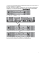 33
33
-
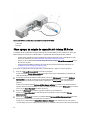 34
34
-
 35
35
-
 36
36
-
 37
37
-
 38
38
-
 39
39
-
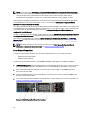 40
40
-
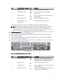 41
41
-
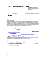 42
42
-
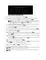 43
43
-
 44
44
-
 45
45
-
 46
46
-
 47
47
-
 48
48
-
 49
49
-
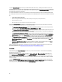 50
50
-
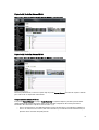 51
51
-
 52
52
-
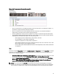 53
53
-
 54
54
-
 55
55
-
 56
56
-
 57
57
-
 58
58
-
 59
59
-
 60
60
-
 61
61
-
 62
62
-
 63
63
-
 64
64
-
 65
65
-
 66
66
-
 67
67
-
 68
68
-
 69
69
-
 70
70
-
 71
71
-
 72
72
-
 73
73
-
 74
74
-
 75
75
-
 76
76
-
 77
77
-
 78
78
-
 79
79
-
 80
80
-
 81
81
-
 82
82
-
 83
83
-
 84
84
-
 85
85
-
 86
86
-
 87
87
-
 88
88
-
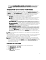 89
89
-
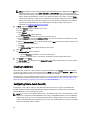 90
90
-
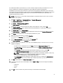 91
91
-
 92
92
-
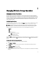 93
93
-
 94
94
-
 95
95
-
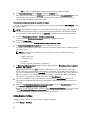 96
96
-
 97
97
-
 98
98
-
 99
99
-
 100
100
-
 101
101
-
 102
102
-
 103
103
-
 104
104
-
 105
105
-
 106
106
-
 107
107
-
 108
108
-
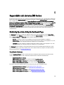 109
109
-
 110
110
-
 111
111
-
 112
112
-
 113
113
-
 114
114
-
 115
115
-
 116
116
-
 117
117
-
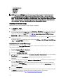 118
118
-
 119
119
-
 120
120
-
 121
121
-
 122
122
-
 123
123
-
 124
124
-
 125
125
-
 126
126
-
 127
127
-
 128
128
-
 129
129
-
 130
130
-
 131
131
-
 132
132
-
 133
133
-
 134
134
-
 135
135
-
 136
136
-
 137
137
-
 138
138
-
 139
139
-
 140
140
-
 141
141
-
 142
142
-
 143
143
-
 144
144
-
 145
145
-
 146
146
-
 147
147
-
 148
148
-
 149
149
-
 150
150
-
 151
151
-
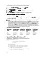 152
152
-
 153
153
-
 154
154
-
 155
155
-
 156
156
-
 157
157
-
 158
158
-
 159
159
-
 160
160
-
 161
161
-
 162
162
-
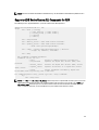 163
163
-
 164
164
-
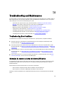 165
165
-
 166
166
-
 167
167
-
 168
168
-
 169
169
-
 170
170
-
 171
171
-
 172
172
-
 173
173
-
 174
174
-
 175
175
-
 176
176
-
 177
177
-
 178
178
-
 179
179
-
 180
180
-
 181
181
-
 182
182
-
 183
183
-
 184
184
-
 185
185
-
 186
186
-
 187
187
-
 188
188
-
 189
189
-
 190
190
-
 191
191
-
 192
192
-
 193
193
-
 194
194
-
 195
195
-
 196
196
-
 197
197
-
 198
198
-
 199
199
-
 200
200
-
 201
201
-
 202
202


en otros idiomas
- English: Dell DR2000v User guide
Artículos relacionados
-
Dell DR4300 Guía del usuario
-
-
-
Dell DR4100 El manual del propietario
-
-
-
-
Dell PowerVault DL2000 Guía del usuario
-
-
Dell PowerVault NX3610 Guía del usuario
Otros documentos
-
Buffalo HD-PZN1.0U3B Guía del usuario
-
Canon GP 160 El manual del propietario
-
Christie LX1750 Manual de usuario
-
Promise Technology NS4300N Manual de usuario
-
laerdal suction unit Guía del usuario
-
-
Brady LOCKOUT PRO 3.0 Administrator's Manual
-
Canon imageRUNNER 2520 Instrucciones de operación