Axis 24889 Manual de usuario
- Categoría
- Accesorios para cámaras de seguridad
- Tipo
- Manual de usuario
Este manual también es adecuado para

81-IN6209R1
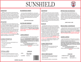
PRODUCT INSTRUCTIONS
MODEL:
24889, 29892
COMMUNICATIONS
f
or
Before attempting to connect or operate this product,
please read these instructions completely.

!
!
SAFETY PRECAUTIONSIMPORTANT SAFEGUARDS
1. Read Instructions - All the safety and operating instructions
should be read before the unit is operated.
2. Retain Instructions - The safety and operating instructions
should be retained for future reference.
3. Heed Warnings - All warnings on the unit and in the operating
instructions should be adhered to.
4. Follow Instructions - All operating and user instructions should
be followed.
5. Electrical Connections - Only a qualified electrician should make
electrical connections.
6. Attachments - Do not use attachments not recommended by the
product manufacturer as they may cause hazards.
7. Cable Runs -All cable runs must be within permissible
distance.
8. Mounting - This unit must be properly and securely mounted to
a supporting structure capable of sustaining the weight of
the unit. Accordingly:
a. The installation should be made by a qualified installer.
b. The installation should be in compliance with local codes.
c. Care should be exercised to select suitable hardware to install the
unit, taking into account both the composition of the mounting
surface and the weight of the unit. Be sure to periodically
examine the unit and the supporting structure to make sure
that the integrity of the installation is intact. Failure to comply
with the foregoing could result in the unit separating from the
support structure and falling, with resultant damages or injury
to anyone or anything struck by the falling unit.
DOME/HOUSING/ELECTRICAL COMPONENT
WARRANTY INFORMATION
Axis, Incorporated warrants that its domes and housing
sold here under shall be fit for the ordinary purpose for which
said products are intended and shall be free from defects in
material and workmanship for a period of three years from date
of sale to buyer. Note that all electrical components will be
warranted for a period of three years from date of sale to buyer.
Axis makes no other warranty of any kind with respect
to this product, whether expressed or implied, including,
without limitation, the implied warranty of fitness for a particular
purpose.
In the event of a breach of the above warranty, Axis shall,
at its option, repair or replace said product. This is Axis's
sole obligation under this warranty. In no event shall Axis
be liable for any incidental or consequential damages, as
defined in section 2-715 of the Uniform Commercial Code by a
breach of this warranty.
Axis shall repair or replace defective products upon
shipment of products returned prepaid to Axis.
Repairs made necessary by reason of accident, misuse or
normal wear shall be charged at Axis's standard rate.
This warranty gives you specific legal rights, and you may also
have other rights which vary from state to state.
UNPACKING
Unpack carefully. Electronic components can be damaged if
improperly handled or dropped. If an item appears to have been
damaged in shipment, replace it properly in its carton and notify
the shipper.
Be sure to save:
1. The shipping carton and packaging material. They are the safest
material in which to make future shipments of the equipment.
2. These Installation and Operating Instructions.
SERVICE
If the unit ever needs repair service, the customer should contact
Axis (1-800-444-2947) for authorization to return and
shipping instructions.
TECHNICAL SUPPORT
If technical support is needed, Axis has set-up a
technical support
1-800- 444-2947
CAUTION: TO REDUCE THE RISK OF ELECTRICAL SHOCK,
DO NOT OPEN COVERS.
NO USER SERVICEABLE PARTS INSIDE.
REFER SERVICING TO QUALIFIED SERVICE PERSONNEL.
The lightning flash with an arrowhead symbol,
with in an equilateral triangle, is intended to alert the
user to the presence of non-insulated "dangerous
voltage" within the product's enclosure that may
be of sufficient magnitude to constitute a risk of
electric shock to persons.
The exclamation point with in an equilateral triangle
is intended to alert the user to presence of important
operating and maintenance (servicing) instructions
in the literature accompanying the appliance.
AXIS TECHNICAL SUPPORT
C AUTION
R ISK OF
ELECTRIC SHOCK !
line for their customers.

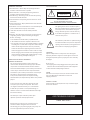
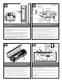
Unpacking the Product
24889
Input Power: 24 VAC
Power Consumption: 1.45Amp Total Consumption
Power Output: 27 Watts Heater/Blower
Up to 8 Watts Camera Power
Tools Required: Phillips Screwdriver
7/16 Wrench or Socket
Electrical Specifications
24VAC 50Watts
Wire
Gauge
Distance
22 20 18 16 14 12
55 90 150 230 270 600
Energía De Entrada: 24 VAC
De Consumo De Energía: 1.45Amp Total Consumption
De Salida De Energía: 27 Vatios De Heater/Blower
Up to 8 Vatios De Energía De la
Cámara fotográfica
Herramientas Requeridas: Destornillador Phillips
7/16 llave o zócalo
Puissance D'entrée : 24 VCA
De Puissance D'Énergie : 1.45Amp Total Consumption
De Rendement De Puissance : 27 Watts De Heater/Blower
Up to 8 Watts De Puissance
D'Appareil-photo Les Outils Ont exigé : Tournevis Phillips
7/16 clé ou douille
Zugeführte Energie: 24 VAC
Leistungsaufnahme: 1.45Amp Total Consumption
Abgabeleistung: 27 Watt Heater/Blower
Up to 8 Watt Kamera-Energie
Werkzeuge Erforderten: Kreuzkopfschraubenzieher
7/16 Schlüssel oder Einfaßung
Poder De Entrada: 24 VAC
De Consumo De Potência: 1.45Amp Total Consumption
De Saída De Poder: 27 Watts De Heater/Blower
Up to 8 Watts De Poder Da Câmera
As Ferramentas Requereram: Chave de fenda Phillips
7/16 de chave ou de soquete
Alimentazione in ingresso Di Entrata: 24 VCA
Di Assorbimento di corrente Di energia: 1.45Amp Total
Consuption
Di Uscita Di Alimentazione: 27 Watt Di Heater/Blower
Up to 8 Watt Di Alimentazione Della
Macchina fotografica
Attrezzi Richiesti: Cacciavite "phillips"
7/16 chiave o di zoccolo
!!

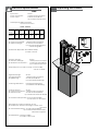
Remove the tilt mechanism from the bracket.
• Quite el mecanismo de la inclinación del
soporte.
• Enlevez le mécanisme d'inclinaison de la
parenthèse.
• Entfernen Sie die Neigungeinheit vom
Haltewinkel.
• Remova o mecanismo da inclinação do suporte.
• Rimuova il meccanismo di inclinazione dalla
staffa.
Attach the bracket to the wall and secure
appropriately.
• Una el soporte a la pared y asegúrelo apropia-
damente.
• Attachez la parenthèse au mur et la fixez conve-
nablement.
• Bringen Sie den Haltewinkel zur Wand an und
sichern Sie passend.
• Una o suporte à parede e fixe-o apropriada-
mente.
• Fissi la staffa alla parete e fissi giustamente.
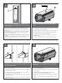
Install the (2) cable strain relief plugs on the bottom
of the housing and tighten with the locknuts.
• Instale (2) los enchufes del retenedor de cable del cable en el
fondo de la cubierta y apriete con las tuercas de fijación.
• Installez (2) les prises de passe-fils de câble sur le fond du logement
et serrez avec les contre-écrous.
• Bringen Sie die (2) Kabelgummidurchführungsringstecker auf
die Unterseite des Gehäuses an und ziehen Sie mit den
Kontermuttern fest.
• Instale (2) os plugues do protetor da fiação do cabo no fundo da
carcaça e aperte-os com as contraporcas.
• Installi (2) le spine di gommino di protezione del cavo sulla
parte inferiore dell'alloggiamento e stringa con i contro
dadi.
Remove the (2) screws on top of the
housing and lift it open.
• Quite (2) los tornillos encima de la cubierta y levántelos
abiertos.
• Enlevez (2) les vis sur le logement et soulevez-les ouvertes.
• Entfernen Sie die (2) Schrauben auf das Gehäuse und heben
Sie sie geöffnet an.
• Remova (2) os parafusos no alto da carcaça e levante-os
abertos.
• Rimuova (2) le viti in cima all'alloggiamento ed alzile aperte.
1
2
4
3

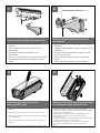
Place camera on sled and align mounting holes on
each. Adjust camera parallel to sled and tighten the
bolt on the bottom.
• Coloque la cámara fotográfica en el trineo y alinee los agujeros de
montaje en cada uno. Ajuste la cámara fotográfica paralela al trineo y
apriete el perno en el fondo.
• Placez l'appareil-photo sur le traîneau et alignez les trous de support sur
chacun. Ajustez l'appareil-photo parallèle au traîneau et serrez le
boulon sur le fond.
• Setzen Sie Kamera auf Schlitten und richten Sie Entlüftungslöcher auf
jedem aus. Justieren Sie die Kamera, die zum Schlitten parallel ist und
ziehen Sie den Schraubbolzen auf der Unterseite fest.
• Coloque a câmera no trenó e alinhe furos de montagem em cada um.
Ajuste a câmera paralela ao trenó e aperte o parafuso no fundo.
• Disponga la macchina fotografica sulla slitta ed allinei i fori di montag-
gio su ciascuno. Registri la macchina fotografica parallela alla slitta e
stringa il bullone sulla parte inferiore.
Sled
Screw
Camera Sled
Feed the wiring through the conduit plugs and make
all connections to the camera and lens.
• Alimente el cableado a través de los enchufes del conducto y
haga todas las conexiones a la cámara fotográfica y a la lente.
• Alimentez le câblage par les prises de conduit et établissez tous
les rapports à l'appareil-photo et à l'objectif.
• Ziehen Sie die Verdrahtung durch die Rohrstecker ein und stellen
Sie alle Beziehungen zur Kamera und zum Objektiv her.
• Alimente a fiação através dos plugues da canalização e faça
todas as conexões à câmera e à lente.
• Alimenti i collegamenti tramite le spine del condotto e faccia tutti
i collegamenti alla macchina fotografica ed all'obiettivo.
REAR PANEL
DC-Iris
Control Cable
External
Microphone/
Line Input
Audio Output
I/O
Terminal
Connector
Power
Connector
Network
Connector
and PoE
Input
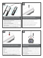
24VAC
Run 24VAC power through a conduit plug, and place the
stripped power wire ends into the 24AC power board.
•
Funcione la energía 24VAC a través de un enchufe del conducto, y ponga los
extremos pelados del alambre de la energía en el tablero de energía 24AC.
• Courez la puissance 24VAC par une prise de conduit, et placez les extrémités
dépouillées de fil de puissance dans carte d'alimentation 24AC.
• Lassen Sie Energie 24VAC durch einen Rohrstecker, laufen und setzen Sie die
abgestreiften Energie Leitung Enden in das Energie 24AC Brett.
• Funcione o poder 24VAC através de um plugue da canalização, e coloque as
extremidades descascadas do fio do poder na placa de poder 24AC.
• Faccia funzionare l'alimentazione 24VAC tramite una spina del condotto e
disponga le estremità messe a nudo del legare di alimentazione nel bordo di
alimentazione 24AC.
Tighten the terminal block screws then the conduit plugs.
•
Apriete los tornillos del bloque de terminales entonces los
enchufes del conducto.
• Serrez les vis de TB puis les prises de conduit.
• Ziehen Sie die Klemmenblockschrauben dann die Rohrstecker
fest.
• Aperte os parafusos do bloco terminal então os plugues da
canalização.
• Stringa le viti del blocchetto terminali allora le spine del
condotto.
ACH13PCB
J1
THERM 2
HEATER
24 VAC (IN)
BLOWER - (Black)
BLOWER - (Red)
THERM 1
(+)
(-)
YELLOW
PURPLE
12VDC
5
6
7
8

Adjust the focus and focal length until the desired field of view
and focus is obtained. For the 29892 wireless, attach the antenna
lead to the camera.
• Ajuste el foco y la longitud focal hasta que se obtenga el campo visual y el
foco deseados. Para la radio 29892, ate la antena llevan a la cámara.
• Ajustez le foyer et la longueur focale jusqu'à ce que le champ visuel et le
foyer désirés soit obtenu. Pour la radio 29892, attachez l'antenne mènent à
l'appareil-photo.
• Justieren Sie den Fokus und die fokale Länge, bis das gewünschte Blickfeld
und der Fokus erhalten ist. Für den Radioapparat 29892 bringen Sie die
Antenne führen zu die Kamera an.
• Ajuste o foco e o comprimento focal até que o campo de visão e o foco
desejados estejam obtidos. Para o rádio 29892, una a antena conduzem à
câmera.
• Registri il fuoco e la lunghezza focale fino ad ottenere il campo visivo ed il
fuoco voluti. Per la radio 29892, attacchi l'antenna conducono alla
macchina fotografica.
Adjust
Lens
Here
Close the top cover and tighten to the base with the
hex screws.
• Cierre la cubierta superior y apriete a la base con los tornillos
de la tuerca hexagonal.
• Fermez la couverture supérieure et serrez à la base avec les
vis de sortilège.
• Schließen Sie die obere Abdeckung und ziehen Sie zur
Unterseite mit den Hexagonschrauben fest.
• Feche a tampa superior e aperte-a à base com os parafusos
do hex.
• Chiuda la copertura superiore e stringa alla base con le viti
del hex.
If desired, use the security screws in place of hex
screws.
• Si está deseado, utilice los tornillos de la seguridad en lugar de
los tornillos de la tuerca hexagonal.
• Si désiré, utilisez les vis de sécurité au lieu des vis de sortilège.
• Wenn Sie gewünscht werden, benutzen Sie die Sicherheit
Schrauben anstatt der Hexagonschrauben.
• Se desejado, use os parafusos da segurança no lugar dos
parafusos do hex.
• Se voluto, utilizzi le viti di sicurezza al posto delle viti del hex.
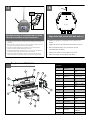
If mounting to pole, attach assembly using 3/4” mount-
ing straps (not provided).
• Si monta al poste, una a asamblea usando las correas que montan del
3/4"(no proporcionadas).
• Si montant au poteau, attachez l'assemblée en utilisant les courroies de
montage de 3/4"(non fournies).
• Bei der Befestigung zum Pfosten, bringen Sie Versammlung mit 3/4"den
Befestigungsbügeln an (nicht bereitgestellt).
• Se montando ao pólo, una o conjunto usando as cintas de montagem
de 3/4"(não fornecidas).
• Se montando al palo, fissi il complessivo usando le cinghie di montag-
gio di 3/4"(non fornite).
11
12
9
10

Slide Sunshield over first grove of housing
top.
• Resbale arboleda del excedente de Sunshield la
primera de la tapa de la cubierta.
• Glissez plantation d'excédent de Sunshield la première
de dessus de logement.
• Schieben Sie erste Waldung des Sunshield Über-
schusses der Gehäuseoberseite.
• Deslize bosque do excesso de Sunshield o primeiro do
alto da carcaça.
• Faccia scorrere boschetto dell'eccedenza di Sunshield
il primo della parte superiore dell'alloggiamento.
Align to fit grove
13
Connect antenna to antenna plug.
• Conecte la antena con el enchufe de antena.
• Reliez l'antenne à la prise d'antenne.
• Schließen Sie Antenne an Antennenstecker an.
• Conecte a antena ao plugue de antena.
• Colleghi l'antenna alla spina di antenna.
Slide grommet tightly against housing top.
• Resbale el ojal firmemente contra tapa de la cubierta.
• Glissez le canon isolant étroitement contre le dessus de
logement.
• Schieben Sie Gummimuffe fest gegen Gehäuseober-
seite.
• Deslize o ilhó firmemente de encontro à parte superior
da carcaça.
• Faccia scorrere strettamente il gommino di protezione
contro la parte superiore dell'alloggiamento.
Align sunshield with antenna and slide down
towards housing.
• Alinee el protector del sol con la antena y resbale abajo
hacia la cubierta.
• Alignez le bouclier du soleil avec l'antenne et glissez vers le
bas vers le logement.
• Richten Sie Sonneschild mit Antenne aus und schieben Sie
unten in Richtung zum Gehäuse.
• Alinhe o protetor do sol com a antena e deslize para baixo
para a carcaça.
• Allini lo schermo del sole con l'antenna e faccia scorrere giù
verso alloggiamento.
14
1615
(For Wireless Unit 29892)
(For Wireless Unit 29892) (For Wireless Unit 29892)

Align holes and secure with bolt and nut.
• Alinee los agujeros y asegúrelos con el perno y la
tuerca.
• Alignez les trous et les fixez avec le boulon et l'écrou.
• Richten Sie Bohrungen aus und sichern Sie mit
Schraubbolzen und Nuß.
• Alinhe furos e fixe-os com parafuso e porca.
• Allinei i fori e fissi con il bullone ed il dado.
Rear View
Hole
24889, 29892
Replacement Parts List
14
7
12
10
9
N/A
11
4
1
3
2
6
Item
Number
Comments Comments
1
2
3
4
5*
6
7
9
10
N/S
11
12
13
RPACH010
RPACH070
RPACH110
RPACH050
RPACH020
RPACH060
ACB2
N/A
RPACH130
RPACHPK
ACHY
ACH2
RPACHPC24
WM800
Front End Cap
Lower Housing
Body
Rear End Cap
Camera Sled
Captive Fasteners
(2)
Upper Housing
Body
Blower Assembly
(240)
Vent Plugs
Packet Assembly
SunShield
Heater
PCB
Wall Mount
5
N/S
N/S
N/S
RPTNC-7DB ANTENNA
RPVL2556
WIRELESS PIGTAIL
GROMMET
18
TOP
GROVE
Press down evenly on sun shield, the sun shield
will snap into position on top set of groves
• Apriete uniformemente en el protector del sol, el protector del sol se
encajará a presión hacia la posición respecto al sistema de la tapa de
arboledas.
• Enfoncez même sur le bouclier du soleil, le bouclier du soleil se cassera
en le place sur l'ensemble de dessus de plantations.
• Drücken Sie gleichmäßig auf Sonneschild, das Sonneschild reißt in
Position auf Oberseitensatz Waldungen herunter.
• Comprima uniformente no protetor do sol, o protetor do sol agarrará
na posição sobre o jogo da parte superior dos bosques.
• Comprima anche sullo schermo del sole, lo schermo del sole schioc-
cherà nella posizione sull'insieme della parte superiore dei boschetti.
17
(For Wireless Unit 29892)
Transcripción de documentos
for COMMUNICATIONS MODEL: 24889, 29892 PRODUCT INSTRUCTIONS Before attempting to connect or operate this product, please read these instructions completely. 81-IN6209R1 IMPORTANT SAFEGUARDS 1. Read Instructions - All the safety and operating instructions should be read before the unit is operated. 2. Retain Instructions - The safety and operating instructions should be retained for future reference. 3. Heed Warnings - All warnings on the unit and in the operating instructions should be adhered to. 4. Follow Instructions - All operating and user instructions should be followed. 5. Electrical Connections - Only a qualified electrician should make electrical connections. 6. Attachments - Do not use attachments not recommended by the product manufacturer as they may cause hazards. 7. Cable Runs -All cable runs must be within permissible distance. 8. Mounting - This unit must be properly and securely mounted to a supporting structure capable of sustaining the weight of the unit. Accordingly: a. The installation should be made by a qualified installer. b. The installation should be in compliance with local codes. c. Care should be exercised to select suitable hardware to install the unit, taking into account both the composition of the mounting surface and the weight of the unit. Be sure to periodically examine the unit and the supporting structure to make sure that the integrity of the installation is intact. Failure to comply with the foregoing could result in the unit separating from the support structure and falling, with resultant damages or injury to anyone or anything struck by the falling unit. DOME/HOUSING/ELECTRICAL COMPONENT WARRANTY INFORMATION Axis, Incorporated warrants that its domes and housing sold here under shall be fit for the ordinary purpose for which said products are intended and shall be free from defects in material and workmanship for a period of three years from date of sale to buyer. Note that all electrical components will be warranted for a period of three years from date of sale to buyer. Axis makes no other warranty of any kind with respect to this product, whether expressed or implied, including, without limitation, the implied warranty of fitness for a particular purpose. In the event of a breach of the above warranty, Axis shall, at its option, repair or replace said product. This is Axis's sole obligation under this warranty. In no event shall Axis be liable for any incidental or consequential damages, as defined in section 2-715 of the Uniform Commercial Code by a breach of this warranty. Axis shall repair or replace defective products upon shipment of products returned prepaid to Axis. SAFETY PRECAUTIONS ! C AUTION R ISK OF ELECTRIC SHOCK ! CAUTION: TO REDUCE THE RISK OF ELECTRICAL SHOCK, DO NOT OPEN COVERS. NO USER SERVICEABLE PARTS INSIDE. REFER SERVICING TO QUALIFIED SERVICE PERSONNEL. The lightning flash with an arrowhead symbol, with in an equilateral triangle, is intended to alert the user to the presence of non-insulated "dangerous voltage" within the product's enclosure that may be of sufficient magnitude to constitute a risk of electric shock to persons. ! The exclamation point with in an equilateral triangle is intended to alert the user to presence of important operating and maintenance (servicing) instructions in the literature accompanying the appliance. UNPACKING Unpack carefully. Electronic components can be damaged if improperly handled or dropped. If an item appears to have been damaged in shipment, replace it properly in its carton and notify the shipper. Be sure to save: 1. The shipping carton and packaging material. They are the safest material in which to make future shipments of the equipment. 2. These Installation and Operating Instructions. SERVICE If the unit ever needs repair service, the customer should contact Axis (1-800-444-2947) for authorization to return and shipping instructions. TECHNICAL SUPPORT If technical support is needed, Axis has set-up a technical support line for their customers. AXIS TECHNICAL SUPPORT 1-800- 444-2947 Repairs made necessary by reason of accident, misuse or normal wear shall be charged at Axis's standard rate. This warranty gives you specific legal rights, and you may also have other rights which vary from state to state. ! Electrical Specifications Unpacking the Product 24889 Input Power: Power Consumption: Power Output: 24 VAC 1.45Amp Total Consumption 27 Watts Heater/Blower Up to 8 Watts Camera Power Tools Required: Phillips Screwdriver 7/16 Wrench or Socket 24VAC 50Watts Wire Gauge 22 20 18 16 14 12 Distance 55 90 150 230 270 600 Energía De Entrada: De Consumo De Energía: De Salida De Energía: 24 VAC 1.45Amp Total Consumption 27 Vatios De Heater/Blower Up to 8 Vatios De Energía De la Cámara fotográfica Herramientas Requeridas: Destornillador Phillips 7/16 llave o zócalo Puissance D'entrée : De Puissance D'Énergie : De Rendement De Puissance : 24 VCA 1.45Amp Total Consumption 27 Watts De Heater/Blower Up to 8 Watts De Puissance D'Appareil-photo Les Outils Ont exigé : Tournevis Phillips 7/16 clé ou douille Zugeführte Energie: Leistungsaufnahme: Abgabeleistung: 24 VAC 1.45Amp Total Consumption 27 Watt Heater/Blower Up to 8 Watt Kamera-Energie Werkzeuge Erforderten: Kreuzkopfschraubenzieher 7/16 Schlüssel oder Einfaßung Poder De Entrada: 24 VAC De Consumo De Potência: 1.45Amp Total Consumption De Saída De Poder: 27 Watts De Heater/Blower Up to 8 Watts De Poder Da Câmera As Ferramentas Requereram: Chave de fenda Phillips 7/16 de chave ou de soquete Alimentazione in ingresso Di Entrata: 24 VCA Di Assorbimento di corrente Di energia: 1.45Amp Total Consuption Di Uscita Di Alimentazione: 27 Watt Di Heater/Blower Up to 8 Watt Di Alimentazione Della Macchina fotografica Attrezzi Richiesti: Cacciavite "phillips" 7/16 chiave o di zoccolo 1 2 Remove the tilt mechanism from the bracket. Attach the bracket to the wall and secure appropriately. • Quite el mecanismo de la inclinación del • Una el soporte a la pared y asegúrelo apropia- • • • • • soporte. Enlevez le mécanisme d'inclinaison de la parenthèse. Entfernen Sie die Neigungeinheit vom Haltewinkel. Remova o mecanismo da inclinação do suporte. Rimuova il meccanismo di inclinazione dalla staffa. 3 • • • damente. Attachez la parenthèse au mur et la fixez convenablement. Bringen Sie den Haltewinkel zur Wand an und sichern Sie passend. Una o suporte à parede e fixe-o apropriadamente. Fissi la staffa alla parete e fissi giustamente. 4 Remove the (2) screws on top of the housing and lift it open. Install the (2) cable strain relief plugs on the bottom of the housing and tighten with the locknuts. • Quite (2) los tornillos encima de la cubierta y levántelos abiertos. • Instale (2) los enchufes del retenedor de cable del cable en el fondo de la cubierta y apriete con las tuercas de fijación. • Installez (2) les prises de passe-fils de câble sur le fond du logement et serrez avec les contre-écrous. • Bringen Sie die (2) Kabelgummidurchführungsringstecker auf die Unterseite des Gehäuses an und ziehen Sie mit den Kontermuttern fest. • Instale (2) os plugues do protetor da fiação do cabo no fundo da carcaça e aperte-os com as contraporcas. • Installi (2) le spine di gommino di protezione del cavo sulla parte inferiore dell'alloggiamento e stringa con i contro dadi. • Enlevez (2) les vis sur le logement et soulevez-les ouvertes. • Entfernen Sie die (2) Schrauben auf das Gehäuse und heben Sie sie geöffnet an. • Remova (2) os parafusos no alto da carcaça e levante-os abertos. • Rimuova (2) le viti in cima all'alloggiamento ed alzile aperte. 5 6 External Microphone/ Line Input DC-Iris Control Cable Sled Screw Network Connector and PoE Camera Sled Place camera on sled and align mounting holes on each. Adjust camera parallel to sled and tighten the bolt on the bottom. • • • • • Coloque la cámara fotográfica en el trineo y alinee los agujeros de montaje en cada uno. Ajuste la cámara fotográfica paralela al trineo y apriete el perno en el fondo. Placez l'appareil-photo sur le traîneau et alignez les trous de support sur chacun. Ajustez l'appareil-photo parallèle au traîneau et serrez le boulon sur le fond. Setzen Sie Kamera auf Schlitten und richten Sie Entlüftungslöcher auf jedem aus. Justieren Sie die Kamera, die zum Schlitten parallel ist und ziehen Sie den Schraubbolzen auf der Unterseite fest. Coloque a câmera no trenó e alinhe furos de montagem em cada um. Ajuste a câmera paralela ao trenó e aperte o parafuso no fundo. Disponga la macchina fotografica sulla slitta ed allinei i fori di montaggio su ciascuno. Registri la macchina fotografica parallela alla slitta e stringa il bullone sulla parte inferiore. 7 REAR PANEL Audio Output Power Connector I/O Terminal Connector Feed the wiring through the conduit plugs and make all connections to the camera and lens. • Alimente el cableado a través de los enchufes del conducto y haga todas las conexiones a la cámara fotográfica y a la lente. • Alimentez le câblage par les prises de conduit et établissez tous les rapports à l'appareil-photo et à l'objectif. • Ziehen Sie die Verdrahtung durch die Rohrstecker ein und stellen Sie alle Beziehungen zur Kamera und zum Objektiv her. • Alimente a fiação através dos plugues da canalização e faça todas as conexões à câmera e à lente. • Alimenti i collegamenti tramite le spine del condotto e faccia tutti i collegamenti alla macchina fotografica ed all'obiettivo. YELLOW 8 (+) (-) PURPLE 24 VAC (IN) HEATER BLOWER 12VDC - (Black) BLOWER - (Red) ACH13PCB J1 THERM 1 THERM 2 Input 24VAC Run 24VAC power through a conduit plug, and place the stripped power wire ends into the 24AC power board. • • • • • Funcione la energía 24VAC a través de un enchufe del conducto, y ponga los extremos pelados del alambre de la energía en el tablero de energía 24AC. Courez la puissance 24VAC par une prise de conduit, et placez les extrémités dépouillées de fil de puissance dans carte d'alimentation 24AC. Lassen Sie Energie 24VAC durch einen Rohrstecker, laufen und setzen Sie die abgestreiften Energie Leitung Enden in das Energie 24AC Brett. Tighten the terminal block screws then the conduit plugs. • Apriete los tornillos del bloque de terminales entonces los enchufes del conducto. • Serrez les vis de TB puis les prises de conduit. • Ziehen Sie die Klemmenblockschrauben dann die Rohrstecker fest. Funcione o poder 24VAC através de um plugue da canalização, e coloque as extremidades descascadas do fio do poder na placa de poder 24AC. • Aperte os parafusos do bloco terminal então os plugues da Faccia funzionare l'alimentazione 24VAC tramite una spina del condotto e disponga le estremità messe a nudo del legare di alimentazione nel bordo di alimentazione 24AC. • Stringa le viti del blocchetto terminali allora le spine del canalização. condotto. 9 10 Adjust Lens Here Adjust the focus and focal length until the desired field of view and focus is obtained. For the 29892 wireless, attach the antenna lead to the camera. • • • • • Ajuste el foco y la longitud focal hasta que se obtenga el campo visual y el foco deseados. Para la radio 29892, ate la antena llevan a la cámara. Ajustez le foyer et la longueur focale jusqu'à ce que le champ visuel et le foyer désirés soit obtenu. Pour la radio 29892, attachez l'antenne mènent à l'appareil-photo. Justieren Sie den Fokus und die fokale Länge, bis das gewünschte Blickfeld und der Fokus erhalten ist. Für den Radioapparat 29892 bringen Sie die Antenne führen zu die Kamera an. Ajuste o foco e o comprimento focal até que o campo de visão e o foco desejados estejam obtidos. Para o rádio 29892, una a antena conduzem à câmera. Registri il fuoco e la lunghezza focale fino ad ottenere il campo visivo ed il fuoco voluti. Per la radio 29892, attacchi l'antenna conducono alla macchina fotografica. If desired, use the security screws in place of hex screws. • Si está deseado, utilice los tornillos de la seguridad en lugar de los tornillos de la tuerca hexagonal. • Si désiré, utilisez les vis de sécurité au lieu des vis de sortilège. • Wenn Sie gewünscht werden, benutzen Sie die Sicherheit Schrauben anstatt der Hexagonschrauben. • Se desejado, use os parafusos da segurança no lugar dos parafusos do hex. • Se voluto, utilizzi le viti di sicurezza al posto delle viti del hex. 11 12 If mounting to pole, attach assembly using 3/4” mounting straps (not provided). Close the top cover and tighten to the base with the hex screws. • Si monta al poste, una a asamblea usando las correas que montan del 3/4"(no proporcionadas). • • Cierre la cubierta superior y apriete a la base con los tornillos de la tuerca hexagonal. Si montant au poteau, attachez l'assemblée en utilisant les courroies de montage de 3/4"(non fournies). • Fermez la couverture supérieure et serrez à la base avec les vis de sortilège. • Bei der Befestigung zum Pfosten, bringen Sie Versammlung mit 3/4"den Befestigungsbügeln an (nicht bereitgestellt). • Schließen Sie die obere Abdeckung und ziehen Sie zur Unterseite mit den Hexagonschrauben fest. • Se montando ao pólo, una o conjunto usando as cintas de montagem de 3/4"(não fornecidas). • Feche a tampa superior e aperte-a à base com os parafusos do hex. • Se montando al palo, fissi il complessivo usando le cinghie di montaggio di 3/4"(non fornite). • Chiuda la copertura superiore e stringa alla base con le viti del hex. 13 Align to fit grove Slide Sunshield over first grove of housing top. • Resbale arboleda del excedente de Sunshield la primera de la tapa de la cubierta. • Glissez plantation d'excédent de Sunshield la première de dessus de logement. • Schieben Sie erste Waldung des Sunshield Überschusses der Gehäuseoberseite. • Deslize bosque do excesso de Sunshield o primeiro do alto da carcaça. • Faccia scorrere boschetto dell'eccedenza di Sunshield il primo della parte superiore dell'alloggiamento. 15 (For Wireless Unit 29892) 14 (For Wireless Unit 29892) Connect antenna to antenna plug. • Conecte la antena con el enchufe de antena. • Reliez l'antenne à la prise d'antenne. • Schließen Sie Antenne an Antennenstecker an. • Conecte a antena ao plugue de antena. • Colleghi l'antenna alla spina di antenna. 16 (For Wireless Unit 29892) Slide grommet tightly against housing top. Align sunshield with antenna and slide down towards housing. • Resbale el ojal firmemente contra tapa de la cubierta. • Alinee el protector del sol con la antena y resbale abajo hacia la cubierta. • Glissez le canon isolant étroitement contre le dessus de logement. • Schieben Sie Gummimuffe fest gegen Gehäuseoberseite. • Deslize o ilhó firmemente de encontro à parte superior da carcaça. • Faccia scorrere strettamente il gommino di protezione contro la parte superiore dell'alloggiamento. • Alignez le bouclier du soleil avec l'antenne et glissez vers le bas vers le logement. • Richten Sie Sonneschild mit Antenne aus und schieben Sie unten in Richtung zum Gehäuse. • Alinhe o protetor do sol com a antena e deslize para baixo para a carcaça. • Allini lo schermo del sole con l'antenna e faccia scorrere giù verso alloggiamento. 17 18 (For Wireless Unit 29892) Hole TOP GROVE Rear View Press down evenly on sun shield, the sun shield will snap into position on top set of groves Align holes and secure with bolt and nut. • Apriete uniformemente en el protector del sol, el protector del sol se encajará a presión hacia la posición respecto al sistema de la tapa de arboledas. • Alinee los agujeros y asegúrelos con el perno y la tuerca. • Enfoncez même sur le bouclier du soleil, le bouclier du soleil se cassera en le place sur l'ensemble de dessus de plantations. • Alignez les trous et les fixez avec le boulon et l'écrou. • Drücken Sie gleichmäßig auf Sonneschild, das Sonneschild reißt in Position auf Oberseitensatz Waldungen herunter. • Richten Sie Bohrungen aus und sichern Sie mit Schraubbolzen und Nuß. • Comprima uniformente no protetor do sol, o protetor do sol agarrará na posição sobre o jogo da parte superior dos bosques. • Alinhe furos e fixe-os com parafuso e porca. • Comprima anche sullo schermo del sole, lo schermo del sole schioccherà nella posizione sull'insieme della parte superiore dei boschetti. • Allinei i fori e fissi con il bullone ed il dado. Replacement Parts List Item Number 24889, 29892 5 4 2 12 7 6 11 Comments Comments Front End Cap 1 RPACH010 2 RPACH070 Lower Housing Body 3 RPACH110 Rear End Cap 4 RPACH050 Camera Sled 5* RPACH020 6 RPACH060 7 ACB2 Captive Fasteners (2) Upper Housing Body Blower Assembly (240) N/A 3 N/A 1 9 10 14 9 RPACH130 Vent Plugs 10 RPACHPK Packet Assembly N/S ACHY SunShield 11 ACH2 Heater 12 RPACHPC24 PCB 13 WM800 Wall Mount N/S RPTNC-7DB ANTENNA N/S RPVL2556 WIRELESS PIGTAIL GROMMET N/S-
 1
1
-
 2
2
-
 3
3
-
 4
4
-
 5
5
-
 6
6
-
 7
7
-
 8
8


Axis 24889 Manual de usuario
- Categoría
- Accesorios para cámaras de seguridad
- Tipo
- Manual de usuario
- Este manual también es adecuado para
en otros idiomas
- italiano: Axis 24889 Manuale utente
- English: Axis 24889 User manual
Artículos relacionados
Otros documentos
-
Moog FCH SERIES Instrucciones de operación
-
Moog Videolarm PFH10C8WY Instrucciones de operación
-
-
-
-
-
 SUNSHIELD 312 Guía de instalación
