Legrand RH-200 Multi-way Wall Switch Vacancy Sensor - Guía de instalación
- Tipo
- Guía de instalación

Installation Instructions
Please read all instructions before installing
DESCRIPTION AND OPERATION
RH-200 Multi-way Wall Switch Vacancy Sensors are designed to replace standard
multi-way (3-way, 4-way) switches. They are ideal for any room with multiple
entries such as living and dining rooms, family rooms, bedrooms, bathrooms,
hallways, and any other indoor space where vacancy sensor-based controls with
manual ON/OFF capability are desirable.
Like standard switches, you can press the ON/OFF button to turn the light or fan
(controlled load) ON and OFF. Unlike standard switches, the RH-200 automatically
turns OFF the controlled load after the coverage area has been vacant for a period
of time (Time Delay). If motion is detected within 30 seconds after it automatically
turns OFF, the RH-200 automatically turns the load back ON.
While the sensor is factory preset as a Vacancy Sensor with manual ON operation,
it can be adjusted to work as an occupancy sensor that turns the controlled load
ON automatically upon detection of occupancy in the area.
Lighted Switch
To help you locate the RH-200 in a dark room, the amber LED illuminates the
ON/OFF button while the controlled load is OFF. When the controlled load is ON,
the LED is OFF.
Operating Modes
For multi-way operation the Operating Mode must be the same in all sensors
related to the same load. There are two operating modes to select from:
MODE 1 Vacancy sensor (Manual-ON/OFF, Auto-OFF): The user must press
the ON/OFF button to turn the load ON. The RH-200 keeps the load ON until no
motion is detected by any of the related RH-200s for the time delay period. There
is also a 30 second reset delay after the automatic shut-off. If motion is detected
during this time, the sensor turns the load back on automatically. After the 30
second reset delay has elapsed, the ON/OFF button must be pressed to turn ON
the load.
MODE 2 Occupancy sensor (Auto-ON/OFF with manual control and reset to auto
after 5 minutes of vacancy): The load turns ON and OFF automatically based on
occupancy detection. Once turned ON the RH-200 keeps the load ON until no
motion is detected by any of the related RH-200s for the time delay period. If
the load is turned OFF manually, automatic-ON is re-enabled when no motion is
detected for 5 minutes. This prevents the load from being turned on after it was
deliberately turned OFF.
SPECIFICATIONS
Voltage ................................................................... 120VAC, 60Hz
Load (Single Pole Circuit)
Incandescent or fl uorescent ................................ 0-600 Watts
Fan motor ...................................................................... 1/6 hp
Time Delay Adjustment .............. 15 sec., 5 min., 15 min., 30 min.
Light Level Adjustment ........................................... 10 fc to 150 fc
Environment ...................................... Residential Indoor use only
Operating Temperature ....................32° to 131°F (0° to 55°C)
Humidity .......................................... 95% RH, non-condensing
Tools Needed
Insulated Screwdriver
Wire Strippers
Santa Clara, CA 95050
Call 888.817.0571 for Technical Support
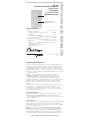
RH-200
Multi-way
Wall Switch
Vacancy Sensor
with Manual ON/OFF
Lens
Lighted Switch
ON/OFF Button

Time Delay
The time delay can be selected by the user during set up. It can be adjusted to
any of these fi xed values:15 seconds/5 minutes/15 minutes/30 minutes. All of
the sensors related to the same load must be set for the same time delay. For
additional information on how to adjust it, please read the SENSOR ADJUSTMENT
& PROGRAMMING section of this installation manual.
Light Level
When the operating mode is set for occupancy sensor, Mode 2 (Auto-ON) this
feature prevents the sensor from automatically turning the lights ON if there is
already enough light in the area.
In a multi-way application, each sensor monitors the light level at it’s location.
If any sensor related to the load detects motion AND the measured light level in
that sensor’s area is lower than it’s Light Level setting, the load turns ON.
To adjust the light level, please read the SENSOR ADJUSTMENT &
PROGRAMMING section of this installation manual.
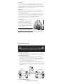
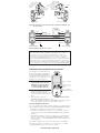
Coverage Area
The RH-200 has a maximum coverage range
of 180 degrees and a coverage area of 600
square feet (56 square meters). The sensor
must have a clear and unobstructed view
of the coverage area. Objects blocking the
sensor’s lens may prevent detection thereby
causing the light to turn OFF even though
someone is in the area.
Windows, glass doors, and other
transparent barriers will obstruct the
sensor’s view and prevent detection.
INSTALLATION & WIRING
WARNING
Disconnect power to the wall switch box by turning OFF
the circuit breaker or removing the fuse for the circuit before
installing the RH-200, replacing lamps, or doing any electrical work.
1. Prepare the switch box.
After the power is turned OFF at the circuit breaker box, remove the existing
wall plate and mounting screws. Pull the old switch out from the wall box.
2. Identify the type of circuit.
You may connect the RH-200 to a single pole or multi-way circuit. These
instructions describe only the 3-way circuit application. For information about
other applications, consult technical support or the Watt Stopper website. If
you are unable to clearly identify some or all of the wires mentioned in this
manual, you should consult with a qualifi ed electrician.
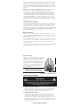
In a 3-way circuit (see Fig. 2), two traveler wires connect to both switches.
Another wire provides power from the circuit box to one of the switches. A wire
connects from one switch to the load. A ground wire may also be connected to
a ground terminal on the old switches. A neutral wire should also be present in
both wall boxes.
NEUTRAL
GROUND
LOAD/Common
(power to lamp)
NEUTRAL
GROUND
HOT/Common
(power from circuit box)
TRAVELER
TRAVELER
MASTER SWITCH
AUXILIARY SWITCH
Fig. 2: Typical 3-Way Switch Wiring
25'
(7.6m)
12'
(3.7m)
www.wattstopper.com/athome
Fig. 1: Sensor Coverage Area

CAUTION
For your safety: Connecting a proper ground to the sensor
provides protection against electrical shock in the event of certain
fault conditions. If a proper ground is not available, consult with
a qualifi ed electrician before continuing installation.
3. Prepare the Wires.
Tag the wires currently connected to the existing switch so
that they can be identifi ed later. Disconnect the wires. Make
sure the insulation is stripped off of the wires to expose
their copper cores to the length indicated by the “Strip
Gage,” in Fig. 3. (approx. 1/2 inch).
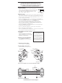
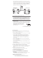
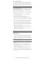
4. Wire the sensor.
Twist the existing wires together with the wire leads on the RH-200 sensors as
indicated below. Cap them securely using wire nuts provided. (See Fig. 4 & 5)
• Connect the green or non-insulated (copper) GROUND wire from the circuit to
the green terminal on the RH-200.
• Connect the NEUTRAL wire from the circuit and from the lamp (LOAD) to the
white wire on the master RH-200. Connect the NEUTRAL wire from the circuit
in the other wiring box to the white wire on the auxiliary RH-200.
The term “master” designates the RH-200 that connects to the load.
• Connect the power wire from the circuit box (HOT) to the black wire on the
auxiliary RH-200 and to the TRAVELER 1 wire.
• Connect the TRAVELER 1 wire from the black wire of the auxiliary RH-200 to
the black wire of the master RH-200.
• Connect the lamp power (LOAD) to the red wire on the master RH-200.
• Cap the red wire on the auxiliary RH-200.
• Connect the TRAVELER 2 wire coming from the yellow wire of another RH-200
to the yellow wire of the RH-200 that you are wiring.
5. Put the RH-200s into their respective
wall boxes.
Position them with the lens positioned
above the ON/OFF button (lens at top, ON/
OFF button at bottom). Secure to the wall
box with the screws provided.
6. Make any necessary adjustments.
See the SENSOR ADJUSTMENT &
PROGRAMMING section for information.
7. Attach the new cover plate.
Secure it with the screws provided.
8. Restore power to the circuit.
Turn on the breaker or replace the fuse
MASTER RH-200 AUXILIARY RH-200
TO
P
INDOOR US
E
O
NL
Y
L
L
TOP
INDOOR
USE
ONLY
L
L
Red -> LOAD
(power to lamp
or fan)
White ->
NEUTRAL
GROUND
TERMINAL
Red -> capped
GROUND
TERMINAL
White ->
NEUTRAL
Yellow-> TRAVELER 2
to AUX RH-200
Yellow-> TRAVELER 2
to MASTER RH-200
HOT (power
from circuit box)
Black-> TRAVELER 1
power to
MASTER RH-200
Black-> TRAVELER 1
power from
AUX RH-200
Fig. 4: Sensor orientation, wire connections and wall box assembly
AUXILIARY RH-200
MASTER RH-200
TOP
INDOOR USE ONLY
TOP
INDOOR USE ONLY
Red
Ground
Yellow
Black
White
Red
Ground
Yellow
Black
White
Load
Traveler 1
Traveler 2
Neutral
Hot
Neutral
Fig. 5 Reference wiring diagram
Initial Power-up
There is an initial warm-up
period. If the sensor is in
Mode 2 “Automatic ON” it may
take up to a minute before the
lights turn ON. However, the
lights can be turned ON/OFF
manually by pressing the “ON/
OFF Button” at anytime when
power is supplied to the unit.
Call 888.817.0571 for Technical Support
Strip Gage
1/2"
12.7 mm
Fig. 3: Wire
Stripping

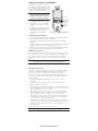
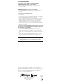
SENSOR ADJUSTMENT & PROGRAMMING
To program the RH-200, you use controls
located under the ON/OFF button. The wall
switch cover plate must be removed to gain
access to the mode button and adjustment
trimpots under the ON/OFF button.
For multi-way operation, the
Operating Mode and the Time Delay
adjustments should be the same in all
sensors related to the same load.
1. Firmly grasp the side edges of the
Lock Bar and gently pull it away from
the switch face until it clicks. Do NOT
attempt to pull the Lock Bar off of the
switch!
2. Firmly grasp the side edges of the ON/
OFF button. Slide the button downward
approximately 1/2 inch to expose
the mode button and adjustment
trimpots.
Setting up the Operating Mode
Select the operating mode by pressing the Mode button. The amber LED behind
the switch button blinks to indicate the selected mode:
• One blink indicates Mode 1 (Vacancy Sensor Operation), Manual-ON/OFF,
Auto-OFF
• Two blinks indicates Mode 2 (Occupancy Sensor Operation), Auto-ON/OFF with
manual control and reset to auto (after 5 minutes of vacancy)
To change the operating mode, press the Mode button. The LED blinks to indicate
the selected mode. After that, the unit operates in the indicated mode.
Adjusting the Time Delay
Turn the right trimpot counter-clockwise to reduce the amount of time the lights
will remain on after the last motion detection (minimum = 15 seconds). Turn the
same trimpot clockwise to increase this time delay (maximum = 30 minutes).
You can only select the following values: 15 seconds/5 minutes/15 minutes/30
minutes.
Warning: Do not overturn the Time Delay adjustment trimpot!
Adjusting the Light Level
This feature is factory set at maximum, so that even the brightest light will not
prevent the sensor from turning the load ON when it detects occupancy. If this
feature is not needed, leave the light level at maximum, fully clockwise.
The light level must be adjusted when lights would normally be turned OFF
because there is enought natural illumintation. Each RH-200 may have a different
light level setting.
1. Set all RH-200s to Mode 1 (Manual-ON) - except for the one that you’re
adjusting.
Set the RH-200 you’re adjusting so that it is in Mode 2 (Automatic-ON).
2. Reduce the time delay to 15 seconds.
3. Adjust the Light Level trimpot to minimum (fully counter-clockwise) on the unit
that you’re adjusting. Move out of the coverage area. Let the sensor time out so
lights are OFF and then wait 30 seconds more.
4. Without casting a shadow on the sensor, enter the area. The lights should
remain OFF. Adjust the Light Level trimpot clockwise in small increments.
After each adjustment, wait 5-10 seconds to see if the lights turn ON.
Continue this procedure until the lights turn ON. At this setting the light will
not turn ON automatically with occupancy if the light level measured at this
sensor is above the current natural illumination.
5. Repeat the process (beginning with step 1) for each RH-200 in your multi-way
confi guration until the Light Level has been adjusted properly in all of them.
6. When you have fi nished adjusting the Light Level of all the RH-200s, return
them all to Mode 2.
7. Reset the time delay to the desired setting in all units.
Warning: Do not overturn the Light Level adjustment trimpot!
TOP
INDOOR USE ONLY
Lock Bar
Mode Button
& Adjustment
Trimpots
Slide down
ON/OFF
Button
Time Delay
15
minutes
Mode
Level
06006r1
1–Manual
2–Auto-ON
Fig. 6: Sensor Adjustment Controls
www.wattstopper.com/athome

Call 888.817.0571 for Technical Support
TEST MODE
To test the detection coverage:
1. Press and hold the ON/OFF button. After 10 seconds the lighted switch turns
off. The load turns ON if it was not already ON. The sensor is now in a TEST
mode that lasts 5 minutes. (You can end the TEST mode sooner by pressing the
ON/OFF button for another 10 seconds).
During the TEST mode, the controlled load turns ON for 5 seconds each
time the sensor that initiated the TEST mode detects occupancy.
2. Move out of the coverage area or stand very still. The controlled load turns OFF
after 5 seconds if no motion is detected.
3. Move into the coverage area for the unit that initiated the TEST mode. The
controlled load turns ON for 5 seconds each time the sensor detects motion.
After 5 seconds expire without motion detection, the load turns OFF. The
controlled load turns ON automatically with the next motion detection and
stays ON for 5 seconds.
4. Repeat as necessary to ensure that the desired coverage areas are within
detection range.
You can do this test for each RH-200 in your multi-way confi guration. So that you
can determine the actual coverage area for each multi-way switch individually,
only the RH-200 that is in TEST mode will control the load.
TROUBLESHOOTING
Lighted switch is OFF, no load response to ON/OFF button press:
• Make certain that the circuit breaker is on and functioning.
Lighted switch is ON, no load response to ON/OFF button press:
• Check the light bulb and/or motor switch on the fan mechanism.
Load will not turn OFF automatically:
• Press ON/OFF button. If the controlled load turns OFF, go to next step.
• The time delay can be set from 15 seconds to 30 minutes. Check the time
delay setting for each RH-200 in your multi-way confi guration. Ensure that all
RH-200s have the same time delay setting.
• Ensure that there is no movement within the coverage area for all the sensors
related to the load for the set time delay. Hot air currents and heat radiant
devices can cause false detection. Make sure the sensor is at least 6 feet (2
meters) away from devices that are a signifi cant heat source (e.g. heater,
heater vent, high wattage light bulb).
Load will not turn ON automatically when the area is occupied and the
sensors are in Mode 2 (lighted switch is ON):
• Press ON/OFF button. If the load turns ON, check the Light Level setting. The
light level can prevent the sensor from turning ON the load automatically.
Make sure the sensor lenses are not blocked and that you are within the
coverage area of at least one sensor.
• If the load does not turn ON when you press the ON/OFF button, check the light
bulb and/or motor switch on the fan mechanism.
If load does not respond properly after following troubleshooting, turn OFF
power to the circuit then check wire connections or call technical support.

WARRANTY INFORMATION
Watt Stopper/Legrand warranties its products to be free of defects in materials
and workmanship for a period of fi ve (5) years. There are no obligations or
liabilities on the part of Watt Stopper/Legrand for consequential damages arising
out of, or in connection with, the use or performance of this product or other
indirect damages with respect to loss of property, revenue or profi t, or cost of
removal, installation or reinstallation.
2800 De La Cruz Boulevard, Santa Clara, CA 95050
Technical Support: 888.817.0571
www.wattstopper.com/at home
06247r2 6/2007
Please
Recycle

Por favor leer todas las instrucciones antes de realizar la instalación
RH-200
Sensor de Desocupación de pared
(3 vías, 4 vías)
confi gurable
con control manual de
ENCENDIDO/ APAGADO
DESCRIPCION Y OPERACION
Los Sensores de Desocupación de pared (3 vias, 4 vias) confi gurables RH-200
están diseñados para sustituir interruptores de luz convencionales de 3 y 4 vías
o el interruptor de un ventilador. Son ideales para lugares o habitaciones que
tengan múltiples entradas tales como: salas y comedores, cuartos de televisión,
dormitorios, baños, pasillos y corredores y cualquier otra área en una residencia
donde se deseen controles manuales de ENCENDIDO/APAGADO con detección de
ocupación/desocupación.
Igual que con un interruptor convencional, usted presiona el botón de
ENCENDIDO/APAGADO para encender o apagar la luz o ventilador (carga
controlada). Sin embargo, el RH-200 apagará automáticamente la carga
controlada cuando el área de cobertura ha permanecido desocupada por un
período de tiempo defi nido como Retardo de Apagado. Si se detecta movimiento
durante los siguientes 30 segundos después de que la carga se ha apagado
automáticamente, el RH-200 la encenderá nuevamente en forma también
automática.
Aunque el sensor viene confi gurado de fábrica para funcionar como un Sensor
de Desocupación (es decir, que requiere de encendido manual por el usuario),
el mismo puede ser confi gurado para operar como un Sensor de Ocupación
que encenderá automáticamente la carga en el preciso instante en que detecte
ocupación en su área de cobertura.
Interruptor Iluminado
Para facilitar la ubicación del RH-200 en un cuarto oscuro, un LED color ámbar
ilumina el botón de ENCENDIDO/APAGADO cuando la carga controlada se
encuentra apagada. Cuando por el contrario esta última se encuentra encendida,
el LED estará apagado.
Modos de Operación
Para conexiones de 3 y 4 vías de dos o más RH-200s, se recomienda que el Modo
de Operación sea el mismo en todos los sensores que estén controlando una
misma carga. Es posible elegir entre dos modos de operación durante la etapa de
instalación y confi guración del sensor:
MODO 1 Sensor de Desocupación (ENCENDIDO/APAGADO manual, APAGADO
AUTOMATICO): el usuario debe presionar el botón de ENCENDIDO/APAGADO
para encender la carga. Uno o varios RH-200s controlando una misma carga,
la mantendrán encendida hasta que ninguno de ellos detecte movimiento por
un periodo de tiempo denominado Retardo de Apagado (confi gurable desde 15
Santa Clara, CA 95050
Lente
Botón iluminado de
ENCENDIDO/APAGADO
Instrucciones de Instalación
ESPECIFICACIONES
Voltaje ................................................................... 120VAC, 60Hz
Carga (Circuito unipolar)
Lámparas incandescentes o fl uorescentes ........ 0-600 Watts
Un motor ........................................................................ 1/6 hp
Ajuste del Retardo de Apagado
............................... desde 15 segundos hasta 30 minuto
Ajuste del Nivel de Luz Natural .............................. 10 fc to 150 fc
Condiciones de operación
...........................Solo para uso residencial en interiores
Temperatura ..........................................32° to 131°F (0° to 55°C)
Humedad .....................95% Humedad relativa, sin condensación
Herramientas necesarias:
Desatornillador con aislamiento
Peladora de cable
Llame al 888.817.0571 para recibir asistencia técnica

segundos hasta 30 minutos). Existe un periodo de 30 segundos, inmediatamente
después de que la carga se ha apagado automáticamente, durante el cual los
sensores RH-200 la encenderán nuevamente en forma automática si alguno de
estos detecta movimiento. Si transcurren más de 30 segundos, será necesario
presionar el botón de ENCENDIDO/APAGADO nuevamente para poder encender
la carga.
MODO 2 Sensor de Ocupación (ENCENDIDO/APAGADO automático con control
manual y retorno a ENCENDIDO AUTOMATICO después de 5 minutos de
desocupación): la carga se enciende y se apaga automáticamente por detección
de ocupación. Los RH-200s mantienen la carga encendida hasta que todos
ellos dejen de detectar movimiento por un periodo de tiempo igual al defi nido
como Retardo de Apagado. Si la carga es apagada manualmente, la operación
de ENCENDIDO AUTOMATICO se reestablece después de que los sensores no
han detectado movimiento por 5 minutos. Esto evita que la carga se encienda
automáticamente cuando la misma ha sido apagada manualmente por elección
del usuario.
Tiempo de Retardo de Apagado
El tiempo de Retardo de Apagado puede ser confi gurado por el usuario durante la
instalación del producto. Para el mismo se pueden elegir los siguientes valores:
15 segundos, 5 minutos, 15 minutos y 30 minutos. Se recomienda que todos los
RH-200 conectados en grupo sean confi gurados con el mismo tiempo de Retardo
de Apagado. Para información adicional sobre cómo realizar lo anterior, por favor
lea la sección de CONFIGURACION Y PROGRAMACION DEL SENSOR en este
instructivo de instalación.
Nivel de Luz Natural
Cuando el sensor está confi gurado para operar en Modo 2 como un sensor de
ocupación (ENCENDIDO/APAGADO automático) el ajuste del Nivel de Luz Natural
evita que el sensor encienda automáticamente las luces si existe sufi ciente luz
natural en la habitación.
En una conexión de dos o más RH-200s, es decir, en una conexión 3 o 4 vías, cada
sensor monitorea el nivel de luz natural en su área. Cualquiera de los sensores
que detecte movimiento y que determine que la luz natural es insufi ciente
encenderá la carga.
Para ajustar el Nivel de Luz Natural por favor lea la sección de CONFIGURACION
Y PROGRAMACION DEL SENSOR en este instructivo de instalación.
Area de Cobertura
El RH-200 tiene un rango de cobertura máximo de
180 grados, y cubre un área de 600 pies cuadrados
(56 metros cuadrados). El RH-200 debe poder
tener visibilidad completa y sin obstrucciones del
área de cobertura. La carga podría apagarse aun
cuando alguien se encuentre dentro del área de
cobertura si existen objetos bloqueando el lente
del sensor y por tanto evitando que el mismo
detecte movimiento.
Ventanas, puertas de vidrio, y otras barreras
transparentes obstruirán la cobertura del
sensor y evitarán que exista detección.
Fig. 1: Patrón de cobertura del sensor
INSTALACION Y CABLEADO
ADVERTENICA
Desconecte la corriente que alimenta la caja de conexiones
apagando el disyuntor (breaker) o removiendo el fusible para el circuito
correspondiente antes de instalar el RH-200, reemplazar luces,
o realizar cualquier trabajo eléctrico.
1. Prepare la caja de conexiones.
Después de haber desconectado la corriente eléctrica a nivel del disyuntor
(breaker) del circuito correspondiente, retire la placa del interruptor y los
tornillos de montaje. Extraiga el interruptor existente de la caja.
2. Identifique el tipo de circuito.
Usted puede conectar el RH-200 a un circuito unipolar, o una conexión de
3 o 4 vías de dos o más RH-200s. Estas instrucciones de instalación solo
describen la conexión tipo 3 vías de dos RH-200s. Para información sobre
otras aplicaciones, consulte nuestro departamento de soporte técnico o visite
la página Web de Watt Stopper. Si usted es incapaz de identifi car claramente
alguno de los cables mencionados en este manual, usted debe consultar con
un electricista califi cado.
www.wattstopper.com/athome
25'
(7.6m)
12'
(3.7m)

En una conexión tipo 3 vías (ver Fig. 2), dos conectores viajeros conectan los
dos interruptores. Otro cable provee la corriente de Línea o fase desde la caja
de disyuntores (breakers) hasta una de las dos cajas de conexiones. Otro cable
conecta la otra caja a la carga. Un cable de conexión a tierra también puede
estar presente en las cajas de conexiones y conectado a las terminales de
tierra de los interruptores de 3 vías existentes. Un cable de conexión a neutro
también debe estar presente en ambas cajas de conexiones.
Fig. 2: Conexión típica de dos interruptores de 3 vías
CUIDADO
Por su propia seguridad: el conectar el sensor apropiadamente a tierra
provee protección contra un choque eléctrico que pueda ocurrir en caso de
una operación defectuosa. Si no hay disponibilidad de una conexión a tierra
consulte con un electricista califi cado antes de continuar con la instalación.
3. Prepare los cables.
Ponga algún identifi cador en cada uno de los cables actualmente existentes en
las cajas de conexiones de tal forma que pueda identifi carlos posteriormente.
Desconecte los cables. Asegúrese de que el aislante del cable se encuentra
pelado apropiadamente para exponer el interior de
alambre de cobre a un largo de aproximadamente
1/2 pulgada y de acuerdo a como se indica en esta
guía de longitud Fig. 3.
Fig. 3: Pelado apropiado del cable
4. Conecte el sensor.
Tuerza conjuntamente los cables existentes en la caja de conexiones con los
cables del sensor RH-200 utilizando los conectores (“wire nuts”) provistos de
acuerdo a los diagramas de las Figuras 4 y 5.
• Conecte el cable verde (o alambre de cobre sin aislante) que conecta a TIERRA
a la terminal verde de cada RH-200.
• Conecte el cable de conexión a NEUTRO del circuito y de la lámpara o
ventilador (CARGA) al cable blanco del RH-200 denominado como “maestro”.
Conecte un cable de conexión a neutro al cable blanco del otro RH-200
denominado como “auxiliar”. El término “maestro” es utilizado acá
únicamente para designar el sensor que esta conectado directamente a la
carga controlada.
• Conecte el cable de LINEA (o FASE) del circuito al cable negro del RH-200
auxiliar y al cable VIAJERO 1.
• Conecte el cable VIAJERO 1 proveniente del cable negro del RH-200 auxiliar al
cable negro del RH-200 maestro.
• Conecte el cable que alimenta la lámpara o ventilador (CARGA) al cable rojo
del RH-200 maestro.
• Por seguridad, ponga un conector (“wire nut”) al cable rojo del RH-200 auxiliar
que NO conecta a una carga.
• Conecte los cables amarillos de los dos RH-200 mediante el cable VIAJERO 2.
5. Coloque los RH-200s dentro de las cajas de conexiones.
El lente debe quedar posicionado arriba del botón de ENCENDIDO/APAGADO.
Asegure cada uno de los sensores a su respectiva caja con los tornillos
provistos.
6. Reactive la corriente eléctrica en el circuito.
Encienda el disyuntor (breaker) del circuito o reinstale el fusible.
7. Compruebe el funcionamiento del sensor.
Lea la sección de MODO DE PRUEBA.
8. Revise la sección de CONFIGURACION & PROGRAMACION
DEL SENSOR.
Si desea modifi car la confi guración del producto, siga las instrucciones de la
sección de CONFIGURACION & PROGRAMACION DEL SENSOR.
9. Monte la nueva placa decorativa.
Asegure el sensor a la caja con los tornillos provistos.
Llame al 888.817.0571 para recibir asistencia técnica
NEUTRO
TIERRA
NEUTRO
TIERRA
LINEA/FASE/Alambre Común
(proveniente de la caja de
disyuntores o "breakers"
)
VIAJERO
VIAJERO
CARGA/Alambre Común
(Energía a la lámpara)
INTERRUPTOR MAESTRO
INTERRUPTOR AUXILIAR
Strip Gage
1/2"
12.7 mm
Longitud

RH-200
MAESTRO
RH-200 AUXILIAR
T
OP
INDOOR
U
S
E
O
NLY
L
L
T
O
P
INDOOR U
S
E
O
NLY
L
L
Rojo -> CARGA
(
Energía a la
lámpara)
Blanco ->
NEUTRO
TERMINAL
TIERRA
Rojo -> capsulado
Blanco ->
NEUTRO
Amarillo-> VIAJERO 2
al RH-200 AUX
Amarillo-> VIAJERO 2
al RH-200 MAESTRO
LINEA/FASE
(proveniente de la caja de
disyuntores o "breakers"
)
Negro-> VIAJERO 1
Energía al
RH-200 MAESTRO
Negro-> VIAJERO 1
Energía proveniente del
RH-200 AUXILIAR
TERMINAL
TIERRA
Fig. 4: Orientación del sensor, conexión de cables y montaje del producto en la
caja de conexiones
RH-200 AUXILIAR
RH-200 MAESTRO
TOP
INDOOR USE ONLY
TOP
INDOOR USE ONLY
Rojo
Tierra
Amarillo
Negro
Blanco
Rojo
Tierra
Amarillo
Negro
Blanco
Carga
Viajero 1
Viajero 2
Neutro
Linea/Fase
Neutro
Fig. 5: Diagrama de conexión de referencia
CONFIGURACION & PROGRAMACION DEL SENSOR
Para confi gurar el sensor RH-200 usted
debe utilizar los controles ubicados detrás
del botón de ENCENDIDO/APAGADO. Es
necesario desmontar la placa decorativa
para obtener acceso al Botón de Selección
de Modos y a las Perillas de Ajuste.
Se recomienda que todos los RH-200
en una conexión de 3 o 4 vías esten
confi gurados con el mismo valor de
Retardo de Tiempo de Apagado y
en el mismo modo de operación.
1. Tome la Barra de Seguridad
fi rmemente por ambos extremos y
jálela hacia afuera delicadamente. No
trate de despegarla completamente del
sensor!
2. Tome fi rmemente el botón de
ENCENDIDO/APAGADO por ambos extremos y
deslícelo hacia abajo aproximadamente 1/2 pulgada de tal forma que el Botón
de Selección de Modos y las Perillas de Ajuste queden expuestas.
Selección del Modo de Operación
Seleccione el Modo de Operación presionando el Botón de Selección de Modos. El
LED color ámbar ubicado detrás del botón de ENCENDIDO/APAGADO parpadeará
en un patrón determinado que le indicará el modo seleccionado:
• Un patrón de un solo parpadeo repetido 3 veces, indicará Modo 1 (Operación
como Sensor de Desocupación), ENCENDIDO/APAGADO manual, APAGADO
automático.
• Un patrón de dos parpadeos consecutivos, repetido 3 veces, indicará Modo 2
(Operación como Sensor de Ocupación), ENCENDIDO/APAGADO automático
con control manual y retorno a ENCENDIDO Automático después de 5 minutos
de desocupación.
Para cambiar el modo de operación presione el Botón de Selección de Modos.
El LED repetirá el patrón seleccionado tres veces. Después de eso, la unidad
estará programada para operar en el modo seleccionado.
www.wattstopper.com/athome
Retardo Inicial de Operación
Existe un periodo de tiempo, inmediatamente después de que se habilita
la corriente al sensor, ya sea durante su instalación inicial o después de
una falla de corriente que dure más de 5 minutos, durante el cual el sensor
no encenderá la carga automáticamente si este se encuentra en Modo de
operación 2 (ENCENDIDO/APAGADO Automático). Esto se debe a un periodo de
calentamiento inicial necesario que puede durar hasta 1 minuto. Durante este
intervalo de tiempo, sin embargo, continúa siendo posible el encender o apagar
las luces manualmente con solo presionar el botón de ENCENDIDO/APAGADO.
TOP
INDOOR USE ONLY
Barra de Seguridad
Botón de Selección
de Modos y Perillas
de Ajuste
Deslice el Botón de
ENCENDIDO/APAGADO
Time Delay
15
minutes
Mode
Level
06006r1
1–Manual
2–Auto-ON
Fig. 6: Controles de ajuste

Ajuste del Retardo de Apagado
Gire la perilla izquierda en dirección contraria a las manecillas del reloj para
reducir el tiempo que permanecerá encendida la carga después de la última
detección de movimiento (valor mínimo = 15 segundos). Gire la misma perilla en
sentido de las manecillas del reloj para incrementar el Retardo de Apagado (valor
máximo = 30 minutos). Usted puede seleccionar solo los siguientes valores: 15
segundos /5 minutos / 15 minutes / 30 minutos.
Advertencia: No sobregire la perilla de ajuste del Retardo de Apagado!
Ajuste del Nivel de Luz Natural
Esta función vendrá confi gurada de fábrica a su valor máximo de tal forma que
aun la luz natural más brillante no evitará que el sensor ENCIENDA la carga
cuando este detecte ocupación. Si no se requiere de esta función, deje el ajuste
de Nivel de Luz Natural en su valor máximo.
El ajuste del nivel de luz natural debe realizarse en un determinado momento en
el que exista sufi ciente luz natural como para que usted considere innecesario
mantener encendida la luz artifi cial.
1. Coloque todos los RH-200s en Modo de Operación 1 (Encendido Manual)
excepto aquel que usted desee ajustar. Coloque este último en Modo de
Operación 2 (Encendido Automático).
2. Reduzca el tiempo de retardo de apagado a 15 segundos.
3. Mueva la perilla de Ajuste de Nivel de Luz Natural a su valor mínimo
(completamente en sentido contrario a las manecillas del reloj) en el RH-200
que usted este ajustando. Salga de la habitación y deje que el sensor apague
las luces después del retardo de apagado de 15 segundos. Espere 30 segundos
más.
4. Ingrese nuevamente a la habitación tratando de no crear una sombra sobre
el sensor. Esta vez, las luces deben permanecer apagadas. Gire la perilla de
Ajuste de Nivel de Luz Natural en pequeños incrementos en sentido de las
manecillas de reloj. Después de cada ajuste, espere entre 5 y 10 segundos
para ver si las luces se encienden. Continúe con este procedimiento hasta
que las luces se enciendan. A este valor de ajuste, las luces no se encenderán
automáticamente con la detección de ocupación si la cantidad de luz natural
es mayor a la existente actualmente.
5. Repita este proceso (empezando con el paso 1) para cada RH-200 en su
cableado tipo 3 o 4 vías hasta que el Nivel de Luz Natural haya sido ajustado
apropiadamente en cada uno de los sensores.
6. Cuando usted haya terminado de ajustar el Nivel de Luz natural para todos los
RH-200, regréselos a Modo de Operación 2.
7. Reajuste el tiempo de retardo de apagado al valor deseado en todos los
sensores.
Advertencia: No sobregire la perilla de ajuste del Nivel de Luz Natural!
MODO DE PRUEBA
Para probar la cobertura del sensor:
1. Oprima y mantenga oprimido el botón de ENCENDIDO/APAGADO. Después de
transcurridos 10 segundos el interruptor iluminado parpadeará. La carga se
encenderá si no estaba ya encendida. El sensor se encuentra ahora en modo
de PRUEBA, el cual durará 5 minutos (usted puede sacar el sensor de modo
de PRUEBA en cualquier momento presionando el botón de ENCENDIDO/
APAGADO por otros 10 segundos más).
Durante el modo de PRUEBA, la carga controlada por el sensor se
encenderá por 5 segundos cada vez que el sensor detecta movimiento.
2. Movilícese fuera del área de cobertura o permanezca inmóvil. La carga
controlada se apagará después de 5 segundos si el sensor no detecta
movimiento.
3. Movilícese dentro del área de cobertura. La carga controlada se encenderá
por 5 minutos cada vez que el sensor detecte movimiento. Después de
transcurridos 5 segundos de no detección, la carga se apagará. La carga
se encenderá automáticamente con la próxima detección y se mantendrá
encendida por otros 5 segundos.
4. Repita según sea necesario para asegurarse que el área que se desea cubrir
con el sensor se encuentra dentro del rango de cobertura del mismo.
Usted puede realizar esta prueba para cada uno de los RH-200s en su cableado
tipo 3 o 4 vías. De tal forma que usted pueda corroborar adecuadamente el patrón
de cada sensor individualmente, solo el RH-200 que esta en Modo de Prueba
controlara la carga.
Llame al 888.817.0571 para recibir asistencia técnica

SOLUCION DE PROBLEMAS
La carga no se enciende cuando usted presiona el botón de
ENCENDIO/APAGADO y el botón no está iluminado:
• Asegúrese de que el disyuntor (breaker) del circuito funcione y que se
encuentre encendido.
La carga no se enciende cuando usted presiona el botón de
ENCENDIDO/APAGADO, pero el botón sí está iluminado:
• Si al presionar el botón de ENCENDIDO/APAGADO la carga no se enciende,
revise el bombillo (lámpara incandescente) y/o el interruptor del motor del
ventilador.
La carga no se apaga automáticamente:
• Presione el botón de ENCENDIDO/APAGADO. Si la carga se apaga, prosiga con
el siguiente paso.
• El tiempo del retardo de apagado puede ser confi gurado desde 15 segundos
hasta 30 minutos. Corrobore el valor de Retardo de Apagado en cada RH-200.
Asegúrese de que todos los RH-200 tienen el mismo valor.
• Asegúrese de que no haya movimiento a detectar dentro del área de detección
cubierta por cada uno de los sensores hasta que su intervalo de Retardo
de Apagado haya transcurrido. Corrientes de aire caliente y radiadores de
calor pueden ocasionar falsas detecciones. Asegúrese que cada sensor se
encuentra alejado al menos 6 pies (2 metros) de dispositivos que sean fuentes
considerables de calor (por ejemplo: radiadores, salidas de aire caliente,
lámparas de alta potencia).
La carga no se enciende automáticamente cuando el área es ocupada
y los sensores están configurados para operar en Modo 2 (el Botón en
cada uno de ellos sí está iluminado):
• Presione el botón de ENCENDIDO/APAGADO. Si la carga controlada se
enciende, revise la confi guración del Nivel de Luz Natural. Esta función puede
evitar que el sensor (o sensores) encienda(n) la carga en forma automática.
Asegúrese de que ninguno de los lentes de los RH-200s está siendo obstruido
y de que usted se encuentra dentro del área de cobertura de al menos uno de
ellos.
• Si al presionar el botón de ENCENDIDO/APAGADO la carga no se enciende,
revise el bombillo (lámpara incandescente) y/o el interruptor del motor del
ventilador.
Si la carga no se comporta apropiadamente después de haber
realizado los pasos anteriores, desconecte la corriente al circuito
desde el disyuntor (breaker) y revise las conexiones de los cables
o llame al 888.817.0571 para recibir asistencia técnica.
2800 De La Cruz Boulevard, Santa Clara, CA 95050
Technical Support: 888.817.0571
www.wattstopper.com/at home
06247r2 6/2007
Recycle
por favor
INFORMACION SOBRE LA GARANTIA DE PRODUCTO
Watt Stopper/Legrand garantiza que sus productos están libres de defectos
en sus materiales y ensamble por un período de cinco (5) años. No existen
obligaciones o responsabilidades por parte de Watt Stopper / Legrand por daños
ocasionados por o en conexión con el uso o desempeño de este producto u otros
daños indirectos en materia de pérdida de propiedad, ventas o ganancias, o
costos por retiro, instalación o desinstalación
-
 1
1
-
 2
2
-
 3
3
-
 4
4
-
 5
5
-
 6
6
-
 7
7
-
 8
8
-
 9
9
-
 10
10
-
 11
11
-
 12
12


Legrand RH-200 Multi-way Wall Switch Vacancy Sensor - Guía de instalación
- Tipo
- Guía de instalación
en otros idiomas
Artículos relacionados
-
Legrand RS-250-N Universal Guía de instalación
-
wattstopper RH-250 Instrucciones de operación
-
-
Legrand RS-100U PIR Application-Specific Wall Switch Occupancy Sensor Instrucciones de operación
-
-
-
-
-
-
