Legrand RS-100U PIR Application-Specific Wall Switch Occupancy Sensor Instrucciones de operación
- Tipo
- Instrucciones de operación

Installation Instructions
Please read all instructions before installing
DESCRIPTION AND OPERATION
The RS-100U Application-Specifi c Wall Switch Occupancy Sensor is designed
to replace a residential light switch. It is ideal for laundry rooms, utility rooms,
storage areas, closets and any other indoor area in a residential building where
occupancy sensor-based automatic ON/OFF controls are desirable. The sensor
requires no adjustments to operate successfully in those particular applications
for which it was designed.
Lighted Switch
To help you locate the RS-100U in a dark room, an amber LED illuminates the
ON/OFF button while the controlled light (load) is OFF. When the load is ON, the
LED is OFF.
Push Button
The push button can be used to manually turn ON and OFF the load. To turn the
load OFF, tap fi rmly on the push button once. The lighted switch will turn ON
and the load will turn OFF. If the load is turned OFF manually, Automatic-ON is
reenabled when no motion is detected for 5 minutes.
Time Delay
The RS-100U has a fi xed time delay of 5 minutes. Lights will remain ON for 5
minutes after the last motion detection.
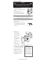
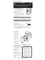
Coverage Area
The RS-100U has a maximum range of 180
degrees and a coverage area of 600 sq. feet (56
sq, meters). The sensor must have a clear and
unobstructed view of the coverage area. Objects
blocking the sensor’s lens may prevent detection
thereby causing the light to turn OFF even though
someone is in the area.
Windows, glass doors, and other transparent barriers will
obstruct the sensor’s view and prevent detection.
RS-100U
PIR Application-Specifi c
Wall Switch
Occupancy Sensor
with Manual ON/OFF
Lens
Lighted Switch
ON/OFF Button
SPECIFICATIONS
Voltage ...............................................................120VAC, 60Hz
Load (Single Pole Circuit)
Incandescent .................................................. 25-500 Watts
Time Delay ................................................................ 5 minutes
Environment ..................................Residential Indoor use only
Operating Temperature ............... 32° to 131°F (0° to 55°C)
Humidity ...................................... 95% RH, non-condensing
Electrical Supply Wire .....minimum temp rating 167° F (75°C)
Tools Needed
Insulated Screwdriver
Wire Strippers
Santa Clara, CA 95050
25'
(7.6m)
12'
(3.7m)
Fig. 1: Sensor Coverage Area
Call 888.817.0571 for Technical Support

INSTALLATION & WIRING
WARNING
Disconnect power to the wall switch box by turning OFF the circuit
breaker or removing the fuse for the circuit before installing the
RS-100U, replacing lamps, or doing any electrical work.
1. Prepare the switch box.
After the power is turned OFF at the circuit
breaker box, remove the existing wall plate and
mounting screws. Pull the old switch out from the
wall box.
2. Identify the type of circuit.
In a Single Pole Circuit (see Fig. 2), two single
wires connect to two screws on the existing
switch. A ground wire may also be present
and connected to a ground terminal on the old
switch.
CAUTION - FOR YOUR SAFETY: Connecting a proper ground to the
sensor provides protection against electrical shock in the event of
certain fault conditions. If a proper ground is not available, consult
with a qualifi ed electrician before continuing installation.
Only connect the RS-100U to a Single Pole Circuit. The RS-100U is not suitable
for 3-way switching. If the existing wiring does not match the description for a
Single Pole Circuit, you should consult with a qualifi ed electrician.
3. Prepare the Wires.
Tag the wires connected to the existing switch,
so that they can be identifi ed later. Disconnect
the wires. Make sure the insulation is stripped
off the wires to expose their copper cores to the
length indicated by the “Strip Gage,” (in Fig. 3)
(approx. 1/2 inch).
4. Wire the sensor.
Twist the existing wires
together with the wire
leads on the RS-100U
sensor as indicated below.
Cap them securely using
the wire nuts provided
(See Fig 4).
• Connect the green or
non-insulated (copper)
GROUND wire from the
circuit to the green wire on
the RS-100U.
• Connect the power wire
from the circuit box (HOT)
to the black wire on the
RS-100U.
• Connect the power wire to
the lamp (LOAD) to the red
wire on the RS-100U.
5. Put the RS-100U in the wall box.
Position the lens above the ON/OFF button
(lens at top, button at bottom) and secure it
to the wall box with the screws provided.
6. Attach the new cover plate.
Secure it to the wall box with the screws
provided.
7. Restore power to the circuit.
Turn ON the breaker or replace the fuse.
8. Test the sensor’s operation.
See TEST MODE.
www.wattstopper.com/athome
Ground
HOT (power from
circuit box)
LOAD
(power
to lamp)
NEUTRAL
Fig. 2: Typical Single
Pole Switch
Wiring
Green
–
>
GROUND
Black
–
>
HOT (power
from
circuit box)
Red
–
>
LOAD
(power
to lamp)
Fig. 4: Sensor orientation, wire connections
and wall box assembly
Strip Gage
1/2"
12.7 mm
Fig. 3: Wire Stripping
Initial Power-up Delay
There is an initial warm-up
period the fi rst time power is
applied to the unit and after
a power failure lasting more
than 5 minutes. It may take
up to 1 minute before the
lights turn ON. However, the
lights can be turned ON/OFF
manually by pressing the ON/
OFF button at any time when
power is supplied to the unit.

TEST MODE
To test the detection coverage:
During the TEST mode, the controlled load turns ON for 5 seconds each time the
sensor detects occupancy.
1. Press and hold the ON/OFF button. After 10 seconds the lighted switch turns
OFF. The controlled load turns ON if it was not already ON. The sensor is now
in a TEST mode that lasts 5 minutes. (You can end the TEST mode sooner by
pressing the ON/OFF button for another 10 seconds).
2. Move out of the coverage area or stand very still. The controlled load turns OFF
after 5 seconds if no motion is detected.
3. Move into the coverage area. The controlled load turns ON for 5 seconds
each time the sensor detects motion. After 5 seconds expire without motion
detection, the load turns OFF. The controlled load turns ON automatically with
the next motion detection and stays ON for 5 seconds.
4. Repeat as necessary to ensure that the desired coverage areas are within
detection range.
TROUBLESHOOTING
Load will not turn ON (lighted switch is visible):
• Move in front of the sensor to automatically turn lights ON. If lights do not turn
ON, press the ON/OFF button. The lighted switch should turn OFF and the
controlled load should turn ON, if not:
• Check the light bulb.
• Make certain the circuit breaker is ON and functioning.
• Turn OFF power to the circuit then check wire connections.
• Remember that if the load is turned OFF manually, Automatic-ON is reenabled
only after no motion is detected for 5 minutes.
Light will not turn ON (lighted switch is NOT visible):
• Check the light bulb.
• Make certain that the circuit breaker is ON and functioning.
• Turn OFF power to the circuit then check wire connections.
Load will not turn OFF:
The time delay is 5 minutes (fi xed time delay).
• Make sure no motion occurs in the coverage area until the time delay expires.
• If the load does not turn OFF, call Technical Support at 888-817-0571.
• Hot air currents and heat radiant devices can cause false detection. Make sure
the sensor is at least 6 feet (2 meters) away from devices that are a signifi cant
heat source (e.g heater, heater vent, high wattage light bulb).
• Press the ON/OFF button. If the controlled load does not turn OFF, turn OFF
the power to the circuit, then check wire connections.
WARRANTY INFORMATION
Watt Stopper/Legrand warranties its products to be free of defects in materials
and workmanship for a period of fi ve (5) years. There are no obligations or
liabilities on the part of Watt Stopper/Legrand for consequential damages arising
out of, or in connection with, the use or performance of this product or other
indirect damages with respect to loss of property, revenue or profi t, or cost of
removal, installation or reinstallation.
2800 De La Cruz Boulevard, Santa Clara, CA 95050
Technical Support: 888.817.0571
www.wattstopper.com/athome
06017r2 2/2007
Please
Recycle

DESCRIPCION Y OPERACION
El Sensor de Ocupación infrarrojo-pasivo de pared sin ajustes con control manual
de ENCENDIDO/APAGADO sustituye un interruptor de luz convencional. Es ideal
para cuartos de servicio y almacenamiento, guardarropas y cualquier otra área en
una residencia donde se deseen controles automáticos de ENCENDIDO/APAGADO
con detección de ocupación. El sensor no requiere de ajustes para operar
exitosamente en aquellas aplicaciones para las cuales fue diseñado.
Interruptor Iluminado
Para facilitar la ubicación del RS-100U en un cuarto oscuro, un LED color ámbar
ilumina el botón de ENCENDIDO/APAGADO cuando las luces (carga) controladas
se encuentran apagadas. Cuando por el contrario, si la carga se encuentra
encendida, el LED estará apagado.
Botón Pulsador
El botón pulsador puede ser utilizado para ENCENDER o APAGAR la carga. Para
APAGAR la carga, presione fi rmemente el botón una vez. El botón iluminado
se encenderá y la carga se APAGARA. Si la carga es apagada manualmente, la
operación de ENCENDIDO AUTOMATICO se reestablece después de que el sensor
no ha detectado movimiento por 5 minutos.
Tiempo de Retardo de Apagado
El RS-100U tiene un tiempo de retardo de apagado
de 5 minutos. Las luces permanecerán encendidas
por 5 minutos después de la última detección de
movimiento.
Area de Cobertura
RS-100U tiene un rango de cobertura máximo de
180 grados, y cubre un área de 600 pies cuadrados
(56 metros cuadrados). RS-100U debe poder
tener visibilidad completa y sin obstrucciones del
área de cobertura. La carga podría apagarse aun
cuando alguien se encuentre dentro del área de
cobertura si existen objetos bloqueando el lente
del sensor y por tanto evitando que el mismo
detecte movimiento.
Ventanas, puertas de vidrio, y otras barreras transparentes obstruirán
la cobertura del sensor y evitarán que exista detección.
RS-100U
Sensor de Ocupación
Infrarrojo-pasivo
de pared sin ajustes
con control manual
de ENCENDIDO/
APAGADO
Lente
Botón iluminado de
ENCENDIDO/APAGADO
Santa Clara, CA 95050
25'
(7.6m)
12'
(3.7m)
Fig 1: Patrón de cobertura
del sensor
Llame al 888.817.0571 para recibir asistencia técnica
Por favor leer todas las instrucciones antes de realizar la instalación
ESPECIFICACIONES
Voltaje .................................................................................. 120VAC, 60Hz
Carga (Circuito unipolar)
Lámparas incandescentes .................................................. 25-500 Watts
Ajuste del Retardo de Apagado ..................................................5 minutos
Condiciones de operación. ..........Solo para uso residencial en interiores
Temperatura .......................................... entre 32° y 131°F (0° y 55°C)
Humedad ...........................95% Humedad relativa, sin condensación
Herramientas necesarias
Desatornillador con aislamiento
Peladora de cable
Instrucciones de Instalación

INSTALACION Y CABLEADO
ADVERTENICA
Desconecte la corriente que alimenta la caja de conexiones
apagando el disyuntor (breaker) o removiendo el fusible para el circuito
correspondiente antes de instalar el RS-100U, reemplazar luces,
o realizar cualquier trabajo eléctrico.
1. Prepare la caja de conexiones.
Después de haber desconectado la corriente
eléctrica a nivel del disyuntor (breaker) del
circuito correspondiente, retire la placa del
interruptor y los tornillos de montaje. Extraiga
el interruptor existente de la caja.
2. Identifique el tipo de circuito.
En un Circuito Unipolar (ver Fig. 2), dos cables
independientes se conectan a dos tornillos en
el interruptor existente. Un cable de conexión
a tierra también puede estar presente en la
caja de conexiones y conectado a la terminal de
tierra del interruptor.
CUIDADO: Por su propia seguridad: el conectar el sensor apropiadamente a
tierra provee protección contra un choque eléctrico que pueda ocurrir en caso
de una operación defectuosa. Si no hay disponibilidad de una conexión a tierra
consulte con un electricista califi cado antes de continuar con la instalación.
Conecte el RS-100U únicamente a un Circuito Unipolar. El RS-100U no
está diseñado para operar en una confi guración tipo “3 vías” (3-way). Si el
cableado existente en la caja de conexiones no concuerda con la descripción
de un Circuito Unipolar, usted debe consultar con un electricista califi cado.
3. Prepare los cables.
Ponga algún identifi cador en cada uno de
los cables actualmente existentes en la
caja de conexiones de tal forma que pueda
identifi carlos posteriormente. Desconecte los
cables. Asegúrese de que el aislante del cable se
encuentra pelado apropiadamente para exponer el interior de alambre de
cobre a un largo de aproximadamente 1/2 pulgada y de acuerdo a como se
indica en esta guía de longitud Fig. 3.
4. Conecte el sensor.
Tuerza conjuntamente
los cables existentes en
la caja de conexiones
con los cables del sensor
RS-100U utilizando los
conectores (“wire nuts”)
provistos de acuerdo al
diagrama Fig. 4.
• Conecte el cable verde
(o alambre de cobre sin
aislante) que conecta a
TIERRA al cable verde del
RS-100U.
• Conecte el cable de LINEA
(o FASE) del circuito al
cable negro del RS-100U.
• Conecte el cable que
alimenta la lámpara al
cable rojo del RS-100U.
5. Coloque el RS-100U dentro
de la caja de conexiones.
Posicione el lente arriba del botón
de ENCENDIDO/APAGADO y asegure
el sensor a la caja de conexiones
con los tornillos provistos.
6. Monte la nueva placa
decorativa.
Asegure el sensor a la caja con los
tornillos provistos.
7. Reactive la corriente eléctrica
en el circuito.
Encienda el disyuntor (breaker) del
circuito o reinstale el fusible.
8. Pruebe el funcionamiento del
sensor.
Siga la sección de MODO DE
PRUEBA.
www.wattstopper.com/athome
Tierra
LINEA/FASE (proveniente de la
caja de disyuntores o
“breakers”)
CARGA
(alimentación de
corriente
a la carga)
NEUTRO
Fig. 2: Cableado típico
de un Circuito
Verde
–
>
TIERRA
Negro
–
>
LINEA/FASE
(proveniente de la caja
de disyuntores
o “breakers”)
Rojo
–
>
CARGA
(alimentación
de corriente
a la carga)
Fig. 4: Orientación del sensor, conexión de
cables y montaje del producto en la
caja de conexiones
Strip Gage
1/2"
12.7 mm
Fig. 3: Pelado apropiado
del cable
Retardo Inicial de Operación
Existe un periodo de calentamiento
inicial inmediatamente después de
que se habilita la corriente al sensor
por primera vez o después de que
ocurre una falla de corriente que
dure más de 5 minutos. Puede tomar
hasta 1 minuto antes de que las luces
se enciendan automáticamente. Sin
embargo durante este periodo de
calentamiento o durante la operación
normal del sensor, basta con que el
mismo reciba corriente para que sea
posible ENCENDER o APAGAR las
luces manualmente presionando el
botón de ENCENDIDO/APAGADO.

MODO DE PRUEBA
Para probar la cobertura del sensor:
Durante el modo de PRUEBA, la carga controlada por el sensor se encenderá por
5 segundos cada vez que el sensor detecta movimiento.
1. Oprima y mantenga oprimido el botón de ENCENDIDO/APAGADO. Después de
transcurridos 10 segundos el interruptor iluminado se apagará. La carga se
encenderá si no estaba ya encendida. El sensor se encuentra ahora en modo
de PRUEBA, el cual durará 5 minutos (usted puede sacar el sensor de modo
de PRUEBA en cualquier momento presionando el botón de ENCENDIDO/
APAGADO por otros 10 segundos más).
2. Movilícese fuera del área de cobertura o permanezca inmóvil. La carga
controlada se apagará después de 5 segundos si el sensor no detecta
movimiento.
3. Movilícese dentro del área de cobertura. La carga controlada se encenderá
por 5 minutos cada vez que el sensor detecte movimiento. Después de
transcurridos 5 segundos de no detección, la carga se apagará. La carga
se encenderá automáticamente con la próxima detección y se mantendrá
encendida por otros 5 segundos.
4. Repita según sea necesario para asegurarse que el área que se desea cubrir
con el sensor se encuentra dentro del rango de cobertura del mismo.
SOLUCION DE PROBLEMAS
La carga no se enciende automáticamente cuando el área es ocupada
(el Botón sí está iluminado):
• Movilícese en frente del sensor para encender automáticamente las luces. Si
las luces no se encienden, presione el botón de ENCENDIDO/APAGADO. Las
luces deberán encenderse y el botón iluminado deberá apagarse. Si esto no
sucede:
• Asegúrese de que el disyuntor (breaker) del circuito funcione y que se
encuentre encendido.
• Desconecte la corriente del circuito en cuestión desde el disyuntor (breaker) y
revisa las conexiones de los cables.
• Recuerde que si la carga es apagada manualmente, la operación de
ENCENDIDO/APAGADO AUTOMATICO se reestablece únicamente después de
que el sensor no ha detectado movimiento por 5 minutos.
La carga no se enciende automáticamente cuando el área es ocupada
(el Botón no está iluminado):
• Revise el bombillo (lámpara incandescente).
• Asegúrese de que el disyuntor (breaker) del circuito funcione y que se
encuentre encendido.
• Desconecte la corriente del circuito en cuestión desde el disyuntor (breaker) y
revise las conexiones de los cables.
La carga no se apaga automáticamente:
• El tiempo de retardo de apagado es 5 minutos.
• Asegúrese de que no hay movimiento a detectar dentro del área de cobertura
del sensor hasta que el tiempo de retardo de apagado transcurra.
• Si la carga no se APAGA, llame a la línea de soporte técnico 888-817-0571.
• Corrientes de aire caliente y radiadores de calor pueden ocasionar falsas
detecciones. Asegúrese que el sensor se encuentra alejado al menos 6 pies (2
metros) de dispositivos que sean fuentes considerables de calor (por ejemplo:
radiadores, salidas de aire caliente, lámparas de alta potencia).
• Presione el botón de ENCENDIDO/APAGADO. Si la carga no se apaga
desconecte la corriente al circuito desde el disyuntor (breaker) y revise las
conexiones de los cables.
INFORMACION SOBRE LA GARANTIA DE PRODUCTO
Watt Stopper/Legrand garantiza que sus productos están libres de defectos
en sus materiales y ensamble por un período de cinco (5) años. No existen
obligaciones o responsabilidades por parte de Watt Stopper / Legrand por daños
ocasionados por o en conexión con el uso o desempeño de este producto u otros
daños indirectos en materia de pérdida de propiedad, ventas o ganancias, o
costos por retiro, instalación o desinstalación.
22800 De La Cruz Boulevard, Santa Clara, CA 95050
Asistencia Técnica: 888.817.0571
www.wattstopper.com/athome
06017r2 02/2007
-
 1
1
-
 2
2
-
 3
3
-
 4
4
-
 5
5
-
 6
6


Legrand RS-100U PIR Application-Specific Wall Switch Occupancy Sensor Instrucciones de operación
- Tipo
- Instrucciones de operación
en otros idiomas
Artículos relacionados
-
wattstopper WattStopprer RS-150U Instrucciones de operación
-
Legrand RH-200 Multi-way Wall Switch Vacancy Sensor - Guía de instalación
-
-
-
-
-
wattstopper RH-250 Instrucciones de operación
