
1
DRILLING MACHINE FOR WOODEN SLEEPERSDRILLING MACHINE FOR WOODEN SLEEPERS
PERCEUSE SUR POUR TRAVERSES EN BOISPERCEUSE SUR POUR TRAVERSES EN BOIS
HOLZSCHWELLENBOHRMASCHINEHOLZSCHWELLENBOHRMASCHINE
TALADRO PARA TRAVIESAS DE MADERATALADRO PARA TRAVIESAS DE MADERA
TRAPANO PER TRAVERSE IN LEGNOTRAPANO PER TRAVERSE IN LEGNO
SD-9P-ECO SD-9P2-ECO
PATENTED
23M048 - 6261138
ENGLISHENGLISH
FRANÇAISFRANÇAIS
DEUTSCHDEUTSCH
ESPAÑOLESPAÑOL
ITALIANOITALIANO
OPERATION AND MAINTENANCE MANUAL ..............................4
(Translation of the original instruction)
NOTICE D’UTILISATION ET ENTRETIEN ........................................14
(Traduction des instructions originales
BEDIENUNGSANLEITUNG ...........................................................24
(Übersetzung der Originalanleitung)
MANUAL DE USO Y MANTENIMIENTO ......................................34
(Traducción de las instrucciones originales)
MANUALE D’USO E MANUTENZIONE ........................................44
(Istruzioni originali)

2
1
2
4
- To avoid serious burns, do not touch the hot exhaust.
- Pour éviter des brûlures sérieuses, ne pas toucher à l’échappement lorsqu’il est chaud.
- Um ernsthafte Verbrennungen zu vermeiden, berühren Sie nicht den heißen Auspufftopf.
- Para evitar posibles quemaduras graves, no tocar el tubo de escape cuando está caliente.
- Per evitare gravi ustioni non toccare il tubo di scarico quando é caldo.
4321
- Petrol is extremely flammable and explosive. Stop engine before refueling. DO NOT SMOKE.
Refuel in a well ventilated area away from naked flames or sparks.
- L’essence est extrêmement inflammable et explosive. Arrêter le moteur avant de faire le plein. NE PAS FUMER.
Faire le plein dans un lieu bien aéré et éloigné de toutes flammes et étincelles.
- Benzin ist extrem feuergefährlich und explosiv. Deshalb stoppen Sie den Motor vor dem Nachtanken. NICHT RAUCHEN.
Tanken Sie in gut belüfteten Räumen oder auf entsprechenden Flächen, niemals in der Nähe von Flammen oder Funkenflug.
- La gasolina es sumamente inflamable y explosiva. Llenar siempre el depósito de mezcla con el motor parado en un
lugar bien aireado y alejado de llamas y chispas. PROHIBIDO FUMAR.
- La benzina é estremamente infiammabile ed esplosiva. Fare il pieno di miscela esclusivamente a motore fermo, in
un luogo ben areato e lontano da fiamme o sorgenti di calore. NON FUMARE.
- Before using the drilling machine, carefully read the instructions contained in this manual.
SAVE THESE INSTRUCTIONS: this manual contains important safety and operating instructions for the drilling machine.
- Avant d’utiliser la perceuse, lire attentivement les instructions de ce manuel.
CONSERVEZ CES INSTRUCTIONS: cette notice contient d'importantes instructions relatives à la sécurité et au fonc-
tionnement de la perceuse.
- Vor Inbetriebnahme unbedingt die Bedienungsanleitungen durchlesen.
BEWAHREN SIE DIESE HINWEISE AUF: diese Bedienungsanleitung enthält wichtige Sicherheits- und Gebrauchsanwei-
sungen für die Bohrmaschine.
- Antes de utilizar la taladradora, leer atentamente las instrucciones contenidas en el presente manual.
GUARDE ESTAS INSTRUCCIONES: este manual contiene instrucciones de seguridad y funcionamiento importantes
para la taladradora.
- Prima di utilizzare il trapano, leggere attentamente le istruzioni contenute in questo manuale.
CONSERVARE QUESTE ISTRUZIONI: questo manuale contiene importanti istruzioni per la sicurezza e il funzionamento
del trapano.
3
WARNING LABELS - ETIQUETTES SIGNALETIQUES - WARNSCHILDER -
ETIQUETAS DE ATENCION - ETICHETTE D’AVVERTENZA
- Exhaust gas contains carbon monoxide, an odourless and deadly poison. Do not run Engine in an enclosed area.
- Les gaz d’échappements contiennent du monoxyde de carbone, qui est un poison mortel et inodore.
Ne pas faire fonctionner le moteur dans un local fermé.
- Auspuffgase enthalten Kohlenmonoxid, ein geruchloses, tödliches Gift.
Lassen Sie den Motor nicht in geschlossenen Râumen laufen.
- Los gases de escape contienen monóxido de carbono, un gas mortal e inodoro.
No hacer funcionar el motor en un local cerrado.
- I gas di scarico contengono monossido di carbonio, gas mortale ed inodore.
Non far funzionare il motore in locale chiuso.
- Always wear protective goggles and working gloves.
Avoid wearing clothes that may present a risk to personal safety.
- Porter toujours des lunettes de protection et des gants de travail.
Eviter les vetements susceptibles de constituer un danger pour la sécurité personnelle.
- Immer Schutzbrille und Arbeitshandschuhe tragen. Zweckmässige Kleidung tragen, die beim Arbeiten mit der Bohr-
maschine den Bediener nicht gefährden kann.
- Llevar siempre gafas de protección y guantes de seguridad.
Evitar las prendas de vestir que puedan constituir un peligro para la seguridad personal.
- Indossare sempre occhiali protettivi e guanti da lavoro.
Evitare abbigliamenti che possano costituire pericolo per l’incolumità personale.

3
(Basic drilling machine)
(perceuse de base)
(Grundbohreinheit)
(taladradora base)
(trapano base)
SD-9P-ECO = + PRM-U N
(guard)
(protection)
(Schutzrohr)
(protección)
(protezione)
+ TPM 200-26N
(end piece)
(terminaison)
(Endstück)
(terminación)
(terminazione)
+ MND
(spindle)
(broche)
(Spindel)
(mandril)
(mandrino)
(Basic drilling machine)
(perceuse de base)
(Grundbohreinheit)
(taladradora base)
(trapano base)
SD-9P2-ECO = + PRM-U N
(guard)
(protection)
(Schutzrohr)
(protección)
(protezione)
+ TPM 190-24N
(end piece)
(terminaison)
(Endstück)
(terminación)
(terminazione)
+ MND
(spindle)
(broche)
(Spindel)
(mandril)
(mandrino)
1.2
1.1
1.3 1.4
1.10
1.9
1.8
1.6
1.7
1.5
FIG. A

4
DRILLING MACHINE FOR WOODEN SLEEPERS
1. GENERAL CHARACTERISTICS (See Fig. A)
– Max. drilling capacity*: .......................................................................................................................... Ø 25 mm
– Maximum drilling thickness*: ............................................................................................................... 200 mm
– Speed without load: ..................................................................................................................................850 rpm
– Space dimensions .................................................................................................................. see Fig. 10 and 11
– Weight: .............................................................................................................................................................. 19,1 kg
* Depending on the type of wood, it is also possible to drill larger diameters and tickness , for specific applications,
please contact CEMBRE.
1.1) .2 stroke combustion engine
– Type:.................................................................................................2-stroke, horizontal shaft, single cylinder
– Model: ............................................................................................................................................ KAWASAKI TJ45E
– Displacement: ..............................................................................................................................................45.4 cm3
– Power (SAE J1349): ..................................................................................................................1.4 kW / 7500 rpm
– Fuel: .................................................................................................................2% (1:50) petrol mixture (see § 8)
– Fuel consumption: ...................................................................................................470 g/kW.hr / 350 g/hp.hr
– Clutch: ...............................................................................................centrifugal with automatic intervention
– Start: ....................................................................................................by rope pull with automatic rewinding
– Ignition: ....................................................................................................... solid state ignition (none breaker)
– Spark plug: ..............................................................................................................NGK BPMR7A o
r equivalents
– Fuel tank capacity: ..................................................................................................................................... 0,9 litres
– Emissions: ............................................................................................
according to “Phase V” European regulation
2016/1628 and EPA regulation for engine in class V
– A centrifugal clutch assists with start up and auger positioning at low speed. If the engine stalls
during the drilling operation, the machine may be restarted with the auger remaining in the
sleeper.
1.2) Emergency lever for quick auger release: if necessary, this lever allows immediate release of
the auger from the machine, which can then be removed from the working area.
1.3) Shock absorber: located between the drive shaft and the spindle to drastically reduce vibration
to the operator.
1.4) Adjustable depth gauge: a graduated scale on the fixed guard enables the desired hole depth
to be set, which automatically stops the travel of the auger.
1.5) Adjustable main handle: the handle controlling the drilling machine during operation, can
be fixed in two different positions.
Incorporated, on the right hand side are the machine controls:
– “ON/OFF” switch.
– Accelerator.
– Accelerator lock button.
1.6) Fixed guard: stainless steel guard protecting the spindle, featuring a graduated depth gauge.
ENGLISH

5
ENGLISH
1.7) “MND” type spindle: featuring an automatic quick lock mechanism suitable for augers with Ø
14 mm shank. “MND 1” Spindle; available as an option: suitable for augers with Ø 16 mm shank.
1.8) PRM-UN type detachable guard: stainless steel telescopic element, controlled by the return
springs, which provides protection for the auger. The lower end is threaded for attachment of the
TPM..N end piece.
1.9) TPM... N end piece: threaded centring device for attachment to the PRM-UN guard. Alternative
end pieces are available, with different diameters, to suit different size bushes (see § 3.2).
1.10) Return springs: to assist the retraction of the auger from the sleeper on completion of the
drilling operation and to reduce operator effort.
2. ACCESSORIES SUPPLIED WITH THE DRILLING MACHINE
The drill is supplied complete with the
“Accessories Kit” code: 6001554, containing:
– 1 pc 4 mm allen key.
– 1 pc spark plug key.
– 1 pc measuring cylinder for fuel preparation.
3. ADDITIONAL ACCESSORIES AVAILABLE
3.1) Auger with Ø 14 mm shank.
Correct operation of the machine and its safe and rapid release of the augers, in case of need,
are guaranteed only by using CEMBRE original PV range augers.
TYPE ø
(mm)
L
(mm)
Max. drilling
thickness: (mm)
PV170-465 17 465 340
PV180 18 325 200
PV190 19 325 200
PV200 20 325 200
PV210 21 325 200
PV220 22 325 200
PV250** 25 325 200
PV280 28 325 200
TYPE ø
(mm)
L
(mm)
Max. drilling
thickness: (mm)
PV100 10 325 200
PV130 13 325 200
PV140 14 325 200
PV150 15 325 200
PV160 16 325 200
PV160-465 465 340
PV170 17 325 200
PV170L* 375 250
PV..
L
ø
ø 14 mm

6
3.3) “MND1” spindle
interchangeable with standard “MND” spindle , featuring an
automatic quick lock mechanism suitable for augers with a
Ø 16 mm shank x 325 mm long.
ENGLISH
3.4) “VAL-P6” case
Case suitable for storing all the accessories supplied with
the drilling machine together with a series of augers.
3.5) “VAL-SD” case
Steel case suitable for storing both the complete drilling
machine (disassembled detachable guard) and the
VAL-P6 accessory case.
3.2) TPM...N end pieces interchangeable with the standard model:
* long type
VAL-P6
MND1
TPM...N
VAL-SD
TYPE Max. auger ø
(mm)
Baseplate hole ø
(mm)
TPM100-18N 10 18
TPM170-24N 17 24
TPM190-24N 19 24
TPM190-26N 19 26
TPM200-26N 20 26
TPM200-26LN* 20 26
TPM220-26N 22 26
TPM250-31N 25 31
TPM280-34N 28 34

7
ENGLISH
4. DRILLING
4.1) Preparing the drilling machine
Remove drilling machine, detachable guard and
auger from storage case.
Stop the engine before removing the auger
4.1.1) Fitting and removing the auger (Ref. to Fig. 1a)
Select the auger suitable for the work to be done:
– Turn the emergency lever (12) and fully insert the auger.
– Release the emergency lever.
– Manually rotate the auger until a click is heard, indicating automatic locking.
To remove the auger: turn the emergency lever, manually rotate and remove the auger from the spindle.
4.1.2) Assemble the TPM... guard nozzle (Ref. to Fig. 1b)
– Select the guard nozzle suitable for the hole to be drilled (Ref. to § 3.2):
– Fully screw counter-clockwise the guard nozzle (1) into the detachable guard PRM-UN.
4.1.3) Assemble the guard PRM-UN (Ref. to Fig. 1c)
To fit the detachable guard PRM-UN proceed as follows:
– Rotate two latches (3) into the vertical position.
– Slide the detachable guard PRM-UN onto the shafts.
– Rotate the latch (3) into the horizontal position to lock the guard.
4.1.4) Setting the hole depth (See Fig. 1d)
Open the lever and loosen the adjuster (26). Position the adjuster to the desired depth on the
graduated scale. Tighten the adjuster and close the lever (23).
During the drilling operation, the adjuster butts against the detachable guard at the preset hole
depth to prevent any further travel of the auger.
4.2) USING THE DRILLING MACHINE
The drilling machine can be used independently or in conjunction with the support trolley:
4.2.1) Using the drilling machine “independently” (Ref. to Fig. 5)
With the drilling machine on the ground follow the instructions in § 7.
Allow the machine to “warm up” for 2 minutes prior to commencement of work.
Locate the machine on the sleeper in the desired position, locate the guard end piece TPM into the
bush of the chair and proceed as § 4.3.

8
4.2.2) Using the drilling machine with the support trolley (Ref. to Fig. 6).
– Insert the spigot (30) of the drill into the housing of the trolley (see Fig. 3).
– Follow the instructions in § 7 and allow the machine to “warm up” for 2 minutes prior to com-
mencement of work.
– Using the main handle on the drilling machine, move the trolley over the sleeper to the desired
hole position and locate the guard end piece TPM into the bush of the chair.
Note: For use of the support trolley, refer to specific “Service and Maintenance Manual”.
4.3) Drilling
The auger starts to rotate only when the engine is fully revved: rev the engine gradually and then
operate a slight starting pressure on the machine so that the bit tip catches and starts drilling the
wood with the automatic advancement, without additional force from the operator. When the pre-
set drilling depth is reached, the adjustment device (26) prevents any further advancement; at this
stage, release the accelerator (08) and the return springs (25) will automatically retract the machine.
4.4) Emergency release
Correct operation of the machine and its safe and rapid release of the augers, in
case of need, are guaranteed only by using CEMBRE original PV range augers.
To remove the machine during a drilling operation, proceed as follows:
4.4.1) Machine equipped with “MND” spindle
– Immediately release the accelerator.
– Operate the emergency lever (12) moving it downwards.
– Keeping the lever depressed, slightly twist the machine, to release the auger. Lift and remove the
machine from the auger.
4.4.2) Machine equipped with “MND1” spindle
– Immediately release the accelerator.
– Operate the emergency lever (12) which immediately releases the auger from the machine. Lift
and remove the machine from the auger.
5. REPLACING THE SPINDLE (See Fig. 1 and 2)
For augers having a Ø 16 mm shank, the “MND1” spindle must be interchanged with the standard
“MND” spindle.
Replace the spindle as follows:
ENGLISH

9
ENGLISH
5.1) Removing the “MND” spindle
– Remove the detachable guard PRM-UN and the auger (see § 4.1.1).
– Turn the fixed guard (23) and remove from the spindle, exposing the spindle shaft (15).
– By means of the 4 mm allen key supplied with the machine, remove grubscrew (18).
– Remove circlip (16) and locating pin (17).
– Slide the spindle from the shaft (13).
5.2) Fitting the “MND1” spindle
– Slide the “MND 1” spindle onto the shaft (15). Ensure that the spindle guide (19) is correclty po-
sitioned.
– Align the hole on the shaft (13) with the corresponding holes on the spindle (20).
– Insert the locating pin (17) and fit the circlip (16).
– Fit and tighten the grubscrew (18).
– Fit the fixed guard (23).
– Insert and secure the auger (Ø 16 mm shank); (see § 5.3).
– Fit the detachable guard PRM-UN (see § 4.1.2).
5.3) Fitting and removing the auger on the “MND1” spindle
– Turn the emergency lever (12), align the two grooves
on the auger with the red reference line on the end
of the spindle and fully insert the auger.
– Release the emergency lever (12).
To remove the auger, turn the emergency lever (12)
extract the auger from the spindle.
6. MAINTENANCE
Before servicing or removing any parts, stop the engine and allow it to cool.
Always remove the spark plug cap from the spark plug when servicing the engine
to prevent accidental starting.
Periodic inspections are essential for the proper functioning of the engine;
refer to “KAWASAKI” manual provided with the machine for the safe use of the
engine and for further requested maintenance operations.
6.1) ROUTINE MAINTENANCE OF THE MACHINE
6.1.1) Lubrication
Depending on ambient conditions and use, periodically lubricate the return spring shafts, pro-
ceeding as follows:
– Remove the detachable guard PRM-UN and the springs.
– Carefully clean the shafts using a clean cloth soaked in kerosene.
– Lubricate the shafts with a general purpose oil.
– Re-assemble the springs and detachable guard..
Grooves on the
auger
Red reference line
on the spindle

10
Every 20 hours of operation
6.1.2) Fuel filter cleaning (See Fig. 7)
– Pick the grommet out of the fuel tank and than remove the fuel filter assembly from the fuel tank
together with the grommet and the fuel tube to keep dust entering into the fuel filter.
– Clean the fuel filter assembly in a bath of high flash-point solvent.
– Dry the fuel filter assembly before reassembly.
Improper use of solvents can results in fire or explosion.
6.1.3) Air filter cleaning (See Fig. 8)
– With a screwdriver remove the two screws holding the filter to the carburetor.
– Open the two halves of the casing and remove the filter element.
– Remove the filter element and wash the filter element in detergent and water and dry it thoroughly.
– Reassemble all parts.
Operating in dusty condition may require more frequent maintenance than above.
Do not operate the engine with air filter removed.
Every 50 hours of operating
6.1.4) Spark plug cleaning (See Fig. 9)
– Disconnect the spark plug wire lead then with a spark plug key, remove the spark plug.
– Clean the electrode taking care not to damage the insulation.
– Check and adjust if necessary, the electrode gap. (0.6 mm - 0.7 mm).
– Install and tighten the spark plug to 14 Nm, then connect the spark plug lead.
– In case of plug replacement, use type NGK BPMR7A or equivalent:
BOSCH WSR5F / DENSO W22MPR-U / CHAMPION RCJ6Y.
6.1.5) Checking of screws
Check and re-tighten all screws where necessary.
6.2) SPECIAL MAINTENANCE OF THE MACHINE
Special maintenance operations require the intervention of qualified personnel only, please contact
CEMBRE (see § 10).
6.3) Storing of the machine for long periods
– Completely empty the fuel tank.
– Start the engine and let it run until it stops, so that all fuel is exhausted from the machine.
– Remove the spark plug.
– Pour 3-5 cm3 of oil into the cylinder.
– Repeatedly pull gently on the starting rope to ahieve dispersion of the oil in the cylinder, then
reinstall the spark plug.
– With a clean cloth soaked with motor oil clean all metal parts of the machine. Store the machine
in its appropriate case or in a dry environment protecting it against accidental damage and dust.
ENGLISH

11
ENGLISH
I
0
a)
7. STARTING THE ENGINE
7.1) Set the engine switch to the “I” position (Fig. a).
7.2) Repeatedly operate the fuel pump until fuel flows through the
overflow pipe (Fig. b).
7.3) Only with a cool engine, set the ‘choke lever’ upwards, on the
left side in starting position (Fig. c); when engine is warm or in case
of high ambient temperature, set this lever downward in working
position (Fig. f).
7.4) Pull sharply on the starting rope and then release slowly; the
engine, before ignition, may require more than one operation (Fig. d).
Do not over-extend the starting rope and always release it slowly
once the motor is running; a sudden release could damage the
starting system.
If the engine does not start, do not repeatedly pull the starting
rope with the ‘choke lever’ in start position. This could create a fuel
excess in the cylinder and make ignition more difficult. In this case,
set the lever in working position and repeat the starting operation.
Once started, change the speed of the engine twice to allow the
remaining air to leave the carburettor.
7.5) Just after starting, accelerate the engine gradually before
starting any activity, then press the accelerator button (Fig. e) till
the ‘choke lever’ automatically returns, then release the button.
7.6) Allow the engine to warm up for approximately 2 minutes then
completely press the accelerator button and start to drill.
7.7) To stop the engine, set the engine switch to the “O” position.
7.8) Idling speed adjustment:
if necessary, adjust the idling screw (Fig. f), so that the engine
maintains a stable idling speed (2800 rpm).
7.9) Carburettor adjustment
The carburettor has been factory set.
The system controlling the gas emissions from this motor consists of
a carburettor and ignition system
to guarantee the best results.
The carburettor is adjusted to pro-
vide the air/fuel mixture required
to achieve low consumption and
low emission of injurious gas.
The engine will perform at its
optimum after a “running-in”
period of approximately 200
drilling operations.
d)
c)
f)
b)
e)
speed increase
speed decreases

12
ENGLISH
8. FUEL PREPARATION
The drilling machine features a two-stroke petrol engine run on a 2% (1:50) oil/petrol mixture;
a measuring cylinder is supplied showing on the left of the index line, the appropriate marks to
achieve this required mixture.
Use only 2-stroke engine high quality oil.
This engine is certified to operate on unleaded regular grade petrol only.
A minimum of 89 octane on the antiknock index is recommended.
Warning: do not remove or alter in any way, the valve in the cap of the fuel tank.
8.1) Fuel tank cap
A breather passage is incorporated in the tank cap.
If this passage is clogged, the fuel will not flow into the
carburetor, causing problems with starting or running the
engine. At the same time, make sure that the base of the
breather assembly is fitted firmly into the groove inside
the tank cap, as shown. Sfiato
Tappo
Serbatoio
Gancio
Membrana
Tank cap
Breather
assembly
Fuel tank
Breather
Breather
passage

13
9. TRANSPORTING THE MACHINE
After completion of the work, proceed as follows:
9.1) Carefully clean the drill, remove all wood shavings.
9.2) Clean the return spring shafts and lubricate if necessary (see § 6.1.1).
9.3) For ease of transportation, to prevent accidental damage and to keep the machine dry, use
the recommended steel storage case; ref. VAL-SD (see § 3.5) which can also house the de-
tachable guard and the VAL-P6 accessory case.
10. RETURN TO CEMBRE FOR OVERHAUL
In the case of a breakdown contact our Area Agent who will advise you on the problem and give
you the necessary instructions on how to dispatch the tool to our nearest service Centre; if possible,
attach a copy of the Test Certificate supplied by CEMBRE together with the tool or fill in and attach
the form available in the “ASSISTANCE” section of the CEMBRE website.
Acoustic Noise (Directive 2006/42/EC, annexe 1, point 1.7.4.2 letter u)
– The weighted continuous acoustic pressure level equivalent
A at the work place LpA is equal to .................................................................................................... 93,5 dB (A)
– The maximum value of the weighted acoustic displacement
pressure C at the work place LpCPeak is equal to ...........................................................................109,9 dB (C)
– The acoustic power level emitted by the machine
LWA is equal to ......................................................................................................................................... 101,6 dB (A)
Risks due to vibration (Directive 2006/42/EC, annexe 1, point 2.2.1.1)
Tests carried out in compliance with the indications contained in EN ISO 5349-1/2 and UNI EN 28662-1
Standards and under operating conditions much more severe than those normally found, certify
that the weighted root mean square in frequency of the acceleration the upper limbs are ex-
posed is 5,78 m/sec2 max.
ENGLISH

14
PERCEUSE POUR TRAVERSES EN BOIS
1. CARACTERISTIQUES GENERALES (Voir Fig. A)
– Capacité maximum de perçage *: ..................................................................................................... Ø 25 mm
– Profondeur maximum de perçage *: ................................................................................................. 200 mm
– Vitesse à vide sur le mandrin: ...............................................................................................................850 rpm
– Dimensions d‘enconbrement: ................................................................................................Voir Fig.10 et 11
– Poids: ................................................................................................................................................................. 19,1 kg
* Selon le type de bois, il est possible de percer des diamètres et épaisseurs supérieurs. Pour exigences spécifiques,
contacter CEMBRE.
1.1) Moteur thermique 2 temps
– Type:................................................................................................. 2 temps, arbre horizontal, monocylindre
– Model: ............................................................................................................................................ KAWASAKI TJ45E
– Cylindrée: ....................................................................................................................................................... 45,4 cm3
– Puissance nominale (SAE J1349): ......................................................................................1,4 kW / 7500 rpm
– Carburant: ...........................................................................................................mélange à 2% (1:50) (voir § 8)
– Consommation de carburant: .............................................................................470 g/kW.hr / 350 g/hp.hr
– Entraînement: .......................................................................................embrayage centrifuge automatique
– Démarrage: ..........................................................................................par lanceur à enrouleur automatique
– Sistème d’allumage: ......................................................................................................................... électronique
– Bougie: .....................................................................................................................NGK BPMR7A ou équivalent
– Capacité du reservoir: ................................................................................................................................0,9 litre
– Emissions: .................................................................................................. en accord à la “Phase V” règlement
(UE) 2016/1628 et règlement EPA pour moteur en classe V
– Embrayage entre l’arbre moteur et l’arbre de la broche, type centrifuge automatique permettant
á la mèche de rester immobile lors du démarrage du moteur et au ralent.
Cette caractéristique est très utile lorsque le moteur s’arrète accidentellement au cours d’une
opération de perçage; en effet, il pourra redémarrer normalement même si la mèche est déjà
engagée dans la traverse.
1.2) Levier de secours pour décrochage rapide de la mèche: permet, en cas de besoin, de décro-
cher immédiatement la mèche de la perceuse afin d’éloigner immédiatement cette dernière de la
zone de travail.
1.3) Goupille d’interface pour chariot support: pour monter la perceuse sur le chariot support,
également utile comme poignée pour le transport de la machine.
1.4) Bride de réglage de la profondeur de perçage: cette bride permet de régler la profondeur de
perçage souhaitée sur l’échelle graduée située sur la protection fixe.
La bride bloque l’avance de la mèche lorsqu’elle bute sur la protection mobile.
1.5) Guidon orientable: élément de soutien, de guidage et de contrôle de la perceuse pendant
les phases de travail, peut être fixée dans deux positions différentes. Sur la poignée droite sont
regroupées, dans une position pratique pour l’opérateur, toutes les commandes nécessaires au
fonctionnement de la perceuse:
– Interrupteur ”I/O” (I = marche; O = arrêt).
– Accélérateur.
– Blocage de l’accélérateur en position semi-ouverte.
1.6) Protection fixe: élément en acier inox destiné à recouvrir et à protéger la broche; elle est munie
d’une échelle graduée permettant d’afficher la profondeur de perçage.
FRANÇAIS

15
1.7) Broche de type “MND”: la broche est munie d’un dispositif d’accrochage rapide et de blocage
automatique des mèches. Apte au montage de mèches à queue d’accouplement de 14 mm Ø. Une
broche interchangeable type “MND1”est disponible sur demande.
1.8) Protection mobile type PRM-UN: élément télescopique en acier inox contrôlé par les ressorts
de rappel, elle protège efficacement la mèche. Terminé dans sa partie inférieure par un filetage pour
visser la terminaison TPM....N
1.9) Terminaison type TPM 200-26N: élément de centrage de Ø ext. 25 mm qui s’engage dans les
trous correspondants des selles. Permet l’utilisation de mèches de Ø max. 20 mm. La terminaison
est fournie montée sur la protection PRM-UN et peut êtrerempla cée en cas de besoin par des
terminaisons ayant des diamètres de centrage différents (Voir § 3.2).
1.10) Ressorts de rappel: éléments de remontée/extraction de la mèche hors du bois sans effort
pour l’opérateur une fois l’opération de perçage terminée.
2. ACCESSOIRES FOURNIS AVEC LA PERCEUSE
La perceuse est livrée accompagnée du
“Kit d’Accessoires”
code 6001554, comprenant:
– 1 clé Allen de 4 mm.
– 1 clé pour bougie d’allumage.
– 1 mesure pour la préparation du mélange.
3. ACCESSOIRES A DEMANDER SEPAREMENT
3.1) Mèches avec queue d’accouplement Ø 14 mm.
Accessoires spécifiques pour le marché français pour APPLICATION PAS-
SAGE A NIVEAU: * Mèche longue pour Traverse ** Mèche pour Platelage
FRANÇAIS
Le fonctionnement correct de la machine ainsi que le débrochage sûr et rapide des mèches de per-
çage, en cas de nécessité, ne sont garantis qu’avec l’utilisation des mèches CEMBRE de la série PV.
TYPE ø
(mm)
L
(mm)
Épaisseur max.
de forage (mm)
PV170-465 17 465 340
PV180 18 325 200
PV190 19 325 200
PV200 20 325 200
PV210 21 325 200
PV220 22 325 200
PV250** 25 325 200
PV280 28 325 200
TYPE ø
(mm)
L
(mm)
Épaisseur max.
de forage (mm)
PV100 10 325 200
PV130 13 325 200
PV140 14 325 200
PV150 15 325 200
PV160 16 325 200
PV160-465 465 340
PV170 17 325 200
PV170L* 375 250
PV..
L
ø
ø 14 mm

16
FRANÇAIS
3.3) Broche “MND1”
Broche à dispositif d’accouplement rapide et blocage auto-
matique des mèches.
Interchangeable avec la broche standard “MND” et apte au
montage des mèches avec queue d’accouplement de 16
mm Ø et 325 mm de long.
3.4) Mallette “VAL-P6”
Mallette de rangement pour tous les accessoires fournis
avec la perceuse et une série de mèches.
3.5) Coffret “VAL-SD”
Robuste coffret métallique pour ranger la perceuse
complète (avec protection mobile démontée) et la
mallette des accessoires “VAL-P6”.
3.2) Terminaisons “TPM...N interchangeables avec celle standard:
Accessoires spécifiques pour le marché français:
TPM 170-24N et pour APPLICATION PASSAGE
A NIVEAU: TPM 250-31N et TPM 200-26LN
(longue)
VAL-P6
MND1
TPM...N
VAL-SD
TYPE ø maxi mèche
(mm)
ø trou de la selle
(mm)
TPM100-18N 10 18
TPM170-24N 17 24
TPM190-24N 19 24
TPM190-26N 19 26
TPM200-26N 20 26
TPM200-26LN* 20 26
TPM220-26N 22 26
TPM250-31N 25 31
TPM280-34N 28 34
* longue

17
FRANÇAIS
4. PERÇAGE
4.1) Préparation de la perceuse
Le point de départ est la perceuse en conditions de stockage, c’est à dire:
– Sans protection mobile.
– Sans mèche.
Couper le moteur avant changement de la mèche
4.1.1) Montage (et démontage) de la mèche (Voir Fig. 1a)
Après avoir choisi la mèche:
– Abaisser complètement le levier de secours (12) et en le maintenant dans cette position introduire
la queue de la mèche dans la broche et la pousser à fond.
– Lâcher le levier de secours (12).
– Tourner la mèche en la poussant toujours à fond jusqu’à ce que l’on entende le déclic de blocage
automatique.
Pour démonter la mèche, il suffit d’abaisser complètement le levier de secours et, en le maintenant dans
cette position, de tourner légèrement la mèche puis tirer énergiquement.
4.1.2) Montage de la terminaison TPM ... (Voir Fig. 1b)
Choisir la terminaison qui correspond au diamètre du trou à percer (voir § 3.2):
– Visser à fond la terminaison (1) dans le sens contraire des aiguilles d’une montre, sur la protection
PRM-UN.
4.1.3) Montage de la protection mobile PRM-UN (Voir Fig. 1c)
Pour monter la protection mobile, procédez de la façon suivante:
– Tourner de 90° en position verticale les deux loquets (3).
– Introduire la protection mobile PRM-UN sur les tiges.
– Tourner de 90° en position horizontale les deux loquets (3).
4.1.4) Réglage de la profondeur de perçage (Voir Fig. 1d)
Desserrer la bride (26) de réglage de la course en tirant le levier et la placer sur la valeur souhaitée
de l’échelle graduée gravée sur la protection fixe (23) en prenant le bord inférieur comme repère.
Bloquer la bride dans cette position en repoussant le levier.
Lorsque au cours du perçage la mèche atteint la profondeur souhaitée, la bride de réglage bute sur
la protection mobile ce qui arrête l’avance de la mèche.
4.2) UTILISATION DE LA PERCEUSE
La perceuse est conçue pour être utilisée en version “portative” ou sur chariot-support.
4.2.1) Emploi de la perceuse en version “portative” (Voir Fig. 5)
– La perceuse au sol, faire démarrer le moteur en procédant de la façon indiquée au § 7.
Maintenir la marche de réchauffement 2 minutes environ avant de commencer à travailler.
– Prendre la perceuse par le guidon de façon à la placer sur la traverse à percer, engager l’élément
de centrage de la terminaison TPM dans le trou de la selle et procédez selon les indications du § 4.3.

18
4.2.2) Emploi de la perceuse sur chariot-support (Voir Fig. 6)
– Engager la poignée (30) de la perceuse dans le logement du chariot (voir Fig. 3).
– Faire démarrer le moteur en procédant de la façon indiquée au § 7; maintenir la marche de ré-
chauffement 2 minutes environ avant de commencer à travailler.
– A l’aide du guidon de la perceuse, faire avancer le chariot de façon à se placer à l’endroit du
perçage à effectuer, engager l’élément de centrage de la terminaison TPM, dans le trou de la selle.
Pour l’utilisation du chariot-support, consulter la notice d’utilisation et d’entretien relative.
4.3) Perçage
La mèche ne commence à tourner que lorsque l’on augmente le régime du moteur.
Porter progressivement le moteur à plein régime, exercer une légère pression initiale sur la per-
ceuse de telle sorte que la mouche prenne prise et commence à entraîner la mèche dans le bois en
avançant automatiquement, sans effort de la part de l’opérateur.
Lorsque l’on atteint la profondeur de perçage programmée, la bride de réglage (26) bloque toute
possibilité d’avance; lâcher l’accélérateur (08) alors que la perceuse remonte automatiquement
entraînée par les ressorts de rappel (25).
4.4) Décrochage de secours
Le fonctionnement correct de la machine ainsi que le débrochage sûr et rapide
des mèches de perçage, en cas de nécessité, ne sont garantis qu’avec l’utilisation
des mèches CEMBRE de la série PV.
Pour éloigner rapidement la perceuse de la zone de travail en cas d’urgence au cours d’une opération
de perçage, procéder de la façon suivante:
4.4.1) Perceuse équipée de broche “MND”
– Lâcher immédiatement l’accélérateur.
– Pousser le levier de secours (12) vers le bas.
– Tout en maintenant le levier baissé, exercer une légère rotation dans le sens des aiguilles d’une
montre (ou inverse) de la perceuse de façon à désassembler la mèche de celle-ci et à pouvoir
s’éloigner immédiatement de la zone.
4.4.2) Perceuse équipée de broche “MND1”
– Lâcher immédiatement l’accélérateur.
– Pousser le levier de secours (12) vers le bas de façon à désassembler la mèche de la perceuse et
à pouvoir s’éloigner immédiatement de la zone.
5. CHANGEMENT DE BROCHE (Ref. Fig. 1 et 2)
Pour utiliser des mèches à queue d’accouplement de Ø 16 mm, il faut utiliser la broche “MND1”
interchangeable avec la broche standard “MND”.
Le changement de broche s’accomplit de la façon suivante:
FRANÇAIS

19
Queue de la mèche
Ligne rouge de référence
sur la broche
5.1) Démontage de la broche “MND”
– Enlever la protection mobile PRM-UN et la mèche (voir § 4.1.1).
– Enlever la protection fixe (23) en faisant tourner avec force toute la carcasse de façon à contrer
la résistance des deux billes à ressort; on peut ainsi la décrocher des goujons et l’extraire
aisément de façon à laisser visible l’arbre de la broche (15).
– Enlever la vis (18) à l’aide de la clé Allen de 4 mm fournie avec l’appareil.
– Enlever l’anneau (16) de façon à extraire l’arbre (17) et la broche.
5.2) Montage de la broche “MND1”
– Introduire la broche “MND1” sur l’arbre (15) en l’orientant de façon à ce que la languette (19) de
la broche s’engage dans le logement correspondant sur l’arbre.
– Aligner le trou situé sur l’arbre (13) avec les trous sur la broche (20).
– Engager la goupille (17) d’accouplement de la broche (20) dans l’arbre (13) du levier de secours
et la bloquer à l’aide de l’anneau ressort correspondant (16).
– Serrer à fond la vis (18) de fixation de la broche (20) sur l’arbre (15).
– Remonter la protection fixe (23) et la mèche de Ø 16 mm (voir § 5.3).
– Remonter la protection mobile PRM-UN (voir § 4.1.2).
5.3) Montage (et démontage) des mèches sur la broche “MND1”
– Baisser complètement le levier de secours (12) et le maintenir dans cette position pendant que
l’on enfonce à fond la queue de la mèche dans le trou correspondant de la broche. Pour introduire
la queue de façon sûre et correcte dans le logement
correspondant sur la broche, maintenir alignées les
deux marques situées sur la queue avec la ligne rouge
de repère sur la partie terminale de la broche.
– Baisser le levier de secours (12). Pour démonter la mèche,
il suffit de la tirer avec force après avoir tourné complè-
tement le levier de secours (12).
6. ENTRETIEN
Avant d’accomplir des opérations d’entretien ou d’enlever des éléments, arrêter
le moteur et le laisser refroidir.
Enlever toujours le chapeau de la bougie lors de l’etretien du moteur pour
prévenir un démarrage accidentel.
Des inspections périodiques sont indispensables pour le bon fonctionnement
du moteur; consultez le manuel “KAWASAKI” fourni avec la machine pour une
utilisation sûre du moteur et pour les autres opérations de maintenance prévues.
6.1) ENTRETIEN COURANT DE LA PERCEUSE
6.1.1) Graissage
Graisser périodiquement (selon l’intensité d’emploi et l’environnement dans lequel on travaille) les
tiges des ressorts de rappel; pour cela, agir de la façon suivante:
– Extraire la protection mobile PRM-UN et les ressorts.
– Nettoyer soigneusement les tiges à l’aide de chiffons propres humectés de kérosène.
– Graisser les tiges à l’aide de quelques gouttes d’huile que l’on appliquera uniformément de façon
à former un film.
– Remonter les ressorts, la protection mobile et bloquer l’ensemble.
FRANÇAIS

20
Toutes les 20 heures de fonctionnement
6.1.2) Nettoyage du filtre à carburant (Ref. Fig. 7)
– Enlever le joint d’étanchéité du réservoir de carburant puis retirer le filtre à carburant du réservoir
en même temps que le joint d’étanchéité et le tube du carburant afin d’éviter la pénétration de
poussière dans le filtre à carburant.
– Nettoyer le groupe du filtre à carburant dans un bain, avec un solvant ayant un point d’inflam-
mabilité haut.
– Sécher le groupe du filtre à carburant avant de le remonter.
L’emploi proscrit de solvants peut être l’origine d’incendies ou d’explosions.
6.1.3) Nettoyage du filtre à air (Ref. Fig. 8)
– Dévisser à l’aide d’un tournevis les deux vis qui fixent le filtre au carburateur.
– Ouvrir les deux coques, extraire l’élément filtrant.
– Laver l’élément au détergent et à l’eau et le sécher soigneusement.
– Remonter tous les éléments.
Dans un milieu très poussiéreux, la fréquence d’entretien pourrait devoir être plus intense que celle
qui est indiquée ci-dessus.
Ne pas faire fonctionner le moteur, le filtre à air étant démonté.
Toutes les 50 heures de fonctionnement
6.1.4) Nettoyage de la bougie d’allumage (Ref. Fig. 9)
– Déconnecter le conducteur du câble de la bougie, et démonter la bougie à l’aide de la clé fournie.
– Brosser les électrodes sans endommager la céramique
– Vérifier l’écartement (0,6 - 0,7 mm); si nécessaire réetalonner.
– Installer et serrer la bougie à 14 Nm, puis connecter le câble de la bougie.
– Si le remplacement est indispensable, utiliser une bougie type NGK BPMR7A ou équivalentes:
BOSCH WSR5F / DENSO W22MPR-U / CHAMPION RCJ6Y.
6.1.5) Vérification de la boulonnerie
Vérifier et resserrer les boulons, les écrous et les vis.
6.2) ENTRETIEN SPECIAL DE LA PERCEUSE
Les opérations d’entretien spécial nécessitent l’intervention uniquement de personnel qualifié,
veuillez s’il vous plaît contacter CEMBRE (Voir § 10).
6.3) Période d’inactivité prolongée
– Vider le réservoir.
– Mettre en marche le moteur jusqu’à l’équisement du carburant.
– Démonter la bougie d’allumage.
– Verser 3 à 5 cm3 d’huile moteur dans le cylindre.
– Tirer doucement, à plusieurs reprise, la poignée de démarrage afin de parfaitement diffuser l’huile
versée dans le cylindre et réinstaller la bougie d’allumage.
– Avec un chiffon propre imbibé d’huile moteur, nettoyer toutes les parties métalliques de la perceuse.
– Ranger celle-ci dans son coffret, à l’abri des chocs et de la poussière.
FRANÇAIS

21
FRANÇAIS
I
0
a)
7. MISE EN SERVICE DU MOTEUR THERMIQUE
7.1) Placer l’interrupteur en position “I” (Fig. a).
7.2) Amener le mélange au carburateur en actionnant la “pompe”
plusieurs fois jusqu’à ce qu’on voit passer le mélange dans le tube
de trop-plein transparent (Fig. b).
7.3) Seulement à moteur froid, porter le levier “starter” complète-
ment à gauche en haut en position de “démarrage” (Fig. c); en cas
de haute température ambiante ou à moteur chaud, le laisser en
bas en position “marche” (Fig. f).
7.4) Tirer énergiquement le lanceur et le lâcher doucement; il pourra
se révéler nécessaire de tirer plusieurs fois avant de parvenir à faire
démarrer le moteur (Fig. d).
Ne tirer pas le lanceur au dela de sa course, le lâcher doucement le
moteur mis en marche; une relache rapide pourrait endommager
le système d’enroulement.
Si le moteur ne démarre pas, il faut éviter de tirer trop de fois le
lanceur avec le levier “starter” en position de marche. Cela pourrait
produire un excès d’essence dans le piston et rendre plus difficile
la mise en marche. Dans ce cas, maintenir le levier en position de
marche et répéter la procédure de mise en marche. Une fois le
moteur en marche, faire varier la vitesse du moteur plusieurs de
fois, pour permettre la sortie de l’air résiduelle par le carburateur.
7.5) Le moteur parti, agir progressivement sur l’accélérateur (Fig.
e) jusqu’au moment ou le levier “starter” se met automatiquement
en position “marche”, puis relâcher l’accélérateur.
7.6) Maintenir le moteur en marche de chauffage pour environ 2
minutes avant de commencer toute operation puis presser com-
plètement l’accélérateur et commencer le perçage.
7.7) Pour éteindre le moteur, mettre l’interrupteur en position “O”.
7.8) Réglage du minimum: si nécessaire, regler la vis du minimum
(fig. f) de façon que le moteur se maintienne en marche au minimum
en conditions stables (2800 rpm).
7.9) Réglage du carburateur
Le carburateur a été reglé préalablement en fabrique.
Le système de contrôle du gaz
d’émission appliqué à ce moteur
consiste en un carburateur et en un
système d’allumage qui garan-
tissent résultats optimums.
Le carburateur est réglé de façon à
garantir une mélange air / essence
tel à assurer bas consommation
et bas émission de gaz nuisibles.
AVIS: La puissance effective du
moteur ne sera atteinte qu’au
terme d’une période de rodage
de 200 percages environ.
d)
c)
f)
b)
e)
le n° de tours augmente
le n° de tours diminue

22
FRANÇAIS
8. PREPARATION DU MELANGE
Le moteur de la perceuse est à deux temps et fonctionne à l’aide d’un mélange huile-essence à
2% (1:50); pour doser la quantité d’huile, utiliser la mesure en prenant comme référence les valeurs
indiquées à la gauche de l’echelle correspondant au mélange à 2%.
Utiliser de l’huile synthèse pour moteurs à 2 temps.
Ce moteur est certifié pour fonctionner uniquement avec une essence normale sans plomb. On
conseille un indice minimum d’octane 89 pour l’antidétonant.
Attention: ne jamais manipuler ou endommager la membrane contenue dans le bouchon du réservoir.
8.1) Bouchon réservoir
Dans le bouchon du réservoir est incorporé une membrane
de soupirail. Vérifier que le passage ne soit bloqué si non
l’essence ne s’écoule pas de façon correcte dans le carbura-
teur, provoquant problèmes d’allumage ou de marche du
moteur. S’assurer que la membrane soit bien accrochée à
l’intérieur du bouchon. Sfiato
Tappo
Serbatoio
Gancio
Membrana
Bouchon
Accroche
Réservoir
de carburant
Membrane
Soupirail

23
9. RANGEMENT DE LA PERCEUSE
Le travail terminé, et avant de ranger la perceuse:
9.1) Nettoyer soigneusement la perceuse, surtout dans la zone de la mèche, et enlever les résidus
éventuels à l’aide d’un chiffon propre sur lequel on pourra verser quelques gouttes de kérosène.
9.2) Nettoyer et éventuellement graisser les tiges des ressorts de rappel (voir § 6.1.1).
9.3) Ranger la perceuse en un lieu fermé et à l’abri de la poussière, de l’humidité et des coups
accidentels. Pour une meilleure protection, CEMBRE recommande d’utiliser le coffret mé-
tallique VAL-SD (voir § 3.5) qui contient:
– La perceuse.
– La protection mobile (démontée de la perceuse).
– La mallette des accessoires VAL-P6.
10. ENVOI EN REVISION A CEMBRE
En cas de dysfonctionnement de l’appareil, merci de vous adresser à notre Agent Régional qui vous
conseillera et le cas échéant vous donnera les instructions nécessaires pour envoyer l’appareil à
notre Centre de Service le plus proche. Dans ce cas, joindre une copie du Certificat d’Essai livré par
CEMBRE avec l’appareil ou remplir et joindre le formulaire disponible dans la section “ASSISTANCE”
du site web CEMBRE.
Pression sonore aérienne (Directive 2006/42/CE, annexe 1, point 1.7.4.2, lettre u)
– Le niveau de pression sonore continue équivalente
pondérée A sur le poste de travail LpA est ...................................................................................... 93,5 dB (A)
– Le niveau de pression sonore instantanée
pondérée C sur le poste de travail LpCPek est ................................................................................ 109,9 dB (C)
– Le niveau de puissance acoustique dégagée
par la machine LWA est .........................................................................................................................101,6 dB (A)
Risques dérivés des vibrations (Directive 2006/42/CE, annexe 1, point 2.2.1.1)
Des mesures réalisées conformément aux indications des Normes EN ISO 5349-1/2 et UNI EN 28662 -1,
dans des conditions d’emploi représentatives des conditions normales, montrent que la valeur
quadratique moyenne pondérée, en fréquence, de l’accélération à laquelle sont exposés les
membres supérieurs est de 5,78 m/sec2 maxi.
FRANÇAIS

24
DEUTSCH
HOLZSCHWELLENBOHRMASCHINE
1. ALLGEMEINE EIGENSCHAFTEN (siehe Bild A)
– Max. Bohrdurchmesser *:...................................................................................................................... Ø 25 mm
– Max. Schwellenstärke *: .......................................................................................................................... 200 mm
– Leerlaufdrehzahl: ...................................................................................................................................850 U/min
– Abmessungen: ......................................................................................................................siehe Bild 10 und 11
– Gewicht: ........................................................................................................................................................... 19,1 kg
* Je nach den Holztypen ist es möglich grössere Bohrdurchmessers und Schwellenstärke zu bohren. Für spezielle
Anwendungen, bitte sich an CEMBRE wenden.
1.1) Zweitaktmotor:
– Typ: ...........................................................................................................2-Takt, horizontale Welle, Einzylinder
– Modell: ........................................................................................................................................... KAWASAKI TJ45E
– Hubraum: ....................................................................................................................................................... 45,4 cm3
– Leistung (SAE J1349): ........................................................................................................ 1,4 kW / 7500 U/min
– Kraftstoff: ...........................................................................................................................2% (1:50) (siehe Pkt. 8)
– Kraftstoffverbrauch: ................................................................................................470 g/kW.hr / 350 g/hp.hr
– Kupplung: ...........................................................................Fliehkraftkupplung mit Automatischen Anlauf
– Anlassen: ...............................................................................................................................................Starterkordel
– Zündung: ...........................................................................................................................................................Digital
– Zündkerze: ...................................................................................................NGK BPMR7A oder gleichwertige
– Benzintankkapazität: ................................................................................................................................0,9 Liter
– Emissionen: ........................................................................ Nach der “Phase V”
Verordnung (UE) 2016/1628
und der Verordnung EPA Klass V-Motoren
– Die Fliehkraftkupplung zwischen Motor und Spindel ermöglicht, dass die Spindel im Leerlauf
stehenbleibt, und der Motor, wenn der Bohrer im Holz steckt, angelassen werden kann.
1.2) Schnelle Entriegelungsvorrichtung des Bohrers bei Gefahr: Durch das Betätigen des Nothebels
ist ein schnelles Ausspannen des Bohrers von der Spindel möglich und die Maschine kann aus dem
Gefahrenbereich herausgetragen werden.
1.3) Verbindungszapfen für Fahrwagen: zur Befestigung der Bohrmaschine auf dem Stützwagen,
der auch als Griff für den Transport der Maschine dient.
1.4) Einstellring für die Bohrtiefe: Durch das Einstellen der Bohrtiefe auf der Skalierung wird eine
Beschädigung des Bohrers beim Durchbohren der Schwellen verhindert.
Das bewegliche Schutzrohr schiebt sich beim Bohrvorgang über das feste Schutzrohr und stösst
an den Einstellring.
1.5) Verstellbarer Haltegriff: Stütz, Führung und Steuerelement für die Durchführung der Arbeitspha-
sen. Dieser Haltegriff kann in zwei verschiedenen Positionen befestigt werden. Im Handgriff sind
die Betätigungselemente integriert:
– Schalter “I/O” (I = ein; O = aus).
– Gashebel.
– Blockierung.
1.6) Festes Schutzrohr: Rohr aus Edelstahl zum Schutz der Spindel mit Einstellring für die Bohrtiefe
und Skalierung in Zentimeter.

25
DEUTSCH
1.7) Spindel Typ MND: Schnellspannfutter mit automatischer Blockierung für Bohrer mit einem
Schaftdurchmesser von 14 mm. Auf Anfrage ist ein Schnellspannfutter mit automatischer Blockie-
rung für Bohrer mit einem Schaftdurchmesser von 16 mm lieferbar (Typ MND1).
1.8) Bewegliches Schutzrohr Typ PRM-UN: Bewegliches Schutzrohr aus Edelstahl zum Schutz des Boh-
rers. Es endet an der Unterseite mit einem Gewindeteil, auf das das Endstück TPM..N aufgeschraubt wird.
1.9) Endstück Typ TPM 200-26N: Die Zentrierspitze des beweglichen Schutzrohres entspricht dem
Durchmesser der Bohrung in der Rippenplatte (25 mm). Der maximale Bohrerdurchmesser beträgt 20
mm. Das Endstück wird auf der Schutzvorrichtung PRM-UN montiert geliefert und kann im Bedarfsfall
mit Endstücken mit unterschiedlichen Zentrierdurchmessern ausgewechselt werden (siehe Punkt 3.2).
1.10) Rückzugsfedern: Rückzugsfedern zum einfachen Herausziehen der Bohrvorrichtung nach
Beenden des Bohrvorganges und dadurch geringe körperliche Belastung des Bedieners durch das
teleskopische Federsystem.
2. MITGELIEFERTES ZUBEHÖR FÜR BOHRMASCHINE
Zum Lieferumfang gehören folgende Teile vom
“Kit Zubehör” Nr. 6001554:
– 1 St. Inbusschlüssel 4 mm.
– 1 St. Zündkerzenschlüssel.
– 1 St. Meßbehälter für Benzingemisch.
3. ZUSÄTZLICH LIEFERBARES ZUBEHÖR
3.1) Bohrer mit einem Schaftdurchmesser Ø 14 mm.
Für eine sichere Handhabung der Maschine und das schnelle Lösen der Maschine vom Bohrer (im
Notfall) ist nur bei der Verwendung von CEMBRE Originalbohrern vom Typ PV… gewährleistet.
TYP ø
(mm) L (mm) Max. Material
-dicke (mm)
PV170-465 17 465 340
PV180 18 325 200
PV190 19 325 200
PV200 20 325 200
PV210 21 325 200
PV220 22 325 200
PV250** 25 325 200
PV280 28 325 200
TYP ø
(mm) L (mm) Max. Material
-dicke (mm)
PV100 10 325 200
PV130 13 325 200
PV140 14 325 200
PV150 15 325 200
PV160 16 325 200
PV160-465 465 340
PV170 17 325 200
PV170L* 375 250
PV..
L
ø
ø 14 mm

26
VAL-SD
3.3) Spindel Typ “MND1”
Schnellspannfutter mit automatischer Blockierung für Bohrer
mit einem Schaftdurchmesser 16 mm und einer Länge von
325 mm.
DEUTSCH
3.4) Zubehörkoffer “VAL-P6”
Stabiler Koffer zur Aufbewahrung des Zubehörs.
3.5) Metallkoffer “VAL-SD”
Stabiler Metallkoffer für die komplette Schwellen-
bohrmaschine (bewegliches Schutzrohr demontiert)
und für den Zubehörkoffer “VAL-P6”.
3.2) Endstücken “TPM...N” mit dem Standardendstück auswechselbar:
VAL-P6
MND1
TPM...N
* Lang
TYP Max. Bohrer ø
(mm)
Bohrung ø in die Rippenplatte
(mm)
TPM100-18N 10 18
TPM170-24N 17 24
TPM190-24N 19 24
TPM190-26N 19 26
TPM200-26N 20 26
TPM200-26LN* 20 26
TPM220-26N 22 26
TPM250-31N 25 31
TPM280-34N 28 34

27
DEUTSCH
4. BOHRVORRICHTUNG
4.1) Vorbereitung der Bohrmaschine
Es wird davon ausgegangen, daß die Bohrmaschine noch nicht montiert ist; d.h.:
– Ohne bewegliches Schutzrohr.
– Ohne Bohrer.
Vor dem Bohrerwechsel Motor ausschalten
4.1.1) Montage (und Demontage) des Bohrers (siehe Bild 1a)
Nach der Auswahl des Bohrers erfolgt die Montage in folgenden Schritten:
– Nothebel (12) betätigen und den Bohrerschaft in die Spindel bis zum Anschlag einführen.
– Nothebel (12) wieder loslassen.
– Bohrer drehen, bis ein spürbares Einrasten erfolgt.
Zur Demontage des Bohrers, den Nothebel betätigen und nach einer leichten Drehung den Bohrer mit
Kraft herausziehen.
4.1.2) Anbringen des TPM-Endstücks... (siehe Bild 1b)
Wählen Sie das Endstück entsprechend des Durchmessers des zu bohrenden Lochs (siehe Pkt. 3.2):
– Schrauben Sie das Endstück (1) gegen den Uhrzeigersinn an das PRM-UN-Schutzrohr.
4.1.3) Montage des beweglichen Schutzrohres Typ PRM-UN (siehe Bild 1c)
Bringen Sie nun das PRM-UN-Schutzrohr an:
– Drehen Sie die beiden Verriegelung (3) um 90° in senkrechte Position.
– Schieben Sie den beweglichen PRM-UN-Schutz auf die Vorrichtung.
– Drehen Sie nun die beiden Verriegelung (3) in waagerechte Position um 90°.
4.1.4) Einstellen der Bohrtiefe (siehe Bild 1d)
Anschlagring (26) durch Lösen des Exenterhebels auf die gewünschte eingravierte Bohrtiefe auf
dem festen Schutzrohr (23) einstellen und Exenterhebel wieder feststellen.
Erreicht der Bohrer während des Bohrvorganges die eingestellte Bohrtiefe, stößt der das bewegliche
Schutzrohr gegen den Anschlagring und der Bohrer kann nicht weiter in das Material eindringen.
4.2) GEBRAUCH DER BOHRMASCHINE
Die Bohrmaschine kann sowohl im “tragbaren” Modus als auch mit dem Stützwagen zusammen
verwendet werden.
4.2.1) Verwendung der Bohrmaschine im “tragbaren” Modus (siehe Bild 5)
– Die Bohrmaschine wie in Pkt. 7 beschrieben starten.
Die Maschine ca. 2 Minuten warmlaufen lassen.
– Mit dem Haltegriff die Bohrmaschine zum Arbeitsplatz tragen. Die Bohrmaschine mit der Zent-
rierspitze des beweglichen Endstück TPM in die Rippenplatte der zu bohrenden Holzschwelle
stellen und vorgehen wie im § 4.3 angegeben.

28
4.2.2) Verwendung der Bohrmaschine mit Stützwagen (siehe Bild 6)
– Den Griff (30) der Bohrmaschine in den Wagensitz einführen (siehe Bild 3).
– Die Bohrmaschine wie in Pkt. 7 beschrieben starten
Die Maschine ca. 2 Minuten warmlaufen lassen.
– Den Haltegriff der Bohrmaschine festhalten und den Wagen gleiten lassen, bis der gewünschte
Bohrpunkt erreicht wird. Die Bohrmaschine mit der Zentrierspitze des beweglichen Endstück
TPM in die Rippenplatte der zu bohrenden Holzschwelle stellen.
Hinweiss: Beim Einsatz des Stützwagens auf die entsprechende Bedienungsanleitung achten.
4.3) Bohrvorgang
Der Bohrer fängt durch langsames Erhöhen der Geschwindigkeit zu drehen an.
Beim Erreichen der maximalen Geschwindigkeit einen leichten Druck auf die Bohrmaschine in
Richtung Schwelle ausüben. Der Holzbohrer zieht sich durch seine Schneidgeometrie selbständig
in die Schwelle, ohne daß der Bediener große Kraft ausüben muß.
Beim Erreichen der eingestellten Bohrtiefe (bewegliches Schutzrohr stößt gegen den Einstellring) Gas
zurücknehmen, damit sich die Bohrmaschine selbständig durch die Federn aus dem Bohrloch hebt.
4.4) Entrieglungsvorrichtung des Bohrers bei Gefahr
Für eine sichere Handhabung der Maschine und das schnelle Lösen der Maschine
vom Bohrer (im Notfall) ist nur bei der Verwendung von CEMBRE Originalbohrern
vom Typ PV… gewährleistet.
Um die Bohrmaschine bei einer drohenden Gefahr aus dem Bereich zu nehmen, sind folgende
Schritte einzuhalten:
4.4.1) Bohrmaschine mit Spindel Typ “MND”
– Gashebel sofort loslassen.
– Nothebel (12) betätigen.
– Nothebel in dieser Position halten und die gesamte Maschine mit dem Handgriff leicht drehen
und somit den Bohrer aushängen.
– Die Maschine vom Bohrer heben und aus dem Gefahrenbereich heraustreten.
4.4.2) Bohrmaschine mit Spindel Typ “MND1”
– Gashebel sofort loslassen.
– Nothebel (12) betätigen, damit sich der Bohrer automatisch aushängt.
– Die Maschine vom Bohrer heben und aus dem Gefahrenbereich heraustreten.
5. WECHSELN DER SPINDEL (siehe Bild 1 und 2)
Um den Bohrer mit einem Schaftdurchmesser 16 mm zu verwenden, muß die Spindel “MND” de-
montiert und die Spindel “MND1” folgendermaßen montiert werden:
DEUTSCH

29
5.1) Demontage der Spindel “MND”
– Bewegliches Schutzrohr PRM-UN und Bohrer demontieren (siehe Pkt. 4.1.1).
– Festes Schutzrohr (23) durch kräftiges Drehen lösen. Das feste Schutzrohr ist durch 2 Federstücke
gesichert. Das Schutzrohr über dem Zentrierstift (29) von der Antriebs welle ziehen, die
dabei sichtbar wird.
– Inbusschraube (18) mit dem mitgelieferten Inbusschlüssel (4 mm) lösen.
– Sicherungsring (16) abnehmen, und der Sicherungsstift (17) der die Spindel mit Entrieglungswelle
(13) selbst verbindet, herausziehen.
5.2) Montage der Spindel “MND1”
– Spindel “MND1“ in die Antriebswelle (15) stecken. Dabei ist auf die richtige Position der Paßfedern
(19) und der Spindel zu achten.
– Entrieglungswelle (13) und Spindel (20) so ausrichten, daß der Sicherungsstift (17) montiert
werden kann.
– Sicherungsstift (17) montieren, und mit dem Sicherungsring (16) sichern.
– Inbusschraube (18) einsetzen und mit dem mitgelieferten Inbusschlüssel (4 mm) fest ziehen.
– Festes Schutzrohr (23) wieder montieren.
– Bohrer mit Schaftdurchmesser 16 mm wieder einsetzen (siehe Pkt. 5.3).
– Bewegliches Schutzrohr PRM-UN wieder montieren (siehe Pkt. 4.1.2).
5.3) Montage und Demontage von Bohrern in Spindel “MND1”
– Nothebel (12) betätigen und in dieser Position halten.
– Bohrer in die Spindel einführen und dabei den Abdruck
auf dem Schaft des Bohrers mit der roten Markierungslinie
auf der Spindel in Übereinstimmung bringen.
– Nothebel (12) loslassen.
Um den Bohrer zu demontieren ist es ausreichend, den
selben mit Kraft zu Ziehen, nachdem der Nothebel (12)
betätigt worden ist.
6. WARTUNG
Bei Reparaturen oder Wartung an der Maschine ist die Maschine abzustellen
und abkühlen zu lassen. Um ein versehentliches Starten der Maschine zuver-
hindern, ist der Zündkerzenstecker von der Zündkerze zu entfernen.
Regelmäßige Kontrollen sind unerlässlich für das gute Funktionieren des Mo-
tors; siehe mit der Maschine zur Verfügung gestellte “KAWASAKI” Bedienungs-
anleitung für die sichere Benutzung des Motors und für die weitere vorgese-
henen Wartungsoperationen.
6.1) NORMALE WARTUNG DER BOHRMASCHINE
6.1.1) Abschmieren der Bohrmaschine
In regelmäßigen Abständen sind die Führungsstangen für das bewegliche Schutzrohr abzuschmie-
ren. Diese Wartung ist abhängig von der Anzahl der Einsätze der Maschine und den dazugehörigen
Umweltbedingungen. Folgende Arbeitsschritte sind notwendig:
– Bewegliches Schutzrohr PRM-UN und Federn demontieren.
– Stangen sorgfältig mit sauberem und in Kerosin getränktem Lappen reinigen.
– Öl gleichmäßig auf die Führungsstangen verteilen.
– Federn, bewegliches Schutzrohr wieder montieren.
Gravierung auf
dem Bohrer
Rote Referenzlinie
auf der Spindel
DEUTSCH

30
Alle 20 Betriebsstunden
6.1.2) Reinigung des Benzinfilters (siehe Bild 7)
– Dichtung auf dem Tank entfernen und den Benzinfiltergruppe herausziehen, damit kein Schmutz
in den Tank gelangt.
– Filter mit Waschbenzin reinigen.
– Filter trocknen lassen und anschließend wieder einbauen.
Bei einer falschen Benutzung von Lösungsmitteln besteht Brand- und Explosions- gefahr.
6.1.3) Reinigung des Luftfilters (siehe Bild 8)
– Beide Schrauben des Luftfilterdeckels lösen.
– Das Luftfilterelement entnehmen.
– Das Luftfilterelement in Reinigungsmittel und Wasser waschen und anschließend gut trocknen.
– Alle Teile wieder einbauen.
Bei Arbeiten unter sehr staubiger Umgebung Filter mehrmals reinigen.
Alle 50 Betriebsstunden
6.1.4) Reinigung der Zündkerze (siehe Bild 9)
– Zündkerzenstecker von der Zündkerze entfernen, die Zündkerze mit dem.
Zündkerzenschlüssel losschrauben.
– Die Elektroden gut reinigen mit einer Drahtbürste.
– Elektrodenabstand kontrollieren (0,6 ÷ 0,7 mm).
– Zündkerze einschrauben und mit 14 Nm festziehen und den Zündkerzenstecker aufstecken.
– Im Falle, daß die Zündkerze ausgetauscht werden muß, eine Zündkerze vom Typ NGK BPMR7A
verwenden oder ähnlich:
BOSCH WS R5F / DENSO W22MPR-U / CHAMPION RCJ6Y.
6.1.5) Kontrolle aller Schrauben
Alle Schrauben und Muttern auf Festsitz kontrollieren und eventuell nachziehen.
6.2) AUSSERORDENTLICHE WARTUNG DER BOHRMASCHINE
Die außerordentliche Wartungsarbeiten müssen nur von qualifiziertem Personal durchgeführt
werden, bitte CEMBRE kontaktieren (siehe Pkt. 10).
6.3) Wartung vor längerer Lagerung
– Benzintank vollständig entleeren.
– Motor anlassen bis er von selbst ausgeht, damit kein Benzin im Tank und im Vergaser vorhanden ist.
– Zündkerze herausdrehen.
– 3-5 cm3 Motoröl in den Zylinder einfüllen.
– Die Starterkordel mehrmals ziehen um das Öl gut zu verteilen und die Zündkerze einschrauben.
– Mit einem sauberem und in Öl getränktem Lappen alle Metallteile einreiben.
– Die Bohrmaschine in dem Transportkoffer VAL-SD lagern oder an einen trockenen Ort stellen.
DEUTSCH

31
DEUTSCH
I
0
a)
7. STARTEN DES MOTORS
7.1) Den elektrischen Schalter auf “I” stellen (Bild a).
7.2) Mehrmals auf den kleinen Pumpknopf drücken, bis das Benzin-
gemisch durch den durchsichtigen Kunststoffschlauch fliesst (Bild
b).
7.3) Nur bei kaltem Motor den Luftschalter in die obere linke Position
“Start” (Bild c) bringen, im Falle von hohen Temperaturen oder bei
warmem Motor, den Shoke auf der Position “Funktion” (Bild f) lassen.
7.4) Die Starterkordel mit kräftigen Zügen ziehen und immer wie-
der vorsichtig aufrollen lassen. Für den Motorstart können einige
Startversuche notwendig sein (Bild d).
Ziehen Sie die Starterkordel nicht über den Anschlag und lassen
Sie diese wieder langsam los. Das plötzliche Loslassen kann zur
Beschädigung der Aufwickelvorrichtung führen.
Wenn der Motor nach mehrfachem ziehen nicht anspringt, den
Hebel in Position “Funktion” stellen.
Wenn der Motor dann gestartet ist, den Gasknopf etwas betätigen
und somit die Drehzahl mehrfach verändern.
7.5) Sobald der Motor gestartet ist, mit dem Gasknopf langsam die
Drehzahl erhöhen (Bild e). bis der Shokehebel automatisch in die
Position “Operation” geht. Danach den Gasknopf.
7.6) Lassen Sie den Motor 2 Minuten warmlaufen, bevor damit die
Arbeit begonnen wird.
7.7) Um den Motor auszuschalten, einfach den Schalter auf Position
“0” stellen.
7.8) Einstellen der Leerlaufdrehzahl: Bei Bedarf kann die Leerlauf-
drehzahl (Bild f), eingestellt werden. Die ideale Leerlaufdrehzahl
beträgt ungefähr 2800 U/min.
7.9) Vergaser einstellen
Der Vergaser ist bereits werkseitig optimal eingestellt. Die Regelung
der optimalen Verbrennung wird durch den Vergaser und durch die
Zündung gewährleistet.
Der Vergaser ist so konstruiert,
das mit dem Luft-KraftstoffGe-
misch so wenig wie möglich
Benzin verbraucht wird und ge-
ringe Emissionen entsehen.
Hinweis: Optimale Leistungen
des Motors werden nach einer
Einlaufzeit von ca. 200 Bohrun-
gen erreicht.
d)
c)
f)
b)
e)
Erhöhung der Leerlaufdrehzahl
Senkung der Leerlaufdrehzahl

32
DEUTSCH
8. BENZINGEMISCH VORBEREITUNG
Die Bohrmaschine hat einen Zweitaktmotor, der mit einem Benzin-Ölgemisch 2% (1:50) arbeitet.
Für die Zubereitung verwenden Sie bitte den mitgelieferten Meßbecher und beziehen sich auf die
linken Werte, die für das Gemisch 2% bestimmt ist.
Nur Öl für 2-Takt Motoren verwenden.
Der Motor arbeitet mit bleifreiem Benzin mit einer Mindestoktanzahl von 89.
Achtung: Das Ventil im Benzintank darf auf keinen Fall beschädigt oder verstellt werden.
8.1) Tankdeckel
In der Kappe ist eine Membran eingebaut für die Luft-
entlastung. Stellen Sie sicher, dass der Durchgang nicht
verstopft ist, ansonsten wird der Kraftstoff nicht richtig in
dem Vergaser fließen, was zu Problemen beim Motorbe-
trieb führen kann. Stellen Sie sicher, dass das Membran
fest im Deckel sitzt. Sfiato
Tappo
Serbatoio
Gancio
Membrana
Deckel
Haken
Benzintank
Membran
Ablassventil

33
9. LAGERUNG DER BOHRMASCHINE
Nach der Arbeit die Bohrmaschine wie beschrieben außer Betrieb nehmen:
9.1) Die Maschine besonders im Bereich des Bohrers von Spänen reinigen. Bei Bedarf einen Lappen
mit Kerosin befeuchtet zur Reinigung verwenden.
9.2) Führungsstangen reinigen und eventuell schmieren (siehe Pkt. 6.1.1).
9.3) Die Bohrmaschine in einem geschlossenem Raum vor Staub und Feuchtigkeit aufbewahren.
Für einen optimalen Schutz empfiehlt CEMBRE die Verwendung des stabilen Metallkoffers
Typ VAL-SD, in dem folgende Teile aufbewahrt werden können:
– Schwellenbohrmaschine.
– Bewegliches Schutzrohr.
– Stabiler Koffer für Zubehör VAL-P6.
10. EINSENDUNG AN CEMBRE ZUR ÜBERPRÜFUNG
Sollten an dem Gerät Fehler auftreten, wenden Sie sich bitte an unsere Gebietsvertretung, die
Sie gerne beraten und Ihnen alle nötigen Informationen zum Einsenden des Gerätes an unseren
Hauptsitz geben wird. Wenn vorhanden, legen Sie dem Gerät bitte eine Kopie des von CEMBRE
mitgelieferten Zertifikates bei oder füllen das, unter dem Bereich “SUPPORT“ der CEMBRE Website,
verfügbare Formular aus und fügen es bei.
Lärmschutzbestimmung
(Richtlinie 2006/42/EG, Anhang 1, Nummer 1.7.4.2, Buchstabe u)
– Der konstante Lärmpegel entsprechend
Gewichtung A am Arbeitsplatz LpA entspricht .............................................................................. 93,5 dB (A)
– Der höchste Lärmpegel entsprechend
Gewichtung C am Arbeitsplatz LpCPeak entspricht ...................................................................... 109,9 dB (C)
– Die Lärmbelastung des Geräts LWA entspricht ............................................................................101,6 dB (A)
Risiken aufgrund von Vibrationen (Richtlinie 2006/42/EG, Anhang 1, Nr 2.2.1.1)
Messungen entsprechend der Normen EN ISO 5349-1/2 und NI EN 28662-1, unter repräsentativen
Bedingungen haben gezeigt, dass der durchschnittliche Meßwert an den oberen Teilen, die den
Vibrationen ausgesetzt sind überschreiten nicht den Wert von 5,78 m/sek2.
DEUTSCH

34
TALADRADORA PARA TRAVIESAS DE MADERA
1. CARACTERÍSTICAS GENERALES (Ref. Fig. A)
– Capacidad max. de perforación *: ...........................................................................................hasta Ø 25mm
– Espesor máximo de perforación *: ..................................................................................................... 200 mm
– Velocidad sin carga del mandril:..........................................................................................................850 rpm
– Dimensiones del espacio): .................................................................................................... véase Fig. 10 y 11
– Peso: ................................................................................................................................................................... 19,1 kg
* Según el tipo de madera es posible taladrar diámetros y espesores mayores. Para necesidades particulares
ponerse en contacto con CEMBRE.
1.1) Motor de explosión de 2 tiempos
– Tipo: ............................................................................................ 2 tiempos árbol horizontal, monocilíndrico
– Modelo: .......................................................................................................................................... KAWASAKI TJ45E
– Cilindrada: .....................................................................................................................................................45,4 cm3
– Potencia (SAE J1349): .............................................................................................................1,4 kW / 7500 rpm
– Carburante: ........................................................................................................mezcla al 2% (1:50) (véase § 8)
– Consumo de carburante: ......................................................................................470 g/kW.hr / 350 g/hp.hr
– Embrague: ......................................................................................
centrífugo con intervención automática
– Arranque: ............................................................................................. por tirón con rebobinado automático
– Puesta en marcha: .........................................................................
de tirón con enrollamiento automático
– Bujia de encendido:.......................................................................................... NGK BPMR7A o equivalentes
– Capacidad del
depósito
:..........................................................................................................................0,9 litros
– Emisiones:................................................................................conforme a la “Fase V” de la reglamentación
(UE) 2016/1628 y la reglamentación EPA para motores de clase V
– Embrague entre árbol motor y árbol del mandril, tipo centrífugo automático que permite a la
broca permanecer inmóvil tanto cuando se arranca el motor como cuando hay un nivel bajo de
revoluciones. Esta característica resulta muy útil cuando se apaga acci dentalmente el motor
durante una operación de perforación ya que éste se podrá volver a arrancar normalmente incluso
con la broca ya introducida en el travesaño.
1.2) Palanca de emergencia para desenganche rápido de la broca: permite en caso de necesidad
desenganchar inmediatamente la broca de la taladradora para poder llevarse inmediatamente a
esta última de la zona de trabajo.
1.3) Perno de interfaz para carro de soporte: para montar el taladro en el carro de soporte, útil
también como asa para el transporte de la máquina.
1.4) Brida de regulación de la profundidad de perforación: esta brida permite regular en la escala
graduada situada en la protección fija, la profundidad de perforación deseada. La brida bloquea el
avance de la broca cuando choca con la protección móvil.
1.5) Brazos de soporte orientable: elemento de soporte, guía y control de la taladradora durante
las fases de trabajo, puede fijarse en dos posiciones diferentes. En la empuñadura derecha están
agrupados, en una posición cómoda para el operador, todos los mandos necesarios para el funcio-
namiento de la taladradora:
– Interruptor ”I/O” (I = encendido; O = apagado).
– Acelerador.
– Bloqueo del acelerador en posición semiabierta.
1.6) Protección fija: elemento de acero inoxidable que contiene y protege el mandril, está provisto
de una escala graduada para leer la profundidad de perforación.
ESPAÑOL

35
1.7) Mandril “MND”: el mandril está provisto de un dispositivo de acoplamiento rápido y de blo-
queo automático de las brocas. Es apto para montar brocas con macho de unión de 14 mm Ø. Bajo
pedido está disponible un mandril, “MND1”, apto para broca con macho de unión de 16 mm Ø.
1.8) Protección móvil PRM-UN: elemento telescópico de acero inoxidable controlado por los
muelles de retorno que protege de forma eficaz la broca perforadora. Termina abajo con una parte
de rosca sobre la cual está atornillada la terminación TPM...N
1.9) Terminación TPM 200-26N: elemento de centrado (con Ø ext. = 25 mm) que se inserta en los
taladros correspondientes de las placas o de los rodamientos utilizados habitualmente en el sector
ferroviario. Permite utilizar brocas de perforación con Ø máx. igual a 20 mm. La terminación es su-
ministrada montada sobre la protección PRM-UN y puede ser reemplazada en caso de necesidad
con terminaciones que tengan diámetros de centrado diferentes (Vease 3.2).
1.10) Muelles de retorno: elementos para subida/extracción de la broca de la madera una vez la
operación de perforación acaba sin precisar esfuerzo por parte del operador.
2. ACCESORIOS SUMINISTRADOS CON EL EQUIPO DE LA TALADRADORA
La taladradora se entrega equipada con el siguiente
“kit de accesorios” código 6001554, que consta de:
– 1 llave Allen de 4 mm.
– 1 llave para bujía de encendido.
– 1 recipiente para la preparación de la mezcla.
3. ACCESORIOS SUMINISTRADOS POR SEPARADO
3.1) Brocas con macho de unión de Ø 14 mm.
ESPAÑOL
El correcto funcionamiento de la máquina y el desenganche seguro y rápido de las brocas, en caso
de necesidad, sólo son garantizados si se utilizan brocas originales CEMBRE de la serie PV.
TIPO ø
(mm)
L
(mm)
Espesor máx. de
perforacion (mm)
PV170-465 17 465 340
PV180 18 325 200
PV190 19 325 200
PV200 20 325 200
PV210 21 325 200
PV220 22 325 200
PV250 25 325 200
PV280 28 325 200
TIPO ø
(mm)
L
(mm)
Espesor máx. de
perforacion (mm)
PV100 10 325 200
PV130 13 325 200
PV140 14 325 200
PV150 15 325 200
PV160 16 325 200
PV160-465 465 340
PV170 17 325 200
PV170L 375 250
PV..
L
ø
ø 14 mm

36
VAL-SD
ESPAÑOL
3.3) Mandril “MND1”
Mandril con dispositivo de acoplamiento rápido y bloqueo
automático de las brocas.
Intercambiable con el mandril estándar “MND” y apto para
montar brocas con macho de unión de Ø 16 mm y 325 mm de
longitud.
3.4) Estuche “VAL-P6”
Estuche para guardar todos los accesorios suministrados
en el equipamiento de la taladradora y una serie de brocas.
3.5) Caja “VAL-SD”
Sólida caja metálica para guardar tanto la taladradora
completa (con la protección móvil desmontada) como
el estuche “VAL-P6” con los accesorios.
3.2) Terminaciones TPM..N intercambiables con la estándar:
* larga
VAL-P6
MND1
TPM...N
TIPO ø max. barrenas
(mm)
ø taladro placa
(mm)
TPM100-18N 10 18
TPM170-24N 17 24
TPM190-24N 19 24
TPM190-26N 19 26
TPM200-26N 20 26
TPM200-26LN* 20 26
TPM220-26N 22 26
TPM250-31N 25 31
TPM280-34N 28 34

37
ESPAÑOL
4. PERFORACIÓN
4.1) Preparación de la taladradora
Se considera que la taladradora se encuentra en condiciones de almacenamiento, es decir:
– Sin protección móvil.
– Sin broca.
Parar el motor antes de cambiar la broca
4.1.1) Montaje (y desmontaje) de la broca (Ref. Fig. 1a)
Una vez elegida la broca adecuada a la operación que se tiene que realizar, montarla procediendo
de la manera siguiente:
– Girar completamente la palanca de emergencia (12) y manteniéndola en esta posición insertar
el macho de la broca en el orificio correspondiente del mandril y empujarlo hasta el fondo.
– Soltar la palanca de emergencia (12).
– Girar la broca, manteniéndola siempre empujada a fondo, hasta sentir el enganche de bloqueo
automático.
Para desmontar la broca, es suficiente girar completamente la palanca de emergencia y manteniéndola
en esta posición girar ligeramente la broca y tirar de ella con fuerza.
4.1.2) Montaje de la terminación TPM... (Ref. a Fig. 1b)
Elija la terminación relacionada con el diámetro del taladro a realizar (Ref. a § 3.2):
– Atornille en sentido contrario a las agujas del reloj la terminación (1) en la protección PRM-UN.
4.1.3) Montaje de la protección móvil PRM-UN (Ref. a Fig. 1c)
Para montar la protección móvil proceder de la manera siguiente:
– Gire 90 º en posición vertical los dos pestillos (3).
– Empuje la protección móvil PRM-UN sobre los vástagos.
– Gire 90 º en posición horizontal los dos pestillos (3).
4.1.4) Regulación de la profundidad de perforación (Ref. Fig. 1d)
Operando sobre la palanca correspondiente, aflojar la brida (26) de regulación de la carrera y colo-
carla en el valor deseado en la escala graduada grabada en la protección fija (23) tomando como
referencia el borde inferior.
Bloquear la brida en esta posición girando la palanca correspondiente.
Cuando durante la perforación la broca alcanza la profundidad deseada, la brida de regulación
choca con la protección móvil e impide a la broca seguir avanzando.
4.2) UTILIZACIÓN DE LA TALADRADORA
La taladradora SD-9P-ECO está preparada para ser utilizada en modalidad “portátil”, o con carro
de soporte:
4.2.1) Utilización de la taladradora en modalidad “portátil” (Ref. Fig. 5)
– Con la taladradora colocada en el suelo, poner el motor en marcha procediendo de la manera
indicada en el § 7. Mantenerla en marcha de calentamiento 2 minutos aproximadamente antes
de empezar a trabajar.
– Maniobrar la taladradora por los brazos de soporte hasta colocarla encima del travesaño que se
quiere perforar; introducir el elemento de centrado de la terminación TPM dentro del agujero de
la placa metálica que se quiere fijar sobre el la traviesa de madera y preceder como al § 4.3.

38
4.2.2) Utilización de la taladradora con carro de soporte (Ref. Fig. 6)
– Introducir la empuñadura (30) de la taladradora en la sede del carro (véase Fig. 3).
– Poner el motor en marcha procediendo de la manera indicada en el § 7. Mantenerla en marcha
de calentamiento 2 minutos aproximadamente antes de empezar a trabajar.
– Empuñando el brazo de la taladradora hacer deslizarse el carro colocándose sobre el punto de
perforación deseado, introducir el elemento de centrado de la terminación TPM dentro del agujero
de la placa metálica que se quiere fijar sobre el la traviesa de madera.
Nota: para la utilización del carro de soporte, vease el correspondiente “Manual de uso y mantenimiento„
4.3) Perforación
La broca solamente empieza a dar vueltas cuando se aumentan las revoluciones del motor. Llevar
progresivamente el motor a pleno régimen, ejercer una ligera presión inicial sobre la taladradora
de manera que el pequeño tornillo patrón de la broca se agarre y empieza a arrastrar a esta última
dentro de la madera avanzando automáticamente, sin ningún esfuerzo por parte del operador.
Una vez alcanzada la profundidad de perforación programada, la brida de regulación (26) bloquea
cualquier posibilidad de avance ulterior, soltar el acelerador (08) mientras la taladradora sube au-
tomáticamente, arrastrado por los muelles de retorno (25).
4.4) Desenganche de emergencia
El correcto funcionamiento de la máquina y el desenganche seguro y rápido de
las brocas, en caso de necesidad, sólo son garantizados si se utilizan brocas
originales CEMBRE de la serie PV.
Para alejar rápidamente la taladradora de la zona de trabajo en caso de emergencia durante una
operación de perforación, actuar de la manera siguiente:
4.4.1) Taladradora equipada con mandril “MND”
– Soltar inmediatamente el acelerador.
– Accionar la palanca de emergencia (12) moviéndola hacia abajo.
– Manteniendo la palanca bajada, ejercer una ligera rotación sobre el manubrio en sentido horario
o antihorario al fin de desenganchar la broca de la taladradora y poder alejar esta última inme-
diatamente.
4.4.2) Taladradora equipada con mandril “MND1”
– Soltar inmediatamente el acelerador.
– Accionar la palanca de emergencia (12) moviéndola hacia abajo para provocar así el desenganche
inmediato de la broca de la taladradora y poder alejar esta última inmediatamente.
5. CAMBIO DEL MANDRIL (Ref. Fig. 1 y 2)
Para usar brocas con macho de unión de Ø 16 mm, es preciso utilizar el mandril “MND1” intercam-
biable con el mandril estándar “MND”.
El cambio de mandril se efectúa de la manera siguiente:
ESPAÑOL

39
5.1) Desmontaje del mandril “MND”
– Quitar la protección móvil PRM-UN y la broca (véase § 4.1.1).
– Quitar la protección fija (23) haciendo girar con fuerza toda la carcasa hasta vencer la acción de
retención de las dos bolas con muelle; se desengancha así de las clavijas y se puede
extraer fácilmente, dejando visible el árbol mandril (15).
– Quitar el tornillo (18) con la llave Allen de 4 mm suministrada.
– Quitar el aro elástico (16), extraer el árbol (17) y sacar el mandril.
5.2) Montaje del mandril “MND1”
– Insertar el mandril “MND1” sobre el árbol (15) orientándolo de manera que la lengüeta de arrastre
(19) se introduzca en el asiento correspondiente en el árbol mandril.
– Alinear el agujero situado en el árbol (13) de la palanca de emergencia con los agujeros corres-
pondientes del mandril (20).
– Insertar el perno (17) de acoplamiento del mandril (20) en el árbol (13) de la palanca de emer-
gencia y bloquearlo con el aro elástico correspondiente (16).
– Apretar a fondo el tornillo (18) de sujeción del mandril (20) sobre el árbol mandril (15).
– Volver a montar la protección fija (23) y la broca de Ø 16 mm (véase § 5.3)
– Volver a montar la protección móvil PRM-UN (véase § 4.1.2).
5.3) Montaje (y desmontaje) de las brocas en el mandril “MND1”
– Girar completamente la palanca de emergencia (12) y manteniéndola en esta posición insertar
a fondo el macho de la broca en el agujero correspondiente del mandril.
Para insertar el macho rápida y correctamente en el
asiento correspondiente del mandril, mantener alinea-
das las dos improntas presentes en el macho con la
línea roja de referencia dibujada en la parte terminal
del mandril.
– Soltar la palanca de emergencia (12).
Para desmontar la broca es suficiente tirar de ella con
fuerza después de girar completamente la palanca de
emergencia.
6. MANTENIMIENTO
Para cualquier intervención de mantenimiento parar el motor y esperar que
se enfríe. Para evitar puestas en marcha accidentales quitar siempre el cable
de la bujía antes de cualquier intervención de mantenimiento.
Las inspecciones periódicas son esenciales para el buen funcionamiento del
motor; consulte el manual “KAWASAKI” qui acompaña la máquina para la utili-
zacion segura del motor y para las otras operaciones de mantenimiento pro-
gra madas.
6.1) MANTENIMIENTO ORDINARIO DE LA TALADRADORA
6.1.1) Lubricación
Lubricar periódicamente (en función del uso y del medio ambiente donde se trabaja) los vástagos
de los muelles de retorno actuando de la manera siguiente:
– Extraer la protección móvil PRM-UN y los muelles.
– Limpiar cuidadosamente los vástagos utilizando trapos limpios humedecidos con keroseno.
improntas en
el macho
línea roja de
referencia
ESPAÑOL

40
– Lubricar los vástagos con algunas gotas de aceite distribuyéndolas uniformemente para formar
una película.
– Volver a montar los muelles, la protección móvil y bloquear todo el conjunto.
Cada 20 horas de funcionamiento
6.1.2) Limpieza del filtro de la mezcla (Ref. Fig. 7)
– Quitar la junta de goma del depósito de meczla y extraer el filtro de meczla del depósito.
– Limpie el filtro de mezcla en un baño con un disolvente con punto alto de inflamación.
– Seque el filtro y volverlo a montar.
El uso incorrecto de disolventes puede originar fuego o explosión.
6.1.3) Limpieza del filtro del aire (Ref. Fig. 8)
– Desenroscar con un destornillador los dos tornillos que sujetan el filtro al carburador.
– Abrir los dos cascos y extraer el elemento filtrante.
– Lave el elemento filtrante en detergente y agua y séqúelo totalmente.
– Vuelva a montar todas las piezas.
El funcionamiento en condiciones polvorientas puede requerir un mantenimiento más frecuente
del filtro del aire. No naga funcionar el motor con el filtro de aire quitado.
Cada 50 horas de funcionamiento
6.1.4) Limpieza de la bujía de encendido (Ref. Fig. 9)
– Desconecte el cable de la bujía y desenrosque la bujía utilizando la llave suministrada.
– Limpiar el electrodo teniendo cuidado de no dañar el soporte cerámico.
– Verificar y en su caso regular la distancia de los electrodos (0,6 - 0,7 mm).
– Instale y apriete la bujía de encendido a 14 Nm y conecte el cable.
– Si se necesita cambiar la bujía de encendido, utilizar el tipo NGK BPMR7A o equivalentes:
BOSCH WSR5F / DENSO W22MPR-U / CHAMPION RCJ6Y.
6.1.5) Verificación de los pernos
Verificar y volver a apretar todos los pernos, tuercas y tornillos.
6.2) MANTENIMIENTO EXTRAORDINARIO DE LA TALADRADORA
Las operaciones de manutención extraordinaria solicitan la intervención exclusiva de personal
calificado, contactar con CEMBRE (ver § 10).
6.3) Largo período de inactividad
– Vaciar completamente el depósito de carburante.
– Poner en marcha el motor y hacerlo girar hasta que se detenga espontáneamente para tener la
seguridad de que también está completamente vacío el carburador.
– Quitar la bujía de encendido.
– Introducir en el cilindro 3-5 cm3 de aceite para motores.
– Tirar lentamente varias veces la cuerda de arranque al fin de garantizar una buena distribución
del aceite que se ha introducido en el cilindro y remontar la bujía.
– Pasar todas las partes metálicas de la taladradora con un trapo limpio humedecido con aceite
para motores.
– Guardar la taladradora en su caja o en un lugar seco, protegiéndolo convenientemente de posibles
golpes accidentales y del polvo.
ESPAÑOL

41
ESPAÑOL
I
0
a)
7. PUESTA EN MARCHA DEL MOTOR
7.1) Poner el interruptor del motor en la posición “I” (Fig. a).
7.2) Traer la mezcla al carburador operando repetidamente hasta
que la mezcla se deslice de forma transparente (Fig. b).
7.3) Sólo con motor frío, llevar la palanca “mando aire” completa-
mente para arriba hacia izquierda en posición de “inicio” (Fig. c); en
caso de alta temperatura ambiente o motor caliente, dejarla debajo
en posición de “funcionamiento”, (Fig. f).
7.4) Tirar, arrancando, con fuerza del cable de puesta en marcha
y soltarlo suavemente; para obtener la puesta en movimiento del
motor podrá ser necesario más de un tirón (Fig. d).
No tires el cable de arranque más allá del tope, y soltarlo suave-
mente al encenderse el motor; su inesperada liberación podría
causar daño al sistema de rebobinamiento.
Si el motor no se enciende no tirar del cable de arranque demasia-
das veces con la palanca “mando aire” en posición de inicio. Éste
podría causar un exceso de carburante en el cilindro y hacer más
dificultoso el arranque. En este caso, dejar la palanca en posición de
funcionamiento y repetir el procedimiento de arranque. Después
del inicio, variar un par de veces la velocidad del motor, para hacer
salir el aire restante del carburador.
7.5) En cuanto el motor arranque, empujar el “mando gas” aceleran-
do gradualmente, (Fig. e) hasta que la palanca “mando aire” vuelva
automáticamente a posición de “funcionamiento”.
7.6) Mantener el motor en marcha de calefacción 2 minutos antes
de empezar cualquier trabajo y empujar el “mando gas” en posición
de máxima aceleración e iniciar el taladrado.
7.7) Para apagar el motor poner el interruptor en la posición “ O ”.
7.8) Regulación del mínimo: Si necesario, regular el tornillo del
mínimo (Fig. f) de modo que el motor se mantenga en movimiento
al régimen mínimo en condiciones estables, 2800 rpm.
7.9) Regulación del carburador
El carburador ha sido regulado preventivamente en la fábrica.
El sistema de control de los gases de descargue sobrepuesto a este
motor consiste en un carburador y
en un sistema de arranque que
garantizan resultados óptimos.
El carburador es regulado de modo
que garantice una mezcla aire /
carburante tal de asegurar bajos
consumos y bajos niveles de emi-
siones de gases nocivos.
N.B.: la potencia efectiva del mo-
tor sólo será alcanzada después
de un período de rodaje corres-
pondiente a unos 200 taladros.
d)
c)
f)
b)
e)
il n° dei giri aumenta
il n° dei giri diminuisce

42
ESPAÑOL
8. PREPARACIÓN DE LA MEZCLA
El motor de la taladradora es de dos tiempos y funciona con mezcla aceite-gasolina al 2% (1:50);
para dosificar la cantidad de aceite utilizar el recipiente suministrado tomando como referencia los
valores indicados a la izquierda del índice correspondientes a la mezcla del 2%.
Utilizar aceite de alta calidad para motores de 2 tiempos
El motor está certificado para ser utilizado con “gasolina regular” sin plomo.
Está recomendado un índice de anti-detonancia de 89 octanos mínimo.
Atención: evitar absolutamente manipular y alterar la válvula membrana contenida en el tapón
del depósito.
8.1) Tapón del tanque
En el tapón del tanque está incorporada una membrana
de resuello. Comprobar que el paso no se atasque, de otro
modo el carburante no fluye correctamente en el carbura-
dor, causando problemas de encendido o funcionamiento
del motor. Cerciorarse que la membrana esté bien sujeta
dentro del tapón. Sfiato
Tappo
Serbatoio
Gancio
Membrana
Tapón
Gancho
Deposito
Membrana
Resuello

43
9. PUESTA EN REPOSO DE LA TALADRADORA
Al término del trabajo poner en reposo la taladradora procediendo de la manera siguiente:
9.1) Limpiar cuidadosamente la taladradora sobre todo en la zona de la broca quitando posibles
residuos con un trapo limpio eventualmente humedecido con algunas gotas de keroseno.
9.2) Limpiar y en su caso lubricar los vástagos de los muelles de retorno (ver § 6.1.1).
9.3) Guardar la taladradora en un lugar cerrado y protegido del polvo, de la humedad y de los
golpes accidentales. Para una mejor protección, CEMBRE recomienda utilizar la caja metálica
VAL-SD (véase § 3.5) en la cual se pueden guardar:
– La taladradora.
– La protección móvil (desmontada de la taladradora).
– El estuche VAL-P6 de los accesorios.
10. DEVOLUCION A CEMBRE PARA REVISIONES
En caso de fallo de la herramienta, contactar con nuestro Agente de Zona quien les aconsejará y
eventualmente les facilitará las instrucciones necesarias para remitir la herramienta a nuestro cen-
tro de servicio más cercano. En tal caso, adjuntar a ser posible una copia del Certificado de Ensayo
entregado en su día por CEMBRE con la herramienta o completar y adjuntar el formulario disponible
en la sección “ASISTENCIA” del sitio web CEMBRE.
Nivel sonoro aéreo (Directiva 2006/42/CE, anexo 1, punto 1.7.4.2, letra u)
– El nivel de presión acústica contínua equivalente
ponderado A en el puesto de trabajo LpA es de ........................................................................... 93,5 dB (A)
– El nivel máximo de la presión acústica instantánea
ponderada C en el puesto de trabajo LpCPek es de .....................................................................109,9 dB (C)
– El nivel de potencia acústica emitida por la máquina
LWA es de ...................................................................................................................................................101,6 dB (A)
Riesgos debidos a las vibraciones (Directiva 2006/42/CE, anexo 1, punto 2.2.1.1)
Medidas realizadas según las indicaciones de las Normas EN ISO 5349-1/2 y UNI EN 28662-1, en
condiciones de utilización ampliamente representativas respecto a las que se encuentran normal-
mente, atestan que el valor cuadrático medio ponderado en frecuencia de la aceleración a la que
están expuestos los miembros superiores es al máximo de 5,78 m/sec2.
ESPAÑOL

44
TRAPANO PER TRAVERSE IN LEGNO
1. CARATTERISTICHE GENERALI (Rif. a Fig. A)
– Capacità max. di foratura *: ................................................................................................................. Ø 25 mm
– Spessore max. di foratura *: ................................................................................................................... 200 mm
– Velocità a vuoto del mandrino: ............................................................................................................ 850 rpm
– Dimensioni d‘ingombro: .......................................................................................................... Rif. a Fig.10 e 11
– Peso: ................................................................................................................................................................... 19,1 kg
* In funzione del tipo di legno della traversa, è possibile forare diametri e spessori maggiori. Per esigenze specifiche
contattare la CEMBRE.
1.1) Motore a scoppio 2 tempi:
– Tipo: .......................................................................................... 2- tempi, albero orizzontale, monocilindrico
– Modello: ........................................................................................................................................ KAWASAKI TJ45E
– Cilindrata: .........................................................................................................................................................45,4 cc
– Potenza (SAE J1349):...............................................................................................................1,4 kW / 7500 rpm
– Carburante: ...................................................................................................... miscela al 2 % (1:50) (Rif. al § 8)
– Consumo di carburante: ........................................................................................470 g/kW.hr / 350 g/hp.hr
– Frizione: ................................................................................................centrifuga con intervento automatico
– Avviamento: ...............................................................................a strappo con riavvolgimento automatico
– Accensione: ..............................................................................................................................elettronica digitale
– Candela accensione: ............................................................................................NGK BPMR7A o equivalenti
– Capacità serbatoio: ....................................................................................................................................... 0,9 litri
– Emissioni: ..................................................................... in accordo alla “Fase V” del regolamento Europeo
2016/1628 e regolamento EPA per motori in classe V
– Frizione fra albero motore e albero del mandrino, tipo centrifuga con intervento automatico che
consente alla punta di rimanere ferma sia all’avviamento del motore sia a bassi giri. Questa con-
dizione risulta molto utile qualora, nel corso di una foratura, si avesse uno spegnimento accidentale
del motore in quanto potrebbe essere riavviato normalmente anche con la punta già impegnata
nella traversa.
1.2) Leva di emergenza per sgancio rapido della punta: in caso di necessità permette di sganciare
immediatamente la punta di foratura dal trapano che può quindi essere subito spostato dalla zona
di lavoro.
1.3) Perno di interfaccia: per montare il trapano sul carrello di supporto, utile anche come impu-
gnatura per il trasporto della macchina.
1.4) Flangia di regolazione della profondità di foratura: pensata per impostare, sulla scala graduata
incisa sulla protezione fissa, la profondità di foratura desiderata; quando la protezione mobile va in
battuta contro la flangia, l’avanzamento della punta viene bloccato.
1.5) Manubrio di sostegno orientabile: elemento di sostegno, guida e controllo del trapano durante
le fasi di lavoro, può essere fissato in due posizioni diverse. Nella manopola destra sono raggruppati
in posizione agevole per l’operatore tutti i comandi necessari al funzionamento del trapano:
– Interruttore “I/O” (I=acceso; O=spento).
– Acceleratore.
– Blocco in “semi aperto” dell’acceleratore.
1.6) Protezione fissa: elemento in acciaio inossidabile che racchiude e protegge il mandrino é
provvista di scala graduata per la lettura delle profondità di foratura.
ITALIANO

45
ITALIANO
1.7) Mandrino tipo “MND”: il mandrino é dotato di dispositivo di innesto rapido e bloccaggio
automatico delle punte ed é adatto a ricevere punte a DIS.FS 8469 con codolo d’attacco Ø 14 mm,
secondo CAT. 744 / PROG. 500 CAT. 744 / PROG. 501 CAT. 744 / PROG. 502 CAT. 744 / PROG. 503
A richiesta é disponibile un mandrino intercambiabile, tipo “MND1”, per punte con codolo Ø 16 mm.
1.8) Protezione mobile tipo “PRM-UN”: elemento telescopico in acciaio inossidabile, controllato
dalle molle di richiamo, che realizza un’efficace protezione della punta di foratura.
Termina in basso con una parte filettata su cui viene avvitata la terminazione TPM....N
1.9) Terminazione tipo “TPM 200-26N”: elemento di centraggio con øest. = 25 mm da inserire nelle
corrispondenti forature delle piastre o dei cuscinetti di comune impiego ferroviario. Consente l’uso
di punte di foratura con un ømax di 20 mm. La terminazione viene fornita montata sulla protezione
PRM-UN e può essere sostituita in caso di necessità con terminazioni aventi diametri di centraggio
differenti (Rif. al § 3.2)
1.10) Molle di richiamo: elementi per la risalita/estrazione della punta dal legno, ad operazione di
foratura completata, senza richiedere sforzi all’operatore.
2. ACCESSORI FORNITI A CORREDO DEL TRAPANO
Il trapano viene fornito corredato dal seguente
“Kit accessori” codice 6001554, contenente:
– n° 1 chiave a brugola da 4 mm.
– n° 1 chiave per candela di accensione.
– n° 1 misurino per la preparazione della miscela.
3. ACCESSORI DA RICHIEDERE SEPARATAMENTE
3.1) Punte di foratura con codolo d’attacco Ø 14 mm.
Il corretto funzionamento del trapano e lo sgancio sicuro e veloce delle punte, in caso di necessità,
sono garantiti solo se si utilizzano punte originali CEMBRE della serie PV.
TIPO ø
(mm)
L
(mm)
Spessore max. di
foratura (mm)
PV170-465 17 465 340
PV180 18 325 200
PV190 19 325 200
PV200 20 325 200
PV210 21 325 200
PV220 22 325 200
PV250 25 325 200
PV280 28 325 200
TIPO ø
(mm)
L
(mm)
Spessore max. di
foratura (mm)
PV100 10 325 200
PV130 13 325 200
PV140 14 325 200
PV150 15 325 200
PV160 16 325 200
PV160-465 465 340
PV170 17 325 200
PV170L 375 250
PV..
L
ø
ø 14 mm

46
VAL-P6
3.3) Mandrino “MND1”
Mandrino con dispositivo di innesto rapido e bloccaggio auto-
matico delle punte di foratura, intercambiabile col mandrino
standard “MND” é adatto a ricevere le punte a DIS.FS 7874, con
codolo di attacco Ø 16 mm e lunghezza 325 mm secondo:
CAT. 744 / PROG. 490 CAT. 744 / PROG. 492
CAT. 744 / PROG. 491 CAT. 744 / PROG. 493
ITALIANO
3.4) Valigetta “VAL-P6”
Valigetta atta a contenere tutti gli accessori forniti a corredo
del trapano più una serie di punte di foratura.
3.5) Custodia metallica “VAL-SD”
Robusta cassa metallica per il contenimento sia del
trapano completo (protezione mobile smontata) sia
della valigetta “VAL-P6” porta accessori.
3.2) Terminazioni tipo “TPM...N intercambiabili con quella standard:
MND1
TPM...N
* lunga
VAL-SD
TIPO ø max. punta
(mm)
ø foro piastra
(mm)
TPM100-18N 10 18
TPM170-24N 17 24
TPM190-24N 19 24
TPM190-26N 19 26
TPM200-26N 20 26
TPM200-26LN* 20 26
TPM220-26N 22 26
TPM250-31N 25 31
TPM280-34N 28 34

47
TPM...N
ITALIANO
4. FORATURA
4.1) Preparazione del trapano
Si ipotizza il trapano nelle condizioni di immagazzinamento ossia:
– Senza protezione mobile.
– Senza punta di foratura.
Spegnere sempre il motore prima di sostituire la punta
4.1.1) Montaggio (smontaggio) della punta di foratura (Rif. a Fig. 1a)
Scelta la punta adeguata al lavoro da eseguire, montarla procedendo come segue:
– Ruotare completamente la leva di emergenza (12) e, mantenendola in questa posizione, inserire
il codolo della punta nel corrispondente foro del mandrino spingendola sino in battuta contro il
fondo.
– Rilasciare la leva di emergenza (12).
– Ruotare la punta, sempre tenendola spinta in battuta, sino ad avvertire lo scatto del bloccaggio
automatico.
Per smontare la punta di foratura, basta ruotare completamente la leva di emergenza e mantenendola
in questa posizione, imprimere una leggera rotazione alla punta e tirarla con forza.
4.1.2) Montaggio della terminazione TPM... (Rif. a Fig. 1b)
Scegliere la terminazione correlata al diametro del foro da eseguire (Rif. al § 3.2):
– Avvitare a fondo in senso antiorario la teminazione (1) sulla protezione PRM-UN.
4.1.3) Montaggio della protezione mobile PRM-UN (Rif. a Fig. 1c)
Procedere al montaggio della protezione mobile PRM-UN:
– Ruotare di 90° in posizione verticale i due chiavistelli (3).
– Spingere la protezione mobile PRM-UN sugli steli.
– Ruotare di 90° in posizione orizzontale i due chiavistelli (3).
4.1.4) Regolazione della profondità di foratura (Rif. a Fig. 1d)
Sganciare, tramite la relativa levetta, la flangia (26) di regolazione corsa e posizionarla, riferendosi al
bordo inferiore, sul valore desiderato nella scala graduata incisa sulla protezione fissa (23); bloccarla
in questa posizione ruotando la relativa levetta.
Quando la punta, nel corso di una foratura, raggiunge la profondità impostata, la flangia di regolazione
va in battuta contro la protezione mobile ed impedisce un ulteriore avanzamento della punta stessa.
4.2) UTILIZZO DEL TRAPANO
Il trapano foratraverse è predisposto per essere utilizzato in modalità “portatile” o con carrello di
supporto:
4.2.1) Utilizzo del trapano in modalità “portatile” (Rif. a Fig. 5)
– Con il trapano appoggiato a terra, avviare il motore seguendo le procedure illustrate al § 7 e man-
tenerlo in marcia di riscaldamento per circa 2 minuti prima di iniziare qualsiasi lavoro.
– Maneggiando il trapano mediante il manubrio, portarlo sulla traversa da forare inserire l’elemento
di centraggio della terminazione TPM entro il foro della piastra metallica da fissare sulla traversa
di legno quindi procedere come descritto al § 4.3.

48
4.2.2) Utilizzo del trapano con carrello di supporto (Rif. a Fig. 6)
– Inserire l’impugnatura (30) del trapano nella sede del carrello (vedi Fig. 3).
– Avviare il motore seguendo le procedure illustrate al § 7 e mantenerlo in marcia di riscaldamento
per circa 2 minuti prima di iniziare qualsiasi lavoro.
– Impugnando il manubrio del trapano fare scorrere il carrello portandosi sulla traversa da forare,
inserire l’elemento di centraggio della terminazione TPM entro il foro della piastra metallica da
fissare sulla traversa di legno.
Nota: per l’utilizzo del carrello di supporto, riferirsi al relativo “Manuale per l’uso e la manutenzione”.
4.3) Foratura
La punta di foratura inizia a girare solo quando si aumentano i giri del motore:
Portare gradualmente il motore a pieno regime indi esercitare una leggera pressione iniziale sul
trapano in modo che il chiocciolino della punta faccia presa ed inizi a trascinarla nel legno con un
avanzamento automatico senza alcun ulteriore sforzo per l’operatore.
Raggiunta la profondità di foratura scelta, la flangia di regolazione (26) blocca ogni ulteriore corsa,
rilasciare l’acceleratore (08) mentre il trapano risale automaticamente trascinato dalle molle di
richiamo (25).
4.4) Sgancio di emergenza
Il corretto funzionamento del trapano e lo sgancio sicuro e veloce delle punte,
in caso di necessità, sono garantiti solo se si utilizzano punte originali CEMBRE
della serie PV.
Per rimuovere rapidamente il trapano dalla zona di lavoro per una emergenza durante un’operazione
di foratura, operare come segue:
4.4.1) Trapano equipaggiato con mandrino “MND”
– Rilasciare immediatamente l’acceleratore.
– Azionare la leva di emergenza (12) portandola verso il basso.
– Mantenendo la leva abbassata, esercitare sul manubrio una leggera rotazione, in senso orario
oppure antiorario,per sganciare la punta dal trapano stesso che può così essere quindi subito
asportato.
4.4.2) Trapano equipaggiato con mandrino “MND1”
– Rilasciare immediatamente l’acceleratore.
– Azionare la leva di emergenza (12) portandola verso il basso, provocando così l’immediato sgancio
della punta dal trapano stesso che può così essere subito asportato dalla zona di lavoro.
5. SOSTITUZIONE DEL MANDRINO (Rif. a Fig. 1 e 2)
Per usare punte di foratura a DIS. FS 7874 e con codolo Ø 16 mm, si deve utilizzare il mandrino “MND
1” intercambiabile col mandrino standard “MND”.
Per il cambio del mandrino operare come segue:
ITALIANO

49
5.1) Smontaggio del mandrino “MND”
– Togliere la protezione mobile PRM-UN e la punta (Rif. § 4.1.1).
– Togliere la protezione fissa (23) facendo ruotare con forza, per vincere l’azione di ritenuta delle
due sfere con molla, tutto l’involucro in modo da sganciarlo dalle spine e poterlo facil-
mente sfilare mettendo in vista l’albero mandrino (15).
– Togliere il grano (18) tramite la chiave a brugola da 4 mm fornita a corredo.
– Togliere l’anello elastico (16), sfilare l’alberino (17) e il mandrino.
5.2) Montaggio del mandrino “MND1”
– Inserire il mandrino “MND 1” sull’albero mandrino (15) orientandolo in modo che la linguetta (19)
del mandrino si posizioni nella relativa sede nell’albero mandrino.
– Allineare il foro sull’albero (13) della leva coi corrispondenti fori sul mandrino (20).
– Inserire il perno (17) di accoppiamento del mandrino (20) all’albero (13) della leva di emergenza
e bloccarlo col relativo anello elastico (16).
– Serrare a fondo il grano (18) di fissaggio del mandrino (20) all’albero mandrino (15) rimontare la
protezione fissa (23).
– Montare la punta a DIS. FS 7874 con codolo d’attacco Ø 16 (Rif. § 5.3).
– Rimontare la protezione PRM-UN (Rif. § 4.1.2).
5.3) Montaggio (e smontaggio) delle punte sul mandrino “MND1”
– Ruotare completamente la leva di emergenza (12) e mantenendola in questa posizione, inserire
sino in battuta contro il fondo, il codolo della punta nel corrispondente foro sul mandrino. Per
assicurare un rapido corretto inserimento del
codolo nella relativa sede del mandrino, tenere
allineate le due impronte sul codolo con la linea rossa
di riferimento tracciata sulla parte terminale del man-
drino stesso.
– Rilasciare la leva di emergenza (12).
– Per smontare la punta é sufficiente, dopo aver ruotato
completamente la leva di emergenza (12), tirarla con
forza.
6. MANUTENZIONE
Per qualsiasi intervento di manutenzione arrestare il motore e aspettare il suo
raffredamento. Per evitare avviamenti accidentali rimuovere sempre il cavetto
della candela prima di qualsiasi intervento di manutenzione.
I controlli periodici sono indispensabili per il buon funzionamento del motore;
riferirsi al “manuale KAWASAKI” fornito con la macchina per l’utilizzo in sicurez-
za del motore e per le ulteriori operazioni di manutenzione previste.
6.1) MANUTENZIONE ORDINARIA DEL TRAPANO
6.1.1) Lubrificazione
Periodicamente (in funzione dell’utilizzo e dell’ambiente in cui si opera) lubrificare gli steli delle
molle di richiamo operando come segue:
– Sfilare la protezione mobile PRM-UN e le due molle dagli steli.
– Pulire accuratamente gli steli utilizzando stracci puliti inumiditi con kerosene.
– Lubrificare gli steli con poche gocce d’olio curando un’uniforme distribuzione del velo d’olio.
– Rimontare le molle, la protezione mobile e bloccare il tutto.
impronte su
codolo punta
linea rossa di riferimento
su mandrino
ITALIANO

50
Ogni 20 ore di funzionamento
6.1.2) Pulizia del filtro della miscela (Rif. a Fig. 7)
– Togliere il gommino pressatubo dalla sede del serbatoio e sfilare l’insieme “tubo / filtro del ser-
batoio”
– Pulire il filtro con un solvente non infiammabile o con alto punto di infiammabilità.
– Asciugare completamente il filtro prima di rimontarlo.
Attenzione: l’uso improprio di solventi può causare incendi o esplosioni.
6.1.3) Pulizia del filtro dell’aria (Rif. a Fig. 8)
– Mediante giravite svitare le due viti che fissano il coperchio del filtro al carburatore.
– Aprire i due gusci di contenimento, estrarre e lavare l’elemento filtrante in acqua e detergente.
– Asciugare completamente l’elemento filtrante prima di rimontarlo.
Operando in ambienti polverosi é richiesta una più frequente pulizia del filtro dell’aria.
Non azionare il motore senza il filtro inserito.
Ogni 50 ore di funzionamento
6.1.4) Pulizia della candela d’accensione (Rif. a Fig. 9)
– Sconnettere il cavetto della candela e svitare la candela di accensione mediante l’apposita chiave
fornita a corredo.
– Pulire l’elettrodo facendo attenzione a non danneggiare il supporto ceramico.
– Verificare e, se fosse il caso, regolare la distanza degli elettrodi (0,6 ÷ 0,7 mm).
– Rimontare la candela, serrandola con una coppia di 14 Nm, quindi ricollegare il cavetto.
– In caso di sostituzione della candela di accensione utilizzare il tipo NGK BPMR7A o equivalenti:
Bosch WSR5F / Denso W22MPR-U / Champion RCJ6Y.
6.1.5) Verifica della bulloneria
Verificare e riserrare tutta la bulloneria.
6.2) MANUTENZIONE STRAORDINARIA DEL TRAPANO
Le operazioni di manutenzione straordinaria richiedono l’intervento esclusivo di personale qualifi-
cato, contattare la CEMBRE (Rif. § 10).
6.3) Inattività di lunga durata
– Svuotare completamente il serbatoio del carburante.
– Avviare il motore e farlo girare sino al suo arresto spontaneo in modo da garantire anche lo svuo-
tamento completo del carburatore.
– Togliere la candela d’accensione.
– Versare nel cilindro 3-5 cm3 di olio per motore.
– Tirare lentamente a più riprese la fune di avviamento per garantire una buona diffusione dell’olio
versato nel cilindro quindi rimontare la candela.
– Con uno straccio pulito, inumidito con olio motore, ripassare tutte le parti metalli che del trapano.
– Riporre il trapano nella apposita cassetta o in luogo asciutto, proteggendolo adeguatamente da
urti accidentali e dalla polvere.
ITALIANO

51
ITALIANO
I
0
a)
7. AVVIAMENTO DEL MOTORE
7.1) Portare l’interruttore del motore in posizione “I” (Fig. a).
7.2) Richiamare miscela nel carburatore agendo ripetutamente
sulla relativa “pompa” sino a vedere scorrere la miscela nel tubetto
trasparente di “troppo pieno” (Fig. b).
7.3) Solo con motore freddo, portare la leva “comando aria” com-
pletamente verso sinistra in alto in posizione di "avvio" (Fig. c); in
caso di alta temperatura ambiente od a motore caldo, lasciarla in
basso in posizione di "funzionamento" (Fig. f).
7.4) Tirare, a strappo, con forza la fune di avviamento e rilasciarla
dolcemente; per ottenere la messa in moto del motore potrà essere
necessario più di uno strappo (Fig. d).
Non tirare la fune di avviamento oltre la sua corsa, rilasciarla
lentamente a motore avviato; un suo repentino rilascio potrebbe
causare il danneggiamento del sistema di riavvolgitura.
Se il motore non si avvia non tirare la fune di avviamento troppe
volte con la leva "comando aria" in posizione di avvio. Questo po-
trebbe causare un eccesso di carburante nel cilindro e rendere più
difficoltosa l'accensione. In questo caso, lasciare la leva in posizione
di funzionamento e ripetere la procedura di accensione. Dopo l'avvio,
variare la velocità del motore un paio di volte, per far uscire l'aria
residua dal carburatore.
7.5) Appena il motore è partito, agire sul "comando gas" accelerando
gradualmente (Fig. e) fin quando la leva "comando aria" tornerà
automaticamente in posizione di "funzionamento" quindi rilasciare
il "comando gas".
7.6) Mantenere il motore in marcia di riscaldamento al minimo
per circa 2 minuti prima di iniziare qualsiasi lavoro, quindi premere
completamente il "comando gas" e iniziare la foratura.
7.7) Per spegnere il motore portare l’interruttore in posizione “O”.
7.8) Regolazione del minimo:
Se necessario, regolare la vite del minimo (Fig. f) in modo che il
motore si mantenga in moto al regime minimo in condizioni stabili
(2800 rpm).
7.9) Regolazione del carburatore
Il carburatore è stato regolato preventivamente in fabbrica.
Il sistema di controllo dei gas di scarico applicato a questo motore
consiste in un carburatore e in un
sistema di accensione che garan-
tiscono risultati ottimali.
Il carburatore è regolato in modo
da garantire una miscela aria /
carburante tale da assicurare
bassi consumi e basse emissioni
di gas nocivi.
La potenza effettiva del motore
sarà raggiunta solo dopo un
periodo di rodaggio corrispon-
dente a circa 200 forature.
il n° dei giri aumenta
il n° dei giri diminuisce
d)
c)
f)
b)
e)

52
ITALIANO
8. PREPARAZIONE DELLA MISCELA
Il motore del trapano è a due tempi e funziona con miscela olio-benzina al 2% (1:50); per il dosag-
gio della quantità d’olio servirsi dell’apposito misurino fornito a corredo riferendosi ai valori riportati
sulla sinistra dell’indice, relativi a miscela al 2%.
Utilizzare olio di alta qualità per motori a 2 tempi.
l motore é certificato per essere utilizzato con regolare benzina senza piombo.
E’ raccomandato un indice di antidetonanza di 89 ottani minimo.
Attenzione: evitare assolutamente di manipolare o alterare la valvola membrana contenuta nel
tappo del serbatoio e verificare che sia sempre inserita nella propria sede.
8.1) Tappo serbatoio
Nel tappo del serbatoio è incorporata una membrana di sfiato.
Verificare che il passaggio non sia intasato, altrimenti il car-
burante non fluisce correttamente nel carburatore, causando
problemi di accensione o funzionamento del motore. Assicu-
rarsi che la membrana sia ben agganciata all’interno del tappo. Sfiato
Tappo
Serbatoio
Gancio
Membrana
Tappo
Gancio
Serbatoio
Membrana
Sfiato

53
9. MESSA A RIPOSO DEL TRAPANO
A lavoro ultimato, mettere a riposo il trapano, procedendo come segue:
9.1 Pulire accuratamente il trapano, sopratutto nella zona della punta, da residui di lavorazione
utilizzando uno straccio pulito ed eventualmente inumidito con alcune gocce di cherosene.
9.2) Pulire e, se necessario, lubrificare gli steli delle molle di richiamo (Rif. § 6.1.1).
9.3) Riporre il trapano in luogo chiuso ed al riparo da polvere, umidità ed urti accidentali.
Per una migliore protezione, la CEMBRE consiglia l’impiego dell’apposita custodia metallica
tipo VAL-SD (Rif. § 3.5) nella quale trovano posto:
– Il trapano.
– La protezione mobile (smontata dal trapano).
– La valigetta VAL-P6 degli accessori a corredo.
10. RESA ALLA CEMBRE PER REVISIONE
In caso di guasto contattare il nostro Agente di Zona il quale vi consiglierà in merito e fornirà le
istruzioni necessarie per l’invio dell’utensile alla nostra Sede; se possibile, allegare copia del Certi-
ficato di Collaudo a suo tempo fornito dalla CEMBRE con l’utensile oppure, compilare ed allegare il
modulo disponibile nella sezione “ASSISTENZA” del sito web CEMBRE.
Rumore Aereo (Direttiva 2006/42/CE, allegato 1, punto 1.7.4.2, lettera u)
– Il livello di pressione acustica continuo equivalente
ponderato A (*) nel posto di lavoro LpA è pari a ........................................................................... 93,5 dB (A)
– Il valore massimo della pressione acustica istantanea
ponderata C nel posto di lavoro LpCPeak è pari a .......................................................................... 109,9 dB (C)
– Il livello di potenza acustica emessa dalla macchina
LWA è pari a ............................................................................................................................................... 101,6 dB (A)
Rischi dovuti alle vibrazioni (Direttiva 2006/42/CE, allegato 1, punto 2.2.1.1)
Rilievi condotti, secondo le indicazioni della norma EN ISO 5349-1/2 e UNI EN 28662-1, in condizioni
di utilizzo ampiamente rappresentative rispetto a quelle normalmente riscontrabili, attestano che il
valore quadratico medio ponderato, in frequenza, dell’accelerazione cui sono esposte le membra
superiori è al massimo di 5,78 m/sec2.
ITALIANO

54
3
23
90°
90°
❷
90°
90°
❶
❷
❶
❷
❷
90°
90°
❶
❷
❶
❶
FIG. 1 SETTING THE DRILLING MACHINE - PREPARATION DE PERCEUSE - VORBEREITUNG DER
BOHRMASCHINE - PREPARACION DE LA TALADRADORA PREPARAZIONE DEL TRAPANO
FIG. 1a
FIG. 1b
FIG. 1c
FIG. 1d
1
26
12
23

55
30
Support trolley
Chariot support
Stützwagen
Carro de soporte
Carrello di supporto
FIG. 3
POSITIONING THE DRILLING MACHINE
MISE EN PLACE DE LA PERCEUSE
POSITIONIEREN DER BOHRMASCHINE
COLOCACION DE LA TALADRADORA
POSIZIONAMENTO TRAPANO
FIG. 2 SPINDLE CHANGE
CHANGEMENT DE BROCHE
WECHSELN DER SPINDEL
CAMBIO DEL MANDRIL
CAMBIO DEL MANDRINO
18
17
15
13
16
19
Spindle
Broche
Spindel
Mandril
Mandrino

56
FIG. 5
USING THE DRILLING MACHINE “INDEPEN
DENTLY”
EMPLOI DE LA PERCEUSE
EN VERSION “PORTATIVE”
VERWENDUNG DER BOHRMASCHINE
IM “TRAGBAREN” MODUS
UTILIZACIÓN DE LA TALADRADORA
EN MODALIDAD “PORTÁTIL”
UTILIZZO DEL TRAPANO
IN MODALITA’ “PORTATILE”
FIG. 6
USING THE DRILLING MACHINE
IN CONJUNCTION WITH THE
SUPPORT TROLLEY
EMPLOI DE LA PERCEUSE
SUR CHARIOTSUPPORT
VERWENDUNG DER BOHRMASCHINE
MIT STÜTZWAGEN
UTILIZACIÓN DE LA TALADRADORA
CON CARRO DE SOPORTE
UTILIZZO DEL TRAPANO
CON CARRELLO DI SUPPORTO

57
FIG. 8
AIR FILTER CLEANING
NETTOYAGE FILTRE A AIR
REINIGUNG LUFTFILTER
LIMPIEZA FILTRO AIRE
PULIZIA DEL FILTRO ARIA
FIG. 9
SPARK PLUG CLEANING
NETTOYAGE DE LA BOUGIE D’ALLUMAGE
REINIGUNG DER ZÜNDKERZE
LIMPIEZA DE LA BUJIA DE ENCENDIDO
PULIZIA DELLA CANDELA D’ACCENSIONE
– Tube
– Tube
– Benzinrohr
– Tubo
– Tubo
– Grommet
– Joint
– Dichtung
– Junta de goma
– Gommino
pressatubo
– Fuel filter
– Filtre carburant
– Benzinfilter
– Filtro de mezcla
– Filtro Miscela
– Fuel tank
– Réservoir
– Benzintank
– Depósito de mezcla
– Serbatoio miscela
– Transparent overflow
tube
– Tube de troplein
transparent
– Benzinüberlaufrohr
– Tubo transparente de
desbordamiento
– Tubo trasparente
“troppo pieno”
FIG. 7
FUEL FILTER CLEANING
NETTOYAGE FILTRE ESSENCE
REINIGUNG KRAFTSTOFFILTER
LIMPIEZA FILTRO MEZCLA
PULIZIA DEL FILTRO MISCELA

58
FIG. 10
DIMENSIONS mm
(drilling machine)
DIMENSIONS mm
(perceuse)
ABMESSUNGEN mm
(Bohrmaschine)
DIMENSIONES mm
(taladradora)
DIMENSIONI mm
(trapano)
413
935
711
321

59
FIG. 11
DIMENSIONS mm
(drilling machine with support trolley)
DIMENSIONS mm
(perceuse sur chariot support)
ABMESSUNGEN mm
(Bohrmaschine auf dem Stützwagen)
DIMENSIONES mm
(taladradora con carro de soporte)
DIMENSIONI mm
(trapano con carrello di supporto)
1150 max
1642
1562

60
This manual is the property of CEMBRE: any reproduction is forbidden without written permission.
Ce manuel est la proprieté de CEMBRE: toute reproduction est interdite sauf autorisation écrite.
Der Firma CEMBRE bleibt das Eigentumsrecht der Bedienungsanleitung vorbehalten.
Ohne vorherige schriftliche Genehmigung darf die Bedienungsanleitung weder vollständig noch teilweise vervielfältigt werden.
Este manual es propriedad de CEMBRE. Toda reproducción está prohibida sin autorización escrita.
Questo manuale è di proprietà della CEMBRE: ogni riproduzione é vietata se non autorizzata per scritto.
www.cembre.com
CEMBRE S.p.A.
via Serenissima, 9
25135 Brescia
Italy
Ph +39 030 36921
CEMBRE Ltd.
Dunton Park,
Kingsbury Road,
West Midlands, B76 9EB
United Kingdom
Ph +44 01675 470440
CEMBRE S.a.r.l.
22 Avenue Ferdinand
de Lesseps
91420 Morangis Cedex
France
Ph +33 01 60 49 11 90
CEMBRE España S.L.U.
Calle Verano 6 y 8
PI Las Monjas
28850 Torrejón de Ardoz
Madrid - Spain
Ph +34 91 4852580
CEMBRE GmbH
Geschäftsbereich
Energie- und Bahntechnik
Heidemannstr. 166
80939 München
Germany
Ph + 49 89-3580676
CEMBRE GmbH
Geschäftsbereich
Industrie und Handel
Boschstraße 7
71384 Weinstadt
Germany
Ph +49 7151-20536-60
CEMBRE Inc.
Raritan Center Business Park
300 Columbus Circle-S.F,
Edison, NJ 08837 USA
Ph +1 (732) 225-7415
1051 Perimeter Dr. #470
Schaumburg, IL 60173
Midwest Office
Curdworth, Sutton Coldfield
DECLARATION OF CONFORMITY
We: CEMBRE S.p.A. Via Serenissima, 9 – 25135 Brescia (Italy)
Declare under our sole responsibility that the product:
:)s(tnemucod evitamron rehto ro )s(dradnats gniwollof eht htiw ytimrofnoc ni si setaler noitaralced siht hcihw oT
Following the provisions of the UK Legislation(s):
Brescia
Felice Albertazzi
CHIEF SALES & MARKETING OFFICER
Cembre S. .A.
p
DECLARATION OF CONFORMITY -
DECLARATION DE CONFORMITE - KONFORMITÄTSERKLÄRUNG -
DECLARACIÓN DE CONFORMIDAD - DICHIARAZIONE DI CONFORMITÁ
We Nous Wir Nos Noi: CEMBRE S.p.A. Via Serenissima, 9 – 25135 Brescia (Italy)
Declare under our sole responsibility that the product - Déclarons sous notre seule responsabilité que le produit
- Erklären in alleiniger Verantwortung dass das Produkt - Declaramos bajo nuestr responsabilidad que el producto
- Dichiariamo sotto nostra unica responsabilità che il prodotto:
) -s(tnemucod evitamron rehto ro )s(dradnats gniwollof eht htiw ytimrofnoc ni si setaler noitaralced siht hcihw oT
Auquel cette déclaration se réfère est conforme à la (aux) norme(s) ou autre(s) document(s) normatif(s) -
Auf dass sich diese Erklärung bezieht, mit der/den folgenden Norm(en) oder dem/den normativen Dokument(en)
über einstimmt - Al que se refiere esta declaración, cumple la(s) norma(s) u otro(s) documento(s) normativo(s) -
Al quale si riferisce questa dichiarazione è conforme alla(e) norma(e) o altro(i) documento(i) normativo(i):
Following the provisions of EU directive(s) - Conformément aux dispositions de(s) directive(s) EU -
Gemäß den Bestimmungen der EU Richtlinien - De acuerdo con las disposiciones de la(s) directiva(s) EU
Conformemente alle disposizioni della(e) direttiva(e) EU:
Person authorised to compile the technical file - Personne autorisée à constituer le dossier technique -
Person die bevollmächtigt ist, die technischen Unterlagen zusammenzustellen -
Persona facultada para elaborar el expediente técnico - Persona autorizzata a costituire il file tecnico:
Gianluca Cama via Serenissima, 9 – 25135 Brescia (Italy)
Brescia
Felice Albertazzi
CHIEF SALES & MARKETING OFFICER
Cembre S. .A.
p
SD-9P-ECO SD-9P2-ECO
2006/42/EC 2014/30/EU
EN ISO 12100 ISO 7000 EN ISO 3744 EN ISO 11202
EN ISO 5349-1 EN ISO 5349-2 EN ISO 11148-3 EN 13977
SD-9P-ECO SD-9P2-ECO
S.I. 2008/1597 S.I. 2016/1091
30-01-2023
30-01-2023
EN ISO 12100 ISO 7000 EN ISO 3744 EN ISO 11202
EN ISO 5349-1 EN ISO 5349-2 EN ISO 11148-3 EN 13977
-
 1
1
-
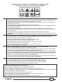 2
2
-
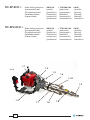 3
3
-
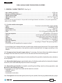 4
4
-
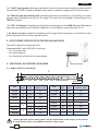 5
5
-
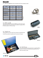 6
6
-
 7
7
-
 8
8
-
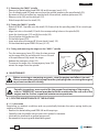 9
9
-
 10
10
-
 11
11
-
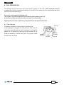 12
12
-
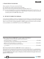 13
13
-
 14
14
-
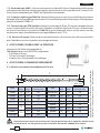 15
15
-
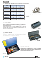 16
16
-
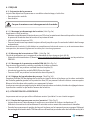 17
17
-
 18
18
-
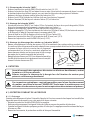 19
19
-
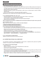 20
20
-
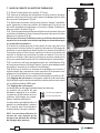 21
21
-
 22
22
-
 23
23
-
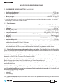 24
24
-
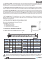 25
25
-
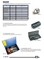 26
26
-
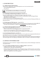 27
27
-
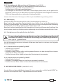 28
28
-
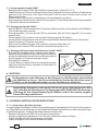 29
29
-
 30
30
-
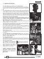 31
31
-
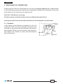 32
32
-
 33
33
-
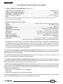 34
34
-
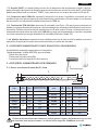 35
35
-
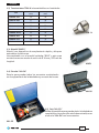 36
36
-
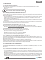 37
37
-
 38
38
-
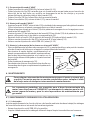 39
39
-
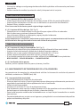 40
40
-
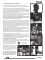 41
41
-
 42
42
-
 43
43
-
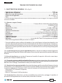 44
44
-
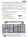 45
45
-
 46
46
-
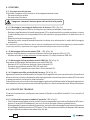 47
47
-
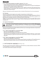 48
48
-
 49
49
-
 50
50
-
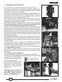 51
51
-
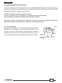 52
52
-
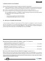 53
53
-
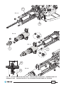 54
54
-
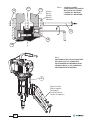 55
55
-
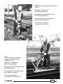 56
56
-
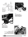 57
57
-
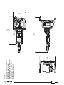 58
58
-
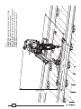 59
59
-
 60
60


en otros idiomas
- français: Cembre SD-9P-ECO Manuel utilisateur
- italiano: Cembre SD-9P-ECO Manuale utente
- Deutsch: Cembre SD-9P-ECO Benutzerhandbuch
- português: Cembre SD-9P-ECO Manual do usuário