LG LW1212HR Guía de instalación
- Tipo
- Guía de instalación

OWNER’S MANUAL
AIR CONDITIONER
Please read this manual carefully before operating
your set and retain it for future reference.
P/NO:MFL67461901
www.lgappliances.com
TYPE:WINDOW
MODELS:LW1212HR

2 Room Air Conditioner
Window-Type Air Conditioner Owner’s Manual
TABLE OF CONTENTS
FOR YOUR RECORDS
Write the model and serial numbers here:
Model #
Serial #
You can find them on a label on the side of each unit.
Dealer's Name
Date Purchased
■ Staple your receipt to this page in the event you need it
to prove date of purchase or for warranty issues.
READ THIS MANUAL
Inside you will find many helpful hints on how to use and
maintain your air conditioner properly. Just a little preventive
care on your part can save you a great deal of time and
money over the life of your air conditioner.
You'll find many answers to common problems in the chart
of troubleshooting tips. If you review our chart of
Troubleshooting Tips first, you may not need to call for
service at all.
PRECAUTION
• Contact the authorized service technician for repair
or maintenance of this unit.
• Contact the installer for installation of this unit.
• The air conditioner is not intended for use by young
children or invalids without supervision.
• Young children should be supervised to ensure that
they do not play with the air conditioner.
• When the power cord is to be replaced, replacement
work shall be performed by authorized personnel only
using only genuine replacement parts.
• Installation work must be performed in accordance
with the National Electric Code by qualified and
authorized personnel only.
Safety Precautions..........................3
Before Operation.............................7
Introduction ....................................8
Electrical Safety ..............................9
Installation ....................................11
Operating Instructions .................16
Maintenance and Service ............20

Owner’s Manual 3
ENGLISH
Safety Precautions
Safety Precautions
To prevent injury to the user or other people and property damage, the following instructions
must be followed.
■ Incorrect operation due to ignoring instruction will cause harm or damage. The seriousness
is classified by the following indications.
■ Meanings of symbols used in this manual are as shown below.
WARNING
CAUTION
This symbol indicates the possibility of death or serious injury.
This symbol indicates the possibility of injury or damage to properties only.
WARNING
■ Installation
Be sure not to do.
Be sure to follow the instruction.
Don’t use a power cord, a
plug or a loose socket which
is damaged.
• Otherwise, it may cause a fire
or electrical shock.
Always plug into a grounded
outlet.
• Otherwise, it may cause a fire
or electrical shock.
Do not modify or extend the
power cord length.
• It will cause electric shock or fire
due to heat generation.
Do not disassemble or
modify products.
• It may cause failure and
electric shock.
Be caution when unpacking
and installing.
• Sharp edges may cause
injury.
Do not use the power cord near
flammable gas or combustibles
such as gasoline, benzene,
thinner, etc.
• It may cause explosion or fire.

4 Room Air Conditioner
Safety Precautions
■ Operation
Do not place the power cord
near a heater.
• It may cause fire and electric
shock.
Do not allow water to run
into electric parts.
• It will cause failure of machine or
electric shock.
Use a soft cloth to clean. Do
not use wax, thinner, or a
strong detergent.
• The appearance of the air
conditioner may deteriorate,
change color, or develop surface
flaws.
Ventilate the room well when
using this appliance
together with a stove, etc.
• An oxygen shortage may occur.
Turn off the power and
breaker firstly when
cleansing the unit.
• Since the fan rotates at high
speed during operation, it may
cause injury.
Turn off the main power
switch when not using it for
a long time.
• Prevent accidental startup and
the possibility of injury.
Unplug the unit if strange
sounds, odors, or smoke
come from it.
• Otherwise it may cause fire and
electric shock accident.
Do not open the suction
inlet grill of the product
during operation.
• Otherwise, it may electrical
shock and failure.
If water enters the product, turn
off the the power switch of the
main body of appliance. Contact
service center after taking the
power-plug out from the socket.
Do not place heavy object
on the power cord and take
care so that the cord should
not be pressed.
• There is danger of fire or electric
shock.
Do not share the outlet with
other appliances.
• It will cause electric shock or fire
due to heat generation.
Take the power plug out if
necessary, holding the head
of the plug and do not touch
it with wet hands.
• Otherwise, it may cause a fire
or electrical shock.
Wax
Thinner

Owner’s Manual 5
ENGLISH
Safety Precautions
CAUTION
■ Installation
Do not operate or stop the
unit by inserting or pulling
out the power plug.
• It will cause electric shock or fire
due to heat generation.
Do not damage or use an
unspecified power cord.
• It will cause electric shock or fire.
Do not operate with wet
hands or in damp
environment.
• It will cause electric shock.
Hold the plug by the head
when taking it out.
• It may cause electric shock and
damage.
When gas leaks, open the
window for ventilation
before operating the unit.
• Otherwise, it may cause
explosion, and a fire.
Never touch the metal parts
of the unit when removing
the filter.
• They are sharp and may cause
injury.
Install the product so that the noise or hot
wind from the outdoor unit may not cause
any damage to the neighbors.
• Otherwise, it may cause dispute with the
neighbors.
Keep level parallel in installing the product.
• Otherwise, it may cause vibration or water
leakage.


Before Operation
Owner’s Manual 7
ENGLISH
Before Operation
1. Contact an installation specialist for installation.
2. Plug in the power plug properly.
3. Use a dedicated circuit.
4. Do not use an extension cord.
5. Do not start/stop operation by plugging/unplugging the power cord.
6. If the cord/plug is damaged, replace it with only an authorized replacement
part.
1. Being exposed to direct airflow for an extended period of time could be
hazardous to your health. Do not expose occupants, pets, or plants to direct
airflow for extended periods of time.
2. Due to the possibility of oxygen deficiency, ventilate the room when used
together with stoves or other heating devices.
3. Do not use this air conditioner for non-specified special purposes (e.g.
preserving precision devices, food, pets, plants, and art objects). Such usage
could damage the items.
1. Do not touch the metal parts of the unit when removing the filter. Injuries can
occur when handling sharp metal edges.
2. Do not use water to clean inside the air conditioner. Exposure to water can
destroy the insulation, leading to possible electric shock.
3. When cleaning the unit, first make sure that the power and breaker are turned
off. The fan rotates at a very high speed during operation. There is a
possibility of injury if the unit’s power is accidentally triggered on while
cleaning inner parts of the unit.
For repair and maintenance, contact your authorized service dealer.
Preparing for Operation
Usage
Cleaning and Maintenance
Service

8 Room Air Conditioner
Introduction
This symbol alerts you to the risk of electric shock.
This symbol alerts you to hazards that could cause harm to
the air conditioner.
This symbol indicates special notes.
NOTICE
This appliance should be installed in accordance with the National Electric Code.
Introduction
Symbols Used in this Manual
Features
Evaporator
Electric Heater
Control Board
Brace
Vertical Air Deflector
(Horizontal Louver)
Horizontal Air Deflector
(Vertical Louver)
Air Discharge
Cabinet
Front Grille Air Filter
Air Intake(Inlet Grille)
Condenser
Base Pan
Compressor
Power Cord
Remote Controller

Electrical Safety
Owner’s Manual 9
ENGLISH
Electrical Safety
Electrical Data
115V~ 230V~
Power cord may include a current
interrupter device. A test and reset button is
provided on the plug case. The device
should be tested on a periodic basis by first
pressing the TEST button and then the
RESET button. If the TEST button does not
trip or if the RESET button will not stay
engaged, discontinue use of the air
conditioner and contact a qualified service
technician.
Use Wall Receptacle Power Supply
Standard 125V, 3-wire grounding
receptacle rated 15A, 125V AC
Standard 250V, 3-wire grounding
receptacle rated 15A, 250V AC
Use 15 AMP. time
delay fuse or 15 AMP.
circuit breaker.
Use 20 AMP. time
delay fuse or 20 AMP.
circuit breaker.
Standard 250V, 3-wire grounding
receptacle rated 20A, 250V AC
Never push the test button during
operation
Otherwise this plug can damaged.
This device contains chemical, including
lead, known to the State of California to
cause cancer, and birth defects or other
reproductive harm.
Wash hands after handling.
Do not remove, modify or immerse this plug.
If this device trips, the cause it to be
corrected before further use.
The conductors inside this cord are
surrounded by shields, which monitor
leakage current.
These shields are not grounded.
<
Periodically examine the cord for any
damage. Do not use this product in the
event the shields become exposed.
Avoid shock hazard, this unit can not
be user serviced opening the tamper
resistant. Sealed portion of the unit
voids all warranties and performance
claims. This unit not intended for use
as an on-off switch.
The shape may be different according to its model.
NOTICE
DO NOT USE AN EXTENSION CORD on 230,
208, and 230/208 Volt units.
All wiring should be made in accordance with local
electrical codes and regulations.
Aluminum house wiring may pose special
problems. Consult a qualified electrician.
NOTICE

10 Room Air Conditioner
Electrical Safety
Electrical Safety
IMPORTANT
(PLEASE READ CAREFULLY)
FOR THE USER'S PERSONAL SAFETY, THIS
APPLIANCE MUST BE PROPERLY GROUNDED
The power cord of this appliance is equipped with a
three-prong (grounding) plug. Use this with a standard
three-slot (grounding) wall power outlet to minimize the
hazard of electric shock. The customer should have the
wall receptacle and circuit checked by a qualified
electrician to make sure the receptacle is properly
grounded.
DO NOT CUT OR REMOVE THE THIRD (GROUND)
PRONG FROM THE POWER PLUG.
A. SITUATIONS WHEN THE APPLIANCE WILL BE
DISCONNECTED OCCASIONALLY:
Because of potential safety hazards, we strongly
discourage the use of an adapter plug. However, if you
wish to use an adapter, a TEMPORARY CONNECTION
may be made. Use UL-listed adapter, available from
most local hardware stores.
The large slot in the adapter must be aligned with the
large slot in the receptacle to assure a proper polarity
connection.
:
Attaching the adapter ground terminal to the wall
receptacle cover screw does not ground the appliance
unless the cover screw is metal, and not insulated, and
the wall receptacle is grounded through the house
wiring. The customer should have the circuit checked
by a qualified electrician to make sure the receptacle
is properly grounded.
Disconnect the power cord from the adapter, using one
hand on each. Otherwise, the adapter ground terminal
might break. DO NOT USE the appliance with a broken
adapter plug.
B. SITUATIONS WHEN THE APPLIANCE WILL BE
DISCONNECTED OFTEN.
Do not use an adapter plug in these situations.
Unplugging the power cord frequently can lead to an
eventual breakage of the ground terminal. The wall
power outlet should be replaced by a three-slot
(grounding) outlet instead.
USE OF EXTENSION CORDS
Because of potential safety hazards, we strongly
discourage the use of an extension cord. However, if
you wish to use an extension cord, use a CSA
certified/UL-listed 3-wire (grounding) extension cord,
rated at 20A, 250V.

Owner’s Manual 11
ENGLISH
Installation
Installation
How to Install the Unit
Window Requirements
1. To prevent vibration and noise, make sure
the unit is installed securely and firmly
2. Install the unit where the sunlight does not
shine directly on the unit.
3. The outside of the cabinet must extend
outward for at least 12" and there should
be no obstacles, such as a fence or wall,
within 20" from the back of the cabinet
because it will prevent heat radiation of the
condenser.
Restriction of outside air will greatly
reduce the cooling efficiency of the air
conditioner.
All side louvers of the cabinet must remain exposed to the outside of the structure.
4. Install the unit a little slanted so the back is slightly lower than the front(about
1
/2").
This will force condensed water to flow to the outside.
5. Install the unit with the bottom about 30"~60" above the floor level.
All supporting parts should be secured to firm wood,
masonry, or metal.
This unit is designed for installation in standard
double hung windows with actual opening widths
from 27" to 39".
The top and bottom window sash must open
sufficiently to allow a clear vertical opening of
16" from the bottom of the upper sash to the window stool.
NOTICE
About
1
/2"
30"~60"
Awning
Cooled air
Fence
Over 20"
Heat
radiation
Interior wall
Stool
16" min
27" to 39"
1
/2" to 1
1
/4"
Offset
Sill
Exterior
23
5
/8" min
(Without frame curtain)

12 Room Air Conditioner
Installation
Installation Kits Contents
NO. NAME OF PARTS Q'TY
1 FRAME CURTAIN 2
2 SILL SUPPORT 2
3 BOLT 2
4 NUT 2
5 SCREW(TYPE A) 13
6 SCREW(TYPE B) 3
7 SCREW(TYPE C) 5
8 FOAM-STRIP 1
9 FOAM-PE 1
10 FRAME GUIDE 2
11
WINDOW LOCKING BRACKET
1
1
2 3 4
8 9
765
1
9
5
5
5
10
10
EPS Material
Upper guide
(Type A)
(Type A)
Suggested Tool Requirements
PREPARATION OF CHASSIS
1. Remove the screws which fasten the cabinet
at both sides and at the back.
2. Slide the unit from the cabinet by gripping the
base pan handle and pulling forward while
bracing the cabinet.
3. Remove EPS Material.
4. Cut the window sash seal to the proper
length. Peel off the backing and attach the
foam-pe
to the underside of the window
sash.
5. Insert the frame guides into the bottom of
the cabinet.
6. Insert the Frame Curtain
into the upper
guide and frame guides
.
7. Fasten the curtains to the unit with 4 Type A
screws.
SCREWDRIVER(+, -), RULER, KNIFE, HAMMER, PENCIL, LEVEL
0
1
1
10
10
(The EPS Material protected the unit when transitting.
You can disuse itafter remving it

Upper Guide
Window Sash
Window stool
Front Angle
Upper guide
Frame Curtain
1
Foam-pe
Foam-pe
9
Cabinet
INDOOR OUTDOOR
INDOOR OUTDOOR
Sash track
Front Angle
Cabinet
About
1
/2"
About
1
/2"
Sill Support
2
Nut
4
Bolt
3
Frame Guide
10
Screw(Type B)
6
Screw(Type B)
6
Sill support
2
Sill support
2
Screw(Type A)
5
Owner’s Manual 13
ENGLISH
Installation
Cabinet Installation
1. Open the window. Mark a line on
center of the window stool(or desired
air conditioner location).
Carefully place the cabinet on the
window stool and align the center
mark on the bottom front with the
center line marked in the window
stool.
2. Pull the bottom window sash down
behind the upper guide until it meets.
Do not pull the window sash down so
tightly that the movement of Frame
Curtain is restricted.
3. Loosely assemble the sill support
using the parts in Fig. 3.
4. Select the position that will place the
sill support near the outer most point
on sill (See Fig. 4)
Be careful when you install the cabinet
(frame guides are broken so easily).
5. Attach the sill support to the cabinet
track hole in relation to the selected
position using 2 Type A screws in
each support(See Fig. 4).
6. The cabinet should be installed with a
very slight tilt(about
1
/2") downward
toward the outside (See Fig. 5).
Adjust the bolt and the nut of sill
support for balancing the cabinet.
7. Attach the cabinet to the window stool
by driving the screws
(Type B:
Length sixteen millimeters and
below.) through the front angle into
window stool.
8. Pull each Frame curtain fully to each
window sash track, and repeat step 2.
NOTICE
NOTICE
Fig. 1
Fig. 2
Fig. 3
Fig. 4
Fig. 5
10

Type C
7
Screw(Type A)
Screw(Type A)
Power cord
Foam-Strip
8
Window locking bracket
11
14 Room Air Conditioner
Installation
9. Attach each Frame curtain the window sash
using screws (Type C).(See Fig. 6)
Do not drill a hole in the bottom pan.
The unit is designed to operate with
approximately 1/2" of water in bottom pan.
10. Slide the unit into the cabinet.(See Fig. 7)
For security purpose, reinstall screws(Type A) at
cabinet's sides.
11. Cut the foam-strip to the proper length
and insert between the upper window
sash and the lower window sash.
(See Fig. 8)
12. Attach the window locking bracket with
a type C screw. (See Fig. 9)
13. Attach the front grille to the cabinet by
inserting the tabs on the grille into the
tabs on the front of the cabinet. Push the
grille in until it snaps into place. (See
Fig.10)
14. Lift the inlet grille and secure it with a type
A screw through the front grille.
(See Fig. 11)
15. Window installation of room air conditioner
is now completed. See ELECTRICAL DATA
for attaching power cord to electrical outlet.
Fig. 6
Fig. 7
Fig. 8
Fig. 9
Fig. 10
Fig. 11
11

Owner’s Manual 15
ENGLISH
Installation
How to Use the Reversible Inlet Grille
1. If you want to pull out the filter upward,
open the inlet grille slightly. Turn inside out
the front grille.
Disassemble the inlet grille from the front
grille with separating the hinged part by
inserting a "—" type screw-driver tip.
Rotate the inlet grille 180 degrees and
insert the hooks into the lower holes of
front grille.
Then, insert the filter. (See Fig.12, 13)
2. Attach the front grille to the cabinet by
inserting the tabs on the grille into the tabs
on the front of the cabinet. Push the grille in
until it snaps into place. (See Fig.14)
3. Lift the inlet grille and secure it with a type
A screw through the front grille.
(See Fig. 15)
4. If you want to pull out the filter downward,
use the reversible inlet grille without
change.
(The grille is already assembled for that
way.)
Fig. 12
Fig. 13
Fig. 14
Fig. 15
Inlet Grille

16 Room Air Conditioner
Operating Instructions
Remote control
The remote control and control panel will look like one of the following pictures.
Power
Temp
Fan Speed
Timer Mode
Energy
Saver
1
4
2
6
3
5
REMOTE CONTROLLER
1
6
7
5
4
2 3
Operating Instructions
1. POWER BUTTON
To turn the air conditioner ON, push the button. To turn the air conditioner OFF, push the button again.
This button takes priority over any other buttons.
2. OPERATION MODE SELECTION BUTTON
Everytime you push this button, it will toggle COOL, FAN and HEAT.
Cool
Heater runs and heats the room.
Compressor runs and cools the room.
Use the
and FAN buttons to set the desied temperature
and circulation fan speed.
Fan
Fan circulate air but compressor does not run.
Use the FAN button to set the desired fan speed.
Heat
Use the
and FAN buttons to set the desied temperature
and circulation fan speed.

Owner’s Manual 17
AUTO RESTART
When power is restored after an electrical power failure, the unit will begin to run at its last setting.
When the air conditioner has been performed its cooling operation and is turned off or set to the fan
position, wait at least 3 minutes before resetting to the cooling operation again.
2Hours 3Hours 4Hours 5Hours
6Hours 7Hours 8Hours 9Hours 10Hours 11Hours 12Hours Cancel)
4. FAN SPEED SELECTOR
Everytime you push this button, it is set as follows. (Hi[ ] Low[ ] Hi[ ]....)
5. ROOM TEMPERATURE SETTING BUTTON
This button can automatically control the temperature of the room. The temperature can be set within a
range of 60°F to 86°F by 1°F.
6. ENERGY SAVER
The fan stops when the compressor stops cooling.
Approximately every 3 munutes the fan will turn on and check the room air to determine if cooling is needed.
7. REMOCON SIGNAL RECEIVER
You will usually use shut-off time while you sleep.
For your sleeping comfort,once timer is set,the temperature setting will raise 2 F after
30min and once again after another 30min.
。
A slight heat odor may come from the unit when first switching to HEAT after the cooling
season is over. This odor, caused by fine dust particles on the heater, will disappear quickly.
ENGLISH
3. ON/OFF TIMER BUTTON
Everytime you push this button, timer is set as follows.(1Hour
ENGLISH
Operating Instructions
y
battery
battery
battery.
battery
battery
one

18 Room Air Conditioner
Operating Instructions
Ventilation
The ventilation lever must be in the CLOSE position in order to maintain the best cooling conditions.
When fresh air is necessary in the room, set the ventilation lever to the OPEN position.
The damper is opened and room air is drawn out.
The direction of air can be controlled wherever
you want to cool by adjusting the horizontal
louver and the vertical louver.
• HORIZONTAL AIR-DIRECTION CONTROL
The horizontal air direction is adjusted by
rotating the vertical louver right or left.
• VERTICAL AIR-DIRECTION CONTROL
The vertical air direction is adjusted by rotating
the horizontal louver forward or backward.
Part A
Part B
VENTCLOSE OPEN
Before using the ventilation feature,
position the lever, as shown. First, pull down
part to horizontal line with part .
NOTICE
Air Direction

Owner’s Manual 19
ENGLISH
Operating Instructions
How to Attach Drain Pan(Optional)
How to Connect a Drain Hose
The air conditioner employs a proper drain method whereby the condensed water (moisture removed from the
air) is drained to the outside.
In very humid weather, (and for reverse cycle models in the reverse mode) excessive condensate water
removed from the air may cause some water to collect. To remove this excess water you can install the drain
pan as detailed below.
1. Take the drain pan which is located in the air discharge.
2. Remove the hole rubber from the base-pan (for some models).
3. Install the drain pan to the right corner of the cabinet with 4 (or 2)
screws.
4. Connect the drain hose of 3/5" inside diameter to the outlet located
at the bottom of the drain pan.You can purchase the drain hose or
tubing locally to satisfy your particular needs. (Drain hose is not
supplied).
A drain hole is provided at the rear of the air conditioner unit.
Select a drain method according to the following.
1. Remove the hole rubber from the base-pan. (for some models)
2. Connect a drain hose of 9/16" inside diameter to the drain pipe as
shown in Fig. 1.
3. Or connect a pipe elbow of 9/16" inside diameter to the drain pipe,
then connect a drain hose of 9/16" inside diameter to the pipe
elbow as shown in Fig. 2.
CABINET
DRAIN
PAN
DRAIN HOSE
SCREW
DRAIN PIPE
DRAIN HOSE
DRAIN PIPE
DRAIN ELBOW
DRAIN HOSE
Fig. 1
Fig. 2

20 Room Air Conditioner
Maintenance and Service
Maintenance and Service
TURN THE AIR CONDITIONER OFF AND REMOVE THE PLUG FROM THE POWER OUTLET.
he air filter should be checked at least twice a month to see if cleaning is necessary. Trapped particles in the
filter will build up and block the airflow. This reduces the cooling capacity and also causes an accumulation of
frost on the cooling coils.
1. Open the inlet grille upward by pulling out the bottom of the inlet grille.(a)
In another case, you can open the inlet grille downward by pulling out the top of the inlet grille.(b)
2. Remove the air filter from the front grille assembly by pulling the air filter up or down slightly.
3. Wash the filter using lukewarm water below 40°C (104°F).(c)
4. Gently shake the excess water from the filter completely. Replace the filter.
Mark ∆ of inlet grille means opening direction.
NOTICE
Air Filter Cleaning
How to Attach Front Grille to Cabinet
1. Pull down front grille from the cabinet top.
2. Push front grille’s tips toward the cabinet in order
to insert front grille’s tabs into
the cabinet.
3. Open the inlet grille.
4. Tighten the screw through the front grille into the
plate of the evaporator or base pan.
5. Close inlet grille.
NOTICE
When the unit operates on extremely hot weather , it turns off automatically to protect compressor.

Owner’s Manual 21
ENGLISH
Maintenance and Service
Common Problems and Solutions
Before calling for service, please review the following list of common problems and solutions.
The air conditioner is operating normally when:
• You hear a pinging noise. This is caused by water being picked up by the condenser on rainy days or in
highly humid conditions. This feature is designed to help remove moisture in the air and improve cooling
efficiency.
• You hear the thermostat click. This is caused by the compressor cycle starting and stopping.
• You see water dripping from the rear of the unit. Water may be collected in the base pan in highly humid
conditions or on rainy days. This water overflows and drips from the rear of the unit.
• You hear the fan running while the compressor is silent. This is a normal operational feature.
The air conditioner may be operating abnormally when:
Problem Possible Causes What To Do
■ The air conditioner is
unplugged or not plugged
in completely
■ The fuse is blown/circuit
breaker is triggered
■ Power failure.
■ The current interrupter
device is tripped.
■ Air flow is restricted
■ TEMP Control set too
higher number.
■ The air filter is dirty.
■ The air conditioner was
just turned on.
■ The room may have been
hot.
■ Cold air is escaping.
■ Cooling coils are iced up
■ The cooling coils are iced
over.
• Make sure the plug is completely plugged into the
outlet
• Check the fuse/circuit breaker box and replace the
fuse or reset the breaker
• In the event of a power failure, set the power control
to OFF. When the power is restored, wait 3 minutes
to restart the air conditioner to prevent the
compressor from overloading
• Press the RESET button located on the power cord
plug. If the RESET button will not stay engaged,
discontinue use of the air conditioner and contact a
qualified service technician.
• Make sure there are no curtains, blinds, furniture or
other obstacles in front of the air conditioner
• Set the TEMP control to a lower number.
• Clean the filter at least every 2 weeks. Refer to the
“Maintenance and Service” section of the manual.
• After the air conditioner is turned on, you need to
give the air conditioner some time to cool the room.
• When the air conditioner is first turned on
you need to allow time for the room to cool down.
• Check for open furnace floor resisters and cold air
returns.
• CLOSE the air conditioner vent
• See Ice appears on the air conditioner below
• Ice may block the air flow and obstruct the air
conditioner from properly cooling the room.
• Set the mode control at HIGH fan or high cool with
the high temperature.
The air conditioner
does not operate
at all
Air conditioner
does not cool
Ice appears on the
air conditioner.

22 Aire Acondicionador
Manual del usuario del acondicionador de aire tipo Ventana
TABLA DE CONTENIDOS
PARA SUS ARCHIVOS
Escriba aquí el modelo y número de serie:
Modelo n°:
Serie n°:
Puede encontrar estos datos en la etiqueta situada en el
lateral de cada unidad.
Nombre del distribuidor:
Fecha de compra:
■ Adjunte su recibo a esta página con la grapadora para
el momento que lo necesite para probar la fecha de su
adquisición o para la validación de la garantía.
LEA ESTE MANUAL
En su interior encontrará muchos consejos útiles sobre la
utilización y mantenimiento de su acondicionador de aire.
Unos pocos cuidados por su parte le pueden ahorrar
mucho tiempo y dinero durante la vida de su
acondicionador de aire.
En la tabla de consejos para la solución rápida de
problemas encontrará muchas respuestas a los problemas
más habituales. Si revisa primero nuestra Tabla de
Consejos para la solución rápida de problemas, tal vez no
necesite llamar nunca al servicio técnico.
PRECAUCIÓN
• Póngase en contacto con un técnico del servicio
autorizado para realizar la reparación y
mantenimiento de esta unidad.
• Póngase en contacto con un instalador para realizar
la instalación de esta unidad.
• Cuando se va a cambiar el cable eléctrico, el trabajo
de reemplazamiento debe ser realizado únicamente
por personal autorizado, utilizando las piezas de
cambio genuinas únicamente.
• El trabajo de reemplazamiento debe ser realizado de
acuerdo con el Código Eléctrico Nacional
únicamente por personal autorizado.
Precauciones de Seguridad.........23
Antes de poner el equipo en
funcionamiento..............................27
Introducción...................................28
Seguraida Electrica.......................29
Instalacion......................................31
Instruccionnes de
Funcionamiento.............................36
Cuidado y Mantenimiento ............40

Manual del Propietario 23
ESPAÑOL
Precauciones de Seguridad
Precauciones de Seguridad
Para evitar lesiones al usuario o a otras personas y daños a la propiedad, estas instrucciones
estén seguirse.
■
Una operación incorrecta por ignorar las instrucciones provocará lesiones o daños. La seriedad se clasifica
por las siguientes indicaciones.
■ Significados de los símbolos utilizados en este manual.
ADVERTENCIA
PRECAUCION
Este símbolo indica la posibilidad de muerte o de seria lesión.
Este símbolo indica sólo la posibilidad de lesiones o daños a la propiedad
ADVERTENCIA
■ Instalación
No hacer.
Siga estas instrucciones.
No utilice un cable de
alimentación, enchufe o una
toma suelta que esté dañada.
• De lo contrario, podría provocar
un incendio o descarga
eléctrica.
Enchufe siempre a un
tomacorriente que tenga
toma a tierra.
• De lo contrario, podría provocar
un incendio o descarga
eléctrica.
No modifique ni alargue el
cable de alimentación.
• De lo contrario, puede provocar
una descarga eléctrica o
incendio debido a la
generación de calor.
No desmonte ni modifique
los productos.
• Puede ocasionar fallos y una
descarga eléctrica.
Tenga cuidado al
desembalar e instalar el
aparato.
• Los bordes afilados pueden
provocar lesiones.
No use el cable de alimentación
cerca gas inflamable o
materiales combustibles tales
como la gasolina, benceno,
disolvente, etc.
• Podría ocurrir una explosión o
incendio.
ilosaG n

24 Aire Acondicionador
Precauciones de Seguridad
■ Operación
No ponga el cable de
alimentación cerca de un
calentador.
• Puede ocasionar un incendio y
una descarga eléctrica.
No permita que entre agua
en las piezas eléctricas.
• Puede provocar fallos en el
producto o descargas
eléctricas.
Utilice un paño suave para
limpiar. No utilice cera,
disolventes o detergentes
fuertes.
•
La apariencia del aparato de aire
acondicionado puede deteriorar,
cambiar el color o desarrollar flujos
en las
superficies.
Ventile bien la sala al usar
este aparato con una estufa,
etc.
• Puede ocurrir un falta de
oxígeno.
Apague el aparato y el
interruptor diferencial
primero antes de limpiar la
unidad.
•
Debido a que el ventilador gira a
alta velocidad durante el
funcionamiento, podría ocasionar
lesiones.
Apague el interruptor de
alimentación principal cuando
no vaya a utilizar el aparato
durante mucho tiempo.
• Evitará el arranque accidental y
la posibilidad de lesiones.
Desenchufe la unidad si oye
un sonido extraño, olores, o
si observa salir humo.
• De lo contrario, puede ocurrir
un incendio y un accidente por
descarga eléctrica.
No abra la parrilla de
entrada al aparato mientras
está en funcionamiento.
• De lo contrario, pueden ocurrir
descargas eléctricas y fallos.
Si entra agua en el producto,
apague el interruptor de la
carcasa principal del aparato.
Póngase en contacto con el
centro de servicio después de
haber sacado el enchufe del
tomacorriente.
No use el cable de alimentación
cerca gas inflamable o materiales
combustibles tales como la
gasolina, benceno, disolvente, etc.
• Puede ocasionar una explosión
o descarga eléctrica.
No comparta el
tomacorriente con otros
electrodomésticos.
•
De lo contrario, puede provocar una
descarga eléctrica o incendio debido
a la generación de calor.
Saque el enchufe en caso de
necesidad, sosteniendo la
cabeza del enchufe y no lo
toque con las manos mojadas.
•
De lo contrario, podría provocar un
incendio o descarga eléctrica.
xaW
Thinner

Manual del Propietario 25
ESPAÑOL
Precauciones de Seguridad
ADVERTENCIA
■ Instalación
No opere ni detenga la
unidad insertando o
estirando de enchufe.
• De lo contrario, puede provocar
una descarga eléctrica o
incendio debido a la
generación de calor.
No dañe ni use un enchufe
de alimentación no
especificado.
• Provocará descargas eléctricas
o incendios.
No toque el producto con
las manos mojadas o en un
ambiente húmedo.
• Provocará descargas
eléctricas.
Sostenga el enchufe por su
cabeza al sacarlo.
• Podría ocasionar una descarga
eléctrica y daños.
Cuando haya un escape de
gas, abra la ventana para
ventilar antes de poner en
marcha la unidad.
• De lo contrario, podría ocurrir
una explosión o incendio.
No toque las partes
metálicas del aparato al
sacar el filtro del aire.
• Son puntiagudas y pueden
provocar lesiones.
Instale el producto de modo que el ruido o
el aire caliente producido por la unidad
externa no moleste a los vecinos.
• De lo contrario puede dar lugar a disputas
vecinales.
Mantenga nivelado el producto al instalarlo.
• De lo contrario se podría causar vibraciones o
escapes de agua.

26 Aire Acondicionador
Precauciones de Seguridad
No se suba a la unidad
interior/exterior ni coloque
objetos sobre la misma.
• Puede lesionarse al caerse del
aparato o al caerse los objetos
que haya colocado.
Inserte siempre el filtro
correctamente.
Límpielo cada dos semanas.
• El funcionamiento sin filtros
puede provocar fallos.
No beba el agua que drena
el aparato de aire
acondicionado.
No ponga plantas ni
animales en la trayectoria
que recorrerá el aire
caliente.
• Podría ocasionar lesiones.
No bloquee la entrada ni la
salida del flujo de aire.
• Puede causar una avería en el
aparato.
Utilice un paño suave para
limpiar. No utilice cera,
disolventes o detergentes
fuertes.
•
La apariencia del aparato de aire
acondicionado puede deteriorar,
cambiar el color o desarrollar flujos
en las superficies.
Tenga cuidado para no
tocar los bordes
puntiagudos al instalar.
• Podría ocasionar lesiones.
Evite un enfriamiento
excesivo y ventile en
ocasiones.
• De lo contrario, podría dañar su
salud.
No introduzca la mano ni
barras en la entrada o salida
del aire durante el
funcionamiento del aparato.
• De lo contrario, podrían ocurrir
lesiones personales.
Operación
Si entra líquido de las pilas en contacto con la piel o
la ropa, lávela inmediatamente con agua. No utilice
el control remoto si las pilas tienen fugas.
• Los productos químicos
de las pilas podrían
causar quemaduras u
otros perjuicios a la
salud.
Si el líquido de las pilas alcanzara su boca, cepille
sus dientes y consulte a un médico.No utilice el
mando a distancia si las pilas han experimentado
fugas.
• Los productos químicos
de las pilas podrían
causar quemaduras u
otros perjuicios a la
salud.

Antes de poner el equipo en funcionamiento
Manual del Propietario 27
ESPAÑOL
Antes de poner el equipo en funcionamiento
1. Póngase en contacto con un especialista para realizar la instalación.
2. Enchufe correctamente la toma de alimentación.
3. Utilice un circuito dedicado.
4. No utilice un cable alargador.
5. No inicie/cese el funcionamiento enchufando/desenchufando el cable
eléctrico.
6. Si el cable/enchufe está dañado, sustitúyalo solo por una pieza autorizada.
1. Estando expuesto a la circulación directa de aire durante un extenso período
de tiempo podría resultar peligroso para su salud. No exponga a las personas,
animales domésticos, o a las plantas a la circulación de aire durante largos
períodos de tiempo.
2. Debido a la probabilidad de falta de oxígeno, ventile el cuarto cuando esté
utilizado el aparato junto con estufas u otros aparatos de calefacción.
3. No utilice este aire acondicionado con propósitos especiales no especificados
(Ej.: conservación de dispositivos de precisión, comida, animales domésticos,
plantas y objetos de arte). Tal uso podría dañar los artículos.
1. No toque las piezas metálicas de la unidad al retirar el filtro. Manejar aristas
afiladas de metal puede causar lesiones.
2. No utilice el agua para limpiar el interior del aire acondicionado. La exposición
al agua puede destruir el aislamiento, conduciendo a posibles descargas
eléctricas.
3. Al limpiar la unidad, asegúrese antes de que la electricidad y el interruptor
están apagados. El ventilador rota a muy alta velocidad durante el
funcionamiento del equipo. Existe la posibilidad de lesiones si acciona
accidentalmente la electricidad de la unidad mientras limpia el interior de la
unidad.
Para cuestiones de reparación y mantenimiento, póngase en contacto con su
distribuidor de servicio autorizado.
Preparación para el funcionamiento
Uso
Limpieza y mantenimiento
Servicio

28 Aire Acondicionador
Introducción
Este símbolo lo advierte de un peligro de accidente por
corriente eléctrica.
Este símbolo lo adiverte de un peligro que pueda causar un
daño del ventliador.
Este símbolo significa condicciones especiales.
CONSEJO
Introducción
Símbolos Utilizados en Este Manual
Características
Este aparato debería instalarse de acuerdo con las normas del Código Eléctrico Nacional.
Calentador Eléctrico
Evaporador
Panel de control
Abrazadera
Deflector de aire vertical
(Rejilla horizontal)
Deflector de aire horizontal
(Rejilla vertical)
Descarga de aire
Gabinete
Rejilla frontal
Filtro de aire
Control remoto
Condensador
Plator de base
Compresor
Cable de alimentacion
Entrada de aire
(Rejilla para entrada)

Seguraida Electrica
Manual del Propietario 29
ESPAÑOL
Seguraida Electrica
Datos Electricos
115V~ 230V~
El cable de alimentación puede incluir un
dispositivo interruptor de corriente. La
carcasa del enchufe cuenta con un botón de
prueba y otro de reinicio. El dispositivo debe
comprobarse periódicamente presionando
primero el botón TEST y después RESET.
Si el botón TEST no se desconecta o si el
botón RESET no permanece activo,
suspenda el uso del aire acondicionado y
póngase en contacto con un técnico de
servicio cualificado.
Utilice el enchufe de la pared Consumo de Energía
Standard 125V, enchufe de 3
Líneas de 15A, 125V AC
Standard 250V, enchufe de 3
Líneas de 15A, 250V AC
Standard 250V, enchufe de 3
Líneas de 20A, 250V AC
Utilice un fusible de
15AMP. o un
Interruptor de 15AMP.
Utilice un fusible de
20AMP. o un
Interruptor de 20AMP.
No presione nunca el botón de prueba durante el
funcionamiento, de lo contrario el enchufe podría
resultar dañado.
Este dispositivo contiene productos químicos,
incluyendo plomo, conocido en el estado de
California como producto cancerígeno y causante de
defectos de nacimiento y otros daños al sistema
reproductor.
Lávese bien las manos tras manipular el dispositivo.
No desmonte, modifique ni sumerja en agua este
enchufe.
Si el dispositivo se activara, deberá corregir la causa
antes de volver a utilizarlo.
Los hilos conductores dentro del cable están rodeados
por blindajes, que supervisan la corriente de fuga.
Estos blindajes no están puestos a tierra.
Examine periódicamente el cable en busca de
cualquier daño. No utilice este producto si los blindajes
resultaran expuestos.
Evite el riesgo de descargas eléctricas; esta unidad no
puede ser reparada por el usuario por ser resistente y
a prueba de alteraciones. Manipular la porción sellada
de la unidad anulará todas las garantías y quejas de
rendimiento. Esta unidad no está diseñada para su uso
como un interruptor de encendido-apagado.
La forma puede ser diferente según su modelo.
CONSEJO
NO USE CABLE DE EXTENSIÓN EN UNIDADES
DE 208, 230, AND 208/230 VOLTIOS.
Todo el cableado deberá realizarse de acuerdo
con los códigos y reglamentos eléctricos
locales.
El cableado doméstico de aluminio podría
ocasionar problemas especiales. Consulte a un
electricista calificado.
CONSEJO

30 Aire Acondicionador
Seguraida Electrica
IMPORTANTE
(FAVORLEA CON ATENCIÓN)
POR LA SEGURIDAD PERSONAL DEL USUARIO, ESTE
APARATO DEBE SER DEBÍDAMENTE NEUTRALIZADO.
El cordón de energía de éste aparato esta equipado
con tres patas(cable a tierra). Utilice éste con un
enchufe de pared de tres salidas(a tierra) para
minimizar el peligro de choque eléctrico. El cliente
debe revisar el receptor de pared y el circuito por un
electricista calificado para asegurarse que la
recepción esta debidamente neutralizada.
NO CORTE O REMUEVA LA TERCERA PATA(GROUND)
DEL ENCHUFE.
A. SITUACIONES EN LAS CUALES EL APARATO
ES DESCONECTADO OCASIONALMENTE:
Debido al peligro potencial, nosotros no
recomendamos el uso de adaptadores. Sin embargo,
si usted desea utilizar un adaptador, una CONEXIÓN
TEMPORAL, puede ser
efectuada. Utilice adaptadores UL, disponibles en la
mayoría de los estable cimientos de
herramientas. La pata mas grande del adaptador
debe ser alineada con la pata mas grande del
interruptor para asegurarse una polarización
adecuada.
Adaptar la terminal del ground del adaptador a
la cubierta de la pared con un
tornillo no neutraliza el aparato a menos que la
cubierta del tornillo sea de metal, u no sea
insolada, y el receptor de pared este
neutralizado a través del alambrado del la casa.
El cliente debe hacer verificar el circuito por un
electricista calificado para asegurarse que el
receptor esta debidamente neutralizado.
Desconecte el cordón de energía del adaptador,
utilizado una mano en cada uno. De lo contrario, la
terminal del adaptador puede romperse. NO UTILICE el
aparato con un enchufe roto.
B. SITUACIONES EN LAS CUALES EL APARATO
ES DESCONECTADO CON
FRECUENCIA.
No utilice un adaptador en estas circunstancias.
Desconectar el cordón de energía con frecuencia lo
llevará al eventual rompimiento de la terminal de
neutralización. La saluda de energía de la pared
debe ser reemplazada por una salida de tres
patas(neutralizada).
USO DE EXTENSIONES
Debido al peligro potencial, no recomendamos la
utilización de extensiones. Sin embargo, si usted
desea utilizar una extensión, utilice una
certificada por CSA/UL de tres alambres,
catalogada 20A, 250V.
Seguraida Electrica

Manual del Propietario 31
ESPAÑOL
Instalacion
Instalacion
Elija el major lugar
Requistios de ventana
1. Para prevenir la vibración y el ruido,
asegure de que la unidad esté instaalada
segura y firmemente.
2. Instale la unidad donde el sol no refleje
directamente en la unidad.
3. La salida debe extenderse hacia afuera por
lo menos 12" y no debe haber obstáculos,
como cercas o paredes, en 20" de la parte
de atrás del gabinete porque va ha
prevenir la rediación de calor del
condensador.
Restriciones del aire de afuera reducirá
grandemente la eficiencia del aire
acondicionado.
Todas las ventanillas de los lados del gabinete deben mantenerse expuestas hacia afuera de
la estructura.
4 Instale la unidad un poco inclinada de tal forma que la parte trasera esté ligeramente
más baja que el frente(cerca de
1
/2").
Esto forzará el agua del condensador hacia afuera.
5. Instale la unidad con la parte inferior cerca de 30"~60" arriba nivel de suelo.
Esta unidad está diseñada para que sea
instalada en ventanas dobles estándares con
una abertura actual de ancho desde 27" a
39".
La parte superior e inferiro de la ventana
debe abrir lo suficiente para permitir una
abertura vertical libre de 16" desde la parte
inferior de la ventana hasta la base de la
misma.
Aproximamente
1
/2"
30"~60"
Pabellón
Aire frio
Cerca
Over 20"
Radiacion
de calor
Interior pared
Taburete
16" min
27" a 39"
1
/2
" a 11
/4
"
Retallo
Aiféizar
Exterior
23
5
/8" min
(Sin cubierta de armazon)

32 Aire Acondicionador
Instalacion
Contenido del Juego de Instalación
DESARMADOR (+, -), REGLA, CUCHILLO, MARTILO, LAPIZ, NIVEL
Requisitos de las herra mientas sugeridas
PREPARACIÓN DEL CHASIS
1. Remueva los tornillos cuales sujetan el
gabinete a ambos lados y en la parte de
atrás.
2. Deslice la unidad fuera del gabinete tomando
el agarradero de la bandeja y hale hacia el
frente mientras mantiene el gabinete.
3. Remueva el material EPS.
4. Corte el marco de la ventana con el largo
apropiado. Desprenda la parte de atrás y
sujete el foam-PE
10
(El material EPS protege la unidad durante
el transporte.
Puede desecharlo tras retirarlo.)
en la parte inferior del
marco de la ventana.
5. Inserta la guía marco en la parte inferior
del gabinete.
6. Inserte los paneles guías
en la guía
superior y en la guia maro .
7. Sujete el armazon a la unidad con 4
tornillos.(Tipo A)
10
NO. NOMBRE LA PARTE
CANTIDAD
1 PANEL GUÍA2
2 SOPORTE DE ALFÉIZAR 2
3 TORNILLO 2
4 TUERCA 2
5 TORNILLO(TIPO A) 13
6 TORNILLO(TIPO B) 3
7 TORNILLO(TIPO C) 5
8 TIRA DE GOMA 1
9 BANDA ADHESIVA 1
10 GUÍA MARCO 2
11
CHAPA DE SOPORTE PARA LA VENTANA
1
1
2 3 4
8 9
765
11
10
Guía superior
9
5
5
5
10
10
Material EPS
(Tipo A)
(Tipo A)

Aproximamente 1/2"
Soporte del Alféizar
2
Pista de
Marco
Angulo de Delante
Tornillo(Tipo B)
6
Soporte del Alféizar
2
Tornillo(Tipo B)
6
Interior
Exterior
Gabinete
Aproximamente 1/2"
Guia Marco
10
Tornillo(Tipo A)
5
Interior Exterior
Soporte del Alféizar
2
Tuerca
4
Tornillo
3
Guía Superior
Marco de Ventana
Taburete de la
Ventana
Angulo de Delante
Guía Superior
Panel Guía
1
Banda adhesiva
Banda adhesiva
9
Gabinet
Manual del Propietario 33
ESPAÑOL
Instalacion
Instalación del Gabinete
1. Abra la ventana. Marque una línea en el
centro del banqueta de la ventana(o la
ubicación deseada del aire acondicionado).
Cuidadosamente ubique el gabinete en la
banqueta de la ventana y alinee la marca
central en el frente inferior con el centro de
la línea marcada en la banqueta de la
ventana.
2. Hale hacia abajo la parte inferior de la
ventana hasta que se una detrás de la guía
superior.
No hale la ventana hacia abajo tan
apretadamente que el movimiento del panel
guía sea restringido.
3. Ligeramente ensamble el soporte del alfeizar
usando las partes de la fig. 3.
4. Seleccione la posición que ubicará el
soporte del alféizar cerca del punto más
exterior del alféizar.(Ver Fig. 4)
Tenga cuidado al instalar el gabinete(las
guías marco se rompen fácilmente).
5. Pegue el soporte antepecho a los rieles de
la caja en relacion a la posicion deseada
usando dos tornillos Tipo A en cada soporte.
(Ver Fig. 4)
6. El gabinete debe ser instalado con una
pequeña caída(cerca de
1
/
2") hacia abajo
hacia afuera (Ver Fig. 5).
7. Adjunte el gabinete al banquete de la
ventana atornillando los tornillos
(Tipo B:
Largo dieciséis milímetros y menos.) a través
del ángulo frontal en la banqueta de la
ventana.
8. Hale cada panel guía completamente a cada
lado de la ventana y repita del paso 2.
CONSEJO
CONSEJO
Fig. 1
Fig. 2
Fig. 3
Fig. 4
Fig. 5
10

34 Aire Acondicionador
Instalacion
9. Adjunte cada panel guía a cada lado de la
ventana usando tornillos (Tipo C).
(Ver Fig. 6)
No perfore la charola del fondo. La unidad está
diseñada para operar con aproximadamente
1/2" de agua en la charola del fondo.
10. Deslice el chasís dentro del gabinete.
(Ver Fig. 7)
Por razones de seguridad, re instale los tornillos
(Tipo A) en los lados del gabinete.
11. Corte la tira de goma a la medida
apropiada e introdúzcala entre la parte
superior e inferior de la ventana.
(Ver Fig. 8)
12. Sujete la chapade soporte en el marco de
la ventana con untornillo tipo C.
(Ver Fig. 9)
13. Pegue el panel frontal a la caja insertando
los fijadores en el panel adentro los del
panel de la caja. (Ver Fig. 10)
14. Levante la parrilla de entrada y ajústela
con tornillos Tipo A, através de la parrilla
frontal. (Ver Fig. 11)
15. Ahora la instalación del aire acondicionado
en la ventana es completada. Vea los DATOS
ELECTRICOS para instalar el cable de
alimentación en la toma de corriente.
Fig. 6
Fig. 7
Fig. 8
Fig. 9
Fig. 10
Fig. 11
7
Chapa de soporte para
la ventana
11
Tira de Goma
8
Tornillo(Tipo A)
Tornillo(Tipo A)
Conrdon
de Alimentacion
Tipo C
11

Manual del Propietario 35
ESPAÑOL
Instalacion
Cómo usar la rejilla de entrada reversible
1. Si usted desea sacar el filtro por arriba, abra
la rejilla de entrada ligeramente.
Vuelte la rejilla frontal.
Separe la parte engoznada insertando la
punta del destornillador de tipo "
_
" para
desensamblar la rejilla de entrada desde la
rejilla frontal.
Gire la rejilla de entrada 180 grados e inserte
los ganchos en los huecos inferiores del rijilla
frontal.
Luego, inserte el filtro. (Ver Fig.12, 13)
2. Pegue el panel frontal a la caja insertando los
fijadores en el panel adentro los del panel de
la caja. (Ver Fig. 14)
3. Levante la parrilla de entrada y ajústela con
tornillos Tipo A, através de la parrilla frontal.
(Ver Fig. 15)
4. Si usted desea sacar el filtro por abajo, usar
la rejilla de entrada reversible.
(La rejilla es ya diseñada para tal manera)
Fig. 12
Fig. 13
Fig. 14
Fig. 15
La rejilla de entrada

36 Aire Acondicionador
Control remoto
El mando a distancia y el panel de control se parecerán a los de las siguientes imágenes.
Power
Temp
Fan Speed
Timer Mode
Energy
Saver
1
4
2
6
3
5
CONTROL REMOTO
1
6
7
5
4
2 3
Instruccionnes de Funcionamiento
1. BOTÓN DE LA CORRIENTE
Para ENCENDER el sistema presione el botón, y para APAGARLO presione el botón otra vez.
Este botón tiene prioridad sobre todos los otros botones.
2. BOTÓN DE SELECCIÓN DEL MODO OPERACIONAL
Cada vez que presione este botón, las palabras FRÍO, VENTILADOR y CALENTAR aparecerán
alternadamente.
Instruccionnes de Funcionamiento
COOL
(frío)
:
El compresor funciona y enfría la habitación. Use los
botones
deseada y la velocidad
de circulación del ventilador.
TEMP/TIMER y FAN (ventilador)
para configurar la temperatura
FAN
(ventilador)
Utilice el botón FAN (ventilador) para
configurar la velocidad deseada del ventilador.
no funciona.El ventilador hace circular el aire pero el compresor
HEAT
(
CALENTAR):
El calentar funciona y calentar la habitación. Use los
botones
deseada y la velocidad
de circulación del ventilador.
TEMP/TIMER y FAN (ventilador)
para configurar la temperatura

Manual del Propietario 37
REINICIO AUTOMÁTICO
Cuando se restablezca la alimentación después de un corte en el suministro, la unidad empezará a
funcionar con su último ajuste.
Cuando el aire acondicionado ha estado operando bajo la fase de enfriamiento y se apaga o se ajusta la posicion de
ventilacion, espere por lo menos 3 minutos, antes de reiniciar la operación de enfriamiento.
Instruccionnes de Funcionamiento
3. BOTÓN ON/OFF TIMER
Cada vez que presione este botón, el marcador de tiempo se ajustará de la siguiente manera:
(1Hora 2 Horas 3 Horas 4 Horas 5 Horas 6 Horas 7 Horas
8 Horas 9 Horas 10 Horas 11 Horas 12 Horas Cancelar).
4. SELECTOR DE LA VELOCIDAD DEL VENTILADOR
Cada vez que presione este botón, el ajuste es como sigue.
(Alto[ ] Bajo[ ] Alto[ ]...)
5. BOTÓN DE SELECCIÓN DE LA TEMPERATURA DE LA HABITACI ÓN
Este botón puede controlar la temperatura del cuarto automáticamente. La temperatura se
puede ajustar de grado en grado, desde 60˚F hasta 86˚F cada 1˚F.
6. AHORRADOR DE ENERGÍA
El ventilador se detiene cuando el compressor no sigue enfriando.
Aproximadamente cada 3 minutos el ventilador se encenderá, y necesitará verificar la
temperatura del cuarto para saber si es necesario más enfriamiento.
7. RECEPTOR DE SEÑAL
Normalmente utilizará el temporizador de apagado mientras duerme.
Para su comodidad mientras duerme, una vez que se
el ajuste de temperatu se
elevará 2°F después de 30 minutos y una
después de otros 30 minutos.
fija el temporizado ,
vez más
ra
Un leve olor podría despedirse de la unidad la primera vez que enciende HEAT (Calentar) al
terminal la temporada de enfriamiento. Ese olor es por haberse depositado un poco de polvo
sobre el calentador y va a desaparecer rápidamente.
ESPAÑOL

38 Aire Acondicionador
Instruccionnes de Funcionamiento
La palanca de ventilación deberá estar en la posición CLOSE (Cerrado) para poder mantener las mejores
condiciones de enfriamiento.
Cuando se necesite aire fresco en la habitación, coloque la palanca de ventilación en la posición OPEN (Abierto).
El amortiguador se abre y se descarga el aire de la habitación.
Antes de usar la característica de ventilación,
coloque la palanca como se muestra. Primero jale hacia
abajo la parte para que quede en una línea horizontal con la parte .
CONSEJO
Ventilacion
Part A
Part B
VENTCLOSE OPEN
VENTILACION
CERRAR ABRIR
Como controlar la direccion del aire
La dirección del aire puede ser controlada cuando usted desee
enfriar, ajustando la palanca vertical y la palanca horiziontal.
• CONTROL DE LA DIRECCIÓN HORIZONTAL DEL
AIRE
La dirección horizontal del aire es ajustada rotando la palanca
vertical hacia la derecha o hacia la izquierda.
• CONTROL DE LA DIRECCIÓN VERTICAL DEL AIRE
La dirección vertical del aire es ajustada
rotando la palanca horizontal hacia adelanto o hacia atrás.

Manual del Propietario 39
ESPAÑOL
Instruccionnes de Funcionamiento
Como colocar la charola de purga(Opcional)
Como conectar una manguera de purga
El aire acondicionado utiliza un método de purga adecuado en donde
el agua condensada (humedad retirada del aire) se purga al exterior.
En climas demasiado húmedos (y para modelos de ciclo invertido en la
modalidad de inversión) el agua condensada excesiva que se retira del
aire puede ocasionar que se recolecte algo de agua. Para eliminar este
exceso de agua, puede instalar una charola de purga como se detalla
a continuación.
1. Tome la charola de purga que se localiza en la descarga de aire o
en la barrera.
2. Retire el orificio de hule de la charola de la base. (para algunos modelos).
3. Instale la charola de purga en el extermo izquierdo del gabinete con 4 (o 2) tornillos.
4. Conecte la manguera de purga en la descarga localizada en el fondo de la charola de purga. Puede
adquirir la manguera o tubería de purgga localmente para satisfacer sus necesidades particulares
(No se incluye la manguera de purga).
Existe una manguera de purga inclulda en la parte de atràs de la
unidad de aire acondicionado.
Elija un método de purga de acuerdo a lo siguiente.
1. Retire el orificio de hule de la charola de la base. (para algunos
modelos).
2. Conecte una manguera de purga de 9/16" de diámetro interior al
tubo de purga como se muestra en la Figura 1.
3. Conecte un codo de tubo de 9/16" de diàmetro interior a la
tubería de purga, después conecte una manguera de purga de
9/16" de diàmetro interior al codo de tubo como se muestra en la
Figura 2.
CABINETE
CHAROLA
DE PURGA
MANGUERA
DE PURGA
TORNILLO
TUBO DE PURGA
MANGUERA DE PURGA
TUBO DE PURGA
CODO DE PURGA
MANGUERA
DE PURGA
Figura 1
Figura 2

CONSEJO
Cuando la unidad opera en clima extremadamente caliente,se apaga automáticamente para proteger
el compresor.

Manual del Propietario 41
ESPAÑOL
Cuidado y Mantenimiento
Problemas y soluciones habituales
Antes de llamar al servicio, tenga a bien revisar la siguiente lista de problemas y sus soluciones.
El acondicionador de aire está funcionando normalmente cuando:
• Escucha un sonido metálico. Lo causa el agua que recoge el condensador en días lluviosos o en condiciones de
mucha humedad. Esta característica está diseñada para ayudar a quitar la humedad en el aire y mejorar la
capacidad de enfriamiento.
• Oye un clic en el termostato. Lo causa el ciclo del compresor que comienza y se detiene.
• Ve gotear agua de la parte posterior de la unidad. El agua puede ser recogida en la bandeja de base en
condiciones de mucha humedad o días de lluvia. Esta agua desborda y gotea desde la parte posterior de la unidad.
• Oye funcionar el ventilador mientras el compresor está silencioso. Esto es una característica operativa normal.
Problema Causas posibles Qué hacer
■ El acondicionador de aire está
desenchufado o no bien
enchufado
■ El fusible está fundido / el
disyuntor está interrumpido
■ Corte de corriente
■ El dispositivo interruptor de
corriente está desconectado.
■ El flujo de aire está disminuido
■ Coloque el control de
TEMPERATURA en un número
más alto.
■ El filtro de aire está sucio.
■ El acondicionador de aire se
acaba de encender.
■
El cuarto aún está caliente.
■ El aire frío se escapa.
■ Los serpentines de
enfriamiento están congelados
■ Los serpentines de
enfriamiento están cubiertos de
hielo.
• Asegúrese que el enchufe está completamente
enchufado dentro del tomacorriente
• Compruebe el fusible /la caja del disyuntor y reemplace
el fusible o vuelva el disyuntor a su lugar.
• En el caso de un corte de corriente, coloque el control
de encendido en OFF. Cuando se haya restaurado la
corriente, espere durante 3 minutos para volver a hacer
funcionar el acondicionador de aire para prevenir la
sobrecarga del compresor.
• Presione el botón RESET situado en el enchufe del
cable de alimentación. Si el botón RESET no
permanece activo, suspenda el uso del aire
acondicionado y póngase en contacto con un técnico de
servicio cualificado.
• Asegúrese que no haya cortinas, persianas, muebles u
otros obstáculos frente al acondicionador de aire
• Gire el control de TEMPERATURA a un número más
bajo.
• Limpie el filtro al menos una vez cada dos semanas.
Refierase a la sección “Cuidado y Mantenimiento” del
manual.
• Después que se enciende el acondicionador de aire,
debe darle un tiempo al acondicionador de aire para
enfriar la habitación.
• Cuando usted enciende el aire acondicionado debe
esperar un momento para que la habitación se enfrie.
• Busque alguna hornalla de resistencia encendida y el
aire frío vuelve.
• CIERRE la ventilación del acondicionador de aire
• Vea Aparece hielo sobre el acondicionador de aire abajo
• El hielo puede bloquear la corriente de aire e impedir
que el acondicionador de aire enfríe correctamente la
habitación.
• Ajustar el control de modo en ‘Ventilación alta’ o
‘Erfriamiento alto’ con la temperatura alta.
El acondicionador
de aire no
funciona para
nada
El acondicionador
de aire no enfría
Aparece hielo
sobre el
acondicionador
de airea

Garantía
GARANTÍA LIMITADA DEL AIRE ACONDICIONADO LG - EE.UU.
COBERTURA DE LA GARANTÍA:
LG Electronics Inc. (“LG”) garantiza que reparará o sustituirá, gratuitamente, su producto si resulta defectuoso en materiales o
mano de obra bajo condiciones normales de uso durante el periodo de garantía mencionado más abajo, efectivo a partir de
la fecha de compra del producto original por parte del consumidor. Esta garantía limitada sólo es válida para el comprador
original del producto y no es asignable ni transferible a ningún otro comprador o usuario final subsecuentes, y efectiva
únicamente cuando el producto se compra a través de un distribuidor autorizado de LG y se utiliza en los Estados Unidos ("EE
UU")
o en cualquiera de sus territorios.
Nota: Los recambios y piezas de repuesto pueden ser nuevos o estar reconstruidos de fábrica y están garantizados durante el
tiempo restante del periodo de garantía de la unidad original o noventa días (90), el periodo de los dos que sea más largo. Por
favor, guarde el recibo de compra o la nota de entrega como prueba de la fecha de compra como comprobante de garantía (se le
puede pedir que presente una copia a LG o a su representante autorizado).
PERIODO DE GARANTÍA:
1 años desde la fecha de compra: Cualquier repuesto interno/funcional y mano de obra
PRO
CESO DE SERVICIO: Servicio a domicilio
Los servicios a domicilio se prestarán durante el periodo de garantía sujeto a disponibilidad en los Estados Unidos. El servicio a
domicilio puede no estar disponible en todas las áreas. Para recibir asistencia técnica a domicilio, el producto debe estar en un
entorno despejado y accesible al personal técnico. Si durante el servicio a domicilio la reparación no se puede llevar a cabo, es
posible que sea necesario desplazarlo a nuestras instalaciones, repararlo y devolverlo a su hogar. Si este fuera el caso, LG puede
optar, a petició
n nuestra, a utilizar el transporte de nuestra elección para desplazar la unidad al y del centro de servicio
autorizado de LG.
ESTA GARANTÍA LIMITADA NO SE APLICA A:
1. Las visitas de Asistencia a domicilio para entregar, recoger
y/o instalar el producto, instruir o sustituir fusibles.
2. Sustitución de fusibles de la casa o reajuste de
interruptores de circuito, la corrección del cableado de la casa
o de la tubería, o la corrección de la instalación del producto.
3.
Los daños o averías causados por fugas / roturas/
congelación de tuberías de agua, líneas de drenaje restringido,
suministro insuficiente de agua o interrumpido, o suministro
insuficiente de aire.
4. Los daños o averías causados por accidentes, plagas e
insectos, rayos, viento, fuego, inundaciones o actos de Dios.
5. Los daños o fallos ocasionados por el mal uso, abuso,
instalación inadecuada, reparación o mantenimiento. Se
considera reparación inadecuada aquella en que se hayan
utilizado piezas no aprobadas o especificadas por LG.
6. Los daños o averías causados por modificaciones no
autorizadas o alteraciones del producto.
7.
Los daños o averías causados por la utilización de una
corriente eléctrica, tensión o código de plomería incorrectos.
8. Daños estéticos, incluyendo arañazos, abolladuras,
desportilladuras u otros daños en el acabado del producto, a
menos que dichos daños sean el resultado de defectos en los
materiales o mano de obra y se informe a LG en el plazo de
siete días naturales (7) a partir de la fecha de entrega.
9. Los daños o la pérdida de componentes de cualquier
producto cuya caja haya sido abierta, haya sido objeto de un
descuento o se haya restaurado.
10. Los productos cuyos números de serie de fábrica
originales hayan sido quitados, borrados o cambiados de
ning
una manera.
11. Las reparaciones cuando el producto se utiliza para
cualquier cosa fuera de lo normal y del uso doméstico
habitual (por ejemplo su alquiler, uso comercial, en oficinas o
en instalaciones de ocio) o en contra de la instrucciones que
se indican en el manual del propietario.
12. La extracción y reinstalación del producto si está instalado
en un lugar inaccesible.
ESTA GARANTÍA SE OTORGA EN SUSTITUCIÓN O EXCLUSIÓN DE TODA OTRA GARANTÍA, EXPRESA O IMPLÍCITA, INCLUYENDO SIN
LIMITAR CUALQUIER GARANTÍA DE CALIDAD O IDONEIDAD CON UN PROPÓSITO CONCRETO. EN LA MEDIDA EN
QUE CUALQUIER
GARANTÍA IMPLÍCITA ES OBLIGADA POR LA LEY, ESTÁ LIMITADA EN DURACIÓN AL PERIODO DE GARANTÍA YA MENCIONADO. LA
REPARACIÓN O REEMPLAZO DE PIEZAS, SEGÚN LO ESTABLECIDO EN ESTA GARANTÍA, ES EL ÚNICO QUE PUEDE RECLAMAR EL
CLIENTE. NI EL FABRICANTE NI SU DISTRIBUIDOR EN LOS EE.UU. SE HACE RESPONSABLE DE CUALQUIER DAÑO (DERIVADO,
INDIRECTO, ESPECIAL O PENAL) DE CUALQUIER NATURALEZA, INCLUYENDO, SIN LIMITACION, LA PÉRDIDA DE INGRESOS O
BENEFICIOS O CUALQUIER OTRO TIPO DE DAÑO, AÚN BASADO EN UN CONTRATO, SEA UN AGRAVIO O DE CUALQUIER OTRA
MANERA.
ALGUNOS ESTADOS NO PERMITEN LA EXCLUSIÓN O LIMITACIÓN DE DAÑOS IMPREVISTOS O RESULTANTES, O LIMITACIONES A LA
DURACIÓN DE LAS GARANTÍAS IMPLÍCITAS, POR LO QUE LA EXCLUSIÓN O LIMITACIÓN MENCIONADA ANTERIORMENTE NO SERÁ
APLICABLE AL USUARIO. ESTA GARANTÍA LE OTORGA DERECHOS LEGALES ESPECÍFIC
OS Y TAMBIÉN PUEDE TENER OTROS QUE
VARIARÁN DE UN ESTADO A OTRO.
COMO OBTENER EL SERVICIO DE ESTA GARANTÍA E INFORMACIÓN ADICIONAL:
Llame al 1-800-243-0000 o visite nuestra página web: www.lg.com.
Dirección de correo ordinario: LG Customer Information Center (ATTN: CIC)
201 James Record Road, Huntsville, AL 35824

WARRANTY
LG ROOM AIR CONDITIONER LIMITED
WARRANTY
-
USA
WH
AT THIS WARRANTY COVERS:
LG Electronics U.S.A., Inc. (“LG”) warrants your LG Room Air Conditioner ("product") against defect in materials or workmanship
under normal household use, during the warranty period set forth below, LG will, at its option, repair or replace the product. This
limited warranty is valid only to the original retail purchaser of the product, is not assignable or transferrable to any subsequent
purchaser or user, and applies only when the product is purchased through an LG authorized dealer or distributor and used within
the United States (“U.S.”) including U.S. Territories.
Not
e: Replacement products and repair parts may be new or factory-remanufactured and are warranted for the remaining portion
of the original unit’s warranty period or ninety (90) days, whichever is longer. Please retain dated receipt or delivery ticket as
evidence of the Date of Purchase for proof of warranty (you may be required to submit a copy to LG or authorized representative).
WARRANTY PERIOD:
1 years from the Date of Purchase: Any internal/ functional Parts and Labor.
HOW SERVICE IS HANDLED: In-Home Service
In-home service will be provided during the warranty period subject to availability within the United States. In-home service may
not
be available in all areas. To receive in-home service, the product must be unobstructed and accessible to service personnel. If
during in-home service repair cannot be completed, it may be necessary to remove, repair and return the product. If in-home
service is unavailable, LG may elect, at our option, to provide for transportation of our choice to and from a LG authorized service
cen
ter.
THIS LIMITED WARRANTY DOES NOT COVER:
1. Ser
vice trips to deliver, pick up, or install the product or
for instruction on product use.
2. Replacing house fuses or resetting of circuit breakers,
correction of house wiring or plumbing, or correction of
product installation.
3. Damage or failure caused by leaky/ broken/ frozen water
pipes, restricted drain lines, inadequate or interrupted
water supply or inadequate supply of air.
4. Damage or failure caused by accidents, pests and vermin,
lightning, wind, fire, floods or acts of God.
5.
Damage or failure resulting from misuse, abuse, improper
installation, repair or maintenance. Improper repair
includes use of parts not approved or specified by LG.
6. Damage or failure caused by unauthorized modification or
alteration to the product.
7. Damage or failure caused by incorrect electrical current,
voltage, or plumbing codes.
8. Cosmetic damage, including scratches, dents, chips or
other damage to the finish of the product, unless such
damage results from defects in materials or
workmanship and is reported to LG within seven (7)
calendar da
ys from the date of delivery.
9. Damage or missing items to any display, open box,
discounted, or refurbished product.
10. Product where the original factory serial numbers have
been removed, defaced or changed in any way.
11. Repairs when product is used in other than normal and
usual household use (e.g. rental, commercial use,
offices, or recreational facilities) or contrary to the
instructions outlined in the owner’s manual.
12. The removal and reinstallation of the Product if it is
inst
alled in an inaccessible location.
THIS
WARRANTY IS IN LIEU OF ANY OTHER WARRANTY, EXPRESS OR IMPLIED, INCLUDING AND WITHOUT LIMITATION TO, ANY
WARRANTY OF MERCHANTABILITY OR FITNESS FOR A PARTICULAR PURPOSE. TO THE EXTENT ANY IMPLIED WARRANTY IS
REQUIRED BY LAW, THIS WARRANTY IS LIMITED IN DURATION TO THE TERM PERIOD EXPRESSED ABOVE. REPAIR OR
REPLACEMENT AS PROVIDED UNDER THIS WARRANTY IS THE EXCLUSIVE REMEDY FOR THE CUSTOMER. NEITHER THE
MANUFACTURER NOR ITS U.S. DISTRIBUTOR SHALL BE LIABLE FOR ANY INCIDENTAL, CONSEQUENTIAL, INDIRECT, SPECIAL, OR
PUNITIVE DAMAGES OF ANY NATURE, INCLUDING AND WITHOUT LIMITATION TO, LOST REVENUES
OR PROFITS, OR ANY OTHER
DAMAGE,
WHETHER BASED IN CONTRACT, TORT, OR OTHERWISE.
SOME STATES DO NOT ALLOW THE EXCLUSION OR LIMITATION OF INCIDENTAL OR CONSEQUENTIAL DAMAGES OR LIMITATIONS
ON HOW LONG AN IMPLIED WARRANTY LASTS, SO THE ABOVE EXCLUSION OR LIMITATION MAY NOT APPLY TO YOU. THIS
WARRANTY GIVES YOU SPECIFIC LEGAL RIGHTS AND YOU MAY ALSO HAVE OTHER RIGHTS THAT VARY FROM STATE TO STATE.
HOW TO OBTAIN WARRANTY SERVICE & ADDITIONAL INFORMATION:
Call 1-800-243-0000 or visit our website at www.lg.com
.
Mail to: LG Customer Information Center (ATTN: CIC)
201 James Record Road, Huntsville, AL 35824

1-800-243-0000
LG Customer Information Center
Register your product Online
www.lgappliances.com
LG ELECTRONICS,INC.
1000 Sylvan Ave.,Englewood Cliffs,NJ 07632
-
 1
1
-
 2
2
-
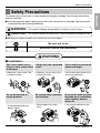 3
3
-
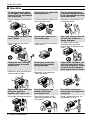 4
4
-
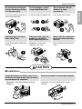 5
5
-
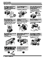 6
6
-
 7
7
-
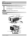 8
8
-
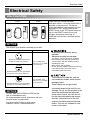 9
9
-
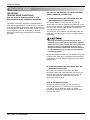 10
10
-
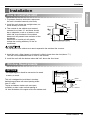 11
11
-
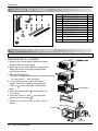 12
12
-
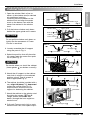 13
13
-
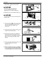 14
14
-
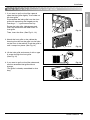 15
15
-
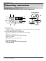 16
16
-
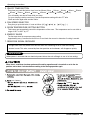 17
17
-
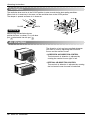 18
18
-
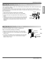 19
19
-
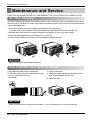 20
20
-
 21
21
-
 22
22
-
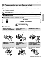 23
23
-
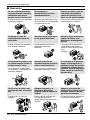 24
24
-
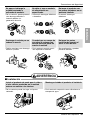 25
25
-
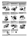 26
26
-
 27
27
-
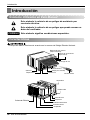 28
28
-
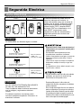 29
29
-
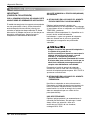 30
30
-
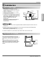 31
31
-
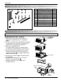 32
32
-
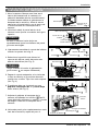 33
33
-
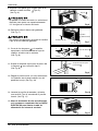 34
34
-
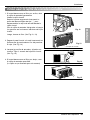 35
35
-
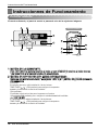 36
36
-
 37
37
-
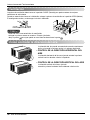 38
38
-
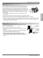 39
39
-
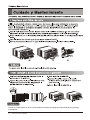 40
40
-
 41
41
-
 42
42
-
 43
43
-
 44
44


LG LW1212HR Guía de instalación
- Tipo
- Guía de instalación
En otros idiomas
- English: LG LW1212HR Installation guide
Documentos relacionados
-
LG Electronics LW7012HR Manual de usuario
-
LG LW7012HR El manual del propietario
-
-
LG LW1812HR El manual del propietario
-
LG LW2410HR El manual del propietario
-
LG LW2416HR El manual del propietario
-
LG LW2414HR El manual del propietario
-
LG M8003R El manual del propietario
-
LG LW1012CR El manual del propietario