
DISHWASHER
INSTAllATIONINSTRUCTIONS
Please read this guide thoroughly
before installation.
To contact LG Electronics, 24 hours a day,
7 days a week:
1-800-243-0000
Or visit us on the Web at: us.lge.com
IMPORTANT SAFETY INSTRUCTIONS
&WARNING
When installing and using your dishwasher, follow basic precautions, including
the following:
• Disconnect electrical power before you start[
• All electrical wiring and grounding must
be done in accordance with national and
local codes.
• If electrical supply is damaged, it must only be
replaced by the manufacturer or its service
agent or a similar qualified person in order to
avoid a hazard.
• This dishwasher must be connected to a
hot water supply between 120°F (49°C)
and 149°F (65°C). This temperature range
provides the best washing results and shortest
cycle time. Temperature should not exceed
149°C (65°F) to prevent damage to dishes.
• This appliance must be positioned near to an
electrical power supply.
• The appliance is to be connected to the water
supply using new hoses. Old hoses should not
be reused.
• Check the dishwasher for any damage before
trying to install it. If you find any damage to
the dishwasher, please contact your dealer
or builder immediately.
GROUNDING INSTRUCTIONS
For a permanently connected dishwasher:
This appliance must be connected to a grounded
metal, permanent wiring system, or an equipment-
grounding conductor must be run with the circuit
conductors and connected to the equipment-
grounding terminal or lead on the appliance.
P/NO. 3828DD3003D

INSTAllATION INSTRUCTIONS
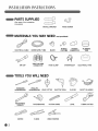
PARTS SUPPLIED
(See page 8 for installation
of bracket)
INSTALL BRACKET WOOD SCREW
MATERIALS YOU
MAY NEED (.otprovided)
ELECTRICALCABLE WATERSUPPLYTUBE ELBOW
o©
FITTINGS
FORTUBE
RUBBER
CONNECTOR
PLUMBERS'
TAPE
TWIST-ON WIRE
AIR GAP CONNECTOR
HOSE CLAMP STRAIN RELIEF ELECTRICAL TAPE
TOOLS YOU WILL NEED
STANDARD PHILLIPS
SCREWDRIVER SCREWDRIVER
HOLE CUTTER ELECTRIC DRILL
ADJUSTABLE
WRENCH
TAPE MEASURE CUTTING KNIFE
GLOVES
LEVEL
SAFETY GLASSES
TUBING CUTTER
NIPPER PLIERS WIRE STRIPPER

INSTAllATION INSTRUCTIONS
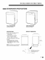
DISHWASHER SPECIFICATIONS
FULL Y INTEGRA TED
LDF6920WW/BB/ST
SEMI-INTEGRATED
LDS4821 WW/BB/ST
SPECIFICATIONS
• Power supply: 120V, 60Hz AC only
• Water Pressure: 20-120 psi
(140-830 kPa)
• Product Dimension (WxDxH):
23 3/4" x 24 5/8" x 33 5/8"
(603 mm x 625 mm x 854 mm)
• Inlet Water Temperature: 120°F (49°C)
• Weight:
Fully Integrated: 90 Ibs. (40.8 kg)
Semi-Integrated: 89 Ibs. (40.5 kg)
Specifications are subject to change
without notice.
NOTE: The features on your dishwasher
may vary from the illustrations shown.
PRODUCT DIMENSIONS
23 3/4" (603 mm)
24 5/8" (625 mm)
%
® •
20 3/8" (518 mm)
32 5/8"
(854 mm)
6 3/4"
(171 mm)
Water supply hose, drain hose
• and electric cable should be
passed through this area
_3" (76 mm)

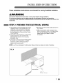
INSTAllATION INSTRUCTIONS
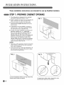
These installation instructions are intended for use by Qualified Installers.
STEP 1: PREPARE CABINET OPENING
1. This dishwasher is designed to fit a standard
dishwasher opening as shown in Fig. 1.
2. Select a location as close to sink as possible for
easy connections to water and drain lines.
3. To ensure proper drainage, the dishwasher
should not be installed more than 10 ft. (3 m)
from the sink.
,
,
If dishwasher is to be installed in a corner, a
minimum of 2 in. (50 mm) is required between
the dishwasher and an adjacent wall.
To allow for proper clearance of plumbing and
electrical, measure a 4" x 7" target area
(Fig. 3) on the side of the cabinet where the
cabinet meets the back wall. Using a 21/2"
diameter hole saw, drill a hole in the target area
within 63/4"of the floor, and no more than 3"
from the back wall. If there is a floor in the
cabinet under the sink, it will also be necessary
to drill or cut through the floor to connect the
water and drain under the sink.
NOTES:
• Failure to cut this opening will result inthe drain
hose interfering with the rear wall, preventing
flush mount installation.
• Ensure that the floor under the dishwasher is at
the same level as the rest of the room to allow
for any service requirements.
FIG. 3
i
,Z
_J
For flush installations ONLY, you may remove the
cabinet brace inside the cabinet. An opening (on either side) is required to route
plumbing and electrical connections.

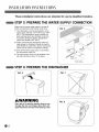
INSTAllATION INSTRUCTIONS
These installation instructions are intended for use by Qualified Installers.
WARNING
For personal safety, remove house fuse or open circuit breaker before installation.
Do not use an extension cord or adapter plug with this dishwasher. Electrical and grounding
connections must comply with the National Electrical Code/provincial and municipal code and/or other
local codes.
STEP 2: PREPARE THE ELECTRICAL WIRING
1. This appliance must be operated with correct
voltage as shown in this manual and on the
rating plate, and connected to a dedicated
properly grounded branch circuit, protected
by a time-delay fuse. Wiring must be 3 wires
including ground.
2. The wiring or cord should be in an accessible
location adjacent to and not behind the
dishwasher and within 4 ft. (1.2 m) of the
dishwasher side.
3. The wiring or cord must be grounded properly.
If in doubt, have it checked by a qualified
electrician. Do NOT connect any other
appliance to the same outlet.
4. The wiring or cord must be routed as shown in
Fig. 4 below.
5. Make sure electrical cable is oriented in the
bottom channels as shown in the figure below.
If you find any damage to the dishwasher,
please contact your dealer or builder
immediately.
NOTE: If you find any damage to the dishwasher, Please contact your dealer or builder immediately.
/
Electrical Cable
\
4 1/2" - 6"
(115 mm - 152 mm)
J

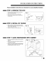
INSTAllATION INSTRUCTIONS
These installation instructions are intended for use by Qualified Installers.
STEP 3: PREPARE THE WATER SUPPLY CONNECTION
Make sure the house water supply is turned off
before connecting the dishwasher water lines.
1. This dishwasher must be connected to a hot
water supply between 120°F (49°C) and 149°F
(65°C). This temperature range provides the
best washing results and shortest cycle time.
To prevent damage to dishes, temperature
should not exceed 149°F (65°C).
2. When connecting the dishwasher water line,
sealing tape or compound should be used on
pipe threads to avoid leaks. Tape or compound
should not be used on compression fittings.
3. Shut off the water supply prior to connecting
the dishwasher water line.
4. The water supply tube must be located in the
left side channel as shown in the figure.
supply line
6-1/2" to 7-3/4"
(165 to 197mm)
STEP 4: PREPARE THE DISHWASHER
FIG. 6 FIG. 7
WARNING
Don't pull or lift with the handle; doing so can
damage the door and hinges. Open door and
grab body frame and top front opening of tub.

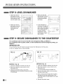
INSTAllATION INSTRUCTIONS
These installation instructions are intended for use by Qualified Installers.
STEP 5: REMOVE TOE KICK
. Remove the two screws attaching the lower
cover to the dishwasher.
* Remove the lower cover from the base.
* Remove the insulation pad from behind the
access panel.
f
FIG. 9
,J
STEP 6: INSTALL 90° ELBOW
When installing the elbow into the inlet valve,
Teflon®tape or pipe joint compound should be
used to avoid water leaks.
Install a 90° elbow onto the water valve.
FFIG. 10
tape
STEP 7: SLIDE DISHWASHER INTO CABINET
• Slide the dishwasher carefully into the cabinet
opening.
• Make sure the drain hose inside the cabinet is
not kinked or pinched.
• Make sure the water supply line and electrical
supply are routed through the channels under
the dishwasher as shown in Fig. 10.
Front of /
dishwasher
_'_"-- Electrical
Water supply
line supply

INSTAllATION INSTF UCTIONS
STEP 8: LEVEL DISHWASHER
1. Make sure that the
dishwasher is level.
Place level on the top
front opening of the
tub from side to side.
3. Make sure that the
gap between the door
and the tub is equal
on both the left and
right sides.
2. Make sure that the
dishwasher is plumb.
Place level on the
front side of the
cabinet.
. Ifthe dishwasher is
not level or the gap on
each side is not equal,
use a wrench to adjust
the 4 leveling feet up
or down until the
dishwasher is level
and the gap on each
side is equal.
STEP 9: SECURE DISHWASHER TO THE COUNTERTOP
For countertops made of wood or that will not be damaged by drilling, use Method 1.
For countertops made of granite, marble, or other materials that could be damaged by drilling, use
Method 2.
IMPORTANT TIPS
• Cover the filter hole with towels to prevent screws from falling down into the pump.
° Use of a magnetic driver is recommended.
FIG. 13
Installation
bracket Screw
METHOD 1 (Fig. 12)
1. Insert the installation brackets into the slot.
2. Bend the brackets to secure them to the
dishwasher tub.
3. Using the provided screws, secure the
dishwasher to the countertop through the holes
in the bracket.
METHOD 2 (Fig. 13)
1. Insert the installation brackets into the slot.
2. Bend the brackets to secure them to the
dishwasher tub.
3. Cut the brackets along the dotted line.
4. Remove the plastic caps on the mounting
bracket access holes.
.
Drive a wood screw through the mounting
bracket and into the cabinet frame. (The
mounting bracket is preinstalled on the side
of the tub.)
6. Reinstall the plastic caps.
J

INSTAllATION INSTRUCTIONS
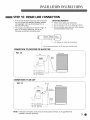
STEP 10: DRAIN LINE CONNECTION
1. If the end of the drain hose does not fit the drain
line, use a heat and detergent resistant adapter
(not supplied). One may be obtained from a
local plumbing shop.
2. The 2 typical connections are shown in Figs. 14
and 15. To prevent siphoning, one of the
following connections should be used.
DRAIN REOUIREMENTS
* Follow local codes and ordinances.
° Do not exceed 10 ft. (3 m) distance to drain.
o Do not connect drain lines from other devices
to the dishwasher drain hose.
For disposal or waste tee connections
Forair gap connections, cut off drain hose at dotted line
CONNECTION TO DISPOSER OR WASTE TEE
f
FIG. 14 Dishwasher
Sink
Drain
Hose
Min. 20" (508 mm)
Min. 30" (770 mm)
Min. 40" (1000 mm) --
CONNECTION TO AIR GAP
FIG. 15
Sink
Air Gap
i
_. Rubber
-- Connector
Dishwasher
J
Min. 20" (508 mm)
Min. 30" (770 mm)
Min. 40" (1000 mm)
NOTE: If the drain connection is less than 20 inches above the floor, an air gap MUST be
installed to prevent siphoning.

INSTAllATION INSTRUCTIONS
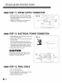
STEP 11: WATER SUPPLY CONNECTION
1. Before connecting, turn off the water supply.
2. After fitting the elbow into the inlet valve, slide
the flexible stainless-steel water line or copper
tube into the elbow.
3. Tighten the compression nut and make sure
that the line is not kinked or pinched.
FIG. 16
Elbow
Water
STEP 12: ELECTRICAL POWER CONNECTION
1. Before beginning, turn off electrical power to the
unit at the circuit breaker.
2. Remove the junction box cover and then install
the strain relief.
3. Twist wire connectors tightly onto the wires;
then wrap each connection with electrical tape.
4. Check again and make sure that all wires are
connected correctly: black to black, white to
white, green ground wire to green ground wire.
5. Replace the junction box cover.
CAUTION
Verify that the black wire is hot (120V). If not, or
if you are unsure of the power supply, have it
checked by a licensed electrician.
f
FIG. 17
Junction box cover
Strain
if
relief _ jk:;_ ' ,) ._.__>
\
___ "_:::-:::- Junction
:, _ box
i i
STEP 13: FINAL CHECK
1. Turn on electrical power.
2. Turn on house water supply.
3. Run the dishwasher on a normal cycle to verify
proper operation and check for leaks.
4. Replace the toekick panel.

[AVAPL IOS
INSIRUCCIONESDEINSIA/AcI
Lea esta guia con detenimiento
antes de la instalacion.
Para contactar LG Electronics, 24 horas
al dfa, 7 dfas a la semana:
1-800-243-0000
O visitenos en la Web en: us.lge.com
fiNSTRUCCIONES DE SEGURIDAD IMPORTANTES
&ADVERTENCIA
Cuando instale o use su lavaplatos, siga precauciones basicas, incluyendo
las siguientes:
• iDesconecte la energ[a electrica antes
de comenzad
• Todo el cableado electrico y la conexion a tierra
debe efectuarse de acuerdo con los c6digos
nacionales y locales.
• Si el suministro electrico esta da_ado, el
fabricante o su agente de servicio tecnico
o una persona calificada similar debe
reemplazarlo a fin de evitar un riesgo.
• Este lavaplatos debe conectarse a un
suministro de agua caliente entre 120°F (49°C)
y 149°F (65°C). Este rango de temperatura
brinda los mejores resultados de lavado y el
ciclo de tiempo mas corto. La temperatura
no debe superar los 149°C (65°F) para evitar
da_os a la vajilla.
• Este aparato debe colocarse cerca de
un suministro de energ[a electrica.
• El aparato debe conectarse al suministro de
agua utilizando mangueras nuevas. No deben
usarse mangueras viejas.
Verifique que el lavaplatos no este da_ado
antes de instalarlo. Si encuentra algOn da_o
en el lavaplatos, comuniquese de inmediato
con su vendedor o constructor.
INSTRUCCIONES DE
CONEXION A TIERRA
Para un lavaplatos conectado en forma
permanente:
Este electrodomestico debe conectarse a un
sistema de cableado permanente con conexi6n a
tierra o debe utilizarse un conductor de conexi6n
a tierra del equipamiento con los conductores
de circuito, y debe conectarse a la terminal de
conexi6n a tierra o conductor del aparato.

INSTRUCCIONESDE INSTAIACION
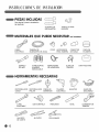
PIEZAS INCLUIDAS
(Ver pagina 8 para la instalacion
del soporte)
SOPORTE DE
INSTALAClON
TORN ILLO PARA
MADERA
MATERIALES QUE PUEDE NECESITAR cnoincluidos)
CABLE TUBERiA DE CODO ACCESORIOS
ELI_CTRICO SUMINISTRO DE AGUA PARA TUBERiA
CONECTOR
DE GOMA
CINTA DE
PLOMERO
ESPAClO CONECTOR DE ABRAZADERA
DE AIRE ALAMBRE DE MANGUERA
ENROSCABLE
ALIVIO DE
TENSION
CINTA AISLANTE
HERRAMIENTAS NECESARIAS
DESTORNILLADOR DESTORNILLADOR
COMON PHILLIPS
FRESA DE
BARRENAR
TALADRO
ELECTRICO
LLAVE
AJUSTABLE
CINTA METRICA TRINCHETA
GUANTES
NIVEL
GAFAS DE
SEGURIDAD
CORTADOR DE
TUBERiA
ALICATES
DE CORTE
ALICATES
PELACABLES

INSTRUCCIONES DE INSTAIACION
ESPECIFICACIONES DEL LAVAPLATOS
TOTALMENTE INTEGRADO
LDF6920WW/BB/ST
SEMI INTEGRADO
LDS4821 WW/BB/ST
ESPECIFICACIONES
• Suministro de energfa: Solo 120V,
60Hz CA
Presion de agua: 20-120 psi
(140-830 kPa)
Dimensiones del producto (AxPxA)
23 3/4" x 24 5/8" x 33 5/8"
(603 mm x 625 mm x 854 mm)
Temperatura de entrada de agua:
120°F (49°C)
Peso:
Totalmente integrado: 90 Ibs. (40.8 kg)
Semi integrado: 89 Ibs. (40.5 kg)
Las especificaciones pueden sufrir
cambios sin previo aviso.
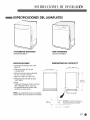
DIMENSIONES DEL PRODUCTO
NOTA: Las caracteristicas de su lavaplatos
pueden diferir de las ilustraciones incluidas.
23 3/4" (603 mm)
Io oo
_TTTTTTTTTTT
24 5/8" (625 mm)
® •
20 3/8" (518 mm)
32 5/8"
(854 mm)
6 3/4"
(171 mm) °t La manguera de suministro de agua, la
manguera de desagQe y el cable el&ctrico
deben pasarse a trav6s de esta area
_3" (76 mm)

INSTF UCCIONESDE INSTAIACION
Estas instrucciones de instalacibn estan dirigidas para el uso
de instaladores calificados.
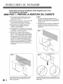
PASO 1: PREPARE LA ABERTURA DEL GABINETE
1. Este lavaplatos esta dise_ado para entrar en
una abertura estandar de lavaplatos como
puede verse en la Fig. 1.
2. Seleccione una ubicacion Io mas cerca posible
de un fregadero para Iograr conexiones
sencillas alas lineas de agua y de desag0e.
3. Para garantizar un desag0e adecuado, el
lavaplatos no debe instalarse a mas de
10 pies (3 m) del fregadero.
4. Si el lavaplatos va a instalarse en una esquina,
se requiere un minimo de 2 pulg. (50 mm) entre
el lavaplatos y la pared adyacente.
5. Para permitir un espacio adecuado para
plomeria y electricidad, mida un Area objetivo
de 4" x 7" (Fig. 3)del lado del gabinete donde
este se une a la pared trasera. Con una sierra
de perforacion de 2 1/2" de diametro, perfore
un orificio en el Area objetivo dentro de 6 3/4"
del piso, y no mas de 3" de la pared trasera.
Si hay un piso en el gabinete bajo el fregadero,
tambien sera necesario perforar o cortar el
piso para conectar el agua y el desag0e bajo
el fregadero.
NOTAS:
• No cortar esta abertura provocara que la
manguera de desag0e interfiera con la pared
trasera, Io que no permitira una instalacion de
montaje a nivel.
° Aseg0rese de que el piso bajo el lavaplatos se
encuentre al mismo nivel que el resto de la
habitacion para permitir requisitos de servicio
posteriores.
Para instalaciones a nivel SOLAMENTE, usted
puede quitar el tirante del gabinete ubicado
dentro del gabinete.
FIG. 3
Se requiere una abertura (en cualquiera de los dos
lados) para dirigir las conexiones de plomeria y de
electricidad.

INSTRUCCIONES DE INSTAIACION
Estas instrucciones de instalacibn estan dirigidas para el uso
de instaladores calificados.
ADVERTENCIA
Para seguridad personal, quite el fusible o abra el interruptor de circuitos antes de comenzar la
instalacibn.
No utilice un cable de extensibn o un enchufe adaptador con este lavaplatos. Las conexiones
el_ctricas y a tierra deben cumplir con el C6digo El_ctrico Nacional/cbdigo provincial y municipal
y/u otros cbdigos locales.
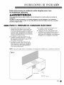
PASO 2: PREPARE EL CABLEADO ELECTRICO
1. Este aparato debe operarse con el voltaje
correcto como se indica en este manual y en
la placa de clasificacion, y debe conectarse
a un circuito derivado dedicado con adecuada
conexi6n a tierra, protegido por un fusible con
retraso. El cableado debe ser de tres alambres
incluyendo la conexi6n a tierra.
2. El cableado o cable debe hallarse en una
ubicaci6n accesible adyacente a y no detras
del lavaplatos y dentro de los 4 pies (1.2 m)
del costado del lavaplatos.
3. El cableado o cable debe contar con una
adecuada conexi6n a tierra. Si tiene alguna
duda, haga que un electricista calificado Io
revise. NO conecte otro electrodomestico
en el mismo tomacorriente.
4. El cableado o cable debe dirigirse como
se indica en la Fig. 4 de abajo.
5. AsegOrese de que el cable electrico este
orientado en los canales inferiores como se
indica en la figura siguiente. Si encuentra
algOn dafio en el lavaplatos, comuniquese de
inmediato con su vendedor o constructor.
NOTA: Si encuentra algOn dafio en el lavaplatos, comuniquese de inmediato con su vendedor o constructor.
FIG. 4
j
Cable electrico
\
4 1/2" - 6"
(115 mm - 152 mm)

INSTRUCCIONESDE INSTAIACION
Estas instrucciones de instalacibn estan dirigidas para el uso
de instaladores calificados.
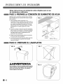
PASO3: PREPARELACONEXIONDESUMINISTRODEAGUA
Verifique que el suministro de agua de la vivienda
este cerrado antes de conectar las lineas de agua
del lavaplatos.
1. Este lavaplatos debe conectarse a un
suministro de agua caliente entre 120°F (49°C) y
149°F (65°C). Este rango de temperatura brinda
los mejores resultados de lavado y el ciclo de
tiempo mas corto. Para evitar dafios a la vajilla,
la temperatura no debe superar los 149°F
(65°C).
2. Cuando conecte la linea de agua del lavaplatos,
debe usarse cinta aislante o compuesto sellador
en las roscas de la tuberia para evitar perdidas.
No debe usarse cinta o compuesto en los
accesorios de compresion.
3. Cierre el suministro de agua antes de conectar
la linea de agua del lavaplatos.
4. La tuberia de suministro de agua debe ubicarse
en el canal del lado izquierdo como puede
verse en la figura.
Suministro
electrico
i " " "n \_
de agua 6 1/2" - 7 3/4"
(165 mm - 197 mm)
PASO4: PREPARE EL LAVAPLATOS
FIG. 7
ADVERTENCIA
No Io levante o tire de la manija; hacerlo puede
dahar la puerta y las bisagras. Abra la puerta y
tome del armaz6n del cuerpo y la abertura
frontal superior del tambor.
_16 _

INSTRUCCIONES DE INSTAIACION
Estas instrucciones de instalacibn estan dirigidas para el uso
de instaladores calificados.
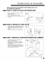
PASO5: QUITE LA PLACADE PROTECCION
Quite los dos tornillos que sujetan la cubierta
inferior al lavaplatos.
Quite la cubierta inferior de la base.
Quite el patio aislante ubicado detras del panel
de acceso.
F/G. 9
Tornillo de
Placa de
protecci6n
PASO 6: INSTALE EL CODO DE 90°
• Cuando instale el codo dentro de la valvula de
entrada, debe usarse cinta Teflon®o compuesto
para juntas de tuberias para evitar perdidas
de agua.
• Instale un codo de 90 ° en la valvula de agua.
f
FIG. 10
_,_Ci nta
Teflon
Codo
J
PASO7: DESLICEELLAVAPLATOSDENTRO DELGABINETE
• Deslice el lavaplatos con cuidado dentro
de la abertura del gabinete.
• AsegQrese de que la manguera de desag0e
ubicada dentro del gabinete no este torcida
ni sufra pellizcos.
• AsegQrese de que la linea de suministro de
agua y el suministro electrico se dirijan a traves
de los canales ubicados debajo del lavaplatos
como puede verse en la Fig. 10.
Frente del /
lavaplatos
Linea de suministro Suministro
electrico
de agua

INSTRUCCIONESDE INSTAIACION
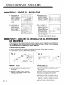
PASO 8: NIVELE EL LAVAPLATOS
,
AsegOrese de que
el lavaplatos este
nivelado. Coloque el
nivel en la abertura
frontal superior del
tambor de lado
a lado.
3. AsegOrese de que
el espacio entre la
puerta y el tambor
sea igual en los lados
izquierdo y derecho.
2. 4.
AsegOrese de que
el lavaplatos este
nivelado en forma
vertical. Coloque el
nivel en el lado
frontal del gabinete.
Si el lavaplatos no
esta nivelado o el
espacio sobre cada
lado no es igual,
utilice una Ilave para
ajustar las 4 patas
de nivelacion hacia
arriba o abajo hasta
que el lavaplatos se
encuentre nivelado
y el espacio sobre cada lado sea igual.
PASO 9: ASEGURE EL LAVAPLATOS AL MOSTRADOR
DE ENCIMERA
Para mostradores de encimera hechos de madera o que no se verbn dahados por la perforacibn,
utilice el M_todo 1. Para mostradores de encimera hechos de granito, mbrmol u otros materiales
que podrian daharse por la perforacibn, utilice el M_todo 2.
CONSEJOS IMPORTANTES
• Cubra el orificio del filtro con toallas para no permitir que caigan tornillos dentro de la bomba.
° Se recomienda el uso de un destornillador magnetico.
f
FIG. 12
i Soporte de
instalaci6n
Tornillo
MI_TODO 1 (Fig. 12)
1. Introduzca los soportes de instalacion en la ranura.
2. Gire los soportes para asegurarlos al tambor
del lavaplatos.
3. Utilizando los tornillos provistos, asegureel
lavaplatos al mostrador de encimera a traves
de los orificios del soporte.
J
F/G. 13
MI_TODO 2 (Fig. 13)
1. Introduzca los soportes de instalacion en la ranura.
2. Gire los soportes para asegurarlos al tambor
del lavaplatos.
3. Corte los soportes a Iolargo de la linea punteada.
4. Quite los tapones plasticos de los orificios
de acceso del soporte de montaje.
5. Introduzca un tornillo para madera a traves del
soporte de montaje y dentro del armazon del
gabinete. (Elsoporte de montaje se encuentre
pre-instalado en el lado del tambor).
6. Vuelvaa instalar lostapones plasticos.

INSTRUCCIONES DE INSTAIACION
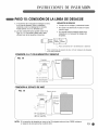
PAsO 10: CONEXION DE LA LiNEA DE DESAGOE
1. Si el extremo de la manguera de desagiJe no entra
en la linea de desagOe,utilice un adaptador
resistente al calory al detergente (no incluido).
Puede obtener uno en su ferreteria local.
2. Las dos conexiones tipicas pueden verse en las
Figs. 14 y 15. Paraevitar el efecto sifon, debe
utilizarseuna de lassiguientes conexiones.
REOUISITOSDE DESAGOE
• Cumpla con los codigos y ordenanzas locales.
• No supere una distancia de 10 pies (3 m) para
drenar el agua.
• No conecte lineas de desagOedesde otros
dispositivos a la manguera de desagOedel
lavaplatos.
Para conexiones en T de eliminaci6n o desecho
Para conexiones de espacio de aire, corte la manguera de desagQe
en la linea punteada
CONEXION A LA T DE ELIMINACION 0 DESECHO
FIG. 14 Lavaplatos
Fregadero Manguera
de
desagQe
Min. 20" (508 mm)
Uin. 30" (770 mm) __1
Min. 40" (1000 mm)
CONEXION AL ESPACIO DE AIRE
F_
FIG. 15
Fregadero
Espacio de aire
Conector
de goma
Lavaplatos
Manguera
de
desagQe
Min. 20" (508 mm)
Uin. 30" (770 mm) __J
Min. 40" (1000 mm)
NOTA: Si la conexion de desagQe es menor a las 20 pulgadas sobre el piso, DEBE instalarse
un espacio de aire para evitar el efecto sifon.

INSTRUCCIONESDE INSTAIACION
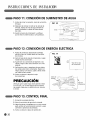
PASO11: CONEXION DE SUMINISTRO DE AGUA
1. Antes de iniciar la conexion, cierre el suministro
de agua.
2. Despues de colocar el codo en la valvula de
entrada, deslice la linea de agua flexible de
acero inoxidable o tuberia de cobre dentro
del codo.
3. Ajuste la tuerca de compresi6n y verifique
que la linea no este torcida o sufra pellizcos.
_FIG. 16
Codo
Lineade
PASO 12: CONEXION DE ENERGiA ELECTRICA
1. Antes de comenzar, desconecte la energfa
electrica hacia la unidad desde el interruptor
de circuitos.
2. Quite la tapa de la caja de conexiones y luego
instale el alivio de tensi6n.
3. Ajuste bien los conectores de alambre a los
cables; luego cubra cada conexi6n con cinta
aislante.
4. Verifique de nuevo y asegQrese de que todos
los cables esten bien conectados: Negro con
negro, blanco con blanco, cable a tierra verde
con cable a tierra verde.
5. Vuelva a colocar la tapa de la caja
de conexiones.
PRECAUCION
Verifique que el cable negro este caliente (120V).
Si no es ad, o si no esterseguro del suministro
de energia, haga que un electricista con licencia
Io revise.
FIG. 17
Tapa de la caja
de conexiones
Alivio de \ .__
tensi6n _ j_ _,L._
_ I ,
' i
\
Caja de
conexiones
PASO13: CONTROLFINAL
1. Encienda la energia electrica.
2. Abra el suministro de agua de la vivienda.
3. Haga funcionar el lavaplatos en un ciclo normal
para verificar el funcionamiento correcto y para
controlar la presencia de perdidas.
4. Vuelva a colocar la placa de proteccion.

NOTES

NOTES

NOTES

P/No. 3828DD3003D
-
 1
1
-
 2
2
-
 3
3
-
 4
4
-
 5
5
-
 6
6
-
 7
7
-
 8
8
-
 9
9
-
 10
10
-
 11
11
-
 12
12
-
 13
13
-
 14
14
-
 15
15
-
 16
16
-
 17
17
-
 18
18
-
 19
19
-
 20
20
-
 21
21
-
 22
22
-
 23
23
-
 24
24


en otros idiomas
- English: LG LDF6920BB Installation guide
Artículos relacionados
Otros documentos
-
Scholtes LFD S3 XL60HZ Operating Instructions Manual
-
Bosch SHX68E15UC/01 Guía de instalación
-
GE DDT575SGF8BB Guía de instalación
-
Haier DWL3025DBBB Guía de instalación
-
GE DDT575SGF0WW Guía de instalación
-
Bosch SHE4AM16UC/03 Guía de instalación
-
Samsung DW80J7550UG/AA-01 Guía de instalación
-
 Kenmore Elite 63016309403 Guía de instalación
-
Kenmore 66513692K600 Guía de instalación
-
Bosch DWHD410HPR/60 Guía de instalación
