Titan Epic 660HPX El manual del propietario
- Categoría
- Rociador de pintura
- Tipo
- El manual del propietario

OWNER'S MANUAL
FOR PROFESSIONAL
USE ONLY
313 - 1229 REV 0498
DO NOT USE EQUIPMENT BEFORE READING THIS MANUAL
Epic
™
660HPX
Epic 660HPX
120V Pump Only - 702-405 120V Complete - 702-410
230V Pump Only - 702-102-CE 230V Complete - 702-104-CE
This manual contains important warnings and instructions.
Please read and retain for reference. Never operate this unit unless it is properly grounded.

PISTON SEAL LUBRICANT
Specially formulated to prevent
materials from adhering to the piston
rod, which becomes abrasive to the
upper seals. Piston Lube will break
down any material that may
accumulate in the wet cup and keep it
from drying.
8 oz individual 700-925
1 qt individual 700-926
8 oz, case of 12 700-911
1 qt, case of 12 700-912
AIRLESS HOSE
I.D. x Length Product No.
1/4" x 25' 316-513
1/4" x 50' 316-505
3/8" x 50' 690-375-50
3/16" x 9' 550-222
3/16" x 15' 550-221
HIGH PRESSURE SWIVELS
Pressure Rated at 5000 psi
Gun-to-Hose
1/4” NPS (F) x 1/4” NPS (M) 500-428
Hose-to-Hose
1/4” NPS (M) x 1/4” NPS(M) 500-424
FITTINGS
1/4" x 1/4" Hose Coupling 490-012
1/4" x 3/8" Hose Coupling 490-016
3/8" x 3/8" Hose Coupling 490-014
T-Fittings, 1/4” x 1/4” 490-036
Tip Filter Retainer 520-046
1/4" Mx1/4"F Swivel Union 490-005
1/4" Mx3/8"F Swivel Union 490-032
Retaining Nut Adapter 490-007
High Pressure Fl. Gauge 730-394
Accessories
LIQUID SHIELD
Cleans and protects spray systems
against rust, corrosion and premature
wear.
Case of 12 (1 quart bottles) 700-888
1 quart 700-889
Table of Contents
Accessories 2
General Repairs/Service 3
Maintenance/Service Record 4
Warnings 5
Aviso (En Español) 6
Attention (En Français) 7
Notice: Fire or Explosion Hazards 8,9,10
Start-up Procedure 10, 11
Application Techniques 12
Cleaning Procedure 13
Airless Tip Selection 13
Troubleshooting
Spray Pattern 13
Airless Gun 13
Airless Pump 14
Flushing Specifications 14
Parts Drawings &
Repair Information 15-25
Low Rider Frame................................. 16
Replacement Labels............................ 17
Armature Replacement........................18
Electrical Schematics...........................20
Motor Housing..................................... 19
Gear Box............................................. 20
Gear Repair......................................... 21
On/Off Switch ......................................21
Motor Starter, Brush
Replacement....................................... 21
Filter Block........................................... 22
Pressure Switch................................... 23
Prime Relief Valve............................... 23
Filter Replacement...............................23
Fluid Section........................................ 24
Syphon Assembly &
Down Tube........................................24
Pump Repair........................................ 25
2
Equipment Job History........................ 26
High Rider Frame.................................27
Skid Frame.......................................... 27
Specifications...................................... 28
Warranty.............................................. 28
U.S. Patents: 3,936,002; 4,220,286;
4,457,472; 4,508,268; 4,494,697;
4,500,119; 4,626,004; 4,611,758;
4,744,571; 4,728,213; 4,768,932;
4,755,638; 4,768,929; 4,840,543;
4,908,538; 5,074,467; 5,425,506
Epic 660HPX

Epic 660HPX
General Repair & Service Notes:
WARNING: Before proceeding, follow the Pressure
Relief Procedure outlined on Page 5. Additionally,
follow all other warnings to reduce the risk of an
injection injury, injury from moving parts or electric
shock. Always unplug the sprayer before servicing!
The following tools are needed when repairing this
sprayer:
Phillips Screwdriver 3/8"Allen Wrench
Needle Nose Pliers 5/16" Allen Wrench
Adjustable Wrench 1/4" Allen Wrench
Rubber Mallet 3/16" Allen Wrench
Flat-blade Screwdriver 1/8" Allen Wrench
1/2" Open End Wrench
1. Before repairing any part of the sprayer, read the
instructions carefully, including all warnings.
2. When disconnecting wires, use needle nose pliers to
separate mating connectors.
CAUTION: Never pull on a wire to disconnect it.
Pulling on a wire could loosen the connector from the
wire.
3. Test your repair before regular operation of the sprayer
to be sure that the problem is corrected. If the sprayer
does not operate properly, review the repair procedure to
determine if everything was done correctly. Refer to the
Troubleshooting Charts to help identify other possible
problems.
4. Make certain that the service area is well ventilated in
case solvents are used during cleaning. Always wear
protective eyewear while servicing. Additional protective
equipment may be required depending on the type of
cleaning solvent. Always contact the supplier of solvents
for recommendations.
5. If you have any further questions concerning your
TITAN Airless Sprayer, call TITAN:
Customer Service Department Tel.1-800-526-5362
Fax 1-800-528-4826
Outside the U.S. Call 1-201-405-7520
Fax 1-201-405-7449
Canada Tel 1-800-565-8665
Fax 1-905-856-8496
120V Pump Only - 702-405 120V Complete - 702-410
230V Pump Only - 702-102-CE 230V Complete - 702-104-CE
3
Syphon Tube
Pressure Control
Return Hose
Add P.S.L. here
(Piston Seal Lubricant)
Fluid Section
Outlet Fitting
Bypass Valve
Paint Filter
Motor
Electrical Box
Figure 1
NOTE: A Repacking Kit (730-401) is available. All parts included
in the kits are listed in the parts list chart on page 24. For best
results use all parts supplied in the Repacking Kit.

Check Motor
Brushes Every
200 Hours
4
Titan Tool is in the business of designing and manufacturing spray systems and accessories that make today’s Painting Professional
become more efficient and profitable. We feel that if you accurately track the maintenance of your equipment on this chart it will
improve the performance of this valuable tool to help you get the most out of your investment.
The chart is easy to follow and to use. The Maintenance Schedule allows for the recording of all your service work and will help you
make sure your unit is always running at peak performance.
Make sure to fill in the boxes at the top of this record with the model number, serial number, date purchased and your company
name. This information will be needed to validate your warranty.
Electric Pump Maintenance Schedule
Service Record
Service Performed
Date Service Center
Cost of Repair
Months in Service
Service Performed
Date Service Center
Cost of Repair
Months in Service
Service Performed
Date Service Center
Cost of Repair
Months in Service
Service Performed
Date Service Center
Cost of Repair
Months in Service
Service Performed
Date Service Center
Cost of Repair
Months in Service
Warranty
Repair
❏ Yes
❏ No
Warranty
Repair
❏ Yes
❏ No
Warranty
Repair
❏ Yes
❏ No
Warranty
Repair
❏ Yes
❏ No
Warranty
Repair
❏ Yes
❏ No
May Be Copied For Field Use
Date
Date Date Date Date
Date
Date Date Date Date
Check Piston Seal Lubricant Level WEEKLY.
EPIC 660HPX
Electric Motor Models
MODEL # SERIAL # DATE PURCHASED COMPANY NAME
Service Performed
Date Service Center
Cost of Repair
Months in Service
Warranty
Repair
❏ Yes
❏ No
Service Performed
Date Service Center
Cost of Repair
Months in Service
Warranty
Repair
❏ Yes
❏ No

An airless spray gun requires that fluid
be introduced to it at very high pressure.
Fluids under high pressure, from spray or
leaks, can penetrate the skin and inject
substantial quantities of toxic fluid into
the body. If not promptly and properly
treated, the injury can cause tissue death
or gangrene and may result in serious,
permanent disability or amputation of the
wounded part. Therefore, extreme
caution must be exercised when using
any airless spray equipment. IF YOU
ARE INJECTED, SEE A PHYSICIAN
IMMEDIATELY. DO NOT TREAT AS A
SIMPLE CUT!
NOTE TO PHYSICIAN:
Injection into
the skin is a serious, traumatic injury. It is
important to treat the injury surgically as
soon as possible. Do not delay treatment
to research toxicity. Toxicity is a concern
with some exotic coatings injected
directly into the bloodstream.
Consultation with a plastic surgeon or a
reconstructive hand surgeon may be
advised.
1) Handle the spray gun carefully.
Keep clear of the nozzle. NEVER point
the gun at yourself or anyone else.
NEVER permit any part of your body to
come in contact with the fluid stream of
either the gun or any hose leak.
ALWAYS keep the gun trigger safety
lever in a locked position when not
spraying. ALWAYS use a tip safety
guard.
2) NEVER attempt to force the flow of
fluid backward through the gun with your
finger, hand or hand-held object against
the gun nozzle. THIS IS NOT AN AIR
SPRAY GUN.
3) NEVER attempt to remove tip,
disassemble or repair equipment without
first doing the following:
4) Before flushing system, always
remove spray tip and adjust fluid
pressure to lowest possible setting.
5) Tighten all fluid connections before
each use. NEVER exceed 3200 psi with
this unit. Make sure that all accessory
hoses, connections, swivels and so forth
can withstand the high pressures which
develop. NEVER exceed the pressure
rating of any component in the system.
6) WARNING: The paint hose can
develop leaks from wear, kinking, abuse,
etc. A leak is capable of injecting fluid into
the skin, therefore the paint hose should
be inspected before each use. NEVER
attempt to plug a hose with any part of
your body, adhesive tape or any other
makeshift device. Do not attempt to
repair a spray hose. Instead, replace it
with a new grounded hose. Use only with
hoses that have spring guards. NEVER
use less than 50' of hose with this unit.
7) Be sure that the airless equipment
being used and the object being sprayed
are properly grounded to prevent static
discharge or sparks which could cause
fire or explosion. WARNING: ALWAYS
hold the gun against metal container
when flushing system with tip removed, to
prevent static discharge. CAUTION: To
reduce the risk of electrical shock, do not
expose to rain. Store indoors.
GROUNDING INSTRUCTIONS: This
product should be grounded. In the event
of an electrical short circuit, grounding
reduces the risk of electric shock by
providing an escape wire for the electric
current. This product is equipped with a
cord having a grounding wire with an
appropriate grounding plug.The plug must
be plugged into an outlet that is properly
installed and grounded in accordance
with all local codes and ordinances.
DANGER - Improper installation of the
grounding plug can result in a risk of
electric shock. If repair or replacement of
the cord or plug is necessary, do not
connect the grounding wire to either flat
blade terminal. The wire with insulation
having an outer surface that is green
(with or without yellow stripes) is the
grounding wire. Check with a qualified
electrician or serviceman if the grounding
instructions are not completely
understood, or if in doubt as to whether
the product is properly grounded. Do not
modify the plug provided; if it will not fit
the outlet, have the proper outlet installed
by a qualified electrician.
• This product is for use on a nominal
120-volt circuit and has a grounding
plug that looks like the plug illustrated
below.
• Make sure that the product is
connected to an outlet having the same
configuration as the plug. No adapter
should be used with this product.
EXTENSION CORDS: Use only a 3-
wire extension cord that has a 3-slot
receptacle that will accept the plug on the
pump. Make sure your extension cord is
in good condition. When using an
extension cord, be sure to use one heavy
enough to carry the current this pump will
draw
.
For lengths less than Use extension gauge
50 ft. (15 meters) 14 AWG
100 ft. (30 meters) 12 AWG
150 ft. (45 meters) 10 AWG
An undersized cord will cause a drop in
line voltage resulting in loss of power and
overheating. If in doubt, use the next
heavier gauge. The smaller the gauge
number, the heavier the cord.
8) ALWAYS keep the working area
around the pump well ventilated.
Additionally, the pump itself should be a
minimum of 25' (7.5m) from the spray
area. If these instructions are not
followed, there is the possibility of fire or
explosion with certain materials.
ALWAYS follow the coating or solvent
manufacturer's safety precautions and
warnings. Never spray flammable
material near open flames, pilot lights or
any source of ignition.
9) ALWAYS wear spray masks and
protective eyewear while spraying.
Additional personal protective equipment
may be required depending on the type of
material being sprayed and conditions of
ventilation. Always contact supplier of
material being sprayed for
recommendation.
10) Keep all extension poles clear of
electrical wires.
11) NEVER alter or modify any part of
this equipment; doing so could cause it to
malfunction.
12) NEVER leave equipment
unattended. Keep away from children or
anyone not familiar with the operation of
airless equipment.
DO NOT USE EQUIPMENT BEFORE READING THIS SECTION
WARNING
HIGH PRESSURE SPRAY
CAN CAUSE SERIOUS INJURY
Maximum Working Pressure 3200 psi, 221 bar
PRESSURE RELEASE PROCEDURE
A. Set trigger safety in a locked position
B. Shut off pump and unplug electrical
cord
C. Release fluid pressure from entire
system and trigger gun
D. Reset trigger safety in a locked position
5

6
Una pistola rociadora sin aire requiere que se
le introduzca líquido a presión muy alta. Los
líquidos bajo presión alta, de la rociadura o de las
fugas, pueden penetrar en la piel e inyectar en el
cuerpo cantidades considerables de líquido
tóxico. Si no se atiende rápida y apropiadamente,
la lesión puede causar muerte del tejido o
gangrena, y puede resultar en incapacidad seria
y permanente o en la amputación de la parte
lesionada. Por lo tanto, hay que emplear
precauciones estrictas al usar cualquier equipo
de rociadura sin aire. SI USTED HA ESTADO
EXPUESTO A LA PENETRACION DE
TOXICOS POR INYECCION, CONSULTE
INMEDIATAMENTE AL MEDICO. ¡NO TRATE
LA HERIDA COMO SI FUERA UNA MERA
CORTADURA!
NOTA PARA EL MEDICO: La penetración de
tóxicos en la piel es una herida seria y
traumática. Es importante tratar la herida
quirúrgicamente lo más pronto posible. No
demore el tratamiento para investigar la
toxicidad. La toxicidad es asunto serio cuando se
trata de la penetración de ciertos revestimientos
tóxicos en la corriente sanguínea. Puede que sea
necesaria la consulta con un cirujano plástico o
un cirujano especialista en la reconstrucción de la
mano.
1) Maneje la pistola de rociadura con cuidado.
Manténgase alejado de la boquilla. JAMAS
apunte la pistola hacia usted u otra persona.
NUNCA permita que parte alguna de su cuerpo
se ponga en contacto con el chorro de líquido de
la pistola o de alguna fuga de la manguera.
SIEMPRE mantenga trabado el seguro de la
pistola mientras no esté rociando. SIEMPRE
utilice el protector de seguridad de la boquilla.
2) JAMAS intente forzar el flujo del líquido por
la pistola hacia atrás con el dedo, la mano o un
objeto sostenido con la mano contra la boquilla
de la pistola, ya que NO SE TRATA DE UNA
PISTOLA DE ROCIADURA DE AIRE.
3) JAMAS intente quitar la boquilla ni
desarmar o reparar el equipo sin haber cumplido
antes con los pasos siguientes:
4) Antes de lavar el sistema, siempre quite la
boquilla de rociadura y ajuste la presión del
líquido al valor más bajo posible.
5) Ajuste todas las conexiones antes de cada
uso. JAMAS supere 3200 libras por pulgada
cuadrada con esta unidad. Asegúrese de que
todas las mangueras, conexiones, articulaciones
giratorias y demás elementos accesorios estén
en condiciones de tolerar las altas presiones que
se presentan. JAMAS exceda la clasificación de
presión de cualquier componente del
sistema.
6) ADVERTENCIA: La manguera de pintura
puede presentar fugas como resultado del
desgaste, retorcimiento, abuso, etc. Las fugas
pueden inyectar líquido a través de la piel, por lo
que la manguera de pintura debe ser
inspeccionada antes de cada uso. JAMAS
intente obturar la manguera con una parte de su
cuerpo o con tela adhesiva o cualquier otro
elemento improvisado. No intente reparar una
manguera de rociadura; en cambio reemplácela
con una manguera nueva conectada a tierra.
Utilice solamente mangueras con protector de
resorte. JAMAS use una manguera de menos de
15,2 m con esta unidad. Almacenar bajo techo.
INSTRUCCIONES PARA LA PUESTA A
TIERRA: Este producto debe conectarse a tierra.
En caso de corto circuito, la conexión a tierra
proporciona una vía de escape para la corriente
eléctrica y reduce el riesgo de choques eléctricos.
El producto está dotado de un cable provisto de
un alambre y de un enchufe de puesta a tierra. El
enchufe debe enchufarse en un tomacorriente
debidamente instalado y dotado de conexión a
tierra, de acuerdo con las estipulaciones de los
códigos y ordenanzas locales.
PELIGRO — La instalación incorrecta del
enchufe de puesta a tierra podría crear el riesgo
de choque eléctrico. Si es necesario reparar o re-
emplazar el cordón o el enchufe, no conecte el
alambre de puesta a tierra a ninguna de las dos
terminales de cuchilla plana. El alambre con
aislamiento exterior verde, con o sin rayas
amarillas, es el alambre de puesta a tierra.
Consulte a un electricista o técnico competente si
no comprende bien las instrucciones para la
conexión a tierra o si tiene dudas de que el
producto está conectado a tierra correctamente.
No modifique el enchufe que viene con el
producto; si no encaja en el tomacorriente, pida a
un electricista competente que instale el
tomacorriente apropiado.
• Este producto ha sido diseñado para usarse en
un circuito de tensión nominal de 120 voltios y
está dotado de un enchufe de puesta a tierra
semejante a la ilustrada más adelante.
• Asegúrese de que el producto esté enchufado
en un tomacorriente que tenga la misma
configuración del enchufe. No debe usarse
ningún adaptador.
CORDON DE EXTENSION — Use sólo un
cordón de extensión trifilar que tenga un enchufe
de puesta a tierra con tres cuchillas, y un
receptáculo con tres ranuras que acepte el
enchufe que viene con el producto. Cerciórese de
que el cordón de extensión esté en buen estado.
Al usar un cordón de extensión, cerciórese de
que sea suficientemente grueso para transportar
la corriente que su producto usará.
Para tramos de menos de: Use cordones de
calibre:
15,2 m 14 AWG
30,4 m 12 AWG
45,7 m 10 AWG
Un cordón demasiado corto provocará una
caída de la tensión, ocasionando una pérdida de
potencia y recalentamiento. Si tiene dudas, use
un calibre más grueso. Cuanto más pequeño sea
el número de calibre, más grueso será el cable.
7) Asegúrese de que el equipo sin aire que
esté empleando y el objeto que se intenta rociar
estén correctamente conectados a tierra para
evitar descargas estáticas o chispas que podrían
ocasionar incendio o explosión. ADVERTENCIA:
Sostenga SIEMPRE la pistola contra el
receptáculo de metal al limpiar el sistema con la
boquilla desprendida, para evitar la descarga
estática. ADVERTENCIA: Para reducir riesgo de
descarga eléctrica, no exponer a la lluvia.
8) SIEMPRE mantenga el lugar de trabajo
alrededor de la bomba bien ventilado. Además, la
bomba en sí debe estar ubicada a no menos de
7,6 m de la operación de rociadura. Si no se
observan estas instrucciones, existe el riesgo de
incendio o explosión con ciertos materiales.
SIEMPRE observe las precauciones y
advertencias de los fabricantes sobre
revestimientos y solventes. Nunca rocíe material
inflamable cerca de llamas expuestas, llamas
piloto o cualquier fuente de ignición.
9) SIEMPRE use máscaras apropiadas y
anteojos de protección durante la operación de
rociadura. Según el tipo de material que se está
rociando y las condiciones de ventilación puede
ser necesario usar equipo personal protector
adicional. Siempre comuníquese con el
proveedor del material para conseguir
recomendaciones.
10) Mantenga todas las varas de extensión
fuera del alcance de cables eléctricos.
11) JAMAS altere o modifique parte alguna de
este equipo, ya que ello puede causar
deficiencias de funcionamiento.
12) JAMAS deje al equipo solo. Manténgalo
fuera del alcance de los niños o de cualquier
persona no familiarizada con la operación de
equipo sin aire.
PROCEDIMIENTO DE
DESCOMPRESION
A. Coloque el seguro de la pistola
en posición trabada.
B. Apague la bomba y desconecte
también el cable de electricidad.
C. Descargue la presión del líquido
de todo el
sistema y de la pistola.
D. Vuelva a trabar el seguro.
NO USE EL EQUIPO ANTES DE LEER ESTA SECCION
ADVERTENCIA
LA ROCIADURA A PRESION ALTA
PUEDE CAUSAR LESION GRAVE.
Presión de Trabajo Máxima 3200 libras por pulgada cuadrada (psi), 221 bar

7
Le liquide introduit dans un pistolet
pulvérisateur sans air doit l’être à pression
extrêmement élevée. Les liquides à haute
pression, en provenance du pulvérisateur ou d’une
fuite quelconque, sont capables de pénétrer la
peau et d’injecter d’importantes quantités de
liquide toxique dans l’organisme. Si elle n’est pas
traitée promptement et avec toute l’attention
voulue, la lésion causée de la sorte peut
provoquer la nécrose des tissus ou la gangrène et
donner lieu à de sérieux handicaps permanents,
voire à l’amputation du membre atteint. Une
prudence extrême s’impose donc lors de
l’utilisation de matériel de pulvérisation sans air.
EN CAS D’INJECTION, CONSULTEZ UN
MEDECIN IMMEDIATEMENT. NE TRAITEZ PAS
LA BLESSURE COMME S’IL S’AGISSAIT
D’UNE SIMPLE COUPURE!
REMARQUE A L’INTENTION DU MEDECIN :
Une injection pénétrant la peau constitue une
lésion traumatique grave qu’il est important de
traiter chirurgicalement aussitôt que possible. Ne
perdez pas de temps à rechercher la toxicité de
l’injection. Il s’agit là d’un risque à envisager en
cas d’injection directe dans le circuit sanguin de
certains revêtements exotiques. La consultation
d’un chirurgien plasticien ou d’un spécialiste de la
chirurgie reconstructive de la main peut être
conseillée.
1) Maniez le pistolet avec soin. Maintenez-vous
à l’écart de la buse. N’en dirigez JAMAIS la buse
vers aucune partie de votre corps ou vers aucune
autre personne. Ne laissez JAMAIS aucune partie
de votre corps entrer en contact avec le flux de
liquide s’échappant du pistolet ou d’une fuite
quelconque au niveau du flexible. Verrouillez
TOUJOURS le levier de sûreté de la détente
lorsque vous n’êtes pas occupé à pulvériser.
Veillez à TOUJOURS utiliser un dispositif de
sûreté à la buse du pistolet.
2) N’essayez JAMAIS de refouler le flux de
liquide dans le pistolet au moyen de votre doigt, de
votre main ou d’un objet maintenu contre la buse
du pistolet. CET APPAREIL N’EST PAS UN
PISTOLET PULVERISATEUR A AIR. N’utilisez
aucune pièce de matériel sans air avec une
pompe non équipée d’une soupape de
surpression.
3) N’essayez JAMAIS d’enlever la buse, de
démonter ou de réparer
l’appareil avant d’avoir accompli la procédure
suivante :
4) Avant de procéder au rinçage du système,
enlevez toujours la buse de pulvérisation et réglez
la pression au niveau le plus faible possible.
5) Serrez bien tous les raccords du système
hydrodynamique avant chaque emploi. Ne
dépassez JAMAIS, avec cet appareil, une
pression de 3200 psi. Assurez-vous que tous les
flexibles accessoires, raccords, articulations, etc.
sont bien capables de résister aux hautes
pressions prévues. Ne dépassez JAMAIS la
capacité de pression nominale d’aucun composant
du système. DANGER : Afin de réduire tout risque
d’électrocution, n’exposez pas à la pluie.
6) ATTENTION : Des fuites risquent de se
produire le long du flexible de peinture sous l’effet
de l’usure, des torsions, des rudes traitements, etc.
auxquels il est éventuellement soumis. Les
injections de liquide dans la peau sont possibles
par la voie de telles fuites. Il est donc important
d’inspecter le flexible avant chaque usage.
N’essayez JAMAIS d’obturer une fuite à l’aide de
votre doigt ou de tout autre membre de votre
corps, de ruban adhésif ou de tout autre moyen de
fortune. N’essayez pas non plus de réparer un
flexible de pulvérisation ; remplacez-le plutôt par
un nouveau flexible mis à la terre. Veillez à
n’utiliser que les flexibles munis de dispositifs de
sécurité à ressort. N’utilisez JAMAIS moins de
15,2 m de flexible avec cet appareil.
7) Assurez-vous que le matériel sans air utilisé
et que l’objet à peindre sont adéquatement mis à
la terre, de façon à éviter toute décharge
d’électricité statique ou toute étincelle susceptible
de provoquer un incendie ou une explosion.
ATTENTION : Tenez TOUJOURS le pistolet
contre un récipient en métal lors du rinçage du
système, après en avoir ôté la buse. Ne vaporisez
JAMAIS de substances inflammables à proximité
de flammes nues, lampes témoin ni d’aucune
source d’allumage. Rangez à l’intérieur.
INSTRUCTIONS DE MISE A LA TERRE : Ce
produit doit être mis à la terre. Dans l’hypothèse
d’un court-circuit électrique, la mise à la terre réduit
le risque de chocs électriques en assurant un fil de
fuite pour le courant électrique. Ce produit est
pourvu d’un cordon possédant un fil de terre avec
fiche appropriée de mise à la terre. La fiche doit
être branchée sur une prise qui est posée et mise
à la terre adéquatement conformément à tous les
codes et règlements locaux.
DANGER - La pose inappropriée de la fiche de
terre peut provoquer un risque de chocs
électriques. Si le cordon ou la fiche doit être réparé
ou remplacé, ne raccordez pas le fil de terre à
l’une ou l’autre borne à lame plate. Le fil possédant
une isolation dont la surface extérieure est verte
(avec ou sans rayures jaunes) est le fil de terre.
Consultez un électricien ou un technicien de
service compétent si vous ne comprenez pas
parfaitement les instructions de mise à la terre ou
si vous ne pouvez affirmer avec certitude que le
produit est dûment mis à la terre. Ne modifiez pas
la fiche fournie ; si elle ne rentre pas dans la prise,
faites poser la prise appropriée par un électricien
compétent.
• Ce produit est destiné à être utilisé sur un circuit
à tension nominale de 120 volts et a une fiche de
terre qui ressemble à la fiche illustrée ci-après.
• S’assurer que le produit est branché sur une
prise ayant la même configuration que la fiche.
Aucun adaptateur ne doit être utilisé avec ce
produit.
CORDONS DE RALLONGE - Utilisez
uniquement un cordon de rallonge à trois fils
pourvu d’une fiche de mise à la terre à trois lames,
et une prise à trois fentes qui acceptera la fiche de
la pompe. Assurez-vous que votre cordon de
rallonge est en bon état. Lorsque vous utilisez un
cordon de rallonge, veillez à en utiliser un
suffisamment puissant pour transporter le courant
que consommera cette pompe.
Pour les longueurs Utilisez une rallonge de
de moins de: calibre:
15,2 m 14 AWG
30,4 m 12 AWG
45,7 m 10 AWG
Un cordon sous-calibré provoquera une chute
de tension secteur ayant pour conséquences une
perte de puissance et une surchauffe. En cas de
doute, utilisez le calibre immédiatement plus
puissant. Plus le numéro de
calibre est bas, plus le cordon est puissant.
8) Le moteur électrique de cet appareil n’est
pas protégé contre les explosions. Il est donc
essentiel d’assurer une bonne ventilation de la
zone de travail et des alentours de la pompe. Il est
également important de maintenir la pompe à une
distance minimale de 7,6 m de la zone de
pulvérisation. Certains matériaux présentent, à
défaut de suivre ces consignes, un risque
d’incendie ou d’explosion. Suivez TOUJOURS les
précautions et avertissements du fabricant de
chaque solvant ou revêtement utilisé.
9) Portez TOUJOURS un masque et des
lunettes de protection lors de vos travaux de
pulvérisation. D’autres articles de protection
personnelle peuvent être nécessaires suivant le
type de produit pulvérisé et les conditions
d’aération. Demandez toujours ses
recommandations à votre fournisseur.
10) Maintenez toutes les tiges de rallonge à
distance des fils électriques.
11) N´altérez ou ne modifiez JAMAIS une
partie quelconque de cet appareil, ce qui pourrait
causer des défaillances.
12) Ne laissez JAMAIS le matériel sans
surveillance. Gardez-le hors de portée des enfants
et de toute personne inexpérimentée quant à
l’usage de matériel sans air.
NE PAS UTILISER LE MATERIEL AVANT D’AVOIR LU CETTE SECTION
ATTENTION!
LES PULVERISATEURS A HAUTE PRESSION PEUVENT
PROVOQUER DE SERIEUSES LESIONS
Pression de travail maximale: 3200 psi — 221 bar
PROCEDURE DE DELESTAGE
DE PRESSION
A. Verrouillez la sûreté de la détente.
B. Arrêtez la pompe et débranchez le
cordon électrique.
C. Délestez la pression dans tout le
système et appuyez sur la détente
du pistolet.
D. Reverrouillez la sûreté de la
détente.

FIRE OR EXPLOSION HAZARD
Static electricity is created by the high velocity of fluid through the pump, hose and tip. If every part of the spray element
is not properly grounded, sparking may occur and the system may become hazardous. Sparking may also occur when
plugging in or unplugging a power supply cord, or starting a gas engine. Sparks can ignite fumes from solvents or the
fluids being sprayed. Always plug the sprayer into an outlet at least 25' (7.5m) away from the spray area. WARNING:
Always flush the unit into a separate metal container with the spray tip removed and the gun held firmly against
the side of the container to assure proper grounding and prevent static discharge which could cause serious
bodily injury.
If you experience any static sparking or slight shock while using this equipment, stop spraying immediately. Check the
entire system for proper grounding. Do not use the system again until the problem has been corrected.
ELECTRIC MOTOR
The electric motors used by TITAN are not explosion proof. Therefore, it is essential to keep the working area
around the pump well ventilated. Additionally, the pump itself should be a minimum of 25' (7.5m) from the spray
area. WARNING: Always keep pump outside of any enclosed spray area. Never clean the exterior of the pump
with any flammable solvents.
GAS ENGINE (Where Applicable)
Always keep pump outside of any enclosed spray area. Keep area around pump well ventilated. Keep all
solvents away from engine exhaust. (Never fill the fuel tank while the engine is running or hot. Fuel spilled on a
hot surface can ignite and cause a fire.) Always attach ground wire located on rear of engine to a grounded
object, i.e. water pipe. NOTE: Refer to engine owner's manual for additional safety and service information.
FLUID SECTION—SOLVENTS
Halogenated Hydrocarbon solvents can cause an explosion when used with aluminum or galvanized components in a
closed (pressurized) fluid system (pumps, heaters, filters, valves, spray guns, tanks, etc.). The explosion could cause
serious injury, death and/or substantial property damage. Cleaning agents, coatings, paints, etc. may contain
Halogenated Hydrocarbon solvents. Titan Tool Inc. spray equipment includes aluminum or galvanized components
and will be affected by Halogenated Hydrocarbon solvents. DO NOT USE HALOGENATED HYDROCARBONS IN
TITAN EQUIPMENT.
EXPLANATION OF THE HAZARD
There are three key elements to the Halogenated Hydrocarbon (HHC) solvent hazard. These elements are:
1. The presence of HHC solvents.
2. Aluminum or galvanized parts.
3. Equipment capable of withstanding pressure.
When all three elements are present, the result can be an extremely violent explosion. The reaction can be sustained
with very little aluminum or galvanized metal: any amount of aluminum is too much. The reaction is unpredictable. Prior
use of an HHC solvent without incident (corrosion or explosion) does NOT mean that such use is safe.
PELIGRO DE INCENDIO O EXPLOSIÓN
La alta velocidad del líquido a través de la bomba, manguera y la boquilla produce electricidad estática. Si algún
componente del equipo de rociadura no está conectado a tierra correctamente pueden producirse chispas y el sistema
se vuelve peligroso. También pueden producirse chispas al enchufar o desenchufar cables eléctricos o al poner en
funcionamiento un motor a gasolina. Las chispas pueden encender los vapores provenientes de los solventes o de los
líquidos rociados. Siempre conecte el rociador a un enchufe ubicado a no menos de 7,5m de distancia de la zona de
rociadura. ADVERTENCIA: Lavar siempre la unidad en un recipiente metálico separado, habiendo quitado la
boca del rociador y teniendo la pistola firmemente contra el lado del recipiente para asegurar una puesta a tierra
correcta y evitar la descarga estática que podría causar lesión corporal grave.
Si ocurren chispas de electricidad estática o si sufre un shock eléctrico ligero mientras usa el equipo, deje de rociar de
immediato. Verifique que el sistema en su totalidad esté conectado a tierra correctamente. No vuelva a usar el sistema
hasta que el problema haya sido resuelto.
MOTOR ELÉCTRICO:
Los motores eléctricos utilizados por TITAN no son a prueba de explosión. Por lo tanto, es esencial mantener el
área de trabajo alrededor de la bomba bien ventilada. Además, la bomba misma debe estar a una distancia
minima de 7,5m del area de rociadura. ADVERTENCIA: Mantener siempre la bomba afuera de cualquier área de
rociadura cerrada. Nunca limpie el exterior de la bomba con solventes inflamables.
8

9
MOTOR A GASOLINA: (Si fuera aplicable)
Siempre mantenga la bomba afuera de cualquier zona de rociadura cerrada. Mantenga el área alrededor de la
bomba bien ventilada. Mantenga todos los solventes lejos del escape del motor. (Nunca liene el tanque de
combustible cuando el motor esté funcionando o caliente. El combustible derramado sobre una superficie
caliente puede encenderse y producir un incendio). El cable a tierra que está ubicado en la parte de atrás del
motor debe estar siempre adherido a un objeto conectado a tierra, por ejemplo, una cañería de agua. NOTA: Vea
el manual de uso del motor para información adicional sobre seguridad y mantenimiento.
SECCION FLUIDO—SOLVENTES
Los solventes a base de hidrocarburos halogenados pueden provocar explosión cuando se usan con componentes
galvanizados o de aluminio en un sistema líquido cerrado (sujeto a presión) (bombas, calefactores, filtros, válvulas,
pistolas de rociadura, tanques, etc.) La explosión podría causar lesiones serias e inclusive la muerte, así como daños
materiales de consideración. Los líquidos de limpieza, revestimientos, pinturas, etc. pueden contener solventes a base
de hidrocarburos halogenados. El equipo de rociadura ofrecido por Titan Tool Inc. tiene componentes galvanizados o de
aluminio y será afectado por solventes a base de hidrocarburos halogenados. NO USE HIDROCARBUROS
HALOGENADOS EN EL EQUIPO TITAN.
EXPLICACION DEL RIESGO
Hay tres elementos fundamentales que condicionan el riesgo de los hidrocarburos halogenados, a saber:
1. Presencia de solventes de hidrocarburos halogenados.
2. Componentes galvanizados o de aluminio.
3. Equipo capaz de tolerar presión.
Cuando todos estos elementos están presentes, el resultado puede ser una explosión sumamente violenta. La reacción
puede tener lugar aun cuando la cantidad de aluminio o metal galvanizado sea muy pequeña: cualquier cantidad de
aluminio es excesiva. La reacción no puede predecirse. El hecho de que un solvente a base de hidrocarburos
halogenados haya sido usado anteriormente sin accidentes (corrosión o explosión) NO significa que dicho uso no es
peligroso.
DANGER!
RISQUE D'INCENDIE OU D'EXPLOSION
La vitesse du liquide à travers la pompe le flexible et la buse produit de l'électricité statique. Si tous les éléments du matériel
de pulvérisation ne sont pas mis à la terre de manière adéquate, ils risquent de favoriser la production d'étincelles et de
rendre le système dangereux. Des étincelles peuvent également se produire lors de branchement ou débranchement d'un
cordon d’alimentation électrique ou lors de la mise en marche d'un moteur au gaz. De telles étincelles sont susceptibles
d'enflammer les vapeurs des solvants ou les liquides pulvérisés. Veillez donc toujours à brancher le pulvérisateur dans une
prise située à au moins 7,5m du pulvérisateur et de la zone de travail. MISE EN GARDE: Toujours rincer l’appareil dans
un récipient métallique distinct après avoir enlevé le bec de pulvérisation et en tenant fermement le pistolet contre
le côté du récipient afin d’assurer une mise à la terre appropriée et de prévenir une décharge statique susceptible
de causer des blessures graves.
Si vous remarquez la formation d'étincelles sous l'effet de la présence d'électricité statique ou que vous ressentez une
légère décharge électrique en cours d'utilisation du matériel, arrêtez immédiatement la pulvérisation. Assurez-vous que tous
les éléments du système sont bien mis à la terre. Ne remettez pas le système en marche avant d'avoir résolu le problème.
MOTEUR ÉLECTRIQUE
Les moteurs électriques utilisés par TITAN ne sont pas protégés contre les explosions. Il est donc essentiel
d'assurer une bonne ventilation de la zone de travail et des environs de la pompe. Il est également important de
maintenir la pompe à une distance minimale de 7,5m de la zone de pulvérisation. ATTENTION: N'introduisez jamais
la pompe dans une zone de pulvérisation fermée. Ne nettoyez jamais nettoyer l'extérieur de la pompe à l'aide de
solvants inflammables.
MOTEUR AU GAZ (le cas échéant)
N'introduisez jamais la pompe dans une zone de pulvérisation fermée. Veillez à ce que les environs de la pompe
soient toujours bien aérés. Ne placez aucun solvant à proximité du système d'échappement du moteur. (Ne
remplissez jamais le réservoir à carburant lorsque le moteur tourne ou s'il est chaud. Renversé sur une surface
chaude, le gaz pourrait s'enflammer et provoquer un incendie.) Veillez à toujours bien raccorder le fil de terre situé
à l'arrière du moteur à un objet mis à la terre (par exemple, une conduite d'eau). REMARQUE: Pour plus de détails
sur les mesures de sécurité et d'entretien pertinentes, consultez le manuel fourni avec le moteur.
SECTION HYDRODYNAMIQUE—SOLVANTS
Les solvants à hydrocarbure halogéné sont explosifs en présence de pièces galvanisées ou en aluminium dans un système
hydrodynamique fermé (pressurisable) (pompes, radiateurs, filtres, soupapes, pistolets pulvérisateurs, réservoirs, etc.)
L'explosion provoquée pourrait donner lieu à des lésions corporelles graves ou même mortelles et/ou à de sérieux

dégâts matériels. Certains produits d'entretien, revêtements, peintures et autres liquides contiennent des solvants à
hydrocarbure halogéné. Les appareils pulvérisateurs de la Titan Tool Inc. comportent des pièces en aluminium et des
composants galvanisés sensibles aux solvants à hydrocarbure halogéné. N’EMPLOYER PAS D’HYDROCARBURES
HALOGÉNÉS DANS LE MATÉRIEL TITAN.
EXPLICATION DU RISQUE
Le danger que présentent les solvants à hydrocarbure halogéné se caractérise par trois éléments clés:
1. La présence de solvants à hydrocarbure halogéné
2. La présence de pièces en aluminium ou galvanisées
3. Un matériel capable de supporter des pressions élevées
La combinaison de ces trois éléments peut donner lieu à une explosion extrêmement violente. La réaction peut se produire
en présence d'une quantité minime d'aluminium ou de métal galvanisé. En fait, la moindre trace d'aluminium en constitue
déjà trop.
La réaction est imprévisible. Toute utilisation antérieure de solvant à hydrocarbure halogéné n'ayant donné lieu à
aucun incident (corrosion ou explosion) NE CONSTITUE NULLEMENT un signe de sécurité.
HALOGENATED SOLVENTS
DEFINITION -- Any hydrocarbon solvent containing any of the elements as listed below:
Consult your material supplier to determine whether your solvent or coating contains Halogenated Hydrocarbon Solvents.
SOLVENTES HALOGENADOS
DEFINICION -- Cualquier solvente a base de hidrocarburos que contenga cualquiera de estos elementos:
EJEMPLOS (lista parcial):
Consulte la información suministrada por su proveedor de materiales para determinar si un solvente o revestimiento
contiene solventes de Hidrocarburos Halogenados.
SOLVANTS HALOGÉNÉS
DÉFINITION -- Tout solvant à hydrocarbure contenant l'un des éléments suivants:
EXEMPLES (liste incomplete):
Pour déterminer si vos solvants ou revêtements contiennent des solvants a hydrocarbure halogéné, consultez votre
fournisseur.
Fluorine (F) "-fluor-" Chlorine (CI) "-chloro-"
Bromine (Br) "-bromo-" Iodine (I) "-Iodo-"
START-UP PROCEDURE
WARNING: High pressure device, thoroughly read and understand the warning section located in the owner's manual and the
label on the sprayer.
IMPORTANT: Whenever starting or cleaning this sprayer, always reduce engine or motor speed. Additionally, never operate
this sprayer for more than 10 seconds without fluid, this can cause unnecessary wear to the packings.
Do not operate dry.
Step 1: Before you plug in the power cord to the electrical outlet or start the gas engine, do the following:
A. Tighten suction and return hoses, then install a minimum of 50' (7.5m) of nylon airless spray hose and airless gun.
Do not install tip yet, or remove if installed. WARNING: If you are supplying your own hoses and spray gun, be sure
they are electrically grounded and rated for at least 3200 psi (221 bar) working pressure, and that the gun has a tip
guard. This is to reduce the risk of serious bodily injury caused by static sparking and fluid injection or
overpressurization, causing a component rupture.
EXAMPLES
(not all-inclusive):
FLUOROCARBON SOLVENTS:
Dichlorofluoromethane
Trichlorofluoromethane
BROMINATED SOLVENTS:
Ethylene dibromide
Methylene chlorobromide
Methyl bromine
IODINATED SOLVENTS:
N-butyl iodide
Methyl iodide
Ethyl iodide
Propyl iodide
CHLORINATED SOLVENTS:
Carbon tetrachloride
Chloroform
Ethylene dichloride
METHYLENE CHLORIDE or
DICHLOROMOETHANE
Monochlorobenzene
Orthodichlorobenzene
Perchloroethylene
TRICHLOROETHANE
Trichloroethylene
Monochlorotoluene
10

B. Preset pressure control by turning the pressure control knob counterclockwise to lowest setting.
C. Place on-off switch in the off position.
D. Be sure to fill the Wet Cup 1/3 full with Piston Seal Lubricant.
Step 2E: ELECTRIC MOTOR
A. Check electrical service. Be sure it is 120V 15 amp minimum and that outlet is properly grounded.
B. Plug electrical cord into a grounded outlet that is at least 25' (7.5m) from the spray area. Make certain that all
extension cords are a three wire, 12 gauge minimum cord with a grounded plug. Never remove third
prong or use an adaptor. Never exceed 150' (45m) of extension cord.
C. If a secondary hose and gun is not installed be sure the plug is secure.
D. Place the suction tube into container containing mineral spirits.
Step 2G: GAS ENGINE (Where Applicable)
A. Check the engine oil level. For instructions refer to the engine manual
supplied.
B. Fill the gas tank. Be sure the engine is cool. Refueling a hot engine
could cause a fire. Close the black fuel shut off lever located under the
air cleaner. Use unleaded high quality gasoline.
C. If a secondary hose and gun is not installed, be sure the plug is secure.
D. Place the suction tube into container containing mineral spirits.
E. Open the fuel shut off lever by pushing it in the direction of the arrow.
F. Move the throttle lever away from fuel tank.
G. Close the engine choke lever, located beneath the air cleaner.
H. Turn the engine switch on. Turn pressure relief prime valve down to
prime position.
I. Pull the starter rope. Holding the frame with one hand, pull the rope
rapidly and firmly. Continue to hold the rope as you let it return. Pull and
return rope until engine starts.
Step 3: Flush oil out of new paint pump: Oil is used by the factory for testing and protection. It is necessary to flush out with
mineral spirits before you begin to spray.
A. Pour 1/2 gallon mineral spirits into a metal container and insert syphon and return tube.
B. Turn pressure relief prime valve down to prime position and turn unit on. Increase pressure slightly. Let solvent
cycle for approximately 30 seconds. Then tilt syphon tube above container and let the sprayer pump itself dry.
Then turn unit off. If you are going to use water based paints, repeat procedure using water.
Step 4: Prepare the paint according to manufacturer's recommendations. Remove any skin that may have formed and stir.
Strain the paint through a fine nylon mesh bag to remove particles that could clog spray tip.
Step 5: Place syphon and return tubes into paint container. Turn pressure relief priming knob, located on side of pump,
down for priming.
Step 6: Turn sprayer on and turn up pressure slightly. Let circulate on prime until no bubbles filter up through the paint.
Step 7: Hold gun firmly against a metal container, disengage trigger lock and trigger gun against side of container. Then,
while gun is triggered, turn the pressure relief valve to the spray position. Keep the gun triggered until all the air is
forced out of the system and the paint flows freely. Release the trigger and engage gun safety lock; set gun down
while unit pressurizes.
Step 8: Check for leaks. If any leaks occur, follow the proper pressure relief procedure before tightening.
Step 9: Turn off sprayer and relieve pressure by turning pressure relief prime knob to prime.
Step 10: With gun trigger lock engaged, install tip and guard as instructed in separate tip or gun manual.
Step 11: Turn sprayer on and rotate the pressure relief prime valve to the spray position.
Step 12: Test on cardboard to check spray pattern. Adjust pressure just until the spray from gun is completely atomized.
11

12
The following techniques, if followed, will assure professional
painting results.
Hold the gun perpendicular to the surface and always at equal
distance from the surface. Depending on the type of material,
surface or desired spray pattern, the gun should be held at a
distance of 12 to 14 inches (30 to 35cm).
Move the gun either across or up and down the surface at a
steady rate. Moving the gun at a consistent speed conserves
material and provides even coverage. The correct spraying
speed allows a full wet coat of paint to be applied without runs
or sags.
Holding the gun closer to the surface deposits more paint on
the surface and produces a narrower spray pattern. Holding the
gun farther from the surface produces a thinner coat and
wider spray pattern. If runs, sags or excessive paint occur,
change to a spray tip with a smaller orifice. Conversely, if
there is an insufficient amount of paint on the surface or you
desire to spray faster, a larger orifice tip should be selected.
APPLICATION TECHNIQUES
If conditions are windy, angle the spray pattern into the wind to
minimize drifting. Work from ground to roof. Do not attempt to
spray if wind is excessive.
For corners and edges, split the center of the spray pattern
on the corner or edge and spray vertically so that both
adjoining sections receive approximate even amounts of
paint.
Maintain uniform spray stroke action. Spray alternately from left
to right and right to left. Begin movement of the gun before the
trigger is pulled.
Avoid arcing or holding the gun at an angle. This will result in
an uneven finish.
Proper Technique
Wrong Technique
When spraying with a shield, hold it firmly against the surface. Angle the spray gun slightly away from the shield and toward the
surface. This will prevent paint from being forced underneath.
Shrubs next to houses should be tied back and covered with a canvas cloth. The cloth should be removed as soon as possible.
Titan Gun Extensions are extremely helpful in these situations.
Nearby objects such as automobiles, outdoor furniture, etc., should be moved or covered whenever in the vicinity of a spray job.
Be careful of any other surrounding objects that could be damaged by overspray.
PROPER LAPPING (overlap of spray pattern) is
essential to an even finish. Lap each stroke. If you are
spraying horizontally, aim at the bottom edge of the
preceding stroke, so as to lap the previous pattern by
50%.

13
Cleaning Procedure
WARNING: High pressure device --
Follow all safety warnings located on
sprayer and in the owner's manual.
Always clean using low pressure,
with the spray tip removed. Always
flush into a separate metal container
away from the sprayer. Never clean
the exterior of the pump while the
pump is plugged in or operating.
PRESSURE RELEASE
PROCEDURE:
Step 1: Engage trigger safety lock on
gun.
Step 2: Turn off pump and release fluid
pressure by turning the pressure relief
prime valve located on the side of pump
down.
LOW PRESSURE CLEANING
PROCEDURE:
Step 3: Remove tip and let soak clean,
in a small container of solvents or water.
Adjust fluid pressure to lowest possible
setting.
Step 4: Turn the pump on. Tilt syphon
tube above paint container, allowing the
sprayer to pump itself dry through the
return tube.
Step 5: Have available container of hot
soapy water if spraying latex (or suitable
solvent for oil base paints). Do not
clean with mineral spirits if using latex
paint as this will make jelly.
Step 6: Place syphon tube into
container with hot soapy water or
solvents. Let circulate for 2-3 minutes,
then turn unit off.
Step 7: To save paint still in spray hose,
turn prime valve up to spray position,
then carefully trigger gun into and
against side of metal paint container.
Be careful of splashing. When cleaning
solution appears, shut off gun and place
gun in a separate metal container.
Repeat process if spraying with two
guns.
Step 8: Trigger gun and let cleaning
solution circulate for approximately 2-3
minutes, then turn unit off.
Step 9: Turn prime valve down and
remove suction tube from cleaning
container. Turn unit on and allow
sprayer to pump dry.
Step 10: Take a clean container of
water or solvent and using low pressure
pump through system until clear. If
cleaning with water, pump a small
amount of mineral spirits or TITAN LS-
10 solution through pump. This will
protect against corrosion.
Step 11: Take suction tube out of
container and let sprayer run itself dry.
Step 12: Check filter on pump and gun.
Clean or replace.
Step 13: Remove spray tip from
solvent, clean with a soft bristle brush
and store in a dry place.
PROBABLE CAUSE
1. Inadequate fluid delivery
2. Fluid not atomizing
3. Insufficient velocity
4. Material too cohesive
5. Tip worn past pump capacity
1. Worn tip
2. Tip may be chipped
1. Plugged, worn or chipped tip
1. Leak in suction tube
2. Not enough hose
3. Tip too large or worn
PROBLEM
Tails
Heavy centered pattern
Distorted pattern
Pattern expanding and
contracting (Surge)
REMEDY
1. Increase pressure
2. Change to smaller tip
3. Clean gun & pump filters
4. Reduce viscosity
5. Replace
1. Replace
2. Replace
1. Clean or replace
1. Tighten
2. Use a minimum of 50'
(15m) of 1/4" high
pressure hose
3. Replace with a new or
smaller tip
TROUBLESHOOTING SPRAY PATTERNS
REMEDY
1. Inspect connections for
air leaks
2. Disassemble and clean
3. Inspect and adjust
4. Inspect and replace
1. Replace
2. Adjust
3. Clean
1. Check fluid supply
2. Clean
3. Replace
PROBABLE CAUSE
1. Air in system
2. Dirty gun
3. Needle assembly out of adjustment
4. Broken or chipped seat
1. Worn or broken needle & seat
2. Needle assembly out of adjustment
3. Dirty gun
1. No paint
2. Plugged filter or tip
3. Broken needle in gun
PROBLEM
Spitting gun
Gun will not shut off
Gun does not spray
TROUBLESHOOTING AIRLESS GUN
Airless Tip Selection
Tips are selected by the orifice size and fan width. The proper
selection is determined by the fan width required for a specific job and
by the orifice size that will supply the desired amount of fluid and
accomplish proper atomization.
For light viscosity fluids, smaller orifice tips generally are desired. For
heavier viscosity materials, larger orifice tips are preferred. Please
refer to the chart below.
Note: Do not exceed the pump's recommended tip size.
The following chart indicates the most common sizes and the
appropriate materials to be sprayed.
.011 - .013 Lacquers & Stains 100 Mesh Filter
.015 - .019 Oil & Latex 50 Mesh Filter
.021 - .026 Heavy Bodied Latex & Blockfillers 5 Mesh Filter
Fan widths measuring 8" to 12" are most preferred because they offer
more control while spraying and are less likely to plug.

14
Flushing
Specifications
1. New Sprayer: Oil is used by the
factory for testing and protection. It
is necessary to flush unit before
spraying.
A. If spraying water-base paint, flush
with mineral spirits followed by
water.
B. If spraying oil-base paint, flush
with mineral spirits only.
2. Changing from water-base to
oil base: Flush with water, then
mineral spirits.
3. Changing from oil-base to
water-base: Flush with mineral
spirits, then water.
4. Changing colors: Flush with a
compatible solvent such as water or
mineral spirits.
5. Storage: To assure proper
performance and long life, always
clean the sprayer thoroughly before
storing.
A. Water-Base Paint: Flush with
water, then mineral spirits and leave
the pump, gun and hose filled with
mineral spirits. Shut off and unplug
the sprayer and turn pressure relief
prime valve to prime to relieve
pressure. Return prime valve to
spray position.
B. Oil-Base Paint: Flush with
mineral spirits. Shut off and unplug
the sprayer, turn the pressure relief
prime valve to prime to relieve
pressure and leave open. Return
prime valve to spray position.
• During storage the power cord
must be coiled around cord holder to
avoid damage.
6. Start-Up After Storage:
A. Water-Base Paint: Flush out
mineral spirits with water.
B. Oil-Base Paint: Flush out the
mineral spirits with the material to be
sprayed.
Always dispose of mineral spirits in a
proper way.
PROBLEM
Electric motor won't run
Gas engine won't start
(where applicable)
Pump won’t prime
Insufficient material flow
Pump will not maintain
pressure
Not enough pressure
Excessive surge at
spray gun
Paint leaks into oil cup
PROBABLE CAUSE
1. Unit unplugged or circuit fuse
blown
2. Pressure setting too low
3. Brushes on motor are worn
4. Electric motor burned out
5. Switch defective
6. Fuse in pump blown
1. Engine switch not on
2. Engine oil level low
3. Out of gas
4. Spark plug cable
disconnected or bad plug
1. Air in line
2. Insufficient pressure
3. Clutch worn or damaged
(Gas models)
1. No paint
2. Syphon strainer clogged
3. Pump/gun filter clogged
4. Pump will not prime, material
too heavy
5. Engine not tuned properly
(Gas)
6. Worn clutch (Gas models)
1. Air leak in system
2. Air leak in syphon tube
3. Inlet valve not seating
4. Worn packings
5. Dirty or worn ball valves
6. Worn valve seats
7. Worn prime valve
1. Pressure setting too low
2. Plugged filters
3. Spray tip too big or worn
4. Engine or motor rpm too low
(Gas)
1. Wrong type of hose
2. Spray tip too big or worn
3. Excessive pressure
1. Worn out packings
REMEDY
1. Check
2. Increase
3. Replace
4. Replace
5. Replace
6. Replace
1. Turn on
2. Try starting engine. If light
on rear glows, add oil
3. Fill
4. Connect or replace
1. Check syphon tube
O-Ring and/or let paint
circulate in prime position
2. Increase pressure
3. Replace
1. Check supply
2. Clean
3. Clean & replace
4. Thin material
5. Tune engine
6. Service
1. Tighten connections
2. Tighten, check for leaks
3. Service or clean
4. Replace
5. Clean or replace
6. Reverse valve seats
7. Replace
1. Increase
2. Clean or replace
3. Change or replace
4. Increase throttle
1. Replace with a minimum
50' grounded nylon braid
high pressure hose
2. Change or replace
3. Decrease pressure and
engine speed
1. Replace
TROUBLESHOOTING AIRLESS PUMP

15
For 230 V
olt Units:
ITEM NO PART NO DESCRIPTION QTY
46 761-725 Power Cord 1
48 770-593 On/Off Plate 1
49 765-083 Toggle Switch 1
50 765-072 Wire 3
51 700-720 230V Fuse 10 Amp 2
54 765-050 Motor Starter 1
313-098 Earth Symbol Label 1
60 765-087 Lock Nut 1
61 765-089 Fuse Block Assembly 1
(See pages 18,19 & 20 for additional and related diagrams.)
NEUTRAL
(BLUE)
FUSES
LINE
(BROWN)
GROUND
(YELLOW-GREEN)
POWER
SWITCH
PRESSURE
SWITCH
MOTOR
240V 50.0 A
SOLID STATE
RELAY
1
2
3
4
NC
Electrical Schematic for 230 Volt Motors
230V Service Instructions
54
51
50
49
48
46
60
61
Figure 3B
Figure 3A
WARNING:
Before proceeding, follow the Pressure Relief
Procedure outlined on Page 5. Additionally, follow all
other warnings to reduce the risk of an injection injury,
injury from moving parts or electric shock. Always unplug
the sprayer before servicing!
On/Off Switch Replacement
1. Remove Cover Plate and screws (#56 & #55). See pg. 20.
2. Disconnect the four wires from the On/Off Switch (#49).
3. Remove the rubber boot and plate (#47 & #48) with a
wrench.
4. Remove the On/Off Switch (#49).
5. Install a new Switch and reattach plate and rubber boot.
Tighten securely.
6. Reconnect the four wires to the new On/Off Switch.
7. Reinstall Switch Cover Plate and screws, with warning
label facing out.
Power Supply Cord Replacement
1. Remove Cover Plate and screws (#55 & #56). See pg. 20.
2. Disconnect the Power Supply Cord (#46) from; a) the
Fuse Holders on #61, and, b) the green wire connected to
the grounding screw (#42). Refer to the Electrical
Schematic, Figure 3A.
3. Loosen the cord grip housing (#45) and remove the power
cord (#46).
4. Install the new cord in reverse order of disassembly.
5. Install the cover and screws with warning label facing out.
Replacement of Motor Starter
1. Remove Cover Plate and screws (#55 & #56). See pg. 20.
2. Disconnect wires, a) the red wires from the pressure
switch, b) the black wire from the motor and, c) the black
wire from the On/Off Switch.
3. Remove screws (#58) and washer and nuts (#52 #53).
4. Replace Motor Starter and re-secure with screws, washer
and nuts (#58, #53 and #52). Always use heat sink material
on the back of the Motor Starter when installing.
5. Reconnect wires according to Figure 3A.
6. Reinstall switch cover and screws, with warning label
facing out.

16
Figure 2
Low Rider Frame Assembly
ITEM NO PART NO DESCRIPTION QTY
117 702-057 Handle 1
118 730-101 Hinge Lock 2
119 702-116 Rear Cross Member 1
120 700-802 Cap Nut 2
121 700-801 1/4” Carriage Bolt 2
122 702-127 Main Frame Right 1
123 710-045 Pin Axle 2
124 710-058 Washer Axle 2
125 702-048 Wheel 2
126 702-087 Spacer 2
127 700-652 Bolt 4
128 710-047 Rubber Boot 2
140 702-126 Main Frame Left 1
141 710-051 Set Screw 2
142 702-061 Axle 1
143 702-060 “Low Rider” Frame 1
Figure 16

17
Epic 660HPX
Syphon Down
Tube for use with
the High Rider
Frame Only
Replacement Labels
PART NO DESCRIPTION QTY
700-418 Front Plate 1
(Front Cover Label)
313-175 “Warning/Attention”
Label in French 1
313-1205 Wraparound Label 1

*
ITEM NO PART NO DESCRIPTION QTY
130 761-023 Screw 2
131 702-046 Rear Cover 1
133 611-405 Snap Ring 1
135 702-040 Outer Fan 1
136 702-045 Rear Motor Housing 1
137 702-047 Wave Washer 1
138 700-681 Screw 2
*139 702-242 Armature 110V 1
For
100 Volt Units:
ITEM NO PART NO DESCRIPTION QTY
139 702-241 Armature 100V 1
For 230 Volt Units:
ITEM NO PART NO DESCRIPTION QTY
139 702-243 Armature 220V 1
Armature Replacement
WARNING: Before proceeding, follow the Pressure
Relief Procedure outlined on Page 5. Additionally,
follow all other warnings to reduce the risk of an
injection injury, injury from moving parts or electric
shock. Always unplug the sprayer before servicing!
1. Remove Rear Cover (#131) by taking out screws
(#130).
2. Remove Snap Ring (#133).
3. Remove Fan (#135).
4. Remove Rear Motor Housing (#136) by removing
screws (#138). NOTE: Make sure to remove Wave
Washer (#137) which should be on the End Bearing of
the Armature.
5. Remove Motor Brushes. Follow Brush replacement
procedure located on page 21.
6. Remove Armature by gently rocking and pulling Fan
from rear of pump.
7. Inspect Armature. If damaged, replace.
8. To replace Armature, reverse steps 1 through 6 here.
Epic 660HPX
18
UNITEC Motor Complete
130
131
133
138
136
135
137
139
Figure 5
*

141
ITEM NO PART NO DESCRIPTION QTY
140 702-404 Outer Housing 1
(Excludes 141)
141 761-244 Screw 1
142 702-084 Motor Field 1
(Excludes 143, 144)
143 700-639 Screws 4
144 702-056 Mounting Stud 2
For 100 Volt Units:
ITEM NO PART NO DESCRIPTION QTY
142 702-211 Motor Field 1
Assembly 100V
For 230 Volt Units:
ITEM NO PART NO DESCRIPTION QTY
142 702-137 Motor Field 1
Assembly 230V
Motor Housing Replacement
WARNING: Before proceeding, follow the Pressure
Relief Procedure outlined on Page 5. Additionally,
follow all other warnings to reduce the risk of an
injection injury, injury from moving parts or electric
shock. Always unplug the sprayer before servicing!
1. Follow steps 1 through 6 in Armature Replacement.
2. Remove Switch cover plate (#56) and Insulator Plate
(#55) located on Page 20.
3. Disconnect black wire from Post (#2) of Motor Starter
(#54).
4. Disconnect black wire from Motor to white wire from
Power Cord.
5. Remove outer Motor Housing (#140).
6. Loosen set screw (#141) and push Motor Field
Assembly (#142) out from the back of the outer Motor
Housing (#140).
7. Inspect Motor Field Assembly (#142). If damaged,
replace.
8. To install Motor Housing, reverse steps 1 through 6
here and steps 1 through 7 of the Armature
Replacement.
19
Epic 660HPX
140
142
144
143
Figure 6

Gear Box
ITEM NO PART NO DESCRIPTION QTY
21 730-260 Screw 19
22 702-053 Brush Plate 2
23 702-039 Brush Insulator 2
24 765-047 Brush Gasket 2
25 702-067 Brush Spring 2
26 702-066 Brush 2
27 700-784 Screw 2
28 700-771 Adjustment Knob 1
29 700-811 O-Ring 1
30 702-079 Oil Seal (#028 O-Ring) 1
31 702-300 Motor Housing 1
(Incl. #29, 30, 59)
32 700-688 Thrust Washer 1
33 730-167 Output Pinion Gear Assy. 1
34 700-514 Thrust Washer 1
35 730-088 Thrust Washer 1
36 700-688 Thrust Washer 2
37 730-360 Crankshaft 1
38 702-073 Pinion Gear 1
39 700-680 Thrust Washer 1
40 702-076 Pump Housing Assembly 1
41 700-681 Screw 4
43 700-791 Safety Plate 1
44 700-418 Front Plate 1
ITEM NO PART NO DESCRIPTION QTY
45 765-063 Cord Grip Assembly 1
46* 765-054 Power Cord 1
47* 700-645 Rubber Boot 1
48* 700-775 On/Off Plate 1
49* 700-646 Toggle Switch 1
50 765-072 Wire, Switch to Starter 1
51* 700-895 Fuse 15 Amp 1
52 700-714 Nut 2
53 700-785 Lock Washer 3
54* 700-657 Motor Starter 1
55 761-192 Insulator Plate 1
56 761-132 Switch Cover Plate 1
57 700-715 Set Screw 1
58 700-713 Screw 2
59 702-014 Grease Seal 1
For 230Volt Units:
ITEM NO PART NO DESCRIPTION QTY
46* 761-725 Power Cord 1
48 770-593 On/Off Plate 1
49 765-083 Toggle Switch 1
50 765-072 Wire 3
51* 700-720 230V Fuse 10 Amp 2
54* 765-050 Motor Starter 1
313-098 Earth Symbol Label 1
60 765-087 Lock Nut 1
61 765-089 Fuse Block Assembly 1
For 100V Units
51 710-050 Fuse 20 Amp
Epic 660HPX
20
21
22
23
24
25
26
27
28
29
31
35
32
33
34
39
40
44
21
43
21
41
37
36
38
36
30
52
21
23
24
27
53
47
57
48
25
22
26
50
51
55
56
54
58
Figure 9
Figure 7
FUSE
100V-20A •
110V-15A •
230V-10A •
45
46
59
21
•
•
•
•
•
•
•
120V Electrical
Schematic
See Figure 7 for the Wiring Diagram.
See page 15 for 230V Service Instructions

Gear Replacement
WARNING: Before proceeding, follow the Pressure
Relief Procedure outlined on Page 5. Additionally,
follow all other warnings to reduce the risk of an
injection injury, injury from moving parts or electric
shock. Always unplug the sprayer before servicing!
1. Remove safety plate (#43).
2. Remove screws (#21) with a 3/16" allen wrench.
3. Slide pump section from crank slide (#300) pg. 24. If
pump section will not slide off, use a screwdriver to pry
pump section down, then slide off.
4. Remove cover (#44).
5. Remove (4) screws #21 with a 3/16" allen wrench.
6. Slide pump housing main assembly (#40) off motor box
housing #31.
7. Inspect gears beginning with crankshaft
assembly(#37). Then, output pinion gear (#33), followed
by pinion gear (#38).
8. Inspect pinion gear on motor armature assembly
(#139) pg. 18 by removing motor as described in motor
replacement section.
9. Reassemble by reversing the above order. When
reassembling, make sure that all washers are in place
and that gears and bearing are properly lubricated.
10. Grease Item #37 every 100 hours. Fitting located
under Plate #44.
11. Grease Item #300 on page 24 every 100 hours.
Fitting located on Item #300 under Plate #44.
On/Off Switch Replacement
WARNING:
Before proceeding, follow the Pressure
Relief Procedure outlined on Page 5. Additionally,
follow all other warnings to reduce the risk of an
injection injury, injury from moving parts or electric
shock. Always unplug the sprayer before servicing!
1. Remove Switch Cover Plate and screws (#56 & #55).
2. Disconnect the two black wires from the On/Off Switch
(#49).
3. Remove the rubber boot and plate (#47 & #48) with a
wrench.
4. Remove the On/Off Switch (#49).
5. Install a new Switch and reattach plate and rubber
boot. Tighten securely.
6. Reconnect the two black wires to the new On/Off
Switch.
7. Reinstall Switch Cover Plate and screws, with warning
label facing out.
Power Supply Cord
Replacement
WARNING: Before proceeding, follow the Pressure
Relief Procedure outlined on Page 5. Additionally,
follow all other warnings to reduce the risk of an
injection injury, injury from moving parts or electric
shock. Always unplug the sprayer before servicing!
1. Remove Switch Cover Plate and screws (#55 & #56).
2. Disconnect the Power Supply Cord (#46) from; a) the
On/Off Switch (#49), b) the white wire connected to the
motor and, c) the green wire connected to the grounding
screw (#42). Refer to the Electrical Schematic, Figure 7.
3. Loosen the cord grip housing (#45) and remove the
power cord (#46).
4. Install the new cord in reverse order of disassembly.
5. Install the cover and screws with warning label facing
out.
Replacement of Motor Starter
WARNING:
Before proceeding, follow the Pressure
Relief Procedure outlined on Page 5. Additionally,
follow all other warnings to reduce the risk of an
injection injury, injury from moving parts or electric
shock. Always unplug the sprayer before servicing!
1. Remove Switch Cover Plate and screws (#55 & #56).
2. Disconnect wires, a) both white/red wires from the
pressure switch, b) the black wire from the motor and, c)
the black wire from the On/Off Switch.
3. Remove screws (#58) and washer and nuts (#52 #53).
4. Replace Motor Starter and resecure with screws,
washer and nuts (#58, #53 and #52). Always use heat
sink material on the back of the Motor Starter when
installing.
5. Reconnect wires according to Figure 7.
6. Reinstall switch cover and screws, with warning label
facing out.
Motor Brush Replacement
WARNING: Before proceeding, follow the Pressure
Relief Procedure outlined on Page 5. Additionally,
follow all other warnings to reduce the risk of an
injection injury, injury from moving parts or electric
shock. Always unplug the sprayer before servicing!
1. Remove Brush Plate (#22).
2. Remover Brush Insulator (#23).
3. Remove Brush Spring (#25). NOTE: To remove brush
spring, push spring down and in for it to release.
4. Back-off screw. Hold Brush Wire and remove Brush.
5. Inspect Motor Brush. If damaged replace.
6. Repeat procedure for other brush.
7. To install Motor Brushes, reverse steps 1 through 6,
NOTE: Never operate this unit without Brush Insulator
and Brush Plate installed.
21

22
Epic 660HPX
Filter Block
ITEM NO PART NO DESCRIPTION QTY
201 710-069 Plug 2
202 702-011 Maxi Filter HSG 1
203 730-083 Filter Spring 1
204 730-067 Filter Cartridge 1
205 757-105 Filter Spring 1
206 702-303 O-Ring 1
207 702-009 Filter HSG 1
210 702-251 Adapter 1
212 730-262 1/4-20 UN Screw 2
214 227-006 1/4” Nipple 1
215 700-537 Gasket 1
216 221-012 Backup Ring 1
217 222-012 O-Ring 1
218 700-246 Bypass Housing 1
(includes #216 & #217)
219* 700-721 #005 O-Ring 1
220 700-250 Bypass Valve Stem 1
222 700-244 Spring 1
224 700-248 Bypass Valve 1
Retainer
225 700-252 Bypass Cam Base 1
226 700-759 Dowel Pin 1
227 700-697 Bypass Valve Handle 1
230 700-258 Bypass Valve Assembly 1
231 702-250 Pressure Control 1
(Includes #232 & #233)
232 700-499 O-Ring 1
233 700-881 Gasket 1
240 702-305 Filter HSG Assembly 1
(Excludes Item #212,
#231, #232, #233, #242)
241 490-106 Elbow 1
242 316-516 Hose 1
* 700-897 Optional PTFE 1
O-Ring
** 700-890 Bypass O-Ring Tool 1
Figure 10
**Supplied but not shown

Pressure Switch Replacement
WARNING: Before proceeding, follow the Pressure Relief
Procedure outlined on page 5. Additionally, follow all
other warnings to reduce the risk of an injection injury,
injury from moving parts or electric shock. Always
unplug the sprayer before servicing!
1. Remove cap screws #212 from bottom of filter block.
2. Remove filter block #240.
3. Remove switch cover plate #56, located near pressure
switch and disconnect two red wires from motor starter
#54. See pg. 20.
4. Remove screw #27 from pressure switch adjustment
knob and slide knob off. See pg. 20.
5. Remove screw #27 located on side of motor housing
#31 and using a 1/8" allen wrench remove set screw
#57, until pressure switch #231 is able to slide down
through. Feed electrical wires down at the same time.
6. Insert new switch assembly #231 into housing while
carefully working the wires into the switch box. Using
needle nose pliers, reconnect wires to motor starter.
7. Making sure that the switch assembly is fully inserted,
tighten set screw #57 with a 1/8" allen wrench until the
switch assembly is secure. Reattach adjustment knob
#28. See pg. 20
8. Inspect O-Rings #232 and 233 on switch assembly. If
properly in place, then install filter block #240 by lining
up dowels. Secure with screws #212.
9. Install insulator plate #55 switch plate #56. See pg. 20
10.The pressure switch is factory calibrated so no
adjustment is required.
Service/Replacement of the
Pressure Relief Prime Valve
WARNING: Before proceeding, follow the Pressure Relief
Procedure outlined on Page 5. Additionally, follow all other
warnings to reduce the risk of an injection injury, injury
from moving parts or electric shock. Always unplug the
sprayer before servicing!
1. Remove the Groove Pin (#226) from Bypass Valve
Handle (#227).
2. Remove Handle (#227) and Bypass Cam (#225).
3. Using a wrench, loosen Bypass Housing (#218) and
unscrew.
4. Unscrew Bypass Retainer (#224) and remove Bypass
Valve Stem (#220).
5. Inspect ball on end of Stem (#220) and O-Ring (#219).
Clean or replace if worn.
6. Screw completed assembly into Filter
Block except for items #225, 226 and 227. Tighten
securely with wrench.
7. Install Bypass Cam (#225) over Bypass Retainer
(#224), lubricate with grease. Line up Groove Pin
on Cam (#225) with hole on Filter Block (#207).
8. Using Groove Pin (#226) line up Stem (#220) with hole
on Handle (#227). Secure Handle with Groove Pin
(#226).
9. IMPORTANT: If Handle (#227) rotates 360° check Pin on
Cam (#225).
Service / Replacement
of Filter
WARNING: Before proceeding, follow the Pressure Relief
Procedure outlined on Page 5. Additionally, follow all other
warnings to reduce the risk of an injection injury, injury
from moving parts or electric shock. Always unplug the
sprayer before servicing!
PUMP FILTER
1. Unscrew Filter Housing (#202).
2. Remove Filter Cartridge (#204). Clean or replace.
3. Inspect O-Ring (#206). Clean or replace.
4. Reattach Filter Housing (#202).
Gun Filter
WARNING:
Follow all safety precautions as described in
high pressure warning section before proceeding. If your
spray gun leaks or spits at the tip when you release the
trigger, the needle or seat is dirty, worn or damaged and
must be cleaned or replaced.
Replacement or Removal of Filter:
1. First pull down on trigger safety guard and swing away
from handle.
2. Unscrew handle from spray head.
3. Unscrew left hand threaded* filter from spray head.
(*NOTE: Left handed thread requires turning the filter
clockwise to remove.)
4. Screw new or cleaned (†) filter into the head.
To reinstall left hand thread turn counterclockwise.
5. Reattach handle to head and secure safety trigger
guard. (NOTE: If filter breaks off in the head use a
small wood screw to remove.)
23
Figure 19 -- (†)For more detail, part number information
and assembly drawings at larger scale, please see the LX -
80 Professional Airless Gun Owner's Manual (#313-012).

24
Fluid Section 660HPX
ITEM NO PART NO DESCRIPTION QTY
300 700-735 Crank & Slide
Connecting Rod Assy. 1
301 730-508 Retainer 1
302 700-587 Upper Guide 1
304 700-603 Upper Seal 1
305 730-505 Pump Housing 1
306 700-678 Head Cap Screw 2
307 700-601 Lower Seal 2
308 730-506 Piston Rod 1
309 762-111 Seal 1
310 762-135 Upper Cage 1
311 762-144 Outlet Valve Ball 1
312 762-073 Outlet Valve Housing 1
313 762-134 Seat 1
314 762-057 O-Ring 1
315 730-515 Piston Assembly 1
317 730-509 Bushing 1
318 700-821 Seal 1
319 730-510 Cage 1
320 762-145 Ball 1
321 762-137 Inlet Valve Seat 1
322 762-058 O-Ring 1
323 730-507 Foot Valve Housing 1
325 730-520 Foot Valve Assembly 1
347 762-202 Packing Tool 1
331 700-211 Pump Syphon Tube 1
332* 700-201 O-Ring (Viton) 1
335 700 213 Pump Syphon Tube Assy. 1
730-401 Repacking Kit: 1
Includes #302, 304, 307, 311,
318, 309, 320
(700-203 Packing Grease and
700-793 Piston Guide Tool
also included)
391 700-804 Gasket 1
392 490-109 Fitting 1
350 730-501 Fluid Section Complete
(#301-305, 307-323) 1
* 700-024 Optional Urethane O-Ring 1
Syphon Assembly
ITEM NO PART NO DESCRIPTION QTY
340 700-206 Syphon Tube
Assembly (#345) 1
341 700-847 Bypass Assembly 1
342 700-204 Syphon Assembly
(Includes #341, 345) 1
343 700-742 Hose Tie Wrap 1
344 700-805 Inlet Screen 1
700-900 Optional
30 Mesh Inlet Screen 1
345 700-212 Clip 1
For High Rider
380 710-018 Syphon Down Tube 1
382 710-046 Inlet Assembly 1
710-191 30 Mesh Screen 1
323 730-511 Housing 1
341 702-239 Bypass Assembly 1
755-109 Pail Hook 1
730-334 Clip Down Tube 1
765-142 Safety Plate 1
350 730-502 Fluid Section Complete 1
(Excludes 391, 392)
391
300
302
304
306
305
307
301
308
309
310
311
313
314
312
318
319
320
321
322
317
323
392
Install smaller
Upper Packing
(700-603)
with raised lip and O Ring
facing down
Install larger
Lower Packings (2)
(700-601)
with raised lip and O Ring
facing up
O RINGS
O RINGS
RAISED
LIP
RAISED
LIP
350
325
315
Figure 10
380
382
323
Syphon Down
Tube for use with
the High Rider
Frame Only
332
331
341
342
340
343
345
344
335

25
Pump Section Repair and
Service
WARNING: Before proceeding, follow the Pressure
Relief Procedure outlined on page 5. Additionally,
follow all other warnings to reduce the risk of an
injection injury, injury from moving parts or electric
shock. Always unplug the sprayer before servicing!
1. Remove Safety Plate (#43). Figure 9.
2. Stop the sprayer at the top of its stroke so that the
piston is in its highest position. Turn off and/or unplug
the sprayer.
3. Remove the bypass hose assembly (#341) with a
wrench and the syphon assembly (#342) by pulling up
on the hose and turn counterclockwise.
4. Tilt pump back for easy access to pump section.
SEAT SERVICE & REPAIR
The design of Titan's Epic Fluid Section allows access to
the inlet and outlet valves and seat without completely
disassembling the Fluid Section. It is possible that the
valves may not seat properly because of debris stuck in
the inlet or outlet seat. Follow the instructions below for
access to those areas.
5. Place a wrench on the Foot Valve (#323) and
unthread.
6. Clean out all debris. Examine Valve and Seat. If
damaged replace. Continue if necessary or reinstall.
7. Place a 3/4" socket on the Outlet Valve Housing and
Seat (#312) and remove.
8. Clean out all debris. Examine Valve and Seat. If
damaged, reverse or replace.
9. Reassemble and test unit. Should unit not perform
properly consult the Troubleshooting Guides on pages
13 &14 of this manual or continue with the Repair and
Packing Replacement instructions below.
SERVICE/REPLACEMENT OF
UPPER (OUTLET) VALVE
10. To clean or replace upper valve, remove Valve
Housing (#312) while piston assembly (#315) is still
attached to pump. This will prevent the piston from
rotating.
11. Remove upper valve case (#310) and Outlet Valve
Seat (#313) & Ball (#311). Clean and inspect along with
Housing (#312). Replace if worn or damaged. Use fine
sandpaper to remove dried paint.
12. Reattach assemblies (#309-#312) to piston #308,
and secure tightly with a wrench.
PACKING REPLACEMENT
13. Remove Outlet Mounting Bolt (#263) from rear of
pump. (As shown in Figure 8, page 22.)
14. Remove screws #306 with a 3/8" allen wrench and
slide pump section down so that the piston is clear to
slide off.
15. Inspect gasket (#391) on fitting after
removing pump section. Clean or Replace.
16. Remove Retainer (#301) and slide piston down
through pump mount assembly (#305) by lightly tapping
on top of piston assembly (#315). Clean and inspect
piston for wear. Replace if necessary.
17. Remove packings (#304 & #307) from pump housing
(#305), and replace with a new set. Always insert
packings with the raised side facing into pump
mount assembly.
18. Reattach Retainer (#301) and make sure that the
upper guide (#302) is cleaned and undamaged.
19. Insert pump housing assembly (#301, #307) into a
vise, leaving enough room to slide piston through bottom
of pump housing (#305).
20. Using the piston guide tool (#346) (included in
repacking kit) which slides over the top of the piston
assembly (#315), insert the piston through bottom of
pump housing (#305) and tap lightly with a rubber mallet
on bottom of piston until inserted.
21. Align flats on piston so that it is perpendicular to
housing (#305) and will line up when reattaching to
connecting rod. This can be achieved by rotating the
piston by placing a wrench on the valve housing
assembly (#312) and turning.
IMPORTANT: NEVER USE A WRENCH ON THE
PISTON ITSELF. THIS COULD CAUSE DAMAGE TO
THE PISTON AND CAUSE LEAKAGE.
22. Slide assembled pump housing with piston assembly
onto connecting rod and secure with screws #306.
Be certain that outlet hole is facing towards pump motor
(#207). NOTE: Packing does not need to
be adjusted.
23. Reattach hose (#242) to fitting (#392) Be sure that
polyethelene gasket (#391) is in place. (See Filter
Block p. 22)
24. Reattach lower foot valve assembly (#325)
25. Reattach pump syphon tube assembly (#335), and
rotate to correct position.
26. Reattach pressure relief tube and syphon hose and
tighten securely.
NOTE: Repacking Kit (730-401) is available. For best results
use all parts supplied in this kit.

26
Job Name Foreman's Name Type of Coating
Date Begun Site Gallons Sprayed
Tips Used Date Completed
QuantitySizes
Job Name Foreman's Name Type of Coating
Date Begun Site Gallons Sprayed
Tips Used Date Completed
QuantitySizes
Job Name Foreman's Name Type of Coating
Date Begun Site Gallons Sprayed
Tips Used Date Completed
QuantitySizes
Job Name Foreman's Name Type of Coating
Date Begun Site Gallons Sprayed
Tips Used Date Completed
QuantitySizes
Job Name Foreman's Name Type of Coating
Date Begun Site Gallons Sprayed
Tips Used Date Completed
QuantitySizes
Job Name Foreman's Name Type of Coating
Date Begun Site Gallons Sprayed
Tips Used Date Completed
QuantitySizes
Job Name Foreman's Name Type of Coating
Date Begun Site Gallons Sprayed
Tips Used Date Completed
QuantitySizes
Job Name Foreman's Name Type of Coating
Date Begun Site Gallons Sprayed
Tips Used Date Completed
QuantitySizes
Job Name Foreman's Name Type of Coating
Date Begun Site Gallons Sprayed
Tips Used Date Completed
QuantitySizes
Job Name Foreman's Name Type of Coating
Date Begun Site Gallons Sprayed
Tips Used Date Completed
QuantitySizes
Job Name Foreman's Name Type of Coating
Date Begun Site Gallons Sprayed
Tips Used Date Completed
QuantitySizes
Job Name Foreman's Name Type of Coating
Date Begun Site Gallons Sprayed
Tips Used Date Completed
QuantitySizes
In order to help you track the superior performance of your Titan Sprayer we recommend you keep this log for your records. We feel you may find it
useful for gauging on-site performance, invoicing or overtime and your estimator's reference.
Equipment Job History
MODEL # SERIAL # DATE PURCHASED COMPANY NAME

27
115V DOMESTIC PUMPS
702-405 660HPX Pump Only
With low rider frame
702-410 660HPX Pump Complete
With low rider frame
702-420 660HPX Pump Only
With high rider frame
702-425 660HPX Pump Complete
With high rider frame
702-43 5 660HPX Pump Only
With skid frame
115V EXPORT PUMPS
702-143-CE 660HPX Pump Complete
With skid frame
702-098-CE 660HPX Pump Only
With low rider frame
702-100-CE 660HPX Pump Complete
With low rider frame
702-107-CE 660HPX Pump Complete
With high rider frame
230V EXPORT PUMPS
702-133-CE 660HPX Pump Only
With skid frame
702-102-CE 660HPX Pump Only
With low rider frame
702-104-CE 660HPX Pump Complete
With low rider frame
702-103-CE 660HPX Pump Only
With high rider frame
702-105-CE 660HPX Pump Complete
With high rider frame
702-174-CE 660HPX Pump Only
With low rider frame & old
syphon
100V EXPORT PUMPS
702-212 660HPX Pump Only
With low rider frame
702-213 660HPX Pump Only
With high rider frame
High Rider Frame Assembly
ITEM NO PART NO DESCRIPTION QTY
200 702-121 Handle 1
201 710-020 Hinge Lock 2
202 700-652 Bolt 4
203 710-058 Axle Washer 2
204 710-044 10” Wheel 2
205 710-194 Snap Ring 2
206 710-199 Leg Plug 2
207 710-198 Brace Plug 2
208 702-141 Main Frame (Incl. 206-10)1
*209 700-761 Cord Holder 1
*210 700-069 Screw 2
211 702-125 High Rider Frame 1
Complete
200
201
205
204
203
202
207
208
211
206
Figure 14
Skid Frame Assembly
ITEM NO PART NO DESCRIPTION QTY
1 700-781 Drip Cup 1
2 700-672 Frame (RT) 1
3 700-671 Frame (L) 1
4 700-674 Caps 4
5 700-652 Carriage Bolts 4
6 700-761 Cord Holder 1
7 700-069 Screw 2
Figure 16
*Not shown
7

TITAN WARRANTY FOR THE 660HPX
Titan Tool, Inc., (“Titan”) warrants that at the time of delivery to the
original purchaser for use (“End User”), the equipment covered by this
warranty is free from defects in material and workmanship. Titan’s
obligation under this warranty is limited to replacing or repairing without
charge those parts which, to Titan’s reasonable satisfaction, are shown
to be defective within twelve (12) months with the exception of defects in
the parts of the pressure control and the drive train/gear box assemblies
which will be repaired or replaced for twenty-four (24) months, and the
electric motor (excluding brush replacement) which will be repaired or
replaced for thirty-six (36) months, all after sale to the End User. This
warranty applies only when the unit is installed and operated in
accordance with the recommendations and instructions of Titan.
This warranty does not apply in the case of damage or wear caused by
abrasion, corrosion or misuse, negligence, accident, faulty installation,
substitution of non-Titan component parts, or tampering with the unit in a
manner to impair normal operation.
Defective parts are to be returned to an authorized Titan sales/service
outlet. All transportation charges, including return to the factory, if
necessary, are to be borne and prepaid by the End User. Repaired or
replaced equipment will be returned to the End User transportation
prepaid.
THERE IS NO OTHER EXPRESS WARRANTY. TITAN HEREBY
DISCLAIMS ANY AND ALL IMPLIED WARRANTIES INCLUDING, BUT
NOT LIMITED TO, THOSE OF MERCHANTABILITY AND FITNESS
FOR A PARTICULAR PURPOSE, TO THE EXTENT PERMITTED BY
LAW. THE DURATION OF ANY IMPLIED WARRANTIES WHICH
CANNOT BE DISCLAIMED IS LIMITED TO THE TIME PERIOD
SPECIFIED IN THE EXPRESS WARRANTY. IN NO CASE SHALL
TITAN LIABILITY EXCEED THE AMOUNT OF THE PURCHASE PRICE.
LIABILITY FOR CONSEQUENTIAL, INCIDENTAL OR SPECIAL
DAMAGES UNDER ANY AND ALL WARRANTIES IS EXCLUDED TO
THE EXTENT PERMITTED BY LAW.
TITAN MAKES NO WARRANTY AND DISCLAIMS ALL IMPLIED
WARRANTIES OF MERCHANTABILITY AND FITNESS FOR A
PARTICULAR PURPOSE WITH RESPECT TO ACCESSORIES,
EQUIPMENT, MATERIALS OR COMPONENTS SOLD BUT NOT
MANUFACTURED BY TITAN. THOSE ITEMS SOLD, BUT NOT
MANUFACTURED BY TITAN (SUCH AS GAS ENGINES, SWITCHES,
HOSES, ETC.) ARE SUBJECT TO THE WARRANTY, IF ANY, OF
THEIR MANUFACTURER. TITAN WILL PROVIDE THE PURCHASER
WITH REASONABLE ASSISTANCE IN MAKING ANY CLAIM FOR
BREACH OF THESE WARRANTIES.
28
PUMP
OPERATING
PRESSURE
MAXIMUM
TIP SIZE
WEIGHT
AMP DRAW
MAX psi
MAXIMUM
GPM OUTPUT
MAXIMUM
HOSE
LENGTH**
POWER
SOURCE
PRODUCT
NUMBER
PUMP ONLY
PRODUCT NO.
COMPLETE
(with 50' Hose &
LX-80 Gun)
440HP
0-3200 psi .021 w/1 gun 27 lbs 9 .44 100 ft 3/4 hp AC
motor
700-155 700-135
447HPX
0-3200 psi .023 w/1 gun 33 lbs 11 .55 150 ft
.85 HP totally
enclosed AC
motor
765-100 765-110
660HPX
0-3200 psi .025 w/1 gun 56 lbs 15 .72 200 ft
1.0 HP totally
enclosed AC
motor
702-405 702-410
690HPG
0-3200 psi .025 w/1 gun 78 lbs -.80 250 ft
4.0 HP
Honda
engine
755-095 755-100
** Hose length depends on material being sprayed, hose diameter and tip size.
*** DP-30 supplied with 25' of hose and a Profit Gun.
DP-30
0-3000 psi .017 w/1 gun 37 lbs 8 .33 100 ft 703-095 703-100
1/2 HP totally
enclosed AC
motor
1100HPX
0-3200 psi
.031 w/1 gun
.021 w/2 guns
90 lbs 15 1.0 300 ft
1.75 HP
totally enclosed
AC motor
781-101 (120v) HR
781-105-CE (230v) HR
781-103 (120v) LR
781-107-CE (230v) LR
781-100 (120v) HR
781-104-CE (230v) HR
781-102 (120v) LR
781-106-CE (230v) LR
.035 w/1 gun
.025 w/2 guns
.019 w/3 guns
1200HPG
0-3200 psi 125 lbs 1.35 300 ft
5.5 HP
Honda
engine
783-101 HR
783-111 LR
783-100 HR
783-110 LR
National Sales & Service
1-800-526-5362
Fax 1-800-528-4826
556 Commerce Street
Franklin Lakes, NJ 07417
Canadian Branch
1-800-565-8665
Fax 1-905-856-8496
200 Towers Road, Unit 7B
Woodbridge, Ontario L4L 5Z8
International
1-201-405-7520
Fax 1-201-405-7449
556 Commerce Street
Franklin Lakes, NJ 07417 USA
© 1998 Titan Tool Inc.
313-1229 Printed in the U.S.A.
REV 0498
Titan and Speeflo are registered trademarks and Epic is a trademark of Titan Tool Inc.
-
 1
1
-
 2
2
-
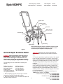 3
3
-
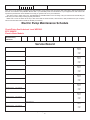 4
4
-
 5
5
-
 6
6
-
 7
7
-
 8
8
-
 9
9
-
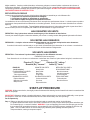 10
10
-
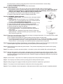 11
11
-
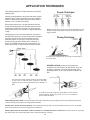 12
12
-
 13
13
-
 14
14
-
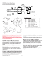 15
15
-
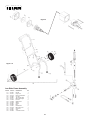 16
16
-
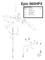 17
17
-
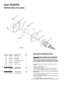 18
18
-
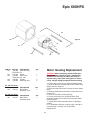 19
19
-
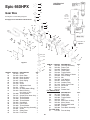 20
20
-
 21
21
-
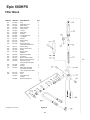 22
22
-
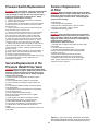 23
23
-
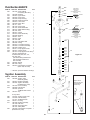 24
24
-
 25
25
-
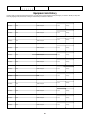 26
26
-
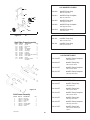 27
27
-
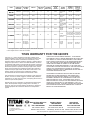 28
28


Titan Epic 660HPX El manual del propietario
- Categoría
- Rociador de pintura
- Tipo
- El manual del propietario
en otros idiomas
- français: Titan Epic 660HPX Le manuel du propriétaire
- English: Titan Epic 660HPX Owner's manual
Artículos relacionados
-
Titan 1200GXC El manual del propietario
-
-
-
-
Titan PowrTwin™ 6900 XLT El manual del propietario
-
-
-
-
-
Otros documentos
-
Ryobi RAP200 El manual del propietario
-
-
PowerStroke PSL1PS11 El manual del propietario
-
HomeRight C800879 Manual de usuario
-
-
Enerpac VE42A Repair Service Instructions
-
 Stenner Pumps SVP4L5 Installation and Maintenance Manual
-
Graymills CLEAN-O-MATIC COM804 El manual del propietario
