
Installation Instructions
Instructions de montage
Instrucciones de montaje
Document No. 129-307
January 21, 2013
OpenAir™ GMA Series
Rotary spring return actuator
Servomoteur à action angulaire avec ressort de rappel
Accionador giratorio de retorno por muelle
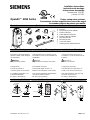
Contents Contenu Contenido
a
b
i
e
g
h
d
c
4.8 x 13
DIN 7981
f
EA0879R3
MANUAL
OVERRIDE
a. Actuator
b. Self-centering shaft adapter
c. Position indicator
d. Shaft adapter locking clip
e. Position indicator adapter
f. Mounting bracket
g. Mounting screws
h. 3 mm hex wrench
i. Auxiliary switch adjustment tool
Hints/Warnings Indications/Mise en garde Indicaciones/Consejos
Keep these instructions together
with the actuator or with the plant
documentation!
Warning:
Do not open the actuator.
Spring preload
Factory set preload: 5°.
Unload by power or mechanical.
For additional information, see
Technical Instructions
EA GMA-1 (155-315P25).
Cette instruction est à conserver avec le
servomoteur ou avec la documentation de
l’installation !
Attention :
Le servomoteur ne doit pas être ouvert.
Précontrainte du ressort
Précontrainte réglée à l’usine : 5°
Remise à zéro électrique ou mécanique.
Pour tout renseignement supplémentaire,
consulter la feuille technique
EA GMA-1 (155-315P25).
¡Conserve las instrucciones con el
accionador o con la documentación de
la planta!
Precaución :
No abra el accionador.
Carga previa del muelle
Valor de fábrica de carga previa: 5°
Vuelta a cero eléctrica o mecánica.
Para más información, véase la hoja
de instrucciones técnicas
EA GMA-1 (155-315P25).
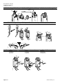
Mounting Position Position de montage Posición de montaje
2A
1A
1
1B
2B
EA0880R1
MANUAL
OVERRIDE
MANUAL
OVERRIDE
EA1045R3
< 45
< 45
90
ASK75.3U
ASK75.3U
IP 54 NEMA 3R
Item Number: 129-307-04, Rev. CA Page 1 of 7

Document No. 129-307
Installation Instructions
January 21, 2013
Limits for Angular Rotation Limites de l’angle de rotation Límites de rotación angular
0
90
90
2
d
1
3
X = steps
X 5
X = 3
0
5
10
15
...
EA1035R1
Shaft Mounting Montage sur l’axe des volets Montaje sobre el eje
f
6
5
2
3
3'
4
4'
1
g
f
EA0884R2
10 mm
7
7'
7.5-9 lb-ft
(10-12 Nm)
7.5-9 lb-ft
(10-12 Nm)
EA0883R2
Manual Override Positionnement manuel Reposición manual
• winding • locking • releasing
• positionner • verrouiller • déverrouiller
• posicionar • enganchar • desenganchar
1
2
3
5
6
7
8
4
HOLD
90º
3 mm
h
x 7-3/4 = 90º
EA0882R2
Page 2 of 7 Siemens Industry, Inc.
La página se está cargando...

Document No. 129-307
Installation Instructions
January 21, 2013
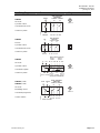
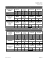
Connecting
Standard
Symbol
Function
Terminal
Designation
Color
Color
Symbol
1 Supply (SP) G Red RD
2 System Neutral G0 Black BK
6 Control signal clockwise Y1 Violet VT
7 Control signal counterclockwise Y2 Orange OG
8 Input Signal: 0-10 Vdc (GMA16x) or 2-10 Vdc (GMA15x) Y Gray GY
24 Vac/dc
Actuator
9 Position Output: 0-10 Vdc (GMA16x) or 2-10 Vdc (GMA15x) U Pink PK
3 Line L Black BK 120 Vac
Actuator
4 Neutral N White WH
S1 Switch A Common Q11 Gray/red GYRD
S2 Switch A N.C. Q12 Gray/blue GYBU
S3 Switch A N.O. Q14 Gray/pink GYPK
S4 Switch B Common Q21 Black/red BKRD
S5 Switch B N.C. Q22 Black/blue BKBU
Auxiliary
Switches
S6 Switch B N.O. Q24 Black/pink BKPK
P1 Feedback Potentiometer 0 to 100% P1 - P2 a White/red WHRD
P2 Feedback Potentiometer Common b White/blue WHBU
Position
indicator
P3 Feedback Potentiometer 100 to 0% P3 - P2 c White/pink WHPK
Câbles de
raccordement
Symbole
Standard
Fonction
Connexion
Bornes
Couleur
Couleur
Abbreviation
1 Alimentation (SP) G Rouge RD
2 Neutre (SN) G0 Noir BK
6 Signal de commande – sens des aiguilles Y1 Violet VT
7 Signal de commande – sens contraire des aiguilles Y2 Orange OG
8 Signal de commande 0…10 V (GMA16x) ou 2…10 V- (GMA15x) Y Gris GY
Servomoteur
24 V~/-
9 Sortie 0 …10 V- (GMA16x) ou 2-10 V- (GMA15x)
pour indicateur de position
U Rose
PK
3 Secteur L Noir BK Servomoteurs
120 V~
4 Neutre N Blanc WH
S1 Commutateur A Commun Q11 Gris/rouge GYRD
S2 Commutateur A N.F. Q12 Gris/bleu GYBU
S3 Commutateur A N.O. Q14 Gris/rose GYPK
S4 Commutateur B Commun Q21 Noir/rouge BKRD
S5 Commutateur B N.F. Q22 Noir/bleu BKBU
commutateurs
auxiliaires
S6 Commutateur B N.O. Q24 Noir/rose BKPK
P1 Potentiomètre réaction 0…100% P1 - P2 a Blanc/rouge WHRD
P2 Potentiomètre réaction Commun b Blanc/bleu WHBU
Indicateur de
position
P3 Potentiomètre réaction 100…0% P3 - P2 c Blanc/rose
WHPK
Conexión
Símbolo
estándar
Función
Terminal
designado
Color
Color
Abreviatura
1 Suministro de corriente (SP) G Rojo RD
2 Sistema neutral G0 Negro BK
6 Señal de control-sentido de las agujas del rejol Y1 Violeta VT
7 Señal de control - sentido contrario a las agujas del reloj Y2 Naranja OG
8 Señal de entrada 0 a 10 V (GMA16x) o 2 a 10V (GMA15x) Y Gris GY
Accionador
24V ca/cc
9 Salida de 0 a 10V cc (GMA16x) o 2 a 10V cc (GMA15x)
para indicador de posición
U Rosado PK
3 Línea L Negro BK Accionador
120V ca
4 Neutro N Blanco WH
S1 Conmutador A Común Q11 Gris/rojo GYRD
S2 Conmutador A N.C. Q12 Gris/azul GYBU
S3 Conmutador A N.A. Q14 Gris/rosado GYPK
S4 Conmutador B Común Q21 Negro/rojo BKRD
S5 Conmutador B N.C. Q22 Negro/azul BKBU
Conmutadores
auxiliares
S6 Conmutador B N.A. Q24 Negro/rosado BKPK
P1 Potenciómetro de realimentación 0 a 100% P1 - P2 a Blanco/rojo WHRD
P2 Potenciómetro de realimentación común b Blanco/azul WHBU
Indicador de
posición
P3 Potenciómetro de realimentación 100 a 0% P3 - P2 c Blanco/rosado WHPK
Page 4 of 7 Siemens Industry, Inc.
La página se está cargando...

Document No. 129-307
Installation Instructions
January 21, 2013
Page 6 of 7 Siemens Industry, Inc.
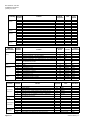
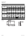
Alambrado de retrofit
Siemens
GMA Serie
Belimo
LF Serie
NF Serie
Honeywell
MS7505 Serie
Johnson
M9208 Serie
Control modulador
(0 to 10 Vdc)
Función
Color Número Color Número Color Número Color Número
Alimento (24V) Rojo 1 Rojo 2 Rojo 1 Rojo 2
Común Negro 2 Negro 1 Negro 2 Negro 1
0(2) to 10 Vdc Entrada Gris 8 Blanco 3 Blanco 3 Gris 3
0(2) to 10 Vdc
Realimentacion
Rosado 9 Naranja 5 Azul 5 Naranja 4
Siemens
GMA Serie
Belimo
LF Serie
NF Serie
Honeywell
MS8105 Serie
Johnson
M9208 Serie
Control de 2 posciones
(24 Vac/Vdc)
Función
Color Número Color Número Color Número Color Número
Alimento (24V) Rojo 1 Rojo 2 Rojo 1 Rojo 2
Común Negro 2 Negro 1 Negro 2 Negro 1
Siemens
GMA Serie
Belimo
LF Serie
NF Serie
Honeywell
MS4105 Serie
Johnson
M9208 Serie
Control de 2 posciones
(120 Vac)
Función
Color Número Color Número
Terminal
Sólo
Número Color Número
Línea (120V) Negro 3 Negro 2 1 Negro 2
Neutro Blanco 4 Blanco 1 2 Blanco 1
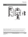
Dimensions Dimensions Dimensiones
Weather Shield
ASK75.3U
Inches (mm)
2-31/32
(75,8)
12-7/16
(315,5)
3-3/4
(95,3)
1-3/8
(35)
7
(177,8)
∅
1.04
(26,5)
OPENING FOR
STANDARD 1/2"
CONDUIT
CONNECTOR (2)
EA1017R3
La página se está cargando...
Transcripción de documentos
Installation Instructions Instructions de montage Instrucciones de montaje Document No. 129-307 January 21, 2013 Rotary spring return actuator Servomoteur à action angulaire avec ressort de rappel Accionador giratorio de retorno por muelle Contenu Contenido OpenAir™ GMA Series Contents i d b a. b. c. d. e. f. g. h. i. h 4.8 x 13 DIN 7981 MANUAL OVERRIDE g e a c Actuator Self-centering shaft adapter Position indicator Shaft adapter locking clip Position indicator adapter Mounting bracket Mounting screws 3 mm hex wrench Auxiliary switch adjustment tool EA0879R3 f Hints/Warnings Indications/Mise en garde Indicaciones/Consejos Keep these instructions together with the actuator or with the plant documentation! Cette instruction est à conserver avec le servomoteur ou avec la documentation de l’installation ! ¡Conserve las instrucciones con el accionador o con la documentación de la planta! Warning: Do not open the actuator. Attention : Le servomoteur ne doit pas être ouvert. Precaución : No abra el accionador. Spring preload Factory set preload: 5°. Précontrainte du ressort Précontrainte réglée à l’usine : 5° Carga previa del muelle Valor de fábrica de carga previa: 5° Unload by power or mechanical. Remise à zéro électrique ou mécanique. Vuelta a cero eléctrica o mecánica. For additional information, see Technical Instructions EA GMA-1 (155-315P25). Pour tout renseignement supplémentaire, consulter la feuille technique EA GMA-1 (155-315P25). Para más información, véase la hoja de instrucciones técnicas EA GMA-1 (155-315P25). Mounting Position Position de montage Posición de montaje 1 1A 1B 2A 5 <4 90 5 2B ASK75.3U MANUAL OVERRIDE MANUAL OVERRIDE ASK75.3U IP 54 NEMA 3R EA0880R1 EA1045R3 <4 Item Number: 129-307-04, Rev. CA Page 1 of 7 Document No. 129-307 Installation Instructions January 21, 2013 Limits for Angular Rotation Limites de l’angle de rotation Límites de rotación angular X=3 d 2 X = steps 0 1 X 5 15 ... 10 5 90 EA1035R1 90 3 Shaft Mounting 0 Montage sur l’axe des volets Montaje sobre el eje 1 4' 4 3' 3 2 7 7' 7.5-9 lb-ft 7.5-9 lb-ft (10-12 Nm) (10-12 Nm) EA0883R2 10 mm f EA0884R2 g f 6 5 Manual Override Positionnement manuel • winding • positionner • posicionar • locking • verrouiller • enganchar Reposición manual • releasing • déverrouiller • desenganchar 90º x 7-3/4 = 90º 3 6 HOLD 2 1 7 8 5 3 mm h EA0882R2 4 Page 2 of 7 Siemens Industry, Inc. Document No. 129-307 Installation Instructions January 21, 2013 Connecting Standard Symbol 24 Vac/dc Actuator 1 2 6 7 8 9 3 4 S1 S2 S3 S4 S5 S6 P1 P2 P3 120 Vac Actuator Auxiliary Switches Position indicator Câbles de raccordement Servomoteur 24 V~/- Servomoteurs 120 V~ commutateurs auxiliaires Indicateur de position Symbole Standard 1 2 6 7 8 9 3 4 S1 S2 S3 S4 S5 S6 P1 P2 P3 Conexión Símbolo estándar Accionador 24V ca/cc 1 2 6 7 8 9 Accionador 120V ca Conmutadores auxiliares Indicador de posición Page 4 of 7 3 4 S1 S2 S3 S4 S5 S6 P1 P2 P3 Terminal Designation Function Supply (SP) System Neutral Control signal clockwise Control signal counterclockwise Input Signal: 0-10 Vdc (GMA16x) or 2-10 Vdc (GMA15x) Position Output: 0-10 Vdc (GMA16x) or 2-10 Vdc (GMA15x) Line Neutral Switch A Common Switch A N.C. Switch A N.O. Switch B Common Switch B N.C. Switch B N.O. Feedback Potentiometer 0 to 100% P1 - P2 Feedback Potentiometer Common Feedback Potentiometer 100 to 0% P3 - P2 G G0 Y1 Y2 Y U L N Q11 Q12 Q14 Q21 Q22 Q24 a b c Alimentation (SP) Neutre (SN) Signal de commande – sens des aiguilles Signal de commande – sens contraire des aiguilles Signal de commande 0…10 V (GMA16x) ou 2…10 V- (GMA15x) Sortie 0 …10 V- (GMA16x) ou 2-10 V- (GMA15x) pour indicateur de position Secteur Neutre Commutateur A Commun Commutateur A N.F. Commutateur A N.O. Commutateur B Commun Commutateur B N.F. Commutateur B N.O. Potentiomètre réaction 0…100% P1 - P2 Potentiomètre réaction Commun Potentiomètre réaction 100…0% P3 - P2 Suministro de corriente (SP) Sistema neutral Señal de control-sentido de las agujas del rejol Señal de control - sentido contrario a las agujas del reloj Señal de entrada 0 a 10 V (GMA16x) o 2 a 10V (GMA15x) Salida de 0 a 10V cc (GMA16x) o 2 a 10V cc (GMA15x) para indicador de posición Línea Neutro Conmutador A Común Conmutador A N.C. Conmutador A N.A. Conmutador B Común Conmutador B N.C. Conmutador B N.A. Potenciómetro de realimentación 0 a 100% P1 - P2 Potenciómetro de realimentación común Potenciómetro de realimentación 100 a 0% P3 - P2 Red Black Violet Orange Gray Pink Black White Gray/red Gray/blue Gray/pink Black/red Black/blue Black/pink White/red White/blue White/pink Connexion Bornes Fonction Función Color Couleur Color Symbol RD BK VT OG GY PK BK WH GYRD GYBU GYPK BKRD BKBU BKPK WHRD WHBU WHPK Couleur Abbreviation G G0 Y1 Y2 Y U Rouge Noir Violet Orange Gris Rose RD BK VT OG GY L N Q11 Q12 Q14 Q21 Q22 Q24 a b c Noir Blanc Gris/rouge Gris/bleu Gris/rose Noir/rouge Noir/bleu Noir/rose Blanc/rouge Blanc/bleu Blanc/rose BK WH GYRD GYBU GYPK BKRD BKBU BKPK WHRD WHBU WHPK Color Color Abreviatura Terminal designado PK G G0 Y1 Y2 Y U Rojo Negro Violeta Naranja Gris Rosado RD BK VT OG GY PK L N Q11 Q12 Q14 Q21 Q22 Q24 a b c Negro Blanco Gris/rojo Gris/azul Gris/rosado Negro/rojo Negro/azul Negro/rosado Blanco/rojo Blanco/azul Blanco/rosado BK WH GYRD GYBU GYPK BKRD BKBU BKPK WHRD WHBU WHPK Siemens Industry, Inc. Document No. 129-307 Installation Instructions January 21, 2013 Alambrado de retrofit Siemens GMA Serie Control modulador (0 to 10 Vdc) Función Alimento (24V) Común 0(2) to 10 Vdc Entrada 0(2) to 10 Vdc Realimentacion Color Número Color Número 1 2 8 9 Rojo Negro Blanco Naranja 2 1 3 5 Siemens GMA Serie Color Rojo Negro Belimo LF Serie NF Serie Número 1 2 Color Color Negro Blanco Dimensions 3 4 Color Negro Blanco Dimensions Weather Shield ASK75.3U 2 1 Belimo LF Serie NF Serie Número Color Rojo Negro Blanco Azul Johnson M9208 Serie Número Color Número 1 2 3 5 Rojo Negro Gris Naranja 2 1 3 4 Honeywell MS8105 Serie Número Rojo Negro Siemens GMA Serie Control de 2 posciones (120 Vac) Función Línea (120V) Neutro Honeywell MS7505 Serie Rojo Negro Gris Rosado Control de 2 posciones (24 Vac/Vdc) Función Alimento (24V) Común Belimo LF Serie NF Serie Color Rojo Negro Johnson M9208 Serie Número 1 2 Honeywell MS4105 Serie Número 2 1 Terminal Sólo Color Rojo Negro Número 2 1 Johnson M9208 Serie Número 1 2 Color Negro Blanco Número 2 1 Dimensiones 2-31/32 (75,8) Inches (mm) EA1017R3 7 (177,8) Page 6 of 7 OPENING FOR STANDARD 1/2" CONDUIT CONNECTOR (2) ∅ 1.04 (26,5) 12-7/16 (315,5) 3-3/4 (95,3) 1-3/8 (35) Siemens Industry, Inc.-
 1
1
-
 2
2
-
 3
3
-
 4
4
-
 5
5
-
 6
6
-
 7
7


Siemens Building Technologies OpenAir GMA Serie Guía de instalación
- Tipo
- Guía de instalación
- Este manual también es adecuado para
en otros idiomas
Otros documentos
-
Siemens GPC166.1P Damper Actuator Manual de usuario
-
-
sauter MV 505954 Fitting Instruction
-
Carel Blast Chiller pCO3 Small Technical Leaflet
-
sauter AVM322 Assembly Instructions
-
-
Genius JA105 Instrucciones de operación
-
ENFORCER SD-7202GC-PEQ Guía de instalación
-
 ENFORCER SD-7103GC-PTQ Guía de instalación
-
SECO-LARM SD-7103GC-PTQ El manual del propietario
