Vetus Up/Down remote panel P102983 Guía de instalación
- Tipo
- Guía de instalación

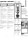
85 (3
3
/
8
”)
85 (3
3
/
8
”)
7 (
1
/
4
”) 78 (3
1
/
16
”)
ø 75 (2
15
/
16
”)
Min. 3 (
1
/
8
”),
max. 25 (1”)
WINDLASS
NEDERLANDS
Gebruik
VOORZICHTIG!
Indien 2 bedieningspanelen zijn geïnstalleerd; bedien de
ankerlier dan nooit gelijktijdig vanaf beide panelen.
- Schakel de hoofdschakelaar in
- Inschakelen paneel:
Druk tweemaal achter elkaar op de aan/uit toets.
Na de eerste keer zal de LED groen knipperen en de zoemer
voortdurend een signaal (.‑.‑.‑.‑.‑.‑.) geven. Binnen 6 secon‑
den moet de aan/uitschakelaar voor de tweede keer worden
ingedrukt. De LED zal nu groen gaan branden; de zoemer
bevestigd met een signaal (‑‑.‑‑) dat het paneel gereed is voor
gebruik.
- Richtingsschakelaar:
Met de richtingsschakelaar wordt de elektromotor bediend.
- Uitschakelen paneel:
Druk na gebruik van de ankerlier eenmaal op de aan/uit
schakelaar. Het paneel laat een signaal horen (.‑.‑.‑‑‑.‑‑).
N.B. 30 minuten nadat de richtingsschakelaar voor het laatst
is bedient zal het paneel automatisch worden uitgeschakeld,
ook dan laat het panel een signaal horen (.‑.‑.‑‑‑.‑‑).
- Schakel de hoofschakelaar uit indien u van boord gaat.
Beveiligingen
Thermische beveiliging van het stuurstroom circuit
Indien een overbelasting optreedt in het stuurstroomcircuit
laat het paneel 1 keer een waarschuwingssignaal horen (‑.‑‑
‑.‑.‑‑‑) en zal de LED gedurende ca. 7 seconden afwisselend
groen en rood oplichten. Na het opheffen van de overbelas‑
ting functioneert alles weer normaal.
Installatie
Monteer het bedieningspaneel bij de stuurstand. De vrije
ruimte achter het paneel moet minimaal 50 mm bedragen
Technische gegevens
Spanning : 8 ‑ 32 Volt
Max. stroom : 3 A
ENGLISH
Use
BE CAREFUL!
If 2 control panels have been installed, never operate the
anchor windlass from both panels at the same time.
- Switch on the main switch
- Switching on the panel:
Press the on/off switch twice.
After the switch is pressed once the LED will flash green
and the buzzer will sound continuously (.‑.‑.‑.‑.‑.‑.) The on/off
switch must be pressed a second time within 6 seconds. The
LED will then remain green and the buzzer will confirm that
the panel is ready for use by giving the signal (‑‑.‑‑).
- Direction switch:
The electric motor is operated by means of the direction
switch.
- Switching off the panel:
Press the on/off switch once after the anchor windlass has
been used. The panel will sound a signal (.‑.‑.‑‑‑.‑‑).
N.B. The panel will switch off automatically 30 minutes after
a direction switch has been operated for the last time. The
panel will signal this also (.‑.‑.‑‑‑.‑‑).
- Switch off the main switch when leaving the ship.
Protection
Thermal protection of the control current
If the control current circuit becomes overloaded the panel
will sound a warning once (‑.‑‑‑.‑.‑‑‑) and the LED will light
up red and green alternately for about 7 seconds. Once the
overloading has been solved the system will function nor‑
mally again.
Installation
Fit the control panel in the wheelhouse. The free space
behind the control panel must be minimum 50 mm (2”).
Technical data
Voltage : 8 ‑ 32 Volt
Max. current : 3 A
P102983
P102983
Ankerlier bedieningspaneel
Anchor windlass control panel
Bedienungspaneel Ankerwinde
Panneau de commande du guindeau
Panel de control para el molinete
Pannello di comando argano
NEDERLANDS
ENGLISH
DEUTSCH
FRANÇAIS
ESPAÑOL
ITALIANO
Copyright © 2011 Maxwell Schiedam Holland
FOKKERSTRAAT 571 ‑ 3125 BD SCHIEDAM ‑ HOLLAND ‑ TEL.: +31 10 4377700
TELEFAX: +31 10 4372673 ‑ 4621286 ‑ E‑MAIL: [email protected] ‑ INTERNET: http://www.vetus.com
P103132 2011‑02 Printed in the Netherlands
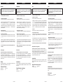
Aansluitschema
Connection diagram
Anschlußkizze
Schéma de cablage
Esquema de conexión
Schema dei collegamenti
P102983
1 Zekering (5 A)
2 Steker
3 Kontrasteker
4 Magneetschakelaar
‘Ophalen’
5 Magneetschakelaar
‘Uitvieren’
Kleurcode bedrading:
A Wit
B Zwart (‑)
C Rood (+)
D Blauw
1 Fuse (5 A)
2 Plug
3 Socket
4 Solenoid switch ‘Hauling in’
5 Solenoid switch ‘Letting go’
Wiring colour code:
A White
B Black (‑)
C Red (+)
D Blue
1 Sicherung (5 A)
2 Stecker
3 Kontrastecker
4 Magnetschalter ‘Einholen’
5 Magnetschalter ‘Ausfieren’
Farbkode für die Bedrahtung:
A Weiß
B Schwarz (‑)
C Rot (+)
D Blau
1 Fusible (5 A)
2 Prise mâle
3 Prise femelle
4 Relais solenoïde ‘Levage’
5 Relais solenoïde
‘Deroulement’
Code de couleur des câbles:
A Blanc
B Noir (‑)
C Rouge (+)
D Bleu
1 Fusible (5 A)
2 Clavija macho
3 Clavija hembra
4 Interruptor magnético ‘Levar’
5 Interruptor magnético
‘Aflojar’
Código de color de los cables:
A Blanco
B Negro (‑)
C Rojo (+)
D Azul
1 Fusible (5 A)
2 Spina maschio
3 Spina femmina
4 Interruttore magnetico
‘Recupero’
5 Interruttore magnetico
‘Spiegamento’
Codice colori cavi:
A Bianco
B Nero (‑)
C Rosso (+)
D Blu
Hoofdafmetingen
Overall dimensions
Hauptabmessungen
Dimensions principales
Dimensiones principales
Dimensioni principali
P103132 P103132 P103132

DEUTSCH
Betrieb
VORSICHT!
Wenn 2 Bedienungspaneele installiert sind, die Ankerwinde
nie von beiden Paneelen aus gleichzeitig bedienen.
- Den Hauptschalter einschalten.
- Das Paneel einschalten:
Zweimal hintereinander auf die Ein‑Aus‑Taste drücken.
Nach dem ersten Mal blinkt die LED grün und der Summer
lässt ein ständiges Signal (.‑.‑.‑.‑.‑.‑.) ertönen. Innerhalb
von 6 Sekunden muss der Ein‑Aus‑Schalter zum zweiten
Mal gedrückt werden. Die LED leuchtet jetzt grün und der
Summer bestätigt mit einem Signal (‑‑.‑‑), dass das Paneel
betriebsbereit ist.
- Richtungsschalter:
Mit dem Richtungsschalter wird der Elektromotor bedient.
- Das Paneel ausschalten:
Nach dem Gebrauch der Ankerwinde einmal auf den Ein‑
Aus‑Schalter drücken. Vom Paneel ertönt jetzt ein Signal
(.‑.‑.‑‑‑.‑‑).
Hinweis: 30 Minuten nachdem der Richtungsschalter zum
letzten Mal bedient wurde, wird das Paneel automatisch
ausgeschaltet. Auch dann ertönt vom Paneel ein Signal
(.‑.‑.‑‑‑.‑‑).
- Vor dem Verlassen des Schiffes den Hauptschalter aus-
schalten.
Sicherungen
Thermische Sicherung des Steuerstrom-kreises
Wenn eine Überbelastung im Steuerstromkreis auftritt, ertönt
vom Paneel einmal ein Warnsignal (‑.‑‑‑.‑.‑‑‑) und die LED
leuchtet etwa 7 Sekunden lang abwechselnd grün und rot
auf. Nach dem Beheben der Überbelastung funktioniert alles
wieder normal.
Einbau
Die Bedienungstafel auf den Steuerstand montieren. Die
Einbautiefe soll mindestens 50 mm sein.
Technische Daten
Spannung : 8 ‑ 32 Volt
Max. Strom : 3 A
FRANÇAIS
Utilisation
ATTENTION !
Si 2 panneaux de commande sont installés, ne jamais
commander le guindeau simultanément à partir des
deux panneaux.
- Brancher l’interrupteur principal
- Brancher le panneau:
Appuyer deux fois de suite sur la touche marche/arrêt.
Après avoir appuyé une première fois sur la touche, la
DEL verte clignote et le bruiteur émet un signal continu
(.‑.‑.‑.‑.‑.‑.). L’interrupteur marche/arrêt doit être enfoncé
une deuxième fois dans les 6 secondes qui suivent. La DEL
verte reste allumée ; le bruiteur confirme par un signal (‑‑.‑‑)
que le panneau est prêt à l’emploi.
- Interrupteur de direction:
L’interrupteur de direction commande le moteur électrique.
- Mise hors fonction du panneau:
Après avoir utilisé le guindeau, appuyer une fois sur l’inter‑
rupteur marche/arrêt. Le panneau émet un signal (.‑.‑.‑‑‑.‑‑
).
N.B. Le panneau est mis automatiquement hors fonction 30
minutes après que l’interrupteur de direction a été actionné
pour la dernière fois ; dans ce cas également le panneau
émet un signal (.‑.‑.‑‑‑.‑‑).
- Mettre l’interrupteur principal hors fonction lorsque
vous quittez le bateau.
Protections
Protection thermique du circuit de commande
En cas de surcharge du circuit de commande, le panneau
émet 1 fois un signal d’avertissement (‑.‑‑‑.‑.‑‑‑) et la DEL cli‑
gnote alternativement rouge et vert pendant environ 7 secon‑
des. Lorsque la surcharge est supprimée, tout fonctionne à
nouveau normalement.
Installation
Placer le tableau de commande dans le poste de pilotage.
L’espace disponible derrière le tableau doit être au moins
de 50‑mm.
Specifications techniques
Tension : 8 ‑ 32 Volt
Courant max. : 3 A
ESPAÑOL
Uso
¡ATENCIÓN!
Si se han instalado 2 tableros de mando, nunca maneje el
molinete desde los dos tableros simultáneamente.
- Conecte el interruptor central
- Tablero de conexión:
Pulse la tecla dos veces una tras otra.
Después de pulsar la primera vez, el LED parpadeará
en verde y el timbre dará esta señal de alarma continua
(.‑.‑.‑.‑.‑.‑.). El interruptor de encendido / apagado se deberá
pulsar por segunda vez dentro de 6 segundos. El LED par‑
padeará enseguida en verde; el timbre dará esta señal de
alarma (‑‑.‑‑) indicando que se puede usar el tablero.
- Inversor:
El electromotor se maneja por medio del inversor.
- Desconexión del tablero:
Después de usar el molinete, pulse una vez el interruptor de
encendido / apagado. El tablero dará esta señal de alarma
(.‑.‑.‑‑‑.‑‑).
NOTA BENE: Treinta minutos después de haber usado el
inversor por última vez, se desconectará automáticamente
el tablero y habrá esta señal de alarma (.‑.‑.‑‑‑.‑‑).
- Desconecte el interruptor central si usted desembarca.
Dispositivos de seguridad
Protector térmico del circuito de corriente de mando
Si se presenta una sobrecarga en el circuito de corriente de
mando, el tablero dará una vez 1 señal de alarma (‑.‑‑‑.‑.‑‑‑),
y el LED parpadeará alternativamente de verde a rojo durante
unos 7 segundos. Después de eliminar la sobrecarga, todo
funcionará normalmente otra vez.
Instalación
Monte el panel de control en la posición de gobierno. Detrás
del panel debe quedar un espacio libre de 50 mm como
mínimo.
Especificaciones técnicas
Tensión : 8 ‑ 32 Volt
Corriente máxima : 3 A
ITALIANO
Uso
ATTENZIONE!
Nel caso in cui siano installati due pannelli di comando,
non governare mai l’argano da entrambi i pannelli con-
temporaneamente.
- Azionare l’interruttore generale
- Accensione del pannello:
Premere il pulsante acceso/spento due volte di seguito.
Dopo avere premuto il pulsante la prima volta il LED lam‑
peggia in colore verde ed il segnalatore acustico emette
un segnale continuo (.‑.‑.‑.‑.‑.‑.). Il pulsante acceso/spento
deve essere premuto per la seconda volta entro 6 secondi.
Dopo avere premuto il pulsante la seconda volta il LED si
illumina di luce verde fissa mentre il segnalatore acustico
emette un segnale (‑‑.‑‑) a conferma che il pannello è pronto
all’uso.
- Interruttore direzionale:
L’interruttore direzionale permette di governare il motore
elettrico.
- Spegnimento del pannello:
Al termine dell’uso dell’argano, premere una volta il pulsante
acceso/spento. Il pannello emette il segnale acustico (.‑.‑.‑‑
‑.‑‑).
N.B. 30 minuti dopo che l’interruttore direzionale è stato
comandato per l’ultima volta, il pannello si spegne automa‑
ticamente, emettendo un segnale acustico (.‑.‑.‑‑‑.‑‑).
- Si raccomanda di spegnere l’interruttore principale prima
di lasciare l’imbarcazione.
Sistemi di protezione
Protezione termica del circuito di alimentazione del siste-
ma di comando
Se si verifica un sovraccarico nel circuito di alimentazione del
sistema di comando, il pannello emette un singolo segnale
acustico (‑.‑‑‑.‑.‑‑‑) mentre il LED si illumina alternativamente
di luce verde e rossa per ca. 7 secondi. Una volta che il cari‑
co di tensione è rientrato nei valori limite, il sistema torna a
funzionare normalmente.
Installazione
Montare il pannello di comando nella postazione di governo.
Lasciare uno spazio libero di almeno 50 mm dietro il pan‑
nello.
Dati tecnici
Tensione : 8 ‑ 32 Volt
Corrente a massima : 3 A
P103132 P103132 P103132 P103132
-
 1
1
-
 2
2

