
Motors | Automation | Energy | Transmission & Distribution | Coatings
ERRATA OF THE CFW500 USER’S MANUAL
ERRATA DEL MANUAL DEL USUARIO CFW500
ERRATA DO MANUAL DO USUÁRIO CFW500
Document: 10006452230 / 00
14818039

INTRODUCTION / INTRODUCCIÓN / INTRODUÇÃO
English
The information of this erratum substitutes the existing information of the CFW500 user’s manual.
The functions in three terminals have been changed:
- GND, from 16 to 12.
- A (-), from 12 to 14.
- B (+), from 14 to 16.
The following terminals have been included:
- 17: GND
- 18: GND (485) - GND exclusive for RS485 port.
Español
Las informaciones contenidas en esta errata substituyen las existentes en el manual del usuario CFW500.
Fueron alteradas las funciones en 3 bornes:
- GND, de 16 para 12.
- A (-), de 12 para 14.
- B (+), de 14 para 16.
Fueron incluidos los bornes:
- 17: GND
- 18: GND (485) - GND exclusivo para puerto RS485.
Português
As informações desta errata substituem as existentes no manual do usuário CFW500.
Foram alteradas as funções em 3 bornes:
- GND, de 16 para 12.
- A (-), de 12 para 14.
- B (+), de 14 para 16.
Foram incluídos os bornes:
- 17: GND
- 18: GND (485) - GND exclusivo para porta RS485.
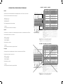
CORRECT / CORRECTO / CORRETO
DI3
DI1
DI2
DI4
+24 V
DO1-RL-NA
DO1-RL-F
DO1-RL-NF
GND
GND (485)
AO1
GND
AI1
+10 V
>300 Ω
≥5 kΩ
rpm
GND
A (-)
+24 V
DO2-TR
B (+)
Connector /Conector Description / Descripción / Descrição
(**)
Top connection / Borne Superior
1 DI1 Digital input 1 / Entrada digital 1
3 DI2 Digital input 2 / Entrada digital 2
(*)
5 DI3 Digital input 3 / Entrada digital 3
7 DI4 Digital input 4 / Entrada digital 4
9 +24 V Power supply +24 Vdc / Fuente +24 Vcc / Fonte +24 Vcc
11 DO1-RL-NO / DO1-RL-NA
Digital output 1 (NO contact of relay 1) /
Salida digital 1 (Contacto NA del relé) /
Saída digital 1 (Contato NA do relé 1)
13 DO1-RL-C
Digital output 1 (Common point of relay 1) /
Salida digital 1 (Punto común del relé 1)
Saída digital 1 (Ponto comum do relé 1)
15 DO1-RL-NC / DO1-RL-NF
Digital output 1 (NC contact of relay 1) /
Salida digital 1(Contacto NC del relé)
Saída digital 1 (Contato NF do relé 1)
17 GND Reference 0 V / Referencia 0 V / Referência 0 V
Bottom connection / Borne Inferior
2 AO1 Analog output 1 / Salida analógica 1 / Saída analógica 1
4 GND Reference 0 V / Referencia 0 V / Referência 0 V
6 AI1 Analog input 1 / Entrada analógica 1
8 +10 V
Reference +10 Vdc for potentiometer /
Referencia +10 Vcc para potenciómetro /
Referência +10 Vcc para potenciômetro
10 DO2-TR
Digital output 2 (transistor) / Salida digital 2 (Transistor) /
Saída digital 2 (transistor)
12 GND Reference 0 V / Referencia 0 V / Referência 0 V
14 A (-) RS485 (terminal A)
16 B (+) RS485 (terminal B)
18 GND (485) GND (RS485)
(*) The digital input 2 (DI2) can also be used as input in frequency (FI). For further details refer to the programming
manual of the CFW500.
(**) For further information, refer to the detailed specification in Section 8.2 ELECTRONICS/GENERAL DATA in the
user’s manual.
(*) La entrada digital 2 (DI2) también puede ser usada como entrada en frecuencia (FI). Para más detalles consulte el
manual
de programación del CFW500.
(**) Para más informaciones consulte la especificación detallada en la Sección 8.2 DATOS DE LA ELECTRÓNICA/
GENERALES del manual del usuário CFW500.
(*) A entrada digital 2 (DI2) também pode ser usada como entrada em frequência (FI). Para mais detalhes consulte o
manual de programação do CFW500.
(**) Para mais informações consulte a especificação detalhada na Seção DADOS DA ELETRÔNICA/GERAIS do manual
do usuário CFW500.
Figure 1: Signals of the connector of the CFW500-IOS plug-in module
Figura 1: Señales del conector del módulo plug-in CFW500-IOS-B
Figura 1: Sinais do conector do módulo plug-in CFW500-IOS-B
INCORRECT / INCORRECTO / INCORRETO
+24 V
DO1-RL-NO
DO1-RL-C
DO1-RL-NC
DI1
DI2
DI3
DI4
rpm
≥5 kΩ
>300 Ω
+24 V
AO1
GND
AI1
+10 V
DO2-TR
GND
B - 485)
A - 485)
Connector / Conector Descripción / Descripción / Descrição
(**)
Top connection / Borne Superior
1 DI1 Digital input 1 / Entrada digital 1
3 DI2 Digital input 2 / Entrada digital 2 (*)
5 DI3 Digital input 3 / Entrada digital 3
7 DI4 Digital input 4 / Entrada digital 4
9 +24 V Power supply +24 Vdc / Fuente +24 Vcc / Fonte +24 Vcc
11 DO1-RL-NO / DO1-RL-NA
Digital output 1 (NO contact of relay 1) /
Salida digital 1(Contacto NA del relé) /
Saída digital 1 (Contato NA do relé 1)
13 DO1-RL-C
Digital output 1 (Common point of relay 1) /
Salida digital 1 (Punto común del relé 1) /
Saída digital 1 (Ponto comum do relé 1)
15 DO1-RL-NC / DO1-RL-NF
Digital output 1 (NC contact of relay 1) /
Salida digital 1 (Contacto NC del relé) /
Saída digital 1 (Contato NF do relé 1)
Bottom connection / Borne
Inferior
2 AO1 Analog output 1 / Salida analógica 1 / Saída analógica 1
4 GND Reference 0 V / Referencia 0 V / Referência 0 V
6 AI1 Analog input 1 / Entrada analógica 1
8 +10 V
Reference +10 Vdc for potentiometer /
Referencia +10 Vcc para potenciómetro /
Referência +10 Vcc para potenciômetro
10 DO2-TR
Digital output 2 (transistor) / Salida digital 2 (Transistor) /
Saída digital 2 (transistor)
12 RS485 - A RS485 (terminal A)
14 RS485 - B RS485 (terminal B)
16 GND Reference 0 V / Referencia 0 V / Referência 0 V
(*) The digital input 2 (DI2) can also be used as input in frequency (FI). For further details refer to the programming
manual of the CFW500.
(**) For further information, refer to the detailed specification in Section 8.2 ELECTRONICS/GENERAL DATA in the
user’s manual.
(*) La entrada digital 2 (DI2) también puede ser usada como entrada en frecuencia (FI). Para más detalles consulte el manual
de programación del CFW500.
(**) Para más informaciones consulte la especificación detallada en la Sección 8.2 DATOS DE LA ELECTRÓNICA/
GENERALES del manual del usuário CFW500.
(*) A entrada digital 2 (DI2) também pode ser usada como entrada em frequência (FI). Para mais detalhes consulte o manual
de programação do CFW500.
(**) Para mais informações consulte a especificação detalhada na Seção DADOS DA ELETRÔNICA/GERAIS do manual
do usuário CFW500.
Figure 3.4: Signals of the connector of the CFW500-IOS plug-in module
Figura 3.4: Señales del conector del módulo plug-in CFW500-IOS
Figura 3.4: Sinais do conector do módulo plug-in CFW500-IOS
-
 1
1
-
 2
2


en otros idiomas
- português: WEG CFW500 Manual do usuário
Artículos relacionados
-
WEG CFW500-IOS -PNP Guía del usuario
-
-
-
-
-
-
-
-
-