Hach Flow Cell FC 48/10 USC Guía de inicio rápido
- Tipo
- Guía de inicio rápido

DOC273.98.90651
Flow Cell FC 48/10 USC
09/2018, Edition 1
Quick start guide
Kurzanleitung
Guida rapida all'uso
Guide de démarrage rapide
Guía de inicio rápido
Hurtigstartguide
Beknopte handleiding
Skrócona instrukcja obsługi
Rövid útmutató
Ghid de iniţiere rapidă

1
Table of Contents
1 English FlowCell FC 48/10 USC ............................................................... 3
2 Deutsch FlowCell FC 48/10 USC ........................................................... 13
3 Italiano FlowCell FC 48/10 USC ............................................................. 23
4 Français FlowCell FC 48/10 USC .......................................................... 33
5 Español FlowCell FC 48/10 USC ........................................................... 43
6 Dansk FlowCell FC 48/10 USC ............................................................... 53
7 Nederlands FlowCell FC 48/10 USC ..................................................... 63
8 Polski FlowCell FC 48/10 USC ................................................................ 73
9 Magyar FlowCell FC 48/10 USC ............................................................. 83
10 Română FlowCell FC 48/10 USC ........................................................ 93

Table of Contents
2

3
1 English FlowCell FC 48/10 USC
1.1 Legal information
Manufacturer: TriOS Mess- und Datentechnik GmbH
Distributor: Hach Lange GmbH
The translation of the manual is approved by the manufacturer.
1.2 Specifications
Specifications are subject to change without notice.
1.3 General information
In no event will the manufacturer be liable for direct, indirect, special, incidental or
consequential damages resulting from any defect or omission in this manual. The
manufacturer reserves the right to make changes in this manual and the products it
describes at any time, without notice or obligation. Revised editions are found on
the manufacturer’s website.
ENERGY SUPPLY
Voltage supply
12–24 V DC (± 10%)
Power consumption
≤ 15 W
Control connection
Trigger input to initiate ultrasonic cleaning (galvanically
isolated); Control voltage 5–24 V DC; Connection via
M5-connector (a suitable M5 connection cable with open end
is included in the delivery)
Power cable
M5-connector with optional DC power adapter cable and
suitable 230 V power supply
AMBIENT
Operating temperature
1 to 40 °C (33.8 to 104 °F)
Storage temperature
–20 to 70 °C (–4 to 158 °F)
Protection type
IP 64
MECHANICS
Dimensions (W/H/D)
115 x 136 x 90 mm (4.53 x 5.35 x 3.54 in.)
Weight
1 kg (2.20 lb)
Materials
Polyoxymethylene (POM) housing
Certification
CE compliant

FlowCell FC 48/10 USC
4 English
1.3.1 Safety information
Please read this entire manual before unpacking, setting up, or operating this
equipment. Pay attention to all danger and caution statements. Failure to do so
could result in serious injury to the operator or damage to the equipment.
Make sure that the protection provided by this equipment is not impaired, do not
use or install this equipment in any manner other than that specified in this manual.
1.3.2 Use of hazard information
1.3.3 Precautionary labels
Read all labels and tags attached to the instrument. Personal injury or damage to
the instrument could occur if not observed. A symbol, if noted on the instrument, will
be included with a danger or caution statement in the manual.
NOTICE
The manufacturer is not responsible for any damages due to misapplication or misuse of
this product including, without limitation, direct, incidental and consequential damages, and
disclaims such damages to the full extent permitted under applicable law. The user is solely
responsible to identify critical application risks and install appropriate mechanisms to protect
processes during a possible equipment malfunction.
DANGER
Indicates a potentially or imminently hazardous situation which, if not avoided, will result in
death or serious injury.
WARNING
Indicates a potentially or imminently hazardous situation which, if not avoided, could result in
death or serious injury.
CAUTION
Indicates a potentially hazardous situation which, if not avoided, could result in minor or
moderate injury.
NOTICE
Indicates a situation that is not related to personal injury.
This symbol, if noted on the instrument, references the instruction manual for
operation and/or safety information.
Electrical equipment marked with this symbol may not be disposed of in
European domestic or public disposal systems. Return old or end-of-life
equipment to the manufacturer for disposal at no charge to the user.

FlowCell FC 48/10 USC
English 5
1.3.4 Chemical and Biological Safety
Normal operation of this device may require the use of chemicals or samples that
are biologically unsafe.
• Observe all cautionary information printed on the original solution containers
and safety data sheets prior to their use.
• Dispose of all consumed solutions in accordance with the local and national
regulations and laws.
• Select the type of protective equipment suitable to the concentration and
quantity of the dangerous material being used.
1.3.5 Product overview
The FlowCell FC 48/10 USC is suitable for NX7500 optical sensors with a path
length of up to 10 mm. There are two versions available:
• LXZ529.99.0002A without panel
• LXZ529.99.0003A with panel
Figure 1 FlowCell FC 48/10 USC
FlowCell with integrated ultra sonic cleaning: In addition to the standard
FlowCell, Hach now also offers an ultrasonic FlowCell which combines the
bypass-installation with direct cleaning.
Fouling on the measurement windows can be prevented by the use of ultrasound.
The condition of the optical path can be monitored at any time through the
monitoring window and the lighting unit.
DANGER
Chemical or biological hazards. If this instrument is used to monitor a
treatment process and/or chemical feed system for which there are regulatory
limits and monitoring requirements related to public health, public safety, food
or beverage manufacture or processing, it is the responsibility of the user of
this instrument to know and abide by any applicable regulation and to have
sufficient and appropriate mechanisms in place for compliance with applicable
regulations in the event of malfunction of the instrument.

FlowCell FC 48/10 USC
6 English
1.3.6 Product components
Make sure that all components have been received. If any items are missing or
damaged, contact the manufacturer or a sales representative immediately.
1.4 Quick Start
1 Power supply 2 Trigger line
3 FlowCell incl. fittings 4 Alignment pin
CAUTION
Multiple hazards. Only qualified personnel must conduct the tasks described in
this section of the document.
3
4
21

FlowCell FC 48/10 USC
English 7
1.4.1 FlowCell design
The Ultrasonic FlowCell is used for cleaning of the measurement windows with
severe dirt contamination. It is suitable for photometers with a path length of up to
10 mm.
The FlowCell provides a light source on the inside which can be activated by
pressing the light button on the side of the housing. When cleaning is in process a
blue LED is used, if cleaning is inactive the light will be white.
1 Outlet for 6 mm hose 2 Monitoring window
3 Inlet for 8 mm hose 4 Power supply
5 Trigger connection to initiate
cleaning
6 Light button
NOTICE
Before setting to work, the FlowCell has to be mounted correctly on the sensor and be filled
with water completely.
3
1 2
4
5
6

FlowCell FC 48/10 USC
8 English
1.4.2 Installation of the sensor
1. For correct positioning of the sensor inside the FlowCell, an alignment pin is
supplied that has to be installed at the bottom of the optical path of the sensor.
The pin can easily be tightened and adjusted by using a small coin.
2. The pin has to be adjusted depending on the path length.
3. When the pin is adjusted, the sensor can be inserted carefully into the
FlowCell. The pin has to be positioned in the guidance opposite to the
monitoring window and will then be led correctly through the FlowCell. The
sensor has to be inserted until there is a resistance.
90° for 10 mm, 2 mm and 0,3 mm 0° for 5 mm and 1 mm
1 Guidance
1

FlowCell FC 48/10 USC
English 9
1.4.3 Connection of electronics
It is a prerequisite that the sensor and FlowCell are installed and mounted correctly
and that the FlowCell is filled completely before starting electronic installation. For
commissioning follow the instructions as follows:
1.4.4 Trigger Line Connection
The trigger line has three connections that leads out of the FlowCell through a
three-wire cable. The construction of the trigger input is shown in the following
block diagram.
NOTICE
FlowCell electronics can only be installed after the sensor is installed correctly and the
Flow-Cell is completely filled with water.
1 Power supply 2 Trigger line
NOTICE
The trigger signal must be applied for at least 100 ms (debouncing)!
1
2
FlowCell
μC
DC
DC
blue
white
brown
Wire
color
Function
blue
white
brown
+5 V (isolated)
Trigger input
GND (isolated)

FlowCell FC 48/10 USC
10 English
To trigger a cleaning process there are two options: You can use the 5 V signal that
is led out of the FlowCell to realize a triggering over an external switch contact.
Alternatively an external signal voltage of 5 to 24 V DC (in reference to GND-line)
can be put on the “Trigger input” line.
1.4.5 Connection of power supply
The power supply is connected through the power socket of the FlowCell like it is
shown in the following polarity illustration.
WARNING
Electrical shock and fire hazards. Make sure that the supplied cord and non-locking plug
meet the applicable country code requirements.
NOTICE
The manufacturer recommends to use only the supplied power supply.
NOTICE
For the power supply of the FlowCell electronics, a power supply unit of 12 to 24 V DC with
an output cable with at least 15 W is needed.
FlowCell
External measurement
controller
Cleaning cycle
Trigger
μC
DC
DC
blue
white
brown
FlowCell
External measurement
controller
Cleaning cycle
Trigger
+5..24 VDC
GND
μC
DC
DC
blue
white
brown
2,1 x 5,5
–
+

FlowCell FC 48/10 USC
English 11
1.4.6 Process of a cleaning cycle
The program sequence of a cleaning cycle is as follows:
1. Wait for trigger event
2. Trigger activated
3. Ultrasound active for 30 sec.
4. Cool-down for 60 sec.
5. Wait for trigger event

FlowCell FC 48/10 USC
12 English

13
2 Deutsch FlowCell FC 48/10 USC
2.1 Rechtsinformation
Hersteller: TriOS Mess- und Datentechnik GmbH
Vertreiber: Hach Lange GmbH
Die Übersetzung des Handbuchs ist vom Hersteller freigegeben.
2.2 Technische Daten
Änderungen vorbehalten.
2.3 Allgemeine Informationen
Der Hersteller ist nicht verantwortlich für direkte, indirekte, versehentliche oder
Folgeschäden, die aus Fehlern oder Unterlassungen in diesem Handbuch
entstanden. Der Hersteller behält sich jederzeit und ohne vorherige Ankündigung
oder Verpflichtung das Recht auf Verbesserungen an diesem Handbuch und den
ENERGIEVERSORGUNG
Spannungsversorgung
12–24 V DC (± 10%)
Stromverbrauch
≤ 15 W
Steueranschluss
Triggereingang zum Start der Ultraschallreinigung
(galvanisch getrennt), Steuerspannung 5–24 V DC
Anschluss über M5-Anschluss (ein geeignetes
M5-Anschlusskabel mit offenem Ende ist in
der Lieferung enthalten)
Netzkabel
M5-Anschluss mit optionalem Gleichstrom-Netzadapterkabel
und geeigneter 230 V-Stromversorgung
UMGEBUNGSTEMPERATUR
Operating temperature
1 bis 40 °C (33.8 bis 104 °F)
Lagertemperatur
–20 bis 70 °C (–4 bis 158 °F)
Schutztyp
IP 64
MECHANIK
Abmessungen (B/H/T)
115 x 136 x 90 mm (4.53 x 5.35 x 3.54 in.)
Gewicht
1 kg (2.20 lb)
Materialien
Polyoxymethylen (POM) Gehäuse
Zertifizierungen
CE-konform

FlowCell FC 48/10 USC
14
hierin beschriebenen Produkten vor. Überarbeitete Ausgaben der
Bedienungsanleitung sind auf der Hersteller-Webseite erhältlich.
2.3.1 Sicherheitshinweise
Bitte lesen Sie dieses Handbuch komplett durch, bevor Sie dieses Gerät
auspacken, aufstellen oder bedienen. Beachten Sie alle Gefahren- und
Warnhinweise. Nichtbeachtung kann zu schweren Verletzungen des Bedieners
oder Schäden am Gerät führen.
Stellen Sie sicher, dass die durch dieses Messgerät bereitgestellte Sicherheit nicht
beeinträchtigt wird. Verwenden bzw. installieren Sie das Messsystem nur wie in
diesem Handbuch beschrieben.
2.3.2 Bedeutung von Gefahrenhinweisen
2.3.3 Warnhinweise
Lesen Sie alle am Gerät angebrachten Aufkleber und Hinweise. Nichtbeachtung
kann Verletzungen oder Beschädigungen des Geräts zur Folge haben.
H I N W E I S
Der Hersteller ist nicht für Schäden verantwortlich, die durch Fehlanwendung oder
Missbrauch dieses Produkts entstehen, einschließlich, aber ohne Beschränkung auf direkte,
zufällige oder Folgeschäden, und lehnt jegliche Haftung im gesetzlich zulässigen Umfang
ab. Der Benutzer ist selbst dafür verantwortlich, schwerwiegende Anwendungsrisiken zu
erkennen und erforderliche Maßnahmen durchzuführen, um die Prozesse im Fall von
möglichen Gerätefehlern zu schützen.
G E F A H R
Kennzeichnet eine mögliche oder drohende Gefahrensituation, die, wenn sie nicht
vermieden wird, zum Tod oder zu schweren Verletzungen führt.
W A R N U N G
Kennzeichnet eine mögliche oder drohende Gefahrensituation, die, wenn sie nicht
vermieden wird, zum Tod oder zu schweren Verletzungen führen kann.
V O R S I C H T
Kennzeichnet eine mögliche Gefahrensituation, die zu geringeren oder moderaten
Verletzungen führen kann.
H I N W E I S
Kennzeichnet eine Situation, die, wenn sie nicht vermieden wird, das Gerät beschädigen
kann. Informationen, die besonders beachtet werden müssen.

FlowCell FC 48/10 USC
15
Im Handbuch wird in Form von Warnhinweisen auf die am Gerät angebrachten
Symbole verwiesen.
2.3.4 Chemische und biologische Sicherheit
Der Normalbetrieb dieses Gerätes erfordert möglicherweise die Verwendung von
biologisch unsicheren Chemikalien oder Proben.
• Beachten Sie vor dem Umgang mit diesen Stoffen alle auf den
Original-Lösungsbehältern und in den Sicherheitsdatenblättern abgedruckten
Gefahrenhinweise und Sicherheitsinformationen.
• Entsorgen Sie alle gebrauchten Lösungen gemäß den örtlichen und nationalen
Bestimmungen und Gesetzen.
• Wählen Sie die für die Konzentration und Menge des verwendeten gefährlichen
Materials geeignete Schutzausrüstung..
2.3.5 Produktübersicht
FlowCell FC 48/10 USC ist für NX7500 optische Sensoren mit einer Weglänge von
bis zu 10 mm geeignet. Versionen:
• LXZ529.99.0002A without panel
• LXZ529.99.0003A with panel
Dies ist das Sicherheits-Warnsymbol. Befolgen Sie alle Sicherheitshinweise im
Zusammenhang mit diesem Symbol, um Verletzungen zu vermeiden. Wenn es
am Gerät angebracht ist, beachten Sie die Betriebs- oder
Sicherheitsinformationen im Handbuch.
Elektrogeräte, die mit diesem Symbol gekennzeichnet sind, dürfen nicht im
normalen öffentlichen Abfallsystem entsorgt werden. Senden Sie Altgeräte an
den Hersteller zurück. Dieser entsorgt die Geräte ohne Kosten für den Benutzer.
G E F A H R
Chemische und biologische Risiken. Wird das Gerät dazu verwendet, ein
Verfahren und/oder eine chemische Zuleitung zu überwachen, für das
vorgeschriebene Grenzwerte und Überwachungsvorschriften im Bereich der
öffentlichen Sicherheit, der Gesundheit oder im Bereich der Lebensmittel- oder
Getränkeherstellung bestimmt wurden, so unterliegt es der Verantwortung des
Benutzers des Geräts, alle solche Bestimmungen zu kennen und diese
einzuhalten und für ausreichende und entsprechende Vorsorgemaßnahmen
zur Einhaltung der für den Fall einer Fehlfunktion des Geräts bestehenden
Bestimmung zu sorgen.

16
Abbildung 2 FlowCell FC 48/10 USC
FlowCell mit integrierter Ultraschallreinigung: Zusätzlich zur Standard-FlowCell
bietet Hach jetzt auch eine Ultraschall-FlowCell an, die die Bypass-Installation mit
einer direktenReinigung kombiniert.
Verschmutzungen auf den Messfenstern können durch den Einsatz von Ultraschall
verhindert werden. Der Zustand des Lichtwegs kann jederzeit durch das
Überwachungsfenster und die Beleuchtungseinheit überwacht werden.
2.3.6 Produktkomponenten
Stellen Sie sicher, dass Sie alle Teile erhalten haben. Wenn Komponenten fehlen
oder beschädigt sind, kontaktieren Sie bitte umgehend den Hersteller oder
Verkäufer.
1 Stromversorgung 2 Triggerleitung
3 FlowCell inkl. Armatur 4 Ausrichtungsstift
3
4
21

FlowCell FC 48/10 USC
17
2.4 Schnellstart
2.4.1 FlowCell Aufbau
Die Ultrasonic FlowCell wird zur Reinigung stark verschmutzter Messfenster
verwendet. Sie ist für Photometer mit einer Weglänge von bis zu 10 mm geeignet.
FlowCell bietet eine Lichtquelle im Inneren, die durch Drücken des Lichtknopfs an
der Gehäuseseite aktiviert werden kann. Während des Reinigungsvorgangs
V O R S I C H T
Mehrere Gefahren. Nur qualifiziertes Personal sollte die in diesem Kapitel des
Dokuments beschriebenen Aufgaben durchführen.
1 Auslass für 6 mm Schlauch 2 Überwachungsfenster
3 Einlass für 8 mm Schlauch 4 Stromversorgung
5 Trigger-Anschluss zum
Reinigungsstart
6 Lichtknopf
H I N W E I S
Vor der Inbetriebnahme muss FlowCell korrekt auf dem Sensor montiert und vollständig mit
Wasser gefüllt sein.
3
1 2
4
5
6

FlowCell FC 48/10 USC
18
leuchtet eine blaue LED; wenn die Reinigung ausgeschaltet ist, ist die Leuchte
weiß.
2.4.2 Installation des Sensors
1. Zur korrekten Positionierung des Sensors im Inneren der FlowCell wird ein
Ausrichtungsstift eingesetzt, der am Boden des Lichtwegs des Sensors
installiert werden muss. Der Stift kann einfach mit einer kleinen Münze
festgezogen und eingestellt werden.
2. Der Stift ist in Abhängigkeit von der Weglänge einzustellen.
3. Wenn der Stift eingestellt wird, kann der Sensor vorsichtig in die FlowCell
eingesetzt werden. Der Stift muss in der Führung gegenüber dem
Überwachungsfenster positioniert werden und wird dann korrekt durch die
90° für 10 mm, 2 mm und 0,3 mm 0° für 5 mm und 1 mm

FlowCell FC 48/10 USC
19
FlowCell geführt. Der Sensor muss eingesetzt werden, bis er auf Widerstand
trifft.
2.4.3 Anschluss von Elektronik
It is a prerequisite that the sensor and FlowCell are installed and mounted correctly
and that the FlowCell is filled completely before starting electronic installation. For
commissioning follow the instructions as follows:
1 Führung
H I N W E I S
FlowCell-Elektronik kann erst installiert werden, nachdem der Sensor korrekt installiert
wurde und die FlowCell vollständig mit Wasser gefüllt ist.
1 Stromversorgung 2 Triggerleitung
1
1
2

FlowCell FC 48/10 USC
20
2.4.4 Triggerleitungsanschluss
Die Triggerleitung hat drei Anschlüsse, die aus der FlowCell durch drei Kabel
herausführen. Der Aufbau des Triggereingangs ist in dem folgenden
Blockdiagramm dargestellt.
Um einen Reinigungsvorgang einzuleiten, bestehen zwei Möglichkeiten: Sie
können eine 5V-Signalspannung benutzen, die aus der FlowCell führt, um eine
Betätigung über einen externen Schaltkontakt auszulösen.
Alternativ kann eine externe Signalspannung von 5 bis 24 V DC (mit Bezug auf
GND-Leitung) an die „Triggereingang"-Leitung angelegt werden.
H I N W E I S
Das Triggersignal muss für mindestens 100 ms angelegt werden (Entprellung)!
FlowCell
μC
DC
DC
blue
white
brown
Wire
color
Function
blue
white
brown
+5 V (isolated)
Trigger input
GND (isolated)
FlowCell
External measurement
controller
Cleaning cycle
Trigger
μC
DC
DC
blue
white
brown
FlowCell
External measurement
controller
Cleaning cycle
Trigger
+5..24 VDC
GND
μC
DC
DC
blue
white
brown

FlowCell FC 48/10 USC
21
2.4.5 Anschluss an das Stromnetz
Das Netzkabel wird an der Steckdose der FlowCell angeschlossen, wie in der
folgenden Polaritätsdarstellung gezeigt wird.
2.4.6 Vorgang eines Reinigungszyklus
Die Programmsequenz eines Reinigungszyklus ist wie folgt:
1. Warten auf Auslösen
2. Trigger aktiviert
3. Ultraschall aktiv für 30 Sek.
4. Abkühlung für 60 Sek.
5. Warten auf Auslösen
W A R N U N G
Elektrische Gefahren und Brandgefahr. Stellen Sie sicher, dass das mitgelieferte Kabel und
der nichtverriegelnde Stecker den Vorschriften des jeweiligen Landes entsprechen.
H I N W E I S
Der Hersteller empfiehlt, ausschließlich die mitgelieferte Stromversorgung zu verwenden.
H I N W E I S
Für die Stromversorgung der FlowCell-Elektronik ist eine Stromversorgungseinheit von
12 bis 24 V DC mit einem Ausgangskabel mit mindestens 15 W erforderlich.
2,1 x 5,5
–
+

FlowCell FC 48/10 USC
22

23
3 Italiano FlowCell FC 48/10 USC
3.1 Informazione legale
Produttore: TriOS Mess- und Datentechnik GmbH
Distributore: Hach Lange GmbH
La traduzione del manuale è approvata dal produttore.
3.2 Specifiche tecniche
Le specifiche tecniche sono soggette a modifica senza preavviso.
3.3 Informazioni generali
In nessun caso, il produttore potrà essere ritenuto responsabile per danni diretti,
indiretti o accidentali per qualsiasi difetto o omissione relativa al presente manuale.
Il produttore si riserva il diritto di apportare eventuali modifiche al presente manuale
ALIMENTAZIONE DI ENERGIA
Tensione di alimentazione
12–24 V DC (± 10%)
Potenza assorbita
≤ 15 W
Collegamento di controllo
Ingresso di attivazione per avviare la pulizia a
ultrasuoni (isolato galvanicamente); Tensione di
controllo 5–24 V CC; Collegamento tramite
connettore M5 (un cavo di collegamento M5 idoneo
con estremità aperta è incluso nella fornitura)
Cavo di alimentazione
Connettore M5 con cavo adattatore di
alimentazione CC opzionale e alimentatore idoneo
a 230 V
AMBIENTE
Temperatura di funzionamento
Da 1 a 40 °C (da 33.8 a 104 °F)
Temperatura di conservazione
Da –20 a 70 °C (da –4 a 158 °F)
Classe di protezione
IP 64
MECCANICA
Dimensioni (L/A/P)
115 x 136 x 90 mm (4.53 x 5.35 x 3.54 in.)
Peso
1 kg (2.20 lb)
Materiali
Poliossimetilene (POM) involucro
Certificati di conformità
Conformità CE

FlowCell FC 48/10 USC
24
e ai prodotti ivi descritti in qualsiasi momento senza alcuna notifica o obbligo
preventivi. Le edizioni riviste sono presenti nel sito Web del produttore.
3.3.1 Informazioni sulla sicurezza
Prima di disimballare, installare o utilizzare l’apparecchio, si prega di leggere l’intero
manuale. Si raccomanda di leggere con attenzione e rispettare le istruzioni
riguardanti note di pericolosità. La non osservanza di tali indicazioni potrebbe
comportare lesioni gravi all'operatore o danni all'apparecchio.
Assicurarsi che i dispositivi di sicurezza insiti nell'apparecchio siano efficaci all'atto
della messa in servizio e durante l'utilizzo dello stesso. Non utilizzare o installare
questa apparecchiatura in modo diverso da quanto specificato nel presente
manuale.
3.3.2 Indicazioni e significato dei segnali di pericolo
3.3.3 Etichette precauzionali
Leggere sempre tutte le indicazioni e le targhette di segnalazione applicate
all'apparecchio. La mancata osservanza delle stesse può causare lesioni personali
A V V I S O
Il produttore non sarà da ritenersi responsabile in caso di danni causati dall'applicazione
errata o dall'uso errato di questo prodotto inclusi, a puro titolo esemplificativo e non
limitativo, i danni incidentali e consequenziali; inoltre declina qualsiasi responsabilità per tali
danni entro i limiti previsti dalle leggi vigenti. La responsabilità relativa all'identificazione dei
rischi critici dell'applicazione e all'installazione di meccanismi appropriati per proteggere le
attività in caso di eventuale malfunzionamento dell'apparecchiatura compete unicamente
all'utilizzatore.
P E R I C O L O
Indica una situazione di pericolo potenziale o imminente che, se non evitata, causa lesioni
gravi anche mortali.
A V V E R T E N Z A
Indica una situazione di pericolo potenziale o imminente che, se non evitata, potrebbe
comportare lesioni gravi, anche mortali.
A T T E N Z I O N E
Indica una situazione di pericolo potenziale che potrebbe comportare lesioni lievi o
moderate.Indica una situazione di pericolo potenziale che potrebbe comportare lesioni lievi
o moderate.
A V V I S O
Indica una situazione che, se non evitata, può danneggiare lo strumento. Informazioni che
richiedono particolare attenzione da parte dell'utente.

FlowCell FC 48/10 USC
25
o danni allo strumento. Un simbolo sullo strumento è indicato nel manuale
unitamente a una frase di avvertenza.
3.3.4 Rischio chimico e biologico
Il normale funzionamento di questo dispositivo può richiedere l'utilizzo di sostanze
chimiche o campioni che comportano rischio biologico.
• Osservare tutte le informazioni di avviso stampate sui contenitori delle soluzioni
originali e sulle schede di sicurezza prima dell'uso.
• Smaltire tutte le soluzioni utilizzate in conformità alle leggi e normative locali e
nazionali.
• Utilizzare l'equipaggiamento di protezione adatto alla concentrazione e alla
quantità di materiale pericoloso utilizzato.
3.3.5 Panoramica del prodotto
Il modello FlowCell FC 48/10 USC è idoneo per sensori ottici NX7500 con una
lunghezza di percorso fino a 10 mm. Versione:
• LXZ529.99.0002A without panel
• LXZ529.99.0003A with panel
Questo è il simbolo di allarme sicurezza. Seguire tutti i messaggi di sicurezza
dopo questo simbolo per evitare potenziali lesioni. Se sullo strumento, fare
riferimento al manuale delle istruzioni per il funzionamento e/o informazioni sulla
sicurezza.
Le apparecchiature elettriche contrassegnate con questo simbolo non possono
essere smaltite attraverso sistemi domestici o pubblici europei. Restituire le
vecchie apparecchiature al produttore il quale si occuperà gratuitamente del loro
smaltimento.
P E R I C O L O
Rischi chimici o biologici. Se questo strumento viene utilizzato per monitorare
un processo di trattamento e/o un sistema di alimentazione di sostanze
chimiche per cui esistono limiti normativi e requisiti di controllo legati a sanità
pubblica, sicurezza pubblica, attività di produzione o trasformazione di alimenti
e bevande, l'utente dello strumento ha la responsabilità di conoscere e
rispettare tutte le eventuali normative applicabili e di predisporre meccanismi
adeguati e sufficienti ai fini del rispetto delle normative vigenti in caso di
malfunzionamento dello strumento stesso.

FlowCell FC 48/10 USC
26
Figura 3 FlowCell FC 48/10 USC
FlowCell con pulizia a ultrasuoni integrata: Oltre al FlowCell standard, Hach
propone ora anche un FlowCell a ultrasuoni che associa l'installazione bypass con
la pulizia diretta.
La contaminazione sulle finestre di misura può essere evitata con l'uso di
ultrasuoni. Lo stato del percorso ottico può essere monitorato in qualunque
momento tramite la finestra di monitoraggio e l'unità di illuminazione.
3.3.6 Componenti del prodotto
Accertarsi che tutte le parti oggetto della fornitura siano state ricevute. In caso di
componenti mancanti o danneggiati, contattare immediatamente il produttore o il
rappresentante.
1 Alimentatore 2 Linea di attivazione
3 FlowCell inclusi raccordi 4 Pin di allineamento
3
4
21

FlowCell FC 48/10 USC
27
3.4 Avvio rapido
3.4.1 Schema di FlowCell
Il dispositivo Ultrasonic FlowCell è usato per la pulizia delle finestre di misurazione
molto contaminate da sporcizia. È idoneo per fotometri con lunghezza di percorso
fino a 10 mm.
A T T E N Z I O N E
Pericoli multipli. Gli interventi descritti in questa sezione del documento devono
essere eseguiti solo da personale qualificato.
1 Uscita per tubo flessibile da 6 mm 2 Finestra di monitoraggio
3 Ingresso per tubo flessibile da 8 mm 4 Alimentatore
5 Connessione di attivazione per l'avvio
della pulizia
6 Pulsante di illuminazione
A V V I S O
prima di avviare il lavoro, FlowCell deve essere montato correttamente sul sensore e
riempito completamente con acqua.
3
1 2
4
5
6

FlowCell FC 48/10 USC
28
Il dispositivo FlowCell è dotato di una fonte di luce all'interno che può essere
attivata premendo il pulsante luce sul lato dell'involucro. Nel corso della pulizia è
utilizzato un LED blu, se la pulizia non è attiva il colore è bianco.
3.4.2 Installazione del sensore
1. Per il corretto posizionamento del sensore all'interno di FlowCell, è fornita una
spina da installare al fondo del percorso ottico del sensore. La spina può
essere serrata e regolata facilmente usando una monetina.
2. La spina deve essere regolata in funzione della lunghezza del percorso.
3. Dopo la regolazione della spina, il sensore può essere inserito con attenzione
in FlowCell. La spina deve essere posizionata nella guida opposta alla finestra
90° per 10 mm, 2 mm e 0,3 mm 0° per 5 mm e 1 mm

FlowCell FC 48/10 USC
29
di monitoraggio e viene poi condotta correttamente attraverso FlowCell. Il
sensore deve essere inserito finché non si avverte una resistenza.
3.4.3 Collegamento dell'elettronica
Costituiscono prerequisito la corretta installazione e il corretto montaggio del
sensore e di FlowCell; FlowCell deve inoltre essere completamente riempito prima
di avviare l'installazione elettronica. Per la messa in esercizio, osservare le
istruzioni che seguono.
1 Guida
A V V I S O
l'elettronica di FlowCell può essere installata solo dopo la corretta installazione del sensore
e dopo che FlowCell è completamente riempito di acqua.
1 Alimentatore 2 Linea di attivazione
1
1
2

FlowCell FC 48/10 USC
30
3.4.4 Collegamento della linea di attivazione
La linea di attivazione presenta tre connessioni che fuoriescono da FlowCell tramite
un cavo a tre fili. La costruzione dell'ingresso di attivazione è illustrata nel seguente
schema a blocchi.
Esistono due alternative per attivare un processo di pulizia: è possibile usare la
tensione di segnale a 5 V in uscita da FlowCell per realizzare un'attivazione
mediante un interruttore esterno.
In alternativa, una tensione di segnale esterna di 5 à 24 V CC (con riferimento alla
linea GND) può essere applicata alla linea "Ingresso attivazione".
A V V I S O
Il segnale di attivazione deve essere applicato per almeno 100 ms (anti rimbalzo)
FlowCell
μC
DC
DC
blue
white
brown
Wire
color
Function
blue
white
brown
+5 V (isolated)
Trigger input
GND (isolated)
FlowCell
External measurement
controller
Cleaning cycle
Trigger
μC
DC
DC
blue
white
brown
FlowCell
External measurement
controller
Cleaning cycle
Trigger
+5..24 VDC
GND
μC
DC
DC
blue
white
brown

FlowCell FC 48/10 USC
31
3.4.5 Collegamento dell'alimentazione
L'alimentazione è collegata tramite l'apposita presa di FlowCell come mostrato nella
seguente illustrazione di polarità.
3.4.6 Processo di un ciclo di pulizia
La sequenza di programma di un ciclo di pulizia è la seguente.
1. Attesa dell'evento di attivazione
2. Attivazione effettuata
3. Attivazione ultrasuoni per 30 secondi.
4. Raffreddamento per 60 secondi.
5. Attesa dell'evento di attivazione
A V V E R T E N Z A
Pericolo di incendio e folgorazione. Verificare che il cavo fornito e la spina senza blocco
soddisfino i requisiti relativi al codice paese.
A V V I S O
Il produttore raccomanda di utilizzare solo l'alimentazione fornita.
A V V I S O
Per l'alimentazione dell'elettronica FlowCell, è necessario un alimentatore di 12 da 24 V CC
con un cavo di uscita da almeno 15 W.
2,1 x 5,5
–
+

FlowCell FC 48/10 USC
32

33
4 Français FlowCell FC 48/10 USC
4.1 Information légale
Fabricant: TriOS Mess- und Datentechnik GmbH
Distributeur: Hach Lange GmbH
La traduction du manuel est approuvée par le fabricant.
4.2 Caractéristiques techniques
Ces caractéristiques sont susceptibles d'être modifiées sans avis préalable.
4.3 Généralités
En aucun cas le constructeur ne saurait être responsable des dommages directs,
indirects, spéciaux, accessoires ou consécutifs résultant d'un défaut ou d'une
omission dans ce manuel. Le constructeur se réserve le droit d'apporter des
ALIMENTATION EN ÉNERGIE
Alimentation électrique
12–24 V DC (± 10%)
Consommation d’énergie
≤ 15 W
Ligne de commande
Entrée de déclenchement pour activer le nettoyage
par ultrasons (isolée galvaniquement)
Tension de commande 5–24 V DC
Branchement via un connecteur M5 (un câble de
branchement M5 adapté avec extrémité libre est
fourni lors de la livraison)
Câble d’alimentation
M5-connector with optional DC power adapter cable
and suitable 230 V power supply
CONDITIONS AMBIANTES
Température d’utilisation
1 à 40 °C (33.8 à 104 °F)
Température de stockage
–20 à 70 °C (–4 à 158 °F)
Type de protection
IP 64
CONCEPTION MÉCANIQUE
Dimensions (L/H/P)
115 x 136 x 90 mm (4.53 x 5.35 x 3.54 in.)
Poids
1 kg (2.20 lb)
Matériaux
Polyoxyméthylène (POM) Boîtier
Certifications
Conformité CE

FlowCell FC 48/10 USC
34
modifications à ce manuel et aux produits décrits à tout moment, sans
avertissement ni obligation. Les éditions révisées se trouvent sur le site Internet du
fabricant.
4.3.1 Consignes de sécurité
Veuillez lire l'ensemble du manuel avant le déballage, la configuration ou la mise en
fonctionnement de cet appareil. Respectez toutes les déclarations de prudence et
d'attention. Le non-respect de cette procédure peut conduire à des blessures
graves de l'opérateur ou à des dégâts sur le matériel.
Assurez-vous que la protection fournie avec cet appareil n'est pas défaillante.
N'utilisez ni n'installez cet appareil d'une façon différente de celle décrite dans ce
manuel.
4.3.2 Interprétation des indications de risques
4.3.3 Etiquettes de mise en garde
Lisez toutes les informations et toutes les étiquettes apposées sur l’appareil. Des
personnes peuvent se blesser et le matériel peut être endommagé si ces
A V I S
Le fabricant décline toute responsabilité quant aux dégâts liés à une application ou un
usage inappropriés de ce produit, y compris, sans toutefois s'y limiter, des dommages
directs ou indirects, ainsi que des dommages consécutifs, et rejette toute responsabilité
quant à ces dommages dans la mesure où la loi applicable le permet. L'utilisateur est seul
responsable de la vérification des risques d'application critiques et de la mise en place de
mécanismes de protection des processus en cas de défaillance de l'équipement.
DANGER
Indique une situation de danger potentiel ou imminent qui, si elle n'est pas évitée, entraîne
des blessures graves, voire mortelles.
A V E R T I S S E M E N T
Indique une situation de danger potentiel ou imminent qui, si elle n'est pas évitée, peut
entraîner des blessures graves, voire mortelles.
A T T E N T I O N
Indique une situation de danger potentiel qui peut entraîner des blessures mineures ou
légères.
A V I S
Indique une situation qui, si elle n'est pas évitée, peut occasionner l'endommagement du
matériel. Informations nécessitant une attention particulière.

FlowCell FC 48/10 USC
35
instructions ne sont pas respectées. Tout symbole sur l'appareil renvoie à une
instruction de mise en garde dans le manuel.
4.3.4 Sécurité chimique et biologique
Le fonctionnement normal de cet appareil peut nécessiter l'utilisation de substances
chimiques ou d'échantillons présentant un danger biologique.
• Respectez toutes les informations de mise en garde imprimées sur les flacons
contenant les solutions originales, ainsi que les informations fournies dans les
fiches techniques sur la sécurité.
• Eliminez toutes les solutions consommées conformément aux réglementations
et lois locales et nationales.
• Sélectionnez le type d'équipement de protection approprié en fonction de la
concentration et de la quantité de substances dangereuses utilisées.
4.3.5 Présentation du produit
FlowCell FC 48/10 USC est compatible avec les capteurs optiques NX7500 dont le
trajet a une longueur inférieure à 10 mm. Version:
• LXZ529.99.0002A without panel
• LXZ529.99.0003A with panel
Ceci est le symbole d'alerte de sécurité. Respectez tous les messages de
sécurité qui suivent ce symbole afin d'éviter tout risque de blessure. S'ils sont
apposés sur l'appareil, se référer au manuel d'utilisation pour connaître le
fonctionnement ou les informations de sécurité.
Le matériel électrique portant ce symbole ne doit pas être mis au rebut dans les
réseaux domestiques ou publics européens. Retournez le matériel usé ou en fin
de vie au fabricant pour une mise au rebut sans frais pour l'utilisateur.
DANGER
Dangers chimiques ou biologiques. Si cet instrument est utilisé pour la
surveillance d'un procédé de traitement et/ou d'un système de dosage de
réactifs chimiques auxquels s'appliquent des limites réglementaires et des
normes de surveillance motivées par des préoccupations de santé et de
sécurité publiques ou de fabrication et de transformation d'aliments ou de
boissons, il est de la responsabilité de l'utilisateur de cet instrument qu'il
connaisse et applique les normes en vigueur et qu'il ait à sa disposition
suffisamment de mécanismes pour s'assurer du bon respect de ces normes
dans l'éventualité d'un dysfonctionnement de l'appareil.

FlowCell FC 48/10 USC
36
Figure 4 FlowCell FC 48/10 USC
FlowCell avec fonction intégrée de nettoyage par ultrasons: En plus du modèle
standard de FlowCell, Hach propose désormais un modèle à ultrasons qui combine
une installation de dérivation et un nettoyage direct.
Il est possible d’éviter l’encrassement des fenêtres de mesure grâce aux ultrasons.
L’état du trajet optique peut être contrôlé à tout instant grâce à la fenêtre de suivi et
à l’unité d’éclairage.
4.3.6 Composants du produit
Assurez-vous d'avoir bien reçu tous les composants. Si un élément est absent ou
endommagé, contactez immédiatement le fabricant ou un représentant commercial.
1 Alimentation électrique 2 Ligne de déclenchement
3 FlowCell avec pièces de fixation 4 Broche repère
3
4
21

FlowCell FC 48/10 USC
37
4.4 Démarrage rapide
4.4.1 Conception de FlowCell
FlowCell à ultrasons est utilisé pour nettoyer les fenêtres de mesure fortement
encrassées. Ce modèle convient aux photomètres dont le trajet optique a une
longueur inférieure à 10 mm.
FlowCell peut être éclairé de l’intérieur ; pour allumer la lumière, appuyer sur le
bouton de la lumière sur le côté du boîtier. Lorsque le nettoyage est en cours, une
A T T E N T I O N
Dangers multiples. Seul le personnel qualifié doit effectuer les tâches détaillées
dans cette section du document.
1 Sortie pour un tuyau de 6 mm 2 Fenêtre de contrôle
3 Entrée pour un tuyau de 8 mm 4 Alimentation électrique
5 Branchement de la ligne de
déclenchement pour activer le nettoyage
6 Bouton de la lumière
A V I S
Avant de l’utiliser, montez correctement FlowCell sur le capteur et remplissez-le entièrement
d’eau.
3
1 2
4
5
6

FlowCell FC 48/10 USC
38
LED bleue est allumée. Si la fonction de nettoyage est désactivée, la LED est
blanche.
4.4.2 Installation du capteur
1. Une broche repère a été fournie pour positionner correctement le capteur à
l’intérieur de FlowCell. Elle doit être installée en-dessous du trajet optique du
capteur. Vous pouvez serrer et régler facilement la broche à l’aide d’une petite
pièce de monnaie.
2. La broche doit être ajustée en fonction de la longueur du trajet.
3. Une fois que la broche est ajustée, insérer le capteur soigneusement dans
FlowCell. La broche doit être insérée dans le dispositif de guidage en face de
90° pour 10 mm, 2 mm et 0,3 mm 0° pour 5 mm et 1 mm

FlowCell FC 48/10 USC
39
la fenêtre de contrôle pour être positionnée correctement dans FlowCell.
Insérer le capteur jusqu’à sentir une résistance.
4.4.3 Raccordements électriques
Il est indispensable que le capteur et FlowCell soient installés et montés
correctement et que FlowCell soit rempli entièrement avant de procéder à
l’installation des câbles électriques. Pour effectuer la mise en service, suivre les
instructions ci-dessous:
1 Guidage
NOTICE
Le système électronique de FlowCell ne peut être installé qu’une fois que le capteur a été
installé correctement et que FlowCell est entièrement rempli d’eau.
1 Alimentation électrique 2 Ligne de déclenchement
1
1
2

FlowCell FC 48/10 USC
40
4.4.4 Branchement de la ligne de déclenchement
La ligne de déclenchement est équipée de trois liaisons sortant de FlowCell via un
câble à trois fils. La conception de l’entrée de déclenchement est présentée dans le
diagramme fonctionnel ci-dessous.
Vous avez deux possibilités pour déclencher un processus de nettoyage : Vous
pouvez utiliser la tension de signal de 5V sortant de FlowCell pour déclencher le
nettoyage via un contact de commutation externe.
Vous pouvez également appliquer une tension de signal externe de 5 à 24 V DC
(voir la ligne GND) sur la ligne de déclenchement.
A V I S
Le signal de déclenchement doit être appliqué pendant au moins 100 ms (pour supprimer
les interférences) !
FlowCell
μC
DC
DC
blue
white
brown
Wire
color
Function
blue
white
brown
+5 V (isolated)
Trigger input
GND (isolated)
FlowCell
External measurement
controller
Cleaning cycle
Trigger
μC
DC
DC
blue
white
brown
FlowCell
External measurement
controller
Cleaning cycle
Trigger
+5..24 VDC
GND
μC
DC
DC
blue
white
brown

FlowCell FC 48/10 USC
41
4.4.5 Branchement de l’alimentation électrique
Le câble d’alimentation électrique est branché sur la prise de courant de FlowCell
comme indiqué sur le schéma de polarité ci-dessous.
4.4.6 Étapes d’un cycle de nettoyage
Le déroulement d’un cycle de nettoyage est le suivant :
1. Attendre l’événement déclencheur
2. Activation du déclenchement
3. Ultrasons activés pendant 30 s
4. Refroidissement pendant 60 s
5. Attendre l’événement déclencheur
A V E R T I S S E M E N T
Risque d'incendie et de choc électrique.Assurez-vous que le cordon et la fiche non
verrouillable fournis sont conformes aux normes du pays concerné.
A V I S
Le constructeur recommande de n'utiliser que l'alimentation fournie.
A V I S
Pour l’alimentation du système électronique de FlowCell, il est nécessaire d’avoir une unité
d’alimentationélectrique de 12 à 24 V DC avec un câble de sortie d’au moins 15 W.
2,1 x 5,5
–
+

FlowCell FC 48/10 USC
42

43
5 Español FlowCell FC 48/10 USC
5.1 Información legal
Fabricante: TriOS Mess- und Datentechnik GmbH
Distribuidor: Hach Lange GmbH
La traducción del manual está aprobada por el fabricante.
5.2 Especificaciones
Las especificaciones están sujetas a cambios sin previo aviso.
5.3 Información general
En ningún caso el fabricante será responsable de ningún daño directo, indirecto,
especial, accidental o resultante de un defecto u omisión en este manual. El
fabricante se reserva el derecho a modificar este manual y los productos que
ENERGIA
Suministro de tensión
12–24 V DC (± 10%)
Consumo de energía
≤ 15 W
Conexión de control
Entrada del disparador para iniciar la limpieza ultrasónica
(aislamiento galvánico), Voltaje de control 5–24 V CC
Conexión a través de conector M5 (el producto incluye una
conexión M5 apta con extremo abierto)
Cable de alimentación
Conector M5 con cable adaptador CC opcional y fuente de
alimentación compatible de 230 V
ENTORNO
Temperatura de
funcionamiento
1 a 40 °C (33.8 a 104 °F)
Temperature de
almacenamiento
–20 a 70 °C (–4 a 158 °F)
Tipo de protección
IP 64
MECÁNICA
DimensionEs (An/Alt/F)
115 x 136 x 90 mm (4.53 x 5.35 x 3.54 pulg.)
Peso
1 kg (2.20 lb)
Materiales
Carcasa de Poliacetal (POM)
Certificationes
Confome a la CE

FlowCell FC 48/10 USC
44
describen en cualquier momento, sin aviso ni obligación. Las ediciones revisadas
se encuentran en la página web del fabricante.
5.3.1 Información de seguridad
Lea todo el manual antes de desembalar, instalar o trabajar con este equipo.
Ponga atención a todas las advertencias y avisos de peligro. El no hacerlo puede
provocar heridas graves al usuario o daños al equipo.
Asegúrese de que la protección proporcionada por el equipo no está dañada. No
utilice ni instale este equipo de manera distinta a lo especificado en este manual.
5.3.2 Uso de la información sobre riesgos
5.3.3 Etiquetas de precaución
Lea todas las etiquetas y rótulos adheridos al instrumento. En caso contrario,
podrían producirse heridas personales o daños en el instrumento. El símbolo que
aparezca en el instrumento se comentará en el manual con una declaración de
precaución.
AVISO
El fabricante no es responsable de ningún daño debido a un mal uso de este producto
incluyendo, sin limitación, daños directos, fortuitos o circunstanciales y reclamaciones sobre
los daños que no estén recogidos en la legislación vigente. El usuario es el responsable de
la identificación de los riesgos críticos y de tener los mecanismos adecuados de protección
de los procesos en caso de un posible mal funcionamiento del equipo.
PELIGRO
Indica una situación potencial o de riesgo inminente que, de no evitarse, provocará la
muerte o lesiones graves.
ADVERTENCIA
Indica una situación potencial o inminentemente peligrosa que, de no evitarse, podría
provocar la muerte o lesiones graves.
PRECAUCIÓN
Indica una situación potencialmente peligrosa que podría provocar una lesión menor o
moderada.
AVISO
Indica una situación que, si no se evita, puede provocar daños en el instrumento.
Información que requiere especial énfasis.
Este es un símbolo de alerta de seguridad. Obedezca todos los mensajes de
seguridad que se muestran junto con este símbolo para evitar posibles lesiones.
Si se encuentran sobre el instrumento, consulte el manual de instrucciones para
obtener información de funcionamiento o seguridad.

FlowCell FC 48/10 USC
45
5.3.4 Seguridad química y biológica
El funcionamiento normal de este dispositivo puede requerir el uso de productos
químicos o muestras biológicamente inseguros.
• Siga toda la información de seguridad impresa en los contenedores originales
de las soluciones y hojas de datos de seguridad antes de utilizarlos.
• Deseche todas las soluciones consumidas de acuerdo con la normativa y
legislación local y nacional.
• Seleccione el tipo de equipo de protección adecuado para la concentración y la
cantidad de material peligroso que se está utilizando..
5.3.5 Descripción general del producto
La FlowCell FC 48/10 USC es apta para los sensores ópticos NX7500 con una
longitud de trayectoria de 10 mm. máximo. Hay dos modelos disponibles:
• LXZ529.99.0002A sin panel
• LXZ529.99.0003A con panel
Figura 5 FlowCell FC 48/10 USC
En Europa, el equipo eléctrico marcado con este símbolo no se debe desechar
mediante el servicio de recogida de basura doméstica o pública. Devuelva los
equipos viejos o que hayan alcanzado el término de su vida útil al fabricante para
su eliminación sin cargo para el usuario.
PELIGRO
Peligro químico o biológico. Si este instrumento se usa para controlar un
proceso de tratamiento y/o un sistema de suministro químico para el que
existan límites normativos y requisitos de control relacionados con la salud
pública, la seguridad pública, la fabricación o procesamiento de alimentos o
bebidas, es responsabilidad del usuario de este instrumento conocer y cumplir
toda normativa aplicable y disponer de mecanismos adecuados y suficientes
que satisfagan las normativas vigentes en caso de mal funcionamiento del
equipo.

FlowCell FC 48/10 USC
46
FlowCell con limpieza ultrasónica integrada: Además de la FlowCell estándar,
Hach ahora ofrece un FlowCell ultrasónico que combina la instalación de bypass
con la limpieza directa.
Las imprecisiones en las ventanas de medición se pueden evitar utilizando
ultrasonido. El estado de la trayectoria óptica se puede monitorizar en cualquier
momento mediante la ventana de monitorización y la unidad de iluminación.
5.3.6 Componentes del producto
Asegúrese de haber recibido todos los componentes. Si faltan artículos o están
dañados, contacte con el fabricante o el representante de ventas inmediatamente.
5.4 Inicio rápido
1 Fuente de alimentación 2 Cable del disparador
3 FlowCell incl. accesorios 4 Pin de alineación
PRECAUCIÓN
Peligros diversos. Sólo el personal cualificado debe realizar las tareas
descritas en esta sección del documento.
3
4
21

FlowCell FC 48/10 USC
47
5.4.1 Diseño del FlowCell
La Ultrasonic FlowCell se utiliza para limpiar las ventanas de medición que
presenten mucha suciedad. Es apto para fotómetros con una longitud de camino
de máx. 10 mm.
La FlowCell proporciona una fuente de iluminación en el interior que se puede
activar presionando el botón de iluminación en el lateral de la carcasa. Cuando la
1 Salida para tubo de 6 mm 2 Ventana de monitorización
3 Entrada para tubo de 8 mm 4 Fuente de alimentación
5 Conexión del disparador para iniciar
la limpieza
6 Botón de iluminación
AVISO
Antes de la configuración para el trabajo, es necesario montar el FlowCell correctamente en
el sensor y llenarlo completamente con agua.
3
1 2
4
5
6

FlowCell FC 48/10 USC
48
limpieza está en marcha, se ilumina un LED azul; cuando la limpieza queda
inactiva, la luz es de color blanco..
5.4.2 Instalación del sensor
1. Para la correcta colocación del sensor dentro del FlowCell se suministra un pin
de alineación que se deberá instalar al final del camino óptico del sensor. El
pin se puede apretar fácilmente y ajustarse utilizando una moneda pequeña.
2. El pin se deberá ajustar en función de la longitud del camino.
3. Cuando el pin está ajustado, el sensor se puede insertar cuidadosamente en el
FlowCell. El pin se debe introducir por la guía situada en el lado opuesto a la
90° para 10 mm, 2 mm y 0,3 mm 0° para 5 mm y 1 mm

FlowCell FC 48/10 USC
49
ventana de monitorización y después se conducirá correctamente a través del
FlowCell. El sensor se deberá insertar hasta que se perciba resistencia.
5.4.3 Connection of electronics
Se requiere que el sensor y el FlowCell estén instalados y montados correctamente
y que el FlowCell esté lleno completamente antes de comenzar con la instalación
electrónica. Para la puesta en marcha, seguir las siguientes instrucciones:
1 Guia
AVISO
Los componentes electrónicos del FlowCell solo se pueden instalar después de que se
haya instalado el sensor de manera correcta y el FlowCell esté completamente lleno de
agua.
1 Fuente de alimentación 2 Cable del disparador
1
1
2

FlowCell FC 48/10 USC
50
5.4.4 Conexión del cable del disparador
El cable del disparador cuenta con tres conexiones que salen del FlowCell a través
de un cable de tres hilos. La estructura de la entrada del disparador se muestra en
el siguiente diagrama de bloques.
Existen dos opciones para disparar un proceso de limpieza: se puede utilizar la
tensión de señal de 5V que sale del FlowCell para la activación a través de un
contacto de conmutación externo.
De manera alternativa, es posible aplicar una tensión de señal externa de +5...+24
VCC (en referencia al cable de puesta a tierra) al cable de «entrada del
disparador».
AVISO
La señal del disparador se debe aplicar durante al menos 100 ms (supresión de rebotes).
FlowCell
μC
DC
DC
blue
white
brown
Wire
color
Function
blue
white
brown
+5 V (isolated)
Trigger input
GND (isolated)
FlowCell
External measurement
controller
Cleaning cycle
Trigger
μC
DC
DC
blue
white
brown
FlowCell
External measurement
controller
Cleaning cycle
Trigger
+5..24 VDC
GND
μC
DC
DC
blue
white
brown

FlowCell FC 48/10 USC
51
5.4.5 Conexión de la fuente de alimentación
La fuente de alimentación se conecta a través de la toma de corriente del FlowCell,
tal y como se muestra en la siguiente ilustración de la polaridad.
5.4.6 Proceso del ciclo de limpieza
La secuencia de un programa de ciclo de limpieza es el siguiente:
1. Esperar al acontecimiento disparador
2. Disparador activado
3. Ultrasonido activo durante 30 s
4. Enfriamiento durante 60 s.
5. Esperar al acontecimiento disparador
ADVERTENCIA
Peligro de descarga eléctrica e incendio. Asegúrese de que el cable suministrado y el
enchufe a prueba de bloqueo cumplen los requisitos de códigos del país pertinentes.
AVISO
El fabricante recomienda utilizar solamente la fuente de alimentación suministrada.
AVISO
Para los componentes electrónicos del FlowCell se requiere una unidad de fuente de
alimentación de 12 a 24 V CC con un cable de salida de al menos 15 W.
2,1 x 5,5
–
+

FlowCell FC 48/10 USC
52

53
6 Dansk FlowCell FC 48/10 USC
6.1 Juridiske oplysninger
Fabrikant: TriOS Mess- und Datentechnik GmbH
Distributør: Hach Lange GmbH
Oversættelsen af manualen er godkendt af producenten.
6.2 Specifikationer
Specifikationerne kan ændres uden varsel.
6.3 Generelle oplysninger
Producenten kan under ingen omstændigheder holdes ansvarlig for direkte,
indirekte, specielle, hændelige eller følgeskader der opstår på baggrund af en
defekt eller udeladelse i denne vejledning. Producenten forbeholder sig ret til når
som helst at foretage ændringer i denne manual og de beskrevne produkter uden
varsel eller forpligtelser. Reviderede udgaver kan findes på producentens webside.
ENERGIFORSYNING
Spændingsforsyning
12–24 V DC (± 10%)
Strømforbrug
≤ 15 W
Styretilslutning
Trigger-indgang til aktivering af ultralydsrensning
(galvanisk isoleret), Styrespænding 5—24 V DC;
Tilslutning via M5-tilslutningsstik (et egnet M5
tilslutningskabel med åben ende er indeholdt i leveringen)
Strømkabel
M5-connector with optional DC power adapter cable and
suitable 230 V power supply
OMGIVELSER
Driftstemperatur
1 til 40 °C (33.8 til 104 °F)
Opbevaringstemperatur
–20 til 70 °C (–4 til 158 °F)
Beskyttelsesklasse
IP 64
MEKANISKE DATA
Mål (b/h/d)
115 x 136 x 90 mm (4.53 x 5.35 x 3.54 in.)
Weight
1 kg (2.20 lb)
Materials
Kabinet Polyoxymethylen (POM)
Certificeringer
CE-godkendt

FlowCell FC 48/10 USC
54
6.3.1 Oplysninger vedr. sikkerhed
Læs hele manualen, inden udpakning, installation eller betjening af dette udstyr.
Overhold alle farehenvisninger og advarsler. Undladelse heraf kan medføre, at
brugeren kommer alvorligt til skade eller beskadigelse af apparatet.
Kontroller, at den beskyttelse, som dette udstyr giver, ikke forringes. Du må ikke
bruge eller installere dette udstyr på nogen anden måde end den, der er angivet i
denne manual.
6.3.2 Brug af sikkerhedsoplysninger
6.3.3 Sikkerhedsmærkater
Læs alle skilte og mærkater, som er placeret på apparatet. Der kan opstå person-
eller instrumentskade, hvis forholdsreglerne ikke respekteres. I håndbogen
refereres der til et symbol på instrumentet med en forholdsregelerklæring.
BEMÆRKNING
Producenten er ikke ansvarlig for eventuelle skader på grund af forkert anvendelse eller
misbrug af dette produkt, herunder uden begrænsning direkte skader, hændelige skader
eller følgeskader, og fraskriver sig ansvaret forsådanne skader i det fulde omfang, som
tillades ifølge gældende lov. Kun brugeren er ansvarlig for at identificere alvorlige risici ved
anvendelsen og installere relevante mekanismer til beskyttelse af processerne i forbindelse
med en eventuel fejl på udstyret.
FARE
Angiver en eventuel eller overhængende farlig situation, der vil medføre dødsfald eller
alvorlige kvæstelser, hvis den ikke undgås.
ADVARSEL
Angiver en potentiel eller umiddelbart farlig situation, som kan resultere i død eller alvorlig
tilskadekomst, hvis den ikke undgås.
FORSIGTIG
Indikerer en potentiel farlig situation, der kan resultere i mindre eller moderat tilskadekomst.
BEMÆRKNING
Angiver en situation, der kan medføre skade på instrumentet, hvis ikke den undgås.
Oplysninger, der er særligt vigtige.
Dette er sikkerhedsalarmsymbolet. Overhold alle sikkerhedsmeddelelser, der
følger dette symbol, for at undgå potentiel kvæstelse. Se brugsanvisningen
vedrørende drifts- eller sikkerhedsoplysninger, hvis det vises på instrumentet.
Elektrisk udstyr mærket med dette symbol må, i Europa, ikke bortskaffes i
sammen med husholdningsaffald eller offentligt affald. Returner gammelt eller
udtjent udstyr til producenten til bortskaffelse uden gebyr.

FlowCell FC 48/10 USC
55
6.3.4 Kemisk og biologisk sikkerhed
Normal drift af denne enhed kan kræve brug af kemikalier eller prøver, som er
biologisk skadelige.
• Overhold alle de advarsler, der er trykt på de oprindelige kemibeholdere, og
sikkerhedsdatabladene, inden kemien tages i brug.
• Bortskaf alle anvendte opløsninger i overensstemmelse med lokale og
nationale love og regler.
• Vælg den type beskyttelsesudstyr, som er egnet til koncentrationen og
mængden af det farlige materiale, der bruges.
6.3.5 Produktoversigt
FlowCell FC 48/10 USC er egnet til brug med de optiske sensorer NX7500 med en
stilængde på op til 10 mm. Version:
• LXZ529.99.0002A without panel
• LXZ529.99.0003A with panel
Figur 6 FlowCell FC 48/10 USC
FlowCell med integreret ultralydsrensning: Som supplement til standard
FlowCellen har Hach nu også en ultralyds FlowCelle, hvor bypass-installationen
bliver kombineret med en funktion til direkte rensning.
Derved kan tilsmudsning af målevinduerne forhindres ved hjælp af ultralyd. Via
kontrolvinduet og belysningsenheden kan den optiske sti kontrolleres på et hvilket
som helst tidspunkt.
FARE
Kemiske eller biologiske farer. Hvis dette instrument anvendes til at overvåge
en behandlingsproces og/eller et kemisk tilførselssystem, hvor der gælder
lovbestemte begrænsninger og overvågningskrav i forbindelse med
folkesundhed, offentlig sikkerhed, føde- og drikkevareproduktion eller
-forarbejdning, ligger ansvaret hos brugeren af instrumentet med hensyn til at
kende og overholde enhver gældende bestemmelse og at sikre tilstrækkelige
og egnede tiltag for at overholde gældende bestemmelser, såfremt
instrumentet ikke fungerer.

FlowCell FC 48/10 USC
56
6.3.6 Produktkomponenter
Sørg for, at alle komponenter er modtaget. Kontakt producenten eller forhandleren
meddet samme, hvis der er mangler eller defekte dele i sendingen.
6.4 Guide til lynstart
1 Strømforsyning 2 Trigger-kabel
3 FlowCell inkl. beslag 4 Positionerings-tap
FORSIGTIG
Flere risici. Kun kvalificeret personale må udføre de opgaver, som er beskrevet
i dette afsnit i dokumentet.
3
4
21

FlowCell FC 48/10 USC
57
6.4.1 Konstruktion af FlowCell
FlowCell med ultralyd bruges til rensning af målevinduet ved kraftig tilsmudsning.
FlowCell er egnet til brug med fotometre med en sti-længde på op til 10 mm.
FlowCell er forsynet med en indvendig lyskilde, som kan aktiveres med
tryk-knappen på siden af kabinettet. Under rensningsprocessen er den blå LED i
brug. Når rensningen er inaktiv, er lyset hvidt.
1 Udtag til 6 mm slange 2 Kontrolvindue
3 Indgang til 8 mm slange 4 Strømforsyning
5 Trigger-indgang til aktivering af
rensning
6 Lys-knap
BEMÆRKNING
Inden FlowCell sættes i drift, skal den være korrekt monteret på sensoren og fuldstændig
fyldt med vand.
3
1 2
4
5
6

FlowCell FC 48/10 USC
58
6.4.2 Installation af sensoren
1. For at kunne positionere sensoren korrekt inde i FlowCell indeholder
leveringen en positionerings-tap, som skal placeres i bunden af sensorens
optiske sti. Tappen kan uden problemer spændes til og indjusteres ved hjælp
af en lille mønt.
2. Tappen skal indjusteres i relation til stiens længde.
3. Når tappen er indjusteret, skal sensoren forsigtigt sættes ind i FlowCell.
Tappen skal placeres i føringen på den modsatte side af kontrolvinduet,
hvorved sensoren kan sættes korrekt ind i FlowCellen. Sensoren skal føres så
langt ind, at der mærkes en modstand.
90° ved 10 mm, 2 mm og 0,3 mm 0° ved 5 mm og 1 mm
1 Føringsskinne
1

FlowCell FC 48/10 USC
59
6.4.3 Tilslutning af elektronik
Det er en forudsætning, at sensor og FlowCell er installeret og monteret korrekt, og
at FlowCellen er fyldt helt med vand, inden installationen af elektronikken
påbegyndes. Følg anvisningerne om idriftsættelsen herunder:
6.4.4 Tilslutning af Trigger-kabel
Trigger-kablet har tre tilslutninger, som føres ud af FlowCell gennem et kabel med
tre ledere. Trigger-indgangens opbygning fremgår af følgende blok-diagram.
BEMÆRKNING
FlowCellens elektronik kan kun installeres, når sensoren er installeret korrekt, og når
FlowCellenmer fuldstændig fyldt med vand.
1 Strømforsyning 2 Trigger-kabel
NBEMÆRKNING
Trigger-signalet skal ligge an i mindst 100 ms (detekterings-tid)!
1
2
FlowCell
μC
DC
DC
blue
white
brown
Wire
color
Function
blue
white
brown
+5 V (isolated)
Trigger input
GND (isolated)

FlowCell FC 48/10 USC
60
Der er to muligheder for aktivering af rensningsprocessen: Aktiveringen kan ske
med en ekstern omskifterkontakt, som trigger rensningen ved hjælp af et signal
med en spænding 5 V fra FlowCellen.
Som alternativ kan der sættes et eksternt signal på „Trigger input“ med en
spænding på 5 til 24 V DC (i forhold til GND-ledningen).
6.4.5 Tilslutning af strømforsyning
Strømforsyningen bliver tilsluttet via strømforsyningsindgangen i FlowCell, som vist
på følgende polaritetsdiagram.
ADVARSEL
Fare for elektrisk stød og brand. Sørg for, at den medfølgende ledning og ikke-låsende stik
opfylder alle gældende, nationale regler.
BEMÆRKNING
Producenten anbefaler, at kun den medfølgende strømforsyning (LZV803) anvendes.
BEMÆRKNING
Til strømforsyning af FlowCell elektronikken er det nødvendigt med en
strømforsyningsenhed på 12 to 24 V DC med et udgangskabel med minimum 15 W.
FlowCell
External measurement
controller
Cleaning cycle
Trigger
μC
DC
DC
blue
white
brown
FlowCell
External measurement
controller
Cleaning cycle
Trigger
+5..24 VDC
GND
μC
DC
DC
blue
white
brown
2,1 x 5,5
–
+

FlowCell FC 48/10 USC
61
6.4.6 Rensningsprocessen
Rensningsprocessen er opbygget på følgende måde:
1. Afventning af trigger-signal
2. Trigger aktiveret
3. Ultralyd aktiveret i 30 sek.
4. Nedkøling i 60 sek.
5. Afventning af trigger-signal

FlowCell FC 48/10 USC
62

63
7 NederlandsFlowCell FC 48/10 USC
7.1 Legale informatie
Fabrikant: TriOS Mess- und Datentechnik GmbH
Distributeur: Hach Lange GmbH
De vertaling van de handleiding is goedgekeurd door de fabrikant.
7.2 Specificaties
Specificaties kunnen zonder kennisgeving vooraf worden gewijzigd.
7.3 Algemene informatie
De fabrikant kan onder geen enkele omstandigheid aansprakelijk worden gesteld
voor directe, indirecte, speciale, incidentele of continue schade die als gevolg van
enig defect of onvolledigheid in deze handleiding is ontstaan. De fabrikant behoudt
het recht om op elk moment, zonder verdere melding of verplichtingen, in deze
VOEDING
Spanningstoevoer
12–24 V DC (± 10%)
Stroomverbruik
≤ 15 W
Bedieningsverbinding
Trigger-ingang naar ultrasone reiniging (galvanisch
geïsoleerd); Bedieningsspanning 5 tot 24 V DC
Verbinding via M5-connector (een geschikte
M5-verbindingskabel met open einde wordt meegeleverd)
Stroomkabel
M5-connector met optionele DC stroomadapterkabel en
geschikte 230 V-voeding
OMGEVINGS
gebruikstemperatuur
1 tot 40 °C (33.8 tot 104 °F)
Opslagtemperatuur
–20 tot 70 °C (–4 tot 158 °F)
Beschermklasse
IP 64
MECHANICA
Afmetingen (B/H/D)
115 x 136 x 90 mm (4.53 x 5.35 x 3.54 inch.)
Gewicht
1 kg (2.20 lb)
Materialen
Behuizing: polyoxymethyleen (POM)
Certificeringen
Conform CE

FlowCell FC 48/10 USC
64
handleiding en de producten die daarin worden beschreven, wijzigingen door te
voeren. Gewijzigde versies zijn beschikbaar op de website van de fabrikant.
7.3.1 Veiligheidsinformatie
Lees deze handleiding voor het uitpakken, installeren of gebruiken van het
instrument. Let op alle waarschuwingen. Wanneer u dit niet doet, kan dit leiden tot
ernstig persoonlijk letsel of schade aan het instrument.
Controleer voor gebruik of het instrument niet beschadigd is. Het instrument mag
op geen andere wijze gebruikt worden dan als in deze handleiding beschreven.
7.3.2 Gebruik van gevareninformatie
7.3.3 Waarschuwingslabels
Lees alle labels en etiketten die op het instrument zijn bevestigd. Het niet naleven
van deze waarschuwingen kan leiden tot letsel of beschadiging van het instrument.
In de handleiding wordt door middel van een veiligheidsvoorschrift uitleg gegeven
over een symbool op het instrument.
LET OP
De fabrikant is niet verantwoordelijk voor enige schade door onjuist toepassen of onjuist
gebruik van dit product met inbegrip van, zonder beperking, directe, incidentele en
gevolgschade, en vrijwaart zich volledig voor dergelijke schade voor zover dit wettelijk is
toegestaan. Uitsluitend de gebruiker is verantwoordelijk voor het identificeren van kritische
toepassingsrisico's en het installeren van de juiste mechanismen om processen te
beschermen bij een mogelijk onjuist functioneren van apparatuur.
GEVAAR
Geeft een potentieel gevaarlijke of dreigende situatie aan die, als deze niet kan worden
voorkomen, kan resulteren in dodelijk of ernstig letsel.
WAARSCHUWING
Geeft een potentieel of op handen zijnde gevaarlijke situatie aan, die als deze niet wordt
vermeden, kan leiden tot dood of ernstig letsel.
VOORZICHTIG
Geeft een mogelijk gevaarlijke situatie aan die kan resulteren in minder ernstig letsel of
lichte verwondingen.
LET OP
Duidt een situatie aan die (indien niet wordt voorkomen) kan resulteren in beschadiging van
het apparaat. Informatie die speciaal moet worden benadrukt.
Dit is het symbool voor veiligheidswaarschuwingen. Volg alle veiligheidsberichten
op die na dit symbool staan, om mogelijk letsel te voorkomen. Als u dit symbool
op het apparaat ziet, moet u de instructiehandleiding raadplegen voor informatie
over de werking of veiligheid.

FlowCell FC 48/10 USC
65
7.3.4 Chemische en biologische veiligheid
De normale bediening van dit apparaat omvat mogelijk het hanteren van gevaarlijke
chemicaliën of biologisch schadelijke monsters.
• Stel u voorafgaand aan het gebruik van de stoffen op de hoogte van alle
waarschuwingen die op de originele verpakkingen van de oplossingen en op de
veiligheidsinformatiebladen staan.
• Voer alle gebruikte oplossingen af volgens de lokale en nationale richtlijnen en
wetten.
• Kies het type beschermende uitrusting dat geschikt is voor de concentratie en
hoeveelheid gevaarlijk materiaal dat wordt gebruikt.
7.3.5 Productoverzicht
De FlowCell FC 48/10 USC is geschikt voor NX7500 optische sensoren met een
padlengte tot 10 mm. Versies:
• LXZ529.99.0002A without panel
• LXZ529.99.0003A with panel
Elektrische apparatuur gemarkeerd met dit symbool mag niet worden afgevoerd
via Europese systemen voor afvoer van huishoudelijk of openbaar afval. Oude
apparatuur of apparatuur aan het einde van zijn levensduur kan naar de fabrikant
worden geretourneerd voor kosteloze verwerking.
GEVAAR
Chemische of biologische gevaren. Als dit instrument wordt gebruikt voor het
sturen van een proces en/of het doseren van chemicaliën waarvoor wettelijke
voorschriften en/of eisen gelden ten aanzien van de volksgezondheid, de
veiligheid, de productie of het verwerken van voedingsmiddelen of dranken,
dient de gebruiker er zorg voor te dragen dat hij/zij bekend is met deze
voorschriften en/of eisen en deze na te leven. Tevens dient de gebruiker er
zorg voor te dragen dat er voldoende maatregelen getroffen zijn en eventueel
vereist materiaal aanwezig is om aan de geldende wetten en eisen in geval
van een defect te voldoen.

FlowCell FC 48/10 USC
66
Afbeelding 7 FlowCell FC 48/10 USC
FlowCell met geïntegreerde ultrasone reiniging: Naast de standaard FlowCell
biedt Hach nu ook een ultrasone FlowCell die de by-passinstallatie combineert met
directe reiniging.
Vervuiling van de meetvensters kan worden voorkomen door het gebruik van
ultrageluid. De conditie van het optische pad kan op elk moment worden
gecontroleerd via het controlevenster en de lichtunit.
7.3.6 Productcomponenten
Controleer of alle componenten zijn ontvangen. Raadpleeg Afbeelding 2. Neem
onmiddellijk contact op met de fabrikant of een verkoopvertegenwoordiger in geval
van ontbrekende of beschadigde onderdelen.
1 Voeding 2 Triggerlijn
3 FlowCell incl. bevestigingen 4 Uitlijnpin
3
4
21

FlowCell FC 48/10 USC
67
7.4 Snelstart
7.4.1 Ontwerp FlowCell
De Ultrasone FlowCell wordt gebruikt voor het reinigen van meetvensters met
sterke vervuiling. Hij is geschikt voor fotometers met een padlengte tot 10 mm.
De FlowCell levert een lichtbron aan de binnenzijde die kan worden geactiveerd
door de lichtknop aan de zijkant van de behuizing in te drukken. Tijdens het
VOORZICHTIG
Diverse gevaren. Alleen bevoegd personeel mag de in dit deel van het
document beschreven taken uitvoeren.
1 Uitgang voor 6 mm slang 2 Controlevenster
3 Ingang voor 8 mm slang 4 Voeding
5 Triggerverbinding voor het initiëren
van de reiniging
6 Lichtknopje
LET OP
Voor de inschakeling moet de FlowCell correct op de sensor worden gemonteerd en
volledig
met water worden gevuld.
3
1 2
4
5
6

FlowCell FC 48/10 USC
68
reinigen wordt een blauwe LED gebruikt, als de reiniging inactief is, is het lampje
wit..
7.4.2 Installatie van de sensor
1. Voor een juiste positionering van de sensor in de FlowCell wordt er een
uitlijnpin geleverd die onderin het optische pad van de sensor moet worden
geplaatst. De pin kan gemakkelijk worden vastgedraaid en afgesteld met een
klein muntje.
2. De pin moet worden afgesteld afhankelijk van de padlengte.
3. Als de pin is afgesteld kan de sensor voorzichtig in de FlowCell worden
geplaatst. De pin moet worden geplaatst in de geleiding tegenover het
90° voor 10 mm, 2 mm en 0,3 mm 0° voor 5 mm en 1 mm

FlowCell FC 48/10 USC
69
controlevenster en wordt dan correct in de FlowCell geschoven. De sensor
moet in de unit worden gestoken tot er een weerstand wordt gevoeld..
7.4.3 Aansluiten van de elektronica
Het is vereist dat de sensor en FlowCell correct worden geïnstalleerd en
gemonteerd en dat de FlowCell volledis is gevuld voordat wordt gestart met de
elektronische installatie. Volg de volgende instructies voor de ingebruikname::
1 Geleiding
LET OP
De elektronica van de FlowCell kunnen alleen worden geïnstalleerd nadat de sensor correct
is geïnstalleerd en de FlowCell volledig met water is gevuld.
1 Voeding 2 Triggerlijn
1
1
2

FlowCell FC 48/10 USC
70
7.4.4 Aansluiting van de triggerlijn
De triggerlijn heeft drie aansluitingen die uit de FlowCell worden geleid via een
drie-aderige kabel. De constructie van de triggeringang wordt weergegeven in het
volgende blokdiagram.
Om een reinigingsproces te triggeren zijn er twee opties: u kunt de 5V
signaalspanning gebruiken die uit de FlowCell wordt geleid om een triggering uit te
voeren via een extern schakelcontact.
Alternatief kan een extra signaalspanning van 5 tot 24 V DC (in referentie tot de
GND-lijn) worden toegepast op de "Triggeringang"-lijn.
LET OP
Het triggersignaal moet minimaal 100 ms worden toegepast (debouncing)!
FlowCell
μC
DC
DC
blue
white
brown
Wire
color
Function
blue
white
brown
+5 V (isolated)
Trigger input
GND (isolated)
FlowCell
External measurement
controller
Cleaning cycle
Trigger
μC
DC
DC
blue
white
brown
FlowCell
External measurement
controller
Cleaning cycle
Trigger
+5..24 VDC
GND
μC
DC
DC
blue
white
brown

FlowCell FC 48/10 USC
71
7.4.5 Aansluiting van de voeding
De voeding wordt aangesloten via het stopcontact van de FlowCell zoals
weergegeven in de volgende polariteitafbeelding.
7.4.6 Proces van een reinigingscyclus
De programmavolgorde van een reinigingscyclus is als volgt:
1. Wachten op triggergebeurtenis
2. Trigger geactiveerd
3. Ultrageluid actief gedurende 30 sec.
4. Afkoelen gedurende 60 sec.
5. Wachten op triggergebeurtenis
WAARSCHUWING
Zorg ervoor dat het meegeleverde snoer en de niet-geborgde stekker in overeenstemming
zijn met de van toepassing zijnde voorschriften van het land..
LET OP
De fabrikant raadt u aan om uitsluitend de meegeleverde netspanningsadapter te
gebruiken.
LET OP
Voor de voeding van de elektronica van de FlowCell, is een voedingsunit van 12 tot 24 VDC
met een uitvoerkabel van minimaal 15 W nodig.
2,1 x 5,5
–
+

FlowCell FC 48/10 USC
72

73
8 Polski FlowCell FC 48/10 USC
8.1 Informacje prawne
Producent: TriOS Mess- und Datentechnik GmbH
Dystrybutor: Hach Lange GmbH
Tłumaczenie instrukcji jest zatwierdzone przez producenta.
8.2 Dane techniczne
Dane techniczne mogą ulec zmianie bez wcześniejszego powiadomienia.
8.3 Ogólne informacje
W żadnym przypadku producent nie ponosi odpowiedzialności za bezpośrednie,
pośrednie, specjalne, przypadkowe lub wtórne szkody wynikające z błędu lub
pominięcia w niniejszej instrukcji obsługi. Producent zastrzega sobie prawo do
ŹRÓDŁO ENERGII
Napięcie zasilające
12–24 V DC (± 10%)
Zużycie energii
≤ 15 W
Kontrola połączenia
Wejście wyzwalające inicjujące czyszczenie
ultradźwiękowe (izolowane galwanicznie),
Napięcie sterujące 5 do 24 VDC
Podłączenie przez złącze M5 (w zestawie znajduje
się odpowiedni kabel przyłączeniowy M5 z otwartą
końcówką)
Kabel zasilający
Gniazdo M5 z opcjonalnym kablem zasilacza prądu
stałego i odpowiednim zasilaczem 230 V
OTOCZENIE
Temperatura pracy
1 do 40 °C (33.8 do 104 °F)
Temperatura przechowywania
–20 do 70 °C (–4 do 158 °F)
Stopień ochrony
IP 64
MECHANIKA
Wymiary (szer./wys./głęb.)
115 x 136 x 90 mm (4.53 x 5.35 x 3.54 cala.)
Waga
1 kg (2.20 lb)
Materiały
Polyoxymethylene (POM) housing
Certyfikaty
Zgodne z normami CE

FlowCell FC 48/10 USC
74
dokonania zmian w niniejszej instrukcji obsługi i w produkcie, której dotyczy w
dowolnym momencie, bez powiadomienia lub zobowiązania. Na stronie
internetowej producenta można znaleźć poprawione wydania.
8.3.1 Informacje dotyczące bezpieczeństwa
Prosimy przeczytać całą niniejszą instrukcję obsługi przed rozpakowaniem,
włączeniem i rozpoczęciem użytkowania urządzenia. Należy zwrócić uwagę na
wszystkie informacje dotyczące niebezpieczeństwa i kroków zapobiegawczych.
Niezastosowanie się do tego może spowodować
poważne obrażenia obsługującego lub uszkodzenia urządzenia. Należy upewnić
się, czy systemy zabezpieczające wbudowane w urządzenie pracują prawidłowo.
Nie używać ani nie instalować tego urządzenia w inny sposób, aniżeli podany w
niniejszej instrukcji.
8.3.2 Korzystanie z informacji o zagrożeniach
8.3.3 Etykiety ostrzegawcze
Przeczytaj wszystkie etykiety dołączone do urządzenia. Nieprzestrzeganie
zawartych na nich ostrzeżeń może doprowadzić do obrażeń ciała i/lub uszkodzenia
POWIADOMIENIE
Producent nie ponosi odpowiedzialności za ewentualne szkody wynikłe z niewłaściwego
stosowania albo użytkowania tego produktu, w tym, bez ograniczeń za szkody
bezpośrednie, przypadkowe i wtórne, oraz wyklucza odpowiedzialność za takie szkody w
pełnym zakresie dozwolonym przez obowiązujące prawo. Użytkownik jest wyłącznie
odpowiedzialny za zidentyfikowanie krytycznych zagrożeń aplikacji i zainstalowanie
odpowiednich mechanizmów ochronnych procesów podczas ewentualnej awarii sprzętu.
IEBEZPIECZEŃSTWO
Wskazuje potencjalnie lub bezpośrednio niebezpieczną sytuację, która — jeśli się jej nie
zapobiegnie —doprowadzi do śmierci lub poważnych obrażeń.
OSTRZEŻENIE
Wskazuje na potencjalną lub bezpośrednio niebezpieczną sytuację, która, jeżeli się jej nie
uniknie, może doprowadzić do śmierci lub ciężkich obrażeń.
UWAGA
Wskazuje na potencjalnie niebezpieczną sytuację, która może doprowadzić do mniejszych
lub umiarkowanych obrażeń.
POWIADOMIENIE
Wskazuje sytuację, która — jeśli się jej nie zapobiegnie — może doprowadzić do
uszkodzenia urządzenia. Informacja, która wymaga specjalnego podkreślenia.ç

FlowCell FC 48/10 USC
75
urządzenia. Symbol umieszczony na urządzeniu jest zamieszczony w podręczniku i
opatrzony informacją o należytych środkach ostrożności.
8.3.4 Bezpieczeństwo chemiczne i biologiczne
Podczas normalnego użytkowania tego urządzenia może zajść konieczność
zastosowania substancji chemicznych lub biologicznie niebezpiecznych próbek.
• Przed użyciem roztworu należy zapoznać się z wszystkimi informacjami
ostrzegawczymi umieszczonymi na jego oryginalnym opakowaniu i treścią kart
danych bezpieczeństwa.
• Wszystkie zużyte roztwory należy usuwać zgodnie z przepisami lokalnymi i
krajowymi.
• Rodzaj sprzętu ochronnego należy dostosować do stężenia i ilości stosowanej
substancji niebezpiecznej.
8.3.5 Charakterystyka produktu
Urządzenie FlowCell FC 48/10 USC nadaje się do czujników optycznych NX7500 o
długości ścieżki do 10 mm. Wersje:
• LXZ529.99.0002A without panel
• LXZ529.99.0003A with panel
Ten symbol ostrzega o niebezpieczeństwie. Aby uniknąć obrażeń ciała, należy
przestrzegać wszystkich instrukcji, którym towarzyszy ten symbol. Jeśli ten
symbol jest umieszczony na urządzeniu, należy zapoznać się z informacjami
bezpieczeństwa użytkowania zamieszczonymi w instrukcji obsługi urządzenia.
Urządzeń elektrycznych oznaczonych tym symbolem nie wolno wyrzucać do
europejskich publicznych systemów utylizacji odpadów. Wyeksploatowane
urządzenia należy zwrócić do producenta w celu ich utylizacji. Producent ma
obowiązek przyjąć je bez pobierania dodatkowych opłat.
IEBEZPIECZEŃSTWO
Zagrożenia chemiczne lub biologiczne. Jeżeli to urządzenie jest
wykorzystywane do monitorowania systemów uzdatniania lub dozowania
substancji chemicznych, których działanie definiują przepisy prawa oraz
wymagania dotyczące zdrowia i bezpieczeństwa publicznego czy też normy
dotyczące wytwarzania lub przetwarzania żywności lub napojów, to na
użytkowniku spoczywa odpowiedzialność za znajomość i przestrzeganie
tychże przepisów, regulacji i norm oraz stosowanie właściwych urządzeń
pozwalających działać zgodnie z przepisami w razie nieprawidłowego działania
niniejszego urządzenia.

FlowCell FC 48/10 USC
76
Rysunek 8 FlowCell FC 48/10 USC
FlowCell ze zintegrowanym czyszczeniem ultradźwiękowym: Oprócz
standardowych wersji FlowCell, firma Hach oferuje również wersję ultradźwiękową
urządzenia FlowCell, które łączy instalację bypass z bezpośrednim czyszczeniem.
Zanieczyszczeniu okienka kontrolnego można zapobiec za pomocą ultradźwięków.
Stan ścieżki optycznej może być w każdej chwili monitorowany za pomocą okienka
kontrolnego i jednostki oświetleniowej.
8.3.6 Komponenty urządzenia
Upewnić się, że zostały dostarczone wszystkie komponenty. W przypadku braku
lub uszkodzenia jakiegokolwiek elementu należy niezwłocznie skontaktować się z
producentem lub z jego przedstawicielem handlowym.
1 Zasilacz 2 Przewód wyzwalacza
3 FlowCell wraz z osprzętem 4 Trzpieńcentrujący
3
4
21

FlowCell FC 48/10 USC
77
8.4 Szybki start
8.4.1 FlowCell design
Ultradźwiękowe urządzenie FlowCell służy do czyszczenia okien pomiarowych
(monitorujących) z silnych zabrudzeń. Nadaje się do fotometrów o długości odcinka
pomiarowego do 10 mm.
Urządzenie FlowCell zapewnia wewnętrzne źródło światła, które można
aktywować, naciskając przycisk oświetlenia z boku obudowy. Podczas czyszczenia
UWAGA
Wiele zagrożeń. Tylko wykwalifikowany personel powinien przeprowadzać
prace opisane w tym rozdziale niniejszego dokumentu.
1 Wylot do węża 6 mm 2 Okno monitorujące
3 Wlot do węża 8 mmç 4 Zasilacz
5 Połączenie wyzwalacza do
inicjowania czyszczenia
6 Wyłącznik światła
POWIADOMIENIE
Przed rozpoczęciem pracy urządzenia FlowCell musi być poprawnie zamontowane na
czujniku i całkowicie napełnione wodą.
3
1 2
4
5
6

FlowCell FC 48/10 USC
78
używana jest niebieska dioda LED, a jeśli czyszczenie jest nieaktywne, światło
diody będzie białe.
8.4.2 Montaż czujników
1. W celu prawidłowego ustawienia czujnika wewnątrz urządzenia FlowCell
dostarczany jest trzpień ustalający, który musi być zainstalowany w dolnej
części ścieżki optycznej czujnika. Trzpień można łatwo dokręcić i wyregulować
za pomocą małej monety.
2. Trzpień należy ustawić w zależności od długości ścieżki.
3. Po wyregulowaniu trzpienia czujnik można ostrożnie włożyć do urządzenia
FlowCell. Trzpień musi być umieszczony naprzeciwko okna monitorującego, a
90° dla 10 mm, 2 mm i 0,3 mm 0° dla 5 mm i 1 mm

FlowCell FC 48/10 USC
79
następnie poprawnie przeprowadzony przez urządzenie FlowCell. Czujnik
musi być włożony do oporu..
8.4.3 Podłączanie elektroniki
Warunkiem wstępnym jest, aby czujnik i urządzenie FlowCell były prawidłowo
zainstalowane i zamontowane oraz aby FlowCell został całkowicie napełniony
przed rozpoczęciem instalacji elektronicznej. Przy uruchomieniu należy
postępować zgodnie z poniższymi instrukcjami:
1 Wskazówka
POWIADOMIENIE
Elektronikę urządzenia FlowCell można zainstalować dopiero po prawidłowym
zainstalowaniu czujnika i całkowitym napełnieniu go wodą.
1 Zasilacz 2 Przewód wyzwalacza
1
1
2

FlowCell FC 48/10 USC
80
8.4.4 Przyłącze przewodu wyzwalającego
Przewód wyzwalający posiada trzy połączenia wyprowadzone z urządzenia
FlowCell za pomocą kabla trójżyłowego. Konstrukcję wejścia wyzwalającego
pokazano na poniższym schemacie blokowym.
Aby uruchomić proces czyszczenia, dostępne są dwie opcje: Za pomocą napięcia
sygnałowego 5V wyprowadzonego z urządzenia FlowCell można przeprowadzić
wzbudzenie przez zewnętrzny styk przełączający.
Alternatywnie na linii "Wejście wyzwalające" można umieścić napięcie sygnału
zewnętrznego 5 do 24 V DC (w odniesieniu do linii GND).
POWIADOMIENIE
Sygnał wyzwalający musi być podawany przez co najmniej 100 ms (debugowanie)!
FlowCell
μC
DC
DC
blue
white
brown
Wire
color
Function
blue
white
brown
+5 V (isolated)
Trigger input
GND (isolated)
FlowCell
External measurement
controller
Cleaning cycle
Trigger
μC
DC
DC
blue
white
brown
FlowCell
External measurement
controller
Cleaning cycle
Trigger
+5..24 VDC
GND
μC
DC
DC
blue
white
brown

FlowCell FC 48/10 USC
81
8.4.5 Połączenie zasilacza
Zasilanie jest podłączane przez gniazdo FlowCell tak, jak pokazano na poniższej
ilustracji biegunowości.
8.4.6 Proces cyklu czyszczenia
Kolejność programowania cyklu czyszczenia jest następująca:
1. Poczekać na zdarzenie wyzwalające.
2. Aktywacja wyzwalacza
3. Aktywny ultradźwięk przez 30 sekund.
4. Chłodzić przez 60 sek.
5. Poczekać na zdarzenie wyzwalające.
OSTRZEŻENIE
Upewnić się, że dostarczony przewód i wtyczka bez blokady spełniają obowiązujące
wymogi przepisów danego kraju.
POWIADOMIENIE
Producent zaleca używanie wyłącznie zasilacza dostarczonego z urządzeniem.
POWIADOMIENIE
Do zasilania elektroniki FlowCell potrzebny jest zasilacz 12 do 24 V DC z kablem
wyjściowym o mocy co najmniej 15 W.
2,1 x 5,5
–
+

FlowCell FC 48/10 USC
82

83
9 Magyar FlowCell FC 48/10 USC
9.1 Jogi információk
Gyártó: TriOS Mess- und Datentechnik GmbH
Elosztó: Hach Lange GmbH
A kézikönyv fordítását a gyártó hagyja jóvá.
9.2 Műszaki adatok
A műszaki adatok előzetes bejelentés nélkül változhatnak.
9.3 Általános tudnivaló
A gyártó semmilyen körülmények között sem felelős a jelen kézikönyv hibájából,
vagy hiányosságaiból eredő közvetlen, közvetett, véletlenszerű, vagy
következményként bekövetkezett kárért. A gyártó fenntartja a kézikönyv és az
ENERGIA ELLÁTÁS
Tápfeszültség
12–24 V DC (± 10%)
Energiafogyasztás
≤ 15 W
Vezérlő csatlakozás
Működtető bemenet az ultrahangos tisztítás inicializálásához
(galvanikusan elkülönített),
Tápfeszültség 5 – 24 VDC
Csatlakozás M5-csatlakozón keresztül (a csomag tartalmaz
egy alkalmas, nyitott végű M5 csatlakozókábelt)
Tápkábel
M5-csatlakozó opcionális DC táp-adapterkábellel és
alkalmas 230V-os tápegységgel
KÖRNYEZETI
Üzemi hőmérséklet
1–40 °C (33.8–104 °F)
Tárolási hőmérséklet
–20–70 °C (–4–158 °F)
Védelem típusa
IP 64
MECHANIKA
Méretek (Sz/Ma/Mé)
115 x 136 x 90 mm (4.53 x 5.35 x 3.54 hüvelyk.)
Tömeg
1 kg (2.20 lb)
Anyagok
Ház: Polioximetilén (POM)
Tanúsítványok
CE megfelelőség

FlowCell FC 48/10 USC
84
abban leírt termékek megváltoztatásának jogát minden értesítés vagy kötelezettség
nélkül. Az átdolgozott kiadások a gyártó weboldalán találhatók.
9.3.1 Biztonsági tudnivaló
Kérjük, olvassa végig ezt a kézikönyvet a készülék kicsomagolása, beállítása vagy
működtetése előtt. Szenteljen figyelmet az összes veszélyjelző és óvatosságra intő
mondatra. Ennek elmulasztása a kezelő súlyos sérüléséhez vagy a berendezés
megrongálódásához vezethet.
A berendezés nyújtotta védelmi funkciók működését nem szabad befolyásolni.
Csak az útmutatóban előírt módon használja és telepítse a berendezést.
9.3.2 A veszélyekkel kapcsolatos tudnivalók alkalmazása
MEGJEGYZÉS
A gyártó nem vállal felelősséget a termék nem rendeltetésszerű alkalmazásából vagy
használatából eredő semmilyen kárért, beleértve de nem kizárólag a közvetlen, véletlen
vagy közvetett károkat, és az érvényes jogszabályok alapján teljes mértékben elhárítja az
ilyen kárigényeket. Kizárólag a felhasználó felelőssége, hogy felismerje a komoly
alkalmazási kockázatokat, és megfelelő mechanizmusokat szereljen fel a folyamatok
védelme érdekében a berendezés lehetséges meghibásodása esetén.
VESZÉLY
Lehetséges vagy közvetlenül veszélyes helyzetet jelez, amely halálhoz vagy súlyos
sérüléshez vezet.
FIGYELMEZTETÉS
Lehetséges vagy közvetlenül veszélyes helyzetet jelez, amely halálhoz vagy súlyos
sérüléshez vezethet.
VIGYÁZAT
Lehetséges veszélyes helyzetet jelez, amely enyhe vagy kevésbé súlyos sérüléshez
vezethet.
MEGJEGYZÉS
A készülék esetleges károsodását okozó helyzet lehetőségét jelzi. Különleges figyelmet
igénylő tudnivaló.

FlowCell FC 48/10 USC
85
9.3.3 Figyelmeztető címkék
Olvassa el a műszerhez csatolt valamennyi címkét és függő címkét. Ha nem tartja
be, ami rajtuk olvasható, személyi sérülés vagy műszer rongálódás következhet be.
A műszeren látható szimbólum jelentését a kézikönyv egy óvintézkedési mondattal
adja meg.
9.3.4 Vegyi és biológiai biztonság
Az eszköz szokásos működtetése során biológiailag veszélyes vegyszerek vagy
minták használatára lehet szükség.
• Használata előtt be kell tartani az oldat eredeti csomagolására nyomtatott és a
biztonsági adatlapokon szereplő valamennyi figyelmeztető előírást.
• Az elhasznált oldatokat a helyi és az országos előírásoknak és törvényeknek
megfelelően kell ártalmatlanítani
• A védőfelszerelés típusát a használt veszélyes anyag koncentrációjának és
mennyiségének megfelelően kell megválasztani.
9.3.5 A termék áttekintése
A FlowCell FC 48/10 USC max. 10 mm úthosszal rendelkező NX7500 optikai
érzékelőkhöz való. Verziók:
• LXZ529.99.0002A without panel
• LXZ529.99.0003A with panel
Ez a biztonsági figyelmeztetés szimbóluma. A személyi sérülések elkerülése
érdekében tartson be minden biztonsági utasítást, amely ezt a szimbólumot
követi. Ha ezt a jelzést a műszeren látja, az üzemeltetésre és biztonságra
vonatkozó információkért olvassa el a használati utasítást.
Az ezzel a szimbólummal jelölt elektromos készülékek Európában nem
helyezhetők háztartási vagy lakossági hulladékfeldolgozó rendszerekbe. A gyártó
köteles ingyenesen átvenni a felhasználóktól a régi vagy elhasználódott
elektromos készülékeket.
VESZÉLY
Kémiai vagy biológiai veszélyek. Ha ez a műszer olyan kezelési folyamat
és/vagy vegyszeradagoló rendszer megfigyelésére szolgál, amelyre a
közegészségüggyel, közbiztonsággal, élelmiszer- és italgyártással vagy
-feldolgozással kapcsolatos jogszabályi korlátozások vonatkoznak, a műszer
felhasználójának a felelőssége, hogy ismerjen és betartson minden vonatkozó
rendszabályt, és hogy a vonatkozó jogszabályoknak megfelelően elégséges és
megfelelő mechanizmust biztosítson arra az esetre, ha a műszer
meghibásodna.

FlowCell FC 48/10 USC
86
Lásd 9 FlowCell FC 48/10 USC
FlowCell integrált ultrahangos tisztítással: A standard FlowCell mellett a Hach
most olyan ultrahangos FlowCellt is kínál, amelyik kombinálja a bypass-beszerelést
közvetlen tisztítással.
Ultrahang használatával megakadályozható, hogy lerakódások keletkezzenek a
mérőablakokon. Bármikor ellenőrizhető a fényút állapota az ellenőrző ablakon és a
világító egységen keresztül.
9.3.6 A termék részegységei
Győződjön meg arról, hogy minden részegységet megkapott. Ha valamelyik tétel
hiányzik vagy sérült, forduljon azonnal a gyártóhoz vagy a forgalmazóhoz.
1 tápegység 2 működtető vezeték
3 FlowCell szerelvényekkel 4 beállító szeg
3
4
21

FlowCell FC 48/10 USC
87
9.4 Beállító szeg
9.4.1 FlowCell design
Az ultrahangos FlowCellt az erősen elszennyeződött mérőablakok tisztítására
használják. Max. 10 mm-es úthosszal rendelkező fénymérőknél alkalmazható.
VIGYÁZAT
Többszörös veszély. A dokumentumnak ebben a fejezetében ismertetett
feladatokat csak képzett szakemberek végezhetik el.
1 kimenet 6 mm-es tömlőhöz 2 ellenőrző ablak
3 bemenet 8 mm-es tömlőhöz 4 tápegység
5 működtető csatlakozás a tisztítás
inicia lizálásához
6 fény gomb
MEGJEGYZÉS
A munkába állítást megelőzően a FlowCellt szakszerűen fel kell szerelni az érzékelőre, és
teljesen fel kell tölteni vízzel.
3
1 2
4
5
6

FlowCell FC 48/10 USC
88
A FlowCell belső fényforrást biztosít, amit a ház oldalán található fény gomb
megnyomásával lehet aktiválni. Egy kék LED világít, amíg a tisztítás folyamatban
van, amikor a tisztítás inaktív, azt fehér fény jelzi.
9.4.2 Az érzékelő beszerelése
1. A FlowCellen belül az érzékelő megfelelő elhelyezése érdekében egy beállító
szeg is van a csomagban, amit az érzékelő optikai útjának az aljára kell
beszerelni. Egy kis érme használatával a szeg könnyedén meghúzható és
beállítható.
2. A szeget az úthossz függvényében kell beállítani.
90° 10 mm-hez, 2 mm-hez és 0,3 mm-hez 0° 5 mm-hez és 1 mm-hez

FlowCell FC 48/10 USC
89
3. Miután a szeget beállította, az érzékelőt óvatosan beillesztheti a FlowCellbe. A
szeget a vezetősín viszi a FlowCell ellenőrző ablakkal szemben levő oldalán a
megfelelő pozícióba. Az érzékelőt addig kell belehelyezni, amíg ellenállás van.
9.4.3 Az elektronika csatlakoztatása
Az elektronikus installálás megkezdésének előfeltétele, hogy az érzékelő és a
FlowCell szakszerűen legyen be- és felszerelve, és hogy a FlowCell legyen teljesen
feltöltve. Az üzembe helyezéshez, kérjük, kövesse az alábbi útmutatót:
1 vezetősín
NOTICE
A FlowCell elektronikája csak akkor installálható, miután az érzékelő szakszerűen
beszerelésre került, és a FlowCell teljesen fel van töltve vízzel.
1 tápegység 2 működtető vezeték
1
1
2

FlowCell FC 48/10 USC
90
9.4.4 Működtető Vezeték Csatlakozás
A működtető vezetéknek három csatlakozása van, ami a FlowCellből egy három
eres kábelen keresztül kerül kivezetésre. A működtető bemenet konstrukciója az
alábbi kapcsolási rajzon látható.
Két lehetőségből lehet választani a tisztítási folyamat beindításához: Használhatja
azt az 5V jelfeszültséget, ami a FlowCellből van kivezetve a működtetés külső
kapcsoló érintkezőn keresztül történő megvalósításához.
Vagy 5–24 V DC külső jelfeszültség (hivatkozva a GND-vezetékre) tehető a
„Működtető bemenet“ vezetékre.
MEGJEGYZÉS
A működtető jelet legalább 100 ms-ig kell alkalmazni (visszaállás)!
FlowCell
μC
DC
DC
blue
white
brown
Wire
color
Function
blue
white
brown
+5 V (isolated)
Trigger input
GND (isolated)
FlowCell
External measurement
controller
Cleaning cycle
Trigger
μC
DC
DC
blue
white
brown
FlowCell
External measurement
controller
Cleaning cycle
Trigger
+5..24 VDC
GND
μC
DC
DC
blue
white
brown

FlowCell FC 48/10 USC
91
9.4.5 A tápegyság csatlakoztatása
A tápegység csatlakoztatása a FlowCell csatlakozóaljzatán keresztül történik, amint
az az alábbi polaritást jelző illusztráción látható.
9.4.6 Egy tisztítási ciklus folyamata
Egy tisztítási ciklus program szekvenciája a következő:
1. Várakozás a működtető eseményre
2. Működtetés aktiválva
3. Ultrahang aktív 30 sec.-ig
4. Lehűtés 60 sec.-ig
5. Várakozás a működtető eseményre
FIGYELMEZTETÉS
Győződjön meg arról, hogy a mellékelt kábel és a nem rögzítő dugó megfelel az
alkalmazandó országkód követelményeinek.
MEGJEGYZÉS
A gyártó kizárólag a mellékelt tápegység használatát javasolja.
MEGJEGYZÉS
A FlowCell elektronika betáplálásához egy legalább 15 W-os kimeneti kábellel rendelkező,
12–24 V DC tápegység szükséges.
2,1 x 5,5
–
+

FlowCell FC 48/10 USC
92

93
10 Română FlowCell FC 48/10 USC
10.1 Informații legale
Producător: TriOS Mess- und Datentechnik GmbH
Distribuitor: Hach Lange GmbH
Traducerea manualului este aprobată de producător.
10.2 Specificaţii
Specificaţiile pot fi modificate fără notificare prealabilă.
10.3 Informaţii generale
Producătorul nu se face responsabil în nicio situaţie de deteriorări directe, indirecte,
speciale, accidentale sau pe cale de consecinţă ce ar rezulta din orice defect sau
omisiune din acest manual. Producătorul îşi rezervă dreptul de a efectua modificări
în acest manual şi produselor pe care le descrie, în orice moment, fără notificare
sau obligaţii. Ediţiile revizuite pot fi găsite pe site-ul web al producătorului.
ALIMENTAREA CU ENERGIE
Alimentarea cu tensiune
12–24 V DC (± 10%)
Consumul de energie
≤ 15 W
Conexiunea de control
Intrare de declanșare pentru inițierea curățării cu
ultrasunete (izolată galvanic); Tensiune de control 5 –
24 VDC; Conexiune printr-un conector M5 (un cablu de
conectare M5 adecvat este inclus în livrare)
Cablu de alimentare
Conector M5 cu adaptor opțional DC și sursă de
alimentare de 230V corespunzătoare
MEDIU
Temperatura de operare
1–40 °C (33.8–104 °F)
Temperatura de depozitare
–20–70 °C (–4–158 °F)
Tip de protecție
IP 64
MECANICĂ
Dimensiuni (L/Î/A)
115 x 136 x 90 mm (4.53 x 5.35 x 3.54 in.)
Greutate
1 kg (2.20 lb)
Materiale
Carcasă: polioxietilenă (POM)
Certificări
Respectă normele CE

FlowCell FC 48/10 USC
94
10.3.1 Informaţii privind siguranţa
Citiţi în întregime manualul înainte de a despacheta, configura şi utiliza aparatura.
Respectaţi toate atenţionările de pericol şi avertismentele. Nerespectarea acestei
recomandări poate duce la vătămări serioase ale operatorului sau la deteriorarea
echipamentului.
Verificaţi dacă protecţia cu care este prevăzută aparatura nu este defectă. Nu
utilizaţi sau nu instalaţi aparatura în niciun alt mod decât cel specificat în prezentul
manual.
10.3.2 Informaţii despre utilizarea produselor periculoase
10.3.3 Etichete de avertizare
Citiţi toate etichetele şi avertismentele cu care este prevăzut instrumentul. În caz de
nerespectare se pot produce vătămări personale sau avarieri ale instrumentului.
Toate simbolurile de pe instrument sunt menţionate în manual cu câte o afirmaţie
de avertizare.
NOTÃ
Producătorul nu este responsabil pentru daunele cauzate de utilizarea incorectă a acestui
produs, inclusiv şi fără a se limita la daunele directe, accidentale sau pe cale de consecinţă
şi neagă responsabilitatea pentru astfel de daune în măsura maximă permisă de lege.
Utilizatorul este unicul responsabil pentru identificarea riscurilor critice şi pentru instalarea
de mecanisme corespunzătoare pentru protejarea proceselor în cazul unei posibile defectări
a echipamentului.
PERICOL
Indică o situaţie periculoasă în mod potenţial sau iminent care, dacă nu este evitată, va
avea ca rezultat decesul sau vătămarea corporală gravă.ç
AVERTISMENT
Indică o situaţie periculoasă în mod potenţial sau iminent care, dacă nu este evitată, poate
conduce la deces sau la o vătămare corporală gravă.
ATENŢ IE
Indică o situaţie periculoasă în mod potenţial care poate conduce la o vătămare corporală
minoră sau moderată.
NOTÃ
Indică o situaţie care, dacă nu este evitată, poate provoca defectarea aparatului. Informaţii
care necesită o accentuare deosebită.
Acesta este simbolul de alertă privind siguranţa. Respectaţi toate mesajele
privind siguranţa care urmează după acest simbol pentru a evita potenţiale
vătămări. În cazul prezenţei pe instrument, consultaţi manualul de instrucţiuni
pentru informaţii referitoare la operare sau siguranţă.

FlowCell FC 48/10 USC
95
10.3.4 Siguranţa chimică şi biologică
Funcţionarea normală a acestui dispozitiv poate necesita utilizarea unor substanţe
chimice sau a unor probe nesigure din punct de vedere biologic.
• Luaţi notă, înainte de utilizare, de toate informaţiile de avertizare inscripţionate
pe recipientele originale ale soluţiilor şi pe fişele tehnice de securitate.
• Casaţi soluţiile consumate conform legilor şi reglementărilor locale şi naţionale.
• Alegeţi echipamentul de protecţie adecvat pentru concentraţia şi cantitatea de
material periculos utilizat.
10.3.5 Prezentarea generală a produsului
FlowCell FC 48/10 USC este potrivit pentru senzorii optici NX7500 și NV3300 cu o
lungime a traseului de până la 10 mm. Versiune:
• LXZ529.99.0002A without panel
• LXZ529.99.0003A with panel
Figura 10 FlowCell FC 48/10 USC
Echipamentele electrice inscripţionate cu acest simbol nu pot fi eliminate în
sistemele publice europene de deşeuri. Returnaţi producătorului echipamentele
vechi sau la sfârşitul duratei de viaţă în vederea eliminării, fără niciun cost pentru
utilizator.
PERICOL
Riscuri de natură chimică sau biologică. Dacă instrumentul este utilizat pentru
a monitoriza un proces de tratare şi/sau un sistem cu alimentare chimică
pentru care există limite reglementate şi condiţii de monitorizare corelate
sănătăţii publice, siguranţei publice, fabricării sau procesării de alimente sau
băuturi, este responsabilitatea utilizatorului acestui instrument de a cunoaşte şi
respecta orice reglementare aplicabilă şi de a avea mecanisme suficiente şi
adecvate pentru a se conforma cu reglementările aplicabile în cazul defectării
instrumentului.

FlowCell FC 48/10 USC
96
FlowCell cu curățare ultrasonică integrată: În plus față de FlowCell standard,
Hach oferă acum și un FlowCell ultrasonic care combină instalarea bypass cu
curățare directă.
Degradarea pe ferestrele de măsurare poate fi prevenită prin utilizarea
ultrasunetelor. Starea canalului optic poate fi monitorizată în orice moment prin
fereastra de monitorizare și unitatea de iluminare.
10.3.6 Componentele produsului
Asiguraţi-vă că aţi primit toate componentele. Dacă oricare dintre elemente lipseşte
sau este deteriorat, contactaţi imediat fie producătorul, fie un reprezentant de
vânzări.
10.4 Pornire rapidă
1 alimentare electrică 2 linia de declanșare
3 FlowCell incl. accesorii 4 alinierea pinilor
ATENŢ IE
Pericole multiple. Numai personalul calificat trebuie să efectueze activităţile
descrise în această secţiune a documentului.
3
4
21

FlowCell FC 48/10 USC
97
10.4.1 Design FlowCell
FlowCell cu ultrasunete este utilizat pentru curățarea ferestrelor de măsurare cu
contaminare puternică de murdărie. Este potrivit pentru fotometre cu o lungime a
traseului de până la 10 mm.
FlowCell oferă o sursă de lumină în interior care poate fi activată prin apăsarea
butonului de lumină pe partea laterală a carcasei. Când funcționează curățarea se
utilizează un LED albastru, dacă nu lumina va fi albă..
1 ieșire pentru furtun de 6 mm 2 fereastră de monitorizare
3 intrare pentru furtun de 8 mm 4 alimentare electrică
5 conexiune de declanșare pentru
inițierea curățării
6 buton luminos
NOTÃ
Înainte de începerea lucrului, FlowCell trebuie montat corect pe senzor și umplut complet cu
apă.
3
1 2
4
5
6

FlowCell FC 48/10 USC
98
10.4.2 Instalarea senzorului
1. Pentru poziționarea corectă a senzorului în interiorul FlowCell este furnizată o
aliniere a pinilor care trebuie instalată în partea inferioară a traseului optic al
senzorului. Pinul poate fi înșurubat și ajustat ușor prin utilizarea unei monede
mici.
2. Pinul trebuie ajustat în funcție de lungimea traseului.
3. Când pinul este reglat senzorul poate fi introdus cu atenție în FlowCell. Pinul
trebuie poziționat în ghidajul opus ferestrei de monitorizare, senzorul fiind apoi
condus corect în FlowCell. Senzorul trebuie introdus până se simte o
rezistență.
90° pentru 10 mm, 2 mm pentru 0,3 mm 0° pentru 5 mm și 1 mm
1 ghidaj
1

FlowCell FC 48/10 USC
99
10.4.3 Conectarea părților electronice
O condiție prealabilă este că senzorul și FlowCell sunt instalate și montate corect și
că FlowCell este umplut complet înainte de începerea instalării părților electronice.
Pentru punerea în funcțiune urmați instrucțiunile după cum urmează:
10.4.4 Conectarea liniei de declanșare
Linia de declanșare are trei conexiuni care ies din FlowCell printr-un cablu cu trei
fire. Construcția intrării de declanșare este arătată în următoarea diagramă bloc.
NOTÃ
Părțile electronice ale FlowCell pot fi instalate numai după ce senzorul este instalat corect și
FlowCell este umplut complet cu apă.
1 Alimentare electrică 2 Linia de declanșare
NOTÃ
Semnalul de declanșare trebuie aplicat pentru cel puțin 100 ms (deconectare)!
1
2
FlowCell
μC
DC
DC
blue
white
brown
Wire
color
Function
blue
white
brown
+5 V (isolated)
Trigger input
GND (isolated)

FlowCell FC 48/10 USC
100
Pentru a declanșa un proces de curățare există două opțiuni: puteți folosi tensiunea
de semnal de 5V care iese din FlowCell pentru a realiza declanșare printr-un
contact extern de comutare.
Alternativ poate fi pusă o tensiune de semnal extern de 5–24 V DC (în raport cu
linia GND) pe linia de ”Trigger input”.
10.4.5 Conectarea sursei de alimentare
Sursa de alimentare este conectată prin mufa de alimentare a FlowCell după cum
este prezentat în următoarea ilustrare a polarității.
AVERTISMENT
Asiguraţi-vă că fişa fără blocare şi cablul furnizat respectă cerinţele în vigoare ale ţării
respective.
NOTÃ
Producătorul recomandă utilizarea exclusivă a sursei de alimentare furnizate.
NOTÃ
Pentru alimentarea cu energie a părților electronice a FlowCell este necesară o sursă de
alimentare de 12–24 V DC cu un cablu de ieșire cu cel puțin 15 W.
FlowCell
External measurement
controller
Cleaning cycle
Trigger
μC
DC
DC
blue
white
brown
FlowCell
External measurement
controller
Cleaning cycle
Trigger
+5..24 VDC
GND
μC
DC
DC
blue
white
brown
2,1 x 5,5
–
+

FlowCell FC 48/10 USC
101
10.4.6 Procesul unui ciclu de curățare
Secvența programului unui ciclu de curățare este după cum urmează:
1. Așteptați evenimentul de declanșare
2. Declanșator activat
3. Ultrasunet activ pentru 30 sec.
4. Răcire timp de 60 sec.
5. Așteptați evenimentul de declanșare

FlowCell FC 48/10 USC
102

© Hach Company/Hach Lange GmbH, 2018. All rights reserved. Printed Germany.
Distributor:
HACH COMPANY World Headquarters
P.O. Box 389, Loveland, CO 80539-0389 U.S.A.
Tel. (970) 669-3050
(800) 227-4224 (U.S.A. only)
Fax (970) 669-2932
www.hach.com
Distributor:
HACH LANGE GMBH
Willstätterstraße 11
D-40549 Düsseldorf, Germany
Tel. +49 (0) 2 11 52 88-320
Fax +49 (0) 2 11 52 88-210
www.de.hach.com
Manufacturer:
TriOS Messund
Datentechnik GmbH
Bürgermeister-Brötje-Str.
25
D-26180 Rastede,
Germany
Transcripción de documentos
DOC273.98.90651 Flow Cell FC 48/10 USC 09/2018, Edition 1 Quick start guide Kurzanleitung Guida rapida all'uso Guide de démarrage rapide Guía de inicio rápido Hurtigstartguide Beknopte handleiding Skrócona instrukcja obsługi Rövid útmutató Ghid de iniţiere rapidă Table of Contents 1 English FlowCell FC 48/10 USC ............................................................... 3 2 Deutsch FlowCell FC 48/10 USC ........................................................... 13 3 Italiano FlowCell FC 48/10 USC ............................................................. 23 4 Français FlowCell FC 48/10 USC .......................................................... 33 5 Español FlowCell FC 48/10 USC ........................................................... 43 6 Dansk FlowCell FC 48/10 USC ............................................................... 53 7 Nederlands FlowCell FC 48/10 USC ..................................................... 63 8 Polski FlowCell FC 48/10 USC ................................................................ 73 9 Magyar FlowCell FC 48/10 USC ............................................................. 83 10 Română FlowCell FC 48/10 USC ........................................................ 93 1 Table of Contents 2 1 English FlowCell FC 48/10 USC 1.1 Legal information Manufacturer: TriOS Mess- und Datentechnik GmbH Distributor: Hach Lange GmbH The translation of the manual is approved by the manufacturer. 1.2 Specifications Specifications are subject to change without notice. ENERGY SUPPLY Voltage supply 12–24 V DC (± 10%) Power consumption ≤ 15 W Control connection Trigger input to initiate ultrasonic cleaning (galvanically isolated); Control voltage 5–24 V DC; Connection via M5-connector (a suitable M5 connection cable with open end is included in the delivery) Power cable M5-connector with optional DC power adapter cable and suitable 230 V power supply AMBIENT Operating temperature 1 to 40 °C (33.8 to 104 °F) Storage temperature –20 to 70 °C (–4 to 158 °F) Protection type IP 64 MECHANICS Dimensions (W/H/D) 115 x 136 x 90 mm (4.53 x 5.35 x 3.54 in.) Weight 1 kg (2.20 lb) Materials Polyoxymethylene (POM) housing Certification CE compliant 1.3 General information In no event will the manufacturer be liable for direct, indirect, special, incidental or consequential damages resulting from any defect or omission in this manual. The manufacturer reserves the right to make changes in this manual and the products it describes at any time, without notice or obligation. Revised editions are found on the manufacturer’s website. 3 FlowCell FC 48/10 USC 1.3.1 Safety information NOTICE The manufacturer is not responsible for any damages due to misapplication or misuse of this product including, without limitation, direct, incidental and consequential damages, and disclaims such damages to the full extent permitted under applicable law. The user is solely responsible to identify critical application risks and install appropriate mechanisms to protect processes during a possible equipment malfunction. Please read this entire manual before unpacking, setting up, or operating this equipment. Pay attention to all danger and caution statements. Failure to do so could result in serious injury to the operator or damage to the equipment. Make sure that the protection provided by this equipment is not impaired, do not use or install this equipment in any manner other than that specified in this manual. 1.3.2 Use of hazard information DANGER Indicates a potentially or imminently hazardous situation which, if not avoided, will result in death or serious injury. WA R N I N G Indicates a potentially or imminently hazardous situation which, if not avoided, could result in death or serious injury. CAUTION Indicates a potentially hazardous situation which, if not avoided, could result in minor or moderate injury. NOTICE Indicates a situation that is not related to personal injury. 1.3.3 Precautionary labels Read all labels and tags attached to the instrument. Personal injury or damage to the instrument could occur if not observed. A symbol, if noted on the instrument, will be included with a danger or caution statement in the manual. This symbol, if noted on the instrument, references the instruction manual for operation and/or safety information. Electrical equipment marked with this symbol may not be disposed of in European domestic or public disposal systems. Return old or end-of-life equipment to the manufacturer for disposal at no charge to the user. 4 English FlowCell FC 48/10 USC 1.3.4 Chemical and Biological Safety DANGER Chemical or biological hazards. If this instrument is used to monitor a treatment process and/or chemical feed system for which there are regulatory limits and monitoring requirements related to public health, public safety, food or beverage manufacture or processing, it is the responsibility of the user of this instrument to know and abide by any applicable regulation and to have sufficient and appropriate mechanisms in place for compliance with applicable regulations in the event of malfunction of the instrument. Normal operation of this device may require the use of chemicals or samples that are biologically unsafe. • Observe all cautionary information printed on the original solution containers and safety data sheets prior to their use. • Dispose of all consumed solutions in accordance with the local and national regulations and laws. • Select the type of protective equipment suitable to the concentration and quantity of the dangerous material being used. 1.3.5 Product overview The FlowCell FC 48/10 USC is suitable for NX7500 optical sensors with a path length of up to 10 mm. There are two versions available: • LXZ529.99.0002A without panel • LXZ529.99.0003A with panel Figure 1 FlowCell FC 48/10 USC FlowCell with integrated ultra sonic cleaning: In addition to the standard FlowCell, Hach now also offers an ultrasonic FlowCell which combines the bypass-installation with direct cleaning. Fouling on the measurement windows can be prevented by the use of ultrasound. The condition of the optical path can be monitored at any time through the monitoring window and the lighting unit. English 5 FlowCell FC 48/10 USC 1.3.6 Product components Make sure that all components have been received. If any items are missing or damaged, contact the manufacturer or a sales representative immediately. 1 3 2 1 Power supply 2 Trigger line 3 FlowCell incl. fittings 4 Alignment pin 4 1.4 Quick Start CAUTION Multiple hazards. Only qualified personnel must conduct the tasks described in this section of the document. 6 English FlowCell FC 48/10 USC 1.4.1 FlowCell design 1 2 6 5 1 Outlet for 6 mm hose 2 Monitoring window 3 Inlet for 8 mm hose 4 Power supply 5 Trigger connection to initiate cleaning 6 Light button 4 3 NOTICE Before setting to work, the FlowCell has to be mounted correctly on the sensor and be filled with water completely. The Ultrasonic FlowCell is used for cleaning of the measurement windows with severe dirt contamination. It is suitable for photometers with a path length of up to 10 mm. The FlowCell provides a light source on the inside which can be activated by pressing the light button on the side of the housing. When cleaning is in process a blue LED is used, if cleaning is inactive the light will be white. English 7 FlowCell FC 48/10 USC 1.4.2 Installation of the sensor 1. For correct positioning of the sensor inside the FlowCell, an alignment pin is supplied that has to be installed at the bottom of the optical path of the sensor. The pin can easily be tightened and adjusted by using a small coin. 2. The pin has to be adjusted depending on the path length. 90° for 10 mm, 2 mm and 0,3 mm 3. 0° for 5 mm and 1 mm When the pin is adjusted, the sensor can be inserted carefully into the FlowCell. The pin has to be positioned in the guidance opposite to the monitoring window and will then be led correctly through the FlowCell. The sensor has to be inserted until there is a resistance. 1 1 Guidance 8 English FlowCell FC 48/10 USC 1.4.3 Connection of electronics NOTICE FlowCell electronics can only be installed after the sensor is installed correctly and the Flow-Cell is completely filled with water. It is a prerequisite that the sensor and FlowCell are installed and mounted correctly and that the FlowCell is filled completely before starting electronic installation. For commissioning follow the instructions as follows: 1 2 1 Power supply 1.4.4 2 Trigger line Trigger Line Connection NOTICE The trigger signal must be applied for at least 100 ms (debouncing)! The trigger line has three connections that leads out of the FlowCell through a three-wire cable. The construction of the trigger input is shown in the following block diagram. FlowCell DC DC μC blue white brown Wire color Function blue +5 V (isolated) white Trigger input brown GND (isolated) English 9 FlowCell FC 48/10 USC To trigger a cleaning process there are two options: You can use the 5 V signal that is led out of the FlowCell to realize a triggering over an external switch contact. External measurement controller FlowCell DC DC Cleaning cycle Trigger blue white brown μC Alternatively an external signal voltage of 5 to 24 V DC (in reference to GND-line) can be put on the “Trigger input” line. External measurement controller FlowCell DC +5..24 VDC GND DC blue white brown μC 1.4.5 Cleaning cycle Trigger Connection of power supply WA R N I N G Electrical shock and fire hazards. Make sure that the supplied cord and non-locking plug meet the applicable country code requirements. NOTICE The manufacturer recommends to use only the supplied power supply. NOTICE For the power supply of the FlowCell electronics, a power supply unit of 12 to 24 V DC with an output cable with at least 15 W is needed. The power supply is connected through the power socket of the FlowCell like it is shown in the following polarity illustration. – + 2,1 x 5,5 10 English FlowCell FC 48/10 USC 1.4.6 Process of a cleaning cycle The program sequence of a cleaning cycle is as follows: 1. Wait for trigger event 2. Trigger activated 3. Ultrasound active for 30 sec. 4. Cool-down for 60 sec. 5. Wait for trigger event English 11 FlowCell FC 48/10 USC 12 English 2 Deutsch FlowCell FC 48/10 USC 2.1 Rechtsinformation Hersteller: TriOS Mess- und Datentechnik GmbH Vertreiber: Hach Lange GmbH Die Übersetzung des Handbuchs ist vom Hersteller freigegeben. 2.2 Technische Daten Änderungen vorbehalten. ENERGIEVERSORGUNG Spannungsversorgung 12–24 V DC (± 10%) Stromverbrauch ≤ 15 W Steueranschluss Triggereingang zum Start der Ultraschallreinigung (galvanisch getrennt), Steuerspannung 5–24 V DC Anschluss über M5-Anschluss (ein geeignetes M5-Anschlusskabel mit offenem Ende ist in der Lieferung enthalten) Netzkabel M5-Anschluss mit optionalem Gleichstrom-Netzadapterkabel und geeigneter 230 V-Stromversorgung UMGEBUNGSTEMPERATUR Operating temperature 1 bis 40 °C (33.8 bis 104 °F) Lagertemperatur –20 bis 70 °C (–4 bis 158 °F) Schutztyp IP 64 MECHANIK Abmessungen (B/H/T) 115 x 136 x 90 mm (4.53 x 5.35 x 3.54 in.) Gewicht 1 kg (2.20 lb) Materialien Polyoxymethylen (POM) Gehäuse Zertifizierungen CE-konform 2.3 Allgemeine Informationen Der Hersteller ist nicht verantwortlich für direkte, indirekte, versehentliche oder Folgeschäden, die aus Fehlern oder Unterlassungen in diesem Handbuch entstanden. Der Hersteller behält sich jederzeit und ohne vorherige Ankündigung oder Verpflichtung das Recht auf Verbesserungen an diesem Handbuch und den 13 FlowCell FC 48/10 USC hierin beschriebenen Produkten vor. Überarbeitete Ausgaben der Bedienungsanleitung sind auf der Hersteller-Webseite erhältlich. 2.3.1 Sicherheitshinweise HINWEIS Der Hersteller ist nicht für Schäden verantwortlich, die durch Fehlanwendung oder Missbrauch dieses Produkts entstehen, einschließlich, aber ohne Beschränkung auf direkte, zufällige oder Folgeschäden, und lehnt jegliche Haftung im gesetzlich zulässigen Umfang ab. Der Benutzer ist selbst dafür verantwortlich, schwerwiegende Anwendungsrisiken zu erkennen und erforderliche Maßnahmen durchzuführen, um die Prozesse im Fall von möglichen Gerätefehlern zu schützen. Bitte lesen Sie dieses Handbuch komplett durch, bevor Sie dieses Gerät auspacken, aufstellen oder bedienen. Beachten Sie alle Gefahren- und Warnhinweise. Nichtbeachtung kann zu schweren Verletzungen des Bedieners oder Schäden am Gerät führen. Stellen Sie sicher, dass die durch dieses Messgerät bereitgestellte Sicherheit nicht beeinträchtigt wird. Verwenden bzw. installieren Sie das Messsystem nur wie in diesem Handbuch beschrieben. 2.3.2 Bedeutung von Gefahrenhinweisen GEFAHR Kennzeichnet eine mögliche oder drohende Gefahrensituation, die, wenn sie nicht vermieden wird, zum Tod oder zu schweren Verletzungen führt. WARNUNG Kennzeichnet eine mögliche oder drohende Gefahrensituation, die, wenn sie nicht vermieden wird, zum Tod oder zu schweren Verletzungen führen kann. VORSICHT Kennzeichnet eine mögliche Gefahrensituation, die zu geringeren oder moderaten Verletzungen führen kann. HINWEIS Kennzeichnet eine Situation, die, wenn sie nicht vermieden wird, das Gerät beschädigen kann. Informationen, die besonders beachtet werden müssen. 2.3.3 Warnhinweise Lesen Sie alle am Gerät angebrachten Aufkleber und Hinweise. Nichtbeachtung kann Verletzungen oder Beschädigungen des Geräts zur Folge haben. 14 FlowCell FC 48/10 USC Im Handbuch wird in Form von Warnhinweisen auf die am Gerät angebrachten Symbole verwiesen. Dies ist das Sicherheits-Warnsymbol. Befolgen Sie alle Sicherheitshinweise im Zusammenhang mit diesem Symbol, um Verletzungen zu vermeiden. Wenn es am Gerät angebracht ist, beachten Sie die Betriebs- oder Sicherheitsinformationen im Handbuch. Elektrogeräte, die mit diesem Symbol gekennzeichnet sind, dürfen nicht im normalen öffentlichen Abfallsystem entsorgt werden. Senden Sie Altgeräte an den Hersteller zurück. Dieser entsorgt die Geräte ohne Kosten für den Benutzer. 2.3.4 Chemische und biologische Sicherheit GEFAHR Chemische und biologische Risiken. Wird das Gerät dazu verwendet, ein Verfahren und/oder eine chemische Zuleitung zu überwachen, für das vorgeschriebene Grenzwerte und Überwachungsvorschriften im Bereich der öffentlichen Sicherheit, der Gesundheit oder im Bereich der Lebensmittel- oder Getränkeherstellung bestimmt wurden, so unterliegt es der Verantwortung des Benutzers des Geräts, alle solche Bestimmungen zu kennen und diese einzuhalten und für ausreichende und entsprechende Vorsorgemaßnahmen zur Einhaltung der für den Fall einer Fehlfunktion des Geräts bestehenden Bestimmung zu sorgen. Der Normalbetrieb dieses Gerätes erfordert möglicherweise die Verwendung von biologisch unsicheren Chemikalien oder Proben. • Beachten Sie vor dem Umgang mit diesen Stoffen alle auf den Original-Lösungsbehältern und in den Sicherheitsdatenblättern abgedruckten Gefahrenhinweise und Sicherheitsinformationen. • Entsorgen Sie alle gebrauchten Lösungen gemäß den örtlichen und nationalen Bestimmungen und Gesetzen. • Wählen Sie die für die Konzentration und Menge des verwendeten gefährlichen Materials geeignete Schutzausrüstung.. 2.3.5 Produktübersicht FlowCell FC 48/10 USC ist für NX7500 optische Sensoren mit einer Weglänge von bis zu 10 mm geeignet. Versionen: • LXZ529.99.0002A without panel • LXZ529.99.0003A with panel 15 Abbildung 2 FlowCell FC 48/10 USC FlowCell mit integrierter Ultraschallreinigung: Zusätzlich zur Standard-FlowCell bietet Hach jetzt auch eine Ultraschall-FlowCell an, die die Bypass-Installation mit einer direktenReinigung kombiniert. Verschmutzungen auf den Messfenstern können durch den Einsatz von Ultraschall verhindert werden. Der Zustand des Lichtwegs kann jederzeit durch das Überwachungsfenster und die Beleuchtungseinheit überwacht werden. 2.3.6 Produktkomponenten Stellen Sie sicher, dass Sie alle Teile erhalten haben. Wenn Komponenten fehlen oder beschädigt sind, kontaktieren Sie bitte umgehend den Hersteller oder Verkäufer. 1 3 2 1 Stromversorgung 2 Triggerleitung 3 FlowCell inkl. Armatur 4 Ausrichtungsstift 16 4 FlowCell FC 48/10 USC 2.4 Schnellstart VORSICHT Mehrere Gefahren. Nur qualifiziertes Personal sollte die in diesem Kapitel des Dokuments beschriebenen Aufgaben durchführen. 2.4.1 FlowCell Aufbau 1 2 6 5 4 1 Auslass für 6 mm Schlauch 2 Überwachungsfenster 3 Einlass für 8 mm Schlauch 4 Stromversorgung 5 Trigger-Anschluss zum Reinigungsstart 6 Lichtknopf 3 HINWEIS Vor der Inbetriebnahme muss FlowCell korrekt auf dem Sensor montiert und vollständig mit Wasser gefüllt sein. Die Ultrasonic FlowCell wird zur Reinigung stark verschmutzter Messfenster verwendet. Sie ist für Photometer mit einer Weglänge von bis zu 10 mm geeignet. FlowCell bietet eine Lichtquelle im Inneren, die durch Drücken des Lichtknopfs an der Gehäuseseite aktiviert werden kann. Während des Reinigungsvorgangs 17 FlowCell FC 48/10 USC leuchtet eine blaue LED; wenn die Reinigung ausgeschaltet ist, ist die Leuchte weiß. 2.4.2 Installation des Sensors 1. Zur korrekten Positionierung des Sensors im Inneren der FlowCell wird ein Ausrichtungsstift eingesetzt, der am Boden des Lichtwegs des Sensors installiert werden muss. Der Stift kann einfach mit einer kleinen Münze festgezogen und eingestellt werden. 2. Der Stift ist in Abhängigkeit von der Weglänge einzustellen. 90° für 10 mm, 2 mm und 0,3 mm 3. 18 0° für 5 mm und 1 mm Wenn der Stift eingestellt wird, kann der Sensor vorsichtig in die FlowCell eingesetzt werden. Der Stift muss in der Führung gegenüber dem Überwachungsfenster positioniert werden und wird dann korrekt durch die FlowCell FC 48/10 USC FlowCell geführt. Der Sensor muss eingesetzt werden, bis er auf Widerstand trifft. 1 1 Führung 2.4.3 Anschluss von Elektronik HINWEIS FlowCell-Elektronik kann erst installiert werden, nachdem der Sensor korrekt installiert wurde und die FlowCell vollständig mit Wasser gefüllt ist. It is a prerequisite that the sensor and FlowCell are installed and mounted correctly and that the FlowCell is filled completely before starting electronic installation. For commissioning follow the instructions as follows: 1 2 1 Stromversorgung 2 Triggerleitung 19 FlowCell FC 48/10 USC 2.4.4 Triggerleitungsanschluss HINWEIS Das Triggersignal muss für mindestens 100 ms angelegt werden (Entprellung)! Die Triggerleitung hat drei Anschlüsse, die aus der FlowCell durch drei Kabel herausführen. Der Aufbau des Triggereingangs ist in dem folgenden Blockdiagramm dargestellt. FlowCell DC DC blue white brown μC Wire color Function blue +5 V (isolated) white Trigger input brown GND (isolated) Um einen Reinigungsvorgang einzuleiten, bestehen zwei Möglichkeiten: Sie können eine 5V-Signalspannung benutzen, die aus der FlowCell führt, um eine Betätigung über einen externen Schaltkontakt auszulösen. External measurement controller FlowCell DC DC blue white brown μC Cleaning cycle Trigger Alternativ kann eine externe Signalspannung von 5 bis 24 V DC (mit Bezug auf GND-Leitung) an die „Triggereingang"-Leitung angelegt werden. External measurement controller FlowCell DC +5..24 VDC GND DC μC 20 blue white brown Cleaning cycle Trigger FlowCell FC 48/10 USC 2.4.5 Anschluss an das Stromnetz WARNUNG Elektrische Gefahren und Brandgefahr. Stellen Sie sicher, dass das mitgelieferte Kabel und der nichtverriegelnde Stecker den Vorschriften des jeweiligen Landes entsprechen. HINWEIS Der Hersteller empfiehlt, ausschließlich die mitgelieferte Stromversorgung zu verwenden. HINWEIS Für die Stromversorgung der FlowCell-Elektronik ist eine Stromversorgungseinheit von 12 bis 24 V DC mit einem Ausgangskabel mit mindestens 15 W erforderlich. Das Netzkabel wird an der Steckdose der FlowCell angeschlossen, wie in der folgenden Polaritätsdarstellung gezeigt wird. – + 2,1 x 5,5 2.4.6 Vorgang eines Reinigungszyklus Die Programmsequenz eines Reinigungszyklus ist wie folgt: 1. Warten auf Auslösen 2. Trigger aktiviert 3. Ultraschall aktiv für 30 Sek. 4. Abkühlung für 60 Sek. 5. Warten auf Auslösen 21 FlowCell FC 48/10 USC 22 3 Italiano FlowCell FC 48/10 USC 3.1 Informazione legale Produttore: TriOS Mess- und Datentechnik GmbH Distributore: Hach Lange GmbH La traduzione del manuale è approvata dal produttore. 3.2 Specifiche tecniche Le specifiche tecniche sono soggette a modifica senza preavviso. ALIMENTAZIONE DI ENERGIA Tensione di alimentazione 12–24 V DC (± 10%) Potenza assorbita ≤ 15 W Collegamento di controllo Ingresso di attivazione per avviare la pulizia a ultrasuoni (isolato galvanicamente); Tensione di controllo 5–24 V CC; Collegamento tramite connettore M5 (un cavo di collegamento M5 idoneo con estremità aperta è incluso nella fornitura) Cavo di alimentazione Connettore M5 con cavo adattatore di alimentazione CC opzionale e alimentatore idoneo a 230 V AMBIENTE Temperatura di funzionamento Da 1 a 40 °C (da 33.8 a 104 °F) Temperatura di conservazione Da –20 a 70 °C (da –4 a 158 °F) Classe di protezione IP 64 MECCANICA Dimensioni (L/A/P) 115 x 136 x 90 mm (4.53 x 5.35 x 3.54 in.) Peso 1 kg (2.20 lb) Materiali Poliossimetilene (POM) involucro Certificati di conformità Conformità CE 3.3 Informazioni generali In nessun caso, il produttore potrà essere ritenuto responsabile per danni diretti, indiretti o accidentali per qualsiasi difetto o omissione relativa al presente manuale. Il produttore si riserva il diritto di apportare eventuali modifiche al presente manuale 23 FlowCell FC 48/10 USC e ai prodotti ivi descritti in qualsiasi momento senza alcuna notifica o obbligo preventivi. Le edizioni riviste sono presenti nel sito Web del produttore. 3.3.1 Informazioni sulla sicurezza AVVISO Il produttore non sarà da ritenersi responsabile in caso di danni causati dall'applicazione errata o dall'uso errato di questo prodotto inclusi, a puro titolo esemplificativo e non limitativo, i danni incidentali e consequenziali; inoltre declina qualsiasi responsabilità per tali danni entro i limiti previsti dalle leggi vigenti. La responsabilità relativa all'identificazione dei rischi critici dell'applicazione e all'installazione di meccanismi appropriati per proteggere le attività in caso di eventuale malfunzionamento dell'apparecchiatura compete unicamente all'utilizzatore. Prima di disimballare, installare o utilizzare l’apparecchio, si prega di leggere l’intero manuale. Si raccomanda di leggere con attenzione e rispettare le istruzioni riguardanti note di pericolosità. La non osservanza di tali indicazioni potrebbe comportare lesioni gravi all'operatore o danni all'apparecchio. Assicurarsi che i dispositivi di sicurezza insiti nell'apparecchio siano efficaci all'atto della messa in servizio e durante l'utilizzo dello stesso. Non utilizzare o installare questa apparecchiatura in modo diverso da quanto specificato nel presente manuale. 3.3.2 Indicazioni e significato dei segnali di pericolo PERICOLO Indica una situazione di pericolo potenziale o imminente che, se non evitata, causa lesioni gravi anche mortali. AVVERTENZA Indica una situazione di pericolo potenziale o imminente che, se non evitata, potrebbe comportare lesioni gravi, anche mortali. ATTENZIONE Indica una situazione di pericolo potenziale che potrebbe comportare lesioni lievi o moderate.Indica una situazione di pericolo potenziale che potrebbe comportare lesioni lievi o moderate. AVVISO Indica una situazione che, se non evitata, può danneggiare lo strumento. Informazioni che richiedono particolare attenzione da parte dell'utente. 3.3.3 Etichette precauzionali Leggere sempre tutte le indicazioni e le targhette di segnalazione applicate all'apparecchio. La mancata osservanza delle stesse può causare lesioni personali 24 FlowCell FC 48/10 USC o danni allo strumento. Un simbolo sullo strumento è indicato nel manuale unitamente a una frase di avvertenza. Questo è il simbolo di allarme sicurezza. Seguire tutti i messaggi di sicurezza dopo questo simbolo per evitare potenziali lesioni. Se sullo strumento, fare riferimento al manuale delle istruzioni per il funzionamento e/o informazioni sulla sicurezza. Le apparecchiature elettriche contrassegnate con questo simbolo non possono essere smaltite attraverso sistemi domestici o pubblici europei. Restituire le vecchie apparecchiature al produttore il quale si occuperà gratuitamente del loro smaltimento. 3.3.4 Rischio chimico e biologico PERICOLO Rischi chimici o biologici. Se questo strumento viene utilizzato per monitorare un processo di trattamento e/o un sistema di alimentazione di sostanze chimiche per cui esistono limiti normativi e requisiti di controllo legati a sanità pubblica, sicurezza pubblica, attività di produzione o trasformazione di alimenti e bevande, l'utente dello strumento ha la responsabilità di conoscere e rispettare tutte le eventuali normative applicabili e di predisporre meccanismi adeguati e sufficienti ai fini del rispetto delle normative vigenti in caso di malfunzionamento dello strumento stesso. Il normale funzionamento di questo dispositivo può richiedere l'utilizzo di sostanze chimiche o campioni che comportano rischio biologico. • Osservare tutte le informazioni di avviso stampate sui contenitori delle soluzioni originali e sulle schede di sicurezza prima dell'uso. • Smaltire tutte le soluzioni utilizzate in conformità alle leggi e normative locali e nazionali. • Utilizzare l'equipaggiamento di protezione adatto alla concentrazione e alla quantità di materiale pericoloso utilizzato. 3.3.5 Panoramica del prodotto Il modello FlowCell FC 48/10 USC è idoneo per sensori ottici NX7500 con una lunghezza di percorso fino a 10 mm. Versione: • LXZ529.99.0002A without panel • LXZ529.99.0003A with panel 25 FlowCell FC 48/10 USC Figura 3 FlowCell FC 48/10 USC FlowCell con pulizia a ultrasuoni integrata: Oltre al FlowCell standard, Hach propone ora anche un FlowCell a ultrasuoni che associa l'installazione bypass con la pulizia diretta. La contaminazione sulle finestre di misura può essere evitata con l'uso di ultrasuoni. Lo stato del percorso ottico può essere monitorato in qualunque momento tramite la finestra di monitoraggio e l'unità di illuminazione. 3.3.6 Componenti del prodotto Accertarsi che tutte le parti oggetto della fornitura siano state ricevute. In caso di componenti mancanti o danneggiati, contattare immediatamente il produttore o il rappresentante. 1 3 2 1 Alimentatore 2 Linea di attivazione 3 FlowCell inclusi raccordi 4 Pin di allineamento 26 4 FlowCell FC 48/10 USC 3.4 Avvio rapido ATTENZIONE Pericoli multipli. Gli interventi descritti in questa sezione del documento devono essere eseguiti solo da personale qualificato. 3.4.1 Schema di FlowCell 1 2 6 5 4 1 Uscita per tubo flessibile da 6 mm 2 Finestra di monitoraggio 3 Ingresso per tubo flessibile da 8 mm 4 Alimentatore 5 Connessione di attivazione per l'avvio della pulizia 6 Pulsante di illuminazione 3 AVVISO prima di avviare il lavoro, FlowCell deve essere montato correttamente sul sensore e riempito completamente con acqua. Il dispositivo Ultrasonic FlowCell è usato per la pulizia delle finestre di misurazione molto contaminate da sporcizia. È idoneo per fotometri con lunghezza di percorso fino a 10 mm. 27 FlowCell FC 48/10 USC Il dispositivo FlowCell è dotato di una fonte di luce all'interno che può essere attivata premendo il pulsante luce sul lato dell'involucro. Nel corso della pulizia è utilizzato un LED blu, se la pulizia non è attiva il colore è bianco. 3.4.2 Installazione del sensore 1. Per il corretto posizionamento del sensore all'interno di FlowCell, è fornita una spina da installare al fondo del percorso ottico del sensore. La spina può essere serrata e regolata facilmente usando una monetina. 2. La spina deve essere regolata in funzione della lunghezza del percorso. 90° per 10 mm, 2 mm e 0,3 mm 3. 28 0° per 5 mm e 1 mm Dopo la regolazione della spina, il sensore può essere inserito con attenzione in FlowCell. La spina deve essere posizionata nella guida opposta alla finestra FlowCell FC 48/10 USC di monitoraggio e viene poi condotta correttamente attraverso FlowCell. Il sensore deve essere inserito finché non si avverte una resistenza. 1 1 Guida 3.4.3 Collegamento dell'elettronica AVVISO l'elettronica di FlowCell può essere installata solo dopo la corretta installazione del sensore e dopo che FlowCell è completamente riempito di acqua. Costituiscono prerequisito la corretta installazione e il corretto montaggio del sensore e di FlowCell; FlowCell deve inoltre essere completamente riempito prima di avviare l'installazione elettronica. Per la messa in esercizio, osservare le istruzioni che seguono. 1 2 1 Alimentatore 2 Linea di attivazione 29 FlowCell FC 48/10 USC 3.4.4 Collegamento della linea di attivazione AVVISO Il segnale di attivazione deve essere applicato per almeno 100 ms (anti rimbalzo) La linea di attivazione presenta tre connessioni che fuoriescono da FlowCell tramite un cavo a tre fili. La costruzione dell'ingresso di attivazione è illustrata nel seguente schema a blocchi. FlowCell DC DC blue white brown μC Wire color Function blue +5 V (isolated) white Trigger input brown GND (isolated) Esistono due alternative per attivare un processo di pulizia: è possibile usare la tensione di segnale a 5 V in uscita da FlowCell per realizzare un'attivazione mediante un interruttore esterno. External measurement controller FlowCell DC DC blue white brown μC Cleaning cycle Trigger In alternativa, una tensione di segnale esterna di 5 à 24 V CC (con riferimento alla linea GND) può essere applicata alla linea "Ingresso attivazione". External measurement controller FlowCell DC +5..24 VDC GND DC μC 30 blue white brown Cleaning cycle Trigger FlowCell FC 48/10 USC 3.4.5 Collegamento dell'alimentazione AVVERTENZA Pericolo di incendio e folgorazione. Verificare che il cavo fornito e la spina senza blocco soddisfino i requisiti relativi al codice paese. AVVISO Il produttore raccomanda di utilizzare solo l'alimentazione fornita. AVVISO Per l'alimentazione dell'elettronica FlowCell, è necessario un alimentatore di 12 da 24 V CC con un cavo di uscita da almeno 15 W. L'alimentazione è collegata tramite l'apposita presa di FlowCell come mostrato nella seguente illustrazione di polarità. – + 2,1 x 5,5 3.4.6 Processo di un ciclo di pulizia La sequenza di programma di un ciclo di pulizia è la seguente. 1. Attesa dell'evento di attivazione 2. Attivazione effettuata 3. Attivazione ultrasuoni per 30 secondi. 4. Raffreddamento per 60 secondi. 5. Attesa dell'evento di attivazione 31 FlowCell FC 48/10 USC 32 4 Français FlowCell FC 48/10 USC 4.1 Information légale Fabricant: TriOS Mess- und Datentechnik GmbH Distributeur: Hach Lange GmbH La traduction du manuel est approuvée par le fabricant. 4.2 Caractéristiques techniques Ces caractéristiques sont susceptibles d'être modifiées sans avis préalable. ALIMENTATION EN ÉNERGIE Alimentation électrique 12–24 V DC (± 10%) Consommation d’énergie ≤ 15 W Ligne de commande Entrée de déclenchement pour activer le nettoyage par ultrasons (isolée galvaniquement) Tension de commande 5–24 V DC Branchement via un connecteur M5 (un câble de branchement M5 adapté avec extrémité libre est fourni lors de la livraison) Câble d’alimentation M5-connector with optional DC power adapter cable and suitable 230 V power supply CONDITIONS AMBIANTES Température d’utilisation 1 à 40 °C (33.8 à 104 °F) Température de stockage –20 à 70 °C (–4 à 158 °F) Type de protection IP 64 CONCEPTION MÉCANIQUE Dimensions (L/H/P) 115 x 136 x 90 mm (4.53 x 5.35 x 3.54 in.) Poids 1 kg (2.20 lb) Matériaux Polyoxyméthylène (POM) Boîtier Certifications Conformité CE 4.3 Généralités En aucun cas le constructeur ne saurait être responsable des dommages directs, indirects, spéciaux, accessoires ou consécutifs résultant d'un défaut ou d'une omission dans ce manuel. Le constructeur se réserve le droit d'apporter des 33 FlowCell FC 48/10 USC modifications à ce manuel et aux produits décrits à tout moment, sans avertissement ni obligation. Les éditions révisées se trouvent sur le site Internet du fabricant. 4.3.1 Consignes de sécurité A V I S Le fabricant décline toute responsabilité quant aux dégâts liés à une application ou un usage inappropriés de ce produit, y compris, sans toutefois s'y limiter, des dommages directs ou indirects, ainsi que des dommages consécutifs, et rejette toute responsabilité quant à ces dommages dans la mesure où la loi applicable le permet. L'utilisateur est seul responsable de la vérification des risques d'application critiques et de la mise en place de mécanismes de protection des processus en cas de défaillance de l'équipement. Veuillez lire l'ensemble du manuel avant le déballage, la configuration ou la mise en fonctionnement de cet appareil. Respectez toutes les déclarations de prudence et d'attention. Le non-respect de cette procédure peut conduire à des blessures graves de l'opérateur ou à des dégâts sur le matériel. Assurez-vous que la protection fournie avec cet appareil n'est pas défaillante. N'utilisez ni n'installez cet appareil d'une façon différente de celle décrite dans ce manuel. 4.3.2 Interprétation des indications de risques DANGER Indique une situation de danger potentiel ou imminent qui, si elle n'est pas évitée, entraîne des blessures graves, voire mortelles. AVERTISSEMENT Indique une situation de danger potentiel ou imminent qui, si elle n'est pas évitée, peut entraîner des blessures graves, voire mortelles. ATTENTION Indique une situation de danger potentiel qui peut entraîner des blessures mineures ou légères. A V I S Indique une situation qui, si elle n'est pas évitée, peut occasionner l'endommagement du matériel. Informations nécessitant une attention particulière. 4.3.3 Etiquettes de mise en garde Lisez toutes les informations et toutes les étiquettes apposées sur l’appareil. Des personnes peuvent se blesser et le matériel peut être endommagé si ces 34 FlowCell FC 48/10 USC instructions ne sont pas respectées. Tout symbole sur l'appareil renvoie à une instruction de mise en garde dans le manuel. Ceci est le symbole d'alerte de sécurité. Respectez tous les messages de sécurité qui suivent ce symbole afin d'éviter tout risque de blessure. S'ils sont apposés sur l'appareil, se référer au manuel d'utilisation pour connaître le fonctionnement ou les informations de sécurité. Le matériel électrique portant ce symbole ne doit pas être mis au rebut dans les réseaux domestiques ou publics européens. Retournez le matériel usé ou en fin de vie au fabricant pour une mise au rebut sans frais pour l'utilisateur. 4.3.4 Sécurité chimique et biologique DANGER Dangers chimiques ou biologiques. Si cet instrument est utilisé pour la surveillance d'un procédé de traitement et/ou d'un système de dosage de réactifs chimiques auxquels s'appliquent des limites réglementaires et des normes de surveillance motivées par des préoccupations de santé et de sécurité publiques ou de fabrication et de transformation d'aliments ou de boissons, il est de la responsabilité de l'utilisateur de cet instrument qu'il connaisse et applique les normes en vigueur et qu'il ait à sa disposition suffisamment de mécanismes pour s'assurer du bon respect de ces normes dans l'éventualité d'un dysfonctionnement de l'appareil. Le fonctionnement normal de cet appareil peut nécessiter l'utilisation de substances chimiques ou d'échantillons présentant un danger biologique. • Respectez toutes les informations de mise en garde imprimées sur les flacons contenant les solutions originales, ainsi que les informations fournies dans les fiches techniques sur la sécurité. • Eliminez toutes les solutions consommées conformément aux réglementations et lois locales et nationales. • Sélectionnez le type d'équipement de protection approprié en fonction de la concentration et de la quantité de substances dangereuses utilisées. 4.3.5 Présentation du produit FlowCell FC 48/10 USC est compatible avec les capteurs optiques NX7500 dont le trajet a une longueur inférieure à 10 mm. Version: • LXZ529.99.0002A without panel • LXZ529.99.0003A with panel 35 FlowCell FC 48/10 USC Figure 4 FlowCell FC 48/10 USC FlowCell avec fonction intégrée de nettoyage par ultrasons: En plus du modèle standard de FlowCell, Hach propose désormais un modèle à ultrasons qui combine une installation de dérivation et un nettoyage direct. Il est possible d’éviter l’encrassement des fenêtres de mesure grâce aux ultrasons. L’état du trajet optique peut être contrôlé à tout instant grâce à la fenêtre de suivi et à l’unité d’éclairage. 4.3.6 Composants du produit Assurez-vous d'avoir bien reçu tous les composants. Si un élément est absent ou endommagé, contactez immédiatement le fabricant ou un représentant commercial. 1 3 2 1 Alimentation électrique 2 Ligne de déclenchement 3 FlowCell avec pièces de fixation 4 Broche repère 36 4 FlowCell FC 48/10 USC 4.4 Démarrage rapide ATTENTION Dangers multiples. Seul le personnel qualifié doit effectuer les tâches détaillées dans cette section du document. 4.4.1 Conception de FlowCell 1 2 6 5 4 1 Sortie pour un tuyau de 6 mm 2 Fenêtre de contrôle 3 Entrée pour un tuyau de 8 mm 4 Alimentation électrique 5 Branchement de la ligne de déclenchement pour activer le nettoyage 6 Bouton de la lumière 3 A V I S Avant de l’utiliser, montez correctement FlowCell sur le capteur et remplissez-le entièrement d’eau. FlowCell à ultrasons est utilisé pour nettoyer les fenêtres de mesure fortement encrassées. Ce modèle convient aux photomètres dont le trajet optique a une longueur inférieure à 10 mm. FlowCell peut être éclairé de l’intérieur ; pour allumer la lumière, appuyer sur le bouton de la lumière sur le côté du boîtier. Lorsque le nettoyage est en cours, une 37 FlowCell FC 48/10 USC LED bleue est allumée. Si la fonction de nettoyage est désactivée, la LED est blanche. 4.4.2 Installation du capteur 1. Une broche repère a été fournie pour positionner correctement le capteur à l’intérieur de FlowCell. Elle doit être installée en-dessous du trajet optique du capteur. Vous pouvez serrer et régler facilement la broche à l’aide d’une petite pièce de monnaie. 2. La broche doit être ajustée en fonction de la longueur du trajet. 90° pour 10 mm, 2 mm et 0,3 mm 3. 38 0° pour 5 mm et 1 mm Une fois que la broche est ajustée, insérer le capteur soigneusement dans FlowCell. La broche doit être insérée dans le dispositif de guidage en face de FlowCell FC 48/10 USC la fenêtre de contrôle pour être positionnée correctement dans FlowCell. Insérer le capteur jusqu’à sentir une résistance. 1 1 Guidage 4.4.3 Raccordements électriques NOTICE Le système électronique de FlowCell ne peut être installé qu’une fois que le capteur a été installé correctement et que FlowCell est entièrement rempli d’eau. Il est indispensable que le capteur et FlowCell soient installés et montés correctement et que FlowCell soit rempli entièrement avant de procéder à l’installation des câbles électriques. Pour effectuer la mise en service, suivre les instructions ci-dessous: 1 2 1 Alimentation électrique 2 Ligne de déclenchement 39 FlowCell FC 48/10 USC 4.4.4 Branchement de la ligne de déclenchement A V I S Le signal de déclenchement doit être appliqué pendant au moins 100 ms (pour supprimer les interférences) ! La ligne de déclenchement est équipée de trois liaisons sortant de FlowCell via un câble à trois fils. La conception de l’entrée de déclenchement est présentée dans le diagramme fonctionnel ci-dessous. FlowCell DC DC blue white brown μC Wire color Function blue +5 V (isolated) white Trigger input brown GND (isolated) Vous avez deux possibilités pour déclencher un processus de nettoyage : Vous pouvez utiliser la tension de signal de 5V sortant de FlowCell pour déclencher le nettoyage via un contact de commutation externe. External measurement controller FlowCell DC DC blue white brown μC Cleaning cycle Trigger Vous pouvez également appliquer une tension de signal externe de 5 à 24 V DC (voir la ligne GND) sur la ligne de déclenchement. External measurement controller FlowCell DC +5..24 VDC GND DC μC 40 blue white brown Cleaning cycle Trigger FlowCell FC 48/10 USC 4.4.5 Branchement de l’alimentation électrique AVERTISSEMENT Risque d'incendie et de choc électrique.Assurez-vous que le cordon et la fiche non verrouillable fournis sont conformes aux normes du pays concerné. A V I S Le constructeur recommande de n'utiliser que l'alimentation fournie. A V I S Pour l’alimentation du système électronique de FlowCell, il est nécessaire d’avoir une unité d’alimentationélectrique de 12 à 24 V DC avec un câble de sortie d’au moins 15 W. Le câble d’alimentation électrique est branché sur la prise de courant de FlowCell comme indiqué sur le schéma de polarité ci-dessous. – + 2,1 x 5,5 4.4.6 Étapes d’un cycle de nettoyage Le déroulement d’un cycle de nettoyage est le suivant : 1. Attendre l’événement déclencheur 2. Activation du déclenchement 3. Ultrasons activés pendant 30 s 4. Refroidissement pendant 60 s 5. Attendre l’événement déclencheur 41 FlowCell FC 48/10 USC 42 5 Español FlowCell FC 48/10 USC 5.1 Información legal Fabricante: TriOS Mess- und Datentechnik GmbH Distribuidor: Hach Lange GmbH La traducción del manual está aprobada por el fabricante. 5.2 Especificaciones Las especificaciones están sujetas a cambios sin previo aviso. ENERGIA Suministro de tensión 12–24 V DC (± 10%) Consumo de energía ≤ 15 W Conexión de control Entrada del disparador para iniciar la limpieza ultrasónica (aislamiento galvánico), Voltaje de control 5–24 V CC Conexión a través de conector M5 (el producto incluye una conexión M5 apta con extremo abierto) Cable de alimentación Conector M5 con cable adaptador CC opcional y fuente de alimentación compatible de 230 V ENTORNO Temperatura de funcionamiento 1 a 40 °C (33.8 a 104 °F) Temperature de almacenamiento –20 a 70 °C (–4 a 158 °F) Tipo de protección IP 64 MECÁNICA DimensionEs (An/Alt/F) 115 x 136 x 90 mm (4.53 x 5.35 x 3.54 pulg.) Peso 1 kg (2.20 lb) Materiales Carcasa de Poliacetal (POM) Certificationes Confome a la CE 5.3 Información general En ningún caso el fabricante será responsable de ningún daño directo, indirecto, especial, accidental o resultante de un defecto u omisión en este manual. El fabricante se reserva el derecho a modificar este manual y los productos que 43 FlowCell FC 48/10 USC describen en cualquier momento, sin aviso ni obligación. Las ediciones revisadas se encuentran en la página web del fabricante. 5.3.1 Información de seguridad AV I S O El fabricante no es responsable de ningún daño debido a un mal uso de este producto incluyendo, sin limitación, daños directos, fortuitos o circunstanciales y reclamaciones sobre los daños que no estén recogidos en la legislación vigente. El usuario es el responsable de la identificación de los riesgos críticos y de tener los mecanismos adecuados de protección de los procesos en caso de un posible mal funcionamiento del equipo. Lea todo el manual antes de desembalar, instalar o trabajar con este equipo. Ponga atención a todas las advertencias y avisos de peligro. El no hacerlo puede provocar heridas graves al usuario o daños al equipo. Asegúrese de que la protección proporcionada por el equipo no está dañada. No utilice ni instale este equipo de manera distinta a lo especificado en este manual. 5.3.2 Uso de la información sobre riesgos PELIGRO Indica una situación potencial o de riesgo inminente que, de no evitarse, provocará la muerte o lesiones graves. ADVERTENCIA Indica una situación potencial o inminentemente peligrosa que, de no evitarse, podría provocar la muerte o lesiones graves. PRECAUCIÓN Indica una situación potencialmente peligrosa que podría provocar una lesión menor o moderada. AV I S O Indica una situación que, si no se evita, puede provocar daños en el instrumento. Información que requiere especial énfasis. 5.3.3 Etiquetas de precaución Lea todas las etiquetas y rótulos adheridos al instrumento. En caso contrario, podrían producirse heridas personales o daños en el instrumento. El símbolo que aparezca en el instrumento se comentará en el manual con una declaración de precaución. Este es un símbolo de alerta de seguridad. Obedezca todos los mensajes de seguridad que se muestran junto con este símbolo para evitar posibles lesiones. Si se encuentran sobre el instrumento, consulte el manual de instrucciones para obtener información de funcionamiento o seguridad. 44 FlowCell FC 48/10 USC En Europa, el equipo eléctrico marcado con este símbolo no se debe desechar mediante el servicio de recogida de basura doméstica o pública. Devuelva los equipos viejos o que hayan alcanzado el término de su vida útil al fabricante para su eliminación sin cargo para el usuario. 5.3.4 Seguridad química y biológica PELIGRO Peligro químico o biológico. Si este instrumento se usa para controlar un proceso de tratamiento y/o un sistema de suministro químico para el que existan límites normativos y requisitos de control relacionados con la salud pública, la seguridad pública, la fabricación o procesamiento de alimentos o bebidas, es responsabilidad del usuario de este instrumento conocer y cumplir toda normativa aplicable y disponer de mecanismos adecuados y suficientes que satisfagan las normativas vigentes en caso de mal funcionamiento del equipo. El funcionamiento normal de este dispositivo puede requerir el uso de productos químicos o muestras biológicamente inseguros. • Siga toda la información de seguridad impresa en los contenedores originales de las soluciones y hojas de datos de seguridad antes de utilizarlos. • Deseche todas las soluciones consumidas de acuerdo con la normativa y legislación local y nacional. • Seleccione el tipo de equipo de protección adecuado para la concentración y la cantidad de material peligroso que se está utilizando.. 5.3.5 Descripción general del producto La FlowCell FC 48/10 USC es apta para los sensores ópticos NX7500 con una longitud de trayectoria de 10 mm. máximo. Hay dos modelos disponibles: • LXZ529.99.0002A sin panel • LXZ529.99.0003A con panel Figura 5 FlowCell FC 48/10 USC 45 FlowCell FC 48/10 USC FlowCell con limpieza ultrasónica integrada: Además de la FlowCell estándar, Hach ahora ofrece un FlowCell ultrasónico que combina la instalación de bypass con la limpieza directa. Las imprecisiones en las ventanas de medición se pueden evitar utilizando ultrasonido. El estado de la trayectoria óptica se puede monitorizar en cualquier momento mediante la ventana de monitorización y la unidad de iluminación. 5.3.6 Componentes del producto Asegúrese de haber recibido todos los componentes. Si faltan artículos o están dañados, contacte con el fabricante o el representante de ventas inmediatamente. 1 3 2 1 Fuente de alimentación 2 Cable del disparador 3 FlowCell incl. accesorios 4 Pin de alineación 5.4 Inicio rápido PRECAUCIÓN Peligros diversos. Sólo el personal cualificado debe realizar las tareas descritas en esta sección del documento. 46 4 FlowCell FC 48/10 USC 5.4.1 Diseño del FlowCell 1 2 6 5 4 1 Salida para tubo de 6 mm 2 Ventana de monitorización 3 Entrada para tubo de 8 mm 4 Fuente de alimentación 5 Conexión del disparador para iniciar la limpieza 6 Botón de iluminación 3 AV I S O Antes de la configuración para el trabajo, es necesario montar el FlowCell correctamente en el sensor y llenarlo completamente con agua. La Ultrasonic FlowCell se utiliza para limpiar las ventanas de medición que presenten mucha suciedad. Es apto para fotómetros con una longitud de camino de máx. 10 mm. La FlowCell proporciona una fuente de iluminación en el interior que se puede activar presionando el botón de iluminación en el lateral de la carcasa. Cuando la 47 FlowCell FC 48/10 USC limpieza está en marcha, se ilumina un LED azul; cuando la limpieza queda inactiva, la luz es de color blanco.. 5.4.2 Instalación del sensor 1. Para la correcta colocación del sensor dentro del FlowCell se suministra un pin de alineación que se deberá instalar al final del camino óptico del sensor. El pin se puede apretar fácilmente y ajustarse utilizando una moneda pequeña. 2. El pin se deberá ajustar en función de la longitud del camino. 90° para 10 mm, 2 mm y 0,3 mm 3. 48 0° para 5 mm y 1 mm Cuando el pin está ajustado, el sensor se puede insertar cuidadosamente en el FlowCell. El pin se debe introducir por la guía situada en el lado opuesto a la FlowCell FC 48/10 USC ventana de monitorización y después se conducirá correctamente a través del FlowCell. El sensor se deberá insertar hasta que se perciba resistencia. 1 1 Guia 5.4.3 Connection of electronics AV I S O Los componentes electrónicos del FlowCell solo se pueden instalar después de que se haya instalado el sensor de manera correcta y el FlowCell esté completamente lleno de agua. Se requiere que el sensor y el FlowCell estén instalados y montados correctamente y que el FlowCell esté lleno completamente antes de comenzar con la instalación electrónica. Para la puesta en marcha, seguir las siguientes instrucciones: 1 2 1 Fuente de alimentación 2 Cable del disparador 49 FlowCell FC 48/10 USC 5.4.4 Conexión del cable del disparador AV I S O La señal del disparador se debe aplicar durante al menos 100 ms (supresión de rebotes). El cable del disparador cuenta con tres conexiones que salen del FlowCell a través de un cable de tres hilos. La estructura de la entrada del disparador se muestra en el siguiente diagrama de bloques. FlowCell DC DC blue white brown μC Wire color Function blue +5 V (isolated) white Trigger input brown GND (isolated) Existen dos opciones para disparar un proceso de limpieza: se puede utilizar la tensión de señal de 5V que sale del FlowCell para la activación a través de un contacto de conmutación externo. External measurement controller FlowCell DC DC blue white brown μC Cleaning cycle Trigger De manera alternativa, es posible aplicar una tensión de señal externa de +5...+24 VCC (en referencia al cable de puesta a tierra) al cable de «entrada del disparador». External measurement controller FlowCell DC +5..24 VDC GND DC μC 50 blue white brown Cleaning cycle Trigger FlowCell FC 48/10 USC 5.4.5 Conexión de la fuente de alimentación ADVERTENCIA Peligro de descarga eléctrica e incendio. Asegúrese de que el cable suministrado y el enchufe a prueba de bloqueo cumplen los requisitos de códigos del país pertinentes. AV I S O El fabricante recomienda utilizar solamente la fuente de alimentación suministrada. AV I S O Para los componentes electrónicos del FlowCell se requiere una unidad de fuente de alimentación de 12 a 24 V CC con un cable de salida de al menos 15 W. La fuente de alimentación se conecta a través de la toma de corriente del FlowCell, tal y como se muestra en la siguiente ilustración de la polaridad. – + 2,1 x 5,5 5.4.6 Proceso del ciclo de limpieza La secuencia de un programa de ciclo de limpieza es el siguiente: 1. Esperar al acontecimiento disparador 2. Disparador activado 3. Ultrasonido activo durante 30 s 4. Enfriamiento durante 60 s. 5. Esperar al acontecimiento disparador 51 FlowCell FC 48/10 USC 52 6 Dansk FlowCell FC 48/10 USC 6.1 Juridiske oplysninger Fabrikant: TriOS Mess- und Datentechnik GmbH Distributør: Hach Lange GmbH Oversættelsen af manualen er godkendt af producenten. 6.2 Specifikationer Specifikationerne kan ændres uden varsel. ENERGIFORSYNING Spændingsforsyning 12–24 V DC (± 10%) Strømforbrug ≤ 15 W Styretilslutning Trigger-indgang til aktivering af ultralydsrensning (galvanisk isoleret), Styrespænding 5—24 V DC; Tilslutning via M5-tilslutningsstik (et egnet M5 tilslutningskabel med åben ende er indeholdt i leveringen) Strømkabel M5-connector with optional DC power adapter cable and suitable 230 V power supply OMGIVELSER Driftstemperatur 1 til 40 °C (33.8 til 104 °F) Opbevaringstemperatur –20 til 70 °C (–4 til 158 °F) Beskyttelsesklasse IP 64 MEKANISKE DATA Mål (b/h/d) 115 x 136 x 90 mm (4.53 x 5.35 x 3.54 in.) Weight 1 kg (2.20 lb) Materials Kabinet Polyoxymethylen (POM) Certificeringer CE-godkendt 6.3 Generelle oplysninger Producenten kan under ingen omstændigheder holdes ansvarlig for direkte, indirekte, specielle, hændelige eller følgeskader der opstår på baggrund af en defekt eller udeladelse i denne vejledning. Producenten forbeholder sig ret til når som helst at foretage ændringer i denne manual og de beskrevne produkter uden varsel eller forpligtelser. Reviderede udgaver kan findes på producentens webside. 53 FlowCell FC 48/10 USC 6.3.1 Oplysninger vedr. sikkerhed BEMÆRKNING Producenten er ikke ansvarlig for eventuelle skader på grund af forkert anvendelse eller misbrug af dette produkt, herunder uden begrænsning direkte skader, hændelige skader eller følgeskader, og fraskriver sig ansvaret forsådanne skader i det fulde omfang, som tillades ifølge gældende lov. Kun brugeren er ansvarlig for at identificere alvorlige risici ved anvendelsen og installere relevante mekanismer til beskyttelse af processerne i forbindelse med en eventuel fejl på udstyret. Læs hele manualen, inden udpakning, installation eller betjening af dette udstyr. Overhold alle farehenvisninger og advarsler. Undladelse heraf kan medføre, at brugeren kommer alvorligt til skade eller beskadigelse af apparatet. Kontroller, at den beskyttelse, som dette udstyr giver, ikke forringes. Du må ikke bruge eller installere dette udstyr på nogen anden måde end den, der er angivet i denne manual. 6.3.2 Brug af sikkerhedsoplysninger FA R E Angiver en eventuel eller overhængende farlig situation, der vil medføre dødsfald eller alvorlige kvæstelser, hvis den ikke undgås. A D VA R S E L Angiver en potentiel eller umiddelbart farlig situation, som kan resultere i død eller alvorlig tilskadekomst, hvis den ikke undgås. FORSIGTIG Indikerer en potentiel farlig situation, der kan resultere i mindre eller moderat tilskadekomst. BEMÆRKNING Angiver en situation, der kan medføre skade på instrumentet, hvis ikke den undgås. Oplysninger, der er særligt vigtige. 6.3.3 Sikkerhedsmærkater Læs alle skilte og mærkater, som er placeret på apparatet. Der kan opstå personeller instrumentskade, hvis forholdsreglerne ikke respekteres. I håndbogen refereres der til et symbol på instrumentet med en forholdsregelerklæring. Dette er sikkerhedsalarmsymbolet. Overhold alle sikkerhedsmeddelelser, der følger dette symbol, for at undgå potentiel kvæstelse. Se brugsanvisningen vedrørende drifts- eller sikkerhedsoplysninger, hvis det vises på instrumentet. Elektrisk udstyr mærket med dette symbol må, i Europa, ikke bortskaffes i sammen med husholdningsaffald eller offentligt affald. Returner gammelt eller udtjent udstyr til producenten til bortskaffelse uden gebyr. 54 FlowCell FC 48/10 USC 6.3.4 Kemisk og biologisk sikkerhed FA R E Kemiske eller biologiske farer. Hvis dette instrument anvendes til at overvåge en behandlingsproces og/eller et kemisk tilførselssystem, hvor der gælder lovbestemte begrænsninger og overvågningskrav i forbindelse med folkesundhed, offentlig sikkerhed, føde- og drikkevareproduktion eller -forarbejdning, ligger ansvaret hos brugeren af instrumentet med hensyn til at kende og overholde enhver gældende bestemmelse og at sikre tilstrækkelige og egnede tiltag for at overholde gældende bestemmelser, såfremt instrumentet ikke fungerer. Normal drift af denne enhed kan kræve brug af kemikalier eller prøver, som er biologisk skadelige. • Overhold alle de advarsler, der er trykt på de oprindelige kemibeholdere, og sikkerhedsdatabladene, inden kemien tages i brug. • Bortskaf alle anvendte opløsninger i overensstemmelse med lokale og nationale love og regler. • Vælg den type beskyttelsesudstyr, som er egnet til koncentrationen og mængden af det farlige materiale, der bruges. 6.3.5 Produktoversigt FlowCell FC 48/10 USC er egnet til brug med de optiske sensorer NX7500 med en stilængde på op til 10 mm. Version: • LXZ529.99.0002A without panel • LXZ529.99.0003A with panel Figur 6 FlowCell FC 48/10 USC FlowCell med integreret ultralydsrensning: Som supplement til standard FlowCellen har Hach nu også en ultralyds FlowCelle, hvor bypass-installationen bliver kombineret med en funktion til direkte rensning. Derved kan tilsmudsning af målevinduerne forhindres ved hjælp af ultralyd. Via kontrolvinduet og belysningsenheden kan den optiske sti kontrolleres på et hvilket som helst tidspunkt. 55 FlowCell FC 48/10 USC 6.3.6 Produktkomponenter Sørg for, at alle komponenter er modtaget. Kontakt producenten eller forhandleren meddet samme, hvis der er mangler eller defekte dele i sendingen. 1 3 2 1 Strømforsyning 2 Trigger-kabel 3 FlowCell inkl. beslag 4 Positionerings-tap 4 6.4 Guide til lynstart FORSIGTIG Flere risici. Kun kvalificeret personale må udføre de opgaver, som er beskrevet i dette afsnit i dokumentet. 56 FlowCell FC 48/10 USC 6.4.1 Konstruktion af FlowCell 1 2 6 5 1 Udtag til 6 mm slange 2 Kontrolvindue 3 Indgang til 8 mm slange 4 Strømforsyning 5 Trigger-indgang til aktivering af rensning 6 Lys-knap 4 3 BEMÆRKNING Inden FlowCell sættes i drift, skal den være korrekt monteret på sensoren og fuldstændig fyldt med vand. FlowCell med ultralyd bruges til rensning af målevinduet ved kraftig tilsmudsning. FlowCell er egnet til brug med fotometre med en sti-længde på op til 10 mm. FlowCell er forsynet med en indvendig lyskilde, som kan aktiveres med tryk-knappen på siden af kabinettet. Under rensningsprocessen er den blå LED i brug. Når rensningen er inaktiv, er lyset hvidt. 57 FlowCell FC 48/10 USC 6.4.2 Installation af sensoren 1. For at kunne positionere sensoren korrekt inde i FlowCell indeholder leveringen en positionerings-tap, som skal placeres i bunden af sensorens optiske sti. Tappen kan uden problemer spændes til og indjusteres ved hjælp af en lille mønt. 2. Tappen skal indjusteres i relation til stiens længde. 90° ved 10 mm, 2 mm og 0,3 mm 3. 0° ved 5 mm og 1 mm Når tappen er indjusteret, skal sensoren forsigtigt sættes ind i FlowCell. Tappen skal placeres i føringen på den modsatte side af kontrolvinduet, hvorved sensoren kan sættes korrekt ind i FlowCellen. Sensoren skal føres så langt ind, at der mærkes en modstand. 1 1 58 Føringsskinne FlowCell FC 48/10 USC 6.4.3 Tilslutning af elektronik BEMÆRKNING FlowCellens elektronik kan kun installeres, når sensoren er installeret korrekt, og når FlowCellenmer fuldstændig fyldt med vand. Det er en forudsætning, at sensor og FlowCell er installeret og monteret korrekt, og at FlowCellen er fyldt helt med vand, inden installationen af elektronikken påbegyndes. Følg anvisningerne om idriftsættelsen herunder: 1 2 1 Strømforsyning 6.4.4 2 Trigger-kabel Tilslutning af Trigger-kabel NBEMÆRKNING Trigger-signalet skal ligge an i mindst 100 ms (detekterings-tid)! Trigger-kablet har tre tilslutninger, som føres ud af FlowCell gennem et kabel med tre ledere. Trigger-indgangens opbygning fremgår af følgende blok-diagram. FlowCell DC DC μC blue white brown Wire color Function blue +5 V (isolated) white Trigger input brown GND (isolated) 59 FlowCell FC 48/10 USC Der er to muligheder for aktivering af rensningsprocessen: Aktiveringen kan ske med en ekstern omskifterkontakt, som trigger rensningen ved hjælp af et signal med en spænding 5 V fra FlowCellen. External measurement controller FlowCell DC DC Cleaning cycle Trigger blue white brown μC Som alternativ kan der sættes et eksternt signal på „Trigger input“ med en spænding på 5 til 24 V DC (i forhold til GND-ledningen). External measurement controller FlowCell DC +5..24 VDC GND DC blue white brown μC 6.4.5 Cleaning cycle Trigger Tilslutning af strømforsyning A D VA R S E L Fare for elektrisk stød og brand. Sørg for, at den medfølgende ledning og ikke-låsende stik opfylder alle gældende, nationale regler. BEMÆRKNING Producenten anbefaler, at kun den medfølgende strømforsyning (LZV803) anvendes. BEMÆRKNING Til strømforsyning af FlowCell elektronikken er det nødvendigt med en strømforsyningsenhed på 12 to 24 V DC med et udgangskabel med minimum 15 W. Strømforsyningen bliver tilsluttet via strømforsyningsindgangen i FlowCell, som vist på følgende polaritetsdiagram. – + 2,1 x 5,5 60 FlowCell FC 48/10 USC 6.4.6 Rensningsprocessen Rensningsprocessen er opbygget på følgende måde: 1. Afventning af trigger-signal 2. Trigger aktiveret 3. Ultralyd aktiveret i 30 sek. 4. Nedkøling i 60 sek. 5. Afventning af trigger-signal 61 FlowCell FC 48/10 USC 62 7 NederlandsFlowCell FC 48/10 USC 7.1 Legale informatie Fabrikant: TriOS Mess- und Datentechnik GmbH Distributeur: Hach Lange GmbH De vertaling van de handleiding is goedgekeurd door de fabrikant. 7.2 Specificaties Specificaties kunnen zonder kennisgeving vooraf worden gewijzigd. VOEDING Spanningstoevoer 12–24 V DC (± 10%) Stroomverbruik ≤ 15 W Bedieningsverbinding Trigger-ingang naar ultrasone reiniging (galvanisch geïsoleerd); Bedieningsspanning 5 tot 24 V DC Verbinding via M5-connector (een geschikte M5-verbindingskabel met open einde wordt meegeleverd) Stroomkabel M5-connector met optionele DC stroomadapterkabel en geschikte 230 V-voeding OMGEVINGS gebruikstemperatuur 1 tot 40 °C (33.8 tot 104 °F) Opslagtemperatuur –20 tot 70 °C (–4 tot 158 °F) Beschermklasse IP 64 MECHANICA Afmetingen (B/H/D) 115 x 136 x 90 mm (4.53 x 5.35 x 3.54 inch.) Gewicht 1 kg (2.20 lb) Materialen Behuizing: polyoxymethyleen (POM) Certificeringen Conform CE 7.3 Algemene informatie De fabrikant kan onder geen enkele omstandigheid aansprakelijk worden gesteld voor directe, indirecte, speciale, incidentele of continue schade die als gevolg van enig defect of onvolledigheid in deze handleiding is ontstaan. De fabrikant behoudt het recht om op elk moment, zonder verdere melding of verplichtingen, in deze 63 FlowCell FC 48/10 USC handleiding en de producten die daarin worden beschreven, wijzigingen door te voeren. Gewijzigde versies zijn beschikbaar op de website van de fabrikant. 7.3.1 Veiligheidsinformatie LET OP De fabrikant is niet verantwoordelijk voor enige schade door onjuist toepassen of onjuist gebruik van dit product met inbegrip van, zonder beperking, directe, incidentele en gevolgschade, en vrijwaart zich volledig voor dergelijke schade voor zover dit wettelijk is toegestaan. Uitsluitend de gebruiker is verantwoordelijk voor het identificeren van kritische toepassingsrisico's en het installeren van de juiste mechanismen om processen te beschermen bij een mogelijk onjuist functioneren van apparatuur. Lees deze handleiding voor het uitpakken, installeren of gebruiken van het instrument. Let op alle waarschuwingen. Wanneer u dit niet doet, kan dit leiden tot ernstig persoonlijk letsel of schade aan het instrument. Controleer voor gebruik of het instrument niet beschadigd is. Het instrument mag op geen andere wijze gebruikt worden dan als in deze handleiding beschreven. 7.3.2 Gebruik van gevareninformatie G E VA A R Geeft een potentieel gevaarlijke of dreigende situatie aan die, als deze niet kan worden voorkomen, kan resulteren in dodelijk of ernstig letsel. WAARSCHUWING Geeft een potentieel of op handen zijnde gevaarlijke situatie aan, die als deze niet wordt vermeden, kan leiden tot dood of ernstig letsel. VOORZICHTIG Geeft een mogelijk gevaarlijke situatie aan die kan resulteren in minder ernstig letsel of lichte verwondingen. LET OP Duidt een situatie aan die (indien niet wordt voorkomen) kan resulteren in beschadiging van het apparaat. Informatie die speciaal moet worden benadrukt. 7.3.3 Waarschuwingslabels Lees alle labels en etiketten die op het instrument zijn bevestigd. Het niet naleven van deze waarschuwingen kan leiden tot letsel of beschadiging van het instrument. In de handleiding wordt door middel van een veiligheidsvoorschrift uitleg gegeven over een symbool op het instrument. Dit is het symbool voor veiligheidswaarschuwingen. Volg alle veiligheidsberichten op die na dit symbool staan, om mogelijk letsel te voorkomen. Als u dit symbool op het apparaat ziet, moet u de instructiehandleiding raadplegen voor informatie over de werking of veiligheid. 64 FlowCell FC 48/10 USC Elektrische apparatuur gemarkeerd met dit symbool mag niet worden afgevoerd via Europese systemen voor afvoer van huishoudelijk of openbaar afval. Oude apparatuur of apparatuur aan het einde van zijn levensduur kan naar de fabrikant worden geretourneerd voor kosteloze verwerking. 7.3.4 Chemische en biologische veiligheid G E VA A R Chemische of biologische gevaren. Als dit instrument wordt gebruikt voor het sturen van een proces en/of het doseren van chemicaliën waarvoor wettelijke voorschriften en/of eisen gelden ten aanzien van de volksgezondheid, de veiligheid, de productie of het verwerken van voedingsmiddelen of dranken, dient de gebruiker er zorg voor te dragen dat hij/zij bekend is met deze voorschriften en/of eisen en deze na te leven. Tevens dient de gebruiker er zorg voor te dragen dat er voldoende maatregelen getroffen zijn en eventueel vereist materiaal aanwezig is om aan de geldende wetten en eisen in geval van een defect te voldoen. De normale bediening van dit apparaat omvat mogelijk het hanteren van gevaarlijke chemicaliën of biologisch schadelijke monsters. • Stel u voorafgaand aan het gebruik van de stoffen op de hoogte van alle waarschuwingen die op de originele verpakkingen van de oplossingen en op de veiligheidsinformatiebladen staan. • Voer alle gebruikte oplossingen af volgens de lokale en nationale richtlijnen en wetten. • Kies het type beschermende uitrusting dat geschikt is voor de concentratie en hoeveelheid gevaarlijk materiaal dat wordt gebruikt. 7.3.5 Productoverzicht De FlowCell FC 48/10 USC is geschikt voor NX7500 optische sensoren met een padlengte tot 10 mm. Versies: • LXZ529.99.0002A without panel • LXZ529.99.0003A with panel 65 FlowCell FC 48/10 USC Afbeelding 7 FlowCell FC 48/10 USC FlowCell met geïntegreerde ultrasone reiniging: Naast de standaard FlowCell biedt Hach nu ook een ultrasone FlowCell die de by-passinstallatie combineert met directe reiniging. Vervuiling van de meetvensters kan worden voorkomen door het gebruik van ultrageluid. De conditie van het optische pad kan op elk moment worden gecontroleerd via het controlevenster en de lichtunit. 7.3.6 Productcomponenten Controleer of alle componenten zijn ontvangen. Raadpleeg Afbeelding 2. Neem onmiddellijk contact op met de fabrikant of een verkoopvertegenwoordiger in geval van ontbrekende of beschadigde onderdelen. 1 3 2 1 Voeding 2 Triggerlijn 3 FlowCell incl. bevestigingen 4 Uitlijnpin 66 4 FlowCell FC 48/10 USC 7.4 Snelstart VOORZICHTIG Diverse gevaren. Alleen bevoegd personeel mag de in dit deel van het document beschreven taken uitvoeren. 7.4.1 Ontwerp FlowCell 1 2 6 5 1 Uitgang voor 6 mm slang 2 Controlevenster 3 Ingang voor 8 mm slang 4 Voeding 5 Triggerverbinding voor het initiëren van de reiniging 6 Lichtknopje 4 3 LET OP Voor de inschakeling moet de FlowCell correct op de sensor worden gemonteerd en volledig met water worden gevuld. De Ultrasone FlowCell wordt gebruikt voor het reinigen van meetvensters met sterke vervuiling. Hij is geschikt voor fotometers met een padlengte tot 10 mm. De FlowCell levert een lichtbron aan de binnenzijde die kan worden geactiveerd door de lichtknop aan de zijkant van de behuizing in te drukken. Tijdens het 67 FlowCell FC 48/10 USC reinigen wordt een blauwe LED gebruikt, als de reiniging inactief is, is het lampje wit.. 7.4.2 Installatie van de sensor 1. Voor een juiste positionering van de sensor in de FlowCell wordt er een uitlijnpin geleverd die onderin het optische pad van de sensor moet worden geplaatst. De pin kan gemakkelijk worden vastgedraaid en afgesteld met een klein muntje. 2. De pin moet worden afgesteld afhankelijk van de padlengte. 90° voor 10 mm, 2 mm en 0,3 mm 3. 68 0° voor 5 mm en 1 mm Als de pin is afgesteld kan de sensor voorzichtig in de FlowCell worden geplaatst. De pin moet worden geplaatst in de geleiding tegenover het FlowCell FC 48/10 USC controlevenster en wordt dan correct in de FlowCell geschoven. De sensor moet in de unit worden gestoken tot er een weerstand wordt gevoeld.. 1 1 Geleiding 7.4.3 Aansluiten van de elektronica LET OP De elektronica van de FlowCell kunnen alleen worden geïnstalleerd nadat de sensor correct is geïnstalleerd en de FlowCell volledig met water is gevuld. Het is vereist dat de sensor en FlowCell correct worden geïnstalleerd en gemonteerd en dat de FlowCell volledis is gevuld voordat wordt gestart met de elektronische installatie. Volg de volgende instructies voor de ingebruikname:: 1 2 1 Voeding 2 Triggerlijn 69 FlowCell FC 48/10 USC 7.4.4 Aansluiting van de triggerlijn LET OP Het triggersignaal moet minimaal 100 ms worden toegepast (debouncing)! De triggerlijn heeft drie aansluitingen die uit de FlowCell worden geleid via een drie-aderige kabel. De constructie van de triggeringang wordt weergegeven in het volgende blokdiagram. FlowCell DC DC blue white brown μC Wire color Function blue +5 V (isolated) white Trigger input brown GND (isolated) Om een reinigingsproces te triggeren zijn er twee opties: u kunt de 5V signaalspanning gebruiken die uit de FlowCell wordt geleid om een triggering uit te voeren via een extern schakelcontact. External measurement controller FlowCell DC DC blue white brown μC Cleaning cycle Trigger Alternatief kan een extra signaalspanning van 5 tot 24 V DC (in referentie tot de GND-lijn) worden toegepast op de "Triggeringang"-lijn. External measurement controller FlowCell DC +5..24 VDC GND DC μC 70 blue white brown Cleaning cycle Trigger FlowCell FC 48/10 USC 7.4.5 Aansluiting van de voeding WAARSCHUWING Zorg ervoor dat het meegeleverde snoer en de niet-geborgde stekker in overeenstemming zijn met de van toepassing zijnde voorschriften van het land.. LET OP De fabrikant raadt u aan om uitsluitend de meegeleverde netspanningsadapter te gebruiken. LET OP Voor de voeding van de elektronica van de FlowCell, is een voedingsunit van 12 tot 24 VDC met een uitvoerkabel van minimaal 15 W nodig. De voeding wordt aangesloten via het stopcontact van de FlowCell zoals weergegeven in de volgende polariteitafbeelding. – + 2,1 x 5,5 7.4.6 Proces van een reinigingscyclus De programmavolgorde van een reinigingscyclus is als volgt: 1. Wachten op triggergebeurtenis 2. Trigger geactiveerd 3. Ultrageluid actief gedurende 30 sec. 4. Afkoelen gedurende 60 sec. 5. Wachten op triggergebeurtenis 71 FlowCell FC 48/10 USC 72 8 Polski FlowCell FC 48/10 USC 8.1 Informacje prawne Producent: TriOS Mess- und Datentechnik GmbH Dystrybutor: Hach Lange GmbH Tłumaczenie instrukcji jest zatwierdzone przez producenta. 8.2 Dane techniczne Dane techniczne mogą ulec zmianie bez wcześniejszego powiadomienia. ŹRÓDŁO ENERGII Napięcie zasilające 12–24 V DC (± 10%) Zużycie energii ≤ 15 W Kontrola połączenia Wejście wyzwalające inicjujące czyszczenie ultradźwiękowe (izolowane galwanicznie), Napięcie sterujące 5 do 24 VDC Podłączenie przez złącze M5 (w zestawie znajduje się odpowiedni kabel przyłączeniowy M5 z otwartą końcówką) Kabel zasilający Gniazdo M5 z opcjonalnym kablem zasilacza prądu stałego i odpowiednim zasilaczem 230 V OTOCZENIE Temperatura pracy 1 do 40 °C (33.8 do 104 °F) Temperatura przechowywania –20 do 70 °C (–4 do 158 °F) Stopień ochrony IP 64 MECHANIKA Wymiary (szer./wys./głęb.) 115 x 136 x 90 mm (4.53 x 5.35 x 3.54 cala.) Waga 1 kg (2.20 lb) Materiały Polyoxymethylene (POM) housing Certyfikaty Zgodne z normami CE 8.3 Ogólne informacje W żadnym przypadku producent nie ponosi odpowiedzialności za bezpośrednie, pośrednie, specjalne, przypadkowe lub wtórne szkody wynikające z błędu lub pominięcia w niniejszej instrukcji obsługi. Producent zastrzega sobie prawo do 73 FlowCell FC 48/10 USC dokonania zmian w niniejszej instrukcji obsługi i w produkcie, której dotyczy w dowolnym momencie, bez powiadomienia lub zobowiązania. Na stronie internetowej producenta można znaleźć poprawione wydania. 8.3.1 Informacje dotyczące bezpieczeństwa POWIADOMIENIE Producent nie ponosi odpowiedzialności za ewentualne szkody wynikłe z niewłaściwego stosowania albo użytkowania tego produktu, w tym, bez ograniczeń za szkody bezpośrednie, przypadkowe i wtórne, oraz wyklucza odpowiedzialność za takie szkody w pełnym zakresie dozwolonym przez obowiązujące prawo. Użytkownik jest wyłącznie odpowiedzialny za zidentyfikowanie krytycznych zagrożeń aplikacji i zainstalowanie odpowiednich mechanizmów ochronnych procesów podczas ewentualnej awarii sprzętu. Prosimy przeczytać całą niniejszą instrukcję obsługi przed rozpakowaniem, włączeniem i rozpoczęciem użytkowania urządzenia. Należy zwrócić uwagę na wszystkie informacje dotyczące niebezpieczeństwa i kroków zapobiegawczych. Niezastosowanie się do tego może spowodować poważne obrażenia obsługującego lub uszkodzenia urządzenia. Należy upewnić się, czy systemy zabezpieczające wbudowane w urządzenie pracują prawidłowo. Nie używać ani nie instalować tego urządzenia w inny sposób, aniżeli podany w niniejszej instrukcji. 8.3.2 Korzystanie z informacji o zagrożeniach IEBEZPIECZEŃSTWO Wskazuje potencjalnie lub bezpośrednio niebezpieczną sytuację, która — jeśli się jej nie zapobiegnie —doprowadzi do śmierci lub poważnych obrażeń. OSTRZEŻENIE Wskazuje na potencjalną lub bezpośrednio niebezpieczną sytuację, która, jeżeli się jej nie uniknie, może doprowadzić do śmierci lub ciężkich obrażeń. U WA G A Wskazuje na potencjalnie niebezpieczną sytuację, która może doprowadzić do mniejszych lub umiarkowanych obrażeń. POWIADOMIENIE Wskazuje sytuację, która — jeśli się jej nie zapobiegnie — może doprowadzić do uszkodzenia urządzenia. Informacja, która wymaga specjalnego podkreślenia.ç 8.3.3 Etykiety ostrzegawcze Przeczytaj wszystkie etykiety dołączone do urządzenia. Nieprzestrzeganie zawartych na nich ostrzeżeń może doprowadzić do obrażeń ciała i/lub uszkodzenia 74 FlowCell FC 48/10 USC urządzenia. Symbol umieszczony na urządzeniu jest zamieszczony w podręczniku i opatrzony informacją o należytych środkach ostrożności. Ten symbol ostrzega o niebezpieczeństwie. Aby uniknąć obrażeń ciała, należy przestrzegać wszystkich instrukcji, którym towarzyszy ten symbol. Jeśli ten symbol jest umieszczony na urządzeniu, należy zapoznać się z informacjami bezpieczeństwa użytkowania zamieszczonymi w instrukcji obsługi urządzenia. Urządzeń elektrycznych oznaczonych tym symbolem nie wolno wyrzucać do europejskich publicznych systemów utylizacji odpadów. Wyeksploatowane urządzenia należy zwrócić do producenta w celu ich utylizacji. Producent ma obowiązek przyjąć je bez pobierania dodatkowych opłat. 8.3.4 Bezpieczeństwo chemiczne i biologiczne IEBEZPIECZEŃSTWO Zagrożenia chemiczne lub biologiczne. Jeżeli to urządzenie jest wykorzystywane do monitorowania systemów uzdatniania lub dozowania substancji chemicznych, których działanie definiują przepisy prawa oraz wymagania dotyczące zdrowia i bezpieczeństwa publicznego czy też normy dotyczące wytwarzania lub przetwarzania żywności lub napojów, to na użytkowniku spoczywa odpowiedzialność za znajomość i przestrzeganie tychże przepisów, regulacji i norm oraz stosowanie właściwych urządzeń pozwalających działać zgodnie z przepisami w razie nieprawidłowego działania niniejszego urządzenia. Podczas normalnego użytkowania tego urządzenia może zajść konieczność zastosowania substancji chemicznych lub biologicznie niebezpiecznych próbek. • Przed użyciem roztworu należy zapoznać się z wszystkimi informacjami ostrzegawczymi umieszczonymi na jego oryginalnym opakowaniu i treścią kart danych bezpieczeństwa. • Wszystkie zużyte roztwory należy usuwać zgodnie z przepisami lokalnymi i krajowymi. • Rodzaj sprzętu ochronnego należy dostosować do stężenia i ilości stosowanej substancji niebezpiecznej. 8.3.5 Charakterystyka produktu Urządzenie FlowCell FC 48/10 USC nadaje się do czujników optycznych NX7500 o długości ścieżki do 10 mm. Wersje: • LXZ529.99.0002A without panel • LXZ529.99.0003A with panel 75 FlowCell FC 48/10 USC Rysunek 8 FlowCell FC 48/10 USC FlowCell ze zintegrowanym czyszczeniem ultradźwiękowym: Oprócz standardowych wersji FlowCell, firma Hach oferuje również wersję ultradźwiękową urządzenia FlowCell, które łączy instalację bypass z bezpośrednim czyszczeniem. Zanieczyszczeniu okienka kontrolnego można zapobiec za pomocą ultradźwięków. Stan ścieżki optycznej może być w każdej chwili monitorowany za pomocą okienka kontrolnego i jednostki oświetleniowej. 8.3.6 Komponenty urządzenia Upewnić się, że zostały dostarczone wszystkie komponenty. W przypadku braku lub uszkodzenia jakiegokolwiek elementu należy niezwłocznie skontaktować się z producentem lub z jego przedstawicielem handlowym. 1 3 2 1 Zasilacz 2 Przewód wyzwalacza 3 FlowCell wraz z osprzętem 4 Trzpieńcentrujący 76 4 FlowCell FC 48/10 USC 8.4 Szybki start U WA G A Wiele zagrożeń. Tylko wykwalifikowany personel powinien przeprowadzać prace opisane w tym rozdziale niniejszego dokumentu. 8.4.1 FlowCell design 1 2 6 5 1 Wylot do węża 6 mm 2 Okno monitorujące 3 Wlot do węża 8 mmç 4 Zasilacz 5 Połączenie wyzwalacza do inicjowania czyszczenia 6 Wyłącznik światła 4 3 POWIADOMIENIE Przed rozpoczęciem pracy urządzenia FlowCell musi być poprawnie zamontowane na czujniku i całkowicie napełnione wodą. Ultradźwiękowe urządzenie FlowCell służy do czyszczenia okien pomiarowych (monitorujących) z silnych zabrudzeń. Nadaje się do fotometrów o długości odcinka pomiarowego do 10 mm. Urządzenie FlowCell zapewnia wewnętrzne źródło światła, które można aktywować, naciskając przycisk oświetlenia z boku obudowy. Podczas czyszczenia 77 FlowCell FC 48/10 USC używana jest niebieska dioda LED, a jeśli czyszczenie jest nieaktywne, światło diody będzie białe. 8.4.2 Montaż czujników 1. W celu prawidłowego ustawienia czujnika wewnątrz urządzenia FlowCell dostarczany jest trzpień ustalający, który musi być zainstalowany w dolnej części ścieżki optycznej czujnika. Trzpień można łatwo dokręcić i wyregulować za pomocą małej monety. 2. Trzpień należy ustawić w zależności od długości ścieżki. 90° dla 10 mm, 2 mm i 0,3 mm 3. 78 0° dla 5 mm i 1 mm Po wyregulowaniu trzpienia czujnik można ostrożnie włożyć do urządzenia FlowCell. Trzpień musi być umieszczony naprzeciwko okna monitorującego, a FlowCell FC 48/10 USC następnie poprawnie przeprowadzony przez urządzenie FlowCell. Czujnik musi być włożony do oporu.. 1 1 Wskazówka 8.4.3 Podłączanie elektroniki POWIADOMIENIE Elektronikę urządzenia FlowCell można zainstalować dopiero po prawidłowym zainstalowaniu czujnika i całkowitym napełnieniu go wodą. Warunkiem wstępnym jest, aby czujnik i urządzenie FlowCell były prawidłowo zainstalowane i zamontowane oraz aby FlowCell został całkowicie napełniony przed rozpoczęciem instalacji elektronicznej. Przy uruchomieniu należy postępować zgodnie z poniższymi instrukcjami: 1 2 1 Zasilacz 2 Przewód wyzwalacza 79 FlowCell FC 48/10 USC 8.4.4 Przyłącze przewodu wyzwalającego POWIADOMIENIE Sygnał wyzwalający musi być podawany przez co najmniej 100 ms (debugowanie)! Przewód wyzwalający posiada trzy połączenia wyprowadzone z urządzenia FlowCell za pomocą kabla trójżyłowego. Konstrukcję wejścia wyzwalającego pokazano na poniższym schemacie blokowym. FlowCell DC DC blue white brown μC Wire color Function blue +5 V (isolated) white Trigger input brown GND (isolated) Aby uruchomić proces czyszczenia, dostępne są dwie opcje: Za pomocą napięcia sygnałowego 5V wyprowadzonego z urządzenia FlowCell można przeprowadzić wzbudzenie przez zewnętrzny styk przełączający. External measurement controller FlowCell DC DC blue white brown μC Cleaning cycle Trigger Alternatywnie na linii "Wejście wyzwalające" można umieścić napięcie sygnału zewnętrznego 5 do 24 V DC (w odniesieniu do linii GND). External measurement controller FlowCell DC +5..24 VDC GND DC μC 80 blue white brown Cleaning cycle Trigger FlowCell FC 48/10 USC 8.4.5 Połączenie zasilacza OSTRZEŻENIE Upewnić się, że dostarczony przewód i wtyczka bez blokady spełniają obowiązujące wymogi przepisów danego kraju. POWIADOMIENIE Producent zaleca używanie wyłącznie zasilacza dostarczonego z urządzeniem. POWIADOMIENIE Do zasilania elektroniki FlowCell potrzebny jest zasilacz 12 do 24 V DC z kablem wyjściowym o mocy co najmniej 15 W. Zasilanie jest podłączane przez gniazdo FlowCell tak, jak pokazano na poniższej ilustracji biegunowości. – + 2,1 x 5,5 8.4.6 Proces cyklu czyszczenia Kolejność programowania cyklu czyszczenia jest następująca: 1. Poczekać na zdarzenie wyzwalające. 2. Aktywacja wyzwalacza 3. Aktywny ultradźwięk przez 30 sekund. 4. Chłodzić przez 60 sek. 5. Poczekać na zdarzenie wyzwalające. 81 FlowCell FC 48/10 USC 82 9 Magyar FlowCell FC 48/10 USC 9.1 Jogi információk Gyártó: TriOS Mess- und Datentechnik GmbH Elosztó: Hach Lange GmbH A kézikönyv fordítását a gyártó hagyja jóvá. 9.2 Műszaki adatok A műszaki adatok előzetes bejelentés nélkül változhatnak. ENERGIA ELLÁTÁS Tápfeszültség 12–24 V DC (± 10%) Energiafogyasztás ≤ 15 W Vezérlő csatlakozás Működtető bemenet az ultrahangos tisztítás inicializálásához (galvanikusan elkülönített), Tápfeszültség 5 – 24 VDC Csatlakozás M5-csatlakozón keresztül (a csomag tartalmaz egy alkalmas, nyitott végű M5 csatlakozókábelt) Tápkábel M5-csatlakozó opcionális DC táp-adapterkábellel és alkalmas 230V-os tápegységgel KÖRNYEZETI Üzemi hőmérséklet 1–40 °C (33.8–104 °F) Tárolási hőmérséklet –20–70 °C (–4–158 °F) Védelem típusa IP 64 MECHANIKA Méretek (Sz/Ma/Mé) 115 x 136 x 90 mm (4.53 x 5.35 x 3.54 hüvelyk.) Tömeg 1 kg (2.20 lb) Anyagok Ház: Polioximetilén (POM) Tanúsítványok CE megfelelőség 9.3 Általános tudnivaló A gyártó semmilyen körülmények között sem felelős a jelen kézikönyv hibájából, vagy hiányosságaiból eredő közvetlen, közvetett, véletlenszerű, vagy következményként bekövetkezett kárért. A gyártó fenntartja a kézikönyv és az 83 FlowCell FC 48/10 USC abban leírt termékek megváltoztatásának jogát minden értesítés vagy kötelezettség nélkül. Az átdolgozott kiadások a gyártó weboldalán találhatók. 9.3.1 Biztonsági tudnivaló MEGJEGYZÉS A gyártó nem vállal felelősséget a termék nem rendeltetésszerű alkalmazásából vagy használatából eredő semmilyen kárért, beleértve de nem kizárólag a közvetlen, véletlen vagy közvetett károkat, és az érvényes jogszabályok alapján teljes mértékben elhárítja az ilyen kárigényeket. Kizárólag a felhasználó felelőssége, hogy felismerje a komoly alkalmazási kockázatokat, és megfelelő mechanizmusokat szereljen fel a folyamatok védelme érdekében a berendezés lehetséges meghibásodása esetén. Kérjük, olvassa végig ezt a kézikönyvet a készülék kicsomagolása, beállítása vagy működtetése előtt. Szenteljen figyelmet az összes veszélyjelző és óvatosságra intő mondatra. Ennek elmulasztása a kezelő súlyos sérüléséhez vagy a berendezés megrongálódásához vezethet. A berendezés nyújtotta védelmi funkciók működését nem szabad befolyásolni. Csak az útmutatóban előírt módon használja és telepítse a berendezést. 9.3.2 A veszélyekkel kapcsolatos tudnivalók alkalmazása V E S Z É LY Lehetséges vagy közvetlenül veszélyes helyzetet jelez, amely halálhoz vagy súlyos sérüléshez vezet. FIGYELMEZTETÉS Lehetséges vagy közvetlenül veszélyes helyzetet jelez, amely halálhoz vagy súlyos sérüléshez vezethet. V I G Y Á Z AT Lehetséges veszélyes helyzetet jelez, amely enyhe vagy kevésbé súlyos sérüléshez vezethet. MEGJEGYZÉS A készülék esetleges károsodását okozó helyzet lehetőségét jelzi. Különleges figyelmet igénylő tudnivaló. 84 FlowCell FC 48/10 USC 9.3.3 Figyelmeztető címkék Olvassa el a műszerhez csatolt valamennyi címkét és függő címkét. Ha nem tartja be, ami rajtuk olvasható, személyi sérülés vagy műszer rongálódás következhet be. A műszeren látható szimbólum jelentését a kézikönyv egy óvintézkedési mondattal adja meg. Ez a biztonsági figyelmeztetés szimbóluma. A személyi sérülések elkerülése érdekében tartson be minden biztonsági utasítást, amely ezt a szimbólumot követi. Ha ezt a jelzést a műszeren látja, az üzemeltetésre és biztonságra vonatkozó információkért olvassa el a használati utasítást. Az ezzel a szimbólummal jelölt elektromos készülékek Európában nem helyezhetők háztartási vagy lakossági hulladékfeldolgozó rendszerekbe. A gyártó köteles ingyenesen átvenni a felhasználóktól a régi vagy elhasználódott elektromos készülékeket. 9.3.4 Vegyi és biológiai biztonság V E S Z É LY Kémiai vagy biológiai veszélyek. Ha ez a műszer olyan kezelési folyamat és/vagy vegyszeradagoló rendszer megfigyelésére szolgál, amelyre a közegészségüggyel, közbiztonsággal, élelmiszer- és italgyártással vagy -feldolgozással kapcsolatos jogszabályi korlátozások vonatkoznak, a műszer felhasználójának a felelőssége, hogy ismerjen és betartson minden vonatkozó rendszabályt, és hogy a vonatkozó jogszabályoknak megfelelően elégséges és megfelelő mechanizmust biztosítson arra az esetre, ha a műszer meghibásodna. Az eszköz szokásos működtetése során biológiailag veszélyes vegyszerek vagy minták használatára lehet szükség. • Használata előtt be kell tartani az oldat eredeti csomagolására nyomtatott és a biztonsági adatlapokon szereplő valamennyi figyelmeztető előírást. • Az elhasznált oldatokat a helyi és az országos előírásoknak és törvényeknek megfelelően kell ártalmatlanítani • A védőfelszerelés típusát a használt veszélyes anyag koncentrációjának és mennyiségének megfelelően kell megválasztani. 9.3.5 A termék áttekintése A FlowCell FC 48/10 USC max. 10 mm úthosszal rendelkező NX7500 optikai érzékelőkhöz való. Verziók: • LXZ529.99.0002A without panel • LXZ529.99.0003A with panel 85 FlowCell FC 48/10 USC Lásd 9 FlowCell FC 48/10 USC FlowCell integrált ultrahangos tisztítással: A standard FlowCell mellett a Hach most olyan ultrahangos FlowCellt is kínál, amelyik kombinálja a bypass-beszerelést közvetlen tisztítással. Ultrahang használatával megakadályozható, hogy lerakódások keletkezzenek a mérőablakokon. Bármikor ellenőrizhető a fényút állapota az ellenőrző ablakon és a világító egységen keresztül. 9.3.6 A termék részegységei Győződjön meg arról, hogy minden részegységet megkapott. Ha valamelyik tétel hiányzik vagy sérült, forduljon azonnal a gyártóhoz vagy a forgalmazóhoz. 1 3 2 1 tápegység 2 működtető vezeték 3 FlowCell szerelvényekkel 4 beállító szeg 86 4 FlowCell FC 48/10 USC 9.4 Beállító szeg V I G Y Á Z AT Többszörös veszély. A dokumentumnak ebben a fejezetében ismertetett feladatokat csak képzett szakemberek végezhetik el. 9.4.1 FlowCell design 1 2 6 5 1 kimenet 6 mm-es tömlőhöz 2 ellenőrző ablak 3 bemenet 8 mm-es tömlőhöz 4 tápegység 5 működtető csatlakozás a tisztítás inicia lizálásához 6 fény gomb 4 3 MEGJEGYZÉS A munkába állítást megelőzően a FlowCellt szakszerűen fel kell szerelni az érzékelőre, és teljesen fel kell tölteni vízzel. Az ultrahangos FlowCellt az erősen elszennyeződött mérőablakok tisztítására használják. Max. 10 mm-es úthosszal rendelkező fénymérőknél alkalmazható. 87 FlowCell FC 48/10 USC A FlowCell belső fényforrást biztosít, amit a ház oldalán található fény gomb megnyomásával lehet aktiválni. Egy kék LED világít, amíg a tisztítás folyamatban van, amikor a tisztítás inaktív, azt fehér fény jelzi. 9.4.2 Az érzékelő beszerelése 1. A FlowCellen belül az érzékelő megfelelő elhelyezése érdekében egy beállító szeg is van a csomagban, amit az érzékelő optikai útjának az aljára kell beszerelni. Egy kis érme használatával a szeg könnyedén meghúzható és beállítható. 2. A szeget az úthossz függvényében kell beállítani. 90° 10 mm-hez, 2 mm-hez és 0,3 mm-hez 88 0° 5 mm-hez és 1 mm-hez FlowCell FC 48/10 USC 3. Miután a szeget beállította, az érzékelőt óvatosan beillesztheti a FlowCellbe. A szeget a vezetősín viszi a FlowCell ellenőrző ablakkal szemben levő oldalán a megfelelő pozícióba. Az érzékelőt addig kell belehelyezni, amíg ellenállás van. 1 1 vezetősín 9.4.3 Az elektronika csatlakoztatása NOTICE A FlowCell elektronikája csak akkor installálható, miután az érzékelő szakszerűen beszerelésre került, és a FlowCell teljesen fel van töltve vízzel. Az elektronikus installálás megkezdésének előfeltétele, hogy az érzékelő és a FlowCell szakszerűen legyen be- és felszerelve, és hogy a FlowCell legyen teljesen feltöltve. Az üzembe helyezéshez, kérjük, kövesse az alábbi útmutatót: 1 2 1 tápegység 2 működtető vezeték 89 FlowCell FC 48/10 USC 9.4.4 Működtető Vezeték Csatlakozás MEGJEGYZÉS A működtető jelet legalább 100 ms-ig kell alkalmazni (visszaállás)! A működtető vezetéknek három csatlakozása van, ami a FlowCellből egy három eres kábelen keresztül kerül kivezetésre. A működtető bemenet konstrukciója az alábbi kapcsolási rajzon látható. FlowCell DC DC blue white brown μC Wire color Function blue +5 V (isolated) white Trigger input brown GND (isolated) Két lehetőségből lehet választani a tisztítási folyamat beindításához: Használhatja azt az 5V jelfeszültséget, ami a FlowCellből van kivezetve a működtetés külső kapcsoló érintkezőn keresztül történő megvalósításához. External measurement controller FlowCell DC DC blue white brown μC Cleaning cycle Trigger Vagy 5–24 V DC külső jelfeszültség (hivatkozva a GND-vezetékre) tehető a „Működtető bemenet“ vezetékre. External measurement controller FlowCell DC +5..24 VDC GND DC μC 90 blue white brown Cleaning cycle Trigger FlowCell FC 48/10 USC 9.4.5 A tápegyság csatlakoztatása FIGYELMEZTETÉS Győződjön meg arról, hogy a mellékelt kábel és a nem rögzítő dugó megfelel az alkalmazandó országkód követelményeinek. MEGJEGYZÉS A gyártó kizárólag a mellékelt tápegység használatát javasolja. MEGJEGYZÉS A FlowCell elektronika betáplálásához egy legalább 15 W-os kimeneti kábellel rendelkező, 12–24 V DC tápegység szükséges. A tápegység csatlakoztatása a FlowCell csatlakozóaljzatán keresztül történik, amint az az alábbi polaritást jelző illusztráción látható. – + 2,1 x 5,5 9.4.6 Egy tisztítási ciklus folyamata Egy tisztítási ciklus program szekvenciája a következő: 1. Várakozás a működtető eseményre 2. Működtetés aktiválva 3. Ultrahang aktív 30 sec.-ig 4. Lehűtés 60 sec.-ig 5. Várakozás a működtető eseményre 91 FlowCell FC 48/10 USC 92 10 Română FlowCell FC 48/10 USC 10.1 Informații legale Producător: TriOS Mess- und Datentechnik GmbH Distribuitor: Hach Lange GmbH Traducerea manualului este aprobată de producător. 10.2 Specificaţii Specificaţiile pot fi modificate fără notificare prealabilă. ALIMENTAREA CU ENERGIE Alimentarea cu tensiune 12–24 V DC (± 10%) Consumul de energie ≤ 15 W Conexiunea de control Intrare de declanșare pentru inițierea curățării cu ultrasunete (izolată galvanic); Tensiune de control 5 – 24 VDC; Conexiune printr-un conector M5 (un cablu de conectare M5 adecvat este inclus în livrare) Cablu de alimentare Conector M5 cu adaptor opțional DC și sursă de alimentare de 230V corespunzătoare MEDIU Temperatura de operare 1–40 °C (33.8–104 °F) Temperatura de depozitare –20–70 °C (–4–158 °F) Tip de protecție IP 64 MECANICĂ Dimensiuni (L/Î/A) 115 x 136 x 90 mm (4.53 x 5.35 x 3.54 in.) Greutate 1 kg (2.20 lb) Materiale Carcasă: polioxietilenă (POM) Certificări Respectă normele CE 10.3 Informaţii generale Producătorul nu se face responsabil în nicio situaţie de deteriorări directe, indirecte, speciale, accidentale sau pe cale de consecinţă ce ar rezulta din orice defect sau omisiune din acest manual. Producătorul îşi rezervă dreptul de a efectua modificări în acest manual şi produselor pe care le descrie, în orice moment, fără notificare sau obligaţii. Ediţiile revizuite pot fi găsite pe site-ul web al producătorului. 93 FlowCell FC 48/10 USC 10.3.1 Informaţii privind siguranţa NOTÃ Producătorul nu este responsabil pentru daunele cauzate de utilizarea incorectă a acestui produs, inclusiv şi fără a se limita la daunele directe, accidentale sau pe cale de consecinţă şi neagă responsabilitatea pentru astfel de daune în măsura maximă permisă de lege. Utilizatorul este unicul responsabil pentru identificarea riscurilor critice şi pentru instalarea de mecanisme corespunzătoare pentru protejarea proceselor în cazul unei posibile defectări a echipamentului. Citiţi în întregime manualul înainte de a despacheta, configura şi utiliza aparatura. Respectaţi toate atenţionările de pericol şi avertismentele. Nerespectarea acestei recomandări poate duce la vătămări serioase ale operatorului sau la deteriorarea echipamentului. Verificaţi dacă protecţia cu care este prevăzută aparatura nu este defectă. Nu utilizaţi sau nu instalaţi aparatura în niciun alt mod decât cel specificat în prezentul manual. 10.3.2 Informaţii despre utilizarea produselor periculoase PERICOL Indică o situaţie periculoasă în mod potenţial sau iminent care, dacă nu este evitată, va avea ca rezultat decesul sau vătămarea corporală gravă.ç AV E R T I S M E N T Indică o situaţie periculoasă în mod potenţial sau iminent care, dacă nu este evitată, poate conduce la deces sau la o vătămare corporală gravă. AT E N Ţ I E Indică o situaţie periculoasă în mod potenţial care poate conduce la o vătămare corporală minoră sau moderată. NOTÃ Indică o situaţie care, dacă nu este evitată, poate provoca defectarea aparatului. Informaţii care necesită o accentuare deosebită. 10.3.3 Etichete de avertizare Citiţi toate etichetele şi avertismentele cu care este prevăzut instrumentul. În caz de nerespectare se pot produce vătămări personale sau avarieri ale instrumentului. Toate simbolurile de pe instrument sunt menţionate în manual cu câte o afirmaţie de avertizare. Acesta este simbolul de alertă privind siguranţa. Respectaţi toate mesajele privind siguranţa care urmează după acest simbol pentru a evita potenţiale vătămări. În cazul prezenţei pe instrument, consultaţi manualul de instrucţiuni pentru informaţii referitoare la operare sau siguranţă. 94 FlowCell FC 48/10 USC Echipamentele electrice inscripţionate cu acest simbol nu pot fi eliminate în sistemele publice europene de deşeuri. Returnaţi producătorului echipamentele vechi sau la sfârşitul duratei de viaţă în vederea eliminării, fără niciun cost pentru utilizator. 10.3.4 Siguranţa chimică şi biologică PERICOL Riscuri de natură chimică sau biologică. Dacă instrumentul este utilizat pentru a monitoriza un proces de tratare şi/sau un sistem cu alimentare chimică pentru care există limite reglementate şi condiţii de monitorizare corelate sănătăţii publice, siguranţei publice, fabricării sau procesării de alimente sau băuturi, este responsabilitatea utilizatorului acestui instrument de a cunoaşte şi respecta orice reglementare aplicabilă şi de a avea mecanisme suficiente şi adecvate pentru a se conforma cu reglementările aplicabile în cazul defectării instrumentului. Funcţionarea normală a acestui dispozitiv poate necesita utilizarea unor substanţe chimice sau a unor probe nesigure din punct de vedere biologic. • Luaţi notă, înainte de utilizare, de toate informaţiile de avertizare inscripţionate pe recipientele originale ale soluţiilor şi pe fişele tehnice de securitate. • Casaţi soluţiile consumate conform legilor şi reglementărilor locale şi naţionale. • Alegeţi echipamentul de protecţie adecvat pentru concentraţia şi cantitatea de material periculos utilizat. 10.3.5 Prezentarea generală a produsului FlowCell FC 48/10 USC este potrivit pentru senzorii optici NX7500 și NV3300 cu o lungime a traseului de până la 10 mm. Versiune: • LXZ529.99.0002A without panel • LXZ529.99.0003A with panel Figura 10 FlowCell FC 48/10 USC 95 FlowCell FC 48/10 USC FlowCell cu curățare ultrasonică integrată: În plus față de FlowCell standard, Hach oferă acum și un FlowCell ultrasonic care combină instalarea bypass cu curățare directă. Degradarea pe ferestrele de măsurare poate fi prevenită prin utilizarea ultrasunetelor. Starea canalului optic poate fi monitorizată în orice moment prin fereastra de monitorizare și unitatea de iluminare. 10.3.6 Componentele produsului Asiguraţi-vă că aţi primit toate componentele. Dacă oricare dintre elemente lipseşte sau este deteriorat, contactaţi imediat fie producătorul, fie un reprezentant de vânzări. 1 3 2 1 alimentare electrică 2 linia de declanșare 3 FlowCell incl. accesorii 4 alinierea pinilor 4 10.4 Pornire rapidă AT E N Ţ I E Pericole multiple. Numai personalul calificat trebuie să efectueze activităţile descrise în această secţiune a documentului. 96 FlowCell FC 48/10 USC 10.4.1 Design FlowCell 1 2 6 5 4 1 ieșire pentru furtun de 6 mm 2 fereastră de monitorizare 3 intrare pentru furtun de 8 mm 4 alimentare electrică 5 conexiune de declanșare pentru inițierea curățării 6 buton luminos 3 NOTÃ Înainte de începerea lucrului, FlowCell trebuie montat corect pe senzor și umplut complet cu apă. FlowCell cu ultrasunete este utilizat pentru curățarea ferestrelor de măsurare cu contaminare puternică de murdărie. Este potrivit pentru fotometre cu o lungime a traseului de până la 10 mm. FlowCell oferă o sursă de lumină în interior care poate fi activată prin apăsarea butonului de lumină pe partea laterală a carcasei. Când funcționează curățarea se utilizează un LED albastru, dacă nu lumina va fi albă.. 97 FlowCell FC 48/10 USC 10.4.2 Instalarea senzorului 1. Pentru poziționarea corectă a senzorului în interiorul FlowCell este furnizată o aliniere a pinilor care trebuie instalată în partea inferioară a traseului optic al senzorului. Pinul poate fi înșurubat și ajustat ușor prin utilizarea unei monede mici. 2. Pinul trebuie ajustat în funcție de lungimea traseului. 90° pentru 10 mm, 2 mm pentru 0,3 mm 3. 0° pentru 5 mm și 1 mm Când pinul este reglat senzorul poate fi introdus cu atenție în FlowCell. Pinul trebuie poziționat în ghidajul opus ferestrei de monitorizare, senzorul fiind apoi condus corect în FlowCell. Senzorul trebuie introdus până se simte o rezistență. 1 1 98 ghidaj FlowCell FC 48/10 USC 10.4.3 Conectarea părților electronice NOTÃ Părțile electronice ale FlowCell pot fi instalate numai după ce senzorul este instalat corect și FlowCell este umplut complet cu apă. O condiție prealabilă este că senzorul și FlowCell sunt instalate și montate corect și că FlowCell este umplut complet înainte de începerea instalării părților electronice. Pentru punerea în funcțiune urmați instrucțiunile după cum urmează: 1 2 1 Alimentare electrică 2 Linia de declanșare 10.4.4 Conectarea liniei de declanșare NOTÃ Semnalul de declanșare trebuie aplicat pentru cel puțin 100 ms (deconectare)! Linia de declanșare are trei conexiuni care ies din FlowCell printr-un cablu cu trei fire. Construcția intrării de declanșare este arătată în următoarea diagramă bloc. FlowCell DC DC μC blue white brown Wire color Function blue +5 V (isolated) white Trigger input brown GND (isolated) 99 FlowCell FC 48/10 USC Pentru a declanșa un proces de curățare există două opțiuni: puteți folosi tensiunea de semnal de 5V care iese din FlowCell pentru a realiza declanșare printr-un contact extern de comutare. External measurement controller FlowCell DC DC Cleaning cycle Trigger blue white brown μC Alternativ poate fi pusă o tensiune de semnal extern de 5–24 V DC (în raport cu linia GND) pe linia de ”Trigger input”. External measurement controller FlowCell DC +5..24 VDC GND DC blue white brown μC Cleaning cycle Trigger 10.4.5 Conectarea sursei de alimentare AV E R T I S M E N T Asiguraţi-vă că fişa fără blocare şi cablul furnizat respectă cerinţele în vigoare ale ţării respective. NOTÃ Producătorul recomandă utilizarea exclusivă a sursei de alimentare furnizate. NOTÃ Pentru alimentarea cu energie a părților electronice a FlowCell este necesară o sursă de alimentare de 12–24 V DC cu un cablu de ieșire cu cel puțin 15 W. Sursa de alimentare este conectată prin mufa de alimentare a FlowCell după cum este prezentat în următoarea ilustrare a polarității. – + 2,1 x 5,5 100 FlowCell FC 48/10 USC 10.4.6 Procesul unui ciclu de curățare Secvența programului unui ciclu de curățare este după cum urmează: 1. Așteptați evenimentul de declanșare 2. Declanșator activat 3. Ultrasunet activ pentru 30 sec. 4. Răcire timp de 60 sec. 5. Așteptați evenimentul de declanșare 101 FlowCell FC 48/10 USC 102 Distributor: HACH COMPANY World Headquarters P.O. Box 389, Loveland, CO 80539-0389 U.S.A. Tel. (970) 669-3050 (800) 227-4224 (U.S.A. only) Fax (970) 669-2932 [email protected] www.hach.com Distributor: HACH LANGE GMBH Willstätterstraße 11 D-40549 Düsseldorf, Germany Tel. +49 (0) 2 11 52 88-320 Fax +49 (0) 2 11 52 88-210 [email protected] www.de.hach.com Manufacturer: TriOS Messund Datentechnik GmbH Bürgermeister-Brötje-Str. 25 D-26180 Rastede, Germany © Hach Company/Hach Lange GmbH, 2018. All rights reserved. Printed Germany.-
 1
1
-
 2
2
-
 3
3
-
 4
4
-
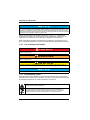 5
5
-
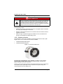 6
6
-
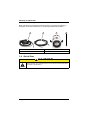 7
7
-
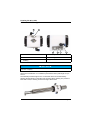 8
8
-
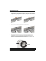 9
9
-
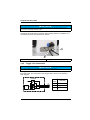 10
10
-
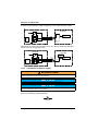 11
11
-
 12
12
-
 13
13
-
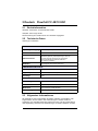 14
14
-
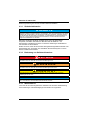 15
15
-
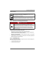 16
16
-
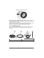 17
17
-
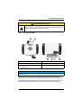 18
18
-
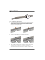 19
19
-
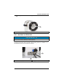 20
20
-
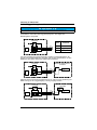 21
21
-
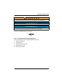 22
22
-
 23
23
-
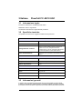 24
24
-
 25
25
-
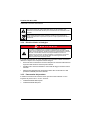 26
26
-
 27
27
-
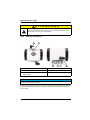 28
28
-
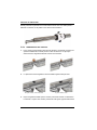 29
29
-
 30
30
-
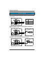 31
31
-
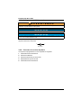 32
32
-
 33
33
-
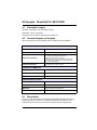 34
34
-
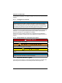 35
35
-
 36
36
-
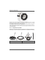 37
37
-
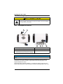 38
38
-
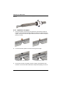 39
39
-
 40
40
-
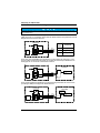 41
41
-
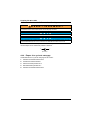 42
42
-
 43
43
-
 44
44
-
 45
45
-
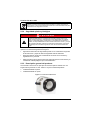 46
46
-
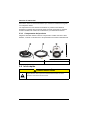 47
47
-
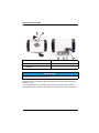 48
48
-
 49
49
-
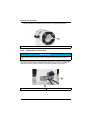 50
50
-
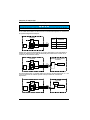 51
51
-
 52
52
-
 53
53
-
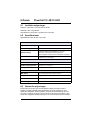 54
54
-
 55
55
-
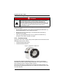 56
56
-
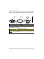 57
57
-
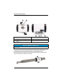 58
58
-
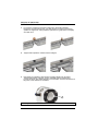 59
59
-
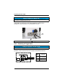 60
60
-
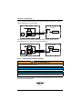 61
61
-
 62
62
-
 63
63
-
 64
64
-
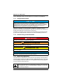 65
65
-
 66
66
-
 67
67
-
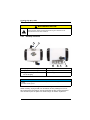 68
68
-
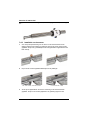 69
69
-
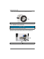 70
70
-
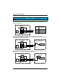 71
71
-
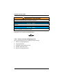 72
72
-
 73
73
-
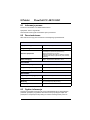 74
74
-
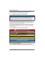 75
75
-
 76
76
-
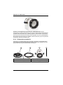 77
77
-
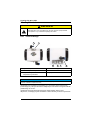 78
78
-
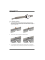 79
79
-
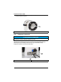 80
80
-
 81
81
-
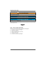 82
82
-
 83
83
-
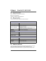 84
84
-
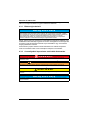 85
85
-
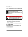 86
86
-
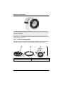 87
87
-
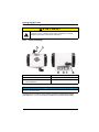 88
88
-
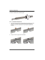 89
89
-
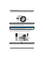 90
90
-
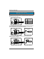 91
91
-
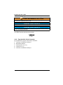 92
92
-
 93
93
-
 94
94
-
 95
95
-
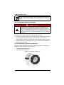 96
96
-
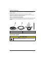 97
97
-
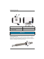 98
98
-
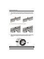 99
99
-
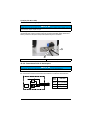 100
100
-
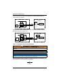 101
101
-
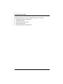 102
102
-
 103
103
-
 104
104


Hach Flow Cell FC 48/10 USC Guía de inicio rápido
- Tipo
- Guía de inicio rápido
En otros idiomas
- français: Hach Flow Cell FC 48/10 USC Guide de démarrage rapide
- italiano: Hach Flow Cell FC 48/10 USC Guida Rapida
- English: Hach Flow Cell FC 48/10 USC Quick start guide
- Deutsch: Hach Flow Cell FC 48/10 USC Schnellstartanleitung
- Nederlands: Hach Flow Cell FC 48/10 USC Snelstartgids
- dansk: Hach Flow Cell FC 48/10 USC Hurtig start guide
- polski: Hach Flow Cell FC 48/10 USC Skrócona instrukcja obsługi
- română: Hach Flow Cell FC 48/10 USC Ghid de inițiere rapidă


