Craftsman 13953904D El manual del propietario
- Categoría
- Abridor de puerta de garage
- Tipo
- El manual del propietario

Owner'sManual/ManualDelPr0pietari0
CRAFTSMAN°
112 HP
315MHz GARAGE DOOR OPENER
ABRIDOR DE PUERTA DE COCHERA
For Residential Use Only/Solo para uso residencial
Model/Modelo • 139.53904D
DE 315MHz
m
Z
G3
I"11
"0
Z_
0
Read and follow all safety rules and
operating instructions before first use
of this product.
Fasten the manual near the garage
door after installation.
Periodic checks of the opener are
required to ensure safe operation.
Leer y seguir todas las reglas de
seguridad y las instrucciones de
operacion antes de usar este producto
por primera vez.
Guardar este manual cerca de la
puerta de la cochera.
Se deben realizar revisiones
periodicas del abridor de puertas para
asegurar su operacion segura.
0Qus
Sears, Roebuck and Co., Hoffman Estates, IL 60179 U.S.A
www.sears.com/craftsman

TABLE OF CONTENTS
INTRODUCTION 2- 7
Safetysymbol and signal word review .......................................2
Preparing your garagedoor........................................................ 3
Tools needed..............................................................................3
Planning ..................................................................................4-5
Carton inventory .........................................................................6
Hardware inventory.....................................................................7
ASSEMBLY 8-11
Assemblethe rail and install the trolley......................................8
Fastenthe rail to the motor unit and
Install the idler pulley..................................................................9
Install the belt and attachthe belt cap retainer.........................10
Setthe tension..........................................................................11
INSTALLATION 11-26
Installation safetyinstructions ..................................................11
Determinethe headerbracket location .....................................12
Install the headerbracket.......................................................... 13
Attach the rail to the headerbracket.........................................14
Position the opener...................................................................15
Hangthe opener .......................................................................16
Install the door control .............................................................17
Install the lights ........................................................................18
Attach the emergencyreleaserope and handle........................ 18
Electrical requirements.............................................................19
Install The Protector System®..............................................20-22
Fastenthe door bracket.......................................................23-24
Connectthe door arm to thetrolley .....................................25-26
ADJUSTMENT 27-29
Adjust thetravel limits ..............................................................27
Adjust theforce ........................................................................28
Testthe safety reversalsystem.................................................29
TestThe Protector System®...................................................... 29
OPERATION 30-34
Operationsafety instructions ....................................................30
Using your garagedoor opener................................................ 30
Using the wall-mounted Door Control...................................... 31
To open the door manually.......................................................31
Careofyour garagedoor opener..............................................32
Having a problem?....................................................................33
Diagnostic chart........................................................................34
PROGRAMMING 35-36
To add or reprograma hand-held remote control .................... 35
To eraseall codes.....................................................................35
3-Function Remotes..................................................................35
To add, reprogram or changea KeylessEntry PIN...................36
REPAIRPARTS 37-38
Rail assembly parts ..................................................................37
Installation parts .......................................................................37
Motor unit assembly parts........................................................ 38
ACCESSORIES 39
WARRANTY 39
REPAIRPARTS& SERVICE BACKCOVER
INTRODUCTION
Safely Symboland SignalWordReview
This garage door opener has beendesignedand tested to offer safe serviceprovided it is installed, operated,maintained and tested in
strict accordancewith the instructions and warnings contained in this manual.
Mechanical
Electrical
Whenyou seethese SafetySymbols and Signal Words on the
following pages,they will alertyou to the possibility of serious
injury or deathif you do not comply with the warnings that
accompanythem. Thehazardmay come from something
mechanicalor from electric shock. Readthe warnings carefully.
Whenyou seethis Signal Word on the following pages, it will
alertyou to the possibility of damageto your garagedoor and/or
the garagedoor opener if you do not comply with the cautionary
statements that accompany it. Readthem carefully.

Preparingyourgaragedoor
Beforeyou begin:
* Disablelocks.
* Removeany ropes connectedto garage door.
° Complete the following test to make sureyour garage door is
balancedand is not sticking or binding:
1. Lift the door about halfwayas shown. Releasethe door. If
balanced, it should stay in place,supported entirely by its
springs.
2. Raiseand lower the door to seeif there is any binding or
sticking.
If your door binds, sticks, or is out of balance,call a trained door
systems technician.
To prevent possible SERIOUSINJURYor DEATH:
° ALWAYScall atrained door systems technician if garage
door binds, sticks or is out of balance.An unbalanced
garagedoor may not reversewhen required.
° NEVERtry to loosen, move or adjust garagedoor, door
springs, cables,pulleys, brackets or their hardware,ALL of
which are under EXTREMEtension.
° DisableALL locks and removeALL ropes connectedto
garagedoor BEFOREinstalling and operating garagedoor
opener to avoidentanglement.
To prevent damageto garage door and opener:
° ALWAYSdisable locks BEFOREinstalling and operatingthe
opener.
° ONLYoperate garagedoor openerat 120V, 60 Hzto avoid
malfunction and damage.
SectionalDoor
One-Piece Door
Tools needed
During assembly, installation and adjustment of the opener,
instructions will call for handtools as illustrated below.
Stepladder
Level (optional)
Pencil
Tape Measure
Dr_ Wire Cutters
Drill 3/16", 5/16"
_0 and 5/32"
1/2", 5/8", 7/16", 9/16" Pliers
and 1/4"
Hack Saw
Claw Hammer
Screwdriver
Adjustable End Wrench

P_nnmg
Identify the type and height of your garagedoor. Surveyyour
garageareato see if any of the conditions below apply to your
installation. Additional materials may be required.You may find it
helpful to referback to this pageand the accompanying
illustrations asyou proceedwith the installation of your opener.
Dependingon your requirements,there are several installation
steps which may call for materialsor hardware not included in
the carton.
• Installation Step 1 - Lookat the wall or ceiling abovethe
garagedoor. Theheader bracketmust be securelyfastenedto
structural supports.
• Installation Step 5 - Doyou havea finished ceiling in your
garage? If so, a support bracket and additionalfastening
hardware may be required.
• Installation Step 10 - Dependingupon garageconstruction,
extension brackets or wood blocks may be neededto install
sensors
• Installation Step 10 - Alternatefloor mounting of the safety
reversingsensor will require hardwarenot provided.
• Doyou havean access door in addition to the garagedoor? If
not, Model 53702 EmergencyKeyReleaseis required.See
Accessoriespage.
• Lookat the garage door where it meetsthe floor. Any gap
betweenthe floor and the bottom of the door must not exceed
1/4" (6 mm). Otherwise,the safetyreversalsystem maynot
work properly. SeeAdjustment Step 3. Floor or door should be
repaired.
SECTIONALDOORINSTALLATIONS
• Doyou havea steel, aluminum, fiberglass or glass panel door?
If so, horizontal and vertical reinforcement is required
(Installation Step 11).
• Theopener should be installed abovethe center of the door. If
there is a torsion spring or center bearing plate in the way of
the header bracket, it may be installed within 4 feet (1.22 m)
to the left or right of the door center. See Installation Steps 1
and 11.
• If your door is morethan 7 feet (2.13 m) high, see rail
extension kits listed on Accessoriespage.
SectionalDoor Installation
Horizontal and vertical reinforcement
is needed for lightweight garage doors
(fiberglass, steel, aluminum, door with
glass panels, etc.). See page 23 for details.
Header Wail
Rail
Extension Spring
OR
FINISHED CEILING
Support bracket &
fastening hardware
is required.
See page 16.
,tor unit
Wall-
mounted [
Door Access Door
Control
©
Safety Reversing Sensor
Gap between floor
and bottom of door
must not exceed 1/4" (6 mm).
Safety
Reversing
Sensor
CLOSED POSITION
Header
Bracket Trolley
/ Stop Bolt Trolley
L
_ Garage ...... .....
F///,_ Door 'c_/ --I Belt
_////4 Spring I
__ _/Str"a?ht L Emergency Release
_/ Arm i_ Rope&Handle
I _ _ Curved
Header _ _ Door
Wall Ix\/I \ Arm
Garage HI £oo:
oooJ-1-lJ _ek_

Planning(Continued)
ONE-PIECEDOORINSTALLATIONS
• Generally,a one-piecedoor does not require reinforcement. If
your door is lightweight, refer to the information relatingto
sectional doors in Installation Step 11.
• Dependingon your door's construction, you may need
additional mounting hardwarefor the door bracket (Step 11).
Without a properly working safety reversal system, persons
(particularly small children) could be SERIOUSLYINJUREDor
KILLEDby a closing garagedoor.
• Thegap betweenthe bottom of the garage door and the
floor MUST NOTexceed1/4" (6 mm). Otherwise,the safety
reversalsystem may not work properly.
• Thefloor or the garage door MUSTbe repairedto eliminate
the gap.
ONE-PIECEDOORWITHOUTTRACK
FINISHED CEILING
Support bra(
& fastening
hardware is required.
See page 16.
rdf'l I
Safety Reversing Sensor
Header Wall
Rail
J
Access
Door
Safety Reversing
Gap between floor Sensor
Wall-mounted
Door Control
and bottom of door must not exceed 1/4" (6 ram).
Motor Unit
eader
,'all
CLOSED POSITION
Trolley Stop Bolt
Belt Trolley
Straight Door
Door
Arm
Arm
-- Garage
Door
Emergency
Release
Rope & Handle
ONE-PIECEDOORWITHTRACK
Jl__ Gapbteween floor Sensor
_._v .-\ and bottom of door
Safety
must not exceed 1/4" (6 mm).
Reversing Sensor
CLOSED POSITION
Trolley Stop Bolt Belt Trolley
Door
Bracket
Garage
Door
Straight
Door
Arm
Rail
Release
Rope &
Handle

CartonInventory
Your garagedoor opener is packagedin one carton which
contains the motor unit and all parts illustrated below.
Accessorieswill depend on the model purchased.If anything is
missing, carefully check the packing material. Parts may be stuck
in the foam. Hardwarefor assemblyand installation is shown on
the next page.Savethe carton and packing material until
installation and adjustment is complete.
Door Control Button
SECURITY÷*_
3-Function Remote Control (1)
Belt Cap Retainer
Trolley
MotorUnitwith 2 LightLenses
IdlerPulley
Rail
Fron! (header) /_#/
j
Header Bracket
Rail
Center/Back
Sections
@
Belt
Door Bracket
CurvedDoor
ArmSection
Hanging Brackets
Safety Reversing
Sensor Bracket (2)
The Protector System®
(2) Safety Reversing Sensors
(1 Sending Eyeand 1 Receiving Eye)
with 2-Conductor White & White/Black
Bell Wire attached
2-Conductor BellWire
White & White/Red
Safety Labels
and
Literature
Straight Door
Arm Section

HardwareInventory
Separateall hardwareand group as shown below for the assembly and installation procedures.
ASSEMBLYHARDWARE
Spring/Trolley Nut (1) Lock Nut Lock Washer Nut
1/4"-20 (2) 3/8" (1) 3/B" (1)
Bolt 1/4"-20xl-3/4" (2)
Trolley Threaded Shaft (1)
Master
Link (2)
Idler Bolt (1)
iNSTALLATiONHARDWARE
O
Carriage Bolt Wing Nut Ring
1/4"-20x1/B" (2) 1/4"-20 (2) Fastener (3)
Lag Screw
5/16"-9xl-5/8" (2)
Lag Screw
5/16"-18xl-7/8" (2)
Hex Bolt
5/16"-18x7/8" (4)
Nut 5/16"-18 (4)
Screw
6ABx1-1/4" (2)
LockWasher 5/16" (5)
Self-Threading Screw
1/4"-14x5/8" (2)
Handle
Insulated
Staples (30)
Screw 6-3Bx1" (2)
Drywall Anchors (2)
Clevis Pin Clevis Pin Clevis Pin
5/16"x1-1/2" (1) 5/16"x1" (1) 5/16"x1-1/4" (1)
o_
Rope

ASSEMBLY STEP 1
Assemble the Raft & Install the Trolley
To avoidinstallationdifficulties,do notrunthe garagedoor
openeruntil instructedto do so.
To prevent INJURYfrom pinching, keephandsand fingers
away from the joints while assembling the rail.
Thefront rail has a cut out "window" at the door end (see
illustration). Thehole abovethis windowis larger onthe top of
the raft than on the bottom. A smaller hole 3-1/2" (8.9 cm) away
is close to the rail edge.Rotatethe back rail so it hasa similar
hole close to the oppositeedge,about 4-3/4" (12 cm) from the far
end.
1. Removethe straight door arm and hanging bracketpackaged
inside the front rail and set asidefor Installation Step5 and 12.
NOTE:Toprevent INJURYwhile unpacking therail carefully
remove the straight door arm stored within the rail section.
2. Align the rail sections on a flat surface asshown and slide the
taperedends into the larger ones. Tabs along the side will lock
into place.
3. Placethe motor unit on packing material to protect the cover,
and rest the back end of the rail on top. Forconvenience,put a
support under the front end of the rail.
4. As a temporary stop, insert a screwdriver into the hole
10"(25 cm) from the front end of the rail, as shown.
5. Checkto besure there are 4 plastic wear pads insidethe inner
trolley. If they becameloose during shipping, checkall packing
material. Snapthem back into position asshown.
6. Slide the trolley assembly along the rail from the back end to
the screwdriver.
Trolley
,ered
End
3ered
End
,ered
End
lack Rails
(TO MOTOR UNIT)
_..._rewd rive_,_
"_ /_/ Tabs
Window 0 ///
Cut-Out ', ///
\ _/.// FrontRail
Idler V_._ (TO DOOR)
Pulley
Hole _ ;
)ered
End
Inner Trolley
dar Pads

ASSEMBLY STEP 2
Fastenthe Rail to the MotorUnit
,, Inserta 1/4"-20xl-3/4" bolt into the cover protection bolt hole
on the back end of the rail as shown. Tighten securelywith a
1/4"-20 lock nut. DoNOT overtighten.
* Removethe two bolts from the top of the motor unit.
* Placethe "U" bracket,flat sidedown, on the motor unit and
align the bracketholes with the bolt holes. Fastenwith the
previously removed bolts.
* Align the rail assemblywith the top of the motor unit. Slide the
rail end onto the "U" bracket,all the way to the stops that
protrude on the top and sides of the bracket.
To avoid SERIOUSdamageto garagedoor opener, use ONLY
those bolts/fasteners mounted in the top of the opener.
"U" Bracket
Bolt
Bolts
Motor Unit
Sprocket
Cover
Protection
Bolt Hole
HARDWARESHOWNACTUALSIZE
Lock Nut
Bolt 1/4"-20xl-3/4" 1/4"-20
SLIDE RAIL TO STOPS
ONTOPAND SIDES
OFBRACKET
I Lock Nut
ASSEMBLY STEP 3
Install theIdler Pulley
* Laythe belt besidethe rail, as shown. Graspthe end with the
hookedtrolley connector and pass approximately 12" (30 cm)
of beltthrough the window. Keepthe ribbed side toward the
rail, and allow it to hang until Assembly Step 5.
* Removethe tapefrom the idler pulley. The inside center should
be pre-greased.If dry, regreaseto ensure proper operation.
* Placethe idler pulley into the window as shown.
* Insertthe idler bolt from the top through the rail and pulley.
Tighten with a 3/8" lock washer and nut underneaththe rail
until the lock washer is compressed.
* Rotatethe pulley to be sure it spins freely.
* Inserta 1/4"-20xl-3/4" bolt into the trolley stop holein the
front of the rail as shown. Tighten securely with a 1/4"-20 lock
nut.
Grease
_. _ __lnside
Pulley
_ _ Idler Pulley
Lock Washer 3/8"-_
Nut 3/8"
I
Trolley
Connector
Bolt
r _ Lock
Pulley , Nut
Idler Bolt
HARDWARESHOWNACTUALSIZE
Bolt 1/4"-20x1-3/4" Lock Nut 1/4"-20 Nut 3/8" Lock Washer 3/8"

ASSEMBLY STEP 4
Insta// the Be/t and Attach the Be/t Cap Retainer
1. Pull the belt around the idler pulleyand toward the trolley. The
ribbed side must contact thepulley.
2. Hookthe trolley connector into the retaining slot on the trolley
as shown.
3. With the trolley against the screwdriver, dispensethe
remainderof the belt along the rail length toward the motor
unit and around the sprocket. The sprocket teeth must engage
the belt.
4. Checkto make sure the belt is not twisted. Connectthe trolley
threadedshaft with the master link, as illustrated:
* Pushpins of master link bar through holes in end of belt
and trolley threadedshaft.
* Pushmaster link cap over pins and past pin notches.
. Slide clip-on spring over capand onto pin notchesuntil both
pins are securely locked in place.
5. Insertthe trolley threaded shaft through the hole in the trolley.
Besure the belt is not twisted.
6. Holdthe belt at the trolley shaft as you thread the spring nut by
hand onto the shaft until finger tight against the trolley. Do not
useany tools.
7. Removethe screwdriver.
8. Position the belt cap retainerover the motor unit sprocket as
shown and fasten to the mounting platewith 8x3/8" hex screws
provided.
To avoid possible SERIOUSINJURYto fingers from moving
garagedoor opener:
• ALWAYSkeephand clearof sprocket while operating
opener.
• Securely attachsprocket cover BEFOREoperating.
HARDWARESHOWNACTUALSIZE
Hex Screw 8x3/8"
Spring/Trolley Nut
Master Link
Clip-On Spring
Master LinkCap
Idler Pulley
Trolley
Connector
Retaining
Slot
Pin
Notch|
Trolley Master
Threaded Link Bar
Shaft
Hole
Hex Screws
Belt Cap_ #8x3/8"
Retainer _.,,,_, _ ,
Motor Unit
I Sprocket
Plate
10

ASSEMBLY STEP 5
Set the Tension
• Inserta screwdriver tip into one of the nut ring slots and brace
it firmly against the trolley.
• Placea 7/16" open end wrench on the squareend. Rotatethe
nut about 1/4 turn until the spring releasesand snaps the nut
ring against the trolley.
This sets the spring to optimum belt tension.
Youhave nowfinishedassemblingyourgaragedoor opener.
Please read thefollowingwarningsbeforeproceedingto the
installationsection.
Square
End
Trolley
Nut Ring
Nut Ring
_1 _ BEFORE1" -_
(2.5 cm)
t_. AFTERRELEASE
1-1/4"
(3.18 cm)
INSTALLATION
IMPORTANTINSTALLATIONINSTRUCTIONS
To reducethe riskof SEVEREINJURYor DEATH:
1. READAND FOLLOWALL INSTALLATIONWARNINGSAND
INSTRUCTIONS.
2. Install garagedoor opener ONLYon properly balancedand
lubricated garagedoor. An improperly balanceddoor may
NOT reversewhen required and could result in SEVERE
INJURYor DEATH.
3. ALL repairsto cables,spring assemblies and other
hardware MUSTbe made by a trained door systems
technician BEFOREinstalling opener.
4. DisableALL locks and remove ALL ropes connectedto
garagedoor BEFOREinstalling openerto avoid
entanglement.
5. Install garagedoor opener 7 feet (2.13 m) or more above
floor.
6. Mount the emergency releasewithin reach, but at least
6 feet (1.8 m) abovethe floor and avoiding contact with
vehiclesto avoid accidentalrelease.
7. NEVERconnectgarage door opener to power source until
instructed to do so.
8. NEVERwear watches, rings or looseclothing while
installing or servicing opener.They could be caught in
garage door or opener mechanisms.
9. Install wall-mounted garage door control:
* within sight of the garage door.
* out of reachof children at minimum height of
5 feet (1.5 m).
* awayfrom ALL moving parts of the door.
10. Placeentrapmentwarning label on wall next to garagedoor
control.
11. Placemanual release/safetyreversetest label in plain view
on inside of garage door.
12. Upon completion of installation, test safety reversalsystem.
Door MUSTreverseon contact with a 1-1/2" (3.8 cm) high
object (or a 2x4 laid flat) on the floor.
11

INSTALLATION STEP 1
Determinethe HeaderBracketLocation
To prevent possible SERIOUSINJURYor DEATH:
* HeaderbracketMUST be RIGIDLYfastenedto structural
support on headerwall or ceiling, otherwise garagedoor
might not reversewhen required. DONOTinstall header
bracket over drywall.
. Concreteanchors MUST be usedif mounting headerbracket
or 2x4 into masonry.
. NEVERtry to loosen, move or adjust garagedoor, springs,
cables, pulleys,brackets, or their hardware,ALL of which
are under EXTREMEtension.
. ALWAYScall atrained door systems technician if garage
door binds, sticks, or is out of balance.An unbalanced
garagedoor might not reversewhen required.
Installation procedures vary according to garagedoor types.
Follow the instructions which applyto your door.
1. Closethe door and mark the insidevertical centerline of the
garagedoor.
2. Extendthe line onto the headerwall abovethe door.
Youcanfastentheheader bracketwithin 4 feet
(1.22 m) ofthe left or right ofthe doorcenteronly if a
torsionspringor center bearingplate is in the way;or you
canattachit tothe ceiling (see page 13) whenclearanceis
minimal. (It may be mountedon thewall upsidedownif
necessary,to gainapproximately1/2" (1 cm).)
If you need to install the headerbracket on a 2x4 (on wall or
ceiling), use lag screws (not provided) to securely fastenthe
2x4 to structural supports asshown here and on page 13.
3. Openyour door to the highest point of travel asshown. Draw
an intersecting horizontal line on the headerwall abovethe
high point:
• 2" (5 cm) abovethe high point for sectional door and
one-piecedoor with track.
• 8" (20 cm) abovethe high point for one-piecedoor without
track.
This height will providetravel clearancefor the top edge of the
door.
NOTE:If the total number of inches exceedstheheight
availablein your garage,use the maximum height possible, or
refer to page 13 for ceiling installation.
Header Wall
Unfinished
Ceiling _ OPTIONALBRACKETHEADERFORMOUNTCEILING
Vertical Centerline
of Garage Door
2x4
Structural
Supports
Header Wall
"_-_--2" (5 cm) Track
Highest Point
of Travel
--Door
Sectional door with curved track
H
Y
Header Wall Track
I
Highest Point
_oHf Travel
T
One-piece door with horizontal track
Door
Hardware
Header Wall
:8" (20 cm)
Highest
Point
One-piece door without track:
jamb hardware
Header Wall
: 8" (20cm)
Pivot
One-piece door without track:
pivot hardware
12

INSTALLATION STEP 2
Install theHeaderBracket
You can attachthe headerbracketeither to the wall abovethe
garagedoor, or to the ceiling. Follow the instructions which will
work bestfor your particular requirements. Donot install the
headerbracketoverdrywall. If installingintomasonry,use
concreteanchors(not provided).
WALLHEADERBRACKETINSTALLATION
* Centerthe bracket on the vertical centerline with the bottom
edge of the bracket on the horizontal line asshown (with the
arrow pointing toward the ceiling).
• Mark thevertical set of bracket holes. Drill 3/16" pilot holesand
fastenthe bracketsecurely to a structural support with the
hardware provided.
HARDWARESHOWNACTUALSIZE
Lag Screw
5/16"-9xl -5/8"
Header
- Wall
2x4
Structural
Support
f
1
Horizontal
Line
Highest Point of
Garage Door Travel
Wall Mount
Optional
Mounting Holes
Vertical
Centerline
Door
Lag Screws
5/16"x9x 1-5/8"
Spring
Garage
-- Door-
Vertical
Centerline
of Garage Door
CEILINGHEADERBRACKETINSTALLATION
• Extendthe vertical centerline onto the ceiling as shown.
• Centerthe bracket on the vertical mark, no more than
6" (15 cm) from the wall. Make sure the arrow is pointing away
from the wall. The bracketcan be mounted flush against the
ceiling when clearanceis minimal.
• Mark the side holes. Drill 3/16" pilot holes and fasten bracket
securelyto a structural support with the hardwareprovided.
Ceiling Mounting Holes
/
Header y
Bracket
6" (15 cm) Maximum
Door
Spring
//_ /_ _ -FinishedCeiling-
/ Vertical Centerline
_ of Garage Door
-- Lag Screws
5/16"x9x1-5/8"
- Header Wall --
13

iNSTALLATiON STEP 3
Attachthe Rail to the HeaderBracket
• Position the opener on the garagefloor below the header
bracket. Usepacking material asa protective base. NOTE:If the
door spring is in the wayyou'll needhelp. Havesomeone hold
theopener securely on a temporary support to allow the rail to
clearthe spring.
• Position the rail bracket againstthe headerbracket.
• Align the bracket holesand join with a clevis pin 5/16"x1-1/2"
as shown.
• Inserta ring fastenerto secure.
Header Wall
Header Bracket
Idler Pulley
Header
Bracket
\
Mounting
Hole
0
\
\
J Garage
Door
OpenerCarton or
Temporary
Support
HARDWARESHOWNACTUALSiZE
ClevisPin5/16"x1-1/2"
Ring Fastener
14

INSTALLATION STEP 4
Positionthe Opener
Follow instructions which applyto your door type as illustrated.
SECTIONALDOORORONE-PIECEDOORWITH TRACK
A 2x4 laid flat is convenient for setting an ideal door-to-rail
distance.
• Removefoam packaging.
• Raisethe opener onto a stepladder.You will need help at this
point if the ladder is not tall enough.
• Openthe door all the way and placea 2x4 laid flat on the top
section beneaththe rail.
• If the top section or panel hits the trolley whenyou raise
the door, pull down on the trolley releasearm to disconnect
inner and outer sections. Slide the outer trolley toward the
motor unit. Thetrolley can remain disconnected until
Installation Step 12 is completed.
To prevent damageto garage door, rest garage door opener
rail on 2x4 placedon top section of door.
Rail iil
_Door 2x4 is used to determine
tfheCOcrer_Ctg?ouating height
ENGAGED
ONE-PIECEDOORWITHOUTTRACK
A 2x4 on its side is convenientfor setting an ideal
door-to-rail distance.
• Removefoam packaging.
• Raisethe opener onto a stepladder.You will need help at this
point if the ladder is not tall enough.
• Openthe door all the way and placea 2x4 on its side on the
top section of the door beneaththe rail.
• Thetop of the door should be levelwith thetop of the motor
unit. Donot position the opener more than 4" (10 cm) above
this point.
H Header iii'
I I I._L _[T_acket ii.!_
i tfheCOrer_Ctg?ounting height
15

INSTALLATION STEP 5
Hangthe Opener
Threerepresentativeinstallations are shown. Yours may be
different. Hangingbrackets should be angled (Figure 1) to provide
rigid support. Onfinished ceilings (Figure2 and Figure3), attach
a sturdy metal bracket to structural supports before installing the
opener.This bracketand fastening hardwareare not provided.
1. Measurethe distancefrom eachside of the motor unit to the
structural support.
2. Cut both piecesof the hanging bracketto required lengths.
3. Drill 3/16" pilot holes in the structural supports.
4. Attach one end of eachbracketto a support with
5/16"-18xl -7/8" lag screws.
5. Fastenthe opener to the hanging brackets with
5/16"-18x7/8" hex bolts, lock washers and nuts.
6. Checkto make sure the rail is centered over the door (or in line
with the headerbracket if the bracket is not centeredabovethe
door).
7. Removethe 2x4. Operatethe door manually. If the door hits
the rail, raisethe header bracket.
NOTE:DONOTconnectpower to openerat this time.
HARDWARESHOWNACTUALSIZE
Hex Bolt
5/16"-18x7/8"
Nut 5/16"-18 Lock Washer 5/16"
To avoid possible SERIOUSINJURYfrom afalling garage door
opener,fasten it SECURELYto structural supports of the
garage.Concreteanchors MUSTbe usedif installing any
brackets into masonry.
Figure1
Supports
Measure ',
Distance
Bolt 5/16"-18x7/8"
Lock
Nut 5/16"-18
Lag Screws
5/16"-18xl -7/8"
Figure2
Bolt 5/16"-18x7/8"
Lock Washer 5/16"
Nut 5/16"- 18
FINISHED CEILING
(Not Provided)
Bolt 5/16"-18x7/8"
Lock Washer 5/16"
Nut 5/16"-18
Figure3
Bolt 5/16"-18x7/8"
Lock Washer 5/16"
Nut 5/16"- 18
(Not Provided)
Bolt 5/16"-18x7/8"
Lock Washer 5/16"
Nut 5/16"-18
16

INSTALLATION STEP 6
Install theDoorControl
Locate door control within sight of door, at a minimum height of
5 feet (1.5 m) where small children cannot reach, awayfrom
moving parts of door and door hardware.
1. Strip 1/4" (6 mm) of insulation from oneend of bell wire and
connect to the two terminal screws on back of door control by
color: white to 2 and white/red to 1.
2. Fastenthe Door Control Button securelywith 6ABx1-1/2"
screws. If installing into drywall, drill 5/32" holes and usethe
anchors provided.
3. Runbell wire up wall and across ceiling to motor unit. Use
insulated staples to secure wire in severalplaces. Donot pierce
wire with a staple, creating a short or open circuit.
4. Connectthe bell wire to the quick-connect terminals on the
motor unit panel:white to white; white/red to red.
5. Position the antennawire as shown.
6. Usetacks or staplesto permanently attachentrapment warning
label to wall near door control, and manual release/safety
reversetest label in a prominent location on inside of garage
door.
NOTE:DONOTconnectpower and operateopener at this time.
Thetrolley will travel to the furl open position but will not return
to the close position until thesensor beamis connectedand
properly aligned.
To prevent possible SERIOUSINJURYor DEATHfrom
electrocution:
• Besure power is not connected BEFOREinstalling door
control.
• ConnectONLYto 24 VOLTlow voltage wires.
To prevent possible SERIOUSINJURYor DEATHfrom a closing
garagedoor:
• Install door control within sight of garagedoor, out of reach
of children at a minimum height of 5 feet (1.5 m) and away
from ALL moving parts of door.
• NEVERpermit children to operateor play with door control
push buttons or remote control transmitters.
• Activate door ONLYwhen it can be seenclearly, is properly
adjusted and there are no obstructions to door travel.
• ALWAYSkeepgarage door in sight until completely closed.
NEVERpermit anyoneto cross path of closing garage door.
HARDWARESHOWNACTUALSIZE
Screw 6ABx1-1/2" Insulated
Lighted Door Control Button Drywall Anchors Staples
Te,e ,w t, VV,re
(BACK VIEW)
DOOR CONTROL BUTTON
Quick-Connect
To release or insert wire,
push in tab with
screwdriver tip
Strip wire 7/16" Red/
(11 mm)
7/16" (11 mrn)l
Door Control
Connections
White Grey
Antenna
17

INSTALLATION STEP 7
Install theLights
• Pressthe releasetabs on both sides of lens. Gentlyrotate lens
back and downward until the lens hinge is in thefully open
position. Do not removethe lens.
• Install a 100 watt maximum light bulb in eachsocket. Light
bulb size should be A19, standard neckonly. The lights will
turn ONand remain lit for approximately 4-1/2 minutes when
power is connected.Thenthe lights will turn OFF.
• Reversethe procedureto close the lens.
• UseA19,standard neck garagedoor opener bulbs for
replacement.
NOTE:Useonly standard light bulbs. Theuseof short neck or
speciafity light bulbs may overheatthe endpanel or light socket.
To prevent possible OVERHEATINGof the endpanelor light
socket:
• DONOTuse short neck or specialty light bulbs.
• DONOTuse halogen bulbs. UseONLYincandescent.
To prevent damageto the opener:
• DONOTuse bulbs larger than IOOW.
• ONLYuseA19 size bulbs.
Release Tab
100 Watt (Max) _ )
Standard Light Bulb
/
/
/
100 Watt (Max)
Standard
Light Bulb --
Lens
Hinge
INSTALLATION STEP 8
AttachtheEmergencyRe/ease Ropeand Hand/e
- Threadone end of the rope through the hole in the top of the
red handleso "NOTICE"readsright side up asshown. Secure
with an overhandknot at least 1" (2.5 cm) from the end of the
ropeto prevent slipping.
• Threadthe other end of the rope through the hole in the release
arm of the outer trolley.
• Adjust rope lengthso the handle is 6 feet (1.83 m) abovethe
floor. Ensurethat the rope and handle clearthe tops of all
vehiclesto avoid entanglement.Securewith an overhand knot.
NOTE:If it is necessaryto cut the rope, heat sealthe cut end with
a match or lighter to prevent unraveling.
To prevent possible SERIOUSINJURYor DEATHfrom a falling
garagedoor:
• If possible, useemergencyreleasehandleto disengage
trolley ONLYwhen garagedoor is CLOSED.Weakor broken
springs or unbalanceddoor could result in an open door
falling rapidly and/or unexpectedly.
• NEVERuseemergency releasehandle unless garage
doorway is clear of persons and obstructions.
• NEVERusehandle to pull door open or closed. If rope knot
becomesuntied, you could fall.
Trolley
I
Emergency _ _. Overhand
Release Handle _Knot
18

INSTALLATION STEP 9
E/ectrica/ Requirements
To avoidinstallationdifficulties,do notrunthe openerat this
time.
To reducethe risk of electric shock, your garagedoor opener has
a grounding type plug with a third grounding pin. This plug will
only fit into a grounding type outlet. If the plug doesn't fit into the
outlet you have, contact a qualified electricianto install the proper
outlet.
RIGH_
To prevent possible SERIOUSINJURYor DEATHfrom
electrocution or fire:
• Besure power is not connectedto the opener,and
disconnect power to circuit BEFOREremoving cover to
establish permanentwiring connection.
• Garagedoor installation and wiring MUSTbe in compliance
with ALL local electrical and building codes.
• NEVERusean extension cord, 2-wire adapteror change
plug in ANYway to make it fit outlet. Besure the opener is
grounded.
PERMANENT WIRING
CONNECTION
If permanent wiringis requiredbyyourlocal code,refer to the
followingprocedure.
To make a permanent connection through the 7/8" hole in the top
of the motor unit:
• Removethe motor unit cover screws and set the cover aside.
• Removethe attached3-prong cord.
• Connectthe black (line) wire to the screw on the brass
terminal; the white (neutral) wire to the screw on the silver
terminal; and the ground wire to the green ground screw. The
openermustbe grounded.
• Reinstallthe cover.
To avoidinstallationdifficulties,do notrunthe openerat this
time.
Ground Tab
Green
Ground Screw
Ground Wire
White Wire Wire
19

INSTALLATION STEP 10
Install TheProtectorSystem
Thesafety reversingsensormustbeconnectedand aligned
correctlybeforethe garagedooropenerwill movein the down
direction.
IMPORTANTINFORMATIONABOUTTHESAFETYREVERSING
SENSOR
When properly connectedand aligned, the sensor will detect an
obstacle in the pathof its electronic beam. Thesending eye (with
an amber indicator light) transmits an invisible light beamto the
receiving eye (with a green indicator light). If an obstruction
breaks the light beamwhile the door is closing, the door will stop
and reverseto full open position, and the opener lights will flash
10 times.
Theunits must be installed inside the garageso that the sending
and receivingeyes face eachother across the door, no morethan
6" (15 cm) abovethefloor. Either can be installed on the left or
right of the door as long as the sun nevershines directly into the
receiving eye lens.
Themounting brackets are designedto clip onto the track of
sectional garagedoors without additional hardware.
Be sure power is not connectedto the garagedoor opener
BEFOREinstalling the safety reversing sensor.
To prevent SERIOUSINJURYor DEATHfrom a closing garage
door:
• Correctly connect and align the safety reversingsensor. This
required safety deviceMUST NOTbe disabled.
• Install the safety reversing sensor so beamis NOHIGHER
than 6"(15 cm) above garagefloor.
If it is necessaryto mount the units on the wall, the brackets
must be securelyfastenedto a solid surface such asthe wall
framing. Extensionbrackets (seeAccessories) are availableif
needed.If installing in masonry construction, add a pieceof wood
at eachlocation to avoid drilling extra holesin masonry if
repositioning is necessary.
Theinvisible light beam path must be unobstructed. No part of
the garagedoor (or door tracks, springs, hinges, rollers or other
hardware) may interrupt the beamwhile the door is closing.
IH, i 111
Facingthe doorfrom insidethegarage
2O

INSTALLINGTHE BRACKETS
Besure power to the opener is disconnected. Install and align
the brackets so the sensors will face eachother across the garage
door, with the beam no higher than 6"(15 cm) abovethe floor.
They may be installed in one of three ways, as follows.
Garage doortrackinstallation(preferred):
* Slip the curved arms over the rounded edge of each door track,
with the curved arms facing the door. Snap into placeagainst
the side of the track. It should lie flush, with the lip hugging the
back edge of the track, asshown in Figure1.
If your door track will not support the bracket securely,wall
installation is recommended.
Wall installation(Figure2 & 3):
* Placethe bracketagainst the wall with curved arms facing the
door. Besure there is enough clearancefor the sensor beamto
be unobstructed.
o If additional depth is needed,an extensionbracket (see
Accessories)or wood blocks can be used.
o Usebracket mounting holes asa template to locate and
drill (2) 3/16" diameter pilot holeson the wall at eachside of
the door, no higher than 6" (15 cm) abovethe floor.
o Attach brackets to wall with lag screws (not provided).
o If using extensionbrackets or wood blocks, adjust right and
left assembliesto the same distanceout from the mounting
surface. Make sure all door hardwareobstructions are cleared.
Floorinstallation(Figure4):
• Usewood blocksor extensionbrackets (seeAccessories)to
elevatesensor bracketsso the lenseswill beno higher than
6" (15 cm) abovethe floor.
• Carefullymeasure and place right and left assembliesat the
same distanceout from the wall. Besure all door hardware
obstructions are cleared.
• Fastento the floor with concrete anchors as shown.
Figure1
DOOR TRACK MOUNT (RIGHT SIDE)
L Door
_ Track
I1' up
Indicator
Light
Figure2 WALL MOUNT (RIGHT SIDE)
Fasten Wood Block to Wall with
Lag Screws (Not Provided)
Indicator
_ Light Senskort
- screws>
(Not Provided)
Lens - -_
Figure3
(Provided with
Extension ._ _
Bracket)
WALL MOUNT (RIGHT SIDE)
Extension
Bracket
(See Accessories)
I_r_ (Provided with
-- _r_ I Extension Bracket)
_ (._/'_/"_-_ Sensor
_C_i'_ " Bracket
I Indicator
Lens Light
Figure4 FLOOR MOUNT (RIGHT SIDE)
HARDWARESHOWNACTUALSIZE
Carriage Bolt Wing Nut Staples
1/4"-20xl/2" 1/4"-20
f
_l-- Attach with
Concrete Anchors
; (Not Provided)
Light
Sensor--S-
Bracket
21

MOUNTINGANDWIRINGTHESAFETYREVERSINGSENSORS
• Slide a 1/4"-20xl/2" carriage bolt head into the slot on each
sensor. Usewing nuts to fastensensors to brackets,with
lenses pointing toward eachother across the door. Besure the
lens is not obstructed by a bracket extension (Figure5).
• Fingertighten the wing nuts.
• Runthe wires from both sensorsto the opener. Use insulated
staplesto secure wire to wall and ceiling.
° Strip 7/16" (11 mm) of insulation from eachset of wires.
Separatewhite and white/black wires sufficiently to connect to
the opener quick-connect terminals. Twist like colored wires
together. Insert wires into quick-connect holes: white to white
and white/black to grey (Figure6).
ALIGNINGTHESAFETYREVERSINGSENSORS
• Plug in the opener. Theindicator lights in both the sending and
receiving eyeswill glow steadilyif wiring connections and
alignment are correct.
Thesending eyeamber indicator light will glow regardlessof
alignment or obstruction. If the green indicator light in the
receiving eyeis off, dim, or flickering (and the invisible light beam
path is not obstructed), alignment is required.
° Loosenthe sending eyewing nut and readjust, aiming directly
at the receiving eye.Lock in place.
° Loosenthe receiving eyewing nut and adjust sensoruntil it
receivesthe sender's beam.Whenthe green indicator light
glows steadily, tighten the wing nut.
Figure5
Wing Nut
1/4"-20
Lens
TROUBLESHOOTINGTHESAFETYREVERSINGSENSORS
1. If the sending eyeindicator light does not glow steadily after
installation, checkfor:
° Electric power to the opener.
° A short in the white or white/black wires. Thesecan occur at
staples, or at opener connections.
° Incorrect wiring betweensensors and opener.
° A broken wire.
2. If the sending eyeindicator light glows steadilybut the
receiving eyeindicator light doesn't:
° Checkalignment.
° Checkfor an open wire to the receiving eye.
3. If the receiving eyeindicator light is dim, realign either sensor.
NOTE:Whenthe invisible beam path is obstructed or misaligned
while the door is closing, the door will reverse.If the door is
already open,it will not close. Theopenerlights will blink 10
times. Seepage 20.
Figure6
Bell Wire
Connect Wire to
Quick-Connect Terminals
Bell Wire
\
1. Strip wire 7/16"
(11 mm)
7/16" (11 mm}l
2. Twist like colored
wires together
3. To release or insert
wire, push in tab with
screwdriver tip
Safety Reversing Sensor
Invisible Light Beam
Protection Area
Safety Reversing Sensor
22
Red White Grey
Quick-Connect Terminals

iNSTALLATiON STEP 1 1
FastentheDoorBracket
Follow instructions which applyto your door type as illustrated
below or on the following page.
A horizontal reinforcementbraceshould be ions enough
tobe securedto twoor three verticalsupports. A vertical
reinforcementbraceshouldcoverthe heightof thetop panel.
Figure1 shows one pieceof angle iron as the horizontal brace.
Forthe vertical brace, 2 piecesof angleiron are usedto createa
U-shapedsupport. Thebest solution is to checkwith your garage
door manufacturer for an openerinstallation door reinforcement
kit.
NOTE:Many door reinforcement kits provide for direct attachment
of theclevis pin and door arm. In this caseyou will not needthe
door bracket, proceedto Step 12.
SECTIONALDOORS
1. Centerthe door bracketon the previously marked vertical
centerline usedfor the headerbracketinstallation. Note correct
UPplacement, asstamped insidethe bracket.
2. Position thetop edgeof the bracket 2"-4"(5-10 cm) belowthe
top edge of the door, ORdirectly below anystructural support
acrossthe top of the door.
3. Mark, drift holesand install asfollows, dependingon your
door's construction:
Metal or light weightdoors using a vertical angle iron brace
between the doorpanel support and the doorbracket:
* Drill 3/16" fastening holes. Securethedoor bracketusing the
two 1/4"-14x5/8" self-threading screws(Figure2A).
* Alternately, usetwo 5/16" bolts, lock washersand nuts (not
provided) (Figure2B).
Metal, insulated or light weight factoryreinforced doors:
* Drill 3/16" fastening holes. Securethedoor bracketusing the
self-threading screws (Figure3).
WoodDoors:
* Usetop and bottom or side to side door bracketholes. Drill
5/16" holesthrough the door and secure bracketwith 5/16"x2"
carriagebolts, lock washers and nuts (not provided) (Figure4).
NOTE:The1/4"-14x5/8"self-threading screws are not intendedfor
use on wooddoors.
HARDWARE
SHOWNACTUAL
SIZE
If-Threading
rew
"-14x5/8"
Fiberglass,aluminum or lightweight steel garage doors will
requirereinforcement BEFOREinstallation of door bracket.
Contactyour door manufacturer for reinforcement kit.
Vertical
Centerline
of Garage
Door
Figure 1
Vertical
Reinforcement
Vertical
Centerline
o_arage Door
=
Self-Threading
Screw 1/4"-14x5/8"
Figure 2A
_rtical
Centerline
of Garage Door
UP
Figure 3
Screw
1/4"-14x5/8"
Vertical
Reinforcement
,_ Vertical
(_£ 1071_LI Centerline
7ollololof ?rage Door
Bolt/ TIIo[Ol :
5/16"-18x2" IOILIbl. -
(NotProvided) totl?hl "-¢_.
H Lu.p.eh' uP
ort O0.
5/16" I_ut _-
5/16"-18
Figure 2B
Inside Edge
of Door or
Reinforcement Board
Bolt
/16x2.
/"°tPr°vided/% /
Vertical "__-
Centerline __
of Garage _ _'-_.
Door
7
Figure 4
23

ONE-PIECEDOORS
Pleasereadand comply with the warnings and reinforcement
instructions on the previous page.They applyto one-piecedoors
also.
* Centerthe door bracketon the top of thedoor, in line with the
headerbracketas shown. Mark eitherthe left and right, or the
top and bottom holes.
* Meta/Doors: Drill 3/16" pilot holes andfasten the bracketwith
the 1/4"-14x5/8" self-threadingscrews provided.
* WoodDoors: Drift 5/16" holesand use5/16"x2"carriagebolts,
lock washers and nuts (not provided) or 5/16"x1-1/2" lag
screws (not provided) depending on your installation needs.
NOTE:Thedoor bracket may be installed on the top edgeof the
door if required for your installation. (Refer to the dotted fine
optional placement drawing.)
HARDWARESHOWN
ACTUAL SIZE
Self-Threading Screw
1/4"-14x5/8"
Header Wall
2x4 Support
Door
Bracket
Optional
Placement
of Door
Bracket
Vertical
Centerline of
Garage Door
i Finished Ceiling i
HORIZONTALANDVERTICAL
REINFORCEMENTIS NEEDED
FORLiGHTWEiGHTGARAGE
DOORS(FIBERGLASS,ALUMINUM,
STEEL, DOORSWiTH GLASS
PANEL,ETC.). (NOT PROVIDED)
For a door with no exposed framing,
or for the optional installation, use
lag screws 5/16"x1-1/2" (Not Provided)
to fasten door bracket.
Door
_ Self-Threading
Screw
' 1/4"-14x5/8"
Top of Door
(Inside Garage)
Optional
Placement
METALDOOR
Lock
_-- Washer
, 5/16"
t
i
i
, Top of Door
Garage)
Top Edge
of Door
Optional
Placement
b arriage Bolt
5/16"x2"
(Not Provided)
WOOD DOOR
24

INSTALLATION STEP 12
ConnectDoorArm to Trolley
Follow instructions which applyto your door type as illustrated
below and on the following page.
SECTIONALDOORSONLY
Make suregaragedoor isfully closed. Pullthe emergency release
handleto disconnect the outer trolley from the inner trolley. Slide
the outertrolley back (awayfrom the pulley) about8" (20 cm) as
shown in Figures1,2 and 3.
Figure 1:
• Fastenstraight door arm section to outer trolley with the
5/16"x1"clevis pin. Securethe connection with a ring fastener.
• Fastencurved section to the door bracketin the sameway,
using the 5/16"x1-1/4" clevis pin.
IMPORTANT."Thegroove on thestraight door arm MUSTface
away from the curved door arm (Figure4).
Figure2:
• Bring arm sections together. Findtwo pairs of holesthat line
up andjoin sections. Select holesasfar apart as possible to
increasedoor arm rigidity.
Figure3, Holealignmentalternative:
• If holes in curved arm areaboveholes in straight arm,
disconnect straight arm. Cut about 6" (15 cm) from the solid
end. Reconnectto trolley with cut end down asshown.
• Bring arm sections together.
• Findtwo pairs of holes that line up and join with bolts, lock
washersand nuts.
Pull the emergencyreleasehandletoward the opener at a 45°
angle sothat thetrolley releasearm is horizontal. Proceedto
Adjustment Step1, page27. Trolley will re-engageautomatically
when opener isoperated.
HARDWARESHOWNACTUALSIZE
o Oo
Nut 5/16"-18 Lock Washer 5/16" Ring Fastener
Clevis Pin Clevis Pin
5/16"x1" (Trolley) 5/16"x1-1/4" (Door Bracket)
Hex Bolt
5/16"-18x7/8"
Figure
Figure2
Figure3
Figure4
Pulley
/iz__ 8"(20 cm) rain.!!
- "q'_- _m --'-n,
, ,....
olley
Stop Bolt / InnerI I ',\ ,,
/ /rolleYli _ Trolle.
Ring I°1 "t -- Clevis Pin
Fastener I°1 I 5/16"x1"
/ lil_J Emergency
" IolE_ _ Release
,@ Door iol_ J_ Handle
Bracket I_1--
l._-_ Straight
Door Arm
CuHed DoorArm
Clevis Pin 5/16"x1-1/4"
Pulley
8" (20 cm) rain.
Bolts
Door Bracket
Pulley
/L, 8"(20cm) mi..__i
_ -,q'_- _ -7,
Trolley / _ _
stopBolt,ock // !
Washers _//
5/16' /,'-,7
Nuts / /o7
5/16"-1_11_ #
_'_ _/_1_S!B X7: ,,
"-" Cut this end
CORRECT INCORRECT
25

ALLONE-PIECEDOORS
1.Assemblethedoorarm, Figure5:
IMPORTANT'.Thegroove on thestraight door arm MUSTface
away from the curved door arm.
• Fastenthe straight and curved door arm sections together to
the longest possible length (with a 2 or 3 hole overlap).
• With the door closed, connectthe straight door arm sectionto
the door bracketwith the 5/16"x1-1/4" clevis pin.
• Securewith a ring fastener.
2. Adjustmentprocedures,Figure6:
• On one-piecedoors, before connectingthe door arm to the
trolley, the travel limits must beadjusted. Limit adjustment
screws are located on the left side panelasshown on page
27. Follow adjustment procedures below.
• Open dooradjustment:decreaseUPtravel limit
- Turn the UPlimit adjustment screw counter-clockwise
4 turns.
- Pressthe Door Control push button. Thetrolley will travel to
thefully open position.
- Manually raisethe door to the open position (parallel to the
floor), and lift the door armto thetrolley. Thearm should
touch thetrolley just in back of the door arm connector
hole. Referto the fully opentrolley/door arm positions in the
illustration. If thearm does not extendfar enough,adjust the
limit further. Onefull turn equals2" (5 cm) of trolley travel.
° Closeddooradjustment:decreaseDOWNtravel limit
- Turn the DOWNlimit adjustment screw clockwise4 complete
turns.
Figure6
Inner Trolley
I _ Emergency ReleaseHandle
Closed
I Door
Figure5
CORRECT INCORRECT
Door
Bracket _ Ring
,__.-tj_ Fastener Nuts
_C_X_"- __ Lock 5/16"-18
_-[_.__",,._ Washers I t'£'_
i _ _"_e___ 5/16" I I'_1!
ClevisPin StraightJ / ///
J16xllJ4
Bo,te
5/16'-18x7/8 _ _ Curved
DoorArm
Pressthe Door Control push button. Thetrolley will travel to
the fully closed position.
- Manually close the door and lift the door armto thetrolley.
Thearm should touch thetrolley just aheadof the door arm
connector hole. Referto the fully closed trolley/door arm
positions in the illustration. If the arm is behind the connector
hole, adjust the limit further. Onefull turn equals 2"(5 cm) of
trolley travel.
3. Connectthedoorarmto thetrolley:
• Closethe doorand join the curvedarm to the connector
hole in the trolley with the remainingclevis pin. It may be
necessaryto lift the door slightly to makethe connection.
• Securewith aring fastener.
• Runthe openerthrough a complete travel cycle. Ifthe door
hasa slight "backward" slant in full open position as shown in
the illustration, decreasethe UPlimit until thedoor is parallel
to the floor.
NOTE:Whensetting the up limit on the following page,the door
should not havea "backward"slant whenfully openas illustrated
below. A slight backwardslant will cause unnecessarybucking
and/orjerking operationas the door is being openedor closed
from the fully openposition.
Inner Trolley
Outer Trolley
Open Door (Incorrect)
26

ADJUSTMENT STEP 1
AdjusttheUPand DOWNTravelLimits
Limit adjustment settings regulatethe points at which the door
will stop when moving up or down.
To operatethe opener, press the Door Control push bar. Runthe
opener through a complete travel cycle.
• Doesthe door open and close completely?
• Doesthe door stay closed and not reverseunintentionally when
fully closed?
If your door passesboth of these tests, no limit adjustments are
necessaryunless the reversing test fails (seeAdjustment Step 3,
page 29).
Adjustment procedures are outlined below. Readthe procedures
carefully before proceedingto Adjustment Step2. Usea
screwdriver to make limit adjustments. Runthe openerthrougha
completetravel cycleafter eachadjustment.
NOTE:Repeatedoperationof the opener during adjustment
procedures may cause themotor to overheatand shut off. Simply
wait 15 minutes and try again. If anything interferes with the
door's upward travel, it will stop. If anythinginterferes with the
door's downward travel (including binding or unbalanceddoors),
it will reverse.
HOWANDWHENTOADJUSTTHE LIMITS
• If thedoordoesnot opencompletelybut opensat leastfive
feet (1.5 m):
Increaseup travel. Turn the UPlimit adjustmentscrew
clockwise. Oneturn equals2" (5 cm) of travel.
NOTE:Toprevent the trolley from hitting the coverprotection
bolt, keepa minimum distance of 2-4"(5 cm - 10 cm) between
the trolley and thebolt.
• If doordoesnot openat least5 feet (1.5 m):
Adjust the UP(open) force asexplained in Adjustment Step 2.
• If thedoordoesnot closecompletely:
Increasedown travel. Turn the down limit adjustment screw
counterclockwise. Oneturn equals 2" (5 cm) of travel.
If door still won't closecompletely and the trolley bumps into
the pulley bracket (page4), try lengtheningthe door arm
(page 25) and decreasingthe down limit.
• If theopenerreversesin fully dosed position:
Decreasedown travel. Turn the down limit adjustment screw
clockwise. Oneturn equals2" (5 cm) of travel.
Without a properly installed safety reversalsystem, persons
(particularly small children) could be SERIOUSLYINJUREDor
KILLEDby a closing garagedoor.
• Incorrect adjustment of garagedoor travel limits will
interfere with proper operation of safety reversalsystem.
• If one control (force or travel limits) is adjusted,the other
control may also need adjustment.
• After ANY adjustments are made,the safety reversal system
MUSTbe tested. Door MUSTreverse on contact with
1-1/2" (3.8 cm) high object (or 2x4 laid flat) on floor.
To prevent damageto vehicles, be sure fully open door
provides adequateclearance.
Cover Protection Bolt
I
___2_4., l.--.,,j o o
0 0 0__
Left Panel Limit Adjustment
Screws
le
ADJUSTMENT LABEL
• If thedoorreverseswhen closingand there is no visible
interferenceto travel cycle:
If theopener lightsareflashing, theSafetyReversingSensors
are either not installed, misaligned,or obstructed. See
Troubleshooting, page22.
Testthe door for binding: Pull the emergencyreleasehandle.
Manually open and close the door. If the door is binding or
unbalanced,call for a trained door systems technician. If the
door is balancedand not binding, adjust the DOWN(close)
force. SeeAdjustment Step 2.
27

ADJUSTMENT STEP 2
AdjusttheForce
Forceadjustment controls are located on the right panel of the
motor unit. Forceadjustment settings regulatethe amount of
power requiredto open and close the door.
If the forces are set too light, door travel may be interrupted by
nuisance reversalsin the down direction and stops in the up
direction. Weatherconditions can affect the door movement, so
occasionaladjustment may be needed.
The maximumforceadjustmentrangeis about3/4 ofa
completeturn. Do not force controls beyondthat point. Turn
force adjustment controls with a screwdriver.
NOTE:If anything interferes with the door's upward travel, it will
stop. If anything interferes with the door's downward travel
(including binding or unbalanceddoors), it will reverse.
HOWANDWHENTOADJUSTTHE FORCES
1. Testthe DOWN(c/ose) force
• Graspthe door bottom when the door is about halfway
through DOWN(close) travel. Thedoor should reverse.
Reversalhalfwaythrough down travel does not guarantee
reversal on a 1-1/2"(3.8 cm) obstruction. SeeAdjustment
Step3, page 29. If the dooris hardto holdor doesn't
reverse,decreasethe DOWN(close) force by turning
the control counterclockwise. Make small adjustments until
the door reversesnormally. After eachadjustment, run the
openerthrough a completecycle.
• If the doorreversesduringthe down(close)cycleand the
openerlightsaren't flashing, IncreaseDOWN(close) force
by turning the control clockwise. Make small adjustments
until the door completes a close cycle. After each
adjustment, run the openerthrough a completetravel cycle.
Do not increase the force beyondthe minimum amount
required to close the door.
2. Testthe UP (open)force
• Graspthe door bottom when the door is about halfway
through UP(open) travel.The door should stop. If the door
is hardtohold or doesn'tstop, DECREASEUP(open) force
by turning the control counterclockwise. Make small
adjustments until the door stops easily and opens fully.
After eachadjustment, run the opener through a complete
travel cycle.
• If the doordoesn'topenat least 5 feet (1.5 m),
INCREASEUP (open)force by turning the control clockwise.
Make small adjustments until door opens completely.
Readjustthe UP limit if necessary.After eachadjustment,
run the openerthrough a completetravel cycle.
Without a properly installed safety reversalsystem, persons
(particularly small children) could be SERIOUSLYINJUREDor
KILLEDby a closing garagedoor.
• Too much force on garage door will interfere with proper
operation of safety reversalsystem.
• NEVERincreaseforce beyond minimum amount required to
close garage door.
• NEVERuseforce adjustments to compensatefor a binding
or sticking garage door.
• If one control (force or travel limits) is adjusted,the other
control may also need adjustment.
• After ANY adjustments are made,the safety reversal system
MUSTbe tested. Door MUSTreverse on contact with
1-1/2" (3.8 cm) high object (or 2x4 laid flat) on floor.
Right Panel
0 0
Force Adjustment
Controls
®
Antenna
ADJUSTMENTLABEL
Open Force
Close Force
28

ADJUSTMENT STEP 3
Testthe SafetyReversalSystem
TEST
• With the door fully open, placea 1-1/2" (3.8 cm) board (or a
2x4 laid flat) on the floor, centered under the garagedoor.
• Operatethe door in the down direction. Thedoor mustreverse
on striking the obstruction.
ADJUST
• If the door stops on the obstruction, it is not traveling far
enough in the down direction. Increasethe DOWNlimit by
turning the DOWNlimit adjustment screw counterclockwise 1/4
turn.
NOTE:On a sectional door, make sure limit adjustments do not
force the door arm beyonda straight up and down position.
See theillustration on page 25.
° Repeatthe test.
° Whenthe door reverseson the 1-1/2" (3.8 cm) board, remove
the obstruction and run the opener through 3 or 4 complete
travel cyclesto test adjustment.
° If the unit continues to fail the Safety ReverseTest, call for a
trained door systems technician.
IMPORTANTSAFETYCHECK:
Testthe Safety ReverseSystem after:
• Eachadjustment of door arm length, limits, or force controls.
• Any repair to or adjustment of the garagedoor (including
springs and hardware).
• Any repair to or buckling of the garagefloor.
• Any repair to or adjustment of the opener.
Without a properly installed safety reversalsystem, persons
(particularly small children) could be SERIOUSLYINJUREDor
KILLEDby a closing garagedoor.
• Safety reversalsystem MUST betested every month.
• If one control (force or travel limits) is adjusted,the other
control may also need adjustment.
° After ANY adjustments are made,the safety reversal system
MUSTbe tested. Door MUSTreverse on contact with
1-1/2" (3.8 cm) high object (or 2x4 laid flat) on the floor.
(or a 2x4 laid flat)
ADJUSTMENT STEP 4
TestTheProtectorSysterr
° Pressthe remote control push button to open the door.
° Placethe opener carton inthe pathof the door.
° Pressthe remote control push button to close the door. The
door will not move more than an inch (2.5 cm), and the opener
lights will flash.
Thegarage door openerwill not close from a remoteif the
indicator light in either sensor is off (alerting you to the fact that
the sensor is misaligned or obstructed).
If the openerclosesthedoorwhenthe safety reversingsensor
is obstructed(and the sensorsare nomore than 6" (15 cm)
abovethefloor), call for a trained doorsystemstechnician.
Without a properly installed safety reversing sensor, persons
(particularly small children) could be SERIOUSLYINJUREDor
KILLEDby a closing garagedoor.
Safety Reversing Sensor Safety Reversing Sensor
29

OPERATION
iMPORTANTSAFETYiNSTRUCTiONS
To reducethe riskof SEVEREiNJURYor DEATH:
1. READANDFOLLOWALL WARNINGSAND
iNSTRUCTiONS.
2. ALWAYSkeepremote controls out of reachof children.
NEVERpermit children to operateor play with garagedoor
control push buttons or remote controls.
3. ONLYactivategarage door when it can beseenclearly, it is
properly adjusted and there are no obstructions to door
travel.
4. ALWAYSkeepgaragedoor in sight until completely closed.
NOONESHOULDCROSSTHE PATHOFTHEMOVING
DOOR.
5. NOONESHOULDGOUNDERA STOPPED,PARTIALLY
OPENEDDOOR.
6. if possible, useemergency releasehandleto disengage
trolley ONLYwhen garagedoor is CLOSED.Weak or
brokensprings or unbalanceddoor could result in an open
door failing rapidly and/or unexpectedly,causing SEVERE
INJURYor DEATH.
7. NEVERuseemergency releasehandle unless garage
doorway is clear of persons and obstructions.
8. NEVERuse handleto pull garagedoor open or closed, if
rope knot becomesuntied, you could fail.
9. if one control (force or travel limits) is adjusted,the other
control may also needadjustment.
10. After ANY adjustments are made,the safety reversal
system MUST betested.
11. Safety reversalsystem MUST betested every month.
Garagedoor MUSTreverseon contact with 1-1/2" high
(3.8 cm) object (or a 2x4 laid fiat) on the floor. Failureto
adjust the garagedoor opener properly may cause SEVERE
INJURYor DEATH.
12. ALWAYSKEEPGARAGEDOORPROPERLYBALANCED
(see page3). An improperly balanceddoor may not reverse
when required and could result in SEVEREINJURYor
DEATH.
13. ALL repairsto cables,spring assembliesand other
hardware, ALL of which are under EXTREMEtension,
MUSTbe madeby a trained door systems technician.
14. ALWAYSdisconnect electric power to garagedoor opener
BEFOREmakingANY repairs or removing covers.
15SAVETHESEINSTRUCTIONS.
UsingYourGarageDoorOpener
Your Security÷®opener and hand-held remote control havebeen
factory-set to a matching code which changeswith eachuse,
randomly accessing over 100 billion new codes.Your opener will
operatewith up to eight Security÷_eremote controls and one
Security+® KeylessEntrySystem. if you purchase a new remote,
or if you wish to deactivateany remote,follow the instructions in
the Programming section.
Activateyour opener withany of the following:
* Thehand-held RemoteControl. Hold the large push button
down until the door starts to move.
o Thewall-mounted Door Control: Holdthe push button or bar
down until the door starts to move.
o TheKeylessEntry (SeeAccessories): if provided with your
garagedoor opener, it must be programmed beforeuse. See
Programming.
Whenthe opener is activated(with the safety reversingsensor
correctly installedand aligned)
1. if open, the door will close, if closed, it will open.
2. if closing, the door will reverse.
3. if opening, the door will stop.
4. if the door hasbeen stopped in a partially open position, it will
close.
5. if obstructed while closing, the door will reverse,if the
obstruction interrupts the sensor beam, the opener lights will
blink for five seconds.
6. if obstructed while opening,the door will stop.
7. if fully open,the door will not close when the beam is broken.
Thesensor hasno effect in the opening cycle.
if the sensor is not installed, or is misaligned, the door won't
close from a hand-held remote. However,you can close the door
with the Door Control or KeylessEntry, if you activatethem until
down travel is complete, if you releasethem too soon, the door
will reverse.
Theopener lights will turn on under the following conditions:
when the opener is initially plugged in; when power is restored
after interruption; when the opener is activated.
Theywiii turn off automatically after4-1/2 minutes or provide
constant light when the Light feature on the Motion Detecting
Control Consoleis activated. Bulb size is A19. Bulb power is 100
watts maximum.
Security,F_ light feature: Lights will also turn on when someone
walks through the open garagedoor. With a Motion Detecting
Control Console,this feature may be turned off asfollows: With
the opener lights off, press and hold the light button for 10
seconds, until the light goeson, then off again.To restore this
feature,start with the opener lights on, then press and hold the
light button for 10 seconds until the light goes off, then on again.
3O

Using the Wall-Mounted Door Control
Press the push button to open or close the door.
Press againto reversethe door during the closing
cycle or to stop the door while it's opening.
ToOpenthe DoorManually
To prevent possible SERIOUSINJURYor DEATHfrom a falling
garagedoor:
• If possible, useemergencyreleasehandleto disengage
trolley ONLYwhen garagedoor is CLOSED.Weakor broken
springs or unbalanceddoor could result in an open door
falling rapidly and/or unexpectedly.
• NEVERuseemergency releasehandle unless garage
doorway is clear of persons and obstructions.
• NEVERusehandle to pull door open or closed. If rope knot
becomesuntied, you could fall.
DISCONNECTTHETROLLEY:
Thedoor should be fully closed if
possible. Pull down on the
emergency releasehandle (so that
the trolley releasearm snaps into a
vertical position) and lift the door
manually. Thelockout feature
preventsthe trolley from
reconnecting automatically, and the
door can be raised and lowered
manually as often asnecessary.
TORE-CONNECTTHETROLLEY:
Pull the emergencyreleasehandle
toward the opener at an angle so
that the trolley releasearm is
horizontal. Thetrolley will
reconnect on the next UPor DOWN
operation, either manually or by
using the door control or remote.
Trolley
Trolley -- ._._
Release Arm
(In Manual
Disconnect
Position)
Lockoutposition
(Manual disconnect)
Trolley
Trolley
Release
_. _ Arm
Emergency "%
Release Handle _ -\\ ._
(Down and Back) _£.,'
TOreconnect
31

CARE OF YOUR OPENER
LIMIT ANDFORCEADJUSTMENTS:
Weatherconditions may causesome
minor changes in door operation
requiring some re-adjustments,
particularly during the first year of
operation.
Pages27 and 28 referto the limit
and force adjustments. Onlya
screwdriver is required.Follow the
instructions carefully.
Repeatthe safetyreversetest
(AdjustmentStep3, page 29) after
anyadjustmentof limits or force.
FORCECONTROLS
LIMIT CONTROLS
MAINTENANCESCHEDULE
Oncea Month
• Manually operate door. If it is unbalancedor binding, call a
trained door systems technician.
• Checkto be sure door opens& closesfully. Adjust limits
and/or force if necessary(see pages27 and 28).
• Repeatthe safety reversetest. Make any necessary
adjustments (seeAdjustment Step 3).
Oncea Year
• Oil door rollers, bearingsand hinges. Theopener does not
require additional lubrication. Do not greasethe door tracks.
THEREMOTECONTROLBATTERY
To prevent possible SERIOUSINJURYor DEATH:
• NEVERallow small children near batteries.
• If batteryis swallowed, immediately notify doctor.
To reduce risk of fire, explosion or chemical burn:
• ReplaceONLYwith 3V2032 coin batteries.
• DONOT recharge,disassemble,heatabove 100°C (212°F)
or incinerate.
Thelithium battery should produce
power for up to 5 years.
To replacebattery, usethe visor clip or
screwdriver bladeto pry open the case
as shown. Insert battery positive side
up (+).
Dispose of old battery properly.
Open this end
first to avoid/_. < _'_,_J
cracking f (_ kS--<_,_?-_
hous_
Replacethe batterywith only 3V2032 coin cell batteries.
NOTICE:To complywith FCCand or Industry Canadarules (IC),adjustment or modificationsof this
receiverand/or transmitter are prohibited,except for changing the code setting or replacingthe
battery.THEREARENOOTHERUSERSERVICEABLEPARTS.
Tested to Comply with FCCStandards FOR HOMEOR OFFICEUSE.Operation is subject to the
following two conditions: (1) this device may not cause harmful interference,and (2) this device
mustacceptanyinterference received,including interferencethat may causeundesiredoperation.
32

HAVING A PROBLEM?
1. My doorwill notclose andthe light bulbsblink on mymotor
unit:Thesafety reversing sensor must be connectedand
aligned correctly before the garagedoor opener will move in
the down direction.
* Verify the safety sensorsare properly installed, aligned and
free of anyobstructions. Referto Installation Step10: Instafl
TheProtector System° .
• Checkdiagnostic LEDfor flashes on the motor unit then
referto the Diagnostic Chart on the following page.
2. My remoteswill notactivatethe door:
• Reprogram remotesfollowing the programming
instructions. Referto Programming.
• If remote will still not activateyour door, checkdiagnostic
LEDfor flashes on motor unit then refer to Diagnostic Chart
on the following page.
3. My doorreversesfor noapparentreason:Repeatsafety
reversetest after adjustments to force or travel limits. Theneed
for occasionaladjustment for theforce and limit settings is
normal. Weatherconditions in particular can affect door travel.
• Manually check door for balanceor anybinding problems.
• Referto Adjustment Step2, Adjust the force.
4. My doorreversesfor noapparentreasonafterfully closing
and touchingthe floor: Repeatsafety reversetest after
adjustments to force or travel limits. The needfor occasional
adjustment for the force and limit settings is normal. Weather
conditions in particular canaffect door travel.
• Referto Adjustment Step 1,Adjust the UPand DOWNTravel
Limits. Decreasedown travel by turning down limit
adjustment screw clockwise.
5. My lightswill notturn offwhendoor isopen:
• Thegarage door opener is equipped with a security light
feature. This feature activatesthe light on when the safety
sensor beam hasbeen obstructed. SeeAccessoriespage.
Safet
Reversing Sensor
Bell Wire
-4
@ @
LEDorIIlII I
Sending Eye Safety Reversing
Sensor (Amber Indicator Light)
\
Receiving Eye Safety Reversing
Sensor (Green Indicator Light)
6. My motorunithumsbriefly:
• First verify that the trolley is against the stop bolt.
• Releasethe door from the opener by pulling the Emergency
ReleaseRope.
• Manually bring the door to a closed position.
• Loosenthe belt by adjusting the outernut4 to 5 turns. This
relievesthe tension.
• Runthe motor unit from the remote control or door control.
The trolley should travel towards the door and stop. If the
trolley re-engageswith the door, pull the Emergency
ReleaseRopeto disengage.
• Decreasethe UPtravel by turning the UPTravel adjustment
screw 2 full turns awayfrom the arrow.
_1_ 1-1/4"
(3.18 cm)
• Re-Tightenthe outer nut until the trolley spring is
approximately 1-1/4" (3.18 cm) in length.
• If the trolley does not move awayfrom the bolt, repeatthe
steps above.
33

J
Safety Reversing Sensor
Diagnostic Chart
Bell Wire
\
Safetyreversingsensors
wire open(brokenor
disconnected).
OR
Safetyreversingsensorswire
shortedor black/whitewire
reversed.
Doorcontrolor
wire shorted.
Safety reversingsensors
slightlymisaligned
(dim or flashingLED).
Motoroverheatedor possible
RPM sensorfailure. Unplug
to reset.
Motor CircuitFailure.
ReplaceReceiver
LogicBoard.
"0
"0
"0
"'0
"'0
Symptom:Oneor bothofthe Indicatorfights on thesafety reversingsensorsdo notglow
steady.
• Inspect sensor wires for a short (staple in wire), correct wiring polarity (black/white wires
reversed), brokenor disconnected wires, replace/attachas needed.
• Disconnect all wires from back of motor unit.
• Removesensors from bracketsand shorten sensor wires to 1-2 ft (30-60 cm) from back of
eachsensor.
• Reattachsending eyeto motor unit using shortened wires. If sending eyeindicator light
glows steadily, attach the receiving eye.
• Align sensors, if the indicator lights glow replacethe wires for the sensors. If the sensor
indicator lights do not light, replacethe safety reversing sensors.
Symptom:LEDis not lit ondoorcontro/.
• Inspect door control/wires for a short (staple in wire), replaceas needed.
• Disconnect wires at door control, touch wires together. If motor unit activates, replacedoor
control.
° If motor unit does not activate,disconnect door control wires from motor unit. Momentarily
short across red and white terminals with jumper wire. If motor unit activates, replacedoor
control wires.
Symptom:Sendingindicatorfightglowssteadily, receiving indicatorlight is dim or flashing.
° Realign receiving eyesensor, cleanlens and secure brackets.
• Verify door track is firmly securedto wall and doesnot move.
Symptom:Motor hasoverheated;the motorunit doesnotoperateor trolley is stuckonstop
bolt= Motor unithumsbrief/y; RPM Sensor= Shorttravel 6-8" (15-20 cm).
• Unplug unit to reset.Try to operate motor unit, check diagnostic code.
° If it is still flashing 5times and motor unit moves 6-8" (15-20 cm), replaceRPMsensor.
• If motor unit doesn't operate,motor unit is overheated.Wait 30 minutes and retry. If motor
unit still will not operate replacelogic board.
Symptom:Motor unitdoesn'toperate.
• Replacelogic board becausemotor rarelyfails.
34

PROGRAMMING
NOTICE:If this Security+_ garage door opener is operated with a non-rolling code transmitter, the technical measurein the receiverof
the garage door opener, which provides security against code-theft devices, will be circumvented. Theowner of the copyright in the
garage door opener doesnot authorize thepurchaser or supplier of the non-rolling code transmitter to circumvent that technical
measure.
Your garagedoor opener has alreadybeen programmed at the factory to operatewith your hand-held remote control. The door will
open and close when you press the large push button.
Below are instructions for programming your opener to operatewith additional Security÷® 315 MHzremote controls.
ToAddorReprograma Hand-heldRemoteControl
USINGTHE "LEARN" BUTTON
ToErase All Codes From Motor Unit Memory
To deactivateany unwanted remote,first eraseall codes:
Pressand hold the "learn" button on motor LL_
unit until the learn indicator light goes out L /
(approximately 6 seconds). All previous codes "-'h-2Le)_ _ /
are now erased. Reprogram eachremote or I ill
e ,essent wishtouse
"! w/
1. Pressand releasethe "learn" button on the
motor unit. Thelearn indicator light will
glow steadilyfor 30 seconds.
2. Within 30 seconds, press and hold the
button on the hand-held remote*that you
wish to operateyour garage door.
4. Releasethe button when the motor unit
lights blink. It has learnedthe code. If light
bulbs are not installed, two clicks will be
heard.
\1 /
*3-Function Remotes (315 MHz)
If providedwith your garage door opener,the large button is
factory programmed to operate it. Additional buttons on any
Security÷®3-Function remote ,,,-"P':_ _
or compact remote can be
programmed to operate other
Security÷®garage door
openers.
35

ToAdd, Reprogram or Change a Key/ess Entry PIN
NOTE:Your new KeylessEntry must be programmed to operateyour garage door opener.
USINGTHE "LEARN" BUTTON
1. Pressand releasethe "learn" button on
motor unit. The learn indicator light will
glow steadily for 30 seconds.
2. Within 30 seconds, enter a four digit
personalidentification number (PIN) of
your choice on the keypad.Thenpress
and hold the ENTERbutton.
3. Releasethe button whenthe motor unit
lights blink. It has learnedthe code. If
light bulbs are not installed, two clicks will
be heard.
\1 /
OneButtonC/ose:Openercan be closed by pressing only the
ENTERbutton if the one button close feature has beenactivated.
This feature hasbeen activatedat the factory. To activateor
deactivatethis feature press and hold buttons 1 and 9 for 10
seconds. Thekeypadwill blink twice whenthe one button close is
active. The keypadwill blink four times when one button close is
deactivated.
Tochangean existing,knownPIN
If the existing PIN is known, it may be changedby one person
without using a ladder.
1. Pressthe four buttons for the present PIN,then press and hold
the# button.
Theopener light will blink twice. Releasethe # button.
2. Pressthe new 4-digit PINyou havechosen,then press ENTER.
Themotor unit lights will blink oncewhen the PIN hasbeen
learned.
Test by pressing the new PIN, then press ENTER.The door
should move.
Toset a temporary PIN
You may authorize accessby visitors or service peoplewith a
temporary 4-digit PIN.After a programmed number of hours or
number of accesses,this temporary PINexpires and will no
longer open the door. It can be usedto close the door evenafter
it hasexpired. To set a temporary PIN:
1. Pressthe four buttons for your personal entry PIN (not the last
temporary PIN),then press and hold the _, button.
Theopener light will blink three times. Releasethe button.
2. Pressthe temporary 4-digit PINyou havechosen,then press
ENTER.
Theopener light will blink four times.
3. To set the number of hoursthistemporary PIN will work, press
the number of hours (up to 255), then press _,.
OR
3. To set the number of timesthis temporary PIN will work, press
the number of times (up to 255), then press#.
Theopener light will blink oncewhen the temporary PIN has been
learned.
Test by pressing the four buttons for thetemporary PIN,then
press ENTER.Thedoor should move. If thetemporary PINwas
set to a certain number of openings, remember that thetest has
used up one opening.To clear thetemporary password, repeat
steps 1-3, setting the number of hours or times to 0 in step 3.
36

REPAIR PARTS
Rail Assembly Parts
5 144C54 Idler pulley
6 41A5250 Full belt assembly
Installation Parts
7
3
6
m
11
/
KEY
NO.
1
2
3
4
5
6
7
8
9
10
11
12
13
12D598-1 "U" bracket
NOTSHOWN
183A163 Wearpads
PART
NO.
41A4166
41A6140-1
10A20
29B137
41A2828
41A4494-1
41A5047-2
41A5047
178B35
178B34
12B776
41A5034
41A5266-1
41A5257-18
114A4070
DESCRIPTION
Doorcontrol button
3-Function remote control case (no circuit board)
3V 2032 Lithium battery
Visor clip
Emergencyreleaserope and handle assembly
2-Conductor bell wire: white and white/red
Headerbracketw/clevis pin and fastener
Door bracketw/clevis pin andfastener
Curveddoor arm section
Straight door arm section
Hangingbracket
Safety sensor kit: receiving and sending eyeswith
3' (.9 m) 2-conductor bell wire attached
Safety sensor bracket
NOTSHOWN
Installation hardwarebag
(includes hardware listed on page 7)
Owner's manual
37

Motor Unit Assembly Parts
7 \
18
5
17
9
5
/
16
11
/ /
13 / 14
7
(Down)
Brown Contact LIMIT SWITCH ASSY,
Wire _/'p_
¢/_L[_I_ \ Grey
_\_IAu _ Wire
Drive _ I_]._/. _.....
Gear _. _"Lj ,i_'_
Center Limit (Up) _ Yellow
Contact Contact Wire
KEY
NO.
1
2
4
5
6
7
8
9
10
11
PART
NO.
41A4371
41A4885-4
41A2817
41B4245
41D178-1
4A1344
108D77
30B532
12A373
41A3150
41C4842
KEY PART
DESCRIPTION NO. NO. DESCRIPTION
Belt CapRetainer 12
Gearand sprocket assembly. 13
Complete with: Spring washer,thrust 14
washer, retaining ring, bearing plate, 15
roll pins (2), drive gear andworm
gear,helical gearw/retainer and 16
gtease 17
Drive/worm gear kit w/grease, roll
pins (2)
Line cord 18
End panelsw/all labels
Light socket 19
Lens
Capacitor- 1/2 HP
Capacitorbracket
Terminal block w/screws
Universalreplacementmotor &
bracketassembly. Completewith:
Motor, worm, bracket, bearing
assembly,RPM sensor
41A5525-36
41A2818
41D3452
41A2822-1
41C4398A
41AB150
41C5499
41C5500
41A5484-3
41A2826
41A2825
Cover
Limit switch drive & retainer
Limit switch assembly
Interrupter cup
RPM sensor assembly
Receiverlogic board assembly.
Completewith: Logic board, end
panel w/all labels, light socket
High voltage wire harness
Low voltage wire harness
End panelw/all labels
NOTSHOWN
Motor shaft bearing kit
Openerassembly hardware kit
(includes screws not designated by a
number in illustration)
38

ACCESSORIES
EmergencyKeyRelease:
Requiredfor a garagewith NOaccess
door. Enableshomeowner to open garage
door manually from outside by
disengaging trolley.
139.53728
8 Foot(2.40 m) Rail Extension:
To allow an 8 foot (2.40 m) door to open
fully.
139.53729
10 Foot(3 m) Rail Extension:
To allow a 10 foot (3 m) door to open
fully.
139.53753
139.53752
139.53754
SECURITY.I-®3-FunctionRemoteControl:
Includesvisor clip.
SECURITY+®Compact
3-FunctionRemoteControl:
With loop for attaching key ring.
SECURITY+® KeylessEntry:
Enableshomeowner to operategaragedoor
opener from outside by entering a password.
Also can add a temporary passwordfor
visitors or service persons.
139.53589
139.53687
SupportBrackets:
t_
Forfinished ceilings or where additional L_l
support is required, basedon garage
construction. Includes brackets and
fastening hardware.
41A5281 139.53749
139.53709
ExtensionBrackets:
(Available onlythroughSearsParts&
Service)
(Optional) Forsafety sensor installation
onto the wall or floor.
DoorClearanceBrackets:
(ForSectiona/DoorsOn/y)
Replacestop bracketsand rollers on door
to reduce heightof door travel. For use
when installing opener in garagewith low
headroomclearance.
WARRANTY
Premium ControlConsole:
Provides a lock feature to prevent operation of
garage door from portable remotes. A light
feature controls the opener lights. Canbe
usedto program the opener to accept
additional remotes.
Plug-InLightControl:
Enableshomeowner to turn ona lamp,
television or other appliancefrom car,
bedside,or anywhere in the home with a
remote.
CRAFTSMAN GARAGE DOOR OPENER LIMITED WARRANTY
90-DAY IN-HOME FULLWARRANTYON PRODUCT
For 90 days from the date of purchase,this product will be repaired, free of charge, if defective in material or workmanship.
ADDITIONALLIMITED WARRANTYON PARTS
From the 91st day up to 1 year from thedate of purchase, replacement parts for any defective parts on this product will befurnished, free of charge.
You pay for labor.
ADDITIONALLIMITEDWARRANTYON MOTOR
From the 91st day and through 10 years, if the motor on this product is defective, a replacement motor will befurnished free of charge. You pay for labor.
WARRANTYRESTRICTION
This Craftsman Garage Door Opener Limited Warranty does not cover light bulbs or repair parts necessary because of operator abuse or negligence, including the
failure to install, ad ust andoperate this garagedoor opener accordingto instructions contained in the owner's manual. This limited warranty also does not cover
any prob ems caused by nterference.
LIMITATION ON LIABILITY
Seller will not beliable for loss or damage to property or any incidental or consequential loss or expense from property damage due directly or indirectly to the use
of this product. Some states do not allow the exclusion or hmitation of incidental or consequential damages, so the above limitation or exclusion may not apply to
you.
DISCLAIMEROFIMPLIED WARRANTIES
Exceptfor the motor, all implied warranties for this product, including but not limited to any implied warranties of merchantability and fitness for a particular
purpose, are limited in duration to the 91st day through 1-year limited warranty period set forth above. All im£1iedwarranties with respect to the motor are limited
in duration to the 91st day through lO-year limited warranty period set forth above. No implied warranties will exist or apply after such periods. Some Statesdo
not allow limitations on how long an implied warranty lasts, so the above limitations may not apply to you.
WARRANTYSERVICEISAVAILABLEBYCALLING1-800-4-MY-HOME®.
This warranty applies only while this product is in use in the United States.
This warranty gives you specific legal rights, and you may also have other rights which vary from state to state.
Sears, Roebuck and Co., Dept. 817WA, HoffmanEstates, IL 60179
39

CONTENIDO
INTRODUCCI#N 2-7
Revisi6n de los simbolos y t6rminos de seguridad ................................2
Preparaci6n de la puertade su cochera..................................................3
Herramientas necesarias......................................................................... 3
Planificaci6n ...................................................................................... 4-5
Inventariode lacaja de cart6n................................................................ 6
Inventariode piezas................................................................................ 7
MONTAJE 8-11
Monte el riel y instale eltrole..................................................................8
Fijeel riel al motor e instale lapolea Ioca...............................................9
Fijeel riel a la unidad del motor y instale la polea Ioca...........................9
Instale la banday sujete el ret6n
de lacubierta de la banda .................................................................... 10
Fije latensi6n de la banda..................................................................... 11
INSTALACI#N 11-26
Instrucci6nes de seguridad para la instalaci6n..................................... 11
Determine d6ndeva a instalar la m6nsula del cabezal..........................12
Instale la m6nsula del cabezal............................................................... 13
Coloqueel riel en la m6nsula del cabezal............................................. 14
Coloqueel abridor en posici6n............................................................. 15
Cuelgueel abridor ................................................................................. 16
Instale la unidad de control de la puerta...............................................17
Instale las luces.................................................................................... 18
Instale la manijay la cuerda de emergencia.........................................18
Requisitos para la instalaci6n el6ctrica.................................................19
Instale la Sistema de Protecci6n®................................................... 20-22
Fije lam6nsula de la puerta............................................................ 23-24
Conecteel brazode la puerta al trole.............................................. 25-26
AJUSTES 27-29
Ajuste el limite del recorrido .................................................................27
Ajuste lafuerza ..................................................................................... 28
Pruebe el sistema de retroceso de seguridad.......................................29
Pruebe la Sistema de Protecci6n_ ........................................................29
OPERACI#N 30-34
Instrucci6nes de seguridad para laoperaci6n ...................................... 30
C6mo usar suabridor de puertade cochera.........................................30
C6mo usar launidad de control de pared............................................. 31
C6moabrir lapuerta manualmente...................................................... 31
Mantenimiento de su abridor de puertade cochera.............................32
Si tiene alg_n problema ........................................................................ 33
Tablade diagn6stico............................................................................. 34
PROGRAMACI#N 35-36
C6moagregar o reprogramar un control remoto manual.....................35
C6mo borrar todos los c6digos ............................................................35
Controles remotos de 3 funciones ........................................................35
C6moagregar, reprogramar o cambiar un
c6digo de entrada sin Ilave................................................................... 36
ACCESORIOS 37
GARANTiA 37
NtlMEROSDESERVICIO
CONTRATAPA
INTRODUCCION
Revisi6nde los simbolosy t_rminosdeseguridad
Esteabridor de puertade cochera ha sido diseSadoy probado para un funcionamiento seguro, siempre y cuando se instale, se pruebe, seopere y se
le d6 mantenimiento como se indica en este manual, cumpliendo al piede laletra con todas las advertencias einstrucciones generalesaqui
contenidas.
Mecanica
EI6ctrica
Estasadvertenciasy/o simbolos de seguridad que aparecen en este
manual le alertar_.ndeque existe el riesgo de una lesi#n seria o de
muerte si no se siguen las instrucciones correspondientes. El peligro
puede ser el6ctrico (electrocuci6n) o mec_.nico.Lea las instrucciones con
mucho cuidado.
Ouandovea esta palabray/o simbolo de seguridad en este manual, le
alertar_,de queexiste el riesgo de daSarla puertade la cocheray/o el
abridor si no sesiguen las instrucciones correspondientes. Lea las
instrucciones con mucho cuidado.

Preparaci6nde la puerta de su cochera
Antes de comenzar:
• Quite los seguros.
• Retire cualquiercuerda o cable queest6 conectado a la puerta.
• Haga la siguiente prueba con su puerta paraverificar queest6
balanceaday queno se atore ni se pandee:
1. Levantela puerta hastala mitad de su recorrido como se muestra.
Sueltela puerta. Si est,. balanceada,deber_,mantenerse en esa
posici6n con s61oel soporte de los resortes.
2. Subay baje la puerta; observesi seatora con algo o si se pandea.
Si su puertase atora o se pandea,o no est,. balanceadaIlamea un
t_cnico especializadoen sistemas de puertas.
Paraevitar una LESIONGRAVEo INOLUSOLA MUERTE:
• SIEMPREIlamea unt_cnico profesional para que le d_ servicio a
su puerta de cocherasi 6sta se atora, se pandeaoest,.
desbalanceada.Unapuerta de cocheraque no est6 bien
balanceadapuede que no retroceda como se requiere.
• NUNCAintente aflojar, mover ni ajustar la puerta de su cochera,
los resortes de la puerta, los cables, las poleas, las m_nsulas ni la
tornilleria, pues TODOSestos elementos est_.nbajo tensi6n
EXTREMA.
• Quite TODOSlos seguros y retire TODASlas cuerdas conectadasa
la puertade cocheraANTESde instalar y operar elabridor de la
puerta de cochera paraevitar que seenreden.
Paraevitar que sedaSenel puerta y el abridor:
• SIEMPREquite los seguros ANTESde instalar y/o de operar el
abridor.
• SOLAMENTEopereel abridor de puertade cochera con corriente
de 120V, 60Hz con objeto de evitarsu mal funcionamiento y queel
abridor sedaSe.
Puertaseccional
Puertadeunasolapieza
Herramientasnecesarias
Duranteel montaje, instalaci6n y ajuste delabridor, las instrucciones le
indicar_.nc6mo usar las herramientas que aparecenen la siguiente
ilustraci6n.
Escalera
Cintade medir
Taladro Brocasde3/16,5/16
y 5/32 de pulgada
Llavesde tuercas1/2,5/8,
7/16, 9/16 y 1/4 de pulgada
Lapiz
Cortadora de alambre
Sierrade mano
Destornillador
..... o9
Llaveinglesa

Planificaci6n
Identifique laaltura y eltipo de su puerta de cochera. Reviseel Areade
su cocheray observesi alguna de lassiguientes instalaciones
corresponden a la suya. A veces serequieren materiales adicionales, asi
quetal vez seaconvenientetener esta hoja y las ilustraciones
correspondientes a mano cuando inicie la instalaci6n de su abridor.
Dependiendode sus necesidadesindividuales, es posible queen algunos
casos vayaa necesitar materialeso herramientasque no se incluyen con
este producto.
• Instalaci6n Paso 1- Observe la pared o el cielo rasojusto por encima
de la puertade la cochera. La m_nsula del cabezaldebe estar
firmemente sujeta a los soportes de la estructura.
• Instalaci6n Paso 5- Si el plaf6n o cielo rasode su cochera tiene
acabado,es posible que necesite una m_nsula desoporte y/o m_.s
pernos y tornilleria para la instalaci6n.
• Instalaci6n Paso 10 - Dependiendodel tipo de construcci6n de su
cochera, esposible que necesitem_nsulas deextensi6n o bloques de
madera para instalar los sensores.
• Instalaci6n Paso 10 - El montajeen el piso del sensor queactiva el
sistema de retroceso de seguridad podria requerir piezasque no se
incluyen.
• &Hayotra puerta que d_ acceso a la cochera? Si no esasi, ser_.
necesario contar con el sistema de Ilavede emergenciaModelo 53702.
Vea la p_.ginade Accesorios.
Observe el punto donde la puerta hacecontacto con el piso. El
espacioentre la basede la puerta y el piso no debeexceder
6 mm (1/4 de pulgada). Si no esasi, se corre el riesgo de queel
sistema de retroceso de emergencia nofuncione correctamente.Vea
Ajustes, Paso3. Ser_.necesarioreparar ya sea el piso o la puerta.
INSTALACIONCONUNAPUERTASECCIONAL
• Si tiene una puertade acero, aluminio, fibra de vidrio o con paneles de
vidrio, necesitar_,refuerzos verticales y horizontales en la puerta
(Instalaci6n, Paso 11).
• El abridor se debe instalar por encima del centro de la puerta, pero si
existe algQnresorte de tensi6n o placa de apoyo en el paso de la
m6nsula del cabezal,se puede instalar hastaa 1.22 m (4 pies) a la
derecha oa la izquierda del centro de la puerta.Vea Instalaci6n,
Pasos del 1 al 11.
• Si su puertaes de m_.sde 2.13 m (7 pies) de altura, vea Extensiones
de riel en lasecci6n de Accesorios.
INSTALACIONCONUNAPUERTASECCIONAL
Los refuerzosverticalesy horizontalesson
necesariosparalas puertasde eocherade
materialesma.slivianos(fibrade vidrio,acero,
aluminioo puertasconpanelesde vidrio).
Vealapagina23, dondeencontraramasdetalles.
CIELORASOCONACABADO
Serequieremensulade
soportey tornillos o
sujetadores.Vealapagina16.
Pareddelantera
Resortede extensbn
O
Resortede torsbn
Unidaddel motor
la puertade
garage._U
Unidadde
controlde
la puerta,
instalada
en la pa[_]d
de
acceso
Sensorde seguridaddereversa
Elespacio entrela basede
la puertayel pisonodebe
exceder6 mm(1/4 de pulg.).
Sensorde seguridaddereversa
O
_ ensula EN POSlClONCERRADA
delcabezal Pernode
/////] / parodeltrole Trole
///_ puertade o_. | an a
je t '/\ I
_///_1_ _ /o 'Brazode L Cuerdaymanija
/_L_ _ /_ la puerta | del sistemade
_////,_ = /o/ recto ...-L. liberaci6n
_.._._J _ de emergencia
• I_\ PT_ Brazo
_red _. _. curvode
_lanteraI_ -- , -
......... _" Mensula lapuerra
Jerta --I- de la
_la puerta
bchera

Planificaci6n(continUa)
INSTALACIONCONPUERTASDE UNASOLAPIEZA
• Generalmenteunapuerta de unasola piezano requiererefuerzos
adicionales. Si ustedtiene una puerta de material liviano y quiere
reforzarla, consulte la informaciCn respecto a puertas seccionales,
contenida en InstalaciCn,Paso 11.
• Dependiendodel dise_o de su puerta, tal vez necesite piezasde
montaje adicionales para la mCnsulade la puerta (Paso 11).
Sin un sistema de retrocesode seguridad quefuncione debidamente,
al cerrar la puertade la cocherase corre el riesgo de que las
personas (y en particular los ni_os peque_os) sufran LESIONES
GRAVESo INCLUSOLA MUERTE.
• El espacioentre la basede la puerta de la cochera y el piso NO
DEBEexceder 6 mm (1/4 de pulgada). De no ser asi, el sistema de
retroceso de seguridad no vaafuncionar debidamente.
• El piso o la puerta de la cochera seDEBErepararpara eliminar
este espacio.
PUERTADEUNASOLAPIEZASIN CARRIL
Pareddelantera
CIELORASOCONACABADO
Se requieremensula deso
ytornitloso sujetadores.
Veatap_tgina16.
Riel
Unidaddelmotor
J
Puerta de
acceso
O
Sensorde seguridad
Elespacioentre la base de reversa
Senso}de seguridad lapuertay el pisonodebede
de reversa exceder6 mm(1/4de pulg.).
Unidadde controlde lapuerta,
instaladaen la pared
ired
lantera
EN POSICIONCERRADA
Pernode pare
deltrole i Banda Trole
\Mensu,X I
Mensula _JII I
d_ la pue_ l_ Cuerday manija
,.A""__ I ] del sistemade
'_ Brazlorecto Brazo ] liberacion.de
de la puerta i!!ratoa _3 emergencla
X_,_Puerta de curvo
la cochera
EN POSICIONCERRADA
Pernode pare Banda Trole
_deltrole t.... I ,._L_.._
',Mensula Brazode la I I _'% I
delcabezal puertacurv_ Riel
...... ,..... I
_/J _Mensulade _Brazorlc_o I_cuerdaymanija
///I la puerta , "'_'_" I del sistemade
_/J , dela puerta i liberaciCn
,PaUeortcah_a _ de emergencia
de reversa

Inventariode la caja de cartdn
Su abridor viene empacadoen una caja de cart6n que contiene el motor
y las piezasque se muestranen la siguiente ilustraci6n. Tome notade
que los accesorios depender_.ndel modelo que hayacomprado. Si falta
alguna pieza,revise con cuidado el materialde empaqueya que en
ocasiones las piezasseatoran en el mismo.
Toda la tornilleria y las piezasnecesariaspara el montaje e instalaci6n de
su puerta se ilustran en la siguiente p_.gina.Conservela caja y los
materiales de empaquehastaque la instalaci6n y el ajuste se hayan
terminado.
Bot6ndecontrolde lapuerta
SECURITY÷®
Controles remoto de3 funciones (1)
Cubierta de la banda
Trole
Unidad del motor con dos lente
Polea Loca
Seccion delantera
M6nsula del cabezal
Banda
M6neula de la puerta
Secciones central
y posterior del riel
M6nsula en 'U'
Secci6ncurvadel
brazodela puerta
M6neulas para colgar
M6neulas para los sensores del
sistema de retroceso de seguridad (2)
Protector System®
Sensores del sistema de
retroceso de seguridad (un ojo emisor
y un ojo receptor) conectados a un cable
de campana de dosconductores.
Blanco y blanco/negro (2)
Cabledecampanade2 conductores
Blancoy blanco/rojo
Etiquetasde
seguridad y
literatura
Seccion recta
del brazode
la puerta

/nventariodepiezas
Antes de la instalaci6n, organicetodas las piezasen grupos como se muestra en lasiguiente ilustraci6n.
TORNILLERiAY PIEZASPARAELIVIONTAJE
©
Tuerca de Arandela de Tuerca de
Resorte / tuerca del trole (1) 1/4-20 de pulg. (2) 3/8 de pulg. (1) 3/8 de pulg. (1)
Perno de
1/4-20xl-3/4 de pulg. (2)
Flecharoscada del trole (1)
I
Enlacemaestro (2)
Perno Ioco (1)
TORNILLERiAY PIEZASPARALAINSTALACION
Perno de coche
de 1/4-20xl/2 de pulg, (2)
Tuerca de mariposa
1/4-20 de pulg, (2)
I
de 5/16-9xl-5/8 de pulg. (2)
Tornillo de cabeza cuadrada
de 5/16-18xl-7/8 de pulg. (2)
O
Anillo sujetador (3)
DIllllllllllllPlll
Perno hexagonal
de 5/16-18x7/8 de pulg. (4)
Tuerca de
5/16-18 de pulg, (4)
Arandela de 5/16 de pulg. (5)
Tornillo autorroscante
de 1/4-14x5/8 de pulg. (2)
Tornillo 6ABx1-1/4 de pulg. (2)
Manija
Grapas con
aislamiento (30)
Tornillo de 6-32xl pulg. (2)
Taquete paramuro falso (2)
8 {
Pasador de chaveta Pasador de chaveta Pasador de chaveta
de 5/16x1-1/2 depulg. (1) de 5/16xl de pulg, (1) de 5/16x1-1/4 de pulg, (1)
Cuerda

MONTAJE, PASO 1
Monteelfie/e insta/eeltrole
Noenciendani useel abridorhastaqueIleguealpasodela
instalaci6ncorrespondiente,deotramaneracorreel riesgode
complicarelprocesodeinstalaci6n.
El riel delanterotiene una "ventana" cortada en el extremo de lapuerta
(veala ilustracibn). El orificioque se encuentrapor encima de esta
ventana es mbsgrande en /a parte superiorde/fie/que en/aparte
inferior. Hay un orificio m_s pequefio que seencuentraa
8.9 cm (3-1/2 depulg.) y est# cercade la orilla del rieL Gire el riel
posterior de maneraque tenga un orificio similar cercade la orilla
opuesta, m#s o menos a 12 cm (4-3/4 depulg.) del extremo.
1. Quite el brazo recto de la puerta, las m_nsulas paracolgar y el
pasador de chavetaque viene empacadodentro del riel delantero y
p6ngalos a un lado para usarlos en elPaso 5 y 12 de la Instalaci6n.
NOTA:Para no sufrir unaLESIONal desempacarel riel, mueva con
cuidado el brazo recto de la puerta que est_ almacenadodentro de la
secci6n de rieL
2. Alinee las seccionesdel riel sobre una superficie plana exactamente
como se indica y luego deslice los extremos m_.speque_osdentro de
los m_.sgrandes. Las pesta_asque se encuentrana Io largo de los
lados del riel sevan aajustar en su lugar.
Paraevitar QUESEPELLIZQUE,conserve los manos y dedos lejos de
las juntas cuando monte el reil.
3. Coloqueel motor sobre el material de empaquepara proteger la
cubierta del mismo y apoye elextremo posterior del riel encima. Para
que le resulte m_.sc6modo, ponga alg_n tipo de apoyo bajo el
extremo delantero del riel.
4. Ponga en el riel un destornillador como tope temporal del trole a
25 cm (10 pulg.) del centro del orificio de la polea Ioca, como se
indica en lailustraci6n.
5. Revisey cerci6rese de que haya4 cojinetes de desgastedentro del
trole interno, estos cojinetes son de pl_.stico.Si los cojinetes sehan
soltado durante el transporte, revisetodo el material de empaque.
Ponga los cojinetes de desgasteen su lugar como se indica.
6. Deslice el trole a Io largo del riel desde el extremo posterior hacia el
destornillador.
Trole

MONTAJE, PASO 2
Fije el riel a la unidadde/motor
• Coloque un perno de 1/4-20xl-3/4 de pulg. dentro del orificio de la
cubierta de protecci6n que se encuentraen el extremo posterior del
riel, como se indica en la ilustraci6n. Apriete bien el perno con tuerca
de 1/4-20 de pulg. NO ajustedemasiado la tuerca.
• Quite dos pernos de la parte superior del motor.
• Ponga la m6nsula en 'U' sobre el motor con el lado piano haciaabajo
y alinee los orificios de la m6nsula con los orificios de los pernos.
Sujete con los pernos que quit6 antes.
• Alinee el riel con laparte superior del motor. Desliceel extremo del
riel en la m6nsula en 'U', hasta los topes que sobresalen en la parte
superior y a los lados de la m#nsula.
Use SOLOel pernoy la tuerca que vienen montados en la parte
superior del abridor para evitar que el abridor de la puertade cochera
se dafieSERIAMENTE.
M@sula en 'U'
Perno
Orificio para I
elpernoen _i_
lacubierta II
de protecci0nU
Rueda dentada del motor
ESTASPIEZASSE [VIUESTRANEN SU TA[VIA_IOREAL
@
_ Tuerca de
Perno de 1/4-20xl-3/4 de pulg. 1/4 de pulg.-20
I
I
Tuerca
DESLICEEL RIEL HASTA
LOSTOPESQUEESTANEN
LA PARTESUPERIORYA LOS
LADOSDE LA MENSULA
MONTAJE, PASO 3
Instale la polea Ioca
• Colocar la banda a un lado del riel, tal como se muestra. Introducir
por la abertura el extremo con el gancho de conexi6n alcarro y pasar
aproximadamente unas30 cm (12 pulg.) de bandahacia elotro lado,
con el lado de las nervaduras hacia el riel. Dejarlaasi hastael paso5
de Montaje.
• Quite la cinta de la poleaguia. El interior del centro deberia estar
engrasado. Siasi no fuera, lubriquelo nuevamente.
• Instalela poleaen la abertura, tal como se muestra en la ilustraci6n.
• Haga pasar el perno eje por el riel y la polea,coloc_.ndolodesde
arriba. Ajuste la tuerca de presi6n de 3/8 de pulg. hastaque la
arandelade presi6n quedetotalmente comprimida.
• Hagagirar la poleaguia para asegurarsede que se mueva libremente.
• Coloque un perno de 1/4-20 x 1-3/4 de pulg. en el agujero del tope del
carro ubicado en elfrente del riel, tal como se muestra en la
ilustraci6n. Aj_stelo firmemente con una tuerca de presi6n
de 1/4 de pulg.-20.
Arandelade
3/8de pulg.
O
3/8 de pulg.
Perno
Orificio de
parodeltrole
Engraseelinterior \
_de lapolea \
_ PoleaIoca
Conector
deltrole PoleaIoca _ Tuerca
PernoIoco
ESTASPIEZASSE [VlUESTRANEN SU TA[VlA_IOREAL
Pernode 1/4-20xl-3/4 de pulg. Tuercade
1/4 de pulg.-20
Tuerca de Arandelade
3/8 de pulg. 3/8de pulg.

MONTAJE, PASO 4
Instale la banday sujete el ret_nde/a cubierta
de la banda
1. Jale la bandaalrededor de la polea Ioca haciael trole. El/ado
acanaladodebe estar en contacto con iapolea.
2. Engancheel conectador del trole en la ranura de retenci6n que se
encuentraen eltrole como se indica en lailustraci6n.
3. Ponga eltrole contra las pinzasy alimente el resto de la bandaa todo
Io largo del riel hacia la unidad del motor y alrededor de la rueda
dentada. Los dientes de la ruedadentada deben retenerla polea.
4. Verifique que la banda no est_ torica y que el lado PLANOdel eje
roscado deltrole est_ haciael reil. Con_cteloel eje roscado deltrolley
al estab6n maestro, como aparenceen la ilustraci6n:
• Ponga los pasadores de la barradel eslab6n maestro atrav_s de
los orificios que seencuentran en el extremo de la banday por la
flecha dentada deltrole.
• Ponga lacubierta del eslab6n maestro sobre los pasadoresy m_.s
all_.de las ranuras de los pasadores.
• Deslice el resorte de clip sobre la cubierta y en las ranuras de los
pasadoreshastaque ambos pasadores quedenfirmes y seguros
en su lugar.
5. Inserteel eje roscado deltrolley en el orificio deltrole. Cerci6resede
queia banda no est_ torcioday que el/ado PLANOdel ejeroscado del
trolley estb haciael reil.
6. Sostenga la banda en la flecha deltrole a medida queatornilla la
tuerca de resorte manualmenteen laflecha hastaque est_ bien
ajustada contra el trole. No use herramientas para hacer esto.
7. Quite el destornillador.
8. Coloqueel ret_n de la cubierta de la bandasobre la rueda dentadadel
abridor como se muestra en la ilustraci6n, y sujete la placa de
montaje con lostornillo hexagonalesde 8x3/8 de pulg. que se
incluyen.
Paraevitar posibles LESIONESGRAVESen los dedos causadaspor
las partes m6viles del abridor de puerta de cochera:
• SIEMPREmantengalas manos lejos de la rueda dentada mientras
est_ funcionando el abridor.
• Fije bien el desplegador de cadenaANTESde operar el abridor.
ESTASPIEZASSEIVIUESTRAN
ENSU TA[VIA_IONORMAL
Tornillo hexagonal
8x3/8 de pulg. Resorte/tuerca deltrole
Resorte de clip
del enlace maestro
Tapa del
enlace maestro
..--.
IndentaciO_'_
delperno Bar_adel
Eje roscado
deltrole enlace maestro
Conector
deltrole
PoleaIoca
¢_" resorte
Orificio
con ranura
Orificio
Ret6n de la _ Tornillo hexagonals
cubierta de _ 8x3/8 de pulg.
la banda
Polea
i
, I
Placade
montaje
10

MONTAJE, PASO 5
Fije la tensi6n de la banda
• Ponga la punta de un destornillador dentro de una de lasranuras del
anillo de latuerca y suj_telofirmemente contra el trole.
• Ponga una Ilaveabiertade 7/16 de pulg en el extremo cuadrado. D_
vueltaa la tuerca m_.so menos un 1/4 de su giro completo hasta que
sesuelte el resorte y el anillo de la tuerca quede contra el trole.
Estofija el resorte a latensi6n 6ptima de la banda.
Yatermin#dearmarsuabridordepuertadecochera.Leales
siguientesadvertenciasantesdecontinuara lasecci#nde
instalaci#n.
Extremo
Trole
Extremo
cuadrado Anillo de latuerca Anillo de la tuerca
_1- ANTES d _ DESPUESDESUELTE
-- 2.5 cm -- -- 3.18 cm
(1 pulg.) (1-1/4 de pulg.)
INSTALACION
INSTRUCCIONESIMPORTANTESPARALAINSTALACION
Para reducirel riesgode unaLESIONGRAVEo
la MUERTE:
1. LEAY SIGAAL PIEDELA LETRATODASLAS INSTRUCCIONES
PARALA INSTALACION.
2. Instale el abridor de puertade cochera SOLOsi la puerta de la
cocheraest,. debidamente balanceaday lubricada. Si lapuerta no
est,. debidamente balanceadaesposible que NOretroceda cuando
se requiera,Io que podria ocasionar unaLESIONGRAVEo
INCLUSOLA MUERTE.
3. TODASlas reparacionesde los cables, resortes y otras piezas las
DEBEIlevara cabo un t@nico especializadoen sistemas de
puertas, ANTESde instalar el abridor.
4. Quite TODOSlos seguros y retireTODASlas cuerdas conectadas
a la puerta de la cocheraANTESde instalar el abridor para de
evitar que se enreden.
5. Instale el abridor de la puerta de cocheraa una distancia
de 2.13 m (7 pies) del piso.
6. Monte la manija de liberaci6n de emergencia dentro alcance, pero
unaaltura minima de 1.8 m (6 pies) sobre el y evitar contacto con
los vehiculos para evitar liberaci6n accidente.
7. NUNCAconecte el abridor de la puerta de cocheraa unafuente de
energiael@trica hastaque asi se indique.
8. NUNCAIleve puestos relojes, anillos ni ropa muy floja mientras
est_ instalando o dando servicio al abridor, pues podrian atorarse
en la puertade la cocherao en los mecanismos delabridor.
9. Instale el control de paredde la puerta de cochera:
• de manera que quede a la vista desde la puerta de la cochera.
• fuera delalcancede los ni_os y a unaaltura minima de
5 pies (1.5 m).
• lejos de TODASlas partes m6viles de la puerta.
10. Coloque la calcomaniaque advierte sobre el riesgo deatraparse
cercadel control de la puertade la cochera,en la pared.
11. Coloque la calcomaniaque contiene la prueba de retroceso de
seguridad y liberaci6n de emergenciaa plenavista en la parte
interior de la puertade lacochera.
12. AI concluir la instalaci6n, pruebe elsistema de retroceso de
seguridad. La puerta DEBEretrocederal entrar en contactocon un
objeto de 3.8 cm (1-1/2 de pulg.) o bien con un pedazode
madera de 5x10 cm (2x4 pulg.) puesto pianosobre el piso.
11

INSTALACION, PASO 1
Determine d6ndevaa insta/arla m_nsulade/cabeza/
Paraevitar una posible LESIONGRAVEo INOLUSOLA MUERTE:
• La m_nsula del cabezalDEBEquedar R(GIDAMENTEsujetaal
soporte estructural en la pareddelantera o en el cielo raso,de no
ser asi es posible que la puertade la cochera no retroceda cuando
se requiera.NO instale la m_nsula del cabezalen muros falsos.
• Se DEBENusar sujetadores paraconcreto si el montaje de la
m_nsula del cabezalo del pedazode maderade
5x10 cm (2x4 pulg.) se haceen mamposteria.
• NUNCAtrate deaflojar, mover ni ajustar la puerta de la cochera,
los resortes, los cables, las poleas,las m_nsulas ni la tornilleria,
puesTODASestas piezasest_.nbajo una tensi6n EXTREMA.
• SIEMPREIlamea unt_cnico especializadoen sistemas de puertas
si la puerta de cocherase pandea,se atora o si est,.
desbalanceada.Unapuerta de cocheraque no est_ balanceada
puede no retrocedercuando se requiera.
El proceso de instalaci6n varia dependiendo de los diferentes tipos de
puerta de cochera. Siga lasinstrucciones que correspondan asu puerta.
1. Cierre la puerta y marque la lineacentral vertical del interior de la
puerta.
2. ContinUemarcando esta linea hacia arriba hasta Ilegara la pared
delantera,por encima de la puerta.
Esposible instalarla m_nsula del cabezal hastauna distancia
m_xima de 1.22 m (4 pies) a cada lado del centrode la puerta,
pero _nicamente si un resortedetorsi6n o unplaca central de
apoyose encuentraen el recorrido. Tambi_n cuandoel espacioes
reducido,se puede instalar la m_nsula en el cielo rasoo plaf6n de
la cochera(yea la p_gina 13). (Asimismo,se puede instalar
invertida sobrela pared si es necesario,esto le dar_
aproximadamente1 cm(1/2 de pulg.) de espacio.)
Si necesitainstalar la m_nsula del cabezalen un pedazode maderade
5x10 cm (2x4 pulg.) (ya sea en la paredo en el techo), usetornillos
de cabezacuadrada o pijas (no seincluyen) para sujetar el pedazode
madera a los soportes estructurales, como se indica aqui yen la
p_.gina13.
Abra la puerta hastael punto m_.salto de su recorrido como se
muestra. Marque una linea horizontal que intersecte en la pared
delanteray adel punto m_.salto del recorrido:
• 5 cm (2 pulg.) por encima del punto m_.salto en elcaso de puertas
seccionalesy puertas de unasola piezacon riel.
• 20 cm (8 pulg.) por encima del punto m_.salto en el caso de
puertas de unasola piezasin riel.
A esta altura, el extremo superior de la puertatendr_,suficiente
espacio parasu recorrido.
NOTA:Si el nEimerototal de centfinetros excedela altura disponible
en su cochera, use laaltura m#xima posible o consulte la p#gina 13
para la InstalaciSnen el cielo raso o plafSn.
Pared
delantera
\
INSTALACIONOPCIONALDE
LAMcNSULADELCABEZAL
EN EL CIELORASO _,.
Cielo raso
sin acabado
Uneacentral
verticalde la
aje Pedazode madera
de 5x10cm (2x4pulg.)
Soportesde
la estructura
Pareddelantera
Carril
Punto masalto
delrecorrido
Puertaseccionalcon carrilcurvo
Pareddelantera
J
Puertadeuna sola piezacon
carril horizontal
cm (2pulg.)
Carril
Punto masalto
delrecorrido
Pareddelantera
m(8 pulg.)
Puerta ma$ alto
orrido
Tornilleria
del
montante
Puertade unasola piezasin carrih
tornilleria del montante
Pareddelantera
Pivote
Puertadeuna pieza sin carrih
tornilleria del pivote
12

INSTALACION, PASO 2
Insta/e /a m_nsu/ade/cabeza/
Lam_nsuladelcabezalsepuedefijara laparedjustoporencimadela
puertadelacocherao enelcieloraso.Sigalasinstruccionesquesean
m_.sadecuadasparasucochera.Noinstalela m_nsuladelcabezalen
unmurofalso.Si vaa fijar la m_nsuladelcabezala ladrillo o
mamposteria,asegziresedeutilizarsujetadoresdecemento(nose
incluyen).
INSTALACIONDE LAMENSULADELCABEZALEN LAPARED
DELANTERA
• Coloque la m_nsula sobre la linea central vertical con el borde inferior
sobre la linea horizontal, como se muestra en la ilustraci6n (con la
flecha de la m_nsula apuntando hacia el techo).
• Marque los orificios de la m_nsula que van en lineavertical. Taladre
los orificios con una broca de 3/16 de pulgaday sujete la m_nsula al
soporte de la estructura con la tornilleria que se incluye.
ESTASPIEZASSE MUESTRAN ENSU
TAMANO REAL
de 5/16por9xl-5/8 de pulgadas
Montajeen lapared
Orificios opcionales
para la instalacbn
Pared
delantera
Pedazode
maderade
5x10cm
(2x4 pulg.)
Lfnea i
horizontales
Puntomas altodel
recorridodela puerta
de la garaje
Linea central
verticalde la
puertade garaje
•Tornillosde cabeza
cuadradade
5/16x9x1-5/8depulg.
Resortede la puerta
- Puertade la cochera -
Lineacentral
puertade garaje
INSTALACIONDE LAMENSULADELCABEZALEN ELCIELORASO
• Extienda lalinea central vertical sobre el cielo raso como se muestra
en la ilustraci6n.
• Coloque la m_nsula enel centro de la lineaa no m_.sde
15 cm (6 pulg.) de la pared.Cerci6resede que la flecha de la m_nsula
apunte haciael lado opuesto de la pared. La m_nsulapuede ser
instalada pegadaal cielo rasocuando el espacio esmuy reducido.
• Marque d6ndeva a taladrar los orificios laterales.Taladre los orificios
con unabroca de 3/16 de pulgaday fije la m_nsula firmemente al
soporte de la estructura con la tornilleria que se incluye.
Orificiosparalainstalaci6n
en eleielo raso
/--_" - Cielo raso conacabado -t / / __ __ t / Lineacentral
t t _ _ / _ verticalde lapuertade garaje
Uensuladel t _cabezal
Maximode 15 cm,
Resortede
la puerta cuadradade
5/16xgx1-5/8depulg.
-- Pareddelantera--
13

INSTALACION, PASO 3
Coloque el fie/en la m_nsula de/cabezal
* Coloqueel abridor sobre el piso de la cocheradebajo de la m_nsula
del cabezal.Use el material de empaquecomo base para protegerlo.
NOTA:Si el resorte de la puerta estb obstruyendo, vaa necesMr
ayuda, Otrapersona tendr_ que sostener el abridor firmemente sobre
un soporte temporal para permitir queel riel pueda librar el resorte,
,, Coloque la m_nsula del riel contra la m_nsula del cabezal.
,, Coloqueel extremo del riel delanterodentro de lam_nsula del cabezal
y una ambos elementoscon un pasadorde chaveta de 5/16 por 1-1/2
de pulg., como se muestra en la ilustraci6n.
" Suj_telos con un anillo sujetador.
Pareddelantera
-- Mensula del cabezal
-- PoleaIoca
M6nsula
del
cabezal
\
\
Orificio de
montaje
0
\
Puerta de
la cochera
Caja delabridor
o soporte temporal
ESTASPIEZAS SEMUESTRAN EN SUTAMA_IOREAL
0
Pasador de chavetade Anillo sujetador
5/16 por 1-1/2 de pulg.
14

INSTALACION, PASO 4
Coloque el abridor en posici6n
Siga las instruccionescorrespondientes al tipo de puerta de su cochera,
como semuestra en lailustraci6n.
PUERTASECCIONAL0 PUERTADE UNASOLAPIEZACONCARRIL
Un pedazode madera de 5x10 cm (2x4 pulg.) leser_.de ayudaal
determinar la distancia idealentre la puerta y el riel.
• Retire la espumade embalaje.
• Ponga elabridor sobre la escalera;si la escalera no es Io
suficientemente alta,va a necesitar ayuda.
• Abra completamente la puertay coloque el pedazode madera
de 5x10 cm (2x4 pulg.) en la secci6n superior, de maneraque quede
debajo del riel.
• Si el panelsuperior golpea el trole al levantarla puerta, tire hacia
abajoel brazo de liberaci6n deltrole paradesconectar las secciones
interna y externa del mismo. Deslice el trole externo hacia el motor. El
trole puede permanecerdesconectado hastael final del Paso 12 de la
secci6n de Instalaci6n.
Paraevitar que la puertade cochera sufra daSos,apoye el riel
del abridor de la misma sobre un pedazode maderade
5x10 cm (2x4 pulg.) colocado en la secci6n superior de la puerta.
Riel
'_ Puerta El pedazode maderade5x10cm(2x4 pulg.)
I I se utilizaparadeterminarla distanciacorrecta
de instalacbn desdeeltecho.
CONECTADO
PUERTADEUNASOLAPIEZASIN CARRIL
Coloque un pedazode maderade 5x10 cm (2x4 pulg.) sobre su lado de
ayudaal determinar la distancia idealentre la puerta y el riel.
• Retire la espumade embalaje.
• Ponga elabridor sobre la escalera;si la escalera no es Io
suficientemente alta,va a necesitar ayuda.
• Abra completamente la puertay coloque un pedazode maderade
5x10 cm (2x4 pulg.) sobre su lado en la secci6n superior, de manera
quequede debajo del riel.
• La parte superior de la puerta debeestar alineada con la parte
superior de la unidad del motor. No instale el abridor a m_.sde
10 cm (4 pulg.) por encima de este punto.
i
IJ Mensu,a ili
Elpedazo demaderade
5x10cm(2x4 pulg.)seutiliza paradeterminar
la distanciacorrectadeinstalaci6ndesdeel techo.
15

INSTALACION, PASO 5
Cue/gueel abridor
Aqui se muestran tres ejemplos distintos para lainstalaci6n; sin
embargo, es posible que su cochera no concuerdecon ninguno de ellos.
Las m_nsulasde soporte deben estar en _.ngulo(Figura 1), para que
proporcionen un soporte rigido. En caso detener un cielo rasoacabado
(Figura 2y Figura3), instaleuna m_nsula de metal resistente en alg_n
soporte de la estrucura antesde instalar el abridor. No se incluye esta
m_nsula ni latornilleria.
1. Mida la distancia desde cada lado de la unidad del motor hasta el
soporte de la estructura.
2. Corte las dos partes de lasm_nsulas colgantes a la medida adecuada.
3. Taladre losorificios de 3/16 de pulgadaen los soportes de la
estructura.
4. Fije un extremo de cada m_nsula al soporte con tornillos de cabeza
cuadradade 5/16 -18xl-7/8 de pulg.
5. Fijeel abridor alas m_nsulascolgantes con pernos hexagonales de
5/16 -18x7/8 de pulg.,y sus tuercas y arandelas correspondientes.
6. Verifique queel abridor est_ centrado sobre la puerta (o alineadocon
la m_nsula del cabezal,si la m_nsula no est,. centradasobre la
puerta).
7. Quite el pedazode madera de 5x10 cm (2x4 pulg.). Hagafuncionar la
puerta manualmente. Si la puerta golpeael riel, suba la m_nsula del
cabezal.
NOTA:NOconecte el abridor a la fuente de energfa el#ctricaen este
momento.
ESTASPIEZASSE NIUESTRANENSU
TAMANO REAL
Tornillo de cabezacuadrada
de 5/16-18xl-7/8 de pulg.
Pernohexagonal
de 5/16-18x7/8depulg.
Tuerca de
5/16-18de pulg. Arandelade 5/16depulg.
Paraevitar la posibilidad de una LESIONGRAVEsi se cae elabridor
de la puertade cochera, suj6telo FIRMEMENTEa los soportes
estructurales de lacochera. SeDEBENusar sujetadores para concreto
si alguna de las m_nsulas se vaa instalar en mamposteria.
Figura1
la estruotura
Midala ',
distancia
Pernosde ,
5/16-18x7/8de pulg. ,,
Arandelasde
5/16 depulg.
Tuercasde
5/16-18de pulg.
Tornillosde cabeza
cuadradade
5/16-18xl-7/8 depulg.
Figura2
Soportede la , _ _
estructuranovisible _ _ - -
Mensula
(no se incluye) _ _
;;%o osd c, ,oo socoo c ° oo
I cabezacuadrada_
Pernosde _ co
5/16-18x7/8depulg.
Arandelasde
5/16 de
Tuercasde
5/16-18de pulg.
de 5/16-18xl-7/8 de pulg. _- _"
(No seincluyen)
......... Pernosde
5/16-18x7/8de pulg.
Arandelasde 5/16 de pulg.
Tuercasde 5/16-18depulg.
Figura3
(No se incluyen)
Pernosde
_.__. 5/16-18x7/8depulg.
Arandelasde 5/16 de pulg.
Pernosde Tuercasde 5/16-18de pulg.
5/16-18x7/8depulg.
5/16 de pulg.
Tuercasde
5/16-18de pulg.
16

INSTALACION, PASO 6
Insta/e /a Contro/de /a Puerta
Ubique el control de la puerta de maneraque quede a la vista desde la
puerta y a una altura minima de 1.5 m (5 pies) donde los niSos
pequeSosno Io puedanalcanzary lejos de las partes m6viles de la
puerta y de latornilleria.
1. Pele 6 mm (1/4 de pulg.) del extremo del cablede campana y
con6ctelo alas terminales detornillo correspon-dientes al color del
cable en la parte posterior de la puerta de la unidad de control; blanco
a 2y blanco y rojo a 1.
2. Sujetefirmemente el bot6n de control de la puerta con tornillos de
6ABx1-1/2 de pulg. Si se va a instalar en un muro falso, taladre dos
orificios de 5/32 de pulg.y use los sujetadoresque se incluyen.
3. Corra el cablede campana al motor a Io largo de la pared y el techo,
use grapascon aislamiento en varios puntos a Iolargo del cable para
sujetarlo. Tengacuidado de no perforar el cable al engraparlo,creando
asi un corto circuito o un circuito abierto.
4. Conecteel cable de campana alas terminales de conexi6n r_.pidadel
panelde la unidad del motor: blancoal blanco; blanco/rojo al rojo.
5. Coloqueel cable de la antenacomo seindica.
6. Usetachuelas o grapas para sujetar permanentementela calcomania
de advertenciasobre el riesgo de quedar atrapado; estacalcomania
debeestar en la pared y cercadel control de la puerta. Lacalcomania
de advertenciade la prueba de retrocesode seguridad y liberaci6n
manual debe colocarse en un punto prominente del interior de la
puerta de la cochera.
NOTA:NOconecte elabridor a la energfa el#ctrica ni Io haga funcionar
en este momento. El trole har# el recorrido hastaIlegar a la posiciSn
completamente abierta,pero no regresar#a la posiciSn cerrada hasta
que el rayo del sensor est# conectadoy alineado debidamente.
Para evitar la posibilidad de unaLESIONGRAVEo INCLUSOLA
MUERTEpor electrocuci6n:
• ANTESde instalar el control de lapuerta, cerci6rese de que la
energiael6ctrica no est6 conectada.
• Conecteel control SOLOacables de bajo voltajede 24 VOLTIOS.
Para evitar la posibilidad de unaLESIONGRAVEe INCLUSO
LA MUERTEcuando la puerta de lacochera se est,. cerrando:
• Instaleel control de la puertade manera que quedea la vista desde
la puertade la cochera,fuera del alcancede los niSos a unaaltura
minima de 1.5 m (5 pies), y alejadode las partes m6viles de la
puerta.
• NUNCApermita que los niSos haganfuncionar o jueguen con los
botones de control de la puerta ni con los transmisores de control
remoto.
• Hagafuncionar la puerta SOLOsi la puedever claramente, si la
puerta est,. debidamenteajustada,y si no no hay ninguna
obstrucci6n en su recorrido.
• SIEMPREtenga a la vista la puerta de lacochera hastaque est6
completamente cerrada. NUNCApermita que alguien seatraviese en
el recorrido de la puerta de la cochera cuando se est,. cerrando.
ESTASPIEZASSE MUESTRAN ENSU TAMANO REAL
Bot6ndecontrolde lapuerta Sujetadorespara
6ABx 1-1/2pulg. rnurofalso
Grapascon
aislamiento
I/ _4_C_-_I campana
Tornillos /_ _..,J
terminales _
(VISTAPOSTERIOR)
BOTONDECONTROLDE LAPUERTA
Terminalesde
conexi6nr_
Parasoltaro insertirel cable,
empuje la lengQetahacia
dentrocon la puntade
un destornillador Rojo_
Peleel cable
11 mm(7/16 depulg.)
puerta
Blanco Gris
Antena
17

INSTALACION, PASO 7
Instale /as luces
• Oprima las lengiJetasde liberaci6n a ambos lados de la lente. Rote la
lentesuavemente haciaatr_.sy hacia abajo hastaque la bisagra quede
en la posici6n totalmente abierta. No quite la lente.
• Instalebombillos de 100 vatios como m_.ximoen cada portal_mpara.
Los bombillos deben ser de A19 cuello standard s61o.Encuanto se
conecte laelectricidad, las luces se ENCENDERANy permanecer_.n
encendidas por aproximadamente cuatro minutos y medio; luego las
luces seAPAGAN.
• Invierta el procedimiento para cerrar lalente.
• Para reemplazo uso los bombillos parael abridor de puerta de
cochera deA19, estandar.
NOTA:$51outilice bombillos est_ndar.El uso de bombillos de cuello
corto o especialespuede sobrecalentar el panel o la portal#mpara.
Paraevitar un posible SOBRECALENTAMIENTOdel portabombillas:
• NO utilice bombillas de cuello corto ni de tipo especial.
• NO utilice bombillas hal6genas. Utilice SOLObombillas
incandescentes.
Paraevitar daSoal abridor:
• NO utilice bombillas m_.sgrande que 100W.
• SOLOutilice bombillas de tama_o A19.
Lengeeta
de liberaci6n
Bombilloestandar
de 100vatios --
(maximo)
/
/
Bombilloestandar
de 100vatios
(maximo)
Bisagra
de la lente
INSTALACION, PASO 8
Coloque la manija y la cuerda de emergencia
• Pase un extremo de lacuerda atrav_s del orificio que se encuentra
en la parte superior de la manijaroja de maneraque la palabra
"NOTIOE"(aviso) sea legible,como se indica en la ilustraci6n.
AsegQrelacon un nudo por Io menosa 2.5 cm (1 pulg.) del extremo
de la cuerdapara evitar que se resbale.
• Pase el otro extremo de la cuerdaatrav6s del orificio del brazo de
liberaci6n del trole exterior.
• Ajuste el largo de la cuerdade tal maneraque la manija quede a
1.83 m (6 pies) del piso. hagaun nudo paraasegurarla. Paraevitar
que la cuerdao lamanija se enganche enalgo, aseg_rese de que no
toquen el techo de ning_n vehiculo.
NOTA:Si es necesariocortar /acuerda, queme con un cerillo o un
encendedor el extremo que cort5 para sellarlay evitar que se desenrede.
Paraevitar la posibilidad de una LESIONGRAVEo INOLUSOLA
MUERTEsi la puerta de lacochera se cae:
• De ser posible, use lamanija de emergencia parasoltar el trole
SOLOcuando la puerta de la cochera est_ CERRADA.Si los
resortes est,. d_biles o rotos, o bien si la puertaest,.
desbalanceada,la puerta abierta podria caerser_.piday/o
inesperadamente.
• NUNCAuse la manija deemergencia amenos quela entradaa la
cochera est_ libre de obstrucciones y no hayaninguna persona
presente.
• NUNCAuse la manija paratirar de la puerta paraabrirla o cerrarla.
Si el nudo de la cuerdase suelta, usted podria caerse.
Trole
I
I _den __///__
Manijade.___ .:_ Nudo
emergencia k),_,-"
18

INSTALACION, PASO 9
Requisites para la instalaci6n el_ctrica
Para evitar dificultadesconla instalaci6n,no enciendani use el
abridoren este memento.
Para reducir el riesgo de cheque el_ctrico, su abridor para puerta de
cocheraviene con una clavija de conexi6n atierra detres patas. Esta
clavija s61ose puedeconectar a una toma de corriente puestaa tierra y
con tres entradas. Si la clavija no entra en la toma de corriente que usted
tiene, dirijase a un electricista profesional para que le instale latoma de
corriente correcta.
CORRECOINCORREO
Paraevitar la posibilidad de una LESIONGRAVEo INCLUSOLA
MUERTEper electrocuci6n o incendio:
• Cerci6resede que el abridor no est_ conectado a la energia
el6ctrica, y desconectela alimentaci6n el_ctrica al circuito ANTES
de quitar la cubierta paraestablecer la conexi6n del cableado
permanente.
• Tanto la instalaci6n come el cableado de la puerta de cochera
DEBENcumplir con TODOSlos c6digos localesde construcci6n y
el_ctricos.
• NUNCAuse una extensi6n ni un adaptador de dos hilos, tampoco
modifique la clavija para poder enchufarla.Aseg_rese de que el
abridor est_ puesto atierra.
CONEXIONCON
CABLEADO PERMANENTE
Si la reglamentaci6n local exige que su abridortongacableado
permanente, siga lossiguientespasos.
Paraconectar el abridor a la corriente el_ctrica deforma permanentea
trav6s del orificio de 7/8 de pulg. Iocalizadoen laparte superior del
motor:
• Quite lostornillos de la cubierta de la unidad del motor y deje la
cubierta a un lade.
• Quite el cablede tres entradas.
• Conecteel cable negro (linea) altornillo de laterminal de cobre, el
cable blanco (neutral) al tornillo de la terminal color plata,y el cable
verde (tierra) al tornillo verde de la puestaa tierra. Elabrider debe
estar puesto a tierra.
• Vuelva a poner la cubierta en su lugar y atornillela.
Para evitar dificultades conla inslalaci6n, ne encienda ni use el
abrider en este memento.
LengQeta
de la tierra
\
Tornillo verde
de puestaa tierra
Cable atierra
Cable blanco
negro
Cable
negro
19

INSTALACION, PASO 10
Insta/e la Sistemade Protecci6n®
Elsensordelsistemaderetrocesodeseguridaddebeestarinstalado
y alineadocorrectamente,antesdequeel abridordela puertade
cocheramuevalapuertahaciaabajo.
INFORMACIONIMPORTANTECONRESPECTOAL SENSORDEL
SISTEMADE RETROCESODESEGURIDAD
Si seinstala y sealinea correctamente, el sensor del sistema de
retroceso de seguridad detectar_,cualquier obst_.culoque secruce en el
recorrido del rayo electr6nico. El ojo emisor (el quetiene laluz
indicadora decolor _.mbar)envia un rayo electr6nico invisible al ojo
receptor (el que tiene la luz indicadora de color verde). Si alg_n objeto
obstruyera este rayo invisible mientras la puerta seest,. cerrando, la
puerta sedetendr_,autom_.ticamente,retroceder_,hastaabrirse por
completo, y la luz del abridor parpadear_,diezveces.
Estos sensoresse deben instalar en el interior de la cochera de manera
que el ojo emisor y elojo receptor est6nuno frente al otro a ambos
lados de la puerta y a una distancia m_.ximade 15 cm (6 pulg.) del piso.
Ambos sensoresse puedeninstalar en cualquiera de los dos lados de la
puerta, ya seael derecho o el izquierdo, siempre y cuando nunca le d6 el
sol directamente a la lente del ojo receptor.
Las m6nsulas para lainstalaci6n han sido dise_adas paraque sesujeten
directamente al carril de la puerta, sin la necesidadde tornilleria ni piezas
adicionales.
Cerci6resede que la energiael6ctrica no est6 conectadaalabridor de
la puerta de lacochera ANTESde instalar el sensor del sistema de
retroceso de seguridad.
Paraevitar una LESIONGRAVEo INOLUSOLA MUERTEcuando la
puerta de la cochera seest,. cerrando:
• Conectey alinee correctamente el sensor del sistema de retroceso
de seguridad. Estedispositivo de seguridad es necesarioy NOSE
DEBEdesactivar.
• Instaleel sensor del sistema de retroceso de seguridad de manera
queel rayo NO ESTI_a m_.sde 15 cm (6 pulg.) del piso.
Si esnecesario instalar las unidades sobre la pared,aseg_rese de que
todas las m6nsulas est6nsujetas a una superficie s61ida,por ejemplo,
uno de los soportes de lapared. Las m6nsulasde extensi6n est_.n
disponibles, si se necesitan (vea la secci6n de Accesorios). Siva a
instalar los sensores sobre ladrillo o mamposteria, use un pedazode
madera para evitar hacer orificios innecesarios sobre la mamposteria en
caso que necesitecambiarlos de lugar.
El trayecto del rayo elecr6nico invisible debe estar libre de cualquier
obstrucci6n. Ninguna de laspartes de lapuerta (los carriles, resortes,
bisagras, rodillos, u otras piezasotornilleria) debe interrumpir elrayo
cuando la puerta seest6 cerrando.
z/
Sensorde seguridaddereversaa
unadistancia maxima
de 15 cm (6pulg.)delpiso
Areadeprotecci6ndel
rayoelectr6nicoinvisible
Sensorde seguridaddereversaa
unadistancia maxima
de 15cm (6pulg.)del piso
Vistadela puertadesdeel interiordela cochera
20

INSTALACIONDE LASMI_NSULAS
Aseg_resede queel abridornoest_ conectadoa la corriente
el_ctrica.
Instaley alinee las m_nsulas de maneraque los sensoresest_n uno
frente al otro en los lados opuestos de la puerta,a una distancia m_.xima
de 15 cm (6 pulg.) del piso. Instale las m_nsulas de unade las tres
maneras siguientes:
Instalaci#n en el carril de la puerta de la cochera(recomendada):
• Deslice los brazos curvos sobre la orilla redondeadade cada uno de
los carriles de la puerta, con los brazos curvos apuntando hacia la
puerta. Col6quelos en su posici6n contra el costado del carril. Debe
quedar ras, con el reborde pegadoa la orilla posterior del carril, como
se ilustra en la Figura1.
Si el carril de su puerta no soporta la m_nsula firmemente, se
recomienda que la instale sobre la pared.
Instalaci#n en la pared (Figura2 y 3):
• Coloque la m_nsula contra la pared con los brazos curvos apuntando
hacia la puerta. Cerci6resede quehaya suficiente espacio para queel
rayo del sensor no est_ obstruido.
• Si es necesariotener m_.sprofundidad, puede usar m_nsulas de
extensi6n (veaAccesorios) o bloques de madera.
• Use los orificios de montaje de la m_nsula para marcar y taladrar los
(2) orificios de 3/16 de pulgadade di_metro a cadalado de lapuerta a
unadistancia m_.ximade 15 cm (6 pulg.) del piso.
• Fije la m_nsula a la paredcon tornillos de cabezacuadrada (no se
incluyen).
• Si est,. usando m_nsulas de extensi6n o bloques de madera por la
falta deespacio, aseg_rese deque las dos unidadesqueden a la
misma distancia de la superficie de montaje. Asimismo, aseg_resede
que no hayaninguna obstrucci6n.
Instalaci#n en el piso (Figura 4):
• Use bloques de maderao m_nsulas de extensi6n (veaAccesorios)
para elevar lasm6nsulas de los sensores de manera quelas lentes
quedena una distancia m_ima de 15 cm (6 pulg.) del piso.
• Cuidadosamente mida e instale las unidadesderecha y izquierdaa la
misma distancia con respecto ala pared.AsegQresede que no haya
ninguna obstrucci6n.
• Fijeal piso las m_nsulas para los sensores con los sujetadores para
cemento, como semuestra en la ilustraci6n.
Figura1
Carril de
III ,ap.e a
I-LI _ Reborde
INSTALAClON EN ELCARRIL DE LA PUERTA(LADO DERECHO)
Luz
indicadora
Figura2 INSTALAClON EN LA PARED(LADO DERECHO)
Fije el bloquedemaderaa laparedcon
tornillosdecabezacuadrada(Nose incluyen)
Luz
indicadora Mensula
_-_del sensor
_LJnie - -(N° st 'n_
cuadrada
Figura3
INSTALAClON ENLA PARED(LADO DERECHO)
de extensi6n)
Figura4
INSTALACIONEN EL PISO(LADO DERECHO)
ESTASPIEZASSE MUESTRANEN SU TAMA_IO REAL
Pernode coche
de 1/4-20xl/2 de pulg.
Tuerca de mariposa Grapascon
1/4-20de pulg. aislamiento
l _ Usesujetadores
, H o pernos para
' v concreto
, ' (Nose incluyen)
Luz
indicadora
delsensor
21

MONTAJEY CABLEADODELOSSENSORESDELSISTEMADE
SEGURIDADDE REVERSA
• Deslice la cabezade un perno de coche de 1/4-20xl/2 de pulgada
dentro de la ranura de los sensores. Usetuercas de mariposa para
sujetar los sensores alas m_nsulas, con las lentes de cadasensor
frente afrente a ambos lados de la puerta.Cerci6resede que la
extensi6n de la m_nsula no obstruya las lentes (Figura 5).
• Apriete lastuercas de mariposa amano.
• Lleve los cables de los dos sensores al abridor. Utilice grapas con
aislamiento para sujetar el cable a la paredy al cielo raso.
• Pele 11 mm (7/16 de pulg.) del aislamiento en cadajuego de cables.
Separelos alambres blanco y blanco/negro los suficiente para que
pueda conectarlos alas terminales de conexi6n r_.pidadelabridor, de
la forma siguiente. Tuerzajuntos los cables del mismo color. Inserte
los cables en los orificios de conexi6n r_.pida:el blancoal blanco y el
blanco/negro al gris (Figura6).
COMOALINEARLOSSENSORESDESEGURIDADDEREVERSA
• Conecteel abridor; las luces del sensor emisory del sensor receptor
sedeben de encenderypermanecer encendidassi todas las
conexiones delcableadoy la alineaci6n se han hechocorrectamente.
La luz_.mbardel sensor que emiteel rayo seencender#aunque est_
obstruido o fuera de alineaci6n, pero si la luz verde del sensor receptor
del rayo est,. apagada,parpadeao seve baja, (y no hay ninguna
obstrucci6n en el recorrido del rayo de luz invisible), ser_.necesario
alinearlos.
• Afloje la tuerca de mariposa del sensor emisor y reajuste el sensor.
Apuntedirectamente al otro sensory apriete la tuerca de mariposa.
• Afloje la tuerca de mariposa del sensor receptor del rayo,y reajuste
hastaque reciba el rayodel sensor emisor. Unavez que la luz verde
brille continuamente, apriete la tuerca de mariposa.
Figura5
Tuercade mariposa
Pernode coche "__
de 1/4-20xl/2 de pulg.
DIAGNOSTICODEFALLASCONRESPECTOA LOSSENSORESDEL
SISTEIVIADESEGURIDADDEREVERSA
1. Si la luzverde del sensor que emiteel rayo no permanece encendida
despu6s de la instalaci6n, verifique Io siguiente:
• El suministro de corriente el@trica al abridor.
• Que hayaun corto circuito en alguno de los cables, ya seael
blanco, o el blanco/negro. Estoocurre frecuentemente donde hay
alguna grapa.
• AIg_n error en laconexi6n de los cables de los sensoresal abridor.
• AIgQncable roto.
2. Si la luz indicadora del sensor que emite el rayoenciende y
permanece encendida,pero la luz del otro sensor no enciende:
• Verifique que est6ncorrectamente alineados.
• Verifique que no haya un alambre roto en el cable del sensor
receptor.
3. Si la luz indicadora del sensor receptor esta d6bil o baja, verifique la
alineaci6n de los sensores.
NOTA:Si la trayectoria del rayo invisible seve obstruida o est# fuera de
alineaciSn,al tratar de cerrar la puerta #sta se abrir# autom#ticamente. Si
la puerta est#abierta, simplemente no sepodr# cerrar, y las luces de
abridor parpadear#ndiez veces. Veala p#gina 20.
Figura6
Cabledecampana
Cielo raso conacabado
Conecteel cablealas
terminalesdeconexbn rapida
Cabledecampana
1. Peleelcable
11 mm (7/16de pulg.)
7/16de pulg (11 m_rl}
2. Tuerzajuntos loscables
del mismocolor
Area de protecci6ndel
Sensorde seguridaddereversa rayoelectr6nicoinvisible
\,
Sensorde seguridadde reversa
3. Paraintroduciro soltarel
cable,empujelalengQeta
haciadentrocon lapunta
de un destornillador
Rojo Blanco Gris
Terminalesdeconexi6nrapida
22

INSTALAC|ON, PASO 11
Fije la m_nsulade la puerta
Siga lasinstrucciones que correspondan al tipo de puerta queusted
tenga, seg_n las ilustraciones siguientes o de lapr6xima p@ina.
Si usaUnrefuerzo horizontal,debeser Io suficientementelargo
para poderfijado a dos oires soportesverticales. Si usaunrefuerzo
vertical, debecubrirla altura del panelsuperiorde lapue_ta.
Enla Figura1 semuestra un tramo de hierro en_,ngulocome refuerzo
horizontal. Comerefuerzo vertical, se usan dos hierros en_,ngulo
paraformar un perfil enU. La mejor alternativaseda consultar con el
fabricante de lapuerta para comprar directamente un juego de refuerzo
estructural parainstalaci6n del mecanismo de apertura.
NOT,d:Hayjuegos prefabricados derefuerzo quepermiten la conexiOn
directa de la chavetay del brazede lapuerta. En estecase, no necesitar#
instalar la m#nsula de la puerta; continLiecon elPaso 12.
PUERTASSECCIONALES
1. Centrela m@sula de lapuertaen la lineavertical de centre marcada
anteriormente para lainstalaci6n de la m_nsula de cabecera.
Aseg_resede que el lademarcado con la inscripci6n "UP" en el
interior de lam_nsula quede haciaarriba.
2. El bordesuperior de la m_nsuladebe quedarauna distancia de
5a 10 cm (2 a4 pulgadas) per debajo delborde superior de lapuerta,
o directamente bajo un soportetransversal en laparte superior de la
puerta.
3. Hagalosagujeros y proceda con lassiguientes instrucciones de
instalaci6n, seg_n el tipo de puerta:
Puertasmetdlicas o fivianasconrefuerzovertical de hierro en #ngulo
entre la nervadurade soporte delpanel de la puerta y la mdnsulade la
puerta:
= Hagalos agujeros de3/16 pulgadasparafijar lam@sula. Fije la
m_nsula de lapuerta con dos tornillos autorroscantes de 1/4-14x5/8
de pulg (Figura 2A).
= Comealternativa puede usardos pernosde 5/16 de pulg.con
arandelasde presi6ny tuercas (no incluidos) (Figura 2B).
Puertasmetdlicas, con aislacidn e livianas, referzadas de fdbfica:
• Hagalos agujeros de3/16 de pulg. parafijar la m_nsula. Fijela
m_nsula de lapuerta con tornillos autorroscantes (Figura3).
Puertasde madera:
= Puedeusar losagujeros lateraleso superior einferior de lam_nsula.
Hagalosagujeros correspondientes de 5/16 de pulg. en lapuerta y fije
lam_nsula contornillos de 5/16x2 depulg., arandelas de presi6n y
tuercas (no incluidos) (Figura 4).
NOT,d:Los tomillos autorroscantes de 1/4-14x5/8 de pulg. no son aptos
para puertas de madera.
ESTASPiEZAS
SEIVIUESTRAN
EN SU TAMANO
REAL
rnillo autorroscantede
-14x5/8de pulg.
En puertas degaraje de fibra de vidrio, aluminio o acero liviano ES
NECESARIOcolocar losrefuerzos ANTESde instalar lam_nsula de la
puerta. Consulte con el fabricante de la puerta sobre juegos
prefabricados de refuerzo.
Figura1
UbicaciOnde
de puerta
Linea vertical
del centre
de la puerta
PARAPUERTASLIVIANASDE
OARAJE(0E FIBRA DEVIDRI0,
ACERO FINe, ALUMINIO, PUERTAS
CONPANELESDE VIDRiO, ETC.), ES
NECESARIOINSTALARUN
REFUERZOHORIZONTALY UNO
VERTICAL(NO INCLIIIDOS).
Refuerzo
vertical
_ nea vertical
del centre
de la puerta
i/ up
i_ ARRiBA)
M_nsuIa.__._._:7,,,/ "_
de la puerta "_,,
Tornillo autorroscant_
de 1/4-14x5/8 de pulg.
Figura2A
Refuerzo vertical
(Nolincluid_ Linea vertical
L&lo]i_l_,l delcentre
%7oO11ili de i puerta
Pernode PN_,I'ot. L up
/16-18x2IOt IXI"-Fq: /ARR'BA/
pu, IotJ5C!-,,->,81
M@sula _ _(_ _ID.J_"
de la puerta (_,
Arandela de_
presiOnde Tuerca'de _-
5/16 de pulg. 5/16 de pulg.-18
Figura2B
Figura3
neavertical
del centre
de la puerta
UP
(ARRIBA)
autorroscantede_
1/4-14x5/8 de pulg. I
Borde interne
de la puerta o
Pernode _ panel de refuezo
5/16x2 de pulg_\
(No incluido_ _
_ ecae_i
de la puerta "_P-'_ '_"_,
Figura4
23

PUERTASDEUHASOLAPiEZA
Leay respetetodas las advertenciase instrucciones respectoa los
refuerzoscontenidas en la p_,ginaanterior, ya que son v_,lidastambi_n
para puertas de unasola pieza.
• Centrela m_nsula en la parte superior de la puerta,alineada con la
m_nsula del cabezal,tal se muestra en la iiustraci6n. Marque ya sea
los orificios derecho e izquierdoo superior einferior.
• Puertasmet_licas: Hagaagujeros guia de 3/16 de pulg. y fije
la m_nsula con lostornillos autorroscantes de 1/4-14x5/8 de pulg.
(incluidos).
• Puertas de madera: Haga losagujeros de 5/16 de pulg. y fije la
m_nsula con tornillos de 5/16x2 de pulg., tuercas y arandelas de
presiOn(no incluidos), o con tirafondos de5/16x1-1/2 de pulg. (no
incluidos), seg_nlas condiciones particulares de instalaciOn.
NOT,d:La mbnsulapara la puerta puede ser instalada sobre el borde
superior de lapuerta si es necesariopara su instalaciOnenparticular.
(Veala ilustraciOnde colocaciOnopcional, sefialada con 13Ifnea
punteada).
ESTASPIEZAS SE
IVlUESTRANEN SU
TAIVIANOREAL
Tornillo autorroscantede
1/4-14x5/8depulg.
Pared de cabecera Soporte de 3.8 cm
(2x4 pulg.)
de la puerta
opcional del
a mensula
de la puerta
Linea vertica
del
de la puerta
PARAPUERTASLIVIANASDE
OARAJE(BE EIBRA DEVIDRIO,
ACEROFINO,ALUMINiO, PUERTAS
CONPANELESBE VIDRiO, ETC.),
ESNECESARIOINSTALARUN
REFUERZOHORIZONTALY UNO
VERTICAL.(NO iNCLUIDOS)
MOnsula
de la
En puertas sin marco expuesto o en la instalacion
opcional, utilice tirafondos de 5/16x1-1/2 de pulg.
(No incluidos) para fijar la mOnsulade la puerta.
_--To rnillos autorroscantes
_ _de 1/4-14x5/8 de pulg.
, Parte superior
de la puerta
(lado interno)
Borde
superior
de la puerta
UbicaciOn
opcional
PUERTAMETALICA
Tuerca de
5/16 de pulg.-18_
MOnsula ',
de la
i_ Arandela de
presi6n de
, 5/16 de pulg.
, Parte superior
de la puerta
(lado interno)
Borde superior
de la puerta
Ubicaci6n
opcional
: Pernode
_-- 5/16x2 de pulg.
(No incluidos)
PUERTADEMADERA
24

INSTALACION, PASO 12
Conectee/brazo de lapuerta a/trole
Siga lasinstrucciones que correspondan al tipo de puerta decochera que
ustedtenga, como semuestra a continuaci6n yen la p_.ginasiguiente.
SOLOPARAPUERTASSECCIONALES
Cerci6resedeque la puerta de la cocheraest_ completamente cerrada.
Tire de lamanijade emergencia paradesconectarel trole exterior del trole
interior. Deslice el trole exterior haciaatr_.s(en direcci6n opuestaa la
polea) por Io menos20 cm (8 pulg.) como se indica en las Figuras1,2 y 3.
Figura 1:
• Fijela secci6nrectadel brazode la puertaaltrole exterior usando un
pasadorde chavetade5/16xl pulg.Asegurelaconexi6n con el anillo
sujetador.
• Fijela secci6n curvadel brazo a la m_nsula de la puertade la misma
manera,con un pasadorde chavetade 5/16 por 1-1/4 de pulg.
IMPORTANTE:El ranura enel brazorecto dela puerta DEBE
volt#esedel brazo curvado de lapuerta (Figura 4).
Figura2:
• Junte las dos seccionesdel brazo, Iocalizandodos paresde orificios
quese puedanalinear. Seleccionedos orificios que est_ntan separados
como sea posible para aumentar larigidez del brazode lapuerta.
Figura3, Opcionespara alinear losorificios:
• Encaso de quelos orificios del brazo curvo nose puedanalinear
con los orificios del brazorecto, desconecteel brazo recto y corte
aproximadamente 15 cm (6 pulg.) del extremo queno tiene orificios.
Vuelvaa conectarlo al trole, con elextremo cortado hacia abajo,como
se muestra.
• Junte las dos seccionesde los brazos.
• Localice dos paresde orificios deambas seccionesque sepuedan
alineary _nalos con tornillos, arandelasy tuercas.
Tire de lamanijade emergencia haciaelabridor en un _.ngulode 45
grados, de maneraque el brazo de liberaci6n del trole est_ en posici6n
horizontal. Procedaa la secci6nde Ajustes, Paso 1, enla p_.gina27. El
trole volver_,a estar listo autom_.ticamente,cuando se opere elabridor.
Polea
', Lo menos20 cm ,,
(8 pulg.).__.__),,
Pernodetope/ . ,i I I',TI" "rrole
deltrole / )r.ole I I ',_/ exterior
. / mren°rl I _11
An.fllo I°1 _ Pasadordechaveta
suletador 1_Ti_x_-de pulg.
/ Manija de
M6nsula de Iol2_j-_ emergencia
"_z_ la puert_,_ _Brazo
\ .,/_ recto
r_',--_o/ " Brazo ourvo
Figllra 1 _ Pasador de ohaveta
de 5/16x1-1/4 depulg.
Polea
\ ', Lo menos20 cm ',
_ _8 ,"_,.)---)L
/ c
Pernodetope
del trole Arandelas/
de 5/16 /c
de pulg. /ot
Tuercas de / /o/
5/16 de pulg.-18 / /o°/
Figura2
M6nsula de la puerta
Pernos de
5/16-18x7/8
de pulg.
ESTASPIEZASSE [VlUESTRANEN SU TA[VlA_IOREAL
Tuercade Arandelade Anillosuietador
5/16depulg.-]8 5/16depulg.
Pasadordechavetade Pasadordechavetade
5/16x1depulg.(paraeltrole) 5/16x1-1/4depulg.
(paralam6nsulade lapuerta)
Perno
hexagonalde
5/16-18x7/8 de pulg.
Polea
\', Lomenos 20 cm ',
_ _(----r_8,"Jg.)----_L
Pernode tope
del trole Arandelas // !
de 5/16 /_ /
Tuercas de de pulg. _u/
d dx
Figura3
CORRECTO INCORRECTO
Figura4
i (Ranura
volteese a
fuera)
25

TODASLASPUERTASDEUNASOLAPIEZA
1. Arme el brazo de lapuerta, Figura5:
IMPORTANTE:El ranura enel brazo recto de/a puerta DEBEvolt#esedel
brazo curvado de lapuerta.
• Sujete las dos seccionesde los brazosde la puerta(recto y curvo) a
la mayor distancia posible, de maneraque dos otres de los orificios
sesobrepongan uno al otro.
• Cierre la puertay fije la secci6n recta del brazoala m_nsula de la
puerta con el pasadorde chavetade 5/16x1-1/4 de pulgada.
• Aseg_relos con un anillo sujetador.
2. Procedimientodeajuste, Figura 6:
• Si tiene unapuertade unasola pieza,deber_,ajustar los limites
del recorrido antes de conectarel brazode la puerta. Los tornillos
de ajustedel limite de recorrido seencuentran en el paneldel
lado izquierdo,como semuestra en la ilustracidn queaparece
en lap_.gina27. Siga el procedimiento deajuste que aparecea
continuaci6n.
• Ajustede la puerta al abrirla: Disminuyael limite del recorrido
HACIAARRIBA
- Ajuste el tornillo paraajustar ellimite del recorrido HACIAARRIBA,
d_.ndole4 vueltashacia laizquierda.
- Oprima el bot6n de control de lapuerta. El trole deber_,ir hastala
posici6n completamente abierta.
- Abra la puerta manualmentede maneraque est_ paralelacon el
piso y subael brazo de lapuertaal trole. Elbrazo de la puerta
deber_,tocar eltrole justo en la parte posterior del orificio conector.
Consultela ilustraci6n correspondienteal brazode la puertay
al trole en su posici6n completamente abierta.Si el brazo no se
extiende Iosuficiente, ajusteel limite del recorrido de la puerta; cada
vueltacompleta deltornillo equivalea 5 cm (2 pulg.) del recorrido
deltrole.
• Ajustede la puerta al cerrarla: Disminuyael limite del recorrido
HACIAABAJO
- Ajuste el tornillo paraajustar ellimite del recorrido HACIAABAJO,
d_.ndole4 vueltascompletas hacia laderecha.
Figura 6
Trole interno
Figura5
(
CORRECTO INCORRECTO
(Ranura
volteesea
fuera)
Mdnsula de la puerta
Pasador de Brazo recto
chaveta de
5/16x1-1/4
de pulg. Pernos de
5/16-18x7/_
de pulg.
jetador
Tuerca de
Arandela de 5/16 de pulg.-18
5/16 de pulg.
Brazo curvo
- Oprima el bot6n de control de la puerta,el trole deber_,ir hasta la
posici6n completamente cerrada.
- Cierrela puerta manualmentey subael brazode la puerta al
trole. El brazode la puerta deber_,tocar el trole justo delantedel
orificio conector del brazode la puerta. Consultela ilustraci6n
correspondiente al brazo de lapuertay altrole en su posici6n
completamente cerrada. Si el brazo queda detr_.sdel orificio
conector, ajuste el limite del recorrido de la puerta; cadavuelta
completa deltornillo equivalea5 cm. (2 pulg.) de recorrido del
trole.
3. Conecteel brazode la puertaal trole:
• Cierrela puertay sujete el brazo curvo al orificio conector del trole
con el _ltimo pasadorde chaveta.Esposible que necesite levantar
un pocola puerta manualmente parapoder hacer estaconexi6n.
• Asegurecon unanillo sujetador.
• Opereel abridor durante un ciclo completo del recorrido. Si la
puerta pareceestaren cierto _.ngulo(haciaatr_.s)cuandoest,.
completamente abierta,como semuestra en la siguiente ilustraci6n,
disminuya el limite del recorrido haciaarriba hastaque la puerta
quede paralelaal piso.
NOTA:AI establecerel Ifmite hacia arriba como se indica en la p_gina
siguiente, lapuerta no debe tener una incfinaciSn "haciaatr#s" cuando
est# totalmente abierta, como seilustra abajo. Unaligera incfinaciSnhacia
arras ocasionar# que la puerta se pandeeinnecesariamentey/o quela
operaciSnno seauniforme al abrir o cerrar lapuerta desdela posiciSn
totalmente abierta.
Trole interno
Trole externo
Puerta abierta
26
Angulodelapuerta
(incorrecto)

AJUSTES, PASO 1
Ajuste e//imite de/recorrido
AI ajustar el limite del recorrido de la puerta, se regula hastaqu6 punto
_sta sedetendr_,al abrir y al cerrar.
Para poneren marchael abridor, oprima el bot6n de control de la puerta.
Hagafuncionar el abridor durante un ciclo completo del recorrido.
• _,Lapuertase abrey se cierra completamente?
• &La puertase mantiene cerrada y no retrocede indebidamentecuando
est,. completamente cerrada?
Si su puerta pasaestas dos pruebas, no necesitar_,hacer m_.sajustes al
limite del recorrido. Pero si no pasa la prueba de la retroceso, tendr_,que
ajustar el limite del recorrido (veaAjustes, Paso 3, en la p_.gina29).
El procedimiento de ajuste seexplica a continuaci6n: Lea el
procedimiento con cuidado antes de continuar con el Paso 2 de la
secci6n de Ajustes. Use un destornillador para hacer los ajustes al limite
del recorrido. Despu_sde Ilevar a cabounajuste, haga funcionarel
abridorduranteun ciclo completodel recorrido.
NOTA:El abrir y cerrar la puerta varias vecesdurante elprocedimiento de
ajustepuede causar queel abridor se sobrecalientey al sobrecalentarse
se apagar£ $51o espere quinceminutos y contin_e con los ajustes
necesarios. Si algo interfiere con el recorrido de lapuerta en su
trayectoria hacb arriba, #sta se detendr#.Peru si algo la obstruye en su
trayectoria hacb abajo (incluyendo un posible desnivel odesbalanceo), la
puerta retroceder£
COMOY CUANDOAJUSTARLOSLIMITES
• Si la puerta nose abre completamente,pero abrepot Io menos
1.5 m (5 pies):
(
Aumente el limite del recorrido hacia ARRIBA. D_vuelta al tornillo de
ajustedel limite haciaarriba, gir_.ndolo haciala derecha. Cadavuelta
deltornillo equivale a5 cm (2 pulg.) del recorrido.
NOTA:Para evitar que el trole golpee elpemo de la cubierta de
protecci6n, mantenga una distancia mfi7imade 5 a 10cm (2 a 4 pulg.)
entre el trole y el pemo.
• Si la puerta nose abre pot Io menos 1.5 m (5 pies):
Ajuste la fuerza del movimiento hacia ARRIBAde la puerta (abierta),
como se indica en el Paso 2de la secci6n de Ajustes.
• Si la puerta nocierra completamente:
Aumente el limite del recorrido hacia abajo. D_vuelta al tornillo de
ajustedel limite del recorrido hacia la izquierda, (direcci6n opuesta a
las manecillas del reloj); cadavuelta deltornillo equivale a
5 cm (2 pulg) del recorrido.
Si a_n despu6s de esteajuste y del trole contra m_nsula de lapolea
del cable (p_.gina4), la puertacontinua sin cerrar completamente,
alargueel brazo de la puerta (p_.gina25) y disminuya el limite del
recorrido haciaabajo. •
• Si la puerta retrocedecuandoest_ en la posici#ncompletamente
cerrada:
Disminuya el limite del recorrido hacia abajo. D_vuelta al tornillo de
ajustedel limite del recorrido hacia la derecha(direcci6n de las
manecillas del reloj); cadavuelta del tornillo equivalea 5 cm (2 pulg.)
del recorrido.
Si el sistema de retroceso de seguridad no se hainstalado
debidamente,las personas (y los nifios pequefios en particular)
podrian sufrir LESIONESGRAVESo INCLUSOLA MUERTEcuando se
cierra la puerta de la cochera.
• El ajuste incorrecto de los limites del recorrido de la puerta de la
cochera interferir_,con laoperaci6n adecuadadel sistema de
retroceso de seguridad.
• Si se ajusta uno de los controles (limites de lafuerza o del
recorrido), es posible que sea necesarioajustar tambi_n el otro
control.
• Despu6sde Ilevara cabo cualquier ajuste, se DEBEprobar el
sistema de retroceso de seguridad. La puerta DEBEretrocederal
entrar encontacto con un objeto de 3.8 cm (1-1/2 de pulg.) de
altura (o bien un pedazode madera de 5x10 cm (2x4 pulg.)
acostado) en el piso.
Paraevitar que los vehiculos sufran dafios, cerci6rese de quecuando
la puerta est_completamente abierta hayaespaciosuficiente.
Pernode la cubierta de protecci6n
{---h]oo o o
J
l
/
Panel del lado izquierdo Tornillospara elajuste
dellimitedel recorrido
CALCOMANiADEAJUSTES
Si /a puerta retrocedeal cerrary nohay ningunainterferencia
visibleen el ciclo de/recorrido:
Si la luces delabridor parpadean,esto significa que los sensores del
sistema de retroceso de seguridad no est_.ninstalados, no est_.n
alineados correctamente o hay alguna obstrucci6n. Vea la secci6n de
Diagn6stico de fallas en la p_.gina22.
Pruebe la puerta paraverificar que no sedoble ni se pandee.Tire de
la manijade liberaci6n de emergencia,y abra y cierre la puerta
manualmente. Si la puerta sepandea,Ilamea un t_cnico especializado
en sistemas de puertas. Si la puerta no pareceestar desbalanceadani
se pandea,continue con el ajuste de la fuerza del movimiento hacia
ABAJO de la puerta (cerrada),como se indica en el Paso2 de de la
secci6n de Ajustes.
27

AJUSTES, PASO 2
Ajuste la fuerza
Los controles para el ajuste de la fuerza del abridor se encuentran en el
panel de posterior de la unidad del motor. Estos ajustescontrolar_.n la
fuerza que ser_.necesariapara abrir y cerrar lapuerta.
Si lafuerza es muy d_bil, es posible que la puerta hagaesos molestos
retrocesos al cerrarla (movimiento hacia abajo) y que se detengaal
abrirla (movimiento haciaarriba). Elclima puede afectar el movimiento
de la puerta, asi que esposible que tenga que hacer algunos ajustes
ocasionalmente.
El m_ximomargen deajuste de la fuerzaes 3/4 de unavuelta. No
trate de forzarel controlms all_ de este punto. Use un destornillador
para hacer los ajustes.
NOTA:Si algo interfiere con el recorrido de la puerta en su trayectoria
hacia arriba, #stase detendr#. Pero si algo la obstruye en su trayectoria
hacia abajo (incluyendo un posible desnivel o desbalanceo),esto activar#
la retroceso y la puerta retroceder#.
COMOY CUANDOAJUSTARLAFUERZADELABRIDOR
1. Pruebe /a fuerzade/recorrido hacia ABAJO(cerrar)
• Sujete la puerta manualmenteagarr_.ndolapor la parte inferior y
det_ngalam_.so menos a la mitad del recorrido haciaABAJO
(cerrar); la puerta deber_,retroceder. Si la puertaretrocede a la
mitad del recorrido, esto no garantiza quela puerta retroceder_,al
toparse con una obstrucci6n de 3.8 cm (1-1/2 de pulg). Dirfjase al
Paso 3 de lasecciSn deAjustes, en la p#gina 29. Si es dificil
sostener la puerta o bien si la puerta noretrocede, DISMINUYA
lafuerza del movimiento haciaABAJO (cerrar), con el control de
ajuste d_.ndolevuelta hacia la izquierda.Haga peque_osajustes
hastaque la puerta retroceda correctamente. Despu_sde Ilevara
caboun ajuste, hagafuncionar elabridor durante un ciclo
completo del recorrido.
• Si la puerta retrocede automticamente en la trayectoriahacia
abajo (cerrar), y la lucesdel abridor noest_n parpadeando,
AUMENTEla fuerza de la trayectoria haciaABAJO (cerrar) con el
control de ajuste d_.ndolevuelta hacia laderecha. HagapequeSos
ajustes hasta quela puertacomplete un ciclo de cerrado. Despu_s
de Ilevaracabo el ajuste, hagafuncionar elabridor durante un
ciclo completo del recorrido. No aumente la fuerzam#s del mfnimo
necesariopara cerrar la puerta.
2. Pruebe la fuerza del recorrido hacia ARRIBA(abrir)
• Sujete la puerta manualmenteagarr_.ndolapor la parte inferior y
det_ngalam_.so menos a la mitad del recorrido haciaARRIBA
(abrir); la puertadeber_,detenerse.Si la puerta no se detiene o es
dificil sostenerla, DISMINUYA la fuerzade la puerta haciaARRIBA
con el control de ajuste, d_.ndolevuelta hacia laizquierda. Haga
pequeSosajustes hastaque la puerta paref_.cilmentey abra
completamente. Despu_sde Ilevara cabo cada ajuste, haga
funcionar el abridor durante un ciclo completo del recorrido.
• Si la puerta no se abre por Io menos1.5 m (5 pies), AUMENTEla
fuerza del RECORRIDOhaciaARRIBA (abrir) con el control de
ajuste, d_.ndolevuelta hacia la derecha. Hagapeque_os ajustes
hastaque la puerta abra completamente. Reajusteel limite del
recorrido haciaARRIBAsi es necesario.Despu_sde Ilevara cabo
cadaajuste, hagafuncionar el abridor durante un ciclo completo
del recorrido.
Si el sistema de retroceso de seguridad no se hainstalado
debidamente,las personas (y los niSos pequeSosen particular)
podrian sufrir LESIONESGRAVESo INCLUSOLA MUERTEcuando se
cierra la puerta de la cochera.
• Si el limite de la fuerza de la puerta de la cochera esexcesivo
interferir_,con la operaci6n adecuadadel sistema de retroceso de
seguridad.
• NUNCAaumentela fuerza m_.sall_.de la cantidad minima que se
requiera paracerrar la puertade la cochera.
• NUNCAuse los ajustes de lafuerza para compensar si la puerta de
la cochera se pandeao se atora.
• Si se ajusta uno de los controles (limites de lafuerza o del
recorrido), es posible que sea necesarioajustar tambi_n el otro
control.
• Despu_sde Ilevara cabo cualquier ajuste, se DEBEprobar el
sistema de retroceso de seguridad. La puerta DEBEretrocederal
entrar encontacto con un objeto de 3.8 cm (1-1/2 de pulg.) de
altura (o bien un pedazode madera de 5x10 cm (2x4 pulg.)
acostado) en el piso.
Paneldelladoderecho
Controlesparaelajuste
de la fuerzade lapuerta
O O
®
CALCOMANiADE AJUSTES
La fuerza deabrir La fuerza decerrar
28

AJUSTES, PASO 3
Pruebee/sistema de retrocesode seguridad
PRUEBA
• Abra completamente la puerta, coloque un pedazode madera
de 3.8 cm (1-1/2 de pulg.) (o un pedazode madera de
5x10 cm (2x4 pulg.) acostado sobre el piso) en el centro de la puerta
de lacochera.
• Opere la puerta en ladirecci6n haciaabajo. La puerta deber_
retroceder autom_.ticamenteal hacer contacto con la obstrucci6n.
AJUSTE
• Si lapuerta sedetiene al toparse con la obstrucci6n, esto significa que
el recorrido haciaABAJO (cerrar) no es suficiente. Aumente el limite
del recorrido haciaABAJO,con eltornillo correspondiente, haci_ndolo
girar 1/4 de vuelta hacia laizquierda.
NOTA:Si su puerta es seccional, asegElresede que los ajustes al
Ifinite no hagan queel brazo de lapuerta semueva m#s all# de una
posici6n recta haciaarriba y hacia abajo. Vealailustraci6n en la
p#gina 25.
• Repita la prueba.
• Si lapuerta retrocede autom_.ticamenteal hacer contacto con el
pedazode maderade 3.8 cm (1-1/2 de pulg.), quite la obstrucci6n y
abra y cierre la puertacompletamente por Io menos tres o cuatro
veces paraverificar que el ajuste seaadecuado.
• Si launidad sigue fallando la prueba del sistema de reversade
seguridad, Ilamea un t_cnico en sistemas de puertas.
VERIFICACIONIMPORTANTEDESEGURIDAD:
Compruebeel sistema de reversade seguridad despu6s de que:
• Se haganajustes al largo del brazo de lapuerta, los limites del
recorrido, o los controles de la fuerza.
• Se hagan reparacioneso ajustes a la puerta de la cochera (incluyendo
los resortes y la tornilleria).
• Se hagan reparacionesal piso de la cochera porque est6 desnivelado,
etc.
• Se hagan reparacioneso ajustes al abridor.
Si el sistema de retroceso de seguridad no se hainstalado
debidamente,las personas (y los niSos pequeSosen particular)
podrian sufrir LESIONESGRAVESo INCLUSOLA MUERTEcuando se
cierra la puerta de la cochera.
• El sistema de retroceso de seguridad se DEBEprobar cada mes.
• Si se ajusta uno de los controles (limites de lafuerza o del
recorrido), es posible que sea necesarioajustar tambi6n el otro
control.
• Despu6sde Ilevara cabo cualquier ajuste, se DEBEprobar el
sistema de retroceso de seguridad. La puerta DEBEretrocederal
entrar encontacto con un objeto de 3.8 cm (1-1/2 de pulg.) de
altura (o bien un pedazode madera de 5x10 cm (2x4 pulg.)
acostado) en el piso.
[
_1 1/2de u
pig)
(oun pedazode maderade 5x10cm
(2x4pulg.)acostadosobreel piso)
AJUSTES, PASO 4
Pruebela SistemadeProtecciNP
• Oprima el bot6n de la unidad de control remoto para abrir la puerta.
• Coloque la cajade cart6n del abridor en latrayectoria de lapuerta.
• Oprima de nuevoel bot6n de la unidad de control remoto para cerrar
la puerta; 6sta no se deber_,mover m_.sde una pulgada
2.5 cm (1 pulg.) y las lucesdel abridor empezar_.na parpadear.
La puerta no sepodr_,cerrar con ninguno de los controles remotos si las
luces indicadoras de cualquiera de los sensores est_.napagadas
(indic_.ndoleque los sensores est_.nfuera de alineaci6n, o que existe
alguna obstrucci6n).
Si el abridorcierra la puerta cuandoel sensordel sistema de
retrocesode seguridadest_ obstruido (y lossensoresnoest_n a ms
de 15 cm(6 pulg.) del piso), Ilame a unt_cnico especializadoen
sistemas de puertas.
Si el sensor de retroceso de seguridad no se ha instalado
debidamente,las personas (y los niSos pequeSosen particular)
podrian sufrir LESIONESGRAVESo INCLUSOLA MUERTEcuando se
cierra la puerta de la cochera.
Sensorde seguridaddereversa Sensorde seguridaddereversa
29

OPERAC|ON
INSTRUCCIONESllViPORTANTESDESEGURIDAD
Parareducirel riesgode LESiONESGRAVESo la IViUERTE:
1. LEAY SIGATODASLAS ADVERTENCIASY LAS INSTRUCCIONES
DEOPERACION.
2. SIEMPREconserve los controies remotos fuera delalcancede los
ni_os. NUNCApermita que los ni_os operen o jueguencon los
botones dei control de la puertade la cochera ni con los controles
remotos.
3. SOLOactive la puerta de la cochera siempre y cuando ia pueda ver
con claridad, est_ debidamenteajustaday no hayaninguna
obstrucciCn en ei recorrido de la puerta al cerrarse.
4. SIEMPREtonga la puerta de ia cocheraa la vista hastaque est_
completamente cerrada. NADIEDEBEATRAVESARELRECORRIDO
DELA PUERTACUANDOEST', ENMOVIMIENTO.
5. NADIEDEBEPASARPOR DEBAJODELA PUERTASI EST',
DETENIDAY PARCIALMENTEABIERTA.
6. De set posibie, useel desenganchede emergenciapara soltar el
carro, SOLOcuando la puerta del garaje est_CERRADA.Un
resorte d_bii o roto, o unapuerta desbalanceadapuede caerse
rC,pida y repentinamente,yes un RIESGOGRAVEDEACCIDENTES,
quepueden set INCLUSOMORTALES.
7. NUNCAuse la manija de liberaciCnde emergenciaa menos que la
entradaa la cochera est_ fibre de obstrucciones y no hayaninguna
persona presente.
8. NUNCAuse la manija paratirar de la puerta paraabrirla o cerrarla.
Si el nudo de la cuerda se suelta,usted podria caerse.
9. Si ajusta uno de los controles (limites de lafuerza o del recorrido),
es posibleque sea necesarioajustar tambi_n el otto control.
10. Despu_sde Ilevara cabo cualquier ajuste, se DEBEprobar el
sistema de retroceso de seguridad.
11. El sistema de reversade seguridad se DEBEprobar cadames. La
puerta DEBEinvertir su direcciCn al entrar en contacto con un
objeto de 3.8 cm (1-1/2 de pulg.) de altura (o un tablCn de madera
de 2x4 pulg.) apoyado sobre el piso. El ajuste y la regulaciCn
incorrectas de la abre-puertas de garaje puede causar GRAVES
LESIONESe INCLUSOLA MUERTE.
12. SIEMPREMANTENGALA PUERTADE LACOCHERA
DEBIDAMENTEBALANCEADA(vea la pC,gina 3). Si la puerta no
estC,debidamente balanceadapodria no retrocedercuando se
requiera, Io quepodria ocasionar una LESIONGRAVEo INCLUSO
LA MUERTE.
13. TODASlas reparaciones necesariasen los cables, resortes y otras
piezas las DEBEIlevara cabo unt_cnico especializadoen sistemas
de puertas, puesTODASestas piezasestC,n bajo una tensiCn
EXTREMA.
14. SIEMPREdesconecte eisuministro de energiael_ctrica al abridor
de la puertade la cocheraANTESde Ilevar a cabo cualquier
reparaciCno de quitar las cubiertas.
15.CONSERVEESTASINSTRUCCIONES.
CCmoUsar su Aflfidor de Puertade Cocflem
Su abridor Security÷_ y ei control remoto manual han sido
programados en la fC,brica con un cCdigocoincidente que cambia cada
vezque se usa, accesandoal azar mC,s de 100,000 millones de cCdigos
nuevos. Su abridor funcionarC,hastacon 8 controles remotos
Security÷®y un sistemade entrada sin ilaveSecurity÷_L Si compra un
control remoto nuevo, o si deseadesactivaralg_n control remoto, siga
las instrucciones que aparecenen la secciCnsobre CCmoprogramar el
abridor.
Activesu abridorde alguna de las siguientes maneras:
* El Control remoto manuahMantenga oprimido el botCngrande hasta
que la puerta se empiece a mover.
* El Control de paredde la puerta: Mantengaoprimido el botCn hasta
que la puerta se empiece a mover.
* La Entrada sin Ilave (VeaAccesorios): Si su abridor de puertade
cocheraviene con este accesorio,deberC,estar programado antesde
usarlo. Vea ProgramaciCn.
Una vezactivado el abfidor (con el sensor de seguridad de retroceso
correctamente instaladoy alineado)
1. Si la puerta estC,abiertase vaa cerrar. Si la puertaestC,cerrada se va
aabrir.
2. Si la puerta seestC,cerrando va a retroceder.
3. Si la puerta seestC,abriendo seva a detener.
4. Si la puerta se hadetenido en un punto parcialmenteabierta, se va a
cerrar.
5. Sial cerrarse la puerta se top6 con alguna obstrucciCn, va a
retroceder. Si la obstrucciCn interrumpe el rayodel sensor, las luces
dei abridor van a parpadeardurante cinco segundos.
6. Sial abrirse la puertasetop6 con alguna obstrucciCn,se va a detener.
7. Si la puerta estC,completamente abierta, no vaa cerrar si ei rayoestC,
interrumpido. El sensor no tiene ning_n efecto en ei ciclo de apertura.
Si el sensor no se ha instaiado o estC,desaiineado,la puerta no se cerrarC,
con eicontrol remoto manual.Sin embargo, la puerta se puede cerrar
con elControl de la puerta o la Entradasin Ilave,siempre y cuando los
active hastaque el recorrido haciaabajo hayaterminado. Si los suelta
demasiado pronto, la puertava a retrocederC,.
Las luces de/aflridor se encender6,nen los siguientes casos: Siempre
que conecteel abridor inicialmente;cuando se restaura el suministro de
energia despu(_sde unainterrupci6n; cuando el abridor se activa.
Las luces seapaganautom6,ticamentedespu(_sde4 minutos y 1/2 o se
quedan encendidascuando se activa Luz en laconsola de control de
detecci6n de movienmiento. Los bombillos deben serde A19. El poder de
la bombilla es100 m6,ximode vatios.
La funci#n de la luz de/Security._: Las luces se encender6,ntambi(m si
alguien camina por la puerta de lacochera cuando est6,abierta. Si tiene la
consola de control de detecci6n de movienmiento, estafunci6n puede
desactivarse como sigue: Conlas luces delabridor apagadas, oprima y
mantengaoprimido el bot6n de la luz durante 10 segundos hasta que la
luz se encienday se apaguede nuevo. Paravolver a activar estafunci6n,
empiece el procedimiento con las luces encendidas, luego oprima y
mantengaoprimido el bot6n de la luz durante 10 segundos hasta que la
luz se apaguey luegose enciendade nuevo.
3O

C6mousar la unidadde contro/depared
Oprima el bot6n iluminado paraabrir o cerrar la puerta.
Oprima de nuevo paraque la puerta retrocedaen el ciclo de
cierre o paradetener lapuerta cuando se est,.abriendo.
C6moabrir la puertamanualmente
Paraevitar la posibilidad de una LESIONGRAVEo INCLUSOLA
MUERTEsi la puerta de lacochera se cae:
• De ser posible, use lamanija de liberaci6n de emergencia para
soltar el trole SOLOcuando la puerta de la cocheraest_ CERRADA.
Si los resortes est_.nd_biles o rotos, o bien si la puertaest,.
desbalanceada,la puerta abierta podria caerser_.piday/o
inesperadamente.
• NUNCAuse la manija de liberaci6nde emergencia amenos quela
entrada a la cochera est_ libre de obstrucciones y no haya ninguna
persona presente.
• NUNCAuse la manija paratirar de la puerta paraabrirla o cerrarla.
Si el nudo de la cuerdase suelta, usted podria caerse.
COMODESCONECTARELTROLE:
La puerta debeestar completamente
cerrada si es posible. Tire de la manijade
liberaci6n de emergencia (de maneraque
el brazode liberaci6ndel trole quede en
una posici6n vertical) y levantela puerta
manualmente. Lafunci6n de seguro evita
que eltrole se vuelva aconectar
autom_.ticamente,y la puerta pueda
subirse y bajarse manualmente con la
frecuencia quesea necesaria.
COMORECONECTARELTROLE:
Tire de la manijade liberaci6n de
emergencia hacia el abridor en un
_.nguloqueel brazode liberaci6n del
trole quede horizontal. Eltrole se
reconecta en la siguiente operaci6n
hacia ARRIBAo haciaABAJO,yasea
manual o mediante el uso del control de
la puerta o delcontrol remoto.
Trole
de desconexidn
manual)
Posici6n con el seguro
(desconexi6n manual)
Trole
_e
n
de "-._ deltroleManija
liberaci6nde ",_-
emergencia _,_ _-^
(por debajoy por detras)"' _'_o_2_. '
Para reconectar
31

MANTENIMIENTO DE SU ABRIDOR DE
PUERTA DE COCHERA
AJUSTESDE LIMITEY FUERZA:
Las condiciones climatol6gicas pueden
ocasionar cambios menores en la
operaci6n de la puerta, los cuales van a
requerir algunos reajustes, en particular
durante el primer a_ode operaci6n.
En las p_.ginas27 y 28 se encuentrala
informaci6n sobre los ajustes de limite y
de fuerza.Lo _nico que necesita esun
destornillador. Siga las instrucciones
con cuidado.
Repita la pruebade retrocesode
seguridad(Ajustes, Paso3, P_gina 29)
CONTROLES DE FUERZA
CONTROLES DE LIMITE
despu_sdehacerajustesa loslimiteso lafuerza.
CALENDARIODE iVlANTENliVlIENTO
Llnavezal mes
• Hagafuncionar la puerta manualmente. Si est,. desbalanceadao se
pandea, Ilamea un t@nico especializado en sistemas de puertas.
• Revise para cerciorarse de que lapuerta se abra y se cierre
completamente. Ajuste loslimitesy/o lafuerza de ser necesario (yea
las p_.ginas27 y 28).
• Repita la prueba de laretroceso de seguridad. Hagalos ajustes
necesarios (veaAjustes, Paso3).
Una vezal a#o
• Ponga aceiteen losrodillos, loscojinetes y lasbisagras de lapuerta.
El abridor no necesitalubricaci6n adicional. No lubrique los carriles de
la puerta.
LABATERIADELCONTROLREMOTO
Paraevitar la posibilidad de LESIONESGRAVESo incluso LA
MUERTE:
• NUNCApermita que los niSos pequeSosest_ncerca de
las baterias.
• Si alguien se traga una bateria, Ilameal m_dico de inmediato.
Para reducir el riesgo de incendio, explosi6n o combusti6n quimica:
• Reemplace UNICAMENTEcon baterias planas3V2032.
• NO recargue,desarme, calientepor encima de 212 °F (100 °C) o
incinere.
La bateriade litio puededurar hasta5 a_os.
Paracambiar la bateria, useel broche del
viserao un destornillador paraabrir latapa,
tal como seindica en la ilustraci6n. Coloque
la bateria con el lado positivo hacia arriba (+).
Elimine las baterias usadasenforma
adecuada.
Abra este extremo
primeropara
evitarque J (_ _'2_:_
lacaja se ,_" _._d_/-'_-b_/j
agrle_
Reemplacela bateria _nicamente con bateriasplanastipo 3V2032.
AVISO: Para cumplir con las reglas de la FCC y/o de Canada (IC), ajustes o modificaciones de este receptor I
y/o emisor estan prohibidos, excepto pot el cambio de la graduaci6n del c6digo o el reemplazo de la pila. NO I
HAY OTRAS PIEZAS REPARABLES DEL USUARIO. I
Se ha probado para cumplir con las normas de la FCC para USO DEL HOGAR O DE LA OFICINA. La
operaci6n est,1 sujeta alas dos condiciones siguientes:(1) este dispositivo no puede causar interferencia I
perjudicial, y (2)este dispositivo debe aceptar cualquier interferencia recibida, incluyendo la interferencia que
puede causar una operac 6n no deseab e.
32

SI TIENE ALGUN PROBLEMA
1. La puertano cierra y las lucesde la unidaddel motorparpadean:El
sensor del sistema de retrocesode seguridad debeestar instaladoy
alineado correctamente paraque el sistema de apertura de la puerta
de lacochera se muevaen sentido descendente.
• Aseg_resede que los sensores de seguridad est6ninstalados y
alineados correctamente, y queest6n libres de obstrucciones.
Oonsultela secci6n Instalaci6n, Paso 10:Instale La Sistema de
ProtecciSn®.
• Compruebe los LEDdediagn6stico de launidad del motor para ver
si parpadean.Luego consulte la tabla de diagnSstico en la
siguiente p_.gina.
2. Elcontrolremoto noactiva la puerta:
• Vuelva a programar el control remoto seg_n las instrucciones.
Consultela secci6n sobre su programaciSn.
• Si el control remoto sigue sin activar la puerta, compruebe el LED
de diagn6stico de la unidad del motor para ver si parpadea;luego
consulte/a tab/ade diagnSstico en lasiguiente p_.gina.
3. La puertainvierte el movimientosin ninguna raz6naparente: ajuste
la fuerza o los limites del recorrido y repita la prueba de retroceso de
seguridad. Es normal tener que ajustar la fuerza y los limites del
recorrido peri6dicamente. Las condiciones atmosf6ricas pueden
afectaral recorrido de la puerta.
• Compruebe manualmente si la puertatiene problemas de
equilibrado o si queda atascada.
• Consulteel apartadoAjustes, Paso2: Ajuste/a fuerza.
4. La puertase cierracompletamente,toca el sueloy se vuelve a
abrir, sin ning_n motivo aparente: ajuste lafuerza o loslimitesdel
recorrido y repita la pruebade retroceso de seguridad. Esnormal
tener que ajustar lafuerza y los limites del recorrido peri6dicamente.
Las condiciones atmosf6ricas puedenafectar al recorrido de la puerta.
• Consulteel apartadoAjustes, Paso 1:Ajuste los ffmites de/
recorrido haciaARRIBAy hacia ABAJO.Reduzcael recorrido hacia
abajo, girando el tornillo deajuste en sentido horario.
5. Las luces no se apagancuando la puerta se abre:
• El sistema de apertura de la puertade la cocheracuenta con una
funci6n de seguridad de luz. Estafunci6n activa la luz cuando el
hazdel sensor est,.obstruido. Veala p_.ginadeAccesorios.
Cable de campana
Sensor de seguridadde reversa
Sensorde seguirdaddereversasensor Sensorde seguirdadde reversasensor
ernisor(Luz indicadoraarnbar) recepto(Luz indicadoraverde)
\
6. La unidaddel motoremite un breve zumbido:
• En primer lugar, compruebe si el trole est,. atascado en el pernode
tope.
• Libere la puerta del abridor tirando de lacuerda de emergencia.
• Cierre la puerta manualmente.
• Afloje la cadena haciendogirar la tuerca exterior4 6 5 vueltas. Se
aliviar_,la tensi6n.
• Hagafuncionar la unidad del motor con elcontrol remoto o con el
conmutador de pared. Eltrole debe desplazarsehacia la puerta, y
detenerse.Si se engrana con la puerta,tire de lacuerda de
liberaci6n de emergenciapara desengranarlo.
• Reduzcael recorrido haciaARRIBA, girando el tornillo del recorrido
haciaARRIBA dos vueltas completas, en direcci6n opuestaa la
flecha.
1_ 3.18 cm
(1-1/4depulg.)
• Vuelva aapretar la tuerca exterior hasta que el resorte del trole est6
aproximadamente a 3.18 cm (1-1/4 de pulg.) de Iongitud.
• Repita estos pasos si el trole no se liberadel pernode tope.
33

Cable de campana
"Sensordeseguridadde reversa
Tabla de Diagn6stico
i i
ZZ!.ZZ'.ZZZZZZZZ.ZZZ'_Z'_ZZ'_Z'_Z'_ZZ'_ZZ'_ZZZZZZZZZZZZZZZ
El sbtema de apertura de la puerta cuenta con unafunci6n de autodiagnSstico.
El bot6n "Aprender"/LED de diagnSsticoparpadear# variasvecesantesde
detenerse,indicando que haencontrado un posible problema. Consultela tabla
de diagnSsticoa continuaciSn.
Elcircuitodelossensoresde
seguridaddereversaest_abierto
(cablerotoodesconectado).
0 BIEN
Hayuncortocircuitoenelcable
delossensoresdeseguridadde
reversa,o loscablesblancoy
negroest_ninvertidos.
Elcontroldela puertao el
e
cabletienenuncortocircuito.
Lossensoresdeseguridadde
reversaest_nligeramentemal
alineados(LEDd_bilo
parpadeante).
Elmotorsecalientao hayun
posiblefallodeRPM.
Descon_cteloparareiniciarlo.
Fallaelcircuitoimpreso
delmotor.Cambieel circuito
impresodel receptor.
Sintoma: Una o ambas /uces indicadorasde lossensores de seguridad de reversa nopermanecen
encendidas.
• Inspeccione los cables de los sensores paradeterminar si presentanun cortocircuito (grapa enel
cable), corrija la polaridad de los cables (cables blanco y negro invertidos), cables rotos o
desconectados, sustituir/conectar seg_n proceda.
• Desconectetodos los cables en el dorso de la unidad del motor.
• Quite los sensoresde sus soportes y acorte sus cablesa 30-60 cm (1-2 pies) desdela parte posterior
de cadasensor.
• Vuelva a conectar la c_lulatransmisora con la unidad del motor, utilizando los cables cortos. Si la luz
indicadora de lac_lulatransmisora permaneceencendida, conecte lac_lula receptora.
• Alinee los sensores. Si las luces indicadoras se encienden,sustituya los cables de los sensores.Si las
luces de los sensores no seencienden, sustituya los sensoresde seguridad de reversa.
Sintoma: El LEDde/contro/de/a puerta nose enciende.
• Inspeccione la unidad de control de la puerta/cable para ver si tienen un cortocircuito (grapa clavada
en elcable) y sustituya Ioque proceda.
• Desconecte los cablesde la unidad de control de la puerta y hagapuentecon los cables. Si la unidad
del motor se activa, sustituya la unidad de control.
• Si elmotor no se activa, desconectedel motor los cables de control de la puerta. Conun cable, haga
puente entre los terminales rojo y blanco. Si el motor se activa, cambie los cables de control de la
puerta.
Sintoma:La/uzindicadorade/a c#/u/atransmisorapermaneceencendida;/a /uzde/a c#/u/a
receptoraesd#bfloparpadea.
• Vuelvaaalinearlac_luladelsensordelreceptor,limpielalentey asegureel soporte.
• Aseg_resedequeelrieldelapuertaest_fijadofirmementealaparedy quenosemueva.
Sintoma: El motorest_ muyca/iente; El motorno funcionacorrectamenteo el tro/e est_ atascadoen
e/pemo de tope= El motoremite un brevezumbido;Sensorde RPM = Recorridocorto
15-20 cm (6-8 pu/g )
• Desconecte la unidad para reiniciarla. Intente hacerfuncionar el motor, compruebe el c6digo de
diagn6stico.
• Si sigue parpadeando5 veces y el motor se mueve15-20 cm (6-8 pulg.), cambie el sensor de RPM.
• Si elmotor no funciona, significa que est,. muy caliente. Deje pasar30 minutos y vuelva a intentarlo.
Si el motor sigue sin funcionar, cambieel circuito impreso.
Sintoma: Elmotorno funciona.
• Cambieel circuito impreso yaque es raro que falle el motor.
34

PROGRAMACION
AVISO:Si utiliza esteabre puertas degaraje Security,I._ con un transmisor no dotado de un sistema de c6digos de salto (c6digo aleatorio), se verst7
circunvenidas lasmedidas t#cnicas incorporadas en el receptor del abridor para proteger contra los aparatos de captura de c6digos. El propietario de
los derechos propiedad intelectual delabridor no autoriza ni al comprador ni al proveedor de un transmisor no dotado de un sistema dec6digos de
salto (c6digo aleatorio) a circunvenir dichas medidas t#cnicas.
Su abridor de puerta de cocheraya viene programado def_.bricapara operar con su control remoto manual.La puerta seabrir_,y se cerrar_,cuando
oprima el bot6n grande.
A continuaci6n se proveen las instrucciones para programar su abridor para que opere con controles remotos Security,tl._ adicionales 315 MHz.
C6moagregaro reprogramaruncontro/remotomanua/
COMOUSAREL BOTONLEARN(APRENDER)
Para borrartodos/oscddigosde/a memoria de la
unidadde/motor
Para desactivarcualquier control remoto que no desee usar,antes que
nada borretodos los c6digos:
Oprima y mantenga oprimido el bot6n "Aprender" de
la unidad del motor, hasta que la luz del indicador de
Aprender seapague (aproximadamente6 segundos).
Ya estar_.nborrados todos los c6digos anteriores.
Vuelvaa programar cadauno de los controles
remotos o la entradasin Ilaveque deseeusar.
1. Oprima y suelteel bot6n "Aprender" de la
unidad del motor. La luz indicadora deeste
bot6n estar_,encendida por 30 segundos.
2. En los 30 segundos, oprima y mantenga
oprimido el bot6n del control remoto manual*
quedesee usar parasu puerta de cochera.
*Contro/es remotos de 3 funciones (315 MHz)
Si es provisto con su abridor de puerta de la cochera, el bot6n grande
ha sido programado en laf_.bricaparaoperaci6n de su abridor. Los
botones adicionales de cualquier
control remoto de funciones _ .,,-¢_-_
m_ltiples Security,!,_*o de un
minicontrol remoto pueden
programarse para operar otros
abridores de puerta de cochera
Security+ ®.
3. Suelte el bot6n cuando las luces de la unidad del
motor empiecena parpadear.Yaaprendi6 el
c6digo. Si no sehan puesto bombillos, se
escuchar_.ndos chasquidos.
\1/
35

C6moagregar,reprogramarocambiarunc6digode entradasin/lave
NOTA:Su tTuevaEntrada sin l/avedebeprogramarse para queopere el abridor de la puerta de su cochera.
COMOUSAREL BOTONLEARN(APRENDER)
1. Oprima y suelte el bot6n "Aprender" de la
unidad del motor. La luz indicadora de este
bot6n estar_,encendida por 30 segundos.
2. Enlos 30 segundos, introduzca un nQmerode
identificaci6n personal (PIN) que haya elegido,
usando el teclado. Luego optima y mantenga
oprimido el bot6n ENTER.
3. Suelteel bot6n cuando las lucesde la unidad
del motor empiecenaparpadear.Ya aprendi6
el c6digo. Si no ha instalado bombillos, se
escuchar_.ndos chasquidos.
\1/
Cierre con unbot6n: Elabridor se puede cerrar presionando s61oel
bot6n ENTERsi est,.activada la funci6n de cierre con un bot6n. Esta
funci6n viene activadade f_.brica.Paraactivarla o desactivarla,presione
y mantengapresionados los botones 1 y 9 durante 10 segundos. El
teclado parpadear_,dos veces cuando se active la funci6n de cierre con
un bot6n,y parpadear_,cuatro vecescuando se la desactive.
Para cambiarun PIN existente
Si el PIN existenteya esconocido, unapersona Io puede cambiar sin
usar una escalera.
1. Oprima los cuatro botonesque correspondan al PIN actual, luego
oprima y mantengaoprimido el bot6n #.
La luzdel abridor parpadear_,dos veces. Suelte el bot6n #.
2. Oprima el nuevo PIN de cuatro digitos y luego oprima ENTER.
Las luces de la unidad del motor parpadear_.nunavez cuando el PIN se
hayaaprendido.
Pruebe oprimiendo el nuevo PIN, luego optima ENTER.La puerta debe
moverse.
Para poner un PIN temporal
Usted puedeautorizar el accesoa sus visitas o a personal de servicio
con un PINtemporal decuatro digitos. Despu6sde un determinado
nQmerode horas programadas, o n_mero de accesos,este PINtemporal
expira y no vuelve a abrir la puerta. Se puedeusar paracerrar la puerta
aQndespu6sde que hayaexpirado. Haga Iosiguiente para poner un PIN
temporal:
1. Optima los cuatro botonescorrespondientes a su PINde entrada
personal (no el _ltimo PIN temporal); luegooptima y mantenga
oprimido elbot6n _:.
La luzdel abridor va a parpadear tres veces. Suelteel bot6n.
2. Optima los cuatro digitos del PINtemporal que haya elegido, luego
oprima ENTER.
La luzdel abridor va a parpadear_,cuatro veces.
3. Parafijar el n_mero de horasque el PINtemporal debefuncionar,
optima el n_mero de horas (hasta 255), luego optima _:.
0
3. Parafijar el n_mero de vecesque el PINtemporal debefuncionar,
optima el n_mero de veces (hasta 255), luego optima #.
La luzdel abridor parpadear_,unavez cuando el PINtemporal hayasido
aprendido.
Pruebe oprimiendo los cuatro botonescorrespondientes al PIN temporal,
luego oprima ENTER.La puerta debemoverse. Si el PIN temporal seha
fijado para abrir la puerta un determinado n_mero deveces, recuerde
que la prueba constituye una vez. Paraborrar lacontraseSatemporal,
repita los pasos del 1 al 3; fijando el n_mero de horas o de vecesen O,
en el paso 3.
36

ACCESORIOS
139.53702
/
139.53728
Liberadorde la Ilave deemergencia:
Se requiereen las cocherasque NOtienen puerta de
acceso. Permiteal due5o de la casaabrir la puerta
de lacochera manualmente desdeel exterior,
desconectando el trole.
Extensi6ndel riel de 2.40 m (8 pies):
Permiteque una puertade 2.40 m (8 pies) seabra
completamente.
139.53729
Extensi6ndel riel de 3 m (10 pies):
Permiteque una puertade 3 m (10 pies) seabra
completamente.
139.53589
41A5281
139.53709
M_nsulas de soporte:
Paracielos rasos sin acabados o en los casosen
que se necesitesoporte adicional, basadoen la
construcci6n de la cochera. Incluye las m_nsulasy
los sujetadores.
M_nsulasdeextension:
(S#loest_ndisponiblesa trav_sdeRefaccionesy
ServicioSears)
(Opcionales)Paralainstalaci6ndelsensorde
seguridadenlaparedo enelpiso.
M_nsulas para la altura dela puerta:
(S#Iopara puertasseccionales)
Sustituyen alas m_nsulas superiores y los rodillos
de lapuerta para reducir la altura del recorrido de la
puerta. Parausarse cuandose instala el abridor en
unacochera con poca tolerancia (altura).
139.53753
139.53752
139.53754
139.53687
139.53749
SECURITY÷® Controlremoto
de 3 funciones:
Incluyeel clip del visor.
SECURITY÷®Controlremotocompacto
de3funciones:
(:;onlazadapara ponerseenelIlavero.
SECURITY÷® Entradasin Ilave:
Permite al dueSode la casaoperar la puerta de la
cochera desdeel exterior, ingresando una
contraseSa.Tambi_n puede agregarse una
contraseSatemporal paravisitas o personal de
servicio.
Consola de controlPremium:
Cuentacon una funci6n de seguro para evitar que
la puerta de lacochera funcione desdecontroles
remotos port_.tiles.Cuentatambi_n con una
funci6n de luz que controla las luces del abridor.
Se puede usar para programar elabridor para
aceptar controles remotos adicionales.
Control de luz enchufable:
Permite al due_o de la casaencender una I_.mpara,
la televisi6n, u otro aparato dom_stico con el
control remoto desdeel co@e, la cama, o
dondequiera quese encuentreen la casa.
GARANTIA
GARANTIA LIMITADA DE ABRIDOR DE PUERTA DE COCHERA CRAFTSMAN
GARANTIACOMPLETAEN CASA DE90 DIAS POR PRODUCTO
Para 90 dias a partir de la fecha de compra, este producto se reparar, sin cargo, si se determina que est4 defectuoso en su material o manufactura.
GARANTiALIMITADA ADICIONAL POR LAS PIEZAS
Desde el dia 91hasta 1 a_o @spuds de la fecha de compra, las piezas del reemplazo paraalguna parte defectuosa en este producto se proporcionar_n, libre de la carga.
Usted paga por el trabajo.
GARANTiALIMITADAADICIONAL PORLAVIDA DELMOTOR
Desde el dia 91 hasta 10 a_os, si el motor en este producto es defectuoso, un motor del reemplazo se proporcionar4 libre la carga. Usted paga por el trabajo.
RESTRICCIONDE LAGARANTJA
Este garantia limitada delabridor de puerta de cochera de Craftsman no cubre las bombillas ni la reparaci6n despiden necesario a causa del abuso de operario ni negligencia,
inclusive el fracaso para instalar, ajustar y operar este abridor de puerta decochera seg_n instrucciones contenidas en el manual. Este garantia limitada tambi6n no cubre ningOn
problema causado por interferencia.
LiMITE DERESPONSABILIDADLEGAL
El vendedor no sera responsible de la pdrdida ni el dafio a la propiedad ni ninguna pdrdida ni el gasto casuals ni consecuentesdel dafiode la propiedad debido directamenta
ni indirectamenta al uso de este producto. Algunosestadosno permiten la exclusion ni la limitacibn de dafios casuals, asi qe el encima de la limitaci6n ni la exclusi6n no
puede aplicar a usted.
DENEGACIONDE GARANTIASIMPLICITAS
Menos el motor, todasgarantias implicitas para este producto, inclusive pero no limitado a ningunagarantia implicita de merchantability y salud para un prop6sito particular, se
limitan en la duracidn al dia 91 por de3 afios limit6 la garantiia el conjunto del periodo adelante arrriba. Todas garantias implicitas con respecto al motor se limitan en la
duraci6n al dia 91 aunque de 7 afios de la garantia adelante arriba. Algunosestados no permiten las limitaciones en cuean laraga una garantia implicita duran, asi que el encima
de limitaciones no puede aplicar a usted.
SERVICIO DE LAGARANTIAESTADISPONIBLELLAMANDO1-800-4-MY-HOME _
Esta garanti4 aplica solo mientras este producto est_ en el uso en los Estados Unidos.
Esta garantfa le da derechos legales especificos, y useted puede tenor tambi6n otoros derechos que vafian del estado para indicar.
Sears, Roebuck and Co., Dept. 817WA, Hoflman Estates, IL 60179
37

Your Home
For troubleshooting, product manuals and expert advice:
www.managemylife.corn
For repair - in your home - of all major brand appliances,
lawn and garden equipment, or heating and cooling systems,
no matter who made it, no matter who sold it!
For the replacement parts, accessories and
owner's manuals that you need to do-it-yourself.
For Sears professional installation of home appliances
and items like garage door openers and water heaters.
1-800-4-MY-HOME ® (1-800-469-4663)
Call anytime, day or night (U.S.A. and Canada)
www.sears.com www.sears.ca
Our Home
For repair of carry-in items like vacuums, lawn equipment,
and electronics, call anytime for the location of your nearest
Sears Parts & Repair Service Center
1-800-488-1222 (U.S.A.) 1-800-469-4663 (Canada)
www.sears.com www.sears.ca
To purchase a protection agreement on a product serviced by Sears:
1-800-827-6655 (U.S.A.) 1-800-361-6665 (Canada)
Para pedir servicio de reparaci6n
a domicilio, y para ordenar piezas:
1-888-SU-HOGAR ®
(1-888-784-6427)
www.sears.com
Au Canada pour service en frangais:
1-800-LE-FOYER Mc
(1-800-533-6937)
www.sears.ca
114A4070B
® RegisteredTrademark / TMTrademark /SMService Mark of Sears, Roebuck and Co.
® Marca Registrada / TMMarca de FAbrica/ SMMama de Servicio de Sears, Roebuck and Co.
MD
MCMarque de commerce / Marque ddposde de Sears, Roebuck and Co.
@2011 Sears, Roebuck and Co.
-
 1
1
-
 2
2
-
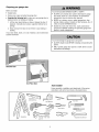 3
3
-
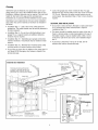 4
4
-
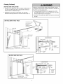 5
5
-
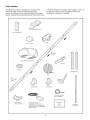 6
6
-
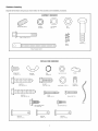 7
7
-
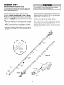 8
8
-
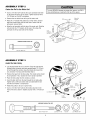 9
9
-
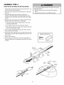 10
10
-
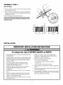 11
11
-
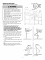 12
12
-
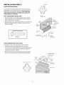 13
13
-
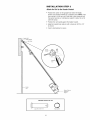 14
14
-
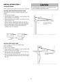 15
15
-
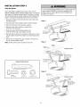 16
16
-
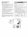 17
17
-
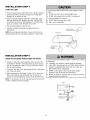 18
18
-
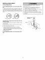 19
19
-
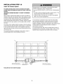 20
20
-
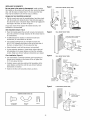 21
21
-
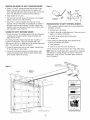 22
22
-
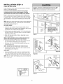 23
23
-
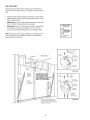 24
24
-
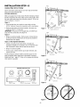 25
25
-
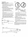 26
26
-
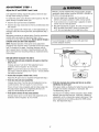 27
27
-
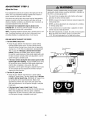 28
28
-
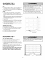 29
29
-
 30
30
-
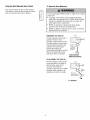 31
31
-
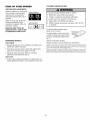 32
32
-
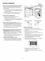 33
33
-
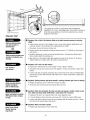 34
34
-
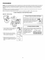 35
35
-
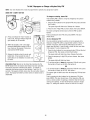 36
36
-
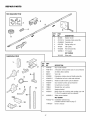 37
37
-
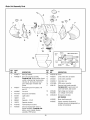 38
38
-
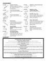 39
39
-
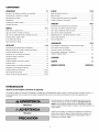 40
40
-
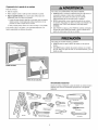 41
41
-
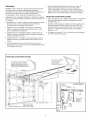 42
42
-
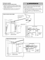 43
43
-
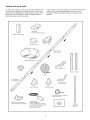 44
44
-
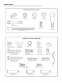 45
45
-
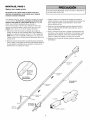 46
46
-
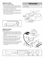 47
47
-
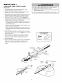 48
48
-
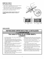 49
49
-
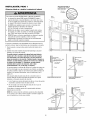 50
50
-
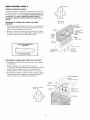 51
51
-
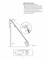 52
52
-
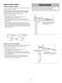 53
53
-
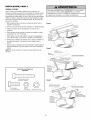 54
54
-
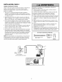 55
55
-
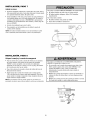 56
56
-
 57
57
-
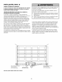 58
58
-
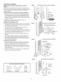 59
59
-
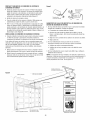 60
60
-
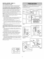 61
61
-
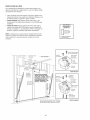 62
62
-
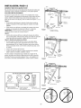 63
63
-
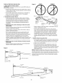 64
64
-
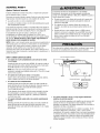 65
65
-
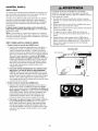 66
66
-
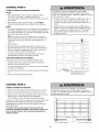 67
67
-
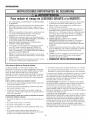 68
68
-
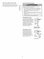 69
69
-
 70
70
-
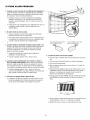 71
71
-
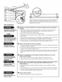 72
72
-
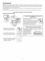 73
73
-
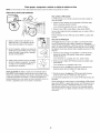 74
74
-
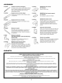 75
75
-
 76
76


Craftsman 13953904D El manual del propietario
- Categoría
- Abridor de puerta de garage
- Tipo
- El manual del propietario
en otros idiomas
- English: Craftsman 13953904D Owner's manual
Artículos relacionados
-
Craftsman 13953939D El manual del propietario
-
Craftsman 139.53919 El manual del propietario
-
-
-
-
-
-
-
-