GE PP989 Owner's Manual and Installation Instructions
- Tipo
- Owner's Manual and Installation Instructions

GEAppliances.com
-IS
Safety Instructions .......... 2-3
Operating Instructions
Bridge Burner ...................... 6
Cooktop Vent System .............. 6
Cookwore Tips ..................... 7
Dual Surface Unit .................. 6
Features of Your Cooktop .......... 4
Surface Units..................... S,6
Temperature Limiter ............... 6
Care and Cleaning
Control Knobs ...................... 8
Glass Cooktop .................. 9, 10
Vent Filter and Chamber ........... 8
Vent Grille .......................... 8
Installation Instructions
Ductwork ................. 15-18, 22
Electrical Connections ........ 22-24
Exhaust Blower Ratings ........... 17
Final Assembly .................... 25
Installing the Cooktop ......... 20-22
Installing the Gasket .............. 19
Preparation ................... 13-15
Safety Precautions ................ 11
Unpacking the Cooktop ....... 12, 19
Troubleshooting Tips......... 26
Consumer Support
Consumer Support ................ 30
Warranty .......................... 29
PP989
Write the model and serial
numbers here:
Model #
Serial #
Find these numbers on a label
under the cooktop, on the side
of the vent chamber.
49-80635 05-11GE

IMPORTANT SAFETY INFORMATION.
READ ALL INSTRUCTIONS BEFORE USING.
[A WARNING I
Read all safety instructions before using the product. Failure to follow these instructions may result in fire, electric shock,
serious injury or death.
jA WARNING i GENERAL SAFETYINSTRUCTIONS
Use this appliance for its intended purpose as described
in this OwneFs Manual.
Never use your appliance for warming or heating the
room.
Be sure your appliance is properly installed and
grounded by a qualified installer in accordance with the
provided installation instructions.
*:, Do not attempt to repair or replace any part of your
range unless it is specifically recommended in this
manual. All other servicing should be referred to a
qualified technician.
Before performing any service, unplug the cooktop
or disconnect the power supply at the household
distribution panel by removing the fuse or switching off
the circuit breaker.
Do not leave children alone-children should not be left
alone or unattended in an area where an appliance is in
use. They should never be allowed to climb, sit or stand
on any part of the appliance.
CAUTION" Do not store items of interest to
children above a cooktop-children climbing on the
cooktop to reach items could be seriously injured.
*:, Use only dry pot holders-moist or damp pot holders on
hot surfaces may result in burns from steam. Do not let
pot holders touch hot surface units or heating elements.
Do not use a towel or other bulky cloth in place of pot
holders.
iiiil}i
iiiiiiili_
iiiiiiili_
Do not touch the surface elements. These surfaces may
be hot enough to burn even though they are dark in
color. During and after use, do not touch, or let clothing
or other flammable materials contact the surface units
or areas nearby the surface units; allow sufficient time
for cooling first. Other surfaces of the appliance may
become hot enough to cause burns. Potentially hot
surfaces include the cooktop and areas facing the
cooktop.
Do not heat unopened food containers. Pressure could
build up and the container could burst, causing an
injury.
Cook meat and poultry thoroughly-meat to at least an
internal temperature of 160°F and poultry to at least
an internal temperature of 180°F. Cooking to these
temperatures usually protects against foodborne illness.
jA WARNING i KEEPFLAMMABLEMATERIALSAWAY FROM
THECOOKTOP.
Do not store or use flammable material near the
cooktop, including paper, plastic, pot holders, linens,
wall coverings, curtains, drapes and gasoline or other
flammable vapors and liquids.
Never wear loose-fitting or hanging garments while
using the appliance. These garments may ignite if they
contact hot surfaces causing severe burns.
Do not let cooking grease or other flammable materials
accumulate on or near the cooktop. Grease on the
cooktop may ignite.
Cleon ventilating hoods frequently. Grease should not
be allowed to accumulate on the hood or filter.
2 SAVE THESE INSTRUCTIONS

IMPORTANT SAFETY INFORMATION.
READ ALL INSTRUCTIONS BEFORE USING.
GEAppliances.com
IA WARNING I IN THEEVENTOFA FIRE,TAKE THEFOLLOWING
STEPSTO PREVENTTHE FIREFROM SPREADING:
Do not use water on grease fires. Never pick up a
flaming pan. Turn the controls off. Smother a flaming
pan on a surface unit by covering the pan completely
with a well-fitting lid, cookie sheet or flat tray. Use
a multi-purpose dry chemical or foam-type fire
extinguisher.
jA WARNING JRADIANT COOKTOP SAFETYINSTRUCTIONS
Never leave the surface units unattended at medium or
high heat settings. Boilovers cause smoking and greasy
spillovers that may catch on fire.
Never leave oil unattended while frying. If allowed to
heat beyond its smoking point, oil may ignite resulting
in fire that may spread to surrounding cabinets. Use a
deep fat thermometer whenever possible to monitor oil
temperature.
To avoid oil spillover and fire, use a minimum amount of
oil when shallow pan-frying and avoid cooking frozen
foods with excessive amounts of ice.
Useproperpan size--select cookware having flat
bottoms largeenough to cover the surface heating
element.Theuseof undersizedcookware will expose
a portion of the surface unit to direct contact and may
resultinignition of clothing. Properrelationship of
cookware to surfaceunit will also improve efficiency.
_:,Only certain types of glass, glass/ceramic, earthenware
or other glazed containers are suitable for cooktop
service; others may break because of the sudden
change in temperature.
To minimize the possibility of burns, ignition of
flammable materials and spillage, the handle of a
container should be turned toward the center of the
range without extending over nearby surface units.
When preparing flaming foods under a hood, turn the
fan on.
iiiiiil
iiiiiiili_
iiiiiiiii1_
iiiiiiili_
iiiiiiili_
Avoid scratching or impacting the glass cooktop. Doing
so may lead to broken glass. The cooktop can be
scratched with items such as knives, sharp instruments,
rings or other jewelry, and rivets on clothing.
Do not cook on a broken cooktop. If glass cooktop
should break, cleaning solutions and spillovers
may penetrate the broken cooktop and create a
risk of electric shock. Contact a qualified technician
immediately.
Do not place or store items that can melt or catch fire
on the glass cooktop, even when it is not being used. If
the cooktop is inadvertently turned on, they may ignite.
Heat from the cooktop after it isturned off may cause
them to ignite also.
Use CERAMA BRY1-E®ceramic Cooktop Cleaner and
CERAHA BRYTE®Cleaning Pad to clean the cooktop.
Wait until the cooktop cools and the indicator light goes
out before cleaning. A wet sponge or cloth on a hot
surface can cause steam burns. Some cleaners can
produce noxious fumes if applied to a hot surface. Note:
Sugar spills are an exception. They should be scraped
off while still hot using an oven mitt and a scraper. See
the Cleaning the glass cooktop section for detailed
instructions.
Read and follow all instructions and warnings on the
cleaning cream label.
Use care when touching the cooktop. The glass surface
of the cooktop will retain heat after the controls have
been turned off.

Features of Your Cooktop.
Throughout this manual, features and appearance may vary from your model.
0
CO_TRO,took FAN
®
J
.@
Feuture Index (Featuresand appearance may vary)
0 Left Rear Surface Unit
Bridge Surface Unit
Left Front Surface Unit
Vent Grille
Vent Filter (below the vent grille)
Right Rear Surface Unit
Dual Surface Unit
0 Model and Serial Number Label lunderthe cool<top,
on the right side of the vent chamber)
O Left Rear Surface Unit Control
Left Front Surface Unit Control
Left Side Not Surface Indicator Lights (oneforeachsurfaceunit)
Vent Fan Speed Control
Control Lock Knob
Right Side Not Surface Indicator Lights lone for each surface unitI
0 Dual Surface Unit Control
Right Rear Surface Unit Control
G Surface Unit On Indicator Light

Using the surface units, GEApplionces.com
i
¸¸¸5¸¸i
ii /i i _
ii Z i _i_ i i i
HOT ON
Besure you turn the control knob
to OFFwhen you finish cooking.
Radiant Surface Units
Thecontrol for the radiant surface unit can
be set anywhere between LO and HI for an
unlimited number of heat settings.With the
infinite switch the coilcycleson and off to
maintain your selectedcontrol setting.
To bring liquidsto a boil faster, use a lid to
cover the pan.
Thecontrol knob must bepushed down and
turned from the OFF position.When the
control knobs are in any position other than off,
they may be turned without pushing down.
Besureyou turn the control knob off when you
finish cooking.Youwill feela clickat the OFF
position.
Thesurface unit ON indicator light will glow
when any surface unit ison.
The HOTsurface indicator light will glow when
the glasssurface ishot and will remain on until
the surface has cooled.
Never cook directly on the glass.
Always use cookware.
Always place the pan in the center
of the surface unit you are cooking on.
Do not slide cookware across the
cooktop because it can scratch the
glass. The glass is scratch-resistant,
not scratchproof.
About the radiant surface units...
The radiant cooktop features heating units
beneath a smooth glass surface.
NOTE:A slight odor isnormal when anew
cooktop isusedfor the first time.Itiscaused
bythe heating of new parts and insulating
materials and will disappearin ashort time.
NOTE:On models with light coloredglass
cooktops,it is normal for the cookingzonesto
changecolor when hot orcooling down. Thisis
temporary and will disappear asthe glass cools
to room temperature.
Thesurface unit will cycle onand off to
maintain your selectedcontrol setting.
It is safe to place hot cookware from the oven
or surface on the glass surface when the
surface is cool.
Evenafter the surface units are turned off,the
glasscooktop retains enough heat to continue
cooking.Toavoid over-cooking, remove pans
from the surface units when the food iscooked.
Avoid placing anything on the surface unit until
it has cooled completely.
Water stains (mineraldeposits)are removable
using thecleaning creamor fullstrength
white vinegar.
_,Useof window cleanermay leavean
iridescentfilmon the cooktop. Thecleaning
cream will remove this discoloration.
Don't storeheavy itemsabove the cooktop.If
they drop onto the cooktop, they can cause
damage.
Do not use the surface as a cutting board.

Using the surface units,
&
Sma"6'
surface unit Large 9"
Setting Su[foce UnitSetting
Dual Surface Unit
The right front surface unit has 2 cooking sizes
to selectfrom soyou can match the size ofthe
unit to the sizeof the cookware you are using.
To usethe large(9-inch)surface unit,turn the
knob clockwiseto D and selectthe desired
setting.The unitwill heat the entire area
contained by the larger circle.
To usethe small(6-inch)surface unit,turn the
knob counterclockwiseto D and selectthe
desiredsetting.Theunit will only heat the area
insidethe smallercircle.
g_,F Bridge Surface Unit
._/f"_l_& Make surethe pan restsflat on the glass
J_ cooktop and it isnot resting on the trim. Ifyou
I ! notice poor cooking performance, movethe
J pan to make sure it isflat onthe cooktop.
To usethe bridgeburner,turn the burner knob
to D and selectthe desiredsetting.Theunit will
Buine!_ i_ Fr0_t-----_ heat the front surface burner and the bridge.
Burner and
Bridge
Choosepans that match the circle/bridge area
as closelyaspossible.
Touse onlythe front surface unit,turn the
burner knobto [I_ and select the desired
setting. Theunit will only heat the front surface
burner.
Youcan create an oblong heated areaby using
the left rear unit in addition to thefront unit
bridge combination.
Surface Elements Cycle On and Off
Surface elementswill cycleon and off to
maintain the temperature you haveselected.
All radiant surface elements have a
temperature limiter that protects the glass
cooktop from getting too hot.
Thetemperature limiter may cyclethe
elements off while cooking if:
Thepan boilsdry
Thepan bottom isnot flat.
Thepan isoff-center.
Thereisno pan on the element.
Temperature Limiter
Everyradiant surface unit hasatemperature
limiter.
Thetemperature limiterprotects the glass
cooktop from getting too hot.
Thetemperature limitermay cycle the units off
for a time if:
Thecooktop ison while cooking.
Thepan boilsdry.
Thepan bottom isnot flat.
Thepan isoff-center.
Thereisno pan on the unit.
Control Lock-Out for Surface Units
UNLOCKe
LOCK ® ..,,,,,,.r_
@
To activate control lock-out, turn the Control
Lock knobto LOCK.Thiswill prevent surface
units from heating. An indicator light will glow
to show that they are locked.The downdraft
fan will remain operable with control lockout
engaged.
Inthe locked position,the cooktop will produce
an audible sound if any surface unit control
knob isengaged or moved to a position other
than OFF.
FAN
o_F_
o
How to Operate the Vent System
The built-in vent system helps remove cooking
vapors, odors and smoke from foods prepared
on the cooktop.
To operate the downdraft vent system, turn
the vent fan speed control knob to HI, MED
or LO, as needed.
Continuous use of the vent system while
cooking helps keep the kitchen comfortable
and less humid, reducing cooking odors
and soiling moisture that normally creates a
frequent need for cleaning.

Selecting types of cookwure
ngode]s. (onnon-inductionmodels) GEAppliances.com
The following information will help you choose cookware which will give good performance on glass cooktops. See insert
for cookware to use with induction cooktops.
Check pans for flat bottoms by
using a straight edge.
Stainless Steel:
recommended
Aluminum:
heavy weight recommended
Good conductivity. Aluminum residues
sometimes appear asscratches onthe cooktop
but can be removed ifcleaned immediately.
Becauseof its low melting point, thin weight
aluminum should not
be used.
Copper Bottom:
recommended
Copper may leaveresidueswhich can appear
as scratches.The residuescan be removed,as
long asthe cooktop iscleaned immediately.
However, do not let these pots boil dry.
Overheated metal can bond to glass cooktops.
An overheated copper bottom pot will leavea
residuethat will permanently stain the cooktop
if not removed immediately.
Porcelain Enamel on Cast Iron:
recommended if bottom of pan is coated
Porcelain Enamel on Steel:
not recommended
Heating empty puns can cause permanent
damage to cooktop glass. The enamel can melt
and bond to the ceramic cooktop.
Glass-ceramic:
not recommended
Poor performance. Willscratch the surface.
Stoneware:
not recommended
Poor performance. May scratch the surface.
Cast Iron:
not recommended-unless designed specifically
for glass cooktops
Poor conductivity and slow to absorb heat. Will
scratch the cooktop surface.
Pans with rounded, curved,
ridged or warped bottoms are not
recommended.
NOTE:Follow all cookware manufacturer's recommendations when using any typeof cookware on
the ceramiccooktop.
DO not place wet pans
On the glass cooktop.
Do notusewokswith _upport
ringson theglasscooktop
For Best Results
Place only dry pans on the surface
elements. Do not place lids on the surface
elements, particularly wet lids.
Do not use woks that have support rings.
This type of wok will not heat on glass
surface elements.
iiiiiiiiii_i_iii_
We recommend that you use only a flat-
bottomed wok. They are available at your
local retail store. The bottom of the wok
should have the same diameter as the
surface element to ensure proper contact.
Some special cooking procedures require
specific cookware such as pressure
cookers, deep-fat fryers, etc. All cookware
must have flat bottoms and be the correct
size.
Avoid allowing foods to boil dry as some
cookware may stick to the cooking
surface, causing permanent damage to
the cooktop.

Care and cleaning of the cooktop.
Be sure electrical power is off and all surfaces are cool before cleaning any part of the cooktop.
How to Remove Protective Shipping Film and Packaging Tape
Carefullygrasp acorner ofthe protective
shipping film with your fingers and slowly peel
it from the appliance surface. Donot use any
sharp itemsto remove the film. Removeall of
the film before usingthe appliance for the first
time.
Toassureno damage isdone to the finish
of the product, the safest way to remove
the adhesive from packaging tape on new
appliances isan application of a household
liquid dishwashing detergent. Applywith a soft
cloth and allow to soak.
NOTE:Theadhesivemust beremoved from all
parts.It cannot beremoved if it is bakedon.
Vent Grille
Before cleaning the vent grille, be sure the
exhaust blower is turned off.
To clean the vent grille, remove it from the
cooktop by lifting it up and off.Wipe with a
damp cloth. If necessary,the vent grille can be
washed in the sink.
Usedishwashing liquid for cleaning.
Donot use abrasivecleaners,Theywill damage
the vent grille'sfinish.
Donot clean the vent grille in the dishwasher.
Vent Filter and Chamber
The filter is held in place at an angle with a
hold bump. Lift the filter up and out of the in place.
vent opening diagonally.
To clean the filter, swish it in hot, soapy water.
Rinsewell and dry thoroughly.
Do not operate the vent without the filter
in place.
Vent Filter
Vent
Chamber
Do not operate the vent without the filter
Remove and replace the filter diagonally through the
vent opening,
Toorder filterspleasecallourtoll-freenumber:
National Parts Center...........800.626.2002
Filter..........................................# WBO2X10651
When replacing the filter, make sure it rests, at an
angle, on the supports in the vent opening.
Toclean the vent chamber, usehot, soapy
water. Rinsewith clean water and dry
thoroughly. Donot useabrasive cleaners;they
will damage the finish.Replacethe filterafter it
iscleaned anddry.
Shapedurea Control Knobs
Thecontrol knobsmay be removed for easier
cleaning.
Hake sure the knobs are in the OFFpositions
and pull them straight off the stems for
cleaning.
Toclean the knobs, place them ina
dishwasher or wash with soapand water. Rinse
with cleanwater. Hake surethe insidesof knobs
are dry before replacing.
Replacethe knobs in the OFF position to
ensure proper placement.
Stainless Steel Surfaces (on some models)
Do not usea steel wool pad; it will scratch the
surface.
Toclean the stainless steel surface, usewarm
sudsy water or a stainlesssteel cleaner or
polish.Alwayswipe the surface inthe direction
of the grain. Followthe cleaner instructions for
cleaning the stainlesssteel surface.
To inquire about purchasing stainless steel
appliance cleaner or polish,or to find the
location of a dealer nearest you, pleasecallour
toll-free number:
National Parts Center 1.800.626.2002
8 GEAppliances.com

Cleaning the glass cooktop. GEAppliances.com
Clean your cooktop
aftereach spill. Use
CERAMABRYTE®Ceramic
Cooktop Cleaner.
Normal Daily Use Cleaning
ONLYuseCERANABRY1-E®CeramicCooktop
Cleaneronthe glasscooktop. Other creams
may not be aseffective.
To maintain and protect the surface ofyour
glasscooktop, follow these steps:
%
Beforeusing the cooktop for the
first time, clean itwith CERAMABRYTE®
Ceramic Cooktop Cleaner.This helps
protect the top and makes clean-up
easier.
r_ Daily useof CERAMABRYTE®Ceramic
Cooktop Cleanerwill help keepthe
cooktop lookingnew.
@
%
Shakethe cleaning cream well.
Applyafew drops of CERAIVlA
BRYTE®Ceramic Cooktop Cleanerdirectly
to the cooktop.
Usea paper towel or CERAMA
BRYTE®Cleaning Padfor Ceramic
Cooktopsto clean the entire cooktop
surface.
Use a dry cloth or paper towel
to remove all cleaning residue.
No need to rinse.
NOTE:It is very important that you DONOT
heat the cooktop until it has been cleaned
thoroughly.
/! ij(55¸¸¸¸¸¸¸¸¸¸¸¸¸¸¸¸:¸¸0//
Use a CERAIVlABRYTE®Cleaning
Pad for Ceramic Cooktops or a
Scotch-Brite ®Multi-Purpose No
Scratch blue scrub pad.
Burned-On Residue
WARNING:DAMAGEto your
glass surface may occur ifyou use scrub
pads other than the pad included
with your cooktop.
[Z] Allow the cooktop to cool.
[] Spread a few drops of CERAIVlABRYTE®
Ceramic CooktopCleanerto the entire
burned residue area.
@
Using the included CERAMABRYTE®
Cleaning Pad for Ceramic Cooktops, rub
the residue area, applying pressure as
needed.
%
@
If any residue remains, repeat the steps
listed above as needed.
For additional protection, after all
residue has been removed, polish the
entire surface with CERAMABRYTE®
Ceramic Cooktop Cleaner and a paper
towel.
The CERAMABRYTE®Ceramic
Cooktop Scraper and all
recommended supplies are
available through our Parts
Center. See instructions under "To
Order Parts" section on next page.
NOTE: Do not use a dull or nicked
blade.
Heavy, Burned-On Residue
F71
Allow the cooktop to cool.
Use a single-edge razor blade scraper
at approximately a 45° angle against
the glass surface and scrape the soil. It
will be necessary to apply pressure to
the razor scraper in order to remove
the residue.
@
%
After scraping with the razor
scraper, spread a few drops of
CERAMABRYTE®CeramicCooktop Cleaner
to the entire burned residue area. Use the
CERAMABRYTE®Cleaning Pad to
remove any remaining residue.
Foradditional protection, after all
residue has been removed, polish the
entire surface with CERAMABRYTE®
Ceramic Cooktop Cleaner and a paper
towel.

Cleaning the glass cooktop.
Metal Marks and Scratches
%
Be careful not to slide pots and pans
across your cooktop. It will leave metal
markings on the cooktop surface.
These marks are removable using
the CERAMABRYTE®Ceramic Cooktop
Cleaner with the
CERAMABRYTE®Cleaning Pad
for Ceramic Cooktops.
r_ if pots with a thin overlay of aluminum
or copper are allowed
to boil dry, the overlay may leave black
discoloration on the cooktop.
This should be removed immediately
before heating again or the
discoloration may be permanent.
WARNING: carefu/Ucheck
the bottom of pans for roughness that would
scratch the cooktop.
Glass surface--potential for permanent damage.
Our testing shows that
if you are cooking high
sugar mixtures such as
jelly or fudge and have
a spillover, it can cause
permanent damage to the
glass surface unless the
spillover is immediately
removed.
Damage from Sugary Spills and Melted Plastic
Turn off all surface units. Remove hot
pans.
[] Wearing an oven mitt:
a. Use a single-edge razor blade
scraper (CERAMABRYTE®Ceramic
Cooktop Scraper) to move the spill to
a cool area on the cooktop.
b. Remove the spill with paper towels.
r_ Any remaining spillover should be left
until the surface of the cooktop has
cooled.
r_ Don't use the surface units again until
all of the residue has been completely
removed.
NOTE:If pitting or indentation in the glass
surface has already occurred, the cooktop
glass will have to be replaced. In this case,
service will be necessary.
To Order Parts
To order CERAMABRYTE®Ceramic Cooktop
Cleaner and the cooktop scraper,please call
our toll-free number:
National Parts Center 800.626.2002
CERAHABRYTE®
Ceramic Cooktop Cleaner.. # WX!OX300
CERAHABRYTE®
CeramicCooktop Scraper.. # WXl0X0302
Kit ....................... # WB64X5027
(Kitincludes cream and razor scraper)
CERAMABRYTE®Cleaning Pads for
Ceramic Cooktops ......... #WX!0X350
10

I
I
stailati
str cti
ns
Radiant
DowndraftCooktop
I If you have questions, call 800.GE.CARES (800.432.2737) or visit our Website at: GEAppliances.com 1
BEFORE YOU BEGIN
Read these instructions completely and carefully.
.IMPORTANT - Savetheseinstructions
for local inspector's use.
"IMPORTANT - Observe all governing
codes and ordinances.
, Note to Installer - Be sure to leave these
instructions with the Consumer.
, Note to Consumer - Keep these instructions for
future reference.
, Unless very knowledgeable in the installation of
this product, engage a professional installer.
, Proper installation is the responsibility of the
installer.
, Product failure due to improper installation is not
covered under the Warranty.
WARNING - Beforebeginningthe
installation, switch power off at the service
panel and lock the service disconnecting means
to prevent power from being switched on
accidentally. When the service disconnecting
means cannot be locked, securely fasten a
prominent warning device, such as a tag, to
the service panel.
IMPORTANT SAFETY INSTRUCTIONS
WARNING - TOREDUCETHERISK
OF FIRE,ELECTRIC SHOCK OR INJURY TO
PERSONS, OBSERVE THE FOLLOWING:
FI Installationwork and electricalwiringmust be
done by qualifiedperson(s)inaccordance with
allapplicablecodes and standards,including
fire-rated construction.
D
E1
Sufficient air is needed for proper combustion
and exhausting of gases through the flue
(chimney) of fuel burning equipment to
prevent back drafting. Follow the heating
equipment manufacturer's guidelines and
safety standards such as those published by
the National Fire Protection Association (NFPA),
and the American Society for Heating,
Refrigeration and Air Conditioning Engineers
(ASHRAE),and the local code authorities.
When cutting or drilling into wall or ceiling, do
not damage electrical wiring and other hidden
utilities.
r_ Ducted fans must always be vented to the
outdoors.
. This unit must be properly grounded.
WARNING - ToREDUCETHERISKOF
FIRE,USE ONLY METAL DUCTWORK.
ii

Installation Instructions
UNPACKING YOUR COOKTOP
PARTS INCLUDED (PACKED BELOW THE COOKTOPI
, Blower assembly , (9) Sheet metal screws , Vent filter
, Blower plenum (8-18 x 3/8") , Cleaning cream
, (4) Nuts (10-32 keps - nuts with , Foam gasket tape (9 ft. roll) , Scrub sponge or scraper
lock washers attached) , Vent grille (on some models)
Check to be sure that all packing materials
and tape have been removed. This will include
tape on control knobs (if applicable), adhesive
tape, wire ties, cardboard and protective
plastic. Failure to remove these materials could
result in damage to the appliance once the
appliance has been turned on and surfaces
have heated.
Sheet Metal
Screws (9)(8-28
x s/8")
Cleaning Cream
Scrub Sponge
Vent Grille
Foam Gasket Tape
CAUTION:
DO NOT LIFT
FROM VENT
OPENING OR
BUMP GLASS
m
CAUTION: GLASS IS FRAGILE DO NOT
BUMP EDGE OF GLASS DURING
INSTALLATION
Blower Assembly and (4) Mounting
Nuts (10-32 keps - nuts with lock
washers attached)
Blower Vent
Plenum Filter
12

Installation Instructions
PREPARATION
TOOLS AND MATERIALS
YOU WILL NEED
o Saw
, Flat-blade screwdriver
Electrician's pliers
. Duct tape
Measuring tape or scale
. Carpenter's square
, 7/16" wrench or socket set
, Drill and drill bit
, Sheet metal screws
, Junction box*
, 3/4" flexible conduit*
, Electrical wire per local code*
, Wire nuts*
, Ductwork
*NOTE: Electrical installation kit JXCK89 may be
ordered separately and includes all the ports
necessary to connect the cooktop to typical
rough-in wiring.
CAUTION: FOR PERSONAL SAFETY,
REMOVE HOUSE FUSE OR OPEN CIRCUIT
BREAKER BEFORE PREPARING JUNCTION BOX.
ELECTRICAL REQUIREMENTS
Thisappliance must be suppliedwith the proper voltage
and frequency, aslisted in these Installation Instructions,
and connected to an individual, properlygrounded branch
circuit, protected bya40-amp circuit breaker or time delay
fuses.
Allwire connections must be made in accordance with
local codes and properly insulated.Checkwith your local
utility for governing electrical codes and ordinances.Inthe
absence of local electricalcodes,the National Electrical
Code,ANSI/NFPANo. 70 - LatestEdition,governing electric
range installations,must be followed.
A copy of the National ElectricalCodecan be obtained by
writing to:
National FireProtectionAssociation
Batterymarch Park
Quincy,IVlA02260
EffectiveJanuary 1,1996,the National ElectricalCode
requiresthat new,but not existing, construction utilize a
four-conductor connection to an electric range.When
installing an electricrange in newconstruction, follow
the instructions in NEWCONSTRUCTIONANDFOUR-
CONDUCTORBRANCHCIRCUITCONNECTION.
Youmust useathree-wire, single-phase AC208Y/&20Volt
or 2/40/120Volt,60 Hertzelectricalsystem with separate
ground. Ifyou connect to aluminum wiring, properly
installed connectors approved for usewith aluminum
wiring must be used.
30" COOKTOP (DIMENSIONS FOR REFERENCE ONLY)
Unitshown fullyassembled.
227_d'
(22_16" SS)_,_
29_"
-,9 (30"_5) _ $ 2Y16"
I (2_" ss)
._ 28sA,,
Unit must be vented to the outside!
13

Installation Instructions
CABINET PREPARATION
l_l PREPARING FOR INSTALLATION
Positioning the cooktop
Thecooktopisdesignedtolookbestwhencenteredina
cabinetat least30"wide.
Theexhaust vent beneath the cooktop must be located
between wall studs or floorjoists sothat the ductwork may
be installed properly.
At least 6" must be allowed between sideedgesof the
cooktop and adjacent walls.
is"max_::-I
depth of _ ..... I J
unprotected /11 I I I II
overhead /11 I I I ..... _,_• -
cabinets | 30" min. I J__ mln. nelgin:
J clearancefrom T---- i- I Trom counl:eRop
/ countertop h__ _ _):onegresl: cabinet:
Lto un rotected _ _ on either sideof
6" min.
IF_" I I I clearance
II I I I I fromcutout
_._ waits
Avoid placing cabinets abovethe cooktop unit, if possible,
in order to reducethe hazardscaused by reaching over
heated surface units.If cabinetsare placed overthe
cooktop, the riskscan bereduced by installing a range
hood that projects horizontallya minimum of 5 inches
beyondthe bottom of the cabinets.
If cabinetry isused abovethe cooktop, allow a minimum
30" clearance between the cooking surface and the bottom
of any unprotected cabinet.
Ifthe clearance between the cooktop and the cabinetry is
lessthan 30",the cabinet bottom must be protected with
flame retardant millboard at least 1/¢' thick, covered with
28 gauge sheet steel or 0.020"thick copper. Clearance
between the cooktop and the protected cabinetry MUST
NEVERBELESSTHAN 24".
EXCEPTION:Installationof a listed microwave oven or
cooking appliance overthe cooktop shallconform to the
installation instructions packed with that appliance.
A .tS"minimum must be kept from the sideedgeof the
cooktop to the bottom of any cabinet not directly abovethe
cooktop, Ifthe clearance islessthan 15%adjacent cabinets
should be at least 6"from the sideedgeof the cooktop.
[] PREPARING THE BASE CABINET
Thiscooktop isdesignedto fit easily into a variety
of cabinets.However, some cabinets may require
modifications.
Preparing a cabinet that isagainst a wall
Insomecabinets,the sidesmay need to be scooped or cut
down S3A"as shown,and the corner braces removed in
order to accommodate the unit.
In75cm and 90 cm frameless Europeancabinets,
the back panel may needto be cut down 53A"to
accommodate the unit.
Preparing a peninsula or island-type cabinet
Ina peninsulaor island-typecabinet, the sidesmay need to
be scooped or cut down, and the corner braces removedin
order to accommodate the unit.
for European
cabinets
s_ I 144 I W I
nwoxk.
I'_ ROUGH PREPARATION
OF JUNCTION BOX
CAUTION: FORPERSONALSAFETY,
REMOVE HOUSE FUSE OR OPEN CIRCUIT
BREAKER BEFORE PREPARING JUNCTION
BOX.
Install an approved junction box within shaded area
shown in diagram. Junction box must be at least 10½"
below top of cabinet.
Run conductors from residence wiring to junction box
according to local electrical codes.
9" :
!6"
i0½"
14

Installation Instructions
CABINET PREPARATION CUTOUTS
ITI PREPARING THE COUNTERTOP
The countertop must have a deep flat surface
to accommodate the cooktop and the vent.
Countertops with a rolled front edge and
backsplash may not provide the flat surface
area required.
25" min. flat surface area required
Clearance between inside front of cabinet and
rear of countertop cutout must be 20s/8'' in order to
accommodate cooktop depth.
!_" min.
A 1/2" wide flat area is required around the edge
of opening for support of the unit. The cooktop
unit must be level and sit squarely into countertop
opening.
Carefully cut countertop opening according to the
dimensions shown in the illustration. Be sure that
the opening is cut squarely, with sides parallel to
each other and the rear exactly perpendicular to
the sides.
1_" min.
Fs] PREPARING FOR DUCTWORK
NOTE:Ductwork MUSTbe vented to outside. DONOTvent
into a wall, ceiling, crawlspace, attic or any concealed
space.
Cut hole in cabinet wall or floor as appropriate for your
installation. Makesure exhaust duct islocated between wall
studsorfloor joists.
NOTE:When cutting or drilling into wall or ceiling, do not
damage electrical wiring and other hidden utilities.
Rear Wall Venting
Downward Venting
[] BLOWERTO DUCTWORKALIGNMENT
Ingeneral,the useof flexibleducting isdiscouraged because
itcan causeseverelyrestricted airflow. However,ifthe
blower outlet and the floor or wall duct location do NOTalign
well, then flexible METALducting can be usedto adept to an
offset. Goodalignment without useof flexibleducting isbest.
NOTE:
• Donot exceed the maximum recommended offset of 6".
• Donot allow the flexible ducting to kinkor collapse.
• Dostretch the flexibleducting as much as possibleto
eliminate as much ofthe corrugation as possible.
_ C6e"n_ralXne _[_
toCenterlineZ]I If_ I El
,,," Offset _ I
Bottom Venting Back Venting
(Requires 3¼"x 10'!
A 3_A"x 10" rectangleto 6" round transition duct isavailableat
your local building supply store.
NOTE:Illustrations are for planning purposes only.
15

Installation Instructions
DUCTWORK CALCULATIONS
Calculate Total Equivalent Ductwork Length
Equivalent Number Equivalent
Duct Pieces Length* x Used - Length
5" round
straight 2.7 ft. x (ft.) t- ft.
6" round
straight 1ft. × (ft.) t- ft.
3¼" x i0"
straight 1ft. x ( ft.Y- ft.
5", 90°
(_ elbow 37 ft. x ( 1= ft.
6", 90°
elbow 12ft. x ( )- ft.
5", 45°
elbow 18ft. × ( )= ft.
6", 45°
elbow 7 ft. x ( )- ft.
Flexible
metal offset
adapter 34 ft. x ( )- ft.
3½" x i0"
90° elbow 14ft. x ( ): ft.
3½" x 10"
45° elbow 8 ft. x ( ): ft.
3½" x i0"
90°flat elbow 33 ft. x ( ): ft.
5" round
[_to 3½" x 10"
transition 3 ft. x ( )= ft.
6" round
to 3½" x 10"
transition 2 ft. x ( )- ft.
Subtotal Column 1- ft.
*Equivalentlengthsofduct piecesarebasedonactual
testsand reflectrequirementsfor goodventing
performancewith anydowndraft cooktop.
1-1Vleasureand listfeet of straightduct used.Countand
listthe quantity of allother ductpiecesfor the "Number
Used"ofeachtype.
IMPORTANT:
For maximum efficiency, use the shortest and straightest
duct run possible, with as few fittings as possible. For
satisfactory performance, the duct run should not
exceed 100 feet equivalent length.
Venting performance isimproved by using larger
diameter duct.
Equivalent Number Equivalent
Duct Pieces Length* x Used - Length
5" round
to3½" x i0"
_ transition
90° elbow 37 ft. x ( )= ft.
6" round
to3½" x i0"
transition
90° elbow a,ft. x ( )- ft.
_ 3½"x i0"
to 6" round
transition 2 ft. x ( )= ft.
3½" x ilO"
to 6"round
transition
90° elbow 4 ft. × ( )= ft.
Tapered 5"
round to
6" round
transition 6 ft. x ( )- ft.
S" round collar
to 6" round
transition 13 ft. x ( )- ft.
S" round
wall cap
C_ with damper 84 ft. x ( )= ft.
6" round
wall cap
with damper 24 ft. x ( )- ft.
3½" x i0"
wall cap
with damper
__ 6" round
roof cap
24 ft. x ( )-
33ft. x ( l-
Subtotal Column 2-
Subtotal Column 1-
TOTAL DUCTWORK =
ft.
ft.
ft.
ft.
ft.
Should not exceed 100 feet.
If flexible metal ducting is used, all the equivalent
feet values in the table should be doubled. The
flexible metal duct should be straight and smooth
and extended as much as possible.
DO NOT use flexible plastic ducting.
Vent installation should not exceed 100 feet
equivalent length.
16

Installation Instructions
EXHAUST BLOWER RATINGS
EXHAUST BLOWER SAFETYWARNING
Sufficient air is needed for proper combustion and exhausting of gases through the flue (chimney) of
other fuel burning equipment to prevent back drafting. Follow the heating equipment manufacturer's
guidelines and safety standards such as those published by the National Fire Protection Association
(NFPA),the American Society for Heating, Refrigeration and Air Conditioning Engineers(ASHRAE)and
local code authorities.
17

Installation Instructions
DUCTWORK INSTALLATION
(Note: For planning purposes only.)
171INSTALLING THE DUCTWORK
Use galvanized or aluminum duct in 6" round or 3VJ'
x 10" size, or a combination of both.
PVC duct should be used if installing under a poured
concrete slab.
NOTE: Local building code must be followed in
specifying approved type and schedule of ALL
duct used.
Always use an appropriate roof or wall cap with
damper. Laundry-type wall caps should NEVER
be used.
Through Cabinet Toe Space
Between Floor Joist
Downward Venting
Install ductwork, making male-female connections
in the direction of airflow as shown. Secure all joints
with sheet metal screws and duct tape to assure an
airtight seal.
Air Flow
-J uct Tape Over Seam
and Screw
Screw
Use the shortest and straightest duct run possible.
For satisfactory performance, the duct run should
not exceed :100feet equivalent length. Refer to the
"DUCTWORK CALCULATIONS" chart for equivalent
lengths. Use this chart to calculate the total
equivalent length of the ductwork.
OPTIONAL INSTALLATION:
REAR WALL VENTING
5" round duct may be used on SHORT DUCT runs,
but best results will be obtained using 31/4'' x 10"
or 6" round ducting.
Inside Wall to Roof Direct to Outside
Rear Wall Venting
To convert blower exhaust direction, remove four
nuts behind the filter which hold blower and wire
finger guard.
Rotate blower and reinstall to vent chamber, as
shown above. Retighten nuts, but do not overtighten.
18

Installation Instructions
UNPACKING THE COOKTOP/INSTALLING THE GASKET
I_ INSTALLING THE FOAM GASKET
Do not install the cooktop into the countertop
without installing the foam gasket as shown.
It protects the bottom edge of the glass from the
countertop and seals the cooktop against spills.
Remove the cooktop along with its shipping pad
from the shipping box. Remove the shipping block
from the downdraft vent opening and place it under
the shipping pad to provide level support.
Center vent shipping block -
place under the shipping pad to
provide level support
CAUTION: GLASSISFRAGILE.
DO NOT BUMP EDGE OF GLASS DURING
INSTALLATION.
Locate the foam gasket tape included with
your cooktop.
Peel off the white backing to install the foam gasket
tape on the bottom side of the cooktop glass as
shown.
Note: On stainless steel model PP989S, apply the
foam tape around the outer edge of the glass only
on the sides and rear of the unit.
Foam Gasket Installation Notes:
,The foam gasket tape should be installed within
1/8" of the edge of the glass. Do not stretch or
twist the foam gasket tape.
A CAUTION:Failure to install foam
gasket tape greatly increases the potential
of breaking the cooktop glass when installing,
especially in Corian ®or granite countertops.
, Use care not to stretch the foam gasket tape
while it is installed or it will not stay in place.
. Do not place foam gasket tape over the metal
flanges.
, Butt the foam gasket tape ends together at each
corner without overlapping.
,Trim the foam gasket tape to length without
stretching.
, Mitre cut outside corners of foam gasket tape
slightly if necessary for appearance.
/
Foam
Gasket
Tape
Edge
, Do not scratch the glass while cutting the foam
gasket tape.
19

Installation Instructions
INSTALLING THE COOKTOP
[] INSTALLING THE COOKTOP
, CAUTION:
DO NOT LIFT
FROM VENT
OPENING.
Lift the cooktop by the gloss side edges as shown.
NOTE: Do not use the gloss top vent opening to lift
or move the cooktop into position.
Lower the cooktop into the countertop opening,
guiding it into position. Gloss is fragile-do not allow
it to drop onto the countertop. Support from the
underside and lower slowly.
Curefully remove your fingers one corner at o time
to lower the cooktop into position.
NOTE: Do not use Silicone RTV or caulk to bond
cooktop gloss to countertop.
| CHECKING FOR FLATNESS
Inspect the cooktop gloss for rocking or uneven
gap on oil four sides at the countertop surface.
Do not attempt to force the gloss to meet
the countertop.
INSTALLING THE OPTIONAL
INSTALLATION BRACKETS
NOTE: Check for glass flatness in Step 10 before
installing optional installation brackets.
Optional installation
bracketand
thumbscrew(not
included)
]
Cooktop _ Countertop
Screws supplied_ I
_---- Thumbscrew
with cooktop
To order optional installation brackets/thumbscrews,
call the National Parts Center at 800.626.2002.
Order two of each part: WB02X11331 Bracket
WB01X10353 Screw
To install optional installation brackets:
Remove 2 screws on both sides under cooktop.
Align optional installation bracket under cooktop
and reinstall screws through the slot in the bracket.
Do this on both sides of the cooktop.
Thread the thumbscrew through the hole
in the bracket and tighten to secure the cooktop
to the countertop. Repeat on the other side.
IMPORTANT: Turn thumbscrew until it touches
the bottom of the countertop. Do not overtighten.
20

Installation Instructions
INSTALLING THE COOKTOP
['_ INSTALLING THE BLOWER PLENUH
TO THE COOKTOP
Slide the plenum, with the blower opening on the
left, into the opening in the bottom of the cooktop.
Push up on the plenum until the stops on the
plenum contact the bottom of the cooktop, and
snap the plenum into place. (You may have to move
the plenum back and forth to work it into place.)
;_ Install 2 screws
Install 4 screws
Secure the plenum to the bottom of the cooktop,
on each side, using the four (4) screws provided.
Further secure the plenum to the cooktop, from
the top side, using the two screws (2) provided.
r_ INSTALLING THE BLOWER
TO THE PLENUM
Orient the blower discharge opening to match the
ductwork in Steps 6 and 7. Slide the four threaded
studs on the side of the blower housing into the
four holes on the side of the plenum.
NOTE: See Step 14 for installing the transition
duct to the blower. It may be easier to install the
transition duct to the blower before installing the
blower to the plenum.
From the vent opening in the top of the cooktop,
fasten the blower assembly securely to the plenum
with four (4) nuts.
4 Nuts
(7/16"
socket
required)_
21

Installation Instructions
INSTALLING THE COOKTOP
ATTACHING A BLOWER
TRANSITION DUCT
Use a blower transition duct for all downward
duct installations to connect to 6" round standard
ductwork. This 5½" x 10" rectangle to 6" round
transition duct is available at your local building
supply store.
(on other
side)
Remove the cardboard packing in the blower outlet.
Install the transition duct to the blower outlet. Secure
all joints with duct tape to assure an airtight seal.
[]_] CONNECTING THE
DUCTWORK
Connect the ductwork prepared in Steps 5 and 6 to
the blower transition duct.
BLOWER ELECTRICAL
CONNECTIONS
Loosen the two screws and remove and discard
the sheet metal strap covering the g-pin connector
on the cooktop bottom. Save the screws for
reinstallation later.
screws
and discord
strop
r_ BLOWER ELECTRICAL
CONNECTIONS {cont.}
, Connect the g-pin plug on the blower assembly to
the matching g-pin receptacle on the bottom of the
wire enclosure.
5-pin
connectors
Fold all wires into the electrical enclosure. Secure the
enclosure with the screws removed earlier, making
sure that no wires are trapped.
5-pin
connectors
-- Electrical
enclosure
Flexible
conduit
22

Installation Instructions
ELECTRICALCONNECTIONS
|BEFORE MAKING ELECTRICAL
CONNECTIONS
Note to Electrician: The power leads supplied with this
appliance are UL-recognized for connection to large
gauge household wiring.
The insulation of these leads is rated at temperatures
much higher than the temperature rating of household
wiring. The current carrying capacity of a conductor is
governed by the wire gauge and also the temperature
rating of the insulation around the wire.
Aluminum Wiring- WARNI NG:
iMPROPERCONNECTION OF ALUMINUM HOUSE
WiRiNG TO THE COPPER LEADSCAN RESULTIN
SERIOUSPROBLEMS.
Attach copper wires to aluminum wiring using special
connectors designed and UL-listed far joining copper
to aluminum. Follow the connector manufacturer's
recommended procedure closely.
Service Loop - Leave a loop in the wires to the cooktop
so that the cooktop can be lifted 12 inches without
having to disconnect the wiring.
ELECTRICAL REQUIREMENTS*
Model # Voltage Frequency KW
PP989 120/240V 60Hz 9.1KW
120/208V 60Hz 6.9KW
*For reference only. Verify with product rating plate.
Rating Plate
Electrical installation kit J×CK89 may be ordered
separately and includes all the parts necessary to
connect the cooktop to typical rough-in wiring.
| INSTALL 3/4" FLEXIBLE CONDUIT
Remove the screws holding
the wire compartment cover
and remove the cover.
Feed the power
supply leads
through the
conduit; be sure to
leave enough length
to properly connect
these leads to the
cooktop power leads.
Thread the leads
through an anti-
short bushing and
firmly seat the
bushing in the end
of the conduit.
Feed the leads
through the hole
in the wire
compartment.
As local codes
permit purchase
a listed conduit
connector suitable
for the size conduit.
Insert the conduit
through the
connector and
attach it to the
cover. Allow
enough slack to
easily attach the
wires to the
cooktop.
Note: Do not install
the cooktop without
a listed conduit
connector. The
conduit connector
should be installed
before reinstalling
the wiring cover.
When complete,
reinstall the wire
compartment cover.
PowerSupply Anti-Short
Leads Bushing Conduit
Bushing (FullySeated)
_'_'_
Conduit
Connector
Conduit
Cover
23

Installation Instructions
ELECTRICALCONNECTIONS
JTY]MAKING ELECTRICAL CONNECTIONS
Effective January 1, 1996, the National
Electrical Code requires that new, but not
existing, construction utilize a four-conductor
connection to an electric range. When installing
an electric range in new construction, follow the
instructions in NEW CONSTRUCTION AND FOUR-
CONDUCTOR BRANCH CIRCUIT CONNECTION.
You must use a three-wire, single-phase
AC 208V/120 Volt or 240/120 Volt, 60 Hertz
electrical system with separate ground.
If you connect to aluminum wiring, properly
installed connectors approved for use with
aluminum wiring must be used.
New construction and four-conductor branch
circuit connection
.When installing in new construction, or
.When installing in a mobile home, or
.When local codes do not permit grounding
through neutral:
4-Conductor Branch Circuit
When connecting the cooktop to a 4-conductor
circuit, connect the red leads of the cooktop and
the power supply to the branch circuit red lead;
connect the black leads to each other. Connect
the cooktop white lead to the power supply and
branch circuit neutral leads, which are white or
gray. Ground the unit by connecting the green
conductor of the cooktop to the bare or green
leads of the power supply and branch circuit
(ground leads).
4-ConductorBranchCircuit
BranchCircuit
Power Cooktop
Supply Power
Leads Leads
Red Red Red
120_VA White or 0 Whiteor 0
_ NEUTRAL Gray _ Gray 0 White
120VJAC
Black Black Black
Bareor Bareor
Green A Green _,_ Green
GND
MAKING ELECTRICALCONNECTIONS
(cont.)
Three-conductor brunch circuit connection
.When installing in existing construction built
prior to January 1, 1996, and if permitted by
local codes:
3-Conductor Branch Circuit
When connecting cooktop to a 3-conductor
circuit, connect the red leads of the cooktop and
the power supply to the branch circuit red lead;
connect the black leads to each other. Connect
the green and white leads of the cooktop to the
power supply and branch circuit neutral leads,
which are white or gray.
3-ConductorBranchCircuit
BranchCircuit
Power Cooktop
Supply Power
Leads Leads
Red Red Red
12_V_AC White or 0 Wh;ieoi 4_-
NEUTRAL Gray _ ::i:_
24

Installation Instructions
FINAL ASSEMBLY
INSTALL DOWNDRAFT FILTERAND
VENT GRILLE
Do not operate the vent without the filter
in place.
. Place the filter diagonally through the vent
opening.
Filter
Vent
-Chamber
. Plake sure it rests, at an angle, on the supports
in the vent opening.
. Carefully place the vent grille onto the
downdraft opening.
CHECK OPERATION OF DOWNDRAFT
. Turn the vent fan speed control to HI, NED
and LO to make sure all speeds operate correctly.
25

Before you call for service...
Troubleshooting Tips--Save time and money! Review this chart first and you may not need to call for service.
Possible Causes What To Do
Water won't boil , Cover pan with a lid.
, Turn the downdraft fan OFFuntil the water beginsto boil.
Surface units will not Improper cookware , Pan bottoms should be flat, fairly heavyweight and
maintain a rolling boil being used. the same diameter as the surface unit selected.
or cooking is slo_v
Surfa_nits do A fuse in your home may • Replacethe fuse or resetthe circuit breaker.
not work properly be blown or the circuit
breaker tripped.
Cooktop controls , Check to see the correct control is set for the surface
improperly set. unit you are using.
Tiny scratches or metal Incorrect cleaning • Seethe Cleaning the glass cooktop section.
marks (may appear as methods being used.
cracks) or abrasions on Cookware with rough , Besure cookware bottoms and cookware are clean
radiant cooktop glass bottoms being used or before use.Usecookware with smooth bottoms.Tiny
surface coarse particles (salt scratches are not removable but will become less
or sand} were between visible in time as a result of cleaning.
the cookware and the
surface of the cooktop.
Cookware has been slid
across the cooktop surface.
Areas of discoloration Improper cookware , Harks from aluminum and copper pans as well as
or dark streaks on the being used. mineral deposits from water or food can be removed
cooktop with the cleaning cream.
Hot surface on a model • Thisisnormal. Thesurface may appear discolored when it is
with a light-colored cooktop, hot. Thisistemporary and will disappear as the glass cools.
Food spillovers not • See the Cleaning the glass cooktop section.
cleaned before next use.
Incorrect cleaning , Use recommended cleaning procedures.
methods being used.
Hot sugar mixtures Hot cooktop came into , See the Glass surface potential for permaent damage
or plastic melted contact with these section in the Cleaning the glass cooktop section.
to the surface substances.
Pitting for indentation) Hot sugar mixture , Call a qualified technician for replacement.
fthe cooktop spilled or plastic melted
on the cooktop.
Cooktop making an Cooktop is locked. , Check to be sure the Control Lock knob isturned
audible sound to UNLOCK.
Frequent cycling Improper cookware , Use only flat cookware to minimize cycling.
off and on of being used.
surface units
Cooktop feels hot Improper cookware , The glass cooktop surface may seem hotter than you
being used. are used to.This isnormal. Use pans which are absolutely flat.
Control knob will Cooktop controls , When the knob is in the OFFposition, it must be pushed
not turn improperly set. down before it can be turned. When the knob is in any
other position, it can be turned without being pushed in.
Poor venting Clogged filter. • Clean filter per instructions.
House too airtight. • Open a window slightly to provide fresh air source.
Wall cap obstructed. , Remove blockage from exterior wall cap.
Wall cap damper door , Check exterior wall cap damper door for free
stuck, movement or obstruction.
26
Duct length exceeds , Reduce number of elbows to simplify duct run.
recommended 1OO
equivalent foot maximum.

Notes. GEAppliances.com
27

Notes.
28

GE Electric Cooktop Warranty.
All warranty service provided by our Factory Service
Centers, or an authorized Customer Care®technician.
To schedule service, on-line, visit us at GEAppliances.com,
or coil 800.GE.CARES (800.432.2737). Please have serial
number and model number available when calling for service.
Stapleyour receipt here.
Proof of the original purchase
date is needed to obtain service
under the warranty.
GE Will Replace:
One Year
From the date ofthe
origina!purchase
Any part of the cooktop which fails due to a defect in materials or workmanship. Duringthis
limited one-year warranty, GEwill alsoprovide, free of charge, all labor and in-home serviceto
replace the defective part.
Five Years A replacement glass caoktop if itshould: crack due to thermal shock;discolor;or if the
From the date ofthe pattern wears off.
original purchase A replacement radiant surface unit ifit should burn out.
During this limited additional four-year warranty, you will be responsible for any labor or
in-home service.
Service trips to your home to teach you how to use
the product.
Improper installation, delivery or maintenance.
;Product damage or failure of the product if it is abused,
misused, modified, used for other than the intended
purpose, or used commercially.
Damage to the glass cooktop caused by use of cleaners
other then the recommended cleaning creams and pads.
Damage to the glass cooktop caused by hardened spills
of sugary materials or melted plastic that are not cleaned
according to the directions in the Owner's Manual.
Replacement of house fuses or resetting of circuit breakers.
Damage to the product caused by accident, fire, floods or
acts of God.
Incidental or consequential damage caused by possible
defects with this appliance.
Damage caused after delivery.
Product not accessible to provide required service.
EXCLUSION OF IMPLIED WARRANTIES--Your sole end exclusive remedy is product repair us provided in
this Limited Warranty. Any implied warranties, including the implied warranties of merchantability or
fitness for u particular purpose, are limited to one year or the shortest period allowed by law.
This warranty is extended to the original purchaser and any succeeding owner for products purchased for home
use within the USA. If the product is located in an area where service by a GE Authorized Servicer is
not available, you may be responsible for a trip charge or you may be required to bring the product to an
Authorized GE Service Location for service. In Alaska, the warranty excludes the cost of shipping or
service calls to your home.
Some states do not allow the exclusion or limitation of incidental or consequential damages. This warranty gives
you specific legal rights, and you may also have other rights which vary from state to state. To know what your
legal rights are, consult your local or state consumer affairs office or your state's Attorney General.
Warrantor: General Electric Company. Louisville, KY 40225
29

Consumer Support.
GEAppliances Website GEAppliances.com
Have a question or need assistancewith your appliance?Try the GEAppliancesWebsite 2/4hours a day,
any day of the year! Forgreater convenience and faster service,you can now download Owner's Manuals,
order parts or even schedule serviceon-line.
Schedule Service GEAppliances.com
Expert GErepair serviceisonly one step away from your door.Get on-lineand schedule your serviceat
your convenience any day of theyear! Or call 800.GE.CARES(800./432.2737)during normal businesshours.
RealLifeDesignStudio GEAppliances.com
GEsupports the Universal Designconcept-products, servicesand environments that can be used by
people of all ages,sizesand capabilities. We recognizethe need to designfor a wide range of physicaland
mental abilities and impairments. Fordetails of GE'sUniversalDesignapplications, including kitchen design
ideasfor peoplewith disabilities,check out our Website today. Forthe hearing impaired, pleasecall 800.TDD.
GEAC(800.833./4322).
Extended Warranties
GEAppliances.com
Purchase a GEextended warranty and learn about special discounts that are available while your warranty
isstillin effect. You can purchase it on-line anytime, or call 800.626.222/4during normal businesshours.
GEConsumer Home Serviceswill still be there after your warranty expires.
Partsand Accessories
GEAppliances.com
Individuals qualified to servicetheir own appliances can have parts or accessoriessent directly to their homes
(VISA,MasterCard and Discovercards are accepted).Order on-line today, 2/4hours every day or by phone
at 800.626.2002 during normal businesshours.
Instructions contained in this manual cover procedures to be performed by any user. Other servicing
generally should be referred to qualified service personnel. Caution must be exercised, since improper
servicing may cause unsafe operation.
Contact Us
GEAppliances.com
If you are not satisfied with the serviceyou receivefrom GE,contact uson our Website with all the details
including your phone number, or write to: General Manager, Customer Relations
GEAppliances,Appliance Park
Louisville,KY/40225
Register Your Appliance GEAppliances.com
Register your new appliance on-line--at your convenience! Timely product registration willallow for enhanced
communication and prompt service under the terms of your warranty, should the need arise. You may also mail
in the pre-printed registration card included in the packing material.
Printed inthe United States

GEAppliances.com
0
"0
(1)
(1)
U
LD
u
>
Instrucciones de seguridad ........ 2-3
Instrucciones de operaci6n
Caracteristicas de su estufa ............... 4
Ideas sabre las piezas de cocina ........... 7
Limitactor de temperatura ................. 6
Quemaclor de puente ...................... 6
Sistema de ventilaci6n de la estufa ........ 6
Uniclacles de superficie ................... 5,6
Uniclacl de superficie €ioble................. 6
Cuidodo y limpiezo
Botones de control ......................... 8
Estufa de vidrio ............................ 9
Rejilla de ventilaci6n ...................... 8
Sistema de ventilaci6n ..................... 6
Instrucciones de instalaci6n
C6mo €lesempacar la estufa .............. 19
C6mo instalar la estufa ............... 20, 21
C6mo instalar la junta .................... 19
Conexiones el6ctricas ................ 23, 24
Ensamblaje final .......................... 25
indices de soplado de escape ............. 17
Precauciones de seguridad ............... 11
Preparaci6n ........................... 13-15
Red de conductos .............. 15, 16, 18, 22
Ideassobre la identificaci6n
y soluci6n de averias ............ 26, 27
Apoyo al consumidor
Apoyo al consumidor ..................... 30
Garantia .................................. 29
Escriba el n(Jmero de modelo y
de serie aqui:
!odelo #
Serie #
Encuentre estos nOmeros en una
etiqueta debajo de la estufa, en el lado
de la cdmara de ventilaci6n.
PP989
49-80635 05-11GE

INSTRUCCIONES DE SEGURIDAD IMPORTANTES.
LEA TODAS LAS INSTRUCCIONES ANTES DE USAR.
JAADVERTENCIA ]
Lea todas las instrucciones de seguridad antes de utilizar este producto. No seguir estas instrucciones puedegenerar un
incendio, una descarga el6ctrica, lesiones corporales o la muerte.
IA ADVERTENClA j lNSTRUCCIONESGENERALESDESEGURIDAD
Use este aparato s61ocon el objetivo para el que
fue creado,como se describe en este Manual del
Propietario.
Aseg@ese de que un t6cnico calificado realice una
correctainstalaci6n y puesta a tierra del artefacto de
acuerdo con las instrucciones de instalaci6n provistas.
No intente reparar o cambiar ninguna pieza de
su cocina a menos que est6 especificamente
recomendado en estemanual. Cualquier otro servicio
debe realizarlo un t6cnicocalificado.
Antes de realizar cualquier clase de reparaci6n,
desenchufe la cocina o desconecte el suministro
el6ctricodesde el panel de distribuci6n dom6stico
quitando el fusibleo desconectando el interruptor de
circuitos.
_:, No deje a los niBos solos; 6stos no deben quedar solos
o sinatenci6n en un 6rea donde un aparato est6 en usa.
Nuncadebe permitirse que se suban, sienten o paren en
cualquierparte de este aparato.
PRECAUCION:Noalmacene elementos
de inter6s para niSos sabre una cocina o en la
protecci6ntrasera de una cocina: los niSos que se
trepan a la cocinapara alcanzar elementos pueden
resultar gravemente heridos.
':, $61ouseagarraderas secas:las agarraderas h0medas
o mojadas colocadas ensuperficiescalientes
puedenprovocar quemaduras devapor. Nopermita
que lasagarraderas entren en contacto con unidades
de superficieolos elementoscalentadores calientes.
iiiiiil
iiiiiiili_
iiiiiiili_
iiiiiiili_
No utilicetoallas u otras telasgruesas en lugar de una
agarradera.
Nunca use su electrodom6stico para calentar la
habitaci6n.
No toque las unidades de superficie, los
elementoscalentadores o la superficie interior del
horno. Estassuperficies pueden estar Io suficientemente
calientes paraquemar aOn cuando tengan un color
oscuro. Durante ydespu6s del usa, no toque o deje que
su vestimenta u otrosmateriales inflamables entren en
contacto con unidades de superficie, 6reas cercanas
alas unidades de superficie o cualquier 6rea interior
del homo; deje pasar un tiempoprudencial para que se
enfrien. Otras superficies del aparatopueden calentarse
Io suficiente como para provocarquemaduras. Las
superficies potencialmente calientesincluyen la estufa,
las 6reas orientadas hacia la estufa, la abertura de
ventilaci6n del homo, las superficies cercanasa la
abertura y las hendiduras ubicadas alrededor de
lapuerta del horno.
No caliente recipientes cerrados de alimentos. Podrfa
haberuna acumulaci6n de presi6n en el recipiente y
6ste podrfaexplotar, provocando lesiones.
Cocinecarnes de resy de ave por completo: Las
carnes de reshasta alcanzar una temperatura interna
de por Iomenos 160°F(71°C)y las carnesde avea
unatemperatura interna depor Iomenos 180°F(82°C).
Lacocci6n a estas temperaturas generalmente protege
de enfermedades transmitidas por losalimentos.
i,& ADVERTENClA 1IvlANTENGALOS P1ATERIALESINFLAMABLES
'ALEJADO5 DE LA ESTUFA.
No almacene o utilice materiales inflamables dentro
de un homo o cerca de la estufa, tales coma papel,
pl6stico,agarraderas, telas, recubrimientos de
pared, cortinas y gasolina u otros vapores y liquidos
inflamables.
_:,Nuncausevestimentas holgadas o amplias mientras
utiliceelaparato. Estasvestimentas pueden prenderse
fuego sientran encontacto con superficiescalientes,
provocandoquemaduras graves.
No permita que la grasa de la cocci6n u otros
materialesinflamables seacumulen dentro de la cocina
o en sucercania.Lagrasadentro del homo o sobre la
estufa puede encenderse.
Limpielascampanas deventilaci6n con frecuencia.
Nodebe permitirse la acumulaci6n degrasa en la
campanao enel filtro.
2 GUARDE ESTASINSTRUCCIONES

INSTRUCCIONES DE SEGURIDAD IMPORTANTES.
LEA TODAS LAS INSTRUCCIONES ANTES DE USAR.
GEAppliances.com
JAADVERTENCIA IEN CASO DE INCENDIO, SIGA LOSSIGUIENTES
PASOSPARAEVITARLA PROPAGACION DEL FUEGO:
No utilice agua en incendios de grasa. Nunca levante
unasart6n en llamas. Apague los controles. Apague
una sart6nen llamas sobre una unidad de superficie
cubriendo la sart6n por completo con una tapa que
ajuste bien, una plancha para galletas o una bandeja
plana. Utilice un qdmico seco multiuso o un extintor de
incendios de espuma.
JAADVERTENCIA INSTRUCCIONES DE SEGURIDAD DE LA ESTUFA
I
RAD ANTE
Nuncadeje las unidadesdesuperficie sinatenci6n en
configuracionesdecalor media o alta. Losalimentosque
hierveny sederraman pueden provocar humo
yderrames grasososque pueden prendersefuego.
Nunca deje aceite sin atenci6n mientras fib. Si se
dejacalentar m6s all6 del punto de humeo, el aceite
puedeencenderse, provocando un incendio que
podriapropagarse a los gabinetes cercanos. Utilice
unterm6metro para grasa cuando sea posible
paracontrolar la temperatura del aceite.
Para evitar el derrame de aceite y un incendio, utilice
unacantidad minima de aceite cuando fria en sartenes
pocoprofundas y evite la cocci6n de alimentos
congeladoscon una cantidad excesiva de hielo.
Utiliceel tamaBo de recipienteadecuado: Elija
recipientesconbasesplanas Iosuficientemente grandes
paracubrirel elemento calentador desuperficie.La
utilizaci6nderecipientes m6s peque_osdejar6 expuesta
una porci6nde la unidad de superficieal contacto
directo, Ioquepuede provocar el encendido de sus
vestimentas. Unarelaci6nadecuada del recipientecon
la unidad de superficie tambi6n mejorar6 la eficiencia.
_:,$61ociertos tipos de recipientes de vidrio, vidrio/
cer6mico,cer6mica, u otros recipientes vidriados
pueden utilizarsesobre la estufa; otros pueden romperse
debido al cambiorepentino de temperatura.
Paraminimizar la posibilidadde quemaduras, el
encendidode materiales inflamablesy losderrames,
la manija delos recipientesdeben girarse hacia el
centrode la cocina sinextenderse sobreninguna unidad
desuperficie cercana.
si ftambea alimentos bajo Iacampana, encienda etventitador.
iii[iil
iii[iiili_
iii[iiili_
iii[iiili_
iii[iiili_
iii[iiili_
Tenga cuidado al tocar la estufa. La superficie de
vidriode la estufa retendr6 calor despu6s de que los
controlesse hayan apagado.
Eviterayar o golpear laestufa devidrio. Estopodria
romper el vidrio. Laestufa puedesufrir rayones
con articulos talescomo cuchillos,instrumentos
punteagudos,anillos u otrasjoyas y abrojos de
vestimentas.
Antes de utilizar el ciclo deauto-limpieza, limpie la
grasaylos derrames de alimentos del horno. Una
cantidadexcesiva degrasa puedeencenderse,
generando da_os par el humo en su hogar.
Nocoloqueo almaceneelementosque pueden
derretirseoprendersefuegosobrelaestufa devidrio,
a0n cuandonola est@usando.Sila estufaseenciende
enformaaccidental,puedenprendersefuego. Elcalor
provenientedela estufao dela ventilaci6ndel homo
tambi@npuedeprenderlosfuego,a0n sielaparato est6
apagado.
Useel limpiador de estufascer6micas CERAP1A
BRYTE®yla esponjillade limpiezaCERAMABRYTE®para
limpiar laestufa.Esperehasta que la estufa seenfrie
y la luzindicadora se apague antes de limpiar. Una
esponjao un paso h0medos sobreuna superficie
caliente puedenprovocar quemaduras devapor.
Algunoslimpiadorespueden producir humost6xicos
sise losaplica a unasuperficiecaliente.NOTA:Los
derrames de az0carson la excepci6n. _stosdeben
quitarse mientras est6ncalientesutilizando una
agarradera y un raspador. Parainstruccionesdetalladas,
ver la secci6nC6mo limpiar la estufa devidrio.
Lea y cumpla con todas las instrucciones y
advertenciasde la etiqueta de la crema de limpieza.

Caracteristicas de su estufa.
A travds de este manual, las caracteristicas y la apariencia podfian variar de acuerdo con su model®.
0
Indite de caracteristicas (lascaractefisticas y la apariencia podfian variar de acuerdo con su model®)
0 Unidad de superficie posterior izquierda
0 Unidad de superficie de puente
O Unidad de superficie frontal izquierda
I
CONTROL LOCK
O Parrilla de ventilaci6n Lo__°_""
0 Filtro de ventilaci6n (debajo de la parrilla de ventilaci6n) (_ (JlJ)
O Unidad de superficie posterior derecha
0 Unidad de superficie doble
O Etiqueta con los n(_merosde model®y serie (debajodela estufa, . i
en el lad® derecho de la cdmara de ventilaci6n) _ _ s _
o@
O Control de la unidad de superficie posterior izquierda .ot _
Control de la unidad de superficie frontal izquierda 0' --c
O Luces indicadoras de que la superficie estd caliente del lad® _....
izquierdo (una pot cada unidad de superficie) ® I
G Control de velocidad del ventilador de ventilaci6n
Perilla de bloqueo de control
Luces indicadoras de que la superficie estd caliente del lad® derecho (unapot cada
unidad de superficie)
Control de unidad de superficie doble
Control de unidad de superficie posterior derecha
G Luz indicadora encendida de la unidad de superficie
FAN
OFF ,9/
@
_,-_ OFF
- Lo _o-
. ®

C6mousar lasunidades desuperficie.
:ill:i(Zi!l! i!Z%i ¸ )L! /L4( :
IIIIiii!IIiIIIIIIiiiiii
!ii
!(k( ¸)k;;
Cerci6rese de girar el bot6n de
control a apagado (OFF)cuando
termine de cocinar.
Unidades de superficie radiantes
Elcontroldela unidaddesuperficieradiante
puedecolocarseencualquierlugarentreLO(Bajo)
y HI(Alto)paraun n0merodeseleccionesde
calentamientoilimitado.Conel interruptorinfinitoel
embobinadohacecicloentreencendidoy apagado
paramantenercontroldesuselecci6n.
Parahervirliquidos,useunaaliao sart6nquetenga
tapa.
Elbot6ndecontroldebeempujarsehaciaabajoy
movidodesdelaposici6nOFF(Apagado).Cuandolos
botonesdecontrolest6nencualquierposici6nque
noseaAPAGADO,puedenmoversesinpresionarlos.
Cerci6resedegirarel bot6ndecontrola laposici6n
apagadocuandoterminedecocinar.Ustedsentir6
undic enlaposici6nOFF.
Laluzindicadorade launidaddesuperficiebrillar6
cuandocualquieradelasunidadesdesuperficie
est6nencendidasON(Encendido).
ElluzindicadoradeHOTSURFACE(Superficie
Calientel,brillardncuandolasuperficiedevidrioestd
calienteypermanecerdasihastaquelamismase
hayaenfriado.
Nunca cocine directamente sabre
el vidfio. Siempre use piezas de
cocina.
Siempre coloque la sart6n en el
centro de launidad de superficie en
la queest6cocinando.
No deslice sartenes encima de la
superficie de la estufa porque esto
podria rasguF_arel vidrio. Elvidrio
es resistente, pero no esa prueba
de rasgu_os.
Acerca de las unidades de superficie radiantes...
Laestufaradiantetieneunidadescalentadoraspar
debajodeunasuperficiesuavedevidrio.
NOTA:Unolorligemesnormalcuandounaestufa
nuevaesusadaparprimeravezEstoescausadopar
elcalentamientodelaspartesnuevasy losmateriales
deaislamientoy desaparecerdencortotiempo.
NOTA:Enalgunosmodelosdeestufasconvidrioscon
coloresligeros,esnormalquelazonadecocinado
cambiedecolorcuandosecalientao cuandose
enfrfa.Estoestemporaly desaparecerdconformeel
vidrioseenfrfaa temperaturaambiente.
Launidaddesuperficiehar6cicloentreencendido
y apagadoparamantenerloscontrolesdesu
selecci6n.
Losmanchasdeagua(depdsitosdeminerales)
seremuevenusandounacmmadelimpiezao
vinagreblancopuro.
Elusadelimpiadordeventanaspodria@jaruna
pelfculairidiscentesabrela estufa.Locremade
limpiezaremoverdestadecoloracidn.
Noalmaceneartfculospesadossabrelaestufa.
Sisecaensabrelaestufa,podrfandaharla.
Nouselasuperficiecomatabladecarte.
Essegurocolocarunapiezadecocinacalientedel
homoo delasuperficiesabrela superficiedevidrio
cuandola superficieest6fria.
A0ndespu6sdequelasunidadesdesuperficie
sonapagadas,laestufadevidrioretienesuficiente
calorparacontinuarcocinando.Paraevitar
cocinarexcesivamente,remuevalassartenes
delasunidadesdesuperficiecuandola comida
sehayacocinado.Evitecolocarning0nobjeto
sabrelasupefficiehastaquesehayaenfriado
completamente.

C6mousar los unidades desuperficie.
0
7 Z "
0
dela unidad Selecci6nde ta
desuperfide unidaddeSuperficie
pequer_ade611 grandede9!'
Unidad de superficie dob/e
La unidad de superficiefrontal derechatiene
dostamahos para cocinar entrelosque usted
puede escogery ad podrd combinar el tamaho
correctodela sartdn que seencuentre usando
conla unidad de superficieapropiada.
Para usar una unidad de superficie grande (9"),
gire el bot6n en direcci6n de las agujas del reloj
haciaI_y seleccioneel ajuste deseado. La
unidad calentarciel@ea completa contenida
en el circulo grande.
Para usar la unidad de super_iciepequeha(6"),
gire el bot6n en direcci6n contraria alas agujas
del relojDy seleccione elajuste deseado. La
unidad calentar6 solamenteel drea contenida
en el circulo peque_o.
q)uemador
puente
Unidad de superficie de puente
Cerci6resede quela sart@ndescansade manera
planasobrelaestufadevidrioy deque no est6
descansandoen losextremos.Siustednota poco
rendimientodecocci6n,mueva lasart@npara
cerciorarsede que est6apoyadade manera
planasobrelaestufa.
Parausarelquemadordepuente,gireel bot6n
delquemadorhacia[_Jy seleccioneelajuste
deseado.Launidadcalentar6la superficiefrontal
y el puente.
Escojasartenesque haganjuego conelarea
circular/puentetanto como seaposible.
Parausarsolamentelaunidad desuperficie
frontal,gireelbot6ndel quemadorhaciaFJ
y seleccioneelajustedeseado.Launidad
calentar6el quemadorde superficiefrontal.
Ustedpuedecrear un @ea de calentamiento
oblonga usando la combinaci6n de la unidad
posterior izquierda y el puente de la unidad
frontal.
Los e/ementos de superficie se encienden y apagan
Loselementos de superficie seenciendeny
apagan para mantener la temperatura que
usted ha seleccionado.
Todos loselementos desuperficiecuentan con
un limitador de temperatura que protege la
estufa de vidrio de calentarse demasiado.
Ellimitador de temperatura puede apagar los
elementos durante la cocci6n si:
Elrecipientehierveen seco.
La basedelrecipienteno esplana.
Elrecipienteno estd centrado.
No hay un recipienteen el elemento.
Limitador de temperutura
Cada unidad de superficie radiante tiene un
limitador de temperatura.
Ellimitador de temperatura protege la estufa
de vidrio de calentarse demasiado.
Ellimitador de temperatura podria hacer que la
unidad entre en ciclo apagado si:
Laestufa estd encendida mientms se cocina.
Lasartdn hierve vada.
Elrondo de la sartdn no es piano.
,: Lasartdn no estd centmda.
No hay sartdn sobre la unidad.
LOCK ® ..,,,_'!,_
@
Bloqueo de control de los unidodes de
Para activar el bloqueo de control, gire la
perilla Control Lock (Bloqueode control) a
LOCI<(Bloqueo).Estono permitircique las
unidades de super_iciesecalienten. Una luz
indicadora seencender@para demostrar que
estc_nbloqueadas. Elventilador de corriente
superficie
descendente permanecer@ operable con el
bloqueo de control activado.
Enla posici6n bloqueada, la estufa producirci
un sonido audible si cualquier perilla de control
de unidad de super_iciese activa o gira aotra
posici6n que no seaOFF(ApagadoJ.
C6mo operar el sistema de ventilaci6n
Elsistema de ventilaci6n incorporado ayuda a
remover losvaporesde la cocina, losolores y el
humo de lascomidas preparadas enla estufa.
Paraoperar el sistema de ventilaci6n de
aire descendente (downdraft),gire el bot6n
de control de lavelocidad del ventilador de
ventilaci6n a HI (Alto),MED(Hedio)oLO(Bajo),
seg0n sea necesario.
Elusocontinuo delsistema de ventilaci6n
mientras cocina ayuda a mantener la cocina
c6moda y menos hOmeda,reduciendo
losolores decocina y la humedad que
normalmente crea la necesidad frecuente de
limpieza.

Elecci6ndelostiposderecipientesdecocci6n
puramoddosdeestufadevidfio.
GEAppliances.com
La siguiente informaci6n Io ayudard a elegir los recipientes de cocci6n que brindan un buen desempeho en estufas
de vidrio. Ver el folleto sabre recipientes para usar con estufas de inducci6n.
Verifique que los recipientes
tenganbases planas utilizando una
regla.
Acero inoxidable:
Recomendadas
Aluminio:
Pesopesado recomendadas
Buenaconductividad. Residuosde aluminio
a veces parecen rasguBaduras en la estufa,
pero pueden removersesi selimpian
inmediatamente. Debidoa su bajo punto de
fusi6n,elaluminio de pesoligero no debe
usarse.
Fondo de cobre:
Recomendadas
Elcobre podrfa dejar residuos que pueden
lucir coma rasgu_aduras. Los residuos se
pueden remover siempre que se limpie la
inmediatamente. Sin embargo, no deje que
estas sartenes de cobre hiervan en seco. El
metal sobrecalentado de puede fun@ con
las estufus de vidrio. Una sart6n de fondo de
cobre sobrecalentada dejarc_residuos que se
convertirc_n en manchas permanentes sabre la
estufa si no se remueven inmediatamente.
Esmulte de porcelunu sabre
hierrofundido:
Serecomienda sila basede la alia seencuentra
Vidrio-Cer_micu:
Otiles,pero no son recomendadas
Rendimiento pobre. Podr[an rayar la superficie.
Esmalte de porcelana sabre acero:
No se recomienda
Calentar recipientes ratios puede provocar
da_os permanentes al vidrio de las estufas.
Elesmalte puede derretirse y adherirse a la
estufa cerdmica.
Cer6mica:
No se recomienda
Desempe_o pobre. Raya la superficie.
Vidrio-cer6mico:
No se recomienda
Desempe_o pobre. Puede rayar la
superficie.
Hierro fundido:
No se recomienda, a menos que se encuentre
espedficamentedisehadopara estufas de vidrio
Pobre conductividad y lentitud
paraabsorber el calor. Raya la
superficie de la estufa.
revestida
No se recomiendan redpientes
conbases redondeadas, curvadas,
conrebordes o torceduras.
NOTA: Siga todas las recomendaciones del fabricante de recipientes cuando utilice cualquierclase
de recipiente de cocci6n sabre la estufa cerdmica.
€oloquerecipientesmojados
Sobre!aestufadevidrio.
No use woks con anillos de
SOportesobre Io estufa de vidrio.
Utilice woks debase piano Sabre !a
estufa de vidrio.
Para mejores resultados
iiiiiiiiii_i_iii_
Coloque s61orecipientes secos sabre los
elementos de superficie. Nocoloque tapas
sabre los elementos desuperficie, en
especial tapas mojadas.
No use woks con anillos de soporte.
Esta clase de wok no se calienta
sobreelementos de superficie de vidrio.
Recomendamos el usa de woks
debase plana solamente. Se
encuentrandisponibles en su negocio
minoristalocal, La base del wok debe
tenet el mismo di@metroque el elemento
de superficie para asegurar uncontacto
adecuado.
Algunos procedimientos de
cocci6nespeciales requieren recipientes de
cocci6n espec[ficos, como ollas a presi6n,
freidoras, etc. Todos los recipientes de
cocci6n deben tener bases planas y set
del tamahocorrecto.
No permita que los alimentos hiervanen
seco ya que los recipientes decocci6n
pueden adherirse a lasuperficie de
cocci6n, provocandodahos permanentes
a la estufa.

Cuidado y limpieza de la estufa.
Cercidrese de que el suministro eldctrico estd suspendido y que todas las superficies estdn ffias antes de limpiar
cualquier parte de la estufa.
C6mo quitar el envoltorio de protecci6n y la cinta de embalaje
Concuidado tome una punta del envoltorio de protecci6n
con susdedos y lentamente qu[telo de la superficie
del artefacto. No use elementos filosos para quitar el
envoltorio. Quite todo el envoltorio antes de usar el
artefacto par primera vez.
Rejilla de ventilaciSn
Antes delimpiar la rejilla de ventilaci6n, aseg(_resedeque
el ventilador de salida est_ apagado.
Paralimpiar la rejilla de ventilaci6n, quitelade laestufa
levant6ndolahaciaarribay afuera. Limpielacon unpaho
hOmedo.Sifueranecesario,la rejittadeventitaci6npuede
Paraasegurarse de no da_ar el acabado del producto,
la mejor forma de quitar el pegamento de la cinta de
empaque de los aparatos nuevos consiste en aplicar
detergente para vajillas liquido.Aplique con un paso
suave y deje remojar.
NOTA:Deberetirarseetadhesivodetodaslospartes.Sise
c_ quitar.
lavarseenel fregadero.Utiiiceliquidode iavaptatosparalavar.
Noutiticelimpiadoresabrasivos.DaBar6nei acabadode iarejiita
deventitaci6n.Nolavela rejittadeventitaci6nenel lavaplatos.
C(Tmara y filtro de ventilaci6n
Elfiltro essostenido en su lugar en un @ngulocon una No opere la ventilaci6n sin el filtro en su lugar.
protuberancia de tope. Levante el filtro y extr@igalode la
abertura de ventilaci6n diagonalmente.
Para limpiar el filtro, ag[telo en agua caliente y
enjabonada. Enju@guetobien y s@quetocompletamente.
No opere la ventilaci6n sin el filtro en su lugar.
Filtro de
ventilaci6n
C6mara de
Remueva y reemplace elfiltro diagonalmente a
trav6s de la abertura de ventilaci6n.
Paraordenarfiltros,porfavor 116menosgratuitamente
al n0mero:
Centrodepartes nacionaL...................................800.626.2002
Filtro.......................................................................# WBO2X10651
Cuando se encuentre reemplazando el filtro, cerd6rese de
que descanse, en un 6ngulo, en los soportes en la abertura
de ventilaci6n.
Paralimpiar la cdmara deventilaci6n, useaguacatientey
enjabonada.Enjuagueconagualimpiaysequebien.Nouse
limpiadoresabrasivos;dahar6n elacabado.Reemplaceelfiltro
despu_sde quetolimpiey Ioseque.
Botones de control
AreaSombread
\- Las perillasde control pueden quitarse para
limpiarse.
Para limpiar lasperillas,cerci6resede que est@nen
la posici6n de OFF(Apagado)Hale cada perilla hacia
fuera del v6stago.
Para Iimpiar las perillas, col6quelosen un
lavaplatos o realicela limpieza con agua yjab6n.
Enjuaguecon agua limpia.Aseg0reseque los
interiores de lasperillasest@nsecos antes de volver
a colocarlas.
Cuando reemplace las perillas,reviseque est@nen
la posici6n de OFF(Apagado)para garantizar la
colocaci6n correcta.
8
Superficies de Acero Inoxidable (en algunos modelos)
No use virutas de acero; _stas dafiar6n la superficie.
Para limpiar la superficie de acero inoxidable, useagua tibia
conjab6n o un limpiador o pulidor para acero inoxidable.
Siempre limpie lasuperficie en la direcci6n del veteado. Siga las
instrucciones del limpiador para limpiar
la superficie de acero inoxidable.
Para consultar sobre la compra de limpiadores olustradores de
aparatos de acero inoxidable, o para encontrar la ubicaci6n del
distribuidor m6s cercano, Ilame a nuestro nOmero gratuito:
Centro de partes nacional .................................1.800.626.2002
GEAppliances.com

C6mo limpiar la estufa de vidrio. GEAppliances.com
Limpie su estufa despu@s
de cada derrame. Use el
limpiador de estufas de
cer6mica CERAMA BRYTE®.
Limpieza de uso normal diario
SOLAMENTEuse limpiador de estufas de
cerc_micaCERAMABRYTE®en suestufa de
vidrio. Otras cremas podr[an no serefectivas.
Para mantener y proteger la superficie
de su estufa de vidrio, siga estasinstrucciones:
[]
Antes de usar la estufa por primer(] vez,
Ifmpielacon limpiador deestufas de
cerc_micaCERAMABRYTE®.Estoayuda a
proteger la parte superior 7 hace que la
limpieza sea mc_sf(_cil.
r_ Elusodiario del limpiador de estufas de
cerc_micaCERAMABRYTE®ayudar(_a
mantener la estufa luciendo como nueva.
@
Remuevalacrema de limpieza bien.
Aplique unasgotas de limpiador de
estufas de cerc_micaCERAMABRYTE®
directamente sobre la estufa.
%
Useuna toalla de papel o una almohadilla
de limpiar estufas de cerc_micaCERAMA
BRYTE®para limpiar la superficie entera
de la estufa.
r_ use un trapo seco o una toalla de papel
para remover los residuos de la
limpieza. No necesita enjuagar.
NOTA:Esmuy importante que usted NO
CALIENTEla estufa hasta que la haya
limpiado completamente.
_ b
ii_ !_iiii i_ _i_i_i_i i_i I
Use una almohadilla de limpiar
estufas de cerc_mica CERAMA
BRYTE®o una almohadilla
de restregar azul suave
multiprop6sitos Scotch-Brite ®.
Residuo quemado encima de la superficie
ADVERTENCIA: A-Oa
su superficie de vidrio podria ocurrir si usted
usa almohadillas para restregar que no sean
las incluidas con su estufa.
Permita que la estufa se enfr[e.
Riegue algunas gotas del limpiador de
estufas de cer@micaCERAIVlABRYTE®
en el 6rea entera donde se encuentra el
residuo quemado.
r_ usando la almohadilla de limpiar
estufas de cer@micaCERAMABRYTE®
incluida, restriegue el @reade residuo,
aplicando presi6n donde sea necesario.
%
@
Si cualquier residuo permanece, repita
los pasos enumerados anteriormente
seg0n sea necesario.
Para protecci6n adicional, despu6s de
que todo el residuo haya sido removido,
pula la superficie entera con la crema
limpiadora de estufas de cerc_mica
CERAMABRYTE®y con una toalla de
papel.
)
El raspador de estufas de
cer6mica CERAMABRYTE®y todos
los accesorios recomendados
est6n disponibles a trav6s de
nuestro Centro de partes. Ver
las instrucciones bajo la secci6n
"Para ordenar partes" en la
pr6×ima p6gina.
NOTA: No use una navaja bota o
mellada.
Residuo quemado pesado encima de la superficie
@
Permita que la estufa se enfr[e.
Use un raspador de navaja 0nica a
apro×imadamente un c_ngulode 450
contra la superficie de vidrio
y raspe el sucio. Ser6 necesario aplicar
presi6n al raspador para remover el
residuo.
Despu6s de raspar con el
raspador, aplique algunas gotas de
limpiador de estufas de cerc_mica
CERAMA BRYTE® en el 6rea entera del
residuo quemado. Use la almohadilla de
%
limpiar estufas de cerc_micaCERAMA
BRYTE®para remover los residuos
restantes.
Para protecci6n adicional, despu6s de
que todo el residuo haya sido removido,
pula la superficie entera con el
limpiador de estufas de cerc_mica
CERAMABRYTE®y con una toalla de
papel.

C6mo limpiar el vidrio de la estufa.
Marcas met61icas y rasgufladuras
%
Tenga cuidado de no deslizar ollas o
sartenes a trav6s de su estufa. Elias
dejar@nmarcas sobre la superficie de
su estufa.
Estasmarcas son removibles usando
el limpiador de estufas de cerc_mica
CERAMABRYTE®con la almohadilla de
limpiar estufas de cer@micaCERAMA
BRYTE®.
Si permite que olios con cubiertas finas
de aluminio o de cobre hiervan en
seco, la cubierta podrfa dejar
decoloraciones negras sobre la estufa.
Estasdeberfan removerse inmediatamente
antes de calentar la estufa de nuevo
o la decoloraci6n se convertirc_en
decoloraciones permanentes.
ADVERTENCIA: Con
mucho cuidado inspeccione el rondo de las
sartenes en bOsquedade protuberancias que
puedan rasguhar la estufa.
Superficie de vidrio-potencial de daflo permanente.
Nuestras pruebas
muestran que si
usted est6 codnando
con mezdas de alta
concentraci6n de az0car,
tales comojalea o
caramelo y ocurre un
derrame, puede causar
daSo permanente a la
superfide de vidrio de
la estufa a no ser
que sea removida
inmediatamente.
Dafio de derrames de az(lcar y pl6stico derretido
%
Apague todas las unidades de
superficie. Remueva las sartenes
calientes.
Usando un guante de hornos:
a. Use un raspador de navaja 0nica
(Raspador de estufas de cerc_mica
CERAMABRYTE®)para remover el
derrame a un @teafria en la estufa.
b. Remueva el derrame con toallas de
papel.
r_ Cualquier resto del derrame debe
dejarse hasta que la estufa se haya
enfriado.
No use las unidades de
superficie de nuevo hasta que todos los
residuos hayan sido completamente
removidos.
NOTA: Siya ban ocurrido hendiduras o
indentaciones en la superficie de vidrio,
el vidrio de la estufa tendrd que ser
reemplazado. En este caso, serd necesario
darle servicio a la estufa.
Para ordenar partes
Para ordenar el limpiador de estufas de
cer6mica CERAMABRYTE®y el raspador
para estufas, pot favor II@menos
gratuitamente al nOmero:
Centro de partes nacional 800.526.2002
El limpiador de
estufas de cer6mica
CERAMA BRYTE® ......... # WX!OXSO0
Raspador de estufas
de cerSmica
CERAMABRYTE® ........ # WX!OX0502
Kit ....................... # WB64XS027
(ElKit incluye la crema y el raspador)
Almohadilla de limpiar estufas de
cer6mica CERAIVIABRYTE®..#WX! 0X550
lO

Instrucciones
deinstalaci6
Estufaradiantede
ventilaci6ndescendente
I Sitiene alguna pregunta, Ilame al 800.GE.CARES(800.432.2737)o visite nuestro sitio en la Web: GEAppliances.com 1
ANTES DE COMENZAR
Lea estas instrucciones completa y
cuidadosamente.
.IMPORTANTE -Guardeestas
instrucciones para ser usadas par el inspector
el6ctrico.
. IMPORTANTE - Observetodoslos
c6digosy ordenanzas aplicables.
, Nora al instalador - Cerci6rese de dejar estas
instrucciones con el Consumidor.
Nota al consumidor - Guarde estas
instrucciones para referencia futura.
. A no ser que usted sea una persona muy bien
entrenada en la instalaci6n de este producto,
busque la ayuda de un instalador profesional.
. La instalaci6n apropiada es la responsabilidad
del instalador.
Si este producto folio par una instalaci6n
inapropiada, la Garantia no cubrir6 este
producto.
_kADVERTENCIA = Antes de comenzar la
instalaci6n, desconecte el interruptor de
suministro el@ctrico en el panel de servicio y
cierre el mecanismo de seguridad para evitar
que alguien Io conecte accidentalmente.
Cuando no exista un dispositivo de cierre de
seguridad, amarre un aviso visible, coma una
etiqueta al panel de servicio hacienda la
advertencia.
INSTRUCCIONES IMPORTANTES DE
SEGURIDAD
ADVERTENCIA - PARAREDUCIREL
RIESGO DE INCENDIOS, DESCARGAS
ELECTRICAS O LESIONES PERSONALES,
OBSERVE LO SIGUIENTE:
171 El trabajo de instalaci6n y el alambrado
el6ctrico debe hacerlo una persona(s)
calificada conforme o todos los c6digos
y est6ndares aplicables, incluyendo una
construcci6n aprobada par el inspector de
incendios.
[] Suficiente aire es necesario para una
combusti6n apropiada y para deshacerse de
los gases a trav6s de una salida de humo
(chimenea) de equipos que queman
combustibles para prevenir retroalimentaci6n.
Siga los recomendaciones del fabricante
del equipo de calentamiento y los est6ndares
de seguridad tales coma los publicados par la
Asociaci6n nacional de protecci6n de
incendios (NFPA),y la Sociedad americana de
ingenieros de calefacci6n, acondicionadores
de aire y refrigeraci6n (ASHRAE),y los c6digos
de las autoridades locales.
E1
Cuando se encuentre cortando o taladrando
en la pared o en el techo, no da_e los
alambrados el6ctricos u arras utilidades
escondidas.
rD1 Los ventiladores conectados a conductos
deben siempre estar ventilados hacia el
exterior.
, Lo unidad debe estar conectada a tierra
apropiadamente.
ADVERTENCIA - PARAREDUCIREL
RIESGO DE INCENDIOS, SOLAMENTE USE
CONDUCTOS M ET,ALICOS.
11

Instruccionesde instalaci6n
DESEMPACANDO SU ESTUFA
PARTES INCLUIDAS (EMPACADAS DEBAJO DE LA ESTUFA)
, Ensambladura del soplador
, C6mara del soplador
, Tuercas (4)(10-32 tuercas -
con sus arandelas de cierre
pegadas)
Tornillos de plancha
met61ica(9)(8-18 x 3/8'1
, Cinta de junta de espuma (folio
de 9 pies)
, Rejilla de ventilaci6n
, Filtro del ventilador
, Crema de limpieza
, Esponja de restriegue o
raspador (en algunos modelos)
Aseg0rese que todos los materiales
de empaque y cintas se hayan retirado. Esto
incluye cintas sobre las perillas de control (si
corresponde),cinta adhesiva, cintas de ajuste,
cart6n y pl6stico protector, si estos materiales
no se retiran se puede producir como resultado
un daflo sobre el electrodom6stico, una vez
que el mismo fue encendido y las superficies se
calientan.
Tornillos de plancha
met61ica (9)
(8-!8 x 3/8'!
Cremade limpieza
(wx!oxsoo)
Esponja de restriegue
o raspador
(en algunos modelos)
Rejilla de ventilaci6n
Cinta dejunta de espuma
(rollo de 9 pies)
A
s
PRECAUCION:
NO LEVANTE POR
LA ABERTURA DE
VENTILACION O
CHOQUE EL VIDRIO.
,& PRECAUCI6N:ELVIDRIO ES FR,6,GIL.
NO CHOQUE LA ESQUINAS DEL VIDRIO
DURANTE LA INSTALACION.
Ensambladura del soplador
y tuercas de montaje (4)
(10-32 tuercas-con sus arandelas
de cierre pegactas)
Pleno del Filtro del
soplador ventilador
12

Instruccionesde instalaci6n
PREPARACI6N
HERRAMIENTAS QUE NECESITAR/_
, Sierra
, Destornillador piano
, Alicates de electricista
, Cinta adhesiva de conductos
, Cinta m@rica o escala
, Escuadra de carpintero
, Llave de 7/16" ojuego de cubos
, Taladradora y broca
, Tornillos para hojas met61icas
, caja de uni6n*
, Conducto flexible de 3/4"*
, Cable el6ctrico de acuerdo con los c6digos
locales*
, Tuerca se alambre*
, Conductos
*NOTA: El Kit de instalaci6n el6ctrica JXCK89
puede ordenarse por separado e incluye todas las
partes necesarias para conectar la estufa a un
alambrado tipico.
s
A PRECAUCION: PARA SU SEGURIDAD
PERSONAL, REMUEVA EL FUSIBLE DE LA CASA O
EL INTERRUPTOR DE CIRCUITO ANTES DE
COMENZAR LA INSTALACI6N.
REQUISITOSELI_CTRICOS
Esteelectrodom@sticodebe suplirsecon elvoltaje y
la frecuencia apropiados, conforme seindica en estas
Instruccionesde Instalaci6n,y debe set conectado a un ramo
el@ctricoconectado apropiadamente a tierra, protegido
pot un interruptor de circuito de 40 amperios o fusiblesde
dilataci6n de tiempo.
Todaslasconexiones dealambres deben hacerse
de acuerdo con losc6digos localesy deben estar
apropiadamente aisladas.P6ngaseen contacto con la
compaBfade utilidades localpara losc6digosel@ctricos
y ordenanzas de sugobierno. Enla ausencia de c6digos
el@ctricoslocales,el National ElectricalCode,ANSI/NFPANo.
70 - en su m6s reciente edici6n,que gobierna la instalaci6n
de estufas el@ctricas,deben seguirse.
Ustedpuede obtener una copia del National ElectricalCode
escribiendo a:
National FireProtectionAssociation
Batterymarch Park
Quincy,IVlA02260
Efectivoel I de enero de 1996,elNational Electrical
Coderequiereque lasconstrucciones nuevas,pero no
ya existentes,utilicen conexionesdecuatro conductores
para estufas el@ctricos.Cuando seencuentre instalando
una estufa el@ctricaen una construcci6n nueva,siga las
instruccionesen CONSTRUCCIONNUEVAYCONEXIONDE
RAIVlALDECIRCUITODECUATROCONDUCTORES.
Usteddebe usarun sistema el@ctricode cablesde tres
alambres,defase sencilla AC208Y/120voltios o 2/40/120
voltios,60 Hertzcon conexi6na tierra pot separado. Siusted
conecta a alambres de aluminio, debe usarconectadoras
aprobados para el usocon alambrado de aluminio.
ESTUFA DE 30" (DIMENSIONES PARA REFERENCIA SOLAMENTE)
La unidad se muestra totalmente ensamblada.
227/1d' 29_"
(30" SS) "1
28_"
La unidod debe tener ventilaci6n hacia el exterior!
13

Instruccionesde instalaci6n
PREPARACION DEL GABINETE
m PREPARACI6N PARA LA INSTALACI6N
Posici6n de su estufa
Laestufaest6disefladaparalucirmejorcuandoest6centrada
enungabinetedeporIomenosB0"deancho.
Laventanilladeescapedebajodelaestufadebeestar
Iocalizadaentrelosbajantesdelaparedoentrelasvigasdel
pisodeformaqueeltrabajodetubospuedaserinstalado
apropiadamente.
PotIomenos6"sedebendejarentrelosextremoslateralesde
laestufaylasparedesadyacentes.
La
profundidad
del6rea
elevadade
los gabinetes
debesetde
unmdximo
de !3"
Toleranciaminima
de30"a partirde
laencimerahasta
lasuperficie
elevada
noproteg_g.
II
Atturaminima de 15"
desdela encimera
hastael gabinete
m6s cercano en
cualquiera delos
iados
de launidad.
Toterancia
minimade 6"a
partir
del corte hasta
los ladosde
lasparedes.
Evitecolocargabinetesencimadelaunidad,siesposible,
parareducirlospeligroscausadospottenetqueintentar
alcanzarunidadesdesuperficiecalentadas.Silosgabinetes
est6ncolocadosencimadelaestufa,losriesgossepueden
reducirinstalandounacapuchadeestufaqueproyecte
horizontalmenteunmfnimode5pulgadasm6sall6delfondo
delosgabinetes.
Siseusangabineteriasencimadelaestufa,dejeuna
toleranciaminimade30"entrelasuperficiedecocinay el
rondodecualquiergabinetenoprotegido.
Silatoleranciaentrelaestufay lagabineteriaesmenorde
S0",elgabinetedebeprotegerseconunaplancharetardante
dellamasdeporIomenos1/4"degrueso,cubiertaconuna
planchamet61icadeacerocalibre28oconunapanchade
cobrede0.020".Latoleranciaentrelaestufay lagabineteria
protegidaNUNCADEBESERMENORDE24".
E×CEPCION:Lainstalaci6ndeunhomodemicroondas
especificadoodeunelectrodom_sticodecocinasobreuna
estufadebeconformarsealasinstruccionesdeinstalaci6n
empacadasconeseelectrodom@stico.
15"minimasdebendejarsea partirdecadaladode
extremodelaestufahastaelrondodecualquiergabinete
nodirectamentecolocadosobrelaestufa.Silatoleranciaes
menorde15",losgabinetesadyacentesdebensetdepotIo
menos6"desdeelladoextremodelaestufa,
[] PREPARACI6N DEL GABINETE DE LA
BASE
Estaestufaest6disefladapara ajustarf@ilmenteen una
variedadde gabinetes.Sinembargo,algunosgabinetespodrian
requerirmodificaciones.
Preparandoun gabinetequeajuste contra la pared
Enalgunosgabinetes,losladospodr[annecesitarserrebajados
o cortados5_" como semuestraen la figura,y lasabrazaderas
de lasesquinasremovidasparaacomodar la unidad.
Engabineteseuropeossinforma de75 cmy 90 cm,elpanel
posteriorpodr[anecesitarserrebajadohasta53A''para
acomodar la unidad.
Prepamndoungabinetetipo peninsulaotipo isla
Engabinetestipopeninsulao isla,losladospodr[annecesitar
serrebajadoso cortados,y lasabrazaderasdelasesquinas
removidaspara acomodarla unidad.
_. Para
gabinetes
europeos
Aproximadamente aprox. 5_"
5¾"
r_ PREPARACI6N R#,PIDA DE UNA CAJA
DE UNION
PRECAUCI6N: PARASEGURIDADPERSONAL,
REMUEVAELFUSIBLEDELACASA 0 ABRA ELINTERRUPTOR
DECIRCUITOANTESDEPREPARARLACAJADEUNION.
Instaleunacajadeuni6naprobadadentrodelareasombrada
eneldiagramaquesemuestraenlailustraci6n.Lacajadeuni6n
puedeestarapotIomenos10Y2"delgabinetesuperior.
Paselosconductoresdesdeelalambradodelaresidenciahastala
cajadeuni6ndeacuerdoconlosc6digosel@ctricos.
16"
9,,ct
!0½"
14

Instruccionesde instalaci6n
CORTES DE PREPARACION DEL GABINETE
r_ PREPARANDO LA ENCIMERA
La encimera debe tener una superficie plana
profunda para acomodar la estufa y la
ventilaci6n. Las encimeras con un extremo
frontal rodado y "backsplash" puede no
proporcionar el 6rea de superficie plana
requerida. Area de superficie plana de
_ un minimo requeridode 25"
La tolerancia entre el frente interno del gabinete
y la parte posterior del corte en la encimera debe
ser de 20%" para poder acomodar la profundidad
de la estufa.
!_" M[n.
Un 6rea plana de 1/2" de ancho se requiere
alrededor del extremo de la abertura para
soportar la unidad. La unidad debe set nivelada y
sentarse derecha en la abertura de la encimera.
Con cuidado corte la abertura de la encimera
de acuerdo con las dimensiones mostradas en
la ilustraci6n. Cerci6rese de que la abertura es
cortada derecha, con los lados paralelos entre
siy con la parte posterior exactamente
perpendicular a loslados.
20%"
15
r_] PREPARACIONESPARALOSCONDUCTOS
NOTA:Eltmbajo deconductosDEBEtenerventilaci6nhaciael
exterior.NOVENTILEhacialasparedes,techo,esquinas,6ticoso
cualquierotrolugar cerrado.
Corteunagujeroenlapareddelgabineteo enelpisodelgabinete
segOnseaapropiadoparasuinstalaci6n.Cerci6resedequelos
tubosdeescapeestdnIocalizadosentrelosbajantesdelaparedo
lasvigasdelpiso.
NOTA:Cuandoseencuentrecortandoo taladrandoen la paredo
en eltecho,nodamelosalambradosel_ctricosuotras utilidades
escondidas.
9½"
18_" 6½"
Ventitaci6nde la paredposterior
Ventitaci6nvertical
r_ ALINEACI6NDELOSCONDUCTOSDELSOPLADOR
Engeneral,noinstamosalusodeconductosflexiblesporque6ste
puedecausarseverasrestriccionesdelflujodeaire,Sinembargo,
silasalidadelsopladory laIocalizaci6nenlaparedoenelpisoNO
representaunproblemadealineaci6n,entoncesustedpuedeusar
conductosflexiblesMETALICOSparaadaptarlacompensaci6n,
UnbuencentramientosinnecesidaddeconductosflexiblesesIo
preferido.
NOTA:
, Noexcedalaadaptaci6nmdximarecomendadade6".
, Nopermitaqueelconductoflexiblesedobleoquecolapse.
, Alargueelconductoflexibletantocomaseaposibleparaevitar
lacorrugaci6ntantocomaseaposible.
6"Hdximas
desdelaI[nea _,%_
centralhastala!_"J
I IJ,,_i 1 I_nea;11
I I_ _ I central@ _
_ ,,,,centramient_
//
Ventitaci6ndefondo Ventitaci6ntrasera
(Requiere3¼"x !0")
Unrectdngulode3_"x lO"a unatransici6ndeconductoredondo
de6"estddisponibleensutiendadesuministrosparaconstrucci6n
local.
NOTA:Lasilustracionessonsimplementeparaqueusted
planifique.

Instruccionesde instalaci6n
CALCULOSDE LOSCONDUCTOS
Colcule Io Iongitud de conducto equivolente totol
Longitud N6mero Longitud
Piezas de conducto equivalente*x usado - equivalente
Redondos
(_ ectos de 5" 2,7 Pies x ( PiesY= Pies
Redondos
rectos de 6" 1 Pies x ( PiesY- Pies
Recto
3_£'x 10" i Pies x ( Pies):- Pies
Codo de
(_ 5", 90° 37 Pies x ( ) = PiesCodo de
6", 90° 12 Pies × ( ) = Pies
Codo de
(_ 5",45 ° 18 Pies × ( ) = Pies
Codo de
6", 45° 7 Pies × ( ) - Pies
Adaptadorde
encentramiento
demetalflexible 34 Pies × ( ) - Pies
Codo de 90°
3_4£'x10" 14 Pies x ( ) = Pies
Codo de 4S°
3_"× 10" 8 Pies × ( ) = Pies
Codopianode
90°3¼"xlO" 33 Pies x ( ) = Pies
Redondosde
5"a transici6n
_1 de 3V4"x10" 3 Pies x ( ) = Pies
Redondosde6"
atransid6nde
3K"x 10" 2 Pies x ( ) - Pies
Columna subtotal 1 - Pies
*Laslongitudesequivalentesdelaspiezasde
conductoest6nbasadasenpruebasrealesy
reflejanlosrequisitosparaunbuenrendimiento
deventilaci6nconcualquierestufadeflujode
airedescendente.
tlVtiday liste lospiesde losconductos rectos usados.
Cuentey listela cantidad de todos losotrospedazos de
conducto para el "N0mero usado" de cada tipo.
IMPORTANTE:
Paraeficienciam6xima,uselaporci6ndeconductom6s
cortaymasrectaposible,conla menorcantidadde
accesoriosposible.Paraunrendimientosatisfactorio,el
conductonodebeexceder100piesdeIongitudequivolente.
Elrendimientodelaventilaci6nesmejoradausando
conductosdemayordiametro.
Piezas de conducto
Redondode
5"atransici6n
de 3¼"x 10"
Codode 90°
Redondode
6"atransici6n
de 3¼"x 10"
Codode 90°
3_/J' x 10"
a transici6n
redonda de6"
3½"x 10"
a transici6n
redonda de6"
Codode 90
Longitud NOmero
equivalente*x usado =
37 Pies x ( )=
4 Pies x ( )=
2 Pies x ( )=
Longitud
equivalente
Pies
Pies
Pies
4 Pies × ( )- Pies
Redondode5"
convergente
atransid6n
redonda de6" 6 Pies × ( ) - Pies
Cuelloredondo
de 5"atransici6n
redondade 6" 13 Pies x ( ) - Pies
Tapa redonda
de pared de5"
con reguiador
detiro 84 Pies × ( ) = Pies
Tapa redonda
de pared de6"
con reguiador
detiro 24 Pies × ( )- Pies
Tapadepared
de3_" x]_0"con
reguladordetiro
<_ Tapa detecho
redondade6"
24 Pies x ( )-
33 Pies x ( )-
Columna subtotal 2 -
Columna subtotal 1 -
CONDUCTOSTOTALES=
Pies
Pies
Pies
Pies
Pies
No debe e×cederios 100 pies.
Sise utilizaun conducto de ventilaci6n met61ico,sedeber6n
duplicar todos losvaloresen piesequivalentes enla tabla. El
conducto met61icoflexible deber6 set recto,lisoy sedeber6
extender Iom6ximo posible.
NOUSEconductos de pi6stico flexibles.
Lainstalaci6n de la ventilaci6n no debe exceder la Iongitud
equivalente a 100 pies.
16

Instruccionesde instalaci6n
RANGOS DELSOPLADOR DE ESCAPE
ADVERTENCIA DE SEGURIDAD DEL SOPLADOR DE ESCAPE
Suficienteaireesnecesariopara unacombusti6napropiaday para deshacersedelosgasesatrav@sdeuna
salidadehumo(chimenea)deequiposque quemancombustiblesparaprevenirretroalimentaci6n.Sigalas
recomendacionesdelfabricante delequipodecalentamientoy losest6ndaresdeseguridadtalescomolos
publicadospor laAsociaci6nnacionaldeprotecci6ndeincendios(NFPA),y laSociedadamericanadeingenieros
decalefacci6n,acondicionadoresdeairey refrigeraci6n(ASHRAE),y losc6digosde lasautoridadeslocales.
17

Instruccionesde instalaci6n
INSTALACI6N DE LOS CONDUCTOS
(Nota: Solamente con el prop6sito de planificaci6n.)
E] c6Flo INSTALAR LOS CONDUCTOS
Use conductos de aluminio o galvanizados en 6"
o 3½"x 10" en tama_o, o una combinaci6n de
ambos.
Conductos de PVCse deben usar si se est6n
instalando bajo una capa de concreto vaciado.
NOTA: Los c6digos de construcci6n locales se
deben obedecer en especificar el tipo aprobado y la
planificaci6n de TODOS los conductos usados.
Siempre use una tapa con regulador de tiro
de techo o de pared. Las tapas de pared para
electrodom6sticos de lavanderia no se deben usar
NUNCA.
Atrav@sdel espacio Entre las vigas det piso
de la base del gabinete
Ventitaci6n descendente
Instale el trabajo de conductos, haciendo que
la direcci6n de las conexiones vaya de macho a
hembra para el flujo de aire, como se muestra.
Asegure todas lasjuntas con los tornillos para
planchas met61icasy con cinta adhesiva de
conductos para asegurar la hermeticidad.
Para eficiencia m6xima, use la porci6n de conducto
m6s corta y m6s recta posible, con la menor
cantidad de accesorios posible.
Cinta adhesiva de
-_ onductos sobre lajunta
y el tornillo
Flujo del aire
Tornillo
Para un rendimiento satisfactorio, el conducto no
debe exceder 100 pies de Ion.gitud equivalente.
Refi6rase al cuadro de los "CALCULOS DE LA
TUBERiA" para longitudes equivalentes. Use el
cuadro para calcular la Iongitud equivalente total
de los conductos.
INSTALACI6N OPCIONAL: VENTILACI6N
POR LA PAREDPOSTERIOR
Para corrientes de CONDUCTO CORTO se puede
utilizar el conducto circular de S pulgadas pero
los mejores resultados se obtendr6n con uno de
3,2S pulgadas x 10 pulgadas o con un sistema de
conductos circulares de 6 pulgadas.
Enel interior de la pared
hacia eltecho
Directamente
hacia elexterior
Ventilaci6npor la pared posterior
Para convertir la direcci6n del soplador de escape,
remueva las cuatro tuercas detr6s del filtro que
sostiene el soplador y el protector de alambre.
Rote el soplador y reinstale a la c6mara de
ventilaci6n, como se muestra encima. Apriete de
nuevo las tuercas, pero no las apriete demasiado.
18

Instruccionesde instalaci6n
COMO DESEMPACARLA ESTUFA/ INSTALAR LA JUNTA
D C6MO INSTALAR LA JUNTA DE
ESPUHA
No instale la estufa en la encimera sin
haber instalado la junta de espuma como se
muestra. Esta protege elextremo inferior del vidrio
de la encimera y sella la estufa contra derrames.
Remueva la estufa junto a sus almohadillas
de empaque de la caja de envio. Remueva el bloque
de envio de la abertura de ventilaci6n descendente
(downdraft) y col6quela debajo de la almohadilla de
envio para proporcionar apoyo de nivel.
Centre el bloque de envio de
la ventilaci6n debajo de la
almohadilla de envio para
proporcionar apoyo de nivel.
A PRECAUCI6N: EL VIDRIO ES FRAGIL.
NO GOLPEE LOS E×TREHOS DEL VIDRIO
DURANTE LA INSTALACI6N.
Localice lacinta dejunta de espuma incluida con su
estufa.
Pelela parte posterior blanca para instalar
la cinta de lajunta de espuma en el lado del fondo
del vidrio de la estufa como se muestra.
Nota: Enel modelo de acero inoxidable PP989S,
aplique la cinta de espuma Onicamente alrededor
del borde exterior del vidrio en los lados y parte
posterior de la unidad.
Notas sobre la instalaci6n de la junta
de espuma:
, Lacinta dejunta de espuma deberia ser instalada
dentro de :]_/8"del extremo del vidrio. No alargue
o doble la cinta dejunta de espuma.
s
_, PRECAUCION: no instalar la cinta de
junta de espuma aumenta el potencia de que
el vidrio de la estufa se rompa cuando se est6
instalando, especialmente en encimeras
Corian®o de granito.
, Use cuidado extremo de no alargar la cinta
dejunta de espuma mientras la instala o no
permanecerd en su lugar.
. No coloque la cinta dejunta de espuma sobre los
bordes metdlicos.
, Empalme los extremos de la cinta dejunta de
espuma en cada esquina sin que una quede
encima de la otra.
Cubra todo el marco con la cinta dejunta de
espuma sin alargarla.
Corte las esquinas externas de la cinta dejunta
de espuma ligeramente si fuera necesario para
que luzca bien.
/
\ Cintade
mdximo al
extremo del vidrio
, No rasguhe el vidrio mientras corta la cinta
dejunta de espuma.
19

Instruccionesde instalaci6n
C6MO INSTALAR LA ESTUFA
E_]C6MO INSTALAR LA ESTUFA
PRECAUCION:
NO LEVANTE POR
LA ABERTURA DE
VENTILACI6N.
Levante la estufa por los extremos del lado del vidrio
como se muestra.
NOTA: No use la abertura de ventilaci6n para
levantar o mover la estufa de posici6n.
Baje la estufa hacia la abertura en la encimera,
gui6ndola hasta Ilegar a su posici6n. El vidrio es
fr6gil-no permita que se caiga sobre la encimera.
Apoye desde el lado inferior y baje con cuidado.
Cuidadosamente remueva sus dedos de una
esquina a la vez para bajar Io estufa hasto su
posici6n.
NOTA: No use RTVde silicona o masilla para unir el
vidrio de la estufa a la encimera.
C6MO INSPECCIONAR LO PLANO
Inspeccione el vidrio de la estufa en busca de
rocas o brechas con protuberancias en todos los
lados de la superficie de la encimera. No intente
forzar el vidrio a moldearse a la encimera.
J-'h
Inspeccione/en /
buscade brechas /
FilC6MO COLOCAR LOS SOPORTES DE
INSTALACI6N OPCIONALES
NOTA:Verifiqueque el vidrio est@piano en el paso 9 antes
de colocar los soportes de instalaci6n opcionales.
Soporte de instalaci6n
opcional y tornillo de
apriete manual (no
incluicto)
I
/
Estufa J Mostradordeencimera
_1 Tornillodeapriete
Tornillosprovistos &4.---manual
conlaestufa
Para solicitar soportes de instalaci6n opcionales/
tornillos de apriete, Ilame al Centro Nacional de Piezas
al 800.626.2002.
Solicite dos de cada pieza: WBO2X!!331 Soporte
WBO1X!0353 Tornillo
Para colocar soportes de instalaci6n opcionales:
Quite los 2 tornillos a ambos lados bajo la estufa.
Alinee el soporte de instalaci6n opcional bajo la
estufa y reinstale los tornillos a trav6s de la ranura del
soporte.
Haga esto en ambos lados de la estufa.
Introduzca el tornillo de apriete a trav6s del orificio
del soporte y ajuste para fijar la estufa al mostrador
de encimera. Repita en el otro lado.
IMPORTANTE: Gire el tornillo de apriete hasta que
toque la parte inferior de la estufa. No ajuste de m6s.
20

Instruccionesde instalaci6n
C6MO INSTALAR LA ESTUFA
F_lC6MO INSTALAR LA C/_MARA DEL
SOPLADOR DE LA ESTUFA
Deslicela c6mara con laaberturadelsopladordel lado
izquierdo enla aberturaenelfondodela estufa Empuje
la c6marahastaque sedetengacuandola c6marahaga
contacto conelfondodela estufa y la c6maraencaje
ensulugar (Esposibleque ustedtenga que moverla
c6marahaciaadelantey hacia arraspara encontrarsu
lugarexacto)
; tns_ale 2 tornillos
, 4torni,,os
Asegurelac6maraal fondo dela estufa
encada lado usandoloscuatro (4)tornillos
proporcionadosLuegoasegurelac6mara a laestufa
a partir delladosuperior usandolosdos(2)tornillos
proporcionados
C6MO INSTALAR LA C/_MARA DEL
SOPLADOR
Oriente la abertura de descarga del soplador
hasta que iguale el conducto en los Pasos 6 y 7
Deslice las cuatro tachuelas roscadas en el lado del
alojamiento del soplador en los cuatro agujeros en
el lado de la c6mara
NOTA: Ver el Paso 14 para la instalaci6n del
conducto de transici6n del soplador. Es posible que
sea mds f6cil instalar el conducto de transici6n al
soplador antes de instalar el soplador a la c6mara.
A partir de la abertura de ventilaci6n en la parte
superior de la estufa apriete la ensambladura del
soplador de manera firme a la c6mara con cuatro
(4)tuercas
4 tuercas
(se necesita
un cubo de
tuercas de
7/16")
21

Instruccionesde instalaci6n
COMO PEGAR UNA TRANSICION DE SOPLADOR
C6MO PEGAR UNA TRANSlCION DE
SOPLADOR
Use un conducto de transici6n de soplador para
todas las instalaciones de conductos de flujo de aire
descendente para conectar las piezas de conducto
de 6" redondas. Este conducto rect6ngulo de 3½"
x 10" a conducto de 6" redondo de transici6n est6
disponible en su ferreteria local.
[en
el otro lado)
Remueva la empaquetadura de cart6n en la salida
del soplador.
Instale el conducto de transici6n a la salida
del soplador. Asegure toda lasjuntas con
cinta adhesiva de conducto para asegurar
hermeticidad.
r_l C6MO CONECTAR LOS CONDUCTOS
Conecte el conducto preparado en los Pasos 5 y 6
al conducto de transici6n del soplador.
| CONE×IONES ELI_CTRICAS
DEL SOPLADOR
Afloje los tornillos y remueva y descarte el tirante
met61ico que cubre el conectador de 5 pasadores.
Guarde los tornillos para la reinstalaci6n m6s
tarde.
_uitelos tornillos
y descarte la cinta
r_ CONE×IONES ELI_CTRICAS
DEL SOPLADOR (cont.)
Conecte el tap6n de 5 pasadores en la
ensambladura para combinar con el recept6culo
de 5 pasadores en el fondo del alojamiento
alambrado.
Doble todos los alambres en el alojamiento el6ctrico.
Asegure el alojamiento con los tornillos removidos
anteriormente, cercior6ndose de que no quedaron
alambres atrapados.
Conectores de
5 pasantes
\
Alojamiento
el@ctrico
Conducto
flexible
22

Instruccionesde instalaci6n
CONE×IONES ELI CTRICAS
ANTES DE HACER CONEXIONES
ELI_CTRICAS
Nora el electricisto: Losconductores proporcionados con
este electrodom6stico sonreconocidos por la ULpara
conexionesel6ctricasresidencialesde calibres altos.
Elaislamiento de estosconductores esconsiderado a
temperaturas mucho mayores que lasesperadas en
residencias.Lacapacidad de carga actual de un conductor
esdeterminado porel calibre del cabley tambi6n por la
temperatura considerada del aislamiento alrededor del
cable.
Aiambrede aluminio-_ ADVERTENCIA:
UNA CONE×I6NDELALAMBREDEALUMINIORESIDENCIAL
INAPROPIADAA CONDUCTORESDECOBREPUEDE
RESULTARENPROBLEMASSERIOS.
Una losalambres de aluminio y losalambres de cobre
usando conectadores especialmente disenadosy
reconocidos par ULpara unir cobre y ahminio. Sigael
procedimiento recomendado par el fabricante de los
conectadores muy de cerca.
Onda de servicio - Dejeunaonda en el alambre de la estufa
de forma tal que la estufa pueda serlevantada 12 pulgadas
sintener que desconectarsedel alambrado.
REQUISITOS ELI_CTRICOS*
# Modelo Voltaje Frecuencia KW
PP989 120/240V 60Hz 9.1KW
120/208V 60Hz 6.9KW
*Para referencia solamente. Verifiquecon la plato de
especificaci6ndel producto.
o de
ecificaci6n
El Kit de instalaci6n el6ctrica J×CK89 puede ordenarse
pot separado e incluye todas las partes necesarias para
conectar la estufa a un alambrado tfpico.
23
INSTALE UN CONDUCTO FLEXIBLE
DE 3/4"
Remuevalostornillos que sostienen
la cubierta del compartimiento del
alambre y remueva la cubierta.
Alimentelosconductores
paraelsuministro
el6ctricoatrav_sdel
conducto;cerci@ese
de@jarsuficiente
Iongitudparaconectar
apropiadamenteestos
conductores
alosconductores
el6ctricosdelaestufa.
Envuelvalos
conductoresa
tray,sdelbushing
ocojineteanti-
cortocircuitosyasiente
firmementeelbushingen
elextremodelconducto.
Alimentelosconductores
atray,sdelagujeroen
elcompartimientode
alambre.
ConformeIopermitan
losc6digoslocales,
compreunconectador
deconductoapropiado
paraeltamanodel
conducto.Inserteel
conductoatrav6sdel
conectadoryp@uelo
alacubierta.Dejeun
huelgosuficientepara
poderpegarloscables
f6cilmenteconloscables
delaestufa.
Nota:NoInstalelaestufa
sinunconectadorde
conductocertificado.El
conectadordeconducto
deberfainstalarseantes
dereinstalarlacubierta
decables.
Cuandohaya
completado
elproceso,reinstale
lacubiertadel
compartimiento
deloscables.
Conductores Conducto
del suministro Bushing anti-
el6ctrico cortocircuito
Bushing (asentado completamente)
Conectador
de conducto
Conducto ta

Instruccionesde instalaci6n
CONE×IONES ELI CTRICAS
r_ c61vlo HACERLASCONE×JONES
ELECTRICAS
Efectivo el i de enero de 1996, el National Electrical
Code requiere las construcciones nuevas, pero no ya
existentes, utilicen conexiones de cuatro conductores
para estufas el_ctricos. Cuando se encuentre instalando
una estufa el_ctrica en una construcci6n nueva, siqalas
instrucciones en CONSTRUCCIONNUEVAY CONEXIONDE
RAMALDECIRCUITODECUATROCONDUCTORES.
Usted debe usar un sistema el@ctricode cables de tres
alambres, de fase sencilla AC 208Y/120 voltio o 240/120
voltio, 60 Hertz con tierra por separado. Si usted conecta
a alambres de aluminio, usted debe usar conectadores
aprobados para el uso con alambrado de aluminio.
Construcciones nuevas y conexi6n de circuito de ramal
de cuatro conductores
• Cuando instale una construcci6n nueva, o
• Cuando instale una casa m6vil, o
• Cuando losc6digos locales no permitan conexi6n a
tierra a tray,s del neutro:
Circuito de ramal de 4 conductores
Cuando conecte la estufa a un circuito de cuatro
conductores o filamentos, conecte los conductores rojos
de la estufa y el suministro el_ctrico al conductor rojo del
ramal del circuito; conecte los conectadores negros entre
sf.Conecte el conductor blanco de la estufa al suministro
el_ctrico y a los conductores neutros del ramal del
circuito, los que son blancos o grises. Conecte a tierra la
unidad conectando el conductor verde de la estufa a los
conductores pelados o verdes del suministro el_ctrico y
del ramal de circuito (conductores de conexi6n a tierra).
Circuitoderamalde4conductores
Ramal Conductores Conductores
del circuito del deenergia
suministro de la
deenergia estufa
Rojo _Rojo
120V-_AC Blanco w Blanco
NEUTRO oor,s Blarloo
120VIAC
Negro 0 Negro
Pelado Pelado
overde _,_ overde A Verde
TIERRA
C6PIO HACER LAS CONEXIONES
ELi_CTRICAS (cont.)
Conexi6n de ramal de circuito de tres
conductores
.Cuando se encuentre instalando en una
construcci6n existente construida antes del 1 de
enero de 2996, y si asi Io permiten los c6digos
locales:
Conexi6n de ramal de circuito de 3 conductores
Cuando conecte la estufa a un circuito
de 3 conductores, conecte los conductores rojos
de la estufa y el suministro el6ctrico al conductor
rojo del ramal del circuito; conecte los conductores
negros entre si. Conecte los conductores verdes
y blancos de la estufa al suministro el6ctrico y
a los conductores neutros del ramal del circuito
el6ctrico, que son blancos o grises.
Circuitoderamalde3conductores
Ramal Conductores Conductores
del circuito del deenergia
suministro dela
deenergia estufa
mojo ,tL Rojo _L Rojo
....--,q"_ Blanco _v ulanco
]zuv Au ...... ogris ,all ogris A Blanco
_ l',lLU/ltU _ Verde
1 ,_ Negro _ Negro
24

Instruccionesde instalaci6n
ENSAMBLAJE FINAL
COMO INSTALAR EL FILTRO DE FLUJO
DOWNDRAFT Y LA PARRILLA DE
VENTILACION
No opere la ventilaci6n sin el filtro en
su lugar.
, Coloque el filtro diGgonGImente a trav6s
de la abertura de ventilaci6n.
Filtro de
j ventilaci6n
Cdmara de
- ventilaci6n
, Cerci6rese de que el filtro descanse, en un
6ngulo, en los soportes de Ic]obertura de
ventilaci6n.
, Cuidadosamente coloque la parrilla de
ventilaci6n en la abertura de ventilaci6n
de aire descendente (downdrcfft).
INSPECCIONE LA OPERACION DE
VENTILACION DE AIRE DESCENDENTE
{DOWNDRAFT}
o Gire el control de velocidad ctel ventilador de
ventilaci6n c] la posici6n HI (Alto), MED (Medio)
y LO (Bc]jo),porc] cerciororse de que todas los
velocidades operan correctomente.
25

Antes de llamar para solicitar servicio...
Ideassabrela identificaci6ny soluci6nde problemas- iAhorre tiempoy dinero! Reviseestatabla primeroy esposiblequa no necesite
Ilamamos enbusca deservicio.
Causas posibles Qu6 hacer
El agua no hierve , Cubra la sart6n con una tapa.
Apague el ventilador (Posici6n OFF)hasta que el agua
comience a hervir.
Lasunidadesdesuperficie Instrumentos de cocina , Losfondos de las sartenes deberfan ser pianos, de peso
nasemantienen hirviendo inapropiados siendo considerable y del mismo diametro que la superficie de
a la cacci6n es lenta usados, cocina seleccionada.
Las unidades de Un fusible en su casa • Reemplace el fusible o reajuste el interruptor de circuitos.
superficie no funcionan podda haberse volado
aprapiadamente o el interruptor de circuito
se aterriz6.
Los controles de la , Inspeccione que el control correcto haya sido
estufa estSn colocados seleccionado para la unidad de superficie que usted
1nopropiadamente, seleccion6.
RasguSos diminutos o M6todos de limpieza • Ver la secci6n C6mo limpiar el vidrio de la estufa.
marcasdemeta/(podrian incorrectos siendo usados.
parecer grietas) o Sartenes con el rondo • Cerci6rese de que los fondos de las sartenes y que las
abrasiones sabre la
superficie de vidria
de/a estufa radiante
6spero est6n siendo usadas
o hubo particulas gruesas
(salo arena) entre la sart6n
y la superfide de la estufa.
La sart6n se ha deslizado
a trav6s de la superfide
de la estufa.
sartenes mismas est_n limpias antes de usar. Use
sartenes con fondos suaves. Las rasgaduras diminutas
no son removibles pero se convierten en mas y mas
pequeBas al ser limpiadas y al pasar el tiempo.
Areas de decaloraci6n Sartenes inapropiadas , Lasmarcas de sartenes de aluminio y de cobre, asi
a rayas ascuras en la siendo usadas, coma los dep6sitos minerales del agua y de los alimentos
estufa pueden removerse usando la crema de limpieza.
Superficies calientes en • Esto es normal. La superficie podria parecer decolorada
un modelo con una estufa cuando estc_caliente. Esto estemporal y desaparecerc_n
de color pSlido, conforme el vidrio se enfria.
Derrames de comida qua • Lea la secci6n de Limpieza de la cocina de vidrio.
no se limpiaron hasta
el siguiente usa.
Usa de m6todos , Use los procedimientos de limpieza recomendados.
incorrectos de limpieza.
Mezdasdeaz4carcaliente
o pl4sticosederriti6sabre
la superficie
La sart6n caliente se puso, Consulte la secci6n Superficie de vidrio-potencial de daho
en contacto con estas permanente en la secci6n C6mo limpiar la cubierta de vidrio
sustancias, de la estufa.
26

Causas posiNes Qu6 hacer
Picadura (a hendidura) Hezda de az_car caliente, Llame a un t6cnico calificado para su reemplazo.
de la cocina derramada o pl_stico
derretido en la cocina.
La cocina emite La cocina est6 bloqueada., AsegL_resede que el Selector de Control de Bloqueo (Control
un sonido que sepuede Lock Selector) est6 en UNLOCK(Desbloqueo).
escuchar
Ciclos entre apagado Sartenes inapropiadas , Use solamente piezas de cocina pianos para minimizar
Y encendido en los siendo usadas, los ciclos.
unJdades de superficie
La estufa se siente Sartenes inapropiadas , Lasuperficie de vidrio de la estufa podrfa parecer mc_s
caliente siendo usadas, caliente de Io que usted acostumbra a experimentar. Esto
es normal. Use sartenes que sean absolutamente pianos.
El bot6n de control Los controles de la , Cuando el bot6n estc_en la posici6n OFF(apagado),
no gira estufa est6n ajustados el bot6n debe empujarse hacia abajo antes de ser girado.
inapropiadamente. Cuando el bot6n esta en cualquier otra posici6n, Duede
girarse sin empujarse.
Ventilaci6n deficiente Filtro tapado. • Limpie el filtro conforme a los instrucciones.
La casa demasiado , Abra una ventana levemente para proporcionar
cerrada, una fuente de aire.
La tapa de la pared , Remueva el bloqueo de la tapa de la pared exter{or.
est6 obstruida.
La tapa del regulador de , Inspeccione la tapa de la pared exterior del regulador
tiro de la pare est8 de tiro para movimiento libre u obstrucci6n.
atascada.
La Iongitud del conducto , Reduzca el nOmero de codos para simplificar
excede el m6ximo de 1OO la trayectoria del conducto.
pies recomendado.
27

Notas.
28

Garantia de GEpara su estufa de cubierta el ctrico.
Todos los servicios de garantia los proporcionan nuestros
Centros de Reparaci6n de Fdbrica o nuestros tdcnicos Customer
Care®autorizados. Para concertar una cita de reparaci6n, en
linea, visftenos en GEAppliances.com, o Ilame al 800.GE.CARES
(800.452.2757). Cuando Ilame para solicitar servicio, par favor tenga
amano el nOmero de serie y el nOmero de modelo.
Pegue aquf su recibo.
Serequiem facilitar prueba
de la fecha de compra original
para obtener un servicio
bajo la garantia.
GE reemplazar(7:
Un aSo Cualquierparte de la estufa a gas que falle debido a defectos en los materiales
A partirde la fecho oen la fabricaci6n. Durante estagaranda limitada de un aSo,GEtambi6n proporcion6, sin
de la compra original costa alguno, toda la mano de obra y losserviciosinternos para reemplazar partes defectuosas.
Cinco aSos
A partir de la fecha
de la compra original
Una estufa de vidrio de reemplazo si esque: la ruptura sedebe a un golpe t@mico;la
decoloraci6n; o siel molclesedesgasta.
Una unidad de superficie radiante sisequema.
Durante esta garantia adicional limitada de cuatro aSos, usted ser6 responsable de cualquier
labor o servicio en casa.
viajes de servicio a su casa para mostrarle c6mo
funciona el equipo.
Instalaci6n, entrega o mantenimiento inapropriada.
Da_o o fallas del producto en caso de abuso, usa
inadecuado, modificaci6n, usa para otros prop6sitos que
no sean el adecuado, o usa comercial.
Daffo a la estufa de vidrio causado par el usa de
limpiadores diferentes a los cremas y almohadillas
recomendadas.
Reemplazo de fusibles de la casa o reajuste del sistema de
circuitos.
Daffo al producto causado par accidentes, incendios,
Jnundaciones o actos de la naturaleza de fuerza mayor.
Daffos incidentales o consecuenciales causados por
defectos posJbles con este aparato.
Daffos causados despu_s de la entrega.
Producto no accesible para facilitar el servicJo requerido.
Daffo a la estufa de vidrio causado por derrames
endurecidos de materiales azucarados o por pl6stico
derretido que no sean limpiados conforme a las dJreccJones
en el Manual del propietarJo.
EXCLUSION DE GARANT[AS IMPL[CITAS--Su 5nico y exclusivo derecho es la reparaci6n del producto, tal y
coma se indica en esta Garantia limitada. Cualquier garantia implicita, incluyendo las garantias implicitas
de comerciabilidad o adecuaci6n para un fin determinado, est_n limitadas a un aria o el periodo de
tiempo m_s breve permitido par la ley.
Esta garantia se extiende al comprador original y cualquier compmdor posterior de productos comprados para uso
residencial dentro des Estados Unidos. Si elproducto estd situado en un drea que no dispone de servicio por porte de un
proveedor de servicio autorizado de GE,podria tener que hacerse cargo de los costes de envfo o bien podria solicitdrsele
que Ileve el producto a una centro de servicio de GEautorizado para realizar la reparaci6n. En Alaska, la gamntia excluye
el costo de envio o los visitas de servicio a su casa.
Algunos estados no permiten Io exclusi6n o los limitaciones de dahos incidentales o consecuenciales. Esta gamntia do
derechos legales espedficos, y usted podria tener otros derechos que variardn de estado a estado. Pare saber cudles son
sus derechos legales, consulte a la oficina de asuntos del consumidor local o la oficina del Prucurador (Attorney General)
en su Iocalidad.
Garante: General Electric Company. Louisville, KY 40225 29

Apoyo al consumidor.
Pdgina Web de GEAppliances GEAppliances.com
¢Tienealguna pregunta sabre suelectrodom6stico? iPruebela pc_ginaWeb de GEAppliances 2z_horas al da,
cualquier d[a del aho! Paramayor convenienciay servicio m@sr@pido,ya puede descargar los IVlanualesde los
Propietarios,pedirpiezas o incluso hacer una cita en I[neapara que vengan a realizaruna reparaci6n.
Solicite una reparaci6n GEAppliances.com
Elserviciode expertosGEest_ a tan s61oun pasode su puerta, iEntreen I[neay soliciteso reparaci6n cuando
le venga bien cualquier d[adel aho! O Ilame a1800.GE.CARES(800.432.2737)durante horas normales de oficina.
RealLifeDesignStudio(Estudiodedisehoparalavidareal)GEAppliances.corn
GEapoya el concepto de Dise_o Universal-productos, serviciosy ambientes que pueden usar gente detodas
lasedades,tama_os y capacidades. Reconocemosla necesidadde dise_ar para una gran gama de habilidades
y dificultades fisicas y mentales. Param6s detalles cobre las aplicaciones de GEDise_o Universal,incluyendo
ideas de dise_o para la cocina para personas con discapacidades, mire nuestra p6gina Web hay mismo. Para
personas con dificultades auditivas, favor de Ilamar al 800.TDD.GEAC(800.855./4522).
Garandas amp/iadas GEAppliances.com
Compre una garantia ampliada y obtenga detalles sabre descuentos especiales disponibles mientras su garant[a
estc_a0n activa. Puede comprarla en I[nea en cualquier momenta, o Ilamar a1800.626.2224 durante horas
normales de oficina. GEConsumer Home Services estar_ a0n ah[ cuando su garant[a termine.
Piezas y OCCeSOriOS GEAppliances.com
Aquellos individuos con la calificaci6n necesaria para reparar sus propios electrodom6sticos pueden pedir que
se les manden las piezas o accesorios directamente a sus hogares (aceptamos las tarjetas VISA,MasterCard y
Discover). Haga su pedido en I[nea hay, 2z_horas cada d[a o Ilamar par tel6fono a1800.626.2002 durante horas
normales de oficina.
Lasinstrucdones descritas en este manual cubren los procedimientos a seguir par cualquier usuario.
Cualquier otra reparad6n deberia, par regla general, referirse a personal calificado autorizado. Debe
ejercerse precaud6n ya que las reparadones incorrectas pueden causar condidones de fundonamiento
inseguras.
P6ngase en contacto con nosotros GEAppliances.com
Sino estc_satisfecho con el servicio que recibe de GE,p6ngase en contacto con nosotros en nuestra pc_gina
Web indicando todos los detalles as[ coma su n0mero de tel6fono o escr[banos a:
General Manager, Customer Relations
GEAppliances,Appliance Park
Louisville,KY40225
Registre su electrodom_stico GEAppliances.com
iRegistre su nuevo electrodom6stico en linea--cuando usted prefiera! Elregistrar su producto a tiempo le
proporcionarc_, si surgiera la necesidad, una mejor comunicaci6n y un servicio mc_src_pidobajo los t6rminos de
su garantfa, mambi6n puede enviar su tarjeta de registro pre-impresa que se incluye en el material
de embalaje.
Impreso en los E-U
-
 1
1
-
 2
2
-
 3
3
-
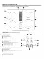 4
4
-
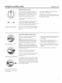 5
5
-
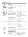 6
6
-
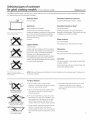 7
7
-
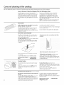 8
8
-
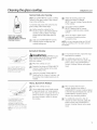 9
9
-
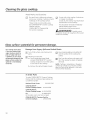 10
10
-
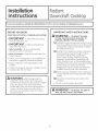 11
11
-
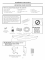 12
12
-
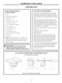 13
13
-
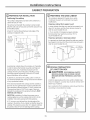 14
14
-
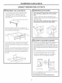 15
15
-
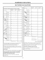 16
16
-
 17
17
-
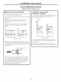 18
18
-
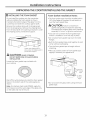 19
19
-
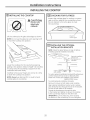 20
20
-
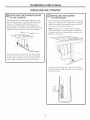 21
21
-
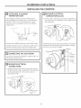 22
22
-
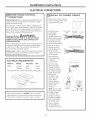 23
23
-
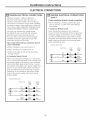 24
24
-
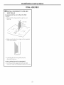 25
25
-
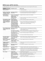 26
26
-
 27
27
-
 28
28
-
 29
29
-
 30
30
-
 31
31
-
 32
32
-
 33
33
-
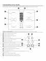 34
34
-
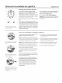 35
35
-
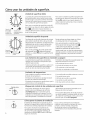 36
36
-
 37
37
-
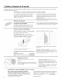 38
38
-
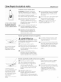 39
39
-
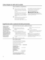 40
40
-
 41
41
-
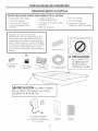 42
42
-
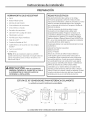 43
43
-
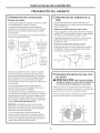 44
44
-
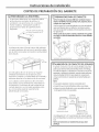 45
45
-
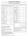 46
46
-
 47
47
-
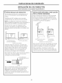 48
48
-
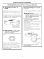 49
49
-
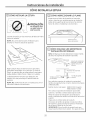 50
50
-
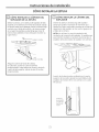 51
51
-
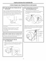 52
52
-
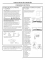 53
53
-
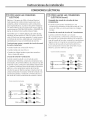 54
54
-
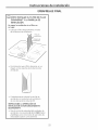 55
55
-
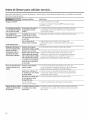 56
56
-
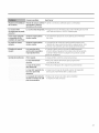 57
57
-
 58
58
-
 59
59
-
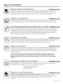 60
60


GE PP989 Owner's Manual and Installation Instructions
- Tipo
- Owner's Manual and Installation Instructions
En otros idiomas
- English: GE PP989
Documentos relacionados
-
GE JP989KKCC Manual de usuario
-
-
GE PHP960SM1SS El manual del propietario
-
Hotpoint JAS640RMSS El manual del propietario
-
-
GE Appliances JB256RMSS El manual del propietario
-
-
-
GE JP656B0C3 Guía de instalación
-