I stallatio
I struction
30"ElectricCooktop
CP350, JP340, JP346, JP356, PP912, PP932, PP942,
PP944, PP945, PP950
Pl If you have questions, call 800.GE.CARES or visit our website at: GEApplionces.com
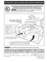
BEFORE YOU BEGIN
Read these instructions completely and carefully.
. IMPORTANT - savetheseinstructions
for local inspector's use.
. IMPORTANT - Observeollgoverning
codes and ordinances.
, Note to Installer- Be sure to leave these
instructions with the Consumer.
, Note to Consumer - Keep these instructions for
future reference.
, Product failure due to improper installation is not
covered under the Warranty.
A WARNING - This appliance must be
properly grounded.
. ATTENTION INSTALLER - ALL
COOKTOPS lUST BE HARD WIRED {DIRECT
WIRED} INTO AN APPROVED JUNCTION BOX. A
"PLUG AND RECEPTACLE" IS NOT PERMITTED
ON THESE PRODUCTS.
, Proper installation is the responsibility of the
installer and product failure due to improper
installation is NOT covered under warranty.
MATERIALS YOU WILL NEED
Junction Box Wire Nuts
TOOLS YOU WILL NEED
Pencil
Phillips Head
Screwdriver
Ruler or Straightedge
SaberSaw
1/8" Drill Bit & Electric or
Hand Drill
Safety Glasses
PARTS INCLUDED
4 Screws
(WBIX1137)
Foam Tape
2 Hold Down
Brackets
31-i0637-5 (07-12GE) 1

Installation Instructions
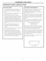
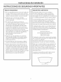
IMPORTANT SAFETY INSTRUCTIONS
w
FOR YOUR SAFETY
. For Personal Safety, remove house fuse or open
circuit breaker before beginning installation.
Failure to do so could result in serious injury or
death.
. Be sure your cooktop is installed properly by a
qualified installer or service technician.
. To eliminate the risk of burns or fire due to
reaching over heated surface elements, cabinet
storage located above the surface units should
be avoided. If cabinet storage space is to be
provided, the risk con be reduced by installing a
range hood that projects horizontally a minimum
of S" beyond the bottom of the cabinets. Cabinet
installation above the cooktop may be no deeper
than 13".
. Make sure the cabinets and wall coverings
around the cooktop can withstand the
temperatures (up to 200°F) generated y the
cooktop.
. The cooktop should be easy to reach and lighted
with natural light during the day.
. Always disconnect the electrical service to
the cooktop before repairing or servicing the
cooktop. This can be done by disconnecting the
fuse or circuit breaker. Failure to do this could
result in a dangerous or fatal shock. Know where
your main disconnect switch is located. If you do
not know, have your electrician show you.
ELECTRICAL REQUIREMENTS
This appliance must be supplied with the proper
voltage and frequency, and connected to an
individual, properly grounded branch circuit,
protected by a circuit breaker or a time delay fuse
as noted on name plate.
We recommend you have the electrical wiring and
hookup of your cooktop connected by a qualified
electrician. After installation, have the electrician
show you where your main cooktop disconnect is
located.
Wiring must conform to National Electrical Code.
You can get a copy of the National Electrical Code,
ANSI/NFPA No. 70-Latest Edition, by writing:
National Fire Protection Association
Batterymarch Park
Quincy, MA 02269
The cooktop conduit wiring is approved for copper
wire connection only, and if you have aluminum
house wiring, you must use special UL approved
connectors for joining copper to aluminum.
You must use a two-wire, three conductor 208/240
VAC, 60 Hertz electrical system. A white (neutral)
wire is not needed for this unit. The cooktop must
be installed in a circuit that does not exceed 125
VAC nominal to ground.
Refer to the name plate on your cooktop for the
KW rating for your cooktop.
Name plate location

Installation Instructions
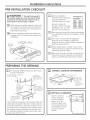
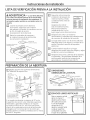
PRE-INSTALLATION CHECKLIST
WARN ING - Theelectricalpowerto
the cooktop supply line must be shut offwhile
connections are being made. Failure to do so
could result in serious injury or death.
r_ When preparing cooktop opening, make sure
the inside of the cabinet and the cooktop do
not interfere with each other. (See section on
preparing the opening.)
r_ Remove packaging materials and literature
package from the cooktop before beginning
installation.
Cooktop
Fa
ra
Remove Installation
Instructions from literature
pack and read them
carefully before you begin.
Be sure to place all
literature, Owner's Manual,
Installations, etc. in a safe
place for future reference.
_SYINSTALL_ONOrYOURN_
30"OOOKT_
_%:m.;%':_ g',51:12,_'2;':::'
Make sure you have all the tools and materials
you need before starting the installation of the
cooktop.
Your home must provide the adequate
electrical service needed to safely and
properly use your cooktop. (Refer to section on
electrical requirements.)
When installing your cooktop in your home,
make sure all local codes and ordinances are
followed exactly as stated.
Make sure the wall coverings, countertop and
cabinets around the cooktop can withstand
heat (up to 200°F) generated by the cooktop.
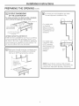
PREPARING THE OPENING
r_ The following MINIMUM clearance dimensions
must be maintained.
13"MAX, Depth of unprotected
overhead cabinets
1-1/2" HIN.
Clearance from
cutout to side wall
on the right of the
unit
30" MIN.
Clearance from 15" MIN. Height
countertop to countertop to
unprotected nearest cabinet on
overhead either side of unit
surface
2" IV]IN,Clearance
from cutout to side
wall on the left of
the unit
If a 30" clearance between the cooking surface and
overhead combustible materials or metal cabinets
cannot be maintained, a minimum clearance of 24"
is required and the underside of the cabinets above
the cooktop must be protected with not less than
1/4" insulating millboard covered with sheet metal
not less than 0.0122" thick.
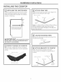
r_ OVERALL COOKTOP DIMENSIONS
29-3/4" ..._I_'._ 21-5/8" (21-1/2" SS)
129-_J8'_SA
_,I_ __ _LI _-=J_,Front
L// Cnn_nn _ 4-3/16" Rear
___ _..... _" __"_ at the conduit
L---...m____1-_...,.l , location
"I*'1 6-1/4" Rear
on Model PP945
19-i/4" q_._.,-,_ & PP950
r_ VERTICAL CLEARANCE
Allow 5" minimum 8-1/4"
vertical clearance
from the cooktop
bottom (or 8-1/4"
minimum depth from
the countertop) to any
combustible surfaces,
such as a cabinet
drawer.
3

Installation Instructions
PREPARING THE OPENING (Cont)
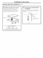
[_ CUTOUT DIMENSIONS
OF THE COUNTERTOP
To insure accuracy, it is best to make a template
when cutting the opening in the counter.
th of cut
1-3/4" Min. Between _ cut ---'f_ " _ ]
cutout and the wall ---_:_;;;_ _ I
2-1/2" Min. from front edge III
of cutout and front edge of
countertop
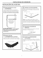
JXTR32X CUTOUT FILLER TRIM KIT:
A filler trim kit is available for use if your countertop
cutout is larger than the dimensions shown, up to
29-13/16" x 20-7/16". Order JXTRS2X to reduce the
cutout opening for installation of this cooktop. This
kit may be ordered from your GE Dealer.
r_ Make sure the wall coverings, countertop and
cabinets around the cooktop can withstand
heat (up to 200°F) generated by cooktop.
countertop must
withstand heat up
to 200°F.
[]_] For Americans with Disabilities Act (ADA)
Forward Approach Installation Only:
For models with
no drop box,
allow 5" minimum
depth between the
countertop and an
enclosure.
For models with
a drop box, allow
6-1/2" minimum
depth between the
countertop and an
enclosure.
(PP945)
NOTE: The enclosure must be made of wood
material. Also, an access panel is required for the
junction box, hold-down brackets, and service.

Installation Instructions
INSTALLING THE COOKTOP
INSTALLING THE JUNCTION BOX
Install an approved junction box where it will be
easily reached through the front of the cabinet
where the cooktop will be located. The cooktop
conduit is 3 feet long.
_C
Install junction box so that
it can be reached through
the front of the cabinet.
]
t
16"
Min.
2_
A IMPORTANT: The junction box must be
locatedwhere itwillallow considerableslackin
the conduitforserviceability.
E_ PROTECT SURFACE OF COOKTOP
Placea towel or tablecloth onto the countertop.
Lay the cooktop upside down onto the protected
surface.
Bottom of Cooktop
Cloth under Cooktop
[_ ATTACH FOAM TAPE
Apply the foam tape around the outer edge of the
glass. Do not overlap the foam tape.
Bottom of Cooktop
-_. _ '---. .......... z-;_ .........
Note: On CP350S, PP912S, PP932S, PP942S, PP944S,
PP945S & PP950S models, apply the foam tape
around the outer edge of the glass on the sides and
rear of the unit only.
LOCATE MOUNTING PARTS
Remove the hold down brackets and screws from
the literature package.
Mounting Screw
FsI ATTACH BRACKETS TO COOKTOP
Screw the hold down bracket to the side
of the cooktop unit. Repeat for opposite side of
cooktop.
Cooktop Gloss
Hold Down
Bracket

Installation Instructions
INSTALLING THE COOKTOP (CONT.)
INSERT COOKTOP INTO CUTOUT
Insert the cooktop centered into the cutout
opening. Make sure the front edge ofthe
countertop is parallel to the cooktop. Make final
check that all required clearances are met.
Hold Down
Bracket
0
[_ ATTACH HOLD DOWN BRACKETS
TO CABINET
Open the cabinet door and screw the hold down
brackets to the cabinet sides with the screws
provided.
Mounting Screw
Burner Box Sides
t
Use suitable fasteners
for anchorage in cabinet
sides
Cabinet Side

Installation Instructions
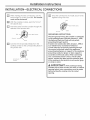
INSTALLATION--ELECTRICAL CONNECTIONS
D
El
When making the wire connections, use the
entire length of conduit provided. The conduit
must not be shortened.
With the cooktop in place, open the front of
the cabinet door.
Insert the wires from the conduit through the
openinq of the junction box.
Ground Red __
Black
Strain Relief Clamp
F6]
Connect the red and black leads from the
cooktop conduit to the corresponding leads in
the junction box.
Ground wire
location
,/_ Red
Black
r_ once the connections are made, secure wires
together using wire nuts.
Red
Strain
Ground / v Black
Relief Clamp
GROUNDING INSTRUCTIONS:
The bare ground wire in the conduit is connected
to the cooktop frame. Effective January 1, 1996,
the National Electrical Code will not permit
grounding through neutral.
If used in new construction after January 1, 1996 or
in a mobile home, recreational vehicle or
if local codes do not permit grounding through
the neutral white lead, attach the appliance
grounding lead (green or copper) to the residence
grounding conductor (green or bare copper) in
accordance with local codes. When connecting
to a 21conductor branch circuit, if local codes
permit, connect the bare ground connector lead
of the cooktop to the branch circuit neutral (gray
or white in color).
A IMPORTANT: _fthe cooktop is being
installed into a blind counter (one with no cabinet
opening below), wire connections must be made
before putting the cooktop into the cutout
opening.

Installation Instructions
CHECKLISTS
[i]
[]
D
[]
B1
PRE-TEST CHECKLIST
Remove all protective film, if present, and any
stickers.
Check to be sure that all wiring is secure and
not pinched or in contact with moving parts.
Check level of appliance.
Check that the cooktop is properly grounded.
[]_] OPERATION CHECKLIST
E1
D
EEl
Remove all items from the top of the cooktop
surface.
Turn on the power to the cooktop.(Refer to
your Owner's Manual.) Verify that all surface
burners operate properly.
Check that the circuit breaker is not tripped
nor the house fuse blown.
Check that conduit is securely connected to
thejunction box.
See Owner's Manual for troubleshooting list.
NOTE TO ELECTRICIAN:
The power leads supplied with this appliance are
UL recognized for connections to larger gauge
household wiring. The insulation of these leads
is rated at temperatures much higher than
the temperature rating of household wiring.
The current carrying capacity of a conductor
is governed by the wire gauge and also the
temperature rating of the insulation around the
wire.
NOTE: ALUMINUM WIRING
, WARNING:
IHPROPER CONNECTION OF ALUMINUH
HOUSE WIRING TO THE COPPER LEADS CAN
RESULT IN A SERIOUS PROBLEH.
, Splice copper wires to aluminum wiring
using special connectors designed and UL
approved for joining copper to aluminum
and follow the manufacturer's recommended
connector procedure closely.
NOTE: Wire used, location and enclosure of
splices, etc., must conform to good wiring
practice and local codes.

Instruccio
deinstalaci6n
Estufael ctricoe 30"
CP350, JP340, JP346, JP356, PP912, PP932, PP942,
PP944, PP945, PP950
[] "Si tiene alguna pregunta, Ilame al 800.GE.CARES o visite nuestro sitio Web en: GEAppliances.com"
ANTES DE COMENZAR
Leo estos instrucciones por completo
y con cuidodo.
.IMPORTANTE - Conserveestas
instrucciones para el uso del inspector local.
.IMPORTANTE -cumplocontodoslos
c6digos y reglas aplicables.
, Nota para el instalador - AsegOrese de dejar estas
instrucciones en poder del consumidor.
, Nota para el consumidor - Conserve estas
instrucciones para referencias futuras.
, El mal funcionamiento del producto debido
a una instoloci6n incorrect° no est6 cubierto por Io
Garontia.
A_ADVERTENCIA - Esteaparato debe
descargarse a tierra correctamente.
.ATENCI6N INSTALADOR-
TODAS LAS ESTUFAS DEBEN CONTAR CON
CABLEADO (CABLEADO DIRECTO) A UNA CAJA
DE EMPALMES APROBADA. ESTOS PRODUCTOS
NO ACEPTAN ENCHUFES Y RECEPT#,CULOS.
, La instalaci6n correcta es responsabilidad
del instalador, y el mal funcionamiento del producto
debido a una instalaci6n inadecuada NO est6
cubierto bajo la garantia.
PARTES INCLUIDAS
/4Tornillos Cinta de espuma
(WBIX1137)
NECESITARA
LOSSlGUIENTES MATERIALES
Caja de empalmes Tuercas para cables
NECESITARA LAS SIGUIENTES
HERRAMIENTAS
Ldpiz
Destornillador Phillips
Regla o
regla para nivelar
Sierra
Broca perforadora de 1/8"
y taladro el@ctricoomanual
Gafas de seguridad
31-i0637-5 (07-12 GE) ].

Instruccionesde instalaci6n
INSTRUCCIONES DE SEGURIDAD IMPORTANTES
PARA SU SEGURIDAD
. Para su seguridad personal, retire los fusibles de
su hogar o bien abra el cortacircuitos antes de
comenzar con la instalaci6n. El no hacerlo puede
resultar en lesiones serias o incluso la muerte.
. AsegOreseque su estufa sea instalada
correctamente par un instalador o t6cnico de
servicio calificado.
. Para eliminar el riesgo de quemaduras
o incendio debido al contacto con los elementos
de superficie calentados, debe evitarse el
almacenaje en los gabinetes ubicados sabre
los elementos de superficie. Si se cuenta con
espacio en un gabinete, puede reducir el riesgo
instalando una campana que se proyecte
horizontalmente un minima de 5" m6s del fondo
de los gabinetes. La instalaci6n de gabinetes
sabre la estufa no debe exceder 13"
de profundidad.
. AsegOreseque los gabinetes y las cubiertas
de las paredes alrededor de la estufa puedan
soportar lastemperaturas generadas par la
estufa (hasta 200 °F).
. La estufa debe ser f6cil de alcanzar y deber6
contar con iluminaci6n natural durante el dia.
. Siempre desconecte la toma el@ctricaque va
hacia la estufa antes de reparar o dar servicio
a la estufa. Esto puede hacerse desconectando
el fusible o cortacircuitos. No hacer esto puede
resultar en un shock el6ctrico peligroso o fatal.
Sepa en d6nde se Iocaliza el interruptor principal
de desconexi6n. Si no Io sabe, pidale a su
electricista que le muestre la ubicaci6n.
REQUISlTOS ELI_CTRICOS
Este aparato debe contar con el voltaje y
frecuencia adecuados, y deber6 conectarse
a un circuito derivado individual debidamente
descargado a tierra, protegido par un cortacircuitos
o un fusible temporizado coma Io indica la placa.
Le recomendamos que un electricista calificado
conecte el cableado el6ctrico y conexi6n de
su estufa. Despu6s de la instalaci6n, pidale al
electricista que le muestre en d6nde se Iocaliza el
interruptor principal de desconexi6n de su estufa.
Elcableado debe cumplir con el C6digo Nacional
sabre Electricidad. Puede obtener una copia del
C6d!go Nacional sabre Electricidad, ANSI/NFPANo.
70-Ultima edici6n, escribiendo a:
Asociaci6n Nacional
para la Prevenci6n de Incendios
Batterymarch Park
Quincy, MA 02269
Elcableado conductor de la estufa est6 aprobado
para conexiones 0nicamente con cables de cobre,
y si cuenta con cableado
de aluminio, debe usar conectores especiales
aprobados par UL para unit cobre con aluminio.
Debe usar un sistema el6ctrico con conductor de
dos cables y tres conductores 208/240 VCA, de
60 Hertz. No se requiere un cable blanco (neutral)
para esta unidad. La estufa debe instalarse en
un circuito que no exceda 125 VCA nominales de
descarga a tierra.
Consulte el r6tulo sabre su estufa para conocer
la clasificaci6n en kilovatios de su estufa.
Ubicaci6n del r6tulo

Instruccionesde instalaci6n
J J
LISTA DE VERIFICACION PREVIA A LA INSTALACION
A ADVERTENCIA - Lacorrienteel_ctrica
a la tuberia de abastecirniento de la estufa debe
cortarse durante la realizaci6n de conexiones. El
no hacerlo puede resultar en una lesi6n seria o la
muerte.
[] Cuando se prepare para la abertura
de la estufa, asegOrese que el interior
del gabinete y laestufa no interfieran uno con
el otro. (Consulte la secci6n
de preparaci6n de la abertura).
r_ Retire los materiales de empaque y
el material impreso de la estufa antes
de comenzar la instalaci6n.
Paquete de
material impreso
Empaque de espuma
de poliestireno
Estufa
ra
[]
EEl
FF]
Saque las instrucciones de
instalaci6n del paquete de
material impreso y 16alas
cuidadosamente antes de
comenzar.
AsegOresede colocar
todo el material impreso,
Manual de propietario,
Instalaciones, etc.,en un
lugar seguro para referencia futura.
EASYINSTALLA_ONOFYOU_NEW
30"¢OOKTOP
°X_#2'd]':'_s£'4._,_£@?££y£
Aseg6rese de contar con todas las
herramientas y materiales que necesita antes
de comenzar la instalaci6n de la estufa.
Suhogar debe contar con el servicio el6ctrico
adecuado para el uso seguro y correcto de su
estufa. (Consulte la secci6n de requisitos
el6ctricos).
Cuando instale la estufa en su hogar,
aseg6rese de cumplir todos los c6digos y reglas
locales tal y como se establecen.
Aseg@esede que las cubiertas de las paredes,
el mostrador y los gabinetes alrededor de la
estufa puedan soportar las temperaturas
generadas por la estufa (hasta 200 °F).
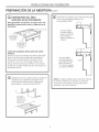
PREPARACION DE LA ABERTURA
r_] Deben seguirse las siguientes dimensiones
HiNIHAS de espacio libre.
1-1/2" MJN.Espacio
13" MAX, desde el @ea
Profundidad cortada hasta
de los la pared lateral
gabinetes a la derecha
superiores de launidad
sin
protecci6n
30" MJN.
Espaciodesde 3_5"MJN.AItura
el mostrador _sde
hasta la superficie el mostrador
superior sin hasta el
protecd6n gabinete m6s
cualquiera
de los lados
2" MJN.Espacio desde de la unidad
el 6rea cortada hasta
la pared lateral a la
izquierda de la unidad
Sino puede mantenerse un espacio de 30" entre
la superficie de cocci6n y los materiales superiores
inflamables o gabinetes met61icos,se requiere
un espacio minimo de 24", asi como que el lado
inferior de los gabinetes encima de la estufa est6n
protegidos con no menos de 1/4" de cart6n gris
aislante cubierto con 16minasmet61icasde no menos
de 0.0122" de grosor.
_-I DIPIENSIONES
GENERALES DE LA ESTUFA
29 3"4" , 21-3/8"
(29__%(_AO) _ (21-1/2' AO [acero ino×idable])
/ __1 _ 3-1/4" Frente
Fqtufn _ 4-3/16" Parte
_ - ..... _._..,--"_ posterior en la
k_-'_ ___J T ubicaci6n del
_ _"_" conducto
3.9-3./4" qh_ -_ 28" 6-3.//4" Parte
posterior en los
modelos PP945 y
PP950
B1
ESPACIOS LIBRES VERTICALES
_-3._"_ i_,,U_l
CAJON I _
Dejeun espacio vertical
de por Io menos5"
desdela parte inferior
de la placa de cocci6n
(ouna profundidad
minima de 8-1/4"
desdela mesada)hasta
cualquier superficie
combustible,tal como
el caj6n de un gabinete.

Instrucciones de instalaci6n
J
PREPARACION DE LA ABERTURA (Cont)
DIMENSIONES DEL
AREA
CORTADA EN EL MOSTRADOR
Para garantizar la precisi6n, es mejor crear una
plantilla al momento de cortar la abertura en el
mostrador.
19-5/8" oncho del carte
!
1-3/4"
Instruccionesde instalaci6n
J
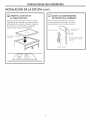
INSTALACION DE LA ESTUFA
rT] INSTALACION DE LA CAJA
DE EMPALMES
Instale una caja de empalmes aprobada en
un lugar de f6cil acceso a trav6s del frente del
gabinete en donde pueda colocarse la estufa.
Elconducto de la estufa tiene 4 pies de Iongitud.
tnstale la caja de
empalmesde modoque
pueda alcanzarse
a trav@sdelfrente
del gabinete.
A IMPO RTANTE: Lacajade empalmes
debe JocoJizorseen donde elconducto est6Jo
suticientementetlojopora permitirque
se Jed6 servicio.
PROTECCI6N DE
LA SUPERFICIE DE LA ESTUFA
CoIoque una toalla o mantel sobre el mostrador.
Coloque la estufa al rev6s sobre el 6rea protegida.
Parteinferior de Ioestufa
Patio debajo de Io estufa
ITI APLIQUE LA CINTA DE ESPUMA
Aplique la cinta de espuma alrededor del borde
externo del vidrio. No aplique un exceso de cinta
de espuma.
Parte inferior de la estufa
_ jj .
j.-JJ
- -. Cinta de espuma o
•//J//ljj //._.
' .
j.J
la estufa
Nota: En los modelos CP350S, PP912S, PP932S,
PP942S, PP944S, PP945S y PP950S, aplique la cinta
de espuma 6nicamente alrededor del borde exterior
del vidrio en los lados y parte posterior de la unidad.
LOCALICE LAS PARTES DE
MONTAJE
Saque las abrazaderas de montaje y tornillos del
empaque con material impreso.
Tornillo de montaje
r_ SUJETE LAS ABRAZADERAS
A LA ESTUFA
Atornille la abrazadera de montaje a un lado de la
unidad de la estufa. Repita en el lado opuesto de la
estufa.
Agujero
previamente
perforado
Parte inferior de la estufa
Cinta de espuma
" . jl Ij"
-. ii I
Vidrio de la estufa
Abrazadera
de montaje

Instruccionesde instalaci6n
J
INSTALACION DE LA ESTUFA (CONT.}
[_] INSERTE LA ESTUFA EN
EL AREA CORTADA
Inserte la estufa centrada en el 6rea cortada.
AsegOrese de que el borde frontal del mostrador
est6 paralelo con respecto a la estufa. Aseg0rese
de verificar al final que todos los espacios
especificados hayan sido respetados.
Abrazadera _
demontaje
IlL] SUJETE LAS ABRAZADERAS
DE MONTAJE AL GABINETE
Abra la puerta del gabinete y atornille
las abrazaderas de montaje a los lados
del gabinete con los tornillos incluidos.
Ladosde la caja
Tornillodemontaje dehornillas
t
Usesujetadoresadecuados
parafijaci6n alos ladosdel
gabinete
Lado del gabinete

Instruccionesde instalaci6n
J J
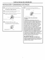
INSTALACION--CON EXION ES ELECTRICAS
r_ cuando realice las conexiones de
cables,
utilice toda la extensi6n del conducto incluido.
El conducto no debe reducirse.
Con la estufa colocada en su lugar, abra el
frente de la puerta del gabinete.
Inserte los cables del conducto a trav6s de la
abertura de la caja de empalmes.
Descarga a tierra
Pinza de alivio de tensi6n
S] Conectelos cables rojoy negro
del conductor de la estufa a los cables
correspondientes en la caja de empalmes.
Rojo
_b
Ubicad6ndelcablede
descargaaderra Negro
r_ una vez que se hayan realizado las
conexiones, fije los cables con las tuercas
para cables.
Descarga a tierra
R#o
_/ Negr_ inza
de alivio de tensi6n
INSTRUCCIONES PARA DESCARGA
A TIERRA:
El cable pelado de descarga a tierra en el
conducto se conecta al armaz6n de la estufa. A
partir del 1 de enero de 1996, el C6digo National
sabre Electricidad no permitir6 la descarga a
tierra a trav_s de cables neutraies. Si se usa en
una construcci6n nueva despu_s del 1 de enero
de 1996 o bien en una casa rodante, vehiculo
recreativo, o bien si los c6digos locales no
permiten la descarga a tierra a trav_s de cables
blancos neutrales, sujete el cable de descarga a
tierra del aparato (verde o cobre) al conductor
de descarga a tierra de la residencia (verde o
cobre) de acuerdo con los c6digos locales. Cuando
conecte a un circuito derivado de 3 conductores,
si Io permiten los c6digos locales, conecte el
cable del conector de descarga a tierra al circuito
derivado neutral (de color gris o blanco).
A IMPORTANTE: silaestufaseva
a instalar en un mostrador sin salida (uno sin
abertura del gobinete inferior), los conexiones del
cableado deber6n realizarse antes de colocar la
estufa en el 6rea cortada.

Instruccionesde instalaci6n
J
LISTAS DE VERIFICACION
| LISTA DE VERIFICACI6N PREVIA
Retire toda la pelicula protectora, si la hay,
y las calcomanias.
Verifique que todos los cables est6n fijos y que
no est6n torciclos o en contacto con partes
m6viles.
EC_ Verifique el nivel del aparato.
r_ Verifique que la estufa est6 descargada
a tierra correctamente.
r
[_] LISTA DE VERIFICACI6N
DE OPERACI6N
Retire todos los objetos que se encuentren
sobre la superficie de la estufa.
Encienda la toma de corriente de la estufa.
(Consulte su Manual del propietario). Verifique
que todas las hornillas de la superficie
funcionen correctamente.
Verifique que el cortacircuitos no est6
desactivado o que se haya fundido el fusible
de su hogar.
Verifique que el conducto est6 conectado
correctamente a la caja de empalmes.
Consulte el Manual del propietario para ver la
lista de resoluci6n de problemas.
NOTA PARA EL ELECTRICISTA:
Los cables de corriente incluidos con este
aparato cuentan con la aprobaci6n de UL para
cone×iones a cableado dom_stico de mayor
calibre. El aislante de estos cables se califica a
temperaturas m6s elevadas que las del cableado
dom_stico. La capacidad de carga actual de
un conductor depende del calibre del cable y
tambi_n de la calificaci6n de la temperatura del
aislante alrededor del cable.
NOTA: CABLEADO DE ALUMINIO
ADVERTENCIA:
LA CONE×I6N INADECUADA DEL CABLEADO
DOHI_STICO DE ALUHINIO A LOS CABLES DE
COBRE PUEDE RESULTAR EN UN PROBLEHA
GRAVE.
Una los cables de cobre a los de aluminio con
conectores especiales dise_ados y aprobados
por UL para unir cables de cobre a cables de
aluminio; asimismo, siga cuidadosamente las
recomendaciones del fabricante al manipular
el conector.
NOTA: El uso de los cables, la ubicaci6n
y alojamiento de empalmes, etc., deben
realizarse correctamente y de acuerdo con los
c6digos locales.
-
 1
1
-
 2
2
-
 3
3
-
 4
4
-
 5
5
-
 6
6
-
 7
7
-
 8
8
-
 9
9
-
 10
10
-
 11
11
-
 12
12
-
 13
13
-
 14
14
-
 15
15
-
 16
16


GE PP945WM2WW Guía de instalación
- Tipo
- Guía de instalación
- Este manual también es adecuado para
en otros idiomas
- English: GE PP945WM2WW Installation guide