Zoeller 1263-0001 Instrucciones de operación
- Tipo
- Instrucciones de operación

1
© 2020. All rights reserved.
Español p. 17
SEWAGE PUMP
MODEL #1263
Serial Number
Purchase Date
Zoeller
®
is a registered trademark
of Zoeller Co. All Rights Reserved.
Questions, problems, missing parts? Before returning to your retailer, call our customer
service department at 1-800-584-8089, 7:30 a.m. - 5:00 p.m., EST, Monday - Friday.
ATTACH YOUR RECEIPT HERE
SW1316 B
ZoellerAtHome.com

2
© 2020. All rights reserved.
Please read and understand this entire manual before attempting to assemble, operate, or install the
product.
• NOTE: Pumps with the “UL” Mark and pumps with the “US” mark are tested to UL Standard
UL778. CSA certied pumps are certied to CSA Standard C22.2 No. 108. (CUS.)
• ELECTRICAL SHOCK ALERT.
To reduce the risk of electric shock, install only a circuit protected by a ground-fault circuit-interruptor
(GFCI). Make certain that the ground fault receptacle is within the reach of the pump’s power supply
cord. DO NOT USE AN EXTENSION CORD.
• ELECTRICAL SHOCK ALERT.
Follow all local electrical and safety codes, as well as the National Electrical Code (NEC) and the
Occupational Safety and Health Act (OSHA).
• ELECTRICAL SHOCK ALERT.
Do not kink power cable, and never allow the cable to come in contact with oil, grease, hot surfaces,
chemicals, or sharp objects. Replace damaged or worn wiring cord immediately.
• ELECTRICAL SHOCK ALERT.
As a safety measure, each electrical outlet should be checked for ground using an Underwriters
Laboratory Listed circuit analyzer, which will indicate if the power, neutral, and ground wires are
correctly connected to your outlet. If they are not, contact a licensed electrician.
• ELECTRICAL SHOCK ALERT.
These pumps are supplied with a 3-prong grounded plug to help protect you against the possibility of
electrical shock. DO NOT UNDER ANY CIRCUMSTANCES REMOVE THE GROUND PIN.
• ELECTRICAL SHOCK ALERT.
To reduce the risk of electric shock, install only a circuit protected by a ground-fault circuit-interruptor
(GFCI).
• ELECTRICAL SHOCK ALERT.
Make sure the pump electrical supply circuit is equipped with fuses or circuit breakers of proper
capacity. A separate branch circuit is recommended, sized according the National Electrical Code
for the current shown on the pump name plate.
• CHEMICAL ALERT.
Prop65 Warning for California residents: WARNING: Cancer and Reproductive Harm -
www.P65Warnings.ca.gov
SAFETY INFORMATION
DANGER
• ELECTRICAL SHOCK HAZARD
.
Always disconnect power source before performing any work on or near the motor or its connected
load. If the power disconnect point is out-of-sight, lock it in the open position and tag it to prevent
unexpected application of power. Failure to do so could result in fatal electrical shock.
• ELECTRICAL SHOCK HAZARD.
Do not handle the pump with wet hands or when standing in water as fatal electrical shock could
occur. Disconnect main power before handling unit for ANY REASON!
• RISK OF ELECTRIC SHOCK.
These pumps have not been investigated for use in swimming pool areas.
WARNING

3
© 2020. All rights reserved.
CAUTION
CAUTION
• PRODUCT DAMAGE MAY RESULT.
Make certain that the power source conforms to the requirements of your equipment.
• PRODUCT DAMAGE MAY RESULT.
Maximum continuous operating water temperature for standard model pumps must not exceed
104°F (40°C).
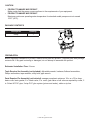
Before beginning installation of product, make sure all parts are present. Compare parts with package
contents list. If any part is missing or damaged, do not attempt to assemble the product.
Estimated Installation Time: 2 hours
Tools Required for Assembly (not included): Adjustable wrench, hacksaw, flathead screwdriver,
Phillips screwdriver, tape measure, utility knife, pipe wrench.
Description Quantity
Pump 1
PREPARATION
Parts Required For Assembly (not included): sewage pump basin minimum 18 in. w x 30 in. deep,
basin cover, basin gasket, 2 in. check valve, 2 in. union, gate valve or ball valve as required by codes, 2
in. Sched 40 PVC pipe, 2-step PVC glue system (primer and sealer), cable or zip ties.
PACKAGE CONTENTS

4
© 2020. All rights reserved.
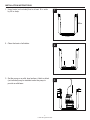
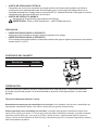
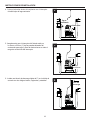
1. Sewage pumps are pumps used to remove
waste water that contains solids up to 2 in.
in diameter. The most common application is
for draining bathroom waste water to a sewer
or septic line.
Three prong
grounded
outlet
equipped
with a
ground fault
interruptor
2 in. Discharge
pipe
Upper level drainage
Cleanout
Flange
Lavatory
45°
Elbow
2 in. Check
valve
2 in. gate valve
Union
Vent pipe
Sink
Main waste
line to sewer
or septic tank
Switch
Pump
1
2. These pumps are equipped with a float switch. The
pump will turn on automatically when the water level in
the basin reaches the “on” level.
On
2
Off
3
Item On Level O Level
1263 10.25 in. 5 in.
3. The pump will turn off automatically when the water
level in the basin reaches the “off” level.
GENERAL PUMP INFORMATION

5
© 2020. All rights reserved.
INSTALLATION INSTRUCTIONS
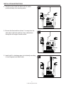
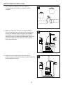
30 in.
18 in.
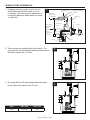
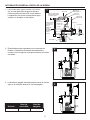
1. Use a basin (not included) that is at least 18 in. wide
by 30 in. deep.
1
2. Clean the basin of all debris.
2
3. Set the pump on a solid, level surface. A brick or block
(not included) may be installed under the pump to
provide a solid base.
3

6
© 2020. All rights reserved.
INSTALLATION INSTRUCTIONS
4
5
6
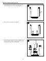
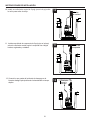
4. Place the pump inside the basin with the switch
positioned away from incoming water.
5. Be sure the oat switch is at least 1 in. away from the
side walls of the basin and free of any obstructions
through the full range of switch motion.
6. Install rigid 2 in. discharge pipe (not included) according
to local, regional, and state codes.
Incoming
water
Switch
Switch
1 in.
Minimum
Discharge
Pipe

7
© 2020. All rights reserved.
INSTALLATION INSTRUCTIONS
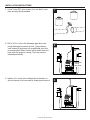
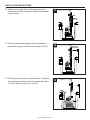
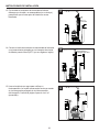
7. Use a 2-step PVC glue system (not included) to join
pipe and any ttings needed.
8. Drill a 3/16 in. hole in the discharge pipe above the
pump discharge to prevent air lock. Pumps have a
vent located in the pump, but an additional vent hole
is recommeded. Water stream will be visible from this
hole when the pump is running. The hole must be
cleaned periodically.
9. Install a 2 in. union (not included) above the basin to
allow the pump to be removed for cleaning and service.
Discharge
Pipe
Additional
3/16-in.
Vent Hole
Union
7
8
9

8
© 2020. All rights reserved.
INSTALLATION INSTRUCTIONS
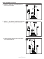
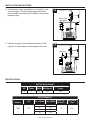
10. Install a 2 in. check valve (not included) above the
union to prevent back-ow.
11. Install a 2 in. gate valve (not included) above the check
valve as required by local, regional or state codes.
12. Connect remaining discharge pipe into main waste
line to sewer or septic tank.
Check
Valve
Gate
Valve
Main
waste line
10
11
12

9
© 2020. All rights reserved.
INSTALLATION INSTRUCTIONS
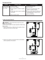
13. Attach power supply cord to discharge pipe using
cable or zip ties (not included) to allow the oat switch
to move freely.
14. Connect pump power supply cord to a receptacle
protected by a ground fault circuit interruptor (GFCI).
Cable or
Zip Ties
GFCI
protected
receptacle
13
14
15. Fill the basin with water to check operation. The pump
will start when the water level has reached the switch
“on” level. Refer to page 4 for “on” level.
On
15

10
© 2020. All rights reserved.
INSTALLATION INSTRUCTIONS
16. Install a basin cover and gasket (not included) on the
top of the basin. This will contain gases and odors,
prevent debris from falling into the basin, and prevent
personal injury.
Basin cover
and gasket
16
17. Install a vent pipe (not included) according to local,
regional, or state codes to remove gases and odors.
Vent pipe
17
MOTOR DATA CHART
HP Phase Volts Max Amps
Locked Rotor
Amps
1/2 1 115 9.8 19.5
PERFORMANCE
Item
Number
HP Ft. of Head Flow (GPM)
Shut O
Head (Ft.)
Discharge
Size
1263 1/2
0 103
18 2 in.
5 90
10 60
15 23
SPECIFICATIONS

11
© 2020. All rights reserved.
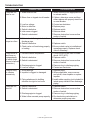
TROUBLESHOOTING
Problem Possible Cause Corrective Action
Pump will not
start or run.
1. Water level too low. 1. Water must be at the appropriate level
to activate switch.
2. Blown fuse or tripped circuit breaker. 2. If blown, determine cause and then
either replace with properly sized fuse,
or reset breaker.
3. Low line voltage. 3. Contact an electrician.
4. Motor is defective. 4. Replace pump.
5. Switch is defective. 5. Replace switch.
6. Inlet screen clogged. 6. Remove debris.
7. Switch is obstructed. 7. Remove obstruction to ensure free
motion of switch.
Pump starts and
stops too often.
1. Water is back-flowing into basin from
discharge pipe.
1. Install check valve.
2. Switch is defective. 2. Replace switch.
3. Check valve not functioning properly
or leaking.
3. Be sure check valve is installed and
operating properly. Replace check
valve if necessary .
Pump shuts off
and turns on
independently
of switch (trips
thermal overload
protection.)
1. Excessive water temperature. 1. Pump should not be used for water
above
104°F (40°C).
2. Switch is defective. 2. Replace switch.
3. Switch is obstructed. 3. Remove obstruction to ensure free
motion of switch.
4. Discharge pipe is clogged. 4. Remove clog in discharge piping.
5. Low line voltage. 5. Contact an electrician.
Pump is noisy
or vibrates
excessively.
1. Worn bearings. 1. Replace pump.
2. Impeller is clogged or damaged. 2. Where applicable, remove screen
and volute, clean impeller or replace
impeller.
3. Piping attachment to building
structure too rigid or too loose.
3. Install rubber coupling (not included) to
isolate pump vibration from discharge
piping.
Pump will not
shut off.
1. Switch is defective. 1. Replace switch.
2. Switch is obstructed. 2. Remove obstruction to ensure free
motion of switch.
3. Discharge pipe is clogged. 3. Remove clog in discharge piping.
4. Water inflow exceeds pump capacity.
.
4. Re-check sizing calculations to
determine proper pump size.

12
© 2020. All rights reserved.
Problem Possible Cause Corrective Action
Pump operates,
but delivers little
or no water.
1. Low line voltage. 1. Contact an electrician.
2. Inlet screen clogged. 2. Remove debris.
3. Broken impeller or debris in impeller
cavity.
3. Remove screen and volute, clean
impeller or replace impeller.
4. Check valve stuck closed or installed
backwards.
4. Be sure check valve is installed and
operating properly. Replace check
valve if necessary .
5. Shut off valve closed. 5. Open shut off valve.
TROUBLESHOOTING
CARE AND MAINTENANCE
WARNING: Always disconnect pump from power
supply before handling.
Inspect and test system for proper operation at least every
three months.
1. Remove any build-up of debris from the switch or float,
and check to be sure it moves freely.
1
2
2. Remove any debris from the basin that could interfere
with the operation of the switch.

13
© 2020. All rights reserved.
WARRANTY
This product is warranted for three years from the date of purchase. Subject to the conditions
hereinafter set forth, the manufacturer will repair or replace to the original consumer, any portion of
the product which proves defective due to defective materials or workmanship. To obtain warranty
service, contact the dealer from whom the product was purchased. The manufacturer retains the sole
right and option to determine whether to repair or replace defective equipment, parts or components.
Damage due to conditions beyond the control of the manufacturer is not covered by this warranty.
THIS WARRANTY WILL NOT APPLY: (a) To defects or malfunctions resulting from failure to properly
install, operate or maintain the unit in accordance with printed instructions provided; (b) to failures
resulting from abuse, accident or negligence or use of inappropriate chemicals or additives in the
water; (c) to normal maintenance services and the parts used in connection with such service; (d)
to units which are not installed in accordance with normal applicable local codes, ordinances and
good trade practices; and (e) if the unit is used for purposes other than for what it was designed and
manufactured.
RETURN OF WARRANTED COMPONENTS: Any item to be repaired or replaced under this warranty
must be returned to the manufacturer at Kendallville, Indiana or such other place as the manufacturer
may designate, freight prepaid.
THE WARRANTY PROVIDED HEREIN IS IN LIEU OF ALL OTHER EXPRESS WARRANTIES,
AND MAY NOT BE EXTENDED OR MODIFIED BY ANYONE. ANY IMPLIED WARRANTIES SHALL
BE LIMITED TO THE PERIOD OF THE LIMITED WARRANTY AND THEREAFTER ALL SUCH
IMPLIED WARRANTIES ARE DISCLAIMED AND EXCLUDED. THE MANUFACTURER SHALL
NOT, UNDER ANY CIRCUMSTANCES, BE LIABLE FOR INCIDENTAL, CONSEQUENTIAL OR
SPECIAL DAMAGES, SUCH AS, BUT NOT LIMITED TO DAMAGE TO, OR LOSS OF, OTHER
PROPERTY OR EQUIPMENT, LOSS OF PROFITS, INCONVENIENCE, OR OTHER INCIDENTAL
OR CONSEQUENTIAL DAMAGES OF ANY TYPE OR NATURE. THE LIABILITY OF THE
MANUFACTURER SHALL NOT EXCEED THE PRICE OF THE PRODUCT UPON WHICH SUCH
LIABILITY IS BASED.
This warranty gives you specic legal rights, and you may have other rights which vary from state to
state. Some states do not allow limitations on duration of implied warranties or exclusion of incidental
or consequential damages, so the above limitations may not apply to you.
In those instances where damages are incurred as a result of an alleged pump failure, the
Homeowner must retain possession of the pump for investigation purposes.

14
© 2020. All rights reserved.
1
(WIRE PACK)
(WIRE PACK)
2
4
3
5
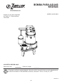
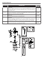
ITEM DESCRIPTION
MODEL
1263
1
Cord Kit
025390
Includes cord w/o-ring, case o-ring (115x4 NBR), clamp screws
(M5-0.8x16), cap screws (M6-1.0x15), GND screw (M4-0.7x6.0)
2
Capacitor Kit
025383
Includes capacitor, cap screws (M6-1.0x15), mounting screw (M4-
0.7x6), case o-ring (115x4 NBR)
3
Base Kit
025388
Includes pump base, screws (M5-0.8x15)
4
Cap Kit
025385
Includes cap screws (M6-1.0x15), GND screw (M4-0.7x6.0), case o-ring
(115x4 NBR), cap with handle, guard and plug, nameplate screw
(M3x1.34), switch to case screws, switch
5
Float Kit
025381
Includes guide rod, guide strap, oat
REPAIR PARTS

15
© 2020. All rights reserved.
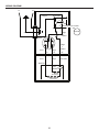
WIRING DIAGRAM
(3)
L1
L2
(1)
(2)
1
2
3
4
RUN
O.L.
MOTOR
BLUE
RED
SWITCH
BLACK
WHITE
GREEN
START
YELLOW
BLUE
RED
CAPACITOR
COM
NC
FLOAT
BLACK
OR
WHITE
BLACK
OR
WHITE

16
© 2020. All rights reserved.

14
BOMBA PARA AGUAS
NEGRAS
MODELO #1263-0001
Número de serie
Fecha de compra
Zoeller
®
es una marca registrada
de Zoeller Co. Todos derechos
reservados.
¿Preguntas, problemas, partes faltantes? Antes de acudir al minorista, llame a nuestro departamento
de servicio al cliente al 1-800-584-8089, de lunes a viernes de 7:30 a.m. a 5:00 p.m., EST.
ADJUNTE SU RECIBO AQUÍ
SW1316 S
ZoellerAtHome.com

15
Lea y comprenda completamente este manual antes de intentar ensamblar, usar o instalar el producto.
• NOTA: Las bombas con la marca “UL” y con la marca “US” se prueban para cumplir los estándares de UL
UL778. Las bombas con certicación CSA cumplen con el estándar CSA C22.2 No. 108. (CUS.)
• ALERTA DE DESCARGA ELÉCTRICA.
Para reducir el riesgo de descarga eléctrica, instale solamente un circuito protegido por un interruptor de
circuito con protección de falla a tierra (GFCI, por sus siglas en inglés). Cerciórese de que el receptáculo
de falla a tierra esté dentro del alcance del cable de alimentación eléctrica de la bomba. NO USE NINGÚN
CABLE DE EXTENSIÓN.
• ALERTA DE DESCARGA ELÉCTRICA.
Siga todos los códigos locales eléctricos y de seguridad, además del Código nacional de electricidad (NEC,
por sus siglas en inglés) y el de la Administración de Salud y Seguridad Ocupacional (OSHA, por sus siglas
en inglés).
• ALERTA DE DESCARGA ELÉCTRICA.
No doble el cable de alimentación y nunca permita que el cable entre en contacto con aceite, grasa,
superficies calientes, productos químicos u objetos punzantes. Cambie inmediatamente los cables dañados
o desgastados.
• ALERTA DE DESCARGA ELÉCTRICA.
Como medida de seguridad, la tierra de todo tomacorriente eléctrico debe ser verificada con un analizador
de circuito aprobado por Underwriters Laboratory, el cual indicará si los cables vivo, neutro y tierra están
conectados correctamente al tomacorriente. De no estar conectados correctamente, llame a un electricista
calificado que cuente con la debida licencia.
• ALERTA DE DESCARGA ELÉCTRICA.
Estas bombas vienen con un enchufe de 3 clavijas, con conexión a tierra, para protegerlo en caso de una
descarga eléctrica. BAJO NINGUNA CIRCUNSTANCIA QUITE EL CONECTOR DE TIERRA.
• ALERTA DE DESCARGA ELÉCTRICA.
Para reducir el riesgo de descarga eléctrica, instale un circuito protegido por un interruptor con detección
de falla a tierra (GFCI). Todas bombas vienen con provisiones para fuga de tierra adecuada para proteger
contra la posibilidad de descarga eléctrica.
INFORMACIÓN DE SEGURIDAD
PELIGRO
• PELIGRO DE ELECTROCUCIÓN.
Siempre desconecte el suministro de fuerza eléctrica antes de hacer cualquier trabajo en o cerca del motor o su carga
conectada.
Si el punto de desconexión de la alimentación está fuera de la vista, fíjelo en la posición abierta
y etiquételo para evitar una aplicación de alimentación inesperada. El incumplimiento de dicho paso podría
provocar una descarga eléctrica fatal.
• PELIGRO DE ELECTROCUCIÓN.
No manipule la bomba con las manos húmedas ni cuando esté parado en el agua, ya que podría ocurrir una descarga
eléctrica fatal. SIN IMPORTAR EL MOTIVO, desconecte la alimentación principal antes de manipular la unidad.
• PELIGRO DE CHOQUE ELÉCTRICO.
Esta bomba no ha sido diseñada para uso en áreas de piscinas.
ADVERTENCIA

16
CAUTION
Antes de comenzar a instalar el producto, asegúrese de tener todas las piezas. Compare las piezas con
la lista del contenido del paquete. No intente ensamblar el producto si falta alguna pieza o si estas están
dañadas.
Tiempo de instalación estimado: 2 horas.
Herramientas necesarias para el ensamblaje (no se incluyen): Llave ajustable, sierra de mano, destornillador de
cabeza plana, destornillador Phillips, cinta métrica, cuchillo para uso general, llave para tubos
Descripción Cantidad
Bomba 1
PREPARACIÓN
Piezas requeridas para el ensamblaje (no incluidas): contenedor para agua de la bomba de sumidero de al
menos 45 cm (18 pulg.) de ancho x 75 cm (30 pulg.) de profundidad, cubierta del contenedor, junta del contenedor,
válvula de retención de 2 pulg., unión de 5 cm (2 pulg.), válvula de paso o válvula de bola según lo exigen los
códigos, Tubería de PVC Sched 40 de DN50 (2 pulg.), sistema para pegar PVC de 2 pasos (imprimante y sellador),
cable o abrazaderas de plástico
CONTENIDO DEL PAQUETE
• ALERTA DE DESCARGA ELÉCTRICA.
Compruebe que el circuito de suministro de energía eléctrica de la bomba esté equipado con fusibles o
cortacircuitos de la capacidad adecuada. Es aconsejable usar un circuito derivado independiente con la
capacidad estipulada en el Código eléctrico nacional de EE.UU. (National Electrical Code) según la corriente
especificada en la placa de identificación de la bomba.
• ALERTA DE PRODUCTO QUÍMICO.
Advertencia de Proposición 65 para residentes de California
ADVERTENCIA: Cáncer y Daño Reproductivo - www.P65Warnings.ca.gov
PRECAUCIÓN
• PUEDE PROVOCAR DAÑO AL PRODUCTO
Asegúrese de que la fuente de energía cumpla los requisitos de su equipo.
• PUEDE PROVOCAR DAÑO AL PRODUCTO
En los modelos de bombas estándar, la temperatura máxima del agua en régimen permanente nunca deberá
exceder los 40°C (104°F).

17
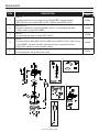
1. Las bombas para aguas servidas son bombas
que se usan para eliminar agua servida que
contiene sólidos de hasta 5,08 cm de diámetro.
La aplicación más común es para drenar agua
servida a un desagüe o línea séptica.
Tomacorriente
con puesta a
tierra de tres
clavijas
equipado
con un
interruptor
de falla de
puesta
a tierra
Tubo de descarga
de 2 pulg
Drenaje de
nivel superior
Tapón de
protección
Bomba
Brida
Lavamanos
Válvula de
control de
2 pulg
Válvula de
compuerta de 2 pulg
Unión
Tubería de
ventilación
Fregadero
Tubería de desagüe
principal al desagüe
o tanque séptico
Codo
de 45°
Interruptor
1
2. Estas bombas están equipadas con un interruptor de
flotador. La bomba se encenderá automáticamente
cuando el nivel de agua en el recipiente alcance el nivel de
encendido.
Nivel de
encendido
2
Nivel de
apagado
3
Artículo
Nivel de
encendido
Nivel de
apagado
1263-0001 10.7 pulg. 5.4 pulg.
3. La bomba se apagará automáticamente cuando el nivel de
agua en el recipiente alcance el nivel de apagado.
INFORMACIÓN GENERAL ACERCA DE LA BOMBA

18
INSTRUCCIONES DE INSTALACIÓN
76,20
cm
45,72 cm
1. Se un recipiente (no se incluye) que sea de al menos
45,72 cm de ancho por 76,20 cm de profundidad.
1
2. Elimine todos los desechos del recipiente.
2
3. Fije la bomba en una supercie sólida y nivelada. Puede
instalar un ladrillo o bloque (no se incluye) debajo de la
bomba para proporcionar una base sólida.
3

19
INSTRUCCIONES DE INSTALACIÓN
4
5
6
4. Coloque la bomba dentro del recipiente con el interruptor
ubicado lejos del agua entrante.
5. Asegúrese de que el interruptor del otador esté por
lo menos a 25 mm (1”) de las paredes laterales del
contenedor para agua y libre de obstrucciones en todo el
rango de movimiento del interruptor.
6. Instale una tubería de descarga rígida de 2” (no incluida) de
acuerdo con los códigos locales, regionales y estatales.
Agua
entrante
Interruptor
Interruptor
Mínimo
de 2,54 cm
Tubo de
descarga

20
INSTRUCCIONES DE INSTALACIÓN
7. Use un sistema de adhesivo PVC de 2 pasos (no
se incluye) para unir la tubería y cualquier conector
necesario.
8. Taladre un oricio de 4,76 mm en el tubo de descarga
sobre la descarga de la bomba para evitar obstrucciones
de aire. Las bombas poseen una agujero de ventilación,
sin embargo, se recomienda un agujero de ventilación
adicional. El chorro de agua será visible desde este oricio
cuando la bomba esté funcionando. El oricio se debe
limpiar periódicamente.
9. Instale una unión de 2 pulg (no se incluye) sobre el
recipiente para permitir que la bomba se pueda extraer para
nes de limpieza y servicio.
Tubo de
descarga
Agujero de
ventilación
adicional
de 3/16 pulg.
Unión
7
8
9

21
INSTRUCCIONES DE INSTALACIÓN
10. Instale una válvula de control de 2 pulg (no se incluye) sobre
la unión para evitar el reujo.
11. Instale una válvula de compuerta de 2 pulg (no se incluye)
sobre la válvula de control según lo requieran los códigos
locales, regionales y estatales.
12. Conecte lo que queda de la tubería de descarga en la
línea de desagüe principal hacia el alcantarillado o tanque
séptico.
Válvula
de control
Válvula de
compuerta
Tubería de
desagüe
principal
10
11
12

22
INSTRUCCIONES DE INSTALACIÓN
13. Fije el cable de suministro de electricidad al tubo de
descarga con el cable o un amarracables (no se incluye)
para permitir que el interruptor de otador se mueva
libremente.
14. Conecte el cable de suministro de electricidad de la bomba
a un tomacorriente protegido por un interruptor de circuito
de falla de puesta a tierra (GFCI, por sus siglas en inglés).
Cable o un
amarracables
Tomacorriente
protegido por GFCI
13
14
15. Llene el recipiente con agua para vericar su
funcionamiento. La bomba comenzará a funcionar cuando
el nivel de agua haya llegado al nivel de encendido
del interruptor. Consulte la página 4 para el nivel “on”
(encendido).
On
15

23
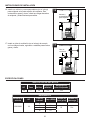
INSTRUCCIONES DE INSTALACIÓN
16. Instale una cubierta y una empaquetadura (no se incluye)
para recipiente en la parte superior del recipiente. Esto
contendrá los gases y olores, evitará que caigan desechos
al recipiente y evitará lesiones personales.
Cubierta y
empaquetadura
para recipiente
16
17. Instale un tubo de ventilación (no se incluye) de acuerdo
con los códigos locales, regionales o estatales para eliminar
gases y olores.
Tubo de
ventilación
17
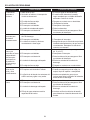
TABLA DE DATOS DEL MOTOR
HP Fase Voltios
Amperaje
máximo
Amperaje del
rotor bloqueado
1/2 1 115 9.8 19.5
RENDIMIENTO
Número de
artículo
HP
Pies de
cabezal
Flujo (GPM)
Cabezal de
cierre (pies)
Tamaño de
descarga
1263-0001 1/2
0
103
5
90
18 2 in.10
60
15
23
ESPECIFICACIONES

24
SOLUCIÓN DE PROBLEMAS
Problema Causa Posible Correción del Defecto
La bomba no
enciende ni
funciona.
1. Water level too low. 1. El nivel de agua es demasiado bajo.
2. Se fundió un fusible o el interruptor de
circuito se desconectó.
2. Si está fundido, determine la causa y
luego reemplace por un fusible del tamaño
adecuado o reinicie el circuito.
3. El voltaje de línea es bajo. 3. Póngase en contacto con un electricista.
4. El motor está dañado. 4. Reemplace la bomba.
5. El interruptor está dañado. 5. Reemplace el interruptor.
6. La malla de entrada está tapada. 6. Retire los desechos.
7. El interruptor está obstruido. 7. Retire la obstrucción para asegurar el libre
movimiento del interruptor.
La bomba
enciende pero
se detiene
constantemente.
1. El agua se devuelve al recipiente desde el
tubo de descarga.
1. Instale la válvula de control.
2. El interruptor está dañado. 2. Reemplace el interruptor.
3. La válvula de control no funciona
correctamente o tiene fugas.
3. Asegúrese de que la válvula de control esté
instalada adecuadamente y de que funciona
correctamente. Reemplace la válvula de
control si es necesario.
La bomba se
cierra y se
enciende en forma
independiente
del interruptor
(se dispara en
la protección
de sobrecarga
térmica).
1. La temperatura del agua es excesiva. 1. No se debe usar la bomba para agua sobre
40 ˚C (104 ˚F).
2. El interruptor está dañado. 2. Reemplace el interruptor.
3. El interruptor está obstruido. 3. Retire la obstrucción para asegurar el libre
movimiento del interruptor.
4. La tubería de descarga está tapada. 4. Elimine la suciedad de la tubería de
descarga.
5. El voltaje de línea es bajo. 5. Póngase en contacto con un electricista.
La bomba
tiene mucho
ruido y vibra
excesivamente.
1. Los rodamientos están desgastados. 1. Reemplace la bomba.
2. El impulsor está obstruido o dañado. 2. Cuando corresponda, quite la rejilla y la
espiral, limpie el impulsor o reemplácelo.
3. La fijación de la tubería a la estructura del
edificio está muy rígida o muy suelta.
3. Instale un acoplador de goma (no se
incluye) para aislar la vibración de la bomba
desde el tubo de descarga.
La bomba no se
cierra.
1. El interruptor está dañado. 1. Reemplace el interruptor.
2. El interruptor está obstruido. 2. Retire la obstrucción para asegurar el libre
movimiento del interruptor.
3. La tubería de descarga está tapada. 3. Elimine la suciedad de la tubería de
descarga.
4. El flujo de agua entrante excede la
capacidad de la bomba.
4. Vuelva a verificar los cálculos de tamaño
para determinar el tamaño adecuado de la
bomba.

25
Problema Causa Posible Correción del Defecto
La bomba funciona
pero sale muy
poca o nada de
agua.
1. El voltaje de línea es bajo. 1. Póngase en contacto con un electricista.
2. La malla de entrada está tapada. 2. Retire los desechos.
3. El impulsor está roto o hay suciedad en la
cavidad del impulsor.
3. Retire la malla y la voluta, limpie el impulsor
o reemplácelo.
4. La válvula de control está cerrada o
instalada al revés.
4. Asegúrese de que la válvula de control esté
instalada y funcionando correctamente.
Reemplace la válvula de control si es
necesario.
5. La válvula de cierre está cerrada. 5. Abra la válvula de cierre.
SOLUCIÓN DE PROBLEMAS
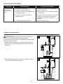
Cuidado y mantenimiento
ADVERTENCIA: Siempre desconecte la bomba del
suministro de alimentación antes de manipularla.
Inspeccione y pruebe el buen funcionamiento de los sistemas
al menos cada tres meses.
1. Retire cualquier acumulación o desecho del interruptor o
del flotador y revíselo para asegurarse de que se mueve
libremente.
1
2
2. Retire todos los desechos en la pila que puedan interferir
con el funcionamiento del interruptor.

26
GARANTÍA
Este producto se garantiza por un período de tres años a partir de la fecha de compra. Sujeto a
las condiciones indicadas a continuación, el fabricante se compromete a reparar o reemplazar
al consumidor original cualquier parte del producto que resulte defectuosa debido a defectos de
materiales o mano de obra. Para obtener el servicio de garantía, póngase en contacto con el
distribuidor al que le compró el producto. El fabricante se reserva el derecho y la opción exclusivos
de determinar si se deben reparar o sustituir los equipos, piezas o componentes defectuosos. Los
daños debidos a circunstancias ajenas al control del fabricante no están cubiertos por esta garantía.
ESTA GARANTÍA NO APLICARÁ: (a) a defectos o mal funcionamiento ocasionados por no instalar,
operar o mantener la unidad de acuerdo con las instrucciones impresas proporcionadas, (b) a los
fallos resultantes del abuso, accidentes o negligencia o uso inapropiado de productos químicos o
aditivos en el agua, (c) a los servicios normales de mantenimiento y las piezas utilizadas en relación
con dicho servicio; (d) a las unidades que no estén instaladas de acuerdo con los códigos locales,
ordenanzas y buenas prácticas comerciales normalmente aplicables y (e) la unidad se utiliza para
nes distintos a los que fue diseñada y fabricada.
DEVOLUCIÓN DE COMPONENTES EN GARANTÍA: Cualquier elemento a ser reparado o
reemplazado bajo esta garantía debe ser devuelto al fabricante en Kendallville, Indiana o a cualquier
otro lugar que el fabricante pueda designar, con ete prepagado.
LA GARANTÍA AQUÍ CONTENIDA ESTÁ EN LUGAR DE TODAS LAS OTRAS GARANTÍAS
EXPRESAS Y NO PUEDE SER AMPLIADA O MODIFICADA POR NADIE. CUALQUIER GARANTÍA
IMPLÍCITA DEBERÁ LIMITARSE AL PERÍODO DE ESTA GARANTÍA LIMITADA Y A PARTIR
DE ENTONCES TODAS DICHAS GARANTÍAS IMPLÍCITAS QUEDARÁN RECHAZADAS Y
EXCLUIDAS. EL FABRICANTE NO SERÁ RESPONSABLE, BAJO NINGUNA CIRCUNSTANCIA, DE
NINGÚN DAÑO INCIDENTAL, CONSECUENTE O ESPECIAL, COMO, A TÍTULO ENUNCIATIVO
PERO NO RESTRICTIVO, LA PÉRDIDA DE OTROS BIENES O EQUIPOS, LA PÉRDIDA DE
BENEFICIOS, INCONVENIENTES U OTROS DAÑOS INCIDENTALES O CONSECUENTES DE
CUALQUIER TIPO O CARÁCTER. LA RESPONSABILIDAD DEL FABRICANTE NO DEBERÁ
SUPERAR EL PRECIO DEL PRODUCTO EN EL CUAL SE BASE TAL RESPONSABILIDAD.
Esta garantía le otorga a usted derechos legales especícos y podría tener otros derechos que
varían de un estado a otro. Algunos estados no permiten limitaciones en la duración de una garantía
implícita, de forma que la limitación anterior podría no aplicar a usted. Algunos estados no permiten
la exclusión o limitación de daños incidentales o emergentes, de forma que la limitación o exclusión
anterior podría no aplicar a usted.
EN AQUELLAS INSTANCIAS EN QUE HAYA DAÑOS CAUSADOS POR UNA PRESUNTA FALLA DE LA BOMBA,
EL PROPIETARIO DEBERÁ CONSERVAR LA BOMBA A FIN DE INVESTIGAR DICHA FALLA.

27
1
(WIRE PACK)
(WIRE PACK)
2
4
3
5
ARTÍCULO DESCRIPCIÓN
MODELO
1263
1
Kit de cable
025390
Incluye cable sin junta tórica, caja con junta tórica NBR 115x4, tornillos de
sujeción M5-0.8x16, tornillos de cabeza M6-1.0x15, tornillo de conexión a
tierra M4-0.7x6.0
2
Kit de capacitor
025383
Incluye condensador, tornillos de cabeza M6-1.0x15, tornillo de montaje
M4-0.7x6, junta tórica de caja 115x4 NBR
3
Kit de Base
025388
Incluye base de bomba, tornillos M5-0.8x15
4
Kit de tapa
025385
Incluye tornillos de cabeza M6-1.0x15, tornillo gr M4-0.7x6.0, junta tórica
de caja 115x4 NBR, tapa con manija, protector y tapón, tornillo de placa
de identicación M3x1.34, interruptor para tornillos de caja, interruptor
5
Kit de otador
025381
Incluye barra de guía, correa de guía, otador
PIEZAS DE REPUESTO

28
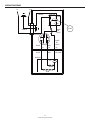
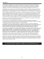
WIRING DIAGRAM
(3)
L1
L2
(1)
(2)
1
2
3
4
Funciona
Lazo
abierto
MOTOR
Azul
Rojo
Interruptor
Negro
Blanco
Verde
Arranque
Amarillo
Azul
Rojo
Capacitor
Flotador
Negro
o
Blanco
Negro
o
Blanco
Normalmente cerrado
Común
-
 1
1
-
 2
2
-
 3
3
-
 4
4
-
 5
5
-
 6
6
-
 7
7
-
 8
8
-
 9
9
-
 10
10
-
 11
11
-
 12
12
-
 13
13
-
 14
14
-
 15
15
-
 16
16
-
 17
17
-
 18
18
-
 19
19
-
 20
20
-
 21
21
-
 22
22
-
 23
23
-
 24
24
-
 25
25
-
 26
26
-
 27
27
-
 28
28
-
 29
29
-
 30
30
-
 31
31


Zoeller 1263-0001 Instrucciones de operación
- Tipo
- Instrucciones de operación
en otros idiomas
Artículos relacionados
-
Zoeller 2701-0005 Manual de usuario
-
-
-
-
-
-
-
-
-
