
CONTENTS
1 Safety Information
1 Operating Information
1 Tools and Materials Needed
1 Optional Tools and Materials
2 What Comes in the Carton
2 Step-by-Step Installation
4 Ventilation Requirements
4 Electrical Requirements
4 10-Year Limited Warranty
4 SureStart™ Protection
READ AND SAVE
THESE INSTRUCTIONS
SAFETY INFORMATION
Read the following safety information
before installing this Whole House Attic Fan.
Failure to follow these instructions could
result in personal injury or property
damage. If you need assistance in
understanding these instructions or have
questions or comments, please call
1-800-247-8368.
WARNING – TO REDUCE THE RISK
OF FIRE OR ELECTRIC SHOCK, DO NOT
USE THIS FAN WITH ANY SOLID-STATE
SPEED CONTROL DEVICE.
WARNING – TO REDUCE THE RISK OF
FIRE, ELECTRIC SHOCK, OR INJURY TO
PERSONS, OBSERVE THE FOLLOWING:
• Use this unit only in the manner intended
by the manufacturer. If you have questions,
contact the manufacturer
.
• Before servicing or cleaning unit, switch
power off at service panel and lock the
service disconnecting means to prevent
po
wer from being s
witched on accidentally.
When the service disconnecting means
cannot be locked,
securely fasten a
prominent warning device, such as a tag,
to the ser
vice panel.
• Do not install on ceilings less than seven
feet above the floor
.
CAUTION – FOR GENERAL
VENTILATING USE ONLY. DO NOT
USE TO EXHAUST HAZARDOUS OR
EXPLOSIVE MATERIALS AND VAPORS.
CAUTION – THIS UNIT HAS AN
UNGUARDED IMPELLER. DO NOT USE
IN LOCATIONS READILY ACCESSIBLE
TO PEOPLE OR ANIMALS.
WARNING – TO REDUCE THE RISK
OF FIRE, ELECTRIC SHOCK, OR
INJURY TO PERSONS, OBSERVE
THE FOLLOWING:
• Qualified person(s) in accordance with all
applicable codes and standards, including
fire-rated construction, must do installation
work and electrical wiring.
• Sufficient air is needed for proper
combustion and exhausting of gases
through the flue (chimney) of fuel burning
equipment to prevent back drafting. Follow
the heating equipment manufacturer’s
guideline and safety standards such as
those published by the National Fire
Protection Association (NFPA), and the
American Society for Heating, Refrigeration
and Air Conditioning Engineers (ASHRAE),
and the local code authorities.
• When cutting or drilling into wall or ceiling,
do not damage electrical wiring and other
hidden utilities.
• Ducted fans must always be vented to the
outdoors.
• DO NOT install this unit over a tub or
sho
wer
.
• NEVER place a switch where it can be
reached from a tub or sho
wer
.
• This unit must be wired and grounded in
accordance with all applicable state and
local codes.
OPERA
TING INFORMA
TION
• Keep screened windows and/or doors open
when the fan is operating to avoid drawing
carbon monoxide from furnace and water
hea
ter flues and extinguishing pilot lights
of appliances.
• During hot weather requiring air
conditioning, when outside air is cooler
than indoors,
cool the house quicker by
first
operating the whole house fan for
a
pproxima
tely 10 minutes.
Then turn off
the fan and turn on the air conditioner
.
1
TOOLS AND MATERIALS NEEDED
• Portable electric drill
• Drill bits:
3
/
16-,
1
/
8-, and
1
/
4-inch
• Reciprocating saw or saber saw.
Keyhole saw can be used for cutting
sheet rock, but not lumber.
• Screwdriver(s) with Phillips and
slotted bits
• Allen wrench:
1
/
4-inch
• (2)
1
/
4-inch open-end wrenches or
ratchets with 1/4-inch sockets
• Tape measure or folding ruler
• Pencil
• Utility knife
• Safety goggles
• Heavy gauge (bailing) wire:
approximately 18 inches long
• (2) 1-inch drywall screws
• (2) Twist-on electrical wire connectors
Optional Tools and Materials-
• Stapler – for attaching skirting material
instead of using screws provided
• Rubber weather stripping with adhesive
backing, approximately 1
1
/
2 inches wide
by 72 inches long – to help reduce
vibration noise
• 2 x 4-inch lumber: (1) 6-foot length –
if required in Step 2
• (5) thumb tacks or push pins – to
secure template to ceiling for cutting
out shutter opening
• Code required electrical materials
Note: Before you begin the
step-by-step installation, read
the sections on “Attic Ventilation
Requirements”
and
“Electrical
Requirements”
on page 4.
24˝and 30˝ Direct Drive
Whole House Attic Fan
Installation
Instructions
Part No. 18595

2
Step-by-step
installation
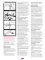
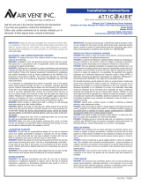
Step 1: Select a central
location for the fan
• Your whole house attic fan is designed for
horizontal mounting on the floor of your
attic, usually above a centrally located
hall
way.
• In the hallway, find the center of the ceiling
by measuring half the distance between the
walls. Mark the spot with a pencil.
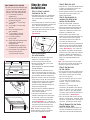
• Drill a hole on the ceiling mark, and push
a straight length of wire through the hole so
you can locate it in the attic.
(Illustration A)
Step 2: Investigate
the attic location
• Go to the attic and find the hole you’ve
made in the ceiling from below.
• Locate the joist nearest to the hole.
• Clear the insulation from a 3 by 3-foot
area around the joist.
Wear work gloves to avoid skin irritation
from the insulation.
• Check for electrical and other wires or
pipes. If any wires or pipes are in the way,
you can ha
ve them moved by a professional
or pick another location to mount the fan.
• Check the clearance above the fan location.
There must be a
t least 30 inches between
the top of the fan and the roof.
Providing
enough air space above the fan helps
prevent the motor from overheating and
keeps it running efficiently.
•
Check the joist for stability (it should not
rock from side to side).
If the joist is
stable, move on to Step 3.
•
If the joist has too much play
,
install
stabilizers tha
t bridge across to the joists
on either side.
Do this by nailing do
wn
2 x 4-inch boards perpendicular to the
joists
(Illustration B). The 2 x 4s must be
at least as long as the fan (24 or 30 inches)
and must be spaced at least 36 inches
apart so that the fan fits between them.
Note: Do not cut any joists. Unless
properly framed, a cut joist can weaken
the structural support of the house.
Step 3: Mark the joist
•
From the attic, use the test hole you drilled
in Step #1 to estimate the center of the
hallway ceiling along the joist.
• At that spot, drill a hole on each side of the
joist so you can locate the joist in the
hallway ceiling below.
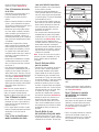
Step 4: Use template to
measure the hole in the
ceiling for the shutter
• From the hallway below, remove the
shutter from its carton and lay it aside.
• Cut out the template (pattern) printed on
the outside of the shutter carton with a
utility knife. Note that the center of the
template is marked with an x.
• On the hallway ceiling, make a mark
between the two holes you drilled from the
attic. Find the center of the ceiling by
measuring the distance to the walls on
each side, and adjust the mark.
• Use a thumbtack or push pin to temporarily
fasten the center of the template (marked
with an x) to the mark at the center of the
ceiling.
(Illustration C). Then, make sure
the template is straight by measuring the
distance to the wall on both ends. Hold the
template in position with thumbtacks or
push pins on the corners. Use a pencil to
draw a line around the outside of the
template.
Note: The ceiling cutout is for the shutter,
not the fan itself. Do not cut the hole in the
ceiling to the size of the fan assembly.
Step 5: Cut the hole
for the shutter
• Cut out the hole you have drawn around
the template, using a reciprocating saw,
saber saw or keyhole saw
. Be careful
not to cut into the joist.
• From the sheetrock you cut out, saw a
1
1
/
2-inch strip the full length of the
material. Then saw 2 inches off one
end of the strip.
• Screw the 1
1
/
2-inch-wide strip of
sheetrock to the bottom of the exposed
joist in the ceiling. Use 1-inch dr
ywall
screws. Leave a 1-inch space at each
end of the strip to allow for clearance of
the shutter frame.
(Illustration D)
• Place the shutter frame into the ceiling
cutout to see how it fits. Carefully shave
off excess sheetrock with a utility knife, if
necessary. Remove the shutter frame.
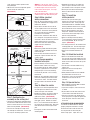
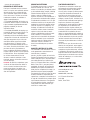
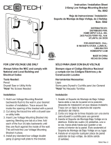
Step 6: Remove the fan blade
from the motor shaft
• Using a
1
/
4-inch Allen wrench, loosen the
setscrew that holds the fan blade on the
motor shaft. Pull the blade straight off the
D
Desired fan
location
C
1˝
1˝
B
Stabilizers
WHAT COMES IN THE CARTON
• To make sure you have everything you
need to install your new whole house
attic fan, unpack the carton and take
inventory. The carton should contain:
(1) Fan assembly mounted on
wooden frame
(2) Metal brackets for mounting fan
assembly to attic joist
(4)
1
/
4-inch bolts, 2
1
/
2 inches long,
with nuts
(6)
1
/
4-inch bolts, 1
1
/
4 inches long,
with nuts
(4) Pieces of skirting material
(stiff cardboard)
(12)
1
/
2-inch Phillips screws for
attaching skirting material
(1) Fan shutter packed in
its own carton.
(6) Screws with white painted heads
and (4) plastic anchors for
mounting shutter.
(1) Cardboard template, printed on
the outside of the shutter carton
(1) Electrical pull chain extension, (1)
pull chain connector and
(1) pull chain bell connector.
A
Final fan
location
Center
of hallway
ceiling

3
• Optional - From the attic, apply 1
1
/
2-inch
wide adhesive-backed weather stripping to
the bottom edges of the fan frame that
make contact with the joists. This helps
reduce vibration noise.
• Set the fan onto the joist, making sure the
saddle brackets slide down onto the joist.
Step 8: Make electrical
wiring connections
• Refer to “Electrical Requirements” section,
page 4 for information on bringing electric
po
wer to fan location.
• At your home’s breaker box, turn off the
electrical power to the circuit associated
with the fan. Do not turn on the power to
this circuit until you have completely
finished the fan installation.
• From the attic, remove the cover from the
fan’s wiring box. Using twist-on electrical
connectors, connect the black wire from the
power supply to the fan’s black wire.
Connect the white wire from the power
supply to the fan’s white wire.
(Illustration G)
• Connect the ground wire from the power
supply to the screw provided on the back
of the wiring box.
• Push the wire connections into the fan’s
wiring box. Replace the box cover and
screw it closed.
Step 9: Secure mounting
brackets to the joist
• From the hallway, center the fan assembly
over the shutter cutout in the ceiling.
• Use the lower hole of the saddle-mounting
bracket as a guide to drill a
1
/
4-inch hole
through the joist. Secure the mounting
bracket to the joist with a 2
1
/
2-inch-long
bolt and nut.
• Follow the same procedure with the lower
hole of the mounting bracket on the other
side of the fan frame.
Then drill and bolt
the upper holes of the brackets on both
sides.
Step 10: Mount the shutter
• Using the chain connector provided, attach
the short pull chain from the fan’s on-off
s
witch to the pull chain extension.
• Position the shutter in the ceiling cutout so
the pull chain passes through the chain
guide in the shutter
.
(Illustration H)
• Mark the location of the shutter mounting
holes with a pencil.
Remove the shutter.
• Use a
3
/
16-inch bit to drill the four holes on
the corners of the shutter frame. Don’t drill
holes for the two screws that go into the
joist.
• Insert plastic anchors into the four drilled
mounting holes.
• Reposition the shutter in the cutout and
fasten it in place with two screws in the
joist and four screws in the plastic anchors.
• Cut the pull chain to the desired length.
Attach the bell connector to the end of
the chain.
Step 11: Install the
skirting material
• From the attic, you will notice gaps
between the ceiling sheet rock and some
sides of the fan frame. These gaps must
be blocked off with the cardboard skirting
material provided in order to have a sealed-
off vacuum box for the fan and shutter.
• Cut the skirting material to size with a
utility knife. Position it on the outside of
the fan frame so the lower edge is flush
with the ceiling sheetrock.
• Attach the skirting material by drilling
1
/
8-inch pilot holes and then fastening with
the screws provided. Or you can use a
stapler. (Illustration I)
• The skirting material can be notched for the
incoming power line. Use duct tape to join
cutout pieces of skirting or fill small gaps.
• Replace the insulation around the fan
frame.
Step 12: Attach the fan blade
• Attach the fan blade to the motor shaft.
The setscrew on the blade should be on the
flat side of the motor shaft. Position the fan
blade near the end of the shaft, not up next
to the motor.
• The hub of the fan blade should face up
into the attic.
• Tighten the setscrew securely with a
1
/
4-inch allen wrench.
• Slowly rotate the blade one full revolution
by hand to make sure there are no
obstructions.
If there are an
y obstructions,
remove them and recheck the fan
clearance.
Step 13: Operate the fan
• Open windows and interior doors of rooms
to be ventilated by the fan.
•
If you have a fireplace, make sure the flue
is c
losed.
• At your home’s breaker box, switch on the
circuit breaker associa
ted with the fan.
• Pull once on the pull-chain to operate the
fan at high speed. Pull again to operate the
fan at low speed. Pull once more to turn
the fan off.
ATTIC VENTILATION REQUIREMENTS
In order for the whole house fan to work
properly, adequate ventilation is needed
to exhaust the hot air from the attic that
the fan pulls into the attic from your
home’s living space. If your attic is not
shaft, and put it aside to prevent it from
being damaged.
• Note that the setscrew is tightened against
the flat side of the motor shaft.
(Illustration E)
Step 7: Position the fan
assembly on the ceiling joist
• Using the pre-drilled holes provided, mount
the two metal saddle brackets to the inside
of the fan frame with the six 1
1
/
4-inch-long
bolts and nuts provided.
(Illustration F)
• Pass the fan assembly to a helper in the
attic through the shutter hole. If easier, you
can carry the assembly up to the attic.
E
H
I
Set screw
Attic side
Chain guide
Inside
hallway
Flat side of motor shaft
F
G
BLACK
RED
(LO)
BLACK
(HI)
GROUND
WHITE
Motor prewired
to switch at factory
Preconnected
to motor

4
TEN YEAR LIMITED WARRANTY
Direct Drive
Whole House Fans are warranted
for ten (10) years from date of purchase
a
gainst defects in workmanship and materi-
als. This warranty covers the fan blade and
motor. Any part believed to be defective
must be returned to the factory (Air Vent, Inc.,
4117 Pinnacle Point Drive, Suite 400, Dallas,
Texas 75211) freight prepaid. If found to be
defective following examination, any defec-
tive part will be replaced free of charge and
returned freight prepaid. This warranty does
not cover any labor costs, including those
required for field repair or replacement or
removal of any allegedly defective part. This
warranty gives you specific legal rights and
you may also have other rights, which vary,
from state to state.
SUREST
ART PROTECTION
The product to which this warranty applies is
covered by SureStart protection for a period
of five (5) years, provided that the product
has been installed in strict accordance with
written installation instructions and in accor-
dance with all local codes and standards,
including those pertaining to fire-rated con-
struction. Under this warranty feature,will
replace any part covered by this warranty
and found to be defective during the
SureStart period (The SureStart period begins
when the whole house attic fan installation is
completed). Maximum liability under
SureStart will be equal to the reasonable cost
of the replacement part, including labor to
remove the defective part and install the
replacement part.
In instances in which according to the
terms of this warranty, has agreed to pay the
cost of labor required to replace a defective
part, will provide reimbursement only upon
receipt of a copy of the contractor’s invoice
or other written evidence of the completion of
the work which at its sole discretion, deems
acceptable.
www
.air
vent.com
800-AIR-VENT (247-8368)
4117 Pinnacle Point Drive
Suite 400
Dallas, Texas 75211
™
ÍNDICE
4 Información de seguridad
5 Información sobre el funcionamiento
5 Herramientas y materiales
necesarios
5 Herramientas y materiales
opcionales
5 Contenido de la caja
5 Instalación paso a paso
8 Requisitos de ventilación
8 Requisitos eléctricos
8 Garantía limitada de 10 años
8 Protección SureStart™
LEA Y GUARDE ESTAS
INSTRUCCIONES
INFORMACIÓN DE SEGURIDAD
Lea la siguiente información de seguridad
antes de instalar este ventilador de ático
para toda la casa. Si no se siguen estas
instrucciones,
podrían
producir lesiones personales o daños a la
propiedad. Si necesita asistencia par
a
comprender estas instrucciones o si tiene
preguntas o comentarios, llame al
1-800-247-8368.
ADVERTENCIA – P
ARA REDUCIR LOS
RIESGOS DE INCENDIO Y DESCARGAS
ELÉCTRICAS, NO USE ESTE VENTI-
LADOR CON UN CONTROLADOR DE
VELOCIDAD DE ESTADO SÓLIDO.
ADVERTENCIA – P
ARA REDUCIR LOS
RIESGOS DE INCENDIO, DESCARGAS
ELÉCTRICAS Y LESIONES, SIGA ESTAS
RECOMEND
ACIONES:
• Use esta unidad sólo de la manera prevista
por el fabricante. Si tiene alguna duda,
contacte al fabricante.
• Antes de realizar el mantenimiento o
limpiar la unidad, desconecte el suministro
ATTIC VENTILATION REQUIREMENTS
(CONTINUED FROM PAGE 3)
adequately vented, the whole house fan
will shut off automatically.
•
The WH242ML 24-inch direct drive whole
house fan requires a minimumof 6 square
feet, or approximately 864 square inches, of
open attic vent area.
• The WH302ML 30-inch direct drive whole
house fan requires a minimumof 7.6 square
feet, or approximately 1100 square inches, of
open attic vent area. Check your attic
ventilation system to make sure that it
provides at least these minimum amounts of
open vent area. Typically, under-eave or soffit
vents are installed near the floor of the attic,
and roof louvers, gable vents, or ridge vents
are installed high in the attic to allow air to
escape. These vents are installed to provide
attic ventilation year round, and when the
whole house fan is on, these vents provide
the net free area to exhaust it.
Remember: When measuring your vents,
obstructions such as louvers and screens
need to be factored into the open area. A
good rule of thumb is to divide the vent’s
size in half.
ELECTRICAL REQUIREMENTS
Your whole house attic fan runs on standard
115-volt house current. Electrical installation
and wiring of the fan must adhere to the
National Electrical Code and all local codes
that apply, including fire-rated construction.
Wiring the whole house attic fan itself is a
simple procedure that most homeowners can
accomplish (see Step 8, page 3). However,
bringing the electrical power supply to the
fan requires a higher level of electrical
knowledge and skill. If you are not
experienced at installing residential electrical
wiring and/or are not familiar with all national
and local electrical codes, you should hire a
qualified electrician to do the wiring for you.
Ventilador con
transmisión directa de
24 y 30 pulgadas
Instrucciones
de instalación

xión del suministro eléctrico, fije al
tablero un letrero de advertencia bien
visible, como un rótulo.
PRECAUCIÓN – USE ESTE VENTI-
LADOR SÓLO PARA VENTILACIÓN
GENERAL. NO LO USE PARA EXTRAER
MATERIALES Y VAPORES PELIGROSOS
O EXPLOSIVOS.
PRECAUCIÓN – ESTA UNIDAD TIENE
LAS ASPAS SIN PROTECCIÓN. NO LA
USE EN LUGARES DE FÁCIL ACCESO A
PERSONAS O ANIMALES.
ADVERTENCIA: – PARA REDUCIR
LOS RIESGOS DE INCENDIO, DESCAR-
GAS ELÉCTRICAS Y LESIONES, SIGA
ESTAS RECOMENDACIONES:
• Las tareas de instalación y cableado
eléctrico deben ser realizadas por per
-
sonal calificado, de acuerdo con todos
los códigos y normas que correspondan,
incluidos los de la construcción clasifica-
da como ignífuga.
• A fin de evitar la aspiración inversa, se
requiere suficiente aire para la com-
bustión y la descarga correcta de los
gases por el tubo de humo (chimenea)
de los equipos que queman combustible.
Siga las pautas del fabricante de los
equipos y las normas de seguridad tales
como las publicadas por la Asociación
Nacional de Protección contra Incendios
(NFPA) de los Estados Unidos y la
Sociedad Americana de Ingenieros de
Calefacción, Refrigeración y Aire
Acondicionado (ASHRAE), así como los
códigos de las autoridades locales.
• Cuando corte o taladre la pared o el cielo
raso, no dañe el cableado eléctrico u
otras instalaciones de servicios ocultas.
•
Los ventiladores con conductos deben
ventear siempre hacia el exterior.
• NO instale esta unidad sobre una
bañera o ducha.
• NUNCA coloque interruptores en lugares
donde puedan accionarse desde una
bañera o ducha.
•
No instale en cielorrasos de menos de siete
pies por encima del piso.
• Esta unidad debe cablearse y conectarse a
tierra de acuerdo con todos los códigos
esta
tales y locales a
plicables.
INFORMACIÓN SOBRE EL
FUNCIONAMIENTO
• Cuando el ventilador esté en funciona-
miento, mantenga abiertas las ventanas
y/o
las puertas con mallas, a fin de
evitar la aspiración de monóxido de
carbono de los tubos de humo de hornos
:
y calefones, e impedir que se apaguen
las llamas piloto de los artefactos.
• En épocas de calor en las que se utilice
aire acondicionado, si el aire exterior
está más frío que el interior, la casa se
refrigera más rápido haciendo funcionar
primero el ventilador de ático durante
aproximadamente 10 minutos. Luego,
apague el ventilador y encienda el
acondicionador de aire.
Instalación
paso a paso
Paso 1: Elija una ubicación
central para el ventilador
• El ventilador está diseñado para ser
instalado horizontalmente en áticos,
generalmente sobre un vestíbulo o
pasillo central.
• Determine el centro del cielo raso del
vestíbulo o pasillo midiendo la mitad de
la distancia entre las paredes. Marque el
punto central con un lápiz.
• Taladre un orificio en la marca del cielo
raso y pase un pedazo de alambre a
5
HERRAMIENTAS Y MATERIALES
NECESARIOS
• Taladro eléctrico portátil
• Brocas de
3
/
16 pulg.,
1
/
8 pulg. y
1
/
4 pulg.
• Sierra oscilante o de vaivén. Puede
usarse una sierra de calar para cortar
planchas de yeso, pero no para madera.
• Destornilladores con punta Phillips y
punta ranurada
• Llave Allen de
1
/
4 pulg.
• (2) llaves de boca de
1
/
4 pulg. o llaves
de tubo de
1
/
4 pulg. con trinquete
• Cinta de medición o regla plegable
• Lápiz
• Cuchilla multipropósito
• Gafas de seguridad
• Alambre grueso (alambre de fardo) de
aproximadamente 18 pulg. de longitud
• (2) tornillos de 1 pulg. para panel
de yeso
• (2) conectores atornillables para
cable eléctrico
Herramientas y materiales opcionales-
• Grapadora para fijar el material de
relleno, en lugar de usar los tornillos
suministrados
• Cintas selladoras de goma con reverso
adhesivo, de aproximadamente 1
1
/
2
pulg. de ancho y 72 pulg. de longitud,
para reducir el ruido causado por las
vibraciones
• Viga de 2 x 4 pulg.: 1 tramo de 6 pies, si
se requiere en el paso 2
• 5 tachuelas o chinchetas para fijar la
plantilla al cielo raso al cortar la abertura
para la persiana
• Materiales requeridos por los códigos
vigentes
Nota: Antes de comenzar la insta-
lación paso a paso, lea las secciones
"Requisitos de ventilación" y
"Requisitos eléctricos" en la página 8.
A
Ubicación
final del
ventilador
Centro
del cielo
raso del
vestíbulo
CONTENIDO DE LA CAJA
• A fin de asegurarse de contar con todos
los materiales necesarios para
instalar su nuevo ventilador abra la caja y
revise el contenido. La caja debe
contener:
(1) conjunto del ventilador montado
en un marco de madera
(2) soportes metálicos para montar el
conjunto del ventilador a las
viguetas del ático
(4) pernos de
1
/
4 pulg. x 2
1
/
2 pulg.
de largo, con tuercas
(6) pernos de
1
/
4 pulg. x 1
1
/
4 pulg. de
largo, con tuercas
(4) piezas de material de relleno
(cartón rígido)
(12) tornillos Phillips de
1
/
2 pulg. para
fijar el material de relleno
(1) persiana del ventilador empaqueta
da en su propia caja.
(6) tornillos de cabeza blanca y
(4) anclajes de plástico para
montar la persiana.
(1) plantilla de cartón, impresa en la
parte exterior de la caja de la
persiana
(1) cadena de accionamiento del inte-
rruptor eléctrico, (1) conector de
cadena y (1) conector de campana
para cadena.

en dirección recta para sacarla del eje y
póngala a un lado para evitar que se
dañe.
• Tenga en cuenta que el perno prisionero
está apretado contra el lado plano del eje
del motor
(Ilustración E).
Paso 7: Coloque el conjunto
del ventilador en la vigueta
del cielo raso
•
Utilice los orificios per
forados de fábrica
para colocar los dos soportes de montaje
metálicos en la parte interna del mar
co
del ventilador, usando los 6 tornillos de
1
1
/
4 pulg. provistos y sus tuercas
(Ilustración F).
• Pase a un ayudante ubicado en el ático el
conjunto del ventilador a través de la
abertura de la persiana. Si le resulta más
fácil, puede llevar el conjunto al ático
usted mismo.
través del mismo, para localizar el
orificio en el ático.
(Ilustración A)
Paso 2: Busque una ubicación
en el ático
• Suba al ático y busque el orificio en el
cielo raso perforado desde abajo.
• Localice la vigueta más cercana al
orificio.
• Elimine el material aislante en un área de
3 pies x 3 pies alrededor de la vigueta.
Use guantes de trabajo para evitar que el
material aislante le irrite la piel.
• Compruebe que no haya cables eléctri-
cos, otros cables o tuberías. De haber
cables o tuberías que interfieran en la
ubicación del ventilador, solicite a un
instalador profesional que los cambie de
lugar o elija otra ubicación para instalar
el ventilador
.
• Compruebe el espacio libre al techo
sobre la ubicación del ventilador. Debe
haber 30 pulg. como mínimo entre la
parte superior del ventilador y el techo.
Un espacio de aire adecuado sobre el
ventilador ayuda a evitar que el motor se
recaliente y le permite funcionar con
buen rendimiento.
• Compruebe la estabilidad de la vigueta
(no debe poder moverse de un lado a
otro). Si la vigueta está firme, continúe
con el paso 3.
• Si la vigueta tiene demasiado juego,
instale puentes estabilizadores entre la
vigueta y las dos viguetas contiguas, a
ambos lados de ella. Para ello, clave pa-
neles de 2 x 4 pulg. perpendicularmente
a las viguetas
(Ilustración B). Estos pa-
neles deben tener por lo menos la
longitud del ventilador (24 ó 30 pulg.) y
deben separarse 36 pulg. como mínimo
para poder colocar entre ellos el
ventilador.
Nota: No corte ninguna vigueta. A
menos que estén correctamente soste-
nidas, las viguetas cortadas pueden
debilitar el soporte estructural de la casa.
Paso 3: Marque la vigueta
•
Desde el ático, use el orificio de prueba
per
forado en el paso 1 para calcular el
centro del cielo raso del vestíbulo a lo
largo de la vigueta.
•
En ese lugar
, taladre un orificio a cada
lado de la vigueta para poder localizarla
desde abajo, en el cielo raso del
vestíbulo.
Paso 4: Use la plantilla para
medir la aber
tura del cielo
raso para instalar la persiana
• Desde el vestíbulo, retire la persiana de
la caja y déjela a un lado.
• Usando una cuchilla multipropósito,
corte la plantilla impresa en la parte exte-
rior de la caja de la persiana (la plantilla
se usará de guía). El centro de la plantilla
está mar
cado con una "X".
• En el cielo raso del vestíbulo, haga una
marca entre los dos orificios perforados
desde el ático. Determine el centro del
cielo raso midiendo la distancia entre
las paredes de cada lado y corrija la
posición de la marca.
• Use una tachuela o chincheta para fijar
temporalmente el centro de la plantilla
(marcado con la "X") a la marca del cen-
tro del cielo raso
(Ilustración C). Luego,
asegúrese de que la plantilla esté en
escuadra midiendo la distancia a la pared
desde ambos extremos. Sostenga la
plantilla en posición colocando tachuelas
o chinchetas en las esquinas. Utilice un
lápiz para trazar una línea siguiendo el
contorno de la plantilla.
Nota: El corte en el cielo raso es para la
persiana, no para el ventilador en sí. No
corte el orificio según el tamaño del
ventilador.
Paso 5: Corte un orificio
para la persiana
• Usando una sierra oscilante, de vaivén o
de calar, corte el orificio siguiendo la
línea trazada alrededor de la plantilla.
Tenga cuidado de no cortar la vigueta.
• En la plancha de yeso recortada, corte
una banda de 1
1
/
2 pulg. de ancho a todo
lo largo del material. Luego corte 2 pulg.
en uno de los extremos de la banda.
•
Atornille la banda de yeso de 1
1
/
2 pulg.
de ancho a la parte inferior de la vigueta
expuesta del cielo raso. Utilice los torni-
llos para panel de yeso de 1 pulg. Deje
un espacio de 1 pulg. en ambos
extremos de la banda como separación
del marco de la persiana
(Ilustración D).
• Coloque el marco de la persiana en la
abertura del cielo raso y compruebe
cómo se ajusta al orificio. De ser nece-
sario, recorte cuidadosamente el exceso
de la plancha de yeso usando la cuchilla
multipropósito. Retire el marco de la
persiana.
Paso 6: Retir
e el aspa
del ventilador del eje del motor
•
Usando la llave Allen de
1
/
4 pulg., afloje
el perno prisionero que sujeta el aspa del
ventilador al eje del motor. Tire del aspa
6
D
Ubicación deseada
del ventilador
C
B
Estabilizadoras
E
Perno prisionero
Lado plano del eje del motor
1 pulg.
1 pulg.

• Opcional: Desde el ático, aplique a los
bordes inferiores del mar
co del venti-
lador que entran en contacto con las
viguetas, cintas selladoras con reverso
adhesivo de 1
1
/
2 pulg. de ancho. Esto
contribuye a reducir el ruido causado
por las vibraciones.
• Coloque el ventilador en la vigueta,
asegurándose de que los soportes de
montaje se deslicen hacia abajo sobre la
vigueta.
Paso 8: Conecte el
cableado eléctrico
• Consulte la sección "Requisitos eléctri-
cos" en la página 8 para obtener informa-
ción acerca de la conexión del suministro
eléctrico al lugar de instalación del
venti
lador.
• En la caja de disyuntores de la casa,
desconecte el suministro eléctrico del
cir
cuito donde se va a instalar el venti-
lador. No vuelva a conectarlo hasta no
haber finalizado completamente la insta-
lación del ventilador.
• Desde el ático, retire la tapa de la caja de
conexiones del ventilador. Utilizando los
conectores eléctricos atornillables,
conecte el cable negro del suministro
eléctrico al cable negro del ventilador, y
el cable blanco del suministro al cable
blanco del ventilador
(Ilustración G).
• Conecte el cable de tierra del suministro
eléctrico al tornillo provisto en la parte
posterior de la caja de conexiones.
• Empuje los cables dentro de la caja de
conexiones del ventilador. Vuelva a poner
la tapa de la caja y atorníllela para
cerrarla.
Paso 9: Asegure los soportes
de montaje a la vigueta
del cielo raso
• Desde el pasillo o vestíbulo, centre el
conjunto del ventilador sobre la abertura
para la persiana en el cielo raso.
• Use el orificio inferior del soporte de
montaje como guía para perforar un ori-
ficio de
1
/
4 pulg. a través de la vigueta.
Asegure el soporte de montaje a la
vigueta con un perno de 2
1
/
2 pulg. de
largo y su correspondiente tuerca.
• Siga el mismo procedimiento para el ori-
ficio inferior del soporte de montaje en el
otro lado del marco del ventilador.
Luego, taladre y sujete con pernos usan-
do los orificios superiores de los
soportes, a ambos lados.
Paso 10: Instale la persiana
• Utilice el conector de cadena provisto
para fijar la cadena corta de
accionamiento del interruptor de
encendido/apagado del ventilador a la
extensión de la cadena.
•
Coloque la persiana en la abertura del
cielo raso de modo que la cadena de
accionamiento pase a través de su guía
en la persiana
(Ilustración H).
•
Marque la posición de los orificios de
montaje de la persiana con un lápiz.
Retire la persiana.
• Utilice una broca de
3
/
16 pulg. para per-
forar los cuatro orificios en las esquinas
del mar
co de la persiana. No taladre los
orificios de los dos tornillos sobre la
vigueta.
•
Inserte anclajes plásticos en los cuatro
orificios de montaje perforados.
•
V
uelva a colocar la persiana en la aper
-
tura y fíjela en posición con los dos
tornillos de la vigueta y los cuatro
tornillos en los anclajes plásticos.
• Corte la cadena de accionamiento a la
longitud deseada. Coloque el conector de
campana en el extremo de la cadena.
Paso 11: Instale el
material de relleno
• Desde el ático, notará separaciones entre
la plancha de yeso del cielo raso y los
lados del marco del ventilador. Estas
separaciones deben ser bloqueadas con
el material de relleno provisto a fin de
obtener una caja de vacío sellada para el
ventilador y la persiana.
• Corte el material de relleno a la medida
con una cuchilla multipropósito. Ponga el
material en el exterior del marco del
ventilador, de modo que el borde inferior
quede a nivel de la plancha de yeso del
cielo raso.
• Instale el material de relleno perforando
orificios de guía de
1
/
8 pulg. y fijándolo
luego con los tornillos provistos. Si lo
desea, use una grapadora (Ilustración I).
• Puede ser necesario cortar una muesca
en el material de relleno para pasar la
línea de suministro eléctrico. Utilice cinta
de conducto para unir las piezas recor-
tadas del material de relleno y llenar las
separaciones pequeñas.
• Vuelva a colocar el material aislante
alrededor del marco del ventilador.
Paso 12: Coloque el aspa
el ventilador
• Coloque el aspa en el eje del motor. El
perno prisionero del aspa debe apoyarse
en el lado plano del eje del motor.
• El núcleo del aspa debe quedar mirando
hacia arriba, hacia el lado del ático.
• Ajuste firmemente el perno prisionero
usando la llave Allen de
1
/
4 pulg.
• Con la mano, haga girar lentamente el
aspa una vuelta completa para compro-
bar que no haya obstrucciones. De
haberlas, corríjalas y compruebe nueva-
mente la separación del ventilador.
Paso 13: Haga funcionar
el ventilador
• Abra las ventanas y las puertas interiores
de las habitaciones que va a ventilar el
ventilador.
• Si la habitación tiene una chimenea,
asegúrese de que el tubo de humo esté
cerrado.
• En la caja de disyuntores de la casa,
conecte el disyuntor correspondiente
al circuito donde está instalado el
ventilador.
•
T
ire una vez de la cadena de acciona-
miento para que el ventilador funcione a
alta velocidad. Tire de ella nuevamente
para que funcione a baja velocidad. Tire
7
F
H
I
G
NEGRO
ROJO
(BAJO)
NEGRO
(ALTO)
TIERRA
BLANCO
Motor conectado de
fábrica al interruptor
Conexión de
fábrica al motor
Lado del ático
Guía de cadena
Interior del
pasillo o
vestíbulo

una vez más para apagarlo.
REQUISITOS DE VENTILACIÓN
Para que el ventilador funcione correcta-
mente, se requiere una ventilación adecua-
da para extraer el aire caliente del ático
que el ventilador aspira desde las habita-
ciones de la casa. Si el ático no está ade-
cuadamente ventilado, el ventilador se
apagará automáticamente.
• El ventilador WH242ML de 24 pulg. con
transmisión directa requiere un mínimo de
6 pies cuadrados (aproximadamente 864
pulgadas cuadradas) de área de
ventilación abierta.
• El ventilador WH302ML de 30 pulg. con
transmisión directa necesita al menos 7.6
pies cuadrados (unas 1100 pulgadas
cuadradas) de área de ventilación abierta.
Compruebe el sistema de ventilación del
ático para asegurarse de que el área de
ventilación abierta tenga como mínimo
esas dimensiones. En general, suelen
instalarse respiraderos debajo del alero o
en el techo, cerca del piso del ático, o bien
persianas de techo y respiraderos en
muros o caballetes del tejado, próximos a
la parte superior del ático, a fin de permitir
la salida del aire. Estos respiraderos venti-
lan el ático durante todo el año. No
obstante, cuando el ventilador se hace
funcionar, proveen el área libre neta nece-
saria de descarga.
Recuerde: Al medir los respiraderos, para
el cálculo del área abierta neta deben te-
nerse en cuenta las obstrucciones tales
como las persianas y las mallas. Una
buena regla práctica es dividir en dos el
área del respiradero.
REQUISITOS ELÉCTRICOS
El ventilador funciona con el suministro
eléctrico estándar de la casa de 115
voltios. La instalación y el cableado eléctri-
co del ventilador deben cumplir el Código
Eléctrico Nacional (NEC) de los Estados
Unidos y todos los códigos locales
vigentes, incluidos los correspondientes a
la construcción clasificada como ignífuga.
El cableado del ventilador en sí es un pro-
cedimiento sencillo que la mayoría de los
propietarios de viviendas pueden realizar
(consulte el paso 8 en la página 6). Sin
embargo, el tendido de la conexión del
suministro eléctrico hasta el ventilador
requiere un nivel más alto de conoci-
mientos y habilidad para realizar instala-
ciones eléctricas. Si usted no tiene
experiencia en la instalación de cableado
eléctrico residencial y/o no está familia-
rizado con todos los códigos eléctricos
nacionales o locales, contrate a un
electricista calificado para que realice
el trabajo.
GARANTÍA LIMITADA DE 10 AÑOS
Los ventiladores con transmisión a correa
están garantizados contra defectos de
mano de obra y materiales
por diez (10) años a partir de la fecha de
compra. Esta garantía cubre las aspas y el
motor. Toda pieza que se considere defec-
tuosa debe devolverse a la fábrica (Air
Vent, 4117 Pinnacle Point Drive, Suite 400,
Dallas, Texas 75211 ) con porte postal
prepagado. Si después de la inspección
determina que la pieza está defectuosa,
dicha pieza se reemplazará sin cargo y se
devolverá con porte postal prepagado.
Esta garantía no cubre los costos de mano
de obra, incluidos los requeridos para
reparaciones, reemplazos o desmontaje en
el lugar de la instalación de cualquier pieza
supuestamente defectuosa. Esta garantía
le otorga derechos legales específicos y
usted puede tener otros derechos que
varían de un estado a otro.
PROTECCIÓN SURESTART
El producto de ventilación cubierto por
esta garantía está cubierto por la protec-
ción SureStart durante un período de
cinco (5) años, siempre que dicho produc-
to haya sido instalado estrictamente de
acuerdo con las instrucciones de insta-
lación escritas de y cumpliendo todos los
códigos y normas locales, incluidas los de
la construcción clasificada como ignífuga.
Según estos términos de la garantía,
reemplazará sin cargo toda pieza cubierta
por la garantía que se determine está
defectuosa durante el plazo cubierto por
SureStart (el plazo de SureStart comienza
cuando finaliza la instalación del venti-
lador). La responsabilidad civil máxima de
según los términos de SureStart será igual
al costo razonable de la pieza de repuesto,
incluida la mano de obra necesaria para
desmontar la pieza defectuosa e instalar el
repuesto.
En los casos en que, de acuerdo con los
términos de esta garantía, acepte pagar el
costo de la mano de obra necesaria para
reemplazar una pieza defectuosa, realizará
el reembolso sólo contra el recibo de una
copia de la factura del contratista o de otra
evidencia por escrito donde conste la final-
ización del trabajo que, a su solo criterio,
considere aceptable.
www.airvent.com
800-AIR-VENT (247-8368)
4117 Pinnacle Point Drive
Suite 400
Dallas, Texas 75211
™
8
-
 1
1
-
 2
2
-
 3
3
-
 4
4
-
 5
5
-
 6
6
-
 7
7
-
 8
8


Air Vent WH242ML Instrucciones de operación
- Tipo
- Instrucciones de operación
en otros idiomas
Artículos relacionados


Otros documentos
-
 Commercial Electric 5042-5PK Instrucciones de operación
-
Marley Engineered Products 761 Manual de usuario
-
NuTone 791LEDNT Guía de instalación
-
-
NuTone 763RLN Manual de usuario
-
-
Schaefer TW24B-HD Guía del usuario
-
 DuoDeck 96240 Guía de instalación

