Air Vent HE15WW Instrucciones de operación
- Tipo
- Instrucciones de operación

Installation Instructions
HE15 High Efciency Powered Attic Fan
Important Safety Information
HE15 Ventilador de ático eléctrico de alta eciencia
Información importante para su seguridad
WARNING: Read all warning messages and instructions
before starting installation of this fan. Failure to follow these
safety instructions can result in injury or even death. If you
need assistance in understanding these instructions or have
questions or comments, please call (800) 247-8368.
ELECTRICAL HAZARDS
DANGER: The electrical installation and wiring of this fan must
be done by a qualied electrician in accordance with all local
codes and standards, including re-rated construction. Failure
to do the installation properly can result in re or even death.
NOTE: A few hours of operation without apparent problems
does not necessarily imply that the installation is safe.
DANGER: Do not use this fan with any solid state speed control
device. Use of a solid state speed control can result in a re
causing injury or death.
DANGER: Watch out for existing electrical wiring and other
utility wires or pipes when selecting a location for the fan. Do
not install the fan where there is electrical wiring in the way.
Select another location or have a qualied electrician move the
wiring to a different location.
DANGER: Before servicing or cleaning the unit, switch the power
off at the service panel and lock the service panel to prevent the
power from being switched on accidentally. When the service
disconnecting means cannot be locked, securely fasten a
prominent warning device, such as a tag, to the service panel.
LACERATION HAZARDS
DANGER: This fan has an unguarded fan blade. Do not use in
locations which are readily accessible to people or animals. Do
not let children play in an attic where this fan has been installed.
Contact with this fan while in operation can result in injury or
even death.
DANGER: Switch the power off at the service panel and lock
the service panel before servicing the motor. When the service
disconnecting means cannot be locked, securely fasten a
prominent warning device, such as a tag, to the service panel. This
fan is thermostatically controlled - it may start at any time if the
power is not switched off at the service panel. Contact with the fan
blades while the fan is operating can result in serious injury.
WARNING: This product has sharp metal edges that can cut
your hands. Wear canvas work gloves while handling the fan
during installation.
OTHER HAZARDS
DANGER: This fan is for general ventilating use only. Do not use
to exhaust hazardous or explosive materials or vapors. Use of
this fan to exhaust hazardous, explosive or ammable materials
may result in a re or explosion, causing injury or death.
PRECAUCIÓN: Lea todos las instrucciónes y advertencias,
antes de empezar a instalar este ventilador. El caso omiso
de estas instrucciónes, puede ocasiónarle lesiónes graves
o inclusive hasta la muerte. Si usted necesita ayuda para
comprender estas instrucciónes, tiene preguntas o comentarios,
favor de llamar al: (800) 247-8368.
RIESGOS ELECTRICOS
PELIGRO: La instalación electrica y el alambrado de este
ventilador debera ser hecho por una electricista cualicado de
acuerdo con todos códigos y las normas locales, incluyendo
normas de fuego para la construcción. El caso omiso de una
instalación apropiada puede provocar fuego o inclusive hasta la
muerte. NOTA: Unas pocas horas con el ventilador operando sin
problemas aparentes no signica que la instalación sea segura.
PELIGRO: No use este ventilador con controles de velocidad
de estado sólido. Usar controles de velocidad de estado
sólido puede provocar incendio y lesiones o la muerte, en
consecuencia.
PELIGRO: Tenga cuidado con las instalaciónes electricas ya
existentes o cualquier otra instalación o tuberías cuando elija el
lugar apropiado para su ventilador. No instale el ventilador donde
haya alambres o cables que le puedan estorbar. Elija otro lugar o
consulte con un electricista cualicado para hacer un movimiento
de instalación electrica adecuada hacia otro lugar.
PELIGRO: Antes de hacer servicio o limpieza a la unidad,
cerciórese de cortar la corriente de la caja de registro eléctrico y
asegúrela para prevenir que se haga una conexión imprevista.
Si es imposible asegurar la caja de registro eléctrico, amarre
seguramente un aviso del peligro tal como una etiqueta a la caja.
RIESGOS DE LACERACIÓN
PELIGRO: Este ventilador tiene unas aspas peligrosas de
metal sin protección. No coloque en lugares al alcance de las
personas o animales. No permita que los niños jueguen en el
ático cuando el ventilador haya sido instalado. El contacto con
este ventilador cuando esté en funcionamiento puede provocar
daños graves o inclusive hasta la muerte.
PELIGRO: Ceriórese de cortar la corriente de la caja de registro
eléctrico y asegúrela, antes de empezar a trabajar en la banda
del motor o el motor. El contacto con la banda del ventilador
mientras esté funcionando puede ocasionarle heridas graves.
Esto también le puede atraer hacia las aspas provocando
daños más graves o inclusive hasta la muerte.
PRECAUCIÓN: Este producto tiene bordes muy alados que
podrían cortarle las manos. Use guantes de lona mientras
usted esté instalado el ventilador.
OTROS RIESGOS
PELIGRO: Uso exclusivo para ventilación general. No use este
producto para extraer gases peligrosos, materiales explosivos
u otros vapores.
Install Sht Part #19059
© 2017 Air Vent Inc.
4/2017
1

HE15 HIGH EFFICIENCY POWERED ATTIC FAN
INSTALLATION INSTRUCTIONS
NOTE: Air intake openings are necessary for proper exhaust
operation. Best results will be obtained if these openings are
located around the eaves. Undereave soft grills or continuous
soft vents are suggested.
TOOLS NEEDED: 1 gang steel junction box with at least one
3/4" knockout and a cover plate, electric drill, tape measure,
hammer & nails, utility knife and pencil, jig or sabre saw, roong
nails, phillips screw driver, adjustable wrench, wire cutter, work
gloves and safety glasses.
HE15 VENTILADOR DE ÁTICO ELÉCTRICO DE ALTA
EFICIENCIA INSTRUCCIÓNES PARA LA INSTALACIÓN
NOTA: Aberturas para la toma de aire son necesarias para una
apropiada operación. Se obtendrán mejores resultados si estas
aberturas están localizadas alrededor de los aleros. Se sugiere el
uso de rejiillas de soto bajo alero o ventilas continuas de soto.
HERRAMIENTAS NECESARIAS: Caja de empalme de acero
con 1 salida, con oricio de al menos 3/4" y tapa, taladro, cinta
de medir o regla, martillo, clavos para techo, navaja, lapiz,
serrucho, destornillador llave, tijeras, lentes de seguridad y
guantes de uso rudo.
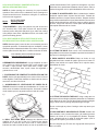
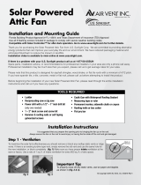
1. POSITIONING THE POWER ATTIC VENTILATOR ON THE
ROOF: Set the unit approximately in the center of the roof close
to the ridgeline. Position the ventilator so that the unit can only be
seen from one side of the house.
1. ACOMODANDO EL VENTILADOR DE PODER EN EL
TECHO: Acomode la unidad aproximadamente en el centro del
techo cerca del madero horizontal superior. Acomode la unidad
de tal manera que solo se pueda ver de un lado de la casa.
2. DRILL THE GUIDE HOLE: Measure the distance to the
ridgeline and to one end of the roof. Transfer these exterior
dimensions to inside the attic. Next locate a center position
between two rafters (inside the attic) as near as possible to the
Pies cuadrados (metros cuadrados) de abertuna
para toma de aire abertuna necesaria
outside measurements. Drill a guide hole through the roof from
inside that is an equal distance between the two rafters. Place a
marker through the roof for quick identication while on the roof.
2. HAGA EL AGUJERO-GUÍA: Mida la distancia del madero
horizontal superior hasta el punto nal del techo. Traslade las
medidas exteriores a la parte interna del ático. Despues localice
una posición centrada entre 2 vigas (dentro del ático) lo mas cerca
posible de las dimensiónes exteriores. Haga un agujero guía en
el techo. Ponga una marca en el techo para una identicación
más rapida mientras esté en el techo.
3. CUTTING THE HOLE: Draw a circle 14.5" in diameter using
the guidehole as the center. A template is provided on the back of
the carton for drawing the circle.
3. PARA HACER EL AGUJERO: Dibuje un círculo de 14.5
pulgadas de di·metro usando el agujero-guía como el centro. El
patrón viene incluido en la parte trasera de la caja de carton,
para dibujar el círculo.
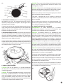
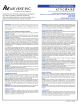
4. CUTTING THE HOLE IN THE ROOF: Using a sabre saw, cut
and remove all roof shingles (and deck) inside the 14.5" diameter
circle. Next cut an extra 1 inch off the top half of the hole (shingles
only) to allow room for placing and positioning the ange.
Do not cut through any rafters. Cutting a rafter may cause your
roof to sag.
4. PARA CORTAR EL AGUJERO EN EL TECHO: Usando una
sierra caladora, corte y remueva las tejas (y la madera) que este
adentro del círculo de 14 1/2 pulgadas de diámetro. Después
corte 1 pulgada más en la parte de arriba del agujero (solo la
teja) para dar espacio y acomodar la corona.
No corte ningúna viga. El cortar una viga puede causar que su
techo se hunda.
Model Opening Needed
HE15 4.4
1.)
2.)
3.)
Modelo
HE15 4.4
Sq. Ft. of Air Intake
2

5. SECURING THE BASE: Make sure the base ange parallels
the ridgeline of the roof. The embossed arrow and word UP
should be pointing towards the ridgeline. Slip the upper half of
the ange under the shingles.
Center the unit over the hole. Attach the ange securely to the roof
using roong nails around the perimeter of the unit (underneath
shingles at the top). A non-hardening caulk can be used to seal
between the ange and shingles.
5. PARA ASEGURAR LA BASE: Cerciórese de que la base de
la corona esté paralela con la del madero horizontal superior
del techo. Las echas realizadas y la palabra “UP” deben estar
apuntado hacia el madero horizontal superior. Deslice la parte
superior de la corona debajo de las tejas.
Centre la unidad sobre el agujero. Junte la corona seguramente
al techo usando clavos para techo alrededor del perímetro de la
unidad (debajo de las tejas superiores). Una goma suave puede
ser usada para sellar la corona con la teja.
6. WIRING THE MOTOR/UNIT:
CAUTION: This unit will operate for 1-2 minutes immediately
after the power is connected to provide conrmation that the fan
is functioning properly.
DANGER: The electrical installation and wiring of this fan must
be done by a qualied electrician in accordance with all local
codes and standards, including re-rated construction. Failure
to do the installation properly can result in re or even death.
NOTE: A few hours of operation without apparent problems does
not necessarily imply that the installation is safe.
DANGER: Do not use this fan with any solid state speed control
device. Use of a solid state speed control can result in a re
causing injury or death.
DANGER: Make sure the circuit breaker powering the circuit on
which the fan will operate is turned OFF before wiring the motor.
You can be shocked or electrocuted if the breaker is not off.
Wire the motor directly to the homes power supply in accordance
with local building codes and standards.
The motor is provided with a 3/4" coupling to secure the
conduit to a grounded junction box. Ensure that the junction
box is grounded.
Do not connect this product to an existing thermostat. The
product self regulates according to temperature and humidity
so an in-line thermostat is not required.
6. CONEXIÓN DEL MOTOR Y LA UNIDAD:
ADVERTENCIA: La unidad funcionará por 1-2 minutos
inmediatamente después de conectar la alimentación, para
conrmar que el ventilador funcione correctamente.
PELIGRO: La instalación eléctrica y el alambrado de este
ventilador deberá ser hecho por una electricista capacitado de
acuerdo con todos códigos y normas locales, incluyendo normas
contra incendios en la construcción. El caso omiso de una
instalación apropiada puede provocar incendios o inclusive la
muerte. NOTA: Unas pocas horas con el ventilador operando sin
problemas aparentes no signica que la instalación sea segura.
PELIGRO: No use este ventilador con controles de velocidad
de estado sólido. Usar controles de velocidad de estado sólido
puede provocar incendio y lesiones o la muerte, en consecuencia.
PELIGRO: Cerciórese de que el circuito de poder que va alimentar
el circuito del ventilador este APAGADO antes de conectar el
termostato. Podría usted recibir una descarga eléctrica o resultar
electrocutado si la corriente no está apagada.
Conecte el motor directamente a la alimentación de la vivienda
de acuerdo con las normas y códigos de construcción locales.
El motor incluye un acople de 3/4" para asegurar el conducto a
la caja de empalme con conexión a tierra. Verique que la caja
de empalme esté conectada a tierra.
No conecte este producto a un termostato existente. El producto
se autorregula según la temperatura y la humedad, por lo tanto,
no se requiere un termostato en la línea.
4.)
5.)
6.)
3

7. THERMOSTAT OPERATION: The integral thermostat/
humidistat operates automatically. When the power ventilator
is powered, the fan should start automatically when the attic
condition rises above 90�F or 65% relative humidity and will cut
off when the attic drops below that setting.
DANGER: Switch the power off at the service panel and lock
the service panel before servicing the motor. When the service
disconnecting means cannot be locked, securely fasten a
prominent warning device, such as a tag, to the service panel. This
fan is thermostatically controlled - it may start at any time if the
power is not switched off at the service panel. Contact with the fan
blades while the fan is operating can result in serious injury.
7. OPERACIÓN DEL TERMOSTATO: El termostato/higrostato
integrado funciona automáticamente. Cuando se encienda
la turbina de ventilación, el ventilador debería arrancar
automáticamente si la temperatura del ático supera los 90�F o
65 % de humedad y se apagará cuando las condiciones del ático
estén por debajo de esos valores.
PELIGRO: Cerciórese de cortar la corriente de la caja de registro
eléctrico y asegúrela, antes de empezar a trabajar en el motor.
Si es imposible asegurar la caja de registro eléctrico, amarre
seguramente un aviso del peligro tal como una etiqueta a la
caja. Este ventilador está controlado por un termostato que lo
puede hacer funcionar en cualquier momento si el interruptor no
está apagado en la caja de registro eléctrico. El contacto con
las aspas de este ventilador cuando el ventilador esté operando
puede provocar daños serios.
LIMITED LIFETIME WARRANTY
The High Efciency Powered Attic Fan has a limited lifetime
warranty from date of purchase against defects in workmanship
and materials. This warranty covers fan blade, motor, thermostat
and housing. If you believe any part is defective, call (800) 247-
8368 for Customer Service. If it’s determined that parts need to
be returned, they must be shipped freight prepaid to Air Vent,
4117 Pinnacle Point Drive, Suite 400, Dallas, TX 75211. If found
to be defective following examination by Air Vent, any defective
part will be replaced free of charge and returned freight prepaid.
This warranty does not cover any labor costs, including those
required for eld repair, replacement or removal of any allegedly
defective part. This warranty gives you specic legal rights and
you may also have other rights which vary from state to state.
REPLACEMENT PLUS PROTECTION
The Air Vent product to which this warranty applies is covered by
Replacement Plus protection for a period of ve (5) years, provided
that the product has been installed in strict accordance with Air
Vent’s written installation instructions and in accordance with all
local codes and standards, including those pertaining to re-rated
construction. Under this warranty feature, Air Vent, at no charge,
will replace any part covered by this warranty and found to be
defective during the Replacement Plus period (the Replacement
Plus period begins when the power vent installation is completed.)
Air Vent’s maximum liability under Replacement Plus will be equal
to the reasonable cost of the replacement part, including labor to
remove the defective part and install the replacement part.
In instances in which Air Vent, according to the terms of this
warranty, has agreed to pay the cost of labor required to replace
a defective part, Air Vent will provide reimbursement only upon
receipt of a copy of the contractor’s invoice or other written
evidence of the completion of the work which Air Vent, at its sole
discretion, deems acceptable.
GARANTÍA DE POR VIDA LIMITADA EN PIEZAS
El ventilador de ático eléctrico de alta eciencia tiene una
garantía de por vida limitada a partir de la fecha de compra,
contra defectos de manufactura y materiales. Esta garantía
cubre las aspas, el motor, el termostato, y la cubierta de metal.
Si usted considera que alguna pieza es defectuosa, llame
al Departamento de Servicio al Cliente, (800) 247-8368. Si
se determina que las piezas deben ser devueltas a Air Vent,
envíelas con porte postal prepagado a Air Vent, 4117 Pinnacle
Point Drive, Suite 400, Dallas, TX 75211. Si encontramos
defectos bajo el examen de Air Vent, Inc., cualquier parte será
reemplazada sin costo alguno y le devolveremos el dinero
de su ete. Esta garantía no cubre ningún costo por mano
de obra, incluyendo aquellos solicitados para reparar fallas,
reemplazamientos o cambio de cualquier parte defectuosa que
se declare. Esta garantía le da derechos especícos y legales,
y usted asimismo tendrá otros derechos los cuales varían de
estado a estado.
PROTECCIÓN REPLACEMENT PLUS
El producto de ventilación Air Vent para el cual esta garantía aplica
está cubierto con la protección Replacement Plus por un periodo
de 5 annos, a condición de que el producto haya sido instalado
de acuerdo con las instrucciones escritas de instalación de Air
Vent y de acuerdo con todos los estándares y códigos locales,
incluyendo aquellos pertinentes al factor de riesgo de incendio
en las construcciones. Bajo este aspecto de la garantia, Air Vent,
sin costo alguno, remplazará cualquier pieza cubierta por la
garantia encontrada defectuosa durante el periodo marcado por
la proteccion Replacement Plus (el periodo Replacement Plus
inicia cuando la instalación eléctrica del ventilador sea concluida).
La responsabilidad máxima de Air Vent, bajo el periodo de
Replacement Plus será igual al costo de la parte a reemplazar,
incluyendo la mano de obra requerida para remover la parte
defectuosa e instalar la parte de reemplazo.
En circustancias en las cuales Air Vent, de acuerdo con los
términos de esta garantia, haya acordado pagar el costo de la
mano de obra para reemplazar una parte defectuosa, Air Vent
proveerá el reembolso solamente bajo la recepción de una
copia de la factura del contratista u otra evidencia escrita de la
conclusión del trabajo, la cual será juzgada aceptable bajo la
exclusiva discreción de Air Vent.
4
[email protected] | www.airvent.com | 800-AIR-VENT (247-8368)
4117 Pinnacle Point Drive | Suite 400 | Dallas, TX 75211
-
 1
1
-
 2
2
-
 3
3
-
 4
4


Air Vent HE15WW Instrucciones de operación
- Tipo
- Instrucciones de operación
en otros idiomas
Artículos relacionados
-
 Air Vent HE15WW Guía de instalación
-
 Air Vent 53862 Guía de instalación
-
 Air Vent SC8BL Instrucciones de operación
-
 Air Vent 53832 Guía de instalación
-
 Air Vent ASRHPWW Instrucciones de operación
-
 Air Vent RV28ML Instrucciones de operación
-
Air Vent NPSG8 Instrucciones de operación
-
 Air Vent 97330 Guía de instalación
-
 Air Vent WCGB Instrucciones de operación
-
 Air Vent 54301 Instrucciones de operación


