Craftsman 139.53982SRT El manual del propietario
- Categoría
- Abridor de puerta de garage
- Tipo
- El manual del propietario
Este manual también es adecuado para

Owner's Manual/Manual Del Propietario
1/2 HP
GARAGE DOOR OPENER
ABRIDOR DE PUERTA DE COCHERA
For Residential Use Only/Sblo para uso residencial
Models/Modelos 139.53982SRT • 139.53995SRT
I11
I"/1
O'J
Zt
Read and follow all safety rules
and operating instructions before
first use of this product.
Fasten the manual near the garage
door after installation.
Periodic checks of the opener are
required to ensure safe operation.
Leer y seguir todas las reglas de
seguridad y las instrucciones de
operacibn antes de usar este
producto por primera vez.
Guardar este manual cerca de la
puerta de la cochera.
Se deben realizar revisiones
peribdicas del abridor de puertas
para asegurar su operacibn
segura.
Sears, Roebuck and Co., Hoffman Estates, IL 60179 U.S.A
www.sears.com/craftsman

TABLE OF CONTENTS
Introduction 2. 7
Safety symbol and signal word review ........................ 2
Preparing your garage door ........................................ 3
Tools needed ............................................................... 3
Planning .................................................................. 4-5
Carton inventory .......................................................... 6
Hardware inventory ..................................................... 7
Assembly 8-11
Assemble the rail and install trolley ............................. 8
Fasten rail to motor unit and install idler pulley ..........9
Install the chain/cable and
attach the sprocket cover .......................................... 10
Tighten the chain ....................................................... 11
Installation 11.27
Installation safety instructions .................................... 11
Determine the header bracket location ................ 12-13
Install the header bracket .......................................... 14
Attach the rail to the header bracket ......................... 15
Position the opener ................................................... 16
Hang the opener ....................................................... 17
Install the door control ............................................... 18
Install the lights ......................................................... 19
Attach the emergency release rope and handle ....... 19
Electrical requirements .............................................. 20
Install the Protector System ®................................ 21-23
Fasten the door bracket ....................................... 24-25
Connect the door arm to the trolley ..................... 26-27
Adjustment 28-30
Adjust the travel limits ............................................... 28
Adjust the force ......................................................... 29
Test the safety reversal system ................................. 30
Test the Protector System ®........................................ 30
Operation 31.34
Operation safety instructions ..................................... 31
Using your garage door opener ................................ 31
Using the walt-mounted Door Control ....................... 32
To open the door manually ........................................ 32
Care of your garage door opener .............................. 33
Having a problem? .................................................... 34
Programming 35-36
To add a hand-held remote control ........................... 35
To erase all codes ..................................................... 35
3-Function Remotes Controls ................................... 35
To add or change a Keyless Entry PIN ..................... 36
Repair Parts 37.38
Rail assembly parts ................................................... 37
Installation parts ........................................................ 37
Motor unit assembly parts ......................................... 38
Accessories 39
Warranty
Service Numbers
39
40
INTRODUCTION
Safety Symbol
and Signal Word Review
This garage door opener has been designed and tested to offer safe service provided it is installed, operated,
maintained and tested in strict accordance with the instructions and warnings contained in this manual.
Mechanical
Electrical
When you see these Safety Symbols and Signal
Words on the following pages, they will alert you to
the possibility of serious injury or death if you do
not comply with the warnings that accompany them.
The hazard may come from something mechanical
or from electric shock. Read the warnings carefully.
When you see this Signal Word on the following
pages, it wilt alert you to the possibilityof damage to
your garage door and/or the garage door opener if
you do not comply with the cautionary statements
that accompany it. Read them carefully.
2

Preparing your Garage Door
Before you begin:
• Disable locks.
• Remove any ropes connected to garage door.
• Complete the following test to make sure your
garage door is balanced and is not sticking or
binding:
1. Lift the door about halfway as shown. Release
the door. If balanced, it should stay in place
supported entirely by its springs.
2. Raise and lower the door to see if there is any
binding or sticking.
If your door binds, sticks, or is out of balance, call
a trained door systems technician.
Toprevent possible SERIOUSINJURYORDEATH:
• ALWAYScall a trained door systems technician if
garagedoor binds, sticks, or is out of balance.An
unbalancedgaragedoor may not reversewhen
required.
• NEVERtry to loosen, move or adjust garagedoor, door
springs, cables, pulleys, brackets or their hardware,all
of which are under EXTREMEtension.
• DisableALL locks andremove ALL ropes connectedto
garagedoor BEFOREinstalling and operating garage
door openerto avoid entanglement.
Toprevent damageto garagedoor and opener:
• ALWAYSdisablelocks BEFOREinstalling and operating
the opener.
• ONLYoperategaragedoor opener at 120V,60 Hzto
avoid malfunction and damage.
Sectional Door
One-Piece Door
Level
Tools Needed
During assembly, installation and adjustment of the
opener, instructions will call for hand tools as
illustrated below.
Stepladder
Pencil
Tape Measure
Hack Saw
Screwdriver
Adjustable End Wrench
3

Planning
Identify the type and height of your garage door.
Survey your garage area to see if any of the
conditions below apply to your installation. Additional
materials may be required. You may find it helpful to
refer back to this page and the accompanying
illustrations as you proceed with the installation of
your opener.
Depending on your requirements, there are several
installation steps which may call for materials or
hardware not included in the carton.
• Installation Step 1 - Look at the walt or ceiling
above the garage door. The header bracket must
be securely fastened to structural supports.
• Installation Step 5 - Do you have a finished ceiling
in your garage? If so, a support bracket and
additional fastening hardware may be required.
• Installation Step 10 - Depending upon garage
construction, extension brackets or wood blocks
may be needed to install sensors.
• Installation Step 10-Alternate floor mounfing of
the safety reversing sensor will require hardware
not provided.
Do you have an access door in addition to the
garage door? If not, Model 53702 Emergency Key
Release is required. See Accessories page.
Look at the garage door where it meets the floor.
Any gap between the floor and the bottom of the
door must not exceed 1/4" (6 mm). Otherwise, the
safety reversal system may not work properly. See
Adjustment Step 3. Floor or door should be
repaired.
SECTIONAL DOOR INSTALLATIONS
Do you have a steel, aluminum, fiberglass or glass
panel door? If so, horizontal and vertical
reinforcement is required (Installation Step 11).
The opener should be installed above the center of
the door. If there is a torsion spring or center
bearing plate in the way of the header bracket, it
may be installed within 4 feet (1.22 m) to the left or
right of the door center. See Installation Steps 1
and 11.
• If your door is more than 7 feet high (2.13 m), see
rail extension kits listed on Accessories page.
SECTIONAL DOOR INSTALLATION
Horizontal and vertical reinforcement
is needed for lightweight garage doors
(fiberglass, steel, aluminum, door with
glass panels, etc.). See page 24 for details.
Header Wail
Slack in chain tension
is normal when
garage door is closed.
Extension Spring
OR
Torsion Spring
FINISHED CEILING
Support bracket &
fastening hardware
is required.
See page 17.
Rail
Wall-
Door
Control
Safety Reversing
Gap between floor Sensor
and bottom of door
Safety Reversing Sensor must not exceed I/4" (6 rnrn).
Access Door
©
CLOSED POSITION
4

Planning (continued)
ONE-PIECE DOOR INSTALLATIONS
• Generally, a one-piece door does not require
reinforcement. If your door is lightweight, refer to
the information relating to sectional doors in
Installation Step 11.
• Depending on your door's construction, you may
need additional mounting hardware for the door
bracket (Step 11).
Without a properly working safety reversal system,
persons (particularly small children) could be
SERIOUSLYINJUREDor KILLEDby a closing garage
door.
• Thegap betweenthe bottom of the garage door and
thefloor MUSTNOTexceed1/4" (6 ram). Otherwise,
the safety reversal system may not work properly.
• Thefloor or the garagedoor MUSTbe repaired to
eliminate the gap.
ONE-PIECE DOOR WITHOUT TRACK
Header Wall
FINISHED CEILING
Support bracket
& fastening
hardware is required.
See page f 7
Rail
Slack in chain tension
is normal when garage
door is closed
Motor Unit
Access
Door
©
f
Safety Reversing Sensor
Safety Reversing
Sensor
Gap between floor
and bottom of door must not exceed 1/4" (6 ram)
ONE-PIECE DOOR WITH TRACK
Wait-mounted
Door Control
_/_ CLOSED POSITION
Trolley Stop Bolt Cable Trolley
I
Bracket Rail
Door Bracket
Emergency
ReleaseStraight Curved Rope & Handle
Door Door
leader Arm Arm
Call
Access I
Door I
()I
f_
Reversing
Gap between floor Sensor
_- and bottom of door
Safety must not exceed I/4" (6 mm)
Reversing Sensor
CLOSED POSITION
Trolley Stop Bolt Cable Chain
_ L'I
Header Curved _ :_ilg
Bracket Door Ar Rml
ooo©oooo©©o)
D r I E ency
_oo r i ht Release
Bracketoor Stag _i_c_se& e
Door _ht Rope &
Garage Arm Handle
5

Carton Inventory
Your garage door opener is packaged in two cartons
which contains the motor unit and the parts illustrated
below. Note that accessories will depend on the
model purchased. If anything is missing, carefully
check the packing material. Parts may be stuck in the
foam. Hardware for assembly and installation is
shown on the next page. Save the carton and
packing material until installation and adjustment
is complete.
Models 53982, 53995
Premium Control Console
Models 53982 (2), 53995 (2)
SECURITY,I. Three-Function
Remote Control with Visor Clip
©
Sprocket Cover
Model 53995
Keyless Entry
Header Bracket
Rail
Front (header)
Section
Chain
Idler Pulley
Trolley
I
Rail
Center/Back
Sections
U Bracket
Curved Door
Arm Section
Light Lens (2)
11
Hanging Brackets
Safety Sensor
Bracket (2)
DoorBracket
(2) Salty Reve_ing Senso_
(f Sending Eye and 1 Receiving Eye)
with 2-ConductorWhite&Whge/Black
Beil Wirea_ached
2-Conductor Bell Wire
White & White/Red
Safety Labels
and
Literature
Straight Door
Arm Section
6

Hardware Inventory
Separate all hardware and group as shown below for the assembly and installation procedures.
ASSEMBLY HARDWARE
Lock Nut Lock Washer Nut
Chain Spreader (2) 1/4"-20 (2) 3/8" (1) 3/8" (1)
Bolt 1/4"-20 x 1-3/4" (2)
Trolley Threaded Shaft (1)
INSTALLATION HARDWARE
i
Master
Link (2)
Idler Bolt (1)
Carriage Bott
1/4"-20 x 1/2" (2)
qP ©
Wing Nut Ring
1/4"-20 (2) Fastener (3)
Lag Screw Hex Bolt
5/16"-9 x 1-5/8" (2) 5/16"-18 x 7/8" (4)
©
Nut 5/16"-18 (8)
©
Lock Washer 5/16" (7)
Handle
fl
Insulated
Staples (30)
Lag Screw Screw
5/16"-18 x 1-7/8" (2) 6AB x 1-1/4" (2) Screw 6-32 x 1" (2)
@
Carriage Bolt
5/16"-18 x 2-1/2" (2) Dry Wall Anchors (2)
o] @ ol
Clevis Pin Clevis Pin
5/16" x 1-1/2" (1) 5/16" x 1" (1)
Spacer (2)
C ol
Clevis Pin
5/16" x 1-1/4" (1)
Rope
7

ASSEMBLY STEP 1
Assemble the Rail & Install the Trolley
To avoid installation difficulties, do not run the
garage door opener until instructed to do so.
The front rail has a cut out "window" at the door end
(see illustration). The hole above this window is
larger on the top of the rail than on the bottom. A
smaller hole 3-1/2" (8.9 cm) away is close to the rail
edge. Rotate the back rail so it has a similar hole
close to the opposite edge, about 4-3/4" (12 cm)
from the far end. A 3-piece rail uses two back rails.
1. Remove the straight door arm, hanging brackets
and clevis pin packaged inside the front rail and
set aside for Installation Step 5 and 12.
2. Align the rail sections on a flat surface exactly as
shown and slide the tapered ends into the larger
ones. Tabs along the side will lock into place.
Toprevent INJURYfrom pinching, keephandsand
fingers away from the joints while assemblingthe rail.
3.
Place the motor unit on packing material to protect
the cover, and rest the back end of the rail on top.
For convenience, put a support under the front
end of the rail.
4. As a temporary trolley stop, clamp a locking pliers
onto the rail, 8" (20 cm) from the center of the
idler pulley hole, as shown.
5. Check to be sure there are 4 plastic wear pads
inside the inner trolley, if they became loose
during shipping, check all packing material. Snap
them back into position as shown.
6. Connect the inner and outer trolleys as shown.
7. Slide the trolley assembly along the rail from the
back end to the locked pliers.
8" (20 cm) Distance from
Idler Pulley Hole
Locking Pliers
Idler
Window
Hole Cut-Out
Tapered
Tapered
Back Rails
(TO MOTOR UNIT)
Tabs
Front Rail
(TO DOOR)
Outer Trolley
__lnner Trolley
8

ASSEMBLY STEP 2
Fasten the Rail to the Motor Unit
• Insert a 1/4"-20 x 1-3/4 bolt into the cover
protection bolt hole on the back end of the rail as
shown. Tighten securely with a 1/4"-20 lock nut.
Do NOT overtighten.
• Remove the two bolts from the top of the motor
unit.
• Attach spreaders to the U bracket by snapping
them into place.
• Place the U bracket, flat side down, on the motor
unit and align the bracket holes with the bolt holes.
Fasten with the previously removed bolts.
• Align the rail assembly with the top of the motor
unit. Slide the rail end onto the U-bracket, all the
way to the stops that protrude on the top and
sides of the bracket.
Toavoid SERIOUSdamageto garagedoor opener,
use ONLYthose bolts/fasteners mounted in the top of
the opener.
"U" Bracket
Bolt
I
Cover
Protection
Bolt Hole
Motor Unit
Bolts _ Sprocket
HARDWARE SHOWN ACTUAL SIZE
[_ Lock Nut
Bolt 1/4"-20 x 1-3/4 1/4"-20
I
I
Lock Nut
SLIDE RAIL TO STOPS
ON TOPAND SIDES
OF BRACKET
ASSEMBLY STEP 3
Install the Idler Pulley
• Lay the chain/cable beside the rail, as shown.
Grasp the end with the cable loop and pass
approximately 12" (30 cm) of cable through the
window. Allow it to hang until Assembly Step 5.
• Remove the tape from the idler pulley. The inside
center should be pre-greased. If dry, regrease to
ensure proper operation.
• Place the idler pulley into the window as shown.
• Insert the idler bolt from the top through the rail
and pulley. Tighten with a 3/8" lock washer and nut
underneath the rail until the lock washer is
compressed.
• Rotate the pulley to be sure it spins freely.
• Insert a 1/4"-20xl-3/4 bolt into the trolley stop hole
in the front of the rail as shown. Tighten securely
with a 1/4"-20 lock nut.
Chain and
Cable
3/8"Lock i
Washer_
I_ 318" Nut
i
Bolt
Trolley _,
Stop Hole :
Inside Pulley
Pulley _
Cable Loop Idler Pulley
HARDWARE SHOWN ACTUAL SIZE
Idler Bolt Bolt 1/4"-20 x 1-314 Lock Nut 1/4"-20 Nut3/8" Lock Washer3/8"
9

ASSEMBLY STEP 4
Install the Chain/Cable
and Attach the Sprocket Cover
1. Pull the cable around the idler pulley and toward
the trolley.
2. Connect the cable loop to the retaining slot on the
trolley, as shown (Figure 1):
• From below, push pins of master link bar up
through cable loop and trolley slot.
• Push master link cap over pins and past pin
notches.
• Slide clip-on spring over cap and onto pin
notches until both pins are securely locked in
place.
3. With the trolley against the pliers, dispense the
remainder of the cable/chain along the rail toward
the motor unit and around the sprocket. The
sprocket teeth must engage the chain (Figure 2).
4. Check to make sure the chain is not twisted, then
connect it to the threaded shaft with the remaining
master link.
5. Thread the inner nut and lock washer onto the the
trolley threaded shaft (Figure 3).
6. Insert the trolley threaded shaft through the hole
in the trolley. Be sure the chain is not twisted
(Figure 4).
7. Loosely thread the outer nut onto the trolley
threaded shaft.
8. Remove the locking pliers.
9. Align the tabs on the sprocket cover with the slots
in the mounting plate. Squeeze cover and insert
tabs in slots.
Toavoid possible SERIOUSINJURYto fingers from
moving garage door opener:
• ALWAYSkeephand clear of sprocket while operating
opener.
• Securelyattach sprocket cover BEFOREoperating.
Dispensing Carton
Leave Chain and Cable
Inside Dispensing
Carton to Prevent Kinking.
/
Keep Chain and Cable
Taut When Dispensing
Figure 1
Cable Loo
Idler
Pulley
Master Link : :
Clip-On Spring
Master
, , LinkCap
i i
i i
Master
j Link Cap
Trolley : : Pin
Threaded I ,
,_Notch
Shaft , ,
\ Master
Round Hole Link Bar
Slotted Hole
' Master
Cable
Link Bar
Figure 2
Sprocket
Cover_ Motor Unit
; ' Sprocket
Front _ Back
Tab Slot :
/ Tab Slot
Mounting
Plate
Figure 3
_'_lnner Nut Threaded
•.. Shaft
•"" Lock 5/16"
Washer
5/16"
Figure 4
TroIley
Threaded
Shaft
Round
lO

ASSEMBLY STEP 5
Tighten the Chain
• Spin the inner nut and lock washer down the trolley
threaded shaft, away from the trolley.
• To tighten the chain, turn outer nut in the direction
shown (Figure 1).
• When the chain is approximately 1/8" (3 mm)
above the base of the rail at its midpoint, re-tighten
the inner nut to secure the adjustment.
Sprocket noise can result if chain is too loose.
When installation is complete, you may notice some
chain droop with the door closed. This is normal. If
the chain returns to the position shown in Figure 2
when the door is open, do not re-adjust the chain.
NOTE: During future maintenance, ALWAYS pull the
emergency release handle to disconnect trolley
before adjusting chain.
NOTE: You may notice loosening of chain after
Adjustment Step 3 (Test the Safety Reversal
System). Check for proper tension and readjust
chain if necessarJ_ Then repeat Adjustment Step 3.
You have now finished assembling your garage
door opener. Please read the following warnings
before proceeding to the installation section.
Figure 1
Trolley
Outer Lock Threaded
Nut Washer Shaft
T° Tighten Outer Nut "_ID_ I _ /
Figure 2
Chain i
Base of Rail Mid length of Rail
INSTALLATION
IMPORTANT INSTALLATION INSTRUCTIONS
To reduce the risk of severe injury or death:
1. READAND FOLLOWALL INSTALLATIONWARNINGS
AND INSTRUCTIONS.
2. Install garage door opener only on properly balanced
and lubricated garagedoor.An improperly balanced
door may not reversewhen requiredand could result in
SEVEREINJURYor DEATH.
3. All repairsto cables,spring assemblies and other
hardware MUSTbe madeby a trained door systems
technician BEFOREinstalling opener.
4. Disableall locks and remove all ropes connectedto
garagedoor BEFOREinstalling opener to avoid
entanglement.
5. Install garage door opener 7 feet (2.13 m) or more
abovefloor.
6. Mount emergencyreleasehandle 6 feet (1.83 m) above
floor.
7. NEVERconnect garage door openerto power source
until instructed to do so.
8. NEVERwearwatches, rings or loose clothing while
installing or servicing opener.They could becaught in
garagedoor or opener mechanisms.
9. Install wall-mounted garagedoor control:
• within sight of the garagedoor
• out of reachof children at minimum height of 5feet
(1.52 m)
• away from all moving parts of the door.
10. Placeentrapment warning label on wall next to garage
door control.
11. Placemanual release/safetyreversetest label in plain
view on inside of garagedoor.
12. Upon completion of installation, test safety reversal
system. Door MUSTreverse on contact with a one-
inch (2.5 cm) high object (or a 2x4 laid flat) on
the floor.
11

INSTALLATION STEP 1
Determine the Header Bracket
Location
Toprevent possible SERIOUSINJURYor DEATH:
• HeaderbracketMUSTbe RIGIDLYfastenedto
structural support on headerwall or ceiling, otherwise
garagedoor might not reversewhen required. DONOT
install header bracketover drywall.
• Concreteanchors MUST be usedif mounting header
bracket or 2x4 into masonry.
• NEVERtry to loosen, move or adjust garagedoor,
springs, cables, pulleys, brackets,or their hardware,all
of which are under EXTREMEtension.
•ALWAYScalla trained door systems technician if
garagedoor binds, sticks, or is out of balance.An
unbalancedgarage door might not reversewhen
required.
Vertical
Center_ine
Finished
Ceiling
2x4 Structural
Supports
Installation procedures vary according to garage door
types. Follow the instructions which apply to your
door.
SECTIONAL DOOR AND ONE-PIECE DOOR
WITH TRACK
1. Close the door and mark the inside vertical
centerline of the garage door.
2. Extend the line onto the header wall above the
door.
You can fasten the header bracket within 4 feet
(1.22 m) of the left or right of the door center
only if a torsion spring or center bearing plate
is in the way; or you can attach it to the ceiling
(see page 14) when clearance is minimal. (It
may be mounted on the wall upside down if
necessary, to gain approximately 1/2" (1 cm).
If you need to install the header bracket on a 2x4
(on wall or ceiling), use lag screws (not provided)
to securely fasten the 2x4 to structural supports as
shown here and on page 13.
3. Open your door to the highest point of travel as
shown. Draw an intersecting horizontal line on the
header walt 2" (5 cm) above the high point. This
height will provide travel clearance for the top edge
of the door.
NOTE: Door clearance brackets are available for
sectional doors when headroom clearance is less
than 2" (5 cm). See accessory page 39.
Proceed toStep _ page 14.
Ceiling
Header Wall
I--2" (5 cm) Track
Highest Point
of Travel
Door
Sectional door
with curved track
One-piece door
with horizontal
track
Header Wall
Track
__ H_rhreSvteP°int
Highest Point
of Travel
12

ONE-PIECE DOOR WITHOUT TRACK
1.Close the door and mark the inside vertical
centerline of your garage door. Extend the line
onto the header wall above door, as shown.
If headroom clearance is minimal, you can install
the header bracket on the ceiling. See page 14.
If you need to install the header bracket on a 2x4
(on wall or ceiling), use lag screws (not provided)
to securely fasten the 2x4 to structural supports
as shown.
2. Open your door to the highest point of travel as
shown. Measure the distance from the top of the
door to the floor. Subtract the actual height of the
door. Add 8" (20 cm) to the remainder. (See
Example).
3. Close the door and draw an intersecting horizontal
line on the header wall at the determined height.
NOTE: If the total number of inches exceeds the
height available in your garage, use the maximum
height possible, or refer to page 14 for ceiling
installation.
EXAMPLE
Distance from top of door
(at highest point of travel) to floor ..... 92" 2.3 m
Actual height of door ............... -88" 2.2 m
Remainder ........................ 4" 10 cm
Add ............................. +8" 20 cm
Bracket height on header wall ....... =12" 30 cm
(Measure UP from top of CLOSED door.)
Proceed to Step 2, page 14.
Unfinished
Ceiling
Header Wall
Vertical
Centerline
2x4
Header Wall
f o%ev,t oiot
Floor
One-piece door without track:
jamb hardware
CEILING MOUNT
FOR
HEADER BRACKET
One-piece door without track:
pivot hardware
13

INSTALLATION STEP 2
Install the Header Bracket
You can attach the header bracket either to the wall
above the garage door, or to the ceiling. Follow the
instructions which will work best for your particular
requirements. Do not install the header bracket
over drywall. If installing into masonry, use
concrete anchors (not provided).
WALL HEADER BRACKET INSTALLATION
• Center the bracket on the vertical centerline with
the bottom edge of the bracket on the horizontal
line as shown (with the arrow pointing toward the
ceiling).
• Mark the vertical set of bracket holes. Drill 3/16"
pilot holes and fasten the bracket securely to a
structural support with the hardware provided.
HARDWARESHOWNACTUALSIZE
Lag Screw
5/16"-9xl-5/8"
Wall Mount
Optional
Mounting Holes
Header
/
/ / j
-- j
I j
Highest Point of
Garage Door Travel
Vertica_
Centerline
Garage
Door
Vertical
Centerline
Lag Screws
5/16"x9x1-5/8"
CEILING HEADER BRACKET INSTALLATION
• Extend the vertical centerline onto the ceiling as
shown.
• Center the bracket on the vertical mark, no more
than 6" (15 cm) from the wall. Make sure the arrow
is pointing away from the walt. The bracket can be
mounted flush against the ceiling when clearance
is minimal.
• Mark the side holes. Drill 3/16" pilot holes and
fasten bracket securely to a structural support with
the hardware provided.
Ceiling Mounting Holes
Header _
Bracket
/
6" (15 cm) Maximun
Door
Lag Screws
-_5/16"x9x1-5/8"
Header Wall
14

_ Header Bracket
Idler Pulley
INSTALLATION STEP 3
Attach the Rail to the
Header Bracket
NOTE: (Optional) With an existing Craftsman
installation, you may re-use the old header bracket
with the two plastic spacers included in the hardware
bag. Place the spacers inside the bracket on each
side of the rail, as illustrated.
• Position the opener on the garage floor below the
header bracket. Use packing material as a
protective base. NOTE: If the door spring is in the
way you'll need help. Have someone hold the
opener securely on a temporary support to allow
the rail to clear the spring.
• Position the front rail end within the header bracket
and join with a 5/16"x1-1/2" clevis pin as shown.
• Insert a ring fastener to secure.
0
/
Mounting
Hole
0
OPTION WITH
EXISTING CRAFTSMAN
INSTALLATION
Garage
Door
Opener Carton or
Temporary
Support
HARDWARE SHOWN ACTUAL SIZE
Clevis Pin 5/16"x1-1/2" Ring fastener
15

INSTALLATION STEP 4
Position the Opener
Follow instructions which apply to your door type as
illustrated.
SECTIONAL DOOR OR ONE-PIECE DOOR WITH
TRACK
A 2x4 laid fiat is convenient for setting an ideal
door-to-rail distance.
• Raise the opener onto a stepladder. You will need
help at this point if the ladder is not tall enough.
• Open the door all the way and place a 2x4 laid flat
on the top section beneath the rail.
• If the top section or panel hits the trolley when you
raise the door, pull down on the trolley release arm
to disconnect inner and outer sections. Slide the
outer trolley toward the motor unit. The trolley can
remain disconnected until Installation Step 12
is completed.
Toprevent damageto garage door, rest garage door
opener rail on 2x4 placedon top section of door.
Trolley
eleas
ENGAGED RELEASED V
ONE-PIECE DOOR WITHOUT TRACK
• With the door fully open and parallel to the floor,
measure the distance from the floor to the top of
the door.
• Using a stepladder as a support, raise the top of
the opener to this height.
• The top of the door should be level with the top of
the motor unit. Do not position the opener more
than 2" (5 cm) above this point.
Header
/Bracket
1Ii
! Top of Door
Top of Motor
16

INSTALLATION STEP 5
Hang the Opener
Two representative installations are shown. Yours
may be different. Hanging brackets should be angled
(Figure 1) to provide rigid support. On finished
ceilings (Figure 2), attach a sturdy metal bracket to
structural supports before installing the opener. This
bracket and fastening hardware are not provided.
(See Accessories).
1. Measure the distance from each side of the motor
unit to the structural support.
2. Cut both pieces of the hanging bracket to required
lengths.
3. Drill 3/16" pilot holes in the structural supports.
4. Attach one end of each bracket to a support with
5/16"-18xl-7/8" lag screws.
5. Fasten the opener to the hanging brackets with
5/16"-18x7/8" hex bolts, lock washers and nuts.
6. Check to make sure the rail is centered over the
door (or in line with the header bracket if the
bracket is not centered above the door).
7. Remove the 2x4. Operate the door manually. If
the door hits the rail, raise the header bracket.
NOTE: DO NOT connect power to opener at this
time.
Toavoid possible SERIOUSINJURYfrom a falling
garagedoor opener,fasten it SECURELYto structural
supports of the garage.Concreteanchors MUST be used
if installing any brackets into masonry.
Figure 1
Suppo_s
Measure
Distance
Bolt 5/16"-18 x 7/8"
Lock Washer 5/16"
Nut 5/16"-18
Lag Screws
5/16"-18 x 1-7/8"
Bolt 5/16"-18 x 7/8"
Bolt 5/16"-18 x 7/8"
Lock Washer 5/16"
Nut 5/16"-18
Nut 5/16"-18
HARDWARE SHOWN ACTUAL SIZE
Hex Boff
5/16"- 18x7/8"
Lag Screw
5/16"-18xl-7/8"
©
Nut 5/16"-18
©
Lock Washer 5/16"
17

INSTALLATION STEP 6
Install the Door Control
Locate door control within sight of door, at a
minimum height of 5 feet (1.52 m) where small
children cannot reach, away from moving parts of
door and door hardware. If installing into drywall, drill
5/32" holes and use the anchors provided. For
pre-wired installations (as in new home
construction), it may be mounted to a single gang
box (Figure 2).
1.Strip 7/16" (11 mm) of insulation from one end of
bell wire and connect to the two screw terminals
on back of door control by color: white wire to
2 and white/red wire to the 1.
2. Remove white cover by gently prying at slot in top
of the cover with a small flat head screwdriver.
Fasten with 6ABxl-1/4"self-tapping screws
(drywall installation) or 6-32x1" machine screws
(into gang box) as follows:
• Install bottom screw, allowing 1/8" (3 mm) to
protrude above walt surface.
• Position bottom of door control on screw head
and slide down to secure. Adjust screw
for snug fit.
• Drill and install top screw with care to avoid
cracking plastic housing. Do not over tighten.
• Insert top tabs and snap on cover.
3. (For standard installation only) Run bell wire up
walt and across ceiling to motor unit. Use
insulated staples to secure wire in several places.
Do not pierce wire with a staple, creating a short
or open circuit.
4. Strip 7/16" (11 mm) of insulation from end of bell
wire. Connect bell wire to the quick-connect
terminals as follows: white to white and white/red
to red.
NOTE: When connecting multiple door controls to
the opener, twist same color wires together. Insert
wires into quick-connect holes: white to white and
red/white to red.
5. Position the antenna wire as shown.
6. Use tacks or staples to permanently attach
entrapment warning label to walt near door
control, and manual release/safety reverse test
label in a prominent location on inside of garage
door.
NOTE: DO NOT connect power and operate
opener at this time. The trolley will travel to the
full open position but will not return to the close
position until the sensor beam is connected and
properly aligned.
Wire
To prevent possible SERIOUSINJURYor DEATHfrom
electrocution:
• Be sure power is not connectedBEFOREinstalling door
control.
• ConnectONLYto 24VOLTlow voltage wires.
To prevent possible SERIOUSINJURYor DEATHfrom a
closing garagedoor:
• Install door control within sight of garage door, out of
reachof children at a minimum height of 5 feet
(1.52 m), and awayfrom all moving parts of door.
• NEVERpermit children to operateor play with door
control push buttons or remote control transmitters.
• Activate door ONLYwhen it can be seenclearly,is
properly adjusted, and there are no obstructions to door
travel.
• ALWAYSkeepgaragedoor in sight until completely
closed. NEVERpermit anyoneto cross path of closing
garagedoor.
Outside Keylock Accessory Connections
To opener quick-connect terminals: white to white;
white/red to red.
HARDWARE SHOWN ACTUAL SIZE
Control Console (std installation) _r _1_
InsuIated
Staples
Control Console (we-wired) Dry Wall Anchors
Figure 1 Figure 2
REMOVE & REPLACE COVER PRB-WIRED
iNSTALLATION
To Replace,
Insert Top Twist
Tabs First _ _ _' Here
24 VoIt
2-Conductor
Bell Wire in
Gang Box
PREMIUM
CONTROL CONSOLE Lighted
Top Push Button
Mounting \
Hole
> Terminal
Screws
Bottom
Mounting
Hole
(BACK VIEW)
Bell Wire
Quick-Connect
Door ControI To release wire, push in
Connections tab with screwdriver tip
Strip wire 7/16" (11 ram)
Antenna
Red White Grey
18

INSTALLATION STEP 7
Install the Lights
• Press the release tabs on both sides of lens. Gently
rotate lens back and downward until the lens hinge
is in the fully open position. Do not remove
the lens.
• Install up to a 100 watt maximum light bulb in each
socket. The lights will turn ON and remain lit for
approximately 4-1/2 minutes when power is
connected. Then the lights will turn OFE
• Reverse the procedure to close the lens.
• If the bulbs burn out prematurely due to vibration,
replace with a Garage Door Opener bulb.
NOTE: Use only standard light bulbs. The use of
short neck or speciality light bulbs may overheat the
endpanel or light socket.
Release Tab
100 Watt (Max) _ Lens
Standard _ Hinge
Light Bulb
1O0Watt (Max)
Standard Light Bulb
INSTALLATION STEP 8
Attach the Emergency Release
Rope and Handle
• Thread one end of the rope through the hole in the
top of the red handle so "NOTICE" reads right side
up as shown. Secure with an overhand knot at
least 1" (2.5 cm) from the end of the rope to
prevent slipping.
• Thread the other end of the rope through the hole
in the release arm of the outer trolley.
• Adjust rope length so the handle is 6 feet (1.83 m)
above the floor. Secure with an overhand knot.
• Toprevent possible SERIOUSINJURYor DEATHfrom
a falling garagedoor:
- If possible, useemergencyreleasehandleto
disengagetrolley ONLYwhen garagedoor is
CLOSED.Weakor brokensprings or unbalanced
door could result in an open door falling rapidly
and/or unexpectedly.
- NEVERuse emergencyreleasehandle unless garage
doorway is clear of persons and obstructions.
• NEVERusehandle to pull door open or closed. If rope
knot becomesuntied, you could fall.
NOTE: If it is necessary to cut the rope, heat seal
the cut end with a match or lighter to prevent
unraveling.
Trolley
Emergency _ .._ KOVe[hand
Release Handle )_
19

INSTALLATION STEP 9
Electrical Requirements
To avoid installation difficulties, do not run the
opener at this time.
To reduce the risk of electric shock, your garage
door opener has a grounding type plug with a third
grounding pin. This plug will only fit into a grounding
type outlet. If the plug doesn't fit into the outlet you
have, contact a qualified electrician to install the
proper outlet.
@wo@
If permanent wiring is required by your local
code, refer to the following procedure.
To make a permanent connection through the 7/8"
hole in the top of the motor unit:
• Remove the motor unit cover screws and set the
cover aside.
• Remove the attached 3-prong cord.
• Connect the black (line) wire to the screw on the
brass terminal; the white (neutral) wire to the
screw on the silver terminal; and the ground wire
to the green ground screw. The opener must be
grounded.
• Reinstall the cover.
To avoid installation difficulties, do not run the
opener at this time.
Toprevent possible SERIOUSINJURYor DEATHfrom
electrocution or fire:
• Be sure poweris not connectedto the opener,and
disconnect powerto circuit BEFOREremoving cover to
establish permanentwiring connection.
• Garagedoor installation and wiring MUSTbe in
compliancewith all localelectrical and building codes.
• NEVERusean extension cord, 2-wire adapter,or
changeplugin anyway to makeit fit outlet. Be sure
the opener is grounded.
PERMANENT WIRING
CONNECTION
Ground Tab
Green
Ground Screw_
Black
Wire
White Wire
2O

INSTALLATION STEP 10
Install The Protector System _
The safety reversing sensor must be connected
and aligned correctly before the garage door
opener will move in the down direction.
IMPORTANT INFORMATION ABOUT
THE SAFETY REVERSING SENSOR
When properly connected and aligned, the sensor
will detect an obstacle in the path of its electronic
beam. The sending eye (with an orange indicator
light) transmits an invisible light beam to the
receiving eye (with a green indicator light). If an
obstruction breaks the light beam while the door is
closing, the door wilt stop and reverse to full open
position, and the opener lights will flash 10 times.
The units must be installed inside the garage so that
the sending and receiving eyes face each other
across the door, no higher than 6" (15 cm) above the
floor. Either can be installed on the left or right of the
door as long as the sun never shines directly into the
receiving eye lens.
The mounting brackets are designed to clip onto the
track of sectional garage doors without additional
hardware.
• Be sure power is not connectedto the garage door
openerBEFOREinstalling the safety reversing sensor.
• Toprevent SERIOUSINJURYor DEATHfrom a closing
garagedoor:
- Correctly connect and align the safety reversing
sensor.This required safety device MUSTNOTbe
disabled.
- Install the safety reversing sensor so beamis NO
HIGHERthan 6" (15 cm) abovegarage floor.
If it is necessary to mount the units on the wall, the
brackets must be securely fastened to a solid
surface such as the wall framing. Extension brackets
(see accessories) are available if needed, if
installing in masonry construction, add a piece of
wood at each location to avoid drilling extra holes in
masonry if repositioning is necessary.
The invisible light beam path must be unobstructed.
No part of the garage door (or door tracks, springs,
hinges, rollers or other hardware) may interrupt the
beam while the door is closing.
Sensor Beam InvisibIe Light Beam
6" (15 cm) max. Protection Area
above floor
SensorBeam
6" (15 cm) max.
above #oor
Facing the door from inside the garage
21

INSTALLING THE BRACKETS
Be sure power to the opener is disconnected.
Install and align the brackets so the sensors will face
each other across the garage door, with the beam no
higher than 6" (15 cm) above the floor. They may be
installed in one of three ways, as follows.
Garage door track installation (preferred):
• Slip the curved arms over the rounded edge of
each door track, with the curved arms facing the
door. Snap into place against the side of the track.
It should lie flush, with the lip hugging the back
edge of the track, as shown in Figure 1.
If your door track will not support the bracket
securely, wall installation is recommended.
Wall installation:
• Place the bracket against the wall with curved arms
facing the door. Be sure there is enough clearance
for the sensor beam to be unobstructed.
• If additional depth is needed, an extension bracket
(see Accessories) or wood blocks can be used.
• Use bracket mounting holes as a template to locate
and drill (2) 3/16" diameter pilot holes on the wall at
each side of the door, no higher than 6" (15 cm)
above the floor.
•Attach brackets to wall with lag screws
(not provided).
• If using extension brackets or wood blocks, adjust
right and left assemblies to the same distance out
from the mounting surface. Make sure all door
hardware obstructions are cleared.
Floor installation:
• Use wood blocks or extension brackets (see
Accessories) to elevate sensor brackets so the
lenses will be no higher than 6" (15 cm) above
the floor.
• Carefully measure and place right and left
assemblies at the same distance out from the wall.
Be sure all door hardware obstructions are cleared.
• Fasten to the floor with concrete anchors as shown.
HARDWARESHOWNACTUALSIZE
Carriage Bolt Wing Nut Staptes
I/4"-20xl/2" I/4"-20
Figure 1 DOOR TRACK MOUNT (RIGHT SIDE)
Door
Track
Sensor
Bracket
Indicator
light
Figure 2 WALL MOUNT (RIGHT SIDE)
Extension
Bracket
(See Accessories)
(Provided with
Extension Bracket)
(Provided with
Extension
Bracket) @_
Indicator
Lens light
Sensor
Bracket
Figure 3 FLOOR MOUNT (RIGHT SIDE)
Lens
Sensor
Bracket
Extension
Bracket)
\ Indicator
light
(Provided with
Extension Bracket)
l Attach with
concrete anchors
(not provided)
/ [ Extension
_iBseaCe_tessories)
', _
61
22

MOUNTING AND WIRING THE SAFETY SENSORS
• Slide a 1/4"-20xl/2" carriage bolt head into the slot
on each sensor. Use wing nuts to fasten sensors to
brackets, with lenses pointing toward each other
across the door. Be sure the lens is not obstructed
by a bracket extension (Figure 4).
• Finger tighten the wing nuts.
• Run the wires from both sensors to the opener. Use
insulated staples to secure wire to wall and ceiling.
• Strip 7/16" (11 mm) of insulation from each set of
wires. Separate white and white/black wires
sufficiently to connect to the opener quick-connect
terminals. Twist like colored wires together. Insert
wires into quick-connect holes: white to white and
white/black to grey (Figure 5).
ALIGNING THE SAFETY SENSORS
• Plug in the opener. The indicator lights in both the
sending and receiving eyes will glow steadily if
wiring connections and alignment are correct.
The sending eye orange indicator light will glow
regardless of alignment or obstruction. If the green
indicator light in the receiving eye is off, dim, or
flickering (and the invisible light beam path is not
obstructed), alignment is required.
• Loosen the sending eye wing nut and readjust,
aiming directly at the receiving eye. Lock in place.
• Loosen the receiving eye wing nut and adjust
sensor until it receives the sender's beam. When
the green indicator light glows steadily, tighten the
wing nut.
Figure 5
Figure 4
Carriage bolt -'_)
1/4"-20x1/2"
Wing nut
TROUBLESHOOTING THE SAFETY SENSORS
1. If the sending eye indicator light does not glow
steadily after installation, check for:
• Electric power to the opener.
•A short in the white or white/black wires. These
can occur at staples, or at opener connections.
• Incorrect wiring between sensors and opener.
•A broken wire.
2. If the sending eye indicator light glows steadily but
the receiving eye indicator light doesn't:
• Check alignment.
• Check for an open wire to the receiving eye.
3. If the receiving eye indicator light is dim, realign
either sensor.
NOTE: When the invisible beam path is obstructed
or misaligned while the door is closing, the door will
reverse. If the door is already open, it will not close.
The opener lights will flash 10 times. See page 21.
Connect Wire to
Quick-Connect Terminal
Bell Wire Finished
Ceiling
Bell Wire
J
1_ (ltrliprn_)e 7/16'!
I 7J1_'{11 mal/ i
2. Twist like colored
wires together
3. Insert into
appropriate terminals
Sensor
Invisible Light Beam
Protection Area
Sensor
Red White Grey
Quick-Connect Terminals
23

INSTALLATION STEP 11
Fasten the Door Bracket
Follow instructions which apply to your door type
as illustrated below or on the following page.
A horizontal reinforcement brace should be long
enough to be secured to two vertical supports. A
vertical reinforcement brace should cover the
height of the top panel.
The illustration shows one piece of angle iron as the
horizontal brace. For the vertical brace, two pieces of
angle iron are used to create a "U"-shaped support
(Figure 1). The best solution is to check with your
garage door manufacturer for an opener installation
door reinforcement kit.
NOTE: Many vertical brace installations provide for
direct attachment of the clevis pin and door arm. In
this case you will not need the door bracket; proceed
to Installation Step 12.
SECTIONAL DOORS
• Center the door bracket on the previously marked
vertical centerline used for the header bracket
installation. Note correct UP placement, as
stamped inside the bracket (Figure 2).
• Position the bracket on the face of the door within
the following limits:
A) The top edge of the bracket 2"-4" (5-10 cm)
below the top edge of the door.
B) The top edge of the bracket directly below any
structural support across the top of the door.
Toprevent damageto garage door, reinforce insideof
door with angle iron both vertically and horizontally.
HARDWARE SHOWN ACTUAL SIZE
© ©
Nut 5/16"-18 Lockwasher 5/16"
Carriage Bolt
5/16"-18x2-1/2"
• Mark and drill 5/16" left and right fastening holes.
Secure the bracket as shown in Figure 1 if there is
vertical reinforcement.
If your installation doesn't require vertical
reinforcement but does need top and bottom
fastening holes for the door bracket, fasten as shown
in Figure 2.
Header Bracket
Horizontal and vertical reinforcement
is needed for lightweight garage doors
(fiberglass, aluminum, steel, doors with
Figure 1
24

ONE-PIECE DOORS
Please read and comply with the warnings and
reinforcement instructions on the previous page.
They apply to one-piece doors also.
• Center the door bracket on the top of the door, in
line with the header bracket as shown. Mark either
the left and right, or the top and bottom holes.
• Drill 5/16" pilot holes and fasten the bracket with
hardware supplied.
If the door has no exposed framing, drill 3/16" pilot
holes and fasten the bracket with 5/16"x1-1/2" lag
screws (not provided) to the top of the door.
NOTE: The door bracket may be installed on the top
edge of the door if required for your installation.
(Refer to the dotted line optional placement drawing.)
Drill 3/16" pilot holes and substitute 5/16"x1-1/2" lag
screws (not provided) to fasten the bracket to the
door.
HARDWARE SHOWN ACTUAL SIZE
© ©
Nut 5/16"-18 Lockwasher 5/16"
Carriage Bolt
5/16"-18x2-I/2"
Header Wall
2x4Suppod
Finished Ceiling
Horizontal and vertical
reinforcement is needed for
lightweight garage doors
(fiberglass, aluminum, steel
door with glass panel etc.)
(not provided).
For a door with no exposed framing,
or for the optional installation, use
5/16"x1-1/2" lag screws (not provided)
to fasten door bracket.
25

INSTALLATION STEP 12
Connect Door Arm to Trolley
Follow instructions which apply to your door type as
illustrated below and on the following page.
SECTIONAL DOORS ONLY
• Make sure garage door is fully closed. Pull the
emergency release handle to disconnect the outer
trolley from the inner trolley. Slide the outer trolley
back (away from the pulley) for 8" (20 cm)
minimum as shown in Figures 1, 2 and 3.
• Figure 1:
- Fasten straight door arm section to outer trolley
with the 5/16"x1" clevis pin. Secure the
connection with a ring fastener.
- Fasten curved section to the door bracket in the
same way, using the 5/16"x1-1/4" clevis pin.
• Figure 2:
- Bring arm sections together. Find two pairs of
holes that line up and join sections. Select holes
as far apart as possible to increase door arm
rigidity.
• Figure 3, Hole alignment alternative:
- If holes in curved arm are above holes in straight
arm, disconnect straight arm. Cut about 6"
(15 cm) from the solid end. Reconnect to trolley
with cut end down as shown.
- Bring arm sections together.
- Find two pairs of holes that line up and join with
bolts, lock washers and nuts.
• Pull the emergency release handle toward the
opener at a 45° angle so that the trolley release
arm is horizontal. Proceed to Adjustment Step 1,
page 28. Trolley will re-engage automatically when
opener is operated.
HARDWARESHOWNACTUALSIZE
© ©0'
Nut 5/16"-18 Lock Washer 5/16" Ring Fastener
G ol
Clevis Pin Clevis Pin Hex Bolt
5/16"x1" (Trolley) 5/16"xl- I/4" (Door Bracket) 5/16"-18x7/8"
Pulley
,i
/ o L _T_
Trolley / I L,_1"_F_ Outer
Stop Bolt Inner _
Rin / Trolley "5 Trolley
g _ Clevis Pin
Fastener 5/16"x1"
._ Emergency
Release
_L _Bracket
O Door _ Handle
Straight
Door Arm
C{evis Pin Curved Door Arm
5/16-x 1_i1_4
Figure 1
Pulley
Figure 2
Door Bracket
Bolts
_ 5116"-18x7/8"
Pulley
/ iL 8" (20 cm) MIN, .._:
Figure 3
26

ALL ONE-PIECE DOORS
1.Assemble the door arm, Figure 4:
• Fasten the straight and curved door arm sections
together to the longest possible length (with a 2
or 3 hole overlap).
• With the door closed, connect the straight door
arm section to the door bracket with the
5/16"xl- 1/4" clevis pin.
• Secure with a ring fastener.
2.Adjustment procedures, Figure 5:
• On one-piece doors, before connecting the door
arm to the trolley, the travel limits must be
adjusted. Limit adjustment screws are located on
the left side panel as shown on page 28. Follow
adjustment procedures below.
• Open door adjustment: decrease UP
travel limit
- Turn the UP limit adjustment screw
counter-clockwise 4 turns.
- Press the Door Control push button. The trolley
will travel to the fully open position.
- Manually raise the door to the open position
(parallel to the floor), and lift the door arm to the
trolley. The arm should touch the trolley just in
back of the door arm connector hole. Refer to
the fully open trolley/door arm positions in the
illustration. If the arm does not extend far
enough, adjust the limit further. One full turn
equals 2" (5 cm) of trolley travel.
• Closed door adjustment: decrease DOWN
travel limit
- Turn the DOWN limit adjustment screw
clockwise 4 complete turns.
Door
Bracket
Clevis Pin Straigt
5/16"x 1-1/4" Arm
Ring
Fastener
Lock
Washers
5/16"
Bolts
5/16"-18 x 7/8 Curved
Figure 4 Door Arm
- Press the Door Control push button. The trolley
will travel to the fully closed position.
- Manually close the door and lift the door arm to
the trolley. The arm should touch the trolley just
ahead of the door arm connector hole. Refer to
the fully closed trolley/door arm positions in the
illustration. If the arm is behind the connector
hole, adjust the limit further. One full turn equals
2" (5 cm) of trolley travel.
3. Connect the door arm to the trolley:
• Close the door and join the curved arm to the
connector hole in the trolley with the remaining
clevis pin. It may be necessary to lift the door
slightly to make the connection.
• Secure with a ring fastener.
• Run the opener through a complete travel cycle. If
the door has a slight "backward" slant in full open
position as shown in the illustration, decrease the
UP limit until the door is parallel to the floor.
NOTE: When setting the up limit on the following
page, the door should not have a "backward" slant
when fully open as illustrated below. A slight
backward slant will cause unnecessary bucking
and/or jerking operation as the door is being opened
or closed from the fully open position.
Figure 5
Fully Closed
Trolley
Door Arm
Conne_or Hole
_DoorArm
Emergency Release Handle
Closed
(Undesirable)
27

ADJUSTMENT STEP 1
Adjust the UP and DOWN Travel
Limits
Limit adjustment settings regulate the points at which
the door will stop when moving up or down.
To operate the opener, press the Door Control push
button. Run the opener through a complete
travel cycle.
• Does the door open and close completely?
• Does the door stay closed and not reverse
unintentionally when fully closed?
If your door passes both of these tests, no limit
adjustments are necessary unless the reversing test
fails (see Adjustment Step 3, page 30).
Adjustment procedures are outlined below. Read the
procedures carefully before proceeding to
Adjustment Step 2. Use a screwdriver to make limit
adjustments. Run the opener through a complete
travel cycle after each adjustment.
NOTE: Repeated operation of the opener during
adjustment procedures may cause the motor to
overheat and shut off. Simply wait 15 minutes and
try again.
NOTE: ff anything interferes with the door's upward
travel, it will stop. If anything interferes with the
door's downward travel (including binding or
unbalanced doors), it will reverse.
HOW AND WHEN TO ADJUST THE LIMITS
• If the door does not open completely but opens
at least five feet (1.5 m):
Increase up travel. Turn the UP limitadjustment
screw clockwise. One turn equals 2" (5 cm) of
trolley travel.
NOTE: To prevent the trolley from hitting the cover
protection bolt, keep a minimum distance of 2-4"
(5 cm - 10 cm) between the trolley and the bolt.
• If door does not open at least 5 feet (1.5 m):
Adjust the UP (open) force as explained in
Adjustment Step 2.
• If the door does not close completely:
Increase down travel. Turn the down limit
adjustment screw counterclockwise. One turn
equals 2" (5 cm) of trolley travel.
If door still won't close completely, try lengthening
the door arm (page 26) and decreasing the
down limit.
• If the opener reverses in fully closed position:
Decrease down travel. Turn the down limit
adjustment screw clockwise. One turn equals 2"
(5 cm) of trolley travel.
Without a properly installed safety reversal system,
persons (particularly small children) could be
SERIOUSLYINJUREDor KILLEDby a closing garage
door.
• Incorrect adjustment of garage door travel limits will
interfere with proper operation of safety reversal
system.
• If one control (force or travel limits) is adjusted, the
other control may also needadjustment.
• After ANYadjustments are made,the safety reversal
system MUSTbe tested. Door MUSTreverseon
contact with one-inch (2.5 cm) high object (or 2x4 laid
flat) on floor.
Toprevent damageto vehicles, besure fully open door
provides adequateclearance.
Limit Adjustment
Sc_-ew S
Adjustment Label
If the door reverses when closing and there is
no visible interference to travel cycle:
If the opener lights are flashing, the Safety
Reversing Sensors are either not installed,
misaligned, or obstructed. See Troubleshooting,
page 23.
Test the door for binding: Pull the emergency
release handle. Manually open and close the door.
If the door is binding, call a trained door systems
technician. If the door is not binding or unbalanced,
adjust the DOWN (close) force. See Adjustment
Step 2.
28

ADJUSTMENT STEP 2
Adjust the Force
Force adjustment controls are located on the right
side panel of the motor unit. Force adjustment
settings regulate the amount of power required to
open and close the door.
If the forces are set too light, door travel may be
interrupted by nuisance reversals in the down
direction and stops in the up direction. Weather
conditions can affect the door movement, so
occasional adjustment may be needed.
The maximum force adjustment range is about
3/4 of a complete turn. De not force controls
beyond that point. Turn force adjustment controls
with a screwdriver.
NOTE: If anything interferes with the door's upward
travel, it will stop. If anything interferes with the
door's downward travel (including binding or
unbalanced doors), it will reverse.
HOW AND WHEN TO ADJUST THE FORCES
1. Test the DOWN (close) force
• Grasp the door bottom when the door is about
halfway through DOWN (close) travel. The door
should reverse. Reversal halfway through down
travel does not guarantee reversal on a one-inch
(2.5 cm) obstruction. See Adjustment Step 3,
page 30. If the door is hard to hold or doesn't
reverse, DECREASE the DOWN (close) force
by turning the control counterclockwise. Make
small adjustments until the door reverses
normally. After each adjustment, run the opener
through a complete cycle.
• If the door reverses during the down (close)
cycle and the opener lights aren't flashing,
INCREASE DOWN (close) force by turning the
control clockwise. Make small adjustments until
the door completes a close cycle. After each
adjustment, run the opener through a complete
travel cycle. Do not increase the force beyond
the minimum amount required to close the door.
2. Test the UP (open) force
• Grasp the door bottom when the door is about
halfway through UP (open) travel. The door
should stop. If the door is hard to hold or
doesn't stop, DECREASE UP (open) force by
turning the control counterclockwise. Make small
adjustments until the door stops easily and
opens fully. After each adjustment, run the
opener through a complete travel cycle.
• If the door doesn't open at least 5 feet
(1.5 m), INCREASE UP (open) force by turning
the control clockwise. Make small adjustments
until door opens completely. Readjust the UP
limit if necessary. After each adjustment, run the
opener through a complete travel cycle.
Without a properly installed safety reversal system,
persons (particularly small children) could be
SERIOUSLYINJUREDor KILLEDby a closing garage
door.
• Toomuch force on garagedoor will interfere with
proper operation of safety reversalsystem.
• NEVERincreaseforce beyondminimum amount
required to close garagedoor.
• NEVERuseforce adjustments to compensate for a
binding or sticking garage door.
• If one control (force or travel limits) is adjusted, the
other control may also needadjustment.
• After ANYadjustments are made,the safety reversal
system MUSTbe tested. Door MUSTreverseon
contact with one-inch (2.5 cm) high object (or 2x4 laid
flat) on floor.
Force Adjustment
Controls
O_]E,J,.LII II II ..... IIII
Right Side Panel
Adjustment Label
29

ADJUSTMENT STEP 3
Test the Safety Reversal System
TEST
• With the door fully open, place a one-inch (2.5 cm)
board (or a 2x4 laid flat) on the floor, centered
under the garage door.
• Operate the door in the down direction. The door
must reverse on striking the obstruction.
ADJUST
• If the door stops on the obstruction, it is not
traveling far enough in the down direction.
Increase the DOWN limit by turning the DOWN
limit adjustment screw counterclockwise 1/4 turn.
NOTE: On a sectional door, make sure limit
adjustments do not cause the trolley to move
within 2-1/2" (6.3 cm) of the trolley stop bolt. If
necessary lengthen straight door arm to maintain
this minimum distance.
• Repeat the test.
• When the door reverses on the one-inch (2.5 cm)
board, remove the obstruction and run the opener
through 3 or 4 complete travel cycles to test
adjustment.
IMPORTANT SAFETY CHECK:
Repeat Adjustment Steps 1, 2 and 3 after:
• Each adjustment of door arm length, limits, or
force controls.
• Any repair to or adjustment of the garage door
(including springs and hardware).
• Any repair to or buckling of the garage floor.
• Any repair to or adjustment of the opener.
Without a properly installed safety reversal system,
persons (particularly small children) could be
SERIOUSLYINJUREDor KILLEDby a closing garage
door.
• Safetyreversal system MUSTbe tested every month.
• If one control (force or travel limits) is adjusted, the
other control may also needadjustment.
• After ANYadjustments are made,the safety reversal
system MUSTbe tested. Door MUSTreverseon
contact with one-inch (2.5 cm) high object (or 2x4 laid
flat) on thefloor.
One-inch board (or a 2x4 laid flat)
ADJUSTMENT STEP 4
Test the Protector System ®
• Press the remote control push button to open
the door.
• Place the opener carton in the path of the door.
• Press the remote control push button to close the
door. The door will not move more than an inch
(2.5 cm), and the opener lights wilt flash.
The garage door opener will not close from a remote
if the indicator light in either sensor is off (alerting
you to the fact that the sensor is misaligned
or obstructed).
If the opener closes the door when the safety
reversing sensor is obstructed (and the sensors
are no more than 6" (15 cm) above the floor), call
for a trained door systems technician.
Without a properly installed safety reversing sensor,
persons (particularly small children) could be
SERIOUSLYINJUREDor KILLEDby a closing garage
door.
Safety Reversing Sensor
/
Safety ReversingSensor
3O

OPERATION
IMPORTANT SAFETY INSTRUCTIONS
To reduce the risk of severe injury or death:
1. READAND FOLLOWALLWARNINGSAND
INSTRUCTIONS.
2. ALWAYSkeep remote controls out of reachof children.
NEVERpermit children to operateor playwith garage
door control push buttons or remote controls.
3. ONLYactivate garagedoor when it can be seenclearly,it
is properly adjusted, and there are no obstructions to
door travel.
4. ALWAYSkeepgarage door in sight until completely
closed. NOONESHOULDCROSSTHEPATHOFTHE
MOVINGDOOR.
5. NOONESHOULDGOUNDERA STOPPED,PARTIALLY
OPENDOOR.
6. If possible, useemergency releasehandleto disengage
trolley ONLYwhen garagedoor is CLOSED.Weakor
broken springs or unbalanceddoor could result in an
open door falling rapidlyand/or unexpectedly.
7. NEVERuse emergencyreleasehandleunless garage
doorway is clear of persons and obstructions.
8. NEVERusehandleto pull garage door open or closed.
If rope knot becomesuntied, you could fall.
9. If one control (force or travel limits) is adjusted, the
other control may also needadjustment.
10. After ANYadjustmentsare made, the safety reversal
system MUSTbetested.
11. Safety reversalsystem MUST betested every month.
Garagedoor MUSTreverse on contact with one-inch
(2.5 cm) high object (or a 2 x 4 laid flat) on the floor.
12. ALWAYSKEEPGARAGEDOORPROPERLYBALANCED
(seepage3). An improperly balanceddoor may not
reversewhen required and could result in SEVERE
INJURYor DEATH.
13. All repairs to cables, spring assemblies and other
hardware,all of which are under EXTREMEtension,
MUSTbe madeby a trained door systemstechnician.
14. ALWAYSdisconnect electric powerto garage door
opener BEFOREmaking any repairs or removing
covers.
15SAVETHESEINSTRUCTIONS•
Using Your Garage Door Opener
Your Security+ opener and hand-held remote control
have been factory-set to a matching code which
changes with each use, randomly accessing over 100
billion new codes. Your opener will operate with up to
eight Security+ remote controls and one Security+
Keytess Entry System. If you purchase a new
remote, or if you wish to deactivate any remote,
follow the instructions in the Programming section.
Activate your opener with any of the following:
• The hand-held Remote Controk Hold the large
push button down until the door starts to move.
• The wall-mounted Door Control'. Hold the push
button down until the door starts to move.
• The Keyless Entry (See Accessories): If provided
with your garage door opener, it must be
programmed before use. See Programming.
When the opener is activated (with the safety
reversing sensor correctly installed and aligned)
1. If open, the door will close. If closed, itwill open.
2. If closing, the door wilt reverse.
3. If opening, the door will stop.
4. If the door has been stopped in a partially open
position, itwill close.
5. If obstructed while closing, the door will reverse. If
the obstruction interrupts the sensor beam, the
opener lights will blink for five seconds.
6. If obstructed while opening, the door wilt stop.
7. If fully open, the door will not close when the beam
is broken. The sensor has no effect in the opening
cycle.
If the sensor is not installed, or is misaligned, the
door won't close from a hand-held remote. However,
you can close the door with the Door Control, the
Outdoor Key Switch, or Keytess Entry, if you activate
them until down travel is complete. If you release
them too soon, the door will reverse.
The opener lights will turn on under the following
conditions: when the opener is initially plugged in;
when power is restored after interruption; when the
opener is activated.
They will turn off automatically after 4-1/2 minutes or
provide constant light when the Light feature on the
Premium Control Console is activated. Bulb size is
100 watts maximum.
Security,I. Light Feature: Lights will also turn on
when someone walks through the open garage door.
With a Premium Control Console, this feature may be
turned off as follows: With the opener lights off, press
and hold the light button for 10 seconds, until the
light goes on and off again. To restore this feature,
start with the opener lights on, then press and hold
the light button for 10 seconds until the light goes off,
then on again.
31

Using the Wall.Mounted
Door Control
THE PREMIUM CONTROL
CONSOLE
Press the lighted push button to
open or close the door. Press
again to reverse the door during
the closing cycle or to stop the
door while it's opening.
Lighted
Light
Button
Lock
utton
Light feature
Press the Light button to turn the opener light on or
off. It will not control the opener lights when the door
is in motion, if you turn it on and then activate the
opener, the light will remain on for 4-1/2 minutes.
Press again to turn it off sooner. The 4-1/2 minute
interval can be changed to 1-1/2, 2-1/2, or 3-1/2
minutes as follows: Press and hold the Lock button
until the light blinks (about 10 seconds). A single blink
indicates that the timer is reset to 1-1/2 minutes.
Repeat the procedure and the light will blink twice,
resetting the timer to 2-1/2 minutes. Repeat again for
a 3-1/2 minute interval, etc., up to a maximum of four
blinks and 4-1/2 minutes.
Lock feature
Designed to prevent operation of the door from
hand-held remote controls. However, the door wilt
open and ctose from the Door Control, the Outdoor
Key Switch and the Keyiess Entry Accessories.
To activate, press and hold the Lock button for 2
seconds. The push button light will flash as long as
the Lock feature is on.
To turn off, press and hold the Lock button again for
2 seconds. The push button light will stop flashing.
The Lock feature will also turn off whenever the
"learn" button on the motor unit panel is activated.
Additional feature when used with the 3-function
hand-held remote
To control the opener lights:
In addition to operating the door,
you may program the remote to
operate the lights.
1.With the door closed, press and hold a smalt
remote button that you want to control the light.
2. Press and hold the Light button on the Premium
Control Console.
3.While holding the Light button, press and hold the
Lock button on the door control.
4. After the opener lights flash, release alt buttons.
To Open the Door Manually
• Toprevent possible SERIOUSINJURYor DEATHfrom
a falling garagedoor:
- If possible, useemergencyreleasehandleto
disengagetrolley ONLYwhen garagedoor is
CLOSED.Weakor brokensprings or unbalanced
door could result in an open door falling rapidly
and/or unexpectedly.
- NEVERuse emergencyreleasehandle unless garage
doorway is clear of persons and obstructions.
• NEVERusehandle to pull door open or closed. If rope
knot becomesuntied, you could fall.
DISCONNECT THE TROLLEY:
The door shoutd be fully Trolle
closed if possible. Pull -
down on the emergency
release handle (so that the
trolley release arm snaps
Trolley .._.%
into a vertical position) and Release arn
lift the door manually. The (inManuaI
Disconnect
lockout feature prevents the Position)
trolley from reconnecting
automatically, and the door I_
can be raised and lowered
manually as often as
necessary.
Lockout position
(Manual disconnect)
TO RE-CONNECT THE
TROLLEY:
Pull the emergency
release handle toward the
opener at an angle so that
the trolley release arm is
horizontal The trolley wilt
reconnect on the next UP
or DOWN operation, either
manually or by using the
door control or remote.
Trolley
- I
TRr_lleeaYse
Emergency "__
Release Handle
(Down and Back)_ ÷ s
To _connect
32

Care of Your Opener THE REMOTE CONTROL BATTERY
LIMIT AND FORCE ADJUSTMENTS:
Weather conditions may
cause some minor
changes in door
operation requiring some
re-adjustments,
particularly during the
first year of operation.
Pages 28 and 29 refer to
the limit and force
adjustments. Only a
screwdriver is required.
FORCECONTROLS
LIMIT CONTROLS
Follow the instructionscarefully.
Repeat the safety reverse test (page 30) after any
adjustment of limits or force.
MAINTENANCE SCHEDULE
Once a Month
• Manually operate door. If it is unbalanced or
binding, call a trained door systems technician.
• Check to be sure door opens & closes fully. Adjust
limits and/or force if necessary. (See pages 28
and 29.)
• Repeat the safety reverse test. Make any
necessary adjustments. (See Adjustment Step 3.)
Twice a Year
• Check chain tension. Disconnect trolley first. Adjust
if necessary (See page 11).
Once a Year
• Oil door rollers, bearings and hinges. The opener
does not require additional lubrication. Do not
grease the door tracks.
Toprevent possible SERIOUSINJURYor DEATH:
• NEVERallow small children near batteries.
• If battery is swallowed, immediately notify doctor.
The lithium battery should
produce power for up to
5 years. To replace battery, use
the visor clip or screwdriver
blade to pry open the case as
shown. Insert battery positive
side up (+).
Dispose of old battery properly.
3-FUNCTION
Open this end
first to avoid
cracking
NOTICE: To comply with FCC and or Mdustry Canada (tC) rules, adjustment or
modifications ot this receiverand/or transmitter are prohibited,except for changit]g the
codesetting or rep_acit]gthe battery THEREARENOOTHERUSERSERVICEABLEPARTS.
the following two conditions: (_) this device may not cause harmful interference,and
Testedto Comply with FOGStandardsFORHOMEOROFFICEUSE Operationissubjectto
(2) this devicemustacceptany interferencereceived,includinginterferencethat maycause
undesiredopera ion
33

Having a Problem?
1. The opener doesn't operate from either the Door
Control or the remote control:
Does the opener have electric power? Plug a lamp into the
outlet. If it doesn't light, check the fuse box or the circuit
breaker. (Some outlets are controlled by a wall switch.)
• Have you disabled all door locks? Review installation
instruction warnings on page 11.
• Is there a build-up of ice or snow under the door? The door
may be frozen to the ground. Remove any restriction.
• The garage door spring may be broken. Have it replaced.
• Repeated operation may have tripped the overload
protector in the motor. Wait 15 minutes and try again.
2. Opener operates from the remote, but not from the
Door Control:
• Is the door control lit? If not. reverse the wires. If the
opener runs, check for a faulty wire connection at the door
control, a short under the staples, or a broken wire.
• Are the wiring connections correct? Review Installation
Step 6, page 18.
3. The door operates from the Door Control, but not from
the remote control:
• Is the door push button flashing? If your model has the
Lock feature, make sure it is off.
• Program the opener to match the remote control code.
(Refer to instructions on the motor unit panel.) Repeat with
all remotes.
4. The remote control has short range:
• Change the location of the remote control in your car.
• Check to be sure the antenna on the side or back panel of
motor unit extends fully downward.
• Some installations may have shorter range due to a metal
door. foil backed insulation, or metal garage siding.
(Antenna Extender Kit 41A3504)
5. Opener noise is disturbing in living quarters of home:
• If operational noise is a problem because of proximity of
the opener to the living quarters, the Vibration Isolator Kit
41A3263 can be installed. This kit was designed to
minimize vibration to the house and is easy to install.
6. The garage door opens and closes by itself:
• Be sure that all remote control push buttons are off.
• Remove the bell wire from the door control terminals and
operate from the remote only. If this solves the problem, the
door control is faulty (replace). or there is an intermittent short
on the wire between the door control and the motor unit.
• Clear memory and re-program all remote controls.
7. The door doesn't open completely:
• Is something obstructing the door? Is it out of balance, or
are the springs broken? Remove the obstruction or repair
the door.
• If the door is in good working order but now doesn't open
all the way, increase the up force. See Adjustment Step 2
• If the door opens at least 5 feet (1.5 m), the travel limits
may need to be increased. One turn equals 2 inches
(5 cm) of travel. See Adjustment Step 1
Repeat the safety reverse test after the adjustment is
complete.
8. The door stops but doesn't close completely:
• Review the travel limits adjustment procedures on page 28.
Repeat the safety reverse test after any adjustment of door
arm length, close force or down limit.
9. The door opens but won't close:
• If the opener lights blink, check the safety reversing sensor.
See Installation Step 10.
• If the opener lights don't blink and it is a new installation.
check the down force. See Adjustment Step 2. For an
existing installation, see below.
Repeat the safety reverse test after the adjustment is complete
10. The door reverses for no apparent reason and opener
lights don't blink:
• Is something obstructing the door? Pull the emergency
release handle. Operate the door manually. If it is unbalanced
or binding, call a trained door systems technician.
• Clear any ice or snow from the garage floor area where
the door closes.
• Review Adjustment Step 2
• If door reverses in the fully closed position, decrease the
travel limits (Adjustment Step 1).
Repeat safety reverse test after adjustments to force or travel
limits. The need for occasional adjustment of the force and
limit settings is normal. Weather conditions in particular can
affect door travel
11. The door reverses for no apparent reason and opener
lights blink for 5 seconds after reversing:
• Check the safety reversing sensor. Remove any obstruction
or align the receiving eye. See Installation Step 10.
12, The opener lights don't turn on:
• Replace the light bulbs (100 watts maximum). Use a standard
neck garage door opener bulb if regular bulb burns out.
13, The opener lights don't turn off:
• Is the Light feature on? Turn it off.
14. The opener strains or maximum force is needed to
operate door:
• The door may be out of balance or the springs may be
broken. Close the door and use the emergency release
handle to disconnect the trolley. Open and close the door
manually. A properly balanced door will stay in any point of
travel while being supported entirely by its springs. If it
does not, disconnect the opener and call a trained door
systems technician. Do not increase the force to operate
the opener.
15. The opener motor hums briefly, then won't work:
• The garage door springs may be broken. See above.
• If the problem occurs on the first operation of the opener,
door may be locked. Disable the door lock. If the chain was
removed and reinstalled, the motor may be out of phase.
Remove the chain; cycle the motor to the down position.
Observe the drive sprocket. When it turns in a clockwise
direction and stops in the down position, reinstall the chain.
Repeat the safety reverse test after the adjustment is
complete
16. The opener won't operate due to power failure:
• Use the emergency release handle to disconnect the
trolley. The door can be opened and closed manually.
When power is restored, press the Door Control push
button and trolley will automatically reconnect (unless
trolley is in lockout position.) See page 32.
• The Emergency Key Release accessory (for use on
garages with no service door) disconnects the trolley from
outside the garage in case of power failure.
17. The chain droops or sags:
• It is normal for the chain to droop slightly in the closed door
position. Use the emergency release to disconnect the
trolley. If the chain returns to normal height when the trolley
is disengaged and the door reverses on a 2x4 laid fiat, no
adjustments are needed (see page 11).
34

PROGRAMMING
Your garage door opener has already been programmed at the factory to operate with your hand-held remote
control. The door will open and close when you press the large push button.
Below are instructions for programming your opener to operate with additional Security+ remote controls.
To Add an Additional Hand-held Remote Control
USING THE "LEARN" BUTTON USING THE PREMIUM CONTROL CONSOLE
1. Press and release the "learn"
button on the motor unit. The
learn indicator light will glow
steadily for 30 seconds.
2. Within 30 seconds, press and
hold the button on the hand-held
remote* that you wish to operate
your garage door.
3. Release the button when the
motor unit lights blink. It has
learned the code. If light bulbs
are not installed, two clicks will
be heard.
\1 /
1. Press and hold the button on the
hand-held remote* that you wish
to operate your garage door.
2. While holding the remote button,
press and hold the LIGHT button
on the Premium Control Console.
3.
Continue holding both buttons
while you press the push bar on
the Premium Control Console
(all three buttons are held).
4. Release buttons when the motor
unit lights blink. It has learned the
code. If light bulbs are not
installed, two clicks will be heard.
/
To Erase All Codes From Motor
Unit Memory
To deactivate any unwanted I [_- III
remote, first erase all codes:
Press and hold the "learn" button
on motor unit until the learn
indicator light goes out (approximately 6 seconds). All
previous codes are now erased. Reprogram each
remote or keyless entry you wish to use.
*3.Function Remotes
If provided with your garage door opener, the large
button is factory programmed to operate it. Additional
buttons on any
Security+ 3-function
remote or compact
remote can be
programmed to operate
other Security+ garage
door openers.
35

To Add or Change a Keyless Entry PIN
NOTE: Your new Keyless Entry must be programmed to operate your garage door opener.
USING THE "LEARN" BUTTON USING THE PREMIUM CONTROL CONSOLE
1. Press and release the "learn"
button on motor unit. The learn
indicatorlight will glow steadily for
30 seconds.
2. Within 30 seconds, enter a four
digit personal identification
number (PIN) of your choice on
the keypad. Then press and hold
the ENTER button.
3. Release the button when the motor
unit lights blink. It has learned the
code. If light bulbs are not
installed,two clicks will be heard.
\1 /
To change an existing, known PiN
If the existing PIN is known, it may be changed by one
person without using a ladder.
1. Press the four buttons for the present PIN, then
press and hold the # button.
The opener light will blink twice. Release the #
button.
2. Press the new 4-digit PIN you have chosen, then
press Enter.
The motor unit lights will blink once when the PIN has
been learned.
Test by pressing the new PIN, then press Enter. The
door should move.
To set a temporary PiN
You may authorize access by visitors or service people
with a temporary 4-digit PIN. After a programmed
number of hours or number of accesses, this temporary
PIN expires and will no longer open the door. It can be
used to close the door even after it has expired. To set
a temporary PIN:
1. Press the four buttons for your personal entry PIN
(not the last temporary PIN), then press and hold the
button.
The opener light will blink three times. Release the
button.
NOTE: This method requires two people if the Keyless
Entry is already mounted outside the garage.
1. Enter a four digit personal
identificationnumber (PIN) of your
choice on the keypad. Then press
and hold ENTER.
2. While holding the ENTER button,
press and hold the LIGHT button
on the Premium Control Console.
3. Continue holding the ENTER and
LIGHT buttons while you press the
push bar on the Premium Control
Console (all three buttons are
held).
4. Release buttons when the motor
unit lightsblink. It has learned the
code. If lightbulbs are not
installed,two clicks will be heard.
36
2. Press the temporary 4-digit PIN you have chosen,
then press Enter.
The opener light will blink four times.
3. To set the number of hours this temporary PIN will
work, press the number of hours (up to 255), then
press :_.
OR
3. To set the number of times this temporary PIN will
work, press the number of times (up to 255), then
press #.
The opener light will blink once when the temporary PIN
has been learned.
Test by pressing the four buttons for the temporary PIN,
then press Enter. The door should move. If the
temporary PIN was set to a certain number of openings,
remember that the test has used up one opening.To
clear the temporary password, repeat steps 1-3, setting
the number of hours or times to 0 in step 3.

REPAIR PARTS
Rail Assembly Parts
3
\
\
Installation Parts
2J, d l
4
6
KEY PART
NO. NO. DESCRIPTION
1
2
3
4
5
6
7
8
183A163
KEY PART
NO. NO. DESCRIPTION
1
2
3
4
5
6
7
8
9
10
11
12
13
14
15
16
4A1008 Master link kit
41C5141-1 Complete trolley assembly
183C158-3 Rail- front (header) section
183C157-3 Rail- center/back section (2)
144C56 Chain idler pulley
41A5249 Chain and cable
144C62 Spreader
12D598-1 U bracket
NOT SHOWN
Wear pads
41A4884
41A5076
10A20
29B137
31D431
31B430
10A2
41A2828
217A238
12B590
41A5047
178B35
178B34
12B350
41A5034
41A5266-1
41A5258
114A2501
Premium control console
3-function remote control case
(no circuit board)
3V 2032 Lithium battery
Visor clip
Keyless entry keypad cover
Keyless entry battery cover
9 Volt battery
Emergency release rope & handle assy.
2-Conductor bell wire: white &
white/red
Header bracket w/clevis pin & fastener
Door bracket w/clevis pin & fastener
Curved door arm section
Straight door arm section
Hanging brackets
Safety sensor kit: receiving and
sending eyes with 3' 2-conductor bell
wire attached
Safety sensor bracket
NOT SHOWN
Assy & Installation hardware bag
(see page 7)
Owner's manual
37

Motor Unit Assembly Parts
KEY PART
NO. NO.
1 31D380
2 41C4220A
3 41A2817
4 41B4245
5 41A5484-2
6 4A1344
7 108D67
8 30B363
9 12A373
10 41A3150
11 41D3058
KEY PART
DESCRIPTION NO. NO. DESCRIPTION
Sprocket cover 12
Gear and sprocket assembly 13
Complete with: Spring washer, 14
thrust washer, retaining ring,
bearing plate, roll pins (2), drive 15
gear and worm gear, helical gear 16
w/retainer and grease 17
Drive/worm gear kit w/grease,
roll pins (2)
Line cord 18
End panels w/all labels
Light socket 19
Lens
Capacitor - 1/2 HP
Capacitor bracket
Terminal block w/screws
Universal replacement motor &
bracket assembly
Complete with: Motor, worm,
bracket, bearing assembly, RPM
sensor
41A5525-9
41A2818
41D3452
41A2822-1
41C4398A
41A5483-2
41C5499
41C5512
41D178-1
41A2826
41A2825
Cover
Limit switch drive & retainer
Limit switch assembly
Interrupter cup assembly
RPM sensor assembly
Receiver logic board assy.
Complete with: Logic board, end
panel w/all labels, light socket
High voltage wire harness assy.
Low voltage wire harness assy.
End panel w/all labels
NOT SHOWN
Motor shaft bearing kit
Opener assembly hardware kit
(includes screws not designated
by a number in illustration)
38

ACCESSORIES
139.53702
139.53703
139.53784
139.53785
Emergency Key Release:
Required for a garage with NO
access door. Enables homeowner
to open garage door manually from
outside by disengaging trolley.
Outdoor Key Switch:
Operates the garage door
automatically from outside when
remote control is not handy.
8 Foot Rail Extension:
allow an 8 foot door to open
i fully.
10 Foot Rail Extension:
,.To allow a 10 foot door to open
_fully.
139.53681
139.53680
139.53684
139.53687
SECURITY+ 3-Function Remote
Control:
Includes visor clip.
SECURITY+ Compact
3-Function Remote Control:
With loop for attaching key ring.
SECURITY+ Keyless Entry:
Enables homeowner to operate
garage door opener from outside by
entering a password.Also can add a
temporary password for visitors or
service persons.
Premium Control Console:
Provides a lockfeature to prevent
operationof garage door from portable
remotes, A light feature controls the
opener lights,Can be used to program
the opener to accept additional remotes.
139.53589
41A5281
Support Brackets:
For finished ceilings or where
additional support is required, based
on garage construction. Includes
brackets and fastening hardware.
Extension Brackets:
(Available only through Sears
Parts & Service)
(Optional) For safety sensor
installation onto the walt or floor.
139.53786
139.53709
Plug-In Light Control:
Enables homeowner to turn on a
lamp, television or other appliance
from car, bedside, or anywhere in
the home with a remote.
Door Clearance Brackets:
(For Sectional Doors Only)
Replaces top brackets and rollers on
door to reduce height of door travel,
For use when installing opener in
garage with low headroom clearance,
WARRANTY
SEARS WARRANTY
FULL 90-DAY WARRANTY ON GARAGE DOOR OPENER
For 90 days from the date of purchase, Sears will repair this Garage Door Opener, free of charge, if defecfJve in material or workmanship.
LIMITED WARRANTY
From the 91st day until one year from the date of purchase, Sears will furnish replacement parts for any defective parts, free of charge.
You pay for labor.
LIMITED WARRANTY ON MOTOR
II2HP MOTOR: After 1 year and through 5 years, if the motor on this Garage Door Opener is defective, Sears will furnish a
replacement motor, free of charge. You pay for labor.
LIMITATION ON LIABILITY
SEARS WILL NOT BE LIABLE FOR LOSS OR DAMAGE TO PROPERTY OR ANY INCIDENTAL OR CONSEQUENTIAL LOSS OR
EXPENSE FROM PROPERTY DAMAGE DUE DIRECTLY OR INDIRECTLY TO THE USE OF THIS PRODUCT. Some states do not
allow the exclusion or limitation of incidental or consequential damages, so the above limitation or exclusion may not apply to you.
This warranty does not cover light bulbs or repair parts necessary because of operator abuse or negligence, including the failure to
install, adjust and operate this garage door opener according to instructions contained in the owner's manual.
WARRANTY SERVICE IS AVAILABLE BY CONTACTING THE NEAREST SEARS SERVICE CENTER IN THE UNITED STATES.
This warranty applies only while this product is in use in the United States.
This warranty gives you specific legal rights, and you may also have other rights which vary from state to state.
Sears, Roebuck and Co., Dept. 817WA, Hoffman Estates, IL 60179
39

CONTENIDO
Introduccibn 2. 7
Revisi6n de los simbolos y terminos de seguridad .........2
Preparacien de la puerta de su cochera ......................... 3
Herramientas necesarias ................................................ .3
Planificaci6n ........................................... A-5
Inventario de la caja de cart6n ........................................ 6
Inventario de piezas ......................................................... 7
Montaje 8-11
Monte el riel y instaleel trote. .............
Fije el del a la unidad del motor y instale la polea teca ..9
Instate la cadena y cable y coloque la cubiertade la
rueda dentada del motor .............................................. 10
Apriete la cadena ........................................................... 11
Instalacibn 1 I-27
Instrucelones de seguridad para la instalaci6n.............. 11
Determine d6nde va a instalar
la mensula del cabezal ........................................... 12-13
Instate la mensula del cabezal ..................................... 14
Coloque el riel en la mensula del cabezal ..................... 15
Coloque el abridor en posicien ...................................... 16
Cuelgue el abridor ........................................................ 17
Instate la unidad de control de la puerta ...................... /18
Instate las luces ............................................................. 19
Instale la manija y la cuerda de emergencia ................ /19
Requisites para la instalacien electdca ........................ .20
Instate la Sistema de Protecci6n_............................ .21-23
Fije la mensula de la puerta .................................... .24-25
Conecte el brazo de la puerta al trole ..................... .26-27
Ajustes 28.30
Ajuste el limite del recorrido ......................................... .28
Ajuste la fuerza .............................................................. 29
Pruebe el sistema de retroceso de seguridad .............. .30
Pruebe la Sistema de Protecci6n®................................. 30
Operacibn 31.34
Instrucelones de seguridad para la operacien .............. 31
C6mo usar su abridor de puerta de cochera ................ .31
C6mo usar la unidad de control de pared .................... .32
C6mo abrir la puerta manualmente .............................. .32
Mantenimiento de su abridor de puerta de cochera__..33
Si tiene elgt_nprobtema ................................................. 34
Cbmo Programar el Abridor 35.36
Cemo agregar un control remoto manual ..................... 35
C6mo borrar todos los c6digos, ..................................... 35
Control remotos de tres funciones. ............................... .35
Para agregar o cambiar al PIN de
entrada sin Ilave .......................................................... 36
Accesorios 37
Garantia 37
Numeros de Servicio
Contratapa
INTRODUCCI(_N
Revisibn de los Simbolos y T_rminos
de Seguridad
Este abridor de puerta de cochera ha sido diseSado y probado para un funcionamiento seguro, siempre y cuando se instale,
se pruebe, se opere y se le de mantenimiento como se indica en este manual, cumpliendo al pie de la letra con todas las
advertencias e instrucciones generales aqui contenidas.
Mecbnica
EI6ctrica
Estas advertencias y/o simbolos de seguridad que
aparecen en este manual le alertar_n de que existe el
riesgo de una lesi6n seria o de muerte si no se siguen
]as instrucciones correspondientes. El peligro puede ser
electrico (electrocuciSn) o mec_nico. Lea las instrucciones
con mucho cuidado.
Cuando vea esta palabra y/o elmbolo de seguridad en este
manual, le alertar_ de que existe el riesgo de daSar la
puerta de la cochera y/o el abridor si no se siguen las
instrucciones correspondientes. Lea las instrucciones con
mucho cuidado.
2

Preparacibn de la Puerta de
su Cochera
Antes de comenzar:
• Quite los seguros
• Retire cualquier cuerda o cable que est6 conectado
a la puerta
• Haga la siguiente prueba con su puerta para verificar
que est6 balanceada y que no se atore ni se pandee:
1 Levante la puerta hasta la mitad de su recorrido como
se muestra Suelte la puerta Si est_ balanceada,
deber_ mantenerse en esa posici6n con s61o el
soporte de los resortes
2 Suba y baje la puerta; observe si se atora con algo o
si se pandea
Si su puerta se atora o se pandea, o no est_
balanceada Ilame a un t6cnico especializado en
sistemas de puertas
Pue_a seccional
ParaevitarunaLESIONGRAVEo INCLUSOLAMUERTE:
• SIEMPREllameaunt_cnicoprofesionalparaqueled_
servicioa supuertadecocherasi_staseatora,sepandea,o
est_desbalanceadaUnapuertadecocheraquenoest_bien
balanceadapuedeno retrocedercomoserequiere
•NUNCAintenteaflojar,moverni ajustarlapuertadesu
cochera,losresortesde lapuerta,loscables,laspoleas,las
m6nsulasni latornillerfa,puestodosestoselementosest_n
bajotensi6nEXTREMA
•QuiteTODOSlossegurosy retireTODASlascuerdas
conectadasalapuertadecocheraANTESdeinstalary operar
elabddordela puertadecocheraparaevitarqueseenreden
ParaevitardaSosalapuertayal abridor:
•SIEMPREquitelossegurosANTESdeinstalary/ode operar
el abridor
•SOLAMENTEopereel abridordepuertadecocheracon
corrientede120V60Hzconobjetodeevitarsureal
funcionamientoy queelabddorsedaSe
m
r.n
Z_
I--
Puerta de una sola pieza
Herramientas Necesarias
Durante el montaje, instalaci6n y ajuste del abridor, las
instrucciones le indicar_n usar las herramientas que
aparecen en la siguiente ilustraci6n
: _ Cortadoradeatambre
0 Y P g Pinzas
3

Planificacibn
Identifique la altura y el tipo de su puerta de cochera.
Revise el _rea de su cochera y observe si alguna de
]as siguientes instalaciones corresponden a la suya.
A veces se requieren materiales adicionales, asi que tal
vez sea conveniente tener esta hoja y las ilustraciones
cerrespondientes a la mano cuando inicie la instalaci6n de
su abridor.
Dependiendo de sus necesidades individuales, es posible
queen algunos cases vaya a necesitar materiales o
herramientas que no se incluyen con este producto
• Instalaci6n Paso 1- Mire la pared o el techo encima de
la puerta de garaje El par6ntesis de encabezamiento
debe ser abrochado seguramente a apoyos
estructurales
• Instalaci6n Paso 5 - Si el plaf6n o cielo raso de su
cochera tiene acabado, es posible que necesite una
m6nsula de soporte y/o m_s pernos y tornilleria para la
instalaci6n
• Instalaci6n Paso 10 - Dependiendo del tipo de
construcci6n de su cochera, es posible que necesite
m6nsulas de extensi6n o bloques de madera para
instalar los sensores
• Instalaci6n Paso 10 - El montaje en el piso del sensor
que activa el sistema de retroceso de seguridad podria
requerir piezas que no se incluyen
&Hay otra puerta que d6 acceso a la cochera? Si no es
asi, ser_ necesario contar con el sistema de llave de
emergencia Modelo 53702. Vea la p_gina de Accesorios.
Observe el punto donde la puerta hace contacto con el
piso. El espacio entre la base de la puerta y el piso no
debe exceder 6 mm (1/4 de pulgada). Si no es asi, se
corre el riesgo de que el sistema de retroceso de
emergencia no funcione correctamente. Vea Ajustes,
Paso 3. Ser_ necesario reparar ya sea el piso o la
puerta.
INSTALACI(3N CON UNA PUERTA SECCIONAL
• Si tiene una puerta de acero, aluminio, fibra de vidrio, o
con paneles de vidrio, necesitar_ refuerzos verticales y
horizontales en la puerta (Instalaci6n, Paso 11)
• El abridor se debe instalar arriba del centro de la puerta,
pero si existe algDn resorte de tensi6n o placa de apoyo
en el paso de la m6nsula del cabezal, se puede instalar
hasta a 122 m (4 pies) a la derecha o a la izquierda del
centro de la puerta Vea Instalaci6n, Pasos 1 a111
• Si su puerta es de m_s de 213 m (7 pies) de altura, vea
Extensiones de riel en la secci6n de Accesorios
INSTALACI(3N CON UNA PUERTA SECCIONAL
Losrefuerzosverticalesyderizontalesson
necesadospa[a las puertasdecocherade
matedalesm_slivianos(tibia de vidde,acero,
aluminio,o puerlas conpanelesdevideo)
Yea lap_gina24, doadeenconttar_ m_sdetalies
Pareddelantera
La holguraen la tenside
de la cadenaes normal
cuande ia puer[ase
e[iciJent_8 CelTad3
\
Resode de extensi6n
O
Resortede tors_6n
CIELORAS0 CONACABADO
Se reduierem_n_la de
_orte ytomillos o
sujetaderesVea la p_ginat7
Riel
Unideddet motor
Sensordel sistema
de retrocesode segedded
Unidadde
controlde
la puerla, Puer_ade
instaleda acceso
en lapared
Elespacioent,'ela basede
la pueria y el pisono debede
exceder6 mm (1/4de pulg)
Sensordelsistema
de rettoceso desegu_ided
©
M_nsula
delcabezal
Pemo de
\
Mensula
de ta
puerta
ENPOSICIONCERP,ADA
Trole
Cadena
delsistemade
liberaci6n
de emergencia
Brazo
curv0 de
la pue_ta
4

Planificacibn (continua)
|NSTALACI(3N CON PUERTAS DE UNA SOLA PIEZA
• Generalmente una puerta de una sola pieza no requiere
refuerzos adicionales. Si usted tiene una puerta de
material liviano y quiere reforzarla, consulte la
informaci6n respecto a puertas seccionales, contenida
en Instalaci6n, Paso 11.
• Dependiendo del diseSo de su puerta, tal vez necesite
piezas de montaje adicionales para la m6nsula de la
puerta (Paso 11).
Sinun sistemade retrocesodeseguridadquefuncione
debidamente,alcerrarla puertadela cocherasecorreel
riesgodequelaspersonas(yenparticularlosnifios
pequefios)sufranLESlONESGRAVESo {NCLUSOLAMUERTE.
•Elespacioentrela basedelapuertadelacocherayel piso
NODEBEexceder6 mm(1/4depulgada).Denoserasi,el
sistemaderetrocesodeseguridadnovaa funcionar
debidamente.
•Elpisoo lapuertadelacocheraSEDEBErepararpara
eliminaresteespacio.
PUERTA DE UNA SOLA PIEZA
SIN CARRIL
Elespado entrela base
Senso_delsistemade la paerlayel pisono debe de
retrocesode segurided exceder6 mm{1/4depalg.)
CIELORASOCON ACABADO
/
Se requiereme_suladesoparte
ytomilios osujetadores.
Vea la p_gina17
Riet
Laholguraen la tensidn
de ta ¢edenaes normal
¢uaedola paeria se Unideddet motor
eP,cueflt[aterraria
(
Sensordel sistemade
_etrocesodesegudded
Unipaddecontrol dela paeda,
instaladaen la pared
Pared
delantera
[NPOSICION CERRADA
Pemo de pare
T_ole
Cuerda y manija
pal sislemade
liberation de
emergencia
PUERTA DE UNA PIEZA CON CARRIL
,<
ENPOSIC_N CERRADA
Pemo de pare Cable
Sensordelsistema de
retrocesode segunded
Et espacioentrela basede
la pueria yel pisono debe
exceder6 mm(1/4 de belg.)
Sensordel
sistemade
retrocesode segurided
Pare_
delantera
Braze recto de
la paerta
Riel
Cuerday manija
delsistemade
tiberacipa
deemergencia
5

Inventario de la Caja de Cartbn
Su abridor viene empacado en dos cajas de cart6n que
contienen el motor y las piezas que se muestran en la
siguiente ilustraci6n, Tome nota de que los accesorios
depender_n del modelo que haya comprado. Si falta
alguna pieza, revise con cuidado el material de empaque
ya que en ocasiones las piezas se atoran en el material de
empaque. Toda la tornilleria y las piezas necesarias para el
montaje e instalaci6n de su puerta se ilustran en la
siguiente p_gina, Conserve la caja y los materiales de
empaque hasta que la instalaci6n y el ajuste se hayan
terminado.
Modsios53982 53995
Conssia de control Premium
Modsios53982 (2),53995(2)
SECURITY÷
Controlremolodetresfunsiones,
con clipparasi visor (2)
Cubiertadela rueda
dentadadsi motor
Modelo53995
Entradasin Ilave
M_nssiadeicabezal
Trole
\
\
Lentapar tatuz(2)
HH
M_nssiasparacolgar
Secsi6ndelantara
dsi 8el(cabezat)
Dosm_nsulasparael sensor
del sistemadereversadesegurida8
M_ssia de la pueda
reversade seguSdad(un ojotransmisor
y un ojoreceptor)conectadosa uncane
de campanade doscoPductores
Btancoy blancoy negro
Dos cabtescoPdue_3res
de campana.Blancoyblancdrojo
E_uetasde
seguddady
iiteratura
=Y
Secci6ncurvadel
brazode Iapuerta
Secsi6nrecta
delbrazode
tapuerta
6

Inventario de Piezas
Antes de la instalaci6n, organice todas las piezas en grupos como se muestra en la siguiente ilustraci6n,
TORNILLER|A Y PIEZAS PARA EL MONTAJE
Tuercade Arandelade Tuerca de
Desplegadorde Iacadena (2) 1/4-20(2) 3/8pulg (1) 3/8pulg (1)
Pemo de
1/4-20xi-3/4 putg (2)
i
En{acemaestro(2)
Flecharoscadadeltm[e(I)
TORNILLERiA Y PIEZAS PARA LA INSTALAOI6N
Pemo[oco(I)
Pemodeccche Tuercade madposa Ani[_osujetador(3)
de I/4-20x1/2 pukj.(2) 1/4-20(2)
Tornillodecabeza cuadrada
de 5/16-9xi-5/8 de pukj.(2)
de 5116-18xi-7/8putg (2)
Pemo de ccchede5/16-18x2-1/2pu[g (2)
Pemo hexagonal
de 5/16-18x7/8pukj.(4)
Tornillo 6ABxl-l/4 puig.(2)
Taquetesparamuro falso (2)
©
Tuerca de
5/16-18pulg (8)
©
Arange[ade 5/16pulg(7)
Manija
Grapascon
materiataislante
(30)
Tomillo de 6-32xl pulg.(2)
Espaciador(2)
C C ol
Pasadorde chaveta Pasagorde chaveta Pasagorde chaveta
de 5/16x1-112pulg.(1) de 5/16xi pulg.(1) de 5/16xi-1/4 putg.(I)
l
Cuerda
7

MONTAJE, PASO 1
Monte el Riel e Instale el Trole
No encienda ni use el abridor hasta que Ilegue al paso
de la instalacibn correspondiente, de otra manera
corre el riesgo de complicar el proceso de instalacibn.
El riel delantero tiene una "ventana" cortada en el extremo
de la puerta (vea la ilustraciSn). El orificio que se
encuentra arriba de esta ventana es m_s grande en la
parte superior del riel queen/a parte inferio_ Hay un
orificio m_s pequeffo que se encuentra a 8.9 cm (3-1/2
pulg.) y est& cerca de la orilla del rieL Gire el riel posterior
de manera que tenga un orificio similar cerca de la orilla
opuesta, m&s o menos a 12 cm (4-3/4 pulg.) del extremo.
Un riel de tres partes utiliza dos rieles posteriores
1. Quite el brazo recto de la puerta, las m6nsulas para
colgar y el pasador de chaveta que viene empacado
dentro del riel delantero y pSngalos a un lado para
usados en el Paso 5 y 12 de la InstalaciSn.
2. Alinee las secciones del riel sobre una superficie plana
exactamente como se indica y luego deslice los
extremos m_s pequeffos dentro de los m_s grandes.
Las pestafias que se encuentran a Io largo de los lados
del riel se van a ajustar en su lugar.
ParaevitarunaLESIONdepellizc0,conserve10smanosy
dedoslejosdelasjuntascuandomonteelreiL
3. Coloque el motor sobre el material de empaque para
proteger la cubierta del mismo y apoye el extremo
posterior del riel encima. Para que le resulte m_s
c6modo, ponga algQn tipo de apoyo bajo el extremo
delantero del rieL
4. Ponga en el riel una pinzas con seguro como tope
temporal del trole a 20 cm (8 pulg.) del centro del
orificio de la polea Ioca, como se indica en la ilustraciSn.
5. Revise y cerciSrese de que haya 4 cojinetes de
desgaste dentro del trole intemo, estos cojinetes son de
pl_stico. Si los cojinetes se han soltado durante el
transporte, revise todo el material de empaque. Ponga
los cojinetes de desgaste en su lugar como se indica.
6. Conecte los troles interno y externo coma se muestra
en la ilustraciSn.
7. Deslice el trole a Io largo del riel desde el extremo
posterior hacia las pinzas.
Extremom_s
f e "
Dit nc[ _ Trole ex!erno
_tana (A LA PUERTA) " Cojinetesde desgaste
8

MONTAJE, PASO 2
Fije el Riel a la Unidad del Motor
• Coloque un perno de 1/4-20xl-3/4 de pulg dentro del
orificio de la cubierta de protecci6n que se encuentra en
el extremo posterior del riel, como se indica en la
ilustraci6n Apriete bien el perno con tuerca de
1/4-20 de pulg NO ajuste demasiado la tuerca
• Quite los dos tornillo de la parte superior del motor
• Coloque los desplegadores en la m6nsula en 'U'
Escuchar_ un chasquido cuando quedan en su ]ugar
• Ponga la m6nsula en 'U' sobre el motor con el lado
piano hacia abajo y alinee los orificios de la m6nsula
con los orificios de los pernos Sujete con los pernos
que quit6 antes
• Alinee el riel con la parte superior del motor. Deslice el
extremo del riel en la m6nsula en 'U', hasta los topes
que sobresalen en la parte superior y a los lados de la
m6nsula
ESTAS PIEZAS SE MUESTRAN
EN SU TAMANO REAL
[_ Tuercade
Pernode 114-20xl-314de putg 114-20depulg
UseSOLOlospernosy la tuercaquevienenrnontadosenla
partesuperiordelabridorparaevitarqueelabridordela
puertadecocherasedaSeSERIAMENTE
Pemo
I
Orificio para
el pernoen
lacubier_a
de protecci6n
Enganche
poste_res,
/ lueg0c01oque
DESLICEEL RIELHAST#, las pesta_s
I_ LOSTOPESQUE ESTANEN dent_0dela
LA PARTESUPERIORY ALOS ranurasdelanteras
i LADOSDE LAMENSULA
Tue_ca
MONTAJE, PASO 3
Instale la Polea Loca
• Acomode la cadena y cable a un lado del riel, como se
ilustra Tome el extremo del cable que tiene una lazada
y pase aproximadamente 30 cm (12 pulg) de cable a
trav6s de la ventana Deje el cable colgando hasta Ilegar
al Paso 5 de Montaje
• Retire la cinta de la polea Ioca El interior del centro
debe estar engrasado Si se ha secado, vuelva a
engrasarlo para asegurar que la operaci6n sea
adecuada
• Coloque la polea Ioca dentro de la ventana como se
muestra en la ilustraci6n
• Inserte el perno Ioco desde la parte superior y a trav6s
del riel y la polea. Apriete con una roldana y una tuerca
de 3/8 de pulg. por debajo del riel hasta que la arandela
quede comprimida.
• Haga girar la polea para cerciorarse de que da vuelta
]ibremente.
• Pase un perno de 1/4-20xl-3/4 de pulg. por el orificio de
paro del trole que se encuentra en la parte delantera del
riel, como se muestra en la ilustraci6n. Apriete bien con
una tuerca de 1/4-20 de pulg.
Caa_eenaY Polea Riel
Arandelade _ _._ Lazadadel cable
3/8 de pulg. I , _,,,_ _ PoleaIoca
I_1 Tuercade
i 3/8de puig.
_etno Ioco
ESTAS PIEZAS SE MUESTRAN EN SO TAMA_tO REAL
©
Pemode1/4-20xi-314depulg. Tuercade
I/4-20 de puig.
Tuerca de
3/8 de putg
Arandelade
318depulg
9

MONTAJE, PASO 4
Instale la Cadena y Cabld y Coloque la
Cubiertade La Rueda Dentada del
Motor
1. Hale el cable alrededor de la polea Ioca y hacia el trole.
2. Conecte la lazada del cable a la ranura de retencibn del
trole, como se muestra en la ilustraci6n (Figura 1):
• Empuje los pernos de la barra de enlace maestro
desde abajo hacia arriba y p_selos a trav6s de la
lazada del cable y la ranura del trole.
• Empuje la tapa del enlace maestro sobre los pemos y
las ranuras de los pernos.
• Deslice el resorte de clip sobre la tapa y sobre las
ranuras de los pernos hasta que los dos pernos est6n
bien celocados y seguros en su lugar.
3. Con el trole contra las pinzas, alimente el resto del
cable y cadena a Io largo del riel, hacia el motor y
alrededor de la pole& Los dientes del pifi6n deben
enganchar la cadena (Figure 2).
4. Revise para cerciorarse de que la cadena no est6
torcida, luego cen6ctela a el eje roscado con el enlace
maestro restante.
5. Enrosque la tuerca interna y la roldana en el eje
roscado del trole (Figura 3).
6. Pase el eje roscado del trole a trav6s del orificio
que tiene el trole. Cercibrese de que la cadena no
est6 torcida (Figura 4).
7. Enrosque la tuerca extema en el eje roscado del trole,
dej_ndola floja.
8. Quite las pinzas con seguro.
9. Alinee las pestafias de la cubierta de la rueda dentada
del motor con las ranuras de la placa de montaje.
Oprima la cubierta e inserte las pestafias en las Polea
ranuras, ioca
Figura 2
Cubiortadela rud_l IF[_
dentada delmotor_ Ruedadentada
i delmolor
Ranurade la / Ranurade la
posiofla delantera : / posiofia posterior
Plata de
ParaevitarposiblesLESIONESGRAVESenlosdedoscausadas
porlaspartesrnOvilesdelabridordepuertadecochera:
•SIEMPREmantengalasrnanoslejosdela ruedadentada
est_funcionandoelabridor
• PongalacubiertadelapoleaANTESdehacerfuncionarel
abridor.
CatiOnparaalirnentar
el cable/cadena
Deje lacadenay
el cabledentr0detcation
i!e setuerza.
Mientrasalimente tacadenay
elcable debemanteneriostensos
Figura 1
i I
i I
Resortede clip _ Tapadel
del enlacemaestro / enlacemaestro
i
Resodedeclip _ Tapadel
del enlace maestro_ enlacemaestro
Lazada
delcable
\
\
I_dentaci6n
de_perno
/
e1_1808maestro
redondo
Orificio
Barfa del
Cable
enlace maestro
Figura 3
//( Tuercal£terna
Arandeta de Sf16pulg.
de Sf16putg.
Eje roscado
deltrole
Figura 4
Eje roscado
deltrole
Orific_
_edondo
IO

MONTAJE, PASO 5
Apriete la cadena
• Gire la tuerca interna y ajuste la roldana; baje ambas por
]a flecha roscada, alej_ndolas del trole
• Para apretar la cadena, gire la tuerca externa en la
direcci6n que se indica en la Figura 1
• Una vez que la cadena est6 aproximadamente 125 cm
(1/2 pulg) arriba de la base del riel en su punto medio,
vuelva a apretar la tuerca interna para asegurar el ajuste
Si la cadena queda demasiado floja la polea puede hacer
ruido
Una vez terminada la instalaci6n, es posible que observe
que la cadena cuelga un poco cuando la puerta est_
cerrada, pero esto es normal. Si la cadena regresa a la
posici6n que se ilustra en la Figura 2 cuando la puerta
est_ abierta, no vuelva a ajustar la cadena.
NOTA: En el futuro, cuando le de mantenimiento
SIEMPRE jale la manija de emergencia para desconectar
el trole antes de ajustar la eadena.
NOTA: Es posible que la cadena se afloje despu6s del
Paso 3 de Ajustes (Pruebe el Sistema de reversa de
seguridad). Verifique que la tensi6n sea la debida y
reajuste la eadena si es necesario. Luego repita el
Paso 3 de Ajustes.
Ya terrain6 de armar su abridor de puerta de cochera,
por favor lea les siguientes advertencias antes de
continuar a la Secci6n de instalaci6n.
Figura 1
Tue_ca Flecha
Para apretar extema Roldana delt_oie
Figura 2
Cadena i
Base del_iel Mitad deldel
INSTALACION
INSTRUCCIONES MUY IMPORTANTES PARA LA INSTALACION
Para reducir el riesgo de una lesibn grave o la muerte:
1. LEAYSIGA AL PiE DELA LETRATODASLAS
INSTRUCCIONESPARALA INSTALACION.
2. Instaleel abridor de puerta decochera s61osi la puerta de la
cochera estd debidamente equilibrada y Iubricada. Si la puerta
no estd debidamenteequilibrada es posible que no retroceda
cuando asi se requiere, Io que podria ocasionar una lesi6n
grave e incluso la muerte.
3. Todas las reparacionesde los cables, resortes y otras partes
las DEBEIlevara caboun t_cnico especializadoen sistemas
de puertas, antes de instalar elabridor.
4. Desarmetodos los seguros y retire todas lascuerdas
conectadasa la puerta de la cochera antes de instalar el
abridor con el objeto de evitar que se enreden.
5. Instaleel abridor de lapuerta de cochera auna distanciade
2.10 m (7 pies) del piso.
6. Monte la manija de liberaci6n deemergencia a unadistancia
de 1.80 m (6 pies) del piso.
7. NUNCAconecteelabridor de la puertadecocheraa una fuente
de energiaeldctricahastaqueasise indique.
8. NUNCAIlevepuestos relojes, anillos ni prendas muy flojas
mientras est6 instalando o dando servicio al abridor, puee
podrian atorarse en la puerta de lacochera o en los
mecanismos del abridor.
9. Instaleel control de paredde lapuerta de cochera:
• de manera que quede a la vista desdela puertade
la cochera
• fuera del alcancede los niSosy a unaaltura minima de 5
pies
• lejos de todas las partes m6viles de la puerta.
10. Coloquelacalcomaniaqueadviertesobreel riesgodeenredarse
cercadelcontrol delapuertadela cochera,enla pared.
11. Coloque la calcomania quecontiene la pruebade reversa de
seguridad y liberaci6n de emergenciaa plenavista en la
parte interior de la puerta de la cochera.
12. N concluir la instalaci6n, pruebe elsistema de reversade
seguridad. La puerta DEBEretroceder al entrar encontacto
con un objeto de2.5 cm (1 pulg.) o bien con un pedazo de
maderade 5 x 10 cm (2x4 pulg.) puesto sobre el piso.
11

INSTALACION, PASO 1
Determine d6nde va a instalar
la m6nsula del cabezal
Paraevitar una posible LESIONGRAVEo incluso LA MUERTE:
• LamdnsuladelcabezalDEBEquedarRiGIDAMENTEsujetaal
soporteestructuralen lapareddelanterao enelcieloraso,de no
serasiesposiblequelapuertadela cocherano retrocedacuando
serequiera.NOinstalelam_nsuladelcabezalen murosfalsos.
• Se DEBENusar sujetadores para concreto si el montaje de la
mdnsula delcabezalo del pedazode maderade 5 x 10 cm
(2 x 4 pulg.) se hace en mamposteria.
• NUNCAtrate deaflojar,mover ni ajustarlapuertadelacochera,
los resortes,los cables,laspoleas,las m_nsulasni la tomilleria,
puestodasestaspiezasestdnbajo unatensiSnEXTREMA.
• SIEMPREIlamea un tdcnico especializadoen sistemas de
puertas si la puerta de cocherase pandea,seatora o si estd
desequilibrada. Unapuerta de cocheraque no est_
equilibrada puede no retroceder cuando se requiera.
CieIo raso
L_neacentral
vedica$ Pedazodemadera
de 5xlOcm
(2x4 pulg.) Sopories de
la es[[ucur_
El proceso de instalaci6n varia dependiendo de los
diferentes tipos de puerta de cochera. Siga las instrucciones
que correspondan a su puerta.
PUERTA SECCIONAL
Y PUERTA DE UNA SOLA PIEZA CON CARRIL
1. Cierre la puerta y marque la linea central vertical del
interior de la puerta.
2. ContinUe marcando esta linea hacia arriba hasta Begar a
la pared delantera, arriba de la puerta.
Es posible instalar la m6nsula del cabezal hasta a
una distancia de m_iximo 1.20 m (4 pies) a cada lado
del centro de la puerta, pero t3nicamente si un resorte
de torsi6n o un placa central de apoyo se encuentra
en el recorrido. Tambi_n cuando el espacio es
reducido, se puede instalar la m6nsula en el cielo
raso o plafbn de la cochera (vea la p_igina 14).
(Asimismo, se puede instalar invertida sobre la pared
si es necesario, esto le darb aproximadamente 1.25
cm (1/2 pulg.) de espacio.)
Si necesita instalar la m6nsula del cabezal en un pedazo
de madera de 5x10 cm (2x4 pulg.) (ya sea en la pared o
en el techo), use tornillos de cabeza cuadrada o pijas (no
se incluyen) para sujetar el pedazo de madera de 5x10
cm (2x4 pulg.) a los soportes estructurales, como se
indica aqui y en la p_gina 13.
3. Abra la puerta hasta el punto m_s alto de su recorrido
como se muestra. Marque una linea horizontal que
intersecte en la pared delantera y a 5 cm (2 pulg.) de]
punto m_s alto del recorrido. A esta altura, el extremo
superior de la puerta tendr_ suficiente espacio para su
recorrido.
NOTA: Existen tambi6n las m6nsulas de extensiSn para
puertas seccionales que requieran m_s de 5 cm (2 pulg.) de
tolerancia. Vea la SecciSn de Accesorios en la pbgina 37.
ContinUe con el Paso 2, pbgina 14.
]'echo
I
Pa_eddelantera
5cm
:-- (2 I_lg.) Cardl
i
Puntom_s alto
deltecotrido
Pue_a
Puerta seccional
con carril curvo
Puertade una
sola pieza
con carril
horizontal
Pareddelantora
5cm Cardl
PL_ntorn_salto
12

PUERTA DE UNA SOLA PIEZA SIN CARRIL
1. Cierre la puerta y marque la linea central vertical en la
parte interior de la puerta de la cochera. Extienda esta
linea hasta ]a pared delantera arriba de la puerta, como
se muestra en la ilustraci6n.
Si el espacio en la parte superior es muy reducido,
puede instalar la m6nsula del cabezal en el techo. Yea
la p_gina 14.
Si es necesario instalar la m6nsula del cabezal en un
pedazo de madera de 5x10 cm (2x4 pulg.) ya sea en la
pared o en el cielo raso, use los tornillos de cabeza
cuadrada o pijas (no se incluyen) para sujetar el
pedazo de madera de 5x10 cm (2x4 pulg.) a los
soportes de la estructura de la cochera,
come se muestra.
2. Abra la puerta hasta el punto m_s alto del recorrido
come se muestra. Mida la distancia entre la parte
superior de la puerta y el piso, a esto r6stele la
altura real de la puerta, y al resultado s6mele 20 cm
(8 pulg.). (Vea el ejemplo).
3. Cierre la puerta de la cochera y marque una linea
horizontal sobre la pared delantera a la altura que le
haya determinado mediante el cMculo anterior.
NOTA: Si el n_mero total de centimetros excede la altura
disponible en su cochera, use la altura mbxima posible,
o consulte la p_gina 14 para la Instalaci6n en el cielo
raso o plafSn.
EJEMPLO
Distancia entre la parte superior
de la puerta (en su punto m_s alto
de desplazamiento) y el piso
Altura real de la puerta
Resultado
Sume
Altura a la que se debe sujetar
la m6nsula en la pared delantera =0.30 m (=12 pulg)
(Midiendo hacia arriba desde la parte
superior de la puerta cerrada)
2.30 m (92 pulg)
-2,20 m (-88 pulg)
-0,10 m (4 pulg)
+0.20 m (+8 pulg)
ContinUe con el Paso 2, p_gina 14.
Pared Linea Pedazo
delantera central
INSTALACI6N
OPCIONAL DE
LA MENSULA DEL
CABEZAL EN EL
CIELO RASO
Pueda 1
Pareddelantera
J
Punt0 m_salto
detrecorrido
/
S_ _ Piso
Puerta de una sola pieza sin carril:
tornilleria del montante
Punt0 mb,s alto
del_eco_rido
Pareddelantem _ .
" ......" ;'7; T
... ,;;;,,
Puelta
Puerta de una pieza sin carril:
tomilleria del pivote
13

INSTALACION, PASO 2
Instale la m_,nsula del cabezal
La m6nsula del cabezal se puede sujetar a la pared justo
arriba de la puerta de la cochera o en el cielo raso, Siga
las instrucciones que sean las m_s adecuadas para las
necesidades de su cochera, No instale la m6nsula del
cabezal en un muro falso. Si va a sujetar la m6nsula
del cabezal a ladrillo o mamposteria, asegt)rese de
utilizar sujetadores de cemento (no se incluyen).
INSTALACI_N DE LA M#NSULA DEL CABEZAL EN LA
PARED DELANTERA
• Coloque la m6nsula sobre la linea central vertical con el
borde inferior sobre la linea horizontal come se muestra
en la ilustraci6n (con la flecha de la m6nsula apuntando
hacia el techo),
• Marque los orificios de la m6nsula que van en linea
vertical. Taladre los orificios con una broca de 3/16 de
pulgada y sujete la m6nsula al soporte de la estructura
con la tornilleria que se indic&
ESTAS PIEZAS SE MUESTRAN
EN SU TAMANO NORMAL
de 5/16 porgxt-5/8 putgadas
Montajeen Iapared
Orificiosopcionales
paraIainstalaci6n
Pared
detantera
Sop0rie
de 5xt0 cm abeza
(2x4 puig.) #
Punto mils altodel
recorr_dodelapueda
delacocheta
INSTALACI(3N DE LA M#NSULA DEL CABEZAL EN EL
ClELO RASO
•Extienda la linea central vertical sobre el cielo raso come
se muestra en la ilustraci6n,
•Coloque la m6nsula al centre de la linea a no m_s de 15
cm (6 pulg,) de la pared. Cerci6rese de que la flecha de
la m6nsula apunte al lado opuesto de la pared. La
m6nsula puede ser instalada pegada al cielo raso cuando
el espacio es muy reducido.
• Marque donde va a taladrar los orificios laterales, Taladre
los oriflcios con una broca de 3/16 de pulgada y sujete la
m6nsula firmemente al soporte de la estructura con la
tornilleria que se incluye,
O_ifktiosparalainstalaci6n
en el cielo [&so
M_nsuIadel
cabezal
/
M_ximode 15 cm(6 _lg.)
Resortede
la puerta
TomiBosde cabeza
cuadradao pJjasde
pulgadas
14

Pareddelantera
M_nsulade$cabezal
PoleMoca
INSTALACION, PASO 3
Coloque el riel en la m_nsula
del cabezal
NOTA: (Opcional) Si hay una instalaci6n previa de
Craftsman, puede volver a usar la m_nsula del cabezal de
la instalaci6n previa con los dos espaciadores de pl&stico
que se incluyen en la bolsa de tornillos. Coloque los
espaciadores dentro de la m6nsula a cada lado del riel,
como se muestra en la ilustraciSn.
• Coloque el abridor sobre el piso de la cochera debajo de
]a m6nsula del cabezal. Use el hule espuma del
empaque como base para protegedo. NOTA: Si el
resorte de la puerta est& obstruyendo, va a necesitar
ayuda. Otra persona tendr& que sostener el abridor
firmemente sobre un soporte temporal para ayudarle a
que el riel pueda librar el resorte.
• Coloque el extremo del riel delantero dentro de la
m6nsula del cabezal y una ambos elementos con un
pasador de chaveta de 5/16 por 1-1/2 pulg., como
aparece en la ilustraci6n.
• Suj6telos con un anillo sujetador.
Resotte
de
torsi6n
0
Odficio de
montaje
0
Espaciador ()+iScio
de montaje
PCK)NPARA UNA
INSTALACKSNPREVIA
DECRAFTSMAN
adel abridor
o soportetemporal
ESTAS PIEZAS SE MUESTRAN
EN SU TAMAI_IO NORMAL
Pasadordechavetade AniiIosujetador
5/16pot I-1/2 puIg.
15

INSTALACION, PASO 4
Coloque el abridor
Siga las instrucciones correspondientes al tipo de puerta
de su cochera, como se muestra en la ilustraci6n
PUERTA SECCIONAL O PUERTA DE UNA SOLA PIEZA
CON CARRIL
Un pedazo de madera de 5x10 cm (2x4 pulg.) le ser_ de
ayuda al determinar la distancia ideal entre la puerta y el
fieL
• Ponga el abridor sobre la escalera, si la escalera no es
Io suficientemente alta, va a necesitar ayuda
• Abra completamente la puerta y coloque el pedazo de
madera de 5x10 cm (2x4 pulg) en la secci6n superior,
de manera que quede debajo del rieL
• Si el panel superior golpea el trole al ]evantar la puerta,
jale hacia abajo el brazo de liberaci6n del trole para
desconectar las secciones interna y externa del mismo
Deslice el trole externo hacia el motor El trole puede
permanecer desconectado hasta el final del Paso 12
Paraevitar que la puerta de cochera sufra dafios, apoye el riel
del abridor de la puerta de cochera sobre un pedazode madera
de 5 x 10 cm (2 x 4 pulg) colocado en la secci6n superior de
la puert&
deltrote
CONTECTADO
PUERTA DE UNA SOLA PIEZA SIN CARRIL
• Abra completamente la puerta de manera que quede
paralela con el piso, mida la distancia entre el piso y la
parte superior de la puerta
• Coloque el abridor a esta altura, utilizando una escalera
como apoyo
• La parte superior de la puerta debe de estar alineada
con la parte superior de la unidad del motor No instale
el abridor a m_s de 5 cm (2 pulg) arriba de este punto
Sopodede
/caSecera
I
Ofilla dela puefla
Operador
16

INSTALACION, PASO 5
Cuelgue el abridor
Aqui se muestran dos ejemplos distintos para la
instalaci6n; sin embargo, es posible que su cochera no
concuerde con ninguno de ellos. Las m6nsulas de soporte
deben de estar en _ngulo (Figura 1), para que
proporcionen un soporte rigido. En caso de tener un cielo
raso (Figura 2), instale una m6nsula de metal resistente en
algL)n soporte de la estrucura antes de instalar el abridor.
No se incluye esta m6nsula ni la tornilleria.
(Vea Accesorios)
Paraevitar la posibilidad de una LESIONGRAVEsi se cae el
abridor de la puerta de cochera, sujdtele FIRMEMENTEa los
soportes estructurales de la cochera. Sedeben usar
sujetadorespara concreto si alguna de las mdnsulasseva a
instalar en mamposteria.
Figura 1
1. Mida la distancia entre cada lado de la unidad del motor
y el soporte de la estructura.
2. Corte las dos partes de las m6nsulas colgantes a la
medida adecuada.
3. Taladre los orificios de 3/16 de pulgada en los soportes
de la estructura.
4. Sujete un extremo de cada m6nsula al soporte con
tornillos de cabeza cuadrada o pijas de
5/16 -18xl-7/8 pulgadas.
5. Sujete el abridor alas m6nsulas colgantes con pernos
hexagonales de 5/16 -18x7/8 pulg., y sus tuercas y
roldanas correspondientes.
6. Verifique que el abridor est6 centrado sobre la puerta (o
alineado con la m6nsula del cabezal, si la m6nsula no
est_ centrada sobre la puerta).
7. Quite el pedazo de madera de 5x10 cm (2x4 pulg.).
Haga funcionar la puerta manualmente. Si la puerta
golpea el riel, suba la m6nsula del cabezaL
NOTA: NO conecte el abridor a la fuente de energia
electrica en este momento.
ESTAS PIEZAS SE MUESTRAN EN SU TAMAI_IO NORMAL
Tomillode cabezacuadrada
o pijade 5/t6-18xl-7/8 putg.
©©
Pernohexagonal Tuerca de
de 5/16+18x7/8pulg. 5/16+18putg. Rotdanade 5/t6 pulg.
"ornili0sdecabeza
Midala -- cuadradao pijas de
disl_ncia 5/t6-18xl-7/8 putg.
Pemos de
5/16-18x7/8pulg.
tuercas de 5/16pulg.
roldanasde 5/16+18putg.
Figura 2
Pem0s de - °r
5/16-18x7/8pulg.
tuercasde \
5/16 pulg.
roldanasde
5/1648 pulg.
Pernosde
5/16-t8x7/8 pulg.
tuercasde 5/16pulg.
roldanasde 5/16-18pulg.
17

INSTALACION, PASO 6
Instale la unidad de control de la puerta
Ubique el control de la puerta de manera que quede a la
vista desde la puerta y a una altura minima de 1.5 m (5
pies) donde los niffos pequeffos no Io puedan alcanzar y
lejos de las partes m6viles de la puerta y de la tornilleria. Si
se va a instalar en un muro falso, taladre dos orificios de
0.40 cm (5/32 de pulg.) y use los sujetadores que se
incluyen. Para una instalaci6n pre-cableada, (por ejemplo,
en una casa en construcci6n) los modelos de consola se
pueden instalar en una caja mQItiple est&ndar (Figura 2).
1. Pele 1 cm (7/16 de pulg.) del extremo del cable de
campana y con6ctelo alas terminales de tornillo
correspondientes al color del cable en la parte posterior de
la puerta de la unidad de control; blanco a 2 y blanco y
rojoa 1.
2. aodelo de consola: Con un desarmador abra la tapa por
el costado. Sujete con un tornillo autorroscante de 6AB por
1-1/4 pulgadas (instalaci6n est&ndar ) o con un tornillo para
metales de 6 -32 por 1 pulgadas (dentro de la caja mQItiple)
como se indica a continuaci6n:
• Instale el tornillo de la parte inferior de manera que
sobresalga por Io menos 0.25 cm (1/8 de pulg.) de
la pared.
• Coloque la parte inferior de la unidad de control de la
puerta sobre la cabeza del tornillo y deslicelo para
sujetarlo, apriete el tornillo.
• Taladre y coloque el tornillo de la parte superior con
precauci6n de no romper la cubierta pl&stica de la
unidad. No apriete en exeeso.
• Inserte las lengOetas superiores y cierre la cubierta.
(Para quitar la tapa despu_s de la instalaci6n, use un
clip para papeles o un destornillador chico para levantar
la tapa).
3. (Onicamente para las instalaeiones eet_ndar) Corra el
cable de campana al motor a Io largo de la pared y
el techo, use grapas con aislamiento en varios puntos Figura 1
a Io largo del cable para sujetarlo. Tenga cuidado de no QUITARYVOLVERA
perforar el cable al engraparlo, creando asi un corto circuito PONERLATAPA
0 un drcuito abierto. Paravdverap0ne[la,
primer0inserte_ _oi!iParaqdtar,
4. Retire m&s o menos un centimetro (7/16 pulg.) del las[engOetas d0ble
aislamiento en un extremo del cable de campana. Conecte supe[iores_" aqd
el cable a las terminales de conexi6n r&pida de acuerdo a -/_-"
su color, como sigue: el blanco al blance y el blanco y rojo _.._
al rojo. 1
5. Coloque el cable de la antena como se indic&
6. Use tachuelas o grapas para sujetar permanentemente la
calcomania de advertencia sobre el riesgo de quedar
atrapado; esta calcomania debe estar en la pared y cerca
del control de la puerta. La calcomania de advertencia de
la prueba de reversa de seguridad y liberaci6n manual
debe colocarse en un punto prominente del interiorde la
puerta de la cochera.
NOTA: NO conecte el abridor a la energia el_ctrica ni Io
haga funcionar en este momento. El trole hark el recorrido
hasta Ilegar a la posicibn completamente abierta, pero
no regresar_ a la posici6n cerrada hasta que el rayo
del sensor est6 conectado y alineado debidamente.
-- Seguro
Odficiosupel
de montaj_
Para sdtar el cable,empuje la
Tornillos leng_Jetahaciadentrocon lapunt_
terminates de undestorniliado_
Cablede Oriflcio
campana inferior Peleelcable
de montaje 1cm (7/16 plug)
(VISTA POSTERIOR)
18
Paraevitarla posibilidad de unaLESIONGRAVEo incluso LA
MUERTEporelsctrocuci6n:
• ANTESde instalarel control de la puerta, csrci6resede quela
snergiael6ctrica no est6conectada.
• C0necteel controlSOLOacablesde baj0voltajede24 VOLTIOS.
Paraevitarla posibilidad de unaLESIONgraveeincluso
LAMUERTEcuand0 la pusrtade la c0chera se estAcerrando:
• Instaleel control de la puertade maneraquequedea la vista
dssdela puertade la cochsra fuera delalcancsde los nifios a
unaaltura minima de 15 m (5 piss) y alsjadode las partss
m6viles de lapuerta
• NUNCApsrmitaqus los niffos haganfuncionar o jusgusncon
los botonesde control de la pusrta ni con lostransmisorss de
control remoto.
• Hagafuncionar la puertaSOLOsi la puedever daramsnte si la
puertasst_ debidamentsajustada y si no no hay ninguna
obstrucci6n en su rscorrido
• SIEMPREtengaa la vista la puertade la cocherahastaque sst_
completamentscerrada NUNCApermitaquealguien se
atraviessenel rscorrido dela pusrta de la cocheracuandose
sstdcerrando
Conexiones para la unidad de control exterior
Conecte alas terrminales de conexi6n rapida: el blanco al
banco; banco/rojo a rojo.
ESTAS PIEZAS SE MUESTRAN EN SU TAMA_IO NORMAL
Grapas con
6AB por14/4 p{_Ig.(insta_aci6nest_ndar) aidamiento
6*32po_1pulg.(instaiaci6np_e-caLdeada) Sujetadoresparamuro faiso
Figura 2 INSTALACIONPRECABLEADA
Cabledecampana de
24 vdtios dedoscondudores
en lac_a mOrtipie
Terminalesde
conexi6n r_pida
Cable de -
Bot6nconluz campana ._
de dos
ConexJonesdel

INSTALACION, PASO 7
Instale las luces y lentes
• Oprima ias iengOetas de iiberaci6n a ambos iados
de ia iente Rote ia iente suavenmente hacia atr_s y
hacia abajo hasta que ia bisagra quede in ia posici6n
totalmente abierta No quite ia iente
• instaie focos de hasta 100 vatios como m_ximo en cada
portal_mpara En cuanto se conecte ia electricidad, ias
iuces se van a enGender y permanecer_n encendidas
por aproximadamente cuatro minutos y medio; iuego ias
iuces se apagan
• invierta el procedimiento para cerrar ia iente
• Si los focos se funden prematuramente debido a ia
vibraci6n, use los focos para el Abridor de puerta de
cochera
NOTA: S61o utilice focos est&nda_ El use de focos de
cuello corto e especiales puede sobrecalentar el panel o la
portal&mpara
Leng_eta
deliberaci6n
Focoest_ndar de Ialente
de I O0valJos
(m_ximo)
Focoesl_ndar
INSTALACION, PASO 8
Coloque la cuerda y la manija
de emergencia
• Pase un extremo de ia cuerda a trav6s del orificio que
se encuentra en ia parte superior de ia manija roja de
manera que la paiabra "NOTICE" (aviso) sea legible,
como se indica en la ilustraci6n Asegt]rela con un nudo
en un extremo de la cuerda por io menos a 25 cm (1
pulg) del extremo de ia cuerda para evitar que se
resbale
• Pase el otro extremo de ia cuerda a trav6s del orificio
del brazo de iiberaci6n del trole exterior
• Ajuste el largo de la cuerda de tal manera que ia manija
quede a seis pies del piso y haga un nudo para
aseguraria
NOTA: Si es necesario cortar la cuerda, queme con un
cerillo e un encendedor el extreme que cert6 para sellarla
y evitar que se desenrede
• ParaevitarlaposibilidaddeunaLESIONGRAVEo inclusoLA
MUERTEsila puertadelacocherasecae:
- Deserposible,uselamanijadeemergenciaparasoltarel
troleSOLOcuandolapuertadela cocheraest_CERRADASi
losresortesest_d_bileso rotos,o biensi lapuertaest_
desequilibradapodriasucederquelapuertaabiertasecaiga
r_piday/o inesperadamente
- NUNCAuselamanijadeemergenciaa menosquelaentrada
ala cocheraest6iibredeobstruccionesy nohayaninguna
personapresente
•NUNCAusela manijaparajalarla puertaparaabrirlao
cerrarlaSiel nudodela cuerdase suelta,usedpodria
caerse
Trole
Maniiade _ _ Nudo
emergencia )_
19

INSTALACION, PASO 9
Requisitos para la instalaci6n el6ctrica
Para evitar dificultades con la instatacibn, no encienda
ni use el abridor en este momento.
Para reducir el riesgo de cheque el6ctrico, su abridor para
puerta de cochera viene con una clavija de conexi6n a
tierra de tres patas. Esta clavija s61o se puede conectar a
una toma de corriente puesta a tierra y con tres entradas.
Si la clavija no entra en la toma de corriente que usted
tiene, dirijase a un electricista profesional para que le
instale la toma de corriente correct&
Si la reglamentacibn local exige que su abridor tenga
cableado permanente, siga los siguientes pasos.
Para conectar el abridor a la corriente el6ctrica de forma
permanente a trav6s del orificio de 2.19 cm (7/8 pulg.)
]ocalizado en la parte superior del motor:
• Quite los tornillos de la tapa del abridor y deje la
cubierta a un lade.
• Quite el cable de tres entradas
• Conecte el cable (linea) negro al tornillo de la terminal
de cobre, el cable blanco (neutral) al tornil]o de la
terminal color plata, y el cable a tierra al tornillo verde de
la puesta a tierra El abridor debe de estar puesto a
tierra.
• Vuelva a poner la tapa en su lugar y atornille
Paraevitar la posibilidad de unaLESIONGRAVEo incluso LA
MUERTEper electrocuci6n o incendio:
• Cerci6resede queel abridor no estd conectado a la energia
el_ctrica, y desconecte laalimentaci6n el_ctrica al circuito
ANTESde quitar la cubierta paraestablecer laconexi6n del
cableadopermanente.
• Tantola instalaci6n come el cableadode la puertade cochera
DEBENcumplir con todos los c6digos localesde
construcci6n y eldctricos.
• NUNCAuse unaextensi6n ni un adaptador de dos hilos,
tampoco modifique la clavija para poderenchufada.
Aseg_rese que el abridor est_ puesto atierra.
CONEXIONCON
CABLEADO PERMANENTE
Lang(Jeta
delatierra
TomiIloverde
de puestaa fJerfa
CaNe a tierra . negro
CaNe Nanc0 Cable
negro
2O

INSTALACI6N, PASO 10
Instale la Sistema de Proteccibn _
El sensor de| sistema de retroceso de seguridad debe
estar instalado y alineado correctamente, antes de que
el abridor de la puerta de cochera mueva la puerta
hacia abajo.
INFORMACI_N IMPORTANTE CON RESPECTO
AL SENSOR DEL SISTEMA DE RETROCESO
DE SEGURIDAD
Si se instala y se alinea correctamente, el sensor del
sistema de retroceso de seguridad detectar_ cualquier
obst_culo que se cruce en el recorrido del rayo electr6nico.
El ojo emisor (el que tiene la luz indicadora de color
anaranjado) envia un rayo electr6nico invisible al ojo
receptor (el que tiene la luz indicadora de color verde).
Si algtTn objeto obstruyera este rayo invisible mientras la
puerta se est_ cerrando, la puerta se detendr_
autom_ticamente, retroceder_ hasta abrirse por
completo, y la luz del abridor parpadear_ diez veces.
Estos sensores se deben instalar en el interior de la
cochera de manera que el ojo emisor y el ojo receptor
est6n uno frente al otro a ambos lades de la puerta y a
una distancia m_xima de 15 cm (6 pulg.) del piso. Ambos
sensores se pueden instalar en cualquiera de los dos
lades de la puerta, ya sea el derecho o el izquierdo,
siempre y cuando nunca le d6 el sol directamente a la
]ente del ojo receptor.
• Cerci6resedequelaenergiaeldctricanoestdconectadaal
abridordela puertadelacocheraANTESdeinstalarel
sensordelsistemade retrocesodeseguridad,
• ParaevitarunaLESIONGRAVEo INCLUSOLAMUERTE
cuandolapuertadela cocheraseest&cerrando:
- Conecteyalfneecorrectamenteelsensordelsistemade
retrocesodeseguridad,Estedispositivodeseguridades
necesarioy NOSEDEBEdesactivar.
- Instaleelsensordelsistemaderetrocesodeseguridadde
maneraqueel rayoNOESTEa m_sde15cm (6 pulg,)
delpiso,
Las m6nsulas para la instalaci6n hart sido diseSadas para
que se sujeten directamente al carril de la puerta, sin la
necesidad de tornilleria ni piezas adicionales.
Si es necesario instalar las unidades sobre la pared,
asegQrese de que todas las m6nsulas est6n sujetas a una
superficie s61ida, por ejemplo, uno de los soportes de la
pared. Las m6nsulas de extensi6n est_n disponibles, si se
necesitan (yea la secci6n de Accesorios). Siva a instalar
los sensores sobre ladrillo o mamposteria, use un pedazo
de madera para evitar hacer orificios innecesarios sobre la
mamposteria en case que necesite cambiarlos de lugar.
El trayecto del rayo elecr6nico invisible debe estar libre de
cualquier obstrucci6n. Ninguna de las partes de la puerta
(los carriles, resortes, bisagras, rodillos, u otras piezas o
tornilleria) debe interrumpir el rayo cuando la puerta se
est6 cerrando.
Areade protecc_ndel
rayo electr6nicoinvisible
Vista de la puerta desde el interior de la cochera
21

INSTALACI(_N DE LAS MIeNSULAS
Asegbrese de que el abridor no est6 conectado a la
corriente el6ctrica.
]nstale y alinee las m6nsulas de manera que los sensores
est6n uno frente al otto en los lados opuestos de la
puerta, a una distancia m_xima de 15 cm (6 pulg.) del
piso. Instale las m6nsulas de acuerdo con una de las
tres maneras siguientes.
Instalaci6n en el carril de la puerta de la cochera
(recomendada) :
• Deslice los brazos curvos sobre la orilla redondeada de
cada uno de los carriles de la puerta, con los brazos
curvos apuntando hacia la puerta. Col6quelos en su
posici6n contra el costado del carriL Debe quedar ras,
con el reborde pegado a la orilla posterior del carril,
como se ilustra en la Figura 1.
Si el carril de su puerta no soporta la m6nsula firmemente,
se recomienda que la instale sobre la pared.
Instalaci6n en la pared:
• Coloque la m6nsula contra la pared con los brazos
curvos apuntando hacia la puerta. Cerci6rese de que
haya suficiente espacio para que el rayo del sensor no
est6 obstruido.
• Si es necesario tener m_s profundidad, puede usar
m6nsulas de extensi6n (vea Accesorios) o bloques
de madera.
• Use los orificios de montaje de la m6nsula para marcar
y taladrar (2) los dos orificios de 3/16 de pulgada de
di_metro a cada lado de la puerta a una distancia
m_xima de 15 cm (6 puig.) del piso.
• Fije la m6nsula a la pared con tornillos de cabeza
cuadrada o pijas (no se incluyen).
• Si est_ usando m6nsulas de extensi6n o bloques de
madera por la falta de espacio, asegt]rese de que las
dos unidades queden a la misma distancia de la
superficie de montaje. Asimismo, aseg6rese de
que no haya ninguna obstrucci6n.
Instalacidn en el piso:
• Use bloques de madera o m6nsulas de extensi6n (vea
Accesorios) para elevar las m6nsulas de los sensores de
manera que las lentes queden a una distancia m_xima
de 15 cm (6 pulg.) del piso.
• Cuidadosamente mida y instale las unidades derecha y
izquierda a la misma distancia con respecto a la pared.
AsegDrese de que no haya ninguna obstrucci6n.
• Fije al piso las m6nsulas para los sensores con los
sujetadores para cemento, como se muestra en
la ilustraci6n.
ESTAS PIEZAS SE MUESTRAN EN SU TAMA_IO REAL
Pemodeccche Tue_cade mariposa Grapas
de 1/4-20xl/2 putg. 1/4-20pulg.
Figura 1 INSTALACION EN EL CARRIL DE LA PUERTA
(LADO DERECHO)
CarHlde
Mdesula
det sens0[
I °
Luz
indi_dom
Figura 2 INSTALACI()N EN LA PARED (LADO DERECHO)
M6nsulade extensiSn
(yeaAccesorios)
I (Seincluyeen el
paquetedelas
eIpadeetede
de extensi6n) Lente indicad0m
Figura 3 INSTALACI(_N EN EL PISO (LADO DERECHO)
Lente
Mdesula
delsenso_
(Se incluyeen el
paquetedeias
re6nsulasde
extensi6n)
/
(Se incluyeon
eI paquelede
tasm_nsulas
_de extensi6n)
Usesujetaderes
c0n¢_eto
(no seincluyen)
extensi6n
(yeaAccesorios)
i i
22

MONTAJE Y CABLEADO DE LOS SENSORES DEL
SISTEMA DE RETROCESO DE SEGURIDAD
• Deslice la cabeza de un perno de coche de 1/4-20xl/2
pulgada dentro de la ranura de los sensores. Use tuercas
de mariposa para sujetar los sensores alas m6nsulas,
con las lentes de cada sensor frente a frente a ambos
]ados de la puerta. Cerci6rese de que la extensi6n de la
m6nsula no obstruya las lentes (Figura 4).
• Apriete las tuercas de mariposa a mano.
• Lleve los cables de los dos sensores al abridor. Utilice
grapas con aislamiento para sujetar el cable a la pared y
al cielo raso.
• Pele 11 mm (7/16 pulg.) del aislamiento en cada juego
de cables. Separe los alambres blanco y blanco/negro
los suficiente para que pueda conectados alas
terminales de conexi6n r_pida del abridor, de la forma
siguiente. Tuerza juntos los cables del mismo color.
Inserte los cables en los orificios de conexi6n r_pida: el
blanco al blanco y el blanco/negro al gris (Figura 5).
C(3MO ALINEAR LOS SENSORES DE SEGURIDAD
• Conecte el abridor; las ]uces del sensor emisor y del
sensor receptor se deben de encender y permanecer
eneendidas si todas las conexiones del cableado y la
alineaci6n se hart hecho correctamente.
La luz anaranjada del sensor que emite el rayo se
encender& aunque est6 obstruido o fuera de alineaci6n,
pero si la luz verde del sensor receptor del rayo est_
apagada, parpadea o se ve baja, (y no hay ninguna
obstrucci6n en el recorrido del rayo de luz invisible), ser_
necesario alinearlos.
• Afloje la tuerca de mariposa del sensor emisor y reajuste
el sensor. Apunte directamente al otto sensor y apriete la
tuerca de mariposa.
• Afloje la tuerca de mariposa del sensor receptor del rayo,
y reajuste hasta que reciba el rayo del sensor emiser.
Una vez que la luz verde brille continuamente, apriete la
tuerca de mariposa.
Figura 5
Cable de campana
Cielo raso con acabado
Figura 4
Pemodecocbe _"
de 1/4-20x1/2pulg.
DIAGN(3ST|CO DE FALLAS CON RESPECTO
A LOS SENSORES DEL SISTEMA DE REVERSA
DE SEGURIDAD
1. Si la luz verde del sensor que emite el rayo no
permanece encendida despu6s de la instalaci6n,
verifique Io siguiente:
• El suministro de corriente el6ctrica al abridor.
• Que haya un corto circuito en alguno de los cables,
ya sea el blanco, o el blanco/negro. Esto ocurre
frecuentemente donde hay alguna grapa o en las
conexiones de las terminales de conexi6n r_pida.
• AIg6n error en la conexi6n de los cables de los
sensores al abridor.
• AIg6n cable roto.
2. Si la luz indicadora del sensor que emite el rayo
enciende y permanece encendida, pero la luz del otro
sensor no enciende:
• Verifique que est6n correctamente alineados.
• Verifique que no haya un alambre roto en el cable del
sensor receptor.
3. Si la luz indicadora del sensor receptor esta d6bil o baja,
verifique la alineaci6n de los sensores.
NOTA: Si la trayectoria del raye invisible se ve ebstruida e
estb fuera de alineaci6n, al tratar de eerrar la puerta 6sta se
abrir_ autem&ticamente. Si la puerta est_ abierta,
simplemente no se podr& cerrar, y las luces de abridor
parpadear&n diez veces. Yea la p&gina 21.
C0necte el cable a Ias
te_minales de conexi6n r_pida
Cable de campana
\
1, Peleelcane
1! mm (7/16pulg.)
_Y16 pul_ 11rrlm)l
Sensor
/_reade protecd_ det
rayo electr6nicoinvisible
/
Sensor
3. lnserteen las
terminatesapropiadas
Rojo BIanco Gris
TerminaiesdeConexi6nR_pida
23

INSTALACION, PASO 11
Fije la Mdnsula de la Puerta
Siga las instrucciones que correspondan al tipo de puerta
de cochera que usted tenga, como se muestra en la
ilustraci6n o en la p_gina siguiente.
Si usa un puntal horizontal, _ste debe de set Io
suficientemente largo para sujetarlo a dos soportes
verticales. Si usa un puntal vertical, _ste debe de set
de la altura del panel superior.
La ilustraci6n muestra una pieza de hierro en _ngulo come
puntal horizontal. Para el puntal vertical se deben usar dos
piezas de hierro en _ngulo con objeto de crear un soporte
en "U" (Figura 1). La mejor soluci6n es ponerse en contacto
con la compaSfa fabricante de la puerta de su cochera e
informarse acerca de los juegos de refuerzos de puertas
para la instalaci6n de un abridor.
NOTA: Muchas de las instalaciones con soporte o
puntal vertical toman en cuenta la instalaciSn directa de los
pasadores de chaveta y el brazo de la puerta. En este
caso, no necesitar& instalar la m_nsula para la puerta;
proceda al Paso 12.
PUERTAS SECCIONALES
• Coloque la m6nsula para la puerta sobre la linea
central vertical que habia marcado previamente para
la instalaci6n de la m6nsula del cabezaL AsegDrese
de que la leyenda "UP" (arriba) est6 en la posici6n
correct& como est_ indicado en la parte interior de
la m6nsula (Figura 2).
• Coloque la m6nsula sobre la parte frontal de la puerta,
dentro de los limites siguientes:
A) El borde superior de la m6nsula 5-10 cm (2-4 pulg.)
debajo del borde superior de la puerta.
Paraevitar que la puerta de la c0cherasedaSe, refuerceel
interior de la puerta con _ngulos de hierro tanto vertical como
horizontalmente,
ESTAS PIEZAS SE MUESTRAN EN SU TAMANO REAL
©
de pulgada Arandelade 5116depulgada
Pemo decochede
5/16-I8 por2-I/2 puigada
B) La orilla superior de la m6nsula debe de estar
directamente debajo de algtTn soporte de la
estructura a Io largo de la parte superior de la puerta.
• Marque y taladre dos orificios de 5/16 pulg. para los
sujetadores a la derecha y a la izquierda. Sujete la
m6nsula al refuerzo vertical (si 6ste existe), como se
muestra en la Figura 1.
Si el tipo de instalaci6n de su cochera no requiere refuerzos
verticales, pero si necesita los orificios para los sujetadores
de la m6nsula, taladre y fijelos come se muestra en la
Figura 2.
M_nsuladet cabezal
Sisu puetta esde metal,aluminio,
:igura 1
Figura 2
24

PUERTAS DE UNA SOLA P|EZA
Lea y respete todas las advertencias e instrucciones
respecto a los refuerzos, contenidas en la p_gina anterior,
Instalaci6n de puertas seccionales, ya que todos los
refuerzos para su puerta de una sola pieza son
los mismos.
• Coloque la m6nsula de la puerta en el centro de la parte
superior de la misma, alineada con la m6nsula del
cabezal, seg0n se indica en la ilustraci6n. Marque ya
sea los orificios derecho e izquierdo o superior y inferior.
• Taladre los orificios piloto de 5/16 pulg. y sujete la
m6nsula con la tornilleria que se incluye.
Si la puerta no tiene un marco exterior expuesto, taladre
dos orificios de 3/16 pulg. y sujete la m6nsula a la parte
superior de la puerta con tornillos de cabeza cuadrada de
5/16x1-1/2 pulg. (No se incluyen).
NOTA: La m6nsula para la puerta puede ser instalada
sobre la orilla superior de la puerta si es necesario para su
instalaciSn en particular: (Vea la ilustraciSn de colocaciSn
opcional, seffalada con la linea punteada). Taladre dos
orificios de 3/16 de pulg. y sujete la m6nsula a la parte
superior de la puerta con tomillos de cabeza cuadrada de
5/16x1-1/2 pulgadas (no se incluyen).
ESTAS PIEZAS SE MUESTRAN EN SU TAMANO REAL
de pulgada Arandelade 5/16de putgada
Pemo de ccchede
5/16-18pot 2-I/2 pulgada
Paredde[anteta
Soportede
maderade 5x10cm
(2x4 plug)
Cielo raso con acabado
M6nsuiadelcabezat
M_asulade
la pueria
central vertical
de ia puerta de
cochera
Sisu pueria esde metal,aluminio,
libra de vkJfiooconpanelesde
refuerzosve_a[es yhodzontales.
(no se inciuyen)
Sisu puertanotiene un marcoexterior
expuesto,o en casode quetengaque
recurrira lainsta[aci6nopciona[,use
total[Sosde cabezacuadradade 5/16x1-1/2pulg
(llo se iilcluyen)parasujetarIamensulade lapuer_
®
de 5/16 de
puigada
Extremo
superiorde[a
_ puerta (interior
_" I delacochera)
,_J Odila superior_j de ta pueria
._ Colocaci6n
oNional
Pernode coche
de 5/16-18pot
2-1/2 puig.
25

INSTALACION, PASO 12
Conecte el Brazo de la Puerta al Trole
Siga las instrucciones que correspondan al tipo de puerta
de cochera que usted tenga, como se muestra
a continuad6n yen la p_gina siguiente.
S_LO PARA PUERTAS SECCIONALES
• Cerci6rese de que la puerta de la cochera est6
completamente cerrada. Hale la manija de emergencia
para desconectar el trole exterior del trole interior.
Deslice el trole exterior hacia atr_s (en direcci6n opuesta
a la polea) por Io menos 20 cm (8 pulg.) como se indica
en las Figuras 1, 2 y 3.
• Figura 1:
- Fije la secci6n recta del brazo de la puerta al trole
exterior usando un pasador de chaveta de 5/16xl
pulg. Asegure la conexiSn con el anilIo sujetador.
- Fije la secci6n curva del brazo a la m6nsula de
la puerta de la misma manera, con un pasador de
chaveta de 5/16 por 1-1/4 pulg.
• Figura 2:
- Junte las dos secciones del brazo, Iocalizando dos
pares de orificios que se puedan alinear. Seleccione
dos orificios que est6n tan separados como sea
posible para aumentar la rigidez del brazo de la
puerta.
• Figura 3, Opciones para alinear los orificios:
- En caso de que los orificios deI brazo curvo no se
puedan alinear con los orificios del brazo recto,
desconecte el brazo recto y corte aproximadamente
15 cm (6 pulg.) del extremo que no tiene orificios.
Vuelva a conectarlo al trole, con el extremo cortado
hacia abajo, como se muestra.
- Junte las dos secciones de los brazos.
- Localice dos pares de orificios de ambas secciones
que se puedan alinear y Qnalos con pernos, arandelas
y tuercas.
• Hale la manija de emergencia hacia el abridor en
un _ngulo de 45 grados, de manera que el brazo de
liberad6n del trole est6 en posici6n horizontal. Proceda
a la secciSn de Ajustes, Paso 1, en la p_gina 28. El trole
volver_ a estar listo autom_ticamente, cuando se opere
el abridor.
Figura 1
Figura 2
Poba
Lo menos 20 cm :
_ IqDie
Pernode tope / I _", Tr01e
delttole Tt0te , _t_ ex[erior
_ interior Ill ex[eriot
Anillo __iiiii _Pasadetde chaveta
sujetador de5h6xlpulg.
/
/
/ Manijade
O M_nsulade
_a pueda
' _ Btazo
_ recto
de 5/16x1-1Npulg.
Polea
: Lo menos 20 cm :
Pernode tope
deltrole
Atandelas
de 5/16q8
5_ iii e t_na_6_asl_}//Iuercasde pulgadas
e os de
5/16q8x7/8
p
Polea
Lomenos20cm ,
ESTAS PIEZAS SE MUESTRAN EN SU TAMA_IO REAL
@
5TTte6rca8d('eepuIgada As/rf;ddee_pd;ada AnilIosujetador
Pasade_de chavetad Pasade_de chavetade hexagonalde
5/16xi pulg.{parael trote) 5/16xt4/4 de pulg.(papa 5/t6-18x7/8
lamdesulade lapuede) de pulgada
Figura 3
5/16q8x7/8
de pulgada
Core este extren'o
26

TODAS LAS PUERTAS DE UNA SOLA PIEZA
1.Arme el brazo de la puerta, Figura 4:
• Sujete las dos secdones de los brazos de la puerta
(recto y curvo) a ]a mayor distanda posible, de
(manera que dos o tres de los orifidos se sobrepongan
uno al otro).
• Cierre la puerta y fije ]a secd6n recta del brazo a la
m6nsula de la puerta con el pasador de chaveta de
5/16x1-1/4 de pulgada.
• AsegDrelos con un anillo sujetador.
2. Procedimiento de ajuste, Figura 5:
• Si tiene una puerta de una sola pieza, deber_ ajustar
los limites del recorrido antes de conectar el brazo de
]a puerta. Los tornillos de ajuste del limite de recorrido
se encuentran en el panel del lado izquierdo, como se
muestra en la ilustrad6n que aparece en la p_gina 28.
Siga el procedimiento de ajuste que aparece a
continuaci6n.
• Ajuste de la puerta a! abrirla: disminuya el |imite
de! recorrido hacia arriba
-Ajuste el tornillo para ajustar el Ifmite del recorrido
HACIAARRIBA, d_ndole 4 vueltas hada la izquierda.
- Oprima el bot6n de control de la puerta. El trole
deber_ ir hasta la posid6n completamente abierta.
-Abra la puerta manualmente de manera que est6
paralela con el piso y suba el brazo de ]a puerta al
trole. El brazo de la puerta deber_ tocar el trole justo
en la parte posterior del orificio conectoE Consulte la
ilustrad6n correspondiente al brazo de la puerta y al
trole en su posid6n completamente abierta. Si el
brazo no se extiende Io sufidente, ajuste el limite del
recorndo de la puerta; cada vuelta completa del
tornillo equivale a 5 cm (2 pulg.) del recorndo del
trole.
• Ajuste de la puerta at cerrarla: disminuya el limite
del recorrido hacia abajo
-Ajuste el tornillo para ajustar el limite del recorrido
HACIAABAJO, d_ndole 4 vueltas completas hacia la
derecha.
Mensulade lapuer[a
Pasadorde
chavetade
5/16xI-I/4
de pulgada
Figura 4
Pemo$ de
5/16-18x7/8 \
de pulgada Brazo curvo
- Oprima el bot6n de control de la puerta, el trole
deber_ ir hasta la posici6n completamente cerrada.
- Cierre ]a puerta manualmente y suba el brazo de la
puerta al trole. El brazo de la puerta deber_ tocar el
trole justo delante del orificio conector del brazo de
la puerta. Consulte la ilustraci6n correspondiente al
brazo de la puerta y al trole en su posiciSn
completamente cerrada. Si el brazo queda detr_s del
oriflcio conector, ajuste el limite del recorrido de la
puerta; cada vuelta completa del tornillo equivale a
5 cm (2 pulg.) de recorrido del trole.
3. Conecte el brazo de la puerta al trole
• Cierre la puerta y sujete el brazo curvo al orificio
conector del trole con el Dltimo pasador de chaveta.
Es posible que necesite levantar un poco la puerta
manualmente para poder hacer esta conexiSn.
• Asegure con un anillo sujetador.
• Opere el abridor durante un ciclo completo del
recorrido. Si la puerta parece estar en cierto _ngulo
(hacia atr_s) cuando est_ completamente abierta,
como se muestra en la siguiente ilustraciSn, disminuya
el ]imite del recorrido HACIAARRIBA hasta que la
puerta quede paralela al piso.
NOTA: AI establecer el limite hacia arriba como se indica
en la p&gina siguiente, la puerta no debe tener una
inclinaciSn "hacia atr&s" cuando este totalmente abierta,
como se ilustra abajo. Una ligera inclinaciSn hacia atr&s
ocasionar& que la puerta se pandee innecesariamente y/o
que la operaci6n no sea uniforme al abrir o cerrar la puerta
desde la posiciSn totalmente abierta.
Figura 5
Troieenla posici6ncompietamentecerrada
Onficioconectordel
brazode lapueda
_Brazo de la pue_
Manijade emergencia
Puer_a
Troleenla posici6ncompletamenteablerta
A_guloco,recto Or_ficioconectordel
brazode lapuerta
-..... ........ ..L
Angut0 de _apuerta Brazo de ta puerta
Puettaabieda (Noes deseab{e)
27

AJUSTES, PASO 1
Ajuste el Limite del Recorrido
HACIA ARRIBA y HACIA ABAJO
AI ajustar el limite del recorrido de la puerta, se regula
hasta qu6 punto 6sta se detendr_ al abrir y al cerrar.
Para porter en marcha el abridor, oprima el bot6n de
control de la puerta. Haga funcionar el abridor durante
un ciclo compete del recorrido.
• &La puerta se abre y se cierra completamente?
• z.La puerta se mantiene cerrada y no retrocede
indebidamente cuando est_ completamente cerrada?
Si su puerta pasa estas dos pruebas, no necesitar_ hacer
m_s ajustes al limite del recorddo. Pero si no pasa la
prueba de la "retroceso, tendr_ que ajustar el ]imite del
recorrido. (Vea Ajustes, Paso 3, en la p_gina 30).
El procedimiento de ajuste se explica a continuaci6n: Lea
el procedimiento con cuidado antes de continuar con el
Paso 2 de la secci6n de Ajustes. Use un destornillador
para hacer los ajustes al limite del recorrido. Despu_e de
nevar a cabo un ajuste, haga funcionar el abridor
durante un ciclo complete del recorrido.
NOTA: El abrir y cerrar /a puerta varias veces duranle e/
procedimiento de ajuste puede causar que el abridor se
sebrecaliente y al sobrecalentarse se apagarb.
SSIo espere quince minutes y continQe con los ajustes
necesarios.
NOTA: Si algo interfiere con el recorrido de la puerta en su
trayectoria hacia arriba, 6sta se detendr4. Pero si alge la
obstruye en su trayectoria hacia abajo (incluyendo un
posible desnivel o desbalanceo), la puerta retrocede_.
COMO Y CUANDO AJUSTAR LOS LJMITES
• Si la puerta no se abre completamente, pero abre
per Io menos 1.5 m (5 pies):
Aumente el limite del recorrido HACIAARRIBA.
D6 vuelta al tornillo de ajuste del limite hacia arriba,
gir_ndolo hacia la derecha. Cada vuelta del tornillo
equivale a 2 pulg (5 cm). del recorrido.
NOTA: Para evitar que el trole golpee el perno de la
cubierta de protecciSn, mantenga una distancia minima de
5 a 10 cm (2 a 4 pulg.) entre el trole y el perno.
• Si la puerta no abre per Io menos 1.5 m (5 pies):
Ajuste la fuerza del movimiento HACIAARRIBA de la
puerta (abierta), come se indica en el Paso 2 de la
secci6n de Ajustes.
• Si la puerta no cierra completamente:
Aumente el limite del recorrido hacia abajo. D6 vuelta
al torniflo de ajuste del limite del recorrido hacia la
izquierda, (direcci6n opuesta alas manecillas del reloj);
cada vuelta del tornillo equivale a 2 pulg (5 cm). del
recorrido.
Si ann despu6s de este ajuste la puerta contint_a sin
cerrar completamente, alargue el braze de la puerta
(p_gina 26) y disminuya el limite del recorrido
hacia abajo.
Siel sistemaderetrocesodeseguridadnosehainstalado
debidamente,laspersonas(ylosniSospequefiosen
particular)podriansufrirLESIONESGRAVESo INCLUS0LA
MUERTEcuandosecierrala puertade lacochera.
• Elajusteincorrectodeloslimitesdelrecorridodela puerta
dela cocherainterferir_conlaoperaci6nadecuadadel
sistemaderetrocesodeseguridad.
•Si seajustaunodeloscontroles(limitesdelafuerzaodel
recorrido),esposiblequeseanecesarioajustartambi_nel
otrocontrol.
• Despu_sdeIlevaracabocualquierajuste,SEDEBEprobarel
sistemaderetrocesodeseguridad.LapuertaDEBE
retrocederalentrarencontactoconunobjetode2.5cm
(1pulg)dealtura,o bienunpedazodemaderade5 x 10cm
(2x4) acostadoenel piso.
Paraevitar que los vehiculos sufran daSos, cerci6rese de que
cuando la puerta estd completamente abiertahayaespacio
suficiente.
[
Pemo de lacuBierradeprotecci6n
I
a 10 cm Paneldel ladeizquierdo
2 a 4 pulg_/
Tornillos paraelajuste
del lJmitedelrecorrido
Catcomaniade ajustes
• Si la puerta retrocede cuando est_ en la posicidn
completamente cerrada:
Disminuya el limite del recorrido hacia abajo. D6 vuelta
al tornillo de ajuste del limite del recorrido hacia la
derecha (direcci6n de las manecillas del reloj); cada
vuelta del tornillo equivale a 2 pulg (5 cm). del recorrido.
• Si la puerta retrocede al cerrar y no hay ninguna
interferencia visible en el ciclo del recorrido:
Si la luces del abridor parpadean, esto significa que los
sensores del sistema de retroceso de seguridad no
est_n instalados, no est_n alineados correctamente,
o hay alguna obstrucci6n. Vea la secci6n de Diagn6stico
de fallas en la p_gina 23.
Pruebe la puerta para verificar que no se doble ni se
pandee. Hale la manija de liberaci6n de emergencia,
y abra y cierre la puerta manualmente. Si la puerta se
pandea, Ilame a un t6cnico especializado en sistemas
de puertas. Si la puerta no parece estar desbalanceada
ni se pandea, continDe con el ajuste de ]a fuerza del
movimiento HAClAABAJO de la puerta (cerrada), como
se indica en el Paso 2 de de la secci6n de Ajustes.
28

AJUSTES, PASO 2
Ajuste la Fuerza
Los controles para el ajuste de la fuerza del abridor se
encuentran en el panel del lado derecho de la unidad del
motor. Estos ajustes controlar_n la fuerza que ser_
necesaria para abrir y cerrar la puerta.
Si la fuerza es muy d6bil, es posible que la puerta haga
esos molestos retrocesos al cerrarla (movimiento hacia
abajo) y que se detenga al abrirla (movimiento hacia
arriba). El clima puede afectar el movimiento de la puerta,
asi que es posible que tenga que hacer algunos ajustes
ocasionalmente.
El mbximo margen de ajuste de la fuerza es 3/4 de una
vuelta, no trate de forzar el control mbs all_ de este
punto. Use un destorniliador para hacer los ajustes.
NOTA: Si algo interfiere con el recorrido de la puerta en su
trayectoria hacia arriba, 6sta se detendr& Pero si algo la
obstruye en su trayectoria hacia abajo (incluyendo un
posible desnivel o desbalanceo), esto activa_ la retroceso
y la puerta retroceder&
COMO Y CUANDO AJUSTAR LA FUERZA
DEL ABRIDOR
1. Pruebe la fuerza del recorrido HACIA ABAJO (cerrar)
• Sujete ia puerta manuaimente agarr_ndola por la parte
inferior y det6ngala m_s o menos a la mitad del
recorrido HACiAABAJO (cerrar); ia puerta deber_
retroceder. Si la puerta retrocede a la mitad del
recorrido, esto no garantiza que la puerta retroceder&
al toparse con una obstrucci6n de 2.5 cm (1 pulg).
Dirijase al Paso 3 de la secci6n de Ajustes, en la
p&gina 30. Si es dificil sostener la puerta, o bien si
la puerta no retrocede, DISMINUYA la fuerza del
movimiento HACiA ABAJO (cerrar), con el control de
ajuste d_ndole vuelta hacia la izquierda. Haga
pequefios ajustes hasta que la puerta retroceda
correctamente. Despu6s de lievar a cabo un ajuste,
haga funcionar el abridor durante un ciclo completo
del recorrido.
• Si la puerta retrocede autombticamente en la
trayectoria hacia abajo (cerrar), y la luees del
abridor no estbn parpadeando, AUMENTE la fuerza
de la trayectoria HACIAABAJO (cerrar) con el control
de ajuste d_ndole vuelta hacia la derecha. Haga
pequefios ajustes hasta que la puerta complete un
ciclo de cerrado. Despu6s de Ilevar a cabo el ajuste,
haga funcionar el abridor durante un ciclo completo del
recorrido. No aumente la fueFza m&s del minimo
necesario para cerrar la puerta.
2. Pruebe la fuerza del recorrido HACIA ARRIBA (abrir):
• Sujete ia puerta manuaimente agarr_ndola por la parte
inferior y det6ngala m_s o menos a la mitad del
recorrido HACIAARRIBA (abrir); la puerta deber_
detenerse. Si la puerta no se detiene o es dificil
sosteneda, DISMINUYA la fuerza de la puerta HACIA
ARRIBA con el control de ajuste, dbndole vuelta hacia
]a izquierda. Haga pequefios ajustes hasta que la
puerta pare f_cilmente y abra completamente.
Despu6s de ilevar a cabo cada ajuste, haga funcionar
el abridor durante un ciclo completo del recorrido.
Si elsistema de retroceso de seguridad no se hainstalado
debidamente,las personas (y los niSos pequefios en
particular) podrian sufrir LESIONESGRAVESo INCLUSOLA
MUERTEcuando se cierra la puerta de la cochera.
• Si el limite de la fuerza de la puerta de la cochera es excesivo
interferird con la operaci6n adecuadadel sistema de
retrocesode seguridad.
• NUNCAaumente la fuerza m_s all_ de la cantidad minima que
se requierapara cerrar la puertade la cochera.
• NUNCAuse los ajustes de la fuerza para compensar si la
puerta de la cocherase pandeao se atora.
• Si seajusta uno de los controles (limites de la fuerza o del
recorrido), esposible que seanecesarioajustar tambi_n el
otro control.
• Despudsde Ilevaracabo cualquier ajuste,SE DEBEprobar el
sistema de retroceso de seguridad. Lapuerta DEBE
retrocederal entrar en contacto con un objeto de2.5 cm (1
pulg) dealtura (o bien un pedazode madera de (2x4)
acostado en el piso.
_,==7o
Controlesparaelajuste
deIa fuerzade la puerla
0 0 O'_..U. II II II ..... IIII
Paneldel ladoderecho
Calcomaniade ajustes
• Si la puerta no abre por Io menos 1.5 m (5 pies),
AUMENTE la fuerza del RECORRIDO HACIAARRIBA
(abrir) con el control de ajuste, dbndole vuelta hacia la
derecha. Haga pequefios ajustes hasta que la puerta
abra completamente. Reajuste el limite del recorrido
HACIAARRIBA si es necesario. Despu6s de Ilevar a
cabo cada ajuste, haga funcionar el abridor durante un
ciclo completo del recorrido.
29

AJUSTES, PASO 3
Pruebe el Sistema de Retroceso de
Seguridad
PRUEBA
• Abra completamente la puerta, coloque un pedazo de
madera de (1 pulg) (o un pedazo de madera de 5x10 cm
(2x4 pulg) acostado sobre el piso) en el centro de la
puerta de la cochera
• Opere la puerta en la direcci6n hacia abajo La puerta
deber_ retroceder autom_ticamente al hacer
contacto con la obstrucci6n
AJUSTE
• Si la puerta se detiene al toparse con la obstrucci6n, esto
significa que el recorrido hacia abajo (cerrar) no es
suficiente Aumente el limite del recorrido HAClA ABAJO,
con el tornillo correspondiente, haci6ndolo girar 1/4 de
vuelta hacia la izquierda
NOTA: Si su puerta es seccional, aseg_rese de que los
ajustes al limite no hagan que el trole se mueva a menos
de 6.3 cm (2.5 pulg.) de distancia del perno de tope del
trole. De ser necesario, alargue el brazo recto de la puerta
para conservar esta distancia minima.
• Repita la prueba
• Si la puerta retrocede autom_ticamente al hacer contacto
con el pedazo de madera de 25 cm (1 pulg ), quite la
obstrucci6n y abra y cierre la puerta completamente por Io
menos cuatro o cinco veces para verificar que el ajuste
sea adecuado
VERIFICACION IMPORTANTE DE SEGURIDAD:
Repita los pasos de Ajustes 1, 2 y 3 cada vez que:
• Se hagan ajustes al largo del brazo de la puerta, los
limites del recorrido, o los controles de la fuerza
• Se hagan reparaciones o ajustes a la puerta de la cochera
(incluyendo los resortes y la tornilleria)
• Se hagan reparaciones al piso de la cochera porque est6
desnivelado, etc
• Se hagan reparaciones o ajustes al abridor
Siel sistemaderetrocesodeseguridadnosehainstalado
debidamente,laspersonas(ylosnifiospequefiosen
particular)podriansufrirLESl0NESGRAVESo INCLUS0LA
MUERTEcuandosecierrala puertade lacochera
•ElsistemaderetrocesodeseguridadSEDEBEprobar
cadarnes
•Si seajustaunode loscontroles(Ifmitesdelafuerzaodel
recorrido),esposiblequeseanecesarioajustartambi_nel
otrocontrol
•Despu6sdeIlevaracaboCUALQUIERajuste,SEDEBEprobar
el sistemaderetrocesodeseguridadLapuertaDEBE
retrocederal entrarencontactoconunobjetode25 cm
(1 pulg)dealtura(o bienun pedazodemaderade5x10cm
(2 x 4) acostadoenel piso
]_ demaderade1
{2x4 pulg.)acostadosobreetpiso)
AJUSTES, PASO 4
Pruebe la Sistema de Proteccibn ®
• Optima el bot6n de la unidad de control remoto para
abrir la puerta
• Coloque la caja de cart6n del abridor en la trayectoria de
la puerta
• Oprima de nuevo el bot6n de la unidad de control remoto
para cerrar la puerta; 6sta no se deber_ mover m_s
de una pulgada (25 cm) y las luces del abridor
empezar_n a parpadean
La puerta no se podr_ cerrar con ninguno de los controles
remotos si las luces indicadoras de cualquiera de los
sensores est_n apagadas (indic_ndole que los sensores
est_n fuera de alineaci6n, o que existe alguna obstrucci6n)
Si el abridor cierra la puerta cuando el sensor del
sistema de retroceso de seguridad estb obstruido (y los
sensores no estbn a mbs de 15 cm (6 pulg.) del piso),
|lame a un t6cnico especializado en sistemas de puertas.
3O
Siel sensorderetrocesodeseguridadnosehainstalado
debidamente,laspersonas(ylosnifiospequefiosen
particular)podriansufrirLESIONESGRAVESo INCLUS0
LAMUERTEcuandosecierrala puertade lacochera
J
Sensordelsistema de Sensordelsistemade
ret_ocesodeseguridad ret_ocesodesegu_dad

OPERACION
INSTRUCCIONES IMPORTANTES DE SEGURIDAD
Para reducir el riesgo de lesiones graves o la muerte:
1. LEA YSIGATODASLASADVERTENCIASY LAS
INSTRUCCIONESDE OPERACI6N.
2. SIEMPREconserve los controles remotos fuera del alcance
de los nifios. NUNCAperrnita que los nifios operen o jueguen
con los botones del control de la puerta de la cochera ni con
los controles remotos.
3. SOLOactive lapuerta de la cochera siempre y cuando la
puedanver con claridad, est6 debidamenteajustaday no haya
ninguna obstrucci6n en el recorrido de la puerta al cerrarse.
4. SIEMPREtenga la puerta dela cocheraa la vista hastaque estd
completamentecerrad& NADIEDEBEATRAVESAREL
RECORRIDODELA PUERTACUANDOESTAENMOVIMIENTO.
5. NADIEDEBEPASARPORDEBAJODELA PUERTASI EST/_
DETENIDAY PARCIALMENTEABIERTA.
6. De ser posible, use laliberaci6n de emergencia para soltar el
trole SOLOcuando la puerta de la cocheraestd CERRADA.Si
los resortes est_n d_biles o rotos, o bien si la puerta est_
desbalanceada,la puerta secaiga rdpida y/o inesperadamente
cuando est_ abierta.
7. NUNCAuse la manijade liberaci6n de ernergenciaa menos
quela entrada ala cocheraeet_libre de obstrucciones y no
hayaninguna persona presente.
& NUNCAusela rnanija parahalar lapuertaparaabrida o
cerrada.Si el nudo de la cuerda sesuelta,usted podriacaerse.
9. Si se ajusta uno de los controles (limites de la fuerza o del
recorrido), es posibleque sea necesarioajustar tambi_n el
otto control.
10. Despu_sde Ilevara cabocualquier ajuste, SEDEBEprobar
el sistema de retroceso de segurida&
11. El sistema de retroceso de seguridad SEDEBEprobar cada
rues. Lapuerta DEBEretrocederal entrar en contacto con un
objeto de 2.5 crn (1 pulg) de altura o bien un pedazode
madera de 5x 10 cm (2x4) acostado en el piso.
12. SIEMPREMANTENGALAPUERTADELACOCHERA
DEBIDAMENTEBALANCEADA(veala pdgina3). Si la puerta
no estd debidamente balanceadapodria no retroceder
cuando se requiera, Io quepodria ocasionar una LESION
GRAVEo INCLUSOLA MUERTE.
13. Todaslas reparacionesnecesariasen los cables, resortesy
otras piezas las DEBEIlevara cabo un t_cnico especializado
en sietemas de puertas, puestodas estas piezas estdnbajo
unatensi6n EXTREMA.
14. SIEMPREdesconecte elsuministro deenergia eldctrica al
abridor de la puerta de la cocheraANTESde Ilevara cabo
cualquier reparaci6n o de quitar las cubiertas.
15.CONSERVEESTASINSTRUCCIONES.
Cbmo usar su abridor de puerta de
cochera
Su abridor Security÷ y el control remoto manual han sido
programados en la f_brica con un c6digo coincidente que
cambia cada vez que se usa, accesando al azar m_s de
100,000 millones de c6digos nuevos. Su abridor funcionar_
hasta con 8 controles remotos Security÷ y un sistema de
entrada sin Ilave Security÷. Si compra un control remoto
nuevo, o si desea desactivar alg6n control remoto, siga las
instrucciones que aparecen en la secci6n sobre CSmo
programar el abridor.
Active su abridor de alguna de las siguientes maneras:
• El Control remoto manual: Mantenga oprimido el bot6n
grande hasta que la puerta se empiece a mover.
• El Control de pared de la puerta: Mantenga oprimido el
bot6n hasta que la puerta se empiece a mover.
• La Entrada sin Ilave (vea Accesorios): Si su abridor de
puerta de cochera viene con este accesorio, deber_
estar programado antes de usado. Vea C6mo programar
el abridor.
Una vez activado el abridor (con el sensor de seguridad
de retroceso correctamente instalado y alineado)
1. Si la puerta est_ abierta se va a cerrar. Si la puerta est_
cerrada se va a abrir.
2. Si ]a puerta se est_ cerrando va a retroceder.
3. Si ]a puerta se est_ abriendo se va a deteneE
4. Si la puerta se ha detenido en un punto parcialmente
abierta, se va a cerrar.
5. Sial cerrarse la puerta se top6 con alguna obstrucci6n,
va a retrocedeE Si la obstrucci6n interrumpe el rayo del
sensor, las luces del abridor van a parpadear durante
cinco segundos.
6. Si al abrirse la puerta se top6 con alguna obstrucci6n,
se va a detener.
7. Si la puerta eet_ completamente abierta, no va a cerrar
si el rayo est_ interrumpido. El sensor no tiene ningOn
efecto en el ciclo de apertura.
Si el sensor no se ha instalado o est_ deealineado, la
puerta no cerrar_ con el control remoto manual. Sin
embargo, la puerta se puede cerrar con el Control de la
puerta, el Interruptor de Ilave extemo, o la Entrada sin
Ilave, siempre y cuando los active hasta que el recorrido
hacia abajo haya terminado. Si suelta demasiado pronto.
la puerta va a retroceder&
Las lutes del abridor se encender_n en los siguientes
casos: siempre que conecte el abridor inicialmente; cuando
se restaura el suministro de energia despu6s de una
interrupci6n; cuando el abridor se activa.
Las luces se apagan autom_ticamente despu6s de cuatro
minutos y medio, o se quedan encendidas cuando se
activa Luz en la Consola de control de Premium. Los
bombillos deben ser de 100 vatios m_ximo.
La caracteristica de la luz del Security÷: Las luces se
encender_n tambi6n si alguien camina por la puerta de la
cochera cuando est_ abierta. Si tiene la Consola de control
Premium, esto puede desactivarse como sigue: Con las
luces del abridor apagadas, oprima y mantenga oprimido
el bot6n de la luz durante 10 segundos hasta que la luz se
encienda y se apague de nuevo. Para volver a activar esta
caracteristica, empiece el procedimiento con las luces
encendidas, luego oprima y mantenga oprimido el bot6n
de la luz durante 10 segundos hasta que la luz se apague
y luego se encienda de nuevo.
31

Cbmo Usar la Unidad de Control
de Pared
Cbmo Abrir la Puerta Manualmente
LA CONSOLA DE CONTROL
PREMIUM
Oprima el bot6n iluminado para abrir o
cerrar la puerta, Optima de nuevo para
que la puerta retroceda en el ciclo de
cierre o para detener la puerta cuando
se est_ abriendo,
t Bot6n
Iluminado
Bot6n
_aeLuz
BorOn
del
Segu_o
Luz
Oprima el bot6n de Luz para encender o apagar la luz del
abridor. Este bot6n no controla las luces del abridor cuando
la puerta est_ en movimiento. Si usted enciende la luz y
]uego activa el abridor, la luz permanecer_ encendida
durante cuatro minutos y medic. Oprima el bot6n
nuevamente para que la Iuz se apague antes. El intervalo
de cuatro minutos y medic puede cambiarse a un minuto y
medic, dos minutos y medic o tres minutos y medic, como
sigue: Oprima y mantenga oprimido el bot6n del seguro
(Lock) hasta que la luz empiece a parpadear (alrededor de
10 segundos). Si parpadea una vez, esto indica que el
medidor de tiempo se ha fijado a un minuto y medic.
Repita el procedimiento y la luz parpadear_ dos veces, Io
que significa que el intervalo se ha fijado en dos minutos y
medic. Repita una vez m_s si desea un intervalo de tres
minutos y medic, etc., hasta un m_ximo de cuatro minutos
y medic, en cuyo caso la luz parpadear_ cuatro veces.
Seguro
Esta funci6n est_ disefiada para evitar la operaci6n de la
puerta con los controles remotos manuales. No obstante, la
puerta se puede abrir y cerrar con los siguientes
accesorios: el Control de la puerta, el ]nterruptor de Ilave
extemo, y la Entrada sin Ilave.
Para activar esta funci6n, oprima y mantenga oprimido el
bot6n del seguro (Lock) por dos segundos. La luz del bot6n
va a parpadear_n mientras est6 activado el seguro.
Para desactivar la funci6n, oprima y mantenga oprimido el
bot6n del seguro por dos segundos. La luz del bot6n dejar_
de parpadear. La funci6n del seguro tambi6n se apaga
siempre que el bot6n "aprender" del panel del motor est6
activado.
Funci6n adicional cuando se usa con el control remoto
manual de tres funciones
Para controlar las luces del abridor:
Adem_s de la operaci6n de la puerta,
tambi6n puede programar el control remoto
para el funcionamiento de las luces.
1. Con la puerta cerrada, oprima y mantenga oprimido un
bot6n pequefio del control remoto que deseee usar para
el control de la luz.
2. Oprima y mantenga oprimido el bot6n de Luz del control
de la puerta.
3. Mientras mantiene oprimido el bot6n de Luz, oprima y
mantenga oprimido el bot6n del seguro (Lock) del control
de la puerta.
4. Despu6s de que las luces del abridor se enciendan
brevemente, suelte todos los botches.
• ParaevitarlaposibilidaddeunaLESIONGRAVEo INCLUSO
LAMUERTEsi lapuertadelacocherasecae:
- Deserposible,uselamanijadeliberaci6ndeemergencia
parasoltareltroleSOLOcuandolapuertadelacochera
est6CERRADA.Silosresortesest_nd6bileso rotos,o
biensi lapuertaest_desbalanceada,lapuertaabierta
p0driacaerser_piday/0 inesperadamente.
- NUNCAuselamanijadeliberaci6ndeernergenciaa men0s
quela entradaala c0cheraest6libredeobstruccionesy
nohayaningunapersonapresente.
• NUNCAusela manijaparahalarlapuertaparaabrirla0
cerrarla.Siel nudodela cuerdasesuelta,ustedpodrfa
caerse.
COMO DESCONECTAR EL
TROLE:
La puerta debe estar
completamente cerrada si es
posible. Hale la manija de
liberaci6n de emergencia (de
manera que el brazo de
liberaci6n del trole quede en
una posici6n vertical) y levante
la puerta manualmente.
La funci6n de seguro evita que
el trole se vuelva a conectar
autom_ticamente, y la puerta
pueda subirse y bajarse
manualmente con la frecuencia
que sea necesaria.
COMO RECONECTAR EL
TROLE:
Hale la manija de liberaci6n de
emergencia hacia el abridor en
un _ngulo que el brazo de
liberaci6n del trole quede
horizontal, El trole se reconecta
en la siguiente operaci6n
HACIAARRIBA o HACIA
ABAJO, ya sea manual o
mediante el uso del control de
la puerta o del control remoto,
Trole
Brazo de
liberaci6n
(en Iaposici6n
de desconexi6n
manual)
Posici6n con el seguro
(desconexibn manual)
Trole
Brazode
liberaci6n
liberaci6nde a_"_"
emergencia ..
(Abajoy la Esp e_'_. ''
Para reconectar
32

Mantenimiento de su Abridor de LA BATERiADEL CONTROL REMOTO
Puerta de Cochera
AJUSTES DE L|MITE Y FUERZA:
Las condiciones
climatol6gicas pueden
ocasionar cambios
menores en la operaci6n
de la puerta, los cuales
van a requerir
algunos reajustes,
en particular durante el
primer a5o de operaci6n
En las p_ginas 28 y 29 se
encuentra la informaci6n
CONTROLESDEFUERZA
CONTROLES DE LiMITE
sobre los ajustes de Iimite y de fuerza Lo Dnico que
necesita es un destornillador Siga las instrucciones con
cuidado
Repita la prueba de retroceso de seguridad (p&gina 30)
despu_s de hacer ajustes a los limites o |a fuerza.
CALENDARIO DE MANTENIM|ENTO
Una vez al rues
• Haga funcionar la puerta manualmente Si est_
desbalanceada o se pandea, Ilame a un t6cnico
especializado en sistemas de puertas
• Revise para cerciorarse de que la puerta se abra y se
cierre completamente Ajuste los Iimites y/o la fuerza de
ser necesario (Vea las p_ginas 28 y 29)
• Repita la prueba de la retroceso de seguridad Haga los
ajustes necesarios (Vea Ajustes, Paso 3)
Dos veces al a_o
• Verifique la tensi6n de la cadena Primero desconecte el
trole y ajQstelo si es necesario (Consulte la p_gina 11)
Una vez al a_o
• Ponga aceite en los rodillos, los cojinetes y las bisagras
de la puerta El abridor no necesita lubricaci6n adicional
No lubrique los carriles de la puerta
Paraevitarla posibilidaddeLESIONESGRAVESoINCLUSO
LAMUERTE:
•NUNCApermitaquelosnifiospequeSosest_ncercade
lasbaterfas
•Si alguiensetragaunabateda,Ilameal m_dicodeinmediato
La bater|a de litio debe producir
energia durante cinco aSos
Para cambiar la bateria use el
clip del visor o un destornillador
para abrir la caja, como se
indica en la ilustraci6n Coloque
]a bateria con el lado positivo
hacia arriba (+)
Deseche las baterias viejas de
la manera adecuada
3-FUNCIONES
Abra esteextrerno
p_ime_opara
evilarque
lacaiase
FAVISO: F_ra cumplir con I_s reglas de laFCC y/o de Canad_ (IC), _s reglas, aiustes o
modific'aciones de este teceplor y/o transmisotesfan 13rohib_os, excepto pot el c'ambio de la
gradu_d6n del c6digo o elreemplazo de la #il_ NO HAYOTRAS PIEZAS REPARASLES DEL
USUARIO
OFICINA La operaci6n est_ sujeta _ _s dos condiciones siguientes:(1 ) esle dispositivo no puedeSe ha probado par_ cumplir con las normas de la FCC para USO DEL HOGAR 0 DE LA
causal ir_teffelenc_ pe_u{_id_l, y (2) esle dispositivo debe ace13tal cuaiquier inter[erencJa recibic[
r_cLtyendo _ r_tef_ei_n_ qu_ pued_ c3u$_t Ltn3op_rsc (_nno desire
33

Si Tiene Algun Problema
1. El abridor no fonciona con el control de la puerta ni con el
control remoto:
• _,Est_ el abridor conectado a la electdcidad? Conecte una lampara
a la toma de cordente. Si no se enciende, revise ia caja de fusibles
o el disyuntor. (Algunas tomas de cordente se controlan con un
interruptor de pared).
• &Ha desactivado todos los seguros de ias paertas? Revise las
advertencias de las instrucciones de instalaci6n que aparecen en la
pagina 11.
• &Hay nieve o hielo acumulado debajo de la puerta? La puerta
puede congelarse y quedarse pegada al piso. Elimine esta
restdcci6n.
• El resorte de la puerta de la cochera puede estar roto. Haga que Io
cambien.
• Es posible que las repetidas operaciones hayan disparado el
protector de sobrecarga del motor. Espere 15 minutos y vuelva a
intentar.
2. El abridor opera con el control remoto, pero no funciona con el
control de la puerta:
• z.Esta ilaminado el control? Si no 1oest& invieda los cables. Si el
abddor funciona, revise que los alambres est6n bien conectados en
el control de la puerta, vea si hay algt3n corto circuito debajo de las
grapas o algtin alambre roto.
• _.Laa conexiones del cableado son correctas? Revise el Paso 6 de
la secci6n de Instalaci6n en la p_gina 18.
3. La puerta funciona con el control de la puerta, pero no funciona
con el control remoto:
• 6Esta parpadeando el bot6n del control de la puerta? Si el modelo
de su abddor tiene la funci6n de seguro (Lock), cerci6rese de que
est_ apagada.
• Programe el abridor para que coincida con el c6digo del control
remoto. (Consulte las instrucciones que se encuentran en el panel
del motor). Repita esto con todos los controles remotos.
4. El control remoto tiene eorto alcance:
• Cambie la ubicaci6n del control remoto en su coche.
• Revise y cerci6rese de que la antena que ae encuentra a un lado o
en el panel posterior de la unidad del motor se extienda hacia abajo
completamente.
• Algunas instalaciones pueden tener menor alcance si las puertas
son de metal, tienen aislamiento con capa met_lica, o el
recabdmiento externo de la cochera es de metal. (Estuche de
extensi6n de antena 41A3504).
5. El ruido que hace el abridor molesta en lae habitaciones de la
caea:
• Si el ruido de ]a operacidn del abddor es un problema porqae ]as
habitaciones de la casa est6n muy cerca, se puede instalar un
Aialador de vibraci6n 41A3263. Este accesodo est& diseSado para
minimizar la vibraci6n en la casa yes f_cil de instalar.
6. La puerta de la cochera se abre y se cierra por si so/a:
• Aseg_rese de que todos los botones del control remoto est_n
apagados.
• Quite el alambre de campana de las terminales del control de la
puerta y haga funcionar la puerta solamente con el control remoto.
Si esto resuelve el problema, el control de la puerta tiene alguna
falla (cambielo), o hay algtin corto circaito intermitente en el
alambre entre el control de la puerta y la unidad del motor.
• Borre la memoda y vuelva a programar todos los controles remotos.
7. La poerta no abre completamente:
• z.Hay algo que est_ obstruyendo la puerta? &Esta desbalanceada, o
los resodes est&n rotos? Elimine la obstrucci6n o repare la pueda.
• Si la puerta esta en buenas condiciones pero no abre completamente,
aumente ]afuerza hacia ardba. Vea Ajuates, Paso 2.
• Si la puerta abre pot Io menos cinco pies (1.5 m), es posible que se
tengan que aumentar los limites del recorddo. Una vuelta equivale a
5 cm (2 pulg), del recorddo. Vea Ajustes, Paso 1.
Repita la prueba de retroceso de segufidad despues de terminar el ajuste.
8. La puerta se detiene pero no cierra eompletamente:
• Revise los procedimientos de ajuste de los I[mites del recorddo que
aparecen en la p_gina 28.
Repita la prueba de retroceso de seguridad despu6s de realizar
cualquier ajuete al largo del brazo de la puerta, a la fuerza o a! limite
hacia abajo.
9. La puerta se abre pero no se cierra:
• Si las luces del abridor parpadean, revise el sensor de retroceso de
seguddad. Yea la secci6n de Instalack_n, Paso 10.
• Si las luces del abridor no parpadean y se trata de una instalaci6n
nueva, revise la fuerza hacia abajo. Vea la secci6n deAjustes,
Paso 2. Si se trata de aria instalaci6n ya existente, yea a
continuaci6n.
Repita la prueba de retroceso de seguridad despues de terminar
el ajuste.
10. La puerta retrocede sin razOn aparente y lae luces del abridor
no parpadean:
• _Hay algo que est_ obstruyendo la puerta? Jale la manija de
liberaci6n de emergencia. Opere la puerta manualmente. Siesta
desbalanceada o se pandea, Ilame a un t_cnico especializado en
sistemas de puertas.
• Limpie el piso de la cochera si tiene hielo o nieve en el punto
donde la puerta cierra.
• Revise Ajustes, Paso 2.
• Si la puerta retrocede en la poaici6n completamente cerrada,
diaminaya los limites de recorddo (Ajustes, Paso 1).
Repita la prueba de retroceso de seguridad despues de hacer los
ajustes a la fuerza o a los limites de/recorrido. La neceeidad de un
ajuste ocasional de la fuerza y del Iimite es normal. Lae condiciones
climatol6gicas en particular pueden afectar el recorrido de la puerta.
11. La puerta retrocede sin raz(_n aparente y las lutes del abridor
parpadean por cinco segundos despu_s de que retrocede:
• Revise el sensor de retroceso de seguridad. Quite cualquier
obstrucci6n o alinee el ojo receptor. Vea la secci6n de Instalack_n,
Paso 10.
12. Las Ioees del abridor no se encienden:
• Gamble los bombillos (de 100 vatios maximo). Use un bombillo
est_ndar para puerta de cochera, si el bombillo se funde.
13. Lae lutes del abridor no ee apagan:
• _,Est_ activada la funci6n de luz? Si es asi, ap_guela.
14. El abridor necesita la maxima fuerza para operar la puerta:
• La puerta podria estar desbalanceada, o los resortes podrian
estar rotos. Cierre la puerta y use la manija de liberaci6n de
emergencia para desconectar el trole. Abra y cierre la paerta
manaalmente. Si la puerta esta bien equilibrada se sostiene en
cualquier punto del recorddo con s6lo el soporte de sus resortes. Si
esto no ocurre, desconecte el abddor y Ilame a un t6cnico
especializado en sistemas de puertas. No aumente la fuerza
para operar el abridor.
15. El motor hate un ruido brevemente pero luego no funciona:
• Los resortes de la puerta de la cochera podrian estar rotos. Vea los
p&rrafos anteriores.
• Si el problema se presenta la pdmera vez que opera el abddor,
puede ser que la puerta est6 con seguro. Quite el seguro de la
puerta. Si ha quitado la cadena y la ha vuelto a instalar, el motor
podria estas desfasado. Quite la cadena; corra el ciclo del motor
hasta la posici6n hacia abajo. Observe la o rueda dentada, si gira a
la derecha, y se detiene en la posici6n hacia abajo, vuelva a
instalar la cadena.
Repita la prueba de retroceso de seguridad despues de terminar
el ajuste.
16. El abridor no funciona debido a una falla en el suministro
de energia:
• Use la manija de liberaci6n de emergencia para desconectar el
trole. La puerta se puede abdr y cerrar manualmente. Cuando se
restaure el suministro de energia, opdma el botdn de control de ia
paerta y el trole se vaelve a conectar autom_ticamente (a menos
que est6 con seguro). Vea la p_gina 32.
• El accesodo Uave de liberaci6n de emergencia (que se usa
solamente en las cocheras que no tienen una puerta de aervicio)
desconecta el trole desde fuera de la cochera en caso de una falla
en el suministro de energia.
17. Si la eadena se cuelga o se afloja:
• Es normal que la cadena cuelgue un poco cuando la puerta esta
cerrada. Use la liberaci6n de emergencia para desconectar el trole.
Si la cadena vuelve a su altura normal cuando el trole est&
desconectado y la puerta retrocede al toparse con un pedazo de
madera de madera de 5x10 cm (2x4 pulg.) no es necesado
efectuar ningtin ajuste. (Vea la p_gina 11).
34

C6MO PROGRAMAR EL ABRIDOR
Su abridor de puerta de cochera ya viene programado de f_brica para operar con su control remoto manual. La puerta se
abrir_ y se cerrar_ cuando oprima el bot6n grande.
A continuaci6n se proveen las instrucciones para programar su abridor para que opere con controles remotos
Security÷ adicionales.
Cbmo Agregar un Control Remoto Manual Adicional
COMO USAR EL BOT6N "APRENDER" (LEARN) COMO USAR LA CONSOLA DECONTROL PREMIUM
1. Oprima y suelte el bot6n "Aprender"
de la unidad del motor. La luz
indicadora de este bot6n estar_
encendida por 30 segundos.
1. Oprima y mantenga orimido el
bot6n del control remoto manual*
que desee usar para la puerta de
su cochera.
2. En los 30 segundos, oprima y
mantenga oprimido el bot6n del
control remoto manual* que desee
usar para su puerta de cochera.
3. Suelte el bot6n cuando las luces de
la unidad del motor empiecen a
parpadear. Ya aprendi6 el c6digo.
Si no se han puesto bombillos, se
escuchar_n dos chasquidos.
2. Mientras mantiene oprimido el
bot6n del control remoto, oprima y
mantenga oprimido el bot6n LUZ
(LIGHT) de la Consola de control
Premium.
3. ContinDe oprimiendo los dos
botones mientras oprime tambi6n la
barra de la Consola de Control
Premium (con los tres botones
oprimidos).
4. Suelte los botones cuando las luces
de la unidad del motor parpadeen.
Si no se han puesto bombillos, se
escuchar_n dos chasquidos.
Para borrar todos los cbdigos de la
memoria de la unided del motor
Para desactivar cualquier control remoto _a°_°_°"_ __o[[L_A_ II
que no desee usar, antes que nada borre
todos los c6digos:
Oprima y mantenga oprimido el bot6n
"Aprender" de la unidad del motor, hasta
que la luz del indicador de "Aprender" se apague
(aproximadamente 6 segundos). Ya estar_n borrados todos
los cZ_igos anteriores. Vuelva a programar cada uno de los
controles remotos o la entrada sin Ilave que desee usar.
*Control remotos de tres funciones
Si es provisto con su abridor de puerta de la cochera, el
bot6n grande ha sido programado en la f_brica para
operaci6n de su abddor. Los botones adicionales de
cualquier control remoto de
funciones mt_ltiples
Security÷, o de un
minicontrol remoto pueden
programarse para operar
otros abridores de puerta
de ccchera Security÷.
35

Para Agregar o Cambiar el PIN de Entrada sin Llave
NOTA: Su nueva Entrada sin Ilave debe programarse para que opere el abridor de la puerta de su cochera.
COMO USAR EL BOT(_N "APRENDER" (LEARN) C(_MO USAR LA CONSOLA DE CONTROL PREMIUM
1. Oprima y suelte el bot6n "Aprender"
de la unidad del motor. La luz
indicadora de eete bot6n estar_
encendida por 30 segundos.
i En los 30 segundos, ingrese un
nt]mero de identificaci6n personal
(PIN) que haya elegido, usando el
teclado. Luego oprima y mantenga
oprimido el bot6n ENTER.
Suelte el bot6n cuando las luces de
]a unidad del motor empiecen a
parpadear. Ya aprendi6 el c6digo.
Si no se han puesto bombillos, se
escuchar_n dos chasquidos.
Para cambiar un PIN existente
Si el PIN existente ya es conocido, una persona Io puede
cambiar sin usar una escalera.
1. Oprima los cuatro botones que correspondan al PIN
actual, luego oprima y mantenga oprimido el bot6n #.
La ]uz del abridor parpadear_ dos veces. Suelte el
bot6n #.
2. Oprima el nuevo PIN de cuatro digitos y luego oprima
EnteE
Las luces de la unidad del motor parpadear_n una vez
cuando el PIN se haya aprendido.
Pruebe oprimiendo el nuevo PIN, luego oprima Enter.
La puerta debe moverse.
Para poner un PIN temporal
Usted puede autorizar el acceso a sus visitas o a personal
de servicio con un PIN temporal de cuatro digitos.
Despu6s de un determinade nt_mero de horas
programadas, o nt_mero de accesos, este PIN temporal
expira y no vuelve a abrir la puerta. Se puede usar para
cerrar la puerta at_n despu6s de que haya expirado. Haga
Io siguiente para porter un PIN temporal:
1. Oprima los cuatro botones cerrespondientes a su PIN
de entrada personal (no el Qltimo PIN temporal); luego
oprima y mantenga oprimido el bot6n 2.
La ]uz del abridor va a parpadear tres veces. Suelte el
bot6n.
/
36
NOTA: Este m6todo requiere dos personas si la Entrada
sin Ilave ya est_ montada fuera de la cochera.
1. EIngrese un nt]mero de identificaci6n
personal (PIN) que haya elegido,
usando el teclado. Luego oprima y
mantenga oprimido el bot6n ENTER.
2. Mientras mantiene oprimido el bot6n
ENTER, oprima y mantenga oprimido
el bot6n de la luz (LIGHT) de la
Consola de Control Premium.
3. ContinDe oprimiendo los dos
botones, ENTER y LIGHT, mientras
oprime tambi6n la barra de la
Consola de Control Premium
(con los tres botones oprimidos).
4. Suelte los botones cuando las luces
de la unidad del motor empiecen a
parpadear. Ya aprendi6 el c6digo.
Si no se han puesto bombillos, se
escuchar_n dos chasquidos.
2. Oprima los cuatro digitos del PIN temporal que haya
elegido, luego oprima Enter.
La luz del abridor va a parpadear_ cuatro veces.
3. Para fijar el nt_mero de horas que el PIN temporal debe
funcionar, oprima el nDmero de horas (hasta 255), luego
oprima *.
O
3. Para fijar el nt_mero de veces que el PIN temporal debe
funcionar, oprima el nDmero de veces (hasta 255), luego
oprima #.
La luz del abridor parpadear_ una vez cuando el PIN
temporal haya sido aprendido.
Pruebe oprimiendo los cuatro botones correspondientes al
PIN temporal, luego oprima Enter. La puerta debe
moverse. Si el PIN temporal se ha fijade para abrir la
puerta un determinado nQmero de veces, recuerde que la
prueba constituye una vez. Para borrar la contraseSa
temporal, repita los pasos 1 al 3; fijando el nt]mero de
horas o de veces en O,en el paso 3.

ACCESORIOS
139.53702
139.53703
139.53784
Liberador de la Ilave de emergencia:
Se requiere en las cocheras que NO
tienen puerta de acceso. Permite al
dueSo de la casa abrir la puerta de la
cochera manualmente desde el exterior,
desconectando el trole.
Interruptor de la gave externa:
Opera la puerta de la cochera
autom_ticamente desde el exterior
cuando el control remoto no est_ a
]a mano.
Extensibn del riel de 2.40 m
(8 pies):
Permite que una puerta de 2.40 m
(8 pies) se abra completamente.
139.53681
139.53680
139.53684
SECURITY+ Control remoto de 3
funciones:
]nctuye el clip del visor.
SECURITY+ Control remoto
compacto de 3 funciones:
Con lazada para ponerse en el
Ilavero.
SECURITY+ Entrada sin Ilave:
Permite al dueSo de la casa operar la
puerta de la cochera desde el exterior,
ingresando una contraseSa. Tambi6n
puede agregarse una contraseSa
temporal para visitas o personal de
servicio.
139.53785
Extensibn del riel de 3 m (10 pies):
Permite que una puerta de 3 m
(10 pies) se abra completamente.
139.53687 Consola de control Premium:
CuentaconunafundSn de seguropara evitar
quela puertade lacocherafuncbne desde
controlesremotos por_tJles.Cuentatam_
con unafunddn de luzque controlalas lucesdel
abndor.Se puede usarpara programarel abndor
paraaceptar controlesremotos adidonales.
139.53589
41A5281
M6nsulas de soporte: 139.53786
Control de luz enchufable:
GARANT|A
Para cielos rasos sin acabados o en
los casos en que se necesite soporte
adicional, basado en la construcci6n
de la cochera. Inctuye las m6nsulas y
los sujetadores.
M6nsulas de extensibn:
($61o est_n disponibles a tray,s de
Refacciones y Servicio Sears)
(Opcionales) Para la instalaci6n del
sensor de seguridad en la pared o en
el piso.
139.53709
Permite al dueSo de la casa encender
una I_mpara, la televisi6n, u otto
aparato dom6stico con el control remoto
desde el coche, la cama, o dondequiera
que se encuentre en la casa,
M6nsulas para la altura de la puerta:
(Sblo para puertas seccionales)
Sustituyen a las m6nsulas superiores y
los rodillos de la puerta para reducir la
altura del recorrido de la puerta, Para
usarse cuando se instala el abridor en
una cochera con poca tolerancia
(altura).
GARANTIA SEARS
EL ABRIDOR DE PUERTA DE COCHERA TIENE UNA GARANT|A COMPLETA DE 90 D|AS
Durante 90 dias a partir de la fecha de compra, Sears har_ las reparaciones de su Abridor de puerta de cochera sin costo para usted si el
abridor tiene defectos en materiales o mano de obra.
GARANT|A LIMITADA
A partir del dia 91o. y hasta transcurrido un aSo desde la fecha de compra, Sears proporcionar& las piezas de repuesto que est6n defectuosas,
sin costo alguno. Usted paga la mano de obra.
GARANT|A LIMITADA DEL MOTOR
Motor de 1/2 caballo de fuerza: Despu6s del primeraSo y hasta un plazo de 5 aSos, si el motor del Abridor de puerta de cochera est&
defectuoso, Sears proporcionar_ on motor de repuesto, sin costo alguno. Usted paga la mano de obra.
LiMITE DE LA RESPONSABILIDAD
SEARSNOSERARESPONSABLEPORLASPERDIDASO DAI_OSQUESUFRALAPROPIEDAD,NIPORPERDIDASO GASTOSINCIDENTALESO
CONSECUENTESDERIVADOSDEDAJ_OSALAPROPIEDADQUE PUDIERANDIRECTAO INDIPJECTAMENTESERELRESULTADODELUSARESTE
PRODUCTO.Enalgur_s estadosno est_permitidola exclusi6no lirr_e de losdaSosincidentaleso consecuentes,demaneraqueellimiteo exdusiSnarnba
citadopuedenoaplicaren sucaso.
Esta garantia no cubre focos ni piezas de repuesto necesarias cuando este producto se ha tratado indebidamenteo con negligencia, incluyendono llevar
a cabo la instalaci6n, ajustey operaei6n deeste abridorde pue4a de cochera de acuerdo alas instrucciones contenidasen el instructivodel propietario.
ELSERVlClO DEGARANTiA EST/k DISPONIBLE CON PONERSE ENCONTACTO CON ELCENTRO DE SERVlCIO SEARS M/kSCERCANO EN LOS
ESTADOS UNIDOS.
Esta garantia aplica solamente mientras este producto se est6 usando en los Estados Unidos.
Esta garantia le otorga derechos legales especificos, y usted podria tener otros derechos que pueden ser diferentes en cada estado.
Sears, Roebuck and Co., Dept. 817WA, Hoffman Estates, IL 60179
37

Get it fixed, atyour home or ours!
Your Home
For repair-in your home-of all major brand appliances,
lawn and garden equipment, or heating and cooling systems,
no matter who made it, no matter who sold it!
For the replacement parts, accessories and
owner's manuals that you need to do-it-yourself.
For Sears professional installation of home appliances
and items like garage door openers and water heaters.
1-800-4-MY-HOME ® (1-800-469-4663)
Call anytime, day or night (U.S.A. and Canada)
www.sears.com www.sears.ca
Our Home
For repair of carry-in items like vacuums, lawn equipment,
and electronics, call or go on-line for the location of your nearest
Sears Parts & Repair Center.
1-800-488-1222
Call anytime, day or night (U.S.A. only)
www.sears.com
To purchase a protection agreement (U.S.A.)
or maintenance agreement (Canada) on a product serviced by Sears:
1-800-827-6655 (U.S.A.) 1-800-361-6665 (Canada
Para pedir servic=o de reparacion
a domicdio, y para ordenar piezas:
1-888-SU-HOGAR SM
(1-888-784-6427)
Au Canada pour service en fran(;a=s:
1-800-LE-FOYER Mc
(1-800-533-6937)
www.sears ca
114A2501F
_, Reg_stereg Trademark / m Trademark f ' Service Mark of Sears, Roebuck and Co
,2, Marca Reglstrada f T_Marca de Fabrlca f ' Mama de Serv_c_o de Sears, Roebuck and Co
Marqde de commerce / MD Marque deposee de Sears, Roebuck and Co
,_,2003 Sears Roebuck an_ Co
Prln[ed in Mexico
-
 1
1
-
 2
2
-
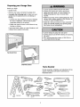 3
3
-
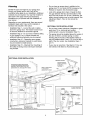 4
4
-
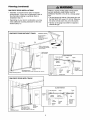 5
5
-
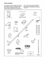 6
6
-
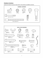 7
7
-
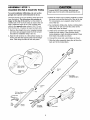 8
8
-
 9
9
-
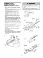 10
10
-
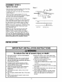 11
11
-
 12
12
-
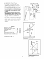 13
13
-
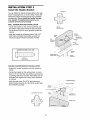 14
14
-
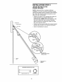 15
15
-
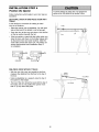 16
16
-
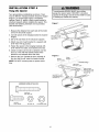 17
17
-
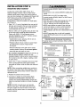 18
18
-
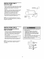 19
19
-
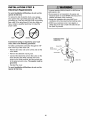 20
20
-
 21
21
-
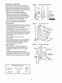 22
22
-
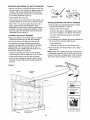 23
23
-
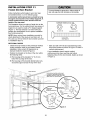 24
24
-
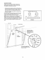 25
25
-
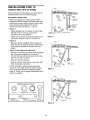 26
26
-
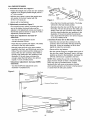 27
27
-
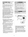 28
28
-
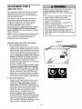 29
29
-
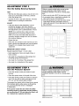 30
30
-
 31
31
-
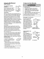 32
32
-
 33
33
-
 34
34
-
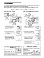 35
35
-
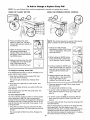 36
36
-
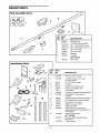 37
37
-
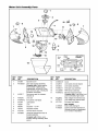 38
38
-
 39
39
-
 40
40
-
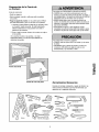 41
41
-
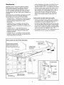 42
42
-
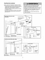 43
43
-
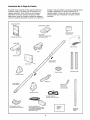 44
44
-
 45
45
-
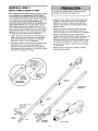 46
46
-
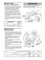 47
47
-
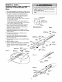 48
48
-
 49
49
-
 50
50
-
 51
51
-
 52
52
-
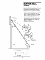 53
53
-
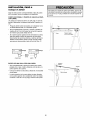 54
54
-
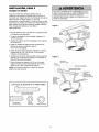 55
55
-
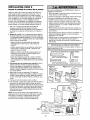 56
56
-
 57
57
-
 58
58
-
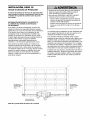 59
59
-
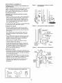 60
60
-
 61
61
-
 62
62
-
 63
63
-
 64
64
-
 65
65
-
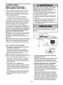 66
66
-
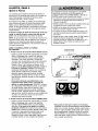 67
67
-
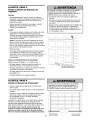 68
68
-
 69
69
-
 70
70
-
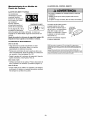 71
71
-
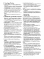 72
72
-
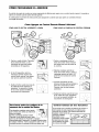 73
73
-
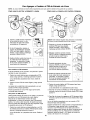 74
74
-
 75
75
-
 76
76


Craftsman 139.53982SRT El manual del propietario
- Categoría
- Abridor de puerta de garage
- Tipo
- El manual del propietario
- Este manual también es adecuado para
en otros idiomas
Artículos relacionados
-
Craftsman 139.53910D El manual del propietario
-
Craftsman 13953975SRT1 Manual de usuario
-
-
-
Craftsman 13953985 El manual del propietario
-
-
-
-
-