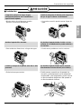
LG LMNC126BTG0.AMWALMH Guía de instalación
- Tipo
- Guía de instalación

ENGLISH
LG Multi Type
Air Conditioner
(Ceiling Duct Type)
INSTALLATION MANUAL
LG
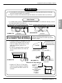
IMPORTANT
• Please read this installation manual completely before
installing the product.
• When the power cord is damaged, replacement work shall
be performed by authorized personnel only.
• Installation work must be performed in accordance with
the national wiring standards by authorized personnel
only.
• Please retain this installation manual for future reference
after reading it thoroughly.
website http://www.lgservice.com
e-mail http://lgservice.com/techsup.html
ESPAÑOL

2 Multi Type Air Conditioner
Multi Type Air Conditioner Installation Manual
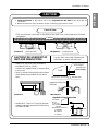
TABLE OF CONTENTS
Safety Precautions..............3
Introduction .........................6
Installation of Indoor...........7
Connecting Pipes to the
Indoor Unit.........................12
Connecting Pipes to the ..14
Checking the Drainage .....14
Connecting Cables
between Indoor Unit .........15
Group Control....................17
Two Thermistor system....17
E.S.P.(External Static
Pressure) Setting...............18
How to Set E.S.P? .............19
Installation
Requirements
Required Parts Required Tools
•
Four Type “A” screws
•
Connecting cable
•
Level
•
Screw driver
•
Electric drill
•
Hole core drill (ø70mm)
•
Pipes: Gas side...........
1
/
2
",
3
/
8
"
Liquid side...........................
1
/
4
"
•
Insulated drain hose
•
Insulation materials
•
Flaring Tools set
•
Additional Drain hose
(Inner Dia...............25mm)
•
Screw driver
•
Hexagonal Wrench (4mm/5mm)
•
Gas-leak Detector

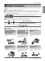
Safety Precautions
Installation Manual 3
ENGLISH
To prevent injury to the user or other people and property damage, the following instructions must be
followed.
■ Be sure to read before installing the air conditioner.
■ Be sure to observe the cautions specified here as they include important items related to safety.
■ Incorrect operation due to ignoring instruction will cause harm or damage. The seriousness is
classified by the following indications.
■ Meanings of symbols used in this manual are as shown below.
This symbol indicates the possibility of death or serious injury.
This symbol indicates the possibility of injury or damage to properties only.
■ Installation
Be sure not to do.
Be sure to follow the instruction.
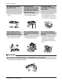
Safety Precautions
Do not use a defective or
underrated circuit breaker.
Use this appliance on a
dedicated circuit.
• There is risk of fire or electric
shock.
For electrical work, contact
the dealer, seller, a
qualified electrician, or an
Authorized Service Center.
• Do not disassemble or repair
the product. There is risk of
fire or electric shock.
Always ground the
product.
• There is risk of fire or electric
shock.
Install the panel and the
cover of control box
securely.
• There is risk of fire or electric
shock.
Always install a dedicated
circuit and breaker.
• Improper wiring or installation
may cause fire or electric
shock
Use the correctly rated
breaker or fuse.
• There is risk of fire or electric
shock.

Safety Precautions
■ Operation
4 Multi Type Air Conditioner
Do not modify or extend
the power cable.
• There is risk of fire or electric
shock.
Do not let the air
conditioner run for a long
time when the humidity is
very high and a door or a
window is left open.
• Moisture may condense and
wet or damage furniture.
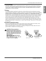
Be cautious when
unpacking and installing
the product.
• Sharp edges could cause
injury. Be especially careful of
the case edges and the fins on
the condenser and evaporator.
For installation, always
contact the dealer or an
Authorized Service Center.
• There is risk of fire, electric
shock, explosion, or injury.
Do not install the product
on a defective installation
stand.
• It may cause injury, accident,
or damage to the product.
Be sure the installation
area does not deteriorate
with age.
• If the base collapses, the air
conditioner could fall with it,
causing property damage,
product failure, and personal
injury.
Do not store or use flammable gas or combustibles near the product.
• There is risk of fire or failure of product.
Gasolin

Installation Manual 5
ENGLISH
Safety Precautions
Always check for gas
(refrigerant) leakage after
installation or repair of
product.
• Low refrigerant levels may
cause failure of product.
Install the drain hose to
ensure that water is
drained away properly.
• A bad connection may cause
water leakage.
Keep level even when
installing the product.
• To avoid vibration or water
leakage.
Do not install the product
where the noise or hot air
from the outdoor unit could
damage the neighborhoods.
• It may cause a problem for
your neighbors.
Use two or more people to
lift and transport the
product.
• Avoid personal injury.
Do not install the product
where it will be exposed to
sea wind (salt spray)
directly.
• It may cause corrosion on the
product. Corrosion, particularly
on the condenser and evaporator
fins, could cause product
malfunction or inefficient
operation.
90˚
■ Installation

6 Multi Type Air Conditioner
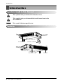
Introduction
This symbol alerts you to the risk of electric shock.
This symbol alerts you to hazards that could cause harm to the
air conditioner.
This symbol indicates special notes.
NOTICE
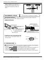
Introduction
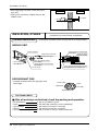
Symbols Used in this Manual
Features
Air filters
Air intake vents
Remote Controller
Air outlet vents
more than
10cm

Installation Manual 7
ENGLISH
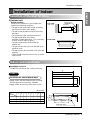
Installation of Indoor
Installation of Indoor
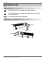
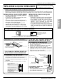
Selection of the best location
1) Indoor unit
Select location
Install the air conditioner in the location that
satisfies the following conditions.
• The place shall easily bear a load exceeding
four times the indoor unit’s weight.
• The place shall be able to inspect the unit as
the figure.
• The place where the unit shall be leveled.
• The place shall allow easy water
drainage.(Suitable dimension “H” is necessary
to get a slope to drain as figure.)
• The place shall easily connect with the
outdoor unit.
• The place where the unit is not affected by an
electrical noise.
• The place where air circulation in the room will
be good .
• There should not be any heat source or steam
near the unit
H
600600
Top view
(unit: mm)
Front view
Inspection hole
(600X600)
Control box
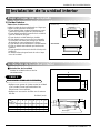
Indoor unit installation
■ Installation of Unit
Install the unit above the ceiling correctly.
• Apply a joint-canvas between the unit and
duct to absorb unnecessary vibration.
• Apply a filter Accessory at air return hole.
CASE 1
POSITION OF SUSPENSION BOLT
(Unit:mm)
9/12k 708 678 434 51 537 455 230 172
18k 1058 1028 434 51 537 805 230 172
24k 1258 1228 434 51 537 1075 230 172
Dimension
Capacity
ABCDEFGH
Drainage hole
A
B
CD
1-3 mm
F
H
G
E

8 Multi Type Air Conditioner
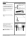
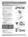
• Select and mark the position for fixing
bolts.
• Drill the hole for set anchor on the face of
ceiling.
• Insert the set anchor and washer onto the
suspension bolts for locking the
suspension bolts on the ceiling.
• Mount the suspension bolts to the set
anchor firmly.
• Secure the installation plates onto the
suspension bolts (adjust level roughly)
using nuts, washers and spring washers.
CAUTION: Tighten the nut and bolt
to prevent unit falling
1 Set anchor
Old building New building
2 Plate washer
3 Spring washer
4 Nut
5 Suspension
bolts
Installation of Indoor
• Install the unit leaning to a drainage hole
side as a figure for easy water drainage.
• A place where the unit will be leveled and
that can support the weight of the unit.
• A place where the unit can withstand its
vibration.
• A place where service can be easily
performed.
CASE 2
POSITION OF CONSOLE BOLT
M10 Nut
M10 SP. washer
M10 washer
X 4
X 4
(Local
supply)
X 4
M10 Nut
M10 SP. washer
M10 washer
X 4
X 4
(Local
supply)
X 4

Installation Manual 9
ENGLISH
Installation of Indoor
Ceiling
CAUTION
1~3mm
Drainage hole
Drainage hole
U-Trap
B
C
A ≥ 70mm
B ≥ 2C
C ≥ 2 x SP
SP = External Pressure
(mmAq)
Ex) External Pressure
= 10mmAq
A ≥ 70mm
B ≥ 40mm
C ≥ 20mm
A
Make sure to be closed.
Unit
Drainage pipe
(Local supply)
Thermal insulator
(Local supply)
Drainage hole
CAUTION FOR GRADIENT OF
UNIT AND DRAIN PIPING
Lay the drain hose with a downward
inclination so water will drain out.
Front of view
• Always lay the drain with downward
inclination (1/50 to 1/100).
Prevent any upward flow or reverse flow
in any part.
• 5mm or thicker formed thermal insulator
shall always be provided for the drain
pipe.
• Install the P-Trap (or U-Trap) to prevent
a water leakage caused by the blocking
of intake air filter.
Applied U-Trap Dimension
1. Install declination of the indoor unit is very important for the drain of the duct type air
conditioner.
2. Minimum thickness of the insulation for the connecting pipe shall be 5mm.
• The unit must be horizontal or declined to the drain hose connected when finished
installation.
CORRECT
CORRECT
INCORRECT
INCORRECT
• Upward routing not
allowed

10 Multi Type Air Conditioner
• Drill the piping hole with 70mm dia, hole
core drill.
• Piping hole should be slightly slant to the
outdoor side.
5~7mm
Indoor Outdoor
WALL
INSULATION, OTHERS
Insulate the joint and tubes completely.
All thermal insulation must comply with local requirement.
INDOOR UNIT
REFRIGERANT PIPE
• Insulate and tape both the gas pipe and
liquid pipe.
■ After all workings are finished, check the working and operation.
• Air distribution Is the air circulation good?
• Drain Is the drainage smoothly and no sweating?
• Gas leakage Is the piping connection correctly?
• Wiring Is the wiring connection correctly?
• Service Valve Lock-bolt Is the lock-bolt of Service Valve loosened?
THERMAL INSULATION
TEST AND CHECK
Make sure that there is no clearance here.
Overlap with thermal
insulator for piping.
Thermal insulator for refrigerant pipe
(Local supply)
Thermal insulator for
piping(Local supply)
Hose clip for thermal insulator(Local supply)
Union for liquid pipe
Refrigerant pipe and thermal
insulator(Local supply)
Union for gas pipe
Thermal insulator for refrigerant pipe
(Local supply)
Hose clip for thermal insulator
(Local supply)
Power cable
Liquid pipe
Thermal insulator
Gas pipe
Tape
Installation of Indoor

Installation Manual 11
ENGLISH
Installation of Indoor
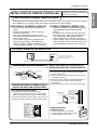
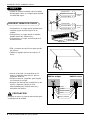
INSTALLATION OF REMOTE CONTROLLER
Install the remote control box
and cord correctly.
• Although the room temperature sensor is in the indoor unit, the remote control box should
be installed in such places away from direct sunlight and high humidity.
INSTALLATION OF THE REMOTE CONTROLLER
• Select places that is not splashed by
water.
• Select control position after receiving
customer approval.
• The room temperature sensor of the
thermostat for temperature control is built
in the indoor unit.
• This remote controller equipped with
liquid crystal display. If this position is
higher or lower, display is difficult to see.
(The standard height is 1.2~1.5m high)
ROUTING OF THE REMOTE CONTROL CORD
• Keep the remote control cord away from
the refrigerant piping and the drain
piping.
• To protect the remote control cord from
electrical noise, place the cord at least
5cm away from other power cables.
(Audio equipment, Television set, etc)
• If the remote control cord is secured to a
wall, provide a trap at the top of the cord
to prevent water droplets from running.
POINT OF REMOTE CONTROLLER INSTALLATION
DISASSEMBLING THE REMOTE CONTROLLER
ELECTRICAL WIRING TO THE INDOOR UNIT
Make sure that wire and terminal
numbers are matched on unit side
and remote controller side.
(Main board)
CN REMO
The maximum length of the cord is 100m.
If the length of the cord exceeds 50m, use a wire size greater than 0.5mm
2
.
Remote controller
CN REMO
Remote
control
box body
Lever carefully
the box open
using a screw
driver, etc.
Front case
T
h
e
lo
w
e
r p
a
rt
Face of wall
Upper notch
Upper flange
Under plate
Remote
control cord
Remote
control unit
Tapping screw
(Local supply)
Lower notch
Face of wall
Upper notch
Lower notch
Switch box
(Local supply)
Under plate
Remote
control unit
Remote
control cord
Screw
(Local supply)
Cord
clamp
Push hand
(Part B)
(Part A)
FIXING OF REMOTE
CONTROL CORD
1. Fix the cord clamps on the wall
by ø3 tapping screws(Local supply).
2. Fix the remote control cord.
PROCEDURE OF INSTALLATION
1. Fix the under plate on the switch box by
screws(Local supply). In this case, fit the under
plate on the wall, and be careful of deformation.
2. Receive the remote control cord in the switch box.
3. Hook the remote control unit on the under plate.
WHEN THE REMOTE CONTROLLER IS
INSTALLED WITH THE CORD BURIED.
PROCEDURE OF INSTALLATION
1. Fix the under plate on the wall by self tapping
screws (accessory).
2. Make a slit (Part A) at the top side of the remote
controller by nipper.
3.Rout the cord as shown in the following figure. In
this case, push the cord into the around of
case(Part B).
4. Hook the remote control unit on the under plate.
WHEN THE REMOTE CONTROLLER IS
INSTALLED WITH THE CORD EXPOSED.

12 Multi Type Air Conditioner
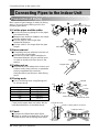
Connecting Pipes to the Indoor Unit
Connecting Pipes to the Indoor Unit
Preparation of Piping
Main cause of gas leakage is defect in flaring
work. Carry out correct flaring work in the
following procedure.
1) Cut the pipes and the cable.
■ Use the accessory piping kit or the pipes
purchased locally.
■ Measure the distance between the indoor
and the outdoor unit.
■ Cut the pipes a little longer than
measured distance.
■ Cut the cable 1.5m longer than the pipe
length.
2) Burrs removal
■ Completely remove all burrs from the cut
cross section of pipe/tube.
■ Put the end of the copper tube/pipe to
downward direction as you remove burrs
in order to avoid to let burrs drop in the
tubing.
3) Putting nut on
■ Remove flare nuts attached to indoor and
outdoor units, than put them on pipe/tube
having completed burr removal.
(Not possible to put them on after flaring
work)
4) Flaring work
■ Carry out flaring work using flaring tool
as shown below.
Firmly hold copper tube in a bar(or die) as
indicated dimension in the table above.
5) Check
■ Compare the flared work with figure.
■ If flare is noted to be defective, cut off the
flared section and do flaring work again.
Copper
tube
90°
Slanted Uneven Rough
Pipe
Reamer
Point down
Flare nut
Copper tube
Bar
Copper pipe
Clamp handle
Red arrow mark
Cone
Yoke
Handle
Bar
"A"
Inclined
Inside is shining without scratches.
Smooth all round
Even length
all round
Surface
damaged
Cracked Uneven
thickness
= Improper flaring =
Outside Diameter "A"
1/4" 0~0.5
3/8" 0.5~0.8
1/2" 0.5~0.8
5/8" 0.8~1.0
3/4" 1.0~1.3

Installation Manual 13
ENGLISH
Connecting Pipes to the Indoor Unit
6) Pipe bending
Annealed copper pipe with small diameter (ø6.35 or ø9.52) can be easily bent manually. In
this case, secure large R(radius) for the bend section and gradually bend pipe. If annealed
copper pipe is large in diameter (ø15.88 or ø19.05), bend pipe with bender. Use bender
appropriate for the pipe diameter.
7)
Brazing
In refrigerant piping, bending (in particular, acute bending) must be minimized to reduce
piping resistance. Bending is, however, necessary in some places by virtue of the installation
position of devices auxiliary to the packaged air conditioner, or of the building structure,
piping distance or finishing appearance. If a more acute bend is required than that attainable
by pipe bender, perform brazing using ready-made elbow. Aside from this function, brazing
also serves to connect straight pipes, generally using ready-made sockets. While brazing,
protect piping against heat with wet cloth to avoid damaging valve packing or burning
thermal insulator with burner heat. While brazing, blow inert gas (nitrogen gas or carbonic
gas) to prevent formation of oxidation film in copper piping; otherwise, the refrigerant circuit
will clog. The blowing of nitrogen gas (or carbonic gas) through 3-way valves is described in
the following:
8)
Refrigerant piping(Flare piping)
When connecting piping, be sure to keep piping dry(keep piping away from water), clean
(keep piping away from dust) and airtight (avoid refrigerant leakage).
When connecting piping on rainy days or making a through-hole in wall, take due care to
prevent water or plaster from entering piping.
CAUTION: This procedure is
designed to prevent formation of
oxidation film by filling piping with
inert gas. Note that excessive gas
pressure will generate pinholes at
brazed points.
(Nitrogen gas: Supply pressure
0.05~0.1kg/cm
2
G)
When supplying inert gas, be sure
to open one end of piping.
Water enters Plaster enters

14 Multi Type Air Conditioner
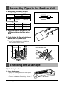
1) Checking the Drainage
1. Check the drainage.
• Spray one or two glasses of water upon
the evaporator.
• Ensure that water flows drain hose of
indoor unit without any leakage.
1. When piping installation work you
must check the connecting pipe size.
2. Align the center of the pipings and
sufficiently tighten the flare nut by
hand
3. Finally, tighten the flare nut with torque
wrench until the wrench clicks.
■ When tightening the flare nut with torque
wrench, ensure the direction for tightening
follows the arrow on the wrench.
Connecting Pipes to the Outdoor Unit
Connecting Pipes to the Outdoor Unit
Checking the Drainage
Indoor Units Gas side Liquid side
9k Ø9.52(3/8") Ø6.35(1/4")
12k Ø12.7(1/2") Ø6.35(1/4")
18k Ø12.7(1/2") Ø6.35(1/4")
24k Ø15.88(5/8") Ø6.35(1/4")
Connector
Branch distributor Unit
A
B
Torque
wrench
A-UNIT
B-UNIT
C-UNIT
D-UNIT
Gas side piping
Liquid side piping
Torque
wrench
Connector
Branch Distributor Unit
A-UNIT
B-UNIT
C-UNIT
D-UNIT
Gas side piping
Gas side piping
Gas side piping
Liquid side piping
Liquid side piping
*Connecting pipe size
Indoor Units
Gas
AB
9k Ø12.7 Ø9.52
24k Ø12.7 Ø15.88

Installation Manual 15
ENGLISH
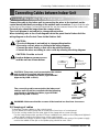
Connecting Cables between Indoor Unit and Outdoor Unit
Connecting Cables between Indoor Unit
2) Clamping of cables
1) Arrange 2 power cables on the control panel.
2) First, fasten the steel clamp with a screw to the inner boss of control panel.
3) For the cooling model, fix the other side of the clamp with a screw strongly.
For the heat pump model, put the 0.75mm
2
cable(thinner cable) on the clamp and tighten it
with a plastic clamp to the other boss of the control panel.
4) In Australia, the length of power supply cord measured from the entry of the power supply
cord to the middle of live pin on the power plug should be over 1.8m.
WARNING: Make sure that the screws of the terminal are free from looseness.
CAUTION: The power cord connected to the outdoor
unit should be complied with the following
specifications (Rubber insulation, type H05RN-F
approved by HAR or SAA).
The connecting cable connected to the indoor and
outdoor unit should be complied with the following
specifications (Rubber insulation, type H07RN-F
approved by HAR or SAA).
NORMAL
CROSS-SECTIONAL
AREA 2.5mm
2
ø8.5mm
GN/YL
20mm
NORMAL
CROSS-SECTIONAL
AREA 0.75mm
2
ø7.5mm
GN/YL
20mm
Connect the cable to the indoor unit by connecting the wires to the terminals on the
control board individually according to the outdoor unit connection. (Ensure that the color
of the wires of the outdoor unit and the terminal No. are the same as those of the indoor unit.)
The earth wire should be longer than the common wires.
The circuit diagram is not subject to change without notice.
When installing, refer to the circuit diagram behind the panel front of Indoor Unit the
wiring diagram on the Control Cover Inside Outdoor Unit.
Connect the cable to the Indoor unit.
CAUTION:
• The circuit diagram is not subject to change without notice.
• Be sure to connect wires according to the wiring diagram.
• Connect the wires firmly, so that not to be pulled out easily.
• Connect the wires according to color codes by referring the wiring diagram.
Air
Conditioner
Main power source
Circuit Breaker
Use a circuit breaker
or time delay fuse.
CAUTION: Provide a circuit
breaker between power source
and the unit as shown below.

16 Multi Type Air Conditioner
Connecting Cables between Indoor Unit
CAUTION:
After the confirmation of the above conditions, prepare the wiring as follows:
1. Never fail to have an individual power specialized for the air conditioner. As for the
method of wiring, be guided by the circuit diagram pasted on the inside of control box
cover.
2. Provide a circuit breaker switch between power source and the unit.
3. The screw which fasten the wiring in the casing of electrical fittings are liable to come
loose from vibrations to which the unit is subjected during the course of
transportation. Check them and make sure that they are all tightly fastened. (If they
are loose, it could give rise to burn-out of the wires.)
4. Specification of power source
5. Confirm that electrical capacity is sufficient.
6. Be sure that the starting voltage is maintained at more than 90 percent of the rated
voltage marked on the name plate.
7. Confirm that the cable thickness is as specified in the power sources specification.
(Particularly note the relation between cable length and thickness.)
8. Never fail to equip a leakage breaker where it is wet or moist.
9. The following troubles would be caused by voltage drop-down.
• Vibration of a magnetic switch, damage on the contact point there of, fuse breaking,
disturbance to the normal function of a overload protection device.
• Proper starting power is not given to the compressor.

Installation Manual 17
ENGLISH
Air Purging of the Connecting Pipes and the Indoor Unit
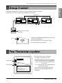
Group Control
Two Thermistor system
It operates maximum 16 Units by only one Wired Remote Controller,
and each Unit starts sequentially to prevent overcurrent.
• Open the rear cover of Remote
Controller to set up the mode.
•
Selectable options are three as follows
.
- Remo: Sensing the room Temperature.
- Indoor Unit: Sensing the intake air into
indoor Unit.
- 2 TH: Sensing the lower temperature of
the two thermistors.
• To set up the mode, adjust the slide
switch to desired mode position on
installing.
Operation unit
ZONE
1234
Humidify
JET
AUTO
AUTO SWING OPERATION
FAN SPEED
Program set
SUB FUNCTION
SET TEMP
Room Temp
HI
MED
LO
Heater
Defrost
Filter
Preheat
Out door
Time
Timer
On
Set no. Time
Off
01 03 05 07 09 11 13 15 17 19 21 23
Indoor Unit 1
Terminal(Local Supply)
Block
Terminal(Local Supply)
Block
Terminal(Local Supply)
Block
Main PCB
#1
Main PCB
#2
Main PCB
#16
Wired Remote Controller
(Standard)
Indoor Unit 2
Main PCB
Indoor Unit 16
Connector
RED(12V)
YL(SIGNAL)
BR(GND)
RED(12V)
YL(SIGNAL)
BR(GND)
YL(SIGNAL)
BR(GND)
Connecting Cable(Local Supply)
Connector Connector
....
....
YL(SIGNAL)
BR(GND)
YL(SIGNAL)
BR(GND)
YL(SIGNAL)
BR(GND)
Remote
Controller
PCB
Single
Group
Slide Switch2
Slide Switch1
Remo.
Room Temp. Sensing
Indoor Unit
2 TH(Remo.+Indoor)
• On installing, don't impact to the PCB
and LCD display.
• Don't remove the protection sheet.
• Use the specified screw.
• On installing, turn off the main power.
CAUTION
Single
Group
Slide Switch2
• Using the supplied Wired Remote Controller,
wire them like above.
• Move slide switch 2 to "Group" position.
• Ensure that the color of wire.

18 Multi Type Air Conditioner
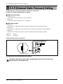
E.S.P.(External Static Pressure) Setting
(1) Open the rear cover of the wired remote-controller to set the mode.
(2) Select one of three selectable modes as follows.
■ Without Zone System
1. Position V-H, F-H:
• This position sets the maximum E.S.P as a default set.
2. Position V-L:
• This position sets the minimum E.S.P as a default set.
■ With Zone System
1. Position V-H:
• Maximum E.S.P setting & Fan speed is varied according to the state of dampers by micom.
2. Position F-H:
• Maximum E.S.P setting & Fan speed doesn't vary according to the opening & Closing of dampers.
3. Position V-L:
• Minimum E.S.P setting & Fan speed is varied according to the state of dampers by micom.
*Maximum : 3mmAq
Minimum : All-0mmAq
(3) Move the slide switch to set position.
(4) Close the rear cover and check if it works normally.
TH
R14H
SW TH
REMO
MAIN
2TH
OP7
R18H
R17H
OP6
LO
STAND
SW HIGH
HI
R03S
C070
R04S
R02S
R01S
OP3
OP2 OP1
R19H
R11H
R13H R12H
OP5R16H OP4
R15H
CO1H
V-L
V-H
F-H
Slide switch for ceiling height
CAUTION: Select the position after checking duct work and E.S.P of the unit.
Maunfactured in the position F-H.
E.S.P.(External Static Pressure) Setting

Installation Manual 19
ENGLISH
How to Set E.S.P?
Preheat
ZONE
Operation unit Program set
Room Temp
MED
LO
AUTO
JET
Heater
Defrost
Filter
Humidify
Out door
Timer
On
Set no. Time
Off
01 03 05 07 09 11 13 15 17 19 21 23
1234
OPERATION
FAN SPEED
SUB FUNCTION
SET TEMP
HI
AUTO SWING
Time
Preheat
ZONE
Operation unit Program set
Room Temp
MED
LO
AUTO
JET
Heater
Defrost
Filter
Humidify
Out door
Timer
On
Set no. Time
Off
01 03 05 07 09 11 13 15 17 19 21 23
1234
OPERATION
FAN SPEED
SUB FUNCTION
SET TEMP
HI
AUTO SWING
Time
Time
SUB FUNCTION
SET TEMP
OPERATIONAUTO SWING
Preheat
ZONE
Operation unit Program set
Room Temp
MED
LO
AUTO
JET
Heater
Defrost
Filter
Humidify
Out door
Timer
On
Set no. Time
Off
01 03 05 07 09 11 13 15 17 19 21 23
1234
FAN SPEED
HI
Time
SUB FUNCTION
SET TEMP
OPERATIONAUTO SWING
Preheat
ZONE
Operation unit Program set
Room Temp
MED
LO
AUTO
JET
Heater
Defrost
Filter
Humidify
Out door
Timer
On
Set no. Time
Off
01 03 05 07 09 11 13 15 17 19 21 23
134
FAN SPEED
HI
2
Timer
1
2
3
5
4
Timer
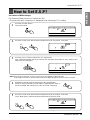
Procedure of RPM change:
Ex) External Static pressure is 1mmAq for "9k"
• To protect the unit, compressor is designed to be off during E.S.P. setting.
Push the "On/Off" button.
The unit will start.
Push the "Timer" and "Wind" button simultaneously for more then 3 seconds.
Push the "Up" of "Down" button for E.S.P adjustment.
And, adjust the number which you want.(In this example, the number is "215". Refer to the
table 1 on the next page.)
Shift the fan speed mode by pressing the fan speed button.
And then, Adjust numbers of next steps by repeating the stage 3.
(In this example, the numbers are "235" and "250" respectly)
Push the "Timer" and "Wind" button simultaneously for more than 3 seconds.
Then, Wind Data is memorized by the EEPROM of the main PCB.
Note: The range of selection is from 1~254. Since, the display is two Digit only.
If the range selection is above 100 then the third digit will appear in the screen as shown.
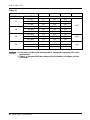
How to Set E.S.P?

20 Multi Type Air Conditioner
Static Pressure(mmAq)
Setting Value
0 1 2 Capacitor.
Ca(Btu/h) Step(Hi/Med/Lo)
7.5 CMM 175 160 150
9k 6.5 CMM 200 185 175
5.5 CMM 220 208 195
9 CMM 110 95 80
12k 8 CMM 145 135 120
7 CMM 175 160 150
13.5 CMM 113 103 100
18k 12 CMM 140 130 120
10 CMM 173 155 145
17.5 CMM 80 50 30
24k 16 CMM 145 130 120
14 CMM 170 160 150
[Table. 1]
: 1. Be sure to set the value refering table 1. Unexpected set value will cause
mal-function.
2. Table 1 is based at 230V. According to the fluctuation of voltage, air flow
rate varies.
NOTICE
How to Set E.S.P?
2.0µF
2.5µF
3.5µF

ESPAÑOL
LG
Aire acondicionado
de
canalización de techo
MANUAL DE INSTALACIÓN
IMPORTANTE
• Lea este manual de instrucciones completamente antes de
instalar el producto.
• El trabajo de instalación debe realizarse de acuerdo con el
Reglamento Eléctrico nacional y únicamente por personal
autorizado.
• Después de leer completamente este manual de instalación,
guárdelo para futuras consultas.

2 Aire acondicionado de Tipo Cassete
Aire acondicionado de Tipo Cassete Manual de instalación
ÍNDICE
Precauciones de seguridad .......................................3
Introducción.................................................................6
Instalación de la unidad interior................................7
Conexión de los conductos a la unidad interior....12
Conexión de los conductos a la unidad exterior...14
Comprobación del desagü.......................................14
Conexión del cable situado entre la unidad interior
y la exterio .................................................................15
Control de grupo.......................................................17
Sistema de dos termistores.....................................17
Establecimiento de la E.S.P (External Static
Pressure, Presión estática externa) ........................18
Establecimiento de la E.S.P (External Static
Pressure, Presión estática externa)?......................19
❏ Calibre de nivel
❏ Destornillador
❏ Taladro eléctrico
❏ Taladradora (ø70mm)
❏ Metro horizontal
❏ Kit de herramientas para abocinado
❏ Llaves de apriete del par especificado
1,8 kg-m, 4,2 kg-m, 5,5 kg-m, 6,6 kg-m
(diferentes dependiendo del número del modelo)
❏ Llave inglesa.......Media unión
❏ Un vaso de agua
❏ Destornillador
❏ Llave hexagonal de apriete (4mm)
❏ Detector de escape de gases
❏ Bomba de vacío
❏ Colector
❏ Manual del usuario
❏ Termómetro
❏ Soporte para el mando a distancia
Requisitos de instalación
Herramientas necesarias

Precauciones de seguridad
Manual de instalación
3
ESPAÑOL
Para evitar lesiones al usuario o a otras personas y daños a la propiedad, siga estas
instrucciones.
■
Una operaci’on incorrecta por ignorar las instrucciones provocará lesiones o daños. La
seriedad se clasifica por las siguientes indicaciones.
■ Significados de los símbolos utilizados en este manual.
ADVERTENCIA
PRECAUCIÓN
Este símbolo indica la posibilidad de muerte o de seria lesión.
Este símbolo indica sólo la posibilidad de lesión o daño a la propiedad.
ADVERTENCIA
Prohibido.
Recuerde seguir las instrucciones.
Precauciones de seguridad
■ Instalación
No utilice un interruptor automático
defectuoso o de valor nominal inferior
al correspondiente. Utilice un circuito
específico para este aparato.
• Existe riesgo de incendio o
descarga eléctrica.
Para trabajos eléctricos, póngase en
contacto con el distribuidor, vendedor,
técnico cualificado o centro de
asistencia técnica autorizado.
• No desmonte ni repare el
aparato. Existe riesgo de
incendio o descarga eléctrica.
Realice siempre la conexión
del aparato a tierra.
• Existe riesgo de incendio o
descarga eléctrica.
Instale correctamente el
panel y la cubierta de la
caja de control.
• Existe riesgo de incendio o
descarga eléctrica.
Instale siempre un circuito y
un interruptor específico.
• Un cableado o instalación
inadecuados pueden provocar
un incendio o una descarga
eléctrica.
Utilice el interruptor o
fusible de valor nominal
adecuado.
• Existe riesgo de incendio o
descarga eléctrica.

4 Aire acondicionado de Tipo Cassete
Precauciones de seguridad
No modifique ni extienda el cable de
alimentación.
• Existe riesgo de incendio o descarga
eléctrica.
Tenga cuidado al desembalar e instalar el
aparato.
•
Los bordes afilados podrían provocar lesiones.
Tenga especial cuidado con los bordes de la caja
y las aletas del condensador y evaporador.
Para la instalación, póngase en contacto
siempre con su vendedor o centro de
asistencia técnica autorizado.
• Existe riesgo de incendio, descarga
eléctrica, explosión o lesiones.
No instale el aparato en una superficie de
instalación insegura.
• Podría causar lesiones, accidentes o daños
en el aparato.
Asegúrese de que el soporte de instalación no
se deteriora con el tiempo.
•
Si el soporte cae, el aire acondicionado también puede
caer, causando daños materiales, avería del aparato y
lesiones personales.
No deje funcionando el aire acondicionado
durante mucho tiempo cuando la humedad sea
muy alta y haya una puerta o ventana abierta.
• Podría condensarse la humedad y mojar o
dañar el mobiliario.
No almacene ni utilice gas inflamable o
combustibles cerca del aparato.
• Existe riesgo de incendio o avería del
aparato.
■ Operación
Gasolin

ESPAÑOL
Manual de instalación
5
Precauciones de seguridad
Compruebe siempre las fugas de gas
(refrigerante) después de la instalación o
reparación del aparato.
• Niveles bajos de refrigerante pueden
producir una avería del aparato.
Instale la manguera de drenaje para asegurarse
de que el agua se drena correctamente.
• Una mala conexión puede causar fugas de
agua.
Instale el aparato bien nivelado.
• Para evitar las vibraciones o fugas de agua.
No instale el aparato donde el ruido o el aire
caliente de la unidad exterior pueda molestar a
los vecinos.
• Podría tener problemas con los vecinos.
Levante y transporte el aparato entre dos o más
personas.
• Evite lesiones personales.
No instale el aparato donde quede expuesto
directamente al viento del mar (rocío salino).
• Podría causar corrosión en el aparato. La
corrosión, particularmente en las aletas del
condensador y del evaporador, podría causar
un funcionamiento defectuoso del aparato o
un funcionamiento ineficaz.
PRECAUCIÓN
90˚
■ Instalación

6 Aire acondicionado de Tipo Cassete
Introducción
Este símbolo le avisa del riesgo de descarga eléctrica.
Este símbolo le avisa de riesgos que pueden producir daños al
aire acondicionado.
Este símbolo indica notas especiales.
AVISO
Introducción
Símbolos utilizados en este manual
Características
more than
10cm
Filtros de aire
Salida de aire
Toma de aire
Control remoto

ESPAÑOL
Manual de instalación
7
Instalación de la unidad interior
Instalación de la unidad interior
1) Unidad interior
Seleccione la ubicación
Instale el equipo de aire acondicionado en el lugar que
cumpla con las siguientes condiciones.
•
El lugar deberá poder sostener fácilmente una carga
cuatro veces superior al peso de la unidad interior.
•
El lugar deberá permitir la inspección de la unidad tal
como se muestra en la figura.
•
El lugar donde la unidad deberá ser nivelada.
•
El lugar deberá tener un acceso fácil a un desagüe.
(Es necesaria una altura para conseguir un desnivel
de desagüe tal como se muestra en la figura.)
•
El lugar donde conecta fácilmente a la unidad exterior.
•
El lugar no deberá estar afectado por interferencias
eléctricas.
•
El lugar permitirá una buena circulación del aire por la
habitación.
•
No deberá hallarse ninguna fuente de calor ni vapor
cerca de la unidad.
■ Instalación de la unidad
Instale la unidad sobre el techo
correctamente.
• Aplique una goma de juntas entre la unidad
y las conducciones para absorber las
vibraciones innecesarias.
• Aplique un accesorio de filtro en el retorno
de aire.
Elegir el lugar más apropiado
Instalación de la unidad interior
H
600600
Vista superior
(unidad: mm)
Vista frontal
Espacio de inspección
(600X600)
Caja del control
A
B
CD
1-3 mm
F
H
G
E
Desagüe
POSICIÓN DEL PERNO DE SUSPENSIÓN
Unidad: (mm)
CASO 1
9/12k 708 678 434 51 537 455 230 172
18k 1058 1028 434 51 537 805 230 172
24k 1258 1228 434 51 537 1075 230 172
Dimensiones
Capacidad
ABCDEFGH

8 Aire acondicionado de Tipo Cassete
Instalación de las unidades Interior
CASO 2
POSICIÓN DEL PERNO DE LA CONSOLA
• Instale la unidad inclinada hacia la salida
del desagüe como en la figura para facilitar
la salida del agua.
• Colóquela en un lugar donde pueda estar
nivelada y que resista el peso de la
unidad.
• Colóquela en un lugar donde la unidad
pueda resistir las vibraciones.
• Colóquela en un lugar accesible para el
mantenimiento.
Tuerca
M10
Arandela
M10
Arandela M10 SP
Arandela M10
Arandela M10
Tuerca M10
X 4
X 4
(Suministro
Local)
(Suministro
Local)
X 4
X 4
X 4
X 4
• Elija y marque las posiciones para anclar
los pernos.
• Taladre el agujero para el anclaje en el
techo.
• Inserte el anclaje y la arandela en los
pernos colgantes para fijar los pernos
colgantes al techo.
• Monte los pernos colgantes para sujetar
con firmeza el anclaje.
• Asegure las láminas de instalación en los
pernos colgantes (ajuste el nivel
aproximadamente) usando tuercas y
arandelas de lámina.
PRECAUCIÓN
: Asegure la tuerca y el perno para evitar que
se desprenda la unidad
1 Anclaje
Edificio antiguo
Edificio nuevo
2 Arandela
3 Arandela de lámina
4 Tuerca
5 Pernos colgantes

ESPAÑOL
Manual de instalación
9
Instalación de las unidades Interior
Techo
ATENCIÓN
Desagüe
Desagüe.
U-Trap
B
C
A ≥ 70mm
B ≥ 2C
C ≥ 2 x SP
SP = Presión externa
(mmAq)
Ex) Presión externa
= 10mmAq
A ≥ 70mm
B ≥ 40mm
C ≥ 20mm
A
Unidad
Desagüe
PRECAUCIÓN PARA ELGRADIANTE
DE LA UNIDAD Y TUBO DE DRENAJE
Coloque la manguera de drenaje con una
inclinación descendente de modo que pueda
drenarse el agua.
Aislante térmico
(Suministro Local)
Tubo de desagüe
(Suministro Local)
Asegúrese de
dejarlo cerrado.
1~3mm
Vista Frontal
• Coloque siempre el desagüe con una
inclinación en bajada (1/50 a 1/100).
Evite un reflujo hacia arriba o hacia
atrás en cualquier parte de su
recorrido.
• El tubo de desagüe debe ir provisto
de un aislante térmico de 5mm de
grosor.
• Instale el P-Trap (o U-Trap) para
evitar las fugas de agua causadas
por el bloqueo del filtro de aire de
entrada.
1. La instalación inclinada de la unidad interior es muy importante para el drenaje
del aire acondicionado de conductos.
2. El grosor mínimo del aislamiento para la tubería de conexión debe ser de 5mm.
• La unidad debe estar en posición horizontal o inclinada a la salida de drenaje cuando
se haya terminado la instalación.
CORRECTO
CORRECTO
INCORRECTO
Dimensión U-Trap aplicada
INCORRECTO
• La inclinación de los
tubos hacia arriba no
se permite

10 Aire acondicionado de Tipo Cassete
Instalación de las unidades Interior
• Taladre el orificio para la tubería de
70mm de diámetro con una broca hueca.
• El orificio para la tubería debe estar
ligeramente inclinado por el lado de
salida.
AISLAMIENTO, OTROS
Aísle la juntura y los tubos por completo.
Todos los aislamientos térmicos deben cumplir las
exigencias locales.
UNIDAD INTERIOR
TUBERÕAS DE REFRIGERACIÓN
• Aísle y una con cinta el tubo de gas y el
tubo de líquido.
■
Después de que haya terminado todas las operaciones, compruebe las operaciones y el funcionamiento.
• Distribución de aire: Es buena la circulación de aire?
• Desagüe: No hay obstáculos para el desagüe ni hay sudoración?
• Fugas de gas: Las conexiones de las tuberías son correctas?
• Cableado: Las conexiones de los cables son correctas?
• Tornillo de bloqueo: El tornillo de bloqueo del compresor ha sido liberado?
AISLAMIENTO TÉRMICO
COMPROBACIONES
5~7mm
Interior Exterior
Muro
Junta para tubo de gas
Tubo de refrigeración y aislante térmico
(Suministro local)
Aislamiento térmico para tubo de
refrigeración (Suministro local)
Junta para tubo de líquido.
Abrazadera de manguera para aislamiento
térmico (Suministro local)
Asegúrese de que no haya distancia en este lugar.
Se sorbre pone con aislante
térmico para tuberia
Aislante térmico para tubo de
refrigeración (Suministro local)
Aislante térmico para
tubería (Suministro local)
Abrazadera de manguera para aislamiento
térmico (Suministro local)
Cable eléctrico
Tubo de
líquido
Aislante térmico
Tubo de gas
Cinta

ESPAÑOL
Manual de instalación
11
Instalación de las unidades Interior
INSTALACIÓN DE LA CAJA DEL CONTROL REMOTO
Instale correctamente el cable
y la caja del control remoto.
• Aunque el sensor de la temperatura ambiente se encuentra en la unidad interior, la caja del control
remoto debe instalarse de modo que no esté expuesta a la luz solar directa ni a una humedad alta.
I
NSTALACIÓN DE LA CAJA DEL CONTROL REMOTO
• Escoja un lugar donde no pueda producirse
salpicaduras de agua.
• Consulte con el cliente para que éste de su
aprobación sobre la ubicación.
• El sensor de la temperatura ambiente del
termóstato para el control de temperatura se
encuentra en la unidad interior.
• El control remoto está equipado con una
pantalla de cristal líquido. Si lo sitúa a una
altura excesiva o insuficiente se hará difícil
consultarlo. (La altura habitual es a 1.2-1.5m)
INSTALACIÓN DEL CABLE DE LA CAJA DEL
CONTROL REMOTO
• Mantenga el cable del control remoto alejado de
los conductos de refrigeración y de desagüe.
• Para proteger el cable del control remoto de
interferencias eléctricas, sitúe el cable como
mínimo a 5cm de distancia de otros cables
eléctricos (equipo musical, televisión, etc.)
• Si el cable del control remoto se fija a una pared,
coloque un capuchón en el extremo superior del
cable para evitar que las
gotas se deslicen
por él.
PUNTO DE INSTALACIÓN DEL CONTROL REMOTO
DESMONTAR EL CONTROL REMOTO
EL CABLEADO ELÉCTRICO A LA UNIDAD INTERIOR
Asegúrese de que los números de
cable y de terminal coincidan entre
el lateral de la unidad y el lateral
del control remoto.
(Consola principal)
CN REMO
CN REMO
Longitud del la máxima del cable es de 100m.
Si la longitud del cable supera los 50m., utilice un cable de tamaño superior a los 0,5mm
2
.
Caja del control remoto
L
a
p
a
rte
in
fe
rio
r
Caja de control remoto
Haga palanca con cuidado
sobre la apertura de la caja
mediante un destornillador, etc.
Caja frontal
Exterior de la pared
Encaje superior
Flanco superior
Base
Cable del control
remoto
Unidad de
control remoto
Tornillo
(Suministro local)
Encaje
inferior
Exterior de la pared
Encaje superior
Encaje inferior
Caja del interruptor
(Suministro local)
Base
Unidad del control remoto
Cable del control remoto
Tornillo (Suministro local)
Abrazadera
de cable
Presione
manualmente
(Pieza B)
(Pieza A)
FIJACIÓN DEL CABLE DEL
CONTROL REMOTO
1. Fije las abrazaderas del cable en la pared
con tornillos de 3 (
Suministro local
).
2. Fije el cable del control remoto.
PROCEDIMIENTO DE INSTALACIÓN
1. Fije la base de la caja del interruptor con tornillos
(Suministro local). En éste caso, encaje la base
en la pared con cuidado de no deformarla.
2. Conecte el cable del control remoto a la caja del
interruptor.
3. Acople la unidad del control remoto a la base.
SI LA CAJA DEL CONTROL REMOTO SE
INSTALA CON EL CABLE EMPOTRADO
PROCEDIMIENTO DE INSTALACIÓN
1. Fije la base de la caja del interruptor con los
tornillos suministrados.
2. Practique una abertura (Pieza A) en el lado
superior del control remoto con pinzas.
3. Coloque el cable como se muestra en la figura
siguiente. En este caso, coloque el cable para
poder colocar la tapa (Pieza B).
4. Acople la unidad del control remoto a la base.
SI LA CAJA DEL CONTROL REMOTO SE
INSTALA CON EL CABLE A LA VISTA

12 Aire acondicionado de Tipo Cassete
Conexión de los conductos a la unidad interior
Conexión de los conductos a la unidad interior
Preparación de las tuberías
La principal causa de fugas de gas es un defecto en
el proceso de conexión por abocardado. Realice las
conexiones por abocardado del siguiente modo.
1) Corte las tuberías y el cable
■ Utilice el kit de accesorios para las
tuberías o las tuberías que adquiera
usted.
■ Mida la distancia entre la unidad interior y
la exterior.
■ Corte las tuberías más largas que las
medidas tomadas.
■ Corte el cable 1.5m más largo que la
longitud del tubo.
2) Elimine las irregularidades
■ Elimine totalmente las irregularidades
del tubo por donde ha sido cortado.
■ Coloque el extremo del tubo de cobre
hacia abajo mientras elimina las
irregularidades para evitar que caigan
impurezas en el tubo.
3) Colocación de la tuerca
■ Saque las tuercas abocardadas que se
encuentran en las unidades interiores y
exteriores y colóquelas en la tubería
una vez eliminadas las
irregularidades.(No es posible
colocarlas después del proceso de
abocardado)
4) Abocardado
■ Proceda al abocardado usando las
herramientas de abocardar como se
muestra a continuación.
Sujete firmemente el tubo en un troquel como
se indica en la tabla de dimensiones anterior.
5) Comprobación
■ Compare el resultado del abocardado con
la figura.
■ Si observa que el abocardado es
defectuoso, corte la sección abocardada y
proceda de nuevo a realizar la operación.
Tubo de cobre
90°
Sesgado Desigual Áspero
Tubo
Escariador
Incline hacia abajo
Tuerca de abocardado
Tubo de cobre
Troquel
Tubo de cobre
Manilla del tornillo
Marca de la
flecha roja
Cono
Estribo de
montaje
Manilla
Troquel
"A"
Inclinado Superficie
dañada
Grosor no
uniforme
Fracturado
Longitud igual
Liso en toda la superficie
El interior brilla sin
rasguños
=
Abocardado incorrecto
=
Diámetro exterìor
"A"
1/4" 0~0.5
3/8" 0.5~0.8
1/2" 0.5~0.8
5/8" 0.8~1.0
3/4" 1.0~1.3

ESPAÑOL
Manual de instalación
13
Conexión de los conductos a la unidad interior
6) Curvatura de la tubería
El tubo de cobre cocido de pequeño diámetro (ø6.35 o ø9.52) puede doblarse
manualmente con facilidad. En este caso, asegúrese de tomar un radio (R) grande para la
sección curvada y doble el tubo gradualmente. Si el tubo de cobre cocido es de mayor
diámetro (ø15.88 o ø19.05) utilice una herramienta para doblarlo. Use la herramienta
adecuada para el diámetro del tubo.
7) Abrazadera
En las tuberías refrigerantes, las curvaturas deben ser mínimas (especialmente las
pronunciadas) para reducir la resistencia de la tubería. Sin embargo, es necesario curvarlas
en algunos lugares por la ubicación de los dispositivos auxiliares del aire acondicionado, o
por la estructura del edificio, la distancia de las tuberías o el acabado final. Si se requiere
una curvatura muy pronunciada que la que se puede conseguir doblando el tubo, realice
soldaduras utilizando codos prefabricados. Además de esta función, la soldadura también
sirve para conectar tuberías rectas, utilizando generalmente empalmes prefabricados. Al
soldar, proteja la tubería del calor con un paño húmedo para evitar causar desperfectos en
el recubrimiento de la válvula o quemar el aislamiento térmico con el calor del soldador.
Cuando realice la soldadura, aplique gas inerte (gas nitrógeno o gas carbónico) para evitar
la formación de capas de oxidación en la tubería de cobre. En caso contrario, el circuito
refrigerante se oxidará. La aplicación de gas nitrógeno (o gas carbónico) a través de
válvulas de tres vías se describe en el apartado siguiente:
8) Conducción refrigerante (tuberías abocardadas)
Cuando conecte las tuberías, asegúrese de mantener los tubos secos (manteniéndolos
lejos del agua), limpios (manteniéndolos lejos del polvo) y herméticos (evite fugas de
refrigerante).
Si conecta los tubos en días de lluvia o hace un agujero en la pared, tenga cuidado para
evitar que entre agua o polvo en los tubos.
PRECAUCIÓN
a. Este procedimiento está diseñado para prevenir
la formación de capas de oxidación al llenar la
tubería con gas inerte.Tenga en cuenta que
una excesiva presión de gas puede generar
perforaciones en los puntos de soldadura.
(Gas nitrógeno: presión de suministro
0,05~0,1kg/cm
2
G)
b. Cuando aplique gas inerte, asegúrese de
que hay salida al otro extremo.
El agua penetra El yeso penetra

14 Aire acondicionado de Tipo Cassete
1.
Al realizar las tareas de instalación, deberá
revisar el tamaño del conducto de conexión.
* Conexión del tubo
2. Alinee el centro de las tuberías y
enrosque la tuerca con los dedos.
3.
Finalmente, apriete la tuerca con la llave
dinamométrica hasta que la llave haga clic.
■ Cuando apriete la tuerca con la llave
dinamométrica, asegúrese de que la
dirección en que la aprieta es la que marca
la llave.
Conexión de los conductos a la unidad exterior
Connector
Distribuidor de la sucursal
A
B
Llave dinamométrica
Unidad-A
Unidad-B
Unidad-C
Unidad-D
Tubería de gas
Tubería de líquido
Llave
dinamométrica
Connector
Distribuidor de la sucursal
Unidad-A
Unidad-B
Unidad-C
Unidad-D
Tuber
Tuber
ía de gas
a de gas
Tubería de gas
Tu b er ía de líquido
Conexión de los conductos a la unidad exterior
Comprobación del desagüe
Unidad interior Gas Liquido
9k Ø9.52(3/8") Ø6.35(1/4")
12k Ø12.7(1/2") Ø6.35(1/4")
18k Ø12.7(1/2") Ø6.35(1/4")
24k Ø15.88(5/8") Ø6.35(1/4")
1) Comprobación del desagüe
1. Compruebe el desagüe
• Vierta uno o dos vasos de agua sobre el
evaporador.
• Asegúrese de que el agua fluye por la
manguera de desagüe de la unidad interior
sin pérdidas.
Gas
AB
9k Ø12.7 Ø9.52
24k Ø12.7 Ø15.88
Unidad
interior

ESPAÑOL
Manual de instalación
15
Conexión del cable situado entre la unidad interior y la exterior
Conexión del cable situado entre la unidad interior y la exterior
Conecte el cable a la unidad interior uniendo los cables a las terminales de la placa de control
individualmente según la conexión de la unidad exterior. (Cerciórese de que el color de los
cables de la unidad exterior y el número de terminal son los mismos que los de la unidad interior).
El cable de toma a tierra debería ser más largo que los cables de común.
Al instalar, consulte el diagrama del circuito que hay detrás del panel frontal de la unidad interior.
• Al instalar, consulte el diagrama del circuito que hay detrás del panel frontal de la unidad interior.
•
Al instalar, consulte el diagrama de cableado de la cubierta de control que hay dentro de la unidad exterior.
Conectar el cable a la unidad interior
PRECAUCIÓN:
• El diagrama de circuito anterior está sujeto a cambio sin previo aviso.
• Cerciórese de conectar los cables de acuerdo con el diagrama de cableado.
• Conecte los cables firmemente, de modo que no pueda estirar de ellos fácilmente.
• Conecte los cables según los códigos de color consultando el diagrama de cableado.
PRECAUCIÓN: Si no se va a
utilizar un enchufe, proporcione
un disyuntor entre la fuente de
alimentación y la unidad como se
muestra a continuación.
PRECAUCIÓN: El cable de alimentación conectado a la
unidad “A” debería cumplir con las especificaciones
siguientes:Tipo “B” aprobado por HAR o SAA.
El cable de alimentación que conecta la unidad exterior
con la interior debería cumplir con las siguientes
especificaciones:Tipo “B” aprobado por HAR o SAA.
PRECAUCIÓN
: Asegúrese de que los tornillos queden bien
sujetos para evitar que se suelten.
Aire
acondicionado
Fuente de alimentación principal
Disyuntor
Use un disyuntor o
fusible de retardo
de tiempo
ÁREA CRUZADA
NORMAL 0.75mm
2
ø7.5mm
GN/YL
20m
m
ÁREA CRUZADA
NORMAL 2.5mm
2
ø8.5mm
GN/YL
20m
m
2) Colocación de la abrazadera en los cables
1) Coloque 2 cables eléctricos en el panel de control.
2) Primero, apriete la abrazadera de acero con un tornillo al interior del panel de control.
3) Para el modelo sólo frío, fije firmemente el otro extremo de la abrazadera con un tornillo.
Para el modelo de bomba de calor, coloque el cable de 0.75mm
2
(el más delgado) en la
abrazadera y sujételo con una abrazadera de plástico a la parte exterior del panel de control.
4) En Australia, la longitud del cable de suministro eléctrico medido de la entrada de corriente
hasta la mitad de la clavija del enchufe debe ser de más de 1.8m.

16 Aire acondicionado de Tipo Cassete
Conexión del cable situado entre la unidad interior y la exterior
PRECAUCIÓN:
Después de confirmar las condiciones anteriores, prepare el cableadode la
siguiente manera.
1. Que no falte un circuito eléctrico individual específico para el aparato de aire acondicionado. Al
igual que para el método de cableado, guíese por el diagrama del circuito situado en la cubierta
de control.
2. Apriete firmemente los tornillos del terminal para evitar que se suelten. Después de apretarlos,
tire ligeramente de los cables para asegurarse de que no se mueven. (Si están sueltos la unidad
no funcionará con normalidad o se podrán quemar los cables).
3. Especificación de la fuente de alimentación.
4. Asegúrese de que la capacidad eléctrica es suficiente.
5. Compruebe que se mantiene el voltaje de inicio a más del 90% de la tensión nominal que se
indica en la placa.
6. Compruebe que el grosor del cable es el especificado en la especificación de la fuente de
alimentación. (Fíjese en concreto en la relación entre la longitud y grosor del cable)
7. No instale un interruptor diferencial anti-escape de toma a tierra en un área húmeda o mojada.
8. Lo siguiente podría producirse debido a una caída en el voltaje.
• Vibración en el interruptor magnético, que dañará el punto de contacto, estropeará el fusible y
provocará un mal funcionamiento debido a la sobrecarga
9. Se incorporarán en el cableado fijo los medios para la desconexión del suministro de
alimentación que deberán tener un espacio libre de contacto de al menos 3mm en cada
conductor (fásico) activo.

ESPAÑOL
Manual de instalación
17
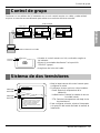
Control de grupo
Control de grupo
Sistema de dos termistores
Funciona con un máximo de 16 unidades con un solo contorl remoto con cable y cada unidad
se pone en marcha secuencialmente para evitar una corriente eléctrica excesiva.
• Usando el control remoto con hilo, conéctelos según se
ha indicado.
• Mover el conmutador deslizante 2 a la posición
“GROUP” (grupo)
• Asegúrese del color del cable.
PCB
control
remoto
Operation unit
ZONE
1234
Humidify
JET
AUTO
AUTO SWING OPERATION
FAN SPEED
Program set
SUB FUNCTION
SET TEMP
Room Temp
HI
MED
LO
Heater
Defrost
Filter
Preheat
Out door
Time
Timer
On
Set no. Time
Off
01 03 05 07 09 11 13 15 17 19 21 23
Unidad Interior 1
Bloque de Terminales
(alimentación eléctrica local)
Block
Bloque de Terminales
(alimentación eléctrica local)
Block
Bloque de Terminales
(alimentación eléctrica local)
Block
PCB Principal
#1
PCB Principal
#2
PCB Principal
#16
Mando a Distancia con Cable
Unidad Interior 2
PCB Principal
Unidad Interior 16
Conector
RED(12V)
YL(SIGNAL)
BR(GND)
RED(12V)
YL(SIGNAL)
BR(GND)
YL(SIGNAL)
BR(GND)
Cable de conexión(alimentación eléctrica local)
Conector Conector
....
....
YL(SIGNAL)
BR(GND)
YL(SIGNAL)
BR(GND)
YL(SIGNAL)
BR(GND)
Interruptor
deslizante 2
Individual
Grupo
Interruptor
deslizante 1
Interruptor
deslizante 2
Detección a distancia
Individual
Grupo
Temp. habitación
Unidad interior
2 TH(Remo.+interior)
• Al realizar la instalación, no evite los
impactos del PCB y el display LCD.
• No retire la lámina de protección.
• Utilice el tornillo especificado.
• Al realizar la instalación, desconecte
de la red.
PRECAUCIÓN
• Abra la tapa trasera del control remoto para
configurar el modo.
•
Se dispone de tres opciones seleccionables.
- Remo: Detecta la temperatura de la
habitación.
- Unidad interior: Detecta la entrada de aire en
la unidad interior.
- 2 TH: Detecta la temperatura más baja de los
dos termistores.
• Para configurar el modo, ajuste el interruptor
a la posición del modo deseado al realizar la
instalación.

18 Aire acondicionado de Tipo Cassete
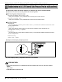
Establecimiento de la E.S.P (External Static Pressure, Presión estática externa)
Establecimiento de la E.S.P (External Static Pressure, Presión estática externa)
(1) Abra la tapa posterior del mando a distancia con cable para fijar el modo de funcionamiento.
(2) Seleccione uno de los tres modos posibles de la forma siguiente:
■
Sin Zone System (sistema de área)
1. Posición V-H (Variable - Alto), F-H (Fijo – Alto)
• Esta posición establece como predeterminada la máxima presión estática externa.
2. Posición V-L (Variable – Bajo)
• Esta posición establece como predeterminada la mínima presión estática externa.
■
Con Zone System
1. Posición V-H
• Micom establecerá la máxima presión estática externa y la velocidad del ventilador atendiendo al estado
de los amortiguadores.
2. Posición F-H
• Ni la máxima presión estática externa ni la velocidad del ventilador variarán atendiendo a los
amortiguadores de cierre y de apertura.
3. Posición V-L
• Micom establecerá la mínima presión estática externa y la velocidad del ventilador atendiendo al estado
de los amortiguadores.
* Máximo:3 mmAq
Mínimo:Todo – 0 mmAq
(3) Desplace el interruptor para fijar la posición.
(4) Cierre la tapa posterior y compruebe si funciona con normalidad.
PRECAUCIÓN
:
• Seleccione la posición tras la comprobación del funcionamiento del conducto y la presión estática
externa
de la unidad.
• Se ha fabricado en la posición F-H.
TH
R14H
SW TH
REMO
MAIN
2TH
OP7
R18H
R17H
OP6
LO
STAND
SW HIGH
HI
R03S
C070
R04S
R02S
R01S
OP3
OP2 OP1
R19H
R11H
R13H R12H
OP5R16H OP4
R15H
CO1H
V-L
V-H
F-H
Interruptor para la altura del techo

ESPAÑOL
Manual de instalación
19
Establecimiento de la E.S.P (External Static Pressure, Presión estática externa)?
Establecimiento de la E.S.P (External Static Pressure, Presión estática externa)?
Preheat
ZONE
Operation unit Program set
Room Temp
MED
LO
AUTO
JET
Heater
Defrost
Filter
Humidify
Out door
Timer
On
Set no. Time
Off
01 03 05 07 09 11 13 15 17 19 21 23
1234
OPERATION
FAN SPEED
SUB FUNCTION
SET TEMP
HI
AUTO SWING
Time
Preheat
ZONE
Operation unit Program set
Room Temp
MED
LO
AUTO
JET
Heater
Defrost
Filter
Humidify
Out door
Timer
On
Set no. Time
Off
01 03 05 07 09 11 13 15 17 19 21 23
1234
OPERATION
FAN SPEED
SUB FUNCTION
SET TEMP
HI
AUTO SWING
Time
Time
SUB FUNCTION
SET TEMP
OPERATIONAUTO SWING
Preheat
ZONE
Operation unit Program set
Room Temp
MED
LO
AUTO
JET
Heater
Defrost
Filter
Humidify
Out door
Timer
On
Set no. Time
Off
01 03 05 07 09 11 13 15 17 19 21 23
1234
FAN SPEED
HI
Time
SUB FUNCTION
SET TEMP
OPERATIONAUTO SWING
Preheat
ZONE
Operation unit Program set
Room Temp
MED
LO
AUTO
JET
Heater
Defrost
Filter
Humidify
Out door
Timer
On
Set no. Time
Off
01 03 05 07 09 11 13 15 17 19 21 23
134
FAN SPEED
HI
2
Timer
1
2
3
5
4
Timer
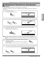
Cambio de RPM:
Ex) La presión estática externa es de 1mmAq para el modelo "9k".
• Al producir la unidad, el compresor se diseñó para estar apagado durante la configuración
de la E.S.P.
Pulse el botón “On/Off”.
La unidad comenzará a funcionar.
Pulse los botones “Timer” (Reloj) y “Wind” (Ventilación) a la vez durante más de 3 segundos.
Pulse el botón “Up” (más) o “Down” (menos) para ajustar la presión estática externa.
Establezca el número que desea.
(En este ejemplo, el número es “215”.)
Cambie el modo de velocidad del ventilador pulsando el botón de
velocidad del ventilador.
A continuación, establezca los números de los pasos siguientes
repitiendo la fase3.
(En este ejemplo, los números son “235” y “250” respectivamente)
Pulse los botones “Timer” (Reloj) y “Wind” (Ventilación) a la vez durante más de 3 segundos.
A continuación, Wind Data (Datos del ventilador) se memorizan en el PCB principal.
Nota: el intervalo de selección abarca de 1 a 254. Como el visor sólo muestra dos dígitos, si el
intervalo de selección es superior a 100, el tercer dígito aparecerá en la pantalla de la siguiente
forma.

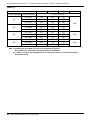
20 Aire acondicionado de Tipo Cassete
Establecimiento de la E.S.P (External Static Pressure, Presión estática externa)?
[Tabla. 1]
Nota: 1. Asegúrese de que establece los valores que aparecen en la tabla 1.
Si se establece un valor distinto, el funcionamiento será defectuoso.
2. La Tabla 1 se basa en 230 V. Dependiendo de la variación del voltaje, la proporción del flujo de
aire también variará.
La Presión constante(mmAq)
El Valor poniente
0 1 2 Capacitor.
El Nombre ejemplar
El paso (hola/Med/aquí)
7.5 CMM 175 160 150
9k 6.5 CMM 200 185 175
5.5 CMM 220 208 195
9 CMM 110 95 80
12k 8 CMM 145 135 120
7 CMM 175 160 150
13.5 CMM 113 103 100
18k 12 CMM 140 130 120
10 CMM 173 155 145
17.5 CMM 80 50 30
24k 16 CMM 145 130 120
14 CMM 170 160 150
2.0µF
2.5µF
3.5µF

P/No.: 3828A20403T
-
 1
1
-
 2
2
-
 3
3
-
 4
4
-
 5
5
-
 6
6
-
 7
7
-
 8
8
-
 9
9
-
 10
10
-
 11
11
-
 12
12
-
 13
13
-
 14
14
-
 15
15
-
 16
16
-
 17
17
-
 18
18
-
 19
19
-
 20
20
-
 21
21
-
 22
22
-
 23
23
-
 24
24
-
 25
25
-
 26
26
-
 27
27
-
 28
28
-
 29
29
-
 30
30
-
 31
31
-
 32
32
-
 33
33
-
 34
34
-
 35
35
-
 36
36
-
 37
37
-
 38
38
-
 39
39
-
 40
40
-
 41
41


LG LMNC126BTG0.AMWALMH Guía de instalación
- Tipo
- Guía de instalación
en otros idiomas
Artículos relacionados
-
LG AMNH186BHA0.ANWALAR Guía de instalación
-
LG AMNH126BTG0 Manual de usuario
-
LG MB09AHL Guía de instalación
-
-
-
LG A3UW36GFAB.AWGTLAR Manual de usuario
-
-
LG JRNU18GB2G3.APUNEB El manual del propietario
-
-
Otros documentos
-
Mitsubishi Electric PAC-MKA53BC Manual de usuario
-
Friedrich MD12Y3JM Instrucciones de operación
-
-
-
Mitsubishi Electric SEZ-KA60 Guía de instalación
-
-
Infiniton SSDC-4630 El manual del propietario
-
Infiniton CCFL-6321 El manual del propietario
-
Mitsubishi PAC-AK52BC Guía de instalación
-