Infiniton GG-320 El manual del propietario
- Categoría
- Encimeras
- Tipo
- El manual del propietario

1
Instruction Manual
Built-In Gas Hob
Please read this manual before the operation, and keep this manual for future use.
ENGLISH
GG-319
GG-320

2
Contents
1. Close-up View......................................................................................03
2. How to Use Your Gas hob.................................................................09
3. How to Keep Your Gas hob in Shape...............................................10
4. Practical Advice..................................................................................11
5. Is there a problem?............................................................................11
6. Installation Instructions for built-in..................................................12
7. Table1 Burners and Nozzle Specifications .....................................17
8. Table2 How to convert gas source...................................................18
9. Table3 Adapting to different types of gas .......................................19
10. Table4 Gas source and national comparison table.......................20
11. NOTICE ..........................................................................................21

3
Congratulations on choosing this appliance, which you will find is dependable and easy to use. We advise
you to read this manual for best performance and to extend the lifespan of your appliance. Thank you.
Close-up View
1. Auxiliary Burners
2. Semi-rapid burner
3. Rapid burner
4. Triple ring wok burner
5. Ignitor for Gas Burners (only on certain models)
6. Safety Device (only on certain models) - Activates if the flame accidentally goes out (spills, drafts, etc.),
interrupting the delivery of gas to the burner.
7. Control Knobs for Gas Burners and Electric Hot Plates
How to Use Your Gas hob
The position of the corresponding gas burner is indicated on each control knob.
Gas Burners
The burners are different in size and power. Choose the most appropriate one for the diameter of the
cookware being used.
The burner can be regulated with the corresponding control knob by using one of the following settings:
OFF
High
Low

4
On those models fitted with a safety device
The knob must be pressed for about 6 seconds until the flame is lighted and warmed up.
On those models fitted with an igniter
The electric ignition button, identified by the symbol, must be pressed first, then the corresponding knob
is pushed and turned in the counter-clockwise direction to the "High” setting.
To light a burner: Simply press the corresponding knob and turn it in the counter-clockwise direction to
the High setting, keep press until the burner is lighted.
Caution: If the flame goes out accidentally, turn off the gas with the control knob and try to light it again at
least 1 minute later.
To turn off a burner: Turn the knob in the clockwise direction until it is stopped (it should be on the "·"
setting).
How to Keep Your Gas hob in Shape
Before cleaning or performing maintenance on your gas hob, disconnect it from the electrical power supply
(included battery power).
To extend the lifespan of the gas hob, it is absolutely indispensable that it is cleaned carefully, thoroughly
and usually, please keep in mind to the following:
The enameled parts and the glass top, must be washed with warm water without using abrasive
powders or corrosive substances which could ruin them;
The removable parts of the burners should be washed usually with warm water and soap, make sure to
remove caked-on substances;
Automatic igniter pin, the end must be cleaned carefully and usually, make sure ignition keep working
normally.
Stainless steel top plate and other steel parts can be stained if keep touch with high concentration
calcareous water or corrosive detergents (containing phosphorus). To extend the lifespan, we advise
these parts be rinsed thoroughly with water and dry them by blowing, It is a good idea to clean up any
spills too.
After glass hob working, the surface must be cleaned by a damp cloth to remove dust or food residues.
Glass surface should be cleaned regularly with warm water and non-corrosive detergent.
First, to remove all food residues or greases with a cleaning scraper, e.g.
Cleaning scraper (not supplied) (Fig. 1).
While the cooking surface is warm, clean it with a suitable cleaning product and paper towels, then rub
with a damp cloth and dry surface. Such as aluminum foil, plastic items, objects made of synthetic
material, sugar or foods with a high sugar content that have been melted onto the surface, it must be
removed immediately.
While the cooking surface is still hot, clean it with a scraper and a transparent protective film which
prevent to make more dirt. This also protect the surface from damage caused by food with a high sugar
content.

5
Do not use abrasive sponges or cleaning products, these holds true for chemically aggressive cleaners,
like oven sprays and stain removers (Fig.2);
Fig.1 Fig.2
Cleaning the grill/pan support, it is recommended to clean it while it is still hot. To move grill away from
the hob and put it in sink, remove the food residues or grease first, after grill has cooled, rinse it with
water.
Greasing the Gas Valves
Over time, the gas valves may be sticked, and it is difficult to turn on/off. For this case, should clean the
inside of valve and greased it.
Kind reminder: This procedure must be performed by a technician authorized by the
manufacturer.
Practical Advice
Practical Advice on Using the Burners
For best performance, follow these general guidelines:
Use the appropriate cookware for each burner (see table) in order to prevent the flame to reach the
side of the pot or pan;
Always use cookware with a flat bottom and keep the lid on;
When the contents come to a boil, turn the knob to "Low".
Burner
Ø Cookware diameter (cm)
Auxiliary burner
10~14
Semi-rapid burner
16~20
Rapid burner
22~24
Triple ring wok burner
24~26
To identify the type of burner, refer to the designs in the section entitled, "Burner and Nozzle Specifications".
Is there a Problem?
If you find the gas hob cannot work suddenly or cannot work properly. Before calling customer service for
assistance, let us check what we can do.
First of all, check and confirm there have no interruptions to the gas and electrical supplies, particularly, if
the gas valves keeping turn on.

6
The burner cannot be lighted or the flame is not uniform around the burner.
Check to make sure that:
The gas holes on the burner are not clogged;
All of the movable parts of burners are fixed correctly;
There is no air flow around the cooking surface.
The flame does not keep lighting to the burner with thermocouple.
Check to make sure that:
You press the knob all the way;
You keep pressing the knob for enough time to activate the thermocouple.
The gas holes are not clogged in the area corresponding to the thermocouple.
The flame goes out while turning knob to "Low" setting.
Check to make sure that:
The gas holes are not clogged.
There is no air flow around the cooking surface.
The minimum has been adjusted correctly (see the section entitled "Minimum Regulation").
The cookware is not stable.
Check to make sure that:
The bottom of the cookware is perfectly flat.
The cookware is centered correctly on the burner.
The support grids have not been inverted.
After checked all of these, the gas hob still does not work properly, please call the Customer Service Center
and inform them of:
--Tile type of problem.
--The gas hob model number (Model....) as indicated on the packing carton.
Never call the technicians who is not authorized by your supplier, and refuse to use the spare parts which
are not from manufacturer.
Installation Instructions for built-in
The following instructions are directed at the qualified installer, so the installation and maintenance
procedures may be followed in the most professional and expert manner.
Important: Unplug the electrical connection before performing any maintenance or regular upkeep
work.
Positioning for gas hob
Important: this unit may be installed and used only in permanently ventilated rooms.
The following requirements must be observed:
a) The room must be fitted with a ventilation system which ventilates smoke and gases from combustion to
the outside of rooms.
This must be done by hood or electric ventilator.

7
In a chimney stack or branched flue. Directly to the Outside
(exclusively for cooking appliances)
b) The room must be allowed for the influx of the air which is for proper combustion. The air flow for
combustion purposes must not less than 2 m³/h per kW of installed capacity. The air supply will be
effected by influx from the outside through a duct, its inner cross section is at least 100cm² and must not
be blocked accidentally.
The gas hob without safety devices, to prevent flame go out accidentally, must have a ventilation
working on twice volume. For example, a minimum of 200 cm² (Fig. 3). Otherwise, the room can be
vented indirectly through adjacent rooms which is fitted with ventilation ducts to the outside. Although
the adjacent rooms are not shared areas, bedrooms, but fire risk is hidden (Fig. 4).
Adjacent Room Room to be Vented
Examples of ventilation holes for comburent air. Enlarging the ventilation slot between window and floor
Fig.3 Fig.4
c) Intensive and prolonged working of the gas hob that needs to intensify ventilation, e.g. opening
windows or increasing the power of the air intake system (if present).
d) Liquefied petroleum gases are heavier than air, so settle it downward. Rooms in which LPG tanks are
installed must be fitted with ventilation to the outside to avoid of gas leakage.
Therefore, LPG tanks which are empty or partially full, must not be installed or stored in rooms or spaces
below ground level (cellars etc.). It is a good idea to keep only the tank which is working currently in the
room, and make sure that it is not closed to heating source (ovens, fireplaces, stoves, etc.).
Installation of built-in gas hob
The gas hobs are designed with protection degree against excessive heating, the appliance can be
installed next to cabinets, and the height should not exceed the hob.
For a correct installation, the following precautions must be followed:
a) The hob may be located in a kitchen, a diner or bed/ sitting room, but not in a bathroom or shower room.
b) The furniture standing near to the unit, it is higher than the working boards, it must be placed at least
110mm distance to the edge of the board.
c) The cabinets should be positioned near to the hood at a height of 420 mm at least (Fig. 5).

8
Fig.5
d) Hob should be installed directly under a cupboard, the latter should be at least 700mm from the worktop,
as shown in Fig. C.
e) Fixing fittings (hooks, screws) are provided to place the hob on work top, measure 20 to 40 mm in
thickness (see Fig. 6).
Fig.6
Hook position for Hook position for Hook position for
H=20mm top H=30mm top H=40mm top
N.B: Use the hooks contained in the "accessories bag"

9
f) In the event the gas hob is not installed on a built-in oven, a wooden panel must be inserted for insulation.
This panel must be placed at least 20 mm distance from the bottom of hob.
lmportant: When installing the hob on a built-in oven, the oven should be placed on two wooden strips; in
the case of a joining cabinet surface, remember to leave a space of 45 x 560 mm at least from the back
side..
When install hob on a built-in oven without forced ventilation, ensure that have air inlets and outlets to
ventilate the interior of the cabinet adequately.
Gas connection for gas hob
The gas hob should be connected to the gas-supply by a registered installer. During installation it is
essential to fit an approved gas tap to isolate the supply from the hob for the convenience of any
subsequent removal or servicing. Connect the hob to the gas mains or liquid gas, it must be carried out
according to the prescribed regulation in force, and only after it is ascertained that it is adaptable to the type
of gas to be used. If not, follow the instructions indicated in the paragraph headed "Adaptation to different
gas types". In the case of connection to liquid gas by tank, use pressure regulators that conform to the
regulation in force.
Important: For safety, for the correct regulation of gas use and long life of the hob, ensure that the gas
pressure conforms to the indications given in table 1 "Burners and Nozzle Specifications".
Connection to non-flexible tube
(copper or steel)
Connection to the gas source must be done in such a way as to not create any stress points at any part of
the gas hob.
The hob is fitted with an adjustable "L" shape connector and a gasket to the gas supply.
The connector should be dismounted and the gasket must be replaced.
The feeding connector of the gas to the hob is threaded 1/2 gas cylinder.
Connection to flexible steel tube
The gas feed connector to the hob is threaded, 1/2" connector for round gas pipe. Only use pipes and
sealing gaskets that conform to the standards currently in force. The maximum length of the flexible pipes
must not exceed 2000 mm. Once the connection has been made, ensure that the flexible metal tube does
not touch any moving parts and not be crushed.

10
Check the Seal
Once the hob was installed, make sure all the connections are properly sealed, use a soapy water to test,
never use flame.
Electrical Connection
The hob fitted with a tripolar electrical supply cord which are designed to be used alternating
current .According to the indications on the rating plate located under the hob. The earthing wire can be
identified by its yellow-green colour.
In the case of installation over a built-in electric oven, the electrical connections for the hob and oven should
be independent, not only for safe purpose, but also be convenient to remove them in the future.
Electrical Connection for Gas hob
Fit the supply cord with a standard plug for the demand rate indicated on the rating plate or connect it
directly to the electrical mains. In the latter case, a single pole switch must be placed between the hob and
the mains, with a minimum opening between the contacts of 3 mm in compliance with current safety codes
(the earthing wire must not be interrupted by the switch). The power supply cord must be positioned so that
it does not reach a temperature in excess of 50℃ than room temperature at any point.
Before actual connection make sure that:
The fuse and electrical system can withstand the load required by the hob;
The electrical supply system is equipped with an efficient earth hook-up according to the norms and
regulations prescribed by law;
The plug or switch are easily accessible.
Important: the wires in the main lead are coloured in accordance with the following code:
Green & Yellow - Earth
Blue - Neutral
Brown - Live
As the colours of the wires in the main lead may not correspond with the coloured markings identifying the
terminals in your plug, proceed as follows: Connect the Green & Yellow wire to terminal marked "E" or
or coloured Green or Green & Yellow.
Connect the Brown wire to the terminal marked "L" or coloured Red.
Connect the Blue wire to the terminal marked "N" or coloured Black.

11
Table1: Burners and Nozzle Specifications
Adapting the Gas hob for Different Types of Gas
At 15°C and 1013 mbar - dry gas
P.C.I.G20 37.78 MJ/m³ P.C.I.G25.1 32.51 MJ/m³
P.C.I.G25 32.49 MJ/m³ P.C.I.G27 30.98 MJ/m³
P.C.I.G2.350 27.20MJ/ m³ P.C.I.G30 49.47MJ/Kg
Replacement of burner nozzle: loosen the nozzle with a dedicated wrench(7).Fit
the new nozzle according to the required gas type (see table 1 for reference)。
After you have converted the gas hob to another gas type, make sure you have placed a label
containing that information on the appliance.
G20
G30
Burner
Thermal
power (kW)
Nozzle 1/100
(mm)
Thermal power (kW)
Nozzle 1/100 (mm)
Auxiliary (Small) (A)
1.0
71
1.0
52
Semi rapid (Medium)
1.80
97
1.8
67
Rapid (R)
2.40
110
2.40
77
Triple Ring (TR)
3.40
125
3.40
93
Supply pressures
20mbar
30mbar

12
TABLE2: How to Convert Gas Source
Adjustment of the reduced valve flow
Burners
Flame
Converting the
hob from LPG
to natural gas
Converting the
hob from natural gas
Gas to LPG
Regular burners
Full flame
Replace the burner
Nozzle according
To the guidelines in
table 1
Replace the burner
Nozzle according
to the guidelines in
table 1
Saving flame
Loosen the adjustment
Spindle (see fig.7 below )
And adjust the flame
Loosen the adjustment
Spindle (see fig.7 below )
And adjust the flame
Valve adjustment
Valve adjustment should be done with the control knob set at Burner ON saving flame position.
Remove the knob, and adjust the flame with a tiny screwdriver (see fig.7 below).
Fig.7
To check the adjusted flame: heat the burner at full open position for 10 minutes. Then turn the knob into the
saving setting. The flame should not extinguish nor move to the nozzle. If it extinguish or moves to the
nozzle, readjust the valves.
Flame selection
As the burners are adjusted correctly, the flame should be light blue, and the inner flame should be clear.
The size of flame depends on the position of the related control knob.
-Burner ON, large flame -Burner ON, small flame(saving mode)-Burner OFF
Fig.8
See fig.8 for various operating options (flame size selection); the burner should be set at a large flame
during the initial phase of cooking, it make food boil quickly. Then should turn knob to the saving flame

13
position to maintain the cooking. It is possible to adjust the flame size stepless.
It is prohibited to adjust the flame between the Burner OFF and Burner ON large flame positions.
High quantity of energy can be conserved if the hob is used correctly, parameters are designed correctly,
and appropriate cookware is used. The energy conservation be as follows:
· Up to 60% are conserved when proper pots are used,
· Up to 60% are conserved when the unit is operated correctly and the suitable flame size is chosen.
It is a prerequisite for efficient and energy-saving operation of hob that the burners are kept clean at all
times (in particular the flame slots and nozzles). Adapting to different types of gas
TABLE 3: Adapting to different types of gas
APPLIANCE CATEGORY: I2H I2E I2E+ I2L I2HS I2ELS I2ELW I3+ I3B/P I3B/P I3B/P I3P I2H3+ II2E3B/P II2HS3B/P
II2ELWLS3B/P II2ELL3B/P
Burner
Type of
Gas
Pressure
Nozzle
diameter
Nominal Charge
Reduced Charge
mbar
1/100mm
g/h
l/h
kW
kcal/h
kW
kcal/h
Auxiliary
Natural
G20
20
71
—
95
1.0
860
0.40
344
Butane
G30
30
52
72.6
—
1.0
860
0.40
344
37
47
72.6
—
1.0
860
0.40
344
50
45
72.6
—
1.0
860
0.40
344
Semi-rapid
Natural
G20
20
97
—
171
1.8
1548
0.60
516
Butane
G30
30
67
130.8
—
1.8
1548
0.60
516
37
64
130.8
—
1.8
1548
0.60
516
50
59
130.8
—
1.8
1548
0.60
516
Rapid
Natural
G20
20
110
—
228
2.4
2064
0.90
774
Butane
G30
30
77
174
—
2.4
2064
0.90
774
37
73
174
—
2.4
2064
0.90
774
50
67
174
—
2.4
2064
0.90
774
Triple-ring wok
Natural
G20
20
125
—
323
3.4
2924
1.50
1290
Butane
G30
30
93
247
—
3.4
2924
1.50
1290
37
88
247
—
3.4
2924
1.50
1290
50
82
247
—
3.4
2924
1.50
1290

14
TABLE 4: Gas source and national comparison table
Gas group
Supply pressure
Country
I2H
G20 20mbar
AT, BG, CZ, DK, EE, FI, GR, HR, HU, IS, IE, IT, LV,
LT, NO, PT, RO, SK, SI, ES, SE, CH, TR, GB
I2E
G20 20mbar
DE, LU
I2E+
G20/G25 at 20/25 mbar
BE, FR
I2L
G25 25mbar
NL
I2HS
G20/G25.1 25 mbar
HU
I2ELS
G20 20 mbar,G2.350 13 mbar
PL
I2ELW
G20/G27 20 mbar
PL
I3+
G30-G31 (28-30)-37 mbar
BE, CY, CZ, EE, FR, GR, IE, IT, LT, LU, LV, PT, RO,
SK, ES, CH, GB
I3B/P
G30 30 mbar
BE, CY, CZ, DK, EE, FI, GR, HR, LV, LT, LU, MT,
NL, NO, SK, SI, SE, TR
I3B/P
G30 37 mbar
PL
I3B/P
G30 50mbar
AT, DE, HU, CH
I3P
G31 37 mbar
CH,FR,GR,IE,ES,GB
I2H3+
G20 20MBAR,
G30-G31(28-30)-37mbar
GR,IE,IT,PT,ES,GB,CH,CZ,SI,SK
II2E3B/P
G20 20mbar,g30 30mbar
RO
II2HS3B/P
G20/G25.1 25mbar,
G30 30mbar
HU
II2ELWLS3B/P
G20/G27 20mbar,
G2.350 13mbar,G30 37mbar
PL
II2ELL3B/P
G20 20mbar,G25 25mbar,
G30 50mbar
DE
This hob conforms to the following European Economic Community directives:
-73/23/EEC of 19/02/73 (Low Voltage) and subsequent modification;
-89/336/EEC of 03/05/89 (Electromagnetic compatibility) and subsequent modifications;
-90/396/EEC of 29/06/90 (Gas)and subsequent modifications;
-93/68/EEC of 22/07/93 and subsequent modifications.

15
NOTICE:
A. Prior to installation, ensure that the local distribution condition (nature of the gas pressure) and the
adjustment of the appliance are compatible.”
B. “The adjustment conditions for this appliance are stated on the rating label.”
C. “This gas hob is not connected to combustion products evacuation device. It shall be installed and
connected in accordance with current installation regulations. Particular attention shall be given to the
relevant requirement regarding ventilation.”
D. “CAUTION: The use of a gas hob lead to the production of heat, moisture and products of combustion in
the room in which it is installed. Ensure that the kitchen is well ventilated especially when the hob is in
working: keep natural ventilation holes open or install a mechanical ventilation device.”

• This appliance can be used by children aged from 8 years and
above and persons with reduced physical, sensory or mental
capabilities or lack of experience and knowledge if they have been
given supervision or instruction concerning use of the appliance in a
safe way and understand the hazards involved.
• Children shall not play with the appliance. Cleaning and user
maintenance shall not be made by children without supervision.
• If the supply cord is damaged, it must be replaced by the
manufacturer, its service agent or similarly qualified persons in order
to avoid a hazard.
• Warning: If the surface is cracked, switch off the appliance to
avoid the possibility of electric shock.
• Metallic objects such as knives, forks, spoons and lids should not
be placed on the surface since they can get hot
• A steam cleaner is not to be used.
• Do not use a steam cleaner to clean your cooktop.
• The appliance is not intended to be operated by means of an
external timer or separate remote-control system.
• WARNING: Danger of fire: do not store items on the cooking
surfaces.
• The cooking process has to be supervised. A short term cooking
process has to be supervised continuously.
• WARNING: Unattended cooking with fat or oil can be
dangerous and may result in fire. NEVER try to extinguish a fire with
water, but switch off the appliance and then cover flame e.g. with a lid
or a fire blanket.

1
MANUAL DE INSTRUCCIONES
PLACA DE GAS
GG-319
GG-320
ESPAÑOL

2
ESTIMADO CLIENTE
Con el fin de que obtenga el mayor desempeño de su producto, por favor lea este manual de
instrucciones cuidadosamente antes de comenzar a utilizarlo, y guárdelo para su futura referencia.

3
ÍNDICE
DESCRIPCIÓN DE LA UNIDAD ............................................................................................................... 4
USO DE LA UNIDAD ................................................................................................................................ 5
QUEMADOR DE GAS ........................................................................................................................... 5
RECOMENDACIONES .......................................................................................................................... 5
CUIDADO DE LA UNIDAD ........................................................................................................................ 6
INSTRUCCIONES DE INSTALACIÓN ...................................................................................................... 8
UBICACIÓN DE LA UNIDAD ................................................................................................................. 8
INSTALACIÓN DE LA UNIDAD EMPOTRABLE ................................................................................... 9
CONEXIÓN DE GAS PARA LA UNIDAD ............................................................................................ 11
CONEXIÓN AL TUBO NO FLEXIBLE ................................................................................................. 11
CONEXIÓN AL TUBO DE ACERO FLEXIBLE .................................................................................... 12
CONEXIÓN ELÉCTRICA .................................................................................................................... 12
CONEXIÓN ELÉCTRICA PARA ENCIMERA DE GAS ....................................................................... 12
ADAPTAR LA UNIDAD A LOS DIFERENTES TIPOS DE GAS .............................................................. 13
CONVERTIR LA FUENTE DE GAS .................................................................................................... 14
SELECCIÓN DE LA LLAMA ................................................................................................................ 15
ADAPTAR A LOS DIFERENTES TIPOS DE GAS .............................................................................. 16
FUENTE DE GAS Y TABLA DE COMPARACIÓN NACIONAL ........................................................... 17

4
DESCRIPCIÓN DE LA UNIDAD
1. Quemadores auxiliares.
2. Quemador semi rápido.
3. Quemador rápido.
4. Quemador para wok de tres anillos.
5. Ignición para quemadores de gas (Solo para algunos modelos).
6. Dispositivo de seguridad (Solo para algunos modelos), se activa cuando la llama se apaga
accidentalmente e interrumpe el paso de gas al quemador.
7. Perillas de control de la unidad.
Nota:
La bandeja para grasa en acero inoxidable y la rejilla de hierro fundido ubicada en el quemador y caja
de empaque de la parrilla, deben ser instaladas respectivamente arriba y abajo del elemento calefactor
eléctrico, de tal manera que la resistencia queda en la mitad de las dos. (Solo para algunos modelos)

5
USO DE LA UNIDAD
La posición del quemador de gas o el quemador eléctrico (Solo para algunos modelos) es indicado en
cada perilla de control.
QUEMADOR DE GAS
Estos quemadores difieren en tamaño y potencia. Elija el más adecuado para el utensilio que desea
utilizar con esta unidad.
El quemador puede ser regulado con la perilla de control correspondiente usando uno de los siguientes
ajustes:
3
Congratulations on choosing appliance, which you will find is dependable and easy to use. We recommend
that you read this manual for best performance and to extend the life of your appliance. Thank you.
Close-up View
1. Auxiliary Burners
2. Semi-rapid burner
3. Rapid burner
4. Triple ring wok burner
5. Ignitor for Gas Burners (only on certain models)
6. Safety Device (only on certain models) - Activates if the flame accidentally goes out (spills, drafts,
etc.),interrupting the delivery of gas to the burner.
7. Control Knobs for Gas Burners and Electric Hot Plates
NOTICE
The stainless steel grease pan and the cast-iron grill, located in the burner and grate packing box, must be
installed, respectively, below and above the electric heating element so that tile element is enclosed
between the two.
How To Use Your Appliance
The position of the corresponding gas burner or electric hot plate (if present) is indicated on each control
knob.
Gas Burners
The burners differ in size and power. Choose the most appropriate one for the diameter of the cookware
being used.
The burner can be regulated with the corresponding control knob by using one of tile following settings:
OFF
High
Low
To turn on one of the burners, place a lighted match or lighter near the burner,press the knob all the
way in and turn in the counter-clockwise direction to the "High" setting.
On those models fitted with a safety device (6), the knob must be pressed in for about 6
Para encender uno de los quemadores, coloque un encendedor o fosforo cerca del quemador, presione
la perilla de control y gírela a la posición de “Alto”.
Para los modelos que tienen dispositivo de seguridad (6), la perilla debe ser presionada por cerca de 6
segundos hasta que el dispositivo que mantiene la llama encendida se caliente.
Para los modelos que cuentan con un encendedor incorporado (5), este será identificado con el símbolo
“
4
seconds ,untilthedevicethatkeeps theflamelightedw arms up.
On those models fitted with an ignitor (5),the"5"ignitionbutton,identifiedbythe symbol,must
firstbepressedandthenthecorrespondingknobpushedallthew ayinandturnedinthecounter-clockw ise
directiontothe"H igh"setting.
Somemodels areequippedw ithanignition sw itchincorporatedintothecontrolknob.Ifthis is thecase,the
ignitor(5)is present,butnotthe"7"sw itch(the symbolis locatedneareachknob).
To light a burner,simply press the corresponding knob all the w ay in and,then,turn it in the
counter-clockw isedirectiontotheH ighsetting,keepingitpressedinuntiltheburnerlights.
Caution: Iftheburneraccidentlygoes out,turn offthegas w iththecontrolknobandtrytolightitagain
afterw aitingatleast1minute.
To turn off a burner,turntheknobintheclockw isedirectionuntilitstops (itshouldbeonthe"."setting).
How to Keep Your Cooktop in Shape
Beforecleaningorperformingmaintenanceon yourappliance,disconnectitfrom theelectricalpow er
supply.
To extend the life of the cooktop, it is absolutely indispensable that it be cleaned
carefully and thoroughly on a frequent basis, keeping in mind the following:
●Theenameledparts andtheglass top,ifpresent,mustbew ashedw ithw arm w aterw ithoutusing
abrasivepow ders orcorrosivesubstances w hichcouldruinthem;
●Theremovableparts oftheburners shouldbew ashedfrequentlyw ithw arm w aterandsoap,making
suretoremovecaked-on substances;
●On cooktops w ithautomaticignition,theendoftheelectronicignition devicemustbecleanedcarefully
andfrequently,makingsurethatthegas holes arenotclogged;
●Stainless steelcan bestained ifitremains in contactw ithhighlycalcareous w ateroraggressive
detergents (containingphosphorous)foran extendedperiodoftime,itis recommendedthattheseparts
berinsedthoroughlyw ithw aterandthen driedw ell,Itis alsoagoodideatoclean upanyspills;
●Beforeusingtheceramicglass module,thesurfacemustbecleaned,usingadampclothtoremovedust
orfoodresidues.Theceramicglass surfaceshouldbecleanedregularlyw ithasolutionofw arm w aterand
anon-abrasivedetergent,periodically,specialproducts w illneedtobeusedtoclean thesurface.First,
removeallfoodbuilduporgreasew ithacleaningscraper,e.g.
CERA (notsupplied)(Fig.1).
Clean thecookingsurfacew hen itis stillw arm w ithasuitablecleaningproductandpapertow els.Then
rubw ithadampclothanddry.Aluminum foil,plasticitems,objects madeofsyntheticmaterial,sugaror
foods w ithahighsugarcontentthathavemeltedontothesurfacemustberemovedimmediately w itha
scraperw hilethecookingsurfaceis stillhot.Specialcleaningproducts forceramicglass surfaces form a
transparentprotectivelayerw hichfights dirtybuildup.This alsoprotects thesurfacefrom damagecaused
byfood w ithahighsugarcontent.Do notuseabrasivesponges orcleaningproducts underany
circumstances.This holds trueforchemicallyaggressivecleaners,likeoven sprays andstain removers
(Fig.2);
”. Para hacer uso de este encendedor, presione el botón del encendedor y luego presione la perilla
del quemador que desea utilizar y gírela hacia la posición de “Alto”.
Algunos modelos cuentan con el dispositivo encendedor incorporado en cada perilla de control. Si este
es el caso, el encendedor estará presente (5) mas no el interruptor (7) (El símbolo
4
seconds ,untilthedevicethatkeeps theflamelightedw arms up.
On those models fitted with an ignitor (5),the"5"ignitionbutton,identifiedbythe symbol,must
firstbepressedandthenthecorrespondingknobpushedallthew ayinandturnedinthecounter-clockw ise
directiontothe"H igh"setting.
Somemodels areequippedw ithanignition sw itchincorporatedintothecontrolknob.Ifthis is thecase,the
ignitor(5)is present,butnotthe"7"sw itch(the symbolis locatedneareachknob).
To light a burner,simply press the corresponding knob all the w ay in and,then,turn it in the
counter-clockw isedirectiontotheH ighsetting,keepingitpressedinuntiltheburnerlights.
Caution: Iftheburneraccidentlygoes out,turn offthegas w iththecontrolknobandtrytolightitagain
afterw aitingatleast1minute.
To turn off a burner,turntheknobintheclockw isedirectionuntilitstops (itshouldbeonthe"."setting).
How to Keep Your Cooktop in Shape
Beforecleaningorperformingmaintenanceon yourappliance,disconnectitfrom theelectricalpow er
supply.
To extend the life of the cooktop, it is absolutely indispensable that it be cleaned
carefully and thoroughly on a frequent basis, keeping in mind the following:
●Theenameledparts andtheglass top,ifpresent,mustbew ashedw ithw arm w aterw ithoutusing
abrasivepow ders orcorrosivesubstances w hichcouldruinthem;
●Theremovableparts oftheburners shouldbew ashedfrequentlyw ithw arm w aterandsoap,making
suretoremovecaked-on substances;
●On cooktops w ithautomaticignition,theendoftheelectronicignition devicemustbecleanedcarefully
andfrequently,makingsurethatthegas holes arenotclogged;
●Stainless steelcan bestained ifitremains in contactw ithhighlycalcareous w ateroraggressive
detergents (containingphosphorous)foran extendedperiodoftime,itis recommendedthattheseparts
berinsedthoroughlyw ithw aterandthendriedw ell,Itis alsoagoodideatoclean upanyspills;
●Beforeusingtheceramicglass module,thesurfacemustbecleaned,usingadampclothtoremovedust
orfoodresidues.Theceramicglass surfaceshouldbecleanedregularlyw ithasolutionofw arm w aterand
anon-abrasivedetergent,periodically,specialproducts w illneedtobeusedtoclean thesurface.First,
removeallfoodbuilduporgreasew ithacleaningscraper,e.g.
CERA (notsupplied)(Fig.1).
Clean thecookingsurfacew hen itis stillw arm w ithasuitablecleaningproductandpapertow els.Then
rubw ithadampclothanddry.Aluminum foil,plasticitems,objects madeofsyntheticmaterial,sugaror
foods w ithahighsugarcontentthathavemeltedontothesurfacemustberemovedimmediately w itha
scraperw hilethecookingsurfaceis stillhot.Specialcleaningproducts forceramicglass surfaces form a
transparentprotectivelayerw hichfights dirtybuildup.This alsoprotects thesurfacefrom damagecaused
byfood w ithahighsugarcontent.Do notuseabrasivesponges orcleaningproducts underany
circumstances.This holds trueforchemicallyaggressivecleaners,likeoven sprays andstain removers
(Fig.2);
está ubicado cerca
de cada perilla).
Advertencia!
Si el quemador se apaga accidentalmente, gire la perilla de control a la posición de apagado e intente
encender el quemador nuevamente después de 1 minuto.
Por seguridad se recomienda que cierre el suministro de gas en caso de no usar la unidad.
Para apagar el quemador, simplemente gire la perilla a la posición de apagado.
RECOMENDACIONES
Uso de los quemadores
Para un mejor rendimiento de la unidad, siga los pasos dados a continuación:
Use el utensilio adecuado para cada quemador, esto con el fin de evitar que la llama alcance las
partes laterales de la olla o sartén. (Mire la tabla a continuación para fácil referencia).
Use siempre utensilios con la parte inferior plana y mantenga la tapa puesta en todo momento.
Cuando la preparación empiece a hervir, gire la perilla a la posición “Bajo”.
Quemador
Diámetro del utensilio (cm)
Quemador auxiliar
10-14
Quemador semi rápido
16-20
Quemador rápido
22-24
Quemador para Wok de anillo triple
24-26
Para identificar el tipo de quemador, refiérase a la sección “Descripción de la unidad”
Apagado
Alto
Bajo

6
Uso del quemador giratorio “Half Fish-Kettle Burner”
Los dos quemadores centrales tienen una forma elíptica y pueden ser girados hasta 90 grados. Esto
permite que la unidad sea más flexible ya que permite usarla de diferentes maneras.
Para girar los quemadores, proceda de la siguiente manera:
Asegúrese que estos se encuentran completamente fríos.
Levante el quemador por completo de su cubierta
Reemplácelo en su cubierta en la posición deseada.
Asegúrese que los quemadores se encuentran correctamente colocados antes de usarlos.
Adicionalmente, los dos quemadores pueden ser usados juntos o separadamente con ollas de
diferentes tamaños.
Para mejor rendimiento de la unidad, siga las recomendaciones dadas a continuación:
Todos los tipos de cacerolas pueden ser usadas en la superficie vitrocerámica. Sin embargo, se
recomienda el uso de cacerolas cuya parte inferior sea completamente plana. Cacerolas con una
parte inferior más gruesa distribuirán el calor de manera mas uniforme.
6
●Alltypes ofcasseroles canbeusedontheceramicglass cookingsurface.H ow ever,itis importantthat
thebottom beperfectlyflat.Casseroles w iththickerbottoms distributeheatmoreevenly.
Usecookw arethediameterofw hichis atleastas largeas thecookingareasothatalloftheheatproduced
bytheheatinqelementis used.
●Makesurethatthebottom oftilepotis alw ays dryandclean to insuregoodcontactbetw een the
cookw areandthecookingsurface.This w illalsoincreasethelifeofthepots andoftheceramicglass
surfaceas w ell.
●Do notusethesamecookw arethatyouuseforgas burners becausetheconcentratedheatthey
producecandeform thebottom ofthepot.Therefore,youw illnotachievebestresults w henusingthese
pots ontheceramicglass surface.
Notice: Theglueusedtosealtheglass surfacemayleavetraces ontheappliance.W erecommendthatthe
modulebecleanedw ithanon-abrasivecleanerbeforebeingused
thefirsttime.Duringthefirstfew hours ofuse,youmaydetectthesmellofrubber;this w illdisappearaftera
shorttime.
Is there a problem?
Itmayoccurthatthecooktop does notfunction ordoes notfunction properly.Beforecallingcustomer
serviceforassistance,lets seew hatcanbedone.
Firstofall,checktoseethattherearenointerruptions in thegas andelectricalsupplies,and,inparticular,
thatthegas valves forthemains areopen.
The burner does not light or the flame is not uniform around the burner.
Check to make sure that:
●Thegas holes ontheburnerarenotclogged;
●Allofthemovableparts thatmakeuptheburneraremountedcorrectly;
●Therearenodraughts aroundthecookingsurface.
The flame does not stay lighted on the model with the safety device.
Check to make sure that:
●Youpress theknoballthew ayin;
●Youkeeptheknobpressedinlongenoughtoactivatethesafetydevice.
●Thegas holes arenotcloggedintheareacorrespondingtothesafetydevice.
The burner does not remain on when set to "Low".
Check to make sure that:
●Thegas holes arenotclogged.
●Therearenodraughts neartirecookingsurface.
Use utensilios cuyo diámetro sea al menos tan amplio como el área de cocción, de tal manera que todo
el calor producido por la unidad será utilizado. Esto no solo ayudara a ahorrar dinero, sino además
permitirá que los alimentos sean cocidos de manera mas uniforme.
6
●Alltypes ofcasseroles canbeusedontheceramicglass cookingsurface.H ow ever,itis importantthat
thebottom beperfectlyflat.Casseroles w iththickerbottoms distributeheatmoreevenly.
Usecookw arethediameterofw hichis atleastas largeas thecookingareasothatalloftheheatproduced
bytheheatinqelementis used.
●Makesurethatthebottom oftilepotis alw ays dryandclean to insuregoodcontactbetw een the
cookw areandthecookingsurface.This w illalsoincreasethelifeofthepots andoftheceramicglass
surfaceas w ell.
●Donotusethesamecookw arethatyouuseforgas burners becausetheconcentratedheatthey
producecandeform thebottom ofthepot.Therefore,youw illnotachievebestresults w henusingthese
pots ontheceramicglass surface.
Notice: Theglueusedtosealtheglass surfacemayleavetraces ontheappliance.W erecommendthatthe
modulebecleanedw ithanon-abrasivecleanerbeforebeingused
thefirsttime.Duringthefirstfew hours ofuse,youmaydetectthesmellofrubber;this w illdisappearaftera
shorttime.
Is there a problem?
Itmayoccurthatthecooktopdoes notfunction ordoes notfunction properly.Beforecallingcustomer
serviceforassistance,lets seew hatcanbedone.
Firstofall,checktoseethattherearenointerruptions inthegas andelectricalsupplies,and,inparticular,
thatthegas valves forthemains areopen.
The burner does not light or the flame is not uniform around the burner.
Check to make sure that:
●Thegas holes ontheburnerarenotclogged;
●Allofthemovableparts thatmakeuptheburneraremountedcorrectly;
●Therearenodraughts aroundthecookingsurface.
The flame does not stay lighted on the model with the safety device.
Check to make sure that:
●Youpress theknoballthew ayin;
●Youkeeptheknobpressedinlongenoughtoactivatethesafetydevice.
●Thegas holes arenotcloggedintheareacorrespondingtothesafetydevice.
The burner does not remain on when set to "Low".
Check to make sure that:
●Thegas holes arenotclogged.
●Therearenodraughts neartirecookingsurface.
Asegúrese que la parte inferior de la cacerola se encuentra completamente seca y limpia, esto
mejorara el contacto entre la unidad y el quemador. Además ayudara a preservar la vida útil de los
utensilios y la unidad.
No use los mismos utensilios para quemadores de gas con superficie vitrocerámica, ya que los
quemadores de gas debido a su calor concentrado deforman los utensilios, de esta manera no
alcanzara los mejores resultados usando estos utensilios con superficies vitrocerámicas.
Nota:
En el primer uso, durante las primeras horas, puede detectar un olor a caucho, este olor es normal y
desaparecerá después de algún tiempo.
CUIDADO DE LA UNIDAD
Antes de realizarle la limpieza o mantenimiento a la unidad, desconéctela de la fuente de suministro
eléctrico.
Para extender la vida útil de la unidad se recomienda que sea limpiada de manera regular y
cuidadosamente con el fin de proteger el acabado de la misma. Siga las indicaciones dadas a
continuación:
Las partes esmaltadas y el cristal superior (Si cuenta con este elemento) deben ser lavados con

7
agua tibia. Evite el uso de detergentes fuertes o solventes ya que esto puede dañar su acabado.
Las partes removibles de la unidad deben ser lavadas con abundante agua y detergente suave.
Siempre asegúrese de remover alimentos adheridos.
En unidades con mecanismo de encendedor automático, asegúrese de limpiar el dispositivo de
ignición electrónico de manera cuidadosa y frecuentemente. Asegúrese que los agujeros de gas no
se encuentren taponados.
La superficie de acero inoxidable puede presentar manchas si permanece en contacto con agua
altamente calcárea o detergentes muy fuertes (Que contengan fosforo) por un periodo de tiempo
muy prolongado. Para evitar esto se recomienda que estas partes sean muy bien lavadas con agua
y se sequen completamente. También se recomienda limpiar cualquier derrame que se pueda
presentar a la mayor brevedad.
Antes de usar modulo de vitrocerámica, la superficie debe ser limpiada usando un paño suave
ligeramente humedecido para remover polvo o residuos de alimentos. La superficie vitrocerámica
debe ser limpiada regularmente con una solución de agua tibia y detergente suave, productos
especiales serán necesitados para limpiar la superficie. Primero, retire todos los alimentos
acumulados o grasa con un raspador
Cera (No suministrada) (Fig. 1)
Limpie la superficie de cocción cuando aun este caliente con un producto de limpieza adecuado y con
toallas de papel. Luego, use un paño húmedo y seque por completo.
Hojas de aluminio, productos plásticos, objetos hechos de material sintético, azúcar o alimentos con un
alto contenido de azúcar que se hayan derretido en la superficie de la unidad, deberán ser limpiados tan
pronto sea posible y mientras la superficie se encuentre aún caliente. Productos de limpieza para
superficies vitrocerámicas forman una capa protectora transparente que ayuda a protegerla contra la
suciedad acumulada. Estos también protegen la superficie del daño causado por alimentos con altos
contenidos en azúcar. No use esponjas abrasivas o productos de limpieza abrasivos tales como
rociadores para estufas y removedores de manchas bajo ninguna circunstancia.
5
Fig.1 Fig.2
●W hencleaningthegrill,itis recommendedthatyoudosow hileitis stillhot,usingthehandles provided
tomoveitfrom thecooktoptothesink.Toremovethepanbeneaththegrill,itis agoodideatow aituntil
theheatingelementhas cooled(roughlyafter15 minutes)
Greasing the Gas Valves
Overtime,thegas valves maystickorbecomedifficulttoturn.Ifthis is thecase,themustbecleanedonthe
insideandtheregreased, i
N.B.:This procedure must be performed by a technician authorized by the
manufacturer.
Practical Advice
Practical Advise on Using the Burners
Forbestperformance,follow thesegeneralguidelines:
●Usetheappropriatecookw areforeachburner(seetable)inordertopreventtheflamefrom reachingthe
sides ofthepotorpan;
●Alw asyusecookw arew ithaflatbottom andkeepthelidon;
●W henthecontents cometoaboil,turntheknobto"Low ".
Burner ØCookware diameter (cm)
Semi–rapidburner 16 -20
Auxiliaryburner 10-14
Rapidburner 16 -20
Tripleringw okburner 24-26
Toidentifythetypeofburner,refertothedesigns inthesectionentitled,"BurnerandNozzleSpecifications".
Practical Advice on Using the Half Fish-Kettle Burner
Thetw ocentralburners,orH alfFish-Kettleburners,areellipticinform andcanbeturnedupto 90°.This
makes thecooktopmoreflexibleinterms ofhow itcanbeused.
Toturnthetw ocentralburners 90~,proceedas follow s:
●Makesurethattheburners arecool;
●Lifttheburnercompletelyoutofits housing;
●Replaceitinits housinginthepositiondesired;
●Makesurethattheburners arepositionedcorrectlybeforeuse.
Inaddition,thetw ocentralburners canbeusedintandem orseparatelyw ithcookw areofdifferent
Forbestperformance,keepinmindthefollow ing:
Cuando limpie la rejilla se recomienda hacerlo mientras estas se encuentren aún calientes. Use los
elementos necesarios para evitar quemaduras. Para remover la bandeja de grasa debajo de la rejilla, es
buena idea esperar hasta que esta se enfríe, lo cual podría tomar cerca de 15 minutos.
Engrasar las válvulas de gas
Con el tiempo, las válvulas de gas se pueden pegar o ser difíciles de girar. En este caso, es necesario
que las limpie en su interior y las engrase de nuevo.

8
Importante!
Este procedimiento debe ser realizado por un técnico calificado.
INSTRUCCIONES DE INSTALACIÓN
Estas instrucciones están dirigidas al personal de instalación certificado y los procedimientos de
mantenimiento deben ser seguidos de la manera más profesional posible.
Importante!
Desconecte la unidad de la fuente eléctrica antes de realizar procedimientos de mantenimiento,
instalación o reparación.
UBICACIÓN DE LA UNIDAD
Importante!
Esta unidad debe ser instalada y usada en espacios con una adecuada ventilación. Siga los pasos que
se presentan a continuación:
1. El lugar donde la unidad va a ser instalada debe ser adecuado con un sistema de ventilación que
permita ventilar humos y gases hacia el exterior.
Se debe instalar una campana de ventilación o un ventilador eléctrico que se active automáticamente
cuando la campana este siendo usada.
7
●Tileminimum has beenadjustedcorrectly(seethesectionentitled,"Minimum Regulation").
The cookware is not stable.
Check to make sure that:
●Thebottom ofthecookw areis perfectlyflat.
●Thecookw areis centeredcorrectlyontheburnerorelectrichotplate.
●Thesupportgrids havenotbeeninverted.
Installation Instructions for built-in
Thefollow inginstructions aredirectedatthequalifiedinstallersothattheinstallation andmaintenance
procedures maybefollow edinthemostprofessionalandexpertmannerpossible.Important: Unplug the
electrical connection before performing any maintenance or regulation upkeep work.
Positioning for gas hob
Important: this unitmaybeinstalledandusedonlyinpermanentlyventilatedrooms accordingtotheBritish
Stancards Codes OfPractice:B.S.6172 /B.S.5440,Par.2 andB.S.6891CurrentEditions.Thefollow ing
requirements mustbeobserved:
a) Theroom mustbefittedw ithaventilationsystem w hichvents smokeandgases from combustiontothe
outside.
This mustbedonebymeans ofahoodorelectricventilatorthatturns on automaticallyeachtimethe
hoodis operated.
Inachimneystackorbranchedflue. DirectiytotheOutside
(exclusivelyforcookingappliances)
b) Theroom mustalsoallow fortheinfluxoftheairneededforpropercombustion.Theflow ofairfor
combustion purposes mustnotbeless than 2 m³/hperkW ofinstalledcapacity.Thesupplyofsaidair
canbeeffectedbymeans ofdirectinfluxfrom theoutsidethroughaductw ithainnercross sectionofat
least100cm²w hichmustnotbeabletobeaccidentallyblocked.Thoseappliances w hicharenotfitted
w ithasafetydevicetopreventtheflamefrom accidentallygoingoutmusthaveaventilation opening
tw icethesizeotherw iserequired,i.e.aminimum of200cm²(Fig.3).Otherw ise,theroom can be
ventedindirectlythroughadjacentrooms fittedw ithventilation ducts totheoutsideas describedabove,
as longas theadjacentrooms arenotsharedareas,bedrooms orpresenttheriskoffire(Fig.4).
DetailA AdjacentRoom Room tobeVented
2. El lugar también debe permitir la entrada del aire necesitado para una adecuada combustión. El flujo
de aire para propósitos de combustión no deberá ser menor a 2m3/h por Kw de la capacidad
instalada. El suministro de dicho aire puede ser efectuado a través de una entrada directa desde el
exterior a través de un ducto con una sección cruzada interna de al menos 125cm2, el cual deberá
ser colocado cuidadosamente para evitar que sea accidentalmente bloqueado. Las aplicaciones que
no cuenten con un dispositivo de seguridad deberán contar con una abertura de ventilación dos
veces mayor a la mencionada anteriormente (Fig. 3). De lo contrario, el cuarto puede ser ventilado
de manera indirecta a través de cuartos adyacentes adecuados con ductos de ventilación hacia el
exterior como se describe anteriormente, mientras que estos cuartos adyacentes no sean áreas
compartidas, habitaciones o representes riesgo de incendios (Fig. 4).
En una pila de chimenea o combustión
ramificada
(Exclusivamente para aplicaciones de cocción)
Directamente al exterior

9
8
Examples of ventilation holes for comburant air. Enlarging the ventilation slot between window and floor
Fig.3 Fig.4
c) Intensive and prolonged use of the appliance may necessitate supplemental ventilation, e.g. opening a
Window or increasing the power of the air intake system (if present).
d) Liquidified petroleum gases are heavier than air and, as a result, settle downwards. Rooms in which
LPG tanks are installed must be fitted with ventilation openings to the outside in order to allow the gas
to escape in the event of a leak. Therefore, LPG tanks, whether empty or
partially full, must not be installed or stored in rooms or spaces below ground level'(cellars, ect.). It is
also a good idea to keep only the tank currently being used in the room, making sure that it is not near
sources of heat (ovens, fireplaces, stoves, etc.) that could raise the internal
temperature of the tank above 50ºC.
Installation of built-in stove tops
The gas hobs are prepared with protection degree against excessive heating of type X, the appliance can
therefore be installed next to cabinets, provided the height does not exceed that of the hob. For a correct
installation of the cooking hob the following precautions must be followed:
a) The hob may be located in a kitchen, a ketone/diner or bed sitting room, but not in a bathroom or shower
room.
b) The furniture standing next to the unit, that is highe1 than the working boards, must be placed at least
110mm from the edge of the board.
c) The cabinets should be positioned next to the hood at a height of at least 420 mm (Fig. 5).
Fig.5
d) Should the hob be install-ed directly under a cupboard the letter should be at least 700mm (millimetres)
from the worktop, as shown in Fig. C.
e) The dimensions of the room for the furniture must those indicated in the figures in the last two pages the
cover. Fixing hooks are provided which allow place the hob plate on work tops that measure 20 to 40 mm
in thickness (see Fig. 6).To obtain a of the hob plate it is advisable to use all the fixing supplied.
3. Un uso intensivo y prolongado de la unidad puede necesitar ventilación suplementaria, como puede
ser abrir una ventana o incrementar la potencia del sistema de entrada de aire (De ser el caso).
4. Gases de petróleo licuado son más pesados que el aire, por la tanto se ubicara en la parte baja.
Cuartos en los que tanques GLP se encuentren instalados deberán ser adecuados con aberturas de
ventilación al exterior, esto con el fin de permitir que el gas escape en caso de presentarse una fuga.
De igual manera, los tanques GLP, aunque estén vacíos o medio llenos, no deberán ser instalados o
almacenados en cuartos o espacios debajo del nivel del suelo (Sótanos, etc). Así mismo, mantenga
únicamente el tanque que está siendo usado en la habitación, y asegúrese que este no se encuentra
cerca de fuentes de calor (Hornos, Chimeneas, estufas, etc) que puedan aumentar su temperatura
interna a más de 50ºC.
INSTALACIÓN DE LA UNIDAD EMPOTRABLE
Los quemadores de la unidad han sido fabricados con un grado
de protección contra calor excesivo de tipo X. Aunque esta
unidad puede ser instalada cerca de gabinetes, asegúrese que
el alto no supera el alto de los quemadores. Siga los pasos
dados a continuación para una instalación correcta de la unidad:
Esta unidad debe ser instalada en una cocina, comedor, o
sala de estar, pero no deberá ser instalada en baños o
cuartos de lavado.
Los muebles ubicados al lado de la unidad, que sean más
altos que la superficie de la unidad, deberán ser colocados
al menos a 110mm del borde del tablero.
Los gabinetes deberán estar ubicados al lado de la campana
a una altura de al menos 420mm (Fig. 5).
Si la unidad va a ser instalada bajo una alacena, la distancia
deberá ser de mínimo 700mm. Use la figura anterior como
referencia.
Ganchos de fijación son suministrados para colocar la unidad en encimeras que tengan 20 a 40mm
de grosor (Fig. 6).
Detalle A
Cuarto adyacente
Cuarto a ser
ventilado
Ejemplos de agujeros de ventilación para
aire comburente
Ampliar la ranura de ventilación entre la
ventana y el suelo
8
Examples of ventilation holes for comburant air. Enlarging the ventilation slot between window and floor
Fig.3 Fig.4
c) Intensive and prolonged use of the appliance may necessitate supplemental ventilation, e.g. opening a
Window or increasing the power of the air intake system (if present).
d) Liquidified petroleum gases are heavier than air and, as a result, settle downwards. Rooms in which
LPG tanks are installed must be fitted with ventilation openings to the outside in order to allow the gas
to escape in the event of a leak. Therefore, LPG tanks, whether empty or
partially full, must not be installed or stored in rooms or spaces below ground level'(cellars, ect.). It is
also a good idea to keep only the tank currently being used in the room, making sure that it is not near
sources of heat (ovens, fireplaces, stoves, etc.) that could raise the internal
temperature of the tank above 50ºC.
Installation of built-in stove tops
The gas hobs are prepared with protection degree against excessive heating of type X, the appliance can
therefore be installed next to cabinets, provided the height does not exceed that of the hob. For a correct
installation of the cooking hob the following precautions must be followed:
a) The hob may be located in a kitchen, a ketone/diner or bed sitting room, but not in a bathroom or shower
room.
b) The furniture standing next to the unit, that is highe1 than the working boards, must be placed at least
110mm from the edge of the board.
c) The cabinets should be positioned next to the hood at a height of at least 420 mm (Fig. 5).
Fig.5
d) Should the hob be install-ed directly under a cupboard the letter should be at least 700mm (millimetres)
from the worktop, as shown in Fig. C.
e) The dimensions of the room for the furniture must those indicated in the figures in the last two pages the
cover. Fixing hooks are provided which allow place the hob plate on work tops that measure 20 to 40 mm
in thickness (see Fig. 6).To obtain a of the hob plate it is advisable to use all the fixing supplied.

10
9
Fig.6
Hook position for Hook position for Hook position for
H=30mm top H=40mm top H=20mm top
N.B: Use the hook contained in the "accessories set"
f) In the event the cooktop is not installed above a built-in oven, a wood panel must be inserted as insulation.
This panel must be placed at least 20 mm from the bottom of the cooktop itself.
lmportant: When installing the hob above a built-in oven, the oven should be placed on two wooden
strips; in the case of a joining cabinet surface, remember to leave a space of at least 45 x 560 mm at the
back.
When installing on a built-in oven without forced ventilation, ensure that there are air inlets and outlets for
ventilating the interior of the cabinet adequately.
Nota: use el gancho que viene en el set de accesorios
Si la unidad no es instalada sobre un horno empotrable, se debe insertar un panel de madera para
aislar. Este panel debe ser colocado al menos a 20mm de la parte inferior de la unidad.
Importante!
Cuando instale la unidad sobre un horno empotrable, el horno debe ser colocado en dos secciones de
madera, en caso de una superficie de gabinete unido. Recuerde dejar un espacio de al menos
45x560mm en la parte posterior.
Espacio libre es requerido
cuando fija la unidad sin una
campana en la parte superior
Espacio libre es requerido
cuando fija la unidad con una
campana en la parte superior
Posición de gancho para
encimera de H=20mm
Posición de gancho para
encimera de H=30mm
Posición de gancho para
encimera de H=40mm

11
9
Fig.6
Hook position for Hook position for Hook position for
H=30mm top H=40mm top H=20mm top
N.B: Use the hook contained in the "accessories set"
f) In the event the cooktop is not installed above a built-in oven, a wood panel must be inserted as insulation.
This panel must be placed at least 20 mm from the bottom of the cooktop itself.
lmportant: When installing the hob above a built-in oven, the oven should be placed on two wooden
strips; in the case of a joining cabinet surface, remember to leave a space of at least 45 x 560 mm at the
back.
When installing on a built-in oven without forced ventilation, ensure that there are air inlets and outlets for
ventilating the interior of the cabinet adequately.
Cuando instale sobre un horno empotrado sin ventilador forzado, asegúrese que en el interior del
gabinete hay entradas y salidas de aire.
10
Gas connection for gas hob
The Cooker should be connected to the gas-supply by a corgi registered installer. During installation of this
product it is essential to fit an approved gas tap to isolate the supply from the appliance for the convenience
of any subsequent removal or servicing. Connection of the appliance to the gas mains or liquid gas must be
carried out according to the prescribed regulation in force, and only after it is ascertained that it is adaptable
to the type of gas to be used. If not, follow the instructions indicated in the paragraph headed "Adaptation to
different gas types". In the case of connection to liquid gas, by tank, use pressure regulators that conform to
the regulation in force.
Important: For safety, for the correct regulation of gas use and long life of the appliance, ensure that the
gas pressure conforms to the indications given in table 1 "Nozzle and burner characteristics".
Connection to non-flexible tube
(copper or steel)
Connection to the gas source must be done in such a way as to not create any stress points at any part of
the appliance.
The appliance is fitted with an adjustable, "L" shaped connector and a gasket for the attachment to the gas
supply.
Should this connector have to be turned, the gasket must be replaced (supplied with the appliance).
The feeding connector of the gas to the appliance is threaded 1/2 gas male cylinder.
Connection to flexible steel tube
The gas feed connector to the appliance is a threaded, male 1/2" connector for round gas pipe. Only use
pipes and sealing gaskets that conform to the standards currently in force. The maximum length of the
flexible pipes must not exceed 2000 mm. Once the connection has been made, ensure that the flexible
metal tube does not touch any moving parts and is not crushed.
Check the Seal
Once the appliance has been installed, make sure all the connections are properly sealed, using a soapy
water solution. Never use a flame.
Electrical Connection
The cooktops fitted with a tripolar electrical supply cord are designed to be be used with alternating current
according to the indications on the rating plate located under the cooktop. The earthing wire can be
identified by its yellow-green colour.
In the case of installation over a built-in electric oven, the electrical connections for the cooktop and oven
should be independent, not only for safety purposes, but also to facilitate removal of one or both in the
future.
Electrical Connection for Gas Cooktop
Fit the supply cord with a standard plug for the demand rate indicated on the rating plate or connect it
directly to the electrical mains. In the latter case, a single pole switch must be placed between the appliance
CONEXIÓN DE GAS PARA LA UNIDAD
Conexión de gas para cocinar con gas
La unidad debe ser conectada al suministro de gas por un instalador certificado. Durante la instalación
de este producto es esencial adaptar un grifo de gas aprobado para aislar el suministro del aparato con
el fin de facilitar cualquier posterior remoción o mantenimiento. La conexión de la unidad a la red de gas
o gas líquido debe ser llevada a cabo de acuerdo con la regulación que este actualmente en vigor, y
sólo después de que se determine que es adaptable al tipo de gas a utilizar. Si no es así, siga las
instrucciones indicadas en el párrafo "Adaptación a los distintos tipos de gas". En el caso de conexión
para gas líquido, por tanque, utilice reguladores de presión que se ajusten a la normativa vigente.
Importante!
Por razones de seguridad, para la correcta regulación del uso del gas y para alargar la vida útil de la
unidad, asegúrese que la presión del gas se ajusta a las indicaciones dadas en la tabla 1
"Especificación de los quemadores y boquillas".
CONEXIÓN AL TUBO NO FLEXIBLE
(Cobre o acero)
La conexión a la fuente de gas debe hacerse de tal manera que no cree ningún punto de tensión en
cualquier parte de la unidad.
Esta unidad está equipada con un conector ajustable en forma de "L" y una junta para la fijación al
suministro de gas.
En caso de que este conector tenga que ser convertido, debe ser reemplazada la junta (suministrada
con el aparato).
El conector de alimentación de gas al aparato es un cilindro macho de gas de ½ roscado.

12
CONEXIÓN AL TUBO DE ACERO FLEXIBLE
El conector de alimentación de gas al aparato es un conector macho de 1/2 roscado para tubería de gas
redonda. Únicamente utilice tuberías y juntas que se ajusten a las normas actualmente en vigor. La
longitud máxima de los tubos flexibles no debe superar los 2.000 mm. Una vez que la conexión se ha
realizado, asegúrese que el tubo metálico flexible no toque ninguna pieza móvil y no esté aplastado.
Revisar el sello
Una vez que el aparato ha sido instalado, asegúrese que todas las conexiones estén bien selladas,
utilizando una solución de agua jabonosa. Nunca use una llama.
CONEXIÓN ELÉCTRICA
Las encimeras de gas equipadas con un cable de suministro eléctrico tripolar están diseñadas para su
uso con corriente alterna de acuerdo a las indicaciones en la placa de características situada debajo de
la unidad. El cable a tierra puede ser identificado por su color amarillo-verde.
En el caso de la instalación sobre un horno eléctrico empotrado, las conexiones eléctricas de la unidad
y el horno deben ser independientes, no sólo por motivos de seguridad, sino también para facilitar la
remoción de uno o ambos en el futuro.
CONEXIÓN ELÉCTRICA PARA ENCIMERAS DE GAS
Coloque el cable de alimentación con un enchufe estándar con la clasificación indicada en la placa de
características o conéctelo directamente a la red eléctrica. En este último caso, un solo polo interruptor
debe colocarse entre el aparato y la red eléctrica, con una apertura mínima entre los contactos de 3 mm
en el cumplimiento de los códigos de seguridad vigentes (el cable a tierra no debe ser interrumpido por
el interruptor). El cable de alimentación debe ser colocado de manera que no alcance una temperatura
superior a los 50ºC por encima de la temperatura ambiente en ningún punto.
Antes de la conexión actual asegúrese de lo siguiente:
El fusible y el sistema eléctrico pueden soportar la carga requerida por la unidad
Que el sistema de suministro eléctrico este equipado con una transmisión en circuito a tierra eficaz,
según las normas y reglamentos prescritos por la ley
Que el enchufe o el interruptor son de fácil acceso.
Importante!
Los hilos del cable principal están coloreados de acuerdo con el siguiente código:
Verde y amarillo Cable a tierra
Azul Neutral
Marrón Directo
Como los colores de los cables de la toma principal pueden no corresponder con las marcas de color
que identifican los terminales de su enchufe, proceda de la siguiente manera: Conecte el cable verde y
amarillo a la terminal marcada "E" o
11
andthemains,w ithaminimum openingbetw een thecontacts of3 mm in compliancew ithcurrentsafety
codes (theearthingw iremustnotbeinterruptedbythesw itch).Thepow ersupplycordmustbepositioned
sothatitdoes notreachatemperatureinexcess of50~C aboveroom temperatureatanypoint.
Beforeactualconnectionmakesurethat:
●Thefuseandelectricalsystem canw ithstandtheloadrequiredbytheappliance;
●Thattheelectricalsupplysystem is equipedw ithan efficientearthhook-upaccordingtothenorms and
regulations prescribedbylaw ;
●Thattheplugorsw itchareeasilyaccessible.
Important: thew ires inthemains leadarecolouredinaccordancew iththefollow ingcode:
G reen&Yellow - Earth
Blue - Neutral
Brow n - Live
As thecolours ofthew ires inthemains leadmaynotcorrespondw iththecolouredmarkings identifyingthe
terminals inyourplug,proceedas follow s:ConnecttheG reen&Yellow w iretoterminalmarked"E"
or orcolouredG reenorG reen&Yellow .
ConnecttheBrow nw iretotheterminalmarked"L"orcolouredRed.
ConnecttheBluew iretotheterminalmarked"N"orcolouredBlack.
Adapting the Cooktop for Different Types of Gas
Table1 Burners and Nozzle Specifications
G20/ G25 G25.1 G27 G2.350 G30 G31
Burner Thermal
power
(kW)
Nozzle
1/100
(mm)
Thermal
power
kW
Nozzle
1/100
(mm)
Thermal
power
kW
Nozzle
1/100
(mm)
Thermal
power
kW
Nozzle
1/100
(mm)
Thermal
power
kW
Nozzle
1/100
(mm)
Nozzle
1/100
(mm)
Nozzle
1/100
(mm)
Thermal
power
(kW)
Nozzle
1/100
(mm)
Auxiliary
(Small) (A)
1.0 71 1.0 75 1.0 79 1.0 98 1.0 52 47 45 1.0 52
Semi rapid
(Medium) 1.80 97 1.80 105 1.80 106 1.80 125 1.8 67 64 59 1.8 67
Rapid (R) 2.40 110 2.40 118 2.40 120 2.40 138 2.40 77 72 67 2.4 77
Triple Ring
(TR) 3.40 125 3.40 142 3.40 143 3.40 185 3.40 93 88 82 3.4 93
Supply
pressures 20mbar 25mbar 20mbar 13mbar 30
mbar
37
mbar
50
mbar
37
Mbar
At15°C and1013 mbar-drygas
P.C.I.G 20 37.78MJ/m³ P.C.I.G 25.1 32.51MJ/m³
P.C.I.G 25 32.49MJ/m³ P.C.I.G 27 30.98MJ/m³
P.C.I.G 2.350 27.20MJ/m³ P.C.I.G 30 49.47MJ/Kg
Specifications
Model EF-5759G
G as Type L.P.G
G as Pressure 2800Pa
o coloreada de verde o verde y amarillo.
Conecte el cable marrón a la terminal marcada “L” o coloreada de rojo.
Conecte el cable azul a la terminal marcada como “N” o coloreada de negro.

13
ADAPTAR LA UNIDAD A LOS DIFERENTES TIPOS DE GAS
Especificación de los quemadores y boquillas
En 15℃ v 1013 mbar-dry gas
P.C.I.G20 37.78 MJ/m³ P.C.I.G25.1 32.51 MJ/m³
P.C.I.G25 32.49 MJ/m³ P.C.I.G27 30.98 MJ/m³
P.C.I.G2.350 27.20MJ/ m³ P.C.I.G30 49.47MJ/Kg
Reemplazo de la boquilla del quemador
Afloje la boquilla con una llave delicadamente (7). Coloque la nueva
boquilla, asegúrese que esta es apta para el tipo de gas requerido (Mire
al anterior tabla para referencia)
Después de haber convertido la unidad a un tipo de gas diferente,
asegúrese de colocar una etiqueta con la nueva información
correspondiente en la unidad.
12
Type of Ignition Electricity
Heat Power(kw) Auxiliary Burner Semi-rapid
Burner Semi-rapid
Burner Triple Ring Wok
Burner
1.0 1.8 1.8 3.4
Input Voltage AC110V 60HZ
Replacement of bumer nozzle: loosen the nozzle with a dedicated wrench(7).Fit
the new nozzle, suitable for the required gas type (see table above for reference)。
After you have converted the cooktop to another gas type, make sure you have placed a label
containing that information on the appliance.
Adjustment of the reduced valve flow
TABLE2: How to convert gas source
Burners Flame Converting the
cooktop from LPG
to natural gas
Converting the
Cooktop from natural
Gas to LPG
Regular burners
Full flame Replace the burner
Nozzle according
To the guidelines in
table 1
Replace the burner
Nozzle according
to the guidelines in
table 1
Saving flame Loosen the adjustment
Spindle (see fig.7 below )
And adjust the flame
Loosen the adjustment
Spindle (see fig.7 below )
And adjust the flame
Valve adjustment
Valve adjustment should be done with the control knob set at Burner ON saving flame position.
Remove the knob, and adjust the flame with a tiny screwdriver (see fig.7 below).

14
CONVERTIR LA FUENTE DE GAS
Quemadores
Llama
Convertir la unidad de
LPG a gas natural
Convertir la unidad de
gas natural a LPG
Quemadores regulares
Llama completa
Reemplace la perilla del
quemador de acuerdo a
la guía en la tabla 1
Reemplace la perilla del
quemador de acuerdo a
la guía en la tabla 1
Ahorro de llama
Afloje el ajuste del eje
(Fig.7) y ajuste la llama
Afloje el ajuste del eje
(Fig.7) y ajuste la llama
Ajuste de la válvula
El ajuste de la válvula debe ser ajustado con la perilla de control ajustada en la posición de ahorro de
llama ON.
Remueva la perilla y ajuste la llama con la ayuda de un destornillador pequeño.
12
Type of Ignition Electricity
Heat Power(kw) Auxiliary Burner Semi-rapid
Burner Semi-rapid
Burner Triple Ring Wok
Burner
1.0 1.8 1.8 3.4
Input Voltage AC110V 60HZ
Replacement of bumer nozzle: loosen the nozzle with a dedicated wrench(7).Fit
the new nozzle, suitable for the required gas type (see table above for reference)。
After you have converted the cooktop to another gas type, make sure you have placed a label
containing that information on the appliance.
Adjustment of the reduced valve flow
TABLE2: How to convert gas source
Burners Flame Converting the
cooktop from LPG
to natural gas
Converting the
Cooktop from natural
Gas to LPG
Regular burners
Full flame Replace the burner
Nozzle according
To the guidelines in
table 1
Replace the burner
Nozzle according
to the guidelines in
table 1
Saving flame Loosen the adjustment
Spindle (see fig.7 below )
And adjust the flame
Loosen the adjustment
Spindle (see fig.7 below )
And adjust the flame
Valve adjustment
Valve adjustment should be done with the control knob set at Burner ON saving flame position.
Remove the knob, and adjust the flame with a tiny screwdriver (see fig.7 below).
Revisar el ajuste de la llama: caliente el quemador con la perilla en posición máxima por 10 minutos.
Luego, gire la perilla a la posición de ahorro. La llama no se debe extinguir ni mover a la boquilla. Si
esta se extingue o se mueve sobre la boquilla, es necesario que reajuste la válvula.
Nota:
Depende del usuario el convertir la unidad a otro tipo de gas, a menos que sea requerido por las
condiciones locales y este ajuste debe ser realizado por una persona capacitada en un centro de
servicio con licencia.

15
SELECCIÓN DE LA LLAMA
Si los quemadores están ajustados correctamente, las llamas deben ser de color azul claro, y el cono
interior debe ser claramente visible. El tamaño de la llama depende de la posición de la perilla de
control del quemador relacionado.
Ver también la figura 8 para diversas opciones de funcionamiento (selección del tamaño de la llama); el
quemador debe fijarse en la posición máxima durante la fase inicial de la cocción para llevar la comida a
ebullición, y luego debe girarse a la posición de ahorro para mantener la cocción. También es posible
ajustar el tamaño de la llama sin escalonamientos.
Está prohibido ajustar la llama en la posición que se encuentra entre el Quemador Apagado y
Quemador Encendido, Llama en posición máxima.
Cantidades significativas de energía se pueden ahorrar si el aparato se utiliza correctamente, si los
parámetros son ajustados correctamente, y con utensilios de cocina adecuados. El ahorro puede darse
de la siguiente manera:
Hasta el 60 por ciento de ahorro cuando se usan ollas adecuadas,
Hasta el 60 por ciento de ahorro cuando la unidad funciona correctamente y el tamaño de la llama
adecuada es elegido.
Es un requisito previo para un funcionamiento eficiente y ahorro de energía que los quemadores se
mantengan limpios en todo momento (en particular, las ranuras de llama y boquillas). Adaptado a los
distintos tipos de gas
Quemador encendido, llama
en posición máxima
Quemador encendido, llama en posición
mínima (Modo de ahorro)
Quemador apagado
Fig. 8

16
ADAPTAR A LOS DIFERENTES TIPOS DE GAS
Categoría de aplicación:
Quemador
Tipo de
gas
Presión
Diámetro
de la
boquilla
Carga nominal
Carga reducida
mbar
1/100mm
g/h
l/h
kW
kcal/h
kW
kcal/h
Auxiliar
Natural
G20
20
71
—
95
1.0
860
0.40
344
Butane
G30
30
52
72.6
—
1.0
860
0.40
344
37
47
72.6
—
1.0
860
0.40
344
50
45
72.6
—
1.0
860
0.40
344
Semi rápido
Natural
G20
20
97
—
171
1.8
1548
0.60
516
Butane
G30
30
67
130.8
—
1.8
1548
0.60
516
37
64
130.8
—
1.8
1548
0.60
516
50
59
130.8
—
1.8
1548
0.60
516
Rápido
Natural
G20
20
110
—
228
2.4
2064
0.90
774
Butane
G30
30
77
174
—
2.4
2064
0.90
774
37
73
174
—
2.4
2064
0.90
774
50
67
174
—
2.4
2064
0.90
774
De triple
anillo
Natural
G20
20
125
—
323
3.4
2924
1.50
1290
Butane
G30
30
93
247
—
3.4
2924
1.50
1290
37
88
247
—
3.4
2924
1.50
1290
50
82
247
—
3.4
2924
1.50
1290
13
Fig.7
Checking the adjusted flame:heat the burner at full open position for 10 minutes. The turn the knob into the saving
setting. The flame should not extinguish nor move to the nozzle. If it goes off or moves over to the nozzle, readjust
the valves.
Note.
It is up to the used to request converting the appliance to another gas type if so required by the local conditions at a
licensed gas fitter/ service.
Flame selection
At the burners adjusted correctly, the flames should be light blue, and the inner cone should be clearly visible. The
size of flame depends on the position of the related burner control knob.
-Burner ON●large flame -Burner ON●small flame●saxing mode●-Burner OFF
Fig.8
See also fig.8 for various operating options(flame size selection); the burner should be set at a large flame during
the initial phase of cooking to bring the food to boiling, and then the knob should be turned to the saving flame
position to maintain the cooking. It is also possible to adjust the flame size stepless.
It is prohibited to adjust the flame in the range between the Burner OFF and Burner ON large flame
positions.
Significant quantities of energy can be saved if the appliance is used correctly, parameters set correctly, and
appropriate cookware is used.The savings can be as follows●
·Up to 60 per cent savings when proper pots are used,
·Up to 60 per cent savings when the unit is operated correctly and the suitable flame size is
chosen..
It is a prerequisite for efficient and energy-saving iperation of the cooktop that the burners are kept chean at all times
(in particular the flame slots and nozzles). Adapting to different types of gas
TABLE 3: Adapting to different types of gas
APPLIANCE CATEGORY: I2H I2E I2E+ I2L I2HS I2ELS I2ELW I3+ I3B/P I3B/P I3B/P I3P I2H3+ II2E3B/P II2HS3B/P
II2ELWLS3B/P II2ELL3B/P
Burner Type of
Gas
Pressure Nozzle
diameter Nominal Charge Reduced Charge
mbar 1/100mm g/h l/h kW kcal/h kW kcal/h
Auxiliary
Natural
G20 20 72 —95 1.0 860 0.40 344
Natural
G25 25 72 —99.7 1.0 860 0.40 344
Natural 25 75 —99.6 1.0 860 0.40 344

17
FUENTE DE GAS Y TABLA DE COMPARACIÓN NACIONAL
15
G27
Natural
G2.350 13 185 —450 3.4 2924 1.50 1290
Butane G30
30 93 247 —3.4 2924 1.50 1290
37 88 247 —3.4 2924 1.50 1290
50 82 247 —3.4 2924 1.50 1290
Butane G31 37 93 247 —3.4 2924 1.50 1290
TABLE 4: Gas source and national comparison table
Gas group Spply pressure Country
I2H G20 20mbar AT, BG, CZ, DK, EE, FI, GR, HR, HU, IS, IE, IT, LV,
LT, NO, PT, RO, SK, SI, ES, SE, CH, TR, GB
I2E G20 20mbar DE, LU
I2E+ G20/G25 at 20/25 mbar BE, FR
I2L G25 25mbar NL
I2HS G20/G25.1 25 mbar HU
I2ELS G20 20 mbar,G2.350 13 mbar PL
I2ELW G20/G27 20 mbar PL
I3+ G30-G31 (28-30)-37 mbar BE, CY, CZ, EE, FR, GR, IE, IT, LT, LU, LV, PT, RO,
SK, ES, CH, GB
I3B/P G30 30 mbar BE, CY, CZ, DK, EE, FI, GR, HR, LV, LT, LU, MT,
NL, NO, SK, SI, SE, TR
I3B/P G30 37 mbar PL
I3B/P G30 50mbar AT, DE, HU, CH
I3P G31 37 mbar CH,FR,GR,IE,ES,GB
I2H3+ G20 20MBAR,
G30-G31(28-30)-37mbar GR,IE,IT,PT,ES,GB,CH,CZ,SI,SK
II2E3B/P G20 20mbar,g30 30mbar RO
II2HS3B/P G20/G25.1 25mbar,
G30 30mbar HU
II2ELWLS3B/P G20/G27 20mbar,
G2.350 13mbar,G30 37mbar PL
II2ELL3B/P G20 20mbar,G25 25mbar,
G30 50mbar DE
This appliance conforms with the following European Economic Community directives:
-73/23/EEC of 19/02/73 (Low Voltage) and subsequent modification;
-89/336/EEC of 03/05/89 (Electromagnetic compatibility) and subsequent modifications;
-90/396/EEC of 29/06/90 (Gas)and subsequent modifications;
-93/68/EEc of 22/07/93 and subsequent modifications.
NOTICE●
A.”prior to installation●ensure that the local distribution condition(nature of the gas pressure)
And the adjustment of the appliance are compatible.”
B. “The adjustment conditions for this appliance are stated on the label.”
Grupo de gas
Presión de alimentación
País

18
Nota:
A. "antes de la instalación, asegúrese que la presión del gas es la correcta y el ajuste de la unidad son
compatibles."
B. "Las condiciones de ajuste para este aparato se indican en la etiqueta."
C. "Esta unidad no está conectada a dispositivos de evacuación de productos de combustión. Debe ser
instalada y conectada en conformidad con las actuales regulaciones de instalación. Se debe prestar
especial atención a las exigencias pertinentes sobre la ventilación”.
D. "PRECAUCIÓN: El uso de un aparato de cocción de gas tiene como resultado la producción de calor,
por lo tanto mantenga la unidad alejada de productos combustibles. Asegúrese que la habitación esté
bien ventilada cuando el aparato está en uso: mantenga orificios de ventilación natural o instale un
dispositivo de ventilación mecánico”.

• Este electrodoméstico puede ser utilizado por niños a partir de 8 años y
personas con capacidades físicas, sensoriales o mentales reducidas o sin
experiencia y conocimiento si han recibido supervisión o instrucciones
sobre el uso del artefacto de una manera segura y entienden el peligro
involucrado.
• Los niños no deben jugar con el aparato. La limpieza y el
mantenimiento por parte del usuario no deben ser realizados por niños
sin supervisión.
• Si el cable de alimentación está dañado, debe ser reemplazado por el
fabricante, su agente de servicio o personas calificadas para evitar un
peligro.
• Advertencia: si la superficie está rajada, apague el aparato para evitar la
posibilidad de una descarga eléctrica.
• Los objetos metálicos como cuchillos, tenedores, cucharas y tapas no
deben colocarse sobre la superficie, ya que pueden calentarse.
• No se debe usar un limpiador de vapor.
• No use un limpiador de vapor para limpiar su cubierta.
• El aparato no está diseñado para ser operado por medio de un
temporizador externo o un sistema de control remoto por separado.
• ADVERTENCIA: Peligro de incendio: no guarde artículos en las
superficies de cocción.
• El proceso de cocción debe ser supervisado. Un proceso de cocción a
corto plazo debe ser supervisado continuamente.
• ADVERTENCIA: La cocción desatendida con grasa o aceite puede ser
peligrosa y provocar un incendio. NUNCA intente apagar un incendio
con agua, apague el aparato y cubra la llama, p. con una tapa o una manta
de fuego.

1
Manual de instruções
Fogão a gás embutido
Por favor, leia este manual antes da operação e guarde este manual para uso futuro.
GG-319
GG-320
PORTUGUES

2
Conteúdo
1. Close-up Viqr_......................................................................................03
2. .................................................................09
3. ...............................................10
4. ..................................................................................11
5. ............................................................................11
6. ................................................,,,..12
7. ,,,,,,,,........................17
8. ...........................................,,,...18
9. .......................................19
10. ....,,,............20
11. ..,,,,....................................................................................21
Como usar seu fogão a gás
Como manter seu fogão a gás em forma
Conselho prático
Existe algum problema?
Instruções de instalação para built-in
Tabela1 Especificações dos Queimadores e Bicos
Tabela 2 Como converter a fonte de gás
Tabela 3 Adaptação a diferentes tipos de gás
Tabela 4 Fonte de gás e tabela de comparação nacional
AVISO PRÉVIO

3
Parabéns por escolher este aparelho, que você encontrará confiável e fácil de usar. Aconselhamo-lo a ler
este manual para um melhor desempenho e prolongar a vida útil do seu aparelho. Obrigado.
Close-up, vista
1. Queimadores Auxiliares
2. Queimador semi-rápido
3. Queimador rápido
4. Queimador wok anel triplo
5. Ignitor para queimadores a gás (apenas em alguns modelos)
6. Dispositivo de segurança (somente em determinados modelos) - Ativa se a chama se apagar
acidentalmente (derramamentos, correntes de ar, etc.),
interrompendo a entrega de gás ao queimador.
7. Botões de controle para queimadores a gás e placas elétricas
Como usar seu fogão a gás
A posição do queimador a gás correspondente é indicada em cada botão de controle.
Queimadores a Gás
Os queimadores são diferentes em tamanho e potência. Escolha o mais adequado para o diâmetro da panela a ser utilizada.
O queimador pode ser regulado com o botão de controle correspondente usando uma das seguintes configurações:
FORA
Alto
Baixo

4
Nos modelos equipados com um dispositivo de segurança
O botão deve ser pressionado por cerca de 6 segundos até que a chama seja acesa e aquecida.
Nos modelos equipados com um dispositivo de ignição
O botão elétrico de ignição, identificado pela símbolo, deve ser pressionado primeiro, depois o botão correspondente
é empurrado e girado no sentido anti-horário para a configuração "Alto".
Para acender um queimador: Basta pressionar o botão correspondente e girá-lo no sentido anti-horário
até a configuração Alta, manter pressionado até que o queimador esteja aceso.
Cuidado: Se a chama se apagar acidentalmente, desligue o gás com o botão de controle e tente acendê-
lo novamente pelo menos 1 minuto depois.
Para desligar um queimador: Gire o botão no sentido horário até que ele pare (ele deve estar no "·"
configuração).
Como manter seu fogão a gás em forma
Antes de limpar ou executar a manutenção em sua placa a gás, desconecte-a da fonte de alimentação
elétrica (energia da bateria incluída).
Para prolongar a vida útil da placa de fogão a gás, é absolutamente indispensável que ela seja limpa
cuidadosamente, minuciosamente e normalmente, lembre-se do seguinte:
As partes esmaltadas e o tampo de vidro, devem ser lavados com água morna sem usar pós
abrasivos ou substâncias corrosivas que possam arruiná-los;
As partes removíveis dos queimadores devem ser lavadas geralmente com água morna e sabão,
certifique-se de remover as substâncias endurecidas;
Pino de ignição automático, a extremidade deve ser limpa com cuidado e, geralmente, certifique-
se de que a ignição continue funcionando normalmente.
A placa superior de aço inoxidável e outras peças de aço podem ser manchadas se mantiver
contato com água calcária de alta concentração ou detergentes corrosivos (contendo fósforo). Para
prolongar a vida útil, aconselhamos que estas peças sejam lavadas cuidadosamente com água e
seque-as ao soprar. É uma boa ideia também limpar os derrames.
Após o funcionamento da placa de vidro, a superfície deve ser limpa com um pano húmido para
remover pó ou restos de comida. A superfície do vidro deve ser limpa regularmente com água morna
e detergente não corrosivo.
Em primeiro lugar, remover todos os resuos alimentares ou massas lubrificantes com um raspador
de limpeza, e.
Raspador de limpeza (não fornecido) (fig. 1).
Enquanto a superfície de cozimento estiver quente, limpe-a com um produto de limpeza adequado e
toalhas de papel, depois esfregue com um pano úmido e uma superfície seca. Como folha de
alumínio, itens de plástico, objetos feitos de material sintético, açúcar ou alimentos com alto teor de
açúcar que foram derretidos na superfície, devem ser removidos imediatamente.
Enquanto a superfície de cozimento ainda estiver quente, limpe-a com um raspador e uma película
protetora transparente que evite fazer mais sujeira. Isso também protege a superfície contra danos
causados por alimentos com alto teor de açúcar.

5
Não use esponjas abrasivas ou produtos de limpeza, isso vale para limpadores quimicamente
agressivos, como sprays de forno e removedores de manchas (Fig.2);
Fig.1 Fig.2
Limpando o suporte da grelha / panela, recomenda-se limpá-lo enquanto ainda estiver quente. Para
mover a grelha para fora da placa e colocá-la na pia, remova os resíduos de alimentos ou graxa
primeiro, depois que a grade esfriar, enxágüe com água.
Lubrificação das válvulas de gás
Com o tempo, as válvulas de gás podem ficar coladas e é difícil ligar / desligar. Para este
caso, deve limpar o interior da válvula e engraxá-lo.
Lembrete: Este procedimento deve ser realizado por um técnico autorizado pelo fabricante.
Conselho prático
Conselhos práticos sobre o uso dos queimadores
Para um melhor desempenho, siga estas diretrizes gerais:
Use a panela apropriada para cada queimador (veja a tabela) para evitar que a chama alcance
a lateral da panela ou frigideira;
Sempre use panelas com fundo plano e mantenha a tampa;
Quando o conteúdo começar a ferver, gire o botão para "Low".
Queimador
ØDiâmetro de panelas (cm)
Queimador auxiliar
10~14
Queimador semi-rápido
16~20
Queimador rápido
22~24
Queimador de wok triplo
24~26
Para identificar o tipo de queimador, consulte os desenhos na seção intitulada "Especificações do bico e do
queimador".
Existe algum problema?
Se você encontrar o fogão a gás não pode funcionar de repente ou não pode funcionar corretamente.
Antes de ligar para o atendimento ao cliente, vamos verificar o que podemos fazer.
Primeiro de tudo, verifique e confirme que não há interrupções no fornecimento de gás e elétrico,
particularmente, se as válvulas de gás se mantiverem ligadas.

6
O queimador não pode ser aceso ou a chama não é uniforme ao redor do
queimador. Certifique-se de que:
Os orifícios de gás no queimador não estão entupidos;
Todas as partes móveis dos queimadores são fixadas corretamente;
Não há fluxo de ar ao redor da superfície de cozimento.
A chama não mantém a iluminação do queimador com termopar.
Certifique-se de que:
� � � � � Tmaž� npcqqgml _� m� ` mršm� rmbm� m� a_k gl f m9
� Tmaž� aml rgl s_� npcqqgml _l bm� m� ` mršm� nmp� rck nm� qsdgagcl rc� n_p_� _rgt _p� m� rcpk mn_p,
� Mq� mpgd√agmq� bc� e˜ q� l šm� cqršm� cl rsngbmq� l _� ˜ pc_� amppcqnml bcl rc� _m� rcpk mn_p,�
A chama apaga-se enquanto gira o botão para a definição
"Baixa". Certifique-se de que:
Os orifícios de gás não estão entupidos.
Não há fluxo de ar ao redor da superfície de cozimento.
O mínimo foi ajustado corretamente (veja a seção intitulada "Regulamento Mínimo")..
A panela não é estável.
Certifique-se de que:
A parte inferior da panela é perfeitamente plana.
A panela está centrada corretamente no queimador.
As grades de suporte não foram invertidas.
Depois de verificar todos esses itens, a placa a gás ainda não funciona adequadamente, ligue para o
Centro de Atendimento ao Cliente e informe-os sobre:
--Tipo de tipo de problema.
- O número do modelo do fogão a gás (Modelo ....), conforme indicado na embalagem da embalagem.
Nunca ligue para os técnicos que não estão autorizados pelo seu fornecedor e se recuse a usar as peças
sobressalentes que não sejam do fabricante.
Instruções de instalação para built-in
As instruções a seguir são direcionadas ao instalador qualificado, portanto, os procedimentos de
instalação e manutenção podem ser seguidos da maneira mais profissional e especializada.
Importante: Desconecte a conexão elétrica antes de realizar qualquer manutenção ou trabalho de
manutenção regular.
Posicionamento para placa a gás
Importante: esta unidade pode ser instalada e usada somente em salas permanentemente ventiladas.
Os seguintes requisitos devem ser observados:
A) A sala deve estar equipada com um sistema de ventilação que ventile a fumaça e gases da combustão
para o exterior dos quartos.
Isso deve ser feito por capuz ou ventilador elétrico.

7
Diretamente para o exterior
Em uma chaminé ou combustão ramificada.
(exclusivamente para aparelhos de cozinha)
A) A sala deve ser permitida para o influxo do ar que é para a combustão apropriada. O fluxo de ar para
Combustão não deve ser inferior a 2 m³ / h por kW de capacidade instalada. O suprimento de ar será
afetado pelo influxo do lado externo através de um duto, sua seção transversal interna é de pelo
menos 100cm² e não deve ser bloqueada acidentalmente.
O fogão a gás sem dispositivos de segurança, para evitar que a chama saia acidentalmente, deve ter
uma ventilação trabalhando em duas vezes o volume. Por exemplo, um mínimo de 200 cm² (Fig. 3).
Caso contrário, a sala pode ser ventilada indiretamente através de salas adjacentes que são
equipadas com dutos de ventilação para o exterior. Embora os quartos adjacentes não sejam áreas
compartilhadas, os quartos, mas o risco de incêndio está escondido (Fig. 4).
Quarto Adjacente Room to be Vented
Exemplos de orifícios de ventilação para ar comburente. Ampliando a fenda de ventilação entre a janela e o chão
Fig.3 Fig.4
a'Funcionamento intensivo e prolongado da placa de gás que necessita de intensificar a ventilação, e. abrir janelas
ou aumentar a potência do sistema de admissão de ar (se presente).
b' Os gases de petróleo liquefeitos são mais pesados que o ar, por isso, baixe-os para baixo. As salas nas quais os
tanques de GLP são instalados devem estar equipadas com ventilação externa para evitar vazamentos de gás.
Portanto, tanques de GLP que estão vazios ou parcialmente cheios, não devem ser instalados ou
armazenados em salas ou espaços abaixo do nível do solo (adegas, etc.). É uma boa idéia manter
apenas o tanque que está funcionando atualmente na sala e certifique-se de que ele não esteja fechado
para a fonte de aquecimento (fornos, lareiras, fornos, etc.).
Instalação de fogão a gás embutido
As placas de gás são projetadas com grau de proteção contra aquecimento excessivo, o aparelho pode
ser instalado próximo a gabinetes e a altura não deve exceder a placa.
Para uma instalação correta, as seguintes precauções devem ser seguidas:
_' O fogão pode estar localizado em uma cozinha, lanchonete ou cama / sala de estar, mas não em um
banheiro ou chuveiro.
`' O móvel de pé perto da unidade, é maior do que as placas de trabalho, deve ser colocado pelo menos
110 mm de distância para a borda da placa.
a' Os armários devem ser posicionados perto do capuz a uma altura de pelo menos 420 mm (Fig. 5).

8
Fig.5
b' O fogão deve ser instalado diretamente sob um armário, este último a pelo menos 700 mm da bancada,
como mostrado na Fig. C.
c' Conexões de fixação (ganchos, parafusos) são fornecidas para colocar a placa no tampo da mesa,
medem de 20 a 40 mm de espessura (ver Fig. 6).
Fig.6
Posição do gancho para Posição do gancho para Posição do gancho para
H=20mm top H=30mm top H=40mm top
N.B: Use os ganchos contidos no "saco de acessórios"

9
f) Caso a placa de gás não esteja instalada em um forno embutido, um painel de madeira deve ser inserido
para isolamento.
Este painel deve ser colocado a pelo menos 20 mm de distância do fundo da placa.
Importante: Ao instalar o fogão em um forno embutido, o forno deve ser colocado em duas tiras
de madeira; no caso de uma superfície de gabinete de união, lembre-se de deixar um espaço de
45 x 560 mm pelo menos do lado de trás.
Quando instalar a placa de fogão num forno incorporado sem ventilação forçada, certifique-se de que tem
entradas e saídas de ar para ventilar adequadamente o interior do armário.
Conexão de gás para fogão a gás
O fogão a gás deve ser conectado ao fornecimento de gás por um instalador registrado. Durante a
instalação, é essencial instalar uma torneira de gás aprovada para isolar o suprimento da placa para a
conveniência de qualquer remoção ou manutenção subseqüente. Ligue a placa à rede de gás ou a gás
líquido, deve ser executada de acordo com a regulamentação prescrita em vigor, e somente depois de se
verificar que é adaptável ao tipo de gás a ser utilizado. Caso contrário, siga as instruções indicadas no
parágrafo "Adaptação a diferentes tipos de gás". No caso de conexão a gás líquido por tanque, use
reguladores de pressão que estejam em conformidade com a regulamentação vigente.
Importante: Para segurança, para a regulação correta do uso de gás e longa vida útil da placa, certifique-
se de que a pressão do gás esteja de acordo com as indicações fornecidas na tabela 1 "Especificações
dos Queimadores e Bico".
Conexão para tubo não flexível
(cobre ou aço)
A ligação à fonte de gás deve ser feita de forma a não criar pontos de tensão em nenhuma parte da placa
de gás.
A placa está equipada com um conector em forma de "L" ajustável e uma junta no fornecimento de gás.
O conector deve ser desmontado e a junta deve ser substituída.
O conector de alimentação do gás para a placa é enroscado com 1/2 cilindro de gás.
Conexão para tubo de aço flexível
O conector de alimentação de gás para a placa é rosqueado, conector de 1/2 "para tubo de gás redondo.
Use apenas tubos e juntas de vedação que estejam em conformidade com os padrões atualmente em
vigor. O comprimento máximo dos tubos flexíveis não deve exceder 2000 mm. a conexão foi feita,
assegure-se de que o tubo de metal flexível não toque em nenhuma peça móvel e não seja esmagado.

10
Verifique o selo
Uma vez que a placa tenha sido instalada, certifique-se de que todas as conexões estejam devidamente
seladas, use água com sabão para testar, nunca use chamas.
Conexão elétrica
A placa está equipada com um cabo de alimentação tripolar que é projetado para ser usado alternando
atual .De acordo com as indicações na placa de classificação localizada sob a placa. O fio de
aterramento pode ser identificado por sua cor amarelo-esverdeada.
No caso de instalação sobre um forno elétrico embutido, as conexões elétricas para a placa e o forno
devem ser independentes, não apenas para fins de segurança, mas também para removê-las no futuro.
Conexão elétrica para fogão a gás
Coloque o cabo de alimentação com um plugue padrão para a taxa de demanda indicada na placa de
identificação ou conecte-o diretamente à rede elétrica. Neste último caso, um interruptor de polo simples
deve ser colocado entre a placa e a rede elétrica, com uma abertura mínima entre os contatos de 3 mm,
de acordo com os códigos de segurança atuais (o fio terra não deve ser interrompido pelo interruptor). O
cabo da fonte de alimentação deve ser posicionado de forma que não atinja uma temperatura superior a
50 ℃ em relação à temperatura ambiente em nenhum momento.
Antes da conexão real, certifique-se de que:
O fusível e o sistema elétrico podem suportar a carga exigida pela placa;
O sistema de alimentação elétrica é equipado com uma eficiente ligação à terra de acordo com as
normas e regulamentos prescritos por lei;
O plugue ou o interruptor são facilmente acessíveis.
Importante: os fios no fio principal são coloridos de acordo com o seguinte código:
Verde e Amarelo - Terra
Azul - Neutro
Brown - ao vivo
Como as cores dos fios no condutor principal podem não corresponder às marcações coloridas que
identificam os terminais em seu plugue, proceda da seguinte forma: Conecte o fio verde e amarelo ao
terminal marcado com "E" ouou colorido verde ou verde e amarelo.Conecte o fio marrom ao terminal
marcado com "L" ou com o vermelho colorido.Conecte o fio azul ao terminal marcado com "N" ou preto
colorido.

11
Tabela 1: Especificações dos queimadores e bicos
Adaptando o fogão a gás para diferentes tipos de gás
P.C.I.G25.1 32.51 MJ/m³
P.C.I.G27 30.98 MJ/m³
A 15 ° C e 1013 mbar - gás seco
P.C.I.G20 37.78 MJ/m³
P.C.I.G25 32.49 MJ/m³
P.C.I.G2.350 27.20MJ/ m³ P.C.I.G30 49.47MJ/Kg
Substituição do bocal do queimador: solte o bocal com uma chave específica (7).
Encaixe o novo bocal de acordo com o tipo de gás necessário (consulte a tabela 1 para
referência) 。
Depois de ter convertido a placa de fogão a outro tipo de gás, certifique-se de que colocou uma etiqueta
com essa informação no aparelho.
G20
G30
Queimador
Térmico
potência (kW)
Bico 1/100
(mm)
Poder
Térmico
(kW)
Bico 1/100
(mm)
Auxiliar (Pequeno) (A)
1.0
71
1.0
52
Semi-rápido (Médio)
1.80
97
1.8
67
Rapid (R)
2.40
110
2.40
77
Anel Triplo (TR)
3.40
125
3.40
93
Pressões de abastecimento
20mbar
30mbar

12
TABELA2: Como converter a fonte de gás
Ajuste do fluxo de válvula reduzido
Queimadores Chama Conversão da placa do
GLP para o gás natural
Convertendo o
fogão a gás natural
Gás a GLP
Queimadores
regulares
Chama cheia Substitua o bocal do
queimador de acordo com
as diretrizes da tabela 1
Substitua o bocal do
queimador de acordo
com as diretrizes da
tabela 1
Chama de
poupança
Solte o fuso de ajuste
(veja a figura 7 abaixo)
E ajuste a chama
Solte o fuso de ajuste
(veja a figura 7 abaixo)
E ajuste a chama
Ajuste de válvula
O ajuste da válvula deve ser feito com o botão de controle ajustado no Burner ON, economizando a
posição da chama. Remova o botão e ajuste a chama com uma pequena chave de fenda (veja a figura
7 abaixo).
Fig.7
-Burner ON, chama grande -Burner OFF
Fig.8
Para verificar a chama ajustada: aqueça o queimador na posição totalmente aberta por 10 minutos. Em
seguida, gire o botão para a configuração de salvamento. A chama não deve extinguir nem se mover para o
bocal. Se ele se apagar ou se mover para o bocal, reajuste as válvulas.
Seleção de chamas
Como os queimadores são ajustados corretamente, a chama deve ser azul clara e a chama interna deve
estar clara. O tamanho da chama depende da posição do botão de controle relacionado.
-Burner ON, chama grande
Veja a fig.8 para várias opções de operação (seleção do tamanho da chama); o queimador deve ser
ajustado em uma grande chama durante a fase inicial de cozimento, fazer ferver o alimento rapidamente.
Então deve girar o botão para a chama salvadora

13
posição para manter o cozimento. É possível ajustar o tamanho da chama stepless.
8 I2H I2E I2E+ I2L I2HS I2ELS I2ELW I3+ I3B/P I3B/P I3B/P I3P I2H3+ II2E3B/P II2HS3B/P
II2ELWLS3B/P II2ELL3B/P
Queimador Tipo de
Gás
Pressão Bocal
diâmetro
Carga nominal
Charge Carga Reduzida
mbar
1/100mm
g/h
l/h
kW
kcal/h
kW
kcal/h
Auxiliar
Natural
G20
20
71
—
95
1.0
860
0.40
344
Butano
G30
30
52
72.6
—
1.0
860
0.40
344
37
47
72.6
—
1.0
860
0.40
344
50
45
72.6
—
1.0
860
0.40
344
Semi-rápido
Natural
G20
20
97
—
171
1.8
1548
0.60
516
Butano
G30
30
67
130.8
—
1.8
1548
0.60
516
37
64
130.8
—
1.8
1548
0.60
516
50
59
130.8
—
1.8
1548
0.60
516
Rápido
Natural
G20
20
110
—
228
2.4
2064
0.90
774
Butano
G30
30
77
174
—
2.4
2064
0.90
774
37
73
174
—
2.4
2064
0.90
774
50
67
174
—
2.4
2064
0.90
774
Wok de anel triplo
Natural
G20
20
125
—
323
3.4
2924
1.50
1290
Butano
G30
30
93
247
—
3.4
2924
1.50
1290
37
88
247
—
3.4
2924
1.50
1290
50
82
247
—
3.4
2924
1.50
1290
É proibido ajustar a chama entre as posições de chama grandes do queimador desligado e do queimador.
Uma alta quantidade de energia pode ser conservada se a placa for usada corretamente, se os parâmetros
forem projetados corretamente e se forem usados utensílios adequados. A conservação de energia é a
seguinte:
· Até 60% são conservados quando são utilizados potes apropriados
· Até 60% são conservados quando a unidade é operada corretamente e o tamanho adequado da chama é
escolhido.
É um pré-requisito para uma operação eficiente e economizadora de energia da placa de cozinhar, que os
queimadores sejam sempre mantidos limpos (em particular, as ranhuras de chama e os bicos). Adaptando-
se a diferentes tipos de gás
TABELA 3: Adaptação a diferentes tipos de gás
CATEGORIA DE APARELHOS:

14
TABELA 4: Tabela de comparação de fontes de gás e nacional
Grupo de gás Pressão de abastecimento País
I2H
G20 20mbar
AT, BG, CZ, DK, EE, FI, GR, HR, HU, IS, IE, IT, LV,
LT, NO, PT, RO, SK, SI, ES, SE, CH, TR, GB
I2E
G20 20mbar
DE, LU
I2E+
G20/G25 at 20/25 mbar
BE, FR
I2L
G25 25mbar
NL
I2HS
G20/G25.1 25 mbar
HU
I2ELS
G20 20 mbar,G2.350 13 mbar
PL
I2ELW
G20/G27 20 mbar
PL
I3+
G30-G31 (28-30)-37 mbar
BE, CY, CZ, EE, FR, GR, IE, IT, LT, LU, LV, PT, RO,
SK, ES, CH, GB
I3B/P
G30 30 mbar
BE, CY, CZ, DK, EE, FI, GR, HR, LV, LT, LU, MT,
NL, NO, SK, SI, SE, TR
I3B/P
G30 37 mbar
PL
I3B/P
G30 50mbar
AT, DE, HU, CH
I3P
G31 37 mbar
CH,FR,GR,IE,ES,GB
I2H3+
G20 20MBAR,
G30-G31(28-30)-37mbar
GR,IE,IT,PT,ES,GB,CH,CZ,SI,SK
II2E3B/P
G20 20mbar,g30 30mbar
RO
II2HS3B/P
G20/G25.1 25mbar,
G30 30mbar
HU
II2ELWLS3B/P
G20/G27 20mbar,
G2.350 13mbar,G30 37mbar
PL
II2ELL3B/P
G20 20mbar,G25 25mbar,
G30 50mbar
DE
Esta placa está em conformidade com as seguintes diretrizes da Comunidade Econômica Européia:
-73/23 / EEC de 19/02/73 (Baixa Tensão) e posterior modificação;
-89/336 / EEC de 03/05/89 (Compatibilidade Eletromagnética) e modificações subseqüentes;
-90/396 / CEE de 29/06/90 (Gás) e posteriores modificações;
-93/68 / CEE de 22/07/93 e posteriores modificações.

15
AVISO PRÉVIO:
A. Antes da instalação, certifique-se de que a condição de distribuição local (natureza da pressão do
gás) e o ajuste do aparelho são compatíveis. ”
B. “As condições de ajuste para este aparelho estão indicadas na etiqueta de classificação.”
C. “Este fogão a gás não está conectado ao dispositivo de evacuação de produtos de combustão. Ele
deve ser instalado e conectado de acordo com os regulamentos atuais de instalação. Deve ser dada
especial atenção à requisito relevante em relação à ventilação. ”
UIDADO: O uso de um fogão a gás leva à produção de calor, umidade e produtos de combustão em
a sala em que está instalado. Certifique-se de que a cozinha é bem ventilada, especialmente quando a
placa está em funcionamento: mantenha os orifícios de ventilação naturais abertos ou instale um
dispositivo de ventilação mecânica. ”

• Este aparelho pode ser utilizado por crianças com idade igual ou
superior a 8 anos e pessoas com capacidades físicas, sensoriais ou
mentais reduzidas ou sem experiência e conhecimento, se tiverem
recebido supervisão ou instruções sobre a utilização do aparelho de
forma segura e compreender o perigo envolvido.
• As crianças não devem brincar com o aparelho. Limpeza e
manutenção pelo usuário não devem ser realizadas por crianças sem
supervisão.
• Se o cabo de alimentação estiver danificado, ele deve ser substituído
pelo fabricante, seu agente de serviço ou pessoas qualificadas para
evitar um risco.
• Aviso: se a superfície estiver rachada, desligue o aparelho para evitar
a possibilidade de choque elétrico.
• Objetos de metal como facas, garfos, colheres e tampas não devem
ser colocados na superfície, pois podem ficar quentes.
• Um limpador a vapor não deve ser usado.
• Não use um limpador a vapor para limpar sua capa.
• O aparelho não foi concebido para ser operado através de um
temporizador externo ou de um sistema de controlo remoto separado.
• ATENÇÃO: Perigo de incêndio: Não armazene itens nas superfícies
de cozimento.
• O processo de cozimento deve ser supervisionado. Um processo de
cocção de curto prazo deve ser monitorado continuamente.
• AVISO: A cozedura desacompanhada com gordura ou óleo pode ser
perigosa e causar um incêndio. NUNCA tente extinguir um fogo com
água, desligue o aparelho e cubra a chama, p. com uma capa ou um
manto de fogo.

-
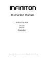 1
1
-
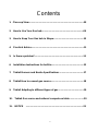 2
2
-
 3
3
-
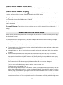 4
4
-
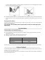 5
5
-
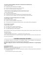 6
6
-
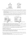 7
7
-
 8
8
-
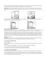 9
9
-
 10
10
-
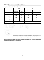 11
11
-
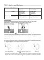 12
12
-
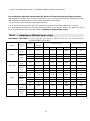 13
13
-
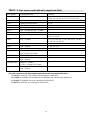 14
14
-
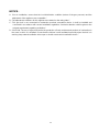 15
15
-
 16
16
-
 17
17
-
 18
18
-
 19
19
-
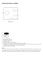 20
20
-
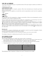 21
21
-
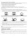 22
22
-
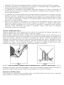 23
23
-
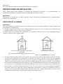 24
24
-
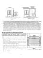 25
25
-
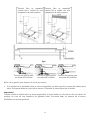 26
26
-
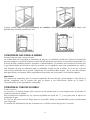 27
27
-
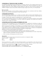 28
28
-
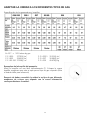 29
29
-
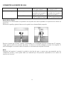 30
30
-
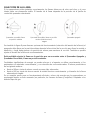 31
31
-
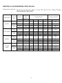 32
32
-
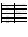 33
33
-
 34
34
-
 35
35
-
 36
36
-
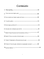 37
37
-
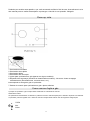 38
38
-
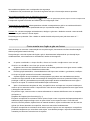 39
39
-
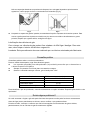 40
40
-
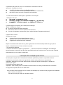 41
41
-
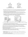 42
42
-
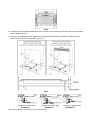 43
43
-
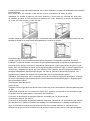 44
44
-
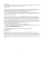 45
45
-
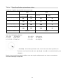 46
46
-
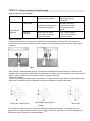 47
47
-
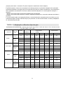 48
48
-
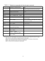 49
49
-
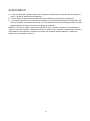 50
50
-
 51
51
-
 52
52


Infiniton GG-320 El manual del propietario
- Categoría
- Encimeras
- Tipo
- El manual del propietario
En otros idiomas
- English: Infiniton GG-320 Owner's manual
- português: Infiniton GG-320 Manual do proprietário
Documentos relacionados
Otros documentos
-
Klarstein 53034968 El manual del propietario
-
-
Aspes AEI1401X El manual del propietario
-
-
Svan SVEC3W El manual del propietario
-
Becken BGH2337 PLACA GAS El manual del propietario
-
 EAS EMH750CGB Manual de usuario
-
Bartscher 1051993 Instrucciones de operación
-
Groupe Brandt 3CF-950BBUT El manual del propietario
-
Candy PC PG750 S X Manual de usuario
