
www.schneider-electric.com
1494409
Altistart 48
Guide d'exploitation
User manual
Benutzerhandbuch
Guía de explotación
Guida all’impiego
用户手册
12/2012
Démarreurs-ralentisseurs progressifs,
Soft start- soft stop units,
Sanftanlasser,
Arrancadores, ralentizadores
progresivos,
Avviatori-rallentatoriprogressvi,
软起动器


4 1494409 12/2012
FRANÇAIS
D'une façon générale toute intervention, tant sur la partie électrique que sur la partie
mécanique de l'installation ou de la machine, doit être précédée de la coupure de l'alimentation
contrôle (CL1 - CL2) et puissance (1/L1 - 3/L2 - 5/L3) de l’Altistart 48.
En exploitation le moteur peut être arrêté par suppression de l’ordre de marche alors que le
démarreur reste sous tension. Si la sécurité du personnel exige l'interdiction de tout
redémarrage intempestif, ce verrouillage électronique est insuffisantþ: prévoir une coupure sur
le circuit de puissance.
Le démarreur comporte des dispositifs de sécurité qui peuvent en cas de défauts commander
l'arrêt du démarreur et par là-même l'arrêt du moteur. Ce moteur peut lui-même subir un arrêt
par blocage mécanique. Enfin, des variations de tension ou des coupures d'alimentation
peuvent également être à l'origine d'arrêts.
La disparition des causes d'arrêt risque de provoquer un redémarrage entraînant un danger
pour certaines machines ou installations, en particulier pour celles qui doivent être conformes
aux réglementations relatives à la sécurité.
ll importe donc que, dans ces cas-là, l'utilisateur se prémunisse contre ces possibilités de
redémarrage notamment par l'emploi d'un détecteur de vitesse basse, provoquant en cas
d'arrêt non programmé du moteur, la coupure de l'alimentation du démarreur.
Les produits et matériels présentés dans ce document sont à tout moment susceptibles
d'évolution ou de modification tant au plan technique et d'aspect que de l'utilisation. Leur
description ne peut en aucun cas revêtir un aspect contractuel.
L'installation et la mise en œuvre de ce démarreur doivent être effectuées conformément aux
normes internationales IEC et aux normes nationales de son lieu d'utilisation. Cette mise en
conformité est de la responsabilité de l'intégrateur qui doit respecter entre autres, pour la
communauté européenne, la directive CEM.
Le respect des exigences essentielles de la directive CEM est conditionné notamment par
l'application des prescriptions contenues dans ce document.
L'Altistartþ48 doit être considéré comme un composant, ce n'est ni une machine ni un appareil
prêt à l'utilisation selon les directives européennes (directive machine et directive compatibilité
électromagnétique). Il est de la responsabilité de l’intégrateur final de garantir la conformité de
sa machine à ces normes.

1494409 12/2012 5
FRANÇAIS
Sommaire
Les étapes de la mise en œuvre _____________________________________________________ 5
Configuration usine _______________________________________________________________ 7
Recommandations préliminaires _____________________________________________________ 8
Caractéristiques techniques _________________________________________________________ 9
Recommandations d'emploi ________________________________________________________ 10
Association démarreur-moteur ______________________________________________________ 13
Encombrement __________________________________________________________________ 19
Précautions de montage __________________________________________________________ 21
Montage en coffret ou armoire ______________________________________________________ 22
Borniers puissance ______________________________________________________________ 23
Borniers contrôle ________________________________________________________________ 28
Câblage / Commandes RUN - STOP _________________________________________________ 29
Schéma d'application _____________________________________________________________ 30
Protections thermiques ___________________________________________________________ 40
Afficheur et programmation ________________________________________________________ 44
Option terminal déporté ___________________________________________________________ 47
Menu Réglages SEt ______________________________________________________________ 48
Menu Protection PrO _____________________________________________________________ 53
Menu Réglages avancés drC _______________________________________________________ 57
Menu Affectation des entrées / sorties IO _____________________________________________ 61
Menu Paramètres 2ème moteur St2 _________________________________________________ 65
Menu Communication COP ________________________________________________________ 69
Menu Paramètre visualisé SUP _____________________________________________________ 71
Tableau de compatibilité __________________________________________________________ 74
Maintenance ___________________________________________________________________ 75
Défauts - causes - remèdes ________________________________________________________ 76
Tableaux de mémorisation configuration/réglages ______________________________________ 82

6 1494409 12/2012
ENGLISH
DEUTSCH
ESPAÑOL
ITALIANO
FRANÇAIS
Les étapes de la mise en œuvre
1 - Réceptionner l’Altistart 48
• S’assurer que la référence du démarreur inscrite sur l’étiquette est conforme au bordereau de livraison
correspondant au bon de commande.
• Ouvrir l’emballage, et vérifier que l’Altistart 48 n’a pas été endommagé pendant le transport.
2 - Montage du variateur en position verticale
• Fixer l’Altistart 48, en suivant les recommandations
page 22
and
23
.
3 - Raccorder à l’Altistart 48 :
• Raccorder le démarreur-ralentisseur progressif à la terre.
• Le réseau d’alimentation contrôle (CL1 - CL2), en s’assurant qu’il est hors tension
• Le réseau d’alimentation puissance (1/L1 - 3/L2 - 5/L3), en s’assurant qu’il est hors tension
• Le moteur (2/T1 - 4/T2 - 6/T3) en s’assurant que son couplage correspond à la tension du réseau
Nota
: Pour d’autres schémas de câblage,
voir page 31 et page 35
.
Dans le cas d’une utilisation de l’ATS48
ppp
Q / l’ATS48
ppp
YS316 dans les enroulements triangle du moteur
suivre les recommandations
page 12
,
page 13
et schémas
page 33
.
AVERTISSEMENT
DÉMARREUR-RALENTISSEUR PROGRESSIF ENDOMMAGÉ
N'installez jamais, ni ne faites fonctionner un démarreur-ralentisseur progressif s'il apparaît être défectueux.
Le non-respect de ces instructions peut provoquer la mort, des blessures graves ou des dom-
mages matériels.
2/T1
4/T2
A2
B2
C2
6/T3
STOP
RUN
LI3
LI4
+24V
LO1
LO2
COM
AO1
R1A
R1C
R2A
R2C
R3A
R3C
3/L2
1/L1
5/L3
CL1
CL2
2
4
6
– KM1
12
34
56
M1
3
c
U1
W1
V1
– T1
PTC1
PTC2
R2A
R2C
R1A
R1C
1314
– Q1
– KM3
12
34
56
– KM3
A1A2
– KM1
A1A2
A1
A1
LO+
(1)
Q2
S1
1
2
1
2
1
2
– Q1
1
3
5
(2)
(3)
– Q3 – Q5
– Q4
Arrêt d’urgence
Commande 2 fils
(1) Mise en place de fusibles ultra rapides dans le cas de la
coordination type 2 (selon IEC 60 947-4-2).
(2)Affectation du relais R1 : relais d’isolement (r1I). Attention
aux limites d’emploi du contact, relayer pour les contacteurs
de fort calibre. Voir “Caractéristiques électriques”, page 29.
(3)
Attention aux limites d’emploi du contact, relayer pour les
contacteurs de fort calibre.
Voir “Caractéristiques
électriques”, page 29.

1494409 12/2012 7
ITALIANO
ESPAÑOL
DEUTSCHENGLISHFRANÇAIS
Les étapes de la mise en œuvre
4 - Mettre le contrôle sous tension (CL1-CL2)
• Mise en marche sans la partie puissance et sans donner l'ordre de marche.
• Vérifier que S1 est ouvert.
• Fermer: Q1, ensuite Q3 puis Q4.
• le démarreur affiche:
nLP
(pour signaler que la puissance est hors tension).
5 - Régler le courant nominal moteur In
• Régler la valeur du courant nominal moteur indiqué sur la plaque signalétique,
6 - Mettre la puissance sous tension (1/L1 - 3/L2 - 5/L3)
•Fermer Q5.
• Le démarreur affiche:
rdY
(pour signaler que la puissance est hors tension)
7 - Démarrer le moteur
• Appuyer sur "S1" pour démarrer l’installation.
8 - Informations de dépannage
• Voir Défauts - causes - remèdes
page 77
ATTENTION
RISQUE D'ENDOMMAGEMENT DU DÉMARREUR PROGRESSIF
• Verifier l’alimentation sur CL1 - CL2:
ATS48pppQ doit être à 220 - 415 V AC
ATS48pppY doit être à 110 - 230 V AC
Le non-respect de ces instructions peut provoquer des dommages matériels
ATTENTION
MAUVAISE PROTECTION CONTRE LES SURINTENSITÉS
Le démarreur ATS 48 est configuré en usine pour pouvoir démarrer une application standard ne
nécessitant pas de fonction spécifique, avec une classe de protection moteur : classe 10.
Une modification des réglages reste possible suivant la méthode d’accès aux paramètres,
page 46
.
Dans tous les cas le paramètre In doit être ajusté à la valeur de courant indiquée sur la plaque moteur.
Le non-respect de ces instructions peut provoquer des dommages matériels.
nLP
SEt
ESC
ENT
ESC
ESC
In
Affichage de l’état du démarreur

8 1494409 12/2012
ENGLISH
DEUTSCH
ESPAÑOL
ITALIANO
FRANÇAIS
Configuration usine
Préréglages
L’Altistart 48 est préréglé en usine pour les conditions d’emploi les plus courantes :
• Utilisation de l’ATS 48 sur le réseau d’alimentation du moteur (et non inséré en "triangle" dans les
enroulements du moteur)
• Courant nominal moteur In :
- ATS 48 •••Q : préréglé pour un moteur standard 415 volts 4 pôles
- ATS 48 •••Y : préréglé au courant NEC, moteur 460 volts
• Courant de limitation (ILt) : 400% du courant In du moteur
• Rampe d’accélération (ACC) : 15 secondes
• Couple initial au décollage (tq0) : 20% du couple nominal
• Arrêt (StY) : Arrêt roue libre (-F-)
• Protection thermique moteur (tHP) : courbe de protection classe 10
• Affichage : rdY (Démarreur prêt) avec tensions puissance et contrôle présentes, courant moteur en
fonctionnement
• Entrées logiques :
- LI1 : STOP
- LI2 : RUN
- LI3 : Forçage arrêt roue libre (LIA)
- LI4 : Forçage mode local (LIL)
• Sorties logiques :
- LO1 : Alarme thermique moteur (tA1)
- LO2 : Moteur alimenté (rnI)
• Sorties relais :
- R1 : Relais de défaut (r1I)
- R2 : Relais de court-circuitage en fin de démarrage
- R3 : Moteur alimenté (rnI)
• Sortie analogique :
- AO : Courant moteur (OCr, 0 - 20 mA)
• Paramètres de communication :
- Connecté via la liaison série, le démarreur a l’adresse logique (Add) = « 0 »
- Vitesse de transmission (tbr) : 19200 bits par seconde
- Format de communication (FOr) : 8 bits, sans parité, 1 bit de stop (8n1)
Si les valeurs ci-dessus sont compatibles avec l’application, le démarreur peut être utilisé sans modification
des réglages.

1494409 12/2012 9
ITALIANO
ESPAÑOL
DEUTSCHENGLISHFRANÇAIS
Recommandations préliminaires
Manutention et stockage
Pour assurer la protection du démarreur avant son installation, manutentionner et stocker l’appareil dans son
emballage.
Manutention à l’installation
La gamme Altistart 48 comprend 6 tailles d'appareils, de masses et de dimensions différentes.
Les petits démarreurs peuvent être extraits de leur emballage et installés sans appareil de manutention.
Les gros démarreurs nécessitent l'utilisation d'un appareil de manutention; à cet effet ils sont munis "d'oreilles”
de manutention. Respecter les précautions décrites ci-dessous :
Ne pas manipuler le démarreur par les barres de puissance
45°
maxi

10 1494409 12/2012
ENGLISH
DEUTSCH
ESPAÑOL
ITALIANO
FRANÇAIS
Caractéristiques techniques
Environnement
(1) Les ATS 48 de degré de protection IP00 doivent être équipés d’une barrière de protection
pour assurer la sécurité des personnes contre les contacts électriques
Degré de protection • IP 20 pour ATS 48D17• à C11•
• IP00 pour ATS 48C14• à M12• (1)
Tenue aux vibrations Selon IEC 68-2-6 :
• 1,5 mm crête de 2 à 13 Hz
• 1 gn de 13 à 200 Hz.
Tenue aux chocs Selon IEC 68-2-27 :
• 15 gn, 11 ms
Pollution ambiante maximale Degréþ3 selon IEC 947-4-2.
Humidité relative maximale 93 % sans condensation ni ruissellement, selon IEC 68-2-3
Température de l'air ambiant au
voisinage de l'appareil
Pour stockage: -25°C à +70°C
Pour fonctionnementþ:
• - 10 °C à + 40 °C sans déclassement
• jusqu'à +60 °C en déclassant le courant de 2 % par °C au dessus
de 40°C
Altitude maximale d'utilisation 1000 m sans déclassement (au-delà, déclasser le courant de 2 %
par 100 m supplémentaires)
Position de fonctionnement Verticale à ± 10 °

1494409 12/2012 11
ITALIANO
ESPAÑOL
DEUTSCHENGLISHFRANÇAIS
Recommandations d'emploi
Couple disponible
Les courbes Cd et Id représentent le démarrage d'un moteur
asynchrone en direct sur le réseau.
La courbe Cd1 indique l'enveloppe du couple disponible avec un
ATS 48, qui est fonction du courant de limitation ILt. La
progressivité du démarrage est obtenue par le contrôle du couple
moteur à l'intérieur de cette enveloppe.
Cr : couple résistant, qui doit être toujours inférieur au couple Cd1.
Choix du démarreur-ralentisseur
Un service moteur S1 correspond à un démarrage suivi d’un fonctionnement à charge constante permettant
d’atteindre l’équilibre thermique.
Un service moteur S4 correspond à un cycle comprenant un démarrage, un fonctionnement à charge
constante et un temps de repos. Ce cycle est caractérisé par un facteur de marche.
L'Altistart 48 doit être choisi en fonction du type d’application "standard" ou "sévère" et de la puissance
nominale du moteur. Les applications "standard" ou "sévère" définissent les valeurs limites de courant et de
cycle pour les services moteur S1 et S4.
Attention : ne pas utiliser l’Altistart 48 en amont de récepteurs autres que des moteurs
(par exemple transformateurs ou résistances sont interdits). Ne pas raccorder des
condensateurs de compensation du facteur de puissance aux bornes d’un moteur
commandé par un Altistart 48
Application standard
Exemple : pompe centrifuge.
En application standard l’Altistart 48 est dimensionné pour répondre à :
• en service S1 : un démarrage à 4 In pendant 23 secondes ou un démarrage à 3 In pendant 46 secondes,
en partant de l’état froid.
• en service S4 : un facteur de marche de 50 % et 10 démarrages par heure, avec 3 In pendant 23 secondes
ou 4 In pendant 12 secondes ou un cycle thermiquement équivalent.
Dans ce cas la protection thermique moteur doit être positionnée en classe de protection 10.
Application sévère
Exemple : broyeur.
En application sévère l’Altistart 48 est dimensionné pour répondre à un service S4 avec un facteur de marche
de 50 % et 5 démarrages par heure, à 4 In pendant 23 secondes ou un cycle thermiquement équivalent.
Dans ce cas la protection thermique moteur doit être positionnée en classe de protection 20. Le courant
In ne
doit pas rester à son réglage usine
, il doit être ajusté à la valeur indiquée sur la plaque moteur.
Nota
: il est possible de surclasser le démarreur d’un calibre, par exemple choix d’un ATS 48D17Q pour un
moteur 11 kW - 400 V en service moteur S4.
Pour cela, court-circuiter l’Altistart en fin de démarrage. Ceci permet 10 démarrages par heure à 3 In pendant
23 secondes au maximum ou équivalent et la protection thermique moteur doit être positionnée en classe 10.
0
0
0,25
0,5
0,75 1
N/Ns
Cr
Cd1
Cd
ILt
Id

12 1494409 12/2012
ENGLISH
DEUTSCH
ESPAÑOL
ITALIANO
FRANÇAIS
Recommandations d'emploi
L’Altistart 48 gamme Q (230-415 V) connecté en ligne avec le
moteur ou dans l’enroulement triangle du moteur
L’Altistart 48 connecté dans la ligne d’alimentation du moteur
Le couplage moteur dépend de la tension
d’alimentation,
ici en étoile
L1
ATS48
U2
V2
1/L1
3/L2
5/L3
2/T1
4/T2
6/T3
W2
U1
V1 W1
L2 L3
Le couplage moteur dépend de la tension
d’alimentation,
ici en triangle
ATS48
U2
V2
1/L1
3/L2
5/L3
2/T1
4/T2
6/T3
W2
U1
V1
W1
L1 L2 L3

1494409 12/2012 13
ITALIANO
ESPAÑOL
DEUTSCHENGLISHFRANÇAIS
Recommandations d'emploi
L’Altistart 48 connecté dans l’enroulement triangle du moteur en série
avec chaque enroulement
Les ATS48
ppp
Q ou ATS48
ppp
YS316 associés à des moteurs couplés en triangle peuvent être insérés en
série dans les enroulements du moteur. Ils sont ainsi soumis à un courant inférieur au courant en ligne dans
un rapport
Ö
3, ce qui permet d’utiliser un démarreur de plus faible calibre.
Cette possibilité est configurable dans le menu Réglages avancés (dLt = On).
Les réglages du courant nominal et du courant de limitation, ainsi que le courant affiché en fonctionnement
restent les valeurs en ligne, évitant le calcul pour l’utilisateur.
Le montage de l’Altistart 48 connecté dans l’enroulement triangle moteur n’est possible que
pour les démarreurs ATS48
ppp
Q ou ATS48
ppp
YS316 . Ce montage n’autorise :
- pas de freinage dynamique
- pas de fonction cascade
- pas de fonction préchauffage
Voir les tableaux page pour définir l’association démarreur-moteur.
Exemple :
Un moteur 400 V de 110 kW avec un courant ligne de 195 A (courant plaqué pour le couplage triangle).
Le courant dans chaque enroulement est égale à 195/1,7 soit 114 A.
On choisira le calibre du démarreur qui possède le courant nominal maximum permanent juste au dessus de
ce courant soit le calibre 140 A (ATS48C14Q pour une application standard).
Afin d’éviter ce calcul, utiliser les tableaux pages et qui indiquent directement le calibre du démarreur
correspondant à la puissance moteur en fonction du type d’application.
Couplage dans l’enroulement
triangle du moteur
ATS48pppQ / ATS48pppYS316
ATS48
U2
V2
1/L1
3/L2
5/L3
2/T1
4/T2
6/T3
W2
U1
V1
W1

14 1494409 12/2012
ENGLISH
DEUTSCH
ESPAÑOL
ITALIANO
FRANÇAIS
Association démarreur-moteur
Application standard, réseau 230 / 415 V, démarreur dans la
ligne
Le courant nominal moteur In ne doit pas dépasser le courant max permanent en classe 10.
(1) Valeur non indiquée lorsqu’il n’existe pas de moteur normalisé correspondant.
Déclassement en température
Le tableau ci dessus tient compte d’une utilisation à une température ambiante de 40 °C maxi.
L’ATS 48 peut être utilisé jusqu’à une température ambiante de 60 °C à condition d’appliquer au courant max
permanent en classe 10 un déclassement de 2 % par degré au dessus de 40 °C.
exemple : ATS 48D32Q à 50 °C déclassement de 10 x 2 % = 20 %, 32 A passe à 32 x 0,8 = 25,6 A (courant
nominal moteur maxi).
Moteur Démarreur 230 / 415 V (+ 10 % - 15 %) - 50 / 60 Hz
Puissance plaquée moteur Courant max
permanent en
classe 10
Calibre
ICL
Référence démarreur
230 V 400 V
kW kW A A
4 7,5 17 17 ATS 48D17Q
5,5 11 22 22 ATS 48D22Q
7,5 15 32 32 ATS 48D32Q
9 18,5 38 38 ATS 48D38Q
11 22 47 47 ATS 48D47Q
15 30 62 62 ATS 48D62Q
18,5 37 75 75 ATS 48D75Q
22 45 88 88 ATS 48D88Q
30 55 110 110 ATS 48C11Q
37 75 140 140 ATS 48C14Q
45 90 170 170 ATS 48C17Q
55 110 210 210 ATS 48C21Q
75 132 250 250 ATS 48C25Q
90 160 320 320 ATS 48C32Q
110 220 410 410 ATS 48C41Q
132 250 480 480 ATS 48C48Q
160 315 590 590 ATS 48C59Q
(1) 355 660 660 ATS 48C66Q
220 400 790 790 ATS 48C79Q
250 500 1000 1000 ATS 48M10Q
355 630 1200 1200 ATS 48M12Q
M

1494409 12/2012 15
ITALIANO
ESPAÑOL
DEUTSCHENGLISHFRANÇAIS
Association démarreur-moteur
Application sévère, réseau 230 / 415 V, démarreur dans la
ligne
Le courant nominal moteur In ne doit pas dépasser le courant max permanent en classe 20.
(1) Valeur non indiquée lorsqu’il n’existe pas de moteur normalisé correspondant.
Déclassement en température
Le tableau ci dessus tient compte d’une utilisation à une température ambiante de 40 °C maxi.
L’ATS 48 peut être utilisé jusqu’à une température ambiante de 60 °C à condition d’appliquer au courant max
permanent en classe 20 un déclassement de 2 % par degré au dessus de 40 °C.
exemple : ATS 48D32Q à 50 °C déclassement de 10 x 2 % = 20 %, 22 A passe à 22 x 0,8 = 17,6 A (courant
nominal moteur maxi).
Moteur Démarreur 230 / 415 V (+ 10 % - 15 %) - 50 / 60 Hz
Puissance plaquée moteur Courant max
permanent en
classe 20
Calibre
ICL
Référence démarreur
230 V 400 V
kW kW A A
3 5,5 12 17 ATS 48D17Q
4 7,5 17 22 ATS 48D22Q
5,5 11 22 32 ATS 48D32Q
7,5 15 32 38 ATS 48D38Q
9 18,5 38 47 ATS 48D47Q
11 22 47 62 ATS 48D62Q
15 30 62 75 ATS 48D75Q
18,5 37 75 88 ATS 48D88Q
22 45 88 110 ATS 48C11Q
30 55 110 140 ATS 48C14Q
37 75 140 170 ATS 48C17Q
45 90 170 210 ATS 48C21Q
55 110 210 250 ATS 48C25Q
75 132 250 320 ATS 48C32Q
90 160 320 410 ATS 48C41Q
110 220 410 480 ATS 48C48Q
132 250 480 590 ATS 48C59Q
160 315 590 660 ATS 48C66Q
(1) 355 660 790 ATS 48C79Q
220 400 790 1000 ATS 48M10Q
250 500 1000 1200 ATS 48M12Q
M

16 1494409 12/2012
ENGLISH
DEUTSCH
ESPAÑOL
ITALIANO
FRANÇAIS
Association démarreur-moteur
Application standard, réseau 230 / 415 V, démarreur dans le
triangle
Le courant nominal moteur In ne doit pas dépasser le courant max permanent en classe 10.
(1) Valeur non indiquée lorsqu’il n’existe pas de moteur normalisé correspondant.
Déclassement en température
Le tableau ci dessus tient compte d’une utilisation à une température ambiante de 40 °C maxi.
L’ATS 48 peut être utilisé jusqu’à une température ambiante de 60 °C à condition d’appliquer au courant max
permanent en classe 10 un déclassement de 2 % par degré au dessus de 40 °C.
exemple : ATS 48D32Q à 50 °C déclassement de 10 x 2 % = 20 %, 55 A passe à 55 x 0,8 = 44 A (courant
nominal moteur maxi).
Moteur Démarreur 230 / 415 V (+ 10 % - 15 %) - 50 / 60 Hz
Puissance plaquée moteur Courant max
permanent en
classe 10
Calibre
ICL
Référence démarreur
230 V 400 V
kW kW A A
7,5 15 29 29 ATS 48D17Q
9 18,5 38 38 ATS 48D22Q
15 22 55 55 ATS 48D32Q
18,5 30 66 66 ATS 48D38Q
22 45 81 81 ATS 48D47Q
30 55 107 107 ATS 48D62Q
37 55 130 130 ATS 48D75Q
45 75 152 152 ATS 48D88Q
55 90 191 191 ATS 48C11Q
75 110 242 242 ATS 48C14Q
90 132 294 294 ATS 48C17Q
110 160 364 364 ATS 48C21Q
132 220 433 433 ATS 48C25Q
160 250 554 554 ATS 48C32Q
220 315 710 710 ATS 48C41Q
250 355 831 831 ATS 48C48Q
(1) 400 1022 1022 ATS 48C59Q
315 500 1143 1143 ATS 48C66Q
355 630 1368 1368 ATS 48C79Q
(1) 710 1732 1732 ATS 48M10Q
500 (1) 2078 2078 ATS 48M12Q
M

1494409 12/2012 17
ITALIANO
ESPAÑOL
DEUTSCHENGLISHFRANÇAIS
Association démarreur-moteur
Application sévère, réseau 230 / 415 V, démarreur dans le
triangle
Le courant nominal moteur In ne doit pas dépasser le courant max permanent en classe 20.
(1) Valeur non indiquée lorsqu’il n’existe pas de moteur normalisé correspondant.
Déclassement en température
Le tableau ci dessus tient compte d’une utilisation à une température ambiante de 40 °C maxi.
L’ATS 48 peut être utilisé jusqu’à une température ambiante de 60 °C à condition d’appliquer au courant max
permanent en classe 20 un déclassement de 2 % par degré au dessus de 40 °C.
exemple : ATS 48D32Q à 50 °C déclassement de 10 x 2 % = 20 %, 38 A passe à 38 x 0,8 = 30,4 A (courant
nominal moteur maxi).
Moteur Démarreur 230 / 415 V (+ 10 % - 15 %) - 50 / 60 Hz
Puissance plaquée moteur Courant max
permanent en
classe 20
Calibre
ICL
Référence démarreur
230 V 400 V
kW kW A A
5,5 11 22 29 ATS 48D17Q
7,5 15 29 38 ATS 48D22Q
9 18,5 38 55 ATS 48D32Q
15 22 55 66 ATS 48D38Q
18,5 30 66 81 ATS 48D47Q
22 45 81 107 ATS 48D62Q
30 55 107 130 ATS 48D75Q
37 55 130 152 ATS 48D88Q
45 75 152 191 ATS 48C11Q
55 90 191 242 ATS 48C14Q
75 110 242 294 ATS 48C17Q
90 132 294 364 ATS 48C21Q
110 160 364 433 ATS 48C25Q
132 220 433 554 ATS 48C32Q
160 250 554 710 ATS 48C41Q
220 315 710 831 ATS 48C48Q
250 355 831 1022 ATS 48C59Q
(1) 400 1022 1143 ATS 48C66Q
315 500 1143 1368 ATS 48C79Q
355 630 1368 1732 ATS 48M10Q
(1) 710 1732 2078 ATS 48M12Q
M

18 1494409 12/2012
ENGLISH
DEUTSCH
ESPAÑOL
ITALIANO
FRANÇAIS
Association démarreur-moteur
Application standard, réseau 208 / 690 V, démarreur dans la
ligne
Le courant nominal moteur In ne doit pas dépasser le courant max permanent en classe 10.
(1) Valeur non indiquée lorsqu’il n’existe pas de moteur normalisé correspondant.
Déclassement en température
Le tableau ci dessus tient compte d’une utilisation à une température ambiante de 40 °C maxi.
L’ATS 48 peut être utilisé jusqu’à une température ambiante de 60 °C à condition d’appliquer au courant max
permanent en classe 10 un déclassement de 2 % par degré au dessus de 40 °C.
exemple : ATS 48D32Y à 50 °C déclassement de 10 x 2 % = 20 %, 32 A passe à 32 x 0,8 = 25,6 A (courant
nominal moteur maxi).
Moteur Démarreur 208 / 690 V (+ 10 % - 15 %) - 50 / 60 Hz
Puissance plaquée moteur Courant max
permanent en
classe 10
Calibre
ICL
Référence
démarreur
208 V 230 V 440 V 460 V 500 V 575 V 690 V
HP HP kW HP kW HP kW A A
3 5 7,5 10 9 15 15 17 17 ATS 48D17Y
5 7,5 11 15 11 20 18,5 22 22 ATS 48D22Y
7,5 10 15 20 18,5 25 22 32 32 ATS 48D32Y
10 (1) 18,5 25 22 30 30 38 38 ATS 48D38Y
(1)15223030403747 47 ATS 48D47Y
15 20 30 40 37 50 45 62 62 ATS 48D62Y
20 25 37 50 45 60 55 75 75 ATS 48D75Y
25 30 45 60 55 75 75 88 88 ATS 48D88Y
30 40 55 75 75 100 90 110 110 ATS 48C11Y
40 50 75 100 90 125 110 140 140 ATS 48C14Y
50 60 90 125 110 150 160 170 170 ATS 48C17Y
60 75 110 150 132 200 200 210 210 ATS 48C21Y
75 100 132 200 160 250 250 250 250 ATS 48C25Y
100 125 160 250 220 300 315 320 320 ATS 48C32Y
125 150 220 300 250 350 400 410 410 ATS 48C41Y
150 (1) 250 350 315 400 500 480 480 ATS 48C48Y
(1) 200 355 400 400 500 560 590 590 ATS 48C59Y
200 250 400 500 (1) 600 630 660 660 ATS 48C66Y
250 300 500 600 500 800 710 790 790 ATS 48C79Y
350 350 630 800 630 1000 900 1000 1000 ATS 48M10Y
400 450 710 1000 800 1200 (1) 1200 1200 ATS 48M12Y
M

1494409 12/2012 19
ITALIANO
ESPAÑOL
DEUTSCHENGLISHFRANÇAIS
Association démarreur-moteur
Application sévère, réseau 208 / 690 V, démarreur dans la
ligne
Le courant nominal moteur In ne doit pas dépasser le courant max permanent en classe 20.
(1) Valeur non indiquée lorsqu’il n’existe pas de moteur normalisé correspondant.
Déclassement en température
Le tableau ci dessus tient compte d’une utilisation à une température ambiante de 40 °C maxi.
L’ATS 48 peut être utilisé jusqu’à une température ambiante de 60 °C à condition d’appliquer au courant max
permanent en classe 20 un déclassement de 2 % par degré au dessus de 40 °C.
exemple : ATS 48D32Y à 50 °C déclassement de 10 x 2 % = 20 %, 22 A passe à 22 x 0,8 = 17,6 A (courant
nominal moteur maxi).
Moteur Démarreur 208 / 690 V (+ 10 % - 15 %) - 50 / 60 Hz
Puissance plaquée moteur Courant max
permanent en
classe 20
Calibre
ICL
Référence
démarreur
208 V 230 V 440 V 460 V 500 V 575 V 690 V
HP HP kW HP kW HP kW A A
2 3 5,5 7,5 7,5 10 11 12 17 ATS 48D17Y
3 5 7,5 10 9 15 15 17 22 ATS 48D22Y
5 7,5 11 15 11 20 18,5 22 32 ATS 48D32Y
7,5 10 15 20 18,5 25 22 32 38 ATS 48D38Y
10 (1) 18,5 25 22 30 30 38 47 ATS 48D47Y
(1)15223030403747 62 ATS 48D62Y
15 20 30 40 37 50 45 62 75 ATS 48D75Y
20 25 37 50 45 60 55 75 88 ATS 48D88Y
25 30 45 60 55 75 75 88 110 ATS 48C11Y
30 40 55 75 75 100 90 110 140 ATS 48C14Y
40 50 75 100 90 125 110 140 170 ATS 48C17Y
50 60 90 125 110 150 160 170 210 ATS 48C21Y
60 75 110 150 132 200 200 210 250 ATS 48C25Y
75 100 132 200 160 250 250 250 320 ATS 48C32Y
100 125 160 250 220 300 315 320 410 ATS 48C41Y
125 150 220 300 250 350 400 410 480 ATS 48C48Y
150 (1) 250 350 315 400 500 480 590 ATS 48C59Y
(1) 200 355 400 400 500 560 590 660 ATS 48C66Y
200 250 400 500 (1) 600 630 660 790 ATS 48C79Y
250 300 500 600 500 800 710 790 1000 ATS 48M10Y
350 350 630 800 630 1000 900 1000 1200 ATS 48M12Y
M

20 1494409 12/2012
ENGLISH
DEUTSCH
ESPAÑOL
ITALIANO
FRANÇAIS
Encombrement
ATS 48D17 • …C66 •
ATS 48
a
mm
b
mm
c
mm
e
mm
G
mm
H
mm
Ø
mm
Masse
kg
D17Q, D17Y
D22Q, D22Y
D32Q, D32Y
D38Q, D38Y
D47Q, D47Y
160 275 190 6,6 100 260 7 4,9
D62Q, D62Y
D75Q, D75Y
D88Q, D88Y
C11Q, C11Y
190 290 235 10 150 270 7 8,3
C14Q, C14Y
C17Q, C17Y
200 340 265 10 160 320 7 12,4
C21Q, C21Y
C25Q, C25Y
C32Q, C32Y
320 380 265 15 250 350 9 18,2
C41Q, C41Y
C48Q, C48Y
C59Q, C59Y
C66Q, C66Y
400 670 300 20 300 610 9 51,4
e
G==
a
H
c
4 x Ø
b

1494409 12/2012 21
ITALIANO
ESPAÑOL
DEUTSCHENGLISHFRANÇAIS
Encombrement
ATS 48C79 • …M12 •
ATS 48
a
mm
b
mm
c
mm
e
mm
G
mm
H
mm
Ø
mm
Masse
kg
C79Q, C79Y
M10Q, M10Y
M12Q, M12Y
770 890 315 20 350 850 11 115
GG==
c
a
6 x Ø
b
He

22 1494409 12/2012
ENGLISH
DEUTSCH
ESPAÑOL
ITALIANO
FRANÇAIS
Précautions de montage
Installer l'appareil verticalement, à ± 10°.
Eviter de le placer à proximité d'éléments chauffants, en particulier lorsque ceux ci sont en dessous.
Respecter un espace libre suffisant pour assurer la circulation de l'air nécessaire au refroidissement, qui se fait
par ventilation du bas vers le haut.
Veiller à ce qu’aucun liquide, poussière ou
objet conducteur ne tombe dans le démarreur
(degré de protection IP00 par le dessus)
Ventilation du démarreur
Sur les calibres munis d’un ventilateur de refroidissement celui ci est alimenté automatiquement dès que la
température du radiateur atteint 50 °C. Il est mis hors tension lorsque la température redescend à 40 °C.
Débit des ventilateurs :
ATS 48 D32 • et D38 • : 14 m
3
/heure
ATS 48 D47 • : 28 m
3
/heure
ATS 48 D62 • à C11 • : 86 m
3
/heure
ATS 48 C14 • et C17 • : 138 m
3
/heure
ATS 48 C21 • à C32 • : 280 m
3
/heure
ATS 48 C41 • à C66 • : 600 m
3
/heure
ATS 48 C79 • à M12 • : 1200 m
3
/heure
≥
100 mm
≥
50 mm
≥
50 mm
≥
100 mm

1494409 12/2012 23
ITALIANO
ESPAÑOL
DEUTSCHENGLISHFRANÇAIS
Montage en coffret ou armoire
Coffret ou armoire métallique de degré de protection IP23
Respecter les précautions de montage indiquées à la page précédente.
Afin d'assurer une bonne circulation d'air dans le démarreurþ:
- prévoir des ouïes de ventilation,
- s'assurer que la ventilation est suffisante, sinon
installer une ventilation forcée, avec filtre si
nécessaire.
Puissance dissipée par les démarreurs, non court-circuités,
à leur courant nominal
Nota :
Lorsque les démarreurs sont court-circuités, leur puissance dissipée est négligeable (entre 15 et 30 W).
- Consommation contrôle (tous calibres): 25 W sans ventilateurs
- Consommation contrôle avec ventilateurs en fonctionnement :
Référence démarreur
ATS 48
Puissance en W
Référence démarreur
ATS 48
Puissance en W
D17Q, D17Y 59 C21Q, C21Y 580
D22Q, D22Y 74 C25Q, C25Y 695
D32Q, D32Y 104 C32Q, C32Y 902
D38Q, D38Y 116 C41Q, C41Y 1339
D47Q, D47Y 142 C48Q, C48Y 1386
D62Q, D62Y 201 C59Q, C59Y 1731
D75Q, D75Y 245 C66Q, C66Y 1958
D88Q, D88Y 290 C79Q, C79Y 2537
C11Q, C11Y 322 M10Q, M10Y 2865
C14Q, C14Y 391 M12Q, M12Y 3497
C17Q, C17Y 479
Démarreurs Puissances actives (W) Puissance apparente
(VA)
ATS 48D17
p
to C17
p
30 80
ATS 48C21
p
to C32
p
50 130
ATS 48C41
p
to M12
p
80 240
θ¡ 40¡C
θ 40 C

24 1494409 12/2012
ENGLISH
DEUTSCH
ESPAÑOL
ITALIANO
FRANÇAIS
Borniers puissance
Disposition des bornes puissance, ATS 48D17 • à C11 •
Moteur à raccorder en 2/T1, 4/T2, 6/T3
Bornes Fonctions
Capacité maximale de raccordement
Couple de serrage des bornes
ATS 48
D17 • D22 •
D32 • D38 •
D47 •
ATS 48
D62 • D75 •
D88 • C11 •
ATS 48
C14 • C17 •
ATS 48
C21 • C25 •
C32 •
ATS 48
C41 • C48 •
C59 • C66 •
ATS 48
C79 • M10
• M12 •
t
Prises de
terre reliées
à la terre
10 mm
2
1,7 N.m
16 mm
2
3 N.m
120 mm
2
27 N.m
120 mm
2
27 N.m
240 mm
2
27 N.m
2x240 mm
2
27 N.m
8 AWG
15 lb.in
4 AWG
26 lb.in
Bus Bar
238 lb.in
Bus Bar
238 lb.in
Bus Bar
238 lb.in
Bus Bar
238 lb.in
1/L1
3/L2
5/L3
Alimentatio
n puissance
16 mm
2
3 N.m
50 mm
2
10 N.m
95 mm
2
34 N.m
240 mm
2
34 N.m
2x240 mm
2
57 N.m
4x240 mm
2
57 N.m
8 AWG
26 lb.in
2/0 AWG
88 lb.in
2/0 AWG
300 lb.in
Bus Bar
300 lb.in
Bus Bar
500 lb.in
Bus Bar
500 lb.in
2/T1
4/T2
6/T3
Sorties vers
le moteur
16 mm
2
3 N.m
50 mm
2
10 N.m
95 mm
2
34 N.m
240 mm
2
34 N.m
2x240 mm
2
57 N.m
4x240 mm
2
57 N.m
8 AWG
26 lb.in
2/0 AWG
88 lb.in
2/0 AWG
300 lb.in
Bus Bar
300 lb.in
Bus Bar
500 lb.in
Bus Bar
500 lb.in
A2
B2
C2
Court-
circuitage
démarreur
16 mm
2
3 N.m
50 mm
2
10 N.m
95 mm
2
34 N.m
240 mm
2
34 N.m
2x240 mm
2
57 N.m
4x240 mm
2
57 N.m
8 AWG
26 lb.in
2/0 AWG
88 lb.in
2/0 AWG
300 lb.in
Bus Bar
300 lb.in
Bus Bar
500 lb.in
Bus Bar
500 lb.in
1/L1
A2 2/T1 B2 4/T2 C2 6/T3
3/L2
s
s
5/L3
M
A2
2/T1
B2
4/T2
C2
6/T3


1494409 12/2012 29
ITALIANO
ESPAÑOL
DEUTSCHENGLISHFRANÇAIS
Borniers contrôle
Les borniers contrôle sont munis de connecteurs débrochables avec détrompeur.
Pour les démarreurs ATS 48C17 • à M12 •, l'accès aux borniers contrôle nécessite de retirer le capot de
protection.
Caractéristiques électriques
Disposition des bornes contrôle
Capacité maximale de raccordement : 2,5 mm2 (12 AWG)
Couple de serrage maximal : 0,4 N.m (3,5 lb.in)
Bornes Fonction Caractéristiques
CL1
CL2
Alimentation du contrôle de
l’Altistart
ATS 48 • • • Q : 220 à 415 V + 10% - 15%, 50 / 60 Hz
ATS 48 • • • Y : 110 à 230 V + 10% - 15%, 50 / 60 Hz
Consommation page 23.
R1A
R1C
Contact à fermeture (NO) du relais
programmable r1
Pouvoir de commutation mini :
• 10 mA pour 6 V
a
Pouvoir de commutation maxi sur charge inductive
(cos
ϕ
= 0,5 et L/R = 20 ms) :
• 1,8 A pour 230 V
c
et 30 V
a
Tension max 400 V
R2A
R2C
Contact à fermeture (NO) du relais
de fin de démarrage r2
R3A
R3C
Contact à fermeture (NO) du relais
programmable r3
STOP
RUN
LI3
LI4
Arrêt démarreur (état 0 = arrêt)
Marche démarreur (état 1 = marche
si STOP à l’état 1)
Entrée programmable
Entrée programmable
4 entrées logiques 24 V d'impédance 4,3 k
Ω
Umax = 30 V, Imax = 8 mA
état 1 : U > 11 V - I > 5 mA
état 0 : U < 5 V - I < 2 mA
24V Alimentation des entrées logiques + 24V ± 25% isolée et protégée contre les courts-
circuits et surcharge; débit maximal : 200 mA
LO+ Alimentation des sorties logiques A raccorder au 24 V ou à une source externe
LO1
LO2
Sorties logiques programmables 2 sorties à collecteur ouvert, compatibles automate
niveau 1, norme IEC 65A-68
• Alimentation +24 V (mini 12 V maxi 30 V)
• Courant maxi 200 mA par sortie avec une source
externe
AO1 Sortie analogique programmable Sortie configurable en 0 - 20 mA ou 4 - 20 mA
• précision ± 5 % de la valeur maxi, impédance de
charge maxi 500
Ω
COM Commun des entrées / sorties 0 V
PTC1
PTC2
Entrée pour sondes PTC Résistance totale du circuit sonde 750
Ω
à 25 °C (3
sondes de 250
Ω
en série par exemple)
(RJ 45) Prise pour
• terminal déporté
• Power Suite
• Bus de communication
RS 485 Modbus
CL1
CL2
R1A
R1C
R2A
R2C
R3A
R3C
STOP
RUN
LI3
LI4
24V
LO+
LO1
LO2
AO1
COM
PTC1
PTC2
(RJ 45)

30 1494409 12/2012
ENGLISH
DEUTSCH
ESPAÑOL
ITALIANO
FRANÇAIS
Câblage / Commandes RUN - STOP
Précautions de câblage
Puissance
Respecter les sections des câbles préconisées par les normes.
Le démarreur doit être impérativement raccordé à la terre, afin d'être en conformité avec les réglementations
portant sur les courants de fuite. Lorsqu’une protection amont par "dispositif différentiel résiduel" est imposée
par les normes d’installation il est nécessaire d’utiliser un dispositif de type A-Si (évite les déclenchements
intempestifs à la mise sous tension). Vérifier la compatibilité avec les autres appareils de protection. Si
l'installation comporte plusieurs démarreurs sur la même ligne, raccorder séparément chaque démarreur à la
terre. Si nécessaire, prévoir une inductance de ligne (consulter le catalogue).
Séparer les câbles de puissance des circuits à signaux bas niveau de l'installation (détecteurs, automates
programmables, appareils de mesure, vidéo, téléphone).
Commande
Séparer les circuits de commande et les câbles de puissance.
Fonctions des entrées logiques RUN et STOP (
Voir schéma d’application
page 32
)
Commande 2 fils
La marche et l’arrêt sont commandés par l’état 1þ(marche) ou 0 (arrêt), qui est pris en compte sur les entrées
RUN et STOP en même temps.
Lors d'une mise sous tension ou d'une remise à zéro de défaut manuelle le moteur redémarre si l’ordre RUN
est présent.
Commande 3 fils
La marche et l’arrêt sont commandés par 2 entrées logiques différentes.
L’arrêt est obtenu à l’ouverture (état 0) de l’entrée STOP.
L’impulsion sur l’entrée RUN est mémorisée jusqu’à ouverture de l’entrée STOP.
Lors d'une mise sous tension ou d'une remise à zéro de défaut manuelle ou après une commande d’arrêt, le
moteur ne peut être alimenté qu'après une ouverture préalable (état 0) puis une nouvelle impulsion (état 1) de
l’entrée RUN.

1494409 12/2012 31
ITALIANO
ESPAÑOL
DEUTSCHENGLISHFRANÇAIS
Schéma d'application
ATS 48 : 1 sens de marche avec contacteur de ligne, arrêt en roue libre,
coordination type 1
(1)Mise en place de fusibles ultra rapides dans le cas de la coordination type 2 (selon IEC 60 947-
4-2).
(2)Affectation du relais R1 : relais d’isolement (r1I). Voir “Caractéristiques électriques”, page 29.
Attention aux limites d’emploi du contact, relayer pour les contacteurs de fort calibre.
(3)Insérer un transformateur lorsque la tension du réseau est différente de celle admissible par le
contrôle de l’ATS 48. Voir “Caractéristiques électriques”, page 29.
M
2/T1
4/T2
6/T3
STOP
RUN
LI3
+24V
LO+
LO1
LO2
COM
AO1
R1A
R1C
R2A
R2C
R3A
R3C
3/L2
1/L1
5/L3
CL2
2
4
6
– KM1
12
34
56
M1
3
c
U1
W1
V1
– T1
R1A
(2)
R1C
1314
– Q1
1314
– KM1
– S1
– S2
– KM1
A1A2
A1
A1
– KM1
Q3
(1)
54 53
1
2
1
2
1
2
– Q1
1
3
5
CL1
LI4
PTC1
PTC2
(3)
– Q3 – Q5
– Q4
U2
V2
2/T1
4/T2
6/T3
W2
U1
V1 W1
U2
V2
2/T1
4/T2
6/T3
W2
U1
V1
W1
M1
Arrêt
d’urgence
Couplage étoile
Couplage triangle

32 1494409 12/2012
ENGLISH
DEUTSCH
ESPAÑOL
ITALIANO
FRANÇAIS
Schéma d'application
ATS 48 : 1 sens de marche avec contacteur de ligne, court-circuitage, arrêt
libre ou contrôlé, coordination type 1
(1) Mise en place de fusibles ultra rapides dans le cas de la coordination type 2 (selon IEC 60 947-
4-2).
(2) Affectation du relais R1 : relais d’isolement (r1I). Attention aux limites d’emploi du contact,
relayer pour les contacteurs de fort calibre. Voir “Caractéristiques électriques”, page 29.
(3) Attention aux limites d’emploi du contact, relayer pour les contacteurs de fort calibre.
Voir “Caractéristiques électriques”, page 29.
(4) Insérer un transformateur lorsque la tension du réseau est différente de celle admissible par le
contrôle de l’ATS 48. Voir “Caractéristiques électriques”, page 29.
(5)Voir “Commande 2 fils”, page 30.
(6)Voir “Commande 3 fils”, page 30.
M
2/T1
4/T2
A2
B2
C2
6/T3
ST OP
RU N
LI3
LI4
+24V
LO1
LO2
COM
AO1
R1 A
R1 C
R2 A
R2 C
R3 A
R3 C
3/L2
1/L1
5/L3
CL1
CL2
2
4
6
– KM1
12
34
56
M1
3
c
U1
W1
V1
– T1
PTC1
PTC2
R2 A
R2 C
R1 A
R1 C
1314
– Q1
– KM3
12
34
56
– KM3
A1A2
– KM1
A1A2
A1
A1
S1
+24V
ST OP
RU N
LO+
(1)
S2
Q2
S1
ST OP
1
2
1
2
1
2
+24V
– Q1
1
3
5
(4)
(2)
(3)
– Q1
– Q3 – Q5
– Q4
U2
V2
2/T1
4/T2
6/T3
W2
U1
V1 W1
U2
V2
2/T1
4/T2
6/T3
W2
U1
V1
W1
M1
Arrêt
d’urgence
Commande 3 fils (6)
Couplage étoile
Couplage triangle
Commande 2 fils
Commande par
PC ou PLC

1494409 12/2012 33
ITALIANO
ESPAÑOL
DEUTSCHENGLISHFRANÇAIS
Schéma d'application
ATS 48 : 1 sens de marche, arrêt libre, coordination type 1, avec contac-
teur de ligne, court-circuitage, couplage dans le triangle du moteur,
ATS 48•••Q ou ATS 48•••YS316.
Nota
: Régler
dlt
sur
on
(voir “Menu Réglages avancés drC”, page 58)
(1)Mise en place de fusibles ultra rapides dans le cas de la coordination type 2 (selon IEC 60 947-
4-2).
(2)Utilisation de KM1 obligatoire. Prévoir une protection thermique différentielle externe type Vigirex
pour Compact NS80, bloc Vigi pour Compact NS400 à 630, consulter le catalogue Merlin Gérin
pour les calibres supérieurs.
(3)Affectation du relais R1 : relais d’isolement (r1I). Attention aux limites d’emploi du contact, relayer
pour les contacteurs de fort calibre. Voir “Caractéristiques électriques”, page 29.
(4)Attention aux limites d’emploi du contact, relayer pour les contacteurs de fort calibre. Voir
“Caractéristiques électriques”, page 29.
(5)Insérer un transformateur lorsque la tension du réseau est différente de celle admissible par le
contrôle de l’ATS 48. Voir “Caractéristiques électriques”, page 29.
(6)Voir “Commande 2 fils”, page 30.
(7)Voir “Commande 3 fils”, page 30.
(8)Inductances de ligne éventuelles
Lorsque le contacteur de court-circuitage est utilisé, la détection du défaut "PHF" peut-être
allongée.
M
2/T1
4/T2
A2
B2
C2
6/T3
ST OP
RU N
LI3
LI4
+24V
LO1
LO2
COM
AO1
R1 A
R1 C
R2 A
R2 C
R3 A
R3 C
3/L2
1/L1
5/L3
CL1
CL2
2
4
6
– KM1
12
34
56
PTC1
PTC2
– KM3
12
34
56
A1
S1
LO+
(1)
(3)
S2
Q2
1
2
1
2
– Q1
1
3
5
– T1
R2 A
R2 C
R1 A
R1 C
1314
– Q1
– KM3
A1A2
– KM1
A1A2
A1
1
2
(4)
(5)
(2)
U1
W1
V1
V2
W2
U2
– Q3 – Q5
– Q4
ATS48
U2
V2
1/L1
3/L2
5/L3
2/T1
4/T2
6/T3
W2
U1
V1
W1
+24V
ST OP
RU N
S1
ST OP
+24V
Commande 3 fils (7)
Arrêt
d’urgence
Commande 2 fils
Commande par
PC ou PLC
Couplage étoile
Couplage triangle

34 1494409 12/2012
ENGLISH
DEUTSCH
ESPAÑOL
ITALIANO
FRANÇAIS
Schéma d'application
ATS 48 : 1 sens de marche, arrêt libre ou contrôlé, contacteur de ligne,
court-circuitage moteur, PV/GV avec deux jeux de paramètres
(4) Attention aux limites d’emploi du contact, relayer pour les contacteurs de fort calibre. Voir “Caractéristiques
électriques”, page 29.
(5) Affectation du relais R1 : relais d’isolement (r1I). Attention aux limites d’emploi du contact, relayer pour les
contacteurs de fort calibre. Voir “Caractéristiques électriques”, page 29.
LI3 = LIS (second jeu de paramètres moteur)
S3 : 1 = PV, 2 = GV
M
RUN
STOP
LI3
LI4
+24V
LO1
LO2
COM
AO1
R1A
R1C
R2A
R2C
R3A
R3C
PTC1
PTC2
LO+
2/T1
4/T2
A2
B2
C2
6/T3
3/L2
1/L1
5/L3
CL1
2
4
6
– KM1
12
34
56
CL2
– KM3
12
34
56
– KM2
– KM5
A1
Q2
1
2
1
2
– Q1
1
3
5
– T1
0
220
1
2
KA1 KM2
(1)
(2)
M1
3
c
U1
W1
V1
W2
U2
V2
(3)
– Q4
– Q3
– Q5
(1) Mise en place de fusibles ultra rapides dans
le cas de la coordination type 2 (selon IEC 60
947-4-2).
(2) Insérer un transformateur lorsque la tension du réseau
est différente de celle admissible par le contrôle de l’ATS
48. Voir “Caractéristiques électriques”, page 29.
(3) S’assurer de la concordance des sens de rotation du
moteur pour les 2 vitesses.
KA1 KM1 KM5KM2
KM5
KA1
S2
S1
KM2
KM2
KM1
KM5
Q1
220
0
A1
R1C
R1A
KM3
A1
R2C
R2A
KA1
S3
2
1
(5)
(4)
Arrêt
d’urgence

1494409 12/2012 35
ITALIANO
ESPAÑOL
DEUTSCHENGLISHFRANÇAIS
Schéma d'application
ATS 48 : 1 sens de marche avec contacteur de ligne, démarrage et
ralentissement de plusieurs moteurs en cascade avec un seul Altistart
(1) Mise en place de fusibles dans le cas de la coordination type 2 (selon IEC 60 947-4-2).
(2) Insérer un transformateur lorsque la tension du réseau est différente de celle admissible par le contrôle de
l’ATS 48. Voir “Caractéristiques électriques”, page 29.
(3) KM1 : à dimensionner en fonction de la puissance totale des moteurs.
Important :
• Il faut configurer une entrée logique de l’ATS48 "en cascade" (LI3 = LIC). Voir “Activation de la fonction
cascade”, page 60.
• En cas de défaut il n'est pas possible de décélérer ou de freiner les moteurs alors en service.
• Ajuster la protection thermique de chaque disjoncteur Qn1 au courant nominal moteur.
M
– KM11
1
2
3
4
5
6
– KM12
1
2
3
4
5
6
– KM1
1
2
3
4
5
6
1/L1
3/L2
5/L3
2/T1
4/T2
6/T3
A1
–T1
2
4
6
1
– Q11
3
5
U1
W1
V1
M1
3
– KM21
1
2
3
4
5
6
– KM22
1
2
3
4
5
6
2
4
6
1
– Q21
3
5
U2
W2
V2
M2
3
– KMn1
1
2
3
4
5
6
– KMn2
1
2
3
4
5
6
2
4
6
1
– Qn1
3
5
Un
Wn
Vn
Mn
3
Mi
3
2
4
6
1
2
1
2
1
2
CL1
CL2
A1
RU N
+24V
KAT
LI3
STO P
KALI T
KALI T
A
KA KALI
B
(1)
– Q2
– Q1
1
3
5
(2)
(3)
– Q3 – Q5
– Q4
Moteur 2
Moteur n
Moteur i
Moteur 1

36 1494409 12/2012
ENGLISH
DEUTSCH
ESPAÑOL
ITALIANO
FRANÇAIS
Schéma d'application
ATS 48 : 1 sens de marche avec contacteur de ligne, démarrage et
ralentissement de plusieurs moteurs en cascade avec un seul Altistart.
Commande moteur 1
Commande moteur 2
BPM1 : Bouton "Marche" moteur 1 BPA1 : Bouton "Arrêt" moteur 1
BPM2 : Bouton "Marche" moteur 2 BPA2 : Bouton "Arrêt" moteur 2
KAM1 AR1 KM11 KM12
KM12
KTSHUNT
SHUNT
KAT ACDECBPM1
BPA1
BPA1
KAM1 KM11 KAM1 KM11
KM11
KM12
KM12 AR1 AR1
AR1
ART
B
A
D
C
KM21
KMi1
KMn1
(n-1) contacts
KAM2 AR2 KM21 KM22
KM22
KTSHUNT
SHUNT
KAT ACDECBPM2
BPA2
BPA2
KAM2 KM21 KAM2 KM21
KM21
KM22
KM22 AR2 AR2
AR2
ART
D
C
F
E
KM11
KMi1
KMn1
(n-1) contacts

1494409 12/2012 37
ITALIANO
ESPAÑOL
DEUTSCHENGLISHFRANÇAIS
Schéma d'application
ATS 48 : 1 sens de marche avec contacteur de ligne, démarrage et
ralentissement de plusieurs moteurs en cascade avec un seul Altistart.
Commande moteur n
Commande cascade
Entre deux demandes d’arrêt consécutives, attendre la fin de la temporisation KALIT
BPMn : Bouton "Marche" moteur n R1 doit être configuré en relais d’isolement (r1 = r1I)
BPAn : Bouton "Arrêt" moteur n
KAMn ARn KMn1 KMn2
KMn2
KTSHUNT
SHUNT
KAT ACDECBPMn
BPAn
BPAn
KAMn KMn1 KAMn KMn1
KMn1
KMn2
KMn2 ARn ARn
ARn
ART
F
E
H
G
KM11
KM21
KMi1
(n-1) contacts
KAT KT
KA
K KALI KALIT
KALIT ART ACDEC SHUNT
H
G
J
I
A1
R2C
ATS 48
R2A
R1C
R1A
Réglage des
temporisations
1 s > KA > 0,1 s
K > 0,2 s
KALI > K
KALIT > 0,1 s

38 1494409 12/2012
ENGLISH
DEUTSCH
ESPAÑOL
ITALIANO
FRANÇAIS
Schéma d’application
ATS 48 : 1 sens de marche avec contacteur de ligne, démarrage et
ralentissement de plusieurs moteurs en cascade avec un seul Altistart.
Commande cascade
MST : Bouton "Marche" général
MHT : Bouton "Arrêt" général.
KM1 KA K KALI
KM1MST
MHT
Qn1
Qi1
Q21 KAM1 KAM2 KAMi KAMn
AR2AR1 ARi ARn
Q11
J
I
n contacts
n contacts
n contacts

1494409 12/2012 39
ITALIANO
ESPAÑOL
DEUTSCHENGLISHFRANÇAIS
Schéma d’application
ATS 48 : 1 sens de marche avec contacteur de ligne, démarrage et
ralentissement de plusieurs moteurs en cascade avec un seul Altistart.
Explication de la séquence complète.
Démarrer avec MST pour faire monter KM1 (contacteur de ligne)
1 - 2 - 3
Presser BPM1 pour démarrer le moteur 1. Pour démarrer le moteur 2 presser BPM2, presser BPMn pour
démarrer le moteur n.
Quand BPM1 est actionné, KAM1 monte, KM11 aussi parce que ACDEC est monté (l’ATS48 est sous tension
avec MST et KM1).
KA monte parce que KAM1 est fermé. Après un temps ajustable KAT monte aussi.
4 - 5
L’ATS48 démarre le moteur parce qu’il y a eu un ordre de marche sur RUN avec KA et KAT.
KAM1 retombe par KAT.
KM11 reste fermé.
6 - 7
En fin de démarrage, R2 de l’ATS48 monte, SHUNT est fermé, KM12 est fermé par SHUNT et KM11 reste
fermé.
8 - 9
Après un court instant R2 retombe et R1 aussi (fonction court-circuitage démarreur).
KM11 s’ouvre parce que ACDEC est ouvert.
Le moteur reste alimenté par KM12.
L’ATS48 affiche un code d’état.
Pour démarrer un autre moteur, la même logique sera respectée. Pour démarrer le moteur n, utilisez
BPMn et pour arrêter le moteur n utiliser BPAn. Il est possible de démarrer et d’arrêter n’importe quel
moteur dans n’importe quel ordre.
Pour arrêter le moteur 1 presser BPA1. AR1 se ferme
a - b - c - d
K et KALI sont fermés.
LI de l’ATS48 reçoit un ordre de KALI et KALIT (LI doit être ajusté à la valeur LIC).
R1 et R2 de l’ATS48 montent (une impulsion sur R2 et R1 reste fermé jusqu’à l’arrêt complet du moteur).
e
KM11 se ferme.
Après un temps réglable KT et KALIT montent.
f
L’ATS48 reçoit un ordre d’arrêt par KALIT.
g
KM12 retombe.
L’ATS48 décélère le moteur.
h
R1 de l’ATS48 s’ouvre quand le moteur est totalement arrêté.
i
KM11 s’ouvre.
L’ATS48 est prêt à démarrer ou à arrêter un autre moteur.

40 1494409 12/2012
ENGLISH
DEUTSCH
ESPAÑOL
ITALIANO
FRANÇAIS
Schéma d’application
ATS 48 : 1 sens de marche avec contacteur de ligne, démarrage et
ralentissement de plusieurs moteurs en cascade avec un seul Altistart.
Chronogramme
48 c
a
f
b
e
d
g
h
h
i
h
3
1
2
5
69
7
Moteur alimenté par l’ATS48
LI3
STOP
RUN
RI
(Relais d’isolement)
KM11
Vitesse
R2
(Commande du contacteur
de court-circuitage démarreur)
KM12
Démarrage moteur Arrêt moteur
ATS48 au repos

1494409 12/2012 41
ITALIANO
ESPAÑOL
DEUTSCHENGLISHFRANÇAIS
Protections thermiques
Protection thermique du démarreur
Protection thermique par sonde CTP fixée sur le radiateur et par calcul de l’échauffement des thyristors.
Protection thermique du moteur
Le démarreur calcule en permanence l'échauffement du moteur à partir du courant nominal réglé In et du
courant réellement absorbé.
Les échauffements peuvent être provoqués par une faible ou forte surcharge, de longue ou de courte durée.
Les courbes de déclenchement pages suivantes sont établies en fonction du rapport entre le courant de
démarrage Id et le courant moteur (réglable) In.
La norme IEC60947-4-2 définit les classes de protection donnant les capacités de démarrage du moteur à
chaud et à froid sans défaut thermique. Les différentes classes de protection sont données pour un état FROID
(correspond à un état thermique moteur stabilisé, hors tension) et pour un état CHAUD (correspond à un état
thermique moteur stabilisé, à puissance nominale).
En sortie d'usine, le démarreur est en classe de protection 10.
Il est possible de modifier cette classe de protection à partir du menu PrO.
La protection thermique affichée par le démarreur correspond à la constante de temps fer.
- une alarme surcharge qui prévient si le moteur dépasse son seuil d'échauffement nominal (état thermique
moteur = 110 %).
- un défaut thermique qui arrête le moteur en cas de dépassement du seuil critique d'échauffement (état
thermique moteur = 125 %).
Dans le cas d’un démarrage long le démarreur peut déclencher en défaut ou alarme thermique malgré une
valeur affichée inférieure à la valeur de déclenchement.
Le défaut thermique peut être signalé par le relais R1, si la protection thermique n’a pas été inhibée.
Après un arrêt du moteur ou une mise hors tension du démarreur, le calcul de l’état thermique se poursuit,
même si le contrôle n’est pas alimenté. Le contrôle thermique de l'Altistart interdit le redémarrage du moteur
si son échauffement est encore trop élevé.
Dans le cas d'emploi d'un moteur spécial (antidéflagrant, immergé,...), prévoir une protection thermique par
sondes PTC.

42 1494409 12/2012
ENGLISH
DEUTSCH
ESPAÑOL
ITALIANO
FRANÇAIS
Protections thermiques
Protection thermique du moteur
Courbes à froid
Temps de déclenchement pour application standard
(Classe 10)
Temps de déclenchement pour application sévère
(Classe 20)
3 In 5 In 3,5 In 5 In
46 s 15 s 63 s 29 s
0,5
1
10
100
1000
10000
t(s)
8,00
Id/In
7,507,006,506,005,505,004,504,003,503,002,502,001,51,12
Classe 30
Classe 10A
Classe 2
Classe 20
Classe 15
Classe 10
Classe 25

1494409 12/2012 43
ITALIANO
ESPAÑOL
DEUTSCHENGLISHFRANÇAIS
Protections thermiques
Protection thermique du moteur
Courbes à chaud
Temps de déclenchement pour application standard
(Classe 10)
Temps de déclenchement pour application sévère
(Classe 20)
3 In 5 In 3,5 In 5 In
23 s 7,5 s 32 s 15 s
0,5
1
10
100
1000
10000
t(s)
8,00
Id/In
7,507,006,506,005,505,004,504,003,503,002,502,001,51,12
Classe 30
Classe 25
Classe 20
Classe 15
Classe 10
Classe 10A
Classe 2

44 1494409 12/2012
ENGLISH
DEUTSCH
ESPAÑOL
ITALIANO
FRANÇAIS
Protections thermiques
Protection thermique moteur par sondes PTC
Il est possible de connecter au bornier de la carte contrôle des sondes PTC intégrées au moteur et mesurant
sa température. Cette information analogique est gérée par le démarreur.
Le traitement de l’information " dépassement thermique sonde PTC " peut être utilisé de deux façons :
- arrêt sur défaut lorsque le signal est actif
- alarme lorsque le signal est actif. Cette alarme peut être visualisée dans un mot d’état du démarreur
(liaison série) ou sur une sortie logique configurable.
Nota :
La protection par sondes PTC ne désactive pas la protection thermique moteur effectuée par calcul, les 2
protections peuvent cohabiter.

1494409 12/2012 45
ITALIANO
ESPAÑOL
DEUTSCHENGLISHFRANÇAIS
Afficheur et programmation
Fonctions des touches et de l'afficheur
L'action sur ou ne mémorise pas le choix.
Mémorisation, enregistrement du choix affiché
:
La mémorisation s'accompagne d'un clignotement de l'affichage
Règle d’affichage
Le principe d’affichage des nombres diffère selon l’échelle maxi du paramètre et sa valeur.
• Echelle maxi 9990 :
- valeurs 0,1 à 99,9 (exemples : 05.5 = 5,5 ; 55.0 = 55 ; 55.5 = 55,5)
- valeurs 100 à 999 (exemple : 555 = 555)
- valeurs 1000 à 9990 (exemple : 5.55 = 5550)
• Echelle maxi 99900 :
- valeurs 1 à 999 (exemples : 005 = 5 ; 055 = 55 ; 550 = 550)
- valeurs 1000 à 9990 (exemple : 5.55 = 5550)
- valeurs 10000 à 99900 (exemple : 55.5 = 55500)
ESC ENT
• 3 afficheurs "7 segments"
• Entre dans un menu ou
dans un paramètre, ou
enregistre le paramètre ou
la valeur affichée
• Passe au menu ou au
paramètre précédent, ou
augmente la valeur
affichée
• Sort d’un menu ou d’un paramètre, ou
abandonne la valeur affichée pour revenir à la
valeur précédente en mémoire
• Passe au menu ou au paramètre suivant,
ou diminue la valeur affichée
ENT

46 1494409 12/2012
ENGLISH
DEUTSCH
ESPAÑOL
ITALIANO
FRANÇAIS
Afficheur et programmation
Accès aux menus
(1) La gestion de la valeur "XXX" affichée est donnée dans le tableau ci-après.
(2) Le menu St2. n’est visible que si la fonction "second jeu de paramètres moteur" est configurée.
Accès aux paramètres
Mémorisation, enregistrement du choix affiché
:
La mémorisation s'accompagne d'un clignotement de l'affichage
Exemple :
XXX
(1)
ESC
ENT
ESC
ESC
ENT
ESC
ESC
ENT
ESC
ESC
ENT
ESC
ESC
ENT
ESC
ESC
ENT
ESC
ESC
ENT
ESC
Réglages
Protection
Réglages avancés
Affectation des entrées/sorties
Paramètres 2ème moteur (2)
Communication
Affichage de l’état du démarreur
Choix du paramètre visualisé et code
de verrouillage
ENT
ESC
ENT
ESC
ENT
ESC
ENT
Menu
Paramètre Valeur ou affectation
Paramètre suivant
1 clignotement
(enregistrement)
Déplacement dans
les menus

1494409 12/2012 47
ITALIANO
ESPAÑOL
DEUTSCHENGLISHFRANÇAIS
Afficheur et programmation
Affichage de l’état du démarreur
La valeur "XXX" affichée suit les règles suivantes :
Lorsque le démarreur est en limitation de courant, la valeur affichée "XXX" clignote.
Dès que le démarreur est en défaut, il affiche un code défaut, il reste possible de modifier des paramètres.
Valeur affichée Condition
Code du défaut
Démarreur en défaut
nLP
rdY
Démarreur sans ordre de marche et
:
• Puissance non alimentée
• Puissance alimentée
tbS
Temporisation de démarrage non écoulée
HEA
Chauffage moteur en cours
Paramètre de surveillance choisi par l’utilisateur
(menu SUP). En réglage usine : courant moteur
Démarreur avec ordre de marche
brL
Démarreur en freinage
Stb
Attente d’un ordre de commande (RUN ou STOP)
en mode cascade

48 1494409 12/2012
ENGLISH
DEUTSCH
ESPAÑOL
ITALIANO
FRANÇAIS
Option terminal déporté
Le terminal déporté
VW3 G48101
peut être monté sur la porte du coffret ou de l’armoire; il est fourni avec un
joint qui permet un montage avec degré d’étanchéité IP65. Il est muni d’un câble de 3 m de long avec prises,
la communication se fait par la connexion RJ45 / modbus du démarreur (
voir la notice fournie avec le
terminal
). Il comporte le même affichage et les mêmes boutons de programmation que l’Altistart 48 avec en
plus un commutateur de verrouillage d’accès aux menus.
Vue face avant : Vue face arrière :
Gestion du commutateur du terminal déporté
Le commutateur 3 positions du terminal est utilisé de la manière suivante :
• position verrouillée : seuls les paramètres de surveillance sont accessibles et la modification du choix
du paramètre affiché lorsque le démarreur est en marche n’est pas possible.
• position mi-verrouillée : accès limité aux paramètres des menus SEt, PrO et SUP.
• position déverrouillée : tous les paramètres sont accessibles.
Les éventuelles restrictions d’affichage dues au
commutateur du terminal déporté restent applicables
sur le démarreur après avoir été déconnecté y compris
après une mise hors tension du démarreur.
ESC
ENT
Afficheur
3 caractères
Connecteur
Commutateur 3 positions
ATS48
RJ45
Sub D 9 points

1494409 12/2012 49
ITALIANO
ESPAÑOL
DEUTSCHENGLISHFRANÇAIS
Menu Réglages SEt
Pour l’accès aux paramètres, page 46.
Courant nominal moteur
Courant de limitation en % de In
Couple initial de décollage
Temps de rampe d’accélération
Choix du type d’arrêt
Décélération
(Pompe)
Freinage Roue libre
Temps de rampe de décélération
Paramètres dans menu
Sélection possible
Paramètre apparaissant selon la sélection
Seuil de passage en roue libre en fin de décélération
Niveau de couple de freinage interne
Temps de freinage pseudo continu

50 1494409 12/2012
ENGLISH
DEUTSCH
ESPAÑOL
ITALIANO
FRANÇAIS
Menu Réglages SEt
La modification des paramètres de réglages n’est possible qu’à l’arrêt.
(1) Réglage usine de In correspondant à la valeur usuelle d’un moteur normalisé 4 pôles en tension 400 V en
classe 10 (pour ATS 48•••Q).
Réglage usine de In correspondant à la valeur usuelle d’un moteur normalisé suivant NEC en tension
460 V, en classe 10 (pour ATS 48•••Y).
Code Description Plage
de réglage
Préréglage
usine
In
Courant nominal moteur
0,4 à 1,3 ICL (1)
Régler la valeur du courant nominal moteur indiqué sur la plaque signalétique, même dans le cas du
couplage du démarreur dans l’enroulement triangle du moteur (dLt dans le menu PrO).
Vérifier que ce courant est compris entre 0,4 et 1,3 ICL (ICL : Calibre du démarreur).
ILt
Courant de limitation
150 à 700 %
de In, limité à
500 % de ICL
400 % de In
Le courant de limitation ILt s’exprime en % de In.
À charge maximale, la valeur ILt doit être suffisamment élevée pour permettre le démarrage du
moteur.
Si l'application requiert plus de 500 % de IcL, la taille du démarreur progressif doit être changée en
conséquence.
Il est limité à 500 % de ICL
(calibre du démarreur, voir les tableaux “Association démarreur-moteur”,
page 14.)
Courant de limitation = ILt x In.
exemple 1 : In = 22 A, ILt = 300 %, courant de limitation = 300 % x 22 A = 66 A
exemple 2 : ATS 48C21Q, avec ICL = 210 A
In = 195 A, ILt = 700 %, courant de limitation = 700 % x 195 = 1365,
limité à 500 % x 210 = 1050 A
ACC
Temps de rampe d’accélération
1 à 60 s 15 s
C’est le temps de croissance du couple de démarrage entre 0 et le couple nominal Cn, c’est à dire la
pente de la rampe de croissance de couple.
100
80
60
40
20
0
0
ACC
Temps (s)
Couple de référence
en % de Cn

1494409 12/2012 51
ITALIANO
ESPAÑOL
DEUTSCHENGLISHFRANÇAIS
Menu Réglages SEt
Code Description Plage
de réglage
Préréglage
usine
tq0
Couple initial de décollage
0 à 100 % de
Cn
20 %
Réglage du couple initial lors des phases de démarrage, varie de 0 à 100 % du couple nominal
Ce couple initiale de décollage doit être réglée afin que le moteur tourne dès qu'elle lui est appliquée.
Si le couple est trop faible, le moteur aura des difficultés à démarrer après le signal de « marche ».
StY
Choix du type d’arrêt
d-b-F -F-
Trois types d’arrêts sont possibles :
- d -
: Arrêt décéléré par contrôle du couple. Le démarreur applique un couple moteur afin de
décélérer progressivement sur la rampe, évitant un arrêt brutal. Ce type d’arrêt permet de réduire
efficacement les coups de bélier sur une pompe.
- b -
: Arrêt en freinage dynamique, le démarreur générant un couple de freinage dans le moteur,
afin d’assurer le ralentissement en cas d’inertie importante.
- F -
: Arrêt en roue libre, aucun couple n’est appliqué au moteur par le démarreur.
Nota : Si le démarreur est couplé dans l’enroulement triangle du moteur seul l’arrêt type b
n’est pas autorisé.
100
tq0 = 40
80
60
40
20
0
0
Cn
ACC
Temps (s)

52 1494409 12/2012
ENGLISH
DEUTSCH
ESPAÑOL
ITALIANO
FRANÇAIS
Menu Réglages SEt
Code Description Plage
de réglage
Préréglage
usine
dEC
Temps de rampe de décélération
1 à 60 s 15 s
Ce paramètre n’est accessible que si StY = -d-.
Permet de régler un temps compris entre 1 à 60 s, pour passer du couple estimé au couple nul (=
pente de la rampe de décroissance de couple lors d’un arrêt -d-).
Ceci adapte la progressivité de la décélération et évite les chocs hydrauliques sur les applications
pompe par une modification de la pente de la référence couple.
EdC
Seuil de passage en roue libre en fin de décélération
0 à 100 % 20 %
Ce paramètre n’est accessible que si StY = -d- et si le paramètre CLP du menu entraînement (drC)
est resté en préréglage usine (On).
Permet de régler le niveau du couple final compris entre 0 et 100 % du couple estimé en début de
décélération.
Dans les applications du type pompe, le contrôle de la décélération n’est pas nécessairement
effective en dessous d’un niveau de charge réglé par Edc.
Si le couple estimé en début de décélération est en dessous de 20, c’est-à-dire 20 % du couple
nominal, la décélération contrôlée n’est pas activée, passage en roue libre.
100
80
60
40
20
0
dEC
Temps (s)
Couple estimé en % du couple nominal
100
80
60
40
20
0
dEC
EdC
Temps (s)
Couple estimé en % du couple nominal
Fin de décélération contrôlée

1494409 12/2012 53
ITALIANO
ESPAÑOL
DEUTSCHENGLISHFRANÇAIS
Menu Réglages SEt
Code Description Plage
de réglage
Préréglage
usine
brC
Niveau de couple de freinage interne
0 à 100 % 50 %
Ce paramètre n’est accessible que si StY = -b-.
Pour arrêt type -b-, permet de régler l’intensité de freinage.
Le freinage est actif jusqu’à 20 % de la vitesse nominale, l’arrêt total du moteur s’ajuste en réglant
le temps de l’injection de courant pseudo continu dans le moteur (sur deux phases). Voir paramètre
suivant EbA.
Temps injection pseudo continu : T2 = T1 x EbA
Nota : le temps T1 n’est pas déterminé par brC. T1 est le temps en secondes qu’il a fallu au moteur
pour passer de 100 % de la vitesse nominale à 20 % (dépend donc des caractéristiques moteur et
de l’application).
EbA
Temps de freinage pseudo continu
20 à 100 % 20 %
Ce Paramètre N’est Accessible Que Si Sty = -b-.
Pour Arrêt Type -b-, Ajustement Du Temps D’injection De Courant En Fin De Freinage.
Permet D’ajuster Le Temps D’injection De Courant.
Réglable De 20 À 100 % Du Temps De Freinage Dynamique (T1).
Exemple :
Freinage Dynamique = 10 S (T1)
Le Temps D’arrêt Peut Varier De 2 À 10 S (T2)
Eba = 20 Correspond À Un Temps D’injection De 2 S
Eba = 100 Correspond À Un Temps D’injection De 10 S
Réglage Usine : 20
100 %
20 %
0
T1
T2
brc = 0
brc = 100
Vitesse moteur
Temps de freinage
dynamique
Ajustement arrêt
moteur par EbA

54 1494409 12/2012
ENGLISH
DEUTSCH
ESPAÑOL
ITALIANO
FRANÇAIS
Menu Protection PrO
Pour l’accès aux paramètres, page 46.
Activation Sous-charge moteur
Protection thermique moteur.
Classes de protection 10, 20…
Alarme Défaut Désactivation
Paramètres dans menu
Sélection possible
Paramètre apparaissant selon la sélection
Temps de sous-charge moteur
Temps de démarrage trop long (défaut)
en secondes
Activation surcharge courant
Alarme
Défaut Désactivation
Temps de surcharge courant
Prise en compte rotation de phases 123, 321
Temps avant redémarrage
Seuil de perte phase
Activation surveillance moteur par sondes PTC
Redémarrage automatique
Remise à zéro de l’état thermique
Seuil de sous-charge moteur en %
du couple nominal
Niveau de surcharge courant en %
du courant nominal

1494409 12/2012 55
ITALIANO
ESPAÑOL
DEUTSCHENGLISHFRANÇAIS
Menu Protection PrO
La modification des paramètres de protection n’est possible qu’à l’arrêt.
La configuration d’une surveillance en alarme (ALA) prévient de la présence d’un défaut mais
n’assure pas de protection directe de l’installation
Code Description Plage
de réglage
Préréglage
usine
tHP
Protection thermique moteur
10
Voir “Protections thermiques”, page 41.
30 : classe 30
25 : classe 25
20 : classe 20 (application sévère)
15 : classe15
10 : classe 10 (application standard)
10A : classe 10A
2 : sous classe 2
OFF : pas de protection
ULL
Activation sous-charge moteur
OFF
En cas de couple moteur inférieur à un seuil réglable LUL pendant un temps supérieur à une valeur réglable
tUL :
-
ALA : activation d’une alarme (bit interne et sortie logique configurable)
- dEF : verrouillage du démarreur et affichage du défaut ULF
- OFF : pas de protection
LUL
Seuil de sous-charge moteur
20% à 100%
de Cn
60 %
Ce paramètre n’est pas disponible si ULL = OFF.
LUL est ajustable de 20% à 100% du couple nominal moteur.
tUL
Temps de sous-charge moteur
1 à 60 s 60 s
Ce paramètre n’est pas disponible si ULL = OFF.
La temporisation tUL est activée dès que le couple moteur est inférieur au seuil LUL, elle est remise
à zéro si le couple repasse ce seuil LUL de + 10% (hystérésis).
tLS
Temps de démarrage trop long
10 à 999 s ou
OFF
OFF
Si le temps de démarrage dépasse la valeur de tLS, le démarreur se verrouille et affiche le défaut
StF. Les conditions qui déterminent la fin d’un démarrage sont : tension réseau appliquée au moteur
(angle d’allumage mini) et courant moteur inférieur à 1,3 In.
- OFF : pas de protection
20 %
(Cn) 100 %
t
C
LUL
+10 %
ULL
< tUL tUL
(hystérésis)
détection

56 1494409 12/2012
ENGLISH
DEUTSCH
ESPAÑOL
ITALIANO
FRANÇAIS
Menu Protection PrO
La configuration usine surveillance en alarme (ALA) prévient de la présence d’un défaut mais
n’assure pas de protection directe de l’installation
Code Description Plage
de réglage
Préréglage
usine
OIL
Activation surcharge courant
OFF
Fonction active uniquement en régime établi.
Si le courant moteur dépasse un seuil réglable LOC pendant un temps supérieur à une valeur
réglable tOL :
- ALA : activation d’une alarme (bit interne et sortie logique configurable)
- dEF : verrouillage du démarreur et affichage du défaut OLC
- OFF : pas de protection
LOC
Seuil de surcharge courant
50% à 300%
de In
80 %
Ce paramètre n’est pas disponible si OIL = OFF.
LOC est ajustable de 50% à 300% du courant nominal moteur.
tOL
Temps de surcharge courant
0,1 à 60 s 10 s
Ce paramètre n’est pas disponible si OIL = OFF.
La temporisation tOL est activée dès que le courant moteur est supérieur au seuil LOC, elle est
remise à zéro si le courant redescend sous ce seuil LOC d’au moins 10% (hystérésis).
50 %
300 %
I
t
OIL
LOC
tOL
< tOL
-10 %
(hystérésis)
détection

1494409 12/2012 57
ITALIANO
ESPAÑOL
DEUTSCHENGLISHFRANÇAIS
Menu Protection PrO
La configuration usine surveillance en alarme (ALA) prévient de la présence d’un défaut mais
n’assure pas de protection directe de l’installation
Code Description Plage
de réglage
Préréglage
usine
PHr
Protection contre l’inversion des phases du réseau
321 ou 123
ou no
no
Si les phases du réseau ne sont pas dans l’ordre configuré, le démarreur se verrouille et affiche le
défaut PIF.
- 321 : sens inverse (L3 - L2 - L1)
- 123 : sens direct (L1 - L2 - L3)
- no : pas de surveillance
tbS
T
emps avant redémarrage
0 à 999 s 2 s
Evite des démarrages consécutifs trop rapprochés pouvant surchauffer le moteur. La temporisation
est déclenchée à partir du passage en roue libre.
En commande 2 fils le redémarrage s’effectue après la temporisation si l’entrée de commande RUN
est restée actionnée.
En commande 3 fils le redémarrage s’effectue après la temporisation si on donne un nouvel ordre
de commande RUN (front montant).
Le démarreur affiche "tbS" pendant la temporisation.
PHL
Seuil de perte phase
5 à 10 % 10 %
Si le courant moteur devient inférieur à ce seuil dans une phase pendant 0,5 s ou dans les trois
phases pendant 0,2 s, le démarreur se verrouille et affiche le défaut PHF.
Réglable entre 5 et 10 % du calibre du démarreur ICL.
PtC
Activation surveillance moteur par sondes PTC
OFF
Les sondes PTC du moteur doivent être connectées à l’entrée analogique adéquate. Cette
protection est indépendante de la protection thermique calculée (paramètre tHP), les deux
protections peuvent être utilisées conjointement.
- ALA : activation d’une alarme (bit interne et sortie logique affectable)
- dEF : verrouillage du démarreur et affichage du défaut OtF
- OFF : pas de protection
ArS
Redémarrage automatique
On - OFF OFF
Après verrouillage sur défaut, si celui-ci a disparu et que les autres conditions de fonctionnement le
permettent.
Le redémarrage s'effectue par une série de tentatives automatiques séparées de 60 s. Si le
démarrage ne s'est pas effectué au bout de 6þtentatives, la procédure est abandonnée et le
démarreur reste verrouillé jusqu'à sa mise hors puis sous tension ou son réarmement manuel (voir
chapitre "Défauts - causes - remèdes" page 77). Les défauts qui autorisent cette fonction sont: PHF
FrF, CLF, USF. Le relais de sécurité du démarreur reste alors enclenché si la fonction est active.
L’ordre de marche doit rester maintenu.
Cette fonction n’est utilisable qu’en commande 2 fils.
- OFFþ: Fonction inactive
- Onþ: Fonction active
S'assurer que le redémarrage intempestif ne présente pas de danger humain ou
matériel
rtH
Remise à zéro de l’état thermique moteur calculée par le démarreur
no - YES no
- no : Fonction inactive
- YES : Fonction active

58 1494409 12/2012
ENGLISH
DEUTSCH
ESPAÑOL
ITALIANO
FRANÇAIS
Menu Réglages avancés drC
Paramètres dans menu
Limitation de couple en % du couple nominal
Niveau du Boost en tension
Couplage du démarreur dans l’enroulement triangle
Essais sur petit moteur
Commande en couple
Compensation de pertes statoriques
Gain en décélération
Activation de la fonction cascade
Tension réseau (pour le calcul de P en kW)
Fréquence réseau
Remise à zéro des kWh ou du temps de fonctionnement
Retour aux réglages usine

1494409 12/2012 59
ITALIANO
ESPAÑOL
DEUTSCHENGLISHFRANÇAIS
Menu Réglages avancés drC
La modification des paramètres de Réglages avancés n’est possible qu’à l’arrêt.
Code Description Plage
de réglage
Préréglage
usine
tLI
Limitation de couple.
10 à 200 %
ou OFF
OFF
Permet d’écrêter la référence couple pour éviter des passages en hypersynchrone sur des
applications à forte inertie. Permet un démarrage à couple constant si tqO = tLI.
- OFF : pas de limitation
- 10 à 200 : réglage de la limitation en % du couple nominal
bSt
Niveau du Boost en tension.
50 à 100 %
ou OFF
OFF
Possibilité d'appliquer à l’apparition d’un ordre de marche pendant 100 ms une tension réglable. A
l’issue de cette durée, le démarreur reprend une rampe d’accélération standard à partir de la valeur
de couple initial réglé (tq0).
Cette fonction permet de vaincre un éventuel couple "de décollage" (phénomène d’adhérence à
l’arrêt ou dur mécanique).
- OFF : Fonction inactive
- 50 à 100þ: réglage en % de la tension nominale moteur
En cas de surclassement du démarreur (Im moteur > Im ATS48), une valeur trop
élevée du paramètre bSt peut provoquer un verrouillage du démarreur en OCF
dLt
Couplage du démarreur dans l’enroulement triangle.
on - OFF OFF
Cette disposition permet un surclassement de 1,7 en puissance du démarreur, mais n’autorise pas
de freinage dynamique.
- OFF : couplage normal en ligne
- On : couplage dans l’enroulement triangle du moteur
Le courant nominal moteur In reste celui de la plaque signalétique du moteur, et l’affichage du
courant correspond au courant ligne du réseau d’alimentation. La valeur du courant nominal In
(menu SEt) reste la valeur plaquée moteur pour le couplage triangle, le démarreur effectuant lui
même la conversion pour contrôler le courant dans les enroulements.
Ce paramètre n’est accessible que pour les démarreurs
ATS 48•••Q ou ATS48•••YS316
.
• Avec cette fonction, le freinage dynamique n’est pas possible.
• Pas de fonction cascade
• Pas de préchauffage
• Respecter impérativement le schéma de raccordement page 33
50 %
Un
100 ms
100 %
Un
t
U
C
tq0
Cd
Rampe de couple

60 1494409 12/2012
ENGLISH
DEUTSCH
ESPAÑOL
ITALIANO
FRANÇAIS
Menu Réglages avancés drC
Code Description Plage
de réglage
Préréglage
usine
SSt
Essais sur petit moteur
On-OFF OFF
Pour vérifier le démarreur dans un environnement de test ou de maintenance, sur un moteur de
puissance très inférieure au calibre du démarreur (en particulier pour les démarreurs de forte
puissance).
Le paramètre commande en couple CLP est automatiquement désactivé.
- OFF : fonction inactive
- On : fonction active
• SSt revient à l'état OFF dès la coupure de la tension contrôle. A la remise sous-tension
suivante le défaut PHF et le paramètre CLP retrouvent leur configuration initiale.
• SST est uniquement dédié à la maintenance et les tests du démarreur.
CLP
Commande en couple
(type de commande). On-OFF On
- OFF : fonction inactive
- On : fonction active
En position On le démarrage et le ralentissement se font en rampe de couple.
En position OFF le démarrage et le ralentissement se font par une variation de tension.
Pour les applications mettant en jeu des moteurs en parallèle sur un même démarreur ou un moteur
de très faible puissance par rapport au calibre du démarreur (utilisation d'un moteur sous-
dimensionné pour essai du démarreur), la commande en tension est préconisée (CLP = OFF).
LSC
Compensation des pertes statoriques
0 à 90 % 50 %
Paramètre actif en phases d’accélération (et de décélération si StY = -d-).
En cas d’oscillations de couple, réduire ce paramètre progressivement jusqu’à un fonctionnement
correct.
Les phénomènes d’oscillations sont principalement rencontrés en cas de couplage du démarreur
dans l’enroulement triangle du moteur et en cas de moteurs à fort glissement.
tIG
Gain en décélération
(pour commande en couple). 10 à 50 % 40 %
Ce paramètre n’est accessible que si CLP = On et si le paramètre StY (menu réglages SEt) = -d-.
Permet d’éliminer les instabilités en décélération.
Ajuster en plus ou moins en fonction des oscillations.
CSC
Activation de la fonction cascade
On-OFF OFF
Voir schéma page .
- On : fonction active
- OFF : fonction inactive
Ce paramètre n’est accessible que si le relais R1 a été préalablement affecté à la fonction "relais
d’isolement" et si les fonctions "forçage arrêt roue libre", "couplage du démarreur dans l’enroulement
triangle du moteur" et "préchauffage" ne sont pas configurées.
Affecter une entrée LI = LIC.
255 moteurs maxi.
ULn
Tension réseau.
170 à 460 V
(ATS48••Q)
180 à 790 V
(ATS48••Y)
400 V
(ATS48••Q)
460 V
(ATS48••Y)
Ce paramètre sert au calcul de la puissance affichée (paramètres LPr et LAP du menu SUP). La
précision de l’affichage dépend du réglage correct de ce paramètre.

1494409 12/2012 61
ITALIANO
ESPAÑOL
DEUTSCHENGLISHFRANÇAIS
Menu Réglages avancés drC
(1) Cette information "kWh consommés" est accessible seulement avec l’atelier logiciel PowerSuite ou en ligne
avec Modbus (adresse W4074).
Code Description Plage de
réglage
Préréglage
usine
FrC
Fréquence réseau.
50-60-
AUt
AUt
- 50 : 50 Hz (tolérance de surveillance du défaut fréquence FrF = ± 20 %).
- 60 : 60 Hz (tolérance de surveillance du défaut fréquence FrF = ± 20 %).
- AUt : reconnaissance automatique de la fréquence du réseau par le démarreur avec une tolérance
de surveillance du défaut fréquence FrF = ± 5 %.
Les choix 50 et 60 sont recommandés en cas d’alimentation par groupe électrogène, compte tenu
de leur grande tolérance.
rPr
Remise à zéro des kWh ou du temps de fonctionnement
no-APH-
trE
no
- no : fonction inactive
- APH : remise à zéro des kWh (1)
- trE : remise à zéro du temps de fonctionnement
Une confirmation de l’ordre de remise à zéro est à faire par ENT. Les actions de APH et trE sont
immédiates, puis le paramètre revient automatiquement à no.
FCS
Retour aux réglages usine.
no-YES no
Permet de réinitialiser tous les paramètres à leur valeur "sortie d’usine".
- no : fonction inactive
- YES : fonction active, nécessite un appui prolongé (2 s environ) pour être prise en compte, puis
confirmation par un clignotement de l’affichage. Le retour à no du paramètre FCS se fait ensuite
automatiquement à l’appui sur ESC.
Ce paramètre n’est pas modifiable via le terminal déporté.

62 1494409 12/2012
ENGLISH
DEUTSCH
ESPAÑOL
ITALIANO
FRANÇAIS
Menu Affectation des entrées / sorties IO
Paramètres dans menu
Sélection possible
Paramètre apparaissant selon la sélection
Affectation de l’entrée logique LI3
Affectation de l’entrée logique LI4
Non affecté
Forçage arrêt roue libre
Défaut externe
Préchauffage moteur
Forçage en mode commande locale
Inhibition de toutes les protections
Réarmement du défaut thermique moteur
Activation de la fonction cascade
Réarmement des défauts
Activation du second jeu
de paramètres moteur
Niveau de préchauffage
(si préchauffage sélectionné)
Temporisation avant préchauffage.
0 à 999 s
Paramètres
visibles si
LIH affecté
Relais de défaut Relais d’isolement
Affectation de la sortie logique LO1
Affectation de la sortie logique LO2
Affectation du relais R1
Affectation du relais R3
Non affecté
Alarme thermique moteur 1
Moteur alimenté
Alarme sous charge moteur
Alarme sonde PTC
Second jeu de paramètres moteur activé
Affectation de la sortie analogique AO
Non affecté
Courant moteur
Couple moteur
Etat thermique moteur
Cosinus
ϕ
Puissance active
Configuration de la sortie analogique
Mise à l’échelle du signal maxi de
la sortie analogique
Alarme courant moteur
Choix
possible
Choix
possible
Choix
possible
Pour l’accès aux paramètres page 46
Rappel
Entrée logique RUN : non affectable
Entrée logique STOP : non affectable
Commande du contacteur de court-circuitage démarreur : non affectable (R2)

1494409 12/2012 63
ITALIANO
ESPAÑOL
DEUTSCHENGLISHFRANÇAIS
Menu Affectation des entrées / sorties IO
La modification des paramètres d’affectation des entrées / sorties n’est possible qu’à l’arrêt.
(1) Cette affectation nécessite un appui sur ENT pendant 10 s pour être validée. (Confirmation par un
clignotement de l’affichage).
Ce paramètre n’est pas modifiable via le terminal déporté.
Code Description Plage
de réglage
Préréglage
usine
LI3
LI4
Entrées logiques
LIA
LIL
La fonction choisie est active si l’entrée est sous tension.
- no : non affectée.
- LIA : forçage arrêt roue libre dès l’apparition d’un ordre STOP. Ce choix n’apparaît pas si le
paramètre CSC du menu drC est sur "On". Force la configuration de l’arrêt en type roue libre, mais
ne commande pas l’arrêt.
- LIE : défaut externe. Permet au démarreur de prendre en compte un défaut utilisateur externe
(niveau, pression,...). Le moteur s’arrête en roue libre et le démarreur affiche EtF.
- LIH : (1) préchauffage moteur. Ce choix n’apparaît pas si le paramètre CSC du menu drC est sur
"On". Permet de protéger le moteur contre le gel ou contre des écarts de température pouvant
provoquer de la condensation. A l’arrêt du moteur un courant réglable IPr traverse celui ci après une
temporisation réglable tPr, si l’entrée est activée. Ce courant échauffe le moteur sans entraîner sa
rotation. IPr et tbr doivent être ajustés (voir ci après).
Le préchauffage est établi
lorsque l’entrée est sous tension et que le moteur est arrêté, après que
les temporisations tPr et tbS (menu PrO) soient écoulées. Le préchauffage s’arrête si l’entrée
est désactivée, ou si un ordre de marche est donné, ou si l’entrée STOP est actionnée.
- LIL :
forçage en mode de commande locale. En cas d’utilisation de la liaison série, permet de passer
du mode ligne (commande par liaison série) au mode local (commande par le bornier).
- LII : (1) inhibition de toutes les protections. Attention cette utilisation entraîne la perte de la garantie
du démarreur. Permet une marche forcée du démarreur dans les cas d’urgence (désenfumage par
exemple).
- LIt : réarmement du défaut thermique moteur.
- LIC : activation de la fonction cascade. Dans ce cas la protection thermique moteur est inhibée et
le relais R1 doit être configuré en relais d’isolement. Permet de démarrer et de décélérer plusieurs
moteurs identiques à la suite avec un seul démarreur (voir schéma d’application).
- LIr : réarmement des défauts réarmables.
- LIS : activation du second jeu de paramètres moteur. Permet de démarrer et de décélérer deux
moteurs différents à la suite ou un moteur avec deux configurations différentes avec un seul
démarreur.
RUN
LI
tbS
tPr
Vitesse
Courant IPr

64 1494409 12/2012
ENGLISH
DEUTSCH
ESPAÑOL
ITALIANO
FRANÇAIS
Menu Affectation des entrées / sorties IO
Code Description Plage
de réglage
Préréglage
usine
IPr
Niveau de préchauffage.
0 à 100 % 0 %
Ce paramètre apparaît après l’affectation de LI3 ou de LI4 à la fonction
LIH : préchauffage moteur.
Il permet de régler le courant de préchauffage.
Pour régler le niveau de courant moteur, utiliser un
ampèremètre à lecture courant efficace vrai.
Le paramètre In n’a aucune influence sur le courant IPr.
tPr
Temporisation avant préchauffage.
0 à 999 mn 5 mn
Ce paramètre apparaît après l’affectation de LI3 ou de LI4 à la fonction
LIH : préchauffage moteur.
Le préchauffage est enclenché lorsque l’entrée est sous tension, après que les temporisations
tPr et tbS (menu PrO) soient écoulées.
LO1
LO2
Sorties logiques
tAI
rnI
- no : non affectée.
- tAI : alarme thermique moteur. Voir 41.
- rnI : moteur alimenté (informe qu’il y a potentiellement du courant dans le moteur).
- AIL : alarme courant moteur (seuil OIL et temps tOL du menu PrO dépassés). Voir “
Fonction active
uniquement en régime établi.
”, page 56.
- AUL : alarme sous-charge moteur (seuil LUL et temps tUL du menu PrO dépassés). Voir 55.
- APC : alarme sonde PTC moteur. Voir “Activation surveillance moteur par sondes PTC”, page 57.
- AS2 :
second jeu de paramètres moteur activé. Voir LIS
“Entrées logiques”, page 63.
r1
Relais R1
rIF
- r1F : relais de défaut. Le relais R1 est activé lorsque le démarreur est sous-tension (contrôle CL1/
CL2 au minimum). Le relais R1 est désactivé lorsqu’un défaut apparaît, le moteur passe en roue
libre. Voir cas particulier lorsque la fonction redémarrage automatique est activée et voir “Défauts -
causes - remèdes”, page 77 à 82.
- r1I : relais d’isolement. Le relais R1 est destiné à commander le contacteur de ligne à partir des
ordres de commande RUN et STOP et à signaler un défaut. Le relais R1 est activé sur un ordre de
marche RUN (ou de préchauffage). Il est désactivé en fin de freinage, de décélération, ou lors du
passage en roue libre après un ordre d’arrêt STOP. Il est également désactivé dés l’apparition d’un
défaut, le moteur passe en roue libre.
r3
Relais R3
rnI
- no : non affectée.
- tAI : alarme thermique moteur. Voir 41.
- rnI : moteur alimenté (informe qu’il y a potentiellement du courant dans le moteur).
- AIL : alarme courant moteur (seuil OIL et temps tOL du menu PrO dépassés). Voir “
Fonction active
uniquement en régime établi.
”, page 56.
- AUL : alarme sous-charge moteur (seuil LUL et temps tUL du menu PrO dépassés). Voir 55.
- APC : alarme sonde PTC moteur. Voir “Activation surveillance moteur par sondes PTC”, page 57.
- AS2 :
second jeu de paramètres moteur activé. Voir LIS
“Entrées logiques”, page 63.
ATTENTION
RISQUE D’ENDOMMAGEMENT DU MOTEUR
Si la fréquence de ligne est fluctuant, il est obligatoire d’utiliser un appareil externe pour controler
la fréquence et de désactiver la fonction de préchauffage en cas de fluctuations.
Le non respect de ces instructions entrainera la mort ou des blessures graves.

1494409 12/2012 65
ITALIANO
ESPAÑOL
DEUTSCHENGLISHFRANÇAIS
Menu Affectation des entrées / sorties IO
Relais R2 de fin de démarrage (non affectable)
Le relais de fin de démarrage R2 est enclenché lorsque le démarreur est sous tension, qu'il n'est pas en défaut,
et que le démarrage du moteur est terminé. Il est déclenché sur demande d’arrêt et sur défaut. Il comporte un
contact à fermeture (NO).
Il peut être utilisé pour autoriser le court-circuitage de l’ATS 48 en fin de démarrage.
Code Description Plage
de réglage
Préréglage
usine
AO
Sortie analogique
OCr
- no : non affectée
- OCr : courant moteur
- Otr : couple moteur
- OtH : état thermique moteur
- OCO : cosinus
ϕ
- OPr : puissance active
O4
Configuration du type de signal délivré par la sortie AO.
020 - 420 020
- 020 : signal 0 - 20 mA
- 420 : signal 4 - 20 mA
ASC
Mise à l’échelle du signal maxi de la sortie analogique
50 à 500 % 200
E
n pourcentage de la valeur nominale du paramètre configuré ou de 1 pour le cosinus
ϕ
.

66 1494409 12/2012
ENGLISH
DEUTSCH
ESPAÑOL
ITALIANO
FRANÇAIS
Menu Paramètres 2
ème
moteur St2
Les paramètres du 1
er
ou 2
ème
moteur sont sélectionnés à partir de l’entrée logique (LIS). Par contre la prise
en compte des paramètres moteur sélectionnés se fait :
Paramètres dans menu
Paramètre apparaissant selon la sélection et l’affectation de StY dans le menu SEt
Courant nominal moteur
Courant de limitation
Temps de rampe d’accélération
Couple initial de décollage
Temps de rampe de décélération
Seuil de passage en roue libre
en fin de décélération
Limitation du couple maximal
Sur la prochaine décélération
Sur la prochaine décélération
Gain en décélération
Sur la prochaine accélération
Immédiatement
Sur la prochaine accélération
Sur la prochaine accélération
Immédiatement
Sur la prochaine décélération

1494409 12/2012 67
ITALIANO
ESPAÑOL
DEUTSCHENGLISHFRANÇAIS
Menu Paramètres 2ème moteur St2
Ce menu n’est visible que si une entrée logique est affectée à la fonction activation du second jeu de
paramètres moteur (LIS) dans le menu Affectation des entrées / sorties I O.
(1) Réglage usine de In2 correspondant à la valeur usuelle d’un moteur normalisé 4 pôles en tension 400 V en
classe 10 (pour ATS 48•••Q).
Réglage usine de In2 correspondant à la valeur usuelle d’un moteur normalisé suivant NEC en tension
460 V, en classe 10 (pour ATS 48•••Y).
Code Description Plage
de réglage
Préréglage
usine
In2
Courant nominal moteur
0,4 à 1,3
ICL
(1)
Régler la valeur du courant nominal moteur indiqué sur la plaque signalétique, même dans le cas
du couplage du démarreur dans l’enroulement triangle du moteur (PrO).
Vérifier que ce courant est compris entre 0,4 et 1,3 ICL (ICL : Calibre du démarreur). Voir
“Association démarreur-moteur”, page 14.
IL2
Courant de limitation
150 à
700 % de
In, limité à
500 % de
ICL
400 % de
In
Le courant de limitation IL2 s’exprime en % de In2.
Il est limité à 500 % de ICL (calibre du démarreur, voir les tableaux “Association démarreur-moteur”,
page 14).
Courant de limitation = IL2 x In2
exemple 1 : In2 = 21 A, IL2 = 300 %, courant de limitation = 300 % x 22 A = 66 A
exemple 2 : ATS 48C21Q, avec ICL = 210 A
In2 = 195 A, IL2 = 700 %, courant de limitation = 700 % x 195 = 1365,
limité à 500 % x 210 = 1050 A
AC2
Temps de rampe d’accélération
1 à 60 s 15 s
C’est le temps de croissance du couple de démarrage entre 0 et le couple nominal Cn, c’est à dire
la pente de la rampe de croissance de couple.
100
80
60
40
20
0
0
AC2
Temps (s)
Couple de référence
en % de Cn

68 1494409 12/2012
ENGLISH
DEUTSCH
ESPAÑOL
ITALIANO
FRANÇAIS
Menu Paramètres 2ème moteur St2
Code Description Plage
de réglage
Préréglage
usine
tq2
Couple initial de décollage
0 à 100 %
de Cn
20 %
Réglage du couple initial lors des phases de démarrage, varie de 0 à 100 % du couple nominal.
dE2
Temps de rampe de décélération
1 à 60 s 15 s
Ce paramètre n’est accessible que si StY = -d-.
Permet de régler un temps compris entre 1 à 60 s, pour passer du couple estimé au couple nul (=
pente de la rampe de décroissance de couple lors d’un arrêt -d-).
Ceci adapte la progressivité de la décélération et évite les chocs hydrauliques sur les applications
pompe par une modification de la pente de la référence couple.
100
tq2 = 40
80
60
40
20
0
0
Cn
AC2
Temps (s)
100
80
60
40
20
0
dE2
Temps (s)
Couple estimé en % du couple nominal

1494409 12/2012 69
ITALIANO
ESPAÑOL
DEUTSCHENGLISHFRANÇAIS
Menu Paramètres 2ème moteur St2
Code Description Plage
de réglage
Préréglage
usine
Ed2
Seuil de passage en roue libre en fin de décélération
0 à 100 % 20 %
Ce paramètre n’est accessible que si StY = -d- et si le paramètre CLP du menu entraînement (drC)
est resté en préréglage usine (On).
Permet de régler le niveau du couple final compris entre 0 et 100 % du couple estimé en début de
décélération.
Dans les applications du type pompe, le contrôle de la décélération n’est pas nécessairement en
dessous d’un niveau de charge réglé par Ed2.
Si le couple estimé en début de décélération est en dessous de 20, c’est-à-dire 20 % du couple
nominal, la décélération contrôlée n’est pas activée, passage en roue libre.
tL2
Limitation du couple maximal.
10 à 200 %
ou OFF
OFF
Permet d’écrêter la référence couple pour éviter des passages en hypersynchrone sur des
applications à forte inertie. Permet un démarrage à couple constant si tq2 = tL2.
- OFF : pas de limitation
- 10 à 200 : réglage de la limitation en % du couple nominal
tI2
Gain en décélération
(pour commande en couple). 10 à 50 % 40 %
Ce paramètre n’est accessible que si CLP = On et si le paramètre StY (menu réglages SEt) = -d-.
Permet d’éliminer les instabilités en décélération.
Ajuster en plus ou moins en fonction des oscillations.
100
80
60
40
20
0
dE2
Ed2
Temps (s)
Couple estimé en % du couple nominal
Fin de décélération contrôlée

70 1494409 12/2012
ENGLISH
DEUTSCH
ESPAÑOL
ITALIANO
FRANÇAIS
Menu Communication COP
Paramètres dans menu
Adresse du démarreur
Vitesse de communication
Format de communication
Réglage du time out de la liaison série
Configuration de la liaison pour
communiquer avec le terminal déporté.

1494409 12/2012 71
ITALIANO
ESPAÑOL
DEUTSCHENGLISHFRANÇAIS
Menu Communication COP
La modification des paramètres du menu Communication n’est possible qu’à l’arrêt
.
Le protocole utilisé en interne est Modbus.
(1) S’assurer que le temps réglé est compatible avec la sécurité de fonctionnement de la
machine
Code Description Plage
de réglage
Préréglage
usine
Add
Adresse du démarreur
par la liaison série RS485. 0 à 31 0
tbr
Vitesse de communication
en kilobits par seconde
.
4,8 - 9,6 -
19,2
19,2
FOr
Format de communication
8o1 : 8 bits de données, parité impaire, 1 bit de stop
8E1 : 8 bits de données, parité paire, 1 bit de stop
8n1 : 8 bits de données, sans parité, 1 bit de stop
8n2 : 8 bits de données, sans parité, 2 bits de stop
8n1
tLP
Réglage du time out de la liaison série
(1)
0,1 à 60 s 5 s
PCt
Configuration de la liaison série pour communiquer avec le
terminal déporté
On : fonction active. Configure temporairement le démarreur (tbr et
FOr) pour communiquer avec le terminal déporté, à utiliser dans le
cas ou tbr et FOr ne sont pas à la valeur par défaut.
OFF : fonction configuration temporaire inactive.
PCT revient à l’état OFF dés la coupure de la tension contrôle.
A la remise sous-tension suivante les paramètres tbr et FOr
retrouvent leur configuration initiale.
OFF

72 1494409 12/2012
ENGLISH
DEUTSCH
ESPAÑOL
ITALIANO
FRANÇAIS
Menu Paramètre visualisé SUP
Paramètres dans menu
Cosinus
ϕ
Etat thermique moteur en %
Courant moteur
Durée de fonctionnement depuis
la dernière remise à 0
Puissance active en %
Couple moteur en %
Puissance active en kW
Visualisation de l’état en cours
(ACC, rUn, dEC, …)
Sens de rotation des phases 1-2-3
ou 3-2-1
Code de verrouillage du terminal
Régler ULn dans le menu drC
Dernier défaut survenu

1494409 12/2012 73
ITALIANO
ESPAÑOL
DEUTSCHENGLISHFRANÇAIS
Menu Paramètre visualisé SUP
La modification du paramètre à visualiser est possible à l’arrêt ou en fonctionnement.
En réglage usine le courant moteur est affiché (paramètre LCr).
L’affichage choisi est enregistré par :
-1
er
appui sur la touche ENT : le choix est provisoire, il sera effacé à la prochaine mise hors tension.
-2
ème
appui sur la touche ENT pendant 2 secondes : l’affichage clignote, le choix est définitif sauf
modification.
Code Paramètre Unité
COS
Cosinus
ϕ
0,01
tHr
Etat thermique moteur
Varie de 0 à 125 %
100 % correspond à l’état thermique nominal pour le courant In réglé.
%
LCr
Courant moteur
En ampères jusqu’à 999 A (exemples : 01.5 = 1,5 A ; 15.0 = 15 A ; 150 = 150 A)
En kilo-ampères à partir de 1000 A (exemples : 1.50 = 1500 A ; 1.15 = 1150 A)
A ou kA
rnt
Durée de fonctionnement
en heures depuis la dernière remise à zéro.
En heures jusqu’à 999 h (exemples : 001 = 1 h ; 111 = 111 h)
En kilo-heures de 1000 à 65535 (exemples : 1.11 = 1110 h ; 11.1 = 11100 h)
Au delà de 65535 h (65.5) l’affichage est remis à zéro
Le temps de fonctionnement est compté lorsque le moteur n'est pas à l'arrêt, c'est à
dire lorsqu'on amorce les thyristors (chauffage, accélération, régime permanent,
décélération, freinage) et en régime permanent court-circuité.
La remise à zéro du compteur d'heures peut s'effectuer en ligne par le mot de
commande et par le terminal à l'arrêt. A la mise hors tension du contrôle le compteur
d'heures est sauvegardé en EEPROM.
h ou kh
LPr
Puissance active
Varie de 0 à 255 %
100 % correspondant à la puissance au courant nominal et à la pleine tension.
%
Ltr
Couple moteur
Varie de 0 à 255 %
100 % correspond au couple nominal.
%
LAP
Puissance active en kW
Ce paramètre nécessite de configurer la valeur exacte de la tension réseau ULn dans
le menu drC.
kW
EtA
Visualisation de l’état en cours
- nLP : démarreur sans ordre de marche et puissance non alimentée
- rdY : démarreur sans ordre de marche et puissance alimentée
- tbS : temporisation de démarrage non écoulée
- ACC : accélération en cours
- dEC : décélération en cours
- rUn : marche en régime établi
- brL : freinage en cours
- CLI : démarreur en limitation de courant
- nSt : forçage arrêt roue libre via la liaison série
LFt
Dernier défaut apparu
(page 77).
Lorsqu’aucun défaut n’a été mémorisé, l’afficheur indique
nOF
.
Lorsque les défauts ont été inhibés, l’afficheur affiche
InH
.
PHE
Sens de rotation des phases
vues du démarreur
- 123 : sens direct (L1-L2-L3)
- 321 : sens inverse (L3-L2-L1)

74 1494409 12/2012
ENGLISH
DEUTSCH
ESPAÑOL
ITALIANO
FRANÇAIS
Menu Paramètre visualisé SUP
Lorsque l’accès est verrouillé par un code, seuls les paramètres de surveillance sont accessibles, avec choix
provisoire du paramètre affiché uniquement.
Code Paramètre
COd
Code de verrouillage du terminal
Permet de protéger la configuration du démarreur par un code d’accès.
Attention : Avant d’entrer un code, ne pas oublier de le noter soigneusement
•
OFF
: aucun code ne verrouille l’accès
- Pour verrouiller l’accès, composer un code (2 à 999) en incrémentant l’affichage par
puis
appuyer sur ENT. "On" s’affiche alors, l’accès au paramètre est verrouillé.
•
On
: un code verrouille l’accès (2 à 999)
-
Pour déverrouiller l’accès
, composer le code en incrémentant l’affichage par
puis appuyer
sur ENT. Le code reste alors affiché, l’accès est déverrouillé jusqu’à la prochaine mise hors
tension. A la remise sous tension suivante l’accès au paramètre redevient verrouillé.
-
Si on entre un code erroné
, l’affichage repasse à "On", l’accès au paramètre reste verrouillé.
•
XXX
: l’accès au paramètre est déverrouillé (le code reste affiché).
-
Pour réactiver le verrouillage avec le même code
, l’accès au paramètre étant déverrouillé,
revenir à "On" par la touche
, puis appuyer sur ENT. "On" reste affiché, l’accès au paramètre
est verrouillé.
-
Pour verrouiller l’accès avec un nouveau code
, l’accès au paramètre étant déverrouillé,
composer le nouveau code en incrémentant l’affichage par
ou
puis appuyer sur ENT.
"On" s’affiche alors, l’accès au paramètre est verrouillé.
-
Pour supprimer le verrouillage
, l’accès au paramètre étant déverrouillé, revenir à "OFF" par
la touche
, puis appuyer sur ENT. "OFF" reste affiché, l’accès au paramètre est déverrouillé
et le reste même après mise hors puis sous tension.

1494409 12/2012 75
ITALIANO
ESPAÑOL
DEUTSCHENGLISHFRANÇAIS
Tableau de compatibilité
Le choix des fonctions d’application peut être limité par l’incomptaibilité de certaines fonctions entre elles. Les
fonctions qui ne sont pas listées dans ce tableau ne font l’objet d’aucune incompatibilité.
Fonctions
Arrêt en décélération
Arrêt en freinage dynamique
Forçage arrêt roue libre
Protection thermique
Perte d’une phase moteur
Câblage dans l’enroulement triangle du moteur
Essais sur petit moteur
Cascade
Préchauffage
Arrêt en décélération
Arrêt en freinage dynamique
Forçage arrêt roue libre
Protection thermique
(2)
Perte d’une phase moteur
Câblage dans l’enroulement triangle du moteur
Essais sur petit moteur
Cascade
Préchauffage
(2)
Fonctions compatibles
Fonctions incompatibles
Sans objet
(1) Perte d’une phase moteur non détectée
(2) Pendant le préchauffage moteur, la protection thermique n’est pas assurée. Régler correctement le courant
de préchauffage IPr

76 1494409 12/2012
ENGLISH
DEUTSCH
ESPAÑOL
ITALIANO
FRANÇAIS
Maintenance
Entretien
L’Altistart 48 ne nécessite pas d’entretien préventif. Il est néanmoins conseillé à intervalles réguliers de :
- vérifier l’état et le serrage des connexions
- s’assurer que la température au voisinage de l’appareil reste à un niveau acceptable et que la ventilation
reste efficace (durée de vie moyenne des ventilateurs : 3 à 5 ans selon les conditions d’exploitation)
- dépoussiérer le refroidisseur si nécessaire
Assistance à la maintenance
En cas d’anomalie à la mise en service ou en exploitation, s’assurer tout d’abord que les recommandations
relatives à l’environnement, au montage et aux raccordements ont été respectées.
Le premier défaut détecté est mémorisé et affiché sur l’écran : le démarreur se verrouille, et les relais R1 et R2
changent d’état, selon leur affectation.
Effacement du défaut
Couper l’alimentation contrôle du démarreur en cas de défaut non réarmable.
Attendre l’extinction totale de l’afficheur.
Rechercher la cause du défaut pour l’éliminer.
Rétablir l’alimentation : ceci a pour effet d’effacer le défaut si celui-ci a disparu.
Dans certains cas, il peut y avoir redémarrage automatique après disparition du défaut, si cette fonction a été
programmée.
Menu surveillance
Il permet la prévention et la recherche des causes de défauts par affichage de l’état du démarreur et de ses
valeurs courantes.
Rechanges et réparations
Consulter les services de Schneider Electric.Il permet la prévention et la recherche des causes de défauts par
affichage de l’état du démarreur et de ses valeurs courantes.

1494409 12/2012 77
ITALIANO
ESPAÑOL
DEUTSCHENGLISHFRANÇAIS
Défauts - causes - remèdes
En règle générale, quand il y a une anomalie à la mise en route du démarreur, il est préférable de faire
un réglage usine et de refaire les réglages étape par étape.
Non démarrage sans affichage de défaut
• Pas d’affichage : vérifier la présence réseau sur l’alimentation contrôle CL1/CL2 (page 29)
• Vérifier que le code affiché ne correspond pas à l’état normal du démarreur (page 47)
• Vérifier la présence des ordres de marche RUN/STOP (page 30)
Défauts non réarmables
Lorsque ce type de défaut apparaît, le démarreur se verrouille, le moteur passe en roue libre.
Signalisation :
• Ouverture du relais fin de démarrage R2
• Ouverture du relais R1 (suite au verrouillage du démarreur)
• Clignotement du code défaut sur l'afficheur
• Mémorisation des 5 derniers défauts, visibles avec l’atelier logiciel PowerSuite
Conditions de redémarrage :
• Disparition des causes du défaut
• Coupure puis rétablissement de l'alimentation contrôle
Défaut affiché Cause probable Procédure, remède
InF
Défaut interne
Couper puis rétablir l’alimentation
contrôle. Si le défaut persiste faire appel
aux services Schneider Electric.
OCF
Surintensité :
• court-circuit impédant en sortie du
démarreur
• court-circuit interne
• contacteur de court-circuitage collé
• surclassement démarreur
Mettre le démarreur hors tension.
• Vérifier les câbles de liaison et
l'isolement moteur
• Vérifier les thyristors
• vérifier le contacteur de court-
circuitage (contact collé)
• Vérifier la valeur du paramètre bSt
dans le menu drC page .
PIF
Inversion de phases.
La rotation des phases du réseau n'est
pas concordante avec la sélection faite
par PHr dans le menu Protection.
Inverser deux phases du réseau ou mettre
PHr = no
EEF
Défaut mémoire interne
Couper puis rétablir l’alimentation
contrôle. Si le défaut persiste faire appel
aux services Schneider Electric.

78 1494409 12/2012
ENGLISH
DEUTSCH
ESPAÑOL
ITALIANO
FRANÇAIS
Défauts - causes - remèdes
Défauts réarmables spontanément à la disparition de leurs causes
Lorsque ce type de défaut apparaît, le démarreur se verrouille, le moteur passe en roue libre.
Signalisation :
• Ouverture du relais fin de démarrage R2
• Ouverture du relais R1, seulement s’il est configuré en relais d’isolement
• Clignotement du code défaut sur l'afficheur, tout le temps de la présence du défaut
• Mémorisation des 5 derniers défauts, visibles avec l’atelier logiciel PowerSuite
Conditions de redémarrage :
• Disparition des causes du défaut
• En commande 2 fils, il faut que l’ordre de marche soit maintenu sur l’entrée RUN
• En commande 3 fils, il faut un nouvel ordre de marche (front montant) sur l’entrée RUN
Défaut affiché Cause probable Procédure, remède
CFF
Configuration invalide
à la mise sous
tension.
• Faire un retour au réglage usine dans
le menu entraînement drC.
• Reconfigurer le démarreur.
CFI
Configuration invalide
La configuration chargée dans le
démarreur par liaison série est
incohérente.
• Vérifier la configuration précédemment
chargée.
• Charger une configuration cohérente

1494409 12/2012 79
ITALIANO
ESPAÑOL
DEUTSCHENGLISHFRANÇAIS
Défauts - causes - remèdes
Défauts réarmables manuellement pouvant faire l’objet d’un redémarrage
automatique
(1)
Lorsque ce type de défaut apparaît, le démarreur se verrouille, le moteur passe en roue libre.
Signalisation avec redémarrage automatique :
• Ouverture du relais fin de démarrage R2.
• Ouverture du relais R1, seulement s’il est configuré en relais d’isolement. R1 reste fermé s’il est configuré
en relais de défaut, page 64.
• Clignotement du code défaut sur l'afficheur, tout le temps de la présence du défaut.
• Mémorisation des 5 derniers défauts, visibles avec l’atelier logiciel PowerSuite.
Conditions de redémarrage pour les défauts suivants avec un redémarrage automatique (en commande 2 fils
uniquement) :
• Disparition des causes du défaut.
• Ordre de marche maintenu sur l’entrée RUN.
• 6 tentatives de redémarrage espacées de 60 secondes chacune sont effectuées. A la sixième, si le défaut
est toujours présent, il devient un défaut réarmable manuellement (voir page suivante) et R1 s’ouvre s’il est
configuré en relais de défaut.
(1) Si la fonction redémarrage automatique n’est pas sélectionnée, page 81 pour la signalisation et conditions
de redémarrage de ces défauts
(2) Apres chaque demarrage de l'alimentation la detection sur FrF est faites seulement au premier demarrage
de l'allimentation.
(3) Pour les prochaine mise sous tension de l'alimentation principale, une mauvaise fréquence peux générer
le defaut PHF de désynchronisation.
Défaut affiché Cause probable Procédure, remède
FrF
(2)
Fréquence réseau hors tolérance.
Ce défaut est configurable dans le
menu Réglages avancés drC,
paramètre FrC.
• Vérifier le réseau.
• Vérifier que la configuration du paramètre
FrC est compatible avec le réseau utilisé
(groupe électrogène par exemple).
PHF
(3)
Perte d’une phase réseau
Perte d’une phase moteur
Si le courant moteur devient inférieur
à un seuil réglable PHL dans une
phase pendant 0,5 s ou dans les trois
phases pendant 0,2 s.
Ce défaut est configurable dans le
menu protection PrO, paramètre PHL.
• Vérifier le réseau, la stabilité du réseau, le
raccordement du démarreur, et les appareils
de séparation éventuellement situés entre le
réseau et le démarreur (contacteur, fusibles,
disjoncteur,...).
• Si le relais de court-circuit est utilisé, vérifier
la mécanique (usure, dur mécanique,
lubrification, obstacle ...)
• Vérifier le raccordement du moteur (bornes
T1, T2, T3), et les appareils de séparation
situés éventuellement entre le démarreur et
le moteur (contacteurs, disjoncteurs,...).
• Vérifier l’état du moteur.
• Vérifier que la configuration du paramètre
PHL est compatible avec le moteur utilisé.

80 1494409 12/2012
ENGLISH
DEUTSCH
ESPAÑOL
ITALIANO
FRANÇAIS
Défauts - causes - remèdes
Défauts réarmables manuellement pouvant faire l’objet d’un redémarrage
automatique
(1)
Lorsque ce type de défaut apparaît, le démarreur se verrouille, le moteur passe en roue libre.
Signalisation avec redémarrage automatique :
• Ouverture du relais fin de démarrage R2.
• Ouverture du relais R1, seulement s’il est configuré en relais d’isolement. R1 reste fermé s’il est configuré
en relais de défaut, page 64.
• Clignotement du code défaut sur l'afficheur, tout le temps de la présence du défaut.
• Mémorisation des 5 derniers défauts, visibles avec l’atelier logiciel PowerSuite.
Conditions de redémarrage pour les défauts suivants :
• Disparition des causes du défaut
• Ordre de marche maintenu (commande 2 fils seulement)
(1) Si la fonction redémarrage automatique n’est pas sélectionnée, page 81 pour la signalisation et conditions
de redémarrage de ces défauts
Défaut affiché Cause probable Procédure, remède
USF
Défaut d’alimentation puissance
lors d’un ordre de marche.
• Vérifier la tension et le circuit d’alimentation
puissance.
CLF
Perte alimentation contrôle • Coupure supérieure à 200 ms sur CL1/CL2

1494409 12/2012 81
ITALIANO
ESPAÑOL
DEUTSCHENGLISHFRANÇAIS
Défauts - causes - remèdes
Défauts réarmables manuellement uniquement
Lorsque ce type de défaut apparaît, le démarreur se verrouille, le moteur passe en roue libre.
Signalisation :
• Ouverture du relais fin de démarrage R2.
• Ouverture du relais R1.
• Clignotement du code défaut sur l'afficheur, tout le temps de la présence du défaut.
• Mémorisation des 5 derniers défauts, visibles avec l’atelier logiciel PowerSuite.
Conditions de redémarrage :
• Disparition des causes du défaut.
• Un ordre de marche (commande 2 fils ou 3 fils, nécessite un front montant sur l’entrée RUN) pour réarmer
le défaut (1).
• Un autre ordre de marche (commande 2 fils ou 3 fils, nécessite un front montant sur l’entrée RUN) pour
démarrer le moteur.
(1) Le réarmement sur un ordre de marche est inactif si LI est affectée à la fonction "réarmement défaut (LIr)".
Défaut affiché Cause probable Procédure, remède
SLF
Défaut liaison série
• Vérifier le raccordement de la prise RS485.
EtF
Défaut externe
• Vérifier le défaut pris en compte.
StF
Démarrage trop long
• Vérifier la mécanique (usure, dur mécanique,
lubrification, obstacle,...).
• Vérifier la valeur du réglage tLS dans le
Menu PrO 55.
• Vérifier le dimensionnement démarreur-
moteur par rapport au besoin mécanique.
OLC
Surcharge courant.
• Vérifier la mécanique (usure, dur mécanique,
lubrification, obstacle,...).
• Vérifier la valeur des paramètres LOC et tOL
dans le menu PrO 56.
OLF
Défaut thermique moteur.
• Vérifier la mécanique (usure, dur mécanique,
lubrification, obstacle,...).
• Vérifier le dimensionnement démarreur-
moteur par rapport au besoin mécanique.
• Vérifier la valeur du paramètre tHP dans le
Menu PrO 55 et celle du paramètre In dans
le Menu SEt 50.
• Vérifier le bon isolement électrique du
moteur.
• Attendre le refroidissement du moteur avant
de redémarrer.
OHF
Défaut thermique démarreur.
• Vérifier la mécanique (usure, dur mécanique,
lubrification, obstacle,...).
• Vérifier le dimensionnement du démarreur
par rapport au moteur et au besoin
mécanique.
• Vérifier le fonctionnement du ventilateur si
l’ATS48 utilisé en est équipé, ainsi que le
libre passage de l’air et la propreté du
radiateur. S’assurer que les précautions de
montage sont respectées.
• Attendre le refroidissement de l’ATS48 avant
de redémarrer.

82 1494409 12/2012
ENGLISH
DEUTSCH
ESPAÑOL
ITALIANO
FRANÇAIS
Défauts - causes - remèdes
Défauts réarmables manuellement uniquement
Réarmement des défauts par une entrée logique
Si une entrée logique LI est configurée en "Réarmement du défaut thermique moteur" ou en "Réarmement des
défauts réarmables", il faut :
• Une impulsion sur l'entrée logique LI
• En commande 2 fils, le moteur redémarre si l'ordre de marche est maintenu sur l’entrée RUN
• En commande 3 fils, le moteur redémarre sur un nouvel ordre de marche (front montant) sur l’entrée RUN
Défaut affiché Cause probable Procédure, remède
OtF
Défaut thermique moteur détecté par
les sondes PTC.
• Vérifier la mécanique (usure, dur
mécanique, lubrification, obstacle,...).
• Vérifier le dimensionnement
démarreur- moteur par rapport au
besoin mécanique.
• Vérifier la valeur du paramètre PtC
dans le Menu PrO 57.
• Attendre le refroidissement du moteur
avant de redémarrer.
ULF
Sous-charge moteur.
• Vérifier le circuit hydraulique.
• Vérifier la valeur des paramètres LUL
et tUL dans le menu protection PrO 55.
LrF
Rotor bloqué
en régime permanent.
Ce défaut est actif uniquement en régime
permanent avec contacteur de court-
circuitage démarreur.
Il est détecté si le courant dans une phase
est supérieur ou égal à 5 In pendant plus
de 0,2 s.
• Vérifier la mécanique (usure, dur
mécanique, lubrification, obstacle,...).
Err7
Possible seulement sur le terminal
déporté :
Valeurs incorrectes de tbr et FOr
• Configurer tbr = 19,2 et FOr = 8n1
ou PCt = On (voir page 71)

1494409 12/2012 83
ITALIANO
ESPAÑOL
DEUTSCHENGLISHFRANÇAIS
Tableaux de mémorisation configuration/réglages
Démarreur ATS 48......................................................................................................................................
n° identification client éventuel....................................................................................................................
Code d’accès éventuel................................................................................................................................
Menu Réglages
SEt
Menu Protection
PrO
(1) Dépend du calibre du démarreur.
Code Réglage usine Réglage client Code Réglage usine Réglage client
In
(1)
dEC
15 s
ILt
400 %
EdC
20 %
ACC
15 s
brC
50 %
tq0
20 %
EbA
20 %
StY
-F-
Les paramètres grisés apparaissent si les fonctions correspondantes ont été configurées.
Code Réglage usine Réglage client Code Réglage usine Réglage client
tHP
10
tOL
10,0
ULL
OFF
PHr
no
LUL
60 %
tbS
2 s
tUL
60 %
PHL
10 %
tLS
OFF
PtC
OFF
OIL
OFF
ArS
OFF
LOC
80 %
rtH
no
Les paramètres grisés apparaissent si les fonctions correspondantes ont été configurées.

84 1494409 12/2012
ENGLISH
DEUTSCH
ESPAÑOL
ITALIANO
FRANÇAIS
Tableaux de mémorisation configuration/réglages
Menu Réglages avancés
drC
Menu Affectation des entrées / sorties
IO
(1) -ATS 48•••Q : 400 V
-ATS 48•••Y : 460 V
Code Réglage usine Réglage client Code Réglage usine Réglage client
tLI
OFF
LSC
50 %
bSt
OFF
tIG
40 %
dLt
OFF
CSC
OFF
SSt
OFF
ULn
(1)
CLP
On
FrC
AUt
Les paramètres grisés apparaissent si les fonctions correspondantes ont été configurées.
Code Réglage usine Réglage client Code Réglage usine Réglage client
LI3
LIA
r1
r1I
LI4
LIL
r3
rn1
IPr
0 %
AO
OCr
tPr
5 mn
O4
020
LO1
tA1
ASC
200
LO2
rn1
Les paramètres grisés apparaissent si les fonctions correspondantes ont été configurées.

1494409 12/2012 85
ITALIANO
ESPAÑOL
DEUTSCHENGLISHFRANÇAIS
Tableaux de mémorisation configuration/réglages
Menu Paramètres 2
ème
moteur St2
Ce menu n’est visible que si une entrée logique est affectée à la fonction activation du second jeu de
paramètres moteur (LIS) dans le menu Affectation des entrées / sorties I O.
Menu Communication COP
(1) Dépend du calibre du démarreur.
Code Réglage usine Réglage client Code Réglage usine Réglage client
In2
(1)
dE2
15 s
IL2
400 %
Ed2
20 %
AC2
15 s
tL2
OFF
tq2
20 %
tI2
40 %
Code Réglage usine Réglage client Code Réglage usine Réglage client
Add
0
tLP
5 s
tbr
19,2 kBits / s
PCt
OFF
FOr
8n1

86 1494409 12/2012
ENGLISH
As a rule, the Altistart 48 control (CL1 - CL2) and power (1/L1 - 3/L2 - 5/L3) supplies must be
disconnected before any operation on either the electrical or mechanical parts of the
installation or machine.
During operation the motor can be stopped by cancelling the run command. The starter
remains powered up. If personnel safety requires prevention of sudden restarts, this electronic
locking system is not sufficient: fit a breaker on the power circuit.
The starter is fitted with safety devices which, in the event of a fault, can stop the starter and
consequently the motor. The motor itself may be stopped by a mechanical blockage. Finally,
voltage variations or line supply failures can also cause shutdowns.
If the cause of the shutdown disappears, there is a risk of restarting which may endanger
certain machines or installations, especially those which must conform to safety regulations.
In this case the user must take precautions against the possibility of restarts, in particular by
using a low speed detector to cut off power to the starter if the motor performs an
unprogrammed shutdown.
The products and equipment described in this document may be changed or modified at any
time, either from a technical point of view or in the way they are operated. Their description can
in no way be considered contractual.
This starter must be installed and set up in accordance with both international and national
standards. Bringing the device into conformity is the responsibility of the systems integrator
who must observe the EMC directive among others within the European Union.
The specifications contained in this document must be applied in order to comply with the
essential requirements of the EMC directive.
The Altistart 48 must be considered as a component: it is neither a machine nor a device ready
for use in accordance with European directives (machinery directive and electromagnetic
compatibility directive). It is the responsibility of the final integrator to guarantee conformity to
the relevant standards.

1494409 12/2012 87
ENGLISH
Contents
Steps for setting up the starter ______________________________________________________ 88
Factory configuration _____________________________________________________________ 90
Preliminary recommendations ______________________________________________________ 91
Technical specifications ___________________________________________________________ 92
Operating recommendations _______________________________________________________ 93
Starter-motor combi nations ________________________________________________________ 96
Dimensions ___________________________________________________________________ 102
Mounting recommendations _______________________________________________________ 104
Mounting in a wall-fixing or floor-standing enclosure ____________________________________ 105
Power terminals ________________________________________________________________ 106
Control terminals _______________________________________________________________ 111
Wiring/RUN - STOP commands ____________________________________________________ 112
Application diagram _____________________________________________________________ 113
Thermal protection ______________________________________________________________ 123
Display unit and programming _____________________________________________________ 127
Remote terminal option __________________________________________________________ 130
Settings menu (Set) _____________________________________________________________ 131
Protection menu (PrO) ___________________________________________________________ 136
Advanced settings menu (drC) _____________________________________________________ 140
I/O menu (IO) __________________________________________________________________ 144
2nd motor parameters menu (St2) __________________________________________________ 148
Communication menu (COP) ______________________________________________________ 152
Parameter displayed menu (SUP) __________________________________________________ 154
Compability table _______________________________________________________________ 157
Maintenance __________________________________________________________________ 158
Faults - causes - remedies ________________________________________________________ 159
Configuration/Settings tables ______________________________________________________ 165

88 1494409 12/2012
ENGLISH
Steps for setting up the starter
1 - Check the delivery of the Altistart 48
• Check that the starter reference printed on the label is the same as that on the delivery note corresponding
to the purchase order.
• Remove the Altistart 48 from its packaging and check that it has not been damaged in transit.
2 - Mount the soft starter vertically
• Fit the Altistart 48 in accordance with the recommendations
on page 104 and page 105.
3 - Connect the Altistart 48:
• Wire the soft starter to the ground.
• The control line supply (CL1 – CL2), ensuring that it is off
• The power line supply (1/L1 - 3/L2 - 5/L3), ensuring that it is off
• The motor (2/T1 - 4/T2 - 6/T3), ensuring that its coupling corresponds to the supply voltage
Note:
For other wiring diagrams,
see page 113 to page 117
.
If the ATS48
ppp
Q / ATS48
ppp
YS316 is used in the motor delta windings, follow the recommendations
on
page 94, page 95
and the diagrams
on page 115
.
WARNING
DAMAGED SOFT STARTER EQUIPMENT
Do not operate or install any soft starter or soft starter accessory that appears damaged.
Failure to follow these instructions can result in death, serious injury or equipment damage.
2/T1
4/T2
A2
B2
C2
6/T3
STOP
RUN
LI3
LI4
+24V
LO1
LO2
COM
AO1
R1A
R1C
R2A
R2C
R3A
R3C
3/L2
1/L1
5/L3
CL1
CL2
2
4
6
– KM1
12
34
56
M1
3
c
U1
W1
V1
– T1
PTC1
PTC2
R2A
R2C
R1A
R1C
1314
– Q1
– KM3
12
34
56
– KM3
A1A2
– KM1
A1A2
A1
A1
LO+
(1)
Q2
S1
1
2
1
2
1
2
– Q1
1
3
5
(2)
(3)
– Q3 – Q5
– Q4
Emergency Stop
2-wire control
(1) Installation of fast-acting fuses for type 2 coordination
(conforming to IEC 60 947-4-2)
(2) Assignment of relay R1: isolating relay (r1I). Beware of the
operating limits of the contact, for example when connecting
to high rating contactors. See “Electrical characteristics”,
page 111.
(3) Beware of the operating limits of the contact, for example
when connecting to high rating contactors. See See “Electrical
characteristics”, page 111.

1494409 12/2012 89
ENGLISH
Steps for setting up the starter
4 - Powering up the control part (CL1-CL2)
• Powering up without the power part and without giving the run command.
• Check that S1 is open.
• Switch on: Q1, then Q3, then Q4.
• The starter displays: nLP (to indicate that the power is switched off).
5 - Adjust In nominal motor current
• See Nominal Motor Current on Motor Nameplate
6 - Powering up the power part (1/L1 - 3/L2 - 5/L3)
• Switch on: Q5.
• The soft starter displays:
rdY
(to indicate that the starter is powered up and ready).
7 - Start the motor
• Push S1, the motor starts
8 - Troubleshooting information
• See Faults - causes - remedies
page 159
CAUTION
RISK OF DAMAGE TO THE SOFT STARTER
• Check the power supply on CL1 - CL2:
ATS48pppQ must be 220 - 415 V AC
ATS48pppY must be 110 - 230 V AC
Failure to follow these instructions can result in equipment damage
CAUTION
MOTOR OVERHEATING HAZARD
The ATS 48 starter is factory-configured for a standard application which does not require specific
functions. It has motor protection class 10.
The settings can be changed by accessing the parameters as described
on page 128
.
In all cases the In parameter must be set to the current value indicated on the motor rating plate.
Failure to follow these instructions can result in equipment damage
nLP
SEt
ESC
ENT
ESC
ESC
In
Display of starter status

90 1494409 12/2012
ENGLISH
Factory configuration
Factory settings
The Altistart 48 is factory-set for the most common operating conditions:
• The ATS 48 is used on the motor line supply (it is not inserted as a delta connection in the motor windings)
• Nominal motor current In:
- ATS 48 •••Q: preset for a standard 400 V 4-pole motor
- ATS 48 •••Y: preset for NEC current, 460 V motor
• Limiting current (ILt): 400% of the motor current In
• Acceleration ramp (ACC): 15 seconds
• Initial torque on starting (tq0): 20% of the nominal torque
• Stop (StY): Freewheel stop (-F-)
• Motor thermal protection (tHP): class 10 protection curve
• Display: rdY (starter ready) with power and control voltage present, motor current operating
• Logic inputs:
-LI1: STOP
- LI2: RUN
- LI3: Forced freewheel stop (LIA)
- LI4: Forced local mode (LIL)
• Logic outputs:
- LO1: Motor thermal alarm (tA1)
- LO2: Motor powered (mI)
• Relay outputs:
- R1: Fault relay (r1I)
- R2: Bypass relay at the end of starting
- R3: Motor powered (mI)
• Analog output:
- AO: Motor current (OCr, 0 - 20 mA)
• Communication parameters:
- Connected via the serial link, the starter has the logic address (Add) = "0"
- Transmission speed (tbr): 19200 bits per second
- Communication format (FOr): 8 bits, no parity, 1 stop bit (8nl)
If the above values are compatible with the application, the starter can be used without changing the settings.

1494409 12/2012 91
ENGLISH
Preliminary recommendations
Handling and storage
To ensure the starter is protected before installation, handle and store the device in its packaging.
Handling on installation
The Altistart 48 range comprises 6 sizes of device, with various weights and dimensions.
Small starters can be removed from their packaging and installed without a handling device.
A handling device must be used with large starters; for this reason they are supplied with handling "lugs". The
precautions described below must be observed:
Do not handle the starter by the power rails
45°
maxi

92 1494409 12/2012
ENGLISH
Technical specifications
Environment
(1) ATS 48 starters with degree of protection IP00 must be fitted with a protective bar to
protect personnel against electrical contact
Degree of protection • IP 20 for ATS 48D17• to C11•
• IP00 for ATS 48C14• to M12• (1)
Vibration resistance Conforming to IEC 68-2-6:
• 1.5 mm peak from 2 to 13 Hz
• 1 gn from 13 to 200 Hz
Shock resistance Conforming to IEC 68-2-27:
• 15 g, 11 ms
Maximum ambient pollution Degree 3 conforming to IEC 947-4-2
Maximum relative humidity 93% without condensation or dripping water conforming to
IEC 68-2-3
Ambient temperature around the unit Storage: - 25 °C to + 70 °C
Operation:
• - 10 °C to + 40 °C without derating
• up to +60 °C, derating the current by 2% for each °C above 40 °C
Maximum operating altitude 1000 m without derating (above this, derate the current by 2 % for
each additional 100 m)
Operating position Vertical at ± 10°

1494409 12/2012 93
ENGLISH
Operating recommendations
Available torque
Curves Ts and Is represent the direct line starting of an
asynchronous motor.
Curve Ta1 indicates the total torque range available with an
ATS 48, which is dependent on the limiting current ILt. The
progression of the starter is controlled by the motor torque within
this range.
Tr: Resistive torque, which must always be less than the Ts1
torque.
Selecting the soft start - soft stop unit
S1 motor duty corresponds to starting followed by operation at constant load enabling the thermal equilibrium
to be reached.
S4 motor duty corresponds to a cycle comprising starting, operation at constant load and an idle period. This
cycle is characterised by a load factor.
The Altistart 48 must be selected depending on the type of application ("standard" or "severe") and the nominal
power of the motor. "Standard" or "severe" applications define the limiting values of the current and the cycle
for motor duties S1 and S4.
Caution: Do not use the Altistart 48 upstream of loads other than motors (for example
transformers and resistors are forbidden). Do not connect power factor correction
capacitors to the terminals of a motor controlled by an Altistart 48
Standard application
Example: centrifugal pump
In standard applications, the Altistart 48 is designed to provide:
• in S1 duty: starting at 4 In for 23 seconds or starting at 3 In for 46 seconds from a cold state.
• in S4 duty: a load factor of 50% and 10 starts per hour, with 3 In for 23 seconds or 4 In for 12 seconds or an
equivalent thermal cycle.
In this case, the motor thermal protection must conform to protection class 10.
Severe application
Example: grinder
In severe applications, the Altistart 48 is designed for S4 duty with a load factor of 50% and 5 starts per hour
at 4 In for 23 seconds or an equivalent thermal cycle.
In this case, the motor thermal protection must conform to protection class 20. Current
In must not remain at
its factory setting
but must be set to the value indicated on the motor rating plate.
Note
: The starter can be oversized by one rating, for example by selecting an ATS 48D17Q for an 11 kW -
400 V motor in motor duty S4.
To do this, short-circuit the Altistart at the end of starting. This permits 10 starts per hour at 3 times In for
23 seconds maximum or equivalent and the thermal motor protection must conform to class 10.
0
0
0.25
0.5
0.75 1
N/Ns
Cr
Ts1
Ts
ILt
Is

94 1494409 12/2012
ENGLISH
Operating recommendations
The Altistart 48 Q range (230-415 V) connected in line with the
motor or in the motor delta winding
The Altistart 48 connected in the motor supply line
See application diagram
page 114
L1
ATS48
U2
V2
1/L1
3/L2
5/L3
2/T1
4/T2
6/T3
W2
U1
V1 W1
L2 L3
The motor connection depends on the supply voltage,
which in this example is a star connection.
ATS48
U2
V2
1/L1
3/L2
5/L3
2/T1
4/T2
6/T3
W2
U1
V1
W1
L1 L2 L3
The motor connection depends on the supply voltage,
which in this example is a delta connection.

1494409 12/2012 95
ENGLISH
Operating recommendations
The Altistart 48 connected in the motor delta winding in series with each
winding
ATS48
ppp
Q or ATS48
ppp
YS316 starters connected to motors with delta connections can be inserted in series
in the motor windings. They are powered by a current which is less than the line current by a factor of
√
3, which
enables a starter with a lower rating to be used.
Note:
This option can be configured in the Advanced settings menu (dLt = On).
The nominal current and limiting current settings as well as the current displayed during operation are on-line
values and so do not have to be calculated by the user.
The Altistart 48 can only be connected in the motor delta winding for ATS48
ppp
Q or
ATS48
ppp
YS316
starters. This means that:
- dynamic braking stop is not possible
- cascading is not possible
- preheating is not possible
See the tables on page 96 for more information about starter-motor combinations.
See application diagram
page 115
Example:
A 400 V - 110 kW motor with a line current of 195 A (nominal current for the delta connection).
The current in each winding is equal to 195/1.7 or 114 A.
The rating is determined by selecting the starter with a maximum permanent nominal current just above this
current, i.e. 140 A (ATS48C14Q for a standard application).
To avoid having to calculate the rating in this way, use the tables on page 98 and 99 which indicate the rating
of the starter corresponding to the motor power for each application type.
ATS48pppQ / ATS48pppYS316
ATS48
U2
V2
1/L1
3/L2
5/L3
2/T1
4/T2
6/T3
W2
U1
V1
W1
Connection in the motor delta winding

96 1494409 12/2012
ENGLISH
Starter-motor combinations
Standard application, 230/415 V supply, starter with
line connection
The nominal motor current In must not exceed the max. permanent current in class 10.
(1) Value not indicated when there is no corresponding standardised motor.
Temperature derating
The information in the table above is based on operation at a maximum ambient temperature of 40°C.
The ATS 48 can be used up to an ambient temperature of 60°C as long as the max. permanent current in class
10 is derated by 2% for each degree above 40°C.
Example: ATS 48D32Q at 50°C derated by 10 x 2% = 20%, 32 A becomes 32 x 0.8 = 25.6 A (max. nominal
motor current).
Motor Starter 230/415 V (+ 10% - 15%) - 50/60 Hz
Nominal motor power Max. permanent
current in class 10
ICL
rating
Starter reference
230 V 400 V
kW kW A A
4 7.5 17 17 ATS 48D17Q
5.5 11 22 22 ATS 48D22Q
7.5 15 32 32 ATS 48D32Q
9 18.5 38 38 ATS 48D38Q
11 22 47 47 ATS 48D47Q
15 30 62 62 ATS 48D62Q
18.5 37 75 75 ATS 48D75Q
22 45 88 88 ATS 48D88Q
30 55 110 110 ATS 48C11Q
37 75 140 140 ATS 48C14Q
45 90 170 170 ATS 48C17Q
55 110 210 210 ATS 48C21Q
75 132 250 250 ATS 48C25Q
90 160 320 320 ATS 48C32Q
110 220 410 410 ATS 48C41Q
132 250 480 480 ATS 48C48Q
160 315 590 590 ATS 48C59Q
(1) 355 660 660 ATS 48C66Q
220 400 790 790 ATS 48C79Q
250 500 1000 1000 ATS 48M10Q
355 630 1200 1200 ATS 48M12Q
M

1494409 12/2012 97
ENGLISH
Starter-motor combinations
Severe application, 230/415 V supply, starter with
line connection
The nominal motor current In must not exceed the max. permanent current in class 20.
(1) Value not indicated when there is no corresponding standardised motor.
Temperature derating
The information in the table above is based on operation at a maximum ambient temperature of 40°C.
The ATS 48 can be used up to an ambient temperature of 60°C as long as the max. permanent current in class
20 is derated by 2% for each degree above 40°C.
Example: ATS 48D32Q at 50°C derated by 10 x 2% = 20%, 22 A becomes 22 x 0.8 = 17.6 A (max. nominal
motor current).
Motor Starter 230/415 V (+ 10% - 15%) - 50/60 Hz
Nominal motor power Max. permanent
current in class 20
ICL
rating
Starter reference
230 V 400 V
kW kW A A
3 5.5 12 17 ATS 48D17Q
4 7.5 17 22 ATS 48D22Q
5.5 11 22 32 ATS 48D32Q
7.5 15 32 38 ATS 48D38Q
9 18.5 38 47 ATS 48D47Q
11 22 47 62 ATS 48D62Q
15 30 62 75 ATS 48D75Q
18.5 37 75 88 ATS 48D88Q
22 45 88 110 ATS 48C11Q
30 55 110 140 ATS 48C14Q
37 75 140 170 ATS 48C17Q
45 90 170 210 ATS 48C21Q
55 110 210 250 ATS 48C25Q
75 132 250 320 ATS 48C32Q
90 160 320 410 ATS 48C41Q
110 220 410 480 ATS 48C48Q
132 250 480 590 ATS 48C59Q
160 315 590 660 ATS 48C66Q
(1) 355 660 790 ATS 48C79Q
220 400 790 1000 ATS 48M10Q
250 500 1000 1200 ATS 48M12Q
M

98 1494409 12/2012
ENGLISH
Starter-motor combinations
Standard application, 230/415 V supply, starter with delta
connection
The nominal motor current In must not exceed the max. permanent current in class 10.
(1) Value not indicated when there is no corresponding standardised motor.
Temperature derating
The information in the table above is based on operation at a maximum ambient temperature of 40°C.
The ATS 48 can be used up to an ambient temperature of 60°C as long as the max. permanent current in class
10 is derated by 2% for each degree above 40°C.
Example: ATS 48D32Q at 50°C derated by 10 x 2% = 20%, 55 A becomes 55 x 0.8 = 44 A (max. nominal motor
current).
Motor Starter 230/415 V (+ 10% - 15%) - 50/60 Hz
Nominal motor power Max. permanent
current in class 10
ICL
rating
Starter reference
230 V 400 V
kW kW A A
7.5 15 29 29 ATS 48D17Q
9 18.5 38 38 ATS 48D22Q
15 22 55 55 ATS 48D32Q
18.5 30 66 66 ATS 48D38Q
22 45 81 81 ATS 48D47Q
30 55 107 107 ATS 48D62Q
37 55 130 130 ATS 48D75Q
45 75 152 152 ATS 48D88Q
55 90 191 191 ATS 48C11Q
75 110 242 242 ATS 48C14Q
90 132 294 294 ATS 48C17Q
110 160 364 364 ATS 48C21Q
132 220 433 433 ATS 48C25Q
160 250 554 554 ATS 48C32Q
220 315 710 710 ATS 48C41Q
250 355 831 831 ATS 48C48Q
(1) 400 1022 1022 ATS 48C59Q
315 500 1143 1143 ATS 48C66Q
355 630 1368 1368 ATS 48C79Q
(1) 710 1732 1732 ATS 48M10Q
500 (1) 2078 2078 ATS 48M12Q
M

1494409 12/2012 99
ENGLISH
Starter-motor combinations
Severe application, 230/415 V supply, starter with delta
connection
The nominal motor current In must not exceed the max. permanent current in class 20.
(1) Value not indicated when there is no corresponding standardised motor.
Temperature derating
The information in the table above is based on operation at a maximum ambient temperature of 40°C.
The ATS 48 can be used up to an ambient temperature of 60°C as long as the max. permanent current in class
20 is derated by 2% for each degree above 40°C.
Example: ATS 48D32Q at 50°C derated by 10 x 2% = 20%, 38 A becomes 38 x 0.8 = 30.4 A (max. nominal
motor current).
Motor Starter 230/415 V (+ 10% - 15%) - 50/60 Hz
Nominal motor power Max. permanent
current in class 20
ICL
rating
Starter reference
230 V 400 V
kW kW A A
5.5 11 22 29 ATS 48D17Q
7.5 15 29 38 ATS 48D22Q
9 18.5 38 55 ATS 48D32Q
15 22 55 66 ATS 48D38Q
18.5 30 66 81 ATS 48D47Q
22 45 81 107 ATS 48D62Q
30 55 107 130 ATS 48D75Q
37 55 130 152 ATS 48D88Q
45 75 152 191 ATS 48C11Q
55 90 191 242 ATS 48C14Q
75 110 242 294 ATS 48C17Q
90 132 294 364 ATS 48C21Q
110 160 364 433 ATS 48C25Q
132 220 433 554 ATS 48C32Q
160 250 554 710 ATS 48C41Q
220 315 710 831 ATS 48C48Q
250 355 831 1022 ATS 48C59Q
(1) 400 1022 1143 ATS 48C66Q
315 500 1143 1368 ATS 48C79Q
355 630 1368 1732 ATS 48M10Q
(1) 710 1732 2078 ATS 48M12Q
M

100 1494409 12/2012
ENGLISH
Starter-motor combinations
Standard application, 208/690 V supply, starter with
line connection
The nominal motor current In must not exceed the max. permanent current in class 10.
(1) Value not indicated when there is no corresponding standardised motor.
Temperature derating
The information in the table above is based on operation at a maximum ambient temperature of 40°C.
The ATS 48 can be used up to an ambient temperature of 60°C as long as the max. permanent current in class
10 is derated by 2% for each degree above 40°C.
Example: ATS 48D32Y at 50°C derated by 10 x 2% = 20%, 32 A becomes 32 x 0.8 = 25.6 A (max. nominal
motor current).
Motor Starter 208/690 V (+ 10% - 15%) - 50/60 Hz
Nominal motor power Max. permanent
current in class
10
ICL
rating
Starter
reference
208 V 230 V 440 V 460 V 500 V 575 V 690 V
HP HP kW HP kW HP kW A A
3 5 7.5 10 9 15 15 17 17 ATS 48D17Y
5 7.5 11 15 11 20 18.5 22 22 ATS 48D22Y
7,5 10 15 20 18.5 25 22 32 32 ATS 48D32Y
10 (1) 18.5 25 22 30 30 38 38 ATS 48D38Y
(1)15223030403747 47 ATS 48D47Y
15 20 30 40 37 50 45 62 62 ATS 48D62Y
20 25 37 50 45 60 55 75 75 ATS 48D75Y
25 30 45 60 55 75 75 88 88 ATS 48D88Y
30 40 55 75 75 100 90 110 110 ATS 48C11Y
40 50 75 100 90 125 110 140 140 ATS 48C14Y
50 60 90 125 110 150 160 170 170 ATS 48C17Y
60 75 110 150 132 200 200 210 210 ATS 48C21Y
75 100 132 200 160 250 250 250 250 ATS 48C25Y
100 125 160 250 220 300 315 320 320 ATS 48C32Y
125 150 220 300 250 350 400 410 410 ATS 48C41Y
150 (1) 250 350 315 400 500 480 480 ATS 48C48Y
(1) 200 355 400 400 500 560 590 590 ATS 48C59Y
200 250 400 500 (1) 600 630 660 660 ATS 48C66Y
250 300 500 600 500 800 710 790 790 ATS 48C79Y
350 350 630 800 630 1000 900 1000 1000 ATS 48M10Y
400 450 710 1000 800 1200 (1) 1200 1200 ATS 48M12Y
M

1494409 12/2012 101
ENGLISH
Starter-motor combinations
Severe application, 208/690 V supply, starter with line
connection
The nominal motor current In must not exceed the max. permanent current in class 20.
(1) Value not indicated when there is no corresponding standardised motor.
Temperature derating
The information in the table above is based on operation at a maximum ambient temperature of 40°C.
The ATS 48 can be used up to an ambient temperature of 60°C as long as the max. permanent current in class
20 is derated by 2% for each degree above 40°C.
Example: ATS 48D32Y at 50°C derated by 10 x 2% = 20%, 22 A becomes 22 x 0.8 = 17.6 A (max. nominal
motor current).
Motor Starter 208/690 V (+ 10% - 15%) - 50/60 Hz
Nominal motor power Max. permanent
current in class
20
ICL
rating
Starter
reference
208 V 230 V 440 V 460 V 500 V 575 V 690 V
HP HP kW HP kW HP kW A A
2 3 5.5 7.5 7.5 10 11 12 17 ATS 48D17Y
3 5 7.5 10 9 15 15 17 22 ATS 48D22Y
5 7.5 11 15 11 20 18.5 22 32 ATS 48D32Y
7,5 10 15 20 18.5 25 22 32 38 ATS 48D38Y
10 (1) 18.5 25 22 30 30 38 47 ATS 48D47Y
(1)15223030403747 62 ATS 48D62Y
15 20 30 40 37 50 45 62 75 ATS 48D75Y
20 25 37 50 45 60 55 75 88 ATS 48D88Y
25 30 45 60 55 75 75 88 110 ATS 48C11Y
30 40 55 75 75 100 90 110 140 ATS 48C14Y
40 50 75 100 90 125 110 140 170 ATS 48C17Y
50 60 90 125 110 150 160 170 210 ATS 48C21Y
60 75 110 150 132 200 200 210 250 ATS 48C25Y
75 100 132 200 160 250 250 250 320 ATS 48C32Y
100 125 160 250 220 300 315 320 410 ATS 48C41Y
125 150 220 300 250 350 400 410 480 ATS 48C48Y
150 (1) 250 350 315 400 500 480 590 ATS 48C59Y
(1) 200 355 400 400 500 560 590 660 ATS 48C66Y
200 250 400 500 (1) 600 630 660 790 ATS 48C79Y
250 300 500 600 500 800 710 790 1000 ATS 48M10Y
350 350 630 800 630 1000 900 1000 1200 ATS 48M12Y
M

102 1494409 12/2012
ENGLISH
Dimensions
ATS 48D17 • …C66 •
ATS 48
a
mm
b
mm
c
mm
e
mm
G
mm
H
mm
Ø
mm
Weight
kg
D17Q, D17Y
D22Q, D22Y
D32Q, D32Y
D38Q, D38Y
D47Q, D47Y
160 275 190 6.6 100 260 7 4.9
D62Q, D62Y
D75Q, D75Y
D88Q, D88Y
C11Q, C11Y
190 290 235 10 150 270 7 8.3
C14Q, C14Y
C17Q, C17Y
200 340 265 10 160 320 7 12.4
C21Q, C21Y
C25Q, C25Y
C32Q, C32Y
320 380 265 15 250 350 9 18.2
C41Q, C41Y
C48Q, C48Y
C59Q, C59Y
C66Q, C66Y
400 670 300 20 300 610 9 51.4
e
G==
a
H
c
4 x Ø
b

1494409 12/2012 103
ENGLISH
Dimensions
ATS 48C79 • …M12 •
ATS 48
a
mm
b
mm
c
mm
e
mm
G
mm
H
mm
Ø
mm
Weight
kg
C79Q, C79Y
M10Q, M10Y
M12Q, M12Y
770 890 315 20 350 850 11 115
GG==
c
a
6 x Ø
b
He

104 1494409 12/2012
ENGLISH
Mounting recommendations
Install the unit vertically, at ± 10°.
Do not install the unit close to, especially above, heating elements.
Leave sufficient free space to ensure that the air required for cooling purposes can circulate from the bottom
to the top of the unit.
Check that no liquids, dust or conductive
objects can fall into the starter (degree of
protection IP00 from above)
Starter ventilation
On starters fitted with a cooling fan, the fan is switched on automatically as soon as the heatsink temperature
reaches 50°C. It is switched off when the temperature falls back to 40°C.
Fan flow rate:
ATS 48 D32 • and D38 • : 14 m
3
/hour
ATS 48 D47 • : 28 m
3
/hour
ATS 48 D62 • to C11 • : 86 m
3
/hour
ATS 48 C14 • and C17 • : 138 m
3
/hour
ATS 48 C21 • to C32 • : 280 m
3
/hour
ATS 48 C41 • to C66 • : 600 m
3
/hour
ATS 48 C79 • to M12 • : 1,200 m
3
/hour
≥
100 mm
≥
50 mm
≥
50 mm
≥
100 mm

1494409 12/2012 105
ENGLISH
Mounting in a wall-fixing or floor-standing enclosure
Metal wall-fixing or floor-standing enclosure with IP 23 degree
of protection
Observe the mounting recommendations on the previous page.
To ensure proper air circulation in the drive:
- Fit ventilation grilles.
- Ensure that ventilation is adequate: if not install
a forced ventilation unit, with a filter if necessary.
Power dissipated by the starters, not bypassed, at their nomi-
nal current
Note: When the starters are bypassed the amount of power dissipated is extremely small (between 15
and 30 W)
- Control consumption (all ratings): 25 W non-ventilated
- Control consumption with fan
ventilated
:
Starter reference
ATS 48
Power in W
Starter reference
ATS 48
Power in W
D17Q, D17Y 59 C21Q, C21Y 580
D22Q, D22Y 74 C25Q, C25Y 695
D32Q, D32Y 104 C32Q, C32Y 902
D38Q, D38Y 116 C41Q, C41Y 1339
D47Q, D47Y 142 C48Q, C48Y 1386
D62Q, D62Y 201 C59Q, C59Y 1731
D75Q, D75Y 245 C66Q, C66Y 1958
D88Q, D88Y 290 C79Q, C79Y 2537
C11Q, C11Y 322 M10Q, M10Y 2865
C14Q, C14Y 391 M12Q, M12Y 3497
C17Q, C17Y 479
Soft start Power consumption (W) Apparent power (VA)
ATS 48D17
p
to C17
p
30 80
ATS 48C21
p
to C32
p
50 130
ATS 48C41
p
to M12
p
80 240
θ¡ 40¡C
θ 40 C

106 1494409 12/2012
ENGLISH
Power terminals
Layout of the power terminals, ATS 48D17 • to C11 •
Motor to be connected to 2/T1, 4/T2, 6/T3
Terminals Functions
Maximum connection capacity
Terminal tightening torque
ATS 48
D17 • D22 •
D32 • D38 •
D47 •
ATS 48
D62 • D75 •
D88 • C11 •
ATS 48
C14 • C17 •
ATS 48
C21 • C25 •
C32 •
ATS 48
C41 • C48 •
C59 • C66 •
ATS 48
C79 •
M10 •
M12 •
t
Earth
connections
connected
to earth
10 mm
2
1.7 N.m
16 mm
2
3 N.m
120 mm
2
27 N.m
120 mm
2
27 N.m
240 mm
2
27 N.m
2x240
mm
2
27 N.m
8 AWG
15 lb.in
4 AWG
26 lb.in
Busbar
238 lb.in
Busbar
238 lb.in
Busbar
238 lb.in
Busbar
238 lb.in
1/L1
3/L2
5/L3
Power
supply
16 mm
2
3 N.m
50 mm
2
10 N.m
95 mm
2
34 N.m
240 mm
2
34 N.m
2x240 mm
2
57 N.m
4x240
mm
2
57 N.m
8 AWG
26 lb.in
2/0 AWG
88 lb.in
2/0 AWG
300 lb.in
Busbar
300 lb.in
Busbar
500 lb.in
Busbar
500 lb.in
2/T1
4/T2
6/T3
Outputs to
motor
16 mm
2
3 N.m
50 mm
2
10 N.m
95 mm
2
34 N.m
240 mm
2
34 N.m
2x240 mm
2
57 N.m
4x240
mm
2
57 N.m
8 AWG
26 lb.in
2/0 AWG
88 lb.in
2/0 AWG
300 lb.in
Busbar
300 lb.in
Busbar
500 lb.in
Busbar
500 lb.in
A2
B2
C2
Starter
bypass
16 mm
2
3 N.m
50 mm
2
10 N.m
95 mm
2
34 N.m
240 mm
2
34 N.m
2x240 mm
2
57 N.m
4x240
mm
2
57 N.m
8 AWG
26 lb.in
2/0 AWG
88 lb.in
2/0 AWG
300 lb.in
Busbar
300 lb.in
Busbar
500 lb.in
Busbar
500 lb.in
1/L1
A2 2/T1 B2 4/T2 C2 6/T3
3/L2
s
s
5/L3
M
A2
2/T1
B2
4/T2
C2
6/T3


1494409 12/2012 111
ENGLISH
Control terminals
The control terminals are fitted with one way plug-in connectors.
In order to access the control terminals on ATS 48C17 • to M12 • starters, the protective cover must be removed.
Electrical characteristics
Layout of control terminals
Maximum connection capacity : 2.5 mm2 (12 AWG)
Maximum tightening torque : 0.4 N.m (3.5 lb.in)
Terminals Function Characteristics
CL1
CL2
Altistart control power supply ATS 48
ppp
Q: 220 to 415 V + 10% - 15%, 50/60 Hz
ATS 48
ppp
Y: 110 to 230 V + 10% - 15%, 50/60 Hz
Consumption see page 105.
R1A
R1C
Normally open (N/O) contact of
programmable relay r1
Min. switching capacity
• 10 mA for 6 V
c
Max. switching capacity on inductive load (cos
ϕ
= 0.5
and L/R = 20 ms):
• 1.8 A for 230 V
a
and 30 V
c
Max. voltage 400 V
R2A
R2C
Normally open (N/O) contact of end
of starting relay r2
R3A
R3C
Normally open (N/O) contact of
programmable relay r3
STOP
RUN
LI3
LI4
Stop starter (state 0 = stop)
Run starter (state 1 = run if STOP is
at 1)
Programmable input
Programmable input
4 x 24 V logic inputs with 4.3 k
W
impedance
Umax = 30 V, Imax = 8 mA
state 1: U > 11 V - I > 5 mA
state 0: U < 5 V - I < 2 mA
24V Logic input power supply +24 V ± 25% isolated and protected against short-
circuits and overloads, maximum current: 200 mA
LO+ Logic output power supply To be connected to 24 V or an external source
LO1
LO2
Programmable logic outputs 2 open collector outputs, compatible with level 1 PLC,
IEC 65A-68 standard.
• Power supply +24 V (min. 12 V, max. 30 V)
• Max. current 200 mA per output with an external
source
AO1 Programmable analog output Output can be configured as 0 - 20 mA or 4 - 20 mA
• accuracy ± 5% of the max. value, max. load
impedance 500
Ω
COM I/O common 0 V
PTC1
PTC2
Input for PTC probes Total resistance of probe circuit 750
W
at 25°C
(3 x 250
W
probes in series, for example)
(RJ 45) Connector for
• remote terminal
• PowerSuite
• communication bus
RS 485 Modbus
CL1
CL2
R1A
R1C
R2A
R2C
R3A
R3C
STOP
RUN
LI3
LI4
24V
LO+
LO1
LO2
AO1
COM
PTC1
PTC2
(RJ 45)

112 1494409 12/2012
ENGLISH
Wiring/RUN - STOP commands
Wiring recommendations
Power
Observe the cable cross-sectional areas recommended in the standards.
The starter must be earthed to conform to the regulations concerning leakage currents. When the use of an
upstream "residual current device" for protection is required by the installation standards, an A-Si type device
must be used (to avoid accidental tripping during power up). Check its compatibility with the other protective
devices. If the installation involves several starters on the same line, each starter must be earthed separately.
If necessary, fit a line choke (consult the catalogue).
Keep the power cables separate from circuits in the installation with low-level signals (detectors, PLCs,
measuring apparatus, video, telephone).
Control
Keep the control circuits away from the power cables.
Functions of the RUN and STOP logic inputs (
See application diagram see
page 114
)
2-wire control
Run and stop are controlled by state 1 (run) or 0 (stop), which is taken into account at the same time on the
RUN and STOP inputs.
On power-up or a manual fault reset the motor will restart if the RUN command is present.
3-wire control
Run and stop are controlled by 2 different logic inputs.
A stop is obtained on opening (state 0) the STOP input.
The pulse on the RUN input is stored until the stop input opens.
On power-up or a manual fault reset or after a stop command, the motor can only be powered once the RUN
input has been opened (state 0) followed by a new pulse (state 1).

1494409 12/2012 113
ENGLISH
Application diagram
ATS 48: Non-reversing, with line contactor, freewheel stop, type 1 coordi-
nation
(1)Installation of fast-acting fuses for type 2 coordination (conforming to IEC 60 947-4-2)
(2)Assignment of relay R1: isolating relay (r1I). See “Electrical characteristics”, page 111. Beware
of the operating limits of the contact, for example when connecting to high rating contactors.
(3)Insert a transformer if the supply voltage is different to that permitted by the ATS 48 control. See
“Electrical characteristics”, page 111.
M
2/T1
4/T2
6/T3
STOP
RUN
LI3
+24V
LO+
LO1
LO2
COM
AO1
R1A
R1C
R2A
R2C
R3A
R3C
3/L2
1/L1
5/L3
CL2
2
4
6
– KM1
12
34
56
M1
3
c
U1
W1
V1
– T1
R1A
(2)
R1C
1314
– Q1
1314
– KM1
– S1
– S2
– KM1
A1A2
A1
A1
– KM1
Q3
(1)
54 53
1
2
1
2
1
2
– Q1
1
3
5
CL1
LI4
PTC1
PTC2
(3)
– Q3 – Q5
– Q4
U2
V2
2/T1
4/T2
6/T3
W2
U1
V1 W1
U2
V2
2/T1
4/T2
6/T3
W2
U1
V1
W1
M1
stop
Emergency
Star connection
Delta connection

114 1494409 12/2012
ENGLISH
Application diagram
ATS 48: Non-reversing with line contactor, bypass, freewheel or controlled
stop, type 1 coordination
(1) Installation of fast-acting fuses for type 2 coordination (conforming to IEC 60 947-4-2)
(2) Assignment of relay R1: isolating relay (r1I). Beware of the operating limits of the contact, for
example when connecting to high rating contactors. See “Electrical characteristics”, page 111.
(3) Beware of the operating limits of the contact, for example when connecting to high rating
contactors. See “Electrical characteristics”, page 111.
(4) Insert a transformer if the supply voltage is different to that permitted by the ATS 48 control. See
“Electrical characteristics”, page 111.
(5)See “2-wire control”, page 112.
(6)See “3-wire control”, page 112.
M
2/T1
4/T2
A2
B2
C2
6/T3
ST OP
RU N
LI3
LI4
+24V
LO1
LO2
COM
AO1
R1 A
R1 C
R2 A
R2 C
R3 A
R3 C
3/L2
1/L1
5/L3
CL1
CL2
2
4
6
– KM1
12
34
56
M1
3
c
U1
W1
V1
– T1
PTC1
PTC2
R2 A
R2 C
R1 A
R1 C
1314
– Q1
– KM3
12
34
56
– KM3
A1A2
– KM1
A1A2
A1
A1
S1
+24V
ST OP
RU N
LO+
(1)
S2
Q2
S1
ST OP
1
2
1
2
1
2
+24V
– Q1
1
3
5
(4)
(2)
(3)
– Q1
– Q3 – Q5
– Q4
U2
V2
2/T1
4/T2
6/T3
W2
U1
V1 W1
U2
V2
2/T1
4/T2
6/T3
W2
U1
V1
W1
M1
Emergency
stop
3-wire control (6
)
PC or PLC
control
2-wire
control (5)
Star
connection
Delta
connection

1494409 12/2012 115
ENGLISH
Application diagram
ATS 48: Non-reversing, freewheel stop, type 1 coordination, with line
contactor, bypass, connection to delta in the motor, ATS 48•••Q or
ATS 48•••YS316
Note: Set
dlt
to
on
(see “Advanced settings menu (drC)”, page 141)
(1)Installation of fast-acting fuses for type 2 coordination (conforming to IEC 60 947-4-2).
(2)It is mandatory to use KM1. External differential thermal protection will need to be added type
Vigirex pour Compact NS80, bloc Vigi pour Compact NS400 à 630,consulter le catalogue Merlin
Gérin pour les calibres supérieurs.
(3)Assignment of relay R1: isolating relay (r1I). Beware of the operating limits of the contact, for
example when connecting to high rating contactors. See “Electrical characteristics”, page 111.
(4)Beware of the operating limits of the contact, for example when connecting to high rating
contactors. See “Electrical characteristics”, page 111.
(5)Insert a transformer if the supply voltage is different to that permissible by the ATS 48 control.
See “Electrical characteristics”, page 111.
(6)See “2-wire control”, page 112.
(7)See “3-wire control”, page 112.
(8)Inductances de lignes éventuelles
If the bypass contactor is used, "PHF" fault detection can be extended.
M
2/T1
4/T2
A2
B2
C2
6/T3
ST OP
RU N
LI3
LI4
+24V
LO1
LO2
COM
AO1
R1 A
R1 C
R2 A
R2 C
R3 A
R3 C
3/L2
1/L1
5/L3
CL1
CL2
2
4
6
– KM1
12
34
56
PTC1
PTC2
– KM3
12
34
56
A1
S1
LO+
(1)
(3)
S2
Q2
1
2
1
2
– Q1
1
3
5
– T1
R2 A
R2 C
R1 A
R1 C
1314
– Q1
– KM3
A1A2
– KM1
A1A2
A1
1
2
(4)
(5)
(2)
U1
W1
V1
V2
W2
U2
– Q3 – Q5
– Q4
ATS48
U2
V2
1/L1
3/L2
5/L3
2/T1
4/T2
6/T3
W2
U1
V1
W1
+24V
ST OP
RU N
S1
ST OP
+24V
2-wire
control (6)
PC or PLC
control
3-wire control (7)
Emergency
stop
connection to delta in the motor

116 1494409 12/2012
ENGLISH
Application diagram
ATS 48: Non-reversing, freewheel or controlled stop, line contactor, motor
bypass, LSP/HSP with two sets of parameters
(4) Beware of the operating limits of the contact, for example when connecting to high rating contactors. See
“Electrical characteristics”, page 111.
(5) Assignment of relay R1: isolating relay (r1I). Beware of the operating limits of the contact, for example when
connecting to high rating contactors. See “Electrical characteristics”, page 111.
LI3 = LIS (second set of motor parameters)
S3: 1 = LSP, 2 = HSP
M
RUN
STOP
LI3
LI4
+24V
LO1
LO2
COM
AO1
R1A
R1C
R2A
R2C
R3A
R3C
PTC1
PTC2
LO+
2/T1
4/T2
A2
B2
C2
6/T3
3/L2
1/L1
5/L3
CL1
2
4
6
– KM1
12
34
56
CL2
– KM3
12
34
56
– KM2
– KM5
A1
Q2
1
2
1
2
– Q1
1
3
5
– T1
0
220
1
2
KA1 KM2
(1)
(2)
M1
3
c
U1
W1
V1
W2
U2
V2
(3)
– Q4
– Q3
– Q5
(1) Installation of fast-acting fuses in the case
of type 2 coordination (conforming to IEC
60 947-4-2).
(2) Insert a transformer if the supply voltage is different to
that permitted by the ATS 48 control. See “Electrical
characteristics”, page 111.
(3) Ensure that the directions of motor rotation correspond for
both speeds.
KA1 KM1 KM5KM2
KM5
KA1
S2
S1
KM2
KM2
KM1
KM5
Q1
220
0
A1
R1C
R1A
KM3
A1
R2C
R2A
KA1
S3
2
1
(5)
(4)
Emergency
stop

1494409 12/2012 117
ENGLISH
Application diagram
ATS 48: Non-reversing with line contactor, starting and deceleration of se-
veral cascaded motors with a single Altistart
(1) Installation of fuses for type 2 coordination (conforming to IEC 60 947-4-2)
(2) Insert a transformer if the supply voltage is different to that permitted by the ATS 48 control. See “Electrical
characteristics”, page 111.
(3) KM1: Must be sized in accordance with the total power of the motors.
Important:
• A "cascading" logic input must be configured on the ATS48 (LI3 = LIC). See “Activation of the cascade
function”, page 142.
• In the event of a fault it will not be possible to decelerate or brake any motors that may be running at that
time.
• Adjust the thermal protection of each circuit breaker Qn1 to the nominal motor current.
M
– KM11
1
2
3
4
5
6
– KM12
1
2
3
4
5
6
– KM1
1
2
3
4
5
6
1/L1
3/L2
5/L3
2/T1
4/T2
6/T3
A1
–T1
2
4
6
1
– Q11
3
5
U1
W1
V1
M1
3
– KM21
1
2
3
4
5
6
– KM22
1
2
3
4
5
6
2
4
6
1
– Q21
3
5
U2
W2
V2
M2
3
– KMn1
1
2
3
4
5
6
– KMn2
1
2
3
4
5
6
2
4
6
1
– Qn1
3
5
Un
Wn
Vn
Mn
3
Mi
3
2
4
6
1
2
1
2
1
2
CL1
CL2
A1
RU N
+24V
KAT
LI3
STO P
KALI T
KALI T
A
KA KALI
B
(1)
– Q2
– Q1
1
3
5
(2)
(3)
– Q3 – Q5
– Q4
Motor 2
Motor n
Motor i
Motor 1

118 1494409 12/2012
ENGLISH
Application diagram
ATS 48: Non-reversing with line contactor, starting and deceleration of se-
veral cascaded motors with a single Altistart
Motor 1 control
Motor 2 control
BPM1: "Run" button motor 1 BPA1: "Stop" button motor 1
BPM2: "Run" button motor 2 BPA2: "Stop" button motor 2
KAM1 AR1 KM11 KM12
KM12
KTSHUNT
SHUNT
KAT ACDECBPM1
BPA1
BPA1
KAM1 KM11 KAM1 KM11
KM11
KM12
KM12 AR1 AR1
AR1
ART
B
A
D
C
KM21
KMi1
KMn1
(n-1) contacts
KAM2 AR2 KM21 KM22
KM22
KTSHUNT
SHUNT
KAT ACDECBPM2
BPA2
BPA2
KAM2 KM21 KAM2 KM21
KM21
KM22
KM22 AR2 AR2
AR2
ART
D
C
F
E
KM11
KMi1
KMn1
(n-1) contacts

1494409 12/2012 119
ENGLISH
Application diagram
ATS 48: Non-reversing with line contactor, starting and deceleration of se-
veral cascaded motors with a single Altistart
Motor n control
Cascade control
Wait for the end of the timer KALIT between 2 consecutive stop requests
BPMn: "Run" button motor n R1 must be configured as an isolating relay (r1 = r1I)
BPAn: "Stop" button motor n
KAMn ARn KMn1 KMn2
KMn2
KTSHUNT
SHUNT
KAT ACDECBPMn
BPAn
BPAn
KAMn KMn1 KAMn KMn1
KMn1
KMn2
KMn2 ARn ARn
ARn
ART
F
E
H
G
KM11
KM21
KMi1
(n-1) contacts
KAT KT
KA
K KALI KALIT
KALIT ART ACDEC SHUNT
H
G
J
I
A1
R2C
ATS 48
R2A
R1C
R1A
Time delay
settings
1 s > KA > 0.1 s
K > 0.2 s
KALI > K
KALIT > 0.1 s

120 1494409 12/2012
ENGLISH
Application diagram
ATS 48: Non-reversing with line contactor, starting and deceleration of se-
veral cascaded motors with a single Altistart
Cascade control
MST: General "Run" button
MHT: General "Stop" button
KM1 KA K KALI
KM1MST
MHT
Qn1
Qi1
Q21 KAM1 KAM2 KAMi KAMn
AR2AR1 ARi ARn
Q11
J
I
n contacts
n contacts
n contacts

1494409 12/2012 121
ENGLISH
Application diagram
ATS 48: Non-reversing with line contactor, starting and deceleration of se-
veral cascaded motors with a single Altistart
Description of the complete sequence
Start with MST so that KM1 rises (line contactor)
1 - 2 - 3
Press BPM1 to start motor 1. Press BPM2 to start motor 2, press BPMn to start motor n.
When BPM1 is pressed, KAM1 rises, as does KM11 because ACDEC is activated (the ATS48 is powered by
MST and KM1).
KA rises because KAM1 is closed. KAT also rises after an adjustable time delay.
4 - 5
The ATS48 starts the motor following a run command on RUN with KA and KAT.
KAM1 drops out due to KAT.
KM11 remains closed.
6 - 7
At the end of starting, R2 on the ATS48 rises, SHUNT is closed, KM12 is closed by SHUNT and KM11 remains
closed.
8 - 9
After a short time R2 drops out followed by R1 (starter bypass function).
KM11 opens because ACDEC is open.
The motor continues to be powered by KM12.
ATS48 display a status code.
Follow the same procedure to start the next motor. To start motor n use BPMn and to stop motor n use
BPAn. The motors can be started and stopped in any order.
To stop motor 1 press BPA1. AR1 closes
a - b - c - d
K and KALI are closed.
LI on the ATS48 receives a command from KALI and KALIT (LI must be adjusted to value LIC).
R1 and R2 on the ATS48 rise (a pulse on R2 and R1 remains closed until the motor has come to a complete
stop).
e
KM11 closes.
After an adjustable time delay, KT and KALIT rise.
f
The ATS48 receives a stop command from KALIT.
g
KM12 drops out.
The ATS48 decelerates the motor.
h
R1 on the ATS48 opens when the motor has come to a complete stop.
i
KM11 opens.
The ATS48 is ready to start or stop another motor.

122 1494409 12/2012
ENGLISH
Application diagram
ATS 48: Non-reversing with line contactor, starting and deceleration of se-
veral cascaded motors with a single Altistart
Trend diagram
48 c
a
f
b
e
d
g
h
h
i
h
3
1
2
5
69
7
Motor powered by the ATS48
LI3
STOP
RUN
RI
(Isolating relay)
KM11
Speed
R2
(Control of the
starter bypass contactor)
KM12
Motor start Motor stop
ATS48 idle

1494409 12/2012 123
ENGLISH
Thermal protection
Starter thermal protection
Thermal protection is provided by the PTC probe fitted on the heatsink and by calculating the temperature rise
of the thyristors.
Motor thermal protection
The starter continuously calculates the temperature rise of the motor based on the controlled nominal current
In and the actual current absorbed.
Temperature rises can be caused by a low or high overload with a long or short duration. The tripping curves
on the following pages are based on the relationship between the starting current Is and the (adjustable) motor
current In.
Standard IEC60947-4-2 defines the protection classes giving the starting capacities of the motor (warm or cold
start) without thermal faults. Different protection classes are given for a COLD state (corresponding to a
stabilised motor thermal state, switched off) and for a WARM state (corresponding to a stabilised motor thermal
state, at nominal power).
The starter is factory-set to protection class 10.
This protection class can be modified using the PrO menu.
The thermal protection displayed by the starter corresponds to the iron time constant.
- An overload alarm is activated if the motor exceeds its nominal temperature rise threshold (motor thermal
state = 110%).
- A thermal fault stops the motor if it exceeds the critical temperature rise threshold (motor thermal state =
125%).
In the event of a prolonged start, the starter can trip on a fault or thermal alarm even if the value displayed is
less than the trip value.
The thermal fault can be indicated by relay R1 if thermal protection has not been disabled.
After the motor has stopped or the starter has been switched off, the thermal state is calculated even if the
control circuit is not powered. The Altistart thermal control prevents the motor from restarting if the temperature
rise is too high.
If a special motor is used (flameproof, submersible, etc.) thermal protection should be provided by PTC probes.

124 1494409 12/2012
ENGLISH
Thermal protection
Motor thermal protection
Cold curves
Trip time for a standard application (class 10) Trip time for a severe application (class 20)
3 In 5 In 3.5 In 5 In
46 s 15 s 63 s 29 s
0.5
1
10
100
1000
10000
t(s)
8.00
I/I
e
7.507.006.506.005.505.004.504.003.503.002.502.001.51.12
Class 30
Class 10A
Class 2
Class 20
Class 15
Class 10
Class 25

1494409 12/2012 125
ENGLISH
Thermal protection
Motor thermal protection
Warm curves
Trip time for a standard application (class 10) Trip time for a severe application (class 20)
3 In 5 In 3.5 In 5 In
23 s 7.5 s 32 s 15 s
0.5
1
10
100
1000
10000
t(s)
8.00
I/I
e
7.507.006.506.005.505.004.504.003.503.002.502.001.51.12
Class 30
Class 25
Class 20
Class 15
Class 10
Class 10A
Class 2

126 1494409 12/2012
ENGLISH
Thermal protection
Motor thermal protection with PTC probes
PTC probes integrated in the motor to measure its temperature can be connected to the control card terminals.
This analog value is managed by the starter.
The "PTC probe thermal overshoot" value can be processed and used in two ways:
- stop in the event of a fault if the signal is active
- activate an alarm if the signal is active. This alarm can be displayed in a starter status word (serial link)
or on a configurable logic output.
Note:
PTC probe protection does not deactivate the motor thermal protection provided by the calculation. Both types
of protection can operate in parallel.

1494409 12/2012 127
ENGLISH
Display unit and programming
Functions of the keys and the display
Pressing or does not store the choices.
Store, save the displayed choice
:
The display flashes when a value is stored.
Display principle
The display principle for numbers differs depending on the maximum scale of the parameter and its value.
• Max. scale 9990:
- values 0.1 to 99.9 (examples: 05.5 = 5.5; 55.0 = 55; 55.5 = 55.5)
- values 100 to 999 (example: 555 = 555)
- values 1000 to 9990 (example: 5.55 = 5550)
• Max. scale 99900:
- values 1 to 999 (examples: 005 = 5; 055 = 55; 550 = 550)
- values 1000 to 9990 (example: 5.55 = 5550)
- values 10000 to 99900 (example: 55.5 = 55500)
ESC ENT
• 3 seven-segment
displays
• Enters a menu or a
parameter, or saves the
displayed parameter or
value
• Returns to the previous
menu or parameter, or
increases the displayed
value
• Exits a menu or parameter, or aborts the
displayed value to return to the previous value
in the memory
• Goes to the next menu or parameter, or
decreases the displayed value
ENT

128 1494409 12/2012
ENGLISH
Display unit and programming
Accessing menus
(1) Management of the displayed value "XXX" is given in the table on the next page.
(2) Menu St2. is only visible if the "second set of motor parameters" function is configured.
Accessing parameters
Store, save the displayed choice
:
The display flashes when a value is stored.
Example:
XXX
(1)
ESC
ENT
ESC
ESC
ENT
ESC
ESC
ENT
ESC
ESC
ENT
ESC
ESC
ENT
ESC
ESC
ENT
ESC
ESC
ENT
ESC
Settings
Protection
Advanced settings
Assignment of the inputs/outputs
2nd motor parameters (2)
Communication
Display of starter status
Selection of the parameter
displayed and the locking code
ENT
ESC
ENT
ESC
ENT
ESC
ENT
Menu
Parameter Value or assignment
Next parameter
1 flash
(save)
Browsing within
the menus

1494409 12/2012 129
ENGLISH
Display unit and programming
Display of starter status
The displayed value "XXX" follows the following rules:
When current limiting is applied to the starter, the displayed value "XXX" flashes.
It is still possible to modify the parameters even if a fault occurs on the starter.
Value displayed Condition
Fault code
Faulty starter
nLP
rdY
Starter without run command and
:
• Power not supplied
• Power supplied
tbS
Starting time delay not elapsed
HEA
Motor heating in progress
Monitoring parameter selected by the user
(SUP menu). Factory setting: motor current
Starter with run command
brL
Starter braking
Stb
Waiting for a command (RUN or STOP) in cascade
mode

130 1494409 12/2012
ENGLISH
Remote terminal option
The
VW3 G48101
remote terminal can be mounted on the door of the wall-mounted or floor-standing enclosure
with a seal which offers IP 65 protection. It has a 3 m cable with connectors and communication is via the RJ45/
Modbus connection on the starter (
see the manual supplied with the terminal
). It has the same display and
the same programming buttons as the Altistart 48 with the addition of a menu access locking switch.
View of the front panel: View of the rear panel:
Control of the remote terminal switch
The 3-position switch on the terminal is used as follows:
• locked position : only the monitoring parameters can be accessed. When the starter is running, it is
not possible to select a different parameter to be displayed.
• partly locked position : limited access to the SEt, PrO and SUP menu parameters.
• unlocked position : all parameters can be accessed.
Any display restrictions applied to the starter by the
remote terminal switch will still be in force once the
starter has been disconnected and even after it has
been switched off.
ESC
ENT
4-character
3-character
Connector
3-position switch
ATS48
RJ45
9-pin Sub D

1494409 12/2012 131
ENGLISH
Settings menu (Set)
To access the parameters, see page 128.
Nominal motor current
Limiting current as a % of In
Initial starting torque
Acceleration ramp time
Selection of the type of stop
Deceleration
(pump)
Braking Freewheel
Deceleration ramp time
Parameters in menu
Can be selected
Parameter appears according to selection
Threshold for changing to freewheel stop mode at the
end of deceleration
Internal braking torque level
Pseudo-continuous braking time

132 1494409 12/2012
ENGLISH
Settings menu (Set)
The settings parameters can only be modified when the motor is stopped.
(1) Factory setting of In corresponding to the usual value of a 4-pole 400 V standardised motor with class 10
protection (for ATS 48•••Q).
Factory setting of In corresponding to the usual value of a 460 V standardised motor in accordance with
NEC and with class 10 protection (for ATS 48•••Y).
Code Description Setting
range
Factory setting
In
Nominal motor current
0.4 to 1.3 ICL (1)
Adjust the value of the nominal motor current indicated on the rating plate, even if the starter is
connected in the motor delta winding (dLt in the PrO menu).
Check that the current is between 0.4 and 1.3 ICL (ICL: starter rating).
ILt
Limiting current
150 to 700%
of In, limited to
500% of ICL
400% of In
The limiting current ILt is expressed as a % of In.
With the maximum load, the ILt should be set at a high enough value to allow the motor to start.
If the application requires more than 500% Icl, the sarter must be oversized.
It is limited to 500% of ICL
(starter rating, see “Starter-motor combinations”, page 96.)
Limiting current = ILt x In.
Example 1: In = 22 A, ILt = 300%, limiting current = 300% x 22 A = 66 A
Example 2: ATS 48C21Q, with ICL = 210 A
In = 195 A, ILt = 700%, limiting current = 700% x 195 = 1365,
limited to 500% x 210 = 1050 A
ACC
Acceleration ramp time
1 to 60 s 15 s
This is the rise time of the starter torque between 0 and the nominal torque Tn, i.e. the gradient of the
torque ramp on acceleration.
100
80
60
40
20
0
0
ACC
Time (s)
Reference torque
as a % of Tn

1494409 12/2012 133
ENGLISH
Settings menu (Set)
Code Description Setting
range
Factory
setting
tq0
Initial starting torque
0 to 100% of
Tn
20%
Initial torque setting during the starting phases, varies from 0 to 100% of the nominal torque.
Initial starting torque should be set in order to produce motor rotation as soon as the order is applied
to the motor.
If set too low, the motor will rotate later after the “Run” signal.
StY
Selection of the type of stop
d-b-F -F-
Three types of stop are possible:
- d -
: Soft stopping by control of torque. The starter applies a motor torque in order to decelerate
prgressively on the ramp, avoiding a rapid stop. This type of stop reduces the risk of water hammer
on a pump.
- b -
: Dynamic braking stop: The starter generates a braking torque in the motor which will slow the
motor down if there is considerable inertia.
- F -
: Freewheel stop: No torque is applied to the motor by the starter.
Note : If the starter is connected to "delta in the motor", stop type b is not permitted.
100
tq0 = 40
80
60
40
20
0
0
Cn
ACC
Time (s)

134 1494409 12/2012
ENGLISH
Settings menu (Set)
Code Description Setting
range
Factory
setting
dEC
Deceleration ramp time
1 to 60 s 15 s
This parameter can only be accessed if StY = -d-.
Can be used to set a time between 1 to 60 s to switch from the estimated torque to zero torque (=
gradient of the torque ramp on deceleration when a -d- stop is applied).
This modifies the progression of the deceleration and avoids hydraulic shocks in pump applications
by modifying the gradient of the torque reference.
EdC
Threshold for changing to freewheel stop mode at the end of
deceleration
0 to 100% 20%
This parameter can only be accessed if StY = -d- and if the CLP parameter in the drive menu (drC)
is still set to the factory setting (On).
Can be used to set the final torque level between 0 and 100% of the estimated torque at the start of
deceleration.
In pump applications, deceleration control is not necessarily effective below a load level set by Edc.
If the estimated torque at the start of deceleration is below 20, i.e. 20% of the nominal torque,
controlled deceleration is not activated, and the motor changes to freewheel mode.
100
80
60
40
20
0
dEC
Time (s)
Estimated torque as a % of the nominal torque
100
80
60
40
20
0
dEC
EdC
Time (s)
Estimated torque as a % of the nominal torque
End of controlled deceleration

1494409 12/2012 135
ENGLISH
Settings menu (Set)
Code Description Setting
range
Factory
setting
brC
Internal braking torque level
0 to 100% 50%
This parameter can only be accessed if StY = -b-.
For stop type -b-, used to adjust the braking intensity.
Braking is active up to 20% of the nominal speed. The total stop of the motor is configured by
adjusting the injection time of the pseudo-continuous current in the motor (on two phases). See the
next parameter EbA.
Pseudo-continuous injection time: T2 = T1 x EbA
Note: Time T1 is not determined by brC. T1 is the time required in seconds for the motor to fall from
100% of the nominal speed to 20% (depends on the motor and application characteristics).
EbA
Pseudo-continuous braking time
20 to 100% 20%
This parameter can only be accessed if StY = -b-.
For stop type -b-, adjustment of the current injection time at the end of braking.
Can be used to adjust the current injection time.
Can be set at 20 to 100% of the dynamic braking time (T1).
Example:
Dynamic braking = 10 s (T1)
The stopping time can vary from 2 to 10 s (T2)
EbA = 20 Corresponds to an injection time of 2 s
EbA = 100 Corresponds to an injection time of 10 s
Factory setting: 20
100 %
20 %
0
T1
T2
brc = 0
brc = 100
Motor speed
Dynamic
braking time
Adjustment of motor
stop by EbA

136 1494409 12/2012
ENGLISH
Protection menu (PrO)
To access the parameters, see page 128.
Activation of motor underload
Motor thermal protection
Protection classes 10, 20, etc.
Alarm Fault Deactivation
Parameters in menu
Can be selected
Parameter appears according to selection
Motor underload time
Excessive starting time (fault)
in seconds
Activation of current overload
Alarm
Fault Deactivation
Current overload time
Acceptance of phase rotation, 123, 321
Time before restarting
Phase loss threshold
Activation of motor monitoring by PTC probes
Automatic restart
Reset thermal state
Motor underload threshold as a %
of the nominal torque
Current overload level as a %
of the nominal current

1494409 12/2012 137
ENGLISH
Protection menu (PrO)
The protection parameters can only be modified when the motor is stopped.
The configuration of a monitoring alarm (ALA) indicates the presence of a fault but will not
directly protect the installation
Code Description Setting
range
Factory
setting
tHP
Motor thermal protection
10
See “Thermal protection”, page 123.
30: class 30
25: class 25
20: class 20 (severe application)
15: class 15
10: class 10 (standard application)
10A: class 10A
2: sub-class 2
OFF: no protection
ULL
Activation of motor underload
OFF
If the motor torque is less than an adjustable threshold LUL for a period of time longer than an
adjustable value tUL:
- ALA: an alarm is activated (internal bit and configurable logic output)
- dEF: the starter is locked and the ULF fault is displayed
- OFF: no protection
LUL
Motor underload threshold
20% to 100%
of Tn
60%
This parameter is not available if ULL = OFF.
LUL can be set at between 20% and 100% of the nominal motor torque.
tUL
Motor underload time
1 to 60 s 60 s
This parameter is not available if ULL = OFF.
Time delay tUL is activated as soon as the motor torque falls below threshold LUL. It is reset to zero
if the torque rises above this threshold LUL by + 10% (hysteresis).
tLS
Excessive starting time
10 to 999 s or
OFF
OFF
If the starting time exceeds the value of tLS, the starter is locked and displays the fault StF. The
conditions for the end of starting are: line voltage applied to the motor (min. firing angle) and motor
current less than 1.3 In.
- OFF: no protection
20 %
(Cn) 100 %
t
T
LUL
+10 %
ULL
< tUL tUL
(hysteresis)
detection

138 1494409 12/2012
ENGLISH
Protection menu (PrO)
The factory configuration of a monitoring alarm (ALA) indicates the presence of a fault but
will not directly protect the installation
Code Description Setting
range
Factory
setting
OIL
Activation of current overload
OFF
Function active only in steady state
If the motor current exceeds an adjustable threshold LOC for a period of time longer than an
adjustable value tOL:
- ALA: an alarm is activated (internal bit and configurable logic output)
- dEF: the starter is locked and the OLC fault is displayed
- OFF: no protection
LOC
Current overload threshold
50% to 300%
of In
80%
This parameter is not available if OIL = OFF.
LOC can be set at between 50% and 300% of the nominal motor current.
tOL
Current overload time
0.1 to 60 s 10 s
This parameter is not available if OIL = OFF.
Time delay tOL is activated as soon as the motor current rises above threshold LOC. It is reset to
zero if the current falls below this threshold LOC again by at least 10% (hysteresis).
50 %
300 %
I
t
OIL
LOC
tOL
< tOL
-10 %
(hysteresis)
detection

1494409 12/2012 139
ENGLISH
Protection menu (PrO)
The factory configuration of a monitoring alarm (ALA) indicates the presence of a fault but
will not directly protect the installation
Code Description Setting
range
Factory
setting
PHr
Protection against line phase inversion
321 or 123 or
no
no
If the line phases are not in the order configured, the starter locks and displays the fault PIF.
- 321: reverse (L3 - L2 - L1)
- 123: forward (L1 - L2 - L3)
- no: no monitoring
tbS
Time before starting
0 to 999 s 2 s
Avoids starts in quick succession which may overheat the motor. The time delay starts when the
motor changes to freewheel mode.
In 2-wire control, the motor is restarted after the time delay if the RUN command input is still
activated.
In 3-wire control, the motor is restarted after the time delay if a new RUN command is sent (rising
edge).
The starter displays "tbS" during the time delay.
PHL
Phase loss threshold
5 to 10% 10%
If the motor current falls below this threshold in one phase for 0.5 s or in all three phases for 0.2 s,
the starter locks and displays the fault PHF.
Can be set at between 5 and 10% of the ICL starter rating.
PtC
Activation of motor monitoring by PTC probes
OFF
The PTC probes on the motor must be connected to the correct analog input. This protection is
independent of the calculated thermal protection (tHP parameter). Both types of protection can be
used simultaneously.
- ALA: an alarm is activated (internal bit and assignable logic output)
- dEF: the starter is locked and the OtF fault is displayed
- OFF: no protection
ArS
Automatic restart
On - OFF OFF
After locking on a fault, if the fault has disappeared and the other operating conditions permit the
restart.
A series of automatic attempts are made to restart the starter at intervals of 60 s. If a restart has not
been possible after 6 attempts, the procedure is abandoned and the starter remains locked until it is
switched off then switched on again or reset manually (see "Faults - causes - remedies" page 159).
The following faults permit this function: PHF, FrF, CLF, USF. The starter fault relay remains
activated if this function is active. The run command must be maintained.
This function can only be used in 2-wire control.
- OFF: Function inactive
- On: Function active
Check that an accidental start will not endanger personnel or equipment in any way
rtH
Reset motor thermal state calculated by the starter
no - YES no
- no: Function inactive
- YES: Function active

140 1494409 12/2012
ENGLISH
Advanced settings menu (drC)
Parameters in menu
Torque limit as a % of the nominal torque
Voltage boost level
Starter with delta winding connection
Tests on small motor
Torque control
Stator loss compensation
Deceleration gain
Activation of the cascade function
Line voltage (to calculate P in kW)
Line frequency
Reset kWh or the operating time
Return to factory settings

1494409 12/2012 141
ENGLISH
Advanced settings menu (drC)
The Advanced setting parameters can only be modified when the motor is stopped.
Code Description Setting
range
Factory
setting
tLI
Torque limit
10 to 200%
or OFF
OFF
Can be used to limit the torque reference to avoid regenerative behaviour in applications with high
inertia. Can be used for constant torque starting if tqO = tLI.
- OFF: no limit
- 10 to 200: limit set as a % of the nominal torque
bSt
Voltage boost level
50 to 100%
or OFF
OFF
An adjustable voltage can be applied when a run command is present for 100 ms. Once this time
has elapsed, the starter follows a standard acceleration ramp starting at the initial torque value set
(tq0).
This function can be used to avoid any "starting" torque (phenomenon caused by friction on stopping
or by mechanical play).
- OFF: Function inactive
- 50 to 100: setting as a % of the nominal motor voltage
In the case of overrating the starter (Im motor> Im ATS48), a value of the parameter
bSt too high can cause the starter to trip in OCF
dLt
Starter with delta winding connection
on - OFF OFF
This configuration will permit a rating increase of 1.7 in the starter power but does not permit braking
or deceleration.
- OFF: normal line torque
- On: motor with delta winding connection
The nominal motor current In is the same as that specified on the motor rating plate and the current
displayed corresponds to the line current of the line supply. The nominal current value In (SEt menu)
is the same as that specified on the motor rating plate for the delta connection. The starter carries
out the conversion itself to control the current in the windings.
This parameter can only be accessed for ATS 48•••Q or ATS 48••• YS316
starters.
• With this function, dynamic braking stop is not possible.
• Cascading is not possible
• Preheating is not possible
•The wiring diagram page 115 must be respected
50 %
Un
100 ms
100 %
Un
t
U
T
tq0
Ts
Torque ramp

142 1494409 12/2012
ENGLISH
Advanced settings menu (drC)
Code Description Setting
range
Factory
setting
SSt
Tests on small motor
On - OFF OFF
To check the starter in a testing or maintenance environment,
on a motor
whose power is very
much lower than the starter rating (in particular for high power starters).
The torque control parameter CLP is automatically deactivated.
- OFF: function inactive
- On: function active
Note:
•
SSt returns to the OFF state as soon as the control voltage is disconnected. On the next
power up, the PHF
fault and the CLP parameter return to their initial configuration.
•
SST is only dedicated for maintenance and testing of the starter.
CLP
Torque control
(type of control) On-OFF On
- OFF: function inactive
- On: function active
In the On position, starting and deceleration follow the torque ramp.
In the OFF position, starting and deceleration are controlled by voltage variation.
Voltage control is recommended for applications which use motors in parallel on one starter or a
motor whose power is very low in relation to the starter rating (use of an undersized motor to test
the starter) (CLP = OFF).
LSC
Stator loss compensation
0 to 90% 50%
Parameter active in acceleration phases (and deceleration phases if StY = -d-).
In the event of torque oscillations, reduce this parameter gradually until the device is functioning
correctly.
Oscillations are most common if the starter is connected in the motor delta winding or in motors
with excessive slip.
tIG
Deceleration gain
(for torque control) 10 to 50% 40%
This parameter can only be accessed if CLP = On and if the StY parameter (SEt Settings menu) =
-d-.
Can be used to eliminate instability during deceleration.
Adjust the parameter in accordance with the oscillations.
CSC
Activation of the cascade function
On-OFF OFF
See page 122
- On: function active
- OFF: function inactive
This parameter can only be accessed if relay R1 has previously been assigned to the "isolating
relay" function and if the "forced freewheel stop", "starter in the motor delta winding" and
"preheating" functions are not configured.
Assign an input LI = LIC.
255 motors max.
ULn
Line voltage
170 to 460 V
(ATS48••Q)
180 to 790 V
(ATS48••Y)
400 V
(ATS48••Q)
460 V
(ATS48••Y)
This parameter is used to calculate the power displayed (LPr and LAP parameters from the SUP
menu). The display will only be accurate if this parameter has been set correctly.

1494409 12/2012 143
ENGLISH
Advanced settings menu (drC)
(1) This information « kWh consumed » is only visible with the PowerSuite software workshop or online with
Modbus (address W4074).
Code Description Adjustment
range
Factory
setting
FrC
Line frequency
50-60-AUt AUt
- 50: 50 Hz (monitoring tolerance of frequency fault FrF = ± 20%).
- 60: 60 Hz (monitoring tolerance of frequency fault FrF = ± 20%).
- AUt: automatic recognition of the line frequency by the starter with frequency fault monitoring
tolerance FrF = ± 5%.
Selections 50 and 60 are recommended if the power supply is provided by a generating set, given
their high tolerance.
rPr
Reset kWh or the operating time
no-APH-trE no
- no: function inactive
- APH: kWh reset to zero (1)
- trE: operating time reset to zero
The reset command must be confirmed with ENT. APH and trE take effect immediately. The
parameter then automatically returns to no.
FCS
Return to factory settings
no-YES no
Used to reset all parameters to their factory settings.
- no: function inactive
- YES: function active, must be pressed and held down (for approx. 2 s) in order to be taken into
account. The display flashes to confirm. The FCS parameter is then automatically reset to no by
pressing ESC.
This parameter cannot be modified via the remote terminal.

144 1494409 12/2012
ENGLISH
I/O menu (IO)
Parameters in menu
Can be selected
Parameter appears according to selection
Assignment of logic input LI3
Assignment of logic input LI4
Not assigned
Forced freewheel stop
External fault
Motor preheating
Force to local control mode
Inhibits all protection
Reset motor thermal fault
Activation of the cascade function
Reset faults
Activation of second
set of motor parameters
Preheating level
(if preheating is selected)
Time delay before preheating
0 to 999 s
Parameters
visible if
LIH assigned
Fault relay Isolating relay
Assignment of logic output LO1
Assignment of logic output LO2
Assignment of relay R1
Assignment of relay R3
Not assigned
Thermal alarm motor 1
Motor powered
Motor underload alarm
PTC probe alarm
Second set of motor parameters activated
Assignment of analog output AO
Not assigned
Motor current
Motor torque
Motor thermal state
Cosine
ϕ
Active power
Configuration of the analog output
Scale setting of max. signal of
analog output
Motor current alarm
Can be
selected
Can be
selected
Can be
selected
To access the parameters see page 128
Note
Logic input RUN: cannot be assigned
Logic input STOP: cannot be assigned
Starter bypass contactor control: cannot be assigned (R2)

1494409 12/2012 145
ENGLISH
I/O menu (IO)
The I/O parameters can only be modified when the motor is stopped.
(1) In order for this assignment o take effect, ENT must be pressed for 10 s (confirmed by flashing display).
This parameter cannot be modified via the remote terminal.
Code Description Setting
range
Factory
setting
LI3
LI4
Logic inputs
LIA
LIL
The selected function is active if the input is powered up.
- no: not assigned.
- LIA: forced freewheel stop as soon as a STOP command is received. This selection does not
appear if the CSC parameter in the drC menu is set to "On". Forces the configuration of a freewheel
type stop, but does not control the stop.
- LIE: external fault. Enables the starter to detect an external user fault (level, pressure, etc.). The
motor comes to a freewheel stop and the starter displays EtF.
- LIH: (1) motor preheating. This selection does not appear if the CSC parameter in the drC menu
is set to "On". Used to prevent the motor from freezing or to prevent temperature deviations which
may cause condensation. Once the motor has stopped an adjustable current IPr flows through it
after an adjustable time delay tPr, if the input is active. This current heats the motor without causing
it to rotate. IPr and tbr must be adjusted (see below).
Preheating starts
when the input is activated and the motor has stopped, after time delays tPr
and tbS (PrO menu) have elapsed. Preheating stops if the input is deactivated, if a run command
is sent or if the STOP input is activated.
- LIL: force to local control mode.
If a serial link is used, changes from line mode (control via serial link)
to local mode (control via terminals).
- LII: (1) inhibits all protection. Warning: This type of use invalidates the starter warranty. Used to
override the starter in the event of an emergency (smoke extraction system for example).
- LIt: reset motor thermal fault
- LIC: activation of the cascade function. In this case motor thermal protection is disabled and relay
R1 must be configured as an isolating relay. Can be used to start and decelerate several identical
motors one after the other with a single starter (see application diagram).
- LIr: reset faults which can be reset
- LIS: activation of second set of motor parameters. Used to start and decelerate two different
motors one after the other or one motor with two different configurations using a single starter.
RUN
LI
tbS
tPr
Speed
IPr current

146 1494409 12/2012
ENGLISH
I/O menu (IO)
Code Description Setting
range
Factory
setting
IPr
Preheating level
0 to 100% 0%
This parameter appears after LI3 or LI4 have been assigned to function
LIH: motor preheating. It
can be used to set the preheating current.
Use a true value current reading ammeter to set the
motor current level.
Parameter In has no effect on the current IPr.
tPr
Time delay before preheating
0 to 999 mn 5 mn
This parameter appears after LI3 or LI4 have been assigned to function
LIH: motor preheating.
Preheating starts when the input is activated, after time delays tPr and tbS (PrO menu) have
elapsed.
LO1
LO2
Logic outputs
tAI
rnI
- no: not assigned.
- tAI: motor thermal alarm. See page 123.
- rnI: motor powered (indicates that there may be current in the motor).
- AIL: motor current alarm (threshold OIL and time tOL of PrO menu exceeded). See “
Function active
only in steady state
”, page 138.
- AUL: motor underload alarm (threshold LUL and time tUL of PrO menu exceeded). See page 137.
- APC: motor PTC probe alarm. See “Activation of motor monitoring by PTC probes”, page 139.
- AS2:
second set of motor parameters activated. See LIS
“Logic inputs”, page 145.
r1
Relay R1
rIF
- r1F: fault relay. Relay R1 is activated when the starter is powered up (minimum CL1/CL2 control).
Relay R1 is deactivated when a fault occurs and the motor switches to freewheel mode. See the
special case when the automatic restart function is activated and Faults - causes - remedies
page 160 to 164.
- r1I: isolating relay. Relay R1 is designed to control the line contactor on the basis of the RUN and
STOP commands and to indicate faults. Relay R1 is activated by a RUN command (or a preheating
command). It is deactivated at the end of braking or deceleration or when the motor switches to
freewheel mode after a STOP command. It is also deactivated when a fault occurs. The motor
switches to freewheel mode at this point.
r3
Relay R3
rnI
- no: not assigned.
- tAI: motor thermal alarm. See page 123.
- rnI: motor powered (indicates that there may be current in the motor).
- AIL: motor current alarm (threshold OIL and time tOL of PrO menu exceeded). See “
Function active
only in steady state
”, page 138.
- AUL: motor underload alarm (threshold LUL and time tUL of PrO menu exceeded). See page 137.
- APC: motor PTC probe alarm. See “Activation of motor monitoring by PTC probes”, page 139.
- AS2:
second set of motor parameters activated. See LIS
“Logic inputs”, page 145.
CAUTION
RISK OF DAMAGE TO THE MOTOR
If the line frequency is fluctuating, it is mandatory to use an external device to monitor the
frequency and switch off the preheating function in case of fluctuations.
Failure to follow these instructions can result in equipment damage.

1494409 12/2012 147
ENGLISH
I/O menu (IO)
End of starting relay R2 (cannot be assigned)
The end of starting relay R2 is activated when the starter is powered up, no faults are present and the motor
has completed the start-up phase. It is deactivated in the event of a stop request or a fault. It has one normally
open contact (N/O).
It can be used to bypass the ATS 48 at the end of the starting phase.
Code Description Setting
range
Factory
setting
AO
Analog output
OCr
- no: not assigned
- OCr: motor current
- Otr: motor torque
- OtH: motor thermal state
- OCO: cosine
ϕ
- OPr: active power
O4
Configuration of the type of signal supplied by output AO
020 - 420 020
- 020: 0 - 20 mA signal
- 420: 4 - 20 mA signal
ASC
Scale setting of max. signal of the analog output
50 to 500% 200
A
s a percentage of the nominal value of the parameter configured or of 1 for the cosine
ϕ
.

148 1494409 12/2012
ENGLISH
2nd motor parameters menu (St2)
The parameters for 1st or 2nd motor are selected by the logic input (LIS). Taking into account the motor
parameters selected :
Parameters in menu
Paramèter appears according to the selection and to the assignement of StY in the SEt menu
Nominal motor current
Limiting current
Acceleration ramp time
Initial starting torque
Deceleration ramp time
Threshold for changing to
freewheel stop mode at the end
of deceleration
Maximum torque limiting
Deceleration gain
On the next deceleration
On the next deceleration
On the next acceleration
Immediately
On the next acceleration
On the next acceleration
Immediately
On the next deceleration

1494409 12/2012 149
ENGLISH
2nd motor parameters menu (St2)
This menu is only visible if a logic input is assigned to the function for activating a second set of motor
parameters (LIS) in the I/O menu.
(1) Factory setting of In2 corresponding to the usual value of a 4-pole 400 V standardised motor with class 10
protection (for ATS 48•••Q).
Factory setting of In2 corresponding to the usual value of a 460 V standardised motor in accordance with
NEC and with class 10 protection (for ATS 48•••Y).
Code Description Setting
range
Factory
setting
In2
Nominal motor current
0.4 to 1.3
ICL
(1)
Adjust the value of the nominal motor current indicated on the rating plate, even if the starter is
connected in the motor delta winding (PrO).
Check that the current is between 0.4 and 1.3 ICL (ICL: starter rating). See “Starter-motor
combinations”, page 96.
IL2
Limiting current
150 to
700% of In,
limited to
500% of
ICL
400% of In
The limiting current IL2 is expressed as a % of In2.
It is limited to 500% of ICL (starter rating, see “Starter-motor combinations”, page 96).
Limiting current = IL2 x In2
Example 1: In2 = 21 A, IL2 = 300%, limiting current = 300% x 22 A = 66 A
Example 2: ATS 48C21Q, with ICL = 210 A
In2 = 195 A, IL2 = 700%, limiting current = 700% x 195 = 1365,
limited to 500% x 210 = 1050 A
AC2
Acceleration ramp time
1 to 60 s 15 s
This is the rise time of the starter torque between 0 and the nominal torque Tn, i.e. the gradient of
the torque ramp on acceleration.
100
80
60
40
20
0
0
AC2
Time (s)
Reference torque
as a % of Tn

150 1494409 12/2012
ENGLISH
2nd motor parameters menu (St2)
Code Description Setting
range
Factory
setting
tq2
Initial starting torque
0 to 100%
of Tn
20%
Initial torque setting during the starting phases, varies from 0 to 100% of the nominal torque.
dE2
Deceleration ramp time
1 to 60 s 15 s
This parameter can only be accessed if StY = -d-.
Used to set a time between 1 to 60 s to switch from the estimated torque to zero torque (= gradient
of the torque ramp on deceleration when a -d- stop is applied).
This modifies the progression of the deceleration and avoids hydraulic shocks in pump applications
by modifying the gradient of the torque reference.
100
tq2 = 40
80
60
40
20
0
0
Cn
AC2
Time (s)
100
80
60
40
20
0
dE2
Time (s)
Estimated torque as a % of the nominal torque

1494409 12/2012 151
ENGLISH
2nd motor parameters menu (St2)
Code Description Setting
range
Factory
setting
Ed2
Threshold for changing to freewheel stop mode at the end of
deceleration
0 to 100% 20%
This parameter can only be accessed if StY = -d- and if the CLP parameter in the drive menu (drC)
is still set to the factory setting (On).
Used to set the final torque level between 0 and 100% of the torque estimated at the beginning of
deceleration.
In pump applications, deceleration control is not necessarily below a load level set by Ed2.
If the estimated torque at the start of deceleration is below 20, i.e. 20% of the nominal torque,
controlled deceleration is not activated, and the motor changes to freewheel mode.
tL2
Maximum torque limit
10 to 200%
or OFF
OFF
Used to limit the torque reference to avoid regenerative behaviour in applications with high inertia.
Can be used for constant torque starting if tq2 = tL2.
- OFF: no limit
- 10 to 200: limit set as a % of the nominal torque
tI2
Deceleration gain
(for torque control) 10 to 50% 40%
This parameter can only be accessed if CLP = On and if the StY parameter (SEt Settings menu) =
-d-.
Used to eliminate instability during deceleration.
Adjust the parameter in accordance with the oscillations.
100
80
60
40
20
0
dE2
Ed2
Time (s)
Estimated torque as a % of the nominal torque
End of controlled deceleration

152 1494409 12/2012
ENGLISH
Communication menu (COP)
Parameters in menu
Starter address
Communication speed
Communication format
Serial link timeout setting
Configuration of the link for
communication with the remote terminal.

1494409 12/2012 153
ENGLISH
Communication menu COP
The communication menu parameters can only be modified when the motor is stopped.
The internal protocol used is Modbus.
(1) Check that the time set will not interfere with the safe operation of the machine
Code Description Setting
range
Factory
setting
Add
Starter address
by the RS485 serial link 0 to 31 0
tbr
Communication speed
in kbps
.
4.8 - 9.6 -
19.2
19.2
FOr
Communication format
8o1: 8 data bits, odd parity, 1 stop bit
8E1: 8 data bits, even parity, 1 stop bit
8n1: 8 data bits, no parity, 1 stop bit
8n2: 8 data bits, no parity, 2 stop bits
8n1
tLP
Serial link timeout setting
(1)
0.1 to 60 s 5 s
PCt
Configuration of the serial link for communication with the
remote terminal
On: function active. Temporarily configures the starter (tbr and FOr)
for communication with the remote terminal, to be used in case of
tbr and For a not a factory value.
OFF : Temporary configuration function inactive.
PCT returns to the OFF state as soon as the control voltage is
disconnected. On the next power up, the tbr and FOr
parameters return to their initial configuration.
OFF

154 1494409 12/2012
ENGLISH
Parameter displayed menu (SUP)
Parameters in menu
Cosine
ϕ
Motor thermal state as a %
Motor current
Operating time since the last reset
Active power as a %
Motor torque as a %
Active power in kW
Display of the current state
(ACC, rUn, dEC, etc.)
Phase rotation direction, 1-2-3
or 3-2-1
Terminal locking code
Set ULn in the drC menu
Last fault detected

1494409 12/2012 155
ENGLISH
Parameter displayed menu (SUP)
The parameter to be displayed can be modified with the motor stopped or running.
The factory setting displays the motor current (parameter LCr).
The display chosen is saved by:
- Pressing the ENT key once: the choice is temporary, it will be cleared at the next power up.
- Pressing the ENT key again for 2 seconds: the display flashes, the choice is permanent and cannot be
modified.
Code Parameter Unit
COS
Cosine
ϕ
0.01
tHr
Motor thermal state
Varies from 0 to 125%
100% corresponds to the nominal thermal state for the current In set.
%
LCr
Motor current
In amperes up to 999 A (examples: 01.5 = 1.5 A; 15.0 = 15 A; 150 = 150 A)
In kiloamperes starting at 1000 A (examples: 1.50 = 1500 A; 1.15 = 1150 A)
A or kA
rnt
Operating time
in hours since the last reset.
In hours up to 999 hrs (examples: 001 = 1 hr; 111 = 111 hrs)
In kilo-hours from 1000 to 65535 (examples: 1.11 = 1110 hrs; 11.1 = 11100 hrs)
Above 65535 hrs (65.5) the display is reset to zero.
Operating time is counted when the motor is not stopped, i.e. when the thyristors are
fired (heating, acceleration, steady state, deceleration, braking) and in continuous
bypass operation.
The hour counter can be reset in line mode using the control word or via the terminal
with the motor stopped. When the control part is switched off the hour counter is saved
in the EEPROM.
h or kh
LPr
Active power
Varies from 0 to 255%
100% corresponds to the power at nominal current and at full voltage.
%
Ltr
Motor torque
Varies from 0 to 255%
100% corresponds to the nominal torque.
%
LAP
Active power in kW
This parameter requires configuration of the exact value of the line voltage ULn in the
drC menu.
kW
EtA
Display of the current state
- nLP: starter without run command and power not supplied
- rdY: starter without run command and power supplied
- tbS: starting time delay not elapsed
- ACC: acceleration in progress
- dEC: deceleration in progress
- rUn: steady state operation
- brL: braking in progress
- CLI: starter in current limiting mode
- nSt : force to freewheel stop by serial link
LFt
Last fault detected
(see page 159).
If no faults have been saved, the display shows
nOF
.
If faults have been inhibited, the display shows
Inh
.
PHE
Phase rotation direction
viewed from the starter
- 123: forward (L1 - L2 - L3)
- 321: reverse (L3 - L2 - L1)

156 1494409 12/2012
ENGLISH
Parameter displayed menu (SUP)
When access is locked using a code, only the monitoring parameters can be accessed, with only a temporary
choice of parameter displayed.
Code Parameter
COd
Terminal locking code
Enables the starter configuration to be protected using an access code.
Caution: Before entering a code, do not forget to make a careful note of it
•
OFF
: no access locking codes
- To lock access, enter a code (2 to 999). The display can be incremented using the
key.
Now press ENT. "On" appears on the screen to indicate that the parameters have been locked.
•
On
: a code is locking access (2 to 999)
-
To unlock access
, enter the code (incrementing the display using the
key) and press ENT.
The code remains on the display and access is unlocked until the next power down. Parameter
access will be locked again on the next power-up.
-
If an incorrect code is entered
, the display changes to "On" and the parameters remain
locked.
•
XXX
: parameter access is unlocked (the code remains on the screen).
-
To reactivate locking with the same code
when the parameters have been unlocked, return
to "On" using the
button then press ENT. "On" appears on the screen to indicate that the
parameters have been locked.
-
To lock access with a new code
when the parameters have been unlocked, enter a new code
(increment the display using the
or
keys) and press ENT. "On" appears on the screen to
indicate that the parameters have been locked.
-
To clear locking
when the parameters have been unlocked, return to "OFF" using the
button and press ENT. "OFF" remains on the screen. The parameters are unlocked and will
remain unlocked until the next restart.

1494409 12/2012 157
ENGLISH
Compability table
The choice of application functions can be limited by the incompability between certain functions. The functions
that are not listed in the table are not incompatible with any other functions.
Functions
Soft stop
Dynamic braking stop
Force freewheel stop
Thermal protection
Loss of a motor phase
Connecting to "delta in the motor"
Test on small motor
Cascade
Preheating
Soft stop
Dynamic braking stop
Force freewheel stop
Thermal protection
(2)
Loss of a motor phase
Connecting to "delta in the motor"
Test on small motor
Cascade
Preheating
(2)
Compatible functions
Incompatible functions
Not significant
(1) Motor phase loss not detected
(2) While motor’s preheating, the thermal protection is not assured. Set the preheating current IPr.

158 1494409 12/2012
ENGLISH
Maintenance
Servicing
The Altistart 48 does not require any preventative maintenance. It is nevertheless advisable to perform the
following regularly:
- Check the condition and tightness of connections
- Ensure that the temperature around the unit remains at an acceptable level and that ventilation is effective
(average service life of fans: 3 to 5 years depending on the operating conditions)
- Remove any dust from the heatsink if necessary
Assistance with maintenance
If a problem arises during setup or operation, ensure that the recommendations relating to the environment,
mounting and connections have been observed.
The first fault detected is memorized and displayed on the screen: the starter locks and relays R1 and R2
change state according to their assignment.
Clearing the fault
Switch off the starter power supply in the event of a fault which cannot be reset.
Wait for the display to go off completely.
Find the cause of the fault in order to correct it.
Restore the power supply: this clears the fault if it has disappeared.
In some cases there may be an automatic restart once the fault has disappeared if this function has been
programmed.
Monitoring menu
This is used to prevent and find the causes of faults by displaying the starter status and its current values.
Spares and repairs
Consult Schneider Electric product support.

1494409 12/2012 159
ENGLISH
Faults - causes - remedies
As a general rule, if a problem arises when the starter is started, it is advisable to return to the factory
settings and repeat your settings step by step.
Starter does not start, no fault displayed
• No display: check that the line supply is present on the control supply CL1/CL2 (see page 111).
• Check that the code displayed does not correspond to the normal state of the starter (see page 129).
• Check for the presence of the RUN/STOP commands (see page 112).
Faults which cannot be reset
When this type of fault appears the starter locks and the motor switches to freewheel mode.
Signalling:
• Opening of end of starting relay R2
• Opening of relay R1 (following starter locking)
• Fault code flashes on the display
• Storing of the last 5 faults, visible with the PowerSuite software workshop
Restart conditions:
• Disappearance of the causes of the fault
• Disconnection and reconnection of the control supply
Fault displayed Probable cause Procedure, remedy
InF
Internal fault
Disconnect and reconnect the control
supply. If the fault persists, contact
Schneider Electric product support.
OCF
Overcurrent:
• impeding short-circuit on starter output
• internal short-circuit
• bypass contactor stuck
• overrate starter
Switch the starter off.
• Check the connecting cables and the
motor isolation
• Check the thyristors
• Check the bypass contactor (contact
stuck)
• Check the parameter value bSt in the
menu drC page 141
PIF
Phase inversion
Line phase inversion does not conform to
the selection made by PHr in the
Protection menu.
Invert two line phases or set PHr = no
EEF
Internal memory fault
Disconnect and reconnect the control
supply. If the fault persists, contact
Schneider Electric product support.

160 1494409 12/2012
ENGLISH
Faults - causes - remedies
Faults which can be reset as soon as their causes disappear
When this type of fault appears the starter locks and the motor switches to freewheel mode.
Signalling:
• Opening of end of starting relay R2.
• Opening of relay R1 only if it is configured as an isolating relay.
• The fault code flashes on the display as long as the fault is present.
• Storing of the last 5 faults, visible with the PowerSuite software workshop.
Restart conditions:
• Disappearance of the causes of the fault.
• In 2-wire control the run command must be maintained on the RUN input.
• In 3-wire control a new run command (rising edge) is required on the RUN input.
Fault displayed Probable cause Procedure, remedy
CFF
Invalid configuration
on power-up • Revert to the factory setting in the drive
menu drC.
• Reconfigure the starter.
CFI
Invalid configuration
The configuration loaded in the starter via
the serial link is incompatible.
• Check the configuration loaded
previously.
• Load a compatible configuration.

1494409 12/2012 161
ENGLISH
Faults - causes - remedies
Faults which can be reset manually and can generate an automatic restart
(1)
When this type of fault appears the starter locks and the motor switches to freewheel mode.
Signalling with automatic restart:
• Opening of end of starting relay R2
• Opening of relay R1 only if it is configured as an isolating relay. R1 remains closed if it is configured as a
fault relay, see page 146
• The fault code flashes on the display as long as the fault is present
• Storing of the last 5 faults, visible with the PowerSuite software workshop
Restart conditions for the following faults with automatic restarting (in 2-wire control only):
• Disappearance of the causes of the fault
• Run command maintained on the RUN input
• 6 restart attemps are carried out at intervals of 60 seconds. At the 6th attempt if the fault is still present it
trips requiring a manual reset (see following page) and R1 opens if it is configured as a fault relay
(1) If the automatic restart function is not selected, see page 163 for the signalling and restart conditions of
these faults.
(2) After each Power ON of the control supply, the FrF detection is done only at the first power ON of the main
supply.
(3) For next Power ON of the main supply, bad frequency will also generate a desynchronization fault PHF.
Fault
displayed
Probable cause Procedure, remedy
FrF
(2)
Line frequency, out of tolerance
This fault can be configured in the
Advanced settings menu drC, parameter
FrC.
• Check the line.
• Check that the configuration of the FrC
parameter is compatible with the line
used (generating set for example).
PHF
(3)
Loss of a line phase
Loss of a motor phase
If the motor current falls below an
adjustable threshold PHL in one phase for
0.5 s or in the three phases for 0.2 s.
This fault can be configured in the
Protection menu PrO, parameter PHL.
• Check the line, the frequency stability, the
connection to the starter and any devices
located between the line and the starter
(contactor, fuses, circuit-breaker, etc.).
• If bypass contator. is used, check the
mechanism ( wear, mechanical play,
lubrication, blockages...)
• Check the motor connection (T1, T2, T3
terminal) and any isolating devices located
between the starter and the motor
(contactors, circuit-breakers, etc.).
• Check the motor state.
• Check that the configuration of the PHL
parameter is compatible with the motor
used.

162 1494409 12/2012
ENGLISH
Faults - causes - remedies
Faults which can be reset manually and can generate an automatic restart
(1)
When this type of fault appears the starter locks and the motor switches to freewheel mode.
Restart conditions for the following faults:
• Disappearance of the causes of the fault
• Run command maintained (2-wire control only)
(1) If the automatic restart function is not selected, see page 163 for the signalling and restart conditions of
these faults.
Fault
displayed
Probable cause Procedure, remedy
USF
Power supply fault
on a run command • Check the power supply circuit and
voltage.
CLF
Control line failure • Loss of CL1/CL2 for more than 200 ms

1494409 12/2012 163
ENGLISH
Faults - causes - remedies
Faults which can be manually reset only
When this type of fault appears the starter locks and the motor switches to freewheel mode.
Signalling:
• Opening of end of starting relay R2
• Opening of relay R1
• The fault code flashes on the display as long as the fault is present
• Storing of the last 5 faults, visible with the PowerSuite software workshop
Restart conditions:
• Disappearance of the causes of the fault
• A run command (2 or 3-wire control, requires a rising edge on the RUN input) to reset the fault (1)
• Another run command (2 or 3-wire control, requires a rising edge on the RUN input) to restart the motor
(1) A reset will not take place on a run command if LI is assigned to the "fault reset (LIr)" function.
Fault
displayed
Probable cause Procedure, remedy
SLF
Serial link fault
• Check the RS485 connection.
EtF
External fault
• Check the fault taken into account.
StF
Excessive starting time
• Check the mechanism (wear, mechanical
play, lubrication, blockages, etc.).
• Check the value of the tLs setting in the PrO
menu page 137.
• Check the sizing of the starter-motor in
relation to the mechanical requirement.
OLC
Current overload
• Check the mechanism (wear, mechanical
play, lubrication, blockages, etc.).
• Check the value of the LOC and tOL
parameters in the PrO menu page 138.
OLF
Motor thermal fault
• Check the mechanism (wear, mechanical
play, lubrication, blockages, etc.).
• Check the sizing of the starter-motor in
relation to the mechanical requirement.
• Check the value of the tHP parameter in the
PrO menu page 137 and that of the In
parameter in the SEt menu page 132.
• Check the electrical isolation of the motor.
• Wait for the motor to cool before restarting.
OHF
Starter thermal fault
• Check the mechanism (wear, mechanical
play, lubrication, blockages, etc.).
• Check the sizing of the starter in relation to
the motor and the mechanical requirement.
• Check the operation of the fan (if the ATS48
used has one), ensuring that the air passage
is not obstructed in any way and the heatsink
is clean. Ensure that the mounting
recommendations are observed.
• Wait for the ATS48 to cool before restarting.

164 1494409 12/2012
ENGLISH
Faults - causes - remedies
Faults which can be manually reset only
Reset faults using a logic input
If a logic input LI is configured as "reset motor thermal fault" or "reset faults which can be reset", the following
conditions must be met:
• A pulse on logic input LI
• In 2-wire control the motor will restart if the run command is maintained on the RUN input
• In 3-wire control the motor will restart on a new run command (rising edge) on the RUN input
Fault displayed Probable cause Procedure, remedy
OtF
Motor thermal fault detected by the
PTC probes
• Check the mechanism (wear,
mechanical play, lubrication,
blockages, etc.).
• Check the sizing of the starter-motor in
relation to the mechanical requirement.
• Check the value of the PtC setting in
the PrO menu page 139.
• Wait for the motor to cool before
restarting.
ULF
Motor underload
• Check the hydraulic circuit.
• Check the value of the LUL and tUL
parameters in the Pro protection menu
page 137.
LrF
Locked rotor
in steady state
This fault is only active in steady state with
starter bypass contactor.
It is detected if the current in a phase is
greater than or equal to 5 In for more than
0.2 s.
• Check the mechanism (wear,
mechanical play, lubrication,
blockages, etc.).
Err7
Only possible on the remote terminal:
incorrect values for tbr and FOr
• Configured tbr = 19,2 and FOr = 8n1
or PCt = On see page 153

1494409 12/2012 165
ENGLISH
Configuration/Settings tables
ATS 48 starter....................................................................................................................................................
Customer identification no.(if applicable)...........................................................................................................
Access code (if applicable).................................................................................................................................
Settings menu
SEt
Protection menu
PrO
(1) Depends on the starter rating.
Code Factory setting Customer setting Code Factory setting Customer setting
In
(1)
dEC
15 s
ILt
400%
EdC
20%
ACC
15 s
brC
50%
tq0
20%
EbA
20%
StY
-F-
The parameters in shaded boxes appear if the corresponding functions have been configured.
Code Factory setting Customer setting Code Factory setting Customer setting
tHP
10
tOL
10.0
ULL
OFF
PHr
no
LUL
60%
tbS
2 s
tUL
60%
PHL
10%
tLS
OFF
PtC
OFF
OIL
OFF
ArS
OFF
LOC
80%
rtH
no
The parameters in shaded boxes appear if the corresponding functions have been configured.

166 1494409 12/2012
ENGLISH
Configuration/Settings tables
Advanced settings menu
drC
I/O menu
IO
(1) -ATS 48 •••Q: 400 V
-ATS 48•••Y: 460 V
Code Factory setting Customer setting Code Factory setting Customer setting
tLI
OFF
LSC
50%
bSt
OFF
tIG
40%
dLt
OFF
CSC
OFF
SSt
OFF
ULn
(1)
CLP
On
FrC
AUt
The parameters in shaded boxes appear if the corresponding functions have been configured.
Code Factory setting Customer setting Code Factory setting Customer setting
LI3
LIA
r1
r1I
LI4
LIL
r3
rn1
IPr
0%
AO
OCr
tPr
5 mn
O4
020
LO1
tA1
ASC
200
LO2
rn1
The parameters in shaded boxes appear if the corresponding functions have been configured.

1494409 12/2012 167
ENGLISH
Configuration/Settings tables
2nd motor parameters menu St2
This menu is only visible if a logic input is assigned to the function for activating a second set of motor
parameters (LIS) in the I/O menu.
Communication menu COP
(1) Depends on the starter rating.
Code Factory setting Customer setting Code Factory setting Customer setting
In2
(1)
dE2
15 s
IL2
400%
Ed2
20%
AC2
15 s
tL2
OFF
tq2
20%
tI2
40%
Code Factory setting Customer setting Code Factory setting Customer setting
Add
0
tLP
5 s
tbr
19.2 kbps
PCt
OFF
FOr
8n1

168 1494409 12/2012
DEUTSCH
Grundsätzlich muss die Spannungsversorgung des Steuerteils (CL1 - CL2) und des
Leistungsteils (1/L1 - 3/L2 - 5/L3) des Altistart 48 ausgeschaltet werden, bevor elektrische oder
mechanische Eingriffe an der Anlage oder im Gerät erfolgen.
Während des Betriebs kann es durch das Rücksetzen des Fahrbefehls zu einem Anhalten des
Motors kommen, wobei der Sanftanlasser jedoch unter Spannung bleibt. Falls es zur Sicherheit
des Personals erforderlich ist, ein plötzliches Wiederanlaufen zu verhindern, ist eine
elektronische Sperre nicht ausreichend: Sehen Sie zu diesem Zweck eine Trennung des
Leistungsschaltkreises vor.
Der Sanftanlasser verfügt über Sicherheitsvorrichtungen, die bei Störungen das Gerät selbst
und damit auch den Motor abschalten können. Der Motor kann auch durch mechanische Fehler
blockiert werden. Ebenso können Schwankungen der Versorgungsspannung oder
Stromausfälle die Ursache für das Anhalten der Motoren sein.
Nach Beseitigung der Ursache, die das Anhalten ausgelöst hat, kann es bei einigen Maschinen
und Anlagen durch den automatischen Wiederanlauf zu einem erhöhten Risiko kommen;
insbesondere ist dies bei Maschinen zu berücksichtigen, die bestimmten
Sicherheitsanforderungen entsprechen müssen.
Sofern dies der Fall ist, hat der Betreiber durch die Verwendung von Drehzahlwächtern, die die
Versorgungsspannung des Sanftanlassers abschalten, dafür Sorge zu tragen, dass ein
Wiederanfahren des Motors nach einem nicht vorgesehenen Anhaltevorgang nicht möglich ist.
Technische und betriebsrelevante Änderungen zu den in diesen Unterlagen aufgeführten
Produkten und Geräten sind jederzeit auch ohne Vorankündigung vorbehalten. Die hierin
enthaltenen Beschreibungen sind unverbindlich.
Einbau und Inbetriebnahme dieses Sanftanlassers müssen den internationalen IEC-Normen
und den am Einbauort geltenden nationalen Normen entsprechen. Der Anwender ist für die
Einhaltung dieser Normen verantwortlich. Innerhalb der Europäischen Union sind außerdem
die entsprechenden Vorschriften zur Elektromagnetischen Verträglichkeit (EMV) zu befolgen.
Die in diesem Dokument enthaltenen Angaben müssen angewendet werden, um die
grundlegenden Anforderungen der EMV-Richtlinie zu erfüllen.
Der Altistartþ48 muss als Komponente angesehen werden. Er ist weder eine Maschine noch ein
einsatzbereites Gerät nach europäischen Vorschriften (Maschinenrichtlinie und Richtlinie zur
elektromagnetischen Verträglichkeit). Es liegt in der Verantwortung des Anlagenherstellers,
dafür zu sorgen, daß seine Anlage diesen Vorschriften entspricht.

1494409 12/2012 169
DEUTSCH
Inhalt
Vorgehensweise zur Inbetriebnahme ________________________________________________ 170
Werkseitige Konfiguration ________________________________________________________ 172
Einleitende Empfehlungen ________________________________________________________ 173
Technische Daten ______________________________________________________________ 174
Einsatzempfehlungen ___________________________________________________________ 175
Zuordnung von Sanftanlasser und Motor _____________________________________________ 178
Abmessungen _________________________________________________________________ 184
Vorsichtsmaßnahmen beim Einbau _________________________________________________ 186
Einbau in ein Gehäuse oder einen Schaltschrank ______________________________________ 187
Leistungsklemmenleisten _________________________________________________________ 188
Steuerklemmenleisten ___________________________________________________________ 193
Verdrahtung / Befehle RUN - STOP ________________________________________________ 194
Schaltungsempfehlung __________________________________________________________ 195
Thermische Schutzvorrichtungen ___________________________________________________ 205
Anzeige und Programmierung _____________________________________________________ 209
Option Bedienterminal ___________________________________________________________ 212
Menü "Einstellung" SEt __________________________________________________________ 213
Menü "Schutz" PrO _____________________________________________________________ 218
Menü "Zusätzliche Einstellungen" drC _______________________________________________ 222
Menü "Belegung der Eingänge / Ausgänge" IO ________________________________________ 226
Menü "Parameter 2. Motor" St2 ____________________________________________________ 230
Menü "Kommunikation" COP ______________________________________________________ 234
Menü "Angezeigter Parameter" SUP ________________________________________________ 236
Tabelle Kompatibilität ____________________________________________________________ 239
Wartung ______________________________________________________________________ 240
Störungen - Ursachen - Behebung _________________________________________________ 241
Tabellen für Konfiguration / Einstellungen ____________________________________________ 247

1494409 12/2012
170
DEUTSCH
Vorgehensweise zur Inbetriebnahme
1 - Empfang des Altistart 48
• Überprüfen, ob die Angaben auf dem Typenschild des Sanftanlassers mit der Bezeichnung auf dem
Bestellschein und auf dem Lieferschein übereinstimmen.
• Verpackung öffnen und überprüfen, dass der Altistart 48 nicht während des Transportes beschädigt wurde.
2 - Vertikale Montage des Umrichters
• Den Altistart 48 entsprechend den
Seite 186
und
Seite 187
montieren.
3 - An den Altistart 48 folgendes anschließen
• Verdrahten Sie den Sanftstart erdungsanschluss.
• Das Versorgungsnetz für den Steuerteil (CL1 - CL2): Achten Sie darauf, dass es ausgeschaltet ist
• Das Versorgungsnetz für den Leistungsteil (1/L1 - 3/L2 - 5/L3): Achten Sie darauf, dass es ausgeschaltet ist
• Den Motor (2/T1 - 4/T2 - 6/T3): Achten Sie darauf, dass seine Schaltung der Netzspannung entspricht.
Hinweis
: Für weitere Anschlussdiagramme, siehe Seiten
Seite 195 bis Seite 204
.
Bei Verwendung des ATS48
ppp
Q / ATS48
ppp
YS316 in den Dreieckwicklungen des Motors bitte nach den
Empfehlungen auf
Seite 176
,
Seite 177
und dem Schaltplan auf
Seite 197
vorgehen.
WARNUNG
BESCHÄDIGTE SANFTANLASSERKOMPONENTEN
Installieren Sie Sanftanlasser bzw. Zubehörteile nicht und nehmen Sie sie nicht in Betrieb, wenn sie
beschädigt sind.
Die Nichtbeachtung dieser Anweisungen kann zu Tod, schwerer Körperverletzung oder Materi-
alschäden führen!
2/T1
4/T2
A2
B2
C2
6/T3
STOP
RUN
LI3
LI4
+24V
LO1
LO2
COM
AO1
R1A
R1C
R2A
R2C
R3A
R3C
3/L2
1/L1
5/L3
CL1
CL2
2
4
6
– KM1
12
34
56
M1
3
c
U1
W1
V1
– T1
PTC1
PTC2
R2A
R2C
R1A
R1C
1314
– Q1
– KM3
12
34
56
– KM3
A1A2
– KM1
A1A2
A1
A1
LO+
(1)
Q2
S1
1
2
1
2
1
2
– Q1
1
3
5
(2)
(3)
– Q3 – Q5
– Q4
Not AUS
(1) Einsatz superflinker Sicherungen bei einer Koordination
Typ 2 (gemäß IEC 60 947-4-2).
(2) Belegung von Relais R1: Netzschützansteuerung (r1I).
Beachten Sie die Einsatzgrenzen des Kontaktes, bei
Schützen großer Baugröße ggf. Koppelschütz vorsehen.
Siehe “Elektrische Kenndaten”, Seite 193.
(3) Beachten Sie die Einsatzgrenzen des Kontaktes, bei
Schützen großer Baugröße ggf. Koppelschütz vorsehen.
Siehe “Elektrische Kenndaten”, Seite 193.
2-Draht-Steuerung

1494409 12/2012 171
DEUTSCH
Vorgehensweise zur Inbetriebnahme
4 - Den Steuerteil einschalten (CL1-CL2)
• Einschalten, ohne dass der Leistungsteil eingeschaltet wird und ohne dass ein Fahrbefehl erteilt wird.
• Überprüfen Sie, daß "S1" offen ist .
• Schließen: Q1, dann Q3, dann Q4.
• Der Sanftanlasser zeigt an:
nLP
(gibt an, dass der Leistungsteil spannungslos ist).
.
5 - Motorbemessungs-BetriebsstromIneinstellen
• Den auf dem Leistungsschild angegebenen Nennstrom des Motors einstellen.
6 - Den Leistungsteil einschalten (1/L1 - 3/L2 - 5/L3)
• Schließen: Q5.
• Der Sanftanlasser zeigt an:
rdY
(gibt an, dass der Leistungsteil spannungslos ist).
7 - Starten Sie den Motor
• Drücken S1, Um Motor zu starten
8 - Informationen zur Fehlerbehebung
• Sehen Störungen - Ursachen - Behebung
Seite 241
VORSICHT
GEFAHR VON SCHÄDEN AM SANFTANLASSER
• Die Spannungsversorgung an CL1 - CL2 prüfen:
ATS48pppQ - Spannung muss 220 - 415 VAC betragen
ATS48pppY - Spannung muss 110 - 230 VAC betragen
Die Nichtbeachtung dieser Anweisungen kann zu Materialschäden führen!
VORSICHT
GEFAHR DER MOTORÜBERHITZUNG
Der Sanftanlasser ATS 48 ist werkseitig so konfiguriert, dass er eine Standardanwendung,die keine
spezifische Funktion erfordert, bei einem Motorschutz der Klasse 10 anlaufen lassen kann.
Eine Veränderung der Einstellungen bleibt entsprechend dem Verfahren des Zugriffs auf die Parameter
möglich, siehe
Seite 210
.
In jedem Fall muss der Parameter In auf den Wert des auf dem Leistungsschild des Motors angegebenen
Bemessungsstroms eingestellt werden.
Die Nichtbeachtung dieser Anweisungen kann zu Materialschäden führen!
nLP
SEt
ESC
ENT
ESC
ESC
In
Anzeige des Zustands des Sanftanlassers

1494409 12/2012
172
DEUTSCH
Werkseitige Konfiguration
Voreinstellungen
Der Altistart 48 wurde werkseitig für die am häufigsten benötigten Anwendungen voreingestellt:
• Verwendung des ATS 48 im Versorgungsnetz des Motors (und nicht im "Dreieck" in die Motorwicklungen
integriert)
• Nennstrom In des Motors:
- ATS 48 •••Q: voreingestellt für einen 4-poligen Standardmotor 400 V
- ATS 48 •••Y: voreingestellt auf den Strom NEC, Motor 460 V
• Motorbegrenzungsstrom (ILt): 400% des Nennstroms In des Motors
• Hochlaufzeit (ACC): 15 Sekunden
• Losbrechmoment beim Hochlauf (tq0): 20% des Nennmomentes
• AUS (StY): Anhalten im freien Auslauf (-F-)
• Thermischer Motorschutz (tHP): Auslösekennlinie der Klasse 10
• Anzeige: rdY (Sanftanlasser bereit), Spannung von Leistungs- und Steuerteil liegt an, Motorstrom in Betrieb
• Logikeingänge:
- LI1 : STOP
- LI2 : RUN
- LI3 : Anhalten im freien Auslauf (LIA)
- LI4 : LOCAL-Betrieb (LIL)
• Logikausgänge:
- LO1 : Alarm Thermische Überlast Motor (tA1)
- LO2 : Motor in Betrieb (rnI)
• Relaisausgänge:
- R1 : Störmelderelais (r1I)
- R2 : Überbrückungsrelais am Ende des Anlaufs (By-Pass)
- R3 : Motor in Betrieb (rnI)
• Analogausgang:
- AO : Motorstrom (OCr, 0 - 20 mA)
• Kommunikationsparameter:
- Anschluss über die serielle Schnittstelle, der Sanftanlasser hat die logische Adresse (Add) = " 0 "
- Datenübertragungsrate (tbr): 19200 Bit pro Sekunde
- Datenübertragungsformat (FOr): 8 Bit, keine Parität, 1 Stoppbit (8n1)
Wenn die oben genannten Werte mit der Anwendung vereinbar sind, kann der Sanftanlasser ohne
Modifizierung der Einstellungen eingesetzt werden.

1494409 12/2012 173
DEUTSCH
Einleitende Empfehlungen
Handhabung und Lagerung
Um den Schutz des Sanftanlassers vor der Montage sicherzustellen, sollte das Gerät in seiner Verpackung
bewegt und gelagert werden.
Handhabung bei der Montage
Die Baureihe Altistart 48 besteht aus 6 Baugrößen von Sanftanlassern, die sich in ihrem Gewicht und den
Abmessungen unterscheiden.
Die kleinen Sanftanlasser lassen sich ohne zusätzliche Hilfe auspacken und montieren.
Für die großen Sanftanlasser ist ein Hebezeug notwendig, sie sind daher mit Transportösen ausgestattet. Die
nachfolgenden Vorsichtsmaßnahmen beachten:
Den Sanftanlasser nicht mit Hilfe der Leistungsanschlüsse (Kupferschienen) handhaben
45°
max.

1494409 12/2012
174
DEUTSCH
Technische Daten
Umgebungsbedingungen
(1) Die ATS 48 mit der Schutzart IP00 müssen mit einer Schutzabdeckung ausgestattet
werden, um die Sicherheit des Personals vor elektrischen Berührungen zu gewährleisten
Schutzart • IP 20 bei ATS 48D17• bis C11•
• IP00 bei ATS 48C14• bis M12• (1)
Schockfestigkeit Gemäß IEC 68-2-6:
• 1,5 mm Spitze zu Spitze von 2 bis 13 Hz
• 1 gn von 13 bis 200 Hz
Stoßfestigkeit Gemäß IEC 68-2-27:
• 15 gn, 11 ms
Maximaler Verschmutzungsgrad Gradþ3 gemäß IEC 947-4-2.
Maximale relative Luftfeuchtigkeit 93 % ohne Kondensation und Tropfwasser, gemäß IEC 68-2-3
Umgebungslufttemperatur Lagerung: - 25 °C bis +70 °C
Betrieb:
• - 10 °C bis + 40 °C ohne Leistungsminderung
• bis zu + 60 °C durch Reduzierung des Stroms um 2 % pro °C
über 40 °C
Max. Aufstellhöhe für Betrieb 1000 m ohne Leistungsminderung (Reduzierung des Stroms um 2
% je zusätzliche 100 m)
Einbaulage Vertikal bei ± 10 °

1494409 12/2012 175
DEUTSCH
Einsatzempfehlungen
Verfügbares Drehmoment
Die Kennlinien M
A
und I
A
stellen den Anlauf eines
Asynchronmotors direkt am Versorgungsnetz dar.
Die Kennlinie M
A1
gibt die Hüllkurve des mit einem ATS 48
verfügbaren Drehmoments an, das vom Begrenzungsstrom ILt
abhängt. Der progressive Anlauf wird durch die Steuerung des
Motordrehmoments innerhalb dieser Hüllkurve erreicht.
M
L
: Gegenmoment, muss immer kleiner als das Drehmoment M
A1
sein.
Auswahl des Sanftanlassers
Die Betriebsart S1 des Motors entspricht einem Anlauf, gefolgt von einem Betrieb mit konstanter Belastung,
dessen Dauer ausreicht, den thermischen Beharrungszustand zu erreichen.
Die Betriebsart S4 des Motors entspricht einem Zyklus, der einen Anlauf, einen Betrieb mit konstanter
Belastung und eine Pause umfasst. Dieser Zyklus wird durch eine relative Einschaltdauer gekennzeichnet.
Der Altistart 48 muss in Abhängigkeit des Anwendungstyps "Standard" oder "Schweranlauf" und der
Nennleistung des Motors ausgewählt werden. Die Anwendungen "Standard" oder "Schweranlauf" legen die
Grenzwerte für Stromstärke und Zyklus bei den Betriebsarten S1 und S4 des Motors fest.
Achtung: Den Altistart 48 nicht vor anderen Verbrauchern als Motoren einsetzen
(beispielsweise Transformatoren oder Widerstände sind unzulässig). An den Klemmen
eines über einen Altistart 48 gesteuerten Motors keine Kondensatoren zur Kompensation
des Leistungsfaktors anschließen
Anwendung "Standard"
Beispiel: Zentrifugalpumpe.
Bei Standardanwendungen ist der Altistart 48 so dimensioniert, dass er folgenden Kenndaten entspricht:
• in Betriebsart S1: ein Anlauf bei 4 I
e
während 23 Sekunden oder ein Anlauf bei 3 I
e
während 46 Sekunden,
ausgehend von kaltem Zustand des Motors.
• in Betriebsart S4: eine relative Einschaltdauer von 50 % und 10 Anlaufvorgänge pro Stunde, bei 3 I
e
während 23 Sekunden oder 4 I
e
während 12 Sekunden bzw. ein thermisch damit vergleichbarer Zyklus.
In diesem Fall muss der thermische Motorschutz auf Auslöseklasse 10 eingestellt sein.
Anwendung "Schweranlauf"
Beispiel: Brechwerk.
Bei Anwendungen mit Schweranlauf ist der Altistart 48 so dimensioniert, dass er einer Betriebsart S4 mit einer
relativen Einschaltdauer von 50 % und 5 Anlaufvorgängen pro Stunde entspricht, bei 4 I
e
während 23
Sekunden oder einem thermisch damit vergleichbaren Zyklus.
In diesem Fall muss der thermische Motorschutz auf Auslöseklasse 20 eingestellt sein. Der Strom
I
e
darf nicht
auf seiner Werkseinstellung bleiben
, er muss auf den auf dem Leistungsschild des Motors gestempelten
Wert eingestellt werden.
Anmerkung
: Der Sanftanlasser kann um eine Leistungsstufe überdimensioniert werden, beispielsweise die
Auswahl eines ATS 48D17Q für einen Motor 11 kW - 400 V bei Betriebsart S4 des Motors.
Dazu muss der Altistart am Ende des Anlaufvorgangs überbrückt werden. Dies ermöglicht maximal 10
Anlaufvorgänge pro Stunde bei 3 I
e
während 23 Sekunden oder thermisch damit vergleichbare Vorgänge, und
der thermische Motorschutz muss auf Auslöseklasse 10 eingestellt sein.
0
0
0,25
0,5
0,75 1
n/ns
M
L
M
A1
M
A
ILt
I
A

1494409 12/2012
176
DEUTSCH
Einsatzempfehlungen
Altistart 48 Reihe Q (230-415 V) in der Zuleitung der Motors
oder in der Dreieckwicklung des Motors angeschlossen
Altistart 48 in der Zuleitung des Motors angeschlossen
Die Schaltung des Motors hängt von der
Versorgungsspannung ab,
hier in
Sternschaltung
L1
ATS48
U2
V2
1/L1
3/L2
5/L3
2/T1
4/T2
6/T3
W2
U1
V1 W1
L2 L3
Die Schaltung des Motors hängt von der
Versorgungsspannung ab,
hier in
Dreieckschaltung
ATS48
U2
V2
1/L1
3/L2
5/L3
2/T1
4/T2
6/T3
W2
U1
V1
W1
L1 L2 L3

1494409 12/2012 177
DEUTSCH
Einsatzempfehlungen
Altistart 48 in der Dreieckwicklung des Motors in Reihe mit jeder Wicklung
angeschlossen (Wurzel-3-Schaltung)
Die Typen ATS48
ppp
Q oder ATS48
ppp
YS316 zusammen mit Motoren in Dreieckschaltung können in Serie
in die Wicklungen des Motors integriert werden. Auf diese Weise unterliegen sie einem Strom, der im
Verhältnis
√
3 niedriger als der Netzstrom ist. Dies wiederum ermöglicht die Verwendung eines Sanftanlassers
einer geringeren Leistungsstufe.
Diese Möglichkeit kann im Menü "Zusätzliche Einstellungen" konfiguriert werden (dLt = On).
Die Einstellungen von Nennstrom und Begrenzungsstrom sowie der während des Betriebs angezeigte Strom
bleiben dabei die im Netz vorliegenden Werte und vermeiden so die Notwendigkeit einer Umrechnung durch
den Anwender.
Die Schaltung des Altistart 48, bei der er in der Dreieckwicklung des Motors angeschlossen
wird, ist nur mit den Sanftanlassern der Typen ATS48
ppp
Q oder ATS48
ppp
YS316 möglich.
Diese Schaltung lässt folgendes zu:
- Keine Anhalten dynamischer Bremsung
- keine Funktion "Kaskadenbetrieb"
- keine Funktion "Motorheizung"
Siehe die Tabellen auf Seite 178 zur Festlegung der Zuordnung von Sanftanlasser und Motor.
Beispiel:
Gegeben ist ein 400-V-Motor mit 110 kW und einem Netzstrom von 195 A (für die Dreieckschaltung
gestempelter Strom).
Der Strom in jeder Wicklung ist gleich 195/1,7 also 114 A.
Man wählt die Baugröße des Sanftanlassers mit dem maximalen Dauer-Nennstrom, der direkt über diesem
Strom liegt, d. h. die Baugröße 140 A (ATS48C14Q für eine Standardanwendung).
Diese Berechnung können Sie vermeiden, wenn Sie die Tabellen auf Seite 180 et 181 verwenden, die in
Abhängigkeit des Anwendungstyps direkt die Baugröße des Sanftanlassers angeben, die der Motorleistung
entspricht.
Schaltung in der
Dreieckwicklung des Motors
(Wurzel-3-Schaltung)
ATS48pppQ / ATS48pppYS316
ATS48
U2
V2
1/L1
3/L2
5/L3
2/T1
4/T2
6/T3
W2
U1
V1
W1

1494409 12/2012
178
DEUTSCH
Zuordnung von Sanftanlasser und Motor
Standardanwendung, Netz 230 / 415 V,
Sanftanlasser in der Zuleitung
Der Motorbemessungs-Betriebsstrom I
e
darf den maximalen Dauerstrom in Klasse 10 nicht überschreiten.
(1) Keine Angabe eines Wertes, da es keinen entsprechenden Normmotor gibt.
Leistungsminderung in Abhängigkeit der Temperatur
Die Tabelle auf dieser Seite geht von einem Einsatz bei einer Umgebungstemperatur von maximal 40 °C aus.
Der ATS 48 kann bis zu einer Umgebungstemperatur von 60 °C eingesetzt werden, vorausgesetzt dass der
maximale Dauerstrom in Klasse 10 pro Grad über 40 °C um 2 % herabgestuft wird.
Beispiel: ATS 48D32Q bei 50 °C mit Herabstufung um 10 x 2 % = 20 %, 32 A werden zu 32 x 0,8 = 25,6 A
(maximaler Nennstrom des Motors).
Motor Sanftanlasser 230 / 415 V (+ 10 % - 15 %) - 50 / 60 Hz
Motorleistung lt. Typenschild Max. Dauerstrom
in Klasse 10
Kaliber
ICL
Typ Sanftanlasser
230 V 400 V
kW kW A A
4 7,5 17 17 ATS 48D17Q
5,5 11 22 22 ATS 48D22Q
7,5 15 32 32 ATS 48D32Q
9 18,5 38 38 ATS 48D38Q
11 22 47 47 ATS 48D47Q
15 30 62 62 ATS 48D62Q
18,5 37 75 75 ATS 48D75Q
22 45 88 88 ATS 48D88Q
30 55 110 110 ATS 48C11Q
37 75 140 140 ATS 48C14Q
45 90 170 170 ATS 48C17Q
55 110 210 210 ATS 48C21Q
75 132 250 250 ATS 48C25Q
90 160 320 320 ATS 48C32Q
110 220 410 410 ATS 48C41Q
132 250 480 480 ATS 48C48Q
160 315 590 590 ATS 48C59Q
(1) 355 660 660 ATS 48C66Q
220 400 790 790 ATS 48C79Q
250 500 1000 1000 ATS 48M10Q
355 630 1200 1200 ATS 48M12Q
M

1494409 12/2012 179
DEUTSCH
Zuordnung von Sanftanlasser und Motor
Anwendung mit Schweranlauf, Netz 230 / 415 V,
Sanftanlasser in der Zuleitung
Der Motorbemessungs-Betriebsstrom I
e
darf den maximalen Dauerstrom in Klasse 20 nicht überschreiten.
(1) Keine Angabe eines Wertes, da es keinen entsprechenden Normmotor gibt.
Leistungsminderung in Abhängigkeit der Temperatur
Die Tabelle auf dieser Seite geht von einem Einsatz bei einer Umgebungstemperatur von maximal 40 °C aus.
Der ATS 48 kann bis zu einer Umgebungstemperatur von 60 °C eingesetzt werden, vorausgesetzt dass der
maximale Dauerstrom in Klasse 20 pro Grad über 40 °C um 2 % herabgestuft wird.
Beispiel: ATS 48D32Q bei 50 °C mit Herabstufung um 10 x 2 % = 20 %, 22 A werden zu 22 x 0,8 = 17,6 A
(maximaler Nennstrom des Motors).
Motor Sanftanlasser 230 / 415 V (+ 10 % - 15 %) - 50 / 60 Hz
Motorleistung lt. Typenschild Max. Dauerstrom
in Klasse 20
Kaliber
ICL
Typ Sanftanlasser
230 V 400 V
kW kW A A
3 5,5 12 17 ATS 48D17Q
4 7,5 17 22 ATS 48D22Q
5,5 11 22 32 ATS 48D32Q
7,5 15 32 38 ATS 48D38Q
9 18,5 38 47 ATS 48D47Q
11 22 47 62 ATS 48D62Q
15 30 62 75 ATS 48D75Q
18,5 37 75 88 ATS 48D88Q
22 45 88 110 ATS 48C11Q
30 55 110 140 ATS 48C14Q
37 75 140 170 ATS 48C17Q
45 90 170 210 ATS 48C21Q
55 110 210 250 ATS 48C25Q
75 132 250 320 ATS 48C32Q
90 160 320 410 ATS 48C41Q
110 220 410 480 ATS 48C48Q
132 250 480 590 ATS 48C59Q
160 315 590 660 ATS 48C66Q
(1) 355 660 790 ATS 48C79Q
220 400 790 1000 ATS 48M10Q
250 500 1000 1200 ATS 48M12Q
M

1494409 12/2012
180
DEUTSCH
Zuordnung von Sanftanlasser und Motor
Standardanwendung, Netz 230 / 415 V,
Sanftanlasser in Dreieckschaltung (Wurzel-3-Schaltung)
Der Motorbemessungs-Betriebsstrom I
e
darf den maximalen Dauerstrom in Klasse 10 nicht überschreiten.
(1) Keine Angabe eines Wertes, da es keinen entsprechenden Normmotor gibt.
Leistungsminderung in Abhängigkeit der Temperatur
Die Tabelle auf dieser Seite geht von einem Einsatz bei einer Umgebungstemperatur von maximal 40 °C aus.
Der ATS 48 kann bis zu einer Umgebungstemperatur von 60 °C eingesetzt werden, vorausgesetzt dass der
maximale Dauerstrom in Klasse 10 pro Grad über 40 °C um 2 % herabgestuft wird.
Beispiel: ATS 48D32Q bei 50 °C mit Herabstufung um 10 x 2 % = 20 %, 55 A werden zu 55 x 0,8 = 44 A
(maximaler Nennstrom des Motors).
Motor Sanftanlasser 230 / 415 V (+ 10 % - 15 %) - 50 / 60 Hz
Motorleistung lt. Typenschild Max. Dauerstrom
in Klasse 10
Kaliber
ICL
Typ Sanftanlasser
230 V 400 V
kW kW A A
7,5 15 29 29 ATS 48D17Q
9 18,5 38 38 ATS 48D22Q
15 22 55 55 ATS 48D32Q
18,5 30 66 66 ATS 48D38Q
22 45 81 81 ATS 48D47Q
30 55 107 107 ATS 48D62Q
37 55 130 130 ATS 48D75Q
45 75 152 152 ATS 48D88Q
55 90 191 191 ATS 48C11Q
75 110 242 242 ATS 48C14Q
90 132 294 294 ATS 48C17Q
110 160 364 364 ATS 48C21Q
132 220 433 433 ATS 48C25Q
160 250 554 554 ATS 48C32Q
220 315 710 710 ATS 48C41Q
250 355 831 831 ATS 48C48Q
(1) 400 1022 1022 ATS 48C59Q
315 500 1143 1143 ATS 48C66Q
355 630 1368 1368 ATS 48C79Q
(1) 710 1732 1732 ATS 48M10Q
500 (1) 2078 2078 ATS 48M12Q
M

1494409 12/2012 181
DEUTSCH
Zuordnung von Sanftanlasser und Motor
Anwendung mit Schweranlauf, Netz 230 / 415 V,
Sanftanlasser in Dreieckschaltung (Wurzel-3-Schaltung)
Der Motorbemessungs-Betriebsstrom I
e
darf den maximalen Dauerstrom in Klasse 20 nicht überschreiten.
(1) Keine Angabe eines Wertes, da es keinen entsprechenden Normmotor gibt.
Leistungsminderung in Abhängigkeit der Temperatur
Die Tabelle auf dieser Seite geht von einem Einsatz bei einer Umgebungstemperatur von maximal 40 °C aus.
Der ATS 48 kann bis zu einer Umgebungstemperatur von 60 °C eingesetzt werden, vorausgesetzt dass der
maximale Dauerstrom in Klasse 20 pro Grad über 40 °C um 2 % herabgestuft wird.
Beispiel: ATS 48D32Q bei 50 °C mit Herabstufung um 10 x 2 % = 20 %, 38 A werden zu 38 x 0,8 = 30,4 A
(maximaler Nennstrom des Motors).
Motor Sanftanlasser 230 / 415 V (+ 10 % - 15 %) - 50 / 60 Hz
Motorleistung lt. Typenschild Max. Dauerstrom
in Klasse 20
Kaliber
ICL
Typ Sanftanlasser
230 V 400 V
kW kW A A
5,5 11 22 29 ATS 48D17Q
7,5 15 29 38 ATS 48D22Q
9 18,5 38 55 ATS 48D32Q
15 22 55 66 ATS 48D38Q
18,5 30 66 81 ATS 48D47Q
22 45 81 107 ATS 48D62Q
30 55 107 130 ATS 48D75Q
37 55 130 152 ATS 48D88Q
45 75 152 191 ATS 48C11Q
55 90 191 242 ATS 48C14Q
75 110 242 294 ATS 48C17Q
90 132 294 364 ATS 48C21Q
110 160 364 433 ATS 48C25Q
132 220 433 554 ATS 48C32Q
160 250 554 710 ATS 48C41Q
220 315 710 831 ATS 48C48Q
250 355 831 1022 ATS 48C59Q
(1) 400 1022 1143 ATS 48C66Q
315 500 1143 1368 ATS 48C79Q
355 630 1368 1732 ATS 48M10Q
(1) 710 1732 2078 ATS 48M12Q
M

1494409 12/2012
182
DEUTSCH
Zuordnung von Sanftanlasser und Motor
Standardanwendung, Netz 208 / 690 V,
Sanftanlasser in der Zuleitung
Der Motorbemessungs-Betriebsstrom I
e
darf den maximalen Dauerstrom in Klasse 10 nicht überschreiten.
(1) Keine Angabe eines Wertes, da es keinen entsprechenden Normmotor gibt.
Leistungsminderung in Abhängigkeit der Temperatur
Die Tabelle auf dieser Seite geht von einem Einsatz bei einer Umgebungstemperatur von maximal 40 °C aus.
Der ATS 48 kann bis zu einer Umgebungstemperatur von 60 °C eingesetzt werden, vorausgesetzt dass der
maximale Dauerstrom in Klasse 10 pro Grad über 40 °C um 2 % herabgestuft wird.
Beispiel: ATS 48D32Y bei 50 °C mit Herabstufung um 10 x 2 % = 20 %, 32 A werden zu 32 x 0,8 = 25,6 A
(maximaler Nennstrom des Motors).
Motor
Sanftanlasser 208 / 690 V (+ 10 % - 15 %) - 50 / 60 Hz
Motorleistung lt. Typenschild Max.
Dauerstrom in
Klasse 10
Kaliber
ICL
Typ
Sanftanlasser
208 V 230 V 440 V 460 V 500 V 575 V 690 V
HP HP kW HP kW HP kW A A
3 5 7,5 10 9 15 15 17 17 ATS 48D17Y
5 7,5 11 15 11 20 18,5 22 22 ATS 48D22Y
7,5 10 15 20 18,5 25 22 32 32 ATS 48D32Y
10 (1) 18,5 25 22 30 30 38 38 ATS 48D38Y
(1)15223030403747 47 ATS 48D47Y
15 20 30 40 37 50 45 62 62 ATS 48D62Y
20 25 37 50 45 60 55 75 75 ATS 48D75Y
25 30 45 60 55 75 75 88 88 ATS 48D88Y
30 40 55 75 75 100 90 110 110 ATS 48C11Y
40 50 75 100 90 125 110 140 140 ATS 48C14Y
50 60 90 125 110 150 160 170 170 ATS 48C17Y
60 75 110 150 132 200 200 210 210 ATS 48C21Y
75 100 132 200 160 250 250 250 250 ATS 48C25Y
100 125 160 250 220 300 315 320 320 ATS 48C32Y
125 150 220 300 250 350 400 410 410 ATS 48C41Y
150 (1) 250 350 315 400 500 480 480 ATS 48C48Y
(1) 200 355 400 400 500 560 590 590 ATS 48C59Y
200 250 400 500 (1) 600 630 660 660 ATS 48C66Y
250 300 500 600 500 800 710 790 790 ATS 48C79Y
350 350 630 800 630 1000 900 1000 1000 ATS 48M10Y
400 450 710 1000 800 1200 (1) 1200 1200 ATS 48M12Y
M

1494409 12/2012 183
DEUTSCH
Zuordnung von Sanftanlasser und Motor
Anwendung mit Schweranlauf, Netz 208 / 690 V,
Sanftanlasser in der Zuleitung
Der Motorbemessungs-Betriebsstrom I
e
darf den maximalen Dauerstrom in Klasse 20 nicht überschreiten.
(1) Keine Angabe eines Wertes, da es keinen entsprechenden Normmotor gibt.
Leistungsminderung in Abhängigkeit der Temperatur
Die Tabelle auf dieser Seite geht von einem Einsatz bei einer Umgebungstemperatur von maximal 40 °C aus.
Der ATS 48 kann bis zu einer Umgebungstemperatur von 60 °C eingesetzt werden, vorausgesetzt dass der
maximale Dauerstrom in Klasse 20 pro Grad über 40 °C um 2 % herabgestuft wird.
Beispiel: ATS 48D32Y bei 50 °C mit Herabstufung um 10 x 2 % = 20 %, 22 A werden zu 22 x 0,8 = 17,6 A
(maximaler Nennstrom des Motors).
Motor
Sanftanlasser 208 / 690 V (+ 10 % - 15 %) - 50 / 60 Hz
Motorleistung lt. Typenschild Max.
Dauerstrom in
Klasse 20
Kaliber
ICL
Typ
Sanftanlasser
208 V 230 V 440 V 460 V 500 V 575 V 690 V
HP HP kW HP kW HP kW A A
2 3 5,5 7,5 7,5 10 11 12 17 ATS 48D17Y
3 5 7,5 10 9 15 15 17 22 ATS 48D22Y
5 7,5 11 15 11 20 18,5 22 32 ATS 48D32Y
7,5 10 15 20 18,5 25 22 32 38 ATS 48D38Y
10 (1) 18,5 25 22 30 30 38 47 ATS 48D47Y
(1)15223030403747 62 ATS 48D62Y
15 20 30 40 37 50 45 62 75 ATS 48D75Y
20 25 37 50 45 60 55 75 88 ATS 48D88Y
25 30 45 60 55 75 75 88 110 ATS 48C11Y
30 40 55 75 75 100 90 110 140 ATS 48C14Y
40 50 75 100 90 125 110 140 170 ATS 48C17Y
50 60 90 125 110 150 160 170 210 ATS 48C21Y
60 75 110 150 132 200 200 210 250 ATS 48C25Y
75 100 132 200 160 250 250 250 320 ATS 48C32Y
100 125 160 250 220 300 315 320 410 ATS 48C41Y
125 150 220 300 250 350 400 410 480 ATS 48C48Y
150 (1) 250 350 315 400 500 480 590 ATS 48C59Y
(1) 200 355 400 400 500 560 590 660 ATS 48C66Y
200 250 400 500 (1) 600 630 660 790 ATS 48C79Y
250 300 500 600 500 800 710 790 1000 ATS 48M10Y
350 350 630 800 630 1000 900 1000 1200 ATS 48M12Y
M

1494409 12/2012
184
DEUTSCH
Abmessungen
ATS 48D17 • …C66 •
ATS 48
a
mm
b
mm
c
mm
e
mm
G
mm
H
mm
Ø
mm
Gewicht
kg
D17Q, D17Y
D22Q, D22Y
D32Q, D32Y
D38Q, D38Y
D47Q, D47Y
160 275 190 6,6 100 260 7 4,9
D62Q, D62Y
D75Q, D75Y
D88Q, D88Y
C11Q, C11Y
190 290 235 10 150 270 7 8,3
C14Q, C14Y
C17Q, C17Y
200 340 265 10 160 320 7 12,4
C21Q, C21Y
C25Q, C25Y
C32Q, C32Y
320 380 265 15 250 350 9 18,2
C41Q, C41Y
C48Q, C48Y
C59Q, C59Y
C66Q, C66Y
400 670 300 20 300 610 9 51,4
e
G==
a
H
c
4 x Ø
b

1494409 12/2012 185
DEUTSCH
Abmessungen
ATS 48C79 • …M12 •
ATS 48
a
mm
b
mm
c
mm
e
mm
G
mm
H
mm
Ø
mm
Gewicht
kg
C79Q, C79Y
M10Q, M10Y
M12Q, M12Y
770 890 315 20 350 850 11 115
GG==
c
a
6 x Ø
b
He

1494409 12/2012
186
DEUTSCH
Vorsichtsmaßnahmen beim Einbau
Die Installation des Gerätes erfolgt vertikal, bis ± 10°.
Nicht in der Nähe von Wärmequellen einbauen, insbesondere wenn diese sich unter dem Gerät befinden.
Ausreichend Freiraum lassen, damit genug Luft für Kühlung zirkulieren kann. Das Gerät wird von unten nach
oben belüftet.
Darauf achten, dass keine Flüssigkeit, kein
Staub oder leitender Gegenstand in den
Sanftanlasser fällt (Schutzart IP00 von oben)
Belüftung des Sanftanlassers
Bei den mit einem Lüfter ausgestatteten Baugrößen schaltet sich dieser automatisch ein, sobald die
Temperatur des Kühlkörpers 50 °C erreicht. Sobald die Temperatur wieder auf 40 °C absinkt, schaltet er sich
aus.
Durchsatz der geräteinternen Lüfter:
ATS 48 D32 • und D38 • : 14 m
3
/Stunde
ATS 48 D47 • : 28 m
3
/Stunde
ATS 48 D62 • bis C11 • : 86 m
3
/Stunde
ATS 48 C14 • und C17 • : 138 m
3
/Stunde
ATS 48 C21 • bis C32 • : 280 m
3
/Stunde
ATS 48 C41 • bis C66 • : 600 m
3
/Stunde
ATS 48 C79 • bis M12 • : 1200 m
3
/Stunde
≥
100 mm
≥
50 mm
≥
50 mm
≥
100 mm

1494409 12/2012 187
DEUTSCH
Einbau in ein Gehäuse oder einen Schaltschrank
Gehäuse oder Schaltschrank aus Metall (Schutzart IP23)
Die Einbauempfehlungen auf der vorhergehenden Seite müssen beachtet werden.
Zur Gewährleistung der Luftzirkulation im Sanftanlasser:
- Belüftungsschlitze vorsehen
- Prüfen, ob die Belüftung ausreicht. Falls nicht,
Fremdbelüftung gegebenenfalls mit einem Filter
installieren
Verlustleistung der Sanftanlasser, ohne By-Pass Betrieb
(Überbrückungsschütz), bei Betrieb mit Nennstrom
Hinweis:
Wenn die Sanftanlasser überbrückt sind, kann ihre Verlustleistung vernachlässigt werden (zwischen
15 und 30 W).
- Leistungsaufnahme Steuerteil (alle Baugrößen): 25 W ohne Lüfter
- Leistungsaufnahme Steuerteil mit Lüfter:
Typ Sanftanlasser
ATS 48
Leistung in W
Typ Sanftanlasser
ATS 48
Leistung in W
D17Q, D17Y 59 C21Q, C21Y 580
D22Q, D22Y 74 C25Q, C25Y 695
D32Q, D32Y 104 C32Q, C32Y 902
D38Q, D38Y 116 C41Q, C41Y 1339
D47Q, D47Y 142 C48Q, C48Y 1386
D62Q, D62Y 201 C59Q, C59Y 1731
D75Q, D75Y 245 C66Q, C66Y 1958
D88Q, D88Y 290 C79Q, C79Y 2537
C11Q, C11Y 322 M10Q, M10Y 2865
C14Q, C14Y 391 M12Q, M12Y 3497
C17Q, C17Y 479
Sanftstart Leistungsaufnahme (W) Scheinleistung (VA)
ATS 48D17
p
to C17
p
30 80
ATS 48C21
p
to C32
p
50 130
ATS 48C41
p
to M12
p
80 240
θ¡ 40¡C
θ 40 C

1494409 12/2012
188
DEUTSCH
Leistungsklemmenleisten
Anordnung der Leistungsklemmen, ATS 48D17 • bis C11 •
Anschluss des Motors an 2/T1, 4/T2, 6/T3
Klem-
men
Funktionen
Maximale Anschlusskapazität
Anzugsmoment der Klemmen
ATS 48
D17 • D22 •
D32 • D38 •
D47 •
ATS 48
D62 • D75 •
D88 • C11 •
ATS 48
C14 • C17 •
ATS 48
C21 • C25 •
C32 •
ATS 48
C41 • C48 •
C59 • C66 •
ATS 48
C79 • M10 •
M12 •
t
Erdungs-
klemmen
mit
Anschluss
an die Erde
10 mm
2
1,7 Nm
16 mm
2
3 Nm
120 mm
2
27 Nm
120 mm
2
27 Nm
240 mm
2
27 Nm
2x240 mm
2
27 Nm
8 AWG
15 lb.in
4 AWG
26 lb.in
Schiene
238 lb.in
Schiene
238 lb.in
Schiene
238 lb.in
Schiene
238 lb.in
1/L1
3/L2
5/L3
Leistungs-
versorgung
16 mm
2
3 Nm
50 mm
2
10 Nm
95 mm
2
34 Nm
240 mm
2
34 Nm
2x240 mm
2
57 Nm
4x240 mm
2
57 Nm
8 AWG
26 lb.in
2/0 AWG
88 lb.in
2/0 AWG
300 lb.in
Schiene
300 lb.in
Schiene
500 lb.in
Schiene
500 lb.in
2/T1
4/T2
6/T3
Ausgänge
zum Motor
16 mm
2
3 Nm
50 mm
2
10 Nm
95 mm
2
34 Nm
240 mm
2
34 Nm
2x240 mm
2
57 Nm
4x240 mm
2
57 Nm
8 AWG
26 lb.in
2/0 AWG
88 lb.in
2/0 AWG
300 lb.in
Schiene
300 lb.in
Schiene
500 lb.in
Schiene
500 lb.in
A2
B2
C2
Über-
brücken des
Sanft-
anlassers
(By-Pass)
16 mm
2
3 Nm
50 mm
2
10 Nm
95 mm
2
34 Nm
240 mm
2
34 Nm
2x240 mm
2
57 Nm
4x240 mm
2
57 Nm
8 AWG
26 lb.in
2/0 AWG
88 lb.in
2/0 AWG
300 lb.in
Schiene
300 lb.in
Schiene
500 lb.in
Schiene
500 lb.in
1/L1
A2 2/T1 B2 4/T2 C2 6/T3
3/L2
s
s
5/L3
M
A2
2/T1
B2
4/T2
C2
6/T3


1494409 12/2012 193
DEUTSCH
Steuerklemmenleisten
Die Steuerklemmenleisten besitzen steckbare Klemmen mit Verwechselungsschutz.
Bei den Sanftanlassern ATS 48C17 • bis M12 • muss für den Zugang zu den Steuerklemmenleisten die
Schutzabdeckung entfernt werden.
Elektrische Kenndaten
Anordnung der Steuerklemmen
Maximale Anschlusskapazität : 2,5 mm2 (12 AWG)
Maximales Anzugsmoment : 0,4 Nm (3,5 lb.in)
Klemmen Funktion Technische Daten
CL1
CL2
Spannungsversorgung des
Steuerteils des Altistart
ATS 48 • • • Q : 220 bis 415 V + 10% - 15%, 50 / 60 Hz
ATS 48 • • • Y : 110 bis 230 V + 10% - 15%, 50 / 60 Hz
Leistungsaufnahme 187.
R1A
R1C
Schließer (NO) des
programmierbaren Relais r1
Minimales Schaltvermögen:
• 10 mA bei 6 V
c
Maximales Schaltvermögen bei induktiver Belastung
(cos
ϕ
= 0,5 und L/R = 20 ms):
• 1,8 A bei 230 V
c
und 30 V
a
Spannung maximal 400 V
R2A
R2C
Schließer (NO) des Relais für das
Ende des Anlaufvorgangs r2
R3A
R3C
Schließer (NO) des
programmierbaren Relais r3
STOP
RUN
LI3
LI4
Sanftanlasser AUS (logisch 0 = AUS)
Sanftanlasser EIN (logisch 1 = EIN,
wenn STOP auf logisch 1)
Programmierbarer Eingang
Programmierbarer Eingang
4 Logikeingänge 24 V mit einer Impedanz von 4,3 k
Ω
Umax = 30 V, Imax = 8 mA
logisch 1: U > 11 V - I > 5 mA
logisch 0: U < 5 V - I < 2 mA
24V Spannungsversorgung der
Logikeingänge
+ 24V ± 25% getrennt und geschützt vor Kurzschlüssen
und Überlastung, maximaler Strom: 200þmA
LO+ Spannungsversorgung der
Logikausgänge
Anschluss an 24 V oder eine externe Spannungsquelle
LO1
LO2
Programmierbare Logikausgänge 2 Ausgänge mit Open Collector, kompatibel mit SPS-
Steuerungen Niveau 1, Norm IEC 65A-68
• Spannungsversorgung +24 V (min. 12 V, max. 30 V)
• Max. Strom 200 mA pro Ausgang bei einer externen
Spannungsquelle
AO1 Programmierbarer Analogausgang Ausgang konfigurierbar für 0 - 20 mA oder 4 - 20 mA
• Genauigkeit ± 5 % des maximalen Wertes, max.
Lastimpedanz 500
Ω
COM
Gemeinsamer der Ein-und Ausgänge
0 V
PTC1
PTC2
Eingang für PTC-Fühler Gesamtwiderstand des Fühler-Schaltkreises 750
Ω
bei
25 °C (z. B. 3 Fühler von 250
Ω
in Reihe)
(RJ 45) Steckbuchse für
• Bedienterminal
• Power Suite
• Kommunikationsbus
RS 485 Modbus
CL1
CL2
R1A
R1C
R2A
R2C
R3A
R3C
STOP
RUN
LI3
LI4
24V
LO+
LO1
LO2
AO1
COM
PTC1
PTC2
(RJ 45)

1494409 12/2012
194
DEUTSCH
Verdrahtung / Befehle RUN - STOP
Empfehlungen zur Verdrahtung
Leistungsteil
Die Empfehlungen für Kabelquerschnitte befolgen, die in den Normen angegeben sind.
Der Sanftanlasser muss geerdet werden, um die Vorschriften hinsichtlich der Ableitströme zu erfüllen. Wenn
die Installationsvorschriften einen Einsatz eines F1-Schutzschalters vorsehen, müssen Sie ein Gerät vom Typ
A-Si verwenden, das ein versehentliches Auslösen beim Einschalten vermeidet. Prüfen Sie die Vereinbarkeit
mit den anderen Schutzgeräten. Wenn mehrere Sanftanlasser an einer Netzzuleitung installiert sind, muss
jeder Sanftanlasser separat geerdet werden. Es wird empfohlen, gegebenenfalls eine Netzdrossel vorzusehen
(siehe Katalog).
Die Leistungskabel getrennt von den niedrigpegeligen Signalkreisen in der Installation (Detektoren, SPS-
Steuerungen, Messvorrichtungen, Video, Telefon) verlegen.
Steuerteil
Die Steuerkreise und Leistungskabel voneinander getrennt halten.
Funktionen der Logikeingänge RUN und STOP (
Siehe Schaltungsempfe-
hlung 196
)
2-Draht-Steuerung
EIN und AUS werden durch logisch 1 (EIN) oder 0 (AUS) gesteuert, die gleichzeitig an den Eingängen RUN
und STOP berücksichtigt werden.
Beim Einschalten oder einem manuellen Reset nach einer Störung läuft der Motor wieder an, wenn der Befehl
RUN vorliegt.
3-Draht-Steuerung
EIN und AUS werden über 2 verschiedene Logikeingänge gesteuert.
Das Anhalten wird durch das Öffnen (logisch 0) des Eingangs STOP erreicht.
Der Impuls des Eingangs RUN wird bis zum Öffnen des Eingangs STOP gespeichert.
Bei einem Einschalten oder einem manuellen Reset nach einer Störung bzw. nach einem Haltebefehl kann der
Motor erst nach dem Öffnen (logisch 0) und einem anschließenden neuen Impuls (logisch 1) am Eingang RUN
wieder anlaufen.

1494409 12/2012 195
DEUTSCH
Schaltungsempfehlung
ATS 48: 1 Drehrichtung mit Netzschütz, Anhalten im freien Auslauf, Koor-
dination Typ 1
(1)Einsatz superflinker Sicherungen bei einer Koordination Typ 2 (gemäß IEC 60 947-4-2).
(2)Belegung von Relais R1: Netzschützansteuerung (r1I). Siehe “Elektrische Kenndaten”,
Seite 193. Beachten Sie die Einsatzgrenzen des Kontaktes, bei Schützen großer Baugröße ggf.
Koppelschütz vorsehen.
(3)Einen Transformator integrieren, wenn die Netzspannung von der für den Steuerteil des ATS 48
zulässigen Spannung abweicht. Siehe “Elektrische Kenndaten”, Seite 193.
M
2/T1
4/T2
6/T3
STOP
RUN
LI3
+24V
LO+
LO1
LO2
COM
AO1
R1A
R1C
R2A
R2C
R3A
R3C
3/L2
1/L1
5/L3
CL2
2
4
6
– KM1
12
34
56
M1
3
c
U1
W1
V1
– T1
R1A
(2)
R1C
1314
– Q1
1314
– KM1
– S1
– S2
– KM1
A1A2
A1
A1
– KM1
Q3
(1)
54 53
1
2
1
2
1
2
– Q1
1
3
5
CL1
LI4
PTC1
PTC2
(3)
– Q3 – Q5
– Q4
U2
V2
2/T1
4/T2
6/T3
W2
U1
V1 W1
U2
V2
2/T1
4/T2
6/T3
W2
U1
V1
W1
M1
Not-
AUS
in Dreieckschaltung in Sternschaltung

1494409 12/2012
196
DEUTSCH
Schaltungsempfehlung
ATS 48: 1 Drehrichtung mit Netzschütz, Überbrückungsschaltung
(By-Pass), freier oder geführter Auslauf, Koordination Typ 1
(1) Einsatz superflinker Sicherungen bei einer Koordination Typ 2 (gemäß IEC 60 947-4-2).
(2) Belegung von Relais R1: Netzschützansteuerung (r1I). Beachten Sie die Einsatzgrenzen des
Kontaktes, bei Schützen großer Baugröße ggf. Koppelschütz vorsehen. Siehe “Elektrische
Kenndaten”, Seite 193.
(3) Beachten Sie die Einsatzgrenzen des Kontaktes, bei Schützen großer Baugröße ggf.
Koppelschütz vorsehen.
Siehe “Elektrische Kenndaten”, Seite 193.
(4) Einen Transformator integrieren, wenn die Netzspannung von der für den Steuerteil des ATS 48
zulässigen Spannung abweicht. Siehe “Elektrische Kenndaten”, Seite 193.
(5) Siehe “2-Draht-Steuerung”, Seite 194.
(6) Siehe “3-Draht-Steuerung”, Seite 194.
M
2/T1
4/T2
A2
B2
C2
6/T3
ST OP
RU N
LI3
LI4
+24V
LO1
LO2
COM
AO1
R1 A
R1 C
R2 A
R2 C
R3 A
R3 C
3/L2
1/L1
5/L3
CL1
CL2
2
4
6
– KM1
12
34
56
M1
3
c
U1
W1
V1
– T1
PTC1
PTC2
R2 A
R2 C
R1 A
R1 C
1314
– Q1
– KM3
12
34
56
– KM3
A1A2
– KM1
A1A2
A1
A1
S1
+24V
ST OP
RU N
LO+
(1)
S2
Q2
S1
ST OP
1
2
1
2
1
2
+24V
– Q1
1
3
5
(4)
(2)
(3)
– Q1
– Q3 – Q5
– Q4
U2
V2
2/T1
4/T2
6/T3
W2
U1
V1 W1
U2
V2
2/T1
4/T2
6/T3
W2
U1
V1
W1
M1
Not-
AUS
in Dreieckschaltung
3-Draht-Steuerung (7)
Steuerung über
PC oder SPS
2-Draht-
Steuerung (6)
in Sternschaltung

1494409 12/2012 197
DEUTSCH
Schaltungsempfehlung
ATS 48: 1 Drehrichtung, freier Auslauf, Koordination Typ 1, mit Netzschütz
Überbrückungsschaltung (By-Pass), Wurzel-3-Schaltung im Motor,
ATS 48•••Q oder ATS 48•••YS 316.
Hinweis:
Einstellen
dlt
auf
on
(voir “Menü "Zusätzliche Einstellungen" drC”, Seite 222)
(1)Einsatz superflinker Sicherungen bei einer Koordination Typ 2 (gemäß IEC 60 947-4-2).
(2)Verwendung von KM1 obligatorisch. Es muß ein externer thermischer Schutz vorgesehen
werden type Vigirex pour Compact NS 80, bloc Vigi pour Compact NS 400 à 630, consulter le
catalogue Merlin Gérin pour les calibres supérieurs.
(3)Belegung von Relais R1: Netzschützansteuerung (r1I). Beachten Sie die Einsatzgrenzen des
Kontaktes, bei Schützen großer Baugröße ggf. Koppelschütz vorsehen. Siehe “Elektrische
Kenndaten”, Seite 193.
(4)Beachten Sie die Einsatzgrenzen des Kontaktes, bei Schützen großer Baugröße ggf.
Koppelschütz vorsehen. Siehe “Elektrische Kenndaten”, Seite 193.
(5)Einen Transformator integrieren, wenn die Netzspannung von der für den Steuerteil des ATS 48
zulässigen Spannung abweicht. Siehe “Elektrische Kenndaten”, Seite 193.
(6)Siehe “2-Draht-Steuerung”, Seite 194.
(7)Siehe “3-Draht-Steuerung”, Seite 194.
(8)Inductances de lignes éventuelles
Wenn das Überbrückungsschütz (By-Pass) eingesetzt wird, kann die Erkennung der Störung "PHF"
verlängert werden.
M
2/T1
4/T2
A2
B2
C2
6/T3
ST OP
RU N
LI3
LI4
+24V
LO1
LO2
COM
AO1
R1 A
R1 C
R2 A
R2 C
R3 A
R3 C
3/L2
1/L1
5/L3
CL1
CL2
2
4
6
– KM1
12
34
56
PTC1
PTC2
– KM3
12
34
56
A1
S1
LO+
(1)
(3)
S2
Q2
1
2
1
2
– Q1
1
3
5
– T1
R2 A
R2 C
R1 A
R1 C
1314
– Q1
– KM3
A1A2
– KM1
A1A2
A1
1
2
(4)
(5)
(2)
U1
W1
V1
V2
W2
U2
– Q3 – Q5
– Q4
ATS48
U2
V2
1/L1
3/L2
5/L3
2/T1
4/T2
6/T3
W2
U1
V1
W1
+24V
ST OP
RU N
S1
ST OP
+24V
Schaltung in der Dreieckwicklung des Motors
Steuerung über
PC oder SPS
3-Draht-Steuerung (7)
Not-
AUS
2-Draht-
Steuerung (6)

1494409 12/2012
198
DEUTSCH
Schaltungsempfehlung
ATS 48: 1 Drehrichtung, freier oder geführter Auslauf, Netzschütz, Über-
brückungsschaltung (By-Pass), Motor kleine/große Drehzahl mit zwei Para-
metersätzen
(4) Beachten Sie die Einsatzgrenzen des Kontaktes, bei Schützen großer Baugröße ggf. Koppelschütz
vorsehen. Siehe “Elektrische Kenndaten”, Seite 193.
(5) Belegung von Relais R1: Netzschützansteuerung (r1I). Beachten Sie die Einsatzgrenzen des Kontaktes,
bei Schützen großer Baugröße ggf. Koppelschütz vorsehen. Siehe “Elektrische Kenndaten”, Seite 193.
LI3 = LIS (zweiter Parametersatz Motor)
S3: 1 = kleine Drehzahl, 2 = große Drehzahl
M
RUN
STOP
LI3
LI4
+24V
LO1
LO2
COM
AO1
R1A
R1C
R2A
R2C
R3A
R3C
PTC1
PTC2
LO+
2/T1
4/T2
A2
B2
C2
6/T3
3/L2
1/L1
5/L3
CL1
2
4
6
– KM1
12
34
56
CL2
– KM3
12
34
56
– KM2
– KM5
A1
Q2
1
2
1
2
– Q1
1
3
5
– T1
0
220
1
2
KA1 KM2
(1)
(2)
M1
3
c
U1
W1
V1
W2
U2
V2
(3)
– Q4
– Q3
– Q5
(1) Einsatz superflinker Sicherungen bei einer
Koordination Typ 2 (gemäß IEC 60947-4-2).
(2) Einen Transformator integrieren, wenn die Netzspannung
von der für den Steuerteil des ATS 48 zulässigen
Spannung abweicht. Siehe “Elektrische Kenndaten”,
Seite 193.
(3) Die Übereinstimmung der Drehrichtungen des Motors für
die beiden Drehzahlen überprüfen.
KA1 KM1 KM5KM2
KM5
KA1
S2
S1
KM2
KM2
KM1
KM5
Q1
220
0
A1
R1C
R1A
KM3
A1
R2C
R2A
KA1
S3
2
1
(5)
(4)
Not-
AUS

1494409 12/2012 199
DEUTSCH
Schaltungsempfehlung
ATS 48: 1 Drehrichtung mit Netzschütz, Anlauf und Auslauf mehrerer Mo-
toren in Kaskadenschaltung mit einem einzigen Altistart
(1) Einsatz von Sicherungen bei einer Koordination Typ 2 (gemäß IEC 60 947-4-2).
(2) Einen Transformator integrieren, wenn die Netzspannung von der für den Steuerteil des ATS 48 zulässigen
Spannung abweicht. Siehe “Elektrische Kenndaten”, Seite 193.
(3) KM1 muss in Bezug auf die Gesamtleistung des Motors ausgewählt werden.
Wichtig:
• Ein Logikeingang des ATS48 muss in "Kaskadenbetrieb" (LI3 = LIC) konfiguriert werden. Siehe “Aktivierung
der Funktion "Kaskadenbetrieb"”, Seite 224.
• Bei einer Störung können die dann in Betrieb befindlichen Motoren nicht herunter geführt oder gebremst
werden.
• Stellen Sie den thermischen Schutz des Leistungsschalters Qn1 auf den Motornennstrom ein.
M
– KM11
1
2
3
4
5
6
– KM12
1
2
3
4
5
6
– KM1
1
2
3
4
5
6
1/L1
3/L2
5/L3
2/T1
4/T2
6/T3
A1
–T1
2
4
6
1
–
Q11
3
5
U1
W1
V1
M1
3
– KM21
1
2
3
4
5
6
– KM22
1
2
3
4
5
6
2
4
6
1
– Q21
3
5
U2
W2
V2
M2
3
– KMn1
1
2
3
4
5
6
– KMn2
1
2
3
4
5
6
2
4
6
1
– Qn1
3
5
Un
Wn
Vn
Mn
3
Mi
3
2
4
6
1
2
1
2
1
2
CL1
CL2
A1
RU N
+24V
KAT
LI3
STO P
KALI T
KALI T
A
KA KALI
B
(1)
– Q2
– Q1
1
3
5
(2)
(3)
– Q3 – Q5
– Q4
Motor 2
Motor n
Motor i
Motor 1

1494409 12/2012
200
DEUTSCH
Schaltungsempfehlung
ATS 48: 1 Drehrichtung mit Netzschütz, Anlauf und Auslauf mehrerer Mo-
toren in Kaskadenschaltung mit einem einzigen Altistart.
Steuerung Motor 1
Steuerung Motor 2
BPM1: Taster "EIN" Motor 1 BPA1: Taster "AUS" Motor 1
BPM2: Taster "EIN" Motor 2 BPA2: Taster "AUS" Motor 2
KAM1 AR1 KM11 KM12
KM12
KTSHUNT
SHUNT
KAT ACDECBPM1
BPA1
BPA1
KAM1 KM11 KAM1 KM11
KM11
KM12
KM12 AR1 AR1
AR1
ART
B
A
D
C
KM21
KMi1
KMn1
(n-1) Kontakte
KAM2 AR2 KM21 KM22
KM22
KTSHUNT
SHUNT
KAT ACDECBPM2
BPA2
BPA2
KAM2 KM21 KAM2 KM21
KM21
KM22
KM22 AR2 AR2
AR2
ART
D
C
F
E
KM11
KMi1
KMn1
(n-1) Kontakte

1494409 12/2012 201
DEUTSCH
Schaltungsempfehlung
ATS 48: 1 Drehrichtung mit Netzschütz, Anlauf und Auslauf mehrerer Mo-
toren in Kaskadenschaltung mit einem einzigen Altistart.
Steuerung Motor n
Steuerung der Kaskade
Zwischen zwei aufeinanderfolgenden Haltebefehlen: auf das Ende der Verzögerungszeit
KALIT warten
BPM
N
: Taster "EIN" Motor n R1 muss als Netzschützansteuerung konfiguriert werden (r1 = r1I)
BPAn: Taster "AUS" Motor n
KAMn ARn KMn1 KMn2
KMn2
KTSHUNT
SHUNT
KAT ACDECBPMn
BPAn
BPAn
KAMn KMn1 KAMn KMn1
KMn1
KMn2
KMn2 ARn ARn
ARn
ART
F
E
H
G
KM11
KM21
KMi1
(n-1) Kontakte
KAT KT
KA
K KALI KALIT
KALIT ART ACDEC SHUNT
H
G
J
I
A1
R2C
ATS 48
R2A
R1C
R1A
Einstellung der
Verzögerungen
1 s > KA > 0,1 s
K > 0,2 s
KALI > K
KALIT > 0,1 s

1494409 12/2012
202
DEUTSCH
Schaltungsempfehlung
ATS 48: 1 Drehrichtung mit Netzschütz, Anlauf und Auslauf mehrerer Mo-
toren in Kaskadenschaltung mit einem einzigen Altistart.
Steuerung der Kaskade
MST: Taster "EIN" allgemein
MHT: Taster "AUS" allgemein.
KM1 KA K KALI
KM1MST
MHT
Qn1
Qi1
Q21 KAM1 KAM2 KAMi KAMn
AR2AR1 ARi ARn
Q11
J
I
n Kontakte
n Kontakte
n Kontakte

1494409 12/2012 203
DEUTSCH
Schaltungsempfehlung
ATS 48: 1 Drehrichtung mit Netzschütz, Anlauf und Auslauf mehrerer Mo-
toren in Kaskadenschaltung mit einem einzigen Altistart.
Erklärung der vollständigen Sequenz.
Mit MST starten, damit KM1 (Netzschütz) anzieht
1 - 2 - 3
BPM1 drücken, um Motor 1 zu starten. BPM2 drücken, um Motor 2 zu starten, und BPMn drücken, um Motor n
zu starten.
Wenn BPM1 betätigt ist, zieht KAM1 an, ebenso KM11, da ACDEC angezogen hat (der ATS48 ist mit MST
und KM1 eingeschaltet).
KA zieht an, da KAM1 geschlossen ist. Nach einer einstellbaren Zeit zieht auch KAT an.
4 - 5
Der ATS48 startet den Motor, da ein Fahrbefehl auf RUN mit KA und KAT erteilt wurde.
KAM1 fällt über KAT wieder ab.
KM11 bleibt geschlossen.
6 - 7
Am Ende des Anlaufvorgangs zieht R2 des ATS48 an, SHUNT ist geschlossen, KM12 ist über SHUNT
geschlossen, und KM11 bleibt geschlossen.
8 - 9
Nach einem kurzen Augenblick fällt R2 und ebenso R1 wieder ab (Funktion zur Überbrückung des
Sanftanlassers).
KM11 öffnet sich, da ACDEC offen ist.
Der Motor bleibt über KM12 in Betrieb.
Der die ATS48 zeigt eine Status-Code.
Zum Starten eines weiteren Motors wird dieselbe Logik eingehalten. Zum Starten des Motors n
verwenden Sie BPMn und zum Anhalten des Motors n BPAn. Jeder beliebige Motor kann in jeder
beliebigen Reihenfolge gestartet und angehalten werden.
BPA1 drücken, um Motor 1 anzuhalten. AR1 schließt sich
a - b - c - d
K und KALI sind geschlossen.
LI des ATS48 empfängt einen Befehl von KALI und KALIT (LI muss auf den Wert LIC eingestellt werden).
R1 und R2 des ATS48 ziehen an (ein Impuls auf R2 und R1 bleibt geschlossen, bis der Motor vollständig
angehalten hat).
e
KM11 schließt sich.
Nach einer einstellbaren Zeit ziehen KT und KALIT an.
f
Der ATS48 empfängt einen Haltebefehl über KALIT.
g
KM12 fällt ab.
Der ATS48 verzögert den Motor.
h
R1 des ATS48 öffnet sich, wenn der Motor vollständig angehalten hat.
i
KM11 öffnet sich.
Der ATS48 ist zum Starten oder Anhalten eines weiteren Motors bereit.

1494409 12/2012
204
DEUTSCH
Schaltungsempfehlung
ATS 48: 1 Drehrichtung mit Netzschütz, Anlauf und Auslauf mehrerer Mo-
toren in Kaskadenschaltung mit einem einzigen Altistart.
Steuerungsdiagramm
48 c
a
f
b
e
d
g
h
h
i
h
3
1
2
5
69
7
Motor gespeist über den ATS48
LI3
STOP
RUN
RI
(Netzschützansteuerung)
KM11
Drehzahl
R2
(Steuerung des Überbrückungs-
schützes (By-Pass) des
Sanftanlassers)
KM12
Starten Motor Anhalten Motor
ATS48 im Ruhezustand

1494409 12/2012 205
DEUTSCH
Thermische Schutzvorrichtungen
Thermischer Schutz des Sanftanlassers
Thermischer Schutz über PTC-Fühler auf dem Kühlkörper und durch Berechnung der Erwärmung der
Thyristoren.
Thermischer Schutz des Motors
Der Sanftanlasser berechnet andauernd die Erwärmung des Motors ausgehend vom eingestellten Nennstrom
In und dem tatsächlich aufgenommenen Strom.
Die Erwärmungen können durch eine geringe oder starke Überlastung mit langer oder kurzer Dauer beeinflusst
werden. Die Auslösekennlinien auf den folgenden Seiten wurden in Abhängigkeit des Verhältnisses zwischen
dem Anlaufstrom I
A
und dem (einstellbaren) Motorstrom I
e
erstellt.
Die Norm IEC60947-4-2 legt die Auslöseklassen fest und gibt dabei die Anlaufkapazitäten des Motors in
warmem und kaltem Zustand ohne Auftreten von thermischen Störungen an. Die verschiedenen
Auslöseklassen werden für KALTEN Zustand (entspricht einem stabilisierten thermischen Zustand des Motors
ohne Spannung) und WARMEN Zustand (entspricht einem stabilisierten thermischen Zustand des Motors bei
Nennleistung) angegeben.
Werkseitig wird der Sanftanlasser auf Auslöseklasse 10 eingestellt.
Diese Auslöseklasse kann über das Menü PrO verändert werden.
Der vom Sanftanlasser angezeigte thermische Schutz entspricht der Zeitkonstante von Eisen.
- ein Überlastalarm, der ausgelöst wird, wenn der Motor seinen Schwellwert für die Nennerwärmung
überschreitet (thermischer Zustand des Motors = 110 %).
- eine thermische Störung, die den Motor bei Überschreiten des kritischen Erwärmungsschwellwertes
anhält (thermischer Zustand des Motors = 125 %).
Bei einem langen Hochlauf kann der Sanftanlasser mit einer Störung oder einem thermischen Alarm auslösen,
obwohl ein Wert angezeigt wird, der unter dem Auslösewert liegt.
Die thermische Störung kann über das Relais R1 angezeigt werden, falls der thermische Schutz nicht
aufgehoben wurde.
Nach einem Anhalten des Motors oder einem Ausschalten des Sanftanlassers wird die Berechnung des
thermischen Zustands fortgesetzt, selbst wenn die Steuerung nicht mit Spannung versorgt wird. Die
thermische Überwachung des Altistart verhindert den Wiederanlauf des Motors, wenn seine
Erwärmungszustand noch zu hoch ist.
Bei Einsatz eines Sondermotors (explosionsgeschützter Motor, Tauchmotor,...) muss ein thermischer Schutz
über PTC-Fühler vorgesehen werden.

1494409 12/2012
206
DEUTSCH
Thermische Schutzvorrichtungen
Thermischer Schutz des Motors
Auslösekennlinien in kaltem Zustand
Auslösezeit für Standardbetrieb (Klasse 10) Auslösezeit für Schweranlauf (Klasse 20)
3 I
e
5 I
e
3,5 I
e
5 I
e
46 s 15 s 63 s 29 s
0,5
1
10
100
1000
10000
t(s)
8,00
I/I
e
7,507,006,506,005,505,004,504,003,503,002,502,001,51,12
Klasse 30
Klasse 10A
Klasse 2
Klasse 20
Klasse 15
Klasse 10
Klasse 25

1494409 12/2012 207
DEUTSCH
Thermische Schutzvorrichtungen
Thermischer Schutz des Motors
Auslösekennlinien in warmem Zustand
Auslösezeit für Standardbetrieb (Klasse 10) Auslösezeit für Schweranlauf (Klasse 20)
3 I
e
5 I
e
3,5 I
e
5 I
e
23 s 7,5 s 32 s 15 s
0,5
1
10
100
1000
10000
t(s)
8,00
I/I
e
7,507,006,506,005,505,004,504,003,503,002,502,001,51,12
Klasse 30
Klasse 25
Klasse 20
Klasse 15
Klasse 10
Klasse 10A
Klasse 2

1494409 12/2012
208
DEUTSCH
Thermische Schutzvorrichtungen
Thermischer Schutz des Motors über PTC-Fühler
An der Klemmenleiste der Steuerkarte können in den Motor integrierte PTC-Fühler angeschlossen werden, die
die Temperatur des Motors messen. Diese analoge Information wird vom Sanftanlasser verwaltet.
Die Verarbeitung der Information " thermisches Überschreiten PTC-Fühler " kann auf zwei verschiedene Arten
eingesetzt werden:
- Anhalten über Störung, wenn das Signal aktiviert ist
- Alarm, wenn das Signal aktiviert ist. Dieser Alarm kann in einem Statuswort des Sanftanlassers (serielle
Schnittstelle) oder über einen konfigurierbaren Logikausgang angezeigt werden
Hinweis:
Der Schutz über PTC-Fühler deaktiviert nicht den über eine Berechnung ausgeführten thermischen Schutz des
Motors, beide Schutzfunktionen können zusammen verwendet werden.

1494409 12/2012 209
DEUTSCH
Anzeige und Programmierung
Funktionen der Tasten und der Anzeige
Über oder erfolgt keine Speicherung der Auswahl.
Speicherung der angezeigten Auswahl
:
Bei Speicherung blinkt die Anzeige
Anzeigemaßstab
Das Anzeigeprinzip der Zahlen ist je nach maximaler Skala des Parameters und seines Wertes
unterschiedlich.
• Maximale Skala 9990:
- Werte 0,1 bis 99,9 (Beispiele: 05.5 = 5,5 ; 55.0 = 55 ; 55.5 = 55,5)
- Werte 100 bis 999 (Beispiel: 555 = 555)
- Werte 1000 bis 9990 (Beispiel: 5.55 = 5550)
• Maximale Skala 99900:
- Werte 1 bis 999 (Beispiele: 005 = 5 ; 055 = 55 ; 550 = 550)
- Werte 1000 bis 9990 (Beispiel: 5.55 = 5550)
- Werte 10000 bis 99900 (Beispiel: 55.5 = 55500)
ESC ENT
• 3-stellige
7-Segment Anzeige
• Wechselt in ein Menü oder
in einen Parameter oder
speichert den Parameter
oder den angezeigten
Wert
• Wechselt in das
vorhergehende Menü oder
in den vorhergehenden
Parameter oder erhöht den
angezeigten Wert
• Verlässt ein Menü oder einen Parameter oder
kehrt vom angezeigten Wert zum zuletzt
gespeicherten Wert zurück
• Wechselt in das nächste Menü oder in den
nächsten Parameter oder verringert den
angezeigten Wert
ENT

1494409 12/2012
210
DEUTSCH
Anzeige und Programmierung
Zugriff auf die Menüs
(1) Die Handhabung des angezeigten Wertes "XXX" wird in der nachfolgenden Tabelle angegeben.
(2) Das Menü St2 ist nur sichtbar, wenn die Funktion "Zweiter Parametersatz Motor" konfiguriert ist.
Zugang zu den Parametern
Speicherung der angezeigten Auswahl
:
Bei Speicherung blinkt die Anzeige
Beispiel:
XXX
(1)
ESC
ENT
ESC
ESC
ENT
ESC
ESC
ENT
ESC
ESC
ENT
ESC
ESC
ENT
ESC
ESC
ENT
ESC
ESC
ENT
ESC
Einstellung
Schutz
Zusätzliche Einstellungen
Belegung der Eingänge / Ausgänge
Parameter des 2. Motors (2)
Kommunikation
Anzeige des Zustands des Sanftanlassers
Auswahl des angezeigten
Parameters und Zugriffscode
ENT
ESC
ENT
ESC
ENT
ESC
ENT
Menü
Parameter Wert oder Zuordnung
Nächster Parameter
1 Aufblinken
(Speicherung)
Bewegung innerhalb
der Menüs

1494409 12/2012 211
DEUTSCH
Anzeige und Programmierung
Anzeige des Zustands des Sanftanlassers
Der angezeigte Wert "XXX" unterliegt den nachfolgenden Regeln:
Wenn sich der Sanftanlasser in Strombegrenzung befindet, blinkt der angezeigte Wert "XXX".
Sobald sich der Sanftanlasser in Störung befindet, zeigt er einen Störungscode an. Die Veränderung von
Parametern bleibt jedoch weiter möglich.
Angezeigter Wert Zustand
Störungscode
Sanftanlasser in Störung
nLP
rdY
Sanftanlasser ohne Fahrbefehl und
:
• Leistungsteil nicht mit Spannung versorgt
• Leistungsteil mit Spannung versorgt
tbS
Anlaufverzögerung nicht verstrichen
HEA
Motorheizung aktiv
Vom Anwender ausgewählter Überwachungs-
parameter (Menü SUP).
In Werkseinstellung: Motorstrom
Sanftanlasser mit Fahrbefehl
brL
Sanftanlasser in Bremsbetrieb
Stb
Warten auf einen Steuerbefehl (RUN oder STOP)
im Modus "Kaskadenbetrieb"

1494409 12/2012
212
DEUTSCH
Option Bedienterminal
Das Bedienterminal
VW3 G48101
kann auf der Tür des Gehäuses oder des Schaltschranks montiert werden.
Im Lieferumfang befindet sich eine Dichtung, mit deren Hilfe sich eine Dichtigkeit gemäß Schutzart IP65
herstellen lässt. Es besitzt ein 3 m langes Kabel mit Steckbuchsen, die Kommunikation erfolgt über den
Anschluss RJ45 / Modbus des Sanftanlassers (
siehe mit dem Bedienterminal geliefertes Handbuch
). Es
verfügt über dieselbe Anzeige und dieselben Programmiertaster wie der Altistart 48. Zusätzlich besitzt das
Terminal einen Schalter zur Sperrung des Zugriffs auf die Menüs.
Vorderansicht: Rückansicht:
Handhabung des Schalters des Bedienterminals
Der Schalter mit 3 Positionen des Bedienterminals wird auf folgende Weise verwendet:
• Gesperrte Position : Nur auf die Überwachungsparameter kann zugegriffen werden. Die Veränderung
der Auswahl des angezeigten Parameters ist nicht möglich, wenn der Sanftanlasser in Betrieb ist.
• Halbgesperrte Position : Zugriff eingeschränkt auf die Parameter der Menüs SEt, PrO und SUP.
• Entsperrte Position : Alle Parameter sind zugänglich.
Die eventuellen Einschränkungen der Anzeige
aufgrund des Schalters am Bedienterminal bleiben
nach einer Unterbrechung der Verbindung mit dem
Bedienterminal sowie nach einem Ausschalten des
Sanftanlassers direkt am Gerät weiterhin bestehen.
ESC
ENT
3-stellige
Anzeige
Steckverbinder
Schalter mit 3 Positionen
ATS48
RJ45
Sub D 9-polig

1494409 12/2012 213
DEUTSCH
Menü "Einstellung" SEt
Angaben zum Zugriff auf die Parameter 210.
Motorbemessungs-Betriebsstrom
Begrenzungsstrom in % von In
Losbrechmoment beim Hochlauf
Hochlaufzeit
Auswahl der Auslaufarten
Geführter Auslauf
(Pumpe)
Bremsung Freier
Auslauf
Auslaufzeit
Parameter im Menü
Auswahl möglich
Je nach Auswahl erscheinender Parameter
Schwellwert Übergang in freien Auslauf
am Ende des Auslaufes
Bremsstärke (intern)
Einstellzeit für Gleichstrombremsung

1494409 12/2012
214
DEUTSCH
Menü "Einstellung" SEt
Die Änderung der Einstellparameter ist nur im Stillstand möglich.
(1) Werkseinstellung von In entsprechend dem gebräuchlichen Wert eines 4-poligen Normmotors mit 400 V
Netzspannung in Klasse 10 (bei ATS 48•••Q).
Werkseinstellung von In entsprechend dem gebräuchlichen Wert eines Normmotors gemäß NEC mit 460 V
Netzspannung in Klasse 10 (bei ATS 48•••Y).
Code Beschreibung Einstell-
bereich
Werks-
einstellung
In
Motorbemessungs-Betriebsstrom
0,4 bis 1,3 ICL (1)
Den auf dem Leistungsschild angegebenen Nennstrom des Motors einstellen, selbst wenn der
Sanftanlasser in der Dreieckwicklung des Motors geschaltet wird (dLt im Menü PrO).
Überprüfen, dass dieser Strom zwischen 0,4 und 1,3 ICL liegt (ICL: Baugröße des Sanftanlassers).
ILt
Motorbegrenzungsstrom
150 bis 700 %
von In,
begrenzt auf
500 % von ICL
400 % von In
Der Motorbegrenzungsstrom ILt wird in % von In angegeben.
Für die maximale Last sollte ILt auf einen Wert gesetzt werden, der den Motorstart ermöglicht.
Wenn die Anwendung mehr als 500 % Icl erfordert, muss ein größerer Anlasser verwendet werden.
Er ist begrenzt auf 500 % von ICL
(Baugröße des Sanftanlassers, siehe die Tabellen “Zuordnung von
Sanftanlasser und Motor”, Seite 178.
Begrenzungsstrom = ILt x In.
Beispiel 1: In = 22 A, ILt = 300 %, Begrenzungsstrom = 300 % x 22 A = 66 A
Beispiel 2: ATS 48C21Q, wobei ICL = 210 A
In = 195 A, ILt = 700 %, Begrenzungsstrom = 700 % x 195 = 1365,
begrenzt auf 500 % x 210 = 1050 A
ACC
Hochlaufzeit
1 bis 60 s 15 s
In dieser Zeit steigt das Anlaufmoment zwischen 0 und dem Nennmoment M
N
an, d. h. sie beschreibt
die Steigung der Rampe bei zunehmendem Drehmoment.
100
80
60
40
20
0
0
ACC
Zeit (s)
Referenz-Drehmoment
in % von M
N

1494409 12/2012 215
DEUTSCH
Menü "Einstellung" SEt
Code Beschreibung Einstell-
bereich
Werks-
einstellung
tq0
Losbrechmoment beim Hochlauf
0 bis 100 %
von M
N
20 %
Einstellung des Losbrechmomentes in den Anlaufphasen, einstellbar von 0 bis 100 % des
Nennmomentes.
Das anfängliche Startdrehmoment sollte so festgelegt werden, dass eine Motordrehung erfolgt,
sobald der Befehl an den Motor ausgegeben wird.
Wird das Drehmoment zu niedrig gewählt, dreht sich der Motor erst nach dem „Run“-Signal.
StY
Auswahl der Auslaufarten
d-b-F -F-
Drei Auslaufarten sind möglich:
- d -
: Auslauf bis Halt über Drehmomentsteuerung. Der Sanftanlasser beaufschlagt ein
Motordrehmoment um entlang der Rampe auszulaufen; es wird so ein heftiger Bremsruck
verhindert. Dieses Auslauffunktion vermindert sehr effektiv z.B. Wasserschläge auf eine
Pumpe.
- b -
: Anhalten mit dynamischer Bremsung; der Sanftanlasser erzeugt dabei ein Bremsmoment im
Motor, um die Verzögerung bei großem Massenträgheitsmoment gewährleisten zu können.
- F -
: Anhalten im freien Auslauf, der Sanftanlasser legt kein Drehmoment am Motor an
(Austrudeln).
Wenn der Sanftanlasser in der Dreieckswicklung des Motors verdrahtet ist, ist nur die Auslaufart F
zulässig.
100
tq0 = 40
80
60
40
20
0
0
M
N
ACC
Zeit (s)

1494409 12/2012
216
DEUTSCH
Menü "Einstellung" SEt
Code Beschreibung Einstell-
bereich
Werks-
einstellung
dEC
Auslaufzeit
1 bis 60 s 15 s
Dieser Parameter ist nur zugänglich, wenn StY = -d-.
Ermöglicht die Einstellung einer Zeit zwischen 1 und 60 s, um vom geschätzten Drehmoment zum
Drehmoment Null zu gelangen (= geführter Auslauf mit abnehmendem Drehmoment beim Anhalten
in Auslaufart -d-).
Diese Funktion passt die Progressivität des Auslaufvorgangs an und vermeidet hydraulische Stöße
bei Pumpenanwendungen durch eine Anpassung des Drehmomentsollwertes.
EdC
Schwellwert Übergang in freien Auslauf am Ende des
Auslaufphase
0 bis 100 % 20 %
Dieser Parameter ist nur zugänglich, wenn StY = -d- und wenn sich der Parameter CLP des Menüs
Antrieb (drC) in Werkseinstellung befindet (On).
Ermöglicht die Einstellung der Höhe des Enddrehmomentes zwischen 0 und 100 % des am Anfang
des Auslaufvorgangs geschätzten Drehmomentes.
Bei Pumpenanwendungen ist ein geführter Auslauf unterhalb des mit Edc eingestellten Wertes
normalerweise nicht notwendig.
Wenn das am Anfang des Auslaufvorgangs geschätzte Drehmoment unter 20 liegt, d. h. 20 % des
Nennmomentes, wird der geführte Auslauf nicht aktiviert, und es erfolgt ein freier Auslauf.
100
80
60
40
20
0
dEC
Zeit (s)
Geschätztes Drehmoment in % des Nennmomentes
100
80
60
40
20
0
dEC
EdC
Zeit (s)
Geschätztes Drehmoment in % des Nennmomentes
Ende des geführten Auslaufs

1494409 12/2012 217
DEUTSCH
Menü "Einstellung" SEt
Code Beschreibung Einstell-
bereich
Werks-
einstellung
brC
Stärke des internen Bremsmoments
0 bis 100 % 50 %
Dieser Parameter ist nur zugänglich, wenn StY = -b-.
Bei einem Anhalten in Auslaufart -b- lässt sich mit diesem Parameter die Stärke der Bremsung
regeln.
Die Bremsung ist nur bis 20 % der Nenndrehzahl möglich; das endgültige Anhalten des Motors wird
durch die Einstellung der Einspeisezeit von Gleichstrom im Motor (auf zwei Phasen) geregelt. Siehe
nächster Parameter EbA.
Einspeisezeit Gleichstrom: T2 = T1 x EbA
Hinweis: Die Zeit T1 wird nicht über brC festgelegt. T1 ist die Zeit in Sekunden, die der Motor
benötigt hat, um von 100 % der Nenndrehzahl zu 20 % zu gelangen (hängt somit von den
Kenndaten des Motors und der Anwendung ab).
EbA
Einstellzeit für Gleichstrombremsung
20 bis 100 % 20 %
Dieser Parameter ist nur zugänglich, wenn StY = -b-.
Bei einem Anhalten in Auslaufart -b- legt dieser Parameter die Einspeisezeit für Gleichstrom am
Ende der Bremsung fest.
Ermöglicht die Einstellung der Einspeisezeit für Gleichstrom.
Einstellbar von 20 bis 100 % der dynamischen Bremszeit (T1).
Beispiel:
Dynamische Bremsung = 10 s (T1)
Die Anhaltezeit kann zwischen 2 und 10 s (T2) schwanken
EbA = 20 entspricht einer Einspeisezeit von 2 s
EbA = 100 entspricht einer Einspeisezeit von 10 s
Werkseinstellung: 20
100 %
20 %
0
T1
T2
brc = 0
brc = 100
Motordrehzahl
Zeit der dynamischen
Bremsung
Einstellung Anhalten
Motor über EbA

1494409 12/2012
218
DEUTSCH
Menü "Schutz" PrO
Angaben zum Zugriff auf die Parameter 210.
Aktivierung Unterlasterkennung Motor
Thermischer Motorschutz
Auslöseklassen 10, 20…
Alarm Fehler Deaktivierung
Parameter im Menü
Auswahl möglich
Je nach Auswahl erscheinender Parameter
Verweilzeit Unterlast Motor
Überschreitung Hochlaufzeit (Fehler)
Angabe in Sekunden
Aktivierung Überstromüberwachung
Alarm
Fehler Deaktivierung
Zulässige Zeit des Überstroms
Drehfeldüberwachung 123, 321
Startverzögerung
Schwellwert Phasenverlust Motor
Aktivierung der Überwachung des Motors
über PTC-Fühler
Automatischer Wiederanlauf
Reset thermische Motordaten
Schwellwert Unterlast Motor in %
des Nennmomentes
Höhe des Überstroms in %
des Nennstroms

1494409 12/2012 219
DEUTSCH
Menü "Schutz" PrO
Die Änderung der Schutzparameter ist nur im Stillstand möglich.
Die Konfiguration einer Alarmüberwachung (ALA) meldet das Vorliegen einer Störung,
gewährleistet jedoch keinen direkten Schutz für die Anlage
Code Beschreibung Einstell-
bereich
Werks-
einstellung
tHP
Thermischer Motorschutz
10
Siehe “Thermische Schutzvorrichtungen”, Seite 205.
30 : Klasse 30
25 : Klasse 25
20 : Klasse 20 (Schweranlauf)
15 : Klasse 15
10 : Klasse 10 (Standardbetrieb)
10A : Klasse 10A
2 : Unterklasse 2
OFF : kein Schutz
ULL
Aktivierung Unterlasterkennung Motor
OFF
Bei einem Motordrehmoment unterhalb eines einstellbaren Schwellwertes LUL während einer
Zeit, die länger als ein einstellbarer Wert tUL ist:
- ALA: Aktivierung eines Alarms (internes Bit und konfigurierbarer Logikausgang)
- dEF: Sperren des Sanftanlassers und Anzeige der Störung ULF
- OFF: kein Schutz
LUL
Schwellwert Unterlast Motor
20% bis
100% von
M
N
60 %
Dieser Parameter ist nicht verfügbar, wenn ULL = OFF.
LUL ist einstellbar von 20% bis 100% des Motor-Nennmomentes.
tUL
Verweilzeit Unterlast Motor
1 bis 60 s 60 s
Dieser Parameter ist nicht verfügbar, wenn ULL = OFF.
Die Verzögerung tUL ist aktiviert, sobald das Motormoment unterhalb des Schwellwertes LUL liegt.
Sie wird auf Null zurückgesetzt, wenn das Drehmoment diesen Schwellwert LUL wieder um + 10%
(Hysterese) überschreitet.
tLS
Überschreitung
Hochlaufzeit 10 bis 999 s
oder OFF
OFF
Wenn die Hochlaufzeit den Wert von tLS überschreitet, sperrt sich der Sanftanlasser und zeigt die
Störung StF an. Die Bedingungen, die das Ende eines Anlaufvorgangs festlegen, sind:
Netzspannung liegt am Motor an (minimaler Zündwinkel) und Motorstrom unter 1,3 In.
- OFF: kein Schutz
20 %
(Mn) 100 %
t
M
LUL
+10 %
ULL
< tUL tUL
(Hysterese)
Erkennung

1494409 12/2012
220
DEUTSCH
Menü "Schutz" PrO
Die werkseitige Konfiguration einer Alarmüberwachung (ALA) meldet das Vorliegen einer
Störung, gewährleistet jedoch keinen direkten Schutz für die Anlage
Code Beschreibung Einstell-
bereich
Werks-
einstellung
OIL
Aktivierung Überstromüberwachung
OFF
Funktion nur aktiv bei stabilem Betrieb.
Wenn der Motorstrom einen einstellbaren Schwellwert LOC während einer Zeitdauer überschreitet,
die länger als ein einstellbarer Wert tOL ist:
- ALA: Aktivierung eines Alarms (internes Bit und konfigurierbarer Logikausgang)
- dEF: Sperren des Sanftanlassers und Anzeige der Störung OLC
- OFF: kein Schutz
LOC
Schwellwert des Überstroms
50% bis
300% von In
80 %
Dieser Parameter ist nicht verfügbar, wenn OIL = OFF.
LOC ist einstellbar von 50% bis 300% des Motor-Nennstroms.
tOL
Verweilzeit des Überstroms
0,1 bis 60 s 10 s
Dieser Parameter ist nicht verfügbar, wenn OIL = OFF.
Die Verzögerung tOL ist aktiviert, sobald der Motorstrom oberhalb des Schwellwertes LOC liegt. Sie
wird auf Null zurückgesetzt, wenn der Strom diesen Schwellwert LOC wieder um mindestens 10%
(Hysterese) unterschreitet.
50 %
300 %
I
t
OIL
LOC
tOL
< tOL
-10 %
(Hysterese)
Erkennung

1494409 12/2012 221
DEUTSCH
Menü "Schutz" PrO
Die werkseitige Konfiguration einer Alarmüberwachung (ALA) meldet das Vorliegen einer
Störung, gewährleistet jedoch keinen direkten Schutz für die Anlage
Code Beschreibung Einstell-
bereich
Werks-
einstellung
PHr
Aktivierung der Drehfeldüberwachung
321 oder 123
oder no
no
Wenn sich die Phasen des Netzes nicht in der konfigurierten Reihenfolge befinden, sperrt sich der
Sanftanlasser und zeigt die Störung PIF an.
- 321 : umgekehrte Drehrichtung (L3 - L2 - L1)
- 123 : direkte Drehrichtung (L1 - L2 - L3)
- no : keine Überwachung
tbS
Startverzögerung
0 bis 999 s 2 s
Vermeidet zeitlich zu dicht liegende aufeinanderfolgende Anlaufvorgänge, die den Motor überhitzen
können. Die Verzögerung wird ausgelöst, sobald der Motor in den freien Auslauf übergeht.
Bei 2-Draht-Steuerung erfolgt der Wiederanlauf nach der Verzögerung, wenn der Eingang des
Befehls RUN gehalten wurde.
Bei 3-Draht-Steuerung erfolgt der Wiederanlauf nach der Verzögerung, wenn ein neuer Befehl RUN
(ansteigende Flanke) erteilt wird.
Der Sanftanlasser zeigt während der Verzögerung "tbS" an.
PHL
Schwellwert Motorphasenverlust
5 bis 10 % 10 %
Wenn der Motorstrom in einer Phase während 0,5 s oder in den drei Phasen während 0,2 s unter
diesen Schwellwert abfällt, sperrt sich der Sanftanlasser und zeigt die Störung PHF an.
Einstellbar zwischen 5 und 10 % der Baugröße des Sanftanlassers ICL.
PtC
Aktivierung der Überwachung des Motors über PTC-Fühler.
OFF
Die PTC-Fühler des Motors müssen an den entsprechenden Analogeingang angeschlossen
werden. Dieser Schutz in unabhängig von dem berechneten thermischen Schutz (Parameter tHP),
beide Schutzvorrichtungen können gemeinsam eingesetzt werden.
- ALA: Aktivierung eines Alarms (internes Bit und belegbarer Logikausgang)
- dEF: Sperren des Sanftanlassers und Anzeige der Störung OtF
- OFF: kein Schutz
ArS
Automatischer Wiederanlauf
On - OFF OFF
Nach Sperren infolge einer Störung, wenn die Störung beseitigt wurde und die übrigen
Betriebsbedingungen ein Wiederanlaufen zulassen.
Das Wiederanlaufen erfolgt über eine Reihe automatischer Versuche im Abstand von 60 s. Wenn der
Sanftanlasser nach dem 6. Versuch nicht in Betrieb geht, bleibt er verriegelt und es muß ein manueller
Reset erfolgen bzw. ein kurzes Wegschalten der Versorgungsspannung (siehe Kapitel "Störungen –
Ursachen - Behebung" seite 241). Folgende Störmeldungen lassen diese Funktion zu:
PHF
, FrF,
CLF, USF. Das Sicherheitsrelais des Sanftanlassers bleibt angezogen, wenn die Funktion aktiv ist.
Der Fahrbefehl muss gehalten werden.
Diese Funktion kann nur bei einer 2-Draht-Steuerung verwendet werden.
- OFF: Funktion inaktiv
- On: Funktion aktiv
Stellen Sie sicher, dass ein plötzlicher Wiederanlauf keine Gefahren für Mensch oder
Maschine birgt
rtH
Zurücksetzen des berechneten thermischen Motorzustands
durch den Sanftanlasser
no - YES no
- no: Funktion inaktiv
- YES: Funktion aktiv

1494409 12/2012
222
DEUTSCH
Menü "Zusätzliche Einstellungen" drC
Parameter im Menü
Begrenzung des Drehmoments in % des Nennmoments
Höhe der Boost-Spannung
Schaltung des Sanftanlassers in der Dreieckwicklung
des Motors (Wurzel-3-Schaltung)
Test an Motor mit geringer Leistung
Drehmomentsteuerung
Kompensation der Statorverluste
Verstärkung während des Auslaufs
Aktivierung der Funktion "Kaskadenbetrieb"
Bereich der Netzspannung (für die Berechnung von P in kW)
Netzfrequenz
Reset der kWh oder der Betriebszeit auf Null
Rückkehr zu den Werkseinstellungen

1494409 12/2012 223
DEUTSCH
Menü "Zusätzliche Einstellungen" drC
Die Änderung der Parameter im Menü „Zusätzliche Einstellungen“ ist nur im Stillstand möglich.
Code Beschreibung Einstell-
bereich
Werks-
einstellung
tLI
Drehmomentbegrenzung
10 bis 200 %
oder OFF
OFF
Ermöglicht die Begrenzung des Drehmomentsollwerts, um Übergänge in übersynchronen Betrieb
bei Anwendungen mit hohem Massenträgheitsmoment zu vermeiden. Ein Hochlauf mit konstantem
Drehmoment ist möglich, wenn tqO = tLI.
- OFF: keine Begrenzung
- 10 bis 200: Einstellung der Begrenzung in % des Nennmoments
bSt
Höhe der Boost-Spannung
50 bis 100 %
oder OFF
OFF
Ermöglicht bei Vorliegen eines Fahrbefehls während 100 ms das Anlegen einer einstellbaren
Spannung. Am Ende dieser Dauer nimmt der Sanftanlasser wieder eine standardmäßige
Hochlauframpe ausgehend von dem eingestellten Wert des Ausgangsdrehmoments (tq0) an.
Mit dieser Funktion kann ein eventuelles "Losbrechmoment" (Haftreibung im Stillstand oder einer
mechanischen Schwergängigkeit) überwunden werden.
- OFF: Funktion inaktiv
- 50 bis 100: Einstellung in % der Nennspannung des Motors
Bei Überdimensionierung des Sanftanlassers (I Motor > I ATS48), kann ein zu
hoher Wert des Parameters bSt eine Verriegelung des Sanftanlassers mit OCF
auslösen
dLt
Schaltung des Sanftanlassers in der Dreieckwicklung des
Motors
(Wurzel-3-Schaltung)
on - OFF OFF
Diese Schaltung ermöglicht bezogen auf die Leistung eine 1,7fache Überdimensionierung des
Sanftanlassers, Bremsung oder Auslauf sind jedoch nicht möglich.
- OFF: normale Schaltung in der Zuleitung
- On: Schaltung in der Dreieckwicklung des Motors
Der Nennstrom In des Motors bleibt der auf dem Leistungsschild des Motors angegebene Strom,
und die Anzeige des Stroms entspricht dem Netzstrom des Versorgungsnetzes. Der Wert des
Nennstroms In (Menü SEt) bleibt der auf dem Leistungsschild des Motors gestempelte Wert für die
Dreieckschaltung, da der Sanftanlasser selbst die Umrechnung für die Steuerung des Stroms in den
Wicklungen vornimmt.
Dieser Parameter ist nur bei den Sanftanlassern ATS 48•••Q zugänglich oder ATS 48••• YS 316.
•
Mit dieser Funktion ist dynamisches Bremsen nicht möglich
• Keine Funktion "Kaskadenbetrieb"
• Keine Motorheizung
• Das Verdrahtungsdiagramm auf Seite 197 muss beachtet werden
50 %
Un
100 ms
100 %
Un
t
U
M
tq0
Ma
Drehmomentrampe

1494409 12/2012
224
DEUTSCH
Menü "Zusätzliche Einstellungen" drC
Code Beschreibung Einstell-
bereich
Werks-
einstellung
SSt
Test an Motor mit geringer Leistung
On-OFF OFF
Zur Überprüfung des Sanftanlassers in einer Test- oder Wartungsumgebung an einem Motor mit
einer Leistung, die deutlich unter der Baugröße des Sanftanlassers liegt (insbesondere bei
Sanftanlassern mit hoher Leistung).
Der Parameter "Drehmomentsteuerung" CLP ist automatisch deaktiviert.
- OFF: Funktion inaktiv
- On: Funktion aktiv
• SSt kehrt in den Zustand OFF zurück, sobald die Steuerspannung unterbrochen ist. Beim
darauffolgenden Wiedereinschalten nehmen die Störung PHF und der Parameter CLP
wieder ihre Ausgangskonfiguration ein.
• SST dient ausschließlich der Wartung und Prüfung des Anlassers.
CLP
Drehmomentsteuerung
(Steuerungsart). On-OFF On
- OFF: Funktion inaktiv
- On: Funktion aktiv
In der Position On erfolgen Hochlauf und Auslauf über eine Drehmomentrampe.
In der Position OFF erfolgen Hochlauf und Auslauf über eine Spannungsänderung.
Bei Anwendungen mit am selben Sanftanlasser parallelgeschalteten Motoren oder einem Motor mit
sehr geringer Leistung bezogen auf die Baugröße des Sanftanlassers (Verwendung eines
unterdimensionierten Motors zum Testen des Sanftanlassers) wird die Spannungssteuerung (CLP
= OFF) empfohlen.
LSC
Kompensation der Statorverluste
0 bis 90 % 50 %
Parameter aktiv während der Hochlaufphasen (und der Auslaufphasen bei StY = -d-).
Bei Drehmomentschwankungen muss dieser Parameter solange verringert werden, bis sich ein
korrekter Betrieb einstellt.
Schwingungserscheinungen treten im wesentlichen bei Schaltung des Sanftanlassers in der
Dreieckwicklung des Motors und bei Motoren mit starkem Schlupf auf.
tIG
Verstärkung während des Auslaufs
(bei Drehmomentsteuerung).
10 bis 50 % 40 %
Dieser Parameter ist nur zugänglich, wenn CLP = On und wenn der Parameter StY (Menü
Einstellung SEt) = -d-.
Ermöglicht die Eliminierung von Instabilitäten während des Auslaufs.
Je nach den auftretenden Schwingungen auf einen größeren oder kleineren Wert einstellen.
CSC
Aktivierung der Funktion "Kaskadenbetrieb"
On-OFF OFF
Siehe Steuerungsdiagramm auf Seite 204.
- On: Funktion aktiv
- OFF: Funktion inaktiv
Dieser Parameter ist nur dann zugänglich, wenn das Relais R1 zuvor mit der Funktion
"Netzschützansteuerung" belegt wurde und wenn die Funktionen "Anhalten im freien Auslauf",
"Schaltung des Sanftanlassers in der Dreieckwicklung des Motors" und "Motorheizung" nicht
konfiguriert sind.
Einem Eingang LI = LIC zuordnen.
Maximal 255 Motoren.
ULn
Bereich der Netzspannung
170 bis 460 V
(ATS48••Q)
180 bis 790 V
(ATS48••Y)
400 V
(ATS48••Q)
460 V
(ATS48••Y)
Dieser Parameter dient der Berechnung der angezeigten Leistung (Parameter LPr und LAP im Menü
SUP). Die Genauigkeit der Anzeige hängt von der korrekten Einstellung dieses Parameters ab.

1494409 12/2012 225
DEUTSCH
Menü "Zusätzliche Einstellungen" drC
(1) Die Information "verbrauchte kWh" ist nur mit der Software PowerSuite oder online mit Modbus (Adresse
W4074) sichtbar.
Code Beschreibung Einstell-
bereich
Werks-
einstellung
FrC
Netzfrequenz
50-60-
AUt
AUt
-
50 : 50 Hz (Überwachungstoleranz der Störung "Netzfrequenz außerhalb Toleranz" FrF = ± 20 %).
- 60 : 60 Hz (Überwachungstoleranz der Störung "Netzfrequenz außerhalb Toleranz" FrF = ± 20 %).
- AUt : Automatische Erkennung der Netzfrequenz durch den Sanftanlasser mit einer
Überwachungstoleranz der Störung "Netzfrequenz außerhalb Toleranz" FrF = ± 5 %
Die Wahlmöglichkeiten 50 und 60 werden bei Spannungsversorgung über einen Generator
aufgrund der auftretenden großen Toleranzen empfohlen.
rPr
Reset der kWh oder der Betriebszeit auf Null
no-APH-
trE
no
- no: Funktion inaktiv
- APH: Rücksetzen der kWh auf Null (1)
- trE: Rücksetzen der Betriebszeit auf Null
Eine Bestätigung des Reset-Befehls muß über ENT erfolgen. Die Ausführung von APH und trE
erfolgt unmittelbar, der Parameter stellt sich anschließend automatisch auf no zurück.
FCS
Rückkehr zu den Werkseinstellungen
no-YES no
Reinitialisieren aller Parameter auf ihren Ausgangswert "Werkseinstellung".
- no: Funktion inaktiv
- YES: Funktion aktiv, erfordert ein längeres Betätigen (etwa 2 s) zur Berücksichtigung,
anschließend blinkt die Anzeige zur Bestätigung. Die Rückkehr des Parameters FCS auf den Wert
no erfolgt automatisch bei Betätigen von ESC.
Dieser Parameter lässt sich nicht über das Bedienterminal verändern.

1494409 12/2012
226
DEUTSCH
Menü "Belegung der Eingänge / Ausgänge" IO
Parameter Aim Menü
Auswahl möglich
Je nach Auswahl erscheinender Parameter
Belegung von Logikeingang LI3
Belegung von Logikeingang LI4
Nicht belegt
Anhalten im freien Auslauf
Externer Fehler
Motorheizung
Modus LOCAL-Betrieb
Unterdrückung aller Schutzfunktionen
Reset der thermischen Störung
des Motors
Aktivierung der Funktion
"Kaskadenbetrieb"
Reset der Störungen
Aktivierung des zweiten Satzes
der Motorparameter
Stärke der Motorheizung
(wenn Motorheizung ausgewählt ist)
Wartezeit bis Beginn Motorheizung
0 bis 999 s
Parameter
sichtbar wenn
LIH belegt
Störmelderelais Netzschützansteuerung
Belegung des Logikausgangs LO1
Belegung des Logikausgangs LO2
Belegung von Relais R1
Belegung von Relais R3
Nicht belegt
Alarm Thermische Überlast Motor 1
Motor in Betrieb
Alarm Unterlasterkennung Motor
Alarm PTC-Fühler
Zweiter Parametersatz Motor aktiviert
Belegung des Analogausgangs AO
Nicht belegt
Motorstrom
Motormoment
Thermischer Zustand des Motors
Cosinus
ϕ
Wirkleistung
Konfiguration des Analogausgangs
Skalierung des maximalen Signals des
Analogausgangs
Alarm Motorstrom
Auswahl
möglich
Auswahl
möglich
Auswahl
möglich
Angaben zum Zugriff auf die Parameter 210
Bitte beachten
Logikeingang RUN : nicht belegbar
Logikeingang STOP : nicht belegbar
Steuerung des Überbrückungsschützes des Sanftanlassers : nicht belegbar (R2)

1494409 12/2012 227
DEUTSCH
Menü "Belegung der Eingänge / Ausgänge" IO
Die Änderung der Parameter für die Belegung der Eingänge / Ausgänge ist nur im Stillstand möglich.
(1) Diese Belegung erfordert ein Betätigen von ENT für die Dauer von 10 s, damit eine Berücksichtigung
erfolgt. (Bestätigung durch Blinken der Anzeige).
Dieser Parameter lässt sich nicht über das Bedienterminal verändern.
Code Beschreibung Einstell-
bereich
Werks-
einstellung
LI3
LI4
Logikeingänge
LIA
LIL
Die gewählte Funktion ist aktiv, wenn der Eingang unter Spannung ist.
- no: nicht belegt.
- LIA: Anhalten im freien Auslauf, sobald ein STOP-Befehl erteilt wird. Diese Auswahl erscheint
nicht, wenn der Parameter CSC im Menü drC auf "On" eingestellt ist. Erzwingt die
Konfiguration des Anhaltens im freien Auslauf, aber steuert nicht das Anhalten.
- LIE: externer Fehler. Ermöglicht dem Sanftanlasser die Berücksichtigung einer anwenderseitigen
externen Störung (Niveau, Druck,...). Der Motor hält im freien Auslauf an, und der
Sanftanlasser zeigt EtF an.
- LIH: (1) Motorheizung. Diese Auswahl erscheint nicht, wenn der Parameter CSC im Menü drC auf
"On" eingestellt ist. Ermöglicht den Schutz des Motors vor Frost oder
Temperaturschwankungen, die zur Kondenswasserbildung führen können. Im Stillstand des
Motors fließt ein einstellbarer Strom IPr nach einer einstellbaren Verzögerung tPr durch den
Motor, wenn der Eingang aktiviert ist. Dieser Strom erwärmt den Motor, ohne dass der Motor
sich dreht. IPr und tbr müssen eingestellt werden (siehe unten).
Die Motorheizung wird eingeschaltet,
wenn der Eingang unter Spannung und der Motor im
Stillstand ist, nachdem die Verzögerungen tPr und tbS (Menü PrO) verstrichen sind. Die
Motorheizung endet, wenn der Eingang deaktiviert wird oder wenn ein Fahrbefehl erteilt
wird bzw. wenn der Eingang STOP betätigt wird.
-
LIL: Modus LOCAL-Betrieb. Bei Verwendung der seriellen Schnittstelle ermöglicht dies ein
Umschalten vom REMOTE-Betrieb (Steuerung über die serielle Schnittstelle) in den LOCAL-
Betrieb (Steuerung über die Klemmenleiste).
- LII: (1) Unterdrückung aller Schutzfunktionen. Achtung, diese Betriebsart führt zum Erlöschen der
Garantie des Sanftanlassers. Ermöglicht einen erzwungenen Betrieb des Sanftanlassers in
Notfällen (z. B. Absaugen von Rauchgasen).
- LIt: Reset der thermischen Störung des Motors.
- LIC: Aktivierung der Funktion "Kaskadenbetrieb". In diesem Fall wird der thermische Schutz des
Motors unterdrückt, und das Relais R1 muss als Netzschützansteuerung konfiguriert werden.
Ermöglicht Hochlauf und Auslauf mehrerer identischer Motoren nacheinander über einen
einzigen Sanftanlasser (siehe Schaltungsempfehlung).
- LIr: Reset der Störungen, die ein Wiedereinschalten zulassen.
- LIS: Aktivierung des zweiten Parametersatzes des Motors. Ermöglicht Hochlauf und Auslauf von
zwei unterschiedlichen Motoren nacheinander oder eines Motors mit zwei unterschiedlichen
Konfigurationen über nur einen Sanftanlasser.
RUN
LI
tbS
tPr
Drehzahl
Strom IPr

1494409 12/2012
228
DEUTSCH
Menü "Belegung der Eingänge / Ausgänge" IO
Code Beschreibung Einstell-
bereich
Werks-
einstellung
IPr
Stärke der Motorheizung
0 bis 100 % 0 %
Dieser Parameter erscheint nach der Belegung von LI3 oder LI4 mit der Funktion
LIH:
Motorheizung. Er ermöglicht die Einstellung des Stroms, der während der Motorheizung fließt.
Benutzen Sie ein Amperemeter (Effektivwert) um den Motorstrom zu setzen.
Der Parameter In hat keinen Einfluss auf den Strom IPr.
tPr
Wartezeit bis Beginn Motorheizung
0 bis 999 mn 5 mn
Dieser Parameter erscheint nach der Belegung von LI3 oder LI4 mit der Funktion
LIH:
Motorheizung. Die Motorheizung wird eingeschaltet, wenn der Eingang unter Spannung ist,
nachdem die Verzögerungen tPr und tbS (Menü PrO) verstrichen sind.
LO1
LO2
Logikausgänge
tAI ,rnI
- no: nicht belegt.
- tAI: Alarm Thermische Überlast Motor. Siehe Seite 205.
- rnI: Motor in Betrieb (informiert, dass potentiell Strom im Motor fließt).
- AIL: Alarm Motorstrom (Schwellwert OIL und Zeit tOL im Menü PrO überschritten). Siehe “
Funktion
nur aktiv bei stabilem Betrieb.
”, Seite 220.
- AUL: Alarm Unterlast Motor (Schwellwert LUL und Zeit tUL im Menü PrO überschritten). Siehe
Seite 219.
- APC: Alarm PTC-Fühler Motor. Siehe “Aktivierung der Überwachung des Motors über PTC-
Fühler.”, Seite 221.
- AS2:
Zweiter Parametersatz Motor aktiviert. Siehe LIS
“Logikeingänge”, Seite 227.
r1
Relais R1
rIF
- r1F: Störmelderelais. Das Relais R1 wird aktiviert, wenn der Sanftanlasser unter Spannung ist
(zumindest Steuerteil CL1/CL2). Das Relais R1 wird deaktiviert, wenn eine Störung auftritt,
der Motor geht dann in den freien Auslauf über. Siehe Sonderfall, wenn die Funktion
"Automatischer Wiederanlauf" aktiviert ist, und Störungen - Ursachen - Behebung.Seite 241
bis 246
- r1I: Netzschützansteuerung. Das Relais R1 dient der Steuerung des Netzschützes ausgehend von
den Steuerbefehlen RUN und STOP und der Signalisierung einer Störung. Das Relais R1
wird bei einem Fahrbefehl RUN (oder einem Befehl für die Motorheizung) aktiviert. Es wird
am Ende der Bremsung und des Auslaufs oder beim Übergang in den freien Auslauf nach
einem Haltebefehl STOP deaktiviert. Bei Auftreten einer Störung wird es ebenfalls deaktiviert,
der Motor geht dann in den freien Auslauf über.
r3
Relais R3
rnI
- no: nicht belegt
- tAI: Alarm Thermische Überlast Motor. Siehe Seite 205.
- rnI: Motor in Betrieb (informiert, dass potentiell Strom im Motor fließt).
- AIL: Alarm Motorstrom (Schwellwert OIL und Zeit tOL im Menü PrO überschritten). Siehe “
Funktion
nur aktiv bei stabilem Betrieb.
”, Seite 220.
- AUL: Alarm Unterlast Motor (Schwellwert LUL und Zeit tUL im Menü PrO überschritten). Siehe
Seite 219.
- APC: Alarm PTC-Fühler Motor. Siehe “Aktivierung der Überwachung des Motors über PTC-
Fühler.”, Seite 221.
- AS2:
Zweiter Parametersatz Motor aktiviert. Siehe LIS
“Logikeingänge”, Seite 227.
VORSICHT
GEFAHR FÜR MOTORSCHÄDEN
Wenn die Netzfrequenz schwankt, ist es notwendig ein externes Gerät zur Überwachung
der Frequenz zu benutzten und die Funktion Stillstandsheizung zu deaktivieren.
Zuwiderhandlungen können in Materialschäden resultieren.

1494409 12/2012 229
DEUTSCH
Menü "Belegung der Eingänge / Ausgänge" IO
Relais R2 "Ende des Hochlaufvorgangs" (nicht belegbar)
Das Relais R2 "Ende des Hochlaufvorgangs" wird eingeschaltet, wenn der Sanftanlasser unter Spannung ist,
keine Störung vorliegt, und das Hochlaufen des Motors beendet ist. Bei einer Halteanforderung und bei einer
Störung wird es ausgeschaltet. Es besteht aus einem Schließer (NO).
Dieses Relais kann eingesetzt werden, um die Überbrückung des ATS 48 am Ende des Hochlaufs zu
ermöglichen.
Analogausgang
Code Beschreibung Einstell-
bereich
Werks-
einstellung
AO
Analogausgang
OCr
- no: nicht belegt
- OCr: Motorstrom
- Otr: Motordrehmoment
- OtH: Thermischer Zustand des Motors
- OCO: Cosinus
ϕ
- OPr: Wirkleistung
O4
Konfiguration des vom Ausgang AO gelieferten Signaltyps
020 - 420 020
- 020 : Signal 0 - 20 mA
- 420 : Signal 4 - 20 mA
ASC
Skalierung des maximalen Signals des Analogausgangs
50 bis 500 %
200
I
n Prozent des Nennwerts des konfigurierten Parameters oder von 1 für den Cosinus
ϕ
.

1494409 12/2012
230
DEUTSCH
Menü "Parameter 2. Motor" St2
Die Parameter des ersten oder zweiten Motors werden über digitalen Eingang ausgewählt (LIS).
Sie werden aktiviert:
Parameter im Menü
Aktualisierung der Parameter je nach Auswahl von StY im Menü SEt
Motorbemessungs-Betriebsstrom
Begrenzungsstrom
Hochlaufzeit
Losbrechmoment beim Hochlauf
Auslaufzeit
Schwellwert Übergang in freien
Auslauf am Ende des Auslaufs
Drehmomentbegrenzung
Verstärkung während des Auslaufs
Beim nächsten Auslaufvorgang
Beim nächsten Auslaufvorgang
Beim nächsten Anlaufvorgang
Sofort
Beim nächsten Anlaufvorgang
Beim nächsten Anlaufvorgang
Sofort
Beim nächsten Auslaufvorgang

1494409 12/2012 231
DEUTSCH
Menü "Parameter 2. Motor" St2
Dieses Menü ist nur sichtbar, wenn ein Logikeingang mit der Funktion “Aktivierung des zweiten
Parametersatzes für den Motor” (LIS) im Menü “Belegung der Eingänge / Ausgänge I O” belegt ist.
(1) Werkseinstellung von In2 entsprechend dem gebräuchlichen Wert eines 4-poligen Normmotors mit 400 V
Netzspannung in Klasse 10 (bei ATS 48•••Q).
Werkseinstellung von In2 entsprechend dem gebräuchlichen Wert eines Normmotors gemäß NEC mit
460 V Netzspannung in Klasse 10 (bei ATS 48•••Y).
Code Beschreibung Einstell-
bereich
Werks-
einstellung
In2
Motorbemessungs-Betriebsstrom
0,4 bis 1,3
ICL
(1)
Den auf dem Leistungsschild angegebenen Nennstrom des Motors einstellen, selbst wenn der
Sanftanlasser in der Dreieckwicklung des Motors geschaltet wird (PrO).
Überprüfen, dass dieser Strom zwischen 0,4 und 1,3 ICL liegt (ICL: Baugröße des Sanftanlassers).
Siehe “Zuordnung von Sanftanlasser und Motor”, Seite 178.
IL2
Motorbegrenzungsstrom
150 bis
700 % von
In, begrenzt
auf 500 %
von ICL
400 % von In
Der Motorbegrenzungsstrom IL2 wird in % von In2 angegeben.
Er ist begrenzt auf 500 % von ICL (Baugröße des Sanftanlassers, siehe die Tabellen “Zuordnung
von Sanftanlasser und Motor”, Seite 178).
Begrenzungsstrom = IL2 x In2
Beispiel 1: In2 = 21 A, IL2 = 300 %, Begrenzungsstrom = 300 % x 22 A = 66 A
Beispiel 2: ATS 48C21Q, wobei ICL = 210 A
In2 = 195 A, IL2 = 700 %, Begrenzungsstrom = 700 % x 195 = 1365,
begrenzt auf 500 % x 210 = 1050 A
AC2
Hochlaufzeit
1 bis 60 s 15 s
In dieser Zeit steigt das Anlaufmoment zwischen 0 und dem Nennmoment M
N
an, d. h. sie
beschreibt die Steigung der Rampe bei zunehmendem Drehmoment.
100
80
60
40
20
0
0
AC2
Zeit (s)
Referenz-Drehmoment
in % von M
N

1494409 12/2012
232
DEUTSCH
Menü "Parameter 2. Motor" St2
Code Beschreibung Einstell-
bereich
Werks-
einstellung
tq2
Losbrechmoment beim Hochlauf
0 bis 100 %
von
M
N
20 %
Einstellung des Losbrechmomentes in den Anlaufphasen, einstellbar von 0 bis 100 % des
Nennmomentes.
dE2
Auslaufzeit
1 bis 60 s 15 s
Dieser Parameter ist nur zugänglich, wenn StY = -d-.
Ermöglicht die Einstellung einer Zeit zwischen 1 und 60 s, um vom geschätzten Drehmoment zum
Drehmoment Null zu gelangen (= geführter Auslauf mit abnehmendem Drehmoment beim Anhalten
in Auslaufart -d-).
Diese Funktion passt die Progressivität des Auslaufvorgangs an und vermeidet hydraulische Stöße
bei Pumpenanwendungen durch eine Anpassung des Drehmomentsollwertes.
100
tq2 = 40
80
60
40
20
0
0
M
N
AC2
Zeit (s)
100
80
60
40
20
0
dE2
Zeit (s)
Geschätztes Drehmoment in % des
Nennmomentes

1494409 12/2012 233
DEUTSCH
Menü "Parameter 2. Motor" St2
Code Beschreibung Einstell-
bereich
Werks-
einstellung
Ed2
Schwellwert Übergang in freien Auslauf am Ende der
Auslaufphase
0 bis
100 %
20 %
Dieser Parameter ist nur zugänglich, wenn StY = -d- und wenn sich der Parameter CLP des Menüs
Antrieb (drC) in Werkseinstellung befindet (On).
Ermöglicht die Einstellung der Höhe des Endmomentes zwischen 0 und 100 % des am Anfang des
Auslaufvorgangs geschätzten Drehmomentes.
Bei Pumpenanwendungen ist ein geführter Auslauf unterhalb des mit Ed2 eingestellen Wertes
normalerweise nicht notwendig.
Wenn das am Anfang des Auslaufvorgangs geschätzte Drehmoment unter 20 liegt, d. h. 20 % des
Nennmomentes, wird der geführte Auslauf nicht aktiviert, und es erfolgt ein freier Auslauf.
tL2
Drehmomentbegrenzung
10 bis
200 %
oder OFF
OFF
Ermöglicht die Begrenzung des Drehmomentsollwerts, um Übergänge in übersynchronen Betrieb
bei Anwendungen mit hohem Massenträgheitsmoment zu vermeiden. Ein Hochlauf mit konstantem
Drehmoment ist möglich, wenn tq2 = tL2.
- OFF: keine Begrenzung
- 10 bis 200: Einstellung der Begrenzung in % des Nennmoments
tI2
Verstärkung während des Auslaufs
(bei Drehmomentsteuerung)
10 bis 50 %
40 %
Dieser Parameter ist nur zugänglich, wenn CLP = On und wenn der Parameter StY (Menü
Einstellung SEt) = -d-.
Ermöglicht die Eliminierung von Instabilitäten während des Auslaufs.
Je nach den auftretenden Schwingungen auf einen größeren oder kleineren Wert einstellen.
100
80
60
40
20
0
dE2
Ed2
Zeit (s)
Geschätztes Drehmoment
in % des Nennmomentes
Ende des geführten Auslaufs

1494409 12/2012
234
DEUTSCH
Menü "Kommunikation" COP
Parameter im Menü
Adresse des Sanftanlassers
Datenübertragungsgeschwindigkeit
Datenübertragungsformat
Einstellung des Time Out der seriellen
Schnittstelle
Konfiguration der Schnittstelle für die
Kommunikation mit dem Bedienterminal

1494409 12/2012 235
DEUTSCH
Menü "Kommunikation" COP
Die Änderung der Parameter des Menüs „Kommunikation“ ist nur im Stillstand möglich.
Intern wird das Modbus-Protokoll verwendet.
(1) Überprüfen Sie, dass die eingestellte Zeit mit der Betriebssicherheit der Maschine
vereinbar ist
Code Beschreibung Einstell-
bereich
Werks-
einstellung
Add
Adresse des Sanftanlassers
über die serielle Schnittstelle RS485 0 bis 31 0
tbr
Datenübertragungsrate
in Kilobit pro Sekunde 4,8 - 9,6 -
19,2
19,2
FOr
Datenübertragungsformat
8o1 : 8 Datenbits, ungerade Parität, 1 Stoppbit
8E1 : 8 Datenbits, gerade Parität, 1 Stoppbit
8n1 : 8 Datenbits, keine Parität, 1 Stoppbit
8n2 : 8 Datenbits, keine Parität, 2 Stoppbits
8n1
tLP
Einstellung des Time Out der seriellen Schnittstelle
(1)
0,1 bis 60 s 5 s
PCt
Konfiguration der seriellen Schnittstelle für die
Kommunikation mit dem Bedienterminal
On: Funktion aktiv. Konfiguriert den Sanftanlasser vorübergehend
(tbr und FOr) für die Kommunikation mit dem Bedienterminal.
Konfiguriert den Anlasser (tbr und For) temporär auf die
Kommunikation mit dem externen Terminal, kommt zum Einsatz
wenn tbr und F0r nicht in Werkseinstellung ist.
OFF: Funktion temporäre Konfiguration inaktiv
PCt kehrt in den Zustand OFF zurück, sobald die
Steuerspannung unterbrochen ist. Beim darauffolgenden
Wiedereinschalten nehmen die Parameter tbr und FOr wieder
ihre Ausgangskonfiguration ein
OFF

1494409 12/2012
236
DEUTSCH
Menü "Angezeigter Parameter" SUP
Parameter im Menü
Cosinus
ϕ
Thermischer Zustand des Motors in %
Motorstrom
Betriebszeit nach letztem Reset
Wirkleistung in %
Motorlast/-moment in %
Wirkleistung in kW
Anzeige des aktuellen Zustands
(ACC, rUn, dEC, …)
Phasenfolge 1-2-3 oder 3-2-1
Zugriffscode des Terminals
ULn im Menü drC einstellen
Letzter Fehler

1494409 12/2012 237
DEUTSCH
Menü "Angezeigter Parameter" SUP
Der angezeigte Parameter kann im Stillstand oder während des Betriebs verändert werden.
In der Werkseinstellung wird der Motorstrom angezeigt (Parameter LCr).
Die gewählte Anzeige wird wie folgt gespeichert:
- 1. Drücken der ENT-Taste: Die Auswahl ist vorübergehend und wird beim nächsten Abschalten gelöscht.
- 2. Drücken der ENT-Taste für die Dauer von 2 Sekunden: Die Anzeige blinkt, und die Auswahl ist außer
bei einer Veränderung definitiv.
Code Parameter Einheit
COS
Cosinus
ϕ
0,01
tHr
Thermischer Zustand des Motors
Dieser Parameter nimmt Werte von 0 bis 125 % an.
100 % entspricht dem thermischen Nennzustand für den eingestellten Strom In.
%
LCr
Motorstrom
In Ampere bis 999 A (Beispiele: 01.5 = 1,5 A ; 15.0 = 15 A ; 150 = 150 A)
In Kilo-Ampere ab 1000 A (Beispiele: 1.50 = 1500 A ; 1.15 = 1150 A)
A oder kA
rnt
Betriebszeit
in Stunden nach dem letzten Reset.
In Stunden bis 999 h (Beispiele: 001 = 1 h ; 111 = 111 h)
In tausend Stunden von 1000 bis 65535 (Beispiele: 1.11 = 1110 h ; 11.1 = 11100 h)
Über 65535 h (65.5) wird die Anzeige auf Null zurückgesetzt.
Die Betriebszeit wird gezählt, wenn der Motor sich nicht im Stillstand befindet, d. h.
sobald die Thyristoren gezündet werden (Heizung, Hochlauf, Dauerbetrieb, Auslauf,
Bremsung) und im Dauerbetrieb mit überbrücktem Sanftanlasser.
Der Reset des Betriebsstundenzählers kann online über ein Steuerungswort und über
das Terminal im Stillstand erfolgen. Beim Abschalten des Steuerungsteils wird der
Betriebsstundenzähler im EEPROM gespeichert.
h oder kh
LPr
Wirkleistung
Dieser Parameter nimmt Werte von 0 bis 255 % an.
100 % entspricht der Leistung bei Nennstrom und voller Spannung.
%
Ltr
Motorlast/-moment
Dieser Parameter nimmt Werte von 0 bis 255 % an.
100 % entspricht dem Nennmoment.
%
LAP
Wirkleistung in kW
Für diesen Parameter muss der exakte Wert der Netzspannung ULn im Menü drC
konfiguriert werden.
kW
EtA
Anzeige des aktuellen Zustands
- nLP : Sanftanlasser ohne Fahrbefehl und Leistung nicht mit Spannung versorgt
- rdY : Sanftanlasser ohne Fahrbefehl und Leistung mit Spannung versorgt
- tbS : Startverzögerung nicht verstrichen
- ACC : im Hochlauf
- dEC : im Auslauf
- rUn : Funktion im stabilen Betrieb
- brL : in Bremsung
- CLI : Sanftanlasser in Strombegrenzung
- nSt : Erzwungener " Freier Auslauf " über serielle Schnittstelle
LFt
Letzter Fehler
(241).
Wenn keine Störung gespeichert wurde, erscheint auf der Anzeige
nOF.
Wenn Fehler unterdrückt wurden, zeigt das Display
InH
an.
PHE
Phasenfolge
vom Sanftanlasser aus gesehen (Drehfeldüberwachung)
- 123 : direkte Drehrichtung (L1-L2-L3)
- 321 : umgekehrte Drehrichtung (L3-L2-L1)

1494409 12/2012
238
DEUTSCH
Menü "Angezeigter Parameter" SUP
Wenn der Zugriff über einen Code gesperrt ist, sind nur die Überwachungsparameter zugänglich, und der
angezeigte Parameter kann nur provisorisch ausgewählt werden.
Code Parameter
COd
Zugriffscode des Terminals
Ermöglicht den Schutz der Konfiguration des Sanftanlassers über einen Zugriffscode.
Achtung: Vor der Eingabe eines Codes sollten Sie diesen sorgfältig notieren
•
OFF
: Der Zugriff wird durch keinen Code gesperrt.
- Um den Zugriff zu sperren, geben Sie einen Code (2 bis 999) ein. Erhöhen Sie die Anzeige
dabei über
, und drücken Sie anschließend auf ENT. Darauf erscheint "On", und der Zugriff
auf den Parameter ist gesperrt.
•
On
: Der Zugriff wird über einen Code (2 bis 999) gesperrt.
-
Um den Zugriff freizuschalten
, geben Sie den Code ein. Erhöhen Sie die Anzeige dabei über
, und drücken Sie anschließend auf ENT. Der Code wird weiterhin angezeigt, und der Zugriff
ist bis zum nächsten Abschalten freigegeben. Beim nächsten Einschalten wird der Zugriff auf
den Parameter wieder gesperrt.
-
Wird ein fehlerhafter Code eingegeben
, schaltet die Anzeige wieder auf "On", und der
Zugriff auf den Parameter bleibt gesperrt.
•
XXX
: Der Zugriff auf den Parameter ist freigegeben (der Code wird weiterhin angezeigt).
-
Um die Sperre mit demselben Code zu reaktivieren
, wenn der Zugriff auf den Parameter
freigegeben ist, kommen Sie über die Taste
zurück auf "On", und drücken anschließend auf
ENT. "On" wird weiterhin angezeigt, und der Zugriff auf den Parameter ist gesperrt.
-
Um den Zugriff mit einem neuen Code zu sperren
, wenn der Zugriff auf den Parameter
freigegeben ist, geben Sie den neuen Code ein und verändern dabei die Anzeige über
oder
und drücken anschließend auf ENT. Darauf erscheint "On", und der Zugriff auf den
Parameter ist gesperrt.
-
Um die Sperre zu entfernen
, wenn der Zugriff auf den Parameter freigegeben ist, kommen
Sie über die Taste
zurück auf "OFF" und drücken anschließend auf ENT. "OFF" wird
weiterhin angezeigt, der Zugriff auf den Parameter ist freigegeben und bleibt dies auch nach
einem Abschalten und anschließendem Wiedereinschalten.

1494409 12/2012 239
DEUTSCH
Tabelle Kompatibilität
Die Auswahl der Applikationsfunktionen kann durch Inkompatibilitäten von Funktionen
untereinander beschränkt sein. Die Funktionen, die nicht aufgelistet sind, sind nicht von solchen
Einschränkungen betroffen.
Funktionen
Halt über geführten Auslauf
Halt über gebremsten Auslauf
Erzwungener Freier Auslauf
Thermischer Schutz
Verlust einer Motorphase
Verdrahtung in der Dreieckswicklung des Motors
Test an Motor mit geringer Leistung
Kaskade
Motorheizung
Halt über geführten Auslauf
Halt über gebremsten Auslauf
Erzwungener Freier Auslauf
Thermischer Schutz
(2)
Verlust einer Motorphase
Verdrahtung in der Dreieckswicklung des Motors
Test an Motor mit geringer Leistung
Kaskade
Motorheizung
(2)
Funktion kompatibel
Funktion nicht kompatibel
Ohne Bezug
(1) Verlust einer nicht überwachten Motorphase
(2) Während der Motorheizung ist der thermische Motorschutz nicht gewährleistet. Regel : Einen entsprechenden
Heizstromwert IPr einstellen

1494409 12/2012
240
DEUTSCH
Wartung
Wartung
Der Altistart 48 erfordert keine vorbeugende Wartung. Dennoch sollten in regelmäßigen Abständen:
- Zustand und Festigkeit der Verbindungen kontrolliert werden
- geprüft werden, dass die Temperatur in der Nähe des Gerätes im zulässigen Bereich bleibt und dass die
Belüftung wirksam arbeitet (durchschnittliche Lebensdauer von Lüftern: 3 bis 5 Jahre, je nach
Einsatzbedingungen)
- der Kühlkörper, falls erforderlich, entstaubt werden
Unterstützung bei der Wartung
Bei einer Störung während der Inbetriebnahme oder des Betriebs muss zunächst sichergestellt werden, dass
die Empfehlungen bezüglich Umgebung, Einbau und Anschluss befolgt wurden.
Die zuerst festgestellte Störung wird gespeichert und auf dem Terminal angezeigt: Der Sanftanlasser sperrt
sich, und die Relais R1 und R2 ändern je nach Belegung ihren Zustand.
Löschen von Störungen/Fehlern
Bei einer Störung, die ein Wiedereinschalten nicht zulässt, die Spannungsversorgung des Steuerteils des
Sanftanlassers unterbrechen.
Abwarten, bis die Anzeige komplett erloschen ist.
Den Grund für die Störung feststellen, und diese beseitigen.
Spannung wieder herstellen: Ist die Störung behoben, wird die Fehleranzeige gelöscht.
In bestimmten Fällen erfolgt nach Verschwinden der Störung ein automatischer Wiederanlauf, falls diese
Funktion programmiert wurde.
Menü Überwachung
Dieses Menü unterstützt bei der Vorbeugung und Ursachenforschung von Störungen mittels Anzeige des
Zustandes des Sanftanlassers und seiner aktuellen Werte.
Ersatzteile und Reparatur
Wenden Sie sich bitte an die Service-Abteilung von Schneider Electric.

1494409 12/2012 241
DEUTSCH
Störungen - Ursachen - Behebung
Tritt eine Störung bei der Inbetriebnahme des Gerätes auf, sollte in der Regel auf die Werkseinstellung
zurückgegriffen werden, um danach die benötigten Einstellungen schrittweise vorzunehmen.
Kein Hochlaufen ohne Fehleranzeige
• Keine Anzeige: Prüfen, ob die Netzspannung an der Spannungsversorgung des Steuerteils CL1/CL2 anliegt
(193)
• Prüfen, ob der angezeigte Code nicht dem normalen Betriebszustand des Gerätes entspricht (211)
• Prüfen, ob die Fahrbefehle RUN/STOP erteilt wurden (194)
Störungen, die ein Wiedereinschalten nicht zulassen
Bei diesem Störungstyp sperrt sich der Sanftanlasser, und der Motor geht in den freien Auslauf über.
Signalisierung:
• Öffnen des Relais “Ende des Hochlaufvorgangs” R2
• Öffnen des Relais R1 (infolge des Sperrens des Sanftanlassers)
• Aufleuchten des Fehlercodes auf der Anzeige
• Speichern der fünf letzten Fehlermeldungen, die mit der Software PowerSuite angezeigt werden können
Bedingungen für den Wiederanlauf:
• Behebung der Störungsursachen
• Unterbrechung, dann Wiederherstellung der Spannungsversorgung des Steuerteils
Angezeigte
Störung
Wahrscheinliche Ursache Maßnahme, Behebung
InF
Interner Fehler
Spannungsversorgung des Steuerteils
unterbrechen, dann wiederherstellen. Besteht
die Störung weiterhin, wenden Sie sich bitte
an Schneider Electric.
OCF
Überstrom:
• Impedanter Kurzschluss am Ausgang
des Sanftanlassers
• Interner Kurzschluss
• Überbrückungsschütz verklebt
• Überdimensionierung Sanftanlasser
Sanftanlasser spannungslos machen.
• Verbindungskabel und Isolierung des
Motors überprüfen
• Thyristoren überprüfen
• Überbrückungsschütz überprüfen (Kontakt
verklebt)
• Kontrollieren Sie den Parameter bSt im
Menü drC auf Seite 223.
PIF
Drehfeldänderung
Die Phasenfolge des Netzes stimmt nicht
mit der über PHr im Menü Schutz
getroffenen Auswahl überein.
Zwei Phasen des Netzes vertauschen oder
PHr = no setzen
EEF
Störung des internen Speichers
(EEPROM)
Spannungsversorgung des Steuerteils
unterbrechen, dann wiederherstellen. Besteht
die Störung weiterhin, wenden Sie sich bitte
an Schneider Electric.

1494409 12/2012
242
DEUTSCH
Störungen - Ursachen - Behebung
Störungen, die bei Verschwinden der Ursachen von selbst ein Wiedereins-
chalten zulassen
Bei diesem Störungstyp sperrt sich der Sanftanlasser, und der Motor geht in den freien Auslauf über.
Signalisierung:
• Öffnen des Relais “Ende des Hochlaufvorgangs” R2.
• Öffnen des Relais R1, aber nur wenn es als Netzschützansteuerung konfiguriert ist.
• Aufleuchten des Fehlercodes auf der Anzeige, solange die Störung andauert.
• Speichern der fünf letzten Fehlermeldungen, die mit der Software PowerSuite angezeigt werden können.
Bedingungen für den Wiederanlauf:
• Behebung der Störungsursachen.
• Bei 2-Draht-Steuerung muss der Fahrbefehl am Eingang RUN gehalten werden.
• Bei 3-Draht-Steuerung ist ein neuer Fahrbefehl (ansteigende Flanke) am Eingang RUN erforderlich.
Angezeigte
Störung
Wahrscheinliche Ursache Maßnahme, Behebung
CFF
Unzulässige Konfiguration
beim
Motorstart.
• Im Menü Antrieb drC zur Werkseinstellung
zurückkehren.
• Sanftanlasser neu konfigurieren.
CFI
Unzulässige Konfiguration
Die über die serielle Schnittstelle in das
Gerät geladene Konfiguration ist
inkonsistent.
• Die zuvor geladene Konfiguration
überprüfen.
• Eine konsistente Konfiguration laden

1494409 12/2012 243
DEUTSCH
Störungen - Ursachen - Behebung
Störungen, die ein Wiedereinschalten zulassen und bei denen es zu einem
automatischen Wiederanlauf kommen kann
(1)
Bei diesem Störungstyp sperrt sich der Sanftanlasser, und der Motor geht in den freien Auslauf über.
Signalisierung bei automatischem Wiederanlauf:
• Öffnen des Relais “Ende des Hochlaufvorgangs” R2
• Öffnen des Relais R1, aber nur wenn es als Netzschützansteuerung ausgeführt ist. R1 bleibt geschlossen,
wenn es als Fehlermelderelais ausgeführt ist, 228
• Aufleuchten des Fehlercodes auf der Anzeige, solange die Störung andauert
• Speichern der fünf letzten Fehlermeldungen, die mit der Software PowerSuite angezeigt werden können
Bedingungen für den Wiederanlauf bei folgenden Störungen mit automatischem Wiederanlauf (nur bei 2-
Draht-Steuerung):
• Behebung der Störungsursachen
• Fahrbefehl am Eingang RUN gehalten
• Es werden 6 Versuche für einen Wiederanlauf im Zeitzyklus von 60 Sekunden durchgeführt. Beim sechsten
Versuch, und noch vorhandenem Fehler, muß ein manueller Reset erfolgen (siehe nachstehende Seite) und
R1 wird geöffnet, wenn es als Fehlerrelais konfiguriert wurde.
(1) Ist die Funktion automatischer Wiederanlauf nicht gewählt, 245 bezüglich Signalisierung und Bedingungen
für den Wiederanlauf bei diesen Störungen
(2) Nach jedem Einschalten der Spannungsversorgung des Steuerteils erfolgt die FRF-Erkennung nur beim
ersten Einschalten der Netzspannungsversorgung.
(3) Beim nächsten Einschalten der Netzspannungsversorgung führt eine fehlerhafte Frequenz auch zu einem
Synchronisationsfehler PHF.
Angezeigte
Störung
Wahrscheinliche Ursache Maßnahme, Behebung
FrF
(2)
Netzfrequenz außerhalb Toleranz.
Diese Störung kann im Menü “Zusätzliche
Einstellungen” drC, Parameter FrC,
konfiguriert werden.
• Netz prüfen.
• Prüfen, ob die Konfiguration des
Parameters FrC mit dem angeschlossenen
Netz vereinbar ist (z. B. Generator).
PHF
(3)
Ausfall einer Netzphase
Ausfall einer Motorphase
Wenn der Motorstrom in einer Phase für
0,5 s oder in allen drei Phasen für 0,2 s
unter einen eingestellten Schwellwert PHL
sinkt.
Diese Störung kann im Menü Schutz PrO,
Parameter PHL, konfiguriert werden.
• Überprüfen Sie die Netzleitung, die
Frequenzstabilität, den Anschluss am
Anlasser und alle Geräte zwischen der
Netzleitung und dem Anlasser (Schütz,
Sicherungen, Leistungsschalter usw.).
• Falls ein Überbrückungsschütz verwendet
wird, prüfen Sie den Mechanismus
(Verschleiß, mechanisches Spiel,
Schmierung, Blockierungen...).
• Prüfen Sie den Motoranschluss (Klemmen
T1, T2, T3) und die eventuell zwischen
Sanftanlasser und Motor geschalteten
Trennvorrichtungen (Schütze,
Trennschalter, ...) prüfen.
• Zustand des Motors prüfen.
• Prüfen, ob die Konfiguration des Para-
meters PHL zum eingesetzten Motor passt.

1494409 12/2012
244
DEUTSCH
Störungen - Ursachen - Behebung
Störungen, die ein Wiedereinschalten zulassen und bei denen es zu einem
automatischen Wiederanlauf kommen kann
(1)
Bedingungen für den Wiederanlauf bei folgenden Störungen:
• Behebung der Störungsursachen
• Fahrbefehl wird gehalten (nur bei 2-Draht-Steuerung)
(1) Ist die Funktion automatischer Wiederanlauf nicht gewählt, 245 bezüglich Signalisierung und Bedingungen
für den Wiederanlauf bei diesen Störungen
Angezeigte
Störung
Wahrscheinliche Ursache Maßnahme, Behebung
USF
Netz nicht vorhanden
bei einem
Fahrbefehl.
• Spannung und Schaltkreis der
Leistungsversorgung prüfen.
CLF
Ausfall der Spannungsversorgung des
Steuerteils
• Unterbrechung von mehr als 200 ms an
CL1/CL2

1494409 12/2012 245
DEUTSCH
Störungen - Ursachen - Behebung
Fehler, die über einen manuellen Reset quittiert werden können
Bei diesem Störungstyp sperrt sich der Sanftanlasser, und der Motor geht in den freien Auslauf über.
Signalisierung:
• Öffnen des Relais “Ende des Hochlaufvorgangs” R2.
• Öffnen des Relais R1.
• Aufleuchten des Fehlercodes auf der Anzeige, solange die Störung andauert.
• Speichern der fünf letzten Fehlermeldungen, die mit der Software PowerSuite angezeigt werden können.
Bedingungen für den Wiederanlauf:
• Behebung der Störungsursachen.
• Ein Fahrbefehl (2- oder 3-Draht-Steuerung, erfordert eine ansteigende Flanke am Eingang RUN), um die
Störung rückzustellen (1).
• Ein weiterer Fahrbefehl (2- oder 3-Draht-Steuerung, erfordert eine ansteigende Flanke am Eingang RUN),
um den Motor anlaufen zu lassen.
(1) Das Rückstellen bei einem Fahrbefehl ist inaktiv, wenn LI mit der Funktion "Reset Störung (LIr)" belegt ist.
Angezeigte
Störung
Wahrscheinliche Ursache Maßnahme, Behebung
SLF
Fehler serielle Schnittstelle
• Anschluss des Steckers RS485 prüfen.
EtF
Externer Fehler
• Berücksichtigte Störung prüfen.
StF
Hochlaufzeit zu lang
• Mechanik prüfen (Verschleiss, mechanische
Schwergängigkeit, Schmierung, Hindernisse,...).
• Wert der Einstellung tLS im Menü PrO prüfen
Seite 219.
• Prüfen, ob Sanftanlasser und Motor für die
bestehende mechanische Beanspruchung ausgelegt
sind.
OLC
Überstrom.
• Mechanik prüfen (Verschleiss, mechanische
Schwergängigkeit, Schmierung, Hindernisse,...).
• Werte der Parameter LOC und tOL im Menü PrO
prüfen Seite 220.
OLF
Thermischer Fehler des
Motors.
• Mechanik prüfen (Verschleiss, mechanische
Schwergängigkeit, Schmierung, Hindernisse,...).
• Prüfen, ob Sanftanlasser und Motor für die
bestehende mechanische Beanspruchung ausgelegt
sind.
• Wert des Parameters tHP im Menü PrO Seite 219 und
des Parameters In im Menü SEt Seite 214 prüfen.
• Korrekte elektrische Isolierung des Motors prüfen.
• Vor dem Wiederanlauf Abkühlung des Motors
abwarten.
OHF
Thermischer Fehler des
Sanftanlassers.
• Mechanik prüfen (Verschleiss, mechanische
Schwergängigkeit, Schmierung, Hindernisse,...).
• Prüfen, ob der Sanftanlasser für den eingesetzten
Motor und die bestehende mechanische
Beanspruchung ausgelegt ist.
• Funktionstüchtigkeit des Lüfters prüfen, falls beim
eingesetzten ATS48 vorhanden, ebenso
ungehinderten Luftdurchfluss und Sauberkeit des
Kühlkörpers. Sicherstellen, dass die
Montagevorschriften eingehalten wurden.
• Vor dem Wiederanlauf Abkühlung des ATS48
abwarten.

1494409 12/2012
246
DEUTSCH
Störungen - Ursachen - Behebung
Fehler, die über einen manuellen Reset quittiert werden können unique-
ment
Rückstellen der Störungen über einen Logikeingang
Wenn ein Logikeingang LI mit "Reset der thermischen Störung des Motors" oder "Reset der Störungen, die ein
Wiedereinschalten zulassen" konfiguriert ist, wird dazu folgendes benötigt:
• Ein Impuls am Logikeingang LI
• Bei 2-Draht-Steuerung läuft der Motor wieder an, wenn der Fahrbefehl am Eingang RUN gehalten wird
• Bei 3-Draht-Steuerung läuft der Motor bei einem neuen Fahrbefehl (ansteigende Flanke) am Eingang RUN
wieder an.
Angezeigte
Störung
Wahrscheinliche Ursache Maßnahme, Behebung
OtF
Durch die PTC-Fühler
festgestellte thermische
Störung des Motors.
• Mechanik prüfen (Verschleiss, mechanische
Schwergängigkeit, Schmierung, Hindernisse,...).
• Prüfen, ob Sanftanlasser und Motor für die
bestehende mechanische Beanspruchung ausgelegt
sind.
• Wert des Parameters PtC im Menü Pro prüfen
Seite 221
• Vor dem Wiederanlauf Abkühlung des Motors
abwarten.
ULF
Unterlast Motor.
• Hydraulischen Kreislauf prüfen.
• Wert der Parameter LUL und tUL im Menü Schutz PrO
prüfen (Seite 219).
LrF
Rotor blockiert
im Nennbetrieb.
Diese Störung ist nur im
Dauerbetrieb bei vorhandenem
Überbrückungsschütz des
Sanftanlassers aktiviert.
Sie wird festgestellt, wenn der
Strom in einer Phase für mehr als
0,2 s größer oder gleich 5 In ist.
• Mechanik prüfen (Verschleiss, mechanische
Schwergängigkeit, Schmierung, Hindernisse,...).
Err7
Nur möglich mit dem remote
Terminal:
Die Werte für tbr und For sind
nicht korrekt.
• koniguriert tbr = 19,2 und FOr = 8n1 oder PCt = siehe
auf Seite 235

1494409 12/2012 247
DEUTSCH
Tabellen für Konfiguration / Einstellungen
Sanftanlasser ATS 48...................................................................................................................................
Kundenspezifische Bezeichnung :...........................................................................................
Eventueller Zugriffscode :.............................................................................................................................
Menü "Einstellung"
SEt
wurden.
Menü "Schutz"
PrO
wurden.
(1) Hängt von der Baugröße des Sanftanlassers ab.
Code Werkseinstellung Einstellung des
Kunden
Code Werkseinstellung Einstellung des
Kunden
In
(1)
dEC
15 s
ILt
400 %
EdC
20 %
ACC
15 s
brC
50 %
tq0
20 %
EbA
20 %
StY
-F-
Die grau hinterlegten Parameter erscheinen, wenn die entsprechenden Funktionen konfiguriert
Code Werkseinstellung Einstellung des
Kunden
Code Werkseinstellung Einstellung des
Kunden
tHP
10
tOL
10,0
ULL
OFF
PHr
no
LUL
60 %
tbS
2 s
tUL
60 %
PHL
10 %
tLS
OFF
PtC
OFF
OIL
OFF
ArS
OFF
LOC
80 %
rtH
no
Die grau hinterlegten Parameter erscheinen, wenn die entsprechenden Funktionen konfiguriert

1494409 12/2012
248
DEUTSCH
Tabellen für Konfiguration / Einstellungen
Menü "Zusätzliche Einstellungen"
drC
wurden.
Menü "Belegung der Eingänge / Ausgänge"
IO
wurden.
(1) -ATS 48•••Q : 400 V
-ATS 48•••Y : 460 V
Code Werkseinstellung Einstellung des
Kunden
Code Werkseinstellung Einstellung des
Kunden
tLI
OFF
LSC
50 %
bSt
OFF
tIG
40 %
dLt
OFF
CSC
OFF
SSt
OFF
ULn
(1)
CLP
On
FrC
AUt
Die grau hinterlegten Parameter erscheinen, wenn die entsprechenden Funktionen konfiguriert
Code Werkseinstellung Einstellung des
Kunden
Code Werkseinstellung Einstellung des
Kunden
LI3
LIA
r1
r1I
LI4
LIL
r3
rn1
IPr
0 %
AO
OCr
tPr
5 mn
O4
020
LO1
tA1
ASC
200
LO2
rn1
Die grau hinterlegten Parameter erscheinen, wenn die entsprechenden Funktionen konfiguriert

1494409 12/2012 249
DEUTSCH
Tabellen für Konfiguration / Einstellungen
Menü "Parameter 2. Motor" St2
Dieses Menü ist nur sichtbar, wenn ein Logikeingang mit der Funktion “Aktivierung des zweiten
Parametersatzes für den Motor” (LIS) im Menü “Belegung der Eingänge / Ausgänge I O” belegt ist.
Menü "Kommunikation" COP
(1) Hängt von der Baugröße des Sanftanlassers ab.
Code Werkseinstellung Einstellung des
Kunden
Code Werkseinstellung Einstellung des
Kunden
In2
(1)
dE2
15 s
IL2
400 %
Ed2
20 %
AC2
15 s
tL2
OFF
tq2
20 %
tI2
40 %
Code Werkseinstellung Einstellung des
Kunden
Code Werkseinstellung Einstellung des
Kunden
Add
0
tLP
5 s
tbr
19,2 kBit / s
PCt
OFF
FOr
8n1

250 1494409 12/2012
ESPAÑOL
De forma general, cualquier intervención, tanto en la parte eléctrica como en la mecánica de la
instalación o de la máquina, debe ir precedida de la interrupción de la alimentación de control
(CL1 - CL2) y de potencia (1/L1 - 3/L2 - 5/L3) del Altistart 48.
En funcionamiento, el motor se puede parar eliminando la orden de marcha mientras el
arrancador permanece en tensión. Si la seguridad del personal exige la prohibición de
cualquier arranque intempestivo, este bloqueo electrónico se hace insuficiente: prevea una
interrupción del circuito de potencia.
El arrancador incluye dispositivos de seguridad que pueden, en caso de que se produzcan fallos,
controlar la parada del arrancador y la parada del motor. Este motor puede sufrir una parada
debido a bloqueo mecánico. También, las variaciones de tensión o las interrupciones de
alimentación también pueden ser el motivo de determinadas paradas.
La desaparición de las causas de las paradas puede provocar un rearranque que suponga un
riesgo para determinadas máquinas o instalaciones, especialmente para las que deben ser
conformes a las normas relativas a la seguridad.
Es importante, por tanto, para estos casos, que el usuario se proteja contra dichas
posibilidades de rearranque con la ayuda de un detector de baja velocidad que provoque, en
caso de parada no programada del motor, la interrupción de la alimentación del arrancador.
Los productos y materiales que se presentan en este documento son susceptibles de sufrir
cambios o modificaciones tanto en el aspecto técnico como en el de utilización. La descripción
de los mismos no puede, bajo ningún concepto, revestir un carácter contractual.
La instalación y la puesta en marcha de este arrancador deben efectuarse según las normas
internacionales IEC y las normas nacionales locales. Su cumplimiento es responsabilidad del
integrador, que, si se encuentra en la comunidad europea, debe respetar, entre otras normas,
la directiva CEM.
El respeto de estas normas fundamentales de la directiva CEM viene condicionado
especialmente por la aplicación de las prescripciones que contiene el presente documento.
El Altistart 48 debe ser considerado como un componente; no es ni una máquina ni un aparato
preparado para funcionar según las directivas europeas (directiva sobre maquinaria y directiva
sobre compatibilidad electromagnética). Es responsabilidad del integrador final garantizar la
conformidad de su máquina a la normativa.

1494409 12/2012 251
ESPAÑOL
Contenido
Etapas de la instalación __________________________________________________________ 252
Configuración de fábrica _________________________________________________________ 254
Recomendaciones preliminares ____________________________________________________ 255
Especificaciones técnicas ________________________________________________________ 256
Recomendaciones de empleo _____________________________________________________ 257
Asociación arrancador - motor _____________________________________________________ 260
Dimensiones __________________________________________________________________ 266
Precauciones de instalación ______________________________________________________ 268
Montaje en cofre o en armario _____________________________________________________ 269
Borneros de potencia ____________________________________________________________ 270
Borneros de control _____________________________________________________________ 275
Cableado / Control RUN - STOP ___________________________________________________ 276
Esquema de aplicación __________________________________________________________ 277
Protecciones térmicas ___________________________________________________________ 287
Visualizador y programación ______________________________________________________ 291
Opción terminal remoto __________________________________________________________ 294
Menú Ajustes SEt ______________________________________________________________ 295
Menú Protección PrO ____________________________________________________________ 300
Menú Ajustes avanzados drC _____________________________________________________ 304
Menú Asignación de entradas / salidas IO ____________________________________________ 308
Menú Parámetros del 2º motor St2 _________________________________________________ 312
Menú Comunicación COP ________________________________________________________ 316
Menú Supervisión SUP __________________________________________________________ 318
Tabla de compatibilidad __________________________________________________________ 321
Mantenimiento _________________________________________________________________ 322
Fallos - causas - soluciones _______________________________________________________ 323
Tablas de memorización configuración/ajustes ________________________________________ 329

252 1494409 12/2012
ESPAÑOL
Etapas de la instalación
1 - Recepción del Altistart 48
• Asegúrese de que la referencia del arrancador que aparece inscrita en la etiqueta pertenece a la factura
de entrega correspondiente a la orden de pedido.
• Abra el embalaje y compruebe que el Altistart 48 no ha sufrido daños durante el transporte.
2 - Instalación del variador verticalmente
• Fijación del Altistart 48 siguiendo las recomendaciones de la
página 268
y la
página 269.
3 - Conectar al Altistart 48:
• Conectar el arrancador suave en el tierra.
• La red de alimentación de control (CL1 - CL2), asegurándose de que está sin tensión
• La red de alimentación de potencia (1/L1 - 3/L2 - 5/L3), asegurándose de que está sin tensión
• El motor (2/T1 - 4/T2 - 6/T3), asegurándose de que su acoplamiento corresponde a la tensión de la red
Note
: Per altri schemi di cablaggio, consult
la página 277 to página 286
.
En caso de utilizarse el ATS48
ppp
Q o ATS48
ppp
YS316 en los devanados del triángulo del motor, siga las
recomendaciones de las
páginas 258
y
259
y los esquemas de la
página 279.
ADVERTENCIA
EQUIPO DAÑADO
No maneje ni instale ningún arrancador progresivo o accesorio del arrancador progresivo que parezca
estar dañado.
Si no se respetan estas instrucciones pueden producirse graves lesiones, daños materiales o
incluso la muerte.
2/T1
4/T2
A2
B2
C2
6/T3
STOP
RUN
LI3
LI4
+24V
LO1
LO2
COM
AO1
R1A
R1C
R2A
R2C
R3A
R3C
3/L2
1/L1
5/L3
CL1
CL2
2
4
6
– KM1
12
34
56
M1
3
c
U1
W1
V1
– T1
PTC1
PTC2
R2A
R2C
R1A
R1C
1314
– Q1
– KM3
12
34
56
– KM3
A1A2
– KM1
A1A2
A1
A1
LO+
(1)
Q2
S1
1
2
1
2
1
2
– Q1
1
3
5
(2)
(3)
– Q3 – Q5
– Q4
Paro de emergencia
Control 2 hilos
(1) Colocación de fusibles ultrarrápidos en caso de
coordinación de tipo 2 (según IEC 60 947-4-2).
(2) Asignación del relé R1: relé de aislamiento (r1I). Atención a
los límites de empleo del contacto, relevar para los contactores
de gran calibre.Véase “Características eléctricas”, página 275.
(3) Atención a los límites de empleo del contacto, relevar para
los contactores de gran calibre. Véase “Características
eléctricas”, página 275.

1494409 12/2012 253
ESPAÑOL
Etapas de la instalación
4 - Poner el control en tensión (CL1-CL2)
• Encendido sin la parte de potencia y sin dar la orden de marcha.
• Verificar que S1 está abierto.
• Cerrar: Q1, después Q3, después Q4.
• El arrancador muestra: nLP (para indicar que la potencia está sin tensión)
5 -
Ajuste
In corriente nominal del motor
• Ajuste el valor de la corriente nominal del motor indicado en la placa de características.
6 - Poner la potencia en tensión (1/L1 - 3/L2 - 5/L3)
•Cerrar: Q5.
• El arrancador muestra:
rdY
(para indicar que el arrancador está listo y en tensión)
7 - Arranque del motor
• Pulsar S1, para arrancar el motor.
8 - Sobre cómo solucionar problemas
• Véase Fallos - causas - soluciones
página 323
ATENCIÓN
RIESGO DE DAÑOS EN EL ARRANCADOR PROGRESIVO
•
Compruebe la alimentación eléctrica en CL1 - CL2:
ATS48pppQ
debe ser 220 - 415 V CA
ATS48pppY
debe ser 110 - 230 V CA
Si no se respetan estas instrucciones, pueden producirse daños en el equipo
ATENCIÓN
PELIGRO DE SOBRECALENTAMIENTO DEL MOTOR
El arrancador ATS 48 está configurado de fábrica para poder iniciar una aplicación estándar que no
requiera funciones específicas y con un motor de clase de protección 10.
Se pueden modificar los ajustes siguiendo el método de acceso a los parámetros,
página 292.
En cualquiera de los casos, el parámetro In debe ajustarse al valor de corriente indicado en la placa del
motor.
Si no se respetan estas instrucciones, pueden producirse daños en el equipo
nLP
SEt
ESC
ENT
ESC
ESC
In
Visualización del estado del arrancador

254 1494409 12/2012
ESPAÑOL
Configuración de fábrica
Preajustes
El Altistart 48 se entrega preajustado de fábrica para las condiciones de uso más habituales:
• Utilización del ATS 48 en la red de alimentación del motor (en lugar de insertado en “triángulo” en
los devanados del motor)
• Corriente nominal del motor In:
- ATS 48 •••Q: preajustado para un motor estándar de 400 voltios y 4 polos
- ATS 48 •••Y: preajustado a la corriente NEC, motor de 460 voltios
• Corriente de limitación (ILt): 400% de la corriente In del motor
• Rampa de aceleración (ACC): 15 segundos
• Para inicial en el arranque (tq0): 20% del par nominal
• Parada (StY): Parada en rueda libre (-F-)
• Protección térmica del motor (tHP): curva de protección de clase 10
• Visualización: rdY (arrancador listo) con tensión de potencia y control presentes, corriente del motor
en funcionamiento
• Entradas lógicas:
-LI1: STOP
- LI2: RUN
- LI3: Forzado de parada en rueda libre (LIA)
- LI4: Forzado en modo local (LIL)
• Salidas lógicas:
- LO1: Alarma térmica del motor (tA1)
- LO2: Motor alimentado (rnI)
• Salidas de relé:
- R1: Relé de fallo (r1I)
- R2: Relé de by-pass al final del arranque
- R3: Motor alimentado (rnI)
• Salida analógica:
- AO: Corriente del motor (OCr, 0 - 20 mA)
• Parámetros de comunicación:
- Conectado a través del enlace serie, el arrancador tiene la dirección lógica (Add) = « 0 »
- Velocidad de transmisión (tbr): 19.200 bits por segundo
- Formato de comunicación (FOr): 8 bits, sin paridad, 1 bit de parada (8n1)
En caso de que los valores mencionados sean compatibles con la aplicación, puede utilizarse el arrancador
sin modificar los ajustes.

1494409 12/2012 255
ESPAÑOL
Recomendaciones preliminares
Manutención y almacenamiento
Para que el arrancador esté protegido antes de su instalación, proteja y almacene el aparato en su embalaje.
Manutención en la instalación
La gama Altistart 48 incluye aparatos de 6 tamaños, de peso y dimensiones diferentes.
Los arrancadores pequeños se pueden retirar de su embalaje e instalar sin manutención.
Los arrancadores grandes requieren un aparato de manutención, por lo que están equipados con “orejas” de
manutención. Respetar las precauciones siguientes:
No manipular el arrancador por las barras de potencia
45°
máx.

256 1494409 12/2012
ESPAÑOL
Especificaciones técnicas
Entorno
(1) Los ATS 48 con grado de protección IP00 deben estar equipados con una barrera de
protección para garantizar la seguridad de las personas contra los contactos eléctricos
Grado de protección • IP 20 para ATS 48D17• a C11•
• IP00 para ATS 48C14• a M12• (1)
Resistencia a las vibraciones Según la norma IEC 68-2-6:
• 1,5 mm pico de 2 a 13 Hz
• 1 gn de 13 a 200 Hz.
Resistencia a los choques Según la norma IEC 68-2-27:
• 15 gn, 11 ms
Contaminación ambiente máxima Grado þ3 según IEC 947-4-2.
Humedad relativa máxima 93% sin condensación ni goteo, según la norma IEC 68-2-3
Temperatura ambiente cerca
del aparato
En almacenamiento: - 25 °C a +70 °C
En funcionamiento:
• - 10 °C a + 40 °C sin desclasificación
• hasta + 60 °C desclasificando la corriente un 2 % por °C
por encima de los 40 °C
Altitud máxima de uso 1.000 m sin desclasificación (a mayor altitud, desclasifique la
corriente un 2 % cada 100 m adicionales)
Posición de funcionamiento Vertical a ± 10°

1494409 12/2012 257
ESPAÑOL
Recomendaciones de empleo
Par disponible
Las curvas Md e Id representan el arranque de un motor asíncrono
en modo directo en la red.
La curva Md1 indica la envolvente del par disponible con un ATS
48, que depende de la corriente de limitación ILt. La progresividad
del arranque se obtiene mediante el control del par motor en el
interior de esta envolvente.
Mr: par resistente, que siempre debe ser inferior al par Md1.
Selección del arrancador-ralentizador
Un servicio de motor S1 corresponde a un arranque seguido de un funcionamiento con carga constante que
permite alcanzar el equilibrio térmico.
Un servicio de motor S4 corresponde a un ciclo que incluye un arranque, un funcionamiento con carga
constante y un tiempo de reposo. Este ciclo se caracteriza por un factor de marcha.
El Altistart 48 debe elegirse en función del tipo de aplicación “estándar” o “severa” y de la potencia nominal del
motor. Las aplicaciones “estándar” o “severas” definen los valores límites de corriente y de ciclo para los
servicios de motor S1 y S4.
Atención: no utilizar el Altistart 48 aguas arriba de receptores que no sean los motores (por
ejemplo, transformadores o resistencias). No conecte condensadores de compensación
del factor de potencia a las bornas de un motor controlado por un Altistart 48
Aplicación estándar
Ejemplo: bomba centrífuga.
En aplicación estándar, el Altistart 48 está dimensionado para responder a:
• En servicio S1: un arranque a 4 In durante 23 segundos o un arranque a 3 In durante 46 segundos,
partiendo del estado frío.
• En servicio S4: un factor de marcha del 50% y 10 arranques por hora, con 3 In durante 23 segundos
o 4 In durante 12 segundos, o bien un ciclo térmicamente equivalente.
En este caso, la protección térmica del motor debe ajustarse en la clase de protección 10.
Aplicación severa
Ejemplo: trituradora.
En aplicación severa, el Altistart 48 está dimensionado para responder a un servicio S4 con un factor de
marcha del 50% y 5 arranques por hora, a 4 In durante 23 segundos o bien un ciclo térmicamente equivalente.
En este caso, la protección térmica del motor debe ajustarse en la clase de protección 20. La corriente
In no
debe permanecer con el ajuste de fábrica
, sino que debe ajustarse al valor indicado en la placa del motor.
Nota
: es posible sobreclasificar el arrancador de un calibre, por ejemplo: selección de un ATS 48D17Q para
un motor de 11 kW - 400 V en servicio S4.
Para ello, es preciso cortocircuitar el Altistart al final del arranque. Esto permite realizar 10 arranques por hora
a 3 In durante 23 segundos como máximo o equivalente y la protección térmica del motor debe ajustarse a la
clase 10.
0
0
0,25
0,5
0,75 1
N/Ns
Mr
Md1
Md
ILt
Id

258 1494409 12/2012
ESPAÑOL
Recomendaciones de empleo
Altistart 48 de la gama Q (230-415 V) conectado en línea
con el motor o en el devanado del triángulo del motor
Altistart 48 conectado a la línea de alimentación del motor
El acoplamiento del motor depende de la
tensión de alimentación,
en este caso en
estrella
L1
ATS48
U2
V2
1/L1
3/L2
5/L3
2/T1
4/T2
6/T3
W2
U1
V1 W1
L2 L3
El acoplamiento del motor depende de la
tensión de alimentación,
en este caso en
triángulo
ATS48
U2
V2
1/L1
3/L2
5/L3
2/T1
4/T2
6/T3
W2
U1
V1
W1
L1 L2 L3

1494409 12/2012 259
ESPAÑOL
Recomendaciones de empleo
Altistart 48 conectado en el devanado del triángulo del motor en serie
con cada devanado
Los ATS48
ppp
Q o ATS48
ppp
YS316 asociados a motores acoplados en triángulo pueden insertarse en serie
en los devanados del motor. De esta forma quedan sometidos a una corriente inferior a la corriente de línea
en una relación
√
3, lo que permite utilizar un arrancador de calibre más bajo.
Esta posibilidad se puede configurar en el menú Ajustes avanzados (dLt = On).
Los ajustes de la corriente nominal y de la corriente de limitación, así como de la corriente mostrada en
funcionamiento, siguen siendo los valores en línea, de forma que el usuario no tenga que calcularlos.
El montaje del Altistart 48 conectado en el devanado del triángulo del motor sólo es posible
para los arrancadores ATS48
ppp
Q o ATS48
ppp
YS316. Este montaje:
- No frenado dinámico
- No permite la función en cascada
- No permite la función de calentamiento previo
Véanse las tablas de la página 260 para definir la asociación entre el arrancador y el motor.
Ejemplo:
Un motor de 400 V y 110 kW con una corriente de línea de 195 A (corriente que figura en la placa para el
acoplamiento de triángulo).
La corriente de cada devanado es igual a 195/1,7 es decir, 114 A.
Se debe elegir el calibre del arrancador que posea la corriente nominal máxima permanente justo encima de
esta corriente, es decir, el calibre 140 A (ATS48C14Q para una aplicación estándar).
Para evitar realizar este cálculo, utilice las tablas de la página 262 y 263, que indican directamente el calibre
del arrancador correspondiente a la potencia del motor en función del tipo de aplicación.
Acoplamiento en el devanado
del triángulo del motor
ATS48pppQ / ATS48pppYS316
ATS48
U2
V2
1/L1
3/L2
5/L3
2/T1
4/T2
6/T3
W2
U1
V1
W1

260 1494409 12/2012
ESPAÑOL
Asociación arrancador - motor
Aplicación estándar, red de 230 / 415 V, arrancador en línea
La corriente nominal del motor In no debe superar la corriente máx. permanente en clase 10.
(1) Valor no indicado cuando no existe motor normalizado correspondiente.
Desclasificación de temperatura
La tabla anterior tiene en cuenta una utilización a una temperatura ambiente de 40 °C máx.
El ATS 48 puede utilizarse hasta una temperatura ambiente de 60 °C con la condición de aplicar a la corriente
máx. permanente en clase 10 una desclasificación del 2% por grado por encima de 40 °C.
Ejemplo: ATS 48D32Q a 50 °C desclasificación de 10 x 2% = 20%, 32 A pasa a 32 x 0,8 = 25,6 A (corriente
nominal máx. del motor).
Motor Arrancador 230 / 415 V (+ 10% - 15%) - 50 / 60 Hz
Potencia indicada en la placa
del motor
Corriente máx.
permanente en
clase 10
Calibre
ICL
Referencia del arrancador
230 V 400 V
kW kW A A
4 7,5 17 17 ATS 48D17Q
5,5 11 22 22 ATS 48D22Q
7,5 15 32 32 ATS 48D32Q
9 18,5 38 38 ATS 48D38Q
11 22 47 47 ATS 48D47Q
15 30 62 62 ATS 48D62Q
18,5 37 75 75 ATS 48D75Q
22 45 88 88 ATS 48D88Q
30 55 110 110 ATS 48C11Q
37 75 140 140 ATS 48C14Q
45 90 170 170 ATS 48C17Q
55 110 210 210 ATS 48C21Q
75 132 250 250 ATS 48C25Q
90 160 320 320 ATS 48C32Q
110 220 410 410 ATS 48C41Q
132 250 480 480 ATS 48C48Q
160 315 590 590 ATS 48C59Q
(1) 355 660 660 ATS 48C66Q
220 400 790 790 ATS 48C79Q
250 500 1000 1000 ATS 48M10Q
355 630 1200 1200 ATS 48M12Q
M

1494409 12/2012 261
ESPAÑOL
Asociación arrancador - motor
Aplicación severa, red de 230 / 415 V, arrancador en línea
La corriente nominal del motor In no debe superar la corriente máx. permanente en clase 20.
(1) Valor no indicado cuando no existe motor normalizado correspondiente.
Desclasificación de temperatura
La tabla anterior tiene en cuenta una utilización a una temperatura ambiente de 40 °C máx.
El ATS 48 puede utilizarse hasta una temperatura ambiente de 60 °C con la condición de aplicar a la corriente
máx. permanente en clase 20 una desclasificación del 2% por grado por encima de 40 °C.
Ejemplo: ATS 48D32Q a 50 °C desclasificación de 10 x 2% = 20%, 22 A pasa a 22 x 0,8 = 17,6 A (corriente
nominal máx. del motor).
Motor Arrancador 230 / 415 V (+ 10% - 15%) - 50 / 60 Hz
Potencia indicada en la placa
del motor
Corriente máx.
permanente en
clase 20
Calibre
ICL
Referencia del arrancador
230 V 400 V
kW kW A A
3 5,5 12 17 ATS 48D17Q
4 7,5 17 22 ATS 48D22Q
5,5 11 22 32 ATS 48D32Q
7,5 15 32 38 ATS 48D38Q
9 18,5 38 47 ATS 48D47Q
11 22 47 62 ATS 48D62Q
15 30 62 75 ATS 48D75Q
18,5 37 75 88 ATS 48D88Q
22 45 88 110 ATS 48C11Q
30 55 110 140 ATS 48C14Q
37 75 140 170 ATS 48C17Q
45 90 170 210 ATS 48C21Q
55 110 210 250 ATS 48C25Q
75 132 250 320 ATS 48C32Q
90 160 320 410 ATS 48C41Q
110 220 410 480 ATS 48C48Q
132 250 480 590 ATS 48C59Q
160 315 590 660 ATS 48C66Q
(1) 355 660 790 ATS 48C79Q
220 400 790 1000 ATS 48M10Q
250 500 1000 1200 ATS 48M12Q
M

262 1494409 12/2012
ESPAÑOL
Asociación arrancador - motor
Aplicación estándar, red de 230 / 415 V, arrancador en el
triángulo
La corriente nominal del motor In no debe superar la corriente máx. permanente en clase 10.
(1) Valor no indicado cuando no existe motor normalizado correspondiente.
Desclasificación de temperatura
La tabla anterior tiene en cuenta una utilización a una temperatura ambiente de 40 °C máx.
El ATS 48 puede utilizarse hasta una temperatura ambiente de 60 °C con la condición de aplicar a la corriente
máx. permanente en clase 10 una desclasificación del 2% por grado por encima de 40 °C.
Ejemplo: ATS 48D32Q a 50 °C desclasificación de 10 x 2% = 20%, 55 A pasa a 55 x 0,8 = 44 A (corriente
nominal máx. del motor).
Motor Arrancador 230 / 415 V (+ 10% - 15%) - 50 / 60 Hz
Potencia indicada en la placa
del motor
Corriente máx.
permanente en
clase 10
Calibre
ICL
Referencia del arrancador
230 V 400 V
kW kW A A
7,5 15 29 29 ATS 48D17Q
9 18,5 38 38 ATS 48D22Q
15 22 55 55 ATS 48D32Q
18,5 30 66 66 ATS 48D38Q
22 45 81 81 ATS 48D47Q
30 55 107 107 ATS 48D62Q
37 55 130 130 ATS 48D75Q
45 75 152 152 ATS 48D88Q
55 90 191 191 ATS 48C11Q
75 110 242 242 ATS 48C14Q
90 132 294 294 ATS 48C17Q
110 160 364 364 ATS 48C21Q
132 220 433 433 ATS 48C25Q
160 250 554 554 ATS 48C32Q
220 315 710 710 ATS 48C41Q
250 355 831 831 ATS 48C48Q
(1) 400 1022 1022 ATS 48C59Q
315 500 1143 1143 ATS 48C66Q
355 630 1368 1368 ATS 48C79Q
(1) 710 1732 1732 ATS 48M10Q
500 (1) 2078 2078 ATS 48M12Q
M

1494409 12/2012 263
ESPAÑOL
Asociación arrancador - motor
Aplicación severa, red de 230 / 415 V, arrancador en el triáng-
ulo
La corriente nominal del motor In no debe superar la corriente máx. permanente en clase 20.
(1) Valor no indicado cuando no existe motor normalizado correspondiente.
Desclasificación de temperatura
La tabla anterior tiene en cuenta una utilización a una temperatura ambiente de 40 °C máx.
El ATS 48 puede utilizarse hasta una temperatura ambiente de 60 °C con la condición de aplicar a la corriente
máx. permanente en clase 20 una desclasificación del 2% por grado por encima de 40 °C.
Ejemplo: ATS 48D32Q a 50 °C desclasificación de 10 x 2% = 20%, 38 A pasa a 38 x 0,8 = 30,4 A (corriente
nominal máx. del motor).
Motor Arrancador 230 / 415 V (+ 10% - 15%) - 50 / 60 Hz
Potencia indicada en la placa
del motor
Corriente máx.
permanente en
clase 20
Calibre
ICL
Referencia del arrancador
230 V 400 V
kW kW A A
5,5 11 22 29 ATS 48D17Q
7,5 15 29 38 ATS 48D22Q
9 18,5 38 55 ATS 48D32Q
15 22 55 66 ATS 48D38Q
18,5 30 66 81 ATS 48D47Q
22 45 81 107 ATS 48D62Q
30 55 107 130 ATS 48D75Q
37 55 130 152 ATS 48D88Q
45 75 152 191 ATS 48C11Q
55 90 191 242 ATS 48C14Q
75 110 242 294 ATS 48C17Q
90 132 294 364 ATS 48C21Q
110 160 364 433 ATS 48C25Q
132 220 433 554 ATS 48C32Q
160 250 554 710 ATS 48C41Q
220 315 710 831 ATS 48C48Q
250 355 831 1022 ATS 48C59Q
(1) 400 1022 1143 ATS 48C66Q
315 500 1143 1368 ATS 48C79Q
355 630 1368 1732 ATS 48M10Q
(1) 710 1732 2078 ATS 48M12Q
M

264 1494409 12/2012
ESPAÑOL
Asociación arrancador - motor
Aplicación estándar, red de 208 / 690 V, arrancador en línea
La corriente nominal del motor In no debe superar la corriente máx. permanente en clase 10.
(1) Valor no indicado cuando no existe motor normalizado correspondiente.
Desclasificación de temperatura
La tabla anterior tiene en cuenta una utilización a una temperatura ambiente de 40 °C máx.
El ATS 48 puede utilizarse hasta una temperatura ambiente de 60 °C con la condición de aplicar a la corriente
máx. permanente en clase 10 una desclasificación del 2% por grado por encima de 40 °C.
Ejemplo: ATS 48D32Y a 50 °C desclasificación de 10 x 2% = 20%, 32 A pasa a 32 x 0,8 = 25,6 A (corriente
nominal máx. del motor).
Motor Arrancador 208 / 690 V (+ 10% - 15%) - 50 / 60 Hz
Potencia indicada en la placa del motor Corriente máx.
permanente en
clase 10
Calibre
ICL
Referencia
arrancador
208 V 230 V 440 V 460 V 500 V 575 V 690 V
HP HP kW HP kW HP kW A A
3 5 7,5 10 9 15 15 17 17 ATS 48D17Y
5 7,5 11 15 11 20 18,5 22 22 ATS 48D22Y
7,5 10 15 20 18,5 25 22 32 32 ATS 48D32Y
10 (1) 18,5 25 22 30 30 38 38 ATS 48D38Y
(1)15223030403747 47 ATS 48D47Y
15 20 30 40 37 50 45 62 62 ATS 48D62Y
20 25 37 50 45 60 55 75 75 ATS 48D75Y
25 30 45 60 55 75 75 88 88 ATS 48D88Y
30 40 55 75 75 100 90 110 110 ATS 48C11Y
40 50 75 100 90 125 110 140 140 ATS 48C14Y
50 60 90 125 110 150 160 170 170 ATS 48C17Y
60 75 110 150 132 200 200 210 210 ATS 48C21Y
75 100 132 200 160 250 250 250 250 ATS 48C25Y
100 125 160 250 220 300 315 320 320 ATS 48C32Y
125 150 220 300 250 350 400 410 410 ATS 48C41Y
150 (1) 250 350 315 400 500 480 480 ATS 48C48Y
(1) 200 355 400 400 500 560 590 590 ATS 48C59Y
200 250 400 500 (1) 600 630 660 660 ATS 48C66Y
250 300 500 600 500 800 710 790 790 ATS 48C79Y
350 350 630 800 630 1000 900 1000 1000 ATS 48M10Y
400 450 710 1000 800 1200 (1) 1200 1200 ATS 48M12Y
M

1494409 12/2012 265
ESPAÑOL
Asociación arrancador - motor
Aplicación severa, red de 208 / 690 V, arrancador en línea
La corriente nominal del motor In no debe superar la corriente máx. permanente en clase 20.
(1) Valor no indicado cuando no existe motor normalizado correspondiente.
Desclasificación de temperatura
La tabla anterior tiene en cuenta una utilización a una temperatura ambiente de 40 °C máx.
El ATS 48 puede utilizarse hasta una temperatura ambiente de 60 °C con la condición de aplicar a la corriente
máx. permanente en clase 20 una desclasificación del 2% por grado por encima de 40 °C.
Ejemplo: ATS 48D32Y a 50 °C desclasificación de 10 x 2% = 20%, 22 A pasa a 22 x 0,8 = 17,6 A (corriente
nominal máx. del motor).
Motor Arrancador 208 / 690 V (+ 10% - 15%) - 50 / 60 Hz
Potencia indicada en la placa del motor Corriente máx.
permanente en
clase 20
Calibre
ICL
Referencia
arrancador
208 V 230 V 440 V 460 V 500 V 575 V 690 V
HP HP kW HP kW HP kW A A
2 3 5,5 7,5 7,5 10 11 12 17 ATS 48D17Y
3 5 7,5 10 9 15 15 17 22 ATS 48D22Y
5 7,5 11 15 11 20 18,5 22 32 ATS 48D32Y
7,5 10 15 20 18,5 25 22 32 38 ATS 48D38Y
10 (1) 18,5 25 22 30 30 38 47 ATS 48D47Y
(1)15223030403747 62 ATS 48D62Y
15 20 30 40 37 50 45 62 75 ATS 48D75Y
20 25 37 50 45 60 55 75 88 ATS 48D88Y
25 30 45 60 55 75 75 88 110 ATS 48C11Y
30 40 55 75 75 100 90 110 140 ATS 48C14Y
40 50 75 100 90 125 110 140 170 ATS 48C17Y
50 60 90 125 110 150 160 170 210 ATS 48C21Y
60 75 110 150 132 200 200 210 250 ATS 48C25Y
75 100 132 200 160 250 250 250 320 ATS 48C32Y
100 125 160 250 220 300 315 320 410 ATS 48C41Y
125 150 220 300 250 350 400 410 480 ATS 48C48Y
150 (1) 250 350 315 400 500 480 590 ATS 48C59Y
(1) 200 355 400 400 500 560 590 660 ATS 48C66Y
200 250 400 500 (1) 600 630 660 790 ATS 48C79Y
250 300 500 600 500 800 710 790 1000 ATS 48M10Y
350 350 630 800 630 1000 900 1000 1200 ATS 48M12Y
M

266 1494409 12/2012
ESPAÑOL
Dimensiones
ATS 48D17 • …C66 •
ATS 48
a
mm
b
mm
c
mm
e
mm
G
mm
H
mm
Ø
mm
Peso
kg
D17Q, D17Y
D22Q, D22Y
D32Q, D32Y
D38Q, D38Y
D47Q, D47Y
160 275 190 6,6 100 260 7 4,9
D62Q, D62Y
D75Q, D75Y
D88Q, D88Y
C11Q, C11Y
190 290 235 10 150 270 7 8,3
C14Q, C14Y
C17Q, C17Y
200 340 265 10 160 320 7 12,4
C21Q, C21Y
C25Q, C25Y
C32Q, C32Y
320 380 265 15 250 350 9 18,2
C41Q, C41Y
C48Q, C48Y
C59Q, C59Y
C66Q, C66Y
400 670 300 20 300 610 9 51,4
e
G==
a
H
c
4 x Ø
b

1494409 12/2012 267
ESPAÑOL
Dimensiones
ATS 48C79 • …M12 •
ATS 48
a
mm
b
mm
c
mm
e
mm
G
mm
H
mm
Ø
mm
Peso
kg
C79Q, C79Y
M10Q, M10Y
M12Q, M12Y
770 890 315 20 350 850 11 115
GG==
c
a
6 x Ø
b
He

268 1494409 12/2012
ESPAÑOL
Precauciones de instalación
Instale el aparato en posición vertical, a ± 10°.
Evite colocarlo cerca de elementos que irradien calor, especialmente cuando éstos estén por debajo.
Deje espacio libre suficiente para garantizar la circulación del aire necesario para el enfriamiento, que se
realiza por ventilación de abajo hacia arriba.
Asegúrese de que los líquidos, el polvo o los
objetos conductores no caigan dentro del
arrancador (grado de protección IP00 por la
parte superior)
Ventilación del arrancador
En los calibres provistos de un ventilador de refrigeración, éste se alimenta automáticamente en cuanto la
temperatura del radiador alcanza 50 °C y pasa a fuera de tensión cuando la temperatura vuelve a bajar a 40°C.
Caudal de los ventiladores:
ATS 48 D32 • y D38 • : 14 m
3
/hora
ATS 48 D47 • : 28 m
3
/hora
ATS 48 D62 • a C11 • : 86 m
3
/hora
ATS 48 C14 • y C17 • : 138 m
3
/hora
ATS 48 C21 • a C32 • : 280 m
3
/hora
ATS 48 C41 • a C66 • : 600 m
3
/hora
ATS 48 C79 • a M12 • : 1.200 m
3
/hora
≥
100 mm
≥
50 mm
≥
50 mm
≥
100 mm

1494409 12/2012 269
ESPAÑOL
Montaje en cofre o en armario
Cofre o armario metálico con grado de protección IP23
Respete las precauciones de montaje que se indican en la página anterior.
Con el fin de asegurar la buena circulación de aire en el arrancador:
- Prevea rejillas de ventilación
- Asegúrese de que la ventilación es suficiente.
En caso contrario, instale una ventilación
forzada con filtro si fuera necesario.
Potencia disipada por los arrancadores (sin by-pass)
a su corriente nominal
Atención:
Cuando los arrancadores están by-paseados, su potencia disipada es irrelevante (entre 15 y 30 W).
- Control del consumo (todos los calibres): 25 W sin ventilación
- Control del consumo con ventiladores en marcha:
Referencia del
arrancador
ATS 48
Potencia en W
Referencia del
arrancador
ATS 48
Potencia en W
D17Q, D17Y 59 C21Q, C21Y 580
D22Q, D22Y 74 C25Q, C25Y 695
D32Q, D32Y 104 C32Q, C32Y 902
D38Q, D38Y 116 C41Q, C41Y 1339
D47Q, D47Y 142 C48Q, C48Y 1386
D62Q, D62Y 201 C59Q, C59Y 1731
D75Q, D75Y 245 C66Q, C66Y 1958
D88Q, D88Y 290 C79Q, C79Y 2537
C11Q, C11Y 322 M10Q, M10Y 2865
C14Q, C14Y 391 M12Q, M12Y 3497
C17Q, C17Y 479
Arranque progresivo Consumo de potencia (W) Potencia aparente (VA)
ATS 48D17
p
to C17
p
30 80
ATS 48C21
p
to C32
p
50 130
ATS 48C41
p
to M12
p
80 240
θ¡ 40¡C
θ 40 C

270 1494409 12/2012
ESPAÑOL
Borneros de potencia
Disposición de las bornas de potencia, ATS 48D17 • a C11 •
Motor para conectar a 2/T1, 4/T2, 6/T3
Bornas Funciones
Capacidad máxima de conexión
Par de ajuste de las bornas
ATS 48
D17 • D22 •
D32 • D38 •
D47 •
ATS 48
D62 • D75 •
D88 • C11 •
ATS 48
C14 • C17 •
ATS 48
C21 • C25 •
C32 •
ATS 48
C41 • C48 •
C59 • C66 •
ATS 48
C79 • M10 •
M12 •
t
Tomas
de tierra
conectadas
a tierra
10 mm
2
1,7 N.m
16 mm
2
3 N.m
120 mm
2
27 N.m
120 mm
2
27 N.m
240 mm
2
27 N.m
2 x 240 mm
2
27 N.m
8 AWG
15 lb.in
4 AWG
26 lb.in
Barra
de bus
238 lb.in
Barra
de bus
238 lb.in
Barra
de bus
238 lb.in
Barra
de bus
238 lb.in
1/L1
3/L2
5/L3
Alimentación
de potencia
16 mm
2
3 N.m
50 mm
2
10 N.m
95 mm
2
34 N.m
240 mm
2
34 N.m
2 x 240 mm
2
57 N.m
4 x 240 mm
2
57 N.m
8 AWG
26 lb.in
2/0 AWG
88 lb.in
2/0 AWG
300 lb.in
Barra
de bus
300 lb.in
Barra
de bus
500 lb.in
Barra
de bus
500 lb.in
2/T1
4/T2
6/T3
Salidas
hacia el
motor
16 mm
2
3 N.m
50 mm
2
10 N.m
95 mm
2
34 N.m
240 mm
2
34 N.m
2 x 240 mm
2
57 N.m
4 x 240 mm
2
57 N.m
8 AWG
26 lb.in
2/0 AWG
88 lb.in
2/0 AWG
300 lb.in
Barra
de bus
300 lb.in
Barra
de bus
500 lb.in
Barra
de bus
500 lb.in
A2
B2
C2
Corto-
circuito del
arrancador
16 mm
2
3 N.m
50 mm
2
10 N.m
95 mm
2
34 N.m
240 mm
2
34 N.m
2 x 240 mm
2
57 N.m
4 x 240 mm
2
57 N.m
8 AWG
26 lb.in
2/0 AWG
88 lb.in
2/0 AWG
300 lb.in
Barra
de bus
300 lb.in
Barra
de bus
500 lb.in
Barra
de bus
500 lb.in
1/L1
A2 2/T1 B2 4/T2 C2 6/T3
3/L2
s
s
5/L3
M
A2
2/T1
B2
4/T2
C2
6/T3


1494409 12/2012 275
ESPAÑOL
Borneros de control
Los borneros de control están provistos de conectores desconectables con decodificador.
En los arrancadores ATS 48C17 • a M12 •, para acceder a los borneros de control es necesario retirar la tapa
de protección.
Características eléctricas
Disposición de las bornas de control
Capacidad máxima de conexión : 2,5 mm2 (12 AWG)
Par de ajuste máximo : 0,4 N.m (3,5 lb.in)
Bornas Función Características
CL1
CL2
Alimentación del control del Altistart ATS 48 • • • Q: 220 a 415 V + 10% - 15%, 50 / 60 Hz
ATS 48 • • • Y: 110 a 230 V + 10% - 15%, 50 / 60 Hz
Consumo véase la página 269.
R1A
R1C
Contacto (NA) del relé programable
r1
Poder de conmutación mín. :
• 10 mA para 6 V
c
Poder de conmutación máx. en carga inductiva
(cos
ϕ
= 0,5 y L/R = 20 ms):
• 1,8 A para 230 V
c
y 30 V
a
Tensión máx. 400 V
R2A
R2C
Contacto (NA) del relé de final de
arranque r2
R3A
R3C
Contacto (NA) del relé programable
r3
STOP
RUN
LI3
LI4
Parada del arrancador
(estado 0 = parada)
Marcha del arrancador (estado 1
= marcha si STOP en estado 1)
Entrada programable
Entrada programable
4 entradas lógicas de 24 V con impedancia de 4,3 k
Ω
Umáx = 30 V, Imáx = 8 mA
estado 1: U > 11 V - I > 5 mA
estado 0: U < 5 V - I < 2 mA
24V Alimentación de las entradas
lógicas
+24V ± 25% aislada y protegida contra los by-pass y las
sobrecargas; consumo máximo: 200 mA
LO+ Alimentación de las salidas lógicas Para conectar al 24 V o a una fuente externa
LO1
LO2
Salidas lógicas programables 2 salidas de colector abierto, compatibles con
autómatas de nivel 1, norma IEC 65A-68
• Alimentación +24 V (mín. 12 V máx. 30 V)
• Corriente máx. de 200 mA por salida con una fuente
externa
AO1 Salida analógica programable Salida configurable a 0 - 20 mA o 4 - 20 mA
• precisión ± 5% del valor máx., impedancia de carga
máx. 500
Ω
COM Común de las entradas/salidas 0 V
PTC1
PTC2
Entrada para sondas PTC Resistencia total del circuito de la sonda 750
Ω
a 25 °C
(3 sondas de 250
Ω
en serie, por ejemplo)
(RJ 45) Toma para
• terminal remoto
• Power Suite
• bus de comunicación
RS 485 Modbus
CL1
CL2
R1A
R1C
R2A
R2C
R3A
R3C
STOP
RUN
LI3
LI4
24V
LO+
LO1
LO2
AO1
COM
PTC1
PTC2
(RJ 45)

276 1494409 12/2012
ESPAÑOL
Cableado / Control RUN - STOP
Precauciones de cableado
Potencia
Respete las secciones de los cables recomendadas por las normas.
El arrancador debe conectarse obligatoriamente a tierra para cumplir con las normas relativas a las corrientes
de fuga. Cuando la normativa exija la instalación de una protección de cabecera de “dispositivo diferencial
residual”, debe utilizarse un dispositivo de tipo A-Si (evita las activaciones inesperadas en la puesta en
tensión). Compruebe la compatibilidad con los demás aparatos de protección. Si la instalación incluye más de
un arrancador en la misma línea, conecte cada arrancador a tierra. En caso de que sea necesario, prevea una
inductancia de línea (consulte el catálogo).
Aleje los cables de potencia de los circuitos con señales de bajo nivel de la instalación (detectores, autómatas
programables, aparatos de medida, vídeo, teléfono).
Control
Separe los circuitos de control y los cables de potencia.
Funciones de las entradas lógicas RUN y STOP (
Véase el esquema de
aplicación véase la página 278
)
Control 2 hilos
La marcha y la parada se controlan por el estado 1 (marcha) o 0 (parada), que se tiene en cuenta en las
entradas RUN y STOP al mismo tiempo.
Cuando se produce una puesta en tensión o una reinicialización de fallo manual, el motor arranca de nuevo si
está presente la orden RUN.
Control 3 hilos
La marcha y la parada están controladas por 2 entradas lógicas diferentes.
La parada se produce con la apertura (estado 0) de la entrada STOP.
El impulso en la entrada RUN permanece en la memoria hasta la apertura de la entrada STOP.
Cuando se produce una puesta en tensión o una reinicialización de fallo manual o tras una orden de parada,
sólo se puede alimentar el motor una vez realizada una apertura previa (estado 0) y a continuación un nuevo
impulso (estado 1) de la entrada RUN.

1494409 12/2012 277
ESPAÑOL
Esquema de aplicación
ATS 48: 1 sentido de marcha con contactor de línea, parada en rueda libre,
coordinación de tipo 1
(1)Colocación de fusibles ultrarrápidos en caso de coordinación de tipo 2 (según IEC 60 947-4-2).
(2)Asignación del relé R1: relé de aislamiento (r1I). Véase “Características eléctricas”, página 275.
Atención a los límites de empleo del contacto, relevar para los contactores de gran calibre.
(3)Insertar un transformador cuando la tensión de la red sea diferente a la admitida por el control
del ATS 48. Véase “Características eléctricas”, página 275.
M
2/T1
4/T2
6/T3
STOP
RUN
LI3
+24V
LO+
LO1
LO2
COM
AO1
R1A
R1C
R2A
R2C
R3A
R3C
3/L2
1/L1
5/L3
CL2
2
4
6
– KM1
12
34
56
M1
3
c
U1
W1
V1
– T1
R1A
(2)
R1C
1314
– Q1
1314
– KM1
– S1
– S2
– KM1
A1A2
A1
A1
– KM1
Q3
(1)
54 53
1
2
1
2
1
2
– Q1
1
3
5
CL1
LI4
PTC1
PTC2
(3)
– Q3 – Q5
– Q4
U2
V2
2/T1
4/T2
6/T3
W2
U1
V1 W1
U2
V2
2/T1
4/T2
6/T3
W2
U1
V1
W1
M1
Paro
de emergencia
en triángulo acoplamiento
en estrella acoplamiento

278 1494409 12/2012
ESPAÑOL
Esquema de aplicación
ATS 48: 1 sentido de marcha con contactor de línea, by-pass, parada libre
o controlada, coordinación de tipo 1
(1)Colocación de fusibles ultrarrápidos en caso de coordinación de tipo 2 (según IEC 60 947-4-2).
(2)Asignación del relé R1: relé de aislamiento (r1I). Atención a los límites de empleo del contacto,
relevar para los contactores de gran calibre. Véase “Características eléctricas”, página 275.
(3)Atención a los límites de empleo del contacto, relevar para los contactores de gran calibre.
Véase “Características eléctricas”, página 275.
(4)Insertar un transformador cuando la tensión de la red sea diferente a la admitida por el control
del ATS 48. Véase “Características eléctricas”, página 275.
(5)Véase “Control 2 hilos”, página 276.
(6)Véase “Control 3 hilos”, página 276.
M
2/T1
4/T2
A2
B2
C2
6/T3
ST OP
RU N
LI3
LI4
+24V
LO1
LO2
COM
AO1
R1 A
R1 C
R2 A
R2 C
R3 A
R3 C
3/L2
1/L1
5/L3
CL1
CL2
2
4
6
– KM1
12
34
56
M1
3
c
U1
W1
V1
– T1
PTC1
PTC2
R2 A
R2 C
R1 A
R1 C
1314
– Q1
– KM3
12
34
56
– KM3
A1A2
– KM1
A1A2
A1
A1
S1
+24V
ST OP
RU N
LO+
(1)
S2
Q2
S1
ST OP
1
2
1
2
1
2
+24V
– Q1
1
3
5
(4)
(2)
(3)
– Q1
– Q3 – Q5
– Q4
U2
V2
2/T1
4/T2
6/T3
W2
U1
V1 W1
U2
V2
2/T1
4/T2
6/T3
W2
U1
V1
W1
M1
Paro de
emergencia
en triángulo acoplamiento
Control 3 hilos (6)
Control por
PC o PLC
Control 2
hilos (5)
en estrella acoplamiento

1494409 12/2012 279
ESPAÑOL
Esquema de aplicación
ATS 48: 1 sentido de marcha, parada libre, coordinación de tipo 1, con
contactor de línea, by-pass, acoplamiento en el triángulo del motor,
ATS48
ppp
Q o ATS48
ppp
YS 316.
Nota
: Ajustar
dlt
para
on
(Consulte
“Menú Ajustes avanzados drC”, página 304
)
(1)Colocación de fusibles ultrarrápidos en caso de coordinación de tipo 2 (según IEC 60 947-4-2).
(2)Utilización de KM1 obligatoria. Prever una protección térmica diferencial externa type Vigirex
pour Compact NS80, bloc Vigi pour Compac NS 400 à 630, consulter la catalogue Merlin Gérin
pour les calibres supérieurs.
(3)Asignación del relé R1: relé de aislamiento (r1I). Atención a los límites de empleo del contacto,
relevar para los contactores de gran calibre. Véase “Características eléctricas”, página 275.
(4)Atención a los límites de empleo del contacto, relevar para los contactores de gran calibre. Véase
“Características eléctricas”, página 275.
(5)Insertar un transformador cuando la tensión de la red sea diferente a la admitida por el control
del ATS 48. Véase “Características eléctricas”, página 275.
(6)Véase “Control 2 hilos”, página 276.
(7)Véase “Control 3 hilos”, página 276.
(8)Inductances de ligne éventuelles
Cuando se utiliza el contactor de by-pass, la detección del fallo “PHF” se puede alargar
M
2/T1
4/T2
A2
B2
C2
6/T3
ST OP
RU N
LI3
LI4
+24V
LO1
LO2
COM
AO1
R1 A
R1 C
R2 A
R2 C
R3 A
R3 C
3/L2
1/L1
5/L3
CL1
CL2
2
4
6
– KM1
12
34
56
PTC1
PTC2
– KM3
12
34
56
A1
S1
LO+
(1)
(3)
S2
Q2
1
2
1
2
– Q1
1
3
5
– T1
R2 A
R2 C
R1 A
R1 C
1314
– Q1
– KM3
A1A2
– KM1
A1A2
A1
1
2
(4)
(5)
(2)
U1
W1
V1
V2
W2
U2
– Q3 – Q5
– Q4
ATS48
U2
V2
1/L1
3/L2
5/L3
2/T1
4/T2
6/T3
W2
U1
V1
W1
+24V
ST OP
RU N
S1
ST OP
+24V
Acoplamiento en el devanado del triángulo del motor
Control por
PC o PLC
Control 3 hilos (7)
Paro de
emergenci
a
Control 2
hilos (5)

280 1494409 12/2012
ESPAÑOL
Esquema de aplicación
ATS 48: 1 sentido de marcha, parada libre o controlada, contactor de línea,
by-pass del motor, PV/GV con dos juegos de parámetros
(4) Atención a los límites de empleo del contacto, relevar para los contactores de gran calibre.
Véase “Características eléctricas”, página 275.
(5) Asignación del relé R1: relé de aislamiento (r1I). Atención a los límites de empleo del contacto, relevar
para los contactores de gran calibre. Véase “Características eléctricas”, página 275.
LI3 = LIS (segundo juego de parámetros del motor)
S3: 1 = PV, 2 = GV
M
RUN
STOP
LI3
LI4
+24V
LO1
LO2
COM
AO1
R1A
R1C
R2A
R2C
R3A
R3C
PTC1
PTC2
LO+
2/T1
4/T2
A2
B2
C2
6/T3
3/L2
1/L1
5/L3
CL1
2
4
6
– KM1
12
34
56
CL2
– KM3
12
34
56
– KM2
– KM5
A1
Q2
1
2
1
2
– Q1
1
3
5
– T1
0
220
1
2
KA1 KM2
(1)
(2)
M1
3
c
U1
W1
V1
W2
U2
V2
(3)
– Q4
– Q3
– Q5
(1) Colocación de fusibles ultrarrápidos en el
caso de la coordinación de tipo 2 (según
IEC 60 947-4-2).
(2) Insertar un transformador cuando la tensión de la red
sea diferente a la admitida por el control del ATS 48.
Véase “Características eléctricas”, página 275.
(3) Asegúrese de que los sentidos de giro del motor
coinciden para las 2 velocidades.
KA1 KM1 KM5KM2
KM5
KA1
S2
S1
KM2
KM2
KM1
KM5
Q1
220
0
A1
R1C
R1A
KM3
A1
R2C
R2A
KA1
S3
2
1
(5)
(4)
Paro de
emergencia

1494409 12/2012 281
ESPAÑOL
Esquema de aplicación
ATS 48: 1 sentido de marcha con contactor de línea, arranque y
ralentización de varios motores en cascada con un solo Altistart
(1) Colocación de fusibles en caso de la coordinación de tipo 2 (según IEC 60 947-4-2).
(2) Insertar un transformador cuando la tensión de la red sea diferente a la admitida por el control del ATS 48.
Véase “Características eléctricas”, página 275.
(3) KM1 debe dimensionarse en función de la potencia total de los motores.
Importante:
• Es preciso configurar una entrada lógica del ATS48 “en cascada” (LI3 = LIC). Véase “Activación de la
función de cascada”, página 306.
• En caso de fallo, no es posible ralentizar ni frenar los motores en servicio.
• Ajustar la protección térmica de cada disyuntor Qn1 a la corriente nominal del motor.
M
– KM11
1
2
3
4
5
6
– KM12
1
2
3
4
5
6
– KM1
1
2
3
4
5
6
1/L1
3/L2
5/L3
2/T1
4/T2
6/T3
A1
–T1
2
4
6
1
– Q11
3
5
U1
W1
V1
M1
3
– KM21
1
2
3
4
5
6
– KM22
1
2
3
4
5
6
2
4
6
1
– Q21
3
5
U2
W2
V2
M2
3
– KMn1
1
2
3
4
5
6
– KMn2
1
2
3
4
5
6
2
4
6
1
– Qn1
3
5
Un
Wn
Vn
Mn
3
Mi
3
2
4
6
1
2
1
2
1
2
CL1
CL2
A1
RU N
+24V
KAT
LI3
STO P
KALI T
KALI T
A
KA KALI
B
(1)
– Q2
– Q1
1
3
5
(2)
(3)
– Q3 – Q5
– Q4
Motor 2
Motor n
Motor i
Motor 1

282 1494409 12/2012
ESPAÑOL
Esquema de aplicación
ATS 48: 1 sentido de marcha con contactor de línea, arranque y
ralentización de varios motores en cascada con un solo Altistart
Control motor 1
Control motor 2
BPM1: botón “Marcha” motor 1 BPA1: botón “Parada” motor 1
BPM2: botón “Marcha” motor 2 BPA2: botón “Parada” motor 2
KAM1 AR1 KM11 KM12
KM12
KTSHUNT
SHUNT
KAT ACDECBPM1
BPA1
BPA1
KAM1 KM11 KAM1 KM11
KM11
KM12
KM12 AR1 AR1
AR1
ART
B
A
D
C
KM21
KMi1
KMn1
(n-1) contactos
KAM2 AR2 KM21 KM22
KM22
KTSHUNT
SHUNT
KAT ACDECBPM2
BPA2
BPA2
KAM2 KM21 KAM2 KM21
KM21
KM22
KM22 AR2 AR2
AR2
ART
D
C
F
E
KM11
KMi1
KMn1
(n-1) contactos

1494409 12/2012 283
ESPAÑOL
Esquema de aplicación
ATS 48: 1 sentido de marcha con contactor de línea, arranque y
ralentización de varios motores en cascada con un solo Altistart
Control motor n
Control cascada
Entre dos ordenes de parada consecutivas, esperar al fin de la temporización KALIT
BPMn: botón “Marcha” motor n R1 debe configurarse como relé de aislamiento (r1 = r1I)
BPAn: botón “Parada” motor n
KAMn ARn KMn1 KMn2
KMn2
KTSHUNT
SHUNT
KAT ACDECBPMn
BPAn
BPAn
KAMn KMn1 KAMn KMn1
KMn1
KMn2
KMn2 ARn ARn
ARn
ART
F
E
H
G
KM11
KM21
KMi1
(n-1) contactos
KAT KT
KA
K KALI KALIT
KALIT ART ACDEC SHUNT
H
G
J
I
A1
R2C
ATS 48
R2A
R1C
R1A
Ajuste de las
temporizaciones
1 s > KA > 0,1 s
K > 0,2 s
KALI > K
KALIT > 0,1 s

284 1494409 12/2012
ESPAÑOL
Esquema de aplicación
ATS 48: 1 sentido de marcha con contactor de línea, arranque y
ralentización de varios motores en cascada con un solo Altistart
Control cascada
MST: botón “Marcha” general
MHT: botón “Parada” general
KM1 KA K KALI
KM1MST
MHT
Qn1
Qi1
Q21 KAM1 KAM2 KAMi KAMn
AR2AR1 ARi ARn
Q11
J
I
n contactos
n contactos
n contactos

1494409 12/2012 285
ESPAÑOL
Esquema de aplicación
ATS 48: 1 sentido de marcha con contactor de línea, arranque y
ralentización de varios motores en cascada con un solo Altistart
Explicación de la secuencia completa
Arranque con MST para hacer subir KM1 (contactor de línea)
1 - 2 - 3
Pulsar BPM1 para arrancar el motor 1. Para arrancar el motor 2, pulsar BPM2; pulsar BPMn para arrancar
el motor n.
Cuando se acciona BPM1, KAM1 cierra y KM11 también porque ACDEC está cerrado (el ATS48 está
en tensión con MST y KM1).
KA cierra porque KAM1 está cerrado. Después de un tiempo que se puede ajustar, KAT también cierra.
4 - 5
El ATS48 arranca el motor porque se ha producido una orden de marcha en RUN con KA y KAT.
KAM1 vuelve a caer por KAT.
KM11 permanece cerrado.
6 - 7
Al final del arranque, R2 del ATS48 cierra, SHUNT está cerrado, KM12 está cerrado por SHUNT y KM11
permanece cerrado.
8 - 9
Después de un breve instante, R2 vuelve a caer y R1 también (función de by-pass del arrancador).
KM11 se abre porque ACDEC está abierto.
El motor sigue alimentado por KM12.
ATS48 muestra un código de estado.
Para arrancar otro motor, se respetará la misma lógica. Para arrancar el motor n, utilice BPMn y para
detener el motor n, utilice BPAn. Es posible arrancar y parar cualquier motor en cualquier orden.
Para parar el motor 1, pulse BPA1. AR1 se cierra
a - b - c - d
K y KALI están cerrados.
LI del ATS48 recibe una orden de KALI y KALIT (LI debe ajustarse al valor LIC).
R1 y R2 del ATS48 cierran (un impulso en R2 y R1 permanece cerrado hasta la parada completa del motor).
e
KM11 se cierra.
Después de un período que se puede ajustar, KT y KALIT suben.
f
El ATS48 recibe una orden de parada por KALIT.
g
KM12 vuelve a caer.
El ATS48 ralentiza el motor.
h
R1 del ATS48 se abre cuando el motor está totalmente parado.
i
KM11 se abre.
El ATS48 está listo para arrancar o parar otro motor.

286 1494409 12/2012
ESPAÑOL
Esquema de aplicación
ATS 48: 1 sentido de marcha con contactor de línea, arranque y
ralentización de varios motores en cascada con un solo Altistart
Cronograma
48 c
a
f
b
e
d
g
h
h
i
h
3
1
2
5
69
7
Motor alimentado por el ATS48
LI3
STOP
RUN
RI
(Relé de aislamiento)
KM11
Velocidad
R2
(Control del contactor de by-pass
del arrancador)
KM12
Arranque del motor Parada del motor
ATS48 en reposo

1494409 12/2012 287
ESPAÑOL
Protecciones térmicas
Protección térmica del arrancador
Protección térmica por sonda CTP fijada al radiador y calculando el calentamiento de los tiristores.
Protección térmica del motor
El arrancador calcula permanentemente el calentamiento del motor a partir de la corriente nominal ajustada In
y la corriente realmente absorbida.
Los calentamientos pueden deberse a una sobrecarga débil o fuerte, de larga o corta duración.
Las curvas de disparo de las páginas siguientes se establecen en función de la relación entre la corriente de
arranque Id y la corriente del motor (ajustable) In.
La norma IEC60947-4-2 define las clases de protección que proporcionan las capacidades de arranque del
motor en frío y en caliente sin fallo térmico. Las diferentes clases de protección se indican para un estado FRÍO
(corresponde a un estado térmico del motor estabilizado, fuera de tensión) y para un estado CALIENTE
(corresponde a un estado térmico del motor estabilizado, con potencia nominal).
En la salida de fábrica, el arrancador tiene una clase de protección 10.
Esta clase de protección se puede modificar a partir del menú PrO.
La protección térmica que muestra el arrancador corresponde a la constante de tiempo fer.
- Una alarma de sobrecarga que avisa si el motor supera su umbral de calentamiento nominal
(estado térmico del motor = 110%).
- Un fallo térmico que detiene el motor en caso de superarse el umbral crítico de calentamiento
(estado térmico del motor = 125%).
En el caso de un arranque prolongado, el arrancador puede dispararse por fallo o alarma térmica a pesar de que
el valor mostrado sea inferior al valor de disparo.
El fallo térmico puede señalarse mediante el relé R1 si no se ha inhibido la protección térmica.
Después de una parada del motor o de quitar tensión al arrancador, el cálculo del estado térmico continúa,
aunque el control no esté alimentado. El control térmico del Altistart prohibe el rearranque del motor si su
estado térmico es aún demasiado elevado.
En caso de emplearse un motor especial (a prueba de explosiones, sumergido, etc.), debe preverse una
protección térmica por sondas PTC.

288 1494409 12/2012
ESPAÑOL
Protecciones térmicas
Protección térmica del motor
Curvas en frío
Tiempo de disparo para aplicación estándar
(Clase 10)
Tiempo de disparo para aplicación severa
(Clase 20)
3 In 5 In 3,5 In 5 In
46 s 15 s 63 s 29 s
0,5
1
10
100
1000
10000
t(s)
8,00
Id/In
7,507,006,506,005,505,004,504,003,503,002,502,001,51,12
Clase 30
Clase 10A
Clase 2
Clase 20
Clase 15
Clase 10
Clase 25

1494409 12/2012 289
ESPAÑOL
Protecciones térmicas
Protección térmica del motor
Curvas en caliente
Tiempo de disparo para aplicación estándar
(Clase 10)
Tiempo de disparo para aplicación severa
(Clase 20)
3 In 5 In 3,5 In 5 In
23 s 7,5 s 32 s 15 s
0,5
1
10
100
1000
10000
t(s)
8,00
Id/In
7,507,006,506,005,505,004,504,003,503,002,502,001,51,12
Clase 30
Clase 25
Clase 20
Clase 15
Clase 10
Clase 10A
Clase 2

290 1494409 12/2012
ESPAÑOL
Protecciones térmicas
Protección térmica del motor por sondas PTC
Es posible conectar al bornero de la tarjeta de control sondas PTC integradas en el motor para medir su
temperatura. El arrancador gestiona esta información analógica.
El tratamiento de la información “rebasamiento térmico de sonda PTC” puede utilizarse de dos formas:
- Parada por fallo cuando la señal está activa
- Alarma cuando la señal está activa. Esta alarma se puede ver en una palabra de estado del arrancador
(enlace serie) o en una salida lógica configurable
Nota:
La protección por sondas PTC no desactiva la protección térmica del motor efectuada por cálculo: las 2
protecciones pueden existir al mismo tiempo.

1494409 12/2012 291
ESPAÑOL
Visualizador y programación
Funciones de las teclas y del visualizador
Al pulsar el botón o no se graba en memoria el valor elegido.
Grabación en memoria y registro de los valores mostrados
:
Al grabar un valor en la memoria, el visualizador parpadea.
Reglas de visualización
El principio de visualización de los números varía en función de la escala máxima del parámetro y su valor.
• Escala máx. 9990:
- Valores 0,1 a 99,9 (ejemplos: 05.5 = 5,5 ; 55.0 = 55 ; 55.5 = 55,5)
- Valores 100 a 999 (ejemplo: 555 = 555)
- Valores 1000 a 9990 (ejemplo: 5.55 = 5550)
• Escala máx. 99900:
- Valores 1 a 999 (ejemplos: 005 = 5 ; 055 = 55 ; 550 = 550)
- Valores 1000 a 9990 (ejemplo: 5.55 = 5550)
- Valores 10000 a 99900 (ejemplo: 55.5 = 55500)
ESC ENT
• 3 visualizadores de
“7 segmentos”
• Para entrar en un menú
o en un parámetro o para
registrar el parámetro o
el valor mostrado
• Para pasar al menú o al
parámetro previo o para
aumentar el valor mostrado
• Para salir de un menú o un parámetro o para
desechar el valor mostrado y volver al valor
anterior grabado en la memoria
• Para pasar al menú o al parámetro
siguiente o para disminuir el valor
mostrado
ENT

292 1494409 12/2012
ESPAÑOL
Visualizador y programación
Acceso a los menús
(1) La gestión del valor “XXX” mostrado se indica en la tabla que figura a continuación.
(2) El menú St2. sólo se puede ver si se ha configurado la función “segundo juego de parámetros del motor”.
Acceso a los parámetros
Grabación en memoria y registro de los valores mostrados
:
Al grabar un valor en la memoria, el visualizador parpadea.
Ejemplo:
XXX
(1)
ESC
ENT
ESC
ESC
ENT
ESC
ESC
ENT
ESC
ESC
ENT
ESC
ESC
ENT
ESC
ESC
ENT
ESC
ESC
ENT
ESC
Ajustes
Protección
Ajustes avanzados
Asignación de las entradas/salidas
Parámetros del 2º motor (2)
Comunicación
Visualización del estado del arrancador
Selección del parámetro visualizado
y código de bloqueo
ENT
ESC
ENT
ESC
ENT
ESC
ENT
Menú
Parámetro Valor o asignación
Parámetro siguiente
1 parpadeo
(registro)
Desplazamiento
por los menús

1494409 12/2012 293
ESPAÑOL
Visualizador y programación
Visualización del estado del arrancador
El valor “XXX” mostrado sigue las reglas siguientes:
Cuando el arrancador está en limitación de corriente, el valor mostrado “XXX” parpadea.
Desde el momento en el que el arrancador presenta un fallo, muestra un código y sigue siendo posible
modificar los parámetros.
Valor mostrado Condición
Código de fallo
Fallo en el arrancador
nLP
rdY
Arrancador sin orden de marcha y
:
• Potencia no alimentada
• Potencia alimentada
tbS
Temporización antes de arranque no transcurrida
HEA
Calentamiento del motor en curso
Parámetro de control elegido por el usuario
(menú SUP). Ajuste de fábrica: corriente motor
Arrancador con orden de marcha
brL
Arrancador en frenado
Stb
Espera de una orden de control (RUN o STOP)
en modo cascada

294 1494409 12/2012
ESPAÑOL
Opción terminal remoto
El terminal remoto
VW3 G48101
se puede montar en la puerta del cofre o del armario; se suministra con una
junta que permite un montaje con grado de estanqueidad IP65. Está provisto de un cable de 3 m de longitud
con tomas y la comunicación se efectúa a través de la conexión RJ45 / modbus del arrancador (
véanse las
instrucciones suministradas con el terminal
). Incluye la misma visualización y los mismos botones de
programación que el Altistart 48, además de un conmutador de bloqueo de acceso a los menús.
Vista de la parte delantera: Vista de la parte trasera:
Gestión del conmutador del terminal remoto
El conmutador de 3 posiciones del terminal se utiliza como sigue:
• Posición bloqueada : sólo se puede acceder a los parámetros de control y no se puede modificar
la selección del parámetro mostrado cuando el arrancador está en marcha.
• Posición semibloqueada : acceso limitado a los parámetros de los menús SEt, PrO y SUP.
• Posición desbloqueada : es posible acceder a todos los parámetros.
Las eventuales restricciones de visualización debidas
al conmutador del terminal remoto siguen siendo
aplicables al arrancador después de haberse
desconectado, incluido después de quitar tensión al
arrancador.
ESC
ENT
Visualizador
3 caracteres
Conector
Conmutador de 3 posiciones
ATS48
RJ45
Sub D de 9 pins

1494409 12/2012 295
ESPAÑOL
Menú Ajustes SEt
Para acceder a los parámetros, véase la página 292.
Corriente nominal del motor
Corriente de limitación en % de In
Par inicial de arranque
Tiempo de rampa de aceleración
Selección del tipo de parada
Deceleración
(bomba)
Frenado Rueda libre
Tiempo de rampa de deceleración
Parámetros en el menú
Selección posible
Parámetro que aparece según la selección
Umbral de paso en rueda libre
al final de la deceleración
Nivel de par de frenado interno
Tiempo de frenado pseudo continuo

296 1494409 12/2012
ESPAÑOL
Menú Ajustes SEt
Los parámetros de ajuste sólo pueden modificarse con el motor parado.
(1) Ajuste de fábrica de In correspondiente al valor usual de un motor normalizado de 4 polos en tensión 400 V
y clase 10 (para ATS 48•••Q).
Ajuste de fábrica de In correspondiente al valor usual de un motor normalizado según NEC en tensión
460 V y clase 10 (para ATS 48•••Y).
Código Descripción Rango
de ajuste
Ajuste
de fábrica
In
Corriente nominal del motor
0,4 a 1,3 ICL (1)
Ajuste el valor de la corriente nominal del motor indicado en la placa de características, incluso en
caso de acoplamiento del arrancador en el devanado del triángulo del motor (dLt en el menú PrO).
Compruebe que esta corriente está comprendida entre 0,4 y 1,3 ICL (ICL: calibre del arrancador).
ILt
Corriente de limitación
150 a 700%
de In, limitado
a 500% de ICL
400% de In
La corriente de limitación ILt se expresa en % de In.
Con la carga máxima, ILt se debe ajustar a un valor lo suficientemente alto como para permitir el
arranque del motor.
Si la aplicación requiere más de un 500% de IcL, se deberá sobredimensionar el arrancador.
Está limitado al 500% de ICL
(calibre del arrancador, véanse las tablas “Asociación arrancador -
motor”, página 260.
Corriente de limitación = ILt x In.
Ejemplo 1: In = 22 A, ILt = 300%, corriente de limitación = 300% x 22 A = 66 A
Ejemplo 2: ATS 48C21Q, con ICL = 210 A
In = 195 A, ILt = 700%, corriente de limitación = 700% x 195 = 1365,
limitado a 500% x 210 = 1.050 A
ACC
Tiempo de rampa de aceleración
1 a 60 s 15 s
Tiempo de crecimiento del par de arranque entre 0 y el par nominal Cn, es decir, la pendiente de
la rampa de crecimiento de par.
100
80
60
40
20
0
0
ACC
Tiempo (s)
Par de referencia
en % de Cn

1494409 12/2012 297
ESPAÑOL
Menú Ajustes SEt
Código Descripción Rango
de ajuste
Ajuste
de fábrica
tq0
Par inicial de arranque
0 a 100%
de Cn
20%
Ajuste del par inicial en las fases de arranque, varía de 0 a 100% del par nominal.
El par de arranque inicial se debe ajustar a fin de producir el giro del motor tan pronto como se
aplique la orden al motor.
Si se ajusta a un valor demasiado bajo, el motor girará más tarde después de la señal "Run".
StY
Selección del tipo de parada
d-b-F -F-
Existen tres tipos de parada:
- d -
: Parada en deceleración por control de par. El arrancador aplica un par al motor con el fin de
parar progresivamente según la rampa, evitando una parada en seco. Este tipo de parada
permite reducir eficazmente los golpes de arriete en una bomba.
- b -
: Parada en frenado dinámico; el arrancador genera un par de frenado en el motor para
garantizar la ralentización en caso de inercia importante.
- F -
: Parada en rueda libre, el arrancador no aplica ningún par al motor.
Nota
:Si el arrancador está conectado en el devanado del triángulo del motor, sólo la parada tipo
F no est
á
autorizada.
100
tq0 = 40
80
60
40
20
0
0
Mn
ACC
Tiempo (s)

298 1494409 12/2012
ESPAÑOL
Menú Ajustes SEt
Código Descripción Rango
de ajuste
Ajuste
de fábrica
dEC
Tiempo de rampa de deceleración
1 a 60 s 15 s
Sólo se puede acceder a este parámetro si StY = -d-.
Permite ajustar un intervalo de tiempo comprendido entre 1 y 60 s, para pasar del par estimado al
par nulo (= pendiente de la rampa de reducción de par en una parada -d-).
De esta forma se adapta la progresividad de la deceleración y se evitan choques hidráulicos en
las aplicaciones de bombas, mediante la modificación de la pendiente de la referencia de par.
EdC
Umbral de paso en rueda libre al final de la deceleración
0 a 100% 20%
Sólo se puede acceder a este parámetro si StY = -d- y si el parámetro CLP del menú
accionamiento (drC) ha permanecido con el ajuste de fábrica (On).
Permite ajustar el nivel del par final comprendido entre 0 y 100% del par estimado al principio de
la deceleración.
En las aplicaciones de tipo bomba, el control de la deceleración no se encuentra necesariamente
por debajo de un nivel de carga ajustado por Edc.
Si el par estimado al principio de la deceleración se encuentra por debajo de 20, es decir, 20% del
par nominal, la deceleración controlada no se activa: paso en rueda libre.
100
80
60
40
20
0
dEC
Tiempo (s)
Par estimado en % del par nominal
100
80
60
40
20
0
dEC
EdC
Tiempo (s)
Par estimado en % del par nominal
Fin de deceleración controlada

1494409 12/2012 299
ESPAÑOL
Menú Ajustes SEt
Código Descripción Rango
de ajuste
Ajuste
de fábrica
brC
Nivel de par de frenado interno
0 a 100% 50%
Sólo se puede acceder a este parámetro si StY = -b-.
En la parada de tipo -b-, permite ajustar la intensidad de frenado.
El frenado está activo hasta el 20% de la velocidad nominal, la parada completa del motor se
establece ajustando el tiempo de inyección de la corriente pseudo continua en el motor (en dos
fases). Véase el parámetro EbA siguiente.
Tiempo de inyección pseudo continua: T2 = T1 x EbA
Nota: brC no determina el tiempo T1. T1 es el tiempo en segundos que ha necesitado el motor
para pasar del 100% de la velocidad nominal al 20% (por lo tanto, depende de las características
del motor y de la aplicación).
EbA
Tiempo de frenado pseudo continuo
20 a 100% 20%
Sólo se puede acceder a este parámetro si StY = -b-.
Para la parada de tipo -b-, ajuste del tiempo de inyección de corriente al final del frenado.
Permite ajustar el tiempo de inyección de corriente.
Ajustable del 20 al 100% del tiempo de frenado dinámico (T1).
Ejemplo:
Frenado dinámico = 10 s (T1)
El tiempo de parada puede variar de 2 a 10 s (T2)
EbA = 20 Corresponde a un tiempo de inyección de 2 s
EbA = 100 Corresponde a un tiempo de inyección de 10 s
Ajuste de fábrica: 20
100 %
20 %
0
T1
T2
brc = 0
brc = 100
Velocidad del motor
Tiempo de frenado
dinámico
Ajuste de la parada
del motor mediante EbA

300 1494409 12/2012
ESPAÑOL
Menú Protección PrO
Para acceder a los parámetros, véase la página 292.
Activación subcarga del motor
Protección térmica del motor.
Clases de protección 10, 20…
Alarma Fallo Desactivación
Parámetros en el menú
Selección posible
Parámetro que aparece según la selección
Tiempo de subcarga del motor
Tiempo de arranque demasiado largo (fallo)
en segundos
Activación sobrecarga de corriente
Alarma
Fallo Desactivación
Tiempo de sobrecarga de corriente
Reconocimiento de rotación de fases 123, 321
Tiempo antes del rearranque
Umbral de pérdida de fase
Activación del control del motor
por sondas PTC
Rearranque automático
Reinicialización del estado térmico
Umbral de subcarga del motor
en % del par nominal
Nivel de sobrecarga de corriente
en % de la corriente nominal

1494409 12/2012 301
ESPAÑOL
Menú Protección PrO
Los parámetros de protección sólo pueden modificarse en la parada.
La configuración de un control de alarma (ALA) notifica la presencia de un fallo pero no
garantiza la protección directa de la instalación
Código Descripción Rango
de ajuste
Ajuste
de fábrica
tHP
Protección térmica del motor
10
Véase “Protecciones térmicas”, página 287.
30: clase 30
25: clase 25
20: clase 20 (aplicación severa)
15: clase 15
10: clase 10 (aplicación estándar)
10A: clase 10A
2: en clase 2
OFF: sin protección
ULL
Activación subcarga del motor
OFF
En caso de un par motor inferior a un umbral ajustable LUL durante un tiempo superior a un
valor ajustable tUL:
-
ALA: activación de una alarma (bit interno y salida lógica configurable)
- dEF: bloqueo del arrancador y visualización del fallo ULF
- OFF: sin protección
LUL
Umbral de subcarga del motor
20% a 100%
de Mn
60%
Este parámetro no está disponible si ULL = OFF.
LUL se puede ajustar del 20 al 100% del par nominal del motor.
tUL
Tiempo de subcarga del motor
1 a 60 s 60 s
Este parámetro no está disponible si ULL = OFF.
La temporización tUL se activa desde que el par motor es inferior al umbral LUL y se reinicializa
si el par pasa este umbral LUL de + 10% (histéresis).
tLS
Tiempo de arranque demasiado largo
10 a 999 s
uOFF
OFF
Si el tiempo de ajuste supera el valor de tLS, el arrancador se bloquea y muestra el fallo StF. Las
condiciones que determinan el final de un arranque son las siguientes: tensión de red aplicada al
motor (ángulo de encendido mínimo) y corriente del motor inferior a 1,3 In.
- OFF: sin protección
20 %
(Cn) 100 %
t
C
LUL
+10 %
ULL
< tUL tUL
(histéresis)
detección

302 1494409 12/2012
ESPAÑOL
Menú Protección PrO
La configuración de fábrica de un control de alarma (ALA) notifica la presencia de un fallo
pero no garantiza la protección directa de la instalación
Código Descripción Rango
de ajuste
Ajuste
de fábrica
OIL
Activación sobrecarga de corriente
OFF
Función activa únicamente en el régimen establecido.
Si la corriente del motor supera el umbral ajustable LOC durante un tiempo superior a un valor
ajustable tOL:
- ALA: activación de una alarma (bit interno y salida lógica configurable)
- dEF: bloqueo del arrancador y visualización del fallo OLC
- OFF: sin protección
LOC
Umbral de sobrecarga de corriente
50% a 300%
de In
80%
Este parámetro no está disponible si OIL = OFF.
LOC se puede ajustar del 50% al 300% de la corriente nominal del motor.
tOL
Tiempo de sobrecarga de corriente
0,1 a 60 s 10 s
Este parámetro no está disponible si OIL = OFF.
La temporización tOL se activa desde el momento en el que la corriente del motor es superior al
umbral LOC y se reinicializa si la corriente vuelve a descender por debajo de dicho umbral de al
menos un 10% (histéresis).
50 %
300 %
I
t
OIL
LOC
tOL
< tOL
-10 %
(histéresis)
detección

1494409 12/2012 303
ESPAÑOL
Menú Protección PrO
La configuración de fábrica de un control de alarma (ALA) notifica la presencia de un fallo
pero no garantiza la protección directa de la instalación
Código Descripción Rango
de ajuste
Ajuste
de fábrica
PHr
Protección contra la inversión de las fases de red
321 o 123
ono
no
Si las fases de la red no están en el orden configurado, el arrancador se bloquea y muestra el fallo
PIF.
- 321: sentido inverso (L3 - L2 - L1)
- 123: sentido directo (L1 - L2 - L3)
- no: sin control
tbS
Tiempo antes del rearranque
0 a 999 s 2 s
Evita arranques consecutivos demasiado próximos que puedan calentar excesivamente el motor.
La temporización se dispara a partir del paso en rueda libre.
En el control de 2 hilos, el rearranque se efectúa después de la temporización si la entrada de
control RUN ha permanecido accionada.
En el control de 3 hilos, el rearranque se efectúa después de la temporización si se da una nueva
orden de control RUN (frente ascendente).
El arrancador muestra “tbS” durante la temporización.
PHL
Umbral de pérdida de fase
5 a 10% 10%
Si la corriente del motor pasa a ser inferior a este umbral en una fase durante 0,5 s o en las tres
fases durante 0,2 s, el arrancador se bloquea y muestra el fallo PHF.
Ajustable entre el 5 y el 10% del calibre del arrancador ICL.
PtC
Activación del control del motor por sondas PTC
OFF
Las sondas PTC del motor deben conectarse a la entrada analógica adecuada. Esta protección
es independiente de la protección térmica calculada (parámetro tHP); las dos protecciones se
pueden utilizar conjuntamente.
- ALA: activación de una alarma (bit interno y salida lógica asignable)
- dEF: bloqueo del arrancador y visualización del fallo OtF
- OFF: sin protección
ArS
Rearranque automático
On - OFF OFF
Después del bloqueo por fallo, siempre que éste haya desaparecido y las demás condiciones de
funcionamiento lo permitan.
El rearranque se efectúa mediante una serie de intentos automáticos separados 60 s. Si el
arranque no se produce a los 6 intentos, el proceso se abandona y el arrancador permanece
bloqueado hasta que se apague y se vuelva a poner en tensión o mediante rearme manual (ver
capítulo "Fallos - causas - soluciones"
página 323
). Los fallos que autorizan esta función son: PHF,
FrF, CLF, USF. El relé de seguridad del arrancador permanece activado si la función también está
activada. La orden de marcha debe mantenerse.
Esta función sólo puede utilizarse con control 2 hilos.
- OFFþ: función inactiva.
- Onþ: función activa.
Asegúrese de que el rearranque automático no comporta riesgos humanos ni
materiales
rtH
Reinicializaci
ón del estado térmico del motor calculado por el
arrancador
no - YES no
- no: función inactiva
- YES: función activa

304 1494409 12/2012
ESPAÑOL
Menú Ajustes avanzados drC
Parámetros en el menú
Limitación de par en % del par nominal
Nivel del Boost en tensión
Acoplamiento del arrancador en el devanado del triángulo
Pruebas en motor pequeño
Control de par
Compensación de pérdidas estatóricas
Ganancia en deceleración
Activación de la función de cascada
Tensión de red (para calcular P en kW)
Frecuencia de red
Reinicialización de los kWh o del tiempo de funcionamiento
Retorno a los ajustes de fábrica

1494409 12/2012 305
ESPAÑOL
Menú Ajustes avanzados drC
Los parámetros de los ajustes avanzados sólo pueden modificarse en la parada.
Código Descripción Rango
de ajuste
Ajuste
de fábrica
tLI
Limitación de par
10 a 200%
u OFF
OFF
Permite limitar la referencia de par para evitar pasar al modo hipersíncrono en aplicaciones de
fuerte inercia. Permite un arranque de par constante si tqO = tLI.
- OFF: sin limitación
- 10 a 200: ajuste de la limitación en % del par nominal
bSt
Nivel del Boost en tensión
50 a 100%
u OFF
OFF
Posibilidad de aplicar una tensión ajustable durante 100 ms cuando aparece una orden de marcha.
Cuando termina este intervalo de tiempo, el arrancador retoma una rampa de aceleración estándar
a partir del valor de par inicial ajustado (tq0).
Esta función permite superar un eventual par “de despegue” (fenómeno de adherencia en la parada
o mecánica dura).
- OFF: función inactiva
- 50 a 100: ajuste en % de la tensión nominal del motor
En caso de sobreclasificación del arrancador (Im motor > Im ATS48), un valor muy
elevado del parámetro bSt puede provocar un bloqueo del arrancador en OCF
dLt
Acoplamiento del arrancador en el devanado del triángulo
on - OFF OFF
Esta disposición permite realizar una sobreclasificación de 1,7 en potencia del arrancador, pero
no permite frenado dinamica.
- OFF: par normal en línea
- On: acoplamiento en el devanado del triángulo del motor
La corriente nominal del motor In sigue siendo la de la placa de características del motor, y la
visualización de la corriente corresponde a la corriente de línea de la red de alimentación. El valor
de la corriente nominal In (menú SEt) sigue siendo el valor que figura en la placa del motor para
el acoplamiento del triángulo; el arrancador realiza por sí mismo la conversión para controlar la
corriente en los devanados.
Sólo se puede acceder a este parámetro para los arrancadores ATS 48•••Q
o
ATS
48•••YS316.
• Con esta funci
ón, no frenado dinámico.
• Sin función de cascada
• Sin calentamiento previo
•
Se debe respetar ell esquema de cableado de la página 279
50 %
Un
100 ms
100 %
Un
t
U
C
tq0
Cd
Rampa de par

306 1494409 12/2012
ESPAÑOL
Menú Ajustes avanzados drC
Código Descripción Rango
de ajuste
Ajuste
de fábrica
SSt
Pruebas en motor pequeño
On - OFF OFF
Para comprobar el arrancador en un entorno de prueba o de mantenimiento en un motor de
potencia muy inferior al calibre del arrancador (en particular para los arrancadores de gran
potencia).
El parámetro de control de par CLP se desactiva automáticamente.
- OFF: función inactiva
- On: función activa
• SSt vuelve al estado OFF desde que se corta la tensión de control. En la siguiente puesta
en tensión, el fallo PHF y el parámetro CLP recuperan su configuración inicial.
• SST está dedicado únicamente al mantenimiento y a las pruebas del arrancador.
CLP
Control de par
(tipo de control). On - OFF On
- OFF: función inactiva
- On: función activa
En posición On, el arranque y la ralentización se realizan en rampa de par.
En posición OFF, el arranque y la ralentización se realizan mediante una variación de tensión.
Para las aplicaciones relativas a motores en paralelo en un mismo arrancador o un motor de muy
baja potencia en relación con el calibre del arrancador (utilización de un motor subdimensionado
para probar el arrancador), se recomienda el control de tensión (CLP = OFF).
LSC
Compensación de las pérdidas estatóricas
0 a 90% 50%
Parámetro activo en las fases de aceleración (y de deceleración si StY = -d-).
En caso de oscilaciones de par, reduzca este parámetro progresivamente hasta que el
funcionamiento sea correcto.
Los fenómenos de oscilación se dan principalmente en los casos de acoplamiento del arrancador
en el devanado del triángulo del motor y en el caso de motores de gran deslizamiento.
tIG
Ganancia de deceleración
(para control de par). 10 a 50% 40%
Sólo se puede acceder a este parámetro si CLP = On y si el parámetro StY (menú ajustes SEt) = -d-.
Permite eliminar las inestabilidades en la deceleración.
Ajuste en más o en menos en función de las oscilaciones.
CSC
Activación de la función de cascada
On - OFF OFF
Véase el esquema en la página 286.
- On: función activa
- OFF: función inactiva
Sólo se puede acceder a este parámetro si el relé R1 se ha asignado previamente a la función “relé
de aislamiento” y si las funciones “forzado de parada en rueda libre”, “acoplamiento del arrancador
en el devanado del triángulo del motor” y “calentamiento previo” no están configuradas.
Asignar una entrada LI = LIC.
255 motores como máximo.
ULn
Tensión de la red
170 a 460 V
(ATS48••Q)
180 a 790 V
(ATS48••Y)
400 V
(ATS48••Q)
460 V
(ATS48••Y)
Este parámetro sirve para calcular la potencia mostrada (parámetros LPr y LAP del menú SUP).
La precisión de la visualización depende del ajuste correcto de este parámetro.

1494409 12/2012 307
ESPAÑOL
Menú Ajustes avanzados drC
(1) La información "kWh consumida" solamente es visible con el software Powersuite o mediante Modbus
(dirección W4074).
Código Descripción Rango
de ajuste
Ajuste de
fábrica
FrC
Frecuencia de red
50-60-
AUt
AUt
-
50: 50 Hz (tolerancia de control del fallo de frecuencia FrF = ± 20%).
- 60: 60 Hz (tolerancia de control del fallo de frecuencia FrF = ± 20%).
- AUt: reconocimiento automático de la frecuencia de la red por el arrancador con una tolerancia
de control del fallo de frecuencia FrF = ± 5%.
Se recomiendan las opciones 50 y 60 en caso de alimentación por grupos electrógenos, teniendo
en cuenta su gran tolerancia.
rPr
Reinicialización de los kWh o del tiempo de funcionamiento
no-APH-
trE
no
- no: función inactiva
- APH: reinicialización de los kWh (1)
- trE: reinicialización del tiempo de funcionamiento
Debe confirmarse la orden de reinicialización mediante “ENT”. Las acciones de APH y trE son
inmediatas; a continuación, el parámetro vuelve automáticamente a no.
FCS
Retorno a los ajustes de fábrica
no - YES no
Permite restablecer todos los parámetros a su valor de “salida de fábrica”.
- no: función inactiva
- YES: función activa; requiere una pulsación prolongada (2 s aproximadamente) para que se
tenga en cuenta y a continuación una confirmación mediante el parpadeo de la visualización.
El retorno a no del parámetro FCS se realiza después automáticamente al pulsar ESC.
Este parámetro no se puede modificar a través del terminal remoto.

308 1494409 12/2012
ESPAÑOL
Menú Asignación de entradas / salidas IO
Parámetros en el menú
Selección posible
Parámetro que aparece según la selección
Asignación de la entrada lógica LI3
Asignación de la entrada lógica LI4
Sin asignar
Forzado de parada en rueda libre
Fallo externo
Calentamiento previo del motor
Forzado en modo de control local
Inhibición de todas las protecciones
Rearme del fallo térmico del motor
Activación de la función de cascada
Rearme de los fallos
Activación del segundo juego
de parámetros del motor
Nivel de calentamiento previo (si se
ha seleccionado el calentamiento previo)
Temporización antes del calentamiento
previo. 0 a 999 s
Parámetros
visibles si
LIH está asignado
Relé de fallo
Relé de aislamiento
Asignación de la salida lógica LO1
Asignación de la salida lógica LO2
Asignación del relé R1
Asignación del relé R3
Sin asignar
Alarma térmica del motor 1
Motor alimentado
Alarma de subcarga del motor
Alarma de sonda PTC
Segundo juego de parámetros de motor activado
Asignación de la salida analógica AO
Sin asignar
Corriente mot.
Par motor
Estado térmico del motor
Coseno
ϕ
Potencia activa
Configuración de la salida analógica
Puesta a escala de la señal máx. de
la salida analógica
Alarma de corriente del motor
Opciones
posibles
Opciones
posibles
Opciones
posibles
Para acceder a los parámetros véase la página 292
Advertencia
Entrada lógica RUN: no asignable
Entrada lógica STOP: no asignable
Control del contactor de by-pass del arrancador: no asignable (R2)

1494409 12/2012 309
ESPAÑOL
Menú Asignación de entradas / salidas IO
Los parámetros de asignación de las entradas / salidas sólo pueden modificarse en la parada.
(1) Esta asignación requiere pulsar ENT durante 10 s para que se valide. (Confirmación mediante parpadeo
de la visualización.)
Este parámetro no se puede modificar a través del terminal remoto.
Código Descripción Rango
de ajuste
Ajuste de
fábrica
LI3
LI4
Entradas lógicas
LIA
LIL
La función elegida está activa si la entrada está en tensión.
- no: sin asignar.
- LIA: forzado de parada en rueda libre desde que aparece una orden de STOP. Esta opción
no aparece si el parámetro CSC del menú drC está en “On”. Fuerza la configuración de
la parada en rueda libre pero no controla la parada.
- LIE: fallo externo. Permite al arrancador tener en cuenta un fallo de usuario externo (nivel,
presión, etc.). El motor se para en rueda libre y el arrancador muestra EtF.
- LIH: (1) calentamiento previo del motor. Esta opción no aparece si el parámetro CSC del menú
drC está en “On”. Permite proteger el motor del hielo o de las diferencias de temperatura
que pueden provocar condensación. En la parada del motor, la corriente ajustable IPr lo
atraviesa después de la temporización ajustable tPr, si la entrada está activada. Esta
corriente calienta el motor sin conllevar la rotación. IPr y tbr deben estar ajustados
(véase a continuación).
El calentamiento previo se establece
cuando la entrada está en tensión y el motor está
parado, una vez transcurridas las temporizaciones tPr y tbS (menú PrO). El calentamiento
previo se detiene si la entrada está desactivada, si se da una orden de marcha o si se
acciona la entrada STOP.
- LIL:
forzado en modo de control local. En caso de utilizarse el enlace serie, permite pasar del modo
de línea (control por enlace serie) al modo local (control por el bornero).
- LII: (1) inhibición de todas las protecciones. Atención: esta utilización conlleva la pérdida de la
garantía del arrancador. Permite el funcionamiento forzado del arrancador en los casos de
emergencia (extracción de humo, por ejemplo).
- LIt: rearme del fallo térmico del motor.
- LIC: activación de la función de cascada. En este caso, la protección térmica del motor se inhibe
y el relé R1 debe configurarse como relé de aislamiento. Permite arrancar y decelerar varios
motores idénticos seguidos con un solo arrancador (véase el esquema de aplicación).
- LIr: rearme de los fallos rearmables.
- LIS: activación del segundo juego de parámetros del motor. Permite arrancar y decelerar dos
motores diferentes seguidos o un motor con dos configuraciones diferentes con un solo
arrancador.
RUN
LI
tbS
tPr
Velocidad
Corriente IPr

310 1494409 12/2012
ESPAÑOL
Menú Asignación de entradas / salidas IO
Código Descripción Rango
de ajuste
Ajuste de
fábrica
IPr
Nivel de calentamiento previo
0 a 100% 0%
Este parámetro aparece después de asignar LI3 o LI4 a la función
LIH: calentamiento previo del
motor. Permite ajustar la corriente de calentamiento previo.
Para ajustar el nivel de corriente
del motor, utilizar un amperímetro (corriente eficaz)
El parámetro In no tiene ningún efecto en la corriente IPr.
tPr
Temporización antes del calentamiento previo
0 a 999 mn 5 mn
Este parámetro aparece después de asignar LI3 o LI4 a la función
LIH: calentamiento previo
del motor. El calentamiento previo se activa cuando la entrada está en tensión, una vez
transcurridas las temporizaciones tPr y tbS (menú PrO).
LO1
LO2
Salidas lógicas
tAI
rnI
- no: sin asignar.
- tAI: alarma térmica del motor. Véase página 287.
- rnI: motor alimentado (informa de que puede haber corriente en el motor).
- AIL: alarma de corriente del motor (umbral OIL y tiempo tOL del menú PrO superados).
Véase “
Función activa únicamente en el régimen establecido.
”, página 302.
- AUL: alarma de subcarga del motor (umbral LUL y tiempo tUL del menú PrO superados).
Véase página 301.
- APC: alarma de la sonda PTC del motor. Véase “Activación del control del motor por sondas
PTC”, página 303.
- AS2:
segundo juego de parámetros de motor activado. Véase LIS
“Entradas lógicas”,
página 309.
r1
Relé R1
rIF
- rIF: relé de fallo. El relé R1 se activa cuando el arrancador está en tensión (control CL1/CL2
como mínimo). El relé R1 se desactiva cuando aparece un fallo; el motor pasa a rueda libre.
Véase el caso particular cuando la función de rearranque automático está activada y “Fallos
- causas - soluciones”, página 323a 328
- r1I: relé de aislamiento. El relé R1 está destinado a controlar el contactor de línea a partir de
las órdenes de control RUN y STOP y a señalar fallos. El relé R1 se activa con una orden
de marcha RUN (o de calentamiento previo). Se desactiva al final del frenado o de la
deceleración, o al pasar a rueda libre después de una orden de parada STOP. También
se desactiva cuando aparece un fallo; el motor pasa a rueda libre.
r3
Relé R3
rnI
- no: sin asignar.
- tAI: alarma térmica del motor. Véase página 287.
- rnI: motor alimentado (informa de que puede haber corriente en el motor).
- AIL: alarma de corriente del motor (umbral OIL y tiempo tOL del menú PrO superados).
Véase “
Función activa únicamente en el régimen establecido.
”, página 302.
- AUL: alarma de subcarga del motor (umbral LUL y tiempo tUL del menú PrO superados).
Véase página 301.
- APC: alarma de la sonda PTC del motor. Véase “Activación del control del motor por sondas
PTC”, página 303.
- AS2:
segundo juego de parámetros de motor activado. Véase LIS
“Entradas lógicas”,
página 309.
ATTENTIÓN
RIESGO DE DAÑAR EL MOTOR
Si la frecuencia de la red es inestable. Es obligatorio usar un equipo externo para supervisar
la frecuencia y desactivar la función de precalentamiento en caso de fluctuaciones.
Si no se siguen estas recomendaciones el equipo pueden producirse daños
materiales.

1494409 12/2012 311
ESPAÑOL
Menú Asignación de entradas / salidas IO
Relé R2 de final de arranque (no asignable)
El relé de final de arranque R2 se activa cuando el arrancador está en tensión, no presenta ningún fallo y ha
terminado el arranque del motor. Se activa mediante solicitud de parada y por un fallo. Incluye un contacto
(NA).
Se puede utilizar para permitir realizar by-pass del ATS 48 al final del arranque.
Código Descripción Rango
de ajuste
Ajuste de
fábrica
AO
Salida analógica
OCr
- no: sin asignar
- OCr: corriente motor
- Otr: par motor
- OtH: estado térmico del motor
- OCO: coseno
ϕ
- OPr: potencia activa
O4
Configuración del tipo de señal generada por la salida AO
020 - 420 020
- 020: señal 0 - 20 mA
- 420: señal 4 - 20 mA
ASC
Puesta a escala de la señal máx. de la salida analógica
50 a 500% 200
E
n porcentaje
del valor nominal del parámetro configurado o de 1 para el coseno
ϕ
.

312 1494409 12/2012
ESPAÑOL
Menú Parámetros del 2º motor St2
Los parámetros del 1º o 2º motor son seleccionados a partir de la entrada lógica (LIS). Por el contrario los
parámetros motor seleccionados se toman en cuenta:
Parámetro en el menú
Parámetro que aparece según la selección y la afectación de StY en el menú SEt
Corriente nominal del motor
Corriente de limitación
Tiempo de rampa de aceleración
Par inicial de arranque
Tiempo de rampa de deceleración
Umbral de paso a rueda libre
al final de la deceleración
Limitación del par máximo
Ganancia en deceleración
En la siguiente deceleración
En la siguiente deceleración
En la siguiente aceleración
Inmediatamente
En la siguiente aceleración
En la siguiente aceleración
Inmediatamente
En la siguiente deceleración

1494409 12/2012 313
ESPAÑOL
Menú Parámetros del 2º motor St2
Este menú sólo se puede ver si se ha asignado una entrada lógica a la función de activación del
segundo juego de parámetros del motor (LIS) en el menú Asignación de entradas / salidas I O.
(1) Ajuste de fábrica de In2 correspondiente al valor usual de un motor normalizado de 4 polos en tensión
400 V y clase 10 (para ATS 48•••Q).
Ajuste de fábrica de In2 correspondiente al valor usual de un motor normalizado según NEC en tensión
460 V y clase 10 (para ATS 48•••Y).
Código Descripción Rango
de ajuste
Ajuste de
fábrica
In2
Corriente nominal del motor
0,4 a 1,3
ICL
(1)
Ajuste el valor de la corriente nominal del motor indicado en la placa de características, incluso en
caso de acoplamiento del arrancador en el devanado del triángulo del motor (PrO).
Compruebe que esta corriente está comprendida entre 0,4 y 1,3 ICL (ICL: calibre del arrancador).
Véase “Asociación arrancador - motor”, página 260.
IL2
Corriente de limitación
150 a
700 % de
In, limitado
a 500 %
de ICL
400 %
de In
La corriente de limitación IL2 se expresa en % de In2.
Está limitado al 500% de ICL (calibre del arrancador, véanse las tablas “Asociación arrancador -
motor”, página 260).
Corriente de limitación = IL2 x In2
Ejemplo 1: In2 = 21 A, IL2 = 300%, corriente de limitación = 300% x 22 A = 66 A
Ejemplo 2: ATS 48C21Q, con ICL = 210 A
In2 = 195 A, IL2 = 700%, corriente de limitación = 700% x 195 = 1365,
limitado a 500% x 210 = 1.050 A
AC2
Tiempo de rampa de aceleración
1 a 60 s 15 s
Tiempo de crecimiento del par de arranque entre 0 y el par nominal Cn, es decir, la pendiente de la
rampa de crecimiento de par.
100
80
60
40
20
0
0
AC2
Tiempo (s)
Par de referencia
en % de Cn

314 1494409 12/2012
ESPAÑOL
Menú Parámetros del 2º motor St2
Código Descripción Rango
de ajuste
Ajuste de
fábrica
tq2
Par inicial de arranque
0 a 100%
de Mn
20%
Ajuste del par inicial en las fases de arranque, varía de 0 a 100% del par nominal.
dE2
Tiempo de rampa de deceleración
1 a 60 s 15 s
Sólo se puede acceder a este parámetro si StY = -d-.
Permite ajustar un intervalo de tiempo comprendido entre 1 y 60 s, para pasar del par estimado al
par nulo (= pendiente de la rampa de reducción de par en una parada -d-).
De esta forma se adapta la progresividad de la deceleración y se evitan choques hidráulicos en
las aplicaciones de bombas, mediante la modificación de la pendiente de la referencia de par.
100
tq2 = 40
80
60
40
20
0
0
Mn
AC2
Tiempo (s)
100
80
60
40
20
0
dE2
Tiempo (s)
Par estimado en % del par nominal

1494409 12/2012 315
ESPAÑOL
Menú Parámetros del 2º motor St2
Código Descripción Rango
de ajuste
Ajuste de
fábrica
Ed2
Umbral de paso en rueda libre al final de la deceleración
0 a 100% 20%
Sólo se puede acceder a este parámetro si StY = -d- y si el parámetro CLP del menú
accionamiento (drC) ha permanecido con el ajuste de fábrica (On).
Permite ajustar el nivel del par final comprendido entre 0 y 100% del par estimado al principio de
la deceleración.
En las aplicaciones de tipo bomba, el control de la deceleración no se encuentra necesariamente
por debajo de un nivel de carga ajustado por Ed2.
Si el par estimado al principio de la deceleración se encuentra por debajo de 20, es decir, 20%
del par nominal, la deceleración controlada no se activa: paso en rueda libre.
tL2
Limitación del par máximo
10 a 200%
u OFF
OFF
Permite limitar la referencia de par para evitar pasar al modo hipersíncrono en aplicaciones de
fuerte inercia. Permite un arranque de par constante si tq2 = tL2.
- OFF: sin limitación
-10 a 200: ajuste de la limitación en % del par nominal
tI2
Ganancia de deceleración
(para control de par). 10 a 50% 40%
Sólo se puede acceder a este parámetro si CLP = On y si el parámetro StY (menú ajustes SEt) = -d-.
Permite eliminar las inestabilidades en la deceleración.
Ajuste en más o en menos en función de las oscilaciones.
100
80
60
40
20
0
dE2
Ed2
Tiempo (s)
Par estimado en % del par nominal
Fin de deceleración controlada

316 1494409 12/2012
ESPAÑOL
Menú Comunicación COP
Parámetros en el menú
Dirección del arrancador
Velocidad de comunicación
Formato de comunicación
Ajuste de la temporización del enlace serie
Configuración del enlace para
comunicarse con el terminal remoto.

1494409 12/2012 317
ESPAÑOL
Menú Comunicación COP
Los parámetros del menú Comunicación sólo pueden modificarse en la parada
.
El protocolo interno utilizado es Modbus.
(1) Asegúrese de que el tiempo ajustado es compatible con la seguridad de funcionamiento
de la máquina
Código Descripción Rango
de ajuste
Ajuste
de fábrica
Add
Dirección del arrancador
por el enlace serie RS485. 0 a 31 0
tbr
Velocidad de comunicación
en kilobits por segundo
.
4,8 - 9,6 -
19,2
19,2
FOr
Formato de comunicación.
8o1: 8 bits de datos, paridad impar, 1 bit de parada
8E1: 8 bits de datos, paridad par, 1 bit de parada
8n1: 8 bits de datos, sin paridad, 1 bit de parada
8n2: 8 bits de datos, sin paridad, 2 bits de parada
8n1
tLP
Ajuste de la temporización del enlace serie
(1)
.
0,1 a 60 s 5 s
PCt
Configuración del enlace serie para comunicarse con el
terminal remoto.
On: función activa. Configura temporalmente el arrancador (tbr y
FOr) para comunicarse con el terminal remoto, en caso que tbr y
FOr no estén en valore de fábrica.
OFF: función de configuración temporalmente inactiva.
PCt vuelve al estado OFF desde que se corta la tensión de
control. En la siguiente puesta en tensión, los parámetros tbr
y FOr recuperan su configuración inicial.
OFF

318 1494409 12/2012
ESPAÑOL
Menú Supervisión SUP
Parámetros en el menú
Coseno
ϕ
Estado térmico del motor en %
Corriente mot.
Duración de funcionamiento desde
la última reinicialización
Potencia activa en %
Par motor en %
Potencia activa en kW
Visualización del estado en curso
(ACC, rUn, dEC, etc.)
Sentido de rotación de las fases 1-2-3
o 3-2-1
Código de bloqueo del terminal
Ajuste ULn en el menú drC
Último fallo ocurrido

1494409 12/2012 319
ESPAÑOL
Menú Supervisión SUP
Es posible modificar el parámetro que se va a visualizar en parada o en funcionamiento.
En el ajuste de fábrica, la corriente del motor se visualiza (parámetro LCr).
La visualización elegida se registra:
-1
a
pulsación de la tecla ENT: la elección es provisional y se borrará la próxima vez que se deje el aparato
sin tensión.
-2
a
pulsación de la tecla ENT durante 2 segundos: la visualización parpadea y la selección es definitiva
salvo que se modifique.
Código Parámetro Unidad
COS
Coseno
ϕ
0,01
tHr
Estado térmico del motor
Varía de 0 a 125%
100% corresponde al estado térmico nominal para la corriente In ajustada.
%
LCr
Corriente mot.
En amperios hasta 999 A (ejemplos: 01,5 = 1,5 A; 15,0 = 15 A; 150 = 150 A)
En kilo-amperios a partir de 1.000 A (ejemplos: 1,50 = 1.500 A; 1,15 = 1.150 A)
A o kA
rnt
Duración de funcionamiento
en horas desde la última reinicialización.
En horas hasta 999 h (ejemplos: 001 = 1 h; 111 = 111 h)
En kilo-horas de 1.000 a 65.535 (ejemplos: 1,11 = 1.110h; 11,1 = 11.100 h)
Superadas las 65.535 h (65,5) la visualización se vuelve a poner a cero
El tiempo de funcionamiento se cuenta cuando el motor no está parado, es decir,
cuando se activan los tiristores (calentamiento, aceleración, régimen permanente,
deceleración, frenado) y en régimen permanente by-pass.
La reinicialización del contador horario puede realizarse en línea mediante la palabra
de control y el terminal en la parada. En la puesta fuera de tensión del control, el
contador horario se guarda en la memoria EEPROM.
h o kh
LPr
Potencia activa
Varía de 0 a 255%
100% corresponde a la potencia en la corriente nominal y a plena tensión.
%
Ltr
Par motor
Varía de 0 a 255%
100% corresponde al par nominal.
%
LAP
Potencia activa en kW
Este parámetro requiere configurar el valor exacto de la tensión de red ULn en el
menú drC.
kW
EtA
Visualización del estado en curso
- nLP: arrancador sin orden de marcha y potencia no alimentada
- rdY: arrancador sin orden de marcha y potencia alimentada
- tbS: temporización de arranque no transcurrida
- ACC: aceleración en curso
- dEC: deceleración en curso
- rUn: marcha en régimen establecido
- brL: frenado en curso
- CLI: arrancador en limitación de corriente
- nSt : forzado parada en rueda libre vía conexión serie
LFt
Último fallo aparecido
(véase la página 323).
Cuando no se ha memorizado ningún fallo, el visualizador indica
nOF.
Cuando los defectos estén inhibidos aparece el mensaje
InH
.
PHE
Sentido de rotación de las fases
vistas desde el arrancador
- 123: sentido directo (L1 - L2 - L3)
- 321: sentido inverso (L3 - L2 - L1)

320 1494409 12/2012
ESPAÑOL
Menú Supervisión SUP
Cuando el acceso está bloqueado mediante un código, sólo se puede acceder a los parámetros de control
y sólo se puede seleccionar provisionalmente el parámetro mostrado.
Código Parámetro
COd
Código de bloqueo del terminal
Permite proteger la configuración del arrancador mediante un código de acceso.
Cuidado: Antes de introducir un código, no se olvide de anotarlo cuidadosamente
•
OFF
: ningún código bloquea el acceso
- Para bloquear el acceso, componga un código (de 2 a 999) aumentando la visualización
con
y a continuación pulse ENT. Aparece “On” y se bloquea el acceso al parámetro.
•
On
: un código bloquea el acceso (de 2 a 999)
-
Para desbloquear el acceso
, componga el código aumentando la visualización con
y
a continuación pulsando ENT. El código permanece mostrado y el acceso se desbloquea
hasta la próxima puesta fuera de tensión. En la siguiente puesta en tensión, el acceso al
parámetro vuelve a estar bloqueado.
-
Si se introduce un código incorrecto
, la visualización vuelve a pasar a “On” y el acceso
al parámetro sigue bloqueado.
•
XXX
: el acceso al parámetro está desbloqueado (el código permanece mostrado).
-
Para activar de nuevo el bloqueo con el mismo código
, con el acceso al parámetro
desbloqueado, vuelva a “On” con la tecla
y a continuación pulse ENT. Aparece “On” y
se bloquea el acceso al parámetro.
-
Para bloquear el acceso con un nuevo código
, con el acceso alparámetro desbloqueado,
componga el nuevo código aumentando la visualización con
o
y pulsando ENT.
Aparece “On” y se bloquea el acceso al parámetro.
-
Para eliminar el bloqueo
, con el acceso al parámetro desbloqueado, vuelva a “OFF” con la
tecla
y a continuación pulse ENT. “OFF” permanece mostrado, el acceso al parámetro se
desbloquea y el resto incluso después de la puesta fuera y en tensión.

1494409 12/2012 321
ESPAÑOL
Tabla de compatibilidad
La elección de las funciones de aplicación puede ser limitada por la incompatibilidad de ciertas funciones entre
ellas. Las funciones que no son listadas en esta tabla no tienen ninguna incompatibilidad.
Funciones
Parada en deceleración
Parada dinámica
Forzado parada en rueda libre
Protección térmica
Pérdida fase motor
Cableado en el devanado del triángulo del motor
Prueba con pequeño motor
Cascada
Precalentamiento
Parada en deceleración
Parada dinámica
Forzado parada en rueda libre
Protección térmica
(2)
Pérdida fase motor
Cableado en el devanado del triángulo del motor
Prueba con pequeño motor
Cascada
Precalentamiento
(2)
Funciones compatibles
Funciones incompatibles
Sin objeto
(1)
Pérdida fase motor no detectada
.
(2) Mientras el precalentamiente del motor, la protecc
ión térmica no está asegurada. Arreglar correctamente el
corriente de precalentaminento IPr.

322 1494409 12/2012
ESPAÑOL
Mantenimiento
Mantenimiento
El Altistart 48 no necesita mantenimiento preventivo. No obstante, es aconsejable realizar las siguientes
operaciones periódicamente:
- Compruebe el estado y los aprietes de las conexiones
- Asegúrese de que la temperatura cercana al aparato se mantiene a un nivel aceptable y que la ventilación
es eficaz (duración de vida media de los ventiladores: de 3 a 5 años dependiendo de las condiciones de
explotación)
- Quite el polvo del radiador en caso de que sea necesario
Asistencia al mantenimiento
Si detecta anomalías en la puesta en servicio o durante la explotación, compruebe en primer lugar que las
recomendaciones relativas a las condiciones ambientales, el montaje y las conexiones se han respetado.
El primer fallo que se detecta queda grabado en memoria y aparece en la pantalla: el arrancador se bloquea
y los relés R1 y R2 cambian de estado según su asignación.
Eliminación de fallos
Corte la alimentación de control del arrancador si se trata de un fallo no rearmable.
Espere a que se apague por completo el visualizador.
Busque la causa del fallo y elimínela.
Restablezca la alimentación: al hacerlo, se borra el fallo en caso de que haya desaparecido.
En algunos casos, se puede volver a arrancar automáticamente una vez desaparecido el fallo, siempre
que esta función haya sido programada.
Menú Supervisión
Permite prever y encontrar las causas de los fallos mediante la visualización del estado del arrancador y de
los valores actuales.
Repuestos y reparaciones
Consulte los servicios de Schneider Electric.

1494409 12/2012 323
ESPAÑOL
Fallos - causas - soluciones
Por regla general, cuando se produzca alguna anomalía al poner en marcha el arrancador, es preferible
realizar un ajuste de fábrica y volver a realizar los ajustes por etapas.
Sin arranque ni visualización de fallos
• Sin visualización: compruebe la presencia de tensión en la alimentación de control CL1/CL2 (véase la
página 275)
• Compruebe que el código mostrado no corresponde al estado normal del arrancador (véase la página 293)
• Compruebe la presencia de las órdenes de marcha RUN/STOP (véase la página 276)
Fallos no rearmables
Cuando aparece este tipo de fallo, el arrancador se bloquea y el motor pasa a rueda libre.
Señalización:
• Apertura del relé de final de arranque R2
• Apertura del relé R1 (después del bloqueo del arrancador)
• Parpadeo del código de fallo en el visualizador
• Memorización de los 5 últimos fallos, visibles con el software integrado PowerSuite
Condiciones de rearranque:
• Desaparición de las causas del fallo
• Corte y posterior restablecimiento de la alimentación de control
Fallo visualizado Posible causa Procedimiento, solución
InF
Fallo interno
Cortar y restablecer a continuación la
alimentación de control. Si el fallo persiste,
contacte con los servicios de Schneider
Electric.
OCF
Sobreintensidad:
• By-pass de impedancia en la salida del
arrancador
• By-pass interno
• Contactor de by-pass pegado
• Sobreclasificación arrancador
Quite tensión al arrancador.
• Compruebe los cables de enlace y
el aislamiento del motor
• Compruebe los tiristores
• Compruebe el contactor de by-pass
(contacto pegado)
• Verificar el valor del parámetro bSt en
el menú drC, véase la página 305
PIF
Inversión de fases
La rotación de las fases de la red no
coincide con la selección efectuada por
PHr en el menú Protección.
Invierta dos fases de la red o ajuste
PHr = no
EEF
Fallo de memoria interno
Corte y restablezca a continuación la
alimentación de control. Si el fallo persiste,
contacte con los servicios de Schneider
Electric.

324 1494409 12/2012
ESPAÑOL
Fallos - causas - soluciones
Fallos rearmables inmediatamente en la desaparición de las causas
Cuando aparece este tipo de fallo, el arrancador se bloquea y el motor pasa a rueda libre.
Señalización:
• Apertura del relé de final de arranque R2.
• Apertura del relé R1 únicamente si está configurado como relé de aislamiento.
• Parpadeo del código de fallo en el visualizador mientras está presente el fallo.
• Memorización de los 5 últimos fallos, visibles con el software integrado PowerSuite.
Condiciones de rearranque:
• Desaparición de las causas del fallo.
• En el control de 2 hilos, es preciso que la orden de marcha se mantenga en la entrada RUN.
• En el control de 3 hilos, se necesita una nueva orden de marcha (frente ascendente) en la entrada RUN.
Fallo visualizado Posible causa Procedimiento, solución
CFF
Configuración incorrecta
en la puesta
en tensión.
• Vuelva a los ajustes de fábrica en el
menú de accionamiento drC.
• Configure de nuevo el arrancador.
CFI
Configuración incorrecta
La configuración cargada en el
arrancador mediante enlace serie no es
coherente.
• Compruebe la configuración
previamente cargada.
• Cargue una configuración coherente.

1494409 12/2012 325
ESPAÑOL
Fallos - causas - soluciones
Fallos rearmables manuellement que pueden ser objeto de rearranque
automático
(1)
Cuando aparece este tipo de fallo, el arrancador se bloquea y el motor pasa a rueda libre.
Señalización con rearranque automático:
• Apertura del relé de final de arranque R2
• Apertura del relé R1 únicamente si está configurado como relé de aislamiento. R1 permanece cerrado
si está configurado como relé de fallo, véase la página 310
• Parpadeo del código de fallo en el visualizador mientras está presente el fallo
• Memorización de los 5 últimos fallos, visibles con el software integrado PowerSuite
Condiciones de rearranque para los fallos siguientes con rearranque automático (en control de 2 hilos
únicamente):
• Desaparición de las causas del fallo
• Orden de marcha mantenida en la entrada RUN
• Se realizan 6 intentos de rearranque separados 60 segundos cada uno. A la sexta, si el fallo aún está
presente, se debe rearmar manualmente (ver página siguiente) y el R1 se abre si está configurado como
relé de fallo.
(1) Si no se ha seleccionado la función de rearranque automático, véase la página 327 para la señalización
y las condiciones de rearranque de estos fallos.
(2) Después de cada encendido de la alimentación de control, la detección de FRF se lleva a cabo solo en el
primer encendido de la alimentación principal.
(3) En el siguiente encendido de la alimentación principal, una mala frecuencia generará también un fallo PHF
de desincronización.
Fallo visualizado Posible causa Procedimiento, solución
FrF
(2)
Frecuencia de red sin tolerancia.
Este fallo se puede configurar en el menú
Ajustes avanzados drC, parámetro FrC.
• Compruebe la red.
• Compruebe que la configuración del
parámetro FrC es compatible con la
red utilizada (grupos electrógenos,
por ejemplo).
PHF
(3)
Pérdida de una fase de red
Pérdida de una fase de motor
Si la corriente del motor pasa a ser inferior
al umbral ajustable PHL en una fase
durante 0,5 s o en las tres fases durante
0,2 s.
Este fallo se puede configurar en el menú
de protección PrO, parámetro PHL.
• Compruebe la red, la estabilidad de la
frecuencia, la conexión del arrancador
y todos los dispositivos situados entre
la red y el arrancador (contactor,
fusibles, disyuntor, etc.).
• Si se usa el contactor de bypass,
compruebe el mecanismo (desgaste,
juego mecánico, lubricación,
bloqueos...)
• Compruebe la conexión del motor
(bornas T1, T2, T3) y los aparatos de
aislamiento eventualmente situados
entre la red y el motor (contactores,
disyuntores, etc.).
• Compruebe el estado del motor.
• Compruebe que la configuración del
parámetro PHL es compatible con el
motor utilizado.

326 1494409 12/2012
ESPAÑOL
Fallos - causas - soluciones
Fallos rearmables manuellement que pueden ser objeto de rearranque
automático
(1)
Condiciones de rearranque para los fallos siguientes:
• Desaparición de las causas del fallo
• Orden de marcha mantenida (control de 2 hilos únicamente)
(1) Si no se ha seleccionado la función de rearranque automático, véase la página 327 para la señalización
y las condiciones de rearranque de estos fallos.
Fallo visualizado Posible causa Procedimiento, solución
USF
Fallo de alimentación de potencia
en
una orden de marcha.
• Compruebe la tensión y el circuito de
alimentación de potencia.
CLF
Pérdida de alimentación de control
• Corte superior a 200 ms en CL1/CL2

1494409 12/2012 327
ESPAÑOL
Fallos - causas - soluciones
Fallos rearmables manualmente uniquement
Cuando aparece este tipo de fallo, el arrancador se bloquea y el motor pasa a rueda libre.
Señalización:
• Apertura del relé de final de arranque R2.
• Apertura del relé R1.
• Parpadeo del código de fallo en el visualizador mientras está presente el fallo.
• Memorización de los 5 últimos fallos, visibles con el software integrado PowerSuite.
Condiciones de rearranque:
• Desaparición de las causas del fallo.
• Una orden de marcha (control de 2 o 3 hilos, requiere un frente ascendente en la entrada RUN)
para rearmar el fallo (1).
• Otra orden de marcha (control de 2 o 3 hilos, requiere un frente ascendente en la entrada RUN)
para rearmar el motor.
(1) El rearme por una orden de marcha está inactivo si LI se ha asignado a la función “rearme de fallo (LIr)”.
Fallo visualizado Posible causa Procedimiento, solución
SLF
Fallo del enlace serie
• Compruebe la conexión de la toma RS485.
EtF
Fallo externo
• Comprobar el fallo que se ha tenido en cuenta.
StF
Arranque demasiado
largo
• Compruebe la mecánica (desgaste, resistencia
mecánica, lubricación, obstáculos, etc.).
• Compruebe el valor del ajuste tLS en el menú PrO
página 301.
• Compruebe el dimensionamiento arrancador-motor
en relación con las necesidades mecánicas.
OLC
Sobrecarga de corriente
• Compruebe la mecánica (desgaste, resistencia
mecánica, lubricación, obstáculos, etc.).
• Compruebe el valor de los parámetros LOC y tOL en
el menú PrO página 302.
OLF
Fallo térmico del motor
• Compruebe la mecánica (desgaste, resistencia
mecánica, lubricación, obstáculos, etc.).
• Compruebe el dimensionamiento arrancador-motor
en relación con las necesidades mecánicas.
• Compruebe el valor del parámetro tHP en el menú
PrO página 301 y el del parámetro In en el menú SEt
página 296.
• Compruebe que el aislamiento eléctrico del motor es
correcto.
• Espere a que se enfríe el motor antes de volver a
arrancar.
OHF
Fallo térmico del
arrancador
• Compruebe la mecánica (desgaste, resistencia
mecánica, lubricación, obstáculos, etc.).
• Compruebe el dimensionamiento del arrancador en
relación con el motor y las necesidades mecánicas.
• Compruebe si el ventilador funciona correctamente
(en caso de que el ATS48 utilizado esté equipado con
él), si el aire circula libremente y si el radiador está
limpio. Asegúrese de que respeta las precauciones
de montaje.
• Espere a que se enfríe el motor del ATS48 antes de
volver a arrancar.

328 1494409 12/2012
ESPAÑOL
Fallos - causas - soluciones
Fallos rearmables manualmente uniquement
Rearme de los fallos por una entrada lógica
Si se ha configurado una entrada lógica LI en “Rearme del fallo térmico del motor” o en “Rearme de los fallos
rearmables”, es preciso:
• Pulsar la entrada lógica LI
• En el control de 2 hilos, el motor vuelve a arrancar si la orden de marcha se mantiene en la entrada RUN
• En el control de 3 hilos, el motor vuelve a arrancar con una nueva orden de marcha (frente ascendente) en
la entrada RUN
Fallo visualizado Posible causa Procedimiento, solución
OtF
Fallo térmico del motor
detectado por las sondas PTC
• Compruebe la mecánica (desgaste, resistencia
mecánica, lubricación, obstáculos, etc.).
• Compruebe el dimensionamiento arrancador-
motor en relación con las necesidades
mecánicas.
• Compruebe el valor del parámetro PtC en el
menú PrO página 303.
• Espere a que se enfríe el motor antes de
volver a arrancar.
ULF
Subcarga del motor
• Compruebe el circuito hidráulico.
• Compruebe el valor de los parámetros LUL y
tUL en el menú de protección PrO página 301.
LrF
Rotor bloqueado
en régimen
permanente.
Este fallo está activo únicamente
en régimen permanente con
contactor de
by-pass del arrancador.
Se detecta si la corriente en una fase
es superior o igual a 5 In durante
más de 0,2 s.
• Compruebe la mecánica (desgaste,
resistencia mecánica, lubricación, obstáculos,
etc.).
Err7
Con el terminal de puerta:
valore incorrecots de tbr y For
• Configurar tbr = 19,2 y FOr = 8n1o PCt =
véase la página 317

1494409 12/2012 329
ESPAÑOL
Tablas de memorización configuración/ajustes
Arrancador ATS 48...........................................................................................................................................
n° identificación cliente eventual.......................................................................................................................
Código de acceso eventual...............................................................................................................................
Menú Ajustes
SEt
Menú Protección
PrO
(1) Depende del calibre del arrancador.
Código Ajuste de fábrica Ajuste cliente Código Ajuste de fábrica Ajuste cliente
In
(1)
dEC
15 s
ILt
400%
EdC
20%
ACC
15 s
brC
50%
tq0
20%
EbA
20%
StY
-F-
Los parámetros sombreados aparecen si se han configurado las funciones correspondientes.
Código Ajuste de fábrica Ajuste cliente Código Ajuste de fábrica Ajuste cliente
tHP
10
tOL
10,0
ULL
OFF
PHr
no
LUL
60%
tbS
2 s
tUL
60%
PHL
10%
tLS
OFF
PtC
OFF
OIL
OFF
ArS
OFF
LOC
80%
rtH
no
Los parámetros sombreados aparecen si se han configurado las funciones correspondientes.

330 1494409 12/2012
ESPAÑOL
Tablas de memorización configuración/ajustes
Menú Ajustes avanzados
drC
Menú Asignación de entradas / salidas
IO
(1) -ATS 48•••Q: 400 V
-ATS 48•••Y: 460 V
Código Ajuste de fábrica Ajuste cliente Código Ajuste de fábrica Ajuste cliente
tLI
OFF
LSC
50%
bSt
OFF
tIG
40%
dLt
OFF
CSC
OFF
SSt
OFF
ULn
(1)
CLP
On
FrC
AUt
Los parámetros sombreados aparecen si se han configurado las funciones correspondientes.
Código Ajuste de fábrica Ajuste cliente Código Ajuste de fábrica Ajuste cliente
LI3
LIA
r1
r1I
LI4
LIL
r3
rn1
IPr
0%
AO
OCr
tPr
5 mn
O4
020
LO1
tA1
ASC
200
LO2
rn1
Los parámetros sombreados aparecen si se han configurado las funciones correspondientes.

1494409 12/2012 331
ESPAÑOL
Tablas de memorización configuración/ajustes
Menú Parámetros del 2
o
motor St2
Este menú sólo se puede ver si se ha asignado una entrada lógica a la función de activación
del segundo juego de parámetros del motor (LIS) en el menú Asignación de entradas / salidas I O.
Menú Comunicación COP
(1) Depende del calibre del arrancador.
Código Ajuste de fábrica Ajuste cliente Código Ajuste de fábrica Ajuste cliente
In2
(1)
dE2
15 s
IL2
400%
Ed2
20%
AC2
15 s
tL2
OFF
tq2
20%
tI2
40%
Código Ajuste de fábrica Ajuste cliente Código Ajuste de fábrica Ajuste cliente
Add
0
tLP
5 s
tbr
19,2 kBits / s
PCt
OFF
FOr
8n1

332 1494409 12/2012
ITALIANO
In generale qualsiasi intervento, sia sulla parte elettrica che su quella meccanica dell’impianto
o della macchina, deve essere preceduto dall’interruzione dell’alimentazione controllo (CL1 -
CL2) e potenza (1/L1 - 3/L2 - 5/L3) dell’Altistart 48.
In fase d’impiego il motore può essere fermato interrompendo gli ordini di marcia anche con
l’avviatore sotto tensione. Se per la sicurezza del personale è necessario impedire qualsiasi
riavviamento intempestivo questo blocco elettronico è insufficiente: prevedere un dispositivo
di interruzione sul circuito di potenza.
L’avviatore è dotato di dispositivi di sicurezza che in caso di funzionamento difettoso possono
comandare l’arresto dell’avviatore e del motore. Quest’ultimo può fermarsi anche in seguito a
blocco meccanico. Altre cause di arresto possono essere rappresentate dalle variazioni di
tensione e dalle interruzioni di alimentazione.
L’eliminazione delle cause di arresto può determinare un riavviamento pericoloso per alcune
macchine o impianti, in particolare per quelle che devono essere conformi alle normative
specifiche in materia di sicurezza.
È quindi importante che in questi casi l’utente si premunisca contro la possibilità di
riavviamenti utilizzando un rilevatore di bassa velocità che provoca, in caso di arresto non
programmato del motore, l’interruzione dell’alimentazione dell’avviatore.
I prodotti e i materiali presentati in questo manuale sono suscettibili di evoluzioni o modifiche
in qualsiasi momento, sia per quanto concerne gli aspetti tecnici che le modalità d’impiego. La
loro descrizione non può pertanto rivestire in alcun caso un aspetto contrattuale.
L'installazione e la messa in opera dell’avviatore devono essere effettuate in conformità con le
norme internazionali IEC le norme nazionali vigenti nel Paese d’impiego. L’installatore è
responsabile della messa in conformità dell’apparecchio e del rispetto, per quanto riguarda
la Comunità Europea, della direttiva EMC.
Il rispetto dei requisiti essenziali della direttiva EMC è condizionato all’applicazione di quanto
specificato nel presente manuale d’impiego.
L'Altistartþ48 deve essere considerato un componente, dal momento che in base alle direttive
europee (direttiva macchine e direttiva compatibilità elettromagnetica) non si tratta né di una
macchina né di un’apparecchiatura pronta all’impiego. La responsabilità di garantire la
conformità della macchina a queste norme è a carico dell’utente finale.

1494409 12/2012 333
ITALIANO
Sommario
Le fasi della messa in opera ______________________________________________________ 334
Configurazione di base __________________________________________________________ 336
Consigli preliminari ______________________________________________________________ 337
Caratteristiche tecniche __________________________________________________________ 338
Consigli di impiego ______________________________________________________________ 339
Associazione avviatore-motore ____________________________________________________ 342
Dimensioni di ingombro __________________________________________________________ 348
Consigli di montaggio ____________________________________________________________ 350
Montaggio in cassetta o armadio ___________________________________________________ 351
Morsettiere potenza _____________________________________________________________ 352
Morsettiere controllo _____________________________________________________________ 357
Cablaggio / Comandi RUN - STOP _________________________________________________ 358
Schema di applicazione __________________________________________________________ 359
Protezioni termiche _____________________________________________________________ 369
Display e programmazione _______________________________________________________ 373
Opzione terminale remotato _______________________________________________________ 376
Menu Regolazioni SEt ___________________________________________________________ 377
Menu Protezione PrO ___________________________________________________________ 382
Menu Regolazioni avanzate drC ___________________________________________________ 386
Menu Configurazione degli ingressi/uscite IO _________________________________________ 390
Menu Parametri 2° motore St2 ____________________________________________________ 394
Menu Comunicazione COP _______________________________________________________ 398
Menu Parametro visualizzato SUP _________________________________________________ 400
Tabella di compatibilità ___________________________________________________________ 403
Manutenzione _________________________________________________________________ 404
Difetti - cause - procedure d’intervento ______________________________________________ 405
Tabelle di memorizzazione configurazione/regolazioni __________________________________ 411

334 1494409 12/2012
ITALIANO
Le fasi della messa in opera
1 - Ricevimento del Altistart 48
• Assicurarsi che il riferimento dell’avviatore riportato sull’etichetta sia conforme a quanto indicato sulla bolla
di consegna e sull’ordine
• Aprire l’imballo e verificare che l’Altistart 48 non sia stato danneggiato durante il trasporto
.
2 - Montaggio del variatore in posizione verticale
• Installare l’Altistart 48 seguendo i consigli riportati
a pagina 350 e pagina 351.
3 - Collegare all’Altistart 48:
• Collegare l'avviatore statico a terra.
• La rete di alimentazione controllo (CL1 - CL2), assicurandosi che sia fuori tensione
• La rete di alimentazione potenza (1/L1 - 3/L2 - 5/L3), assicurandosi che sia fuori tensione
• Il motore (2/T1 - 4/T2 - 6/T3) assicurandosi che gli avvolgimenti motore siano collegati secondo la tensione
della rete di alimentazione
Nota
: Per schemi di collegamento, vedere
pagina 359
a
pagina 363
In caso di un impiego dell’ATS48
ppp
Q o ATS48
ppp
YS316 con collegamento a triangolo del motore
seguire iconsigli riportati a pagina
340
, pagina
341
e schemi pagina
361
.
AVVERTENZA
AVVIATORE PROGRESSIVO DANNEGGIATO
Non usare o installare l'avviatore o qualunque suo accessorio se apparentemente danneggiato.
La mancata osservanza di queste istruzioni può causare danni all'apparecchiatura.
2/T1
4/T2
A2
B2
C2
6/T3
STOP
RUN
LI3
LI4
+24V
LO1
LO2
COM
AO1
R1A
R1C
R2A
R2C
R3A
R3C
3/L2
1/L1
5/L3
CL1
CL2
2
4
6
– KM1
12
34
56
M1
3
c
U1
W1
V1
– T1
PTC1
PTC2
R2A
R2C
R1A
R1C
1314
– Q1
– KM3
12
34
56
– KM3
A1A2
– KM1
A1A2
A1
A1
LO+
(1)
Q2
S1
1
2
1
2
1
2
– Q1
1
3
5
(2)
(3)
– Q3 – Q5
– Q4
Arresto d’emergenza
(1) Installazione di fusibili ad intervento ultra rapido in caso di
coordinamento tipo 2 (secondo IEC 60 947-4-2).
(2) Configurazione del relè R1: relè d’isolamento (r1I).
Attenzione ai limiti d’impiego del contatto,
utilizzare un relè di appoggio per i contattori di forte calibro.
Vedere “Caratteristiche elettriche”, pagina 357
(3) Attenzione ai limiti d’impiego del contatto, utilizzare un relè
di appoggio per i contattori di forte calibro. Vedere
“Caratteristiche elettriche”, pagina 357
Comando 2 fili

1494409 12/2012 335
ITALIANO
Le fasi della messa in opera
4 - Mettere sotto tensione la parte controllo (CL1-CL2)
• Accensione senza i componenti di alimentazione e senza il comando di marcia.
• Controllare che S1 è aperto.
• Chiudere: Q1, poi Q3, poi Q4.
• Il display dell’avviatore visualizza:
nLP
(per segnalare che la parte potenza è fuori tensione)
.
5 - Regolare In Corrente nominale motore
• Regolare il valore della corrente nominale motore indicata sulla targa motore,
6 - Mettere sotto tensione la parte potenza (1/L1 - 3/L2 - 5/L3)
• Accendere: Q5.
• Il display dell’avviatore visualizza:
rdY
(per segnalare che l’avviatore è sotto tensione e pronto).
7 - Avvio del motore
• Premere S1, per avviare il motore.
8 - Informazioni sulla risoluzione dei problemi
• Vedere Difetti - cause - procedure d’intervento
pagina 405
ATTENZIONE
RISCHIO DI DANNI ALL'AVVIATORE
•
Controllare l'alimentazione su CL1 - CL2:
ATS48pppQ
: 220 - 415 V AC
ATS48pppY
: 110 - 230 V AC
Il mancato rispetto di queste istruzioni può provocare danni alle apparecchiature
ATTENZIONE
PERICOLO DI SURRISCALDAMENTO DEL MOTORE
L’avviatore ATS 48 è preconfigurato di base per poter avviare un motore in un’applicazione standard che
non richiede funzioni specifiche con classe di protezione motore: classe 10.
La modifica delle regolazioni resta possibile seguendo il metodo di accesso ai parametri,
pagina 374
.
In tutti i casi il parametro In deve essere regolato al valore di corrente indicato sulla targa motore.
Il mancato rispetto di queste istruzioni può provocare danni alle apparecchiature
nLP
SEt
ESC
ENT
ESC
ESC
In
Visualizzazione stato avviatore

336 1494409 12/2012
ITALIANO
Configurazione di base
Preregolazioni
L’Altistart 48 è preregolato di base per le condizioni d’impiego più comuni e frequenti:
• Utilizzo dell’ATS 48 sulla rete di alimentazione del motore (e non inserito nel "triangolo" degli avvolgimenti
del motore)
• Corrente nominale motore In:
- ATS 48 •••Q: preregolata per un motore standard 400 volt 4 poli
- ATS 48 •••Y: preregolata alla corrente NEC, motore 460 volt
• Corrente di limitazione (ILt): 400% della corrente In del motore
• Rampa di accelerazione (ACC): 15 secondi
• Coppia inziale all’avviamento (tq0): 20% della coppia nominale
• Arresto (StY): Arresto ruota libera (-F-)
• Protezione termica motore (tHP): curva di protezione classe 10
• Visualizzazione: rdY (Avviatore pronto) con tensioni potenza e controllo presenti, corrente motore
in funzionamento
• Ingressi logici:
-LI1: STOP
- LI2: RUN
- LI3: Forzatura arresto ruota libera (LIA)
- LI4: Forzatura modo locale (LIL)
• Uscite logiche:
- LO1: Allarme termico motore (tA1)
- LO2: Motore alimentato (rnI)
• Uscite relè:
- R1: Relè di difetto (r1I)
- R2: Relè di by-pass a fine avviamento
- R3: Motore alimentato (rnI)
• Uscita analogica:
- AO: Corrente motore (OCr, 0 - 20 mA)
• Parametri di comunicazione:
- Collegato tramite collegamento seriale, l’indirizzo logico dell’avviatore è (Add) = « 0 »
- Velocità di trasmissione (tbr): 19200 bit al secondo
- Formato di comunicazione (FOr): 8 bit, senza parità, 1 bit di stop (8n1)
Se i valori sopra indicati sono compatibili con l’applicazione l’avviatore può essere utilizzato senza modifica
delle regolazioni.

1494409 12/2012 337
ITALIANO
Consigli preliminari
Manutenzione e immagazzinaggio
Per assicurare la protezione dell’avviatore prima della sua installazione si consiglia di spostare
e immagazzinare l’apparecchio nel suo imballo originale.
Installazione
La gamma Altistart 48 comprende 6 taglie diverse, di pesi e dimensioni differenti.
Gli avviatori di piccole dimensioni possono essere estratti dal loro imballo originale e installati senza l’impiego
di particolari sistemi per la movimentazione.
Al contrario gli avviatori di grandi dimensioni richiedono l’utilizzo di un sistema per la movimentazione e a
questo scopo sono dotati di appositi ganci. Rispettare quanto indicato nell’illustrazione qui di seguito riportata:
Non maneggiare in alcun caso l’avviatore dalle barre
potenza
45°
maxi

338 1494409 12/2012
ITALIANO
Caratteristiche tecniche
Caratteristiche generali
(1) Gli avviatori ATS 48 con grado di protezione IP00 devono essere dotati di una barriera
di protezione per garantire la sicurezza delle persone contro i contatti elettrici.
Grado di protezione
• IP20 per ATS 48D17• a C11•
• IP00 per ATS 48C14• a M12• (1)
Tenuta alle vibrazioni Secondo IEC 68-2-6:
• 1,5 mm cresta da 2 a 13 Hz
• 1 gn da 13 a 200 Hz
Tenuta agli urti Secondo IEC 68-2-27:
• 15 gn, 11 ms
Inquinamento ambientale max Gradoþ3 secondo IEC 947-4-2.
Umidità relativa max 93 % senza condensa né gocciolamento, secondo IEC 68-2-3
Temperatura ambiente vicino
all'apparecchio
Per immagazzinaggio: da - 25 °C a +70 °C
Per funzionamento:
• da - 10 °C a + 40 °C senza declassamento
• fino a + 60 °C declassando la corrente del 2 % per °C oltre i 40 °C
Altitudine massima d'impiego 1000 m senza declassamento (oltre i 1000 m declassare
la corrente dello 2 % ogni 100 m aggiuntivi)
Posizione di funzionamento Verticale a ± 10 °

1494409 12/2012 339
ITALIANO
Consigli di impiego
Coppia disponibile
Le curve Cd e Id rappresentano l’avviamento di un motore
asincrono su rete.
La curva Cd1 mostra l’evoluzione della coppia disponibile con un
ATS 48, in funzione della corrente di limitazione ILt.
La progressività dell’avviamento si ottiene controllando la coppia
di accelerazione durante questa evoluzione.
Cr: coppia resistente, che deve essere sempre inferiore alla coppia
Cd1.
Scelta dell’avviatore-rallentatore
Un servizio motore S1 corrisponde ad un avviamento seguito da un funzionamento a carico costante che
consente il raggiungimento dell’equlibrio termico.
Un servizio motore S4 corrisponde ad un ciclo comprendente un avviamento, un funzionamento a carico
costante ed un tempo di riposo. Questo ciclo è caratterizzato da un fattore di marcia.
L'Altistart 48 deve essere scelto in funzione del tipo di applicazione "standard" o "severa" e della potenza
nominale del motore. Le applicazioni "standard" o "severa" definiscono i valori limite di corrente e di ciclo per i
servizi motore S1 e S4.
Attenzione: non utilizzare l’Altistart 48 a monte di utenze diverse dai motori (non utilizzare
mai trasformatori o resistenze). Non collegare condensatori di compensazione del fattore
di potenza ai morsetti di un motore comandato da un Altistart 48
Applicazione standard
Esempio: pompa centrifuga.
In applicazione standard l’Altistart 48 è dimensionato per rispondere a:
• in servizio S1: un avviamento a 4 In per 23 secondi o un avviamento a 3 In per 46 secondi, partendo
dallo stato a freddo.
• in servizio S4: un fattore di marcia del 50 % e 10 avviamenti all’ora, con 3 In per 23 secondi o 4 In per 12
secondi o un ciclo termico equivalente.
In questo caso la protezione termica motore deve essere in classe 10.
Applicazione severa
Esempio: frantumatore.
In applicazione severa l’Altistart 48 è dimensionato per rispondere ad un servizio S4 con un fattore di marcia
del 50 % e 5 avviamenti all’ora, a 4 In per 23 secondi o un ciclo termico equivalente.
In questo caso la protezione termica motore deve essere in classe 20. La corrente
In non deve restare
alla preregolazione di base
, ma essere regolata al valore riportato sulla targa motore.
Nota:
è possibile surclassare l’avviatore scegliendo ad esempio un ATS 48D17Q per un motore 11 kW - 400V
in servizio motore S4.
Per fare questo by-passare l’Altistart a fine avviamento. Questo consente 10 avviamenti all’ora a 3 In per 23
secondi al massimo o equivalente con protezione termica motore in classe 10.
0
0
0,25
0,5
0,75 1
N/Ns
Cr
Cd1
Cd
ILt
Id

340 1494409 12/2012
ITALIANO
Consigli di impiego
Altistart 48 gamma Q (230-415 V) collegato in linea con il mo-
tore o nell’avvolgimento a triangolo del motore
Altistart 48 collegato sulla linea di alimentazione del motore
Il collegamento motore dipende dalla
tensione di alimentazione,
qui a stella
L1
ATS48
U2
V2
1/L1
3/L2
5/L3
2/T1
4/T2
6/T3
W2
U1
V1 W1
L2 L3
Il collegamento motore dipende dalla
tensione di alimentazione,
qui a triangolo
ATS48
U2
V2
1/L1
3/L2
5/L3
2/T1
4/T2
6/T3
W2
U1
V1
W1
L1 L2 L3

1494409 12/2012 341
ITALIANO
Consigli di impiego
Altistart 48 collegato nell’avvolgimento a triangolo del motore in serie
con ogni avvolgimento
Gli avviatori ATS48
ppp
Q o ATS48
ppp
YS316 associati a motori collegati a triangolo possono essere inseriti in
serie negli avvolgimenti del motore. In tal modo sono sottoposti ad una corrente inferiore alla corrente in linea
in un rapporto
√
3, cosa che consente di utilizzare un avviatore di calibro inferiore.
Questa configurazione può essere impostata nel menu Regolazioni avanzate (dLt = On).
Le regolazioni della corrente nominale e della corrente di limitazione, così come la corrente visualizzata
in funzionamento restano i valori in linea, evitandone il calcolo all’utilizzatore.
LIl montaggio dell’Altistart 48 collegato sull’avvolgimento a triangolo del motore è possibile
solo per gli avviatori ATS48
ppp
Q o ATS48
ppp
YS316. Questo tipo di montaggio:
- no frenatura dinamica
- è incompatibile con la funzione avviamento in cascata
- è incompatibile con la funzione preriscaldamento
Vedere le tabelle a pagina 342 per definire l’associazione avviatore-motore.
Esempio:
Prendiamo in considerazione un motore 400 V da 110 kW con una corrente di linea di 195 A (corrente indicata
per il collegamento a triangolo).
La corrente in ciascun avvolgimento è uguale a 195/1,7 ovvero 114 A.
Si sceglierà l’avviatore con corrente nominale massima permanente subito al di sopra di questo valore di
corrente ovvero il calibro 140 A (ATS48C14Q per un’applicazione standard).
Per evitare questo calcolo utilizzare le tabelle a pagina 344 e 345 che indicano direttamente il calibro
dell’avviatore corrispondente alla potenza motore in funzione del tipo di applicazione.
Collegamento nell’avvolgimento a triangolo
del motore
ATS48pppQ / ATS48pppYS316
ATS48
U2
V2
1/L1
3/L2
5/L3
2/T1
4/T2
6/T3
W2
U1
V1
W1

342 1494409 12/2012
ITALIANO
Associazione avviatore-motore
Applicazione in servizio standard, rete 230 / 415 V,
avviatore sulla linea
La corrente nominale motore In non deve superare la corrente max permanente in classe 10.
(1) Valore non indicato dal momento che non esiste un motore normalizzato corrispondente.
Declassamento in temperatura
La tabella sopra riportata tiene conto di un impiego ad una temperatura ambiente di 40 °C max.
L’ATS 48 può essere utilizzato fino ad una temperatura ambiente di 60 °C a condizione che venga applicato
alla corrente max permanente in classe 10 un declassamento del 2 % per grado al di sopra dei 40 °C.
Esempio: ATS 48D32Q a 50 °C declassamento di 10 x 2 % = 20 %, 32 A passa a 32 x 0,8 = 25,6 A (corrente
nominale motore max).
Motore Avviatore 230 / 415 V (+ 10 % - 15 %) - 50 / 60 Hz
Potenza motorer Corrente max
permanente
in classe 10
Calibro
ICL
Riferimento avviatore
230 V 400 V
kW kW A A
4 7,5 17 17 ATS 48D17Q
5,5 11 22 22 ATS 48D22Q
7,5 15 32 32 ATS 48D32Q
9 18,5 38 38 ATS 48D38Q
11 22 47 47 ATS 48D47Q
15 30 62 62 ATS 48D62Q
18,5 37 75 75 ATS 48D75Q
22 45 88 88 ATS 48D88Q
30 55 110 110 ATS 48C11Q
37 75 140 140 ATS 48C14Q
45 90 170 170 ATS 48C17Q
55 110 210 210 ATS 48C21Q
75 132 250 250 ATS 48C25Q
90 160 320 320 ATS 48C32Q
110 220 410 410 ATS 48C41Q
132 250 480 480 ATS 48C48Q
160 315 590 590 ATS 48C59Q
(1) 355 660 660 ATS 48C66Q
220 400 790 790 ATS 48C79Q
250 500 1000 1000 ATS 48M10Q
355 630 1200 1200 ATS 48M12Q
M

1494409 12/2012 343
ITALIANO
Associazione avviatore-motore
Applicazione in servizio severo, rete 230 / 415 V,
avviatore sulla linea
La corrente nominale motore In non deve superare la corrente max permanente in classe 20.
(1) Valore non indicato dal momento che non esiste un motore normalizzato corrispondente.
Declassamento in temperatura
La tabella sopra riportata tiene conto di un impiego ad una temperatura ambiente di 40 °C max.
L’ATS 48 può essere utilizzato fino ad una temperatura ambiente di 60 °C a condizione che venga applicato
alla corrente max permanente in classe 20 un declassamento del 2 % per grado al di sopra dei 40 °C.
Esempio: ATS 48D32Q a 50 °C declassamento di 10 x 2 % = 20 %, 22 A passa a 22 x 0,8 = 17,6 A (corrente
nominale motore max)
Motore Avviatore 230 / 415 V (+ 10 % - 15 %) - 50 / 60 Hz
Potenza motore Corrente max
permanente in
classe 20
Calibro
ICL
Riferimento avviatore
230 V 400 V
kW kW A A
3 5,5 12 17 ATS 48D17Q
4 7,5 17 22 ATS 48D22Q
5,5112232ATS 48D32Q
7,5153238ATS 48D38Q
9 18,53847ATS 48D47Q
11 22 47 62 ATS 48D62Q
15 30 62 75 ATS 48D75Q
18,5 37 75 88 ATS 48D88Q
22 45 88 110 ATS 48C11Q
30 55 110 140 ATS 48C14Q
37 75 140 170 ATS 48C17Q
45 90 170 210 ATS 48C21Q
55 110 210 250 ATS 48C25Q
75 132 250 320 ATS 48C32Q
90 160 320 410 ATS 48C41Q
110 220 410 480 ATS 48C48Q
132 250 480 590 ATS 48C59Q
160 315 590 660 ATS 48C66Q
(1) 355 660 790 ATS 48C79Q
220 400 790 1000 ATS 48M10Q
250 500 1000 1200 ATS 48M12Q
M

344 1494409 12/2012
ITALIANO
Associazione avviatore-motore
Applicazione in servizio standard, rete 230 / 415 V,
avviatore nel triangolo
La corrente nominale motore In non deve superare la corrente max permanente in classe 10.
(1) Valore non indicato dal momento che non esiste un motore normalizzato corrispondente.
Declassamento in temperatura
La tabella sopra riportata tiene conto di un impiego ad una temperatura ambiente di 40 °C max.
L’ATS 48 può essere utilizzato fino ad una temperatura ambiente di 60 °C a condizione che venga applicato
alla corrente max permanente in classe 10 un declassamento del 2 % per grado al di sopra dei 40 °C.
Esempio: ATS 48D32Q a 50 °C declassamento di 10 x 2 % = 20 %, 55 A passa a 55 x 0,8 = 44 A (corrente
nominale motore max)
Motore Avviatori 230 / 415 V (+ 10 % - 15 %) - 50 / 60 Hz
Potenza motore Corrente max
permanente
in classe 10
Calibreo
ICL
Riferimento avviatore
230 V 400 V
kW kW A A
7,5 15 29 29 ATS 48D17Q
9 18,5 38 38 ATS 48D22Q
15 22 55 55 ATS 48D32Q
18,5 30 66 66 ATS 48D38Q
22 45 81 81 ATS 48D47Q
30 55 107 107 ATS 48D62Q
37 55 130 130 ATS 48D75Q
45 75 152 152 ATS 48D88Q
55 90 191 191 ATS 48C11Q
75 110 242 242 ATS 48C14Q
90 132 294 294 ATS 48C17Q
110 160 364 364 ATS 48C21Q
132 220 433 433 ATS 48C25Q
160 250 554 554 ATS 48C32Q
220 315 710 710 ATS 48C41Q
250 355 831 831 ATS 48C48Q
(1) 400 1022 1022 ATS 48C59Q
315 500 1143 1143 ATS 48C66Q
355 630 1368 1368 ATS 48C79Q
(1) 710 1732 1732 ATS 48M10Q
500 (1) 2078 2078 ATS 48M12Q
M

1494409 12/2012 345
ITALIANO
Associazione avviatore-motore
Applicazione in servizio severo, rete 230 / 415 V,
avviatore nel triangolo
La corrente nominale motore In non deve superare la corrente max permanente in classe 20.
(1) Valore non indicato dal momento che non esiste un motore normalizzato corrispondente.
Declassamento in temperatura
La tabella sopra riportata tiene conto di un impiego ad una temperatura ambiente di 40 °C max.
L’ATS 48 può essere utilizzato fino ad una temperatura ambiente di 60 °C a condizione che venga applicato
alla corrente max permanente in classe 20 un declassamento del 2 % per grado al di sopra dei 40 °C.
Esempio: ATS 48D32Q a 50 °C declassamento di 10 x 2 % = 20 %, 38 A passa a 38 x 0,8 = 30,4 A (corrente
nominale motore max).
Motore Avviatore 230 / 415 V (+ 10 % - 15 %) - 50 / 60 Hz
Potenza motore Corrente max
permanente
in classe 20
Calibro
ICL
Riferimento avviatore
230 V 400 V
kW kW A A
5,5112229ATS 48D17Q
7,5152938ATS 48D22Q
9 18,53855ATS 48D32Q
15 22 55 66 ATS 48D38Q
18,5 30 66 81 ATS 48D47Q
22 45 81 107 ATS 48D62Q
30 55 107 130 ATS 48D75Q
37 55 130 152 ATS 48D88Q
45 75 152 191 ATS 48C11Q
55 90 191 242 ATS 48C14Q
75 110 242 294 ATS 48C17Q
90 132 294 364 ATS 48C21Q
110 160 364 433 ATS 48C25Q
132 220 433 554 ATS 48C32Q
160 250 554 710 ATS 48C41Q
220 315 710 831 ATS 48C48Q
250 355 831 1022 ATS 48C59Q
(1) 400 1022 1143 ATS 48C66Q
315 500 1143 1368 ATS 48C79Q
355 630 1368 1732 ATS 48M10Q
(1) 710 1732 2078 ATS 48M12Q
M

346 1494409 12/2012
ITALIANO
Associazione avviatore-motore
Applicazione in servizio standard, rete 208 / 690 V,
avviatore sulla linea
La corrente nominale motore In non deve superare la corrente max permanente in classe 10.
(1) Valore non indicato dal momento che non esiste un motore normalizzato corrispondente.
Declassamento in temperatura
La tabella sopra riportata tiene conto di un impiego ad una temperatura ambiente di 40 °C max.
L’ATS 48 può essere utilizzato fino ad una temperatura ambiente di 60 °C a condizione che venga applicato
alla corrente max permanente in classe 10 un declassamento del 2 % per grado al di sopra dei 40 °C.
Esempio: ATS 48D32Y a 50 °C declassamento di 10 x 2 % = 20 %, 32 A passa a 32 x 0,8 = 25,6 A (corrente
nominale motore max).
Motore Avviatore 208 / 690 V (+ 10 % - 15 %) - 50 / 60 Hz
Potenza motore Correntet max
permanente
in classe 10
Calibro
ICL
Riferimento
avviatore
208 V 230 V 440 V 460 V 500 V 575 V 690 V
HP HP kW HP kW HP kW A A
3 5 7,5 10 9 15 15 17 17 ATS 48D17Y
5 7,5 11 15 11 20 18,5 22 22 ATS 48D22Y
7,5 10 15 20 18,5 25 22 32 32 ATS 48D32Y
10 (1) 18,5 25 22 30 30 38 38 ATS 48D38Y
(1)15223030403747 47 ATS 48D47Y
15 20 30 40 37 50 45 62 62 ATS 48D62Y
20 25 37 50 45 60 55 75 75 ATS 48D75Y
25 30 45 60 55 75 75 88 88 ATS 48D88Y
30 40 55 75 75 100 90 110 110 ATS 48C11Y
40 50 75 100 90 125 110 140 140 ATS 48C14Y
50 60 90 125 110 150 160 170 170 ATS 48C17Y
60 75 110 150 132 200 200 210 210 ATS 48C21Y
75 100 132 200 160 250 250 250 250 ATS 48C25Y
100 125 160 250 220 300 315 320 320 ATS 48C32Y
125 150 220 300 250 350 400 410 410 ATS 48C41Y
150 (1) 250 350 315 400 500 480 480 ATS 48C48Y
(1) 200 355 400 400 500 560 590 590 ATS 48C59Y
200 250 400 500 (1) 600 630 660 660 ATS 48C66Y
250 300 500 600 500 800 710 790 790 ATS 48C79Y
350 350 630 800 630 1000 900 1000 1000 ATS 48M10Y
400 450 710 1000 800 1200 (1) 1200 1200 ATS 48M12Y
M

1494409 12/2012 347
ITALIANO
Associazione avviatore-motore
Applicazione in servizio severo, rete 208 / 690 V,
avviatore sulla linea
La corrente nominale motore In non deve superare la corrente max permanente in classe 20.
(1) Valore non indicato dal momento che non esiste un motore normalizzato corrispondente.
Declassamento in temperatura
La tabella sopra riportata tiene conto di un impiego ad una temperatura ambiente di 40 °C max.
L’ATS 48 può essere utilizzato fino ad una temperatura ambiente di 60 °C a condizione che venga applicato
alla corrente max permanente in classe 20 un declassamento del 2 % per grado al di sopra dei 40 °C.
Esempio: ATS 48D32Y a 50 °C declassamento di 10 x 2 % = 20 %, 22 A passa a 22 x 0,8 = 17,6 A (corrente
nominale motore max).
Motore Avviatore 208 / 690 V (+ 10 % - 15 %) - 50 / 60 Hz
Potenza motore Corrente max
permanente
in classe 20
Calibro
ICL
Riferimento
avviatore
208 V 230 V 440 V 460 V 500 V 575 V 690 V
HP HP kW HP kW HP kW A A
2 3 5,5 7,5 7,5 10 11 12 17 ATS 48D17Y
357,5109151517 22 ATS 48D22Y
5 7,5 11 15 11 20 18,5 22 32 ATS 48D32Y
7,510152018,5252232 38 ATS 48D38Y
10(1)18,52522303038 47 ATS 48D47Y
(1)15223030403747 62 ATS 48D62Y
15 20 30 40 37 50 45 62 75 ATS 48D75Y
20 25 37 50 45 60 55 75 88 ATS 48D88Y
25 30 45 60 55 75 75 88 110 ATS 48C11Y
30 40 55 75 75 100 90 110 140 ATS 48C14Y
40 50 75 100 90 125 110 140 170 ATS 48C17Y
50 60 90 125 110 150 160 170 210 ATS 48C21Y
60 75 110 150 132 200 200 210 250 ATS 48C25Y
75 100 132 200 160 250 250 250 320 ATS 48C32Y
100 125 160 250 220 300 315 320 410 ATS 48C41Y
125 150 220 300 250 350 400 410 480 ATS 48C48Y
150 (1) 250 350 315 400 500 480 590 ATS 48C59Y
(1) 200 355 400 400 500 560 590 660 ATS 48C66Y
200 250 400 500 (1) 600 630 660 790 ATS 48C79Y
250 300 500 600 500 800 710 790 1000 ATS 48M10Y
350 350 630 800 630 1000 900 1000 1200 ATS 48M12Y
M

348 1494409 12/2012
ITALIANO
Dimensioni di ingombro
ATS 48D17 • …C66 •
ATS 48
a
mm
b
mm
c
mm
e
mm
G
mm
H
mm
Ø
mm
Masse
kg
D17Q, D17Y
D22Q, D22Y
D32Q, D32Y
D38Q, D38Y
D47Q, D47Y
160 275 190 6,6 100 260 7
4,9
D62Q, D62Y
D75Q, D75Y
D88Q, D88Y
C11Q, C11Y
190 290 235 10 150 270 7
8,3
C14Q, C14Y
C17Q, C17Y
200 340 265 10 160 320 7
12,4
C21Q, C21Y
C25Q, C25Y
C32Q, C32Y
320 380 265 15 250 350 9
18,2
C41Q, C41Y
C48Q, C48Y
C59Q, C59Y
C66Q, C66Y
400 670 300 20 300 610 9
51,4
e
G==
a
H
c
4 x Ø
b

1494409 12/2012 349
ITALIANO
Dimensioni di ingombro
ATS 48C79 • …M12 •
ATS 48
a
mm
b
mm
c
mm
e
mm
G
mm
H
mm
Ø
mm
Masse
kg
C79Q, C79Y
M10Q, M10Y
M12Q, M12Y
770 890 315 20 350 850 11
115
GG==
c
a
6 x Ø
b
He

350 1494409 12/2012
ITALIANO
Consigli di montaggio
Installare l'apparecchio in posizione verticale, ± 10°.
Evitare di collocare l’avviatore vicino a fonti di calore.
Lasciare attorno all’apparecchio uno spazio libero sufficiente a consentire la circolazione dell’aria necessaria
al raffreddamento, che avviene mediante ventilazione dal basso verso l’alto.
Controllare che all’interno dell’avviatore non
penetrino liquidi, polveri od oggetti conduttori
(
grado di protezione IP00 dalla parte superiore)
Ventilazione dell’avviatore
Negli avviatori dotati di ventilatore di raffreddamento questo viene alimentato automaticamente quando la
temperatura del radiatore raggiunge i 50 °C, mentre viene messo fuori tensione quando la temperatura scende
nuovamente a 40 °C.
Portata dei ventilatori:
ATS 48 D32 • e D38 • : 14 m
3
/ora
ATS 48 D47 • : 28 m
3
/ora
Da ATS 48 D62 • a C11 • : 86 m
3
/ora
Da ATS 48 C14 • e C17 • : 138 m
3
/ora
Da ATS 48 C21 • a C32 • : 280 m
3
/ora
Da ATS 48 C41 • a C66 • : 600 m
3
/ora
Da ATS 48 C79 • a M12 • : 1200 m
3
/ora
≥
100 mm
≥
50 mm
≥
50 mm
≥
100 mm

1494409 12/2012 351
ITALIANO
Montaggio in cassetta o armadio
Cassetta o armadio metallico con grado di protezione IP23
Rispettare i consigli di montaggio indicati nella pagina precedente.
Per garantire una buona circolazione dell’aria all’interno dell’avviatore:
- prevedere delle bocchette di ventilazione,
- assicurarsi che la ventilazione sia sufficiente,
altrimenti prevedere una ventilazione forzata
con filtro.
Potenza dissipata dagli avviatori, senza by-pass,
alla corrente nominale corrispondente
Nota:
Quando gli avviatori sono in by-pass la potenza dissipata è irrilevante (tra 15 e 30 W).
- Assorbimento parte controllo (tutti i calibri): 25 W senza ventilatori
- Assorbimento controllo con ventilatori:
Riferimento avviatore
ATS 48
Potenza in W
Riferimento avviatore
ATS 48
Potenza in W
D17Q, D17Y 59 C21Q, C21Y 580
D22Q, D22Y 74 C25Q, C25Y 695
D32Q, D32Y 104 C32Q, C32Y 902
D38Q, D38Y 116 C41Q, C41Y 1339
D47Q, D47Y 142 C48Q, C48Y 1386
D62Q, D62Y 201 C59Q, C59Y 1731
D75Q, D75Y 245 C66Q, C66Y 1958
D88Q, D88Y 290 C79Q, C79Y 2537
C11Q, C11Y 322 M10Q, M10Y 2865
C14Q, C14Y 391 M12Q, M12Y 3497
C17Q, C17Y 479
Avviamentoprogressivo Assorbimento (W) Potenza apparente (VA)
ATS 48D17
p
to C17
p
30 80
ATS 48C21
p
to C32
p
50 130
ATS 48C41
p
to M12
p
80 240
θ¡ 40¡C
θ 40 C

352 1494409 12/2012
ITALIANO
Morsettiere potenza
Disposizione dei morsetti potenza, da ATS 48D17 • a C11 •
Motore da collegare in 2/T1, 4/T2, 6/T3
Morse
tti
Funzioni
Capacità max di collegamento
Coppia di serraggio dei morsetti
ATS 48
D17 • D22 •
D32 • D38 •
D47 •
ATS 48
D62 • D75 •
D88 • C11 •
ATS 48
C14 • C17 •
ATS 48
C21 • C25 •
C32 •
ATS 48
C41 • C48 •
C59 • C66 •
ATS 48
C79 • M10 •
M12 •
t
Prese di
terra
collegate
alla terra
10 mm
2
1,7 N.m
16 mm
2
3 N.m
120 mm
2
27 N.m
120 mm
2
27 N.m
240 mm
2
27 N.m
2x240 mm
2
27 N.m
8 AWG
15 lb.in
4 AWG
26 lb.in
Bus Bar
238 lb.in
Bus Bar
238 lb.in
Bus Bar
238 lb.in
Bus Bar
238 lb.in
1/L1
3/L2
5/L3
Alimentazio
ne potenza
16 mm
2
3 N.m
50 mm
2
10 N.m
95 mm
2
34 N.m
240 mm
2
34 N.m
2x240 mm
2
57 N.m
4x240 mm
2
57 N.m
8 AWG
26 lb.in
2/0 AWG
88 lb.in
2/0 AWG
300 lb.in
Bus Bar
300 lb.in
Bus Bar
500 lb.in
Bus Bar
500 lb.in
2/T1
4/T2
6/T3
Uscite
verso il
motore
16 mm
2
3 N.m
50 mm
2
10 N.m
95 mm
2
34 N.m
240 mm
2
34 N.m
2x240 mm
2
57 N.m
4x240 mm
2
57 N.m
8 AWG
26 lb.in
2/0 AWG
88 lb.in
2/0 AWG
300 lb.in
Bus Bar
300 lb.in
Bus Bar
500 lb.in
Bus Bar
500 lb.in
A2
B2
C2
By-pass
avviatorer
16 mm
2
3 N.m
50 mm
2
10 N.m
95 mm
2
34 N.m
240 mm
2
34 N.m
2x240 mm
2
57 N.m
4x240 mm
2
57 N.m
8 AWG
26 lb.in
2/0 AWG
88 lb.in
2/0 AWG
300 lb.in
Bus Bar
300 lb.in
Bus Bar
500 lb.in
Bus Bar
500 lb.in
1/L1
A2 2/T1 B2 4/T2 C2 6/T3
3/L2
s
s
5/L3
M
A2
2/T1
B2
4/T2
C2
6/T3

1494409 12/2012 353
ITALIANO
Morsettiere potenza
Disposizione dei morsetti potenza, ATS 48C14 • e C17 •
18
M6
20
2
40
38 62 62
1595
116,55
1625
40
1/L1 3/L2 5/L3
A2 B2 C2
2/T1 4/T2
6/T3
160
=
=
1
14
1
10
320
M6
9xØ9
motore

354 1494409 12/2012
ITALIANO
Morsettiere potenza
Disposizione dei morsetti potenza, da ATS 48C21 • a C32 •
2
66
70 90 90
18
2 15 350
35
M10
20
136,55
136,55
196,55
66
1/L1 3/L2 5/L3
A2 B2
C2
4/T2
2/T1
6/T3
250==
9xØ12
M10
motore

1494409 12/2012 355
ITALIANO
Morsettiere potenza
Disposizione dei morsetti potenza, da ATS 48C41 • a C66 •
0,25 40
165
2165
5
58
11511550
M10
300==
120
20
115 115
69
5
127
40
15
610
1655
1/L1 3/L2 5/L3
B2
C2
4/T2
6/T3
9xØ14
2/T1
A2
M10
motore

356 1494409 12/2012
ITALIANO
Morsettiere potenza
Disposizione dei morsetti potenza, da ATS 48C79 • a M12 •
188
60
60
116,55
5 196,5
229
115
204
26
26
26
26
26
850
20
2
24
5
1705
350== 350
257
164 223,5 209,5
129 26 26 26
26
155 180
1/L1 3/L2 5/L3
A2
B2 C2
2/T1 4/T2
6/T3
18xØ14
M10
M10
motore

1494409 12/2012 357
ITALIANO
Morsettiere controllo
Le morsettiere controllo sono dotate di connettori estraibili con dispositivo meccanico antierrore
Per gli avviatori da ATS 48C17 • a M12 •, l'accesso alle morsettiere di controllo è possibile solo dopo
la rimozione del coperchio di protezione
Caratteristiche elettriche
Disposizione dei morsetti controllo
Capacità max di collegamento : 2,5 mm2 (12 AWG)
Coppia di serraggio max : 0,4 N.m (3,5 lb.in)
Morsetti Funzioni Caratteristiche
CL1
CL2
Alimentazione del controllo del
l’Altistart
ATS 48 • • • Q : 220 a 415 V + 10% - 15%, 50 / 60 Hz
ATS 48 • • • Y : 110 a 230 V + 10% - 15%, 50 / 60 Hz
Assorbimento vedere pagina 351
R1A
R1C
Contatto a chiusura (NO) del relè
programmabile r1
Potere di commutazione min:
• 10 mA per 6 V
c
Potere di commutazione max su carico induttivo
(cos
ϕ
= 0,5 e L/R = 20 ms):
• 1,8 A per 230 V
c
e 30 V
a
Tensione max 400 V
R2A
R2C
Contatto a chiusura (NO) del relè
di fine avviamento r2
R3A
R3C
Contatto in chiusura (NO) del relè
programmabile r3
STOP
RUN
LI3
LI4
Arresto avviatore (stato 0 = arresto)
Marcia avviatore (stato 1 = marcia
si STOP a 1)
Ingresso programmabile
Ingresso programmabile
4 ingressi logici 24 V impedenza 4,3k
Ω
Umax = 30 V, Imax = 8 mA
stato 1 : U > 11 V - I > 5 mA
stato 0 : U < 5 V - I < 2 mA
24V Alimentazione degli ingressi logici + 24 V ± 25% isolata e protetta e contro i cortocircuiti
e i sovraccarichi; portata massima: 200 mA
LO+ Alimentazione delle uscite logiche Da collegare ai 24 V o ad un’alimentazione esterna
LO1
LO2
Uscite logiche programmabili
2 uscite collettore aperto, compatibili controllore livello 1,
norma IEC 65A-68
• Alimentazione +24 V (min 12 V max 30 V)
• Corrente max 200 mA per uscita con alimentazione
esterna
AO1 Uscita analogica programmabile Uscita configurabile a 0 - 20 mA o 4 - 20 mA
• precisione ± 5 % del valore max, impedenza di carico
max 500
Ω
COM Comune degli ingressi/uscite 0 V
PTC1
PTC2
Ingresso per sonde PTC Resistenza totale del circuito sonda 750
Ω
a 25 °C (3
sonde da 250
Ω
in serie per esempio)
(RJ 45) Presa per
• terminale remotato
• Power Suite
• Bus di comunicazione
RS 485 Modbus
CL1
CL2
R1A
R1C
R2A
R2C
R3A
R3C
STOP
RUN
LI3
LI4
24V
LO+
LO1
LO2
AO1
COM
PTC1
PTC2
(RJ 45)

358 1494409 12/2012
ITALIANO
Cablaggio / Comandi RUN - STOP
Consigli di cablaggio
Potenza
Rispettare le sezioni dei cavi previsti dalle normative vigenti.
L’avviatore deve essere obbligatoriamente collegato alla terra per poter essere conforme con le specifiche
relative alle correnti di fuga. Quando le norme d’installazione richiedono una protezione a monte mediante
"dispositivo differenziale" è necessario utilizzare un dispositivo di tipo A-Si (evita gli sganciamenti intempestivi
alla messa sotto tensione). Verificare la compatibilità con gli altri dispositivi di protezione. Se l'installazione
prevede più avviatori sulla stessa linea collegare la terra di ciascun avviatore separatamente. Se necessario
prevedere un’induttanza di linea (consultare il catalogo).
Separare i cavi potenza da quelli di segnale a basso livello sull’impianto (trasduttori, controllori programmabili,
dispositivi di misura, video, telefono).
Comando
Separare i circuiti di comando e i cavi di potenza.
Funzioni degli ingressi logici RUN e STOP
(vedere schema di applicazione
a pagina 360)
Comando 2 fili
La marcia e l’arresto sono comandati dallo stato 1þ(marcia) o 0 (arresto), che viene rilevato nello stesso tempo
sugli ingressi RUN e STOP.
Alla messa sotto tensione o in seguito a reset manuale del difetto il motore riavvia se è presente l’ordine RUN .
Comando 3 fili
La marcia e l’arresto sono comandati da 2 ingressi logici diversi.
L’arresto si ottiene all’apertura (stato 0) dell’ingresso STOP.
L’impulso sull’ingresso RUN viene memorizzato fino all’apertura dell’ingresso STOP.
Alla messa sotto tensione, in caso di reset manuale del difetto o in seguito ad un comando di arresto, il motore
può essere alimentato solo in seguito ad un’apertura (stato 0) e ad un nuovo impulso (stato 1) dell’ingresso
RUN.

1494409 12/2012 359
ITALIANO
Schema di applicazione
ATS 48: 1 senso di marcia con contattore di linea, arresto ruota libera,
coordinamento tipo 1
(2)Installazione di fusibili ad intervento ultra rapido in caso di coordinamento tipo 2 (secondo IEC 60
947-4-2).
(3)Configurazione del relè R1: relè d’isolamento (r1I). Vedere “Caratteristiche elettriche”, pagina
357. Attenzione ai limiti d’impiego del contatto, utilizzare un relè di appoggio
per i contattori di forte calibro.
(4)Inserire un trasformatore quando la tensione della rete è diversa da quella ammessa
dal controllo dell’ATS 48. Vedere “Caratteristiche elettriche”, pagina 357.
M
2/T1
4/T2
6/T3
STOP
RUN
LI3
+24V
LO+
LO1
LO2
COM
AO1
R1A
R1C
R2A
R2C
R3A
R3C
3/L2
1/L1
5/L3
CL2
2
4
6
– KM1
12
34
56
M1
3
c
U1
W1
V1
– T1
R1A
(2)
R1C
1314
– Q1
1314
– KM1
– S1
– S2
– KM1
A1A2
A1
A1
– KM1
Q3
(1)
54 53
1
2
1
2
1
2
– Q1
1
3
5
CL1
LI4
PTC1
PTC2
(3)
– Q3 – Q5
– Q4
U2
V2
2/T1
4/T2
6/T3
W2
U1
V1 W1
U2
V2
2/T1
4/T2
6/T3
W2
U1
V1
W1
M1
Arresto
d’emergenza
a stella collegamento a triangolo collegamento

360 1494409 12/2012
ITALIANO
Schema di applicazione
ATS 48: 1 senso di marcia con contattore di linea, by-pass, arresto ruota
libera o controllato, coordinamento tipo 1
(1)Installazione di fusibili ad intervento ultra rapido in caso di coordinamento tipo 2 (secondo IEC
60 947-4-2).
(2)Configurazione del relè R1: relè d’isolamento (r1I). Attenzione ai limiti d’impiego del contatto,
utilizzare un relè di appoggio per i contattori di forte calibro.
Vedere “Caratteristiche elettriche”, pagina 357.
(3)
Attenzione ai limiti d’impiego del contatto, utilizzare un relè di appoggio per i contattori di forte
calibro. Vedere “Caratteristiche elettriche”, pagina 357.
(4) Inserire un trasformatore quando la tensione della rete è diversa da quella ammessa
dal controllo dell’ATS 48. Vedere “Caratteristiche elettriche”, pagina 357.
(5) Vedere “Comando 2 fili”, pagina 358.
(6) Vedere “Comando 3 fili”, pagina 358.
M
2/T1
4/T2
A2
B2
C2
6/T3
ST OP
RU N
LI3
LI4
+24V
LO1
LO2
COM
AO1
R1 A
R1 C
R2 A
R2 C
R3 A
R3 C
3/L2
1/L1
5/L3
CL1
CL2
2
4
6
– KM1
12
34
56
M1
3
c
U1
W1
V1
– T1
PTC1
PTC2
R2 A
R2 C
R1 A
R1 C
1314
– Q1
– KM3
12
34
56
– KM3
A1A2
– KM1
A1A2
A1
A1
S1
+24V
ST OP
RU N
LO+
(1)
S2
Q2
S1
ST OP
1
2
1
2
1
2
+24V
– Q1
1
3
5
(4)
(2)
(3)
– Q1
– Q3 – Q5
– Q4
U2
V2
2/T1
4/T2
6/T3
W2
U1
V1 W1
U2
V2
2/T1
4/T2
6/T3
W2
U1
V1
W1
M1
Arresto
d’emergenza
a stella collegamento
Comando 3 fili (6)
Comando
da PC o
PLC
Comando
2 fili(5)
a triangolo collegamento

1494409 12/2012 361
ITALIANO
Schema di applicazione
ATS 48: 1 senso di marcia, arresto ruota libera , coordinamento tipo 1, con
contattore di linea, by-pass, collegamento a triangolo, ATS 48•••Q o
ATS 48•••YS 316.
Nota
: Regolare
dlt
per
on
(vedere
“Menu Regolazioni avanzate drC”, pagina 386
)
(1)Installazione di fusibili ad intervento ultra rapido in caso di coordinamento tipo 2 (secondo IEC 60
947-4-2).
(2)Utilizzo di KM1 obbligatorio. Prevedere una protezione termica differenziale esterna type Vigirex
pour Compact NS80, bloc Vigi pour Compact NS400 à 630, consulter le ctalogue Merlin Gérin
pour les calibres supérieurs.
(3)Configurazione del relè R1: relè d’isolamento (r1I). Attenzione ai limiti d’impiego del Contatto,
modificarli per i contattori di forte calibro. Vedere “Caratteristiche elettriche”, pagina 357.
(4)Attenzione ai limiti d’impiego del Contatto, utilizzare un relè di appoggio per i contattori di forte
calibro. Vedere “Caratteristiche elettriche”, pagina 357.
(5)Inserire un trasformatore quando la tensione della rete è diversa da quella ammessa
dal controllo dell’ATS 48. Vedere “Caratteristiche elettriche”, pagina 357.
(6)Vedere “Comando 2 fili”, pagina 358.
(7)Vedere “Comando 3 fili”, pagina 358.
(8)Inductances de ligne éventuelles
Quando viene utilizzato il contattore di by-pass il rilevamento del difetto "PHF" può richiedere più
tempo
M
2/T1
4/T2
A2
B2
C2
6/T3
ST OP
RU N
LI3
LI4
+24V
LO1
LO2
COM
AO1
R1 A
R1 C
R2 A
R2 C
R3 A
R3 C
3/L2
1/L1
5/L3
CL1
CL2
2
4
6
– KM1
12
34
56
PTC1
PTC2
– KM3
12
34
56
A1
S1
LO+
(1)
(3)
S2
Q2
1
2
1
2
– Q1
1
3
5
– T1
R2 A
R2 C
R1 A
R1 C
1314
– Q1
– KM3
A1A2
– KM1
A1A2
A1
1
2
(4)
(5)
(2)
U1
W1
V1
V2
W2
U2
– Q3 – Q5
– Q4
ATS48
U2
V2
1/L1
3/L2
5/L3
2/T1
4/T2
6/T3
W2
U1
V1
W1
+24V
ST OP
RU N
S1
ST OP
+24V
Collegamento nell’avvolgimento a triangolo del motore
Comando
da PC o
PLC
Comando 3 fili (7)
Arresto
d’emergenza
Comando
2 fili(5)

362 1494409 12/2012
ITALIANO
Schema di applicazione
ATS 48: 1 senso di marcia, arresto ruota libera o controllato, contattore
di linea, by-pass motore, PV/GV (piccola velocità/grande velocità)
con due set di parametri
(4) Attenzione ai limiti d’impiego del contatto, utilizzare un relè di appoggio per i contattori di forte calibro.
Vedere “Caratteristiche elettriche”, pagina 357.
(5) Configurazione del relè R1: relè d’isolamento (r1I). Attenzione ai limiti d’impiego del contatto, utilizzare un
relè di appoggio per i contattori di forte calibro. Vedere “Caratteristiche elettriche”, pagina 357.
LI3 = LIS (seconda serie di parametri motore)
S3: 1 = PV, 2 = GV
M
RUN
STOP
LI3
LI4
+24V
LO1
LO2
COM
AO1
R1A
R1C
R2A
R2C
R3A
R3C
PTC1
PTC2
LO+
2/T1
4/T2
A2
B2
C2
6/T3
3/L2
1/L1
5/L3
CL1
2
4
6
– KM1
12
34
56
CL2
– KM3
12
34
56
– KM2
– KM5
A1
Q2
1
2
1
2
– Q1
1
3
5
– T1
0
220
1
2
KA1 KM2
(1)
(2)
M1
3
c
U1
W1
V1
W2
U2
V2
(3)
– Q4
– Q3
– Q5
(1) Installazione di fusibili ad intervento ultra
rapido in caso di coordinamento tipo 2 (secondo
IEC 60 947-4-2).
2 Inserire un trasformatore quando la tensione della rete è
diversa da quella ammessa dal controllo dell’ATS 48.
Vedere “Caratteristiche elettriche”, pagina 357.
3 Verificare la concordanza dei sensi di rotazione del motore
per le 2 velocità.
KA1 KM1 KM5KM2
KM5
KA1
S2
S1
KM2
KM2
KM1
KM5
Q1
A1
R1C
R1A
KM3
A1
R2C
R2A
KA1
S3
2
1
(5)
(4)
Arresto
d’emergenza

1494409 12/2012 363
ITALIANO
Schema di applicazione
ATS 48: 1 senso di marcia con contattore di linea, avviamento
e rallentamento di più motori in cascata con un solo Altistart
(1) Installazione di fusibili in caso di coordinamento tipo 2 (secondo IEC 60 947-4-2).
(2) Inserire un trasformatore quando la tensione della rete è diversa da quella ammessa dal controllo
dell’ATS 48. Vedere “Caratteristiche elettriche”, pagina 357.
(3) KM1 è dimensionato in base alla potenza totale dei motori.
Importante :
• È necessario configurare un ingresso logico dell’ATS 48 "in cascata" (LI3 = LIC). Vedere “Attivazione
della funzione cascata”, pagina 388.
• In caso di difetto non è possibile decelerare o frenare i motori in servizio.
• Regolare la protezione termica di ogni interruttore Qn1 alla corrente nominale motore.
M
– KM11
1
2
3
4
5
6
– KM12
1
2
3
4
5
6
– KM1
1
2
3
4
5
6
1/L1
3/L2
5/L3
2/T1
4/T2
6/T3
A1
–T1
2
4
6
1
– Q11
3
5
U1
W1
V1
M1
3
– KM21
1
2
3
4
5
6
– KM22
1
2
3
4
5
6
2
4
6
1
– Q21
3
5
U2
W2
V2
M2
3
– KMn1
1
2
3
4
5
6
– KMn2
1
2
3
4
5
6
2
4
6
1
– Qn1
3
5
Un
Wn
Vn
Mn
3
Mi
3
2
4
6
1
2
1
2
1
2
CL1
CL2
A1
RU N
+24V
KAT
LI3
STO P
KALI T
KALI T
A
KA KALI
B
(1)
– Q2
– Q1
1
3
5
(2)
(3)
– Q3 – Q5
– Q4
Motore 2
Motore n
Motore i
Motore 1

364 1494409 12/2012
ITALIANO
Schema di applicazione
ATS 48: 1 senso di marcia con contattore di linea, avviamento
e rallentamento di più motori in cascata con un solo Altistart.
Comando motore 1
Comando motore 2
BPM1 : Pulsante "Marcia" motore 1 BPA1 : Pulsante "Arresto" motore 1
BPM2 : Pulsante "Marcia" motore 2 BPA2 : Pulsante "Arresto" motore 2
KAM1 AR1 KM11 KM12
KM12
KTSHUNT
SHUNT
KAT ACDECBPM1
BPA1
BPA1
KAM1 KM11 KAM1 KM11
KM11
KM12
KM12 AR1 AR1
AR1
ART
B
A
D
C
KM21
KMi1
KMn1
(n-1) contatti
KAM2 AR2 KM21 KM22
KM22
KTSHUNT
SHUNT
KAT ACDECBPM2
BPA2
BPA2
KAM2 KM21 KAM2 KM21
KM21
KM22
KM22 AR2 AR2
AR2
ART
D
C
F
E
KM11
KMi1
KMn1
(n-1) ccontatti

1494409 12/2012 365
ITALIANO
Schema di applicazione
ATS 48: 1 senso di marcia con contattore di linea, avviamento
e rallentamento di più motori in cascata con un solo Altistart.
Comando motore n
Comando cascata
Tra due ordini di arresto successivi attendere la fine della temporizzazione KALIT
BPMn : Pulsante "Marcia" motore n R1 eve essere configurato come relè d’isolamento (r1 = r1I)
BPAn : Pulsante "Arresto" motore n
KAMn ARn KMn1 KMn2
KMn2
KTSHUNT
SHUNT
KAT ACDECBPMn
BPAn
BPAn
KAMn KMn1 KAMn KMn1
KMn1
KMn2
KMn2 ARn ARn
ARn
ART
F
E
H
G
KM11
KM21
KMi1
(n-1) contatti
KAT KT
KA
K KALI KALIT
KALIT ART ACDEC SHUNT
H
G
J
I
A1
R2C
ATS 48
R2A
R1C
R1A
Regolazione delle
temporizzazioni
1 s > KA > 0,1 s
K > 0,2 s
KALI > K
KALIT > 0,1 s

366 1494409 12/2012
ITALIANO
Schema di applicazione
ATS 48: 1 senso di marcia con contattore di linea, avviamento
e rallentamento di più motori in cascata con un solo Altistart.
Comando cascata
MST : Pulsante "Marcia" generale
MHT : Pulsante "Arresto" generale
KM1 KA K KALI
KM1MST
MHT
Qn1
Qi1
Q21 KAM1 KAM2 KAMi KAMn
AR2AR1 ARi ARn
Q11
J
I
n contatti
n contatti
n contatti

1494409 12/2012 367
ITALIANO
Schema di applicazione
ATS 48: 1 senso di marcia con contattore di linea, avviamento
e rallentamento di più motori in cascata con un solo Altistart.
Spiegazione della sequenza completa.
Avviare con MST (Pulsante "Marcia" generale) per far salire KM1 (contattore di linea)
1 - 2 - 3
Premere BPM1 per avviare il motore 1. Per avviare il motore 2 premere BPM2, premere BPMn per avviare
il motore n.
Quando viene azionato BPM1, KAM1 chiude così come KM11 perchè ACDEC è chiuso (l’ATS48 è sotto
tensione con MST e KM1).
KA chiude poichè KAM1 è chiuso. Dopo un periodo di tempo regolabile chiude anche KAT.
4 - 5
L’ATS48 avvia il motore dal momento che è stato dato un ordine di marcia su RUN con KA e KAT.
KAM1 richiude tramite KAT.
KM11 resta chiuso.
6 - 7
A fine avviamento, R2 dell’ATS48 chiude, SHUNT è chiuso, KM12 è chiuso da SHUNT e KM11 resta chiuso.
8 - 9
Dopo un breve istante R2 richiude così come R1 (funzione by-pass avviatore).
KM11 si apre perchè ACDEC è aperto.
Il motore reste alimentato da KM12.
L’ATS48 visualizza un codice di stato.
Per avviare un altro motore, verrà rispettate la stessa logica. Per avviare il motore n, utilizzare BPMn e
per arrestare il motore n utilizzare BPAn. È possibile avviare e arrestare qualsiasi motore in qualunque
ordine.
Per arrestare il motore 1 premere BPA1. AR1 si chiude
a - b - c - d
K e KALI sono chiusi.
LI dell’ATS48 riceve un ordine da KALI e KALIT (LI deve essere regolato al valore LIC).
R1 e R2 dell’ATS48 chiudono (un impulso su R2 e R1 resta chiuso fino all’arresto completo del motore).
e
KM11 si chiude.
Dopo un periodo di tempo regolabile KT e KALIT chiudono.
f
L’ATS48 riceve un ordine di arresto da KALIT.
g
KM12 ricade.
L’ATS48 decelera il motore.
h
R1 dell’ATS48 si apre quando il motore è completamente fermo.
i
KM11 si apre.
L’ATS48 è pronto ad avviare o ad arrestare un altro motore.

368 1494409 12/2012
ITALIANO
Schema di applicazione
ATS 48: 1 senso di marcia con contattore di linea, avviamento
e rallentamento di più motori in cascata con un solo Altistart.
Cronogramma
48 c
a
f
b
e
d
g
h
h
i
h
3
1
2
5
69
7
Motore alimentato dall’ l’ATS48
LI3
STOP
RUN
RI
(Relè d’isolamento)
KM11
Velocità
R2
(Comando del contattore
di by-pass avviatore)
KM12
Avviamento motore Arresto motore
ATS48 fermo

1494409 12/2012 369
ITALIANO
Protezioni termiche
Protezione termica dell’avviatore
Protezione termica mediante sonda PTC fissata sul radiatore e mediante calcolo del riscaldamento dei tiristori.
Protezione termica del motore
L’avviatore calcola costantemente il riscaldamento del motore a partire dalla corrente nominale In regolata
e dalla corrente realmente assorbita.
I riscaldamenti possono essere provocati da un debole o forte sovraccarico, di lunga o breve durata.
Le curve di intervento riportate nelle pagine che seguono sono stabilite in funzione del rapporto tra la corrente
di avviamento Id e la corrente motore (regolabile) In.
La norma IEC60947-4-2 definisce le classi di protezione che indicano le capacità di avviamento del motore a
caldo e a freddo senza difetto termico. Le diverse classi di protezione sono date per uno stato FREDDO
(corrispondente ad uno stato termico motore stabilizzato, fuori tensione) e per uno stato CALDO
(corrispondente ad uno stato termico motore stabilizzato, a potenza nominale).
L’avviatore è preregolato di base in classe di protezione 10.
È possibile modificare la classe di protezione preimpostata dal menu PrO.
La protezione termica visualizzata dall’avviatore corrisponde alla costante di tempo .
- un allarme sovraccarico segnala se il motore supera la soglia di riscaldamento nominale regolata (stato
termico motore = 110 %).
- un difetto termico che blocca il motore in caso di superamento della soglia critica di riscaldamento (stato
termico motore = 125 %).
In caso di un avviamento prolungato l’avviatore può passare in difetto o segnalare un allarme termico anche
se il valore visualizzato è inferiore alla soglia di intervento.
Il difetto termico può essere segnalato dal relè R1, se la protezione termica non è stata disattivata.
In seguito ad un arresto del motore o alla messa fuori tensione dell’avviatore, il calcolo dello stato termico
prosegue anche se la parte controllo non è alimentata. Il controllo termico dell'Altistart impedisce il
riavviamento del motore se il suo riscaldamento è ancora troppo elevato.
In caso di impiego di un motore speciale (antideflagrante, a immersione, ecc...), prevedere una protezione
termica con sonde PTC.

370 1494409 12/2012
ITALIANO
Protezioni termiche
Protezione termica motore
Curve a freddo
Tempo di intervento per applicazione standard
(Classe 10)
Tempo di intervento per applicazione severa (Classe
20)
3 In 5 In 3,5 In 5 In
46 s15 s63 s29 s
0,5
1
10
100
1000
10000
t(s)
8,00
Id/In
7,507,006,506,005,505,004,504,003,503,002,502,001,51,12
Classe 30
Classe 10A
Classe 2
Classe 20
Classe 15
Classe 10
Classe 25

1494409 12/2012 371
ITALIANO
Protezioni termiche
Protezione termica motore
Curve a caldo
Tempo di intervento per applicazione standard
(Classe 10)
Tempo di intervento per applicazione severa (Classe
20)
3 In 5 In 3,5 In 5 In
23 s7,5 s32 s15 s
0,5
1
10
100
1000
10000
t(s)
8,00
Id/In
7,507,006,506,005,505,004,504,003,503,002,502,001,51,12
Classe 30
Classe 25
Classe 20
Classe 15
Classe 10
Classe 10A
Classe 2

372 1494409 12/2012
ITALIANO
Protezioni termiche
Protezione termica motore con sonde PTC
È possibile collegare alla morsettiera della scheda controllo delle sonde PTC integrate al motore
che ne misurano la temperatura. Questa informazione analogica è gestita dall’avviatore.
L’elaborazione dell’informazione " superamento termico sonde PTC " può essere utilizzata in due modi:
- arresto in seguito a guasto quando il segnale è attivo
- allarme quando il segnale è attivo. Questo allarme può essere visualizzato in una parola di stato
dell’avviatore (collegamento seriale) o su un’uscita logica configurabile.
Nota:
La protezione mediante sonde PTC non disattiva la protezione termica motore effettuata mediante calcolo; le
due protezioni possono coesistere.

1494409 12/2012 373
ITALIANO
Display e programmazione
Funzioni dei tasti e del display
Premendo i tasti o la scelta non viene memorizzata.
Memorizzazione, registrazione della scelta visualizzata:
La memorizzazione è segnalata dal lampeggiamento del valore visualizzato.
Regole di visualizzazione
Il principio di visualizzazione dei numeri differisce a seconda della scala max del parametro e e del suo valore.
• Scala max 9990:
- valori da 0,1 a 99,9 (esempi: 05.5 = 5,5 ; 55.0 = 55 ; 55.5 = 55,5)
- valori da 100 a 999 (esempio: 555 = 555)
- valori da 1000 a 9990 (esempio: 5.55 = 5550)
• Scala max 99900:
- valori da 1 a 999 (esempi: 005 = 5 ; 055 = 55 ; 550 = 550)
- valori da 1000 a 9990 (esempio: 5.55 = 5550)
- valori da 10000 a 99900 (esempio: 55.5 = 55500)
ESC ENT
• 3 display "7 segmenti"
• Consente di entrare
in un menu
o in un parametro
o di memorizzare
• il parametro o il valore
visualizzato
• Consente di passare
al menu o al parametro
precedente o di aumentare
il valore visualizzato
• Consente di uscire da un menu o da un
parametro o di abbandonare il valore
visualizzato per tornare al valore precedente
• Consente di passare al menu o al
parametro successivo, o di diminuire
il valore visualizzato
ENT

374 1494409 12/2012
ITALIANO
Display e programmazione
Accesso ai menu
(1) La gestione del valore "XXX" visualizzato è indicata nella tabella qui di seguito riportata.
(2) Il menu St2 è visibile solo se è configurata la funzione "seconda serie di parametri motore".
Accesso ai parametri
Memorizzazione, registrazione della scelta visualizzata:
La memorizzazione è segnalata dal lampeggiamento del valore visualizzato
Esempio:
XXX
(1)
ESC
ENT
ESC
ESC
ENT
ESC
ESC
ENT
ESC
ESC
ENT
ESC
ESC
ENT
ESC
ESC
ENT
ESC
ESC
ENT
ESC
Regolazioni
Protezione
Regolazioni avanzate
Configurazione ingressi/uscite
Parametri 2° motore (2)
Comunicazione
Visualizzazione stato avviatore
Scelta del parametro visualizzato
e codice di blocco
ENT
ESC
ENT
ESC
ENT
ESC
ENT
Menu
Parametro
Valore o configurazione
Parametro
seguente
1 lampeggiamento
(memorizzazione)
Spostamento
nei menu

1494409 12/2012 375
ITALIANO
Display e programmazione
Visualizzazione dello stato dell’avviatore
Il valore "XXX" visualizzato segue le regole qui di seguito riportate:
Quando l’avviatore è in limitazione di corrente, il valore visualizzato "XXX" lampeggia.
Quando l’avviatore è in difetto visualizza un codice di difetto ma resta tuttavia possibile modificare i parametri.
Valore visualizzato Condizione
Codice del difetto
Avviatore in difetto
nLP
rdY
Avviatore senza ordine di marcia e:
• Potenza non alimentata
• Potenza alimentata
tbS
Temporizzazione di avviamento non trascorsa
HEA
Riscaldamento motore in corso
Parametro di controllo scelto dall’utilizzatore
(menu SUP). In regolazione di base: corrente motore
Avviatore con ordine di marcia
brL
Avviatore in frenatura
Stb
Attesa di un ordine di comando (RUN o STOP)
in modo cascata

376 1494409 12/2012
ITALIANO
Opzione terminale remotato
LIl terminale remotato
VW3 G48101
può essere montato sulla porta della cassetta o dell’armadio; è fornito con
una guarnizione che permette un montaggio con grado di tenuta IP65. È dotato di un cavo di 3 m di lunghezza
con prese integrate; la comunicazione avviene tramite connessione RJ45 / modbus dell’avviatore (
vedere le
istruzioni fornite con il terminale
). Comprende lo stesso display e gli stessi pulsanti di programmazione
dell’Altistart 48 con l’aggiunta di un commutatore di blocco d’accesso ai menu.
Vista lato frontale: Vista lato posteriore:
Gestione del commutatore del terminale remotato
Il commutatore 3 posizioni del terminale viene utilizzato nel modo seguente:
• posizione bloccata : sono accessibili solo i parametri di controllo; la modifica della regolazione
del parametro visualizzato con l’avviatore in marcia non è possibile.
• posizione semi-bloccata : accesso limitato ai parametri dei menu SEt, PrO e SUP.
• posizione sbloccata : sono accessibili tutti i parametri.
Le eventuali limitazioni di visualizzazione dovute
al commutatore del terminale remotato restano
applicabili anche in seguito allo scollegamento o
alla messa fuori tensione dell’avviatore .
ESC
ENT
Display
3 caratteri
Connettore
Commutatore 3 posizioni
ATS48
RJ45
Sub D 9 punti

1494409 12/2012 377
ITALIANO
Menu Regolazioni SEt
Per l’accesso ai parametri, vedere pagina 374.
Corrente nominale motore
Corrente di limitazione in % di In
Coppia iniziale di decollo
Tempo rampa di accelerazione
Scelta del tipo di arresto
Decelerazione
(Pompa)
Frenatura Ruota
Tempo rampa di decelerazione
Parametri del menu
Selezione possibile
Parametro visualizzato in base alla
selezione
Soglia di passaggio in ruota libera a fine decelerazione
Livello coppia di frenatura interna
Tempo di frenatura pseudo continuo

378 1494409 12/2012
ITALIANO
Menu Regolazioni SEt
La modifica dei parametri di regolazione è possibile solo a motore fermo.
(1) Preregolazione di base di In corrispondente al valore tipico di un motore normalizzato 4 poli in tensione
400V in classe 10 (per ATS 48•••Q).
Preregolazione di base di In corrispondente al valore tipico di un motore normalizzato secondo NEC
in tensione 460 V, in classe 10 (per ATS 48•••Y).
Codice Descrizione Campo
di regolazione
Preregolazion
e di base
In
Corrente nominale motore
0,4 a 1,3 ICL (1)
Impostare il valore della corrente nominale motore indicata sulla targa motore, anche in caso
di collegamento dell’avviatore nell’avvolgimento triangolo del motore (dLt nel menu PrO).
Verificare che la corrente sia compresa tra 0,4 e 1,3 ICL (ICL: Calibro dell’avviatore).
ILt
Corrente di limitazione
150 a 700 % di
In, limitata al
500 % de ICL
400 % di In
La corrente di limitazione ILt è espressa in % di In.
Quando il carico è massimo, il valore ILt deve essere sufficientemente elevato per consentire l'avvio
del motore.
Se l'applicazione richiede più di 500% Icl, l'avviatore deve essere sovradimensionato.
È limitata al 500 % di ICL (calibro avviatore, vedere tabelle “Associazione avviatore-motore”,
pagina 342.
Corrente di limitazione = ILt x In.
esempio 1: In = 22 A, ILt = 300 %, corrente di limitazione = 300 % x 22 A = 66 A
esempio 2: ATS 48C21Q, con ICL = 210 A
In = 195 A, ILt = 700 %, corrente di limitazione = 700 % x 195 = 1365,
limitata al 500 % x 210 = 1050 A
ACC
Tempo rampa di accelerazione
da 1 a 60 s 15 s
Tempo di aumento della coppia di avviamento per passare da 0 alla coppia nominale Cn, ovvero
la pendenza della rampa di crescita della coppia.
100
80
60
40
20
0
0
ACC
Tempo (s)
Coppia di riferimento
in % di Cn

1494409 12/2012 379
ITALIANO
Menu Regolazioni SEt
Nota: Se l'avviamento è accoppiato nel triangolo di liquidazione del motore solo smettere di tipo b
non è consentito.
Codice Descrizione Campo
di
regolazione
Preregolazi
one di base
tq0
Coppia iniziale di decollo
da 0 al 100 %
di Cn
20 %
Regolazione della coppia iniziale nelle fasi di avviamento, variabile da 0 al 100 % della coppia
nominale.
Impostare la coppia di avviamento iniziale in modo da produrre la rotazione del motore non appena
viene applicato l'ordine.
Se la coppia è troppo bassa, l'avviamento del motore sarà ritardato rispetto al segnale di marcia.
StY
Scelta del tipo di arresto
d-b-F -F-
Sono possibili tre tipi di arresto:
- d -
: Arresto decelerato mediante controllo della coppia. L’avviatore applica una coppia motore
per decelerare progressivamente sulla rampa, evitando un arresto brusco. Questo tipo di arresto
permette di ridurre efficacemente i colpi di ariete su una pompa.
- b -
: Arresto in frenatura dinamica, con generazione da parte dell’avviatore di una coppia di
frenatura nel motore per assicurare il rallentamento in caso d’inerzia importante.
- F -
: Arresto a ruota libera, senza applicazione di coppia al motore da parte dell’avviatore.
Nota : Se l’avviatore è collegato sull’avvolgimento a triangolo del motore è consentito solo l’arresto
tipo -F- e tipo -d-.
100
tq0 = 40
80
60
40
20
0
0
Cn
ACC
Tempo (s)

380 1494409 12/2012
ITALIANO
Menu Regolazioni SEt
Codice Descrizione Campo
di regolazione
Preregolazio
ne di base
dEC
Tempo rampa di decelerazione
da 1 a 60 s 15 s
Parametro accessibile solo se StY = -d-.
Permette di regolare un tempo compreso tra 1 e 60 s, per passare dalla coppia stimata alla coppia
nulla (= pendenza della rampa di riduzione della coppia in caso di arresto -d-).
Questo consente di adattare la progressione della decelerazione evitando gli shock idraulici
sulle applicazioni pompe tramite modifica del riferimento di coppia.
EdC
Soglia di passaggio a ruota libera a fine decelerazione
da 0 a 100 % 20 %
Parametro accessibile solo se StY = -d- e se il parametro CLP del menu Controllo (drC) è rimasto
alla preregolazione di base (On).
Permette di regolare il livello della coppia finale compreso tra 0 e 100 % della coppia stimata
all’inizio della decelerazione.
Nelle applicazioni del tipo pompe, il controllo della decelerazione non è necessariamente al di sotto
di un livello di carico regolato mediante Edc.
Se la coppia stimata all’inizio della decelerazione è inferiore a 20, ovvero al 20 % della coppia
nominale, la decelerazione controllata non è attivata, con passaggio in ruota libera.
100
80
60
40
20
0
dEC
Tempo (s)
Coppia stimata in % della coppia nominale
100
80
60
40
20
0
dEC
EdC
Tempo (s)
Coppia stimata in % della coppia nominale
Fine decelerazione controllata

1494409 12/2012 381
ITALIANO
Menu Regolazioni SEt
Codice Descrizione Campo
di regolazione
Preregolazi
one di base
brC
Livello coppia di frenatura interna
da 0 a 100 % 50 %
Parametro accessibile solo se StY = -b-.
Per arresto tipo -b-, permette di regolare l’intensità di frenatura
La frenatura è attiva fino al 20 % della velocità nominale, l’arresto totale del motore si aggiusta
regolando il tempo dell’iniezione di corrente pseudo continua nel motore (su due fasi). Vedere
parametro seguente EbA
Tempo iniezione pseudo continua: T2 = T1 x EbA
Nota: il tempo T1 non è determinato da brC. T1 è il tempo in secondi impiegato dal motore per
passare dal 100 % della velocità nominale al 20 % (dipende dalle caratteristiche motore e dal tipo
di applicazione).
EbA
Tempo di frenatura pseudo continua
da 20 a 100
%
20 %
Parametro accessibile solo se StY = -b-.
Per arresto tipo -b-, regolazione del tempo d’iniezione di corrente a fine frenatura.
Permette di regolare il tempo d’iniezione di corrente.
Regolabile dal 20 al 100 % del tempo di frenatura dinamica (T1).
Esempio:
Frenatura dinamica = 10 s (T1)
Il tempo di arresto può variare da 2 a 10 s (T2)
EbA = 20 Corrisponde ad un tempo d’iniezione di 2 s
EbA = 100 Corrisponde ad un tempo d’iniezione di 10 s
Regolazione di base: 20
100 %
20 %
0
T1
T2
brc = 0
brc = 100
Velocità motore
Tempo di frenatura
dinamica
Regolazione arresto
motore mediante EbA

382 1494409 12/2012
ITALIANO
Menu Protezione PrO
Per l’accesso ai parametri, vedere pagina 374.
Attivazione sottocarico motore
Protezione termica motore.
Classi di protezione 10, 20…
Allarme Difetto Disattivazione
Parametri del menu
Selezione possibile
Parametro visualizzato in base alla selezione
Tempo di sottocarico motore
Tempo di avviamento prolungato (difetto)
in secondi
Attivazione sovraccarico corrente
Allarme
Difetto Disattivazione
Tempo di sovraccarico corrente
Presa in conto rotazione delle fasi 123, 321
Tempo prima del riavviamento
Soglia di perdita fase
Attivazione controllo motore con sonde PTC
Riavviamento automatico
Reset stato termico
Soglia di sottocarico motore in %
della coppia nominale
Livello di sovraccarico corrente
in % della corrente nominale

1494409 12/2012 383
ITALIANO
Menu Protezione PrO
La modifica dei parametri di protezione è possibile solo a motore fermo.
La configurazione di un controllo in allarme (ALA) previene la presenza di un difetto ma non
garantisce alcuna protezione diretta dell’installazione
Codice Descrizione Campo
di
regolazione
Preregola
zione di
base
tHP
Protezione termica motore
10
Vedere “Protezioni termiche”, pagina 369.
30: classe 30
25: classe 25
20: classe 20 (applicazione severa)
15: classe15
10: classe 10 (applicazione standard)
10A: classe 10A
2: sottoclasse 2
OFF: nessuna protezione
ULL
Attivazione sottocarico motore
OFF
In caso di coppia motore inferiore ad una soglia regolabile LUL per un tempo superiore
ad un valore regolabile tUL:
- ALA: attivazione di un allarme (bit interno e uscita logica configurabile)
- dEF: blocco dell’avviatore e visualizzazione del difetto ULF
- OFF: nessuna protezione
LUL
Soglia sottocarico motore
da 20% a
100% di Cn
60 %
Parametro non disponibile se ULL = OFF.
LUL è regolabile dal 20% al 100% della coppia nominale motore.
tUL
Tempo sottocarico motore
da 1 a 60 s 60 s
Parametro non disponibile se ULL = OFF.
La temporizzazione tUL viene attivata quando la coppia motore scende al di sotto della soglia LUL
e viene resettata se la coppia supera nuovamente la soglia LUL di + 10% (isteresi).
tLS
Tempo di avviamento prolungato
da 10 a 999 s
o OFF
OFF
Se il tempo di avviamento supera il valore di tLS, l’avviatore si blocca e visualizza il difetto StF. Le
condizioni che determinano la fine di un avviamento sono: tensione rete applicata al motore
(angolo di accensione min) e corrente motore inferiore a 1,3 In.
- OFF: nessuna protezione
20 %
(Cn) 100 %
t
C
LUL
+10 %
ULL
< tUL tUL
(isteresi)
rilevamento

384 1494409 12/2012
ITALIANO
Menu Protezione PrO
La configurazione di base del controllo in allarme (ALA) previene la presenza di un difetto ma
non garantisce alcuna protezione diretta dell’installazione
Codice Descrizione Campo
di
regolazione
Preregola
zione di
base
OIL
Attivazione sovraccarico corrente
OFF
Funzione attiva solamente in regime stabilito.
Se la corrente motore supera una soglia regolabile LOC per un tempo superiore ad un valore
regolabile tOL:
- ALA: attivazione di un allarme (bit interno e uscita logica configurabile)
- dEF: blocco dell’avviatore e visualizzazione del difetto OLC
- OFF: nessuna protezione
LOC
Soglia di sovraccarico corrente
da 50% a
300% di In
80 %
Parametro non disponible se OIL = OFF.
LOC è regolabile da 50% a 300% della corrente nominale motore.
tOL
Tempo di sovraccarico corrente
da 0,1 a 60 s 10 s
Parametro non disponibile se OIL = OFF.
La temporizzazione tOL è attivata quando la corrente motore supera la soglia LOC, e viene
resettata se la corrente scende nuovamente al di sotto della soglia LOC almeno del 10% (isteresi).
50 %
300 %
I
t
OIL
LOC
tOL
< tOL
-10 %
(isteresi)
rilevamento

1494409 12/2012 385
ITALIANO
Menu Protezione PrO
La configurazione di base controllo in allarme (ALA) previene la presenza di un difetto
ma non garantisce alcuna protezione diretta dell’installazione
Codice Descrizione Campo
di
regolazione
Preregola
zione di
base
PHr
Protezione contro l’inversione delle fasi della rete
321 o 123 o
no
no
Se le fasi della rete non seguono l’ordine configurato, l’avviatore si blocca e visualizza il difetto PIF.
- 321: senso inverso (L3 - L2 - L1)
- 123: senso diretto (L1 - L2 - L3)
- no: nessun controllo
tbS
Tempo prima del riavviamento
da 0 a 999 s 2 s
Evita avviamenti consecutivi troppo ravvicinati che potrebbero surriscaldare il motore.
La temporizzazione è attivata a partire dal passaggio a ruota libera.
In comando 2 fili il riavviamento si effettua al termine della temporizzazione se l’ingresso di
comando RUN è ancora azionato.
In comando 3 fili il riavviamento si effettua al termine della temporizzazione se viene dato un nuovo
ordine di comando RUN (fronte di salita).
L’avviatore visualizza "tbS" per la temporizzazione.
PHL
Soglia di perdita fase
da 5 a 10 % 10 %
Se la corrente motore scende al di sotto della soglia regolata in una fase per 0,5 s o nelle tre fasi
per 0,2 s, l’avviatore si blocca e visualizza il difetto PHF.
Regolabile tra 5 e 10 % del calibro dell’avviatore ICL.
PtC
Attivazione controllo motore con sonde PTC
OFF
Le sonde PTC integrate al motore devono essere collegate all’ingresso analogico adatto. Questa
protezione è indipendente dalla protezione termica calcolata (parametro tHP); le due protezioni
possono essre utilizzate contemporaneamente.
- ALA: attivazione di un allarme (bit interno e uscita logica configurabile)
- dEF: blocco dell’avviatore e visualizzazione del difetto OtF
- OFF: nessuna protezione
ArS
Riavviamento automatico
On - OFF OFF
Aè possibile in seguito ad un blocco su difetto, se questo è stato eliminato e se le altre condizioni
di funzionamento lo consentono.
Il riavviamento avviene con una serie di tentativi automatici ad intervalli di 60 s uno dall’altro. Se
dopo 6 tentativi non si verifica l’avviamento, la procedura viene abbandonata e l’avviatore resta
bloccato fino alla messa fuori tensione e alla successiva messa in tensione o fino al suo riarmo
manuale (vedere capitolo "Difetti - cause - procedure d’intervento" pagina 405). I difetti che
autorizzano questa funzione sono: PHF, FrF, CLF, USF. Il relè di sicurezza dell’avviatore resta
quindi sganciato se la funzione è attiva. L’ordine di marcia deve restare mantenuto.
Questa funzione è utilizzabile solo in comando 2 fili.
- OFF: Funzione non attiva
- On: Funzione attiva
Accertarsi che il riavviamento intempestivo non rappresenti un pericolo
per le persone e per il materiale
rtH
Reset dello stato termico motore calcolato dall’avviatore
no - YES no
- no: Funzione non attiva
- YES: Funzione attiva

386 1494409 12/2012
ITALIANO
Menu Regolazioni avanzate drC
Parametri del menu
Limitazione di coppia in % della coppia nominale
Livello del Boost di tensione
Collegamento dell’avviatore sull’avvolgimento triangolo
Prove su motore di piccolo calibro
Comando in coppia
Compensazione perdite statoriche
Guadagno in decelerazione
Attivazione della funzione cascata
Tensione rete (per il calcolo di P in kW)
Frequenza rete
Reset dei kWh o del tempo di funzionamento
Ritorno alle regolazioni di base

1494409 12/2012 387
ITALIANO
Menu Regolazioni avanzate drC
La modifica dei parametri Regolazioni avanzate è possibile solo a motore fermo.
Codice Descrizione Campo
di
regolazione
Preregola
zione di
base
tLI
Limitazione di coppia
da 10 a
200 %
o OFF
OFF
Permette di limitare il riferimento di coppia per evitare passaggi in ipersincrono su applicazioni
a forte inerzia. Permette un avviamento a coppia costante se tqO = tLI.
- OFF: nessuna limitazione
- da 10 a 200: regolazione della limitazione in % della coppia nominale
bSt
Livello del Boost di tensione
da 50 a
100 %
o OFF
OFF
Possibilità di applicare alla comparsa di un ordine di marcia per 100 ms una tensione regolabile.
Al termine di questo intervallo di tempo l’avviatore riprende una rampa di accelerazione standard
a partire dal valore di coppia iniziale regolato (tq0).
Questa funzione permette di vincere un’eventuale coppia "di decollo" (fenomeno di aderenza
all’arresto o di duro meccanico).
- OFF: Funzione non attiva
- da 50 a 100: regolazione in % della tensione nominale motore
In caso di sovradimensionamento dell’avviatore (In motore > In ATS48), un valore
troppo elevato del parametro bSt può provocare il blocco dell’avviatore in OCF
dLt
Collegamento dell’avviatore nell’avvolgimento triangolo
on - OFF OFF
Questo tipo di montaggio permette un surclassamento di 1,7 in potenza dell’avviatore, ma non
permette né frenatura dinamica.
- OFF: collegamento normale in linea
- On: collegamento nell’avvolgimento a triangolo del motore
La corrente nominale motore In resta quella indicata sulla targa motore, mentre il valore di corrente
visualizzato corrisponde alla corrente di linea della rete di alimentazione. Il valore della corrente
nominale In (menu SEt) resta il valore motore per il collegamento a triangolo, dal momento che
l’avviatore effettua la conversione per controllare la corrente presente negli avvolgimenti.
Parametro accessibile solo agli avviatori ATS 48•••Q o ATS 48•••YS 316.
• Con Questa funzione, non è possibilie frenatura dinamica
• Nessuna funzione cascata
• Nessun preriscaldamento
• Lo schema di collegamento di pagina 361 deve essere rispettato.
50 %
Un
100 ms
100 %
Un
t
U
C
tq0
Cd
Rampa di coppia

388 1494409 12/2012
ITALIANO
Menu Regolazioni avanzate drC
Codice Descrizione Campo
di
regolazione
Preregola
zione di
base
SSt
Prove su motore di piccolo calibro
On-OFF OFF
Prove effettuate per verificare l’avviatore a scopo di test o di manutenzione, su un motore di
potenza molto inferiore al calibro dell’avviatore (in particolare per gli avviatori di forte potenza).
Il parametro comando in coppia CLP viene disattivato automaticamente.
- OFF: funzione non attiva
- On: funzione attiva
Nota:
•
SSt torna in OFF all’interruzione della tensione di controllo. Alla successiva rimessa
sotto tensione il difetto PHF
e il parametro CLP riprendono la loro configurazione iniziale.
•
SST è dedicato unicamente alla manutenzione e alle prove dell'avviatore.
CLP
Comando in coppia
(tipo di comando). On-OFF On
- OFF: funzione non attiva
- On: funzione attiva
In posizione On l’avviamento e il rallentamento si effettuano in rampa di coppia.
In posizione OFF l’avviamento e il rallentamento si effettuano con una variazione della tensione.
Per le applicazioni che mettono in gioco più motori in parallelo sullo stesso avviatore o un motore
di potenza molto bassa rispetto al calibro dell’avviatore (utilizzo di un motore sottodimensionato
per testare l’avviatore), si consiglia il comando in tensione (CLP=OFF).
LSC
Compensazione delle perdite statoriche
da 0 a 90 % 50 %
Parametro attivo nelle fasi di accelerazione (e di decelerazione se StY = -d-).
In caso di oscillazioni di coppia, ridurre progressivamente questo parametro fino ad ottenere
un funzionamento corretto.
I fenomeni di oscillazione sono riscontrabili principalmente in caso di collegamento dell’avviatore
sull’avvolgimento a triangolo del motore e in caso di motori a forte scorrimento.
tIG
Guadagno in decelerazione
(per comando in coppia). da 10 a 50
%
40 %
Parametro accessibile solo se CLP = On e se il parametro StY (menu regolazioni SEt) = -d-.
Permette di eliminare le instabilità in decelerazione.
Regolare in più o in meno in funzione delle oscillazioni.
CSC
Attivazione della funzione cascata
On-OFF OFF
Vedere schema pagina 368.
- On: funzione attiva
- OFF: funzione non attiva
Parametro accessibile solo se il relè R1 è stato precedentemente assegnato alla funzione
"relè d’isolamento" e se le funzioni "forzatura arresto ruota libera", "collegamento dell’avviatore
sull’avvolgimento a triangolo del motore" e "preriscaldamento" non sono state configrate.
Configurare un ingresso LI = LIC.
255 motori max.
ULn
Tensione rete
da 170 a
460 V
(ATS48••Q)
da 180 a
790 V
(ATS48••Y)
400 V
(ATS48••
Q)
460 V
(ATS48••
Y)
Questo parametro serve a calcolare la potenza visualizzata (parametri LPr e LAP del menu SUP).
La precisione della visualizzazione dipende dalla regolazione corretta di questo parametro.

1494409 12/2012 389
ITALIANO
Menu Regolazioni avanzate drC
(1) Il valore numerico relativo alla grandezza "kWh consumati" è visibile solamente con il software PowerSuite
o tramite comunicazione ModBus (indirizzo W4074).
Codice Descrizione Campo di
regolazio
ne
Preregola
zione di
base
FrC
Frequenza rete
50-60-
AUt
AUt
- 50: 50 Hz (tolleranza di controllo del difetto frequenza FrF = ± 20 %).
- 60: 60 Hz (tolleranza di controllo del difetto frequenza FrF = ± 20 %).
- AUt: riconoscimento automatico della frequenza di rete da parte dell’avviatore con una tolleranza
di controllo del difetto frequenza FrF = ± 5 %.
La scelta dei valori 50 e 60 è consigliata in caso di alimentazione con gruppo elettrogeno, tenuto
conto dell’ampia tolleranza.
rPr
Reset dei kWh o del tempo di funzionamento
no-APH-
trE
no
- no: funzione non attiva
- APH: reset dei kWh (1)
- trE: reset del tempo di funzionamento
Una conferma dell’ordine di reset deve essere fatta con ENTER. Le azioni di APH e trE sono
immediate quindi il parametro torna automaticamente su no.
FCS
Ritorno alle regolazioni di base
no-YES no
Permette di reinizializzare tutti i parametri al valore "preregolazione di base".
- no: funzione non attiva
- YES: funzione attiva, per essere presa in conto richiede una pressione prolungata (2 s circa),
quindi conferma mediante lampaggiamento del valore visualizzato. Il ritorno a no del parametro
FCS è quindi automatico in seguito alla pressione del tasto ESC.
Parametro non modificabile tramite terminale remotato.

390 1494409 12/2012
ITALIANO
Menu Configurazione degli ingressi/uscite IO
Parametri del menu
Selezione possibile
Parametro visualizzato in base alla selezione
Configurazione dell’ingresso logico LI3
Configurazione dell’ingresso logico LI4
Non configurato
Forzatura arresto ruota libera
Difetto esterno
Preriscaldamento motore
Forzatura in modo comando locale
Inibizione di tutte le protezioni
Riarmo del difetto termico motore
Attivazione della funzione cascata
Riarmo dei difetti
Attivazione della seconda
serie di parametri motore
Livello di preriscaldamento
(conpreriscaldamento selezionato)
Temporizzazione prima del
preriscaldamento. Da 0 a 999 s
Paramètres
visibles si
LIH affecté
Relè di difetto Relè di isolamento
Configurazione dell’uscita logica LO1
Configurazione dell’uscita logica LO2
Configurazione del relè R1
Configurazione del relè R3
Non configurato
Allarme termico motore 1
Motore alimentato
Allarme sottocarico motorer
Allarme sonde PTC
Seconda serie di parametri motore attivata
Configurazione dell’uscita analogica AO
Non configurato
Corrente motore
Coppia motore
Stato termico motore
Coseno
ϕ
Potenza attiva
Configurazione dell’uscita analogica
Messa in scala del segnale max
dell’uscita analogica
Allarme corrente motore
Scelta
possibile
Scelta
possibile
Scelta
possibile
Per l’accesso ai parametri vedere pagina 374
Nota
Ingresso logico RUN: non configurabile
Ingresso logico STOP: non configurabile
Comando del contattore di by-pass avviatore: non configurabile (R2)

1494409 12/2012 391
ITALIANO
Menu Configurazione degli ingressi/uscite IO
La modifica dei parametri di configurazione degli ingressi/uscite è possibile solo a motore fermo.
(1) Per essere validata questa configurazione richiede la pressione del tasto ENT per 10 s. (Conferma
mediante lampaggiamento del valore visualizzato a display).
Parametro non modificabile tramite terminale remotato.
Codice Descrizione Campo
di
regolazion
e
Preregolazi
one di base
LI3
LI4
Ingressi logici
LIA
LIL
La funzione scelta è attiva se l’ingresso è sotto tensione.
- no: non configurata.
- LIA: forzatura arresto ruota libera alla comparsa di un comando di STOP. Questa scelta non
appare se il parametro CSC del menu drC è su "On". Forza la configurazione dell’arresto
a tipo ruota libera, ma non comanda l’arresto.
- LIE: difetto esterno. Permette all’avviatore di prendere in conto un difetto utente esterno (livello,
pressione, ecc...). Il motore si ferma a ruota libera e l’avviatore visualizza EtF.
- LIH: (1) preriscaldamento motore. Questa scelta non appare se il parametro CSC del menu drC
è impostato su "On". Permette di proteggere il motore contro il gelo o contro differenze
di temperatura in grado di provocare della condensa. All’arresto del motore una corrente regolabile
IPr lo attraversa al termine di una temporizzazione regolabile tPr, se l’ingresso
è attivato. Questa corrente riscalda il motore senza provocarne la rotazione. IPr e tbr devono
essere regolati (vedere qui di seguito).
Il preriscaldamento è effettuato quando l’ingresso è sotto tensione e il motore fermo, al termine
delle temporizzazioni tPr e tbS (menu PrO). Il preriscaldamento si arresta se l’ingresso viene
disattivato o se viene dato un ordine di marcia o ancora se viene azionato l’ingresso STOP.
- LIL: forzatura in modo comando locale. In caso di utilizzo del collegamento seriale permette
di passare dal modo in linea (comando mediante collegamento seriale) al modo locale (comando
tramite morsettiera).
- LII: (1) inibizione di tutte le protezioni. Attenzione questo tipo di utilizzo implica la perdita della
garanzia dell’avviatore. Consente la marcia forzata dell’avviatore nei casi di emergenza (rimozione
dei fumi ad esempio).
- LIt: riarmo del difetto termico motore.
- LIC: attivazione della funzione cascata. In questo caso la protezione termica motore viene
disattivata e il relè R1 deve essere configurato come relè d’isolamento. Permette di avviare
e decelerare più motori identici in successione con un solo avviatore (vedere schema di
applicazione).
- LIr: reset dei difetti riarmabili.
- LIS: attivazione della seconda serie di parametri motore. Permette di avviare e di decelerare due
motori diversi in serie o un motore con due configurazioni diverse con un solo avviatore.
RUN
LI
tbS
tPr
Velocità
CorrenteIPr

392 1494409 12/2012
ITALIANO
Menu Configurazione degli ingressi/uscite IO
Codice Descrizione Campo
di regolazione
Preregola
zione di
base
IPr
Livello di preriscaldamento
da 0 a 100 % 0 %
Questo parametro appare in seguito all’assegnazione di LI3 o de LI4 alla funzione LIH:
preriscaldamento motore. Permette di regolare la corrente di preriscaldamento. Per regolare il
livello di corrente motore, utilizzare un amperometro a lettura corrente efficace vera.
Il parametro In non ha alcuna influenza sulla corrente IPr.
tPr
Temporizzazione prima del preriscaldamento
da 0 a 999 mn 5 mn
Questo parametro appare in seguito all’assegnazione di LI3 o de LI4 alla funzione LIH:
preriscaldamento motore. Il preriscaldamento è attivato quando l’ingresso è sotto tensione,
trascorse le temporizzazioni tPr e tbS (menu PrO).
LO1
LO2
Uscite logiche
tAI
rnI
- no: non configurata.
- tAI: allarme termico motore. Vedere pagina 369.
- rnI: motore alimentato (informa che nel motore è potenzialmente presente della corrente).
- AIL: allarme corrente motore (soglia OIL e tempo tOL del menu PrO superati). Vedere “Funzione
attiva solamente in regime stabilito.”, pagina 384.
- AUL: allarme sottocarico motore (soglia LUL e tempo tUL del menu PrO superati).
Vedere pagina 383.
- APC: allarme sonde PTC motore. Vedere “Attivazione controllo motore con sonde PTC”,
pagina 372.
- AS2: seconda serie di parametri motore attivata. Vedere LIS “Ingressi logici”, pagina 391.
r1
Relè R1
rIF
- r1F: relè di difetto. Il relè R1 viene attivato quando l’avviatore è sottotensione (controllo CL1/
CL2 al minimo). Il relè R1 viene disattivato alla comparsa di un difetto, con passaggio del motore
a ruota libera. Vedere il caso particolare con funzione riavviamento automatico attivata e Difetti -
cause - procedure d’intervento, pagina 405 - 410
- r1I: relè d’isolamento. Il relè R1 è destinato al comando del contattore di linea a partire dagli
ordini di comando RUN e STOP e alla segnalazione di un difetto. Il relè R1 viene attivato in seguito
ad un ordine di marcia RUN (o di preriscaldamento e disattivato al termine della frenatura, della
decelerazione, o al momento del passaggio a ruota libera dopo un comando di arresto STOP.
Viene disattivato anche alla comparsa di un difetto, con passaggio del motore a ruota libera.
r3
Relè R3
rnI
- no: non configurata.
- tAI: allarme termico motore. Vedere pagina 369.
- rnI: motore alimentato ((informa che nel motore è potenzialmente presente della corrente).
- AIL: allarme corrente motore (soglia OIL e tempo tOL del menu PrO superati). Vedere
“Funzione attiva solamente in regime stabilito.”, pagina 384.
- AUL: allarme sottocarico motore (soglia LUL e tempo tUL del menu PrO superati). Vedere
pagina 383.
- APC: allarme sonde PTC motore. Vedere “Attivazione controllo motore con sonde PTC”,
pagina 372.
- AS2: seconda serie di parametri motore attivata. Vedere LIS “Ingressi logici”, pagina 391.
ATTENZIONE
RISCHIO DI DANNI AL MOTORE
Se la frequenza di linea è fluttuante, è obbligatorio utilizzare un dispositivo esterno per
monitorare la frequenza e disattivare la funzione di preriscaldamento in caso di fluttuazioni.
Il mancato rispetto di queste istruzioni può causare danni alle apparecchiature.

1494409 12/2012 393
ITALIANO
Menu Configurazione degli ingressi/uscite IO
Relè R2 di fine avviamento (non configurabile)
Il relè di fine avviamento R2 viene inserito quando l’avviatore è sotto tensione, non presenta alcun difetto e la
fase di avviamento del motore è conclusa. Viene disinserito in seguito ad un comando di arresto e in caso di
difetto. Comprende un contatto in chiusura (NO).
Può essere utilizzato per autorizzare il by-pass dell’ATS 48 a fine avviamento.
Codice Descrizione Campo
di
regolazione
Preregol
azione di
base
AO
Uscita analogica
OCr
- no: non configurata
- OCr: corrente motore
- Otr: coppia motore
- OtH: stato termico motore
- OCO: cos
ϕ
- OPr: potenza attiva
O4
Configurazione del tipo di segnale emesso dall’uscita AO
020 - 420 020
- 020: segnale 0 - 20 mA
- 420: segnale 4 - 20 mA
ASC
Messa in scala del segnale max dell’uscita analogica
da 50 a 500
%
200
In percentuale del valore nominale del parametro configurato o di 1 per il cos
ϕ
.

394 1494409 12/2012
ITALIANO
Menu Parametri 2° motore St2
I parametri del 1° o 2° motore sono selezionati dall’ingresso logico (LIS). La presa in considerazione dei
parametri motore selezionati viene effettuata:
Parametri del menù
Parametro visualizzato in base alla selezione e alla configurazione di StY nel menu SEt
Corrente nominale motore
Corrente di limitazione
Tempo rampa di accelerazione
Coppia iniziale di decollo
Tempo rampa di decelerazione
Soglia di passaggio a ruota libera
in fine di decelerazione
Limitazione della coppia massima
Sulla prossima decelerazione
Sulla prossima decelerazione
Guadagno in decelerazione
Sulla prossima accelerazione
Immediatamente
Sulla prossima accelerazione
Sulla prossima accelerazione
Immediatamente
Sulla prossima decelerazione

1494409 12/2012 395
ITALIANO
Menu Parametri 2° motore St2
Questo menu è visibile solo se un ingresso logico è assegnato alla funzione attivazione della seconda
serie di parametri motore (LIS) nel menu Configurazione degli ingressi/uscite I O.
(1) Regolazione di base di In2 corrispondente al valore tipico di un motore normalizzato 4 poli in tensione 400V
in classe 10 (per ATS 48•••Q).
Regolazione di base di In2 corrispondente al valore tipico di un motore normalizzato in base a NEC
in tensione 460 V, in classe 10 (per ATS 48•••Y).
Codice Descrizione Campo
di
regolazion
e
Preregola
zione di
base
In2
Corrente nominale motore
da 0,4 a
1,3 ICL
(1)
Regolare il valore della corrente nominale motore indicata sulla targa motore, anche nel caso in cui
l’avviatore sia collegato sull’avvolgimento a triangolo del motore (PrO).
Verificare che la corrente sia compresa tra 0,4 e 1,3 ICL (ICL: Calibro dell’avviatore).
Vedere “Associazione avviatore-motore”, pagina 342.
IL2
Corrente di limitazione
da 150 a
700 % di
In, limitato
a 500 %
di ICL
400 % di
In
La corrente di limitazione IL2 si esprime in % di In2.
È limitata a 500 % di ICL (calibro avviatore, vedere le tabelle “Associazione avviatore-motore”,
pagina 342).
Corrente di limitazione = IL2 x In2
esempio 1: In2 = 21 A, IL2 = 300 %, corrente di limitazione = 300 % x 22 A = 66 A
esempio 2: ATS 48C21Q, con ICL = 210 A
In2 = 195 A, IL2 = 700 %, corrente di limitazione = 700 % x 195 = 1365,
limitata a 500 % x 210 = 1050 A
AC2
Tempo rampa di accelerazione
da 1 a 60 s 15 s
Si tratta del tempo di aumento della coppia di avviamento per passare da 0 alla coppia nominale
Cn, ovvero la pendenza della rampa di crescita della coppia.
100
80
60
40
20
0
0
AC2
Tempo (s)
Coppia di riferimento
in % di Cn

396 1494409 12/2012
ITALIANO
Menu Parametri 2° motore St2
Codice Descrizione Campo
di
regolazion
e
Preregola
zione di
base
tq2
Coppia iniziale di decollo
da 0 a
100 % di
Cn
20 %
Regolazione della coppia iniziale nelle fasi di avviamento, variabile da 0 a 100 % della coppia
nominale.
dE2
Tempo rampa di decelerazione
da 1 a 60 s 15 s
Parametro accessibile solo se StY = -d-.
Permette di regolare un tempo compreso tra 1 e 60 s, per passare dalla coppia stimata alla coppia
nulla (= pendenza della rampa di riduzione della coppia in caso di arresto -d-).
Questo consente di adattare la progressione della decelerazione evitando gli shock idraulici
sulle applicazionipompe tramite modifica del riferimento di coppia.
100
tq2 = 40
80
60
40
20
0
0
Cn
AC2
Tempo (s)
100
80
60
40
20
0
dE2
Tempo (s)
Coppia stimata in % della coppia nominale

1494409 12/2012 397
ITALIANO
Menu Parametri 2° motore St2
Codice Descrizione Campo
di
regolazion
e
Preregola
zione di
base
Ed2
Soglia di passaggio a ruota libera a fine decelerazione
da 0 a 100
%
20 %
Parametro accessibile solo se StY = -d- e se il parametro CLP del menu Controllo (drC) è rimasto
alla preregolazione di base (On).
Permette di regolare il livello della coppia finale compreso tra 0 e 100 % della coppia stimata
all’inizio della decelerazione.
Nelle applicazioni del tipo pompe, il controllo della decelerazione non è necessariamente al di sotto
di un livello di carico regolato mediante Ed2.
Se la coppia stimata all’inizio della decelerazione è inferiore a 20, ovvero al 20 % della coppia
nominale, la decelerazione controllata non è attivata, con passaggio in ruota libera.
tL2
Limitazione della coppia massima..
da 10 a
200 %
o OFF
OFF
Permette di limitare il riferimento di coppia per evitare passaggi in ipersincrono sulle applicazioni
a forte inerzia. Permette un avviamento a coppia costante se tq2 = tL2.
- OFF: nessuna limitazione
- da 10 a 200: regolazione della limitazione in % della coppia nominale
tI2
Guadagno in decelerazione
(per comando in coppia). 10 à 50 % 40 %
Parametro accessibile solo se CLP = On e se il parametro StY (menu regolazioni SEt) = -d-.
Permette di eliminare le instabilità in decelerazione.
Regolare in più o in meno in funzione delle oscillazioni.
100
80
60
40
20
0
dE2
Ed2
Tempo (s)
Coppia stimata in % della coppia nominale
Fine decelerazione controllata

398 1494409 12/2012
ITALIANO
Menu Comunicazione COP
Parametri del menu
Indirizzo dell’avviatore
Velocità di comunicazione
Formato di comunicazione
Regolazione time out
collegamento seriale
Configurazione del collegamento per
comunicare con il terminale remotato

1494409 12/2012 399
ITALIANO
Menu Comunicazione COP
La modifica dei parametri del menu Comunicazione è possibile solo a motore fermo.
Protocollo di comunicazione utilizzato: Modbus.
(1) Accertarsi che il tempo regolato sia compatibile con la sicurezza di funzionamento
della macchina.
Codice Descrizione Campo
di
regolazione
Preregolazio
ne di base
Add
Indirizzo dell’avviatore
mediante collegamento seriale RS485.
da 0 a 31 0
tbr
Velocità di comunicazione
in kilobit al secondo. 4,8 - 9,6 -
19,2
19,2
FOr
Formato di comunicazione
8o1: 8 bit di dati, parità dispari, 1 bit di stop
8E1: 8 bit di dati, parità pari, 1 bit di stop
8n1: 8 bit di dati, senza parità, 1 bit di stop
8n2: 8 bit di dati, senza parità, 2 bit di stop
8n1
tLP
Regolazione del time out del collegamento seriale (1)
da 0,1a 60 s 5 s
PCt
Configurazione del collegamento seriale per comunicare
con il terminale remotato
On: funzione attiva. Configura temporaneamente l’avviatore (tbr
e FOr) per comunicare con il terminale re remotato, da utilizzare nel
caso i parametri tbr e For non siano impostati ai valori di fabbrica.
OFF: funzione non attiva.
PCt torna su OFF all’interruzione della tensione controllo. Alla
messa sotto tensione seguente i parametri tbr e FOr tornano
alla configurazione iniziale
OFF

400 1494409 12/2012
ITALIANO
Menu Parametro visualizzato SUP
Parametri del menu
Cos
ϕ
Stato termico motore in %
Corrente motore
Durata di funzionamento dopo
l’ultimo azzeramento
Potenza attiva in %
Coppia motore in %
Potenza attiva in kW
Visualizzazione stato in corso
(ACC, rUn, dEC, …)
Senso di rotazione delle fasi 1-2-3
o 3-2-1
Codice di blocco del terminale
Regolare ULn nel menu drC
Ultimo difetto rilevato

1494409 12/2012 401
ITALIANO
Menu Parametro visualizzato SUP
La modifica del parametro da visualizzare è possibile sia con motore fermo che in funzione.
Nella preregolazione di base la corrente motore è visualizzata (parametro LCr).
Il valore scelto viene memorizzato nel modo seguente:
- 1° pressione del tasto ENT: la scelta è provvisoria e sarà cancellata alla messa fuori tensione successiva.
- 2° pressione del tasto ENT per 2 secondi: il valore a display lampeggia, le scelta è definitiva a meno di
modifica
Codice Parametro Unità
COS
Cos
ϕ
0,01
tHr
Stato termico motore
Varia da 0 a 125 %
100 % corrisponde allo stato termico nominale per la corrente In regolata.
%
LCr
Corrente motore
In ampere fino a 999 A (esempi: 01.5 = 1,5 A ; 15.0 = 15 A ; 150 = 150 A)
In kilo-ampere a partire da 1000 A (esempi: 1.50 = 1500 A ; 1.15 = 1150 A
A o kA
rnt
Tempo di funzionamento
in ore dall’ultimo reset.
In ore fino a 999 h (esempi: 001 = 1 h ; 111 = 111 h)
In kilo-ore da 1000 a 65535 (esempi: 1.11 = 1110 h ; 11.1 = 11100 h)
Oltre le 65535 h (65.5) il valore viene resettato
Il tempo di funzionamento viene conteggiato quando il motore non è fermo ovvero
all’innesco dei tiristori (riscaldamento, accelerazione, regime permanente,
decelerazione, frenatura) e in regime permanente con by-pass.
Il reset del contaore può essere effettuato in linea con la parola di comando e a
terminale fermo. Alla messa fuori tensione della parte controllo il contaore viene
salvato nella memoria EEPROM.
h o kh
LPr
Potenza attiva
Varia da 0 a 255 %
100 % corrisponde alla potenza alla corrente nominale e alla piena tensione.
%
Ltr
Coppia motore
Varia da 0 a 255 %
100 % corrisponde alla coppia nominale.
%
LAP
Potenza attiva in kW
Questo parametro richiede di configurare il valore esatto della tensione di rete ULn
nel menu drC.
kW
EtA
Visualizzazione stato in corso
nLP: avviatore senza ordine di marcia e potenza non alimentata
rdY: avviatore senza ordine di marcia e potenza alimentata
tbS: temporizzazione di avviamento non terminata
ACC: accelerazione in corso
dEC: decelerazione in corso
rUn: marcia in regime stabilito
brL: frenatura in corso
CLI: avviatore in limitazione di corrente
nSt: forzatura arresto ruota libera tramite collegamento seriale
LFt
Ultimo difetto rilevato
(vedere pagina 405).
Quando non viene memorizzato alcun difetto il display visualizza il messaggio
nOF
.
Quando i difetti sono stati inibiti, il display visualizza
InH
.
PHE
Senso di rotazione delle fasi
viste dall’avviatore
123: senso diretto (L1-L2-L3)
321: senso inverso (L3-L2-L1)

402 1494409 12/2012
ITALIANO
Menu Parametro visualizzato SUP
Quando l’accesso viene bloccato con un codice, restano accessibili solo i parametri di controllo, con la sola
possibilità di scelta provvisoria del parametro visualizzato.
Codice Parametro
COd
Codice di blocco del terminale
Permette di proteggere la configurazione dell’avviatore con un codice di accesso.
Attenzione: Prima di inserire un codice non dimenticare di annotarlo con cura
•
OFF
: nessun codice blocca l’accesso
- Per bloccare l’accesso comporre un codice (da 2 a 999) aumentando il valore a display
con il tasto
quindi premere il tasto ENT. A display appare il messaggio "On": l’accesso
al parametro è bloccato.
•
On
: un codice blocca l’accesso (da 2 a 999)
-
Per sbloccare l’accesso
comporre il codice aumentando il valore a display con il tasto
quindi premere il tasto ENT. A display resta visualizzato il codice, l’accesso è sbloccato fino
alla messa fuori tensione successiva. Alla nuova messa sotto tensione l’accesso al
parametro torna bloccato.
-
Se viene inserito un codice errato
, il valore a display torna su "On", l’accesso all
parametro resta bloccato.
•
XXX:
l’accesso al parametro è sbloccato (il codice resta visualizzato).
-
Per riattivare il blocco con lo stesso codice
, con l’accesso al parametro sbloccato,
tornare a "On" con il tasto
, quindi premere il tasto ENT. "On" resta visualizzato a display
e l’accesso al parametro è bloccato.
-
Per bloccare l’accesso con un nuovo codice
, con l’accesso al parametro sbloccato,
comporre il nuovo codice aumentando il valore a display con
o
quindi premere il tasto
ENT.A display viene visualizzato "On" e l’accesso al parametro è bloccato.
-
Per eliminare il blocco
, con l’accesso al parametro sbloccato tornare su "OFF" con il tasto
, quindi premere il tasto ENT. "OFF" resta visualizzato a display e l’accesso al parametro
è sbloccato e lo resta anche in seguito alla messa fuori tensione e successiva rimessa in
tensione.

1494409 12/2012 403
ITALIANO
Tabella di compatibilità
Le scelta delle funzioni può essere limitata dall’incompatibilità di interruzione di alcune funzioni.
Le funzioni non inserite nella tabella non sono oggetto d’incompatibilità.
Funzioni
Arresto in decelerazione
Arresto in frenatura dinamica
Forzatura arresto ruota libera
Protezione termica
Perdita di una fase motore
Cablaggio sull’avvolgimento a triangolo del motore
Prove su motore di piccolo calibro
Cascata
Preriscaldamento
Arresto in decelerazione
Arresto in frenatura dinamica
Forzatura arresto ruota libera
Protezione termica
(2)
Perdita di una fase motore
Cablaggio sull’avvolgimento a triangolo motore
Prove su motore di piccolo calibro
Cascata
Preriscaldamento
(2)
Funzioni compatibili
Funzioni incompatibili
Senza oggetto
(1) Perdita di fase motore non rilevata
(2) Durante il preriscaldamento motore, la protezione termica non è garantita. Regolare correttamente la corrente
di preriscaldamento IPr

404 1494409 12/2012
ITALIANO
Manutenzione
Manutenzione
L’Altistart 48 non richiede manutenzione preventiva. Si consiglia tuttavia, ad intervalli regolari, di:
- verificare lo stato e il serraggio delle connessioni
- assicurarsi che la temperatura vicino all’apparecchio resti ad un livello accettabile e che la ventilazione
resti efficace (durata media dei ventilatori: da 3 a 5 anni a seconda delle condizioni d’impiego)
- pulire i filtri del sistema di raffreddamento se necessario.
Assistenza alla manutenzione
Nel caso in cui si verificassero anomalie alla messa in servizio o in fase d’impiego, assicurarsi per prima cosa
che siano state osservate tutte le raccomandazioni relative alle condizioni ambientali, al montaggio e
ai collegamenti.
Il primo difetto rilevato viene memorizzato e visualizzato sul display: l’avviatore si blocca, i relè R1 e R2
cambiano stato a seconda della loro configurazione.
Reset del difetto
Interrompere l’alimentazione dell’avviatore in caso di difetto non riarmabile.
Attendere lo spegnimento totale del display.
Cercare la causa del difetto ed eliminarla.
Ripristinare l’alimentazione: questa operazione consente di resettare il difetto se questo è effettivamente
scomparso.
In alcuni casi può verificarsi un riavviamento automatico in seguito alla scomparsa del difetto, se la funzione
è stata precedentemente programmata.
Menu visualizzazione
Consente la prevenzione e la ricerca delle cause dei difetti mediante visualizzazione dello stato dell’avviatore
e dei valori correnti.
Ricambi e riparazioni
Consultare la rete commerciale Schneider Electric.

1494409 12/2012 405
ITALIANO
Difetti - cause - procedure d’intervento
Come regola generale quando si verifica un’anomalia alla messa in funzione dell’avviatore è preferibile
procedere ad una regolazione di base e rivedere le regolazioni passo per passo.
Mancato avviamento senza segnalazione di difetto
• Nessun valore visualizzato a display: verificare la presenza della rete sull’alimentazione controllo CL1/CL2
(vedere pagina 357)
• Verificare che il codice visualizzato non corrisponda allo stato normale dell’avviatore (vedere pagina 375)
• Verificare la presenza degli ordini di marcia RUN/STOP (vedere pagina 358)
Difetti non riarmabili
Alla comparsa di questo tipo di difetto l’avviatore si blocca e il motore passa a ruota libera.
Segnalazione:
• Apertura del relè fine avviamento R2
• Apertura del relè R1 (in seguito al blocco dell’avviatore)
• Lampeggiamento del codice difetto sul display
• Memorizzazione degli ultimi 5 difetti, visibili con l’atelier software PowerSuite
Condizioni di riavviamento:
• Scomparsa delle cause del difetto
• Interruzione quindi ripristino dell'alimentazione controllo
Difetto Causa probabile Procedura d’intervento
InF
Difetto interno
Scollegare e quindi ripristinare
l’alimentazione controllo. Se il difetto
persiste rivolgersi alla rete commerciale
Schneider Electric.
OCF
Sovracorrente:
• cortocircuito impedente in uscita
dall’avviatore
• cortocircuito interno
• contattore di by-pass incollato
• surclassamento avviatore
Mettere fuori tensione l’avviatore.
• Verificare i cavi di collegamento
e l'isolamento motore
• Verificare i tiristori
• Verificare il contattore di by-pass
(contatto incollato)
• Verificare il valore del parametro bSt
nel menu drC pagina 412.
PIF
Inversione delle fasi.
La rotazione delle fasi della rete non
concorda con la selezione effettuata
tramite PHr nel menu Protezione.
Invertire due fasi della rete o impostare
PHr = no
EEF
Difetto memoria interna
Scollegare e quindi ripristinare
l’alimentazione controllo. Se il difetto
persiste rivolgersi alla rete commerciale
Schneider Electric

406 1494409 12/2012
ITALIANO
Difetti - cause - procedure d’intervento
Difetti riarmabili in seguito alla scomparsa delle cause
Quando si verifica questo tipo di difetto l’avviatore si blocca e il motore passa a ruota libera.
Segnalazione:
• Apertura del relè fine avviamento R2
• Apertura del relè R1, solo se configurato come relè d’isolamento
• Lampeggiamento del codice difetto sul display, per tutta la durata della presenza del difetto
• Memorizzazione degli ultimi 5 difetti, visibili con l’atelier software PowerSuite
Condizioni di riavviamento:
• Scomparsa delle cause del difetto
• In comando 2 fili, è necessario che l’ordine di marcia sia mantenuto sull’ingresso RUN
• In comando 3 fili, è necessario un nuovo ordine di marcia (fronte di salita) sull’ingresso RUN
Difetto Causa probabile Procedura d’intervento
CFF
Configurazione non valida
alla messa
sotto tensione.
• Tornare alle regolazione di base
nel menu controllo drC.
• Riconfigurare l’avviatore
CFI
Configurazione non valida
La configurazione caricata nell’avviatore
mediante collegamento seriale
è incoerente.
• Verificare la configurazione
precedentemente caricata.
• Caricare una configurazione coerente

1494409 12/2012 407
ITALIANO
Difetti - cause - procedure d’intervento
Difetti riarmabili manuellement con la funzione riavviamento automatico
(1)
Quando si verifica questo tipo di difetto l’avviatore si blocca e il motore passa a ruota libera.
Segnalazione con riavviamento automatico:
• Apertura del relè fine avviamento R2.
• Apertura del relè R1, solo se configurato come relè d’isolamento. R1 resta chiuso se configurato come relè
di difetto, vedere pagina 412.
• Lampeggiamento del codice difetto sul display, per tutta la durata della presenza del difetto.
• Memorizzazione degli ultimi 5 difetti, visibili con l’atelier software PowerSuite.
Condizioni di riavviamento per i difetti seguenti con riavviamento automatico (solo in comando 2 fili):
• Scomparsa delle cause del difetto.
• Ordine di marcia mantenuto sull’ingresso RUN.
• Esecuzione di 6 tentativi di riavviamento ad intervalli di 60 secondi l’uno dall’altro. Al sesto tentativo, se il
difetto è sempre presente, l’avviatore diventa riarmabile manualmente (vedere pagina seguente) e R1 si
apre se configurato come relè di difetto.
(1) Se la funzione riavviamento automatico non è selezionata, vedere pagina 409 per la segnalazione e le
condizioni di riavviamento di questi difetti
(2) Dopo ogni attivazione dell'alimentazione di controllo, il rilevamento FRF viene effettuato solo alla prima
attivazione dell'alimentazione principale.
(3) Alle successive attivazioni dell'alimentazione principale, una frequenza errata genererà l'errore PHF di
desincronizzazione.
Difetto Causa probabile Procedura d’intervento
PHF
(2)
Perdita di una fase rete
Perdita di una fase motore
Se la corrente motore scende al di sotto
di una soglia regolabile PHL in una fase
per 0,5 s o nelle tre fasi per 0,2 s.
Questo difetto è configurabile nel menu
protezione PrO, parametro PHL.
• Controllare la linea , la stabilità della
frequenza, il collegamento all'avviatore e
gli eventuali dispositivi ubicati tra la linea
e l'avviatore (contattore, fusibili,
interruttore, ecc.).
• Se si utilizza un contattore di by-pass
controllare il meccanismo (usura, gioco
meccanico, lubrificazione, ostruzioni...)
• Verificare il collegamento del motore
(morsetti T1, T2, T3), e i dispositivi
eventualmente installati tra la rete e
l’avviatore (contattore, fusibili, interruttori,
ecc...)
• Verificare lo stato del motore.
• Verificare che la configurazione del
parametro PHL sia compatibile con il
motore utilizzato.
FrF
(3)
Frequenza rete fuori tolleranza
Questo difetto è configurabile nel menu
Regolazioni avanzate drC, parametro FrC.
• Verificare la rete.
• Verificare che la configurazione del
parametro FrC sia compatibile con la rete
utilizzata (gruppo elettrogeno ad
esempio).

408 1494409 12/2012
ITALIANO
Difetti - cause - procedure d’intervento
Difetti riarmabili manuellement con la funzione riavviamento automatico
(1)
Condizioni di riavviamento per i seguenti difetti:
• Scomparsa delle cause del difetto
• Ordine di marcia mantenuto (comando 2 fili solamente)
(1) Se la funzione riavviamento automatico non è selezionata, vedere pagina 409 per la segnalazione e le
condizioni di riavviamento di questi difetti
Difetto Causa probabile Procedura d’intervento
USF
Difetto alimentazione potenza
all’ordine
di marcia.
• Vérifier la tension et le circuit
d’alimentation puissance.
CLF
Perdita alimentazione controllo
• Interruzione superiore a 200 ms su
CL1/CL2

1494409 12/2012 409
ITALIANO
Difetti - cause - procedure d’intervento
Difetti riarmabili manualmente uniquement.
Quando si verifica questo tipo di difetto, l’avviatore si blocca e il motore passa a ruota libera.
Segnalazione:
• Apertura del relè fine avviamento R2.
• Apertura del relè R1.
• Lampeggiamento del codice difetto sul display, per tutta la durata della presenza del difetto.
• Memorizzazione degli ultimi 5 difetti, visibili con l’atelier software PowerSuite.
Condizioni di riavviamento:
• Scomparsa delle cause del difetto.
• Un ordine di marcia (comando 2 fili o 3 fili, richiede un fronte di salita sull’ingresso RUN) per riarmare il difetto (1).
• Un altro ordine di marcia (comando 2 fili o 3 fili, richiede un fronte di salita sull’ingresso ) per avviare il
motore.
(1) Il riarmo su ordine di marcia è inattivo se LI è assegnato alla funzione "riarmo difetto (LIr)".
Difetto Causa probabile Procedura d’intervento
SLF
Difetto collegamento seriale
• Verificare il collegamento della presa RS485.
EtF
Difetto esterno
• Verificare il difetto.
StF
Avviamento prolungato
• Verificare la meccanica (usura, duro
meccanico, lubrificazione, ostacolo, ecc...).
• Verificare il valore regolato di tLS nel menu
PrO pagina 383.
• Verificare il dimensionamento avviatore-
motore rispetto alle esigenze meccaniche..
OLC
Sovraccarico corrente.
• Verificare la meccanica (usura, duro
meccanico, lubrificazione, ostacolo, ecc...).
• Verificare il valore dei parametri LOC e tOL
nel menu PrO pagina 384.
OLF
Difetto termico motore.
• Verificare la meccanica (usura, duro
meccanico, lubrificazione, ostacolo, ecc...).
• Verificare il dimensionamento avviatore-
motore rispetto alle esigenze meccaniche.
• Verificare il valore del parametro tHP nel
menu PrO pagina 383 e quello del parametro
In nel menu SEt pagina 378.
• Verificare l’isolamento elettrico del motore.
• Attendere il raffreddamento del motore prima
di riavviare.
OHF
Difetto termico avviatore.
• Verificare la meccanica (usura, duro
meccanico, lubrificazione, ostacolo, ecc...).
• Verificare il dimensionamento avviatore-
motore rispetto alle esigenze meccaniche.
• Verificare il funzionamento del ventilatore se
integrato nell’ATS48 utilizzato; controllare
che il passaggio dell’aria avvenga
liberamente e la pulizia del radiatore.
Accertarsi che siano stati osservate
accuratamente le istruzioni d’installazione.
• Attendere il raffreddamento dell’ATS48
prima di riavviare.

410 1494409 12/2012
ITALIANO
Difetti - cause - procedure d’intervento
Difetti riarmabili manualmente uniquement.
Riarmo dei difetti mediante ingresso logico
Se un ingresso logico LI è configurato in "Riarmo del difetto termico motore" o in "Riarmo dei difetti riarmabili",
è necessario:
• Un impulso sull’ingresso logico LI
• In comando 2 fili, il motore riavvia se l’ordine di marcia è mantenuto sull’ingresso RUN
• In comando 3 fili, il motore riavvia su un nuovo ordine di marcia (fronte di salita) sull’ingresso RUN
Difetto Causa probabile Procedura d’intervento
OtF
Difetto termico motore rilevato
dalle sonde PTC.
• Verificare la meccanica (usura,duro
meccanico, lubrificazione, ecc...).
• Verificare il dimensionamento
avviatore-motore in rapporto alle
necessità della meccanica.
• Verificare il valore del parametro PtC
nel Menu PrO pagina 385.
• Attendere il raffreddamento del motore
prima di riavviare.
ULF
Sottocarico motore.
• Verificare il circuito idraulico.
• Verificare i valori dei parametri LUL e
tUL nel menù protezione PrO pagina
383
LrF
Rotore bloccato
in regime permanente.
Questo difetto è attivo solo in regime
permanente con contattore di by-pass
avviatore.
Viene rilevato se la corrente in una fase è
superiore o uguale a 5 In per più di 0,2 s
• Verificare la meccanica (usura, duro
meccanico, lubrificazione, ostacolo,ecc...).
Err7
Possibile solamente sul terminale
remotato: valori errati dei parametri tbr e
For
• Configurazione tbr = 19,2 e For = 8n1 o
PCt = vedere a pagina 399

1494409 12/2012 411
ITALIANO
Tabelle di memorizzazione configurazione/regolazioni
Avviatore ATS 48................................................................................................................................................
Eventuale n° di identificazione Cliente................................................................................................................
Eventuale codice di accesso...............................................................................................................................
Menu Regolazioni
SEt
Menu Protezione
PrO
(1) Dipende dal calibro dell’avviatore.
Codice Regolazione di
base
Regolazione
cliente
Codice Regolazione di
base
Regolazione
cliente
In
(1)
dEC
15 s
ILt
400 %
EdC
20 %
ACC
15 s
brC
50 %
tq0
20 %
EbA
20 %
StY
-F-
I parametri su fondo grigio vengono visualizzati se sono state configurate le funzioni
corrispondenti.
Codice Regolazione di
base
Regolazione
cliente
Codice Regolazione di
base
Regolazione
cliente
tHP
10
tOL
10,0
ULL
OFF
PHr
no
LUL
60 %
tbS
2 s
tUL
60 %
PHL
10 %
tLS
OFF
PtC
OFF
OIL
OFF
ArS
OFF
LOC
80 %
rtH
no
I parametri su fondo grigio vengono visualizzati se sono state configurate le funzioni corrispondenti.

412 1494409 12/2012
ITALIANO
Tabelle di memorizzazione configurazione/regolazioni
Menu Regolazioni avanzate
drC
Menu Configurazione degli ingressi/uscite
IO
(1) -ATS 48•••Q : 400 V
-ATS 48•••Y : 460 V
Codice Regolazione di
base
Regolazione
cliente
Codice Regolazione di
base
Regolazione
cliente
tLI
OFF
LSC
50 %
bSt
OFF
tIG
40 %
dLt
OFF
CSC
OFF
SSt
OFF
ULn
(1)
CLP
On
FrC
AUt
I parametri su fondo grigio vengono visualizzati se sono state configurate le funzioni
corrispondenti.
Codice Regolazione di
base
Regolazione
cliente
Codice Regolazione di
base
Regolazione
cliente
LI3
LIA
r1
r1I
LI4
LIL
r3
rn1
IPr
0 %
AO
OCr
tPr
5 mn
O4
020
LO1
tA1
ASC
200
LO2
rn1
I parametri su fondo grigio vengono visualizzati se sono state configurate le funzioni
corrispondenti.

1494409 12/2012 413
ITALIANO
Tabelle di memorizzazione configurazione/regolazioni
Menu Parametri 2
°
motore St2
Menu visibile solo se un ingresso logico è assegnato alla funzione attivazione della seconda serie
di parametri motore (LIS) nel menu Configurazione degli ingressi/uscite I O.
Menu Comunicazione COP
(1) Dipende dal calibro dell’avviatore
Codice Regolazione di
base
Regolazione
cliente
Codice Regolazione di
base
Regolazione
cliente
In2
(1)
dE2
15 s
IL2
400 %
Ed2
20 %
AC2
15 s
tL2
OFF
tq2
20 %
tI2
40 %
Codice Regolazione di
base
Regolazione
cliente
Codice Regolazione di
base
Regolazione
cliente
Add
0
tLP
5 s
tbr
19,2 kBits / s
PCt
OFF
FOr
8n1

414 1494409 12/2012
中
文
按照规定,对设备或机器的任何电气或机械部件进行操作之前, ATS 48 的控制 (CL1-CL2) 和电源
(1/L1-3/L2-5/L3) 必须断开。
在运行过程中可以通过取消运行命令使电机停机。起动器保持通电。如果为了人员安全需要禁止突
然重起动,则此电气锁定系统是不够的 : 必须在动力电路上安装一个断路器。
本起动器装有安全设备,当出现故障时,可以停止起动器工作继而使电机停机。电机自身可以通过
机械锁定停机。另外,电压变化或电源故障也会导致停机。
如果导致停机的原因消失,则存在重新起动的可能,这将危及某些机器或设备的安全,特别是那些
必须符合安全规范的机器或设备。在这种情况下用户必须采取措施预防自动重起动的发生,特别是
在电机出现不合程序要求的停机时,要使用低速检测器切断起动器的电源。
本文档中介绍的产品和设备可能会因技术原因随时变更或修改。我们保留更改的权力。
起动器安装和设置必须符合国际和国内标准的要求。系统集成商有责任确保设备的合格性,必须遵
守欧盟范围内其他国家的 EMC 规范。
本文档中的技术规范必须遵守,以符合 EMC 条款的基本要求。
ATS 48 必须被视为一个组件,它不是一部已经能够符合欧洲规范的机器或设备 ( 机械规范和电磁兼
容性规范 )。最终的集成商有责任确保其符合相关的标准。

1494409 12/2012 415
中
文
目录
起动器设置步骤 _________________________________________________________________________ 416
出厂配置 _______________________________________________________________________________ 418
初步建议 _______________________________________________________________________________ 419
技术规格 _______________________________________________________________________________ 420
操作建议 _______________________________________________________________________________ 421
起动器 - 电机组合 _______________________________________________________________________ 424
尺寸 ___________________________________________________________________________________ 430
安装建议 _______________________________________________________________________________ 432
壁挂式或落地式安装的壳体 ______________________________________________________________ 433
电源端子 _______________________________________________________________________________ 434
控制端子 _______________________________________________________________________________ 439
接线 /RUN-STOP ( 运行 - 停机 ) 命令 ______________________________________________________440
应用接线图 _____________________________________________________________________________ 441
热保护 _________________________________________________________________________________ 451
显示组件和编程 _________________________________________________________________________ 455
远程操作盘选件 _________________________________________________________________________ 458
设定菜单 (Set) __________________________________________________________________________ 459
保护菜单 (PrO) _________________________________________________________________________ 464
高级设定菜单 (drC) _____________________________________________________________________ 468
I/O 菜单 (IO) ___________________________________________________________________________ 472
第 2 电机参数菜单 (St2) __________________________________________________________________ 476
通讯菜单 (COP) _________________________________________________________________________ 480
显示参数菜单 (SUP) _____________________________________________________________________ 482
兼容性表 _______________________________________________________________________________ 485
维护 _____________________________________________________________________________________ 486
故障 - 原因 - 处理方法 ___________________________________________________________________ 487
配置 / 设定表 ___________________________________________________________________________ 493

416
1494409 12/2012
中
文
起动器设置步骤
1、 ATS 48 的交货
• 检查印在标签上的起动器型号与定单相对应的提货单上标注的型号是否一致。
• 打开 ATS 48 的包装,确认在运输过程中没有发生损坏。
2、 竖直安装软起动器
根据 20 页和 21 页上的指导安装 ATS 48
3、 按如下步骤连接 ATS 48:
• 请将软启动器接地
• 控制线路电源 (CL1 - CL2),确保电源断开
• 主电源 (1/L1 - 3/L2 - 5/L3),确保电源断开
•
电机 (2/T1 - 4/T2 - 6/T3),确保电机电压与电源电压匹配
注意:关于其他接线,请参考
441
-
444
页
如果在电机三角形绕组中使用 ATS48
ppp
Q / ATS48
ppp
YS316,应遵循 10、 11 页的说明以及 31 页的图示。
警告
软起动器设备损坏
不要运行或安装已出现损坏迹象的任何软起动器或软起动器附件。
不按照说明操作可能导致人身伤亡或设备损坏。
2/T1
4/T2
A2
B2
C2
6/T3
STOP
RUN
LI3
LI4
+24V
LO1
LO2
COM
AO1
R1A
R1C
R2A
R2C
R3A
R3C
3/L2
1/L1
5/L3
CL1
CL2
2
4
6
– KM1
12
34
56
M1
3
c
U1
W1
V1
– T1
PTC1
PTC2
R2A
R2C
R1A
R1C
1314
– Q1
– KM3
12
34
56
– KM3
A1A2
– KM1
A1A2
A1
A1
LO+
(1)
Q2
S1
1
2
1
2
1
2
– Q1
1
3
5
(2)
(3)
– Q3 – Q5
– Q4
Emergency Stop
2-wire control
(1) Installation of fast-acting fuses for type 2 coordination
(conforming to IEC 60 947-4-2)
(2) Assignment of relay R1: isolating relay (r1I). Beware of the
operating limits of the contact, for example when connecting
to high rating contactors. See “
电气特性
”, page 439.
(3) Beware of the operating limits of the contact, for example
when connecting to high rating contactors. See See “
电气特性
”, page 439.

1494409 12/2012 417
中
文
起动器设置步骤
4、 控制部分 (CL1-CL2) 通电
• 在不使用电源部件以及不给出运行命令的情况下加电。
• 请检查 S1 是否打为开启状态
• 关闭 Q1, 然后 Q3, Q4
• 起动器显示 : nLP ( 指示电源断开 )。
5、 调整 In 电机额定电流
•
参看电机铭牌上的电机额定电流值
6、 主电源部分通电 (1/L1 - 3/L2 - 5/L3)
•
关闭 Q5
.
• 起动器显示 : rdY ( 指示起动器已通电并待机 )。
7、 启动电机
• 发送一个 “S1” 命令起动系统。
8、问题解决信息看
看 故障 - 原因 - 处理方法
487
页
小心
软起动器损坏风险
• 检查 CL1 - CL2 上的电源:
ATS48pppQ 必须为 220 - 415 V AC
ATS48pppY 必须为 110 - 230 V AC
不遵守这些说明可能导致设备损坏。
小心
电机过热危险
ATS 48 起动器出厂配置用于不需特殊功能的标准应用场合。它具备 10 级的电机保护。
通过改变参数改变设定值,详见第 44 页。
在任何情况下 In 参数都必须设置为电机铭牌上指示的当前值。
不遵守这些说明可能导致设备损坏。
nLP
SEt
ESC
ENT
ESC
ESC
In
起动器状态显示

418
1494409 12/2012
中
文
出厂配置
出厂设定值
ATS 48 出厂时已设定为普通的运行情况 :
•
ATS 48 在电机电源上使用 ( 在电机绕组中未将其串入三角形绕组中 )
•
电机额定电流 In:
- ATS 48•••Q: 为标准 400V 4 极电机预置
-
ATS 48•••Y: 为 NEC 电流、 460V 电机预置
•
限制电流 (ILt): 电机额定电流的 400%
•
加速斜坡 (ACC): 15 秒
•
起动力矩 (tq0): 额定力矩的 20%
•
停机 (StY): 自由停车 (-F-)
•
电机热保护 (tHP): 10 级保护曲线
•
显示 : rdY ( 起动器待机 ),有电源电压和控制电压,电机电流运行
•
逻辑输入 :
-LI1: STOP (停机 )
-LI2: RUN (运行 )
-LI3: 强制自由停车 (LIA)
-LI4: 强制本地模式 (LIL)
•
逻辑输出 :
-LO1: 电机热报警 (tA1)
-LO1: 电机已通电 (ml)
•
继电器输出 :
-R1: 故障继电器 (rlI)
-R2: 起动结束旁路继电器
-R3: 电机已通电 (ml)
•
模拟输出 :
-AO 电机电流 (Ocr, 0-20mA)
•
通讯参数 :
- 通过串口连接,起动器逻辑地址 (Add) 为“0”
- 传输速度 (tbr): 19200 比特每秒
- 传输格式 (For): 8 位,无奇偶校验, 1 个停止位 (8nl)
如果上述值均符合实际应用,则起动器无须改变设定值即可使用。

1494409 12/2012 419
中
文
初步建议
搬运和存放
在安装前为保护起动器,应带着包装进行搬运和存放。
安装搬运
ATS 48 系列有 6 种大小的设备,其重量和尺寸各不相同。
小型起动器可以去除包装,无需吊装设备即可安装。
对于大型起动器必须使用吊装设备;为此其上均带有 “吊环” 。必须遵守如下吊装方式 :
不要用电源轨道搬运起动器
45°
maxi

420
1494409 12/2012
中
文
技术规格
环境
(1) 防护等级为 IP00 的 ATS 48 起动器必须安装保护排以防止人员接触到带电部分。
防护等级
• ATS 48D17 • 至 C11 • 为 IP20
• ATS 48C14 • 至 M12 • 为 IP00 (1)
耐振性 符合 IEC 68-2-6:
•2 至 13Hz 为 1.5mm 峰值
•13 至 200Hz 为 1gn
抗冲击性 符合 IEC 68-2-27:
15g, 11ms
最大环境污染等级 3 级,符合 IEC 947-4-2
最大相对湿度 93% 无冷凝或滴水,符合 IEC 68-2-3
环境温度 贮存 : -25
°C
至 +70
°C
运行 :
•
10
°C
至 +40
°C
不降容
•
最高 +60
°C
, 40
°C
以上每升高 1
°C
电流降低 2%
最大运行高度 1000 米不降容 (1000 米以上,每增加 100 米,电流降低 2%)
运行位置
垂直位置,
±
10
°
以内

1494409 12/2012 421
中
文
操作建议
有效力矩
曲线 Ts 和 Is 表示异步电机直接起动。
曲线 Ts1 表示使用 ATS 48 可获得的总的力矩范围,它取决于限制电
流 ILt。起动器的逐级起动由此范围内的电机力矩控制。
Tr: 阻力矩,它必须低于 Ts1 力矩。
选择软起动 - 软停止单元
S1 电机负载对应于恒载运行,允许获得热平衡。
S4 电机负载对应于周期运行,运行周期由起动、恒载运行和停止过程组成,该周期由负载系数表示。
必须根据应用类型 ( “标准” 或 “重载” ) 和电机额定功率对 ATS 48 进行选择。 “标准” 或 “重载” 型应
用定义了电流限定值和电机负载 S1 和 S4 周期。
注意 : ATS 48 不要使用电机之外的其他负载 ( 例如禁止使用变压器和电阻器 )。
不要将功率因数校正电容连接在由 ATS 48 控制的电机的端子上。
标准应用
例如 : 离心泵
在标准应用中, ATS 48 设计能够提供如下功能 :
• 在 S1 负荷中 : 冷态以 4In 电流持续 23 秒或 3In 电流持续 46 秒起动。
• 在 S4 负荷中 : 负载系数 50%,每小时起动 10 次,以 3In 持续 23 秒或 4In 电流起动 12 秒,或与此相当的热
循环。
在此情况下,电机热保护必须符合 10 级保护等级。
重载应用
例如 : 研磨机
在重载应用中,ATS 48 设计用于 S4 负荷,负载系数为 50%,每小时起动 5 次,电流 4In 持续 23 秒或与此相
当的热循环。
在此情况下,电机热保护必须符合 20 级保护等级。电流 In 决不能保持在出厂设定值,而必须设定为电机铭
牌上所示的值。
注 : 起动器选型可以选大一级,例如对 11kW-400V、以电机负荷 S4 运行的电机可选用 ATS 48D17Q。
为此,应在起动过程结束时将 ATS 48 短路。允许每小时起动 10 次, 3 倍 In 电流最长持续 23 秒或相当的热
循环,电机热保护必须符合 10 级要求。
0
0
0.25
0.5
0.75 1
N/Ns
Cr
Ts1
Ts
ILt
Is

422
1494409 12/2012
中
文
操作建议
ATS 48Q 系列 (230-415V) 与电机直接连接或连接到电机三角形绕组
ATS 48 连接在电机电源线中
电机连接取决于电源电压,在本例中为星
形连接。
L1
ATS48
U2
V2
1/L1
3/L2
5/L3
2/T1
4/T2
6/T3
W2
U1
V1 W1
L2 L3
电机连接取决于电源电压,在本例中为三
角形连接。
ATS48
U2
V2
1/L1
3/L2
5/L3
2/T1
4/T2
6/T3
W2
U1
V1
W1
L1 L2 L3

1494409 12/2012 423
中
文
操作建议
ATS 48 连接到电机三角形绕组,与每一绕组串联
ATS48
ppp
Q 或 ATS48
ppp
YS316 起动器可以串联接入电机三角形绕组中。它们由 1/3 线电流的电流驱动,
这样可以使用低额定值的起动器。
此选项可以在高级设定菜单 (Advanced settings menu) 中进行配置 (dLt=On)。
额定电流和限制电流设定值以及运行过程中显示的电流均为在线值,因此不需要由用户自己计算。
对于 ATS48 系列软起动器, ATS48
ppp
Q 或 ATS48
ppp
YS316 都可以串联连接在电机三角形绕组
中。内三角连接时:
-
不能选择动态制动停机
-
不能使用级联功能
-
不能使用预热功能
关于起动器 - 电机组合的更多信息可参见第 12 页表格。
例如 :
1 台 400V-110kW 电机,线电流 195A ( 三角形连接的额定电流 )。
每一绕组中的电流等于 195/1.7,即 114A。
选择最大允许额定电流稍大于此电流的额定值,即 140A 作为额定值 (ATS48C14Q 用于标准应用 )。
为避免计算额定值,可以使用 14 和 15 页的表,表中给出对应于每种应用类型电机功率的起动器额定值。
连接在电机三角形绕组中
ATS48pppQ / ATS48pppYS316
ATS48
U2
V2
1/L1
3/L2
5/L3
2/T1
4/T2
6/T3
W2
U1
V1
W1

424
1494409 12/2012
中
文
起动器 - 电机组合
标准应用, 230V/415V 电源,起动器直接连接
电机额定电流 In 不能超过 10 级的最大允许电流。
(1) 没有对应的标准化电机时未给出功率值。
温度降容
上表中的值是根据最高环境温度 40°C 时的运行情况给出的。
ATS 48 最高可以在 60°C 环境温度下使用,在 40°C 以上每升高 1°C, 10 级最大允许电流降低 2% 即可。
例 : ATS 48D32Q 在 50°C
下运行,则应降容 10 × 2%=20%,32A 变为 32 × 0.8=25.6A ( 最大电机额定电流 )
电机 起动器 230/415V (+10%-15%) -50/60Hz
电机额定功率 10 级最大
允许电流
ICL
额定值
起动器型号
230V 400V
kW kW A A
4 7.5 17 17 ATS 48D17Q
5.5 11 22 22 ATS 48D22Q
7.5 15 32 32 ATS 48D32Q
9 18.5 38 38 ATS 48D38Q
11 22 47 47 ATS 48D47Q
15 30 62 62 ATS 48D62Q
18.5 37 75 75 ATS 48D75Q
22 45 88 88 ATS 48D88Q
30 55 110 110 ATS 48C11Q
37 75 140 140 ATS 48C14Q
45 90 170 170 ATS 48C17Q
55 110 210 210 ATS 48C21Q
75 132 250 250 ATS 48C25Q
90 160 320 320 ATS 48C32Q
110 220 410 410 ATS 48C41Q
132 250 480 480 ATS 48C48Q
160 315 590 590 ATS 48C59Q
(1) 355 660 660 ATS 48C66Q
220 400 790 790 ATS 48C79Q
250 500 1000 1000 ATS 48M10Q
355 630 1200 1200 ATS 48M12Q
M

1494409 12/2012 425
中
文
起动器 - 电机组合
重载应用, 230V/415V 电源,起动器直接连接
电机额定电流 In 不能超过 20 级的最大允许电流。
(1) 没有对应的标准化电机时未给出功率值。
温度降容
上表中的值是根据最高环境温度 40°C 时的运行情况给出的。
ATS 48 最高可以在 60°C 环境温度下使用, 40°C 以上每升高 1°C, 20 级最大允许电流降低 2% 即可。
例如 : ATS 48D32Q 在 50°C 下运行,则应降容 10 × 2%=20%,22A 变为 22 × 0.8=17.6A ( 最大电机额定电流 )
电机 起动器 230/415V (+10%-15%) -50/60Hz
电机额定功率
20 级中的最大
允许电流
ICL
额定值
起动器型号
230V 400V
kW kW A A
3 5.5 12 17 ATS 48D17Q
4 7.5 17 22 ATS 48D22Q
5.5 11 22 32 ATS 48D32Q
7.5 15 32 38 ATS 48D38Q
9 18.5 38 47 ATS 48D47Q
11 22 47 62 ATS 48D62Q
15 30 62 75 ATS 48D75Q
18.5 37 75 88 ATS 48D88Q
22 45 88 110 ATS 48C11Q
30 55 110 140 ATS 48C14Q
37 75 140 170 ATS 48C17Q
45 90 170 210 ATS 48C21Q
55 110 210 250 ATS 48C25Q
75 132 250 320 ATS 48C32Q
90 160 320 410 ATS 48C41Q
110 220 410 480 ATS 48C48Q
132 250 480 590 ATS 48C59Q
160 315 590 660 ATS 48C66Q
(1) 355 660 790 ATS 48C79Q
220 400 790 1000 ATS 48M10Q
250 500 1000 1200 ATS 48M12Q
M

426
1494409 12/2012
中
文
起动器 - 电机组合
标准应用, 230V/415V 电源,起动器三角形连接
电机额定电流 In 不能超过 10 级的最大允许电流。
(1) 当没有对应的标准化电机时未给出功率值。
温度降容
上表中的值是根据最高环境温度 40°C 时的运行情况给出的。
ATS 48 最高可以在 60°C 环境温度下使用, 40°C 以上每升高 1°C, 10 级最大允许电流降低 2% 即可。
例如 : ATS 48D32Q 在 50°C 下运行,则应降容 10 × 2%=20%,55A 变为 55 × 0.8=44A ( 最大电机额定电流 )
电机 起动器 230/415V (+10%-15%) -50/60Hz
电机额定功率
10 级中的最大
允许电流
ICL
额定值
起动器型号
230V 400V
kW kW A A
7.5 15 29 29 ATS 48D17Q
9 18.5 38 38 ATS 48D22Q
15 22 55 55 ATS 48D32Q
18.5 30 66 66 ATS 48D38Q
22 45 81 81 ATS 48D47Q
30 55 107 107 ATS 48D62Q
37 55 130 130 ATS 48D75Q
45 75 152 152 ATS 48D88Q
55 90 191 191 ATS 48C11Q
75 110 242 242 ATS 48C14Q
90 132 294 294 ATS 48C17Q
110 160 364 364 ATS 48C21Q
132 220 433 433 ATS 48C25Q
160 250 554 554 ATS 48C32Q
220 315 710 710 ATS 48C41Q
250 355 831 831 ATS 48C48Q
(1) 400 1022 1022 ATS 48C59Q
315 500 1143 1143 ATS 48C66Q
355 630 1368 1368 ATS 48C79Q
(1) 710 1732 1732 ATS 48M10Q
500 (1) 2078 2078 ATS 48M12Q
M

1494409 12/2012 427
中
文
起动器 - 电机组合
重载应用, 230V/415V 电源,起动器三角形连接
电机额定电流 In 不能超过 20 级的最大允许电流。
(1) 当没有对应的标准化电机时未给出功率值。
温度降容
上表中的值是根据最高环境温度 40°C 时的运行情况给出的。
ATS 48 最高可以在 60°C 环境温度下使用, 40°C 以上每升高 1°C, 20 级最大允许电流降低 2% 即可。
例如: ATS 48D32Q 在 50°C 下运行,则应降容 10 × 2%=20%,38A 变为38 × 0.8=30.4A ( 最大电机额定电流)
电机 起动器 230/415V (+10%-15%) -50/60Hz
电机额定功率
20 级中的最大
允许电流
ICL
额定值
起动器型号
230V 400V
kW kW A A
5.5 11 22 29 ATS 48D17Q
7.5 15 29 38 ATS 48D22Q
9 18.5 38 55 ATS 48D32Q
15 22 55 66 ATS 48D38Q
18.5 30 66 81 ATS 48D47Q
22 45 81 107 ATS 48D62Q
30 55 107 130 ATS 48D75Q
37 55 130 152 ATS 48D88Q
45 75 152 191 ATS 48C11Q
55 90 191 242 ATS 48C14Q
75 110 242 294 ATS 48C17Q
90 132 294 364 ATS 48C21Q
110 160 364 433 ATS 48C25Q
132 220 433 554 ATS 48C32Q
160 250 554 710 ATS 48C41Q
220 315 710 831 ATS 48C48Q
250 355 831 1022 ATS 48C59Q
(1) 400 1022 1143 ATS 48C66Q
315 500 1143 1368 ATS 48C79Q
355 630 1368 1732 ATS 48M10Q
(1) 710 1732 2078 ATS 48M12Q
M

428
1494409 12/2012
中
文
起动器 - 电机组合
标准应用, 208V/690V 电源,起动器直接连接
电机额定电流 In 不能超过 10 级的最大允许电流。
(1) 当没有对应的标准化电机时未给出功率值。
温度降容
上表中的值是根据最高环境温度 40°C 时的运行情况给出的。
ATS 48 最高可以在 60°C 环境温度下使用, 40°C 以上每升高 1°C, 10 级最大允许电流降低 2% 即可。
例如 : ATS 48D32Y 在 50°C 下运行,则应降容 10 × 2%=20%,32A 变为 32 × 0.8=25.6A ( 最大电机额定电流 )
电机 起动器 208/690V (+10%-15%) -50/60Hz
电机额定功率
10 级中的最
大允许电流
ICL
额定值
起动器型号
208V 230V 440V 460V 500V 575V 690V
HP HP kW HP kW HP kW A A
3 5 7.5 10 9 15 15 17 17 ATS 48D17Y
5 7.5 11 15 11 20 18.5 22 22 ATS 48D22Y
7.5 10 15 20 18.5 25 22 32 32 ATS 48D32Y
10 (1)18.525 22 303038 38 ATS 48D38Y
(1) 15 22 30 30 40 37 47 47 ATS 48D47Y
15 20 30 40 37 50 45 62 62 ATS 48D62Y
20 25 37 50 45 60 55 75 75 ATS 48D75Y
25 30 45 60 55 75 75 88 88 ATS 48D88Y
30 40 55 75 75 100 90 110 110 ATS 48C11Y
40 50 75 100 90 125 110 140 140 ATS 48C14Y
50 60 90 125 110 150 160 170 170 ATS 48C17Y
60 75 110 150 132 200 200 210 210 ATS 48C21Y
75 100 132 200 160 250 250 250 250 ATS 48C25Y
100 125 160 250 220 300 315 320 320 ATS 48C32Y
125 150 220 300 250 350 400 410 410 ATS 48C41Y
150 (1) 250 350 315 400 500 480 480 ATS 48C48Y
(1) 200 355 400 400 500 560 590 590 ATS 48C59Y
200 250 400 500 (1) 600 630 660 660 ATS 48C66Y
250 300 500 600 500 800 710 790 790 ATS 48C79Y
350 350 630 800 630 1000 900 1000 1000 ATS 48M10Y
400 450 710 1000 800 1200 (1) 1200 1200 ATS 48M12Y
M

1494409 12/2012 429
中
文
起动器 - 电机组合
重载应用, 208V/690V 电源,起动器直接连接
电机额定电流 In 不能超过 20 级的最大允许电流。
(1) 当没有对应的标准化电机时未给出值。
温度降容
上表中的值是根据最高环境温度 40°C 时的运行情况给出的。
ATS 48 最高可以在 60°C 环境温度下使用, 40°C 以上每升高 1°C, 20 级最大允许电流降低 2% 即可。
例如 : ATS 48D32Y 在 50°C 下运行,则应降容 10 × 2%=20%,22A 变为 22 × 0.8=17.6A ( 最大电机额定电流 )
电机 起动器 208/690V (+10%-15%) -50/60Hz
电机额定功率
20 级中的最
大允许电流
ICL
额定值
起动器型号
208V 230V 440V 460V 500V 575V 690V
HP HP kW HP kW HP kW A A
2 3 5.5 7.5 7.5 10 11 12 17 ATS 48D17Y
3 5 7.5 10 9 15 15 17 22 ATS 48D22Y
5 7.5 11 15 11 20 18.5 22 32 ATS 48D32Y
7.5 10 15 20 18.5 25 22 32 38 ATS 48D38Y
10 (1) 18.5 25 22 30 30 38 47 ATS 48D47Y
(1)15 22 3030403747 62 ATS 48D62Y
15 20 30 40 37 50 45 62 75 ATS 48D75Y
20 25 37 50 45 60 55 75 88 ATS 48D88Y
25 30 45 60 55 75 75 88 110 ATS 48C11Y
30 40 55 75 75 100 90 110 140 ATS 48C14Y
40 50 75 100 90 125 110 140 170 ATS 48C17Y
50 60 90 125 110 150 160 170 210 ATS 48C21Y
60 75 110 150 132 200 200 210 250 ATS 48C25Y
75 100 132 200 160 250 250 250 320 ATS 48C32Y
100 125 160 250 220 300 315 320 410 ATS 48C41Y
125 150 220 300 250 350 400 410 480 ATS 48C48Y
150 (1) 250 350 315 400 500 480 590 ATS 48C59Y
(1) 200 355 400 400 500 560 590 660 ATS 48C66Y
200 250 400 500 (1) 600 630 660 790 ATS 48C79Y
250 300 500 600 500 800 710 790 1000 ATS 48M10Y
350 350 630 800 630 1000 900 1000 1200 ATS 48M12Y
M

430
1494409 12/2012
中
文
尺寸
ATS 48D17 • ... C66 •
ATS 48 a
mm
b
mm
c
mm
e
mm
G
mm
H
mm
Ø
mm
重量
kg
D17Q, D17Y
D22Q, D22Y
D32Q, D32Y
D38Q, D38Y
D47Q, D47Y
1602751906.6 1002607 4.9
D62Q, D62Y
D75Q, D75Y
D88Q, D88Y
C11Q, C11Y
190 290 235 10 150 270 7 8.3
C14Q, C14Y
C17Q, C17Y
200 340 265 10 160 320 7 12.4
C21Q, C21Y
C25Q, C25Y
C32Q, C32Y
320 380 265 15 250 350 9 18.2
C41Q, C41Y
C48Q, C48Y
C59Q, C59Y
C66Q, C66Y
400 670 300 20 300 610 9 51.4
e
G==
a
H
c
4 x Ø
b

1494409 12/2012 431
中
文
尺寸
ATS 48C79 • ... M12 •
ATS 48 a
mm
b
mm
c
mm
e
mm
G
mm
H
mm
Ø
mm
重量
kg
C79Q, C79Y
M10Q, M10Y
M12Q, M12Y
770 890 315 20 350 850 11 115
GG==
c
a
6 x Ø
b
He

432
1494409 12/2012
中
文
安装建议
垂直安装,倾斜角范围在 ±10° 以内。
不要靠近发热元件安装,特别是不要在发热元件上方安装。
应留出足够的空间以确保冷却空气能够从软起动器底部到顶部进行循环。
确认不会有液体、灰尘或导电物体落入起动器中
( 上方 IP00 防护等级 )
起动器通风
起动器上安装有一个冷却风扇,当散热器温度达到 50
°C
时风扇即自动起动。温度降至 40
°C
以下时风扇将
停止工作。
风扇流量 :
ATS 48 D32 • 和 D38 • : 14m
3
/h
ATS 48 D47 • : 28m
3
/h
ATS 48 D62 • 至 C11 • : 86m
3
/h
ATS 48 C14 • 和 C17 • : 138m
3
/h
ATS 48 C21 • 至 C32 • : 280m
3
/h
ATS 48 C41 • 至 C66 • : 600m
3
/h
ATS 48 C79 • 至 M12 • : 1,200m
3
/h
≥
100 mm
≥
50 mm
≥
50 mm
≥
100 mm

1494409 12/2012 433
中
文
壁挂式或落地式安装的壳体
壁挂式或落地式金属壳体,防护等级为 IP 23
应遵守上页的安装指导。
确保起动器通风充分 :
- 安装通风格栅
- 检查通风是否充分。如不充分,安装一个带滤
网的强迫通风装置。
起动器耗散的功率,无旁路,额定电流时
注 : 起动器带旁路时其耗散功率极小 ( 在 15 到 30W 之间 )
-
控制回路功率损耗 ( 所有额定值 )
:
25W 无通风
- 控制耗电量 (使用风扇通风):
起动器型号
ATS 48
功率
单位 W
起动器型号
ATS 48
功率
单位 W
D17Q, D17Y 59 C21Q, C21Y 580
D22Q, D22Y 74 C25Q, C25Y 695
D32Q, D32Y 104 C32Q, C32Y 902
D38Q, D38Y 116 C41Q, C41Y 1339
D47Q, D47Y 142 C48Q, C48Y 1386
D62Q, D62Y 201 C59Q, C59Y 1731
D75Q, D75Y 245 C66Q, C66Y 1958
D88Q, D88Y 290 C79Q, C79Y 2537
C11Q, C11Y 322 M10Q, M10Y 2865
C14Q, C14Y 391 M12Q, M12Y 3497
C17Q, C17Y 479
软启动 功耗 (W) 视在功率 (VA)
ATS 48D17
p
至
C17
p
30 80
ATS 48C21
p
至
C32
p
50 130
ATS 48C41
p
至
M12
p
80 240
θ 40 C

434
1494409 12/2012
中
文
电源端子
电源端子布置图, ATS 48D17 • 至 C11 •
电机连接至 2/T1、 4/T2、 6/T3
端子 功能
最大接线能力
端子紧固力矩
ATS 48
D17 • D22 •
D32 • D38 •
D47 •
ATS 48
D62 • D75 •
D88 • C11 •
ATS 48
C14 • C17 •
ATS 48
C21 • C25 •
C32 •
ATS 48
C41 • C48 •
C59 • C66 •
ATS 48
C79 • M10 •
M12
•
t
地线接头
接地
10mm
2
1.7 N.m
16mm
2
3 N.m
120mm
2
27 N.m
120mm
2
27 N.m
240mm
2
27 N.m
2x240mm
2
27 N.m
8 AWG
15 lb.in
4 AWG
26 lb.in
母线
238 lb.in
母线
238 lb.in
母线
238 lb.in
母线
238 lb.in
1/L1
3/L2
5/L3
电源
16mm
2
3 N.m
50mm
2
10 N.m
95mm
2
34 N.m
240mm
2
34 N.m
2x240mm
2
57 N.m
4x240mm
2
57 N.m
8 AWG
26 lb.in
2/0 AWG
88 lb.in
2/0 AWG
300 lb.in
母线
300 lb.in
母线
500 lb.in
母线
500 lb.in
2/T1
4/T2
6/T3
至电机输出
16mm
2
3 N.m
50mm
2
10 N.m
95mm
2
34 N.m
240mm
2
34 N.m
2x240mm
2
57 N.m
4x240mm
2
57 N.m
8 AWG
26 lb.in
2/0 AWG
88 lb.in
2/0 AWG
300 lb.in
母线
300 lb.in
母线
500 lb.in
母线
500 lb.in
A2
B2
C2
起动器旁路
16mm
2
3 N.m
50mm
2
10 N.m
95mm
2
34 N.m
240mm
2
34 N.m
2x240mm
2
57 N.m
4x240mm
2
57 N.m
8 AWG
26 lb.in
2/0 AWG
88 lb.in
2/0 AWG
300 lb.in
母线
300 lb.in
母线
500 lb.in
母线
500 lb.in
1/L1
A2 2/T1 B2 4/T2 C2 6/T3
3/L2
s
s
5/L3
M
A2
2/T1
B2
4/T2
C2
6/T3

1494409 12/2012 435
中
文
电源端子
电源端子布置图, ATS 48C14 • 和 C17 •
18
M6
20
2
40
38 62 62
1595
116.55
1625
40
1/L1 3/L2 5/L3
A2 B2 C2
2/T1 4/T2
6/T3
160
=
=
1
14
1
10
320
M6
9xØ9
电机

436
1494409 12/2012
中
文
电源端子
电源端子布置图, ATS 48C21 • 和 C32 •
2
66
70 90 90
18
2 15 350
35
M10
20
136.55
136.55
196.55
66
1/L1 3/L2 5/L3
A2 B2
C2
4/T2
2/T1
6/T3
250==
9xØ12
M10
电机

1494409 12/2012 437
中
文
电源端子
电源端子布置图, ATS 48C41 • 和 C66 •
0,25 40
165
2165
5
58
11511550
M10
300==
120
20
115 115
69
5
127
40
15
610
1655
1/L1 3/L2 5/L3
B2
C2
4/T2
6/T3
9x
Ø
14
2/T1
A2
M10
电机

438
1494409 12/2012
中
文
电源端子
电源端子布置图, ATS 48C79 • 和 M12 •
188
60
60
116.55
5 196.5
229
95
204
26
26
26
26
26
850
20
2
24
5
1705
350== 350
257
164 223.5 209.5
129 26 26 26
26
155 180
1/L1 3/L2 5/L3
A2
B2 C2
2/T1 4/T2
6/T3
18xØ14
M10
M10
电机

1494409 12/2012 439
中
文
控制端子
控制端子使用单向插入式接头连接。
要接近 ATS 48C17 • 至 M12 • 起动器的控制端子,必须将保护罩拆下。
电气特性
控制端子布置图
最大接线能力
: 2.5mm
2
(12 AWG)
最大紧固力矩
: 0.4N.m (3.5 lb.in)
端子 功能 特性
CL1
CL2
ATS
控制电源
ATS 48
•••
Q: 220
至
415V + 10% - 15%, 50/60Hz
ATS 48
•••
Y: 110
至
230V + 10% - 15%, 50/60Hz
能耗见 21 页
R1A
R1C
可编程继电器 r1 的常开 (N/O) 触点 最小开关能力
• 直流 6V 时为 10mA
对感性负载的最大开关能力 (cos φ =0.5,L/R=20ms):
• 对交流 230V 和直流 30V 为 1.8A
最大电压 400V
R2A
R2C
起动结束继电器 r2 的常开 (N/O)
触点
R3A
R3C
可编程继电器 r3 的常开 (N/O) 触点
STOP
RUN
LI3
LI4
起动器停机 ( 状态 0 为停机 )
起动器运行 ( 如果 STOP 为 1,则状
态 1 为运行 )
可编程输入
可编程输入
4 x 24V 逻辑输入,阻抗为 4.3k
?
Umax = 30V, Imax = 8mA
状态
1: U > 11V - I > 5mA
状态
0: U < 5V - I < 2mA
24V
电源逻辑输入
+24V
±
25% 隔离并保护以防短路和过载,
最大电流 : 200mA
LO+
电源逻辑输出 连接至 24V 或外部电源
LO1
LO2
可编程逻辑输出 2 个集电极开路输出端,与 1 级 PLC 兼容,符合 IEC
65A-68 标准。
• 电源 +24V ( 最低 12V,最高 30V)
• 带有外接电源的每个输出端最大电流 200mA
AO1
可编程模拟输出 输出可配置为 0-20mA 或 4-20mA
•
精度为最大值的
±
5%,最大阻抗 500Ω
COM
I/O 公共端
0V
PTC1
PTC2
PTC 传感器输入
25
°C
时传感器回路的总电阻为 750Ω
( 例如, 3 x 250Ω 传感器串联 )
(RJ 45)
接头用于
•
远程操作盘
•
PowerSuite
•
通讯总线
RS 485 Modbus
CL1
CL2
R1A
R1C
R2A
R2C
R3A
R3C
STOP
RUN
LI3
LI4
24V
LO+
LO1
LO2
AO1
COM
PTC1
PTC2
(RJ 45)

440
1494409 12/2012
中
文
接线 /RUN-STOP ( 运行 - 停机 ) 命令
接线指导
电源接线
按照标准中推荐的电缆截面积选用电缆。
起动器必须接地以符合有关漏电流的规范。当安装标准要求使用进线 “残余电流设备” 用于保护时,必须
使用一个 A-Si 类型设备 ( 避免上电过程中出现意外脱扣 )。检查它与其他保护设备的兼容性。如果安装中有
若干起动器连接在同一条线上的情况,则每个起动器必须单独接地。如有必要,应安装一个进线电抗器 ( 参
见产品目录 )。
动力电缆应与弱电信号 ( 检测器、 PLC、测量仪表、视频、电话 ) 电路保持隔离。
控制接线
控制线与动力电缆应保持隔离。
RUN ( 运行 ) 和 STOP ( 停机 ) 逻辑输入端的功能 ( 见 30 页应用接线图 )
2 线控制
运行和停机是由状态 1 ( 运行 ) 和 0 ( 停机 ) 进行控制, RUN 和 STOP 输入状态同时考虑。
在上电或故障手动复位时如果有 RUN 命令则电机会重新起动。
3 线控制
运行和停机由 2 个不同的逻辑输入端控制。
断开 ( 状态 0) STOP 输入可获得停机。
在 RUN 输入端的脉冲一直存储到停机输入断开为止。
在上电或故障手动复位时或在一个停机命令之后,电机只能在 RUN 输入端已断开 ( 状态 0) 之后跟着一个新
脉冲 ( 状态 1) 时才能上电。

1494409 12/2012 441
中
文
应用接线图
ATS 48: 不可逆,带有进线接触器,自由停车,协调 1 型
(1) 安装用于协调 2 型的快速熔断器 ( 符合 IEC 60 947-4-2 标准 )
(2) 继电器 R1 定义 : 隔离继电器 (rll)。见 27 页 “电气特性” 。要了解触点的容量限制,例如当与
高额定值接触器连接时。
(3) 如果电源电压与 ATS 48 所允许的控制电压不同,则应添加一个变压器。见 27 页 “电气特性” 。
M
2/T1
4/T2
6/T3
STOP
RUN
LI3
+24V
LO+
LO1
LO2
COM
AO1
R1A
R1C
R2A
R2C
R3A
R3C
3/L2
1/L1
5/L3
CL2
2
4
6
– KM1
12
34
56
M1
3
c
U1
W1
V1
– T1
R1A
(2)
R1C
1314
– Q1
1314
– KM1
– S1
– S2
– KM1
A1A2
A1
A1
– KM1
Q3
(1)
54 53
1
2
1
2
1
2
– Q1
1
3
5
CL1
LI4
PTC1
PTC2
(3)
– Q3 – Q5
– Q4
U2
V2
2/T1
4/T2
6/T3
W2
U1
V1 W1
U2
V2
2/T1
4/T2
6/T3
W2
U1
V1
W1
M1
紧急停止
中为星形连接。
为三角形连接。

442
1494409 12/2012
中
文
应用接线图
ATS 48: 不可逆,带有进线接触器,旁路,自由停车或可控停车,协调 1 型
(1) 安装用于协调 2 型的快速熔断器 ( 符合 IEC 60 947-4-2 标准 )
(2) 继电器 R1 定义 : 隔离继电器 (rll)。要了解触点的容量限制,例如当与高额定值接触器连接时。
见 27 页 “电气特性” 。
(3) 要了解触点的容量限制,例如当与高额定值接触器连接时。见 27 页 “电气特性” 。
(4) 如果电源电压与 ATS 48 控制所允许的电压不同,则应添加一个变压器。见 27 页 “电气特性” 。
(5) 见 28 页“2- 线控制” 。
(6) 见 28 页“3- 线控制” 。
M
2/T1
4/T2
A2
B2
C2
6/T3
ST OP
RU N
LI3
LI4
+24V
LO1
LO2
COM
AO1
R1 A
R1 C
R2 A
R2 C
R3 A
R3 C
3/L2
1/L1
5/L3
CL1
CL2
2
4
6
– KM1
12
34
56
M1
3
c
U1
W1
V1
– T1
PTC1
PTC2
R2 A
R2 C
R1 A
R1 C
1314
– Q1
– KM3
12
34
56
– KM3
A1A2
– KM1
A1A2
A1
A1
S1
+24V
ST OP
RU N
LO+
(1)
S2
Q2
S1
ST OP
1
2
1
2
1
2
+24V
– Q1
1
3
5
(4)
(2)
(3)
– Q1
– Q3 – Q5
– Q4
U2
V2
2/T1
4/T2
6/T3
W2
U1
V1 W1
U2
V2
2/T1
4/T2
6/T3
W2
U1
V1
W1
M1
紧急停止
3- 线控制 (6)
2- 线控制 (5)
PC 或 PLC
控制
中为星形连接。 为三角形连接。

1494409 12/2012 443
中
文
应用接线图
ATS 48: 不可逆,自由停车或可控停车,协调 1 型,带有进线接触器,旁路,
连接至电机中的三角形绕组,适用于 ATS48
ppp
Q 或 ATS48
ppp
YS316
注意
:
调整
dlt
给
on
(
见
“
高级设定菜单 (drC)
”, 468
页
)
(1) 安装用于协调 2 型的快速熔断器 ( 符合 IEC 60 947-4-2 标准 )
(2) 必须使用 KM1,需要添加外部微分热保护装置。
(3) 继电器 R1 定义 : 隔离继电器 (rll)。要了解触点的容量限制,例如当与高额定值接触器连接
时。见 27 页 “电气特性” 。
(4) 要了解触点的容量限制,例如当与高额定值接触器连接时。见 27 页 “电气特性” 。
(5) 如果电源电压与 ATS 48 控制所允许的电压不同,则应添加一个变压器。见 27 页 “电气特性” 。
(6) 见 28 页“2- 线控制” 。
(7) 见 28 页“3- 线控制” 。
如果使用了旁路接触器,则 “PHF” 故障检测仍然有效。
M
2/T1
4/T2
A2
B2
C2
6/T3
ST OP
RU N
LI3
LI4
+24V
LO1
LO2
COM
AO1
R1 A
R1 C
R2 A
R2 C
R3 A
R3 C
3/L2
1/L1
5/L3
CL1
CL2
2
4
6
– KM1
12
34
56
PTC1
PTC2
– KM3
12
34
56
A1
S1
LO+
(1)
(3)
S2
Q2
1
2
1
2
– Q1
1
3
5
– T1
R2 A
R2 C
R1 A
R1 C
1314
– Q1
– KM3
A1A2
– KM1
A1A2
A1
1
2
(4)
(5)
(2)
U1
W1
V1
V2
W2
U2
– Q3 – Q5
– Q4
ATS48
U2
V2
1/L1
3/L2
5/L3
2/T1
4/T2
6/T3
W2
U1
V1
W1
+24V
ST OP
RU N
S1
ST OP
+24V
2- 线控制 (6)
PC 或 PLC
控制
3- 线控制 (7)
紧急停止
连接在电机三角形绕组中

444
1494409 12/2012
中
文
应用接线图
ATS 48: 不可逆,自由停车或可控停车,协调 1 型,带有进线接触器,电机旁
路, LSP/HSP 有两组参数
(4) 要了解触点的工作限制,例如当与高额定值接触器连接时。见 27 页 “电气特性” 。
(5) 继电器 R1 定义 : 隔离继电器 (rll)。要了解触点的容量限制,例如当与高额定值接触器连接时。见 27 页
“电气特性” 。
LI3=LIS ( 第 2 组电机参数 )
S3: 1=LSP, 2=HSP
M
RUN
STOP
LI3
LI4
+24V
LO1
LO2
COM
AO1
R1A
R1C
R2A
R2C
R3A
R3C
PTC1
PTC2
LO+
2/T1
4/T2
A2
B2
C2
6/T3
3/L2
1/L1
5/L3
CL1
2
4
6
– KM1
12
34
56
CL2
– KM3
12
34
56
– KM2
– KM5
A1
Q2
1
2
1
2
– Q1
1
3
5
– T1
0
220
1
2
KA1 KM2
(1)
(2)
M1
3
c
U1
W1
V1
W2
U2
V2
(3)
– Q4
– Q3
– Q5
(1)
在协调 2 型情况下安装快速熔断器 ( 符合
IEC 60 947-4-2 标准 )
(2) 如果电源电压与 ATS 48 控制所允许的电压不同,则应
添加一个变压器。见 27 页 “电气特性” 。
(3) 应确保电机转动方向与两种速度均能对应。
KA1 KM1 KM5KM2
KM5
KA1
S2
S1
KM2
KM2
KM1
KM5
Q1
220
0
A1
R1C
R1A
KM3
A1
R2C
R2A
KA1
S3
2
1
(5)
(4)
紧急停止

1494409 12/2012 445
中
文
应用接线图
ATS 48: 不可逆,带有进线接触器,用单个 ATS 对级联的多个电机进行起动或减速
(1) 协调 2 型情况下熔断器安装 ( 符合 IEC 60 947-4-2 标准 )
(2) 如果电源电压与 ATS 48 控制所允许的电压不同,则应添加一个变压器。见 27 页 “电气特性” 。
(3) KM1: 必须与所有电机总和的功率相匹配。
注 :
• 在 ATS48 上必须配置一个 “级联” 逻辑输入 (LI3=LIC)。见 58 页 “级联功能激活” 。
• 在出现故障时将不能够对当时正在运行的任何电机进行减速或制动。
• 根据电机额定电流调整每个断路器 QN1 的热保护。
M
(3)
电机 2
电机 n
电机 i
电机 1

446
1494409 12/2012
中
文
应用接线图
ATS 48: 不可逆,带有进线接触器,用单个 ATS 对级联的多个电机进行起动或减速
电机 1 控制
电机 2 控制
BPM1: 电机 1 “起动” 按钮 BPA1: 电机 1 “停止” 按钮
BPM2: 电机 2 “起动” 按钮 BPA2: 电机 2 “停止” 按钮
KAM1 AR1 KM11 KM12
KM12
KTSHUNT
SHUNT
KAT ACDECBPM1
BPA1
BPA1
KAM1 KM11 KAM1 KM11
KM11
KM12
KM12 AR1 AR1
AR1
ART
B
A
D
C
KM21
KMi1
KMn1
(n-1) 个触点
KAM2 AR2 KM21 KM22
KM22
KTSHUNT
SHUNT
KAT ACDECBPM2
BPA2
BPA2
KAM2 KM21 KAM2 KM21
KM21
KM22
KM22 AR2 AR2
AR2
ART
D
C
F
E
KM11
KMi1
KMn1
(n-1) 个触点

1494409 12/2012 447
中
文
应用接线图
ATS 48: 不可逆,带有进线接触器,用单个 ATS 对级联的多个电机进行起动或减速
电机 n 控制
级联控制
连续 2 个停机命令需等待时间继电器 KALIT 延时的结束。
BPMn: 电机 n 的 “起动” 按钮 R1 必须配置为隔离继电器 (r1=rll)
BPAn: 电机 n 的 “停止” 按钮
KAMn ARn KMn1 KMn2
KMn2
KTSHUNT
SHUNT
KAT ACDECBPMn
BPAn
BPAn
KAMn KMn1 KAMn KMn1
KMn1
KMn2
KMn2 ARn ARn
ARn
ART
F
E
H
G
KM11
KM21
KMi1
(n-1) 个触点
KAT KT
KA
K KALI KALIT
KALIT ART ACDEC SHUNT
H
G
J
I
A1
R2C
ATS 48
R2A
R1C
R1A
时间继电器设定
1s > KA > 0.1s
K > 0.2s
KALI > K
KALIT > 0.1s

448
1494409 12/2012
中
文
应用接线图
ATS 48: 不可逆,带有进线接触器,用单个 ATS 对级联的多个电机进行起动或减速
级联控制
MST: 总 “起动” 按钮
MHT: 总 “停止” 按钮
KM1 KA K KALI
KM1MST
MHT
Qn1
Qi1
Q21 KAM1 KAM2 KAMi KAMn
AR2AR1 ARi ARn
Q11
J
I
n 个触点
n 个触点
n 个触点

1494409 12/2012 449
中
文
应用接线图
ATS 48: 不可逆,带有进线接触器,用单个 ATS 对级联的多个电机进行起动或
减速
完整操作顺序说明
按下 MST 起动按钮, KM1 线圈得电 ( 进线接触器 ),主触头闭合
1 - 2 - 3
按 BPM1 起动电机 1。按 BPM2 起动电机 2,按 BPMn 起动电机 n。
当按下 BPM1 时, KAM1 得电,如 KM11 一样,因为 ACDEC 被激活 (ATS48 由 MST 和 KM1 供电 )。
因为 KAM1 闭合, KA 得电。在一段可调的延时后 KAT 也会得电。
4 - 5
ATS48 在有 KA 和 KAT 吸合后, RUN 端子施加运行命令后将会起动电机。
KAM1 由于 KAT 常闭触点打开失电。
KM11 保持闭合。
6 - 7
在起动结束时, R2 在 ATS48 得电, SHUNT 闭合, KM12 被 SHUNT 闭合,而 KM11 保持闭合。
8 - 9
在较短的一段时间之后, R2 在 R1 之后失电 ( 起动器旁路功能 )。
由于 ACDEC 断开, KM11 断开。
电机继续由 KM12 供电。
ATS48 显示一个状态代码。
用同样的步骤起动下一个电机。起动电机 n 按下 BPMn,按下 BPAn 让电机 n 停机。各个电机可以以任何顺
序起动和停止。
要使电机 1 停机,按 BPA1, AR1 闭合
a - b - c - d
K 和 KALI 闭合。
ATS48 上的 LI 从 KALI 和 KALIT 上接收一个命令 (LI 必须调整至 LIC 值 )。
ATS48 上 R1 和 R2 得电动作 (R2 为脉冲信号, R1 保持闭合直到电机完全停下来 )。
e
KM11 闭合。
在一段可调的时延之后, KT 和 KALIT 得电。
f
ATS48 从 KALIT 接受一个停机指令。
g
KM12 失电。
ATS48 使电机减速。
h
当电机完全停下来后 ATS48 上 R1 断开。
i
KM11 断开。
ATS48 可以对其他电机进行起动或停机。

450
1494409 12/2012
中
文
应用接线图
ATS 48: 不可逆,带有进线接触器,用单个 ATS 对级联的多个电机进行起动或减速
动作时序图
48 c
a
f
b
e
d
g
h
h
i
h
3
1
2
5
69
7
电机由 ATS48 供电
LI3
STOP
RUN
RI
( 隔离继电器 )
KM11
速度
R2
( 起动器旁路接触器的控制 )
KM12
电机起动 电机停机
ATS48 空闲

1494409 12/2012 451
中
文
热保护
起动器热保护
通过安装在散热器上的 PTC 传感器和计算晶闸管的温升提供热保护。
电机热保护
起动器会根据受控制的额定电流 In 和实际吸收的电流持续地计算电机的温升。
温升可能由长时间或短时间的欠载或过载引起。下面几页上的脱扣曲线是基于起动电流 Is 和电机电流 In
( 可调整的 ) 做出的。
IEC60947-4-2 标准定义了保护等级,它给出了电机的无热故障起动能力 ( 热起动或冷起动 )。对 COLD
( 冷 ) 状态 ( 对应于稳定的电机热状态,断电 ) 和 WARM ( 热 ) 状态 ( 对应于一个稳定的电机热状态,在额定
功率下 ) 给出了不同的保护等级。
起动器出厂设置为 10 级保护。
可以使用 PrO 菜单修改保护等级。
起动器显示的热保护对应于加热时间常数 (iron time constant)。
- 如果电机超过了其额定温升阈值 ( 电机热状态 =110%) 则激活过载报警。
- 如果超过了临界温升阈值 ( 电机热状态 =125%) 热故障将使电机停机。
在出现起动延长时,即使显示的值低于脱扣值起动器也能由故障或热报警脱扣。
如果没有禁止热保护,则热故障可以由继电器 R1 指示。
在电机已经停机或起动器已被断电后,即使控制电路断电也仍然会计算热状态。 ATS 热控制系统可以防止
在电机温升过高的情况下重新起动电机。
如果使用特殊的电机 ( 防火、水下的等等 ),则应由 PTC 传感器提供热保护。

452
1494409 12/2012
中
文
热保护
电机热保护
冷态曲线
标准应用 (10 级 ) 的脱扣时间 重载应用 (20 级 ) 的脱扣时间
3In 5In 3.5In 5In
46s 15s 63s 29s
0.5
1
10
100
1000
10000
t(s)
8.00
I/I
e
7.507.006.506.005.505.004.504.003.503.002.502.001.51.12
30 级
10A 级
2 级
20 级
15 级
10 级
25 级

1494409 12/2012 453
中
文
热保护
电机热保护
热态曲线
标准应用 (10 级 ) 的脱扣时间 重载应用 (20 级 ) 的脱扣时间
3In 5In 3.5In 5In
23s 7.5s 32s 15s
0.5
1
10
100
1000
10000
t(s)
8.00
I/I
e
7.507.006.506.005.505.004.504.003.503.002.502.001.51.12
30 级
25 级
20 级
15 级
10 级
10A 级
2 级

454
1494409 12/2012
中
文
热保护
使用 PTC 传感器的电机热保护
集成在电机中用以测量其温度的 PTC 传感器可以连接到控制卡端口上,这个模拟值由起动器进行管理。
“PTC probe thermal overshoot” (PTC 传感器热过冲 ) 参数值可通过两种方式进行处理和使用 :
- 如果该信号有效,出现故障时停机
- 如果该信号有效,给出报警。该报警可以显示在起动器状态字 ( 串口 ) 中或可配置逻辑输出
注意 :
PTC 传感器保护不会禁止通过计算给出的电机热保护。两种类型的保护可以并行工作。

1494409 12/2012 455
中
文
显示组件和编程
按键及显示屏的功能
按
或
不会存储所作的选择。
存储,保存显示的选项 :
存储某一值时显示屏将会闪烁。
显示规则
根据参数的最大范围及其值,数字的显示原则有所不同。
• 最大范围 9990:
-0.1 至 99.9 的值 ( 如 : 05.5 = 5.5; 55.0 = 55; 55.5 = 55.5)
-100 至 999 的值 ( 如 : 555 = 555)
- 1000 至 9990 的值 ( 如 : 5.55 = 5550)
• 最大范围 99900:
-1 至 999 的值 ( 如 : 005 = 5; 055 = 55; 550 = 550)
- 1000 至 9990 的值 ( 如 : 5.55 = 5550)
- 10000 至 99900 的值 ( 如 : 55.5 = 55500)
•3 位 7 段显示屏
•
输入菜单或参数,或者保
存显示参数或值
•
返回前一菜单或参数,或
增加显示值
•
退出菜单或参数,或放弃显示的值返回内存
中的先前值
•
显示下一菜单或参数,或减少显示值
ENT

456
1494409 12/2012
中
文
显示组件和编程
访问菜单
(1) 对显示值 “XXX” 的处理在下页表中给出。
(2) 菜单 St2 仅当配置了 “second set of motor parameters” ( 第 2 组电机参数 ) 功能时才可见。
访问参数
存储,保存显示的选项
:
存储某一值时显示屏将会闪烁。
例 :
XXX
(1)
ESC
ENT
ESC
ESC
ENT
ESC
ESC
ENT
ESC
ESC
ENT
ESC
ESC
ENT
ESC
ESC
ENT
ESC
ESC
ENT
ESC
设定
保护
高级设定
输入 / 输出端分配
第 2 电机参数 (2)
通讯
起动器状态显示
显示参数和锁定代码的选择
ENT
ESC
ENT
ESC
ENT
ESC
ENT
菜单
参数 值或定义
下一参数
1 闪烁
( 保存 )
在菜单中浏览

1494409 12/2012 457
中
文
显示组件和编程
起动器状态显示
显示器 “XXX” 遵循以下规则 :
当电流限制用于起动器时,显示的值 “XXX” 将闪烁。
即使起动器上出现故障时仍然可以对参数进行修改。
显示值 状态
故障代码 起动器故障
nLP
rdY
起动器没有运行命令且 :
• 未通电
• 通电
tbS
未经过起动延时
HEA
电机正在加热
用户选择的检测参数 (SUP 菜单 )。出厂设定 : 电机
电流
起动器有运行命令
brL
起动器制动
Stb
在级联模式下等待命令 (RUN 或 STOP)

458
1494409 12/2012
中
文
远程操作盘选件
VW3 G48101 远程操作盘可以安装在壁挂式或落地式安装的封装门上,带有密封条能够提供 IP 65 防护。它
有一条 3m 长的带接头的电缆,通过起动器上的 RJ45/Modbus 接口进行通讯 ( 见端子附带的手册 ). 它具有
与 ATS 48 相同的显示屏和编程按钮,另外还添加了一个菜单访问锁定开关。
前面板视图 :
后面板视图 :
远程操作盘开关的控制
操作盘上的 3 位置开关应按如下原则使用 :
•
锁定位置 : 只有检测参数可以访问。当起动器正在运行时,不能选择显示不同的参数。
•
部分锁定位置 : 对 SEt, PrO 和 SUP 菜单参数进行有限的访问。
•
解锁位置 : 所有参数均可访问。
任何有远程操作盘开关施加给起动器的显示限制在起
动器已断开连接甚至以关机后仍然起作用。
ESC
ENT
4 字符
3 字符
接口
3 位开关
ATS48
RJ45
9 针 Sub D 接头

1494409 12/2012 459
中
文
设定菜单 (Set)
要访问参数,参见 44 页。
额定电机电流
限制电流,以 In 的百分比表示
初始起动力矩
加速斜坡时间
停止方式选择
减速 ( 泵 ) 制动 自由停车
减速斜坡时间
菜单中的参数
可选择
根据选择的参数出现
在减速过程结束时变为自由停车的阈值
内部制动力矩水平
直流制动时间

460
1494409 12/2012
中
文
设定菜单 (Set)
这些设定参数只能在电机停机后进行修改。
(1) In 的出厂设定对应于一个带 10 级保护的 4 极 400V 标准化电机的通常值 ( 对于 ATS 48•••Q)。
In 的出厂设定对应于一个符合 NEC 标准、带 10 级保护的 4 极 460V 标准化电机的通常值
( 对于 ATS 48•••Y)。
代码 说明 设定范围 出厂设定
In
电机额定电流 0.4 至 1.3ICL
(1)
调整铭牌上指示的电机额定电流值,即使起动器已与电机按三角形接法连接 (PrO 菜单中的 dLt)。
确认该电流在 0.4 到 1.3ICL 之间 (ICL: 起动器额定值 )。
ILt
限制电流 In 的 150 至
700%, 限定
在 ICL 的
500%
In 的 400%
限制电流 ILt 以 ICL 的百分比表示。
在最大负载条件下,应当以足够高的值设置 ILt,以允许电机起动。
如果应用需要 500% 以上的 Icl,则起动器一定过大。
限制在 ICL ( 起动器额定值,见 12 页 “起动器 - 电机组合” ) 的 500% 以内。
限制电流 =ILt × In。
例 1:
In=22A, ILt=300%,则限制电流 =300% × 22A=66A
例 2:
ATS 48C21Q,其 ICL=210A
In=195A, ILt=700%,限制电流 =700% × 195=1365,
最高限制为 500% × 210=1050A
ACC
加速斜坡时间 1 至 60s
15s
下图为起动器力矩在 0 到额定力矩 Tn 之间的上升时间,即加速过程中力矩斜坡的梯度。
100
80
60
40
20
0
0
ACC
时间 (s)
基准力矩
Tn 的百分比

1494409 12/2012 461
中
文
设定菜单 (Set)
代码 说明 设定范围 出厂设定
tq0
初始起动力矩 Tn 的 0 至
100%
20%
起动过程中的初始力矩设定,在额定力矩的 0 到 100% 之间变动 。
应当设置初始起动扭矩,从而在对电机施加命令时使得电机转动 。
如果设置过低,则电机将会在 “运行” 信号发出后转动。
StY
停机类型选择
d-b-F -F-
可以使用 3 种类型的停机方式 :
- d -: 通过控制力矩的软停机。起动器对电机施加一个力矩以使其按斜坡逐渐减速,避免快速停
止。这类停止方式能够降低水锤效应的作用。
- b -: 动态制动停机 : 如果存在相当大的惯性,则起动器在电机中产生一个制动力矩,以此使电机
减速。
- F
-
: 自由停车 : 起动器不向电机施加力矩。
注意:如果软起动器采用电机内三角接法, 不允许选择停止类型 “b” ( 动态制动停机 )。
100
tq0 = 40
80
60
40
20
0
0
Cn
ACC
时间 (s)

462
1494409 12/2012
中
文
设定菜单 (Set)
代码 说明 设定范围 出厂设定
dEC
减速斜坡时间 1 至 60s
15s
此参数只在 StY=-d- 才能被访问。
可用于设定一段 1 至 60s 的时间,以便从估算的力矩转换为零力矩 (= 当使用 -d- 类停机时,减速
过程中力矩斜坡的梯度 )
它通过改变力矩基准的梯度改变了减速过程,避免了泵应用中的液体冲击。
EdC
在减速过程末变为自由停车模式的阈值 0 至 100%
20%
此参数只在 StY=-d- 且高级设定菜单 (drC) 中的 CLP 参数仍设置为出厂设定 (On) 时才能被访问。
可用于在减速过程开始时估算力矩的 0 到 100% 之间设定最终的力矩水平。
在泵的应用中,减速控制不一定低于由 Edc 设置的负载水平。
如果在减速开始时估算的力矩低于 20,即额定力矩的 20%,则不会激活受控减速,电机将会转为
自由停车模式。
100
80
60
40
20
0
dEC
时间 (s)
估计力矩,额定力矩的百分比
100
80
60
40
20
0
dEC
EdC
时间 (s)
估算的力矩,为额定力矩的百分比
受控减速结束

1494409 12/2012 463
中
文
设定菜单 (Set)
代码 说明 设定范围 出厂设定
brC
内部制动力矩水平 0 至 100%
50%
此参数只在 StY=-b- 时才能被访问。
对于 -b- 类停机,用于调整制动强度。
制动在额定速度的 20% 以下有效。通过调整电机中直流电流的注入时间 ( 在两相之间 ) 对电机的
停机进行配置。参见下一参数 EbA。
直流电流注入时间 : T2=T1 × EbA
注意 : 时间 T1 不由 brC 决定。T1 是电机速度从额定值的 100% 降至 20% 所需的时间,以秒为单位
( 取决于电机和应用场合的特性 )。
EbA
直流制动时间 20 至 100%
20%
此参数只在 StY=-b- 时才能被访问。
对于 -b- 类停机,调整制动过程末的电流注入时间。
可用于调整电流注入时间。
可设置为动态制动时间 (T1) 的 20 至 100%。
例如 :
动态制动 =10s (T1)
停机时间可从 2 到 10 秒变化 (T2)
EbA=20 对应于 2s 的注入时间
EbA=100 对应于 10s 的注入时间
出厂设定 : 20
100 %
20 %
0
T1
T2
brc = 0
brc = 100
电机速度
动态制动时间
由 EbA 对电机
停机的调整

464
1494409 12/2012
中
文
保护菜单 (PrO)
要访问这些参数,参见 44 页。
电机欠载激活
电机热保护
保护级别 10、 20 等
报警 故障 使无效
菜单中的参数
可选择
根据选择出现的参数
电机欠载时间
过长起动时间 ( 故障 ),以秒为单位
电流过载激活
报警
故障 使无效
电流过载时间
接受相位反接, 123, 321
重起动前的时间
缺相阈值
激活使用 PTC 传感器的电机监测
自动重起动
复位热状态
电机欠载阈值,额定力矩的百分比
电机过载水平,额定电流的百分比

1494409 12/2012 465
中
文
保护菜单 (PrO)
这些设定参数只能在电机停机后进行修改。
检测报警 (ALA) 配置只能提示存在故障但不能直接对设备进行保护。
代码 说明 设定范围 出厂设定
tHP
电机热保护
10
见 39 页 “热保护” 。
30: 30 级
25: 25 级
20: 20 级 ( 重载应用 )
15: 15 级
10: 10 级 ( 标准应用 )
10A: 10A 级
2: 2 子级
OFF: 无保护
ULL
电机欠载激活
OFF
如果电机力矩低于一个可调的阈值 LUL 且持续时间超过可调整的值 tUL:
-
ALA: 报警激活 ( 内部位和可配置逻辑输出 )
- dEF:
起动器被锁定,显示 ULF 故障
- OFF:
无保护
LUL
电机欠载阈值 Tn 的 20% 至
100%
60%
如果 ULL=OFF 则此参数不可用。
LUL 可以设置为电机额定力矩 20% 到 100% 之间的值。
tUL
电机欠载时间 1 至 60s
60s
如果 ULL=OFF 则此参数不可用。
一旦电机力矩降至阈值 LUL 以下时间继电器 tUL 会立即激活。当力矩升高到比此阈值 LUL 高
+10% ( 滞后作用 ) 时它将被重置为 0。
tLS
超长起动时间 10 至 999s 或
OFF
OFF
如果起动时间超过了 tLS 的值,则起动器会被锁定并显示故障 StF。起动结束的条件为 : 施加在电
机上的线电压 ( 最小触发角 ) 和电机电流低于 1.3In。
-
OFF: 无保护
20 %
(Cn) 100 %
t
T
LUL
+10 %
ULL
< tUL tUL
( 滞后 )
检测

466
1494409 12/2012
中
文
保护菜单 (PrO)
检测报警 (ALA) 的出厂配置只能提示存在故障但不能直接对设备进行保护。
代码 说明 设定范围 出厂设定
OIL
电流过载激活
OFF
功能仅在稳定状态下有效。
如果电机电流超过一个可调的阈值 LOC 且持续时间超过可调整的时间值 tOL:
-
ALA: 报警激活 ( 内部位和可配置逻辑输出端 )
- dEF:
起动器被锁定,显示 OLC 故障
- OFF:
无保护
LOC
电流过载阈值 In 的 50% 至
300%
80%
如果 OIL=OFF,则此参数不可用。
LOC 可以在电机额定电流的 50% 到 300% 之间进行设定。
tOL
电流过载时间 0.1 至 60s
10s
如果 OIL=OFF,则此参数不可用。
一旦电机电流升至阈值 LOC 以上时间继电器 tOL 会立即激活。当电流降低到比此阈值 LOC 至少
低 10% ( 滞后作用 ) 时它将被重置为 0。
50 %
300 %
I
t
OIL
LOC
tOL
< tOL
-10 %
( 滞后 )
检测

1494409 12/2012 467
中
文
保护菜单 (PrO)
检测报警 (ALA) 的出厂配置只能提示存在故障但不能直接对设备进行保护。
代码 说明 设定范围 出厂设定
PHr
防止线路相序颠倒 321 或 123
或无
无
如果相线顺序与配置不同,起动器将锁定并显示故障 PIF。
-
321: 反转 (L3-L2-L1)
-
123: 正转 (L1-L2-L3)
-
no: 无检测
tbS
起动前的时间
0 至 999 s
2s
避免电机过热的快速连续起动。当电机转为自由停机模式时时间继电器起动。
在 2 线控制中,如果 RUN 命令输入仍然有效则电机在延时之后重新起动。
在 3 线控制中,如果发送了一个新的 RUN 命令 ( 上升沿 ) 则电机在延时之后会重新起动。
在延时过程中起动器显示 “tbS”。
PHL
缺相阈值 5 至 10%
10%
如果电机某一相中的电流降至此阈值以下并持续 0.5s 或全部三相中电流全部降至此阈值以下持续
0.2s,则起动器将锁定,并显示故障 PHF。
可以被设置为起动器额定值 ICL 的 5% 到 10% 之间的值。
PtC
激活使用 PTC 传感器的电机监测
OFF
电机上的 PTC 传感器必须连接到正确的逻辑输入端上。此保护与计算所得热保护 (tHP 参数 ) 独
立。两种保护可以同时使用。
- ALA:
报警激活 ( 内部位和可配置逻辑输出端 )
- dEF:
起动器被锁定,显示 OtF 故障
- OFF:
无保护
ArS
自动重起动
On - OFF OFF
在由于故障锁定之后,如果故障已消失且其他的运行条件允许重新起动,则将进行一系列起动器重
起动尝试,每次间隔为 60s。如果在 6 次尝试之后还没有成功,则此过程将被放弃,起动器保持在
锁定状态,直至关机后重新开机或手动复位 ( 见“故障- 原因 - 处理方法” )。下列故障时此功能
有效: PHF、FrF、CLF、USF。如果此功能有效则起动器故障继电器将保持激活。运行命令必须保持。
此功能只能用于 2 线控制中。
- OFF: 功能无效
-
On: 功能有效
确认偶然起动不会对人员或设备造成任何危险。
rtH
复位由起动器计算的电机热状态
no - YES no
- no: 功能无效
- YES: 功能有效

468
1494409 12/2012
中
文
高级设定菜单 (drC)
菜单中的参数
力矩限制,为额定值的百分比
电压升高水平
起动器三角形连接
小型电机测试
力矩控制
定子损耗补偿
减速增益
激活级联功能
线电压 ( 以 kW 计算 P)
线路频率
清零 kWh 或运行时间
返回出厂设定

1494409 12/2012 469
中
文
高级设定菜单 (drC)
高级设定参数 (Advanced setting parameters) 只能在电机停机时进行修改。
代码 说明 设定范围 出厂设定
tLI
力矩限制 10 至 200%
或 OFF
OFF
可用于限制力矩给定以避免在高惯性应用场合中的再生能量现象。如果 tqO=tLI 则可用于恒力矩
起动。
- OFF: 无限制
-
10 至 200: 按额定力矩百分比设定的限定值
bSt
电压升高水平 50 至 100%
或 OFF
OFF
当一个运行命令存在达到 100ms 时即可以施加一个可调整的电压。当这段时间结束后,起动器将
会按照一个标准的加速斜坡起动,以初始力矩设定值 (tq0) 开始。
此功能可用于避免任何 “起动” 力矩 ( 由于停止时的摩擦或机械间隙造成的现象 )。
-
OFF: 功能无效
-
50 至 100: 为电机额定电压的一个百分比
在超过起动器额定值的情况下 ( 电机 Im >ATS48 Im),参数 bSt 的过高值将会导致起动器
出现 OCF 脱扣。
dLt
起动器桉三角形接法连接
on - OFF OFF
此配置允许起动器额定功率值增加至 1.7 倍,但不允许制动或减速。
-
OFF: 额定线力矩
- On: 电机按三角形接法连接
电机额定电流 In 与电机铭牌上标注的一样,且显示的电流值对应于电源的线电流。
额定电流值 In (Set 菜单 ) 与电机铭牌上三角形连接的标注值相同。起动器将自行进行转换以控制
绕组中的电流。
该参数只能用于 ATS48
ppp
Q 或 ATS48
ppp
YS316 起动器。
•
使用此功能时,不允许选择动态制动停机。
•
不能使用级联功能
•
不能进行预热
•
接线图必须参照第
443
页
50 %
Un
100 ms
100 %
Un
t
U
T
tq0
Ts
力矩斜坡

470
1494409 12/2012
中
文
高级设定菜单 (drC)
代码 说明 设定范围 出厂设定
SSt
小型电机测试
On - OFF OFF
要在测试或维护环境中对起动器进行检查,使用功率远小于起动器额定值的电机 ( 特别是对于大
功率的起动器 )。
力矩控制参数 CLP 自动无效。
- OFF: 功能无效
- On: 功能有效
• 控制电压一断开 SSt 即返回 OFF 状态。在下一次起动时, PHF 故障和 CLP 参数将会返回其初始配
置 。
•
SST 仅用于起动器维护与测试。
CLP
力矩控制 ( 控制类型 ) On - OFF On
- OFF:
功能无效
- On:
功能有效
在 On 位置,起动和减速按照力矩斜坡进行。
在 OFF 位置,起动和减速由电压的变化进行控制。
对于多个电机并接在一个起动器上,或电机功率相对于起动器额定值非常小 ( 用小型号电机测试
起动器 ) 的情况,建议使用电压控制 (CLP=OFF)。
LSC
定子损耗补偿 0 至 90%
50%
参数在加速阶段 ( 或当 StY=-d- 时的减速阶段 ) 有效。
在出现力矩振荡的情况下,应逐步降低这个参数的值,直至设备正常运行为止。
在起动器与电机按三角形接法连接或滑差率大的电机中振荡是最常见的现象。
tIG
减速增益 ( 用于力矩控制 )
10 至 50%
40%
此参数仅在 CLP=On 或 StY 参数 (Set 设定菜单 ) =-d- 时才可访问。
可用于消除减速过程中的不稳定性。
应根据振荡情况调整这一参数。
CSC
级联功能激活
On - OFF OFF
见 38 页
- On:
功能有效
- OFF:
功能无效
仅当继电器 R1 已事先定义为 “隔离继电器” 功能,或未配置 “强制自由停车” 、 “起动器三角形
接法” 以及 “预热” 功能时可以访问此参数。
定义一个输入端 LI=LIC。
最多 255 个电机。
ULn
线电压
170 至 460V
(ATS48•••Q)
180 至 790V
(ATS48•••Y)
400V
(ATS48•••Q)
460V
(ATS48•••Y)
此参数用于计算显示的功率 (SUP 菜单中的 LPr 和 LAP 参数 )。此显示仅当该参数已被正确设置时
才准确。

1494409 12/2012 471
中
文
高级设定菜单 (drC)
(1)
“
kWh
消耗” 这个信息,仅当使用
PowerSuite
软件或在线
Modbus
通讯时可见
(
地址是
W4074)
。
代码 说明 调整范围 出厂设定
FrC
线路频率
50-60-
AUt
AUt
-
50: 50Hz ( 频率故障 FrF 检测容许偏差 = ± 20%)。
-
60: 60Hz ( 频率故障 FrF 检测容许偏差 = ± 20%)。
-
AUt: 由起动器自动识别线路频率,频率故障检测容许偏差 FrF= ± 5%。
如果由发电机组提供电源,因其具有较高的频率检测允许偏差,建议选择 50Hz 或 60Hz。
rPr
清零 kWh 或运行时间
no-APH-
trE
no
- no:
功能无效
- APH:
kWh 复位为零 (1)
- trE:
运行时间复位为零
清零命令必须使用 ENT 进行确认。 APH 和 trE 立即有效。之后此参数自动返回 no 值。
FCS
返回出厂设定
no-YES no
用于将所有的参数返回其出厂设定。
- no:
功能无效
- YES:
功能有效,必须被按下并保持一段时间 ( 大约 2s) 以便有效。显示屏会闪烁以示确认。之后
按下 ESC 键可自动将 FCS 参数重置为 no。
此参数不能通过远程操作盘进行修改。

472
1494409 12/2012
中
文
I/O 菜单 (IO)
菜单中的参数
可选择
参数根据选择出现
逻辑输入端 LI3 的定义
逻辑输入端 LI4 的定义
无定义
强制自由停车
外部故障
电机预热
强制为本地控制模式
禁止所有保护
复位电机热故障
级联功能激活
复位故障
第二组电机参数激活
预热水平 ( 如选择了预热 )
预热前的延时, 0 至 999s
如定义了 LIH
则参数可见
故障继电器 隔离继电器
逻辑输出 LO1 定义
逻辑输出 LO2 定义
继电器 R1 定义
继电器 R3 定义
未分配
热报警电机 1
电机通电
电机欠载报警
PTC 传感器报警
第 2 组电机参数激活
模拟输出端 AO 定义
无定义
电机电流
电机力矩
电机热状态
功率因数Cos ϕ
有功功率
模拟输出端配置
模拟输出端最大信号的比例设定
电机电流报警
可选择
可选择
可选择
要访问这些参数,见 44 页。
注意 :
逻辑输入 RUN: 不能分配
逻辑输入 STOP: 不能分配
起动器旁路接触器控制 : 不能分配 (R2)

1494409 12/2012 473
中
文
I/O 菜单 (IO)
I/O 参数只能在电机停机时进行修改。
(1) 为使此定义生效, ENT 必须按下 10s ( 显示屏闪烁以示确认 )。
此参数不能通过远程操作盘进行修改。
代码 说明 设定范围 出厂设定
LI3
LI4
逻辑输入 LIA
LIL
如果输入端已通电,则所选功能有效。
- no:
未定义
- LIA:
一旦接收到一个 STOP 命令即进行强制自由停车。如果 drC 菜单中的 CSC 参数设为 “ON”
则此选项不会出现。它将强制使用自由停车,但不会对停车进行控制。
- LIE:
外部故障。允许起动器检测外部用户故障 ( 水位、压力等 )。电机进行自动停车且起动器
显示 EtF。
- LIH:
(1) 电机预热。如果 drC 菜单中的 CSC 参数设为 “ON” 则此选项不会出现。用于防止电机
结冰或可能导致冷凝的温度漂移。如果此输入有效,则当电机停机并经过一段可调整的延
时之后,将会有一个可调整的电流 IPr 通入电机。该电流对电机进行加热但不会使其转
动。 IPr 和 tbr 必须进行调整 ( 见下图 )。
当该输入端激活且电机已停机、且已经过延时 tPr 和 tbS 后,预热开始。如果该输入被禁
止、发送了运行命令或激活了 STOP 输入端,则预热停止。
- LIL:
强制为本地控制模式。如果使用了串口,则从线路模式 ( 通过串口控制 ) 转为本地模式 ( 通
过终端控制 )。
- LII:
(1) 禁止所有保护。警告 : 这类应用将使起动器质保失效。用于在紧急情况下对起动器进行
控制 ( 例如烟雾抽取系统 )。
- LIt:
重置电机热故障
- LIC:
级联功能激活。在这种情况下电机热保护被禁止且继电器 R1 必须配置为隔离继电器。可
用于单个起动器对若干相同电机的顺次起动和减速 ( 见应用接线图 )。
- LIr:
复位可以被复位的故障
- LIS:
第 2 组电机参数激活。用于对两台不同的电机逐个进行起动和减速,或用单个起动器对一
台电机进行两种不同配置的起动或减速。
速度
IPr 电流

474
1494409 12/2012
中
文
I/O 菜单 (IO)
代码 说明 设定范围 出厂设定
IPr
预热水平 0 至 100%
0%
此参数在 LI3 或 LI4 已被定义为 LIH 功能 : 电机预热之后出现。它可用于设置预热电流。使用真值电
流表来设定电机电流水平。
参数 In 对电流 IPr 没有影响。
tPr
预热前延时 0 至 999s
5s
此参数在 LI3 或 LI4 已被定义为 LIH 功能 : 电机预热之后出现。当该输入端激活且已经历延时 tPr
和 tbS (PrO 菜单 ) 后预热开始。
LO1
LO2
逻辑输出
tAI
rnI
- no: 无定义。
- tAI: 电机热报警。见 39 页。
- rnI: 电机上电 ( 提示电机中可能有电流 )。
- AIL: 电机电流报警 ( 超出 PrO 菜单中的阈值 OIL 和时间 tOL)。见 “仅在稳定状态下有效
的功能” , 54 页。
- AUL: 电机欠载报警 ( 超出了 PrO 菜单中的阈值 LUL 和时间 tUL)。见 53 页。
- APC: 电机 PTC 传感器报警。见 “激活使用 PTC 传感器的电机检测” , 55 页。
- AS2: 第 2 组电机参数已激活。见 LIS “逻辑输入” , 61 页。
r1
继电器 R1 rIF
- r1F:
故障继电器。起动器通电时继电器 R1 被激活 ( 最小 CL1/CL2 控制 )。当出现故障及电机转为
自由停车模式时继电器 R1 被置为无效。参见当自动重起动功能被激活时的特殊情况以及
“故障 - 原因 - 处理方法” 。
- r1I:
隔离继电器。继电器 R1 设计用来以 RUN 和 STOP 命令为基础控制线接触器并提示故障。继
电器 R1 由 RUN 命令激活 ( 或一个预热命令 )。在制动或减速结束或当电机在 STOP 命令之后
转为自由停车模式时被置为无效。当出现故障时同样无效。电机在此时转换为自由停车模式。
r3
继电器 R3
rnI
- no:
未定义。
- tAI:
电机热报警。见 39 页。
- rnI:
电机通电 ( 指示电机中可能有电流 )。
- AIL: 电机电流报警 ( 超出了 PrO 菜单中的阈值 OIL 和时间 tOL)。见 “仅在稳定状态下有效的
功能” , 54 页。
- AUL:
电机欠载报警 ( 超出了 PrO 菜单中的阈值 LUL 和时间 tUL)。见 53 页。
- APC:
电机 PTC 传感器报警。见 “激活使用 PTC 传感器的电机检测” , 55 页。
- AS2:
第 2 组电机参数已激活。见 LIS “逻辑输入” , 61 页。
注意
可能对电机造成的危险或损坏:
如果电源频率波动,必须强制使用外部设备来检测频率, 并停止使用电机预热功能。
不按该指导操作会引起设备损坏。

1494409 12/2012 475
中
文
I/O 菜单 (IO)
起动结束继电器 R2 ( 不能被定义 )
当起动器通电、没有故障且电机已经完成起动阶段时激活起动结束继电器 R2。当出现停止请求或故障时被
置为无效。它有一个常开触点 (N/O)。
它可以用于在起动阶段结束时对 ATS 48 进行旁路。
代码 说明 设定范围 出厂设定
AO
模拟输出
OCr
- no: 无定义
- OCr: 电机电流
- Otr: 电机力矩
- OtH: 电机热状态
- OCO: cos ϕ
- OPr: 有功功率
O4
输出端 AO 给出的信号类型的配置
020 - 420 020
- 020: 0-20mA 信号
- 420: 4-20mA 信号
ASC
模拟输出最大信号的比例设定 50 至 500%
200
为已配置参数额定值的百分比,对于 cos ϕ 单位为 1。

476
1494409 12/2012
中
文
第 2 电机参数菜单 (St2)
用于第 1 或第 2 电机的参数由逻辑输入端 (LIS) 选择。选择的电机参数 :
菜单中的参数
参数根据选择和 SET 菜单中 StY 的定义出现
电机额定电流
限制电流
加速斜坡时间
初始起动力矩
减速斜坡时间
在减速过程结束时变为自由停
车模式的阈值
最大力矩限制
减速增益
下一次减速
下一次减速
下一次加速
立即
下一次加速
下一次加速
立即
下一次减速

1494409 12/2012 477
中
文
第 2 电机参数菜单 (St2)
仅当一个逻辑输入端分配给激活 I/O 菜单中的第 2 组电机参数 (LIS) 的功能时此菜单才可见。
(1) In2 的出厂设定对应于一个带 10 级保护的 4 极 400V 标准化电机的通常值 ( 对于 ATS 48•••Q)。
In2 的出厂设定对应于一个符合 NEC 并带有 10 级保护的 460V 标准化电机的通常值 ( 对于 ATS 48•••Y)。
代码 说明 设定范围 出厂设定
In2
电机额定电流 0.4 至 1.3
倍 ICL
(1)
调整铭牌上指示的电机额定电流值,即使起动器已连接于电机三角形绕组中 (PrO)。
检查确认电流在 0.4 到 1.3ICL 之间 (ICL: 起动器额定值 )。见 “起动器 - 电机组合” , 12 页。
IL2
限制电流 In 的 150 至
700%,限
制为 ICL 的
500%
In 的 400%
限制电流 IL2 以 In2 的百分比表示。
它被限制在 ICL ( 起动器额定值,见 “起动器 - 电机组合” , 12 页 ) 的 500%。
限制电流 =IL2 × In2
例 1
:
In2=21A, IL2=300%,限制电流 =300% × 22A=66A
例 2
:
ATS 48C21Q, ICL=210A
In2=195A, IL2=700%,限制电流 =700% × 195=1365,
限制为 500% × 210=1050A
AC2
加速斜坡时间 1 至 60s
15s
它是起动器力矩由 0 到额定力矩 Tn 的上升时间,即加速中力矩斜坡的梯度。
100
80
60
40
20
0
0
AC2
时间 (s)
基准力矩, Tn 的百分比

478
1494409 12/2012
中
文
第 2 电机参数菜单 (St2)
代码 说明 设定范围 出厂设定
tq2
初始起动力矩 Tn 的 0 至
100%
20%
起动阶段的初始力矩,从额定力矩的 0 变化到 100%。
dE2
减速斜坡时间 1 至 60s
15s
此参数仅当 StY=-d- 时才能访问。
用于设定 1 至 60s 的时间从估算力矩到零力矩转换 (= 采用 -d- 类停机时减速中力矩斜坡的梯度 )。
它可以通过修改力矩基准的梯度,改变减速进程,避免泵应用中的液体冲击。
100
tq2 = 40
80
60
40
20
0
0
Cn
AC2
时间 (s)
100
80
60
40
20
0
dE2
时间 (s)
估算力矩,额定力矩的百分比

1494409 12/2012 479
中
文
第 2 电机参数菜单 (St2)
代码 说明 设定范围 出厂设定
Ed2
在减速过程结束时变为自由停车模式的阈值 0 至 100%
20%
此参数仅当 StY=-d- 或高级设定菜单 (drC) 中的 CLP 参数仍设为出厂设定 (On) 时才可以访问。
用于在减速开始时估算力矩的 0 至 100% 之间设定最终力矩水平。
在泵应用中,减速控制不一定低于由 Edc 设置的负载水平。
如果减速开始时估算的力矩低于 20,即额定力矩的 20%,则不会激活受控减速,电机将转为自
由停车模式。
tL2
最大力矩限制 10 至
200% 或
OFF
OFF
用于限制力矩给定以避免在高惯性应用场合中的再生能量效应。
如果 tq2=tLI 则可用于恒力矩起动。
- OFF: 无限制
- 10 至 200: 限制设定为额定力矩的百分比
tI2
减速增益 ( 用于力矩控制 )
10 至 50%
40%
此参数仅当 CLP=On 或 StY 参数 (Set 设定菜单 ) =-d- 才能访问。
用于消除减速过程中的不稳定性。
根据振动情况调整参数。
100
80
60
40
20
0
dE2
Ed2
时间 (s)
估算力矩,额定力矩的百分比
受控减速结束

480
1494409 12/2012
中
文
通讯菜单 (COP)
菜单中的参数
起动器地址
通讯速度
通讯格式
串口超时设定
与远程操作盘或软件包通讯的端口配置

1494409 12/2012 481
中
文
通讯菜单 (COP)
通讯菜单参数只能在电机停机时进行修改。
使用的内部协议为 Modbus。
(1) 确认此时间设定不会干扰机器的安全运行
代码 说明 设定范围 出厂设定
Add
起动器地址, RS485 串口
0 至 31
0
tbr
通讯速度, kbps
4.8 - 9.6 -
19.2
19.2
FOr
通讯格式
8o1: 8 个数据位,奇校验, 1 个停止位
8E1: 8 个数据位,偶校验, 1 个停止位
8n1: 8 个数据位,无校验, 1 个停止位
8n2: 8 个数据位,无校验, 2 个停止位
8n1
tLP
串口超时设定 (1) 0.1 至 60s
5s
PCt
用于与远程操作盘通讯的串口配置
On:
功能有效。临时配置起动器 (tbr 和 For) 用于与远程操作盘的
通讯,以备 tbr 和 For 不是出厂设置值时。
OFF:
临时配置功能无效
控制电压一断开 PCT 即返回 OFF 状态。下一次通电时,tbr 和 For
参数将返回其初始配置。
OFF

482
1494409 12/2012
中
文
显示参数菜单 (SUP)
菜单中显示的参数
Cos
ϕ
电机热状态,以百分比表示
电机电流
上次复位以来的运行时间
有功功率,以百分比表示
电机力矩,以百分比表示
有功功率,以 kW 表示
当前状态显示 (ACC、rUn、dEC 等 )
相位旋转方向, 1-2-3 或 3-2-1
操作盘锁定代码
在 drC 菜单中设置 UIn
前次检测到的故障

1494409 12/2012 483
中
文
显示参数菜单 (SUP)
要显示的参数可以在电机停机或运行时进行修改。
出厂设定为显示电机电流 ( 参数 LCr)。
选择显示项保存 :
- 按 ENT 键一次 : 该选择为临时性的,在下次上电时将被清除。
- 再次按下 ENT 键 2 秒钟 : 显示屏闪烁,此选择为永久性的,不能再修改。
代码 参数 单位
COS
Cos
ϕ
0.01
tHr
电机热状态
从 0 变化到 125%
100% 对应于电流 In 设定的额定热状态。
%
LCr
电机电流
以安培为单位,最高 999A ( 例 : 01.5=1.5A ; 15.0=15A ; 150=150A)
从 1000A 开始以千安为单位 ( 例 : 1.50=1500 ; 1.15=1150A)
A 或 kA
rnt
运行时间,自上次复位起,以小时为单位。
以小时为单位,最大 999 小时 ( 例 : 001=1hr ; 111=111hr)
从 1000 到 65535 以千小时为单位 ( 例 : 1.11=1110hr ; 11.1=11100hr)
超过 65535 小时 (65.5) 显示将被复位为 0。
当电机不停机,即晶闸管被触发 ( 加热、加速、稳定状态、减速、制动 ) 及连续旁
路运行时对运行时间进行计数。
可以在线控模式中使用控制字或在电机停机时通过操作盘对小时计数器进行清零。
当控制部分断电时小时计数器的值被存入 EEPROM 中。
h 或 kh
LPr
有功功率
从 0 至 255% 变化。
100% 对应于在额定电流和满电压时的功率。
%
Ltr
电机力矩
从 0 至 255% 变化。
100% 对应于在额定力矩。
%
LAP
有功功率,单位为 kW
此参数要求在 drC 菜单中配置线电压 Uln 的准确值。
kW
EtA
当前状态显示
-nLP:
起动器无运行命令且未通电
-rdY:
起动器无运行命令且已通电
-tbS:
未经历起动延时
- ACC:
正在加速
-dEC:
正在减速
-rUn:
稳定状态运行
-brL:
正在制动
-CLI:
起动器处于电流限制模式
-nSt :
由串口强制为自由停车模式
LFt
前次检测到的故障 ( 见 75 页 )。
如果没有保存任何故障,则显示
nOF.
如果故障已被禁止
,
则显示
Inh
。
PHE
相位旋转方向,从起动器方向看
-123:
正转 (L1-L2-L3)
-321:
反转 (L3-L2-L1)

484
1494409 12/2012
中
文
显示参数菜单 (SUP)
当使用密码对访问进行锁定时,只有监测参数可以访问,且仅显示参数的临时选项。
代码 参数
COd
操作盘锁定代码
允许使用访问密码对起动器配置进行保护。
注意 : 在输入密码之前,切勿忘记将密码记下。
•
OFF:
无访问锁定密码
- 要对访问进行锁定,输入一个密码 (2 至 999)。显示项可使用 r 键递增。现在按 ENT。画面
上出现 “On” 提示参数已被锁定。
•
On: 访问已被密码锁定 (2 至 999)
- 要对访问进行解锁,应输入密码 ( 使用 r 键递增显示项 ) 并按 ENT。该密码将一直保留在显
示屏上,访问本解锁,直至下一次断电为止。下一次在上电时参数访问会被重新锁定。
- 如果输入了一个错误的密码,显示将会变为 “On” 且参数保持锁定。
•
XXX: 参数访问被解锁 ( 密码保留在画面上 )。
- 在参数已被解锁后要使用相同的密码重新激活锁定,可使用 t 键返回 “On”并按 ENT。画
面上出现 “On” 提示参数已被锁定。
- 在参数已被解锁后要使用新密码对访问进行锁定,可输入一个新密码 ( 使用 r 或 t 键改变显
示项 ) 并按 ENT。画面上出现 “On” 提示参数已被锁定。
- 在参数已被解锁后要清除锁定,可使用 t 键返回 “OFF”并按 ENT。“OFF” 将保留在画面
上。参数被解锁并保持至下一次重起动为止。

1494409 12/2012 485
中
文
兼容性表
应用功能的选择会受到某些功能不兼容的限制。在下表中未列出的功能均可与其他任何功能兼容。
功能
软停止
动态制动停车
强制自由停车
热保护
电机缺相
与电机按三角形连接
小型电机测试
级联
预热
软停止
动态制动停车
强制自由停车
热保护
(2)
电机缺相
(1)
与电机按三角形连接
小型电机测试
级联
预热
(2)
兼容功能
不兼容功能
无意义
(1) 不检测电机缺相
(2) 当电机正在预热时,不进行热保护。应设置预热电流 IPr。

486
1494409 12/2012
中
文
维护
维护
ATS 48 不需要任何预防性维护。建议定期进行以下维护工作:
- 检查连接的状态和紧固程度
- 确保部件周围的温度保持在可接受的水平而且通风有效 ( 风扇平均寿命:3 至 5 年,取决于运行条件 )
- 如有必要应清除散热器上的所有灰尘
维护指南
如果在设置或运行过程中出现问题,应确保遵守与环境、安装和连接相关的规定。
检测到的第一个故障被记忆下来并在屏幕上显示:起动器锁定,继电器 R1 和 R2 根据其定义改变状态。
清除故障
出现不能被复位的故障时应关闭起动器电源。
等待显示屏内容完全消失。
查找故障原因以便排除。
恢复电源 : 如果故障已消除,则此操作可以清除故障状态。
如果已定制了自动重起动功能,则在某些情况下当故障消失后可能会自动重起动。
监测菜单
通过显示起动器状态及其当前参数值来防止和查找故障原因。
备件及修理
请咨询施耐德电气的产品支持部门。

1494409 12/2012 487
中
文
故障 - 原因 - 处理方法
按照常规,如果起动器起动时出现故障,则建议返回出厂设定值并重新按步骤进行设置。
起动器不起动,无故障显示
•
无显示:检查控制电源
CL1/CL2
上是否有电源
(
见
27
页
)
。
•
检查显示的代码是否与起动器正常状态对应
(
见
45
页
)
。
•
检查是否有
RUN/STOP
命令
(
见
28
页
)
。
不能被复位的故障
当此类故障出现时,起动器锁定,电机转为自由停车模式。
故障迹象:
•
起动结束继电器
R2
断开
•
继电器
R1
断开
(
在起动器锁定之后
)
•
显示屏上故障代码闪烁
•
存储最近的
5
次故障,使用
PowerSuite
软件包可以查看
重起动条件:
•
故障原因消失
•
控制电源断开及重新连接
故障显示 可能原因 规程,处理办法
InF
内部故障
断开控制电源后再重新连上。如果故
障仍然存在,应联系施耐德电气产品
支持部门。
OCF
过电流:
• 起动器输出短路
• 内部短路
• 旁路接触器粘连
• 超过起动器额定值
关闭起动器电源。
? t 检查连接电缆和电机隔离。
? t 检查晶闸管
? t 检查旁路接触器 ( 触点粘连 )
?
t
检查菜单
drC
中参数
bSt
的值见
57
页
PIF
相序颠倒
电源倒相不符合 Protection ( 保护 ) 菜单
中 PHr 参数的选择。
倒换两条相线或设置 PHr=no
EEF
内部存储故障
断开控制电源后再重新连上。如果故
障仍然存在,应联系施耐德电气产品
支持部门。

488
1494409 12/2012
中
文
故障 - 原因 - 处理方法
故障原因一消失即可被复位的故障
当此类故障出现时,起动器锁定,电机转为自由停车模式。
故障现象:
•
起动结束继电器 R2 断开。
•
仅当作为隔离继电器时继电器 R1 断开。
•
只要故障存在,显示屏上就一直有故障代码闪烁。
•
存储最近的 5 次故障,使用 PowerSuite 软件可以查看。
重起动条件:
•
故障原因消失
•
在
2
线控制中运行命令必须保留在
RUN
输入端。
•
在
3
线控制中
RUN
输入端需要有新的运行命令
(
上升沿
)
。
故障显示 可能原因 规程,处理办法
CFF
通电时无效配置
• 在高级设定菜单 drC 中返回出厂设定值
• 重新配置起动器。
CFI
无效配置
通过串口载入起动器的配置与之不
兼容。
• 检查前一次载入的配置。
• 载入兼容的配置。

1494409 12/2012 489
中
文
故障 - 原因 - 处理方法
可以被复位并能使起动器自动重新起动的故障 (1)
当此类故障出现时,起动器锁定,电机转为自由停车模式。
伴随自动重起动的故障迹象:
•
起动结束继电器
R2
断开
•
仅当作为隔离继电器时继电器
R1
断开。如果配置为故障继电器则
R1
保持闭合,见
62
页
•
只要故障存在,显示屏上就一直有故障代码闪烁
•
存储最近的
5
次故障,使用
PowerSuite
软件包可以查看
重起动条件,对于下表中伴随自动重起动的故障 ( 仅在 2 线控制中 ):
•
故障原因消失
•
在
RUN
输入端保留有运行命令
•
进行
5
次重起动尝试,每次间隔
60
秒。如果在第
6
次尝试时故障仍然存在,则将成为不可复位的故障。
•
进行
6
次重起动尝试,每次间隔
60
秒。如果在第
6
次尝试时故障仍然存在,则它将脱扣,需要手动复位
(
见下页
)
,且如果被配置为故障继电器则
R1
断开。
(1) 如果没有选择自动重起动功能,则应参见 78 页这些故障的现象和重起动条件。
(2) 在控制电源每次通电之后,仅在主电源首次通电时进行 FRF 检测。
(3) 当主电源随后通电时,不稳定的频率还将产生同步失效故障 PHF。
故障显示
可能原因 处理方法
FrF
(2)
电源频率,超出允许范围
此故障状态可在 Advanced settings ( 高级
设定 ) 菜单 drC 中的 FrC 参数进行配置。
• 检查电源。
• 检查 FrC 参数的配置是否与所使用的电源
匹配 ( 例如发电机组 )。
PHF
(3)
电源缺相
电机缺相
如果电机某一相电流降至可调整的阈值
PHL 以下超过 0.5s 或三相均降至该阈值
以下超过 0.2s。此故障状态可在保护菜单
Pro 中的 PHL 参数进行配置。
• 检查线路、频率稳定性、与起动器以及
位于线路和起动器 (起动器、熔断器、
断路器等)之间任何设备的连接
• 如果使用旁路接触器,请检查机构 (磨
损、机械运动、润滑与堵塞 ...)
• 检查电机连接 (T1, T2, T3 终端)以及所有
处于起动器和电机之间的隔离设备 ( 接触
器、熔断器、断路器等 )。
• 检查电机状态。
•
检查
PHL
参数的配置是否与所使用的电机
匹配。

490
1494409 12/2012
中
文
故障 - 原因 - 处理方法
可以被复位并能使起动器自动重新起动的故障 (1)
下列故障的重起动情况:
•
故障原因消失
•
运行命令保持
(
仅对
2
线控制
)
(1) 当此类故障出现时,起动器锁定,电机转为自由停车模式。
故障显示
可能原因 处理方法
USF
有运行命令时动力电源故障
• 检查动力电源电路和电压。
CLF
控制线路故障 • CL1/CL2 缺失超过 200ms

1494409 12/2012 491
中
文
故障 - 原因 - 处理方法
可以被手动复位的故障
当此类故障出现时,起动器锁定,电机转为自由停车模式。
故障现象:
•
起动结束继电器
R2
断开
•
继电器
R1
断开
•
只要故障存在,显示屏上就一直有故障代码闪烁
•
存储最近的
5
次故障,使用
PowerSuite
软件包可以查看
重起动条件:
•
故障原因消失
•
用一个运行命令
(2
线或
3
线控制,需要
RUN
输入端的上升沿
)
复位故障
(1)
•
另一个运行命令
(2
线或
3
线控制,需要
RUN
输入端的上升沿
)
重起动电机
(1) 如果 LI 被定义为 “故障复位 (LIr) ” 功能,则有运行命令时不会产生复位。
故障显示 可能原因 规程,处理办法
SLF
串口故障 • 检查 RS485 连接。
EtF
外部故障 • 检查已被考虑的故障。
StF
起动时间过长 • 检查机械 ( 磨损情况、机械间隙、润滑、阻
塞等 )。
•
检查
PrO
菜单中的
tLs
参数设定值,
53
页。
•
检查与机械要求相关的起动器
-
电机选型。
OLC
电流过载
•
检查机械 ( 磨损情况、机械间隙、润滑、阻
塞等 )。
• 检查 PrO 菜单中的 LOC 和 tOL 参数设定值,
54 页。
OLF
电机热故障 • 检查机械 ( 磨损情况、机械间隙、润滑、阻
塞等 )。
• 检查与机械要求相关的起动器 - 电机选型。
• 检查 PrO 菜单中的 tHP 参数设定值 (53 页 )
和 SEt 菜单 (53 页 ) 中的 In 参数设定值。
• 检查电机的电气隔离。
• 等待电机冷却下来后再重新起动。
OHF
起动器热故障
•
检查机械 ( 磨损情况、机械间隙、润滑、阻
塞等 )。
• 检查与电机和机械要求相关的起动器选型。
• 检查风扇 ( 如果所用的 ATS48 有的话 ) 的运
行情况,保证空气通路不会受到任何阻断,
且散热器清洁。确保遵守安装建议。
• 等待 ATS48 冷却下来后再重新起动。

492
1494409 12/2012
中
文
故障 - 原因 - 处理方法
可以被手动复位的故障
使用逻辑输入复位故障
如果一个逻辑输入 LI 被配置为 “reset motor thermal fault ( 复位电机热故障 )”或 “reset faults
which can be reset ( 复位可被复位的故障 )” ,则必须满足下列条件 :
•
逻辑输入端有一个脉冲
•
在
2
线控制中如果在
RUN
输入端保持有运行命令,则电机会重起动。
•
在
3
线控制中如果在
RUN
输入端有新的运行命令
(
上升沿
)
,则电机会重起动。
故障显示 可能原因 处理方法
OtF
由 PTC 传感器检测到的电机热故障
• 检查机械 ( 磨损情况、机械间隙、润
滑、阻塞等 )。
•
检查与机械要求相关的起动器 - 电机
选型。
• 检查 Pro 菜单中的 PtC 参数设定值,
55 页。
• 等待电机冷却下来后再重新起动。
ULF
电机欠载 • 检查液压回路。
• 检查 Pro 菜单中的 LUL 和 tUL 参数设定
值, 53 页。
LrF
稳定状态下转子锁定
此故障仅在有起动器旁路接触器的稳定状
态下有效。如果某一相电流大于或等于 5In
并超过 0.2s 就将检测到这一故障。
• 检查机械 ( 磨损情况、机械间隙、润
滑、阻塞等 )。

1494409 12/2012 493
中
文
配置 / 设定表
ATS 48 起动器 ............................................................................................................................................... 客户识
别号码 ( 如果有 ).................................................................................................................................
访问密码 ( 如果有 ).........................................................................................................................................
设定菜单 SEt
保护菜单 PrO
(1) 取决于起动器额定值。
代码 出厂设定 用户设定 代码 出厂设定 用户设定
In
(1)
dEC
15s
ILt
400%
EdC
20%
ACC
15s
brC
50%
tq0
20%
EbA
20%
StY
-F-
如果配置了相应的功能,则阴影框中的参数出现。
代码 出厂设定 用户设定 代码 出厂设定 用户设定
tHP
10
tOL
10.0
ULL
OFF
PHr
no
LUL
60%
tbS
2s
tUL
60%
PHL
10%
tLS
OFF
PtC
OFF
OIL
OFF
ArS
OFF
LOC
80%
rtH
no
如果配置了相应的功能,则阴影框中的参数出现。

494
1494409 12/2012
中
文
配置 / 设定表
高级设定菜单 drC
I/O 菜单 IO
(1) -ATS 48•••Q: 400V
-ATS 48•••Y: 460V
代码 出厂设定 用户设定 代码 出厂设定 用户设定
tLI
OFF
LSC
50%
bSt
OFF
tIG
40%
dLt
OFF
CSC
OFF
SSt
OFF
ULn
(1)
CLP
On
FrC
AUt
如果配置了相应的功能,则阴影框中的参数出现。
代码 出厂设定 用户设定 代码 出厂设定 用户设定
LI3
LIA
r1
rlI
LI4
LIL
r3
rn1
IPr
0%
AO
OCr
tPr
5s
O4
020
LO1
tA1
ASC
200
LO2
rn1
如果配置了相应的功能,则阴影框中的参数出现。

1494409 12/2012 495
中
文
配置 / 设定表
第 2 电机参数菜单 St2
仅当有一个逻辑输入端在 I/O 菜单中被定义为激活第 2 组电机参数的功能时,此菜单才有效。
通讯菜单 COP
(1) 取决于起动器额定值。
代码 出厂设定 用户设定 代码 出厂设定 用户设定
In2
(1)
dE2
15s
IL2
400%
Ed2
20%
AC2
15s
tL2
OFF
tq2
20%
tI2
40%
代码 出厂设定 用户设定 代码 出厂设定 用户设定
Add
0
tLP
5s
tbr
19.2kbps
PCt
OFF
FOr
8n1

00149440914048
ATS48_User_manual_1494409_04
1494409 12/2012
-
 1
1
-
 2
2
-
 3
3
-
 4
4
-
 5
5
-
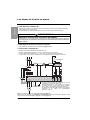 6
6
-
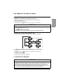 7
7
-
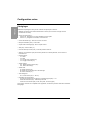 8
8
-
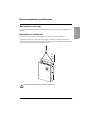 9
9
-
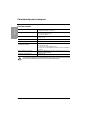 10
10
-
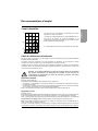 11
11
-
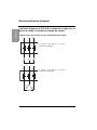 12
12
-
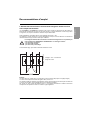 13
13
-
 14
14
-
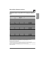 15
15
-
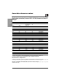 16
16
-
 17
17
-
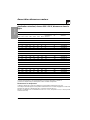 18
18
-
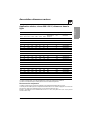 19
19
-
 20
20
-
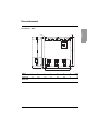 21
21
-
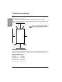 22
22
-
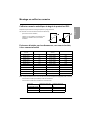 23
23
-
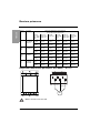 24
24
-
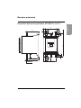 25
25
-
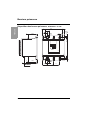 26
26
-
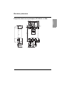 27
27
-
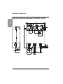 28
28
-
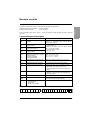 29
29
-
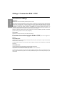 30
30
-
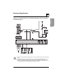 31
31
-
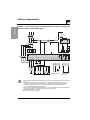 32
32
-
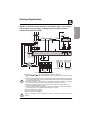 33
33
-
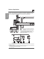 34
34
-
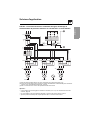 35
35
-
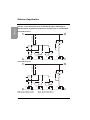 36
36
-
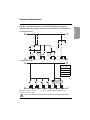 37
37
-
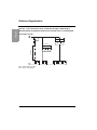 38
38
-
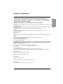 39
39
-
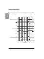 40
40
-
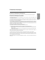 41
41
-
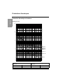 42
42
-
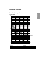 43
43
-
 44
44
-
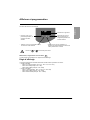 45
45
-
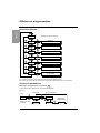 46
46
-
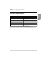 47
47
-
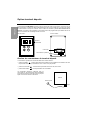 48
48
-
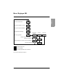 49
49
-
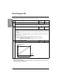 50
50
-
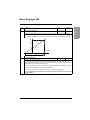 51
51
-
 52
52
-
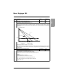 53
53
-
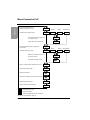 54
54
-
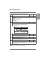 55
55
-
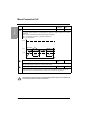 56
56
-
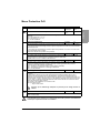 57
57
-
 58
58
-
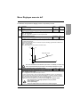 59
59
-
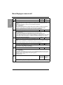 60
60
-
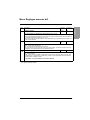 61
61
-
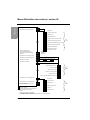 62
62
-
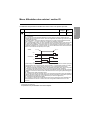 63
63
-
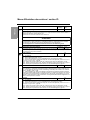 64
64
-
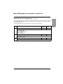 65
65
-
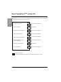 66
66
-
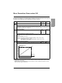 67
67
-
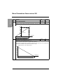 68
68
-
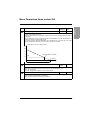 69
69
-
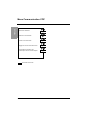 70
70
-
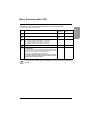 71
71
-
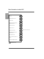 72
72
-
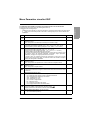 73
73
-
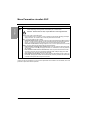 74
74
-
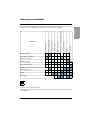 75
75
-
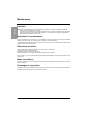 76
76
-
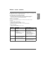 77
77
-
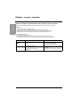 78
78
-
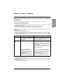 79
79
-
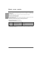 80
80
-
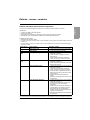 81
81
-
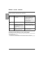 82
82
-
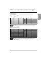 83
83
-
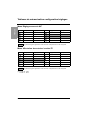 84
84
-
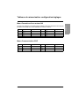 85
85
-
 86
86
-
 87
87
-
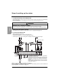 88
88
-
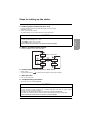 89
89
-
 90
90
-
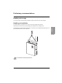 91
91
-
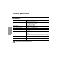 92
92
-
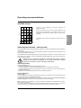 93
93
-
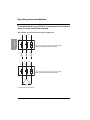 94
94
-
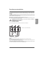 95
95
-
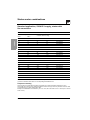 96
96
-
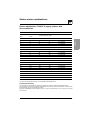 97
97
-
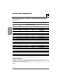 98
98
-
 99
99
-
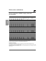 100
100
-
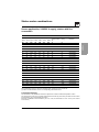 101
101
-
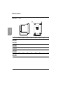 102
102
-
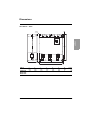 103
103
-
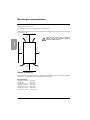 104
104
-
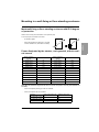 105
105
-
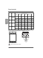 106
106
-
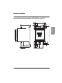 107
107
-
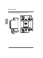 108
108
-
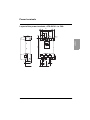 109
109
-
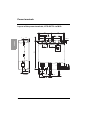 110
110
-
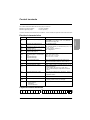 111
111
-
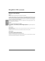 112
112
-
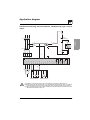 113
113
-
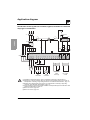 114
114
-
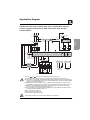 115
115
-
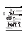 116
116
-
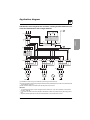 117
117
-
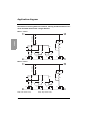 118
118
-
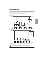 119
119
-
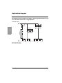 120
120
-
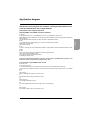 121
121
-
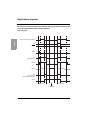 122
122
-
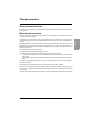 123
123
-
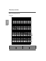 124
124
-
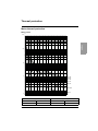 125
125
-
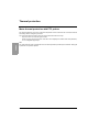 126
126
-
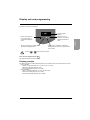 127
127
-
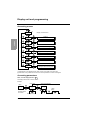 128
128
-
 129
129
-
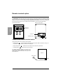 130
130
-
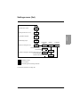 131
131
-
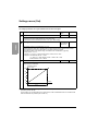 132
132
-
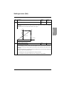 133
133
-
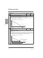 134
134
-
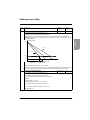 135
135
-
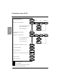 136
136
-
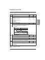 137
137
-
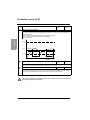 138
138
-
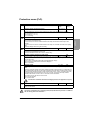 139
139
-
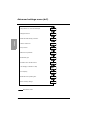 140
140
-
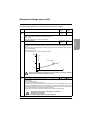 141
141
-
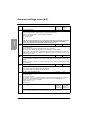 142
142
-
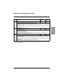 143
143
-
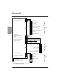 144
144
-
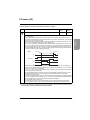 145
145
-
 146
146
-
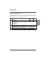 147
147
-
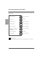 148
148
-
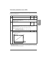 149
149
-
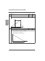 150
150
-
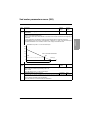 151
151
-
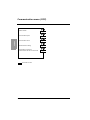 152
152
-
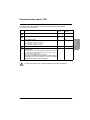 153
153
-
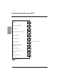 154
154
-
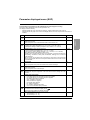 155
155
-
 156
156
-
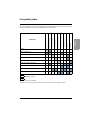 157
157
-
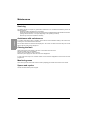 158
158
-
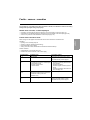 159
159
-
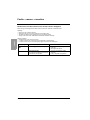 160
160
-
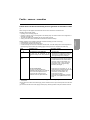 161
161
-
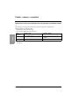 162
162
-
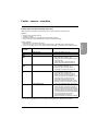 163
163
-
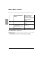 164
164
-
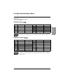 165
165
-
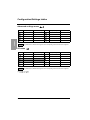 166
166
-
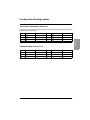 167
167
-
 168
168
-
 169
169
-
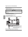 170
170
-
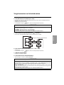 171
171
-
 172
172
-
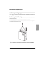 173
173
-
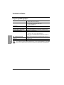 174
174
-
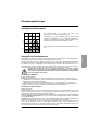 175
175
-
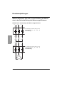 176
176
-
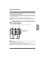 177
177
-
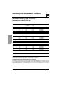 178
178
-
 179
179
-
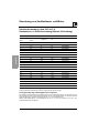 180
180
-
 181
181
-
 182
182
-
 183
183
-
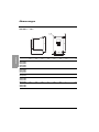 184
184
-
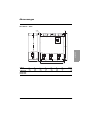 185
185
-
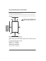 186
186
-
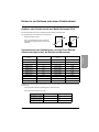 187
187
-
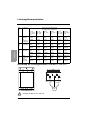 188
188
-
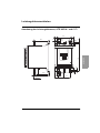 189
189
-
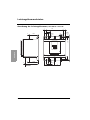 190
190
-
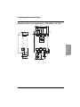 191
191
-
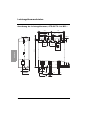 192
192
-
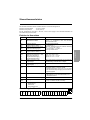 193
193
-
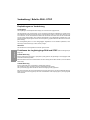 194
194
-
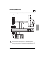 195
195
-
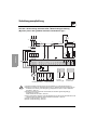 196
196
-
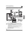 197
197
-
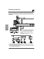 198
198
-
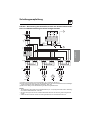 199
199
-
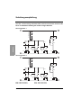 200
200
-
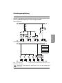 201
201
-
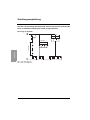 202
202
-
 203
203
-
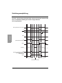 204
204
-
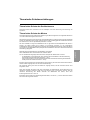 205
205
-
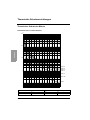 206
206
-
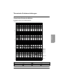 207
207
-
 208
208
-
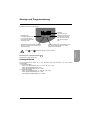 209
209
-
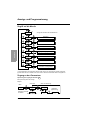 210
210
-
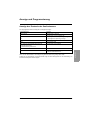 211
211
-
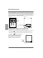 212
212
-
 213
213
-
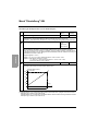 214
214
-
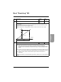 215
215
-
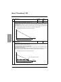 216
216
-
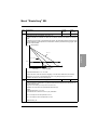 217
217
-
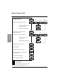 218
218
-
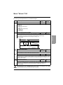 219
219
-
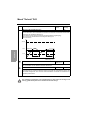 220
220
-
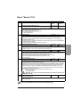 221
221
-
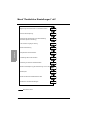 222
222
-
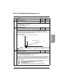 223
223
-
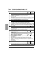 224
224
-
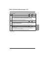 225
225
-
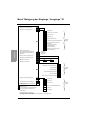 226
226
-
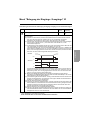 227
227
-
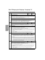 228
228
-
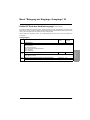 229
229
-
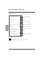 230
230
-
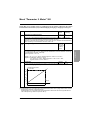 231
231
-
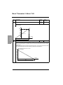 232
232
-
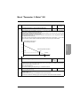 233
233
-
 234
234
-
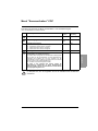 235
235
-
 236
236
-
 237
237
-
 238
238
-
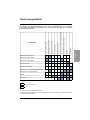 239
239
-
 240
240
-
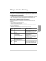 241
241
-
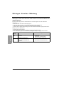 242
242
-
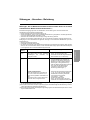 243
243
-
 244
244
-
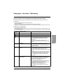 245
245
-
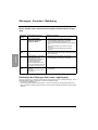 246
246
-
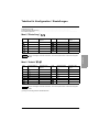 247
247
-
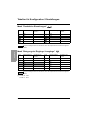 248
248
-
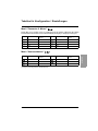 249
249
-
 250
250
-
 251
251
-
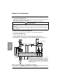 252
252
-
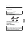 253
253
-
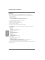 254
254
-
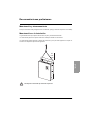 255
255
-
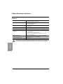 256
256
-
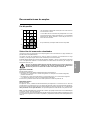 257
257
-
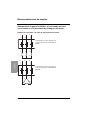 258
258
-
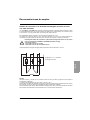 259
259
-
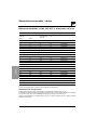 260
260
-
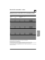 261
261
-
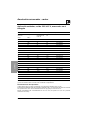 262
262
-
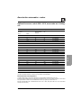 263
263
-
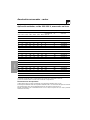 264
264
-
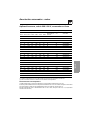 265
265
-
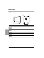 266
266
-
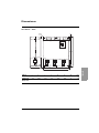 267
267
-
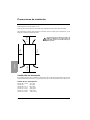 268
268
-
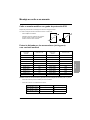 269
269
-
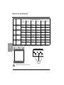 270
270
-
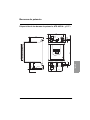 271
271
-
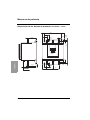 272
272
-
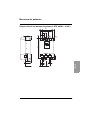 273
273
-
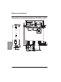 274
274
-
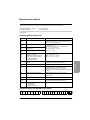 275
275
-
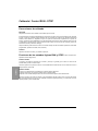 276
276
-
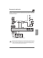 277
277
-
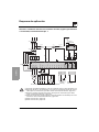 278
278
-
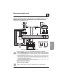 279
279
-
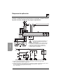 280
280
-
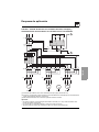 281
281
-
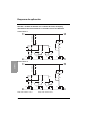 282
282
-
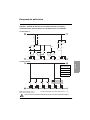 283
283
-
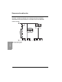 284
284
-
 285
285
-
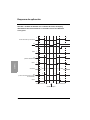 286
286
-
 287
287
-
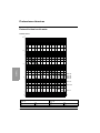 288
288
-
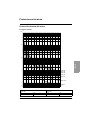 289
289
-
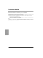 290
290
-
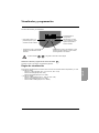 291
291
-
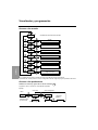 292
292
-
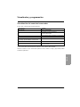 293
293
-
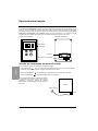 294
294
-
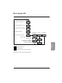 295
295
-
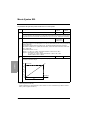 296
296
-
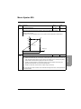 297
297
-
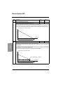 298
298
-
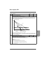 299
299
-
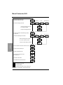 300
300
-
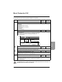 301
301
-
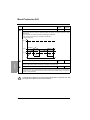 302
302
-
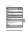 303
303
-
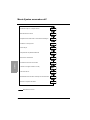 304
304
-
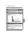 305
305
-
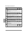 306
306
-
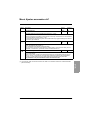 307
307
-
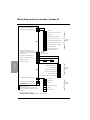 308
308
-
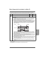 309
309
-
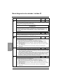 310
310
-
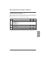 311
311
-
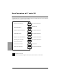 312
312
-
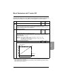 313
313
-
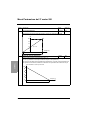 314
314
-
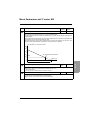 315
315
-
 316
316
-
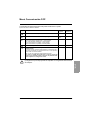 317
317
-
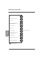 318
318
-
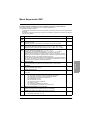 319
319
-
 320
320
-
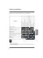 321
321
-
 322
322
-
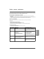 323
323
-
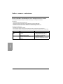 324
324
-
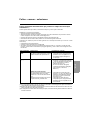 325
325
-
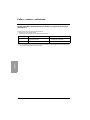 326
326
-
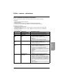 327
327
-
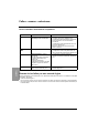 328
328
-
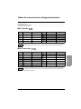 329
329
-
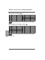 330
330
-
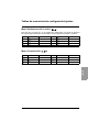 331
331
-
 332
332
-
 333
333
-
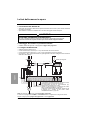 334
334
-
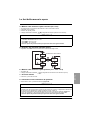 335
335
-
 336
336
-
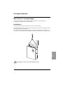 337
337
-
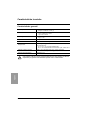 338
338
-
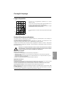 339
339
-
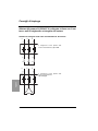 340
340
-
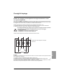 341
341
-
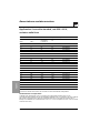 342
342
-
 343
343
-
 344
344
-
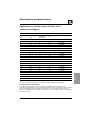 345
345
-
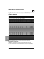 346
346
-
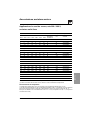 347
347
-
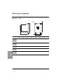 348
348
-
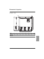 349
349
-
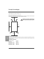 350
350
-
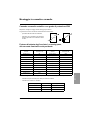 351
351
-
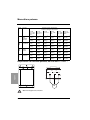 352
352
-
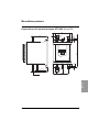 353
353
-
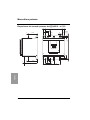 354
354
-
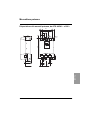 355
355
-
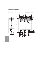 356
356
-
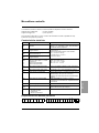 357
357
-
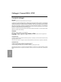 358
358
-
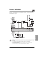 359
359
-
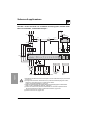 360
360
-
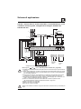 361
361
-
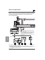 362
362
-
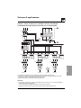 363
363
-
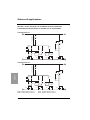 364
364
-
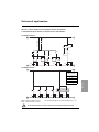 365
365
-
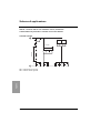 366
366
-
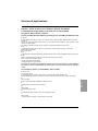 367
367
-
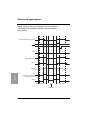 368
368
-
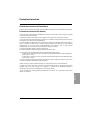 369
369
-
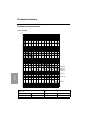 370
370
-
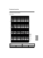 371
371
-
 372
372
-
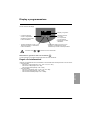 373
373
-
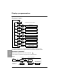 374
374
-
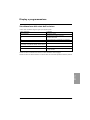 375
375
-
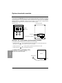 376
376
-
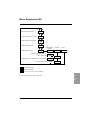 377
377
-
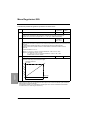 378
378
-
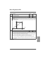 379
379
-
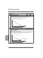 380
380
-
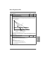 381
381
-
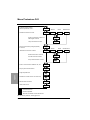 382
382
-
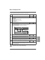 383
383
-
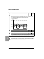 384
384
-
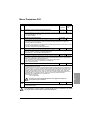 385
385
-
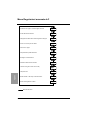 386
386
-
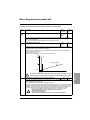 387
387
-
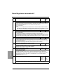 388
388
-
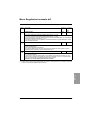 389
389
-
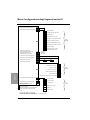 390
390
-
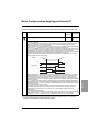 391
391
-
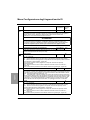 392
392
-
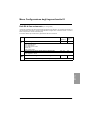 393
393
-
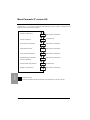 394
394
-
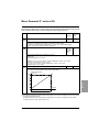 395
395
-
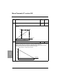 396
396
-
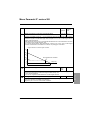 397
397
-
 398
398
-
 399
399
-
 400
400
-
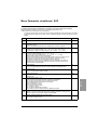 401
401
-
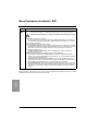 402
402
-
 403
403
-
 404
404
-
 405
405
-
 406
406
-
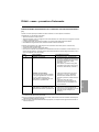 407
407
-
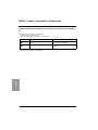 408
408
-
 409
409
-
 410
410
-
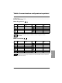 411
411
-
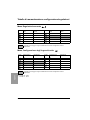 412
412
-
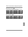 413
413
-
 414
414
-
 415
415
-
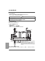 416
416
-
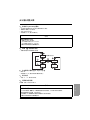 417
417
-
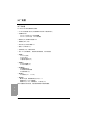 418
418
-
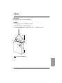 419
419
-
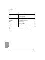 420
420
-
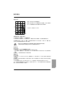 421
421
-
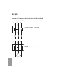 422
422
-
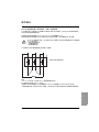 423
423
-
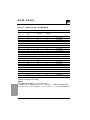 424
424
-
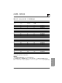 425
425
-
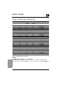 426
426
-
 427
427
-
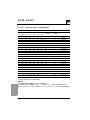 428
428
-
 429
429
-
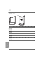 430
430
-
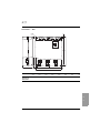 431
431
-
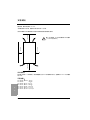 432
432
-
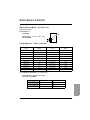 433
433
-
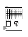 434
434
-
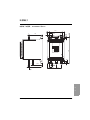 435
435
-
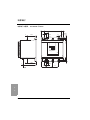 436
436
-
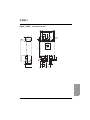 437
437
-
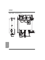 438
438
-
 439
439
-
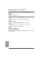 440
440
-
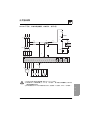 441
441
-
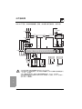 442
442
-
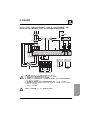 443
443
-
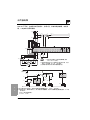 444
444
-
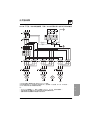 445
445
-
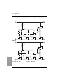 446
446
-
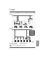 447
447
-
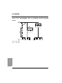 448
448
-
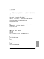 449
449
-
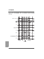 450
450
-
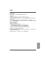 451
451
-
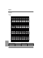 452
452
-
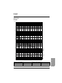 453
453
-
 454
454
-
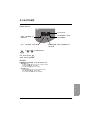 455
455
-
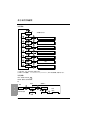 456
456
-
 457
457
-
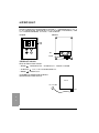 458
458
-
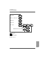 459
459
-
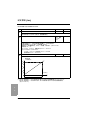 460
460
-
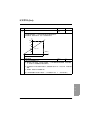 461
461
-
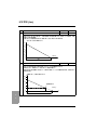 462
462
-
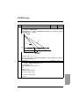 463
463
-
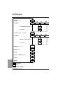 464
464
-
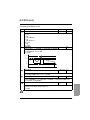 465
465
-
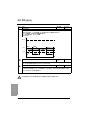 466
466
-
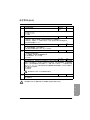 467
467
-
 468
468
-
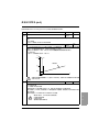 469
469
-
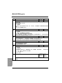 470
470
-
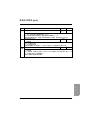 471
471
-
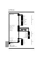 472
472
-
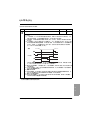 473
473
-
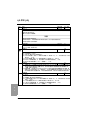 474
474
-
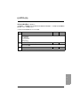 475
475
-
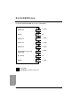 476
476
-
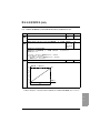 477
477
-
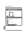 478
478
-
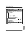 479
479
-
 480
480
-
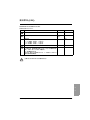 481
481
-
 482
482
-
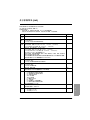 483
483
-
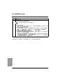 484
484
-
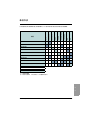 485
485
-
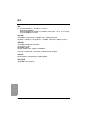 486
486
-
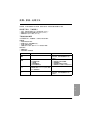 487
487
-
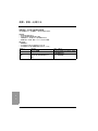 488
488
-
 489
489
-
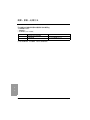 490
490
-
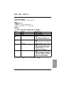 491
491
-
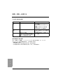 492
492
-
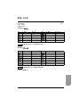 493
493
-
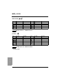 494
494
-
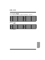 495
495
-
 496
496


en otros idiomas
- français: Eurotherm ATS48 Manuel utilisateur
- italiano: Eurotherm ATS48 Manuale utente
- English: Eurotherm ATS48 User manual
- Deutsch: Eurotherm ATS48 Benutzerhandbuch
Artículos relacionados
Otros documentos
-
 TELEMECANIQUE ALTIVAR 31 El manual del propietario
-
Schneider Electric Altistart 48 Soft Start Units in Motor Control Centers Instruction Sheet
-
Tripp Lite PDUMNH16HVAT, PDUMNH20HVAT, PDUMNH30HVAT and PDUMNH32HVAT El manual del propietario
-
Champion Power Equipment Model #100510 Manual de usuario
-
Bticino M7000CBNCU03 Instrucciones de operación
-
-
Champion Power Equipment 100237 Manual de usuario
-
Eaton EATS30N Installation and User Manual
-
-
