Fanimation LP8294LBN El manual del propietario
- Categoría
- Ventiladores domésticos
- Tipo
- El manual del propietario

Questions, problems, missing parts? Before returning to your retailer, call our customer
service department at 1-800-643-0067, 8 a.m. - 6 p.m., EST, Monday - Thursday, 8 a.m. - 5
p.m., EST, Friday.
1
EB13442
ATTACH YOUR RECEIPT HERE
Serial Number ____________ Purchase Date ____________
Harbor Breeze
®
is a registered trademark
of LF, LLC. All Rights Reserved.
Lowes.com/harborbreeze
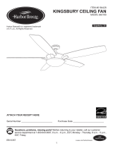
ITEM #0464466
SANTA ANA CEILING FAN
MODEL #LP8294LBN
Español p. 24

2
Lowes.com/harborbreeze
TABLE OF CONTENTS
Package Contents . . . . . . . . . . . . . . . . . . . . . . . . . . . . . . . . . . . . . . . . . . . . . . . . . . . . . . . . . . . . . . 3
Hardware Contents . . . . . . . . . . . . . . . . . . . . . . . . . . . . . . . . . . . . . . . . . . . . . . . . . . . . . . . . . . . . . 4
Safety Information . . . . . . . . . . . . . . . . . . . . . . . . . . . . . . . . . . . . . . . . . . . . . . . . . . . . . . . . . . . . . . 5
Preparation. . . . . . . . . . . . . . . . . . . . . . . . . . . . . . . . . . . . . . . . . . . . . . . . . . . . . . . . . . . . . . . . . . . . 6
Initial Assembly Instructions . . . . . . . . . . . . . . . . . . . . . . . . . . . . . . . . . . . . . . . . . . . . . . . . . . . . . . . 7
Wiring Instructions . . . . . . . . . . . . . . . . . . . . . . . . . . . . . . . . . . . . . . . . . . . . . . . . . . . . . . . . . . . . . 13
Final Assembly Instructions . . . . . . . . . . . . . . . . . . . . . . . . . . . . . . . . . . . . . . . . . . . . . . . . . . . . . . 14
Operating Instructions . . . . . . . . . . . . . . . . . . . . . . . . . . . . . . . . . . . . . . . . . . . . . . . . . . . . . . . . . . 16
Blade Balancing Instructions . . . . . . . . . . . . . . . . . . . . . . . . . . . . . . . . . . . . . . . . . . . . . . . . . . . . . 19
Care and Maintenance . . . . . . . . . . . . . . . . . . . . . . . . . . . . . . . . . . . . . . . . . . . . . . . . . . . . . . . . . . 20
Troubleshooting . . . . . . . . . . . . . . . . . . . . . . . . . . . . . . . . . . . . . . . . . . . . . . . . . . . . . . . . . . . . . . . 21
Warranty . . . . . . . . . . . . . . . . . . . . . . . . . . . . . . . . . . . . . . . . . . . . . . . . . . . . . . . . . . . . . . . . . . . . . 22
Replacement Parts List . . . . . . . . . . . . . . . . . . . . . . . . . . . . . . . . . . . . . . . . . . . . . . . . . . . . . . . . . 23

3
Lowes.com/harborbreeze
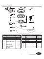
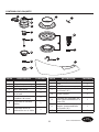
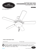
PACKAGE CONTENTS
F
G
I
J
K
L
M
A
N
O
B
C
D
E
2
H
P
12V
PART DESCRIPTION QUANTITY PART DESCRIPTION QUANTITY
1rotoMA
B Hanger Bracket 1
2
2
edalBJ
I
1dornwoDC
1bluBK
L
1yponaC gnilieCD
E Canopy Screw Cover
Receiver (preassembled to
Motor (A))
1
1etomeRM
N
O
1
1
1
1
revoC gnilpuoC rotoMF
G
H
Lower Housing
Assembly
Motor Coupler Washer
(preassembled to Motor (A))
1
Light Kit Assembly
with Glass
Upper Housing Cover
(preassembled to Motor (A))
1
1
yrettaBP
Blade Holder Arm
H

4
Lowes.com/harborbreeze
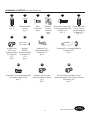
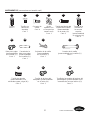
HARDWARE CONTENTS (shown actual size)
AA BB CC DD EE FF
Screw
Qty. 5
Washer-Head
Screw
Qty. 7
Wire
Connector
Qty. 4
Balance
Kit (not
shown to
size)
Qty. 1
Downrod Support Set
Screw (preassembled
to Motor (A))
Qty. 2
Upper Housing
Cover Screw
(preassembled
to Motor (A))
Qty. 6
GG HH II JJ
Hanger Ball
Set Screw
(preassembled
to Downrod
(C))
Qty. 1
Hanger
Ball Pin
(preassembled
to Downrod
(C))
Qty. 1
Downrod Clip
(preassembled to
Downrod (C))
Qty. 1
Downrod Pin (preassembled to
Downrod (C))
Qty. 1
KK LL
MM
Shoulder Screw (preassembled
to Hanger Bracket (B))
Qty. 2
Adapter Plate Screw
(preassembled to Motor
(A))
Qty. 3
Socket Plate Assembly Screw
(preassembled to the Lower Housing
Assembly (G))
Qty. 3

5
Lowes.com/harborbreeze
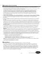
SAFETY INFORMATION
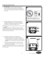
Please read and understand this entire manual before attempting to assemble, operate, or install the
product.
• Before you begin installing the fan, disconnect the power by removing fuses or turning off circuit
breakers.
• Make sure all electrical connections comply with local codes, ordinances, or the National Electrical
code. Hire a qualifi ed electrician or consult a do-it-yourself wiring handbook if you are unfamiliar
with installing electrical wiring.
• Make sure the installation site you choose allows a minimum clearance of 7 ft. from the blades to
the fl oor and at least 30 in. from the ends of the blades to any obstruction.
• If you are mounting the fan to a ceiling outlet box, use a METAL octagonal outlet box.
• Secure the box directly to the building structure. The outlet box and its support must be able to
support the moving weight of the fan (at least 35 lbs.). Do NOT use a plastic outlet box.
• After you install the fan, make sure all connections are secure to prevent the fan from falling.
• For supply connections, if the conductor of a fan is identifi ed as a grounded conductor, then it
should be connected to a grounded conductor power supply. If the conductor of a fan is identifi ed
as an ungrounded conductor, then it should be connected to an ungrounded conductor power
supply. If the conductor of a fan is identifi ed for equipment grounding, then it should be connected
to an equipment-grounding conductor.
• This device complies with Part 15 of the FCC Rules. Operation is subject to the following two
conditions: (1) This device may not cause harmful interference, and (2) this device must accept any
interference received, including interference that may cause undesired operation.
Note: This equipment has been tested and found to comply with the limits for Class B digital
device, pursuant to part 15 of the FCC Rules. These limits are designed to provide reasonable
protection against harmful interference in a residential installation. This equipment generates,
uses and can radiate radio frequency energy and, if not installed and used in accordance with
the instructions, may cause harmful interference to radio or television reception, which can be
determined by turning the equipment off and on, the user is encouraged to try to correct the
interference by one or more of the following measures:
– Reorient or relocate the receiving antenna.
– Increase the separation between the equipment and the receiver.
– Connect the equipment into an outlet on a circuit different from that to which the receiver is
connected.
– Consult the dealer or an experienced radio/TV technician for help.
Note: For a Class A digital device, statements of 15. 105(a) must be included when appropriate for
the device in question.
• The net weight of this fan is: 20.68 lbs.
WARNING:
• Do not install or use this fan if any part is damaged or missing.
• To reduce the risk of fi re, electrical shock, or personal injury, wire connectors provided with this
fan are designed to accept only one 12-gauge house wire and two lead wires from the fan. If your
house wire is larger than 12 gauges or there is more than one house wire to connect to the two fan
lead wires, consult an electrician for the proper size wire connectors to use. Before cutting, drilling
or hammering, verify their location. If needed, contact your electrician, plumber or service person.

6
Lowes.com/harborbreeze
SAFETY INFORMATION
To reduce the risk of ¿ re, electric shock, or personal injury, do not bend the blade arms when
installing them, balancing the blades, or cleaning the fan. Do not insert foreign objects between the
rotating fan blades. Mount the fan to an outlet box marked “ACCEPTABLE FOR FAN SUPPORT”
and use mounting screws provided with the outlet box. Most outlet boxes commonly used for the
support of lighting ¿ xtures are not acceptable for fan support and may need to be replaced. Consult
a quali¿ ed electrician if in doubt.
This fan is to be used in dry locations only.
PREPARATION
Before beginning assembly of product, make sure all parts are present. Compare parts with package
contents list and hardware contents list. If any part is missing or damaged, do not attempt to
assemble the product.
Estimated Assembly Time: 60 minutes
Tools Required for Assembly (not included): Phillips screwdriver, 1/4 in. À athead screwdriver, wire
strippers and step ladder
Helpful Tools (not included): AC tester light, do-it-yourself wiring handbook and wire cutters
'RQRWRSHUDWHWKLVIDQZLWKDYDULDEOH5KHRVWDWZDOOFRQWUROOHURUGLPPHUVZLWFK'RLQJVRFRXOG
result in damage to the ceiling fan's remote control unit.

7
Lowes.com/harborbreeze
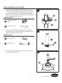
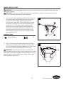
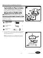
INITIAL ASSEMBLY INSTRUCTIONS
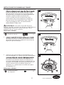
1. Remove the two preassembled downrod support set
screws (EE) on the downrod support from the motor
(A). Retain the screws for later.
Hardware Used
EE
Downrod Support
Set Screws
x 2
1
A
EE
2. Remove the preassembled upper housing cover
screws (FF) from the top of the motor (A). Retain
these screws for later.
Hardware Used
FF
Upper Housing
Cover Screws
x 6
2
A
FF
3. Remove the motor coupler washer (N) and upper
housing cover (O) from the motor (A).
3
A
O
N

8
Lowes.com/harborbreeze
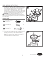
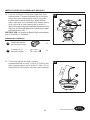
INITIAL ASSEMBLY INSTRUCTIONS
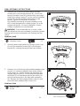
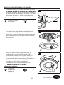
4. Position the blade holder arm (I) over the motor (A)
with threaded posts showing. Make sure the bottom
edge of the blade holder arm (I) is fully seated
against the À ywheel of the motor (A). Attach the
screws (AA) to secure the blade holder arm (I) to the
À ywheel of the motor (A). Repeat for the other blade
holder arm (I).
WARNING: To reduce the risk of personal injury, do
not bend the blade holders when installing, balancing the
blades, or cleaning the fan. Do not insert foreign objects
in between the rotating blades.
Hardware Used
AA
Screw x 4
4
AA
I
A
5. Re-assemble the upper housing cover (O) and motor
coupler washer (N) to motor (A).
5
N
O
6. Secure the motor coupler washer (N) and upper
housing cover (O) using the previously removed
upper housing cover screws (FF). Securely tighten.
Hardware Used
FF
Upper Housing
Cover Screw
x 6
6
N
FF
O

9
Lowes.com/harborbreeze
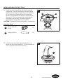
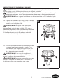
INITIAL ASSEMBLY INSTRUCTIONS
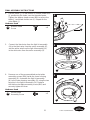
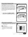
7. Loosen the preassembled hanger ball set screw (GG)
until the hanger ball falls freely down the downrod
(C). Remove the preassembled hanger ball pin (HH)
from the downrod (C) and remove the hanger ball
portion of the downrod (C). Retain the hanger ball pin
(HH) and hanger ball for later.
Hardware Used
GG
Hanger Ball Set
Scre
x 1
HH
Hanger Ball Pin x 1
7
HH
C
GG
8. Remove the preassembled downrod clip (II) and
downrod pin (JJ) from the bottom of the downrod (C).
Retain these two parts for later.
Hardware Used
II
Downrod Clip x 1
JJ
Downrod Pin x 1
8
9. Route the black and white wires from the motor (A)
through the downrod (C).
9
C
A
JJ
II
C

10
Lowes.com/harborbreeze
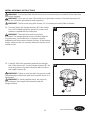
INITIAL ASSEMBLY INSTRUCTIONS
10. Thread the downrod (C) into the downrod support of
the motor (A). Align the holes in the downrod support
of the motor (A) with the holes in the downrod (C)
and re-install the downrod pin (JJ). Secure the
downrod pin (JJ) with the downrod clip (II). Re-install
the two downrod support set screws (EE) and tighten
securely in the downrod support of the motor (A).
WARNING: It is critical the downrod pin (JJ) is
properly installed and the downrod support set screws
(EE) are securely tightened. Failure to do so could result
in the fan falling.
Hardware Used
EE
Downrod Support
Set Screw
x 2
II
Downrod Clip x 1
JJ
Downrod Pin x 1
10
C
EE
A
JJ
II
II
JJ
11. Route the wires through the motor coupling cover (F),
canopy screw cover (E) and ceiling canopy (D).
Note: The keyslots of the canopy screw cover (E)
should be toward the ceiling direction.
11
D
F
E

11
Lowes.com/harborbreeze
INITIAL ASSEMBLY INSTRUCTIONS
12. Route the wires through the previously removed
hanger ball. Insert the previously removed hanger
ball pin (HH) through the two holes in the downrod
(C) and align the hanger ball so the hanger ball
pin (HH) is captured in the groove in the top of the
downrod (C). Pull the hanger ball up tight against
the hanger ball pin (HH). Securely tighten the
preassembled hanger ball set screw (GG).
CAUTION: A loose set screw could result in a wobbly fan.
Hardware Used
GG
Hanger Ball Set
Screw
x 1
HH
Hanger Ball Pin x 1
12
GG
HH
C
13. Cut off excess lead wire approximately 6 to 9 in.
above the top of the downrod (C). Strip insulation off
1/2 in. from the end of each lead wire.
13
C

12
Lowes.com/harborbreeze
INITIAL ASSEMBLY INSTRUCTIONS
WARNING: To avoid possible electrical shock, be sure electricity is turned off at the main fuse
box before hanging.
WARNING: If you are not sure if the outlet box is grounded, contact a licensed electrician for
advice, as it must be grounded for safe operation.
WARNING: The fan must hang with at least 7 ft. of clearance from the fl oor to blades.
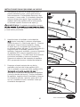
14. Securely attach the hanger bracket (B) to the outlet
box (not included) using the outlet box screws and
washers supplied with the outlet box.
WARNING: The outlet box must be securely
anchored. The hanger bracket must seat fi rmly against
the outlet box. If the outlet box is recessed, remove
wallboard until the bracket contacts the box. If the bracket
and/or outlet box are not securely attached, the fan could
wobble or fall.
14
B
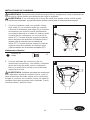
15. Carefully lift the fan assembly and seat the hanger
ball of the downrod (C) on the hanger bracket (B). Be
sure the groove in the ball is lined up with the tab on
the hanger bracket (B).
WARNING: Failure to seat the tab in the groove could
cause damage to electrical wires and possible shock or a
fi re hazard.
WARNING:To avoid possible shock, do not pinch
wires between the hanger ball assembly and the
hanger bracket.
15
C
B

13
Lowes.com/harborbreeze
WIRING INSTRUCTIONS
WARNING: To avoid possible electrical shock, be sure electricity is turned off at the main fuse
box before hanging.
WARNING: If you are not sure if the outlet box is grounded, contact a licensed electrician for
advice, as it must be grounded for safe operation.
1. Connect the green grounding lead from the downrod
(C) and the green grounding lead from the hanger
bracket (B) to the supply grounding conductor
(this may be a bare wire or wire with green colored
insulation). Securely connect the wires with a wire
connector (CC). Securely connect the white fan
motor wire to the white supply (neutral) wire and
secure the connection with a wire connector (CC).
Securely connect the black fan motor wire to the
black supply wire and secure the connection with a
wire connector (CC).
Hardware Used
CC
Wire Connector x 3
1
CC
CC
C
B
2. After connections have been made, turn the leads
upward and carefully push the leads into the outlet
box, with the white and green leads to one side of the
box and the black leads toward the other side.
WARNING: Check to see that all connections are
tight, including the ground wire, and no bare wire is visible
at the wire connectors except for the ground wire. Do not
operate the fan until the blades are in place. Noise and
motor damage could result.
2

14
Lowes.com/harborbreeze
FINAL ASSEMBLY INSTRUCTIONS
1. Remove one of the two preassembled shoulder
screws (KK) in the hanger bracket (B). Loosen the
second shoulder screw (KK) without fully removing it.
Rotate the ceiling canopy (D) so the second shoulder
screw (KK) moves into the small opening of the
keyslot. Tighten the shoulder screw (KK).
Re-install the previously removed shoulder screw
(KK) to fully assemble the ceiling canopy (D) to the
hanger bracket (B). For easy installation, a short
Phillips screwdriver is recommended.
WARNING: To avoid possible ¿ re or shock, make
sure the electrical wires are completely inside the canopy
housing and not pinched between the housing and the
ceiling.
Hardware Used
KK
Shoulder Screw x 1
1
D
KK
2. Securely attach and tighten the canopy screw cover
(E) over the shoulder screws (KK) in the hanger
bracket (B), utilizing the keyslot twist-lock feature.
2
E
3. Remove one of the three preassembled adapter plate
screws (LL) inside the adapter plate at the bottom
of the motor (A). Slightly loosen the remaining two
adapter plate screws (LL). Assemble the light plate
assembly (G) to the adapter plate of the motor (A)
using the two keyslots in the light plate assembly
(G). Replace the third adapter plate screw (LL) and
secure all three adapter plate screws (LL).
Hardware Used
LL
Adapter Plate
Screw
x 3
3
LL
G
A

15
Lowes.com/harborbreeze
FINAL ASSEMBLY INSTRUCTIONS
4. Place a blade (J) on the bottom of a blade holder arm
(I), positioning the holes over the threaded posts.
Tighten the washer-head screws (BB) to secure the
blade (J) and blade holder arm (I). Repeat for the
other blade (J).
Hardware Used
BB
Washer-Head
Screw
x 6
4
J
I
BB
5
A
H
6. Remove one of the preassembled socket plate
assembly screws (MM) inside the lower housing
assembly (G). Assemble the ligth kit assembly
(H) to the lower housing assembly (G) using the two
keyslots in the ligth kit assembly (H). Replace
the third socket plate assembly screw (MM) and
securely tighten all three.
Hardware Used
MM
Socket Plate
Assembly Screw
x 3
6
H
G
MM
5. Connect the black wire from the ligth kit assembly
(H) to the black wire from the motor assembly (A),
and the white wire from the ligth kit assembly (H)
to the white wire from the motor assembly (A).

16
Lowes.com/harborbreeze
FINAL ASSEMBLY INSTRUCTIONS
7. Install the bulb (K) into the socket.
CAUTION: Bulbs are pressurized and may shatter. DO
NOT TOUCH BULBS WITH BARE HANDS. Fingerprints
may result in shorter bulb life. Remove ¿ ngerprints with
alcohol prior to use. To reduce the risk of ¿ re, use a 100-
watt max. type T4-minican JD E11 tungsten halogen bulb.
Turn off the wall switch and allow the bulb to cool for 10
minutes before relamping.
7
K
8. Securely attach the glass by twisting clockwise
onto the light kit assembly (H). Do not overtighten
or force it.
8
H
OPERATING INSTRUCTIONS
1. Restore electrical power to the outlet box by turning
the electricity on at the main fuse box.
1
ON
ON
ON
ON
ON
ON
ON
ON
WARNING
Do not operate this fan with a variable (Rheostat)
wall controller or dimmer switch. Doing so could
result in damage to the ceiling fan's remote control
unit.

17
Lowes.com/harborbreeze
OPERATING INSTRUCTIONS
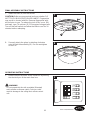
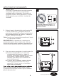
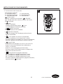
3. Remove the battery cover from the remote (M)
and install the battery (P), ensuring the polarity of
the battery (P) matches the polarity in the battery
compartment. Replace the battery cover.
Note:When it is time to replace battery (P), use a 12-volt
battery.
CAUTION: If you are not expecting to use the remote
for a long period of time, remove the battery to prevent
damage to the remote. Be sure to store the remote away
from excess heat or humidity.
3
M
12V
P
4. Follow these steps to set the remote (M):
a) Slide the dip switch to “1” inside the battery
compartment and turn the power to the fan OFF.
Turn the power ON. The receiver (L) will make two
musical sounds, indicating that the power supply is
normal.
b) Within 30 seconds, press the “LEARN” key on
the back of the remote (M). Your remote and fan
should be synchronized.
To verify successful synchronization, the ceiling fan light
will blink 3 times and remain ON, and the fan will rotate
on HIGH speed.
4
M
12V
a
b
22
2.
IMPORTANT: Using a full range dimmer switch
(not included) to control fan speed will damage
the fan. To reduce the risk of fire or electrical shock,
do not use a full range dimmer switch to control the
fan speed.
For illustrative purposes only-not
intended to cover all types of controls

18
Lowes.com/harborbreeze
OPERATING INSTRUCTIONS
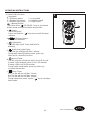
5. Remote (M) functions:
1 = Minimum speed
3 = Medium low speed 4 = Medium speed
5 = Medium high speed
= Natural breeze
Tap either of the “ /1/2/3/4/5/6 ” keys to exit natural
breeze mode and shift to relative key function.
Button:
Turns the fan off.
Press and hold the “ ” key to turn on/off the beep
indicator.
Reverse button:
Controls fan direction.
Turns the light on/off. Press and hold for
dimming.
Light button:
Fan speed:
Walk Away Light Delay:
Turns the fan and light off after 1 minute.
During walk away light delay mode, press any
other key to cancel the function.
Home Shield:
The fan is turned off with the light in the A-B-A cycle.
A mode: Light randomly turns on for 5-20 minutes.
B mode: Light is off for 60 minutes.
During home shield mode, press any other key
to cancel the function.
Sleep Timer:
2H: The fan will turn off after 2 hours.
4H: The fan will turn off after 4 hours.
8H: The fan will turn off after 8 hours.
During sleep timer mode, tap the “ ” key to exit sleep
timer mode.
6 = High speed
2 = Low speed
5
M
2
H

19
Lowes.com/harborbreeze
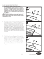
BLADE BALANCING INSTRUCTIONS
1. Interchanging positions of adjacent blades (J)
can redistribute the weight and result in smoother
operation. If wobble decreases, leave the blades (J)
as they are. If wobble increases, switch back to the
original position. Attach the balancing clip from the
balance kit (DD) to the mid-point on the top edge of
one blade (J).
WARNING: The balancing clip must always be ¿ rmly
pushed onto the blade until it touches the edge of the
blade. Failure to do so could allow the clip to À y off and
cause personal injury.
1
DD
J
2. Run the fan at high speed (air downÀ ow) and observe
wobble. Repeat steps 1 and 2 for each blade (J).
Note which blade (J) has the least wobble. On that
blade (J), install the balancing clip (DD) to the top
edge of the blade (J) near the motor (A). Start the
fan and observe wobble. Stop the fan and move the
balancing clip (DD) in small steps toward the end of
the blade (J). At each incremental step, turn on the
fan and observe the wobble. Determine the location
of the balancing clip (DD) that gives the least amount
of wobble.
2
DD
J
A
3. Peel the backing paper from one of the weighted
squares in the balance kit (DD). Secure the weighted
square in the balance kit (DD) ¿ rmly to the top of the
blade (J), centered at the balancing clip location
and between the edges of the blade (J). Remove
the balancing clip, start the fan and observe. If the
wobble still persists, repeat steps 1 through 3 with
the remaining weighted squares until the wobble
disappears.
3
DD
J

20
Lowes.com/harborbreeze
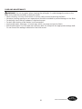
CARE AND MAINTENANCE
WARNING: Do not use water when cleaning the ceiling fan. It could damage the motor or the
fi nish and create the possibility of electrical shock.
• When cleaning, use only a soft brush or lint-free cloth to avoid scratching the fi nish.
• Abrasive cleaning agents are not required and should be avoided to prevent damage to the fi nish.
• Periodically check that all hardware is tight and secure.
• Periodic light dusting of the blades is recommended.
• Avoid using water, cleansers, or harsh rags, which can warp and ruin the fi nish.
• Bulb Replacement: Use 100-watt mini can-base bulb. Re-lamp with the appropriate wattage bulb.
Do not exceed the wattage indicated on the bulb socket.

21
Lowes.com/harborbreeze
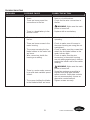
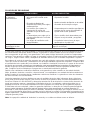
TROUBLESHOOTING
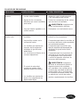
PROBLEM POSSIBLE CAUSE CORRECTIVE ACTION
The fan will not start. 1. The fuse or circuit breaker is
blown.
2. There are loose power line
connections to the fan.
3. There is a dead battery in the
remote control.
1. Check the main and branch circuit
fuses or circuit breakers.
2. Check the line wire connections to
the fan.
WARNING: Make sure the main
power is turned off.
3. Replace with a new battery.
The fan sounds noisy. 1. The blades are not attached to
the fan.
2. There are loose screws in the
motor housing.
3. The screws securing the fan
blade holders to the motor hub
are loose.
4. Wire connectors inside the
housing are rattling.
5. There is a motor noise caused
by a solid-state variable speed
control.
6. The screws holding the blades
to the blade holders are loose.
1. Attach the blades to the fan before
operating.
2. Check to make sure all screws in
the motor housing are snug (do not
overtighten).
3. Check to make sure the screws that
attach the fan blade holders to the
motor hub are tight.
4. Check to make sure the wire
connectors in the switch housing
are not rattling against each other or
against the interior wall of the switch
housing.
WARNING: Make sure the main
power is turned off.
5. Some fan motors are sensitive to
signals from solid-state variable
speed controls. Solid-state controls
are not recommended, choose an
alternative control method.
6. Tighten screws securely.

22
Lowes.com/harborbreeze
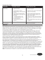
TROUBLESHOOTING
PROBLEM POSSIBLE CAUSE CORRECTIVE ACTION
The fan wobbles
excessively.
1. The set screw in the downrod
support is loose.
2. The set screw in the in
downrod/hanger ball assembly
is loose.
3. The screws securing the fan
blade holders to the motor hub
are loose.
4. The hanger bracket and/
or ceiling outlet box is not
securely fastened.
5. The fan blades are out of
balance.
1. Tighten the set screws securely in the
downrod support.
2. Tighten the set screw in the downrod/
hanger ball assembly.
3. Check to be sure the screws that
attach the fan blade holders to the
motor hub are tight.
4. Tighten the hanger bracket screws to
the outlet box, and secure the outlet
box.
5. Refer to Blade Balancing Instructions
on page 19.
There is not enough
air movement.
The downrod is too short. If possible, consider using a longer
downrod (not included).
WARRANTY
The manufacturer warrants this fan to be free from defects in workmanship and material present at
time of shipment from the factory. The warranty terms from the date of purchase. The motor has a
lifetime warranty, and a 2 year warranty for the light kit and all remaining components. This warranty
applies only to the original purchaser. The manufacturer agrees to correct such defect at no charge
or, at our option, replace the ceiling fan with a comparable or superior model.
To obtain warranty service, present a copy of your sales receipt as proof of purchase. All cost of
removal and reinstallation are the expressed responsibility of the purchaser. Any damage to the
ceiling fan by accident, misuse or improper installation, or by affi xing accessories not produced by
this warranty, are at the purchaser’s own responsibility. The manufacturer assumes no responsibility
whatsoever for fan installation during the lifetime limited warranty. Any service performed by an
unauthorized person will render the warranty invalid.
Due to varying climate conditions, this warranty does not cover changes in brass fi nish, rusting,
pitting, tarnishing, corroding, or peeling. Brass fi nish fans maintain their beauty when protected from
varying weather conditions. Any glass provided with this fan is not covered by the warranty.
Any replacement of defective parts for the ceiling fan must be reported within the fi rst year from the
date of purchase. For the balance of the warranty, call our customer service department at
1-800-643-0067 for return authorization and shipping instructions so that we may repair or replace the
ceiling f a n. Any fan or parts returned improperly packaged is the sole responsibility of the purchaser.
There is no further expressed warranty. The manufacturer disclaims any and all implied warranties.
The duration of any implied warranty which can not be disclaimed is limited to the lifetime limited
period as specifi ed in our warranty. The manufacturer shall not be liable for incidental, consequential
or special damages arising at or in connection with product use or performance except as may
otherwise be accorded by law. This warranty gives you specifi c legal rights and you also have other
rights which vary from state to state. This warranty supersedes all prior warranties.
Note: A small amount of “wobble” is normal and should not be considered a defect.

B
23
Lowes.com/harborbreeze
Printed in China
Harbor Breeze
®
is a registered trademark
of LF, LLC. All Rights Reserved.
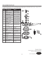
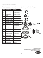
REPLACEMENT PARTS LIST
For replacement parts, call our customer service department at
1-800-643-0067, 8 a.m. - 6 p.m., EST,
Monday - Thursday, 8 a.m. - 5 p.m., EST, Friday.
PART DESCRIPTION PART #
A
Motor
AMA8294LBN
B
Hanger Bracket
APGAC110RBL
C
Hanger Ball/
Downrod Assembly
ADRACT1-6LBN
D
Ceiling Canopy
PPAC1005LBN
E
Canopy Screw
Cover
APPAC1101LBN
F
Motor Coupling
Cover
APPAC1403LBN
G
Lower Hosing
Assembly
AP829404LBN
H AP829406LBN
I
Blade Holder Arm
Light Kit Assembly
with Glass
AP815002-
16LBN
J
Blade
AP815004WA
K
Bulb
PPE11B100
L
Receiver Unit
RECDC8294
M
Remote
TR17
AA
Screw
HDWBH8150NI
BB
Washer Head
Screw
HDWBM8150NI
CC
Wire Connector
HDWWNUTS4
DD
Balance Kit
LBALKT
DD
AA
J
C
D
E
L
F
A
G
K
I
M
CC
BB
2
H
H

¿Preguntas, problemas, piezas faltantes? Antes de volver a la tienda, llame a nuestro
Departamento de Servicio al Cliente al 1-800-643-0067, de lunes a jueves de 8 a.m.
a 6 p.m., y los viernes de 8 a.m. a 5 p.m., hora estándar del Este.
24
ADJUNTE SU RECIBO AQUÍ
Número de serie ____________ Fecha de compra ____________
Harbor Breeze
®
es una marca registrada de LF,
LLC. Todos los derechos reservados.
Lowes.com/harborbreeze
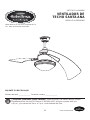
ARTÍCULO # 0464466
VENTILADOR DE
TECHO SANTA ANA
MODELO # LP8294LBN

25
Lowes.com/harborbreeze
ÍNDICE
Contenido del paquete ..........................................................26
Aditamentos ..................................................................27
Información de seguridad .......................................................28
Preparación ..................................................................29
Instrucciones de ensamblaje iniciales ..............................................30
Instrucciones de cableado .......................................................36
,QVWUXFFLRQHVGHHQVDPEODMH¿QDOHV ...............................................37
Instrucciones de funcionamiento ..................................................39
Instrucciones para equilibrar las aspas .............................................42
Cuidado y mantenimiento .......................................................43
Solución de problemas. . . . . . . . . . . . . . . . . . . . . . . . . . . . . . . . . . . . . . . . . . . . . . . . . . . . . . . . . . 44
Garantía .....................................................................45
Lista de piezas de repuesto ......................................................46

F
G
I
J
K
L
M
A
N
O
B
C
D
E
2
H
P
12V
H
26
Lowes.com/harborbreeze
CONTENIDO DEL PAQUETE
PIEZA DESCRIPCIÓN CANTIDAD PIEZA DESCRIPCIÓN CANTIDAD
A Motor 1
B Abrazadera para colgar 1
I Brazo de soporte del aspa 2
C Varilla 1
J Aspa 2
D Base para techo 1
K Bombilla 1
E
Cubierta para el tornillo
de la base
1
L
Receptor (preensamblado
en el motor (A))
1
F
Cubierta para el
acoplador del motor
1
M Control remoto 1
G
Ensamble de carcasa
inferior
1
N
Arandela del acoplador del
motor (preensamblada en el
motor (A))
1
H
Ensamble del kit de
iluminación con el vidrio
1
O
Cubierta de la carcasa
superior (preensamblada
en el motor (A))
1
P Batería 1

27
Lowes.com/harborbreeze
ADITAMENTOS (se muestran en tamaño real)
AA BB CC DD EE FF
Tornillo
Cant. 5
Tornillo con
cabeza de
arandela
Cant. 7
Conector de
cables
Cant. 4
Kit de
equilibrio (no
se muestra en
tamaño real)
Cant. 1
7RUQLOORGH¿MDFLyQGHO
soporte de la varilla
(preensamblado
en el motor (A))
Cant. 2
Tornillo de la
cubierta de
la carcasa
superior
(preensamblado
en el motor (A))
Cant. 6
GG HH II JJ
Bola para colgar
(preensamblada
en la varilla (C))
Cant. 1
Pasador de la
bola para colgar
(preensamblado
en la varilla (C))
Cant. 1
Sujetador de la varilla
(preensamblado
en la varilla (C))
Cant. 1
Pasador de la varilla
(preensamblado en la varilla (C))
Cant. 1
KK LL
MM
Tornillo de reborde
(preensamblado en la
abrazadera para colgar (B))
Cant. 2
Tornillo de la placa del
adaptador (preensamblado
en el motor (A))
Cant. 3
Tornillo del ensamble de la placa del
portalámpara (preensamblado en el
ensamble de carcasa inferior (G))
Cant. 3

28
Lowes.com/harborbreeze
INFORMACIÓN DE SEGURIDAD
Lea y comprenda completamente este manual antes de intentar ensamblar, usar o instalar el producto.
Antes de comenzar la instalación del ventilador, desconecte la alimentación eléctrica retirando los fusibles
o colocando el interruptor de circuito en la posición de apagado.
Asegúrese de que todas las conexiones eléctricas cumplan con los códigos u ordenanzas locales
o el Código Eléctrico Nacional. Si no está familiarizado con la instalación del cableado eléctrico,
FRQWUDWHDXQHOHFWULFLVWDFDOL¿FDGRRFRQVXOWHXQPDQXDOGHFDEOHDGRSDUDKDFHUORXVWHGPLVPR
Asegúrese de que en el lugar de instalación que elija se pueda establecer una distancia mínima
de 2,13 m desde las aspas hasta el piso, y al menos 76,20 cm desde los extremos de las aspas
hasta cualquier obstáculo.
Si va a montar el ventilador en una caja de salida del techo, use una caja de salida octogonal de METAL.
$VHJXUHODFDMDGLUHFWDPHQWHDODHVWUXFWXUDGHOHGL¿FLR/DFDMDGHVDOLGD\VXVRSRUWHGHEHQVHUFDSDFHV
de sostener el peso del ventilador en movimiento (al menos 15,88 kg). NO use una caja de salida
de plástico.
8QDYH]LQVWDODGRHOYHQWLODGRUDVHJ~UHVHGHTXHWRGDVODVFRQH[LRQHVVHDQVHJXUDVD¿QGHHYLWDUTXH
se caiga.
(QORTXHUHVSHFWDDODVFRQH[LRQHVGHVXPLQLVWURVLHOFRQGXFWRUGHOYHQWLODGRUHVWiLGHQWL¿FDGRFRPR
conductor con conexión a tierra, se le debe conectar a un suministro de electricidad con conductor de
SXHVWDDWLHUUD6LHOFRQGXFWRUGHOYHQWLODGRUHVWiLGHQWL¿FDGRFRPRFRQGXFWRUTXHQRHVGHSXHVWDDWLHUUD
se le debe conectar a un suministro de electricidad con conductor sin puesta a tierra. Si el conductor del
YHQWLODGRUHVWiLGHQWL¿FDGRSDUDHTXLSRVGHSXHVWDDWLHUUDVHOHGHEHFRQHFWDUDOFRQGXFWRUGHHTXLSRV
de puesta a tierra.
Este dispositivo cumple con la sección 15 de las reglas de la FCC. El funcionamiento está sujeto a las
siguientes dos condiciones: (1) Este dispositivo no debe causar interferencia perjudicial, y (2) deberá
aceptar cualquier interferencia recibida, incluida la interferencia que pudiese causar la operación no
deseada.
Nota(VWHHTXLSRKDVLGRSUREDGR\VHKDYHUL¿FDGRTXHFXPSOHFRQORVOtPLWHVSDUDXQGLVSRVLWLYRGLJLWDO
clase B, conforme a la sección 15 de las regulaciones de la FCC. Estos límites se han diseñado para
proporcionar una protección razonable contra la interferencia perjudicial en una instalación residencial.
Este equipo genera, usa y puede irradiar energía de radiofrecuencia y, si no se instala y usa de acuerdo
con las instrucciones, puede causar interferencia perjudicial a la recepción de radio o televisión, lo que
se puede determinar al apagar y encender el equipo. Se recomienda al usuario que intente corregir la
interferencia con una o más de las siguientes medidas:
– Reoriente o reubique la antena de recepción.
– Aumente la separación entre el equipo y el receptor.
– Conecte el equipo a un tomacorriente de un circuito distinto al que usa el receptor.
– Solicite ayuda al concesionario o a un técnico con experiencia en radio/TV.
Nota: Para un dispositivo digital clase A, las declaraciones de 15. 105(a) deben estar incluidas cuando
corresponde para el dispositivo en cuestión.
El peso neto de este ventilador es: 9,40 kg
ADVERTENCIA:
No instale ni use este ventilador si falta alguna pieza o si éstas están dañadas.
Para reducir el riesgo de incendios, descargas eléctricas o lesiones personales, los conectores de
cables proporcionados con este ventilador están diseñados para soportar solo un cable de la casa
de calibre 12 y dos cables conductores del ventilador. Si el cable de su casa es de un calibre superior
a 12 o hay más de un cable para conectar los dos cables conductores del ventilador, pregúntele a un
electricista cuál es el tamaño adecuado de los conectores de cables que debe utilizar. Antes de cortar,
WDODGUDURPDUWLOODUYHUL¿TXHODXELFDFLyQGHODVPLVPDV3yQJDVHHQFRQWDFWRFRQVXHOHFWULFLVWD
SORPHURRFRQXQWpFQLFRFDOL¿FDGRVLHVQHFHVDULR

29
Lowes.com/harborbreeze
INFORMACIÓN DE SEGURIDAD
Para reducir el riesgo de incendios, descargas eléctricas o lesiones personales, no doble los
brazos de las aspas al instalarlas, al equilibrarlas o al limpiar el ventilador. No introduzca objetos
extraños entre las aspas en movimiento. Monte el ventilador en una caja de salida marcada como
“ACCEPTABLE FOR FAN SUPPORT” (APTA PARA SOPORTE DE VENTILADOR) y use los tornillos
de montaje que se proporcionan con la caja de salida. La mayoría de las cajas de salida que se
usan comúnmente para sostener ensambles de iluminación no son aptas para sostener un ventilador
y puede ser necesario reemplazarlas. Si tiene dudas, consulte a u
Este ventilador es apto solo para lugares secos.
PREPARACIÓN
Antes de comenzar a ensamblar el producto, asegúrese de tener todas las piezas. Compare las
piezas con la lista del contenido del paquete y la lista de aditamentos. No intente ensamblar el
producto si falta alguna pieza o si éstas están dañadas.
Tiempo estimado de ensamblaje: 60 minutos
Herramientas necesarias para el ensamblaje (no se incluyen):
Destornillador Phillips, destornillador
de cabeza plana de 1/4”, pinzas pelacables y escalera de tijera.
Herramientas útiles (no se incluyen): Luz de prueba CA, manual de cableado para hacerlo usted
mismo y pinzas cortacables.
1RXWLOLFHHVWHYHQWLODGRUFRQXQFRQWURODGRUYDULDEOHGHSDUHG5KHRVWDWRXQUHJXODGRUGH
intensidad. Si lo hiciera podría dañar la unidad del mando a distancia del ventilador de techo.

30
Lowes.com/harborbreeze
INSTRUCCIONES DE ENSAMBLAJE INICIALES
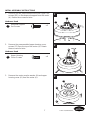
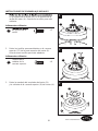
1.
en el soporte de la varilla (EE) en el soporte de la
varilla del motor (A). Guarde los tornillos para más
adelante.
Aditamentos utilizados
EE
del soporte de la
varilla
x 2
1
A
EE
2. Retire los tornillos preensamblados en la carcasa
superior (FF) de la parte superior del motor (A).
Guarde estos tornillos para más adelante.
Aditamentos utilizados
FF
Tornillos de la
cubierta de la
carcasa superior
x 6
2
A
FF
3. Retire la arandela del acoplador del motor (N)
y la cubierta de la carcasa superior (O) del motor (A).
3
A
O
N

31
Lowes.com/harborbreeze
INSTRUCCIONES DE ENSAMBLAJE INICIALES
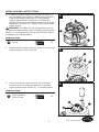
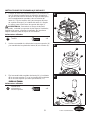
4. Coloque el brazo de soporte del aspa (I) en el motor (A)
con los postes roscados que se muestran. Asegúrese
de que el borde inferior del brazo de soporte del aspa (I)
esté completamente asentado sobre el volante del
motor (A). Fije los tornillos (AA) para asegurar el brazo
de soporte del aspa (I) al volante del motor (A). Repita
los pasos para el otro brazo de soporte del aspa (I) .
ADVERTENCIA: Para reducir el riesgo de lesiones
personales, no doble los soportes de las aspas al instalarlos,
equilibrar las aspas, o limpiar el ventilador. No introduzca
objetos extraños entre las aspas en movimiento.
Aditamentos utilizados
AA
Tornillo x 4
4
AA
I
A
5. Vuelva a ensamblar la cubierta de la carcasa superior (O)
y la arandela del acoplador del motor (N) en el motor (A).
5
N
O
6. Fije la arandela del acoplador del motor (N) y la cubierta
de la carcasa superior (O) con los tornillos de la cubierta
de la carcasa superior que retiró previamente (FF).
Aditamentos utilizados
FF
Tornillo de la
cubierta de la
carcasa superior
x 6
6
N
FF
O

7
HH
C
GG
8
JJ
II
C
32
Lowes.com/harborbreeze
INSTRUCCIONES DE ENSAMBLAJE INICIALES
7.
preensamblada (GG) hasta que salga libremente de
la varilla (C). Retire el pasador de la bola para colgar
preensamblado (HH) de la varilla (C) y retire la parte
de la varilla que posee la bola para colgar (C).
Guarde el pasador de la bola para colgar (HH)
y la bola para colgar para pasos posteriores.
Aditamentos utilizados
GG
de bola para colgar
x 1
HH
Pasador de la bola
para colgar
x 1
8. Retire el pasador preensamblado de la varilla (II)
y el pasador de la varilla (JJ) de la parte inferior de la
varilla (C). Guarde estas dos piezas para los pasos
posteriores.
Aditamentos utilizados
II
Sujetador de la
varilla
x 1
JJ
Pasador de la
varilla
x 1
9. Pase los conductores negro y blanco desde el motor
(A)a través de la varilla (C).
9
C
A

33
Lowes.com/harborbreeze
INSTRUCCIONES DE ENSAMBLAJE INICIALES
10. Enrosque la varilla (C) en el soporte de la varilla
y vuelva a instalar el pasador de la varilla (JJ).
Fije el pasador de la varilla (JJ) y el sujetador de
la varilla (II). Vuelva a instalar los dos tornillos de
ADVERTENCIA: Es fundamental que instale
correctamente el pasador de la varilla (JJ), y que apriete
(EE). El incumplimiento de dicho paso podría hacer que
el ventilador se caiga.
Aditamentos utilizados
EE
del soporte de la
varilla
x 2
II
Sujetador de la
varilla
x 1
JJ
Pasador de la
varilla
x 1
10
C
EE
A
JJ
II
II
JJ
11. Pase los cables a través de la cubierta del acoplador
del motor (F), la cubierta del tornillo de la base (E)
y la base para techo (D).
Nota: El chavetero de los la cubierta para el tornillo
de la base (E) debe ser hacia la dirección del techo.
11
D
F
E

34
Lowes.com/harborbreeze
INSTRUCCIONES DE ENSAMBLAJE INICIALES
12. Pase los cables por la bola para colgar que retiró
anteriormente. Coloque el pasador de la bola para
colgar que retiró anteriormente (HH) a través de
ORVGRVRUL¿FLRVGHODYDULOOD&\DOLQHHODEROD
para colgar para que el pasador (HH) quede inserto
en la ranura de la parte superior de la varilla (C).
-DOHODERODSDUDFROJDU¿UPHPHQWHDOSDVDGRU++
)LMHELHQHOWRUQLOORGH¿MDFLyQGHODERODSDUDFROJDU
preensamblada (GG).
PRECAUCIÓN8QWRUQLOORGH¿MDFLyQÀRMRSRGUtDKDFHU
que el ventilador se tambalee.
Aditamentos utilizados
GG
7RUQLOORGH¿MDFLyQ
de bola para colgar
x 1
HH
Pasador de la
bola para colgar
x 1
12
GG
HH
C
13. Corte el excedente del cable conductor
aproximadamente en unos 15,24 cm a 22,86 cm por
sobre la parte superior de la varilla (C). Pele 1,27 cm
del aislamiento del extremo de cada cable conductor.
13
C
15,24 cm a
22,86 cm

35
Lowes.com/harborbreeze
INSTRUCCIONES DE ENSAMBLAJE INICIALES
ADVERTENCIA: Para evitar una posible descarga eléctrica, asegúrese de cortar la alimentación
eléctrica de la caja de fusibles principal antes de colgar el ventilador.
ADVERTENCIA: Si no está seguro de si la caja de salida tiene puesta a tierra, solicite ayuda
DXQHOHFWULFLVWDFHUWL¿FDGR\DTXHGHEHWHQHUSXHVWDDWLHUUDSDUDXQIXQFLRQDPLHQWRVHJXUR
ADVERTENCIA: Debe colgar el ventilador a una distancia mínima de 2,13 m desde el piso
hasta las aspas.
14. Fije bien la abrazadera para colgar (B) a la caja de
salida (no se incluye) con los tornillos y las arandelas
provistas con la caja de salida.
ADVERTENCIA: La caja de salida debe estar
bien asegurada. La abrazadera para colgar debe estar
bien asentada contra la caja de salida. Si la caja de
VDOLGDHVWiHPSRWUDGDUHWLUHHOSDQHOGH¿EUDSUHQVDGD
hasta que la abrazadera haga contacto con la caja.
Si la abrazadera y/o la caja de salida no están bien
aseguradas, el ventilador podría tambalearse o caerse.
14
B
15. Levante cuidadosamente el ensamble del ventilador
y coloque la bola para colgar de la varilla (C) en
la abrazadera para colgar (B). Asegúrese de que
la ranura de la bola esté alineada con la lengüeta
de la abrazadera para colgar (B).
ADVERTENCIA: Si no coloca la lengüeta en la
ranura, podrían dañarse los cables eléctricos y podrían
ocurrir incendios o descargas eléctricas.
ADVERTENCIA: Para evitar una posible descarga
eléctrica, no apriete los cables entre el ensamble de
la bola para colgar y la abrazadera para colgar.
15
C
B

36
Lowes.com/harborbreeze
INSTRUCCIONES DE CABLEADO
ADVERTENCIA: Para evitar una posible descarga eléctrica, asegúrese de cortar la alimentación
eléctrica de la caja de fusibles principal antes de colgar el ventilador.
ADVERTENCIA: Si no está seguro de si la caja de salida tiene puesta a tierra, solicite ayuda
DXQHOHFWULFLVWDFHUWL¿FDGR\DTXHGHEHWHQHUSXHVWDDWLHUUDSDUDXQIXQFLRQDPLHQWRVHJXUR
1. Conecte el conductor verde con conexión a tierra
de la varilla (C) y el conductor verde con conexión
a tierra de la abrazadera para colgar (B) al conductor
de suministro con conexión a tierra (posiblemente
un conductor desnudo o un cable con aislante verde).
Conecte bien los conductores con un conector de
cables (CC). Conecte de forma segura el conductor
blanco del motor del ventilador al conductor blanco
QHXWUR\¿MHODFRQH[LyQFRQHOFRQHFWRUGH
cables (CC). Conecte de forma segura el conductor
negro del motor del ventilador al conductor negro
\¿MHODFRQH[LyQFRQHOFRQHFWRUGHFDEOHV&&
Aditamentos utilizados
CC
Conector de
cables
x 3
1
CC
CC
C
B
2. Una vez realizadas las conexiones, gire los
conductores hacia arriba y, con cuidado, colóquelos
dentro de la caja de salida; con los conductores
blancos y verdes hacia un lado y los conductores
negros hacia el otro.
ADVERTENCIA9HUL¿TXHTXHWRGDVODVFRQH[LRQHV
estén ajustadas, incluida la conexión a tierra, y que no
haya conductores desnudos visibles en los conectores
excepto el conductor con conexión a tierra. No opere el
ventilador hasta que las aspas estén instaladas. Podría
ocasionar ruidos y daños al motor.
2

37
Lowes.com/harborbreeze
INSTRUCCIONES DE ENSAMBLAJE FINALES
1. Retire uno de los dos tornillos de reborde preensamblados
tornillo de reborde (KK) sin retirarlo del todo. Gire la
base para techo (D) de modo que el segundo tornillo
de reborde (KK) se desplace a la abertura pequeña del
chavetero. Apriete el tornillo de reborde (KK).
Vuelva a instalar el tornillo de reborde que retiró
anteriormente (KK) para ensamblar por completo la
base para techo (D) a la abrazadera para colgar (B).
Para una instalación fácil, se recomienda un
destornillador Phillips corto.
ADVERTENCIA: Para evitar una posible descarga
eléctrica o incendio, asegúrese de colocar los cables eléctricos
completamente dentro de la carcasa de la base y de no
apretarlos entre la carcasa y el techo.
Aditamentos utilizados
KK
Tornillo de reborde
x 1
1
D
KK
2.
de la base (E) sobre los tornillos de reborde (KK) de la
abrazadera para colgar (B), mediante el mecanismo de
seguro por giro del chavetero.
2
E
3. Retire uno de los tres tornillos preensamblados en la
placa del adaptador (LL) dentro de la placa del adaptador
dos tornillos restantes de la placa del adaptador (LL).
Ensamble el ensamble de la placa de iluminación (G)
en la placa del adaptador del motor (A) mediante los dos
chaveteros del ensamble de la placa de iluminación (G).
Vuelva a colocar el tercer tornillo de la placa del
adaptador (LL) y apriete todos los tornillos de la placa
del adaptador (LL).
Aditamentos utilizados
LL
Tornillo de la placa
del adaptador
x 3
3
LL
G
A

38
Lowes.com/harborbreeze
INSTRUCCIONES DE ENSAMBLAJE FINALES
4. Coloque un aspa (J) en la parte inferior de un brazo
los postes roscados. Apriete los tornillos con cabeza
de arandela (BB) para asegurar el aspa (J) y el brazo
del soporte del aspa (I) . Repite el procedimiento
para la otra aspa (J).
Aditamentos utilizados
BB
Tornillo con cabeza
de arandela
x 6
4
J
I
BB
5.
5
A
H
6. Retire uno de los tornillos preensamblados del
ensamble de la placa del portalámpara (MM)
al interior del ensamble de la carcasa inferior (G).
Coloque el ensamble del kit de iluminación (H)
en el ensamble de la carcasa inferior (G) usando los
dos chaveteros del ensamble del kit de iluminación
Vuelva a colocar el tercer tornillo del
ensamble de la placa del portalámpara (MM)
y
Aditamentos utilizados
MM
Tornillo del
ensamble de
la placa del
portalámpara
x 3
6
H
G
MM
Conecte el cable negro desde ensamble del kit de
del kit de iluminación (H) al cabel blanco ensamble
iluminación (H) al cable negro ensamble del
motor (A) y conecte el cable blanco desde ensamble
del motor (A).
I
(H)

39
Lowes.com/harborbreeze
INSTRUCCIONES DE ENSAMBLAJE FINALES
7. Instale la bombilla (K) en el portalámpara.
PRECAUCIÓN: Las bombillas están presurizada y
pueden quebrarse. NO TOQUE LAS BOMBILLAS CON
LAS MANOS DESPROTEGIDAS. Las huellas dactilares
en la bombilla pueden reducir la vida útil de la misma.
Elimine las huellas dactilares con alcohol antes de usar
la bombilla. Para disminuir el riesgo de incendios, utilice
una bombilla minican de tungsteno halógena tipo T4 JD
E11 de 100 vatios como máximo. Apague el interruptor
de pared y deje enfriar la bombilla durante 10 minutos
antes de cambiarla.
7
K
8.
de las manecillas del reloj en el ensamble del kit de
iluminación (H). No apriete demasiado ni fuerce.
8
H
INSTRUCCIONES DE FUNCIONAMIENTO
1. Restablezca la alimentación eléctrica en la caja de
salida volviendo a conectar la electricidad de la caja
de fusibles principal.
1
ON
ON
ON
ON
ON
ON
ON
ON
ADVERTENCIA
No utilice este ventilador con un controlador
variable de pared (Rheostat) o un regulador
de intensidad. Si lo hiciera podría dañar la
unidad del mando a distancia del ventilador
de techo.

2.
Solo para referencia visual-no ha
sido diseñado para cubrir todos los
tipos de controles
IMPORTANTE
El uso de un regulador de la intensidad completa
(no incluido) para controlar la velocidad del
ventilador dañará el dispositivo. Para reducir el
riesgo de incendio o descarga eléctrica, no utilice
dicho regulador para controlar la velocidad del
ventilador.
40
Lowes.com/harborbreeze
INSTRUCCIONES DE FUNCIONAMIENTO
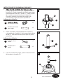
3. Retire la tapa de la batería del control remoto (M)
e instale la batería (P), y asegúrese de que la
polaridad de la batería (P) sea igual a la polaridad
del compartimiento para las mismas. Coloque de
nuevo la cubierta de la batería.
Nota: Cuando sea el momento de reemplazar la batería
(P), use una de 12 voltios.
PRECAUCIÓN: Si el producto no se usará por un
período prolongado, retire la batería para evitar que
se dañe el control remoto. Asegúrese de almacenar el
control remoto alejado del calor y humedad extremos.
3
2
M
12V
P
4. Siga estos pasos para ajustar el control remoto (M):
a) Deslice el interruptor DIP a “1” dentro del
compartimiento de la batería y apague el
ventilador. Encienda la alimentación. El receptor
del ventilador (L) debe emitir dos sonidos
musicales, que indican que el suministro de
electricidad es normal.
b) En menos de 30 segundos, presione el botón
“LEARN” en la parte posterior del control
remoto (M). El control remoto y el ventilador
deben estar sincronizados.
bien, la luz del ventilador de techo titilará 3 veces
y permanecerá encendida, mientras que el ventilador
girará a alta velocidad.
4
M
12V
a
b

41
Lowes.com/harborbreeze
INSTRUCCIONES DE FUNCIONAMIENTO
5. Funciones del control remoto (M):
1 = Velocidad mínima
3 = Velocidad media baja 4 = Velocidad media
5 = Velocidad media alta
= Brisa natural
Presione cualquiera de los botones “ /1/2/3/4/5/6”
para salir del modo brisa natural y cambiar a la función
relativa del botón.
Botón:
Apaga el ventilador.
Mantenga presionado el botón “ ” para
encender/apagar el indicador de sonido.
Botón de revesa:
Controla la dirección del ventilador.
Enciende o apaga la luz. Mantenga presionado para
regular la intensidad.
Botón de la lámpara:
Velocidad del ventilador:
Luz de retardo con sensor de movimiento:
Apaga el ventilador y la luz después de 1 minuto.
Durante el modo luz de retardo con sensor de movimiento,
presione cualquier otro botón para cancelar la función.
Home Shield:
El ventilador está apagado con la luz en el ciclo A-B-A.
Modo A: La luz se enciende de forma aleatoria por
entre 5 y 20 minutos.
Modo B: La luz se apaga durante 60 minutos.
Durante el modo Home Shield, presione cualquier otro
botón para cancelar la función.
Temporizador de apagado automático:
2H: El ventilador se apagará después de 2 horas.
4H: El ventilador se apagará después de 4 horas.
8H: El ventilador se apagará después de 8 horas.
Durante el modo de temporizador de apagado automático,
presione la tecla “ ” para salir.
6 = Velocidad alta
2 = Velocidad baja
5
M
2
H

42
Lowes.com/harborbreeze
INSTRUCCIONES PARA EQUILIBRAR LAS ASPAS
1. Intercambiar la posición de aspas adyacentes (J)
puede redistribuir el peso y hacer que funcione
más suavemente. Si el tambaleo disminuye, deje
las aspas (J) como están. Si el tambaleo aumenta,
vuelva a la posición original. Fije el sujetador de
equilibrio del kit de equilibrio (DD) al punto medio
en el borde superior de una de las aspas (J).
ADVERTENCIA: El sujetador de equilibrio siempre
el borde. Si no lo hace, el sujetador puede salir disparado
y causar daños personales.
1
DD
J
2. Haga funcionar el ventilador a velocidad alta
de aire hacia abajo) y observe el tambaleo.
Repita los pasos 1 y 2 para cada aspa (J). Observe
qué aspa (J) tiene el menor tambaleo. Instale
en dicha aspa (J) el sujetador de equilibrio (DD)
en el borde superior del aspa (J) cerca del motor (A).
Haga funcionar el ventilador y observe si hay
tambaleo. Detenga el ventilador y mueva el sujetador
de equilibrio (DD) a tramos pequeños hacia el
extremo del aspa (J). En cada tramo de incremento
encienda el ventilador y observe el tambaleo.
Determine la ubicación del sujetador de equilibrio
(DD) que permite la menor cantidad de tambaleo.
2
DD
J
A
3. Despegue el papel protector de uno de los
cuadrados con peso del kit de equilibrio (DD).
Fije el cuadrado con peso del kit de equilibrio (DD)
centrado en la ubicación del sujetador de equilibrio
y entre los bordes del aspa (J). Retire el sujetador
(J),
de equilibrio, haga funcionar el ventilador y observe.
Si el tambaleo persiste, repita los pasos del 1 al 3
con los cuadrados con peso restantes hasta que
el tambaleo desaparezca.
3
DD
J

43
Lowes.com/harborbreeze
CUIDADO Y MANTENIMIENTO
ADVERTENCIA: No use agua para limpiar el ventilador de techo. Puede dañar el motor
o el acabado y crear la posibilidad de una descarga eléctrica.
Use solo una brocha suave o un paño que no produzca pelusas para evitar rayar el acabado
al limpiarlo.
Los agentes limpiadores abrasivos son innecesarios y deben evitarse para no dañar el acabado.
Revise periódicamente que todos los aditamentos estén ajustados y asegúrelos.
Se recomienda una limpieza suave del polvo de las aspas periódicamente.
Evite usar agua, limpiadores o paños ásperos, ya que pueden combar y arruinar el acabado.
Reemplazo de las bombillas: Use una minibombilla de base candelabro de 100 vatios. Cambie
la bombilla por una del vataje correcto. No exceda el vataje máximo indicado en el portalámpara.

44
Lowes.com/harborbreeze
SOLUCIÓN DE PROBLEMAS
PROBLEMA CAUSA POSIBLE ACCIÓN CORRECTIVA
El ventilador no
arranca.
1. El fusible o el interruptor de
circuito están fundidos.
2. Alguna de las conexiones
eléctricas que van al ventilador
está suelta.
3. Hay una batería agotada en el
control remoto.
1. Revise los fusibles del circuito de
derivación y del circuito principal
o los interruptores de circuito.
2. Revise las conexiones de los cables
que van hacia el ventilador.
ADVERTENCIA: Asegúrese de
cortar la alimentación eléctrica.
3. Reemplace con una batería nueva.
El ventilador emite
mucho ruido.
1. Las aspas no están sujetas al
ventilador.
2. Hay tornillos sueltos en la
carcasa del motor.
3. Los tornillos que sujetan los
soportes de las aspas del
ventilador al eje del motor
HVWiQÀRMRV
4. Los conectores al interior de la
carcasa repiquetean.
5. El control de velocidad
variable de estado sólido
produce ruidos en el motor.
6. Los tornillos que sujetan las
aspas a los soportes de las
DVSDVHVWiQÀRMRV
1. Fije las aspas al ventilador antes de
ponerlo en funcionamiento.
2. Compruebe que todos los tornillos de
la carcasa del motor estén apretados
(no apriete demasiado).
3. Compruebe que los tornillos que
¿MDQORVVRSRUWHVGHODVDVSDVGHO
ventilador al eje del motor estén
apretados.
4. Compruebe que los conectores de
cable de la carcasa del interruptor
no repiqueteen unos contra otros
o contra las paredes interiores de
la carcasa del interruptor.
ADVERTENCIA: Asegúrese
de cortar la alimentación eléctrica.
5. Algunos motores de ventilador
son sensibles a las señales de los
controles de velocidad variable de
estado sólido. No se recomiendan
los controles de estado sólido, elija
un método de control alternativo.
6. Apriete completamente los tornillos.

45
Lowes.com/harborbreeze
SOLUCIÓN DE PROBLEMAS
PROBLEMA CAUSA POSIBLE ACCIÓN CORRECTIVA
El ventilador
se tambalea
excesivamente.
1. (OWRUQLOORGH¿MDFLyQ\ODWXHUFD
del soporte de la varilla están
ÀRMRV
2. (OWRUQLOORGH¿MDFLyQGHO
ensamble de la bola para colgar/
YDULOODHVWiÀRMR
3. Los tornillos que sujetan los
soportes de las aspas del
ventilador al eje del motor están
ÀRMRV
4. La abrazadera para colgar y/o la
caja de salida del techo no están
ELHQ¿MDGDV
5. Las aspas del ventilador están
desequilibradas.
1. $SULHWHELHQORVWRUQLOORVGH¿MDFLyQHQHO
soporte de la varilla.
2. $SULHWHHOWRUQLOORGH¿MDFLyQHQODYDULOOD
ensamble de la bola para colgar.
3. &RPSUXHEHTXHORVWRUQLOORVTXH¿MDQORV
soportes de las aspas del ventilador al
eje del motor estén apretados.
4. Fije los tornillos de la abrazadera para
colgar a la caja de salida y asegúrela.
5. Consulte las instrucciones de aspa
equilibrada en la página 42.
1RKD\VX¿FLHQWH
movimiento de aire.
La varilla es demasiado corta. De ser posible, puede usar una varilla más
larga (no se incluye).
GARANTÍA
El fabricante garantiza que este ventilador no presenta defectos de fabricación ni en los materiales presentes
en el momento del transporte desde la fábrica. La garantía es efectiva desde la fecha de compra. El motor
tiene una garantía de por vida, y una garantía de 2 años para el kit de iluminación y todos los componentes
restantes. Esta garantía es válida solo para el comprador original. El fabricante acepta reparar dichos defectos
sin cargo o, según nuestro criterio, reemplazar el ventilador de techo por un modelo comparable o superior.
Para obtener el servicio de garantía, presente una copia del recibo de venta como comprobante de la compra.
Todos los costos de extracción y reinstalación son de responsabilidad explícita del comprador. Cualquier daño
al ventilador de techo producido por accidente, uso indebido o instalación incorrecta, o a causa de accesorios
GH¿MDFLyQTXHQRHVWiQFXELHUWRVSRUHVWDJDUDQWtDVHUiUHVSRQVDELOLGDGGHOFRPSUDGRU(OIDEULFDQWHQR
asume ningún tipo de responsabilidad por la instalación del ventilador durante la garantía limitada de por
vida. Cualquier servicio realizado por una persona no autorizada invalidará la garantía.
Debido a las cambiantes condiciones climáticas, esta garantía no cubre cambios en el acabado de latón,
óxido, picaduras, deslustre, corrosión, o descascarado. Los ventiladores con acabado de latón mantienen su
belleza cuando se les protege de las cambiantes condiciones climáticas. La garantía no cubre los elementos
de vidrio incluidos con este ventilador.
Cualquier reemplazo de piezas defectuosas para el ventilador de techo debe informarse dentro del primer
año a partir de la fecha de compra. Para conocer el saldo de la garantía, llame a nuestro Departamento de
Servicio al Cliente al 1-800-643-0067 y obtenga la autorización de la devolución e instrucciones de envío de
modo que podamos reparar o reemplazar el ventilador de techo. Un ventilador o piezas devueltas con un
embalaje incorrecto son de responsabilidad única del comprador. No existe otro tipo de garantía explícita.
El fabricante rechaza cualquiera y todas las garantías implícitas. La duración de cualquier garantía implícita
TXHQRSXHGDUHFKD]DUVHVHOLPLWDDOSHUtRGROLPLWDGRGHSRUYLGDHVSHFL¿FDGRHQQXHVWUDJDUDQWtD(O
fabricante no será responsable por daños incidentales, resultantes o especiales que surjan en relación con el
uso o el funcionamiento del producto, excepto que la ley indique lo contrario. Esta garantía le otorga derechos
OHJDOHVHVSHFt¿FRV\XVWHGWLHQHWDPELpQRWURVGHUHFKRVTXHYDUtDQVHJ~QHOHVWDGR(VWDJDUDQWtDVXVWLWX\H
cualquier garantía previa.
Nota: Una pequeña cantidad de “tambaleo” es normal y no se debe considerar como un defecto.

B
DD
AA
J
C
D
E
L
F
A
G
K
I
M
CC
BB
2
H
H
46
Lowes.com/harborbreeze
Impreso en China
Harbor Breeze
®
es una marca registrada de LF, LLC.
Todos los derechos reservados.
LISTA DE PIEZAS DE REPUESTO
Para obtener piezas de repuesto, llame a nuestro Departamento de Servicio al Cliente
al
1-800-643-0067, 8 a.m. a 6 p.m., y los viernes de 8 a.m. a 5 p.m., hora estándar del Este.
PIEZA DESCRIPCIÓN PIEZA #
Una Motor AMA8294LBN
B
Abrazadera para
colgar
APGAC110RBL
C
Ensamble de la
varilla/bola para
colgar
ADRACT1-6LBN
D Base para techo PPAC1005LBN
E
Cubierta para el
tornillo de la base
APPAC1101LBN
F
Cubierta para el
acoplador del motor
APPAC1403LBN
G
Ensamble de la
carcasa inferior
AP829404LBN
H
Ensamble del kit de
iluminación con el
vidrio
AP829406LBN
I
Brazo de soporte
del aspa
AP815002-
16LBN
J Aspa AP815004WA
K Bombilla PPE11B100
L Unidad receptora RECDC8294
M Control remoto TR17
AA Tornillo HDWBH8150NI
BB
Tornillo con cabeza
de arandela
HDWBM8150NI
CC Conector de cables HDWWNUTS4
DD Kit de equilibrio LBALKT
-
 1
1
-
 2
2
-
 3
3
-
 4
4
-
 5
5
-
 6
6
-
 7
7
-
 8
8
-
 9
9
-
 10
10
-
 11
11
-
 12
12
-
 13
13
-
 14
14
-
 15
15
-
 16
16
-
 17
17
-
 18
18
-
 19
19
-
 20
20
-
 21
21
-
 22
22
-
 23
23
-
 24
24
-
 25
25
-
 26
26
-
 27
27
-
 28
28
-
 29
29
-
 30
30
-
 31
31
-
 32
32
-
 33
33
-
 34
34
-
 35
35
-
 36
36
-
 37
37
-
 38
38
-
 39
39
-
 40
40
-
 41
41
-
 42
42
-
 43
43
-
 44
44
-
 45
45
-
 46
46


Fanimation LP8294LBN El manual del propietario
- Categoría
- Ventiladores domésticos
- Tipo
- El manual del propietario
En otros idiomas
- English: Fanimation LP8294LBN Owner's manual
Documentos relacionados
-
Fanimation LP8293LAZ El manual del propietario
-
-
-
-
-
-
-
-
-
Otros documentos
-
 Harbor Breeze 874 Manual de usuario
-
 Harbor Breeze 0080443 Manual de usuario
-
 Harbor Breeze 856 Manual de usuario
-
 Harbor Breeze 00878 Guía de instalación
-
 Harbor Breeze TILGHMAN WCK52LMW5N Guía de instalación
-
 Harbor Breeze KINGSBURY 40190 Guía de instalación
-
Harbor Breeze CENTREVILLE 40110 Guía de instalación
-
 Harbor Breeze ARMORY 40088 Guía de instalación
-
 Harbor Breeze 40093 Manual de usuario
-
Harbor Breeze 0429784 Guía de instalación


