Fanimation 0233061 Manual de usuario
- Categoría
- Ventiladores domésticos
- Tipo
- Manual de usuario
Este manual también es adecuado para

1
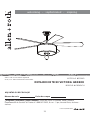
VICTORIA HARBOR CEILING FAN
ITEM #0233061
MODEL #LP8242LCH
Questions, problems, missing parts? Before returning to your retailer, call our customer service
department at
1-888-567-2055, 8 a.m. - 5 p.m., EST, Monday - Friday.
Español p. 23
Serial Number
Purchase Date
ATTACH YOUR RECEIPT HERE
welcPNJOHtTPQIJTUJDaUFEtJOTQJring
allen + roth
®
is a registered trademark
of LF, LLC. All Rights Reserved.
EB13242
Lowes.com/allenandroth

Lowes.com/allenandroth
TABLE OF CONTENTS
Package Contents .........................................................................................................................
Hardware Contents .......................................................................................................................
Safety Information .........................................................................................................................
Preparation ...................................................................................................................................
Assembly Instructions ...................................................................................................................
Wiring Instructions ........................................................................................................................
Final Assembly Instructions ..........................................................................................................
Operating Instruction ....................................................................................................................
Blade Balancing Instructions ........................................................................................................
Care and Maintenance .................................................................................................................
Troubleshooting ............................................................................................................................
Warranty .......................................................................................................................................
Replacement Parts List ................................................................................................................
3
4
4
5
6
10
13
16
18
19
19
21
22
2

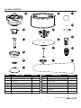
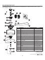
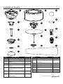
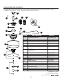
PACKAGE CONTENTS
YTITNAUQ NOITPIRCSED TRAP
YTITNAUQ NOITPIRCSED TRAP
A Motor Assembly 1
B
Hanger Bracket
1
C
Downrod
1
D
Ceiling Canopy 1
E
Canopy Screw Cover
1
F
Motor Coupling Cover
1
G
Light Plate Shade Assembly
1
H
Socket Plate Assembly
1
I
J
K
L
M
N
O
P
Glass
Connection Stud Assembly
Trim Cover
Trim Ball
Bulb
Receiver Unit
Remote
Blade
1
1
1
1
3
1
1
5
Lowes.com/allenandroth
A
B
C
F
I
G
H
J
K
L
M
N
O
P
D
E
3

SAFETY INFORMATION
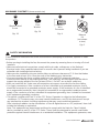
HARDWARE CONTENTS (shown actual size)
Wire
Connector
Qty. 4
CC DD
Balance
Kit
(not shown
to size)
Qty. 1
Fiber
Washer
Qty. 16
BB
AA
Washer-Head
Screw
Qty. 16
Lowes.com/allenandroth
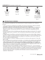
Please read and understand this entire manual before attempting to assemble, operate or install
the product.
Before you begin installing the fan, disconnect the power by removing fuses or turning off circuit
breakers.
Make sure all electrical connections comply with local codes, ordinances, or the National
Electrical code. Hire a qualified electrician or consult a do-it-yourself wiring handbook if you are
unfamiliar with installing electrical wiring.
Make sure the installation site you choose allows a minimum clearance of 7 ft. from the blades
to the floor and at least 30 in. from the ends of the blades to any obstruction.
If you are mounting the fan to a ceiling outlet box, use a METAL octagonal outlet box.
Secure the box directly to the building structure. The outlet box and its support must be able to
support the moving weight of the fan (at least 35 lbs.). Do NOT use a plastic outlet box.
After you install the fan, make sure all connections are secure to prevent the fan from falling.
For supply connections, if the conductor of a fan is identified as a grounded conductor, then it
should be connected to a grounded conductor power supply. If the conductor of a fan is identified
as an ungrounded conductor, then it should be connected to an ungrounded conductor power
supply. If the conductor of a fan is identified for equipment grounding, then it should be connected
to an equipment-grounding conductor.
This device complies with Part 15 of the FCC Rules. Operation is subject to the following two
conditions: (1) This device may not cause harmful interference, and (2) this device must accept
any interference received, including interference that may cause undesired operation.
If the intentional radiator can be classified as a Class B digital device or a PC peripheral, then shall
include the following or equivalent:
Note: This equipment has been tested and found to comply with the limits for Class B digital
device, pursuant to part 15 of the FCC Rules. These limits are designed to provide reasonable
protection against harmful interference in a residential installation. This equipment generates, uses
4

SAFETY INFORMATION
The net weight of this fan is: 20.61 lbs.
Lowes.com/allenandroth
and can radiate radio frequency energy and, if not installed and used in accordance with the
instructions, may cause harmful interference to radio or television reception, which can be
determined by turning the equipment off and on, the user is encouraged to try to correct the
interference by one or more of the following measures:
- Reorient or relocate the receiving antenna.
- Increase the separation between the equipment and the receiver.
- Connect the equipment into an outlet on a circuit different from that to which the receiver is
connected.
Consult the dealer or an experienced radio/TV technician for help.
Note: For a Class A digital device, statements of 15. 105(a) must be included when appropriate
forthe device in question.
Before beginning assembly of product, make sure all parts are present. Compare parts with
package contents list and hardware contents list. If any part is missing or damaged, do not
attempt to assemble the product.
Estimated Assembly Time: 60 minutes
Tools Required for Assembly (not included): Phillips screwdriver, 1/4 in. flathead screwdriver,
wire stripper and step ladder.
Helpful Tools (not included): AC tester light, do-it-yourself wiring handbook and wire cutters.
PREPARATION
WARNING
'RQRWLQVWDOORUXVHIDQLIDQ\SDUWLVGDPDJHGRUPLVVLQJ
To reduce the risk of fire, electrical shock, or personal injury, wire connectors provided with this
fan are designed to accept only one 12-gauge house wire and two lead wires from the fan. If
your house wire is larger than 12-gauge or there is more than one house wire to connect to the
two fan lead wires, consult an electrician for the proper size wire connectors to use. Before
cutting, drilling or hammering, verify their location. If needed, contact your electrician, plumber
or service person.
To reduce the risk of fire, electric shock, or personal injury, do not bend the blade arms when
installing them, balancing the blades, or cleaningWKHIDQ'RQRWLQVHUWIRUHLJQREMHFWVEHWZHHQ
the rotating fan blades. Mount to outlet box marked “ACCEPTABLE FOR FAN SUPPORT” and
use mounting screws provided with the outlet box. Most outlet boxes commonly used for the
support of lighting fixtures are not acceptable for fan support and may need to be replaced.
Consult a qualified electrician if in doubt.
This fan is to be used in dry locations only.
5HDGDOOLQVWUXFWLRQVDQGVDIHW\LQIRUPDWLRQEHIRUHLQVWDOOLQJWKHQHZIDQ5HYLHZDFFRPSDQ\LQJ
assembly diagrams.
CAUTION
5
'RQRWRSHUDWHWKLVIDQZLWKDYDULDEOH5KHRVWDWZDOOFRQWUROOHURUGLPPHUVZLWFK'RLQJVRFRXOG
result in damage to the ceiling fan's remote control unit.

ASSEMBLY INSTRUCTIONS
1
C
2
Lowes.com/allenandroth
C
A
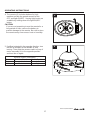
3
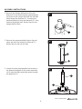
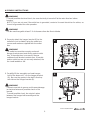
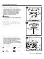
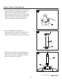
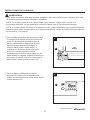
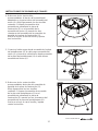
1. Remove the hanger ball portion from the
downrod (C) by loosening the preassembled
set screw in the hanger ball until the ball falls
freely down the downrod (C). Remove the
preassembled pin from the downrod (C), then
remove the hanger ball. Retain the pin and
hanger ball for later.
2. Remove the preassembled hairpin clip and
clevis pin from the bottom of downrod (C).
Retain the pin and clip for later.
3. Loosen the two preassembled set screws in
the downrod support of the motor assembly
(A). Route the black and white wires through
the downrod (C).
C
6

ASSEMBLY INSTRUCTIONS
F
E
5
4
C
A
Lowes.com/allenandroth
D
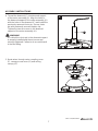
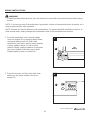
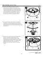
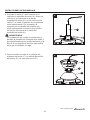
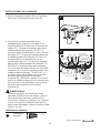
4. Thread the downrod (C) into downrod support
of the motor assembly (A). Align the holes in
the downrod support of the motor assembly (A)
with the holes in the downrod (C) and install the
previously removed clevis pin. Secure clevis
pin with previously removed hairpin clip.
Tighten the two set screws in the downrod
support of the motor assembly (A).
WARNING
It is critical the clevis pin in the downrod support
is properly installed and the set screws are
securely tightened. Failure to do so could result
in the fan falling.
5. Route wires through motor coupling cover
(F), canopy screw cover (E) and ceiling
canopy (D).
7

ASSEMBLY INSTRUCTIONS
Lowes.com/allenandroth
C
7
6
C
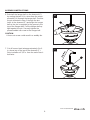
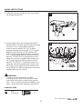
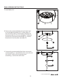
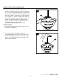
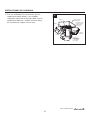
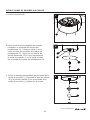
7. Cut off excess lead wire approximately 6 to 9
in. above top of the top of the downrod (C).
Strip insulation off 1/2 in. from the end of each
lead wire.
6. Reinstall the hanger ball on the downrod (C)
by routing the two 54 in. wires from the motor
assembly (A) through the hanger ball. Position
the pin removed in step 1 through the two
holes in the downrod (C) and align the hanger
ball so the pin is captured in the groove in the
top of the hanger ball. Pull the hanger ball up
tight against the pin. Securely tighten the
preassembled set screw in the hanger ball.
A loose set screw could result in a wobbly fan.
CAUTION
8

ASSEMBLY INSTRUCTIONS
B
C
9
B
8
Lowes.com/allenandroth
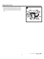
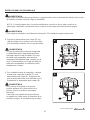
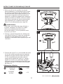
NOTE: If you are not sure if the outlet box is grounded, contact a licensed electrician for advice, as
it must be grounded for safe operation.
WARNING
To avoid possible electrical shock, be sure electricity is turned off at the main fuse box before
hanging.
WARNING
The fan must hang with at least 7 ft. of clearance from the floor to blades.
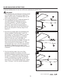
8. Securely attach the hanger bracket (B) to the
outlet box (not included) using the outlet box
screws and washers supplied with the outlet
box.
9.
Carefully lift the assembly and seat hanger
ball of the downrod (C) on the hanger bracket
(B). Be sure the groove in the ball is lined up
with tab on the hanger bracket (B).
WARNING
The outlet box must be securely anchored.
Hanger bracket must seat firmly against outlet
box. If the outlet box is recessed, remove
wallboard until bracket contacts box. If bracket
and/or outlet box are not securely attached, the
fan could wobble or fall.
WARNING
Failure to seat tab in groove could cause damage
to electrical wires and possible shock or fire
hazard.
To avoid possible shock, do not pinch wires
between the hanger ball assembly and the
hanger bracket.
9

WIRING INSTRUCTIONS
O
12V
Battery
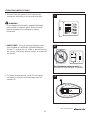
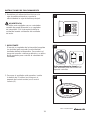
1. To set the transmitter code, remove battery
cover on remote (O) by pressing firmly below
arrow and sliding cover off. Slide code
switches to your choice of up or down position.
Factory setting is all up. Do not use this
position. With a small screwdriver or ball point
pen (not included), slide firmly up or down.
Replace battery cover on remote (O).
1
NOTE: If you are not sure if the outlet box is grounded, contact a licensed electrician for advice, as it
must be grounded for safe operation.
NOTE: Remote (O) has 16 different code combinations. To prevent possible interference from or to
other remote units, simply change the combination code in the transmitter and receiver.
WARNING
To avoid possible electrical shock, be sure electricity is turned off at the main fuse box before wiring
this fan.
Lowes.com/allenandroth
N
2. To set the receiver unit (N) code, slide code
switches to the same positions as set on
remote (O).
2
10

WIRING INSTRUCTIONS
N
B
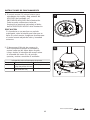
3. Slide the receiver unit (N) into the open end of
the hanger bracket (B).
3
Hardware Used
x 3
Wire
Connector
CC
CC
CC
CC
4
Bl
ue to
Light
Bl
ac
k t
o
M
o
t
or
W
hit
e
t
o
M
o
t
or
all
N
C
B
4. Connect green wires from hanger bracket (B)
and downrod (C) to bare (ground) wire using wire
connector (CC). Connect black wire from
receiver unit (N) marked “AC IN L” to black
supply wire using wire connector (CC). Connect
white wire from receiver unit (N) marked “AC
IN N” to white supply wire using wire connector
(CC). Connect white wire from receiver unit (N)
marked “TO MOTOR N” to white wire from fan
using wire connector supplied with receiver unit
(N). Connect black wire from receiver unit (N)
marked “TO MOTOR L” to black wire from fan
using wire connector supplied with receiver unit
(N). Lastly, connect blue wire from receiver unit
(N) to the blue fan light wire using wire connector
supplied with receiver unit (N).
WARNING
Check to see all connections are tight,
including ground, and no bare wire is visible
at the wire connectors except for the ground
wire. Do not operate fan until the blades are in
place. Noise and motor damage could result.
Lowes.com/allenandroth
11

5. After connections have been made, turn leads
upward and carefully push leads into the outlet
box, with the white and green leads to one side
of the box and the black leads toward the other
side.
5
all
WIRING INSTRUCTIONS
Lowes.com/allenandroth
12

Lowes.com/allenandroth
1
D
2
E
3. Position the blades (P) over the motor
assembly (A) with threaded posts showing.
Make sure the bottom edge of the blades (P)
are fully seated
against the flywheel of motor
assembly (A). Install and tighten the
washer-head screws (AA) with fiber washers
(BB) to secure the blades (P) to the flywheel of
motor assembly (A).
Hardware Used
AA
Washer-Head
Screw
BB
Fiber
Washer
x 15
x 15
1. Remove one of the two preassembled
shoulder screws in the hanger bracket (B).
Loosen the second shoulder screw without
fully removing it. Rotate ceiling canopy (D) so
second shoulder screw moves into the small
opening of the keyslot. Tighten shoulder
screw. Re-install the previously removed
shoulder screw to fully assemble ceiling
canopy (D) to hanger bracket (B).
FINAL ASSEMBLY INSTRUCTIONS
2. Securely attach and tighten the canopy
screw cover (E) over the shoulder screws in
the hanger bracket (B), utilizing the keyslot
twist-lock feature.
WARNING
To avoid possible fire or shock, make sure the
electrical wires are completely inside the canopy
housing and not pinched between the housing
and the ceiling.
AA
P
A
BB
3
13

Lowes.com/allenandroth
FINAL ASSEMBLY INSTRUCTIONS
4
A
G
4. Remove one of the three preassembled
screws inside the adaptor plate at the bottom
of the motor assembly (A). Slightly loosen the
remaining two screws. Assemble the light plate
shade assembly (G) to the adaptor plate of the
motor assembly (A) using the two keyslots in
the light plate shade assembly (G). Replace
the third screw and secure all three screws.
A
5
H
6. Remove one of the four preassembled screws
inside the light plate shade assembly (G).
Slightly loosen the remaining three screws.
Assemble the socket plate assembly (H) to the
light plate shade assembly (G) using the three
keyslots in the socket plate assembly (H).
Replace the fourth screw and secure all four
screws.
6
H
G
14
5. Connect the black wire from the socket plate
assembly (H) to the black wire from the motor
assembly (A), and the white wire from the socket
plate assembly (H) to the white wire from the motor
assembly (A).

Lowes.com/allenandroth
FINAL ASSEMBLY INSTRUCTIONS
7
M
8. Remove the preassembled nut from thread stud
on socket plate assembly (H)
. Position glass (I)
onto the thread stud of socket plate assembly (H)
and secure with nut. Do not overtighten. Twist and
secure the connection stud assembly (J) onto the
thread stud of socket plate assembly (H).
9.
Remove the preassembled finial from connection
stud assembly (J). Assemble the trim cover (K) and
trim ball (L) onto to the connection stud
assembly (J) and secure with finial.
7. Install bulbs (M).
9
L
K
J
8
H
I
J
G
15

Lowes.com/allenandroth
OPERATING INSTRUCTIONS
2
3
O
3. To make fan operational, install 12-volt battery
(included in remote control package) into the
remote (O).
1. Restore electrical power to the outlet box by
turning the electricity on at the main fuse box.
1
ON
ON
ON
ON
ON
ON
ON
ON
16
2.
IMPORTANT: Using a full range dimmer switch
(not included) to control fan speed will damage
the fan. To reduce the risk of fire or electrical shock,
do not use a full range dimmer switch to control the
fan speed.
For illustrative purposes only-not
intended to cover all types of controls
WARNING
Do not operate this fan with a variable (Rheostat)
wall controller or dimmer switch. Doing so could
result in damage to the ceiling fan's remote
control unit.

4
O
4. The remote (O) includes buttons for high,
medium and low fan speeds as well as fan
OFF and light ON/OFF. Varying light levels are
available by holding down the light ON/OFF
button.
If you are not expecting to use the remote for a
long period of time, remove the battery to
prevent damage to the remote. Be sure to store
the remote away from excess heat or humidity.
CAUTION
Lowes.com/allenandroth
OPERATING INSTRUCTIONS
5. If airflow is desired in the opposite direction, turn
the fan off and wait for the blades to stop
turning. Then slide the reverse switch on top of
motor assembly (A) to the opposite position
and turn fan on again.
Season
Summer
Winter
Rotation Direction Switch Position
Clockwise
Counterclockwise
Reverse Switch Information
Right
Left
5
A
17

Lowes.com/allenandroth
1. Interchanging positions of adjacent blades (P)
can redistribute the weight and result in
smoother operation. If wobble decreases,
leave blades (P) as they are. If wobble
increases, switch back to original position.
Attach the balancing clip from the balance kit
(DD) to the mid-point on the top edge of one
blade (P).
2. 5XQWKHIDQDWKLJKVSHHGDLUGRZQÀRZDQG
observe wobble. Repeat steps 1 and 2 for
each blade (P). Note which blade (P) has the
least wobble. On that blade (P), install the
balancing clip (DD) to the top edge of the
blade (P) near the motor assembly (A).
Start the fan and observe wobble. Stop the fan
and move the balancing clip (DD) in small
steps toward the end of the blade (P). At each
incremental step, turn on the fan and observe
the wobble. Determine the location of the
balancing clip (DD) that gives the least amount
of wobble.
3. Peel the backing paper from one of the
weighted squares in the balance kit (DD).
6HFXUHWKHZHLJKWHGVTXDUH¿UPO\WRWKHWRSRI
the blade (P), centered at the balancing clip
location and between the edges of the blade
(P). Remove the balancing clip, start the fan
and observe. If the wobble still persists, repeat
steps 1 through 3 until the wobble disappears.
3
DD
P
BLADE BALANCING INSTRUCTIONS
WARNING
7KHEDODQFLQJFOLSPXVWDOZD\VEH¿UPO\SXVKHG
onto the blade until it touches the edge of the
EODGH)DLOXUHWRGRVRFRXOGDOORZFOLSWRÀ\RII
and cause personal injury.
If the fan wobbles when in use, turn off the fan and follow the below steps:
P
DD
1
DD
P
2
18

Lowes.com/allenandroth
When cleaning, use only a soft brush or lint-free cloth to avoid scratching the finish.
$EUDVLYHFOHDQLQJDJHQWVDUHQRWUHTXLUHGDQGVKRXOGEHDYRLGHGWRSUHYHQWGDPDJHWRILQLVK
RECOMMENDED: Periodically check that the fan motor unit screws, blade screws, support
housing and light kit screws are tight and secure.
3HULRGLFOLJKWGXVWLQJRIWKHEODGHVLVUHFRPPHQGHG$IHDWKHUGXVWHUZLOOZRUNEHVW
$YRLGXVLQJZDWHUFOHDQVHUVRUKDUVKUDJVZKLFKFDQZDUSDQGUXLQWKHILQLVK
%XOE5HSODFHPHQWUse 40-watt candelabra-base bulbs.
CARE AND MAINTENANCE
WARNING
Do not use water when cleaning the ceiling fan. It could damage the motor or the finish and
create the possibility of electrical shock.
Re-lamp with the appropriate wattage bulb. Do not exceed the wattage indicated on the bulb
socket.
Do not install or use fan if any part is damaged or missing.
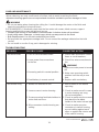
TROUBLESHOOTING
4. Wire connectors inside housing are
rattling.
1. Blades not attached to fan.
2. Loose screws in motor housing.
3. Screws securing fan blade holders to
motor hub are loose.
1. Check main and branch circuit
fuses or circuit breakers.
2. Check line wire connections to
fan.
WARNING
Make sure main power is turned
off!
4. Check to make sure wire
connectors in switch housing
are not rattling against each
other or against the interior wall
of the switch housing.
1. Attach blades to fan before
operating.
2. Check to make sure all screws
in motor housing are snug
(do not overtighten).
3. Check to make sure the screws
that attach the fan blade
holders to the motor hub are tight.
PROBLEM POSSIBLE CAUSE CORRECTIVE ACTION
Fan will not start. 1. Fuse or circuit breaker blown.
2. Loose power line connections
4. Dead battery in remote control.
3. Reversing switch in neutral position.
4. Replace with new battery.
3. Make sure reversing switch
position is all the way to one
side.
to the fan.
Fan sounds noisy.
19

Lowes.com/allenandroth
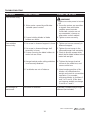
5. Motor noise caused by solid state
variable speed control.
5. Some fan motors are sensitive
to signals from solid-state
variable speed controls.
Solid-state controls are not
recommended, choose an
alternative control method.
6. Screws holding blades to blade
holders are loose.
WARNING
Make sure main power is turned
off!
6. Tighten screws securely.
Fan sounds noisy.
TROUBLESHOOTING
Not enough air
movement.
5. Fan blades are out of balance.
1. Set screw in downrod support is loose.
2. Set screw in downrod/hanger ball
assembly is loose.
3. Screws securing fan blade holders to
motor hub are loose.
4. Hanger bracket and/or ceiling outlet box
is not securely fastened.
5. Interchanging position of fan
blades can redistribute the
weight and result in a smoother
operation. For example,
exchange blades in positions 1
and 3 or 1 and 4. If this does
not improve wobble, exchange
2 and 4 or 2 and 5.
2. Tighten the set screw in the
downrod
/
han
g
er ball assembl
y.
3. Check to be sure screws which
attach the fan blade holders to the
motor hub are tight.
4. Tighten the hanger bracket
screws to the outlet box, and
secure outlet box.
1. Tighten set screws securely in
downrod support.
Too short of downrod.
PROBLEM POSSIBLE CAUSE CORRECTIVE ACTION
Fan wobbles
excessively.
If possible, consider using a longer
downrod (not included).
20

Lowes.com/allenandroth
WARRANTY
To obtain warranty service, present a copy of your sales receipt as proof of purchase. All cost of
removal and reinstallation are the expressed responsibility of the purchaser. Any damage to the
ceiling fan by accident, misuse or improper installation, or by affixing accessories not produced by
this warranty, are at the purchaser’s own responsibility. The manufacturer assumes no responsibility
whatsoever for fan installation during the lifetime limited warranty. Any service performed by an
unauthorized person will render the warranty invalid.
Due to varying climate conditions, this warranty does not cover changes in brass finish, rusting,
pitting, tarnishing, corroding or peeling. Brass finish fans maintain their beauty when protected from
varying weather conditions. Any glass provided with this fan is not covered by the warranty.
Any replacement of defective parts for the ceiling fan must be reported within the first year from the
date of purchase. For the balance of the warranty, call our customer service department at
1-888-567-2055 for return authorization and shipping instructions so that we may repair or replace
the ceiling fan. Any fan or parts returned improperly packaged is the sole responsibility of the purchaser.
There is no further expressed warranty. The manufacturer disclaims any and all implied warranties.
The duration of any implied warranty which can not be disclaimed is limited to the lifetime limited
period as specified in our warranty. The manufacturer shall not be liable for incidental, consequential
or special damages arising at or in connection with product use or performance except as may
otherwise be accorded by law. This warranty gives you specific legal rights and you also have other
rights which vary from state to state. This warranty supersedes all prior warranties.
Note: A small amount of “wobble” is normal and should not be considered a defect.
The manufacturer warrants this fan to be free from defects in workmanship and material present at
time of shipment from the factory. The warranty terms from the date of purchase. The motor has a
lifetime warranty, and a 2 year warranty for the light kit and all remaining components. This warranty
applies only to the original purchaser. The manufacturer agrees to correct such defect at no charge
or, at our option, replace the ceiling fan with a comparable or superior model.
21

REPLACEMENT PARTS LIST
Printed in China
For replacement parts, call our customer service department at 1-888-567-2055, 8 a.m. - 5 p.m.,
EST, Monday - Friday.
DD
CC
AA
BB
K
L
B
C
D
E
F
A
G
H
I
J
M
P
O N
# TRAP NOITPIRCSED TRAP
AMA8242LCH
APGAC110RBL
ADRACT1-6LCH
PPAC1006LCH
APPAC1101LCH
AP824201LCH
AP824203LCH
AP824214WH
P824208CM
AP824213LCH
P824209LCH
P824210CL
PPE12B40
RECAN55
TR350AR
AP824205BLWA
HDWBM8242LCH
HDWBM8242LCH
HDWWNUTS4
LBALKT
Motor Assembly
Hanger Bracket
Downrod
Ceiling Canopy
Canopy Screw Cover
Motor Coupling Cover
Light Plate Shade
Assembly
Socket Plate Assembly
Glass
Connection Stud Assembly
Trim Cover
Trim Ball
Bulb
Receiver Unit
Remote
Blade
Screw
Washer-Head Screw
Wire Connector
Balance Kit
A
B
C
D
E
F
G
H
I
J
K
L
M
N
O
P
AA
BB
CC
DD
allen + roth
®
is a registered trademark
of LF, LLC. All rights reserved.
Lowes.com/allenandroth
22

23
VENTILADOR DE TECHO
VICTORIA HARBOR
ARTÍCULO #0233061
MODELO #LP8242LCH
Número de serie
Fecha de compra
ADJUNTAR SU RECIBO AQUÍ
allen + roth
®
es una marca registrada
de LF, LLC. Todos los derechos reservados.
Lowes.com/allenandroth
¿Preguntas, problemas, piezas faltantes? Antes de volver a la tienda, llame a nuestro
Departamento de Servicio al Cliente al 1-888-567-2055, 8 a.m. - 5 pm, hora del Este, de lunes -
viernes.
welcPNJOHtTPQIJTUJDaUFEtJOTQJring

Lowes.com/allenandroth
Contenido del paquete ...................................................................................................................
Aditamentos ...................................................................................................................................
Información de seguridad ..............................................................................................................
Preparación ...................................................................................................................................
Instrucciones de ensamblaje .........................................................................................................
Instrucciones de cableado .............................................................................................................
Instrucciones de ensamblaje finales ..............................................................................................
Instrucciones de funcionamiento ...................................................................................................
Instrucciones para balancear las aspas ........................................................................................
Cuidado y mantenimiento ..............................................................................................................
Solución de problemas ..................................................................................................................
Garantía .........................................................................................................................................
Lista de piezas de repuesto............................................................................................................
25
26
26
28
29
33
36
39
41
42
42
44
45
ÍNDICE
24

A
B
C
F
I
G
H
J
K
L
M
N
O
P
D
E
Lowes.com/allenandroth
CONTENIDO DEL PAQUETE
A
B
C
D
E
F
G
H
Ensamble del motor
Abrazadera para colgar
varilla
Escudo del techo
Cubierta para los tornillo de
la base
Cubierta para el acoplador
del motor
Ensamble de pantalla de la
placa de iluminación
Ensamble de la placa del
portalámpara
DADITNAC NÓICPIRCSED AZEIP
1
1
1
1
1
1
1
1
I
J
K
L
M
N
O
P
Vidrio
Ensamble de la varilla de
conexión
Tapa del reborde
Bola de reborde
Bombilla
Unidad receptora
Control remoto de mano
Aspa
1
1
1
1
3
1
1
5
DADITNAC NÓICPIRCSED AZEIP
25

Conectores
de cable
Cant. 4
CC DD
Kit de equilibrio
(no se muestra
en tamaño real)
Cant. 1
Arandelas
de fibra
Cant. 16
BB
AA
Tornillos con
cabeza de
arandela
Cant. 16
Lowes.com/allenandroth
ADITAMENTOS
(Se muestan en tamaño real)
INFORMACIÓN DE SEGURIDAD
Lea y comprenda completamente este manual antes de intentar ensamblar, usar o instalar el
producto.
Antes de comenzar la instalación del ventilador, desconecte la alimentación eléctrica retirando
los fusibles o colocando el interruptor de circuito en la posición de apagado.
Asegúrese de todas las conexiones eléctricas cumplan con los códigos locales, las ordenanzas
Nacional de Electricidad. Si no está familiarizado con la instalación del o el Código cableado
eléctrico, contrate a un electricista calificado o consulte un manual de cableado para hacerlo
usted mismo.
Asegúrese de que el sitio de instalación que elija permita una distancia mínima de 2,13 m desde
las aspas hasta el piso y al menos a 76,20 cm desde los extremos de las aspas hasta cualquier
obstáculo.
Si desea montar el ventilador en una caja de salida del techo, use una caja de salida octagonal
de METAL. Asegure la caja directamente a la estructura del edificio. La caja de salida y su soporte
deben ser capaces de sostener el peso del ventilador en movimiento (como mínimo 15,88 kg).
NO use una caja de salida de plástico.
Una vez instalado el ventilador, asegúrese de todas las conexiones sean seguras a fin de evitar
que se caiga.
(QORTXHUHVSHFWDDODVFRQH[LRQHVGHVXPLQLVWURVLHOFRQGXFWRUGHOYHQWLODGRUHVWiLGHQWLILFDGR
como conductor con conexión a tierra, se le debe conectar a un suministro de electricidad con
conductor de puesta a tierra. Si el conductor del ventilador está identificado como conductor que
no es de puesta a tierra, se le debe conectar a un suministro de electricidad con conductor sin
puesta a tierra. Si el conductor del ventilador está identificado para equipos de puesta a tierra, se
le debe conectar al conductor de equipos de puesta a tierra.
Este equipo cumple con lo establecido en la Parte 15 de la Normativa FCC. Su funcionamiento
está sujeto a las dos condiciones siguientes: (1) Este equipo no causará interferencias perjudiciales
y (2) este equipo tolerará cualquier interferencia recibida, incluidas las interferencias que puedan
provocar un funcionamiento no deseado. Si el radiador intencional puede ser clasificado como un
dispositivo digital de clase B o un periférico del ordenador, entonces se deberán incluir los
siguientes o equivalentes:
26

Lowes.com/allenandroth
INFORMACIÓN DE SEGURIDAD
(OSHVRQHWRGHHVWHYHQWLODGRUHVNJ
ADVERTENCIA
NoLnstalenLuseelYentLladorsLfaltaalJunaSLezaoVLéstasestándañadas.
3DUDUHGXFLUHOULHVJRGHLQFHQGLRVGHVFDUJDVHOpFWULFDVROHVLRQHVSHUVRQDOHVORVFRQHFWRUHV
GHFDEOHLQFOXLGRVFRQHVWHYHQWLODGRUHVWiQGLVHxDGRVSDUDVRSRUWDUVyORXQFDEOHLQWHULRUGH
FDOLEUH\GRVFDEOHVFRQGXFWRUHVGHOYHQWLODGRr6LHOFDEOHLQWHULRUHVGHXQFDOLEUHVXSHULRUD
RKD\PiVGHXQFDEOHLQWHULRUSDUDFRQHFWDUORVGRVFDEOHVFRQGXFWRUHVGHOYHQWLODGRr
SUHJ~QWHOHDXQHOHFWULFLVWDFXiOHVVRQORVFRQHcWRUHVGHFDEOHGHWDPDxRFRUUHFWRTXHVH
GHEHQXVDr
3DUDUHGXFLUHOULHVJRGHLQFHQGLRVGHVFDUJDVHOpFWULFDVROHVLRQHVSHUVRQDOHVQRGREOHORV
EUD]RVGHODVDVSDVDOLQVWDODUODVDOHTXLOLEUDUODVRDOOLPSLDUHOYHQWLODGRr1RLQWURGX]FDREMHWRV
H[WUDxRVHQWUHODVDVSDVHQPRYLPLHQWR,QVWDOHHQXQDFDMDGHVDOLGDPDUFDGDFRPR
³$&&(3T$%/()25)$16833257´$3T$P$5$623257('(9(17,/$'25\XVHORV
WRUQLOORVGHPRQWDMHTXHVHSURSRUFLRQDQFRQODFDMDGHVDOLGD/DPD\RUtDGHODVFDMDVGHVDOLGD
TXHVHXVDQFRP~QPHQWHSDUDVRVWHQHUHQVDPEOHVGHLOXPLQDFLyQQRVRQDSWDVSDUDVRVWHQHU
XQYHQWLODGRU\SXHGHVHUQHFHVDULRUHHPSOD]DUODV6LWLHQHGXGDVFRQVXOWHFRQXQHOHFWULFLVWD
FDOLILFDGR
(VWHYHQWLODGRUHVDSWRVyORSDUDOXJDUHVVHFRV
/HDWRGDVODVLQVWUXFFLRQHV\ODLQIRUPDFLyQGHVHJXULGDGDQWHVGHLQVWaODUHOQXHYRYHQWLODGRr.
5HYLVHORVGLDJUDPDVGHHQVDPEODMHDGMXQWRV
PRECAUCIÓN
1RWD7UDVVRPHWHUORDODVSUXHEDVFRUUHVSRQGLeQWHVVHKDGHWHUPLQDGRTXHHVWHHTXLSRFXPSOH
FRQORVOtPLWHVHVWDEOHFLGRVSDUDGLVSRVLWLYRVGLJLWDOHVGH&ODVH%GHFRQIRUPLGDGFRQODSDUWH
GHOD1RUPDWLYD)&&(VWRVOtPLWHVVHKDQHVWDEOHFLGRFRQHOREMHWLYRGHDSRUWDUXQDSURWHFFLyQ
UD]RQDEOHFRQWUDLQWHUIHUHQFLDVSHUMXGLFLDOHVFXaQGRHOHTXLSRVHXWLOL]DHQHOKRJDU(VWHHTXLSR
JHQHUDXWLOL]D\SXHGHHPLWLUHQHUJtDGHUDGLRIUeFXHQFLD\DPHQRVTXHVHLQVWDOH\VHXWLOLFHGH
DFXHUGRFRQHOPDQXDOGHLQVWUXFFLRQHVSXHGHSURYRFDULQWHUIHUHQFLDVSHUMXGLFLDOHVHQODV
FRPXQLFDFLRQHVSRUUDGLR\WHOHYLVLyQ6LHOHTXLSRSURGXFHLQWHUIHUHQFLDVSHUMXGLFLDOHVHQOD
UHFHSFLyQGHUDGLRRWHOHYLVLyQORFXDOSXHGHSUoEDUVHHQFHQGLHQGR\DSDJDQGRHOHTXLSRVH
UHFRPLHQGDDOXVXDULRFRUUHJLUGLFKDVLQWHUIHUHQFLDs
WRPDQGRXQDRYDULDVGHODVVLJXLHQWHV
PHGLGDV
0RGLILFDUODRULHQWDFLyQRXELFDFLyQGHODDQWHQDdHUHFHSFLyQ
$XPHQWDUODVHSDUDFLyQHQWUHHOHTXLSR\HOUHFHSWRU
&RQHFWDUHOHTXLSRDXQDWRPDGHFRUULHQWHRFLUFuLWRGLIHUHQWHDOGHOUHFHSWRU
&RQVXOWHDOGLVWULEXLGRURDXQWpFQLFRHVSHFLDOLVWDdHUDGLRR79SDUDREWHQHUPiVD\XGD
1RWD3DUDXQGLVSRVLWLYRGLJLWDOGHFODVH$ODGHFOaUDFLyQGHDGHEHVHULQFOXLGDFXDQGR
VHDDSURSLDGDSDUDHOGLVSRVLWLYRHQFXHVWLyQ
1RXWLOLFHHVWHYHQWLODGRUFRQXQFRQWURODGRUYDULDEOHGHSDUHG5KHRVWDWRXQUHJXODGRUGH
LQWHQVLGDG6LORKLFLHUDSRGUtDGDxDUODXQLGDGGHlPDQGRDGLVWDQFLDGHOYHQWLODGRUGHWHFKR

Lowes.com/allenandroth
Antes de comenzar a ensamblar el producto, asegúrese de tener todas las piezas. Compare las
piezas con la lista del contenido del paquete y la lista de aditamentos. No intente ensamblar el
producto si falta alguna pieza o si éstas están dañadas.
Tiempo estimado de ensamblaje: 60 minutos
Herramientas necesarias para el ensamblaje (no se incluyen): Destornillador Phillips,
destornillador de punta plana de 1/4”, pinzas pelacables y escalera de tijera.
Herramientas útiles: Luz de prueba CA, manual de cableado para hacerlo usted mismo y pinzas
cortacables.
PREPARACIÓN
28

1
C
2
Lowes.com/allenandroth
C
A
3
C
1. Retire la parte correspondiente a la bola para
colgar del varilla (C) aflojando el tornillo de
fijación de la bola hasta que ésta salga
libremente de la varilla (C). Retire el pasador
preensamblado de la varilla (C) y luego retire
la bola para colgar. Guarde el pasador y la
bola para colgar para pasos posteriores.
2. Retire la sujetador de horquilla del
preensamblados y pasador de horquilla de la
parte inferior de la varilla (C). Guarde el
pasador y el sujetador para pasos posteriores.
3. Afloje los dos tornillos preensamblados de
fijación del soporte de la varilla del ensamble
del motor (A). Pase los conductores negro y
blanco a través de la varilla (C).
INSTRUCCIONES DE ENSAMBLAJE
29

F
E
5
4
C
A
Lowes.com/allenandroth
D
INSTRUCCIONES DE ENSAMBLAJE
4. Enrosque la varilla (C) en el soporte de la
varilla en el ensamble del motor (A). Alinee los
orificios en el soporte de la varilla del
ensamble del motor (A) con los orificios en la
varilla (C) e instale el pasador de horquilla que
retiró anteriormente. Fije el pasador de
horquilla con el sujetador de horquilla que
retiró anteriormente. Apriete los dos tornillos
de fijación del soporte de la varilla del
ensamble del motor (A).
ADVERTENCIA
Es fundamental que instale correctamente el
pasador de horquilla en el soporte de la varilla, y
que ajuste firmemente los tornillos de fijación y las
tuercas. El incumplimiento de dicho paso podría
hacer que el ventilador se caiga.
5. Pase los cables a través de la cubierta del
acoplador del motor (F), la cubierta del tornillo
de la base (E) y la base para techo (D).
30

Lowes.com/allenandroth
C
7
6
C
INSTRUCCIONES DE ENSAMBLAJE
15,24 cm a
22,86 cm
6. Vuelva a instalar la bola para colgar en la
varilla (C) haciendo pasar los dos conductores
de 1,37 m del ensamble del motor (A) a través
de la bola para colgar. Coloque el pasador que
retiró en el paso 1 a través de los dos orificios
de la varilla (C) y alinee la bola para colgar de
manera tal que el pasador quede inserto en la
ranura de la parte superior de la bola para
colgar. Sujete la bola para colgar firmemente
al pasador. Fije bien el tornillo
preensamblados de fijación a la varilla.
Un tornillo de fijación flojo podría hacer que el
ventilador se tambalee.
PRECAUCIÓN
7. Corte el excedente del cable conductor
aproximadamente en unos 15,24 cm a 22,86
cm por sobre la parte superior del varilla (C).
Pele 1,27 cm del aislamiento del extremo de
cada cable conductor.
31

B
C
9
B
8
Lowes.com/allenandroth
NOTA: Si no está seguro de si la caja de salida tiene conexión a tierra, pida consejo a un
electricista certificado, ya que debe tener conexión a tierra para un funcionamiento seguro.
ADVERTENCIA
Para evitar una posible descarga eléctrica, asegúrese de cortar la alimentación eléctrica de la caja
de fusibles principal antes de colgar el ventilador.
ADVERTENCIA
Debe colgar el ventilador a una distancia mínima de 2,13 m desde las aspas hasta el piso.
INSTRUCCIONES DE ENSAMBLAJE
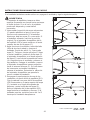
8. Fije bien la abrazadera para colgar (B) a la
caja de salida (no se incluye) con los tornillos
y las arandelas provistas con la caja de salida.
9. Con cuidado levante el ensamble y coloque
la bola para colgar de la varilla (C) en la
abrazadera para colgar (B). Asegúrese de
que la ranura de la bola esté alineada con la
lengüeta de la abrazadera para colgar (B).
ADVERTENCIA
La caja de salida debe estar bien asegurada.
La abrazadera para colgar debe estar bien
asentada contra la caja de salida. Si la caja
de salida está empotrada, retire el panel
hasta que la abrazadera haga contacto con la
caja. Si la abrazadera y/o la caja de salida no
están bien aseguradas, el ventilador podría
tambalearse o caerse.
ADVERTENCIA
Si no coloca la lengüeta en la ranura,
podrían dañarse los cables eléctricos y
podrían ocurrir incendios o descargas
eléctricas.
Para evitar una posible descarga eléctrica,
no apriete los cables entre el ensamble de la
bola para colgar y la abrazadera para colgar.
32

O
12V
batería
1
Lowes.com/allenandroth
N
2
INSTRUCCIONES DE CABLEADO
NOTA: Si no está seguro de si la caja de salida tiene conexión a tierra, pida consejo a un
electricista certificado, ya que debe tener conexión a tierra para un funcionamiento seguro.
NOTA: El control remoto (O) tiene 16 combinaciones de códigos diferentes. Para evitar una posible
interferencia de otras unidades de control remoto simplemente cambie la combinación de código de
su transmisor y su receptor.
ADVERTENCIA
Para evitar una posible descarga eléctrica, asegúrese de cortar la alimentación eléctrica de la caja
de fusibles principal antes de cableado el ventilador.
2. Para configurar el código de la unidad
receptora (N), deslice los interruptores de
código a la misma posición que la de su control
remoto de mano (O).
1. Para configurar el código del transmisor, retire
la cubierta de la batería del control remoto de
mano (O) presionando firmemente bajo la
flecha y deslizando la cubierta hacia fuera.
Deslice los interruptores de código a su
elección hacia arriba o hacia abajo. La
configuración de fábrica es de todo hacia
arriba. No use esta posición. Deslice
firmemente hacia arriba o hacia abajo con un
destornillador o bolígrafo de punta redonda (no
se incluye). Vuelva a colocar la cubierta de la
batería en el control remoto de mano (O).
33

N
B
3
Lowes.com/allenandroth
ADVERTENCIA
Verifique que todas las conexiones estén
ajustadas, incluida la conexión a tierra, y que no
haya conductores desnudos visibles en los
conectores, excepto el conductor con conexión
a tierra. No opere el ventilador hasta que las
aspas estén instaladas. Podría ocasionar ruidos
y daños al motor.
INSTRUCCIONES DE CABLEADO
3. Deslice la unidad receptora (N) en el extremo
abierto de la abrazadera para colgar (B).
CC
CC
N
CC
4
Conductor
verde (puesta
a tierra) desde
la bola para
colgar
Azul
Azul al motor
Negro al motor
Blanco al motor
Negro
Negro
Negro a antena
Conductor verde
(puesta a tierra)
Caja de salida
homologada
Negro
Blanco
Blanco
Blanco
Suministro
eléctrico
del hogar
C
B
Conductor
verde (puesta
a tierra) desde
la abrazadera
para colgar
4. Conecte los conductores verdes de la
abrazadera para colgar (B) y la varilla (C) al
conductor desnudo (a tierra) con el conector de
cables (CC). Conecte el conductor negro de la
unidad receptora (N) marcado “AC IN L” al
conductor negro de alimentación con el conector
de cables (CC). Conecte el conductor blanco de
la unidad receptora (N) marcado “AC IN N” al
conductor blanco de alimentación con el
conector de cables (CC). Conecte el conductor
blanco de la unidad receptora (N) marcado “TO
MOTOR N” al conductor blanco del ventilador
con el conector de cables incluido con la unidad
receptora (N). Conecte el conductor negro de la
unidad receptora marcado “TO MOTOR L” al
conductor negro del ventilador con el conector
de cables que se adjunta con la unidad
receptora (N). Finalmente, conecte el conductor
azul de la unidad receptora (N) al conductor azul
de la iluminación del ventilador con el conector
de cables que se adjunta con la unidad
receptora (N).
Aditamentos utilizados
CC
x 3
Conectores
de cable
34

Lowes.com/allenandroth
INSTRUCCIONES DE CABLEADO
5
Blanco
Negro
Azul
Caja de salida
homologada
Conductor
verde (puesta
a tierra) desde
la abrazadera
para colgar
Conductor verde
(puesta a tierra)
desde la bola
para colgar
Negro a
antena
5. Una vez realizadas las conexiones, gire los
conductores hacia arriba y, con cuidado,
colóquelos dentro de la caja de salida; con los
conductores blancos y verdes hacia un lado y
los conductores negros hacia el otro.
35

Lowes.com/allenandroth
1
D
2
E
INSTRUCCIONES DE ENSAMBLAJE FINALES
AA
P
A
BB
3
1. Retire uno de los dos tornillos de reborde
preensamblados en el abrazadera para colgar
(B). Afloje el segundo tornillo de reborde sin
retirarlo del todo. Gire la base de techo (D) de
modo que el segundo tornillo de reborde se
desplace a la abertura pequeña del chavetero.
Apriete el tornillo de reborde. Vuelva a instalar
el tornillo de reborde que retiró anteriormente
para ensamblar por completo la base para
techo (D) a la abrazadera para colgar (B).
ADVERTENCIA
Para evitar una posible descarga eléctrica o
incendio, asegúrese de colocar los cables
eléctricos completamente dentro de la
carcasa de la base, y de no apretarlos entre
la carcasa y el techo.
2. Coloque y ajuste firmemente la cubierta para
el tornillo de la base (E) sobre los tornillos de
reborde de la abrazadera para colgar
(B),
mediante el mecanismo de seguro por giro del
chavetero.
3. Coloque las aspas (P) en el ensamble del motor
(A) con los postes roscados que se muestran.
Asegúrese de que el borde inferior del aspas
(P) son completamente asentado sobre el
volante del ensamble del motor (A). Instale y
apriete
los tornillos con cabeza de arandela
(AA) junto con las arandelas de fibra (BB) para
asegurar el aspas (P) al volante del ensamble
del motor (A).
Aditamentos utilizados
AA
Tornillos con
cabeza de
arandela
BB
Arandelas
de fibra
x 15
x 15
36

Lowes.com/allenandroth
4
A
G
6. Retire uno de los cuatro tornillos
preensamblados dentro de del ensamble de
pantalla de la placa de iluminación (G).
Afloje ligeramente los tres tornillos
restantes. Coloque el ensamble de ensamble
de la placa del portalámpara (H) en el
ensamble de pantalla de la placa de
iluminación (G) usando los tres chaveteros del
ensamble de la placa del portalámpara (H).
Vuelva a colocar el cuarto tornillo y apriete
cuatro los tornillos.
INSTRUCCIONES DE ENSAMBLAJE FINALES
4. Retire uno de los tres tornillos
preensamblados al interior del ensamble del
adaptador en la parte inferior del ensamble del
motor (A). Afloje ligeramente los dos tornillos
restantes. Coloque el ensamble de la
ensamble de pantalla de la placa de
iluminación (G) en el ensamble de la
ensamble del motor (A) usando los dos
chaveteros del ensamble de la ensamble de
pantalla de la placa de iluminación (G).
Vuelva a colocar el tercera tornillo y apriete
tres los tornillos.
A
5
H
6
H
G
37
5.
Conecte el cable negro desde ensamble de la placa
del portalámpara (H) al cable negro ensamble del
motor (A) y conecte el cable blanco desde ensamble
de la placa del portalámpara (H) al cable blanco
ensamble del motor (A).

Lowes.com/allenandroth
8. Retire la tuerca preensamblada de la varilla
roscada en el ensamble de la placa del
portalámpara (H). Coloque la vidrio (I) en la
varilla roscada del ensamble de la placa del
portalámpara (H) y fíjela con una tuerca. No
apriete demasiado. Gire y fije el ensamble de
la varilla de conexión (J) en la varilla roscada
del ensamble de la placa del portalámpara (H).
9. Retire el remate preensamblado del ensamble de la
varilla de conexión (J). Ensamble la tapa del reborde
(K) y la bola del reborde (L) en el ensamble de la
varilla de conexión (J) y fíjelas con el remate.
7. Instale la bombilla (M).
INSTRUCCIONES DE ENSAMBLAJE FINALES
8
H
I
J
G
9
L
K
J
7
M
8
H
I
J
G
38

Lowes.com/allenandroth
INSTRUCCIONES DE FUNCIONAMIENTO
2
1
ON
ON
ON
ON
ON
ON
ON
ON
1. Restablezca la alimentación eléctrica en la
caja de salida volviendo a conectar la
electricidad de la caja de fusibles principal.
3
O
3. Para que el ventilador esté operativo, instale
la batería de 12 voltios (se incluye en el
paquete del control remoto) en el control
remoto (O).
39
ADVERTENCIA
No utilice este ventilador con un controlador
variable de pared (Rheostat) o un regulador
de intensidad. Si lo hiciera podría dañar la
unidad del mando a distancia del ventilador
de techo.
Solo para referencia visual-no ha
sido diseñado para cubrir todos los
tipos de controles
2. IMPORTANTE
El uso de un regulador de la intensidad completa
(no incluido) para controlar la velocidad del
ventilador dañará el dispositivo. Para reducir el
riesgo de incendio o descarga eléctrica, no utilice
dicho regulador para controlar la velocidad del
ventilador.

4
O
4. El control remoto (O) incluye botones para
velocidades alta, media y baja, además del
APAGADO del ventilador y el
ENCENDIDO/APAGADO de la iluminación.
Podrá acceder a diferentes niveles de
iluminación al presionar hacia abajo el botón
de ENCENDIDO/APAGADO de la iluminación.
Si el producto no se usará por un período
prolongado, retire la batería para evitar que se
dañe el control remoto. Asegúrese de almacenar
el control remoto alejado del calor y humedad
extremos.
PRECAUCIÓN
Lowes.com/allenandroth
INSTRUCCIONES DE FUNCIONAMIENTO
5
A
5. Si desea que el flujo de aire corra en la
dirección opuesta, apague el ventilador y
espere hasta que las aspas dejen de girar.
Luego, deslice el interruptor de reversa sobre
el ensamble del motor (A) a la posición
opuesta y vuelva a encender el ventilador.
Temporada
Verano
Invierno
Dirección de rotación Posición del interruptor
En dirección de las
manecillasdel reloj
En dirección contraria
a las manecillas del reloj
Izquierda
Derecha
Información sobre el interruptor de reversa
40

Lowes.com/allenandroth
3
DD
P
P
DD
1
DD
P
2
INSTRUCCIONES PARA BALANCEAR LAS ASPAS
ADVERTENCIA
El sujetador de equilibrio siempre se debe
empujar firmemente en el aspa hasta que toque
el borde de ésta. Si no lo hace, el sujetador
puede salir disparado y causar daños
personales.
Si el ventilador tambaleo cuando está en uso, apague el ventilador y siga los siguientes pasos:
1. Intercambiar la posición de aspas adyacentes
(P) puede redistribuir el peso y hacer que
funcione más suavemente. Si el tambaleo
disminuye, deje las aspas (P) como están. Si
el tambaleo aumenta, vuelva a la posición
original. Fije el sujetador de equilibrio del kit
de equilibrio (DD) al punto medio en el borde
superior de una de las aspas (P).
2. Haga funcionar el ventilador a velocidad alta
(flujo de aire hacia abajo) y observe el
tambaleo. Repita los pasos 1 y 2 para cada
aspa (P). Tenga en cuenta qué aspa (P) tiene
el menor tambaleo. Instale en dicha aspa (P)
el sujetador de equilibrio en el borde superior
del aspa (P) cerca de del ensamble del motor
(A). Haga funcionar el ventilador y observe si
hay tambaleo. Detenga el ventilador y mueva
el sujetador de equilibrioa tramos pequeños
hacia el extremo del aspa (P). En cada tramo
de incremento encienda el ventilador y
observe el tambaleo. Determine la ubicación
del sujetador de equilibrio que permite la
menor cantidad de tambaleo.
3. Despegue el papel protector de uno de los
cuadrados con peso del kit de equilibrio (DD).
Fije el cuadrado con peso del kit de equilibrio
(DD) firmemente en la parte superior del aspa
(P), centrado en el lugar del sujetador de
balanceo y entre los bordes del aspa (P).
Retire el sujetador del kit de equilibrio (DD),
haga funcionar el ventilador y observe. Si el
tambaleo persiste, repita los pasos del 1 al 3
hasta que el tambaleo desaparezca.
41

Lowes.com/allenandroth
SOLUCIÓN DE PROBLEMAS
Vuelva a cargar con la bombilla de potencia adecuada. No exceda la potencia indicada en el
portalámpara.
No instale ni use el ventilador si falta alguna pieza o si éstas están dañadas.
CUIDADO Y MANTENIMIENTO
No use agua para limpiar el ventilador de techo. Puede dañar el motor o el acabado y crea la
posibilidad de una descarga eléctrica.
ADVERTENCIA
ADVERTENCIA
Asegúrese de cortar la
alimentación eléctrica.
4. Reemplace con nueva batería.
El ventiladoremite
mucho ruido.
SE RECOMIENDA: Revisar periódicamente que los tornillos del motor, los tornillos de las aspas,
la carcasa de soporte y los tornillos del kit de iluminación del ventilador estén apretados y firmes.
6HUHFRPLHQGDXQDOLPSLH]DVXDYHGHOSROYRGHODVDVSDVSHULyGLFDPHQWH/RLGHDOHVXVDUXQ
plumero de plumas.
(YLWHXVDUDJXDOLPSLDGRUHVRWUDSRViVSHURV\DTXHSXHGHQFRPEDU\DUUXLQDUHODFDEDGR
6XVWLWXFLyQGHODVERPELOODVUtilice bombillas de 40 vatios candelabro de base.
Use sólo una brocha suave o un paño sin pelusas para evitar rayar el acabado al limpiarlas.
/RVDJHQWHVOLPSLDGRUHVDEUDVLYRVVRQLQQHFHVDULRV\GHEHQHYLWDUVHSDUDQRGDxDUHO
acabado.
PROBLEMA CAUSA POSIBLE ACCIÓN CORRECTIVA
El ventilador
no arranca.
1. Se fundió un fusible o el interruptor de
circuito.
2. Las conexiones de la línea de
alimentación eléctrica del ventilador.
4. Sin batería en el control remoto de
mano.
1. Las aspas no están sujetas al
ventilador.
2. Hay tornillos flojos en la carcasa del
motor.
3.
Los tornillos que sujetan los soportes
de las aspas del ventilador al eje del
motor están flojos.
1. Fije las aspas al ventilador
antes de ponerlo en
funcionamiento.
2. Compruebe que todos los
tornillos de la carcasa del motor
estén ajustados
(no apriete demasiado).
3. Compruebe que los tornillos que
fijan los soportes de las aspas
del ventilador al eje del motor
estén ajustados.
3. El interruptor de reversa está en la
posición neutra.
3. Asegúrese de que la posición
del interruptor de reversa esté
completamente hacia un lado.
1. Revise los fusibles del circuito
de derivación y del circuito
principal o los interruptores de
circuito.
2. Revise las conexiones del cable
de alimentación del ventilador.
42

Lowes.com/allenandroth
SOLUCIÓN DE PROBLEMAS
PROBLEMA CAUSA POSIBLE ACCIÓN CORRECTIVA
ADVERTENCIA
Asegúrese de cortar la
alimentación eléctrica.
El ventiladoremite
mucho ruido.
6.
Ajuste completamente los tornillos.6. Los tornillos que sujetan las aspas a
los soportes de las aspas están flojos.
4. Los conectores al interior de la
carcasa repiquetean.
4. Compruebe que los conectores
de cable de la carcasa del
interruptor no repiqueteen unos
contra otros o contra las
paredes interiores de la carcasa
del interruptor.
5. El control de velocidad variable de
estado sólido produce ruidos en el
motor.
5. Algunos motores de ventilador
son sensibles a las señales de
los controles de velocidad
variable de estado sólido. No se
recomiendan los controles de
estado sólido, elija un método de
control alternativo.
El ventilador
se tambalea
excesivamente.
1. El tornillo de fijación y la tuerca del
soporte de la varilla están flojos.
1. Fije bien ambos tornillos de fijación
y sus tuercas al soporte de la
varilla.
2. El tornillo de fijación del ensamble de
la bola para colgar/varilla está flojo.
2. Apriete el tornillo de fijación en el
ensamble de la bola para
colgar/varilla.
3. Los tornillos que sujetan los soportes
de las aspas del ventilador al eje del
motor están flojos.
3. Compruebe que los tornillos que
fijan los soportes de las aspas
del ventilador al eje del motor
estén ajustados.
4. La abrazadera para colgar y/o la caja
de salida del techo no están
firmemente ajustados.
4. Ajuste los tornillos de la
abrazadera para colgar a la caja
de salida y asegúrela.
5. Las aspas del ventilador están
desequilibradas.
5.Intercambiar la posición de las
aspas del ventilador puede
redistribuir el peso y hacer que
funcione suavemente. Por
ejemplo, intercambie las aspas
en la posición 1 y 3 ó 1 y 4. Si
no mejora el tambaleo,
intercambie las posiciones 2 y 4
ó 2 y 5.
No hay
suficiente
movimiento de aire.
Si es posible, piense en utilizar
una varilla más larga
(no se incluye).
La varilla es demasiado corta.
43

Lowes.com/allenandroth
GARANTÍA
El fabricante garantiza, de por vida, (con limitaciones) que este ventilador no presenta defectos ni
de fabricación ni en los materiales presentes en el momento del transporte desde la fábrica a partir
de la fecha de compra. Esta garantía es válida sólo para el comprador original. El fabricante acepta
reparar dichos defectos sin cargo o, según nuestro criterio, reemplazar el ventilador de techo por un
modelo comparable o superior.
Para obtener el servicio de garantía, presente una copia del recibo de venta como prueba de la
adquisición. Todos los costos de extracción y reinstalación son responsabilidad explícita del
comprador. Cualquier daño al ventilador de techo producido por accidente, uso indebido o
instalación incorrecta, o a causa de accesorios de fijación que no están cubiertos por esta garantía,
será responsabilidad del comprador. El fabricante no asume ningún tipo de responsabilidad por la
instalación del ventilador durante la garantía limitada de por vida. Cualquier servicio realizado por
una persona no autorizada invalidará la garantía.
Debido a las cambiantes condiciones climáticas, esta garantía no cubre cambios en el acabado de
latón, óxido, picaduras, deslustre, corrosión o descascaramiento. Los ventiladores con acabado de
latón mantienen su belleza cuando se les protege de las cambiantes condiciones atmosféricas. La
garantía no cubre los elementos de vidrio incluidos con este ventilador.
El reemplazo de piezas defectuosas para el ventilador de techo debe informarse dentro del primer
año a partir de la fecha de compra. Para conocer el saldo de la garantía, llame a nuestro.
Departamento de Servicio al Cliente al 1-888-567-2055 y obtenga la autorización para la devolución
y las instrucciones de envío de modo que podamos reparar o reemplazar el ventilador de techo. Un
ventilador o piezas devueltas con un embalaje incorrecto son de responsabilidad única del
comprador. No existe otro tipo de garantía explícita. El fabricante rechaza cualquiera y todas las
garantías implícitas.
La duración de cualquier garantía implícita que no pueda rechazarse se limita al período limitado de
por vida especificado en nuestra garantía. El fabricante no será responsable de daños
circunstanciales, resultantes o especiales que surjan en relación con el uso o el funcionamiento del
producto, excepto que la ley indique lo contrario. Esta garantía le da derechos legales específicos, y
además usted tiene otros derechos que varían según el estado. Esta garantía sustituye cualquier
garantía previa.
Nota: Una pequeña cantidad de “tambaleo” es normal y no se debe considerar como un defecto.
44

Impreso en China
DD
CC
AA
BB
K
L
B
C
D
E
F
A
G
H
I
J
M
P
O N
Lowes.com/allenandroth
LISTA DE PIEZAS DE REPUESTO
Para obtener piezas de repuesto, llame a nuestro Departamento de Servicio al Cliente al Cliente al
1-888-567-2055, 8 a.m. - 5 pm, hora del Este, de lunes a viernes.
es una marca registrada
de LF, LLC. Todos los derechos reservados.
AMA8242LCH
APGAC110RBL
ADRACT1-6LCH
PPAC1006LCH
APPAC1101LCH
AP824201LCH
AP824203LCH
AP824214WH
P824208CM
AP824213LCH
P824209LCH
P824210CL
PPE12B40
RECAN55
TR350AR
AP824205BLWA
HDWBM8242LCH
HDWBM8242LCH
HDWWNUTS4
LBALKT
Ensamble del motor
Abrazadera para colgar
varilla
Escudo del techo
Cubierta para los tornillo de la base
Cubierta para el acoplador del motor
Ensamble de pantalla de la placa de
iluminación
Ensamble de la placa del
portalámpara
Vidrio
Ensamble de la varilla de conexión
Tapa del reborde
Bola de reborde
Bombilla
Unidad receptora
Control remoto de mano
Aspa
Tornillos con cabeza de arandela
Arandelas de fibra
Conectores de cable
Kit de equilibrio
A
B
C
D
E
F
G
H
I
J
K
L
M
N
O
P
AA
BB
CC
DD
PIEZA DESCRIPCIÓN PIEZA #
allen + roth
®
45
-
 1
1
-
 2
2
-
 3
3
-
 4
4
-
 5
5
-
 6
6
-
 7
7
-
 8
8
-
 9
9
-
 10
10
-
 11
11
-
 12
12
-
 13
13
-
 14
14
-
 15
15
-
 16
16
-
 17
17
-
 18
18
-
 19
19
-
 20
20
-
 21
21
-
 22
22
-
 23
23
-
 24
24
-
 25
25
-
 26
26
-
 27
27
-
 28
28
-
 29
29
-
 30
30
-
 31
31
-
 32
32
-
 33
33
-
 34
34
-
 35
35
-
 36
36
-
 37
37
-
 38
38
-
 39
39
-
 40
40
-
 41
41
-
 42
42
-
 43
43
-
 44
44
-
 45
45


Fanimation 0233061 Manual de usuario
- Categoría
- Ventiladores domésticos
- Tipo
- Manual de usuario
- Este manual también es adecuado para
en otros idiomas
- English: Fanimation 0233061 User manual
Artículos relacionados
-
Fanimation LP7942LBZ El manual del propietario
-
-
-
-
-
-
-
-