
CUSTOMER
SUPPORT
INFORMATION
Order toll-free in the U.S.: Call 877-877-BBOX (outside U.S. call 724-746-5500)
FREE technical support 24 hours a day, 7 days a week: Call 724-746-5500 or fax 724-746-0746
Mailing address: Black Box Corporation, 1000 Park Drive, Lawrence, PA 15055-1018
Web site: www.blackbox.com • E-mail: [email protected]
SEPTEMBER 2001
IC907C
IC908C
Relay Output Card PCI—
32 Outputs
32 Outputs/Kit

1
FCC AND IC RFI STATEMENTS
FEDERAL COMMUNICATIONS COMMISSION
AND
INDUSTRY CANADA
RADIO FREQUENCY INTERFERENCE STATEMENTS
This equipment generates, uses, and can radiate radio frequency energy and if not
installed and used properly, that is, in strict accordance with the manufacturer’s
instructions, may cause interference to radio communication. It has been tested
and found to comply with the limits for a Class A computing device in accordance
with the specifications in Subpart J of Part 15 of FCC rules, which are designed to
provide reasonable protection against such interference when the equipment is
operated in a commercial environment. Operation of this equipment in a
residential area is likely to cause interference, in which case the user at his own
expense will be required to take whatever measures may be necessary to correct
the interference.
Changes or modifications not expressly approved by the party responsible
for compliance could void the user’s authority to operate the equipment.
This digital apparatus does not exceed the Class A limits for radio noise emission from
digital apparatus set out in the Radio Interference Regulation of Industry Canada.
Le présent appareil numérique n’émet pas de bruits radioélectriques dépassant les limites
applicables aux appareils numériques de la classe A prescrites dans le Règlement sur le
brouillage radioélectrique publié par Industrie Canada.
EUROPEAN UNION DECLARATION OF CONFORMITY
This equipment complies with the requirements of the European EMC Directive
89/336/EEC.

2
RELAY OUTPUT CARD PCI
NORMAS OFICIALES MEXICANAS (NOM)
ELECTRICAL SAFETY STATEMENT
INSTRUCCIONES DE SEGURIDAD
1. Todas las instrucciones de seguridad y operación deberán ser leídas antes de
que el aparato eléctrico sea operado.
2. Las instrucciones de seguridad y operación deberán ser guardadas para
referencia futura.
3. Todas las advertencias en el aparato eléctrico y en sus instrucciones de
operación deben ser respetadas.
4. Todas las instrucciones de operación y uso deben ser seguidas.
5. El aparato eléctrico no deberá ser usado cerca del agua—por ejemplo, cerca
de la tina de baño, lavabo, sótano mojado o cerca de una alberca, etc..
6. El aparato eléctrico debe ser usado únicamente con carritos o pedestales que
sean recomendados por el fabricante.
7. El aparato eléctrico debe ser montado a la pared o al techo sólo como sea
recomendado por el fabricante.
8. Servicio—El usuario no debe intentar dar servicio al equipo eléctrico más allá
a lo descrito en las instrucciones de operación. Todo otro servicio deberá ser
referido a personal de servicio calificado.
9. El aparato eléctrico debe ser situado de tal manera que su posición no
interfiera su uso. La colocación del aparato eléctrico sobre una cama, sofá,
alfombra o superficie similar puede bloquea la ventilación, no se debe colocar
en libreros o gabinetes que impidan el flujo de aire por los orificios de
ventilación.
10. El equipo eléctrico deber ser situado fuera del alcance de fuentes de calor
como radiadores, registros de calor, estufas u otros aparatos (incluyendo
amplificadores) que producen calor.
11. El aparato eléctrico deberá ser connectado a una fuente de poder sólo del
tipo descrito en el instructivo de operación, o como se indique en el aparato.

3
NOM STATEMENT
12. Precaución debe ser tomada de tal manera que la tierra fisica y la polarización
del equipo no sea eliminada.
13. Los cables de la fuente de poder deben ser guiados de tal manera que no
sean pisados ni pellizcados por objetos colocados sobre o contra ellos,
poniendo particular atención a los contactos y receptáculos donde salen del
aparato.
14. El equipo eléctrico debe ser limpiado únicamente de acuerdo a las
recomendaciones del fabricante.
15. En caso de existir, una antena externa deberá ser localizada lejos de las lineas
de energia.
16. El cable de corriente deberá ser desconectado del cuando el equipo no sea
usado por un largo periodo de tiempo.
17. Cuidado debe ser tomado de tal manera que objectos liquidos no sean
derramados sobre la cubierta u orificios de ventilación.
18. Servicio por personal calificado deberá ser provisto cuando:
A: El cable de poder o el contacto ha sido dañado; u
B: Objectos han caído o líquido ha sido derramado dentro del aparato; o
C: El aparato ha sido expuesto a la lluvia; o
D: El aparato parece no operar normalmente o muestra un cambio en su
desempeño; o
E: El aparato ha sido tirado o su cubierta ha sido dañada.

4
RELAY OUTPUT CARD PCI
TRADEMARKS USED IN THIS MANUAL
Linux
®
is a registered trademark of Linus Torvalds.
Windows
®
is a registered trademark of Microsoft Corporation.
Any other trademarks mentioned in this manual are acknowledged to be the property of the
trademark owners.

5
CONTENTS
Contents
Chapter Page
1. Specifications . . . . . . . . . . . . . . . . . . . . . . . . . . . . . . . . . . . . . . . . . . . . . . . . . . . . 6
2. Introduction. . . . . . . . . . . . . . . . . . . . . . . . . . . . . . . . . . . . . . . . . . . . . . . . . . . . . 7
2.1 Overview . . . . . . . . . . . . . . . . . . . . . . . . . . . . . . . . . . . . . . . . . . . . . . . . . . . . . 7
2.2 What the Package Includes. . . . . . . . . . . . . . . . . . . . . . . . . . . . . . . . . . . . . . 7
3. Installation . . . . . . . . . . . . . . . . . . . . . . . . . . . . . . . . . . . . . . . . . . . . . . . . . . . . . . 8
3.1 Card Setup . . . . . . . . . . . . . . . . . . . . . . . . . . . . . . . . . . . . . . . . . . . . . . . . . . . 8
3.2 Software Installation . . . . . . . . . . . . . . . . . . . . . . . . . . . . . . . . . . . . . . . . . . . 8
3.3 System Installation . . . . . . . . . . . . . . . . . . . . . . . . . . . . . . . . . . . . . . . . . . . . . 8
4. Technical Description. . . . . . . . . . . . . . . . . . . . . . . . . . . . . . . . . . . . . . . . . . . . . 9
4.1 Features . . . . . . . . . . . . . . . . . . . . . . . . . . . . . . . . . . . . . . . . . . . . . . . . . . . . . 9
4.2 Reed Relays . . . . . . . . . . . . . . . . . . . . . . . . . . . . . . . . . . . . . . . . . . . . . . . . . . 9
4.3 Software . . . . . . . . . . . . . . . . . . . . . . . . . . . . . . . . . . . . . . . . . . . . . . . . . . . . . 9
4.4 Programming Examples . . . . . . . . . . . . . . . . . . . . . . . . . . . . . . . . . . . . . . . 10
4.5 Register Description . . . . . . . . . . . . . . . . . . . . . . . . . . . . . . . . . . . . . . . . . . 10
4.6 Connector and Jumper Pinout. . . . . . . . . . . . . . . . . . . . . . . . . . . . . . . . . . 11
4.7 Jumper Setup Options. . . . . . . . . . . . . . . . . . . . . . . . . . . . . . . . . . . . . . . . . 13
Appendix A: Troubleshooting . . . . . . . . . . . . . . . . . . . . . . . . . . . . . . . . . . . . . . . 16
A.1 Tips. . . . . . . . . . . . . . . . . . . . . . . . . . . . . . . . . . . . . . . . . . . . . . . . . . . . . . . . 16
A.2 Calling Black Box . . . . . . . . . . . . . . . . . . . . . . . . . . . . . . . . . . . . . . . . . . . . 16
A.3 Shipping and Packaging . . . . . . . . . . . . . . . . . . . . . . . . . . . . . . . . . . . . . . . 17
Appendix B: Board Layout . . . . . . . . . . . . . . . . . . . . . . . . . . . . . . . . . . . . . . . . . . 18

6
RELAY OUTPUT CARD PCI
1. Specifications
Channels: (32) output
Input Isolation: 400-V optical
Output Relay: 200 million operations, 10-VA resistive load
Relay Contact Current (Maximum): 10 W
Relay Contact Power Ratings (Maximum): 10 W
Relay Contact Resistance: Initial: 0.15 ohms
Relay Contact Speed: Operate: 0.5 ms; Release: 0.5 ms; Bounce: 0.5 ms
Relay Contact Voltage (Maximum): 100-V AC/DC
Relay Rated Life: Low load: 200,000,000 closures; Maximum load: 100,000,000
closures
Signal: TTL compatible address, data, and control
Throughput (Maximum): 600 Hz
Connectors: (1) DB37 male, (1) DB37 female
MTBF: >150,000 hours (calculated)
Power: From the bus; Consumption: Supply line: + 5 VDC; Rating: 270 mA
Size: 4.2"H x 6.3"W (10.7 x 16 cm)
Shipping Weight: 0.3 lb. (0.1 kg)

7
CHAPTER 2: Introduction
2. Introduction
2.1 Overview
The Relay Output Card PCI provides 32 reed relays that can switch power, data,
other electronic signals for control applications. The Card is PCI 2.1 bus
compliant.
2.2 What the Package Includes
The Relay Output Card PCI (part number IC907C) is shipped with the following
items.
• Relay Output Card PCI
• (1) software CD
• This users’ manual
The Relay Output Card PCI Kit (part number IC908C) is shipped with the
following items:
• Relay Output Card PCI
• (1) software CD
• (2) 37-pin male/female terminal blocks
• This users’ manual
If anything is missing or damaged, please call Black Box at 724-746-5500.

8
RELAY OUTPUT CARD PCI
3. Installation
3.1 Card Setup
The Relay Output Card PCI is a fully compliant PCI plug-and-play adapter. The
I/O address is auto-assigned by either your system BIOS or your plug-and-play
operating system.
3.2 Software Installation
F
OR
W
INDOWS
U
SERS
Choose Install Software at the beginning of the CD and select the Digital I/O
software drivers and install SeaI/O.
3.3 System Installation
The Relay Output Card PCI can be installed in any of the PCI expansion slots.
1. Turn off the PC’s power. Disconnect the power cord.
2. Remove the PC’s case cover.
3. Locate an available PCI slot and remove the blank metal slot cover.
4. Gently insert the Relay Output Card PCI into the slot. Make sure that the
Card is seated properly.
5. Replace the retaining screw.
6. Replace the cover.
7. Connect the power cord.
Installation is complete.

9
CHAPTER 4: Technical Description
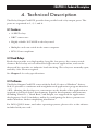
4. Technical Description
The Relay Output Card PCI provides four parallel reed relay output ports. The
ports are organized as 1, 2, 3, and 4.
4.1 Features
• 32 SPST relays
• DB37 connectors
• Highly reliable 10 VA DIP reed relays used
• Multiple cards can reside in the same computer
• PCI 2.1 bus compliant
4.2 Reed Relays
Reed relays provide very high quality, long life, low power, dry contact switch
closures. Reed relays are not suited for high-current applications, and can be
destroyed by capacitive or inductive load switching. The relays are normally open,
and they close when energized.
See Chapter 1 for relay specifications.
4.3 Software
The Relay Output Card PCI comes with the SeaI/O suite of Windows
®
drivers.
SeaI/O provides a consistent and straightforward applications program interface
(API), allowing the developer to concentrate on the details of the application as
opposed to low-level driver development. Popular development environments,
including Visual C++, Visual Basic, and Delphi, are supported for application
development. SeaI/O includes a utility for configuring the driver parameters
under Windows, further simplifying installation.
For DOS, QNX, Linux
®
, and other operating systems, please refer to the software
included with your card.

10
RELAY OUTPUT CARD PCI
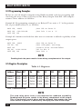
4.4 Programming Examples
Below are several simple examples using 80x86 assembly code for energizing and
checking the state of the reed relays on the Relay Output Card PCI. All examples
assume a base address of 300 Hex.
Example #1: Programming example to set Relay #27 on, write a “1” in bit position
D2, to port address Base+3, or 303 Hex.
MOV DX, 303H ;Set DX to Port D
MOV AL, 00001000B ;Set bit 3 to a ‘1’
OUT DX, AL
Example #2: Another method that takes into account the read-back capability of the
output ports.
MOV DX, 303H ;Set DX to Port D
IN AL, DX ;Get old port setting
NOT AL ;Invert bits - see note below
OR AL, 00001000B ;OR in bit 3
OUT DX, AL ;Set Bit 3
NOTE
Reading back the ports results in the binary complement of the output.
4.5 Register Description
Table 4-1. Registers.
Address Mode D7 D6 D5 D4 D3 D2 D1 D0
Base+0 R/W P1D7 P1D6 P1D5 P1D4 P1D3 P1D2 P1D1 P1D0
Base+1 R/W P2D7 P2D6 P2D5 P2D4 P2D3 P2D2 P2D1 P2D0
Base+2 R/W P3D7 P3D6 P3D5 P3D4 P3D3 P3D2 P3D1 P3D0
Base+3 R/W P4D7 P4D6 P4D5 P4D4 P4D3 P4D2 P4D1 P4D0
R/W = Read/Write bits
NOTE
The reed relay ports have a non-destructive readback capability.
Reading back the ports results in the binary complement of the output.
This is particularly useful when writing software that queries the last
value written to prevent in advertently changing the state of the relays.

11
CHAPTER 4: Technical Description
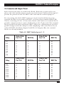
4.6 Connector and Jumper Pinout
Each relay has two sides, an A-side and a B-side. Each side is connected to two
places: the cable and the jumpers on the top of the board. Tables 4-2 through 4-5
provide the pinouts for the two DB37 cable ends and the onboard jumpers.
For easy wiring, the Card’s DB37 connector can be interfaced directly to the
terminal block kit (if you ordered IC907C, you’ll need part number EDN37-SP).
The kit, consisting of a 6-ft. (1.8-m) male/female cable and screw terminal block,
provides a simple means to connect field wiring to the 37-pin cards. The terminal
block provides both male and female DB37 connectors, eliminating the need for
gender changers and other adapters while simplifying cable connections. If you
ordered IC908C (the Relay Output Card PCI—32 Outputs/Kit), the terminal
blocks are already included.
Table 4-2. DB37 labeled ports 1, 2.
Relay A Side Relay B Side
Relay Port 1-A DB37 Pin Port 1-B DB37 Pin
K112120
K223221
K334322
K445423
K556524
K667625
K778726
K889827
Relay A Side Relay B Side
Relay Port 2-A DB37 Pin Port 2-B DB37 Pin
K9 1 10 1 28
K10 2 11 2 29
K11 3 12 3 30
K12 4 13 4 31
K13 5 14 5 32
K14 6 15 6 33
K15 7 16 7 34
K16 8 17 8 35

12
RELAY OUTPUT CARD PCI
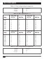
Table 4-3. Power and ground pin assignments.
Ground 18, 36, 37
+5 volts 19
+12 volts 1
Table 4-4. DB37 labeled ports 3, 4.
Relay A Side Relay B Side
Relay Port 3-A DB37 Pin Port 3-B DB37 Pin
K1712120
K1823221
K1934322
K2045423
K2156524
K2267625
K2378726
K2489827
Relay A Side Relay B Side
Relay Port 4-A DB37 Pin Port 4-B DB37 Pin
K25 1 10 1 28
K26 2 11 2 29
K27 3 12 3 30
K28 4 13 4 31
K29 5 14 5 32
K30 6 15 6 33
K31 7 16 7 34
K32 8 17 8 35
Table 4-5. Power and ground pin assignments.
Ground 18, 36, 37
+5 volts 19
+12 volts 1

13
CHAPTER 4: Technical Description
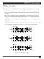
4.7 Jumper Setup Options
The common on each port may be tied to ground, 5, or 12 volts. Either side of
each relay then may be tied to the common. Figure 4-1 shows an example setup.
• Port 4: The common is tied to ground (GND). The A-side of port-4 relay 3
(K27) is tied to the common. The B-side of port-4 relay 6 (K30) is tied to the
common.
• Port 3: The common is tied to ground (GND). The A-side of port-3 relay 2
(K18) is tied to the common. The B-side of port-3 relay 5 (K21) is tied to the
common.
• Port 2: The common is tied to 5 volts. The B-side of port-2 relay 4 (K12) is tied
to the common.
• Port 1: The common is tied to 12 volts. The A-side of port-1 relay 1 (K1) is tied
to the common. The A-side of port-1 relay 8 (K8) is tied to the common.
Figure 4-1. Example setup.

14
RELAY OUTPUT CARD PCI
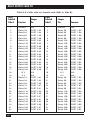
Table 4-6. Cable with two female ends (Side A, Side B).
DB37 DB37
Labeled Jumper Labeled Jumper
Side A Function Pin Side B Pin Common
1 Ground N/A 1 Ground N/A
2 Relay 2A PORT 1-A2 2 Relay 2B PORT 1-B2
3 Relay 4A PORT 1-A4 3 Relay 4B PORT 1-B4
4 Relay 6A PORT 1-A6 4 Relay 6B PORT 1-B6
5 Relay 8A PORT 1-A8 5 Relay 8B PORT 1-B8
6 Relay 10A PORT 2-A2 6 Relay 10B PORT 2-B2
7 Relay 12A PORT 2-A4 7 Relay 12B PORT 2-B4
8 Relay 14A PORT 2-A6 8 Relay 14B PORT 2-B6
9 Relay 16A PORT 2-A8 9 Relay 16B PORT 2-B8
10 Relay 18A PORT 3-A2 10 Relay 18B PORT 3-B2
11 Relay 20A PORT 3-A4 11 Relay 20B PORT 3-B4
12 Relay 22A PORT 3-A6 12 Relay 22B PORT 3-B6
13 Relay 24A PORT 3-A8 13 Relay 24B PORT 3-B8
14 Relay 26A PORT 4-A2 14 Relay 26B PORT 4-B2
15 Relay 28A PORT 4-A4 15 Relay 28B PORT 4-B4
16 Relay 30A PORT 4-A6 16 Relay 30B PORT 4-B6
17 Relay 32A PORT 4-A8 17 Relay 32B PORT 4-B8
18 12 V N/A 18 12 V N/A
19 5 V N/A 19 5 V N/A
20 Relay 1A PORT 1-A1 20 Relay 1B PORT 1-B1
21 Relay 3A PORT 1-A3 21 Relay 3B PORT 1-B3
22 Relay 5A PORT 1-A5 22 Relay 5B PORT 1-B5
23 Relay 7A PORT 1-A7 23 Relay 7B PORT 1-B7
24 Relay 9A PORT 2-A1 24 Relay 9B PORT 2-B1
25 Relay 11A PORT 2-A3 25 Relay 11B PORT 2-B3
26 Relay 13A PORT 2-A5 26 Relay 13B PORT 2-B5
27 Relay 15A PORT 2-A7 27 Relay 15B PORT 2-B7
28 Relay 17A PORT 3-A1 28 Relay 17B PORT 3-B1
29 Relay 19A PORT 3-A3 29 Relay 19B PORT 3-B3
30 Relay 21A PORT 3-A5 30 Relay 21B PORT 3-B5
31 Relay 23A PORT 3-A7 31 Relay 23B PORT 3-B7
32 Relay 25A PORT 4-A1 32 Relay 25B PORT 4-B1

15
CHAPTER 4: Technical Description
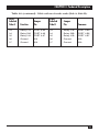
Table 4-6 (continued). Cable with two female ends (Side A, Side B).
DB37 DB37
Labeled Jumper Labeled Jumper
Side A Function Pin Side B Pin Common
33 Relay 27A PORT 4-A3 33 Relay 27B PORT 4-B3
34 Relay 29A PORT 4-A5 34 Relay 29B PORT 4-B5
35 Relay 31A PORT 4-A7 35 Relay 31B PORT 4-B7
36 Ground N/A 36 Ground N/A
37 Ground N/A 37 Ground N/A

16
RELAY OUTPUT CARD PCI
Appendix A. Troubleshooting
A.1 Tips
Following these simple steps can eliminate most common problems.
1. Install software first. After installing the software, add the hardware. This
places the required installation files in the correct locations.
2. Identify all I/O adapters currently installed in your system. This includes your
on-board serial ports, controller cards, sound cards, etc. The I/O addresses
used by these adapters, as well as the IRQ (if any) should be identified.
3. Make sure that there is no conflict with currently installed cards. No two cards
can occupy the same I/O address and may not be allowed to share IRQs.
4. Make sure that the Systems card is securely installed in a motherboard slot.
A.2 Calling Black Box
If you determine that your Relay Output Card PCI is malfunctioning, do not
attempt to alter or repair the unit. It contains no user-serviceable parts. Contact
Black Box at 724-746-5500.
Before you do, make a record of the history of the problem. We will be able to
provide more efficient and accurate assistance if you have a complete description,
including:
• the nature and duration of the problem.
• when the problem occurs.
• the components involved in the problem.
• any particular application that, when used, appears to create the problem or
make it worse.

17
APPENDIX A: Troubleshooting
A.3 Shipping and Packaging
If you need to transport or ship your Relay Output Card PCI:
• Package it carefully. We recommend that you use the original container.
• If you are shipping the Relay Output Card PCI for repair, make sure you
include everything that came in the original package. Before you ship, contact
Black Box to get a Return Authorization (RA) number.

18
RELAY OUTPUT CARD PCI
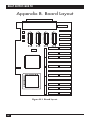
Appendix B. Board Layout
Figure B-1. Board layout.

1000 Park Drive • Lawrence, PA 15055-1018 • 724-746-5500 • Fax 724-746-0746
© Copyright 2001. Black Box Corporation. All rights reserved.
-
 1
1
-
 2
2
-
 3
3
-
 4
4
-
 5
5
-
 6
6
-
 7
7
-
 8
8
-
 9
9
-
 10
10
-
 11
11
-
 12
12
-
 13
13
-
 14
14
-
 15
15
-
 16
16
-
 17
17
-
 18
18
-
 19
19
-
 20
20


Black Box Work Light IC907C Manual de usuario
- Tipo
- Manual de usuario
- Este manual también es adecuado para
En otros idiomas
Documentos relacionados
Otros documentos
-
ESAB M3® Plasma Smart Voltage Height Control Manual de usuario
-
-
Cooper Lighting 6- ControlKeeper 4A - CK4A Guía de instalación
-
-
-
-
DSE DSE7210 Manual de usuario
-
 American Dynamics Intellex DV16000 Installation Note
-
PRASTEL Easymini El manual del propietario
