Gemini PS-04 El manual del propietario
- Categoría
- Mezcladores de audio
- Tipo
- El manual del propietario
Este manual también es adecuado para

OPERATIONS MANUAL
BEDIENUNGSHANDBUCH
MANUAL DEL OPERADOR
MANUEL D’INSTRUCTIONS
10" 3 CHANNEL STEREO MIXER
PROFESSIONELLER 3-KANAL STEREO-MIXER
MEZCLADOR ESTEREO DE 3 CANALES PROFESIONAL
MIXER STEREO 3 VOIES PROFESSIONNEL

CAUTION: This product satisfies FCC regulations when shielded cables and connec-
tors are used to connect the unit to other equipment. To prevent electromagnetic
interference with electric appliances such as radios and televisions, use shielded
cables and connectors for connections.
The exclamation point within an equilateral triangle is intended to alert the user to
the presence of important operating and maintenance (servicing) instructions in
the literature accompanying the appliance.
The lightening flash with arrowhead symbol, within an equilateral triangle, is
intended to alert the user to the presence of uninsulated “dangerous voltage” with-
in the product’s enclosure that may be of sufficient magnitude to constitute a risk
of electric shock to persons.
READ INSTRUCTIONS: All the safety and operating instructions should be read
before the product is operated.
RETAIN INSTRUCTIONS: The safety and operating instructions should be retained
for future reference.
HEED WARNINGS: All warnings on the product and in the operating instructions
should be adhered to.
FOLLOW INSTRUCTIONS: All operating and use instructions should be followed.
CLEANING: The product should be cleaned only with a polishing cloth or a soft dry
cloth. Never clean with furniture wax, benzine, insecticides or other volatile liquids
since they may corrode the cabinet.
ATTACHMENTS: Do not use attachments not recommended by the product manu-
acturer as they may cause hazards.
WATER AND MOISTURE: Do not use this product near water, for example, near a
bathtub, wash bowl, kitchen sink, or laundry tub; in a wet basement; or near a
swimming pool; and the like.
ACCESSORIES: Do not place this product on an unstable cart, stand, tripod, brack-
et, or table. The product may fall, causing serious injury to a child or adult, and
serious damage to the product. Use only with a cart, stand, tripod, bracket, or table
recommended by the manufacturer, or sold with the product. Any mounting of the
product should follow the manufacturer’s instructions, and should use a mounting
accessory recommended by the manufacturer.
CART: A product and cart combination should be moved with care. Quick stops,
excessive force, and uneven surfaces may cause the product and cart combina-
tion to overturn. See Figure A.
VENTILATION: Slots and openings in the cabinet are provided for ventilation and to
ensure reliable operation of the product and to protect it from overheating, and
these openings must not be blocked or covered. The openings should never be
blocked by placing the product on a bed, sofa, rug, or other similar surface. This
product should not be placed in a built-in installation such as a bookcase or rack
unless proper ventilation is provided or the manufacturer’s instructions have been
adhered to.
POWER SOURCES: This product should be operated only from the type of power
source indicated on the marking label. If you are not sure of the type of power sup-
ply to your home, consult your product dealer or local power company.
LOCATION: The appliance should be installed in a stable location.
NON-USE PERIODS: The power cord of the appliance should be unplugged from the
outlet when left unused for a long period of time.
GROUNDING OR POLARIZATION:
• If this product is equipped with a polarized alternating current line plug (a plug
having one blade wider than the other), it will fit into the outlet only one way. This
is a safety feature. If you are unable to insert the plug fully into the outlet, try
reversing the plug. If the plug should still fail to fit, contact your electrician to
replace your obsolete outlet. Do not defeat the safety purpose of the polarized
plug.
• If this product is equipped with a three-wire grounding type plug, a plug having
a third (grounding) pin, it will only fit into a grounding type power outlet. This is a
safety feature. If you are unable to insert the plug into the outlet, contact your elec-
trician to replace your obsolete outlet. Do not defeat the safety purpose of the
grounding type plug.
POWER-CORD PROTECTION: Power-supply cords should be routed so that they
are not likely to be walked on or pinched by items placed upon or against them,
paying particular attention to cords at plugs, convenience receptacles, and the
point where they exit from the product.
OUTDOOR ANTENNA GROUNDING: If an outside antenna or cable system is con-
nected to the product, be sure the antenna or cable system is grounded so as to
provide some protection against voltage surges and built-up static charges. Article
810 of the National Electrical Code, ANSI/NFPA 70, provides information with
regard to proper grounding of the mast and supporting structure, grounding of the
lead-in wire to an antenna discharge unit, size of grounding conductors, location
of antenna-discharge unit, connection to grounding electrodes, and requirements
for the grounding electrode. See Figure B.
LIGHTENING: For added protection for this product during a lightening storm, or
when it is left unattended and unused for long periods of time, unplug it from the
wall outlet and disconnect the antenna or cable system. This will prevent damage
to the product due to lightening and power-line surges.
POWER LINES: An outside antenna system should not be located in the vicinity of
overhead power lines or other electric light or power circuits, or where it can fall
into such power lines or circuits. When installing an outside antenna system,
extreme care should be taken to keep from touching such power lines or circuits
as contact with them might be fatal.
OVERLOADING: Do not overload wall outlets, extension cords, or integral conven-
ience receptacles as this can result in a risk of fire or electric shock.
OBJECT AND LIQUID ENTRY: Never push objects of any kind into this product
through openings as they may touch dangerous voltage points or short-out parts
that could result in a fire or electric shock. Never spill liquid of any kind on the
product.
SERVICING: Do not attempt to service this product yourself as opening or removing
covers may expose you to dangerous voltage or other hazards. Refer all servic-
ing to qualified service personnel.
DAMAGE REQUIRING SERVICE: Unplug this product from the wall outlet and refer
servicing to qualified service personnel under the following conditions:
• When the power-supply cord or plug is damaged.
• If liquid has been spilled, or objects have fallen into the product.
• If the product has been exposed to rain or water.
• If the product does not operate normally by following the operating instructions.
Adjust only those controls that are covered by the operating instructions as an
improper adjustment of other controls may result in damage and will often require
extensive work by a qualified technician to restore the product to its normal oper-
ation.
• If the product has been dropped or damaged in any way.
• When the product exhibits a distinct change in performance, this indicates a
need for service.
REPLACEMENT PARTS: When replacement parts are required, be sure the service
technician has used replacement parts specified by the manufacturer or have the
same characteristics as the original part. Unauthorized substitutions may result in
fire, electric shock, or other hazards.
SAFETY CHECK: Upon completion of any service or repairs to this product, ask the
service technician to perform safety checks to determine that the product is in
proper operating condition.
WALL OR CEILING MOUNTING: The product should not be mounted to a wall or
ceiling.
HEAT: The product should be situated away from heat sources such as radiators,
heat registers, stoves, or other products (including amplifiers) that produce heat.
MULTI LANGUAGE INSTRUCTIONS
ENGLISH..............................................................................................................................................................................................................................................................................PAGE 4
ALL SPECIFICATIONS:...................................................................................................................................................................................................................................................PAGE 6
DEUTSCH............................................................................................................................................................................................................................................................................PAGE 7
ESPAÑOL......................................................................................................................................................................................................................................................................................................................................................................PAGE 9
FRANCAIS....................................................................................................................................................................................................................................................................................................................................................................PAGE 12
PLEASE READ BEFORE USING APPLIANCE, IMPORTANT WARNING & SAFETY INSTRUCTIONS!
RISK OF ELECTRICAL SHOCK DO NOT OPEN!
CAUTION
(2)

(3)
PS-004
REAR
FRONT
FACE
REAR
FRONT
FACE

(44)
Congratulations on your purchase of a Gemini PS-04 10" 3 channel
stereo mixer. This state-of-the-art mixer features the latest technological
advances and is backed by a 3 year warranty, excluding the cross fader.
The cross fader is backed by a separate 90 day warranty. Prior to use
we suggest that you carefully read all the instructions.
- Professional 3 Channel Stereo FX Mixer
- 10" 3 stereo channel mixer
- 6 line, 3 convertible phono/line, RCA inputs
- Master, record, & zone RCA outputs
- ¼" balanced outputs
- Triple ground screw for easy connectivity
FACE:
- Easy removable face plate for user replaceable Rail Glide cross fader
- Bright blue LCD display for FX names & FX parameters
- FX assign switch
- Dry/Wet fader control
- Rotary FX selector & parameter controls
- Dual mode backlit FX on/off & cue effect button
- 3 band rotary line EQ with cut feature & rotary gain channel control
- Lighted push button cue section
- Rotary zone & balance controls
- Dual VU display with bright LED & mode switch
- Master volume fader control
FRONT:
- ¼" headphone output & Mic input
- Cue section with rotary cue volume & CUE/PGM controls with cue split
/mix switch
- Mic section with rotary Mic volume, high & low EQ controls
- Fader section with hamster/reverse, slope, & assign switches
1. All instructions should be read before using this equipment.
2. To reduce the risk of electrical shock, do not open the unit. Please
refer all servicing needs to a Gemini-qualified service technician.
3. Do not expose this unit to direct sunlight or a heat source such as a
radiator or stove.
4. This unit should be cleaned only with a damp cloth. Avoid solvents or
other cleaning detergents.
5. When moving this equipment it should be placed in its original carton
and packaging. This will reduce the risk of damage during transit.
6. DO NOT EXPOSE THIS UNIT TO RAIN OR MOISTURE.
7. DO NOT USE SPRAY CLEANERS OR LUBRICANTS ON CON-
TROLS, SURFACES OR SWITCHES.
1. Before plugging this unit into any outlet, make sure that the VOLTAGE
SELECTION SWITCH (1) is set to the proper voltage. To change the
selection, unscrew the hard plastic protective top with a Phillips head
screw driver. Then use a flat head screw driver to move the switch to the
proper selection (115V/230V). Replace the hard plastic protective top,
and screw into the unit.
2. Ensure that the POWER (4) switch is in the OFF position prior to mak-
ing any connections. This unit comes with a power cord. Plug into the
rear panel POWER CORD (2) jack before plugging it into a proper power
source.
NOTE: LOCATED BY THE POWER CORD (2) JACK IS A 250V FUSE (3) TO PROTECT
AGAINST ELECTRICAL SURGES. TO REPLACE THE FUSE, PLACE A FLAT HEAD
SCREWDRIVER INTO THE GROOVE LOCATED INSIDE THE POWER CORD JACK (2) AND
POP THE FUSE OUT. REPLACE THE FUSE WITH ONLY A 250V FUSE.
3. The PS-04 has four outputs located on the rear panel:
- The MASTER RCA OUTPUT (5) connects the mixer to your main
amplifier using standard audio cables with RCA-type conectors.
- The BALANCED MASTER OUTPUT (8) connects the mixer to your
main amplifier using standard cables with 1/4" connectors. We recom-
mend using balanced cables if the distance to your amp is 10 feet or
more.
- The ZONE (7) output jacks allow the connection of an additional
amplifier with RCA cables.
- The REC (6) output jacks can be used to connect the mixer to the
record input of your recording unit, thus enabling you to record your mix
with RCA cables.
4. Headphones may be plugged into the front panel-mounted HEAD-
PHONES (22) ¼" jack.
5. Microphones may be plugged into the front panel-mounted MICRO-
PHONE (21) ¼" jack.
6. The PS-04 has 3 CONVERTIBLE PHONO/LINE (PH/LN) RCA
INPUTS (10, 14, 18) located on the rear panel on either side of the RCA
INPUTS. Facing the rear panel, the convertible RCA input on your right
is for PH1/LN1 (18). The convertible RCA input in the middle is for
PH2/LN3 (14). The convertible RCA input on your left is for PH3/LN5
(10). Using the PH/LN CONVERTERS (11, 15, 19), located just below
each input, you may convert the PH to LN and vice versa. Plug the
RCA's from your playable medium into each input to be connected to
their respective CHANNELS (CH). The PH INPUTS (10, 14, 18) only
accept turntables with a magnetic cartridge. The STEREO LN INPUTS
(9, 10, 13, 14, 17, 18) only accept line level inputs such as a CD, DAT,
Mini Disc, etc and require the proper switch settingand require the LN
switch setting as indicated in the PH/LN CONVERTER SWITCHES (11,
15, 19).
7. When using (a) turntable(s), you will need to ground the RCA cable(s)
by screwing in the grounding fork(s) to the TRIPLE GROUNDING
SCREWS (12 ,16, 20) located in the rear panel of the PS-04 mixer.
Attach each PH ground lines to one of the TRIPLE GROUND THUMB
SCREWS (12, 16, 20). These are to the right of each PH/LN CONVERT-
ER (11, 15, 19).
NOTE: WHEN USING TURNTABLES, NOT ATTACHING A GROUND MAY CAUSE A SYSTEM
"HUM."
1. Once all of your connections have been made in the rear panel, turn
on the mixer by pressing the POWER SWITCH (4).
2. CH1: To bring this channel into program output (PGM), you must first
decide which line will be in use. Use the LN SWITCH (23) to toggle from
PH1/LN1 (18) to LN2 (17) on this channel. Once you've selected the
proper line, slowly raise the CH1 FADER CONTROL (29) to a comfort-
able level. You can further modify the sound output of this channel by
adjusting the rotary GAIN (24), HIGH (25), MID (27), LOW (26) controls
located to the left of the CH1 FADER CONTROL (29).
3. CH2: To bring this channel into PGM, you must first decide which line
will be in use. Use the LN SWITCH (30) to toggle from PH2/LN3 (14) to
LN4 (13) on this channel. Once you've selected the proper line, slowly
raise the CH2 FADER CONTROL (36) to a comfortable level. You can
further modify the sound output of this channel by adjusting the rotary
GAIN (31), HIGH (32), MID (34), LOW (33) controls located to the left of
the CH2 FADER CONTROL (36).
4. CH3: To bring this channel in to PGM, you must first decide which line
will be in use. Use the LN SWITCH (37) to toggle from PH3/LN5 (10) to
LN6 (9) on this channel. Slowly raise the CH3 FADER CONTROL (43)
to a comfortable level, once you've selected the proper line. You can fur-
ther modify the sound output of this channel by adjusting the rotary
GAIN (38), HIGH (39), MID (41), LOW (40) controls located to the left of
the CH3 FADER CONTROL (43).
NOTE: FOR OPTIMAL PERFORMANCE, BEGIN PROGRAM MIX WITH ROTARY GAIN (24,
31, 38) CONTROLS SET TO MINIMUM (ROTATE IT TO THE COUNTER CLOCKWISE POSI-
TION). MAKE ALL ADJUSTMENTS IN SOUND OUTPUT WITH THE USE OF YOUR
CHANNEL FADER CONTROLS (29, 36, 43), ZONE (51), BALANCE (52), AND MASTER VOL-
UME (47) CONTROLS. THIS WILL PREVENT SIGNAL OVERLOAD AND DECREASE DIS-
TORTION. ONCE YOU HAVE MODIFIED YOUR SOUND AND WOULD LIKE TO INCREASE
THE OUTPUT OF YOUR SOUND, THEN YOU MAY ADJUST THE ROTARY GAIN CONTROL
IF NEEDED.
5. CUE: By connecting a set of headphones to the HEADPHONE (22)
jack, you can monitor any or all channels. Press the CUE BUTTONS
(28, 35, 42) for CH1 through CH3 to assign the CH(s) to be monitored in
your headphones. The respective CUE LED indicators will glow when in
use. Use the front panel located rotary CUE VOLUME CONTROL (44)
to adjust the CUE volume without changing the overall mix. By turning
the front panel located CUE/MIX/PGM (45) rotary control counter clock-
wise you will be able to monitor the assigned CUE signal. Slowly turning
the control clockwise to middle position (MIX) allows you to monitor CUE
mix with PGM. Moving the control clockwise to the right allows you to
monitor PGM output.
Use the CUE SPLIT/MIX SWITCH (48) to split the audio input playing
INTRODUCTION:
FEATURES:
PRECAUTIONS:
IN THE
USA ~ IF YOU EXPERIENCE PROBLEMS WITH THIS UNIT CALL GEMINI CUSTOMER
SERVICE AT: 1 (732) 738-9003. DO NOT ATTEMPT TO RETURN THIS EQUIPMENT TO YOUR
DEALER
.
CONNECTIONS:
OPERATING INSTRUCTIONS:

(5)
in your head phones. When the CUE SPLIT/MIX SWITCH (48) is in MIX
mode you will only be able to monitor your CUE in both headphones,
when the rotary CUE/MIX/PGM CONTROL (45) is in CUE. When the
CUE SPLIT/MIX SWITCH (48) is in SPLIT, you will notice one side of
your headphones will play your CUE and the other side will play PGM,
thus enabling you to monitor both outputs separately. This feature will
only work properly if the CUE/MIX/PGM (45) rotary control is placed at
noon or middle position. If the CUE/MIX/PGM (45) rotary control is set to
CUE you will only here the CUE signal playing on the left side of your
headphones. If the CUE/MIX/PGM (45) rotary control is set to PGM, the
PGM will be the only signal heard from the right side of your head-
phones.
6. CROSS FADER SECTION: The CROSS FADER (46) allows you to
mix from one source to another. The CROSS FADER (46) in your unit is
removable and if the need arises can be easily replaced. Your Gemini
mixer comes with a RG-45 (RAILGLIDE™) DUAL-RAIL CROSS
FADER. RAIL GLIDE™ CROSS FADERS have internal dual stainless
steel rails that allow the slider to ride smoothly and accurately from end
to end. Also available is our RG-45 PRO (PROGLIDE™) Dual-Rail
CROSS FADER. This unique CROSS FADER features, a special curve
designed for scratch mixing. Just purchase one from your Gemini deal-
er and follow the instructions:
NOTE: DO NOT APPLY PRESSURE WHILE USING THE CROSSFADER. LIGHTLY GLIDE
THE CROSSFADER BACK AND FORTH. PRESSING DOWN ON THE CONTROLS CAN
BEND CONTACTS AND CAUSE A LOSS OF SOUND.
7. SLOPE CONTROL: The CROSS FADER SLOPE SWITCH (57)
allows you to adjust the kind of curve the CROSS FADER (46) has. Flip
the CROSS FADER SLOPE SWITCH (57) down to make the slope
steep and cutting (perfect for scratching). Flip the CROSS FADER
SLOPE SWITCH (57) up to make the slope gradual and gentle.
8. REVERSE CONTROL: The CROSS FADER REVERSE SWITCH
(56) allows you to reverse the CROSS FADER (46) so that the right side
CH3 (43) is controlled by the left side of the CROSS FADER (46) and
the left side CH1 (29) or CH2 (36) is controlled by the right side of the
CROSS FADER (46). Flip the switch up to activate the REVERSE (56)
control. Flip the switch down to deactivate the REVERSE (56) control.
NOTE: WHEN THE CROSSFADER REVERSE SWITCH (56) IS ACTIVATED, ONLY THE
CROSSFADER REVERSES. THE CHANNEL SLIDES, GAIN, KILL SWITCHES AND TONAL
CONTROLS DO NOT REVERSE.
9. CROSS FADER ASSIGN: The CROSS FADER ASSIGN SWITCH
(58) is used to place CH(s) on either side of the CROSS FADER (46).
When the ASSIGN SWITCH (58) is in the top position, CH1 (29) & CH3
(36) are assigned to the CROSS FADER (46). When the REVERSE (56)
control is not activated, CH1 (29) will be on the left and CH3 (43) will be
on the right. When the ASSIGN SWITCH (58) is in the bottom position,
CH2 (36) & CH3 (43) are assigned to the CROSS FADER (46). When
the REVERSE (56) control is not activated, CH2 (36) will be on the left
and CH3 (43) will be on the right.
10. OUTPUT SELECTION CONTROL: Once you are comfortable with
the sound level of your music you may adjust the volume with the
MASTER (47) slide control. You may adjust the volume of the zone out-
put with the ZONE (51) rotary control. You may also pan the audio out-
put from left to right with the BALANCE (52) rotary control.
11. MIC SECTION: Plug your main MIC into the MIC (21) 1/4" input
located on the front panel. Connecting a microphone to the MIC (21)
1/4" jack allows voice amplification through the mixer to the stereo
through the MASTER RCA (5), ZONE (7), BALANCED (8) and REC (6)
outputs. This MIC is controlled by the MIC VOLUME (55), HIGH (54),
LOW (53) rotary controls. To activate this section, rotate the MIC VOL-
UME (55) rotary control clockwise. The rotary knob will click and a green
LED will light up to indicate that the MIC (21) is in use. To deactivate this
section rotate the MIC VOLUME (55) rotary control counterclcockwise
until the knob clicks and the green LED turns off.
12. VU METER: The
PS-04 has a dual mode VU METER (50) that
allows you to monitor the decibel levels of CUE and PGM or LEFT and
RIGHT stereo levels of the MASTER output. With the VU MODE
SWITCH (49) you may monitor the output level of the CUE and PGM
when the switch is UP. When this mode is engaged the CUE will be
located on the left of the VU METER (50), while the PGM will be locat-
ed on the RIGHT. Or you can monitor the LEFT and RIGHT stereo deci-
bel levels of the MASTER OUTPUT when the switch is in the DOWN
position.
NOTE: WHEN USING THE EFX SECTION, YOU MAY EXPERIENCE A TONAL BOOST THAT
WILL SEND YOUR MASTER OUTPUT LEVELS INTO THE BLUE (0 THROUGH +11), AS
INDICATED IN YOUR VU METER (50). ADJUST THE CHANNEL FADERS (29, 36, 43), IN
ORDER TO PROTECT YOUR EQUIPMENT FROM A SYSTEM OVERLOAD. TO BEGIN EFX
EXPERIMENTATION, START WITH A LOW PARAMETER SETTING WITH YOUR CHANNEL
FADERS (29, 36, 43) AT MID LEVEL. THEN MOVE SLOWLY THROUGH THE EFX PARAME-
TERS TO EXAMINE THE TONAL BOOST, SAFELY.
The PS-04 is equipped with DIGITAL SIGNAL PROCESSOR (DSP)
effects. This means you may augment the audio output of your program
mix by processing tones through the 26 different effects. When an audio
signal is processed through the DSP effects, a wide range of effects can
be achieved with the PS-04 EFX section. Please follow these instruc-
tions to operate the EFX section of your mixer:
1. EFX ASSIGN: The PS-04 allows you to select the CH to pass through
the effects processor, while choosing multiple levels of EFX. Use the
EFX ASSIGN (64) switch to select a CH to process by flipping the switch
to the LEFT or RIGHT until the EFX ASSIGN LED reaches the CH you
wish to process. You may process the audio outputs of CH1 (29), CH2
(36), CH3 (43), MIC (21), or the MASTER (47). The blue LED indicator
will show you which CH will be processed. When the CUE EFX mode is
activated the EFX ASSIGN LED will blink to indicate which CH will be
processed in CUE.
NOTE: WHEN FLIPPING THROUGH CHANNELS AND THE DRY/WET FADER (59) IS AT
THE WET POSITION, AN AUDIBLE CLICK MAY BE HEARD IN PGM. TO PREVENT THIS
CLICK FROM BEING HEARD, LOWER THE CH SLIDES NOT IN USE TO THE CLOSED,
ZERO POSITION, PLACE THE DRY/WET FADER (59) IN THE DRY POSITION BEFORE
FLIPPING THROUGH THE CH WITH THE EFX ASSIGN (64).
2. DRY/WET FADER: To control this section you must adjust the
DRY/WET FADER (59) in order to increase the level of the EFX proces-
sor. Glide the DRY/WET FADER (59) to the RIGHT to increase the EFX,
drowning out the program mix with a WET effect. Glide the DRY/WET
FADER (59) to the LEFT or DRY area to decrease the EFX, thus dis-
abling all EFX.
3. ON/OFF/CUE EFX: The ON/OFF/CUE EFX (63) button has multiple
functions:
- PGM MODE: Tap the ON/OFF/CUE EFX (63) button. The blue LED
will turn on to indicate that the DSP effects feature has been engaged in
PGM mode. Tap the button again and the DSP effects will be disen-
gaged as the LED turns off.
When using the ON/OFF/CUE EFX (63), you will notice that once an
effect has been engaged, the effect will not change when scrolling
through the EFX selection, using the EFX SELECTOR (60) to find a new
effect as instructed below. In order to change the effect you must tap the
ON/OFF/CUE EFX (63) button to engage the next effect and adjust
PARAMETER settings.
- CUE MODE: For monitoring in your headphones without changing the
PGM, press and hold the ON/OFF/CUE EFX (63) button until the EFX
ASSIGN LED starts to blink to indicate that the DSP effects are engaged
in CUE mode. To disengage the CUE mode, press and hold the
ON/OFF/CUE EFX (63) button until the EFX ASSIGN LED stops blink-
ing.
To disengage the EFX in CUE mode, tap the ON/OFF/CUE EFX (63)
button, and you will monitor the CUE without effects. The EFX ASSIGN
LED button begins blinking indicating that the DSP effects are not
engaged in
CUE MODE. To engage the DSP, tap the ON/OFF/CUE EFX
(63) button to engage the DSP EFX.
4. PARAMETER: To adjust the PARAMETER, or dynamics of the effect
signal of the effect signal, use the PARAMETER (62) rotary knob to
expand or minimize the effect level of the DSP effects. Rotate the PARA-
METER (62) knob clockwise to expand the effect. Rotate the PARAME-
TER (62) knob counter clockwise to minimize the effect.
5. LCD: The blue LCD (61) shows the EFX selection abbreviated name,
to indicate which effect is activated or which effect may be activated at
the top part of the screen. While the bottom part of the screen displays
the PARAMETER level as controlled by the PARAMETER (62) rotary knob.
6. EFX SELECTOR: Use the EFX SELECTOR (60) rotary knob to scan
through the 26 DSP effects as indicated in the blue LCD (61) display.
PPSS-0044
PPSS-0044
REPLACEABLE CROSS FADER
1. UNSCREW THE OUTSIDE FACE PLATE SCREWS ON THE LOWER HALF OF
THE MIXER. REMOVE THE FADER CAPS AND FACE PLATE.
2.UNSCREW THE FADER (B)
SCREWS. DO NOT TOUCH INSIDE
SCREWS (C). CAREFULLY
REMOVE OLD CROSS FADER AND
UNPLUG CABLE (D).
3. PLUG IN THE NEW CROSS
FADER INTO CABLE (D) AND
PLACE BACK INTO MIXER.
4. SCREW THE CROSS FADER TO
MIXER WITH THE FADER PLATE
SCREWS (B).
5. REPLACE THE LOWER HALF
FACE PLATE AND SCREW TO THE
MIXER.
EFX SECTION:

(6)
Once you have found an effect you would like to engage, press and hold
the ON/OFF/CUE EFX (63) button to preview the DSP effect. The EFX
SELECTOR (60) can rotate 360
o
while scanning through the effects.
Rotate the EFX selector knob clockwise to scan forward through the
EFX list. Rotate the EFX SELECTOR (60) counterclockwise to scan
backwards through the EFX list. The effects are listed on page 13.
NOTE: WHEN SCROLLING THROUGH THE EFFECTS YOU WIL FIRST SEE THE NUMBER
OF THE EFFECT, THEN THE LCD (61) WILL AUTOMATICALLY SWITCH THE VIEW TO THE
PARAMETER SETTING. THIS WILL AID IN SCROLLING TO AN EFFECT QUICKLY BY FIND-
ING THE NUMBER OF THE EFFECT.
INPUTS:
Phono.............................................................................3 mV, 47 KOhm
Line............................................................................150 mV, 27 KOhm
MIC 1…………………...................................1.5 mV, 1 K Ohm Balanced
MIC 1 Bass..................................................................................± 12dB
MIC 1 High...................................................................................± 12dB
OUTPUTS:
Amp/Zone...................................................................0 dB 1V, 400 Ohm
Max............................................................................20V Peak-to-Peak
Rec...............................................................................225 mV, 5 KOhm
Balanced Master………………………................................2V, 400 Ohm
GENERAL:
Frequency Response..........................................20Hz - 20KHz +/- 2 dB
Distortion...................................................................................< 0.02%
S/N Ratio....................................................................Better Than 80 dB
Headphone Impedance..............................................................16 Ohm
Power Source..................................................115/230V, 60/50Hz, 20W
Unit Dimensions...........................................................10" x 3.3" x 11.9"
………………………………….................................(254 x 84 x 303 mm)
Weight.........................................................................7.45 lbs (3.38 kg)
SPECIFICATIONS SUBJECT TO CHANGE WITHOUT NOTIFICATION FOR IMPROVEMENT.
EINGÄNGE:
Phono...............................................................................3 mV, 47 KOhm
Line..............................................................................150 mV, 27 KOhm
MIC…………..........………........................1.5 mV, 1 K Ohm symmetrisch
MIC Bass...................................................................................... ± 12dB
MIC High....................................................................................... ± 12dB
AUSGÄNGE:
Amp/Zone....................................................................0 dB 1V, 400 Ohm
Maximum......................................................................20V Spitze-Spitze
Rec.................................................................................225 mV, 5 KOhm
Master, symmetrisch……….............................................….2V, 400 Ohm
ALLGEMEIN:
Frequenzbereich...................................................20Hz - 20KHz +/- 2 dB
Klirrfaktor.....................................................................................< 0.02%
Geräuschspannungsabstand.........................................besser als 80 dB
Kopfhörer Impedanz.....................................................................16 Ohm
Spannungsversorgung......................................115/230V, 60/50Hz, 20W
Abmessungen............................................................. 254 x 84 x 303mm
Gewicht.........................................................................................3.38 kg
TECHNISCHE ÄNDERUNGEN VORBEHALTEN.
SPECIFICATIONS:
SPECIFICATIONS:
ENTRADAS:
Phono.......................................................................... ..3 mV, 47 KOhm
Line............................................................................150 mV, 27 KOhm
MIC 1…………………...............................1.5 mV, 1 K Ohm Balanceada
MIC 1 Grave................................................................................± 12dB
MIC 1 Agudo................................................................................± 12dB
SALIDAS:
Amp/Zone...................................................................0 dB 1V, 400 Ohm
Max...................................................................................20V Pico-Pico
Rec...............................................................................225 mV, 5 KOhm
Master Balanceada……………….......................................2V, 400 Ohm
GENERAL:
Respuesta Frecuencial........................................20Hz - 20KHz +/- 2 dB
Distorsión...................................................................................< 0.02%
Relación señal/ruido.......................................................Mejor de 80 dB
Impedancia Auriculares..............................................................16 Ohm
Alimentación....................................................115/230V, 60/50Hz, 20W
Dimensiones................................................................10" x 3.3" x 11.9"
………………………………….................................(254 x 84 x 303 mm)
Peso............................................................................7.45 lbs (3.38 kg)
LAS ESPECIFICACIONES Y EL DISEÑO ESTÁN SUJETOS A CAMBIOS SIN AVISO PREVIO
CON LA INTENCIÓN DE MEJORAR.
ENTREES:
Phono:............. .............................................................3 mV, 47 KOhms
Ligne:................ .......................................................150 mV, 27 KOhms
MICRO………….......................................1.5 mV, 1 K Ohms Symétrique
MIC Basse....................................................................................+
12 dB
MIC Aigu.......................................................................................+
12 dB
SORTIES:
Amplificateur/Zone…….............................................0 dB 1V, 400 Ohms
Max:............... ................................................................20V Crête/Crête
Enregistrement............................................................225 mV, 5 KOhms
Symétrique......................................................................…2V 400 Ohms
GENERAL:
Bande passante:………….....................................20Hz - 20KHz +/- 2 dB
Distortion:.......................……......................................................< 0.02%
Rapport Signal/Bruit:..........................................……..............…..> 80 dB
Impédance casque:……….........................................................16 Ohms
Alimentation:……..............................................115/230V, 60/50Hz, 20W
Dimensions:...................….................…............….....254 x 84 x 303 mm
Poids: …..:.......................…......................................... 7.45 lbs (3.38 kg)
GEMINI, DANS LE CADRE D'UN SOUCI CONSTANT D'AMÉLIORATION DE SES PRO-
DUITS, SE RÉSERVE LE DROIT DE LES MODIFIER SANS AUCUN PRÉAVIS.0
ESPECIFICACIONES:
CARACTÉRISTIQUES TECHNIQUES

(77)
- Die Cinchbuchsen REC (6) output sind für den Anschluß an ein
Aufnahmegerät vorgesehen.
4. Kopfhörer können an die 6.3 mm Klinkenbuchse HEADPHONE (22)
an der Frontseite angeschlossen werden.
5. Ein Mikrofon ist an die 6.3 mm Klinkenbuchse MICROPHONE (21)
anschliessbar.
6. Der PS-04 hat 3 umschaltbare PHONO/LINE (PH/LN) Cincheingänge
(10, 14, 18). Diese befinden sich auf der Rückseite. Auf die Rückseite
gesehen sind die rechten Cinchbuchsen für PH 1/LN 1 (18), die mit-
tleren für PH 2/LN 3 (14) und die linken für PH 3/ LN 5 (10). Die
Umschaltung erfolgt mit den, unter den Cinchbuchsen befindlichen
Schaltern PH/LN (11, 15, 19). Verbinden Sie Ihr Abspielgerät mit einem
Cinchkabel mit dem Eingang des gewünschten KANALS (CH). An die
Phonoeingänge PH INPUTS (10, 14, 18) können nur Plattenspieler mit
Magnetsystem angeschlossen werden. Die Lineeingänge STEREO LN
INPUTS (9, 10, 13, 14, 17, 18) dienen zum Anschluß von CD, DAT, Mini
Disc- Playern usw.
7. Wenn Sie Plattenspieler an den Mixer anschliessen, achten Sie
darauf, daß das Massekabel der Cinchleitung an die Erdungsschrauben
TRIPLE GROUNDING SCREWS (12, 16, 20) an der Rückseite des PS-
04 angeschlossen wird.
ANMERKUNG: WIRD EIN PLATTENSPIELER OHNE MASSEVERBINDUNG (ERDUNG)
BETRIEBEN, KÖNNEN BRUMMGERÄUSCHE AUFTRETEN.
1. Wenn alle Verbindungen hergestellt sind, schalten Sie den Mixer mit
dem SCHALTER POWER SWITCH (4) ein.
2. KANAL 1 (CH 1): Um diesen Kanal hören zu können, wählen Sie den
gewünschten Eingang mit dem SCHALTER LN SWITCH (23) zwischen
PH 1/LN 1 (18) oder LN 2 (17) aus. Nun können Sie mit dem Regler
GAIN (24) und dem FADER CH 1 CONTROL (29) den Lautstärkepegel
und mit den Reglern HIGH (25), MID (27), LOW (26) den Klang des
Signals beeinflussen.
3. KANAL 2 (CH 2): Um diesen Kanal hören zu können, wählen Sie den
gewünschten Eingang mit dem SCHALTER LN SWITCH (30) zwischen
PH 2/LN 3 (14) und LN 4 (13) aus. Nun können Sie mit dem Regler
GAIN (31) und dem FADER CH 2 CONTROL (36) den Lautstärkepegel
und mit den Reglern HIGH (32), MID (34), LOW (33) den Klang des
Signals beeinflussen.
4. KANAL 3 (CH 3): Um diesen Kanal hören zu können, wählen Sie den
gewünschten Eingang mit dem SCHALTER LN SWITCH (37) zwischen
PH 3/LN 5 (10), und LN 6 (9) aus. Nun können Sie mit dem Regler GAIN
(38) und dem FADER CH 3 CONTROL (43) den Lautstärkepegel und
mit den Reglern HIGH (39), MID (41), LOW (40) den Klang des Signals
beeinflussen.
ANMERKUNG: UM EINEN OPTIMALEN KLANG ZU ERZIELEN, BEGINNEN SIE MIT DEM
KANALFADER (29, 36, 43) IN MÖGLICHST UNTERER STELLUNG (LEISE, NIEDRIGER
PEGEL). SCHALTEN SIE DAS VU-METER AUF CUE/PGM (SIEHE 13.) UND STELLEN SIE
MIT DEM GAIN (24, 31, 38) UND DEN EQ,-REGLERN DEN ERWÜNSCHTEN KLANG SO EIN,
DAß DIE ANZEIGE ETWA 0DB ZEIGT. NUN SCHALTEN SIE DAS VU-METER WIEDER UM
UND REGELN MIT DEN KANALFADERN CHANNEL SLIDE CONTROLS (29, 36, 43) DEN
PEGEL DES JEWEILIGEN KANALS. MIT DEN REGLERN ZONE (51), BALANCE (52),
UND DEM FADER MASTER (47) VOLUME STELLEN SIE DIE GEWÜNSCHTE
AUSGANGSLAUTSTÄRKE EIN.
5. VORHÖREN (CUE): Wenn Sie einen Kopfhörer an die Buchse
HEADPHONE (22) jack anschliessen können Sie alle Kanäle vorhören.
Drücken Sie die Taster CUE BUTTONS (28, 35, 42) für KANAL 1-3 um
den jeweils abzuhörenden Kanal anzuwählen. Die jeweils zugehörige
LED leuchtet dann auf. Mit dem Drehregler CUE VOLUME CONTROL
(44) stellen Sie die gewünschte Abhörlautstärke ein ohne das
Ausgangssignal zu beeinflussen. Drehen Sie den Regler CUE/MIX/PGM
(45) auf der Frontseite ganz nach links, so hören Sie nur das Signal des
gewählten Kanals (CUE). Je weiter Sie nun nach rechts (Uhrzeigersinn)
drehen, um so stärker hören Sie zusätzlich das Ausgangssignal (PGM),
bis am Rechtsanschlag das CUESIGNAL nicht mehr hörbar ist.
Um das Signal im Kopfhörer zu trennen, verwenden Sie den Schalter
CUE SPLIT/MIX SWITCH (48). Im MIX mode hören Sie die Signale im
Kopfhörer wie oben beschrieben. Steht der Schalter CUE SPLIT/MIX
SWITCH (48) im SPLIT mode, hören Sie auf einer Seite das Cuesignal
und auf der anderen Seite das Ausgangssignal (PGM). Für die
beschriebene Funktion muß der Drehregler CUE/MIX/PGM (45) in
Mittelstellung stehen. Drehen Sie den Regler nach links, so hören Sie
nur das CUESIGNAL auf der linken Seite. Drehen Sie nach rechts so
hören Sie nur das PGMSIGNAL auf der rechten Seite.
6. CROSSFADER SEKTION (ÜBERBLENDER): Der CROSSFADER
(46) ermöglicht das Mixen von einem Kanal zum Anderen. Der PS-04 ist
mit einem RG-45 (RAILGLIDE™) DUAL-RAIL CROSSFADER ausges-
Vielen Dank, daß Sie sich für einen GEMINI PS-04 Mixer entschieden
haben. Die Mischpulte sind nach dem neuesten Stand der Technik
hergestellt und mit einer Garantie von 3 Jahren versehen. Der
Crossfader hat eine Garantie von 3 Jahren. Bitte lesen Sie alle
Anweisungen vor der Inbetriebnahme sorgfältig durch.
- 10"-Mixer mit 3 Stereo Kanälen
- 6 Line-,und 3 umschaltbare Phono/Line Cincheingänge
- Cinchausgänge für Master, Record, & Zone
- Symmetrische Masetrausgänge mit 6,3mm Klinkenbuchsen
- 3 Erdungsschrauben für einfache Verbindungen
FRONTPLATTE:
- Abnehmbare Frontplatte für leichten Austausch des Rail-Glide-
Crossfaders
- 3-Band-Eq-Killschalter mit Flashfunktion
- 3-Band-Eq. mit Drehreglern und Gaindrehregler pro Kanal
- Cuesektion mit beleuchteten Tastern
- Drehregler für Zone und Balance
- Stereo-VU-Meter mit hellen LED´s und Modeschalter
- Fader für Master-Volume
FRONTSEITE:
- 6.3mm Klinkenbuchsen für Kopfhörer und Mikrofon
- Cue Sektion mit Drehreglern für Cue Volume & CUE/PGM und Cue
Split/Mix Schalter
- Mikrofon Sektion mit Drehreglern für Mic-Volume und high & low EQ
- Crossfader-Sektion mit Hamster/Reverse, Slope, & Assign Schaltern
1. Vor der Anwendung des Mixers, bitte alle Anweisungen durchlesen.
2. Um einen elektrischen Schock zu vermeiden, das Gerät nicht öffnen.
Servicearbeiten dürfen nur qualifizierten Wartungstechnikern durchge-
führt werden.
3. Setzen Sie das Gerät nie direkter Sonneneinstrahlung oder
Hitzequellen (Heizstrahler o.ä.) aus.
4. Reinigen Sie die Oberflächen nur mit einem weichen Tuch. Keine
scharfen Reinigungsmittel verwenden.
5. Transportieren Sie den Mixer möglichst im Originalkarton, um
Schäden zu vermeiden.
6. SETZEN SIE DIESES GERÄT NIE REGEN ODER STARKER
FEUCHTIGKEIT AUS.
7. VERWENDEN SIE KEIN KONTAKT-, ÖL-, ODER SILIKONSPRAY
AN DEN SCHALTERN, REGLERN, UND FADERN.
1. Bevor Sie den Mixer an eine Steckdose anschließen, stellen Sie sich-
er, daß der VOLTAGE SELECTION SWITCH (1)
(Spannungswahlschalter) auf die vorhandene Netzspannung
eingestellt ist. Um die Einstellung zu ändern, lösen Sie die Schraube der
Plastiksicherung mit einem Kreuzschlitzschraubendreher und drehen
sie die Plastiksicherung zur Seite. Schieben Sie nun mit einem
schmalen Schlitzschraubendreher den Spannungswahlschalter in die
richtige Position (115 V/230 V).
2. Vergewissern Sie sich das der NETZSCHALTER POWER SWITCH
(4) ausgeschaltet ist bevor Sie den Mixer anschliessen. Stecken Sie das
mitgelieferte Netzkabel in die Netzbuchse POWER CORD (2) jack bevor
Sie es in die Steckdose stecken.
ANMERKUNG: IN DIE NETZBUCHSE (2) INTEGRIERT IST EIN SICHERUNGSHALTER MIT
EINER NETZSICHERUNG. ZUM AUSTAUSCHEN DER SICHERUNG STECKEN SIE EINEN
SCHLITZSCHRAUBENDREHER IN DIE INNERE AUSBUCHTUNG DER NETZBUCHSE UND
DRÜCKEN SIE DENSICHERUNGSHALTER HERAUS. ERSETZEN SIE DIE SICHERUNG
DURCH EINE NEUE GLEICHEN TYPS.
3. Der PS-04 hat 4 Ausgänge, welche sich auf der Rückseite befinden.
- Die Cinchausgänge MASTER OUTPUT (5) dienen zum Anschluß an
den Hauptverstärker bis ca. 3 m Kabellänge
- Die 6.3 mm Klinkenbuchsen BALANCED MASTER OUTPUT (8)
dienen zum Anschluß an den Hauptverstärker bei mehr als 3 m
Kabellänge.
- Die Cinchbuchsen ZONE OUTPUT (7) können zum Anschluß an
einen zweiten Verstärker verwendet werden.
PPSS-0044
PPSS-0044
EINLEITUNG:
BEDIENUNG:
ANSCHLÜSSE:
VORSICHTSMAßNAHMEN:
FUNKTIONEN:

(8)
tattet, welcher im Servicefall leicht austauschbar ist. RAIL GLIDE™
CROSSFADER sind mit Doppel-Edelstahlschienen ausgestattet, die ein
sanftes Gleiten zwischen beiden Endpunkten ermöglichen. Lieferbar ist
ausserdem der RG-45 PRO (PROGLIDE™), der speziell für das
Scratchen designed wurde:
ANMERKUNG: ÜBEN SIE KEINEN STARKEN DRUCK VON OBEN AUF DEN CROSSFADER
(46) AUS. ES KANN SONST ZU AUSSETZERN UND KONTAKTPROBLEMEN KOMMEN.
7. KURVENSCHALTER (SLOPE CONTROL): Der Schalter CROSS
FADER SLOPE SWITCH (57) ermöglicht die Umschaltung zwischen
einem weichen Überblenden und einem scharfen, kurzen Überblenden
(scratch-mode).
8. UMKEHRFUNKTION (REVERSE CONTROL): Der Schalter CROSS
FADER REVERSE SWITCH (56) dreht die Funktion des
CROSSFADERS (46) um, so das KANAL 3 (43) auf der linken Seite des
CROSSFADERS (46) liegen und KANAL 1 (29) und KANAL 2 (36) auf
der rechten Seite.
ANMERKUNG: DIE KANALFUNKTIONEN: FADER, GAIN, KILL UND EQ. BLEIBEN VON
DER REVERSEFUNKTION UNBERÜHRT.
9. ZUWEISUNG DES CROSSFADERS (CROSS FADER ASSIGN): Mit
dem Schalter CROSS FADER ASSIGN SWITCH (58) wählen Sie aus
welche Kanäle mit dem CROSSFADER (46) überblendet werden sollen
(REVERSE (56) nicht aktiv). In der oberen Stellung sind KANAL 1 (29)
links und KANAL 3 (43) rechts angewählt. In der unteren Stellung
KANAL 2 (36) links und KANAL 3 (43) rechts.
10. AUSGÄNGE (OUTPUT SELECTION CONTROL): Sind Sie mit dem
Sound zufrieden, stellen Sie mit dem FADER MASTER (47) die gewün-
schte Ausgangslautstärke ein. Mit dem Drehregler BALANCE (52)
stellen Sie das Pegelverhältnis des linken und rechten Kanals ein. Der
Drehregler ZONE (51) regelt den Pegel des ZONE-AUSGANGS (7).
11. MIKROFON (MIC SECTION): Schliessen Sie das MIKROFON an
die Klinkenbuchse MIC 1/4” INPUT (21) auf der Frontseite an. Mit dem
Drehregler/Schalter MIC VOLUME (55) aktivieren Sie den
Mikrofoneingang (grüne LED leuchtet) und stellen den Pegel ein. Die
Drehregler HIGH (54) und LOW (53) dienen zur Klangfarbeneinstellung.
12. VU METER: Der PS-04 hat ein Stereo-VU METER (50) mit zwei
Anzeigemodi zur Kontrolle von CUE und PGM oder L/R-Stereo des
Ausgangssignals Master output. Ist der Schalter VU MODE SWITCH
(49) gedrückt, wird das Stereoausgangssignal angezeigt. Steht der
SCHALTER (49) in der oberen Position, so zeigt das VU-METER (50)
links das CUESIGNAL und rechts das PGMSIGNAL.
ACHTUNG: WENN SIE DIE EFFEKT-SEKTION BENUTZEN, KANN ES SEIN, DASS DURCH
DIE EFFEKTE EINE ZUSÄTZLICHE ERHÖHUNG DES PEGELS AUFTRITT UND DER
AUSGANGSPEGEL DEUTLICH ANSTEIGT, WAS SIE AUCH AN DEN VU-METERN (50)
ABLESEN KÖNNEN. STELLEN SIE DIE KANAL-FADER (29, 36, 43) SO EIN, DASS DER
PEGEL NACHFOLGENDES EQUIPMENT NICHT SCHÄDIGEN ODER ÜBERSTEUERUNGEN
ERZEUGEN KANN. WENN SIE DIE EFFEKTE AUSPROBIEREN, REGELN SIE DIE
PARAMETER AUF EIN NIEDRIGES NIVEAU UND STELLEN SIE DIE KANAL-FADER (29, 36,
43) AUF EINEN MITTLEREN WERT. JETZT KÖNNEN SIE LANGSAM DIE EFX PARAME-
TERS ERHÖHEN, UM HERAUSZUFINDEN, WIE STARK DER PEGELANSTIEG IST.
Der PS-04 ist mit DSP- (Digitaler Signalprozessor) Effekten ausgestat-
tet. Der Einsatz der 26 unterschiedlichen Effekte kann dazu führen, dass
der Ausgangspegel Ihres Mischers sich erhöht. Wenn Sie ein
Audiosignal mit den DSP-Effekten bearbeiten, können Sie mit der
Effektsektion des PS-04 eine Vielzahl unterschiedlicher Ergebnisse
erzielen.
EFFEKT SEKTION:
EINFACH AUSZUTAUSCHENDER
RAIL-GLIDE-CROSSFADER
1. SCHRAUBEN SIE DIE ÄUßEREN STIRNBLECHSCHRAUBEN AN DER UNTEREN
HÄLFTEDES MISCHERS AB. ENTFERNEN SIE DIE FADERKAPPEN UND DAS
STIRNBLECH.
2. SCHRAUBEN SIE DIE SCHRAUBEN DES FADER (B) AB. BERÜHREN SIE NICHT INNERE
SCHRAUBEN (C). ENTFERNEN SIE
SORGFÄLTIG ALTEN KREUZFADER
UND TRENNEN SIE KABEL (D).
3. SCHLIEßEN SIE DEN NEUEN
CROSSFADER IN KABEL (D) AN UND
SETZEN SIEZURÜCK IN MISCHER.
4. SCHRAUBEN SIE DEN CROSSFAD-
ER ZUM MISCHER MIT DEN FADER-
PLATTESCHRAUBEN (B).
5. ERSETZEN SIE DAS DER UNTEREN
HÄLFTE STIRNBLECH UND DIE
SCHRAUBE ZUMMISCHER.
1. EFX ASSIGN: Der PS-04 erlaubt es Ihnen auszuwählen, welche
Kanäle Sie mit Effekten mit wählbarer Intensität bearbeiten möchten.
Benutzen Sie den EFX ASSIGN-Schalter (64), um einen Kanal für die
Effektbearbeitung auszuwählen, indem Sie den Schalter nach links oder
rechts bewegen, bis die EFX ASSIGN LED den gewünschten Kanal
anzeigt. Für die Effektbearbeitung stehen die Audiosignale von CH1
(29), CH2 (36), CH3 (43), MIC (21) und der MASTER (47) zur Auswahl.
Die blaue LED zeigt Ihnen genau, welchen Kanal Sie ausgewählt haben.
Haben Sie den CUE EFX-Modus aktiviert, blinkt die EFX ASSIGN LED,
um Ihnen den Kanal anzuzeigen, der mit Effekten im CUE zu hören ist.
ACHTUNG: WENN SIE DURCH DIE KANÄLE DURCHSTEPPEN UND DER DRY/WET
FADER (59) STEHT AUF DER WET-POSITION, KANN ES SEIN, DASS SIE EIN KLICKEN IM
AUSGANG HÖREN. UM DAS ZU VERHINDERN, REGELN SIE DIE NICHT GENUTZTEN
KANÄLE HERUNTER IN NULLPOSITION UND STELLEN SIE DEN DRY/WET FADER (59)
AUF DIE DRY-POSITION, BEVOR SIE MIT DEM EFX ASSIGN-SCHALTER (64) DIE KANÄLE
DURCHSTEPPEN.
2. DRY/WET FADER: Um die Effekt-Sektion einzustellen, müssen Sie
durch Regeln des DRY/WET FADER (59) den Effektanteil erhöhen.
Schieben Sie den DRY/WET FADER (59) nach rechts, um den
Effektanteil zu erhöhen und den Programmmix mit Effektklang anzure-
ichern. Schieben Sie den DRY/WET FADER (59) nach links, um den
Effektanteil zu verringern oder die Effekte komplett zu deaktivieren.
3. EFX ON/OFF: Der EFX ON/OFF-Knopf (63) hat verschiedene
Funktionen:
- PGM mode: Betätigen Sie den EFX ON/OFF-Knopf (63). Die blaue
LED geht an und zeigt, dass die Effektsektion jetzt im PGM-Modus
arbeitet. Erneutes Betätigen des Knopfs schaltet die Effektsektion aus
und die LED erlischt.
Wenn Sie den EFX ON/OFF-Knopf (63) benutzen, werden Sie fest-
stellen, dass der gewählte Effekt sich auch nicht verändert, wenn Sie die
Effektsektion mit dem EFX selector (60) durchsuchen, um einen neuen
Effekt zu finden. Um den neuen Effekt zu aktivieren, müssen Sie den
EFX ON/OFF-Knopf (63) drücken und können die Parameter einstellen.
- CUE MODE: Zum Abhören im Kopfhörer mit Effekt, ohne dabei das
Programmsignal verändern zu müssen, drücken Sie den EFX ON/OFF-
Knopf (63) so lange, bis die EFX ASSIGN LED anfängt, zu blinken und
damit anzeigt, dass die DSP-Effekte im CUE-Modus eingeschaltet sind.
Um sie wieder auszuschalten, halten Sie den EFX ON/OFF-Knopf (63)
erneut gedrückt, bis die EFX ASSIGN LED aufhört, zu blinken.
Um die Effekte im CUE-Modus zu deaktivieren, drücken Sie den EFX
ON/OFF-Knopf (63) und Sie werden den CUE ohne Effekte hören. Der
EFX ASSIGN LED-Knopf beginnt zu blinken und zeigt damit an, dass
keine DSP-Effekte mehr im CUE-Modus aktiv sind. Um die DSP-Effekte
wieder einzuschalten, drücken Sie den EFX ON/OFF-Knopf (63).
4. PARAMETER: Wenn Sie Parameter oder die Dynamik des
Effektsignals einstellen möchten, benutzen Sie den PARAMETER-
Drehregler (62), um den Effektanteil zu erhöhen oder zu verringern.
Drehen Sie den PARAMETER-Drehregler (62) im Uhrzeigersinn, um
den Effektanteil zu erhöhen. Drehen Sie den PARAMETER-Drehregler
(62) gegen den Uhrzeigersinn, um den Effektanteil zu verringern.
5. LCD: Das blaue LCD-Display (61) zeigt die Namenskürzel der
Effektsektion im oberen Bereich, damit Sie wissen, welcher Effekt
aktiviert ist oder welcher Effekt als nächster aktiviert werden kann. Im
unteren Bereich wird der jeweilige Parameter angezeigt, der vom PARA-
METER-Drehregler (62) verändert werden kann.
6. EFX SELECTOR: Benutzen Sie den EFX SELECTOR
-Drehregler
(60), um durch die 26 DSP-Effekte zu scrollen, die im blauen LCD-
Display angezeigt werden (61). Haben Sie einen Effekt gefunden, den
Sie gerne benutzen würden, halten Sie den EFX ON/OFF-Knopf (63)
gedrückt, um eine Vorschau des DSP-Effekts zu erhalten. Der EFX
SELECTOR-Drehregler (60) ist ein Endlosdrehregler. Drehen Sie den
EFX SELECTOR-Drehregler (60) im Uhrzeigersinn, um vorwärts durch
die Effektliste zu scrollen. Drehen Sie den EFX SELECTOR-Drehregler
(60) entgegen dem Uhrzeigersinn, um rückwärts durch die Effektliste zu
scrollen. Eine Übersicht der Effekte finden Sie auf Seite 13.
ACHTUNG: WENN SIE DURCH DIE EFFEKTLISTE SCROLLEN, SEHEN SIE ZUERST DIE
NUMMER DES EFFEKTS. DAS LCD-DISPLAY (61) SCHALTET AUTOMATISCH AUF DIE
PARAMETER UM. DADURCH KÖNNEN SIE EFFEKTE SCHNELLER NUR ANHAND DER
NUMMERN FINDEN.

(9)
PPSS-0044
PPSS-0044
Felicidades por su compra del mezclador de audio Gemini PS-04.
Este mezclador de diseño está cubierto por una garantía limitada de 3
años, excluyendo el crossfader. El crossfader está garantizado por su
parte durante 90 días. Antes de utilizarlo, por favor lea detenidamente
estas instrucciones.
- Mezclador de 10", 3 canales estéreo
- Entradas RCA para 6 línea, 3 convertible phono/línea
- Salidas RCA de master, record, y zona
- Salida balanceada jack ¼"
- Triple conexión de masa para fácil conectividad
CARATULA:
- Crossfader Rail Guide reemplazable por el propio usuario gracias a la
carátula extraíble
- Kill de 3 bandas con efecto flash
- Ecualizador rotativo de 3 bandas por canal con cut y ganancia por canal
- Pulsador con luz para cue
- Volumen rotativo de zona, y balance
- Doble display VU con LED y interruptor de modo
- Control de volumen Master deslizante
FRONTAL:
- Salida jack ¼" para auriculares y entrada Micrófono
- Sección cue con control de volumen rotativo y CUE/PGM con split cue
- Sección micrófono con volumen rotativo, control agudos y graves
- Sección fader con hamster/reverso, control de curva y interruptores de
asignación
1. Lea todas estas instrucciones antes de usar esta unidad.
2. Para evitar riesgo de shock eléctrico, nunca abra esta unidad. Por
favor deje que un servicio técnico cualificado se encargue de cualquier
anomalía.
3. No exponga esta unidad directamente al sol o a fuentes de calor
como radiadores y estufas.
4. Esta unidad debe limpiarse solo con un trapo seco. Evite disolventes
u otros limpiadores domésticos.
5. Si desea transportar esta unidad, debe realizarlo en el embalaje orig-
inal. Esto evitará daños durante el transporte.
6. NO EXPONGA ESTA UNIDAD A LA LLUVIA O ROCIO.
7. NUNCA UTILICE LIMPIADORES DE SPRAY O LUBRICANTES EN
NINGUN CONTROL O INTERRUPTOR.
1. Antes de conectar el cable de corriente, asegúrese que el SELEC-
TOR DE VOLTAGE (1) esta colocado en la posición correcta. Para
seleccionar el correcto voltaje, desatornille la protección de plástico
duro con un destornillador Philips. Luego use un destornillador plano
para mover el interruptor al voltaje deseado.
2. En la parte trasera encontrará la conexión CABLE PRINCIPAL (2).
Antes de conectar el cable, asegúrese que el INTERRUPTOR GENER-
AL (4) en el frontal está apagado (OFF).
NOTA: AL LADO DEL CABLE PRINCIPAL (2) ENCONTRARÁ UN FUSIBLE DE 250V (3)
PARA PROTEGER LA UNIDAD DE SOBRE TENSIÓN. PARA REEMPLAZAR EL FUSIBLE,
COLOQUE LA PALA DE UN DESTORNILLADOR EN EL AGUJERO (2) Y EXTRAIGA EL
FUSIBLE. REEMPLACE EL FUSIBLE SOLO CON OTRO DE 250V.
3. El PS-04 tiene 4 salidas localizadas en el panel trasero:
- La salida RCA MASTER (5) conecta a al amplificación principal con
cables RCA.
- Otra posibilidad es utilizar la salida MASTER BALANCEADA (8) que
también conecta a la amplificación a través de conectores jack 1/4".
Recomendamos utilizar siempre cables balanceados cuando la distan-
cia hasta su amplificador sea de 3.5 metros o más.
- La salida ZONE (7) permite la conexión a un amplificador auxiliar con
cables RCA.
- La salida REC (6) permite conectar su mezclador a una unidad
grabadora, permitiéndole registrar su mezcla
4. Los auriculares pueden conectarse en la entrada de la parte
delantera HEADPHONE JACK (22).
5. El micrófono pude conectarse a la toma frontal MICROFONO (21)
con jack ¼".
6. El PS-04 tiene 3 entradas RCA CONVERTIBLE PHONO/LINEA
(PH/LN) (10, 14, 18) en el panel trasero. Encarado con el panel trasero,
la entrada convertible de su derecha es para PH 1/LN 1 (18). La entra-
da convertible del centro es para PH 2/LN 3 (14). La entrada convertible
de su izquierda es para PH 3/ LN 5 (10). Usando el CONVERTIDOR
PH/LN (11, 15, 19), localizado justo encima de la entrada, usted puede
convertir esta entrada de PH a LN y viceversa. Conecte los RCA's de
su fuente de sonido en estas entradas para conectarlo a los respectivos
canales (CH). Las entradas PH (10, 14, 18) solo aceptan giradiscos con
cápsula magnética. Las entradas estéreo LN (9, 10, 13, 14, 17, 18),
usando el CONVERTIDOR PH/LN (11, 15, 19), solo aceptan unidades
de nivel de línea como CD, DAT, Mini Disc, etc y requiere la correcta
colocación del interruptor.
7. Cuando utilice giradiscos, necesitará conectar a masa los cables
RCA atornillando las horquillas de masa a los TRIPLE TORNILLOS DE
MASA (12, 16, 20) del panel posterior de su PS-04. Conecte cada línea
de masa de su PH a uno de los TRIPLE TORNILLOS DE MASA (12,
16, 20). Estos están a la derecha de cada convertidor PH/LN (11, 15,
19).
NOTA: EN CASO DE USAR GIRADISCOS, EL NO CONECTAR LA MASA PUEDE CAUSAR
RUIDOS.
1. Una vez haya realizado todas las conexiones en el panel trasero,
encienda el mezclador pulsando el POWER SWITCH (4).
2. CANAL (CH) 1: Para utilizar este canal en su mezcla program mix
(PGM), primero debe decidir que LINEA (LN) va a usar. Use el LN
CONTROL (23) para elegir entre LN 1/PH 1 (18) o LN 2 (17) en este
canal. Eleve suavemente el DESLIZANTE CH 1 CONTROL (29) hasta
un nivel confortable, cuando haya elegido la línea correcta. Usted puede
también modificar la salida de este canal ajustando los controles rota-
tivos de GANANCIA (24), AGUDOS (25), MEDIOS (27), GRAVES (26)
localizados encima del control DESLIZANTE DE CH 1 (29).
3. CH 2: Para utilizar este canal en su mezcla PGM, primero debe
decidir que LN va a usar. Use el LN CONTROL (30) para elegir entre
PH 2/LN 3 (14) o LN4 (13) en este canal. Eleve suavemente el
DESLIZANTE CH 2 CONTROL (36) hasta un nivel confortable, cuando
haya elegido la línea correcta. Usted puede también modificar la salida
de este canal ajustando los controles rotativos de GANANCIA (31),
AGUDOS (32), MEDIOS (34), GRAVES (33) localizados encima del
control DESLIZANTE DE CH 2 (36).
4. CH 3: Para utilizar este canal en su mezcla PGM, primero debe
decidir que LN va a usar. Use el LN CONTROL (37) para elegir entre
PH 3/LN 5 (10) o LN 6 (9) en este canal. Eleve suavemente el
DESLIZANTE CH 3 CONTROL (43) hasta un nivel confortable, cuando
haya elegido la línea correcta. Usted puede también modificar la salida
de este canal ajustando los controles rotativos de GANANCIA (38),
AGUDOS (39), MEDIOS (41), GRAVES (40) localizados encima del
control DESLIZANTE DE CANAL 3 (43).
NOTA: PARA UN ÓPTIMO RESULTADO, INICIE LA MEZCLA CON LOS ROTATIVOS DE
GANANCIA (24, 31, 38) AL MÍNIMO. REALICE TODOS LOS AJUSTES EN LOS
VOLÚMENES DE SALIDA (29, 36, 43), ZONA (51), BALANCE (52), Y MASTER (47). ESTE
PREVIENE LAS SOBRECARGAS DE SEÑAL Y DISTORSIÓN. UNA VEZ FIJADO EL
SONIDO, SI USTED DESEA ELEVAR LA POTENCIA DE LA SALIDA, AJUSTE LOS ROTATIVOS
DE GANANCIA.
5. CUE: Conectando unos auriculares a la toma de AURICULARES
(22), usted podrá monitorizar cualquiera de los canales. Pulse los
botones de CUE (28, 35, 42) para los CH 1 (29) hasta el CH 3 (43),
respectivamente, para asignar que CH(s) van a ser monitorizados. Los
respectivos CUE LED se iluminarán cuando estén en uso. Use el con-
trol rotativo de CUE VOLUMEN (44) para ajustar el volumen de CUE sin
cambiar el nivel de la mezcla. Moviendo el control CUE/MIX/PGM (45)
hacia la IZQUIERDA usted podrá monitorizar la señal asignada a CUE.
Moviendo el control CUE/MIX/PGM (45) hacia el MEDIO permite
mezclar el CUE con el PGM. Moviendo el control CUE/MIX/PGM (45)
control hacia la DERECHA usted podrá monitorizar la salida PGM.
Use el control CUE SPLIT/MIX (48) para dividir la señal de audio entre
los dos auriculares. Cuando el CUE SPLIT/MIX (48) está en MIX modo
usted podrá monitorizar su CUE. Cuando el CUE SPLIT/MIX (48) esta
en modo SPLIT, usted tendrá en un lado del auricular el cue y en el otro
lado el PGM, permitiéndole monitorizar ambas salidas separadas. Esta
función solo se activará si el CUE/MIX/PGM (45) está en el centro. Si el
CUE/MIX/PGM (45) está en CUE usted solo oirá la señal de CUE a la
izquierda de sus auriculares. Si el CUE/MIX/PGM (45) está en PGM,
solo oirá el PGM a la derecha de sus auriculares.
INTRODUCCIÓN:
CARACTERÍSTICAS:
PRECAUCIONES:
CONEXIONES:
FUNCIONAMIENTO:

(10)
6. SECCIÓN CROSS FADER: El CROSS FADER (46) permite mezclar
de una fuente a otra. El CROSS FADER (46) en su unidad es reemplaz-
able y si se necesita, de fácil intercambio. Su mezclador Gemini viene
con un CROSS FADER RG-45 (RAILGLIDE™) DOBLE-RAIL. RAIL
GLIDE™ CROSS FADER tienen dos raíles internos de acero inoxidable
que permite un deslizamiento suave y preciso de un extreme al otro.
También tiene disponible el RG-45 PRO (PROGLIDE™) DOBLE-RAIL.
Este CROSSFADER de características únicas, tiene una curva espe-
cialmente diseñada para scratch. Simplemente compre uno en su dis-
tribuidor habitual y sigua estas instrucciones:
7. CONTROL DE CURVA: El INTERRUPTOR DE CONTROL DE
CURVA (57) le permite ajustar el tipo de curva que usted desea en el
crossfader. Ponga el INTERRUPTOR (57) arriba para hacer la curva
cuadrada y corta, perfecta para scratch. Ponga el INTERRUPTOR (57)
abajo para hacer la curva gradual y suave.
8. CONTROL REVERSO: El control de REVERSO DE CROSSFADER
(56) permite invertir la asignación de los canales del crossfader de man-
era que el CH 3 (43) están controlados por el lado izquierdo. Y el CH 1
(29) o CH 2 (36) se controla por el lado derecho.
NOTA: CUANDO EL REVERSO (56) DE CROSSFADER ESTA ACTIVO, SOLO SE INVIERTE
LA FUNCIÓN DEL CROSSFADER. LOS DESLIZANTES DE CANAL, GANANCIA, KILL, Y
CONTROLES DE TONO NO SE INVIERTEN.
9. ASIGNACION DE CROSSFADER: El control de ASIGNACIÓN DE
CROSSFADER (58) se usa para colocar los canales deseados en
ambos lados del CROSSFADER (46). Al colocar el interruptor de ASI-
GNACIÓN (58) arriba, CANAL 1 (29) y CANAL 3 (43) están asignados
al CROSSFADER (46). Cuando el reverse no esta activo, el CANAL 1
(29) esta a la izquierda y el CANAL 3 (43) esta en la derecha. Si el con-
trol de asignación está abajo, el CANAL 2 (36) y CANAL 3 (43) están
asignados al CROSSFADER (46). Si no esta activado el reverse, el
CANAL 2 (36) está en la izquierda y CANAL 3 (43) en la derecha.
10. CONTROL DE SALIDA: Una vez usted tenga un nivel confortable
de escucha, podrá ajustar el volumen con el control deslizante MASTER
(47). También puede ajustar el volumen de zona con el rotativo ZONA
(51). También puede balancear la salida de audio de derecha a izquier-
da con el BALANCE (52).
11. SECCIÓN MICRO: Al conectar su micrófono principal a la entrada
MIC JACK 1/4" INPUT (21) en el panel frontal podrá amplificar voces a
través de su mezclador. Esta mezcla se controla por los controles rota-
tivos de Volumen de MICRÓFONO (21), AGUDOS (54) y GRAVES (53).
Para activar esta sección, suba el VOLUMEN DE MICRO (55). El con-
trol rotativo hará clic y un LED verde se encenderá indicando que el micro
esta en uso.
12. VU METER: El PS-04 tiene un VU METER (50) de doble función
que permite monitorizar el nivel de decibelios de CUE y PGM o los nive-
les de salida master estéreos. Con el INTERRUPTOR DE MODO VU
(49) usted puede monitorizar la salida de CUE y PGM si el interruptor
está ARRIBA. En este modo el CUE estará en la izquierda del VU
METER (50), mientras el PGM estará a la derecha. O usted puede mon-
itorizar la salida estereofónica de MASTER si el interruptor está en la
posición ABAJO.
NOTA: AL USAR LA SECCIÓN EFX, PUEDE EXPERIMENTAR UN AUMENTO TONAL QUE
HARÁ QUE LA SALIDA MASTER ENTRE EN LA FRANJA DE LEDS AZULES (0 A +11), TAL
COMO INDICA EN SU VU METER (50). AJUATE LOS FADERS DE CANAL (29,36,43), PARA
PROTEGER SU EQUIPO DE SOBRECARGA. PARA EMPEZAR A EXPERIMENTAR CON
LOS EFECTOS, EMPEZAR POR SELECCIONAR UN PARÁMETRO TÉNUE CON SUS
FADERS DE CANAL (29,36,43) A MEDIO NIVEL. ENTONCES MOVER LENTAMENTE A
TRAVÉS DE LOS PARÁMETROS EFX PARA EXAMINAR EL AUMENTO TONAL.
El mezclador PS-04 está equipado con un procesador digital de señal
(DSP). Esto significa que puede aumentar la salida de audio de la mez-
cla mediante el procesado tonal a través de los 26 diferentes efectos.
Cuando se procesa una señal de audio a través del DSP, un amplio
rango de efectos puede ser conseguidocon la sección EFX del PS-04 .
Por favor siga estas instrucciones para trabajar con la sección EFX de
su mezclador:
1. EFX ASSIGN: El PS-04 le permite seleccionar el Canal dónde pasar
el procesado de los efectos, mediante la selección de múltiples niveles
de EFX. Use el selector EFX ASSIGN (64) para seleccionar un canal
dándole al interruptor hacia la izquierda o la derecha hasta que el LED
EFX ASSIGN alcance el canal que quiera para trabajar. Puede procesar
la salida de audio del CH1 (29), CH2 (36), CH3 (43), MIC (21), o del
MASTER (47). El indicador LED azul le mostrará qué canal será proce-
sado. Cuando se active el modo CUE EFX el LED EFX ASSIGN
parpadeará para indicar qué canal será procesado en CUE.
NOTA: MIENTRAS SE SELECCIONAN CANALES Y EL FADER DRY/WET (59) ESTÁ EN LA
POSICIÓN DE WET, UN "CLICK" AUDIBLE PUEDE OIRSE EN PGM. PARA PREVENIR
ESTE "CLICK" DE SER OIDO, REDUZCA LOS FADERS DE LOS CANALES QUE NO SE
USEN HASTA LA POSICIÓN DE CERO, PONGA EL FADER DRY/WET FADER (59) EN LA
POSICIÓN DE DRY POSITION ANTES DE SELECCIONAR A TRAVÉS DE LOS CANALES
CON EL EFX ASSIGN (64).
2. DRY/WET FADER: Para controlar esta sección debe ajustar el
FADER DRY/WET (59) para aumentar el nivel del efecto. Deslice el
FADER DRY/WET (59) hacia la derecha para aumentar el efecto, satu-
rando el PGM con presencia de efectos.Deslice el FADER DRY/WET
(59) hacia la izquierda o Area Dry para disminuir el efecto, inutilizando
todos los efectos.
3. EFX ON/OFF: El botón EFX ON/OFF (63) tiene múltiples funciones:
- MODO PGM: Pulse el botón EFX ON/OFF (63) .El LED azul se
encenderá para indicar que la función efectos DSP ha sido activada en
modo PGM. Pulse el botón EFX ON/OFF (63) de nuevo y la función de
efectos se desactivará y se apagará el LED azul.
Al usar el botón EFX ON/OFF (63), notará que una vez un efecto ha
sido activado, el efecto no cambiará al pasar a través de selecciones de
EFX, usando el selector EFX (60) tal y como se indica más abajo para
encontrar un nuevo efecto. Ajustando el potenciómetro de control de
selección de parámetros cambiará sólo el efecto activado. Para cambiar
los efectos debe presionar el botón EFX ON/OFF (63) para activar el
siguiente efecto y seleccionar los ajustes de parámetros.
- MODO CUE: Para monitorizar en sus auriculares sin cambiar el
PGM, presione y mantenga el botón EFX ON/OFF (63) presionado
hasta que la luz del botón EFX ASSIGN empiece a parpadear lenta-
mente , indicando que los efectos DSP estan activados en modo CUE.
Para desactivar el modo CUE, presione y mantenga presionado el botón
EFX ON/OFF (63) hasta que la luz deje de parpadear.
Para desactivar el EFX en modo CUE, pulse el botón EFX ON/OFF
(63), y monitorizará el CUE sin efectos. El botón EFX ASSIGN
empezará a parpadear durante poco tiempo indicando que los efectos
DSP no estan activados en modo CUE. Para activar el DSP, presione el
botón EFX ON/OFF (63).
4. PARAMETER: Para ajustarr el parámetro, o la dinámica del efecto,
use el control rotativo PARAMETER (62) para expandir o minimizar el
nivel del efecto DSP.
Gire este CONTROL (62) en sentido horario para expandir el
efecto.Gire este CONTROL (62) en sentido anti-horario para minimizar
el efecto.
5. LCD:
El LCD azul (61) muestra el nombre abreviado en la selección
de EFX, para indicar qué efecto está activado o cual puede ser activa-
do en la parte de arriba de la pantalla. Mientras la parte de abajo de la
pantalla muestra el nivel de parámetro tal como se controla mediante el
control rotatorio PARAMETER (62).
6. EFX SELECTOR: Use el control EFX SELECTOR (60) para escanear
a través de los 26 efectos DSP tal como se indica en el LCD azul (61).
Una vez haya encontrado un efecto que le gustaría activar, presione el
botón EFX ON/OFF (63) para realizar la preescucha del efecto DSP. El
control EFX (60) puede girar 360º mientras se escanea a través de los
efectos. Gire el control EFX en sentido horario para buscar hacia ade-
lante a través de la lista de EFX. Gire el control EFX (60) en sentido anti-
horario para realizar la búsqueda hacia atrás a través de la lista de EFX.
Los efectos están listados en la página 14.
NOTA: DURANTE LA BÚSQUEDA A TRAVÉS DE LOS EFECTOS VERÁ PRIMERO EL
NÚMERO DEL EFECTO, ENTONCES EL LCD (61) AUTOMÁTICAMENTE CAMBIARÁ LA
VISTA A LA DE SELECCIÓN DE PARÁMETROS. ESTO AYUDARÁ PARA ACCEDER A UN
EFECTO RÁPIDAMENTE SÓLO CON ENCONTRAR EL NÚMERO DEL EFECTO.
EFX SECTION:
CAMBIAR EL CROSSF
ADER POR
PARTE DEL USUARIO
1. DESATORNILLE LOS TORNILLOS EXTERIORES DE LA CARÁTULA EN LA
MITAD INFERIOR DEL MEZCLADOR. QUITE LOS TORNILLOS DEL CROSSFADER
Y LA CARÁTULA.
2. DESATORNILLE LOS TORNILLOS DEL CROSSFADER (B). NO TOQUE LOS
TORNILLOS INTERIORES (C).
QUITE CUIDADOSAMENTE EL
VIEJO CROSSFADER Y DES-
ENCHUFE EL CABLE(D).
3. ENCHUFE EL CROSSFADER
NUEVO EN EL CABLE (D) Y
COLÓQUELO NUEVAMENTE DEN-
TRO DEL MEZCLADOR.
4. ATORNILLE EL CROSSFADER AL
MEZCLADOR CON LOS TORNIL-
LOS DE LA PLACA DEL CROSS-
FADER (B).
5. SUBSTITUYA LA PLACA Y EL
TORNILLO DE LA MITAD INFERIOR
DEL MEZCLADOR.

(11)
PPSS-0044
PPSS-0044
Nos félicitations à l'occasion de l'achat de votre console de mixage 3
voies Gemini PS-04. Cet appareil, doté des dernières innovations tech-
nologiques, est couvert par une garantie de 3 ans, à l'exception du
crossfader (- 3 mois -). Avant toute utilisation, veuillez lire attentivement
toutes les instructions ci-après.
- Console de Mixage Professionnelle 3 Voies avec Processeur d'Effets
- 10" / 3 voies stéréo
- 3 phonos, 6 lignes, 1 micro
- Sorties séparées: Master, Enregistrement & Zone sur connecteurs RCA
- Sortie Master symétrique sur Jack 6.35mm
- 3 vis de connection pour mise à la terre des platines vinyles
FACE AVANT:
- Crossfader Rail Glide interchangeable
- Corrections paramétriques 3 bandes avec coupure totale
- Ecran bleu LCD avec affichage du nom de l'effet et des paramètres
- Réglage dry/wet en face avant
- Sélection, contrôle & assignation de l'effet situés en face avant
- Touche de déclenchement double usage ON/OFF & CUE EFFECT
rétro éclairée en face avant
- Gain réglable sur chaque voie
- Touches de préécoute rétro-éclairées
- Assignation de l'effet en face avant
- Réglages situés en face avant: sortie auxiliaire (zone) & balance
- Vu-mètre à leds avec sélection d'affichage (Préécoute/Niveau de sortie)
- Réglage du volume général
FAÇADE:
- Connections micro & casque en face avant sur Jack 6.35mm
- Réglages en face avant: volume casque & réglage Cue/PGM
- Section micro en face avant avec contrôle de niveau et double correc-
tion grave/aigu
- Réglages crossfader en face avant: inverseur, réglage de courbe &
assignation
1. Toutes les instructions de fonctionnement doivent être lues avant util-
isation de l'appareil.
2. Afin de réduire les risques de chocs électriques veuillez ne pas ouvrir
l'appareil. En cas de problème merci de prendre contact auprès de votre
revendeur.
3. Ne pas exposer l'appareil au soleil; ne pas l'exposer non plus à toute
source de chaleur (Ex.: radiateur, poêle).
4. Cet appareil ne doit être nettoyé qu'avec un chiffon humide. N'utilisez
pas de solvant ou autre produit de nettoyage.
5. Lorsque vous déplacez cet appareil, veillez à le placer dans son
emballage et carton d'origine. Ceci réduira tout risque d'endommage-
ment durant le transport.
6. PROTÉGEZ CET APPAREIL CONTRE LA PLUIE ET L'HUMIDITÉ.
7. N'APPLIQUEZ AUCUN PRODUIT DE NETTOYAGE OU DE LUBRI-
FICATION SUR LES COMMANDES (FADERS & CROSSFADER), LES
INTERRUPTEURS ET COMMUTATEURS.
1. Avant de brancher le cordon d'alimentation, assurez que le
SÉLECTEUR DE TENSION (1) est commuté sur 230V. Pour modifier la
tension d'alimentation, vous devez enlever le cache de protection à
l'aide d'un tournevis Philips. Puis utilisez un tournevis à tête plate afin de
sélectionner la tension appropriée (115V/230V).
2. Avant de brancher le cordon d'alimentation, assurez vous que l'inter-
rupteur de MISE EN SERVICE (4) soit en position OFF. L'appareil est
livré avec un cordon d'alimentation. Branchez celui-ci sur l'embase
POWER CORD (2) avant de relier le cordon à une prise électrique.
NOTE: VOUS TROUVEREZ UN FUSIBLE DE PROTECTION 250V (3) SUR L'EMBASE DU
CORDON D'ALIMENTATION (2) AFIN DE PROTÉGER L'APPAREIL CONTRE LES SUR-
CHARGES ÉLECTRIQUES. POUR REMPLACER LE FUSIBLE, PLACEZ UN TOURNEVIS À
TÊTE PLATE AU NIVEAU DU CACHE AFIN DE DÉMONTER CE DERNIER; PUIS ENLEVER
LE FUSIBLE EN PLACE À L'AIDE DU TOURNEVIS. N'UTILISEZ QUE DES FUSIBLES DE
250V.
3. La PS-04 possède 4 sorties:
- Sortie principale MASTER (5) équipée de connecteurs RCA pour reli-
er la console de mixage à l'amplificateur à l'aide d'un cordon RCA.
- Cette sortie principale possède aussi une CONNECTION
SYMÉTRIQUE (8) utilisant des Jacks 6.35 mm. Cette dernière est à
utiliser lorsque la distance entre l'amplificateur et la console de mixage
dépasse 3 m.
- La sortie ZONE (7) permet la connection d'un amplificateur addition-
nel à l'aide d'un cordon RCA.
- La sortie ENREGISTREMENT (6) permet de relier la console de mix-
age à l'entrée d'un appareil enregistreur à l'aide d'un cordon RCA
lorsque vous souhaitez enregistrer votre mix.
4. Le casque se branche à la prise CASQUE (22) (Jack 6.35 mm)
située en face avant.
5. Le micro se branche à la prise MICROPHONE (21) (Jack 6.35 mm)
située en face avant.
6. La PS-04 possède 3 ENTREES RCA COMMUTABLES
PHONO(PH)/LIGNE(LN) (10, 14, 18) situées à l'arrière de la console de
mixage. L'entrée commutable située à droite concerne les sources PH
1/ LN 1 (18). L'entrée commutable située au milieu concerne les sources
PH 2/ LN 3 (14). L'entrée commutable située à gauche concerne les
sources PH 3/ LN 5 (10). Utilisez les commutateurs PH/LN (11, 15, 19)
situés au dessus de chaque entrée afin de sélectionner un niveau
Phono ou Ligne, et inversement. Les entrées PH (10, 14, 18) acceptent
les platines vinyles équipées de cellule magnétique. Les entrées LN (9,
10, 13, 14, 17, 18) acceptent les sources de niveau ligne telles que: CD,
DAT, MiniDisc, etc. et nécessite le réglage du bon niveau d'entrée.
7. Lorsque vous utilisez une ou plusieurs platine(s) vinyle(s), il vous faut
relier la masse du cordon RCA de toute platine utilisée aux BORNES
DE MASSE (12, 16, 20) de la console de mixage situées à l'arrière de
la PS-04. Ces dernières sont situées à droite des COMMUTATEURS
PH/LN (11, 15, 19).
NOTE: NE PAS RELIER LA MASSE À LA CONSOLE DE MIXAGE PROVOQUERA DES
BRUITS PARASITES (BOURDONNEMENTS).
1. Lorsque toutes les connections ont été effectuées à l'arrière de l'ap-
pareil, mettez l'appareil sous tension en appuyant sur l'interrupteur
POWER (4).
2. CH 1 / CANAL 1: Avant d'utiliser cette voie, vous devez sélectionner
la source. Utilisez le COMMUTATEUR LN (23) et mettez le sur l'une des
positions suivantes: PH 1/LN 1 (18) ou LN 2 (17). Après avoir sélection-
ner la source, montez le niveau de la voie à l'aide du POTENTIOMÈTRE
LINÉAIRE CH 1 (29). Vous pouvez aussi ajuster le son à l'aide des
réglages suivants: GAIN (24), AIGU (25), MEDIUM (27), BASS (26) &
potentiomètre linéaire de RÉGLAGE DE VOLUME CH 1 (29).
3. CH 2 / CANAL 2: Avant d'utiliser cette voie, vous devez sélectionner
la source. Utilisez le COMMUTATEUR LN (30) et mettez le sur l'une des
positions suivantes: PH 2/LN 3 (14) ou LN 4 (13). Après avoir sélection-
ner la source, montez le niveau de la voie à l'aide du POTENTIOMÈTRE
LINÉAIRE CH 2 (36). Vous pouvez aussi ajuster le son à l'aide des
réglages suivants: GAIN (31), AIGU (32), MEDIUM (34), BASS (33) &
potentiomètre linéaire de RÉGLAGE DE VOLUME CH 2 (36).
4. CH 3 / CANAL 3: Avant d'utiliser cette voie, vous devez sélectionner
la source. Utilisez le COMMUTATEUR LN (37) et mettez le sur l'une des
positions suivantes: PH 3/LN 5 (10) ou LN 6 (9). Après avoir sélection-
ner la source, montez le niveau de la voie à l'aide du POTENTIOMÈTRE
LINÉAIRE CH 3 (43). Vous pouvez aussi ajuster le son à l'aide des
réglages suivants: GAIN (38), AIGU (39), MEDIUM (41), BASS (40) &
potentiomètre linéaire de RÉGLAGE DE VOLUME CH 3 (43).
NOTE: VEUILLEZ EFFECTUER LES RÉGLAGES AVEC LES POTENTIOMÈTRES DE GAIN
(24, 31, 38) RÉGLÉS AU MINIMUM. EFFECTUEZ TOUS LES RÉGLAGES DU NIVEAU DE
SORTIE À L'AIDE DES FADERS LINÉAIRES DE VOLUME (29, 36, 43), DU VOLUME DE LA
SORTIE ZONE (51), DU RÉGLAGE DE BALANCE (52) ET DU VOLUME DE SORTIE
GÉNÉRALE (MASTER) (47). CECI AFIN D'ÉVITER TOUT RISQUE DE DISTORSION.
LORSQUE CES RÉGLAGES ONT ÉTÉ EFFECTUÉS, VOUS POUVEZ AUGMENTER LE
NIVEAU AUDIO À L'AIDE DU GAIN DE CHAQUE CANAL.
5. PRE-ECOUTE: Vous pouvez PRÉ-ÉCOUTER l'ensemble des voies,
individuellement ou simultanément, à l'aide d'un casque relié à la prise
CASQUE (22) (Jack 6.35 mm). Sélectionnez l'une des voies 1 à 3, à
l'aide des touches CUE (28, 35, 42). Lorsque la PRÉ-ÉCOUTE est
enclenchée, la touche CUE s'illuminera.
Utilisez le potentiomètre de VOLUME CUE (44) afin de régler le niveau
du casque. Positionnez le potentiomètre rotatif CUE/MIX/PGM (45) à
gauche pour entendre uniquement le signal de la source sélectionnée.
En positionnant le potentiomètre rotatif CUE/MIX/PGM (45) au milieu
vous entendrez à la fois la source sélectionnée & le signal de la sortie
générale (PGM). En positionnant ce même potentiomètre à droite, vous
entendrez uniquement le signal de la sortie principale (PGM). Utilisez la
INTRODUCTION:
CARACTÉRISTIQUES:
MISES EN GARDE:
CONEXIONS:
FONCTIONNEMENT:

touche CUE SPLIT/MIX (48) afin de diviser le son de la pré-écoute de
votre casque. Lorsque cette touche est en position MIX, vous n'enten-
drez que le signal de la voie sélectionnée. Lorsque cette touche est en
position SPLIT mode, vous entendrez d'un côté le signal de la voie en
pré-écoute et de l'autre le signal de la sortie principale (PGM). Ceci afin
d'avoir les deux signaux audibles séparément lorsque le potentiomètre
rotatif CUE/MIX/PGM (45) est positionné au milieu. Si ce dernier est
situé sur CUE, vous n'entendrez que le signal de la voie en cours de pré-
écoute dans le côté gauche de votre casque. Si le potentiomètre rotatif
CUE/MIX/PGM (45) est positionné sur PGM, vous n'entendrez que le
signal principal (PGM) dans le côté droit de votre casque.
6. SECTION CROSSFADER: Le CROSSFADER (46) permet de pass-
er d'une source à une autre. Le CROSSFADER (46) de votre appareil
est amovible et remplaçable par l'utilisateur. Cet appareil est équipé d'un
CROSSFADER RG- 45 (RAILGLIDE™) à DOUBLE GLISSIÈRE
(DUAL-RAIL) possèdant deux rails en acier inoxydable et procurant un
toucher souple & précis. Vous pouvez aussi équiper votre console de
mixage d'un CROSSFADER RG-45 PRO (PROGLIDE™) possédant
une courbe et une coupure plus appropriées au scratch. Cette pièce est
disponible auprès de tout revendeur Gemini. Veuillez respecter les
instructions suivantes:
NOTE: NE PAS APPUYEZ SUR LE CROSSFADER DURANT SON UTILISATION, CONTENTEZ VOUS DE
LE FAIRE GLISSER DE GAUCHE À DROITE. UNE PRESSION EXCESSIVE PEUT ENDOMMAGER LES
CONTACTS ET GÉNÉRER UNE PERTE DE SON.
7. CROSSFADER CURVE: Le COMMUTATEUR CROSSFADER
CURVE (57) vous permet d'ajuster la courbe du crossfader. Appuyez sur
le bouton poussoir CROSSFADER CURVE (57) pour produire une
courbe raide et coupante (parfaite pour le "scratching"). La libération du
bouton poussoir CROSSFADER CURVE (57) produira une courbe pro-
gressive et modérée.
8. CROSSFADER REVERSE: Le CROSSFADER REVERSE SWITCH
(56) vous permet de renverser le CROSSFADER (46); ainsi le CANAL
3 (43) sera commandé par le côté gauche du CROSSFADER et le
CANAL 1 (29) par le côté droit du CROSSFADER (46). Et CANAL 3
(43) sera commandé par le côté gauche du CROSSFADER et le
CANAL 2 (36) par le côté droit du CROSSFADER (46).
REMARQUE: LORSQUE LE CROSSFADER REVERSE SWITCH (56) EST ACTIVÉ
(DÉPLACÉ À DROITE), SEUL LE CROSSFADER SERA RENVERSÉ. LES CURSEURS
COULISSANTS DES CANAUX, LE GAIN, LES INTERRUPTEURS KILL ET LES COMMAN-
DES DE TONALITÉ NE SONT PAS RENVERSÉS.
9. CROSSFADER ASSIGNATION: Le CROSSFADER est assignable à
l'aide de COMMUTATUER CROSSFADER ASSIGNATION (58). Quand
le commutateur D'ASSIGNER (58) est en position supérieure, CH1 (29)
et CH3 (43) sont assignés à CROSSFADER (46). Quand la commande
CROSSFADER REVERSE (56) n'est pas activée, CH1 (29) sera du côté
gauche et CH3 (43) sera du côté droit. Quand le commutateur CROSS-
FADER ASSIGNATION (58) est en position inférieure, CH2 (36) et CH3
(54) sont assignés à CROSSFADER (46). Quand la commande
CROSSFADER REVERSE (56) n'est pas activée, CH2 (36) sera du
côté gauche et CH3 (43) sera du côté droit.
10. REGLAGE DU NIVEAU DE SORTIE: Le réglage du niveau général
s'effectue à l'aide du POTENTIOMÈTRE LINÉAIRE MASTER (47).
Vous pouvez régler le niveau de la sortie Zone à l'aide du potentiomètre
rotatif ZONE (51). Vous pouvez corriger l'image stéréo (Gauche/Droite)
à l'aide du potentiomètre rotatif BALANCE (52).
11. SECTION MICRO: Connectez votre MICRO à l'entrée MIC (21)
(Jack mono 6.35 mm) situé en face avant. Ceci est commandés par la
commande rotatoire du VOLUME MIC (55), HIGH (54), et LOW (53).
12. VU METRE: La PS-04 possède un VU-MÈTRE (50) commutable
permettant de visualiser le niveau de sortie principal (PGM) et le niveau
d'entrée (CUE) ou les niveaux de sortie gauche & droit. Lorsque le
COMMUTATEUR VU-MÈTRE (49) est en position haute, vous visu-
alisez les niveaux CUE & PGM. Lorsque ce mode est activé le niveau
de PRÉ-ÉCOUTE (CUE) est situé à gauche sur le VU-MÈTRE (50), et
le niveau de sortie général (PGM) est situé à droite. Si vous commutez
cette touche en position basse, vous visualiserez le niveau de sortie
principal (MASTER) sur les canaux gauche & droit.
NOTE: EN UTILISANT LA SECTION EFFET, IL SE PEUT QUE VOTRE NIVEAU DE SORTIE
SUR LE MASTER OUTPUT SOIT TROP IMPORTANT. VOTRE VU-MÈTRE (50) CLIGNOTERA
ALORS EN BLEU ( 0 JUSQU'À +11). AFIN DE NE PAS DÉTÉRIORER VOTRE ÉQUIPEMENT
AVEC UN SIGNAL TROP PUISSANT ET DISTORDU, RÉGLEZ VOS NIVEAU AVEC LES
FADERS DE VOIES (29, 36, 43). LORS DE VOS PREMIERS ESSAIS DE LA SECTION EFFET,
COMMENCEZ AVEC VOS FADERS DE VOIES (29, 36, 43) RÉGLÉS AU MILIEU PUIS
RÉGLEZ VOS PARAMÈTRES EFX POUR VÉRIFIER LE NIVEAU MAXIMUM QUE
PROVOQUE L'EFFET.
La PS-04 est équipée d'un processeur d'effets DSP. Cela vous permet
d'augmenter le niveau audio de votre mix en utilisant un effet parmi les
26 effets qui vous sont proposé. Lorsque le signal audio est processé
par le DSP, une large gamme d'effets peut être archivés avec la section
effets EFX de la PS-04. Veuillez suivre les instructions d'utilisation de la
partie effet EFX de votre table de mixage.
1. EFX ASSIGN: La PS-04 vous permet de sélectionner le CH qui doit
traverser le DSP, tout en choisissant vos réglages d'effets. Utilisez le
sélecteur EFX ASSIGN (64) pour sélectionner un canal à processer en
basculant le sélecteur de droite à gauche jusqu'à ce que le LED du
canal que vous voulez processer s'illumine. Vous pouvez ainsi sélection-
ner le CH1 (29), CH2 (36), CH3 (43), MIC (21) ou le MASTER (47).La
LED bleue désignera le CH qui sera processé. Lorsque le mode CUE
EFX est activé la LED EFX ASSIGN clignote pour indiquer quel CH sera
processé en pré-ecoute CUE.
NOTE: LORS DE LA SÉLECTION DU CH, SI LE POTENTIOMÈTRE DRY/WET (59) EST SUR
LA POSITION WET, UN PETIT CLIC PEUT SE FAIRE ENTENDRE. POUR NE PAS ENTEN-
DRE CE CLIC, LES FADERS DE VOIES NON UTILISÉS DOIVENT ÊTRE EN POSITION
ZÉRO ET PLACEZ LE POTENTIOMÈTRE DRY/WET (59) SUR LA POSITION DRY.
2. RÉGLAGE DRY/WET: Utilisez le potentiomètre DRY/WET (59) afin
de contrôler le niveau de l'effet plutôt que d' augmenter le niveau du
processeur d'effets. Déplacez le potentiomètre DRY/WET (59) sur la
droite pour augmenter le niveau de l'effet dans la sortie audio. Déplacez
le potentiomètre DRY/WET (59) vers la gauche (DRY) pour diminuer le
niveau de l'effet dans le signal audio de sortie.
3. EFX ON/OFF: Le EFX ON/OFF (63) a de multiples fonctions.
- MODE PGM: Appuyez sur le bouton EFX ON/OFF (63). La LED bleue
s'illuminera pour vous indiquez que les effets DSP sont sélectionnés en
mode PGM. Appuyez à nouveau sur le bouton EFX ON/OFF (63) pour
le désélectionner la LED s'éteindra.
Lors de l'utilisation du bouton EFX ON/OFF (63), vous remarquerez
qu'une fois l'effet sélectionné, cet effet ne change pas lors d'une
recherche avec le sélecteur d'effets EFX (60).Pour sélectionner ce nou-
vel effet il faut appuyer sur le bouton EFX ON/OFF (63), vous pourrez
alors modifier ces paramètres.
- MODE CUE: Pour écouter au casque sans changer le PGM, restez
appuyer sur le bouton EFX ON/OFF (63) jusqu'à ce que la LED EFX
ASSIGN clignote en vous indiquant ainsi que les effets DSP ont ainsi
sélectionnés en mode CUE.
Pour désélectionner le mode CUE appuyer de nouveau (en restant
appuyer) sur le bouton EFX ON/OFF (63) jusqu'à ce que la LED cesse
de clignoter. Pour désélectionner les effets dans le CUE, appuyer
brièvement sur le bouton EFX ON/OFF (63), vous aurez ainsi le son en
pré-ecoute au casque sans effets. Le bouton EFX ASSIGN clignote pour
indiquer que les effets ne sont pas sélectionnés en mode CUE. Pour
sélectionner le DSP, appuyez sur le bouton EFX ON/OFF (63).
4. PARAMETER: Pour régler les paramètres ou la dynamique de l'effet,
utilisez le bouton rotatif PARAMETER (62). Tournez le bouton dans le
sens des aiguilles d'une montre pour accentuer l'effet et dans le sens
contraire pour diminuer l'effet.
5. LCD: L'écran LCD bleu (61) permet la visualisation des noms des
effets. Il indique l'effet activé ou l'effet qui peut être activé sur la partie
haute de l'écran. La partie basse de l'écran permet de visualiser le
niveau des paramètres réglable par le bouton PARAMETER (62).
6. EFX SELECTOR: Utilisez le bouton EFX SELECTOR (60) pour
choisir un des 26 effets. Une fois l'effet désiré trouvé, il faut le sélection-
ner en tenant enfoncé la touche EFX ON/OFF (63). Le sélecteur EFX
SELECTOR (60) peut tourner sur 360° permettant ainsi une recherche
rapide. Tournez le bouton dans le sens horaire pour avancer dans la liste
des effets et dans le sens inverse pour reculer. La liste des effets est
disponible dans ce manuel `a page 14.
NOTE : LORS DE L'UTILISATION DU BOUTON EFX SELECTOR (60) APPARAÎTRA EN PRE-
MIER SUR L'ÉCRAN LCD(61) LE NUMÉRO DE L'EFFET PUIS SUIVRA AUTOMATIQUE-
MENT LA VALEUR DU RÉGLAGE DE PARAMÈTRE.
EFX SECTION:
REMPLACEMENT DU CROSSFADER
1. ENLEVEZ LES VIS DE LA PARTIE INFÉRIEURE DE LA FACE AVANT. ENLEVEZ LES
BOUTONS SITUÉS SUR LES FADERS LINÉAIRES ET LE CROSSFADER EN FACE AVANT.
2. ENLEVEZ LES VIS (B) DU CROSS-
FADER. NE TOUCHEZ PAS AUX VIS
INTERIEURES (C). ENLEVEZ
SOIGNEUSEMENT LE CROSSFADER
ET DÉBRANCHEZ LE CABLE (D).
3. BRANCHEZ LE NOUVEAU CROSS-
FADER AU CABLE (D) ET REMETTEZ-
LE DANS SON EMPLACEMENT.
4. REMETTEZ EN PLACE LES VIS DU
CROSSFADER (B).
5. REMETTEZ LES VIS DE LA FACE
AVANT, AINSI QUE LES BOUTONS DES
FADER ET CROSSFADER.

PPSS-0044
PPSS-0044
MUTE 001
MUTE: Cancels audio signal. No sound through outputs.
PASS 002
PASS: All effects are cancelled and the aduio signal runs
clear of effects.
APAN 003
AUTO PAN: Stereo signal transfers from left to right and
right to left automatically.
TRANCE 004
TRANCE: Modulates the frequency sound by giving the
waveform a triangular shape.
PHASER 005
PHASER: Type of flanger that creates phaser effect by
adding phase lagged sound.
LASER 006
LASER: Type of flanger effect that gives a metallic sound to
each frequency hit or where the sound is first introduced.
FLAN1 007
FLANGER 1: This creates a whoosing sound like that of a
plane flying over head. The delay signal increases and
decreases overtime to create this effect.
FLAN2 008
FLANGER 2: This creates a whoosing sound like that of a
plane flying over head. The delay signal increases and
decreases overtime to create this effect.
SHIFT 009
SHIFT: This modulation effect causes the frequency to
expand and retract as the sound spectrum shifts from high to
low frequency again and again as the waveforms tempo is
increased and decreased.
PREVB 010
PLATE REVERBERATION: Simulated echo effect that is
reflected again and again from different sources as the
sound bounces around metallic walls.
LPASS 011
LOW PASS: Filter effect that muffles all frequency signals
except low frequency.
HPASS 012
HIGH PASS: Filter effect that muffles all frequency signals
except high frequency.
BPASS 013
BAND PASS: Filter effect that muffles all frequency signals
except band or mid range.
BSFILT 014
BAND STOP FILTER: Filter effect the muffles the high-mid
and low-mid frequency signals.
LPLFO 015
LOW PASS LOW FREQUENCY OSCILLATOR: This effect
creates a vibrato or smooth up and down varying of the low
pitch frequency and patterns the frequency waveform in a
sine shape.
HPLFO 016
HIGH PASS LOW FREQUENCY OSCILLATOR: This effect
creates a vibrato or smooth up and down variation of the
high pitch frequency and patterns the frequency waveform in
a sine shape.
BPLFO 017
BAND PASS LOW FREQUENCY OSCILLATOR: This effect
creates a vibrato or smooth up and down variation of the
high pitch frequency and patterns the frequency waveform in
a sine shape.
BSLFO 018
BAND STOP LOW FREQUENCY OSCILLATOR: This effect
creates a vibrato or smooth up and down variation of the
high-mid and low-mid pitch frequency and patterns the fre-
quency waveform in a sine shape.
ORIDE 019
OVERRIDE: This feature distorts the frequency levels as
they raise above normal capacity using non linear sound
transformations. The signal sounds louder than normal, with
noise added to the effected frequency as the parameter
increases.
TPAN 020
TRANSFORM PAN: This features turns the audio signals on
and off again and again.
TREM 021
TREMOLO: This feature is a cyclic change in volume or
amplitude modulation.
VIBE 022
VIBE: This feature is a cyclic change in pitch or pitch modu-
lation, a variation of the tremolo effect.
VOCO 023
VOCODER: "VOice operated reCOrDER" replaces the
sound of the original signal, with a sound from another
source without changing the message. The original signal
runs through a low frequency filter, then the signal is
exchanged with the carrier frequency source which is then
modulated with a sine waveform.
DECIM 024
DECIMATOR: This feature decreases the digit capacity of
the sound as clear signals sound increasingly distorted as
the parameter increases.
DELAY 025
DELAY: This feature plays the signal after the signal hits or
is first introduced.
ECHO 026
ECHO: This feature simply repeats the audio signal again
and again with a slight delay.
MUTE 001
MUTE: Schaltet das Audiosignal stumm, sodass kein
Signal mehr aus den Ausgängen gelangt.
PASS 002
PASS: Alle Effekte werden deaktiviert und das
Audiosignal wird ohne Effektanteil ausgegeben.
APAN 003
AUTO PAN: Das Stereosignal wandert automatisch im
Stereopanorama von links nach rechts und rechts nach
links.
TRANCE 004
TRANCE: Ein Flanger-Effekt, der etwas härter klingt.
PHASER 005
PHASER: Eine besondere Art eines Flangers, der etwas
knackiger als ein Flanger klingt.
LASER 006
LASER: Eine Art Flanger-Effekt, der einen metallischen
Klang erzeugt.
FLAN1 007
FLANGER 1: Erzeugt einen Sound wie ein Flugzeug, das
über einen hinweg fliegt. Das Signal wird über seinen
Verlauf verzögert.
FLAN2 008
FLANGER 2: Variante von Flanger 1.
SHIFT 009
SHIFT: Dieser Modulationseffekt verändert den gesamten
Klang abhängig vom Eingangssignal.
PREVB 010
PLATE REVERBERATION: Simuliert einen metallischen
Echo-Effekt.
LPASS 011
LOW PASS: Filter-Effekt, der nur Frequenzen unterhalb
einer bestimmten Frequenz passieren lässt und alle
anderen Frequenzen ausfiltert.
HPASS 012
HIGH PASS: Filter-Effekt, der nur Frequenzen oberhalb
einer bestimmten Frequenz passieren lässt und alle
anderen Frequenzen ausfiltert.
BPASS 013
BAND PASS: Filter-Effekt, der nur Frequenzen innerhalb
eines bestimmten Frequenzbandes im Mittenbereich
passieren lässt und die darüber und darunter befind-
lichen Frequenzen ausfiltert.
BSFILT 014
BAND STOP FILTER: Filter-Effekt, der das Hochmitten-
und Tiefmitten-Signal ausfiltert, alle anderen Frequenzen
aber passieren lässt.
LPLFO 015
LOW PASS LOW FREQUENCY OSCILLATOR: Dieser
Effekt kombiniert ein Low Pass Filter mit einem LFO.
Dabei entstehen Vibrato-Effekte und leichte Variationen.
HPLFO 016
HIGH PASS LOW FREQUENCY OSCILLATOR: Dieser
Effekt kombiniert ein High Pass Filter mit einem LFO.
Dabei entstehen Vibrato-Effekte und leichte Variationen.
BPLFO 017
BAND PASS LOW FREQUENCY OSCILLATOR: Dieser
Effekt kombiniert ein Band Pass Filter mit einem LFO.
Dabei entstehen Vibrato-Effekte und leichte Variationen.
BSLFO 018
BAND STOP LOW FREQUENCY OSCILLATOR: Dieser
Effekt kombiniert ein Band Stop Filter mit einem LFO.
Dabei entstehen Vibrato-Effekte und leichte Variationen.
ORIDE 019
OVERRIDE: Mit diesem Effekt kann das Signal mit nicht
harmonischen Verzerrungen angereichert werden.
TPAN 020
TRANSFORM PAN: Dieser Effekt schaltet das Signal per-
manent ein und aus.
TREM 021
TREMOLO: Dieser Effekt arbeitet wie ein automatischer
Lautstärkeregler, der das Signal schnell laut und leise
regelt und dadurch den typischen Tremolo-Effekt erzielt.
VIBE 022
VIBE: Dieser Effekt ähnelt dem Tremolo-Effekt, nur dass
hier nicht die Lautstärke, sondern die Tonhöhe des
Signals automatisch verändert wird, sodass ein leichtes
Vibrieren zu hören ist.
VOCO 023
VOCODER: Der "VOice operated reCOrDER" ändert die
Klangfarbe eines Signals durch einen anderen Klang,
ohne jedoch dessen Inhalt zu beeinflussen. Aus einer
Gesangsstimme wird z. B. ein Synthesizersound, der
aber immer noch den Text der Gesangsstimme
wiedergibt, nur mit dem Klang eines Synthesizers. Toller
Effekt für spektakuläre Ergebnisse.
DECIM 024
DECIMATOR: Dieser Effekt vermindert die digitale
Auflösung des Signals durch Bit-Reduktion. Signale klin-
gen so immer verzerrter und schmutziger, je höher die
Intensität des Effekts ist.
DELAY 025
DELAY: Dieser Effekt verzögert das Signal leicht.
ECHO 026
ECHO: Dieser Effekt wiederholt das Signal permanent,
fügt jedoch eine leichte Verzögerung hinzu.

MUTE 001
MUTE: Cancela la señal de audio. Ausencia de sonido en las
salidas.
PASS 002
PASS: Todos los efectos se cancelan y la señal de audio
pasa sin pasar por los efectos.
APAN 003
AUTO PAN: La señal estereo pasa de izquierda a derecha y
derecha a izquierda automáticamente.
TRANCE 004
TRANCE: Modula la frecuencia dándole a la forma de onda
una forma triangular.
PHASER 005
PHASER: Un tipo de efecto flanger que crea un efecto de
fase añadiendo un retraso de fase en el sonido.
LASER 006
LASER: Un tipo de efecto flanger que da un sonido metálico
a cada golpe de frecuencia o donde el sonido se introduce
primero.
FLAN1 007
FLANGER 1: Crea un sonido parecido al de un avión volan-
do por encima suyo. El retraso de la señal se incrementa y
disminuye en el tiempo para crear este efecto.
FLAN2 008
FLANGER 2: Crea un sonido parecido al de un avión volan-
do encima suyo. . El retraso de la señal se incrementa y dis-
minuye en el tiempo para crear este efecto.
SHIFT 009
SHIFT: Este efecto de modulación hace que la frecuencia se
expanda y se encoja, tal como el espectro de sonido va cam-
biando de altas a bajas frecuencias, una vez y otra,tal como
el tempo de la onda se va incrementando y disminuyendo.
PREVB 010
PLATE REVERBERATION: Simula un efecto de Eco, que se
va reflejando una y otra vez, desde diferentes fuentes simu-
lando que el sonido rebote sobre paredes metálicas.
LPASS 011
LOW PASS: Efecto Filtro que enmascara todas las frecuen-
cias excepto la baja frecuencia.
HPASS 012
HIGH PASS: Efecto Filtro que enmascara todas las frecuen-
cias excepto la alta frecuencia.
BPASS 013
BAND PASS: Efecto Filtro que enmascara todas las frecuen-
cias excepto banda o rango de frecuencias medias.
BSFILT 014
BAND STOP FILTER: Efecto Filtro que enmascara las fre-
cuencias medio-altas y medio-bajas.
LPLFO 015
LOW PASS LOW FREQUENCY OSCILLATOR: Este efecto
crea un vibrato o una suave variación de la baja frecuencia y
modela la frecuencia de la forma de onda en una forma sinu-
soidal.
HPLFO 016
HIGH PASS LOW FREQUENCY OSCILLATOR: Este efecto
crea un vibrato o una suave variación de la alta frecuencia y
modela la frecuencia de la forma de onda en una forma
senoidal.
BPLFO 017
BAND PASS LOW FREQUENCY OSCILLATOR: Este efec-
to crea un vibrato o una suave variación de la banda de paso
de frecuencia y modela la frecuencia de la forma de onda en
una forma sinusoidal.
BSLFO 018
BAND STOP LOW FREQUENCY OSCILLATOR: Este efec-
to crea un vibrato o una suave variación de las frecuencias
medio-altas y medio-bajas y modela la frecuencia de la forma
de onda en una forma sinusoidal.
ORIDE 019
OVERRIDE: Esta función distorsiona los niveles de frecuen-
cia usando transformaciones de sonido no lineales. La señal
suena más potente que normalmente, con adición de ruido
sobre las frecuencias aplicadas al incrementar los parámet-
ros.
TPAN 020
TRANSFORM PAN: Esta función anula o reproduce la señal
de audio una y otra vez.
TREM 021
TREMOLO: Esta función es un cambio cíclico en modulación
de amplitud o volúmen.
VIBE 022
VIBE: Esta función es un cambio cíclico de pitch o de modu-
lación de pitch, es una variación del efecto Tremolo.
VOCO 023
VOCODER: "Voice operated reCOrDER" reemplaza el
sonido de la señal original, por un sonido de otra fuente sin
cambiar el mensaje. La señal original pasa por un filtro de
baja frecuencia, la señal se cambia con la fuente de frecuen-
cia portadora la cual es modulada mediante una forma de
onda senoidal.
DECIM 024
DECIMATOR: Esta función disminuye la capacidad del
sonido a señales claras de sonido incrementando la distor-
sión a medida que varian los parámetros.
DELAY 025
DELAY: Esta función reproduce la señal después del primer
golpe de señal o entra por primera vez.
ECHO 026
ECHO: Esta función simplemente repite la señal de audio
una y otra vez con un leve retraso.
MUTE 001
MUTE: Elimine tout signal audio. Aucun son ne sort de la
console de mixage.
PASS 002
PASS: Tous les effets sont annulés et seul le signal audio
est audible.
APAN 003
AUTO PAN: Le son stéréo passe automatiquement du
côté gauche au côté droit et inversement.
TRANCE 004
TRANCE: Module les fréquences afin de donner un effet
de vague au son.
PHASER 005
PHASER: Effet de type flanger accompagné d'un
déphasage et d'un retard.
LASER 006
LASER: Effet de type flanger accompagné d'un son
métallique.
FLAN1 007
FLANGER 1: Effet de type avion en phase de décollage
avec le son passant au dessus de la tête.
FLAN2 008
Flanger 2: Idem Flanger 1 avec un son différent.
SHIFT 009
SHIFT: Cette modulation déforme le son en le compri-
mant des aigus vers les basses, et inversement, de façon
continue. Vitesse de l'effet réglable (Tempo).
PREVB 010
RÉVERBÉRATION PLATE: Effet d'écho à réflection mutli-
ple simulant une réflection du son sur des murs
métalliques.
LPASS 011
FILTRE PASSE-BAS: Coupe toutes les fréquences médi-
ums & aigus.
HPASS 012
FILTRE PASSE-HAUT: Coupe toutes les fréquences
médiums & basses.
BPASS 013
FILTRE PASSE-BANDE: Coupe toutes les fréquences
sauf celles sélectionnées et les médiums.
BSFILT 014
FILTRE BAND STOP: Coupe les haut-médiums & bas-
médiums.
LPLFO 015
OSCILLATEUR PASSE BAS - BASSES FRÉQUENCES:
Crée un effet vibrato ou une modulation de son basses
fréquences.
HPLFO 016
OSCILLATEUR PASSE HAUT - BASSES FRÉQUENCES:
Crée un effet vibrato ou une modulation de son hautes
fréquences.
BPLFO 017
OSCILLATEUR PASSE BANDE - BASSES FRÉQUENCES:
Crée un effet vibrato ou une modulation de son.
BSLFO 018
OSCILLATEUR BAND STOP - BASSES FRÉQUENCES:
Crée un effet vibrato ou une modulation de son sur les
fréquences.bas-médiums & haut-médiums.
ORIDE 019
OVERRIDE: Cet effet ajoute de la distorsion au signal. Le
signal sonne plus grave et des sons sont ajoutés au sig-
nal de base. Possibilité de régler l'effet.
TPAN 020
TRANSFORM PAN: Cet effet coupe et remet le son de
façon continue.
TREM 021
TREMOLO: Cet effet modifie de façon cyclique le vol-
ume et l'amplitude de la modulation.
VIBE 022
VIBE: Cet effet modifie de façon cyclique la vitesse de la
modulation. C'est une variation de l'effet tremolo.
VOCO 023
VOCODER ("VOice operated recorder"): Cet effet rem-
place le son du signal original par un autre son sans
modification du message. Le signal original passe dans
un filtre basse fréquence, puis le signal est remplacé par
une autre fréquence porteuse dont la modulation a été
modifiée.
DECIM 024
DECIMATOR: Cette fonction clarifie le son puis lui adjoint
de plus en plus de distorsion.
DELAY 025
DELAY / RETARD: Cet effet continue à lire le signal
plusieurs fois après la première lecture.
ECHO 026
ECHO: Cet effet répète le son après sa première lecture
en y ajoutant un peu de retard (Effet de repetition).

PPSS-0044
PPSS-0044
NOTES:

IN THE USA: IF YOU EXPERIENCE PROBLEMS
WITH THIS UNIT, CALL 1-732-738-9003 FOR GEMINI
CUSTOMER SERVICE. DO NOT ATTEMPT TO RETURN
THIS EQUIPMENT TO YOUR DEALER.
Parts of the design of this product may be protected by worldwide patents.
Information in this manual is subject to change without notice and does not
represent a commitment on the part of the vendor. Gemini Sound Products
Corp. shall not be liable for any loss or damage whatsoever arising from the
use of information or any error contained in this manual. No part of this man-
ual may be reproduced, stored in a retrieval system or transmitted, in any
form or by any means, electronic, electrical, mechanical, optical, chemical,
including photocopying and recording, for any purpose without the express
written permission of Gemini Sound Products Corp. It is recommended that
all maintenance and service on this product is performed by Gemini Sound
Products Corp. or its authorized agents. Gemini Sound Products Corp. will
not accept liability for loss or damage caused by maintenance or repair per-
formed by unauthorized personnel.
Worldwide Headquarters • 120 Clover Place, Edison, NJ 08837 • USA
Tel: (732) 738-9003 • Fax: (732) 738-9006
France • Gemini France (GSL) • 1, Allee d’Effiat, Parc de l’evénement, 91160 Longjumeau, France
Tél: + 33 1 69 79 97 70 • Fax: + 33 1 69 79 97 80
Germany • Gemini Sound Products GmbH • Liebigstr. 16, Haus B - 3.0G, 85757 Karlsfeld, Germany
Tel: 08131 - 39171-0 • Fax: 08131 - 39171-9
UK • Gemini Sound Products • Unit C4 Hazleton Industrial Estate, P08 9JU Waterlooville, UK
Tel: 087 087 00880 • Fax: 087 087 00990
Spain • Gemini Sound Products S.A. • Rosello, 516, 08026 Barcelona, Spain,
Tel: 349-3435-0814 • Fax: 3493-347-6961
___________________________________________________
© Gemini Sound Products Corp. 2004 All Rights Reserved.
Transcripción de documentos
10" 3 CHANNEL STEREO MIXER PROFESSIONELLER 3-KANAL STEREO-MIXER MEZCLADOR ESTEREO DE 3 CANALES PROFESIONAL MIXER STEREO 3 VOIES PROFESSIONNEL OPERATIONS MANUAL BEDIENUNGSHANDBUCH MANUAL DEL OPERADOR MANUEL D’INSTRUCTIONS MULTI LANGUAGE INSTRUCTIONS ENGLISH..............................................................................................................................................................................................................................................................................PAGE 4 ALL SPECIFICATIONS:...................................................................................................................................................................................................................................................PAGE 6 DEUTSCH............................................................................................................................................................................................................................................................................PAGE 7 ESPAÑOL......................................................................................................................................................................................................................................................................................................................................................................PAGE 9 FRANCAIS....................................................................................................................................................................................................................................................................................................................................................................PAGE 12 PLEASE READ BEFORE USING APPLIANCE, IMPORTANT WARNING & SAFETY INSTRUCTIONS! CAUTION RISK OF ELECTRICAL SHOCK DO NOT OPEN! CAUTION: This product satisfies FCC regulations when shielded cables and connectors are used to connect the unit to other equipment. To prevent electromagnetic interference with electric appliances such as radios and televisions, use shielded cables and connectors for connections. regard to proper grounding of the mast and supporting structure, grounding of the lead-in wire to an antenna discharge unit, size of grounding conductors, location of antenna-discharge unit, connection to grounding electrodes, and requirements for the grounding electrode. See Figure B. The exclamation point within an equilateral triangle is intended to alert the user to the presence of important operating and maintenance (servicing) instructions in the literature accompanying the appliance. LIGHTENING: For added protection for this product during a lightening storm, or when it is left unattended and unused for long periods of time, unplug it from the wall outlet and disconnect the antenna or cable system. This will prevent damage to the product due to lightening and power-line surges. The lightening flash with arrowhead symbol, within an equilateral triangle, is intended to alert the user to the presence of uninsulated “dangerous voltage” within the product’s enclosure that may be of sufficient magnitude to constitute a risk of electric shock to persons. READ INSTRUCTIONS: All the safety and operating instructions should be read before the product is operated. POWER LINES: An outside antenna system should not be located in the vicinity of overhead power lines or other electric light or power circuits, or where it can fall into such power lines or circuits. When installing an outside antenna system, extreme care should be taken to keep from touching such power lines or circuits as contact with them might be fatal. RETAIN INSTRUCTIONS: The safety and operating instructions should be retained for future reference. OVERLOADING: Do not overload wall outlets, extension cords, or integral convenience receptacles as this can result in a risk of fire or electric shock. HEED WARNINGS: All warnings on the product and in the operating instructions should be adhered to. FOLLOW INSTRUCTIONS: All operating and use instructions should be followed. OBJECT AND LIQUID ENTRY: Never push objects of any kind into this product through openings as they may touch dangerous voltage points or short-out parts that could result in a fire or electric shock. Never spill liquid of any kind on the product. CLEANING: The product should be cleaned only with a polishing cloth or a soft dry cloth. Never clean with furniture wax, benzine, insecticides or other volatile liquids since they may corrode the cabinet. SERVICING: Do not attempt to service this product yourself as opening or removing covers may expose you to dangerous voltage or other hazards. Refer all servicing to qualified service personnel. ATTACHMENTS: Do not use attachments not recommended by the product manuacturer as they may cause hazards. DAMAGE REQUIRING SERVICE: Unplug this product from the wall outlet and refer servicing to qualified service personnel under the following conditions: WATER AND MOISTURE: Do not use this product near water, for example, near a bathtub, wash bowl, kitchen sink, or laundry tub; in a wet basement; or near a swimming pool; and the like. • When the power-supply cord or plug is damaged. ACCESSORIES: Do not place this product on an unstable cart, stand, tripod, bracket, or table. The product may fall, causing serious injury to a child or adult, and serious damage to the product. Use only with a cart, stand, tripod, bracket, or table recommended by the manufacturer, or sold with the product. Any mounting of the product should follow the manufacturer’s instructions, and should use a mounting accessory recommended by the manufacturer. • If the product has been exposed to rain or water. CART: A product and cart combination should be moved with care. Quick stops, excessive force, and uneven surfaces may cause the product and cart combination to overturn. See Figure A. • If the product has been dropped or damaged in any way. VENTILATION: Slots and openings in the cabinet are provided for ventilation and to ensure reliable operation of the product and to protect it from overheating, and these openings must not be blocked or covered. The openings should never be blocked by placing the product on a bed, sofa, rug, or other similar surface. This product should not be placed in a built-in installation such as a bookcase or rack unless proper ventilation is provided or the manufacturer’s instructions have been adhered to. • If liquid has been spilled, or objects have fallen into the product. • If the product does not operate normally by following the operating instructions. Adjust only those controls that are covered by the operating instructions as an improper adjustment of other controls may result in damage and will often require extensive work by a qualified technician to restore the product to its normal operation. • When the product exhibits a distinct change in performance, this indicates a need for service. REPLACEMENT PARTS: When replacement parts are required, be sure the service technician has used replacement parts specified by the manufacturer or have the same characteristics as the original part. Unauthorized substitutions may result in fire, electric shock, or other hazards. SAFETY CHECK: Upon completion of any service or repairs to this product, ask the service technician to perform safety checks to determine that the product is in proper operating condition. POWER SOURCES: This product should be operated only from the type of power source indicated on the marking label. If you are not sure of the type of power supply to your home, consult your product dealer or local power company. WALL OR CEILING MOUNTING: The product should not be mounted to a wall or ceiling. LOCATION: The appliance should be installed in a stable location. HEAT: The product should be situated away from heat sources such as radiators, heat registers, stoves, or other products (including amplifiers) that produce heat. NON-USE PERIODS: The power cord of the appliance should be unplugged from the outlet when left unused for a long period of time. GROUNDING OR POLARIZATION: • If this product is equipped with a polarized alternating current line plug (a plug having one blade wider than the other), it will fit into the outlet only one way. This is a safety feature. If you are unable to insert the plug fully into the outlet, try reversing the plug. If the plug should still fail to fit, contact your electrician to replace your obsolete outlet. Do not defeat the safety purpose of the polarized plug. • If this product is equipped with a three-wire grounding type plug, a plug having a third (grounding) pin, it will only fit into a grounding type power outlet. This is a safety feature. If you are unable to insert the plug into the outlet, contact your electrician to replace your obsolete outlet. Do not defeat the safety purpose of the grounding type plug. POWER-CORD PROTECTION: Power-supply cords should be routed so that they are not likely to be walked on or pinched by items placed upon or against them, paying particular attention to cords at plugs, convenience receptacles, and the point where they exit from the product. OUTDOOR ANTENNA GROUNDING: If an outside antenna or cable system is connected to the product, be sure the antenna or cable system is grounded so as to provide some protection against voltage surges and built-up static charges. Article 810 of the National Electrical Code, ANSI/NFPA 70, provides information with (2) REAR FRONT REAR FRONT FACE FACE PS-0 04 (3) INTRODUCTION: mend using balanced cables if the distance to your amp is 10 feet or more. Congratulations on your purchase of a Gemini PS-04 10" 3 channel stereo mixer. This state-of-the-art mixer features the latest technological advances and is backed by a 3 year warranty, excluding the cross fader. The cross fader is backed by a separate 90 day warranty. Prior to use we suggest that you carefully read all the instructions. - The ZONE (7) output jacks allow the connection of an additional amplifier with RCA cables. FEATURES: 4. Headphones may be plugged into the front panel-mounted HEADPHONES (22) ¼" jack. - Professional 3 Channel Stereo FX Mixer - 10" 3 stereo channel mixer - 6 line, 3 convertible phono/line, RCA inputs - Master, record, & zone RCA outputs - ¼" balanced outputs - Triple ground screw for easy connectivity 5. Microphones may be plugged into the front panel-mounted MICROPHONE (21) ¼" jack. FACE: - - The REC (6) output jacks can be used to connect the mixer to the record input of your recording unit, thus enabling you to record your mix with RCA cables. Easy removable face plate for user replaceable Rail Glide cross fader Bright blue LCD display for FX names & FX parameters FX assign switch Dry/Wet fader control Rotary FX selector & parameter controls Dual mode backlit FX on/off & cue effect button 3 band rotary line EQ with cut feature & rotary gain channel control Lighted push button cue section Rotary zone & balance controls Dual VU display with bright LED & mode switch Master volume fader control FRONT: - ¼" headphone output & Mic input - Cue section with rotary cue volume & CUE/PGM controls with cue split /mix switch - Mic section with rotary Mic volume, high & low EQ controls - Fader section with hamster/reverse, slope, & assign switches PRECAUTIONS: 6. The PS-04 has 3 CONVERTIBLE PHONO/LINE (PH/LN) RCA INPUTS (10, 14, 18) located on the rear panel on either side of the RCA INPUTS. Facing the rear panel, the convertible RCA input on your right is for PH1/LN1 (18). The convertible RCA input in the middle is for PH2/LN3 (14). The convertible RCA input on your left is for PH3/LN5 (10). Using the PH/LN CONVERTERS (11, 15, 19), located just below each input, you may convert the PH to LN and vice versa. Plug the RCA's from your playable medium into each input to be connected to their respective CHANNELS (CH). The PH INPUTS (10, 14, 18) only accept turntables with a magnetic cartridge. The STEREO LN INPUTS (9, 10, 13, 14, 17, 18) only accept line level inputs such as a CD, DAT, Mini Disc, etc and require the proper switch settingand require the LN switch setting as indicated in the PH/LN CONVERTER SWITCHES (11, 15, 19). 7. When using (a) turntable(s), you will need to ground the RCA cable(s) by screwing in the grounding fork(s) to the TRIPLE GROUNDING SCREWS (12 ,16, 20) located in the rear panel of the PS-04 mixer. Attach each PH ground lines to one of the TRIPLE GROUND THUMB SCREWS (12, 16, 20). These are to the right of each PH/LN CONVERTER (11, 15, 19). NOTE: WHEN USING TURNTABLES, NOT ATTACHING A GROUND MAY CAUSE A SYSTEM "HUM." OPERATING INSTRUCTIONS: 1. All instructions should be read before using this equipment. 2. To reduce the risk of electrical shock, do not open the unit. Please refer all servicing needs to a Gemini-qualified service technician. IN THE USA ~ IF YOU EXPERIENCE PROBLEMS WITH THIS UNIT CALL GEMINI CUSTOMER SERVICE AT: 1 (732) 738-9003. DO NOT ATTEMPT TO RETURN THIS EQUIPMENT TO YOUR DEALER. 3. Do not expose this unit to direct sunlight or a heat source such as a radiator or stove. 4. This unit should be cleaned only with a damp cloth. Avoid solvents or other cleaning detergents. 5. When moving this equipment it should be placed in its original carton and packaging. This will reduce the risk of damage during transit. 6. DO NOT EXPOSE THIS UNIT TO RAIN OR MOISTURE. 7. DO NOT USE SPRAY CLEANERS OR LUBRICANTS ON CONTROLS, SURFACES OR SWITCHES. CONNECTIONS: 1. Before plugging this unit into any outlet, make sure that the VOLTAGE SELECTION SWITCH (1) is set to the proper voltage. To change the selection, unscrew the hard plastic protective top with a Phillips head screw driver. Then use a flat head screw driver to move the switch to the proper selection (115V/230V). Replace the hard plastic protective top, and screw into the unit. 2. Ensure that the POWER (4) switch is in the OFF position prior to making any connections. This unit comes with a power cord. Plug into the rear panel POWER CORD (2) jack before plugging it into a proper power source. NOTE: LOCATED BY THE POWER CORD (2) JACK IS A 250V FUSE (3) TO PROTECT AGAINST ELECTRICAL SURGES. TO REPLACE THE FUSE, PLACE A FLAT HEAD SCREWDRIVER INTO THE GROOVE LOCATED INSIDE THE POWER CORD JACK (2) AND POP THE FUSE OUT. REPLACE THE FUSE WITH ONLY A 250V FUSE. 3. The PS-04 has four outputs located on the rear panel: - The MASTER RCA OUTPUT (5) connects the mixer to your main amplifier using standard audio cables with RCA-type conectors. - The BALANCED MASTER OUTPUT (8) connects the mixer to your main amplifier using standard cables with 1/4" connectors. We recom- (4 4) 1. Once all of your connections have been made in the rear panel, turn on the mixer by pressing the POWER SWITCH (4). 2. CH1: To bring this channel into program output (PGM), you must first decide which line will be in use. Use the LN SWITCH (23) to toggle from PH1/LN1 (18) to LN2 (17) on this channel. Once you've selected the proper line, slowly raise the CH1 FADER CONTROL (29) to a comfortable level. You can further modify the sound output of this channel by adjusting the rotary GAIN (24), HIGH (25), MID (27), LOW (26) controls located to the left of the CH1 FADER CONTROL (29). 3. CH2: To bring this channel into PGM, you must first decide which line will be in use. Use the LN SWITCH (30) to toggle from PH2/LN3 (14) to LN4 (13) on this channel. Once you've selected the proper line, slowly raise the CH2 FADER CONTROL (36) to a comfortable level. You can further modify the sound output of this channel by adjusting the rotary GAIN (31), HIGH (32), MID (34), LOW (33) controls located to the left of the CH2 FADER CONTROL (36). 4. CH3: To bring this channel in to PGM, you must first decide which line will be in use. Use the LN SWITCH (37) to toggle from PH3/LN5 (10) to LN6 (9) on this channel. Slowly raise the CH3 FADER CONTROL (43) to a comfortable level, once you've selected the proper line. You can further modify the sound output of this channel by adjusting the rotary GAIN (38), HIGH (39), MID (41), LOW (40) controls located to the left of the CH3 FADER CONTROL (43). NOTE: FOR OPTIMAL PERFORMANCE, BEGIN PROGRAM MIX WITH ROTARY GAIN (24, 31, 38) CONTROLS SET TO MINIMUM (ROTATE IT TO THE COUNTER CLOCKWISE POSITION). MAKE ALL ADJUSTMENTS IN SOUND OUTPUT WITH THE USE OF YOUR CHANNEL FADER CONTROLS (29, 36, 43), ZONE (51), BALANCE (52), AND MASTER VOLUME (47) CONTROLS. THIS WILL PREVENT SIGNAL OVERLOAD AND DECREASE DISTORTION. ONCE YOU HAVE MODIFIED YOUR SOUND AND WOULD LIKE TO INCREASE THE OUTPUT OF YOUR SOUND, THEN YOU MAY ADJUST THE ROTARY GAIN CONTROL IF NEEDED. 5. CUE: By connecting a set of headphones to the HEADPHONE (22) jack, you can monitor any or all channels. Press the CUE BUTTONS (28, 35, 42) for CH1 through CH3 to assign the CH(s) to be monitored in your headphones. The respective CUE LED indicators will glow when in use. Use the front panel located rotary CUE VOLUME CONTROL (44) to adjust the CUE volume without changing the overall mix. By turning the front panel located CUE/MIX/PGM (45) rotary control counter clockwise you will be able to monitor the assigned CUE signal. Slowly turning the control clockwise to middle position (MIX) allows you to monitor CUE mix with PGM. Moving the control clockwise to the right allows you to monitor PGM output. Use the CUE SPLIT/MIX SWITCH (48) to split the audio input playing P S -0 04 in your head phones. When the CUE SPLIT/MIX SWITCH (48) is in MIX mode you will only be able to monitor your CUE in both headphones, when the rotary CUE/MIX/PGM CONTROL (45) is in CUE. When the CUE SPLIT/MIX SWITCH (48) is in SPLIT, you will notice one side of your headphones will play your CUE and the other side will play PGM, thus enabling you to monitor both outputs separately. This feature will only work properly if the CUE/MIX/PGM (45) rotary control is placed at noon or middle position. If the CUE/MIX/PGM (45) rotary control is set to CUE you will only here the CUE signal playing on the left side of your headphones. If the CUE/MIX/PGM (45) rotary control is set to PGM, the PGM will be the only signal heard from the right side of your headphones. 6. CROSS FADER SECTION: The CROSS FADER (46) allows you to mix from one source to another. The CROSS FADER (46) in your unit is removable and if the need arises can be easily replaced. Your Gemini mixer comes with a RG-45 (RAILGLIDE™) DUAL-RAIL CROSS FADER. RAIL GLIDE™ CROSS FADERS have internal dual stainless steel rails that allow the slider to ride smoothly and accurately from end to end. Also available is our RG-45 PRO (PROGLIDE™) Dual-Rail CROSS FADER. This unique CROSS FADER features, a special curve designed for scratch mixing. Just purchase one from your Gemini dealer and follow the instructions: REPLACEABLE CROSS FADER 12. VU METER: The PS-04 has a dual mode VU METER (50) that allows you to monitor the decibel levels of CUE and PGM or LEFT and RIGHT stereo levels of the MASTER output. With the VU MODE SWITCH (49) you may monitor the output level of the CUE and PGM when the switch is UP. When this mode is engaged the CUE will be located on the left of the VU METER (50), while the PGM will be located on the RIGHT. Or you can monitor the LEFT and RIGHT stereo decibel levels of the MASTER OUTPUT when the switch is in the DOWN position. EFX SECTION: NOTE: WHEN USING THE EFX SECTION, YOU MAY EXPERIENCE A TONAL BOOST THAT WILL SEND YOUR MASTER OUTPUT LEVELS INTO THE BLUE (0 THROUGH +11), AS INDICATED IN YOUR VU METER (50). ADJUST THE CHANNEL FADERS (29, 36, 43), IN ORDER TO PROTECT YOUR EQUIPMENT FROM A SYSTEM OVERLOAD. TO BEGIN EFX EXPERIMENTATION, START WITH A LOW PARAMETER SETTING WITH YOUR CHANNEL FADERS (29, 36, 43) AT MID LEVEL. THEN MOVE SLOWLY THROUGH THE EFX PARAMETERS TO EXAMINE THE TONAL BOOST, SAFELY. The PS-04 is equipped with DIGITAL SIGNAL PROCESSOR (DSP) effects. This means you may augment the audio output of your program mix by processing tones through the 26 different effects. When an audio signal is processed through the DSP effects, a wide range of effects can be achieved with the PS-04 EFX section. Please follow these instructions to operate the EFX section of your mixer: 1. EFX ASSIGN: The PS-04 allows you to select the CH to pass through the effects processor, while choosing multiple levels of EFX. Use the EFX ASSIGN (64) switch to select a CH to process by flipping the switch to the LEFT or RIGHT until the EFX ASSIGN LED reaches the CH you wish to process. You may process the audio outputs of CH1 (29), CH2 (36), CH3 (43), MIC (21), or the MASTER (47). The blue LED indicator will show you which CH will be processed. When the CUE EFX mode is activated the EFX ASSIGN LED will blink to indicate which CH will be processed in CUE. 1. UNSCREW THE OUTSIDE FACE PLATE SCREWS ON THE LOWER HALF OF THE MIXER. REMOVE THE FADER CAPS AND FACE PLATE. 2.UNSCREW THE FADER (B) SCREWS. DO NOT TOUCH INSIDE SCREWS (C). CAREFULLY REMOVE OLD CROSS FADER AND UNPLUG CABLE (D). 3. PLUG IN THE NEW CROSS FADER INTO CABLE (D) AND PLACE BACK INTO MIXER. 4. SCREW THE CROSS FADER TO MIXER WITH THE FADER PLATE SCREWS (B). 5. REPLACE THE LOWER HALF FACE PLATE AND SCREW TO THE MIXER. NOTE: WHEN FLIPPING THROUGH CHANNELS AND THE DRY/WET FADER (59) IS AT THE WET POSITION, AN AUDIBLE CLICK MAY BE HEARD IN PGM. TO PREVENT THIS CLICK FROM BEING HEARD, LOWER THE CH SLIDES NOT IN USE TO THE CLOSED, ZERO POSITION, PLACE THE DRY/WET FADER (59) IN THE DRY POSITION BEFORE FLIPPING THROUGH THE CH WITH THE EFX ASSIGN (64). NOTE: DO NOT APPLY PRESSURE WHILE USING THE CROSSFADER. LIGHTLY GLIDE THE CROSSFADER BACK AND FORTH. PRESSING DOWN ON THE CONTROLS CAN BEND CONTACTS AND CAUSE A LOSS OF SOUND. 7. SLOPE CONTROL: The CROSS FADER SLOPE SWITCH (57) allows you to adjust the kind of curve the CROSS FADER (46) has. Flip the CROSS FADER SLOPE SWITCH (57) down to make the slope steep and cutting (perfect for scratching). Flip the CROSS FADER SLOPE SWITCH (57) up to make the slope gradual and gentle. 8. REVERSE CONTROL: The CROSS FADER REVERSE SWITCH (56) allows you to reverse the CROSS FADER (46) so that the right side CH3 (43) is controlled by the left side of the CROSS FADER (46) and the left side CH1 (29) or CH2 (36) is controlled by the right side of the CROSS FADER (46). Flip the switch up to activate the REVERSE (56) control. Flip the switch down to deactivate the REVERSE (56) control. NOTE: WHEN THE CROSSFADER REVERSE SWITCH (56) IS ACTIVATED, ONLY THE CROSSFADER REVERSES. THE CHANNEL SLIDES, GAIN, KILL SWITCHES AND TONAL CONTROLS DO NOT REVERSE. 9. CROSS FADER ASSIGN: The CROSS FADER ASSIGN SWITCH (58) is used to place CH(s) on either side of the CROSS FADER (46). When the ASSIGN SWITCH (58) is in the top position, CH1 (29) & CH3 (36) are assigned to the CROSS FADER (46). When the REVERSE (56) control is not activated, CH1 (29) will be on the left and CH3 (43) will be on the right. When the ASSIGN SWITCH (58) is in the bottom position, CH2 (36) & CH3 (43) are assigned to the CROSS FADER (46). When the REVERSE (56) control is not activated, CH2 (36) will be on the left and CH3 (43) will be on the right. 10. OUTPUT SELECTION CONTROL: Once you are comfortable with the sound level of your music you may adjust the volume with the MASTER (47) slide control. You may adjust the volume of the zone output with the ZONE (51) rotary control. You may also pan the audio output from left to right with the BALANCE (52) rotary control. 11. MIC SECTION: Plug your main MIC into the MIC (21) 1/4" input located on the front panel. Connecting a microphone to the MIC (21) 1/4" jack allows voice amplification through the mixer to the stereo through the MASTER RCA (5), ZONE (7), BALANCED (8) and REC (6) outputs. This MIC is controlled by the MIC VOLUME (55), HIGH (54), LOW (53) rotary controls. To activate this section, rotate the MIC VOLUME (55) rotary control clockwise. The rotary knob will click and a green LED will light up to indicate that the MIC (21) is in use. To deactivate this section rotate the MIC VOLUME (55) rotary control counterclcockwise until the knob clicks and the green LED turns off. (5) 2. DRY/WET FADER: To control this section you must adjust the DRY/WET FADER (59) in order to increase the level of the EFX processor. Glide the DRY/WET FADER (59) to the RIGHT to increase the EFX, drowning out the program mix with a WET effect. Glide the DRY/WET FADER (59) to the LEFT or DRY area to decrease the EFX, thus disabling all EFX. 3. ON/OFF/CUE EFX: The ON/OFF/CUE EFX (63) button has multiple functions: - PGM MODE: Tap the ON/OFF/CUE EFX (63) button. The blue LED will turn on to indicate that the DSP effects feature has been engaged in PGM mode. Tap the button again and the DSP effects will be disengaged as the LED turns off. When using the ON/OFF/CUE EFX (63), you will notice that once an effect has been engaged, the effect will not change when scrolling through the EFX selection, using the EFX SELECTOR (60) to find a new effect as instructed below. In order to change the effect you must tap the ON/OFF/CUE EFX (63) button to engage the next effect and adjust PARAMETER settings. - CUE MODE: For monitoring in your headphones without changing the PGM, press and hold the ON/OFF/CUE EFX (63) button until the EFX ASSIGN LED starts to blink to indicate that the DSP effects are engaged in CUE mode. To disengage the CUE mode, press and hold the ON/OFF/CUE EFX (63) button until the EFX ASSIGN LED stops blinking. To disengage the EFX in CUE mode, tap the ON/OFF/CUE EFX (63) button, and you will monitor the CUE without effects. The EFX ASSIGN LED button begins blinking indicating that the DSP effects are not engaged in CUE MODE. To engage the DSP, tap the ON/OFF/CUE EFX (63) button to engage the DSP EFX. 4. PARAMETER: To adjust the PARAMETER, or dynamics of the effect signal of the effect signal, use the PARAMETER (62) rotary knob to expand or minimize the effect level of the DSP effects. Rotate the PARAMETER (62) knob clockwise to expand the effect. Rotate the PARAMETER (62) knob counter clockwise to minimize the effect. 5. LCD: The blue LCD (61) shows the EFX selection abbreviated name, to indicate which effect is activated or which effect may be activated at the top part of the screen. While the bottom part of the screen displays the PARAMETER level as controlled by the PARAMETER (62) rotary knob. 6. EFX SELECTOR: Use the EFX SELECTOR (60) rotary knob to scan through the 26 DSP effects as indicated in the blue LCD (61) display. Once you have found an effect you would like to engage, press and hold the ON/OFF/CUE EFX (63) button to preview the DSP effect. The EFX SELECTOR (60) can rotate 360o while scanning through the effects. Rotate the EFX selector knob clockwise to scan forward through the EFX list. Rotate the EFX SELECTOR (60) counterclockwise to scan backwards through the EFX list. The effects are listed on page 13. NOTE: WHEN SCROLLING THROUGH THE EFFECTS YOU WIL FIRST SEE THE NUMBER OF THE EFFECT, THEN THE LCD (61) WILL AUTOMATICALLY SWITCH THE VIEW TO THE PARAMETER SETTING. THIS WILL AID IN SCROLLING TO AN EFFECT QUICKLY BY FINDING THE NUMBER OF THE EFFECT. SPECIFICATIONS: ESPECIFICACIONES: INPUTS: ENTRADAS: Phono.............................................................................3 mV, 47 KOhm Line............................................................................150 mV, 27 KOhm MIC 1…………………...................................1.5 mV, 1 K Ohm Balanced MIC 1 Bass..................................................................................± 12dB MIC 1 High...................................................................................± 12dB OUTPUTS: Phono.......................................................................... ..3 mV, 47 KOhm Line............................................................................150 mV, 27 KOhm MIC 1…………………...............................1.5 mV, 1 K Ohm Balanceada MIC 1 Grave................................................................................± 12dB MIC 1 Agudo................................................................................± 12dB SALIDAS: Amp/Zone...................................................................0 dB 1V, 400 Ohm Max............................................................................20V Peak-to-Peak Rec...............................................................................225 mV, 5 KOhm Balanced Master………………………................................2V, 400 Ohm GENERAL: Amp/Zone...................................................................0 dB 1V, 400 Ohm Max...................................................................................20V Pico-Pico Rec...............................................................................225 mV, 5 KOhm Master Balanceada……………….......................................2V, 400 Ohm GENERAL: Frequency Response..........................................20Hz - 20KHz +/- 2 dB Distortion...................................................................................< 0.02% S/N Ratio....................................................................Better Than 80 dB Headphone Impedance..............................................................16 Ohm Power Source..................................................115/230V, 60/50Hz, 20W Unit Dimensions...........................................................10" x 3.3" x 11.9" ………………………………….................................(254 x 84 x 303 mm) Weight.........................................................................7.45 lbs (3.38 kg) Respuesta Frecuencial........................................20Hz - 20KHz +/- 2 dB Distorsión...................................................................................< 0.02% Relación señal/ruido.......................................................Mejor de 80 dB Impedancia Auriculares..............................................................16 Ohm Alimentación....................................................115/230V, 60/50Hz, 20W Dimensiones................................................................10" x 3.3" x 11.9" ………………………………….................................(254 x 84 x 303 mm) Peso............................................................................7.45 lbs (3.38 kg) SPECIFICATIONS SUBJECT TO CHANGE WITHOUT NOTIFICATION FOR IMPROVEMENT. LAS ESPECIFICACIONES Y EL DISEÑO ESTÁN SUJETOS A CAMBIOS SIN AVISO PREVIO CON LA INTENCIÓN DE MEJORAR. SPECIFICATIONS: CARACTÉRISTIQUES TECHNIQUES EINGÄNGE: ENTREES: Phono...............................................................................3 mV, 47 KOhm Line..............................................................................150 mV, 27 KOhm MIC…………..........………........................1.5 mV, 1 K Ohm symmetrisch MIC Bass...................................................................................... ± 12dB MIC High....................................................................................... ± 12dB Phono:............. .............................................................3 mV, 47 KOhms Ligne:................ .......................................................150 mV, 27 KOhms MICRO………….......................................1.5 mV, 1 K Ohms Symétrique MIC Basse....................................................................................+12 dB MIC Aigu.......................................................................................+12 dB AUSGÄNGE: SORTIES: ALLGEMEIN: GENERAL: Amp/Zone....................................................................0 dB 1V, 400 Ohm Maximum......................................................................20V Spitze-Spitze Rec.................................................................................225 mV, 5 KOhm Master, symmetrisch……….............................................….2V, 400 Ohm Frequenzbereich...................................................20Hz - 20KHz +/- 2 dB Klirrfaktor.....................................................................................< 0.02% Geräuschspannungsabstand.........................................besser als 80 dB Kopfhörer Impedanz.....................................................................16 Ohm Spannungsversorgung......................................115/230V, 60/50Hz, 20W Abmessungen............................................................. 254 x 84 x 303mm Gewicht.........................................................................................3.38 kg Amplificateur/Zone…….............................................0 dB 1V, 400 Ohms Max:............... ................................................................20V Crête/Crête Enregistrement............................................................225 mV, 5 KOhms Symétrique......................................................................…2V 400 Ohms Bande passante:………….....................................20Hz - 20KHz +/- 2 dB Distortion:.......................……......................................................< 0.02% Rapport Signal/Bruit:..........................................……..............…..> 80 dB Impédance casque:……….........................................................16 Ohms Alimentation:……..............................................115/230V, 60/50Hz, 20W Dimensions:...................….................…............….....254 x 84 x 303 mm Poids: …..:.......................…......................................... 7.45 lbs (3.38 kg) GEMINI, DANS LE CADRE D'UN SOUCI CONSTANT D'AMÉLIORATION DE SES PRODUITS, SE RÉSERVE LE DROIT DE LES MODIFIER SANS AUCUN PRÉAVIS.0 TECHNISCHE ÄNDERUNGEN VORBEHALTEN. (6) P S -0 04 EINLEITUNG: - Die Cinchbuchsen REC (6) output sind für den Anschluß an ein Aufnahmegerät vorgesehen. Vielen Dank, daß Sie sich für einen GEMINI PS-04 Mixer entschieden haben. Die Mischpulte sind nach dem neuesten Stand der Technik hergestellt und mit einer Garantie von 3 Jahren versehen. Der Crossfader hat eine Garantie von 3 Jahren. Bitte lesen Sie alle Anweisungen vor der Inbetriebnahme sorgfältig durch. 4. Kopfhörer können an die 6.3 mm Klinkenbuchse HEADPHONE (22) an der Frontseite angeschlossen werden. FUNKTIONEN: 6. Der PS-04 hat 3 umschaltbare PHONO/LINE (PH/LN) Cincheingänge (10, 14, 18). Diese befinden sich auf der Rückseite. Auf die Rückseite gesehen sind die rechten Cinchbuchsen für PH 1/LN 1 (18), die mittleren für PH 2/LN 3 (14) und die linken für PH 3/ LN 5 (10). Die Umschaltung erfolgt mit den, unter den Cinchbuchsen befindlichen Schaltern PH/LN (11, 15, 19). Verbinden Sie Ihr Abspielgerät mit einem Cinchkabel mit dem Eingang des gewünschten KANALS (CH). An die Phonoeingänge PH INPUTS (10, 14, 18) können nur Plattenspieler mit Magnetsystem angeschlossen werden. Die Lineeingänge STEREO LN INPUTS (9, 10, 13, 14, 17, 18) dienen zum Anschluß von CD, DAT, Mini Disc- Playern usw. - 10"-Mixer mit 3 Stereo Kanälen 6 Line-,und 3 umschaltbare Phono/Line Cincheingänge Cinchausgänge für Master, Record, & Zone Symmetrische Masetrausgänge mit 6,3mm Klinkenbuchsen 3 Erdungsschrauben für einfache Verbindungen FRONTPLATTE: - Abnehmbare Frontplatte für leichten Austausch des Rail-GlideCrossfaders - 3-Band-Eq-Killschalter mit Flashfunktion - 3-Band-Eq. mit Drehreglern und Gaindrehregler pro Kanal - Cuesektion mit beleuchteten Tastern - Drehregler für Zone und Balance - Stereo-VU-Meter mit hellen LED´s und Modeschalter - Fader für Master-Volume FRONTSEITE: - 6.3mm Klinkenbuchsen für Kopfhörer und Mikrofon - Cue Sektion mit Drehreglern für Cue Volume & CUE/PGM und Cue Split/Mix Schalter - Mikrofon Sektion mit Drehreglern für Mic-Volume und high & low EQ - Crossfader-Sektion mit Hamster/Reverse, Slope, & Assign Schaltern VORSICHTSMAßNAHMEN: 1. Vor der Anwendung des Mixers, bitte alle Anweisungen durchlesen. 2. Um einen elektrischen Schock zu vermeiden, das Gerät nicht öffnen. Servicearbeiten dürfen nur qualifizierten Wartungstechnikern durchgeführt werden. 3. Setzen Sie das Gerät nie direkter Sonneneinstrahlung oder Hitzequellen (Heizstrahler o.ä.) aus. 4. Reinigen Sie die Oberflächen nur mit einem weichen Tuch. Keine scharfen Reinigungsmittel verwenden. 5. Transportieren Sie den Mixer möglichst im Originalkarton, um Schäden zu vermeiden. 6. SETZEN SIE DIESES GERÄT NIE REGEN ODER STARKER FEUCHTIGKEIT AUS. 7. VERWENDEN SIE KEIN KONTAKT-, ÖL-, ODER SILIKONSPRAY AN DEN SCHALTERN, REGLERN, UND FADERN. ANSCHLÜSSE: 1. Bevor Sie den Mixer an eine Steckdose anschließen, stellen Sie sicher, daß der VOLTAGE SELECTION SWITCH (1) (Spannungswahlschalter) auf die vorhandene Netzspannung eingestellt ist. Um die Einstellung zu ändern, lösen Sie die Schraube der Plastiksicherung mit einem Kreuzschlitzschraubendreher und drehen sie die Plastiksicherung zur Seite. Schieben Sie nun mit einem schmalen Schlitzschraubendreher den Spannungswahlschalter in die richtige Position (115 V/230 V). 2. Vergewissern Sie sich das der NETZSCHALTER POWER SWITCH (4) ausgeschaltet ist bevor Sie den Mixer anschliessen. Stecken Sie das mitgelieferte Netzkabel in die Netzbuchse POWER CORD (2) jack bevor Sie es in die Steckdose stecken. ANMERKUNG: IN DIE NETZBUCHSE (2) INTEGRIERT IST EIN SICHERUNGSHALTER MIT EINER NETZSICHERUNG. ZUM AUSTAUSCHEN DER SICHERUNG STECKEN SIE EINEN SCHLITZSCHRAUBENDREHER IN DIE INNERE AUSBUCHTUNG DER NETZBUCHSE UND DRÜCKEN SIE DENSICHERUNGSHALTER HERAUS. ERSETZEN SIE DIE SICHERUNG DURCH EINE NEUE GLEICHEN TYPS. 3. Der PS-04 hat 4 Ausgänge, welche sich auf der Rückseite befinden. - Die Cinchausgänge MASTER OUTPUT (5) dienen zum Anschluß an den Hauptverstärker bis ca. 3 m Kabellänge - Die 6.3 mm Klinkenbuchsen BALANCED MASTER OUTPUT (8) dienen zum Anschluß an den Hauptverstärker bei mehr als 3 m Kabellänge. - Die Cinchbuchsen ZONE OUTPUT (7) können zum Anschluß an einen zweiten Verstärker verwendet werden. (7 7) 5. Ein Mikrofon ist an die 6.3 mm Klinkenbuchse MICROPHONE (21) anschliessbar. 7. Wenn Sie Plattenspieler an den Mixer anschliessen, achten Sie darauf, daß das Massekabel der Cinchleitung an die Erdungsschrauben TRIPLE GROUNDING SCREWS (12, 16, 20) an der Rückseite des PS04 angeschlossen wird. ANMERKUNG: WIRD EIN PLATTENSPIELER OHNE MASSEVERBINDUNG (ERDUNG) BETRIEBEN, KÖNNEN BRUMMGERÄUSCHE AUFTRETEN. BEDIENUNG: 1. Wenn alle Verbindungen hergestellt sind, schalten Sie den Mixer mit dem SCHALTER POWER SWITCH (4) ein. 2. KANAL 1 (CH 1): Um diesen Kanal hören zu können, wählen Sie den gewünschten Eingang mit dem SCHALTER LN SWITCH (23) zwischen PH 1/LN 1 (18) oder LN 2 (17) aus. Nun können Sie mit dem Regler GAIN (24) und dem FADER CH 1 CONTROL (29) den Lautstärkepegel und mit den Reglern HIGH (25), MID (27), LOW (26) den Klang des Signals beeinflussen. 3. KANAL 2 (CH 2): Um diesen Kanal hören zu können, wählen Sie den gewünschten Eingang mit dem SCHALTER LN SWITCH (30) zwischen PH 2/LN 3 (14) und LN 4 (13) aus. Nun können Sie mit dem Regler GAIN (31) und dem FADER CH 2 CONTROL (36) den Lautstärkepegel und mit den Reglern HIGH (32), MID (34), LOW (33) den Klang des Signals beeinflussen. 4. KANAL 3 (CH 3): Um diesen Kanal hören zu können, wählen Sie den gewünschten Eingang mit dem SCHALTER LN SWITCH (37) zwischen PH 3/LN 5 (10), und LN 6 (9) aus. Nun können Sie mit dem Regler GAIN (38) und dem FADER CH 3 CONTROL (43) den Lautstärkepegel und mit den Reglern HIGH (39), MID (41), LOW (40) den Klang des Signals beeinflussen. ANMERKUNG: UM EINEN OPTIMALEN KLANG ZU ERZIELEN, BEGINNEN SIE MIT DEM KANALFADER (29, 36, 43) IN MÖGLICHST UNTERER STELLUNG (LEISE, NIEDRIGER PEGEL). SCHALTEN SIE DAS VU-METER AUF CUE/PGM (SIEHE 13.) UND STELLEN SIE MIT DEM GAIN (24, 31, 38) UND DEN EQ,-REGLERN DEN ERWÜNSCHTEN KLANG SO EIN, DAß DIE ANZEIGE ETWA 0DB ZEIGT. NUN SCHALTEN SIE DAS VU-METER WIEDER UM UND REGELN MIT DEN KANALFADERN CHANNEL SLIDE CONTROLS (29, 36, 43) DEN PEGEL DES JEWEILIGEN KANALS. MIT DEN REGLERN ZONE (51), BALANCE (52), UND DEM FADER MASTER (47) VOLUME STELLEN SIE DIE GEWÜNSCHTE AUSGANGSLAUTSTÄRKE EIN. 5. VORHÖREN (CUE): Wenn Sie einen Kopfhörer an die Buchse HEADPHONE (22) jack anschliessen können Sie alle Kanäle vorhören. Drücken Sie die Taster CUE BUTTONS (28, 35, 42) für KANAL 1-3 um den jeweils abzuhörenden Kanal anzuwählen. Die jeweils zugehörige LED leuchtet dann auf. Mit dem Drehregler CUE VOLUME CONTROL (44) stellen Sie die gewünschte Abhörlautstärke ein ohne das Ausgangssignal zu beeinflussen. Drehen Sie den Regler CUE/MIX/PGM (45) auf der Frontseite ganz nach links, so hören Sie nur das Signal des gewählten Kanals (CUE). Je weiter Sie nun nach rechts (Uhrzeigersinn) drehen, um so stärker hören Sie zusätzlich das Ausgangssignal (PGM), bis am Rechtsanschlag das CUESIGNAL nicht mehr hörbar ist. Um das Signal im Kopfhörer zu trennen, verwenden Sie den Schalter CUE SPLIT/MIX SWITCH (48). Im MIX mode hören Sie die Signale im Kopfhörer wie oben beschrieben. Steht der Schalter CUE SPLIT/MIX SWITCH (48) im SPLIT mode, hören Sie auf einer Seite das Cuesignal und auf der anderen Seite das Ausgangssignal (PGM). Für die beschriebene Funktion muß der Drehregler CUE/MIX/PGM (45) in Mittelstellung stehen. Drehen Sie den Regler nach links, so hören Sie nur das CUESIGNAL auf der linken Seite. Drehen Sie nach rechts so hören Sie nur das PGMSIGNAL auf der rechten Seite. 6. CROSSFADER SEKTION (ÜBERBLENDER): Der CROSSFADER (46) ermöglicht das Mixen von einem Kanal zum Anderen. Der PS-04 ist mit einem RG-45 (RAILGLIDE™) DUAL-RAIL CROSSFADER ausges- tattet, welcher im Servicefall leicht austauschbar ist. RAIL GLIDE™ CROSSFADER sind mit Doppel-Edelstahlschienen ausgestattet, die ein sanftes Gleiten zwischen beiden Endpunkten ermöglichen. Lieferbar ist ausserdem der RG-45 PRO (PROGLIDE™), der speziell für das Scratchen designed wurde: EINFACH AUSZUTAUSCHENDER RAIL-GLIDE-CROSSFADER 1. SCHRAUBEN SIE DIE ÄUßEREN STIRNBLECHSCHRAUBEN AN DER UNTEREN HÄLFTEDES MISCHERS AB. ENTFERNEN SIE DIE FADERKAPPEN UND DAS STIRNBLECH. 1. EFX ASSIGN: Der PS-04 erlaubt es Ihnen auszuwählen, welche Kanäle Sie mit Effekten mit wählbarer Intensität bearbeiten möchten. Benutzen Sie den EFX ASSIGN-Schalter (64), um einen Kanal für die Effektbearbeitung auszuwählen, indem Sie den Schalter nach links oder rechts bewegen, bis die EFX ASSIGN LED den gewünschten Kanal anzeigt. Für die Effektbearbeitung stehen die Audiosignale von CH1 (29), CH2 (36), CH3 (43), MIC (21) und der MASTER (47) zur Auswahl. Die blaue LED zeigt Ihnen genau, welchen Kanal Sie ausgewählt haben. Haben Sie den CUE EFX-Modus aktiviert, blinkt die EFX ASSIGN LED, um Ihnen den Kanal anzuzeigen, der mit Effekten im CUE zu hören ist. ACHTUNG: WENN SIE DURCH DIE KANÄLE DURCHSTEPPEN UND DER DRY/WET FADER (59) STEHT AUF DER WET-POSITION, KANN ES SEIN, DASS SIE EIN KLICKEN IM AUSGANG HÖREN. UM DAS ZU VERHINDERN, REGELN SIE DIE NICHT GENUTZTEN KANÄLE HERUNTER IN NULLPOSITION UND STELLEN SIE DEN DRY/WET FADER (59) AUF DIE DRY-POSITION, BEVOR SIE MIT DEM EFX ASSIGN-SCHALTER (64) DIE KANÄLE DURCHSTEPPEN. 2. SCHRAUBEN SIE DIE SCHRAUBEN DES FADER (B) AB. BERÜHREN SIE NICHT INNERE SCHRAUBEN (C). ENTFERNEN SIE SORGFÄLTIG ALTEN KREUZFADER UND TRENNEN SIE KABEL (D). 3. SCHLIEßEN SIE DEN NEUEN CROSSFADER IN KABEL (D) AN UND SETZEN SIEZURÜCK IN MISCHER. 2. DRY/WET FADER: Um die Effekt-Sektion einzustellen, müssen Sie durch Regeln des DRY/WET FADER (59) den Effektanteil erhöhen. Schieben Sie den DRY/WET FADER (59) nach rechts, um den Effektanteil zu erhöhen und den Programmmix mit Effektklang anzureichern. Schieben Sie den DRY/WET FADER (59) nach links, um den Effektanteil zu verringern oder die Effekte komplett zu deaktivieren. 4. SCHRAUBEN SIE DEN CROSSFADER ZUM MISCHER MIT DEN FADERPLATTESCHRAUBEN (B). 5. ERSETZEN SIE DAS DER UNTEREN HÄLFTE STIRNBLECH UND DIE SCHRAUBE ZUMMISCHER. 3. EFX ON/OFF: Der EFX ON/OFF-Knopf (63) hat verschiedene Funktionen: ANMERKUNG: ÜBEN SIE KEINEN STARKEN DRUCK VON OBEN AUF DEN CROSSFADER (46) AUS. ES KANN SONST ZU AUSSETZERN UND KONTAKTPROBLEMEN KOMMEN. 7. KURVENSCHALTER (SLOPE CONTROL): Der Schalter CROSS FADER SLOPE SWITCH (57) ermöglicht die Umschaltung zwischen einem weichen Überblenden und einem scharfen, kurzen Überblenden (scratch-mode). 8. UMKEHRFUNKTION (REVERSE CONTROL): Der Schalter CROSS FADER REVERSE SWITCH (56) dreht die Funktion des CROSSFADERS (46) um, so das KANAL 3 (43) auf der linken Seite des CROSSFADERS (46) liegen und KANAL 1 (29) und KANAL 2 (36) auf der rechten Seite. ANMERKUNG: DIE KANALFUNKTIONEN: FADER, GAIN, KILL UND EQ. BLEIBEN VON DER REVERSEFUNKTION UNBERÜHRT. 9. ZUWEISUNG DES CROSSFADERS (CROSS FADER ASSIGN): Mit dem Schalter CROSS FADER ASSIGN SWITCH (58) wählen Sie aus welche Kanäle mit dem CROSSFADER (46) überblendet werden sollen (REVERSE (56) nicht aktiv). In der oberen Stellung sind KANAL 1 (29) links und KANAL 3 (43) rechts angewählt. In der unteren Stellung KANAL 2 (36) links und KANAL 3 (43) rechts. 10. AUSGÄNGE (OUTPUT SELECTION CONTROL): Sind Sie mit dem Sound zufrieden, stellen Sie mit dem FADER MASTER (47) die gewünschte Ausgangslautstärke ein. Mit dem Drehregler BALANCE (52) stellen Sie das Pegelverhältnis des linken und rechten Kanals ein. Der Drehregler ZONE (51) regelt den Pegel des ZONE-AUSGANGS (7). 11. MIKROFON (MIC SECTION): Schliessen Sie das MIKROFON an die Klinkenbuchse MIC 1/4” INPUT (21) auf der Frontseite an. Mit dem Drehregler/Schalter MIC VOLUME (55) aktivieren Sie den Mikrofoneingang (grüne LED leuchtet) und stellen den Pegel ein. Die Drehregler HIGH (54) und LOW (53) dienen zur Klangfarbeneinstellung. 12. VU METER: Der PS-04 hat ein Stereo-VU METER (50) mit zwei Anzeigemodi zur Kontrolle von CUE und PGM oder L/R-Stereo des Ausgangssignals Master output. Ist der Schalter VU MODE SWITCH (49) gedrückt, wird das Stereoausgangssignal angezeigt. Steht der SCHALTER (49) in der oberen Position, so zeigt das VU-METER (50) links das CUESIGNAL und rechts das PGMSIGNAL. EFFEKT SEKTION: ACHTUNG: WENN SIE DIE EFFEKT-SEKTION BENUTZEN, KANN ES SEIN, DASS DURCH DIE EFFEKTE EINE ZUSÄTZLICHE ERHÖHUNG DES PEGELS AUFTRITT UND DER AUSGANGSPEGEL DEUTLICH ANSTEIGT, WAS SIE AUCH AN DEN VU-METERN (50) ABLESEN KÖNNEN. STELLEN SIE DIE KANAL-FADER (29, 36, 43) SO EIN, DASS DER PEGEL NACHFOLGENDES EQUIPMENT NICHT SCHÄDIGEN ODER ÜBERSTEUERUNGEN ERZEUGEN KANN. WENN SIE DIE EFFEKTE AUSPROBIEREN, REGELN SIE DIE PARAMETER AUF EIN NIEDRIGES NIVEAU UND STELLEN SIE DIE KANAL-FADER (29, 36, 43) AUF EINEN MITTLEREN WERT. JETZT KÖNNEN SIE LANGSAM DIE EFX PARAMETERS ERHÖHEN, UM HERAUSZUFINDEN, WIE STARK DER PEGELANSTIEG IST. Der PS-04 ist mit DSP- (Digitaler Signalprozessor) Effekten ausgestattet. Der Einsatz der 26 unterschiedlichen Effekte kann dazu führen, dass der Ausgangspegel Ihres Mischers sich erhöht. Wenn Sie ein Audiosignal mit den DSP-Effekten bearbeiten, können Sie mit der Effektsektion des PS-04 eine Vielzahl unterschiedlicher Ergebnisse erzielen. (8) - PGM mode: Betätigen Sie den EFX ON/OFF-Knopf (63). Die blaue LED geht an und zeigt, dass die Effektsektion jetzt im PGM-Modus arbeitet. Erneutes Betätigen des Knopfs schaltet die Effektsektion aus und die LED erlischt. Wenn Sie den EFX ON/OFF-Knopf (63) benutzen, werden Sie feststellen, dass der gewählte Effekt sich auch nicht verändert, wenn Sie die Effektsektion mit dem EFX selector (60) durchsuchen, um einen neuen Effekt zu finden. Um den neuen Effekt zu aktivieren, müssen Sie den EFX ON/OFF-Knopf (63) drücken und können die Parameter einstellen. - CUE MODE: Zum Abhören im Kopfhörer mit Effekt, ohne dabei das Programmsignal verändern zu müssen, drücken Sie den EFX ON/OFFKnopf (63) so lange, bis die EFX ASSIGN LED anfängt, zu blinken und damit anzeigt, dass die DSP-Effekte im CUE-Modus eingeschaltet sind. Um sie wieder auszuschalten, halten Sie den EFX ON/OFF-Knopf (63) erneut gedrückt, bis die EFX ASSIGN LED aufhört, zu blinken. Um die Effekte im CUE-Modus zu deaktivieren, drücken Sie den EFX ON/OFF-Knopf (63) und Sie werden den CUE ohne Effekte hören. Der EFX ASSIGN LED-Knopf beginnt zu blinken und zeigt damit an, dass keine DSP-Effekte mehr im CUE-Modus aktiv sind. Um die DSP-Effekte wieder einzuschalten, drücken Sie den EFX ON/OFF-Knopf (63). 4. PARAMETER: Wenn Sie Parameter oder die Dynamik des Effektsignals einstellen möchten, benutzen Sie den PARAMETERDrehregler (62), um den Effektanteil zu erhöhen oder zu verringern. Drehen Sie den PARAMETER-Drehregler (62) im Uhrzeigersinn, um den Effektanteil zu erhöhen. Drehen Sie den PARAMETER-Drehregler (62) gegen den Uhrzeigersinn, um den Effektanteil zu verringern. 5. LCD: Das blaue LCD-Display (61) zeigt die Namenskürzel der Effektsektion im oberen Bereich, damit Sie wissen, welcher Effekt aktiviert ist oder welcher Effekt als nächster aktiviert werden kann. Im unteren Bereich wird der jeweilige Parameter angezeigt, der vom PARAMETER-Drehregler (62) verändert werden kann. 6. EFX SELECTOR: Benutzen Sie den EFX SELECTOR-Drehregler (60), um durch die 26 DSP-Effekte zu scrollen, die im blauen LCDDisplay angezeigt werden (61). Haben Sie einen Effekt gefunden, den Sie gerne benutzen würden, halten Sie den EFX ON/OFF-Knopf (63) gedrückt, um eine Vorschau des DSP-Effekts zu erhalten. Der EFX SELECTOR-Drehregler (60) ist ein Endlosdrehregler. Drehen Sie den EFX SELECTOR-Drehregler (60) im Uhrzeigersinn, um vorwärts durch die Effektliste zu scrollen. Drehen Sie den EFX SELECTOR-Drehregler (60) entgegen dem Uhrzeigersinn, um rückwärts durch die Effektliste zu scrollen. Eine Übersicht der Effekte finden Sie auf Seite 13. ACHTUNG: WENN SIE DURCH DIE EFFEKTLISTE SCROLLEN, SEHEN SIE ZUERST DIE NUMMER DES EFFEKTS. DAS LCD-DISPLAY (61) SCHALTET AUTOMATISCH AUF DIE PARAMETER UM. DADURCH KÖNNEN SIE EFFEKTE SCHNELLER NUR ANHAND DER NUMMERN FINDEN. P S -0 04 INTRODUCCIÓN: 5. El micrófono pude conectarse a la toma frontal MICROFONO (21) con jack ¼". Felicidades por su compra del mezclador de audio Gemini PS-04. Este mezclador de diseño está cubierto por una garantía limitada de 3 años, excluyendo el crossfader. El crossfader está garantizado por su parte durante 90 días. Antes de utilizarlo, por favor lea detenidamente estas instrucciones. 6. El PS-04 tiene 3 entradas RCA CONVERTIBLE PHONO/LINEA (PH/LN) (10, 14, 18) en el panel trasero. Encarado con el panel trasero, la entrada convertible de su derecha es para PH 1/LN 1 (18). La entrada convertible del centro es para PH 2/LN 3 (14). La entrada convertible de su izquierda es para PH 3/ LN 5 (10). Usando el CONVERTIDOR PH/LN (11, 15, 19), localizado justo encima de la entrada, usted puede convertir esta entrada de PH a LN y viceversa. Conecte los RCA's de su fuente de sonido en estas entradas para conectarlo a los respectivos canales (CH). Las entradas PH (10, 14, 18) solo aceptan giradiscos con cápsula magnética. Las entradas estéreo LN (9, 10, 13, 14, 17, 18), usando el CONVERTIDOR PH/LN (11, 15, 19), solo aceptan unidades de nivel de línea como CD, DAT, Mini Disc, etc y requiere la correcta colocación del interruptor. CARACTERÍSTICAS: - Mezclador de 10", 3 canales estéreo - Entradas RCA para 6 línea, 3 convertible phono/línea - Salidas RCA de master, record, y zona - Salida balanceada jack ¼" - Triple conexión de masa para fácil conectividad CARATULA: - Crossfader Rail Guide reemplazable por el propio usuario gracias a la carátula extraíble - Kill de 3 bandas con efecto flash - Ecualizador rotativo de 3 bandas por canal con cut y ganancia por canal - Pulsador con luz para cue - Volumen rotativo de zona, y balance - Doble display VU con LED y interruptor de modo - Control de volumen Master deslizante 7. Cuando utilice giradiscos, necesitará conectar a masa los cables RCA atornillando las horquillas de masa a los TRIPLE TORNILLOS DE MASA (12, 16, 20) del panel posterior de su PS-04. Conecte cada línea de masa de su PH a uno de los TRIPLE TORNILLOS DE MASA (12, 16, 20). Estos están a la derecha de cada convertidor PH/LN (11, 15, 19). NOTA: EN CASO DE USAR GIRADISCOS, EL NO CONECTAR LA MASA PUEDE CAUSAR RUIDOS. FUNCIONAMIENTO: FRONTAL: - Salida jack ¼" para auriculares y entrada Micrófono - Sección cue con control de volumen rotativo y CUE/PGM con split cue - Sección micrófono con volumen rotativo, control agudos y graves - Sección fader con hamster/reverso, control de curva y interruptores de asignación PRECAUCIONES: 1. Lea todas estas instrucciones antes de usar esta unidad. 2. Para evitar riesgo de shock eléctrico, nunca abra esta unidad. Por favor deje que un servicio técnico cualificado se encargue de cualquier anomalía. 3. No exponga esta unidad directamente al sol o a fuentes de calor como radiadores y estufas. 4. Esta unidad debe limpiarse solo con un trapo seco. Evite disolventes u otros limpiadores domésticos. 5. Si desea transportar esta unidad, debe realizarlo en el embalaje original. Esto evitará daños durante el transporte. 6. NO EXPONGA ESTA UNIDAD A LA LLUVIA O ROCIO. 7. NUNCA UTILICE LIMPIADORES DE SPRAY O LUBRICANTES EN NINGUN CONTROL O INTERRUPTOR. CONEXIONES: 1. Antes de conectar el cable de corriente, asegúrese que el SELECTOR DE VOLTAGE (1) esta colocado en la posición correcta. Para seleccionar el correcto voltaje, desatornille la protección de plástico duro con un destornillador Philips. Luego use un destornillador plano para mover el interruptor al voltaje deseado. 2. En la parte trasera encontrará la conexión CABLE PRINCIPAL (2). Antes de conectar el cable, asegúrese que el INTERRUPTOR GENERAL (4) en el frontal está apagado (OFF). NOTA: AL LADO DEL CABLE PRINCIPAL (2) ENCONTRARÁ UN FUSIBLE DE 250V (3) PARA PROTEGER LA UNIDAD DE SOBRE TENSIÓN. PARA REEMPLAZAR EL FUSIBLE, COLOQUE LA PALA DE UN DESTORNILLADOR EN EL AGUJERO (2) Y EXTRAIGA EL FUSIBLE. REEMPLACE EL FUSIBLE SOLO CON OTRO DE 250V. 3. El PS-04 tiene 4 salidas localizadas en el panel trasero: - La salida RCA MASTER (5) conecta a al amplificación principal con cables RCA. - Otra posibilidad es utilizar la salida MASTER BALANCEADA (8) que también conecta a la amplificación a través de conectores jack 1/4". Recomendamos utilizar siempre cables balanceados cuando la distancia hasta su amplificador sea de 3.5 metros o más. - La salida ZONE (7) permite la conexión a un amplificador auxiliar con cables RCA. - La salida REC (6) permite conectar su mezclador a una unidad grabadora, permitiéndole registrar su mezcla 4. Los auriculares pueden conectarse en la entrada de la parte delantera HEADPHONE JACK (22). (9) 1. Una vez haya realizado todas las conexiones en el panel trasero, encienda el mezclador pulsando el POWER SWITCH (4). 2. CANAL (CH) 1: Para utilizar este canal en su mezcla program mix (PGM), primero debe decidir que LINEA (LN) va a usar. Use el LN CONTROL (23) para elegir entre LN 1/PH 1 (18) o LN 2 (17) en este canal. Eleve suavemente el DESLIZANTE CH 1 CONTROL (29) hasta un nivel confortable, cuando haya elegido la línea correcta. Usted puede también modificar la salida de este canal ajustando los controles rotativos de GANANCIA (24), AGUDOS (25), MEDIOS (27), GRAVES (26) localizados encima del control DESLIZANTE DE CH 1 (29). 3. CH 2: Para utilizar este canal en su mezcla PGM, primero debe decidir que LN va a usar. Use el LN CONTROL (30) para elegir entre PH 2/LN 3 (14) o LN4 (13) en este canal. Eleve suavemente el DESLIZANTE CH 2 CONTROL (36) hasta un nivel confortable, cuando haya elegido la línea correcta. Usted puede también modificar la salida de este canal ajustando los controles rotativos de GANANCIA (31), AGUDOS (32), MEDIOS (34), GRAVES (33) localizados encima del control DESLIZANTE DE CH 2 (36). 4. CH 3: Para utilizar este canal en su mezcla PGM, primero debe decidir que LN va a usar. Use el LN CONTROL (37) para elegir entre PH 3/LN 5 (10) o LN 6 (9) en este canal. Eleve suavemente el DESLIZANTE CH 3 CONTROL (43) hasta un nivel confortable, cuando haya elegido la línea correcta. Usted puede también modificar la salida de este canal ajustando los controles rotativos de GANANCIA (38), AGUDOS (39), MEDIOS (41), GRAVES (40) localizados encima del control DESLIZANTE DE CANAL 3 (43). NOTA: PARA UN ÓPTIMO RESULTADO, INICIE LA MEZCLA CON LOS ROTATIVOS DE GANANCIA (24, 31, 38) AL MÍNIMO. REALICE TODOS LOS AJUSTES EN LOS VOLÚMENES DE SALIDA (29, 36, 43), ZONA (51), BALANCE (52), Y MASTER (47). ESTE PREVIENE LAS SOBRECARGAS DE SEÑAL Y DISTORSIÓN. UNA VEZ FIJADO EL SONIDO, SI USTED DESEA ELEVAR LA POTENCIA DE LA SALIDA, AJUSTE LOS ROTATIVOS DE GANANCIA. 5. CUE: Conectando unos auriculares a la toma de AURICULARES (22), usted podrá monitorizar cualquiera de los canales. Pulse los botones de CUE (28, 35, 42) para los CH 1 (29) hasta el CH 3 (43), respectivamente, para asignar que CH(s) van a ser monitorizados. Los respectivos CUE LED se iluminarán cuando estén en uso. Use el control rotativo de CUE VOLUMEN (44) para ajustar el volumen de CUE sin cambiar el nivel de la mezcla. Moviendo el control CUE/MIX/PGM (45) hacia la IZQUIERDA usted podrá monitorizar la señal asignada a CUE. Moviendo el control CUE/MIX/PGM (45) hacia el MEDIO permite mezclar el CUE con el PGM. Moviendo el control CUE/MIX/PGM (45) control hacia la DERECHA usted podrá monitorizar la salida PGM. Use el control CUE SPLIT/MIX (48) para dividir la señal de audio entre los dos auriculares. Cuando el CUE SPLIT/MIX (48) está en MIX modo usted podrá monitorizar su CUE. Cuando el CUE SPLIT/MIX (48) esta en modo SPLIT, usted tendrá en un lado del auricular el cue y en el otro lado el PGM, permitiéndole monitorizar ambas salidas separadas. Esta función solo se activará si el CUE/MIX/PGM (45) está en el centro. Si el CUE/MIX/PGM (45) está en CUE usted solo oirá la señal de CUE a la izquierda de sus auriculares. Si el CUE/MIX/PGM (45) está en PGM, solo oirá el PGM a la derecha de sus auriculares. 6. SECCIÓN CROSS FADER: El CROSS FADER (46) permite mezclar de una fuente a otra. El CROSS FADER (46) en su unidad es reemplazable y si se necesita, de fácil intercambio. Su mezclador Gemini viene con un CROSS FADER RG-45 (RAILGLIDE™) DOBLE-RAIL. RAIL GLIDE™ CROSS FADER tienen dos raíles internos de acero inoxidable que permite un deslizamiento suave y preciso de un extreme al otro. También tiene disponible el RG-45 PRO (PROGLIDE™) DOBLE-RAIL. Este CROSSFADER de características únicas, tiene una curva especialmente diseñada para scratch. Simplemente compre uno en su distribuidor habitual y sigua estas instrucciones: CAMBIAR EL CROSSFADER POR PARTE DEL USUARIO 1. DESATORNILLE LOS TORNILLOS EXTERIORES DE LA CARÁTULA EN LA MITAD INFERIOR DEL MEZCLADOR. QUITE LOS TORNILLOS DEL CROSSFADER Y LA CARÁTULA. 2. DESATORNILLE LOS TORNILLOS DEL CROSSFADER (B). NO TOQUE LOS TORNILLOS INTERIORES (C). QUITE CUIDADOSAMENTE EL VIEJO CROSSFADER Y DESENCHUFE EL CABLE(D). 3. ENCHUFE EL CROSSFADER NUEVO EN EL CABLE (D) Y COLÓQUELO NUEVAMENTE DENTRO DEL MEZCLADOR. El mezclador PS-04 está equipado con un procesador digital de señal (DSP). Esto significa que puede aumentar la salida de audio de la mezcla mediante el procesado tonal a través de los 26 diferentes efectos. Cuando se procesa una señal de audio a través del DSP, un amplio rango de efectos puede ser conseguidocon la sección EFX del PS-04 . Por favor siga estas instrucciones para trabajar con la sección EFX de su mezclador: 1. EFX ASSIGN: El PS-04 le permite seleccionar el Canal dónde pasar el procesado de los efectos, mediante la selección de múltiples niveles de EFX. Use el selector EFX ASSIGN (64) para seleccionar un canal dándole al interruptor hacia la izquierda o la derecha hasta que el LED EFX ASSIGN alcance el canal que quiera para trabajar. Puede procesar la salida de audio del CH1 (29), CH2 (36), CH3 (43), MIC (21), o del MASTER (47). El indicador LED azul le mostrará qué canal será procesado. Cuando se active el modo CUE EFX el LED EFX ASSIGN parpadeará para indicar qué canal será procesado en CUE. NOTA: MIENTRAS SE SELECCIONAN CANALES Y EL FADER DRY/WET (59) ESTÁ EN LA POSICIÓN DE WET, UN "CLICK" AUDIBLE PUEDE OIRSE EN PGM. PARA PREVENIR ESTE "CLICK" DE SER OIDO, REDUZCA LOS FADERS DE LOS CANALES QUE NO SE USEN HASTA LA POSICIÓN DE CERO, PONGA EL FADER DRY/WET FADER (59) EN LA POSICIÓN DE DRY POSITION ANTES DE SELECCIONAR A TRAVÉS DE LOS CANALES CON EL EFX ASSIGN (64). 2. DRY/WET FADER: Para controlar esta sección debe ajustar el FADER DRY/WET (59) para aumentar el nivel del efecto. Deslice el FADER DRY/WET (59) hacia la derecha para aumentar el efecto, saturando el PGM con presencia de efectos.Deslice el FADER DRY/WET (59) hacia la izquierda o Area Dry para disminuir el efecto, inutilizando todos los efectos. 4. ATORNILLE EL CROSSFADER AL MEZCLADOR CON LOS TORNILLOS DE LA PLACA DEL CROSSFADER (B). 5. SUBSTITUYA LA PLACA Y EL TORNILLO DE LA MITAD INFERIOR DEL MEZCLADOR. 3. EFX ON/OFF: El botón EFX ON/OFF (63) tiene múltiples funciones: 7. CONTROL DE CURVA: El INTERRUPTOR DE CONTROL DE CURVA (57) le permite ajustar el tipo de curva que usted desea en el crossfader. Ponga el INTERRUPTOR (57) arriba para hacer la curva cuadrada y corta, perfecta para scratch. Ponga el INTERRUPTOR (57) abajo para hacer la curva gradual y suave. 8. CONTROL REVERSO: El control de REVERSO DE CROSSFADER (56) permite invertir la asignación de los canales del crossfader de manera que el CH 3 (43) están controlados por el lado izquierdo. Y el CH 1 (29) o CH 2 (36) se controla por el lado derecho. NOTA: CUANDO EL REVERSO (56) DE CROSSFADER ESTA ACTIVO, SOLO SE INVIERTE LA FUNCIÓN DEL CROSSFADER. LOS DESLIZANTES DE CANAL, GANANCIA, KILL, Y CONTROLES DE TONO NO SE INVIERTEN. 9. ASIGNACION DE CROSSFADER: El control de ASIGNACIÓN DE CROSSFADER (58) se usa para colocar los canales deseados en ambos lados del CROSSFADER (46). Al colocar el interruptor de ASIGNACIÓN (58) arriba, CANAL 1 (29) y CANAL 3 (43) están asignados al CROSSFADER (46). Cuando el reverse no esta activo, el CANAL 1 (29) esta a la izquierda y el CANAL 3 (43) esta en la derecha. Si el control de asignación está abajo, el CANAL 2 (36) y CANAL 3 (43) están asignados al CROSSFADER (46). Si no esta activado el reverse, el CANAL 2 (36) está en la izquierda y CANAL 3 (43) en la derecha. 10. CONTROL DE SALIDA: Una vez usted tenga un nivel confortable de escucha, podrá ajustar el volumen con el control deslizante MASTER (47). También puede ajustar el volumen de zona con el rotativo ZONA (51). También puede balancear la salida de audio de derecha a izquierda con el BALANCE (52). 11. SECCIÓN MICRO: Al conectar su micrófono principal a la entrada MIC JACK 1/4" INPUT (21) en el panel frontal podrá amplificar voces a través de su mezclador. Esta mezcla se controla por los controles rotativos de Volumen de MICRÓFONO (21), AGUDOS (54) y GRAVES (53). Para activar esta sección, suba el VOLUMEN DE MICRO (55). El control rotativo hará clic y un LED verde se encenderá indicando que el micro esta en uso. 12. VU METER: El PS-04 tiene un VU METER (50) de doble función que permite monitorizar el nivel de decibelios de CUE y PGM o los niveles de salida master estéreos. Con el INTERRUPTOR DE MODO VU (49) usted puede monitorizar la salida de CUE y PGM si el interruptor está ARRIBA. En este modo el CUE estará en la izquierda del VU METER (50), mientras el PGM estará a la derecha. O usted puede monitorizar la salida estereofónica de MASTER si el interruptor está en la posición ABAJO. EFX SECTION: NOTA: AL USAR LA SECCIÓN EFX, PUEDE EXPERIMENTAR UN AUMENTO TONAL QUE HARÁ QUE LA SALIDA MASTER ENTRE EN LA FRANJA DE LEDS AZULES (0 A +11), TAL COMO INDICA EN SU VU METER (50). AJUATE LOS FADERS DE CANAL (29,36,43), PARA PROTEGER SU EQUIPO DE SOBRECARGA. PARA EMPEZAR A EXPERIMENTAR CON LOS EFECTOS, EMPEZAR POR SELECCIONAR UN PARÁMETRO TÉNUE CON SUS FADERS DE CANAL (29,36,43) A MEDIO NIVEL. ENTONCES MOVER LENTAMENTE A TRAVÉS DE LOS PARÁMETROS EFX PARA EXAMINAR EL AUMENTO TONAL. (10) - MODO PGM: Pulse el botón EFX ON/OFF (63) .El LED azul se encenderá para indicar que la función efectos DSP ha sido activada en modo PGM. Pulse el botón EFX ON/OFF (63) de nuevo y la función de efectos se desactivará y se apagará el LED azul. Al usar el botón EFX ON/OFF (63), notará que una vez un efecto ha sido activado, el efecto no cambiará al pasar a través de selecciones de EFX, usando el selector EFX (60) tal y como se indica más abajo para encontrar un nuevo efecto. Ajustando el potenciómetro de control de selección de parámetros cambiará sólo el efecto activado. Para cambiar los efectos debe presionar el botón EFX ON/OFF (63) para activar el siguiente efecto y seleccionar los ajustes de parámetros. - MODO CUE: Para monitorizar en sus auriculares sin cambiar el PGM, presione y mantenga el botón EFX ON/OFF (63) presionado hasta que la luz del botón EFX ASSIGN empiece a parpadear lentamente , indicando que los efectos DSP estan activados en modo CUE. Para desactivar el modo CUE, presione y mantenga presionado el botón EFX ON/OFF (63) hasta que la luz deje de parpadear. Para desactivar el EFX en modo CUE, pulse el botón EFX ON/OFF (63), y monitorizará el CUE sin efectos. El botón EFX ASSIGN empezará a parpadear durante poco tiempo indicando que los efectos DSP no estan activados en modo CUE. Para activar el DSP, presione el botón EFX ON/OFF (63). 4. PARAMETER: Para ajustarr el parámetro, o la dinámica del efecto, use el control rotativo PARAMETER (62) para expandir o minimizar el nivel del efecto DSP. Gire este CONTROL (62) en sentido horario para expandir el efecto.Gire este CONTROL (62) en sentido anti-horario para minimizar el efecto. 5. LCD: El LCD azul (61) muestra el nombre abreviado en la selección de EFX, para indicar qué efecto está activado o cual puede ser activado en la parte de arriba de la pantalla. Mientras la parte de abajo de la pantalla muestra el nivel de parámetro tal como se controla mediante el control rotatorio PARAMETER (62). 6. EFX SELECTOR: Use el control EFX SELECTOR (60) para escanear a través de los 26 efectos DSP tal como se indica en el LCD azul (61). Una vez haya encontrado un efecto que le gustaría activar, presione el botón EFX ON/OFF (63) para realizar la preescucha del efecto DSP. El control EFX (60) puede girar 360º mientras se escanea a través de los efectos. Gire el control EFX en sentido horario para buscar hacia adelante a través de la lista de EFX. Gire el control EFX (60) en sentido antihorario para realizar la búsqueda hacia atrás a través de la lista de EFX. Los efectos están listados en la página 14. NOTA: DURANTE LA BÚSQUEDA A TRAVÉS DE LOS EFECTOS VERÁ PRIMERO EL NÚMERO DEL EFECTO, ENTONCES EL LCD (61) AUTOMÁTICAMENTE CAMBIARÁ LA VISTA A LA DE SELECCIÓN DE PARÁMETROS. ESTO AYUDARÁ PARA ACCEDER A UN EFECTO RÁPIDAMENTE SÓLO CON ENCONTRAR EL NÚMERO DEL EFECTO. P S -0 04 INTRODUCTION: Nos félicitations à l'occasion de l'achat de votre console de mixage 3 voies Gemini PS-04. Cet appareil, doté des dernières innovations technologiques, est couvert par une garantie de 3 ans, à l'exception du crossfader (- 3 mois -). Avant toute utilisation, veuillez lire attentivement toutes les instructions ci-après. CARACTÉRISTIQUES: - Console de Mixage Professionnelle 3 Voies avec Processeur d'Effets - 10" / 3 voies stéréo - 3 phonos, 6 lignes, 1 micro - Sorties séparées: Master, Enregistrement & Zone sur connecteurs RCA - Sortie Master symétrique sur Jack 6.35mm - 3 vis de connection pour mise à la terre des platines vinyles - Cette sortie principale possède aussi une CONNECTION SYMÉTRIQUE (8) utilisant des Jacks 6.35 mm. Cette dernière est à utiliser lorsque la distance entre l'amplificateur et la console de mixage dépasse 3 m. - La sortie ZONE (7) permet la connection d'un amplificateur additionnel à l'aide d'un cordon RCA. - La sortie ENREGISTREMENT (6) permet de relier la console de mixage à l'entrée d'un appareil enregistreur à l'aide d'un cordon RCA lorsque vous souhaitez enregistrer votre mix. 4. Le casque se branche à la prise CASQUE (22) (Jack 6.35 mm) située en face avant. 5. Le micro se branche à la prise MICROPHONE (21) (Jack 6.35 mm) située en face avant. FACE AVANT: - Crossfader Rail Glide interchangeable - Corrections paramétriques 3 bandes avec coupure totale - Ecran bleu LCD avec affichage du nom de l'effet et des paramètres - Réglage dry/wet en face avant - Sélection, contrôle & assignation de l'effet situés en face avant - Touche de déclenchement double usage ON/OFF & CUE EFFECT rétro éclairée en face avant - Gain réglable sur chaque voie - Touches de préécoute rétro-éclairées - Assignation de l'effet en face avant - Réglages situés en face avant: sortie auxiliaire (zone) & balance - Vu-mètre à leds avec sélection d'affichage (Préécoute/Niveau de sortie) - Réglage du volume général FAÇADE: - Connections micro & casque en face avant sur Jack 6.35mm - Réglages en face avant: volume casque & réglage Cue/PGM - Section micro en face avant avec contrôle de niveau et double correction grave/aigu - Réglages crossfader en face avant: inverseur, réglage de courbe & assignation MISES EN GARDE: 1. Toutes les instructions de fonctionnement doivent être lues avant utilisation de l'appareil. 2. Afin de réduire les risques de chocs électriques veuillez ne pas ouvrir l'appareil. En cas de problème merci de prendre contact auprès de votre revendeur. 3. Ne pas exposer l'appareil au soleil; ne pas l'exposer non plus à toute source de chaleur (Ex.: radiateur, poêle). 4. Cet appareil ne doit être nettoyé qu'avec un chiffon humide. N'utilisez pas de solvant ou autre produit de nettoyage. 5. Lorsque vous déplacez cet appareil, veillez à le placer dans son emballage et carton d'origine. Ceci réduira tout risque d'endommagement durant le transport. 6. PROTÉGEZ CET APPAREIL CONTRE LA PLUIE ET L'HUMIDITÉ. 7. N'APPLIQUEZ AUCUN PRODUIT DE NETTOYAGE OU DE LUBRIFICATION SUR LES COMMANDES (FADERS & CROSSFADER), LES INTERRUPTEURS ET COMMUTATEURS. CONEXIONS: 1. Avant de brancher le cordon d'alimentation, assurez que le SÉLECTEUR DE TENSION (1) est commuté sur 230V. Pour modifier la tension d'alimentation, vous devez enlever le cache de protection à l'aide d'un tournevis Philips. Puis utilisez un tournevis à tête plate afin de sélectionner la tension appropriée (115V/230V). 2. Avant de brancher le cordon d'alimentation, assurez vous que l'interrupteur de MISE EN SERVICE (4) soit en position OFF. L'appareil est livré avec un cordon d'alimentation. Branchez celui-ci sur l'embase POWER CORD (2) avant de relier le cordon à une prise électrique. NOTE: VOUS TROUVEREZ UN FUSIBLE DE PROTECTION 250V (3) SUR L'EMBASE DU CORDON D'ALIMENTATION (2) AFIN DE PROTÉGER L'APPAREIL CONTRE LES SURCHARGES ÉLECTRIQUES. POUR REMPLACER LE FUSIBLE, PLACEZ UN TOURNEVIS À TÊTE PLATE AU NIVEAU DU CACHE AFIN DE DÉMONTER CE DERNIER; PUIS ENLEVER LE FUSIBLE EN PLACE À L'AIDE DU TOURNEVIS. N'UTILISEZ QUE DES FUSIBLES DE 250V. 3. La PS-04 possède 4 sorties: - Sortie principale MASTER (5) équipée de connecteurs RCA pour relier la console de mixage à l'amplificateur à l'aide d'un cordon RCA. (11) 6. La PS-04 possède 3 ENTREES RCA COMMUTABLES PHONO(PH)/LIGNE(LN) (10, 14, 18) situées à l'arrière de la console de mixage. L'entrée commutable située à droite concerne les sources PH 1/ LN 1 (18). L'entrée commutable située au milieu concerne les sources PH 2/ LN 3 (14). L'entrée commutable située à gauche concerne les sources PH 3/ LN 5 (10). Utilisez les commutateurs PH/LN (11, 15, 19) situés au dessus de chaque entrée afin de sélectionner un niveau Phono ou Ligne, et inversement. Les entrées PH (10, 14, 18) acceptent les platines vinyles équipées de cellule magnétique. Les entrées LN (9, 10, 13, 14, 17, 18) acceptent les sources de niveau ligne telles que: CD, DAT, MiniDisc, etc. et nécessite le réglage du bon niveau d'entrée. 7. Lorsque vous utilisez une ou plusieurs platine(s) vinyle(s), il vous faut relier la masse du cordon RCA de toute platine utilisée aux BORNES DE MASSE (12, 16, 20) de la console de mixage situées à l'arrière de la PS-04. Ces dernières sont situées à droite des COMMUTATEURS PH/LN (11, 15, 19). NOTE: NE PAS RELIER LA MASSE À LA CONSOLE DE MIXAGE PROVOQUERA DES BRUITS PARASITES (BOURDONNEMENTS). FONCTIONNEMENT: 1. Lorsque toutes les connections ont été effectuées à l'arrière de l'appareil, mettez l'appareil sous tension en appuyant sur l'interrupteur POWER (4). 2. CH 1 / CANAL 1: Avant d'utiliser cette voie, vous devez sélectionner la source. Utilisez le COMMUTATEUR LN (23) et mettez le sur l'une des positions suivantes: PH 1/LN 1 (18) ou LN 2 (17). Après avoir sélectionner la source, montez le niveau de la voie à l'aide du POTENTIOMÈTRE LINÉAIRE CH 1 (29). Vous pouvez aussi ajuster le son à l'aide des réglages suivants: GAIN (24), AIGU (25), MEDIUM (27), BASS (26) & potentiomètre linéaire de RÉGLAGE DE VOLUME CH 1 (29). 3. CH 2 / CANAL 2: Avant d'utiliser cette voie, vous devez sélectionner la source. Utilisez le COMMUTATEUR LN (30) et mettez le sur l'une des positions suivantes: PH 2/LN 3 (14) ou LN 4 (13). Après avoir sélectionner la source, montez le niveau de la voie à l'aide du POTENTIOMÈTRE LINÉAIRE CH 2 (36). Vous pouvez aussi ajuster le son à l'aide des réglages suivants: GAIN (31), AIGU (32), MEDIUM (34), BASS (33) & potentiomètre linéaire de RÉGLAGE DE VOLUME CH 2 (36). 4. CH 3 / CANAL 3: Avant d'utiliser cette voie, vous devez sélectionner la source. Utilisez le COMMUTATEUR LN (37) et mettez le sur l'une des positions suivantes: PH 3/LN 5 (10) ou LN 6 (9). Après avoir sélectionner la source, montez le niveau de la voie à l'aide du POTENTIOMÈTRE LINÉAIRE CH 3 (43). Vous pouvez aussi ajuster le son à l'aide des réglages suivants: GAIN (38), AIGU (39), MEDIUM (41), BASS (40) & potentiomètre linéaire de RÉGLAGE DE VOLUME CH 3 (43). NOTE: VEUILLEZ EFFECTUER LES RÉGLAGES AVEC LES POTENTIOMÈTRES DE GAIN (24, 31, 38) RÉGLÉS AU MINIMUM. EFFECTUEZ TOUS LES RÉGLAGES DU NIVEAU DE SORTIE À L'AIDE DES FADERS LINÉAIRES DE VOLUME (29, 36, 43), DU VOLUME DE LA SORTIE ZONE (51), DU RÉGLAGE DE BALANCE (52) ET DU VOLUME DE SORTIE GÉNÉRALE (MASTER) (47). CECI AFIN D'ÉVITER TOUT RISQUE DE DISTORSION. LORSQUE CES RÉGLAGES ONT ÉTÉ EFFECTUÉS, VOUS POUVEZ AUGMENTER LE NIVEAU AUDIO À L'AIDE DU GAIN DE CHAQUE CANAL. 5. PRE-ECOUTE: Vous pouvez PRÉ-ÉCOUTER l'ensemble des voies, individuellement ou simultanément, à l'aide d'un casque relié à la prise CASQUE (22) (Jack 6.35 mm). Sélectionnez l'une des voies 1 à 3, à l'aide des touches CUE (28, 35, 42). Lorsque la PRÉ-ÉCOUTE est enclenchée, la touche CUE s'illuminera. Utilisez le potentiomètre de VOLUME CUE (44) afin de régler le niveau du casque. Positionnez le potentiomètre rotatif CUE/MIX/PGM (45) à gauche pour entendre uniquement le signal de la source sélectionnée. En positionnant le potentiomètre rotatif CUE/MIX/PGM (45) au milieu vous entendrez à la fois la source sélectionnée & le signal de la sortie générale (PGM). En positionnant ce même potentiomètre à droite, vous entendrez uniquement le signal de la sortie principale (PGM). Utilisez la touche CUE SPLIT/MIX (48) afin de diviser le son de la pré-écoute de votre casque. Lorsque cette touche est en position MIX, vous n'entendrez que le signal de la voie sélectionnée. Lorsque cette touche est en position SPLIT mode, vous entendrez d'un côté le signal de la voie en pré-écoute et de l'autre le signal de la sortie principale (PGM). Ceci afin d'avoir les deux signaux audibles séparément lorsque le potentiomètre rotatif CUE/MIX/PGM (45) est positionné au milieu. Si ce dernier est situé sur CUE, vous n'entendrez que le signal de la voie en cours de préécoute dans le côté gauche de votre casque. Si le potentiomètre rotatif CUE/MIX/PGM (45) est positionné sur PGM, vous n'entendrez que le signal principal (PGM) dans le côté droit de votre casque. EFX SECTION: 6. SECTION CROSSFADER: Le CROSSFADER (46) permet de passer d'une source à une autre. Le CROSSFADER (46) de votre appareil est amovible et remplaçable par l'utilisateur. Cet appareil est équipé d'un CROSSFADER RG- 45 (RAILGLIDE™) à DOUBLE GLISSIÈRE (DUAL-RAIL) possèdant deux rails en acier inoxydable et procurant un toucher souple & précis. Vous pouvez aussi équiper votre console de mixage d'un CROSSFADER RG-45 PRO (PROGLIDE™) possédant une courbe et une coupure plus appropriées au scratch. Cette pièce est disponible auprès de tout revendeur Gemini. Veuillez respecter les instructions suivantes: La PS-04 est équipée d'un processeur d'effets DSP. Cela vous permet d'augmenter le niveau audio de votre mix en utilisant un effet parmi les 26 effets qui vous sont proposé. Lorsque le signal audio est processé par le DSP, une large gamme d'effets peut être archivés avec la section effets EFX de la PS-04. Veuillez suivre les instructions d'utilisation de la partie effet EFX de votre table de mixage. REMPLACEMENT DU CROSSFADER 1. ENLEVEZ LES VIS DE LA PARTIE INFÉRIEURE DE LA FACE AVANT. ENLEVEZ LES BOUTONS SITUÉS SUR LES FADERS LINÉAIRES ET LE CROSSFADER EN FACE AVANT. 2. ENLEVEZ LES VIS (B) DU CROSSFADER. NE TOUCHEZ PAS AUX VIS INTERIEURES (C). ENLEVEZ SOIGNEUSEMENT LE CROSSFADER ET DÉBRANCHEZ LE CABLE (D). 3. BRANCHEZ LE NOUVEAU CROSSFADER AU CABLE (D) ET REMETTEZLE DANS SON EMPLACEMENT. 4. REMETTEZ EN PLACE LES VIS DU CROSSFADER (B). 5. REMETTEZ LES VIS DE LA FACE AVANT, AINSI QUE LES BOUTONS DES FADER ET CROSSFADER. NOTE: NE PAS APPUYEZ SUR LE CROSSFADER DURANT SON UTILISATION, CONTENTEZ VOUS DE LE FAIRE GLISSER DE GAUCHE À DROITE. UNE PRESSION EXCESSIVE PEUT ENDOMMAGER LES CONTACTS ET GÉNÉRER UNE PERTE DE SON. 7. CROSSFADER CURVE: Le COMMUTATEUR CROSSFADER CURVE (57) vous permet d'ajuster la courbe du crossfader. Appuyez sur le bouton poussoir CROSSFADER CURVE (57) pour produire une courbe raide et coupante (parfaite pour le "scratching"). La libération du bouton poussoir CROSSFADER CURVE (57) produira une courbe progressive et modérée. 8. CROSSFADER REVERSE: Le CROSSFADER REVERSE SWITCH (56) vous permet de renverser le CROSSFADER (46); ainsi le CANAL 3 (43) sera commandé par le côté gauche du CROSSFADER et le CANAL 1 (29) par le côté droit du CROSSFADER (46). Et CANAL 3 (43) sera commandé par le côté gauche du CROSSFADER et le CANAL 2 (36) par le côté droit du CROSSFADER (46). REMARQUE: LORSQUE LE CROSSFADER REVERSE SWITCH (56) EST ACTIVÉ (DÉPLACÉ À DROITE), SEUL LE CROSSFADER SERA RENVERSÉ. LES CURSEURS COULISSANTS DES CANAUX, LE GAIN, LES INTERRUPTEURS KILL ET LES COMMANDES DE TONALITÉ NE SONT PAS RENVERSÉS. 9. CROSSFADER ASSIGNATION: Le CROSSFADER est assignable à l'aide de COMMUTATUER CROSSFADER ASSIGNATION (58). Quand le commutateur D'ASSIGNER (58) est en position supérieure, CH1 (29) et CH3 (43) sont assignés à CROSSFADER (46). Quand la commande CROSSFADER REVERSE (56) n'est pas activée, CH1 (29) sera du côté gauche et CH3 (43) sera du côté droit. Quand le commutateur CROSSFADER ASSIGNATION (58) est en position inférieure, CH2 (36) et CH3 (54) sont assignés à CROSSFADER (46). Quand la commande CROSSFADER REVERSE (56) n'est pas activée, CH2 (36) sera du côté gauche et CH3 (43) sera du côté droit. 10. REGLAGE DU NIVEAU DE SORTIE: Le réglage du niveau général s'effectue à l'aide du POTENTIOMÈTRE LINÉAIRE MASTER (47). Vous pouvez régler le niveau de la sortie Zone à l'aide du potentiomètre rotatif ZONE (51). Vous pouvez corriger l'image stéréo (Gauche/Droite) à l'aide du potentiomètre rotatif BALANCE (52). 11. SECTION MICRO: Connectez votre MICRO à l'entrée MIC (21) (Jack mono 6.35 mm) situé en face avant. Ceci est commandés par la commande rotatoire du VOLUME MIC (55), HIGH (54), et LOW (53). 12. VU METRE: La PS-04 possède un VU-MÈTRE (50) commutable permettant de visualiser le niveau de sortie principal (PGM) et le niveau d'entrée (CUE) ou les niveaux de sortie gauche & droit. Lorsque le COMMUTATEUR VU-MÈTRE (49) est en position haute, vous visualisez les niveaux CUE & PGM. Lorsque ce mode est activé le niveau de PRÉ-ÉCOUTE (CUE) est situé à gauche sur le VU-MÈTRE (50), et le niveau de sortie général (PGM) est situé à droite. Si vous commutez cette touche en position basse, vous visualiserez le niveau de sortie principal (MASTER) sur les canaux gauche & droit. NOTE: EN UTILISANT LA SECTION EFFET, IL SE PEUT QUE VOTRE NIVEAU DE SORTIE SUR LE MASTER OUTPUT SOIT TROP IMPORTANT. VOTRE VU-MÈTRE (50) CLIGNOTERA ALORS EN BLEU ( 0 JUSQU'À +11). AFIN DE NE PAS DÉTÉRIORER VOTRE ÉQUIPEMENT AVEC UN SIGNAL TROP PUISSANT ET DISTORDU, RÉGLEZ VOS NIVEAU AVEC LES FADERS DE VOIES (29, 36, 43). LORS DE VOS PREMIERS ESSAIS DE LA SECTION EFFET, COMMENCEZ AVEC VOS FADERS DE VOIES (29, 36, 43) RÉGLÉS AU MILIEU PUIS RÉGLEZ VOS PARAMÈTRES EFX POUR VÉRIFIER LE NIVEAU MAXIMUM QUE PROVOQUE L'EFFET. 1. EFX ASSIGN: La PS-04 vous permet de sélectionner le CH qui doit traverser le DSP, tout en choisissant vos réglages d'effets. Utilisez le sélecteur EFX ASSIGN (64) pour sélectionner un canal à processer en basculant le sélecteur de droite à gauche jusqu'à ce que le LED du canal que vous voulez processer s'illumine. Vous pouvez ainsi sélectionner le CH1 (29), CH2 (36), CH3 (43), MIC (21) ou le MASTER (47).La LED bleue désignera le CH qui sera processé. Lorsque le mode CUE EFX est activé la LED EFX ASSIGN clignote pour indiquer quel CH sera processé en pré-ecoute CUE. NOTE: LORS DE LA SÉLECTION DU CH, SI LE POTENTIOMÈTRE DRY/WET (59) EST SUR LA POSITION WET, UN PETIT CLIC PEUT SE FAIRE ENTENDRE. POUR NE PAS ENTENDRE CE CLIC, LES FADERS DE VOIES NON UTILISÉS DOIVENT ÊTRE EN POSITION ZÉRO ET PLACEZ LE POTENTIOMÈTRE DRY/WET (59) SUR LA POSITION DRY. 2. RÉGLAGE DRY/WET: Utilisez le potentiomètre DRY/WET (59) afin de contrôler le niveau de l'effet plutôt que d' augmenter le niveau du processeur d'effets. Déplacez le potentiomètre DRY/WET (59) sur la droite pour augmenter le niveau de l'effet dans la sortie audio. Déplacez le potentiomètre DRY/WET (59) vers la gauche (DRY) pour diminuer le niveau de l'effet dans le signal audio de sortie. 3. EFX ON/OFF: Le EFX ON/OFF (63) a de multiples fonctions. - MODE PGM: Appuyez sur le bouton EFX ON/OFF (63). La LED bleue s'illuminera pour vous indiquez que les effets DSP sont sélectionnés en mode PGM. Appuyez à nouveau sur le bouton EFX ON/OFF (63) pour le désélectionner la LED s'éteindra. Lors de l'utilisation du bouton EFX ON/OFF (63), vous remarquerez qu'une fois l'effet sélectionné, cet effet ne change pas lors d'une recherche avec le sélecteur d'effets EFX (60).Pour sélectionner ce nouvel effet il faut appuyer sur le bouton EFX ON/OFF (63), vous pourrez alors modifier ces paramètres. - MODE CUE: Pour écouter au casque sans changer le PGM, restez appuyer sur le bouton EFX ON/OFF (63) jusqu'à ce que la LED EFX ASSIGN clignote en vous indiquant ainsi que les effets DSP ont ainsi sélectionnés en mode CUE. Pour désélectionner le mode CUE appuyer de nouveau (en restant appuyer) sur le bouton EFX ON/OFF (63) jusqu'à ce que la LED cesse de clignoter. Pour désélectionner les effets dans le CUE, appuyer brièvement sur le bouton EFX ON/OFF (63), vous aurez ainsi le son en pré-ecoute au casque sans effets. Le bouton EFX ASSIGN clignote pour indiquer que les effets ne sont pas sélectionnés en mode CUE. Pour sélectionner le DSP, appuyez sur le bouton EFX ON/OFF (63). 4. PARAMETER: Pour régler les paramètres ou la dynamique de l'effet, utilisez le bouton rotatif PARAMETER (62). Tournez le bouton dans le sens des aiguilles d'une montre pour accentuer l'effet et dans le sens contraire pour diminuer l'effet. 5. LCD: L'écran LCD bleu (61) permet la visualisation des noms des effets. Il indique l'effet activé ou l'effet qui peut être activé sur la partie haute de l'écran. La partie basse de l'écran permet de visualiser le niveau des paramètres réglable par le bouton PARAMETER (62). 6. EFX SELECTOR: Utilisez le bouton EFX SELECTOR (60) pour choisir un des 26 effets. Une fois l'effet désiré trouvé, il faut le sélectionner en tenant enfoncé la touche EFX ON/OFF (63). Le sélecteur EFX SELECTOR (60) peut tourner sur 360° permettant ainsi une recherche rapide. Tournez le bouton dans le sens horaire pour avancer dans la liste des effets et dans le sens inverse pour reculer. La liste des effets est disponible dans ce manuel `a page 14. NOTE : LORS DE L'UTILISATION DU BOUTON EFX SELECTOR (60) APPARAÎTRA EN PREMIER SUR L'ÉCRAN LCD(61) LE NUMÉRO DE L'EFFET PUIS SUIVRA AUTOMATIQUEMENT LA VALEUR DU RÉGLAGE DE PARAMÈTRE. P S -0 04 MUTE 001 MUTE: Cancels audio signal. No sound through outputs. MUTE 001 MUTE: Schaltet das Audiosignal stumm, sodass kein Signal mehr aus den Ausgängen gelangt. PASS 002 PASS: All effects are cancelled and the aduio signal runs clear of effects. PASS 002 PASS: Alle Effekte werden deaktiviert und Audiosignal wird ohne Effektanteil ausgegeben. APAN 003 AUTO PAN: Stereo signal transfers from left to right and right to l e ft automatically. APAN 003 TRANCE 004 TRANCE: Modulates the frequency sound by giving the waveform a triangular shape. AUTO PAN: Das Stereosignal wandert automatisch im Stereopanorama von links nach rechts und rechts nach links. 004 TRANCE: Ein Flanger-Effekt, der etwas härter klingt. 005 PHASER: Type of flanger that creates phaser effect by adding phase lagged sound. TRANCE PHASER PHASER 005 LASER 006 LASER: Type of flanger effect that gives a metallic sound to each frequency hit or where the sound is first introduced. PHASER: Eine besondere Art eines Flangers, der etwas knackiger als ein Flanger klingt. LASER 006 LASER: Eine Art Flanger-Effekt, der einen metallischen Klang erzeugt. FLAN1 007 FLANGER 1: This creates a whoosing sound like that of a plane flying over head. The delay signal increases and decreases overtime to create this effect. FLAN1 007 FLANGER 1: Erzeugt einen Sound wie ein Flugzeug, das über einen hinweg fliegt. Das Signal wird über seinen Verlauf verzögert. FLAN2 008 FLANGER 2: This creates a whoosing sound like that of a plane flying over head. The delay signal increases and decreases overtime to create this effect. FLAN2 008 FLANGER 2: Variante von Flanger 1. SHIFT 009 SHIFT: This modulation effect causes the frequency to expand and retract as the sound spectrum shifts from high to low frequency again and again as the waveforms tempo is increased and decreased. SHIFT 009 SHIFT: Dieser Modulationseffekt verändert den gesamten Klang abhängig vom Eingangssignal. PREVB 010 PLATE REVERBERATION: Simuliert einen metallischen Echo-Effekt. das PREVB 010 PLATE REVERBERATION: Simulated echo effect that is reflected again and again from different sources as the sound bounces around metallic walls. LPASS 011 LOW PASS: Filter-Effekt, der nur Frequenzen unterhalb einer bestimmten Frequenz passieren lässt und alle anderen Frequenzen ausfiltert. LPASS 011 LOW PASS: Filter effect that muffles all frequency signals except low frequency. HPASS 012 HPASS 012 HIGH PASS: Filter effect that muffles all frequency signals except high frequency. HIGH PASS: Filter-Effekt, der nur Frequenzen oberhalb einer bestimmten Frequenz passieren lässt und alle anderen Frequenzen ausfiltert. BPASS 013 BPASS 013 BAND PASS: Filter effect that muffles all frequency signals except band or mid range. BAND PASS: Filter-Effekt, der nur Frequenzen innerhalb eines bestimmten Frequenzbandes im Mittenbereich passieren lässt und die darüber und darunter befindlichen Frequenzen ausfiltert. BSFILT 014 BAND STOP FILTER: Filter effect the muffles the high-mid and low-mid frequency signals. BSFILT 014 LPLFO 015 LOW PASS LOW FREQUENCY OSCILLATOR: This effect creates a vibrato or smooth up and down varying of the low pitch frequency and patterns the frequency waveform in a sine shape. BAND STOP FILTER: Filter-Effekt, der das Hochmittenund Tiefmitten-Signal ausfiltert, alle anderen Frequenzen aber passieren lässt. LPLFO 015 LOW PASS LOW FREQUENCY OSCILLATOR: Dieser Effekt kombiniert ein Low Pass Filter mit einem LFO. Dabei entstehen Vibrato-Effekte und leichte Variationen. HPLFO 016 HIGH PASS LOW FREQUENCY OSCILLATOR: This effect creates a vibrato or smooth up and down variation of the high pitch frequency and patterns the frequency waveform in a sine shape. HPLFO 016 HIGH PASS LOW FREQUENCY OSCILLATOR: Dieser Effekt kombiniert ein High Pass Filter mit einem LFO. Dabei entstehen Vibrato-Effekte und leichte Variationen. BPLFO 017 BAND PASS LOW FREQUENCY OSCILLATOR: This effect creates a vibrato or smooth up and down variation of the high pitch frequency and patterns the frequency waveform in a sine shape. BPLFO 017 BAND PASS LOW FREQUENCY OSCILLATOR: Dieser Effekt kombiniert ein Band Pass Filter mit einem LFO. Dabei entstehen Vibrato-Effekte und leichte Variationen. BSLFO 018 018 BAND STOP LOW FREQUENCY OSCILLATOR: This effect creates a vibrato or smooth up and down variation of the high-mid and low-mid pitch frequency and patterns the frequency waveform in a sine shape. BAND STOP LOW FREQUENCY OSCILLATOR: Dieser Effekt kombiniert ein Band Stop Filter mit einem LFO. Dabei entstehen Vibrato-Effekte und leichte Variationen. ORIDE 019 OVERRIDE: Mit diesem Effekt kann das Signal mit nicht harmonischen Verzerrungen angereichert werden. TPAN 020 TRANSFORM PAN: Dieser Effekt schaltet das Signal permanent ein und aus. TREM 021 TREMOLO: Dieser Effekt arbeitet wie ein automatischer Lautstärkeregler, der das Signal schnell laut und leise regelt und dadurch den typischen Tremolo-Effekt erzielt. VIBE 022 VIBE: Dieser Effekt ähnelt dem Tremolo-Effekt, nur dass hier nicht die Lautstärke, sondern die Tonhöhe des Signals automatisch verändert wird, sodass ein leichtes Vibrieren zu hören ist. VOCO 023 VOCODER: Der "VOice operated reCOrDER" ändert die Klangfarbe eines Signals durch einen anderen Klang, ohne jedoch dessen Inhalt zu beeinflussen. Aus einer Gesangsstimme wird z. B. ein Synthesizersound, der aber immer noch den Text der Gesangsstimme wiedergibt, nur mit dem Klang eines Synthesizers. Toller Effekt für spektakuläre Ergebnisse. DECIM 024 DECIMATOR: Dieser Effekt vermindert die digitale Auflösung des Signals durch Bit-Reduktion. Signale klingen so immer verzerrter und schmutziger, je höher die Intensität des Effekts ist. BSLFO ORIDE 019 OVERRIDE: This feature distorts the frequency levels as they raise above normal capacity using non linear sound transformations. The signal sounds louder than normal, with noise added to the effected frequency as the parameter increases. 020 TRANSFORM PAN: This features turns the audio signals on and off again and again. TREM 021 TREMOLO: This feature is a cyclic change in volume or amplitude modulation. VIBE 022 VIBE: This feature is a cyclic change in pitch or pitch modulation, a variation of the tremolo effect. VOCO 023 VOCODER: "VOice operated reCOrDER" replaces the sound of the original signal, with a sound from another source without changing the message. The original signal runs through a low frequency filter, then the signal is exchanged with the carrier frequency source which is then modulated with a sine waveform. DECIM 024 DECIMATOR: This feature decreases the digit capacity of the sound as clear signals sound increasingly distorted as the parameter increases. DELAY 025 DELAY: This feature plays the signal after the signal hits or is first introduced. DELAY 025 DELAY: Dieser Effekt verzögert das Signal leicht. ECHO 026 ECHO: This feature simply repeats the audio signal again and again with a slight delay. ECHO 026 ECHO: Dieser Effekt wiederholt das Signal permanent, fügt jedoch eine leichte Verzögerung hinzu. TPAN MUTE 001 MUTE: Cancela la señal de audio. Ausencia de sonido en las salidas. PASS 002 PASS: Todos los efectos se cancelan y la señal de audio pasa sin pasar por los efectos. APAN 003 AUTO PAN: La señal estereo pasa de izquierda a derecha y derecha a izquierda automáticamente. TRANCE 004 TRANCE: Modula la frecuencia dándole a la forma de onda una forma triangular. PHASER 005 PHASER: Un tipo de efecto flanger que crea un efecto de fase añadiendo un retraso de fase en el sonido. LASER 006 LASER: Un tipo de efecto flanger que da un sonido metálico a cada golpe de frecuencia o donde el sonido se introduce primero. FLAN1 007 FLANGER 1: Crea un sonido parecido al de un avión volando por encima suyo. El retraso de la señal se incrementa y disminuye en el tiempo para crear este efecto. FLAN2 008 FLANGER 2: Crea un sonido parecido al de un avión volando encima suyo. . El retraso de la señal se incrementa y disminuye en el tiempo para crear este efecto. MUTE 001 MUTE: Elimine tout signal audio. Aucun son ne sort de la console de mixage. PASS 002 PASS: Tous les effets sont annulés et seul le signal audio est audible. APAN 003 AUTO PAN: Le son stéréo passe automatiquement du côté gauche au côté droit et inversement. TRANCE 004 TRANCE: Module les fréquences afin de donner un effet de vague au son. PHASER 005 PHASER: Effet de type flanger accompagné d'un déphasage et d'un retard. LASER 006 LASER: Effet de type flanger accompagné d'un son métallique. FLAN1 007 FLANGER 1: Effet de type avion en phase de décollage avec le son passant au dessus de la tête. FLAN2 008 Flanger 2: Idem Flanger 1 avec un son différent. SHIFT 009 SHIFT: Cette modulation déforme le son en le comprimant des aigus vers les basses, et inversement, de façon continue. Vitesse de l'effet réglable (Tempo). PREVB 010 RÉVERBÉRATION PLATE: Effet d'écho à réflection mutliple simulant une réflection du son sur des murs métalliques. SHIFT 009 SHIFT: Este efecto de modulación hace que la frecuencia se expanda y se encoja, tal como el espectro de sonido va cambiando de altas a bajas frecuencias, una vez y otra,tal como el tempo de la onda se va incrementando y disminuyendo. PREVB 010 PLATE REVERBERATION: Simula un efecto de Eco, que se va reflejando una y otra vez, desde diferentes fuentes simulando que el sonido rebote sobre paredes metálicas. LPASS 011 LOW PASS: Efecto Filtro que enmascara todas las frecuencias excepto la baja frecuencia. HPASS 012 HIGH PASS: Efecto Filtro que enmascara todas las frecuencias excepto la alta frecuencia. LPASS 011 FILTRE PASSE-BAS: Coupe toutes les fréquences médiums & aigus. BPASS 013 BAND PASS: Efecto Filtro que enmascara todas las frecuencias excepto banda o rango de frecuencias medias. HPASS 012 FILTRE PASSE-HAUT: Coupe toutes les fréquences BSFILT 014 BAND STOP FILTER: Efecto Filtro que enmascara las frecuencias medio-altas y medio-bajas. BPASS 013 FILTRE PASSE-BANDE: Coupe toutes les fréquences sauf celles sélectionnées et les médiums. LPLFO 015 LOW PASS LOW FREQUENCY OSCILLATOR: Este efecto crea un vibrato o una suave variación de la baja frecuencia y modela la frecuencia de la forma de onda en una forma sinusoidal. BSFILT 014 FILTRE BAND STOP: Coupe les haut-médiums & basmédiums. LPLFO 015 OSCILLATEUR PASSE BAS - BASSES FRÉQUENCES: Crée un effet vibrato ou une modulation de son basses fréquences. HPLFO 016 OSCILLATEUR PASSE HAUT - BASSES FRÉQUENCES: Crée un effet vibrato ou une modulation de son hautes fréquences. BPLFO 017 OSCILLATEUR PASSE BANDE - BASSES FRÉQUENCES: Crée un effet vibrato ou une modulation de son. BSLFO 018 OSCILLATEUR BAND STOP - BASSES FRÉQUENCES: Crée un effet vibrato ou une modulation de son sur les fréquences.bas-médiums & haut-médiums. ORIDE 019 OVERRIDE: Cet effet ajoute de la distorsion au signal. Le signal sonne plus grave et des sons sont ajoutés au signal de base. Possibilité de régler l'effet. TPAN 020 TRANSFORM PAN: Cet effet coupe et remet le son de façon continue. TREM 021 TREMOLO: Cet effet modifie de façon cyclique le volume et l'amplitude de la modulation. HPLFO 016 HIGH PASS LOW FREQUENCY OSCILLATOR: Este efecto crea un vibrato o una suave variación de la alta frecuencia y modela la frecuencia de la forma de onda en una forma senoidal. BPLFO 017 BAND PASS LOW FREQUENCY OSCILLATOR: Este efecto crea un vibrato o una suave variación de la banda de paso de frecuencia y modela la frecuencia de la forma de onda en una forma sinusoidal. 018 BAND STOP LOW FREQUENCY OSCILLATOR: Este efecto crea un vibrato o una suave variación de las frecuencias medio-altas y medio-bajas y modela la frecuencia de la forma de onda en una forma sinusoidal. BSLFO ORIDE 019 OVERRIDE: Esta función distorsiona los niveles de frecuencia usando transformaciones de sonido no lineales. La señal suena más potente que normalmente, con adición de ruido sobre las frecuencias aplicadas al incrementar los parámetros. médiums & basses. 020 TRANSFORM PAN: Esta función anula o reproduce la señal de audio una y otra vez. VIBE 022 VIBE: Cet effet modifie de façon cyclique la vitesse de la modulation. C'est une variation de l'effet tremolo. 021 TREMOLO: Esta función es un cambio cíclico en modulación de amplitud o volúmen. VOCO 023 VIBE 022 VIBE: Esta función es un cambio cíclico de pitch o de modulación de pitch, es una variación del efecto Tremolo. VOCO 023 VOCODER: "Voice operated reCOrDER" reemplaza el sonido de la señal original, por un sonido de otra fuente sin cambiar el mensaje. La señal original pasa por un filtro de baja frecuencia, la señal se cambia con la fuente de frecuencia portadora la cual es modulada mediante una forma de onda senoidal. VOCODER ("VOice operated recorder"): Cet effet remplace le son du signal original par un autre son sans modification du message. Le signal original passe dans un filtre basse fréquence, puis le signal est remplacé par une autre fréquence porteuse dont la modulation a été modifiée. DECIM 024 DECIMATOR: Cette fonction clarifie le son puis lui adjoint de plus en plus de distorsion. DELAY 025 DELAY / RETARD: Cet effet continue à lire le signal plusieurs fois après la première lecture. ECHO 026 ECHO: Cet effet répète le son après sa première lecture en y ajoutant un peu de retard (Effet de repetition). TPAN TREM DECIM 024 DECIMATOR: Esta función disminuye la capacidad del sonido a señales claras de sonido incrementando la distorsión a medida que varian los parámetros. DELAY 025 DELAY: Esta función reproduce la señal después del primer golpe de señal o entra por primera vez. ECHO 026 ECHO: Esta función simplemente repite la señal de audio una y otra vez con un leve retraso. P S -0 04 NOTES: IN THE USA: IF YOU EXPERIENCE PROBLEMS WITH THIS UNIT, CALL 1-732-738-9003 FOR GEMINI CUSTOMER SERVICE. DO NOT ATTEMPT TO RETURN THIS EQUIPMENT TO YOUR DEALER. Parts of the design of this product may be protected by worldwide patents. Information in this manual is subject to change without notice and does not represent a commitment on the part of the vendor. Gemini Sound Products Corp. shall not be liable for any loss or damage whatsoever arising from the use of information or any error contained in this manual. No part of this manual may be reproduced, stored in a retrieval system or transmitted, in any form or by any means, electronic, electrical, mechanical, optical, chemical, including photocopying and recording, for any purpose without the express written permission of Gemini Sound Products Corp. It is recommended that all maintenance and service on this product is performed by Gemini Sound Products Corp. or its authorized agents. Gemini Sound Products Corp. will not accept liability for loss or damage caused by maintenance or repair performed by unauthorized personnel. Worldwide Headquarters • 120 Clover Place, Edison, NJ 08837 • USA Tel: (732) 738-9003 • Fax: (732) 738-9006 France • Gemini France (GSL) • 1, Allee d’Effiat, Parc de l’evénement, 91160 Longjumeau, France Tél: + 33 1 69 79 97 70 • Fax: + 33 1 69 79 97 80 Germany • Gemini Sound Products GmbH • Liebigstr. 16, Haus B - 3.0G, 85757 Karlsfeld, Germany Tel: 08131 - 39171-0 • Fax: 08131 - 39171-9 UK • Gemini Sound Products • Unit C4 Hazleton Industrial Estate, P08 9JU Waterlooville, UK Tel: 087 087 00880 • Fax: 087 087 00990 Spain • Gemini Sound Products S.A. • Rosello, 516, 08026 Barcelona, Spain, Tel: 349-3435-0814 • Fax: 3493-347-6961 ___________________________________________________ © Gemini Sound Products Corp. 2004 All Rights Reserved.-
 1
1
-
 2
2
-
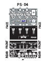 3
3
-
 4
4
-
 5
5
-
 6
6
-
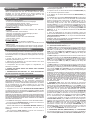 7
7
-
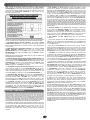 8
8
-
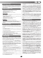 9
9
-
 10
10
-
 11
11
-
 12
12
-
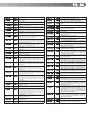 13
13
-
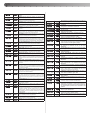 14
14
-
 15
15
-
 16
16


Gemini PS-04 El manual del propietario
- Categoría
- Mezcladores de audio
- Tipo
- El manual del propietario
- Este manual también es adecuado para
en otros idiomas
- français: Gemini PS-04 Le manuel du propriétaire
- English: Gemini PS-04 Owner's manual
- Deutsch: Gemini PS-04 Bedienungsanleitung
Artículos relacionados
-
Gemini PS-01 Manual de usuario
-
-
-
-
-
-
-
-
-