Hitachi DH 22PG Manual de usuario
- Categoría
- Martillos perforadores
- Tipo
- Manual de usuario
Este manual también es adecuado para

Rotary Hammer
Martillo perforador
Máy khoan búa
สวานเจาะกระแทกโรตารี่
DH 22PG
HANDLING INSTRUCTIONS
INSTRUCCIONES DE MANEJO
Hướng dẫn sử dụng
Read through carefully and understand these instructions before use.
Leer cuidadosamente y comprender estas instrucciones antes del uso.
Đọc kỹ và hiểu rõ các hướng dẫn này trước khi sử dụng.

1
1
3
2
4
4
5
6
8
7
L
R
R
L
8
12
34
56
78

2
!
%
#
&
9
@
^
$
0
3
4
2
3
4
3
4
1
*
&
(
910
11 12
13

3
English Español
1
Drill bit Broca
2
Part of SDS-plus shank
Parte delSDS más vástago
3
Front cap Cubierta frontal
4
Grip Sujetador
5
Dust cup Capa de polvo
6
Dust collector (B) Colector de polvo (B)
7
Push button Tecla
8
Change lever Palanquita selectora
9
Drill chuck Portabrocas
0
Chuck adapter Adaptador del portabrocas
!
Chuck adapter (D) Adaptador (D) del portabrocas
@
Bit Broca
#
Socket Cubo
$
Side handle Mango lateral
%
Depth gauge Calibre de profundidad
^
Mounting hole Agujero de
montaje
&
Tape shank adapter Adaptador de la espiga ahusada
*
Cotter Chaveta
(
Rest Apoyo
Tiếng Việt
1
Đầu khoan
2
Bộ phận chuôi SDS chữ thập
SDS-plus
3
Nắp trước
4
Kẹp giữ
5
Cốc bụi
6
Bộ thu bụi (B)
(B)
7
Nút ấn
8
Cần chuyển đổi
9
Đầu cặp mũi khoan
0
Đầu tiếp hợp đầu cặp mũi khoan
!
Đầu tiếp hợp đầu cặp mũi
khoan (D)
(D)
@
Mũi khoan
#
Khớp nối
$
Tay nắm phụ
%
Thước đo độ sâu
^
Lỗ gắn
&
Đầu tiếp hợp chuôi côn
*
Chốt giữ
(
Trụ đỡ

4
English
GENERAL POWER TOOL SAFETY WARNINGS
WARNING
Read all safety warnings and all instructions.
Failure to follow the warnings and instructions may result
in electric shock, fire and/or serious injury.
Save all warnings and instructions for future reference.
The term “power tool” in the warnings refers to your
mains-operated (corded) power tool or battery-operated
(cordless) power tool.
1) Work area safety
a) Keep work area clean and well lit.
Cluttered or dark areas invite accidents.
b) Do not operate power tools in explosive
atmospheres, such as in the presence of
flammable liquids, gases or dust.
Power tools create sparks which may ignite the
dust or fumes.
c) Keep children and bystanders away while
operating a power tool.
Distractions can cause you to lose control.
2) Electrical safety
a) Power tool plugs must match the outlet.
Never modify the plug in any way.
Do not use any adapter plugs with earthed
(grounded) power tools.
Unmodified plugs and matching outlets will
reduce risk of electric shock.
b) Avoid body contact with earthed or grounded
surfaces, such as pipes, radiators, ranges and
refrigerators.
There is an increased risk of electric shock if
your body is earthed or grounded.
c) Do not expose power tools to rain or wet
conditions.
Water entering a power tool will increase the
risk of electric shock.
d) Do not abuse the cord. Never use the cord for
carrying, pulling or unplugging the power tool.
Keep cord away from heat, oil, sharp edges or
moving parts.
Damaged or entangled cords increase the risk
of electric shock.
e) When operating a power tool outdoors, use an
extension cord suitable for outdoor use.
Use of a cord suitable for outdoor use reduces
the risk of electric shock.
f) If operating a power tool in a damp location
is unavoidable, use a residual current device
(RCD) protected supply.
Use of an RCD reduces the risk of electric shock.
3) Personal safety
a) Stay alert, watch what you are doing and use
common sense when operating a power tool.
Do not use a power tool while you are tired or
under the influence of drugs, alcohol or medication.
A moment of inattention while operating power
tools may result in serious personal injury.
b) Use personal protective equipment. Always wear
eye protection.
Protective equipment such as dust mask, non-
skid safety shoes, hard hat, or hearing protection
used for appropriate conditions will reduce
personal injuries.
c) Prevent unintentional starting. Ensure the switch
is in the off-position before connecting to power
source and/or battery pack, picking up or
carrying the tool.
Carrying power tools with your finger on the
switch or energising power tools that have the
switch on invites accidents.
d) Remove any adjusting key or wrench before
turning the power tool on.
A wrench or a key left attached to a rotating part
of the power tool may result in personal injury.
e) Do not overreach. Keep proper footing and
balance at all times.
This enables better control of the power tool in
unexpected situations.
f) Dress properly. Do not wear loose clothing or
jewellery. Keep your hair, clothing and gloves
away from moving parts.
Loose clothes, jewellery or long hair can be
caught in moving parts.
g) If devices are provided for the connection of
dust extraction and collection facilities, ensure
these are connected and properly used.
Use of dust collection can reduce dust related hazards.
4) Power tool use and care
a) Do not force the power tool. Use the correct
power tool for your application.
The correct power tool will do the job better and
safer at the rate for which it was designed.
b) Do not use the power tool if the switch does
not turn it on and off.
Any power tool that cannot be controlled with
the switch is dangerous and must be repaired.
c) Disconnect the plug from the power source
and/or the battery pack from the power tool
before making any adjustments, changing
accessories, or storing power tools.
Such preventive safety measures reduce the risk
of starting the power tool accidentally.
d) Store idle power tools out of the reach of children
and do not allow persons unfamiliar with the
power tool or these instructions to operate the
power tool.
Power tools are dangerous in the hands of
untrained users.
e) Maintain power tools. Check for misalignment
or binding of moving parts, breakage of parts
and any other condition that may affect the
power tools operation.
If damaged, have the power tool repaired before
use.
Many accidents are caused by poorly maintained
power tools.
f) Keep cutting tools sharp and clean.
Properly maintained cutting tools with sharp
cutting edges are less likely to bind and are
easier to control.
g) Use the power tool, accessories and tool bits
etc. in accordance with these instructions, taking
into account the working conditions and the
work to be performed.
Use of the power tool for operations different from
those intended could result in a hazardous situation.
01Eng_DH22PG_ChVT 7/13/12, 2:18 PM4

5
English
5) Service
a) Have your power tool serviced by a qualified repair
person using only identical replacement parts.
This will ensure that the safety of the power tool
is maintained.
PRECAUTION
Keep children and infirm persons away.
When not in use, tools should be stored out of reach of
children and infirm persons.
CORDLESS ROTARY HAMMER SAFETY
WARNINGS
1. Wear ear protectors.
Exposure to noise can cause hearing loss.
2. Use auxiliary handle(s), if supplied with the tool.
Loss of control can cause personal injury.
3. Hold power tool by insulated gripping surfaces,
when performing an operation where the cutting
accessory may contact hidden wiring or its own
cord. Cutting accessory contacting a "live" wire may
make exposed metal parts of the power tool "live"
and could give the operator an electric shock.
4. Do not touch the bit during or immediately after
operation. The bit becomes very hot during
operation and could cause serious burns.
5. Before starting to break, chip or drill into a wall,
floor or ceiling, thoroughly confirm that such items
as electric cables or conduits are not buried inside.
6. Always hold the body handle and side handle of
the power tool firmly. Otherwise the counterforce
produced may result in inaccurate and even
dangerous operation.
7. Wear a dust mask
Do not inhale the harmful dusts generated in drilling
or chiseling operation. The dust can endanger the
health of yourself and bystanders.
SPECIFICATIONS
* Be sure to check the nameplate on product as it is subject to change by areas.
STANDARD ACCESSORIES
(1) Plastic case .................................................................. 1
(2) Side handle ................................................................. 1
(3) Depth gauge ............................................................... 1
Standard accessories are subject to change without
notice.
Voltage (by areas)* (110 V, 115 V, 120 V, 127 V, 220 V, 230 V, 240 V)
Power Input 620 W*
No-load speed 0 – 1500 /min
Full-load impact rate 0 – 6200 /min
Capacity: concrete 3.4 – 22 mm
steel 13 mm
wood 24 mm
Weight (without cord and side handle) 1.9 kg
01Eng_DH22PG_ChVT 7/13/12, 2:18 PM5

6
English
OPTIONAL ACCESSORIES (sold separately)
Adapter for slender shaft
(SDS-plus shank)
Drill bit (Slender shaft)
䢇
Drilling holes in concrete or tile
+
Drill bit (Taper shank)
Taper shank
adapter
Cotter
䢇
Drilling holes in concrete
䢇Anchor setting
Anchor setting adapter
+ +
Chuck
adapter
Drill chuck
(13 VLRB-D)
Special
screw
䢇 Demolishing operation
Dust cup
Dust collector (B)
Rotation + Hammering
䢇
Drilling holes in concrete or tile
䢇 Drilling anchor holes
䢇 Driving screws
䢇 Drilling in steel or wood
, Driver bit - Driver bit
Drill bit for steel Drill bit for
wood
Bull point
(Round type)
Drill bit
Tool Adapters
Use on jobs facing upwards
Rotation only
( )
Straight shank bit for
impact drill
13 mm Rotary hammer chuck
(SDS-plus shank)
01Eng_DH22PG_KovT 2/4/11, 10:51 AM6

7
English
䢇 Drilling holes in concrete or tile
Drill bit (slender shaft)
Outer dia. Overall length Effective length
3.4 mm
90 mm 45 mm
3.5 mm
Taper shank adapter
Taper mode
Morse taper No.1
Morse taper No.2
A-Taper
B-taper
䢇 Drilling anchor holes
SDS-plus Drill bit
Outer dia. Overall length Effective length
4.0 mm 110 mm 50 mm
5.0 mm
110 mm 50 mm
160 mm 100 mm
5.5 mm 110 mm 50 mm
6.5 mm 160 mm 100 mm
7.0 mm 160 mm 100 mm
8.0 mm 160 mm 100 mm
8.5 mm 160 mm 100 mm
9.0 mm 160 mm 100 mm
12.0 mm
166 mm 100 mm
260 mm 200 mm
12.7 mm 166 mm 100 mm
14.0 mm 166 mm 100 mm
15.0 mm 166 mm 100 mm
16.0 mm
166 mm 100 mm
260 mm 200 mm
17.0 mm 166 mm 100 mm
19.0 mm 260 mm 200 mm
20.0 mm 250 mm 200 mm
22.0 mm 250 mm 200 mm
APPLICATIONS
Rotation and hammering function
䡬 Drilling anchor holes
䡬 Drilling holes in concrete
䡬 Drilling holes in tile
Rotation only function
䡬 Drilling in steel or wood
(with optional accessories)
䡬 Tightening machine screws, wood screws
(with optional accessories)
PRIOR TO OPERATION
1. Power source
Ensure that the power source to be utilized conforms
to the power requirements specified on the product
nameplate.
2. Power switch
Ensure that the power switch is in the OFF position. If
the plug is connected to a power receptacle while the
power switch is in the ON position, the power tool
will start operating immediately, which could cause a
serious accident.
3. Extension cord
When the work area is removed from the power
source, use an extension cord of sufficient thickness
and rated capacity. The extension cord should be
kept as short as practicable.
4. Mounting the drill bit (Fig. 1)
CAUTION
To prevent accidents, make sure to turn the switch
off and disconnect the plug from the receptacle.
NOTE
When using tools such as bull points, drill bits, etc.,
make sure to use the genuine parts designated by
our company.
(1) Clean the shank portion of the drill bit.
(2) Insert the drill bit in a twisting manner into the tool
holder until it latches itself (Fig. 1).
(3) Check the latching by pulling on the drill bit.
(4) To remove the drill bit, fully pull the grip in the
direction of the arrow and pull out the drill bit (Fig. 2).
5. Installation of dust cup or dust collector (B)
(Optional accessories) (Fig. 3, Fig. 4)
When using a rotary hammer for upward drilling
operations attach a dust cup or dust collector (B) to
collect dust or particles for easy operation.
䡬 Installing the dust cup
Use the dust cup by attaching to the drill bit as shown
in Fig. 3.
When using a bit which has big diameter, enlarge the
center hole of the dust cup with this rotary hammer.
䡬 Installing dust collector (B)
When using dust collector (B), insert dust collector
(B) from the tip of the bit by aligning it to the groove
on the grip (Fig. 4).
CAUTION
䡬 The dust cup and dust collector (B) are for exclusive
use of concrete drilling work. Do not use them for
wood or metal drilling work.
䡬 Insert dust collector (B) completely into the chuck
part of the main unit.
Optional accessories are subject to change without notice.
䢇 Anchor setting
Anchor setting adapter
Anchor size
W 1/4”
W 5/16”
W 3/8”
01Eng_DH22PG_KovT 2/4/11, 10:51 AM7

8
English
䡬 When turning the rotary hammer on while dust
collector (B) is detached from a concrete surface,
dust collector (B) will rotate together with the drill bit.
Make sure to turn on the switch after pressing the
dust cup on the concrete surface. (When using dust
collector (B) attached to a drill bit that has more than
190 mm of overall length, dust collector (B) cannot
touch the concrete surface and will rotate. Therefore
please use dust collector (B) by attaching to drill bits
which have 166 mm, 160 mm, and 110 mm overall
length.)
䡬 Dump particles after every two or three holes when
drilling.
䡬 Please replace the drill bit after removing dust
collector (B).
6. Selecting the driver bit
Screw heads or bits will be damaged unless a bit
appropriate for the screw diameter is employed to
drive in the screws.
7. Confirm the direction of bit rotation (Fig. 5)
The bit rotates clockwise (viewed from the rear side)
by pushing the R-side of the push button.
The L-side of the push button is pushed to turn the bit
counterclockwise.
8. RCD
The use of a residual current device with a rated
residual current of 30mA or less at all times is
recommended.
HOW TO USE
CAUTION
To prevent accidents, make sure to turn the switch
off and disconnect the plug from the receptacle when
the drill pits and other various parts are installed or
removed. The power switch should also be turned
off during a work break and after work.
1. Switch operation
The rotation speed of the drill bit can be controlled
steplessly by varying the amount that the trigger
switch is pulled. Speed is low when the trigger switch
is pulled slightly and increases as the switch is pulled
more. Continuous operation may be attained by
pulling the trigger switch and depressing the stopper.
To turn the switch OFF, pull the trigger switch again
to disengage the stopper, and release the trigger
switch to its original position.
However, the switch trigger can only be pulled in
halfway during reverse and rotates at half the speed
of forward operation.
The switch stopper is unusable during reverse.
2. Rotation + hammering
This rotary hammer can be set to rotation and
hammering mode by turning the change lever to the
mark (Fig. 6).
(1) Mount the drill bit.
(2) Pull the trigger switch after applying the drill bit tip to
the drilling position (Fig. 7).
(3) Pushing the rotary hammer forcibly is not necessary
at all. Pushing slightly so that drill dust comes out
gradually is sufficient.
CAUTION
When the drill bit touches construction iron bar, the
bit will stop immediately and the rotary hammer will
react to revolve. Therefore grip the side handle and
handle tightly as shown in Fig. 7.
3. Rotation only
This rotary hammer can be set to rotation only mode
by turning the change lever to the
mark (Fig. 8).
To drill wood or metal material using the drill chuck
and chuck adapter (optional accessories), proceed as
follows.
Installing drill chuck and chuck adapter (Fig. 9).
(1) Attach the drill chuck to the chuck adapter.
(2) The part of the SDS-plus shank is the same as the
drill bit. Therefore, refer to the item of “Mounting the
drill bit” for attaching it.
CAUTION
䡬 Application of force more than necessary will not
only expedite the work, but will deteriorate the tip
edge of the drill bit and reduce the service life of the
rotary hammer in addition.
䡬 Drill bits may snap off while withdrawing the rotary
hammer from the drilled hole. For withdrawing, it is
important to use a pushing motion.
䡬 Do not attempt to drill anchor holes or holes in
concrete with the machine set in the rotation only
function.
䡬 Do not attempt to use the rotary hammer in the
rotation and striking function with the drill chuck and
chuck adapter attached. This would seriously shorten
the service life of every component of the machine.
4. When driving machine screws (Fig. 10)
First, insert the bit into the socket in the end of chuck
adapter (D).
Next, mount chuck adapter (D) on the main unit
using procedures described in 4 (1), (2), (3), put the
tip of the bit in the slots in the head of the screw,
grasp the main unit and tighten the screw.
CAUTION
䡬 Exercise care not to excessively prolong driving time,
otherwise, the screws may be damaged by excessive
force.
䡬 Apply the rotary hammer perpendicularly to the screw
head when driving the screw; otherwise, the screw
head or bit will be damaged, or driving force will not
be fully transferred to the screw.
䡬 Do not attempt to use the rotary hammer in the
rotation and striking function with the chuck adapter
and bit attached.
5. When driving wood screws (Fig. 10)
(1) Selecting a suitable driver bit
Employ plus-head screws, if possible, since the driver
bit easily slips off the heads of minus-head screws.
(2) Driving in wood screws
䡬 Prior to driving in wood screws, make pilot holes
suitable for them in the wooden board. Apply the bit
to the screw head grooves and gently drive the screws
into the holes.
䡬 After rotating the rotary hammer at low speed for a
while until the wood screw is partly driven into the
wood, squeeze the trigger more strongly to obtain
the optimum driving force.
CAUTION
Exercise care in preparing a pilot hole suitable for the
wood screw taking the hardness of the wood into
consideration. Should the hole be excessively small
or shallow, requiring much power to drive the screw
into it, the thread of the wood screw may sometimes
be damaged.
01Eng_DH22PG_ChVT 7/13/12, 1:53 PM8

9
English
6. Using depth gauge (Fig. 11)
(1) Loosen the knob on the side handle, and insert the
depth gauge into the mounting hole on the side
handle.
(2) Adjust the depth gauge position according to the
depth of the hole and thighten the knob securely.
7. How to use the drill bit (taper shank) and the taper
shank adapter
(1) Mount the taper shank adapter to the rotary hammer
(Fig. 12).
(2) Mount the drill bit (taper shank) to the taper shank
adapter (Fig. 12).
(3) Turn the switch ON, and drill a hole in prescribed
depth.
(4) To remove the drill bit (taper shank), insert the cotter
into the slot of the taper shank adapter and strike the
head of the cotter with a hammer supporting on a
rests (Fig. 13).
LUBRICATION
Low viscosity grease is applied to this rotary hammer so
that it can be used for a long period without replacing
the grease. Please contact the nearest service center for
grease replacement when any grease is leaking form
loosened screw.
Further use of the rotary hammer with lock off grease
will cause the machine to seize up reduce the service life.
CAUTION
A special grease is used with this machine, therefore,
the normal performance of the machine may be badly
affected by use of other grease. Please be sure to let
one of our service agents undertake replacement of
the grease.
MAINTENANCE AND INSPECTION
1. Inspecting the drill bits
Since use of a dull tool will cause motor
malfunctioning and degraded efficiency, replace the
drill bit with new ones or resharpen them without
delay when abrasion is noted.
2. Inspecting the mounting screws
Regularly inspect all mounting screws and ensure
that they are properly tightened. Should any of the
screws be loose, retighten them immediately. Failure
to do so could result in serious hazard.
3. Maintenance of the motor
The motor unit winding is the very ”heart” of the
power tool. Exercise due care to ensure the winding
does not become damaged and/or wet with oil or
water.
4. Inspecting the carbon brushes
For your continued safety and electrical shock
protection, carbon brush inspection and replacement
on this tool should ONLY be performed by a HITACHI
Authorized Service Center.
5. Replacing supply cord
If the supply cord of Tool is damaged, the Tool must
be returned to Hitachi Authorized Service Center for
the cord to be replaced.
6. Service parts list
A: Item No.
B: Code No.
C: No. Used
D: Remarks
CAUTION
Repair, modification and inspection of Hitachi Power
Tools must be carried out by an Hitachi Authorized
Service Center.
This Parts List will be helpful if presented with the
tool to the Hitachi Authorized Service Center when
requesting repair or other maintenance.
In the operation and maintenance of power tools, the
safety regulations and standards prescribed in each
country must be observed.
MODIFICATIONS
Hitachi Power Tools are constantly being improved
and modified to incorporate the latest technological
advancements.
Accordingly, some parts (i.e. code numbers and/or
design) may be changed without prior notice.
NOTE
Due to HITACHI’s continuing program of research and
development, the specifications herein are subject to
change without prior notice.
01Eng_DH22PG_ChVT 7/13/12, 1:53 PM9

10
Español
ADVERTENCIAS DE SEGURIDAD GENERAL
DE LA HERRAMIENTA ELÉCTRICA
ADVERTENCIA
Lea todas las instrucciones y advertencias de seguridad.
Si no se siguen las advertencias e instrucciones, podría
producirse una descarga eléctrica, un incendio y/o daños
graves.
Guarde todas las advertencias e instrucciones para futura
referencia.
El término “herramienta eléctrica” en las advertencias
hace referencia a la herramienta eléctrica que funciona
con la red de suministro (con cable) o a la herramienta
eléctrica que funciona con pilas (sin cable).
1) Seguridad del área de trabajo
a) Mantenga la zona de trabajo limpia y bien iluminada.
Las zonas desordenadas u oscuras pueden
provocar accidentes.
b) No utilice las herramientas eléctricas en entornos
explosivos como, por ejemplo, en presencia de
líquidos inflamables, gases o polvo.
Las herramientas eléctricas crean chispas que
pueden inflamar el polvo o los humos.
c) Mantenga a los niños y transeúntes alejados
cuando utilice una herramienta eléctrica.
Las distracciones pueden hacer que pierda el control.
2) Seguridad eléctrica
a) Los enchufes de las herramientas eléctricas tienen
que ser adecuados a la toma de corriente.
No modifique el enchufe.
No utilice enchufes adaptadores con herramientas
eléctricas conectadas a tierra.
Si no se modifican los enchufes y se utilizan tomas
de corriente adecuadas se reducirá el riesgo de
descarga eléctrica.
b) Evite el contacto corporal con superficies conectadas
a tierra como tuberías, radiadores y frigoríficos.
Hay mayor riesgo de descarga eléctrica si su
cuerpo está en contacto con el suelo.
c) No exponga las herramientas eléctricas a la lluvia
o a la humedad.
La entrada de agua en una herramienta eléctrica
aumentará el riesgo de descarga eléctrica.
d) No utilice el cable incorrectamente. No utilice el
cable para transportar, tirar de la herramienta
eléctrica o desenchufarla.
Mantenga el cable alejado del calor, del aceite, de
bordes afilados o piezas móviles.
Los cables dañados o enredados aumentan el
riesgo de descarga eléctrica.
e) Cuando utilice una herramienta eléctrica al aire
libre, utilice un cable prolongador adecuado para
utilizarse al aire libre.
La utilización de un cable adecuado para usarse
al aire libre reduce el riesgo de descarga eléctrica.
f) Si no se puede evitar el uso de una herramienta
eléctrica en un lugar húmedo, utilice un suministro
protegido mediante un dispositivo de corriente
residual (RCD).
El uso de un RCD reduce el riesgo de descarga
eléctrica.
3) Seguridad personal
a) Esté atento, preste atención a lo que hace y utilice
el sentido común cuando utilice una herramienta
eléctrica.
No utilice una herramienta eléctrica cuando esté
cansado o esté bajo la influencia de drogas,
alcohol o medicación.
La distracción momentánea cuando utiliza
herramientas eléctricas puede dar lugar a
importantes daños personales.
b) Utilice un equipo de protección. Utilice siempre
una protección ocular.
El equipo de protección como máscara para el
polvo, zapatos de seguridad antideslizantes, casco
o protección para oídos utilizado para condiciones
adecuadas reducirá los daños personales.
c) Evite un inicio involuntario. Asegúrese de que el
interruptor está en “off” antes de conectar la
herramienta a una fuente de alimentación y/o
batería, cogerla o transportarla.
El transporte de herramientas eléctricas con el
dedo en el interruptor o el encendido de
herramientas eléctricas con el interruptor
encendido puede provocar accidentes.
d) Retire las llaves de ajuste antes de encender la
herramienta eléctrica.
Si se deja una llave en una pieza giratoria de la
herramienta eléctrica podrían producirse daños
personales.
e) No se extralimite. Mantenga un equilibrio
adecuado en todo momento.
Esto permite un mayor control de la herramienta
eléctrica en situaciones inesperadas.
f) Vístase adecuadamente. No lleve prendas sueltas
o joyas. Mantenga el pelo, la ropa y los guantes
alejados de las piezas móviles.
La ropa suelta, las joyas y el pelo largo pueden
pillarse en las piezas móviles.
g) Si se proporcionan dispositivos para la conexión
de extracción de polvo e instalaciones de recogida,
asegúrese de que están conectados y se utilizan
adecuadamente.
La utilización de un sistema de recogida de polvo
puede reducir los riesgos relacionados con el polvo.
4) Utilización y mantenimiento de las herramientas
eléctricas
a) No fuerce la herramienta eléctrica. Utilice la
herramienta eléctrica correcta para su aplicación.
La herramienta eléctrica correcta trabajará mejor
y de forma más segura si se utiliza a la velocidad
para la que fue diseñada.
b) No utilice la herramienta eléctrica si el interruptor
no la enciende y apaga.
Las herramientas eléctricas que no pueden
controlarse con el interruptor son peligrosas y
deben repararse.
c) Desconecte el enchufe de la fuente eléctrica y/o
la batería de la herramienta eléctrica antes de
hacer ajustes, cambiar accesorios o almacenar
herramientas eléctricas.
Estas medidas de seguridad preventivas reducen
el riesgo de que la herramienta eléctrica se ponga
en marcha accidentalmente.
d) Guarde las herramientas eléctricas que no se
utilicen para que no las cojan los niños y no
permita que utilicen las herramientas eléctricas
personas no familiarizadas con las mismas o con
estas instrucciones.
Las herramientas eléctricas son peligrosas si son
utilizadas por usuarios sin formación.
02Spa_DH22PG_ChVT 7/13/12, 2:26 PM10

11
Español
e) Mantenimiento de las herramientas eléctricas.
Compruebe si las piezas móviles están mal
alineadas o unidas, si hay alguna pieza rota u
otra condición que pudiera afectar al
funcionamiento de las herramientas eléctricas.
Si la herramienta eléctrica está dañada, llévela a
reparar antes de utilizarla.
Se producen muchos accidentes por no realizar
un mantenimiento correcto de las herramientas
eléctricas.
f) Mantenga las herramientas de corte afiladas y
limpias.
Las herramientas de corte correctamente
mantenidas con los bordes de corte afilados son
más fáciles de controlar.
g) Utilice la herramienta eléctrica, los accesorios y las
brocas de la herramienta, etc. de acuerdo con estas
instrucciones, teniendo en cuenta las condiciones
laborales y el trabajo que se va a realizar.
La utilización de la herramienta eléctrica para
operaciones diferentes a aquellas pretendidas
podría dar lugar a una situación peligrosa.
5) Revisión
a) Lleve su herramienta a que la revise un experto
cualificado que utilice sólo piezas de repuesto
idénticas.
Esto garantizará el mantenimiento de la seguridad
de la herramienta eléctrica.
PRECAUCIÓN
Mantenga a los niños y a las personas enfermas alejadas.
Cuando no se utilicen, las herramientas deben almacenarse
fuera del alcance de los niños y de las personas enfermas.
ADVERTENCIAS DE SEGURIDAD DEL
MARTILLO PERFORADOR
1. Utilice protectores auditivos
La exposición al ruido puede provocar una pérdida
de audibilidad.
2. Utilice los mangos auxiliares en el caso de que se
proporcionen con la herramienta.
La pérdida de control puede provocar lesiones
personales.
3. Sostenga la herramienta eléctrica por las superficies
de agarre aisladas cuando realice una operación en la
que el accesorio de corte pueda entrar en contacto con
el cableado oculto o con su propio cable. Si el accesorio
de corte entra en contacto con un cable con corriente,
las partes metálicas expuestas de la herramienta
eléctrica pueden transmitir esa corriente y producir una
descarga eléctrica al operador.
4. No tocar la broca durante ni inmediatamente después
de trabajar, puesto que se pone ardiente y puede
causar quemaduras serias.
5. Antes de empezar a romper, picar o perforar en una
pared, suelo o techo, comprobar cuidadosamente
que no hayan objetos empotrados, tales como cables
o conductos eléctricos.
6. Sujetar siempre firmemente el asidero del cuerpo y
el asidero lateral de la herramienta. De lo contrario,
la contrafuerza producida podría causar un
funcionamiento impreciso e incluso peligroso.
7. Utilice máscara para el polvo
No inhale el polvo dañino generado al perforar. El
polvo puede poner en peligro su salud y la de los
viandantes.
ESPECIFICACIONES
* Verificar indefectiblemente los datos de la placa de características de la máquina, pues varían de acuerdo con el
país de destino.
ACCESORIOS ESTANDAR
(1) Caja de plástico .......................................................... 1
(2) Mango lateral .............................................................. 1
(3) Calibre de profundidad .............................................. 1
Los accesorios estándar están sujetos a cambio sin previo
aviso.
Voltaje (por áreas)* (110 V, 115 V, 120 V, 127 V, 220 V, 230 V, 240 V)
Acometida 620 W*
Velocidad sin carga 0 – 1500
/min
Velocidad de percusión a carga plena 0 – 6200 /min
Capacidad: hormigón 3,4 – 22 mm
acero 13 mm
madera 24 mm
Peso (sin cable ni mango lateral) 1,9 kg
02Spa_DH22PG_ChVT 7/13/12, 2:26 PM11

12
Español
ACCESORIOS FACULTATIVOS (de venta por separado)
Adaptador para eje fino
(SDS más vástago)
Broca de taladro (Eje fino)
䢇
Perforación de agujeros en
cemento o losa
+
Broca de taladro (Vástago cónico)
Adaptador
cónico
Chaveta
䢇 Montaje de ancla
Adaptador de montaje de ancla
+ +
Adaptador de
portabrocas
Portabrocas
(13 VLRB-D)
Tornillo
especial
䢇 Trabajo de roturación
Copa de polvo
Colector de polvo (B)
Rotación
solamente
Rotación + golpeteo
䢇
Perforación de agujeros en
cemento o losa
䢇 Taladrar orificios de anclaje
䢇 Colocación de tornillos
䢇 Taladrar en acero o madera
, Punta del
destornillador
Broca para acero
Broca para madera
Broca de taladro
Herramienta
Adaptadores
Utilizar en trabajos colocados
hacia arriba
Puntero
(tipo redondo)
- Punta del
destornillador
Broca de vástago recto
para martillo roto-percutor
䢇 Agujeros de taladro en
hormigón
( )
Portabrocas del martillo
perforador de 13 mm
(SDS más vástago)
02Spa_DH22PG_KovT 2/4/11, 11:11 AM12

13
Español
䢇 Perforación de agujeros en cemento o losa
Broca de taladro (Eje fino)
Diám. externo
Longitud total Longitud efectiva
3,4 mm
90 mm 45 mm
3,5 mm
Broca SDS-plus
Diám. externo
Longitud total Longitud efectiva
4,0 mm 110 mm 50 mm
5,0 mm
110 mm 50 mm
160 mm 100 mm
5,5 mm 110 mm 50 mm
6,5 mm 160 mm 100 mm
7,0 mm 160 mm 100 mm
8,0 mm 160 mm 100 mm
8,5 mm 160 mm 100 mm
9,0 mm 160 mm 100 mm
12,0 mm
166 mm 100 mm
260 mm 200 mm
12,7 mm 166 mm 100 mm
14,0 mm 166 mm 100 mm
15,0 mm 166 mm 100 mm
16,0 mm
166 mm 100 mm
260 mm 200 mm
17,0 mm 166 mm 100 mm
19,0 mm 260 mm 200 mm
20,0 mm 250 mm 200 mm
22,0 mm 250 mm 200 mm
APPLICACION
Rotación y función de golpeteo
䡬 Perforación de orificios de anclaje
䡬 Perforación de orificios de hormigón
䡬 Perforación de orificios de baldosa
Rotación solamente
䡬 Perforación de orificios en hormigón o madera
(con accesorios facultativos)
䡬 Apretar tornillos en metal o madera
(con accesorios facultativos)
ANTES DE LA PUESTA EN MARCHA
1. Alimentación
Asegurarse de que la alimentación de red que ha de
ser utilizada responda a las exigencias de corriente
especificadas en la placa de características del
producto.
2. Conmutador de alimentación
Asegurarse de que el conmutador de alimentación
esté en la posición OFF (desconectado). Si la clavija
está conectada en la caja del enchufe mientras el
conmutador de alimentación esté en posición ON
(conectado) las herramientas eléctricas empezarán a
trabajar inmediatamente, provocando un serio
accidente.
3. Cable de prolongación
Cuando está alejada el área de trabajo de la red de
alimentación, usar un cable de prolongación de un
grosor y potencia nominal suficiente. El cable de
prolongación debe ser mantenido lo más corto posible.
4. Montaje de la broca (Fig. 1)
PRECAUCION
Para evitar accidentes, cerciórese de desactivar y de
desconectar el enchufe del tomacorriente.
NOTA
Cuando ulilice herramientas como por ejemplo:
cinceles, brocas de taladro, etc., cerciórese de utilizar
piezas genuinas diseñadas por nuestra compañía.
(1) Limpie la parte del vástago de la broca de taladro.
(2) Inserte la broca de taladro girando en el sujetador de
la herramienta hasta que se asegure bien (Fig. 1).
(3) Verifique si esta bien asegurado tirando de la broca
de taladro.
(4) Para extraer la broca, tire completamente de la
empuñadura en el sentido de la flecha y tire hacia
afuera de la broca (Fig. 2).
5. Cuando instale la copa de polvo o el lector de polvo
(B) (Accesorios facultativos)(Fig. 3, Fig. 4)
Cuando emplee un martillo perforador para trabajos
de taladrado hacia arriba, extraiga el adaptador de
recolección de polvo e instale una copa de polvo o un
colector de polvo (B) para recolectar las partículas a
fin de facilitar la operación.
䡬 Instalación de la copa de polvo
Emplee la copa de polvo instalando la broca como se
muestra en la Fig. 3.
Cuando emplee una broca de gran diámetro, agrande
el orificio central de la copa de polvo con este martillo
perforador.
䡬 Instalación del colector de polvo (B)
Para emplear el colector de polvo (B), Insértelo desde
la punta de la broca alineándolo con la ranura de la
empuñadura (Fig. 4).
Adaptador cónico
Modo cónico
Cono Morse (No.1)
Cono Morse (No.2)
Cono A
Cono B
䢇 Taladrar orificios de anclaje
䢇 Montaje de ancla
Los accesorios de norma están sujetos a cambio sin
previo aviso.
Adaptador de montaje de ancla
Medida de ancla
W 1/4”
W 5/16”
W 3/8”
02Spa_DH22PG_KovT 2/4/11, 11:11 AM13

14
Español
(1) Montar la broca.
(2) Presionar el interruptor de gatillo después de poner
la punta de la broca en la posición para taladrar (Fig. 7).
(3) No es necesario presionar con fuerza la broca.
Presionar ligeramente la broca de forma que el polvo
producido al taladrar salga al exterior gradualmente.
PRECAUCIÓN
Cuando la broca toque una barra de hierro de construción
se detendrá inmediatamente y el martillo perforador
tenderá a girar. Por lo tanto, sujetar el mango lateral y
sostenerlo firmemente como se ilustra en la Fig. 7.
3. Rotación solamente
Este martillo perforador se puede ajustar
exclusivamente en modo giratorio. Para ello, basta
con girar la palanca de ajuste hasta la posición de la
marca
(Fig. 8).
Para perforar madera o metal empleando el
portabrocas y el adaptador del portabrocas (accesorio
facultativo), proceder como sigue.
Instalación del portabrocas y adaptador del
portabrocas (Fig. 9).
(1) Instale la broca en el adaptador del portabrocas.
(2) La parte del SDS más vástago es igual que una
broca. Por lo tanto, para instalarla, consulte ”Montaje
de la broca”.
PRECAUCIÓN
䡬 La aplicación de fuerza excesiva acelerará el trabajo
pero dañará la punta de la broca y reducirá la vida
útil del martillo perforador.
䡬 La broca puede salirse al quitar el martillo perforador
del orificio perforado. Para extraer esta herramienta
es importante empujar hacia de lante.
䡬 No intentar perforar orificios de anclaje o perforar el
concreto con la máquina puesta en la función de
rotación solamente.
䡬 No intentar usar el martillo perforador en la función de
rotación y golpeteo con el portabrocas y el adaptador del
portabrocas instalados. Esto reducirá considerablemente
la vida útil de cada componente de la máquina.
4. Cuando coloque tornillos para metal (Fig. 10)
En primer lugar, inserte la broca en el cubo del
extremo del adaptador (D) de portabroca.
A continuación, monte el adaptador (D) de portabroca
en la unidad principal empleando los procedimientos
descritos en 4 (1), (2), y (3), coloque la punta de la
broca en las ranuras de la cabeza del tornillo, sujete
la unidad principal, y apriete el tornillo.
PRECAUCIÓN
䡬 Tener cuidado en no prolongar excesivamente el
accionamiento de la herramienta, ya que de lo contrario,
pueden dañarse los tornillos por el exceso de fuerza.
䡬 Colocar el martillo perforador en forma perpendicular
sobre la cabeza del tornillo al atornillarlo, ya que en
caso contrario, puede dañarse la cabeza del tornillo o
la broca, e incluso, la fuerza de accionamiento puede
que no se transfiera por completo al tornillo.
䡬 No intente emplear la perforadora de percusión en la
función de rotación y golpeteo con el adaptador de
portabroca y la broca instalados.
5. Atornillando tornillos para madera (Fig. 10)
(1) Escoger una broca destornillador apropiada y emplear
tornillos con cabeza +, en lo posible, debido a que los
tornillos con cabeza – hacen que se zafe fácilmente el
destornillador.
PRECAUCIÓN
䡬 La copa de polvo y el colector de polvo (B) son para
emplearse exclusvamente en trabajos de perforación
de hormigón. No los emplee para trabajar con madera
o metal.
䡬 Inserte completamente el colector de polvo (B) en la
parte del portabrocas de la unidad principal.
䡬 Cuando ponga en funcionamiento del martillo
perforador meintras el colector de polvo (B) esté
separado de la superficie de hormigón, dicho colector
girará junto con la broca. Cerciórese de apretar el
gatillo interruptor después de haber presionado la
copa de polvo sobre la superficie de hormigón.
(Cuando emplee la copa de polvo con una broca de
no más de 190 mm de longitud total, el colector de
polvo (B) no podrá tocar la superficie de hormigón
girará. Por lo tanto, emplee el colector de polvo (B)
con brocas de 166, 160, y 110 mm de longitud total.)
䡬 Vacíe las partículas del colector de polvo (B) después
de haber taladrado dos o tres orificios.
䡬 Después de haber extraído el colector de polvo (B),
vuelva a colocar a broca.
6. Selección de la broca destornillador
Puede dañarse las cabezas de tornillos y las brocas
de atornillar menos que se emplee la broca apropiada
según sea el diámetro del tornillo.
7. Confirmar la dirección de rotación de la broca (Fig. 5)
La broca gira en el sentido de las agujas del reloj
(visto desde el lado trasero) empujando el lado R del
botón.
Si empuja el lado L del botón, la broca girará en
sentido contrario a las agujas del reloj.
8. RCD
Se recomienda el uso permanente de un dispositivo
de corriente residual con una corriente residual
nominal equivalente o inferior a 30 mA.
COMO SE USA
PRECAUCIÓN
Para evitar accidentes, cerciórese de poner este
interruptor en OFF y de desconectar el enchufe del
tomacorriente cuando instale o extraiga brocas y
otras piezas. El interruptor de alimentación también
deberá ponerse en OFF durante un descanso en el
trabajo y después de haber finalizado dicho trabajo.
1. Operación del conmutador
La velocidad rotatoria de la broca de taladro puede
ser controlad variando la fuerza con la que se aprieta
el pulsador. La velocidad está baja cuando se aprieta
ligeramente el pulsador y se aumenta al apretar más
el pulsador. La operación contínua puede ser
alcanzada apretando el pulsador y apretando hacia
abajo el dispositivo de ajuste. Para ponel el pulsador
en OFF (desconectado) volver a apretar el pulsador
para desconectar el dispositivo de ajuste, y soltar el
pulsador a su posición normal.
No obstante, el disparador de conmutador sólo puede
activarse a medio camino durante el reverso y gira a
la mitad de velocidad de la operación de avance.
El tope del conmutador no puede utilizarse durante
el reverso.
2. Rotación + golpeteo
Este martillo perforador se puede ajustar en modo
giratorio y en modo de martillo. Para ello, basta con
girar la palanca de ajuste hasta la posición de la
marca
(Fig. 6).
02Spa_DH22PG_ChVT 7/13/12, 2:07 PM14

15
Español
(2) Atornillado
䡬 Antes de atornillar los tornillos para madera, hay que
hacer orificios apropiados en la madera, aplicando
luego la broca destornillador en la cabeza del tornillo
y colocar asi éste en los orificios.
䡬 Luego de hacer rotar la herramienta lentamente hasta
que el tornillo quede parcialmente metido en la
madera, apretar más el gatillo para obtener la fuerza
óptima de atornillado.
PRECAUCIÓN
Tener cuidado al preparar el orificio para que sea
apropiado para el tornillo, teniendo en cuenta la
dureza de la madera. Si el orificio es excesivamente
pequeño o estrecho, se requiere mucha fuerza para
atornillar y a veces puede dañarse la rosca.
6. Modo de usar el tope (Fig. 11)
(1) Afloje el perno de perilla del asa lateral, e inserte el
retenedor en el surco en U de dicha asa lateral.
(2) Ajustar la posición del retenedor de acuerdo a la
profundidad del agujero, y apretar firmemente el
perno de perilla.
7. Modo de usar la broca (espiga ahusada) y el adaptador
de la espiga ahusada
(1) Montar el adaptador de la espiga ahusada en el martillo
perforador (Fig. 12).
(2) Montar la broca (espiga ahusada) en el adaptador de
la espiga ahusada (Fig. 12).
(3) Poner el interruptor en la posición de encendido
(ON), y taladrar un agujero de la profundidad
especificada.
(4) Para quitar la broca (espiga ahusada), insertar la
chaveta en la ranura del adaptador de la espiga
ahusada y golpear la cabeza de la chaveta con un
martillo. Usar apoyos como se muestra en la Fig. 13.
LUBRICACION
A este martillo perforador deberá aplicársele grasa de
baja viscosidad,de esta forma, el martillo podrá usarse
durante un largo período de tiempo sin cambiar de
grasa. Ponerse por favor en contacto con el agente de
reparaciones más cercano para cambiar la grasa si ésta
se escapase a través de los tornillos flojos.
La falta de grasa hará que el martillo perforador se
agarrote disminuyendo por lo tanto su duración.
PRECAUCIÓN
En esta herramienta deberá usarse la grasa
especificada. El uso de otras grasas podría afectar
negativamente al rendimiento. Cerciórese de
preguntar a sus agentes de servicio por la grasa de
repuesto.
MANTENIMENTO E INSPECCION
1. Inspeccionar la broca de taladro
Debido a que el uso de brocs desafiladas pueden
causar mal funcionamiento del motor y desmejorar
la eficacia del taladro, hay que reemplazar las brocas
en malas condiciones por nuevas o afilarlas de
inmediato al advertir abrasión.
2. Inspeccionar los tornillos de montaje
Regularmente inspeccionar todos los tornillos de
montaje y asegurarse de que estén apretados
firmemente. Si cualquier tornillo estuviera suelto,
volver a apretarlo inmediatamente. El no hacer esto
provocaría un riesgo serio.
3. Mantenimiento de motor
La unidad de bobinado del motor es el verdadero
corazón” de las herramientas eléctricas. Prestar el
mayor cuidado y asegurarse de que el bobinado no
se dañe y/o se humedezca con aceite o agua.
4. Inspección de las escobillas
Por motivos de seguridad contra descargas eléctricas,
la inspección y el reemplazo de las escobillas deberán
realizarse solamente en un centro de servicio
autorizado por hitachi.
5. Reemplazo del cable de alimentación
Si el cable de alimentación de la herramienta está dañado,
envíe la herramienta al Centro de Servicio Autorizado de
Hitachi para que le cambien el cable de alimentación.
6. Lista de repuestos
A: N°. ítem
B: N°. código
C: N°. usado
D: Observaciones
PRECAUCIÓN
La reparación, modificación e inspección de las
herramientas eléctricas Hitachi deben ser realizadas
por un Centro de Servicio Autorizado de Hitachi.
Esta lista de repuestos será de utilidad si es presentada
junto con la herramienta al Centro de Servicio
Autorizado de Hitachi, para solicitar la reparación o
cualquier otro tipo de mantenimiento.
En el manejo y el mantenimiento de las herramientas
eléctricas, se deberán observar las normas y
reglamentos vigentes en cada país.
MODIFICACIONES
Hitachi Power Tools introduce constantemente
mejoras y modificaciones para incorporar los últimos
avances tecnológicos.
Por consiguiente, algunas partes (por ejemplo,
números de códigos y/o diseño) pueden ser
modificadas sin previo aviso.
NOTA
Debido al programa continuo de investigación y
desarrollo de HITACHI estas especificaciones están
sujetas a cambio sin previo aviso.
02Spa_DH22PG_ChVT 7/13/12, 2:07 PM15

16

17

18
+
+
+
●
●
●
●
●
●
●
●

19
○
○
○
○
○
○
●
●
●

20
○
○
○
○
○
○
○
○
○
○
○
○
○

21
○
○

Tiếng Việt
22
CÁC NGUYÊN TẮC AN TOÀN CHUNG
CẢNH BÁO!
Hãy đọc tất cả các cảnh báo an toàn và tất cả các hướng
dẫn.
Việc không tuân theo các cảnh báo và hướng dẫn có thể
dẫn đến bị điện giật, cháy và/hoặc bị thương nghiêm trọng.
Giữ lại tất cả các cảnh báo và hướng dẫn để tham khảo
trong tương lai.
Thuật ngữ "dụng cụ điện" có trong các cảnh báo đề cập đến
dụng cụ điện (có dây) điều khiển bằng tay hoặc dụng cụ
điện (không dây) vận hành bằng pin.
1) Khu
vực làm việc an toàn
a) Giữ khu vực làm việc sạch và đủ ánh sáng.
Khu vực làm việc tối tăm và bừa bộn dễ gây tai nạn.
b) Không vận hành dụng dụ điện trong khu vực
dễ cháy nổ, chẳng hạn như nơi có chất lỏng dễ
cháy, khí đốt hoặc bụi khói.
Các dụng dụ điện tạo tia lửa nên có thể làm bụi khói
bén lửa.
c) Không để trẻ em và những người không phận sự
đứng gần khi vận hành dụng dụ điện.
Sự phân tâm có thể khiến bạn mất kiểm soát.
2)
An toàn về điện
a) Phích cắm dụng cụ điện phải phù hợp với ổ cắm.
Không bao giờ được cải biến phích cắm dưới
mọi hình thức. Không được sử dụng phích tiếp
hợp với dụng cụ điện nối đất (tiếp đất).
Phích
cắm nguyên bản và ổ cắm điện đúng loại sẽ
giảm nguy cơ bị điện giật.
b) Tránh để cơ thể tiếp xúc với các bề mặt nối đất
hoặc tiếp đất như đường ống, lò sưởi, bếp ga và
tủ lạnh.
Có
nhiều nguy cơ bị điện giật nếu cơ thể bạn nối
hoặc tiếp đất.
c) Không để các dụng cụ điện tiếp xúc với nước
mưa hoặc ẩm ướt.
Nước thấm vào dụng cụ điện sẽ làm tăng nguy cơ bị
điện giật.
d) Không được lạm dụng dây dẫn điện. Không bao
giờ nắm dây để xách, kéo hoặc rút dụng cụ điện.
Để dây cách xa nơi có nhiệt độ cao, trơn trượt,
vật sắc cạnh hoặc bộ phận chuyển động.
Dây
bị hư hỏng hoặc rối sẽ làm tăng nguy cơ bị điện
giật.
e) Khi vận hành dụng cụ điện ở ngoài trời, hãy sử
dụng dây nối thích hợp cho việc sử dụng ngoài
trời.
Sử dụng dây nối ngoài trời thích hợp làm giảm nguy
cơ bị điện giật.
f) Nếu không thể tránh khỏi việc vận hành dụng cụ
điện ở một nơi ẩm thấp, thì hãy sử dụng thiết bị
dòng điện dư (RCD) được cung cấp để bảo vệ.
Việc sử dụng một RCD làm giảm nguy cơ bị điện
giật.
3)
An toàn cá nhân
a) Luôn cảnh giác, quan sát những gì bạn đang làm
và phán đoán theo kinh nghiệm khi vận hành
dụng dụ điện.Không được sử dụng dụng cụ điện
khi mệt mỏi hoặc dưới ảnh hưởng của rượu, ma
túy hoặc dược phẩm.
Một thoáng mất tập trung khi vận hành dụng cụ điện
có thể dẫn đến chấn thương cá nhân nghiêm trọng.
b) Sử dụng thiết bị bảo vệ cá nhân. Luôn luôn đeo
kính bảo vệ mắt.
Thiết bị bảo vệ như mặt nạ ngăn bụi, giày an toàn
chống trượt, nón bảo hộ lao động, hoặc thiết bị bảo
vệ thính giác được sử dụng trong các điều kiện thích
hợp sẽ làm giảm các thương tích cá nhân.
c) Ngăn chặn việc vô tình mở máy. Đảm bảo rằng
công tắc đang ở vị trí tắt trước khi kết nối đến
nguồn điện và/hoặc bộ nguồn pin, thu gom hoặc
mang vác công cụ.
Việc mang vác các công cụ điện khi ngón tay của
bạn đặt trên công tắc hoặc tiếp điện cho các công cụ
điện khiến cho công tắc bật lên sẽ dẫn đến các tai
nạn.
d) Tháo
mọi khóa điều chỉnh hoặc chìa vặn đai ốc ra
trước khi bật dụng cụ điện.
Chìa
vặn đai ốc hoặc chìa khóa còn cắm trên một bộ
phận quay của dụng dụ điện có thể gây thương tích
cá nhân.
e) Không với tay quá xa. Luôn luôn đứng vững và
cân bằng.
Điều này giúp kiểm soát dụng cụ điện trong tình
huống bất ngờ tốt hơn.
f) Trang phục phù hợp. Không mặc quần áo rộng
lùng thùng hoặc đeo trang sức. Giữ tóc, quần áo
và găng tay tránh xa các bộ phận chuyển động.
Quần áo rộng lùng thùng, đồ trang sức hoặc tóc dài
có thể bị cuốn vào các bộ phận chuyển động.
g) Nếu có các thiết bị đi kèm để nối máy hút bụi và
các phụ tùng chọn lọc khác, hãy đảm bảo các
thiết bị này được nối và sử dụng đúng cách.
Việc sử dụng các thiết bị này có thể làm giảm độc hại
do bụi gây ra.
4) Sử dụng và bảo dưỡng dụng cụ điện
a) Không được ép máy hoạt động quá mức. Sử
dụng đúng loại dụng cụ điện phù hợp với công
việc của bạn.
Dụng cụ điện đúng chủng loại sẽ hoàn thành công
việc tốt và an toàn hơn theo đúng tiêu chí mà máy
được thiết kế.
b) Không
sử dụng dụng cụ điện nếu công tắc
không tắt hoặc bật được.
Bất kỳ dụng cụ điện nào không thể điều khiển được
bằng công tắc đều rất nguy hiểm và phải được sửa
chữa.
c)
Luôn rút phích cắm ra khỏi nguồn điện và/hoặc
bộ nguồn pin khỏi các công cụ điện trước khi
thực hiện bất kỳ điều chỉnh, thay đổi phụ tùng,
hoặc cất giữ dụng cụ điện nào.
Những biện pháp ngăn ngừa như vậy giúp giảm
nguy cơ dụng cụ điện khởi động bất ngờ.
d) Cất giữ dụng cụ điện không sử dụng ngoài tầm
tay trẻ em và không được cho người chưa quen
sử dụng dụng cụ điện hoặc chưa đọc hướng dẫn
sử dụng này vận hành dụng cụ điện.
Dụng cụ điện rất nguy hiểm khi ở trong tay người
chưa được đào tạo cách sử dụng.
e) Bảo dưỡng dụng cụ điện. Kiểm tra đảm bảo các
bộ phận chuyển động không bị xê dịch hoặc mắc
kẹt, các bộ phận không bị rạn nứt và kiểm tra các
điều kiện khác có thể ảnh hưởng đến quá trình
vận hành máy. Nếu bị hư hỏng, phải sửa chữa
dụng cụ điện trước khi sử dụng.
Nhiều tai nạn xảy ra do bảo quản dụng dụ điện kém.
f) Giữ các dụng cụ cắt sắc bén và sạch sẽ.
Dụng cụ cắt có cạnh cắt bén được bảo quản đúng
cách sẽ ít khi bị kẹt và dễ điều khiển hơn.
g) Sử dụng dụng cụ điện, các phụ tùng và đầu cài,
v.v…đúng theo những chỉ dẫn này, lưu ý đến các
điều kiện làm việc và công việc phải thực hiện.
Vận hành dụng cụ điện khác với mục đích thiết kế có
thể dẫn đến các tình huống nguy hiểm.

23
Tiếng Việt
THÔNG SỐ KỸ THUẬT
Điện áp (theo khu vực)* (110 V, 115 V, 120 V, 127 V, 220 V, 230 V, 240 V, )
Công suất 620 W*
Tốc độ không tải 0 – 1.500 /phút
Mức động lực tải tối đa 0 – 6.200 /phút
Công suất: Bê tông 3,4 – 22 mm
Thép 13 mm
Gỗ 24 mm
Trọng lượng (không kể dây và tay
nắm phụ)
1,9 kg
* Lưu ý luôn kiểm tra nhãn mác trên sản phẩm vì thông số này có thể thay đổi theo khu vực.
CÁC PHỤ TÙNG TIÊU CHUẨN
(1) Vỏ nhựa ....................................................................... 1
(2) Tay nắm phụ ................................................................ 1
(3) Thước đo độ sâu .........................................................1
Phụ tùng tiêu chuẩn có thể thay đổi mà không báo trước.
5) Bảo dưỡng
a) Đem dụng cụ điện của bạn đến thợ sửa chữa
chuyên nghiệp để bảo dưỡng, chỉ sử dụng các
phụ tùng đúng chủng loại để thay thế.
Điều này giúp đảm bảo duy trì tính năng an toàn của
dụng cụ điện.
PHÒNG NGỪA
Giữ trẻ em và những người không phận sự tránh xa
dụng cụ.
Khi không sử dụng, các dụng cụ điện phải được cất giữ
tránh xa tầm tay trẻ em và người không phận sự
CẢNH BÁO AN TOÀN KHI SỬ DỤNG MÁY
KHOAN BÚA CHẠY PIN
1. Đeo dụng cụ bảo vệ tai.
Tác động của tiếng ồn có thể gây điếc tai.
2. Sử dụng (các) tay nắm phụ nếu kèm theo máy.
Mất kiểm soát máy có thể gây ra thương tích cá nhân.
3. Giữ dụng cụ điện ở phần tay cầm cách điện khi thực
hiện công việc mà phụ tùng cắt có thể tiếp xúc với
các dây điện ngầm hoặc dây của chính dụng cụ. Phụ
tùng cắt khi tiếp xúc với dây dẫn “có điện” có thể làm cho
các bộ phận kim loại hở của dụng cụ trở thành “có điện”
và gây giật điện cho người vận hành.
4. Không
sờ vào mũi khoan trong khi hoặc ngay sau khi
máy chạy. Mũi khoan rất nóng trong khi hoạt động và có
thể gây bỏng nặng.
5. Trước khi bắt đầu phá, bào hoặc khoan vào tường, sàn
nhà hay trần nhà, phải xem xét kỹ càng liệu có các vật
như cáp điện hoặc đường ống chôn ngầm bên trong hay
không.
6.
Luôn luôn giữ tay cầm thân máy và tay nắm phụ của
dụng cụ một cách chắc chắn. Nếu không thì lực phản
tác dụng có thể làm cho hoạt động của máy không chính
xác, thậm chí còn gây nguy hiểm.
7. Đeo mặt nạ chống bụi
Không hít vào bụi có hại tạo ra trong khi khoan hoặc đục.
Bụi có thể gây nguy hiểm cho sức khỏe của bản thân và
những người bên ngoài.

Tiếng Việt
24
+
+
+
CÁC PHỤ TÙNG TÙY CHỌN (bán riêng)
Dụng cụ Các đầu tiếp hợp
Quay + búa
● Khoan lỗ trong bê tông hoặc
gạch
Mũi khoan (trục mảnh)
Đầu tiếp hợp dùng cho
trục mảnh (chuôi SDS
chữ thập)
● Khoan lỗ trong bê tông hoặc
gạch
Dùng trong các công việc
phải ngửa mặt lênbụi
Mũi khoan Cốc bụi Bộ thu bụi (B)
● Khoan lỗ neo
Mũi khoan (chuôi côn)
Đầu tiếp hợp
chuôi côn
Chốt giữ
● Khoan lỗ trong bê tông
(Mũi khoan chuôi thẳng để khoan va đập)
Đầu cặp mũi khoan búa
13mm (chuôi SDS chữ thập)
● Đế neo
Đầu tiếp hợp đế neo
● Hoạt động phá dỡ
Điểm bull (kiểu tròn)
Chỉ quay
● Các vít dẫn động
Ụ máy khoan
(13 VLRB-D)
Đầu vặn vít Đầu vặn vít
● Khoan trong thép hoặc gỗ
Vít chuyên
dụng
Đầu tiếp hợp
đầu cặp mũi
khoan
Mũi khoan dùng
khoan thép
Mũi khoan
dùng khoan gỗ

25
Tiếng Việt
ỨNG DỤNG
Chức năng quay và búa
○ Khoan lỗ neo
○ Khoan lỗ trong bê tông
○ Khoan lỗ trong gạch (ốp lát), ngói
Chức năng chỉ quay
○ Khoan trong thép hoặc gỗ
(với các phụ kiện tuỳ chọn)
○ Xiết vít máy, vít gỗ
(với các phụ kiện tuỳ chọn)
TRƯỚC KHI VẬN HÀNH
1. Nguồn điệne
Đảm bảo rằng nguồn điện sử dụng phù hợp với yêu cầu
nguồn điện có trên nhãn mác sản phẩm.
2. Công tắc điện
Đảm bảo rằng công tắc điện nằm ở vị trí OFF. Nếu nối
phích cắm với ổ cắm trong khi công tắc điện ở vị trí ON,
dụng cụ điện sẽ b
ắt đầu hoạt động ngay lập tức và có
thể gây tai nạn nghiêm trọng.
3. Dây nối dài
Khi khu vực làm việc ở cách xa nguồn điện, sử dụng một
dây nối đủ dày và điện dung phù hợp. Kéo dây nối càng
ngắn càng tốt.
4. Gắn mũi khoan (Hình 1)
CẢNH BÁO
Để phòng ngừa tai nạn, phải chắc chắn tắt công tắc điện
và rút phích cắm ra khỏi ổ cắm.
CHÚ Ý
Khi sử dụ
ng các dụng cụ như điểm bull, mũi khoan,
v.v..., phải đảm bảo sử dụng phụ tùng chính hiệu do
công ty chúng tôi chỉ định
(1) Làm sạch phần thân mũi khoan.
(2) Lắp mũi khoan theo kiểu xoắn vào giá đỡ dụng cụ cho
đến khi tự nó bám vào chốt (Hình 1).
(3) Kiểm tra lại chốt bằng cách kéo mũi khoan lên.
(4) Để tháo mũi khoan, kéo hết chuôi kẹp theo hướng mũi
tên và kéo mũi khoan ra (Hình 2).
5. Lắp cốc bụi hoặc b
ộ thu bụi (B) (phụ kiện tuỳ chọn)
(Hình 3, Hình 4)
Khi sử dụng máy khoan búa để khoan ngược lên phải
gắn thêm một cốc bụi hoặc bộ thu bụi (B) để gom bụi
hoặc các vật khác để công việc được dễ dàng.
○ Lắp cốc bụi
Sử dụng cốc bụi bằng cách gắn nó vào mũi khoan như
Hình 3.
Khi sử dụng một mũi khoan có đường kính lớn, hãy mở
rộng l
ỗ tâm của cốc bụi bằng máy khoan búa này.
○ Lắp bộ thu bụi (B)
Khi sử dụng bộ thu bụi (B), gắn bộ thu bụi (B) vào từ đầu
khoan bằng cách gióng thẳng nó theo rãnh trên kẹp giữ
(Hình 4).
CẢNH BÁO
○ Cốc bụi và bộ thu bụi (B) chỉ dùng vào việc khoan bê
tông. Không sử dụng khi khoan gỗ hay kim loại.
○ Gắn bộ thu bụi (B) vào hẳn đầu kẹp của thân máy chính.
○ Khi bật điện máy khoan búa trong khi bộ thu b
ụi (B) bị
tháo rời ra từ một bề mặt bêtông, bộ thu bụi (B) sẽ quay
cùng với mũi khoan.
○ Phải chắc chắn bật công tắc sau khi ấn cốc bụi lên bề
mặt bêtông. (Khi sử dụng bộ thu bụi (B) gắn vào mũi
khoan có tổng chiều dài trên 190 mm, bộ thu bụi (B) sẽ
không thể chạm vào bề mặt bêtông và sẽ quay. Do đó
xin hãy sử dụng bộ thu bụi (B) bằng cách gắn vào mũi
khoan có t
ổng chiều dài là 166 mm, 160 mm và 110
mm).
○ Loại bỏ các mảnh phoi sau khi khoan hai hoặc ba lỗ.
○ Xin thay mũi khoan sau khi tháo bộ thu bụi (B).
● Khoan lỗ trong bê tông hoặc gạch
Mũi khoan (trục mảnh)
Đường kính
ngoài
Chiều dài tổng
Chiều dài hiệu
quả
3,4 mm
90 mm 45 mm
3,5 mm
Mũi khoan SDS chữ thập
Đường kính
ngoài
Chiều dài tổng
Chiều dài hiệu
quả
4,0 mm 110 mm 50 mm
5,0 mm
110 mm 50 mm
160 mm 100 mm
5,5 mm 110 mm 50 mm
6,5 mm 160 mm 100 mm
7,0 mm 160 mm 100 mm
8,0 mm 160 mm 100 mm
8,5 mm 160 mm 100 mm
9,0 mm 160 mm 100 mm
12,0 mm
166 mm 100 mm
260 mm 200 mm
12,7 mm 166 mm 100 mm
14,0 mm 166 mm 100 mm
15,0 mm 166 mm 100 mm
16,0 mm
166 mm 100 mm
260 mm 200 mm
17,0 mm 166 mm 100 mm
19,0 mm 260 mm 200 mm
20,0 mm 250 mm 200 mm
22,0 mm 250 mm 200 mm
● Khoan lỗ neo
Đầu tiếp hợp chuôi côn
Chế độ côn
Độ côn Morse số 1
Độ côn Morse số 2
Côn-A
Côn-B
● Đế neo
Đầu tiếp hợp đế neo
Kích thước neo
W 1/4”
W 5/16”
W 3/8”
Các phụ tùng tùy chọn có thể thay đổi mà không báo trước

Tiếng Việt
26
6. Chọn đầu vặn vít
Các đầu vít hoặc mũi khoan sẽ bị hư hỏng nếu một mũi
khoan không phù hợp với đường kính của vít được sử
dụng để dẫn hướng trong vít.
7. Xác định đúng hướng quay của mũi khoan (Hình 5)
Muốn cho mũi khoan quay theo chiều kim đồng hồ (nhìn
từ phía sau) hãy ấn bên phải (R-side) của nút ấn.
Muốn cho mũi khoan quay ngược chiều kim đồng hồ,
hãy ấn bên trái (L-side) của nút ấn.
8. RCD
Khuyến khích sử dụng thiết bị dòng điện dư với thiết bị
có dòng điện ở mức 30mA hoặc ít hơn.
CÁCH SỬ DỤNG
CẢNH BÁO
Để phòng tránh tai nạn, phải chắc chắn tắt công tắc và
rút phích cắm ra khỏi ổ cắm khi đang tháo lắp các ổ mũi
khoan và các bộ phận khác. Cũng phải tắt công tắc điện
trong khi nghỉ và sau khi làm việc.
1. Thao tác vận hành
Có thể điều chỉnh tốc độ quay của mũi khoan một cách
liên tục bằng cách kéo cò để thay đổi độ lớn của công
tắc chạy máy. Tốc độ thấp khi cò công tắc chạy máy
được kéo nhẹ và tăng lên khi cò được kéo nhiều hơn.
Có thể hoạt động liên tục bằng cách kéo cò chạy máy và
ấn nút khoá.
Để tắt máy, kéo cò công tắc chạy máy một lần nữa để
mở nút khoá, và nhả cò công tắc chạy máy về vị trí ban
đầu.
Tuy nhiên, cò công tắc chạy máy chỉ kéo được giữa
chừng trong khi đảo ngược chiều và quay theo chiều
tiến với một nửa tốc độ.
Nút khoá không sử dụng được trong khi quay ngược
chiều.
2. Quay + búa
Máy khoan búa này có thể được đặt ở chế độ quay và
búa bằng cách xoay cần chuyển đổi đến ký hiệu
(Hình 6).
(1) Gắn mũi khoan.
(2) Kéo cò công tắc chạy máy sau khi đặt đầu mũi khoan
đến vị trí khoan (Hình 7).
(3) Không phải dùng sức ấn mạnh máy khoan búa. Ấn nhẹ
nhàng sao cho bụi khoan đùn ra dần dần là đủ.
CẢNH BÁO
Khi mũi khoan chạm vào phần cốt sắt, mũi khoan sẽ
ngừng ngay lập tức và khoan sẽ phản ứng lại để quay.
Do đó hãy nắm chặt tay nắm phụcạnh và tay nắm như
Hình 7.
3. Chỉ quay
Máy khoan búa này có thể đặt ở chế độ chỉ quay bằng
cách xoay cần chuyển đổi đến ký hiệu
(Hình 8).
Để khoan gỗ hoặc kim loại bằng cách sử dụng ụ máy
khoan và đầu tiếp hợp đầu cặp mũi khoan (phụ kiện tuỳ
chọn), tiến hành như sau.
Lắp ụ máy khoan và đầu tiếp hợp đầu cặp mũi khoan
(Hình 9).
(1) Gắn ụ máy khoan vào đầu tiếp hợp đầu cặp mũi khoan.
(2) Bộ phận chuôi SDS chữ thập cũng giống như mũi
khoan. Do đó xin tham khảo mục "Gắn mũi khoan" để
gắn nó vào.
CẢNH BÁO
○ Dùng
lực nhiều hơn cần thiết sẽ không làm cho công
việc nhanh hơn, mà còn làm hại thêm đầu mũi khoan và
giảm tuổi thọ của khoan.
○ Mũi khoan có thể bị gãy trong khi rút khoan ra khỏi lỗ
khoan. Để rút khoan lên, điều quan trọng là phải dùng
chuyển động đẩy.
○ Đừng cố khoan các lỗ neo hoặc lỗ trong bê tông khi máy
khoan đang đặt ở chức năng chỉ quay.
○ Đừng cố sử dụng khi máy khoan đang ở chức năng
quay và đập và mâm cặp ụ máy khoan và đầu tiếp hợp
đầu cặp mũi khoan cặp mũi khoan đang gắn vào máy.
Việc này sẽ làm giảm rất nhiều tuổi thọ của các bộ phận
của máy.
4. Khi dẫn hướng vít (Hình 10)
Đầu tiên, đưa mũi khoan vào ổ ở phần cuối của đầu tiếp
hợp đầu cặp mũi khoan (D).
Tiếp theo, gắn đầu tiếp hợp đầu cặp mũi khoan (D) vào
thân máy bằng cách áp dụng các quy trình thao tác miêu
tả ở 4 (1), (2), (3), đặt đầu mũi khoan vào các rãnh trong
đầu vít, nắm chặt thân máy và xiết vít.
CẢNH BÁO
○
Chú ý làm việc đừng kéo dài thời gian vặn vít nhiều quá,
nếu không vít có thể bị hỏng do dùng lực quá nhiều.
○ Đặt khoan thẳng góc với đầu vít khi vặn vít, nếu không
đầu vít hoặc mũi khoan sẽ bị hỏng, hoặc lực vặn sẽ
không truyền được đầy đủ sang vít.
○ Đừng cố làm việc khi máy khoan đang ở chức năng
quay và đập và khi mâm cặp ụ máy khoan và đầu tiếp
hợp đầu cặp mũi khoan đang gắn vào máy.
5. Khi
vặn vít gỗ (Hình 10)
(1) Chọn đầu vặn vít phù hợp
Chọn vít có đầu chữ thập, nếu có thể, vì đầu vặn vít dễ
bị trượt ra khỏi vít có đầu rãnh thẳng.
(2) Vặn vít gỗ
○ Trước khi vặn vít gỗ, hãy khoan trước các lỗ định hướng
phù hợp trên tấm gỗ. Đưa đầu vặn vào rãnh vít và vặn
vít nhẹ nhàng vào lỗ.
○
Sau khi cho máy khoan quay ở tốc độ thấp một lúc đến
khi vít gỗ được vặn vào gỗ một phần, ép cò công tắc
chạy máy mạnh hơn để có lực vặn tối ưu.
CẢNH BÁO
Chú ý cẩn thận khi chuẩn bị khoan lỗ dẫn hướng phù
hợp với vít gỗ bằng cách xem xét đến độ cứng của gỗ.
Nếu lỗ nhỏ quá hoặc nông quá, cần nhiều lực hơn để
vặn vít vào, đôi khi ren vít có thể bị hỏng.
6. Sử dụng thước đo độ sâu (Hình 11)
(1) Nới lỏng núm vặn trên tay nắm phụ, và gắn thước đo độ
sâu vào lỗ gắn trên tay nắm bên.
(2) Điều chỉnh vị trí của thước đo độ sâu theo chiều sâu của
lỗ và xiết chặt núm chắc chắn.
7.
Cách sử dụng mũi khoan (chuôi côn) và đầu tiếp
hợp chuôi côn
(1) Gắn đầu tiếp hợp chuôi côn vào máy khoan (Hình 12).
(2) Gắn mũi khoan (chuôi côn) vào đầu tiếp hợp chuôi côn
(Hình 12).
(3) Bật công tắc (vị trí ON), và khoan một lỗ với độ sâu cho
trước.
(4) Để tháo mũi khoan (chuôi côn), lắp chốt giữ vào khe của
đầu tiếp hợp chuôi côn và gõ đầu của chốt giữ bằng búa
đỡ trên một giá đỡ (Hình 13).
BÔI TRƠN
Mỡ có độ nhớt thấp bôi vào máy khoan búa để máy có thể
sử dụng được lâu dài mà không phải thay mỡ. Xin liên hệ
với trung tâm dịch vụ gần nhất để được thay mỡ khi mỡ bị
rò rỉ do vít lỏng.
Ngoài ra việc sử dụng khoan búa có mỡ lock off sẽ làm cho
máy không bị giảm tuổi thọ.
CẢNH BÁO
Có một loại mỡ chuyên dụng dùng cho máy khoan
này, do đó hiệu năng tiêu chuẩn của máy có thể bị ảnh
hưởng do sử dụng loại mỡ khác. Xin hãy chắc chắn để
cho một đại lý dịch vụ của chúng tôi đảm nhiệm việc thay
mỡ này.

27
Tiếng Việt
BẢO DƯỠNG VÀ KIỂM TRA
1. Kiểm tra các mũi khoan
Do việc sử dụng một dụng cụ cùn mòn sẽ làm cho động
cơ bị trục trặc và hiệu quả bị giảm sút, hãy thay mũi
khoan bằng các mũi mới hoặc mài sắc lại ngay khi phát
hiện thấy bị mòn.
2. Kiểm tra các đinh ốc đã lắp
Thường xuyên kiểm tra tất cả các đinh ốc đã lắp và
đảm bảo rằng chúng được siết chặt. N
ếu có bất kỳ đinh
ốc nào bị nới lỏng, siết chặt lại ngay lập tức. Nếu không
làm như vậy có thể gây nguy hiểm nghiêm trọng.
3. Bảo dưỡng động cơ
Cuộn dây động cơ là "trái tim" của dụng cụ điện. Kiểm
tra và bảo dưỡng để đảm bảo cuộn dây không bị hư
hỏng và/hoặc ẩm ướt do dính dầu nhớt hoặc nước.
4. Ki
ểm tra chổi than
Để bảo vệ an toàn lâu dài và tránh sốc điện, việc kiểm tra
và thay mới chổi than CHỈ được thực hiện bởi TRUNG
TÂM DỊCH VỤ ỦY QUYỀN HITACHI.
5. Thay dây điện
Nếu dây điện của Dụng cụ bị hư hỏng, phải đem Dụng
cụ đến Trung tâm bảo dưỡng ủy quyền của Hitachi để
thay dây mới.
6. Danh sách phụ tùng bảo dưỡ
ng
A: Số linh kiện
B: Mã số
C: Số đã sử dụng
D: Ghi chú
CẢNH BÁO
Sửa chữa, biến cải và kiểm tra Dụng cụ điện Hitachi phải
được thực hiện bởi một Trung tâm Dịch vụ Ủy quyền
của Hitachi.
Cung cấp Danh sách phụ tùng kèm theo dụng cụ cho
Trung tâm dịch vụ ủy quyền Hitachi là rất hữu ích khi yêu
cầu sửa chữa hoặc bảo dưỡng.
Trong khi vận hành và bả
o trì dụng cụ điện, phải tuân
theo các nguyên tắc an toàn và tiêu chuẩn quy định của
từng quốc gia.
SỬA ĐỔI
Dụng cụ điện Hitachi không ngừng được cải thiện và
sửa đổi để thích hợp với các tiến bộ kỹ thuật mới nhất.
Theo đó, một số bộ phận (vd: mã số và/hoặc thiết kế) có
thể được thay đổi mà không cần thông báo trước.
CHÚ Ý
Do chương trình nghiên cứu và phát triển liên tục của
Hitachi, các thông số kỹ thuật nêu trong tài liệu này có thể
thay đổi mà không thông báo trước.

28
/
“”
() ()
1)
a)
b)
c)
2)
a)
b)
c)
d)
e)
f)
(RCD)
3)
a)
b)
c)
/
d)
e)
f)
g)
4)
a)
b)
c) /
d)
e)
f)
g)

29
5)
a)
1.
2.
3.
"
"
""
4.
5.
6.
7.
()*
(110 V, 115 V, 120 V, 127 V, 220 V, 230 V, 240 V)
620
0 – 1500/
0 – 6200/
: 3.4 – 22 .
13 .
24 .
() 1.9 .
*
(1) .......................................................................... 1
(2) ................................................................................1
(3) ................................................................................1

ไทย
30
+
+
+
อุปกรณประกอบ (แยกจําหนาย)
เครื่องมือชุดปรับแตง
หมุน + กระแทก
●
()( SDS-plus)
●
(B)
●
()
●
()
13 .
( SDS-plus)
●
●
()
เฉพาะหมุน
●
(13 VLRB-D)
●

31
ไทย
●
()
3.4 .
90 . 45 .
3.5 .
4.0 . 110 . 50 .
5.0 .
110 . 50 .
160 . 100 .
5.5 . 110 . 50 .
6.5 . 160 . 100 .
7.0 . 160 . 100 .
8.0 . 160 . 100 .
8.5 . 160 . 100 .
9.0 . 160 . 100 .
12.0 .
166 . 100 .
260 . 200 .
12.7 . 166 . 100 .
14.0 . 166 . 100 .
15.0 . 166 . 100 .
16.0 .
166 . 100 .
260 . 200 .
17.0 . 166 . 100 .
19.0 . 260 . 200 .
20.0 . 250 . 200 .
22.0 . 250 . 200 .
●
1
2
A
B
●
W 1/4”
W 5/16”
W 3/8”
การใชงาน
○
○
○
○
()
○ ()
คําแนะนํากอนการใชงาน
1. แหลงไฟฟา
2. สวิทซไฟฟา
OFF
ON
3. สายไฟฟาพวง
4. การติดตั้งหัวสวาน (รูปที่ 1)
ขอควรระวัง:
หมายเหตุ:
(1)
(2) (รูปที่ 1)
(3)
(4)
(
รูปที่ 2
)
5. การติดตั้งครอบกันฝุนหรือชุดเก็บฝุน (B) (อุปกรณประกอบ) (รูปที่
3, รูปที่ 4)
(B)
○
รูปที่ 3
○ (B)
(B) (B)
(รูปที่ 4)

ไทย
32
ขอควรระวัง:
○ (B)
○ (B)
○ (B)
(B)
( (B)
190 . (B)
(B)
166 ., 160 . 110 .)
○ 2 3
○ (B)
6. การเลือกไขควงสวาน
7. ตรวจดูทิศทางที่หมุนไขควงสวาน (รูปที่ 5)
() R
L
8. อุปกรณปองกันไฟดูด (RCD)
การใชอุปกรณปองกันไฟดูดแนะนําใหใชรวมกับกระแสไฟที่กําหนด
30 มิลลิแอมป หรือนอยกวาตลอดเวลา
วิธีการใช
ขอควรระวัง:
1. การใชสวิทซ
OFF
2. การหมุน + การกระแทก
(รูปที่ 6)
(1)
(2) (รูปที่ 7)
(3)
ขอควรระวัง:
รูปที่ 7
3. เฉพาะการหมุน
(รูปที่ 8)
(
)
: (รูปที่ 9)
(1)
(2) “
”
ขอควรระวัง:
○
○
○
○
4. การขันสกรู (รูปที่ 10)
(D)
(D) 4
(1), (2), (3)
ขอควรระวัง:
○
○
○
5. การขันตะปูเกลียวไม (รูปที่ 10)
(1)
(2)
○
○

33
ไทย
ขอควรระวัง:
6. การใชบรรทัดวัด (รูปที่ 11)
(1)
(2)
7. การใชหัวสวาน (กานปรับเทเปอร) กับตัวปรับเทเปอร
(1) (รูปที่ 12)
(2) () (รูปที่ 12)
(3) ON
(4) ()
(รูปที่ 13)
การหลอลื่น
ขอควรระวัง:
การบํารุงรักษาและการตรวจสอบ
1. การตรวจสอบหัวสวาน
2. การตรวจสอบสกรูยึด
3. การบํารุงรักษามอเตอร
/
4. การตรวจสอบแปรงถาน
5. การเปลี่ยนสายไฟฟา
6. รายการอะไหลซอม
A:
B:
C:
D:
คําเตือน
การแกไข
(
/
)
หมายเหตุ

34
1
2
3
4
5
6
7
8
9
10
11
12
13
14
15
16
17
18
19
20
21
22
23
24
25
26
27
28
29
30
31
32
34
35
36
37
38
39
40
41
42
43
45
44
46
47
48
49
50
51
52
53
63
56
57
59
60
64
61
65
67
66
68
69
70
71
72
33
54
58
62
55
501
502
503
ABCD
1306-3451
2306-3401
3325-5971
4327-8791
5324-5261
6322-8121
7327-8731
8305-4904D4×30
9 –––––– 1
10 965-469 1
11 9 44 -274 1
12 327-875 1
13 872-654 1 1AP-10
14 325-594 1
15 949-213 1 M4×5
16 306-334 1
17 306-333 1
18 959-156 1 D7.0
19 327-876 1
20 327-877 1
21 301-672 1
22 311-814 1 P-15
23 327-878 1
24 306-340 1
25 325-601 1
26 306-326 1
27 327-880 1
28 325-588 1
29 306-976 1
30 306-324 1
31 321-007 1
32 327-870 1
33 327-869 1 "43-45"
34 306-322 1
35 325-587 1
36 327-871 1
37 325-584 1
38 325-585 1
39 306-320 1
40 327-872 1
41 995 -634 1 D12.5
42 626-VVM 1 626VVC2PS2L
43 324-543 1
44 324-545 1
45 324-544 1
46 878-609 1 S-24
ABCD
47 306-312 1
48 609-DDC 1 609DDC3PS2-L
49 958-915 1
50-1 360-798U 1
110V -120V
"48, 49, 54, 55"
50-2 360-798E 1 220V-230V
50-3 360-798F 1 240V
51 327-868 1
52 981-824 2 D4×45
53-1 340-701C 1 110V-120V
53-2 340-701E 1 220V-230V
53-3 340-701F 1 240V
54 982-631 1
55 608-VVM 1 608VVC2PS2L
56 –––––– 1
57 327-881 1
58 324-537 1
59 324-550 1
60 322-853 1
61 324-552 1
62 324-538 1
63 955-203 2
64 999-041 2
65 324-536 1
66-1 953-327 1 D8.8
66-2 938-051 1 D10.1
67 930-039 1
68 937-631 1
69 984-750 2 D4×16
70 –––––– 1
71 327-882 1
72 301-653 3 D4×20
501 327-883 1
502 324-548 1
503 303-709 1

Hitachi Koki Co., Ltd.
Sinagawa Intercity Tower A, 15-1, Konan 2-chome,
Minato-ku, Tokyo, Japan
208
Code No. C99159436 F
Printed in China
Transcripción de documentos
Rotary Hammer Martillo perforador 手提電動鎚鑽 Máy khoan búa สวานเจาะกระแทกโรตารี่ DH 22PG HANDLING INSTRUCTIONS INSTRUCCIONES DE MANEJO 使用說明書 Hướng dẫn sử dụng คูมือการใชงาน Read through carefully and understand these instructions before use. Leer cuidadosamente y comprender estas instrucciones antes del uso. 使用前務請詳加閱讀 Đọc kỹ và hiểu rõ các hướng dẫn này trước khi sử dụng. โปรดอานโดยละเอียดและทําความเขาใจกอนใชงาน 000Book̲DH22PG̲ChVT.indb A 2011/02/17 9:22:54 1 2 2 3 4 4 1 3 4 6 5 5 6 L R 8 7 L R 7 8 8 1 000Book̲DH22PG̲ChVT.indb 1 2011/02/17 9:22:55 9 10 @ 4 3 # ! 9 0 3 4 2 11 12 ^ % 4 1 & 3 $ 13 & * ( 2 000Book̲DH22PG̲ChVT.indb 2 2011/02/17 9:22:55 English 1 2 3 4 5 6 7 8 9 0 ! @ # $ % ^ & Drill bit Español Broca 中國語 鑽頭 Part of SDS-plus shank Parte delSDS más vástago SDS-plus 長柄部 Front cap Cubierta frontal 前帽 Grip Sujetador 夾卡 Dust cup Capa de polvo 防塵杯 Dust collector (B) Colector de polvo (B) 集塵器(B) Push button Tecla 按鈕 Change lever Palanquita selectora 選擇桿 Drill chuck Portabrocas 鑽頭夾盤 Chuck adapter Adaptador del portabrocas 夾盤附加器 Chuck adapter (D) Adaptador (D) del portabrocas 夾盤附加器(D) Bit Broca 螺絲鑽頭 Socket Cubo 夾緊器 Side handle Mango lateral 側柄 深度計 Depth gauge Calibre de profundidad Mounting hole Agujero de montaje 安裝孔 Tape shank adapter Adaptador de la espiga ahusada 錐柄附加器 Cotter Chaveta 製銷 ( Rest Apoyo 台座 1 Đầu khoan 2 Bộ phận chuôi SDS chữ thập 3 Nắp trước 4 Kẹp giữ 5 Cốc bụi 6 Bộ thu bụi (B) 7 Nút ấn 8 Cần chuyển đổi 9 Đầu cặp mũi khoan 0 Đầu tiếp hợp đầu cặp mũi khoan หัวสวาน สวนของดามสวาน SDS-plus ครอบหนา ตัวจับ ครอบกันฝุน ชุดเก็บฝุน (B) ปุมกด คันเปลี่ยนจังหวะ ล็อกสวาน ตัวปรับล็อก ! Đầu tiếp hợp đầu cặp mũi khoan (D) ตัวปรับล็อก (D) @ Mũi khoan # Khớp nối $ Tay nắm phụ % Thước đo độ sâu ^ Lỗ gắn & Đầu tiếp hợp chuôi côn * Chốt giữ ( Trụ đỡ * Tiếng Việt ไทย หัวสวาน แหวน มือจับขาง บรรทัดวัด รูยึด ตัวปรับเทเปอร ลิ่ม แทน 3 000Book̲DH22PG̲ChVT.indb 3 2011/02/17 9:22:55 English GENERAL POWER TOOL SAFETY WARNINGS WARNING Read all safety warnings and all instructions. Failure to follow the warnings and instructions may result in electric shock, fire and/or serious injury. Save all warnings and instructions for future reference. The term “power tool” in the warnings refers to your mains-operated (corded) power tool or battery-operated (cordless) power tool. 1) Work area safety a) Keep work area clean and well lit. Cluttered or dark areas invite accidents. b) Do not operate power tools in explosive atmospheres, such as in the presence of flammable liquids, gases or dust. Power tools create sparks which may ignite the dust or fumes. c) Keep children and bystanders away while operating a power tool. Distractions can cause you to lose control. 2) Electrical safety a) Power tool plugs must match the outlet. Never modify the plug in any way. Do not use any adapter plugs with earthed (grounded) power tools. Unmodified plugs and matching outlets will reduce risk of electric shock. b) Avoid body contact with earthed or grounded surfaces, such as pipes, radiators, ranges and refrigerators. There is an increased risk of electric shock if your body is earthed or grounded. c) Do not expose power tools to rain or wet conditions. Water entering a power tool will increase the risk of electric shock. d) Do not abuse the cord. Never use the cord for carrying, pulling or unplugging the power tool. Keep cord away from heat, oil, sharp edges or moving parts. Damaged or entangled cords increase the risk of electric shock. e) When operating a power tool outdoors, use an extension cord suitable for outdoor use. Use of a cord suitable for outdoor use reduces the risk of electric shock. f) If operating a power tool in a damp location is unavoidable, use a residual current device (RCD) protected supply. Use of an RCD reduces the risk of electric shock. 3) Personal safety a) Stay alert, watch what you are doing and use common sense when operating a power tool. Do not use a power tool while you are tired or under the influence of drugs, alcohol or medication. A moment of inattention while operating power tools may result in serious personal injury. b) Use personal protective equipment. Always wear eye protection. Protective equipment such as dust mask, nonskid safety shoes, hard hat, or hearing protection used for appropriate conditions will reduce personal injuries. c) Prevent unintentional starting. Ensure the switch is in the off-position before connecting to power source and/or battery pack, picking up or carrying the tool. Carrying power tools with your finger on the switch or energising power tools that have the switch on invites accidents. d) Remove any adjusting key or wrench before turning the power tool on. A wrench or a key left attached to a rotating part of the power tool may result in personal injury. e) Do not overreach. Keep proper footing and balance at all times. This enables better control of the power tool in unexpected situations. f) Dress properly. Do not wear loose clothing or jewellery. Keep your hair, clothing and gloves away from moving parts. Loose clothes, jewellery or long hair can be caught in moving parts. g) If devices are provided for the connection of dust extraction and collection facilities, ensure these are connected and properly used. Use of dust collection can reduce dust related hazards. 4) Power tool use and care a) Do not force the power tool. Use the correct power tool for your application. The correct power tool will do the job better and safer at the rate for which it was designed. b) Do not use the power tool if the switch does not turn it on and off. Any power tool that cannot be controlled with the switch is dangerous and must be repaired. c) Disconnect the plug from the power source and/or the battery pack from the power tool before making any adjustments, changing accessories, or storing power tools. Such preventive safety measures reduce the risk of starting the power tool accidentally. d) Store idle power tools out of the reach of children and do not allow persons unfamiliar with the power tool or these instructions to operate the power tool. Power tools are dangerous in the hands of untrained users. e) Maintain power tools. Check for misalignment or binding of moving parts, breakage of parts and any other condition that may affect the power tools operation. If damaged, have the power tool repaired before use. Many accidents are caused by poorly maintained power tools. f) Keep cutting tools sharp and clean. Properly maintained cutting tools with sharp cutting edges are less likely to bind and are easier to control. g) Use the power tool, accessories and tool bits etc. in accordance with these instructions, taking into account the working conditions and the work to be performed. Use of the power tool for operations different from those intended could result in a hazardous situation. 4 01Eng_DH22PG_ChVT 4 7/13/12, 2:18 PM English 5) Service a) Have your power tool serviced by a qualified repair person using only identical replacement parts. This will ensure that the safety of the power tool is maintained. PRECAUTION Keep children and infirm persons away. When not in use, tools should be stored out of reach of children and infirm persons. CORDLESS ROTARY HAMMER SAFETY WARNINGS 1. 2. 3. 4. 5. 6. Wear ear protectors. Exposure to noise can cause hearing loss. Use auxiliary handle(s), if supplied with the tool. Loss of control can cause personal injury. 7. Hold power tool by insulated gripping surfaces, when performing an operation where the cutting accessory may contact hidden wiring or its own cord. Cutting accessory contacting a "live" wire may make exposed metal parts of the power tool "live" and could give the operator an electric shock. Do not touch the bit during or immediately after operation. The bit becomes very hot during operation and could cause serious burns. Before starting to break, chip or drill into a wall, floor or ceiling, thoroughly confirm that such items as electric cables or conduits are not buried inside. Always hold the body handle and side handle of the power tool firmly. Otherwise the counterforce produced may result in inaccurate and even dangerous operation. Wear a dust mask Do not inhale the harmful dusts generated in drilling or chiseling operation. The dust can endanger the health of yourself and bystanders. SPECIFICATIONS Voltage (by areas)* Power Input No-load speed Full-load impact rate Capacity: concrete steel wood Weight (without cord and side handle) (110 V, 115 V, 120 V, 127 V, 220 V, 230 V, 240 V) 620 W* 0 – 1500 /min 0 – 6200 /min 3.4 – 22 mm 13 mm 24 mm 1.9 kg * Be sure to check the nameplate on product as it is subject to change by areas. STANDARD ACCESSORIES (1) Plastic case .................................................................. 1 (2) Side handle ................................................................. 1 (3) Depth gauge ............................................................... 1 Standard accessories are subject to change without notice. 5 01Eng_DH22PG_ChVT 5 7/13/12, 2:18 PM English OPTIONAL ACCESSORIES (sold separately) Tool Adapters 䢇 Drilling holes in concrete or tile Adapter for slender shaft (SDS-plus shank) Rotation + Hammering Drill bit (Slender shaft) 䢇 Drilling holes in concrete or tile Use on jobs facing upwards Drill bit Dust cup Dust collector (B) 䢇 Drilling anchor holes + Taper shank adapter Drill bit (Taper shank) Cotter 䢇 Drilling holes in concrete 13 mm Rotary hammer chuck (SDS-plus shank) shank bit for impact drill ( Straight ) 䢇Anchor setting Anchor setting adapter 䢇 Demolishing operation Rotation only Bull point (Round type) 䢇 Driving screws , Driver bit Drill chuck (13 VLRB-D) - Driver bit + 䢇 Drilling in steel or wood Special screw Drill bit for steel + Chuck adapter Drill bit for wood 6 01Eng_DH22PG_KovT 6 2/4/11, 10:51 AM English 䢇 Drilling holes in concrete or tile Outer dia. 3.4 mm 3.5 mm APPLICATIONS Drill bit (slender shaft) Overall length Effective length 90 mm 45 mm SDS-plus Drill bit Outer dia. 4.0 mm Overall length 110 mm 110 mm 160 mm 110 mm 160 mm 160 mm 160 mm 160 mm 160 mm 166 mm 260 mm 166 mm 166 mm 166 mm 166 mm 260 mm 166 mm 260 mm 250 mm 250 mm 5.0 mm 5.5 mm 6.5 mm 7.0 mm 8.0 mm 8.5 mm 9.0 mm 12.0 mm 12.7 mm 14.0 mm 15.0 mm 16.0 mm 17.0 mm 19.0 mm 20.0 mm 22.0 mm Effective length 50 mm 50 mm 100 mm 50 mm 100 mm 100 mm 100 mm 100 mm 100 mm 100 mm 200 mm 100 mm 100 mm 100 mm 100 mm 200 mm 100 mm 200 mm 200 mm 200 mm 䢇 Drilling anchor holes Taper shank adapter Taper mode Morse taper No.1 Morse taper No.2 A-Taper B-taper 䢇 Anchor setting Anchor setting adapter Anchor size W 1/4” W 5/16” W 3/8” Optional accessories are subject to change without notice. Rotation and hammering function 䡬 Drilling anchor holes 䡬 Drilling holes in concrete 䡬 Drilling holes in tile Rotation only function 䡬 Drilling in steel or wood (with optional accessories) 䡬 Tightening machine screws, (with optional accessories) 7 screws PRIOR TO OPERATION 1. Power source Ensure that the power source to be utilized conforms to the power requirements specified on the product nameplate. 2. Power switch Ensure that the power switch is in the OFF position. If the plug is connected to a power receptacle while the power switch is in the ON position, the power tool will start operating immediately, which could cause a serious accident. 3. Extension cord When the work area is removed from the power source, use an extension cord of sufficient thickness and rated capacity. The extension cord should be kept as short as practicable. 4. Mounting the drill bit (Fig. 1) CAUTION To prevent accidents, make sure to turn the switch off and disconnect the plug from the receptacle. NOTE When using tools such as bull points, drill bits, etc., make sure to use the genuine parts designated by our company. (1) Clean the shank portion of the drill bit. (2) Insert the drill bit in a twisting manner into the tool holder until it latches itself (Fig. 1). (3) Check the latching by pulling on the drill bit. (4) To remove the drill bit, fully pull the grip in the direction of the arrow and pull out the drill bit (Fig. 2). 5. Installation of dust cup or dust collector (B) (Optional accessories) (Fig. 3, Fig. 4) When using a rotary hammer for upward drilling operations attach a dust cup or dust collector (B) to collect dust or particles for easy operation. 䡬 Installing the dust cup Use the dust cup by attaching to the drill bit as shown in Fig. 3. When using a bit which has big diameter, enlarge the center hole of the dust cup with this rotary hammer. 䡬 Installing dust collector (B) When using dust collector (B), insert dust collector (B) from the tip of the bit by aligning it to the groove on the grip (Fig. 4). CAUTION 䡬 The dust cup and dust collector (B) are for exclusive use of concrete drilling work. Do not use them for wood or metal drilling work. 䡬 Insert dust collector (B) completely into the chuck part of the main unit. 7 01Eng_DH22PG_KovT wood 2/4/11, 10:51 AM English 䡬 When turning the rotary hammer on while dust collector (B) is detached from a concrete surface, dust collector (B) will rotate together with the drill bit. Make sure to turn on the switch after pressing the dust cup on the concrete surface. (When using dust collector (B) attached to a drill bit that has more than 190 mm of overall length, dust collector (B) cannot touch the concrete surface and will rotate. Therefore please use dust collector (B) by attaching to drill bits which have 166 mm, 160 mm, and 110 mm overall length.) 䡬 Dump particles after every two or three holes when drilling. 䡬 Please replace the drill bit after removing dust collector (B). 6. Selecting the driver bit Screw heads or bits will be damaged unless a bit appropriate for the screw diameter is employed to drive in the screws. 7. Confirm the direction of bit rotation (Fig. 5) The bit rotates clockwise (viewed from the rear side) by pushing the R-side of the push button. The L-side of the push button is pushed to turn the bit counterclockwise. 8. RCD The use of a residual current device with a rated residual current of 30mA or less at all times is recommended. HOW TO USE CAUTION To prevent accidents, make sure to turn the switch off and disconnect the plug from the receptacle when the drill pits and other various parts are installed or removed. The power switch should also be turned off during a work break and after work. 1. Switch operation The rotation speed of the drill bit can be controlled steplessly by varying the amount that the trigger switch is pulled. Speed is low when the trigger switch is pulled slightly and increases as the switch is pulled more. Continuous operation may be attained by pulling the trigger switch and depressing the stopper. To turn the switch OFF, pull the trigger switch again to disengage the stopper, and release the trigger switch to its original position. However, the switch trigger can only be pulled in halfway during reverse and rotates at half the speed of forward operation. The switch stopper is unusable during reverse. 2. Rotation + hammering This rotary hammer can be set to rotation and hammering mode by turning the change lever to the mark (Fig. 6). (1) Mount the drill bit. (2) Pull the trigger switch after applying the drill bit tip to the drilling position (Fig. 7). (3) Pushing the rotary hammer forcibly is not necessary at all. Pushing slightly so that drill dust comes out gradually is sufficient. CAUTION When the drill bit touches construction iron bar, the bit will stop immediately and the rotary hammer will react to revolve. Therefore grip the side handle and handle tightly as shown in Fig. 7. 3. Rotation only This rotary hammer can be set to rotation only mode by turning the change lever to the mark (Fig. 8). To drill wood or metal material using the drill chuck and chuck adapter (optional accessories), proceed as follows. Installing drill chuck and chuck adapter (Fig. 9). (1) Attach the drill chuck to the chuck adapter. (2) The part of the SDS-plus shank is the same as the drill bit. Therefore, refer to the item of “Mounting the drill bit” for attaching it. CAUTION 䡬 Application of force more than necessary will not only expedite the work, but will deteriorate the tip edge of the drill bit and reduce the service life of the rotary hammer in addition. 䡬 Drill bits may snap off while withdrawing the rotary hammer from the drilled hole. For withdrawing, it is important to use a pushing motion. 䡬 Do not attempt to drill anchor holes or holes in concrete with the machine set in the rotation only function. 䡬 Do not attempt to use the rotary hammer in the rotation and striking function with the drill chuck and chuck adapter attached. This would seriously shorten the service life of every component of the machine. 4. When driving machine screws (Fig. 10) First, insert the bit into the socket in the end of chuck adapter (D). Next, mount chuck adapter (D) on the main unit using procedures described in 4 (1), (2), (3), put the tip of the bit in the slots in the head of the screw, grasp the main unit and tighten the screw. CAUTION 䡬 Exercise care not to excessively prolong driving time, otherwise, the screws may be damaged by excessive force. 䡬 Apply the rotary hammer perpendicularly to the screw head when driving the screw; otherwise, the screw head or bit will be damaged, or driving force will not be fully transferred to the screw. 䡬 Do not attempt to use the rotary hammer in the rotation and striking function with the chuck adapter and bit attached. 5. When driving wood screws (Fig. 10) (1) Selecting a suitable driver bit Employ plus-head screws, if possible, since the driver bit easily slips off the heads of minus-head screws. (2) Driving in wood screws 䡬 Prior to driving in wood screws, make pilot holes suitable for them in the wooden board. Apply the bit to the screw head grooves and gently drive the screws into the holes. 䡬 After rotating the rotary hammer at low speed for a while until the wood screw is partly driven into the wood, squeeze the trigger more strongly to obtain the optimum driving force. CAUTION Exercise care in preparing a pilot hole suitable for the wood screw taking the hardness of the wood into consideration. Should the hole be excessively small or shallow, requiring much power to drive the screw into it, the thread of the wood screw may sometimes be damaged. 8 01Eng_DH22PG_ChVT 8 7/13/12, 1:53 PM English 6. Using depth gauge (Fig. 11) (1) Loosen the knob on the side handle, and insert the depth gauge into the mounting hole on the side handle. (2) Adjust the depth gauge position according to the depth of the hole and thighten the knob securely. 7. How to use the drill bit (taper shank) and the taper shank adapter (1) Mount the taper shank adapter to the rotary hammer (Fig. 12). (2) Mount the drill bit (taper shank) to the taper shank adapter (Fig. 12). (3) Turn the switch ON, and drill a hole in prescribed depth. (4) To remove the drill bit (taper shank), insert the cotter into the slot of the taper shank adapter and strike the head of the cotter with a hammer supporting on a rests (Fig. 13). LUBRICATION Low viscosity grease is applied to this rotary hammer so that it can be used for a long period without replacing the grease. Please contact the nearest service center for grease replacement when any grease is leaking form loosened screw. Further use of the rotary hammer with lock off grease will cause the machine to seize up reduce the service life. CAUTION A special grease is used with this machine, therefore, the normal performance of the machine may be badly affected by use of other grease. Please be sure to let one of our service agents undertake replacement of the grease. CAUTION Repair, modification and inspection of Hitachi Power Tools must be carried out by an Hitachi Authorized Service Center. This Parts List will be helpful if presented with the tool to the Hitachi Authorized Service Center when requesting repair or other maintenance. In the operation and maintenance of power tools, the safety regulations and standards prescribed in each country must be observed. MODIFICATIONS Hitachi Power Tools are constantly being improved and modified to incorporate the latest technological advancements. Accordingly, some parts (i.e. code numbers and/or design) may be changed without prior notice. NOTE Due to HITACHI’s continuing program of research and development, the specifications herein are subject to change without prior notice. MAINTENANCE AND INSPECTION 1. Inspecting the drill bits Since use of a dull tool will cause motor malfunctioning and degraded efficiency, replace the drill bit with new ones or resharpen them without delay when abrasion is noted. 2. Inspecting the mounting screws Regularly inspect all mounting screws and ensure that they are properly tightened. Should any of the screws be loose, retighten them immediately. Failure to do so could result in serious hazard. 3. Maintenance of the motor The motor unit winding is the very ”heart” of the power tool. Exercise due care to ensure the winding does not become damaged and/or wet with oil or water. 4. Inspecting the carbon brushes For your continued safety and electrical shock protection, carbon brush inspection and replacement on this tool should ONLY be performed by a HITACHI Authorized Service Center. 5. Replacing supply cord If the supply cord of Tool is damaged, the Tool must be returned to Hitachi Authorized Service Center for the cord to be replaced. 6. Service parts list A: Item No. B: Code No. C: No. Used D: Remarks 9 01Eng_DH22PG_ChVT 9 7/13/12, 1:53 PM Español ADVERTENCIAS DE SEGURIDAD GENERAL DE LA HERRAMIENTA ELÉCTRICA ADVERTENCIA Lea todas las instrucciones y advertencias de seguridad. Si no se siguen las advertencias e instrucciones, podría producirse una descarga eléctrica, un incendio y/o daños graves. Guarde todas las advertencias e instrucciones para futura referencia. El término “herramienta eléctrica” en las advertencias hace referencia a la herramienta eléctrica que funciona con la red de suministro (con cable) o a la herramienta eléctrica que funciona con pilas (sin cable). 1) Seguridad del área de trabajo a) Mantenga la zona de trabajo limpia y bien iluminada. Las zonas desordenadas u oscuras pueden provocar accidentes. b) No utilice las herramientas eléctricas en entornos explosivos como, por ejemplo, en presencia de líquidos inflamables, gases o polvo. Las herramientas eléctricas crean chispas que pueden inflamar el polvo o los humos. c) Mantenga a los niños y transeúntes alejados cuando utilice una herramienta eléctrica. Las distracciones pueden hacer que pierda el control. 2) Seguridad eléctrica a) Los enchufes de las herramientas eléctricas tienen que ser adecuados a la toma de corriente. No modifique el enchufe. No utilice enchufes adaptadores con herramientas eléctricas conectadas a tierra. Si no se modifican los enchufes y se utilizan tomas de corriente adecuadas se reducirá el riesgo de descarga eléctrica. b) Evite el contacto corporal con superficies conectadas a tierra como tuberías, radiadores y frigoríficos. Hay mayor riesgo de descarga eléctrica si su cuerpo está en contacto con el suelo. c) No exponga las herramientas eléctricas a la lluvia o a la humedad. La entrada de agua en una herramienta eléctrica aumentará el riesgo de descarga eléctrica. d) No utilice el cable incorrectamente. No utilice el cable para transportar, tirar de la herramienta eléctrica o desenchufarla. Mantenga el cable alejado del calor, del aceite, de bordes afilados o piezas móviles. Los cables dañados o enredados aumentan el riesgo de descarga eléctrica. e) Cuando utilice una herramienta eléctrica al aire libre, utilice un cable prolongador adecuado para utilizarse al aire libre. La utilización de un cable adecuado para usarse al aire libre reduce el riesgo de descarga eléctrica. f) Si no se puede evitar el uso de una herramienta eléctrica en un lugar húmedo, utilice un suministro protegido mediante un dispositivo de corriente residual (RCD). El uso de un RCD reduce el riesgo de descarga eléctrica. 3) Seguridad personal a) Esté atento, preste atención a lo que hace y utilice el sentido común cuando utilice una herramienta eléctrica. 02Spa_DH22PG_ChVT 10 b) c) d) e) f) g) No utilice una herramienta eléctrica cuando esté cansado o esté bajo la influencia de drogas, alcohol o medicación. La distracción momentánea cuando utiliza herramientas eléctricas puede dar lugar a importantes daños personales. Utilice un equipo de protección. Utilice siempre una protección ocular. El equipo de protección como máscara para el polvo, zapatos de seguridad antideslizantes, casco o protección para oídos utilizado para condiciones adecuadas reducirá los daños personales. Evite un inicio involuntario. Asegúrese de que el interruptor está en “off” antes de conectar la herramienta a una fuente de alimentación y/o batería, cogerla o transportarla. El transporte de herramientas eléctricas con el dedo en el interruptor o el encendido de herramientas eléctricas con el interruptor encendido puede provocar accidentes. Retire las llaves de ajuste antes de encender la herramienta eléctrica. Si se deja una llave en una pieza giratoria de la herramienta eléctrica podrían producirse daños personales. No se extralimite. Mantenga un equilibrio adecuado en todo momento. Esto permite un mayor control de la herramienta eléctrica en situaciones inesperadas. Vístase adecuadamente. No lleve prendas sueltas o joyas. Mantenga el pelo, la ropa y los guantes alejados de las piezas móviles. La ropa suelta, las joyas y el pelo largo pueden pillarse en las piezas móviles. Si se proporcionan dispositivos para la conexión de extracción de polvo e instalaciones de recogida, asegúrese de que están conectados y se utilizan adecuadamente. La utilización de un sistema de recogida de polvo puede reducir los riesgos relacionados con el polvo. 4) Utilización y mantenimiento de las herramientas eléctricas a) No fuerce la herramienta eléctrica. Utilice la herramienta eléctrica correcta para su aplicación. La herramienta eléctrica correcta trabajará mejor y de forma más segura si se utiliza a la velocidad para la que fue diseñada. b) No utilice la herramienta eléctrica si el interruptor no la enciende y apaga. Las herramientas eléctricas que no pueden controlarse con el interruptor son peligrosas y deben repararse. c) Desconecte el enchufe de la fuente eléctrica y/o la batería de la herramienta eléctrica antes de hacer ajustes, cambiar accesorios o almacenar herramientas eléctricas. Estas medidas de seguridad preventivas reducen el riesgo de que la herramienta eléctrica se ponga en marcha accidentalmente. d) Guarde las herramientas eléctricas que no se utilicen para que no las cojan los niños y no permita que utilicen las herramientas eléctricas personas no familiarizadas con las mismas o con estas instrucciones. Las herramientas eléctricas son peligrosas si son utilizadas por usuarios sin formación. 10 7/13/12, 2:26 PM Español e) Mantenimiento de las herramientas eléctricas. Compruebe si las piezas móviles están mal alineadas o unidas, si hay alguna pieza rota u otra condición que pudiera afectar al funcionamiento de las herramientas eléctricas. Si la herramienta eléctrica está dañada, llévela a reparar antes de utilizarla. Se producen muchos accidentes por no realizar un mantenimiento correcto de las herramientas eléctricas. f) Mantenga las herramientas de corte afiladas y limpias. Las herramientas de corte correctamente mantenidas con los bordes de corte afilados son más fáciles de controlar. g) Utilice la herramienta eléctrica, los accesorios y las brocas de la herramienta, etc. de acuerdo con estas instrucciones, teniendo en cuenta las condiciones laborales y el trabajo que se va a realizar. La utilización de la herramienta eléctrica para operaciones diferentes a aquellas pretendidas podría dar lugar a una situación peligrosa. 5) Revisión a) Lleve su herramienta a que la revise un experto cualificado que utilice sólo piezas de repuesto idénticas. Esto garantizará el mantenimiento de la seguridad de la herramienta eléctrica. PRECAUCIÓN Mantenga a los niños y a las personas enfermas alejadas. Cuando no se utilicen, las herramientas deben almacenarse fuera del alcance de los niños y de las personas enfermas. ADVERTENCIAS DE SEGURIDAD DEL MARTILLO PERFORADOR 1. Utilice protectores auditivos La exposición al ruido puede provocar una pérdida de audibilidad. 2. Utilice los mangos auxiliares en el caso de que se proporcionen con la herramienta. La pérdida de control puede provocar lesiones personales. 3. Sostenga la herramienta eléctrica por las superficies de agarre aisladas cuando realice una operación en la que el accesorio de corte pueda entrar en contacto con el cableado oculto o con su propio cable. Si el accesorio de corte entra en contacto con un cable con corriente, las partes metálicas expuestas de la herramienta eléctrica pueden transmitir esa corriente y producir una descarga eléctrica al operador. 4. No tocar la broca durante ni inmediatamente después de trabajar, puesto que se pone ardiente y puede causar quemaduras serias. 5. Antes de empezar a romper, picar o perforar en una pared, suelo o techo, comprobar cuidadosamente que no hayan objetos empotrados, tales como cables o conductos eléctricos. 6. Sujetar siempre firmemente el asidero del cuerpo y el asidero lateral de la herramienta. De lo contrario, la contrafuerza producida podría causar un funcionamiento impreciso e incluso peligroso. 7. Utilice máscara para el polvo No inhale el polvo dañino generado al perforar. El polvo puede poner en peligro su salud y la de los viandantes. ESPECIFICACIONES Voltaje (por áreas)* (110 V, 115 V, 120 V, 127 V, 220 V, 230 V, 240 V) Acometida 620 W* 0 – 1500 /min Velocidad sin carga Velocidad de percusión a carga plena 0 – 6200 /min Capacidad: hormigón acero madera 3,4 – 22 mm 13 mm 24 mm Peso (sin cable ni mango lateral) 1,9 kg * Verificar indefectiblemente los datos de la placa de características de la máquina, pues varían de acuerdo con el país de destino. ACCESORIOS ESTANDAR (1) Caja de plástico .......................................................... 1 (2) Mango lateral .............................................................. 1 (3) Calibre de profundidad .............................................. 1 Los accesorios estándar están sujetos a cambio sin previo aviso. 11 02Spa_DH22PG_ChVT 11 7/13/12, 2:26 PM Español ACCESORIOS FACULTATIVOS (de venta por separado) Herramienta Adaptadores 䢇 Perforación de agujeros en cemento o losa Rotación + golpeteo Broca de taladro (Eje fino) Adaptador para eje fino (SDS más vástago) 䢇 Perforación de agujeros en cemento o losa Utilizar en trabajos colocados hacia arriba Broca de taladro Copa de polvo Colector de polvo (B) 䢇 Taladrar orificios de anclaje + Broca de taladro (Vástago cónico) Adaptador cónico Chaveta 䢇 Agujeros de taladro en hormigón Portabrocas del martillo perforador de 13 mm (SDS más vástago) Broca de vástago recto ( para martillo roto-percutor) 䢇 Montaje de ancla Adaptador de montaje de ancla 䢇 Trabajo de roturación Puntero (tipo redondo) Rotación solamente 䢇 Colocación de tornillos Portabrocas (13 VLRB-D) , Punta del - Punta del destornillador destornillador + 䢇 Taladrar en acero o madera Tornillo especial + Adaptador de portabrocas Broca para acero Broca para madera 12 02Spa_DH22PG_KovT 12 2/4/11, 11:11 AM Español 䢇 Perforación de agujeros en cemento o losa Diám. externo 3,4 mm 3,5 mm Broca de taladro (Eje fino) Longitud total Longitud efectiva 90 mm 45 mm Broca SDS-plus Diám. externo 4,0 mm 5,0 mm 5,5 mm 6,5 mm 7,0 mm 8,0 mm 8,5 mm 9,0 mm 12,0 mm 12,7 mm 14,0 mm 15,0 mm 16,0 mm 17,0 mm 19,0 mm 20,0 mm 22,0 mm Longitud total 110 mm 110 mm 160 mm 110 mm 160 mm 160 mm 160 mm 160 mm 160 mm 166 mm 260 mm 166 mm 166 mm 166 mm 166 mm 260 mm 166 mm 260 mm 250 mm 250 mm Longitud efectiva 50 mm 50 mm 100 mm 50 mm 100 mm 100 mm 100 mm 100 mm 100 mm 100 mm 200 mm 100 mm 100 mm 100 mm 100 mm 200 mm 100 mm 200 mm 200 mm 200 mm 䢇 Taladrar orificios de anclaje Adaptador cónico Modo cónico Cono Morse (No.1) Cono Morse (No.2) Cono A Cono B 䢇 Montaje de ancla Adaptador de montaje de ancla Medida de ancla W 1/4” W 5/16” W 3/8” Los accesorios de norma están sujetos a cambio sin previo aviso. APPLICACION Rotación y función de golpeteo 䡬 Perforación de orificios de anclaje 䡬 Perforación de orificios de hormigón 䡬 Perforación de orificios de baldosa Rotación solamente 䡬 Perforación de orificios en hormigón o madera (con accesorios facultativos) 䡬 Apretar tornillos en metal o madera (con accesorios facultativos) ANTES DE LA PUESTA EN MARCHA 1. Alimentación Asegurarse de que la alimentación de red que ha de ser utilizada responda a las exigencias de corriente especificadas en la placa de características del producto. 2. Conmutador de alimentación Asegurarse de que el conmutador de alimentación esté en la posición OFF (desconectado). Si la clavija está conectada en la caja del enchufe mientras el conmutador de alimentación esté en posición ON (conectado) las herramientas eléctricas empezarán a trabajar inmediatamente, provocando un serio accidente. 3. Cable de prolongación Cuando está alejada el área de trabajo de la red de alimentación, usar un cable de prolongación de un grosor y potencia nominal suficiente. El cable de prolongación debe ser mantenido lo más corto posible. 4. Montaje de la broca (Fig. 1) PRECAUCION Para evitar accidentes, cerciórese de desactivar y de desconectar el enchufe del tomacorriente. NOTA Cuando ulilice herramientas como por ejemplo: cinceles, brocas de taladro, etc., cerciórese de utilizar piezas genuinas diseñadas por nuestra compañía. (1) Limpie la parte del vástago de la broca de taladro. (2) Inserte la broca de taladro girando en el sujetador de la herramienta hasta que se asegure bien (Fig. 1). (3) Verifique si esta bien asegurado tirando de la broca de taladro. (4) Para extraer la broca, tire completamente de la empuñadura en el sentido de la flecha y tire hacia afuera de la broca (Fig. 2). 5. Cuando instale la copa de polvo o el lector de polvo (B) (Accesorios facultativos)(Fig. 3, Fig. 4) Cuando emplee un martillo perforador para trabajos de taladrado hacia arriba, extraiga el adaptador de recolección de polvo e instale una copa de polvo o un colector de polvo (B) para recolectar las partículas a fin de facilitar la operación. 䡬 Instalación de la copa de polvo Emplee la copa de polvo instalando la broca como se muestra en la Fig. 3. Cuando emplee una broca de gran diámetro, agrande el orificio central de la copa de polvo con este martillo perforador. 䡬 Instalación del colector de polvo (B) Para emplear el colector de polvo (B), Insértelo desde la punta de la broca alineándolo con la ranura de la empuñadura (Fig. 4). 13 02Spa_DH22PG_KovT 13 2/4/11, 11:11 AM Español PRECAUCIÓN 䡬 La copa de polvo y el colector de polvo (B) son para emplearse exclusvamente en trabajos de perforación de hormigón. No los emplee para trabajar con madera o metal. 䡬 Inserte completamente el colector de polvo (B) en la parte del portabrocas de la unidad principal. 䡬 Cuando ponga en funcionamiento del martillo perforador meintras el colector de polvo (B) esté separado de la superficie de hormigón, dicho colector girará junto con la broca. Cerciórese de apretar el gatillo interruptor después de haber presionado la copa de polvo sobre la superficie de hormigón. (Cuando emplee la copa de polvo con una broca de no más de 190 mm de longitud total, el colector de polvo (B) no podrá tocar la superficie de hormigón girará. Por lo tanto, emplee el colector de polvo (B) con brocas de 166, 160, y 110 mm de longitud total.) 䡬 Vacíe las partículas del colector de polvo (B) después de haber taladrado dos o tres orificios. 䡬 Después de haber extraído el colector de polvo (B), vuelva a colocar a broca. 6. Selección de la broca destornillador Puede dañarse las cabezas de tornillos y las brocas de atornillar menos que se emplee la broca apropiada según sea el diámetro del tornillo. 7. Confirmar la dirección de rotación de la broca (Fig. 5) La broca gira en el sentido de las agujas del reloj (visto desde el lado trasero) empujando el lado R del botón. Si empuja el lado L del botón, la broca girará en sentido contrario a las agujas del reloj. 8. RCD Se recomienda el uso permanente de un dispositivo de corriente residual con una corriente residual nominal equivalente o inferior a 30 mA. COMO SE USA PRECAUCIÓN Para evitar accidentes, cerciórese de poner este interruptor en OFF y de desconectar el enchufe del tomacorriente cuando instale o extraiga brocas y otras piezas. El interruptor de alimentación también deberá ponerse en OFF durante un descanso en el trabajo y después de haber finalizado dicho trabajo. 1. Operación del conmutador La velocidad rotatoria de la broca de taladro puede ser controlad variando la fuerza con la que se aprieta el pulsador. La velocidad está baja cuando se aprieta ligeramente el pulsador y se aumenta al apretar más el pulsador. La operación contínua puede ser alcanzada apretando el pulsador y apretando hacia abajo el dispositivo de ajuste. Para ponel el pulsador en OFF (desconectado) volver a apretar el pulsador para desconectar el dispositivo de ajuste, y soltar el pulsador a su posición normal. No obstante, el disparador de conmutador sólo puede activarse a medio camino durante el reverso y gira a la mitad de velocidad de la operación de avance. El tope del conmutador no puede utilizarse durante el reverso. 2. Rotación + golpeteo Este martillo perforador se puede ajustar en modo giratorio y en modo de martillo. Para ello, basta con girar la palanca de ajuste hasta la posición de la (Fig. 6). marca 02Spa_DH22PG_ChVT 14 (1) Montar la broca. (2) Presionar el interruptor de gatillo después de poner la punta de la broca en la posición para taladrar (Fig. 7). (3) No es necesario presionar con fuerza la broca. Presionar ligeramente la broca de forma que el polvo producido al taladrar salga al exterior gradualmente. PRECAUCIÓN Cuando la broca toque una barra de hierro de construción se detendrá inmediatamente y el martillo perforador tenderá a girar. Por lo tanto, sujetar el mango lateral y sostenerlo firmemente como se ilustra en la Fig. 7. 3. Rotación solamente Este martillo perforador se puede ajustar exclusivamente en modo giratorio. Para ello, basta con girar la palanca de ajuste hasta la posición de la marca (Fig. 8). Para perforar madera o metal empleando el portabrocas y el adaptador del portabrocas (accesorio facultativo), proceder como sigue. Instalación del portabrocas y adaptador del portabrocas (Fig. 9). (1) Instale la broca en el adaptador del portabrocas. (2) La parte del SDS más vástago es igual que una broca. Por lo tanto, para instalarla, consulte ”Montaje de la broca”. PRECAUCIÓN 䡬 La aplicación de fuerza excesiva acelerará el trabajo pero dañará la punta de la broca y reducirá la vida útil del martillo perforador. 䡬 La broca puede salirse al quitar el martillo perforador del orificio perforado. Para extraer esta herramienta es importante empujar hacia de lante. 䡬 No intentar perforar orificios de anclaje o perforar el concreto con la máquina puesta en la función de rotación solamente. 䡬 No intentar usar el martillo perforador en la función de rotación y golpeteo con el portabrocas y el adaptador del portabrocas instalados. Esto reducirá considerablemente la vida útil de cada componente de la máquina. 4. Cuando coloque tornillos para metal (Fig. 10) En primer lugar, inserte la broca en el cubo del extremo del adaptador (D) de portabroca. A continuación, monte el adaptador (D) de portabroca en la unidad principal empleando los procedimientos descritos en 4 (1), (2), y (3), coloque la punta de la broca en las ranuras de la cabeza del tornillo, sujete la unidad principal, y apriete el tornillo. PRECAUCIÓN 䡬 Tener cuidado en no prolongar excesivamente el accionamiento de la herramienta, ya que de lo contrario, pueden dañarse los tornillos por el exceso de fuerza. 䡬 Colocar el martillo perforador en forma perpendicular sobre la cabeza del tornillo al atornillarlo, ya que en caso contrario, puede dañarse la cabeza del tornillo o la broca, e incluso, la fuerza de accionamiento puede que no se transfiera por completo al tornillo. 䡬 No intente emplear la perforadora de percusión en la función de rotación y golpeteo con el adaptador de portabroca y la broca instalados. 5. Atornillando tornillos para madera (Fig. 10) (1) Escoger una broca destornillador apropiada y emplear tornillos con cabeza +, en lo posible, debido a que los tornillos con cabeza – hacen que se zafe fácilmente el destornillador. 14 7/13/12, 2:07 PM Español (2) Atornillado 䡬 Antes de atornillar los tornillos para madera, hay que hacer orificios apropiados en la madera, aplicando luego la broca destornillador en la cabeza del tornillo y colocar asi éste en los orificios. 䡬 Luego de hacer rotar la herramienta lentamente hasta que el tornillo quede parcialmente metido en la madera, apretar más el gatillo para obtener la fuerza óptima de atornillado. PRECAUCIÓN Tener cuidado al preparar el orificio para que sea apropiado para el tornillo, teniendo en cuenta la dureza de la madera. Si el orificio es excesivamente pequeño o estrecho, se requiere mucha fuerza para atornillar y a veces puede dañarse la rosca. 6. Modo de usar el tope (Fig. 11) (1) Afloje el perno de perilla del asa lateral, e inserte el retenedor en el surco en U de dicha asa lateral. (2) Ajustar la posición del retenedor de acuerdo a la profundidad del agujero, y apretar firmemente el perno de perilla. 7. Modo de usar la broca (espiga ahusada) y el adaptador de la espiga ahusada (1) Montar el adaptador de la espiga ahusada en el martillo perforador (Fig. 12). (2) Montar la broca (espiga ahusada) en el adaptador de la espiga ahusada (Fig. 12). (3) Poner el interruptor en la posición de encendido (ON), y taladrar un agujero de la profundidad especificada. (4) Para quitar la broca (espiga ahusada), insertar la chaveta en la ranura del adaptador de la espiga ahusada y golpear la cabeza de la chaveta con un martillo. Usar apoyos como se muestra en la Fig. 13. LUBRICACION A este martillo perforador deberá aplicársele grasa de baja viscosidad,de esta forma, el martillo podrá usarse durante un largo período de tiempo sin cambiar de grasa. Ponerse por favor en contacto con el agente de reparaciones más cercano para cambiar la grasa si ésta se escapase a través de los tornillos flojos. La falta de grasa hará que el martillo perforador se agarrote disminuyendo por lo tanto su duración. PRECAUCIÓN En esta herramienta deberá usarse la grasa especificada. El uso de otras grasas podría afectar negativamente al rendimiento. Cerciórese de preguntar a sus agentes de servicio por la grasa de repuesto. 3. Mantenimiento de motor La unidad de bobinado del motor es el verdadero corazón” de las herramientas eléctricas. Prestar el mayor cuidado y asegurarse de que el bobinado no se dañe y/o se humedezca con aceite o agua. 4. Inspección de las escobillas Por motivos de seguridad contra descargas eléctricas, la inspección y el reemplazo de las escobillas deberán realizarse solamente en un centro de servicio autorizado por hitachi. 5. Reemplazo del cable de alimentación Si el cable de alimentación de la herramienta está dañado, envíe la herramienta al Centro de Servicio Autorizado de Hitachi para que le cambien el cable de alimentación. 6. Lista de repuestos A: N°. ítem B: N°. código C: N°. usado D: Observaciones PRECAUCIÓN La reparación, modificación e inspección de las herramientas eléctricas Hitachi deben ser realizadas por un Centro de Servicio Autorizado de Hitachi. Esta lista de repuestos será de utilidad si es presentada junto con la herramienta al Centro de Servicio Autorizado de Hitachi, para solicitar la reparación o cualquier otro tipo de mantenimiento. En el manejo y el mantenimiento de las herramientas eléctricas, se deberán observar las normas y reglamentos vigentes en cada país. MODIFICACIONES Hitachi Power Tools introduce constantemente mejoras y modificaciones para incorporar los últimos avances tecnológicos. Por consiguiente, algunas partes (por ejemplo, números de códigos y/o diseño) pueden ser modificadas sin previo aviso. NOTA Debido al programa continuo de investigación y desarrollo de HITACHI estas especificaciones están sujetas a cambio sin previo aviso. MANTENIMENTO E INSPECCION 1. Inspeccionar la broca de taladro Debido a que el uso de brocs desafiladas pueden causar mal funcionamiento del motor y desmejorar la eficacia del taladro, hay que reemplazar las brocas en malas condiciones por nuevas o afilarlas de inmediato al advertir abrasión. 2. Inspeccionar los tornillos de montaje Regularmente inspeccionar todos los tornillos de montaje y asegurarse de que estén apretados firmemente. Si cualquier tornillo estuviera suelto, volver a apretarlo inmediatamente. El no hacer esto provocaría un riesgo serio. 15 02Spa_DH22PG_ChVT 15 7/13/12, 2:07 PM 中國語 一般安全規則 警告 閱讀所有安全警告說明 未遵守警告與說明可能導致電擊、火災及 重傷害。 或其他嚴 請妥善保存所有警告與說明,以供未來參考之用。 「電動工具」一詞在警告中,係指電源操作(有線) 之電動工具或電池操作(無線)之電動工具。 1) 工作場所安全 a) 保持工作場所清潔及明亮。 雜亂或昏暗的區域容易發生意外。 b) 勿在易產生爆炸之環境中操作,譬如有易燃液 體、瓦斯或粉塵存在之處。 電動工具產生火花會引燃粉塵或煙氣。 c) 當操作電動工具時,保持兒童及過往人員遠 離。 分神會讓你失去控制。 2) 電氣安全 a) 電動工具插頭必須與插座配合,絕不可以任何 方法修改插頭,且不得使用任何轉接插頭於有 接地之電動工具。 不修改插頭及所結合之插座可減少電擊。 b) 避免身體接觸到接地面諸如管子、散熱器、爐 灶及冰箱。 如果你的身體接地或搭地,會增加電擊的危 險。 c) 勿讓電動工具淋雨或曝露在潮濕的環境下。 電動工具進水會增加電繫的危險。 d) 勿濫用電源線。絕勿使用電源線去纏繞、拖拉 電動工具或拔插頭,保持電源線遠離熱氣、油 氣、尖角或可動零件。 損壞或纏繞的電源線會增加電繫之危險。 e) 電動工具在室外操作時要使用一適合室外用的 延長線。 使用合適之室外用延長線會減少電擊的危險。 f) 若無法避免在潮濕地區操作電動工具,請使用 以殘餘電流裝置 (RCD) 保護的電源。 使用 RCD 可降低觸電危險。 3) 人員安全 a) 保持機警,注意你正在做什麼,並運用普通常 識操作電動工具。 當你感到疲勞或受藥品、酒精或醫療影響時, 勿操作電動工具。 操作中瞬間的不注意可能造成人員嚴重的傷 害。 b) 使用個人防護裝備,經常配戴安全眼鏡。 配戴防塵口罩、防滑安全鞋、硬帽等防護裝 備,或在適當情況下使用聽覺防護,可減少人 員傷害。 c) 防止意外啟動。在連接電源及 或電池組、拿 起或攜帶工具前,請確認開關是在「off」(關 閉)的位置。 以手指放在開關握持電動工具,或在電動工具 的開關於“on”的狀況下插上插頭,都會導致 意外發生。 d) 在將電動工具啟動前,先卸下任何調整用鑰匙 或扳手。 扳手或鑰匙遺留在電動工具的轉動部位時,可 能導致人員傷害。 e) 身體勿過度伸張,任何時間要保持站穩及平 衡。 以便在不預期的狀態下,能對電動工具有較好 的控制。 f) 衣著要合宜,別穿太鬆的衣服或戴首飾。 保持你的頭髮、衣服及手套遠離轉動部位。 寬鬆的衣服、手飾及長髮會被捲入轉動部位。 g) 如果裝置要用於粉塵抽取及集塵設施,要確保 其連接及正當使用。 使用集塵裝置可減少與灰塵相關的危險。 4) 電動工具之使用及注意事項 a) 勿強力使用電動工具,使用正確之電動工具為 你所需。 正確使用電動工具會依其設計條件使工作做得 更好更安全。 b) 如果開關不能轉至開及關的位置,勿使用電動 工具。 任何電動工具不能被開關所控制是危險的,必 須要修理。 c) 進行任何調整、更換配件或收存電動工具時, 必須將插頭與電源分開,且 或將電池組從電 動工具中取出。 此種預防安全措施可減少意外開啟電動機之危 險。 d) 收存停用之電動工具,遠離兒童,且不容許不 熟悉電動工具或未瞭解操作電動工具說明書的 人操作電動工具。 在未受過訓練的人手裡,電動工具極為危險。 e) 保養電動工具,檢核是否有可動零件錯誤的結 合或卡住、零件破裂及可能影響電動工具操作 的任何其他情形。 電動工具如果損壞,在使用前要修好。 許多意外皆肇因於不良的保養。 f) 保持切割工具銳利清潔。 適當的保養切割工具,保持銳利之切削鋒口, 可減少卡住並容易控制。 16 03ChT̲DH22PG̲ChVT.indd 16 2012/07/13 14:57:27 中國語 g) 按照說明書使用電動工具、配件及刀具時,必 須考量工作條件及所執行之工作。 若未依照這些使用說明操作電動工具時,可能 造成相關之危害情況。 5) 維修 a) 讓你的電動工具由合格修理人員僅使用相同的 維修零件更換。 如此可確保電動工具的安全得以維持。 注意事項: 不可讓孩童和體弱人士靠近工作場所。 應將不使用的工具存放在孩童和體弱人士伸手不及的 地方。 充電式手提鎚鑽安全警告 1. 佩戴護耳罩。 噪音會導致聽力喪失。 2. 使用工具隨附的輔助把手(若有)。 失去控制會導致人身傷害。 3. 由於刀身可能會接觸到隱藏的配線,因此僅可從 絕緣的抓握面抓住電動工具。 與「帶電」纜線接 觸的刀身,可能使電動工具的外露金屬部位「通 電」,而導致操作者觸電。 4. 作業直後的鑽頭仍處在高熱狀態下,切不可摸觸, 以免灼傷。 5. 纘盤牆壁,天花板,地板時,應先確認有無理設 電纜或電管道類。 6. 使用手提電動鎚鑽時,應牢牢握住工具的操作柄 和側柄。否則,所產生的反作用力會將孔鑽歪, 甚至會造成危險。 7. 佩戴防塵口罩 不要吸入在鑽鑿操作過程中產生的有害粉塵。粉 塵會危機到自身和旁觀者的身體健康。 規 格 電壓(按地區)* (110 V, 115 V, 120 V, 127 V, 220 V, 230 V, 240 V) 輸入功率 540 W* 額定輸出功率 290 W 無負荷速度 0 – 1500 轉 / 分 滿載衝擊率 0 – 6200 次 能力 : 分 混凝土 金 屬 木 材 3.4 – 22 mm 13 mm 24 mm 重量(不含線纜和側柄) 1.9 kg * 當須改變地區時應檢查產品上的銘牌。 標 準 附 件 (1) 塑料盒 .............................................................1 (2) 側柄 ................................................................1 (3) 深度計 .............................................................1 標準附件可能不預先通告而徑予更改。 17 03ChT̲DH22PG̲ChVT.indd 17 2012/07/13 14:57:28 中國語 選購附件(分開銷售) 工具 附加器 ● 鑽鑿混凝土或瓷磚 鑽頭(細長柄) ● 鑽鑿混凝土或瓷磚 鑽頭 細長柄附加器 (SDS-plus 長柄) 於頂上作業使用 防塵杯 集塵器(B) 旋鑽 + 錘擊 ● 鑽鑿錨栓孔 + 鑽頭(錐柄) 錐柄附加器 製銷 ● 鑽鑿混凝土 ( 衝擊鑽專用的直柄鑽頭 ) 13 mm 旋轉鎚夾盤 (SDS-plus 長柄) ● 錨栓裝定 錨栓裝定附加器 ● 粉碎工作 尖鑽(圓形) 僅限旋鑽 ● 旋螺絲 ⊕ 螺絲鑽頭 ⊖ 螺絲鑽頭 ● 鑽孔鋼材或木材 鑽頭夾盤 (13 VLRB-D) + 特種螺絲 鋼材鑽頭 木材鑽頭 + 夾盤附 加器 18 000Book̲DH22PG̲ChVT.indb 18 2011/02/17 9:22:56 中國語 ● 鑽鑿混凝土或瓷磚 用 途 鑽頭(細長柄) 外徑 總長 有效長度 3.4 mm 3.5 mm 90 mm 45 mm SDS-plus 鑽頭 外徑 4.0 mm 5.0 mm 5.5 6.5 7.0 8.0 8.5 9.0 mm mm mm mm mm mm 12.0 mm 12.7 mm 14.0 mm 15.0 mm 16.0 mm 17.0 19.0 20.0 22.0 mm mm mm mm 總長 110 110 160 110 160 160 160 160 160 166 260 166 166 166 166 260 166 260 250 250 mm mm mm mm mm mm mm mm mm mm mm mm mm mm mm mm mm mm mm mm ● 鑽鑿錨栓孔 錐柄附加器 錐度模式 1 號莫式錐度 2 號莫式錐度 A 號 - 錐度 B 號 - 錐度 ● 錨栓裝定 錨栓裝定附加器 錨栓尺寸 W 1/4” W 5/16” W 3/8” 有效長度 50 mm 50 mm 100 mm 50 mm 100 mm 100 mm 100 mm 100 mm 100 mm 100 mm 200 mm 100 mm 100 mm 100 mm 100 mm 200 mm 100 mm 200 mm 200 mm 200 mm 旋鑽與錘擊 ○ 鑽開錨栓孔 ○ 對混凝土鑽孔 ○ 對瓷磚鑽孔 單純旋鑽 ○ 對鋼材或木材鑽孔 (與選購附件匹配使用) ○ 旋緊機器螺絲、木螺絲 (與選購附件匹配使用) 作 業 之 前 1. 電源 確認所使用的電源與工具銘牌上標示的規格是否 相符。 2. 電源開關 確認電源開關是否切斷。若電源開關接通,則插 頭插入電源插座時電動工具將出其不意地立刻轉 動,從而招致嚴重事故。 3. 延伸線纜 若作業場所移到離開電源的地點,應使用容量足 夠、鎧裝合適的延伸線纜,並且要盡可能地短些。 4. 安裝鑽頭(圖 1) 注意: 為避免意外事故,請務必關閉開關並拔下電源插 頭。 註: 當使用尖鑽、鑽頭等工具時,請務必使用本公司原 裝配件。 (1) 清潔鑽頭柄。 (2) 旋轉鑽頭將其插入鑽頭夾盤直至插鎖插緊。(圖 1) (3) 拉鑽頭以檢查是否完全插緊。 (4) 卸下鑽頭時,首先請按箭頭所示方向將夾卡完全 拉出,然後將鑽頭從夾卡拉出。 (圖 2) 5. 安裝集塵杯和集塵器 (B)(選購附件) (圖 3、圖 4) 使用手提電動鎚鑽進行頭上工作時,請裝上集塵 杯和集塵器 (B),以減少灰塵的掉下便於操作。 ○ 集塵杯的安裝方法 請按照圖 3 所示方法,將集塵杯裝在鑽頭上使用。 使用粗徑鑽頭時,請用主機將集塵杯的中心孔開 大。 選購附件可能不預先通告而徑予更改。 19 000Book̲DH22PG̲ChVT.indb 19 2011/02/17 9:22:57 中國語 ○ 集塵器 (B) 的安裝方法 使用集塵器 (B) 時,請將集塵器 (B) 與夾卡上的筒 套對準後, 將集塵器 (B) 從鑽頭的頂端插進鑽頭 (圖 4)。 注意: ○ 集塵杯和集塵器 (B) 是專門用於混凝土的鑽孔, 請勿用於金屬、木材的鑽孔。 ○ 請將集塵器 (B) 完全插入主機的夾盤部。 ○ 當集塵器 (B) 與混凝土表面有一段距離的狀態 下,打開手提電動鎚鑽開關進行工作時,集塵 器 (B) 會跟鑽頭同時旋轉。因此,請務必將集 塵杯緊壓在混凝土面上後再打開開關進行鑽孔 工作。(如將集塵器 (B) 用於全長 190 mm 以上 的鑽頭時,集塵器 (B) 便無法貼緊混凝土面而 旋轉。因此,請將集塵器 (B) 與全長 166 mm, 160 mm, 110 mm 的鑽頭配套使用。) ○ 每鑽 2 ∼ 3 個孔後,請將粉塵丟掉。 ○ 更換鑽頭時,請卸下集塵 (B) 以後再進行。 6. 選擇旋螺絲鑽頭 為了避免螺絲頭或鑽頭被損壞,旋螺絲時一定要 用與螺絲直徑相配的鑽頭。 7. 確認鑽頭的旋轉方向(圖 5) 按下按鈕右側時,鑽頭按順時針方向旋轉(從後 部看) 。按下按鈕左側時, 鑽頭按逆時針方向旋 轉 8. RCD 使用殘餘電流裝置時,建議採 30mA 以下的額定 殘餘電流。 使 用 方 法 注意: 在進行鑽頭及各種零部件的安裝、拆卸,中斷作業 時及作業之後,為防止發生意外事故,請務必關閉 開關,從插座拔出插頭。 1. 開關的操作 鑽頭尖的轉速可以靠改變觸發開關拉動量來控制。 輕拉觸發開關,轉速低;稍用力拉開關,轉速高。 拉動觸發開關後再按下停止銷的話,便可進行連 續作業。 若想關掉觸發開關,請再次拉動觸發開 關,以使停止銷鬆開並使觸發開關回到其起始位 置。 然而,倒轉時只能將觸發開關拉出一半,旋轉速 度為正常旋轉時的約一半。 另外,倒轉時不能使用開關止動器。 2. 旋鑽+錘擊 可藉由將選擇桿轉至“ ”記號的方式,而將此 旋轉鎚鑽設為旋鑽與鎚鑽模式(圖 6)。 (1) 安裝鑽頭。 (2) 將鑽具尖端放到鑽孔位置,然後拉動觸發開關。 (圖 7) (3) 使用手提電動鎚錘作業不需要用力推壓。祇要稍 加按壓,讓鑽碎的粉塵徐徐排出即可。 注意: 當鑽頭碰到建築物的鋼節時將立即停止轉動。但手 提電動鎚鑽隨即反應而轉動(如圖 7)這時候,必 需握緊側柄和手柄。 3. 祗旋鑽 可藉由將選擇桿轉至“ ”記號的方式,而將此旋 轉鎚鑽設為旋鑽模式(圖 8)。 用配備的鑽頭夾盤和夾盤附加器木材或金屬時, 按下列程序操作。 安裝鑽頭夾盤和夾盤附加器:(圖 9) (1) 將鑽頭夾盤裝配在夾盤附件上。 (2) SDS-plus 長柄部與鑽頭相同。因此裝配 SDS-plus 長柄時,請參照“安裝鑽頭”處的說明。 注意: ○ 過分用力不僅無助於作業,而且會損壞鑽頭的 刃尖,縮短手提電動鎚鑽的壽命。 ○ 從鑽孔中抽出手提電動鎚鑽時鑽頭可能會折斷, 所以抽出時必須小心。 ○ 不要在單旋轉鑽的功能下用手提電動鎚鑽鑽錨 孔或在混凝土上鑽孔。 ○ 裝有鑽頭夾盤和夾盤附加器時,不要在旋轉加 錘擊的功能下使用手提電動鎚鑽,這會嚴重鑽 頭短縮機器各個部件的壽命。 4. 在旋機械螺絲時(圖 10) 首先, 把鑽頭插入夾盤附加器 (D) 端部的夾緊器 中。 然後,按 4(1),(2),(3),(4)中所描述的步 驟把夾盤附加器 (D) 裝在主部件上,鑽頭的刃尖 放入螺絲頭部的槽內,抓緊主部件,旋緊螺絲。 注意: ○ 注意不要過分加長旋螺絲的時間,否則,過大 的力會損壞螺絲。 ○ 旋螺絲時,手提電動鎚鑽要垂直對準螺絲頭, 否則,螺絲頭或鑽頭會被損壞,或者旋轉力不 能被完全傳給螺絲。 ○ 裝有鑽頭和夾盤附加器時,不要在旋轉加錘擊 的功能下使用錘鑽。 20 03ChT̲DH22PG̲ChVT.indd 20 2012/07/16 9:04:28 中國語 5. 在旋木螺絲時(圖 10) (1) 選擇適當的鑽頭 如果可能的話,請儘量使用十字頭螺絲,因為鑽 頭很容易滑出一字頭螺絲的槽。 (2) 旋進木螺絲 ○ 在旋進木螺絲之前,在木板上開適當的先導孔, 然後把鑽頭放入螺絲頭部的槽內,緩緩地將螺絲 旋進孔內。 ○ 低速轉動手提電動鎚鑽一會兒直到木螺絲被旋進 木板一部分,然後更緊地握住觸發開關以便得到 最佳旋轉力。 注意: 在為木螺絲準備先導孔時特別注意木板的硬度。如 果孔極小或極淺,用較大的力旋螺絲進孔的話,有 時會損壞木螺絲的螺紋。 6. 使用深度計(圖 11) (1) 旋松側柄的圓頭螺絲,把深度計插進側柄上的安 裝孔。 (2) 按孔深調節深度計的位置,然後旋緊圓頭螺栓。 7. 鑽頭(錐柄)和錐柄附加器的使用 (1) 把錐柄附加器安裝於手提電動鎚鑽上(圖 12)。 (2) 把鑽頭(錘柄)安裝於錘柄附加器上(圖 12)。 (3) 接通開關,按預定深度,鑽開一個孔口。 (4) 拆卸鑽頭(錐柄)時,可將製銷插入錐柄附加器 的縫隙,把鑽頭放在台座上,用錐子敲打製銷頭 部(圖 13)。 潤 滑 此一手提電動鎚鑽應使用低粘度滑脂。這樣,可長時 間使用而無需更換滑脂。若滑脂從鬆動的螺絲中泄漏 出來,請與最鄰近的服務站聯繫,更換滑脂。 如果在滑脂缺少的狀態下繼續使用,手提電動鎚鑽就 會卡住,並因而縮短使用壽命。 2. 檢查安裝螺釘 要經常檢查安裝螺釘是否緊固妥善。若發現螺釘 鬆了,應立即重新扭緊,否則會導致嚴重的事故。 3. 電動機的維護 電動機繞線是電動工具的“心臟部”。應仔細檢查 有無損傷,是否被油液或水沾濕。 4. 檢查碳刷 為了保證長期安全操作和防止觸電,必須僅由經 授權的日立維修中心檢查和更換碳刷。 5. 更換電源線 如果工具的電源線破損,必須將工具送回日立授 權的服務中心來更換電源線。 6. 維修部件目錄 A: 項目號碼 B: 代碼號碼 C: 所使用號碼 D: 備注 注意: 日立電動工具的修理、維護和檢查必須由日立所認 可的維修中心進行。 當尋求修理或其他維護時,將本部件目錄與工具一 起提交給日立所認可的維修中心會對您有所幫助。 在操作和維護電動工具中,必須遵守各國的安全規 則和標准規定。 改進: 日立電動工具隨時都在進行改進以適應最新的技術進 步。 因此,有些部件(如,代碼號碼和 或設計)可能未 預先通知而進行改進。 註: 為求改進,本手冊所載規格可能不預先通告而徑予 更改。 注意: 此手提電動鎚鑽使用指定的滑脂,因此使用其他滑 脂可能會對機器性能帶來不利影響。請一定讓服務 站為你更換滑脂。 維 護 和 檢 查 1. 檢查鑽頭 由於使用磨損後的鑽頭會使馬達工作失常,並會 降低效率。所以一旦發現鑽頭磨損,應立即用新 的鑽頭或者磨鋒利的鑽頭進行更換。 21 03ChT̲DH22PG̲ChVT.indd 21 2012/07/13 14:59:31 Tiếng Việt CÁC NGUYÊN TẮC AN TOÀN CHUNG CẢNH BÁO! Hãy đọc tất cả các cảnh báo an toàn và tất cả các hướng dẫn. Việc không tuân theo các cảnh báo và hướng dẫn có thể dẫn đến bị điện giật, cháy và/hoặc bị thương nghiêm trọng. Giữ lại tất cả các cảnh báo và hướng dẫn để tham khảo trong tương lai. Thuật ngữ "dụng cụ điện" có trong các cảnh báo đề cập đến dụng cụ điện (có dây) điều khiển bằng tay hoặc dụng cụ điện (không dây) vận hành bằng pin. 1) Khu vực làm việc an toàn a) Giữ khu vực làm việc sạch và đủ ánh sáng. Khu vực làm việc tối tăm và bừa bộn dễ gây tai nạn. b) Không vận hành dụng dụ điện trong khu vực dễ cháy nổ, chẳng hạn như nơi có chất lỏng dễ cháy, khí đốt hoặc bụi khói. Các dụng dụ điện tạo tia lửa nên có thể làm bụi khói bén lửa. c) Không để trẻ em và những người không phận sự đứng gần khi vận hành dụng dụ điện. Sự phân tâm có thể khiến bạn mất kiểm soát. 2) An toàn về điện a) Phích cắm dụng cụ điện phải phù hợp với ổ cắm. Không bao giờ được cải biến phích cắm dưới mọi hình thức. Không được sử dụng phích tiếp hợp với dụng cụ điện nối đất (tiếp đất). Phích cắm nguyên bản và ổ cắm điện đúng loại sẽ giảm nguy cơ bị điện giật. b) Tránh để cơ thể tiếp xúc với các bề mặt nối đất hoặc tiếp đất như đường ống, lò sưởi, bếp ga và tủ lạnh. Có nhiều nguy cơ bị điện giật nếu cơ thể bạn nối hoặc tiếp đất. c) Không để các dụng cụ điện tiếp xúc với nước mưa hoặc ẩm ướt. Nước thấm vào dụng cụ điện sẽ làm tăng nguy cơ bị điện giật. d) Không được lạm dụng dây dẫn điện. Không bao giờ nắm dây để xách, kéo hoặc rút dụng cụ điện. Để dây cách xa nơi có nhiệt độ cao, trơn trượt, vật sắc cạnh hoặc bộ phận chuyển động. Dây bị hư hỏng hoặc rối sẽ làm tăng nguy cơ bị điện giật. e) Khi vận hành dụng cụ điện ở ngoài trời, hãy sử dụng dây nối thích hợp cho việc sử dụng ngoài trời. Sử dụng dây nối ngoài trời thích hợp làm giảm nguy cơ bị điện giật. f) Nếu không thể tránh khỏi việc vận hành dụng cụ điện ở một nơi ẩm thấp, thì hãy sử dụng thiết bị dòng điện dư (RCD) được cung cấp để bảo vệ. Việc sử dụng một RCD làm giảm nguy cơ bị điện giật. 3) An toàn cá nhân a) Luôn cảnh giác, quan sát những gì bạn đang làm và phán đoán theo kinh nghiệm khi vận hành dụng dụ điện.Không được sử dụng dụng cụ điện khi mệt mỏi hoặc dưới ảnh hưởng của rượu, ma túy hoặc dược phẩm. Một thoáng mất tập trung khi vận hành dụng cụ điện có thể dẫn đến chấn thương cá nhân nghiêm trọng. b) Sử dụng thiết bị bảo vệ cá nhân. Luôn luôn đeo kính bảo vệ mắt. c) d) e) f) g) Thiết bị bảo vệ như mặt nạ ngăn bụi, giày an toàn chống trượt, nón bảo hộ lao động, hoặc thiết bị bảo vệ thính giác được sử dụng trong các điều kiện thích hợp sẽ làm giảm các thương tích cá nhân. Ngăn chặn việc vô tình mở máy. Đảm bảo rằng công tắc đang ở vị trí tắt trước khi kết nối đến nguồn điện và/hoặc bộ nguồn pin, thu gom hoặc mang vác công cụ. Việc mang vác các công cụ điện khi ngón tay của bạn đặt trên công tắc hoặc tiếp điện cho các công cụ điện khiến cho công tắc bật lên sẽ dẫn đến các tai nạn. Tháo mọi khóa điều chỉnh hoặc chìa vặn đai ốc ra trước khi bật dụng cụ điện. Chìa vặn đai ốc hoặc chìa khóa còn cắm trên một bộ phận quay của dụng dụ điện có thể gây thương tích cá nhân. Không với tay quá xa. Luôn luôn đứng vững và cân bằng. Điều này giúp kiểm soát dụng cụ điện trong tình huống bất ngờ tốt hơn. Trang phục phù hợp. Không mặc quần áo rộng lùng thùng hoặc đeo trang sức. Giữ tóc, quần áo và găng tay tránh xa các bộ phận chuyển động. Quần áo rộng lùng thùng, đồ trang sức hoặc tóc dài có thể bị cuốn vào các bộ phận chuyển động. Nếu có các thiết bị đi kèm để nối máy hút bụi và các phụ tùng chọn lọc khác, hãy đảm bảo các thiết bị này được nối và sử dụng đúng cách. Việc sử dụng các thiết bị này có thể làm giảm độc hại do bụi gây ra. 4) Sử dụng và bảo dưỡng dụng cụ điện a) Không được ép máy hoạt động quá mức. Sử dụng đúng loại dụng cụ điện phù hợp với công việc của bạn. Dụng cụ điện đúng chủng loại sẽ hoàn thành công việc tốt và an toàn hơn theo đúng tiêu chí mà máy được thiết kế. b) Không sử dụng dụng cụ điện nếu công tắc không tắt hoặc bật được. Bất kỳ dụng cụ điện nào không thể điều khiển được bằng công tắc đều rất nguy hiểm và phải được sửa chữa. c) Luôn rút phích cắm ra khỏi nguồn điện và/hoặc bộ nguồn pin khỏi các công cụ điện trước khi thực hiện bất kỳ điều chỉnh, thay đổi phụ tùng, hoặc cất giữ dụng cụ điện nào. Những biện pháp ngăn ngừa như vậy giúp giảm nguy cơ dụng cụ điện khởi động bất ngờ. d) Cất giữ dụng cụ điện không sử dụng ngoài tầm tay trẻ em và không được cho người chưa quen sử dụng dụng cụ điện hoặc chưa đọc hướng dẫn sử dụng này vận hành dụng cụ điện. Dụng cụ điện rất nguy hiểm khi ở trong tay người chưa được đào tạo cách sử dụng. e) Bảo dưỡng dụng cụ điện. Kiểm tra đảm bảo các bộ phận chuyển động không bị xê dịch hoặc mắc kẹt, các bộ phận không bị rạn nứt và kiểm tra các điều kiện khác có thể ảnh hưởng đến quá trình vận hành máy. Nếu bị hư hỏng, phải sửa chữa dụng cụ điện trước khi sử dụng. Nhiều tai nạn xảy ra do bảo quản dụng dụ điện kém. f) Giữ các dụng cụ cắt sắc bén và sạch sẽ. Dụng cụ cắt có cạnh cắt bén được bảo quản đúng cách sẽ ít khi bị kẹt và dễ điều khiển hơn. g) Sử dụng dụng cụ điện, các phụ tùng và đầu cài, v.v…đúng theo những chỉ dẫn này, lưu ý đến các điều kiện làm việc và công việc phải thực hiện. Vận hành dụng cụ điện khác với mục đích thiết kế có thể dẫn đến các tình huống nguy hiểm. 22 04Vie̲DH22PG̲ChVT.indd 22 2012/07/13 15:28:09 Tiếng Việt 5) Bảo dưỡng a) Đem dụng cụ điện của bạn đến thợ sửa chữa chuyên nghiệp để bảo dưỡng, chỉ sử dụng các phụ tùng đúng chủng loại để thay thế. Điều này giúp đảm bảo duy trì tính năng an toàn của dụng cụ điện. PHÒNG NGỪA Giữ trẻ em và những người không phận sự tránh xa dụng cụ. Khi không sử dụng, các dụng cụ điện phải được cất giữ tránh xa tầm tay trẻ em và người không phận sự CẢNH BÁO AN TOÀN KHI SỬ DỤNG MÁY KHOAN BÚA CHẠY PIN 1. Đeo dụng cụ bảo vệ tai. Tác động của tiếng ồn có thể gây điếc tai. 2. Sử dụng (các) tay nắm phụ nếu kèm theo máy. Mất kiểm soát máy có thể gây ra thương tích cá nhân. 3. Giữ dụng cụ điện ở phần tay cầm cách điện khi thực hiện công việc mà phụ tùng cắt có thể tiếp xúc với các dây điện ngầm hoặc dây của chính dụng cụ. Phụ tùng cắt khi tiếp xúc với dây dẫn “có điện” có thể làm cho các bộ phận kim loại hở của dụng cụ trở thành “có điện” và gây giật điện cho người vận hành. 4. Không sờ vào mũi khoan trong khi hoặc ngay sau khi máy chạy. Mũi khoan rất nóng trong khi hoạt động và có thể gây bỏng nặng. 5. Trước khi bắt đầu phá, bào hoặc khoan vào tường, sàn nhà hay trần nhà, phải xem xét kỹ càng liệu có các vật như cáp điện hoặc đường ống chôn ngầm bên trong hay không. 6. Luôn luôn giữ tay cầm thân máy và tay nắm phụ của dụng cụ một cách chắc chắn. Nếu không thì lực phản tác dụng có thể làm cho hoạt động của máy không chính xác, thậm chí còn gây nguy hiểm. 7. Đeo mặt nạ chống bụi Không hít vào bụi có hại tạo ra trong khi khoan hoặc đục. Bụi có thể gây nguy hiểm cho sức khỏe của bản thân và những người bên ngoài. THÔNG SỐ KỸ THUẬT Điện áp (theo khu vực)* (110 V, 115 V, 120 V, 127 V, 220 V, 230 V, 240 V, ) Công suất 620 W* Tốc độ không tải 0 – 1.500 /phút Mức động lực tải tối đa 0 – 6.200 /phút Công suất: Bê tông Thép Gỗ Trọng lượng (không kể dây và tay nắm phụ) 3,4 – 22 mm 13 mm 24 mm 1,9 kg * Lưu ý luôn kiểm tra nhãn mác trên sản phẩm vì thông số này có thể thay đổi theo khu vực. CÁC PHỤ TÙNG TIÊU CHUẨN (1) Vỏ nhựa .......................................................................1 (2) Tay nắm phụ ................................................................1 (3) Thước đo độ sâu.........................................................1 Phụ tùng tiêu chuẩn có thể thay đổi mà không báo trước. 23 04Vie̲DH22PG̲ChVT.indd 23 2012/07/13 15:28:10 Tiếng Việt CÁC PHỤ TÙNG TÙY CHỌN (bán riêng) Dụng cụ ● Khoan lỗ trong bê tông hoặc gạch Các đầu tiếp hợp Mũi khoan (trục mảnh) Đầu tiếp hợp dùng cho trục mảnh (chuôi SDS chữ thập) ● Khoan lỗ trong bê tông hoặc gạch Dùng trong các công việc phải ngửa mặt lênbụi Mũi khoan Cốc bụi Bộ thu bụi (B) Quay + búa ● Khoan lỗ neo Mũi khoan (chuôi côn) + Đầu tiếp hợp Chốt giữ chuôi côn ● Khoan lỗ trong bê tông (Mũi khoan chuôi thẳng để khoan va đập) Đầu cặp mũi khoan búa 13mm (chuôi SDS chữ thập) ● Đế neo Đầu tiếp hợp đế neo ● Hoạt động phá dỡ Điểm bull (kiểu tròn) Chỉ quay ● Các vít dẫn động Ụ máy khoan (13 VLRB-D) ⊕ Đầu vặn vít ⊖ Đầu vặn vít + ● Khoan trong thép hoặc gỗ Mũi khoan dùng Mũi khoan khoan thép dùng khoan gỗ Vít chuyên dụng + Đầu tiếp hợp đầu cặp mũi khoan 24 000Book̲DH22PG̲ChVT.indb 24 2011/02/17 9:22:58 Tiếng Việt ● Khoan lỗ trong bê tông hoặc gạch ỨNG DỤNG Mũi khoan (trục mảnh) Đường kính ngoài Chiều dài tổng Chiều dài hiệu quả 90 mm 45 mm 3,4 mm 3,5 mm Mũi khoan SDS chữ thập Đường kính ngoài Chiều dài tổng Chiều dài hiệu quả 4,0 mm 110 mm 50 mm 110 mm 50 mm 160 mm 100 mm 5,0 mm 5,5 mm 110 mm 50 mm 6,5 mm 160 mm 100 mm 7,0 mm 160 mm 100 mm 8,0 mm 160 mm 100 mm 8,5 mm 160 mm 100 mm 9,0 mm 160 mm 100 mm 166 mm 100 mm 12,0 mm 260 mm 200 mm 12,7 mm 166 mm 100 mm 14,0 mm 166 mm 100 mm 15,0 mm 166 mm 100 mm 166 mm 100 mm 16,0 mm 260 mm 200 mm 17,0 mm 166 mm 100 mm 19,0 mm 260 mm 200 mm 20,0 mm 250 mm 200 mm 22,0 mm 250 mm 200 mm ● Khoan lỗ neo Đầu tiếp hợp chuôi côn Chế độ côn Độ côn Morse số 1 Độ côn Morse số 2 Côn-A Côn-B ● Đế neo Đầu tiếp hợp đế neo Kích thước neo W 1/4” W 5/16” W 3/8” Các phụ tùng tùy chọn có thể thay đổi mà không báo trước Chức năng quay và búa ○ Khoan lỗ neo ○ Khoan lỗ trong bê tông ○ Khoan lỗ trong gạch (ốp lát), ngói Chức năng chỉ quay ○ Khoan trong thép hoặc gỗ (với các phụ kiện tuỳ chọn) ○ Xiết vít máy, vít gỗ (với các phụ kiện tuỳ chọn) TRƯỚC KHI VẬN HÀNH 1. Nguồn điệne Đảm bảo rằng nguồn điện sử dụng phù hợp với yêu cầu nguồn điện có trên nhãn mác sản phẩm. 2. Công tắc điện Đảm bảo rằng công tắc điện nằm ở vị trí OFF. Nếu nối phích cắm với ổ cắm trong khi công tắc điện ở vị trí ON, dụng cụ điện sẽ bắt đầu hoạt động ngay lập tức và có thể gây tai nạn nghiêm trọng. 3. Dây nối dài Khi khu vực làm việc ở cách xa nguồn điện, sử dụng một dây nối đủ dày và điện dung phù hợp. Kéo dây nối càng ngắn càng tốt. 4. Gắn mũi khoan (Hình 1) CẢNH BÁO Để phòng ngừa tai nạn, phải chắc chắn tắt công tắc điện và rút phích cắm ra khỏi ổ cắm. CHÚ Ý Khi sử dụng các dụng cụ như điểm bull, mũi khoan, v.v..., phải đảm bảo sử dụng phụ tùng chính hiệu do công ty chúng tôi chỉ định (1) Làm sạch phần thân mũi khoan. (2) Lắp mũi khoan theo kiểu xoắn vào giá đỡ dụng cụ cho đến khi tự nó bám vào chốt (Hình 1). (3) Kiểm tra lại chốt bằng cách kéo mũi khoan lên. (4) Để tháo mũi khoan, kéo hết chuôi kẹp theo hướng mũi tên và kéo mũi khoan ra (Hình 2). 5. Lắp cốc bụi hoặc bộ thu bụi (B) (phụ kiện tuỳ chọn) (Hình 3, Hình 4) Khi sử dụng máy khoan búa để khoan ngược lên phải gắn thêm một cốc bụi hoặc bộ thu bụi (B) để gom bụi hoặc các vật khác để công việc được dễ dàng. ○ Lắp cốc bụi Sử dụng cốc bụi bằng cách gắn nó vào mũi khoan như Hình 3. Khi sử dụng một mũi khoan có đường kính lớn, hãy mở rộng lỗ tâm của cốc bụi bằng máy khoan búa này. ○ Lắp bộ thu bụi (B) Khi sử dụng bộ thu bụi (B), gắn bộ thu bụi (B) vào từ đầu khoan bằng cách gióng thẳng nó theo rãnh trên kẹp giữ (Hình 4). CẢNH BÁO ○ Cốc bụi và bộ thu bụi (B) chỉ dùng vào việc khoan bê tông. Không sử dụng khi khoan gỗ hay kim loại. ○ Gắn bộ thu bụi (B) vào hẳn đầu kẹp của thân máy chính. ○ Khi bật điện máy khoan búa trong khi bộ thu bụi (B) bị tháo rời ra từ một bề mặt bêtông, bộ thu bụi (B) sẽ quay cùng với mũi khoan. ○ Phải chắc chắn bật công tắc sau khi ấn cốc bụi lên bề mặt bêtông. (Khi sử dụng bộ thu bụi (B) gắn vào mũi khoan có tổng chiều dài trên 190 mm, bộ thu bụi (B) sẽ không thể chạm vào bề mặt bêtông và sẽ quay. Do đó xin hãy sử dụng bộ thu bụi (B) bằng cách gắn vào mũi khoan có tổng chiều dài là 166 mm, 160 mm và 110 mm). ○ Loại bỏ các mảnh phoi sau khi khoan hai hoặc ba lỗ. ○ Xin thay mũi khoan sau khi tháo bộ thu bụi (B). 25 04Vie̲DH22PG̲ChVT.indd 25 2011/02/17 13:30:23 Tiếng Việt 6. Chọn đầu vặn vít Các đầu vít hoặc mũi khoan sẽ bị hư hỏng nếu một mũi khoan không phù hợp với đường kính của vít được sử dụng để dẫn hướng trong vít. 7. Xác định đúng hướng quay của mũi khoan (Hình 5) Muốn cho mũi khoan quay theo chiều kim đồng hồ (nhìn từ phía sau) hãy ấn bên phải (R-side) của nút ấn. Muốn cho mũi khoan quay ngược chiều kim đồng hồ, hãy ấn bên trái (L-side) của nút ấn. 8. RCD Khuyến khích sử dụng thiết bị dòng điện dư với thiết bị có dòng điện ở mức 30mA hoặc ít hơn. CÁCH SỬ DỤNG CẢNH BÁO Để phòng tránh tai nạn, phải chắc chắn tắt công tắc và rút phích cắm ra khỏi ổ cắm khi đang tháo lắp các ổ mũi khoan và các bộ phận khác. Cũng phải tắt công tắc điện trong khi nghỉ và sau khi làm việc. 1. Thao tác vận hành Có thể điều chỉnh tốc độ quay của mũi khoan một cách liên tục bằng cách kéo cò để thay đổi độ lớn của công tắc chạy máy. Tốc độ thấp khi cò công tắc chạy máy được kéo nhẹ và tăng lên khi cò được kéo nhiều hơn. Có thể hoạt động liên tục bằng cách kéo cò chạy máy và ấn nút khoá. Để tắt máy, kéo cò công tắc chạy máy một lần nữa để mở nút khoá, và nhả cò công tắc chạy máy về vị trí ban đầu. Tuy nhiên, cò công tắc chạy máy chỉ kéo được giữa chừng trong khi đảo ngược chiều và quay theo chiều tiến với một nửa tốc độ. Nút khoá không sử dụng được trong khi quay ngược chiều. 2. Quay + búa Máy khoan búa này có thể được đặt ở chế độ quay và búa bằng cách xoay cần chuyển đổi đến ký hiệu (Hình 6). (1) Gắn mũi khoan. (2) Kéo cò công tắc chạy máy sau khi đặt đầu mũi khoan đến vị trí khoan (Hình 7). (3) Không phải dùng sức ấn mạnh máy khoan búa. Ấn nhẹ nhàng sao cho bụi khoan đùn ra dần dần là đủ. CẢNH BÁO Khi mũi khoan chạm vào phần cốt sắt, mũi khoan sẽ ngừng ngay lập tức và khoan sẽ phản ứng lại để quay. Do đó hãy nắm chặt tay nắm phụcạnh và tay nắm như Hình 7. 3. Chỉ quay Máy khoan búa này có thể đặt ở chế độ chỉ quay bằng cách xoay cần chuyển đổi đến ký hiệu (Hình 8). Để khoan gỗ hoặc kim loại bằng cách sử dụng ụ máy khoan và đầu tiếp hợp đầu cặp mũi khoan (phụ kiện tuỳ chọn), tiến hành như sau. Lắp ụ máy khoan và đầu tiếp hợp đầu cặp mũi khoan (Hình 9). (1) Gắn ụ máy khoan vào đầu tiếp hợp đầu cặp mũi khoan. (2) Bộ phận chuôi SDS chữ thập cũng giống như mũi khoan. Do đó xin tham khảo mục "Gắn mũi khoan" để gắn nó vào. CẢNH BÁO ○ Dùng lực nhiều hơn cần thiết sẽ không làm cho công việc nhanh hơn, mà còn làm hại thêm đầu mũi khoan và giảm tuổi thọ của khoan. ○ Mũi khoan có thể bị gãy trong khi rút khoan ra khỏi lỗ khoan. Để rút khoan lên, điều quan trọng là phải dùng chuyển động đẩy. ○ Đừng cố khoan các lỗ neo hoặc lỗ trong bê tông khi máy khoan đang đặt ở chức năng chỉ quay. ○ Đừng cố sử dụng khi máy khoan đang ở chức năng quay và đập và mâm cặp ụ máy khoan và đầu tiếp hợp đầu cặp mũi khoan cặp mũi khoan đang gắn vào máy. Việc này sẽ làm giảm rất nhiều tuổi thọ của các bộ phận của máy. 4. Khi dẫn hướng vít (Hình 10) Đầu tiên, đưa mũi khoan vào ổ ở phần cuối của đầu tiếp hợp đầu cặp mũi khoan (D). Tiếp theo, gắn đầu tiếp hợp đầu cặp mũi khoan (D) vào thân máy bằng cách áp dụng các quy trình thao tác miêu tả ở 4 (1), (2), (3), đặt đầu mũi khoan vào các rãnh trong đầu vít, nắm chặt thân máy và xiết vít. CẢNH BÁO ○ Chú ý làm việc đừng kéo dài thời gian vặn vít nhiều quá, nếu không vít có thể bị hỏng do dùng lực quá nhiều. ○ Đặt khoan thẳng góc với đầu vít khi vặn vít, nếu không đầu vít hoặc mũi khoan sẽ bị hỏng, hoặc lực vặn sẽ không truyền được đầy đủ sang vít. ○ Đừng cố làm việc khi máy khoan đang ở chức năng quay và đập và khi mâm cặp ụ máy khoan và đầu tiếp hợp đầu cặp mũi khoan đang gắn vào máy. 5. Khi vặn vít gỗ (Hình 10) (1) Chọn đầu vặn vít phù hợp Chọn vít có đầu chữ thập, nếu có thể, vì đầu vặn vít dễ bị trượt ra khỏi vít có đầu rãnh thẳng. (2) Vặn vít gỗ ○ Trước khi vặn vít gỗ, hãy khoan trước các lỗ định hướng phù hợp trên tấm gỗ. Đưa đầu vặn vào rãnh vít và vặn vít nhẹ nhàng vào lỗ. ○ Sau khi cho máy khoan quay ở tốc độ thấp một lúc đến khi vít gỗ được vặn vào gỗ một phần, ép cò công tắc chạy máy mạnh hơn để có lực vặn tối ưu. CẢNH BÁO Chú ý cẩn thận khi chuẩn bị khoan lỗ dẫn hướng phù hợp với vít gỗ bằng cách xem xét đến độ cứng của gỗ. Nếu lỗ nhỏ quá hoặc nông quá, cần nhiều lực hơn để vặn vít vào, đôi khi ren vít có thể bị hỏng. 6. Sử dụng thước đo độ sâu (Hình 11) (1) Nới lỏng núm vặn trên tay nắm phụ, và gắn thước đo độ sâu vào lỗ gắn trên tay nắm bên. (2) Điều chỉnh vị trí của thước đo độ sâu theo chiều sâu của lỗ và xiết chặt núm chắc chắn. 7. Cách sử dụng mũi khoan (chuôi côn) và đầu tiếp hợp chuôi côn (1) Gắn đầu tiếp hợp chuôi côn vào máy khoan (Hình 12). (2) Gắn mũi khoan (chuôi côn) vào đầu tiếp hợp chuôi côn (Hình 12). (3) Bật công tắc (vị trí ON), và khoan một lỗ với độ sâu cho trước. (4) Để tháo mũi khoan (chuôi côn), lắp chốt giữ vào khe của đầu tiếp hợp chuôi côn và gõ đầu của chốt giữ bằng búa đỡ trên một giá đỡ (Hình 13). BÔI TRƠN Mỡ có độ nhớt thấp bôi vào máy khoan búa để máy có thể sử dụng được lâu dài mà không phải thay mỡ. Xin liên hệ với trung tâm dịch vụ gần nhất để được thay mỡ khi mỡ bị rò rỉ do vít lỏng. Ngoài ra việc sử dụng khoan búa có mỡ lock off sẽ làm cho máy không bị giảm tuổi thọ. CẢNH BÁO Có một loại mỡ chuyên dụng dùng cho máy khoan này, do đó hiệu năng tiêu chuẩn của máy có thể bị ảnh hưởng do sử dụng loại mỡ khác. Xin hãy chắc chắn để cho một đại lý dịch vụ của chúng tôi đảm nhiệm việc thay mỡ này. 26 04Vie̲DH22PG̲ChVT.indd 26 2012/07/13 15:31:46 Tiếng Việt BẢO DƯỠNG VÀ KIỂM TRA 1. Kiểm tra các mũi khoan Do việc sử dụng một dụng cụ cùn mòn sẽ làm cho động cơ bị trục trặc và hiệu quả bị giảm sút, hãy thay mũi khoan bằng các mũi mới hoặc mài sắc lại ngay khi phát hiện thấy bị mòn. 2. Kiểm tra các đinh ốc đã lắp Thường xuyên kiểm tra tất cả các đinh ốc đã lắp và đảm bảo rằng chúng được siết chặt. Nếu có bất kỳ đinh ốc nào bị nới lỏng, siết chặt lại ngay lập tức. Nếu không làm như vậy có thể gây nguy hiểm nghiêm trọng. 3. Bảo dưỡng động cơ Cuộn dây động cơ là "trái tim" của dụng cụ điện. Kiểm tra và bảo dưỡng để đảm bảo cuộn dây không bị hư hỏng và/hoặc ẩm ướt do dính dầu nhớt hoặc nước. 4. Kiểm tra chổi than Để bảo vệ an toàn lâu dài và tránh sốc điện, việc kiểm tra và thay mới chổi than CHỈ được thực hiện bởi TRUNG TÂM DỊCH VỤ ỦY QUYỀN HITACHI. 5. Thay dây điện Nếu dây điện của Dụng cụ bị hư hỏng, phải đem Dụng cụ đến Trung tâm bảo dưỡng ủy quyền của Hitachi để thay dây mới. 6. Danh sách phụ tùng bảo dưỡng A: Số linh kiện B: Mã số C: Số đã sử dụng D: Ghi chú CẢNH BÁO Sửa chữa, biến cải và kiểm tra Dụng cụ điện Hitachi phải được thực hiện bởi một Trung tâm Dịch vụ Ủy quyền của Hitachi. Cung cấp Danh sách phụ tùng kèm theo dụng cụ cho Trung tâm dịch vụ ủy quyền Hitachi là rất hữu ích khi yêu cầu sửa chữa hoặc bảo dưỡng. Trong khi vận hành và bảo trì dụng cụ điện, phải tuân theo các nguyên tắc an toàn và tiêu chuẩn quy định của từng quốc gia. SỬA ĐỔI Dụng cụ điện Hitachi không ngừng được cải thiện và sửa đổi để thích hợp với các tiến bộ kỹ thuật mới nhất. Theo đó, một số bộ phận (vd: mã số và/hoặc thiết kế) có thể được thay đổi mà không cần thông báo trước. CHÚ Ý Do chương trình nghiên cứu và phát triển liên tục của Hitachi, các thông số kỹ thuật nêu trong tài liệu này có thể thay đổi mà không thông báo trước. 27 000Book̲DH22PG̲ChVT.indb 27 2011/02/17 9:22:59 ไทย กฎความปลอดภัยโดยทั่วไป คําเตือน โปรดอานคําเตือนเพื่อความปลอดภัยและคําแนะนําทั้งหมด การไมปฏิบัติตามคําเตือนและคําแนะนํา อาจทําใหเกิดไฟฟาช็อต เกิดไฟ ไหม และ/หรือการบาดเจ็บสาหัสได บันทึกคําเตือนและคําแนะนําไวสําหรับใชอางอิงในอนาคต คําวา “เครื่องมือกล” ในคําเตือนนี้ หมายถึงเครื่องมือกลที่ใชงานกับปลั๊ก ไฟฟา (มีสายไฟ) หรือใชงานกับแบตเตอรี่ (ไรสาย) 1) พื้นที่ทํางานอยางปลอดภัย a) รักษาพื้นที่ทํางานใหสะอาดและมีแสงสวางเพียงพอ สิ่งของที่เกะกะหรือพื้นที่มืดจะนํามาซึ่งอุบัติเหตุ b) อยาใชเครื่องมือไฟฟาในบรรยากาศที่อาจระเบิด เชน มี ของเหลวไวไฟ แกสหรือฝุน เครื่องมือไฟฟาอาจเกิดประกายไฟที่อาจทําใหฝุนและไอติดไฟได c) ใชงานเครื่องมือไฟฟาใหไกลจากเด็กและคนเฝาชม คนที่วอกแวกทําใหคุณขาดสมาธิในการทํางานได 2) ความปลอดภัยทางไฟฟา a) ปลั๊กของเครื่องมือไฟฟาตองเหมาะกับเตาเสียบ อยาดัดแปลงปลั๊ก อยาใชปลัก๊ ของตัวปรับแรงดันไฟฟากับเครือ่ งมือไฟฟาชนิดทีต่ อ ลงดิน ปลั๊กกับเตาเสียบที่ไมพอดีกันอาจทําใหคุณถูกไฟฟาดูด b) อยาใหตัวคุณสัมผัสกับพื้นผิวที่ตอลงดิน เชนทอโลหะ เครื่องทําความรอน เตาอบ ตูเย็น เปนตน อาจถูกไฟฟาดูดถารางกายของคุณตอวงจรลงดิน c) อยาใหเครื่องมือไฟฟาถูกกับน้ําฝนหรือความเปยกชื้น น้ําที่เขาไปในเครื่องมือไฟฟาจะเพิ่มความเสี่ยงที่จะถูกไฟฟาดูด d) อยาใชสายไฟฟาในงานอื่น อยาใชสายเพื่อหิ้ว ดึงหรือ เสียบ เครื่องมือไฟฟา ใหสายไฟอยูหางจากความรอน น้ํามัน ขอบแหลมคมหรือชิ้นสวนที่เคลื่อนไหว สายที่ชํารุดหรือตึงอาจทําใหคุณถูกไฟฟาดูดไดงาย e) เมื่อใชงานเครื่องมือไฟฟานอกอาคาร ใชสายพวงชนิดที่ใชกับนอกอาคารเมื่อใชสายที่เหมาะสมจะลด ความเสี่ยงที่จะถูกไฟฟาดูด f) ถาไมสามารถหลีกเลี่ยงการใชงานเครื่องมือกลในสถานที่ที่มี ความชื้นได ใหใชอุปกรณปองกันไฟดูด (RCD) ในการปองกัน ใชอุปกรณปองกันไฟดูดเพื่อลดความเสี่ยงการเกิดไฟฟาช็อต 3) ความปลอดภัยสวนบุคคล a) ระวังตัว ดูสิ่งที่คุณกําลังทํา ใชสามัญสํานึกเมื่อใชเครื่องมือ ไฟฟา อยาใชเครื่องมือไฟฟาเมื่อคุณออนเพลียหรือกินยา สุรา หรือยาเสพติด การขาดสติชั่วขณะเมื่อใชเครื่องมือไฟฟาอาจทําใหคุณบาดเจ็บ สาหัส b) ใชอุปกรณปองกันสวนบุคคล สวมแวนตาปองกันเสมอ อุปกรณปองกัน เชน หนากากกันฝุน รองเทากันลื่น หมวก นิรภัย หรืออุปกรณอุดหูที่เหมาะสม จะลดการบาดเจ็บของ รางกายได 05Tha̲DH22PG̲ChVT.indd 28 c) ปองกันเครื่องจักรทํางานโดยไมตั้งใจ อยาลืมใหสวิทชอยูใน ตําแหนงปด กอนเสียบไฟและ/หรือตอกับแบตเตอรี่ กอนการเก็บ หรือการเคลื่อนยายเครื่องมือ เมื่อจับเครื่องมือไฟฟาเมื่อนิ้วอยูที่ตัวสวิทซ หรือเมื่อเสียบปลั๊ก ขณะเปดสวิทซไวอาจทําใหเกิดอุบัติเหตุ d) เอาสลักปรับแตงหรือประแจออกกอนเปดสวิทซไฟฟา สลักหรือประแจที่ติดกับสวนหมุนของเครื่องมือไฟฟาอาจทําให คุณบาดเจ็บได e) อยาเอื้อมตัว ยืนใหมั่นและสมดุลตลอดเวลา ทําใหควบคุมเครื่องมือไฟฟาไดดีขึ้นเมื่อมีเหตุที่ไมคาดฝน f) แตงตัวใหรัดกุม อยาสวมเสื้อผาหลวมหรือใชเครื่องประดับ ให ผม เสื้อผาและถุงมืออยูหางจากชิ้นสวนที่เคลื่อนที่ เสื้อผาหลวม เครื่องประดับหรือผมยาวอาจถูกชิ้นสวนหมุนรั้ง เขาไป g) ถาออกแบบเครื่องมือไฟฟาไวใหตอกับชุดดูดฝุนหรือเศษวัสดุ ใหเชื่อมตอและใชงานอยางถูกตอง ใชเครื่องเก็บฝุนเพื่อลดฝุนผงที่อันตราย 4) การใชละบํารุงรักษาเครื่องมือไฟฟา a) อยาใชเครื่องมือไฟฟาโดยฝนกําลัง ใชเครื่องมือที่ถูกตองกับ งานของคุณ เครื่องมือไฟฟาที่ถูกตองจะทํางานไดดีกวาและปลอดภัยกวา ใน อัตราตามที่ออกแบบไวแลว b) อยาใชเครื่องมือไฟฟาถาสวิทซปดเปดไมได เครื่องมือไฟฟาที่ควบคุมดวยสวิทซไมไดจะมีอันตรายและตอง ซอมเสีย c) ถอดปลั๊กจากแหลงไฟฟาและ/หรือถอดแบตเตอรี่ออกจากเครื่อง มือกลกอนทําการปรับแตงใดๆ เปลี่ยนอุปกรณเสริม หรือเก็บ รักษา มาตรการปองกันเชนนี้จะลดความเสี่ยงของอุบัติเหตุที่ เครื่องมือไฟฟาจะเริ่มทํางานโดยไมไดตั้งใจ d) เก็บเครื่องมือไฟฟาใหหางจากเด็ก และอยายอมใหผูที่ไมเคยชิน กับเครื่องมือไฟฟาหรือคําแนะนําเหลานี้ใหใชเครื่องมือไฟฟา เครื่องมือไฟฟาเปนสิ่งที่มีอันตรายมากเมื่ออยูในมือของคนที่ ไมชํานาญ e) บํารุงรักษาเครื่องมือไฟฟา ตรวจดูศูนยเคลื่อน สวนบิดงอ ชํารุด หรือสภาพอื่นๆ ที่มีผลตอการทํางานของเครื่องมือไฟฟา หากชํารุด ใหซอมแซมเสียกอนใชงาน อุบัติเหตุจํานวนมากเกิดจากเครื่องมือไฟฟาที่บํารุงรักษาไมดีพอ f) ใหเครื่องมือตัดมีความคมและสะอาด เครื่องมือตัดที่บํารุงรักษาอยางถูกตองและมีขอบคมจะไมคอย บิดงอ และควบคุมไดงายกวา g) ใชเครื่องมือกล อุปกรณเสริม และเครื่องมือชิ้นเล็กชิ้นนอย ฯลฯ ตามคําแนะนําเหลานี้ โดยคํานึกถึงสภาพการทํางาน และงานที่ จะทํา การใชเครื่องมือเพื่อทํางานที่แตกตางไปจากสิ่งที่กําหนดไวเหลา นั้น อาจกอใหเกิดอันตรายได 28 2012/07/13 15:58:11 ไทย 5) การซอมบํารุง a) ใหชางซอมที่ชํานาญเปนผูซอม และเปลี่ยนอะไหลที่เปน ของ แท ทําใหเครื่องมือไฟฟามีความปลอดภัย คําเตือน เก็บใหพนมือเด็กและผูไมชํานาญ หากไมไดใช ควรเก็บใหพนมือเด็กและผูไมชํานาญ คําเตือนเรื่องความปลอดภัยของสวานเจาะกระแทกโรตารี่ไรสาย 1. สวมจุกปดหู เสียงดังอาจทําใหมีปญหาตอการไดยิน 2. ใชมือจับ ถาใหมาพรอมกับเครื่องมือ ถาควบคุมไม ได อาจทําใหบาดเจ็บ 3. ถือเครื่องมือชางโดยจับบนพื้นผิวดามจับที่เปนฉนวนในขณะที่กําลัง ทํางาน ซึง่ อุปกรณเสริมในการตัดอาจสัมผัสกับสายทีซ่ อ นอยู หรือสาย ของเครือ่ งมือเอง อุปกรณเสริมในการตัดทีส่ มั ผัสกับสายในขณะ "ที่ ทํางานอยู" อาจทําใหสว นของโลหะของเครือ่ งมือชางเปดออกในขณะ "ทีท่ าํ งานอยู" และสามารถทําใหผใู ชงานเครือ่ งมือถูกไฟฟาช็อตได 4. อยาแตะปลายดอกสวานขณะหรือทันทีหลัง จากใชงาน หัวสวาน รอนจัดขณะทํางานและอาจลวกผิวหนาได 5. กอนเริ่มกระแทก เจาะหรือควานเขาในผนัง พื้นหรือเพดาน ตรวจดูใหแนใจวาไมมีสายไฟฟาหรือทอฝงอยูเสียกอน 6. จับมือจับและมือจับขางของเครื่องมือไฟฟาใหมั่นคงเสมอ มิฉะนั้น แรงปฏิกิริยาอาจทําใหขาดความแมนยําและกอใหเกิดอันตรายได 7. สวมหนากากกันฝุน อยาสูดดมฝุนที่เปนอันตราย และเกิดเมื่อกําลังเจาะหรือสะกัด ฝุนจะเปนอันตรายตอตัวคุณและคนที่อยูใกลเคียง รายละเอียดจําเพาะ (110 V, 115 V, 120 V, 127 V, 220 V, 230 V, 240 V) 620 วัตต ความเร็วอิสระ 0 – 1500/นาที ความเร็วกระแทกเมื่อทํางานเต็มที่ 0 – 6200/นาที ขีดความสามารถ: คอนกรีต 3.4 – 22 มม. เหล็กกลา 13 มม. ไม 24 มม. น้ําหนัก (ปราศจากสายไฟและมือจับขาง) 1.9 กก. * โปรดตรวจดูปายที่ตัวเลื่ือยไฟฟา เพราะแตกตางไปตามทองทีใ่ ชงาน แรงดันไฟฟา (ตามทองที่ใชงาน)* กําลังไฟฟา อุปกรณมาตรฐาน (1) กลองพลาสติก ..........................................................................1 (2) มือจับขาง ................................................................................1 (3) บรรทัดวัด ................................................................................1 อาจเปลี่ยนแปลงอุปกรณมาตรฐานไดโดยไมตองแจงลวงหนา 29 05Tha̲DH22PG̲ChVT.indd 29 2012/07/13 15:58:11 ไทย อุปกรณประกอบ (แยกจําหนาย) เครือ่ งมือ ● ● เจาะรูในคอนกรีตหรือกระเบื้อง หัวสวาน (กานเรียว) ตัวปรับกานเรียว (ดามสวานแบบ SDS-plus) เจาะรูในคอนกรีตหรือกระเบื้อง ใชกับงานแบบหันขึ้น หัวสวาน หมุน + กระแทก ● ชุดปรับแตง ครอบกันฝุน เจาะรูสกรูยึด หัวสวาน (กานเทเปอร) ชุดเก็บฝุน (B) + ตัวปรับเทเปอร ลิ่ม ● เจาะรูในคอนกรีต (กานสวานตรงเพื่อเจาะแบบกระแทก) ● ล็อกหมุนกระแทก 13 มม. (ดามสวานแบบ SDS-plus) ตั้งคาสกรูยึด ตัวปรับสกรูยึด ● รื้อถอน จุดเปา (แบบกลม) เฉพาะหมุน ● ขันสกรู ⊕ ไขควงหัวแฉก ⊖ ไขควงหัวแบน ● เจาะเหล็กหรือไม ล็อกสวาน (13 VLRB-D) + สกรูพิเศษ + ตัวปรับล็อก หัวสวานเจาะเหล็ก หัวสวานเจาะไม 30 000Book̲DH22PG̲ChVT.indb 30 2011/02/17 9:23:00 ไทย ● เจาะรูในคอนกรีตหรือกระเบื้อง เสนผานศูนยกลางภายนอก 3.4 มม. 3.5 มม. เสนผานศูนยกลางภายนอก 4.0 มม. 5.0 มม. 5.5 มม. 6.5 มม. 7.0 มม. 8.0 มม. 8.5 มม. 9.0 มม. 12.0 มม. 12.7 มม. 14.0 มม. 15.0 มม. 16.0 มม. 17.0 มม. 19.0 มม. 20.0 มม. 22.0 มม. ● หัวสวาน (กานเรียว) ความยาวรวม ความยาวใชงาน 90 มม. 45 มม. หัวสวานแฉก ความยาวรวม 110 มม. 110 มม. 160 มม. 110 มม. 160 มม. 160 มม. 160 มม. 160 มม. 160 มม. 166 มม. 260 มม. 166 มม. 166 มม. 166 มม. 166 มม. 260 มม. 166 มม. 260 มม. 250 มม. 250 มม. ความยาวใชงาน 50 มม. 50 มม. 100 มม. 50 มม. 100 มม. 100 มม. 100 มม. 100 มม. 100 มม. 100 มม. 200 มม. 100 มม. 100 มม. 100 มม. 100 มม. 200 มม. 100 มม. 200 มม. 200 มม. 200 มม. เจาะรูสกรูยึด ตัวปรับเทเปอร แบบเทเปอร เทเปอรเล็กหมายเลข 1 เทเปอรเล็กหมายเลข 2 เทเปอร A เทเปอร B ● ตั้งคาสกรูยึด ตัวปรับสกรูยึด ขนาดสกรูยึด W 1/4” W 5/16” W 3/8” อาจเปลี่ยนแปลงอุปกรณประกอบไดโดยไมตองแจงลวงหนา การใชงาน การทํางานเจาะและกระแทก ○ เจาะรูสกรูยึด ○ เจาะรูในคอนกรีต ○ เจาะรูในกระเบื้อง เฉพาะหมุนอยางเดียว ○ เจาะรูในเหล็กหรือไม (ใชอุปกรณประกอบ) ○ ขันสกรูในเครื่องจักร ขันสกรูในไม (ใชอุปกรณประกอบ) คําแนะนํากอนการใชงาน 1. แหลงไฟฟา ตรวจดูใหแหลงไฟฟาที่จะใชตรงกับรายละเอียดจําเพาะบนแผนปาย ของเลื่อยไฟฟา 2. สวิทซไฟฟา ตรวจดูใหสวิทซไฟฟาอยูในตําแหนง OFF ถาเสียบปลั๊กเขากับ เตาเสียบเมื่อสวิทซอยูในตําแหนง ON เครื่องใชไฟฟาจะทํางาน ทันที และทําใหเกิดอุบัติเหตุที่รายแรงได 3. สายไฟฟาพวง เมื่อพื้นที่ทํางานอยูหางจากแหลงจายไฟ ใหใชสายพวงที่โตและ มีความจุไฟฟามากพอ ควรพยายามใหสายพวงสั้นที่สุดเทาที่จะทําได 4. การติดตั้งหัวสวาน (รูปที่ 1) ขอควรระวัง: เพื่อปองกันอุบัติเหตุ โปรดปดสวิทซและถอดปลั๊กจากเตาเสียบเสียกอน หมายเหตุ: เมื่อใชเครื่องมือเชนจุดเปา หัวสวาน โปรดใชอะไหลแทที่ผลิตจากบริษัท ของเราเสมอ (1) ทําความสะอาดกานสวาน (2) บิดและสอดหัวสวานเขาในตัวจับจนลงเขาที่ (รูปที่ 1) (3) ตรวจสภาพการยึดโดยดึงที่หัวสวาน (4) ถาจะเอาหัวสวานออก ใหดึงตัวจับไปตามทิศทางลูกศร และดึงหัวสวาน ออกไป (รูปที่ 2) 5. การติดตั้งครอบกันฝุนหรือชุดเก็บฝุน (B) (อุปกรณประกอบ) (รูปที่ 3, รูปที่ 4) เมื่อใชสวานเจาะกระแทกโรตารี่เพื่อเจาะแบบเงย ใหติดครอบกันฝุนหรือชุดเก็บฝุน (B) เพื่อดักฝุนหรือเศษวัสดุ ทําใหทํางานไดงายขึ้น ○ การติดตั้งครอบกันฝุน ใชครอบกันฝุนโดยติดกับหัวสวานตามรูปที่ 3 ○ เมือ่ื ใชสวานทีม่ เี สนผานศูนยกลางใหญ ใหขยายศูนยรขู องสวานเจาะกระแทก โรตารี่นี้ การติดตั้งชุดเก็บฝุน (B) เมื่อใชชุดเก็บฝุน (B) ใหสอดชุดเก็บฝุน (B) จากปลายดอกสวาน โดยเล็งใหตรงกับรองที่ตัวจับ (รูปที่ 4) 31 000Book̲DH22PG̲ChVT.indb 31 2011/02/17 9:23:00 ไทย ขอควรระวัง: ○ ใชครอบกันฝุนหรือชุดเก็บฝุน (B) กับงานเจาะคอนกรีตเทานั้น อยาใชกับ งานเจาะไมหรือโลหะ สอดชุดเก็บฝุน (B) เขาที่ตัวปรับล็อกของสวานจนเต็มที่ เมื่อหมุนสวานเจาะกระแทกโรตารี่ขณะถอดชุดเก็บฝุน (B) จาก ผิวคอนกรีต ชุดเก็บฝุน (B) จะหมุนไปพรอมกับหัวสวาน โปรด แนใจวา เปดสวิทซหลังจากกดครอบกันฝุนไปบนผิวคอนกรีต แลว (เมื่อใชชุดเก็บฝุน (B) ที่ติดกับปลายสวานที่ความยาวรวม มากกวา 190 มม. ชุดเก็บฝุน (B) จะไมแตะกับผิวคอนกรีตแต จะหมุน ดังนั้น โปรดใชชุดเก็บฝุน (B) โดยติดเขากับหัวสวานที่มี ความยาว รวม 166 มม., 160 มม. และ 110 มม.) ○ เทวัสดุออกหลังจากเจาะไปแลวสัก 2 หรือ 3 รู ○ โปรดใสหัวสวานเขาที่เดิมหลังจากถอดชุดเก็บฝุน (B) แลว 6. การเลือกไขควงสวาน หัวสกรูหรือไขควงสวานจะชํารุด ถาไมใชไขควงสวานตามขนาดเสน ผานศูนยกลางของสกรูที่จะขัน 7. ตรวจดูทิศทางที่หมุนไขควงสวาน (รูปที่ 5) ไขควงหมุนตามเข็มนาิกา (เมื่อมองจากดานทาย) เมื่อกดดาน R ของ ปุมกด กดดาน L ของปุมกดเพื่อใหไขควงสวานหมุนทวนเข็ม นาิกา 8. อุปกรณปองกันไฟดูด (RCD) การใชอุปกรณปองกันไฟดูดแนะนําใหใชรวมกับกระแสไฟที่กําหนด 30 มิลลิแอมป หรือนอยกวาตลอดเวลา ○ ○ วิธีการใช ขอควรระวัง: เพื่อปองกันอุบัติเหตุ โปรดแนใจที่จะปดสวิทซและถอดปลั๊กออก จากเตาเสียบ เมื่อใสหรือถอดไขควงสวานหรือชิ้นสวนตางๆ ยังควรปดสวิทซแหลงไฟในเวลาพักกลางวันและหลังจากเลิกงานอีก ดวย 1. การใชสวิทซ อาจควบคุมความเร็วหมุนของไขควงสวานไดอยางตอเนื่อง โดยเปลี่ยน ระยะที่ดึงสวิทซไก ความเร็วตํ่ําเมื่อดึงสวิทซไกออกมาเล็กนอย และความเร็วเพิ่มขึ้นเมื่อดึงสวิทซออกมามากขึ้น อาจทํางานตอเนื่อง ไดโดยดึงสวิทซไกและกดสต็อปเปอร ถาผลักสวิทซไปที่ OFF ใหดึง สวิทซไกอีกครั้งเพื่อปลดสต็อปเปอร และปลอยสวิทซไกไปยัง ตําแหนงเดิม อยางไรก็ตาม อาจดึงสวิทซไกไดครึ่งทางเมื่อกลับทิศและหมุนดวย ครึ่งหนึ่งของความเร็วที่เดินหนา ใชสต็อปเปอรไมไดขณะกําลังกลับทิศ 2. การหมุน + การกระแทก อาจตั้งสวานเจาะกระแทกโรตารี่ใหหมุนและกระแทกโดยเปลี่ยนคัน เปลี่ยนจังหวะไปที่เครื่องหมาย (รูปที่ 6) (1) ติดตั้งหัวสวาน (2) ดึงสวิทซไกหลังจากผลักหัวสวานไปยังตําแหนงที่เจาะ (รูปที่ 7) (3) ไม ต อ งกดสว า นเจาะกระแทกโรตารี่ โ ดยใช แ รงมากแต อ ย า งใด กดเพียงเล็กนอยเพื่อใหฝุนวัสดุคอยๆ ออกมาก็พอ ขอควรระวัง: เมื่อหัวสวานแตะกับเหล็กเสริมในคอนกรีต หัวสวานจะหยุดทันที และสวานเจาะกระแทกโรตารี่จะตอบโตโดยหมุนตัว ดังนั้นใหจับที่มือจับและมือจับขางใหแนนตามรูปที่ 7 3. เฉพาะการหมุน อาจตั้งสวานเจาะกระแทกโรตารี่ใหหมุนอยางเดียวไดโดยผลักคัน เปลี่ยนจังหวะไปที่ตําแหนง (รูปที่ 8) ถาจะเจาะไมหรือวัสดุโลหะดวยล็อกสวานและตัวปรับล็อก (อุปกรณ ประกอบ) ใหดําเนินการดังนี้ ติดตั้งล็อกสวานและตัวปรับล็อก: (รูปที่ 9) (1) ติดล็อกสวานเขากับตัวปรับล็อก (2) ดามสวานเปนแบบเดียวกับหัวสวาน ดังนั้นใหอานยอหนา “การติด ตั้งหัวสวาน” แลวติดตั้ง ขอควรระวัง: ○ ถาออกแรงมากเกินไป นอกจากชิ้นงานจะเสื่อมแลว ปลายสวาน จะ เสื่อม และลดอายุใชงานของสวานเจาะกระแทกโรตารี่อีกดวย ○ ปลายสวานอาจปลิ้นออกเมื่อดึงสวานเจาะกระแทกโรตารี่ออกจากรู ที่เจาะไว ถาจะดึงออก อยาลืมใหใชจังหวะกด ○ อยาพยายามเจาะรูสกรูฝงหรือรูในคอนกรีต เมื่อสวานอยูในจังหวะที่ ไมหมุนและกระแทก ○ อยาพยายามใชสวานเจาะกระแทกโรตารี่เมื่อติดตั้งล็อกสวาน และ ตัวปรับล็อกไว เพราะจะลดอายุใชงานของสวนตางๆ ของสวาน ลง เปนอยางมาก 4. การขันสกรู (รูปที่ 10) ในตอนแรก ใหสอดหัวสวานเขาในแหวนที่ปลายของตัวปรับล็อก (D) ตอมา ติดตั้งตัวปรับล็อก (D) เขาที่ตัวสวาน โดยใชลําดับตามขอ 4 (1), (2), (3) สอดปลายของดอกสวานเขาในรองที่หัวของสกรู จับตัว สวานและขันสกรู ขอควรระวัง: ○ ระวังอยาขันเปนเวลานานเกินไป เพราะแรงสวนเกินจะทําใหเกลียวชํารุดได ○ วางสว า นเจาะกระแทกโรตารี่ ใ ห ตั้ ง ฉากกั บ หั ว สกรู ข ณะขั น สกรู มิฉะนั้นหัวสกรูหรือดอกสวานอาจชํารุด หรือแรงบิดเขาไปยังสกรูไดไมพอ ○ อยาพยายามใชสวานเจาะกระแทกโรตารี่ในแบบที่หมุนและกระแทก เมื่อติดตัวปรัปล็อกและหัวสวนอยูู 5. การขันตะปูเกลียวไม (รูปที่ 10) (1) การเลือกไขควงสวานที่เหมาะสม ใชตะปูเกลียวหัวแฉกแบบฝงถามี เพราะปลายดอกสวานอาจเลื่อนออก จากปลายตะปูเกลียวที่มีรองบากไดงาย (2) การขันตะปูเกลียวไม ○ กอนขันตะปูเกลียวไม ใหเจาะรูนําที่เหมาะสมบนแผนไมเสียกอน ติดไขควงสวานกับรองที่หัวตะปูเกลียว และหมุนตะปูเกลียวเขาในรูอยางชาๆ ○ หลังจากหมุนสวานเจาะกระแทกโรตารี่ที่ความเร็วตํ่ําชั่วขณะจนตะปู เกลียวเขาไปในเนื้อไมบางสวนแลว กดสวิทซไกใหแรงเพื่อ ใหไดแรงขันที่เหมาะสม 32 05Tha̲DH22PG̲ChVT.indd 32 2012/07/13 16:01:08 ไทย ขอควรระวัง: ใชความระมัดระวังในการเจาะรูนําที่เหมาะสมกับตะปูเกลียวไม โดย คํานึงถึงความแข็งของเนื้อไม ถารูตื้นหรือเล็กเกินไป จะตอง ใชแรง ขันตะปูเกลียวมากขึ้น จนเกลียวของตะปูอาจชํารุดก็ได 6. การใชบรรทัดวัด (รูปที่ 11) (1) คลายปุมที่มือจับขาง และสอดบรรทัดวัดเขาในรูยึดของมือจับขาง (2) ปรับแตงตําแหนงบรรทัดวัดตามความลึกของรู และขันปุมใหแนน 7. การใชหัวสวาน (กานปรับเทเปอร) กับตัวปรับเทเปอร (1) ติดตัวปรับเทเปอรเขากับสวานเจาะกระแทกโรตารี่ (รูปที่ 12) (2) ติดหัวสวาน (กานปรับเทเปอร) เขากับตัวปรับเทเปอร (รูปที่ 12) (3) ผลักสวิทซไปที่ ON และเจาะรูตามความลึกที่กําหนด (4) ถอดหัวสวาน (กานปรับเทเปอร) โดยสอดลิ่มเขาในรองของตัว ปรับ เทเปอร และใชคอนเคาะหัวลิ่มขณะรองไวบนแทน (รูปที่ 13) การหลอลื่น ทาจาระบีที่มีความหนืดต่ําเขากับสวานเจาะกระแทกโรตารี่เพื่อใชงานนานๆ โดยไมตองเปลี่ยนจาระบี โปรดติดตอศูนยบริการที่อยูใกลที่สุดเพื่อเปลี่ยน จาระบี เมื่อจาระบีรั่วออกจากเกลียวที่หลวมคลอน ถาใชสวานเจาะกระแทกโรตารี่ตอไปเมื่อขาดจาระบี จะทําใหตัวสวาน ฝด และอายุใชงานจะสั้นลง ขอควรระวัง: ใหใชจาระบีพิเศษกับเครื่องมือนี้ ดังนั้นถาใชจาระบีอื่นๆ แลว สมรรถนะของสว า นอาจได รั บ ผลกระทบจนแย เ ป น อย า งยิ่ ง โปรดใหศูนยบริการเปลี่ยนจาระบีใหเสมอ 6. รายการอะไหลซอม A: หมายเลขชิ้นสวน B: รหัสชิ้นสวน C: หมายเลขที่ ใช D: ขอสังเกต คําเตือน ศูนยบริการที่ไดรับอนุญาตของฮิตาชิเทานั้นเปนผูซอม ดัดแปลง และตรวจสอบเครื่องมือไฟฟาของฮิตาชิ รายการอะไหลซอมนี้จะเปนประโยชนเมื่อสงใหศูนยบริการที่ไดรับ อนุญาตของฮิตาชิเทานั้นเพื่อแจงซอมหรือบํารุงรักษา ต อ งปฏิ บั ติ ต ามระเบี ย บและมาตรฐานความปลอดภั ย ของแต ล ะ ประเทศในการใชงานและบํารุงรักษาเครื่องมือไฟฟา การแก ไข มีการปรับปรุงและแกไขเครื่องมือไฟฟาของฮิตาชิเสมอ เพื่อให สอดคลองกับความกาวหนาลาสุดทางเทคโนโลยี ดังนั้น อาจมีการเปลี่ยนแปลงชิ้นสวนบางอยาง (เชน รหัสชิ้นสวน และ/ หรือรูปแบบ) โดยไมตองแจงใหทราบลวงหนา หมายเหตุ เนื่องจากฮิตาชิมีแผนงานวิจัยและพัฒนาอยางตอเนื่อง จําเพาะนี้จึงอาจเปลี่ยนแปลงไดโดยไมตองแจงลวงหนา รายละเอียด การบํารุงรักษาและการตรวจสอบ 1. การตรวจสอบหัวสวาน เนื่ อ งจากการใช เ ครื่ อ งมื อ ที่ ทื่ อ จะทํ า ให ม อเตอร ทํ า งานผิ ด ปกติ และลดประสิทธิภาพลง ใหลับหรือเปลี่ยนหัวสวานเสียใหม เมื่อพบวาเริ่มเยิน 2. การตรวจสอบสกรูยึด ใหตรวจสอบสกรูยึดเสมอ และใหขันไวอยางถูกตอง ถาสกรูหลวม ใหขันเสียใหมโดยทันที มิฉะนั้นอาจเกิดอันตรายมาก 3. การบํารุงรักษามอเตอร การขดลวดของมอเตอรเปนหัวใจสําคัญของเครื่องมือไฟฟา ใหใช ความระมั ด ระวั ง เพื่ อ ไม ใ ห ข ดลวดของมอเตอร ชํ า รุ ด และ/ หรือเปยกน้ําหรือน้ํามัน 4. การตรวจสอบแปรงถาน เพื่อความปลอดภัยและการปองกันไฟฟาดูอยางตอเนื่อง ควรให ศูนยบริการที่ไดรับอนุญาตของฮิตาชิเทานั้น เปนผูตรวจสอบและ เปลี่ยนแปรงถาน 5. การเปลี่ยนสายไฟฟา ถาสายไฟฟาของสวานชํารุด ตองสงกลับไปยังศูนยซอมของฮิตาชิ เพื่อเปลี่ยนเสียใหม 33 05Tha̲DH22PG̲ChVT.indd 33 2012/07/13 16:01:09 34 000Book̲DH22PG̲ChVT.indb 34 2011/02/17 9:23:01 46 47 16 48 17 49 18 503 502 501 19 50 56 20 51 21 22 52 23 1 57 24 58 53 35 25 2 59 54 26 60 4 55 27 36 3 61 29 67 66 65 62 34 37 28 14 5 38 13 39 31 64 69 40 63 68 12 30 6 8 42 32 15 70 41 7 33 9 43 10 72 71 44 11 45 A 1 2 3 4 5 6 7 8 9 10 11 12 13 14 15 16 17 18 19 20 21 22 23 24 25 26 27 28 29 30 31 32 33 34 35 36 37 38 39 40 41 42 43 44 45 46 B 306-345 306-340 325-597 327-879 324-526 322-812 327-873 305-490 –––––– 965-469 944-274 327-875 872-654 325-594 949-213 306-334 306-333 959-156 327-876 327-877 301-672 311-814 327-878 306-340 325-601 306-326 327-880 325-588 306-976 306-324 321-007 327-870 327-869 306-322 325-587 327-871 325-584 325-585 306-320 327-872 995-634 626-VVM 324-543 324-545 324-544 878-609 C 1 1 1 1 1 1 1 4 1 1 1 1 1 1 1 1 1 1 1 1 1 1 1 1 1 1 1 1 1 1 1 1 1 1 1 1 1 1 1 1 1 1 1 1 1 1 S-24 D12.5 626VVC2PS2L "43-45" P-15 D7.0 M4×5 1AP-10 D4×30 D B 306-312 609-DDC 958-915 360-798U 360-798E 360-798F 327-868 981-824 340-701C 340-701E 340-701F 982-631 608-VVM –––––– 327-881 324-537 324-550 322-853 324-552 324-538 955-203 999-041 324-536 953-327 938-051 930-039 937-631 984-750 –––––– 327-882 301-653 327-883 324-548 303-709 A 47 48 49 50-1 50-2 50-3 51 52 53-1 53-2 53-3 54 55 56 57 58 59 60 61 62 63 64 65 66-1 66-2 67 68 69 70 71 72 501 502 503 1 1 1 2 1 1 1 1 1 1 1 1 1 1 1 1 2 2 1 1 1 1 1 2 1 1 3 1 1 1 1 C 1 1 1 D4×20 D4×16 D8.8 D10.1 608VVC2PS2L D4×45 110V-120V 220V-230V 240V 110V-120V "48, 49, 54, 55" 220V-230V 240V 609DDC3PS2-L D Hitachi Koki Co., Ltd. Sinagawa Intercity Tower A, 15-1, Konan 2-chome, Minato-ku, Tokyo, Japan 06Back̲DH22PG̲ChVT.indd 35 208 Code No. C99159436 F Printed in China 2012/07/16 15:04:09-
 1
1
-
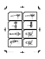 2
2
-
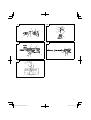 3
3
-
 4
4
-
 5
5
-
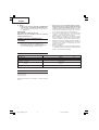 6
6
-
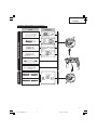 7
7
-
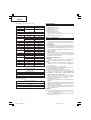 8
8
-
 9
9
-
 10
10
-
 11
11
-
 12
12
-
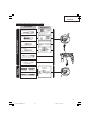 13
13
-
 14
14
-
 15
15
-
 16
16
-
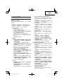 17
17
-
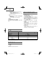 18
18
-
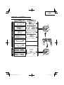 19
19
-
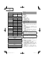 20
20
-
 21
21
-
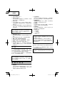 22
22
-
 23
23
-
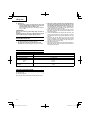 24
24
-
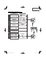 25
25
-
 26
26
-
 27
27
-
 28
28
-
 29
29
-
 30
30
-
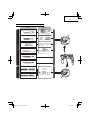 31
31
-
 32
32
-
 33
33
-
 34
34
-
 35
35
-
 36
36


Hitachi DH 22PG Manual de usuario
- Categoría
- Martillos perforadores
- Tipo
- Manual de usuario
- Este manual también es adecuado para
en otros idiomas
- English: Hitachi DH 22PG User manual
Artículos relacionados
-
Hikoki DH24PC3 Manual de usuario
-
Hitachi DH 22PB Handling Instructions Manual
-
Hikoki DH24PC2 Manual de usuario
-
Hitachi Koki DH24PB3 Manual de usuario
-
-
Hitachi DH 24PG Handling Instructions Manual
-
-
-
-