Hitachi DH 22PB Handling Instructions Manual
- Categoría
- Martillos perforadores
- Tipo
- Handling Instructions Manual

Rotary Hammer
Martillo perforador
DH 22PB
HANDLING INSTRUCTIONS
INSTRUCCIONES DE MANEJO
Read through carefully and understand these instructions before use.
Leer cuidadosamente y comprender estas instrucciones antes del uso.

1
2
4
6
8
3
5
7
1
1
2
3
4
4
5
6

2
9
10
13
16
14 15
C
D
B
H
J
K
L
M
O
N
K
P
12
11
E
F
G
1
H
I
3
4
17 18
L
3
4

3
English Español
1
2
3
4
5
6
7
8
9
0
A
B
C
D
E
F
G
H
I
J
K
L
M
N
O
P
Drill bit
Part of SDS-plus shank
Front cap
Grip
Dust cup
Dust collector (B)
Push button
Change lever
Push button
Drill chuck
Chuck adapter
Chuck adapter (D)
Bit
Socket
Side handle
Depth gauge
Mounting hole
Tape shank adapter
Cotter
Rest
Core bit
Core bit shank
Thread
Center pin
Guide plate
Core bit tip
Broca
Parte delSDS más vástago
Cubierta frontal
Sujetador
Capa de polvo
Colector de polvo (B)
Tecla
Palanquita selectora
Tecla
Portabrocas
Adaptador del portabrocas
Adaptador (D) del portabrocas
Broca
Cubo
Mango lateral
Calibre de profundidad
Agujero de montaje
Adaptador de la espiga ahusada
Chaveta
Apoyo
Barrena tubular
Espiga de la barrena tubular
Rosca
Pasador central
Placa guía
Punta de barrena tubular

English
4
GENERAL SAFETY RULES
WARNING!
Read all instructions
Failure to follow all instructions listed below may result in
electric shock, fire and/or serious injury.
The term “power tool” in all of the warnings listed below
refers to your mains operated (corded) power tool or battery
operated (cordless) power tool.
SAVE THESE INSTRUCTIONS
1) Work area
a) Keep work area clean and well lit.
Cluttered and dark areas invite accidents.
b) Do not operate power tools in explosive
atmospheres, such as in the presence of flammable
liquids, gases or dust.
Power tools create sparks which may ignite the dust
of fumes.
c) Keep children and bystanders away while operating
a power tool.
Distractions can cause you to lose control.
2) Electrical safety
a) Power tool plugs must match the outlet.
Never modify the plug in any way.
Do not use any adapter plugs with earthed
(grounded) power tools.
Unmodified plugs and matching outlets will reduce
risk of electric shock.
b) Avoid body contact with earthed or grounded
surfaces such as pipes, radiators, ranges and
refrigerators.
There is an increased risk of electric shock if your
body is earthed or grounded.
c) Do not expose power tools to rain or wet conditions.
Water entering a power tool will increase the risk of
electric shock.
d) Do not abuse the cord. Never use the cord for
carrying, pulling or unplugging the power tool.
Keep cord away from heat, oil, sharp edges or
moving parts.
Damaged or entangled cords increase the risk of
electric shock.
e) When operating a power tool outdoors, use an
extension cord suitable for outdoor use.
Use of a cord suitable for outdoor use reduces the
risk of electric shock
3) Personal safety
a) Stay alert, watch what you are doing and use
common sense when operating a power tool.
Do not use a power tool while you are tired or
under the influence of drugs, alcohol or medication.
A moment of inattention while operating power
tools may result in serious personal injury.
b) Use safety equipment. Always wear eye protection.
Safety equipment such as dust mask, non-skid safety
shoes, hard hat, or hearing protection used for
appropriate conditions will reduce personal injuries.
c) Avoid accidental starting. Ensure the switch is in
the off position before plugging in.
Carrying power tools with your finger on the switch
or plugging in power tools that have the switch on
invites accidents.
d) Remove any adjusting key or wrench before turning
the power tool on.
A wrench or a key left attached to a rotating part of
the power tool may result in personal injury.
e) Do not overreach. Keep proper footing and balance
at all times.
This enables better control of the power tool in
unexpected situations.
f) Dress properly. Do not wear looses clothing or
jewellery. Keep your hair, clothing and gloves away
from moving parts.
Loose clothes, jewellery or long hair can be caught
in moving parts.
g) If devices are provided for the connection of dust
extraction and collection facilities, ensure these are
connected and properly used.
Use of these devices can reduce dust related hazards.
4) Power tool use and care
a) Do not force the power tool. Use the correct power
tool for your application.
The correct power tool will do the job better and
safer at the rate for which it was designed.
b) Do not use the power tool if the switch does not
turn it on and off.
Any power tool that cannot be controlled with the
switch is dangerous and must be repaired.
c) Disconnect the plug from the power source before
making any adjustments, changing accessories, or
storing power tools.
Such preventive safety measures reduce the risk of
starting the power tool accidentally.
d) Store idle power tools out of the reach of children
and do not allow persons unfamiliar with the power
tool or these instructions to operate the power
tool.
Power tools are dangerous in the hands of untrained
users.
e) Maintain power tools. Check for misalignment or
binding of moving parts, breakage of parts and any
other condition that may affect the power tools
operation.
If damaged, have the power tool repaired before
use.
Many accidents are caused by poorly maintained
power tools.
f) Keep cutting tools sharp and clean.
Properly maintained cutting tools with sharp cutting
edges are less likely to bind and are easier to control.
g) Use the power tool, accessories and tool bits etc.,
in accordance with these instructions and in the
manner intended for the particular type of power
tool, taking into account the working conditions
and the work to be performed.
Use of the power tool for operations different from
intended could result in a hazardous situation.
5) Service
a) Have your power tool serviced by a qualified repair
person using only identical replacement parts.
This will ensure that the safety of the power tool is
maintained.
PRECAUTION
Keep children and infirm persons away.
When not in use, tools should be stored out of reach of
children and infirm persons.

English
5
OPTIONAL ACCESSORIES (sold separately)
1. Drilling anchor holes (rotation + hammering)
䡬 Drill bit (Slender shaft)
䡬 Drill bit (Taper shank) and taper shank adapter
Drill bit (slender shaft)
Outer diameter Effective length Overall length
3.4 mm
45 mm 90 mm
3.5 mm
SPECIFICATIONS
Voltage (by areas)* (110V, 115V, 120V, 127V, 220V, 230V, 240V)
Power Input 620 W*
No-load speed 0 – 1050 / min.
Full-load impact rate 0 – 4400 / min.
Capacity: concrete 3.4 – 22 mm
steel 13 mm
wood 32 mm
Weight (without cord and side handle) 2.3 kg
* Be sure to check the nameplate on product as it is subject to change by areas.
STANDARD ACCESSORIES
(1) Plastic case .................................................................. 1
(2) Side handle ................................................................. 1
(3) Depth gauge ............................................................... 1
Standard accessories are subject to change without
notice.
Adapter for slender shaft
(SDS-plus shank)
Drill bit (Slender shaft)
Drill bit (Taper shank) Taper shank adapter
(SDS-plus shank)
Cotter
PRECAUTIONS ON USING ROTARY HAMMER
1. Wear earplugs to protect your ears during operation.
2. Do not touch the bit during or immediately after
operation. The bit becomes very hot during
operation and could cause serious burns.
3. Before starting to break, chip or drill into a wall,
floor or ceiling, thoroughly confirm that such items
as electric cables or conduits are not buried inside.
4. Always hold the body handle and side handle of
the power tool firmly. Otherwise the counterforce
produced may result in inaccurate and even
dangerous operation.
Outer diameter
11.0 mm
12.3 mm
12.7 mm
14.3 mm
14.5 mm
17.5 mm
21.5 mm
Taper mode Applicable drill bit
Morse taper (No.1) Drill bit (taper shank) 11.0 ~ 17.5 mm
Morse taper (No.2) Drill bit (taper shank) 21.5 mm
A-taper Taper shank adapter formed A-taper or B-taper
is provided as an optional accessory, but the
B-taper
drill bit for it is not provided.

English
6
( )
Straight shank bit
for impact drill
䡬 13 mm rotary hammer chuck
For drilling operations when using a straight shank bit for impact drilling with a rotary hammer.
13 mm Rotary hammer chuck
(SDS-plus shank)
Chuck wrench
䡬 Anchor setting adapter (for manual hammer)
Anchor setting adapter
(for manual Hammer)
Anchor setting adapter (SDS-plus shank)
(for rotary hammer)
Overall length: 160, 260 mm
Anchor size
W1/4”
W5/16”
W3/8”
Anchor size
W1/4”
W5/16”
W3/8”
W1/2”
W5/8”
3. Large hole boring (rotation + hammering)
䡬 Center pin, core bit, core bit shank and guide plate
(Guide plate) Center pin Core bit Core bit shank
(SDS-plus shank)
2. Anchor setting (rotation + hammering)
䡬 Anchor setting adapter (for rotary hammer)
Center pin Core bit (outer diameter) Core bit shank
–
25 mm
29 mm
(A)
32 mm Core bit shank (A)
Center pin (A) 35 mm
38 mm
45 mm
Center pin (B) (B)
50 mm
Core bit shank (B)
Do not use core bits with with guide plate
outer diameter of 25 mm (The guide plate is not equipped with core bits
and 29 mm. with outer diameter of 25 mm and 29 mm.)

English
7
4. Crushing operation (rotation + hammering)
Bull point (Round type only)
(SDS-plus shank)
5. Bolt placing operation with Chemical Anchor. (rotation + hammering)
(SDS-plus shank)
12.7 mm Chemical Anchor Adapter
19 mm Chemical Anchor Adapter
Standard socket
on the market
6. Drilling holes and driving screws (rotation only)
䡬 Drill chuck, chuck adapter (G), special screw and chuck wrench
Chuck adapter (G)
(SDS-plus shank)
Chuck wrench
Drill chuck (13 VLRB-D)Special screw
( )

English
8
7. Drilling holes (rotation only)
Chuck adapter (D)
(SDS-plus shank)
Chuck wrench
䡬 13 mm drill chuck ass’y (includes chuck wrench) and chuck (for drilling in steel or wood).
8. Driving Screws (rotation only)
Chuck adapter (D)
(SDS-plus shank)
Bit No. Screw Size Length
No. 2 3 – 5 mm 25 mm
No. 3 6 – 8 mm 25 mm
9. Dust cup, Dust collector (B)
Optional accessories are subject to change without notice.
Dust cup Dust collector (B)
10. Hammer grease A
500 g (in a can)
70 g (in a green tube)
30 g (in a green tube)
Bit No.
Drill chuck (13 VLD-D)

English
9
APPLICATIONS
Rotation and hammering function
䡬 Drilling anchor holes
䡬 Drilling holes in concrete
䡬 Drilling holes in tile
Rotation only function
䡬 Drilling in steel or wood
(with optional accessories)
䡬 Tightening machine screws, wood screws
(with optional accessories)
PRIOR TO OPERATION
1. Power source
Ensure that the power source to be utilized conforms
to the power requirements specified on the product
nameplate.
2. Power switch
Ensure that the power switch is in the OFF position. If
the plug is connected to a power receptacle while the
power switch is in the ON position, the power tool
will start operating immediately, which could cause a
serious accident.
3. Extension cord
When the work area is removed from the power
source, use an extension cord of sufficient thickness
and rated capacity. The extension cord should be
kept as short as practicable.
4. Mounting the drill bit (Fig. 1)
CAUTION
To prevent accidents, make sure to turn the switch
off and disconnect the plug from the receptacle.
NOTE
When using tools such as bull points, drill bits, etc.,
make sure to use the genuine parts designated by
our company.
(1) Clean the shank portion of the drill bit.
(2) Insert the drill bit in a twisting manner into the tool
holder until it latches itself (Fig. 1).
(3) Check the latching by pulling on the drill bit.
(4) To remove the drill bit, fully pull the grip in the
direction of the arrow and pull out the drill bit (Fig. 2).
5. Installation of dust cup or dust collector (B)
(Optional accessories) (Fig. 3, Fig. 4)
When using a rotary hammer for upward drilling
operations attach a dust cup or dust collector (B) to
collect dust or particles for easy operation.
䡬 Installing the dust cup
Use the dust cup by attaching to the drill bit as shown
in Fig. 3.
When using a bit which has big diameter, enlarge the
center hole of the dust cup with this rotary hammer.
䡬 Installing dust collector (B)
When using dust collector (B), insert dust collector
(B) from the tip of the bit by aligning it to the groove
on the grip (Fig. 4).
CAUTION
䡬 The dust cup and dust collector (B) are for exclusive
use of concrete drilling work. Do not use them for
wood or metal drilling work.
䡬 Insert dust collector (B) completely into the chuck
part of the main unit.
䡬 When turning the rotary hammer on while dust
collector (B) is detached from a concrete surface,
dust collector (B) will rotate together with the drill bit.
Make sure to turn on the switch after pressing the
dust cup on the concrete surface. (When using dust
collector (B) attached to a drill bit that has more than
190 mm of overall length, dust collector (B) cannot
touch the concrete surface and will rotate. Therefore
please use dust collector (B) by attaching to drill bits
which have 166 mm, 160 mm, and 110 mm overall
length.)
䡬 Dump particles after every two or three holes when
drilling.
䡬 Please replace the drill bit after removing dust
collector (B).
6. Selecting the driver bit
Screw heads or bits will be damaged unless a bit
appropriate for the screw diameter is employed to
drive in the screws.
7. Confirm the direction of bit rotation (Fig. 5)
The bit rotates clockwise (viewed from the rear side)
by pushing the R-side of the push button.
The L-side of the push button is pushed to turn the bit
counterclockwise.
HOW TO USE
CAUTION
To prevent accidents, make sure to turn the switch
off and disconnect the plug from the receptacle when
the drill pits and other various parts are installed or
removed. The power switch should also be turned
off during a work break and after work.
1. Switch operation
The rotation speed of the drill bit can be controlled
steplessly by varying the amount that the trigger
switch is pulled. Speed is low when the trigger switch
is pulled slightly and increases as the switch is pulled
more. Continuous operation may be attained by
pulling the trigger switch and depressing the stopper.
To turn the switch OFF, pull the trigger switch again
to disengage the stopper, and release the trigger
switch to its original position.
2. Rotation + hammering
This rotary hammer can be set to rotation and
hammering mode by pressing the push button and
turning the change lever to the
mark (Fig. 6).
(1) Mount the drill bit.
(2) Pull the trigger switch after applying the drill bit tip to
the drilling position (Fig. 7).
(3) Pushing the rotary hammer forcibly is not necessary
at all. Pushing slightly so that drill dust comes out
gradually is sufficient.
CAUTION
When the drill bit touches construction iron bar, the
bit will stop immediately and the rotary hammer will
react to revolve. Therefore grip the side handle and
handle tightly as shown in Fig. 7.
3. Rotation only
This rotary hammer can be set to rotation only mode
by pussing the push button and turning the change
lever to the
mark (Fig. 8).
To drill wood or metal material using the drill chuck
and chuck adapter (optional accessories), proceed as
follows.
Installing drill chuck and chuck adapter: (Fig. 9)

English
10
(1) Attach the drill chuck to the chuck adapter.
(2) The part of the SDS-plus shank is the same as the
drill bit. Therefore, refer to the item of “Mounting the
drill bit” for attaching it.
CAUTION
䡬 Application of force more than necessary will not
only expedite the work, but will deteriorate the tip
edge of the drill bit and reduce the service life of the
rotary hammer in addition.
䡬 Drill bits may snap off while withdrawing the rotary
hammer from the drilled hole. For withdrawing, it is
important to use a pushing motion.
䡬 Do not attempt to drill anchor holes or holes in
concrete with the machine set in the rotation only
function.
䡬 Do not attempt to use the rotary hammer in the
rotation and striking function with the drill chuck and
chuck adapter attached. This would seriously shorten
the service life of every component of the machine.
4. When driving machine screws (Fig. 10)
First, insert the bit into the socket in the end of chuck
adapter (D).
Next, mount chuck adapter (D) on the main unit
using procedures described in 4 (1), (2), (3), put the
tip of the bit in the slots in the head of the screw,
grasp the main unit and tighten the screw.
CAUTION
䡬 Exercise care not to excessively prolong driving time,
otherwise, the screws may be damaged by excessive
force.
䡬 Apply the rotary hammer perpendicularly to the screw
head when driving the screw; otherwise, the screw
head or bit will be damaged, or driving force will not
be fully transferred to the screw.
䡬 Do not attempt to use the rotary hammer in the
rotation and striking function with the chuck adapter
and bit attached.
5. When driving wood screws (Fig. 10)
(1) Selecting a suitable driver bit
Employ plus-head screws, if possible, since the driver
bit easily slips off the heads of minus-head screws.
(2) Driving in wood screws
䡬 Prior to driving in wood screws, make pilot holes
suitable for them in the wooden board. Apply the bit
to the screw head grooves and gently drive the screws
into the holes.
䡬 After rotating the rotary hammer at low speed for a
while until the wood screw is partly driven into the
wood, squeeze the trigger more strongly to obtain
the optimum driving force.
CAUTION
Exercise care in preparing a pilot hole suitable for the
wood screw taking the hardness of the wood into
consideration. Should the hole be excessively small
or shallow, requiring much power to drive the screw
into it, the thread of the wood screw may sometimes
be damaged.
6. Using depth gauge (Fig. 11)
(1) Loosen the knob on the side handle, and insert the
depth gauge into the mounting hole on the side
handle.
(2) Adjust the depth gauge position according to the
depth of the hole and thighten the knob securely.
7. How to use the drill bit (taper shank) and the taper
shank adapter
(1) Mount the taper shank adapter to the rotary hammer
(Fig. 12).
(2) Mount the drill bit (taper shank) to the taper shank
adapter (Fig. 12).
(3) Turn the switch ON, and drill a hole in prescribed
depth.
(4) To remove the drill bit (taper shank), insert the cotter
into the slot of the taper shank adapter and strike the
head of the cotter with a hammer supporting on a
rests (Fig. 13).
HOW TO USE THE CORE BIT
(FOR LIGHT LOAD)
When boring penerating large holes use the core bit (for
light loads). At that time use with the center pin and the
core bit shank provided as optional accessories.
1. Mounting
CAUTION
Be sure to turn power OFF and disconnect the plug
from the receptacle.
(1) Mount the core bit to the core bit shank (Fig. 14).
Lubricate the thread of the core bit shank to facilitate
disassembly.
(2) Mount the core bit to the rotary hammer (Fig. 15)
(3) Insert the center pin into the guide plate until it stops.
(4) Engage the guide plate with the core bit, and turn the
guide plate to the left or the right so that it does not
fall even if it faces downward (Fig. 16).
2. How to bore (Fig. 17)
(1) Connect the plug to the power source.
(2) A spring is installed in the center pin.
Push it lightly to the wall or the floor straight.
Connect the core bit tip flush to the surface and start
operating.
(3) When boring about 5 mm in depth the position of the
hole will be established. Bore after that removing the
center pin and the guide plate from core bit.
(4) Application of excessive force will not only expedite
the work, but will deteriorate the tip edge of the drill
bit, resulting in reduced service life of the rotary
hammer.
CAUTION
When removing the center pin and the guide plate,
turn OFF the switch and disconnect the plug from the
receptacle.
3. Dismounting (Fig. 18)
Remove the core bit shank from the rotary hammer
and strike the head of the core bit shank strongly two
or three times with a hammer holding the core bit,
then the thread becomes loose and the core bit can
be removed.
LUBRICATION
Low viscosity grease is applied to this rotary hammer so
that it can be used for a long period without replacing
the grease. Please contact the nearest service center for
grease replacement when any grease is leaking form
loosened screw.
Further use of the rotary hammer with lock off grease
will cause the machine to seize up reduce the service life.
CAUTION
A special grease is used with this machine, therefore,
the normal performance of the machine may be badly
affected by use of other grease. Please be sure to let
one of our service agents undertake replacement of
the grease.

English
11
MAINTENANCE AND INSPECTION
1. Inspecting the drill bits
Since use of a dull tool will cause motor
malfunctioning and degraded efficiency, replace the
drill bit with new ones or resharpen them without
delay when abrasion is noted.
2. Inspecting the mounting screws
Regularly inspect all mounting screws and ensure
that they are properly tightened. Should any of the
screws be loose, retighten them immediately. Failure
to do so could result in serious hazard.
3. Maintenance of the motor
The motor unit winding is the very ”heart” of the
power tool. Exercise due care to ensure the winding
does not become damaged and/or wet with oil or
water.
4. Inspecting the carbon brushes
For your continued safety and electrical shock
protection, carbon brush inspection and replacement
on this tool should ONLY be performed by a HITACHI
AUTHORIZED SERVICE CENTER.
5. Service parts list
A: Item No.
B: Code No.
C: No. Used
D: Remarks
CAUTION
Repair, modification and inspection of Hitachi Power
Tools must be carried out by an Hitachi Authorized
Service Center.
This Parts List will be helpful if presented with the
tool to the Hitachi authorized Service Center when
requesting repair or other maintenance.
In the operation and maintenance of power tools, the
safety regulations and standards prescribed in each
country must be observed.
MODIFICATION
Hitachi Power Tools are constantly being improved
and modified to incorporate the latest technological
advancements.
Accordingly, some parts (i.e. code numbers and/or
design) may be changed without prior notice.
NOTE:
Due to HITACHI’s continuing program of research and
development, the specifications herein are subject to
change without prior notice.

Español
12
NORMAS GENERALES DE SEGURIDAD
¡ADVERTENCIA!
Lea todas las instrucciones
Si no se siguen las instrucciones de abajo podría producirse
una descarga eléctrica, un incendio y/o daños graves.
El término “herramienta eléctrica” en todas las
advertencias indicadas a continuación hace referencia a
la herramienta eléctrica que funciona con la red de
suministro (con cable) o a la herramienta eléctrica que
funciona con pilas (sin cable).
CONSERVE ESTAS INSTRUCCIONES
1) Área de trabajo
a) Mantenga la zona de trabajo limpia y bien
iluminada.
Las zonas desordenadas y oscuras pueden
provocar accidentes.
b) No utilice las herramientas eléctricas en entornos
explosivos como, por ejemplo, en presencia de
líquidos inflamables, gases o polvo.
Las herramientas eléctricas crean chispas que
pueden hacer que el polvo desprenda humo.
c) Mantenga a los niños y transeúntes alejados
cuando utilice una herramienta eléctrica.
Las distracciones pueden hacer que pierda el control.
2) Seguridad eléctrica
a) Los enchufes de las herramientas eléctricas tienen
que ser adecuados a la toma de corriente.
No modifique el enchufe.
No utilice enchufes adaptadores con herramientas
eléctricas conectadas a tierra.
Si no se modifican los enchufes y se utilizan tomas
de corriente adecuadas se reducirá el riesgo de
descarga eléctrica.
b) Evite el contacto corporal con superficies conectadas
a tierra como tuberías, radiadores y frigoríficos.
Hay mayor riesgo de descarga eléctrica si su
cuerpo está en contacto con el suelo.
c) No exponga las herramientas eléctricas a la lluvia
o a la humedad.
La entrada de agua en una herramienta eléctrica
aumentará el riesgo de descarga eléctrica.
d) No utilice el cable incorrectamente. No utilice el
cable para transportar, tirar de la herramienta
eléctrica o desenchufarla.
Mantenga el cable alejado del calor, del aceite, de
bordes afilados o piezas móviles.
Los cables dañados o enredados aumentan el
riesgo de descarga eléctrica.
e) Cuando utilice una herramienta eléctrica al aire
libre, utilice un cable prolongador adecuado para
utilizarse al aire libre.
La utilización de un cable adecuado para usarse
al aire libre reduce el riesgo de descarga eléctrica.
3) Seguridad personal
a) Esté atento, preste atención a lo que hace y utilice
el sentido común cuando utilice una herramienta
eléctrica.
No utilice una herramienta eléctrica cuando esté
cansado o esté bajo la influencia de drogas,
alcohol o medicación.
La distracción momentánea cuando utiliza
herramientas eléctricas puede dar lugar a
importantes daños personales.
b) Utilice equipo de seguridad. Utilice siempre una
protección ocular.
El equipo de seguridad como máscara para el
polvo, zapatos de seguridad antideslizantes, casco
o protección para oídos utilizado para condiciones
adecuadas reducirá los daños personales.
c) Evite un inicio accidental. Asegúrese de que el
interruptor está en “off” antes de enchufarlo.
El transporte de herramientas eléctricas con el
dedo en el interruptor o el enchufe de
herramientas eléctricas con el interruptor
encendido puede provocar accidentes.
d) Retire las llaves de ajuste antes de encender la
herramienta eléctrica.
Si se deja una llave en una pieza giratoria de la
herramienta eléctrica podrían producirse daños
personales.
e) No se extralimite. Mantenga un equilibrio
adecuado en todo momento.
Esto permite un mayor control de la herramienta
eléctrica en situaciones inesperadas.
f) Vístase adecuadamente. No lleve prendas sueltas
o joyas. Mantenga el pelo, la ropa y los guantes
alejados de las piezas móviles.
La ropa suelta, las joyas y el pelo largo pueden
pillarse en las piezas móviles.
g) Si se proporcionan dispositivos para la conexión
de extracción de polvo e instalaciones de recogida,
asegúrese de que están conectados y se utilizan
adecuadamente.
La utilización de estos dispositivos puede reducir
los riesgos relacionados con el polvo.
4) Utilización y mantenimiento de las herramientas
eléctricas
a) No fuerce la herramienta eléctrica. Utilice la
herramienta eléctrica correcta para su aplicación.
La herramienta eléctrica correcta trabajará mejor
y de forma más segura si se utiliza a la velocidad
para la que fue diseñada.
b) No utilice la herramienta eléctrica si el interruptor
no la enciende y apaga.
Las herramientas eléctricas que no pueden
controlarse con el interruptor son peligrosas y
deben repararse.
c) Desconecte el enchufe de la fuente eléctrica antes
de hacer ajustes, cambiar accesorios o almacenar
herramientas eléctricas.
Estas medidas de seguridad preventivas reducen
el riesgo de que la herramienta eléctrica se ponga
en marcha accidentalmente.
d) Guarde las herramientas eléctricas que no se
utilicen para que no las cojan los niños y no
permita que utilicen las herramientas eléctricas
personas no familiarizadas con las mismas o con
estas instrucciones.
Las herramientas eléctricas son peligrosas si son
utilizadas por usuarios sin formación.
e) Mantenimiento de las herramientas eléctricas.
Compruebe si las piezas móviles están mal
alineadas o unidas, si hay alguna pieza rota u
otra condición que pudiera afectar al
funcionamiento de las herramientas eléctricas.
Si la herramienta eléctrica está dañada, llévela a
reparar antes de utilizarla.

Español
13
ESPECIFICACIONES
Voltaje (por áreas)* (110V, 115V, 120V, 127V, 220V, 230V, 240V)
Acometida 620 W*
Velocidad sin carga 0 – 1050 / min.
Velocidad de percusión a carga plena 0 – 4400 / min.
Capacidad: hormigón 3,4 – 22 mm
acero 13 mm
madera 32 mm
Peso (sin cable ni mango lateral) 2,3 kg
* Verificar indefectiblemente los datos de la placa de características de la máquina, pues varían de acuerdo con el
país de destino.
ACCESORIOS ESTANDAR
(1) Caja de plástico .......................................................... 1
(2) Mango lateral .............................................................. 1
(3) Calibre de profundidad .............................................. 1
Los accesorios estándar están sujetos a cambio sin previo
aviso.
Se producen muchos accidentes por no realizar
un mantenimiento correcto de las herramientas
eléctricas.
f) Mantenga las herramientas de corte afiladas y
limpias.
Las herramientas de corte correctamente
mantenidas con los bordes de corte afilados son
más fáciles de controlar.
g) Utilice la herramienta eléctrica, los accesorios y
las brocas de la herramienta, etc., de acuerdo con
estas instrucciones y de la manera adecuada para
el tipo de herramienta eléctrica, teniendo en
cuenta las condiciones laborales y el trabajo que
se va a realizar.
La utilización de la herramienta eléctrica para
operaciones diferentes a pretendidas podría dar
lugar a una situación peligrosa.
5) Revisión
a) Lleve su herramienta a que la revise un experto
cualificado que utilice sólo piezas de repuesto
idénticas.
Esto garantizará el mantenimiento de la seguridad
de la herramienta eléctrica.
PRECAUCIÓN
Mantenga a los niños y a las personas enfermas alejadas.
Cuando no se utilicen, las herramientas deben
almacenarse fuera del alcance de los niños y de las
personas enfermas.
PRECAUCIONES AL USAR EL MARTILLO
PERFORADOR
1. Usar protectores de oídos durante el trabajo.
2. No tocar la broca durante ni inmediatamente después
de trabajar, puesto que se pone ardiente y puede
causar quemaduras serias.
3. Antes de empezar a romper, picar o perforar en una
pared, suelo o techo, comprobar cuidadosamente
que no hayan objetos empotrados, tales como cables
o conductos eléctricos.
4. Sujetar siempre firmemente el asidero del cuerpo y
el asidero lateral de la herramienta. De lo contrario,
la contrafuerza producida podría causar un
funcionamiento impreciso e incluso peligroso.
ACCESORIOS FACULTATIVOS (de venta por separado)
1. Taladrar orificios de anclaje (rotación + golpeteo)
䡬 Broca de taladro (Eje fino)
Adaptador para eje fino
(SDS más vástago)
Broca de taladro (Eje fino)
Broca de taladro (Eje fino)
Diámetro externo Longitud efectiva Longitud total
3,4 mm
45 mm 90 mm
3,5 mm

Español
14
Broca de vástago recto
para martillo roto-percutor
( )
Modo cónico Broca de taladro aplicable
Cono Morse (No.1)
Broca de taradro
11,0 ~ 17,5 mm
(vástago cónico)
Cono Morse (No.2)
Broca de taradro
21,5 mm
(vástago cónico)
Cono A El cono A o B troquelado del adaptador cónico as
suministra como accesorio facultativo pero la
Cono B broca para el mismo no se suministra.
䡬 Portabrocas del martillo perforador de 13 mm
Para la operación de taladrado cuando emplee una broca de vástago recto para taladrar con un martillo
perforador.
Diámetro externo
11,0 mm
12,3 mm
12,7 mm
14,3 mm
14,5 mm
17,5 mm
21,5 mm
Llave de portabrocas
Portabrocas del martillo
perforador de 13 mm
(SDS más vástago)
Adaptador cónico
(SDS más vástago)
Chaveta
䡬 Broca de taladro (vástago cónico) y adaptador cónico
Broca de taladro (Vástago cónico)
2. Montaje de ancla (rotación + golpeteo)
䡬 Adaptador de montaje de ancla (para martillo perforador)
Medida de ancla
W1/4”
W5/16”
W3/8”
Adaptador de montaje de ancla (SDS más vástago)
(para martillo perforador)
Longitud total: 160, 260 mm

Español
15
Pasador central Barrent tubular (diámetro externo) Espiga de la barrena tubular
–
25 mm
29 mm
(A)
32 mm
Espiga de la barrena tubular (A)
Pasador central (A) 35 mm
38 mm
45 mm
Pasador central (B) (B)
50 mm
Espiga de la barrena tubular (B)
No usar barrenas tubulares con placa guía
con un diámetro externo de (La placa guía no se ha equipado con barrenas
25 mm y 29 mm. tubulares con diámetro externo de 25 mm y 29 mm.)
4. Travajo de roturación (rotación + golpeteo)
Puntero (Tipo redondo solamente)
(SDS más vástago)
䡬 Adaptador de montaje de ancla (para martillo manual)
Medida de ancla
W1/4”
W5/16”
W3/8”
W1/2”
W5/8”
Adaptador de montaje de ancla
(para martillo manual)
3. Pertoración de orificio de diámetro grande (rotación + golpeteo)
䡬 Pasador central, barrena tubular, espiga de la barrena tubular y placa guía
Pasador central
Barrena
tubular
Espiga de la barrena
tubular
(SDS más vástago)
5. Trabajo de colocación de pernos para anclaje químico (rotación + golpeteo)
(SDS más vástago)
Adaptador de anclaje químico de 12,7 mm
Adaptador de anclaje químico de 19 mm
(Manguito
adaptador
a la venta
el mercado)
(Placa guia)

Español
16
6. Perforación (rotación solamente)
䡬 Portabrocas, adaptador (G) del portabrocas, tornillo especál y llave de portabrocas
Tornillo especial
Llave de portabrocas
Porabrocas
(13 VLRB-D)
Adaptador (G) de portabrocas
(SDS más vástago)
7. Perforación (rotación solamente)
䡬 Conjunto de portabrocas 13 mm (con llave de portabrocas) y portabrocas (para perforación de orificios en
hormigón o madera)
8. Colocación de tornillos (rotación solamente)
No. de broca
Tamaño del tornillo
Longitud
No.2 3 – 5 mm 25 mm
No.3 6 – 8 mm 25 mm
No. de broca
Portabrocas (13 VLD-D) Adaptador (D) del portabrocas
(SDS más vástago)
Liave de portabrocas
Adaptador (D) del portabrocas
(SDS más vástago)
9. Copa de polvo, Colector de polvo (B)
Los accesorios de norma están sujetos a cambio sin previo aviso.
10. Grasa A para martillo
500 g (en una lata)
70 g (en un tubo naranja)
30 g (en un tubo naranja)
Colector de polvo (B)
Copa de polvo

Español
17
APPLICACION
Rotación y función de golpeteo
䡬 Perforación de orificios de anclaje
䡬 Perforación de orificios de hormigón
䡬 Perforación de orificios de baldosa
Rotación solamente
䡬 Perforación de orificios en hormigón o madera
(con accesorios facultativos)
䡬 Apretar tornillos en metal o madera
(con accesorios facultativos)
ANTES DE LA PUESTA EN MARCHA
1. Alimentación
Asegurarse de que la alimentación de red que ha de
ser utilizada responda a las exigencias de corriente
especificadas en la placa de características del
producto.
2. Conmutador de alimentación
Asegurarse de que el conmutador de alimentación
esté en la posición OFF (desconectado). Si la clavija
está conectada en la caja del enchufe mientras el
conmutador de alimentación esté en posición ON
(conectado) las herramientas eléctricas empezarán a
trabajar inmediatamente, provocando un serio
accidente.
3. Cable de prolongación
Cuando está alejada el área de trabajo de la red de
alimentación, usar un cable de prolongación de un
grosor y potencia nominal suficiente. El cable de
prolongación debe ser mantenido lo más corto
posible.
4. Montaje de la broca (Fig. 1)
PRECAUCIÓN
Para evitar accidentes, cerciórese de desactivar y de
desconectar el enchufe del tomacorriente.
NOTA
Cuando ulilice herramientas como por ejemplo:
cinceles, brocas de taladro, etc., cerciórese de utilizar
piezas genuinas diseñadas por nuestra compañía.
(1) Limpie la parte del vástago de la broca de taladro.
(2) Inserte la broca de taladro girando en el sujetador de
la herramienta hasta que se asegure bien (Fig. 1).
(3) Verifique si esta bien asegurado tirando de la broca
de taladro.
(4) Para extraer la broca, tire completamente de la
empuñadura en el sentido de la flecha y tire hacia
afuera de la broca (Fig. 2).
5. Cuando instale la copa de polvo o el lector de polvo
(B) (Accesorios facultativos)(Fig. 3, Fig. 4)
Cuando emplee un martillo perforador para trabajos
de taladrado hacia arriba, extraiga el adaptador de
recolección de polvo e instale una copa de polvo o un
colector de polvo (B) para recolectar las partículas a
fin de facilitar la operación.
䡬 Instalación de la copa de polvo
Emplee la copa de polvo instalando la broca como se
muestra en la Fig. 3.
Cuando emplee una broca de gran diámetro, agrande
el orificio central de la copa de polvo con este martillo
perforador.
䡬 Instalación del colector de polvo (B)
Para emplear el colector de polvo (B), Insértelo desde
la punta de la broca alineándolo con la ranura de la
empuñadura (Fig. 4).
PRECAUCIÓN
䡬 La copa de polvo y el colector de polvo (B) son para
emplearse exclusvamente en trabajos de perforación
de hormigón. No los emplee para trabajar con madera
o metal.
䡬 Inserte completamente el colector de polvo (B) en la
parte del portabrocas de la unidad principal.
䡬 Cuando ponga en funcionamiento del martillo
perforador meintras el colector de polvo (B) esté
separado de la superficie de hormigón, dicho colector
girará junto con la broca. Cerciórese de apretar el
gatillo interruptor después de haber presionado la
copa de polvo sobre la superficie de hormigón.
(Cuando emplee la copa de polvo con una broca de
no más de 190 mm de longitud total, el colector de
polvo (B) no podrá tocar la superficie de hormigón
girará. Por lo tanto, emplee el colector de polvo (B)
con brocas de 166, 160, y 110 mm de longitud total.)
䡬 Vacíe las partículas del colector de polvo (B) después
de haber taladrado dos o tres orificios.
䡬 Después de haber extraído el colector de polvo (B),
vuelva a colocar a broca.
6. Selección de la broca destornillador
Puede dañarse las cabezas de tornillos y las brocas
de atornillar menos que se emplee la broca apropiada
según sea el diámetro del tornillo.
7. Confirmar la dirección de rotación de la broca (Fig. 5)
La broca gira en el sentido de las agujas del reloj
(visto desde el lado trasero) empujando el lado R del
botón.
Si empuja el lado L del botón, la broca girará en
sentido contrario a las agujas del reloj.
COMO SE USA
PRECAUCIÓN
Para evitar accidentes, cerciórese de poner este
interruptor en OFF y de desconectar el enchufe del
tomacorriente cuando instale o extraiga brocas y
otras piezas. El interruptor de alimentación también
deberá ponerse en OFF durante un descanso en el
trabajo y después de haber finalizado dicho trabajo.
1. Operación del conmutador
La velocidad rotatoria de la broca de taladro puede
ser controlad variando la fuerza con la que se aprieta
el pulsador. La velocidad está baja cuando se aprieta
ligeramente el pulsador y se aumenta al apretar más
el pulsador. La operación contínua puede ser
alcanzada apretando el pulsador y apretando hacia
abajo el dispositivo de ajuste. Para ponel el pulsador
en OFF (desconectado) volver a apretar el pulsador
para desconectar el dispositivo de ajuste, y soltar el
pulsador a su posición normal.
2. Rotación + golpeteo
Este martillo perforador puede usarse en el modo de
rotación y martilleo presionando el botón pulsador y
girando la palanca selectora hasta la marca
(Fig. 6).
(1) Montar la broca.
(2) Presionar el interruptor de gatillo después de poner
la punta de la broca en la posición para taladrar (Fig. 7).
(3) No es necesario presionar con fuerza la broca.
Presionar ligeramente la broca de forma que el polvo
producido al taladrar salga al exterior gradualmente.

Español
18
PRECAUCIÓN
Cuando la broca toque una barra de hierro de
construción se detendrá inmediatamente y el martillo
perforador tenderá a girar. Por lo tanto, sujetar el
mango lateral y sostenerlo firmemente como se ilustra
en la Fig. 7.
3. Rotación solamente
Este martillo perforador puede usarse en el modo de
rotación solamente presionando el pulsador y girando
la palanca selectora hasta la marca
(Fig. 8).
Para perforar madera o metal empleando el
portabrocas y el adaptador del portabrocas (accesorio
facultativo), proceder como sigue.
Instalación del portabrocas y adaptador del
portabrocas: (Fig. 9)
(1) Instale la broca en el adaptador del portabrocas.
(2) La parte del SDS más vástago es igual que una
broca. Por lo tanto, para instalarla, consulte ”Montaje
de la broca”.
PRECAUCIÓN
䡬 La aplicación de fuerza excesiva acelerará el trabajo
pero dañará la punta de la broca y reducirá la vida
útil del martillo perforador.
䡬 La broca puede salirse al quitar el martillo perforador
del orificio perforado. Para extraer esta herramienta
es importante empujar hacia de lante.
䡬 No intentar perforar orificios de anclaje o perforar el
concreto con la máquina puesta en la función de
rotación solamente.
䡬 No intentar usar el martillo perforador en la función
de rotación y golpeteo con el portabrocas y el
adaptador del portabrocas instalados. Esto reducirá
considerablemente la vida útil de cada componente
de la máquina.
4. Cuando coloque tornillos para metal (Fig. 10)
En primer lugar, inserte la broca en el cubo del
extremo del adaptador (D) de portabroca.
A continuación, monte el adaptador (D) de portabroca
en la unidad principal empleando los procedimientos
descritos en 4 (1), (2), y (3), coloque la punta de la
broca en las ranuras de la cabeza del tornillo, sujete
la unidad principal, y apriete el tornillo.
PRECAUCIÓN
䡬 Tener cuidado en no prolongar excesivamente el
accionamiento de la herramienta, ya que de lo
contrario, pueden dañarse los tornillos por el exceso
de fuerza.
䡬 Colocar el martillo perforador en forma perpendicular
sobre la cabeza del tornillo al atornillarlo, ya que en
caso contrario, puede dañarse la cabeza del tornillo o
la broca, e incluso, la fuerza de accionamiento puede
que no se transfiera por completo al tornillo.
䡬 No intente emplear la perforadora de percusión en la
función de rotación y golpeteo con el adaptador de
portabroca y la broca instalados.
5. Atornillando tornillos para madera (Fig. 10)
(1) Escoger una broca destornillador apropiada y emplear
tornillos con cabeza +, en lo posible, debido a que los
tornillos con cabeza – hacen que se zafe fácilmente el
destornillador.
(2) Atornillado
䡬 Antes de atornillar los tornillos para madera, hay que
hacer orificios apropiados en la madera, aplicando
luego la broca destornillador en la cabeza del tornillo
y colocar asi éste en los orificios.
䡬 Luego de hacer rotar la herramienta lentamente hasta
que el tornillo quede parcialmente metido en la
madera, apretar más el gatillo para obtener la fuerza
óptima de atornillado.
PRECAUCIÓN
Tener cuidado al preparar el orificio para que sea
apropiado para el tornillo, teniendo en cuenta la
dureza de la madera. Si el orificio es excesivamente
pequeño o estrecho, se requiere mucha fuerza para
atornillar y a veces puede dañarse la rosca.
6. Modo de usar el tope (Fig. 11)
(1) Afloje el perno de perilla del asa lateral, e inserte el
retenedor en el surco en U de dicha asa lateral.
(2) Ajustar la posición del retenedor de acuerdo a la
profundidad del agujero, y apretar firmemente el
perno de perilla.
7. Modo de usar la broca (espiga ahusada) y el adaptador
de la espiga ahusada
(1) Montar el adaptador de la espiga ahusada en el martillo
perforador (Fig. 12).
(2) Montar la broca (espiga ahusada) en el adaptador de
la espiga ahusada (Fig. 12).
(3) Poner el interruptor en la posición de encendido
(ON), y taladrar un agujero de la profundidad
especificada.
(4) Para quitar la broca (espiga ahusada), insertar la
chaveta en la ranura del adaptador de la espiga
ahusada y golpear la cabeza de la chaveta con un
martillo. Usar apoyos como se muestra en la Fig. 13.
MODO DE USAR LA BARRENA TUBULAR
(PARA CARGAS LIGERAS)
Cuando se tengan que taladrar agujeros grandes, usar la
barrena tubular (para cargas ligeras). Usar también el
pasador central y la espiga de la barrena tubular provistos
como accesorios opcionales.
1. Montaje
PRECAUCIÓN
Cerciorarse de poner el interruptor de la alimentación
en la posición de apagado (OFF) y de desconectar el
enchufe de la toma de alimentación.
(1) Montar la barrena tubular en su espiga (Fig. 14).
Lubricar la rosca de la espiga de la barrena tubular
para facilitar el desmontaje.
(2) Montar la espiga de la barrena tubular en el martillo
perforador (Fig. 15).
(3) Insertar el pasador central en la placa guía hasta que
se pare.
(4) Unir la placa guía con la barrena tubular y girar la
placa guía hacia la izquierda o hacia la derecha de
forma que no se caiga a pesar de estar indicando
hacia abajo (Fig. 16).
2. Modo de taladrar (Fig. 17)
(1) Conectar el enchufe a la toma de alimentación.
(2) El pasador central se ha instalado un resorte.
Presionar ligeramente y sin torcerse hacia la pared o
hacia el pared o hacia el suelo.
Procurar que toda la punta de la barrena tubular esté
en contacto con la superficie a taladrar y luego,
empezar la operación.
(3) Al taladrar aproximadamente 5 mm en profundidad,
la posición del agujero queda ya establecida. Quitar
el pasador central y la placa guía de la barrena tubular
y seguir taladrando.

Español
19
(4) La aplicación de una fuerza excesiva acelerará el
cumplimiento del trabajo, pero deteriorará la punta
de la broca reduciendo la duración del martillo
perforador.
PRECAUCIÓN
Cuando se quite el pasador central y la placa guía,
poner el interruptor en la posición de apagado (OFF)
y desconectar el enchufe de la toma de alimentación.
3. Desmontaje (Fig. 18)
Como otro método, quitar la espiga de la barrena
tubular del martillo perforador y golpear fuertemente
la cabeza de la espiga de la barrena tubular dos o tres
veces con un martillo sujetanto la punta de la barrena.
La parte roscada se aflojará y la barrena tubular
podrá quitarse.
LUBRICACION
A este martillo perforador deberá aplicársele grasa de
baja viscosidad,de esta forma, el martillo podrá usarse
durante un largo período de tiempo sin cambiar de
grasa. Ponerse por favor en contacto con el agente de
reparaciones más cercano para cambiar la grasa si ésta
se escapase a través de los tornillos flojos.
La falta de grasa hará que el martillo perforador se
agarrote disminuyendo por lo tanto su duración.
PRECAUCIÓN
En esta herramienta deberá usarse la grasa
especificada. El uso de otras grasas podría afectar
negativamente al rendimiento. Cerciórese de
preguntar a sus agentes de servicio por la grasa de
repuesto.
MANTENIMENTO E INSPECCION
1. Inspeccionar la broca de taladro
Debido a que el uso de brocs desafiladas pueden
causar mal funcionamiento del motor y desmejorar
la eficacia del taladro, hay que reemplazar las brocas
en malas condiciones por nuevas o afilarlas de
inmediato al advertir abrasión.
2. Inspeccionar los tornillos de montaje
Regularmente inspeccionar todos los tornillos de
montaje y asegurarse de que estén apretados
firmemente. Si cualquier tornillo estuviera suelto,
volver a apretarlo inmediatamente. El no hacer esto
provocaría un riesgo serio.
3. Mantenimiento de motor
La unidad de bobinado del motor es el verdadero
corazón” de las herramientas eléctricas. Prestar el
mayor cuidado y asegurarse de que el bobinado no
se dañe y/o se humedezca con aceite o agua.
4. Inspección de las escobillas
Por motivos de seguridad contra descargas eléctricas,
la inspección y el reemplazo de las escobillas deberán
realizarse SOLAMENTE en un CENTRO DE SERVICIO
AUTORIZADO POR HITACHI.
5. Reemplazo del cable de alimentación
Si el cable de alimentación de la herramienta está
dañado, envíe la herramienta al Centro de Servicio
Autorizado de Hitachi para que le cambien el cable
de alimentación.
6. Lista de repuestos
A: N°. ítem
B: N°. código
C: N°. usado
D: Observaciones
PRECAUCIÓN
La reparación, modificación e inspección de las
herramientas eléctricas Hitachi deben ser realizadas
por un Centro de Servicio Autorizado de Hitachi.
Esta lista de repuestos será de utilidad si es presentada
junto con la herramienta al Centro de Servicio
Autorizado de Hitachi, para solicitar la reparación o
cualquier otro tipo de mantenimiento.
En el manejo y el mantenimiento de las herramientas
eléctricas, se deberán observar las normas y
reglamentos vigentes en cada país.
MODIFICACIONES
Hitachi Power Tools introduce constantemente
mejoras y modificaciones para incorporar los últimos
avances tecnológicos.
Por consiguiente, algunas partes (por ejemplo,
números de códigos y/o diseño) pueden ser
modificadas sin previo aviso.
NOTA:
Debido al programa continuo de investigación y
desarrollo de HITACHI estas especificaciones están
sujetas a cambio sin previo aviso.

20

21
䡬

22
䡬
䡬
䡬
䡬

23
䡬

24
䡬
䡬

25
䡬
䡬
䡬
䡬
䡬
䡬
䡬
䡬
䡬
䡬
䡬
䡬

26
䡬
䡬
䡬
䡬
䡬
䡬
䡬
䡬
䡬

27

28

29

30
A B C D
1 306-345 1
2 306-340 1
3 322-809 1
4 322-810 1
5 322-811 1
6 322-812 1
7 984-118 1
8 939-547 1
9 301-654 4 D5 × 35
10 322-786 1
11
––––––– 1
12 322-789 1
13 317-223 1
14 322-787 1
15 878-885 1 S-18
16 307-688 1
17 322-815 1
18 690-4DD 1 6904DDPS2L
19 322-819 1
20 322-813 1
21 959-156 1 D7.0
22 322-836 1
23 301-677 1
24 301-678 1
25 301-679 1
26 948-310 1
27 322-803 1
28 944-486 1 1AP-20
29 322-804 1
30 322-802 1
31 322-805 1
32 322-808 1
33 322-806 1
34 322-807 1
35 322-801 1
36 322-834 1
37 322-800 1
38 322-793 1
39 322-792 1
40 322-798 1
41 322-799 2
42 322-795 1
43 322-796 1
44 322-794 1
45 301-659 1
46 301-660 1
47 301-661 1
48 306-990 1
49 322-797 1
50 301-663 1
51 626-VVM 1 626VVC2PS2L
52 322-816 1
53 876-796 1 P-22
54 322-818 1
55 608-DDM 1 608DDC2PS2L
56 982-631 2
57 1 360-650U 1 “110V-120V” “55, 56, 61”
A B C D
57 2 360-650E 1 220V-230V
57 3 360-650F 1 240V
58 322-791 1
59 961-672 2 D4 × 50
60 1 340-583C 1 110V-120V
60 2 340-583E 1 220V-230V
60 3 340-583F 1 240V
60 4 340-583J 1 “110V” “GBR(110V), CHN”
61 608-VVM 1 608VVC2PS2L
62 322-832 1
63
––––––– 1
64 ––––––– 1
65 322-790 1
66 999-088 2
67 308-536 2
68 306-945 4 D3 × 10
69 322-838 2
70 1 322-826 1
70 2 322-827 1 “NZL, AUS, GBR(230V),
EUROPE, FIN, NOR, SWE,
DEN, SUI, KOR”
70 3 322-828 1 “TPE, GBR(110V)”
71 1 322-829 1
71 2 322-830 1 “NZL, AUS, GBR(230V),
EUROPE, FIN, NOR, SWE,
DEN, SUI, KOR”
71 3 322-831 1 “TPE, GBR(110V)”
72 322-823 2
73 1 322-825 1
73 2 322-820 1 “TPE, GBR(100V)”
74 930-039 1
75 981-373 2
76 1 953-327 1 D8.8
76 2 938-051 1 D10.1
77 ––––––– 1
78 937-631 1
79 984-750 2 D4 × 16
80 301-653 2 D4 × 20
81 322-837 1
501 322-706 1
502 303-659 1
503 303-709 1

31

32

407
Code No. C99130031
Printed in China
Hitachi Koki Co., Ltd.
Transcripción de documentos
Rotary Hammer Martillo perforador 日立牌手提電動鎚鑽 DH 22PB HANDLING INSTRUCTIONS INSTRUCCIONES DE MANEJO 使用說明書 Read through carefully and understand these instructions before use. Leer cuidadosamente y comprender estas instrucciones antes del uso. 使用前務請詳加閱讀 1 3 4 2 2 4 1 3 4 5 1 5 6 7 8 6 9 10 C D B 3 4 11 12 G F 4 1 H 3 E 13 14 I 15 H K M L J 16 17 18 O N K 2 P L English 1 2 3 4 5 6 7 8 9 0 A B C D E F G H I J K L M N O P 3 Drill bit Part of SDS-plus shank Front cap Grip Dust cup Dust collector (B) Push button Change lever Push button Drill chuck Chuck adapter Chuck adapter (D) Bit Socket Side handle Depth gauge Mounting hole Tape shank adapter Cotter Rest Core bit Core bit shank Thread Center pin Guide plate Core bit tip Español Broca Parte delSDS más vástago Cubierta frontal Sujetador Capa de polvo Colector de polvo (B) Tecla Palanquita selectora Tecla Portabrocas Adaptador del portabrocas Adaptador (D) del portabrocas Broca Cubo Mango lateral Calibre de profundidad Agujero de montaje Adaptador de la espiga ahusada Chaveta Apoyo Barrena tubular Espiga de la barrena tubular Rosca Pasador central Placa guía Punta de barrena tubular 中國語 鑽頭 SDS-plus 長柄部 前帽 夾卡 防塵杯 集塵器(B) 按鈕 選擇桿 按鈕 鑽頭夾盤 夾盤附加器 夾盤附加器(D) 螺絲鑽頭 夾緊器 側柄 深度計 安裝孔 錐柄附加器 製銷 台座 取心鑽具 取心鑽柄 螺紋 中間銷 導板 取心鑽具尖端 English GENERAL SAFETY RULES WARNING! Read all instructions Failure to follow all instructions listed below may result in electric shock, fire and/or serious injury. The term “power tool” in all of the warnings listed below refers to your mains operated (corded) power tool or battery operated (cordless) power tool. SAVE THESE INSTRUCTIONS 1) Work area a) Keep work area clean and well lit. Cluttered and dark areas invite accidents. b) Do not operate power tools in explosive atmospheres, such as in the presence of flammable liquids, gases or dust. Power tools create sparks which may ignite the dust of fumes. c) Keep children and bystanders away while operating a power tool. Distractions can cause you to lose control. 2) Electrical safety a) Power tool plugs must match the outlet. Never modify the plug in any way. Do not use any adapter plugs with earthed (grounded) power tools. Unmodified plugs and matching outlets will reduce risk of electric shock. b) Avoid body contact with earthed or grounded surfaces such as pipes, radiators, ranges and refrigerators. There is an increased risk of electric shock if your body is earthed or grounded. c) Do not expose power tools to rain or wet conditions. Water entering a power tool will increase the risk of electric shock. d) Do not abuse the cord. Never use the cord for carrying, pulling or unplugging the power tool. Keep cord away from heat, oil, sharp edges or moving parts. Damaged or entangled cords increase the risk of electric shock. e) When operating a power tool outdoors, use an extension cord suitable for outdoor use. Use of a cord suitable for outdoor use reduces the risk of electric shock 3) Personal safety a) Stay alert, watch what you are doing and use common sense when operating a power tool. Do not use a power tool while you are tired or under the influence of drugs, alcohol or medication. A moment of inattention while operating power tools may result in serious personal injury. b) Use safety equipment. Always wear eye protection. Safety equipment such as dust mask, non-skid safety shoes, hard hat, or hearing protection used for appropriate conditions will reduce personal injuries. c) Avoid accidental starting. Ensure the switch is in the off position before plugging in. Carrying power tools with your finger on the switch or plugging in power tools that have the switch on invites accidents. d) Remove any adjusting key or wrench before turning the power tool on. A wrench or a key left attached to a rotating part of the power tool may result in personal injury. e) Do not overreach. Keep proper footing and balance at all times. This enables better control of the power tool in unexpected situations. f) Dress properly. Do not wear looses clothing or jewellery. Keep your hair, clothing and gloves away from moving parts. Loose clothes, jewellery or long hair can be caught in moving parts. g) If devices are provided for the connection of dust extraction and collection facilities, ensure these are connected and properly used. Use of these devices can reduce dust related hazards. 4) Power tool use and care a) Do not force the power tool. Use the correct power tool for your application. The correct power tool will do the job better and safer at the rate for which it was designed. b) Do not use the power tool if the switch does not turn it on and off. Any power tool that cannot be controlled with the switch is dangerous and must be repaired. c) Disconnect the plug from the power source before making any adjustments, changing accessories, or storing power tools. Such preventive safety measures reduce the risk of starting the power tool accidentally. d) Store idle power tools out of the reach of children and do not allow persons unfamiliar with the power tool or these instructions to operate the power tool. Power tools are dangerous in the hands of untrained users. e) Maintain power tools. Check for misalignment or binding of moving parts, breakage of parts and any other condition that may affect the power tools operation. If damaged, have the power tool repaired before use. Many accidents are caused by poorly maintained power tools. f) Keep cutting tools sharp and clean. Properly maintained cutting tools with sharp cutting edges are less likely to bind and are easier to control. g) Use the power tool, accessories and tool bits etc., in accordance with these instructions and in the manner intended for the particular type of power tool, taking into account the working conditions and the work to be performed. Use of the power tool for operations different from intended could result in a hazardous situation. 5) Service a) Have your power tool serviced by a qualified repair person using only identical replacement parts. This will ensure that the safety of the power tool is maintained. PRECAUTION Keep children and infirm persons away. When not in use, tools should be stored out of reach of children and infirm persons. 4 English 3. PRECAUTIONS ON USING ROTARY HAMMER 1. 2. Wear earplugs to protect your ears during operation. Do not touch the bit during or immediately after operation. The bit becomes very hot during operation and could cause serious burns. 4. Before starting to break, chip or drill into a wall, floor or ceiling, thoroughly confirm that such items as electric cables or conduits are not buried inside. Always hold the body handle and side handle of the power tool firmly. Otherwise the counterforce produced may result in inaccurate and even dangerous operation. SPECIFICATIONS Voltage (by areas)* Power Input No-load speed Full-load impact rate Capacity: concrete steel wood Weight (without cord and side handle) (110V, 115V, 120V, 127V, 220V, 230V, 240V) 620 W* 0 – 1050 / min. 0 – 4400 / min. 3.4 – 22 mm 13 mm 32 mm 2.3 kg * Be sure to check the nameplate on product as it is subject to change by areas. STANDARD ACCESSORIES (1) Plastic case .................................................................. 1 (2) Side handle ................................................................. 1 (3) Depth gauge ............................................................... 1 Standard accessories are subject to change without notice. OPTIONAL ACCESSORIES (sold separately) 1. Drilling anchor holes (rotation + hammering) 䡬 Drill bit (Slender shaft) Drill bit (Slender shaft) Outer diameter 3.4 mm 3.5 mm Adapter for slender shaft (SDS-plus shank) Drill bit (slender shaft) Effective length Overall length 45 mm 90 mm 䡬 Drill bit (Taper shank) and taper shank adapter Drill bit (Taper shank) Taper shank adapter (SDS-plus shank) Cotter Outer diameter 11.0 mm 12.3 mm 12.7 mm 14.3 mm 14.5 mm 17.5 mm 21.5 mm 5 Taper mode Morse taper (No.1) Morse taper (No.2) A-taper B-taper Applicable drill bit Drill bit (taper shank) 11.0 ~ 17.5 mm Drill bit (taper shank) 21.5 mm Taper shank adapter formed A-taper or B-taper is provided as an optional accessory, but the drill bit for it is not provided. English 䡬 13 mm rotary hammer chuck For drilling operations when using a straight shank bit for impact drilling with a rotary hammer. shank bit ( Straight ) for impact drill 13 mm Rotary hammer chuck (SDS-plus shank) Chuck wrench 2. Anchor setting (rotation + hammering) 䡬 Anchor setting adapter (for rotary hammer) Anchor setting adapter (SDS-plus shank) (for rotary hammer) Overall length: 160, 260 mm Anchor size W1/4” W5/16” W3/8” 䡬 Anchor setting adapter (for manual hammer) Anchor size W1/4” W5/16” W3/8” W1/2” W5/8” Anchor setting adapter (for manual Hammer) 3. Large hole boring (rotation + hammering) 䡬 Center pin, core bit, core bit shank and guide plate (Guide plate) Center pin Center pin – Center pin (A) Center pin (B) Do not use core bits with outer diameter of 25 mm and 29 mm. Core bit Core bit shank (SDS-plus shank) Core bit (outer diameter) 25 mm 29 mm (A) 32 mm 35 mm 38 mm 45 mm (B) 50 mm with guide plate (The guide plate is not equipped with core bits with outer diameter of 25 mm and 29 mm.) Core bit shank Core bit shank (A) Core bit shank (B) 6 English 4. Crushing operation (rotation + hammering) Bull point (Round type only) (SDS-plus shank) 5. Bolt placing operation with Chemical Anchor. (rotation + hammering) socket (Standard on the market ) (SDS-plus shank) 12.7 mm Chemical Anchor Adapter 19 mm Chemical Anchor Adapter 6. Drilling holes and driving screws (rotation only) 䡬 Drill chuck, chuck adapter (G), special screw and chuck wrench Special screw Drill chuck (13 VLRB-D) Chuck wrench 7 Chuck adapter (G) (SDS-plus shank) English 7. Drilling holes (rotation only) Drill chuck (13 VLD-D) Chuck adapter (D) (SDS-plus shank) Chuck wrench 䡬 13 mm drill chuck ass’y (includes chuck wrench) and chuck (for drilling in steel or wood). 8. Driving Screws (rotation only) Chuck adapter (D) (SDS-plus shank) Bit No. Bit No. Screw Size Length No. 2 3 – 5 mm 25 mm No. 3 6 – 8 mm 25 mm 9. Dust cup, Dust collector (B) Dust cup 10. Hammer grease A 500 g (in a can) 70 g (in a green tube) 30 g (in a green tube) Dust collector (B) Optional accessories are subject to change without notice. 8 English APPLICATIONS Rotation and hammering function 䡬 Drilling anchor holes 䡬 Drilling holes in concrete 䡬 Drilling holes in tile Rotation only function 䡬 Drilling in steel or wood (with optional accessories) 䡬 Tightening machine screws, (with optional accessories) wood screws PRIOR TO OPERATION 1. Power source Ensure that the power source to be utilized conforms to the power requirements specified on the product nameplate. 2. Power switch Ensure that the power switch is in the OFF position. If the plug is connected to a power receptacle while the power switch is in the ON position, the power tool will start operating immediately, which could cause a serious accident. 3. Extension cord When the work area is removed from the power source, use an extension cord of sufficient thickness and rated capacity. The extension cord should be kept as short as practicable. 4. Mounting the drill bit (Fig. 1) CAUTION To prevent accidents, make sure to turn the switch off and disconnect the plug from the receptacle. NOTE When using tools such as bull points, drill bits, etc., make sure to use the genuine parts designated by our company. (1) Clean the shank portion of the drill bit. (2) Insert the drill bit in a twisting manner into the tool holder until it latches itself (Fig. 1). (3) Check the latching by pulling on the drill bit. (4) To remove the drill bit, fully pull the grip in the direction of the arrow and pull out the drill bit (Fig. 2). 5. Installation of dust cup or dust collector (B) (Optional accessories) (Fig. 3, Fig. 4) When using a rotary hammer for upward drilling operations attach a dust cup or dust collector (B) to collect dust or particles for easy operation. 䡬 Installing the dust cup Use the dust cup by attaching to the drill bit as shown in Fig. 3. When using a bit which has big diameter, enlarge the center hole of the dust cup with this rotary hammer. 䡬 Installing dust collector (B) When using dust collector (B), insert dust collector (B) from the tip of the bit by aligning it to the groove on the grip (Fig. 4). CAUTION 䡬 The dust cup and dust collector (B) are for exclusive use of concrete drilling work. Do not use them for wood or metal drilling work. 䡬 Insert dust collector (B) completely into the chuck part of the main unit. 䡬 When turning the rotary hammer on while dust collector (B) is detached from a concrete surface, 9 䡬 䡬 6. 7. dust collector (B) will rotate together with the drill bit. Make sure to turn on the switch after pressing the dust cup on the concrete surface. (When using dust collector (B) attached to a drill bit that has more than 190 mm of overall length, dust collector (B) cannot touch the concrete surface and will rotate. Therefore please use dust collector (B) by attaching to drill bits which have 166 mm, 160 mm, and 110 mm overall length.) Dump particles after every two or three holes when drilling. Please replace the drill bit after removing dust collector (B). Selecting the driver bit Screw heads or bits will be damaged unless a bit appropriate for the screw diameter is employed to drive in the screws. Confirm the direction of bit rotation (Fig. 5) The bit rotates clockwise (viewed from the rear side) by pushing the R-side of the push button. The L-side of the push button is pushed to turn the bit counterclockwise. HOW TO USE CAUTION To prevent accidents, make sure to turn the switch off and disconnect the plug from the receptacle when the drill pits and other various parts are installed or removed. The power switch should also be turned off during a work break and after work. 1. Switch operation The rotation speed of the drill bit can be controlled steplessly by varying the amount that the trigger switch is pulled. Speed is low when the trigger switch is pulled slightly and increases as the switch is pulled more. Continuous operation may be attained by pulling the trigger switch and depressing the stopper. To turn the switch OFF, pull the trigger switch again to disengage the stopper, and release the trigger switch to its original position. 2. Rotation + hammering This rotary hammer can be set to rotation and hammering mode by pressing the push button and mark (Fig. 6). turning the change lever to the (1) Mount the drill bit. (2) Pull the trigger switch after applying the drill bit tip to the drilling position (Fig. 7). (3) Pushing the rotary hammer forcibly is not necessary at all. Pushing slightly so that drill dust comes out gradually is sufficient. CAUTION When the drill bit touches construction iron bar, the bit will stop immediately and the rotary hammer will react to revolve. Therefore grip the side handle and handle tightly as shown in Fig. 7. 3. Rotation only This rotary hammer can be set to rotation only mode by pussing the push button and turning the change lever to the mark (Fig. 8). To drill wood or metal material using the drill chuck and chuck adapter (optional accessories), proceed as follows. Installing drill chuck and chuck adapter: (Fig. 9) English (1) Attach the drill chuck to the chuck adapter. (2) The part of the SDS-plus shank is the same as the drill bit. Therefore, refer to the item of “Mounting the drill bit” for attaching it. CAUTION 䡬 Application of force more than necessary will not only expedite the work, but will deteriorate the tip edge of the drill bit and reduce the service life of the rotary hammer in addition. 䡬 Drill bits may snap off while withdrawing the rotary hammer from the drilled hole. For withdrawing, it is important to use a pushing motion. 䡬 Do not attempt to drill anchor holes or holes in concrete with the machine set in the rotation only function. 䡬 Do not attempt to use the rotary hammer in the rotation and striking function with the drill chuck and chuck adapter attached. This would seriously shorten the service life of every component of the machine. 4. When driving machine screws (Fig. 10) First, insert the bit into the socket in the end of chuck adapter (D). Next, mount chuck adapter (D) on the main unit using procedures described in 4 (1), (2), (3), put the tip of the bit in the slots in the head of the screw, grasp the main unit and tighten the screw. CAUTION 䡬 Exercise care not to excessively prolong driving time, otherwise, the screws may be damaged by excessive force. 䡬 Apply the rotary hammer perpendicularly to the screw head when driving the screw; otherwise, the screw head or bit will be damaged, or driving force will not be fully transferred to the screw. 䡬 Do not attempt to use the rotary hammer in the rotation and striking function with the chuck adapter and bit attached. 5. When driving wood screws (Fig. 10) (1) Selecting a suitable driver bit Employ plus-head screws, if possible, since the driver bit easily slips off the heads of minus-head screws. (2) Driving in wood screws 䡬 Prior to driving in wood screws, make pilot holes suitable for them in the wooden board. Apply the bit to the screw head grooves and gently drive the screws into the holes. 䡬 After rotating the rotary hammer at low speed for a while until the wood screw is partly driven into the wood, squeeze the trigger more strongly to obtain the optimum driving force. CAUTION Exercise care in preparing a pilot hole suitable for the wood screw taking the hardness of the wood into consideration. Should the hole be excessively small or shallow, requiring much power to drive the screw into it, the thread of the wood screw may sometimes be damaged. 6. Using depth gauge (Fig. 11) (1) Loosen the knob on the side handle, and insert the depth gauge into the mounting hole on the side handle. (2) Adjust the depth gauge position according to the depth of the hole and thighten the knob securely. 7. How to use the drill bit (taper shank) and the taper shank adapter (1) Mount the taper shank adapter to the rotary hammer (Fig. 12). (2) Mount the drill bit (taper shank) to the taper shank adapter (Fig. 12). (3) Turn the switch ON, and drill a hole in prescribed depth. (4) To remove the drill bit (taper shank), insert the cotter into the slot of the taper shank adapter and strike the head of the cotter with a hammer supporting on a rests (Fig. 13). HOW TO USE THE CORE BIT (FOR LIGHT LOAD) When boring penerating large holes use the core bit (for light loads). At that time use with the center pin and the core bit shank provided as optional accessories. 1. Mounting CAUTION Be sure to turn power OFF and disconnect the plug from the receptacle. (1) Mount the core bit to the core bit shank (Fig. 14). Lubricate the thread of the core bit shank to facilitate disassembly. (2) Mount the core bit to the rotary hammer (Fig. 15) (3) Insert the center pin into the guide plate until it stops. (4) Engage the guide plate with the core bit, and turn the guide plate to the left or the right so that it does not fall even if it faces downward (Fig. 16). 2. How to bore (Fig. 17) (1) Connect the plug to the power source. (2) A spring is installed in the center pin. Push it lightly to the wall or the floor straight. Connect the core bit tip flush to the surface and start operating. (3) When boring about 5 mm in depth the position of the hole will be established. Bore after that removing the center pin and the guide plate from core bit. (4) Application of excessive force will not only expedite the work, but will deteriorate the tip edge of the drill bit, resulting in reduced service life of the rotary hammer. CAUTION When removing the center pin and the guide plate, turn OFF the switch and disconnect the plug from the receptacle. 3. Dismounting (Fig. 18) Remove the core bit shank from the rotary hammer and strike the head of the core bit shank strongly two or three times with a hammer holding the core bit, then the thread becomes loose and the core bit can be removed. LUBRICATION Low viscosity grease is applied to this rotary hammer so that it can be used for a long period without replacing the grease. Please contact the nearest service center for grease replacement when any grease is leaking form loosened screw. Further use of the rotary hammer with lock off grease will cause the machine to seize up reduce the service life. CAUTION A special grease is used with this machine, therefore, the normal performance of the machine may be badly affected by use of other grease. Please be sure to let one of our service agents undertake replacement of the grease. 10 English MAINTENANCE AND INSPECTION 1. Inspecting the drill bits Since use of a dull tool will cause motor malfunctioning and degraded efficiency, replace the drill bit with new ones or resharpen them without delay when abrasion is noted. 2. Inspecting the mounting screws Regularly inspect all mounting screws and ensure that they are properly tightened. Should any of the screws be loose, retighten them immediately. Failure to do so could result in serious hazard. 3. Maintenance of the motor The motor unit winding is the very ”heart” of the power tool. Exercise due care to ensure the winding does not become damaged and/or wet with oil or water. 4. Inspecting the carbon brushes For your continued safety and electrical shock protection, carbon brush inspection and replacement on this tool should ONLY be performed by a HITACHI AUTHORIZED SERVICE CENTER. 5. Service parts list A: Item No. B: Code No. C: No. Used D: Remarks CAUTION Repair, modification and inspection of Hitachi Power Tools must be carried out by an Hitachi Authorized Service Center. This Parts List will be helpful if presented with the tool to the Hitachi authorized Service Center when requesting repair or other maintenance. In the operation and maintenance of power tools, the safety regulations and standards prescribed in each country must be observed. MODIFICATION Hitachi Power Tools are constantly being improved and modified to incorporate the latest technological advancements. Accordingly, some parts (i.e. code numbers and/or design) may be changed without prior notice. NOTE: Due to HITACHI’s continuing program of research and development, the specifications herein are subject to change without prior notice. 11 Español NORMAS GENERALES DE SEGURIDAD ¡ADVERTENCIA! Lea todas las instrucciones Si no se siguen las instrucciones de abajo podría producirse una descarga eléctrica, un incendio y/o daños graves. El término “herramienta eléctrica” en todas las advertencias indicadas a continuación hace referencia a la herramienta eléctrica que funciona con la red de suministro (con cable) o a la herramienta eléctrica que funciona con pilas (sin cable). CONSERVE ESTAS INSTRUCCIONES 1) Área de trabajo a) Mantenga la zona de trabajo limpia y bien iluminada. Las zonas desordenadas y oscuras pueden provocar accidentes. b) No utilice las herramientas eléctricas en entornos explosivos como, por ejemplo, en presencia de líquidos inflamables, gases o polvo. Las herramientas eléctricas crean chispas que pueden hacer que el polvo desprenda humo. c) Mantenga a los niños y transeúntes alejados cuando utilice una herramienta eléctrica. Las distracciones pueden hacer que pierda el control. 2) Seguridad eléctrica a) Los enchufes de las herramientas eléctricas tienen que ser adecuados a la toma de corriente. No modifique el enchufe. No utilice enchufes adaptadores con herramientas eléctricas conectadas a tierra. Si no se modifican los enchufes y se utilizan tomas de corriente adecuadas se reducirá el riesgo de descarga eléctrica. b) Evite el contacto corporal con superficies conectadas a tierra como tuberías, radiadores y frigoríficos. Hay mayor riesgo de descarga eléctrica si su cuerpo está en contacto con el suelo. c) No exponga las herramientas eléctricas a la lluvia o a la humedad. La entrada de agua en una herramienta eléctrica aumentará el riesgo de descarga eléctrica. d) No utilice el cable incorrectamente. No utilice el cable para transportar, tirar de la herramienta eléctrica o desenchufarla. Mantenga el cable alejado del calor, del aceite, de bordes afilados o piezas móviles. Los cables dañados o enredados aumentan el riesgo de descarga eléctrica. e) Cuando utilice una herramienta eléctrica al aire libre, utilice un cable prolongador adecuado para utilizarse al aire libre. La utilización de un cable adecuado para usarse al aire libre reduce el riesgo de descarga eléctrica. 3) Seguridad personal a) Esté atento, preste atención a lo que hace y utilice el sentido común cuando utilice una herramienta eléctrica. No utilice una herramienta eléctrica cuando esté cansado o esté bajo la influencia de drogas, alcohol o medicación. La distracción momentánea cuando utiliza herramientas eléctricas puede dar lugar a importantes daños personales. b) Utilice equipo de seguridad. Utilice siempre una protección ocular. El equipo de seguridad como máscara para el polvo, zapatos de seguridad antideslizantes, casco o protección para oídos utilizado para condiciones adecuadas reducirá los daños personales. c) Evite un inicio accidental. Asegúrese de que el interruptor está en “off” antes de enchufarlo. El transporte de herramientas eléctricas con el dedo en el interruptor o el enchufe de herramientas eléctricas con el interruptor encendido puede provocar accidentes. d) Retire las llaves de ajuste antes de encender la herramienta eléctrica. Si se deja una llave en una pieza giratoria de la herramienta eléctrica podrían producirse daños personales. e) No se extralimite. Mantenga un equilibrio adecuado en todo momento. Esto permite un mayor control de la herramienta eléctrica en situaciones inesperadas. f) Vístase adecuadamente. No lleve prendas sueltas o joyas. Mantenga el pelo, la ropa y los guantes alejados de las piezas móviles. La ropa suelta, las joyas y el pelo largo pueden pillarse en las piezas móviles. g) Si se proporcionan dispositivos para la conexión de extracción de polvo e instalaciones de recogida, asegúrese de que están conectados y se utilizan adecuadamente. La utilización de estos dispositivos puede reducir los riesgos relacionados con el polvo. 4) Utilización y mantenimiento de las herramientas eléctricas a) No fuerce la herramienta eléctrica. Utilice la herramienta eléctrica correcta para su aplicación. La herramienta eléctrica correcta trabajará mejor y de forma más segura si se utiliza a la velocidad para la que fue diseñada. b) No utilice la herramienta eléctrica si el interruptor no la enciende y apaga. Las herramientas eléctricas que no pueden controlarse con el interruptor son peligrosas y deben repararse. c) Desconecte el enchufe de la fuente eléctrica antes de hacer ajustes, cambiar accesorios o almacenar herramientas eléctricas. Estas medidas de seguridad preventivas reducen el riesgo de que la herramienta eléctrica se ponga en marcha accidentalmente. d) Guarde las herramientas eléctricas que no se utilicen para que no las cojan los niños y no permita que utilicen las herramientas eléctricas personas no familiarizadas con las mismas o con estas instrucciones. Las herramientas eléctricas son peligrosas si son utilizadas por usuarios sin formación. e) Mantenimiento de las herramientas eléctricas. Compruebe si las piezas móviles están mal alineadas o unidas, si hay alguna pieza rota u otra condición que pudiera afectar al funcionamiento de las herramientas eléctricas. Si la herramienta eléctrica está dañada, llévela a reparar antes de utilizarla. 12 Español Se producen muchos accidentes por no realizar un mantenimiento correcto de las herramientas eléctricas. f) Mantenga las herramientas de corte afiladas y limpias. Las herramientas de corte correctamente mantenidas con los bordes de corte afilados son más fáciles de controlar. g) Utilice la herramienta eléctrica, los accesorios y las brocas de la herramienta, etc., de acuerdo con estas instrucciones y de la manera adecuada para el tipo de herramienta eléctrica, teniendo en cuenta las condiciones laborales y el trabajo que se va a realizar. La utilización de la herramienta eléctrica para operaciones diferentes a pretendidas podría dar lugar a una situación peligrosa. 5) Revisión a) Lleve su herramienta a que la revise un experto cualificado que utilice sólo piezas de repuesto idénticas. Esto garantizará el mantenimiento de la seguridad de la herramienta eléctrica. PRECAUCIÓN Mantenga a los niños y a las personas enfermas alejadas. Cuando no se utilicen, las herramientas deben almacenarse fuera del alcance de los niños y de las personas enfermas. PRECAUCIONES AL USAR EL MARTILLO PERFORADOR 1. Usar protectores de oídos durante el trabajo. 2. No tocar la broca durante ni inmediatamente después de trabajar, puesto que se pone ardiente y puede causar quemaduras serias. 3. Antes de empezar a romper, picar o perforar en una pared, suelo o techo, comprobar cuidadosamente que no hayan objetos empotrados, tales como cables o conductos eléctricos. 4. Sujetar siempre firmemente el asidero del cuerpo y el asidero lateral de la herramienta. De lo contrario, la contrafuerza producida podría causar un funcionamiento impreciso e incluso peligroso. ESPECIFICACIONES Voltaje (por áreas)* (110V, 115V, 120V, 127V, 220V, 230V, 240V) Acometida 620 W* Velocidad sin carga 0 – 1050 / min. Velocidad de percusión a carga plena 0 – 4400 / min. Capacidad: hormigón acero madera 3,4 – 22 mm 13 mm 32 mm Peso (sin cable ni mango lateral) 2,3 kg * Verificar indefectiblemente los datos de la placa de características de la máquina, pues varían de acuerdo con el país de destino. ACCESORIOS ESTANDAR (1) Caja de plástico .......................................................... 1 (2) Mango lateral .............................................................. 1 (3) Calibre de profundidad .............................................. 1 Los accesorios estándar están sujetos a cambio sin previo aviso. ACCESORIOS FACULTATIVOS (de venta por separado) 1. Taladrar orificios de anclaje (rotación + golpeteo) 䡬 Broca de taladro (Eje fino) Broca de taladro (Eje fino) Adaptador para eje fino (SDS más vástago) Broca de taladro (Eje fino) Diámetro externo 3,4 mm 3,5 mm 13 Longitud efectiva Longitud total 45 mm 90 mm Español 䡬 Broca de taladro (vástago cónico) y adaptador cónico Broca de taladro (Vástago cónico) Adaptador cónico (SDS más vástago) Chaveta Modo cónico Diámetro externo 11,0 mm 12,3 mm 12,7 mm 14,3 mm 14,5 mm 17,5 mm 21,5 mm Broca de taladro aplicable Cono Morse (No.1) Broca de taradro (vástago cónico) 11,0 ~ 17,5 mm Cono Morse (No.2) Broca de taradro (vástago cónico) 21,5 mm Cono A Cono B El cono A o B troquelado del adaptador cónico as suministra como accesorio facultativo pero la broca para el mismo no se suministra. 䡬 Portabrocas del martillo perforador de 13 mm Para la operación de taladrado cuando emplee una broca de vástago recto para taladrar con un martillo perforador. Broca de vástago recto ( para martillo roto-percutor ) Portabrocas del martillo perforador de 13 mm (SDS más vástago) Llave de portabrocas 2. Montaje de ancla (rotación + golpeteo) 䡬 Adaptador de montaje de ancla (para martillo perforador) Adaptador de montaje de ancla (SDS más vástago) (para martillo perforador) Longitud total: 160, 260 mm Medida de ancla W1/4” W5/16” W3/8” 14 Español 䡬 Adaptador de montaje de ancla (para martillo manual) Medida de ancla W1/4” W5/16” W3/8” W1/2” W5/8” Adaptador de montaje de ancla (para martillo manual) 3. Pertoración de orificio de diámetro grande (rotación + golpeteo) 䡬 Pasador central, barrena tubular, espiga de la barrena tubular y placa guía (Placa guia) Pasador central Barrena tubular Espiga de la barrena tubular (SDS más vástago) Pasador central Barrent tubular (diámetro externo) Espiga de la barrena tubular 25 mm – 29 mm (A) Espiga de la barrena tubular (A) 32 mm Pasador central (A) 35 mm 38 mm 45 mm Pasador central (B) (B) Espiga de la barrena tubular (B) 50 mm No usar barrenas tubulares con placa guía con un diámetro externo de (La placa guía no se ha equipado con barrenas 25 mm y 29 mm. tubulares con diámetro externo de 25 mm y 29 mm.) 4. Travajo de roturación (rotación + golpeteo) Puntero (Tipo redondo solamente) (SDS más vástago) 5. Trabajo de colocación de pernos para anclaje químico (rotación + golpeteo) (Manguito adaptador a la venta el mercado) 15 (SDS más vástago) Adaptador de anclaje químico de 12,7 mm Adaptador de anclaje químico de 19 mm Español 6. Perforación (rotación solamente) 䡬 Portabrocas, adaptador (G) del portabrocas, tornillo especál y llave de portabrocas Tornillo especial Porabrocas (13 VLRB-D) Adaptador (G) de portabrocas (SDS más vástago) Llave de portabrocas 7. Perforación (rotación solamente) Portabrocas (13 VLD-D) Adaptador (D) del portabrocas (SDS más vástago) Liave de portabrocas 䡬 Conjunto de portabrocas 13 mm (con llave de portabrocas) y portabrocas (para perforación de orificios en hormigón o madera) 8. Colocación de tornillos (rotación solamente) No. de broca Adaptador (D) del portabrocas (SDS más vástago) No. de broca Tamaño del tornillo Longitud No.2 3 – 5 mm 25 mm No.3 6 – 8 mm 25 mm 9. Copa de polvo, Colector de polvo (B) Copa de polvo 10. Grasa A para martillo 500 g (en una lata) 70 g (en un tubo naranja) 30 g (en un tubo naranja) Colector de polvo (B) Los accesorios de norma están sujetos a cambio sin previo aviso. 16 Español APPLICACION Rotación y función de golpeteo 䡬 Perforación de orificios de anclaje 䡬 Perforación de orificios de hormigón 䡬 Perforación de orificios de baldosa Rotación solamente 䡬 Perforación de orificios en hormigón o madera (con accesorios facultativos) 䡬 Apretar tornillos en metal o madera (con accesorios facultativos) ANTES DE LA PUESTA EN MARCHA 1. Alimentación Asegurarse de que la alimentación de red que ha de ser utilizada responda a las exigencias de corriente especificadas en la placa de características del producto. 2. Conmutador de alimentación Asegurarse de que el conmutador de alimentación esté en la posición OFF (desconectado). Si la clavija está conectada en la caja del enchufe mientras el conmutador de alimentación esté en posición ON (conectado) las herramientas eléctricas empezarán a trabajar inmediatamente, provocando un serio accidente. 3. Cable de prolongación Cuando está alejada el área de trabajo de la red de alimentación, usar un cable de prolongación de un grosor y potencia nominal suficiente. El cable de prolongación debe ser mantenido lo más corto posible. 4. Montaje de la broca (Fig. 1) PRECAUCIÓN Para evitar accidentes, cerciórese de desactivar y de desconectar el enchufe del tomacorriente. NOTA Cuando ulilice herramientas como por ejemplo: cinceles, brocas de taladro, etc., cerciórese de utilizar piezas genuinas diseñadas por nuestra compañía. (1) Limpie la parte del vástago de la broca de taladro. (2) Inserte la broca de taladro girando en el sujetador de la herramienta hasta que se asegure bien (Fig. 1). (3) Verifique si esta bien asegurado tirando de la broca de taladro. (4) Para extraer la broca, tire completamente de la empuñadura en el sentido de la flecha y tire hacia afuera de la broca (Fig. 2). 5. Cuando instale la copa de polvo o el lector de polvo (B) (Accesorios facultativos)(Fig. 3, Fig. 4) Cuando emplee un martillo perforador para trabajos de taladrado hacia arriba, extraiga el adaptador de recolección de polvo e instale una copa de polvo o un colector de polvo (B) para recolectar las partículas a fin de facilitar la operación. 䡬 Instalación de la copa de polvo Emplee la copa de polvo instalando la broca como se muestra en la Fig. 3. Cuando emplee una broca de gran diámetro, agrande el orificio central de la copa de polvo con este martillo perforador. 䡬 Instalación del colector de polvo (B) Para emplear el colector de polvo (B), Insértelo desde la punta de la broca alineándolo con la ranura de la empuñadura (Fig. 4). 17 PRECAUCIÓN 䡬 La copa de polvo y el colector de polvo (B) son para emplearse exclusvamente en trabajos de perforación de hormigón. No los emplee para trabajar con madera o metal. 䡬 Inserte completamente el colector de polvo (B) en la parte del portabrocas de la unidad principal. 䡬 Cuando ponga en funcionamiento del martillo perforador meintras el colector de polvo (B) esté separado de la superficie de hormigón, dicho colector girará junto con la broca. Cerciórese de apretar el gatillo interruptor después de haber presionado la copa de polvo sobre la superficie de hormigón. (Cuando emplee la copa de polvo con una broca de no más de 190 mm de longitud total, el colector de polvo (B) no podrá tocar la superficie de hormigón girará. Por lo tanto, emplee el colector de polvo (B) con brocas de 166, 160, y 110 mm de longitud total.) 䡬 Vacíe las partículas del colector de polvo (B) después de haber taladrado dos o tres orificios. 䡬 Después de haber extraído el colector de polvo (B), vuelva a colocar a broca. 6. Selección de la broca destornillador Puede dañarse las cabezas de tornillos y las brocas de atornillar menos que se emplee la broca apropiada según sea el diámetro del tornillo. 7. Confirmar la dirección de rotación de la broca (Fig. 5) La broca gira en el sentido de las agujas del reloj (visto desde el lado trasero) empujando el lado R del botón. Si empuja el lado L del botón, la broca girará en sentido contrario a las agujas del reloj. COMO SE USA PRECAUCIÓN Para evitar accidentes, cerciórese de poner este interruptor en OFF y de desconectar el enchufe del tomacorriente cuando instale o extraiga brocas y otras piezas. El interruptor de alimentación también deberá ponerse en OFF durante un descanso en el trabajo y después de haber finalizado dicho trabajo. 1. Operación del conmutador La velocidad rotatoria de la broca de taladro puede ser controlad variando la fuerza con la que se aprieta el pulsador. La velocidad está baja cuando se aprieta ligeramente el pulsador y se aumenta al apretar más el pulsador. La operación contínua puede ser alcanzada apretando el pulsador y apretando hacia abajo el dispositivo de ajuste. Para ponel el pulsador en OFF (desconectado) volver a apretar el pulsador para desconectar el dispositivo de ajuste, y soltar el pulsador a su posición normal. 2. Rotación + golpeteo Este martillo perforador puede usarse en el modo de rotación y martilleo presionando el botón pulsador y (Fig. 6). girando la palanca selectora hasta la marca (1) Montar la broca. (2) Presionar el interruptor de gatillo después de poner la punta de la broca en la posición para taladrar (Fig. 7). (3) No es necesario presionar con fuerza la broca. Presionar ligeramente la broca de forma que el polvo producido al taladrar salga al exterior gradualmente. Español PRECAUCIÓN Cuando la broca toque una barra de hierro de construción se detendrá inmediatamente y el martillo perforador tenderá a girar. Por lo tanto, sujetar el mango lateral y sostenerlo firmemente como se ilustra en la Fig. 7. 3. Rotación solamente Este martillo perforador puede usarse en el modo de rotación solamente presionando el pulsador y girando la palanca selectora hasta la marca (Fig. 8). Para perforar madera o metal empleando el portabrocas y el adaptador del portabrocas (accesorio facultativo), proceder como sigue. Instalación del portabrocas y adaptador del portabrocas: (Fig. 9) (1) Instale la broca en el adaptador del portabrocas. (2) La parte del SDS más vástago es igual que una broca. Por lo tanto, para instalarla, consulte ”Montaje de la broca”. PRECAUCIÓN 䡬 La aplicación de fuerza excesiva acelerará el trabajo pero dañará la punta de la broca y reducirá la vida útil del martillo perforador. 䡬 La broca puede salirse al quitar el martillo perforador del orificio perforado. Para extraer esta herramienta es importante empujar hacia de lante. 䡬 No intentar perforar orificios de anclaje o perforar el concreto con la máquina puesta en la función de rotación solamente. 䡬 No intentar usar el martillo perforador en la función de rotación y golpeteo con el portabrocas y el adaptador del portabrocas instalados. Esto reducirá considerablemente la vida útil de cada componente de la máquina. 4. Cuando coloque tornillos para metal (Fig. 10) En primer lugar, inserte la broca en el cubo del extremo del adaptador (D) de portabroca. A continuación, monte el adaptador (D) de portabroca en la unidad principal empleando los procedimientos descritos en 4 (1), (2), y (3), coloque la punta de la broca en las ranuras de la cabeza del tornillo, sujete la unidad principal, y apriete el tornillo. PRECAUCIÓN 䡬 Tener cuidado en no prolongar excesivamente el accionamiento de la herramienta, ya que de lo contrario, pueden dañarse los tornillos por el exceso de fuerza. 䡬 Colocar el martillo perforador en forma perpendicular sobre la cabeza del tornillo al atornillarlo, ya que en caso contrario, puede dañarse la cabeza del tornillo o la broca, e incluso, la fuerza de accionamiento puede que no se transfiera por completo al tornillo. 䡬 No intente emplear la perforadora de percusión en la función de rotación y golpeteo con el adaptador de portabroca y la broca instalados. 5. Atornillando tornillos para madera (Fig. 10) (1) Escoger una broca destornillador apropiada y emplear tornillos con cabeza +, en lo posible, debido a que los tornillos con cabeza – hacen que se zafe fácilmente el destornillador. (2) Atornillado 䡬 Antes de atornillar los tornillos para madera, hay que hacer orificios apropiados en la madera, aplicando luego la broca destornillador en la cabeza del tornillo y colocar asi éste en los orificios. 䡬 Luego de hacer rotar la herramienta lentamente hasta que el tornillo quede parcialmente metido en la madera, apretar más el gatillo para obtener la fuerza óptima de atornillado. PRECAUCIÓN Tener cuidado al preparar el orificio para que sea apropiado para el tornillo, teniendo en cuenta la dureza de la madera. Si el orificio es excesivamente pequeño o estrecho, se requiere mucha fuerza para atornillar y a veces puede dañarse la rosca. 6. Modo de usar el tope (Fig. 11) (1) Afloje el perno de perilla del asa lateral, e inserte el retenedor en el surco en U de dicha asa lateral. (2) Ajustar la posición del retenedor de acuerdo a la profundidad del agujero, y apretar firmemente el perno de perilla. 7. Modo de usar la broca (espiga ahusada) y el adaptador de la espiga ahusada (1) Montar el adaptador de la espiga ahusada en el martillo perforador (Fig. 12). (2) Montar la broca (espiga ahusada) en el adaptador de la espiga ahusada (Fig. 12). (3) Poner el interruptor en la posición de encendido (ON), y taladrar un agujero de la profundidad especificada. (4) Para quitar la broca (espiga ahusada), insertar la chaveta en la ranura del adaptador de la espiga ahusada y golpear la cabeza de la chaveta con un martillo. Usar apoyos como se muestra en la Fig. 13. MODO DE USAR LA BARRENA TUBULAR (PARA CARGAS LIGERAS) Cuando se tengan que taladrar agujeros grandes, usar la barrena tubular (para cargas ligeras). Usar también el pasador central y la espiga de la barrena tubular provistos como accesorios opcionales. 1. Montaje PRECAUCIÓN Cerciorarse de poner el interruptor de la alimentación en la posición de apagado (OFF) y de desconectar el enchufe de la toma de alimentación. (1) Montar la barrena tubular en su espiga (Fig. 14). Lubricar la rosca de la espiga de la barrena tubular para facilitar el desmontaje. (2) Montar la espiga de la barrena tubular en el martillo perforador (Fig. 15). (3) Insertar el pasador central en la placa guía hasta que se pare. (4) Unir la placa guía con la barrena tubular y girar la placa guía hacia la izquierda o hacia la derecha de forma que no se caiga a pesar de estar indicando hacia abajo (Fig. 16). 2. Modo de taladrar (Fig. 17) (1) Conectar el enchufe a la toma de alimentación. (2) El pasador central se ha instalado un resorte. Presionar ligeramente y sin torcerse hacia la pared o hacia el pared o hacia el suelo. Procurar que toda la punta de la barrena tubular esté en contacto con la superficie a taladrar y luego, empezar la operación. (3) Al taladrar aproximadamente 5 mm en profundidad, la posición del agujero queda ya establecida. Quitar el pasador central y la placa guía de la barrena tubular y seguir taladrando. 18 Español (4) La aplicación de una fuerza excesiva acelerará el cumplimiento del trabajo, pero deteriorará la punta de la broca reduciendo la duración del martillo perforador. PRECAUCIÓN Cuando se quite el pasador central y la placa guía, poner el interruptor en la posición de apagado (OFF) y desconectar el enchufe de la toma de alimentación. 3. Desmontaje (Fig. 18) Como otro método, quitar la espiga de la barrena tubular del martillo perforador y golpear fuertemente la cabeza de la espiga de la barrena tubular dos o tres veces con un martillo sujetanto la punta de la barrena. La parte roscada se aflojará y la barrena tubular podrá quitarse. LUBRICACION A este martillo perforador deberá aplicársele grasa de baja viscosidad,de esta forma, el martillo podrá usarse durante un largo período de tiempo sin cambiar de grasa. Ponerse por favor en contacto con el agente de reparaciones más cercano para cambiar la grasa si ésta se escapase a través de los tornillos flojos. La falta de grasa hará que el martillo perforador se agarrote disminuyendo por lo tanto su duración. PRECAUCIÓN En esta herramienta deberá usarse la grasa especificada. El uso de otras grasas podría afectar negativamente al rendimiento. Cerciórese de preguntar a sus agentes de servicio por la grasa de repuesto. MANTENIMENTO E INSPECCION 1. Inspeccionar la broca de taladro Debido a que el uso de brocs desafiladas pueden causar mal funcionamiento del motor y desmejorar la eficacia del taladro, hay que reemplazar las brocas en malas condiciones por nuevas o afilarlas de inmediato al advertir abrasión. 2. Inspeccionar los tornillos de montaje Regularmente inspeccionar todos los tornillos de montaje y asegurarse de que estén apretados firmemente. Si cualquier tornillo estuviera suelto, volver a apretarlo inmediatamente. El no hacer esto provocaría un riesgo serio. 3. Mantenimiento de motor La unidad de bobinado del motor es el verdadero corazón” de las herramientas eléctricas. Prestar el mayor cuidado y asegurarse de que el bobinado no se dañe y/o se humedezca con aceite o agua. 4. Inspección de las escobillas Por motivos de seguridad contra descargas eléctricas, la inspección y el reemplazo de las escobillas deberán realizarse SOLAMENTE en un CENTRO DE SERVICIO AUTORIZADO POR HITACHI. 5. Reemplazo del cable de alimentación Si el cable de alimentación de la herramienta está dañado, envíe la herramienta al Centro de Servicio Autorizado de Hitachi para que le cambien el cable de alimentación. 19 6. Lista de repuestos A: N°. ítem B: N°. código C: N°. usado D: Observaciones PRECAUCIÓN La reparación, modificación e inspección de las herramientas eléctricas Hitachi deben ser realizadas por un Centro de Servicio Autorizado de Hitachi. Esta lista de repuestos será de utilidad si es presentada junto con la herramienta al Centro de Servicio Autorizado de Hitachi, para solicitar la reparación o cualquier otro tipo de mantenimiento. En el manejo y el mantenimiento de las herramientas eléctricas, se deberán observar las normas y reglamentos vigentes en cada país. MODIFICACIONES Hitachi Power Tools introduce constantemente mejoras y modificaciones para incorporar los últimos avances tecnológicos. Por consiguiente, algunas partes (por ejemplo, números de códigos y/o diseño) pueden ser modificadas sin previo aviso. NOTA: Debido al programa continuo de investigación y desarrollo de HITACHI estas especificaciones están sujetas a cambio sin previo aviso. 中國語 一般安全規則 警告! 請通讀本說明書 若不遵守下列注意事項,可能會導致電擊、火災及/或 嚴重傷害。 下述警告中的術語「電動工具」,指插電 (有線) 電 動工具或電池 (無線) 電動工具。 請妥善保管本說明書 1) 工作場所 a) 工作場所應打掃乾淨,並保持充分的亮度。 雜亂無章及光線昏暗容易導致事故。 b) 請勿在易爆炸的環境中操作電動工具,如存在 易燃液體、氣體或粉塵的環境中。 電動工具產生的火花可能會點燃煙塵。 c) 操作電動工具時,孩童與旁觀者勿靠近工作場 所。 工作時分神可能會造成工具失控。 2) 電氣安全 a) 電動工具插頭必須與插座相配。 不得以任何形式改裝插頭。 不得對接地的電動工具使用任何轉接插頭。 原裝插頭及相配插座將會減少電擊的危險。 b) 應避免身體與大地或接地表面,如管道、散熱 器、爐灶、冰箱等的接觸。 若身體接觸大地或接地表面,更會增加電擊的 危險。 c) 電動工具不可任其風吹雨打,或置於潮濕的環 境中。 水進入電動工具也會增加電擊的危險。 d) 要小心使用電線。不要用電線提拉電動工具, 或拉扯電線來拆除工具的插頭。 電線應遠離熱源、油液,並避免接觸到銳利邊 緣或轉動部分。 電線損壞或攪纏在一起會增加電擊的危險。 e) 在室外操作電動工具時,請使用專用延伸線。 使用專用延伸線可降低電擊的危險。 3) 人身安全 a) 保持高度警覺,充分掌握情況,以正常的判斷 力從事作業。 疲勞狀態或服藥、飲酒後,請勿使用電動工 具。 操作電動工具時,一時的疏忽都可能造成嚴重 的人身傷害。 b) 使用安全設備。始終配戴安全眼鏡。 在適用條件下,使用防塵面罩、防滑膠鞋、安 全帽或聽覺保護裝置等安全設備,都會減少人 身傷害。 c) 謹防誤開動。插接電源前,請先確認開關是否 已切斷。 搬移電動工具時指頭接觸開關,或接通開關狀 態下插上電源插座,都容易導致事故。 d) 開動前務必把調整用鍵和扳手類拆除下來。 扳手或鍵留在轉動部分上,可能會造成人身傷 害。 e) 要在力所能及的範圍內進行作業。作業時腳步 要站穩,身體姿勢要保持平衡。 這樣在意外情況下可以更好地控制工具。 f) 工作時衣服穿戴要合適。不要穿著過於寬鬆的 衣服或佩帶首飾。頭髮、衣角和手套等應遠離 轉動部分。 鬆散的衣角、首飾或長髮都可能會捲入轉動部 分。 g) 如果提供連接除塵和集塵的設備,請確認是否 已經連接好並且使用正常。 使用這些設備可降低粉塵引起的危險。 4) 電動工具的使用和維護 a) 不要使勁用力推壓。應正確使用電動工具。 正確使用才能讓工具按設計條件有效而安全地 工作。 b) 如果電動工具不能正常開關,切勿使用。 無法控制開關的電動工具非常危險,必須進行 修理。 c) 進行調整、更換附件或存放工具前,請拆除電 源插頭。 此類預防安全措施可減少誤開動工具的危險。 d) 閒置不用的工具,應存放在孩童夠不到的地 方;不熟悉電動工具或本說明書的人員,不允 許操作本工具。 未經培訓的人員使用電動工具非常危險。 e) 妥善維護工具。檢查轉動部分的對準、連接, 各零件有無異常,及其他足以給工作帶來不良 影響的情況。 如有損壞,必須修理後才能使用。 許多事故都是因工具維護不良引起的。 f) 保持工具鋒利、清潔。 正確維護工具,使其保持鋒利,作業順暢,便 於控制。 g) 請根據本說明書,按照特殊類型電動工具的方 式,使用本工具、附件及鑽頭,並考慮作業條 件及具體的作業情況。 電動工具用於規定外的作業,可能會導致危險 狀況。 5) 維修 a) 本電動工具的維修必須由專業人員使用純正配 件進行。 這樣才能確保電動工具的安全性。 注意事項: 不可讓孩童和體弱人士靠近工作場所。 應將不使用的工具存放在孩童和體弱人士伸手不及的 地方。 20 中國語 使用手提電動鎚鑽時的注意事項 1. 耳朵應塞上耳塞,加以保護。 2. 作業直後的鑽頭仍處在高熱狀態下,切不可摸 觸,以免灼傷。 3. 纘盤牆壁,天花板,地板時,應先確認有無理設 電纜或電管道類。 4. 使用手提電動鎚鑽時,應牢牢握住工具的操作柄 和側柄。否則,所產生的反作用力會將孔鑽歪, 甚至會造成危險。 規 格 電壓(按地區)* (110V, 115V, 120V, 127V, 220V, 230V, 240V) 輸入功率 620 W* 額定輸出功率 無負荷速度 290 W 0-1050轉 分 滿載衝擊率 能力:混凝土 金 屬 木 材 0-4400次 分 3.4-22 mm 13 mm 32 mm 重量(不含線纜和側柄) 2.3 kg *當須改變地區時應檢查產品上的銘牌。 標 準 附 件 (1) 塑料盒 ................................. 1 (2) 側柄 ................................... 1 標準附件可能不預先通告而徑予更改。 (3) 深度計 ................................. 1 選購附件(分開銷售) 1. 鑽開錨栓孔(旋鑽+錘擊) 䡬 鑽頭(細長柄) 鑽頭(細長柄) 細長柄附加器 (SDS-plus 長柄) 鑽頭(細長柄) 外徑 3.4mm 3.5mm 21 有效長度 全長 45 mm 90 mm 中國語 䡬 鑽頭(錐柄)與錐柄附加器 鑽頭(錐柄) 錐柄附加器 (SDS-plus 長柄) 外徑 11.0 12.3 12.7 14.3 14.5 17.5 21.5 製銷 mm mm mm mm mm mm mm 錐度模式 適 用 鑽 頭 1 號莫氏錐度 鑽頭(錐柄) 11.0∼17.5 mm 2 號莫氏錐度 鑽頭(錐柄) 21.5 mm A 號 - 錐度 錐柄附加器製成 A 錐度或 B 錐度,可以選擇, B 號 - 錐度 但與適應的鑽頭不予供應。 䡬 13 mm 鎚鑽夾盤 用手提電動鎚纘進行衝擊鑽孔時,該 13 mm 錐鑽夾盤被用於直柄鑽頭的鑽孔作業上。 (衝擊鑽用直柄鑽頭) 13 mm 鎚鑽夾盤 (SDS-plus 長柄) 夾盤扳手 2. 錨栓的裝定(旋鑽+錘擊) 䡬 錨栓裝定附加器(鎚鑽用) 錨栓尺寸 W1/4" W5/16" W3/8" 錨栓裝定附加器(鎚鑽用) (SDS-plus 長柄) 總長:160, 260 mm 䡬 錨栓裝定附加器(手錘用) 錨栓尺寸 W1/4" W5/16" W3/8" W1/2" W5/8" 錨栓裝定附加器(手錘用) 22 中國語 3. 大孔鑽開(旋鑽+錘擊) 䡬 中間銷、取心鑽具、取心鑽柄與導板 (導板) 中間銷 取心鑽具 取心鑽柄 (SDS-plus 長柄) 中 間 銷 取 心 鑽 具(外徑) 25 mm - 29 mm (A) 中 間 銷 (A) 中 間 銷 (B) (B) 不可使用外徑 25 mm 和 29 mm 的取心鑽具。 32 mm 35 mm 38 mm 45 mm 50 mm 帶導板(外徑 25 mm 和 29 mm 的取心 鑽具不帶導板。) 4. 粉碎工作(旋鑽+錘擊) 尖鑽(僅圓形) (SDS-plus 長柄) 5. 化學錨釘鑽釘作業(旋鑽+錘擊) (市販套筒) 23 取 心 鑽 柄 (SDS-plus 長柄) 12.7 mm 化學錨釘附加器 19 mm 化學錨釘附加器 取 心 鑽 柄 (A) 取 心 鑽 柄 (B) 中國語 6. 鑽孔和旋螺絲(祇旋轉) 䡬 鑽頭夾盤、夾盤附加器(G)、特種螺絲和夾盤板手 特種螺絲 鑽頭夾盤(13VLRB-D) 夾盤附加器(G) (SDS-plus 長柄) 夾盤板手 7. 鑽孔(祇旋轉) 夾盤附加器 (D) 鑽頭夾盤 (13VLD-D) (SDS-plus 長柄) 夾盤扳手 䡬 13 mm 的鑽頭夾盤組件(包括夾盤板手)和夾盤(用於對鋼材和木材的鑽孔) 8. 旋螺絲(祇旋轉) 夾盤附加器 (D) (SDS-plus 長柄) 鑽頭號碼 鑽頭號碼 2 號 3 號 螺絲尺寸 3-5 mm 6-8 mm 9. 集塵杯、集塵器 (B) 集塵杯 長度 25 mm 25 mm 10. 錘潤滑劑 A 500 g (裝在罐中) 70 g (裝在綠管中) 30 g (裝在綠管中) 集塵器 (B) 選購附件可能不預先通告而徑予更改。 24 中國語 用 途 旋鑽與錘擊 䡬 鑽開錨栓孔 䡬 對混凝土鑽孔 䡬 對瓷磚鑽孔 單純旋鑽 䡬 對鋼材或木材鑽孔 (與選購附件匹配使用) 䡬 旋緊機器螺絲、木螺絲 (與選購附件匹配使用) 作 業 之 前 1. 電源 確認所使用的電源與工具銘牌上標示的規格是否 相符。 2. 電源開關 確認電源開關是否切斷。若電源開關接通,則插 頭插入電源插座時電動工具將出其不意地立刻轉 動,從而招致嚴重事故。 3. 延伸線纜 若作業場所移到離開電源的地點,應使用容量足 夠、鎧裝合適的延伸線纜,並且要盡可能地短 些。 4. 安裝鑽頭(圖 1 ) 注意: 為避免意外事故,請務必關閉開關並拔下電源插 頭。 註: 當使用尖鑽、鑽頭等工具時,請務必使用本公司原 裝配件。 (1) 清潔鑽頭柄。 (2) 旋 轉 鑽 頭 將 其 插 入 鑽 頭 夾 盤 直 至 插 鎖 插 緊 。 (圖 1) (3) 拉鑽頭以檢查是否完全插緊。 (4) 卸下鑽頭時,首先請按箭頭所示方向將夾卡完全 拉出,然後將鑽頭從夾卡拉出。(圖 2) 5. 安裝集塵杯和集塵器 (B)(選購附件)(圖 3、 圖 4) 使用手提電動鎚鑽進行頭上工作時,請裝上集塵 杯和集塵器(B),以減少灰塵的掉下便於操作。 25 䡬 集塵杯的安裝方法 請按照圖 3 所示方法,將集塵杯裝在鑽頭上使 用。 使用粗徑鑽頭時,請用主機將集塵杯的中心孔開 大。 䡬 集塵器(B)的安裝方法 使用集塵器(B)時,請將集塵器(B)與夾卡上的筒 套對準後,將集塵器( B ) 從鑽頭的頂端插進鑽頭 (圖 4)。 注意: 䡬 集塵杯和集塵器(B)是專門用於混凝土的鑽孔, 請勿用於金屬、木材的鑽孔。 䡬 請將集塵器(B)完全插入主機的夾盤部。 䡬 當集塵器( B ) 與混凝土表面有一段距離的狀態 下,打開手提電動鎚鑽開關進行工作時,集塵器 (B)會跟鑽頭同時旋轉。因此,請務必將集塵杯 緊壓在混凝土面上後再打開開關進行鑽孔工作。 (如將集塵器(B)用於全長 190 mm 以上的鑽頭 時,集塵器(B)便無法貼緊混凝土面而旋轉。因 此,請將集塵器(B)與全長 166 mm, 160 mm, 110 mm 的鑽頭配套使用。) 䡬 每鑽2∼3個孔後,請將粉塵丟掉。 䡬 更換鑽頭時,請卸下集塵(B)以後再進行。 6. 選擇旋螺絲鑽頭 為了避免螺絲頭或鑽頭被損壞,旋螺絲時一定要 用與螺絲直徑相配的鑽頭。 7. 確認鑽頭的旋轉方向(圖 5) 按下按鈕右側時,鑽頭按順時針方向旋轉(從後 部看)。按下按鈕左側時,鑽頭按逆時針方向旋 轉。 使 用 方 法 注意: 在進行鑽頭及各種零部件的安裝、拆卸,中斷作業 時及作業之後,為防止發生意外事故,請務必關閉 開關,從插座拔出插頭。 1. 開關的操作 鑽頭尖的轉速可以靠改變觸發開關拉動量來控 制。輕拉觸發開關,轉速低;稍用力拉開關,轉 速高。拉動觸發開關後再按下停止銷的話,便可 進行連續作業。若想關掉觸發開關,請再次拉動 中國語 觸發開關,以使停止銷鬆開並使觸發開關回到其起 始位置。 2. 旋鑽+錘擊 按壓按鈕將選擇桿逆時針方向轉到標有“ ”記 號的位置時,手提電動鎚鑽就能以“旋鑽+錘擊” 的模式進行工作。(圖 6) (1) 安裝鑽頭。 (2) 將鑽具尖端放到鑽孔位置,然後拉動觸發開關。 (圖 7) (3) 使用手提電動鎚錘作業不需要用力推壓。祇要稍加 按壓,讓鑽碎的粉塵徐徐排出即可。 注意: 當鑽頭碰到建築物的鋼節時將立即停止轉動。但手 提電動鎚鑽隨即反應而轉動(如圖 7)這時候,必 需握緊側柄和手柄。 3. 旋鑽 按壓按鈕將選擇桿順時針方向轉到標有“ ”號的 位置,手提電動鎚鑽就進行單純旋鑽。(圖 8) 用配備的鑽頭夾盤和夾盤附加器木材或金屬時,按 下列程序操作。 安裝鑽頭夾盤和夾盤附加器:(圖 9) (1) 將鑽頭夾盤裝配在夾盤附件上。 (2) SDS-plus 長柄部與鑽頭相同。因此裝配 SDS-plus 長柄時,請參照“安裝鑽頭”處的說明。 注意: 䡬 過分用力不僅無助於作業,而且會損壞鑽頭的 刃尖,縮短手提電動鎚鑽的壽命。 䡬 從鑽孔中抽出手提電動鎚鑽時鑽頭可能會折 斷,所以抽出時必須小心。 䡬 不要在單旋轉鑽的功能下用手提電動鎚鑽鑽錨 孔或在混凝土上鑽孔。 䡬 裝有鑽頭夾盤和夾盤附加器時,不要在旋轉加 錘擊的功能下使用手提電動鎚鑽,這會嚴重鑽 頭短縮機器各個部件的壽命。 注意: 䡬 注意不要過分加長旋螺絲的時間,否則,過大 的力會損壞螺絲。 䡬 旋螺絲時,手提電動鎚鑽要垂直對準螺絲頭, 否則,螺絲頭或鑽頭會被損壞,或者旋轉力不 能被完全傳給螺絲。 䡬 裝有鑽頭和夾盤附加器時,不要在旋轉加錘擊 的功能下使用錘鑽。 5. 在旋木螺絲時(圖 10) (1) 選擇適當的鑽頭 如果可能的話盡量使用十字頭螺絲,因為鑽頭很 容易滑出一字頭螺絲的槽。 (2) 旋進木螺絲 䡬 在旋進木螺絲之前,在木板上開適當的先導孔, 然後把鑽頭放入螺絲頭部的槽內,緩緩地將螺絲 旋進孔內。 䡬 低速轉動手提電動鎚鑽一會兒直到木螺絲被旋進 木板一部分,然後更緊地握住觸發開關以便得到 最佳旋轉力。 注意: 在為木螺絲準備先導孔時特別注意木板的硬度。如 果孔極小或極淺,用較大的力旋螺絲進孔的話,有 時會損壞木螺絲的螺紋。 6. 使用深度計(圖 11) (1) 旋松側柄的圓頭螺絲,把深度計插進側柄上的安 裝孔。 (2) 按孔深調節深度計的位置,然後旋緊圓頭螺栓。 7. 鑽頭(錐柄)和錐柄附加器的使用 (1) 把錐柄附加器安裝於手提電動鎚鑽上(圖 12)。 (2) 把鑽頭(錘柄)安裝於錘柄附加器上(圖 12)。 (3) 接通開關,按預定深度,鑽開一個孔口。 (4) 拆卸鑽頭(錐柄)時,可將製銷插入錐柄附加器 的縫隙,把鑽頭放在台座上,用錐子敲打製銷頭 部(圖 13)。 4. 在旋機械螺絲時(圖 10) 首先,把鑽頭插入夾盤附加器( D ) 端部的夾緊器 中。 然後,按 4(1),(2),(3),(4)中所描述 的步驟把夾盤附加器(D)裝在主部件上,鑽頭的刃 尖放入螺絲頭部的槽內,抓緊主部件,旋緊螺絲。 26 中國語 怎麼樣使用取心鑽具(輕載用) 注意: 此手提電動鎚鑽使用指定的滑脂,因此使用其他滑 鏜穿大孔時,可使用取心鑽具(輕載用)進行作業。 脂可能會對機器性能帶來不利影響。請一定讓服務 這時候,必需使用選購件的中間銷和取心鑽柄。 站為你更換滑脂。 1. 安裝 注意: 應先確認電源開關是否切斷,插頭有無從電源插座 維 護 和 檢 查 拆除。 1. 檢查鑽頭 由於使用磨損後的鑽頭會使馬達工作失常,並會 降低效率。所以一旦發現鑽頭磨損,應立即用新 的鑽頭或者磨鋒利的鑽頭進行更換。 2. 檢查安裝螺釘 要經常檢查安裝螺釘是否緊固妥善。若發現螺釘 鬆了,應立即重新扭緊,否則會導致嚴重的事 故。 3. 電動機的維護 電動機繞線是電動工具的“心臟部”。應仔細檢 查有無損傷,是否被油液或水沾濕。 4. 檢查碳刷(圖 18) 為了保證長期的安全使用以及避免觸電事故的發 生,本工具的碳刷檢查與更換只能由日立授權的 服務中心進行。 5. 維修部件目錄 A:項目號碼 B:代碼號碼 C:所使用號碼 D:備註 (1) 把取心鑽具安裝於取心鑽柄(圖 14)。潤滑取心 鑽柄的螺紋,可使拆解更加容易。 (2) 把取心鑽柄安裝於手提電動鎚鑽(圖 15)。 (3) 把中間銷插入於導板上直到受擋阻為止。 (4) 把導板和取心鑽具拼裝起來,往右向或左向轉動 導板,直到朝下也不掉落(圖 16)。 2. 怎麼樣進行鑽孔(圖 17) (1) 把插頭接於電源插座。 (2) 中間銷裡裝有彈簧。垂直推壓於牆壁或地板,使 取心鑽具尖端成為與之全面接觸的狀態,然後開 動鑽機。 (3) 鑽到大約 5 mm 深度,鑽孔位置即可確定。這時 候,可從取心鑽具拆下中間銷和導板。 (4) 過分用力不僅無助於作業,而且會損壞鑽頭的刀 尖,縮短手提電動鎚鑽的壽命。 注意: 拆除中間銷和導板時,應先切斷開關,並從電源插 座拆下插頭。 潤 滑 注意: 日立電動工具的修理、維護和檢查必須由日立所認 可的維修中心進行。 當尋求修理或其他維護時,將本部件目錄與工具一 起提交給日立所認可的維修中心會對您有所幫助。 在操作和維護電動工具中,必須遵守各國的安全規 則和標准規定。 此一手提電動鎚鑽應使用低粘度滑脂。這樣,可長時 間使用而無需更換滑脂。若滑脂從鬆動的螺絲中泄漏 出來,請與最鄰近的服務站聯繫,更換滑脂。 如果在滑脂缺少的狀態下繼續使用,手提電動鎚鑽就 會卡住,並因而縮短使用壽命。 改進: 日立電動工具隨時都在進行改進以適應最新的技術 進步。 因此,有些部件(如,代碼號碼和 或設計)可能 未預先通知而進行改進。 3. 拆卸(圖 18) 亦可從手提電動鎚鑽拆下取心鑽柄,然後拿穩取 心鑽具,用錘子強力錘擊取心鑽柄二至三次,讓 螺紋部鬆開,把取心鑽具拆下。 註: 為求改進,本手冊所載規格可能不預先通告而徑予 更改。 27 28 29 A B C 1 2 3 4 5 6 7 8 9 10 11 12 13 14 15 16 17 18 19 20 21 22 23 24 25 26 27 28 29 30 31 32 33 34 35 36 37 38 39 40 41 42 43 44 45 46 47 48 49 50 51 52 53 54 55 56 57 1 306-345 306-340 322-809 322-810 322-811 322-812 984-118 939-547 301-654 322-786 1 1 1 1 1 1 1 1 4 1 1 1 1 1 1 1 1 1 1 1 1 1 1 1 1 1 1 1 1 1 1 1 1 1 1 1 1 1 1 1 2 1 1 1 1 1 1 1 1 1 1 1 1 1 1 2 1 ––––––– 322-789 317-223 322-787 878-885 307-688 322-815 690-4DD 322-819 322-813 959-156 322-836 301-677 301-678 301-679 948-310 322-803 944-486 322-804 322-802 322-805 322-808 322-806 322-807 322-801 322-834 322-800 322-793 322-792 322-798 322-799 322-795 322-796 322-794 301-659 301-660 301-661 306-990 322-797 301-663 626-VVM 322-816 876-796 322-818 608-DDM 982-631 360-650U D D5 × 35 S-18 6904DDPS2L A B C 57 2 57 3 58 59 60 1 60 2 60 3 60 4 61 62 63 64 65 66 67 68 69 70 1 70 2 360-650E 360-650F 322-791 961-672 340-583C 340-583E 340-583F 340-583J 608-VVM 322-832 322-790 999-088 308-536 306-945 322-838 322-826 322-827 1 1 1 2 1 1 1 1 1 1 1 1 1 2 2 4 2 1 1 70 3 71 1 71 2 322-828 322-829 322-830 1 1 1 71 3 72 73 1 73 2 74 75 76 1 76 2 77 78 79 80 81 501 502 503 322-831 322-823 322-825 322-820 930-039 981-373 953-327 938-051 1 2 1 1 1 2 1 1 1 1 2 2 1 1 1 1 ––––––– ––––––– D7.0 1AP-20 ––––––– 937-631 984-750 301-653 322-837 322-706 303-659 303-709 D 220V-230V 240V D4 × 50 110V-120V 220V-230V 240V “110V” “GBR(110V), CHN” 608VVC2PS2L D3 × 10 “NZL, AUS, GBR(230V), EUROPE, FIN, NOR, SWE, DEN, SUI, KOR” “TPE, GBR(110V)” “NZL, AUS, GBR(230V), EUROPE, FIN, NOR, SWE, DEN, SUI, KOR” “TPE, GBR(110V)” “TPE, GBR(100V)” D8.8 D10.1 D4 × 16 D4 × 20 626VVC2PS2L P-22 608DDC2PS2L “110V-120V” “55, 56, 61” 30 31 32 Hitachi Koki Co., Ltd. 407 Code No. C99130031 Printed in China-
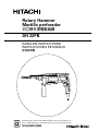 1
1
-
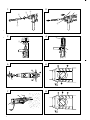 2
2
-
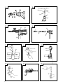 3
3
-
 4
4
-
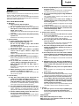 5
5
-
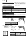 6
6
-
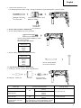 7
7
-
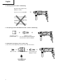 8
8
-
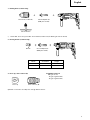 9
9
-
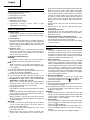 10
10
-
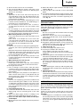 11
11
-
 12
12
-
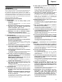 13
13
-
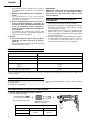 14
14
-
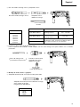 15
15
-
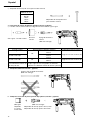 16
16
-
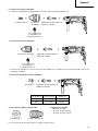 17
17
-
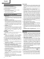 18
18
-
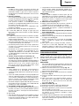 19
19
-
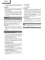 20
20
-
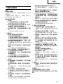 21
21
-
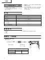 22
22
-
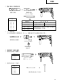 23
23
-
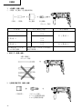 24
24
-
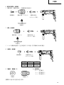 25
25
-
 26
26
-
 27
27
-
 28
28
-
 29
29
-
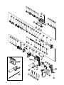 30
30
-
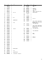 31
31
-
 32
32
-
 33
33
-
 34
34


Hitachi DH 22PB Handling Instructions Manual
- Categoría
- Martillos perforadores
- Tipo
- Handling Instructions Manual
en otros idiomas
- English: Hitachi DH 22PB
Artículos relacionados
-
Hitachi DH 24PG Handling Instructions Manual
-
Hitachi Koki DH24PB3 Manual de usuario
-
Hikoki DH24PC3 Manual de usuario
-
-
-
Hitachi Saw DH 24PB3 Manual de usuario
-
-
-
-
Hikoki DH 24 PF Manual de usuario