Hikoki DH24PC3 Manual de usuario
- Categoría
- Martillos perforadores
- Tipo
- Manual de usuario
Este manual también es adecuado para

Rotary Hammer
Martillo perforador
สว่านเจาะกระแทกโรตารี
DH 24PC3
HANDLING INSTRUCTIONS
INSTRUCCIONES DE MANEJO
คู่มือการใช้งาน
Read through carefully and understand these instructions before use.
Leer cuidadosamente y comprender estas instrucciones antes del uso.
โปรดอ่านโดยละเอียดและทำความเข้าใจก่อนใช้งาน

1
R
L
L
R
1
3
4
2
4
5
6
7
8
8
9
9
1
3
5
7
2
4
6
8

2
3
4
0
2
#
!
8
9
9
8
4
^
&
%
3
*
1
4
*
)
(
3
4
@
$
9
11
13
15
10
12
14
16

3
q
q
w
e
r
t
y
w
18
20
17
19
21

4
English Español
ไทย
1
Drill bit Broca
หัวสว่าน
2
Part of SDS-plus shank
Parte del SDS más
vástago
ส
่
วนของด้ามสว่าน
แบบ SDS-plus
3
Front cap Cubierta frontal
ครอบหน้า
4
Grip Sujetador
ตัวจับ
5
Dust cup Capa de polvo
ครอบกันฝุ่น
6
Dust collector (B) Colector de polvo (B)
ชุดเก็บฝุ่น (B)
7
Push button Tecla
ปุ่มกด
8
Change lever Palanquita selectora
คันเปลี
ยนจังหวะ
9
Push button Tecla
ปุ่มกด
0
Drill chuck Portabrocas
ล็อกสว่าน
!
Chuck adapter
Adaptador del portabrocas
ตัวปรับล็อก
@
Chuck adapter (D)
Adaptador (D) del
portabrocas
ตัวปรับล็อก (D)
#
Bit Broca
หัวสว่าน
$
Socket Cubo
แหวน
%
Side handle Mango lateral
มือจับข้าง
^
Depth gauge Calibre de profundidad
บรรทัดวัด
&
Mounting hole Agujero de montaje
รูยึด
*
Tape shank adapter
Adaptador de la espiga
ahusada
ตัวปรับเทเปอร์
(
Cotter Chaveta
ลิ
ม
)
Rest Apoyo
แท่น
q
Core bit Barrena tubular
จานเจียรเพชรคอนกรีต
w
Core bit shank
Espiga de la barrena
tubular
เพลาจานเจียรเพชรคอนกรีต
e
Thread Rosca
เกลียว
r
Center pin Pasador central
เดือย
t
Guide plate Placa guía
แผ่นราง
y
Core bit tip Punta de barrena tubular
ปลายจานเจียรเพชรคอนกรีต

5
English
GENERAL SAFETY RULES
WARNING!
Read all instructions
Failure to follow all instructions listed below may result
in electric shock, fi re and/or serious injury.
The term “power tool” in all of the warnings listed
below refers to your mains operated (corded) power
tool or battery operated (cordless) power tool.
SAVE THESE INSTRUCTIONS
1) Work area
a) Keep work area clean and well lit.
Cluttered and dark areas invite accidents.
b) Do not operate power tools in explosive
atmospheres, such as in the presence of
fl ammable liquids, gases or dust.
Power tools create sparks which may ignite the
dust of fumes.
c) Keep children and bystanders away while
operating a power tool.
Distractions can cause you to lose control.
2) Electrical safety
a) Power tool plugs must match the outlet.
Never modify the plug in any way.
Do not use any adapter plugs with earthed
(grounded) power tools.
Unmodifi ed plugs and matching outlets will
reduce risk of electric shock.
b) Avoid body contact with earthed or grounded
surfaces such as pipes, radiators, ranges and
refrigerators.
There is an increased risk of electric shock if your
body is earthed or grounded.
c) Do not expose power tools to rain or wet
conditions.
Water entering a power tool will increase the risk
of electric shock.
d) Do not abuse the cord. Never use the cord for
carrying, pulling or unplugging the power tool.
Keep cord away from heat, oil, sharp edges or
moving parts.
Damaged or entangled cords increase the risk of
electric shock.
e) When operating a power tool outdoors, use an
extension cord suitable for outdoor use.
Use of a cord suitable for outdoor use reduces
the risk of electric shock.
The use of a residual current device with a rated
residual current of 30mA or less at all times is
recommended.
3) Personal safety
a) Stay alert, watch what you are doing and use
common sense when operating a power tool.
Do not use a power tool while you are tired or
under the infl uence of drugs, alcohol or medication.
A moment of inattention while operating power
tools may result in serious personal injury.
b) Use safety equipment. Always wear eye protection.
Safety equipment such as dust mask, non-skid
safety shoes, hard hat, or hearing protection
used for appropriate conditions will reduce
personal injuries.
c) Avoid accidental starting. Ensure the switch is in
the off position before plugging in.
Carrying power tools with your fi nger on the
switch or plugging in power tools that have the
switch on invites accidents.
d) Remove any adjusting key or wrench before
turning the power tool on.
A wrench or a key left attached to a rotating part
of the power tool may result in personal injury.
e) Do not overreach. Keep proper footing and
balance at all times.
This enables better control of the power tool in
unexpected situations.
f) Dress properly. Do not wear loose clothing or
jewellery. Keep your hair, clothing and gloves
away from moving parts.
Loose clothes, jewellery or long hair can be
caught in moving parts.
g) If devices are provided for the connection of dust
extraction and collection facilities, ensure these
are connected and properly used.
Use of these devices can reduce dust related
hazards.
4) Power tool use and care
a) Do not force the power tool. Use the correct
power tool for your application.
The correct power tool will do the job better and
safer at the rate for which it was designed.
b) Do not use the power tool if the switch does not
turn it on and off.
Any power tool that cannot be controlled with the
switch is dangerous and must be repaired.
c) Disconnect the plug from the power source
before making any adjustments, changing
accessories, or storing power tools.
Such preventive safety measures reduce the risk
of starting the power tool accidentally.
d) Store idle power tools out of the reach of children
and do not allow persons unfamiliar with the
power tool or these instructions to operate the
power tool.
Power tools are dangerous in the hands of
untrained users.
e) Maintain power tools. Check for misalignment or
binding of moving parts, breakage of parts and
any other condition that may affect the power
tools operation.
If damaged, have the power tool repaired before
use.
Many accidents are caused by poorly maintained
power tools.
f) Keep cutting tools sharp and clean.
Properly maintained cutting tools with sharp
cutting edges are less likely to bind and are
easier to control.
g) Use the power tool, accessories and tool bits
etc., in accordance with these instructions and
in the manner intended for the particular type
of power tool, taking into account the working
conditions and the work to be performed.
Use of the power tool for operations different
from intended could result in a hazardous
situation.
5) Service
a)
Have your power tool serviced by a qualifi ed
repair person using only identical replacement
parts.
This will ensure that the safety of the power tool
is maintained.
PRECAUTION
Keep children and infi rm persons away.
When not in use, tools should be stored out of reach of
children and infi rm persons.

English
6
ROTARY HAMMER SAFETY WARNINGS
1. Wear ear protectors.
Exposure to noise can cause hearing loss.
2. Use auxiliary handles supplied with the tool.
Loss of control can cause personal injury.
3. Do not touch the bit during or immediately after
operation. The bit becomes very hot during operation
and could cause serious burns.
4. Before starting to break, chip or drill into a wall, fl oor
or ceiling, thoroughly confi rm that such items as
electric cables or conduits are not buried inside.
5. Always hold the body handle and side handle of
the power tool fi rmly. Otherwise the counterforce
produced may result in inaccurate and even
dangerous operation.
6. Wear a dust mask
Do not inhale the harmful dusts generated in drilling
or chiseling operation. The dust can endanger the
health of yourself and bystanders.
SPECIFICATIONS
Voltage (by areas)*
(110V, 115V, 120V, 127V, 220V, 230V, 240V)
Power Input 800 W*
No-load speed 0 – 1150/min.
Full-load impact rate 0 – 4600/min.
Capacity: concrete 3.4 – 24 mm
steel 13 mm
wood 32 mm
Weight (without cord and side handle)
2.4 kg
* Be sure to check the nameplate on product as it is subject to change by areas.
STANDARD ACCESSORIES
(1) Plastic case ..................................................................1
(2) Side handle..................................................................1
(3) Depth gauge ................................................................1
Standard accessories are subject to change without
notice.
OPTIONAL ACCESSORIES (sold separately)
1. Drilling anchor holes (rotation + hammering)
○ Drill bit (Slender shaft)
Adapter for slender shaft
(SDS-plus shank)
Drill bit (Slender shaft)
Drill bit (slender shaft)
Outer diameter Effective length Overall length
3.4 mm
45 mm 90 mm
3.5 mm
○ Drill bit (Taper shank) and taper shank adapter
Drill bit (Taper shank)
Taper shank adapter
(SDS-plus shank)
Cotter
Outer diameter
11.0 mm
12.3 mm
12.7 mm
14.3 mm
14.5 mm
17.5 mm
21.5 mm
Taper mode Applicable drill bit
Morse taper (No.1) Drill bit (taper shank) 11.0 ~ 17.5 mm
Morse taper (No.2) Drill bit (taper shank) 21.5 mm
A-taper Taper shank adapter formed A-taper or B-taper
is provided as an optional accessory, but the
drill bit for it is not provided.
B-taper

7
English
○ 13 mm rotary hammer chuck
For drilling operations when using a straight shank bit for impact drilling with a rotary hammer.
13 mm rotary hammer chuck
(SDS-plus shank)
Chuck wrench
(
Straight shank bit
for impact drill
)
2. Anchor setting (hammering only)
○ Anchor setting adapter (for rotary hammer)
Anchor setting adapter (SDS-plus shank)
(for rotary hammer)
Overall length: 160, 260 mm
Anchor size
W1/4”
W5/16”
W3/8”
○ Anchor setting adapter (for manual hammer)
Anchor setting adapter
(for manual Hammer)
Anchor size
W1/4”
W5/16”
W3/8”
W1/2”
W5/8”
3. Large hole boring (rotation + hammering)
○ Center pin, core bit, core bit shank and guide plate.
(Guide plate) Center pin Core bit
Core bit shank
(SDS-plus shank)
Center pin Core bit (outer diameter) Core bit shank
–
(A)
25 mm
29 mm
Core bit shank (A)
Center pin (A)
32 mm
35 mm
38 mm
Center pin (B) (B)
45 mm
50 mm
Core bit shank (B)
Do not use core bits with
outer diameter of 25 mm and
29 mm.
with guide plate
(The guide plate is not equipped with core bits
with outer diameter of 25 mm and 29 mm.)

English
8
4. Crushing operation (Hammering only)
Bull point (Round type) (SDS-plus shank)
Bull point (Square type) (SDS-plus shank)
5. Groove digging and edging (Hammering only)
Cold chisel (SDS-plus shank)
Cutter (SDS-plus shank)
6. Grooving (Hammering only)
Grooving chisel (SDS-plus shank)
7. Bolt placing operation with Chemical Anchor (rotation + hammering))
(SDS-plus shank)
12.7 mm Chemical Anchor Adapter
19 mm Chemical Anchor Adapter
(
Standard socket
on the market
)

9
English
8. Drilling holes and driving screws (rotation only)
○ Drill chuck, chuck adapter (G), special screw and chuck wrench
Chuck adapter (G)
(SDS-plus shank)
Chuck wrench
Drill chuck (13 VLRB-D)
Special screw
9. Drilling holes (rotation only)
Chuck adapter (D)
(SDS-plus shank)
Chuck wrench
Drill chuck (13 VLD-D)
○ 13 mm drill chuck ass’y (includes chuck wrench) and chuck (for drilling in steel or wood).
10. Driving Screws (rotation only)
Chuck adapter (D)
(SDS-plus shank)
Bit No.
Bit No. Screw Size Length
No. 2 3 – 5 mm 25 mm
No. 3 6 – 8 mm 25 mm
11. Dust cup, Dust collector (B)
Dust cup
Dust collector (B)
12. Hammer grease A
500 g (in a can)
70 g (in a green tube)
30 g (in a green tube)
Optional accessories are subject to change without
notice.

English
10
APPLICATIONS
Rotation and hammering function
○ Drilling anchor holes
○ Drilling holes in concrete
○ Drilling holes in tile
Rotation only function
○ Drilling in steel or wood
(with optional accessories)
○ Tightening machine screws, wood screws
(with optional accessories)
Hammering only function
○ Light-duty chiseling of concrete, groove digging and
edging.
PRIOR TO OPERATION
1. Power source
Ensure that the power source to be utilized conforms
to the power requirements specifi ed on the product
nameplate.
2. Power switch
Ensure that the power switch is in the OFF position. If
the plug is connected to a power receptacle while the
power switch is in the ON position, the power tool
will start operating immediately, which could cause
a serious accident.
3. Extension cord
When the work area is removed from the power
source, use an extension cord of suffi cient thickness
and rated capacity. The extension cord should be
kept as short as practicable.
4. Mounting the drill bit (Fig. 1)
CAUTION:
To prevent accidents, make sure to turn the switch
off and disconnect the plug from the receptacle.
NOTE:
When using tools such as bull points, drill bits, etc.,
make sure to use the genuine parts designated by
our company.
(1) Clean the shank portion of the drill bit.
(2) Insert the drill bit in a twisting manner into the tool
holder until it latches itself. (Fig. 1)
(3) Check the latching by pulling on the drill bit.
(4)
To re
m
ove the drill bit, fully pull the grip in the direction
of the arrow and pull out the drill bit.
(Fig. 2)
5. Installation of dust cup or dust collector (B)
(Optional accessories) (Fig. 3, Fig. 4)
When using a rotary hammer for upward drilling
operations attach a dust cup or dust collector (B) to
collect dust or particles for easy operation.
○ Installing the dust cup
Use the dust cup by attaching to the drill bit as shown
in Fig. 3.
When using a bit which has big diameter, enlarge the
center hole of the dust cup with this rotary hammer.
○ Installing dust collector (B)
When using dust collector (B), insert dust collector
(B) from the tip of the bit by aligning it to the groove
on the grip. (Fig. 4)
CAUTION:
○ The dust cup and dust collector (B) are for exclusive
use of concrete drilling work. Do not use them for
wood or metal drilling work.
○ Insert dust collector (B) completely into the chuck
part of the main unit.
○ When turning the rotary hammer on while dust
collector (B) is detached from a concrete surface,
dust collector (B) will rotate together with the drill
bit. Make sure to turn on the switch after pressing the
dust cup on the concrete surface. (When using dust
collector (B) attached to a drill bit that has more than
190 mm of overall length, dust collector (B) cannot
touch the concrete surface and will rotate. Therefore
please use dust collector (B) by attaching to drill bits
which have 166 mm, 160 mm, and 110 mm overall
length.)
○ Dump particles after every two or three holes when
drilling.
○ Please replace the drill bit after removing dust
collector (B).
6. Selecting the driver bit
Screw heads or bits will be damaged unless a bit
appropriate for the screw diameter is employed to
drive in the screws.
7. Confi rm the direction of bit rotation (Fig. 5)
The bit rotates clockwise (viewed from the rear
side) by pushing the R-side of the push button. The
L-side of the push button is pushed to turn the bit
counterclockwise.
HOW TO USE
CAUTION:
To prevent accidents, make sure to turn the switch
off and disconnect the plug from the receptacle when
the drill bits and other various parts are installed or
removed. The power switch should also be turned
off during a work break and after work.
1. Switch operation
The rotation speed of the drill bit can be controlled
steplessly by varying the amount that the trigger
switch is pulled. Speed is low when the trigger
switch is pulled slightly and increases as the switch
is pulled more. Continuous operation may be
attained by pulling the trigger switch and depressing
the stopper. To turn the switch OFF, pull the trigger
switch again to disengage the stopper, and release
the trigger switch to its original position.
However, the switch trigger can only be pulled in
halfway during reverse and rotates at half the speed
of forward operation.
The switch stopper is unusable during reverse.
2. Rotation + hammering
This rotary hammer can be set to rotation and
hammering mode by pressing the push button and
turning the change lever to the
mark (Fig. 6).
(1) Mount the drill bit.
(2) Pull the trigger switch after applying the drill bit tip
to the drilling position. (Fig. 7)
(3) Pushing the rotary hammer forcibly is not necessary
at all. Pushing slightly so that drill dust comes out
gradually is suffi cient.
CAUTION:
When the drill bit touches construction iron bar, the
bit will stop immediately and the rotary hammer will
react to revolve. Therefore grip the side handle and
handle tightly as shown in Fig. 7.
3. Rotation only
This rotary hammer can be set to rotation only mode
by pressing the push button and turning the change
lever to the
mark (Fig. 8).
To drill wood or metal material using the drill chuck
and chuck adapter (optional accessories), proceed as
follows.
Installing drill chuck and chuck adapter: (Fig. 9)

11
English
(1) Attach the drill chuck to the chuck adapter.
(2) The part of the SDS-plus shank is the same as the
drill bit. Therefore, refer to the item of “Mounting the
drill bit” for attaching it.
CAUTION:
○ Application of force more than necessary will not
only expedite the work, but will deteriorate the tip
edge of the drill bit and reduce the service life of the
rotary hammer in addition.
○ Drill bits may snap off while withdrawing the rotary
hammer from the drilled hole. For withdrawing, it is
important to use a pushing motion.
○ Do not attempt to drill anchor holes or holes in
concrete with the machine set in the rotation only
function.
○ Do not attempt to use the rotary hammer in the
rotation and striking function with the drill chuck
and chuck adapter attached. This would seriously
shorten the service life of every component of the
machine.
4. When driving machine screws (Fig. 10)
First, insert the bit into the socket in the end of chuck
adapter (D).
Next, mount chuck adapter (D) on the main unit
using procedures described in 4 (1), (2), (3), put the
tip of the bit in the slots in the head of the screw,
grasp the main unit and tighten the screw.
CAUTION:
○ Exercise care not to excessively prolong driving time,
otherwise, the screws may be damaged by excessive
force.
○ Apply the rotary hammer perpendicularly to the
screw head when driving the screw; otherwise, the
screw head or bit will be damaged, or driving force
will not be fully transferred to the screw.
○ Do not attempt to use the rotary hammer in the
rotation and hammering function with the drill chuck
and chuck adapter attached.
5. When driving wood screws (Fig. 10)
(1) Selecting a suitable driver bit
Employ cross-recessed screws, if possible, since the
driver bit easily slips off the heads of slotted-head
screws.
(2) Driving in wood screws
○ Prior to driving in wood screws, make pilot holes
suitable for them in the wooden board. Apply the
bit to the screw head grooves and gently drive the
screws into the holes.
○ After rotating the rotary hammer at low speed for a
while until the wood screw is partly driven into the
wood, squeeze the trigger more strongly to obtain
the optimum driving force.
CAUTION:
Exercise care in preparing a pilot hole suitable for
the wood screw taking the hardness of the wood into
consideration. Should the hole be excessively small
or shallow, requiring much power to drive the screw
into it, the thread of the wood screw may sometimes
be damaged.
6. Hammering only
This rotary hammer can be set to hammering only
mode by pressing the push button and turning the
change lever to the
mark (Fig. 11).
(1) Mount the bull point or cold chisel.
(2) Press the push button and set the change lever to
middle of
mark and mark (Fig. 12).
The rotation is released, turn the grip and adjust the
cold chisel to desired position (Fig. 13).
(3) Turn the change lever to
mark (Fig. 11).
Then bull point or cold chisel is locked.
7. Using depth gauge (Fig. 14)
(1) Loosen the knob on the side handle, and insert the
depth gauge into the mounting hole on the side
handle.
(2) Adjust the depth gauge position according to the
depth of the hole and tighten the knob securely.
8. How to use the drill bit (taper shank) and the taper
shank adapter
(1) Mount the taper shank adapter to the rotary hammer.
(Fig. 15)
(2) Mount the drill bit (taper shank) to the taper shank
adapter. (Fig. 15)
(3) Turn the switch ON, and drill a hole in prescribed
depth.
(4) To remove the drill bit (taper shank), insert the cotter
into the slot of the taper shank adapter and strike the
head of the cotter with a hammer supporting on a
rests. (Fig. 16)
HOW TO USE THE CORE BIT
(FOR LIGHT LOAD)
When boring penerating large holes use the core bit (for
light loads). At that time use with the center pin and the
core bit shank provided as optional accessories.
1. Mounting
CAUTION:
Be sure to turn power OFF and disconnect the plug
from the receptacle.
(1) Mount the core bit to the core bit shank. (Fig. 17)
Lubricate the thread of the core bit shank to facilitate
disassembly.
(2) Mount the core bit to the rotary hammer (Fig. 18)
(3) Insert the center pin into the guide plate until it
stops.
(4) Engage the guide plate with the core bit, and turn the
guide plate to the left or the right so that it does not
fall even if it faces downward. (Fig. 19)
2. How to bore (Fig. 20)
(1) Connect the plug to the power source.
(2) A spring is installed in the center pin.
Push it lightly to the wall or the fl oor straight.
Connect the core bit tip fl ush to the surface and start
operating.
(3) When boring about 5 mm in depth the position of the
hole will be established. Bore after that removing the
center pin and the guide plate from core bit.
(4) Application of excessive force will not only expedite
the work, but will deteriorate the tip edge of the drill
bit, resulting in reduced service life of the rotary
hammer.
CAUTION:
When removing the center pin and the guide plate,
turn OFF the switch and disconnect the plug from the
receptacle.
3. Dismounting (Fig. 21)
Remove the core bit shank from the rotary hammer
and strike the head of the core bit shank strongly two
or three times with a hammer holding the core bit,
then the thread becomes loose and the core bit can
be removed.
LUBRICATION
Low viscosity grease is applied to this rotary hammer so
that it can be used for a long period without replacing
the grease. Please contact the nearest service center for
grease replacement when any grease is leaking form
loosened screw.

English
12
Further use of the rotary hammer with lock off grease
will cause the machine to seize up reduce the service
life.
CAUTION:
A special grease is used with this machine, therefore,
the normal performance of the machine may be badly
affected by use of other grease. Please be sure to let
one of our service agents undertake replacement of
the grease.
MAINTENANCE AND INSPECTION
1. Inspecting the drill bits
Since use of a dull tool will cause motor
malfunctioning and degraded effi ciency, replace the
drill bit with new ones or resharpen them without
delay when abrasion is noted.
2. Inspecting the mounting screws
Regularly inspect all mounting screws and ensure
that they are properly tightened. Should any of the
screws be loose, retighten them immediately. Failure
to do so could result in serious hazard.
3. Maintenance of the motor
The motor unit winding is the very “heart” of the
power tool. Exercise due care to ensure the winding
does not become damaged and/or wet with oil or
water.
4. Inspecting the carbon brushes
For your continued safety and electrical shock
protection, carbon brush inspection and replacement
on this tool should ONLY be performed by a Hitachi
Authorized Service Center.
5. Replacing supply cord
If the supply cord of Tool is damaged, the Tool must
be returned to Hitachi Authorized Service Center for
the cord to be replaced.
6. Service parts list
CAUTION:
Repair, modifi cation and inspection of Hitachi Power
Tools must be carried out by a Hitachi Authorized
Service Center.
This Parts List will be helpful if presented with the
tool to the Hitachi Authorized Service Center when
requesting repair or other maintenance.
In the operation and maintenance of power tools, the
safety regulations and standards prescribed in each
country must be observed.
MODIFICATION:
Hitachi Power Tools are constantly being improved
and modifi ed to incorporate the latest technological
advancements.
Accordingly, some parts may be changed without
prior notice.
NOTE:
Due to HITACHI’s continuing program of research and
development, the specifi cations herein are subject to
change without prior notice.

13
Español
NORMAS GENERALES DE SEGURIDA
¡ADVERTENCIA!
Lea todas las instrucciones
Si no se siguen las instrucciones de abajo podría
producirse una descarga eléctrica, un incendio y/o
daños graves.
El término “herramienta eléctrica” en todas las
advertencias indicadas a continuación hace referencia
a la herramienta eléctrica que funciona con la red de
suministro (con cable) o a la herramienta eléctrica que
funciona con pilas (sin cable).
CONSERVE ESTAS INSTRUCCIONES
1) Área de trabajo
a) Mantenga la zona de trabajo limpia y bien
iluminada.
Las zonas desordenadas y oscuras pueden
provocar accidentes.
b) No utilice las herramientas eléctricas en entornos
explosivos como, por ejemplo, en presencia de
líquidos infl amables, gases o polvo.
Las herramientas eléctricas crean chispas que
pueden hacer que el polvo desprenda humo.
c) Mantenga a los niños y transeúntes alejados
cuando utilice una herramienta eléctrica.
Las distracciones pueden hacer que pierda el
control.
2) Seguridad eléctrica
a) Los enchufes de las herramientas eléctricas tienen
que ser adecuados a la toma de corriente.
No modifi que el enchufe.
No utilice enchufes adaptadores con herramientas
eléctricas conectadas a tierra.
Si no se modifi can los enchufes y se utilizan
tomas de corriente adecuadas se reducirá el
riesgo de descarga eléctrica.
b) Evite el contacto corporal con superfi cies
conectadas a tierra como tuberías, radiadores y
frigorífi cos.
Hay mayor riesgo de descarga eléctrica si su
cuerpo está en contacto con el suelo.
c) No exponga las herramientas eléctricas a la lluvia
o a la humedad.
La entrada de agua en una herramienta eléctrica
aumentará el riesgo de descarga eléctrica.
d) No utilice el cable incorrectamente. No utilice el
cable para transportar, tirar de la herramienta
eléctrica o desenchufarla.
Mantenga el cable alejado del calor, del aceite,
de bordes afi lados o piezas móviles.
Los cables dañados o enredados aumentan el
riesgo de descarga eléctrica.
e) Cuando utilice una herramienta eléctrica al aire
libre, utilice un cable prolongador adecuado para
utilizarse al aire libre.
La utilización de un cable adecuado para usarse al
aire libre reduce el riesgo de descarga eléctrica.
3) Seguridad personal
a) Esté atento, preste atención a lo que hace y utilice
el sentido común cuando utilice una herramienta
eléctrica.
No utilice una herramienta eléctrica cuando
esté cansado o esté bajo la infl uencia de drogas,
alcohol o medicación.
La distracción momentánea cuando utiliza
herramientas eléctricas puede dar lugar a
importantes daños personales.
b) Utilice equipo de seguridad. Utilice siempre una
protección ocular.
El equipo de seguridad como máscara para el
polvo, zapatos de seguridad antideslizantes,
casco o protección para oídos utilizado para
condiciones adecuadas reducirá los daños
personales.
c) Evite un inicio accidental. Asegúrese de que el
interruptor está en “off” antes de enchufarlo.
El transporte de herramientas eléctricas con
el dedo en el interruptor o el enchufe de
herramientas eléctricas con el interruptor
encendido puede provocar accidentes.
d) Retire las llaves de ajuste antes de encender la
herramienta eléctrica.
Si se deja una llave en una pieza giratoria de la
herramienta eléctrica podrían producirse daños
personales.
e) No se extralimite. Mantenga un equilibrio
adecuado en todo momento.
Esto permite un mayor control de la herramienta
eléctrica en situaciones inesperadas.
f) Vístase adecuadamente. No lleve prendas
sueltas o joyas. Mantenga el pelo, la ropa y los
guantes alejados de las piezas móviles.
La ropa suelta, las joyas y el pelo largo pueden
pillarse en las piezas móviles.
g) Si se proporcionan dispositivos para la conexión
de extracción de polvo e instalaciones de
recogida, asegúrese de que están conectados y
se utilizan adecuadamente.
La utilización de estos dispositivos puede reducir
los riesgos relacionados con el polvo.
4) Utilización y mantenimiento de las herramientas
eléctricas
a) No fuerce la herramienta eléctrica. Utilice
la herramienta eléctrica correcta para su
aplicación.
La herramienta eléctrica correcta trabajará mejor
y de forma más segura si se utiliza a la velocidad
para la que fue diseñada.
b) No utilice la herramienta elétrica si el interruptor
no la enciende y apaga.
Las herramientas elétricas que no pueden
controlarse con el interruptor son peligrosas y
deben repararse.
c) Desconecte el enchufe de la fuente eléctrica
antes de hacer ajustes, cambiar accesorios o
almacenar herramientas eléctricas.
Estas medidas de seguridad preventivas reducen
el riesgo de que la herramienta eléctrica se ponga
en marcha accidentalmente.
d) Guarde las herramientas eléctricas que no se
utilicen para que no las cojan los niños y no
permita que utilicen las herramientas eléctricas
personas no familiarizadas con las mismas o con
estas instrucciones.
Las herramientas eléctricas son peligrosas si son
utilizadas por usuarios sin formación.
e) Mantenimiento de las herramientas eléctricas.
Compruebe si las piezas móviles están mal
alineadas o unidas, si hay alguna pieza rota u otra
condición que pudiera afectar al funcionamiento
de las herramientas eléctricas.
Si la herramienta eléctrica está dañada, llévela a
reparar antes de utilizarla.
Se producen muchos accidentes por no realizar
un mantenimiento correcto de las herramientas
eléctricas.
f) Mantenga las herramientas de corte afi ladas y
limpias.

Español
14
Las herramientas de corte correctamente
mantenidas con los bordes de corte afi lados
son más fáciles de controlar.
g) Utilice la herramienta eléctrica, los accesorios
y las brocas de la herramienta, etc., de acuerdo
con estas instrucciones y de la manera adecuada
para el tipo de herramienta eléctrica, teniendo en
cuenta las condiciones laborales y el trabajo que
se va a realizar.
La utilización de la herramienta eléctrica para
operaciones diferentes a pretendidas podría dar
lugar a una situación peligrosa.
5) Revisión
a) Lleve su herramienta a que la revise un experto
cualifi cado que utilice sólo piezas de repuesto
idénticas.
Esto garantizará el mantenimiento de la seguridad
de la herramienta eléctrica.
PRECAUCIÓN
Mantenga a los niños y a las personas enfermas
alejadas.
Cuando no se utilicen, las herramientas deben
almacenarse fuera del alcance de los niños y de las
personas enfermas.
ADVERTENCIAS DE SEGURIDAD DEL
MARTILLO PERFORADOR
1. Utilice protectores de oídos.
La exposición al ruido puede causar daños
auditivos.
2. Utilice los mangos auxiliares proporcionados con la
herramienta.
La pérdida de control puede causar daños
personales.
3. No tocar la broca durante ni inmediatamente
después de trabajar, puesto que se pone ardiente y
puede causar quemaduras serias.
4. Antes de empezar a romper, picar o perforar en una
pared, suelo o techo, comprobar cuidadosamente
que no hayan objetos empotrados, tales como
cables o conductos eléctricos.
5. Sujetar siempre fi rmemente el asidero del cuerpo y
el asidero lateral de la herramienta. De lo contrario,
la contrafuerza producida podría causar un
funcionamiento impreciso e incluso peligroso.
6. Utilice máscara para el polvo
No inhale el polvo dañino generado al perforar. El
polvo puede poner en peligro su salud y la de los
viandantes.
ESPECIFICACIONES
Voltaje (por áreas)*
(110V, 115V, 120V, 127V, 220V, 230V, 240V)
Acometida 800 W*
Velocidad sin carga 0 – 1150/min.
Velocidad de percusión a carga plena 0 – 4600/min.
Capacidad: hormigón 3,4 – 24 mm
acero 13 mm
madera 32 mm
Peso (sin cable ni mango lateral) 2,4 kg
* Verifi car indefectiblemente los datos de la placa de características de la máquina, pues varían de acuerdo con el
país de destino.
ACCESORIOS ESTANDAR
(1) Caja de plástico ...........................................................1
(2) Mango lateral ..............................................................1
(3) Calibre de profundidad...............................................1
Los accesorios estándar están sujetos a cambio
sin previo aviso.
ACCESORIOS FACULTATIVOS (de venta por separado)
1. Taladrar orifi cios de anclaje (rotación + golpeteo)
○ Broca de taladro (Eje fi no)
Adaptador para eje fi no
(SDS plus vástago)
Broca de taladro
(Eje fi no)
Broca de taladro (Eje fi no)
Diámetro externo Longitud efectiva Longitud total
3,4 mm
45 mm 90 mm
3,5 mm

15
Español
○ Broca de taladro (vástago cónico) y adaptador cónico
Broca de taladro
(Vástago cónico)
Adaptador cónico
(SDS plus vástago)
Chaveta
Diámetro externo
11,0 mm
12,3 mm
12,7 mm
14,3 mm
14,5 mm
17,5 mm
21,5 mm
Modo cónico Broca de taladro aplicable
Cono Morse (No.1)
Broca de taradro
(vástago cónico)
11,0 ~ 17,5 mm
Cono Morse (No.2)
Broca de taradro
(vástago cónico)
21,5 mm
Cono A El cono A o B troquelado del adaptador cónico
as suministra como accesorio facultativo pero
la broca para el mismo no se suministra.
Cono B
○ Portabrocas del martillo perforador de 13 mm
Para la operación de taladrado cuando emplee una broca de vástago recto para taladrar con un martillo
perforador.
Portabrocas del martillo
perforador de 13 mm
(SDS plus vástago)
Llave de portabrocas
(
Broca de vástago recto
para martillo roto-percutor
)
2. Montaje de ancla (golpeteo solamente)
○ Adaptador de montaje de ancla (para martillo perforador)
Medida de ancla
W1/4”
W5/16”
W3/8”
Adaptador de montaje de ancla (SDS plus vástago)
(para martillo perforador)
Longitud total: 160, 260 mm
○ Adaptador de montaje de ancla (para martillo manual)
Adaptador de montaje de ancla
(para martillo manual)
Medida de ancla
W1/4”
W5/16”
W3/8”
W1/2”
W5/8”

Español
16
3. Pertoración de orifi cio de diámetro grande (rotación + golpeteo)
○ Pasador central, barrena tubular, espiga de la barrena tubular y placa guía.
(Placa guia) Pasador central Barrena
tubular
Espiga de la barrena
tubular
(SDS plus vástago)
Pasador central Barrent tubular (diámetro externo) Espiga de la barrena tubular
–
(A)
25 mm
29 mm
Espiga de la barrena tubular (A)
Pasador central (A)
32 mm
35 mm
38 mm
Pasador central (B) (B)
45 mm
50 mm
Espiga de la barrena tubular (B)
No usar barrenas tubulares
con un diámetro externo
de 25 mm y 29 mm.
Con placa guía
(La placa guía no se ha equipado con barrenas
tubulares con diámetro externo de 25 mm y 29 mm.)
4. Trabajo de roturación (golpeteo solamente)
Puntero (tipo redondo) (SDS plus vástago)
Puntero (tipo cuadrado) (SDS plus vástago)
5. Formación de ranuras y ajuste preciso del ancho (golpeteo solamente)
Cortafríos (SDS plus vástago)
Cortador (SDS plus vástago)
6. Ranurado (golpeteo solamente)
Cortafríos ranurador (SDS plus vástago)

17
Español
7. Trabajo de colocación de pernos para anclaje químico (rotación + golpeteo)
(SDS plus vástago)
Adaptador de anclaje químico de 12,7 mm
Adaptador de anclaje químico de 19 mm
(Manguito
adaptadora la
venta el mercado)
8. Perforación (rotación solamente)
○ Portabrocas, adaptador (G) del portabrocas, tornillo especál y llave de portabrocas
Adaptador (G) de portabrocas
(SDS plus vástago)
Llave de portabrocas
Porabrocas
(13 VLRB-D)
Tornillo especial
9. Perforación (rotación solamente)
Adaptador (D) del portabrocas
(SDS plus vástago)
Liave de portabrocas
Portabrocas (13 VLD-D)
○ Conjunto de portabrocas 13 mm (con llave de portabrocas) y portabrocas (para perforación de orifi cios en
hormigón o madera)
10. Colocación de tornillos (rotación solamente)
Adaptador (D) del portabrocas
(SDS plus vástago)
No. de broca
No. de broca Tamaño del tornillo Longitud
No. 2 3 – 5 mm 25 mm
No. 3 6 – 8 mm 25 mm

Español
18
11. Copa de polvo, Colector de polvo (B)
Copa de polvo
Colector de polvo (B)
12. Grasa A para martillo
500 g (en una lata)
70 g (en un tubo naranja)
30 g (en un tubo naranja)
Los accesorios de norma están sujetos a cambio sin
previo aviso.
APPLICACION
Rotación y función de golpeteo
○ Perforación de orifi cios de anclajes
○ Perforación de orifi cios de hormigón
○ Perforación de orifi cios de baldosa
Rotación solamente
○ Perforación de orifi cios en hormigón o madera
(con accesorios facultativos)
○ Apretar tornillos en metal o madera
(con accesorios facultativos)
Función de golpeteo solamente
○ Cincelado ligero de hormigón, formación de ranuras
y ajuste preciso del ancho.
ANTES DE LA PUESTA EN MARCHA
1. Alimentación
Asegurarse de que la alimentación de red que ha de
ser utilizada responda a las exigencias de corriente
especifi cadas en la placa de características del
producto.
2. Conmutador de alimentación
Asegurarse de que el conmutador de alimentación
esté en la posición OFF (desconectado). Si la clavija
está conectada en la caja del enchufe mientras el
conmutador de alimentación esté en posición ON
(conectado) las herramientas eléctricas empezarán
a trabajar inmediatamente, provocando un serio
accidente.
3. Cable de prolongación
Cuando está alejada el área de trabajo de la red
de alimentación, usar un cable de prolongación de
un grosor y potencia nominal sufi ciente. El cable
de prolongación debe ser mantenido lo más corto
posible.
4. Montaje de la broca (Fig. 1)
PRECAUCION:
Para evitar accidentes, cerciórese de desactivar y de
desconectar el enchufe del tomacorriente.
NOTA:
Cuando ulilice herramientas como por ejemplo:
cinceles, brocas de taladro, etc., cerciórese de utilizar
piezas genuinas diseñadas por nuestra compañía.
(1) Limpie la parte del vástago de la broca de taladro.
(2) Inserte la broca de taladro girando en el sujetador de
la herramienta hasta que se asegure bien. (Fig. 1)
(3) Verifi que si esta bien asegurado tirando de la broca
de taladro.
(4) Para extraer la broca, tire completamente de la
empuñadura en el sentido de la fl echa y tire hacia
afuera de la broca. (Fig. 2)
5. Cuando instale la copa de polvo o el lector de polvo
(B) (Accesorios facultativos)(Fig. 3, Fig. 4)
Cuando emplee un martillo perforador para trabajos
de taladrado hacia arriba, extraiga el adaptador de
recolección de polvo e instale una copa de polvo o
un colector de polvo (B) para recolectar las partículas
a fi n de facilitar la operación.
○ Instalación de la copa de polvo
Emplee la copa de polvo instalando la broca como se
muestra en la Fig. 3.
Cuando emplee una broca de gran diámetro,
agrande el orifi cio central de la copa de polvo con
este martillo perforador.
○ Instalación del colector de polvo (B)
Para emplear el colector de polvo (B), insértelo desde
la punta de la broca alineándolo con la ranura de la
empuñadura. (Fig. 4)
PRECAUCIÓN:
○ La copa de polvo y el colector de polvo (B) son
para emplearse exclusivamente en trabajos de
perforación de hormigón. No los emplee para
trabajar con madera o metal.
○ Inserte completamente el colector de polvo (B) en la
parte del portabrocas de la unidad principal.
○ Cuando ponga en funcionamiento del martillo
perforador mientras el colector de polvo (B) esté
separado de la superfi cie de hormigón, dicho colector
girará junto con la broca. Cerciórese de apretar el
gatillo interruptor después de haber presionado
la copa de polvo sobre la superfi cie de hormigón.
(Cuando emplee la copa de polvo con una broca de
no más de 190 mm de longitud total, el colector de
polvo (B) no podrá tocar la superfi cie de hormigón
girará. Por lo tanto, emplee el colector de polvo (B)
con brocas de 166, 160, y 110 mm de longitud total.)
○ Vacíe las partículas del colector de polvo (B) después
de haber taladrado dos o tres orifi cios.
○ Después de haber extraído el colector de polvo (B),
vuelva a colocar a broca.
6. Selección de la broca destornillador
Puede dañarse las cabezas de tornillos y las brocas de
atornillar menos que se emplee la broca apropiada
según sea el diámetro del tornillo.
7.
Confi rmar la dirección de rotación de la broca (Fig. 5)
La broca rota hacia la derecha (mirándola desde
atrás) al oprimir el lado R (der.) de la tecla. El lado L
(izq.) de la tecla se usa para hacer girar la broca a la
izquierda.
COMO SE USA
PRECAUCIÓN:
Para evitar accidentes, cerciórese de poner este
interruptor en OFF y de desconectar el enchufe del
tomacorriente cuando instale o extraiga brocas y
otras piezas. El interruptor de alimentación también
deberá ponerse en OFF durante un descanso en el
trabajo y después de haber fi nalizado dicho trabajo.
1. Operación del conmutador
La velocidad rotatoria de la broca de taladro puede
ser controlada variando la fuerza con la que se aprieta
el pulsador. La velocidad está baja cuando se aprieta
ligeramente el pulsador y se aumenta al apretar
más el pulsador. La operación contínua puede ser
alcanzada apretando el pulsador y apretando hacia
abajo el dispositivo de ajuste. Para ponel el pulsador
en OFF (desconectado) volver a apretar el pulsador
para desconectar el dispositivo de ajuste, y soltar el
pulsador a su posición normal.

19
Español
No obstante, el disparador de conmutador sólo
puede activarse a medio camino durante el reverso
y gira a la mitad de velocidad de la operación de
avance.
El tope del conmutador no puede utilizarse durante
el reverso.
2. Rotación + golpeteo
Este martillo perforador se puede ajustar en el modo
de rotación y en el modo de golpeteo pulsando la
tecla y girando la palanquita selectora a la marca
(Fig. 6).
(1) Montar la broca.
(2) Presionar el interruptor de gatillo después de poner
la punta de la broca en la posición para taladrar. (Fig.
7)
(3) No es necesario presionar con fuerza la broca.
Presionar ligeramente la broca de forma que
el polvo producido al taladrar salga al exterior
gradualmente.
PRECAUCIÓN:
Cuando la broca toque una barra de hierro de
construción se detendrá inmediatamente y el
martillo perforador tenderá a girar. Por lo tanto,
sujetar el mango lateral y sostenerlo fi rmemente
como se ilustra en la Fig. 7.
3. Rotación solamente
Este martillo selector sólo se puede ajustar en el
modo de rotación pulsando la tecla y girando la
palanquita selectora a la marca
(Fig. 8).
Para perforar madera o metal empleando el
portabrocas y el adaptador del portabrocas
(accesorio facultativo), proceder como sigue.
Instalación del portabrocas y adaptador del
portabrocas: (Fig. 9)
(1) Instale la broca en el adaptador del portabrocas.
(2) La parte del SDS plus vástago es igual que una broca.
Por lo tanto, para instalarla, consulte ”Montaje de la
broca”.
PRECAUCIÓN:
○ La aplicación de fuerza excesiva acelerará el trabajo
pero dañará la punta de la broca y reducirá la vida
útil del martillo perforador.
○ La broca puede salirse al quitar el martillo perforador
del orifi cio perforado. Para extraer esta herramienta
es importante empujar hacia delante.
○ No intentar perforar orifi cios de anclaje o perforar
el concreto con la máquina puesta en la función de
rotación solamente.
○ No intentar usar el martillo perforador en la función
de rotación y golpeteo con el portabrocas y el
adaptador del portabrocas instalados. Esto reducirá
considerablemente la vida útil de cada componente
de la máquina.
4. Cuando coloque tornillos para metal (Fig. 10)
En primer lugar, inserte la broca en el cubo del
extremo del adaptador (D) de portabroca.
A continuación, monte el adaptador (D) de portabroca
en la unidad principal empleando los procedimientos
descritos en 4 (1), (2), y (3), coloque la punta de la
broca en las ranuras de la cabeza del tornillo, sujete
la unidad principal, y apriete el tornillo.
PRECAUCIÓN:
○ Tener cuidado en no prolongar excesivamente
el accionamiento de la herramienta, ya que de lo
contrario, pueden dañarse los tornillos por el exceso
de fuerza.
○ Colocar el martillo perforador en forma perpendicular
sobre la cabeza del tornillo al atornillarlo, ya que en
caso contrario, puede dañarse la cabeza del tornillo
o la broca, e incluso, la fuerza de accionamiento
puede que no se transfi era por completo al tornillo.
○ No intentar usar el martillo perforador en la función
de rotación y golpeteo con el portabrocas y el
adaptador del portabrocas instalados.
5. Atornillando tornillos para madera (Fig. 10)
(1) Emplear tornillos de cabeza estrellada en lo posible,
debido a que los tornillos de cabeza ranurada hacen
que se zafe fácilmente el destornillador.
(2) Atornillado
○ Antes de atornillar los tornillos para madera, hay que
hacer orifi cios apropiados en la madera, aplicando
luego la broca destornillador en la cabeza del tornillo
y colocar asi éste en los orifi cios.
○ Luego de hacer rotar la herramienta lentamente
hasta que el tornillo quede parcialmente metido
en la madera, apretar más el gatillo para obtener la
fuerza óptima de atornillado.
PRECAUCIÓN:
Tener cuidado al preparar el orifi cio para que sea
apropiado para el tornillo, teniendo en cuenta la
dureza de la madera. Si el orifi cio es excesivamente
pequeño o estrecho, se requiere mucha fuerza para
atornillar y a veces puede dañarse la rosca.
6. Golpeteo solamente
Este martillo perforador se puede ajustar en el modo
de golpeteo solamente pulsando la tecla y girando la
palanquita selectora a la marca
(Fig. 11).
(1) Instale el puntero o el cortafríos.
(2) Pulse la tecla y ajuste la palanquita selectora en
medio de la marca
y la marca (Fig. 12).
El giro se libera, gire sujetador y ajuste el cortafríos
en la posición deseada. (Fig. 13).
(3) Gire la palanquita selectora a la marca
(Fig. 11).
Entonces se bloqueará el puntero o el cortafríos.
7. Modo de usar el tope (Fig. 14)
(1) Afl oje el perno de perilla del asa lateral, e inserte el
retenedor en el surco en U de dicha asa lateral.
(2) Ajustar la posición del retenedor de acuerdo a la
profundidad del agujero, y apretar fi rmemente el
perno de perilla.
8. Modo de usar la broca (espiga ahusada) y el
adaptador de la espiga ahusada
(1) Montar el adaptador de la espiga ahusada en el
martillo perforador (Fig. 15).
(2) Montar la broca (espiga ahusada) en el adaptador de
la espiga ahusada (Fig. 15)
(3) Poner el interruptor en la posición de encendido
(ON), y taladrar un agujero de la profundidad
especifi cada.
(4) Para quitar la broca (espiga ahusada), insertar la
chaveta en la ranura del adaptador de la espiga
ahusada y golpear la cabeza de la chaveta con un
martillo. Usar apoyos como se muestra en la Fig. 16.

Español
20
MODO DE USAR LA BARRENA TUBULAR
(PARA CARGAS LIGERAS)
Cuando se tengan que taladrar agujeros grandes, usar
la barrena tubular (para cargas ligeras). Usar también
el pasador central y la espiga de la barrena tubular
provistos como accesorios opcionales.
1. Montaje
PRECAUCIÓN:
Cerciorarse de poner el interruptor de la alimentación
en la posición de apagado (OFF) y de desconectar el
enchufe de la toma de alimentación.
(1) Montar la barrena tubular en su espiga. (Fig. 17)
Lubricar la rosca de la espiga de la barrena tubular
para facilitar el desmontaje.
(2) Montar la espiga de la barrena tubular en el martillo
perforador. (Fig. 18)
(3) Insertar el pasador central en la placa guía hasta que
se pare.
(4) Unir la placa guía con la barrena tubular y girar la
placa guía hacia la izquierda o hacia la derecha de
forma que no se caiga a pesar de estar indicando
hacia abajo. (Fig. 19)
2. Modo de taladrar (Fig. 20)
(1) Conectar el enchufe a la toma de alimentación.
(2) El pasador central se ha instalado un resorte.
Presionar ligeramente y sin torcerse hacia la pared o
hacia el pared o hacia el suelo.
Procurar que toda la punta de la barrena tubular
esté en contacto con la superfi cie a taladrar y luego,
empezar la operación.
(3) Al taladrar aproximadamente 5 mm en profundidad,
la posición del agujero queda ya establecida. Quitar
el pasador central y la placa guía de la barrena
tubular y seguir taladrando.
(4) La aplicación de una fuerza excesiva acelerará el
cumplimiento del trabajo, pero deteriorará la punta
de la broca reduciendo la duración del martillo
perforador.
PRECAUCIÓN:
Cuando se quite el pasador central y la placa guía,
poner el interruptor en la posición de apagado (OFF) y
desconectar el enchufe de la toma de alimentación.
3. Desmontaje (Fig. 21)
Como otro método, quitar la espiga de la barrena
tubular del martillo perforador y golpear fuertemente
la cabeza de la espiga de la barrena tubular dos o
tres veces con un martillo sujetanto la punta de la
barrena. La parte roscada se afl ojará y la barrena
tubular podrá quitarse.
LUBRICACION
A este martillo perforador deberá aplicársele grasa de
baja viscosidad,de esta forma, el martillo podrá usarse
durante un largo período de tiempo sin cambiar de
grasa. Ponerse por favor en contacto con el agente de
reparaciones más cercano para cambiar la grasa si ésta
se escapase a través de los tornillos fl ojos.
La falta de grasa hará que el martillo perforador se
agarrote disminuyendo por lo tanto su duración.
PRECAUCIÓN:
En esta herramienta deberá usarse la grasa
especifi cada. El uso de otras grasas podría afectar
negativamente al rendimiento. Cerciórese de
preguntar a sus agentes de servicio por la grasa de
repuesto.
MANTENIMENTO E INSPECCION
1. Inspeccionar la broca de taladro
Debido a que el uso de brocas desafi ladas pueden
causar mal funcionamiento del motor y desmejorar
la efi cacia del taladro, hay que reemplazar las brocas
en malas condiciones por nuevas o afi larlas de
inmediato al advertir abrasión.
2. Inspeccionar los tornillos de montaje
Regularmente inspeccionar todos los tornillos
de montaje y asegurarse de que estén apretados
fi rmemente. Si cualquier tornillo estuviera suelto,
volver a apretarlo inmediatamente. El no hacer esto
provocaría un riesgo serio.
3. Mantenimiento de motor
La unidad de bobinado del motor es el verdadero
“corazón” de las herramientas eléctricas. Prestar el
mayor cuidado y asegurarse de que el bobinado no
se dañe y/o se humedezca con aceite o agua.
4. Inspección de las escobillas
Por motivos de seguridad contra descargas
eléctricas, la inspección y el reemplazo de las
escobillas deberán realizarse solamente en un
Centro de Servicio Autorizado de Hitachi.
5. Reemplazo del cable de alimentación
Si el cable de alimentación de la herramienta está
dañado, envíe la herramienta al Centro de Servicio
Autorizado de Hitachi para que le cambien el cable
de alimentación.
6. Lista de repuestos
PRECAUCIÓN:
La reparación, modifi cación e inspección de las
herramientas eléctricas Hitachi deben ser realizadas
por un Centro de Servicio Autorizado de Hitachi.
Esta lista de repuestos será de utilidad si es
presentada junto con la herramienta al Centro de
Servicio Autorizado de Hitachi, para solicitar la
reparación o cualquier otro tipo de mantenimiento.
En el manejo y el mantenimiento de las herramientas
eléctricas, se deberán observar las normas y
reglamentos vigentes en cada país.
MODIFICACIONES:
Hitachi Power Tools introduce constantemente
mejoras y modifi caciones para incorporar los últimos
avances tecnológicos.
Por consiguiente, algunas partes pueden ser
modifi cadas sin previo aviso.
NOTA:
Debido al programa continuo de investigación y
desarrollo de HITACHI estas especifi caciones están
sujetas a cambio sin previo aviso.

21

22
○

23
○
○
○
○

24
○

25
○
○

26
○
○
○
○
○
○
○

27
○
○
○
○
○
○
○
○
○
○
○
○
○
○

28
○

29

ไทย
30
กฎความปลอดภัยโดยทั
วไป
คำเตือน!
โปรดอ่านคำแนะนำทั
งหมด
ถ้าไม่ปฏิบัติตามคำแนะนำทั
งหมด อาจถูกไฟฟ้ าดูด เกิดไฟไหม้ และ/
หรือบาดเจ็บสาหัสก็ได้
คำว่า "เครื
องมือไฟฟ้ า" ในคำเตือนต่อไปนี
ทั
งหมดหมายถึงเครื
องมือที
คุณใช้งานกับปลั
กไฟฟ้ า
(มีสายไฟ) หรือใช้งานกับแบตเตอรี
(ไร้สาย)
โปรดปฏิบัติตามคำแนะนำต่อไปนี
1) พื
นที
ทำงาน
a) รักษาพื
นที
ทำงานให้สะอาดและมีแสงสว่างเพียงพอ
ส
ิ
งที
เกะกะและความมืดทำให้เกิดอุบัติเหตุได้
b) อย่าใช
้
เครื
องมือไฟฟ้ าในบรรยากาศที
อาจระเบิด เช
่
น
มีของเหลวไวไฟ แก๊สหรือฝุ่น
เครื
องมือไฟฟ้ าอาจเกิดประกายไฟที
อาจทำให้ฝุ่นและไอติดไฟ
ได้
c) ใช
้
งานเครื
องมือไฟฟ้ าให้ไกลจากเด็กและคนเฝ้ าชม
คนที
วอกแวกทำให้คุณขาดสมาธิในการทำงานได้
2) ความปลอดภัยทางไฟฟ้ า
a) ปลั
กของเครื
องมือไฟฟ้ าต้องเหมาะกับเต้าเส
ี
ยบ
อย่าดัดแปลงปลั
ก
อย่าใช
้
ปลั
กของตัวปรับแรงดันไฟฟ้ ากับเครื
องมือไฟฟ้ าชนิดที
ต่อลงดิน
ปลั
กกับเต้าเส
ี
ยบที
ไม่พอดีกันอาจทำให้คุณถูกไฟฟ้ าดูด
b) อย่าให้ตัวคุณส
ั
มผัสกับพื
นผิวที
ต่อลงดิน เช
่
นท่อโลหะ
เครื
องทำความร้อน เตาอบ ตู้เย็น เป็นต้น
อาจถูกไฟฟ้ าดูดถ้าร
่างกายของคุณต่อวงจรลงดิน
c) อย่าให้เครื
องมือไฟฟ้ าถูกกับนำฝนหรือความเปียกช
ื
น
นำที
เข้าไปในเครื
องมือไฟฟ้ าจะเพิ
มความเส
ี
ยงที
จะถูกไฟฟ้ าดูด
d) อย่าใช
้
สายไฟฟ้ าในงานอื
น อย่าใช
้
สายเพื
อหิ
ว ดึงหรือ
เส
ี
ยบเครื
องม
ือไฟฟ้ า ให้สายไฟอยู่ห่างจากความร้อน นำมัน
ขอบแหลมคมหรือช
ิ
นส
่
วนที
เคลื
อนไหว
สายที
ชำรุดหรือตึงอาจทำให้คุณถูกไฟฟ้ าดูดได้ง่าย
e) เมื
อใช
้
งานเครื
องมือไฟฟ้ านอกอาคาร
ใช้สายพ่วงชนิดที
ใช้กับนอกอาคารเมื
อใช้สายที
เหมาะสมจะลด
ความเส
ี
ยงที
จะถูกไฟฟ้ าดูด
3) ความปลอดภัยส
่
วนบุคคล
a) ระวังตัว ดูส
ิ
งที
คุณกำลังทำ ใช
้
สามัญสำนึกเมื
อใช
้
เครื
องมือ
ไฟฟ้ า อย่าใช
้
เครื
องมือไฟฟ้ าเมื
อคุณอ่อนเพลียหรือกินยา
สุรา หรือยาเสพติด
การขาดสติชั
วขณะเมื
อใช้เครื
องมือไฟฟ้ าอาจทำให้คุณบาดเจ็บ
สาหัส
b) ใช
้
อุปกรณ์นิรภัย สวมแว่นตาป้ องกันเสมอ
อุปกรณ์ป้ องกันเช่นหน้ากากกันฝุ่น รองเท้ากันลื
น หมวกนิรภัย
หรือจุกอุดหูที
เหมาะสมจะเลี
ยงการบาดเจ็บของร่างกายได้
c) ระวังเครื
องทำงานโดยไม่ตั
งใจ ให้สวิทซ
์
อยู่ในตำแหน่งปิด
ก่อนเส
ี
ยบปลั
ก
เมื
อจับเครื
องมือไฟฟ้ าเมื
อนิ
วอยู่ที
ตัวสวิทซ์ หรือเมื
อเส
ี
ยบปลั
ก
ขณะเป
ิดสวิทซ์ ไว้อาจทำให้เกิดอุบัติเหตุ
d) เอาสลักปรับแต่งหรือประแจออกก่อนเปิดสวิทซ
์
ไฟฟ้ า
สลักหรือประแจที
ติดกับส
่
วนหมุนของเครื
องมือไฟฟ้ าอาจทำให้
คุณบาดเจ็บได้
e) อย่าเอื
อมตัว ยืนให้มั
นและสมดุลตลอดเวลา
ทำให้ควบคุมเครื
องมือไฟฟ้ าได้ดีขึ
นเมื
อมีเหตุที
ไม่คาด น
f) แต่งตัวให้รัดกุม อย่าสวมเส
ื
อผ้าหลวมหรือใช
้
เครื
องประดับ
ให้ผม เส
ื
อผ้
าและถุงมืออยู่ห่างจากช
ิ
นส
่
วนที
เคลื
อนที
เส
ื
อผ้าหลวม เรื
องประดับหรือผมยาวอาจถูกชิ
นส
่
วนหมุนรั
ง
เข้าไป
g)
ถ้าออกแบบเครื
องมือไฟฟ้ าไว้ ให้ต่อกับชุดดูดฝุ่นหรือเศษวัสด
ุ
ให้เช
ื
อมต่อและใช
้
งานอย่างถูกต้อง
เมื
อใช้กับชุดอุปกรณ์เหล่านี
จะลดอันตรายจากฝุ่น
4) การใช
้
และบำรุงรักษาเครื
องมือไฟฟ้ า
a) อย่าใช
้
เครื
องมือไฟฟ้ าโดยฝืนกำลัง ใช
้
เครื
องมือที
ถูกต้องกับ
งานของคุณ
เครื
องมือไฟฟ้ าที
ถูกต้องจะทำงานได้ดีกว่าและปลอดภัยกว่า
ในอัตราตามที
ออกแบบไว้แล้ว
b) อย่าใช
้
เครื
องมือไฟฟ้ าถ้าสวิทซ
์
ปิดเปิดไม่ได้
เครื
องมือไฟฟ้ าที
ควบคุมด้วยสวิทซ์ ไม่ได้จะมีอันตรายและต้อง
ซ่อมเส
ี
ย
c) ถอดปลั
กจากแหล่งไฟฟ้ าก่อนปรับแต่ง เปลี
ยนอะไหล่
หรือเก็บรักษา
มาตรการป้ องกันเช่นนี
จะลดความเส
ี
ยงของอุบัติเหตุที
เครื
องมือไฟฟ้ าจะเริ
มทำงานโดยไม่ได้ตั
งใจ
d) เก็บเครื
องมือไฟฟ้ าให้ห่างจากเด็ก และอย่ายอมให้ผู้
ที
ไม่
เคยช
ิ
นกับเครื
องมือไฟฟ้ าหรือคำแนะนำเหล่านี
ให้ ใช
้
เครื
องมือ
ไฟฟ้ า
เครื
องมือไฟฟ้ าเป็นส
ิ
งที
มีอันตรายมากเมื
ออยู่ในมือของคนที
ไม
่
ชำนาญ
e) บำรุงรักษาเครื
องมือไฟฟ้ า ตรวจดูศูนย์เคลื
อน ส
่
วนบิดงอ
ชำรุดหรือสภาพอื
นๆ ที
มีผลต่อการทำงานของเครื
องมือ
ไฟฟ้ า
หากชำรุด ให้ซ
่
อมแซมเส
ี
ยก่อนใช
้
งาน
อุบัติเหตุจำนวนมากเกิดจากเครื
องมือไฟฟ้ าที
บำรุงรักษา
ไม
่ดีพอ
f) ให้เครื
องมือตัดมีความคมและสะอาด
เครื
องมือตัดที
บำรุงรักษาอย่างถูกต้องและมีขอบคมจะไม่ค่อย
บิดงอ และควบคุมได้ง่ายกว่า
g) ใช
้
เครื
องมือไฟฟ้ า ส
่
วนประกอบและปลายเครื
องมือตัดตาม
คำแนะนำเหล่านี
และตามที
ออกแบบไว้ โดยพิจารณาสภาพ
งานและส
ิ
งที
จะใช
้
งาน
ถ้าใช้เครื
องมือไฟฟ้ ากับงานที
ไม่ได้ออกแบบไว้อาจเกิดความ
เส
ี
ยหายได้
5) การซ
่
อมบำรุง
a) ให้ช
่
างซ
่
อมที
ชำนาญเป็นผู้ซ
่
อม และเปลี
ยนอะไหล่ที
เป็น
ของแท้
ทำให้เครื
องมือไฟฟ้ ามีความปลอดภัย
คำเตือน
เก็บให้พ้นมือเด็กและผู้ ไม่ชำนาญ
หากไม่ได้ ใช
้
ควรเก็บให้พ้นมือเด็กและผู้ ไม่ชำนาญ

31
ไทย
คำเตือนความปลอดภัยของสว่านเจาะกระแทกโรตารี
1. สวมจุกปิดหู
เส
ี
ยงดังอาจทำให้มี ญหาต่อการได้ยิน
2. ใช
้
มือจับที
แนบมากับเครื
องมือ
ถ้าควบคุมไม่ได้ อาจทำให้บาดเจ็บ
3. อย่าแตะปลายดอกสว่านขณะหรือทันทีหลัง จากใช้งาน หัวสว่าน
ร้อนจัดขณะทำงานและอาจลวกผิวหน
้าได้
4. ก่อนเริ
มกระแทก เจาะหรือคว้านเข้าในผนัง พื
นหรือเพดาน
ตรวจดูให้แน่ใจว่าไม่มีสายไฟฟ้ าหรือท่อ งอยู่เส
ี
ยก่อน
5. จับมือจับและมือจับข้างของเครื
องมือไฟฟ้ าให้มั
นคงเสมอ มิฉะนั
น
แรงปฏิกิริยาอาจทำให้ขาดความแม่นยำและก่
อให้เกิดอันตรายได้
6. สวมหน้ากากกันฝุ่น
อย่าสูดดมฝุ่นที
เป็นอันตราย และเกิดเมื
อกำลังเจาะหรือสะกัด
ฝุ่นจะเป็นอันตรายต่อตัวคุณและคนที
อยู่ใกล้เคียง
รายละเอียดจำเพาะ
แรงดันไฟฟ้ า (ตามท้องที
ใช้งาน)* (110 โวลท์, 115 โวลท์, 120 โวลท์, 127 โวลท์, 220 โวลท์, 230 โวลท์, 240 โวลท์)
กำลังไฟฟ้ า 800 วัตต์
ความเร็วอิสระ 0 – 1150/นาที
ความเร็วกระแทกเมื
อทำงานเต็มที
0 – 4600/นาที
ขีดความสามารถ: คอนกรีต 3.4 – 24 มม.
เหล็กกล้า 13 มม.
ไม้ 32 มม.
นำหนัก ( ไม่รวมสายไฟฟ้ า) 2.4 กก.
* โปรดตรวจดูป้ายทีตัวเลือยไฟฟ้า เพราะแตกต่างไปตามท้องทีใช้งาน
อุปกรณ์มาตรฐาน
(1) กล่องพลาสติก .......................................................................... 1
(2) มือจับข้าง ................................................................................. 1
(3) บรรทัดวัด ................................................................................ 1
อาจเปลี
ยนแปลงอุปกรณ์มาตรฐานได้ โดยไม่ต้องแจ้งล่วงหน้า
อุปกรณ์ประกอบ (แยกจำหน่าย)
1. การเจาะรูพุก (หมุน + กระแทก)
○ หัวสว่าน (ก้านเรียว)
ตัวปรับก้านเรียว
(ด้ามสว่านแบบ SDS-plus)
หัวสว่าน (ก้านเรียว)
หัวสว่าน (ก้านเรียว)
เส้นผ่านศูนย์กลางภายนอก
ความยาวใช้งาน ความยาวรวม
3.4 มม.
45 มม. 90 มม.
3.5 มม.
○ หัวสว่าน (ก้านเทเปอร์) และตัวปรับเทเปอร์
หัวสว่าน (ก้านเทเปอร์)
ตัวปรับเทเปอร์
(ด้ามสว่านแบบ SDS-plus)
ลิ
ม

ไทย
32
เส
้
นผ่านศูนย์กลางภายนอก
11.0 มม.
12.3 มม.
12.7 มม.
14.3 มม.
14.5 มม.
17.5 มม.
21.5 มม.
แบบเทเปอร์ ดอกสว่านที
ใช้
เทเปอร์เล็กหมายเลข 1 หัวสว่าน (ก้านเทเปอร์) 11.0 ~ 17.5 มม.
เทเปอร์เล็กหมายเลข 2 หัวสว่าน (ก้านเทเปอร์) 21.5 มม.
เทเปอร์ A
ตัวปรับเทเปอร์แบบเทเปอร์ A หรือเทเปอร์ B เป็นอุปกรณ์
ให้เลือก แต่ไม่ได้แนบหัวสว่านมาด้วย
เทเปอร์ B
○ ล็อกหมุนกระแทก 13 มม.
ใช้เจาะเมื
อมีก้านสว่านตรงเพื
อเจาะกระแทกในแบบค้อนหมุน
ล็อกหมุนกระแทก 13 มม.
(ด้ามสว่านแบบ SDS-plus)
ประแจล็อก
(
ก้านสว่านตรงเพื
อเจาะ
แบบกระแทก
)
2. ตั
งค่าสกรูยึด (กระแทกอย่างเดียว)
○ ตัวปรับสกรูยึด (หมุนและกระแทก)
ตัวปรับสกรูยึด (ด้ามสว่านแบบ SDS-plus)
(หมุนและกระแทก)
ความยาวรวม: 160, 260 มม.
ขนาดสกรูยึด
W1/4”
W5/16”
W3/8”
○ ตัวปรับสกรูยึด (กระแทกแบบบังคับด้วยตัวเอง)
ตัวปรับสกรูยึด
(กระแทกแบบบังคับด้วยตัวเอง)
ขนาดสกรูยึด
W1/4”
W5/16”
W3/8”
W1/2”
W5/8”

33
ไทย
3. เจาะรูใหญ่ (หมุน + กระแทก)
○ เดือย, จานเจียรเพชรคอนกรีต, เพลาจานเจียรเพชรคอนกรีต และแผ่นราง
(แผ่นราง) เดือย จานเจียรเพชรคอนกรีต
เพลาจานเจียรเพชรคอนกรีต
(ด้ามสว่านแบบ SDS-plus)
เดือย จานเจียรเพชรคอนกรีต (เส
้
นผ่านศูนย์กลางภายนอก) เพลาจานเจียรเพชรคอนกรีต
–
(A)
25 มม.
29 มม.
เพลาจานเจียรเพชรคอนกรีต (A)
เดือย (A)
32 มม.
35 มม.
38 มม.
เดือย (B) (B)
45 มม.
50 มม.
เพลาจานเจียรเพชรคอนกรีต (B)
อย่าใช้จานเจียรเพชรคอนกรีตที
เส
้
นผ่านศูนย์กลางภายนอก 25 มม.
และ 29 มม.
กับแผ่นราง
(ไม่
มีแผ่นรางแนบมาให้ ใช้กับจานเจียรเพชรคอนกรีตที
มี
เส
้
นผ่านศูนย์กลางภายนอก 25 มม. และ 29 มม.)
4. งานสกัด (กระแทกอย่างเดียว)
จุดเป้ า (แบบกลม) (ด้ามสว่านแบบ SDS-plus)
จุดเป้ า (แบบเหลี
ยม)
(ด้ามสว่านแบบ SDS-plus)
5. ขุดและตัดมุมร่อง (กระแทกอย่างเดียว)
ส
ิ
วเย็น (ด้ามสว่านแบบ SDS-plus)
ใบมีด (ด้ามสว่านแบบ SDS-plus)

ไทย
34
6. เซาะร่อง (กระแทกอย่างเดียว)
ส
ิ
วเซาะร่อง (ด้ามสว่านแบบ SDS-plus)
7. เจาะรู งพุกเคมี (หมุน + กระแทก)
(ด้ามสว่านแบบ SDS-plus)
ตัวปรับพุกเคมีขนาด 12.7 มม.
ตัวปรับพุกเคมีขนาด 19 มม.
(
แหวนมาตรฐาน
ที
มีจำหน่าย
)
8. การเจาะรูและขันสกรู (หมุนอย่างเดียว)
○ ล็อกสว่าน, ตัวปรับล็อก (G), สกรูพิเศษและประแจล็อก
ตัวปรับล็อก (G)
(ด้ามสว่านแบบ SDS-plus)
ประแจล็อก
ล็อกสว่าน (13 VLRB-D)
สกรูพิเศษ
9. การเจาะรู (หมุนอย่างเดียว)
ตัวปรับล็อก (D)
(ด้ามสว่านแบบ SDS-plus)
ประแจล็อก
ล็อกสว่าน (13 VLD-D)
○ ชุดล็อกสว่านขนาด 13 มม. (รวมทั
งประแจล็อก) และล็อก (เพื
อเจาะไม้หรือเหล็ก)

35
ไทย
10. ขันสกรู (หมุนอย่างเดียว)
ตัวปรับล็อก (D)
(ด้ามสว่านแบบ SDS-plus)
เบอร์หัวสว่าน
เบอร์หัวสว่าน ขนาดสกรู ความยาว
หมายเลข 2 3 – 5 มม. 25 มม.
หมายเลข 3 6 – 8 มม. 25 มม.
11. ครอบกันฝุ่น, ชุดเก็บฝุ่น (B)
ครอบกันฝุ่น
ชุดเก็บฝุ่น (B)
12. จาระบีค้อนกระแทก A
500 กรัม (บรรจุถัง)
70 กรัม (บรรจุหลอดเขียว)
30 กรัม (บรรจุหลอดเขียว)
อาจเปลี
ยนแปลงอุปกรณ์ประกอบได้ โดยไม่ต้องแจ้งล่วงหน้า
การใช
้
งาน
การทำงานเจาะและกระแทก
○ เจาะรูสกรูยึด
○ เจาะรูในคอนกรีต
○ เจาะรูในกระเบื
อง
หมุนอย่างเดียว
○ เจาะรูในเหล็กหรือไม้
(ใช้อุปกรณ์ประกอบ)
○ ขันสกรูในเครื
องจักร ขันสกรูในไม้ (ใช้อุปกรณ์ประกอบ)
กระแทกอย่างเดียว
○ เป็นส
ิ
วงานเบาในคอนกรีต เซาะร่องและปาดขอบ
คำแนะนำก่อนการใช
้
งาน
1. แหล่งไฟฟ้ า
ตรวจดูให้แหล่งไฟฟ้ าที
จะใช้ตรงกับรายละเอียดจำเพาะบนแผ่นป้ าย
ของเลื
อยไฟฟ้ า
2. สวิทซ
์
ไฟฟ้ า
ตรวจดูให้สวิทซ์ ไฟฟ้ าอยู่ในตำแหน่ง OFF ถ้าเส
ี
ยบปลั
กเข้ากับ
เต้าเส
ี
ยบเมื
อสวิทซ์อยู่ในตำแหน่ง ON เครื
องใช้ ไฟฟ้ าจะทำงานทันที
และทำให้เกิดอุบัติเหตุที
ร้ายแรงได้
3. สายไฟฟ้ าพ่
วง
เมื
อพื
นที
ทำงานอยู่ห่างจากแหล่งจ่ายไฟ ให้ ใช้สายพ่วงที
โตและ
มีความจุไฟฟ้ ามากพอ ควรพยายามให้สายพ่วงส
ั
นที
สุดเท่าที
จะทำได
้
4. การติดตั
งหัวสว่าน (รูปที
1)
ข้อควรระวัง:
เพื
อป้ องกันอุบัติเหตุ โปรดปิดสวิทซ์และถอดปลั
กจากเต้าเส
ี
ยบเส
ี
ยก่อน
หมายเหตุ:
เมื
อใช้เครื
องมือเช่นจุดเป้ า หัวสว่าน โปรดใช้อะไหล่แท้ที
ผลิตจาก
บริษัทของเราเสมอ
(1) ทำความสะอาดก้านสว่าน
(2) บิดและสอดหัวสว่านเข้าในตัวจับจนลงเข้าที
(รูปที
1)
(3) ตรวจสภาพการยึดโดยดึงที
หัวสว่าน
(4)
ถ้าจะเอาหัวสว่านออก ให้ดึงตัวจับไปตามทิศทางลูกศร และดึงหัวสว่าน
ออกไป (
รูปที
2
)
5. การติดตั
งครอบกันฝุ่นหรือชุดเก็บฝุ่น (B) (อุปกรณ์ประกอบ)
(รูปที
3, รูปที
4)
เมื
อใช้สว่านเจาะกระแทกโรตารี
เพื
อเจาะแบบเงย
ให้ติดครอบกันฝุ่นหรือชุดเก็บฝุ่น (B) เพื
อดักฝุ่นหรือเศษวัสดุ
ทำให้ทำงานได้ง่ายขึ
น
○ การติดตั
งครอบกันฝุ่น
ใช้ครอบกันฝุ่นโดยติดกับหัวสว่านตามรูปที
3
เมือใช้สว่านทีมีเส้นผ่านศูนย์กลางใหญ่ ให้ขยายศูนย์รูของสว่านเจาะ
กระแทกโรตารีนี
○ การติดตั
งชุดเก็บฝุ่น (B)
เมื
อใช้ชุดเก็บฝุ่น (B) ให้สอดชุดเก็บฝุ่น (B) จากปลายดอกสว่าน
โดยเล็งให้ตรงกับร่องที
ตัวจับ (รูปที
4)
ข้อควรระวัง:
○ ใช้ครอบกันฝุ่นหรือชุดเก็บฝุ่น (B) กับงานเจาะคอนกรีตเท่านัน
อย่าใช้กับงานเจาะไม้หรือโลหะ

ไทย
36
○ สอดชุดเก็บฝุ่น (B) เข้าที
ตัวปรับล็อกของสว่านจนเต็มที
○ เมื
อหมุนสว่านเจาะกระแทกโรตารี
ขณะถอดชุดเก็บฝุ่น (B) จากผิว
คอนกรีต ชุดเก็บฝุ่น (B) จะหมุนไปพร้อมกับหัวสว่าน
โปรดแน่ใจว่า
เปิดสวิทซ์หลังจากกดครอบกันฝุ่นไปบนผิวคอนกรีตแล้ว (เมื
อใช้ชุด
เก็บฝุ่น (B) ที
ติดกับปลายสว่านที
ความยาวรวม มากกว่า 190 มม.
ชุดเก็บฝุ่น (B) จะไม่แตะกับผิวคอนกรีตแต่จะหมุน ดังนั
น โปรดใช้
ชุดเก็บฝุ่น (B) โดยติดเข้ากับหัวสว่านที
มีความยาวรวม 166 มม.,
160 มม. และ 110 มม.)
○ เทวัสดุออกหลังจากเจาะไปแล้วส
ั
ก 2 หรือ 3 รู
○ โปรดใส
่
หัวสว่านเข้าที
เดิมหลังจากถอดชุดเก็บฝุ่น (B) แล้ว
6. การเลือกไขควงสว่าน
หัวสกรูหรือไขควงสว่านจะชำรุด ถ้าไม่ใช้ ไขควงสว่านตามขนาดเส
้
น
ผ่านศูนย์กลางของสกรูที
จะขัน
7. ตรวจดูทิศทางที
หมุนไขควงสว่าน (รูปที
5)
ไขควงหมุนตามเข็มนาฬ
ิ
กา (เมื
อมองจากด้านท้าย) เมื
อกดด้าน R ของ
ปุ่มกด กดด้าน L ของปุ่มกดเพื
อให้ ไขควงสว่านหมุนทวนเข็มนาฬ
ิ
กา
วิธีการใช
้
ข้อควรระวัง:
เพื
อป้ องกันอุบัติเหตุ โปรดแน่ใจที
จะปิดสวิทซ์และถอดปลั
กออก
จาก
เต้าเส
ี
ยบ เมื
อใส
่
หรือถอดไขควงสว่านหรือชิ
นส
่
วนต่างๆ ยังควร
ปิดสวิทซ์แหล่งไฟในเวลาพักกลางวันและหลังจากเลิกงานอีกด้วย
1. การใช
้
สวิทซ
์
อาจควบคุมความเร็วหมุนของไขควงสว่านได้อย่างต่อเนื
อง โดยเปลี
ยน
ระยะที
ดึงสวิทซ์ ไก ความเร็วตำเมื
อดึงสวิทซ์ ไกออกมาเล็กน้อย
และความเร็วเพิ
มขึ
นเมื
อดึงสวิทซ์ออกมามากขึ
น อาจทำงานต่อเนื
อง
ได้ โดยดึงสวิทซ์ ไกและกดสต็อปเปอร์ ถ้าผลักสวิทซ์ ไปที
OFF
ให้ดึงสวิทซ์ ไกอีกครั
งเพื
อปลดสต็อปเปอร์ และปล่อยสวิทซ์ ไก
ไปยังตำแหน่งเดิม
อย่างไรก็ตาม อาจดึงสวิทซ์ ไกได้ครึ
งทางเมื
อกลับทิศและหมุนด้วย
ครึ
งหนึ
งของความเร็วที
เดินหน้า
ใช้สต็อปเปอร์ ไม่ได้ขณะกำลังกลับทิศ
2. การหมุน + การกระแทก
อาจตั
งสว่านเจาะกระแทกโรตารี
ให้หมุนและกระแทกโดยกดปุ่ม
เพรสซิ
งและผลักคันเปลี
ยนจังหวะไปที
ตำแหน่ง
(รูปที
6)
(1) ติดตั
งหัวสว่าน
(2) ดึงสวิทซ์ ไกหลังจากผลักหัวสว่านไปยังตำแหน่งที
เจาะ (รูปที
7)
(3) ไม่ต้องกดสว่านเจาะกระแทกโรตารี
โดยใช้แรงมากแต่อย่างใด
กดเพียงเล็กน้อยเพื
อให้ฝุ่นวัสดุค่อยๆ ออกมาก็พอ
ข้อควรระวัง:
เมื
อหัวสว่านแตะกั
บเหล็กเสริมในคอนกรีต หัวสว่านจะหยุดทันที
และสว่านเจาะกระแทกโรตารี
จะตอบโต้ โดยหมุนตัว
ดังนั
นให้จับที
มือจับและมือจับข้างให้แน่นตามรูปที
7
3. หมุนอย่างเดียว
อาจตั
งสว่านเจาะกระแทกโรตารี
ให้หมุนอย่างเดียวได้ โดย
กดปุ่ม
เพรสซิ
งและผลักคันเปลี
ยนจังหวะไปที
ตำแหน่ง
(รูปที
8)
ถ้าจะเจาะไม้หรือวัสดุโลหะด้วยล็อกสว่านและตัวปรับล็อก
(อุปกรณ์ประกอบ) ให้ดำเนินการดังนี
ติดตั
งล็อกสว่านและตัวปรับล็อก: (รูปที
9)
(1) ติดล็อกสว่านเข้ากับตัวปรับล็อก
(2) ด้ามสว่านเป็นแบบเดียวกับหัวสว่าน
ดังนั
นให้อ่านย่อหน้า
“การติดตั
งหัวสว่าน” แล้วติดตั
ง
ข้อควรระวัง:
○ ถ้าออกแรงมากเกินไป นอกจากชิ
นงานจะเส
ื
อมแล้ว ปลายสว่าน
จะเส
ื
อม และลดอายุใช้งานของสว่านเจาะกระแทกโรตารี
อีกด้วย
○ ปลายสว่านอาจปลิ
นออกเมื
อดึงสว่านเจาะกระแทกโรตารี
ออกจาก
รูที
เจาะไว้ ถ้าจะดึงออก อย่าลืมให้ ใช้จังหวะกด
○ อย่าพยายามเจาะรูสกรู งหรือรูในคอนกรีต เมื
อสว่านอยู่ในจังหวะ
ที
ไม่หมุนและกระแทก
○ อย่าพยายามใช้สว่านเจาะกระแทกโรตารี
เมื
อติดตั
งล็อกสว่าน และ
ตัวปรับล็อกไว้ เพราะจะลดอายุใช้งานของส
่
วนต่างๆ ของสว่าน
ลงเป็นอย่างมาก
4. การขันสกรู (รูปที
10)
ในตอนแรก ให้สอดหัวสว่านเข้าในแหวนที
ปลายของตัวปรับล็อก (D)
ต่อมา ติดตั
งตัวปรับล็อก (D) เข้าที
ตัวสว่าน โดยใช้ลำดับตามข้อ 4 (1),
(2), (3) สอดปลายของดอกสว่านเข้าในร่องที
หัวของสกรู จับตัวสว่าน
และขันสกรู
ข้อควรระวัง:
○ ระวังอย่าขันเป็นเวลานานเกินไป
เพราะแรงส
่
วนเกินจะทำให้เกลียวชำรุดได้
○ วางสว่านเจาะกระแทกโรตารี
ให้ตั
งฉากกับหัวสกรูขณะขันสกรู
มิฉะนั
นหัวสกรูหรือดอกสว่านอาจชำรุด
หรือแรงบิดเข้าไปยังสกรูได้ ไม่พอ
○
อย่าพยายามใช้สว่านเจาะกระแทกโรตารี
ในแบบที
หมุนและกระแทก
เมื
อติดล็อกสว่านและตัวปรับล็อกอยู่
5. การขันตะปูเกลียวไม้ (รูปที
10)
(1) การเลือกไขควงสว่านที
เหมาะสม
ใช้ตะปูเกลียวหัวแฉกแบบ งถ้ามี เพราะปลายดอกสว่านอาจเลื
อนออก
จากปลายตะปูเกลียวที
มีร่องบากได้ง่าย
(2) การขันตะปูเกลียวไม้
○ ก่อนขันตะปูเกลียวไม้ ให้เจาะรูนำที
เหมาะสมบนแผ่นไม้เส
ี
ยก่อน
ติดไขควงสว่านกับร่องที
หัวตะปูเกลียว
และหมุนตะปูเกลียวเข้าในรูอย่างช้าๆ
○
หลังจากหมุนสว่านเจาะกระแทกโรตารี
ที
ความเร็วตำชั
วขณะจนตะปู
เกลียวเข้าไปในเนื
อไม้บางส
่
วนแล้ว
กดสวิทซ์ ไกให้แรงเพื
อ ให้ ได้แรงขันที
เหมาะสม
ข้อควรระวัง:
ใช้ความระมัดระวังในการเจาะรูนำที
เหมาะสมกับตะปูเกลียวไม้
โดยคำนึงถึงความแข็งของเนื
อไม้ ถ้ารูตื
นหรือเล็กเกินไป จะต้อง
ใช้แรงขันตะปู
เกลียวมากขึ
น จนเกลียวของตะปูอาจชำรุดก็ได้
6. กระแทกอย่างเดียว
อาจตั
งสว่านเจาะกระแทกโรตารี
ให้กระแทกอย่างเดียวได้ โดย
กดปุ่ม
เพรสซิ
งและผลักคันเปลี
ยนจังหวะไปที
ตำแหน่ง (รูปที
11)
(1) ติดจุดเป้ าหรือส
ิ
วเย็น
(2) ตั
งค่าคันเปลี
ยนจังหวะไประหว่างกลางเครื
องหมาย
กับ
เครื
องหมาย
(รูปที
12)
หยุดหมุน หมุนตัวจับและปรับส
ิ
วเย็นไปยังตำแหน่งที
ต้องการ
(รูปที
13)

37
ไทย
(3) หมุนคันเปลี
ยนจังหวะไปที
เครื
องหมาย (รูปที
11)
ในตอนนี
จุดเป้ าหรือส
ิ
วเย็นจะถูกล็อก
7. การใช
้
บรรทัดวัด (รูปที
14)
(1) คลายปุ่มที
มือจับข้าง และสอดบรรทัดวัดเข้าในรูยึดของมือจับข้าง
(2) ปรับแต่งตำแหน่งบรรทัดวัดตามความลึกของรู และขันปุ่มให้
แน่น
8. การใช
้
หัวสว่าน (ก้านปรับเทเปอร์) กับตัวปรับเทเปอร์
(1) ติดตัวปรับเทเปอร์เข้ากับสว่านเจาะกระแทกโรตารี
(รูปที
15)
(2) ติดหัวสว่าน (ก้านปรับเทเปอร์) เข้ากับตัวปรับเทเปอร์ (รูปที
15)
(3) ผลักสวิทซ์ ไปที
ON และเจาะร
ูตามความลึกที
กำหนด
(4) ถอดหัวสว่าน (ก้านปรับเทเปอร์) โดยสอดลิ
มเข้าในร่องของตัว
ปรับเทเปอร์ และใช้ค้อนเคาะหัวลิ
มขณะรองไว้บนแท่น (รูปที
16)
วิธีใช
้
จานเจียรเพชรคอนกรีต
(สำหรับงานเบา)
เมื
อเจาะรูทะลุขนาดใหญ่โดยใช้จานเจียรเพชรคอนกรีต (สำหรับงานเบา)
ในตอนนี
ให้ ใช้กับเดือย และเพลาจานเจียรเพชรคอนกรีต ที
มีเป็น
อุปกรณ์ ให้เลือกใช้
1. การติดตั
ง
ข้อควรระวัง:
โปรดแน่ใจว่า ปิดไฟฟ้ า OFF และถอดปลั
กออกจากเต้าเส
ี
ยบแล้ว
(1) ติดตั
งจานเจียรเพชรคอนกรีตเข้ากับเพลาจานเจียรเพชรคอนกรีต
(รูปที
17)
หล่อลื
นเกลียวของเพลาจานเจียรเพชรคอนกรีตเพื
อช่วยให้ถอด
ชิ
น
ส
่
วนได้ง่าย
(2) ติดตั
งจานเจียรเพชรคอนกรีตเข้ากับค้อนหมุนกระแทก (รูปที
18)
(3)
สอดเดือยของจานเจียรเพชรคอนกรีตเข้ากับแผ่นราง จนหยุดเข้าที
(4) ติดแผ่นรางเข้ากับจานเจียรเพชรคอนกรีต และหมุนแผ่นรางไป
ทางซ้ายหรือทางขวาจนไม่ตกลง เมื
อหันหน้าลง (รูปที
19)
2. วิธีเจาะ (รูปที
20)
(1) เส
ี
ยบปลั
กเข้ากับแหล่งจ่ายไฟฟ้ า
(2) มีสปริงอยู่ในเดือย
แตะเบาๆ กับพื
นหรือผนังที
จะเจาะ
แตะปลายจานเจียรเพชรคอนกรีตเข้ากับผิวชิ
นงาน และเริ
มเจาะ
(3) เมื
อเจาะได้ลึกประมาณ 5 มม. ตำแหน่งรูจะไม่ส
่
ายไปมา เอาเดือย
และ
แผ่นรางออกจากจานเจียรเพชรคอนกรีตเส
ี
ยก่อนหน้านั
น
(4) เมื
อออกแรงกดมาก นอกจากจะทำให้ประส
ิ
ทธิภาพงานแย่ลงแล้ว
ขอบปลายหัวสว่านจะส
ึ
กหรอ ทำให้ค้อนเจาะกระแทกมีอายุใช้งาน
ส
ั
นลง
ข้อควรระวัง:
เมื
อเอาเดือยและแผ่นรางออก ปิดสวิทซ์ OFF และถอดปลั
ก
ออกจากเต้าเส
ี
ยบ
3. การถอด (รูปที
21)
เอาเพลาจานเจียรเพชรคอนกรีตออกจากหัวค้อนหมุนกระแทก และ
ใช้ค้อนเคาะหัวของเพลาจานเจียรเพชรคอนกรีตอย่างแรง 2-3 ครั
ง
ขณะใช้มือจับจานเจียรเพชรคอนกรีต เกลียวจะหลวมและเอา
จานเจียรเพชรคอนกรีตออกมาได้
การหล่อลื
น
ทาจาระบีที
มีความหนืดตำเข้ากับสว่านเจาะกระแทกโรตารี
เพื
อใช้งานนานๆ
โดยไม่ต้องเปลี
ยนจาระบี โปรดติดต่อศูนย์บริการที
อยู่ใกล้ที
สุดเพื
อเปลี
ยน
จาระบี เมื
อจาระบีรั
วออกจากเกลียวที
หลวมคลอน
ถ้าใช้สว่านเจาะกระแทกโรตารี
ต่อไปเมื
อขาดจาระบี จะทำให้ตัวสว่าน
ฝืดและอายุใช้งานจะส
ั
นลง
ข้อควรระวัง:
ให้ ใช้จาระบีพิเศษกับเครื
องมือนี
ดังนั
นถ้าใช้จาระบีอื
นๆ แล้ว
สมรรถนะของสว่านอาจได้
รับผลกระทบจนแย่เป็ นอย่างยิ
ง
โปรดให้ศูนย์บริการเปลี
ยนจาระบีให้เสมอ
การบำรุงรักษาและการตรวจสอบ
1. การตรวจสอบหัวสว่าน
เนื
องจากการใช้เครื
องมือที
ทื
อจะทำให้มอเตอร์ทำงานผิดปกติและ
ลดประส
ิ
ทธิภาพลง ให้ลับหรือเปลี
ยนหัวสว่านเส
ี
ยใหม่ เมื
อพบว่า
เริ
มเยิ
น
2. การตรวจสอบสกรูยึด
ให้ตรวจสอบสกรูยึดเสมอ และให้ขันไว้อย่างถูกต้อง ถ้าสกรูหลวม
ให้ขันเส
ี
ยใหม่โดยทันที มิฉะนั
นอาจเกิดอันตรายมาก
3. การบำรุงรักษามอเตอร์
การขดลวดของมอเตอร์เป็นหัวใจสำคัญของเครื
องมือไฟฟ้ า ให้ ใช้
ความระมัดระวังเพื
อไม่ให้ขดลวดของมอเตอร
์ชำรุดและ/หรือ
เปียกนำหรือนำมัน
4. การตรวจสอบแปรงถ่าน
เพื
อความปลอดภัยและการป้ องกันไฟฟ้ าดูอย่างต่อเนื
อง ควรให้
ศูนย์บริการที
ได้รับอนุญาตของฮิตาชิเท่านั
น เป็นผู้ตรวจสอบและ
เปลี
ยนแปรงถ่าน
5. การเปลี
ยนสายไฟฟ้ า
ถ้าสายไฟฟ้ าของสว่
านชำรุด
ต้องส
่
งกลับไปยังศูนย์ซ่อมของฮิตาชิ เพื
อเปลี
ยนเส
ี
ยใหม่
6. รายการอะไหล่ซ
่
อม
ข้อควรระวัง:
ศูนย์บริการที
ได้รับอนุญาตของฮิตาชิเท่านั
นเป็นผู้ซ่อม ดัดแปลง
และตรวจสอบเครื
องมือไฟฟ้ าของฮิตาชิ
รายการอะไหล่ซ่อมนี
จะเป็นประโยชน์เมื
อส
่
งให้ศูนย์บริการที
ได้รับ
อนุญาตของฮิตาชิเท่านั
นเพื
อแจ้งซ่อมหรือบำรุงรักษา
ต้องปฏิบัติตามระเบียบและมาตรฐานความปลอดภัยของแต่ละ
ประเทศในการใช้งานและบำรุงรักษาเครื
องมือไฟฟ้ า
การแก้ไข:
มีการปรับปรุงและแก้ ไขเครื
องมือไฟฟ้ าของฮิตาชิเสมอ เพื
อให้
สอดคล้องกับความก้าวหน้าล่าสุดทางเทคโนโลยี
ดังนั
น จึงอาจเปลี
ยนแปลงชิ
นส
่
วนบางอย่างได้ โดยไม่ต้องแจ้ง
ล่วงหน้า
หมายเหตุ
เนื
องจากฮิตาชิมีแผนงานวิจัยและพัฒนาอย่างต่อเนื
อง รายละเอียด
จำเพาะนี
จึงอาจเปลี
ยนแปลงได้ โดยไม่ต้องแจ้งล่วงหน้า

38

39

40
Item
No.
Part Name
1 FRONT CAP
2 STOPPER RING
3 GRIP
4 BALL HOLDER
5 HOLDER PLATE
6 HOLDER SPRING
7 WASHER (B)
8 RETAINING RING FOR D20 SHAFT
9 TAPPING SCREW (W/FLANGE) D5×35
10 GEAR COVER
11 NAME PLATE
12 OIL SEAL
13 SLEEVE
14 FELT PACKING (B)
15 BALL BEARING 6904DDPS2L
16 SLEEVE (A)
17 RETAINING RING 37MM
18 PUSHING BUTTON
19 PUSHING SPRING
20 O-RING (S-18)
21 CHANGE LEVER
22 SPRING (B)
23 STEEL BALL D7.0
24 CYLINDER
25 SECOND GEAR
26 SPRING (A)
27 WASHER (A)
28 RETAINING RING FOR D30 SHAFT
29 SECOND HAMMER
30 O-RING (1AP-20)
31 HAMMER HOLDER
32 O-RING (B)
33 DAMPER (A)
34 O-RING (C)
35 DAMPER HOLDER
36 STOPPER RING
37 STRIKER
38 O-RING
39 PISTON
40 O-RING
41 INNER COVER
42 PISTON PIN
43 WASHER (C)
44 FELT PACKING (A)
45 VALVE
46 FELT PACKING (B)
47 PINION SLEEVE
48 LOCK PLATE
Item
No.
Part Name
49 SECOND PINION
50 CLUTCH SPRING
51 CLUTCH
52 SECOND SHAFT
53 RECIPROCATING BEARING
54 FIRST GEAR
55 SPACER
56 BALL BEARING 626VVC2PS2
57 FELT PACKING
58 O-RING (P-22)
59 PACKING WASHER
60 BALL BEARING 608DDC2PS2L
61 WASHER (A)
62 ARMATURE
63 FAN GUIDE
64 HEX.HD.TAPPING SCREW D4×50
65 STATOR
66 BALL BEARING 608VVC2PS2L
67 HITACHI LABEL
68 HOUSING
69 CHOKE COIL (A)
70 SWITCH
71 PUSHING BUTTON
72 CHOKE COIL (B)
73 INTERNAL WIRE (A)
74 CARBON BRUSH
75 BRUSH HOLDER
76 INTERNAL WIRE (A)
77 CARBON BRUSH
78 NOISE SUPPRESSOR
79 CORD ARMOR
80 CORD CLIP
81 TAPPING SCREW (W/FLANGE) D4×16
82 HANDLE COVER
83 TAPPING SCREW (W/FLANGE) D4×20
84 CORD
501 CASE
502 SIDE HANDLE
503 DEPTH GAUGE

41

42

006
Code No. C99139934 F
Printed in China
Hitachi Koki Co., Ltd.
Transcripción de documentos
Rotary Hammer Martillo perforador 手提電動鎚鑽 สว่านเจาะกระแทกโรตารี DH 24PC3 HANDLING INSTRUCTIONS INSTRUCCIONES DE MANEJO 使用說明書 คู่มือการใช้งาน Read through carefully and understand these instructions before use. Leer cuidadosamente y comprender estas instrucciones antes del uso. 使用前務請詳加閱讀 โปรดอ่านโดยละเอียดและทำความเข้าใจก่อนใช้งาน 00̲DH24PC3̲C99139933̲904.indb A 2009/02/27 9:20:43 1 2 2 3 4 4 1 3 4 6 5 5 6 8 L 7 R L R 7 9 8 9 8 1 00̲DH24PC3̲C99139933̲904.indb 1 2009/02/27 9:20:43 9 4 3 10 # $ @ 3 0 ! 4 2 11 8 12 8 9 9 13 14 & ^ 4 % 15 16 4 1 * ( * 3 ) 2 00̲DH24PC3̲C99139933̲904.indb 2 2009/02/27 9:20:43 17 18 q e w 19 20 t r y q 21 w 3 00̲DH24PC3̲C99139933̲904.indb 3 2009/02/27 9:20:43 English 中國語 Español ไทย หัวสว่าน ส่วนของด้ามสว่าน แบบ SDS-plus ครอบหน้ า ตัวจับ ครอบกันฝุ่น ชุดเก็บฝุ่น (B) ปุ่มกด คันเปลียนจังหวะ ปุ่มกด ล็อกสว่าน ตัวปรั บล็อก 1 Drill bit Broca 2 Part of SDS-plus shank Parte del vástago 3 Front cap Cubierta frontal 前帽 4 Grip Sujetador 夾卡 5 Dust cup Capa de polvo 防塵杯 6 Dust collector (B) Colector de polvo (B) 集塵器(B) 7 Push button Tecla 按鈕 8 Change lever Palanquita selectora 選擇桿 9 Push button Tecla 按鈕 0 Drill chuck Portabrocas 鑽頭夾盤 ! Chuck adapter Adaptador del portabrocas 夾盤附加器 @ Chuck adapter (D) Adaptador (D) del portabrocas 夾盤附加器(D) ตัวปรั บล็อก (D) # Bit Broca 螺絲鑽頭 $ Socket Cubo 夾緊器 % Side handle Mango lateral 側柄 ^ Depth gauge Calibre de profundidad 深度計 & Mounting hole Agujero de montaje 安裝孔 หัวสว่าน แหวน มือจับข้าง บรรทัดวัด รู ยึด * Tape shank adapter Adaptador de la espiga 錐柄附加器 ahusada ( Cotter Chaveta 製銷 ) Rest Apoyo 台座 q Core bit Barrena tubular w Core bit shank Espiga de tubular e Thread Rosca 螺紋 r Center pin Pasador central 中間銷 t Guide plate Placa guía 導板 y Core bit tip Punta de barrena tubular 取心鑽具尖端 鑽頭 SDS la más SDS-plus 長柄部 取心鑽具 barrena 取心鑽柄 ตัวปรั บเทเปอร์ ลิม แท่น จานเจียรเพชรคอนกรี ต เพลาจานเจียรเพชรคอนกรี ต เกลียว เดือย แผ่นราง ปลายจานเจียรเพชรคอนกรี ต 4 00̲DH24PC3̲C99139933̲904.indb 4 2009/02/27 9:20:43 English GENERAL SAFETY RULES WARNING! Read all instructions Failure to follow all instructions listed below may result in electric shock, fire and/or serious injury. The term “power tool” in all of the warnings listed below refers to your mains operated (corded) power tool or battery operated (cordless) power tool. SAVE THESE INSTRUCTIONS 1) Work area a) Keep work area clean and well lit. Cluttered and dark areas invite accidents. b) Do not operate power tools in explosive atmospheres, such as in the presence of flammable liquids, gases or dust. Power tools create sparks which may ignite the dust of fumes. c) Keep children and bystanders away while operating a power tool. Distractions can cause you to lose control. 2) Electrical safety a) Power tool plugs must match the outlet. Never modify the plug in any way. Do not use any adapter plugs with earthed (grounded) power tools. Unmodified plugs and matching outlets will reduce risk of electric shock. b) Avoid body contact with earthed or grounded surfaces such as pipes, radiators, ranges and refrigerators. There is an increased risk of electric shock if your body is earthed or grounded. c) Do not expose power tools to rain or wet conditions. Water entering a power tool will increase the risk of electric shock. d) Do not abuse the cord. Never use the cord for carrying, pulling or unplugging the power tool. Keep cord away from heat, oil, sharp edges or moving parts. Damaged or entangled cords increase the risk of electric shock. e) When operating a power tool outdoors, use an extension cord suitable for outdoor use. Use of a cord suitable for outdoor use reduces the risk of electric shock. The use of a residual current device with a rated residual current of 30mA or less at all times is recommended. 3) Personal safety a) Stay alert, watch what you are doing and use common sense when operating a power tool. Do not use a power tool while you are tired or under the influence of drugs, alcohol or medication. A moment of inattention while operating power tools may result in serious personal injury. b) Use safety equipment. Always wear eye protection. Safety equipment such as dust mask, non-skid safety shoes, hard hat, or hearing protection used for appropriate conditions will reduce personal injuries. c) Avoid accidental starting. Ensure the switch is in the off position before plugging in. Carrying power tools with your finger on the switch or plugging in power tools that have the switch on invites accidents. d) Remove any adjusting key or wrench before turning the power tool on. A wrench or a key left attached to a rotating part of the power tool may result in personal injury. e) Do not overreach. Keep proper footing and balance at all times. This enables better control of the power tool in unexpected situations. f) Dress properly. Do not wear loose clothing or jewellery. Keep your hair, clothing and gloves away from moving parts. Loose clothes, jewellery or long hair can be caught in moving parts. g) If devices are provided for the connection of dust extraction and collection facilities, ensure these are connected and properly used. Use of these devices can reduce dust related hazards. 4) Power tool use and care a) Do not force the power tool. Use the correct power tool for your application. The correct power tool will do the job better and safer at the rate for which it was designed. b) Do not use the power tool if the switch does not turn it on and off. Any power tool that cannot be controlled with the switch is dangerous and must be repaired. c) Disconnect the plug from the power source before making any adjustments, changing accessories, or storing power tools. Such preventive safety measures reduce the risk of starting the power tool accidentally. d) Store idle power tools out of the reach of children and do not allow persons unfamiliar with the power tool or these instructions to operate the power tool. Power tools are dangerous in the hands of untrained users. e) Maintain power tools. Check for misalignment or binding of moving parts, breakage of parts and any other condition that may affect the power tools operation. If damaged, have the power tool repaired before use. Many accidents are caused by poorly maintained power tools. f) Keep cutting tools sharp and clean. Properly maintained cutting tools with sharp cutting edges are less likely to bind and are easier to control. g) Use the power tool, accessories and tool bits etc., in accordance with these instructions and in the manner intended for the particular type of power tool, taking into account the working conditions and the work to be performed. Use of the power tool for operations different from intended could result in a hazardous situation. 5) Service a) Have your power tool serviced by a qualified repair person using only identical replacement parts. This will ensure that the safety of the power tool is maintained. PRECAUTION Keep children and infirm persons away. When not in use, tools should be stored out of reach of children and infirm persons. 5 01Eng̲DH24PC3̲Tha.indd 5 2010/06/07 16:08:40 English ROTARY HAMMER SAFETY WARNINGS 1. Wear ear protectors. Exposure to noise can cause hearing loss. 2. Use auxiliary handles supplied with the tool. Loss of control can cause personal injury. 3. Do not touch the bit during or immediately after operation. The bit becomes very hot during operation and could cause serious burns. SPECIFICATIONS Voltage (by areas)* 4. Before starting to break, chip or drill into a wall, floor or ceiling, thoroughly confirm that such items as electric cables or conduits are not buried inside. 5. Always hold the body handle and side handle of the power tool firmly. Otherwise the counterforce produced may result in inaccurate and even dangerous operation. 6. Wear a dust mask Do not inhale the harmful dusts generated in drilling or chiseling operation. The dust can endanger the health of yourself and bystanders. (110V, 115V, 120V, 127V, 220V, 230V, 240V) Power Input 800 W* No-load speed 0 – 1150/min. Full-load impact rate 0 – 4600/min. Capacity: concrete steel wood 3.4 – 24 mm 13 mm 32 mm Weight (without cord and side handle) 2.4 kg * Be sure to check the nameplate on product as it is subject to change by areas. STANDARD ACCESSORIES (1) Plastic case ..................................................................1 (2) Side handle..................................................................1 (3) Depth gauge ................................................................1 Standard accessories are subject to change without notice. OPTIONAL ACCESSORIES (sold separately) 1. Drilling anchor holes (rotation + hammering) ○ Drill bit (Slender shaft) Drill bit (Slender shaft) Adapter for slender shaft (SDS-plus shank) Drill bit (slender shaft) Outer diameter 3.4 mm 3.5 mm Effective length Overall length 45 mm 90 mm ○ Drill bit (Taper shank) and taper shank adapter Drill bit (Taper shank) Taper shank adapter (SDS-plus shank) Cotter Outer diameter 11.0 mm 12.3 mm 12.7 mm 14.3 mm 14.5 mm 17.5 mm 21.5 mm 00̲DH24PC3̲C99139933̲904.indb 6 Taper mode Applicable drill bit Morse taper (No.1) Drill bit (taper shank) 11.0 ~ 17.5 mm Morse taper (No.2) Drill bit (taper shank) 21.5 mm A-taper Taper shank adapter formed A-taper or B-taper is provided as an optional accessory, but the drill bit for it is not provided. B-taper 6 2009/02/27 9:20:44 English ○ 13 mm rotary hammer chuck For drilling operations when using a straight shank bit for impact drilling with a rotary hammer. ( ) Straight shank bit for impact drill 13 mm rotary hammer chuck (SDS-plus shank) Chuck wrench 2. Anchor setting (hammering only) ○ Anchor setting adapter (for rotary hammer) Anchor setting adapter (SDS-plus shank) (for rotary hammer) Overall length: 160, 260 mm Anchor size W1/4” W5/16” W3/8” ○ Anchor setting adapter (for manual hammer) Anchor size W1/4” W5/16” W3/8” W1/2” W5/8” Anchor setting adapter (for manual Hammer) 3. Large hole boring (rotation + hammering) ○ Center pin, core bit, core bit shank and guide plate. (Guide plate) Center pin Core bit Center pin Core bit (outer diameter) Core bit shank 25 mm 29 mm – (A) Center pin (A) Center pin (B) Core bit shank (SDS-plus shank) (B) 32 mm 35 mm 38 mm 45 mm 50 mm Core bit shank (A) Core bit shank (B) Do not use core bits with with guide plate outer diameter of 25 mm and (The guide plate is not equipped with core bits with outer diameter of 25 mm and 29 mm.) 29 mm. 7 00̲DH24PC3̲C99139933̲904.indb 7 2009/02/27 9:20:44 English 4. Crushing operation (Hammering only) Bull point (Round type) (SDS-plus shank) Bull point (Square type) (SDS-plus shank) 5. Groove digging and edging (Hammering only) Cold chisel (SDS-plus shank) Cutter (SDS-plus shank) 6. Grooving (Hammering only) Grooving chisel (SDS-plus shank) 7. Bolt placing operation with Chemical Anchor (rotation + hammering)) ( Standard socket on the market ) (SDS-plus shank) 12.7 mm Chemical Anchor Adapter 19 mm Chemical Anchor Adapter 8 00̲DH24PC3̲C99139933̲904.indb 8 2009/02/27 9:20:44 English 8. Drilling holes and driving screws (rotation only) ○ Drill chuck, chuck adapter (G), special screw and chuck wrench Special screw Drill chuck (13 VLRB-D) Chuck adapter (G) (SDS-plus shank) Chuck wrench 9. Drilling holes (rotation only) Drill chuck (13 VLD-D) Chuck adapter (D) (SDS-plus shank) Chuck wrench ○ 13 mm drill chuck ass’y (includes chuck wrench) and chuck (for drilling in steel or wood). 10. Driving Screws (rotation only) Chuck adapter (D) (SDS-plus shank) Bit No. Bit No. Screw Size Length No. 2 3 – 5 mm 25 mm No. 3 6 – 8 mm 25 mm 11. Dust cup, Dust collector (B) Dust cup Dust collector (B) 12. Hammer grease A 500 g (in a can) 70 g (in a green tube) 30 g (in a green tube) Optional accessories are subject to change without notice. 9 00̲DH24PC3̲C99139933̲904.indb 9 2009/02/27 9:20:44 English APPLICATIONS Rotation and hammering function ○ Drilling anchor holes ○ Drilling holes in concrete ○ Drilling holes in tile Rotation only function ○ Drilling in steel or wood (with optional accessories) ○ Tightening machine screws, wood screws (with optional accessories) Hammering only function ○ Light-duty chiseling of concrete, groove digging and edging. PRIOR TO OPERATION 1. Power source Ensure that the power source to be utilized conforms to the power requirements specified on the product nameplate. 2. Power switch Ensure that the power switch is in the OFF position. If the plug is connected to a power receptacle while the power switch is in the ON position, the power tool will start operating immediately, which could cause a serious accident. 3. Extension cord When the work area is removed from the power source, use an extension cord of sufficient thickness and rated capacity. The extension cord should be kept as short as practicable. 4. Mounting the drill bit (Fig. 1) CAUTION: To prevent accidents, make sure to turn the switch off and disconnect the plug from the receptacle. NOTE: When using tools such as bull points, drill bits, etc., make sure to use the genuine parts designated by our company. (1) Clean the shank portion of the drill bit. (2) Insert the drill bit in a twisting manner into the tool holder until it latches itself. (Fig. 1) (3) Check the latching by pulling on the drill bit. (4) To remove the drill bit, fully pull the grip in the direction of the arrow and pull out the drill bit. (Fig. 2) 5. Installation of dust cup or dust collector (B) (Optional accessories) (Fig. 3, Fig. 4) When using a rotary hammer for upward drilling operations attach a dust cup or dust collector (B) to collect dust or particles for easy operation. ○ Installing the dust cup Use the dust cup by attaching to the drill bit as shown in Fig. 3. When using a bit which has big diameter, enlarge the center hole of the dust cup with this rotary hammer. ○ Installing dust collector (B) When using dust collector (B), insert dust collector (B) from the tip of the bit by aligning it to the groove on the grip. (Fig. 4) CAUTION: ○ The dust cup and dust collector (B) are for exclusive use of concrete drilling work. Do not use them for wood or metal drilling work. ○ Insert dust collector (B) completely into the chuck part of the main unit. ○ When turning the rotary hammer on while dust collector (B) is detached from a concrete surface, dust collector (B) will rotate together with the drill bit. Make sure to turn on the switch after pressing the dust cup on the concrete surface. (When using dust collector (B) attached to a drill bit that has more than 190 mm of overall length, dust collector (B) cannot touch the concrete surface and will rotate. Therefore please use dust collector (B) by attaching to drill bits which have 166 mm, 160 mm, and 110 mm overall length.) ○ Dump particles after every two or three holes when drilling. ○ Please replace the drill bit after removing dust collector (B). 6. Selecting the driver bit Screw heads or bits will be damaged unless a bit appropriate for the screw diameter is employed to drive in the screws. 7. Confirm the direction of bit rotation (Fig. 5) The bit rotates clockwise (viewed from the rear side) by pushing the R-side of the push button. The L-side of the push button is pushed to turn the bit counterclockwise. HOW TO USE CAUTION: To prevent accidents, make sure to turn the switch off and disconnect the plug from the receptacle when the drill bits and other various parts are installed or removed. The power switch should also be turned off during a work break and after work. 1. Switch operation The rotation speed of the drill bit can be controlled steplessly by varying the amount that the trigger switch is pulled. Speed is low when the trigger switch is pulled slightly and increases as the switch is pulled more. Continuous operation may be attained by pulling the trigger switch and depressing the stopper. To turn the switch OFF, pull the trigger switch again to disengage the stopper, and release the trigger switch to its original position. However, the switch trigger can only be pulled in halfway during reverse and rotates at half the speed of forward operation. The switch stopper is unusable during reverse. 2. Rotation + hammering This rotary hammer can be set to rotation and hammering mode by pressing the push button and turning the change lever to the mark (Fig. 6). (1) Mount the drill bit. (2) Pull the trigger switch after applying the drill bit tip to the drilling position. (Fig. 7) (3) Pushing the rotary hammer forcibly is not necessary at all. Pushing slightly so that drill dust comes out gradually is sufficient. CAUTION: When the drill bit touches construction iron bar, the bit will stop immediately and the rotary hammer will react to revolve. Therefore grip the side handle and handle tightly as shown in Fig. 7. 3. Rotation only This rotary hammer can be set to rotation only mode by pressing the push button and turning the change lever to the mark (Fig. 8). To drill wood or metal material using the drill chuck and chuck adapter (optional accessories), proceed as follows. Installing drill chuck and chuck adapter: (Fig. 9) 10 00̲DH24PC3̲C99139933̲904.indb 10 2009/02/27 9:20:44 English (1) Attach the drill chuck to the chuck adapter. (2) The part of the SDS-plus shank is the same as the drill bit. Therefore, refer to the item of “Mounting the drill bit” for attaching it. CAUTION: ○ Application of force more than necessary will not only expedite the work, but will deteriorate the tip edge of the drill bit and reduce the service life of the rotary hammer in addition. ○ Drill bits may snap off while withdrawing the rotary hammer from the drilled hole. For withdrawing, it is important to use a pushing motion. ○ Do not attempt to drill anchor holes or holes in concrete with the machine set in the rotation only function. ○ Do not attempt to use the rotary hammer in the rotation and striking function with the drill chuck and chuck adapter attached. This would seriously shorten the service life of every component of the machine. 4. When driving machine screws (Fig. 10) First, insert the bit into the socket in the end of chuck adapter (D). Next, mount chuck adapter (D) on the main unit using procedures described in 4 (1), (2), (3), put the tip of the bit in the slots in the head of the screw, grasp the main unit and tighten the screw. CAUTION: ○ Exercise care not to excessively prolong driving time, otherwise, the screws may be damaged by excessive force. ○ Apply the rotary hammer perpendicularly to the screw head when driving the screw; otherwise, the screw head or bit will be damaged, or driving force will not be fully transferred to the screw. ○ Do not attempt to use the rotary hammer in the rotation and hammering function with the drill chuck and chuck adapter attached. 5. When driving wood screws (Fig. 10) (1) Selecting a suitable driver bit Employ cross-recessed screws, if possible, since the driver bit easily slips off the heads of slotted-head screws. (2) Driving in wood screws ○ Prior to driving in wood screws, make pilot holes suitable for them in the wooden board. Apply the bit to the screw head grooves and gently drive the screws into the holes. ○ After rotating the rotary hammer at low speed for a while until the wood screw is partly driven into the wood, squeeze the trigger more strongly to obtain the optimum driving force. CAUTION: Exercise care in preparing a pilot hole suitable for the wood screw taking the hardness of the wood into consideration. Should the hole be excessively small or shallow, requiring much power to drive the screw into it, the thread of the wood screw may sometimes be damaged. 6. Hammering only This rotary hammer can be set to hammering only mode by pressing the push button and turning the change lever to the mark (Fig. 11). (1) Mount the bull point or cold chisel. (2) Press the push button and set the change lever to middle of mark and mark (Fig. 12). The rotation is released, turn the grip and adjust the cold chisel to desired position (Fig. 13). (3) Turn the change lever to mark (Fig. 11). Then bull point or cold chisel is locked. 7. Using depth gauge (Fig. 14) (1) Loosen the knob on the side handle, and insert the depth gauge into the mounting hole on the side handle. (2) Adjust the depth gauge position according to the depth of the hole and tighten the knob securely. 8. How to use the drill bit (taper shank) and the taper shank adapter (1) Mount the taper shank adapter to the rotary hammer. (Fig. 15) (2) Mount the drill bit (taper shank) to the taper shank adapter. (Fig. 15) (3) Turn the switch ON, and drill a hole in prescribed depth. (4) To remove the drill bit (taper shank), insert the cotter into the slot of the taper shank adapter and strike the head of the cotter with a hammer supporting on a rests. (Fig. 16) HOW TO USE THE CORE BIT (FOR LIGHT LOAD) When boring penerating large holes use the core bit (for light loads). At that time use with the center pin and the core bit shank provided as optional accessories. 1. Mounting CAUTION: Be sure to turn power OFF and disconnect the plug from the receptacle. (1) Mount the core bit to the core bit shank. (Fig. 17) Lubricate the thread of the core bit shank to facilitate disassembly. (2) Mount the core bit to the rotary hammer (Fig. 18) (3) Insert the center pin into the guide plate until it stops. (4) Engage the guide plate with the core bit, and turn the guide plate to the left or the right so that it does not fall even if it faces downward. (Fig. 19) 2. How to bore (Fig. 20) (1) Connect the plug to the power source. (2) A spring is installed in the center pin. Push it lightly to the wall or the floor straight. Connect the core bit tip flush to the surface and start operating. (3) When boring about 5 mm in depth the position of the hole will be established. Bore after that removing the center pin and the guide plate from core bit. (4) Application of excessive force will not only expedite the work, but will deteriorate the tip edge of the drill bit, resulting in reduced service life of the rotary hammer. CAUTION: When removing the center pin and the guide plate, turn OFF the switch and disconnect the plug from the receptacle. 3. Dismounting (Fig. 21) Remove the core bit shank from the rotary hammer and strike the head of the core bit shank strongly two or three times with a hammer holding the core bit, then the thread becomes loose and the core bit can be removed. LUBRICATION Low viscosity grease is applied to this rotary hammer so that it can be used for a long period without replacing the grease. Please contact the nearest service center for grease replacement when any grease is leaking form loosened screw. 11 00̲DH24PC3̲C99139933̲904.indb 11 2009/02/27 9:20:44 English Further use of the rotary hammer with lock off grease will cause the machine to seize up reduce the service life. CAUTION: A special grease is used with this machine, therefore, the normal performance of the machine may be badly affected by use of other grease. Please be sure to let one of our service agents undertake replacement of the grease. MAINTENANCE AND INSPECTION 1. Inspecting the drill bits Since use of a dull tool will cause motor malfunctioning and degraded efficiency, replace the drill bit with new ones or resharpen them without delay when abrasion is noted. 2. Inspecting the mounting screws Regularly inspect all mounting screws and ensure that they are properly tightened. Should any of the screws be loose, retighten them immediately. Failure to do so could result in serious hazard. 3. Maintenance of the motor The motor unit winding is the very “heart” of the power tool. Exercise due care to ensure the winding does not become damaged and/or wet with oil or water. 4. Inspecting the carbon brushes For your continued safety and electrical shock protection, carbon brush inspection and replacement on this tool should ONLY be performed by a Hitachi Authorized Service Center. 5. Replacing supply cord If the supply cord of Tool is damaged, the Tool must be returned to Hitachi Authorized Service Center for the cord to be replaced. 6. Service parts list CAUTION: Repair, modification and inspection of Hitachi Power Tools must be carried out by a Hitachi Authorized Service Center. This Parts List will be helpful if presented with the tool to the Hitachi Authorized Service Center when requesting repair or other maintenance. In the operation and maintenance of power tools, the safety regulations and standards prescribed in each country must be observed. MODIFICATION: Hitachi Power Tools are constantly being improved and modified to incorporate the latest technological advancements. Accordingly, some parts may be changed without prior notice. NOTE: Due to HITACHI’s continuing program of research and development, the specifications herein are subject to change without prior notice. 12 00̲DH24PC3̲C99139933̲904.indb 12 2009/02/27 9:20:44 Español NORMAS GENERALES DE SEGURIDA ¡ADVERTENCIA! Lea todas las instrucciones Si no se siguen las instrucciones de abajo podría producirse una descarga eléctrica, un incendio y/o daños graves. El término “herramienta eléctrica” en todas las advertencias indicadas a continuación hace referencia a la herramienta eléctrica que funciona con la red de suministro (con cable) o a la herramienta eléctrica que funciona con pilas (sin cable). CONSERVE ESTAS INSTRUCCIONES 1) Área de trabajo a) Mantenga la zona de trabajo limpia y bien iluminada. Las zonas desordenadas y oscuras pueden provocar accidentes. b) No utilice las herramientas eléctricas en entornos explosivos como, por ejemplo, en presencia de líquidos inflamables, gases o polvo. Las herramientas eléctricas crean chispas que pueden hacer que el polvo desprenda humo. c) Mantenga a los niños y transeúntes alejados cuando utilice una herramienta eléctrica. Las distracciones pueden hacer que pierda el control. 2) Seguridad eléctrica a) Los enchufes de las herramientas eléctricas tienen que ser adecuados a la toma de corriente. No modifique el enchufe. No utilice enchufes adaptadores con herramientas eléctricas conectadas a tierra. Si no se modifican los enchufes y se utilizan tomas de corriente adecuadas se reducirá el riesgo de descarga eléctrica. b) Evite el contacto corporal con superficies conectadas a tierra como tuberías, radiadores y frigoríficos. Hay mayor riesgo de descarga eléctrica si su cuerpo está en contacto con el suelo. c) No exponga las herramientas eléctricas a la lluvia o a la humedad. La entrada de agua en una herramienta eléctrica aumentará el riesgo de descarga eléctrica. d) No utilice el cable incorrectamente. No utilice el cable para transportar, tirar de la herramienta eléctrica o desenchufarla. Mantenga el cable alejado del calor, del aceite, de bordes afilados o piezas móviles. Los cables dañados o enredados aumentan el riesgo de descarga eléctrica. e) Cuando utilice una herramienta eléctrica al aire libre, utilice un cable prolongador adecuado para utilizarse al aire libre. La utilización de un cable adecuado para usarse al aire libre reduce el riesgo de descarga eléctrica. 3) Seguridad personal a) Esté atento, preste atención a lo que hace y utilice el sentido común cuando utilice una herramienta eléctrica. No utilice una herramienta eléctrica cuando esté cansado o esté bajo la influencia de drogas, alcohol o medicación. La distracción momentánea cuando utiliza herramientas eléctricas puede dar lugar a importantes daños personales. 13 00̲DH24PC3̲C99139933̲904.indb 13 b) Utilice equipo de seguridad. Utilice siempre una protección ocular. El equipo de seguridad como máscara para el polvo, zapatos de seguridad antideslizantes, casco o protección para oídos utilizado para condiciones adecuadas reducirá los daños personales. c) Evite un inicio accidental. Asegúrese de que el interruptor está en “off” antes de enchufarlo. El transporte de herramientas eléctricas con el dedo en el interruptor o el enchufe de herramientas eléctricas con el interruptor encendido puede provocar accidentes. d) Retire las llaves de ajuste antes de encender la herramienta eléctrica. Si se deja una llave en una pieza giratoria de la herramienta eléctrica podrían producirse daños personales. e) No se extralimite. Mantenga un equilibrio adecuado en todo momento. Esto permite un mayor control de la herramienta eléctrica en situaciones inesperadas. f) Vístase adecuadamente. No lleve prendas sueltas o joyas. Mantenga el pelo, la ropa y los guantes alejados de las piezas móviles. La ropa suelta, las joyas y el pelo largo pueden pillarse en las piezas móviles. g) Si se proporcionan dispositivos para la conexión de extracción de polvo e instalaciones de recogida, asegúrese de que están conectados y se utilizan adecuadamente. La utilización de estos dispositivos puede reducir los riesgos relacionados con el polvo. 4) Utilización y mantenimiento de las herramientas eléctricas a) No fuerce la herramienta eléctrica. Utilice la herramienta eléctrica correcta para su aplicación. La herramienta eléctrica correcta trabajará mejor y de forma más segura si se utiliza a la velocidad para la que fue diseñada. b) No utilice la herramienta elétrica si el interruptor no la enciende y apaga. Las herramientas elétricas que no pueden controlarse con el interruptor son peligrosas y deben repararse. c) Desconecte el enchufe de la fuente eléctrica antes de hacer ajustes, cambiar accesorios o almacenar herramientas eléctricas. Estas medidas de seguridad preventivas reducen el riesgo de que la herramienta eléctrica se ponga en marcha accidentalmente. d) Guarde las herramientas eléctricas que no se utilicen para que no las cojan los niños y no permita que utilicen las herramientas eléctricas personas no familiarizadas con las mismas o con estas instrucciones. Las herramientas eléctricas son peligrosas si son utilizadas por usuarios sin formación. e) Mantenimiento de las herramientas eléctricas. Compruebe si las piezas móviles están mal alineadas o unidas, si hay alguna pieza rota u otra condición que pudiera afectar al funcionamiento de las herramientas eléctricas. Si la herramienta eléctrica está dañada, llévela a reparar antes de utilizarla. Se producen muchos accidentes por no realizar un mantenimiento correcto de las herramientas eléctricas. f) Mantenga las herramientas de corte afiladas y limpias. 2009/02/27 9:20:44 Español Las herramientas de corte correctamente mantenidas con los bordes de corte afilados son más fáciles de controlar. g) Utilice la herramienta eléctrica, los accesorios y las brocas de la herramienta, etc., de acuerdo con estas instrucciones y de la manera adecuada para el tipo de herramienta eléctrica, teniendo en cuenta las condiciones laborales y el trabajo que se va a realizar. La utilización de la herramienta eléctrica para operaciones diferentes a pretendidas podría dar lugar a una situación peligrosa. 5) Revisión a) Lleve su herramienta a que la revise un experto cualificado que utilice sólo piezas de repuesto idénticas. Esto garantizará el mantenimiento de la seguridad de la herramienta eléctrica. PRECAUCIÓN Mantenga a los niños y a las personas enfermas alejadas. Cuando no se utilicen, las herramientas deben almacenarse fuera del alcance de los niños y de las personas enfermas. ADVERTENCIAS DE SEGURIDAD DEL MARTILLO PERFORADOR 1. Utilice protectores de oídos. La exposición al ruido puede causar daños auditivos. 2. Utilice los mangos auxiliares proporcionados con la herramienta. La pérdida de control puede causar daños personales. 3. No tocar la broca durante ni inmediatamente después de trabajar, puesto que se pone ardiente y puede causar quemaduras serias. 4. Antes de empezar a romper, picar o perforar en una pared, suelo o techo, comprobar cuidadosamente que no hayan objetos empotrados, tales como cables o conductos eléctricos. 5. Sujetar siempre firmemente el asidero del cuerpo y el asidero lateral de la herramienta. De lo contrario, la contrafuerza producida podría causar un funcionamiento impreciso e incluso peligroso. 6. Utilice máscara para el polvo No inhale el polvo dañino generado al perforar. El polvo puede poner en peligro su salud y la de los viandantes. ESPECIFICACIONES Voltaje (por áreas)* (110V, 115V, 120V, 127V, 220V, 230V, 240V) Acometida 800 W* Velocidad sin carga 0 – 1150/min. Velocidad de percusión a carga plena 0 – 4600/min. Capacidad: hormigón acero madera 3,4 – 24 mm 13 mm 32 mm Peso (sin cable ni mango lateral) 2,4 kg * Verificar indefectiblemente los datos de la placa de características de la máquina, pues varían de acuerdo con el país de destino. ACCESORIOS ESTANDAR (1) Caja de plástico ...........................................................1 (2) Mango lateral ..............................................................1 (3) Calibre de profundidad...............................................1 Los accesorios estándar están sujetos a cambio sin previo aviso. ACCESORIOS FACULTATIVOS (de venta por separado) 1. Taladrar orificios de anclaje (rotación + golpeteo) ○ Broca de taladro (Eje fino) Broca de taladro (Eje fino) Adaptador para eje fino (SDS plus vástago) Broca de taladro (Eje fino) Diámetro externo 3,4 mm 3,5 mm Longitud efectiva Longitud total 45 mm 90 mm 14 00̲DH24PC3̲C99139933̲904.indb 14 2009/02/27 9:20:44 Español ○ Broca de taladro (vástago cónico) y adaptador cónico Broca de taladro (Vástago cónico) Adaptador cónico (SDS plus vástago) Chaveta Diámetro externo Modo cónico 11,0 mm 12,3 mm 12,7 mm 14,3 mm 14,5 mm 17,5 mm 21,5 mm Broca de taladro aplicable Cono Morse (No.1) Broca de taradro (vástago cónico) 11,0 ~ 17,5 mm Cono Morse (No.2) Broca de taradro (vástago cónico) 21,5 mm Cono A El cono A o B troquelado del adaptador cónico as suministra como accesorio facultativo pero la broca para el mismo no se suministra. Cono B ○ Portabrocas del martillo perforador de 13 mm Para la operación de taladrado cuando emplee una broca de vástago recto para taladrar con un martillo perforador. ( ) Broca de vástago recto para martillo roto-percutor Portabrocas del martillo perforador de 13 mm (SDS plus vástago) Llave de portabrocas 2. Montaje de ancla (golpeteo solamente) ○ Adaptador de montaje de ancla (para martillo perforador) Adaptador de montaje de ancla (SDS plus vástago) (para martillo perforador) Longitud total: 160, 260 mm Medida de ancla W1/4” W5/16” W3/8” ○ Adaptador de montaje de ancla (para martillo manual) Medida de ancla W1/4” W5/16” W3/8” W1/2” W5/8” Adaptador de montaje de ancla (para martillo manual) 15 00̲DH24PC3̲C99139933̲904.indb 15 2009/02/27 9:20:44 Español 3. Pertoración de orificio de diámetro grande (rotación + golpeteo) ○ Pasador central, barrena tubular, espiga de la barrena tubular y placa guía. (Placa guia) Pasador central Pasador central Barrena tubular Barrent tubular (diámetro externo) Espiga de la barrena tubular 25 mm 29 mm – (A) Pasador central (A) Pasador central (B) Espiga de la barrena tubular (SDS plus vástago) (B) 32 mm 35 mm 38 mm 45 mm 50 mm Espiga de la barrena tubular (A) Espiga de la barrena tubular (B) No usar barrenas tubulares Con placa guía con un diámetro externo (La placa guía no se ha equipado con barrenas de 25 mm y 29 mm. tubulares con diámetro externo de 25 mm y 29 mm.) 4. Trabajo de roturación (golpeteo solamente) Puntero (tipo redondo) (SDS plus vástago) Puntero (tipo cuadrado) (SDS plus vástago) 5. Formación de ranuras y ajuste preciso del ancho (golpeteo solamente) Cortafríos (SDS plus vástago) Cortador (SDS plus vástago) 6. Ranurado (golpeteo solamente) Cortafríos ranurador (SDS plus vástago) 16 00̲DH24PC3̲C99139933̲904.indb 16 2009/02/27 9:20:44 Español 7. Trabajo de colocación de pernos para anclaje químico (rotación + golpeteo) (SDS plus vástago) (Manguito Adaptador de anclaje químico de 12,7 mm adaptadora la venta el mercado) Adaptador de anclaje químico de 19 mm 8. Perforación (rotación solamente) ○ Portabrocas, adaptador (G) del portabrocas, tornillo especál y llave de portabrocas Tornillo especial Porabrocas (13 VLRB-D) Adaptador (G) de portabrocas (SDS plus vástago) Llave de portabrocas 9. Perforación (rotación solamente) Portabrocas (13 VLD-D) Adaptador (D) del portabrocas (SDS plus vástago) Liave de portabrocas ○ Conjunto de portabrocas 13 mm (con llave de portabrocas) y portabrocas (para perforación de orificios en hormigón o madera) 10. Colocación de tornillos (rotación solamente) Adaptador (D) del portabrocas (SDS plus vástago) No. de broca No. de broca Tamaño del tornillo Longitud No. 2 3 – 5 mm 25 mm No. 3 6 – 8 mm 25 mm 17 00̲DH24PC3̲C99139933̲904.indb 17 2009/02/27 9:20:45 Español 11. Copa de polvo, Colector de polvo (B) Copa de polvo Colector de polvo (B) 12. Grasa A para martillo 500 g (en una lata) 70 g (en un tubo naranja) 30 g (en un tubo naranja) Los accesorios de norma están sujetos a cambio sin previo aviso. APPLICACION Rotación y función de golpeteo ○ Perforación de orificios de anclajes ○ Perforación de orificios de hormigón ○ Perforación de orificios de baldosa Rotación solamente ○ Perforación de orificios en hormigón o madera (con accesorios facultativos) ○ Apretar tornillos en metal o madera (con accesorios facultativos) Función de golpeteo solamente ○ Cincelado ligero de hormigón, formación de ranuras y ajuste preciso del ancho. ANTES DE LA PUESTA EN MARCHA 1. Alimentación Asegurarse de que la alimentación de red que ha de ser utilizada responda a las exigencias de corriente especificadas en la placa de características del producto. 2. Conmutador de alimentación Asegurarse de que el conmutador de alimentación esté en la posición OFF (desconectado). Si la clavija está conectada en la caja del enchufe mientras el conmutador de alimentación esté en posición ON (conectado) las herramientas eléctricas empezarán a trabajar inmediatamente, provocando un serio accidente. 3. Cable de prolongación Cuando está alejada el área de trabajo de la red de alimentación, usar un cable de prolongación de un grosor y potencia nominal suficiente. El cable de prolongación debe ser mantenido lo más corto posible. 4. Montaje de la broca (Fig. 1) PRECAUCION: Para evitar accidentes, cerciórese de desactivar y de desconectar el enchufe del tomacorriente. NOTA: Cuando ulilice herramientas como por ejemplo: cinceles, brocas de taladro, etc., cerciórese de utilizar piezas genuinas diseñadas por nuestra compañía. (1) Limpie la parte del vástago de la broca de taladro. (2) Inserte la broca de taladro girando en el sujetador de la herramienta hasta que se asegure bien. (Fig. 1) (3) Verifique si esta bien asegurado tirando de la broca de taladro. (4) Para extraer la broca, tire completamente de la empuñadura en el sentido de la flecha y tire hacia afuera de la broca. (Fig. 2) 5. Cuando instale la copa de polvo o el lector de polvo (B) (Accesorios facultativos)(Fig. 3, Fig. 4) Cuando emplee un martillo perforador para trabajos de taladrado hacia arriba, extraiga el adaptador de recolección de polvo e instale una copa de polvo o un colector de polvo (B) para recolectar las partículas a fin de facilitar la operación. ○ Instalación de la copa de polvo Emplee la copa de polvo instalando la broca como se muestra en la Fig. 3. Cuando emplee una broca de gran diámetro, agrande el orificio central de la copa de polvo con este martillo perforador. ○ Instalación del colector de polvo (B) Para emplear el colector de polvo (B), insértelo desde la punta de la broca alineándolo con la ranura de la empuñadura. (Fig. 4) PRECAUCIÓN: ○ La copa de polvo y el colector de polvo (B) son para emplearse exclusivamente en trabajos de perforación de hormigón. No los emplee para trabajar con madera o metal. ○ Inserte completamente el colector de polvo (B) en la parte del portabrocas de la unidad principal. ○ Cuando ponga en funcionamiento del martillo perforador mientras el colector de polvo (B) esté separado de la superficie de hormigón, dicho colector girará junto con la broca. Cerciórese de apretar el gatillo interruptor después de haber presionado la copa de polvo sobre la superficie de hormigón. (Cuando emplee la copa de polvo con una broca de no más de 190 mm de longitud total, el colector de polvo (B) no podrá tocar la superficie de hormigón girará. Por lo tanto, emplee el colector de polvo (B) con brocas de 166, 160, y 110 mm de longitud total.) ○ Vacíe las partículas del colector de polvo (B) después de haber taladrado dos o tres orificios. ○ Después de haber extraído el colector de polvo (B), vuelva a colocar a broca. 6. Selección de la broca destornillador Puede dañarse las cabezas de tornillos y las brocas de atornillar menos que se emplee la broca apropiada según sea el diámetro del tornillo. 7. Confirmar la dirección de rotación de la broca (Fig. 5) La broca rota hacia la derecha (mirándola desde atrás) al oprimir el lado R (der.) de la tecla. El lado L (izq.) de la tecla se usa para hacer girar la broca a la izquierda. COMO SE USA PRECAUCIÓN: Para evitar accidentes, cerciórese de poner este interruptor en OFF y de desconectar el enchufe del tomacorriente cuando instale o extraiga brocas y otras piezas. El interruptor de alimentación también deberá ponerse en OFF durante un descanso en el trabajo y después de haber finalizado dicho trabajo. 1. Operación del conmutador La velocidad rotatoria de la broca de taladro puede ser controlada variando la fuerza con la que se aprieta el pulsador. La velocidad está baja cuando se aprieta ligeramente el pulsador y se aumenta al apretar más el pulsador. La operación contínua puede ser alcanzada apretando el pulsador y apretando hacia abajo el dispositivo de ajuste. Para ponel el pulsador en OFF (desconectado) volver a apretar el pulsador para desconectar el dispositivo de ajuste, y soltar el pulsador a su posición normal. 18 00̲DH24PC3̲C99139933̲904.indb 18 2009/02/27 9:20:45 Español No obstante, el disparador de conmutador sólo puede activarse a medio camino durante el reverso y gira a la mitad de velocidad de la operación de avance. El tope del conmutador no puede utilizarse durante el reverso. 2. Rotación + golpeteo Este martillo perforador se puede ajustar en el modo de rotación y en el modo de golpeteo pulsando la tecla y girando la palanquita selectora a la marca (Fig. 6). (1) Montar la broca. (2) Presionar el interruptor de gatillo después de poner la punta de la broca en la posición para taladrar. (Fig. 7) (3) No es necesario presionar con fuerza la broca. Presionar ligeramente la broca de forma que el polvo producido al taladrar salga al exterior gradualmente. PRECAUCIÓN: Cuando la broca toque una barra de hierro de construción se detendrá inmediatamente y el martillo perforador tenderá a girar. Por lo tanto, sujetar el mango lateral y sostenerlo firmemente como se ilustra en la Fig. 7. 3. Rotación solamente Este martillo selector sólo se puede ajustar en el modo de rotación pulsando la tecla y girando la palanquita selectora a la marca (Fig. 8). Para perforar madera o metal empleando el portabrocas y el adaptador del portabrocas (accesorio facultativo), proceder como sigue. Instalación del portabrocas y adaptador del portabrocas: (Fig. 9) (1) Instale la broca en el adaptador del portabrocas. (2) La parte del SDS plus vástago es igual que una broca. Por lo tanto, para instalarla, consulte ”Montaje de la broca”. PRECAUCIÓN: ○ La aplicación de fuerza excesiva acelerará el trabajo pero dañará la punta de la broca y reducirá la vida útil del martillo perforador. ○ La broca puede salirse al quitar el martillo perforador del orificio perforado. Para extraer esta herramienta es importante empujar hacia delante. ○ No intentar perforar orificios de anclaje o perforar el concreto con la máquina puesta en la función de rotación solamente. ○ No intentar usar el martillo perforador en la función de rotación y golpeteo con el portabrocas y el adaptador del portabrocas instalados. Esto reducirá considerablemente la vida útil de cada componente de la máquina. 4. Cuando coloque tornillos para metal (Fig. 10) En primer lugar, inserte la broca en el cubo del extremo del adaptador (D) de portabroca. A continuación, monte el adaptador (D) de portabroca en la unidad principal empleando los procedimientos descritos en 4 (1), (2), y (3), coloque la punta de la broca en las ranuras de la cabeza del tornillo, sujete la unidad principal, y apriete el tornillo. PRECAUCIÓN: ○ Tener cuidado en no prolongar excesivamente el accionamiento de la herramienta, ya que de lo contrario, pueden dañarse los tornillos por el exceso de fuerza. ○ Colocar el martillo perforador en forma perpendicular sobre la cabeza del tornillo al atornillarlo, ya que en caso contrario, puede dañarse la cabeza del tornillo o la broca, e incluso, la fuerza de accionamiento puede que no se transfiera por completo al tornillo. 19 00̲DH24PC3̲C99139933̲904.indb 19 ○ No intentar usar el martillo perforador en la función de rotación y golpeteo con el portabrocas y el adaptador del portabrocas instalados. 5. Atornillando tornillos para madera (Fig. 10) (1) Emplear tornillos de cabeza estrellada en lo posible, debido a que los tornillos de cabeza ranurada hacen que se zafe fácilmente el destornillador. (2) Atornillado ○ Antes de atornillar los tornillos para madera, hay que hacer orificios apropiados en la madera, aplicando luego la broca destornillador en la cabeza del tornillo y colocar asi éste en los orificios. ○ Luego de hacer rotar la herramienta lentamente hasta que el tornillo quede parcialmente metido en la madera, apretar más el gatillo para obtener la fuerza óptima de atornillado. PRECAUCIÓN: Tener cuidado al preparar el orificio para que sea apropiado para el tornillo, teniendo en cuenta la dureza de la madera. Si el orificio es excesivamente pequeño o estrecho, se requiere mucha fuerza para atornillar y a veces puede dañarse la rosca. 6. Golpeteo solamente Este martillo perforador se puede ajustar en el modo de golpeteo solamente pulsando la tecla y girando la palanquita selectora a la marca (Fig. 11). (1) Instale el puntero o el cortafríos. (2) Pulse la tecla y ajuste la palanquita selectora en medio de la marca y la marca (Fig. 12). El giro se libera, gire sujetador y ajuste el cortafríos en la posición deseada. (Fig. 13). (3) Gire la palanquita selectora a la marca (Fig. 11). Entonces se bloqueará el puntero o el cortafríos. 7. Modo de usar el tope (Fig. 14) (1) Afloje el perno de perilla del asa lateral, e inserte el retenedor en el surco en U de dicha asa lateral. (2) Ajustar la posición del retenedor de acuerdo a la profundidad del agujero, y apretar firmemente el perno de perilla. 8. Modo de usar la broca (espiga ahusada) y el adaptador de la espiga ahusada (1) Montar el adaptador de la espiga ahusada en el martillo perforador (Fig. 15). (2) Montar la broca (espiga ahusada) en el adaptador de la espiga ahusada (Fig. 15) (3) Poner el interruptor en la posición de encendido (ON), y taladrar un agujero de la profundidad especificada. (4) Para quitar la broca (espiga ahusada), insertar la chaveta en la ranura del adaptador de la espiga ahusada y golpear la cabeza de la chaveta con un martillo. Usar apoyos como se muestra en la Fig. 16. 2009/02/27 9:20:45 Español MODO DE USAR LA BARRENA TUBULAR (PARA CARGAS LIGERAS) Cuando se tengan que taladrar agujeros grandes, usar la barrena tubular (para cargas ligeras). Usar también el pasador central y la espiga de la barrena tubular provistos como accesorios opcionales. 1. Montaje PRECAUCIÓN: Cerciorarse de poner el interruptor de la alimentación en la posición de apagado (OFF) y de desconectar el enchufe de la toma de alimentación. (1) Montar la barrena tubular en su espiga. (Fig. 17) Lubricar la rosca de la espiga de la barrena tubular para facilitar el desmontaje. (2) Montar la espiga de la barrena tubular en el martillo perforador. (Fig. 18) (3) Insertar el pasador central en la placa guía hasta que se pare. (4) Unir la placa guía con la barrena tubular y girar la placa guía hacia la izquierda o hacia la derecha de forma que no se caiga a pesar de estar indicando hacia abajo. (Fig. 19) 2. Modo de taladrar (Fig. 20) (1) Conectar el enchufe a la toma de alimentación. (2) El pasador central se ha instalado un resorte. Presionar ligeramente y sin torcerse hacia la pared o hacia el pared o hacia el suelo. Procurar que toda la punta de la barrena tubular esté en contacto con la superficie a taladrar y luego, empezar la operación. (3) Al taladrar aproximadamente 5 mm en profundidad, la posición del agujero queda ya establecida. Quitar el pasador central y la placa guía de la barrena tubular y seguir taladrando. (4) La aplicación de una fuerza excesiva acelerará el cumplimiento del trabajo, pero deteriorará la punta de la broca reduciendo la duración del martillo perforador. PRECAUCIÓN: Cuando se quite el pasador central y la placa guía, poner el interruptor en la posición de apagado (OFF) y desconectar el enchufe de la toma de alimentación. 3. Desmontaje (Fig. 21) Como otro método, quitar la espiga de la barrena tubular del martillo perforador y golpear fuertemente la cabeza de la espiga de la barrena tubular dos o tres veces con un martillo sujetanto la punta de la barrena. La parte roscada se aflojará y la barrena tubular podrá quitarse. LUBRICACION MANTENIMENTO E INSPECCION 1. Inspeccionar la broca de taladro Debido a que el uso de brocas desafiladas pueden causar mal funcionamiento del motor y desmejorar la eficacia del taladro, hay que reemplazar las brocas en malas condiciones por nuevas o afilarlas de inmediato al advertir abrasión. 2. Inspeccionar los tornillos de montaje Regularmente inspeccionar todos los tornillos de montaje y asegurarse de que estén apretados firmemente. Si cualquier tornillo estuviera suelto, volver a apretarlo inmediatamente. El no hacer esto provocaría un riesgo serio. 3. Mantenimiento de motor La unidad de bobinado del motor es el verdadero “corazón” de las herramientas eléctricas. Prestar el mayor cuidado y asegurarse de que el bobinado no se dañe y/o se humedezca con aceite o agua. 4. Inspección de las escobillas Por motivos de seguridad contra descargas eléctricas, la inspección y el reemplazo de las escobillas deberán realizarse solamente en un Centro de Servicio Autorizado de Hitachi. 5. Reemplazo del cable de alimentación Si el cable de alimentación de la herramienta está dañado, envíe la herramienta al Centro de Servicio Autorizado de Hitachi para que le cambien el cable de alimentación. 6. Lista de repuestos PRECAUCIÓN: La reparación, modificación e inspección de las herramientas eléctricas Hitachi deben ser realizadas por un Centro de Servicio Autorizado de Hitachi. Esta lista de repuestos será de utilidad si es presentada junto con la herramienta al Centro de Servicio Autorizado de Hitachi, para solicitar la reparación o cualquier otro tipo de mantenimiento. En el manejo y el mantenimiento de las herramientas eléctricas, se deberán observar las normas y reglamentos vigentes en cada país. MODIFICACIONES: Hitachi Power Tools introduce constantemente mejoras y modificaciones para incorporar los últimos avances tecnológicos. Por consiguiente, algunas partes pueden ser modificadas sin previo aviso. NOTA: Debido al programa continuo de investigación y desarrollo de HITACHI estas especificaciones están sujetas a cambio sin previo aviso. A este martillo perforador deberá aplicársele grasa de baja viscosidad,de esta forma, el martillo podrá usarse durante un largo período de tiempo sin cambiar de grasa. Ponerse por favor en contacto con el agente de reparaciones más cercano para cambiar la grasa si ésta se escapase a través de los tornillos flojos. La falta de grasa hará que el martillo perforador se agarrote disminuyendo por lo tanto su duración. PRECAUCIÓN: En esta herramienta deberá usarse la grasa especificada. El uso de otras grasas podría afectar negativamente al rendimiento. Cerciórese de preguntar a sus agentes de servicio por la grasa de repuesto. 20 00̲DH24PC3̲C99139933̲904.indb 20 2009/02/27 9:20:45 中國語 一般安全規則 警告! 閱讀所有說明,未遵守下列之說明可能導致電擊、火 災及 / 或嚴重傷害 「電動工具」一詞在下列警告中,關係到電源操作 (有線)之電動工具或電池操作(無線)之電動工具。 記住這些說明 1) 工作場所 a) 保持工作場所清潔及明亮。 雜亂及昏暗區域易發生意外。 b) 勿在易產生爆炸之環境中操作,譬如有易燃液 體、瓦斯或粉塵存在之處。 電動工具產生火花會引燃粉塵或煙氣。 c) 當操作電動工具時,保持兒童及過往人員遠離。 分神會讓你失去控制。 d) 在將電動工具啟動前,先卸下任何調整用鑰匙 或扳手。 扳手或鑰匙遺留在電動工具的轉動部位時,可 能導致人員傷害。 e) 身體勿過度伸張,任何時間要保持站穩及平衡。 以便在不預期的狀態下,能對電動工具有較好 的控制。 f) 衣著要合宜,別穿太鬆的衣服或戴首飾。 保持你的頭髮、衣服及手套遠離轉動部位。 寬鬆的衣服、手飾及長髮會被捲入轉動部位。 g) 如果裝置要用於粉塵抽取及集塵設施,要確保 其連接及正當使用。 使用此類裝置能減少與粉塵有關之危害。 4) 電動工具之使用及注意事項 a) 勿強力使用電動工具,使用正確之電動工具為 你所需。 正確使用電動工具會依其設計條件使工作做得 更好更安全。 2) 電氣安全 b) 如果開關不能轉至開及關的位置,勿使用電動 a) 電動工具插頭必須與插座配合,絕不可以任何 工具。 方法修改插頭,且不得使用任何轉接插頭於有 任何電動工具不能被開關所控制是危險的,必 接地之電動工具。 須要修理。 不修改插頭及所結合之插座可減少電擊。 c) 在做任何調整、更換配件或收存電動工具時, b) 避免身體接觸到接地面諸如管子、散熱器、爐 要將插頭與電源分開,且 / 或將電池從電動工 灶及冰箱。 具中取出。 如果你的身體接地或搭地,會增加電擊的危險。 此種預防安全措施可減少意外開啟電動機之危 c) 勿讓電動工具淋雨或曝露在潮濕的環境下。 險。 電動工具進水會增加電繫的危險。 d) 收存停用之電動工具,遠離兒童,且不容許不 d) 勿濫用電源線。絕勿使用電源線去纏繞、拖拉 熟悉電動工具或未瞭解操作電動工具說明書的 電動工具或拔插頭,保持電源線遠離熱氣、油 人操作電動工具。 氣、尖角或可動零件。 在未受過訓練的人手裡,電動工具極為危險。 損壞或纏繞的電源線會增加電繫之危險。 e) 保養電動工具,檢核是否有可動零件錯誤的結 e) 電動工具在室外操作時要使用一適合室外用的 合或卡住、零件破裂及可能影響電動工具操作 延長線。 的任何其他情形。 使用合適之室外用延長線會減少電擊的危險。 電動工具如果損壞,在使用前要修好 - 許多意 3) 人員安全 外皆肇因於不良的保養。 a) 保持機警,注意你正在做什麼,並運用普通常 f) 保持切割工具銳利清潔。 識操作電動工具。 適當的保養切割工具,保持銳利之切削鋒口, 當你感到疲勞或受藥品、酒精或醫療影響時, 可減少卡住並容易控制。 勿操作電動工具。 g) 按照說明書使用電動工具、配件及刀具等,使 操作中瞬間的不注意可能造成人員嚴重的傷 用特殊型式之電動工具時要考量工作條件及所 害。 執行之工作。 b) 使用安全裝備,常時佩戴安全眼鏡。 使用電動工具未如預期用途之操作時,會導致 安全裝備有防塵口罩、防滑安全鞋、硬帽,或 危害。 在適當情況下使用聽覺防護,可減少人員傷害。 5) 維修 c) 避免意外地啟動。在插電前確認開關是在“off” a) 讓你的電動工具由合格修理人員僅使用相同的 的位置。 維修零件更換。 以手指放在開關握持電動工具,或在電動工具 如此可確保電動工具的安全得以維持。 的開關於“on”的狀況下插上插頭,都會導致 意外發生。 21 00̲DH24PC3̲C99139933̲904.indb 21 2009/02/27 9:20:45 中國語 注意事項: 不可讓孩童和體弱人士靠近工作場所。 應將不使用的工具存放在孩童和體弱人士伸手不及的 地方。 手提電動鎚鑽安全注意事項 1. 佩戴護耳罩。 噪音會導致聽力喪失。 2. 使用工具附帶的輔助把手。 失去控制會導致人身傷害。 規 3. 作業直後的鑽頭仍處在高熱狀態下,切不可摸觸, 以免灼傷。 4. 纘盤牆壁,天花板,地板時,應先確認有無理設 電纜或電管道類。 5. 使用手提電動鎚鑽時,應牢牢握住工具的操作柄 和側柄。否則,所產生的反作用力會將孔鑽歪, 甚至會造成危險。 6. 佩戴防塵口罩 不要吸入在鑽鑿操作過程中產生的有害粉塵。粉 塵會危機到自身和旁觀者的身體健康。 格 電壓(按地區)* (110V, 115V, 120V, 127V, 220V, 230V, 240V) 輸入功率 800 W* 額定輸出功率 400 W 無負荷速度 0 – 1150 轉 / 分 滿載衝擊率 能力:混凝土 金 屬 木 材 重量(不含線纜和側柄) 0 – 4600 次 分 3.4 – 24 mm 13 mm 32 mm 2.4 kg * 當須改變地區時應檢查產品上的銘牌。 標準附件 (1) 塑料盒 ................................................................1 (2) 側柄 ... ................................................................1 (3) 深度計 ................................................................1 標準附件可能不預先通告而徑予更改。 選購附件(分開銷售) 1. 鑽開錨栓孔(旋鑽+錘擊) ○ 鑽頭(細長柄) 細長柄附加器 (SDS-plus 長柄) 鑽頭(細長柄) 鑽頭(細長柄) 外徑 3.4 mm 3.5 mm 有效長度 全長 45 mm 90 mm 22 00̲DH24PC3̲C99139933̲904.indb 22 2009/02/27 9:20:45 中國語 ○ 鑽頭(錐柄)與錐柄附加器 鑽頭(錐柄) 錐柄附加器 (SDS-plus 長柄) 製銷 外徑 11.0 mm 12.3 mm 12.7 mm 14.3 mm 14.5 mm 17.5 mm 21.5 mm 1 2 A B 錐度模式 號莫氏錐度 號莫氏錐度 號 - 錐度 號 - 錐度 適 用 鑽頭(錐柄) 鑽頭(錐柄) 鑽 頭 11.0 ~ 17.5 mm 21.5 mm 錐柄附加器製成 A 錐度或 B 錐度,可以選擇, 但與適應的鑽頭不予供應。 ○ 13 mm 鎚鑽夾盤 用手提電動鎚纘進行衝擊鑽孔時,該 13 mm 錐鑽夾盤被用於直柄鑽頭的鑽孔作業上。 (衝擊鑽用直柄鑽頭) 13 mm 鎚鑽夾盤 (SDS-plus 長柄) 夾盤扳手 2. 錨栓的裝定(祗錘擊) ○ 錨栓裝定附加器(鎚鑽用) 錨栓尺寸 W1/4" W5/16" W3/8" 錨栓裝定附加器(鎚鑽用) (SDS-plus 長柄) 總長:160,260 mm ○ 錨栓裝定附加器(手錘用) 錨栓尺寸 W1/4" W5/16" W3/8" W1/2" W5/8" 錨栓裝定附加器(手錘用) 23 00̲DH24PC3̲C99139933̲904.indb 23 2009/02/27 9:20:45 中國語 3. 大孔鑽開(旋鑽+錘擊) ○ 中間銷、取心鑽具、取心鑽柄與導板 (導板) 中間銷 中 間 銷 – 中 間 銷 (A) 中 間 銷 (B) 不可使用外徑 25 mm 和 29 mm 的取心鑽具。 取心鑽具 取心鑽柄 (SDS-plus 長柄) 取 心 鑽 具(外徑) 25 mm 29 mm (A) 32 mm 35 mm 38 mm 45 mm (B) 50 mm 帶導板(外徑 25 mm 和 29 mm 的取心鑽具 不帶導板。) 取 心 鑽 柄 取 心 鑽 柄 (A) 取 心 鑽 柄 (B) 4. 粉碎作業(祗錘擊) 尖鑽(圓形) (SDS-plus 長柄) 尖鑽(方形) (SDS-plus 長柄) 5. 開槽和修邊(祗錘擊) 冷鏨(SDS-plus 長柄) 鋸具(SDS-plus 長柄) 24 00̲DH24PC3̲C99139933̲904.indb 24 2009/02/27 9:20:45 中國語 6. 開槽(祗錘擊) 開槽鏨(SDS-plus 長柄) 7. 化學錨釘鑽釘作業(旋鑽+錘擊) (SDS-plus 長柄) 12.7 mm 化學錨釘附加器 19 mm 化學錨釘附加器 (市販套筒) 8. 鑽孔和旋螺絲(祇旋轉) ○ 鑽頭夾盤、夾盤附加器 (G)、特種螺絲和夾盤板手 特種螺絲 鑽頭夾盤(13VLRB-D) 夾盤附加器(G) (SDS-plus 長柄) 夾盤板手 9. 鑽孔(祇旋轉) 鑽頭夾盤 (13VLD-D) 夾盤附加器 (D) (SDS-plus 長柄) 夾盤扳手 ○ 13 mm 的鑽頭夾盤組件(包括夾盤板手)和夾盤(用於對鋼材和木材的鑽孔) 25 00̲DH24PC3̲C99139933̲904.indb 25 2009/02/27 9:20:45 中國語 10. 旋螺絲(祇旋轉) 鑽頭號碼 夾盤附加器 (D) (SDS-plus 長柄) 鑽頭號碼 2號 3號 螺絲尺寸 3 - 5 mm 6 - 8 mm 11. 集塵杯、集塵器 (B) 集塵杯 用 長度 25 mm 25 mm 12. 錘潤滑劑 A 500 g(裝在罐中) 70 g(裝在綠管中) 30 g(裝在綠管中) 集塵器 (B) 途 旋鑽與錘擊 ○ 鑽開錨栓孔 ○ 對混凝土鑽孔 ○ 對瓷磚鑽孔 單純旋鑽 ○ 對鋼材或木材鑽孔 (與選購附件匹配使用) ○ 旋緊機器螺絲、木螺絲 (與選購附件匹配使用) 單純錘擊 ○ 輕鑿混凝土、開槽和修邊。 作 業 之 前 1. 電源 確認所使用的電源與工具銘牌上標示的規格是否 相符。 2. 電源開關 確認電源開關是否切斷。若電源開關接通,則插 頭插入電源插座時電動工具將出其不意地立刻轉 動,從而招致嚴重事故。 選購附件可能不預先通告而徑予更改。 3. 延伸線纜 若作業場所移到離開電源的地點,應使用容量足 夠、鎧裝合適的延伸線纜,並且要盡可能地短些。 4. 安裝鑽頭(圖 1) 注意: 避免意外事故,請務必關閉開關並拔下電源插頭。 註: 當使用尖鑽、鑽頭等工具時,請務必使用本公司原 裝配件。 (1) 清潔鑽頭柄。 (2) 旋轉鑽頭將其插入鑽頭夾盤直至插鎖插緊。 (圖 1) (3) 拉鑽頭以檢查是否完全插緊。 (4) 卸下鑽頭時,首先請按箭頭所示方向將夾卡完全拉 出,然後將鑽頭從夾卡拉出。(圖 2) 5. 安裝集塵杯和集塵器 (B)(選購附件) (圖 3、圖 4) 使用手提電動鎚鑽進行頭上工作時,請裝上集塵 杯和集塵器 (B),以減少灰塵的掉下便於操作。 ○ 集塵杯的安裝方法 請按照圖 3 所示方法,將集塵杯裝在鑽頭上使用。 使用粗徑鑽頭時,請用主機將集塵杯的中心孔開 大。 26 00̲DH24PC3̲C99139933̲904.indb 26 2009/02/27 9:20:46 中國語 ○ 集塵器 (B) 的安裝方法 使用集塵器 (B) 時,請將集塵器 (B) 與夾卡上的筒 套對準後,將集塵器 (B) 從鑽頭的頂端插進鑽頭 (圖 4)。 注意: ○ 集塵杯和集塵器 (B) 是專門用於混凝土的鑽孔, 請勿用於金屬、木材的鑽孔。 ○ 請將集塵器 (B) 完全插入主機的夾盤部。 ○ 當集塵器 (B) 與混凝土表面有一段距離的狀態下, 打開手提電動鎚鑽開關進行工作時,集塵器 (B) 會 跟鑽頭同時旋轉。因此,請務必將集塵杯緊壓在 混凝土面上後再打開開關進行鑽孔工作。(如將集 塵器 (B) 用於全長 190 mm 以上的鑽頭時,集塵 器 (B) 便無法貼緊混凝土面而旋轉。因此,請將 集塵器 (B) 與全長 166 mm, 160 mm, 110 mm 的 鑽頭配套使用。) ○ 每鑽 2 ∼ 3 個孔後,請將粉塵丟掉。 ○ 更換鑽頭時,請卸下集塵 (B) 以後再進行。 6. 選擇旋螺絲鑽頭 為了避免螺絲頭或鑽頭被損壞,旋螺絲時一定要 用與螺絲直徑相配的鑽頭。 7. 確認鑽頭的旋轉方向(圖 5) 按下按鈕右側時,鑽頭按順時針方向旋轉(從後 部看)。按下按鈕左側時,鑽頭按逆時針方向旋轉。 使 用 方 法 注意: 在進行鑽頭及各種零部件的安裝、拆卸,中斷作業 時及作業之後,為防止發生意外事故,請務必關閉 開關,從插座拔出插頭。 1. 開關的操作 鑽頭尖的轉速可以靠改變觸發開關拉動量來控制。 輕拉觸發開關,轉速低;稍用力拉開關,轉速高。 拉動觸發開關後再按下停止銷的話,便可進行連 續作業。若想關掉觸發開關,請再次拉動觸發開關, 以使停止銷鬆開並使觸發開關回到其起始位置。 然而,倒轉時只能將觸發開關拉出一半,旋轉速 度為正常旋轉時的約一半。 另外,倒轉時不能使用開關止動器。 2. 旋鑽+錘擊 按壓按鈕,將選擇杆轉至“ ”標記處,鎚鑽能 以旋鑽加錘擊模式工作。(圖 6) (1) 安裝鑽頭。 (2) 將鑽具尖端放到鑽孔位置,然後拉動觸發開關。 (圖 7) (3) 使用手提電動鎚錘作業不需要用力推壓。祇要稍 加按壓,讓鑽碎的粉塵徐徐排出即可。 注意: 當鑽頭碰到建築物的鋼節時將立即停止轉動。但手 提電動鎚鑽隨即反應而轉動(如圖 7)這時候,必 需握緊側柄和手柄。 3. 旋鑽 按壓按鈕,將選擇杆轉至“ ”標記處,鎚鑽能以 單純旋鑽模式工作。(圖 8) 用配備的鑽頭夾盤和夾盤附加器木材或金屬時, 按下列程序操作。 安裝鑽頭夾盤和夾盤附加器:(圖 9) (1) 將鑽頭夾盤裝配在夾盤附件上。 (2) DS-plus 長柄部與鑽頭相同。因此裝配 SDS-plus 長 柄時,請參照“安裝鑽頭”處的說明。 注意: ○ 過分用力不僅無助於作業,而且會損壞鑽頭的 刃尖,縮短手提電動鎚鑽的壽命。 ○ 從鑽孔中抽出手提電動鎚鑽時鑽頭可能會折斷, 所以抽出時必須小心。 ○ 不要在單旋轉鑽的功能下用手提電動鎚鑽鑽錨 孔或在混凝土上鑽孔。 ○ 裝有鑽頭夾盤和夾盤附加器時,不要在旋轉加 錘擊的功能下使用手提電動鎚鑽,這會嚴重鑽 頭短縮機器各個部件的壽命。 4. 在旋機械螺絲時(圖 10) 首先,把鑽頭插入夾盤附加器 (D) 端部的夾緊器中。 然後,按 4(1),(2),(3),(4)中所描述的步驟 把夾盤附加器 (D) 裝在主部件上,鑽頭的刃尖放入 螺絲頭部的槽內,抓緊主部件,旋緊螺絲。 注意: ○ 注意不要過分加長旋螺絲的時間,否則,過大 的力會損壞螺絲。 ○ 旋螺絲時,手提電動鎚鑽要垂直對準螺絲頭, 否則,螺絲頭或鑽頭會被損壞,或者旋轉力不 能被完全傳給螺絲。 ○ 裝有鑽頭夾盤和夾盤附加器時,不要在旋轉加 錘擊的功能下使用鎚鑽。 5. 在旋木螺絲時(圖 10) (1) 選擇適當的鑽頭 如果可能的話,請儘量使用十字頭螺絲,因為鑽 頭很容易滑出一字頭螺絲的槽。 (2) 旋進木螺絲 ○ 在旋進木螺絲之前,在木板上開適當的先導孔, 然後把鑽頭放入螺絲頭部的槽內,緩緩地將螺絲 旋進孔內。 27 00̲DH24PC3̲C99139933̲904.indb 27 2009/02/27 9:20:46 中國語 ○ 低速轉動手提電動鎚鑽一會兒直到木螺絲被旋進 木板一部分,然後更緊地握住觸發開關以便得到 最佳旋轉力。 注意: 在為木螺絲準備先導孔時特別注意木板的硬度。如 果孔極小或極淺,用較大的力旋螺絲進孔的話,有 時會損壞木螺絲的螺紋。 6. 祇錘擊 按壓按鈕,將選擇杆轉至“ ”標記處,鎚鑽能 以單純錘擊模式工作。(圖 11) (1) 安裝尖鑽或冷鏨。 (2) 按壓按鈕,將選擇杆轉至“ ”標記和“ ”標 記的中間。(圖 12) 鬆 開 旋 鈕, 轉 動 夾 卡 將 冷 鏨 調 到 所 需 的 位 置。 (圖 13) (3) 將選擇杆轉至“ ”標記處。(圖 11) 鎖定尖鑽或冷鏨。 7. 使用深度計(圖 14) (1) 旋松側柄的圓頭螺絲,把深度計插進側柄上的安 裝孔。 (2) 按孔深調節深度計的位置,然後旋緊圓頭螺栓。 8. 鑽頭(錐柄)和錐柄附加器的使用 (1) 把錐柄附加器安裝於手提電動鎚鑽上(圖 15)。 (2) 把鑽頭(錘柄)安裝於錘柄附加器上(圖 15)。 (3) 接通開關,按預定深度,鑽開一個孔口。 (4) 拆卸鑽頭(錐柄)時,可將製銷插入錐柄附加器 的縫隙,把鑽頭放在台座上,用錐子敲打製銷頭 部(圖 16)。 (2) 中間銷裡裝有彈簧。垂直推壓於牆壁或地板,使 取心鑽具尖端成為與之全面接觸的狀態,然後開 動鑽機。 (3) 鑽到大約 5 mm 深度,鑽孔位置即可確定。這時候, 可從取心鑽具拆下中間銷和導板。 (4) 過分用力不僅無助於作業,而且會損壞鑽頭的刀 尖,縮短手提電動鎚鑽的壽命。 注意: 拆除中間銷和導板時,應先切斷開關,並從電源插 座拆下插頭。 3. 拆卸(圖 21) 亦可從手提電動鎚鑽拆下取心鑽柄,然後拿穩取 心鑽具,用錘子強力錘擊取心鑽柄二至三次,讓 螺紋部鬆開,把取心鑽具拆下。 潤 滑 此一手提電動鎚鑽應使用低粘度滑脂。這樣,可長時 間使用而無需更換滑脂。若滑脂從鬆動的螺絲中泄漏 出來,請與最鄰近的服務站聯繫,更換滑脂。 如果在滑脂缺少的狀態下繼續使用,手提電動鎚鑽就 會卡住,並因而縮短使用壽命。 注意: 此手提電動鎚鑽使用指定的滑脂,因此使用其他滑 脂可能會對機器性能帶來不利影響。請一定讓服務 站為你更換滑脂。 怎麼樣使用取心鑽具(輕載用) 維 護 和 檢 查 鏜穿大孔時,可使用取心鑽具(輕載用)進行作業。 1. 檢查鑽頭 由於使用磨損後的鑽頭會使馬達工作失常,並會 這時候,必需使用選購件的中間銷和取心鑽柄。 降低效率。所以一旦發現鑽頭磨損,應立即用新 1. 安裝 的鑽頭或者磨鋒利的鑽頭進行更換。 注意: 2. 檢查安裝螺釘 應先確認電源開關是否切斷,插頭有無從電源插座 要經常檢查安裝螺釘是否緊固妥善。若發現螺釘 拆除。 鬆了,應立即重新扭緊,否則會導致嚴重的事故。 3. 電動機的維護 (1) 把取心鑽具安裝於取心鑽柄(圖 17)。潤滑取心 電動機繞線是電動工具的“心臟部”。應仔細檢查 鑽柄的螺紋,可使拆解更加容易。 有無損傷,是否被油液或水沾濕。 (2) 把取心鑽柄安裝於手提電動鎚鑽(圖 18)。 4. 檢查碳刷 (3) 把中間銷插入於導板上直到受擋阻為止。 為了保證長期安全操作和防止觸電,必須僅由經 (4) 把導板和取心鑽具拼裝起來,往右向或左向轉動 授權的日立維修中心檢查和更換碳刷。 導板,直到朝下也不掉落(圖 19)。 5. 更換電源線 2. 怎麼樣進行鑽孔(圖 20) 如果工具的電源線破損,必須將工具送回日立授 (1) 把插頭接於電源插座。 權的服務中心來更換電源線。 28 00̲DH24PC3̲C99139933̲904.indb 28 2009/02/27 9:20:46 中國語 6. 維修部件目錄 注意 日立電動工具的修理、維護和檢查必須由日立所認 可的維修中心進行。 當尋求修理或其他維護時,將本部件目錄與工具一 起提交給日立所認可的維修中心會對您有所幫助。 在操作和維護電動工具中,必須遵守各國的安全規 則和標准規定。 改進: 日立電動工具隨時都在進行改進以適應最新的技術進 步。 因此,有些部件可能未預先通知而進行改進。 註: 為求改進,本手冊所載規格可能不預先通告而徑予 更改。 29 00̲DH24PC3̲C99139933̲904.indb 29 2009/02/27 9:20:46 ไทย กฎความปลอดภัยโดยทัวไป คำเตือน! โปรดอ่านคำแนะนำทังหมด ถ้าไม่ปฏิบัติตามคำแนะนำทังหมด อาจถูกไฟฟ้ าดูด เกิดไฟไหม้ และ/ หรื อบาดเจ็บสาหัสก็ ได้ คำว่า "เครื องมือไฟฟ้ า" ในคำเตือนต่อไปนี ทังหมดหมายถึงเครื องมือที คุณใช้งานกับปลักไฟฟ้ า (มีสายไฟ) หรื อใช้งานกับแบตเตอรี ( ไร้ สาย) โปรดปฏิบัติตามคำแนะนำต่อไปนี 1) พืนทีทำงาน a) รักษาพืนทีทำงานให้สะอาดและมีแสงสว่างเพียงพอ สิงทีเกะกะและความมืดทำให้เกิดอุบัติเหตุได้ b) อย่าใช้เครืองมือไฟฟ้ าในบรรยากาศทีอาจระเบิด เช่น มีของเหลวไวไฟ แก๊สหรือฝุ่ น เครื องมือไฟฟ้ าอาจเกิดประกายไฟทีอาจทำให้ฝ่ ุนและไอติดไฟ ได้ c) ใช้งานเครื องมือไฟฟ้ าให้ ไกลจากเด็กและคนเฝ้ าชม คนทีวอกแวกทำให้คุณขาดสมาธิ ในการทำงานได้ 2) ความปลอดภัยทางไฟฟ้ า a) ปลักของเครืองมือไฟฟ้ าต้องเหมาะกับเต้าเสียบ อย่าดัดแปลงปลัก อย่าใช้ปลักของตัวปรับแรงดันไฟฟ้ ากับเครื องมือไฟฟ้ าชนิ ดที ต่อลงดิน ปลักกับเต้าเสียบที ไม่พอดีกันอาจทำให้คุณถูกไฟฟ้ าดูด b) อย่าให้ตัวคุณสัมผัสกับพืนผิวทีต่อลงดิน เช่นท่อโลหะ เครืองทำความร้อน เตาอบ ตู้เย็น เป็ นต้น อาจถูกไฟฟ้ าดูดถ้าร่ างกายของคุณต่อวงจรลงดิน c) อย่าให้เครืองมือไฟฟ้ าถูกกับนำฝนหรือความเปี ยกชืน นำทีเข้าไปในเครื องมือไฟฟ้ าจะเพิมความเสียงทีจะถูกไฟฟ้ าดูด d) อย่าใช้สายไฟฟ้ าในงานอืน อย่าใช้สายเพือหิว ดึงหรือ เสียบเครืองมือไฟฟ้ า ให้สายไฟอยู่ห่างจากความร้อน นำมัน ขอบแหลมคมหรือชินส่วนทีเคลือนไหว สายทีชำรุ ดหรื อตึงอาจทำให้คุณถูกไฟฟ้ าดูดได้ง่าย e) เมือใช้งานเครืองมือไฟฟ้ านอกอาคาร ใช้สายพ่วงชนิ ดที ใช้กับนอกอาคารเมือใช้สายทีเหมาะสมจะลด ความเสียงทีจะถูกไฟฟ้ าดูด 3) ความปลอดภัยส่วนบุคคล a) ระวังตัว ดูสิงทีคุณกำลังทำ ใช้สามัญสำนึ กเมือใช้เครืองมือ ไฟฟ้ า อย่าใช้เครืองมือไฟฟ้ าเมือคุณอ่อนเพลียหรือกินยา สุรา หรือยาเสพติด การขาดสติชัวขณะเมือใช้เครื องมือไฟฟ้ าอาจทำให้คุณบาดเจ็บ สาหัส b) ใช้อุปกรณ์ นิรภัย สวมแว่นตาป้ องกันเสมอ อุปกรณ์ ป้องกันเช่นหน้ ากากกันฝุ่น รองเท้ากันลืน หมวกนิ รภัย หรื อจุกอุดหูทีเหมาะสมจะเลียงการบาดเจ็บของร่ างกายได้ c) ระวังเครื องทำงานโดยไม่ตังใจ ให้สวิทซ์อยู่ ในตำแหน่ งปิ ด ก่อนเสียบปลัก เมือจับเครื องมือไฟฟ้ าเมือนิ วอยู่ทีตัวสวิทซ์ หรื อเมือเสียบปลัก ขณะเปิ ดสวิทซ์ ไว้อาจทำให้เกิดอุบัติเหตุ 00̲DH24PC3̲C99139933̲904.indb 30 d) เอาสลักปรับแต่งหรือประแจออกก่อนเปิ ดสวิทซ์ ไฟฟ้ า สลักหรื อประแจทีติดกับส่วนหมุนของเครื องมือไฟฟ้ าอาจทำให้ คุณบาดเจ็บได้ e) อย่าเอือมตัว ยืนให้มันและสมดุลตลอดเวลา ทำให้ควบคุมเครื องมือไฟฟ้ าได้ดีขึนเมือมีเหตุที ไม่คาด น f) แต่งตัวให้รัดกุม อย่าสวมเสือผ้าหลวมหรือใช้เครื องประดับ ให้ผม เสือผ้าและถุงมืออยู่ห่างจากชินส่วนทีเคลือนที เสือผ้าหลวม เรื องประดับหรื อผมยาวอาจถูกชินส่วนหมุนรั ง เข้าไป g) ถ้าออกแบบเครื องมือไฟฟ้ าไว้ ให้ต่อกับชุดดูดฝุ่ นหรือเศษวัสดุ ให้เชือมต่อและใช้งานอย่างถูกต้อง เมือใช้กับชุดอุปกรณ์ เหล่านี จะลดอันตรายจากฝุ่น 4) การใช้และบำรุงรักษาเครืองมือไฟฟ้ า a) อย่าใช้เครื องมือไฟฟ้ าโดยฝื นกำลัง ใช้เครืองมือทีถูกต้องกับ งานของคุณ เครื องมือไฟฟ้ าที ถูกต้องจะทำงานได้ดีกว่าและปลอดภัยกว่า ในอัตราตามทีออกแบบไว้แล้ว b) อย่าใช้เครื องมือไฟฟ้ าถ้าสวิทซ์ปิดเปิ ดไม่ ได้ เครื องมือไฟฟ้ าทีควบคุมด้วยสวิทซ์ ไม่ ได้จะมีอันตรายและต้อง ซ่อมเสีย c) ถอดปลักจากแหล่งไฟฟ้ าก่อนปรับแต่ง เปลียนอะไหล่ หรือเก็บรักษา มาตรการป้ องกั น เช่ น นี จะลดความเสี ยงของอุ บั ติ เ หตุ ที เครื องมือไฟฟ้ าจะเริ มทำงานโดยไม่ ได้ตังใจ d) เก็บเครืองมือไฟฟ้ าให้ห่างจากเด็ก และอย่ายอมให้ผู้ที ไม่ เคยชินกับเครื องมือไฟฟ้ าหรื อคำแนะนำเหล่านี ให้ ใช้เครื องมือ ไฟฟ้ า เครื องมือไฟฟ้ าเป็ นสิงทีมีอันตรายมากเมืออยู่ ในมือของคนที ไม่ ชำนาญ e) บำรุงรักษาเครื องมือไฟฟ้ า ตรวจดูศูนย์เคลือน ส่วนบิดงอ ชำรุดหรือสภาพอืนๆ ทีมีผลต่อการทำงานของเครืองมือ ไฟฟ้ า หากชำรุด ให้ซ่อมแซมเสียก่อนใช้งาน อุ บั ติ เ หตุ จ ำนวนมากเกิ ด จากเครื องมื อ ไฟฟ้ าที บำรุ ง รั ก ษา ไม่ดีพอ f) ให้เครื องมือตัดมีความคมและสะอาด เครื องมือตัดทีบำรุ งรั กษาอย่างถูกต้องและมีขอบคมจะไม่ค่อย บิดงอ และควบคุมได้ง่ายกว่า g) ใช้เครืองมือไฟฟ้ า ส่วนประกอบและปลายเครื องมือตัดตาม คำแนะนำเหล่านี และตามทีออกแบบไว้ โดยพิจารณาสภาพ งานและสิงทีจะใช้งาน ถ้าใช้ เครื องมือไฟฟ้ ากับงานที ไม่ ได้ออกแบบไว้อาจเกิดความ เสียหายได้ 5) การซ่อมบำรุง a) ให้ช่างซ่อมทีชำนาญเป็ นผู้ซ่อม และเปลียนอะไหล่ทีเป็ น ของแท้ ทำให้เครื องมือไฟฟ้ ามีความปลอดภัย คำเตือน เก็บให้พ้นมือเด็กและผู้ ไม่ชำนาญ หากไม่ ได้ ใช้ ควรเก็บให้พ้นมือเด็กและผู้ ไม่ชำนาญ 30 2009/02/27 9:20:46 ไทย คำเตือนความปลอดภัยของสว่านเจาะกระแทกโรตารี 1. สวมจุกปิ ดหู เสียงดังอาจทำให้มี ญหาต่อการได้ยิน 2. ใช้มือจับทีแนบมากับเครืองมือ ถ้าควบคุมไม่ ได้ อาจทำให้บาดเจ็บ 3. อย่าแตะปลายดอกสว่านขณะหรื อทันทีหลัง จากใช้งาน หัวสว่าน ร้ อนจัดขณะทำงานและอาจลวกผิวหน้ าได้ 4. ก่อนเริ มกระแทก เจาะหรื อคว้านเข้าในผนั ง พืนหรื อเพดาน ตรวจดูให้แน่ ใจว่าไม่มีสายไฟฟ้ าหรื อท่อ งอยู่เสียก่อน 5. จับมือจับและมือจับข้างของเครื องมือไฟฟ้ าให้มันคงเสมอ มิฉะนั น แรงปฏิกิริยาอาจทำให้ขาดความแม่นยำและก่อให้เกิดอันตรายได้ 6. สวมหน้ ากากกันฝุ่น อย่าสูดดมฝุ่นทีเป็ นอันตราย และเกิดเมือกำลังเจาะหรื อสะกัด ฝุ่นจะเป็ นอันตรายต่อตัวคุณและคนทีอยู่ ใกล้เคียง รายละเอียดจำเพาะ แรงดันไฟฟ้ า (ตามท้องที ใช้งาน)* (110 โวลท์, 115 โวลท์, 120 โวลท์, 127 โวลท์, 220 โวลท์, 230 โวลท์, 240 โวลท์) กำลังไฟฟ้ า 800 วัตต์ ความเร็ วอิสระ 0 – 1150/นาที ความเร็ วกระแทกเมือทำงานเต็มที 0 – 4600/นาที ขีดความสามารถ: คอนกรี ต 3.4 – 24 มม. เหล็กกล้า 13 มม. ไม้ 32 มม. นำหนั ก ( ไม่รวมสายไฟฟ้ า) 2.4 กก. * โปรดตรวจดูป้ายทีตัวเลือยไฟฟ้า เพราะแตกต่างไปตามท้องที ใช้งาน อุปกรณ์ มาตรฐาน (1) กล่องพลาสติก.......................................................................... 1 (2) มือจับข้าง ................................................................................. 1 (3) บรรทัดวัด................................................................................ 1 อาจเปลียนแปลงอุปกรณ์ มาตรฐานได้ โดยไม่ต้องแจ้งล่วงหน้ า อุปกรณ์ ประกอบ (แยกจำหน่ าย) 1. การเจาะรูพุก (หมุน + กระแทก) หัวสว่าน (ก้านเรี ยว) ○ ตัวปรั บก้านเรี ยว (ด้ามสว่านแบบ SDS-plus) หัวสว่าน (ก้านเรี ยว) เส้นผ่านศูนย์กลางภายนอก 3.4 มม. 3.5 มม. ○ หัวสว่าน (ก้านเรียว) ความยาวใช้งาน ความยาวรวม 45 มม. 90 มม. หัวสว่าน (ก้านเทเปอร์ ) และตัวปรั บเทเปอร์ หัวสว่าน (ก้านเทเปอร์ ) ตัวปรั บเทเปอร์ (ด้ามสว่านแบบ SDS-plus) ลิม 31 00̲DH24PC3̲C99139933̲904.indb 31 2009/02/27 9:20:46 ไทย เส้นผ่านศูนย์กลางภายนอก 11.0 มม. 12.3 มม. 12.7 มม. 14.3 มม. 14.5 มม. 17.5 มม. 21.5 มม. ○ แบบเทเปอร์ เทเปอร์ เล็กหมายเลข 1 เทเปอร์ เล็กหมายเลข 2 เทเปอร์ A เทเปอร์ B ดอกสว่านที ใช้ หัวสว่าน (ก้านเทเปอร์ ) 11.0 ~ 17.5 มม. หัวสว่าน (ก้านเทเปอร์ ) 21.5 มม. ตัวปรั บเทเปอร์ แบบเทเปอร์ A หรื อเทเปอร์ B เป็ นอุปกรณ์ ให้เลือก แต่ ไม่ ได้แนบหัวสว่านมาด้วย ล็อกหมุนกระแทก 13 มม. ใช้เจาะเมือมีก้านสว่านตรงเพือเจาะกระแทกในแบบค้อนหมุน านตรงเพือเจาะ ( ก้านสว่แบบกระแทก ) ล็อกหมุนกระแทก 13 มม. (ด้ามสว่านแบบ SDS-plus) ประแจล็อก 2. ตังค่าสกรูยึด (กระแทกอย่างเดียว) ○ ตัวปรั บสกรู ยึด (หมุนและกระแทก) ตัวปรั บสกรู ยึด (ด้ามสว่านแบบ SDS-plus) (หมุนและกระแทก) ความยาวรวม: 160, 260 มม. ขนาดสกรู ยึด W1/4” W5/16” W3/8” ○ ตัวปรั บสกรู ยึด (กระแทกแบบบังคับด้วยตัวเอง) ขนาดสกรู ยึด W1/4” W5/16” W3/8” W1/2” W5/8” ตัวปรั บสกรู ยึด (กระแทกแบบบังคับด้วยตัวเอง) 32 00̲DH24PC3̲C99139933̲904.indb 32 2009/02/27 9:20:46 ไทย 3. เจาะรูใหญ่ (หมุน + กระแทก) ○ เดือย, จานเจียรเพชรคอนกรี ต, เพลาจานเจียรเพชรคอนกรี ต และแผ่นราง (แผ่นราง) เดือย จานเจียรเพชรคอนกรี ต เพลาจานเจียรเพชรคอนกรี ต (ด้ามสว่านแบบ SDS-plus) เดือย จานเจียรเพชรคอนกรี ต (เส้นผ่านศูนย์กลางภายนอก) เพลาจานเจียรเพชรคอนกรี ต 25 มม. – 29 มม. (A) เพลาจานเจียรเพชรคอนกรี ต (A) 32 มม. เดือย (A) 35 มม. 38 มม. 45 มม. เดือย (B) (B) เพลาจานเจียรเพชรคอนกรี ต (B) 50 มม. อย่าใช้จานเจียรเพชรคอนกรี ตที กับแผ่นราง เส้นผ่านศูนย์กลางภายนอก 25 มม. (ไม่ มี แผ่ นรางแนบมาให้ ใช้ กั บจานเจี ยรเพชรคอนกรี ตที มี เส้นผ่านศูนย์กลางภายนอก 25 มม. และ 29 มม.) และ 29 มม. 4. งานสกัด (กระแทกอย่างเดียว) จุดเป้ า (แบบกลม) (ด้ามสว่านแบบ SDS-plus) จุดเป้ า (แบบเหลียม) (ด้ามสว่านแบบ SDS-plus) 5. ขุดและตัดมุมร่อง (กระแทกอย่างเดียว) สิวเย็น (ด้ามสว่านแบบ SDS-plus) ใบมีด (ด้ามสว่านแบบ SDS-plus) 33 00̲DH24PC3̲C99139933̲904.indb 33 2009/02/27 9:20:46 ไทย 6. เซาะร่อง (กระแทกอย่างเดียว) สิวเซาะร่ อง (ด้ามสว่านแบบ SDS-plus) 7. เจาะรู งพุกเคมี (หมุน + กระแทก) ( แหวนมาตรฐาน ทีมีจำหน่ าย ) (ด้ามสว่านแบบ SDS-plus) ตัวปรั บพุกเคมีขนาด 12.7 มม. ตัวปรั บพุกเคมีขนาด 19 มม. 8. การเจาะรูและขันสกรู (หมุนอย่างเดียว) ○ ล็อกสว่าน, ตัวปรั บล็อก (G), สกรู พิเศษและประแจล็อก สกรู พิเศษ ล็อกสว่าน (13 VLRB-D) ตัวปรั บล็อก (G) (ด้ามสว่านแบบ SDS-plus) ประแจล็อก 9. การเจาะรู (หมุนอย่างเดียว) ล็อกสว่าน (13 VLD-D) ตัวปรั บล็อก (D) (ด้ามสว่านแบบ SDS-plus) ประแจล็อก ○ ชุดล็อกสว่านขนาด 13 มม. (รวมทังประแจล็อก) และล็อก (เพือเจาะไม้หรื อเหล็ก) 34 00̲DH24PC3̲C99139933̲904.indb 34 2009/02/27 9:20:46 ไทย 10. ขันสกรู (หมุนอย่างเดียว) เบอร์ หัวสว่าน ตัวปรั บล็อก (D) (ด้ามสว่านแบบ SDS-plus) เบอร์ หัวสว่าน หมายเลข 2 หมายเลข 3 ขนาดสกรู 3 – 5 มม. 6 – 8 มม. 11. ครอบกันฝุ่ น, ชุดเก็บฝุ่ น (B) ครอบกันฝุ่น 12. จาระบีค้อนกระแทก A 500 กรั ม (บรรจุถัง) 70 กรั ม (บรรจุหลอดเขียว) 30 กรั ม (บรรจุหลอดเขียว) ชุดเก็บฝุ่น (B) อาจเปลียนแปลงอุปกรณ์ ประกอบได้ โดยไม่ต้องแจ้งล่วงหน้ า การใช้งาน การทำงานเจาะและกระแทก เจาะรู สกรู ยึด เจาะรู ในคอนกรี ต เจาะรู ในกระเบือง หมุนอย่างเดียว ○ เจาะรู ในเหล็กหรื อไม้ ( ใช้อุปกรณ์ ประกอบ) ○ ขันสกรู ในเครื องจักร ขันสกรู ในไม้ (ใช้อุปกรณ์ ประกอบ) กระแทกอย่างเดียว ○ เป็ นสิวงานเบาในคอนกรี ต เซาะร่ องและปาดขอบ ○ ○ ○ คำแนะนำก่อนการใช้งาน 1. แหล่งไฟฟ้ า ตรวจดูให้แหล่งไฟฟ้ าทีจะใช้ตรงกับรายละเอียดจำเพาะบนแผ่นป้ าย ของเลือยไฟฟ้ า ความยาว 25 มม. 25 มม. 2. สวิทซ์ ไฟฟ้ า ตรวจดูให้สวิทซ์ ไฟฟ้ าอยู่ ในตำแหน่ ง OFF ถ้าเสียบปลักเข้ากับ เต้าเสียบเมือสวิทซ์อยู่ ในตำแหน่ ง ON เครื องใช้ ไฟฟ้ าจะทำงานทันที และทำให้เกิดอุบัติเหตุทีร้ ายแรงได้ 3. สายไฟฟ้ าพ่วง เมือพืนทีทำงานอยู่ห่างจากแหล่งจ่ายไฟ ให้ ใช้สายพ่วงที โตและ มีความจุไฟฟ้ ามากพอ ควรพยายามให้สายพ่วงสันทีสุดเท่าทีจะทำได้ 4. การติ ดตังหัวสว่าน (รูปที 1) ข้อควรระวัง: เพือป้ องกันอุบัติเหตุ โปรดปิ ดสวิทซ์และถอดปลักจากเต้าเสียบเสียก่อน หมายเหตุ: เมือใช้เครื องมือเช่นจุดเป้ า หัวสว่าน โปรดใช้อะไหล่แท้ทีผลิตจาก บริ ษัทของเราเสมอ (1) ทำความสะอาดก้านสว่าน (2) บิดและสอดหัวสว่านเข้าในตัวจับจนลงเข้าที (รูปที 1) (3) ตรวจสภาพการยึดโดยดึงทีหัวสว่าน (4) ถ้าจะเอาหัวสว่านออก ให้ดึงตัวจับไปตามทิศทางลูกศร และดึงหัวสว่าน ออกไป (รูปที 2) 5. การติดตังครอบกันฝุ่ นหรือชุดเก็บฝุ่ น (B) (อุปกรณ์ ประกอบ) (รูปที 3, รูปที 4) เมือใช้สว่านเจาะกระแทกโรตารี เพือเจาะแบบเงย ให้ติดครอบกันฝุ่นหรื อชุดเก็บฝุ่น (B) เพือดักฝุ่นหรื อเศษวัสดุ ทำให้ทำงานได้ง่ายขึน ○ การติดตังครอบกันฝุ่น ใช้ครอบกันฝุ่นโดยติดกับหัวสว่านตามรูปที 3 เมือใช้สว่านทีมีเส้นผ่านศูนย์กลางใหญ่ ให้ขยายศูนย์รขู องสว่านเจาะ กระแทกโรตารีนี ○ การติดตังชุ ดเก็บฝุ่น (B) เมือใช้ชุดเก็บฝุ่น (B) ให้สอดชุดเก็บฝุ่น (B) จากปลายดอกสว่าน โดยเล็งให้ตรงกับร่ องทีตัวจับ (รูปที 4) ข้อควรระวัง: ○ ใช้ครอบกันฝุ่นหรือชุดเก็บฝุ่น (B) กับงานเจาะคอนกรีตเท่านั น อย่าใช้กับงานเจาะไม้หรือโลหะ 35 00̲DH24PC3̲C99139933̲904.indb 35 2009/02/27 9:20:47 ไทย สอดชุดเก็บฝุ่น (B) เข้าทีตัวปรั บล็อกของสว่านจนเต็มที เมือหมุนสว่านเจาะกระแทกโรตารี ขณะถอดชุดเก็บฝุ่น (B) จากผิว คอนกรี ต ชุดเก็บฝุ่น (B) จะหมุนไปพร้ อมกับหัวสว่าน โปรดแน่ ใจว่า เปิ ดสวิทซ์หลังจากกดครอบกันฝุ่นไปบนผิวคอนกรี ตแล้ว (เมือใช้ชุด เก็บฝุ่น (B) ทีติดกับปลายสว่านทีความยาวรวม มากกว่า 190 มม. ชุดเก็บฝุ่น (B) จะไม่แตะกับผิวคอนกรี ตแต่จะหมุน ดังนั น โปรดใช้ ชุดเก็บฝุ่น (B) โดยติดเข้ากับหัวสว่านทีมีความยาวรวม 166 มม., 160 มม. และ 110 มม.) ○ เทวัสดุออกหลังจากเจาะไปแล้วสัก 2 หรื อ 3 รู ○ โปรดใส่หัวสว่านเข้าทีเดิมหลังจากถอดชุ ดเก็บฝุ่น (B) แล้ว 6. การเลือกไขควงสว่าน หัวสกรู หรื อไขควงสว่านจะชำรุ ด ถ้าไม่ ใช้ ไขควงสว่านตามขนาดเส้น ผ่านศูนย์กลางของสกรู ทีจะขัน 7. ตรวจดูทิศทางทีหมุนไขควงสว่าน (รูปที 5) ไขควงหมุนตามเข็มนาฬิกา (เมือมองจากด้านท้าย) เมือกดด้าน R ของ ปุ่มกด กดด้าน L ของปุ่มกดเพือให้ ไขควงสว่านหมุนทวนเข็มนาฬิกา ○ ○ วิธีการใช้ ข้อควรระวัง: เพือป้ องกันอุบัติเหตุ โปรดแน่ ใจทีจะปิ ดสวิทซ์และถอดปลักออก จากเต้าเสียบ เมือใส่หรื อถอดไขควงสว่านหรื อชินส่วนต่างๆ ยังควร ปิ ดสวิทซ์แหล่งไฟในเวลาพักกลางวันและหลังจากเลิกงานอีกด้วย 1. การใช้สวิทซ์ อาจควบคุมความเร็ วหมุนของไขควงสว่านได้อย่างต่อเนื อง โดยเปลียน ระยะทีดึงสวิทซ์ ไก ความเร็ วตำเมือดึงสวิทซ์ ไกออกมาเล็กน้ อย และความเร็ วเพิมขึนเมือดึงสวิทซ์ออกมามากขึน อาจทำงานต่อเนื อง ได้ โดยดึงสวิทซ์ ไกและกดสต็อปเปอร์ ถ้าผลักสวิทซ์ ไปที OFF ให้ดึงสวิทซ์ ไกอีกครั งเพือปลดสต็อปเปอร์ และปล่อยสวิทซ์ ไก ไปยังตำแหน่ งเดิม อย่างไรก็ตาม อาจดึงสวิทซ์ ไกได้ครึ งทางเมือกลับทิศและหมุนด้วย ครึ งหนึ งของความเร็ วทีเดินหน้ า ใช้สต็อปเปอร์ ไม่ ได้ขณะกำลังกลับทิศ 2. การหมุน + การกระแทก อาจตั งสว่านเจาะกระแทกโรตารี ให้หมุ นและกระแทกโดยกดปุ่ ม (รูปที 6) เพรสซิงและผลักคันเปลียนจังหวะไปทีตำแหน่ ง (1) ติดตังหัวสว่าน (2) ดึงสวิทซ์ ไกหลังจากผลักหัวสว่านไปยังตำแหน่ งทีเจาะ (รูปที 7) (3) ไม่ ต้ อ งกดสว่ า นเจาะกระแทกโรตารี โดยใช้ แ รงมากแต่ อ ย่ า งใด กดเพียงเล็กน้ อยเพือให้ฝ่ ุนวัสดุค่อยๆ ออกมาก็พอ ข้อควรระวัง: เมือหัวสว่านแตะกับเหล็กเสริ มในคอนกรี ต หัวสว่านจะหยุดทันที และสว่านเจาะกระแทกโรตารี จะตอบโต้ โดยหมุนตัว ดังนั นให้จับทีมือจับและมือจับข้างให้แน่ นตามรูปที 7 3. หมุนอย่างเดียว อาจตั งสว่านเจาะกระแทกโรตารี ให้หมุ นอย่างเดียวได้ โดยกดปุ่ ม เพรสซิงและผลักคันเปลียนจังหวะไปทีตำแหน่ ง (รูปที 8) ถ้ า จะเจาะไม้ ห รื อวั ส ดุ โ ลหะด้ ว ยล็ อ กสว่ า นและตั ว ปรั บล็ อ ก (อุปกรณ์ ประกอบ) ให้ดำเนิ นการดังนี ติดตังล็อกสว่านและตัวปรั บล็อก: (รูปที 9) (1) ติดล็อกสว่านเข้ากับตัวปรั บล็อก ดังนั นให้อ่านย่อหน้ า (2) ด้ามสว่านเป็ นแบบเดียวกับหัวสว่าน “การติดตังหัวสว่าน” แล้วติดตัง ข้อควรระวัง: ○ ถ้าออกแรงมากเกินไป นอกจากชิ นงานจะเสือมแล้ว ปลายสว่าน จะเสือม และลดอายุใช้งานของสว่านเจาะกระแทกโรตารี อีกด้วย ○ ปลายสว่านอาจปลินออกเมือดึงสว่านเจาะกระแทกโรตารี ออกจาก รู ทีเจาะไว้ ถ้าจะดึงออก อย่าลืมให้ ใช้จังหวะกด ○ อย่าพยายามเจาะรู สกรู งหรื อรู ในคอนกรี ต เมือสว่านอยู่ ในจังหวะ ที ไม่หมุนและกระแทก ○ อย่าพยายามใช้สว่านเจาะกระแทกโรตารี เมือติดตังล็อกสว่าน และ ตัวปรั บล็อกไว้ เพราะจะลดอายุใช้งานของส่วนต่างๆ ของสว่าน ลงเป็ นอย่างมาก 4. การขันสกรู (รูปที 10) ในตอนแรก ให้สอดหัวสว่านเข้าในแหวนทีปลายของตัวปรั บล็อก (D) ต่อมา ติดตังตัวปรั บล็อก (D) เข้าทีตัวสว่าน โดยใช้ลำดับตามข้อ 4 (1), (2), (3) สอดปลายของดอกสว่านเข้าในร่ องทีหัวของสกรู จับตัวสว่าน และขันสกรู ข้อควรระวัง: ○ ระวังอย่าขันเป็ นเวลานานเกินไป เพราะแรงส่วนเกินจะทำให้เกลียวชำรุ ดได้ ○ วางสว่ า นเจาะกระแทกโรตารี ให้ ตั งฉากกั บ หั ว สกรู ข ณะขั น สกรู มิฉะนั นหัวสกรู หรื อดอกสว่านอาจชำรุ ด หรื อแรงบิดเข้าไปยังสกรู ได้ ไม่พอ ○ อย่าพยายามใช้สว่านเจาะกระแทกโรตารี ในแบบทีหมุนและกระแทก เมือติดล็อกสว่านและตัวปรั บล็อกอยู่ 5. การขันตะปูเกลียวไม้ (รูปที 10) (1) การเลือกไขควงสว่านทีเหมาะสม ใช้ตะปูเกลียวหัวแฉกแบบ งถ้ามี เพราะปลายดอกสว่านอาจเลือนออก จากปลายตะปูเกลียวทีมีร่องบากได้ง่าย (2) การขันตะปูเกลียวไม้ ○ ก่อนขันตะปูเกลียวไม้ ให้เจาะรู นำทีเหมาะสมบนแผ่นไม้เสียก่อน ติดไขควงสว่านกับร่ องทีหัวตะปูเกลียว และหมุนตะปูเกลียวเข้าในรู อย่างช้าๆ ○ หลังจากหมุนสว่านเจาะกระแทกโรตารี ทีความเร็ วตำชั วขณะจนตะปู เกลียวเข้าไปในเนื อไม้บางส่วนแล้ว กดสวิทซ์ ไกให้แรงเพือ ให้ ได้แรงขันทีเหมาะสม ข้อควรระวัง: ใช้ ความระมั ดระวั งในการเจาะรู นำที เหมาะสมกั บตะปู เกลี ยวไม้ โดยคำนึ งถึงความแข็งของเนื อไม้ ถ้ารู ตืนหรื อเล็กเกินไป จะต้อง ใช้แรงขันตะปูเกลียวมากขึน จนเกลียวของตะปูอาจชำรุ ดก็ ได้ 6. กระแทกอย่างเดียว อาจตังสว่านเจาะกระแทกโรตารี ให้กระแทกอย่างเดียวได้ โดยกดปุ่ม เพรสซิงและผลักคันเปลียนจังหวะไปทีตำแหน่ ง (รูปที 11) (1) ติดจุดเป้ าหรื อสิวเย็น กับ (2) ตังค่าคันเปลียนจังหวะไประหว่างกลางเครื องหมาย เครื องหมาย (รูปที 12) หยุดหมุน หมุนตัวจับและปรั บสิวเย็นไปยังตำแหน่ งทีต้องการ (รูปที 13) 36 00̲DH24PC3̲C99139933̲904.indb 36 2009/02/27 9:20:47 ไทย (3) หมุนคันเปลียนจังหวะไปทีเครื องหมาย (รูปที 11) ในตอนนี จุดเป้ าหรื อสิวเย็นจะถูกล็อก 7. การใช้บรรทัดวัด (รูปที 14) (1) คลายปุ่มทีมือจับข้าง และสอดบรรทัดวัดเข้าในรู ยึดของมือจับข้าง (2) ปรั บแต่งตำแหน่ งบรรทัดวัดตามความลึกของรู และขันปุ่มให้แน่ น 8. การใช้หัวสว่าน (ก้านปรับเทเปอร์) กับตัวปรับเทเปอร์ (1) ติดตัวปรั บเทเปอร์ เข้ากับสว่านเจาะกระแทกโรตารี (รูปที 15) (2) ติดหัวสว่าน (ก้านปรั บเทเปอร์ ) เข้ากับตัวปรั บเทเปอร์ (รูปที 15) (3) ผลักสวิทซ์ ไปที ON และเจาะรู ตามความลึกทีกำหนด (4) ถอดหัวสว่าน (ก้านปรั บเทเปอร์ ) โดยสอดลิมเข้าในร่ องของตัว ปรั บเทเปอร์ และใช้ค้อนเคาะหัวลิมขณะรองไว้บนแท่น (รูปที 16) วิธี ใช้จานเจียรเพชรคอนกรีต (สำหรับงานเบา) เมื อเจาะรู ทะลุขนาดใหญ่ โดยใช้จานเจียรเพชรคอนกรี ต (สำหรั บงานเบา) ในตอนนี ให้ ใช้กับเดือย และเพลาจานเจียรเพชรคอนกรี ต ทีมีเป็ น อุปกรณ์ ให้เลือกใช้ 1. การติดตัง ข้อควรระวัง: โปรดแน่ ใจว่า ปิ ดไฟฟ้ า OFF และถอดปลักออกจากเต้าเสียบแล้ว (1) ติดตังจานเจียรเพชรคอนกรี ตเข้ากับเพลาจานเจียรเพชรคอนกรี ต (รูปที 17) หล่ อลื นเกลี ยวของเพลาจานเจี ยรเพชรคอนกรี ตเพื อช่ วยให้ ถอด ชินส่วนได้ง่าย (2) ติดตังจานเจียรเพชรคอนกรี ตเข้ากับค้อนหมุนกระแทก (รูปที 18) (3) สอดเดือยของจานเจียรเพชรคอนกรี ตเข้ากับแผ่นราง จนหยุดเข้าที (4) ติดแผ่นรางเข้ากับจานเจียรเพชรคอนกรี ต และหมุนแผ่นรางไป ทางซ้ายหรื อทางขวาจนไม่ตกลง เมือหันหน้ าลง (รูปที 19) 2. วิธีเจาะ (รูปที 20) (1) เสียบปลักเข้ากับแหล่งจ่ายไฟฟ้ า (2) มีสปริ งอยู่ ในเดือย แตะเบาๆ กับพืนหรื อผนั งทีจะเจาะ แตะปลายจานเจียรเพชรคอนกรี ตเข้ากับผิวชินงาน และเริ มเจาะ (3) เมือเจาะได้ลึกประมาณ 5 มม. ตำแหน่ งรู จะไม่ส่ายไปมา เอาเดือย และแผ่นรางออกจากจานเจียรเพชรคอนกรี ตเสียก่อนหน้ านั น (4) เมือออกแรงกดมาก นอกจากจะทำให้ประสิทธิ ภาพงานแย่ลงแล้ว ขอบปลายหัวสว่านจะสึกหรอ ทำให้ค้อนเจาะกระแทกมีอายุใช้งาน สันลง ข้อควรระวัง: เมือเอาเดือยและแผ่นรางออก ปิ ดสวิทซ์ OFF และถอดปลัก ออกจากเต้าเสียบ 3. การถอด (รูปที 21) เอาเพลาจานเจียรเพชรคอนกรี ตออกจากหัวค้อนหมุนกระแทก และ ใช้ค้อนเคาะหัวของเพลาจานเจียรเพชรคอนกรี ตอย่างแรง 2-3 ครั ง ขณะใช้มือจับจานเจียรเพชรคอนกรี ต เกลียวจะหลวมและเอา จานเจียรเพชรคอนกรี ตออกมาได้ การหล่อลืน ทาจาระบีทีมีความหนื ดตำเข้ากับสว่านเจาะกระแทกโรตารี เพือใช้งานนานๆ โดยไม่ต้องเปลียนจาระบี โปรดติดต่อศูนย์บริ การทีอยู่ ใกล้ทีสุดเพือเปลียน จาระบี เมือจาระบีรัวออกจากเกลียวทีหลวมคลอน ถ้าใช้สว่านเจาะกระแทกโรตารี ต่อไปเมือขาดจาระบี จะทำให้ตัวสว่าน ฝื ดและอายุใช้งานจะสันลง ข้อควรระวัง: ให้ ใช้จาระบีพิเศษกับเครื องมือนี ดังนั นถ้าใช้จาระบีอืนๆ แล้ว สมรรถนะของสว่ า นอาจได้ รั บ ผลกระทบจนแย่ เ ป็ นอย่ า งยิ ง โปรดให้ศูนย์บริ การเปลียนจาระบี ให้เสมอ การบำรุงรักษาและการตรวจสอบ 1. การตรวจสอบหัวสว่าน เนื องจากการใช้เครื องมือทีทือจะทำให้มอเตอร์ ทำงานผิดปกติและ ลดประสิทธิ ภาพลง ให้ลับหรื อเปลียนหัวสว่านเสียใหม่ เมือพบว่า เริ มเยิน 2. การตรวจสอบสกรูยึด ให้ตรวจสอบสกรู ยึดเสมอ และให้ขันไว้อย่างถูกต้อง ถ้าสกรู หลวม ให้ขันเสียใหม่ โดยทันที มิฉะนั นอาจเกิดอันตรายมาก 3. การบำรุงรักษามอเตอร์ การขดลวดของมอเตอร์ เป็ นหัวใจสำคัญของเครื องมือไฟฟ้ า ให้ ใช้ ความระมั ด ระวั ง เพื อไม่ ใ ห้ ข ดลวดของมอเตอร์ ช ำรุ ด และ/หรื อ เปี ยกนำหรื อนำมัน 4. การตรวจสอบแปรงถ่าน เพือความปลอดภัยและการป้ องกันไฟฟ้ าดูอย่างต่อเนื อง ควรให้ ศูนย์บริ การที ได้รับอนุ ญาตของฮิตาชิเท่านั น เป็ นผู้ตรวจสอบและ เปลียนแปรงถ่าน 5. การเปลียนสายไฟฟ้ า ถ้าสายไฟฟ้ าของสว่านชำรุ ด ต้องส่งกลับไปยังศูนย์ซ่อมของฮิตาชิ เพือเปลียนเสียใหม่ 6. รายการอะไหล่ซ่อม ข้อควรระวัง: ศูนย์บริ การที ได้รับอนุ ญาตของฮิตาชิเท่านั นเป็ นผู้ซ่อม ดัดแปลง และตรวจสอบเครื องมือไฟฟ้ าของฮิตาชิ รายการอะไหล่ซ่อมนี จะเป็ นประโยชน์ เมือส่งให้ศูนย์บริ การที ได้รับ อนุ ญาตของฮิตาชิเท่านั นเพือแจ้งซ่อมหรื อบำรุ งรั กษา ต้ องปฏิ บั ติ ตามระเบี ยบและมาตรฐานความปลอดภั ยของแต่ ละ ประเทศในการใช้งานและบำรุ งรั กษาเครื องมือไฟฟ้ า การแก้ไข: มีการปรั บปรุ งและแก้ ไขเครื องมือไฟฟ้ าของฮิตาชิเสมอ เพือให้ สอดคล้องกับความก้าวหน้ าล่าสุดทางเทคโนโลยี ดังนั น จึงอาจเปลียนแปลงชินส่วนบางอย่างได้ โดยไม่ต้องแจ้ง ล่วงหน้ า หมายเหตุ เนื องจากฮิตาชิมีแผนงานวิจัยและพัฒนาอย่างต่อเนื อง รายละเอียด จำเพาะนี จึงอาจเปลียนแปลงได้ โดยไม่ต้องแจ้งล่วงหน้ า 37 00̲DH24PC3̲C99139933̲904.indb 37 2009/02/27 9:20:47 38 00̲DH24PC3̲C99139933̲904.indb 38 2009/02/27 9:20:47 39 00̲DH24PC3̲C99139933̲904.indb 39 2009/02/27 9:20:47 I t e m Part Name No. I t e m Part Name No. 49 SECOND PINION 1 FRONT CAP 2 STOPPER RING 50 CLUTCH SPRING 3 GRIP 51 CLUTCH 4 BALL HOLDER 52 SECOND SHAFT 5 HOLDER PLATE 53 RECIPROCATING BEARING 6 HOLDER SPRING 54 FIRST GEAR 7 WASHER (B) 55 SPACER 8 RETAINING RING FOR D20 SHAFT 56 BALL BEARING 626VVC2PS2 9 TAPPING SCREW (W/FLANGE) D5×35 57 FELT PACKING 10 GEAR COVER 58 O-RING (P-22) 11 NAME PLATE 59 PACKING WASHER 12 OIL SEAL 60 BALL BEARING 608DDC2PS2L 13 SLEEVE 61 WASHER (A) 14 FELT PACKING (B) 62 ARMATURE 15 BALL BEARING 6904DDPS2L 63 FAN GUIDE 16 SLEEVE (A) 64 HEX.HD.TAPPING SCREW D4×50 17 RETAINING RING 37MM 65 STATOR 18 PUSHING BUTTON 66 BALL BEARING 608VVC2PS2L 19 PUSHING SPRING 67 HITACHI LABEL 20 O-RING (S-18) 68 HOUSING 21 CHANGE LEVER 69 CHOKE COIL (A) 22 SPRING (B) 70 SWITCH 23 STEEL BALL D7.0 71 PUSHING BUTTON 24 CYLINDER 72 CHOKE COIL (B) 25 SECOND GEAR 73 INTERNAL WIRE (A) 26 SPRING (A) 74 CARBON BRUSH 27 WASHER (A) 75 BRUSH HOLDER 28 RETAINING RING FOR D30 SHAFT 76 INTERNAL WIRE (A) 29 SECOND HAMMER 77 CARBON BRUSH 30 O-RING (1AP-20) 78 NOISE SUPPRESSOR 31 HAMMER HOLDER 79 CORD ARMOR 32 O-RING (B) 80 CORD CLIP 33 DAMPER (A) 81 TAPPING SCREW (W/FLANGE) D4×16 34 O-RING (C) 82 HANDLE COVER 35 DAMPER HOLDER 83 TAPPING SCREW (W/FLANGE) D4×20 36 STOPPER RING 84 CORD 37 STRIKER 501 CASE 38 O-RING 502 SIDE HANDLE 39 PISTON 503 DEPTH GAUGE 40 O-RING 41 INNER COVER 42 PISTON PIN 43 WASHER (C) 44 FELT PACKING (A) 45 VALVE 46 FELT PACKING (B) 47 PINION SLEEVE 48 LOCK PLATE 40 00̲DH24PC3̲C99139933̲904.indb 40 2009/02/27 9:20:47 41 00̲DH24PC3̲C99139933̲904.indb 41 2009/02/27 9:20:47 42 00̲DH24PC3̲C99139933̲904.indb 42 2009/02/27 9:20:47 Hitachi Koki Co., Ltd. 006 Code No. C99139934 F Printed in China 05Back̲DH24PC3̲Tha.indd 43 2010/06/07 16:09:17-
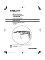 1
1
-
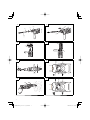 2
2
-
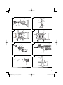 3
3
-
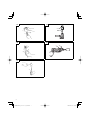 4
4
-
 5
5
-
 6
6
-
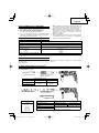 7
7
-
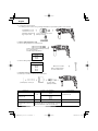 8
8
-
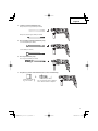 9
9
-
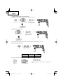 10
10
-
 11
11
-
 12
12
-
 13
13
-
 14
14
-
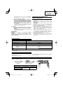 15
15
-
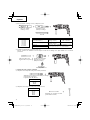 16
16
-
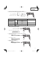 17
17
-
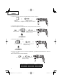 18
18
-
 19
19
-
 20
20
-
 21
21
-
 22
22
-
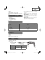 23
23
-
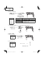 24
24
-
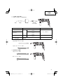 25
25
-
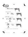 26
26
-
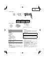 27
27
-
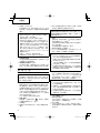 28
28
-
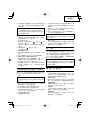 29
29
-
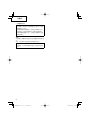 30
30
-
 31
31
-
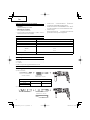 32
32
-
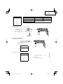 33
33
-
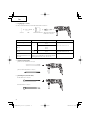 34
34
-
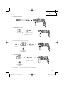 35
35
-
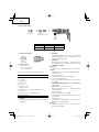 36
36
-
 37
37
-
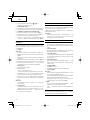 38
38
-
 39
39
-
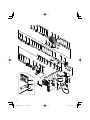 40
40
-
 41
41
-
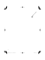 42
42
-
 43
43
-
 44
44


Hikoki DH24PC3 Manual de usuario
- Categoría
- Martillos perforadores
- Tipo
- Manual de usuario
- Este manual también es adecuado para
En otros idiomas
- English: Hikoki DH24PC3 User manual